System/370 Operator's Reference Guide - bitsavers.org
259
--- - ---- System/370 ==-=-:= Operator's Reference Guide
-
Upload
khangminh22 -
Category
Documents
-
view
0 -
download
0
Transcript of System/370 Operator's Reference Guide - bitsavers.org

--- ----- System/370 ==-=-:=
Operator's Reference Guide

First Edition July 1974
Requests for copies of IBM publications should be made to your IBM representative or to the IBM branch office serving your locality. Address comments concerning the contents of this publication to IBM Corporation, DPD Education Development -Publications Services, Education Center, South Road, Poughkeepsie, New York 12602.
© Copyright International Business Machines Corporation 1974
All rights reserved. No portion of this text may be reproduced without express permission of the author.

PREFACE
This guide :s designed as a handy, quick reference for System 370 operators of all levels and models. It includes a problem determination chart, S/370 general information, CPU manual procedures for Models 115 to 195, operator commands for the various operating svstems, IPl procedures for DOSIVS and VS1 and VS2, 1/0 information (status and sense data, restart proceduras, operating hints!' utilities information, a glossary, bibliography, and index.
Since its purpose is to selve as a qu ick reference··a memory jogger to the operator in a dynamic, operating situation·· its content is slanted toward translation of code (bit information such as condition code", status and sense bytes, etc.); command and record formats; operating procedures; and error restart procedures.
System 370 model, embrace different kinds of hardware cOr.:PQ,1e~ts and input/output <Jr.its. The prob:em determination chart in the front of the guide is a generalized procedure for isolating t~ouble in the S/370. Once the malfunctioning unit has been isolated, flow charts for checking out that unit can be found in the relevant Operating Procedures SR l.
CPU manual precedures, by model, are provided in Section 3. The procedure for loading a secondary nucleus and the hard stop procedure are new in the guide. The rest of the procedu."es parallel those provided in the S/360 Operator's Reference Guide.
Depending on the oiJerating system generated, $/370 operators use a variety of commands. OSIVS operators use VS1 and VS2 commands; DOSIVS operators use DOSNS and POWER commands: VM;'370 operators, CP and CMS cOIT\rnacds; remote workstation operators, RES commands; and so on. In other words, each operator uses the commands suitable to his computer, operating system, and operator assignment. Section 4 contains the command formats fer the various operating systems and operator consoles, and for remote as well as central CPU operators.
1/0 status and sense byte information is summarized in Section 5. For the most part, only the first six bytes are show~, since these are ali that concern the operator; the remaining bytes are of interest to the field engineer. Complete status and sense byte information usually appears in t~e Component Description SR L. For some of the smaller systems, however, status and se"se information on 1/0 devices is presented in the Functional Characteristics SRL.
Of necessity, the information in this guide is highly condensed. Complete information is provided in theSRls. To save the operator time we have noted the source of all information in this guide in order to steer him directly to the proper SRl. If the source appears just :Jnce, as at the beginning of Section 2, tris means that all the information in that section comes from that single source. The titles of the source publications can be found in Bibliography 1, a numerically ordered list of all publications cited in this guide. Bibliography 2 lists publications not quoted frem directly, is more comprehensive, and is arranged by subject matter.
Since this is an operator's guide, we have included only information which concerns the uperator. For programming and field engineering information, consult the OS/VS Program· mer's Reference Digest, the DOSIVS Handbook, and the FE Handbook.
Finally, a word of caution. For release-dependent information, check the appropriate SRl to determine whether the information contained in this guide has changed as a result of the r·ow release. As of the date of publication, operator commands are current for OSNSl Release 3, OSIVS2 Release 2, VM/370 Release 2, and DOSIVS Releese 29.


Table of Contents
Section 1: Problem Determination Chart .•.........••..........•....•.. 1·1 How To Call IBM for Service .................................... 1·11
Section 2: General Information . . . . . . . . . • • . . . . . • . . . . . . • • . . • . . • . . . . • . 2·1 Machine Instructions .......................................... 2·1
Floating-Point Instructions ................................... 2·3 Extended Mnemonic Instructions ....•............................ 2·3 Edit and Edmk Pattern Characters . . . . . . . . . . . . . . . . . . . . . • . . . . . . . . . . . 2·3 Condition Codes. . . . . . . . . . . . . . . . . . . . . . . . . . . . . . . . . . . . . . . . . . . . . 2-4 CNOP Alignment ......................•..................... 2-4 Assembler Instructions ........................................ 2·5 Summary of Constants ........................................ 2·5 I/O Command Codes .......................................... 2-6
Channels ............................................... 2-6 Card Readers/Card Punches . . . . . . . . . . . . . . . . . . . . . . . . . . . . . . . . . . . 2-6 Console Printers .......................................•.. 2-6 Magnetic Tapes ........................................... 2-6 Direct Access Storage Devices ................................. 2·7
Code Translation Table ........................................ 2-8 ANSI-Defined Printer Control Characters ............................ 2·11 Machine Instruction Formats .................................... 2·12 Control Registers ............................................ 2·12 Program Status Word (BC Mode) ................................. 2·13 Program Status Word (EC Mode) .................................. 2·13 Channel Command Word ....................................... 2·13 Channel Status Word (hex 40) .................................... 2·13 Program Interruption Codes ..................................... 2·13 Fixed Storage Locations ....................................... 2·14 Limited Channel Logout (hex BO) ................................. 2·14 Machine Check Interruption Code (hex E8) ........................... 2·14 Dynamic Address Translation .................................... 2·15
Virtual (Logical) Address Format ............................... 2·15 Segment Table Entry ...................................... 2·15 Page Table Entry .......................................... 2·15
Hexadecimal and Decimal Conversion ............................... 2·15 Powersof2and 16 ........................................... 2·15
Section 3: CPU Manual Procedures •....•.....•...••.........•...•••.. 3-1 Functional Characteristics of Manual Controls ......................... 3·1 CPU Manual Procedures for:
Mod 115 ............................................... 3·3 Mod 125 ............................................... 3·3 Mod 135 ............................................... 3-6 Mod 145 ............................................... 3-8 Mod 155 ............................................... 3·11 Mod 158 ............................................... 3·13 Mod 165 .........................................•..... 3·15 Mod 168 ............................................... 3·18 Mod 195 ..............................................• 3·22
Section 4: Operator Commands ......••.••.•....•••...•....•.....••• 4·1 DOSNS IPL Commands ....................................... 4·1 DOSNS Job Control and Attention Routine Commands .................. 4-5 DOSNS POWER Commands .................................... 4·20 DOSNS POWER RJE COmm .... ds ................................. 4-22 VS1 Operator Commands (VS1 Release 3) ........................... 4·25 VS1 Message Routing Codes ...................................•. 4·30 VS2 (JES2) Message Routing Codes ..........................••.... 4·30 VS2 Operator Commands (Release L6) ............................. 4·31 VS2 (JES2) Release 2 COmm .... ds ................................. 4-35 OSNS HASP II Version 4 Commands .............................. 4-43 VM/370 Commands ......•..........................•.•...... 4-47 Summary of CMS Commands .••........................•.... , .•• 4-61 CMS Command Formats .....................................•• 4-64 RES Central Operator Commands ...............................•. 4-69 RES Work~tion Operator Commands ............•................. 4·70 SMF Parameters ...•...•......••....................••....... 4-73 CRJE System Operator Commands .....•..................••....•. 4·74
II
II
II
II
II
II
II

CRJE Terminal Command Formats ................................ 4-75 Er.!it Subcommands CRJE ............ . ........................ 4-76 Terminal Commands and Functions CRJE ........................... .4-,7
DOstVS Display Operating Console Commands for Mod 115 ar,a 125 . . . . . .. . ............................. 04-80
OSNS Display Console Control Command .......................... .4-83 Program Function Keys--Entering Commands through PFKs ................ 4-83
I P L Procedures for: DOSNS, Release 29 ......................................... .4-84 VS1, Release 2.0 .................................. 4-86 VS2, Releao;e 1.6 ........................................... .4-88 VS2, Release 2.0 ......................... . ......... .4-89
Section 5: Input/Output Devices and Restart Procedures Status Byte Summary ......................................... 5-1 Sense Byte Summary . . . . . . . . . . . . . . . . . . . . . . . . . . . . . . . . . . . . . . . . . . 5-2 Card Readers: General Hints .................................... 5-10 3504/3505 Stop Indications and Restart Procedures ..................... 5-11 3525 Error Recovery Routines .............. . ................... 5-25 OSNSI Checkpoint Restart. . . . . . . .. . .......................... 5-26 OSNS2 Checkpoint Restart ..................................... 5-27 3340 Disk Drive: Operating Hints ................................. 5-28 Console File ............................................... 5·30 Diskette .................................................. 5-30
Operating Procedures ... _ ................................... 5-31 Cartridge Handling ......................................... 5-32
341013411 Tape Drive. . . . . . . . . . . . . . . . . . .. . ................... 5-34 Operating Procedures after Failures ............................. .5-34 Cleaning Procedures ............. , .......... . ............. 5·34 Tape Handling and Storage ................ . ................ 5-36
3420 Tape Drive ............................................ .5-37 Operating Procedures after Failures. . . . . . . . . . . . . . ...... 5-37 Cleaning Procedures ........................................ 5-37
1403 Printer .............................................. .5-39 3211 Printer ............................................... 5-42
Error RecO\lery Summary .................................... 5-42 Error RecO\lery Procedures ................................... 5-43
Video Disrlay Screen Areas on: Mod 125 ............................................... 5-44 Mod 158 ............................................... 5-45 Mod 168 .............................................. 5-46
Operating the OSNS Display Console I 'Jlod 158) ....................... 5-47 Operating 3270 ................... . ................ 5-49
Section 6: Utilities DOSNS System Utilities . . . . . . . . . . . . . . . . . . . . . . . . . . . . . . . 6-1
Assign Alternate Track Data Cell ............................... 6-1 Clear Data Gell .......... . . . . . . . . . . . . . . . . . . . . . . . . . . . 6- i Clear Disk .................. . . . . . . . . . . . . . . . . . . . . 6-1 Copy and Restore Disk or Data Cell ............................. 6-1 Copy ~nd R~(\r~ Di,kett. . . . . . . . . . . .. 6-2 Deblock. . . . . . . . . . . . . . . . . . . . . . . . . . . . . . . . . . . . . .. 6-2 Fast Copy Disk Volume ............ . .... 6·2 Initialize Data Celt . . . . . . . . . . . . . . . . . . . . . . . . . . . . . . . . . . . . . . 6-2 Initialize Disk . . . . . . . . . . .. . .............................. 6-2 Initialize Tape. . . . . . . . . . . . . . . . . . ................ 6·2 Print Hardcopy File. . . . . . . . . . . . . . ........... 6·3 VTOC Display ........................ _ . . . . . . . . . . . . . . . . . . 6-3 DOS DITTO. . . . . . . . . . .. .................. . ........ 6·3
Sample Control-Statemem Streams for: Initialize Data Celt . . . . . . . . . . . . . . . . . . . . . . . . . . . . . . . . . . . . . . . . . 6-4 Initialize Disk ....................... _ . . . . . . . . . . . . . . . . . . . . 6-4 Initialize Tape. . . . . . . . . . . . . . . . . . . . . . . . . . . . . . . . . . . . . .. . ... 6·4 Fast Copy Disk Volu"1e ... _ .. . ......... 6·5 Printlog . . . . . . ... _ ... _ . . . . . . . . . . . . . . . 6-5 VTOC Display 6-'=' FOP, DtTTO . . . .. . ......... 6-6

OSNS Utilities .........•..............•...................• 6-7 System Utility Programs . . . . . . . . . . . . . • . . . . . . . . . . . . . . . . . . . . . . . 6-7 Data Set Utility Programs . . . . . . . . • . . . • • . . . • . . . . . . . . . . . . . . . . . . 6-7 Independent Utility Programs ..•............•.........••...... 6--8
Index of Functions Performed by Utility Programs ...................... 6-9 Executing a System Utility Program . . . . . . . . • . . . . . . . . . . . . . . . . . . . . . . .6-12
Sample Control-5tatement Streams for: ............................. 6-14 IBCDASDI .......•...•...........•...................... 6-14 IEHDASDR •........•......•............................ 6-14 IEBISAM •.........•.................................... 6-15 IEHLlST ............••................................. 6-15 IEHMOVE " .•...•.......•...•.•...........•....•......• 6-16 IEBPTPCH ..•..........••.......•....................•.. 6-16
OSNS1 Service Aids _ ............•......•....•.•.....•........ 6-18 OSNS10LTEP .......•...•......•......................... .6-19
Sec:tion 7: Glossary ••.•••••••.•••••••.•••••••...•.....••.......• 7-1
Sec:tion 8: Bibliography ••••••••....••.•.•••.••.••••••...•••••...• 8-1
Index
iii


Section 1 Contents II Section 1: Problem Detsnnination awn . . . . . . . . . . . . . . . . . . . . . . . . . . . . . . . 1·1
HowToCalllBMforService .................................... 1·11

Problem Determination DEFINITION OF SYMBOLS USED IN FLOW CHARTS
( )
<> D o
Starting or terminating step.
Question block which is asking for a "yes· no" or "on - off" answer. Output lines will be labeled.
Indicates some action is required or gives a brief description of situation.
Refers reader to some other page for di rections of particular operator action required.
Number within this symbol indicates one of the following:
1. Page number which references this page. 2. This page number, if this is a common
entry from several other pages 3. Page to exit to in order to continue
usage of charts
Page 1-1
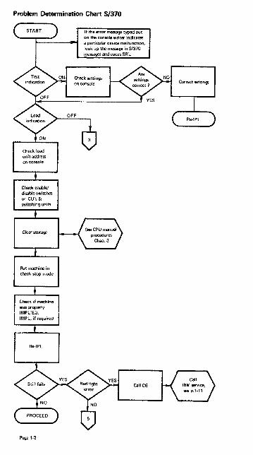
Problem Detennination Chart S/370
unit address on console
Check enablel disable switches on CU', & switching units
Clear storage
Put machine in check stop mode
Check if machine was prQPerly IMPL'ED. IMPL, if required
Re·IPL
Page 1·2
I f the error message typed out on the console writer indicates a particular device malfunction, look up the message in S/370 messages and codes S R L
GaliCE
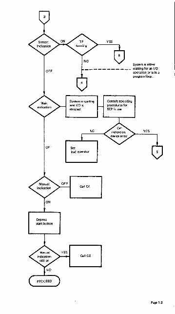
System is waiting and 1/0 is stopped
OFF See
Depress start button
CaIiCE
CaIiCE
Cansu It operating procedures for SCP in use
operation or is in a pregram loop.
Page 1-3
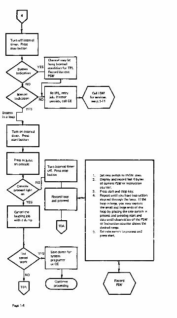
Tum off interval timer. Press stop button
Tum on interval timer. Press start button
f"re;s rcque.l on console
Cancel the looping job with a dump
Page 1-4
Record loop and prooeed
1. Set rate switch to I NSN step. 2. Display and record last 4 bytes
of current PSW or instruction counter.
3. Press start and stop key. 4. Repeat until you have instruction
stepped through the loop. If the loop is large, you may capture the small and large ends of the loop by placing the rate switch in process and pressing start and stop until observation of the PSW or instruction counter shows the desired range.
5. Set rate switch to process and press start.

Do NOT move pack again
pack and device down. Call CE
NO
NO
Bad data or track. Restore pack from backup tape. Restart job.
If possible, continue processing jobs that don't require device.
1. Vary device offline.
2. Notify CE
1. Vary device offline.
2. Notify CE
I f possible, continue processing jobs that don't require device.
Page 1-5
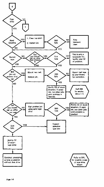
Notify CE "of down tape drive
Continue processing as long as possible without that drive
Page 1-6
Run another job using same tape drive
until problem is resolved.
Suspect defective tape reel
Notify CE of down situation. If PQSsible, run other jobs until problem is resolved

See index for page number of device and go to that page for possible causes!
NO
Notify I BM of down situation.
Failure is in device not covered NO by this chart, e.g., optical
scan paper tape. TP, ETC.
YES
Continue processing .-___ -< with another job and device, if possible
Page 1·7

Press request key on console
I~~ .ji~~ey
request command
Page 1-8
NO This is a hard wait
YES Take appropr iate action
Take appropriate action per messages and codes SRL

Scan console to ensure all messages requiring operator action have been honored
System may be waiting for work. Issue display llCtive command.
The system may have exhausted direct access space. Issue a display Qcommand.
Direct access space will be released if you can start a writer for queue output jobs. You may have to issue a hold Q, stop RDR, cancel jobs in order to start a writer
Release Q to resume normal processing
Take appropriate action per messages
and codes SRL
Force a deviceend interrupt (stop-start the device)
Hold Q to prevent initiation of new jobs
Display job names for information about job starting and stopping
Displav active for current job execution status
Stop readers and writers to correct possible main storage fragmentation
Cancel jobs with a dump, in reverse order of priority
DispljlV active to monitor changing environment
Release Q to resume normal processing
If the porblem can· not be corrected, follow the proce· dure for hard wait
Page 1·9

Page 1-10
Record contents of the current PSW
Save master console sheet
Execute the stand-alone dump

To Call IBM for Service
1. First check to see if there is a CE on site.
2. I f not call your local I BM dispatch at:
Normal IBM Branch Office hours _____ _ Outside of Normal Office hours _____ _
3. Give dispatch the following information:
1. Your company name, your name and extension.
2. Type of machine (box) that gives the error indications.
3. Type of system attached to (Mod 115, Mod 145, etc. I
4. What is your urgency?
5. If known, is your trouble hardware or software.
6. Any special instructions a CE might need to know to get to your account.
7. The CE that normally services your account.
CE NAME--
Page 1·11


Section 2 Contents
Section 2: General Information .: •.•••..••••.•••••••••.•••••••.••.•.• 2·1 Machine Instructions ................•...................••...• 2·1
Floating-Point Instructions .................••..........•..... 2·3 II Extended Mnemonic Instructions ......•.......................... 2·3 Edit and Edmk Pattern Characters . . . . . . . . . . . . . . . . . . . . . . . . . . . . • . • . . 2·3 Condition Codes . . . . . • . . . . . . . . . . . . . . . • . . . . . . . . . • . . . . . . . . • • • • . 2-4 CNOP Alignment .••......•.................................. 2-4 Assembler Instructions ....•........•...•....•.....•...••.....• 2·5 Summary of Constants ......................•...•............. 2·5 I/O Command Codes . . . . . . . . . . . . . . . . . . . . . . . . . . . . . . . • . . . . . . . . . . 2-6
Channels .•........•.........•..............•......•.... 2-6 Card Readers/Card Punches . . . • . . . . . . . . . . . . . . . . . . . • . . . . • • • • . . . 2-6 Console Printers ..•..•...............•..............•.•... 2-6 Magnetic Tapes . . . . • . . . . . . . . . . . . . . . . • . . . . . . . . . . . . . . . • .. . . . . 2-6 Direct Access Storage Devices ............................•..•. 2·7
Code Translation Table ...... ;................................. 2-8 ANSI.,..Defined Printer Control Characters ....................••..... .2·11 Machine Instruction Formats .•............••....•...•.•.•..•.••. 2·12 Control Registers ....•.•....•.•.....•.......•..............•. 2·12 Program Status Word (BC Mode) •......•..•.....•••...•......•... 2·13 Program Status Word (EC Mode) ...........•.•....•.•.••...••.... 2-13 Channel Command Word •......•....•.•............•••.....•... 2-13 Channel Status Word (hex 40) ......••............................ 2-13 Program Interruption Codes ••......•.................•.•..•••..• 2-13 Fixed Storage locations ..•....•...........................•... 2-14 limited Channel logout (hex BO) ................................. 2-14 Machine Check Interruption Code (hex E8) ........................•.. 2-14 Dynamic Address Translation ......................•....•....••.. 2-15
Virtual (logical) Address Format ............................... 2-15 Segment Table Entry ..........•.....................•....•. 2-15 Page Table Entry .....•....................... , ............ 2-15
Hexadecimal and Decimal Conversion •.....••....................... 2-15 Powers of 2 and 16 ........•....•....•.....................••. 2-15

System/370 General Information Source: GX20-1850-2 Systeml370 Reference Summary
MACHINE INSTRUCTIONS OP FOR·
NAME MNEMONIC CODE MAT OPERANDS Add Ic) AR lA RR Rl,R2 Add Ic) A 5A RX Rl,02IX2,B2) Add Decimal Ic) AP FA 55 01 III ,Bl ) ,02(l2,B2) Add Halfword (c) AH 4A RX Rl,02(X2,B2) Add logical (c) AlR lE RR Rl,R2 Add logical (c) Al 5E RX Rl,02(X2,B2) ANO(e) NR 14 RR Rl,R2 ANO (c) N 54 RX Rl,02(X2,B2) ANO Ic) NI 94 SI 01(B1I,12 ANOlc) NC D4 SS 01(l,Bl),02(B2) Branch and Li n k BAlR 05 RR Rl,R2 Branch and Link BAl 45 RX Rl,02(X2,B2) Branch on Condit,,,n BCR 07 RR Ml,R2 Branch on Condition BC 47 RX Ml,02(X2,B2) Branch on Count BCTR 06 RR Rl,R2 Branch on Cou nt BCT 46 RX Rl,021X2,B21 Branch on Index High BXH 86 RS Rl,R3,02(B2) Branch on I ndex low or Equal BXlE 87 RS Rl,R3,02(B2) Clear/fO (c,p) ClRIO 9001 S 02(B2) Compare (c) CR 19 RR Rl.R2 Compare Ic) C 59 RX Rl,02(X2,B2) Compare and Swap (c) CS BA RS Rl,R3,02(B21 Compare Decimal Icl CP F9 55 01{L1,Bl ),02Il2,B2) Compare Double and Swap (c) COS BB RS Rl,R3,D2IB2) Compare Halfword (c) CH 49 RX Rl,021X2,B2) Compare logical Ie) ClR 15 RR Rl,R2 Compare logical Ic) Cl 55 RX Rl,02(X2,B2) Compare logical Ic) ClC 05 SS D1!l,B1I,D2(B2) Compare logical Ic) CLI 95 SI 01(B1),12 Compare Logical Characters ClM BO RS Rl,M3,02(B2)
under Mask Ic) Compare Logical Long (c) ClCl OF RR Rl,R2 Convert to Binary CVB 4F RX Rl,D2(X2,B2) Convert to Decimal CVO 4E RX Rt,D2(X2,B2) Oiagno:;e (p) 83 Model-dependent Oivide OR lD RR Rl,R2 Oivide 0 50 RX Rl,02(X2,B2) Divide Oecimal DP FO SS 01(l1,B1I,02(l2,B2) Edit Ic) EO OE SS 01!l,61 ),02(B2) Edit and Mark Ie) EOMK OF SS 01 (l,61 ),02(62) Exclusive OR Ic) XR 17 RR Rl,R2 Exclusive OR (c) X 57 RX Rl,D2IX2,B2) Exclusive OR (e) XI 97 SI 01(Bl),12 Exclusive OR (c) XC 07 55 01Il,611.D2IB2) Execute EX 44 RX R1,021X2,B2) Halt liO (c,p) HIO 9EOO S D2(B2) Halt Device Ic,p) HOV 9EOl S 02(B2) I nsert Character IC 43 RX R 1, 021X2,B2) Insert Characters under Mask Ic) ICM BF RS Rl,M3,D2(B2) Insert PSW Key Ip) IPK B20B S I nsert Storage Key Ip) ISK 09 RR R1,R2 load lR 18 RR R1,R2 load l 58 RX R1,02(X2,B2) load Address lA 41 RX R1,02(X2,B2) load and Test Ie) lTR 12 RR R1,R2 load Complement (c) lCR 13 RR Rl,R2 Load Control Ip) lCTl 67 RS R1,R3,D2(B2) load Halfword lH 48 RX R1,D2(X2,B2) load Multiple lM 98 RS R1,R3,D2(B21 load Negative (c) lNR 11 RR Rl,R2 load Positive (c) lPR 10 RR R1,R2 load PSW (n,p) lPSW 82 S D2(B2) Load Real Address (c,p) lRA Bl RX Rl,02(X2,B2) Monitor Call MC AF SI D1(B1I,12 Move MVI 92 SI D1(611,12 Move MVC 02 55 01 (l,Bl ),02(B21 Move Long (c) MVCl OE RR Rl,R2 Move Numerics MVN 01 55 01 (l,Bl ),02(B2) Move with Offset MVO Fl SS D1(L1,Bl),D2Il2,B2) Move Zones MVZ 03 55 01(l,Bl ),D2(B2) Multiply MR lC RR Rl,R2 Multiply M 5C RX R l,D2(X2,B2) Multiply Decimal MP FC 55 DHL1,Bl ),D2(l2,B21 Multiply Halfword MH 4C RX Rl,D2IX2,B2) OR (cl OR 16 RR Rl,R2 Page 2-1

MACHINE INSTRUCTIONS (Contd) OP FOR
OR (c) OR (c) OR (e) Pack
NAME MNEMONIC o
CODE MAT 56 RX
OPERANDS Rl,02(X2,B2) 01(B1I,12
Purge TLB (p) Read Direct (p) Reset Reference Bit (c,p) Set Clock (c,p) Set Clock Comparator (p) Set CPU Timer (p) Set Prefix (p) Set Program Mask (n) Set PSW Key from Address (p) Set Storage Key (p) Set System Mask (p) Shift and Round Decimal (e) Shift Left Double (c) Shift Left Double Logical Shift Left Single (c) Shift Left Single Logical Shift Right Double (c) Shift Right Double Logical Shift Right Single (c) Shift Right Single Logical Signal Processor (c.p) Start I/O (c,p) Start 110 Fast Release (c.p) Store Store Channel 10 (c,p) Store Character Store CharBCters under Mask StCNfJ Clock (c) Store Clock Comparator (pI Store Control (p) Store CPU Address (p) Store CPU 10 (p) Store CPU Timer (p) Store Halfword Store Multiple Store Prefix (p) Store Then AND System
Mask (p) Store Then OR Symm Mask (p) Subtract (c) Subtract (c) Subtract Decimal (c) Subtract Hallword (c) Subtract Logical (c) Subtract Logical (c) Supervisor Call Test and Set (c) Test Channel (c,p) Test I/O (c,p) Test under Mask (c) Translate Translate and Test (e) Unpack Write Direct (p) Zero and Add Decimal (cl
F1oatinltPoint Instructions
NAME Add Normalized. Extended (c,x) Add Normalized. Long (c) Add Normalized, Long (c) Add Normalized, Short (c) Add Normalized, Short (c) Add Unnormalized, Long (c) Add Unnormalized. Long (c) Add Un normalized. Short (c) Add Unnormalized. Short (c)
c. Condition code is set. n. New condition code is loaded.
Page 2·2
01 DC PACK PTLB ROD RRB SCK SCKC SPT SPX SPM SPKA SSK SSM SRP SLOA SLOL SLA SLL SROA SROL SRA SRL SIGP SID SIOF ST STiOC STC STCM STCK STCKC STCTL STAP STIOP STPT STH ~TM STPX. STNSM
STOSM SR S SP SH SLR SL SVC TS TCH TID TM TR TRT UNPK WRO ZAP
96 SI 06 SS F2 SS B200 S 85 SI B213 S B204 S B206 S B208 S B210 S 04 RR B20A S 08 RR 80 S FO SS 8F RS 80 RS 8B RS 89 RS BE RS 8C RS 8A RS sa RS AE RS 9COO S 9COI S 50 RX B203 S 42 RX BE RS B205 S B207 S B6 RS B212 S B202 S B209 S 40 RX 00 RS B211 S AC SI
AD SI lB RR 5B RX FB SS 4B RX IF RR 5F RX OA RR 93 S 9FOO S 9000 S 91 SI DC SS 00 SS F3 SS 84 SI F8 SS
01 (L,Bl ).02(B2) 01 (L I,Bl ),02(L2,B2)
01(Bl).12 02(B2) 02(B2) 02(B2) 02(B2) 02(B21 Rl 02(B21 R1,R2 02(B2) 01(L1,Bll,02(B2),13 Rl,02(B2) Rl,02(B2) Rl,02(B2) Rl.02(B2) Rl,02(B2) Rl,02(B2) Rl,02(B2) Rl,02(B2) Rl,R3,02(B2) 02(B2) 02(B2) Rl,02(X2,B2) 02(B2) R 1,02(X2,B2) Rl,M3.02(B2) 02(B2) 02(B2) Rl,R3,02(B2) 02(B2) 02(B2) 02(B2) Rl.02(X2.B2) Rl,R3,D2(B2) 02(B2) 01(B1I,12
D1(B1I,12 Rl,R2 Rl,02(X2.B2) 01( L1,B1I ,02( L2,B2) Rl,02(X2.B2) Rl,R2 Rl.D2(X2,B2) I 02(B2) 02(B2) 02(B21 01(B1I,I2 01 (L,Bl ).D2(B2) 01 (L,Bl ).02(B2) D1(L1,Bl ).D2(L2,B2) 01(B1),I2 01(L1,B1I,D2(L2,B2)
OP FOR-MNEMONIC
AXR AOR AD AER AE AWR AW AUR AU
CODE MAT 36 RR 2A RR 6A RX 3A RR 7A RX 2E RR 6E RX 3E RR 7E RX
OPERANDS Rl.R2 Rl,R2 Rl.02(X2.B2) Rl,R2 Rl,02(X2,B2) Rl.R2 Rl.02(X2,B2) Rl,R2 Rl,02(X2,B2)
p. Privileged instruction. x. Extended precision floating·point.

FloatinltPoint Instructions (Contd) OP FOR-
NAME MNEMONIC WOE MAT OPERANDS Compare, Long Ic) CDR 29 RR R1,R2 Compare, Long Ic) CD 69 RX R1,D21X2,B2) Compare, Short Ic) CER 39 RR R1,R2 Compare, Short Ic) CE 79 RX R1,D2(X2,B2) Divide, Long DDR 20 RR Rl,R2 Divide, Long DO 60 RX Rl,D2(X2,B2) Divide, Short DER 3D RR Rl,R2 Divide, Short DE 70 RX Rl,D2(X2,B2) Halve, Long HDR 24 RR R1,R2 Halve, Short HER 34 RR R1,R2 Load and Test, Long (c) LTDR 22 RR R1,R2 Load and Test, Short IC) LTER 32 RR R1,R2 Load Complement, Long (c) LCDR 23 RR R1,R2 Load Complement, Short (c) LCER 33 RR R1,R2 Load, Long LOR 28 RR Rl,R2 Load, Long LD 68 RX R I,D2IX2,B2) Load Negative, Long Ie) LNDR 21 RR R1,R2 Load Negative, Short (c) LNER 31 RR R1,R2 Load Positive, Long (c) LPDR 20 RR R1,R2 Load Positive, Short Ic) LPER 30 RR Rl,R2 Load Rounded, Extended to Long Ix) LRDR 25 RR Rl,R2 Load Rounded, Long to Short (x) LRER 35 RR Rl,R2 Load, Short LER 38 RR R1,R2 Load, Short LE 78 RX R1,D2(X2,B2) Multiply, Extended (x) MXR 26 RR R1,R2 Multiply, Long MDR 2C RR Rl,R2 Multiply, Long MD 6C RX R1,D2(X2,B2) Multiply, Long/Extended (x) MXDR 27 RR Rl,R2 Multiply, Long/Extended (xl MXD 67 RX R l,D2(X2,B21 Multipl:/, Short MER 3C RR Rl,R2 Multiply, Short ME 7C RX Rl,D2(X2,B21 Siore, Long STD 60 RX Rl,D2(X2,B21 Store, Short STE 70 RX Rl,D2(X2,B21 Subtract Normalized, Extended (c,xl SXR 37 RR Rl,R2 Subtract Normalized, Long Icl SDR 2B RR Rl,R2 Subtract. Normalized, Long leI SO 6B RX R l,D21X2,B21 Subtract Normalized, Shon Icl SER 3B RR Rl,R2 Subtract Normalized, Short Icl SE 7B RX R1,D2(X2,B21 Subtract Unnorrnalized, Long Ici SWR 2F RR Rl,R2 Subtract Unnormalized, Long Ic) SW 6F RX R 1 ,D2IX2,B21 Subtract Unnormalized, Short (c) SUR 3F RR Rl,R2 Subtract Unnormalized, Short (cl SU 7F RX Rl,D2(X2,B2)
EXTENDED MNEMONIC INSTRUCTIONSt Extended Code- Machine Instr.·
Use (RXor RR) Meaning (RXor RR)
General BorBR Unconditional Branch BCor BCR 15, NOPor NOPR No Operation BCor BCR 0,
After BHorBHR Branch on A High BCor BCR 2, Compare BLorBLR Branch on A Low BCor BCR 4, Instructions BE orBER Branch on A Equal B BCor BCR 8, (A:B) BNH orBNHR Branch on A Not High BCor BCR 13,
BNLorBNLR Branch on A Not Low BCorBCR 1" BNEorBNER Branch on A Not Equal B BCorBCR 7,
After BOorBOR Branch on Overflow BCor BCR 1, Arithmetic BPorBPR Branch on Plus BCor BCR 2. Instructions BMorBMR Branch on Minus BCor BCR 4.
BNPorBNPR Branch on Not Plus BCor BCR 13. BNMorBNMR Branch on Not Minus BCor BCR 11. BNZorBNZR Branch on Not Zero BCor BCR 7. BZor BZR Branch on Zero BCor BCR B.
NterTest BOorBOR Branch if Ones BCor BCR 1. under Mask BMorBMR Branch if Mixed BCar BCR 4. Instruction BZorBZR Branch if Zeros BCorBCR 8.
6NOorBNOR Branch if Not Ones BCor BCR 14,
*Second operand not shown; in all cases it Is t For OS{VS and DOS{VS; D2(X2.B2) for RX format or R2 for RR format. source: GC334010.
EDIT AND EDMK PATTERN CHARACTERS (in hex)
2O-digit selector 4O-blank 5C-8sterisk 21-start of significance 4B-period 6B-comma 22-field separator 5B-dollar sign C3D9-CR
Page 2-3

CONDITION CODES Condition Code Setting 0 1 Mask Bit Vlllue 8 4
o.r..llnstructi_
Add, Add Halfword zero <zero >zero .owrflow Add Logical zer~ not_o, zero, not zero,
no carry no carry carry carry AND _0 not_o Compare, Compare Halfword equal 1st op low 1st op high -Compare and Swap/Double equal not equal Compare Logical equal 1st op low 1st op high -ExclusiwOR zero not zero I nsert Characters under Mask all zero htbitone 1st bit zero -Load and Test <zero >zero Load Complement <zero >zero overflow Load Negative <zero Load Positive zero >zero. overflow Move Long count equal count low· count high OII8rlap OR not zero Shift Left DoublelSingie zero <zero >zero owrflow Shift Right Double/Single ~ero <zero >zero Store Clock set not set error not oper Subtract, Subtract Halfword <zero >zero overflow Subtract Logical not zero, zero, not zero,
no carry carry carry Test and Set Test uqder Mask mixed Translate and Test incomplete complete
Decl ..... Instructi_ Add Decimal zero <zero >zsro OIIerflow Compare Decimal equal lst op low ht op high -Edit, Edit and Mark zero <zero >zeru Shift and Round Decimal zero <zero >zero overflow Subtract Decirnel zero <zero >zero CM:rflow Zero and Add zero <zero >zero overflow
Floating-Point lnetructi_
Add Normalized <zero >zero Add Unnormalized zero <zero >zero Comoere equal 1st op low ht op high -Load and Test <zero >zero Load Complement <zero >zero Load Negative <zero Load Positive >zero Subtract Normalized <zero >zero Subtract Unnormalized <zero >zero
I nput/OutpUt I nltructio ..
Clear I/O no oper in CSWstored chan busy not oper progress
Halt Device interruption CSW stored channel not oper pending working
Halt I/O interruption CSW stored burstop not oper pending stopped
Start 1/0, SIOF successful CSWstored busy not oper Store Channel I D ID stored CSW stored busy not oper Test Channel lMIilable interruption burst mode not oper
pending Test I/O available CSWstored busy not oper
Syst .... Control I nstructi_
Load Real Address lranslation STenlry PTentry length lMIilable invalid invalid violation
Reset Reference Bit R=O, C=OI RzO,C=l R=I, C=O I R=l, C=1 Set Clock set secure notoper Signal Processor accepted slat stored busy not oper
CNOP ALIGNMENT DOUBLEWORD
WORD WORD HALFWORD I HALFWORD HALFWORD HALFWORD
BYTE. BYTE BYTE BYTE BYTE , BYTE BYTE ' BYTE
~ ~ ~ ~ 0,8 2,8 4,8 6,8
Page 2-4
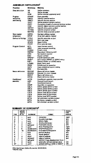
ASSEMBLER INSTRUCTIONSt
Function Mnemonic ..... ng
Data definition DC Define constant OS Define storage CCW Define channel command word
Prowam START Start3S$l!mbly sectioning CSECT Identify control section and linking OSECT Identify dummy section
OXO- Define external dummy section CXO- Cumulative length of external dummy section COM Identify blank common control section ENTRY Identify entry-point symbol EXTRN Identify extemal symbol WXTRN Identify weak external symbol
Base register USING Use base address register assignment DROP Drop base address register
Control of listings TITLE Identify 3S$I!mbly output EJECT Start new page SPACE Space listing PRINT Print optional data
Program Control ICTL Input format control ISEO Input sequence checking PUNCH Punch a card REPRO Reproduce following card ORG Set location counter EOU Equate symbol OPSYN- Equate operation code PUSH- Save current PRINT or USING status POP- Restore ~RINT or USING status LTORG Begin literal pool CNOP Conditional no operation COpy Copy predefined source coding END End assembly
Macro definition MACRO Macro definition header MNOTE Request for error message MEXIT Macro definition exit MEND Macro definition trailer
Conditional ACTR Conditional assembly loop counter assembly AGO Unconditional branch
AIF Conditional branch ANOP Assembly no operation GBLA Define global SETA symbol GBLB Define global SETB symbol GBLC Define global SETC symbol LCLA Define local SETA symbol LCLB Define local SETB symbol LCLC Define local SETC symbol SETA Set arithmetic variable symbol SETB Set binary variable symbol SETC Set character variable symbol
SUMMARY OF CONSTANTSt I .. UED LENGTH.
TYPE BYTES ALIGNMENT FORMAT
C - byte characters X - byte hexadecimal digits B - byte binary digits F 4 word fixed-point binary H 2 halfword fixed-point binary E 4 word short floatinQ1>Oint 0 8 doubleword long floating-point L 16 doubleword extended floating-point P - byte packed decimal Z - byte zoned decimal A 4 word value of address Y 2 halfword value of address S 2 halfword address in base-<lispIaoement form V 4 word externally defined address value 0- 4 word symbol naming a OXO or OSECT
tFor OS/VS and DOSJV5, source: GC33-4010. *05/VS only.
TRUNCA· TlONI PADDING
right left left left left right right right left left left left -left left
Page 2-5

1/0 COMMAND CODES Standard Command Cod. Assignm_.ICCW bits 0-71
xxx x 0000 Invalid tttt ttOl Write tttt 0100 Sense tttt ttl0 Read xxxx 1000 Transfer in Channel tttt 'ttll Control tttt 1100 Read Backward 0000 0011 Control No Operation
x-Slt ignored. t Modifier bit for specific type of 110 device
CONSOLE PRINTERS
Write, No Carrier Return Write, Auto Carrier Return Read Inquiry
01 Sense 04 OB 09 Audible Alarm
OA
3504,3505 CARD READERSl3625 CARD PUNCH Source: GA21-9124
ComMllnd Binary Hex BitM .. nings
Sense 0000 0100 04 li§ St1ICker Feed, Select Stacker SS10 FOIl 00 -1-
Read Only" 1100 F010 01/101 2 Diagnostic Read 11010010 02 F Format Mode Read, Feed, Select Stacker" SSOO F010 a UnfOrmatted Write RCE Format" 0001 0001 11 1 Formatted 3504, 3505 only D OetaMode Write OMR Formatt 0011 0001 31 0 I-EBCDIC
3525 only 1 2-Card image
Write, Feed, Select Stacker SSOO 0001 L Line Position Print Line .... LLLL Ll01 5:bit binary value
*Spec:lal feature on 3525. tSpeclal feature.
PRINTERS: 321113811 (GA24-3543), 3203IIPA, 1403"/2821 (GA24-3312)
After Write Immed I Write without opacing 01
Space 1 Line 09 OB Sense 04
Space 2 Lines 11 13 Load UCSB without folding FB
Space 3 Lines 19 lB Foldt 43
83 Unfold t 23 Skip to Channel ot Skip to Channel 1 89 8B Load UCSB and Fold (axc_ 32111 F3
SkIp to Channel 2 ~1 ~~ UCS GatE Load (1403 :m!yl E8
Skip to Channel 3 99 96 Load FCBt 63
Skip to Channel 4 Al A3 Block Data Check 73
Skip to Channel 5 A9 AB Allow Data Check 7B
Skip to Channel 6 Bl B3 Read PLBt 02
Skip to Channel 7 B9 BB Read UCSBt OA
Skip to Channel 8 Cl C3 Read FCBt 1:<
Skip to Channel 9 C9 CB Diag. Check Read (exc. 3203) 06
Skip to Channel 10 01 03 Diagnostic Writet 05 Skip to Channel 11 09 DB Raise Covert 6B
Skip to Channel 12 El E3 Oiagnost<c Gate t 07 Diagnostic Read (1403 only) 02
"UCS special feature; IPA diagnostics are model-dependent. 13211 only.
3420/3803.3410/3411 MAGNETIC TAPE (* 'Indicate, 3420 only) See GA32-0020, -0021. -0022 for special features and functions of specific models.
== :~7~~d ---, ' ... -~' ,'. oenSity:ty{:~ {T~~;.'~
~~: Reserve" ~ ~ 200 l even off {~~ ~ Sanse Release'" D4 ~ {{ on Request Track-in-Error 1 B ~ odd:~ { ~~ ~~ Loop Write-ta-Read"' 8B" 556 on 7B Set Diagnose·· 48 U) {ff 63 Rewind 07 ~ even off 0 6B
Rewind Unload OF:; {{ o~
=E 6~:~ i~ 8OO:n
:: {~~ !i Backspace File 2F { on AB Forward Space Block 37 Forward Space File 3F Mode Set 2 (9-track). 800 bpi CB Data Security Erase"" 97 Mode Set 2 (9-trackl. 1600 bpi C3 Diagnostic Mode Set" OB I Mode Set 2 (9-track), 6250 bpi" 03
Page 2-6

I/O COMMAND CODES (Contdl DIRECT ACCESS STORAGE DEVICES:
3330-3340 SERIES (GA26-1592, ·1617, -1619, -1620):
230512835 (GA26·1589); 2314 2319 (GA26-3599, -1606)
Command MTOff MTOn"
Control Orient leI 2B Recalibrate 13 Seek 07 Seek Cylinder OB Seek Head lB Space Count OF Set File Mask IF Set Sector (a, tI 23 Restore (executes as a no-opl 17 Vary Sensing (el 27 Diagnostic Load (al 53 Diagnostic Write (al 73
Search Home Address Equal 39 B9 Identifier Equal 31 Bl Identifier H igh 51 Dl Identifier Equal or High 71 Fl Key Equal 29 A9 Key High 49 C9 Key Equal or High 69 E9 Key and Data Equal (dl 2D AD Key and Data High (d) 4D CD Key and Data Eq. or Hi (dl 6D ED
Continue Search Equal (d) 25 A5 Scan Search High (dl 45 C5
Search High or Equal (d) 65 E5 Set Compare (dl 35 B5 Set Compare (d) 75 F5 No Compare (dl 55 D5
Read Home Address lA 9A Count 12 92 Record 0 16 96 Data 06 86 Key and Data OE 8E Count, Key and Data 1E 9E IPL 02 Sector (a,tI 22
Sense Sense I/O 04 Read, Reset Buffered Log (bl A4 Read Buffered Log Ie) 24 Device Release (el 94 Device Reserve (el B4 Read Diagnostic Status 1 (al 44
Count
Nonzero Nonzero 6 6 6 3 (al; nonzero Id I
I 1 1 Nonzero 1 1 512
4 5 5 5 KL KL KL
)"-of bytes (including mask bytes) in search argument
5 8
r~~ of bytes to be transferred
1 24 (al; 6 (dl 24 128 24 (a);6 (d) 24 (al; 6 (dl 16 or 512
Write Home Address 19 5 (exe. 7 on 33401 Record 0 Erase Count, Key and Data Special Count, Key and Data Data Key and Data
* Code same as MT Off except as listed. •• Except 2314, 2319. b. 3330-3340 Series only:
manual reset on 3340. c. 2305/2835 only.
15 8+KL +DL of RO 11 8+KL+DL 10 8+KL+DL 01 8+KL+DL 05 DL OD KL+DL
Q. 2314,2319 only . e. String switch or 2·channel switch
feature required; standard on 2314 with 2844.
f. Special feature required on 3340.
Page 2-7
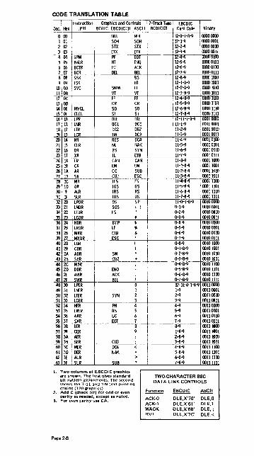
CODE TRANSLATION TABLE
~ : I ~~: 10 OA I SVC 11 OB 12 DC !
I3' 00 I 14 IE MVCl I5 OF ClCl 16 10 'lPR I7! 11 IlNR 18112 lTR I9 I3 lCR
201114 NR 21 I5 ClR 22 16 OR 23; 17 XR 24, IS LR 251 I9 CR
~i ~ ~: 2S IC MR 29 '10 DR 30· IE AlR 31 If SLR 32120 lPOR 33 i 21 LNOR 34 I 22 LTOR 35 23 lCOR 36 24 HOR 37 25 LRDR 38 26 I MXR 3'1 27 MXOR 40 28 LOR 41 29 COR 42 2A ADR 43 2B SDR 44 2C MDR 45 20 DOR 46 2E AWR 47 2F SWR 48 30 LI'ER 49 31 lNER 50 32 lTER 51 33 lCER 52 34 HER 53 35 lRER 54 36 AXR 55 37 SXR 56 38 LER 57 3'1 CER 58 3A AER 5'1 38 SER 60 3C KR 61 3D DER 6< 3E AUR 63 3F SUR
Graphics and Controls BCOIC EBCOIC(J) ASCII
NUl SOH STX ETX PF HT lC DEL
SMM VT FF CR SO SI OLE DCI OC2 TM RES NL BS IL CAN EM CC CUI IFS IGS IRS IUS OS SOS FS
BYP LF ETB ESC
SM CU2
ENO ACK B£l
SYN
PN RS uc EDT
CU3 0C4 NAK
SUB
NUL SOH , STX 1
ETX EOT ENO ACK BEL BS HT IF VT FF
CR I SO SI OLE DCI 002 DC3 OC4 !
NAK 1
SYN ETBi CAN I EM ; SUB i ESC I FS I GS I
~~ I SP I :! I
Binary
0000 0000 ,00000001 100000010
I 12-3-9 0000 0011 i 12-4-9 i 0000 0100 1 12-5-9 I 0000 0101
1
12-6-9 0000 OIlO 12-7-9 0000 OIll
I
12-8-9 I 0000 1000 12-1-8-9 1 0000 1001
I ;~=~=~~ I :: ;~;~ !12-4-8-9 !Ioooo 1100
'I 12-5-8-9 0000 IlOI 12-6-8-9 I 0000 1110 12-7-8-9 , 0000 1111
i 12-11-1-8-9 1 00010000 1 1I-1-9 00010001 1I-2-9 i 00010010 11-3-9 I 0001 0011 11-4-9 I 00010100 1I-5-9 00010101 11-6-9 ' 0001 0110 1I-7-9 0001 o III II -S-9 0001 1000 lI-I-S-9 00011001 1I-2-8-9 , 0001 1010 1I-3-S-9 00011011 11-4-8-9 0001 IlOO
I
Il-5-S-9 ' 0001 1101 11-6-8-9 0001 IlI0 1I-7-8-9 0001 IlI1 11-0-1-8-9 00100000 0-1-9 00100001 0-2-9 00100010 0-3-9 0010 00 II
~~ I:;~~~ 0-6-9 1 00100110 0-7-9 0010 o III o-S-9 0010 1000 0-1-8-9 00101001 0-2-8-9 0010 1010 0-3-8-9 0010 lOll 0-4-8-9 00 10 1I00 0-5-8-9 I 0010 1101
~=:~ I:~;:;~ 12-11+1-8-9 0011 0000 1-9 0011 0001 2-9 0011 0010 3-9 0011 00 II 4-9 00110100 5-9 oonOIOI 6-9 0011 OlIO 7-9 00 II 0111 S-9 0011 1000 I-S-9 001I IDOl
~~~ I:;: :;~ 4-S-9 001I 1100 5-S-9 001I 1I01 6-8-9 001I IlI0 7-S-9 oon 1111
lWO·CHARACTER SSC OATA LINK CONTROLS
1. Two columns of EBCDIC graPhics are shown. The first gives standard bit pattern assignments. The second shows the T·II and TN text printing chains (120 graphics).
2. Add C (check bit) for odd or even parity as needed, except as noted.
Function ~ ASCII
3. For even parity use CA. ACK·O OLE,X'70' OLE,O ACK·1 OLE,X'61' OLE,I WACK OLE,X'6S' OLE,; RVI OLE,X'7C' OLE,<
Page 2·8

CODE TRANSLATION TABLE (Contd)
I nstruction I Graphics and Controls 7-TrackTape Dec. Hex IRX) BCDIC EBCDICIll ASCII BCDIC(2)
6440 STH Sp Sp @ 131 65 41 LA A 6642 STC
i B
67 43 IC C 6844 EX
[
D (fj 45 BAl E I
~ ~ !:gr F G I
7248llH
J H
73 49 CH I 74 4A AH ~ ~ J 75 4B SH K B A8 21
~~!gIMH I[ ) < < l B A84 1 1 M B A84 1
78 4E : CVD 1< + + N B A842 7'l4F ICVB 1* I I 0 B A 84 21 8O,5O[ST ; & + & & P SA
i I.
% A8 21
%1 A 84 y
:; :; A 84 1 \ A 84 2
I" ? ? A8421 ,i
EBCDIC Card Code
no punches 12-il-I"'I 12-0-2"'1 12-0-3"'/
!~~~ 12-il-6"'1 12-il-7"'l 12-{)-S"'l 12-1-8 12-2-8 12-3-8 12-4-8 12-5-8 12-6-8 12-7-8
112
Binary
0100 0000 0100 0001 0100 0010 0100 0011
10100 0100 01000101 OlOOOIlO 0100 am 0100 1000 0100 1001 0100 1010 0100 lOll 0100 BOO 0100 1101 0100 mo 0100 Illl 01010000 01010001
i 01010010 01010011 01010100 01010101
: 0101 OlIO , 01010lll
01011000 01011001 01011010 01011011 01011100
'01011101 01OIlllO OIOlllll OlIO 0000
, 01100001 0110 0010 0110001 01100100
I OlIO 0101 : 01100110 , 01100lll
OlIO 1000
! ~~~ ~~~ ! OlIO lOll
: ~~~ ::~ '0110 1I1O
:~g~~ 1
0lllOOOl , am 0010 01Il 0011 OlllOIOO OlllOIOI Olll OlIO Olllom : ~~~~ = om 1010 am lOll OlllllOO omllOl ammo Olllllll
Page 2·9

CODE TRANSLATION TABLE (Contd)
Instruction GI1IIJhIcS and Controls 1-Track Tape Dec. Hex and Format BCDIC EBCDICI D ASCII BCOICI21
12811 SSM -S 129 81 a a 13082 lPSW -S b b 131 83 Dlaqnose c c 13284 WRD SI d d m 85 RDD e e ~ 86 BXH f f 13511 BXlE 9 9 13688 SRl h h 137 89 SU i i 138&\ SRA D9 8B SLA RS I MOSC SRIll s 141 SO SlDl. c
142 IE SRDA 14381' SlDA + 14490 STM 145 91 1M
}SI j j
14692 MVI k k 147 93 TS -S I I 14894 NI m m 14995 Cli
SI n n
15096 01 0 0
151 97 XI ~ ~ 152 98 LM -RS q q 15399 r r 154 9A 155 98 J 1569C
SIO,SIOF1 El
151 9D TIO,CLRI S I
158'lE HIO,HOV ± 159 9F TeH · Hill AD 161 Al !62 A2 s 5
!63 A3 1 I 164 M u u !65 A5 v v 166 M '" '" 167 A7 x x 168A8 y y J6'/ "9 I z l
170 ""1 171 AB I ~
172 AC !~~}:
r
m AD STOSM SI [ 174 : I!~GP =~~ ~ 175 · 176 BO 0
I77 81 lRA -RX 1
178 B2 See below 2
179 83 · III B4
i · !81 I B5 · 1 · t82 B6 ! STcn IRS I 183 87 lCTL.L.:t 184 88 185 B'l 186 B~ I CS 'I I 181 B~ CD,,,,-S _ . .!...R_S+-I __
~: ~ laM } .,
!90 BE I STCM RS I'll 8F ICM
Op axle (S forma\! B202 - STiDP 8203 - STlDC B204 - SCK 8205 - STCK 8206 - SCKC
Page 2-10
8207 - STCKC 8208 - SPT 8209 - STPT 820A - SPKA B20B - I PK
1 ..
I I
I I I
i i i
I !
i
I
I I
8200 - PTl8 8210 - SPX B2lI - STPX 8212 - STAP 8213 - RRB
EBCDIC Card Code Binary
12-o-I-S llOOOlXXXl 12-0-1 11XXl1XXl1 12-0-2 11XXl0010 12-0-3 10000011
IlZ-11"4 11XXl01W 12-0-5 10000101 12-0-6 IIXXl0llO 12-0-7 11XXl01Il
.12-o-S 10001000
I~~-s 111XXl1001 ,)00)1010
! 12-0-3-8 111XXl101I ! 12-0-4-S
1
11XXl1l00 : 12-0-5-8 IIXXlIIOI
l~~=: 11XXllllO 11XXl1Il1
! 12-11-1-8 , 10010000 '12-11-1
i :~::~ i 12-11-2 1 12- 11-3 11001001\ :12-11-4 10010100 : 12-11-5
i :~ ~~~~ ·12-11-6 ! 10010111 '12-11-7
1 12-11-8 :10011000 : 12-11-'1 10011001 : 12-11-2-8 10011010 12-11-3-8 10011011 12-11-4-8 looll}oo
: 12-11-5-8 10011101 ; 12-11-6-8 11001 1II0 '12-11-7-8 1001111, ,11-0-1-8 10100000 11-0-1 10IOIXXlI 11-0-2 1010 0010 11-0-3 i 10100011 11-0-4 10100100 11-0-5 • 1010 0101
:11-0-6 : 10100110 111-0-7 ' 101001Il 11-0-8 • 10101000
'11-0-9 I 1010 1001 11-0-2-8 10101010
,11-0-3-8 10101011 ,11-0-4-8 , 10101100 ')H)-5-8 i 10101101 11-0-6-8 : 10101110 11-0-7-8 ' 1010 IIIJ 12-11-0-1-8 ! 1011 0000 !2-U-o-I 12-11-0-2 12-II-o-3
: 12-11-0-4 12-11-0-5 1211-0-0 12-11-0-7 12-11-0-8 12-11-0-9 12-II-O-2-8 ]2-lI-o-3-8
i 12-lI-o-4-S , 12-11-0-5-8 12-11-0-6-8 12-11-0-7-8
: 1011 0001 ; 1011 0010
i ~~::~~ i 1011 0101 11011 0110 , 1011 alii : 10111000
10111001 , 10111010 : 10111011
10111100 10111101 10111110 101111Il

CODE TRANSLATION TABLE (Conld)
Instruction Dec. Hex (SSI ' Binary
192 CO 1I000000 193 Cl A ' 1I00oon 194 C2 i B B 11I00 0010 195 C3 I C C 1I00001l 196 C4; ,0 0 1I00 0100 197 C5, E E , 1I000101 198 C6' F F 11000nO 19'1 C7 G G 1100 am 200 C8 H H 1I
2011 C'I ,I I 1I00 1001 202 CA , 1I00 1010 203 CB ! 1 1I00 lOll 204 CC , 1I00 1I00 205 ,CO i , 1I00 1I01 206 : CE 11I00 mo 207 'CF 1I00 llli 208 00
I ~ } I! ' 1I010000
209
1
01 MVN J J I ii~~~~ 210 02 MVC K K
211 , 03 MVZ L L L ' B 1I010011 212 04 : NC ,M M M I B 1I010100
~~ I ~ :g:;c iN N N i B : 1I010101 0 0 0 ! B 11I0IOllO
215 07 XC , P P P ~ B ' llOlom 216 DB ,Q Q Q B 1I01lOOO
~~~! : R R R B 11011001 11I0IIOIO
219 ' DB 1I01101l 220 DC : ii~~ ii~ 221 00 222 DE 1I011110 223 OF 1I011l1l 224 EO lllOOOOO 225 El , 11100001 226 I E2 Is S S ImOOOlO 227'B iT T T llJOOOll 228 : E4 , U U U 1I100100
~ I~~ Iv V V 1I100101 IW W W moollo
231 E7 X X X 1ll1l01ll 232 'E8 y y y I lllO 1000 233E9 Z Z Z Imo 1001 234 EA
! m~~~~ 235 EB 236 EC 1I1O 1I00 237 ; EO ' llID 1I01 23B : EE ~ lIID mo 2J'/,EF mo llli
~~ i ~~ 8 2 llllOOOO 1 llll 0001
:i~ ,11ll001O , 1I1100n
2 F IllllOlOO 245 F5 '5 11llOlOi 246 F6 16 11llOllO 247 F7 '7 ! 1I110111 248
1
F8 ZAP 8 I 1I111ooo 24'1 F9 CP 1 '9 :1I111OO1 250 FA AP 12-11-0-2-8-9111111010 251 FB SP 112-11-0-3-8"'1 1I111011 252 i FC MP 112-11-0-4-8"'1 llli 1100 2531 FO OP 12-11-0-5-8"'1 1I11 1101 254 ,FE
~=~~~=:~i ~gi iii~ 255FF
ANSI-DEFINED PRINTER CONTROL CHARACTERS (A in RECFM field of DCB)
~ Action before printing record blank Space 1 line o Space 2 lines
Space 3 lines Suppress space Skip to line 1 on new page
Page 2·11

MACHINE INSTRUCTION FORMATS FIRST HALFWORD SECOND HALFWDRD THIRD HALFWORD
I
I S~~~~J~ 1 ~~r~~T~~ 2 I I I_~' I
AA I Op Code I At !ji2J I
o REG;S~E~ 112 151 I : OPERC~~ I ~~~R~:
Axl OpCode EI X2 I B2 ! 02 I 78 1112 ISI6 1920 31
: S~~~~TJ~l S~~~~~3 ~~RRf~t~F :
Asl OpCode \~1 o 78 JJ 12 1516 1920 31
I Ib~~~~~A6E: ~~JlRR~~b ,?F :
51! OpCode tr:~ ~ 78 1516 1920 31
I I ~~~:1~6 ~F I
I I~-==i sL OpCode I 62 I ~ o I IS 16 1920 31
I OPERAND 1 OPERAND 2 OPERAND 1 I OPERAND 2
tOPCode~~ {
I LENGTH LENGTH ADDRESS OF I ADDRESS OF
55 0 78. IJl2 1516 1920 3132 3536 47
; I LENGTH ; ~~J>:f~b ~F : ~~:£~b ~F :
Ii OpCode Ff=FBT3cTill~ l 0 1~ 1516 1920 3132 3536 4'
I CONTROL REGISTERS CR Bit. Name of fMkI Aaoo:ioJted with Inlt.
0 0 Block·multiplex'g control Block·multiplex 'g 0 1 SSM suppression control SSM instruction 0 2 TOO clock sync control Multiprocessing 0
5-9 rage size controi } Dynamic addr. transl,
0 10 Unassigned (must be zero} 0
11·12 Segment size control 0 16 Malfunction alert mask
} Mu I tiprocessi ng
0 17 Emergency signal mask 0 18 Extemal call mask 0 19 TOO clock sync check mask 0 20 Clock comparator mask Clock comparator 0 21 CPU timer mask CPU timer 0 24 Interval timer masR Interval timer I 25 Interrupt key mask Interrupt key 1 26 External signal mask External signal 1
1 0-7 Segment table length I Dynamic addr, transl. I 0
8-25 Segment table addf'ess 0
2 0-31 Channel masks Channels I 1
8 16-31 Monitor masks Monitoring ,
0
9 0 Successful branching event mask I 0
1 Instruction fetching event mask 0
I . 1 I Storage alterarlOn event mask Program-event recora'g GR alteration event mask
, 16-31 flER general register masks 0
10 8-31 PER starting address Program-event record'g I 0
11 8-31 PE R endi ng address Program-event record'g 0
14 0 Check'stop control I Machine-check handling 1 1 Svnch. MCEL control 1 2 110 extended logout control 110 extended logout 0 4 Recovery report mask
) """'"~""'. """"'" 0
5 Degradation report mask 0 6 Ext. damage report mask 1 7 Warning mask 0 8 Asynch. MCEL control 0 9 Asynch. fixed log control 0
15 8-28 MCEL address Machine-check handling 512
Page 2·12
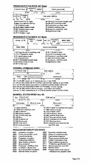
I nstruction address
32 34 36 3940 47148 55 156 63 0-5 Channel 0 to 5 masks 6 Mask for channel 6 and up 7 (E) External mask
32-33 U LC) I nstruction length code 34-35 (CC) Condition code
12 (C=O) Basic control mode 13 (M) Machine-check mask 14 (W=1) Wait state 15 (P=1) Problem state
36 Fixed-point overflow mask 37 Decimal overflow mask 38 Exponent underflow mask 39 Significance mask
PROGRAM STATUS WORD (EC Mode)
0000 0000 I I nstruction address
32 3940 47148 SSIS6 1 (R) Program event recording mask 15 (P=1) Problem state 5 (T=1) Translation mode lS-19 (CC) Condition code 6 m Input/output mask 20 Fixed-point overflow mask 7 (E) External mask 21 Decimal overflow mask
12 (C=l) Extended control mode 22 Exponent underflow mask 13 (M) Machine-check mask 23 Significance mask 14 (W=1) Wait state
CHANNEL COMMAND WORD
I Command code I Data address
CD-bit 32 (SO) causes use of address portion of next CCW. CC-bit 33 (40l causes use of command code and data address of next CCW. SLI-bit 34 (20) causes suppression of possible incorrect length indication. Skip-bit 35 (10) suppresses transfer of information to main storage. PCI-bit 36 (08) causes a channel program controlled interruption. IDA-bit 37 (04) causes bitsS-31 of CCW to specify location of first IDAW.
CHANNEL STATUS WORD (hex 40)
63
31
63
l Key J~I~16C~18 Is116 CCWaddress23124 J I Unit status I Channel status I Byte count I 32 3940 4748 55 156 63
5 Logout pending 40 (SO) Program-eontrolled interruption 6-7 Deferred condition code 41 (40) Incorrect length
32 (So) Attention 42 (20) Program check 33 (40) Status modifier 43 (10) Protection check. 34 (20) Control unit end 44 lOS) Channel data check 35 (10) Busy 45 (04) Channel control check 36 (OS) Channel end 46 (02) I nterface control check 37 (04) Device end 47 (01) Chaining check 38 (02) Unit check 48-63 Residual byte count for the 39 (01) Unit exception last CCW used
PROGRAM INTERRUPTION CODES 0001 Operation exception 0002 Privileged operation excp 0003 Execute exception 0004 Protection exception 0005 Addressing exception 0006 Specification exception 0007 Data exception 0008 Fixed-point overflow excp 0009 Fixed-point divide excp OOOA Decimal overflow exception OOOB Decimal divide exception
OOOC Exponent overflow excp 0000 Exponent underflow excp OOOE Significance exception OOOF Floating-point divide excp 0010 Segment translation excp 0011 Page translation exception 0012 Translation specification excp 0013 Special operation exception 0040 Monitor event 0080 Program event (code may be
combined with another code)
Page 2-13

FIXED STORAGE LOCATIONS
Area, Hex EC dec, addr only Function
0- 7 0 Initial program loading PSW, restart new PSW 8- 15 8 Initial program loading CCW1, restart old PSW
16- 23 10 Initial program loading CCW2 24- 31 18 External old PSW 32- 39 20 upervisor Call old PSW 40- 47 28 Program old PSW 48- 55 30 Machine-check old PSW 56- 63 38 Input/output "Id PSW 64- 71 40 Channel status word C.ee diagram) 72- 75 48 Channel address word (0-3 key, 4-7 zeros, 8-31 CCWaddress] 80- 83 50 Interval timer 88- 95 58 External new PSW 96-103 60 Supervisor Call new PSW
104-111 68 Program new PSW 112-119 70 Machine-check new PSW 120-127 78 Input/output new PSW 132-133 84 CPU address 8SSQC'd with external intlllTuption, or unchanged 132-133 84 X CPU address assoc'd with external interruption, or zeros 134-135 86 X External interruption code 136-139 88 X SVC interruption (0-12 zeros, 1~141LC, 15:0, 16-31 code] 140-143 8C X Program interrupt. (0-12 zeros, 1~141LC, 15:0,16-31 code] 144-147 90 X Translation exception address (0-7 zeros, 8-31 address] 148-149 94 Monitor class (0-7 zeros, 8-15 class number] 150-151 96 X PER interruption code (0-3 code, 4-15 zeros] 152·155 98 X PER address (0-7 zeros, 8-31 address] 156-159 9C Monitor code (0-7 zeros, 8-31 monitor code] 168-171 A8 annelID (0-3type,4-15model,I6-31 max.IOELlength] 172·175 AC I/O extended logout address (0·7 unused, 8-31 address] 176-179 BO Limited channel logout (see diagram) lB5-187 B9 X I/O address (0-7 zeros, 8-23 address] 216-223 DB PU timer save area 224-231 EO lock comparator save area 232-239 E8 Machine-check interruption code (see diagram) 248-251 FB Failing processor storage address (0-7 zeros, 8-31 address] 252-255 FC Region code' 256-351 100 Fixed logout area' 352-383 160 Fl08tin!l"point register save area
384-4471180 1 ~neral register SIMI area 448-511 lCO ntrol register save area 512t 200 CPU extended logout area (size varies)
'*May vary among modelSj see system library manuals for specifiC model. tLocation may be chilnged bY programming (bits 8-28 of CR 15 specify address).
5 Channel 6 Main storage control 7 Main storage 8 CPU 9 Channel
10 Main storage control 11 Main storage
12 13 15 16
12 Control unit 16 I nterface address 17·18 Reserved (00) 19 Sequence code 20 Unit status 21 Cmd. addr. anO key 22 Channel address 23 Device address
23 24 26 2829 31
24-25 Type of termination 00 I nterface disconnect 01 Stop, stack or normal 10 Selective reset 11 System reset
28(A) I/O error alert 29-31 Sequence code
MACHINE-CHECK INTERRUPTION CODE (hex E81
Page 2·14
Val iditv indicators
MCEL length 55156
24 Fail ing stg. address 25 Region code 27 Floating-pt registers 28 General registers 29 Control registers 30 CPU ext'd logout 31 Storage logical 46 CPU timer 47 Clock comparator
31
63

DYNAMIC ADDRESS TRANSLATION
VIRTUAL (LOGICAL) ADDRESS FORMAT
Segment Size 64K 64K 1M 1M
Page Size 4K 2K 4K 2K
[
Bits J 0-7 are
ignored
Segment Index 8-15 8 -15 8 -11 8-11
Page Index 16-19 16-20 12-19 12 -20
Byte Index 20-31 21 -31 20-31 21 - 31
SEGMENT TABLE ENTRY
Page table address
'Normally zeros; ignored on some models. 28:2931
31 (I) Segment-invalid bit.
PAGE TABLE ENTRY (4K) PAGE TABLE ENTRY 12K)
l Page address j~11~0 f{! '0 Page address III°F,A 12131415
12 (I) Page-invalid bit. 13 (I) Page-invalid bit.
HEXADECIMAL AND DECIMAL CONVERSION From hex: locate each hex digit in its corresponding column position and note the decimal equivalents. Add these to obtain the decimal value.
From decimal: (1) locate the largest decimal value in the table that will fit into the decimal number to be converted. and (2) note its hex equivalent and hex column position. (3) Find the decimal remainder. Repeat the process on this and subsequent remainders.
6
Note: Decimal, hexadecimal, (and binary) equivalents of all numbers from 0 to 255 are listed on panels 9 - 12.
HEXADECIMAL COLUMNS
5 4 3 2 1 HEX = DEC HEX = DEC HEX = DEC HEX = DEC HEX= DEC HEX= DEC
0 0 0 0 0 0 0 0 0 0 0 0 1 1,048,576 1 65,536 1 4,096 1 256 1 16 1 1 2 2,097,152 2 131,072 2 8,192 2 512 2 32 2 2 3 3,145,728 3 196,608 3 12,288 3 768 3 48 3 3 4 4,194,304 4 262,144 4 16,384 4 1,024 4 64 4 4 5 5,242,880 5 327,680 5 20,480 5 1,280 5 80 5 5 6 6,291,456 6 393,216 6 24,576 6 1,536 6 96 6 6 7 7,340,032 7 458,752 7 28,672 7 1,792 7 112 7 7 8 8,388,608 8 524.288 8 32,768 8 2,048 8 128 8 8 9 9,437,184 9 589.824 9 36,864 9 2.304 9 144 9 9 A 10,485,760 A 655,360 A 40,960 A 2.560 A 160 A 10 B 11,534,336 B 720,896 B 45,056 B 2.816 B 176 B 11 C 12,582,912 C 786,432 C 49,152 C 3,072 C 192 C 12 D 13,631,488 D 851,968 D 53,248 D 3,328 D 208 D 13 E 14,680,064 E 917,504 E 57,344 E 3,584 E 224 E 14 F 15,728,640 F 983,040 F 61,440 F 3,840 F 240 F 15
0123 4567 0123 4567 0123 4567
BYTE ByTE BVTE
POWERS OF 2 POWERS OF 16
2n n 2iJ = 160
I 16n n
256 8 :z4 = 161 1 0 512 9 28 = 162 11> 1
1024 10 212 = 163 256 2 2048 11 216 = 164 4096 3 4096 12 220 = 165 65536 4
8192113 224 = 166 1048576 5 16384 14
228 = 167 16777216 6 32768 15
232 = 168 268435456 7 65536 16 4294967296 8
131072 17 236 = 169 68 719476736 9
262144 18 :z4O = 1610 1 099 511 627 776 10
524288 19 :z44 = 1611 17 592 186 044 416 11
1048576 20 :z48 = 1612 261474976710656 12 2097152 21 252 = 1613 4 503 599 627 370 496 13 4194304 22 256 = 1614 72 057 594 037 927 936 14 8388608 23 ~o= 1615 1 152921504 606 846 976 15
16777216 24
Page 2-15


Section 3 Contents
Section 3: CPU Manual Procedures. • • • • . . • . . • • . . . . • • • . . . . • . . • . . . . • • • . 3-1 Functional Characteristics of Manual Controls ....... , . . . . . . . . . . . . . . . . . 3-1 CPU Manual Procedures for:
MocIl15 ............................................... 3-3 MocI125 ............................................... 3-3 MocI135 ............................................... 3-6 MocI145 ............................................... 3-8 MocI155 ............................................... 3-11 MocIl58 ............................................... 3-13 MocI165 ............................................... 3·15 MocIl68 ............................................... 3-18 MocI195 ............................................... 3·22
II
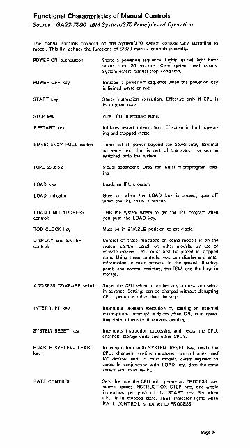
Functional Characteristics of Manual Controls Source: GA22-7000 IBM System/370 Principles of Operation
The manu a! controls provided on the System/370 system console vary according to model. This list defines the functions of S/370 manual controls generally.
POWE R·ON pushbutton Starts a power·on sequence. Lights up red, light turns white after 30 seconds. Clear system reset occurs. System enters manual stop condition.
POWER·OFF key Initiates a power-off sequence when the power·on key is lighted white or red.
START key Starts instruction execution. Effective only if CPU is in stopped state.
STOP key Puts CPU in stopped state.
RESTART key Initiates restart interruption. Effective in both operat· ing and stopped states.
EMERGENCY PULL switch Turns off all power beyond the power·entry tenninal on every unit that is part of the system or can be switched onto the system.
IMPL controls Model dependent. Used for initial microprogram load· ing.
LOAD key Loads an IPL program.
LOAD indicator Goes on when the LOAD key is pressed, goes off when the IPL chain is broken.
LOAD UNIT-ADDRESS Tells the system where to get the IPL program when controls you push the LOAD key.
TOD CLOCK key Must be in ENABLE position to set ciock.
DISPLAY and ENTER Control of these functions on some models is on the controls system control panel; on other models, by use of
console devices. CPU must first be placed in stopped state. Using these controls, you can display and enter information in main storage, in the general, floatingpoint, and control registers, the PSW, and the keys in storage.
ADDRESS COMPARE switch Stops the CPU when it reaches any address you select in advance. Settings can be changed without disrupting CPU operations other than the stop.
INTERRUPT key Interrupts program execution by causing an extemal interruption. Interrupt is taken when CPU is in operating state, otherwi.e it remains pending.
SYSTEM RESET key Interrupts instruction processing and resets the CPU, channels, storage units and other CPU's.
ENABLE SYSTEM·CLEAR In conjunction with SYSTEM RESET key, resets the key CPU, channels, - on-line nonshared control units, and
1/0 devices; and, in most models, ciears registers to zeros. In conjunction with LOAD kay, does the same except you must re-I PL.
RATE CONTROL Sets the rate the CPU will operate at: PROCESS rate, normal speed; INSTRUCTION STEP rate, one whole instruction per push of the START key. Set when CPU is in stopped state. TEST indicator lights when RATE CONTROL is not set to PROCESS.
Page 3-1

TEST indicator
STORE-STATUS key
MANUAL indicator
WAIT indicator
CHECK-STOP indicator
Goes on when a manual control is not in its normal position or when a maintenance function is being performed for the CPU, channels, or storage_
I nitiates store-status function_ Function initiated on some models by pushbutton, on others by use of a special keyboard mnemonic or by CRT-menu selection_ Effective only when CPU is in stopped state_
Goes on when CPU is in stopped state_
Goes on when the CPU is in the wait state_
Goes on when the CPU is in the check-stop state_ A CPU reset will tum it off.
THERMALICB POWER-CHECK Goes on when a thermal condition or a circuit-breaker indicator
SYSTEM indicator
Page 3-2
trip, or both, are detected in the CPU complex. Turned off from CE power control panel.
Goes on when the CPU cluster meter or customerengineer meter is running.

System/370 Model 115 and Model 125 Sources: GA33-1510 Systeml370 Model 115 Functional Characteristics
GA33-1509 Systeml370 Model 125 Procedures
Power-On Procedure
DANGER: Before switching on power, ensure that no person is exposed to risk and that all equipment covers are shut.
1. Ensure system diskette is inserted in console file. 2. Press POWER ON. Red light comes on. 3. IMPL is automatic if diskette is loaded as described in step 1. If not, wait
30 seconds for white light on POWER ON before IMPLing.
Power-Off Procedure
Before removing power:
1. Issue any special commands your operating system requires. 2. Unload tape units and disk drives. 3. Perform 'save usage counters' if needed. 4. Press POWER OFF. The Power·On key turns from white to red, then goes
out.
To IMPL
1. Place Control diskette in the 33FD. 2. Press IMPL key. This loads all microprograms from the console file into
subprocessors which have loadable control storages. A malfunction in the console file causes the File Check light to turn on.
3. During IMPL, 'IMPL IN PROGRESS' appears on the video screen. 4. 'SUCCESSFULLY LOADED' appears when loading is finished. The next
message, 'PROGRAM LOAD', is the signal to begin the IPL procedure.
To IPL for First Time after Power-On
1. Key in specifications as soon as PROGRAM LOAD is displayed on line 13 of the screen.
2. Press ENTER.
NOTE: If message 'IPL ERROR' or 'EC PSW ERR' appears on line 13 of the screen, reload with correct program. Press ENTER.
3. Proceed with usual operating procedures. Check for normal states across entire system.
4. Assign devices and start running jobs.
To Re-IPL
1. In order to get the PROGRAM LOAD display, press MODE SEL, key in L, and press ENTER. Specifications from the last IPL will be displayed.
2. If the specifications are to remain the same, press ENTER. If not, make changes and press ENTER.
3. Proceed with usual operating procedures. Check for normal states across entire system.
4. Assign devices and start running jobs.
Page 3-3

System/370 Model 115 and Model 125 (cont'd)
To Display Registers, PSW, and Main Storage
1. Select ALTER/DISPLAY by keying A in the MODE SELECTION display and pressing ENTE R.
'MODE SELECTION'
SYSTEM RESET ADDRESS COMPARE PROGRAM LOAD INTERVAL TIMER CHECK CONTROL STORAGE DUMP ICA LINE MODES
A AL TER/DISPLAY I INSTRUCTION STEP P RESTART M MAINTENANCE S STORE STATUS U SAVE USAGE COUNTERS
MODE SPECIFICATION**-'*
2. Select the desired display from those listed on the ALTER/DISPLAY frame.
'ALTER/DISPLAY'
G GENERAL REGISTERS C CONTROL REGISTERS
CURRENT PSW FLOATING POINT REGS
K PROTECTION KEY M MAIN STORAGE KEY
STOR/\GE ADDRESS
OOOOOO-FFFFFF OOOOOO-FFFFFF
V MAIN STORAGE VIRTUAL OOOOOO-FFFFFF ADDRESS:
3. Key in the selector character: G for General·Purpose Register, P for Current PSW, etc. With Main Storage and Protection Key you must also key in the address.
4. Press ENTER.
To Alter Registers, PSW, and Main Storage
1. To change one or more of the digits in the display, move the cursor under the first digit to be changed.
2. Key in the new data. The new data" appears on the line under thp old data 3. Before ENTE R is pressed you can still change your input by using the cursor
keys and entering the changes in the usual way. 4. Press ENTER. The new data replaces the old on the screen.
NOTE: If INVALID CHARACTER appears on the screen, you entered a wrong character (either a nonhexadecimal or a nonbinaryl. The cursor marks the first invalid character. Key in the correct information and press ENTER.
Procedure after an Alter/Display
1. Press MODE SEL to get the ALTER/DISPLAY frame again; or 2. Press MODE SEL twice to get the MODE SELECTION frame; or 3. Press CNCL key to return the screen to the operating system and the
START key to resume processing.
Page 3-4
System/370 Model 115 and Model 125 (cont'd)
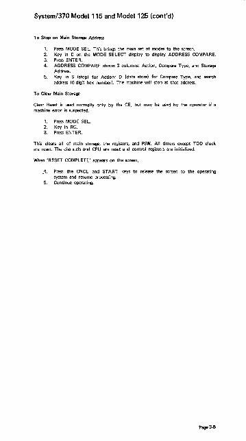
To Stop on Main Storage Address
1. Press MODE SEL. This brings the main set of modes to the screen. 2. Key in C on the MODE SELECT display to display ADDRESS COMPARE. 3. Press ENTER. 4. ADDRESS COMPARE shows 3 columns: Action, Compare Type, and Storage
Address. 5. Key in S (stop) for Action; D (data store) for Compare Type, and search
address (6-digit hex numbed. The machine will stop at that address.
To Clear Main Storage
Clear Reset is used normally only by the CE, but may be used by the operator if a machine error is suspected.
1. Press MODE SEL. 2. Key in RC. 3. Press ENTER.
This clears all of main storage, the registers, and PSW. All timers except TOO clock are reset. The channels and CPU are reset and control registers are initialized.
When 'RESET COMPLETE' appears on the screen,
.4. Press the CNCL and START keys to release the screen to the operating system and r-esume processing.
5. Conti nue operati ng.
Page 3-5

System/370 Model 135 Source: GC38-0005 System/370 Model 135 Procedures
Power-On Procedure
DANGER: Before switching on . power, ensure that no person is exposed to risk and that all equipment covers are shut.
1. Ensure that console file contains IMPL disk (green labell and console file cover is properly closed.
2. Press POWER ON, and wait two minutes. 3. Press LAMP TEST to check lamps. 4. System is ready when POWER ON white light is on.
Power-Off Procedure
1. Preparatory to turning power off:
a. Unload all disk and tape drives. b. Open or diseniJage the print unit release lever on all printers using print
train cartridges.
2. Depress the POWER OFF pushbutton.
To IN\PL
CAUTION: Do not ready any I/O devices during IMPL.
1. Ensure that switches are set to normal positions, console file contains IMPL disk (green labell, and console-printer keyboard is ready.
2. Press START CONSOLE FILE. Ught changes from red to white to off. 3. Wait for IMPL REOD indicator to go off and the MAN indicator to turn on
before IPUng.
To IPL
1. Ensure that IMPL REOD indicator is off, switches are set to normal posi· tions, and MAN indicator is on.
2. Load and make ready the IPL input device. 3. Select IPL input device address on rotary switches C through E (LOAD
UNIT ADDRESS). 4. Press LOAD. 5. Begin operating system procedures. Check for normal status of entire system
before running jobs. 6. Assign devices and start running jobs.
To Display Registen, PSW, and Main Storage
1. Press STOP and wait until MAN indicator comes on. 2. Press ALTER/DISPLAY at console-printer keyboard and wait ~ntil PROCEED
light comes on. 3. Type 2·character mnemonic (0 plus appropriate second letter) and hex ad·
dress. No address is necessary after P (PSW) and T (Store Status).
ALTER/DISPLAY CHART
Mnemonic FunctionlStorage Type
Address Range
Alrer Display (Model Dependenr)
AM OM Main storage 000000-07FFFF Use the number of
t OS Control storage OOOO-DFFP digits indicated. If
AG DG General register O-F necessary, com· AF OF Floating-point register 0,2,4,6 plete the correct AP DP Program status word None number of digits AC DC Control register O-F by inserting zeros AK OK Storage key 000000-07 F F F F as appropriate AR DR Transmission rate tt 1-8 (line number)
AV DV Virtual storage •• 000000- F F FF F F
ST Store status None
Page 3-6

System/370 Model 135 (cont'd)
4. After contents are displayed, press END at console-printer keyboard. 5. To resume operations, press START.
To Alter Registers, PSW, and Main Storage
1. Press STOP and wait until MAN indicator comes on. 2. Press ALTER/DISPLAY at console-printer keybOard and wait until the
PROCEED light comes on. 3. Select a 2-character mnemonic (A plus appropriate second letter) from the
Alter/Display Mnemonics chart, and type the mnemonic and hex address. 4. Enter new characters in positions occupied by characters to be replaced.
Reach required positions by repeating characters. In the case of the current PSW, retype up to and including the new bits desired, and press RETURN. It is unnecessary to retype the remaining bits.
5. Press EN D at console-printer keyboard. 6. Press START to resume operations.
To Stop on Main Storage Address
1. Press STOP. 2. Set STORAGE SELECT to MAIN STORAGE. 3. Set INTERVAL TIMER switch to DISABLE (if requ;red). 4. Set STORAGE ADDRESS rotary switches A through E to desired address. 5. Set COMPARE ADDRESS to ANY. 6. Set appropriate ADDRESS COMPARE CONTROL switch to STOP. 7. Press START.
To resume normal prooessing after CPU stops at the desired address:
1. Set ADDRESS COMPARE to ANY, ADDRESS COMPARE CONTROL to SYNC/NORMAL, NORMAL INTERVAL TIMER to NORMAL (if required).
2. Press START.
To Clear Main Storage
The need for this procedure is indicated by a message at the console-printer keyboard or by an unexplained CPU wait state (WAIT indicator on).
1. Press and hold in ENABLE SYSTEM CLEAR. 2. Press SYSTEM RESET (once only). 3. Release ENABLE SYSTEM CLEAR. 4. Perform IPL procedure. 5. Continue normal processing.
Hard Stop Option
1. The hardstop indicator (white light) comes on whenever the CPU stops. CPU hardware errors are recorded in a logout area of main storage by the CPU. If the software does not create an Environmental Data Recording Set (ERDS), run the SEREP (stand·alone) program to obtain a printout of the latest error information. Keep the EREP or SEREP printouts because they are useful to the CEo
2. On advice of the CE you may then set the CHECK CONTROL switch to CONDITIONAL HARD STOP and operate the CPU.
Page 3-J

System/370 Model 145 Source GC38-0015 Systeml370 Model 145 Operating Procedures
Power-On Procedure
DANGER: Before switching on power, ensure that no person is exposed to risk and that all equipment covers are shut.
1. Insert ·370 microprogram disk in console file and close cover. 2. Press the POWER ON key. 3. IMPL is automatic if:
Rotary switches are in their normal processing positions, b. the ADDRESS COMPARE CONTROL switch is set to SYNCINORM, c. ·370 microprogram disk is mounted in the console file, d. console printer has paper and is ready to print the IMPL GO-NO
GO·COMPLETE message.
This ends the Power-On procedure for MOD 145--No Feature Installed. For MOD 145 with CTCA or ISC feature, continue with steps specified under that feature.
Mod 145-·Channel·to-Channel Adapter (CTCAI Feature Installed
4. Wait for 1/0 INFC DSBLD indicator to tum on, 5. Move the 1/0 INTERFACE switch to the ENABLE position. The adapter is
available to the program when the 1/0 INFC DSBLD indicator turns off.
Mod 145-lntegrated Storage Control (lSC) Feature Installed
4. Wait for the IMPL REQD indicator to turn off. 5. Move the 1/0 INTERFACE A and B switches to the ON position. The ISC is
available to the program when the 1/0 INTFS DSBLD indicator turns off.
Power-Off Procedure
a. Unload all disk and tape drives. b. Open or disengage the print unit release lever on all printers using print
train cartridges. 2. Continue with steps applicable to your system.
Mod 145-·No Features Installed
3. Press the STOP key. 4. Press the POWER·OFF key. NOTE: Do not turn power back on for at least
ten seconds.
Mod 145--Channel-to-Channel Adapter (CTCA) Feature Installed
.:t. Inform the operator of the other system that the cha~ncl to :::ha~~e! ad~;)tcr
is to be removed from use. 4. Move the 1/0 INTERFACE switch to the DISABLE pOSition. 5. Wait for the I/O INFC DSBLD indicator to tum on. 6_ Press the POWER OFF key. NOTE: Do not turn power back on for at least
ten seconds.
Mod 145--lntegrated Storage Control (lSC) Feature Installed
3. Inform the operator of the other system that the ISC feature is to be removed from use (if applicable)_
4. Move the 1/0 INTERFACE A and B switches to the OFF position. 5. Wait for the 1/0 INTFS DSBLD indicator to turn on. 6. Press the POWER OFF key. NOTE: Do not turn power back on for at least
ten seconds.
Page 3-8

System/370 Model 145 (cont'd)
To IMPL
1. Ensure that forms are inserted in the console printer and the *370 microprogram disk is mounted in the console file.
2. Set all rotary switches to their normal operating position. Ensure that the ADDRESS COMPARE CONTROL toggle switch is set to SYNC/NORM.
3. If power is not on, press POWER-ON key. IMPL occurs automatically. If power is on, press START CONSOLE FILE key to initiate the IMPl.
4. The IMPL REQD and CF POWER ON indicators tum on. The START CONSOLE key turns red, then white, as the console file starts reading.
5. The console file powers off automatically when control storage is loaded, and the CF POWER ON indicator and START CONSOLE FILE key light turn off. The System Reset routine executes, the IMPL REQD ,,,dicator turns off, and the CPU enters the soft·stop state {MAN indicator onl. IMPL operation takes approximately 35 seconds.
To IPL
1. Load and ready the System Resident (SYSR ES) device. 2. Dial the address of the !PL device into LOAD UNIT ADDRESS switches
FGH. 3. Press the LOAD key. After an automatic system reset, the IPL operation
starts and the LOAD indicator turns on. 4. When the IPL is complete, the LOAD indicator turns off and the system
either executes the program or enters the soft-stop state, awaiting your action.
Loading the Secondary Nucleus (OS)
1. Place the program to the desired I/O device and make that device ready. 2. Set the three LOAD UNIT ADDRESS switches to the SYSRES address. 3. Set RATE switch to INSTRUCTION STEP. 4. Press LOAD button. Load light comes on and system goes into manual state. 5. Press Alter/Display Mode on PR-KB. Enter in location X'08' the EBCDIC
character to be appended by lEAN UCO. The two hex digits may range from F2 to F9 (determined by last character of nucleus name).
6. Set RATE S1.vitch to PROCESS. 7. Press START.
To Display Registers, PSW, and Main Storage
Display operations can be performed from the PR·KB.
1. Press the STOP key or set the RATE switch to either INSTRUCTION STEP or SINGLE CYCLE HARD STOP.
2. Press the ALTER/DISPLAY key. 3. Wait for both ALTER/DISPLAY MODE and PROCEED indicators to tum
on. 4. Select from the Alter/DISPLAY chart below the appropriate 2-character
mnemonic, and type the mnemonic and address of the information to be displayed.
5. When zeros are typed to the left of the address, a ne\l\l line operation is started automatically. When zeros are not inserted, the RETURN key must be pressed.
6. To continue program processing after the display operation is completed, return the RATE switch to PROCESS and press the Start key.
Page 3-9

System/370 Model 145 (cont'd)
Alter/Display Chart
STORAGE ALTER DISPLAY ADDRESS
AREA MNEMONIC MNEMONIC RANGE
MAIN STORAGE AM DM OOOOOO-OFFFFF*
STORAGE KEY AK OK OOOOOO-OF FFF F'
CONTROL REGISTER AC DC O-F
GENERAL AG DG O-F
REGISTER
FLOATING-POINT AF DF 0,2,4,6 REGISTER
CURRENT PSW AP DP None required
STORE STATUS NONE ST None required
VIRTUAL STORAGE AV DV OOOOOO-FF F FF F
'The upper boundary is movable and depends
upon the capacity of main storage.
To Alter Ragisten, PSW, and Main Storage
1. Alter operations can be performed from the PR-KB. Press the STOP key or set the RATE switch to either INSTRUCTION STEP or SINGLE CYCLE HARD STOP.
2. Press the ALTER/DISPLAY key. 3. Wait for both the ALTER/DISPLAY MODE and PROCEED indicators to
turn on. 4. Select the appropriate 2-character mnemonic from the Alter/Display chart
and type the mnemonic and address of the information to be altered. 5. Enter data, using the space bar to skip over positions not being altered. The
data in the skipped-over positions remains unchanged and prints out each time the space bar is operated.
6. To end the alter operation, press the ALTER/DISPLAY key or the END key.
7. To resume program processing, retul)1 the RATE switch to PROCESS and press the START key.
To Stop on Main Storage Address
1. Press STOP key. MAN indicator comes on. 2. Set STORAGE SELECT switch to MAIN STORAGE position. 3. Set main storage address in STORAGE SELECT rotary switches CDEFGH. 4. Set ADDRESS COMPARE to ANY. NOTE: To guarantee a match on in
!<truction address!!!', the I·COUNTI'R rosition Ireal or logicall mil'" ,,~ , ... ~
5. Set ADDRESS COMPARE CONTROL toggle switch to STOP. 6. Press START key.
TO Clear Main Storage
1. Hold the ENABLE SYSTEM CLEAR key in the operated position. 2. Press the SYSTEM RESET or LOAD key. 3. Release the ENABLE SYSTEM CLEAR key.
Hard Stop Option
On getting a red light error and at the suggestion of service personnel:
1. Set CHECK CONTROL switch to STOP AFTER LOG. The LOG PRES indicator comes on after an error occurs and the machine stops.
2. IPL the SEREP deck and save printout for CEo 3. Press SYSTEM RESET and begin operating. 4. Should second error occur, call CEo
Page 3-10

System/370 Model 155 Source: GA22-6966 System/370 Model 155 Operating Procedures
Power-On Procedure
DANGER: Before switching on power, ensure that no person is exposed to risk and that all equipment covers are shut.
1. Press the POWER-ON key_ The key backlights red when pressed and turns white when the power-on sequence is complete_
Power-Off Procedure
1. Preparatory to turning power off:
a. Unload all disk and tape drives. b. Open or disengage the print release lever on all printers that use print
train cartridges. 2. Press the CPU STOP key. 3. Press the POWER-OFF key. This removes power from the CPU and online
I/O units.
To IPL
1. Load and ready the I P L device. 2. Dial the address of the IPL device into LOAD UNIT switches FGH. 3. Press -the LOAD key. The LOAD indicator turns on. 4. When IPL is complete: the LOAD indicator turns off and the system either
executes the program or enters the soft-stop state, awaiting operator action.
Loading a Secondary Nucleus (OS)
After step 2 above-
1. Set RATE mode switch to INSNSTEP. 2. Press the LOAD key. 3. Alter storage location 08 to the two hex digits designating the secondary
nucleus. The two hex digits may range from F2 to F9 (determined by last character of nucleus name).
4. Set RATE switch to PROCESS. 5. Press START key.
To Display Registers, PSW, and Main Storage
Display operations are performed through the PR-KB.
1. Press the CPU STOP key (machine in manual state). 2. Press the ALTER/DISPLAY key. 3. Wait for both ALT/DISP MODE and PROCEED to tum on. 4. Select the 2-cl1aracter mnemonic (0 plus the appropriate second letter) from
the Alter/Display chart, and type the mnemonic and the address of the information to be displayed.
5. When you type zeros to the left of the address, the operation is started automatically. If you do not type zeros, press the RETURN key to start display.
6. Data is printed starting at the address specified and continues until the ALTER/DISPLAY or END key is pressed.
NOTE: For Alter/Display of general-purpose and floating-point registers, a wraparound is performed (F to 0 for GP registers and 6 to 0 for floatingpoint registers!.
7. Press ALTER/DISPLAY key for the PR-KB to remain in alter/display mode (ALT/DISP MODE indicator stays on), or press the END key to terminate alter/display mode.
Page 3-11
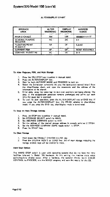
System/370 Model 155 (cont'd)
ALTER/DISPLAY CHART
STORAGE ALTER DISPLAY ADDRESS AREA MNEMONIC MNEMONIC RANGE
MAIN STORAGE AM DM OOOOOO-FFFFFF
GENERAL-PURPOSE AG - DG O-F REGISTER
FLOATING-POINT AF DF 0,2,4,6 REGISTER
CURRENT PSW AP DP NONE REQUIRED
CONTROL REGISTERS AC DC O-F
To Alter Registers, PSW, and Main Storage
1_ Press the CPU STOP key (machine in manual state). 2. Press the ALTER/DISPLAY key. 3. Wait for both AL T/DISP MODE and PROCEED to turn on. 4. Select the 2-character mnemonic {A plus the appropriate second letter! from
the Alter/Display chart, and type the mnemonic and the address of the information to be altered.
5. Enter data, using the space bar to skip over positions not being altered. The data in the skipped-over positions remains unchanged and prints out each time the space bar is operated.
6. To end tne aiter operation, press the ALTEl'liOISPLAY key or END key. If you press the ALTER/DISPLAY key, the PR-KB remains in alter/display mode. If you press the END key, alter/display mode is terminated.
To Stop on Main Storage Address
1. Press the STOP key (machine in manual state). 2. Set STORAGE SELECT switch to MAIN. 3. Set ADDRESS COMPARE switch to ANY. 4. Set the address of the desired storage address in console switches CDEFGH. 5. Set the ADDRESS COMPARE (SAR) toggle switch to STOP. 6. Press the START key.
To Clear Storage
1. Hold down the ENABLE SYSTEM CLEAR key. 2. Press the SYSTEM RESET or LOAD key. All of main storage including the
storage protect key5 will be cleared to zeros.
Hard Stop Option
The HARD STOP switch is used with operating systems that do nOT have the retry facilities inherent in Model 155 hardware. At this setting, the machine stops when parity/machine checks occur. After a hardstop, the operator should returp CHE:K CONTROL to PROCESS, run the SEREP program, and save the results for the CEo
Page 3-12

System/370 Model 158 Source: GC38-(}{)25 Systeml310Model 158 Operating Procedures
Powar.()n Procedure
DANGER: Before switching on power, ensure that no person is exposed to risk and that all equipment covers are shut.
1. Insert the IMPL diskette in the console file. Carefully close cover. 2. Press the POWER ON pushbutton. This button lights red, then white upon
completion of the power·on sequence. An IMPL is automatically initiated.
Powa-.()ff Procedure
1. Preparatory to turning power off:
a. Unload all disk and tape drives. b. Open or disengage the print release lever on all printers that use print
train cartridges.
2. Press the POWER OFF pushbutton to initiate the power-off sequence. The contents of rnain storage are not preserved.
To IMPL
1. Press IMPL pushbutton. This causes the initial microprogram load of the display console and CPU reloadable control stores to occur. During I!VIPL, the message 'IMPL IN PROCESS' is displayed.
2. On completion of IMPL the configuration frame appears. The system is IMPLed in display mode. If PR-KB mode is desired, or timer options, select them on this frame.
3. Exit from the configuration frame by selecting MANUAL with the light pen or by pressing MODE SE L on the keyboard.
To IPL
1. Enter load unit address and select 4 under O-OPERATOR FUNCTIONS or key in letter 0 and 4, followed by letter "L" and J.digit address.
2. Select X-EXECUTE OPERATOR FUNCTION or key in X. Upon completion of a successful I PL the program frame appears.
3. Respond to system messages that appear on the screen. 4. Set time and date.
Loading a Secondary Nucleus (OS)
Follow the procedure shown for the Mod 155, using either the PR-KB or the light pen.
To Display Registers, PSW, and Main Storage
1. Press STOP key. 2. Press MODE SEL to display manual frame. 3. Select '3 ALTER/DISPLAY' under FRAME CONTROL or key in F3. 4. Select D under FUNCTION on the ALTER/DISPLAY frame, or key in D. 5. Select or key in the letter of the facility to be displayed. 6. Key in address-·none necessary for general registers and PSW. 7. Press ENTER. The contents of the facility selected wiU be displayed in the
center of the screen.
Page 3-13

System/370 Model 158 (cont'd)
To Alter Registers, PSW, and Main Storage
1. If the system is in Alter/Display mode, press CANCEL key. This will reo initialize Alter/Display. If the system is in Program mode, (a) press STOP key; (b) press MODE SEL to display Manual frame; select '3 AL TER/ DISPLA Y' or key in F3.
2. Select A under FUNCTION on the ALTER/DISPLAY frame, or key in A. 3. Select or key in the letter of the facility to be altered. 4. Key in address and PSW. 5. Alter data. As the data is entered, the digit appears under the old value and
the cursor is spaced forward. 6. To store altered data, select the ENTER function by use of the light pen or
press ENTER key. If data to be altered is on the top line, the ENTER function must be selected prior to the New Line function, otherwise the data remains unaltered.
7. After altering data, press MODE 5EL once to return to manual frame; twice to return to program frame.
To Stop on Main Storage Address
1. Press MODE SEL to display manual frame. 2. Select 1 ANY and 5 STOP under 5-SAR COM SEL (REAL), 0' key in 51
and S5. 3. Key in E and address of main storage. 4. Press ENTER key.
To Clear Main Storage
1. Select 0·6 5YS RESET CLEAR under O-OPERATOR FUNCTIONS, or key in. letter 0·6.
2. Press ENTER key.
Hard Stop Option
After" hardstop:
1. Return CHECK CONTROL to PROCESS. 2. Select SERVICE frame. 3. Select INDEX frame. 4. Select EXTERNAL DIAGNOSTIC frame. 5. Be sure UN" diskette is inserted in IGAR2. 6. Load "N" disk. 7. PROGRAM frame will be displayed after UN" disk load. Make entries per
Questions asked. 8. Save the results for the CEo
In hardstop mode, the CPU clocks are stopped by any error that causes a machine trap. If CE advises running in hard stoP mode, start the clocks. This will cause the system to run as if it were in PROCESS mode.
Page 3-14

System/370 Model 165 Source: GA22-6969 System/370 Model 165 Operating Procedures
Power-On Procedure
• Check doors, feeds, cards andlor paper. • Check tapes, disks, and two-channel switch, if applicable. • Check coolant and MG power, if applicable.
1. Press POWER ON (turns red). 2. Wait; POWER ON turns white. 3. If manual light does not turn on, check CONSL FILE light_ If on:
a. Set RSDTINONRSDT to RSDT. b. Set FILE SECTION SELECT to O.
Press LOAD MD.
4. If manual light is on, check I/O. a. 2250--Press POWER ON (backlight). b. Disks--Set ENABLE and START.
2701--Set to ENAB LE.
Power·Off Procedure
1. Issue WRITELOG and HALT commands. 2. Press STOP to turn manual light on. 3. Perform two·channel switch procedure, if applicable. 4. Check tapes; press RESET and LOAD REWIND. Aftu rewind, press
UNLOAD and RESET. 5. Check disks; switch to STOP. 6. Press POWER OFF (backlight off). 7. Check coolant and MG power, if applicable.
To IPL
1. Set LOAD UN IT switches to residence volume address. 2. Hold SYSTEM CLEAR; press LOAD. Manual light goes off, LOAD light
comes on, and system reads in the IPL program. 3. When LOAD light goes off, IPL is in and running. 4. Reply to system messages and set TOD clock.
Loading a Secondary Nucleus (OS)
1. Set LOAD UN IT switches to residence volume address. 2. Set RATE switch to INSN STEP. 3. Press the LOAD key. 4. Use the Alter procedure to store, in location 08 (hex), the two hex digits
designating the secondary nucleus. 5. Set RATE switch to PROCESS. 6. Press START key.
To Display General Registers
1. Press STOP 2. Set CRT MODE SELECT to CE and MANUAL ENTRY SELECT to MCAR. 3. Set STORAGE SELECT to GEN PUR. 4. Press = until cursor underscores high-order second byte. 5. Enter 6-digit hex address via data keys. (If error is made, press = until
wraparound, then return to desired byte and enter correct data.) 6. When 6-digit address shows at MCAR, press DISPLAY. See eight bytes of
storage displayed at MCDR on the CRT. 7. To see next doubleword, press ADV ADDRESS, then press DISPLAY. S. To resume, set CRT MODE SELECT to OP and press START.
Page 3-15

System/370 Model 165 (cont'd)
To Alter (Load into) General Registers
1. Perform steps 1·6 of "Display General Register". 2. Set MANUAL ENTRY SELECT to MCDR. Check that the => underscores
desired byte. 3. Enter desired data via data keys. (If error is made, press => until wraparound,
then return to desired byte and enter correct data.) 4. When the right·half of MCDR shows desired data (four bytes), press STORE.
To verify, press DISPLAY. 5. To resume, set CRT MODE SELECT to OP and press START.
To Display Current PSW
1. Press STOP. 2. Set CRT MODE SELECT to CEo 3. See bits 40·63 at IC on CRT. 4. See bits 0-15 and 32·39 at image A3 on indicator viewer. (Bits 16·31 are
a's.) 5. To resume, set CRT MODE SELECT to OP and press START.
To Alter (Load) Current PSW
1. Perform steps 1-4 of "Display Current PSW". 2. Set MANUAL ENTRY SELECT to MCDR. 3. Enter desired data via data keys. (If error is made, press => until wraparound,
then return to desired byte and enter correct data.) 4. When all eight bytes are in MCDR, press SET PSW. To verify, perform steps
1-4 of "Display Current PSW". 5. To resume, set CRT MODE SELECT to OP and press START.
To Display Main Storage
1. Press STOP. 2. Set CRT MODE SELECT to CE and MANUAL ENTRY SELECT to MCAR. 3. Set STORAGE SELECT to MAIN STaR. 4. Press => until cursor underscores second byte. 5. Enter six-digit hex address via data keys. (If error is made, press => until
wraparound, then return to desired byte and enter correct data.) 6. When six·digit address shows at MCAR, press DISPLAY. See eight bytes of
storage displayed at MCDR on the CRT. 7. To see next doubleword, press ADV ADDRESS, then press DISPLAY. S. To resume, set CRT MODE SELECT to OP and press START.
To Alter (Store into) Main Storage
1. Perform steps 1·6 of "Display Storage". 2. Set MANUAL ENTRY SELECT to MCDR. Press => until cursor underscores
desired byte. 3. Enter desired data via data keys. (If error is made, press => until wraparound,
then return to desired byte and enter correct data.) 4. When MCDR shows desired data (eight bytes). press STORE. To verify,
perform steps 1·7 of "Display Storage". 5. To resume, set CRT MODE SELECT to OP and press START.
To Stop on Main Storage Address (Compare Stop)
1. Press STOP. Set STORAGE SELECT to MAIN STaR. 2. Set CRT MODE SELECT to CEo 3. Set ADDRESS COMPARE/SYNC to IC. 4. Set stop on compare (MS) to STOP. 5. Set CS/MS to MS. 6. Set MANUAL ENTRY SELECT to MRAR. 7. Press => until cursor underscores second byte in MRAR. 8. Enter 6·digit hex stop address via data keys. (If error is made, press => until
wraparound, then return to desired byte and enter correct data.) 9. Set CRT MODE SELECT to OP; press START.
10. To resume, set CS/MS to CSiMS, stop on compare (MS) to NORM, ane press START.
Page 3·16

System/370 Model 165 (cont'd)
To Clear Main Storage (Clear Storage)
1. Hold SYSTEM CLEAR; press SYSTEM RESET. 2. Release SYSTEM CLEAR; manual light turns on. 3. Perform I PL.
Hard Stop Option
If both wait and system lights are off, possible hardstop may be assumed. If no special procedures are provided by service personnel, follow procedures in Hardstop option, listed below.
1. Set MACHINE CHECK to STOP ON CHK. 2. At stop, press STOP, CHECK RESET, and START.
Page 3-17
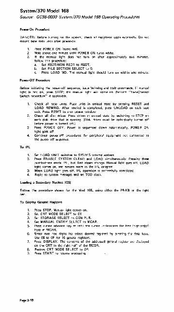
System!370 Model 168 Source: GC38-0030 System/370 Model 168 Operating Procedures
Power-On Procedure
DANGER: Before turning on the system, check all peripheral units externally. Do not mount tape reels until after power·on.
1. Press POWER ON (turns red). 2. Wait about one minute until POWER ON turns white. 3. If the manual light does not turn on after approximately two minutes,
follow this procedure: a. Set RSDT/NON RSDT to RSDT. b. Set FILE SECTION SELECT to o.
Press LOAD MD. The manual light should turn on within one minute.
Power-Off Procedure
Before initiating the power-off sequence, issue Write log and Halt commands. If manual light is not on, press STOP; the manual light will come on. Perform "Two-Channel Switch procedure" if applicable.
1. Check all tape units. Place units in unload state by pressing RESET and LOAD REWIND. After rewind is completed, press UNLOAD on each tape unit. Press RESET to shut power window.
2. Check all disk drives. Place drives in unload state by switching to STOP on each disk drive that is running. (DiSK drives must be individually turned off !Jefore power is turned off.;
3. Press POWER OFF. Power is sequenced down automatically. POWER ON light goes off.
4. Continue power-off procedures fo' peripheral equipment not connected to the power-off sequence.
To IPL
1. Set LOAD UNIT switches to SYSRES volume address. 2. Press ENABLE SYSTEM CLEAR and LOAD simultaneously. Pressing these
pushbuttons starts IPL, but first clears storage. Manual light goes off, LOAD light comes on, and system reads in the IPL program
3. When LOAD light goes off, IPL operation is successfully completed. 4. Reply to system messages and set TOD clock.
Loading a Secondary Nucleus (OS)
Follow the procedure shown for the Mod 165, using either the PR-KB or the light pen.
To Display Genaral Registers
1. Press STOP. Manual light comes on. 2. Set CRT MODE SELECT to CE 3. Set STORAGE SELECT to GEN PUR. 4. Set MANUAL ENTRY SELECT to MCAR. 5. Press cursor advance key => until the cursor underscores the first (high-order!
byte in MCAR. 6. Enter two hex digits (to select desired register) by pressing t~e data keys.
Use 00 to OF for 16 general registers. 7. Press DISPLAY. The contents of the addressed genera! register are displayed
on the CRT in the right half of the MCDR. B. Restore CRT MODE SELECT to OP. 9. Press START to resume processing.
Page 3·18

System/370 Model 168 (cont'd)
To Alter (Store in) General Registers
1. Perform steps 1 through 7 above. 2. Set MANUAL ENTRY SELECT to MCDR. 3. Make certain the cursor is underiining the first byte to be changed. Enter the
data desired by pressing the data keys. In case of error, press the cursor advance key => until wraparound occurs, then return to the byte desired and enter the correct data.
4. Press STORE. Four bytes (right half of MCDR) are loaded into the general register selected.
5. Press DISPLAY to verify the load operation. 6. Restore CRT MODE SELECT to OP. 7. Press START to resume processing.
To Display Current PSW
1. If the manual light is not on, press STOP. 2. Set CRT MODE SELECT to CEo The PSW is displaved in portions. The last
portion (bits 40·63) of the instruction address is directly displayed on the right side of the CRT, in the space designated IC. The entire first word (less the interruption code). as well as bits 32·39 (first portion of secc'1d half of current PSW) may be seen in image A3 of the indicator viewer.
3. Restore CRT MODE SELECT to OP when processing is to continue.
To Alter (Load) Current PSW
1. Press STOP. Manual light turns on. 2. Set CRT MODE SELECT to CEo 3. Set MANUAL ENTRY SELECT to MCDR. 4. Enter the PSW data by pressing the data "eys; the cursor indicates what is
actually entered at a specified location. 5. When all eight bytes of the MCDR are set as desired in the new current
PSW, press SET PSW. Verify change by displaying current PSW. (The only portion not displayed is the interruption code, which should be zero.)
6. Restore CRT MODE SELECT to OP position. 7. Press START to resume processing.
To Display Main Storage
The CRT displays eight bytes, starting with the real location addressed.
1. Press STOP. Manual light turns on. 2. Set CRT MODE SELECT to CEo 3. Set STORAGE SELECT to MAIN STOR. 4. Set MANUAL ENTRY SELECT to MCAR to enter the real addra,s. 5. Press the cursor advance key => until the cursor underscores the second byte
in MCAR. (The first byte is ignored.) 6. Enter a 6-digit hex address by pressing the data keys. As each key is pressed,
the appropriate digit appears in the MCER. As every second digit completes a byte, that byte appears in the MCAR and the cursor advances to the next byte.
7. Press DISPLAY. Eight bytes of storage are displayed at MCDR on the CRT display. To dispiay the next doubleword of main storage, proceed with step 8.
8. Press ADV ADDRESS, then press DISPLAY. ("Blinking" bytes denote bad parity. Press CHECK RESET to clear pending errors.)
9. Restore CRT MODE SELECT to OP. 10. Press START to resume processing.
Page 3-19

System!370 Model 168 (cont'd)
To Alter (Store into) Main Storage
Every store operation should be preceded by a display operation to prevent destruction of data by doubleword storing. For real addresses, use "Display Main Storage" procedure; for logical addresses, use "Translate Address and Display Main Storage" procedure shown after this procedure.
1. Perform steps 1 through 7 of "Display Main Storage" or "Translate Address and Display Main Storage."
2. Set MANUAL ENTRY SELECT to MCDR. 3. Press cursor advance key => until the cursor underscores the byte in MCDR
where the data is to be entered. 4. Enter the data change by pressing the data keys. As soon as the byte is
entered in the MCER, it is transferred to the MCDR where it can be check· ed for accuracy. If an error occurs, press the cursor advance key until wraparound occurs, and return to the byte desired. Enter the correct data.
Translate Address and Display Main Storage
The CRT displays eight bytes, starting with the logical location addressed.
1. Press STOP. Manual light turns on. 2. Set CRT MODE SELECT to CEo 3. Set STORAGE SELECT to MAIN STOR. 4. Set MANUAL ENTRY SELECT to MCAR to enter the logical (virtual)
address. 5. Press the cursor advance k~y => until the cursor underscores the second byte
in MCAR. (The first byte is ignored.) 6. Enter a six-hex-digit logical address by pressing the data keys. As each key is
pressed, the appropriate digit appears in the MCER. As every second digit completes a byte, that byte appears in the MCAR and the cursor advances to the next byte.
7. Press TSLT ADR & DISPLAY MAIN. The real address replaces the logical address in MCAR, and the data at the real address appears in MCDR. If Zeros appear in ooth th~ MCAR and MCDR, t:'ilhel r.i ban:;ldliofi t:}('l:eJ-lliulI associated with the specified logical address has occurred, or the resulting real address is invalid for the system.
8. Restore CRT MODE SELECT to OP. 9. Press START to resume processing.
To Stop on Main Storage Address
1. Press STOP. Manual light turns on. 2. Set STORAGE SELECT to MAIN STOR. 3. Set ADDRESS COMPARE/SYNC: to IC for a match between the IC and the
logical address set in the MRAR; or to CHAN for a match between a real address set in the MRAR and a main storage address selected by a channel; or to CPU/CHAN for a match between a real address set in the MRAR and an address selected either by the CPU or by the channels; or to CPU (REAL) for a match between the address selected by the CPU and the real address set in the MRAR; or to CPU (LOGICAL) which is the same as "Real Address" except that 3
logical address must be entered in the MRAR. 4. Set CS/MS to MS; set stop on oompare (MS) to STOP. 5. Set CRT MODE SELECT to CEo 6. Set MANUAL ENTRY SELECT to MRAR. 7. Press cursor advance key => until the cursor underscores the second byte in
MRAR displayed on the CRT. (Using a six-byte address, ignore the first MRAR byte.)
8. Enter six-hex-digit logical address (where stop is desired) by pressing the data keys. As each key is pressed, the appropriate digit appears in the MCE R. As f?,/ery second digit completes a byte, that byte appears in the MRAR and the cursor advances to the next byte. If an error occurs, press the cursor advance key until wraparound occurs, and return to tpe byte desired, then enter [he correct digits.
9. Return CRT MODE SELECT to OP. 10. Press START to resume processing. 11. When the CPU stops at the desired compare stop, reset CS/MS to CS/MS,
reset stop on compare (MS) to NORM, and press START to resume processing.
Page 3-20

System/370 Model 168 (cont'd)
To Clear Main Storage
Under normal operation, it is unnecessary to clear storage because the operating system provides this function as required.
1. Depress and hold ENABLE SYSTEM CLEAR. 2. Press SYSTEM RESET. Manual light comes on. 3. Re·IPL.
Hard Stop Option
The hardstop option is normally specified for limited operation and should be used only on recommendation of the service personnel. In this case, MACHINE CHECK is set to STOP ON CHK and is left in this position. At stop time:
1. Record all check lights that are turned on; save the information for the service personnel.
2. Re-IPL, or Sl!e appropriate operating system operator's library manual.
Page 3-21

System/370 Model 195 Source: A22-6954 Systeml360 and Systeml370 Model 195
Operating Procedures
Power-On Procedure
DANGER: Before turning on the system, ensure that no person is exposed to risk and check all peripheral units externally. Check that doors are properly closed, feeds not impeded, and paper and card supplies suitable to permit power-on sequencing.
1. Check panel light coolant check or coolant water temperature gage for normal setting before power-on sequence.
2. Press POWER ON (operator control panel); the backlighted key should turn red immediately.
3. At the completion of normal power-on sequence (a matter of seconds), the POWER ON backlight turns white. If, after 90 seconds, POWER ON does not light, check to see whether EMERGENCY PULL has been pulled.
Power-Off Procedure
Before performing the turn-off procedures, issue WRITELOG and HALT commands (if using operating system). If manual light is not turned on, press STOP; manual light turns on. Perform ''Two-Channel Switch Proc;roures" if applicable.
1. Check all tape units. Put them in unload state by pressing RESET and LOAD REWIND. After REWIND is completed, press UNLOAD on each tape unit and press RESET to shut power window.
2. Check all disk drives. Put them in unload state by switching to STOP on each disk drive if drives are running. (Disk drives must be individually turne<:' off before power is turned off.)
3. Press POWER OFF. Power is sequenced down automatically. The power-)n light turns off.
4. Continue power-off procedures for peripheral equipment not connected to the power-off sequence.
Manual IPL
Manual IPL is performed after a power-on sequence, after malfunctions that .1ecessitate reloading the resident portion of the operating system (control program) into main storage, as part of switching from one operating system to another, or for initial load· ing of any stand-alone program.
1. Place the program on the desired I/O device and ready that device. (Check that CRT DISPLAY & TAPE OP is at process. Check that lest light is off, unless a critical switch has been deliberately set to other tban nonmal position.)
2. Set the three LOAD UNIT switches to the I/O address required. 3. If the installation does not use the secondary nucleus, go to step 4. If the
secondary nucleus is used, follow procedure in "Loa:ling the Secondary Nucleus" as direct replacement for step 4.
4. Press LOAD. The load light tlJr~s on, the ma"u2! Hght' tvrll~ off, and o:;v~tern
reset occu~. When the loader portion of the prograrr is in main storage, the load light turns off and control of the system is passed to the channel, which directs the storage of the remainder of the program.
5. If this is a stand-alone program (independent utility: DASDI, DUMPI RESTORE, or RECOVER/REPLACE), and it is loaded properly, the wait light turns on. The IC reads FFCO. Type, for example, INPUT=2400 181 (where 2400 is the magnetic tape device type, and 181 is its hex address). Hold down ALTN CODE key and 'press numHic 5 key. When the job is completed, the program prints out END OF JOB and ente~ the wait state.
Page 3-22

System/370 Model 195 (cont'd)
Loading the Secondary Nucleus (OS)
This procedure replaces step 4 of "Manual IPL" where the installation uses the secondary nucleus instead of the primary nucleus.
1. Press STOP; manual light turns on. 2. Set ADDRESS switches to location hex 80 3. Set ADDRESS COMPARE to INSN SOFT STOP. 4. Press LOAD; load light turns on, the manual light turns off, and system reset
occurs. When the loader portion of the program is in main storage, the load light turns off and the manual light turns on.
5. Perform steps 1-4 of "Display Main Storage" at location hex 000008. 6. Enter the data (2 hex digits) in the appropriate CXR!CBR (data) switches.
The two hex digits may range from F1 to F9. (Last hex digit determined by last character of nucleus name.)
7. Press STORE. S. Return ADDRESS COMPARE switch to normal setting (PROCESS). 9. Press START. (The secondary nucleus has been loaded.)
Page 3-23

Svstem/370 Model 195 (cont'd)
To Alter/Display General Registers, Floating-Point Registers, and Main Storage
Position of CRT DISPLAY & TAPE OP
PROC
I !
FLP REGS
STORAGE
Page 3-24'
Alter/Display Chart
Position of STORIDISPLAYI STG SELECT
GEN REGS
FLP REG
MAIN STORAGE
Operator I Area Displayedl Action Stored
Stop CPU CPU regs on CRT
Set ADDR ESS switches Gen reg specified: 20-23. data in lights 0-31 Press SET CAR. ofCXR/CBR. Place CBR/CXR switch
I to CBR position. Press FTH into CB R (panel M).
To alter, set new data I Data in switches in the appropriate CXRI 0-31 of CXR/CBR. CBR sWItches. Press STORE Ipanel MI.
Stop CPU F LP regs on CRT
Set ADDRESS switches I FLP reg specified:
~:~!2SET CAR. i ~:~~~Iights 0-63
Press FTH into CBR. I
Press STORE. I
Set ADDRESS switches 16 doublewords of to desired storage address. Press SET CA R (panel MI. Place CB R ICX R switch to CXR/CBR position. Press SCAN (panel N).
main storage start· ing at address set in CAR will be dis· played on CRT.
MAIN STORAGE Set ADDRESS switches Doublewordof to desi red storage ad· dress. Press SET CAR. Place CBRiCXR switch to CBR position. Press FTH into CB R.
main storage at address specified in CAR.
To alter, set new data Data in switches in the appropriate CXR/ 0·63 of CXR:CBR. CB R switches. Press STORE (panel M).

System/370 Model 195 (cont'd)
To Display Current PSW
1. Press STOP; manual light turns on. 2. Set CRT DISPLAY & TAPE OP to PROCESS. 3. Read current PSW (bits 0-63) displayed on panel H. 4. Press START to resume processing.
To Alter Current PSW
1. Display current PSW. 2. Place CBR/CXR switch to the CBR position. 3. Set new information in the CXR/CBR (data) switches. 4. Press SET PSW. The current PSW is now altered; the now·current PSW data
is automatically displayed on panel H. 5. Press START to resume instruction processing.
To Stop on Main Storage Address
1. Press STOP; manual light turns on. 2. Set ADDRESS COMPARE to (a) INSN SOFT STOP, (b) SCU STORAGE
SOFT STOP, or (c) CHAN S/F SOFT STOP. 3. Set ADDRESS/ADDRESS COMPARE to the desired stop address. 4. Press START to resume processing. After the compare stop has been accom·
plished, restore switches to their normal settings, then press START.
To Clear Main Storage Only
Under normal operating-system operation, it is unnecessary to clear main storage because the operating system provides this function as required. For certain testing operations, however, it may be desirable to clear main storage. The following pro· cedure clears main storage, but does not alter the contents of general or floating· point registers.
1. Press STOP; manual light turns on. 2. Set STORE/DISPLAY/STG SELECT to MAIN STORAGE. 3. Set CRT DISPLAY & TAPE OP to STORAGE. 4. Set all CXR/CBR switches to 0 or press CBR TO ZEROS. 5. Set (lever) STORAGE TEST to STO (up position) on panel L 6. Press START STORAGE TEST on panel L 7. Restore STORAGE TEST to normal, center position. All of main storage
now contains data (zeros) in CXR/CB R switches. 8. To resume processing, re-IPL the control program.
To Clear System
1. Hold System Clear Enable switch (panel U in the down position while depressing the System Reset switch. This will cause (1) a normal system reset, (2) all of main storage, G RS and. F L RS, and Storage Protect keys to be reset to zero, and (3) the data buffers to be invalidated.
2. Hold System Clear Enable switch in the down position while depressing the Load swi tch. This will cause the machine to execute a normal system clear and then the normal load function.
Page 3-25

System/370 Model 195 (cont'd)
Hardstop Option
If both wait and system lights are off, possible hardstop may be assumed. The hard· stop procedure should be used only at the recommendation of the serviceman.
1. Set MACH CHECK STOP to HARD STOP and leave in this position; the test light remains on. The CPU hard stops on each machine check.
2. At stop time, record all check lights that are turned on; save information for the service personnel.
3. Perform storage error analysis. 4. I f analysis shows main storage failure, perfonn procedure in "Storage
Failure." At the completion of storage reconfiguration, notify the service personnel.
Press SYSTEM RESET. b. Restore MACH CHECK STOP to center (nonnal) position. c. Perform manual IPL of control program; continue processing.
5. If analysis shows buffer failure, perfonn procedure in "Buffer Failure." At the completion of buffer failure procedure, notify the service personnel. a. Press CPU RESET. b. Set MACH CHECK STOP to PROCESS.
Press FORCE MACH CHK. d. Set MACH CHECK STOP to HARD STOP. e. Press START to resume processing in hardstop option.
6. If analysis shows neither main storage nor buffer storage has failed. a. Set MACH CHECK STOP to PROCESS. b. Press START.
Set MACH CHECK STOP to HARDSTOP.
NOTE: See Source SRL for description of "Storage Failure" and "Buffer Failure" procedures.
Page 3·26
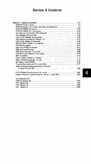
Section 4 Contents
Section 4: Operator Commands ....................................• 4-1 DOSIVS I P L Commands ....................................... 4·1 DOSIVS Job Control and Attention Routine Commands . . . . . . . . . . . . . . . . . . 4·5 DOSIVS POWER Commands ................................... .4·20 DOSIVS POWER RJE Commands ................................ .4·22 VS1 Operator Commands (VS1 Release 3) .......................... .4·25 VS1 Message Routing Codes ..................................... 4·30 VS2 (JES2) Message Routing Codes ............................... .4·30 VS2 Operator Commands (Release 1.6) ............................. 4·31 VS2 (JES2) Release 2 Commands ................................. 4·35 OSIVS HASP II Version 4 Commands .............................. 443 VM/370 Commands ......................................... .447 Summary of CMS Commands ................................... .4-61 CMS Command Formats ...................................... .4·64 RES Central Operator Commands ................................ .4-69 RES Workstation Operator Commands ............................. .4·70 SMF Parameters ............................................ .4·73 CRJE System Operator Commands ............................... .4·74 CRJE Terminal Command Formats ................................ 4·75 Edit Subcommands CRJE ...................................... 4·76 Terminal Commands and Functions CRJE ............................ 4·77 DOSIVS Display Operating Console Commands
for Mod 115 and 125 ...................................... .4·80
OSIVS Display Console Control Command .......................... .4·83 Program Function Keys··Entering Commands through PF Ks ................ 4-83 II I P L Procedures for: DOSIVS, Release 29 ......................................... .4-84 VS1, Release 2.0 ........................................... .4-86 VS2, Release 1.6 ............................................ 4·88 VS2, Release 2.0 ........................................... .4-69

DOS/VS IPL Commands Source: SY33-8571 DOS/VS Handbook, Release 29
Operation
ADD
Operand Remarks
X'cuu'[ (k) ],devicetype[,X'SS' ] Add a device to the PUB table. ,X'ssss' X'cuu': Channel and unit nuni>er ,X'ssssss' (k): Can be specified as either
(S) or a decimal number from 0 to 255. (S) indicates that the device can be switched (that is,physically attached to two adjacent channels). The designated channel is the lower of the two channels. (0)-(255) indicates the priority of a device that cannot be switched,with 0 indicating the highest priority. If (k) is not given, the assumed priority is 255
device actual device (See device type: codes list)
X'ss' device specification (See X'ssss' ASSGN statement). If X 'ssssss ': absent the following values
are ass i gned: X'CO' for 9-track tapes X '90' for 7 -track tapes X'OO' for nontapes. X'OO',X'01',X'02' and X'03' are invalid as X'ss' for magnetic tape.
X'ss' specifies SADxxx (Set ADdress) requirements for IBM 2702 lines: X'OO' for SADO X'Ol' for SAD1 X'02' for SAD2 X'03' for SAD3
X'ss' is required for MICR! OCR device types. It specifies the external interrupt bit in the old PSW, which is used by this devic. to indicate "read complete' The specifications are: X'Ol' PSVV bit 31 X'02' PSW bit 30 X'04' PSW bit 29 X'OS' PSW bit 28 X'10' PSVV bit 27 X'20' PS# bit 26
Page 4-1

DOSIVS IPL Commands
Operation Operand Remarks
ADD The X'55' parameter specifies whether (Cont'd) or not the error correction feature is
present on an IBM 1018 Paper Tape Punch with 2826 Control Unit. These specifications are: X'OO' -No error correction feature X'OI' Error correct ion feature
For the ICA of theM 115/125, X'55' X'ssss' or X'ssssss' is used to specify the line mode setting for a Start/Stop line or a BSC line. This is not accept-ed on the ASSGN statement. If a one or two byte value is specified the specified value is right-justified and the rest of the three bytes is fi lied with zeros.
Note: 'Optional statement; if required it must be entered before SET command
CAT UNIT= X'cuu' Assigns the system logical unit SYSCA X'cuu': Indicates the hexadecimal
channel (c) and unit (uu) number of the device that is I to contain the VSAM cata-log. SYSCAT may only be
I assigned to the following DASD types: 2314/2319 and 3330/3333.
Note: Optional statement; if required the CAT command must follow the SET command and precede the DPD com'd.
DEL X'cuu' Delete a device from the PIJI table. X'cuu': Channel and unit number.
Nate: Optional statement; i~ required it must be entered before SET command
DPD [TYPE={~}][,UNIT= X'cuu', Defines the page data set. TYPE=N: Indicates that the page
CYL= xxxll, VOLID= xxxxxx] data set need not be for-matted and the extent limits have nat been changed.
If TYPE= N is specified but the page
I I dala set does not exist or the extent I limits have been changed, TYPE= N is ignored and the page data set is formatted during !Plo In !hi! C!IP.'. !he
I UNIT and CYL operands must either have been supplied during system ge-neration, or they must be specified in the DPD command.
Page 4-2
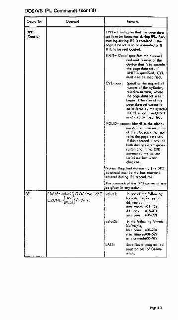
DOSNS IPL Commands (cont'd)
Operation Operand Remarks
DPD TYPE= F indicates that the page data (Cont'd) set is to be formatted during IPl. For-
matting during IPl is required if the page data set is to be extended or if it is to be reallocated.
UNIT= X'cuu' specifies the channel and unit nurrber of the device that is to contain the page data set. If UNIT is specified, CYl must also be specified.
CYL=xxx: Specifies the sequential number of the cylinder, relative to zero, where the page data set is ta . begin. (The size of the page data set extent is cal culated by the system) If CYl is specified,UNIT must also be specified.
VOlID= xxxxxx identifies the alpha-numeric volume serial no of the disk pack that con rains the page data set. If this operand is omitted both during system gene-ration and in the DPD command, the volume serial number is not checked.
Notes: Required statement. The DPD command must be the last command entered during IPL procedures.
The operands of the DPD command may be given in any order.
SET [ DATE= value 1 [, ClOCK=value2 ]J value1: In one of the following
{EAST} formats: mm/dd/yyor [,ZONE= WEST /hh/mm]
dd/mm/yy, mm: month (01-12) dd : day (01-31) yy: year (00-99)
value2: In the foilowing format: hh/mm/ss, hh: hours (00-23) mm: minutes(OO-59) ss : seconds(00-59)
EAST: Specifies a geographical position east of Green-wich.
Page 4-3

DOSNS IPL Commands (cont'd)
Operation
SET (Cont'd)
Page 4-4
Operand
WEST:
hh/mm:
Remarks
Specifies a gea~aphiC\lr position _t of Gree ... -wich.
A decimal value which I indicates the difference in hours and minutes between local and Greenwich Mean Time. hh: 0-12 m.,..: 0-59
Note: Required statement. If any AD~ or DEL commands ore required, they I must precede the SET command. I

DOSNS Job Control and Attention Routine Commands
I
I I
I ,
Name Operatior Operand Remarks Accepted by
! ALLOC Fl= nK [,F2= nK] Allocctes foreground program 'JCC
[,F3= nK] LF4= nK] ~:~:i:/~\V~~u:~e~d~~:::~a'l AR
ALLOCR
I I
I
I ALTER I ,
I
[//] I ASSGN
I I
!
I
The order of operands is I arbitrary. At least one operand
I must be specified.
[BGR= nK] [,F1R=nK] [Allocates real address area ! JCC [,F2R= nKJ [,F3R=nK] I among foreground and back- I,',
[,F4R= nK] I ground programs, Value of n is I an even number. The order of i
I ~:r:~:ai~t:~~~ ·s~c~~::. i xxx XXX Alters 1 to 16 bytes of virtual I AR
storage. XXXXXX is the hex address where alteration is to start.
For any device: I ~t:t;:~~ks see end of this
{ UA 1. [, TEMPl
SYSxxx, IGNf ,PER~
For disks:
(address-I ist SYSyyy
r X'cuu' ! sys=.J 2311 ~PE~ DISK ,TEM or; VOL=volserno]C SHR]
l3330 2314 ! 3340 J
For diskettes:
r X'cuu' } (address-list
SYSxxx 1 SYSyyy rTEMPl 'DISKETTE lPERMJ
3540
SYSyyy
J
~~r~-listl SYSxxx ~~T7 LX'ss'll. TEMP]
'24OOT9 ~ALT ~PERM [,VOL=volserno] 3410Tl _.J
l3410T9 3420T7
3420T9 J
Page 4-5

DOSNS Job Control and Attention Routine Commands (cont'd)
Name Operation
ASSGN (Cont'd)
Page 4-6
Operand Remarks
For remarks see
r ~r~~s-Ibt) , SYSyyy
PRINTER 1403
SYSxxx, 1403U 144:> 3203 3211 5203 5203U
_.~iS statement I
l[~:l I ~ 'J
J For card (read) punches:
r X'cuu' 1
I ~~~~.Iist) I 1442Nl 1442N2
I 252081 252OB2
SYSxxx, 252083
:: [~~J 2596 3525P
I 3525RP
l5425 [::: J For card reade ... :
X'cuu' (address. list) SYSyyy READER 1442Nl 2501 252081
SYSx'O(, 2540R
1 2~ [',~~J 2396 3504
l ~,!" [,,~\]j
I.TEMPl tpm~l
i I
----.-'-.-. ___ '--_--l

DOS/VS Job Control and Attention Routine Commands (cont'd)
Name Operation Operand
I Remarks Accepted
by
I I ASSGN SYSxxx: can be SYSRDR, SYSIPT, SYSIN, ---(Cont'd) SYSPCH, SYSLST, SYSOUT,
SYSLOG, SYSlNK, SYSREC, SYSRlB, SYSSLB, SYSCLB (JCC only,i, or SYSOOO-SYSnnn.
X'cuu l: c= 0-6.
uu= OO-FE (0-254)in hex I address-list: a list of up to seven device
I I
---- addres;es ii1 the form: I (X1cuu', . ~ • r X1CUU f)
I UA: unassign I -
I IGN: unassign and ignore (invalid -- for SYSCLB, SYSRDR, SYSIPT,
SYSIN) I SYSyyy: an~ systeM or programmer logical I
unit. I
device-clas;;~ READER, PRINTER, PUNCH, ! ---- TAPE, DISK, or DISKETTE !
dev ice-type: device code of any supported i device
i X'ss': density (magn.tape only) I ---
I ss BPI Parity Trans I. Conv'l
feat feat
10 200 odd off I
20 200 even off ~f~ ! 28 200 even on off i 30 200 odd off off 38 200 odd en off 50 556 odd off on 60 556 even off off 68 556 even on off I
70 556 odd off off 78 556 odd on off 90 800 odd off on AO 800 even off off A8 800 even on off BO 800 odd off off B8 800 odd on off
; CO 800 single dens 9 tr. CO IbOO single dens. 9 tr. CO 1600 dual dens. 9tr. C8 800 dual dens. 9 tr. DO 6250 sing!e dens.9tr. DO 6250 dual dens. 91r.
Page 4-7

DOS/VS Job Control and Attention Routine Commands (cont'd)
Name Operation
•
ASSGN (Cont'd)
i I I I ; I
Operand
ALT: -
HI: -
H2: -
PERM: --
TEMP: --VOL=¥olserno :
SHR:
Remcrks
specifies alternate tape unit. (Invalid for SYSIPT)
specifies input hopper I for input on 2560 or 5425; is assumed if neither HI nor H2 is specified.
specifies input hopper 2 for input on 2560 or 5425; (invalid for programmers units)
the assignment is permanent
the assignment is temporary
volume serial number of the tope or disk required.
Accepted by
indicates the shored option for diskl devices I
1 ; BATCH : fBGl Start or continue processers
II :1F1 , AR
1
iii where n= 1,2,3 or 4 !
I
I I CANCEL i,.:.' fFBBnGG1 i Cancels execution of current job tAR I A I in specified area '
~ __ 41 ______ ~I __ w_he_re __ n=_I_,_2,_3_0_r_4-4 _____________________ ~I' ____ ~
l I CA~~CEL : blc"k 1 C:mcc!: cxccut:on of currcr.~ lo!:: !JCC
I (;1]1 CLOSE '
I
I
Page 4-8
SYSxxx : for magnetic tope SYSPCH SYSLST SYSOUT SYSOOO-SYSnnn
for DASD (JCC only) ~IN SYSRDR SYSIPT SYSPCH SYSLST
X'cuu', X'5S', UA, IGN, ALT: Values as described in ASSGN command.
'JCS JCC
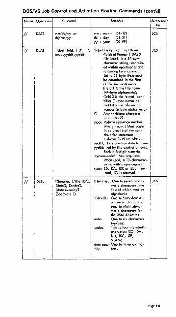
DOS/VS Job Control and Attention Routine Commands (cont'd)
Name Operation
II DATE
II OLAB
II OLBL
Operand
mm/dd/yy or dd/mm/yy
'label fields 1-3' xxxx, yyddd, yyddd,
Remarks
manth (01-12) dd: day (01-31) yy : year (00-99)
C 'label fields 1-3': first three fields of Format 1 OASO file label. Is a 51-byte character string, contained within apostrophes and following by a comma. Entire 51-byte field must be contained in the first of the two statements. Field I is the file name (44-byte alphameric); field 2 is the format identifier (I-byte numeric); field 3 is the file serial number (6-byte alphameric)
C: Any nonblanc character in column 72.
xxxx: Volume sequence number (4-digit num.) Must begin in column 16 of the continuation statement. Columns 1-15 are blank.
yyddd, File creation date followyyddd: ed by file expiration date.
Each is 5-digit numeric. 'system-code' : Not required.
'Iv1-Ien used, a 13-characterstring with in apostrophes.
type: SO, OA, ISCor ISE. If ornitted, SO is assumed.
filename, ['file-IO'], [date], [codes], [date security]
filename: One to seven alphameric characters, the first of which must be alphabetic (See Note I)
'file-IO': One to forty-four alphameric characters (one to eight alphameric characters for the 3540 diskette)
date: One to six characters (yy/ddd)
codes: Two to four alphabetic characters (SO, OA, OU, ISC, ISE, VSAM)
data secu- One to three charac-rity: ters.
Accepted by
JCS
JCS
JCS
Page 4-9

DOS/VS Job Control and Attention Routine Commands (cont'd)
Name Operation
DSPlY
DUMP
DVCDN
I DVCUP
I I END or : ENTER
I
I ! ENDSD
Page 4·10
I !
Operand
xxxxxx
blank ~ -r-
:~s ~~}] FnS PDAREA address, address where n= 1,2,3 or 4
X'cuu'
X'cuu'
blank
blank
Remorks
i Displays 16 byt"" of virtual slo: roge
I Dumps specified areas of virtual i storage
tt-Parometer co"''''' dump on the , SYSLST assigned to the specified
partition. Default is BG SYSLST.
I i
blank:
S:
i 8G, Fn:
i
8GS,FnS:
I
PDAREA:
~",ss, i acldr .... :
I I AR :
1 !
c= 0-6 ':: JCC uu= OO-FE(0-2S4) in hex
I
i X'cuu': c= 0-6 i JCC uu= OO-FE(0-2S4) in I
hex
End of SYSLOG communications : JCe : END for the 3210 and 3215 prin- : AR ! ler keyboards i ENTER for DOC
I Terminates execution of SD aid, program

DOS/VS Job Control and Attention Routine Commands (cont'd)
Operand Remarks [Accepted . by
{ I[[PGM=J progname] [, REAL] C, SIZE=size J]~li PROC= procname COV] J
~PG-=-:--:M'--=-p-ro-gna-m-e-,-o-ne-t-o-'-!e ight a i-
JCC
[symbolic unit], [serial n"mberJ, [type], [sequence numberJ, [relative track]. [number of tracKs], [s"lit cy! 'oder track], (B=!:.:nsJ
phameric characters. Used only if the program is in the core i mage I ibrory
REAL: The resp"crive prosram is to be exec~ted in real mode
SIZE=size: can be ni<, AUTO, or (AUTO,nK) nK : size of area
requIred AUTO: toke program
size (AUTO,nK) : toke
program size pbs nK
PROC=procname; Name of cataloged procedure to be retri",veC. One to eight alphameric characters, the first of which m("'5t be alphabe!:c.
OV: Indicates that overwrite statements follow EXEC statement
;ymbolic unit:
serial nurnbt:r :
type :
I sequence I numb~r:
I relative track:
number of , tracks: I split cylinder
I,tr.ock: oms:
Six alphameric JCS charccte:s i One to six alpna- I
merk characters I One numeric cha- I I"..Jcter i ~;i:':~:t:~ num&-~ <?r.e .'0 five nume- II
riC Character::
,I I
One to rve nume-! ric characters ! One or two nume- I ric characters ! One or two m;~e- I'
ric characters ,
I
I IGNORE 'I blank I Ignore at-r,ormal ~,onditior, iA~
IKC '---" __ --L _____ ---L-____ -'-__ -'-_
Page 4-11

DOS/VS Job Control and Attention Routine Commands (cont'd)
Name Operation Operand Remarks Accepted by
II JOB I jobname [accounting jobname : One to eight alpha- JCS information] meric characters
I accounting One to sixteen
r information: characters
II LBLTYP { TAPE [(nn)]} TAPE: Used when tape files JCS NSD (nn) requiring label infor-
mation, are to be pro cessed and no non-se-quential disk files are to be processed
(nn) : Optional and is present only for future expan-sion (II is ignored by JOB CONTROL)
NSD: Nonsequential disk
I files are to be proces'd Inn): Largest number of ex-
I lenls per single file
(j!J I LlSTIO SYS Causes lisling of I/O assignmenls JCS PROG on SYSLST for JCS and SYSLOG JCC
I Fn for JCC
I I ALL
I SYSxxx UNITS
I DOWN ! UA I I
X'cuu' I where n= 1,2,3 or 41
I, LOG , blank ! Causes logging of job control sta- IJCC , I
temen!s on SYSLOG JAR
! MAP ! blank I Causes a map of area in real and IJCC
I i
virtual storage 10 appear on \AR
I SYSLOG i
MODE I r IR ;AR
CR
11
! I CE, cuu r. I CXX,y]~ I l D [,xx,yJ
,N
! R STATS
Page 4-12

DOS/VS Job Control and Attention Routine Commands (cont'd)
rNo"io~_ra_ti_on~I~ __ o_~ __ ro_n_d ______ r-______ ~_ma __ ~ __________ ~_A_C:~y~Pt_~~-, I MODE I Changes the mode of operation, I : (Cont'd) I changes tile EFL threshold values I I I and gives status inform<Jtion. I I Note: Vv'hen HIR or ECC is speei-
,
! ! tied,-at least one of the opticnal i o~rands within these braces must I be selected. TH is only valid for
I the Model 145 w!'en ECC, Cis
I ' specified with the MODE command . I II MSG {Fn} ! T,onsfers control to m""sage routine
where n= 1,2,3 or 4 AR
, 1// I
i
MTC ! opcode, {SYSxxx1
I
X'cuu' J Cnn]
opcode: BSF, BSR, DSE, ERG, IJCS FSF, F5R, REW, RUN, JCC cr WfM
I I
i i j
N~WVOLi
SY5xxx: Any logical unit II
X'cuu': (only valid for JCC)
c= 0-6 ,",u= DO-FE " (in hex) dc.c. number (01-99) I
! Indicates that a new volume has liAR ; been mounted for the spedfied I partition
I NOLOG I blank I Suppresses logging of job control i JCC I , i I statements on SYSLOG IAR I
I!~//,~~----~I--------~I~I'
OPTION i (~:t~o~ 2, ... J i option : ~:I~O~i:;~ ofthe (5 I i ! : LOG: Log control stote-l ments on SYSLST i
NOL OG: Suppress LOG I DUMP:
I NOiJUMP:
I LINK:
NOLiNK: DECK:
NO DECK :
EDECK:
option Dump registers and I II
temparary real or ' virtual partition enl i SYSLST in case of 'I I abnorrr.al program
end I Suppress DUMP option I Wdte outi'ut of I
~~n~~~rNt~'7;"tof ! linkage eciring. L. Supprcss LINK opti~ Output obiect I maduie on SYSPCH
1 Suppress DECK I
option Punch source PT'IO(;r
definitions en
S,(SPCH
page 4-13

DOS/VS Job Control and Attention Routine Commands (cont'd)
I
I I
I
I
I
Name
I I
Operation
OPTION (Cont'd)
Page 4-14
Operand
I
I
i
! I
Remarks Accepted
NOEDECK
ALIGN
NOALIGN
LIST
NOLIST
LISTX
NOLlSTX
SYM
NOSYM
XREF
NOXREF
ERRS
NOERRS
ACANCEL
Suppress EDECK option Align constants and data areas on boundaries Suppress ALIGN option Output listing of source modu Ie on SYSLST Suppress LIST option Output listing of object module on SYSLST Suppress L1STX option Punch symbal deck on SYSPCH Suppress SYM option Output symbalic cross reference list I on SYSLST Suppress XREF I 6~:;';t listing of I all errors in source program on SYSLST Suppress ERRS option Cancel job if attemp to assign device is unsuccessful
NOACANCEL Await operator action if a device cannot be ass igned
CATAL Catalog program or phase in core image library after completion of linkage editor run
STDLABEL Causes all DASD a
tope labels to be b written on the standard labe I track.
I
by
I

DOSIVS Job Control and Attention Routine Commands (cont'd)
Name Operation Operand Remarks Accepted by
OPTION USRLABEL Causes all DASDortape (Cont'd) labels to be written on
the user labe I track PARSTD Causes all DASDortape
labels to be written on the partition standard label track
48C 48-character set 60C 6O-character set SYSPARM= Specifiesavalueforas-
semblersystemvariable symbol and SYSPARM
[Ill OVEND [comments] Indicates end of overwrite state- JCS ments for a cata loged procedure JCC
VI] PAUSE [commentsl Causes pause immediately after pro- JCS cess ing th is statement. PAUSE state- JCC ment is always printed on SYSLOG. If no 3210,3215 or DOC is available the statement is ignored.
PAUSE [{!!Q} [ EOJ1l Causes pause at end of current job AR
Fn' J step or at end of job where n= 1,2,30r4
PRTY [p I, P2 [, P3 [, P4[, P5]]J] Pn= BG,F 1 ,F2,F30rF4.Allowsthe AR operator to disp lay or change the priority of partitions
VI] RESET {~6G )
Resets i/O device assignments JCS JCC
ALL SYSxxx
ROD blank Causes a II SDR counters for a II non- JCC te leprocess i ng dey ices on the recor-der fi Ie on SYSREC to be updated from the SDR counters in main storage
II RSTRT SYSxxx, nnnn [, file- SYSxxx: Symbolic unit nameofthe JCS name] device on which the check
point records are stored. Can be SYSOOO-SYSnnn
nnn: four character ident ifica-tion of the checkpaint re-cord to be used for restart
filename: symbolic name of the DASDfile to be used for restarting
SET r, UPSI=value 1] valuel:O,1 or X IJCC
[, L1NECT=value21 value2:standard number of lines for [,RCLST=value3J output on each page of SYS LST [, RCPCH=value41 value3:decimal number indicating [,RF=value5] minimum number of SYSLST disk re-[, DATE=value6l cords remaining to be written before [, HC=va lue7l operator warning
Page 4-15

DOS/VS Job Control and Attention Routine Commands (cont'd)
Name Operation Operond ! Remarks Accepted i by
SET [,SVA=value 8] ! I value 4: decimal number indi-
(Cont'd) [, SPl=value 9] eating mimimum number of SYSPCH disk records
I remaining to be I i written before operator , warning
jvalue5: defines to the system , the status of the recorder , fi Ie (IJSYSREC) on
! SYSREC used by the
I RMSR feature
i RF= {YES ~file exists
CREAT create file jvalue 6: in one of the following
formats: I mm/dd/yy or dd/mm/YY i ! mm: month (01-12)
I dd : day (01-31)
ivalue 7: ~'fsT) HC= NO
I , CREATE I
i YES:
~:~~"""""j , NO: No recording i performed I
CREATE: Create a hard i copy file !value 8: storage size in the format I nK, nK for SVA and
i GETVIS area, respectively Ivalue 9: specify CREATE to have
I the system directory list ; (SOL) built in the SVA.
START I
{BGJ
iSome as BATCH AR
I Fn . where n=1 ,2,3 or 4
STOP I blank Stops botched-job progr. processing JCC i filename, ['fiIe-ID'l, filename: One to seven alpha-[date], [file serial I meric characters, the number], [volume se- first of which must be quence number], I alphabetic [file sequence nUmberJ'I'file-ID': One to seventeen ai-(generation number], phameric characters [version number] Idate: One to six characters
i (yy/ddd or d-dddd) i
JCS I
I I I
r
Page 4-16

DOS/VS Job Control and Attention Routine Commands (cont'd)
Namej Operation 1 Operand I Remarks I Accepted i by
II
II
I
!
TLBL Note: For ASCII file 1 (Cont'd) processing the fourth I
and fifth operands are ' called set identifier and file section number, respectively !
Cfile serial number (EBCDIC): } One to six alphameric charac-
~;~~dentifier (ASCII) : Six I a Iphamer i c characters] I
[volume sequence number n' (EBCDIC)J •
g~~e t:e~~~~nn::~i: ~~;r~~I;eJrs I
file sequence nur:ber : One to four! numenc characters I
generation number: One to four ' numeric characters
version number: One to two numer i c characters
TPLAB 'label fields 3-10' ! 'label fields 3-10': Indicated JCS fie Ids of the standard tape f!le
label for either EBCDIC or ASCII. A 49-byte character string, contained within apostrophes
I TPLAB 'label fields 3-10 C i label fields 11-13'
'label fields 3-10': same as above 'I JCS C: Any nonblanc character I
i
UCS
in column 72 I label fields 11-13' : 20 character I
~~:e~~;:~~:~:;!:~ s~ingi begun with fields 3-10 : (no blanks, apostrophes 'I'
or commas separating)
SYSxxx, phasename ! Causes the 240-character universal [, FOLD] L BLOCK] character set contained in the core [,NULMSGJ I image library phase specified by
phcsename to be loaded as buffer storage in the IBM 2821 CU. SYSxxx must be assigned TO a 1403 or 5203 Printer with the UCS
I feature.
JCC
I UNBATCH: blank Terminates foreground processing I JCC
II UPS I ; nnnnnnnn 0, lor X i JCS
II VOL SYSxxx, filename SYSxxx: Can be SYSOOO-SYSnnn i JCS filename: One to seven alpha
meric characters, the first of which must be alphabetic
I i 1
Page 4·17

DOS/VS Job Control and Attention Routine Commands (cont'd)
Name Operation
// XTENT
! I
i I
;
!
Page 4·18
Operand Remarks
T
'ypo, re"","", '_'I "'" 1 for data area (no upper I 'serial no. I I split cylinder) SYSxxx [,82] 2 for overflow area
(for indexed sequent ia I i
i i
I
I i
i
file) 4 for index area (for indexed sequential file) 128 for data area (split cylinder)
sequence: sequence number of extent within multiex-tent fi Ie. Can be 0-255
lower: Lower limit of extent in the form 8
1C
1C
1C2
C2C2H1H2H2 where: 8
1= 0 for 2311 or 2314/
2319; 0-9 for 2321 C
1C
I = 00 for 2311 or
2314/2319; 00-19 for 2321 C
2C
2C2= 000-199 for
2321 or 2314/2319; 000-009 for 2321 H
l=O for 2311 or 2314/
2319; 0-4 for 2321 H
2H
2= 00-09 for 2311;
00-19 for 2321 or 2314/ 2319 Note that the last four strips of subcell 19 Ire reserved for a Itemate track for 2321
upper: Upper limit of extent in the same form as for lower limit.
'serial no. ': 6-olphameric-charc-ter volume serial number contained within apostrophes
SYSxxx: Can be SYSOOO-SYSnnn B2: 0 for 2311 or 2314/2319;
0-9 for 2321
Accepted by
IJ
;
I

DOS/VS Job Control and Attention Routine Commands (cont'd)
Name Operation Operand Remarks Accepted by
II ZONE PAST}
EAST: A geographical position JCS VIlEST. /hh/mm east of Greenwich
WEST: A geographical position west of Greenwich
hh/mm: A decimal value which indicates difference in hours and minutes between local time and Greenwich Mean Time. hh may be in the range 0-12; mm in the range 0-59
/+ ignored [comments] Indicates end of procedure JCS
1* ignored I ignored Columns 1 and 2 are the only JCS I co lumns checked
1& ignored [comments] I Columns 1 and 2 are the only co lumns checked. Comments appear on SYSLOG and SYSLST at EOJ
* comments Column 2 must be blonk
Note 1: If the DLBL and EXTENT statements for a private core image library are in the input stream (that is, the information is not contained on the label cylinder), they must precede the ASSGN SYSClB command.
Page 4·19

DOSIVS POWER Commands Task Management Console Operator Commands Source: SY33-8571 DOS/VS Handbook, Release 29
Operation Operand
S [xx JRDR, [cuu ][,b] START S [xx ]RDR, [cuu ][,b],
rfilenome'J, [vols], [S J S [xx ]RDR,cuu, [b ], cuu
I S [xx ]PRT, [cuu ][,b ] I S [xx ]PUN,[ cuu ][,bp J S [xx ]PUN,[ cuu], [b ],RESTAR
S [ xx ] ~RT ], [ cuu ], [b ]' [tit J PUN bp, zzzz
S RJE, cuu, [~~]
3780 S RJE, cuu, [Er540, cuu
P [xx 1yyy, [cuu 1,~EOJ J STOP CHECKPOIN
P cuu,[.EOJ ] CHECKPOINT
P RJE,cuu
G [xx 1yyy[,cuu 1 REACTIVATE G cuu G xx G RJE,cuu
C [xx ]yyy[,cuu] CANCEL C cuu
I
F [xx l~RT ], [cuu ] [,ALLJ I FLUSH PUN
F cuu[,ALL 1
M [xx] PRT ,[ cuu ][,nn J DISPLAY/ PUN ALTER
M cuu[,count]
T [ xx ]PRT ,[ cuu ][, count] RESTART
T cuu [, count]
E (no-operand) END
E KILL CANCEL
Comments
Reader task Reader task for diskette Reader task for reader/diskette Printer task Punch task Punch task from checkpoint Tape writer Class writer RJE task
RJE simulator task
Reader/writer task
RJE tosk
Reader/writer tosk
Batch portition RJE tosk
A reader/writer tosk
A writer task
Copy counter nn= additional copy
value (1 to 99)
Print write r 1 to ~] task count= -1 to -999
1 to 999 s
POWER system partition
With DUMP
Note: Omission of [xx] denotes partition independent reader/writer task
Note: xx = BG or Fn yyy = RDR,PRT or PUN cuu = Unit record or tape physical device address zzzz= Clau(es) to be assigned to a writer task (one to four alphabetic)
= Job output Class (A through Z) n = Priority 0 through 9 ttt = Tape address (cuu)
Page 4-20

DOS/VS POWER Commands (cont'd) Queue Management Console Operator Commands
Operation Operand Comments
A xxyyy, jname, [jnr J,priority-n TALTER job priority in a specified
i queue to priority n (n={)-9)
T DISPLAY job status in a specified D
~'r~"i~]) I
queue of a specific job ALL All jobs HOLD all jobs in hold stotus FREE a II jobs I'IOt in ho Id status Pn I all jobs with priority n(n={)-9) RJE all RJE jobs LOCAL I all local jobs CLASSz all jobs with closs z (z=A-Z)
D A active reader ,writer and RJE tasks
D B available program and data buffers
D Q free JCT records and track groups
D T system time and dote
HOLD in the specified queue H XXyyy ,{ jname[, jnr l} a specific job
ALL ALL jobs Pn all jobs with priority n
(n= 0-9)
DELETE from the specified queue L XXyyy ,{ jname[, jnr l} a specific job
ALL ALL jobs
RELEASE from the specified queue R xxYYYfname[, jnr l} 1- a specific job
ALL ALL jobs Pn all jobs with priority n
i (n= 0-9)
I JOB only valid if ACCT= YES
I cuu generated
J punch ACCTFIL records to I card unit cuu and delete
ACCTFIL J tit write ACCTFIL recores to
tape un it ttt and de lete ACCTFIL
J DEL delete ACCTFIL
Z DUMP,[TIB,QFL,DFL 1 I Monitor option Z TRACE, [SVC, TSK 1
I
Trace option Z {DUMP },LST liat trace option
TRACE Z {DUMP },END Terminote trace option
TRACE
Note: = BG or Fn yyy = RDR, PRT or PUN
= Un i t record or tope phys i co I deY i ce address = Job output Class (A through Z) = Priority (0 through 9)
Page 4-21

DOSIVS POWER Commands (cont'd) RJE Management Console Operator Commands
Operation Operand Camments
rrmid } BROADCAST Send a message la a
B M, ~erid , 'msg' specific user or to ALLUSERS all terminal users
(ALLUSERS)
r·"Od ) B L, userid[,nrl De lete message(s) for ALLUSERS[,nr 1 a specific user or all ALL messages (nr= 1-99)
rrmid[,nrJ } Display message(s) for a B D, userid[,nr] specific terminal user
ALLUSERS[,nr] or ALLUSERS (nr= 1-99)
INQUIRE about RJ E task status for I U,userid a specific userid I T,termid a specific termid I L,cuu a specific line I ALL ALL valid terminal
designations
["""" II J
CHANGE 0 jname, I jnr I, userid , PRT OUTPUT destination of a job
ALLUSERS , PUN to a specific user, to LOCAL a loca I autput dev ice
or ta all terminal users on a read only basis (ALLUSERS)
FORMAT OF Q's [,AUTOSTART ] ?
Explanation:
Operator response:
Page 4-22
!~~I_~ ckll'ing pt"Jrlition initialization and is in two parts: 1) Format Q's - format queues or warm start 2) Autostart - (only is specified as a generation option) whether
the reader/writer devices should be automatically initiated or nat
[Q,][D,][A,][~~] (EOB) where
1) Response to format Q's is Q- format af Q'ILE records. D- format DATAFIL and Q'ILE records A- format ACCTFIL records These parameters may be specified in any order. If none of the above is specified, no formatting occurs
.. 2) Autostart IS speCIfIed CIS •
YES - Initiate reader/writer devices. Default is amitted NO - Da not initiate reader/writer devices
I
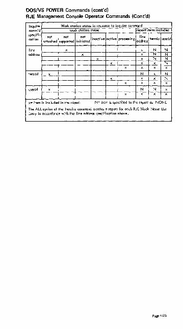
DOS/VS POWER Commands (cont'd) RJE Management Console Operator Commands (Cont'd)
comlnqumir~dr-__ ~W~~~s~ro~t~io~n~st~a~t~~in~r~~~p(on~se~to~i~nq~,u~ir~e~c~om~mra~n~d~~~.-~ work station stat~ report items included
specifi-cation not not not inactive active proc=ing adldinr·eess termid userid
attached supported initiated
line x I N N
address \----t---+--"--+---\---+-----+--C..:.-f---.;'-'-.-+-.:....:........ N N N N
N
termid N N N
userid N i N
x= item is inc luded in the report N= item is specified in the report as NONE
The ALL option of the Inquire command creat~ a report for each RJE Block Name List Entry in accordance with the line address specification above.
Page 4-23

POWER Commands (cont'd) RJE Workstation Commands
ID Operation Operond . .. RJSTART termid, [BRDCSTI, [termtype~ [bufsize), [nopunch ]
* .. RJEND {no operand \
* .. LOGON userid
* .. LOGOFF (no operand)
* .. OUTPUT [jname[ jnr J] ALL ALLUSERS
* .. CONTINUE BEGIN
NO HOLD LOCAL PAGH,count]
* .. CONTINUE (no operand)
* .. DELETE xxyyy,{jname[,jnr J}
ALL . .. STATUS
~"'r~~jmJl HOLD Pn ALLUSERS ALL . .. BRDCSTR (no operand)
* .. MSGR I M,'text'
Page 4·24
Comments
Attach a workstation
Detach a workstation
Begin a user session
Terminate a user session
Request a specific job output ALL output for userid All output for ALLUSERS
Request discontinued output from beginning Delete output for the job Hold output for the job Change destination to local writer Page forward or backward printed
0"',",; r ro '''')
I Count= -1 to -999 pages
1 to 999
Resume with interrupted data black
Delete from the specified queue a specific job ALL jobs
Display job status in the specified queue of a specific jab ALL jobs All jobs in hold status All jobs with priority n (n= 0-9)
Reques t broad cas t messages
Send message to console operator

VS1 Operator Command Outlines (VS1 Release 3) Source: GC24-5091-3 OS/VS1 Programmer's Reference Digest
Operation Operand
f [DUMP['ALl[ [jBN=! jobname* 'IN[=i ] I, USER = useridl
=HOLD
[=s ] rA~CEl} 1 ,OUT =HOlD
IDEV = I unitaddr' devicetype *
" [procname,! identifier *
• May be specified up to five times if separated by commas and enc losed in parentheses. Can be combined with the other para-meters thot are allowed to be specified up to five times_
{DE~NE} [LIST ] PARM=membername
, T
A
r J
,GRAPHIC ,ONLINE U ,TAPE LOFFlINE]I,CUUI/,nnn l
,DASD ,UR
R [,USER=userid] ,All
(Alll,l] ~ ACTI,ll
{DIS~LAY} RT IINACTI,ll
> ,TERM=termid [,device]
tHI=qclassll, USER= useridl} Q i,AllQ] jobname* [,HOlDI CONSOLES
fN=c1ass ' P IN='stringl,string .. ·1'[,All] ~
, OUT=c1ass 'OUT= 'string[,string ... 1 '[,All/,
SQA
USER[' l . ~ I =usend_
• May be specified up to five times if separated by commas and enclosed in parentheses.
DUMP [textl
t~LT} EOD
\fll l ' {H~LD}
IN[":"d~,[ [JON[ j Q I=mclassl ' OUT[=outclassl ~ jobname *[, OUT[ =outclass[outclass .. ,11][, USER= useridl
* May be specified up to five times if separated by commas and enclosed in parentheses.
{lISl~BC } [NOTICESI[,MAIL/ = useridl1 [MAlll/= useridJ [, NOTICES I
{l~G} 'text'
lOGOFF [useridl
Page 4-25

VSl Operator Command Outlines (cont'd)
Operalion
LOGON
MODE
Operond
userid t/posswordJ[TERM (lermid)1 [PROC (procnamell [NOTICES 1
LNONOTlCESJ
[MAIL ] NOMAIL
{
STATUS } RETRY,{RECORD}
QUIET MAIN,{RECORD}
QUIET CONTROL,/THRESHOLD}
\QUIET
Note: Blanks may be used in place of the comroos. in this commcmd.
I \' JOBNAMES\, Til ' DSNAME
{'''C~~C'} i i F~;:s \ I \ SESS\, TI
I {~~;(display-operOnd, ... )I,MN=AI[,KJ)} •
! DISPLAY = \U[STOPI 1)1 {PAGpETTUNE} II \PAGEMEASI
\REACT! \STATUS!
i
I
{PAG~;UN'} I
Page 4·26
I I
{
'( [A~~:] frequency\, In = frequency!, .. I .... }'
PAGEMEAS= frequency (frequency) SYS (SYS)
\
' [ALL;j{time } [ 1ti~e i] \ ( In; (time[,\pogetron] I) ,In- (tlmE'\,\pogetrcnlJ)\ ... ) (,pagetran) . (,pagerran) j
REACT; time (time ~,[ pogetranl]) (,pagetron) SYS (SYS) .

VSl Operator Command Outlines (cont'd)
Operation
I RELEASEI t A f
IREPLYI ) R i
(RESET i ., E I
(ROUTE, , ,0 j
,SENDI I SE i
Operand
ALL \ c
l IN I = inclassi . 10 1= inclassi \' ,JoN I OUTI=outclass "
iooname *[' OUT L :::out':.lossi.ourclass. . :J]' ,USE' = u,erid, \
"" May be specified up to five times if separatea by commas and enclosed in parenthe::.es.
! . • JPRTY=nnll,OUT=s!i,USER~"serid! ,obname ')CLASS=c(
"" Mey be specified up to five ~irnes iT sepo;Qted b,' commas anci ene,lased in parentheses.
[JBN = iobname][, GROUP= (cicss,class ... ,l] ALL
: I USER;:;: .,;serid i ~I CLASS = cloSSi ',DEST = Jserid' [, HOLD=, YES,1
·'Noil r,ALL 1- NOVI :
',e<t' l' L;SER= (userid i, use rid ... til : LOGONj' ,OPERA TOR = routocode JL, SAVE
.71e,,0ge no. r 'DLiESLT_TFJ1 , _, t,_
-_.--+--\S~T:. ! DATE=yy.dddICLOCK=hh.mm.ss,
(START, I S J
'STOPI , P '"
i \ JPnn' ( l : . procnome··'AUf liunitaddr ] r I . I I ! i . _. ~ I,Lde'Jicetype 11 va serio I
1
,(porml
i r'f~~s::~~::,'~c~s>,) , I (lNT,S)·
,\ r ",ode ~ liNT I]' TIME = YES II, DEBUG = YESII, BUF = nnn,)
L IEXT \
lr, .'~z:;ll,,'D=x' c IKEEPIJ :,USER=useridl !,keyword::::option t • i",
* The ~eyword=oprionol poror:1eferts: can follow after ~he los~ positior.al parameter. /,./o.cy be replaced by: :,PARM='SV/A=nnnn, RESV= nn'l.
IIProcname. i.J.iaentifier*I.:;USERO:O.Jserid;,.
I. Pnn I
unitoddr><
I ~o~~~'7~ES f DSNAME SPACE
Ii ~T~o~S be specif:ed up to five rimes ;f separated by commas
end enclosed in poren~heses. Con be ccmbined with the other parameters that are allowed to be specified L:p to five rimes.
Page 4·27

VS1 Operator Command Outlines (cont'd)
Operation
1
1 JOBNAMESl' DSNAME SPACE STATUS A SESS
Operand
~------~~------------,--------------------,-------
(OFF }
t ~~addr, cuu
eWIITCH} SMF
~--------~~---------------------------------------{UN~OAD} unitaddr
~------~~----------------------------------------
{WRITER}
WTR
Page 4·23
I ',ONliNE i
{unitaddr } {,OFFLINE ~ (un itaddr , unitaddr ... ) ,PATH,cuu,{ONLlNE}\
OFFLINE,
{unitaddr } MSTCONS (1-cuu,O-cuu) ,
{~~i~~~;}, HMOCPY [: ~~~Dsl ,OFF ,INCMDS J ,STCMDS
r (ALL 11
l,ROUT=., NONE >J '(rautecadel, r.)Utecadel .. ,»
IFsp={~n} 1
{non}
BSP~ os unitaddr "llSp={~r \' I,JBN = jobnameil, USER = use,;d
l
HOLD
REPEAT={~~';.",J08)} J

Definitions of Substitutional Operands
class
device
devicetype
frequer.cy
hh .mr:1.SS
one input lA-Z, 0-9) or output (A-Z, 0-9) class.
one to fifteen job classes (A-Z, 0-9) without prioriries.
the channel o!')d unit address ~cuu) on an I/O device.
symbolic remote device address used ot RES workstation.
a unit type, such as 2540 or 1403, of the output device to be used.
a four digit decimal number indicating on error count.
the number (0-9) or task dispatchings ccc..;rring before invocation of the !=loge m€:asurement routine.
hour (00-23), minute (00-59), and second (00-59).
a single input class.
id a two digit identifier that is identical to the identifier included in the system message.
identi~ier a unique one ro eight character alphanumeric name that starts with a letter and identifies one task started by a cataloged procedure.
inc lass one to four input queue classes (A-Z, 0-9).
I-cuu, O-cuu the channel and unit addresses (cuu) of the input (I-cuu) and output (O-CUI,..:) devices that make UP a composite console.
jaeclass one to fifteen job classes (A-Z, 0-9). Priority of processing is from left to right.
jobname the nome of a specific prob lem program that appears on the JOB statem~nt .
i keyword==option any voli~ keyword/option combinction that may appear cn a DD i statemem.
! :evel the in-use qu position (1-9 or N) on the STOP line.
a single digit decimal number.
a one to three digit dec imal number.
I outclass one TO eight output classes (A-Z, 0-9).
O-cuu the channel and unit address (cuu) of on output only console.
pogerran a number (,0-255) of poge trans~ission operations (page-ins and page-outs).
Pnn
procnome
qclass
! routecode I
! teXT
t ti:Tle
I ttrt
unitcddr
yy.ddd
jnforma~io:1, of variable formar, to be passed to a problem program.
a partition number (POO-P15).
the nome of a cataloged procedure that resides on SYS 1 . PROCLIB.
one to ~al,;r queue classes (A-Z, 0-9 for input queues, sour for the output queue, HOLD for 'he hold queue).
a system-~o-operotor message routing code.
c single output class IA-Z, 0-9).
information o~ extremely variable format.
c real time :nterval in seconds (0-9).
a four digit decimal number indicating on hour limit.
the channel end unit address fcuu) of an I/O device.
the volume serial number of a disk pack or magnetic tape.
a recording mode: either R (.record) or C {quiet}.
t"e year (00-99) cod julian day (000-366).
Page 4-29

VSl Message Routing Codes Source: SR20-1091 OSVS1 Basic Operations -Illustrations
System Code Definition
Master console acti"" (01 F) Master console information Tape area (01 C)
DASD area (009)
Tape library DASD library Unit Record Area (OlD)
Teleprocessing equipment status System Security
10 System Error Maintenance 11 Sysout device
VS2 (JES2) Message Routing Codes Source: GC38-0210-1 Operator's Reference
System JESZ COOP. Cod~ Definition
lOG Hardcopy log MAIN Master console action MAIN Master console information T,A,PE T~p.c poo~
TAPE Direct access pool TAPE Tape library TAPE Disk I,orary UR Unit record pool TP Teleprocessing control
System security 10 ERROR System error/maintenance 11 Programmer information 12 Emulators 13 Reserved for customer use 14 Reserved for custorrer use 15 Reserved for customer use 16 Reserved for future exoal1sion
Page 4-30

VS2 Operator Command Outline (Release 1.6) Source: GC24-5091-2 OSNS Programmer's Reference Digest
Operation I Operand I
devicetype I r"fi~ 1 I {C~C"l unitoddr
'~;~T'"",,,]]'A"-]J jobname ,IN[;i]
,OUT[=5]
{CO~TROL} , C, D, idd(, L=ccl
I t 1 [" ] I
,GRAPHIC ,OFFLINE
U ,mE [ ONLINE l]'~II'M"] I
,DASD '
{DISbLAY} ,UR
CONSOLES
I I jobname R
I l Q[=qcla .. l N[=qc!assl C,K
DUMP COMM=(comment)
{H~LT} EOD I
fHOLD} 1 H
{ ~[=indassl } !obncme
{L~G} I
It2Xti
r~AM 1 i ""iY',J{~,~Dl MODE MAIN[']{~~I~:D}
CONTROL[ l{THRESHOLD} J ' QUIET
r~~'~~ ) ,CLASS=jobclass
i MODIFY} --~.]"-"., l'QAS-:: l I F
l ,PAUSE= {DATASET}
\ JO.NAMES], Tl ( {MONITOR} (DSNAME
MN I SPACE STATUS
Page 4-31

VS2 Operator Command Outlines (cont'd)
Operalion Operand
{MO~NT} 1 '1 dd (' VOl=(SL,serial) 1 [ (STORAGE I ] ~:~iaC.",'ame\ ,VOL=(AL,serial) ,USE= tUBLlC,
,VOL=(NL,serial) PRIVATE \
{M~RT} t ~~display-operand, .•• ) ['L={~~}J!
jREL:-SE! l~ass]i
~RE~Y ! id,!']text!']
lR~LY ! f ~TOR=(.lartoddr,.ndaddr, ••• )[, SDATAI}
i (used for SOATA '
DUMP)
lRE:ET ! ~,PRTY=nn } i iobname ,CLASS=c [,OUT=s1 I ,PRTY"M, CLASS=c I
I
j5fl DATEzyy.ddd!,CLOCK=hh.mm.ul
lST~RT ! procname[.identifier] I,euul !,volumeseriol] I,parmvalue] 1 !.jobnamel !.LSQA=nnj l.keyworclo<option .... 1
I jGTF I [. ident;fierl [.Ieuu], [volumeserialll i, ( [ MODE= n%~. 5)\ ] I
GTFSNP r i] ] [.8UF=nnnl [, TlME= 1~6( I DEBUG: ~~ ) !.REG=nnn]
\ STOP I \ {proename. lidentifitu I
I I p \ j jobname' (
JST~::N ( ! 'C'NAMES l I DSNAME SPACE STATUS
I
JS~AP ! {OFF }
~~addr,cuu I SW:TCH! SMF
1 UN~OAD( uroitaddr ! lV~Y I ~ uniladdr ~ r { ,uniladdr ~ 1 I \ ( O-cuu ,O-cuu. • •. )
t (I-cuu, O-cuu) , L • (I-cuu, O-cuu) ) J ! {ALL 1 l
AUTH- INFO • ([SYSJ[.IO](,CON5]) f
rLL
} ,CONSOLE • ROUT- NONE
(routecode!, routecodel .•• )
ti"'ddr } J ' ALTCONS; O-euu (I-cuu.O-cuu)
Page 4·32

VS2 Operator Command Outlines (cont'd)
Operation Operand
~ unitaddr I tNlIN
' IONlIN<! l lV~RYl ,OFFLINf (unitaddr,unitaddr ••• ) i ,PATH,euu,
OFFLINE
t~RY\ ~unitaddr (,MSTCONS (l-euu,O-euu)
~ VARY I j'"'''''''''oav [rCM~ !] I V SYSLOG \ ,NOCMDS ,OFF ,INCMDS ,STCMDS
[ROUT: I~~NE }] . (rauteeode(,routeeodeJ ••• ).
~WRIT~LOGI i ~LOSE (
Page 4-33
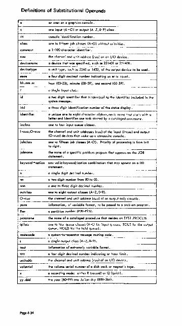
Definitions of Substitutional Operands
f----------------on oreo on a graphics console a -1
class
comment
devicename
devicetype
hh.mm.ss
id
idd
identifier
inelass
l-cuu,O-euu
jabclass
jobnome
. keyword =aplion
one input (A - 0) or output (A-Z, 0-9) class.
console identification number. I one to fifteen job classes (A-O) without prioriti~~ ____ ----l a 1-100 character identifier. I ----------11 the channel and unit address (cuu) on on I/O device.
a device tho' was specified, such as 231401 or 2~n400.
a unit type, such", 2540 ar 1403, of the output device ta be used.
a four digit decimal number indicating 01'1 error count. -----------~
hour (00-23), minute (00-59), and second (00-59).
a single input closs.
a two digit identifier that is identical to the identifier included in the system message.
Q three digit identification number of the status display.
a unique one to eight character alphanumeric nome that starts with a letter and identifies one task started by a cataloged procedure.
one to four input queue classes.
the channel and unit oddresse. (coo) 01 the input (I-cuu) and output (O-ouu) deviCe> that make up a composite console. i
one ta fifteen job cia ..... (A-O). Priority 01 processing i. ~ to right. I the name 01 0 specific problem program that appears on the JOB i statement. ~
on~ valid keyword/option combinatiOl' thot may o~r on a DO l
statement. I
~-----------------------------~ a single digit dec imal number. i
-------------~,I a two digit number from 00 to 03. '1' a one to three digit decimal number.
autclO$$ one to eight output classes (A-Z, 0-9). I ~O-~-u-u-------t-he-c-oo-n-~-I-mm---un-it-~--r-es-.-(c-uu-)-o-Ia-n--o-uI-pu-t-a-nl-y-con--so·-Ie-.----~
pann information, of variable format, to be passed to a problem program. I
p"" a partition number (POO-P15).
~pr-oc-n-ame----t-he-n-Q-me-of-a-c-ataloged procedure· that resides on SYS1.PROCLIB.
qcla.. one to lour queue classes (A-<J r"r input q"eue., sour /0' the output !I
queue, HOLD for the hold queue). .
rautecade a 'Y'tem-to-operotor messoge routing code. ~
a single output closs (A-Z, 0-9). I ~te-xt __ -------i-n~-rma--t-ia-n-o-f-ex-tr-e~~ly~v-a-ri-ab-le-f_o_rma_t_. ___________ . _____
ttlt
unitoddr
a Four digit decimal number indicoiing an hour limit.
the coonnel and unit address (cuu) of an I/O device. --
----------j volserial ~he volume serial number of 0 disk pack or magnetic tape. f------------.------------------~----~---~------~
a recording made: either R (record) or Q (quiet). 1------
yy.ddd the year (60-99) and Jul ian day (000-366).
Page 4·34

VS2 Operator Commands (Release 2) Source: GX38-0227 QS/VS2 Command Language Reference Summary
I I
Command
lCANCELI c i
I ; CONTROL I 1 K i
i
I
I i
i
Parameters
( .1 iObn'. me t [,DUMP] J , U=:Jserld\ ~
.: Ide.~tlher , Jdevocenome ) { umtname
oPtfOn 1 IS:
ALLPSA PSA NUC SOA LSOA RGN LPA TRT CSA SWA
/ C,D,id[,L=CC J
,H [.L=cca 1: D ll:~' ~OLD l l! JJ
:PFK
g fe,nnl. 1 ,~ I
I :~I ,D[,L==JI
lfFK J
1'>.[[.00].'1 ,NONE
,~
.UTfIf.E-n:1n L,L-ccJ
option2 ;s
ALLSDATA NUC SOA LSQA SWA CB
E"O
option3 is:
ALL?DATA PSW REGS SA or SAH JPA LPA ALLPA SPLS
T [ ,!illJ ~L=CC rJ _ ,]
N,PFK=lnnl \ ,CMD",." [ ,1m 1· . ( I [ ,CON= 1 ~ (J l ,KEY=rH'2 [.nn2 j. .. ~
V,USE= I Fe ( [,L=CC J J ISO \
~~~,--I~~-------------Page 4-35
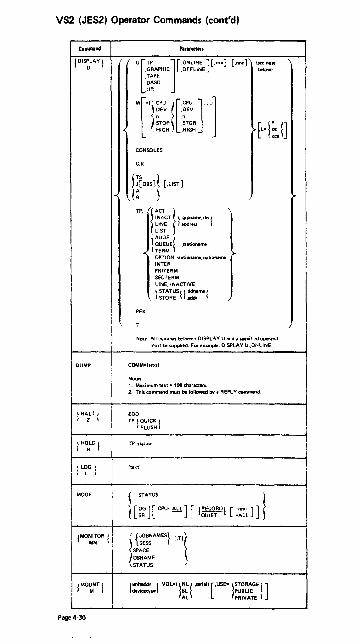
VS2 (JES2) Operator Commands (cont'd)
Canlllllnd Panmet". jDI~LAY ! r ru
", ][.n] [.nnn] {see note
.GRAPHIC .OFFLINE below!
.TAPE
.DASD
.UR
Tl~ ~[? 1] STOR .STOR
[L'l~n . HIGH .HIGH
CONSOLES
C.K
1-< WOBs]l [.LlST]
TP. rCT
}
I NACT l ",poIme,rln t LINE Iddress LIST
\ADDA ( ) QUEUE .S1l1iOlllme
-< TEAM ,. OPTION. Sl.,jonlmt,uplion.,..,. INTER PAITERM seCTERM LINE. INACTIVE
l ~~~~sll:;;me! PFK
-; J
Note: All comOlM between DISPLAY U and I specif,ed ope .... nd
must be supplied. For ex~. DISPLAY U"ONlINE.
DUMP COMM·' .... )
Not": 1. Ma.ICimum lUI· 100 chIrlCten. 2. This commiOd must be followed bY I REPLY command.
I HAZLT! EOD
TP'l~~~~~1
HOLD Tpz:::stltion
'tellt'
L 1
MODE ~ STATUS l [~;][.CPU'~ ] ['j~~TRD! [:~n:L]]
lMO:~OA ! I {=~~) '"I SPACE
(DSNAME STATUS
lMo~t! jun_ I ,VOL" fL( ..... i.1I [.USE·lSTORAGE I] doYic:otype SL PUBLIC
AL PRIVATE
Page 4-36

VS2 (JES2) Operator Commands (cont'd)
Command Param01llIS
1 MO~'FY I [o<""n • .". [.kl.nti'i .... J
L For TCAMOnly'
1"5: 1 ~~:T I [.membe,]
ACTlVE= 1 :!,"':': i [.IDLE ]
AUTOPOll= ~=::e,rint 'l~~Ff
TRACE={ 9,,,,,.me.rln.) ~~F! [ ..... bbbob ] l 1 odar.,..) ~~ F f .•••. bbbbb ~
INTERVAL= 1 SYSTEM [.dat. ] \ POlL.st3tioname,dat3, ~ ~ t
DEBUG= l~ f
BACKUP" l :;e: ~
BHSET=stat,onaroe.j ~! [ .. a. ]
!l
-< LOAD'- ~ ::: f ,text
OPERATOR'" ~~~~n~me ~
SESSION:.grpname,rll1,aaa
TRANLMT=sti:ltionamc.aaa
DEACT= ~ ::;:e ~ ~ ~~~~~ }
1
l)UMP ,
IPL
TIMEDAT( CHArJL
SWITCH
SWAP-=concentrator .stationame 1 ~"tatloname2
OPT=stationame,option,data
l. ladd,,,,, \. 15 \ INTENSE= ( LINE. Igrpname."nl'} {sense. loountt}
t TERM=statiOf'lamc -
SWBACK= (ddn .. n-.e 1,ddname2 }
tadd<eo;1'-'~
~or External Writer OrrIV:
[I (.CLASS=lclassesl I) .JOBID=ljob-id]
.WRITER= [STDWTR ] user-wrlter-name
.FCRMS=[forms-na~~
)
lDEST= [~~:L_Kstation-nan-eJ PAUSE= {FOR"S }
DATASET
>
I
J Page 4-37

VS2 (JES2) Operator Commands (cont'd)
Command
OUIESCE
,REPLY t , A I
jSEND ( , SE I
I SET t T'
jSTART ( 5 I
~ STOP"IJN ~
I' PM
I
TRACE
Page 4·38
Parametl!fs
j 'I:"~'I ["1::'1]] ,'f
L- [ " 1 !~~:op [,do. j I I[ ,L~ E:J r] REF
::E
;d 1 :~::D~nnnnn, {' I.SDATAI~loPtlOnl.op,",n:, 1",li}!' .JOBNAME::nitRle I.STOR;::/btg,tndlbeg end) .
,SOATA(=OPilon\.OPtlonl .. ' I
,STOR==(beg,endt,begendl .. ,)
where DPtions are.
RGN
~ SQA
LSOA'
~,i" ~ ~fault values tor U CSA or SDATA WI,hout.,.
~
I ~otes 1. AU bu, IC, texT 's lor LJUMP repl" only
2. II te"llslnapostrollhes.SYStemwllln~lchange 'OWPlca~(I 10 ,llllll"rC,1' .• '
lobname.PE~FORM 'I1IH'
\
1 i::~',o: lr [~~~R'lu .. ,," ,0""" , I J {[~i:ONJ }j11 .BADCST ,OPERATOR"'rtcodt
'I '"",,0 [ ,l/':TN,con]'Ole I' ,DELETE
LIST
~ ~:~i;V"'.ddd!,ClOCK=hh.mm.'5Llps=nnl It
I lprocname(.,dent.'tp..].[de¥lc:tn,mt'],]
i L[.o,U"""'''''lj,[ ........ ,uej[,ktYWO'd'O.';o"j
ii, \ ~~F ( ixxx;vvy\
whe-re 11101. is "from" unit IKWressiiI1ld
VVyis"to"unltaddre-ss.

VS2 (JES2l Operator Commands (cont'd)
eo-d ........ I TR.;"RCK! l~oBS]{ ['l[IST]]['l')~I]
1 UNl~AD I unitaddress
lVA~Y ! I) un;toddr... ! ['un'Wdr~ l"l (l.un~.O-unit)
O-unlt
,II-un;',o-un;,l ,a-UOIt
LrNllNE !
=l'""T" I] :[~es ][,10 ][,CONS] I
,ROUT'rlL !
NONE rtcode[,rttode)' ..
,Al TCONS· 1 un;!Oddross I (l-unit.O-unid O".Jnit
~~I~~;':nit)t ,MSTCONS
[~--l"AAO=T~Mn SYSlOG ,INCMDS ,STCMDS ,CMOS ,OFF
L- ['ROUT= tLL ! ] N~~(.rtcode] ... l
rddddk,dddddk ( 1 :~~;~~~E I STOR { xxxxxx.xxxxxx ) ddM,ddM
fPU(X' } l,ONLINE I CH(xl,v] I ,OFFLINE [,UNCONO] PATH(dad,xl
lineaddre&S,1 ONTP t OFFTP'I~ I
~'-l :::{ll:l\ gpstat;oMame, {ONTP }, {E}
OFFTP B
f9rpname,dn,) ,{ ONTP }
.. ,:~:: J omp, {~} lWA'T!lOG! [STAAT] CLOSE
ciass
Page 4-39

VS2 (JES2) Operator Commands (cont'd)
eo. .. nd ParlmettfS ! SA l' . I f:-([ ~ 1·1 II 'JObname' .'fObnamt
So 1..,1 .50 1..,1 Tn I·nl .To I·nl I
$8 1 ""0 11'1['''0 I'II l I ) An.PRn ,D ,Rn.PRn ,D I I ~~~~n! I :~! [:~~~"un I :61 J I
$C 11. I I =~.:~! [:=~.:~] ... l:;~.."unl [:~~] ."
I ::~':m ! [:::~AJ .. r I·nl 1 [,0] ·~.me· .p SrI (.n)
Tn 1..,1
$0 I[n I·nl]
1 "·1..,1 :",.....
0
I A G~~] I.JOBII.STCII.TSVI
F[.nl..,llJn Inll[.H]
~ :;! J .A
r Inl} [.In 1..,1] 50 I·nl Sn Inl Tn (-nJ .Tn r.nl
.jobno .....
[L'l~!] I: I [0 ,., 1 r'" I :;:: I (
I TSU \
I OUT
I He'110 .
I
T' 1 I
.lNEn ! r I PATS I
.PUNS I
I I .AMTS !
,RMTn I ,RDRs
I .ADI .doval.devicel ... •
$E ! "~l·~oJ 1 -:
In l·nl[.Jn 1.,,1]. .. 'jobnome'
PRTn ,PRTr. .. , I An.PAn I LRn.PRJ .
l~~"unl[:~'!"unl'
Page 4-40

VS2 (JES2) Operator Commands (cont'd)
Call1tllll1d PmmotlrS
SF t'" I \"1 ["""\"n \
Rn.PRn . D ,An.PRn 0
l~%n! .\~\ [:~~~~n 'l~n' $H
r } a [.CI .... ,]
.k> [.nJ .In [·nl
l~b::l $1
11::~""1 [=~l l PUNn ,PUNn ... lRn.pun! LRn.pun]
$L it [~IH.Jn [~I] ! 50 [~I .sn [·nl ... •
~~~:~,e' .Tn [·nl [.L=I~I] SN t'"1 [::~~~n] I Rn.PRn
~~~~~nl L~~~~n] ...
$0 1 In [~I ~ [.0=<:1 .... '1 [.CI [:~~AJ 'jobname' Sn [.nJ Tn [·n1 .-
SP r JES2
I[n[.nl]
LNEn[.LNEn)..
l:~~nRn ~ [:~~~~n]' .
l~~~~nt [:~~~~n 1" l~~:~nl [:~~~~n]' .
t [.nll [In [.nl] Sn [.nl .sn [.nl . Tn [·nl .Tn [·nl
'jobname'
$R { ALL.for·;d.to·;d [.0--<:1 .... ') ~
1 :~~ ~ .tor·ld,to-id
where for-idis: to-idis:
In LOCAL Sn Rn Tn devicename LOCAL RMTn devicer.ame
Page 4-41

VS2 (JES2) Operator Commands (cont'd)
Com_Ad PIromften I $S I
LNEn[.l.NEn). ..
I 1[" i nl ]
I l :~~~n I L:~~~n l' I
I l :~:~n f L=~~;n]··· I
In I ~~~~n I [::':.~~n l' I
1
I Jft[:c~a~i]
I
I
I I I
!
I '~bn'~'rl:ll i
,O=class
I Acccc.CANCEL
[r~~} ] I A[ecce] . (;::::,.mm) .'Scommand{;commandl ... !" I j I
L[.L·j~e I LNEn'P'[_d] ['~'l~1J
= I I I[n I.,,:] .eI .....
I C.~evel.'tcode[.rtcodeJ ...
I 10SCn lOT! i
An.CON J I ".
j M[~J [.[o"."nd ... ]] [.L·l~e !
I'"" 1 [['''IH'Tr'Tll J i I Rn.PRn IN 2 N I
[,C';d] [.T';d] [~F"formJ [.F.AUTOM) I I I
.G=classe-s
! ! l~~~~nl [[.P l~P [.So l~! J[h"'m )[.~.AUTOM ]]
, I"" 1[:- ] i Ao.AOn .H I RDI .R i \ (.C=class][.O",-class]
sv S,·co."I'1laf\d' [;command'] ..
$Z r . -I . 1[0 j·nl ]
l Ii;:>;,! [ :::::-"J I I
I t "" I [",", I J Rn.ROn .Rn.~Dn I
1 ~~~n I ['~~~~nJ'" I I
Page 4-42

OSNS HASP II Version 4 Commands Source: GC27-6993 HASP /I Version 4 Operator's Guide
HASP commands have the following form:
$verb operand 1 ,operand2 ... , operandn
Wheee:
$ = HASP command identification character-all commands to the HASP SYSTEM start with the $ character.
verb = HASP cOMmand verb-a single character verb which describes the general action which is to be taken. A longer form of the verb may be used which is partially compatible with former versions of the HASP SYSTEM.
operands = HASP command operanGs-operands are used to modify the verb of the command or identify the job or system facility to be acted upon. Commas are used to separate operands when more than one operand is used.
NOTE: If more ooerands are entered than the command is designed to handle, the additional operands will either be ignored or be concaten~ted to the last acceptable operand and handled as one.
The HASP command structure allows for a great amount of flexibility in entering the text of the command. The following ru les apply:
1. FOR TEXT OUTSIDE PAIRED APOSTROPHES:
A. All alphabEtic characters may be ent~red in upper or lower case.
B. Blanks may be inserted at any point in .he command after the initial $ for operator convenience.
C. Apostrophes may appear in the text of the command as a text charac· ter; however, each apostrophe text character must appear in duplicate.
2. FOR TEXT INSIDE PAIRED APOSTROPHES:
All characters must appear as required by t~e indi;'idual command. Text apostrophes must appear in duplicate.
3. Key words for operands may, for the most part, be misspelled. It is only necessary to enter enough information to identify the job or facility desired.
The following examples illustrate the above rules:
1. Sr al!, rmt 4, local SRALL,RMT4,LOCAL
2. Sd",4:lf your job"s output is deleted, resubmit' SDM4:IF YOUR JOB'S OUTPUT IS DELETED,RESUBM!T'
3. $a all or $a a $AA
NOTE: The first line of each example represents the operator's input. The second line represents the internal meaningful representation with the first character of each operand underlined.
Page 4-43

HASP COMMAND VERBS
$A $B $C $0
RELEASE BACKSPACE CANCEL DISPLAY
Operand Types
All jobs or specific jobs Printers Device functions or jobs Disk, units, lines, remotes, messages, jobs, queues, activity, initiators, or operator requests
$E $F $H $1 $N $P
RESTART FORWARD SPACE HOLD INTERRUPT REPEAT
Device functions, or jobs in execution Printers All jobs or specific jobs Printers Device function
$R $S ST
STOP (AFTER CURRENT FUNCTION) ROUTE OUTPUT START
Device, initiator, system, or job By routing group or job Device, initiator, or system
SET Device, initiator, job, message routing or system job number base
$Z HALT (IMMEDIATE) Device
ALTERNATE HASP COMMAND VERBS
AltllmlltS Form Short·
$ALTER ST SBACKLOG SOQ SBACKSRACE $B SDEFINEI $TI $OEFINE $01 $OElETEJ $PF
$OELETE $C
$OISPLAY $0
$ORAIN $P
$LIST $T
$LOCATE $0
$HOLO $H
$IOJ $0
$RELEASE $A
Sample Input-Commants
$ALTER JOB4, P~+4 - up job 4 priority by 4 $BACKLOG - display number of queued jobs $BACKSPACE PRTl - backspace printer 1 $OEF IN E 11,ABC - set initiator classes $OEFINE - list all initiator status information $OELETE JOB 4 - purge job 4 after current activity $DE LETE PRT2 - cancel current output on printer 2 $OISPLAY DISKS $D1SPLAY UNITS $OISPLAY RMTS $ORAIN I - stop all further execution $ORAIN 12 - stop further execution with initia· tor 2 $ORAIN PRTl - stop printing on printer 1 after current job $LlST CON1,15 - list only message classes above 15 $LOCATE JOB 4 - display job information about job 4 $HOLO ALL - prevent all jobs from beginning activity $HOLD JOB 4 - prevent JOB 4 from beginning activity $IOJ JOB 3 - display job information about job 3 $IDJ 'ABCJOB' - display job information about all jobs with name 'ABCJOB' $RELEASE ALL - release all jobs in queue if held by $HOLD ALL $RELEASE JOB 6 - release iob 6
The short form listed in this table is the character string to which the AL TE R· NATE FORM is converted. Thus \/erbs such as: $IOJ, $LOCATE, $DISPLAY are all converted to $0 and are therefore equivalent.
The syntax of each command is checked after the short form has been generated. Therefore the operator should attempt to use the short form of the command in preference to the long form.

ALTERNATE HASP COMMAND VERBS (Cont'd.)
$REPEAT SN $REPEAT PRTl - repeat the current function on printer 1
$RESTART $E $RESTART LN E3 - abort current activity and start over
$ROUTE $R $ROUTE ALL,RMT3,LOCAL - remote output $SET JOBNO. TO STJ $SET JOB NO. TO 4 - set system-generated job
number base $SPACE $T $SPACE PRT1,C=1 - single space each line on
printer until next data set $START $S $START - start job processing
$START LNE3,QXZ3 - start line with password $STATUS $DA $STATUS - list current activity $STOP SZ $STOP PRTl - suspend operations until $START
The short form listed in this table is the character string to which the ALTER· NATE FORM is converted. Thus verbs such as: $IDJ, $LOCATE, $DISPLAY are all converted to SO and are therefore equivalent.
The syntax of each command is checked after the short form has been generated. Therefore the operator should attempt to use the short form of the command in preference to the long form.
HASP COMMAND SUMMARY
JOB QUEUE $AA $DA $DF
$ON
$DQ SHA
JOB LIST $A job list SC job list SD job list
SE job list SH job list SP job list
MISCELLANEOUS JOB SA 'job name' SC 'job name' SD 'job name' SE 'job name'
$H 'job name' SP 'job name' $T Jx ... j , operand
ST Jx ... j
Remote Source Comments
NO Release all jobs YES Display active jobs YES Display number of queued jobs
awaiting different output setups YES Display job information on queued
jobs YES Display number of queued jobs NO Hold all jobs currently in the sys
tem
IF OWNER IF OWNER IF OWNER
NO IF OWNER IF OWNER
IF OWNER IF OWNER
YES NO
IF OWNER IF OWNER
NO
NO
Release specified job(s) Cancel specified job(s) Display job information on specified job(s) Restart execution of specified job(s) Hold specified job(s) Stop specified job(s) after wrrent activity
Release job by as job name Cancel job by OS job name Display job information on job(s) Restart execution of job by OS job name Hold Job by OS job name Stop job by OS job name Set job class or priority - c=class or p=priority Set HASP internal job number
Only the characters required to recognize the uniqueness of each command are defined in this table. For complete entry format. see the individual command description in the HASP operator's guide.
Page 4-45

HASP COMMAND SUMMARY (Cont'd.)
DEVICE LIST $B device list $C device list $E device list
$F device list $1 device list
$N device list $P device list $5 device list $T device $Z device list
SYSTEM $01
$PI
$51 STI $P $PHASP $S STF
STM
MISCELLANEOUS DISPLAY SOD $0 line n
$00 $DR $OU
REMOTE JOB ENTRY $DM $DS $R
IF OWNER IF OWNER IF OWNER
IF OWNER IF OWNER
IF OWNER IF OWNER IF OWNER IF OWNER IF OWNER
YES
NO
NO NO NO NO NO NO
NO
YES YES
YES YES YES
YES YES
IF OWNER
Backspace device( s) Cancel current function on device(s) Restart current function on device(s) Forward space device(s) I nterrupt the current function on printer(s) Repeat current function on device(s} Stop the device(s) Start devic~(s) Set device Halt device(sl (suspend operation)
Display initiator(s), classes and status Stop initiator(s) after current activity Start initiator(s} Set initiator classes Stop system Terminate HASP job Start system Set FCB image for 3211 carriage control C=V Set message routing of command responses
Display direct-access devices Display HASP Remote Job Entry line Display operator requests Display devices on remote(s) DiSfllay local Unit reCOrd devices
Display message Display special routing output Ro~te output for specified job Or device group to another device group
Only the characters required to recognize the uniqueness of each command are defined in this table. For complete pntry format, see the individual ::omma"d descriptior ;" the HASP operator's guide.
Page 4-46

VM/370 Commands Sources: GX20-1926 IBM Virtual Machine Facility/370 Quick Guide for Users
GC20-1086 IBM Virtual Machine Facility/370 Operator's Guide, Release 2
CP commands are divided into eight classes according to type of user. Operator classes are A, Band D. Class G commands are for General Users and apply to the Virtual Machine. They are included here because in some installations operators may also be generai ~sers.
CP commands may be entered in lowercase, uppercase, or both. Many CP commands can be truncated. The truncated version is represented here by capital letters. You may use the truncated 'Iersion or the long form.
The CP commands and their formats shown here are arranged by function. Commands that apply to the Real Machine are indicated by R, those that apply to the Virtual Machine by V.
A summary of CMS commands and the format of some frequently used CMS commands follow.
Page 447

ACNT(R)
Creates accounting records.
{useridl userid2 ... } ALL
ADSTOP(V)
Halts the virtual machine's execution.
ATTACH (R)
Attaches a real device to a specified uset or to the system.
raddr [To] ~ userid /SYSTEM
ATTACH CHANNEL (R)
Attaches a channel to a designated user.
[AS] vaddr [A [10] ]/ As volid \
I ATTach I CHANnel c [To] userid I
CPClassA
CPClassG
CP Class B
CP Class B
BACKSPAC (R) CP Class D
RestartS 8 current spool file.
Printer Format
BAckspac
Punch Format
I BAckspac I raddr [F ile]
BEGIN (V) CP Class G
Starts the execution of a virtual machine.
Begin I [hexloc] I
Page 448

CHANGE (R,V) CP Classes D,G
Alters the attrihutes of a closed spool file.
[u.er.d J CHange
~[:Y~::J 1{(~~! 1::: ' le-
I PUnch spoohd ~ COpy nn !
,ALL) [HOLD I NOHoldJ) Dlst distcode
I I I
CLOSE IV)
jfn [ft l/'I / dsname\_
Terminates spooling operations on a virtual reader, printer, or punch.
CLose
If Reader
vaddr Printer PUnch
) vaddr
\
[HOld I NOHoldJ
CPClassG
CP Cf' Any Class
Allows any virtual machine operator to execute a CP console function from a virtual con.ole read without first having to press the "attention" key to get to the CP console function environment.
I #CP I [commandlinel [#commandline2 . . .J]
The exa.'Jp;e that follows show; how #CP '. usee:
r--------------------, ~ ~~::d _______ ~ :::st~ ~c~n _______ J I #CP , User enters CP environment I #CP query files I QUERY coonmar.d executed I #CP query f;,eS#quffY users I QUERY command execution twice
l data enterede#CP msg op is tape I I'vlSG command executea I 9Vaibble I I *CP data entered I CP environment is entered and i I invalid c.ommand line is reaQ
I I : oat3 entered Ii#CP I CP environment entered
I #CP query fileslidata eotered : QUERY IS not executed; invalid I I command line entered In C,.IS
L ________ -1. ~'~~~ _____ _
Page 449

CPEREP CP Classes C,E",F
Service Program and Error Recording
• Edits and prints an existing history tape and optionally creates a duplicate history tape.
• Edits and prints only the 1/0 errors from an existing history tape and optionally creates another history tape containing only the 1/0 errors.
• Edits and prints only the machine check and channel check errors from an existing history tape, and, optionally creates another history tape containing dnly the machine check and channel check errors.
• Clears from the error recording cylinders all error records, all 1/0 error records, or all machine check and channel check error records. (Only users with Class F command privi· leyes can do a clear operation.t
CPEREP [IC J [HIST) [TAPIN] UCLEARALJ MC CLEARIC ALL CLEARMC
[HELP]
DCP
Displays the contents of real storage locations at the terminal.
lLhexlCC~ [ l-/ Thexloc1 : \
hexloc1 o
DCP
DEFINE (Vt
[LheXIOC2~ l Thexloc2 hexloc2 END
[.bytecount]
Reconfigures the user's virtual machine.
Reader Printer PUnch [As] vaddr CONsole CTCA TIMer 1403 3211
Line [As] vaddr ['BM [1] ] TEL [E2]
vaddr1 [As] vaddr2
T2314 T2319 [As] vaddr [CYL] nnn T3330 T2305
STORage [As] nnnnK
DETACH (Rt
Removes a real device from the CP system.
raddr [From] { userid } SYSTEM
Page 4·50
I )
CP Class E
CP Class G
CP Class B

DETACH IV) CP ClassG
Detaches a virtual device from the virtual machine.
I DETach I vaddr
DETACH CHANNEL IR) CP ClassB
Removes the specified channel and all its related devices from the specified user.
I DETach I CHANnel c [Fromj userid
DIAL IV)
Attaches a terminal device to a multiple access system.
I Dial I userid [vaddrl
DISABLE (R)
Inhibits the use of oommunication lines.
DISCONN IV)
Disconnects the terminal from virtual machine operation.
I DISConn I [HOldl
DISPLAY IV)
Displays storage locations and registers within the virtual machine.
Display I hexloc1 ~ Il \ , ~~::~~~ L[r} ~~~OC2JJ)
Khexloc1 - (
Greg1 > ~~:~ [t} re
g2] t ~:W ) \CSW
DMCP
CP Class ALL
CP Classes A,B
CP Class ALL
CP ClassG
CP Class E
Prints the contents of real storage locations on the user's virtual spooled printer.
DMCP
[LheXIOcl~ [ [Lhexl0c2] 1 Thexlocl {-} Thexl0c2 ['dumpidl hexlocl : hexloc2
~ END
[
LbYteoount] .Tbytecount . bytecount
END
Page 4-51

DRAIN (R) CP Cla'l$D
Stops spooling activ;,y fin the specific device after the current file is finished spooling.
DRain
['~' " I Printer PUnch
raddr .. J ALL
I DUMP (V)
Dumps virtual machine registers and storage to the virtual printer.
DUmp {heXIOC1} [{-} [hexl0c21J Lhexlocl : END J Thexlocl .
[dumpidj
ECHO (VI
Returns data directly to the terminal.
ENABLE (R)
Activates communication lines.
EXTERNAL (VI
Creates an external interrupt condition on the virtual machine.
I EXTernal I [code]
FLUSH (R)
Halts and immediately purges or holds the current '!Pool file ..
I FLush I racldr [ALL] [HOld]
FORCE (RI
Forces logout of the named user.
I FORCE I userid [HOld]
FREE (R)
Releases previously held user spool files.
Page 4·52
CP Class G
CP Class G
CP Classes A,B
CP Class G
CP Class D
CP Class l\
CP Class D

HALT (R)
Stops any active channel program on the real device specified.
I HALT I raddr
CP Class A
HOLD (R) CP Class 0
Defers processing of specified spool output.
IPL (V)
I nitiates a program load on the virtual machine.
Ipl {vaddr leyl·no] [CLear J} system·name NOCLear
LINK (V)
Permits one user to access mini·disks belonging to another user.
LINK [To] userid vaddrl [As] vaddr2 [mode] [[PASS~ ] password]
LOAOBUF (R)
UCS FCB name [
Fold l r Ve~ } Indexj Lnn J
LOAOVFCB (V)
Loads a forms control image for a virtual 3211 printer.
I LOADFVCB I vaddr FCB name
LOCATE
CP ClassG
CP ClassG
CP ClassD
CP Class G
CP Class E
Finds the addresses of CP control blocks associated with a particular user, a user's virtual device, or a real system device.
LOCK (V) CPClassA
Locks specified pages in processor storage.
(userid } ~ firstpage lastpage [MAP] {SYSTEM
LOGON (V) CP Class ALL
I nitiates all virtual machine operation.
Logon I userid [password] [Mask] [Noipl]
Page 4·53

LOGOUT (V)
Terminates a terminal session.
MONITOR (R)
Initiates or terminates the recording of events that occur in the real machine.
MSG(V)
Sends text messages to other users or the system operator.
Message MSG ~
ALL ) userid ~
;perator~
msgtext
msgtext
CP Class ALL
CP Classes A,E
CP Classes A,B
CP Class Any
NETWORK CP Classes A,E,F
Can only be used if one or more 3704/3705 Communications Controllers are controlled b'l a VM/370 environment to:
• Initiate 3704/3705 Load operations • Cause 3704/3705 dump oper.tions • Enable or disable line reocurces • Vary Line resources online or offline • Alter the operating mode of a Partitioned Emulator Program.
• Halt a particular line resource. • Cease all 3704/3705 operations • Query and display 3704/3705 resource status and storage. • Trace activity to and from a 3705/;)704 or a particular resource
The format of the NETWORK command for the A privilege class user is:
HALT resource SHUTDOWN [ALL I radd']
The format of t'la NETWORK command for the A. an('! B privilege class user:
NETWOR K LOAD raddr nopname DUMP raddr [IMMED I OFF I AUT]
ENable [ALL I [resource [resource ... ] I ] DISAble [ALL I [resource [resource ... ] ] ! Query [ALL I [resource [resource ... ] j : DISPLAY raddr hexloc1 [{ -I: l [hexloc2 I END] ] Vary {ONline I OFFline I EP I Ncpl -
[resource tresource ... 1 ]
The format of the Class F NETWORK command is:
TRACE {BTU raddr I resource I END}
Page 4·54
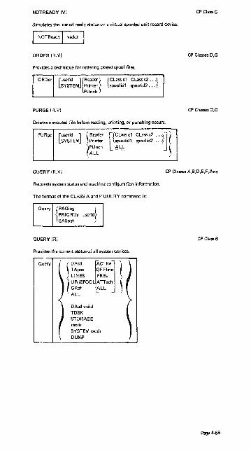
NOTREADY (V)
Simulates the loss of ready status on a virtual spooled unit record device.
I NOT Ready I vaddr
ORDER (R.V)
Provides a technique for ordering closed spool files.
{CLass cl CLass c2 ... } spoolid 1 spoolid2 .. .
PURGE (R.V)
Deletes a spooled file before reading, printing, or punching occurs.
PURge
CPClassG
CP Classes D,G
CP Classes D,G
QUERY (R.V) CP ClassesA,B,D,E,F,Any
Requests system status and machine configuration information.
The format of the CLASS A and P QUERY command is:
QUERY(R) CP ClassB
Provides the current status of all system devices.
Query
rA~ r~J l TApes OFFline LINES FREe UR ISPOOL ATTach GRaf ALL ALL
DAsd volid TDSK STORAGE raddr SYSTEM raddr DUMP
Page 4-55
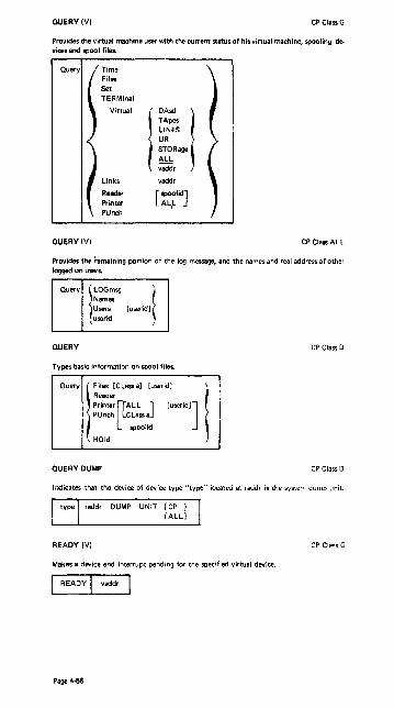
QUERY (V) CPClassG
Provides the virtual machine user with the current status of his virtual machine, spooling devices and spool files.
QUERY (V)
Time Files Set TERMinal
Virtual
Links
Reader Printer
PUnch
! ~~ I STORage
ALL vaddr
vaddr
[ IPOO. lid] AL.L
CP Class ALL
Provides the remaining portion of the log message, and the name-; and real address of other logged on users.
Ouery jLOGmsg ! Names Users [useridl userid
QUERY CP Class 0
Types basic information on spool files.
Ouery I '''" ICl ••• I l,w"'1
I Reader
printB'[[ALL ] [useridl] PUnch CLass a
spoolid
HOld
QUERY DUMP CP Class D
Indicates that the device of device type "type" iocated at raddr is the system dump unit.
type raddr DUMP UNIT {CP } ( .AU}
READY (V) CP Class G
Makes a device end interrupt pending for the specified virtual device.
READY I vaddr
Page 4·56

REPEAT (R) CP Class D
Increases the copies of, or holds, an output spool file.
REPeat raddr
RESET (V) CP Class G
Clears all pending interupts and resets error conditions on the device specified.
I RESETI vaddr
REWIND (V) CP Class G
Rewinds a real tape drive.
I REWIND I vaddr
SAVESVS CP Class E
Saves a virtual machine storage space with registers and PSW as they currently exist.
I SAVESYS I system name
SET (R) CP Class A
Sets special CP preferred options.
FAVored userid
REServe userid
SASsist
PAGing
PRIORity userid
[~XFF]
{~XFF}
{~~F}
SET (R) CP Class B
Establishes disposition for log messages and dumps.
Set
SET
~LOGmsg
IDump
{nn} ,
NULL ;
AUTO CP Lddr} [ALL]
CP Class F
Record Sets the necording mode for a device and Mode sets the recording mode for soft errors
Set RECord
JOFF I ON raddr LIMIT nn BYTE nn BIT n[{~~D} BYTE nn BIT n]
Mode )RETRY/ IOuiet I MAIN \ I Record \
Page 4·57

SET (V)
Sets virtual machine options.
SET
Run Linedit NOTRans
SHUTDOWN (R)
ION I OFF CODE TEXT
{ON } OFF REAL
Checkpoints and terminates the current VM/370 operation.
I SHUTDOWN
SLEEP (V)
CP ClassG
CP Class A
CP Class ALL
Places the virtual machine in a dormant state wiht the terminal keyboard loc~ed.
EJ SPACE (R)
Forces single spacing on the printer.
I SPace I radd r
SPOOL (V)
Changes spooling oontrol options.
SPool { Reader} vaddr
{
printer} PUnch vaddr
START (R)
1 [CLass aJ [CONt ] [HOld ] J
NOCont NOHold ~
. [~~~ofJ \
1
[ [To] usericf] [HOld] ) I OFF J NOHold (
[~~~nt] [CLass aj [COpy nnj ~ I
Restarts a drained device or changes its output spooling class.
STArt
Page 4·58
[:r~::; PUnch ALL
[raddr [Class c] [NOSep] ] J
CP Class D
CP Class G
CP Cla .. D

STOP
Alters the contents of real storage.
l {he. XIOC} hexwordl [hexword2 ... J! Lhexloc
Shexloc nexaata
STOP
STORE (V)
Alters virtual machine storage, PSW, and registers.
STore
I"~~ Lhexloc hexwdl 1"~~2 . I I Shexloc hexdata Gceg Yreg hexwdl [hexwd2 ... J Xreg Psw [hexwdlJ hexwd2
SYSTEM (V)
Simulates virtual machine console functions.
TERMINAL (V)
Changes parameters for terminal operations.
TERMinal I CHardel LINEDel LlNENd EScape
Mask APL ATTn
TRACE (V)
j~~f} I tchar
{~~F}
Traces and records program execution.
TRace SVC I/O PROgram EXTernal [ ,,;- ] PRIV SIO BOTH RUN CCW [ TERMinal] [NORUN] BRanch INSTruct OFf ALL CSW
END
CP ClassC
CP ClassG
CP ClassG
CP ClassG
CP ClassG
Page 4·59

TRANSFER (R.V) CPCI_D
TRANSFERS command to direct an input spool file to a specified user's virtual spool input, or to reclaim input spool files that originated from the specified user.
[ userid ] {SPOOlid} [TO ] {userid} SYSTEM CLass c From ALL
ALL
UNLOCK(R)
Releases storage.
VARY(R)
{ userid fpage Ipage} VIRT=REAL
Varies the availablility of a device.
VARY (ONline} {OFfline} raddr ...
CP Class A
CP ClassB
WARNING (R) CP Classes A,B
Transmits high priority messages to a specified user or to all users.
ASTERISK
Use - to annotate the con!Ole sheet with a comment.
-I anycomment
Page4.flO
CP Class ALL

Summary of CMS Commands Source: GC20-1806-1
This section contains summary descriptions of the commands acceptable in the CMS environment. Although the operator may not need to use all of them, they are included for ease of reference.
Command Usage
ACCESS Define direct access space to a CMS virtual machine, and relate the disk space to a logical directory.
ASSEMBLE Assemble Assembler Language source code
BASIC Compile and execute VM/370 BASIC programs
CMSBATCH Invoke the CMS Batch Facility
COBOL' Compile ANS Version 4 COBOL source code
COMPARE Compare all or part of records in two existing disk files
CONVERT' Convert free form FORTRAN statements to fixed form
COPYF I LE Copy files according to specifications
CP Enter CP console functions from CMS environment
CPEREP Dump error information which has been recorded '-'y VM/370 error recording routine
DDR Perform backup, restore and copy operations for minidisks
DEBUG Enter DEBUG subenvironment
DIRECT Set up VM/370 Directory entries.
DISK Perform disk·te-card and card-to-disk operations for CMS data sets
EDIT Enter EDIT subenvironment
ERf'.SE Delete files from user disks
EXEC Process special procedures made up of frequently used sequences of commands
FILEDEF Provide simulation of OS JCL data definition (DD) statements
FORMAT Prepare disks in CMS SOO-byte block format
FORTGI' Compile FORTRAN source code using G, compiler
FORTHX' Compile FORTRAN source code using H-extended compiler
GENDIRT Create auxiliary module directories
GENMOD Generate absolute non-relocataole file (MODULE files)
GLOBAL Define CMS libraries to be searched for macros and subroutines
GOFORT' Compile FORTRAN source code and execute program iust compiled using Code and Go compiler
INCLUDE Bring additional TEXT files into storage
LlSTDS List any or all data sets on an OS disk
'These commands are used to invoke IBM Program Products, which are available through IBM for a license fee.
Page 4-6'

Summary of CMS Commands (cont'd)
Command Usage
LlSTF I LE List information about user CMS files
LOAD Bring TEXT files into storage and establish linkages
LOADMOD Bring a single MODULE file into storage
MACLIB Perform maintenance on macro libraries
MINIDASD Previously used in VM/370 to format disk volumes in DOS or OS format. It is not a part of VM/370 Release 2; this has been replaced in Release 2 with the MINIDASD function of the OS utility IBCDASDI.
MODMAP Type load map of a MODULE file
MOVEF I LE Move data from one device to another device of the same or different type
PLiOPTl Compile PL/I source code (using optimizing compiler)
PR I NT Spool a specified file to the printer
PUNCH Spool a specified file to the punch
QUERY Request information about the virtual machine
READCARD Read data from spooled card input device
RELEASE Make a diik and its directory inaccessible to a virtual machine
RENAME Change the name of a CMS file or files
RUN Initiate series of functions to be performed on a file
SCR IPT2 Compose and print the specified file
SET Establish, set, or reset virtual machine characteristics
SORT Arrenge a specified file in ascending order according to specified fields in the data record
START Begin execution of programs previously loaded
STATE Verify the existence of a file
SVCTRACE Record information about supervisor calls
SYNONYM Specify alternate names by which Cdl"tain commands may be invoked
TAPE Performs tape·to-ciiik and disk·to·tape operations ior CMS data sets
TAPPDS Load OS partitioned data set (PDS) files from tape to diik
TESTCOB 1 Compile COBOL source code using the COBOL Interactive Debug Compiler.
TESTFORTl Enter a debugging environment for FORTGl 1 and GOFORT1
programs
lThese commands are used to invoke IBM Program Products, which are available through IBM for a license fee.
2This command invokes a text processor which is an IBM User I nstalled Program, available from I BM for a license fee.
Page 4-62

Summary of CMS Commands (cont'd)
Command
TXTLIB
TYPE
UPDATE
VMPDUMP
ZAP
Usage
Perform maintenance on text libraries
Type all or part of a file at the terminal
Make changes in a file as defined by control cards in a record file
Convert system ABEND dumps to printer output.
Provides a means of modifing members of CMS LOADLIBS as created by the CMS command LKED
l These commands are used to invoke IBM Program Products, which are available through IBM for a license fee.
2This command invokes a text processor which is an IBM User I nstalled Program, available from IBM for a license fee.
Page 4-63

CMS Command Formats Source: GC20-1806-1
hwoking the Blrtch Facility CMS
The Batch Facility virtual machine is invoked by the batch operator when he issues the CP IPL command followed by the CMSBATCH command. This sequence takes the form:
iplcms CMS mm/dd/yy WED 17.58.48 cmsbatch Y/S (19E) RIO. THE FOLLOWING NAMES ARE UNDEFINED:
BATEXIT1 BATEXIT2 R; T;O. 14/0.39 08:47:40 WAITING FOR THE READER
The operator may now disconnect the batch machine tenninal. if he wishes, using the CP DISCONN command. The Batc~ Facility will IPL itself after each job is executed.
COPYFILE CMS
Copies files according to operand specifications.
I COPYfile fileid1 [fileid2 ... ] I [ (options)]
options:
[Type l[OLDDateJ [RECfm F] [NOpromPt] [TRAns] ~ NEWDate RECfm V PRompt
[UPcase 1 [From recno ] [FOR recno ] LOWcaseJ FRLabel xxxxxxxx TOLabel xxxxxxxx
[
REPlace1 [Fill c J rTRUnc ] [PAck ] [EBcdic] OVlv Fill hh NOTRunc UNPack APpend J Fill 40 ~---NEWFile -- [LRecl nn] [SPecs ]
NOSPecs
DDR CMS
INVOKING DDR UNDER CMS
DDR [filename [filetype [til~ode]
INVOKING DDR AS A STANDALONE PROGRAM
To use DDR as a standalone program, the operator should IPL it from a real or virtual IPL device as he would any other standalone program. Then indicate where the DDR program is to obtain its control statements by responding to prompting messages at the console.
DIRECT CMS
To build a user directory on a system-owned volume using preallocated cylinders.
[filename [filetype [filemOde] ] ] (EDIT)
If running under VM/370, a nonnal completion results in the newly created directory being dynamically swapped, and placed in use by VM/370 (providing the users class is A, B or C and the directory volume is present in the system owned LIST). I n either case the directory is updated on the directory volume.
Page 4-64

EDIT CMS
Provides access to the EDIT environment
EDIT filename filetype [filemode [(LRECL nnn) ] ]
The CMS user can issue the following subcommands after he has issued an ED IT command.
TOP Moves the current line pointer to the top of the file.
BOttom Moves the current line pointer to the bottom of the file.
DOwn n Moves the current line pointer down the file the number of lines specified.
Up n Moves the current line pointer up the number of lines specified.
Type n Types the number of lines specified, starting at the current pointer position.
DELete n Deletes this line or the number of lines specified.
Change Ixx/yyl Changes the data string xx to the value yy.
Input xxx Inserts the text represented by xxx after the line at which the pointer is positioned.
FORMAT CMS
Formats a disk for use by CMS.
ccu mode [nocyl] [(Recomp) I (LABEL) ]
LISTFILE
Lists information about CMS files
[[fn [ft [fm] ]] [(options)]
options: [Headerl NO Header] [EXec I APpend] [FNamel FTypel FMode I FOrmat IALloclDate I Label]
MOVEFILE
Moves data from one device to another device.
NCPDUMP (Service Program)
routput.ddnameJ] L OUTMOVE
CMS
CMS
CMS
Processes CP spool reader files created by 3704/3705 dumping operations, that is, dump files that are produced as a result ofthe CP NETWORK command with the DUMP operand specified and with either automatic or immediate mode specified.
Page 4-65

NCPDUMP Command:
Although NCPDUMP is a CMS command, its effective use is restricted to the specific user identified by the SYSDUMP operand of the SYSOPER macro in DMKSYS used during VM/370 system generation. The operation of NCPDUMP is similar to VMFDUMP operations.
[DUMPxx] [([ERASE] [NCFORM] [MNEMONIC] [) ] ]
PRINT CMS
Directs a specified spool file to the virtual printer.
PRint I fn It [fm] [(options)]
options:
[ cc ] [MEMber • J [UPcase] [HEX] ~ MEMber name
PUNCH CMS
Directs a specified spool file to the virtual punch.
PUnch fn ft [fm] [(fNOHeader] [MEMber • J)] L~eader J MEMBER name
QUERY CMS
Permits the user to obtain specified information about r·is virtual machine's CMS functions.
READCARD
BLIP RDYMSG LDRTBLS RELPAGE IMPCP IMPEX ABBREV REDTYPE PRDTECT SEARCH
DISK
SYNONYM
FILEDEF MACLIB TXTLIB LIBRARY INPUT OUTPUT
[m~e]
{
' SYSTEM) USER \ ALL )
Reads data from the spooled card input device.
Page 4-66
CMS

SET
Sets or resets CMS virtual machine characteristics.
SET [BLIP string (count)] [ABBREV ] BLIP ON REDTYPE {ON} BLIP OFF IMPEX OFF
IMPCP [LDRTBLS nn] PROTECT
TAPE
l-RDYMSG SMSGl [INPUT a xx] [OUTPUT xx al RDYMSG LMSGJ INPUT OUTPUT J
Performs tape to disk or disk to tape operations for CMS data sets.
TAPE / DUMP l~nf l~\ [~m] [ (optA optB optC) ]
I LOAD [~n [~t [~mJ ] J [ 10ptA optB optC)] I t SCAN [~n [::J] [(optA optB optC)] I < t SKIP l~n! l~! [ 10ptA optS optC)] ~
, MODEset [(optO)]
tapcmd [~J [(optD) ]
- r" ]"$ ['O"~] optC: [EOF nJ NOWTM PRint EOT -- DISK EOF 1
r~ ~J mM DEN 556 DEN 800 GAP11ccuJ [TRTCH{OIOCIOTI E I ET}] DEN 1600 TAPl 181
tapcmd: [BSFI BSRI ERG i FSF I FSR I REW I RUNIWTM]
TAPPOS
eMS
CMS
I I
CMS
Loads an OS partitioned data set (PDSi file or card-image records from tape to disk.
TAPPDS [fn [ft [fm] ]] [(options ... ) ]
options
[NOPDSll-COL1 l [TApn] [END ] IMAXTEN ] PDS J NOCOUJ TAPl NOEND L NOMAXTEN
UPDATE
Makes changes in file as defined by control cards in a record file.
I Update fnl [ftl [fml [fn2[ft2[fm2] ] ] ] '] [(options)] 1
CMS
Page 4-67
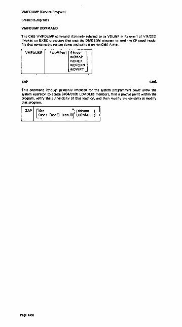
VMFDUMP (Service Program)
Creates dump files
VMFDUMP COMMAND
The CMS VMFDUMP command (formerly referred to as VDUMP in Release 1 of VM/370) invokes an EXEC procedure that uses the DMKEDM program to read the CP spool reader file that contains the system dump and write it on the CMS A-disk.
VMFDUMP [DUMPxx] [ERASE J NOMAP
NOH EX NOFORM NOVIRT
CMS
This command (though primarily intended for the system programmer) could allow the system operator to accesa 3704/3705 LOADLIB members, find a precise point within the program, verify the authenticity of that location, and then mod ify the contents to mod ify that program.
Page 4-68

RES Central Operator Commands Source: GC24-5091-3 OS/VSl Programmer's Reference Digest
Operator commands that require no modification for RES. These commands are not valid from RES workstation.
CONTROL SET DEFINE SWAP DUMP SWITCH HALT UNLOAD LOG VARY MODE WRITELOG
O!,erator commands that use additional operands for RES.
CANCEL REPLY DISPLAY RESET HOLD START* MODIFY STOP MONITOR STOPMN RELEASE WRITER
*Command not valid from workstation.
New operator commands for RES.
LlSTBC ROUTE LOGON SEND LOGOFF
Page 4-69
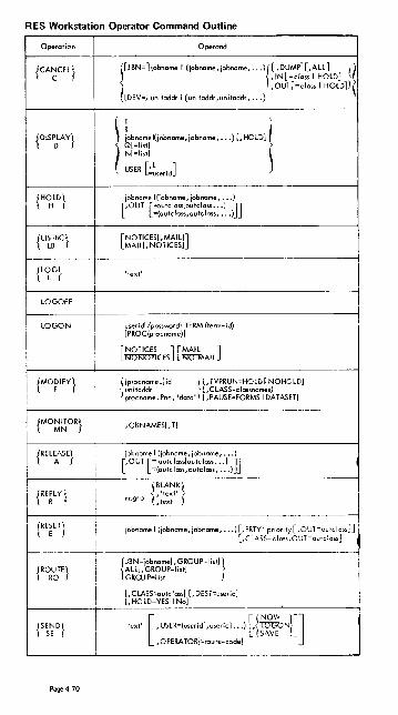
RES Workstation Operator Command Outline
Operation
{CA~CEL}
{DIS~LAY}
{HOLD\ H J
{LI~~BC}
{L~G}
LOGOFF I I I
LOGON I i I
i {MO~IFY}
I I
{MO~~OR} I I
{REL~ASE} i i I I
.'
{RE~ET } i
{ROR'2!E}
f SEND} I SE
Page 4-70
Operand
r"'"];ob"-' <;ob~~,;o"'_, ... '1 [,DUMI'](.ALL] t( (,IN[ ; class I HOLD]
,OUT[;closs I HOLD])
[DEV;I unitaddr I (unitaddr ,unitaddr, ... )
) ~ ... m.(;obO_, ;oboo_, ... )1, 'OWI( O[;listl N[;listl
USER [~~seridJ
jobname I (jobnome, jobname, •.. ) [,OUT [="utclass[outclass •.. 1 ]]
-(outcloss,outclass, •.. J
[NOTlCES[,MAILI] MAIU,NOTICESI
'text'
userid[/passwordl TERM (term-id) [PROC (procnome) I
rNOTICES 1 r MAIL 1 _~n~ __ ~AII_
([procnome.)id ; [,TYPRUN;HOLDINOHOLDI
'I ~~~~an~~e .Pnn, 'data' n:~~~~~:~~~MSI';;~TASET)
JOBNAMESI. TI
jobnome I (job nome , jobnome, ••. ) [,OUT [: outclosslo~tcloss ••. 1 ]]
-(outclass,outclass, ... )
(BLANK \' text}
msgno {I tex t
jobname I (jobname, jobname, ... ) L PRTY;priority[. OUT;outclass]] [. CLASS;c tass, OUT;outciass]
{JBN;jObname[, GROUP;listl 1 ~~~~~~syP;listJ S
[, C LASS~utc!assl [, DEST;useridl [, HOLD;YES I Nol
'text' [,uSER;(USerid[,USerid]. •. ) ['{fR~N}]J ,OPERA TOR[ ;route-code!
I
i

RES Workstation Operator Command Outline (cont'd)
Operatian Operand
{ST~T} r:~io~:~~ i~~ ~~~~~;~~s1'L keyword=option, ••• ]
{S~OP} [identifier I (identifier, identifier, ••• )] iprocname. identifier I (procname, identifier, •• )] [unitaddr I (unitaddr, unitaddr, ••• )]
Specify at least one operand, or any combination up to 5.
eTO~MN} JOB NAMES
{WRITER} ro~ ! WTR unit ,FS P=DS I nnn ,BSP=DS I JOB! nnn ,REPEAT=nnn I (nnn,JOB)
\, lSP=n I C
[, JBN=jobname]
Page 4-71

Definitions of Substitutional Operands- RES
class
classnames
data
devicetype
id
inclass
jobname
list
msgno
(n, .•. )
nbs
I
nfs ! i
outclass I
password I i
Pnn 1 !
pp ! procname
rdr
route-code
term-id i text
I
unit I
unitaddr
userid
wtr
Page 4-72
specifies an input or output class.
1-8 output class names to be associated with the writer.
specifies information to be passed to the procedure.
specifies a device type (for example, PR 1).
specifies any unique one to eight character name that starts with a letter (except for Pnn or ALL).
specifies an input queue class.
specifies the name of a specific problem program.
specifies one to fou; queue classes.
one or two character identification of a message reply.
1, 2, 3 (single space, double space, or triple space).
specifies a single digit decil'!'toJ number, or a list of numbers.
specifies a decimal digit from I to 255.
nnn specifies a workstation (1-200), ao identifies a device type (RD, PR, PU), m identifies a particular device.
specifies a decimal digit from 1 to 100 (indicates the number of pages to be backspaced).
specifies a decimal digit from 1 to 255 (indicates the number of pages to be spaced forward).
specifies an output class.
specifies on assigned sequence of one to eight alphameric ChCii'O'c~ers .
specifies the VS 1 partition number in which the procedure was started.
specifies numerical priority (decimol number from 0 to 13).
specifies the nome of a cataloged procedure.
specifies the name of the reader procedure being started.
specifies a value which identifies a central console.
specifies a unique number (1-200) assigned to a remote terminal.
specifies information to be entered in response to a message.
specifies the symbolic unit address (for example, PR 1) of an I/O device.
specifies the channel and unit address (cuu) of an I/O device.
specifies an assigned sequence of one to seven alphameric characters.
specifies the name of a writer procedure being started.

SMF
SMF
SMFPRMxx parameters
[OPT= {~}J
[DSVO
mJ [REC= l~\J
[EXT= l~~\J JWT=nnn
[SUF=nnnn]
SID=xxxx
[OPI= l~~~J
< USER [
MAN= (NONEl]
~ ALL
1-collect system & job info
2-collect system, job, & job step info
O-no data set or DASD info
1-collect DASD info
2-co lIect data set info
3-collect data set & DASD info
o-no temporary data set info
2-collect temporary data set info
NO-no exits
YES-toke exits
nnn-wait state time limit in minutes
nnnn-buffer size in bytes (max is 8192)
xxxx-systern identification
YES-operator aliowed to modify parameters
NO-operator not allowed to modify parameters
NONE-nO records to SMF data set
USER-only user records to SMF data set (type 128-255)
ALL-all record types to SMF data set
Page 4-73

System Operator Commands for CRJE
Operation Operand
IIRDCST t:-'! C 'text' nnnn DElETE
1000ration I Operand
CENOUT C, J=lobname, C=class
Operation
Operation
MSG
Operation
SHOW
Operation
Operands
[procname.) identifier, {~} = (address, ••• )
Operand
CJM='text' [,U=userid[,QI} /D=userid
Operands
{
JOBS [, jobname J l USERS [,userid] ACTIVE [,NUMBER]
C BRDCST MSGS [,userid) LERB [, lineaddress J SESS [,userid] smm r,~,;d r J
Operands
procname. identifier", ({ FORM }{,ABNO }) NFMT ,NORM NONE
i Operand
i [procname, I identifier
Operation Operands
USERIO C, ~-lA 1001 ! ~ (u.erid,po5Sword) j D iLETE] \ ~ 5 [UPPRESS I i
,R [ESUME] )
Page 4-74

oS/VS CRJE Terminal Command Formats Source: GC24-5091- OS/VS Programmer's Reference Digest
CRJE Terminal Command Formals
COMMANDS
I. CANCEL
2. CONTINUE
iabnome
[
H[ERE] ] BlEGINl N [EXT]
3. DELETE dsname
[NEWJ[NUM ][SfCANl ]
4. ED[IT ~L~a~:aram~;~rs)llNONUM NOS[CANl
FORT {;}
DSLIST CLIST DATA TEXT
[ L f ISTl ]
5. EXEC dsnome NOL[IST]
6. LlSTBC
7. LlSTDS dsnome [S[TATUS]] [H [ISTORYl]
8. LlSTLlB [S fTATUSl] [H [ISTORYJ]
9. LOGOFF
10. LOGON userid/oassword fA [eeT] (accounting information)]
[ BC ] [M [SGlDl ] NOBC NOM[SGIDl
II. OUTPUT jobnome [SMSGl
[
u [SER] (userid) [N [OWl J] L!OGONl
12. SEND'text' o f PERA TOR 1 (i nteger)
13. STATUS fjobname']
14. SUBMIT dsname ,. ••
15. TABSET [
nurn ... ] r!i::!l1illL ] OFF LOUT [PUT]
Page 4-75

EDIT Subcommands
EDIT SUBCOMMANDS
I • linenum (6 text]
2. CA (NCELl jobname
3. C (HANGE] linenurn (linenuml 6 textlll text2 6( A (LL] 1
4. D (ELETEI [linenum (linenum] I
5. END
[ [ Iincrement I [11]11 [~IROMPTI ] 6. I (NPUTl linen..." R ~ N6i'TROMPTI
[ NUM ] 7. L (1ST] (linenum (linenum] 1 NONUM
8. M( ERGE] {~me} (linen..." linenum] {linenuml
[linenum [ increment] ]
9. REN [UMBER].!.Q .!.Q
10. S [AVE] [dsnane] (K (Eyl(keY~bN
11. SC[AN] lIinenum [Iinenuml LOFF]
[u ISERI (useridl[N (OW] II
L lOGON! J J 12. SEND 'text' 0 (PERATOR] (integer)
13. SUB I MIT] {~name} ...
TAB [SET]
r nurn"'l fiN I PUT! 1 OFF OUT [PUT]
L- ....... oJ
14.
Page 4·76

Terminal Commands and Functions
SESSION MANAGEMENT COMMANDS
Command
LOGON
LOGOFF
Function
To identify the user and initiate his session.
To terminate a session.
DATA MANAGEMENT COMMANDS
General
Command
DELETE
Function
To scratch an VS data set or to remove a CRJE data set from the user's .Iibrary.
EDIT To initiate creating or updating operations.
EDIT Subcommands
Subcommand
INPUT
DELETE Implicit CHANGE
MERGE
RENUMBER
LIST
SCAN
SAVE
END
Abbreviation
D
C
M
REN
SC
Function
To insert and/or r~place lines in the active set.
To remove lines in the active data set. To enter or delete lines in the acTive data set. To replace character strings within lines of the active data set.
To combine another data set with the active data set or to copy lines from one place to another within the active data set.
To reassign line numbers to the lines in the active data set.
To display lines of the active date set.
To request a syntax anolysis of Pl/l or FORTRAN source language statements in the acti ve data set.
To stare the active data set in the user's library.
To terminate creating and updating operations and ta delete the active data set.
JOB PROCESSING COMMANDS
Command
SUBMIT
OUTPUT
CONTINUE
CANCEL
Function
To enter a job into the VS job input stream. (Can also be used as an EDIT subcommand; it can be abbreviated SUB when used as a subcommand.)
To request CRJE SYSOUT output of a conversationally - submitted job.
To resume output listing that was previously interrupted.
To remove a job from the CRJE system and to delete any CRJE SYSOUT output of that job. (Can be used as an EDIT subcommand; it may also be abbreviated CA when used as a subcommand.)
STATUS INFORMATION COMMANDS
Command
LlSTLIB
Function
To obtain the name and characteristics of every CRJE data set in the user's library.
Page 4·77

Terminal Commands and Functions (cont'd) CRJE Installation Variables
STATUS INFORMATION COMMANDS (cont.)
Command
LlSTDS
STATUS
Function
To obtoin information obout a porticular CRJE dota set in the user's I ibrory.
To obtain infonnotion about jabs the user has submitted.
MESSAGE COMMANDS
Command
SEND
LlSTBC
Function
To send a message to the central ope rotor or to another terminal user. (Can also be on EDIT subcommand.)
To request the broadcast messages.
TABSET COMMAND
Command Function
TABSET To indicate the tab settings at the terminal. This command affects all input and output and can be either a command or an EDIT subcommand. (Can anly be abbreviated - TAB - as a sub- I
EXEC CbMMAN;mmand.) II
COMmand Function
EXEC To execute a sequence of commands contained in a CRJE data set.
CRJE INSTALLATION VARIABLES
The following functions, restrictions, and assignments are determined by the central ill$tallation when the system is generated.
ADDITIONAL COMMANDS AND SUBCOMMANDS
The installation may odd commands and subcommands to the system by providing the routines to process them.
COMMAND ALIASES
I 1 I I I I
The ill$tollotion may assign alternote verbs (aliases) for the CRJE commands and I subcommands. Duplication of aliases is allowed between modes but not within I the same mode; i.e., the same 01 ies may be used for a command and c subcommand, but it cannot be used for two commands (if in command mode) ncr fori . two subcommands (if in edit mode). Either the CRJE name or the installation alios is recognized when entered from a terminal.
EXIT ROUTINES
Routines may be provided by the instollation to check the aCCQuntirg information on LOGON commands, to check JCL'statements of jobs submitted fa, botch processing, and to obtain accounting information when a user logs off the system. An installation routine may reject a LOGON command and may terminate a job
I submission.
Page 4·78
I I I i

CRJE Installation Variables (cont'd)
SYNTAX CHECKERS
The instailation selects what syntax checkers, if any, are provided in the system and the kind of checking performed (i .e., level of checking or language level supported) •
NUMBER OF LINES PER SYNTAX SCAN
The installation can impose a limit on the number of lines one statement can span and still be scanned as a complete statemenT by the syntax checker.
USER ID/PASSWORD
The installation assigns userids and posswords to authorized terminal users.
CRJE SYSOUT CLASS
The system output class used for remote job output to be returned to terminal users is assigned by the installation.
NUMBER OF LINES PER OUTPUT GROUP
The installation specifies how many lines of output are sent to terminal before allowing the terminal user to interr~pt the output. This only applies to terminals without a special interrupt feature.
MAXIMUM NUMBER OF JOBS
The maximum number of jobs that can reside ,n the central system at one time is determined by the installation. When this maximum is reached, no more jobs are accepted until some of the existing jobs are cancelled or their output is returned.
MAXIMUM NUMBER OF MESSAGES
The installation determines the number of messages that can be maintained by the system at anyone time. This includes messages waiting for delivery aT logan time and messages currently being processed.
ROUTING CODES FOR MULTIPLE CONSOLES
If the central system supports multiple consoles, the installation specifies a routing code for each console. A user may direct a message to an operator at a por~icular console by specifying the routing code for that console.
ON-LINE TERMINAL TEST
I The installation determines whether or not the BTAM On-line Terminal Test facility is provided. This facility provides tests that can be used by the terminal user as a start-up procedure or by the customer engineer for terminal checkout and diagnosis of terminal failure.
Page 4-79

Display Operating Console - Model 115 and Model 125 Source: GC33-537B DOSNS Operating Procedures, Release 29
Examples of the K Command
Note: The K command is used in conjunction with Models 115 and 125 only.
First Second Meaning Example Explanation of Example Operand Operand
,REF Display cur· K S,REF* Assuming that the initiali-rent values zation values are still in of the S· I effect, operands ' K S,DEL=Y,CON=Y,
SEG=6 is displayed in the entry area.
,DELzY Delete meso KS,DEL=Y When the screen is fu II, all sages auto- deletable messages are matically deleted.
,DEL=N Do not de- KS,DEL=N When the screen is full, use lete meso the K command or the cur· sages auto- sor to de lete messages. matically
,CON=Y Delete meso KS,CON=Y When a deletion command sages Ifter has been entered, you can verification check the messages before
they are deleted.
,CON=N Delete meso I K S,CON=N When a deletion command sages im· I has been entered, messages mediately I are deleted immediately.
.SEG=n Delete n I KSEG=4 When you enter
[ lines at a 1 K E,SEG (or just K l. lines 1 time through 4 are deleted.
You may also enter K S since REF is the default value of the S operand.
Page 4-80

Display Operating Console - Model 115 and Model 125 (cont'd)
Examples of the K Command (cont'd)
First Second Meaning Example Explanation of Example Operand Operand
,sEG Delete meso K E,5EG" I Assuming S,SEG=5 was sage lines specified, lines 1 through 5 as specified I are deleted. in S SEG=n
,n Delete line n KE,4 Message line 4 is deleted.
,n,n Delete the K E,2,6 lines 2 through 6 are de-range of ieted. lines from n to n
,N Delete the K E,N The message line numbers line num· I are deleted from the screen. bers
i D ,N Display line I K D,N J A" --" .... ;~'""~ numbers in continuation lines, are
all message numbered until a K E com· lines mand is issued.
D ,N,HOLD Prevents K D,N,HOL I All message lines are num· line num- I bered. Line numbers are bersfrom erased only by K E,N being delet· I command. ed
You may also enter K since E and SEG are default values.
Page 4-81
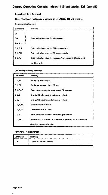
Display Operating Console - Model 115 and Model 125 (cont'd)
Examples of the K Command
Note: The D command is used in conjunction with Models 115 and 125 only_
Entering redisplay mode
Command Meaning
D
l DL Enter redisplay mode for all messages
D L.ALL
DL,AR Enter redisplay mode for AR messages only
D L,BG Enter redisplay mode for BG messages only
D L.Fx Enter redisplay mode for messages from a specified foreground
partition only
ContrOlling redisplay operation
D L,ALL
D L,F2
o L,F4,R
D L,B
D L,F
D L.F.24O
D L,B,70
D L,B
DL,170
Meaning
I Redisplay all messages
I Redisp lay messages from F 2 on Iy
Reset the sc.--. to the most recent F4 meo;zsages
I Change from forward to backward redisplay
Change from backward to forward redisplay
Space forward 240 lines
Spare backward 70 lines
Reset the screen to status wilen redisplay started
Space 170 lines forward or backward, depending on the redisplay
direction currently in effect
Terminating redisplay mode I Command I Meaning
~ Te!""!,,nate rp.rhsplay mode I
Page 4-82

OSNS Display Consoles Sources: GC38-Q260 OS/VS2 Displav Consoles
GC38-02550S/VSl Display Consoles
The CONTROL command (abbreviated K) controls the display console. Each function of this command is described in an appropriate place in the SRL. To request a summary of the CONTROL command operands and the functions that they pertorm, enter the following commands:
{DISPLAYl
D f C,K [,L= {~}
C,K specifies that a summary of CONTROL command operands is to be displayed.
L= { ~~ } specifies the display area (a), console (ccl, or both (cca) at which the display is to be presented. If yo~ omit this operand, the display is presented in the first available display area on the console through which you entered the command; (unless routi"g instructions are in effect).
For example, to display a summary of CONTROL command operands in display area A of console 10, enter:
D C,K,L=10A
A printed summary of Control command formats appears in OSIVS2 (JES 2) com· mands summary which you will find in this section.
PROGRAM FUNCTION KEYS
Entering Commands with the PFKs
The program function keyboard is a group of 12 keys (called PFKs) located on the right side of the operator console keyboard. (It is an optional feature of the model 3277 display console, and is not available for the model 158 display console.) One or more PFKs may be available to yo~ for entering commands. The PFKs are designated for operator command entry by the system programmer during system generation.
Each PFK is defined as conversational or nonconversational. The commands associated with a nonconversational PFK are entered immediately when you press the key. The commands associated with a conversational PFK are presented in the entry area, one at a time, when you press the key. You may make changes to them before you enter them.
In place of keys, the Mod 158 Display Console provides a PFK line (above the instruction line) and entering of commands by light pen.
How to Display the PFK Numbers
Use the following form of the CONTROL command to display and erase the numbers in the PFK display line:
{ D PFK} E PFK
D, PFK specifies that the numbers of the PFKs designated for command entry are to be displayed in the PFK display lir·e.
E ,f'FK specifies that the numbers are to be erased from tha PFK dispiay line.
Example: To request display in the PFK display line (this line is located immediately above the instruction iine), enter:
K D PFK
Page 4-83

I PL Procedure DOS/vS with the DOC Source: GC33-537B-l DOS/VS Operating Procedure, Release 29
Page 4-84
1. Press POWER ON and wait until PROGRAM LOAD appears on the screen.
2. Mount the SYSRES disk pack on a disk drive and ready this device.
3. Mount the pack containing the page data set on the disk drive assigned to SYSVIS. (If the standard assignment for SYSVIS does not exist or is not to be used, any disk drive can be chosen for the pack; the physical address of the drive must then be specified in the DPD command.)
4. Type in the physical device address of the disk drive that holds the SYSRES disk pack. Type in the character C and press ENTER.
5. When WAIT appears on the screen, press REQUEST. This displays the following message:
0103A SPECIFY SUPERVISOR NAME
If you wish to use the default supervisor ($$A$SUPl), press ENTER; otherwise, enter the name of the reqUIred supervisor and then press ENTER.
6. When WAIT appears on the screen again. press REQUEST. This displays one of the following sets of messages:
A. 01301 DATE=date,CLOCK=time,ZONE~difference 0I1OA GIVE IPL COMMANDS
B. ot31A DATE REQUIRED, CLOCK REQUIRED. ZONE=difference
0I10AGIVE IPL COMMANDS
C. 01321 TOO CLOCK INOPERATIVE; NO TOO SUPPORT 0I31ADATE REQUIRED, CLOCK REQUIRED 0110AGIVE IPL COMMANDS
7. Depending on the messages that were printed on SYSLOG (see step 6), take the following action:
A. 1. If all values are satisfactory. enter the SET command without parameters.
2. If the date or time of day is not satisfactory, enter the SET command with both DATE and CLOCI( parameters, and press ENABLE SET.
3. If the zone is not satisfactory, enter the SET command with the ZONE parameter.
4. If none of the values is satisfactory, enter the SET command with all parameters and press ENABLE SET.
B. 1. If the zone value is satisfactory, enter the SET command with DATE and CLOCK parameters, and press ENABLE SET.
2. If the zone value is not satisfactory, enter the SET command with all parameters and press ENABLE SET.
C. Enter the SET command with DATE and CLOCK parameters and press ENABLE SET.

8. Enter the CAT command. if required. to indicate on which physical device the disk pack containing the VSAM catelog is mounted.
g. Enter the DPD command to define the page date set. DPD is mandatory; all operands are optional.
10. Press ENTER. The system then issues the message
DOS/VS IPL COMPLETE
in which case you can go to steps 1 1. 12. and 13. or it issues the messages
DOS/VS IPL COMPLETE 1100A WARM START COpy OF SVA FOUND
Thera are three possible respo;1ses:
A. Enter KEEP. if you wish to keep the current copy of the SVA (Shared Virtual Areal; in this case. steps 11. 1 2. and 13 cannot be executed.
B. Press ENTER. This haS tbe same effact as A. above.
C. Enter REJ. if you do not wish tc keep the current copy of the SVA; in this case yo~ can go to steps 11. 12. and 13.
11. if the SVA option was not specified during system generation. or if you wish to change the size of the existing SVA. enter the SET SVA={nK,nKI job control command.
12. If you wish to create a system directory list (SDLI. specify the SET SDL=CREATE job control ccmmand. followed by a list of the phase names to be included in the SDL
Ii you wish to use the IBM supplied SDL. enter the command EXEC PROC=SDL.
13. If you wish to create an SiJA and SDL for the VSAM modules and include your VSAM modules in this SVA specify:
EXEC PRO('-:- IKQVPSVP..
Page 4-85

IPL Procedure VS1 Sources: GC38-1001 VS1 Release 2 System Messages
GC38-0110 Operator's Library OSNS1 Reference
Shown below are a few sample replies to system messages received during initialization. For complete information consult System Messages. According to your system control program, the messages you receive may have different id's from the ones shown here. Reply, using the id fitting your message.
To start IPl, dial or enter address of SYSRES volume and press lOAD button.
IEA706A SPECIFY VIRTUAL STORAGE SIZE
Press END key or reply r 0, 'u' (for default); or reply r 0, 'ddddd' where ddddd is the number of K bytes for virtual storage.
IEA101A SPECIFY SYSTEM ANDIOR SET PARAMETERS FOR RELEASE 02.0 OSNSI
Press END key or reply r 0, 'u' to iildicate no change in parameters;
r 0, 'u, l' to indicate system should use system generation val ues for all parameters and should print all lists;
r O:prm·: to cancel a parameter for this loading which was specified during system IIIIneration;
r O:prm=val' to indicate the value of this parameter for this loading: r O:prmcval,l' Ie gpecify the value for the parameter and to request a list of all
modules; r O:date=yy.ddd,clock;hh.mm.ss' to reset date andlor local time; r O:data=yy.ddd,clock;hh.mm.ss,gmt' to change date andlor GMT clock. After YO'J se~
the clock, press TOO ClK ENABLE switch before pressing END key.
IEA135A SPECIFY SYS1.DUMP TAPE UNIT ADDRESS OR NO
Press END key or reply r O:no' if a SYS1.DUMP data set will not be used; or r O,'ddd' where ddd is the 2400/3400 series tapp ~vi~~ !c be :!~cd fC'i -::~c ~"I"S~ .~U:'o'ir data set.
'00 IEEBOID CHANGE PARTITIONS - REPLY YES/NO (,LlST) (Ouotes around text are optional from here on.)
Reply r O,no to indicate partitions are not to be defined; r a,Yes partitions are to be redefined; r O,list only a list of partitions is wanted: r O,yes.list partitions are to be redefined and a list is wanted.
'01 IEEl14A SPECIFY SET PARAMETERS OR U
Reply r 1,u for no set parameters; r l,proc= for spacifying a proc; r l,q=(.f) for formatting th~ queue; r l.spool=(chng,fJ for changing spool; or any combination of these, DATE, CLOCK, and GMT are not vaiid at :his time.
'02 iFBOlOD ENTER 'IPL REASON, SUBSYSTEM ID' or 'U'
Page 4-86
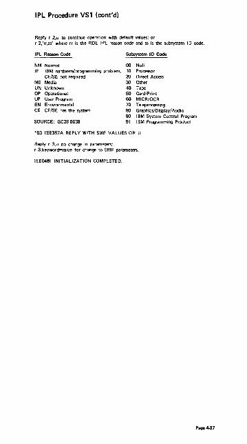
IPL Procedure VS1 (cont'd)
Reply r 2,u to continue operation with default values; or r 2:rr,ss' where rr is the RDE IPL reason code and ss is the subsystem ID code.
IPL Reason Code Subsystem I D Code
NM Normal 00 Null IE IBM hardware/programming problem, 10 Processor
CE/SE not required 20 Direct Access ME Media 30 Other UN Unknown 40 Tape OP Operational 50 Card/Print UP User Program 60 MICR/OCR EN Environmental 70 Teleprocessing CE CEISE has the system BO Graphics/Display/Audio
90 IBM System Control Program SOURCE: GC28-0638 91 IBM Programming Product
*03 IEE357A REPLY WITH SMF VALUES OR U
Reply r 3,u no change in parameters; r 3,keyword=value for change to SMF parameters.
IEE0481 INITIALIZATION COMPLETED.
Page 4-87

IPL Procedure VS2 Sources: GC38-1002 VS2 Release 1.6 System Messages
GC38-0210 Operator's Library OSNS2 Reference
Shown below are a few sample replies to system messages received during initialization. For complete information consult System Messages. According to your system control program, the messages you receive may show different id's from the ones shown here. Reply, using the id appropriate to your message.
To start IPL, dial or enter address of SYSRES volume and press LOAD key.
IEAIOIA SPECIFY SYSTEM PARAMETERS FOR RELEASE 01.6 VS2
Press END key or reply r O,u for default (the system will use the default system parameters in SYS1.PARMLlB); or r O,u, L default and a list of system parameters; r O,parm;, to cancel the parameter for this IPL which was specified during system
generation; r O,parm;yal,L to specify the value for the parameter and request a list of system
parameters.
IEA332A SPECIFY DUMP OR CANCEL
Press END key to cancel or reply r O,DUMP parm (if function is used).
"IEEI14A DATE;73.323,CLOCK;11.08.52 '00 IEE114A DATE;73.323,CLOCK;16.08.52.GMT REPLY WITH SET PARM OR U
Reply r O,u if date and time are correct and there are no set parameters; r O,proc'" (specify proc or r O,aut~nnn (to overridi! auto commands .. n for no, y for yes) 0' r O,q;(252,f) to format the queue; or any combination of these. Do not press the TOO CLK ENABLE switch. Reply r O,data;yy.ddd,clock=hh.mm.ss,gmt to change date and/or GMT clock.
After yoo set clock, depress TOO CLK ENABLE switch before pressing END key.
"01 IFBOIOD ENTER 'IPL REASON, SUBSYSTEM 10' OR 'U'
Reply r I,u to continue operation with default values; or r I,rr,ss where rr is the ROE IPL Reason Code and ss is the Subsystem 10 code.
IPL Reason Code Subsystem 10 Code
NM Normal 00 Null IE IBM hardware/programming problem, 10 Processor
CE/SE not required 20 Direct Access ME Media 30 Other UN Unknown 40 Tape OP Operational 50 Card/Print UP User Program 60 MICR/OCR EN Environmental 70 Teleprocessing CE CEISE has the sy.l.m 80 Graph jc.!DisplayiA'l':!iO
90 IBM System Control Program SOURCE: GC28·0638 91 Programming Product
"02 IEE357A REPLY WITH SMF VALUES OR U
Reply r 2,u (for default) or r 2,keyword;value where ~eyword is an SMF parameter specified by your system programmer.
Page 4-88

IPL Procedure VS2
Sample IPL VS2 Release 2
IEA887A CPU 01 LCL DATE=74.008,CLOCK=01.27.24
IEA887A CPU 00 LCL DATE=74.008,CLOCK=01.29.30 '00 IEA887A TOD CLOCKS MUST 8E SET, OR SELECT ADDRESS r O,addr=O
IEE600i REPLY TO 00 IS;ADDR=O IEE3061 RPLY HAS INVALID NUMERICS IEA887A CPU 01 LCL DATE=74.00s,CLOCK=01.27.50 IEA887A CPU 00 LCL DATE=74.008,CLOCK=01.29.56
'01 IEA887A TOD CLOCKS MUST BE SET, OR SELECT ADDRESS r l,addr=OO
IEE6001 REPLY TO 01 IS;ADDR=OO IEA888A GMT DATE=74.008,CLOCK=06.30.15
'02 IEA888A LCL DATE=74.008,CLOCK=01.30.15 REPLY U, OR GMT, OR LCL TIME
r 2,u '03 IEA889A DEPRESS TOD CLOCK SECURITY SWITCH
IEE600i REPLY TO 02 IS;U r 3,u
IEE6001 REPLY TO 03 IS;U
IEF1651 /I START JES2 (This message would follow)
Page 4-89
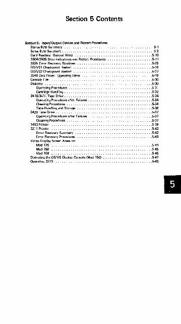
Section 5 Contents
Section 5: Input/Output Devices and Restart Procedures Status Byte Summary ......................................... 5-1 Sense Byte Summary . . . . . . . . . . . . . . . . . . . . . . . . . . . . . . . . . . . . . . . . . . 5-2 Card Readers: General Hints .................................... 5·10 3504/3505 Stop Indications and Restart Procedures ...................•. 5·11 3525 Error Recovery Routines ................................... 5·25 OSNSl Checkpoint Restart ..................................... 5-26 OSNS2 Checkpoint Restart ..................................... 5·27 3340 Disk Drive: Operating Hints ................................. 5-28 Console File ............................................... 5·30 Diskette .................................................. 5·30
Operating Procedures ....................................... 5·31 Cartridge Handling ......................................... 5-32
3410/3411 Tape Drive ......................................... 5-34 Operating Procedures after Failures .............................. 5·34 Cleaning Procedures ........................................ 5-34 Tape Handling and Storage ................................... 5·36
3420 Tape Drive ............................................. 5·37 Operating Procedures after Failures .............................. 5·37 Cleaning Procedures ........................................ 5·37
1403 Printer ............................................... 5·39 3211 Printer ............................................... 542
Error Recovery Summary .................................... 542 Error Recovery Procedures ................................... 5-43
Video Display Screen Areas on: Mod 125 ............................................... 544 Mod 158 ............................................... 545 Mod 168 .•............................................. 5-46
Operating the OSNS Display Console (Mod 158) ....................... 547 Operating 3270 ............................................. 5-49
II

Status Byte Source: Component Description SRL for each device
NOT USED DE DEVICE END ATTN ATTENTION SM STATUS MO CE CHANNEL END UC UNIT CHECK CUE CONTROL UNIT END UE UNIT EXCEPTION
BIT
DEVICE 0 I 2 3 <I 5 6 7
1403 BUSY CE DE UC UE
2301 (2820) SM CUE BUSY CE DE UC UE
2303 ATTN SM CUE BUSY CE DE UC UE
2305(2835) ATTN SM CUE BUSY CE DE UC UE
2319 SM CUE BUSY CE DE UC UE
2400 SM CUE BUSY CE DE UC UE
2560 BUSY CE DE UC UE
2596 BUSY CE DE UC UE
2701 ATTN SM BUSY CE DE UC UE
2702 SM CUE BUSY CE DE UC , .. 2703 SM CUE BUSY CE DE UC I UE
2821 BUSY i CE DE UC.! UE
3203 I BUSY I CE DE UC ! UE
3210 ATTN i SM BUSY CE DE UC UE
3211 ! BUSY CE DE UC I UE
3215 ATTN BUSY I CE I DE UC I UE
3270 ATTN SM CUE BUSY! CE DE UC ! UE
3277 ATTN I BUSY CE I DE UC i
3330 I ··SM :
BUSY CE I DE UC I UE
3340 ! SM CUE BUSY I CE DE UC : UE
3410 I CUE BUSY i CE I DE UC i UE
3411 i I CUE BUSY l CE I DE UC UE
3420(3803) SM CUE BUSY I CE DE UC j UE
3504 I BUSY I CE I DE UC ! UE
3525 i BUSY I CE I DE UC ~ UE
3540 I BUSY! CE i DE UC I
3704 ATTN SM CUE I BUSY i CE DE UC 1 UE
3705 ATTN! SM CUE i BUSY I CE i DE UC ; UE
5203 I i BUSY: CE DE I UC UE
5213 ATTN! SM CUE i BUSY I CE : DE I UC ! UE
5425 i BUSY I CE DE I UC i UE
Page 5-1

Sense Bytes Sources:SY33-8571 DOSIVS Handbook, Release 29
GA22-6895 (2301 only) ___ GA26-5988 (23030nly) __ _
GA26-1589 (23050nly) ... GA33-1506 (3203 only) . ..
GA21-9167 (5425 only) Sense Byte 0
~ DEVIC 0 1 2 3 4 5 6 7
1017 CMD INT BUS DATA ~ REJ REQ OUT CHK TAPE 1018 CMD INT BUS EQ DATA
REJ REQ OUT CHK CHK 1287 CMD ,INT BUS EQ DATA OVER- NON KYBD
REJ I REQ OUT CHK CHK RUN RCVY CORR 1288 ~~D !~ BUS EQ DATA OVER- NON
lOUT ICHK CHK RUN ReVY 1403 CMD liNT ! BUS !EQ
~ ~ CH9
REJ IREQ 'OUT CHK /CH ERR '---1443 I I YPE YPE
I BAR BAR 1442, 2501, CMD INT BUS 'EQ DATA OVER-2520, 2596 REJ REQ OUT ICHK CHK RUN 1419 PCU CMD INT BUS DATA OVER- AUTO'
REJ REQ OUT CHK RUN SELECT 1419 SCU CMD INT BUS I I DATA OVER- S~~:2'r\ REJ REQ OUT I CHK RUN 2260 CMD "NT BUS :EQ
i REJ IREO OUT :HK 2301/2820 CMD ! INT BUS EO DATA OVER-I I REJ iREO OUT CHK CHK RUN .-. 2305 CMD INT BUS EQ DATA OVER-! T REJ REO OUT CHK CHK RUN i I 2311, 2321 'CMD /,NT i BUS 'EQ
: g~~A i;0~R-1 {~~D SEEK REJ iREQ i OUT ICHK CHK
2314, 2319 ~~D i~~ ~LJ; !~~K [ DATA OVER- '{~~D SEEK i CHK RUN K ('HK
2400 ~~D 1~6 BUS 'EQ Ig~~A l~y~R- I ~!lrn I~Wt OUT k:HK 2495 CMD INT BUS IEQ i DATA I~~~~~N ~9J~ REJ REQ OUT HK CHK 2540 CMD liNT BUS EQ i DATA! :UUs'llAL
REJ REQ OUT -HK 'CHK CMD 2560 , CMD INT Q DATA lllit~] NO
REJ REQ HK CHK ~ 2671, 2822 CMD INT BUS Q DATA
REJ liE 0 OUT HK Oil< 3203 CMD INT lEO DATA CHAINBUEii1J·j
PARITY ICHANNEl CHANNfL REJ REQ ' CHK CHK CHK IFOUND '
3210, 3215 'CMD NT EQ ! REJ IuQ ! CHK
3211 !CMD NT : BUS lEO iDATA I~~r!f LOAD
~ REJ REQ iOUT CHK !C"HK r ,CHK
3330 I CMD INT BUS IEQ ,DATA IOVER-f , REJ REQ ; OUT CHK CHK RUN ;
I 3340 ICMD liNT , BUS !~~K I DATA IOVER-, i REJ ~Q OUT ; CHK ! RUN I,
3410, 3411 ,CMD NT I BUS EQ i DATA I OVER-~ ~ REJ ~Q lOUT CHK I CHK RUN ko 3420,3803 i CMD INT i~Jr EQ I DATA OVER-I{~u~ §Wr , REJ REQ CHK i CHK RUN ' R HK 3504, 3505, , CMD NT I BUS EQ i DATA :~T ~y 3525 ! REJ iREQ !OUT CHK ICHK RESET DOSS kev 3540 : CMD INT ,BUS
i,EQ DATA , REJ REQ lOUT CHK CHK
~ 3881 iCMD liNT , BUS EQ ! [ i I I~~~
3886 !CMD liNT I BUS I~~K i rNON- ReP 'REJ ,REQ OUT IINIT ERR
5425 CMD INT BUS EQ DATA INDCARD REJ REO OUT CHK CHK ~VAIlABlF.
Page 5·2

Sense (cont'dl Byte 1
~ 0 1 2 3 4 ! 5 6 7 DEYI 1287 TAPE LATE NO I ~~ALI MODE STKR DOC
SELECT FOUN[
1288 END NO ~ OF DOC OP PAGE FOUN[ 1 1
1419 FLO 6 FLO 7 DOC AMT PRO ACCT# TRANSI SER# SCU VALID VALID UNDER FLD CTLFLD FLO FLO FLD
WHD VALID VALID VALID VALID VALID
2260
2301l282C DATA TRK ! END INVAL NO FilE SVC OVER-ChK IN OVER-IO. SEQ REC PROT OVER- FLOW COUNT RUN CYL FOUND RUN INC
2305 PERM INVAl .. ~END NO FilE OPER-ERROR ~RK OF REC PROT IATION FORMA CYCLE FOUND INC
I - -
2311, DATA TRK END INVAl NO i FilE iMlSSINq OVER-2321 CHK 11\ OVER- OF SEQ I REC ~d PROT ADDR I FLOW
COUN RUN CYl FOUN MARKER I 11'1<;_ 2314, DATA TRK I END INVAl' NO
I ~~~T SERV ICE I OVER-2319 CHK IN ~~~-I ~l I SEQ REC OVER-, FLOW
COUN FOUNDi ! RUN I INC 2400 NOISE i~~=~g~~~!~~Ui 7 TRK AT I WRT I FilE ' TAPE
jlO-RDY&NO Rwq lOAD I STATUSI PROT liND II-ROY & RWD , POINT i I
2560 COVER/ JAM CORNE1 CEll PRINT: PUNCHI READ :/INPUT INT PAR ST 'N 8/9 lCK ! CHK CHK : FDCHK :~NHKJ :-r~NHKj :-r~NHK :-r~NHK
3203 NOT USED
3211 CMD PRINT! PRIN1 [ LINE I FORMS CMD ~EcrIAN RETRY CHK IQUALITt PaS CHK SUP ICAl
,MOTIOJ
3330 PERM INVlD I END i NO i FilE I ~~i~l~ ~;I~~ ERR TRK J OF I REC d PROT
FORMA, CYl 1 FOUN, I ! INC
3340 PER.M INVLD j END i I NO i FilE ViRITE : OPER-ERR TRK OF I 1 REC i PROT IINHIBlTj ~~ON
FORMA CYL FOUN~
3410, NOISE : TU TU I 7 TRK : AT WRT ! FilE i NOT 3411
I:AT STAT ' lOAD STA TUsj PROT I CAPA-B I POINT BlE
3420, r'WISE ! TU TU 17TRK AT I WRT "FilE I NOT 2803 STAT STAT I ,lOAD STATUSj PROT : CAPA-
IA B POINT! i i BlE
3504, PERM AUTO Monol RETRY I 3505, ERR RETRY MAL AFT~q 3525 FUN :~6MPl 3540 PERM AUTO OTION RETRY SPEC
ERR RETRY MAL i AFTER RCRD FUN it~MRPe )(fRD
3886 MARK i INVlD I I SCAN !NON OUT CHK FOR- I INC I RCVY BRD
,MAT ,
5425 READ I PUNCH PRINT PRINT HOP- FEED CHK ICHK DATA CLUTCH PER CHK
1 CHK CHK CHK
Page 5-3
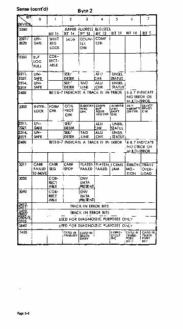
Sense (cont'd) Byte 2
~ 0 1 2 3 4 5 6 7
bEVI 2260 BUFFER ADDRESS REGISTER
BIT 15 BIT 14 BIT 13 BIT 12 BIT 11 BIT 10 BIT 9
2301/ UN- SHIFT SKEW COUN- COMP 2820 SAFE REG TER CHK
LOCK CHK
2305 BUF COR-
LOG RECT-
FULL ABLE
2311, UN- SER/ ALU UNSEL 2321 SAFE DESER rHK STATUS 2314, UN- SER/ TAG ALU UNSEL 2319 SAFE DESER LINE CHK STATUS
2400 BITS 0-7 INDICATE A TRACK IS IN ERROR 16 & 7 INDICATE NO ERROR OR MLtTHRROIt
3203 INTER- FORM COIL SUBSCAN CHAIN HAMMER ANY- DEVICE RING BUF UNIT HAMMER READY
LOCK CHK PROT CHK ADDR SHIFT ON CHK CHK CHK REG CHK CHK
~311, UN- SER/ ALU UNSEL 2321 SAFE DESER HK STATUS t2314, UN- SER/ TAG ALU UNSEL 2319 SAFE DESER LINE CHK STATUS
~400 BITS 0-7 INDICATE A TRACK IS IN ERROR 6 & 7 INDICATE NO ERROR OR MUL TI-ERROR
3211 CARR CARR eMil PLATEN PLATEN FORMS RIBBm. TRAI~~ FAILED SEa STOP FAILED FAILED JAM MO- OVER-
TO MOVE TION LOAD 3330 COR- ENV
RECT DATA ABlE PRESENT
3340 COR- ENV RECT DATA ABlE PRESENT
~l?' TRACK IN ERROR BITS
1~3' TRACK IN ERROR BITS
l~;;!)' USED FOR DIAGNOSTIC PURPOSES ONLY
3540 USED FOR DIAGNOSTIC "URPOSES ONLY
5425 CARD IN, I CARD IN I I,HOPPER I ;ARD IN ! CARD IN PRIMARY SECON-
, f~~LE I ~~~~s- I ~~~~S-DARY I i I i i : 81T 2 - j ~lll
Page 5-4

Sense (cont'd) Byte 3
~ C 1 2 , 3 4 5 6 I 7 nl'vi 2260
I SIT 7 BlHER ADDRE1S REGISTER
I BIT 2 I BIT 1 BIT 8 I BIT 6 I BIT 5 BIT 4 I BIT 3 ~3011 LONG REDUND CHK 2820 2305 RESTART COMMAND
2311 READY! ON UN- ON END SEEK I LINE SAFE LINE OF INC ICYL
2314 BUSY ON UN- WR PACK END M- SEEK LINE SAFE I~~~ CHNG I~~ I~ODE INC
2319 LRC LRC LRC l~fi3 BIT 0 BIT 1 BIT 2 2321 I DRIVE DRIVE READ WRITE, i STRiP INVLD AUTO CECELL
I READY OPER SAFETY SAFETY READY ADDR REST LOC 3205 I CAR- I STEP MOVE
RAGE I CHK CHK I INHIBIT i ICHK i
12400 fRIW LRCR SKEW CRC SKEW 0-1600 BKWD COM-VRC IREQ 1-800 1ST AT! J~ i PARI'
iJ2l1 I UCSB PlB !FCB I COIL l~M- FIELD I USCAR I SEP PARITY PARITY iPARITY It~~T ~J ENG i~~ i~t;f
3330 RESTART COMMAND
3340 RESTART COMMAND
~l?' V~ MTE/ i SKEW END ,ENV 1600 BKWD 1 LRCR
I ~H~~RC CHK BPI IN TU I
~20 R/W MTE/ I SKEW END VRC/ 1600 iBKWD 1 COM-;3803 VRC LRC ~~~R~ ENV BPI ! PARE CHK
~~/5, USED FOR DIAGNOSTIC PURPOSES ONLY
~O CYLINDER ADDRESS IN BINARY
5425 FEE!) AND EMITTER CHECKS (HEX NO)
Page 5-5

Sense (cont'd) Byte 4
I~ 0 1 2 3 4 5 6 7
2260
2301/2820 SEQ SEQ SEQ SEQ SEQ SEQ SEQ SEQ
IND IND IND IND IND IND IND IND
2305 UNUSED
2311,232 I---
2314 PHYSICAL DRIVE IDENTIFICAT/Or-
2319 SEQ SEQ SEQ SEQ SEQ SEQ SEQ SEQ IND 0 IND 1 IND 2 IND 3 IND 4 IND 5 IND 6 IND 7
2400 ECHO RES READ WRITE DELAY SEQ SEQ SEQ ERR TAPE CLOCK CLOCK CNTR IND C IND B IND A
UNIT ERR ERR 3203 HAM- NO MIS- PRINT CHK BIT CHAIN BUF CLOCK
MER RE- FIRE FIRE DATA aUF aUF SUF ADDR CHK SET FAI~i CHK CHK PARITY PARITY PARITY REG CHK
URE CHK CHK CHK CHK
3211
3330 STORAGE PHYSICAL DRIVE ID CONTROL ID G=OOII TO E=OI1100 C=1 01 010 A=111000
H=OOOIII F=010101 D=1000l1 8=110001 3340 STORAGE I PHYSICAL DRIVE ID
CONTROL ID G=OO1110 E=OI1100 C=101010 A=111000 I, H=OOOIII F=010101 D=I00011 B=110001
3410,341 TU TAPE ! DIAG TU~tffiAi POSIT IND TRK CHK CMD CHK CHK I
3420,380 ALU REJ TAPE WRITE MICRO- LWR TAPE ! RES HDWR TAPE INDI- TRGGR PGMDE' ERROR UNIT I RPQ i:RROR UNiT CATE VRC ERROR CHK i
3540 HEAD ADDRESS, MUST BE BINARY ZERO
5425 DEFINES CARD COLUMN GROUP AND TIER OF E~ROR
Page 5-6

Sense (cont'd)
ByteS
~ DEVIC 0 1 2 3 4 5 6 7
2260
2301/2820
2305 [DRIVE SEEK ADDRESS]
2311,2321 COMMAND IN PROGRESS WHEN OVERFLOW INCOMPLETE OCCURS
2314 COMMAND IN PROGRESS WHEN OVERFLOW INCOMPLETE OCCURS
2319
2400 COMMAND IN PROGRESS WHEN OVERFLOW INC OCCURS OR ZERO
3203 OPEN COIL CHK
3211
3330 CYLI NDER ADDRESS
3340 CYLI NDER ADDRESS
3410,3411 NEW WRT PE ID PRTY TACH FALSE RPQ SUB- TM BURST COMP CHK END SYSTEM CHK MARK
3420,3803 NEW NEW WRT PE ID START PARTIAL XCESSVE RES SUB- SUB- TM BURST READ RECORD PSTAMBL RPQ SYSTEM SYSTEM CHK CHK ORTM
3540 RECORD ADDRESS IN BINARY
5425 SPECIFIES ROW (S) FOR THE TIER OF ERROR
Page 5-7

Sense (cant'd) ByteS
~ 0 1 2 3 I 4 I 5 I 6 I 7
2301/282C
2305 [DRIVE SEEK ADDRESS]
3203
3330 REVERSE CYL DIFFER HEAD ADDRESS HIGH HIGH
3340 CYL HEAD ADDRESS HIGH
3410,341 7TRK SHRT DUAL ALT rJ
TAPE UNIT MODEL GAP DE NSIT'f DENSIT
3420,380 7 TRK WRT ' DUAL NRZI I TAPE UNIT MODEL DEFINED
5425
Byte 7
2305 [MESSAGE CODe (HEX) ]
[3203
~* FORMAT TYPE OF REMAINING ENCODED ERROR SENSE BYTES (8-23) MESSAGE
~* FORMAT TYPE OF REMAINING ENCODED ERROR SENSE BYTES (8-23) MESSAGE
3410,341 LAMP I LEFT RT READY I DATA CHK COL COL RESET SEC
CHK CHK ERASE
3420,380 LAMP I TAPE TAPE RESET DATA ERASE I I AIR I LOAD FAIL BOTTOM BOTTOM KEY SCRTY HEAD BRNG - FAIL
I lEFT RIGHT ERASE FA.ILED PRESS i 5425
Page 5-8

Sense (cont'd) Byte 8
~ DEVI 0 1 2 3 4 5 6 I 7
3330 * f----
3340*
3410,3411 FEED END RD BK START THRU VEL DATA VEL
CHK NOT DE1 CHK
3420,380 IRG FEED SDR EARLY EARLY SLOW SLOW : I(ELOC DROP THRU CNTR BGN RC END RD BGN RD END RD RETRY/
INWRT CHK BKCHK BKCHK BKCHK BK CHK RESTRT
Byte 9
~ DEVIC 0 1 I 2 I 3 4 I 5 I 6 7
3420,380~ JDR VLCTY ! SDR COUNTERS TAPE CNTR CHNGR~ CTL
ONWR RESD
Byte 10
~ bEVIC 0 1 2 I 3 4 5 I 6 7
3420, CMD CNTRL i NO BLK WTM TACH T VELO-3803 STATUS STATUS liON RCD NOT START, CITY
REJ REJ RD BKC~ DETECT FAIL i CHK
Byte 11
~ 0 1 2 3 4 5 6 7
~~g, B BUS LO ROS HIIC MCPGM D BUS BR PARITY LO IC BRCQ'o.lD DET PARITY COND ALU I PARITY /HI ROS HDWR ALU1 ALU 1
I ERR
Byte 12
~ bEVIC 0 1 2 3 4 5 6 7
3420, B BUS LO RO~ HIIC MCPGM D BUS BR 3803 PAR ERR ;lo IC BRiHI DETECT PARITY COND
ALU 2 ON BR ROS REC ,mWR ALU 2 ALU 2
* 3330/3340 Bytes B - 23: Iv\eaning depends on format type.
Page 5-9

Card Readers
CARD READERS - GENERAL HINTS
1. A common cause of read checks is off·punched or worn cards. 2. Use a card gauge to determine off punching. 3. A validity check usually indicates a double punch in rows 1-7 of the card. 4. When bringing new cards into the computer room from a different environ
ment (heat, humidityl, do not use them for the first 12 hours. 5. Cards do \Near out. Reproduce master decks when you notice excessive
marking or ~oring on the edges. 6. Some common sense messages that may type out on the console are:
Page 5·10
Intervantion Required - Operator attention is needed to empty the stacker, fill the hopper, press END OF FILE, clear the transport, close a cover, or restore ready status. This indication also accompanies a read station failure that occurs during reading.
Equipment Check - Indicates that the two readings of a column did not agree. Also indicates that the read station failed before reading begins.
Data Check - Indicates that the machine has detected an invalid card column (more than one punch in rows 1-71 in data mode 1.

3504/3505 Stop Indications and Restart Procedures Source: GA21-9,124-33505 Card Reader 3525 Card Punch
Subsystem Component Description
. THERMAL STACKER· COVER HOPPER OPEN
. CHECK TRANSPORT FORMAT REPLACE
CARD 8 4 RESET 2 1
NPRO JAM MACHINE PERMANENT
8 4 CHECK 2 ERROR
If indicators are not in a combination shown on any error display, or if an operator recovery action is unsuccessful, treat the condition as a permanent error and perform the procedure specified by the source program.
INDICATION DISPLAYED: NPRO
RECOVERY PROCEDURE:
Recover is likely.
1. NPRO. (Open the hopper door and press the NPRO key.) 2. Place the last 2 cards that entered the active side of stacker 1 in correct
sequence under the cards in the hopper and close the hopper door. 3. Press the start key.
NOTE: The permanent error key is operative during this stop.
INDICATION DISPLAYED: NPRO, MACHINE CHECK
RECOVERY PROCEDURE:
Recovery is possible. If desired, perform the procedure specified for the NPRO indication two or three times.
Perform the NPRO indication procedure, or if that procedure fails repeatedly:
1. If the reader has a log-out key, press it and write down the digits on each row of the backlighted panel.
2. If the reader has no log-out key, record the error information from the reader log display at the system console.
3. When you report the problem to the CE, also report the error information you recorded.
NOTE: The permanent error key is operative during this stop.
Page 5-11

3504/3505 Stop Indications and Restart Procedures (cant'd)
INDICATION DISPLAYED: NPRO, CHECK CARD
RECOVERY PROCEDURE:
1. NPRO. (Open the hopper door and press the NPRO key.) 2. Remove the last two cards that entered the active side of stacker 1. The first
card stacked is in error; check this card for more than one punch in row posi· tions 1 through 7 in each column and for poor punch registration. (If necessary .. replace the card with a card punched correctly offline.) Place the two cards in correct sequence under the cards in the hopper and close the hopper door.
3. Press the start key. Note: The permanent error key is operative during this stop.
INDICATION DISPLAYED: NPRO, HOPPER, REPLACE 1
RECOVERY PROCEDURE:
Recovery is likely.
1. NPRO. (Open the hopper door and press the NPRO key.) 2. Place the last card that entered the active side of stacker 1 back into
the hopper, then close the hopper door. 3. P,.ss the start key and the end·of·file key.
NOTE: The permanent error key is operative during this stop.
INDICATION DISPLAYED: NPRO, HOPPER, REPLACE 1, MACHINE CHECK
RECOVERY PROCEDURE:
Recovery is possible. If desired, perform the NPRO and REPLACE 1 procedure two or three times. If you do not perform that procedure, or if that procedure fails repeatedly:
1. If the reader has a log·out key, press it and ·write down the digits on each row of the backlighted panel.
2. I f the reader has no log·out key, record the error inform at ion from the r~ader log display at the system console.
3. When you report the problem to the CE, also report the error informa· tion you recorded.
Note: The permanent error key is operative during this stop.
INDICATION DISPLAYED: NPRO, CHECK CARD, REPLACE 1
RECOVERY PROCEDURE:
Page 5·12
1. Remove the cards from the hopper and examine the bottom card for anything that may have caused the misfeed (a burred edge, for ex· ample). Reproduce this card, if necessary.
2. Press NPRO key. 3. Place the last card that entered the active side of stacker 1 in correct
sequence with the card from 1 above and place them under the cards removed from the hopper.
4. Put the cards back into the hopper and close the hopper door. 5. Press the start key.

3504/3505 Stop Indications and Restart Procedures (cont'd)
INDICATION DISPLAYED: NPRO, CHECK CARD, HOPPER, REPLACE 1
RECOVERY PROCEDURE:
1. NPRO. (Open the hopper door and press the NPRO key.) 2. Remove the last card that entered the active side of stacker 1. Check
this card for more than one punch in row positions 1 through 7 in each column and for poor punch registration. (If necessary, replace the card with a card punched correctly offline.) Place the card back in the hopper and close the hopper door.
3. Press the end·of-file and start keys.
NOTE: The permanent error key is operative during this stop.
INDICATION DISPLAYED: HOPPER
RECOVERY PROCEDURE:
Except for end-of-file conditions:
1. Fill the hopper and close the hopper door. 2. Press the start key.
For end-of-file:
1. Press the end of file key. 2. Press the start key.
NOTE: The permanent error key is operative during this stop.
INDICATION DISPLAYED: STACKER
RECOVERY PROCEDURE:
1. Empty the full stacker or set stacker 1 switch to point to empty stacker. 2. Press the start key.
NOTE: The permanent error key is operative duri'ng this stop.
INDICATION DISPLAYED: COVER OPEN
RECOVERY PROCEDURE:
1. Close all covers. 2. Check last card in stacker area to see that it was completely stacked. 3. Press the start key.
NOTE: The permanent error key is operative during this stop.
Page 5-13

3504/3505 Stop I ndications and Restart Procedures (cont'd)
INDICATION DISPLAYED: THERMAl
RECOVERY PROCEDURE:
The read lamp has overheated.
1. NPRO. (Open the hopper door and press the NPRO key.) 2. Place last 2 cards that entered the active side of stacker 1 in correct
sequence under the cards in the hopper and close the hopper door. 3. Press the start key. If the read lamp has cooled enough, the thermal
light will tum off. 4. If the thermal light remains on, allow the lamp to cool for a while,
then press the start key again. Repeat this step until the light remains off.
5. Press the start key. 6. If the thermal condition is persistent, call a Customer Engineer.
NOTE: The permanent error key is operative during this stop.
INDICATION DISPLAYED: HOPPER, JAM
RECOVERY PROCEDURE:
1. Remove cards from hopper, repair or replace any damaged cards, and place the removed cards in correct sequence back into the hopper and close the hopper door.
2. Press the start key.
NOTE: The permanent error key is operative during this stop.
INDICATION DISPLAYED: TRANSPORT, JAM
RECOVERY PROCEDURE:
There Is a jam or misfeed in the transport. Two cards must be placed back in the hopper.
Page 5-14
Machine without selective stacker:
1. Examine the transport for a jam at the pre·read or read station, or for two cards at the pre-read station.
2. If you only recovered one card from the transport, remove the last card that entered the active side of stacker 1.
3. Place these cards in correct sequence under the cards in the hopper and close the hopper door.
4. Press the start kev.
Machine with selective stacker:
1. Examine the transport, from the start of the pre-read station to the end of the post-read station, for cards.
2. Place the last 2 cards fed (that is, the two cards closest to the hopper) in correct sequence under the cards in the hopper and close the hopper door.
3. Place any remaining cards in their appropriate stackers. 4. Press the start key.
NOTE: The permanent error key is operative during this stop.
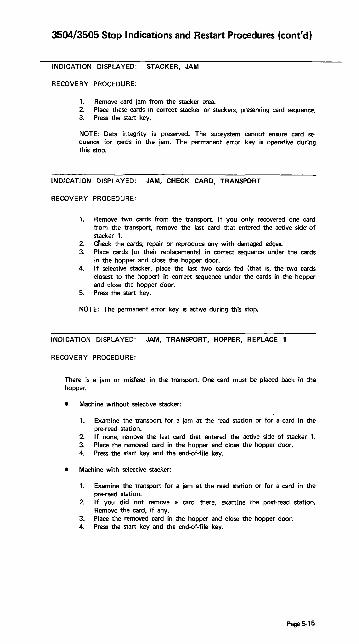
3504/3505 Stop Indications and Restart Procedures (cont'd)
INDICATION DISPLAYED: STACKER, JAM
RECOVERY PROCEDURE:
1. Remove card jam from the stacker area. 2. Place these cards in correct stacker or stackers, preserving card sequence. 3. Press the start key.
NOTE: Data integrity is preserved. The subsystem cannot ensure card sequence for cards in the jam. The permanent error key is operative during this stop.
INDICATION DISPLAYED: JAM, CHECK CARD, TRANSPORT
RECOVERY PROCEDURE:
1. Remove two cards from the transport. If you only recovered one card from the transport, remove the last card that entered the active side· of stacker 1.
2. Cneck the cards; repair or reproduce any with damaged edges. 3. Place cards (or their replacements) in correct sequence under the cards
in the hopper and close the hopper door. 4. If selective stacker, place the last two cards fed (that is, the two cards
closest to the hopper) in correct sequence under the cards in the hopper and close the hopper door.
5. Press the start key.
NOTE: The permanent error key is active during this stop.
INDICATION DISPLAYED: JAM, TRANSPORT, HOPPER, REPLACE 1
RECOVERY PROCEDURE:
There is a jam or misfeed in the transport. One card must be placed back in the hopper.
Mach ine without selective stacker:
1. Examine the transport for a jam at the read station or for a card in the pre-read station.
2. If none, remove the last card that entered the active side of stacker 1. 3. Place the removed card in the hopper and close the hopper door. 4. Press the start key and the end-of-file key.
Machine with selective stacker:
1. Examine the transport for a jam at the read station or for a card in the pre-read station.
2_ If you did not remove a card there, examine the post-read station. Remove the card, if any.
3_ Place the removed card in the hopper and close the hopper door. 4. Press the start key and the end-of-file key.
Page 5-15

3504/3505 Stop Indications and Restart Procedures (cont'd)
INDICATION DISPLAYED: JAM, TRANSPORT, CHECK CARD, HOPPER REPLACE 1
RECOVERY PROCEDURE:
1. Locate and remove the card from the transport. 2. Check the card for damaged edges. 3. Repair or reproduce the card, if necessary. 4. Place the card in the hopper. 5. Press the start key and end·of·file key.
NOTE: The permanent error key is operative during this stop.
INDICATION DISPLAYED: FORMAT RESET
RECOVERY PROCEDURE:
Indicates that an optical mark read or read column eliminate format has been reset by an unformatted read only command or by an unformatted read, feed and select stacker command. If this error occurs within a job, and if the operator has no other information from the programmer, the operator should press the stop key, permanent error key, then the start key to make the device ready. If this error occurs within a job and the programmer has provided operator instructions, the operator should follow these instructions. If this error occurs at job initiation, the operator should NPRO, place the last two cards entering the active side of stacker 1 in correct sequence under the cards in the hopper, close the hopper door, and press the start key.
INDICATION DISPLAYED: NPRO. PERMANENT ERROR
RECOVERY PROCEDURE:
This is a device permanent error - command reject.
1. Perform the error recovery specified by the source program for this type of error.
INDICATION t DISPLAYED: JAM, TRANSPORT, PERMANENT ERROR
RECOVERY PROCEDURE:
This is a device permanent error.
1. If the reader has a log-out key, press it and write down the digits from l'aCh rO\lll of the backlighted panel.
2. I f the reader has no log·out key, record the error information from the reader log display at the system console.
3. When you report the problem to the CE, also report the error informa· tion you recorded.
INDICATION DISPLAYED: JAM, MACHINE CHECK, PERMANENT ERROR
RECOVERY PROCEDURE:
Consider this a permanent error condition and perform the procedure specified by the source program. During this procedure the NPRO key should be pressed with the hopper door open to run cards out of the unit.
Page 5·16

3525 Stop Indications and Restart Procedures Source: GA21-9124-3 3505 Card Reader 3525 Card Punch
Subsystem Component Description
CHIP STACKER COVER FEED BOX OPEN OPEN
CHECK PRESS FORMAT. 3 CARD CARD 8 START 4 RESE1 2 RUN IN
NPRO JAM MACHINE PERM 8 4 CHECK 2. ERROR 1
OFFLINE MIS· STACKER PRINT SELECT 3 SKEW
If indicators are not in a combination shown on any error display, or if an operator recovery action is unsuccessful, treat the condition as a permanent error and perform the procedure specified by the source program.
INDICATION DISPLAYED: CHIP BOX
RECOVERY PROCEDURE:
1. Remove and empty the chip box. 2. Place the chip box back into the machine.
NOTE: After the chip box light comes on, the punch continues to operate for a reasonable period of time if the box is in the machine and properly positioned. However, when the chip box becomes too full to permit machine operation, the operator call light will come on and the punch will stop.
NOTE: Chip box must be in the tray.
J1 RIGHT WRONG
NOTE: The permanent error key is operative during this stop.
Page 5-17
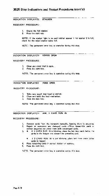
3525 Stop Indications and Restart Procedures (cont'd)
INDICATION DISPLAYED: STACKER
RECOVERY PROCEDURE:
1. Empty the full stacker. 2. Press the start key.
NOTE: If the stacker light is on and neither stacker 1 nor stacker 2 is full, check for the reject stacker being full.
NOTE: The permanent error key is operative during this stop.
INDICATION DISPLAYED: COVER OPEN
RECOVERY PROCEDURE:
1. Close any cover that is open. 2. Press the start key.
NOTE: The permanent error key is operative during this stop.
INDICATIO~ DISPLAYED: FEED OPEN
RECOVERY PROCEDURE:
1. Make sure upper read head is latched. 2. Close and latch the feed mechanism. 3. Press tile starr key.
NOTE: The permanent error key is operative during this stop.
INDICATION DISPLAYED: JAM, 3 CARD RUN IN
RECOVERY PROCEDURE:
Page 5·18
1. Remove cards from the transport manually, keeping them in sequence. 2. Repair or reproduce any damaged cards offline; reassemble cards in
correct sequence and place them with undamaged cards. 3. • If 3 CARD RUN IN is blinking, place the last two cards below the
cards in the hopper and discard the preceding card.
If 3 CARD RUN IN is not blinking, place last three cares below cards in hopper.
4. Place remaining cards in COHee! stacker or Slackers. 5. Press the start key.
NOTE: The permanent error k~y is operative during this stop.

3525 Stop Indications and Restart Procedures (cont'd)
INDICATION DISPLAYED: JAM: MACHINE CHECK, 3 CARD RUN IN
RECOVERY PROCEDURE:
1. Remove all cards from the transport manually, keeping them in sequence.
2. Repair or reproduce any damaged cards offline, then put them, in correct sequence, with the undamaged cards.
3. Place all cards removed at the bottom of the deck in the hopper. 4. Press the start key.
NOTE: The permanent error key is operative during this stop. This is the only time that more than three cards can be returned to the hopper.
INDICATION DISPLAYED: NPRO, MACHINE CHECK
RECOVeRY PROCEDURE:
1. Empty stacker 1. 2. NPRO (While holding cards in hopper away from bottom of hopper, run
cards out of transport by holding the NPRO key down.) 3. Remove all other cards from stacker 1 and place them in their correct
stacker or stackers, if possible. If you cannot determine the correct stackers for these cards, put them aside for later manual distribution.
4. Press the start key.
NOTE: The permanent error key is operative during this stop.
INDICATION DISPLAYED: JAM
RECOVERY PROCEDURE:
1. Remove cards from the card transport area manually, keeping the cards in their correct sequence.
2. Repair or reproduce any damaged cards. 3. Place these cards in their correct place with those removed from the
transport area. 4. • If the jam occurred during a run·in operation:
a. Place the cards in the hopper. b. Press the start key. If the jam occurred during an NPRO operation: a. Place the cards in their appropriate stackers. b. Continue performing the procedure under progress when the
jam occurred.
NOTE: The permanent error key is operative during this step.
INDICATION DISPLAYED: JAM, PRESS START
RECOVERY PROCEDURE:
1. Remove cards from stacker manually, keeping cards in correct sequence. 2. Repair or reproduce any damaged cards offline, then reassemble them in
correct sequence with the undamaged cards; place all these cards in the stacker(s).
3. Press the start key.
NOTE: The permanent error key is operative during this stop.
Page 5·19

3525 Stop Indications and Restart Procedures (cont'd)
INDICATION DISPLAYED: MACHINE CHECK, PRESS START
RECOVERY PROCEDURE:
1. Press the start key.
NOTE: The permanent error key is operative during this stop.
INDICATION DISPLAYED: NPRO, 3 CARD RUN IN
RECOVERY PROCEDURE:
1. Remove cards from hopper and examine throat area. If partially·fed card is stuck in throat, remove it, repair or replace it, and put it on bottom of stack removed from hopper.
b. Remove any dust or pieces of paper from throat area. 2. Empty stacker 1. 3. NPRO (press the NPRO key.) 4. • If 3 CARD RUN IN is blinking, discard first card that entered
stacker 1; place any other stacker 1 cards in hopper. If 3 CARD RUN IN is not blinking, place all cards that entered stacker 1 in hopper.
5. Place cards removed from hopper back into hopper. 6. Press the start key.
NOTE: The permanent error key is operative during this stop. During NPRO, three cards should enter stacker 1 unless one card was stuck in throat; if card was stuck in throat, two cards should enter stacker 1.
INDICATION DISPLAYED: JAM, PERMANENT ERROR
RECOVERY PROCEDURE:
1. Manually remove all cards from the card transport. 2. Perform the procedure specified by the source program
INDICATION DISPLAYED: JAM, MACHINE CHECK, PERMANENT ERROR
RECOVERY PROCEDURE:
1. Manually remove all cards from the card transport. 2. Perform the procedure specified by the source program.
INDICATION DISPLAYED: JAM, PRESS START, MISSElECT
RECOVERY PROCEDURE:
A pu nch error occurred and the error card failed to enter stacker 3.
Page 5·20
1. Examine the last cards to enter stackers 1 and 2 for a card containing a punch error. Place this card in stacker 3.
2. Press the start key.
NOTE: The permanent error key is operative during this stop.

3525 Stop Indications and Restart Procedures (cont'd)
INDICATION DISPLAYED: JAM, PRESS START, MISSELECT, STACKER 3
RECOVERY PROCEDURE;
For a non-punch or read-punch job,
1. Examine stacker 3 for error-free data cards misselected into the stacker. 2. Place these cards in stacker 1 or stacker 2, as appropriate. 3. Press the start key.
For an unknown job,
1. Examine all stackers for m;sselected cards. 2. If correct stacker can be determined, place cards in correct stacker and
press start key. 3. If correct stacker cannot be determined, post penn anent error.
NOTE: The permanent error key is operative during this stop.
INDICATION DISPLAYED: PRINT SKEW, PRESS START
RECOVERY PROCEDURE:
1. Inspect the last 2 cards in each stacker for skewed printing. If neces. sary, manually reproduce and print the cards, or place them aside for
later reproduction. 2. Replace these cards in their correct stackers. 3. Press the start key.
NOTE: The permanent error key is operative during this stop.
INDICATION DISPLAYED: NPRO, PERM ERROR
RECOVERY PROCEDURE:
1. Press stop key, then logout key. If logout number is 4 and 2 on upper line and the lower line is blank, go to step 4. Otherwise, go to step 2.
2. Check for card jam between punch and print stations. If there is a jam, remove cards from transport, then go to step 4. If no jam exists, go to step 3.
3. Did someone NPRO a job without NPRO or PERM ERROR lighted? If so, restart the job. If not, cancel the job and have the program corrected.
4. Perfonn the procedure specified by the source program. During this procedure, run cards out of the lransport by pressing the NPRO key.
Page 5-21

3525 Stop Indications and Restart Procedures (cont'd)
INDICATION DISPLAYED: NPRO, CHECK CARD
RECOVERY PROCEDURE:
1. Press the stop key: the J.card run-in light will come on. 2. Empty stacker 1. 3. . NPRO. (While holding cards in hopper away from bottom of hopper,
run cards out of transport by holding the NPRO key down.) 4. If there are cards remaining in the hopper and only two cards NPRO to
stacker 1, press permanent error key twice to cause two card run-in. 5. Remove and examine the cards that ran into stacker 1. Repair, or
replace with a manually-reproduced card, any damaged cards. 6. Place all these run-out cards under the deck in the hopper, maintaining
correct card sequence. 7. Press the start key.
NOTE: The permanent error key is operative during this stop. If indicatioo is continuous, check to be sure that upper read head is latched.
INDICATION DISPLAYED: FORMAT RESET
RECOVERY PROCEDURE:
Indicates that a read column eliminate format has been reset by an unformatted read only command or by an unformatted read, feed, and select stacker command. If this error occurs within a job, and if the operator has no other information from the programmer, the operator should press the stop key, permanent error key, then the stan key to make the device ready. If this error occurs within a job and the programmer has provided operator instructions, the operator should follow these instructions. If this error occurs at job initiation, the operator should NPRO Oift the cards off the bottom of the hopper and press the NPRO key), load the last two cards &r.ter ir'll .1iK;l..", 1 iJa<;~ under the carcis in tile hopper, and press the start key.
NOTE: The permanent error key is operative during this stop
INDICATION DISPLAYED: OFFLINE
RECOVERY PROCEDURE:
Indicates that the 3535 is disconnected from the system functionally.
To place the 3525 online:
Page 5-22
1. Set the ONLINE/OFFLINE switch to its ONLINE setting.
NOTE: The ONLINE/OFFLINE switch is located at the attachment. If the
3525 is attached to the 3505, the switch is under the 3505 front cover.

3525 Stop Indications and Restart Procedures (cont'd)
INDICATION DISPLAYED: 3 CARD RUN IN
RECOVERY PROCEDURE:
The recovery from the previous error has not been completed.
1. • If 3 CARD RUN IN is blinking, clear the transport and discard the card at the print station. If 3 CARD RUN IN is not blinking, clear the transport, but do not discard the card.
2. Continue with the recovery procedure being performed when this display
If you are starting a new job, press the permanent error key twice to cancel the recovery. CAUTION: Pressing the key cancels the recovery and recovery cannot be accomplished.
INDICATION DISPLAYED: PERMANENT ERROR
RECOVERY PROCEDURE:
If this indicator is lighted and you did not press the permanent error key deliberately, press the permanent error key to turn the light off. This will ensure that a permanent error indication posted for the last job, (or one resulting from an unintended depression of the permanent error key) will not be associated with the present job.
INDICATION DISPLAYED: STACKER 3
RECOVERY PROCEDURE:
The stacker 3 indicator can be on either alone or in combination with other indications. It comes on when a card enters the reject stacker and remains on until the start key is pressed.
If the job being processed is a data security job-that is, if it is important for the cards or the information they contain to be kept under security-the reject stack· er (stacker 3) must be emptied, as part of the restart procedure before the start key is pressed, and at the end of the job. Nonsecurity error cards should be collected for the customer engineer's examination.
INDICATION DISPLAYED: 3 CARD RUN IN, PRESS START
RECOVERY PROCEDURE:
1. Ensure that the last card stacked entered the correct stacker. 2. Remove cards from the transport manually, keeping them in sequence. 3. Repair or reproduce any damaged cards offline; reassemble cards in
correct sequence and place them with undamaged cards. 4. Place last three cards below the cards in the hopper. 5. Place remaining cards in correct stacker or stackers. 6. Press the start key.
NOTE: The permanent error key is operative during this stop.
Page 5·23

LOG-OUT INDICATIONS (NUMBERS)
CHECK TRANSPORT fORMAT REPLACE CARD Ii 4 RESET '1 1 J
NPRO H JAM 4 M~~~:E2 PE~::~~N~
READER
-Upper row of digits', Log.Out
_Lower row of digits.1 Numbers
PUNCH
- Upper row of digits', Log-Qut
\ Numbers _Lower row of digits'
• Ignore the words.
The back lighted panel serves twO functions. Normally, the panel displays indications that show the operator what procedure to follow to recover from an error. (These indications have been discussed earlier in this manual.l When a permanent error occurs that requires machine repair, the recovery procedure directs the operator to prBD the log-out key. When a permanent error occurs that requires machine repair, the recovery procedure directs the operator to press the log-out key. This causes the panel to display a different set of indications, which are called log-out numbers. (The words displayed on a log·out indication are meaningless and should be ignored.l When the oparator calls to report the problem, he should tell the customer engineer what digits are displayed in the upper row, then what digits are displayed in the lower row. If no digits are shown in a row. the operator should report that the row is blank.
EXAMPLE: Indication
CHECk PRESS ,) CARD CARli l! STAAT 4 RUN IN 1
Page 5·24
Possible Report to CE
-Upper Row
_Lower Row
"The 3525 is not working. The
upper row of log-out digits
displays 8. 4. 1. The lower row is blaok."

3525 Error Recovery Routine Source: GA21-9124-3 3505 Card Reader 3525 Card Punch
Subsystem Component Description
Before any programmed punch and/or print retries are performed, the operator must remove all cards that must be completely or partially reprocessed. Your source program error recovery routine can help the operator to decide which cards need to be removed. Some of the information your routine could provide is:
1. The number of cards to be removed. 2. The location of the cards to be removed. 3. Identification by data content of the cards to be removed. 4. The number of blank cards to be put in the 3525 for the recovery pro
cedure.
The error recovery routine should then punch and/or print the data for the card that must be completely reprocessed. Then !lunch and/or print the data for the next card that must be partially reprocessed. The error recovery routine can then retum to the normal source program to finish processing that next card.
For specific recovery techniques, be guided by the error message you receive from the System Control Program in use.
Page 5-25

OSNS1 Checkpoint Restart Source: GC26-3784 OSNS Checkpoint/Restart
HOW TO RESTART A JOB
Automatic Restart
When you receive the message requesting your authorization for a restart:
xxlEF225D SHOULD jobname.stepname.procstepname [checkid] RESTART
you must reply to the request as follows:
{
'YES' } rid, 'HOLD'
'NO'
YES authorizes the restart, HOLD postpones it, and NO prohibits it. After a YES reply the job is reinterpreted by a restart reader named IEFREINT that is started automatically by the system, and if'a MONITOR JOBNAMES is in effect, IEFREINT STARTED and IEFREINT ENDED messages are displayed. These are followed by normal mount messages and a successful restart message.
Deferred Restart
To perform a deferred step restart in VS1, the job to be restarted ",ust be resubmitted. Normal mount messages are d;sp!ayed.
Page 5-26
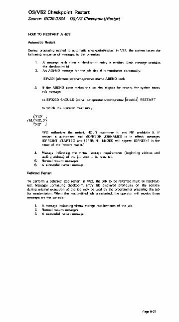
OS/VS2 Checkpoint Restart Source: GC26-3784 OSNS Checkpoint/Restart
HOW TO RESTART A JOB
Automatic Restart
During processing related to automatic checkpoint/restart in VS2, the system issues the following sequence of messages to the operator:
1. A message each time a checkpoint entry is written. Each message contains the checkpoint id.
2. An ABEND message for the job step if it terminates abnormally:
IEF4501 jobname,stepname,procstepname ABEND code
3. If the ABEND code makes the job step eligible for restart, the system issues this message:
xxi EF225D SHOU LD jobname.stepname.procstepname [checkid] RESTART
to which the operator must reply:
{'YES' }
rid, 'HOLD' 'NO'
YES authorizes the restart, HOLD postpones it, and NO prohibits it. If restart is authorized and MONITOR JOBNAMES is in effect, messages IEFREINT STARTED and IEFREINT ENDED will appear. IEFREINT is the name of the 'restart reader:
4. Message indicating the virtual storage requirements (beginning address and ending address) of the job step to be restarted.
5. Normal mount messages. 6. A successful restart message.
Deferred Restart
To perform a deferred step restart in VS2, the job to be restarted must be resubmit· ted. Messages containing checkpoint entry ids displayed previously on the console during original execution of the job may be used by the programmer preparing the job for resubmission. When the resubmitted job is restarted, the operator will receive these messages on the console:
1. A message indicating vir:tual storage requirements of the job. 2. Normal mount messages. 3. A successfu I restart message.
Page 5-27

IBM 3340 Disk Drive Source: GA26-7619 IBM 3340 Reference Manual
READ ONLY FUNCTION
The means to protect previously written data modules is provided by the Read Only function. The following procedures show how to enable or disabJe the Read Only function for either 3348 model.
Enable Read Only Function
1. With data module removed from the drive, press down on IBM logo inset of the handle (A).
2. Turn inset 1000 and snap into place (B). 3. The data module may now be loaded in the desired drive.
Page 5·28

IBM 3340 Disk Drive (cont'd)
Disable Read Only Function
1. With the data module removed from the drive, return the IBM logo inset to its origina,l position (reverse 180°) (e).
2. The data module may now be loaded into the desired drive.
Note: Do not attempt to enable or disable the Read Only function while the data module rests in the drive shroud recess.
Operating Hints
When you take a 3340 drive offline and want to start it up again, press START STOP. The drive cycles up. Then press the ATIENTION button. ATIENTION must be used to signal the system that the drive is ready.
Do not use Power-On or Power-Off switches to load or unload the data module, because these switches are bypassed by the subsystem sequencing controls during a subsystem power-up or power-down operation. Power is turned on or removed by the subsystem sequencing controls.
Page 5-29

Console File Source: GA33-1509-0 System/370 Mod 125 Procedures
The console loads microprogram on diagnostic programs into the system. It is also used by the system to store logs. The miaoprogram diagnostic programs and logs are stored on lightweight magnetic disk cartridges (diskettes).
IBM Diskette Source: GA33-1509 System/370 Mod 125 Procedures
There are two types of diskettes:
The system diskette The service diskette
The System Diskette is used for normal operation.
The Service Diskette is used for loading ASCP.
Because the magnetic disk cartridge (diskette) contains information that is vital to system operation, it must be properly safeguarded.
Avoid:
Rough handling of the diskette. Never write on or mark the diskette. • Localized pressure on any part of the diskette. • Strong. direct sunlight on the diskette.
Page 5-30
Attempts to clean the diskette in any way. ExpolUre of the diskette to magnetic fields. Keep away frolT' all metal objects. Touching of exposed diskette surfaces. Use the handling area. If a magnetic disk ClIrtridge is damaged, inform the CEo

IBM Diskette (cont'd) Operating Procedures Source: GC38'()()15-3 IBM System/370 Mod 145 Operating
Procedures
CONSOLE FILE CARTRIDGE INSERTION and REMOVAL
Insertion
1. Pull handle !8l to ~n console-file cover. 2. Grasp the cartridge tru by its white handling area and remove it from its
envelope. 3. Lower the cartridge ~ until it is stopped by the locating surfaces. 4. Close cover carefully ~ . The centering cone must slide freely into the
center of the disk. If not, check that the cartridge is seated against the locating surfaces and that the cartridge is not damaged.
5. Return the empty carriage envelope to the disk storage rack. 00
Removal
1. Pu II hand Ie !81 to ,22en console-file cover. 2. Grasp the cartridge lID by its white handling area and lift it straight up. 3. Slide the cartridge into its envelope and return it to the disk storage rack
[§] or to the storage area.
Storing Cartridges
Before using, acclimate cartridges to the computer room:
If in mailing carton, wait 24 hours. If not in mailing carton, wait 1 hour. If mounted on a nonpowered file, wait Yo hour.
Place cartridges in their envelopes and store them either in the storage rack or in their original mailing cartons. A storage environment should meet the following criteria:
Temperature Relative Humidity Maximum Wet Bulb Temperature
Shipping and Receiving
400-lIXtF (4,4°-37.S0C) 8%-80% 80°F (26.7°C)
Ship cartridges .inside the original shipping carton. Additional shipping cartons are available at IBM Branch Offices. With the cartridge in place, the package weighs 10 ounces. Be sure to label the package, "DO NOT EXPOSE TO HEAT OR SUNLIGHT."
When receiving cartridges, check for carton and cartridge damage. Save the carton for storing a cartridge and for possible future cartridge shipment.
Page-5-31
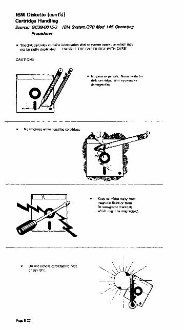
IBM Diskette (cont'd) Cartridge Handling Source: GC38-OO15-3 IBM System/370 Mod 145 Operating
Procedures
• The disk cartridge contains information vital to system operation which may not be easily duplicated. HANDLE THE CARTRIDGE WITH CARE!
CAUTIONS
No smoking while handling cartridges.
Do not expose cartridges to heat or sunlight.
Page 5-32
• No pens or pencils. Never write on disk cartridge. Writing pressure damages disk.
Keep cartridge away from magnetic fields or from ferromagnetic materials which might be magnetized.

IBM Diskette (cont'd) Cartridge Handling (cont'd)
Replace cartridge envelopes when they become worn, cracked, or distorted.
Return cartridge to envelope whenever it is removed from the console file.
Do not touch or clean the disk surface.
Store cartridges in their original shipping cartons, or in the storage rack on the access door.
Page 5-33

IBM 3410/3411 Tape Drive Source: G232-(J()()4 3410/3411 Operator's Guide
Operating Procedure after Failures-
1. The tape unit fails to sense the BOT marker and continues to search forward for it.
a. Ensure that the BOT marker is properly positioned 14 to 18 feet from the physical beginning of tape. (If not, replace the marker.)
b. Re-try load procedure, ensuring that the BOT marker is to the left of the left-hand idler before pressing the LOAD REWIND button.
2. Tape fails to load properly in either column or both columns, or it dumps in either column.
Open vacuum column door and check the door and column edges for contaminants that may have prevented proper sealing. Re-try load procedure.
3. Tape unit fails to sense the end·of·tape (EOT) marker and tape unwinds completely off file reel.
Ensure that the EOT marker is properly positioned approximately 25 feet from the physical end of tape. (If not, replace the marker.) If the marker is properly positioned, the failure could be a programming error or a machine malfunction.
b. Thread tape back across idlen and onto the file reel. Manually wind 10 to 15 turns counterclockwise on file reel and remO\le all slack. Press the LOAD REWIND button. As soon as the tape is loaded and starts to move, press the RESET button. Then press either the LOAD REWIND or the UNLOAD REWIND button, depending on the action desired.
4. Permanent write failures occur immediately beyond BOT.
a. Check the read/write head for contamination. If any doubt exists, clean Uu, he<iU i- "Ci .... "iny Floco:Jur~"'i. Re-lrV juL.
b. If problem recurs, mount a different reel of tape and re-try job.
5. Power is dropped while tape is loaded and not at BOT.
Manually rewind all slack between reels. Restore power and press the RESET and LOAD REWIND buttons. Tape loads into columns and starts moving forward. Again press the RESET button and then press either the LOAD REWIND or the UNLOAD REWIND button, depending on what action is desired.
Cleaning Procedures
Clean tape transport and capstan every eight hours. Use cleaning kit, part 352465. and tape transport cleaner.
Note: Use IBM tape transport cleaner, part 453511, or competitive formulations of the same chemical composition. Performance results cannot be guaranteed when other chemical formulations are used, because they have not been tested by IBM. ami ,tho;r use may impair performance or cause damage to the tape unit or tape.
CAUTION
1. Avoid prolonged skin contact with tape cleaner. 2. Never clean a tape unit with a metal object. Use only materials specified for
each operation. 3. Never touch rubber capstan surface with bare fingers; moisture or oil impairs
tape-tCK:apstan friction. 4. Remove any tape cleaner dropped in the tape path, on the tape guides, or
on the idlers during cleaning. 5. Don't use water in the capstan area or the read/write head area. 6. Never get fluids of any kind in or near the column sensors. 7. Do not use the flat area of top cover or the sliding door ;urface as a work
area.
If faiJures continue after recommended action has been taken, notify the CEo
Page 5·34

IBM 3410/3411 Tape Drive Tape Transport Cleaning Source: G232-0004 3410/3411 Operator's Guide
Tape Transport Cleaning
1. Unload tape and remove from tape unit. 2. Clean tape guides, tape path, idlers, vacuum columns, and vacuum column
door with a lint-free cloth moistened with tape cleaner. Use the small brush moistened with tape cleaner to clean the cleaner blade and corners of tape guides. Water may be used to remove oxide residues only in the vacuum columns. Do not use water on or near the capstan, column sensors, or the read/write head.
3. Clean the read/write head surface with the small brush. 4. Wipe the read/write head and the erase head with a lint-free cloth moistened
with tape cleaner. 5. The cleaning slots are used for brushing residue out of the recessed areas in
the deck.
Capstan Cleaning
1. Rotate the capstan with a finger covered with a lint-free cloth. With the other hand, wipe the capstan surface with a lint·free cloth moistened with tape cleaner. Use no water in this area, and AVOID EXCESSIVE cleaning pressure.
2. Dry the capstan surface with a lint-free cloth before loading tape. AVOID EXCESSIVE PRESSURE.
LEFT HAND IDLER
COLUMN SENSORS CLEANING SLOT
Page 5-35

IBM 3410/3411 Tape Drive Tape Handling and Storage Source: GA32-0022 IBM 3410/3411 Magnetic Tape Subsystem
Component Description
Tape Handling
A tape reel that is not in use on a tape unit should always be stored in its container. Establish procedures to protect magnetic tape from contamination which causes degraded tape unit performance. Some common rules are:
1. Nllller leave tape reels or containers exposed. Tape may be damaged, or dust accumulating on the tape or in the container can contaminate the tape.
2. Erasing a tape reel identification label is a cause of contamination. Use new labels when changing reel identification. Select a label with an adhesive backing that does not leave a residue and that can be applied and removed easily.
3. Never allow a loose end of tape to trail on the floor; dirt picked up in this manner can reach the tape transport and be passed on to other sections of the tape.
4. Do not allow smoking in areas where tape is in use. Ashes contaminate tape. Live ashes can permanently damage the tape surface.
5. Don't touch the tape edges through the reel openings or press on the reel flanges. Such pressure will compress the tape and damage its edges.
6. Be very careful when removing the write-enable ring. Always unload tape before removing the write-enable ring; never remove the ring while tape is loaded on the tape unit.
Tape Stol'llgll
To prevent tape contamination and damage during storage, follow these procedures:
1. Before a tape is stored, secure the loose end of tape with a tape end retainer to prevent the taPe from unwindina in the container.
2. Use gum-free type labels only. -3. Always store tape in an upright position. Never store tapes flat or in stacks;
accidental damage or reel warpage may result. 4. Store tapes in a cabinet or shelf elevated from the floor and away from
sources of paper and dust. Dust can be transferred from the outside of the container to the reel during load and unload operations.
5. To increase life of tapes and system performance, maintain library room temperature at 70° to 75°F and humidity at 30%. Humidity level is impor· tanto
Page 5-36

IBM 3420 Tape Drive Source: 8232-0003-2 IBM 3420 Operator's Guide
6A32-0020 IBM 3803 3420 Magnetic Tape
Subsystem Component Description
CLEANING PROCEDURE
Refer to Tape Unit Cleaning Procedure, order number GY32-5034-0_
OPERATING PROCEDURES AFTER FAILURE
Tape Fails to Thread (With Cartridge)
1_ Remove reel and cartridge. 2. Ensure tape end is undamaged and hangs free in cartridge (if necessary, trim
end with cutter, part 2512063). 3. Check that unlatching cartridge toggle opens tape port 4. Remount reel and cartridge and retry load procedure. 5. If failure recurs, remove reel from cartridge and try load procedure without
cartridge.
Tape Fails to Thread (Without Cartridge)
1. Ensure tape end is undamaged and positioned in threading chute (if necessary, trim end with cutter, part 2512063).
2. Open doors and clear any obstructions from tape path. 3. Close doors and retry load procedure. I f unit still fails, notify CEo
End of Tape Comes Off Machine Reel Hub as Tape Loads in Columns
Check leader length (distance from tape end to BOT marker). Tapes with less than 10-foot (3m) leaders may not load reliably. 'To recover information from tape with short leader, attach additional temporary leader with clear cellophane tape.
NOTE: After information is recovered (reproduced on another tape reel), recondition source reel by cutting off old leader and BOT marker. Trim end with cutter, and apply new BOT marker about 15 feet (4,6m) from leading end. Have marker parallel to and about 1/32 inch (O,B mm) from front edge of tape. Marker must not be wrin kled nor extended beyond tape edge.
Tape Unit Fails to Sense EOT Marker (Tape End Comes Off File Reel)
Verify presence of EOT marker approximately 25 feet (7,6m) from end of tape. If marker is' present, malfunction could be program error or machine failure-notify CE_
1_ Rewind Procedure-With Cartridge: Open front door and manually wind remaining tape on machine reel. Close front door and press RESET and UNLOAD. When cartridge closes, remove cartridge and reel and mount an empty reel on machine_
b. Open doors, manually thread tape from machine reel through tape path, and wind approximately ten turns of tape on file reel. Close doors and press LOAD/REWIND. Unload tape unit and return reel to cartridge when rewinding is complete.
2. Rewind Procedure-Without Cartridge: Do (b) above. Unload tape unit when rewinding is complete.
Pagt5-37

IBM 3420 Tape Drive (cant'd)
Tape Thraads Successfully But Fails to Load in Columns
Check for missing BOT marker, or incorrect leader le.ngth (distance from tape end to BOT marker). Tapes with more than 3O-foot (9m) leaders may not load reliably. If neither condition is present, notify CEo .
Window Fails to Open After Unload Operation
1. Open access door and manually wind remaining tape onto file reel. 2. Close front door and press RESET and UNLOAD. 3. Notify CEo
Channel Fails to Select Tape Unit (Device Switching or Two-Channel Switch Feature Installed)
Check that toggle switches on the appropriate 3803 operator's panel are set to enable selection of the desired tape control and tape unit. (Refer to Subsystem DescriptionIBM 380313420 Magnetic rape Subsystems, order number GA32-{)()21, for a description of switch functions.)
Page 5-38

IBM 1403 Printer Source: SR20-1078 S/360 Operator's Reference Guide
1403
Suggested Restart Procedures for 1403
An 1/0 error causes an interruption condition. When unit check is detected by the program, sense information sent from the device control unit provides more detailed infonnation concerning the cause of the unit check. As a result of program analysis of the sense information, an error message should be made available to the operator to indicate the condition.
The following information describes the minimum actions that should be performed when the program detects unit check.
The actions are related to particular sense indications that can occur. These bits are analyzed by the program. The choice of action(s) to be taken by the operator must be established at the installation.
Intervention Required (Sense Bit 1)
The printer enters a not·ready condition (Ready light off) because one of the follow· ing has accurred:
1. The 1403 Stop key is pressed. (Possible operator error).
2. A mechanical interlock, such as the print unit, is open. (Possible operator error).
3. A forms check. When the Forms-Check light is on, paper feed trouble has occurred or the Carriage Stop Key has been pressed. (Also, the Ready light is off). Any jam condition must be corrected and the Check-Reset key must be pressed before the Start Key is effective. The program should provide an operator message and exit from this error recovery procedure. The operator should then perform one of the following:
a. Correct the not-ready condition, accept the record, and allow the application program to proceed without further retries of the command,
b. Correct the not-ready condition and restart the program from a logical restart point. The logical restart point should be detenn ined at the installation and specified to the operator.
4. End of forms. If an end-of-forms has occurred, the End-of-Forms light is on and the Ready light is off. To reset the printer, press the printer Start Key. The remaining lines of the form are then printed under program controL (Note that the Start Key is pressed only once.)
When a hole is then sensed in channel 1 of the carriage tape (either space to or skip .!Q or .Qy channel-1), the operation is tenninated with both the End-of-Fonns and Forms-Check lights on and the Ready light off. Printing does not occur for the line at which the channel-l hole is sensed. Therefore, a carriage tape with a hole punched in channel 1. should be on the carriage. If there is no hole in channel 1, printing continues even if no forms are in the printer (except for Selective Tape Listing operations).
If no skip-to-channel-1 command is issued, lines are printed (after the last fonn) until the channel-1 punch is sensed. (For Selective Tape Listing operation, new tapes should be mounted when the end-of-forms indication occurs.)
Page 5-39

IBM 1403 Printer (cont'd)
Th~ program should provide an operator message and exit from this error recovery procedure when the end-of-forms indication is detected. The operator should then perform a forms runout (as just described) and satisfy the requirements of the appli· cation program.
5. Sync check. This condition can occur whenever the print chain (or train) is out of synchronism with the print circuitry in the 2821. Depending upon when the sync check occurs, one of the following conditions exists:
a. The sync check occurred when no printing was in progress (no line was printed).
b. The sync check occurred during a print operation and one line was printed.
c. The sync check occurred during printing and two lines were printed.
The program should provide an operator message and exit from this error recovery procedure. The operator should then:
a. Correct the not·ready condition (press the Check· Reset key and then the Start key) and allow the application program to proceed without further retries of the command, or
b. Correct the not·ready condition (press the Check Reset key and then the Start key) and restart the program from a logical point.
If the error persists, a call should be made to the Customer Engineer.
Data check indicates that a code in a data record sent to the printer does not match a code in the UCS (Universal Character Set) feature storage. Printing does not occur in the print position to which the unmatching code applies. The entire line (except for me data cneck position) or only a portion oT the iine may be printed. ThereTore, the last printed line may contain erroneous data and/or an incomplete record. Data check generally indicates that the UCS storage was improperly loaded or that a data record code (other than blank or null) does not compare to any code in the UCS storage.
The program should provide an operator message and exit from this error recovery procedure. The operator should then:
1. Accept the record and indicate that the application program is to proceed without further retry of the command, or
2. Cause the application program to restart from a logicat point.
If the error persists, a call should be made to the Customer Engineer.
Parity Check
This bit indicates that a parity error has been detected in the UCS feature storage. The parity d-.eck can be reset only if the UCS storage is raloaded.
If the parity check occurs while the UCS storage is being loaded, retry the operation once. If the error persists, a call should be made to the Customer Engineer.
If the parity check occurs during printing, the last print line may contain erroneous data. Provide an operator message and exit from this error recovery procedure. At this time, the operator should:
1. Accept the record, cause the program to reload the UCS storage and proceed without further retry of the command, or
2. Cause the program to reload the UCS storage and restart the program at a logical point.
If the error persists, .. call should be made to the Customer Engineer.
Page 5-40

IBM 1403 Printer (Cont'd)
2501 CARD READER
Stacker < ______ .....J
Station Hopper
Ready indicates that the 2501 can accept a command from the program. The ready light comes on when the following conditions exist: 1. Power is on. 2. A card is registered at the pre· read station. 3. Cards are in the hopper, or the end·of·file key has been pressed. 4. The stacker is not full. 5. No feed check condition exists. 6. No cover interlocks are opened. 7. The stop key has not been pressed since the last depression of the start key.
NOTE: Device end status is generated when the 2501 is made Ready. If the 2501 is made Not Ready, and then made Ready again before the channel accepts the first Device End, the ready light does not come on until this status is accepted.
Read Check (Equipment Check sense indicator) comes on when a card is not being read properly. This condition can result from off·punched cards or incorrect registra· tion of cards in the transport. The Read Check is reset by the next read command from the program when the 2501 is not busy.
Validity Check (Data Check sense indicator) informs the operator that the card just read in data mode 1 contains more than one punch in rows 1·7 of a column. The validity check is reset by the next read command from the program when the 2501 is not busy.
Feed Check (lntervention·Required sense indicator) indicates a card jam or improperly positioned card in the hopper, transport, or stacker; or a failure of one of the read· station photocells or lamps. Usually, a feed check can be reset by an NPRO operation; otherwise, the operator must manually remove jammed cards from the transport or stacker area.
Page 5-41
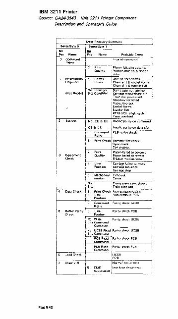
IBM 3211 Printer Source: GA24-3543 IBM 3211 Printer Component
Description and Operator's Guide
Page 5-42
I
Sense Byte 0
Bit Pos Name
1 Intervention Required
(Not Ready)
2 Bus-out
3 Equipment Check
Data Check
Error-Recovery Summary
i Sense Byte 1
i Bit i Pos Name Probable Cause
Print Quality
Forms Ch~ck
Invalid command
Platen fai led to advance ! Ribbon motion & ribbon : skew
I Jam or torn forms
, Channell & end of forms Channell & stacker full
No Interlock Swing gate not latched Bits Condition Carriage stop/release off
Train not positioned i Stop key activated
I
vac, uum check End of forms Stacker full
Jwrtte after single cycle Train overload
I 0 Command PLB parity check i Retry I
I 1 Print Check: I Hammer fire check
I Sync check Coil protect
1
2 Print !Platen failed to advance Quality Platen failed to retract
I Ribbon motion/skew
I 3 Line ! Carriage failed to move Position Carriage sequence
I Carriage stop
I 6 Mechanical I Time-out motion lCancel
! ~ r:~net Check ~ ~~~ :;:::: ~g~B i Position
o Command :Parity check UCSB Retry
Buffer Parity 3 Line Positiofl
'Parity check FCB Check
, No Write !ParitY check UCS 8 i Bits Command !
I Complete I , No UCSB Read Parity check UCSB
Bits Cummand
FCB Read !Parity check FCB i Command;
I PLB Read II Parity check PLB i i Command
~--L-oa-d-C-h-ec-k~:!---------+!IU-C-S-B-------~ 'FCB
Channel 9
j'
Normal occurrence
1
5 CMD Interface disconnect Suppressed

IBM 3211 Printer (Cont'd)
Train Overload
1. Press COVER RAISE. 2. Open the swing gate by pulling out on the swing-gate release lever. 3. Pull the separator-frame release lever and open the separator frame. 4. Push the train-incrementor button to reset the overload check and to move
the train. If the train turns freely (judged by the force required to push the train-incrementor button), the cause of the overload condition may also have been cleared. Attempt to return the printer to normal operation.
5. If the train continues to turn with difficulty or does not move at all, remove the cartridge (see "3216 Cartridge Removal") and push the train-incrementor button. If the train drive turns freely, install another cartridge if available, return the printer to operation, and call for service on the faulty cartridge. If the train drive binds or does not turn at all, call your service representative.
Forms Jam
When forms are feeding improperly due to forms separation or disengagement from the feed pins, the printer stops, FORM CHECK turns on, and the printer cover opens.
1. Open the swing gate by pulling out on the swipg-gate release lever. 2. Inspect the forms in the area of the print line. If forms are not separated or
damaged and appear to be feeding properly, check for a paper chad or other debris covering the forms-sensing device in the lower tractor. This can cause a false indication. Also check the black strip on the separator frame opposite the forms-sensing device. A buildup of paper dust on the strip can cause a fa lse check.
3. Remove separated or damaged forms and use steps 4 through 17 of the forms loading procedure to reload forms.
4. Press CHECK RESET and PRINTER READY, and restart your program. 5. Use steps 19 through 29 of the forms loading procedure (see source publica
tion) to return the printer to operation. Stacker rate, adjustable shelf, and stacker roll adjustments may not be necessary.
Carriage Check
If carriage motion is incorrect, the printer stops with CARRIAGE CHECK on.
1. Press COVER RAISE. 2. Open the . swing gate by pulling out on the swing-gate release lever. 3. Determine if the forms are in proper position for the next print line. 4. Reposition forms if necessary, and set up to restart the program from an
appropriate point. 5. Close and latch the swing gate. 6. Press CHECK RESET and PRINTER READY. 7. If carriage checks continue, call your service representative.
Print Check
A print check is indicated by the printer stopping with PRINT CHECK on.
1. Press COVER RAISE. 2. Open the swing gate by pulling out on the SWing-gate release lever. 3. Inspect the last two printed lines. 4. If the printing is incorrect, set up to restart your program from a point
Jhead of the incorrect lines. 5. When set up, or if the printing appears correct, close and latch the swing
gate and press CHECK RESET. 6. Press PRINTER READY and restart your program. 7. If print checks continue, call your service representative.
Page 543

Model 125 Operator Console Video Screen Source: GA33-1509-0 System/370 Mod 125 Procedures
The Video Screen:
Is a 15 in. video monitor. Is mounted on a separate table and can be rotated through 180°. Displays numeric characters. upper case alphabetic characters, and special symbols. Can be manually adjusted for intensity. Is equipped with a program-controlled audible alarm, which alerts the operator to messages requiring attention.
Display Format 1- - - - - - - - - - - - - - - - - -- - - - - I I 56 characters I
r--J : I 1 I :. I 12 1 I I I I I I
I L __
ill I 4 I lines I
Page 5-44

OS/VS Display Consoles 3277 and Model 158 Display Areas Source: GC38-0260 OSNS2 Display Consoles
Genera I Message Area 191;nes)
~~-----------------------10 II D;splay Area B 12 (4 I;nes) 13 14-----------------------15 16 17 18
Display Arec A
16 I;nes)
J~ _____________________ _ 20 21 22 23 24
PFK D;splay L;ne Instruction line Entry A.rea
12 l;nes1 \.'/arning line
Page 5-45

Model 168 Display Console Display Areas Source: GC38-0260 OSNS2 Display Consoles
MessogeArea(20linn)
19 1'l.. _________________________________ _ 21 n 23 2'
Disploy Areo B (4Iine5l
25- --- - -------------- -- - -- ---------26 27 28 29
-~---------------------------------lL ________ ~I~~~~ ___________________ _
I ~ ~====~~~~~~~~~~~~~~~~==~=~==~~~-~ ----------------------~
Entire Message Area is 30 lines in iengtb
Page 5-46

OS/VS Display Console Operation, Mod 158 Source: GC38-0260 OSNS2 Display Consoles
How to Start the System Using the 3277
To start the system using the 3277 display console, follow the same procedure that you follow for a printer· keyboard console:
Set the LOAD UNIT dials to the unit address of the SYSRES volume, and press the LOAD key on the control paneL Respond to the system parameter messages that appear on the screen. Set the time and date. Start the system input readers and output writers. Vary devices offline as appropriate.
The Model 158 display console does not have LOAD UNIT dials or a LOAD key. After typing in the load unit address or pointing to it with the light pen, the operator points the light pen to the LOAD and EXECUTE functions in that order, which accomplishes the load.
Error Conditions
Several types of errors may occur that directly affect the operation of display consoles·-errors caused either by a programming problem (system error) or a console malfunction (hardware error).
System Errors
When certain types of system errors occur, the screen is blanked, and an error message appears in the center of the screen.
Blank Screen and Error Message
If the error message indicates that a recoverable system error has occurred, perform the action specified by the error message, and then press the CANCEL key. This should restore the screen.
If the error message indicates that an unrecoverable system error has occurred, the system must be loaded again. Follow normal procedures for initial program load (iPL), and notify the programmer responsible for the system.
Console Inactivity
Console inactivity is characterized by a lack of messages or system response to commands.
If your console seems to be abnormally inactive, check the system response by requesting a display of the time:
D T
If it does not respond, cancel any status displays being presented on the inactive console using the procedure for erasing a status display.
If neither of these procedures returns the console to normal activity, check for a console hardware error.
Page 5-47

Display Console Operation, Mod 158 (cont'd)
Error Message Response
If a console hardware error occurs, the following message may appear on the screen:
IEE170E RETRYABLE ERROR. RECENT ACTION MAY NEED TO BE REPEATED. IEE170E PRESS THE CANCEL KEY TO RESTORE THE
SCREEN.
Perform the indicated action (press the CANCEL key). This should restore the screen, including messages displayed in the message area, the PFK display line, the instruction line, and the warning line.
Note: If you do not press the CANCEL key, the system will automatically rewrite the screen (same effect as CANCEL) after about 30 seconds have elapsed. If a console hardware error results from keyboard input, the system will always regard it as a temporary error. If it becomes apparent to you that the error is permanent, switch control to an alternate console (procedures for console switch are describ~d in the Operator's Library Reference publication for the system you are using.)
Blank Screen Response
If the console screen goes blank, a console switch is probably taking place. The follow· ing message should appear on the new console:
IEE1431 OLD=xxx, NEW=xxx, VALDCMD=xx IEE1431 ROUTCDE=i<x[,xx] T=x H=x
In the actual message, the appropriate values will appear in place of the x's. Use the alternate console to continue operating the system, and have the old console checked for the source of the error.
NOTE: It is normal for the screen to go blank for a few seconds if the back·tab key is pressed when the cursor is not in the entry area.
Locked Keyboard Response
Sometimes the system is unable to blank the screen. If you find that you cannot enter commands through a console that appears normal, try to restore the screen by per· forming a CANCEL action.
If a console switch has taken place, operate the system from the alternate console, and have the old console examined for the source of the error.
NOTE: I nhibited input, with or without keyboard locking, may also occur when the system goes into an ABEN D wait state or when a problem occurs in the message handling portion of the control program. Check the procedures described for console inactivity under "System Errors."
Page 5-48

Operating the 3270 Source: GA27-2742 Operator's Guide for IBM 3270
Information Display Systems
Operating Procedure
General Instructions
1. Compose the test message. Write it On a slip of paper if helpful.
2. If necessary, apply power to the display station. Press the CLEAR key and then the RESET key. This will result in an unformatted screen with the cursor in the upper left screen position.
3. Enter the test message from the keyboard.
4. If the Dial feature is installed, call the computer operator and establish a phone connection as explained in the section "Dial Procedure".
5. Press the TEST REQ key and note that the INPUT INHIBITED indicator comes on.
6. Check that the test pattern you requested is received at the selected display station or printer. This completes the entry and replay for the frist R FT message.
Note: To check the Basic Test Pattern, you must enter data from the keyboard, Also, if the display station is equipped with a selector pen, check selector pen operation at this time. A step·by·step explanation of how to check the Basic Test Pattern follows these general instructions.
7. Repeat steps 1 through 6 for each succeeding RFT message until you have completed the RFT series for your display or printer. As you enter a new R FT message, the only change in the message format from the preceding message is the test pattern identification number.
8. Compare the test pattern received with the correct pattern as you finish each test. If you do not receive a test pattern correctly, report it to your supervisor and, if consistent with organizational policy, fill out an OPERATOR TROUBLE REPORT.
PagA 5-49

Operator Trouble Report
POWER FAILURE UNIT IDENTIFICATION ____ _
o Display station won't turn on.
o Display station was operating; went dead. o Noticed smoke or unusual odor at the time.
FAILURE OF
o Printer o Selector Pen o Operator Identification
Card Reader
o Display Station [] Keyboard
o DISCONNECT switch (Dial Feature onlyl
o Keyboard and DISCONNECT switch both inoperative. (Dial Feature onlyl
INDICATORS
Mark the indicators on when failure occurred.
o SYSTEM READY o SYNC SEARCH o SELECTED o TRANSMIT o STATUS o OFF HOOK/AUTO ANSWER
(Dial Feature onlyl
DISPLAY FAILURE
o SYSTEM AVAILABLE o INSERT MODE o INPUT INHIBITED
One or more indicators:
[] Light when they shou Id no! nt:m '! !!~ht '-:Ihc:-: the." ~huu:J.
The image on the screen looks like:
o
o
Cursor
o more than one cursor. o won't move. Dismissing. o is too short or too long. o is normal but display is blank. o is in wrong place (not below
charactersl.
Page 5-50
Nothing displays on screen:
o Is completely blank. o Is glowing brightly. o Image is too bright or too
dim and cannot be adjusted.

Operating the 3270 (Cont'd)
Instructions for Checking Basic Test Pattern, EBCDIC No. 23 or ASCII No. 29
The display image should appear with the cursor located under the character C in the second row of displayed data. No indicators should be on.
1. Key in the row of alphabetic characters and the one space exactly as they appear in the row above. All characters should enter correctly, and cursor should move under I after Space bar is pressed.
2. Move cursor under C of CK in second row of displayed data, using -+ (right) key.
3. Press INS MODE key. INSERT MODE indicator should light. 4. Press A key. Field should now appear ACK. 5. Press FIELD MARK key. (Use B key ~ Operator Console keyboard.) Field
should now appear A;CK (ABCK). 6. Press C key. The d-;ta sho~ld not change, but the INPUT INHIBITED
indicator should, come on (in addition to the INSERT MODE indicator, which has remained on).
7. Press RESET key. Both indicators should go out. 8. Press DEL key. The C should disappear, and the field should now appear
A;K{ABK). 9. Press +- key (New Line). Cursor should move under C character in fourth
row of displayed data. 10. Enter the special characters as they appear in the row above, shifting where
required. Cursor should appear under 0 character after last special character entered.
11. Enter the digits 0 through 9 and the characters, .' and A as they appear in the row above. (On Data Entry keyboards, use the , over • and over $ keys to enter the ,and characters.) The following results should occur:
a. Typewriter and Operator Console keyboards without Numeric Lock feature - all characters should enter.
b. Data Entry keyboard without Numeric Lock feature - characters , . and - enter normally; the A character enters as < symbol. All keyboards with Numeric Lock feature - characters and - enter normally; keyboard should lock and INPUT INHIBITED should light when , and A keys are pressed. (Use Reset and ~ keys to move cursor from those positions.)
12. Check t (Up), J. (Down), and +- (Backspace) cursor move keys for propel operation.
13. Check the typamatic function of the Space bar or any other key with typamatic capability. Use the first field in the fourth row of displayed data for this step.
14. Move cursor under first character displayed of test message. 15. Press any alphameric key. INPUT INHIBITED indicator should come on, and
character should not enter or display because field is designated as a protected data field.
16. Press RESET key. INPUT INHIBITED indicator should go out. 17. Press ENTER key. INPUT INHIBITED indicator should light, and keyboard
should lock. 18. Press RESET key. INPUT INHIBITED indicator should go out, and keyboard
should unlock.
NOTE: The following steps check tab, DUP, and new line functions.
19. Press.... (Tab) key. Cursor should appear under character A in second row of characters.
20. Press DUP key. An asterisk (.) should appear in cursor position, and cursor should move under I of INSERT. (On Operator Console keyboard, use Tab key; cursor should move under I of INSERT, but the asterisk should not appear.)
21. Space one character position. The I should disappear. 22. Press +- (Backtab) key. Cursor should move back one space to where the I
was formerly located. 23. Press Tab key. (Use SKIP key on Data Entry keyboards.) The cursor should
appear in the first character position of the fourth row of displayed data.
Page 5-51

Operating the 3270 (Cont'd)
NOTE: The following steps test the erase and clear functions.
24. Position cursor under character E in second row of displayed data. 25. Press ERASE EOF key. Characters E through Z should disappear, and cursor
should not move. 26. Press ERASE INPUT key. All unprotected data, including keyed-in characters
and field that originally appeared as INSERT CK should disappear from screen.
27. If display station being tested has a selector light-pen attached, continue with step 28. If a pen is not attached, press CLEAR key. All characters remaining on screen should disappear, and cursor should reappear in first character position in first row. Press RESET key, and enter the next test message (steps 1-7 of "General Instructions").
28. Fire pen on detectable field that has a question mark m as its first charac· ter. Ouestion mark should change to a greater-than (» symbol. Remainder of field should not change.
29. Fire pen again on the field. The greater·than symbol should change back to a question mark. Remainder of field should not change.
30. Fire pen on next detectable field that has a greater-than symbol as its first character. The greater-than symbol should change to a question mark. Remainder of field should not change.
31. Fire pen again on same field. Ouestion mark should change back to a greater·than symbol. Remainder of field should not change.
32. Press CLEAR key. All character5 on screen should disappear, and cursor should move to character location O. Press RESET key, and enter the nexl test message (steps 1-7 of "Gener~r 'nstructions").
Page 5·52
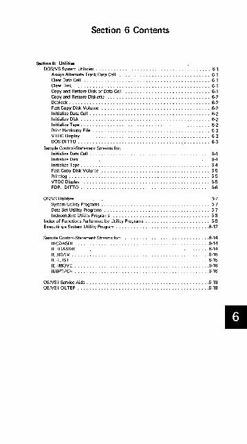
Section 6 Contents
Section 6: Utilities DOSNS System Utilities . . . . . . . . . . . . . . . . . . . . . . . . . . . . . . . . . . . . . . . 6·1
Assign Alternate Track Data Cell ............................... 6·1 Clear Data Cell ........................................... 6-1 Clear Disk .............................................. 6-1 Copy and Restore Disk or Data Cell ............................. 6-1 Copy and Restore Diskette ................................... 6·2 Deblock ................................................ 6·2 Fast Copy Disk Volume ...................................... 6·2 Initialize Data Cell ......................................... 6·2 Initialize Disk ............................................ 6·2 Initialize Tape ............................................ 6·2 Print Hardcopy File ........................................ 6·3 VTOC Display ........................................... 6·3 DOS DITTO ............................................. 6·3
Sample Control·Statement Streams for: Initialize Data Cell . . . . . . . . . . . . . . . ..................... 6-4 Initialize Disk . . . . . . . . . . . . . . . . . . . . . . . . . . . . . . .......... 6-4 Initialize Tape. 6-4 Fast Copy Disk Volume ........ . .......... 6-5 Printlog . . . . . . . . . . . . . . . . . . . . . . . . . . . . 6-5 VTOC Display . . 6·5 FDP: DITTO. . . . . . . . . . . . . . . . . . . . . . . 6·6
OSNS Utilities ............ . . ...... 6·7 System Utility Programs. . . . . . ..... 6·7 Data Set Utility Programs . . . . . . . . . . . . ..... 6·7 Independent Utility Programs ......... . ..... 6·8
I ndex of Functions Performed by Utility Programs . . . . . . . . . . . . . . . . . . . 6-9 Executing a System Utility Program ................................ 6·12
Sample Control·Statement Streams for: ............................. 6·14 IBCDASDI .............................................. 6-14 IEHDASDR ...... . . . . . .......................... 6·14 IEBISAM ...... , . . . . . . . . . .......................... 6·15 IEHlIST . . . . . . . . . . . . . . ............................ 6·15 IEHMOVE . . . . . ............... 6·16 IEBPTPCH .............................................. 6·16
OSNSl Service Aids. . . . . . . . . . . . .......................... 6·18 OSNSl OLTEP ............................................. 6·19
II

DOS/vS System Utilities Source: GC33-5381 "DOS/VS System Utilities, Release 29"
This section contains information on a few of the frequently used DOS Utility programs. Refer to the SRL for complete information.
Assign Alternate Track Data Cell
Purposes:
To assign an alternate track on an IBM 2321 Data Cell Drive. If an alternate track is found defective, a new alternate track must be assigned to the primary track.
To recopy data from the alternate track to the primary track if th is track is no longer defective.
To replace bad records on a specified track if update records are supplied as input.
Assign Alternate Track Disk
Purposes:
To assign an alternate track on an IBM 2311 Disk Storage Drive, an IBM 2314 Direct Access Storage Facility, an IBM 2319 Disk Storage, an IBM 3330 Disk Storage, an IBM 3333 Disk Storage, or an IBM 3340 Direct Access Storage Facility, and to copy data (if present) from a defective track to an alternate track.
If an alternate track is found to be defective, a new alternate track must be assigned to the primary track.
To replace bad records on a specified track if update records are supplied as input.
To change the track-condition indication, and to recopy data (if present) from the alternate track to the primary track.
Restriction: This is only valid for the 2311, the 2314, and 2319.
Clear Data cell
Purposes:
To clear one or more areas on an IBM 2321 Data Cell Drive. To establish preformatted tracks throughout the area cleared. To create a file label in the VTOC.
Clear Disk
Purposes:
To establish preformatted tracks (clear) on one or more extents on an IBM 2311 Disk Storage Drive, an IBM 2314 Direct Access Storage Facility, an IBM 2319 Disk Storage, an IBM 3330 Disk Storage, an IBM 3333 Disk Storage, or an IBM 3340 Direct Access Storage Facility.
To create a file label in the VTOC.
Copy and Restore Disk or Data Cell
Purposes:
To copy a volume or file from an IBM 2311 Disk Storage Drive, an IBM 2314 Direct Access Storage Facility, an IBM 2319 Disk Storage, an IBM 3330 Disk Storage, an IBM 3333 Disk Storage, or an IBM 3340 Direct Access Storage Facility, to cards, disk, or tape.
To copy a volume or file from an IBM 2321 Data Cell Drive to tape.
To restore data to disk or data cell at a later date.
Page 6-1

DOS/VS System Utilities (cont'd)
Copy and Restore Diskette
Purposes:
Deblock
Purposes:
To replace bad labels on an IBM 3540 Diskette Input/Output Unit. To copy the entire contents of a diskette onto another diskette. To eliminate the special records from all data files. To create a backu p copy.
To block an 8OIB1·byte record file to a 344O-byte record file.
To deblock a blocked 3440·byte file in order to create an aO-byte SYSIN file.
To copy files.
To print (list) job control statements and comments from a blocked input file.
To select records (or a group of records) from a blocked 3440·byte file in order to create an SO-byte SYSIN file.
Fast Copy Disk Volume
To copy the entire contents of an IBM 3330 Disk Storage, an IBM 3333 Disk Storage, or an IBM 3340 Direct Access Storage Facility onto another disk device of the same type in a short time. The pack to be copied may contain any combination of DOSIVS data sets and system components.
The contents of this disk may be copied directly to another disk device, or it may be written on magnetic tape, to be restored at a later time. •
Initialize Data Cell
Purpose:
To prepare from one to five new or expired cells for use on an IBM 2321 Data Cell Drive.
Initialize Disk
Purpose:
To prepare one complete disk pack for use on an IBM 2311 Disk Storage Drive, an IBM 2314 Direct Access Storage Facility, an IBM 2319 Disk Storage, an IBM 3330 Disk Storage, an IBM 3333 Disk Storage, or an IBM 3340 Direct Access Storage Facility.
The program can also be used:
To change the volume label(s) and the VTOC (volume table of contents) address of a previously initialized disk pack (other than an emulator pack).
If you specify IS in the input option parameter of the utility modifier statement, surface analysis, HA (home address). and RO (track descriptor record) generation are bypassed. This option assumes that a valid VTOC is present. A work pack used for OS can therefore be converted into a work· pack suitable to be used for DOSIVS.
Initialize Tape
Purposes:
Page 6-2
To write one to eight I BM standard tape volume labels in numerical se· quence, followed by one dummy header label and one tapemark on EBeD IC tapes.

DOS/VS System Utilities (cont'd)
Print Hardcopy File (Printlog) - Models 115 and 125
Purpose:
To print on SYSLST the hardcopy file from an IBM 3330 Disk Storage, an IBM 3333 Disk Storage, or an IBM 3340 Direct Access Storage Facility.
VTOC Display
Purpose:
To display the labels contained in the VTOC of a disk pack on an IBM 2311 Disk Storage Drive, an IBM 2314 Direct Access Storage Facility, an IBM 2319 Disk Storage, an IBM 3330 Disk Storage, an IBM 3333 Disk Storage, an IBM 3340 Direct Access Storage Facility, or of a data cell on an IBM 2321 Data Cell Drive.
Field Developed Program
DOS/DITTO (Program No. 5798-ARN)
Purpose:
DOS/D I TTO is a general·purpose utility program containing 37 utility functions for Unit Record, Tape, and Disk I/O units.
Page 6-3
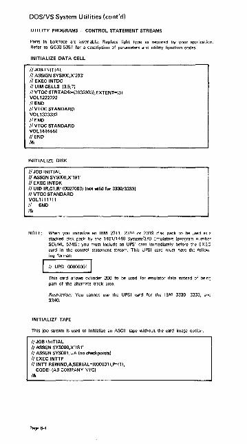
DOS!VS System Utilities (cont'd)
UTILITY PROGRAMS - CONTROL STATEMENT STREAMS
Parts in boldface are invariable. Replace light type as required by your application. Refer to GC33·5381 for a description of parameters and utility function codes.
INITIALIZE DATA CELL
1/ JOB INITIAL /I ASSIGN SYSOOO,X'293' 1/ EXEC INTDC /I UIM CELLS=(3,5,7i /I VTOC STRTADR=(3033303),EXTENT=(5) VOLl222222 /lEND 1/ VTOc STANDARD VOLl333333 /lEND /I VTOC STANDARD VOL1444444 /I END /&
INITIALIZE DISK
/I JOB INITIAL /I ASSGN SYSOOO,X' 191 , /I EXEC INTDK 1/ UID IR,Cl,R=(OO27003) (not valid for 3330/3333) /I VTOC STANDARD VOLll11111 /I END /&
NOTE: When you initialize an IBM 2311, 2314 or 2319 disk pack to be used as a stacked disk pack by the 1401/1440 System/370 Emulators (program number SCEML 5745); you must include an UPSI card immediately before the EXEC card in the control statement stream. This UPSI card must have the follow· ing format:
II UPSI 00000001 I This card allows cylinder 200 to be used for emulator data instead of being part of the alternate track area.
Restriction: You cannot use the UPSI card for the IBM 3330, 3333, anc 3340.
INITIALIZE TAPE
This job stream is used to initialize an ASCII tape without the card image ootion.
/I JOB INITIAL /I ASSGN SYSOOO,X'181, /I ASSGN SYSOO1,UA (no checkpoints) 1/ EXEC INTTP /lINTT REWIND,A,sERIAL=(OOOOO1 ),P=(1),
CODE=(AB COMPANY NYC) /&
Page 6-4

DOS/VS System Utilities (cant'd)
This job stream is used to initialize an ASCII tape with the card image option.
/I JOB INITIAL /I ASSGN SYSOOO,X' 181' 1/ ASSGN SYSOO1,X'182' II ASSGN SYSOO2,UA (no checkpoints) /I EXEC INTTP /I INTT CARD, A (column 80) VOL 1000001 AB COMPANY NYC 1 /lEND VOL1000002 AB COMPANY NYC II END 1&
It is assumed that in each example SYSLOG is permanently assigned.
FAST COPY DISK VOLUME
1. Copy Disk to Disk
/I JOB COPY 3330 to 3330 /I ASSGN SYSOO4,X' 160' II ASSGN SYSOO5,X' 161 , II EXEC FCOPY,REAL II UDD IV=DOSR29 1&
2. Copy Disk to Tape
II JOB COPY 3340 TO TAPE II ASSGN SYSOO4,X'160' II ASSGN SYSOO5X280' II ASSGN SYSOO5X281 ',ALT II TLBL UOUT:BACKUP TAPE' II EXEC FCOPY,REAL II UDT IV=111111 1&
3. Copy Tape to Disk
(input disk) (output disk)
(input disk) (output tape) (alternate tape)
II JOB RESTORE BACKUP TAPE TO DISK /I ASSGN SYSOO4,X'280' . (input tape) /I ASSGN SYS004,X' 281 ',ALT (alternate tape) II ASSGN SYS005,X'160' (output disk) II TLBL UIN:BACKUP TAPE' /I EXEC FCOPY,REAL I/UTD 1&
PRINTLOG
I II JOB NAME /I EXEC PRINTLOG
VTOC DISPLAY
/I JOB VTOC II ASSGN SYSOO4,X' 191 , /I ASSGN SYSOO5,X'ooE' /I PAUSE REPLY NO IF MSG 8V96D IS ISSUED /I EXEC LVTOC 1&
It is not necessary to use a utility modifier card for the VTOC display program.
Page 6-5
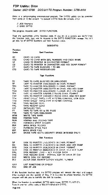
FOP Utility: Ditto Source: S821-0786 DOS/DITTO Program Number: 5798-ARN
Ditto is a self·prompting conversational program. The DITTO utility can be executed from cards or at the console. To execute DITTO from the console, enter:
// JOB Anyname 1/ EXEC DITTO
The program responds with: DITTO FUNCTION.
Type the appropriate utility function code. If you are at a console and don't know the function code, type xxx in response to the DITTO FUNCTION message. You will get this list of DITTO functions and their function codes.
DOS/DITTO
Function Codes Card Functions
CC CARD TO CARD CCS CARD TO CARD WITH SEQ. NUMBERS AND DECK NAME CP CARD TO PRINTER IN CHARACTER FORMAT CD CARD TO PRINTER IN CHARACTER AND HEX DUMP FORMAT CT CARD TO TAPE BLOCKED 1 TO 400 CTS CARD TO TAPE RESEQUENCED
Tape Functions
TC TAPE TO CARD BLOCKED OR UNBLOCKED TP TAPE TO PRINTER UNBLOCKED IN CHAR. FORMAT TPD TAPE TO PRINTER DEBLOCKED IN CHAR. FORMAT TO TAPE TO PRINTER UNBLOCKED IN CHAR. AND HEX DUMP TDD TAPE TO PRltxTER DEBLOCKED IN CHAR. AND HEX DUMP TPV TAPE TO PRINTER VARIABLE RECDS CHAR. FORMAT TDV TAPE TO PRINTER VARIABLE RECDS CHAR. AND HEX DUMP TFA i'RiNT SYSLST TAPES TYPE A FORMS L:ONTHOL, CCW CODE TFD PRINT SYSLST TAPES TYPE D FORMS CONTROL TRS TAPE RECORD SCAN TRL TAPE RECORD LOAD INT INITIALIZE TAPE TT TAPE TO TAPE (01 to 99) FILES TTR TAPE TO TAPE REBLOCKED WTM WRITE TAPE MARK REW REWIND TAPE RUN REWIND AND UNLOAD TAPE FSR FORWARD SPACE RECORD BSR BACK SPACE RECORD FSF FORWARD SPACE FILE BSF BACK SPACE FI LE ERT ERASE TAPE (DATA SECURITY ERASE 341013420 ONLY)
Disk Functions
DP DISK TO PRINTER UNBLOCKED IN CHAR. FORMAT DO DISK TO PRINTER UNBLOCKED IN CHAR. AND HEX DUMP DPD DISK TO PRINTER DEBLOCKED IN CHAR. FORMAT DDD DISK TO PRINTER DEBLOCKED IN CHAR. AND HEX DUMP DRL DISK RECORD LOAD - KEY AND/OR DATA DRS DISK RECORD SCAN - PARTIAL KEY OR DATA OR EOF EOF WRITE DISK EOF RECORD DID ALTER DISK IDENTIFICATION VOLUME NUMBER
XXX LIST FUNCTIONS ON SYSLST EOJ END OF JOB
If the function involves tape, the DITTO program will request the input and output drive numbers and the number of files. If it is a disk to printer function, the DITTO program will ask you to identify the disk by number.
When the function is completed, DITTO again types: DITTO FUNCTION. Type in another utility code, or EOJ if finished with DITTO.
Page 6-6

oS/VS Utilities Source: GC35-00050SIVS Utilities
System Utility Programs
System utility programs manipulate collections of data and system control information_ The system utility programs are:
I EHATLAS, which is used to assign alternate tracks when defective tracks are indicated_
IEHDASDR, which is used to initialize direct access volumes or to dump or restore data.
IEHINITT, which is used to write standard labels on tape volumes.
IEHIOSUP, which is used to update entries in the supervisor call library (VSl only).
IEHLlST, which is used to list system control data.
IEHMOVE, which is used to move or copy collections of data.
IEHPROGM, which is used to build and maintain system control data.
IEHUCAT, which is used to update an OS catalog to the level of a VSAM catalog (non-VSAM data sets). (VSl only)
IFHSTATR, which is used to select, format, and write information about tape errors from the IFASMFDP tape or the SYS1.MAN data set.
A system utility program is executed or invoked through the use of job control statements and util ity control statements.
DATA SET UTILITY PROGRAMS
Data set utility programs manipulate partitioned, sequential, or indexed sequential data sets provided as input to the programs- Data ranging from fields within a logical record to entire data sets can be manipulated. The data set utility programs are:
IEBCOMPR, which is used to compare records in sequential or partitioned data sets.
IEBCOPY, which is used to copy, compress, or merge partitioned data sets, to select or exclude specified members in a copy operation, and to rename andlor replace selected members of partitioned data sets.
I EBDG, which is used to create a test data set conSisting of patterned data.
I EBEDIT, which is used to selectively copy job steps and their associated JO B statements.
IEBGENER, which is used to copy records from a sequential data set or to convert a data set from sequential organization to partitioned organization.
IEBISAM, which is used to place source data from an indexed sequential data set into a sequential data set in a format suitable for subsequent reconstruction.
IEBPTPCH, which is used to print or punch records that reside in a sequential or partitioned data set.
IEBTCRIN, which is used to construct records from the input data stream that have been read from the IBM 2495 Tape Cartridge Reader.
I EBUPDTE, which is used to incorporate changes to sequential or partitioned • data sets.
Data Set utility programs can be executed as jobs or can be invoked as subroutines by a calling program.
Page 6-7

OS/VS Utilities (cont'd)
INDEPENDENT UTILITY PROGRAMS
Independent utility programs operate outside, and in support of, the operating system. They are not supported, however, by the 3066 console, which is only used with the Model 165, System/370. If the 3066 is the only console available, execute independent utilities by following step 3b "Executing IDCDASDI and IBCDMPRS" below. The independent utility programs are:
Page 6-8
IBCDASDI, which is used to initialize a direct access volume and to assign alternate tracks.
IBCDMPRS, which is used to dump and restore the data contents of a direct access volume.
ICAPRTBL, which is used to load the forms control and Universal Character Set buffers of a 3211 after an unsuccessful attempt to IPL, with the 3211 printer assigned as the output portion of a composite console.

Guide to Utility Program Functions Source: GC35-0005-2 OS/VS Utilities
This table shows a list of tasks that the utility programs can be used to perform. The left·hand column shows tasks that you might wan,t to perform. The middle column defines the tasks more specifically. The right·hand column shows the utility programs that can be used for each task. Notice that in some cases more than one program may be available to perform the same task.
TASKS AND UTILITY PROGRAMS
Task
Add Analyze Assign alternate tracks Build
Catalog
Change
Compare
Compress·in·place Connect Construct Convert to partitioned
Convert to sequential Copy
Create
Delete
Dump Edit
Edit and convert to partitioned Ed it and copy
Edit and list
Ed it and pri nt Edit and punch Enter
Exclude
a password tracks on direct access
to a direct access volume a generation index a generation an index a data set a generation data set data set organization logical record length volume serial number of direct access volume a partitioned data set sequential data sets a partitioned data set volumes
Utility Program
IEHPROGM IEHATLAS,IEHDASDR,IBCDASDI
I EHATLAS,I EHDASDR,IBCDASDI VSl ONL Y-IEHPROGM VSl ONL Y-IEHPROGM VSl ONLY -IEHPROGM
IEHPROGM VS10NLY-IEHPROGM
IEBUPDTE IEBGENER
IEHDASDR IEBCOMPR IEBCOMPR
records from MTST and MTDI input a sequential data set created
IEBCOPY VS10NLY-IEHPROGM
IEBTCRIN
as a resu It of an unload sequential data sets a partitioned data set an indexed sequential data set a catalog a direct access volume a partitioned data set a volume of data sets an indexed sequential data set cataloged data sets
IEBCOPY I EBUPDTE,IEBGENER
I EBUPDTE,I EBCOPY IEBISAM,IEBDG
VSl ONL Y-IEHMOVE IEHDASDR,IBCDMPRS,IEHMOVE
IEBCOPY,IEHMOVE IEHMOVE
IEBISAM VSl ONL Y-IEHMOVE
dumped data from tape to direct access job steps members selected members sequential data sets to tape
IEHDASDR,IBCDMPRS IEBEDIT
I EBGEN ER,I EBUPDTE,I EBDG IEBCOPY,IEHMOVE
I EBGENE R,I EHMOVE,I EBUPDTE IBCDMPRS
a library of partitioned members a member
IEBUPDTE IEBDG IEBDG
VS10NLY-IEHPROGM a sequential output data set an index an output job stream a password an index structure records in a partitioned data set a direct access volume MTDI input (Magnetic Data Inscriber) a sequential data set
a job stream a sequential data set error statistics by volume (ESV) records a sequential data set a sequential data set a procedure into a procedure library a partitioned data set member from a copy operation
IEBEDIT IEHPROGM
VS10NLY-IEHPROGM IEBUPDTE
I EHDASDR,IBCDMPRS
IEBTCRIN I EBGEN E R,I EBUPDTE
IEBEDIT IEBGENER,I EBUPDTE
IEHSTATR IEBPTPCH IEBPTPCH
IEBUPDTE
IEBCOPY,IEHMOVE
Page 6-9

Guide to Utility Program Functions (cont'd)
Task Utility Program
Expand
Generate Get alternate tracks Include
Initialize I nsert records Label List
Load
Merge Modify
Move
Number records
Password protect
Punch
Read Reblock
Recover
Release Rename
Renumber Replace
Page 6-10
a partitioned data set a sequential data set test data
on a direct access volume changes to members or sequential data sets a direct access volume into a partitioned data set magnetic tape volumes a password entry a volume table of contents contents of direct access
IEBCOPY IEBGENER
IEBDG
IEHDASDR,IBCDASDI,IEHATLAS
IEBUPDTE IEHDASDR,IBCDASDI
IEBUPDTE IEHINITT
IEHPROGM IEHLlST
volume on system output device number of unused directory
IEHDASDR
blocks and tracks partitioned directories the contents of the catalog (SYSCTLG data set) a previously unloaded partitioned data set an indexed sequential data set an unloaded data set
IEBCOPY IEHLlST
VSl ONL Y-IEHLIST
UCS and FCB buffers of a 3211 partitioned data sets
IEBCOPY IEBISAM
IEHMOVE ICAPRTBL
IEHMOVE,IEBCOPY a partitioned or sequential data set a catalog a volume of data sets cataloged data sets partitioned data sets sequential data sets in a new member in a rartitioned data set add a password delete a password list passwords replace a password a sequential data set partitioned data sets selected records a partitioned data set member a sequential data set selected records Tape Cartridge Reader input a partitioned data set a sequential data set data from defective tracks on direct access volumes a connected volume a partitioned data set member a sequential or partitioned data set moved or copied members logical records a password data on an alternate track identically named members logical records members records in a member records in a partitioned data set selected members selected members in a move or copy operation
IEBUPDTE VSl ONLY-IEHMOVE
IEHMOVE VSl ONLY-IEHMOVE
IEHMOVE IEHMOVE
IEBUPDTE IEBUPDTE
IEHPROGM IEHPROGM IEHPROGM IEHPROGM
IEBGENER,IEBUPDTE,IEBPTPCH IEBPTPCH IEBPTPCH IEBPTPCH IEBPTPCH IEBPTPCH IEBTCRIN IEBCOPY
IEBGENER,IEBUPDTE
IEHATLAS VSl ONL Y-IEHPROGM
I EBCOPY,I EHPROGM
IEHPROGM IEHMOVE IEBUPDTE
IEHPROGM IEHATLAS
IEBCOPY IEBUPDTE IEBUPDTE IEBUPDTE
I EBUPDTE,I EBCOPY IEBCOPY
IEBCOPY,IEHMOVE

OS/VS Utilities (cant'd)
Task Utility Program
Restore a dumped direct access volume from tape IBCDMPRS,I EHDASDR
Scratch a volume table of contents IEHPROGM data sets IEHPROGM
Uncatalog data sets IEHPROGM Unload a partitioned data set I EHMOVE,I EBCOPY
a sequential data set IEHMOVE an indexed sequential data set IEBISAM
Update a catalog to VS2 Release 2 level VS10NLY-IEHUCAT in place a partitioned data set IEBUPDTE DR entries in the supervisor call library IEHIOSUP
Write IPL records and a program on "a direct access volume IBCDASDI,I EHDASDR
Page 6-11

OSIVS EXECUTING A SYSTEM UTILITY PROGRAM
/*
II SYSIN (DD statement for the data set containing utility statements)
DD statements for device allocation
II SYSPRINT (DD statement for the message output data set)
II stepname EXEC PGM = progname
II jobname (JOB statement)
OS/VS UTILITY CONTROL CARD EXAMPLES
1. Card to print
/ DATA CARDS
IISYSUT1 DD • DATA
IISYSUT2 DD SYSOUT = A,DCB = (RECFM = F, BLKSIZE = 80, LR ECl = 80, PRTSP = 1)
IISYSIN DD Dummy
!ISYSPRINT DD SYSOUT = A
IISTEP EXEC PGM=IEBGENER
IICRDPRT JOB
Notes: Place a blank care in front of data cards to orevent overorinting of first card.
Page 6-12

2. Card to tape
1*
DATA CARDS
IISYSUT1 DD *
II SYSUT2 DD Unit = 3410, Label = (.NL), DCB = (RECFM = F, LRECL = 80 BLKSIZE = 80)
II SYSIN DD Dummy
II SYSPRINT DD SYSOUT = A
II STEP EXEC PGM = IEBGENER
II CDTP JOB
Notes: Variations in tape unit or label information must be accounted for in sysUT2 card. Blocking may be specified by RECFM = FB or VB and increasing blksize to some multiple of LRECL.
3. System list
1*
LlSTPDS VOL = 3330 = DLlB02, DSNAME = SYS1.LlNELIB
LlSTPDS DSNAME - (SYS1.PROCLIB, SYS1.SVCLlB)
LlSTVTOC DUMP, VOL = 3330 = 111111
LlSTVTOC DUMP
LlSTCTLG
IISYSIN DD *
IIDD3 DD VOLUME = REF = SYS1.LlNKLlB, UNIT = 2311, DISP = OLD
IIDD2 DD UNIT = 3330, VOLUME = SER = 111111, DISP = OLD
!/DD1 DD DSNAME = SYS1.SVCLlB, DISP = OLD
IISYSPRINT DD SYSOUT = A
IISTEP EXEC PGM = IEHLIST
!!LlST JOB
Page 6-13
I

Sample Control-Statement Streams Source: GC35-00050S!VS Utilities
A few examples of utility functions and the control statements that must be prepared to execute them follow.
IBCDASDI
In this example, a 3330 volume is initialized for later use as a system residence volume. An IPL program is included in standard TXT format.
The example follows:
INIT JOB 'INITIALIZE 3330' MSG TODEV=1403,TOADDR=OOE
DADEF TODEV=3330,TOADDR=l50,IPL=YES VLD NEWVOLlD=Pl0000,OWNERID=BROWN,ADDLABEL=2
VTOCD STRTADR=2,EXTENT=7 IPLTXT
(IPL program text statements)
END
The control statements are discussed below:
DADEF specifies that a 3330 volume is to be initialized and specifies the channel number and unit number. An IPL program is to be included.
VLD specifies a volume serial number and owner identification for the volume to be initialized. It also specifies that space is to be allocated fo' two additional labels.
VTOCD specifies that the volume table of contents is to begin on track 2 and is to extend over nine tracks.
END specifies the end of IPL program text statements. Because IPL text is included, END begins in column 2.
IEHDASDR
In this example, alternate tracks are to be assigned for three suspected defective tracks on a 3330 volume.
The example follows:
IIDASDR3 JOB II EXEC PGM=IEHDASDR IISYSPRINT DD SYSOUT=A '/VOLUME 1 DD UNIT=(3330 .. DEFER),DISP=OLD, II VOLUME=(PRIVATE .. SER=(333000)) I/SYSIN DD •
I'
GETALT GETALT GETALT
LABEL
TODD=VOLUME1,TRACK=00050011 TODD=VOLUME1,TRACK=OOAOOOO7 TODD=VOLUME l,TRACK=01010002 TODD=VOLUME1,NEWVOLlD=DISKOO,OWNERID=SMITH
The control statements are discussed below:
Page 6-14
VOL U MEl DD defines a device that is to contain the 3330 volume (333000).
SYSIN DD defines the control data set, which follows in the input stream.
The GETALT statements specify the ddname of the DD statement defining the device on which the 3330 volume is mounted. The GETAL T statements specify the relative track addresses of the tracks for which alternates are to be assigned.

Sample Control-Statement Streams (cont'd)
LABEL specifies the ddname of the DD statement defining the device on which the 3330 volume is mounted. The LABEL statement changes the serial number of the 3330 volume from 333000 to DISKoo.
IEBISAM
In th is example, an unloaded data set is to be converted to the form of the original indexed sequential data set.
The example follows:
IISTEPA JOB 09#770,SMITH II EXEC PGM=IEBISAM,PARM=LOAD /lSYSPRINT DD SYSOUT=A IISYSUT1 DD DSNAME=INDSEQ,DISP=(,KEEPl.DCB=(DSORG=IS). II DISP=(OLD,KEEPl.VOLUME=SER=001234 IISYSUT2 DD DSNAME=INDSEQ,DISP=('KEEP),DCB=(DSORG=IS), 1/ SPACE=(CYL,(1)l.VOLUME=SER=111112,UNIT=2314 1*
The control statements are discussed below:
EXEC specifies the program name and the LOAD operation.
SYSUTl DD defines the input data set, which is a sequential (unloaded) data set. The data ,set is the second data set on a g·track tape volume.
SYSUT2 DD defines the output data set, which is an indexed sequential data set. One cylinder of space is allocated for the data set on a 2314 volume.
IEHLlST
In this example, a volume table of contents, in edited form, is to be listect.' The edited listing is supplemented by an unedited listing of selected data set control blocks.
The example follows:
IILlSTVTOC JOB 09#550,BLUE II EXEC PGM=I EH LIST /lSYSPRINT DD SYSOUT=A
UNIT=2314,VOLUME=SER=231400,DISP=OLD /lDD2 DD //SYSIN DD
1*
LISTVTOC LlSTVTOC
FORMAT ,VOL=2314=231400 DUMP,VOL=2314=231400,DSNAME=(SET1,SET2,SET3)
The control statements are discussed below:
DD2 DD defines a mountable device on which the volume containing the specified volume table of contents is to be mounted.
SYSI N DD defines the control data set which follows in the input stream.
The first LlSTVTOC statement indicates that the volume table of contents on the specified 2314 volume is to be listed in edited form.
The second LlSTVTOC statement indicates that the data set control blocks representing data sets SET1, SET2, and SET3 are to be listed in unedited form.
Page 6-15

Sample Control-Statement Streams (cont'd)
IEHMOVE
In this example, a volume of data sets is to be moved to a 2314 volume. All data sets that are successfully moved are scratched from the SOurce volume; however, any cata· log entries pertaining to those data sets are not changed. Space is allocated by IEHMOVE. The work data set is deleted when the job step is completed.
The example follows:
IIMOVEVOL II IISYSPRINT IISYSUTl IIDDl
JOB EXEC DD DD DD DD DD DD
09#550,GREEN PGM=IEHMOVE SYSOUT=A UNIT=2314,VOLUME=SER=231400,DISP=OLD UNIT=3330,VOLUME=SER=llllll,D1SP=OLD UNIT=2314,VOLUME=SER=231400,DISP=OLD UN IT=2314, VOLUM E=SE R=231401,DISP=OLD
IIDD2 IIDD3 IISYSIN
1* MOVE VOLUME=2314=231401,TO=2314=231400,PASSWORD
The control statements are discussed below:
SYSUTl DD defines the device that is to contain the work data set. The work data set is removed from the receiving volume when the job step is
completed.
DD 1 DD defines the system residence device.
DD2 DD defines the mountable device on which the receiving volume is to be mounted.
DD3 DD defines a mountable device on which the source volume is to be mounted.
SYS!N DD d~fi!'"!~ th-= ~')ntrl)l rl~t~ q::t.t, whir.h follows in the input stream.
MOVE specifies a move operation for a volume of data sets and defines the source and receiving volumes. This statement also indicates that password· protected data sets are to be included in the operation.
NOTE: IEHPROGM can be used to uncatalog catalog entries pertaining to ,ource data sets and to catalog the moved versions of those data sets.
IEBPTPCH
In this example, a sequential data set is to be punched according to standard soeci"ca· tions. The input data set resides on a 7 ·track tape volume, originally writte r a: a density of 556 bits per inch. The punched output is converted to hexadecimal.
The example follows:
I/PUNCHSET JOB 091t660,SMITH II EXEC PGM=IEBPTf'CH I/SYSPRINT DD SYSOUT=A IISYSUTl DD DSNAME=INSET,UNIT=2400.VOLUME=SER=00123d ,
II LABEL=(,NL),DISP=(OLD,KEEP),DCB=(DEN=l.RECFM=FB, II LRECL=80,BLKSIZE=2000,TRTCH=C) I/SYSUT2 DD UNIT=2540·2 !(SYSIN DD
PUNCH TOTCONV=XE TITLE ITEM=('PUNCH SEQ DATA SET WITH COI\JV TO HEX', '0)
j*
The control statements are discussed below:
Page 6-16
SYSUTl DO defines the input data set. The data set contains 80·byte, f;xeo blocked records.

Sample Control-Statement Streams (cont'd)
SYSUT2 DO defines the output data set. The data set is to be punched by an IBM 2540-2 Card Read Punch (punch feed). Each record from the input data set is represented by two punched cards.
SYSIN DO defines the control data set, which follows in the input stream. The control data set contains the PUNCH and TITLE statements.
PUNCH initiates the punch operation and specifies conversion from alphameric to hexadecimal representation.
TITLE specifies a title to be placed beginning in column 10. The title is not converted to hexadeci mal.
Page 6-17

OS!VS1 Service Aids Source: GC28-0665 OSNSl Service Aids
GTF (Generalized Trace Facility) Traces selected system events such as SVC and 1/0 interruptions.
JOBOD
LIST
Operates as a stand·alone program to format and print the system job queue (SYS1.SYSJOBQEI, the incore joblist, the system scheduler work area data set (SYS1.SYSWADS). and the scheduler work area data set (SWADS).
Formats and prints object modules, load modules, and CSECT identification records. Maps nucleus and link pack area.
OSJOD Operates as a problem program to format and print the system job queue (SYS1.SYSJOBQE), the incore joblist, the system scheduler work area data set (SYS1.SYSWADS), and the scheduler work area data set (SWADS).
PRDMP Formats and prints SAOMP high·speed output (including page dump). SYS1.:JUMP data set, and GTF trace data.
PTFLE Application function: Applies PTF by generating input to the linkage editor. thee invoking the linkage editor. Generate function: Generates JCL and control state· ments needed to apply PTFs or ICRs ir a later step.
SADMP Operates as a stand·alone program to produce a high·speed or low·soeec CC""~ of real storage. The high·speed version also dumps the page data set.
SPZAP Verifies andlor replaces data in a load module.
Page 6-18

How to Set Up an OL TEP Run Source: GC28-0666 OSNSl OL TEP
1. Create OLTEP Data Sets: Run the OLTEP Editor Program to create a data set of online test programs and system configuration data. If you intend to test remote teleprocessing terminals, create a second data set containing configuration data for these symbolically named units. All configuration data, for both local devices and remote terminals, is supplied by IBM Field Engineering.
2. Modify OLTEP Data Sets: Use the OLTEP Punch program to obtain a punch·card copy of a member of the data set that needs to be modified. Then, using REP cards to make the desired changes, replace the member in the OL TEP data set by running the OLTEP Editor.
3. Catalog an OLTEP Procedure: Run the IEBUPDTE utility program to create and catalog an OLTEP procedure. Then, to run OL TEP, enter a START command at the console referring to the 0 L TEP procedure.
4. Define an OLTEP Job: If the START command will not be used to run OL TEP, code and punch JCL (job control statements) to define OLTEP as an OSIVS job. Then, to run OL TEP, enter the JCL in the OSNS job stream. Optionally, include OLTEP control statements with your JCL to define some or all of the tests you want to run.
Page 6-19

How to Set Up an OLTEP Run
Page 6-20
Create and Catalog Ol TEP Procedure
3 Catalog OlTEP Procedure
4 Defj""lE OlTEP Job
· ....••..... 11 ......................... . l
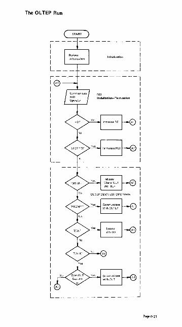
The OLTEP Run
REI Initialization-Termination
I I I I I I I I I I I I I I I I I I I I
----~
Page 6-21

Page 6-22
,-----,---------1 I 61 I I CE Communications
I I I I
I : I I I I I I I I L _____________ J
1--I I I I I I I I Data Protect ton
I -------------'
Scheduling and EKecutingOlTs
L _____________ J

Section 7 Contents
Section 7: Glossary ............................................. 7·'

Glossary Sources: SR20-1078 System/360 Operator's Reference Guide
GC33-5380 DOSNS Service Aids and Procedures
GC20-1699 DP Glossary
NOTE: Asterisk before term indicates American National Standard Institute (ANSI) definition.
a access method: A technique for moving data between main storage and an input/output device.
address constant: A number, or a symbol representing a number, used in calculating storage addresses.
address translation: The process of changing the address of an item of data or an instruction from its virtual address to its real storage address. See also dynamic address translation.
alias: Another name for a member of a partitioned data set; another entry point of a program.
allocate: Assign a resource to a job or task.
asynchronous: Without regular time relationship; unexpected or unpredictable with respect to the execution of a program's instructions.
attribute: A trait; for example, attributes of data include record length, record fermat, data set name, associated device type and volume identification, use, creation date, etc.
auxiliary storage: Data storage other than main storage. Synonymous with external storage, secondary storage.
b basic access method: Any access method in which each input/output statement causes a machine input/output operation to occur. (The primary macro instructions used are READ and WRITE.)
basic control mode: When PSW bit 12 is 0, PSW format and system operation are compatible with standard System/360 operation. This isthe basic control mode in which control registers 0,8, and 14 are available to the system. Abbreviated to BC mode. See also "Extended Con· trol Mode."
batch processing: (See stacked job processing.)
block (records): 1. To group records to conserve storage space or to increase the efficiency of access or processing. 2. A blocked record. 3. A portion of a telecommunications message defined as a unit of data transmission.
block loading: Bringing the control section of a load module into adjoining positions of main storage.
BT AM (basic telecommunications access method): A basic access method that permits a READIWRITE communication with remote devices.
buffer (program input/output): A portion of main storage into which data is read, or from which it is written.
c catalog: 1. The collection of all data set indexes maintained by data management. 2. To in· elude the volume identification of a data set in the catalog. 3. In DOS to add a program to a library.
cataloged data set: A data set that is represented in an index or series of indexes.
cataloged procedure: A set of job control statements in the SYS1.PROCLIB data set. The procedure can be used by naming it in an execute (EXEC) statement.
CAW (channel address word): A ward in main storage at location 72 that specifies the location in main storage where a channel program begins.
Page 7-1

CCW (channel command word): A double word at the location in main storage specified by the CAW_ One or more CCWs make up the channel program that directs channel operations_
CE pack: A disk pack used to test an IBM 2314, or 3330_ It has an RO data length of 6 at any location other than cylinder 0, track 0_
CE volume: If the device is a 2314 or 3330, see CE pack_
channel: A hardware device that connects the CPU and main storage with the 1/0 control units.
channel program: One or more Channel Command Words (CCWs) that control(s) a specific sequence of channel operations. Execution of the specific sequence is initiated by a single start 1/0 instruction.
channel program translation: In a channel program, replacement, by software, of virtual addresses with real addresses.
ell: Core Image Library.
command control block (ceB): Under DOS and TOS, a 16-byte field required for each channel program executed by physical 10CS. This field is used for communication between physical 10CS and the problem program.
connnunication region: Under DOS and TOS, an area of the supervisor set aside for interprogram and intraprogram communication. It contains information useful to both the supetvisor and the problem program. Abbreviated comreg. (Not to be confused with the COMRG macro instruction)_
communications interval: A period of communication between the console operator and Ol TEP. The operator is requested by Ol TEP to enter the test-run definition at this time_
concatenated data set: A group of logically connected data sets.
Configuration Data Set (CDS): A record of information about an 1/0 device or CPU ilCccs::;cd by CL TEP ui"id the CL T.
control blocks: A storage area used by the operating system to hold control information.
control dictionary: The external symbol dictionary and relocation dictionary, collectively, of an object or load modu Ie.
control program: The routines in the operating system that manage resources, im· p lement data organization and communications conventions, or contain privileged operations.
control registers: In S/370, a set of registers used for operating system control of relocation, priority interruption, program event recording, error recovery, and masking operations.
control section: That part of a program specified by the programmer to be a relocatable unit, all of which is to be loaded into adjoining main storage locations.
control volume: A volume that contains one or more indexes of the catalog.
core-wrap mode: The method of operation that records the events of a trace ic the PD area or an alternate area (used by PDAIDS)' It is the default process whe~ no output device for a PDAID trace has been specified.
CPU (central processing unit): The unit of a system that contains the circuits that control and perform the execution of instructions.
CRT (Cathode Ray Tube): Visual Display Screen.
CSW (channel status word): A word in main storage at location 64 that orovides information about the termination of an input/output ooeration.
Page 7-2

d data management: Those parts of the control program that provide access to data sets, enforce data storage conventions, and regulate the use of input/output devices.
data organization: The arrangement of a data set.
data protection: A safeguard invoked to prevent the loss or destruction of customer data.
data security: A safeguard invoked to prevent the accessing of customer data.
data set: The major unit of data storage and retrieval in the operating system, consisting of a collection of data in one of several prescribed arrangements and described by control information that the system has access to.
data set control block (DSCB): A data set label for a data set in direct-access storage.
data set label (DSL): A collection of information that describes the attributes of a data set, and that is normally stored with the data set; a general term for data set control blocks and tape data set labels.
default value: A predetermined value used in place of an omitted entry.
deferred entry: An entry into a subroutine that occurs as a result of a deferred exit from the program that passed control to it.
deferred exit: The passing of control to a subroutine at a time determined by an asynchronous event rather than at a predictable time.
device independence: The ability to request input/output operations without regard to the characteristics of the input/output devices.
device name: Usually, the general name for a kind of device, specified at the time the system is generated. For example, 2314 or 3330 or TAPE. (See Unit name.)
direct access: Retrieval or storage of data by a reference to its location on a volume, rather than relative to the previously retrieved or stored data.
diskette: A flexible magnetic oxide coated disk, permanently enclosed in a semi-rigid protective plastic jacket approx. 8 inches square. During data processing operations the disk turns freely within the jacket. It is capable of storing 1898 128-character data records.
dispatching priority: A number assigned to tasks to determine the order in which they will use the central processing unit in a multitask situation.
DTF (define the file) macro instruction: A macro instruction that describes the characteristics of a logical input/output file, indicates the type of processing for the file, and specifies the I/O areas and routines to process the file.
dump: (1) To print out the contents of all or part of virtual storage or of aux iliary storage. (2) The data resulting from the process as in (1) ..
dynamic address translation (DA T): (1) In S/370, the change of a virtual storage address to an address in real storage during execution of an instruction. (2) A hardware feature that performs the translation.
e emulator: The combination of programming techniques and special machine features that permits a given computing system to execute programs written for another system.
entry point: Any location in a program to which control can be passed by another program.
environmental recording, editing, and printing (EREP): A program that processes the data contained on the system recorder file.
Page 7-3

error recovery procedures: Procedures designed to help isolate, and, when possible, to recover from hardware errors in equipment. The procedures are often used in con· junction with programs that record the statistics of machine malfunctions.
error volume analysis (EVA): With this DOS option, the system issues a message to the operator when a number of temporary read or write errors (specified by the user at system generation time) has been exceeded on a currently accessed tape file.
event: An occurrence of significance to a task; typically, the completion of an asyn· chronous operation, such as input/output.
exchange buffering: A technique using data chaining to avoid moving data in main storage, in which control of buffer segments and user program work areas is passed between data management and the user program.
exclusive segments: Segments in the same region of an overlay program, neither of which is in the path of the other. They cannot be in main storage simultaneously.
execute (EXEC) statement: A job control statement that designates a job step by identifying the load module to be fetched and executed.
expiration date: A date within a tape label for data protection. The tape cannot be used as a scratch tape without permission from the operator until this date has ex· pired.
ex1llnt: The physical locations on input/output devices occupied by or reselVed for a particular data set.
ex1llnded control mode: When PSW bit 12 is set to 1, the PSW format is changed from that used for standard System/360 operation: the channel m ... k bits, instruction length code, and interruption code are removed, and additional mode and mask bits are included. This is the extended control mode, in which all control registers are available to the system for control of facilities that are particular to Systemi370. Abbreviated to EC mode. See also "Basic Control Mode."
extBmal reference: A reference to a symbol defined in another module.
ex1llmal symbol: A control section name, entry point name, or external reference; a symbol contained in the external symbol dictionary.
exlllmal symbol dictionary (ESD): Control information associated with an object or load module which identifies the external symbols in the module.
f F format: A data set record format in which logical records are the same length.
fetch (program): 1. To load requested load modules into main storage, relocating them as necessary. 2. A control routine that accomplished 1.
File Protect Mode (FPM): A mode of operation that insures maximum protectior, and security of customer data. While in file protect mode, the system performs no write operations and reads no customer data.
fixed page: A page in real storage that is not to be paged out.
F/L Trace (Fetch/Load Trace): Under DOS and TOS, a program that records infor,.,a· tion about phases and transients as they are called from a core image library.
9 generation data ~p: A collection of successive, historically related data sets.
GPR (General-purpose register): Temporary storage with capacity of one word. There are 16 GPRs on System/370 computers. .
GSVC Trace (Generalized Supervisor Calls Trace): A program that records SVC inter· rupts as they occur. All or a selected group of SVCs can be traced.
Page 7·4

h hard copy: A printed copy of machine output in a visually readable form, for ex· ample, a printed recording of the messages displayed on the System/370 Model 125 video display unit.
hard stop: A condition, usually caused by an error, in which the CPU is stopped and is not executing the microprogram .
. I IC (instruction counter): Hardware circuit which tells the central processor (CPU) the main storage address at which it will find the next instruction to execute.
inclusive segments: Overlay segments in the same region that can be in main storage simu Itaneously. .
index (data management): 1. A table in the catalog structure used to locate data sets. 2. A table used to locate the records of an indexed sequential data set.
initial program loading (lPL): The initialization procedure which loads the nucleus and begins normal operations.
initiator: The part of the job scheduler that selects jobs and job steps to be executed, allocates input/output devices for them, places them under task control, and at completion of the job, supplies control information for writing job output on a system output unit.
input queue: A queue of job definitions in direct access storage, assigned to a job class and arranged in assigned priority order, waiting to be processed.
input stream: Job· control statements entering the system; may also include input data.
installation: A particular computing system, in terms of the overall work it does and the people who manage it, operate it, apply it to problems, service it, and use the resu Its it produces.
interrupt: A break in the normal sequence ·of instruction execution. It causes an automatic transfer to a preset storage location where appropriate action is taken.
invalid page: In S/370, a page that cannot be directly addressed by the dynamic address translation feature of the central processing unit.
I/O area: An area (portion) of real storage into which data is read or from which data is written; the term buffer is often used in place of I/O area.
I/O Trace (Input/Output Trace): A program that records I/O device activity for all or a selected group of I/O devices.
10CS (input/output control system): A group of macro instruction routines provided by I BM for handling the transfer of data between main storage and external storage devices.
irrecoverable error: A hardware error which cannot be recovered from by the normal hardware and retry procedures .
. J job: 1. A unit of work for the system from the standpoint of installation accounting and control. A job consists of one or more job steps. 2. A collection of related problem programs, identified in the input stream by a JOB statement followed by one or more EXEC statements.
job control starernent: A control statement in the input stream that identifies a job or defines its needs.
job library: A set of user· identified partitioned data sets used as the main source of load modules for a given job.
Page 7·5

job management: A general term for the functions of job scheduling and command processing.
job queue: (See input queue.)
job (JOB) statement: The control statement in the input stream that identifies the beginning of a series of job control statements for a single job.
job step: A unit of work associated with one processing program or one cataloged procedure, and related data.
I language translator: Any assembler, compiler, or other routine that accepts statements in one language and produces equivalent statements in another language.
library: 1. A collection of objects (for example, data sets, volumes, card decks) associ· ated with a particular use, and identified in a directory. See job library, link library, system library. 2. Any partitioned data set.
limit priority: In OSIVS2 and MVT, a number associated with a task in a multitask operation, representing the highest dispatching priority that the task can assign to itself or to any of its subtasks.
link library: A partitioned data set which, unless otherwise specified, is used in fetch· ing load modules referred to in execute (EXEC) statements and in ATTACH, LINK, LOAD, and XCTL macro instructions.
linkage: The coding that connects two separately coded routines.
linkage editor: A program that produces a load module by changing object modules into a form acceptable to fetch, combining object modules and load modules into a single new load module, resolving symbolic cross references among them, replacing, deleting, and adding control sections automatically on request, and providing overlay facilities for modules requesting them.
load: In programming, to enter instructions or data into storage or working registers. In DOSIVS, to brir>9 a program phase from a core image library into virtual storage for execution.
load module: The output of the linkage editor; a program in a form suitable for loading into main storage for execution.
locate mode: A way of providing data by pointing to its location instead of moving it.
logic module: The logical IOCS routine that provides an interface between a processing program and physical IOCS.
logical rerord: A record that is defined in terms of the information it contains rather than by its physical traits .
• loop: A sequence of instructions that is executed repeatedly until a terminal can· dition prevails.
LSERV (label cylinder display): A program that tormats a listing of the label cylinder located on SYSRES.
m machine check analysis and recovery: 1. A feature that checks the severity of a CPU hardware failure and attempts to recover from the interrupt. Abbreviated MCAR. 2. In S/370 Mod 168 MCAR designates Maintenance Control Address Register.
machine check interrupt: The interrupt that occurs if the CPU fails to operate.
macro instruction: The macro instruction statement, the corresponding macro in· struction definition, the resulting assembler language statements, and the machine language instructions and other data produced from the assembler language statements; loosely, anyone of these representations of a machine language instruction secuence.
Page 7-6

main page pool: In DOSIVS, the set of all page frames in real storage not assigned to the supervisor or one of the real partitions.
main storage: 1. The real address area of virtual storage. Contrast with auxiliary storage. 2. All program addressable storage from which instructions may be executed and from which data can be loaded directly into registers.
master scheduler: The part of the control program that responds to operator commands and returns required information.
MCAR Maintenance Control Address Register (Mod 165 and 168)
MCDR Maintenance Control Data Register (Mod 165 and 168)
MCER Maintenance Control Entry Register (Mod 165 and 168)
microprogram: A set of basic or elementary machine instructions that is loaded into control storage to control CPU operations.
module (programming): A program unit that is input to, or output from, a single execution of an assembler, compiler, or linkage editor; a source, object, or load module.
move mode: A way of providing data by moving it instead of pointing to its location.
MRAR Maintenance Ripple Address Register (Mod 165 and 168)
multijob operation: Concurrent execution of job steps from two or more jobs.
multiplexer channel: A channel designed to operate with a number of I/O devices simultaneously on a byte basis. That is, several I/O devices can be transferring records over the multiplexer channel, time-sharing it on a byte basis.
multiplexer mode: A means of transferring records to or from low·speed I/O devices on the multiplexer channel, by interleaving bytes of data. The multiplexer channel sustains simultaneous I/O operations on several subchannels. Bytes of data are inter· leaved and then routed to or from the selected I/O devices or to and from the desired locations in main storage. Multiplex mode is sometimes referred to as byte mode.
multiprogramming system: A system that controls more than one program simulta· neously by interleaving their execution.
multitasking: The concurrent execution of one main task and one or more subtasks in the same position.
n name: A set of one to eight characters that identifies a statement, data set, module, etc., and that is usually associated with the location of that which it identifies.
nucleus: That part of the control program that must always be present in main storage. Also, the main storage area used by the nucleus and other transient control program routines.
o object module: The output of a single execution of an assembler or compiler, which constitutes input to linkage editor. An object module consists of one or more control sections in relocatable, though not executable, form and an associated control dictionary.
offline: 1. • Pertaining to equipment or devices not under control of the central processing unit. 2. Pertaining to program error diagnosis without using the computer system (offline program debugging).
Page 7·7

* online: 1. Pertaining to equipment or devices under control of the central processing unit. 2. Pertaining to a user's ability to interact with a computer.
online test executive program (OL TEP): The control program of the online test system. OL TEP is the interfaoe between the online test and the operating system.
on-line test system: A control program, OLTEP, and a series of tests (OL Ts) designed to test I/O devices while permitting normal system processing in the foreground partitions.
operand: 1. • That which is operated upon. An operand is usually identified by an address part of an instruction. 2. I nformation entered with a command name to define the data on which the command processor operates and to control the execution of the command processor.
operator command: A statement to the control program, issued via a console device, which causes the control program to provide requested information, alter normal operations, initiate new operations, or terminate existing operations.
output queue: A queue of control information describing system output data sets, that specifies to an output writer the location and disposition of system output.
output writer: A part of the job schaduler that writes output data sets onto a system output unit, independently of the program that produced such data sets .
• overflow: 1. That portion of the result of an operation that exceeds the capacity of the intended unit of storage. 2. Pertaining to the generation of overflow as in 11).
p page: 1. A fixed-length block of instructions, data or both, that can be transferred between real storage and external page storage. 2. To transfer instructions, data, or both, between real storage and external page storage.
page dB1a set: An extent in auxiliary storage, in which pages are stored.
PII!JII fault: A program interruption that occurs when a page that is marked "not in real storage" is referred to by an active page. Synonymous with page translation exoeption.
page frame: A 2K block of real storage that can contain a page.
page frame table: A table that contains an entry for each frame. Each frame entry describes how the frame is being used.
page pool: The set of all page frames that may contain pages of programs in virtual mode.
page tabte (PGT): A table that indicates whetMer !::I pagr:' i~ in real S'tor8:gt:' ~nd t:or. relates virtual addresses with real storage addresses.
page translation exception: A program interruption that occurs when a virtual address cannot be translated by the hardware because the invalid bit in the page table entry for that address is set. See also segment translation exception, translation specification exception.
paging The process of transferring pages between real storage and the page data set.
parallel processing: Concurrent execution of one or more programs.
• pa-ameter: A variable that is given a constant value for a specific purpose or process.
partition: 1. In OSIVS1, a division of the dynamic area of virtual storage, established at system generation. 2. In DOSIVS, a division of the virtual address area of virtual storage that is allocated for programs that may be paged.
Page 7·8

Partitioned data set: A data set divided into several members. Each member has a unique name and is listed in a directory at the beginning of the data set. Members can be added or deleted as needed. Records within members are organized sequentially.
path: A series of segments that form the shortest distance in a region between a given segment and the root segment.
physical loeS: Macro instructions and supervisor routines (Channel Scheduler) that schedule and supervise the execution of channel programs. Physical lacs controls the actual transfer of records between the external storage medium and real storage.
physical record: A record that is defined in terms of physical qualities rather than by the information it contains.
polling: A technique by which each of the terminals sharing a communications line is periodically checked to determ ine if it requ ires servicing.
post: Note the occurrence of an event.
private library (of a job step): A partitioned data set other than the link library or the job library.
Private Second Level Directory (PSLD): The Private Second Level Directory is a table, located in the Supervisor and containing the highest phasenames found on the cor· responding directory tracks of the Private Core Image Library.
privileged instruction: An instruction that can be executed only while the CPU is in the supervisor state. Protection I/O, direct control, and any instructions that manipu· late the program status words are privileged.
problem determination aids (PDAID): Programs that trace a specified event when it occurs during the operation of a program. The traces provided are; QTAM Trace, 1/0 Trace, FIL Trace, and GSVC Trace.
problem program: Any program that is executed when the central processing unit is in the problem state; that is, any program that does not contain privileged instructions. This includes IBM-distributed programs, such as language translators and service programs, as well as programs written by a user.
processing program: 1. A general term for any program that is not a control pro· gram. 2. Synonymous with problem program.
processor: 1. • I n hardware, a data processor. 2 .• I n software, a computer program that includes the compiling, assembling, translating, and related functions for a specific programming language. RPG \I processor, FORTRAN processor. 3. Same as processing program.
program event recording: A System/370 feature that enables a program to be alerted to specific events. Abbeviated PER.
PSW (program status word): A double word in main storage used to control the order in which instructions are executed, and to hold and indicate the status of the system in relation to a particular program.
PTF: Program Temporary Fix
q qualified name: A data set name that is composed of multiple names separated by periods (for example, TREE.FRUIT.APPLE).
qualifier: All names in a qualified name other than the rightmost, which is called the simple name.
queue: 1. A waiting line or list formed by items in a system waiting for service; for example, tasks to be performed or messages to be transmitted in message switching system. 2. To arrange in, or form, a queue.
queued access method: An access method that automatically governs the movement of data between the program USing the access method and input/output devices. (The primary macro instructions used are GET and PUT.)
Page 7·9

Ouiesc:e Mode: A mode of operation that requires the foreground partition to be stopped by the operator. The operator does this on the console by issuing the PAUSE EOJ and STOP commands when requested by Ol TEP.
aT AM Trace: A program that records certain supervisor and 110 activities on tape or in core·wrap mode.
r reader: 1. A device that converts information in one form of storage to information in another form of storage. 2. A part of the scheduler that reads an input stream into the system.
ready condition: The condition of a task that is ready to be performed by the central processing unit.
real address: In VS, the address of a location in real storage.
real address area: The area of virtual storage where virtual addresses are equal to real addresses.
real mode: In DOS/vS, the mode of a program that may not be paged.
real storage: The storage of a System/370 computing system from which the central processing unit can directly obtain instructions and data, and to which it can directly return results. Synonymous with processor storage.
real partition: In DOS/VS, a division of the real address area of virtual storage that may be allocated for programs that are not to be paged, or programs that contai~ pages that are to be fixed.
nICOrd: A unit of data.
I1IC<MIfY management support: The facilities that gather information about hardware reliability and allow retry of operations that fail because of CPU, 1/0 device, or channel errors. Abbreviated to RMS.
reenterable: The attribute of a set of code that allowco thf?' ~!'!'!e o:cpy cf the xt v f
code to be used concurrently by two or more tasks.
reliability data extractor (ROE): A function that provides hardware reliability data that is analyzed by IBM.
reIocatabie library: A library of relocatable object modules and lOGS modules required by various compilers. It allows the user to keep frequently used modules available for combination with other modules without recompilation.
resource: Any facility of the computing system or operating system required by a job or task, and including main storage, input/output devices, the central processing unit, data files, and control and processing programs.
resource manager: Any control program routine responsible for the handling of a resource.
* routine: An ordered set of instructions that may have some general or frequent use.
s scheduler: (See master scheduler and job scheduler.)
Second level Directory (SlD): The table, located in the Supervisor and containing the highest phase-names found on the corresponding directory tracks of the system core image.
secondary storage: Auxiliary storage.
_k: Position the access mechanism of a direct-access device at a specified location.
segment: A continuous 64K area of virtual storage, which is allocated to a job or system task.
Page 7·10

segment table (SGT): A table used in dynamic address translation to control user access to virtual storage segments. Each entry indicates the length, location, and availability of a corresponding page table.
segment translation exception: A program interruption that occurs when a virtual address cannot be translated by the hardware because the invalid bit in the segment table entry for that address is set. See also page translation exception, translation specification exception.
self-relocating: A programmed routine that is loaded at any doubleword boundary and can adjust its address values so as to be executed at that location.
self-relocating program: A program that is able to run in any area of storage by having an initialization routine to modify all address constants at object time.
selector channel: A channel designed to operate with only one I/O device at a time. Once the I/O device is selected, a complete record is transferred one byte at a time.
SEREP: A stand·alone environment recording, editing, and printing program that makes the data contained in an error logout area of real storage available for further analysis.
Shared Virtual Area (SVA): The last part of the virtual system address space that contains phases which are reenterable and relocatable and which can be shared between partitions.
simple name: The rightmost component of a qualified name (for example APPLE is the simple name in TREE.FRUIT.APPLE).
soft stop: A condition in which the CPU has stopped processing but continues to handle any requested interruptions.
source module: A series of statements which make up the entire input to a single execution of an assembler or compiler.
stacked job processing: A technique that permits multiple job definitions to be grouped (stacked) for presentation to the system, which automatically recognizes the jobs, one after the other.
stand-alone dump: A program that displays the contents of the registers and all of real storage and that runs independently.
storage block: An area of main storage consisting of 2048 bytes to which a storage key can be assigned.
* storage protection: An arrangement for preventing access to storage for either read· ing, or writing, or both.
subtask: A task in which control is initiated by a main task by means of a macro instruction that attaches it.
supervisor: The part of a control program that coordinates the use of resources and maintains the flow of CPU operations.
supervisor state: The state of CPU operation that allows execution of privileged instructions. When bit 15 of the PSW is zero, the CPU is in the supervisor state.
SV A: See Shared Virtual Area.
SVC (supervisor call): An instruction which causes an SVC interruption in the hard· ware to give control to a control program routine (called an SVC routine) for some specific action, such as reassigning parts of main storage or retrieving data from an I/O device.
synchronous: Occurring with a regular or predictable time relationship.
SYSIN: A system input stream.
SYSOUT: A system output stream.
system generation (SYSGEN): The process of tailoring the IBM·supplied operating system to user requirements. 4
Page 7·11

system debugging aids: A set of routines provided to trace specific program events by using the program event recording facilities. Abbreviated ~:;oAIDS.
System Directory List (SOLI: A list of hi\t1ly used phases (either only in the system Cil or also in the SVAI. This list is placed in the SVA.
system input unit: A device specified as a source of an input stream.
system library: The collection of all cataloged data sets at an installation.
system macro instruction: A macro instruction that provides access to operating system facilities.
system output unit: An output device shared by all jobs.
system recorder file: The data file that is used to record hardware reliability data.
system residence volume: The volume on which the nucleus of the operating system and the highest level index of the catalog are located.
SYSCTlG: An optional system data set on the primary system residence device can· taining addresses relating installation data set names to specific volume numbers.
SYS1.LlNKLlB: A system data set containing the system program modules that are not either permanently resident in main storage or resident in the SYS1.SVCLlB.
SYS1.l0GREC: A system data set on the primary system residence device containing information regarding system failures.
SYS1.NUClEUS: A system data set on the primary system residence device containing the IPl program and the primary nucleus.
SYS1.PROCLlB: A data set containing cataloged procedures-handy setS of control statements that can be called into use by EXEC statements.
SYS1.SVCLlB: A system data set on the primary system residence device containing all of those SVC routines. 1/0 error recovery routines. and access method routines. that are not oermanently resident in m::lin c:t:0r~!JoI?
SYS1.SYSJOBQE: A system data set used by the scheduler as a storage and work area for information about the input and output streams. Contains the input and output queues.
t task: A unit of work for the central processing unit from the standpoint of the control program.
task queue: A queue of all the task control blocks present in the system at anyone time.
task selection: The supervisor mechanism for determining which program should gain control of CPU processing.
telecommunicetions: Data transmission between a system and remotely located devices via a unit that performs format conversion and controls the rate of transmission.
teleprocessing: The processing of data that is received from or sent to remote locations by way of telecommunication lines.
terminal: 1. • A point in a -system or communication network at which data can either enter or leave. 2. Any device capable of sending and receiving information over a communication channel.
Terminating partition: In DOSIVS this is a partition owning a program which is in the process of being terminated either because of a program cancel condition or because of EOJ.
test-run definition: Information requested by OL TEP at the various communications intervals. This information consists of the device to be tested, the test or test routines to be executed, and the options to be exercised.
Page 7-12

test translator: A facility that allows various debugging procedures to be specified in assembler language programs.
text: The control sections of an object or load module.
throughput: The rate at which work can be handled by a system.
trace: 1. To record a series of events as they occur. 2. The record of a series of events .
• tracing routine: A routine that provides a historical record of specified events in the execution of a program.
track hold: A function for protecting DASD tracks that are currently being processed. When track hold is specified in the DTF, a track that is being modified by a task in one partition cannot be concurrently accessed by a task or subtask in another parti· tion.
Transient area: An area in the supervisor used for temporary storage of transient routines, such as non· resident supervisor call or error·handling routines.
transient routines: These self·relocating routines are permanently stored on the system residence device and loaded (by the supervisor) into the transient area when needed for execution.
translation specification exception: A program interruption that occurs when a page table entry, segment table entry, or the control register pointing to the segment table contains information in an invalid format. See also page translation exception, segment translation exception.
transmittal mode: The way the contents of an input buffer are made available to the program, and the way a program makes records available for output.
turnaround time: The time between submission of a job to a computing center and the return of results.
u U format: A data set format in which blocks are of unknown length.
unit name: Usually, the unit address of a particular device, specified at the time a system is installed. For example 191 or 293. (See device name.)
user program: See problem program.
unrecoverable error: See irrecoverable error.
utility program: A program designed to perform a routine task, such as transcribing data from one storage device to another.
v V format: A data set format in which logical records are of varying length and include a length indicator; and in which V format logical records may be blocked, with each block containing a block length indicator.
virtual address: An address that refers to virtual storage and must, therefore, be translated into a real storage address when it is used.
virtual address area: In DOSiVS and OSiVS, the area of virtual storage whose addresses are greater than the highest address of the real address area.
virtual mode: In DOSiVS and OSIVS, the mode of a program which may be paged.
virtual storage: Addressable space that appears to the user as real storage, from which instructions and data are mapped into real storage locations. The size of virtual storage is limited by the addressing scheme of the computing system and by the amount of auxiliary storage available, rather than by the actual number of real storage locations.
Page 7·13

virtual storage access method (VSAM): VSAM is an access method for direct or sequential processing of fixed and variable length records on direct access devices. The records in a VSAM file can be organized either in logical sequence by a key field (key sequence) or in the physical sequence in which they are written on the file (entry· sequence). A key-sequenced file has an index, an entry-sequenced file does not.
volume: 1. That portion of a single unit of storage media which is accessible to a single read/write mechanism, for example, a drum, a disk pack, or part of a disk storage module. 2. A recording medium that b mounted and dismounted as a unit, for example, a reel of magnetic tape, a disk pack, a data cell.
volume table of contents (VTOC): A table associated with a direct-access volume, which describes each data set on the volume.
VSAM access method services: A multifunction utility program that defines VSAM files and allocates space for them, converts indexed sequential files to key-sequenced files with indexes, facilitates data portability between operating systems, creates backup copies of files and indexes, helps make inaccessible files accessible, and lists file and catalog entries.
w wait condition: The condition of a task that needs one or more events to occur before the task can be ready to be performed by the central processing unit.
wait state: The state of the system when no instructions are being processed, but the system is not fully stopped. The system can accept I/O and external interruptions, and can be put through the IPL procedure.
wraparound: 1. The continuation of an operation from the maximum addressable location in storage to the first addressable location. 2. The continuation of register addresses. fr0":l the highest register address to the lowest. 3. On a CRT display device, the continuatIon of an operation, e.g., a read or cursor movement, from ~he last character position in the display buffer to the first position in the displav buffer.
Page 7·14

Section 8 Contents
Section 8: Biblio!r<lphy •..••.......•••.....••••••••••....•....... 8·1
II

BIBLIOGRAPHY: List 1
Publications referenced in this Guide, arranged in numerical order.
This list only contains publications cited in this guide.
GA21-9124-3 (GN21-0166) GA22-6846 GA22-6954 GA22-6966 GA22-6969 GA22-7000 GA22-7017 GA24-3543-3
GA26-1619 GA27-2742-2 GA27-3051
GA32-0020--2 GA32-0021 GA32-0022 GA33-1509 GA33--1510 GA33-3010 GC2tl-1699 GC20--1806-1 GC24-5091-3 GC26-3784 GC27-6993 GC28-0638-1
IBM 3505 Card Reader and 3525 Card Punch Subsystem Component Description IBM S/360 2702 Transmission Control IBM S/360 and S/370 Mod 195 Operating Procedures IBM S/370 Mod 155 Operating Procedures IBM S/370 Mod 165 Operating Procedures IBM S/370 Principles of Operation IBM S/370 155 II DAT IBM 3211 Printer, 3216 Interchangeable Train Cartridge, and 3811 Printer Control Unit Component Description and Operator's Guide IBM 3340 Reference Manual Operator's Guide for IBM 3270 Information Display Systems I ntroduction to 3705 Communications Controller, Principles of Operation IBM 3803 3420 Magnetic Tape Subsystems Component Description IBM 3803 3420 Magnetic Tape Subsystems, Subsystem Description IBM 3410/3411 Magnetic Tape Subsystems Component Description IBM S/370 Mod 125 Procedures IBM S/370 Mod 115 Functional Characteristics IBM S/370 Mod 135 Channel Characteristics Data Processi ng Glossary IBM Virtual Machine Facility/370 Operator's Guide, Release 2 OSIVSl Programmer's Reference Digest VSl Release 3 OSIVS Checkpoint/Restart HASP II Version 4 Operator's Guide OSIVS SYS1.LOGREC Error Recording, VSl Release 2 and VS2 Release 1
GC28-0665-0 OSIVSl Service Aids VS 1 Release 3
GC28-0666-1 OSIVSl OL TEP
GC33-5378-1 GC33--5380--1 GC33-5381-1 GC35-0005-2
GC38-00OS GC38-0015 GC38-0025 GC38-0030 GC38-0110--3 GC38-0210--0 GC38-0210--1 GC38-0255-1
GC38-0260
GC38-1001-2
GC38-1002-1
SR20-1078-4 GX20--1850 GX20--1926
GX38-0227 GY32-5034 SY33-8571 G232-0004 S232-0003-2
VS 1 Release 3 DOSIVS Operating Procedures, Release 29 DOSIVS Serviceability Aids and Debugging Procedures, Release 29 DOSIVS System Utilities, Release 29 OSIVS Utilities VSl Release 3 and VS2 Release 2 IBM S/370 Mod 135 Procedures IBM S/370 Mod 145 Operating Procedures IBM S/370 Mod 158 Operating Procedures IBM S/370 Mod 168 Operating Procedures Operator's Library: OSIVSl Reference VSl Release 3 Operator's Library: OSIVS2 Reference VS2 Release i Operator's Library: OSIVS2 Reference VS2 Release 2 OSIVSl Display Consoles VS 1 Release 2 OSIVS2 Display Consoles VS2 Release 1 VSl System Messages VSl Release 3 VS2 System Msssages VS2 Release 1.6 IBM S/360 Operator's Reference Guide S/370 Reference Summary IBM Virtual MACHINE Facility/370 Quick Guide for Users OSIVS2 (JES2) Command Language Reference Summary Tape Unit Cleaning Procedure (3420 tape) DOSIVS Handbook, Release 29 IBM 3410/3411 Operator's Guide IBM 3420 Operator's Guide
Page 8·1

BIBLIOGRAPHY: List 2
This list is arranged by subject matter and includes some publications not quoted from nor referenced in this guide that are added because they are pertinent and useful for background.
General Information GA22-6822-20 IBM 51360 and S/370 Bibliography GC20-1699 Data Processing Glossary
General System Information GA22-7001 IBM S/370 System Summary GA22-7000 IBM 51370 Principles of Operation GX20-1850-2 S/370 Reference Summary Card SR20-1078-4 IBM S/360 Operator's Reference Guide
Machine System GA33-1510 IBM S/370 Mod 115 Functional Characteristics GA33-1509 IBM S/370 Mod 125 Procedures GA33-1506 IBM S/370 Mod .125 Functional Characteristics GC38-0005 IBM S/370 MOD 135 Procedures GA33-3005 IBM S/370 Mod 135 Functional Characteristics GA33-3010 IBM S/370 Mod 135 Channel Characteristics GC38-0015 IBM 51370 Mod 145 Operating Procedures GA24-3557 IBM 51370 Mod 145 Functional Characteristics GA24-3573 IBM S/370 Mod 145 Channel Characteristics GA22-6966 IBM S/370 Mod 155 Operating Procedures GA22-6942 IBM 51370 Mod 155 Functional Characteristics GA22-6962 IBM S/370 Mod 155 Channel Characteristics GA22-7017 IBM S/370 Mod 155 II DAT Facility GC38-0025 IBM S/370 Mod 158 Operating Procedures GA22-7011 IBM 51370 Mod 158 Functional Characteristics GA22-7012 IBM S/370 Mod 158 Channel Characteristics GA22-6OO9 IBM S/370 Mod 165 Operating Procedures GA22-6935 IBM S/370 Mod 165 Functional Characteristics GA38-003O IBM SI370 Mod 165 Operating Procedures GX22-6984 IBM S/370 Mod 165 Operator's Reference Card GA22-7010 IBM S/370 Mod 168 Functional Characteristics G.A.22-6954 : eM S/3CO drill 5/370 Moo 195 Operating Procedures GA22-6943 IBM S/360 and 51370 Mod 195 Functional Characteristics
DASD GA22-6895
GA26-5988
GA26-1589
GA26-3599
GA26-1606 GA26-1592
GA26-1619
Diskette GA26-4187
IBM S/360 Component -Description 2820 Storage Control and 2301 Drum Storage IBM SI360 Component Description, 2841 and associated DASD, 2311 Disk Storage Drive, 2321 Data Cell Drive, 2303 Drum Storage Component Summary, 2835 Storage Control, 2305 Fixed Head Storage IBM 51360 Component Descriptions, 2314 Direct Access Storage Facility and 2844 Auxiliary Storage Control IBM 2319 Disk Storage Component Description Reference Manual for IBM 3830 Storage Control and IBM 3330 Disk Storage iBM 3340 Component Summary
Di~k:ett'= H2~! ins Prccedu res
Magnetic Tape Units G232-0004 IBM 3410/3411 Operator's Guide GA32-0022 IBM 3410/3411 Magnetic Tape Subsystems Component Description S232-0003-2 IBM 3420 Operator's Guide GA32-0020-2 IBM 3803/3420 Magnetic Tape Subsystems Component Description GA32-0021 IBM 3803/3420 Magnetic Tape Subsystems, Subsystem Description GY32-5034 Tape Unit Cleaning Procedure (3420) SY32-5033 Tape Unit Cleaning Procedures (2420, 3420) GA22-68SS IBM S/360 Component Descriptions: 2400 Series, 2803/2804 Tape
Controls, and 2816 Switching Unit
Printers GA24-3552 IBM 3210 Console Printer Keyboards GA24-3543-3 IBM 3211 Printer, 3216 Interchangeable Train Cartridge, and 3811
Printer Control Unit Component Description and Operator's Guide GA24-3073 IBM 1403 Printer Component Description
Page 8·2

Card Readers andlor Punches GA26-5893 IBM 2560 Multifunction Card Machine Component Description GA21-9124-3 IBM 3504 Card Reader, IBM ·3505 Card Reader and (GN21-0166) IBM 3525 Card Punch Subsystem Component Description GA21-9167 IBM S/370 5425 Multifunction Card Unit Programmer's Reference
Manual and Operator's Guide
Display Equipment GA27-2739 An Introduction to the IBM 3270 Information Display System GA27-2742-2 IBM 3270 Information Display Systems Operator's Guide SY27-2330 IBM 3277 Display Station Troubleshooting Guide GA27-2701 IBM S/360 2250 Display Unit Component Description GA27-2700 IBM S/370 2260 Display Station Component Description
Keyboard and Terminal Devices SH20-1232 IBM 2740 Communication Terminal GC28-2017 IBM 2741 Communication Terminal GA27-3070 IBM 3735 Programmable Buffered Terminal
Transmission Control Devices GA22-6864 IBM 2701 Data Adapter Unit Operation GA22-6846 IBM S/360 2702 Transmission Control GA27-3051 Introduction to 3705 Communications Controller Principles of Opera-
tion
Data Entry Systems GA21-9152-1 IBM 3740 Data Entry System GA21-9131 IBM 3741 Data Station Operator's Guide
Operating Systems GR20-4260-1 Introduction to Virtual Storage in S/370 GC38-0335 Operator's Library OSIVS1 CRJE GC38-0120-3 Operator's Library: OSIVS Console Configurations GC38-0255-1 OS/VS1 Display Consoles (GN27-1432) for VS1 Release 2 GC28-0665 OSIVS1 Service Aids for VS1 Release 3 GC38-0110-3 Operator's Library OSIVS1 Reference VS1 Release 3 GC30-2037 Operator's Library: OS/VS TCAM GC38-1007-3 OSIVS Message Library: Linkage Editor and Loader Messages GC38-1004-3 OS/VS Message Library: Routing and Descriptor Codes GC38-1006-3 OS/VS Message Library: Service Aids and OL TEP Messages GC38-1003-3 OS/VS Message Library: VS System Codes, Release 3 GC38-1001-2 OSIVS Message Library: VS1 System Messages, Release 3 GC38-1005-3 OS/VS Message Library: Utilities Messages, Release 3 GC38-1010-1 OS/VS Message Library: VS1 RES RTAM and Account Messages GC26-3791-3 OS/VS1 System Generation Reference, Release 3 GC24--5093-2 OSIVS1 Debugging Guide, VS1 Release 3 GC28-0666-1 OSIVS1 OLTEP, VS1 Release 3 GC26-3784--3 OSIVS Checkpoint/Restart, VS1 Release 3 and VS2 Release 2 GC28-0668 OS/VS1 SYS1.LOGREC Error Recording, VS1 Release 3 GC24-5091-3 OS/VS1 Programmer's Reference Digest, VS1 Release 3 GC35-0005--2 OSIVs Utilities, VS1 Release 3 and VS2 Release 2
• GC38-0210 Operator's Library: OSIVS2 Reference, Release 1 • GC38-0260 OSIVS2 Display Consoles, VS2 Release 1 • GC38-1002-1 VS2 System Messages, VS2 Release 1.6 • GC28-0638 OSIVS SYS1.LOGREC Error Recording, VSl Release 2 and VS2
GC35-0005-2 GX38-0227 GC38-0210-1 GC27-6993
Release 1 OSIVS Utilities, VS2 Release 2 OSIVS2 (JES2) Command Language Reference Summary Operator's Library OSIVS2 Reference, VS2 Release 2 HASP II Version 4 Operator's Guide
• As of March 1974 and until a succeeding Release to VS2 Release 1.6 is issued, order these publications by substituting T for C. For example, GT38-0210 rather than GC38-0210. If not, you will get publications for VS2 Release 2, the MVM system.
Page 8-3

DOS GC33-5370 GC33-5378-1 GC33-53BO-l GC33-5381-1 GC33-5383 SY33-8571
VM GC20-1806-1 GX20--1926
Page 8-4
Introduction to DOSIVS DOSIVS Operating Procedures, Release 29 DOSIVS Serviceability Aids and Debugging Procedures, Release 29 DOSIVS System Utilities, Release 29 DOSIVS OL TEP Reference DOSIVS Handbook, Release 29
IBM Virtual Machine Facility/370 Operator's Guide, Release 2 I BM Virtual Machine Facility/370 Quick Guide for Users

alignment, CNOP, 2-4 alter main storage
Index
see CPU manual procedures alter PSW
see CPU manual procedures alter registers
see CPU manual procedures ANSI-defined printer control characters, 2-11 assembler instructions, 2-5 assign alternate track data cell utility, 6-1
bibliography 1, 8-1 bibliography 2, 8-2 binary powers table, 2-16
card punch liO command code, 2-6 3525 error recovery, 5-25 3525 stop indications and restart procedures, 5-17
card reader general hints, 5-10 1/0 command code, 2-6 3504/3505 restart procedures, 5-11
channel address word (CAW), 2-13 channel command word (CCW), 2-13 channel logout (hex BO), 2-14 channel status word (CSW)' 2-13 checkpoint restart OSIVS1, 5-26 checkpoint restart OSIVS2, 5-27 ciear data cell utility, 6-1 clear disk utility, 6-1 clear main storage
see CPU manual procedures CMS commands
see operator commands VM/370 CNOP alignment, 2-4 code translation table, 2-8 codes for interruptions, 2-14 commands
see operator commands condition codes, 2-4 console file, 5-30 console printer, 1/0 command code, 2-6 constants, summary of, 2-5 control (k) commands, 4-80, 4-84
see DOSIVS DOC commands, 4-84 see OSIVS display console commands, 4-80
control register allocation, 2-12 control register fieldS, 2-12 copy and restore disk on data cell utility, 6-1 copy and restore diskette utility, 6-2 CP commands, 4-49
see operator commands VM/370 CPU manual procedures for
Mod 115, 3-3 Mod 125, 3-3 Mod 135, 3-6 Mod 145, 3-8 Mod 155, 3-11 Mod 158, 3-13 Mod 165, 3-15 Mod 168, 3-18 Mod 195, 3-22
CRJE system operator commands, 4-74 CRJE terminal operator commands, 4-77
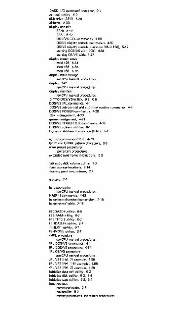
DASD, 1/0 command codes for, 2-7 deblock utility, 6-2 disk drive - 3340, 5-28 diskette, 5-30 display console
3270, 5-49 3277, 5-47 DOSNS DOC commands, 4-80 OSNS display console commands, 4-83 OSNS display console operation (Mod 158), 5-47 starting DOSNS with DOC, 4-84 starting OSNS with, 5-47
display screen areas Mod 125, 5-44 Mod 158, 5-45 Mod 168, 5-46
display main storage see CPU manual procedures
display PSW see CPU manual procedures
display registers see CPU manual procedures
DITTO DOSNS utility, 6-3, 6-6 DOSIVS IPl commands, 4-1 DOSNS job control and attention routine commands, 4-5 DOSNS POWER commands, 4-20 task management, 4-20 queue management, 4-21 DOSNS POWER RJE commands, 4-22 DOSNS system utilities, 6-1 Dynamic Address Translation (DAT), 2-15
edit subcommands CRJE, 4-76 EDIT and EDMK pattern characters, 2-3 error restart procedures
see restart procedures extended mnemonic instructions, 2-3
fast copy disk volume utility, 6-2 fixed storage locations, 2-14 floating point instructions, 2-2
glossary, 7-1
hardstop option see CPU manual procedures
HASP II commands, 4-43 hexadecimal-decimal conversion, 2-15 hexadecimal table, 2-15
IBCDASDI utility, 6-8 IEBISAM utility, 6-7 IEBPTPCH utility, 6-7 IEHDASDR utility, 6-7 IEHlIST utility, 6-7 IEHMOVE utility, 6-7 IMPl procedure
see CPU manual procedures IPl DOSNS commands, 4-1 IPl DOSIVS procedure, 4-84 IPl OSIVS procedure
see CPU manual procedures IPl VSl (ReI. 2) example, 4-86 IPl VS2 (Rei. 1.6) example, 4-88 IP l VS2 (Rei. 2) example, 4-89 initialize data cell utility, 6-2 initialize disk utility, 6·2, 6-4 initialize tape utility, 6-2, 6-4 input/output
command codes, 2-6 devices list, 5-2 restart procedures, see restart procedures

IBM 1403 printer restart procedures, 5·39 3270 display console operation, 5·49 3340 disk drive operating hints, 5·2B 3410 tape operation, cleaning, handling, 5·34 3420 tape operation, cleaning, handling, 5·37 3504/3505 card reader restart procedures, 5·11 3525 error recovery, 5·25
IBM service call procedure, 1·11 interruption codes, 2·14
limited channel logout (hex BO), 2-14 loading a secondary nucleus
see CPU manual procedures
machine check interruption code (hex EBI. 2-14 machine instruction formats, 2-12 machine instructions, 2·1 magnetic tape, 1/0 command code, 2-6 magnetic tape, see also tape manual controls S/370, function of, 3·1 message routing codes VS1, 4·30 message routing codes VS2, 4·30
OLTEPOSNS1,6-19 operator commands
CMS, 4-61 CP, 4-49 CRJE system operator, 4-74 CRJE terminal operator, 4·75 display console control cmds, 4·80 display operating console (DOSIVS) cmds, 4·80 DOSNS IPL, 4·1 DOSNS job control and attention routine, 4·5 DOSNS POWER, 4-20 DOSNS POWER RJE, 4-22 edit subcommands CRJE, 4-76 OSNS HASP II, 4·43 OSNSl Release 3, 4-25 OSNS2 Release 1.6, 4-31 OSNS2 Release 2, 4-36 RES central, 4·69 RES workstation, 4·70 terminal commands and functions CRJE, 4-77 VM/370, 4-47
operating procedures see CPU manual procedures
operator trouble report 3270, 5·50 OSIVSl checkpoint restart, 5·26 OSNS 1 service aids, 6·18 OSNS2 checkpoint restart, 5-27
page table entry, 2·15 POWER commands DOSIVS, 4-20 power-on procedure
see CPU manual procedure power·off procedure
see CPU manual procedures printer
control characters, ANSI-defined, 2-11 1403 restart procedures, 5-39 3211 error recovery procedures, 5-42
printlog utility, 6·3, 6-5 problem determination chart, 1·1 program function keys (PFK), 4-83 program interruption codes, 2-13 program status word (PSW)
BC mode, 2·13 EC mode, 2·13 alter PSW, see CPU manual procedures display PSW, see CPU manual procedures
punch 3525 error recovery routine, 5·25

reader general hints, 5-10 3504/3505 restart procedures, 5-11
RES central operator commands, 4-69 RES workstation operator commands, 4-70 restart procedures
1403 printer, 5-39' 3211 printer, 5-42 3504/3505 card neader, 5-11 3525 punch, 5-17 checkpoint restart OSIVS1, 5-26 checkpoint restart OSIVS2, 5-27
routing codes VS 1, 4-30 routing codes VS2, 4-30
segment table entry, 2-15 sense byte data, 5-2
1017 paper tape reader, 5-2 1018 paper tape punch, 5-2 1287 optical reader, 5-2 1288 optical page reader, 5-2 1403 printer, 5-2 1442 card read punch, 5-2 1443 printer, 5-2 1419 magnetic character reader, 5-2 2260 display station, 5-2 2301 drum storage, 5-2 2305 fixed head storage, 5·2 2314 disk storage, 5-2 2319 disk storage, 5-2 2321 data cell drive, 5-2 2400 series tape units, 5·2 2401 magnetic tape unit, 5-2 2415 magnetic tape unit and control, 5-2 2420 magnetic tape unit, 5-2 2501 card reader, 5-2 2520 card read punch, 5-2 2540 card read punch, 5-2 2560 multi·funclion card macnme, O·:l 2596 card read punch, 5-2 2671 paper tape reader, 5-2 2820 storage control (2301/2820), 5-2 2822 paper tape reader control, 5-2 3203 printer, 5-2 3210 console printer keyboard, 5-2 3211 printer, 5-2 3215 console printer keyboard, 5-2 3330 disk storage, 5·2 3340 disk storage, 5-2 3410/3411 magnetic tape unit and control, 5-2 3420 magnetic tape unit, 5-2 3504 card reader, 5-2 3505 card reader, 5-2 3525 card punch, 5-2 3540 diskette, 5-2 3803 tape control, 5-2 3881 optical mark ,e.roer, 5-2 3886 optical character reader, 5-2 5425 multi-function card unit, 5-2
serviceaidsOSIVS1,6-18 status byte data, 5.1
see sense byte data for units stop on main storage address
see CPU manual procedures storage locations, fixed, 2-14 store procedure
see CPU manual procedures lalter. .. ) S/370 manual controls, 3-1

tape cleaning procedures 3410/3411, 5-34 cleaning procedures 3420, 5-37 handling and storage 3410/3411, 5-36 operating procedures after failures
3410/3411, 5-34 3420, 5-37
transport cleaning, 5-35 terminal commands CRJE, 4-77 troubleshooting S/370, 1-11
utilities, DOSIVS, 5-1 assign altemate track data cell, 6-1 clear data cell, 6-1 clear disk, 6-1 copy and restore disk on data cell, 5-1 copy and restore diskette, 6-2 deblock, 6-2 DITTO DOSIVS (FDP), 5-3, 6-6 fast copy disk volume, 6-2
control stream, 6-5 initialize data cell, 6-2
control stream, 6-4 initialize disk, 5-2
control stream, 6-4 initialize tape, 6-2
control stream, 6-4 printlog. 6-3
control stream, 6-5 VTOC display, 6-3
control stream, 6-5 utilities, OSIVS
data set utilities, 5-7 executing a system utility, 6-12
card to pri nt, 6-12 card to tape, 6-13 system list, 6-13
functions they perform, 5-9 independent utilities, 6-8 system utilities, 6-7 IBCDASDI, 6-8
control stream, 6-14 IEBISAM, 6-7
control stream, 6-15 IEBPTPCH, 6-7
control stream, 6-16 IEHDASDR, 6-7
control stream, 6-14 IEHLlST, 6-7
control stream, 6-15 IEHMOVE, 5-7
control stream, 6-16
video display control commands, 4-80 video display operation, 5-47 video display screens
Mod 125, 5-44 Mod 158, 5-45 Mod 168, 5-46
virtual (logical) address format, 2-15 VM/370 commands, 4-47 VSl reI. 3 operator commands, 4-25 VS2 reI. 1_6 operator commands, 4-31 VS2 (JES2) operator commands, 4-36 VTOC display utility, 6-3, 5-5
writing tape marks DOSIVS, see DOS DITTO, 6-21 OSIVS, use OS DITTO
IBM SYSTEM/370 OPERATOR'S REFERENCE GUIDE, FORM SR20-4460-0
CIRCLE ONE OF THE COMMENTS AND EXPLAIN IN THE SPACE PROVIDED:
SUGGESTED ADDITION ( PAGE __ ) SUGGESTED DELETION ( PAGE __ ) ERROR (PAGE __ ) EXPLANATION:

BUSINESS REPLY MAIL NO POSTAGE STAMP NECESSARY IF MAILED IN THE UNITED STATES
POSTAGE WILL BE PAID BY:
I BM Education Center, Building 005 Department 78l , Publications Services South Road Poughkeepsie, New York 12602
FIRST CLASS
PERMIT NO. 40
ARMONK, NEW YORK

==-=- = ==-=-:=
International Business Machines Corporation Data Processing Division 1133 Westchester Avenue, White Plains, New York 10604 (U.S.A. only)
IBM World Trade Corporation 821 United Nations Plaza, New York. New York 10017 (International)
SR20-4460-O