Synthesis of a TiO 2 ceramic membrane containing SrCo 0.8Fe 0.2O 3 by the sol–gel method with a...
9
Synthesis of a TiO 2 ceramic membrane containing SrCo 0.8 Fe 0.2 O 3 by the sol–gel method with a wet impregnation process for O 2 and N 2 permeation Abdul Latif Ahmad * , Nur Aimie Abdullah Sani, Sharif Hussein Sharif Zein School of Chemical Engineering, Universiti Sains Malaysia, Engineering Campus, Seri Ampangan, 14300 Nibong Tebal, Seberang Perai Selatan, Pulau Pinang, Malaysia Received 24 January 2011; received in revised form 27 March 2011; accepted 27 March 2011 Available online 6 April 2011 Abstract A SrCo 0.8 Fe 0.2 O 3 impregnated TiO 2 membrane (TiO 2 –SrCo 0.8 Fe 0.2 O 3 membrane) was successfully prepared using a sol–gel method in combination with a wet impregnation process. The membrane was subjected to a single gas permeance test using oxygen (O 2 ) and nitrogen (N 2 ). The TiO 2 membrane was immersed in the SrCo 0.8 Fe 0.2 O 3 solution, dried and then calcined to affix SrCo 0.8 Fe 0.2 O 3 into the membrane. The effect of the acid/alkoxide (H + /Ti 4+ ) molar ratio of the TiO 2 sol on the TiO 2 phase transformation was investigated. The optimal molar ratio was found to be 0.5, which resulted in nanoparticles with a mean size of 5.30 nm after calcination at 400 8C. The effect of calcination temperature on the phase transformation of TiO 2 and SrCo 0.8 Fe 0.2 O 3 was investigated by varying the calcination temperature from 300 to 500 8C. X-ray diffraction spectroscopy (XRD) and Fourier transform infrared (FTIR) analysis confirmed that a calcination temperature of 400 8C was preferable for preparing a TiO 2 –SrCo 0.8 Fe 0.2 O 3 membrane with fully crystallized anatase and SrCo 0.8 Fe 0.2 O 3 phases. The results also showed that polyvinyl alcohol (PVA) and hydroxypropyl cellulose (HPC) were completely removed. Field emission scanning electron microscopy (FESEM) analysis results showed that a crack-free and relatively dense TiO 2 membrane (0.75 mm thickness) was created with a multiple dip-coating process and calcination at 400 8C. The gas permeation results show that the TiO 2 and TiO 2 –SrCo 0.8 Fe 0.2 O 3 membranes exhibited high permeances. The TiO 2 – SrCo 0.8 Fe 0.2 O 3 membrane developed provided greater O 2 /N 2 selectivity compared to the TiO 2 membrane alone. # 2011 Published by Elsevier Ltd and Techna Group S.r.l. Keywords: D. Perovskites; TiO 2 ceramic membrane; Sol–gel method; O 2 and N 2 permeation 1. Introduction Ceramic membranes offer many advantages over polymeric membranes. They are stable at high temperatures, exhibit good chemical stability (especially in organic solvents) and have a high pressure resistance [1]. Ceramic membranes are superior for applications in gas separation, food and biotechnology, as well as in the filtration and treatment of water and waste water [2]. The ceramics that have been most extensively studied for membrane applications include Al 2 O 3 , TiO 2 , ZrO 2 and SiO 2 . TiO 2 membranes have garnered considerable attention due to their high hydrothermal and chemical stability; good anti- fouling properties [3]; high surface reactivity to gases, which makes it suitable as a catalyst [4] and high specific surface area for gas sensors [5]. Their potential applications include ultrafiltration processes, catalytic/photocatalytic membrane reactors, gas separations/reactions and gas sensing [6]. TiO 2 exists in a number of crystalline forms, the most important of which are anatase, rutile and brookite. Anatase and rutile are both tetragonal in structure, while brookite has an orthorhombic structure [7]. Anatase is the thermodynamically metastable form with respect to rutile, under all conditions of temperature and pressure [8]. The volume free energy of the rutile phase is always lower than that of the anatase phase. Therefore, heat treatment transforms the anatase phase to the stable rutile phase. The temperature of the transformation depends heavily on the nature and structure of the precursor and on the preparation conditions. Most of the chemical preparation methods yield TiO 2 in the metastable anatase phase and shift it to the rutile phase after further heat treatment [9,10]. The perovskite-type oxide, SrCo 0.8 Fe 0.2 O 3 , is a typical mixed ionic electronic conducting membrane material that has www.elsevier.com/locate/ceramint Available online at www.sciencedirect.com Ceramics International 37 (2011) 2981–2989 * Corresponding author. Tel.: +60 4 593 7788x6414; fax: +60 4 594 1013. E-mail address: [email protected] (A.L. Ahmad). 0272-8842/$36.00 # 2011 Published by Elsevier Ltd and Techna Group S.r.l. doi:10.1016/j.ceramint.2011.03.036
-
Upload
independent -
Category
Documents
-
view
2 -
download
0
Transcript of Synthesis of a TiO 2 ceramic membrane containing SrCo 0.8Fe 0.2O 3 by the sol–gel method with a...

Synthesis of a TiO2 ceramic membrane containing SrCo0.8Fe0.2O3 by the
sol–gel method with a wet impregnation process for O2 and N2 permeation
Abdul Latif Ahmad *, Nur Aimie Abdullah Sani, Sharif Hussein Sharif Zein
School of Chemical Engineering, Universiti Sains Malaysia, Engineering Campus, Seri Ampangan, 14300 Nibong Tebal, Seberang Perai Selatan, Pulau Pinang,
Malaysia
Received 24 January 2011; received in revised form 27 March 2011; accepted 27 March 2011
Available online 6 April 2011
Abstract
A SrCo0.8Fe0.2O3 impregnated TiO2 membrane (TiO2–SrCo0.8Fe0.2O3 membrane) was successfully prepared using a sol–gel method in
combination with a wet impregnation process. The membrane was subjected to a single gas permeance test using oxygen (O2) and nitrogen (N2).
The TiO2 membrane was immersed in the SrCo0.8Fe0.2O3 solution, dried and then calcined to affix SrCo0.8Fe0.2O3 into the membrane. The effect of
the acid/alkoxide (H+/Ti4+) molar ratio of the TiO2 sol on the TiO2 phase transformation was investigated. The optimal molar ratio was found to be
0.5, which resulted in nanoparticles with a mean size of 5.30 nm after calcination at 400 8C. The effect of calcination temperature on the phase
transformation of TiO2 and SrCo0.8Fe0.2O3 was investigated by varying the calcination temperature from 300 to 500 8C. X-ray diffraction
spectroscopy (XRD) and Fourier transform infrared (FTIR) analysis confirmed that a calcination temperature of 400 8C was preferable for
preparing a TiO2–SrCo0.8Fe0.2O3 membrane with fully crystallized anatase and SrCo0.8Fe0.2O3 phases. The results also showed that polyvinyl
alcohol (PVA) and hydroxypropyl cellulose (HPC) were completely removed. Field emission scanning electron microscopy (FESEM) analysis
results showed that a crack-free and relatively dense TiO2 membrane (�0.75 mm thickness) was created with a multiple dip-coating process and
calcination at 400 8C. The gas permeation results show that the TiO2 and TiO2–SrCo0.8Fe0.2O3 membranes exhibited high permeances. The TiO2–
SrCo0.8Fe0.2O3 membrane developed provided greater O2/N2 selectivity compared to the TiO2 membrane alone.
# 2011 Published by Elsevier Ltd and Techna Group S.r.l.
Keywords: D. Perovskites; TiO2 ceramic membrane; Sol–gel method; O2 and N2 permeation
www.elsevier.com/locate/ceramint
Available online at www.sciencedirect.com
Ceramics International 37 (2011) 2981–2989
1. Introduction
Ceramic membranes offer many advantages over polymeric
membranes. They are stable at high temperatures, exhibit good
chemical stability (especially in organic solvents) and have a
high pressure resistance [1]. Ceramic membranes are superior
for applications in gas separation, food and biotechnology, as
well as in the filtration and treatment of water and waste water
[2]. The ceramics that have been most extensively studied for
membrane applications include Al2O3, TiO2, ZrO2 and SiO2.
TiO2 membranes have garnered considerable attention due to
their high hydrothermal and chemical stability; good anti-
fouling properties [3]; high surface reactivity to gases, which
makes it suitable as a catalyst [4] and high specific surface area
* Corresponding author. Tel.: +60 4 593 7788x6414; fax: +60 4 594 1013.
E-mail address: [email protected] (A.L. Ahmad).
0272-8842/$36.00 # 2011 Published by Elsevier Ltd and Techna Group S.r.l.
doi:10.1016/j.ceramint.2011.03.036
for gas sensors [5]. Their potential applications include
ultrafiltration processes, catalytic/photocatalytic membrane
reactors, gas separations/reactions and gas sensing [6].
TiO2 exists in a number of crystalline forms, the most
important of which are anatase, rutile and brookite. Anatase and
rutile are both tetragonal in structure, while brookite has an
orthorhombic structure [7]. Anatase is the thermodynamically
metastable form with respect to rutile, under all conditions of
temperature and pressure [8]. The volume free energy of the
rutile phase is always lower than that of the anatase phase.
Therefore, heat treatment transforms the anatase phase to the
stable rutile phase. The temperature of the transformation
depends heavily on the nature and structure of the precursor and
on the preparation conditions. Most of the chemical preparation
methods yield TiO2 in the metastable anatase phase and shift it
to the rutile phase after further heat treatment [9,10].
The perovskite-type oxide, SrCo0.8Fe0.2O3, is a typical
mixed ionic electronic conducting membrane material that has

A.L. Ahmad et al. / Ceramics International 37 (2011) 2981–29892982
drawn a significant amount of attention and has been applied in
the chemical and petroleum industries. Presently, the use of
SrCo0.8Fe0.2O3 as an O2 separation membrane has been
considered because of its higher oxygen ion and electron
conductivity. SrCo0.8Fe0.2O3 can also operate steadily for
longer durations at high temperatures [11]. A SrCo0.8Fe0.2O3
membrane is usually used alone and is prepared using a
conventional solid state method to form a SrCo0.8Fe0.2O3
powder. This powder is compressed into a disc and sintered
before application in gas-separation processes [12].
To the best of our knowledge, there are no reports on the
preparation of TiO2 membranes containing SrCo0.8Fe0.2O3,
especially using the sol–gel method in combination with a wet
impregnation process. Therefore, this paper reports the
synthesis of TiO2–SrCo0.8Fe0.2O3 membranes for O2 and N2
permeances. The TiO2 membrane was prepared by a sol–gel
method and SrCo0.8Fe0.2O3 was affixed to the TiO2 membrane
using a wet impregnation process. The membranes were
characterized using transmission electron microscopy (TEM),
XRD, FESEM and FTIR. The membrane developed was tested
on O2 and N2 gases and the O2/N2 selectivity across the TiO2
and TiO2–SrCo0.8Fe0.2O3 were documented.
2. Methodology
2.1. Preparation of membrane support and binders
A porous TiO2 disc (prepared from titanium (IV) oxide
powder) was used as a membrane support for a TiO2–
SrCo0.8Fe0.2O3 membrane. The support had a 20-mm diameter
and 2-mm thickness. About 1.75 g of TiO2 powder was loaded
into the stainless steel mold. The mold was then pressed using
hydraulic press equipment up to 20 MPa pressure. After
pressing, the support was dried at 70 8C, followed by a
calcination process at 965 8C for 4 h. To prevent cracking of the
support surface, the heating and cooling rate employed during
the calcinations was 2 8C/min.
Polyvinyl alcohol (PVA) and hydroxypropyl cellulose
(HPC) were used as binders to prevent the formation of cracks
on the thin membrane surface. They were also used to affix the
TiO2–SrCo0.8Fe0.2O3 membrane to the membrane support. The
PVA solution was prepared by dissolving 0.1 g of PVA into
100 ml distilled water, followed by stirring for approximately
1 h. The HPC solution was prepared by dissolving 0.7 g HPC
into 100 ml distilled water and stirring for 1 h.
2.2. Preparation of TiO2 sol
The sol–gel method was used to prepare the TiO2 sol. The
starting materials for the preparation of the TiO2 sol were the
following: (1) titanium tetraisopropoxide (TTIP) as the TiO2
precursor, (2) nitric acid as the catalyst for the peptization, (3)
distilled water as the dispersing medium and (4) isopropanol as
the solvent. TiO2 sol was prepared by hydrolysis of TTIP. A
solution of TTIP in isopropanol (0.45 M) was added drop wise
into a solution of isopropanol (4.5 M) in distilled water under
vigorous stirring. After the hydrolysis reaction was complete,
the remaining white precipitate of titanium hydroxide (Ti (OH)
4) was filtered and washed with water to remove the alcohol.
The filtrate was then dispersed in distilled water (Ti4+) and
nitric acid was added to achieve a 0.5 molar ratio of acid/
alkoxide (H+/Ti4+). The process was repeated with the
following ratios: 0.5, 1.5, 2.5 and 3.5. Next, the solution was
peptized for 2 h at 70 8C. A closed beaker was used to enhance
the rate of peptization. To break the weak bonds of the
agglomerated particles, the sol was treated ultrasonically for
30 min. The final product was a blue, semi-opaque colloidal
dispersion at a concentration of 0.325 M. A dilute concentra-
tion of the dispersion was produced by dilution with distilled
water.
2.3. Preparation of the SrCo0.8Fe0.2O3 solution
SrCo0.8Fe0.2O3 was prepared as described in a previous
publication [13]. Sr(NO3)2, Co(NO3)2�6H2O and FeCI3�6H2O
were weighed in equimolar amounts and dissolved in distilled
water (0.7 M). The solution was stirred for approximately 1 h to
ensure that it was completely dissolved. The SrCo0.8Fe0.2O3
phase was obtained after the membrane was calcined.
2.4. Preparation of the TiO2–SrCo0.8Fe0.2O3 membrane
The TiO2 membrane was created from the TiO2 sol. The
SrCo0.8Fe0.2O3 was then affixed within the TiO2 membrane
pores using a wet impregnation process.
The dipping solution for the TiO2 membrane contained
30 mL 0.05 M TiO2 sol mixed with 10 mL PVA solution and
20 mL HPC solution. An adequate amount of dipping solution
was used to coat the membrane support by dip-coating to form
the supported TiO2 membranes. The membranes were then
dried and calcined at different temperatures (100, 300 and
400 8C) for 2 h. The membranes were screened using TEM and
FTIR analysis and evaluated for membrane performance.
For the SrCo0.8Fe0.2O3 impregnation process, the TiO2
membrane was immersed in a SrCo0.8Fe0.2O3 solution for
10 min. The membrane was then dried and calcined under
atmospheric air at 400 8C for 4 h. The TiO2–SrCo0.8Fe0.2O3
membrane was tested using XRD and FESEM analyses and
evaluation of membrane performance was conducted.
2.5. Membrane characterization
TEM (Philips CM12) was performed to investigate the
dispersion of the particles in the TiO2 sol. The phase
transformation of the membrane during the calcination process
was identified using XRD (Philips PW1729 X-ray generator
with Philips PW1820 diffractometer) with Cu Ka radiation.
The surface and thickness of the membrane were observed
using FESEM (Leo Supra 50VP). FTIR analysis was performed
using the FTIR 2000 Perkin Elmer spectrophotometer and the
samples were prepared using a KBr pellet.

Fig. 1. Schematic diagram of the membrane gas permeation test rig.
A.L. Ahmad et al. / Ceramics International 37 (2011) 2981–2989 2983
2.6. Gas permeation measurement
The experimental apparatus utilized for the gas permeation
measurements is illustrated in Fig. 1. Single-gas permeance was
determined for O2 and N2, and the ideal selectivity was defined
as the ratio of their permeances. The permeance of the
membrane (K) in mol/m2 Pa s was obtained using Eq. (1) [14]:
K ¼q p
AmDP(1)
where qp is the gas flow rate of the permeate stream, Am is the
membrane’s effective surface area and DP is the pressure
difference between the feed and permeate streams. The ideal
selectivity of the membrane,aOz/Nz, is equal to the ratio of
permeances between O2 and N2, as shown in Eq. (2) [14]:
aOz=Nz¼ KO2
KN2
(2)
The permeance of the individual gases was determined in the
temperature range of 28–350 8C and at a fixed operating
pressure of 3 bars.
3. Results and discussion
3.1. Effect of the H+/Ti4+ molar ratio on the TiO2 phase
transformation
In this study, nitric acid was used as the peptizing agent. The
TiO2 membrane properties were studied at several H+/Ti4+
molar ratios, ranging from 0.5 to 3.5. This study was conducted
in the absence of PVA and HPC. Fig. 2(a)–(d) shows the TEM
images of the TiO2 membrane after calcination at 400 8C at
different H+/Ti4+ molar ratios. The TiO2 sol created at a 0.5
molar ratio had the smallest-sized nanoparticles, of roughly
spherical shapes (Fig. 2(a)) and a mean size of 5.30 nm, which
is in contrast to the result reported by Zaspalis et al. [15] using
the same general method (30 nm). Similar trends were reported
by Gestel et al. [3] and Alem et al. [16]. However, the
nanoparticle size in the TiO2 sol increased as the H+/Ti4+ molar
ratio increased from 0.5 to 3.5, while this increase in molar ratio
decreased the pH value from 1.3 to 0.3 (Table 1). A decrease in
pH is believed to favor anatase over rutile transformation [17].
During the peptization process, H+ ions from the nitric acid
are adsorbed by the surface of the sol particles. The ions repel
each other to form a stable colloidal sol. This electrostatic
repulsion also prevents particles from sticking together and
forming aggregates [18]. Peptization with acid leads to the
breakup of large aggregates into nanoparticles by the
electrostatic repulsion of the charged particles. Nanoparticle
sols produced gels with efficient particle packing, while
aggregated sols produced gels with a much more open
structure, higher porosity and a larger pore size. The anatase
phase has been found to have an isoelectric point (pHiep) that
ranges from 4.7 to 6.7. At a pH well below the pHiep (e.g.,
pH = 1–2), the surface of TiO2 would have a net positive
charge, yielding nanoparticle sol [7]. Formation of small pore
size and crack-free membrane heavily depends on the condition
of the utilized sol. It has been shown that membranes with a
smaller pore diameter and a narrower pore size distribution can
be made from a sol of nanoparticles [19].
Fig. 3 shows the XRD patterns of the TiO2 membrane with
different H+/Ti4+ molar ratios and a calcination temperature of
400 8C. The findings indicate that the TiO2 sol with a 0.5 molar
ratio exhibits an amorphous anatase phase as the dominant
XRD peak at 2u = 25.38, whereas an increased molar ratio of
TiO2 sol shows a partial rutile phase transformation. The

Fig. 2. TEM image of TiO2 particles after calcination at 400 8C at different H+/Ti4+ molar ratios: (a) 0.5, (b) 1.5, (c) 2.5 and (d) 3.5.
A.L. Ahmad et al. / Ceramics International 37 (2011) 2981–29892984
addition of acid has a strong influence on the crystal structure of
TiO2. The XRD pattern of TiO2 sol at a 3.5 molar ratio illustrates
an anatase phase that has fully transformed into a rutile phase,
with dominant XRD peaks at 2u = 27.48 and 54.08. The anatase–
rutile phase transformation was accelerated by increasing the
acid concentration. This result was confirmed by a TEM image
showing nanoparticle of increased size, indicating that phase
transformation occurs at an anatase phase with a smaller
nanoparticle size rather than in the rutile phase.
Thus, based upon the TEM and XRD observations, the
optimal H+/Ti4+ molar ratio was found to be 0.5, with a 2 h
peptization process at 70 8C. These conditions were sufficient
to yield a blue (semi-opaque) colloidal dispersion as the final
product with a predominantly anatase phase.
Table 1
pH value of TiO2 sol at different H+/Ti4+ molar ratios.
H+/Ti4+ molar ratio pH
0.5 1.3
1.5 0.8
2.5 0.4
3.5 0.3
3.2. Effect of calcination temperature on TiO2 membrane
The bond configurations of TiO2 membranes calcined at
100, 300 and 400 8C were evaluated by FTIR analysis at wave
numbers ranging from 500 to 4000 cm�1 (Fig. 4). For the
Fig. 3. XRD patterns of TiO2 membranes calcined at 400 8C at different H+/
Ti4+ molar ratios.
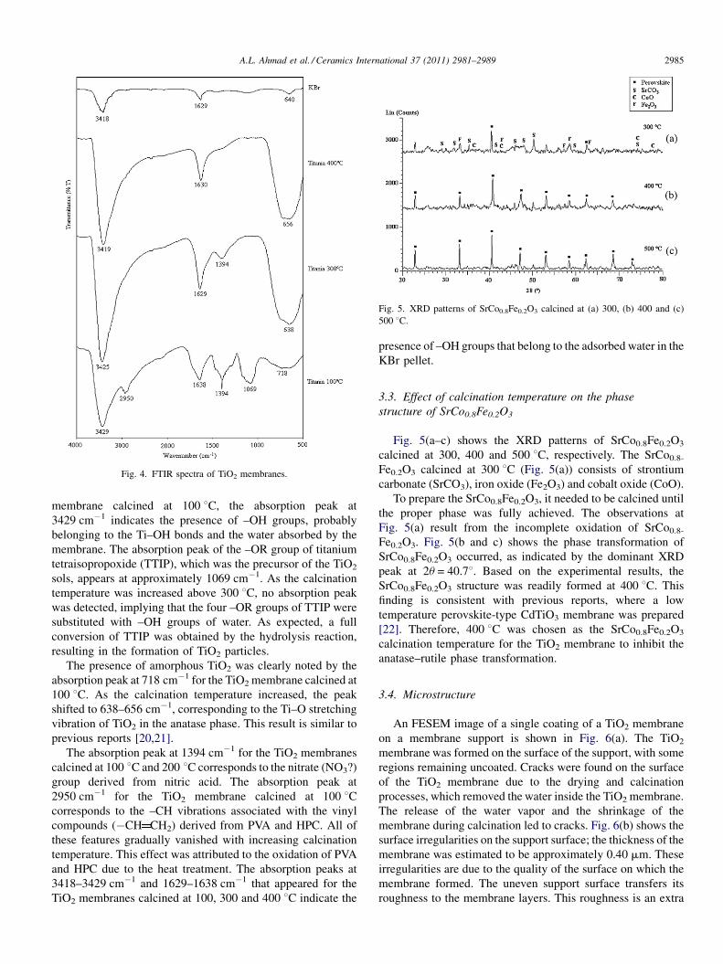
Fig. 4. FTIR spectra of TiO2 membranes.
Fig. 5. XRD patterns of SrCo0.8Fe0.2O3 calcined at (a) 300, (b) 400 and (c)
500 8C.
A.L. Ahmad et al. / Ceramics International 37 (2011) 2981–2989 2985
membrane calcined at 100 8C, the absorption peak at
3429 cm�1 indicates the presence of –OH groups, probably
belonging to the Ti–OH bonds and the water absorbed by the
membrane. The absorption peak of the –OR group of titanium
tetraisopropoxide (TTIP), which was the precursor of the TiO2
sols, appears at approximately 1069 cm�1. As the calcination
temperature was increased above 300 8C, no absorption peak
was detected, implying that the four –OR groups of TTIP were
substituted with –OH groups of water. As expected, a full
conversion of TTIP was obtained by the hydrolysis reaction,
resulting in the formation of TiO2 particles.
The presence of amorphous TiO2 was clearly noted by the
absorption peak at 718 cm�1 for the TiO2 membrane calcined at
100 8C. As the calcination temperature increased, the peak
shifted to 638–656 cm�1, corresponding to the Ti–O stretching
vibration of TiO2 in the anatase phase. This result is similar to
previous reports [20,21].
The absorption peak at 1394 cm�1 for the TiO2 membranes
calcined at 100 8C and 200 8C corresponds to the nitrate (NO3?)
group derived from nitric acid. The absorption peak at
2950 cm�1 for the TiO2 membrane calcined at 100 8Ccorresponds to the –CH vibrations associated with the vinyl
compounds (�CH CH2) derived from PVA and HPC. All of
these features gradually vanished with increasing calcination
temperature. This effect was attributed to the oxidation of PVA
and HPC due to the heat treatment. The absorption peaks at
3418–3429 cm�1 and 1629–1638 cm�1 that appeared for the
TiO2 membranes calcined at 100, 300 and 400 8C indicate the
presence of –OH groups that belong to the adsorbed water in the
KBr pellet.
3.3. Effect of calcination temperature on the phase
structure of SrCo0.8Fe0.2O3
Fig. 5(a–c) shows the XRD patterns of SrCo0.8Fe0.2O3
calcined at 300, 400 and 500 8C, respectively. The SrCo0.8-
Fe0.2O3 calcined at 300 8C (Fig. 5(a)) consists of strontium
carbonate (SrCO3), iron oxide (Fe2O3) and cobalt oxide (CoO).
To prepare the SrCo0.8Fe0.2O3, it needed to be calcined until
the proper phase was fully achieved. The observations at
Fig. 5(a) result from the incomplete oxidation of SrCo0.8-
Fe0.2O3. Fig. 5(b and c) shows the phase transformation of
SrCo0.8Fe0.2O3 occurred, as indicated by the dominant XRD
peak at 2u = 40.78. Based on the experimental results, the
SrCo0.8Fe0.2O3 structure was readily formed at 400 8C. This
finding is consistent with previous reports, where a low
temperature perovskite-type CdTiO3 membrane was prepared
[22]. Therefore, 400 8C was chosen as the SrCo0.8Fe0.2O3
calcination temperature for the TiO2 membrane to inhibit the
anatase–rutile phase transformation.
3.4. Microstructure
An FESEM image of a single coating of a TiO2 membrane
on a membrane support is shown in Fig. 6(a). The TiO2
membrane was formed on the surface of the support, with some
regions remaining uncoated. Cracks were found on the surface
of the TiO2 membrane due to the drying and calcination
processes, which removed the water inside the TiO2 membrane.
The release of the water vapor and the shrinkage of the
membrane during calcination led to cracks. Fig. 6(b) shows the
surface irregularities on the support surface; the thickness of the
membrane was estimated to be approximately 0.40 mm. These
irregularities are due to the quality of the surface on which the
membrane formed. The uneven support surface transfers its
roughness to the membrane layers. This roughness is an extra

Fig. 6. FESEM images of the TiO2 membrane (a) surface and (b) cross-
sectional area calcined at 400 8C after a first time dip-coating process.
Fig. 7. FESEM images of the TiO2 membrane (a) surface and (b) cross-section
area calcined at 400 8C after five dip-coating processes.
Fig. 8. FESEM image of a TiO2–SrCo0.8Fe0.2O3 membrane calcined at 400 8C.
A.L. Ahmad et al. / Ceramics International 37 (2011) 2981–29892986
stress-generating factor that might promote nucleation of
cracks and could result in a defective membrane [15].
Fig. 7(a) and (b) shows FESEM images of the surface and
cross-section, respectively, of the TiO2 membrane after five
dip-coating processes. The surface of the TiO2 membrane after
five coatings became relatively denser and created a more
completely coated membrane compared to after a single
coating (Fig. 6(a)). Continuous contact exists in the interface,
and the thickness of the membrane was found to be
approximately 0.75 mm, as shown in Fig. 7(b). This multiple
coating technique can reduce the pore size and coat the entire
surface of the porous membrane support. After a crack-free
TiO2 membrane was obtained, the SrCo0.8Fe0.2O3 wet
impregnation process was performed.
Fig. 8 shows an image of the TiO2–SrCo0.8Fe0.2O3
membrane, which confirmed the presence of SrCo0.8Fe0.2O3
in the TiO2 membrane. The surface area of the membrane
showed a homogeneous dispersion of SrCo0.8Fe0.2O3 particles
on the TiO2 membrane without cracking.

Fig. 9. Permeance of O2 and N2 across TiO2 membrane as a function of the
operating temperature.
Fig. 11. O2/N2 selectivity of the TiO2 and TiO2–SrCo0.8Fe0.2O3 membranes as
a function of the operating temperature.
A.L. Ahmad et al. / Ceramics International 37 (2011) 2981–2989 2987
3.5. Gas permeation of TiO2–SrCo0.8Fe0.2O3 membrane
Although TiO2 membranes offer numerous applications and
advantages, they possess selectivity drawbacks. A TiO2
membrane not only has a high permeance, but also has a
low selectivity. In this work, the selectivity of TiO2 membranes
was improved by doping SrCo0.8Fe0.2O3 on the surface of the
TiO2 membrane.
The influence of the operating temperature on the O2 and N2
permeances across TiO2 and TiO2–SrCo0.8Fe0.2O3 membranes
is illustrated in Figs. 9 and 10, respectively. Both figures
indicate that as the temperature increased, the O2 and N2
permeances decreased. Fig. 9 demonstrates that O2 exhibited a
higher permeance compared to N2. However, both the O2 and
N2 permeances decreased as the operating temperature
increased from 28 to 350 8C. As the temperature increased,
the permeance of O2 decreased from 3.29E-06 to 1.08E-06 mol/
m2 Pa s (67.1% drop); the permeance of N2 decreased from
2.83E-06 to 1.07E-06 mol/m2 Pa s (62.2% drop). The
decreased permeances were mainly due to a gradual reduction
in surface diffusion. Generally, the loading factor and surface
Fig. 10. Permeance of O2 and N2 across TiO2–SrCo0.8Fe0.2O3 membrane as a
function of the operating temperature.
diffusivity will decrease at higher temperatures [23]. This trend
is similar to that observed for Al2O3–SiO2 membranes and
indicates that the decrease in O2 and N2 permeance as a
function of temperature was due to the lower apparent
activation energy [24].
The permeation results for the TiO2–SrCo0.8Fe0.2O3
membrane show a similar trend to the TiO2 membrane. As
seen in Fig. 10, the O2 permeance decreased from 2.92E-06 to
9.49E-07 mol/m2 Pa s (a 67.5% drop), while the N2 permeance
dropped from 2.32E-06 to 8.08E-07 mol/m2 Pa s (a 65.2%
drop). The decrease of permeance at higher temperatures was a
consequence of improved surface exchange caused by the
addition of SrCo0.8Fe0.2O3. The effect on O2 permeance is
more apparent at lower temperatures. The same trend was
previously reported using a Ag-doped SrCo0.8Fe0.2O3�d oxide
membrane [25].
The O2 exhibits a higher permeance, compared to N2, for
both of the membranes because the order of permeance rates for
gases follows the order of kinetic diameters. The kinetic
diameter of N2 (3.64 A) is larger than that of O2 (3.46 A) [26].
Fig. 11 shows O2/N2 selectivity as a function of the operating
temperature for TiO2 and TiO2–SrCo0.8Fe0.2O3 membranes. It
shows that the selectivity for both of the membranes decreased
as the operating temperature increased. The TiO2–SrCo0.8-
Fe0.2O3 membrane shows the highest O2/N2 selectivity (1.26) at
28 8C, while the TiO2 membrane possesses the lowest O2/N2
selectivity at 350 8C (1.01). The transport mechanism of the O2/
N2 selectivity for both membranes predominantly involves the
Knudsen diffusion mechanism because the value approaches
the theoretical O2/N2 selectivity for the Knudsen diffusion
mechanism (1.07), which is defined as the square root of the
ratio of the heavier molecular weight gas (O2) to the lighter
molecular weight gas (N2).
The trend for TiO2 membrane selectivity indicates that the
gas permeates mostly through the pores formed in the

A.L. Ahmad et al. / Ceramics International 37 (2011) 2981–29892988
crystalline TiO2 membrane [27]. The observations indicate that
the addition of SrCo0.8Fe0.2O3 successfully increased the O2/N2
selectivity and, at the same time, the ability of the membrane to
separate O2 from N2. In addition, the increase in O2/N2
selectivity implies that the large pore size in the TiO2
membrane was successfully filled with SrCo0.8Fe0.2O3.
SrCo0.8Fe0.2O3 contains several transition metal oxides (Fe
and Co) that have been reported to be high-temperature
adsorbents for gas separation. In addition, they theoretically
have an infinitely high selectivity for O2 over N2 or other non-
O2 species [28].
4. Conclusion
TiO2 membranes containing SrCo0.8Fe0.2O3 were success-
fully prepared by the sol–gel method in combination with a
wet impregnation process. Based on our findings, the optimal
peptization ratio of H+/Ti4+ was found to be 0.5, which
results in the formation of a stable and deflocculated sol with
TiO2 fully in the anatase phase. The optimal calcination
temperature for TiO2 and SrCo0.8Fe0.2O3 was 400 8C. At this
temperature, TiO2 is fully transformed to the anatase phase,
while the PVA and HPC are completely removed, and the
oxidation process of SrCo0.8Fe0.2O3 is complete. A single
coating of the TiO2 membrane on the membrane support
resulted in cracks and an uneven surface because of the
quality of the surface on which the membrane was formed. A
crack-free and homogeneous surface of the TiO2–SrCo0.8-
Fe0.2O3 membrane was obtained after multiple dip-coatings
of the TiO2 membrane, followed by a SrCo0.8Fe0.2O3 wet
impregnation process. While examining TiO2–SrCo0.8-
Fe0.2O3 membrane performance, it was found that addition
of SrCo0.8Fe0.2O3 to the TiO2 membrane, which acts as a
filler phase, successfully increased the O2/N2 selectivity of
the TiO2 membrane. The highest selectivity of TiO2–
SrCo0.8Fe0.2O3 membrane was 1.26, compared to 1.16 for
the TiO2 membrane. Therefore, it can be concluded that the
TiO2–SrCo0.8Fe0.2O3 membrane prepared using the
described method has great potential in applications such
as the separation of O2 and as an O2 enrichment membrane.
Acknowledgements
The authors gratefully acknowledge the research funding
provided by the Universiti Sains Malaysia through the
Fundamental Research Grant Scheme (FRGS) and a short-
term research grant. The authors also acknowledge Dr. Mohd
Azmier Ahmad for providing the membrane permeation test
rig. Nur Aimie acknowledges the USM Fellowship for the
support of her studies.
References
[1] Y.S. Lin, A.J. Burggraaf, Preparation and characterization of high temper-
ature thermally stable alumina composite membrane, J. Am. Ceram. Soc.
74 (1991) 219–224.
[2] S.P.S. Badwal, F.T. Chiacchi, Ceramic membrane technologies for oxygen
separation, Adv. Mater. 13 (2001) 993–996.
[3] T.V. Gestel, C. Vandecasteele, A. Buekenhoudt, C. Dotremont, J. Luyten, R.
Leysen, B. Van der Bruggen, G. Maes, Alumina and titania multilayer
membranes for nanofiltration: preparation, characterization and chemical
stability, J. Membr. Sci. 207 (2002) 73–89.
[4] M.R. Mohammadi, M.C. Cordero-Cabrera, D.J. Fray, M. Ghorbani, Prepa-
ration of high surface area titania (TiO2) films and powders using particu-
late sol–gel route aided polymeric fugitive agents, Sens. Actuators B:
Chem. 120 (2006) 86–95.
[5] M.R. Mohammadi, D.J. Fray, M.C. Cordero-Cabrera, Sensor performance
of nanostructured TiO2 thin films derived from particulate sol–gel route
and polymeric fugitive agents, Sens. Actuators B: Chem. 124 (2007) 74–
83.
[6] S. Liu, K. Li, Preparation TiO2/AI2O3 composite hollow fibre membranes,
J. Membr. Sci. 218 (2003) 269–277.
[7] B.L. Bischoff, M.A. Anderson, Peptization process in the sol–gel prepara-
tion of porous anatase (TiO2), Chem. Mater. 7 (1995) 1772–1778.
[8] M. Gopal, W.J.M. Chan, L.C. de Jonghe, Room temperature synthesis of
crystalline metal oxides, J. Mater. Sci. 32 (1997) 6000–6008.
[9] M.C. Cordero-Cabrera, G.S. Walker, D.M. Grant, Effect of processing
parameters on the particle size and stabilisation of titania sols, J. Mater. Sci.
40 (2005) 3709–3714.
[10] M.R. Mohammadi, D.J. Fray, A. Mohammadi, Sol–gel nanostructured
titanium dioxide: controlling the crystal structure, crystallite size, phase
transformation, packing and ordering, Microporous Mesoporous Mater.
112 (2008) 392–402.
[11] J. Tong, W. Yang, R. Cai, B. Zhu, L. Lin, Titanium-base perovskite-type
mixed conducting ceramic membranes for oxygen permeation, Mater.
Lett. 56 (2002) 958–962.
[12] G. Etchegoyen, T. Chartier, P. Del-Gallo, An architectural approach to the
oxygen permeability of a La0.6Sr0.4Fe0.9Ga0.1O3�d perovskite membrane,
J. Eur. Ceram. Soc. 26 (2006) 2807–2815.
[13] A.L. Ahmad, N.F. Idrus, M.R. Othman, Preparation of perovskite alu-
mina ceramic membrane using sol–gel method, J. Membr. Sci. 262
(2005) 129–137.
[14] K. Li, Ceramic Membrane for Separation and Reactions, John Wiley &
Sons Ltd, England, 2007.
[15] V.T. Zaspalis, W. Van Praag, K. Keizer, J.R.H. Ross, A.J. Burggraaf,
Synthesis and characterization of primary alumina, titania and binary
membranes, J. Mater. Sci. 27 (1992) 1023–1035.
[16] A. Alem, H. Sarpoolaky, M. Keshmiri, Titania ultrafiltration membrane:
preparation, characterization and photocatalytic activity, J. Euro. Ceram.
Soc. 29 (2009) 629–635.
[17] V.N. Koparde, P.T. Cummings, Phase transformations during sintering of
titania nanoparticles, ACS Nano 2 (8) (2008) 1620–1624.
[18] S. Winardi, R.R. Mukti, K.N.P. Kumar, J. Wang, W. Wunderlich, T.
Okubo, Critical nuclei size, initial particle size and packing effect on
the phase stability of sol-peptization–gel-derived nanostructured titania,
Langmuir 26 (7) (2010) 4567–4571.
[19] D.S Bae, K.S. Han, S.H. Choi, Preparation and thermal stability of doped
TiO2 composite membranes by the sol–gel process, Solid States Ionics 109
(1998) 239–245.
[20] W. Chen, J. Zhang, Q. Fang, S. Li, J. Wu, F. Li, K. Jiang, Sol–gel
preparation of thick titania coatings aided by organic binder materials,
Sens. Actuators B: Chem. 100 (2004) 195–199.
[21] N. Agoudjil, T. Benkacem, Synthesis of porous titanium dioxide mem-
branes, J. Desalinat. 206 (2007) 531–537.
[22] M.R. Mohammadi, D.J. Fray, Low-temperature perovskite-type cadmium
titante thin films derived from a simple particulate sol–gel process, Acta
Mater. 57 (2009) 1049–1059.
[23] A.L. Ahmad, M.R. Othman, H. Mukhtar, H2 separation from binary gas
mixture using coated alumina–titania membrane by sol–gel technique
at high-temperature region, Int. J. Hydrogen Energy 29 (2004)
817–828.
[24] R.S.A. De Lange, J.H.A. Hekkink, K. Keizer, A.J. Burggraaf, Permeation
and separation studies on microporous sol–gel modified ceramic mem-
branes, Micro. Mater. 4 (1995) 169–186.

A.L. Ahmad et al. / Ceramics International 37 (2011) 2981–2989 2989
[25] L. Tan, L. Yang, X. Gu, W. Jin, L. Zhang, N. Xu, Structure and oxygen
permeability of Ag-doped SrCo0.8Fe0.2O3�d oxide, Am. Inst. Chem. Eng.
50 (3) (2004) 701–707.
[26] T.D. Kusworo, A.F. Ismail, A. Mustafa, Budiyoni, Application of activated
carbon mixed matrix membrane for oxygen purification, Int. J. Sci. Eng. 1
(1) (2010) 21–24.
[27] H.Y. Ha, S.W. Nam, T.H. Lim, I.H. Oh, S.A. Hong, Properties of the TiO2
membranes prepared by CVD of titanium tetraisopropoxide, J. Membr.
Sci. 111 (1996) 81–92.
[28] H. Hao, L. Zhao, J. Hu, X. Hu, H. Hou, Oxygen adsorption/desorption
behavior of YBaCo4O7+d and its application to oxygen removal from
nitrogen, J. Rare Earth 27 (5) (2009) 815–818.