Methanol steam reforming in single-fiber packed bed Pd–Ag membrane reactor: Experiments and modeling
Upload
khangminh22Category
view
2download
0
SYNTHESIS GAS PRODUCTION VIAHYBRID STEAM REFORMING OF NATURAL GAS
AND BIO-LIQUIDS
Ragavendra Prasad Balegedde Ramachandran
Syn
thesis
gas p
rod
uctio
n v
ia H
yb
rid S
team
Refo
rmin
g o
f Natu
ral g
as a
nd
Bio
-liqu
ids
Rag
aven
dra
Pra
sad
Bale
ged
de R
am
ach
an
dra
n
To the public defenseof my thesis titled
“Synthesis gas productionvia Hybrid Steam Reforming of Natural gasand Bio-liquids”
On
14 th February 2013
At 14:45 in Zaal 4building “Waaier”University of Twente
At 14:30, I will give a shortintroduction of my thesis
Ragavendra P. Balegedde Ramachandran
Invitation
Paranymphs
Jose Antonio Medrano [email protected]
&
Laura Garcia [email protected]
In this thesis, hybrid steam reforming (HSR) of natural gas with b io- l iquids such as pyrolys is o i l and crude glycerol to produce synthesis gas is proposed and demonstrated inthe lab scale. This thesis deals with process development, catalysis and techno-economic analysis of hybrid steam reforming process.
ISBN:978-90-365-3518-2
Synthesis gas production via Hybrid Steam Reforming
of Natural gas and Bio-liquids
Ragavendra Prasad Balegedde Ramachandran

[ii]
Promotion committee:
Chairman: Prof.dr.G.J. Vancso University of Twente
Promoter: Prof.dr.S.R.A.Kersten University of Twente
Promoter: Prof.dr.ir.W.P.M.van Swaaij University of Twente
Assistant Promoter: Dr.ir.G.van Rossum University of Twente
Members: Prof.dr.K.Seshan University of Twente
Dr.ir.D.W.F.Brilman University of Twente
Prof.dr.ir. A. Nijmeijer University of Twente
Prof.dr.J.M.Arauzo Pérez University of Zaragoza, Spain
Prof.dr.ir.W.Prins Ghent University, Belgium
The research described in this thesis was financially supported by Agentschap (www.agentschap.nl) in the EOSLT project (project number 07007). The research was carried out at the Sustainable Process Technology group, Faculty of Science and Technology, University of Twente, P.O.Box 217, 7500 AE, Enschede, The Netherlands Ph.D. Thesis, University of Twente
Ragavendra Prasad Balegedde Ramachandran, Enschede, The Netherlands, 2013.
Printed by Ipskamp Drukkers B.V., Enschede, The Netherlands.
Front cover page and Chapter photos taken in Vaalparai, India by Aditya Murali. Back cover page photo: Taken in Manali, Chennai, India PDF copy available at:
http://dx.doi.org/10.3990/1.9789036535182
ISBN: 978-90-365-3518-2
DOI: 10.3990/1.9789036535182
Copyright © Ragavendra Prasad Balegedde Ramachandran, 2013 All rights reserved. No part of the material protected by this copyright notice may be reproduced or utilized in any form or by any means, electronic or mechanical without prior permission from the author and the Promotors.
[iii]
SYNTHESIS GAS PRODUCTION VIA HYBRID STEAM REFORMING OF
NATURAL GAS AND BIO-LIQUIDS
PROEFSCHRIFT
ter verkrijging van
de graad van doctor aan de Universiteit Twente,
op gezag van de rector magnificus,
Prof.dr.H. Brinksma,
volgens besluit van het College voor Promoties
in het openbaar te verdedigen
op donderdag 14 Februari 2013 om 14.45 uur
door
Ragavendra Prasad Balegedde Ramachandran
geboren op 27 oktober 1980
Chennai, India

[iv]
This dissertation has been approved by the Promoters
Prof.dr.ir. W.P.M van Swaaij
Prof.dr.S.R.A.Kersten
and the Assistant Promoter
Dr.ir. G. van Rossum

[v]
Dedicated to my parents

[vi]

[vii]
Contents
Summary 9
Samenvatting 13
ெபாழி ைர 17
Chapter 1 Introduction: Reforming of bio-liquids for 23
synthesis gas production
Chapter 2 Gasification of pyrolysis oil – Product distribution 43
and residue char analysis
Chapter 3 Evaporation of biomass fast pyrolysis oil – Evaluation 75
of char formation
Chapter 4 Preliminary assessment of synthesis gas production 97
via hybrid steam reforming of methane and glycerol
Chapter 5 Synthesis gas production via steam reforming of 137
pyrolysis oil - Assessment of catalyst performance and
hybrid reforming with methane
Chapter 6 Techno-economic assessment of methanol 163
production via hybrid steam reforming of bio-liquids
with natural gas
Outlook 207
Publications 209
About the Author 211
Acknowledgements 213

[viii]

[9]
Summary
This thesis deals with (catalytic) steam reforming of bio-liquids for the production of
synthesis gas. Glycerol, both crude from the biodiesel manufacturing and refined, and
pyrolysis oil are tested as bio-based feedstocks. Liquid bio-based feeds could be
preferred over inhomogeneous fibrous solid biomass because of their logistic
advantages, better mineral balance, and better processability. Especially the ease of
pressurization, which is required for large scale synthesis gas production, is another
clear advantage of liquid biomass. In addition to this, liquefied biomass contains less
contaminants than the biomass from which it originates which will be beneficial with
respect to catalyst poisoning.
The proposed steam reforming process is a hybrid one (HSR - Hybrid Steam
Reforming) in which the bio-liquids are co-reformed with a fossil feed such as natural
gas or naphtha. In this thesis, methane as a model compound for natural gas is
investigated. By co-reforming, implying partnering with the current fossil-based
industry, use is made of the existing infrastructure and markets which should help the
introduction of bio-based synthesis gas. At the level of the chemistry, co-feeding may
minimize the adverse characteristics of the bio-liquid as has been observed for co-
feeding upgraded pyrolysis oil with long residue in a micro Fluid Catalytic Cracking
(FCC) unit.
The HSR process investigated consists of:
1. Evaporation and gasification of the bio-liquid [T > 500 ºC],
2. (Pre)-reforming of the gases and vapors produced under (1) [T = 500 – 800
ºC],
3. Co-reforming of the product of (2) together with methane [T = 800 – 900 ºC].
All three process steps are investigated in newly designed automated dedicated set-
ups. Evaporation has been investigated in an empty tube reactor that allows a
complete and precise carbon balance closure over produced gases, vapors and char.
Steam reforming is tested in fixed bed reactors.

[10]
In these reactors, long duration runs of up to ~100 h are performed under
commercially practiced gas hourly space velocities. These tests have been designed to
give more insight into the actual status and remaining challenges of the process,
compared to the often reported idealized (batch) screening experiments.
The first step of the process is the evaporation and cracking of the bio-liquid. The
results obtained are of value not only for the HSR process, but also for all other
processes in which bio-liquids are injected into a hot environment, such as engines,
boilers and gasifiers. Cracking to gases occurs because the evaporation is carried out
at elevated temperature. An imported issue is the undesired production of char. Pure
glycerol could be evaporated without producing char. Crude glycerol and pyrolysis
oil require very fine and controlled atomization to minimize char production. For
crude glycerol, the formation of char has been clearly linked to the presence of
KOH/NaOH (the remaining catalyst from the biodiesel production) which catalyzes
polymerization reactions in the liquid phase. A direct relationship has been found
between the heating rate (coupled to droplet size) and the amount of char produced.
Pyrolysis oil droplets of ca. 100 μm still result in ca. 8% char on carbon basis. There
are indications that under even more severe atomization conditions less char can be
produced, but this would not result in a practical process.
Neutralized glycerol yields salt(s) as byproducts but no carbonaceous deposits during
the evaporation. For such realistic feeds a facility to remove and to deal with the
produced solids has to be included in the process design. It has turned out that the
temperature of the environment itself, when varied between 500 and 900 ºC, hardly
has an effect on the char production. At higher temperatures of up to 850 ºC and at
higher vapor/gas residence times more gas is produced at the expense of less vapors.
The maximum carbon to gas conversion for pyrolysis oil observed is ~80% which
means that the pre-reform system has to cope with at least 10% of the feed present as
oxygenated vapors and remaining carbon being char (~10%).

[11]
It has been found that there is no fundamental problem in the chemistry / catalysis of
steam reforming of bio-liquids. Three catalysts have been tested, viz. a commercial
Ni/K/Mg on Al2O3 pre-reform catalyst, a commercial Ni on Al2O3 catalyst and an in-
house made Ni/Mg on Al2O3 catalyst, which all showed near equilibrium yields of the
steam reforming reaction for glycerol and pyrolysis oil for S/C = 1 – 15 and T = 600
– 850 ºC. Pure glycerol can be reformed with 100% carbon to gas conversion and
equilibrium yields at temperatures as low as 600 ºC. In contrast, pyrolysis oil shows
excessive coke formation on the catalyst at this low temperature leading to too short
operation times. Even refined glycerol containing only limited amounts of
contaminants (e.g. FAME - Fatty acid methyl esters) shows deactivation of the
catalyst with respect to methane slip already after a few hours. When using this latter
feed the catalysts can be regenerated. With respect to deactivation a distinction has
been made between the activity of the catalyst for carbon to gas conversion
(gasification) and activity for methane (hydrocarbon) conversion via steam reforming
(MSR).
For pyrolysis oil vapors reforming at ~800 ºC, it has been showed that the
commercial Ni/K/Mg pre-reforming catalyst retains a high carbon to gas activity
(conversion) but loses its methane steam reforming (MSR) activity. The MSR activity
of this catalyst could not be regenerated via oxidation of the coke and subsequent
reduction. It is postulated that the carbon to gas conversion is maintained because of
enhanced coke gasification by potassium (K). However, a dedicated series of
experiments in which the K amount on the catalyst was varied has shown that K
reduces the MSR activity. The catalysts having only Mg as promoter show a
decreasing carbon to gas conversion and MSR activity. However, the initial activity of
both could be recovered via regeneration, but after this immediate activity loss
occurred again. From a process point of view, high and stable carbon to gas
conversion in the first steps of the process is more important than good MSR activity.
If the carbon conversion is high enough in the bio-liquid gasifier and pre-reformer,
any methane will be dealt with in the primary reformer.
[12]
Several preliminary longer duration tests of co-reforming (HSR) have been performed
at space velocities close to industrial practice. For pyrolysis oil reforming it has been
found that indeed the co-reformer benefited from the combined fossil and bio-feed:
coke on catalyst was more than ten times lower than in the upstream bio-liquid pre-
reformer. However, apparently this is not enough as the catalyst still deactivated for
pyrolysis oil, both with respect to carbon to gas conversion and MSR, during co-
reforming. For pure and high grade (with regeneration) glycerol the proof of
principle of HSR has been delivered by long duration runs of more than 30 h.
A detailed techno-economic analysis shows that at the current market scenario (2012)
with a natural gas price of 0.2 €/Nm3 and with an assumed crude glycerol price of
200 €/tonne, the average cost of (bio)methanol is estimated as 430 €/tonne for a feed
of 54 wt% of glycerol (on carbon basis) with natural gas, which is 75 €/tonne higher
than for the methanol obtained via only natural gas steam reforming. However, with
current regulations for second generation biofuels (they can be counted double) a
commercial attractive business case could be developed.

[13]
Sammenvating
Dit proefschrift gaat over (katalytisch) stoom reformen van bio-vloeistoffen voor de
productie van synthesegas. Glycerol, zowel in ruwe als opgewerkte vorm (als
bijproduct van biodiesel productie), en pyrolyse-olie zijn getest als bio-gebaseerde
grondstoffen. Vloeibare bio-gebaseerde voedingen zouden de voorkeur kunnen
hebben boven inhomogene vaste biomassa door hun logistieke voordelen en betere
mineralenbalans en verwerkbaarheid. Vooral het gemak van het onder druk brengen,
welke nodig is voor grootschalige productie van synthesegas, is een duidelijk
voordeel van bio-vloeistoffen. Daarnaast bevatten bio-vloeistoffen minder
verontreinigingen dan de biomassa waarvan het afkomstig is; dit zou vergiftiging van
de katalysator kunnen beperken.
Het voorgestelde stoom reform proces is een hybride (HSR - Hybrid steam reforming)
soort waarin de bio-vloeistoffen worden ge-co-reformed met een fossiele voeding,
zoals aardgas of nafta. In dit proefschrift wordt methaan als een modelstof voor
aardgas onderzocht. Door co-reformen, wat samenwerking met de huidige fossiele
industrie impliceert, wordt gebruik gemaakt van de bestaande infrastructuur en
markten die de introductie van bio-gebaseerd synthese gas zou moeten helpen. Op het
niveau van de chemie zou het co-voeden de nadelige eigenschappen van de bio-
vloeistof kunnen onderdrukken zoals is aangetoond met het co-voeden van
opgewaardeerde pyrolyse olie met “long residue” in een micro FCC opstelling.
Het onderzochte HSR proces bestaat uit:
1. Verdampen en vergassen van de bio-vloeistof [T> 500 °C]
2. (Pre)-reformen van de gassen en dampen die bij (1) zijn gevormd [T = 500-800 °C]
3. Co-reformen van het product van (2) met methaan [T = 800 tot 900 °C].
Al deze drie processtappen zijn onderzocht in nieuw ontworpen geautomatiseerde
opstellingen. Verdamping is onderzocht in een lege buis reactor waar een volledige
en nauwkeurige koolstofbalanssluiting over de geproduceerde gassen, dampen en
kool mogelijk was. Stoom reformen is getest in vaste-bed reactoren.
[14]
In deze opstellingen zijn lange duur experimenten tot ~100 uur uitgevoerd met
commercieel relevante contacttijden. Deze testen waren zodanig uitgevoerd dat er
inzicht in de actuele status en resterende uitdagingen van het proces werden
verkregen, dit in tegenstelling tot de vaak in literatuur gerapporteerde geïdealiseerde
(batch) experimenten.
De eerste stap in het proces is het verdampen en kraken van de bio-vloeistof. De
verkregen resultaten zijn niet alleen van waarde voor de HSR-proces, maar voor alle
processen waarbij bio-vloeistoffen worden geïnjecteerd in een warme omgeving, zoals
motoren, verbrandingsketels en vergassers. Omdat de verdamping wordt uitgevoerd
bij verhoogde temperatuur ontstaan ook gassen door middel van thermisch kraken.
Een probleem is de ongewenste productie van kool. Zuivere glycerol kan worden
verdampt zonder koolvorming. Ruwe glycerol en pyrolyse-olie hebben een zeer fijne
en gecontroleerde verneveling nodig om de koolvorming te minimaliseren. Voor ruwe
glycerol, is de vorming van kool duidelijk gerelateerd aan de aanwezigheid van KOH/
NaOH (katalysator restant van de biodieselproductie) die polymerisatiereacties in de
vloeistoffase katalyseert. Een direct verband werd gevonden tussen de
opwarmsnelheid (gerelateerd aan druppelgrootte) en de hoeveelheid geproduceerde
kool. Pyrolyse-olie druppels van ca. 100 μm resulteren nog steeds in ca. 8% kool op
koolstof basis. Er zijn aanwijzingen dat bij nog betere verstuiving nog minder kool
wordt geproduceerd, maar dit is waarschijnlijk niet haalbaar in een praktisch
uitvoerbaar proces.
Geneutraliseerd glycerol heeft zout(en) als vaste bijproducten maar geen koolstof
houdende afzettingen tijdens de verdamping. Voor dit soort realistische voedingen
moeten in het procesontwerp voorzieningen getroffen worden om geproduceerde vaste
stoffen te verwijderen. Gebleken is dat de omgevingstemperatuur, welke is gevarieerd
tussen 500 en 900 °C, nauwelijks een invloed heeft op de koolproductie. Bij hogere
temperaturen tot 850 °C en bij hogere damp / gas verblijftijden wordt meer gas
geproduceerd ten koste van damp. De maximale koolstof naar gas conversie gemeten
voor pyrolyse olie is ~ 80%, hetgeen betekent dat de pre-reformer ten minste 10% van
de voeding als geoxygeneerde dampen moet verwerken.

[15]
Het is gebleken dat er geen fundamenteel probleem is wat betreft de chemie / katalyse
van het stoom reformen van bio-vloeistoffen. Drie katalysatoren zijn getest, namelijk
een commerciële Ni/K /Mg op Al2O3 pre-reform katalysator, een commerciële Ni op
Al2O3 reform katalysator en een eigen gemaakte Ni/Mg op Al2O3 katalysator. Alle drie
de katalysatoren hadden aanvankelijk opbrengsten gelijk aan het evenwicht voor het
stoom reformen van glycerol en pyrolyse-olie bij S/C = 1 - 15 en T = 600-850 °C.
Pure glycerol kan worden gereformd met 100% koolstof naar gas conversie waarbij
het gas op thermodynamisch evenwicht is vanaf ongeveer 600 ºC. Pyrolyse olie
vertoont bij deze lage temperatuur echter overmatige coke-vorming op de katalysator
wat leidt tot te korte operatietijden. Zelfs opgewerkte glycerol welke slechts beperkte
hoeveelheden verontreinigingen (zoals FAME - Fatty acid methyl esters) bevat leidt al
na enkele uren tot deactivatie van de katalysator wat zich uit in methaan doorbraak.
Bij gebruik van deze voeding kunnen de katalysatoren wel worden geregenereerd.
Met betrekking tot katalysator deactivatie moet er een onderscheid gemaakt worden
tussen de activiteit van de katalysator voor de omzetting van koolstof naar gas
(vergassing) en de activiteit voor de omzetting van methaan (koolwaterstof) via
stoomreformen (MSR).
Voor her reformen van pyrolyse-olie dampen op ~800ºC is gebleken dat de
commerciële Ni/K/Mg pre-reform katalysator een hoge koolstof naar gas activiteit
(conversie) behoudt, echter de MSR activiteit gaat verloren. De MSR activiteit van
deze katalysator kan niet worden geregenereerd door oxidatie van de coke en
opeenvolgende reductie. Er wordt gepostuleerd dat de koolstof naar gas conversie
behouden blijft vanwege verhoogde coke vergassing door kalium. Echter, een speciale
reeks experimenten waarin het kalium gehalte op de katalysator is gevarieerd heeft
aangetoond dat kalium ook verantwoordelijk is voor de vermindering van de MSR
activiteit. De katalysatoren die slechts Mg als promotor hadden lieten een dalende
koolstof naar gas conversie en MSR activiteit zien. Echter, de initiële activiteit van
beide katalysatoren kon worden hersteld via regeneratie, waarna er echter direct
weer activiteitverlies optreedt. Vanuit een proces oogpunt is een hoge en stabiele
koolstof naar gas conversie in de eerste stappen van het proces belangrijker dan een
hoge MSR activiteit. Als de koolstof naar gas conversie hoog genoeg is in de bio-

[16]
vloeistof vergasser en pre-reformer, dan kan het methaan vervolgens worden omgezet
in de primaire reformer.
Verscheidende lange duur testen van het co-reformen (HSR) zijn uitgevoerd met
contacttijden dicht bij industriële praktijk. Voor pyrolyse olie reformen is gebleken
dat de co-reformer inderdaad profiteert van de gecombineerde fossiele en bio-
voeding: coke op de katalysator was meer dan tien keer lager dan in de voorop
geschakelde bio-vloeistof pre-reformer. Dit effect is echter nog niet voldoende
aangezien de katalysator nog steeds deactiveerde tijdens het co-reformen van
pyrolyse-olie, zowel voor de koolstof naar gas conversie als de MSR activiteit. Voor
pure en opgewerkte (met regeneratie) glycerol is het HSR concept succesvol
gedemonstreerd voor meer dan 30 uur.
Een gedetailleerde technisch-economische analyse toont aan dat met de huidige
markt (2012) met een aardgasprijs van 0,2 €/Nm3 en aangenomen ruwe glycerol prijs
van 200 € /ton, de gemiddelde kosten van (bio) methanol wordt geschat op 430 €/ton
voor een voeding van 54 gewichts-% glycerol (op koolstof-basis) met aardgas. Dit is
75 €/ton hoger dan voor methanol verkregen uit enkel aardgas. Echter, met de
huidige regelgeving voor tweede generatie biobrandstoffen (ze mogen dubbel geteld
worden) kan een commercieel aantrekkelijke business case ontwikkeld worden.

[17]
ெபாழி ைர
இ த ஆ க ைரய bio-திரவ தி இ Synthesis gas (CO+H2) எ வா தயா க
ேவ எ ப வவ க ப ள . இ த ஆ வ ப தமான Glycerol, Crude Glycerol
ம Biomassஇ (தாவர /வல கழி ெபா க ) இ தயா க ப Pyrolysis oil
ேபா ற bio-திரவ க ப ேசாதைன ெச ய ப ள . உ தியான தி ைம ைடய solid
biomassஐ கா திரவ தைல சிற த . ஏெனன ,
1. திரவ ைத எளதாக இட மா றலா .
2. திரவ சீராக இ .
3. தா ெபா எைட சீராக இ ம
4. எளதான ைறய திரவ ைத ைகயாளலா .
5. றி பாக, அதிக அள Methanol உ ப தி , அதிக அள அ த ள
பய பா க (High pressure applications) திரவ ச யானதாக இ .
6. ேம , bio-திரவ தி ைற த அள கழி தி ம க இ பதா , அதைன
Catalytic Reforming ெச ய , catalyst மா படாம இ க பய ளதாக இ .
இதைன, இ த ஆ வ Catalytic Reformingஐ, Hybrid steam Reforming (HSR) எ ற திய ேகா பா
வவ க ப ள . HSR என ப வ , Methanol எ ற திரவ ைத Synthesis gas ல
தயா க, எ வா (Natural gas) உட bio-திரவ ைத கல Catalytic Reforming ெச வதா . பல
ஆ களாக Methanol எ ற திரவ ைத ைதவ வ (Fossil) ெகா ட எ வா (Natural gas),
Naphtha, நில க , நில எ ெண (Petroleum) தலியவ றிலி ெப பா
தயா க ப வ கிற . Bio-திரவ ைத எ வா ட அறி க ப தினா , Methanol
தயா க த ேபா இ திக சாைலகைள உபேயாக ப தலா . HSR
ெச வதா 1) எ வா வ பய பா ைட ைற கலா 2) Bio-திரவ தி ேகடான
இய ைப HSR ல ைற கலா . இதைன ேப FCC processஇ ஆ வ
றி ப ட ப ள .
HSR process இ
1. Bio-திரவ தி இ நைர ஆவயாக (Evaporation) மா த , ப த
ெவ ப லமாக (T>500ºC) வா வாக (Gasification) மா ற ெச ய ேவ .
2. அ ப உ வா கிய வா ைவ Catalytic reforming லமாக (T=500-800ºC) மா றிய ப ,
[18]
3. வா ைவ, எ வா ட கல (T = 800 – 900 ºC) HSR ெச ய ேவ . ேமேல
றி ப ட அைன Process கைள நா க வ வைம த சாதன கள
ப ேசாதைன ெச ேதா . அத க ப வ ப திகள காணலா .
வா வாக மா ெச ைறைய (1) காலியான Reactor tubeஇ ெவ ப ம ள
அளைவ (droplet size) மா றி வா (Gas), ஆவ (Vapor), ம க (Char), ேபா றைவக
அள க ப டன. தயா த வா ைவ , ஆவைய Fixed bed reactorஇ Catalyst ஐ
பய ப தி மா 100 மண ேநர ப ேசாதைன ெச ய ப ட . இ ப ெச வதா ,
Catalystஐ மிக கமாக ம இ த ைறய இ கி ற சவா கைள க கலா .
ேமேல றி ப ட ெச ைற வள க (1) bio-திரவ ைத அதிக அள ெவ ப ைடய
ழலி ெச வ , Reforming ப ேசாதைன ம ம ல ம ற ெசய ைறகளான Combustion
ம Cracking (Engines, boilers, gasifiers) ேபா றவ ைற க க பய ளதாக இ . இ த
ெசய ைறய , Char ம ேம வ ப மாறாக தயாரா ெபா . Char reactor tubeஐ
அைட , Engine பய பா க இைட றாக இ . ேம , tube இ அ த ைத
அதிக . இதைன தவ ப மிக க ன . ப தமான Glycerol ஐ வா வாக மா ற
ெச ேபா , க (Char) தயாராகவ ைல. ஆனா , Crude Glycerol ம Pyrolysis oil ேபா ற
bio-திரவ கைள வா வாக மா ற ெச ேபா ம ேம க (char) உ வாகிற . இதைன
க ப த bio-திரவ தி ள அளைவ (droplet size) ைற க ேவ . Crude Glycerolஇ
இ உ வா க crude இ இ KOH/NaOH (Catalyst for transesterification) உட
ெதாட இ கிற (இத வவர அறிய பாக நா ைக ப க ). ஆனா , Pyrolysis oil
ள அளவ , ெவ ப வகித தி ெதாட இ கிற . இத வைளவாக, மா 8%
க (எைட அளவ ), Pyrolysis oil இ இ உ வாகிற (ெவ ப வகித : 106 ºC/min).
இதைன அதிக ெவ ப தா ைற க இயலவ ைல (~850ºC). ஆைகயா , Pyrolysis oilஐ
ெப ய அள ெகா ட ஆைலய ெசய ைற ெச வ க ன . Crude Glycerolஐ ெசய
ைற ெச ேபா அதி KOH ல உ வா உ (KCl) Reactorஇ ப கிற . ெப ய
அளவ இ த திரவ ைத எளதான ைறய , இைட வடாம ெசய ைற ெச ய
சிற த catalyst ேதைவ. உ வா உ ைப ெதாட சியாக ந க வசதிக ேதைவ. Pyrolysis oilஇ
இ மா ~80% வா தயா ெச யலா . எ சி இ 20% இ 10-15% Organic ஆவ
இ . இ த ஆவைய Catalyst reforming ல வா வாக மா ற ெச த ேவ .
[19]
இதைன நைட ைறய உ ள Catalystக ெசயலா மா எ ப மிக ெப ய ேக வ . இ த
ேக வ வைட அறிய இர Catalystக 1) நைட ைறய ள Ni/K-Mg-Al2O3 Naphtha pre-
reforming catalyst 2) நா க தயா ெச த ஆரா சி Ni/Mg-Al2O3 catalyst ப ேசாதைன
ெச ய ப டன. இ த இர Catalyst க , இ த நிைலகள (S/C = 1 – 15 ம T =
600 – 850 ºC) எ த வத தட க இ லாம அதிகப ச வா (equilibrium gas yield) தயாராகிற .
ஆனா , அதிக ேநர ( மா 2 மண ேநர தி ேம ) Pyrolysis oilஐ Reforming ெச ேபா ,
Catalyst ம க (coke) ப கிற . Catalyst ம க ப வதா , அ Reforming த ைமைய
இழ கிற . இதனா , Pyrolysis oil இ இ உ வா வா வ அள ைறகிற .
இதனா ெதாட சியாக ப ேசாதைன ய க னமான நிைல ஏ ப கிற . ேம
றி ப ட ழலி , Crude Glycerol ஐ Reforming ெச ேபா , அதி ள
ெபா களான Fatty acids methyl esters, di,tri glycerides, Reforming த ைம ேக
வைளவ கிற . Reforming த ைம ேக வ ேபா , Catalyst ம ப தி க ைய
(Coke) ந கி ம Reforming ஐ ஆர ப கலா (Regeneration/coke removal). இ ப ெச
ேபா Methane Reforming த ைம ம bio-திரவ தி இ க ைய வா வாக
மா திற (carbon conversion to gases) உ ள வ தியாச ைத க டறிவ கிய .
ேம , இ த இர திறைன ைறயாம Catalyst ஐ உபேயாகி க ேவ . ஆனா ,
இ த த வ Crude glycerol/Pure glycerol ச வ கிற . ஆனா , Pyrolysis oil உபேயாகி
ேபா ம அதிகமாக க (Coke) ப வதா , ேம Methane Reforming த ைம
ைறகிற .
இத காரண க டறிய Ni/Al2O3 Catalyst இ potassium எ ற தனம ைத கல Glycerol
Reforming ெச ய ப ட . Glycerol ஐ ேத ெத தத காரண : Glycerol reforming ெச
ேபா Catalyst ம க ப யவ ைல. Potassium கல த Ni/Al2O3 Catalyst ஐ ப ேசாதைன ெச த
ேபா , Methane Reforming த ைம ஆர ப தேல ைற காண ப ட . Potassium பதிலாக
Magensium கல த ேபா Methane Reforming த ைம , bio-திரவ தி இ க ைய
வா வாக மா திற வைரவாக ைற த . ஆனா , இதைன Regeneration ல
தி ப ெப வடலா . ஆைகயா , இதைன ெசய ைற ெபாறிய ய (process engineering)
லமாக ெசா ல ேவ ெமன , அதிக அள bio-திரவ தி இ க ைய
வா வாக ம ெதாட சியாக இ தாேல ேபா . Methane Reforming திற
ைற தா அதைன Primary reforming எ ெசய ைறயா Synthesis gas ஆக
மா றலா .
[20]
ப HSR ெசய ைற ப ேசாதைன ெசய ப ட . இதி 1) ஆவ /வா உ வா
ெசய ைற 2) catalytic Pre-reforming (ெசய ைற) 3) catalytic Primary reforming ெசய
ைறகைள ஒேர இய திர தி ெச ய ப ட . இதி Pyrolysis oil ம எ வா (Methane)
உபேயாகி க ப ட . இ த ப ேசாதைன மா 100 மண ேநர எ வா ைவ ப ன
எ வா Pyrolysis oil கலைவ மா றி மா றி ெச ய ப ட . இத வைள , Primary-
reforming ெசய ைறய உ ள Catalyst ம மா 10 மட ைறவான க pre-reforming
catalyst கா காண ப ட . இ த திய HSR ெசய ைறைய அைன bio-
திரவ தி நி ப க பட .
இ தி க டமாக, இ வைர ப ேசாதைன ெச த HSR ெசய ைற ஒ ெபா ளாதார
ப பா ெச ய ப ட . த ேபா இ கி ற Natural gas வைல 0.2 €/Nm3, Crude glycerol
200 €/tonne எ ற வைலைய நா கேள நி ணய ப பா ெச ய ப ட . HSR
லமாக bio-Methanol தயா தா (54% Glycerol, 46% Methane), அத வைல மா 430 €/tonne,
அதாவ , த ேபா இ Methanol வைலைய வட 75 €/tonne தலாக ெகா க
ேந . ஆனா , இ த ெசய ைறயா பல ந ைமக இ கி றன. இ ப , இ த
ஆ வ லமாக, HSR ெசய ைறைய ஒ மாெப வயாபார தியான ஆ ைவ இன
வ கால கள ெச ய ேவ ெமன ப ைர ெச கிேறா .

[21]

[22]

[23]
.
Chapter 1
Introduction –
Reforming of bio-liquids
for synthesis gas
production

Chapter 1- Introduction – Reforming of bio-liquids for synthesis gas production
[24]
Abstract In this Thesis, hybrid steam reforming of methane together with bio-liquids such as
biomass fast pyrolysis oil and crude glycerol to produce synthesis gas is investigated.
The hybrid steam reforming concept summarizes the following items: 1) Gasification
of bio-liquids 2) Steam reforming of bio-liquids 3) Hybrid steam reforming of bio-
liquids together with methane to produce synthesis gas. In this Chapter, the topic is
introduced by summarizing the major research achievements in the field of steam
reforming of bio-liquids. Followed by that, a brief overview about the scope of this
Thesis is given.

Chapter 1- Introduction – Reforming of bio-liquids for synthesis gas production
[25]
1.1 General Introduction
The controlled use of fire in the Stone Age was one of the earliest discoveries by
mankind [1]. From the Stone Age, mankind used wood (biomass) to fulfill the basic
energy needs by burning it. Although biomass may have proven to be the original fuel
source, other sources such as peat and coal became important in various places where
availability of wood resources became scarce. A major shift from wood to coal and
later crude oil happened during the industrial revolution [2]. This was mainly because
of the increasing energy demands per capita, increase in the population, urbanization
and deforestation. Since then, burning and utilization of fossil fuels has increased
several times to produce energy and chemicals [3]. As a result, presently, fossil fuels
are depleting, their prices are fluctuating and there are concerns that fossil fuels
induced climate change. Therefore, in the last few decades, the search for an
alternative renewable raw material to replace fossil reserves has been intensified all
over the world.
Renewable energy is a form of energy that can be produced from direct solar, wind,
hydro, geothermal, tidal and biomass sources. Presently, biomass contributes to ca. 55
EJ/y to the global energy consumption which may go up to ca. 90 EJ/y according to
Shell by 2050 [4]. The main advantages of using renewable energy sources are:
1. reducing the dependence on non-renewable fossil resources and thus
decreasing greenhouse gas emissions and increasing security of supply,
2. meeting the additional demand created by the growing increasingly energy
consuming population and therewith providing energy for future generations,
3. creation of jobs (economic growth) in both developed and developing areas.
Among the renewable resources, biomass is interesting because it can be stored and
transported and because of its composition. Biomass contains carbon and hydrogen
which are also the constituting atoms of our current fuels and petrochemicals.
Biomass includes plant, wood, crop residues, animal waste, sewage, waste from food
processing etc.
Chapter 1- Introduction – Reforming of bio-liquids for synthesis gas production
[26]
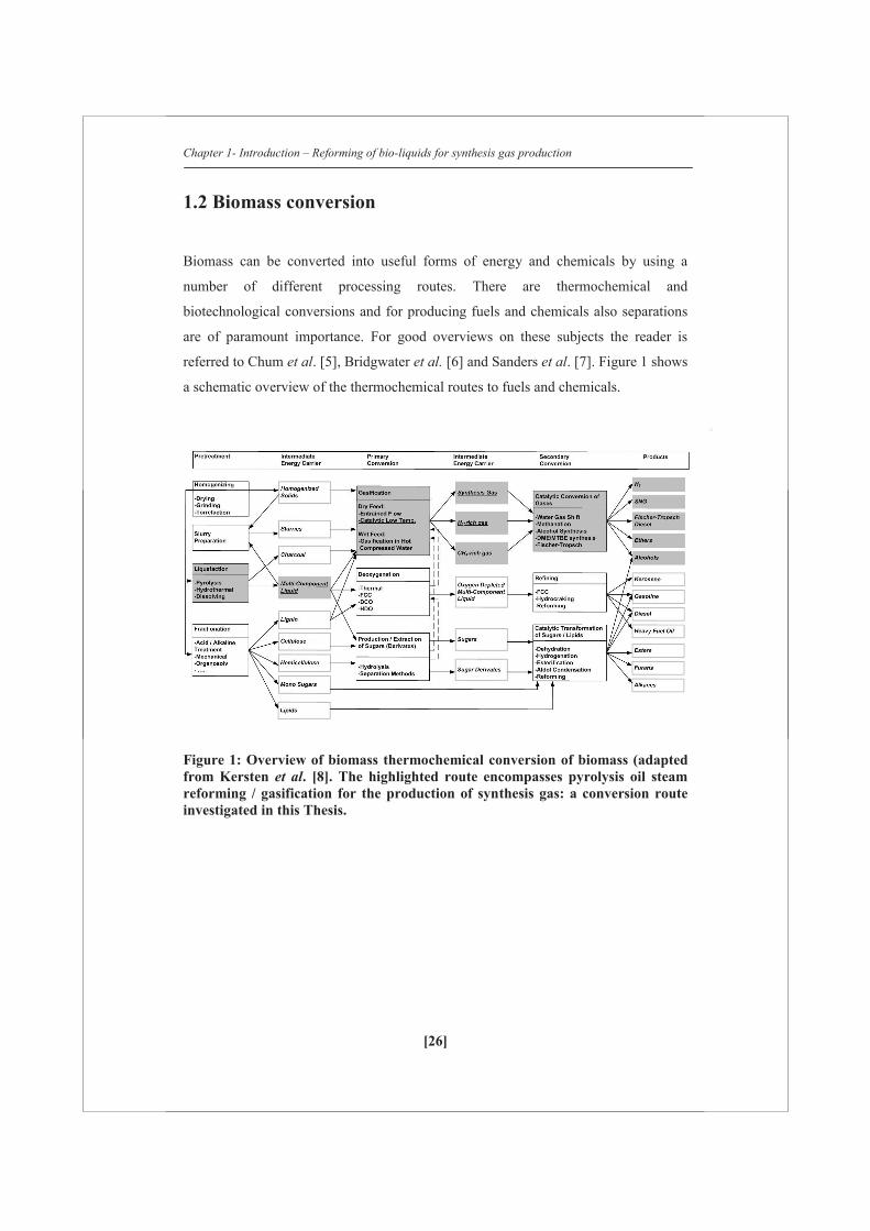
1.2 Biomass conversion
Biomass can be converted into useful forms of energy and chemicals by using a
number of different processing routes. There are thermochemical and
biotechnological conversions and for producing fuels and chemicals also separations
are of paramount importance. For good overviews on these subjects the reader is
referred to Chum et al. [5], Bridgwater et al. [6] and Sanders et al. [7]. Figure 1 shows
a schematic overview of the thermochemical routes to fuels and chemicals.
Figure 1: Overview of biomass thermochemical conversion of biomass (adapted from Kersten et al. [8]. The highlighted route encompasses pyrolysis oil steam reforming / gasification for the production of synthesis gas: a conversion route investigated in this Thesis.
Chapter 1- Introduction – Reforming of bio-liquids for synthesis gas production
[27]
1.3 Synthesis gas
Synthesis gas is a mixture of CO and H2 that can be converted into various fuels and
chemicals (see Figure 1). According to thermodynamics biomass (< 40 wt% water)
can be converted to synthesis gas at temperatures as low as 800 C when enough
steam and/or oxygen is supplied. However, in practice higher gasification
temperatures of above 1200 C are required to produce synthesis gas without the
usage of a catalyst. This process is referred to as entrained flow gasification and is
proven at demonstration scale for biomass [9] and biomass-coal mixtures [10, 11]. At
ca. 800 C a fuel gas is produced containing substantial amounts of tars and
hydrocarbons, mainly CH4, which can be converted into synthesis gas by extensive
cleaning and conditioning [12, 13]. Catalytic gasification of solid biomass has been
investigated to produce synthesis gas from biomass at lower temperatures and thus at
lower costs. This Thesis deals with the production of synthesis gas from relatively dry
bio-liquids (< 30 wt% H2O) via steam reforming (catalytic gasification). Wet biomass
streams [>70 wt% H2O] can be converted into gas by aqueous phase reforming [14]
and supercritical water gasification [15-18]. Due to the very high water concentration
these processes do not yield synthesis gas, but H2 (+ CO2) or CH4 at lower
temperature.
1.4 Reforming of bio-liquids
Steam reforming of bio-liquids is analogous to steam reforming of methane and
naphtha and is supposed to run at ca. 800 C. The overall stoichiometric reactions are:
C6H9O3 + 3H2O 6CO + 7.5H2
CO + H2O CO2 + H2

Chapter 1- Introduction – Reforming of bio-liquids for synthesis gas production
[28]
Glycerol and pyrolysis oil are investigated as feeds in this work. Glycerol becomes
available on the market as a by-product from biodiesel manufacturing via
transesterification [19]. Pyrolysis is a thermochemical process to converted biomass
into pyrolysis oils that can be further upgraded or refined for electricity, transportation
fuels and chemicals production. At the time of writing, several demonstration plants
are considered aiming at maturing the technology and maximizing oil production [20,
21]. Biomass particles decompose in the absence of oxygen at temperatures between
250°C and 550°C into char, liquids (removed from the solid as vapors or as aerosols),
and gases by a process known as pyrolysis. The liquid product, called pyrolysis oil or
bio-oil, is typically condensed and captured downstream of the reactor in single or
multistep (staged) condensers. When the pyrolysis is conducted at temperatures
between 400 °C and 550 °C and small particles are used, very high heating rates are
achieved resulting in maximal liquid production. This process is called fast pyrolysis.
For good reviews on pyrolysis and the applications of pyrolysis oil the reader is
referred to Westerhof et al. [20], Mercader et al. [22], Czernik et al. [23], Bridgwater
et al. [6] and Van Rossum et al. [24]. Table 1 lists typical properties of pyrolysis oil
and glycerol.

Chapter 1- Introduction – Reforming of bio-liquids for synthesis gas production
[29]
Table 1: Typical properties of wood pyrolysis oil [25, 26]
Physical property Pyrolysis oil Neutralized
Crude glycerol
Moisture content (wt%) 15-30 11
pH 2.5 n.m
Specific gravity 1.2 ~1.1-1.2
Elemental composition (wt%)
Carbon 54-58 31.9
Hydrogen 5.5-7.0 8.6
Oxygen 35-40 59.5
Nitrogen 0-0.2 0
Ash 0-0.2 6.6*
HHV (MJ/kg) 16-19 19
Viscosity (at 50 ᵒC, cP) 40-100 n.m
Solids (wt%) 0.2-1 n.m
n.m – not measured *Ash content of crude glycerol is 6.6 wt% (consists of K2O and trace amounts of CaO and Fe2O3) and
crude glycerol is ~4.3 wt% (consists of Na2O)
Crude glycerol contains about ~83 wt% of glycerol, 1.8 wt% of organics (Consists of diglycerides
(0.78%), triglycerides (0.5%), FAME (0.3%), Free fatty acids (0.2%), Methanol (0.01%), trace
amounts of citric acid and acetic acid), 4.4 wt% of inorganics (Consists of 4.3 wt% Sodium Chloride,
0.09 wt% Magnesium Sulphate and 0.01 wt% of Calcium Sulphate)
Reforming bio-liquids instead of gasifying/reforming solid biomass could have some
advantages:
The volumetric energy density of bio-liquids is higher (ca. 5 times). This
makes transport of biomass to the synthesis production site, especially over
long distances, economically more attractive.
Generally a liquid is easier to store, transport and process. Especially
pressurization, which is required for large scale gasification/reforming, will be
easier for liquid feeds.
Chapter 1- Introduction – Reforming of bio-liquids for synthesis gas production
[30]
Bio-liquids could be cleaner than solid raw biomass. Pyrolysis oil for instance
is cleaner than the original feedstock. Because of the relative low process
temperature, the minerals and metals remain in the solid state and are
concentrated in the char. In this way, an option is created to recycle the metals
and minerals locally to the soil. Additionally, catalytic upgrading of pyrolysis
oil to high value fuels and chemicals becomes easier since most of the
impurities (S, Cl, alkali) which deactivate catalysts are separated in the fast
pyrolysis process.
1.5 Literature review
In the following section, a literature review on catalytic reforming of bio-liquids such
as pyrolysis oil, glycerol and representative model compounds of pyrolysis oil is
presented. Most of the reported work focusses on catalyst screening, selection and
development. Only few publications discuss process development issues.
of odel compounds
Pyrolysis oil contains numerous compounds with different functional groups such as
acids, ketones, aldehydes, alcohols etc. Because of this complexity, many scientific
contributions are based on the model compounds to gain insight into oxygenates
reforming over a catalyst bed. The overall stoichiometric reactions for reforming of
any bio-liquid can be written as:
Cracking of oxygenates
CnHmOk gases (CO+CO2+CH4+C2-4+H2) + vapors (CaHbOc) + solid char
Steam reforming of oxygenates
CnHmOk + (n-k) H2O nCO + (n + m/2 – k) H2
Dry reforming of oxygenates
CnHmOk + (n-k) CO2 (2n-k) CO + (m/2) H2
Polymerization of oxygenates (liquid and vapor)
CnHmOk CaHbOc + dH2O + eCO2
Chapter 1- Introduction – Reforming of bio-liquids for synthesis gas production
[31]
Methanation
CO + 3H2 CH4 + H2O (ΔH=-206 kJ/mol)
Water-gas shift
CO + H2O CO2 + H2 (ΔH=-41.1 kJ/mol)
Bouduoard
C(S) + CO2 2 CO (ΔH=170 kJ/mol)
Water-gas reaction
C(S) + H2O CO + H2 (ΔH=~131kJ/mol)
Over the last decade, several researchers investigated acetic acid steam reforming
using catalysts which have Ni as an active metal phase. Acetic acid has been chosen
because it is one of the compounds present in pyrolysis oil [27]. Wang et al. [28]
demonstrated stable reforming activity of a mixture of acetic acid, m-cresol and
syringol at 700 ºC, S/C=5, t=0.09 s using commercial ICI 46 series Ni on alumina
catalyst over a period of ~15 h. Similar stability was reported for 25 h during acetic
acid steam reforming at 600 ºC and S/C =3 in a fixed bed [29]. Also, pure glycerol
showed similar stability for 24 hours during reforming at 600 ºC and S/C~3 using a 3
wt% Ru on Y2O3 catalyst [30]. Wang et al. [31] reported that the coke deposited on
the Nickel on alumina catalyst during steam reforming of acetic acid could be gasified
by steam at the reforming conditions itself.
Basagiannis et al. [32] reported that the coke formation may take place via e.g. the
Boudouard reaction and thermal decomposition via oligomers such as ketene from
acetic acid. To overcome excessive coke formation, several researchers studied steam
reforming of different oxygenates at high molar steam-to-carbon in feed ratio (>3)
[31-36].
The results showed that high temperature (> 650 ºC) and high molar steam-to-carbon
in feed ratio (>3) were required for Nickel on alumina catalysts to achieve almost
complete carbon conversion to gases. An et al. [37] found that the type of carbon
(amorphous or graphitic type) deposited on the catalyst was set by the amount of Ni
loaded on the catalyst. To promote the gasification of carbonaceous deposits several
works were based on Nickel on zirconia catalysts using many oxides of Ce, Zr, La,

Chapter 1- Introduction – Reforming of bio-liquids for synthesis gas production
[32]
Mg, K etc. as promoters. Somsak et al. [38] compared the catalyst performances of Ni
on Al2O3, Ce-Zr and MgO. The Ce-Zr system provided good redox properties and
oxygen mobility prevented the deposition of coke on the catalyst during acetic acid
steam reforming. Matas Güell et al. [39] observed that addition of K and La on
Nickel-zirconia catalyst increased the stability of the catalyst by decreasing the
accumulation of coke on the catalyst. The results obtained by Yan et al. [40] showed
that the Nickel on Ce-Zr catalyst showed a higher yield and better stability than its
commercial Nickel on alumina catalyst counterpart using the aqueous phase of
pyrolysis oil as feed. Takanabe et al. [41] found that even an unpromoted Pt on
zirconia catalyst lost its activity due to the coke deposition via thermal decomposition
of acetic acid on the Pt surface. Bimetallic catalyst systems such as Ni-Co, Co-Fe
systems were also investigated and reported to have stable adsorption of the reactive
coke precursors on the catalyst surface [42]. Li et al. [43] compared impregnation
method with precipitation method for Ni on alumina catalysts on crude ethanol steam
reforming. They [43] reported that the Nickel was easily reducible and obtained a
higher yield of H2 when it was prepared by precipitation method than impregnation
technique. Matas Güell et al. [44] reported that addition of Nickel to K-La-ZrO2
support increased phenol conversion to gases up to ~85%. The gas productions were
fairly stable over a period of 22 h with no CH4 in the product gas was observed.
From the work on model compounds the following can be concluded:
By choosing appropriate process conditions such as temperature, steam over carbon
ratio and catalysts, it is possible to obtain a stable reforming operation over 20 h in
laboratory set-ups. Moreover, mechanisms and pathways leading to coke formation
have been proposed.
Catalyst performance depends on:
1. catalyst preparation methods [45]
2. choice of the promoters and active metal phase [31-46]
3. amount of the active metal phase loaded on the support [47]
Chapter 1- Introduction – Reforming of bio-liquids for synthesis gas production
[33]
1.5.1 Steam reforming of pyrolysis oil and its fractions
National renewable energy limited (NREL, Colorado, United States of America) was
the first to test actual available bio-liquids for the development of a catalytic steam
reforming process to produce hydrogen. The bio-liquids (next to model compounds)
were the aqueous fraction of pyrolysis oil/waste streams [33, 48]. Their initial strategy
to separate pyrolysis oil in an aqueous phase which could be steam reformed for the
production of hydrogen. The heavy phase could then be used for the production of
phenolic resins or adhesive formulations. NREL together with its partners
demonstrated at the laboratory scale using fixed and fluidized bed reactors to produce
H2 from model compounds such as acetic acid, acetol, hydroxyl acetaldehyde,
methanol, sugar fractions, trap grease, crude glycerin, etc. [33,48]. A fluidized bed
was preferred over a fixed bed for bio-liquid streams (aqueous phase of pyrolysis oil
and crude glycerin) since it was less susceptible to plugging due to coking/charring of
the bed [48]. NREL reported that major issues in the development of catalysts for a
fluidized bed are activity (steam reforming and resisting coking) and mechanical
strength (attrition) [28, 31, 49, 50].
Van Rossum et al. [24] worked on the process development of pyrolysis oil reforming
and demonstrated synthesis gas production in a two-stage process where pyrolysis oil
was first atomized/gasified in a fluidized bed and then catalytically converted in the
second stage using commercial steam reforming catalyst in a fixed bed. In this staged
system they showed syngas production for ~12 h with no CH4 or C2-3 generation at a
relatively low GC1HSV of ~100 h-1. Davidian et al. [51] worked on alternating
cracking / steam reforming and regeneration steps. More easily gasifiable coke was
formed on a Ni/Al2O3 catalyst promoted using La and K.
Wang et al. [28] reported that the UCI G-91 steam reforming catalyst activity was
completely recovered after regeneration using steam during steam reforming of the
aqueous phase of pyrolysis oil. However, the carbon deposits above the catalyst bed
blocked the reactor and H2 production decreased with time. In line with that, Garcia et
al. [49] reported that the coke formation takes place via (i) volatile components due to
gas phase reactions and (ii) deposition of char during pyrolysis prior to the catalytic
Chapter 1- Introduction – Reforming of bio-liquids for synthesis gas production
[34]
reforming. To overcome this problem, new catalysts were developed using promoters
such as Ce, Zr, etc. that can enhance steam adsorption and provide gasification of
coke.
Rioche et al. [52] showed that an active phase of platinum metal was sintered during
steam reforming of pyrolysis oil at high S/C of 10.8. Salehi et al. [53] reported that
Ruthenium promoted Nickel on alumina catalyst showed better dispersion while
considerable loss in the surface area and pore volume were not observed during steam
reforming of pyrolysis oil at 850 ºC. Due to this phenomenon, Ru promoted Ni on
alumina catalyst showed higher hydrogen production than unpromoted Ni on alumina
catalyst. Azad et al. [54] reported that the Nickel on zirconia catalyst had higher
carbon deposition than a Ni on alumina catalyst when reforming pyrolysis oil.
Nevertheless, steam reforming of benzene at 700 ºC using a commercial Ni on
alumina catalyst (KATALCO 46) showed a stable gas production for 5 hours. Lan et
al. [55] investigated catalytic steam reforming of pyrolysis oil using a Mg and La
promoted Ni on alumina catalyst in a fixed and fluidized bed. At the same temperature
(800 ºC) and residence time (1 h), fixed bed catalyst had ~0.4 wt% coke, whereas
fluidized bed had almost half of it. Moreover, the coke deposited in the fluidized bed
catalyst was more easily gasified than the coke from the fixed bed.
Xu et al. [56] reported that the sintering of the metal on the support was the main
reason for the deactivation of the catalyst in a fluidized bed. Coke deposition was
eliminated as the main reason for the deactivation of the catalyst because of its
gasification behavior at reaction conditions. To protect the catalyst from the
deactivation, sorption assisted reforming using a mixture of commercial naphtha
reforming Ni on alumina catalyst (Z417 Source China catalyst limited) and dolomite
(to capture CO2) was investigated by Yan et al. [57]. The mixture had higher H2 yield
than without sorbent, nevertheless, the mixture catalyst lost its activity and a
regeneration of sorbent had to be proposed.

Chapter 1- Introduction – Reforming of bio-liquids for synthesis gas production
[35]
Based on the literature studies, the following conclusions can be drawn from the
catalyst perspective:
Initially, the activity of the catalyst is high both in terms of H2 yield or synthesis gas
production. It is possible to achieve a high activity by several catalyst systems such as
Ni/Pt/Ru etc, on zirconia or alumina, promoted using K, Mg, Ca, etc. However, till
now, none of the catalysts showed stable behavior for more than a few hours during
pyrolysis oil steam reforming.
Process development is in its early stages. Spraying pyrolysis oil directly on to fixed
beds cause coke build-up and blocking which prevents stable continuous operation.
The work of Lan et al. [55] indicated that fluidized bed reforming showed slightly
better performance than its counterpart fixed bed reforming. A staged system of
gasifying the pyrolysis oil as a first step and subsequent catalytic conversion (e.g.
steam reforming) seems to minimize the problems related to deactivation of the
reforming catalyst [24].
Chapter 1- Introduction – Reforming of bio-liquids for synthesis gas production
[36]
1.6 This Thesis
An interesting strategy proposed is to integrate bio-refinery with the existing fossil
based industry. One of the possibilities is to produce synthesis gas from biomass and
fossil resources such as natural gas via steam reforming. This so-called hybrid steam
reforming (HSR) concept is schematically visualized in Figure 2. Partnering and
integrating with the fossil based industry has some advantages, such as: making use of
existing infrastructure and producing existing products for existing markets.
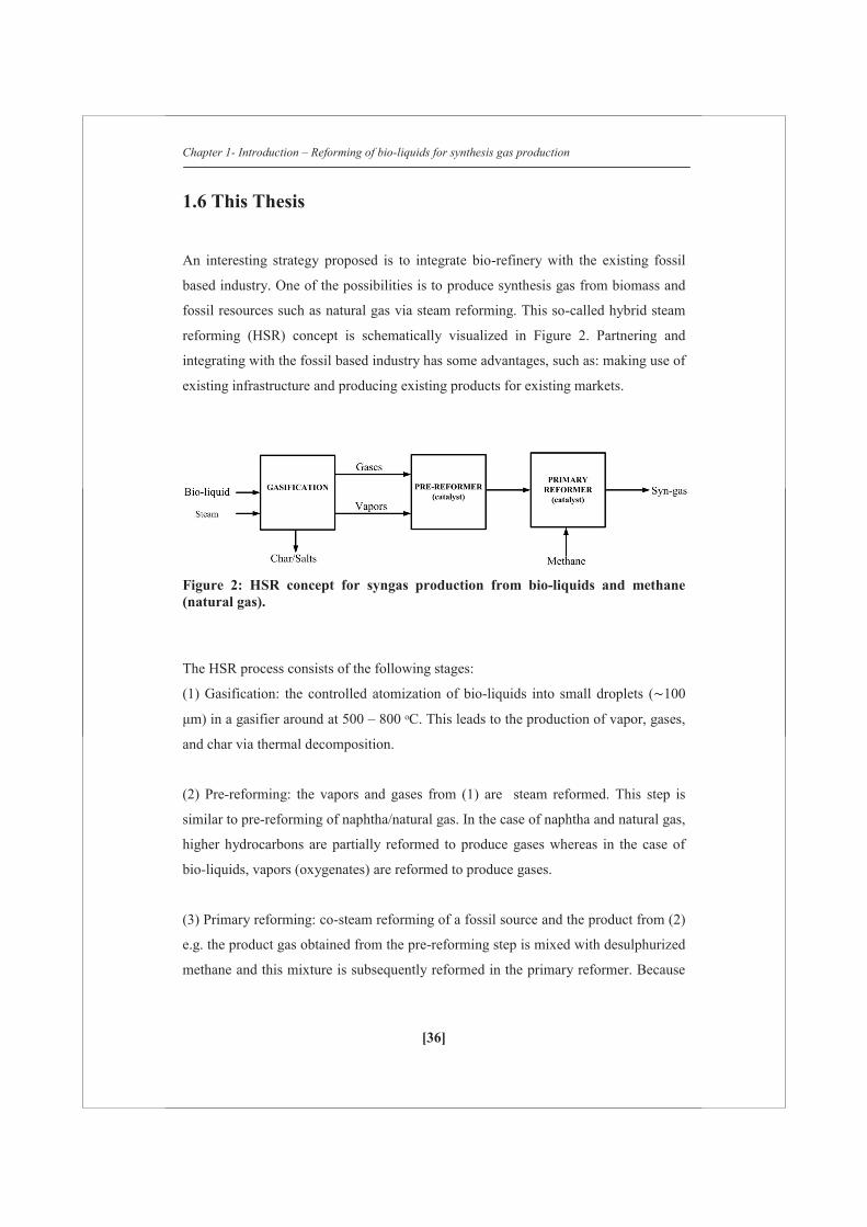
Figure 2: HSR concept for syngas production from bio-liquids and methane (natural gas).
The HSR process consists of the following stages:
(1) Gasification: the controlled atomization of bio-liquids into small droplets ( 100
μm) in a gasifier around at 500 – 800 ᵒC. This leads to the production of vapor, gases,
and char via thermal decomposition.
(2) Pre-reforming: the vapors and gases from (1) are steam reformed. This step is
similar to pre-reforming of naphtha/natural gas. In the case of naphtha and natural gas,
higher hydrocarbons are partially reformed to produce gases whereas in the case of
bio-liquids, vapors (oxygenates) are reformed to produce gases.
(3) Primary reforming: co-steam reforming of a fossil source and the product from (2)
e.g. the product gas obtained from the pre-reforming step is mixed with desulphurized
methane and this mixture is subsequently reformed in the primary reformer. Because
Chapter 1- Introduction – Reforming of bio-liquids for synthesis gas production
[37]
this is similar to natural gas reforming, a high temperature of 800 C is preferred for
this step. The whole concept is summarized in Figure 2.
The following items are investigated in this Thesis:
1. Atomization and gasification of bio-liquids,
2. Reforming of several grades of glycerol, stand-alone and via the hybrid system
with natural gas
3. Reforming of pyrolysis oil, stand-alone and the via hybrid system with natural
gas
4. The techno-economic viability of the HSR concept coupled to methanol
production
In Chapters 2 to 4 atomization followed by gasification (non-catalytic) was
investigated to determine the product distribution from pyrolysis oil and several
grades of glycerol by changing parameters such as temperature, pressure, droplet size,
and pyrolysis oil concentration. The carbon distribution from the pyrolysis oil to
lumped product groups such as gases, vapor (tars) and char was studied in detail. The
results obtained in these Chapters are also of value for design of gasifiers, boilers,
engines fed with bio-liquids, i.e. all processes where bio-liquids are injected in a hot
environment.
The development is continued in Chapter 4 by investigating the behavior of the
commercial steam reforming catalysts in a fixed bed when several grades of glycerols
with different purity are brought in to contact with the catalyst bed. Steam reforming
of pure and crude glycerol was studied at 800 ºC and S/C~3. HSR of glycerol (both
pure and crude) together with methane using commercial steam reforming catalysts
was investigated.
After in depth knowledge is obtained from the gasification of pyrolysis oil and
reforming of crude glycerol (Chapters 2, 3 and 4), the behavior of commercial
naphtha pre-reforming and in-house Mg promoted Ni on alumina catalysts during
steam reforming of pyrolysis oil in a fixed bed is investigated in Chapter 5. The
performance of the catalysts was evaluated based on the gas production and carbon to
Chapter 1- Introduction – Reforming of bio-liquids for synthesis gas production
[38]
gas conversion before and after regeneration. A special focus is given to potassium as
promoter during steam reforming of bio-liquids. Additionally, initial results on HSR
of pyrolysis oil together with methane using a commercial naphtha steam reforming
catalyst are presented.
Finally, in Chapter 6, a techno-economic evaluation of HSR of glycerol together with
methane was performed. The HSR process was designed according to a systematic
procedure and simulated in the commercial UniSim® design suite process simulator.
Based on this window of operation, mass and energy balances for different amount of
glycerol in the HSR concept and a techno-economic evaluation (TEE) were
performed. From the TEE, the cost price of bio-methanol produced via the HSR
process was estimated. An outlook about the future of HSR and how to develop this
process further is presented.
References
1. K.S.Brown, C.W.Marean, A.I.R Herries, Z.Jacobs, C.Tribolo, D. Braun,
D.L.Roberts, M. C.Meyer, J.Bernatchez, Science (2009), vol 325, 859-861
2. P.J.G Pearson, T.J. Foxo, Energy Policy (2012), vol 50, 117-127
3. S.Shafiee, E.Topal, Energy Policy (2009), vol 37, 181-189
4. Open source : Shell energy scenarios to 2050 (2008),
http://www.static.shell.com/static/public/downloads/brochures/corporate_pkg/
scenarios/shell_energy_scenarios_2050.pdf
5. H.L.Chum, R.P.Overend, Fuel processing technology (2001), vol 71, 187-195
6. A.V.Bridgwater, Catalysis today (1996), vol 29, 285-295
7. J.P.M.Sanders, J.H.Clark, G.J.Harmsen, H.J.Heeres, J.J.Heijnen,
S.R.A.Kersten, W.P.M.van Swaaij, J.A.Moulijn, Chemical Engineering and
Processing (2012), vol 51, 117-136
8. S.R.A.Kersten, W.P.M.van Swaaij, L.Lefferts, K.Seshan, Options for
Catalysis in the Thermochemical Conversion of Biomass into Fuels, In:

Chapter 1- Introduction – Reforming of bio-liquids for synthesis gas production
[39]
Catalysis for Renewables: From Feedstock to Energy Production, ed. Centi,
G.; Van Santen, R.A., Wiley-VCH, Weinheim, Germany, 2007.
9. E.Henrich, F.Weirich, Environmental Engineering Science (2004), vol 21, 53-
64
10. C.Higman, M.van der Burgt, Gasification book (2003), Elsevier publications,
ISBN 07506-7707-4
11. Co-gasification at the Buggenum IGCC power plant, A.van Dongen,
M.Kanaar, NUON Power, The Netherlands
12. K.A.Magrini-Bair, S.Czernik, R.French, Y.O.Parent, E.Chornet, D.C.Dayton,
C.Feik, R.Bain, Applied Catalysis A:General (2007), vol 318, 199-206
13. M.M.Yung, W.S.Jablonski, K.A.Magrini-Bair, Energy & Fuels (2009), vol 23,
1874-1887
14. G.W.Huber, R.D.Cortright, J.A.Dumesic, Angewandte Chemie (2004), vol 43,
12 (1549-1551)
15. Y.Matsumura, T.Minowa, B.Potic, S.R.A.Kersten, W.Prins, W.P.M.van
Swaaij, B.van de Beld, D.C.Elliott, G.G. Neuenschwander, Andrea Kruse,
Michael Jerry Antal Jr., Biomass and Bioenergy (2005), vol 29, 269-292
16. G.van Rossum, B.Potic, S.R.A.Kersten, W.P.M.van Swaaij, Catalysis today
(2009), vol 145, 10-18
17. A.G.Chakinala, J.K.Chinthaginjala, K.Seshan, W.P.M. van Swaaij, S.R.A.
Kersten, D.W.F.Brilman, Catalysis Today (2012) 1 (83-92)
18. A.Kruse, Journal of Supercritial fluids (2009), vol 47, 391-399
19. M.Pagliaro, M.Rossi, The Royal Society of Chemistry, 2008, ISBN 978-0-
85404-124-4
20. R.J.M.Westerhof, Refining fast pyrolysis of biomass (2011), ISBN:978-94-
6191-124-7
21. www.btgworld.com
22. F.de Miguel Mercader, Pyrolysis oil upgrading for co-processing in standard
refinery units (2010), ISBN:978-90-365-3085-9
23. S.Czernik, R.French, C.Feik, E.Chornet, Ind.Eng.Chem.Res (2002), vol 41,
4209-4215
24. G.van Rossum, Steam reforming and gasification of pyrolysis oil (2009),
ISBN: 978-90-365-2889-4
Chapter 1- Introduction – Reforming of bio-liquids for synthesis gas production
[40]
25. S.Czernik, A.V.Bridgwater, Energy & Fuels (2004) vol 18, 590-598
26. R.P.B.Ramachandran, G. van Rossum, W.P.M van Swaaij, S.R.A.Kersten,
Energy & Fuels 25 (2011), 5755-5766
27. K.Sipila, E.Kuoppala, L.Fagernas, A.Oasmaa, Biomass and Bioenergy (1998)
vol
14, 103-113
28. D.Wang, S.Czernik, E.Chornet, Energy&Fuels (1998), vol 12, 19-24
29. X.Zheng, C.Yan, R.Hu, J.Li, H.Hai, W.Luo, C.Guo, W.Li, Z.Zhou,
International Journal of Hydrogen Energy (2012), vol 37, 12987-12993
30. T.Hirai, N.Ikenaga, T.Miyake, T.Suzuki, Energy & Fuels (2005) 19, 1761-
1762
31. D.Wang, D.Montane, E.Chornet, Applied Catalysis A:General (1996), vol
143, 245-270
32. A.C.Basagiannis, X.E.Verykios, International Journal of Hydrogen Energy
(2007) vol 32, 3343-3355
33. D.Wang, S.Czernik, D.Montane, M.Mann, E.Chornet, Ind.Eng,Chem.Res
(1997) vol 36, 1507-1518
34. M.Marquevich, S.Czernik, E.Chornet, D.Montane, Energy and Fuels (1999),
vol 13, 1160-1166
35. P.N.Kechagiopoulous, S.S.Voutetakis, A.A.Lemonidou, I.A.Vasalos, Energy
and Fuels (2006), vol 20, 2155-2163
36. J.Medrano, M.Oliva, J.Ruiz, L.Garcia, J.Arauzo, International Journal of
Hydrogen Energy (2008), vol 33, 4387-4396
37. L.An, C.Dong, Y.Yang, J.Zhang, L.He, Renewable energy (2011), vol 36,
930-935
38. T.Somsak, V.Meeyoob, B.Kitiyanana, P.Rangsunvigita, T.Rirksomboona,
Catalysis Today (2011), vol 164, 257-261
39. B.Matas Güell, Doctoral Thesis Book, 2009, ISBN:978-90-365-2879-5
40. C.Yan, F.Cheng, R.Hu, International Journal of Journal Energy (2010), vol 35,
11693-11699
41. K.Takanabe, K.Aika, K.Inazu, T.Baba, K.Seshan, L.Lefferts, Journal of
Catalysis (2006), vol 243, 263-269

Chapter 1- Introduction – Reforming of bio-liquids for synthesis gas production
[41]
42. S.Wang, X.Li, L.Gui, Z.Luo, International Journal of Hydrogen Energy
(2012), vol 37, 11122-11131
43. X.Li, S.Wang, Q.Cai, L.Zhu, Q.Yin, Z.Luo, Applied Biochemistry and
Biotechnology (2012), vol 168, 10-20
44. B.M. Güell, Doctoral Thesis Book, 2009, ISBN:978-90-365-2879-5
45. X.Li, S.Wang, Q.Cai, L.Zhu, Q.Yin, Z.Luo, Applied Biochemistry and
Biotechnology (2012), vol 168, 10-20
46. P.N.Kechagiopoulous, S.S.Voutetakis, A.A.Lemonidou, I.A.Vasalos, Energy
and Fuels (2006), vol 20, 2155-2163
47. F.Bimbela, M.Oliva, J.Ruiz, L.García, J.Arauzo, Journal of Analytical and
Applied pyrolysis (2009), vol 85, 204-213
48. S.Czernik, R.French, C.Feik, E.Chornet, Ind.Eng.Chem.Res (2002), vol 41,
4209-4215
49. L.García, R.French, S.Czernik, E.Chornet, Applied Catalysis A:General
(2000), vol 201, 225-239
50. K.Magrini-Bair, S.Czernik, R.French, Y.Parent, M.Ritland, E.Chornet, (2002).
Fluidizable Catalysts for Producing Hydrogen by Steam Reforming Biomass
Pyrolysis Liquids.Proceedings of the 2002 U.S. DOE Hydrogen and Fuel Cells
Annual Program/Lab R&D Review, 6-10 May 2002, Golden, Colorado
51. T.Davidian, N.Guilhaume, E.Iojoiu, H.Provendier, C.Mirodatos, Applied
Catalysis B:Environmental (2007), vol 73, 116-127
52. C.Rioche, S.Kulkarni, F.C.Meunier, J.P.Breen, R.Burch, Applied catalysis
B:Environmental (2005), vol 61, 130-39
53. E.Salehi, F.S.Azad, T.Harding, J.Abedi, Fuel processing technology (2011),
vol 92, 2203-2210
54. F.S.Azad, J.Abedi, E.Salehi, T.Harding, Chemical engineering journal (2012),
vol 180, 145-150
55. P.Lan, Q.Xu, M.Zhou, L.Lan, S.Zhang, Y.Yan, Chemical engineering
technology (2010), vol 33, 2021-2028
56. Q.Xu, P.Lan, B.Zhang, Z.Ren, Y.Yan, Energy & Fuels (2010), vol 24, 6456-
6462
57. C.Yan, E.Hu, C.Cai, International Journal of Hydrogen Energy (2010), vol 35,
2612-2616

[42]
[42]
Chapter 2
Gasification of pyrolysis oil Product distribution and residue char analysis

Chapter 2 –Gasification of pyrolysis oil – Product distribution and residue char analysis
[44]
Abstract
The evaporation of pyrolysis oil was studied at varying heating rates (~ 1 – 106
°C/min) with surrounding temperatures up to 850 °C. A total product distribution
(gas, vapor and char) was measured using two atomizers with different droplet sizes.
It was shown that with very high heating rates (~ 106 °C/min), the amount of char was
significantly lowered (~8%, carbon basis) compared to the maximum amount which
was produced at low heating rates using a Thermo-gravimetric-analyzer (~ 30 %,
carbon basis; heating rate 1°C/min). The char formation takes place in the 100-350
°C liquid temperature range due to polymerization reactions of compounds in the
pyrolysis oil. All pyrolysis oil fractions (whole oil, pyrolytic lignin, glucose and
aqueous rich/lean phase) showed charring behavior. The pyrolysis oil chars age when
subjected to elevated temperatures (≥ 700 °C), show similar reactivity towards
combustion and steam gasification compared to chars produced during fast pyrolysis
of solid biomass. However, the structure is totally different where the pyrolysis oil
char is very light and fluffy. To be able to use the produced char in conversion
processes (energy or syngas production) it will have to be anchored to a carrier.
This Chapter is published as
Evaporation of pyrolysis oil: Product distribution and residue char analysis, AIChE
journal, 2010, 56, 2200-2210

Chapter 2 –Gasification of pyrolysis oil – Product distribution and residue char analysis
[45]
2.1 Introduction
Syngas production from biomass can play an important role for producing renewable
fuels and chemicals especially when waste streams are being considered. For logistics
and processing advantages, pyrolysis oil is proposed to become an intermediate
energy carrier as the new ‘crude oil’ for refining [1, 2]. To convert pyrolysis oil to
syngas/hydrogen, which is the basis for the production and upgrading (hydrogen) of
many fuels and chemicals, catalytic steam reforming is considered as a very attractive
route since moderate process conditions can be applied and different scale sizes can
be used as compared to high temperature entrained flow gasification [3].
When pyrolysis oil is being catalytically steam reformed, it is always accompanied by
thermal reactions such as gasification and cracking. Already during the evaporation of
the pyrolysis oil, three different products can be identified, namely: permanent gases,
vapors and a carbonaceous solid material (here called char). Especially due to char
formation, a fluidized bed has been preferred [3, 4] to steam reform pyrolysis oil since
clogging of the reactor can be avoided. The char particles are then evenly distributed
into the bed or elutriated from the bed. The distribution between these products is
likely to be influenced by the heating trajectory of the pyrolysis oil droplet and the
final evaporation temperature.
Various groups [3-6] have steam reformed pyrolysis oil or its fractions in a single
fluidized catalytic bed where in most cases, a relatively clean fuel gas was being
produced. However, irreversible catalytic activity loss (leading to increasing methane
levels) was being observed which has mostly been ascribed to attrition/sintering of the
catalyst. Due to this, up till now, no long-term operation of steam reforming (or its
fractions) was feasible to see the influence of other impurities present in the pyrolysis
oil (like sulfur) on the activity of the catalyst. Furthermore, optimization of the
evaporation of pyrolysis oil is limited while using a single reactor because the
reforming catalyst needs a high temperature to produce a methane free syngas at
higher pressures due to the chemical equilibrium [7]. To overcome these problems
which limits the applicability of the process, Van Rossum et al. [3, 7, 8] proposed a
staged reactor concept where the evaporation and catalytic conversion are decoupled
Chapter 2 –Gasification of pyrolysis oil – Product distribution and residue char analysis
[46]
using a fluidized bed for oil evaporation followed by a fixed bed which contains a
steam reforming catalyst. In this way, optimization of both, essentially different,
processes is possible. A clean syngas could be produced when both the fluidized and
fixed bed were at a temperature ~ 800°C. A decrease of the evaporation temperature
showed promising results in such a way that the catalyst was able to actually be in
contact with the primary tars (oxygenated pyrolysis vapors) which are easier to reform
instead of a thermally cracked gas.
A full carbon balance, however, could not be made since not all product streams could
be analyzed; for instance formed char inside the fluidized bed was partly elutriated
from both reactors and ended up in the condenser section. To have a high overall
efficiency of the process, all char has to be converted in the process instead of partly
being considered as a loss. For this, two options seem likely: (i) the char is either
combusted in a separated combustor to supply heat for the endothermic steam
reforming reactions and evaporation (ii) or the char is kept in the reactor and gasified
using steam and/or CO2. An efficiency evaluation [7] showed that internal gasification
is preferable. Additionally, this option would also allow an easier process operation;
external heating is easier to control than maintaining a heat carrier circulation
especially at elevated pressures.
To get more insight in the evaporation of pyrolysis oil, the process is isolated and
studied in this paper. Initially, the effect of temperature, droplet size and heating rate
on the product distribution (char, vapor and gas) is studied. Secondly, the produced
chars are evaluated on its general properties, reactivity and shape. Finally, the
implications will be discussed on designing a process for steam reforming of pyrolysis
oil. In this article, the term ‘char’ refers to char originating from pyrolysis oil
evaporation unless clearly stated otherwise (e.g. char from fast pyrolysis).

Chapter 2 –Gasification of pyrolysis oil – Product distribution and residue char analysis
[47]
2.2 Experimental
2.2.1 Materials
The pyrolysis oils were produced in the Process Development Unit of VTT, Finland
[9]. Two different biomass sources were used, namely pine wood (PW) and forest
residue (FR). The FR oil was also separated into an aqueous rich and aqueous lean
phase via water addition. Pyrolyctic lignin was obtained by adding pine pyrolysis oil
into ice-cooled water as described by Scholze et al. [10]. Activated carbon was
obtained from Norit. The corresponding elemental analyses and water determinations
are given in Table 1.
Table 1: Elemental analyses (wet) and water content determination of the pyrolysis oil and related fractions/compounds used. The rest is mainly oxygen with also compounds like sulfur, nitrogen and ash not determined (n.d)
(wt %) C H Rest H2O
Pyrolysis oil (PW) 41.1 7.4 51.5 24.5
Pyrolysis oil (FR) 40.6 7.6 51.8 23.9
Aqueous rich phase (FR) 23.3 9.4 67.3 52.1
Aqueous lean phase (FR) 48.8 7.5 43.7 12.3
Wood (PW) 45.6 5.8 48.6 6.8
Pyrolytic lignin (PW) 61.2 6.1 31.7 n.d
Wood pyrolysis char (PW) 88.7 2.5 7.5 n.d
Activated carbon (Norit) 85.9 0.6 13.5 n.d
Chapter 2 –Gasification of pyrolysis oil – Product distribution and residue char analysis
[48]
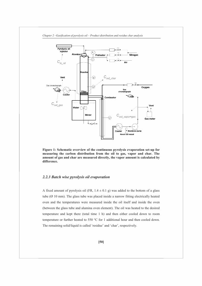
2.2.2 Continuous pyrolysis oil evaporation
To quantify the distribution of pyrolysis oil during evaporation between the gas, vapor
and char phase, a dedicated continuous pyrolysis evaporation set-up was constructed.
A schematic overview of the set-up is given in Figure 1. Pyrolysis oil (FR 100 ml/h,
duration ca. 1 h; Cin_oil) was sprayed into an empty electrically heated stainless steel
tube (Ø 40 mm, length 400 mm) using two different externally cooled atomizers. Two
thermocouples were placed inside the reactor to record the actual temperature in the
middle of the reactor during evaporation experiments. The reported reactor
temperatures are averaged values of the two thermocouples over the whole
experiment. The reactor temperature was varied between 499-847 °C. The two
different atomizers were used to create two different extremes of sizes of droplets
which were measured by pictures taken with a high speed camera (Photron Fastcam
SA1). An ultrasonic atomizer (UA; Lecher US1, spraying angle 30°) created a droplet
size distribution of which the largest droplets were measured to be 88-117 μm
(assisting gas N2 4.0 Nl/min). However, the majority of the droplets was much smaller
but below the resolution limit of the camera. The atomizer was specified for water to
have a Sauter mean diameter of 30 micron. For pyrolysis oil it is expected to be
somewhat higher due to the higher viscosity.
A house-made atomizer consisted (UT) of a needle which was surrounded by an
assisting gas (N2 2.5 Nl/min). A uniform droplet was formed with a diameter of ~1.9
mm. Additional preheated N2 was added directly under the atomizer in a circular way
to avoid vapor condensation on the cooler of the atomizer and to keep the residence
time of the gases around 2-3 s over the temperature range measured. At the end of the
evaporation chamber a filter (mesh size 5 micron) was placed which together with a
small sand layer and enough surface area resulted in a pressure drop of maximal 0.3
bar. The filter temperature was always lower than the reactor temperature (T 498-665
°C). After the filter the stream was split into two streams: (i) one going to a combustor
where the produced gas/vapor mixture was totally combusted with pure oxygen
producing CO2 and H2O. This gas flow was kept constant with a membrane pump
which was placed after a condenser. (ii) the other directly fed to a quenching water
Chapter 2 –Gasification of pyrolysis oil – Product distribution and residue char analysis
[49]
bath which was mechanically stirred to quickly cool the gas/vapor mixture and trap
the condensables.
Two micro-GC’s (2x Varian CP-4900; detecting N2, H2, CH4, CO, CO2, C2H4, C2H6,
C3H6 and C3H8) measured the gas composition of the combustor (Cout_vapor+gas) and of
the quench stream (Cout_gas). The integral carbon balance was made based on nitrogen
as an internal standard which was fed to the evaporator. After an experiment the
collected char on the filter was either collected for analysis and reactivity testing or it
was combusted (Cout_char) to make a total carbon balance over the system. The
carbon to gas ratios and char conversions are measured directly and the carbon to
vapor conversion is calculated by the difference between the combustor and quench
stream according to:
gasoutvaporgasoutvaporout CCC ___
Distribution:
oilin
gasout
C
CGas
_
_100(%), oilin
vaporout
C
CVapor
_
_100(%), inoil
charout
C
CChar
_
_100(%)
The carbon closures of the three different sections were found to be adequate: (i) Gas
only: 101 ± 1 % based on methane addition and recovery in both the combustor and
gas+vapor line, (ii) Gas + vapor: acetic acid was evaporated and partially thermally
cracked (T ~ 720-750 °C, S/C ~ 2.5-5.0). Here, no char is being formed: carbon
recovery 96 ± 1%, (iii) Solid: wood pyrolysis char was combusted with a carbon
recovery of 97 ± 2%. The carbon recovery of all the pyrolysis oil evaporation
experiments (gas + vapor + solid) was 98 ± 4%.
Chapter 2 –Gasification of pyrolysis oil – Product distribution and residue char analysis
[50]
Figure 1: Schematic overview of the continuous pyrolysis evaporation set-up for measuring the carbon distribution from the oil to gas, vapor and char. The amount of gas and char are measured directly, the vapor amount is calculated by difference.
2.2.3 Batch wise pyrolysis oil evaporation
A fixed amount of pyrolysis oil (FR, 1.4 ± 0.1 g) was added to the bottom of a glass
tube (Ø 10 mm). The glass tube was placed inside a narrow fitting electrically heated
oven and the temperatures were measured inside the oil itself and inside the oven
(between the glass tube and alumina oven element). The oil was heated to the desired
temperature and kept there (total time 1 h) and then either cooled down to room
temperature or further heated to 550 °C for 1 additional hour and then cooled down.
The remaining solid/liquid is called ‘residue’ and ‘char’, respectively.
Chapter 2 –Gasification of pyrolysis oil – Product distribution and residue char analysis
[51]
A small nitrogen flow was placed just above the oil to avoid direct contact with air
and to remove the vapors which were released during evaporation. The remaining
residue/Char was weighed. The ‘residue’ which was completely (or almost) soluble in
tetrahydrofuran (THF) was analyzed with Gel permeation chromatograph (GPC) with
THF as elutriation liquid and calibrated using polystyrene.
2.2.4 Thermo-gravimetric Analysis
Heating experiments (mainly pyrolysis oil) were performed in a Mettler Toledo
thermo-gravimetric analyzer (TGA). The samples were heated to 800 °C at a rate of 1,
10 or 100 °C/min in argon (60 ml/min). Combustion experiments were performed in
the same system. In combustion mode, the samples were heated to 800 °C at a rate of
5 °C/min in a mixture of air (20 ml/min) and argon (40 ml/min). Additional to the
TGA balance, the overall weight loss of the sample was quantified with a very
accurate (± 0.1 mg) external balance since some weight loss was already observed
during the stabilization time of the TGA. Two different weight rate losses are defined:
)()(
10
1
TTmmm
dTdX
rwT at a constant heating rate C
1
)()(
10
1
ttmmm
dtdX
rwt s
1
where. τ and τ+1 are logged times, T (°C) the temperature of the sample cup and m0
(mg) the initial amount of pyrolysis oil as weighted with the external balance. The
overall char weight conversions (X) and carbon to char conversions were calculated
using the external balance. The maximum estimated thermal lag (at a heating rate of
100 °C/min using water) using the fusion model is 122 °C.
Chapter 2 –Gasification of pyrolysis oil – Product distribution and residue char analysis
[52]
2.2.5 Steam gasification of char
To gasify, a quartz tube (Ø 45 mm, length 400 mm) was used which was placed inside
an electrically heated oven. A steam generator was used to create a steady steam flow
(~ 300 °C, 0.15-0.5 g/min) and preheated nitrogen (~ 200 °C, 9 Nml/min) was added
as an internal standard. The amount of steam added compared to the char sample (ca.
4-10 mg) was high enough that steam conversions below 1 % were obtained. The char
sample was placed at the end of the oven to ensure adequate pre-heating of the
steam/nitrogen and allow isothermal gasification. The char sample to be gasified was
pre-mixed with quartz (0.2-0.6 g) to lower the pressure drop which can be created due
to the fine structure of the char. The mixed sample (ca. 1 cm in length) was held in the
upper part of the heated quartz tube using quartz wool on both sides. Some pressure
drop (0.2 - 0.5 bar) over the sample was being observed. The reactor outlet was
cooled and all the steam was condensed out of the sample gas. A micro-GC (Varian
CP-4900) was used to analyze the gas composition from which the carbon conversion
was calculated. The gasification rate (rwt, dX/dt) was assumed to directly correspond
to the calculated carbon conversion rate which introduces a small error since most of
the char sample consists out of carbon (75% or more) but also some oxygen and
hydrogen are present.
2.3 Results
2.3.1 Continuous pyrolysis oil evaporation: product distribution
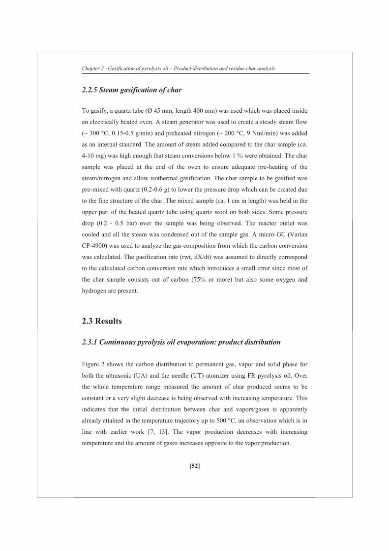
Figure 2 shows the carbon distribution to permanent gas, vapor and solid phase for
both the ultrasonic (UA) and the needle (UT) atomizer using FR pyrolysis oil. Over
the whole temperature range measured the amount of char produced seems to be
constant or a very slight decrease is being observed with increasing temperature. This
indicates that the initial distribution between char and vapors/gases is apparently
already attained in the temperature trajectory up to 500 °C, an observation which is in
line with earlier work [7, 13]. The vapor production decreases with increasing
temperature and the amount of gases increases opposite to the vapor production.
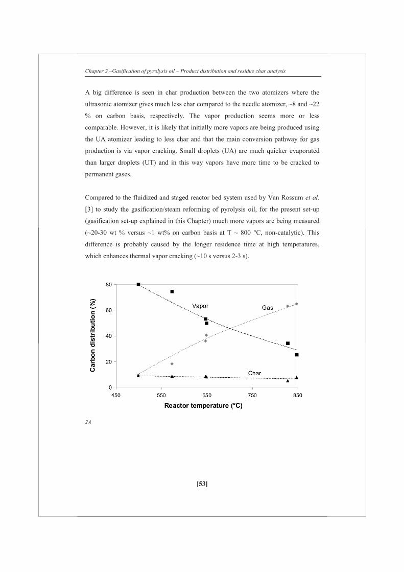
Chapter 2 –Gasification of pyrolysis oil – Product distribution and residue char analysis
[53]
A big difference is seen in char production between the two atomizers where the
ultrasonic atomizer gives much less char compared to the needle atomizer, ~8 and ~22
% on carbon basis, respectively. The vapor production seems more or less
comparable. However, it is likely that initially more vapors are being produced using
the UA atomizer leading to less char and that the main conversion pathway for gas
production is via vapor cracking. Small droplets (UA) are much quicker evaporated
than larger droplets (UT) and in this way vapors have more time to be cracked to
permanent gases.
Compared to the fluidized and staged reactor bed system used by Van Rossum et al.
[3] to study the gasification/steam reforming of pyrolysis oil, for the present set-up
(gasification set-up explained in this Chapter) much more vapors are being measured
(~20-30 wt % versus ~1 wt% on carbon basis at T ~ 800 °C, non-catalytic). This
difference is probably caused by the longer residence time at high temperatures,
which enhances thermal vapor cracking (~10 s versus 2-3 s).
2A

Chapter 2 –Gasification of pyrolysis oil – Product distribution and residue char analysis
[54]
2B
Figure 2: (A,B): carbon distribution over the gas, vapor and solid (char) phase during the evaporation of FR pyrolysis oil using an ultrasonic (A, UA) and needle (B, UT) atomizers at a pyrolysis oil feeding rate of 100 ml/min.
2.3.2 Batch wise pyrolysis oil evaporation: residue analysis
Figure 3 and Table 2 shows the results of the pyrolysis oil evaporation carried out in
glass reactor tubes which are heated at ~ 50 °C/min (oven) to different temperatures.
The residue (Figure 3A) shows a steady decrease in amount with increasing
temperature which stabilizes around T ~ 500 °C. The amount of char shows more or
less a constant production (~ 17 wt %, ~ 32 % carbon basis) although the time-
temperature trajectory has been totally different. The heating trajectory shows quite a
difference between the measured oven temperature and the actual sample temperature.
The oven temperature (Figure 3B), which is usually measured in heating experiments
as for instance with a TGA, shows roughly a constant heating rate till its desired set-
point temperature. However, the sample temperature strongly deviates from the oven
heating trajectory and shows four heating stages as is best illustrated for the Toven =
550°C experiment:

Chapter 2 –Gasification of pyrolysis oil – Product distribution and residue char analysis
[55]
Table 2: Averaged temperatures (at ‘steady-state) and solubility of the obtained ‘residue’ in THF (T:Totally, P:partly, N:not soluble) from FR pyrolysis oil glass reactor tube heating experiments
(wt %) 1 2 3 4 5 6 7 8
Toven (ºC) - 101 152 203 254 368 452 556
Tsample (ºC) 20 79 110 154 209 350 418 544
Solubility in THF T T T T T/P P P N
3A

Chapter 2 –Gasification of pyrolysis oil – Product distribution and residue char analysis
[56]
3B Figure 3: Results of pyrolysis oil evaporation done in glass reactor tubes. (A) residue after a heating-cooling cycle and char after a heating-further heating-cooling cycle. (B) temperature profiles of both the oven (heating rate ca. 50 °C/min) and the liquid/solid itself at three different oven set-points, namely: 100, 250 and 550 °C.
0-3 min: heating of the liquid, some vapor release can already be visually observed.
3-5 min: the liquid temperature increases very slow; this can predominantly be
ascribed to water which is evaporated together with some lights. The vapors which are
being released are colorless and transparent. The difference in oven and sample
temperature almost reaches 200 °C.
5-9 min.: the sample temperature increases at a constant heating rate. The vapors
which are being released get more and more dark with increasing temperature and at a
sample temperature ~ 220 °C a phase transition occurs and a solid is being formed
which is accompanied with a volumetric expansion (± three times) which has also
been described by Wornat et al. [14] during the combustion of pyrolysis oil.
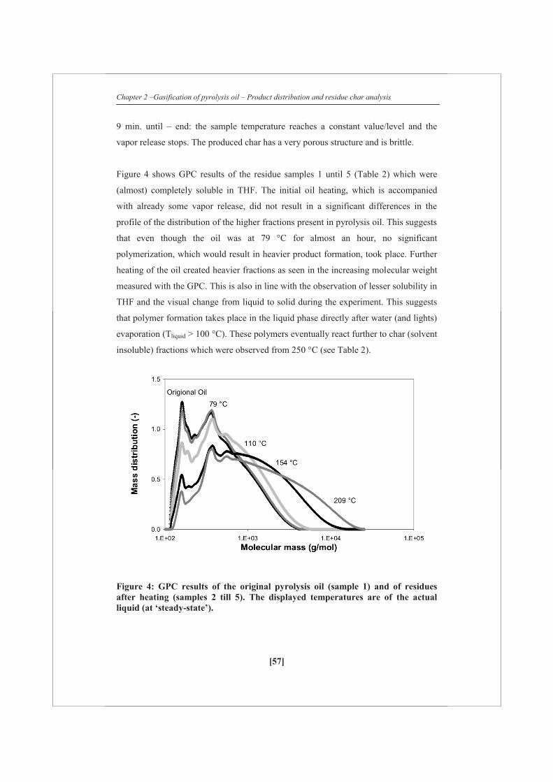
Chapter 2 –Gasification of pyrolysis oil – Product distribution and residue char analysis
[57]
9 min. until – end: the sample temperature reaches a constant value/level and the
vapor release stops. The produced char has a very porous structure and is brittle.
Figure 4 shows GPC results of the residue samples 1 until 5 (Table 2) which were
(almost) completely soluble in THF. The initial oil heating, which is accompanied
with already some vapor release, did not result in a significant differences in the
profile of the distribution of the higher fractions present in pyrolysis oil. This suggests
that even though the oil was at 79 °C for almost an hour, no significant
polymerization, which would result in heavier product formation, took place. Further
heating of the oil created heavier fractions as seen in the increasing molecular weight
measured with the GPC. This is also in line with the observation of lesser solubility in
THF and the visual change from liquid to solid during the experiment. This suggests
that polymer formation takes place in the liquid phase directly after water (and lights)
evaporation (Tliquid > 100 °C). These polymers eventually react further to char (solvent
insoluble) fractions which were observed from 250 °C (see Table 2).
Figure 4: GPC results of the original pyrolysis oil (sample 1) and of residues after heating (samples 2 till 5). The displayed temperatures are of the actual liquid (at ‘steady-state’).

Chapter 2 –Gasification of pyrolysis oil – Product distribution and residue char analysis
[58]
2.3.3 TGA: evaporation
Figure 5 shows the evaporation of pyrolysis oil using TGA with increasing sample
cup temperature. Table 3 shows the amounts of char (both weight and carbon basis)
being produced with TGA for pyrolysis oil and related fractions/compounds. When
the heating rate is varied, the following observations can be made:In the initial heating
stage (up to 175 °C), a clear peak of mass release (Figure 5B) can be identified. This
is the evaporation of water and lights when the liquid temperature is almost constant
similar to as can be seen in Figure 3B (region 3-5 min in the Toven = 550 °C
experiment).
The dX/dt profile (Figure 5C) shows that between the three experiments roughly a
factor of 10x change in conversion rate is being observed which corresponds to the
step change applied in the heating rates. This is an indication that the
reactions/evaporation of the component groups seem to follow first order kinetic
behavior which has been the basis for modeling pyrolysis oil droplet evaporation [13,
15]. The dX/dT (Figure 5B) profiles are quite similar. The small differences observed
are most likely caused by a difference in actual liquid sample temperature and sample
cup temperature which is expected to be large at high heating rates (next to the first
order behavior of the evaporation and reactions).
5A
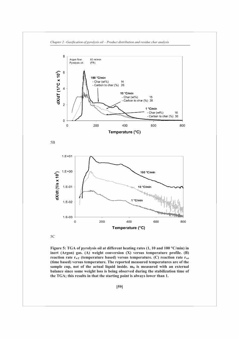
Chapter 2 –Gasification of pyrolysis oil – Product distribution and residue char analysis
[59]
5B
5C
Figure 5: TGA of pyrolysis oil at different heating rates (1, 10 and 100 °C/min) in inert (Argon) gas. (A) weight conversion (X) versus temperature profile. (B) reaction rate rwT (temperature based) versus temperature. (C) reaction rate rwt (time based) versus temperature. The reported measured temperatures are of the sample cup, not of the actual liquid inside. m0 is measured with an external balance since some weight loss is being observed during the stabilization time of the TGA; this results in that the starting point is always lower than 1.

Chapter 2 –Gasification of pyrolysis oil – Product distribution and residue char analysis
[60]
Table 3: Char production using TGA of pyrolysis oil and related fractions/compounds. The amounts are given on both weight and carbon basis. The sample was heated to 800 ºC at a heating rate of 10 ºC/min and an Argon flow of 60 ml/min
(weight %) Weight of feed Carbon to char
Pyrolysis oil (FR) 15 28
Aqueous rich phase (FR) 7 24
Aqueous lean phase (FR) 21 33
Wood (PW) 15 25
Pyrolytic lignin (PW) 43 54
Glucose solution (40 wt%) 7 28
The carbon to char conversion shows a slight trend of increasing char production with
lower heating rates. The produced char amounts are similar to the glass tube heating
experiments and higher than the droplet evaporation experiments. The heating of
different fractions of pyrolysis oil and related compounds (Table 3) all resulted in the
formation of considerable amounts of char. The aqueous, rich fraction of pyrolysis oil,
which is considered to be an important hydrogen resource and easy to steam reform
[4, 5] still resulted in 24 % of carbon which was converted to char. The heavier
fractions of pyrolysis oil (aqueous lean phase and pyrolictic lignin) form high
amounts of char.
The amount of char formed with evaporating pyrolysis oil is under slow heating rates
(1-100 °C/min) similar to pyrolysis of solid biomass at ~ 500 °C (25 % carbon to char
conversion, Table 3). It is striking that such high amounts of char are formed since the
large molecular structures which were present in the original biomass are being de-
polymerized in the pyrolysis process to end up in the pyrolysis oil or are mainly
concentrated in the char by-product. Char formation during pyrolysis oil evaporation
seems to be mainly due to polymerization reactions of the oil as illustrated in
Figure 4.

Chapter 2 –Gasification of pyrolysis oil – Product distribution and residue char analysis
[61]
However, some polymerization reactions and heavies elutriation [16] already take
place during the pyrolysis oil production/condensation directly leading to products
which cannot be re-evaporated. It is then interesting to see if these products can be
readily gasified or that they always lead to the production of char.
It will be important to heat up quickly through the 100 → 350 °C temperature zone
where the polymerization takes place. The lower amount of char formation at higher
heating rates shows clearly that steering is possible. Figure 6 shows heating rates for
the TGA, heated glass tubes and droplet evaporation. The ‘droplet evaporation’
heating rates after “lights” evaporation when char formation starts were estimated
with a heat balance over a droplet according to:
Tdc
NudtdT
pp2
6
with Nusselt (flow around sphere)
7PrRe66.02 31
21
Nu
With dp the droplet size of the pyrolysis oil, cp the heat capacity of a liquid ~ 2000
J/kg/°C, ρ the density of the liquid ~ 1000 kg/m3, λ thermal conductivity of gas ~ 0.06
W/m/°C and ΔT the temperature difference ~ 500 °C (a 50% spread over the
calculated heating rate values is assumed in Figure 6). The estimated heating rates are
in the same order of magnitude as estimated by Garcìa Pèrez et al. [17]. Only very
high heating rates (≥ 105 °C/min) results in significant reductions of char production.
This shows that with widely used heating analyzing equipment such as TGA, an
analysis can be made of maximum char production that is probable from a certain
compound/oil. This can be useful to predict gasification behavior but it must be kept
in mind that the process of evaporation is most likely/essentially different between a
TGA and an atomizer. Probably there is also a minimum amount of char which will
be formed.
Glucose like compounds and heavier fractions are always present in the pyrolysis oil
(both aqueous rich and lean phases) which tend to polymerize rather than to
evaporate/decompose (see Table 3). However, it is possible that with extremely high
heating rates or diluted solutions (e.g. water and methanol) compounds remain
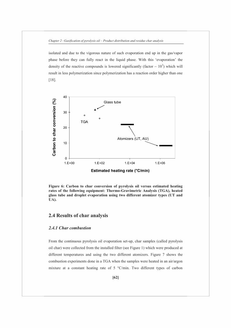
Chapter 2 –Gasification of pyrolysis oil – Product distribution and residue char analysis
[62]
isolated and due to the vigorous nature of such evaporation end up in the gas/vapor
phase before they can fully react in the liquid phase. With this ‘evaporation’ the
density of the reactive compounds is lowered significantly (factor ~ 103) which will
result in less polymerization since polymerization has a reaction order higher than one
[18].
Figure 6: Carbon to char conversion of pyrolysis oil versus estimated heating rates of the following equipment: Thermo-Gravimetric Analysis (TGA), heated glass tube and droplet evaporation using two different atomizer types (UT and UA).
2.4 Results of char analysis
2.4.1 Char combustion
From the continuous pyrolysis oil evaporation set-up, char samples (called pyrolysis
oil char) were collected from the installed filter (see Figure 1) which were produced at
different temperatures and using the two different atomizers. Figure 7 shows the
combustion experiments done in a TGA when the samples were heated in an air/argon
mixture at a constant heating rate of 5 °C/min. Two different types of carbon

Chapter 2 –Gasification of pyrolysis oil – Product distribution and residue char analysis
[63]
containing materials were initially heated to see the difference in the start and the
peak of the combustion process (see Figure 7A), namely char from fast pyrolysis
(wood pyrolysis char) which is known to have a high reactivity and activated carbon
which is quite stable char. The difference in combustion peaks is significant; around
500 °C for wood pyrolysis char and 645 °C for activated carbon.
The collected chars (Figure 7B) show reactivities more similar to char from wood fast
pyrolysis than from activated carbon. This is different to what Branca et al. [19]
measured where the pyrolysis oil char reactivities were lower than those of wood
pyrolysis char. This difference is most likely due to the different char production
methods (cup heating versus atomization). The use of different atomizers shows a
slight difference in reactivity where UA (small droplets) is combusted at a lower
temperature than UT (big droplets). This is remarkable since with small droplet
evaporation, the amount of char being produced is much less and one could think only
a lesser reactive fraction would remain. The reactivity is most likely determined by
the composition of the char and the accessibility for gases. Besides this the
temperature, to which the char has been produced, seems to have an important
influence on the activation and peak temperatures. When pyrolysis oil evaporation
chars are being produced at high temperatures (~ 850 °C), they are less reactive. Up
till a temperature of 654 °C, the reactivity seems similar. This was also confirmed
when chars were produced at different final temperatures (heating rate: 10 °C/min),
kept at those temperatures for 15 min, and then cooled down. The reactivity of these
chars increase with decreasing final temperature of production as is shown in Figure
7C.
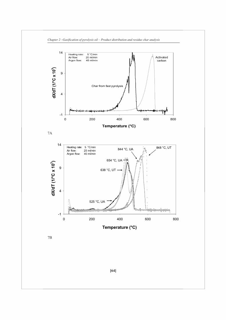
Chapter 2 –Gasification of pyrolysis oil – Product distribution and residue char analysis
[64]
7A
7B

Chapter 2 –Gasification of pyrolysis oil – Product distribution and residue char analysis
[65]
7C
Figure 7: TGA in an air flow. (A) shows combustion profiles during a constant heating of the sample for char produced during the fast pyrolysis of pine wood and of activated carbon. (B) shows combustion profiles of chars collected from the continuous evaporation set-up which was operated at different temperatures using two different atomizers. (C) shows chars produced at a constant heating rate of 10 °C/min and then cured (15 min) at different peak temperatures (550, 700 and 850 °C).
2.4.2 Structural analysis of char
From the chars produced, one was selected for further analysis, namely the pyrolysis
oil char produced at 525 °C with the ultrasonic atomizer (UA, elemental analysis
(wt%): C: 76.7, H: 3.4, Rest: 19.9). This choice was based upon (i) evaporation
experiments showed the lowest char yields with this atomizer and (ii) combustion
activity measurements showed that this chars is among the most reactive. Figure 8
shows SEM photos of the char. The char shows to be consisting of mostly hollow
spheres (wall thickness order magnitude of a few hundred nanometers) which have
been ruptured. Onto and into these larger structures, smaller particles are deposited.
The char is very light/fluffy as compared to char produced during fast pyrolysis of
wood. This is believed to be the reason for the high carbon elutriation from an earlier
used fluidized bed for steam reforming of pyrolysis oil [3, 7, 8].
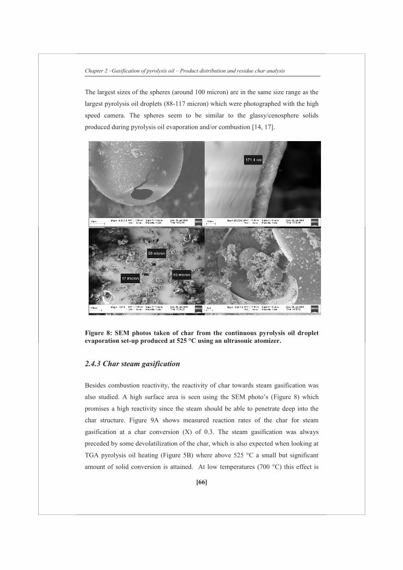
Chapter 2 –Gasification of pyrolysis oil – Product distribution and residue char analysis
[66]
The largest sizes of the spheres (around 100 micron) are in the same size range as the
largest pyrolysis oil droplets (88-117 micron) which were photographed with the high
speed camera. The spheres seem to be similar to the glassy/cenosphere solids
produced during pyrolysis oil evaporation and/or combustion [14, 17].
Figure 8: SEM photos taken of char from the continuous pyrolysis oil droplet evaporation set-up produced at 525 °C using an ultrasonic atomizer.
2.4.3 Char steam gasification
Besides combustion reactivity, the reactivity of char towards steam gasification was
also studied. A high surface area is seen using the SEM photo’s (Figure 8) which
promises a high reactivity since the steam should be able to penetrate deep into the
char structure. Figure 9A shows measured reaction rates of the char for steam
gasification at a char conversion (X) of 0.3. The steam gasification was always
preceded by some devolatilization of the char, which is also expected when looking at
TGA pyrolysis oil heating (Figure 5B) where above 525 °C a small but significant
amount of solid conversion is attained. At low temperatures (700 °C) this effect is

Chapter 2 –Gasification of pyrolysis oil – Product distribution and residue char analysis
[67]
still significant but at higher temperature it is negligible compared to the steam
gasification.
The gasification rate of pyrolysis oil char can be well described with an Arrhenius
type of temperature dependence giving an activation energy (Ea) of 274 kJ/mol which
is at the higher end compared to earlier measured activation energies of steam
gasification of biomass originating chars (Ea: 105-271 kJ/mol) [20]. The reactivity
profiles at the same temperature for pyrolysis oil char, wood pyrolysis char and
activated carbon show distinct behavior (Figure 9B). The activated carbon shows a
constant activity over the whole conversion range measured which can be interpreted
as zero order gasification reactivity in char. The pyrolysis oil char and wood pyrolysis
char show quite similar profile namely a readily decreasing reactivity with increasing
conversion which was also observed by Barrio et al. [20]
The following explanation can be given for this change in reactivity: (i) the reaction
order in char is not zero, (ii) there is inhibition (for instance hydrogen and carbon
monoxide), (iii) the carbon structure changes/is less accessible which results in an
apparent different reaction order and (iv) the char ages in time leading to less reactive
chars. (iii) and (iv) are expected to be dominant in explaining this behavior. The
carbon surface structure has been shown on SEM photos to be very complex (Figure
8) where big hollow spheres are present which could be assumed to be reacting as a
flat plate and smaller deposits which could react away as small porous spheres. This
complex structure could lead to a higher initial rate decreasing with increasing
conversion. The char has shown ‘aging’ (reactivity loss due to thermal exposure)
behavior when it is subjected to elevated temperatures for a certain time (Figure 7C)
leading to a decreasing reactivity rate. The activated carbon giving its constant
reactivity over time is then due to that the overall structure does not change (in the
conversion range measured) and does not undergo ‘aging’ since it was already
subjected to higher temperatures during production.
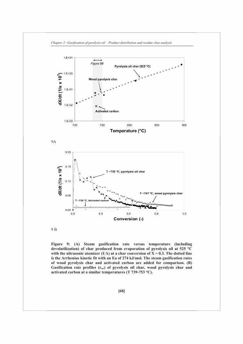
Chapter 2 –Gasification of pyrolysis oil – Product distribution and residue char analysis
[68]
9A
9 B
Figure 9: (A) Steam gasification rate versus temperature (including devolatilization) of char produced from evaporation of pyrolysis oil at 525 °C with the ultrasonic atomizer (UA) at a char conversion of X = 0.3. The dotted line is the Arrhenius kinetic fit with an Ea of 274 kJ/mol. The steam gasification rates of wood pyrolysis char and activated carbon are added for comparison. (B) Gasification rate profiles (rwt) of pyrolysis oil char, wood pyrolysis char and activated carbon at a similar temperatures (T 739-753 °C).

Chapter 2 –Gasification of pyrolysis oil – Product distribution and residue char analysis
[69]
2.4.4 Mechanism of pyrolysis char evaporation
The temperature-time history of a pyrolysis droplet determines not only the amount of
char being formed but also its reactivity as is illustrated in Figure 10. Our results show
that a part of the pyrolysis oil seems to always evaporate, leading to gases and vapors
which can be reformed to create syngas. Another part can either be converted to char
or similar to the abovementioned route generate gases/vapors which is determined by
the heating rate. With higher heating rates the ratio of the rate of
polymerization/gasification is lowered. The formed chars show ‘aging’ behavior when
they are exposed to higher temperatures (above 650 °C, see Figure 7 B and C). This
aging behavior, together with the complex structure of the char, results in steam
gasification rates which decrease with increasing extend of conversion. When the
whole evaporation process would be pressurized, the evaporation curve (Figure 3 and
5) is expected to shift to higher temperatures. This will probably lead to more char
formation since polymerization rates are higher.
Figure 10: Evaporation scheme of pyrolysis oil leading to gases, vapors and char. The formed char can age to form a less reactive char. Both chars can be converted either by gasification (steam and CO2) or combustion. The temperature-time trajectory will determine which pathways are more dominant.
Chapter 2 –Gasification of pyrolysis oil – Product distribution and residue char analysis
[70]
2.5 Implications for steam reforming of pyrolysis oil
The presented results have shown that with the evaporation of pyrolysis oil (or its
fractions) always char will be formed. This has a large impact on steam reforming
process of pyrolysis oil whether single or staged reactor concepts are envisaged. This
char amount can be considerable: a maximum of 32 % on carbon basis was obtained
using FR pyrolysis oil under slow heating conditions. This amount differs with
varying types/qualities of pyrolysis oil [7]. Char formation during slow evaporation is
much higher than other possible reactions leading to solid carbonaceous species such
as coke which can be formed on the steam reforming catalyst (at sufficient high
temperatures) and soot formed via vapor cracking. By applying very high heating
rates the amount of char formed can be significantly reduced where the underlying
mechanism seems to be dilution of the reactive species (~103 times with evaporation)
and/or higher gasification rates of char precursors relative to polymerization.
Specially designed atomizers create very small droplets which can be evaporated
quickly. The speed of evaporation can be further increased with the use of a fluidized
bed which has excellent heat transfer properties. However, not only the amount of
char is important but also in which form it is being created.
Droplet evaporation in a heated empty space leaves a very light/fluffy char residue
which easily elutriates from the reactor before it can be converted. It is therefore
necessary to bind the char to a carrier. Sand has shown to not have enough binding
capacity (fluidization scrapes char of its surface) and therefore more porous materials
are probably preferred so that char formation takes place inside the carrier. How to
contact the pyrolysis oil to such a carrier is not yet straightforward and has to be
investigated further. The initial high temperature difference between the droplet and
the carrier can limit the effectiveness of contacting. The Leidenfrost effect (which was
shown to occur with large pyrolysis oil droplets on a hot surface) can let droplets
bounce off the carrier and it has to be investigated what would be the ideal oil/carrier
particle diameter ratio: a high ratio will cool down the carrier which then would allow
carrier soaking and a low ratio would instantly heat the oil.
Chapter 2 –Gasification of pyrolysis oil – Product distribution and residue char analysis
[71]
Another option could be to modify the shape of the steam/dry reforming catalyst in
such a way that residual char which elutriates from the fluidized bed is bound to it in
the secondary reactor. In this way the char could get sufficient residence time to react.
Preliminary tests in a bubbling fluidized with a more porous bed material have shown
higher carbon to gas conversions as compared to ‘inert’ sand [22]. The char itself has
combustion and gasification properties comparable to other biomass originated chars.
When pyrolysis oil steam/dry reforming is considered, the char can be combusted to
supply heat for the endothermic reforming reactions and evaporation. However, direct
internal gasification of the char is preferred from an efficiency and process operation
point of view [7]. Current steam gasification tests have shown that at the preferred
temperature regime (<700 °C) for operating a fluidized bed for evaporation, the rate
of char conversion is too low. Higher operating pressures will probably enhance this
conversion rate but catalytic active materials seem to be necessary to change char
gasification conversion times from hours to minutes.
2.6 Conclusions
Pyrolysis oil (and all its fractions) evaporation is always coupled with the formation
of char which is formed via polymerization reactions. The speed through which the
pyrolysis oil liquid goes through the 100-350 °C temperature zone determines the
total amount of char that is formed. Very high heating rates (≥ 105 °C/min) which can
be achieved with small droplets lead to much less char (~ 8 %, carbon basis) than the
‘maximum’ amount (~ 30 %, carbon basis) which is measured with analytical heating
equipment like TGA.
Char from pyrolysis oil evaporation has a very open structure and it consists out of
large hollow spheres onto which smaller particles are being deposited. The char has
reactivities towards combustion and steam gasification comparable to char formed
during the pyrolysis of biomass. The char shows aging behavior when subjected to
higher temperatures (≥ 650-700 °C).
Chapter 2 –Gasification of pyrolysis oil – Product distribution and residue char analysis
[72]
References
1. F.de Miguel Mercader, A.Ardiyanti, A.Gutierrez, S.Khromova, E.Leijenhorst,
S.R.A.Kersten, J.A.Hogendoorn, W.Prins, M.J.Groeneveld, Proceedings of the
16th European Biomass Conference and Exhibition. Valencia, Spain, June 2-6,
2008:2103-2106.
2. A.Corma, G.W.Huber, L.Sauvanaud, P.J.O’Conner, J.Catal. (2007) vol 247,
307-327.
3. G.van Rossum, S.R.A.Kersten, W.P.M.van Swaaij, Ind. Eng. Chem. Res.
(2007) vol 46, 3959-3967.
4. Czernik S, French R, Feik C, Chornet E, Ind. Eng. Chem. Res.(2002) vol 41,
4209-4215.
5. P.N.Kechagiopoulos, S.S.Voutetakis, A.A.Lemonidou, I.A.Vasalos, Ind. Eng.
Chem. Res. ( 2009) vol 48, 1400-1408.
6. J.A.Medrano, M.Oliva, J.Ruiz, L.Garcia, J.Arauzo, Proceedings of the 16th
European Biomass Conference and Exhibition. Valencia, Spain, June 2-6,
2008, 2158-2162.
7. G.van Rossum, S.R.A.Kersten, W.P.M.van Swaaij, Ind. Eng. Chem. Res.
(2009) vol 48, 5857-5866.
8. G.van Rossum, B.Potic, S.R.A.Kersten, W.P.M.van Swaaij, Catal. Today.
(2008) vol 145, 10-18.
9. A.Oasmaa, K.Sipilä, Y.Solantausta, E.Kuoppala, Energy & Fuels (2005) vol
19, 2556-2561.
10. B.Scholze, D.Meier, J. Anal. Pyrolysis (2001) vol 60, 41-54.
11. B.Scholze, C.Hanse, D.Meier, J. Anal. Pyrolysis (2001) vol 58-59, 387-400.
12. R.Narayan, M.J.Antal, Ind. Eng. Chem. Res. (1996) vol 35, 1711-1721.
13. C.Branca , C.Di Blasi, Ind. Eng. Chem. Res. (2006) vol 45, 5891-5899.
14. M.J. Wornat, B.G. Porter, N.V.C.Yang, Energy & Fuels (1994) vol 8, 1131-
1142.
15. W.L.H.Hallett, N.A.Clark, Fuel (2006), vol 85, 532-544.
16. E.Daugaard, R.C.Brown, Science in Thermal and Chemical Biomass
Conversion. (2006) vol 2, 1189-1202.

Chapter 2 –Gasification of pyrolysis oil – Product distribution and residue char analysis
[73]
17. M.Garcìa Pèrez, P.Lappas, P.Hughes, L.Dell, A.Chaala, D.Kretschmer. C.Roy
IFRF Combustion Journal (2006) 200601.
18. D.Knežević, W.P.M.van Swaaij, S.R.A.Kersten, Ind. Eng. Chem. Res. (2009)
vol 48, 4731-4743.
19. C.Branca, C.di Blasi, R.Elefante, Ind. Eng. Chem. Res. (2005) vol 44, 799-
810.
20. M.Barrio, B.Gøbel, H.Risnes, U.Henriksen, J.E.Hustad, L.H.Sørensen, Editor:
A.V.Bridgwater, progress in Thermochemical Biomass conversion, MPG
Books Ltd. (2001), vol 1, 32-46.
21. G.Chen, Q.Yu, K.J.Sjőstrőm, Anal. Appl. Pyrolysis (1997) vol 40-41, 491-
499.
22. M.F.Bleeker, H.J.Veringa, S.R.A.Kersten, Applied Catalysis A:General
(2009) vol 357, 5-17

[74]

[75]
Chapter 3
Evaporation of biomass fast
pyrolysis oil Evaluation of char formation
Chapter 3 – Evaporation of biomass fast pyrolysis oil – Evaluation of char formation
[76]
Abstract Evaporation experiments of biomass fast pyrolysis oil and its aqueous fractions at low
(TGA-10 °C/min, Glass tube-100 °C/min) and high (atomization ~106 °C/min) heating
rates are performed. Slow heating of pyrolysis oil produced ~28% char (on carbon
basis) while atomization of oil droplets (~117 μm) produced ~9% char in the
temperature range of 500-850 °C. Aqueous fractions and glucose solutions also
produced less amount of char by evaporating at higher heating rates (~3% char)
when compared to slower heating (~24% char). The results obtained show that in
pyrolysis oil not a single lumped components class can be identified that is primarily
responsible for the char formation. At low heating rate, higher concentrations of
organics in the bio-liquids result in higher char yields, which reveals that a certain
fraction in the oil produce char with a reaction order higher than one (polymerization
reactions). The measured trends in char yield can be described by a model in which
certain fraction of oil is converted by two parallel reactions to char and gas/vapor.
Under high heating rate conditions of the droplets, the vapor/gas phase residence
time (0.8-2.8 s), steam over carbon ratio (0.4-10) and pressure (1-16 bar) turned out
to have no significant on the char yield.
Part of this Chapter has been published as: “Evaporation of biomass fast pyrolysis
oil:Evaluation of char formation in Environmental Progress and Sustainable Energy,
2009, 28, 410-417”.
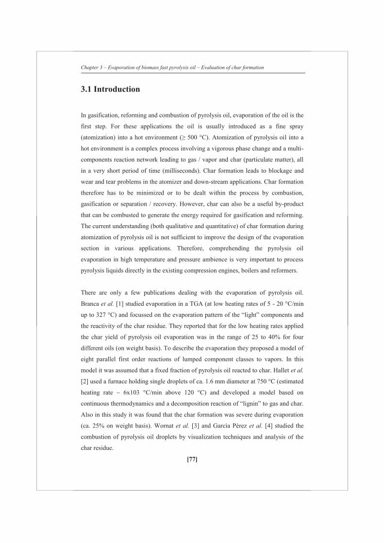
Chapter 3 – Evaporation of biomass fast pyrolysis oil – Evaluation of char formation
[77]
3.1 Introduction
In gasification, reforming and combustion of pyrolysis oil, evaporation of the oil is the
first step. For these applications the oil is usually introduced as a fine spray
(atomization) into a hot environment (≥ 500 °C). Atomization of pyrolysis oil into a
hot environment is a complex process involving a vigorous phase change and a multi-
components reaction network leading to gas / vapor and char (particulate matter), all
in a very short period of time (milliseconds). Char formation leads to blockage and
wear and tear problems in the atomizer and down-stream applications. Char formation
therefore has to be minimized or to be dealt within the process by combustion,
gasification or separation / recovery. However, char can also be a useful by-product
that can be combusted to generate the energy required for gasification and reforming.
The current understanding (both qualitative and quantitative) of char formation during
atomization of pyrolysis oil is not sufficient to improve the design of the evaporation
section in various applications. Therefore, comprehending the pyrolysis oil
evaporation in high temperature and pressure ambience is very important to process
pyrolysis liquids directly in the existing compression engines, boilers and reformers.
There are only a few publications dealing with the evaporation of pyrolysis oil.
Branca et al. [1] studied evaporation in a TGA (at low heating rates of 5 - 20 °C/min
up to 327 °C) and focussed on the evaporation pattern of the “light” components and
the reactivity of the char residue. They reported that for the low heating rates applied
the char yield of pyrolysis oil evaporation was in the range of 25 to 40% for four
different oils (on weight basis). To describe the evaporation they proposed a model of
eight parallel first order reactions of lumped component classes to vapors. In this
model it was assumed that a fixed fraction of pyrolysis oil reacted to char. Hallet et al.
[2] used a furnace holding single droplets of ca. 1.6 mm diameter at 750 °C (estimated
heating rate ~ 6x10³ °C/min above 120 °C) and developed a model based on
continuous thermodynamics and a decomposition reaction of “lignin” to gas and char.
Also in this study it was found that the char formation was severe during evaporation
(ca. 25% on weight basis). Wornat et al. [3] and Garcìa Pèrez et al. [4] studied the
combustion of pyrolysis oil droplets by visualization techniques and analysis of the
char residue.

Chapter 3 – Evaporation of biomass fast pyrolysis oil – Evaluation of char formation
[78]
Wornat et al. [3] did experiments at 1375 °C with droplets of 320 μm. With respect to
formation of particulate matter they concluded that soot was produced by vapor phase
pyrolysis reactions and liquid phase polymerization reactions yielded char. Garcìa-
Pèrez and co-workers [4] were able to produce very fine droplets of ca. 60 μm and
injected them in a heated tube of 700 - 800 °C. By a sophisticated measurement
technique of the droplet diameter in a hot environment, they could show that the
droplet size first decreased and then increased again as a function of residence time.
Lederlin et al. [5] developed a model for evaporation of pyrolysis oil droplets based
on oil with an artificial composition. This model included no char forming
mechanism.
To the best of our knowledge, quantitative information is not yet available in the open
literature on the product distribution (gas, vapor and char) of pyrolysis oil evaporation
when using small droplets (< 2 mm). In Chapter 2, it is already mentioned that the
atomizer produced droplets of 117 μm (maximum droplet size). This work showed
that these 117 μm droplets of pyrolysis oil injected into an inert environment of 500 –
850 °C at atmospheric pressure yielded significantly less char than oil slowly
evaporating in a TGA (8 vs. 30% on carbon basis).
The present investigation deals with the product distribution of pyrolysis oil, its
fractions and glucose solutions using the same atomizer. These feedstocks have been
evaporated at different temperatures (500 – 850 °C) and heating rates (TGA: 10
°C/min, vaporization from a tube: 50 °C/min and atomization: ~ 1x10⁶ to 8x10⁶
°C/min) in order to clarify the char formation mechanism. To investigate the reaction
order of the char formation reactions glucose solutions of different concentration and
pyrolysis oil aqueous phases of different dilution are atomized at ca. 510 °C. In the
discussion, it is evaluated which of the proposed char forming mechanisms is able to
predict our experimental observations. Also the molar steam-to-carbon ratio and
residence time of gases/vapors were varied to study their effect on the product
distribution. Preliminary high pressure atomization experiments were performed using
pure glycerol.

Chapter 3 – Evaporation of biomass fast pyrolysis oil – Evaluation of char formation
[79]
3.2 Experimental
3.2.1 Materials
The pyrolysis oil used in this study was produced by VTT (Finland) from FR [7].
Prior to each experiment, the pyrolysis oil was filtered using a 10 μm filter. The
aqueous and heavy fractions of this oil were prepared by addition of demineralized
water according to the schemes shown in Figure 1. The aqueous fractions ii, iii and iv
represent a well defined dilution series as they contain exactly the same organic
molecules. This series (ii, iii and iv) and glucose solutions of different concentration
were used to study the effect of the concentration of organics on the evaporation.
Aqueous fraction (v) was prepared in a similar way as Czernik et al. [8] which was
widely used for aqueous phase reforming. Glucose was obtained from Sigma Aldrich.
Pyrolytic lignin was prepared by adding the pyrolysis oil into ice-cooled water as
described by Scholze et al. [9]. The elemental composition and water content of the
feedstocks are presented in Table 1. Pure glycerol (~99.999%) was obtained from
Sigma Aldrich and KOH (~97% pure) was obtained from Merck.
Table 1: Elemental analysis and water content determination of pyrolysis oil and its fractions. The rest is mainly oxygen with also other elements like sulfur and nitrogen. Ash is not determined. (n.d = not determined)
Feedstock C
(wt %)
H
(wt %)
Rest
(wt %)
Water
(wt %)
Pyrolysis Oil 40.6 7.6 51.8 23.9
Aqueous fraction (i) 24.4 7.2 68.5 48.5
Aqueous fraction (ii) 16.1 10.7 73.2 67.3
Aqueous fraction (iii) 10.8 10.8 78.4 79.2
Aqeuous fraction (iv) 7.2 10.9 81.9 87.3
Aqeuous fraction (v) 9.5 10.2 80.9 82.1
Heavy fraction 46.5 5.9 47.6 13.5
Pyrolytic lignin 61.2 6.1 31.7 n.d

Chapter 3 – Evaporation of biomass fast pyrolysis oil – Evaluation of char formation
[80]
Figure 1: A schematic process diagram of water addition in different amounts to the pyrolysis oil.
3.2.2 Continuous pyrolysis oil atomization set-up
To quantify the distribution of pyrolysis oil during evaporation between the gas, vapor
and char phase, a dedicated continuous pyrolysis evaporation set-up was constructed.
A schematic overview and representation of the set-up were given in Chapter 2.
3.2.3 Batch wise pyrolysis oil evaporation
A fixed amount of pyrolysis oil (1.4 g) was added to the bottom of a glass tube (Ø 10
mm). The glass tube was placed inside a narrow fitting electrically heated oven and
the temperatures were measured inside the oil itself and inside the oven (between the
glass tube and alumina oven element). A heating rate of the oven of ~ 50 °C/min was
applied which resulted in liquid heating rate of ~100 °C/min at temperatures above
120 °C. A small nitrogen flow was placed just above the oil to avoid direct contact
with air and to remove the vapors which were released during evaporation. The
remaining char was weighed and analyzed for its elemental composition.
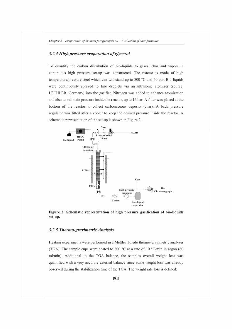
Chapter 3 – Evaporation of biomass fast pyrolysis oil – Evaluation of char formation
[81]
3.2.4 High pressure evaporation of glycerol
To quantify the carbon distribution of bio-liquids to gases, char and vapors, a
continuous high pressure set-up was constructed. The reactor is made of high
temperature/pressure steel which can withstand up to 800 °C and 40 bar. Bio-liquids
were continuously sprayed to fine droplets via an ultrasonic atomizer (source:
LECHLER, Germany) into the gasifier. Nitrogen was added to enhance atomization
and also to maintain pressure inside the reactor, up to 16 bar. A filter was placed at the
bottom of the reactor to collect carbonaceous deposits (char). A back pressure
regulator was fitted after a cooler to keep the desired pressure inside the reactor. A
schematic representation of the set-up is shown in Figure 2.
Figure 2: Schematic representation of high pressure gasification of bio-liquids set-up.
3.2.5 Thermo-gravimetric Analysis
Heating experiments were performed in a Mettler Toledo thermo-gravimetric analyzer
(TGA). The sample cups were heated to 800 °C at a rate of 10 °C/min in argon (60
ml/min). Additional to the TGA balance, the samples overall weight loss was
quantified with a very accurate external balance since some weight loss was already
observed during the stabilization time of the TGA. The weight rate loss is defined:
Furnace
Filter
HPLCPump
F
Reactor
UltrasonicAtomizer
N2/AirPressure relief
20 bar
CoolerGas liquidseparator
Vent
P1
P2Back pressure
regulator
Bio-liquid
Vent
GasChromotograph

Chapter 3 – Evaporation of biomass fast pyrolysis oil – Evaluation of char formation
[82]
)()(
10
1
ttmmm
dtdX
rwt (1/s)
Where τ and τ+1 are logged times, T (°C) the temperature of the sample cup and m0
(mg) the initial amount of pyrolysis oil as weighted with the external balance. The
overall char weight conversions (X) and carbon to char conversions were calculated
using the external balance.
3.2.6 Data analysis
The integral carbon balance was made based on the nitrogen fed to the reactor as an
internal standard. This procedure is reported in detail in Chapter 2. The molar steam-
to-carbon ratio (S/C), residence time and dilution factor were calculated as follows:
3.3 Results and discussions
3.3.1 Thermo-gravimetric analysis
Figure 3 shows the TGA curve of evaporating pyrolysis oil at 10 °C/min up to 800 °C.
This curve is typical and in good agreement with the evaporation curves earlier
reported.1 At temperatures below 200 °C water and light components evaporate. Van
Rossum et al. [6] showed that above 100 °C besides evaporation also polymerization
reactions are already taking place in the liquid phase. In the range of 100 to 350 °C
liquids-bioin carbon of molesliquids-bio in thecontent water system the toadded steam of moles
ratio S/C
[s] liquids)-bio from produced gases(Nitrogen velocity Gas
lengthReactor timeResidence
flowNitrogen liquids-bio from produced Gasesliquids-bio from produced Gases
factor Dilution

Chapter 3 – Evaporation of biomass fast pyrolysis oil – Evaluation of char formation
[83]
polymerization and cracking reactions proceed next to evaporation. Solvent solubility
tests of the liquid at different temperatures6 showed that the first actual char (THF
insoluble material) is formed around 200 °C and only char remains above 500 °C. The
low, but measurable, weight loss rate above 500 °C (see Figure 3) shows that the char
produced is devolatizing / degassing slowly.
Table 2 lists the measured char yields of the feedstocks evaporated in the TGA (10
°C/min up to 800 °C). It has been found that the whole pyrolysis oil containing 23.9
wt% water gives 28 % char (on carbon basis). Pyrolytic lignin clearly produces higher
amount of char (54%). Evaporation of a glucose solution of 40 wt% in the TGA
results in 28 wt% char. Remarkably, aqueous fraction i (48.5 wt% water) also yield a
high amount of char (24%). These results indicate that not a single lumped component
class of pyrolysis oil (e.g. pyrolytic lignin) can be identified that is solely or
predominantly responsible for char formation. Van Rossum et al. [6] has found that in
the range of 1 – 100 °C/min the amount of char produced is not influenced
significantly by the heating rate. This suggests that by performing TGA tests at such
low heating rates, quantification of the maximum amount of char that can be produced
during evaporation is possible. The components in the oil leading possibly to char are
in this case not identified but are only quantified as fraction of the feedstock. In a
practical model (mechanism) for the evaporation of pyrolysis oil, the fraction of the
feed susceptible to char formation can then be assumed to be the TGA char yield. This
fraction can then be converted to char, gas and vapor in the model.
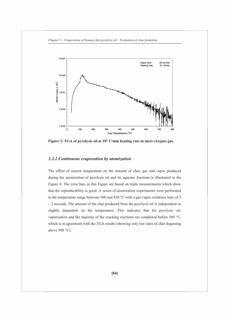
Chapter 3 – Evaporation of biomass fast pyrolysis oil – Evaluation of char formation
[84]
Figure 3: TGA of pyrolysis oil at 10° C/min heating rate in inert (Argon) gas.
3.3.2 Continuous evaporation by atomization
The effect of reactor temperature on the amount of char, gas and vapor produced
during the atomization of pyrolysis oil and its aqueous fractions is illustrated in the
Figure 4. The error bars in this Figure are based on triple measurements which show
that the reproducibility is good. A series of atomization experiments were performed
in the temperature range between 500 and 850 °C with a gas/vapor residence time of 2
– 3 seconds. The amount of the char produced from the pyrolysis oil is independent or
slightly dependent on the temperature. This indicates that for pyrolysis oil,
vaporization and the majority of the cracking reactions are completed before 500 °C,
which is in agreement with the TGA results (showing only low rates of char degassing
above 500 °C).
1.E-03
1.E-02
1.E-01
1.E+00
1.E+01
0 100 200 300 400 500 600 700 800
Cup Temperature (°C)
dX
/dt
(1/s
ec x
103 )
Argon flow : 60 mL/minHeating rate: 10 °C/min

Chapter 3 – Evaporation of biomass fast pyrolysis oil – Evaluation of char formation
[85]
Table 2: Char productions using TGA of pyrolysis oil and related fractions/compounds. The amounts are given both on weight and carbon to char basis. The sample was heated to 800 °C with a heating rate of 10 °C/min and an Argon flow of 60 ml/min
Feedstocks Char wt % Yc (%)
Pyrolysis Oil 15 28
Aqueous fraction 7 24
Heavy fraction 21 33
Glucose solution 7 28
Pyrolytic lignin 43 54
The char yield from pyrolysis oil obtained with the atomizer is significantly lower
compared to TGA results (8-9 vs. 28 % char, carbon basis). This dependence on the
heating rate (1-100 °C/min for TGA vs. 1x10⁶-8x10⁶ °C/min for the 117 μm droplets)
cannot be predicted by the proposed models for pyrolysis oil evaporation that are
based on fixed char yields [1, 2] The char formation model proposed by Baert et al.
[10] for heavy fuel oil, which basically consists of two parallel reactions of a certain
fraction of the feed to char and vapors/gases, is able to predict this trend. To predict
the trend of decreasing char formation for higher heating rates the activation energy of
gas/vapor production reaction needs to be the highest; Baert10 used 100 kJ/mol for
polymerization and 270 kJ/mol for the reaction to gas/vapor. Their model predicted
that while increasing the heating rate from 6x10⁴ to 6x10⁷ °C/min the char production
is decreasing from 12 to 0.5 wt% (on feed basis) for heavy fuel oil.
It is important to notice that the heating rate of pyrolysis oil evaporation by
atomization is a function of the temperature of the droplet. When injected to the hot
environment the droplet is heated to 100-120 °C at which temperature it stays for a
certain time (due to water and lights evaporation) where after it is heated again with a
reasonably fixed rate. In this latter part of the heating trajectory (above 120 °C) char
precursors and char are formed and consequently this heating rate is used in this study
for comparison. The char yield of the aqueous fractions is lower than the char yield of
pyrolysis oil. Probably the aqueous fractions produce less char because of their low or

Chapter 3 – Evaporation of biomass fast pyrolysis oil – Evaluation of char formation
[86]
zero content of pyrolytic lignin, which produces over 50% char in TGA (See Table 2).
This may also explain why at 500 °C aqueous fractions ii, iii and iv produce less char
than fractions i and v (i and v still contain some heavies, see Figure 1). The char
produced from aqueous fractions decreases from 500 to 650/700 °C and hereafter
remains constant. This char yield decrease may be ascribed to faster gasification
reactions of char and/or char precursors (relative to polymerization) of the aqueous
fraction of pyrolysis oil compared to the whole oil.
Our results show that when using the aqueous fraction of pyrolysis for steam
reforming at temperatures around 850 °C, as described by Czernik and co-workers
[7], only a limited amount of char is produced (1- 2% on carbon basis) in the
atomization stage when producing small droplets of 117 μm. Such low char yields can
most likely be dealt with within the evaporator and/or downstream equipment
especially when a fluidized bed is being used and will only have a minor impact on
the overall efficiency. When the whole oil is used for steam reforming under
otherwise identical conditions, as practiced by Van Rossum et al. [11] considerably
more char is produced (8-9%) which makes the design of the evaporator more
complex. At the moment of writing we are testing a new atomizer that produces
droplets of less than 5 μm in order to investigate if it is possible to further reduce the
char production from the whole pyrolysis oil.
Figures 4B and 4C show that at increasing temperature the gas yield is increasing and
the vapor yield is decreasing which is due to thermal cracking reactions of the vapors.
At 500 °C, 70 to 90 % of the carbon in the oil is recovered as vapors, while at high
temperature (850 °C) the vapor yield is 30 – 40% for pyrolysis oil and only 1- 5% for
the aqueous fractions. The carbon to gas conversion is as low as 10-20% at 500 °C
and increases up to 60-65% at 850 °C for pyrolysis oil, whereas for the aqueous
fractions a carbon to gas conversion of 90-95% is achieved at 850 °C. It is not
possible to ascribe the higher carbon to gas conversion for the aqueous fractions
compared to the whole oil (difference is 30% on carbon basis) only to the difference
in char yield (difference is 6-7%). It is therefore concluded that, overall, the vapors
from the aqueous fractions are easier to crack than vapors from the whole oil.

Chapter 3 – Evaporation of biomass fast pyrolysis oil – Evaluation of char formation
[87]
4A
4B
450 500 550 600 650 700 750 800 850 9000
1
2
3
4
5
6
7
8
9
10
Cha
r yi
eld
Yc (
%)
Reactor Temperature (°C)
450 500 550 600 650 700 750 800 850 9000
10
20
30
40
50
60
70
80
90
100
Gas
Yie
ld, Y
G (%
)
Reactor temperature (°C)
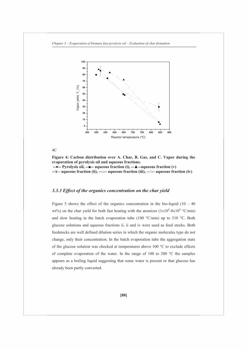
Chapter 3 – Evaporation of biomass fast pyrolysis oil – Evaluation of char formation
[88]
4C
Figure 4: Carbon distribution over A. Char, B. Gas, and C. Vapor during the evaporation of pyrolysis oil and aqueous fractions. --●-- Pyrolysis oil, --■-- aqueous fraction (i), --▲--aqueous fraction (v) --Δ-- aqueous fraction (ii), --□-- aqueous fraction (iii), --○-- aqueous fraction (iv)
3.3.3 Effect of the organics concentration on the char yield
Figure 5 shows the effect of the organics concentration in the bio-liquid (10 – 40
wt%) on the char yield for both fast heating with the atomizer (1x10⁶-8x10⁶ °C/min)
and slow heating in the batch evaporation tube (100 °C/min) up to 510 °C. Both
glucose solutions and aqueous fractions ii, ii and iv were used as feed stocks. Both
feedstocks are well defined dilution series in which the organic molecules type do not
change, only their concentration. In the batch evaporation tube the aggregation state
of the glucose solution was checked at temperatures above 100 °C to exclude effects
of complete evaporation of the water. In the range of 100 to 200 °C the samples
appears as a boiling liquid suggesting that some water is present or that glucose has
already been partly converted.
450 500 550 600 650 700 750 800 850 900
0
10
20
30
40
50
60
70
80
90
100
Vap
or y
ield
, Yv (
%)
Reactor temperature (°C)

Chapter 3 – Evaporation of biomass fast pyrolysis oil – Evaluation of char formation
[89]
Under slow heating conditions the results clearly show that the char yield increases
for higher concentration of organics in the bio-liquids. This result indicates that the
reactions of char precursors to char are of reaction order higher than 1, which would
be expected for polymerization reactions. For glucose solutions such concentration
effect has also been observed under hydrothermal conditions (350 °C, 200 bar) by
Knezevic et al. [12] Using the atomizer, the char yield is lower and the effect of the
concentration is not observed or, if present, falls within the error margins of the
experiments. The absence of a concentration effect may be ascribed to the vigorous
nature of the evaporation under very high heating rates. It is thinkable that with
extremely high heating rates or diluted solutions compounds remain isolated and end
up in the gas/vapor phase before they can fully react in the liquid phase. With this
‘evaporation’ the density of the reactive compounds is lowered significantly (factor
~103) which will result in less polymerization.
Figure 5: Effect of organics on char yield by different heating rates. reactor temperature = 510 ± 10°C , -- ●-- Glucose atomization , --■-- Aqueous fraction atomization , --○-- Glucose (glass tube - 100 °C/min), -- □-- Aqueous fraction (glass tube - 100 °C/min).
0 10 20 30 40 500
5
10
15
20
25
30
35
40
Cha
r yi
eld,
Yc
%
Organics (wt%)
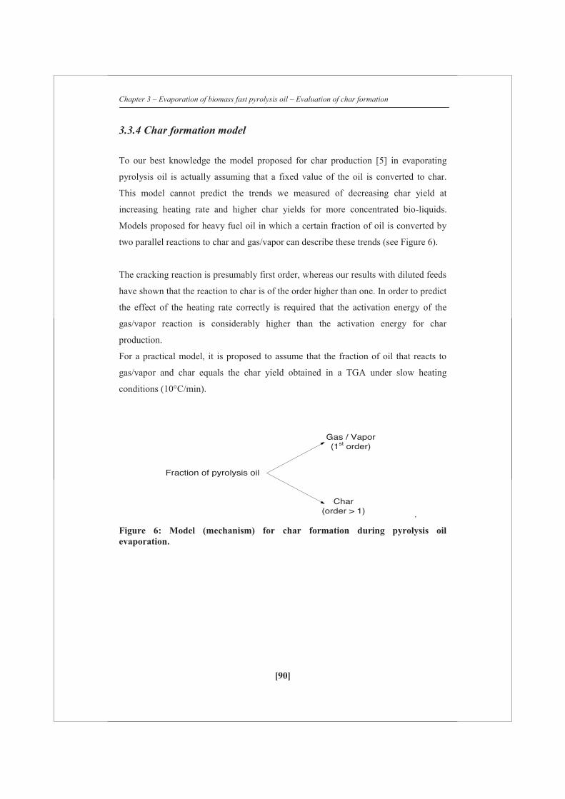
Chapter 3 – Evaporation of biomass fast pyrolysis oil – Evaluation of char formation
[90]
3.3.4 Char formation model
To our best knowledge the model proposed for char production [5] in evaporating
pyrolysis oil is actually assuming that a fixed value of the oil is converted to char.
This model cannot predict the trends we measured of decreasing char yield at
increasing heating rate and higher char yields for more concentrated bio-liquids.
Models proposed for heavy fuel oil in which a certain fraction of oil is converted by
two parallel reactions to char and gas/vapor can describe these trends (see Figure 6).
The cracking reaction is presumably first order, whereas our results with diluted feeds
have shown that the reaction to char is of the order higher than one. In order to predict
the effect of the heating rate correctly is required that the activation energy of the
gas/vapor reaction is considerably higher than the activation energy for char
production.
For a practical model, it is proposed to assume that the fraction of oil that reacts to
gas/vapor and char equals the char yield obtained in a TGA under slow heating
conditions (10°C/min).
.
Figure 6: Model (mechanism) for char formation during pyrolysis oil evaporation.
Fraction of pyrolysis oil
Gas / Vapor(1st order)
Char(order > 1)

Chapter 3 – Evaporation of biomass fast pyrolysis oil – Evaluation of char formation
[91]
3.3.5 Effect of the residence time of gases
The effect of residence time on product distribution at ~750°C without steam addition
during pyrolysis oil gasification is shown in Figure 7a. To decrease the residence time
of gases, additional amount of N2 was added. This means that the product gas is more
diluted with nitrogen. It can be seen in Figure 2 that char formation is almost constant
at 750°C (~7% on carbon basis) with increase in residence time of gases. This is
expected because the initial distribution of carbon in the pyrolysis oil to vapor/gas and
char has already attained in few milliseconds because of high heating rate of droplets.
However, the amount of gases produced increased by increasing the residence time of
the gases/vapors from 0.8 to 2.8 seconds and the amount of unconverted vapors was
decreased showing the thermal cracking of the vapors.
Figure 7: Effect of residence time of gases during gasification of pyrolysis oil, (at T=750°C, S/C=0.4).

Chapter 3 – Evaporation of biomass fast pyrolysis oil – Evaluation of char formation
[92]
3.3.6 Effect of steam over carbon ratio
The effect of steam-to-carbon ratio on the product distribution at ~800°C is shown in
Figure 8. As shown in Figure 8, char formation is slightly decreased from 7.9 to 6.4%
(on carbon basis from S/C of 0.4 to 10). However, by considering the error (±2%) in
the carbon closure, this cannot be considered as a significant effect. Focussing on the
gas and vapor production, it can be seen that more gas is produced when excess steam
is supplied and the vapor production decreases, although the rates of increase and
decrease are smaller at high S/C-ratios (S/C of 5 and above). These results imply that
vapor cracking is slightly enhanced by the addition of steam up.
Figure 8: Carbon distribution during gasification of pyrolysis oil, altering the steam-to-carbon ratio (at 800°C).

Chapter 3 – Evaporation of biomass fast pyrolysis oil – Evaluation of char formation
[93]
3.3.7 Effect of pressure
The effect of pressure from 1 to 16 bar was studied at ~650°C, τ=40 ±10 seconds
using pure glycerol and glycerol with KOH. For pure glycerol the carbon to gas
conversion increased from 64% to ~80% from 1 bar to 6 bar and held constant up to
16 bar. In the whole range char production was not observed. The carbon to gas
conversion at 1 bar cannot be explained. However, at high pressure (from 6 to 16 bar),
the carbon to gas conversion remained at 80±2%. By increasing the pressure (6 bar
and above), all the product gases such as CH4, CO2, CO and H2 are relatively
constant.
For glycerol with KOH, the formation of char is ~3% at all pressures measured. The
results showed that the char formation takes place irrespective of pressure and
temperature (in the temperature range between 450 and 850°C at atomospheric
pressure - see Chapter 4). Also, it was observed that carbon to gas conversion with
KOH was slightly lower than the pure glycerol. These results indicate that KOH has a
definite effect on glycerol even at high pressure.
9A

Chapter 3 – Evaporation of biomass fast pyrolysis oil – Evaluation of char formation
[94]
9B
Figure 9: Product distribution during high pressure gasification of A) pure glycerol at 650 +/-10°C, S/C=1 B) glycerol with 4% by weight KOH at 650 +/-10 °C, S/C=1.
3.4 Conclusions
The char yield of pyrolysis oil evaporation in a hot environment depends strongly on
the heating rate. A char yield of 28% (on carbon basis) is measured under slow
heating conditions in a TGA (10 °C/min to 800 °C) whereas using an atomizer
producing droplets of ca. 117 μm results in 8-9% char in the temperature range of the
environment of 500 to 850 °C. Aqueous fractions of pyrolysis oil and glucose solution
can be atomized (117 μm) yielding only 1 to 2% char for environment temperatures of
650 °C and higher. Next to pyrolysis oil and its aqueous fractions (with different
compositions), pyrolytic lignin and glucose solutions also produced char upon
heating, which shows that not a single lumped components class in pyrolysis oil can
be identified that is predominantly responsible for char formation. Experiments with
low heating rates using aqueous solutions with different concentrations of the same
organics have revealed that the char producing reactions are of order higher than one
(a higher organics concentration results in higher char yields). The measured trends in
Chapter 3 – Evaporation of biomass fast pyrolysis oil – Evaluation of char formation
[95]
char yield can be described by a model in which a certain fraction of oil is converted
by two parallel reactions to char and gas/vapor, with the reaction to char having order
higher than one and the activation energy of gas/vapor production being highest. For a
practical model it is proposed to use the char yield obtained in TGA under slow
heating conditions (say 10 °C/min) to define the fraction of pyrolysis oil that can react
to char, vapor and gas. Under high heating rate conditions of the droplets, the
vapor/gas phase residence time (0.8-2.8 s), steam over carbon ratio (0.4-10) and
pressure (1-16 bar) turned out to have no significant on the char yield.
References
1. C.Branca, C. Di Blasi, Ind. Eng. Chem. Res. (2006), vol 45, 5891-5899
2. W.L.H. Hallet and N.A.Clark, Fuel (2006) vol 85, 532-544
3. M.J.Wornat, B.G.Porter, N.Y.C. Yang Energy Fuels (2002), vol 8, 1131-1142
4. M.Garcia-Pèrez, P.Lappas, P.Hughes, L.Dell, A.Chaala, D.Kretschmer and
C.Roy IFRF Combustion Journal (2006), 200601
5. T.Lederlin, J.E.D.Gauthier, Pyrolysis and Gasification of Biomass and Waste,
Proceedings of an expert meeting (2003), Editor: A.V.Bridgwater, CPL Press,
Berks, U.K. pp 203-214
6. G.van Rossum, B.M.Guell, R.P. Balegedde Ramachandran, K.Seshan,
L.Lefferts, S.R.A. Kersten, W.P.M. van Swaaij AIChE journal (2010), vol 56,
2200-2210
7. A.Oasmaa, K.Sipilä, Y.Solantausta, E.Kuoppala, Energy & Fuels (2005), vol
19, 2556
8. S.Czernik, R.French, C.Feik,E. Chornet, Ind. Eng. Chem. Res. (2002), vol 41,
4209
9. B.Scholze, D.Meier, J. Anal. Pyrolysis (2001) vol 60, 41-54
10. R.S.G.Baert, Combustion Science and technology (1993), vol 90, 125-147
11. G.van Rossum, S.R.A.Kersten, and W.P.M. van Swaaij, Ind. Eng. Chem.
Res(2007), vol 46, 3959-3967
12. D.Knezevic, W.P.M. van Swaaij and S.R.A. Kersten, Ind. Eng. Chem. Res
(2009), vol 48, 4731-4743

[96]

Chapter 4 – Preliminary assessment of synthesis gas production via HSR of methane and glycerol
[97]
Chapter 4
Preliminary assessment of synthesis
gas production via hybrid steam
reforming of methane and glycerol

Chapter 4 – Preliminary assessment of synthesis gas production via HSR of methane and glycerol
[98]
Abstract In this Chapter, hybrid steam reforming (HSR) of desulphurized methane together
with crude glycerol in existing commercial steam reformers to produce synthesis gas
is proposed. The proposed concept consists of a gasifier to produce vapors, gases and
char from crude glycerol, which is coupled with a pre-reformer to further convert the
vapors into gases using steam reforming catalyst. These gases are mixed with
methane and subsequently reformed to synthesis gas (CO+H2) in a primary reformer
using a steam reforming catalyst. In the present work, gasification, steam and hybrid
reforming of glycerol is reported. The total product distribution (gas, vapor and char)
of pure and crude glycerol gasification was quantified at different reaction
temperatures at very high heating rates (atomization: ~106 C/min). With pure and
neutralized crude glycerol, no char formation was observed. However, with crude
glycerol and pure glycerol doped with KOH, a significant amount of char on carbon
basis (~10%) is produced. The results obtained here show that KOH present in
glycerol was responsible for polymerizing higher molecular components formed
during thermal degradation. Steam reforming of pure and neutralized crude glycerol
was studied at different process conditions in the presence of commercial reforming
catalysts. Pure glycerol was easier (in terms of catalyst activity) to reform when
compared to neutralized crude glycerol at high temperature (800 C). The results
from the steam reforming of neutralized crude glycerol show that the loss of catalyst
activity was due to the presence of organic impurities such as FAMEs, di and tri
glycerides. The proposed HSR concept was demonstrated for pure glycerol and crude
glycerol with methane (on C1 basis) in a two-stage fixed bed reformer at 800 ºC using
commercial steam reforming catalyst.
Part of this Chapter has been published as: “Preliminary assessment of synthesis gas
production via hybrid steam reforming of methane and glycerol in Energy & Fuels,
2011, 25 (12), 5755-5766”.

Chapter 4 – Preliminary assessment of synthesis gas production via HSR of methane and glycerol
[99]
4.1 Introduction
Over the past several years, there has been an increasing interest in the use of bio-
diesel as a supplement to the traditional fossil fuels. With the ever-increasing
production of bio-diesel, a surplus of crude glycerol, which is a by-product from
transesterification process, is available for further processing. The crude by-product
stream typically comprises of a mixture of glycerol, methanol, inorganic salts (mainly
catalyst residue), free fatty acids and fatty acid methyl esters in varying quantities.
Purification is required to transform the crude glycerol to usable state for food and
pharmaceutical applications. As a first step in purification, excess methanol is distilled
and re-used for the transesterifcation process. An acid neutralization step is required
to purify crude glycerol further, to convert alkali hydroxide catalyst into its salts (e.g.
chlorides), typically around 5% present in the crude [1]. The combination of high
methanol prices and low crude glycerol prices has made the conversion of crude
glycerol to methanol via steam reforming economically attractive [1]. To take
advantage of the existing natural gas steam reformers, there is a possibility to replace
natural gas by a fraction of crude glycerol on carbon basis. This concept is proposed
here as ‘hybrid steam reforming’ to utilize either a direct crude or purified/neutralized
crude glycerol.
HSR process consists of the following stages: (1) Gasification: controlled atomization
of crude glycerol into small droplets (~100μm) in a gasifier around 500 C. This leads
to the production of vapor, gases and char via thermal decomposition. (2) Steam
reforming: vapor produced from the gasifier can be pre-reformed using a commercial
reforming catalyst. Adhikari et al. [2] reported that a minimum temperature of
~600 C is required to convert glycerol into gases. This step is similar to pre-reforming
of naphtha/natural gas. In the case of naphtha and natural gas, higher hydrocarbons
are partially reformed to produce gases whereas in the case of glycerol, vapors
(oxygenates) are reformed to produce gases. (3) HSR: The product gas obtained from
the pre-reforming step can be mixed with desulphurized methane and reformed in the
primary reformer. Since this is similar to natural gas reforming, a high temperature of
~800 ºC is preferred for this step. The whole concept is summarized in Figure 1A.
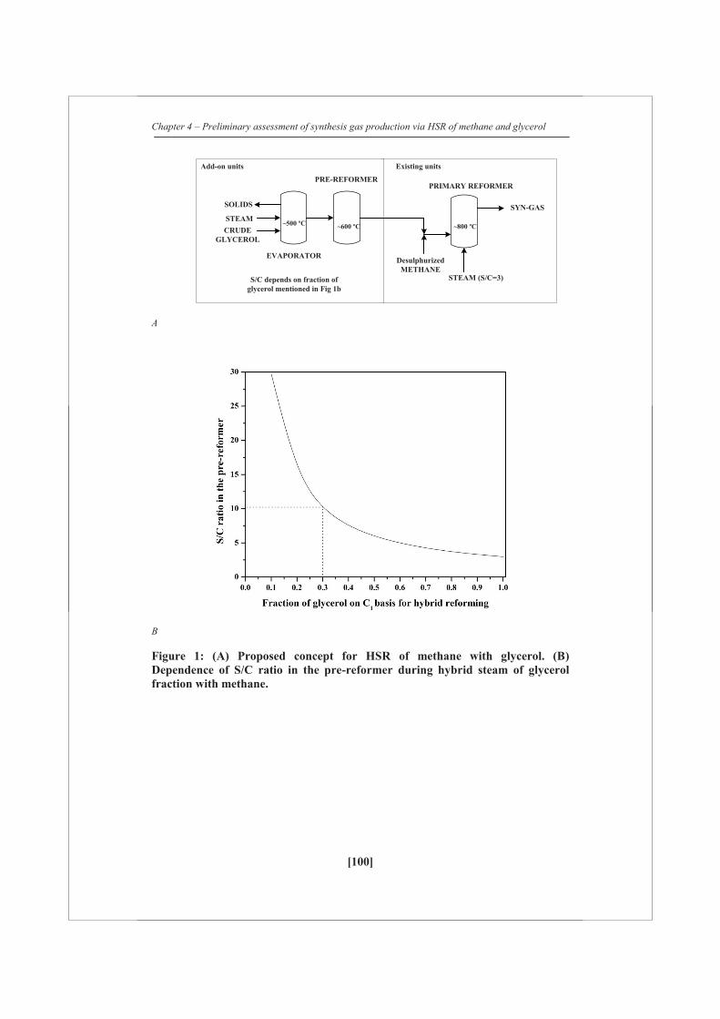
Chapter 4 – Preliminary assessment of synthesis gas production via HSR of methane and glycerol
[100]
A
B
Figure 1: (A) Proposed concept for HSR of methane with glycerol. (B) Dependence of S/C ratio in the pre-reformer during hybrid steam of glycerol fraction with methane.
CRUDEGLYCEROL
EVAPORATOR
PRE-REFORMERPRIMARY REFORMER
SYN-GAS
DesulphurizedMETHANE
STEAM
SOLIDS
STEAM (S/C=3)
Add-on units Existing units
~500 ºC ~600 ºC ~800 ºC
S/C depends on fraction ofglycerol mentioned in Fig 1b
Chapter 4 – Preliminary assessment of synthesis gas production via HSR of methane and glycerol
[101]
Hybrid reforming can be beneficial in many ways:
Steam necessary for the primary reforming (molar S/C~3) can be completely/partly
utilized in the pre-reforming step (S/C ~ 5-15, depends on glycerol fraction). Here,
S/C is defined as the ratio of the total moles of water added including the water
content of the glycerol, over the moles of carbon present in the glycerol. Therefore, no
additional steam is required for the process. Figure 1b summarizes the S/C required
for a specific fraction of crude glycerol (by wt% on C1 basis) available for HSR. For
instance, to process 30 wt% of glycerol on carbon basis, a S/C upto 10 is necessary in
the pre-reforming step, which makes S/C = 3 in the primary reformer with 70 wt% of
remaining carbon from methane. Adding steam to the glycerol reforming step may
enhance char and coke gasification. Here, char is defined as the thermal degradation
product from the feedstock and coke is defined as the carbon deposited on the
catalyst.
A great deal of research has been carried out at the laboratory scale to obtain H2/
synthesis gas from bio-liquids such as glycerol, fast pyrolysis oil or its fractions via
steam reforming [3,4,5,6] or partial oxidation [7] or super-critical gasification
[3,8,9,10] Several supports such as Al2O3, TiO2, SiO2, CeO2, MgO on Nickel and
alumina support modifiers such as ZrO2, CeO2, La2O3, MgO have been screened
based on H2 production via steam reforming of pure glycerol [2,11] and model
compounds [12,13,14]. Adhikari et al. [2] reported that Ni/CeO2 catalyst has a better
activity with >99% glycerol conversion at 600 C and S/C =12, whereas Ni/Al2O3
catalyst has higher activity at 900 C and S/C = 9. Czernik et al. [15] produced H2-rich
gas via steam reforming crude glycerin using a commercial steam reforming catalyst
at 800 C and S/C = 2.6. However, a gradual increase in the methane was reported. To
the best of our knowledge, the quantitative information about the effect of alkali
hydroxides or its salts and the organic impurities present in the crude glycerol during
gasification and steam reforming is not available in the open literature.
In this article, various stages of HSR were tested. To clarify the effect of alkali
hydroxide (e.g KOH), gasification of crude glycerol, pure glycerol with and without
KOH was studied in TGA at a heating rate of 5 C/min up to 600 C. Visual
observation tests during the gasification were performed to study the effect of KOH,
Chapter 4 – Preliminary assessment of synthesis gas production via HSR of methane and glycerol
[102]
which is present in the untreated crude glycerol and alkali salts (e.g. KCl), which is
present in the neutralized crude glycerol. Followed by that, gasification of crude
glycerol, glycerol with and without KOH is studied by atomizing it into fine droplets
in the temperature range between 400 and 800 C. The product distribution from the
feedstocks to gas, vapor and char has been studied in detail. Finally, the behavior of
K, Mg promoted naphtha reforming catalyst and unpromoted Ni/Al2O3 natural gas
reforming catalyst was studied based on their surface area, pore volume and Nickel
particle size using neutralized crude glycerol at steam reforming conditions. Several
implications of the overall concept are discussed at the end of the article.
4.2 Experimental
4.2.1 Materials
Pure glycerol (Sigma Aldrich), in-house produced crude glycerol 1 obtained from
transesterification of waste cooking oil, crude glycerol 2 (neutralized feedstock,
Source: BioMCN, Delfzijl, The Netherlands) and pure glycerol doped with KOH,
NaOH and KCl (NaOH, KOH source: Merck, KCl source: Sigma Aldrich) were used
in this study. Elemental compositions were analyzed with an EA 1108 (Fisons
Intruments). The water content of the glycerol was determined by Karl Fishcer
titration (titrant: Hydranal composite 5, Metrohm 787 KF Titrino). The elemental
composition and the water content of the feedstocks as received are presented in Table
1A. The composition of crude glycerol 2 is given in Table 1B. Organic concentration
of 62.5% by weight (rest: water) was prepared to facilitate atomization for continuous
gasification experiments. Prior to the addition of water, methanol was removed from
the crude glycerol 1 via vacuum distillation. The molecular mass distribution of
condensed liquid obtained after the vaporization of glycerol was measured using a Gel
Permeation Chromatograph (GPC, Agilent Technologies, 1200 series RID detector,
eluent: 1 ml/min). The solvent used was di-methyl sulfoxide (DMSO; 10 mg
sample/ml DMSO). The columns used were 3 PLgel3 μm MIXED-E placed in series.

Chapter 4 – Preliminary assessment of synthesis gas production via HSR of methane and glycerol
[103]
The RID signal is calibrated with polystyrene standards (MW) 162-30000. Two
Ni/Al2O3-based commercial steam reforming catalysts (catalyst A: NiO ~23%,
promoted using MgO, K2O; Catalyst B: NiO~18%, here termed as unpromoted) were
used in this study. The catalyst pellets were crushed and sieved between 3 and 5 mm
particle sizes. The catalyst was mixed with quartz particles of similar particle size
range to have a reasonable bed height of ~100 mm.
Table 1A: Elemental analyses (wet) and water content determination of different glycerol feedstocks (as received). The rest is mainly oxygen also with other elements such as sulfur and nitrogen
Feedstock C (wt%) H (wt%) Rest (wt%) Water (wt%)
Pure glycerol 39.1 8.7 52.2 0
Crude glycerol 1 45.5 7.7 46.8 0
Crude glycerol 2 31.9 8.6 59.5 11
Ash content of crude glycerol 1 is 6.6% (consists of K2O and trace amounts of CaO and Fe2O3) and
crude glycerol 2 is ~4.3% (consists of Na2O)
Table 1B: Composition of crude glycerol 2
Component Weight %
Glycerol 83
Water 11
Organics* 1.78
Inorganics^ 4.4
* Consists of diglycerides (0.78%), triglycerides (0.5%), FAME (0.3%), Free fatty acids (0.2%),
Methanol (0.01%), trace amounts of citric acid and acetic acid.^ Consists of 4.3% sodium chloride,
0.09% Magnesium sulphate and 0.01% of Calcium sulphate

Chapter 4 – Preliminary assessment of synthesis gas production via HSR of methane and glycerol
[104]
4.2.2 Thermo-gravimetric analysis
Thermo-gravimetric analysis (TGA) was carried out in aluminum cups using
NETZSCH STA 449 F3 instrument. The heating rate for all the samples was 5 C/min
from 25 C to a maximum temperature of 600 C using N2 flow of 20 ml/min together
with a protective flow of 40 ml/min. Initial mass of the samples was determined using
an external weighing balance.
The mass rate loss is defined as:
(1/ºC)
where τ and τ+1 are logged times, T (°C) the temperature of the sample cup and m0
(mg) the initial amount of glycerol as weighed with the external balance.
4.2.3 Batch wise gasification
A fixed amount of glycerol solution (2 g) was added to the bottom of a glass tube (Ø
10 mm). The glass tube was placed inside an electrically heated oven and the
temperatures were measured in the solution itself. A heating rate of ~50 °C/min was
applied to the oven. A small nitrogen flow was placed just above the glycerol to avoid
direct contact with air and to remove the vapors, which were released during
gasification. Snapshots were taken during the gasification tests. A brief description of
the procedure was given by Van Rossum et al. [16].
4.2.4 Gasification of glycerol via atomization
To quantify the distribution of glycerol during gasification (atomization) over the gas,
vapor and char, prior to the reforming step and to measure individual gas yields, a
dedicated continuous gasification set-up was constructed. About 1.7 ml/min of
glycerol was sprayed onto an empty electrically heated stainless steel tube (Ø 40 mm,
length 400 mm) using an externally cooled atomizer that produced droplets of ca. 100
μm. A detailed description of the set-up was given by Ramachandran et al. [17]
)()(
10
1
TTmmm
dTdX
rwt

Chapter 4 – Preliminary assessment of synthesis gas production via HSR of methane and glycerol
[105]
4.2.5 Steam and hybrid steam reforming – experimental set-up
A schematic overview of the hybrid reforming set-up is shown in Figure 2. The set-up
consists of three stages: gasification of glycerol, followed by catalytic pre-reforming
of vapors and catalytic reforming of methane together with the gas/vapor produced
from the pre-reforming. All the equipment components were made of stainless steel
(type:R543). The set-up was operated at near atmospheric pressure.
Gasification section:
The gasifier has an internal diameter of 40 mm and a height of 350 mm. It consists of
an ultrasonic atomizer that sprays droplets of ~100 m with a liquid flow rate ranging
from 0.2 to 0.4 ml/min, using a HPLC pump (Instrument Solutions). Nitrogen stream
(flow rate: 0.2 Nl/min) was used to facilitate atomization. The atomizer was fitted in a
copper ring in which water was circulated to keep the temperature below 70ºC. This is
to protect the piezo-electric parts of the atomizer from thermal damage. A pre-heater
(temperature 450ºC) was attached to the top of the gasifier to supply additional
nitrogen (flow rate: 0.4 Nl/min) and steam required for the reaction. This added
stream kept the top of the gasifier at ~400ºC to minimize vapor condensation at the
upper part of the gasifier. A filter was placed at the bottom of the gasifier to collect
the solids. Temperatures were measured at the top, middle and bottom section of the
gasifer. The reported gasification temperature was the average temperature of the
middle and the bottom section of the gasifier.
Pre-reforming section:
Beneath the evaporator, the pre-reformer (40 mm internal diameter and 150 mm
height) was placed, where the gas/vapor mixture from the gasifier is catalytically
converted using a commercial steam reforming catalyst. The catalyst was placed in an
inconel distribution plate at the bottom of the pre-reformer. The temperature of the
pre-reforming section was kept at ~600 C and measured at the middle. Methane was
supplied at the exit of the pre-reformer for HSR experiments.

Chapter 4 – Preliminary assessment of synthesis gas production via HSR of methane and glycerol
[106]
Primary reforming section:
The primary reformer (35 mm internal diameter and 300 mm height) was fitted with
an inconel distribution plate at the middle of the reactor. The bed consists of a mixture
of quartz and catalyst particles (3:1, quartz: catalyst), which was placed over the plate
with a bed height of ~100 mm. Both the pre-reforming and primary reforming catalyst
beds were fixed. The catalyst bed and the exit gas temperatures were ~800ºC
respectively. Both the pre-reforming and primary reforming catalyst were reduced in-
situ with hydrogen (0.2 Nl/min) diluted with nitrogen (0.4 Nl/min) at 800ºC for ~8 h
before each experiment. Temperatures of the primary reformer were measured at the
bottom (product gas from pre-reformer) and also at the middle of the catalyst bed,
which was the reported temperature.
For hybrid reforming experiments, the pre-reformer was used together with the
primary reformer, whereas for “stand-alone” low temperature reforming of glycerol
(LTR, single catalyst bed) and steam reforming or high temperature reforming of
methane or glycerol (HTR, single catalyst bed), the catalyst was placed in the primary
reformer. A representation of the experimental set-up configuration is shown in
Figure 2B & C. Performance of catalysts A and B were screened based on
configuration, as shown in Figure 2B. Catalyst A was used as both pre-reforming and
primary reforming catalyst for HSR experiments. The products from the reformer
were immediately cooled after the cyclone to collect the condensables. A micro-GC
(Varian CP-4900; 10 m mol sieve 5A Ar, 10 m mol sieve 5A He, 10 m PPQ He, 8 m
Sil-5CB He) was used to detect H2, O2, N2, CH4, CO, CO2, C2H4, C2H6, C3H6 and
C3H8. The integral carbon balance and gas production for both the gasification and
catalytic reforming experiments were made based on nitrogen as an internal standard,
which was fed to the atomizer and pre-heater. The gas production from the primary
reformer is reported as Nm3 of H2 or CH4 or CO or CO2 per kilogram of the dry
feedstock.
The catalysts were regenerated using 200 ml/min of air diluted with 100 ml/min of
nitrogen to estimate the amount of carbon deposited (coke) on the catalyst. The
carbon to gas conversion or fraction of carbon converted to gases was calculated at
the steady-state operation that excludes the start-up profile. Gas hourly space velocity
Chapter 4 – Preliminary assessment of synthesis gas production via HSR of methane and glycerol
[107]
on C1 basis is defined as the volume of C1 equivalent species in the feed at the STP
(standard temperature and pressure) per unit volume of the catalyst. C1 equivalent is
used to compare feed stocks containing different number of carbon atoms per
molecule. The carbon closure of experimental set-up was found to be adequate (i) 100
± 3 % using methane and steam at 795 ºC, S/C =3, (ii) 99±3 % using pure glycerol at
805 ºC, S/C =3. There is a slight degree of fluctuation in the gas production due to
glycerol, steam and nitrogen flows.
4.2.6 Catalyst characterization
Commercial steam reforming catalysts (promoted and unpromoted) were
characterized for their surface area, pore volume and active metal dispersion before
and after the steam reforming of crude glycerol 2. Specific surface area measurements
were carried out by the BET method (Micromeritics Tristar). H2 chemisorption
(Chemisorb 2750, Micromeritics) measurements were carried out to determine Ni
dispersion, Ni particle size and the metallic surface area. Prior to the measurement,
the catalyst was reduced using temperature programmed reduction equipped with a
thermal conductivity detector. After reduction, the sample was heated to 800 C at a
rate of 5 C/min in a 5% H2/Ar flow (30ml/min).

Cha
pter
4 –
Pre
limin
ary
asse
ssm
ent o
f syn
thes
is g
as p
rodu
ctio
n vi
a H
SR o
f met
hane
and
gly
cero
l
[108
]
2A
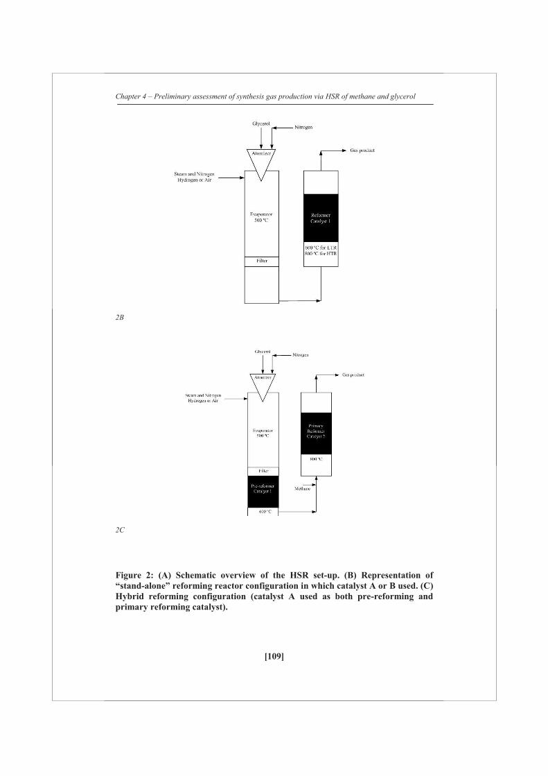
Chapter 4 – Preliminary assessment of synthesis gas production via HSR of methane and glycerol
[109]
2B
2C
Figure 2: (A) Schematic overview of the HSR set-up. (B) Representation of “stand-alone” reforming reactor configuration in which catalyst A or B used. (C) Hybrid reforming configuration (catalyst A used as both pre-reforming and primary reforming catalyst).
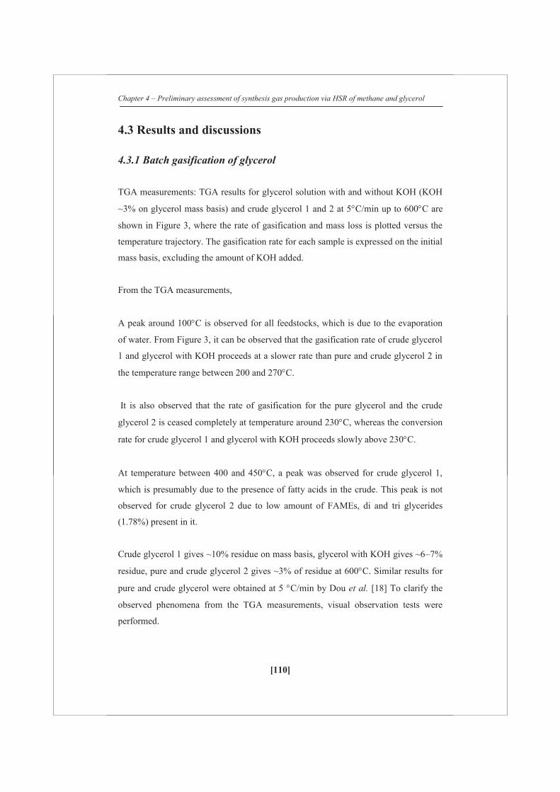
Chapter 4 – Preliminary assessment of synthesis gas production via HSR of methane and glycerol
[110]
4.3 Results and discussions
4.3.1 Batch gasification of glycerol
TGA measurements: TGA results for glycerol solution with and without KOH (KOH
~3% on glycerol mass basis) and crude glycerol 1 and 2 at 5 C/min up to 600 C are
shown in Figure 3, where the rate of gasification and mass loss is plotted versus the
temperature trajectory. The gasification rate for each sample is expressed on the initial
mass basis, excluding the amount of KOH added.
From the TGA measurements,
A peak around 100 C is observed for all feedstocks, which is due to the evaporation
of water. From Figure 3, it can be observed that the gasification rate of crude glycerol
1 and glycerol with KOH proceeds at a slower rate than pure and crude glycerol 2 in
the temperature range between 200 and 270 C.
It is also observed that the rate of gasification for the pure glycerol and the crude
glycerol 2 is ceased completely at temperature around 230 C, whereas the conversion
rate for crude glycerol 1 and glycerol with KOH proceeds slowly above 230 C.
At temperature between 400 and 450 C, a peak was observed for crude glycerol 1,
which is presumably due to the presence of fatty acids in the crude. This peak is not
observed for crude glycerol 2 due to low amount of FAMEs, di and tri glycerides
(1.78%) present in it.
Crude glycerol 1 gives ~10% residue on mass basis, glycerol with KOH gives ~6–7%
residue, pure and crude glycerol 2 gives ~3% of residue at 600 C. Similar results for
pure and crude glycerol were obtained at 5 C/min by Dou et al. [18] To clarify the
observed phenomena from the TGA measurements, visual observation tests were
performed.

Chapter 4 – Preliminary assessment of synthesis gas production via HSR of methane and glycerol
[111]
Table 2: Char productions from batch gasification of glycerol. The amounts are given both on mass and carbon to char basis. The sample was heated to 400 C with a heating rate of ~50 C/min
Feedstocks Salt % (on
dry basis)
Residue,
wt %
Char yield,
wt%
Pure glycerol 0 0.85 No soild residue
Pure glycerol with KOH 0.90 6.10 9.6
Pure glycerol with NaOH 0.94 7.51 11.1
Pure glycerol with KCl 1.22 3.83 0
Glycerol (62.5%) 2.91 4.81 10.9
Crude glycerol 1 n.m 10.2 15.9
Crude glycerol 2 n.m 4.8 0
n.m not measured
Visual study in batch tubes: Figure 4 shows the snapshots taken during the
gasification of glycerol with and without K,NaOH, KCl, crude glycerol 1 and 2. The
glass tubes were heated at a heating rate of ~50 C/min upto 400 C. Figure 4a shows
that the pure glycerol was almost completely evaporated above the boiling point
(290 C), leaving no solid residue in the glass tube. Pure glycerol with 1% KOH
polymerized above ~350 C, which resulted in ~10% char on carbon basis. This is
illustrated in Figure 4b. To crosscheck the effect of KOH, 1% NaOH was added to
pure glycerol. Similar effect as KOH was observed for NaOH (not shown in Figure
4). However, KCl did not polymerize pure glycerol above 350 C. Figure 4 C&D
illustrates the gasification of crude glycerols. The visual study suggests that crude
glycerol 1 has similar effect on polymerization, as glycerol with KOH and crude
glycerol 2 showed similar behavior as glycerol with KCl. Table 2 summarizes the
char yield on carbon basis. It has been visually observed that at the boiling point
(290 C), the solution behaves like a boiling liquid and increase in temperature
resulted in polymerization in the liquid phase. The visual tests indicate that the
formation of char via polymerization is due to the presence of hydroxides and not
because of its salt present in the pure glycerol or crude glycerol 2. GPC analysis of

Chapter 4 – Preliminary assessment of synthesis gas production via HSR of methane and glycerol
[112]
liquids obtained after the vaporization of glycerol with and without KOH, crude
glycerol 1 and 2 was performed to confirm the causes of polymerization.
Figure 3: TGA of crude glycerol, pure glycerol with and without KOH at 5 °C/min heating rate in inert N2 gas.
4A

Chapter 4 – Preliminary assessment of synthesis gas production via HSR of methane and glycerol
[113]
4B
4C
4D
Figure 4: Snapshots of batch tubes during gasification of (a) Glycerol; (b) glycerol with KOH; (c) crude glycerol 1; (d) crude glycerol 2.
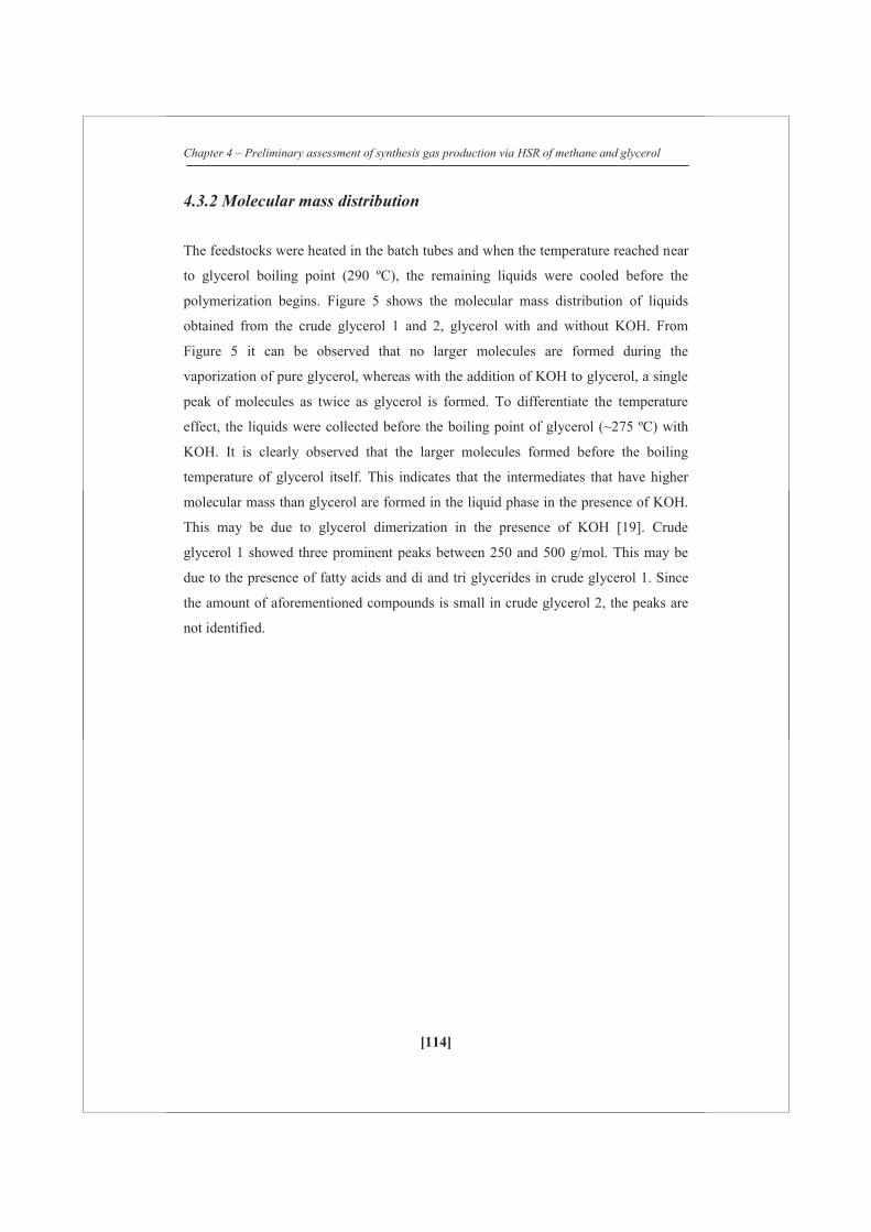
Chapter 4 – Preliminary assessment of synthesis gas production via HSR of methane and glycerol
[114]
4.3.2 Molecular mass distribution
The feedstocks were heated in the batch tubes and when the temperature reached near
to glycerol boiling point (290 ºC), the remaining liquids were cooled before the
polymerization begins. Figure 5 shows the molecular mass distribution of liquids
obtained from the crude glycerol 1 and 2, glycerol with and without KOH. From
Figure 5 it can be observed that no larger molecules are formed during the
vaporization of pure glycerol, whereas with the addition of KOH to glycerol, a single
peak of molecules as twice as glycerol is formed. To differentiate the temperature
effect, the liquids were collected before the boiling point of glycerol (~275 ºC) with
KOH. It is clearly observed that the larger molecules formed before the boiling
temperature of glycerol itself. This indicates that the intermediates that have higher
molecular mass than glycerol are formed in the liquid phase in the presence of KOH.
This may be due to glycerol dimerization in the presence of KOH [19]. Crude
glycerol 1 showed three prominent peaks between 250 and 500 g/mol. This may be
due to the presence of fatty acids and di and tri glycerides in crude glycerol 1. Since
the amount of aforementioned compounds is small in crude glycerol 2, the peaks are
not identified.

Chapter 4 – Preliminary assessment of synthesis gas production via HSR of methane and glycerol
[115]
Figure 5: Molecular mass distribution of liquid products obtained after gasification from different glycerol feedstocks.
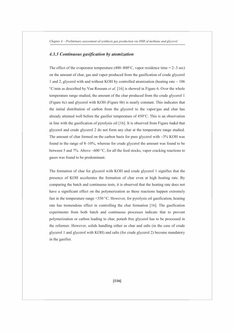
Chapter 4 – Preliminary assessment of synthesis gas production via HSR of methane and glycerol
[116]
4.3.3 Continuous gasification by atomization
The effect of the evaporator temperature (400–800 C, vapor residence time = 2–3 sec)
on the amount of char, gas and vapor produced from the gasification of crude glycerol
1 and 2, glycerol with and without KOH by controlled atomization (heating rate ~ 106
C/min as described by Van Rossum et al. [16] is showed in Figure 6. Over the whole
temperature range studied, the amount of the char produced from the crude glycerol 1
(Figure 6c) and glycerol with KOH (Figure 6b) is nearly constant. This indicates that
the initial distribution of carbon from the glycerol to the vapor/gas and char has
already attained well before the gasifier temperature of 450 C. This is an observation
in line with the gasification of pyrolysis oil [16]. It is observed from Figure 6a&d that
glycerol and crude glycerol 2 do not form any char at the temperature range studied.
The amount of char formed on the carbon basis for pure glycerol with ~3% KOH was
found in the range of 8–10%, whereas for crude glycerol the amount was found to be
between 5 and 7%. Above ~600 C, for all the feed stocks, vapor cracking reactions to
gases was found to be predominant.
The formation of char for glycerol with KOH and crude glycerol 1 signifies that the
presence of KOH accelerates the formation of char even at high heating rate. By
comparing the batch and continuous tests, it is observed that the heating rate does not
have a significant effect on the polymerization as these reactions happen extremely
fast in the temperature range <350 C. However, for pyrolysis oil gasification, heating
rate has tremendous effect in controlling the char formation [16]. The gasification
experiments from both batch and continuous processes indicate that to prevent
polymerization or carbon leading to char, potash free glycerol has to be processed in
the reformer. However, solids handling either as char and salts (in the case of crude
glycerol 1 and glycerol with KOH) and salts (for crude glycerol 2) become mandatory
in the gasifier.
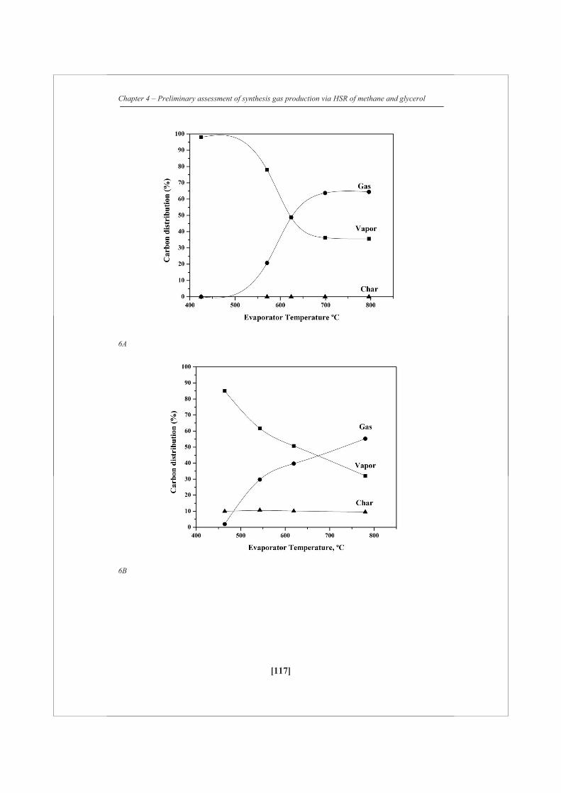
Chapter 4 – Preliminary assessment of synthesis gas production via HSR of methane and glycerol
[117]
6A
6B

Chapter 4 – Preliminary assessment of synthesis gas production via HSR of methane and glycerol
[118]
6C
6D
Figure 6: Carbon distribution over the gas, vapor and char during the gasification of glycerol (A) Pure glycerol (B) glycerol with KOH (C) crude glycerol 1 (D) crude glycerol 2.
Chapter 4 – Preliminary assessment of synthesis gas production via HSR of methane and glycerol
[119]
4.3.4 Pre-reforming and steam reforming of pure glycerol using catalyst A
To evaluate the process conditions of steam reforming, pure glycerol was reformed at
LTR and HTR conditions. Figure 7 shows the gas production (Nm3/kg dry glycerol)
obtained at two different reaction conditions using catalyst A: (A) LTR at S/C=3 and
(B) HTR at S/C = 3. The results are summarized in Table 3. In both the cases, the
carbon recovery to gases was ~100%. In the first 7 h, pre-reforming of glycerol (LTR
(A), 588 C, S/C =3) was performed. The gas production was constant and carbon to
gas conversion was ~103%. During the next 3 h, temperature was increased to
~788 C and S/C was kept constant. In both the cases, the gas production was close to
the equilibrium values, as shown in Table 3. At high temperature reforming
conditions (Case B), almost no methane and C2-3 were observed, whereas at low
temperature conditions, a considerable amount of methane and low amounts of C2-3
were observed in the product gas.
LTR was carried out over a long duration run of 25 h under similar conditions (T =
590°C, S/C ~ 3.5, GC1HSV = 543 h-1) in order to investigate the performance of
catalyst A. Figure 8 shows the effect of time on-stream on the gas production. For the
first 10 h, H2, CO and CO2 gas productions were constant. For the next 5 h, slight
decrease in gas production was observed. There is a drop in the initial activity of the
catalyst. Initially, the average carbon to gas conversion was ~100%, which decreased
to ~90% at the end of the run. Carbon deposited on the catalyst was estimated to be
0.024 g/g of catalyst. The gas productions from the catalytic reforming and
gasification of pure glycerol are given in Table 3. Selectivity (moles of methane/total
moles of product gases) towards methane for LTR and gasification was found to be
~12%. This indicates that at LTR, hydrocarbons produced from the gasification of
glycerol are not reformed as it is limited by thermodynamics.
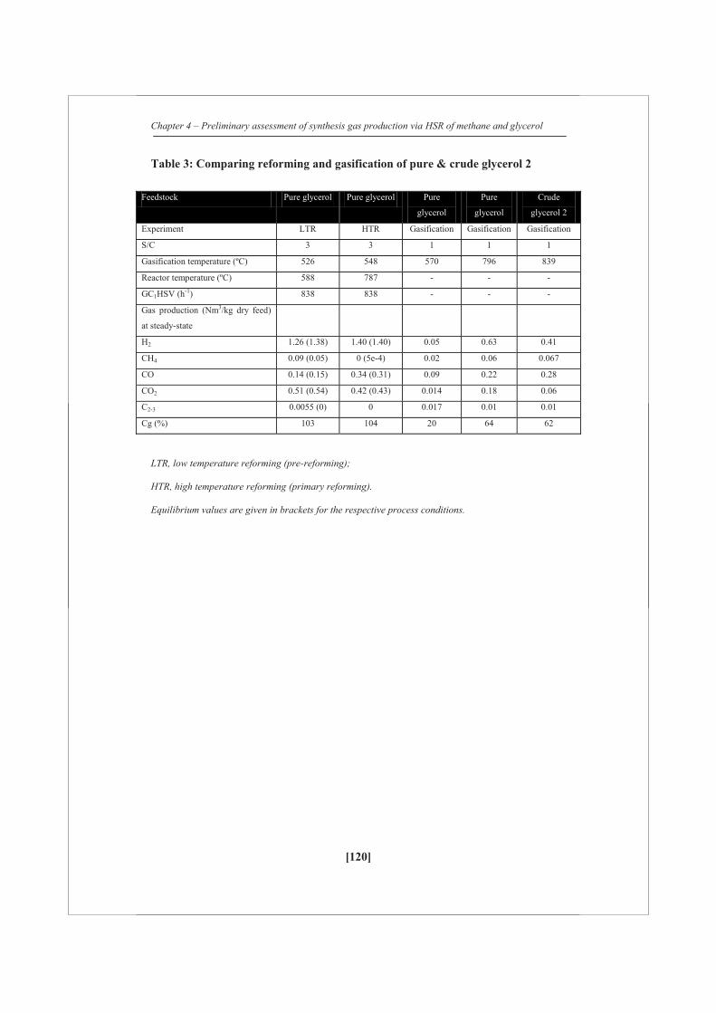
Chapter 4 – Preliminary assessment of synthesis gas production via HSR of methane and glycerol
[120]
Table 3: Comparing reforming and gasification of pure & crude glycerol 2
Feedstock Pure glycerol Pure glycerol Pure
glycerol
Pure
glycerol
Crude
glycerol 2
Experiment LTR HTR Gasification Gasification Gasification
S/C 3 3 1 1 1
Gasification temperature (ºC) 526 548 570 796 839
Reactor temperature (ºC) 588 787 - - -
GC1HSV (h-1) 838 838 - - -
Gas production (Nm3/kg dry feed)
at steady-state
H2 1.26 (1.38) 1.40 (1.40) 0.05 0.63 0.41
CH4 0.09 (0.05) 0 (5e-4) 0.02 0.06 0.067
CO 0.14 (0.15) 0.34 (0.31) 0.09 0.22 0.28
CO2 0.51 (0.54) 0.42 (0.43) 0.014 0.18 0.06
C2-3 0.0055 (0) 0 0.017 0.01 0.01
Cg (%) 103 104 20 64 62
LTR, low temperature reforming (pre-reforming);
HTR, high temperature reforming (primary reforming).
Equilibrium values are given in brackets for the respective process conditions.

Chapter 4 – Preliminary assessment of synthesis gas production via HSR of methane and glycerol
[121]
Figure 7: Pre-reforming and steam reforming of glycerol (A) LTR, S/C = 3, Tcat = 588ºC and (B) HTR, S/C = 3, Tcat = 787ºC. For all cases GC1HSV = 838 h-1.
Figure 8: Long duration pre-reforming of glycerol at T = 590 C, S/C = 3.5, GC1HSV = 543 h-1.
Chapter 4 – Preliminary assessment of synthesis gas production via HSR of methane and glycerol
[122]
4.3.5 Evaluation of catalysts performance on steam reforming of
crude glycerol 2
HTR conditions were chosen to evaluate the catalysts performance on steam
reforming of crude glycerol 2 because it contains ~2% of organic impurities which
may be easier to reform at HTR conditions. No loss of activity or no CH4 was
observed from the gaseous product obtained from steam reforming of pure glycerol
using catalyst A at HTR conditions. Two Nickel on alumina commercial steam
reforming catalysts (catalysts A and B) were chosen for steam reforming of crude
glycerol 2. Figure 9 A,B and C shows two consecutive runs on crude glycerol 2 and
pure glycerol (with 4 wt% KCl) steam reforming, which were done at similar process
conditions (T = 800ºC, S/C = 3, GC1HSV = 600 h-1). KCl was added to pure glycerol
(~4 wt% KCl) to study the effect of inorganic impurities during steam reforming. This
is to differentiate the effect of organic and inorganic impurities present in the crude
glycerol 2.
In the first run for catalyst A, a high gas production for H2 = 1.25 Nm3/kg dry feed,
CO = 0.28 Nm3/kg dry feed, CO2 = 0.38 Nm3/kg dry feed was reached. The gas
production was slowly decreased at the end of 25th hour to H2 = 1.10 Nm3/kg dry
feed, CO = 0.23 Nm3/kg dry feed, CO2 = 0.37 Nm3/kg dry feed. CH4 was
continuously increased and reached a steady-state value of 0.044 Nm3/kg dry feed.
Similar trend was also observed for C2-3 gases. It should be noted that from the
gasification of crude glycerol 2, CH4 and C2-3 were found to be 0.067 Nm3/kg dry
feed and 0.013 Nm3/kg dry feed respectively at 770ºC and S/C =1, C to gas = 62%.
This indicates that the catalyst A still has reasonable oxygenates reforming activity;
nevertheless, its hydrocarbon reforming activity has lost to a certain extent. By
comparing gasification (given in Table 3) and reforming of crude glycerol 2, it is
observed that methane obtained from the gasification is converted 68% at the end of
25th h.
Crude glycerol 2 flow was stopped and the catalyst A was regenerated using a mixture
of air and nitrogen at 800ºC and reactivated using H2 at 800ºC. There was no
appreciable amount of coke on catalyst A was measured. In the second run, the
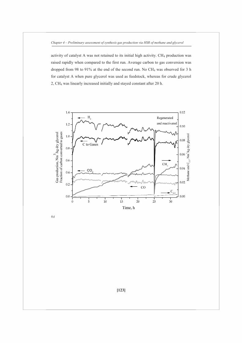
Chapter 4 – Preliminary assessment of synthesis gas production via HSR of methane and glycerol
[123]
activity of catalyst A was not retained to its initial high activity. CH4 production was
raised rapidly when compared to the first run. Average carbon to gas conversion was
dropped from 98 to 91% at the end of the second run. No CH4 was observed for 3 h
for catalyst A when pure glycerol was used as feedstock, whereas for crude glycerol
2, CH4 was linearly increased initially and stayed constant after 20 h.
9A

Chapter 4 – Preliminary assessment of synthesis gas production via HSR of methane and glycerol
[124]
9B
9C
Figure 9: Steam reforming of crude glycerol 2 (A) catalyst A, S/C = 3, Tcat = 804ºC and (B) catalyst B S/C = 3, Tcat = 795ºC. C) pure glycerol with 4% KCl by weight, catalyst A, S/C = 3, Tcat = 803ºC. For all cases GC1HSV = 600 h-1.
Chapter 4 – Preliminary assessment of synthesis gas production via HSR of methane and glycerol
[125]
For catalyst B, similar gas production as catalyst A was attained, except that no CH4
was observed in the first 10 h. CH4 and C2-3 compounds were increased rapidly and
reached a steady-state value of 0.018 Nm3/kg dry feed for CH4 and 0.0018 Nm3/Kg
dry feed for C2-3 compounds, which is almost three times lesser than for catalyst A or
~88% conversion of methane based on its selectivity from reforming and gasification
experiments. After burn-off and reactivation, the activity of the catalyst was retained;
nevertheless, CH4 and C2-3 compounds were rapidly increased. Similar trends on
average carbon to gas conversion as catalyst A was noticed for catalyst B. As shown
in Figure 9c, no CH4 was observed for catalyst A when KCl was added to pure
glycerol, whereas for crude glycerol 2, CH4 was linearly increased from the beginning
of the experiment. This indicates that the organic impurities present in crude glycerol
2 are solely responsible for reducing the initial activity of the catalyst A.
4.3.6 Catalyst analysis
The BET surface area, pore size distribution and Ni dispersion by chemisorption of
fresh and used catalyst A are reported in Table 4. There is a progressive drop in the
BET surface area of the catalyst A from 19.9 to 6.5 m2/g. However, it is noticeable
that surface area reduction also takes place during methane steam reforming at similar
conditions. The surface area after methane steam reforming is comparable with low
temperature reforming of glycerol. Since a reduction in the measured BET surface
area might as well as be caused by obstruction in the pore system, the pore volume of
the catalysts was determined before and after the reaction. No appreciable loss in pore
volume was observed for used catalyst after steam methane reforming. However,
there is appreciable loss in volume after steam reforming of crude glycerol 2 and low
temperature reforming of pure glycerol. The pore volume was reduced further after
the catalyst is regenerated. Since there is considerable decrease in pore volume,
blockage of pores attribute to the reduction in surface area. The properties of the
support and choice of promoters may also have an influence on pore volume
reduction on the catalyst [20].
The Ni surface area, metal dispersion and Ni particle size were found from the
hydrogen chemisorption measurements before and after the steam reforming of
Chapter 4 – Preliminary assessment of synthesis gas production via HSR of methane and glycerol
[126]
glycerol. It is observed that the quantity of hydrogen adsorbed, metal dispersion, Ni
metal surface area and Ni particle diameter were found to be similar between steam
methane reforming and low temperature reforming of glycerol. However, there is a
drastic reduction in the metal dispersion, quantity of hydrogen adsorbed and Ni metal
surface area when crude glycerol 2 was used as a feedstock. Ni particle size has
grown from ~349 to 801 nm. The increase in Ni particle size is attributed to sintering
that depends on Ni loading and support properties. After regeneration, the catalyst A
never retained its high initial activity. This may be due to obstruction in the pore
system of the catalyst caused due to coke deposition. It may be due to presence of
impurities present in the crude glycerol 2. This gives an indication that catalyst A is
designed to work effectively either at low temperature (<600ºC) or for high purity
feed stocks or combination of both.
For catalyst B, BET surface area and pore volume remained constant; however, the
quantity of hydrogen adsorbed and Ni metal surface area reduced drastically. Ni
particle diameter is increased from 199 to ~4000 nm. After regenerating the catalyst,
the initial activity of unpromoted catalyst (Catalyst B) is retained. Therefore, sintering
is not considered to be important, whereas coke deposition due to organic impurities
on the catalyst is a critical design parameter.
4.3.7 Hybrid steam reforming of methane and glycerol
In the hybrid reforming experiment, 28 wt% of glycerol was co-reformed with 72
wt% of methane on C1 basis. The test was carried out for 4 h. Figure 10a shows the
gas production obtained from the hybrid reforming experiment. Initially, there is a
slight fluctuation in the gas productions due to the addition of hydrogen to keep the
catalyst active. The gas production was almost constant over the period of 4 h. An
average carbon recovery of ~97% was obtained. Figure 10B shows the gas production
obtained from three cases: (1) Methane steam reforming; (2) Hybrid reforming and
(3) glycerol steam reforming. The line indicates the equilibrium gas production
obtained at 800 ºC and S/C =3. The gas production is expressed in mol of gas
produced per carbon atom. For all the cases, the experimental values almost reached
the equilibrium gas productions.
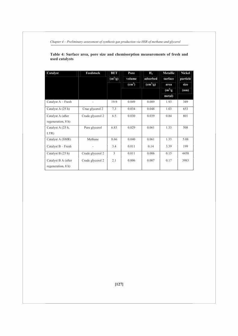
Chapter 4 – Preliminary assessment of synthesis gas production via HSR of methane and glycerol
[127]
Table 4: Surface area, pore size and chemisorption measurements of fresh and used catalysts
Catalyst Feedstock BET
(m2/g)
Pore
volume
(cm3)
H2
adsorbed
(cm3/g)
Metallic
surface
area
(m2/g
metal)
Nickel
particle
size
(nm)
Catalyst A – Fresh - 19.9 0.049 0.089 1.93 349
Catalyst A (25 h) Crue glycerol 2 7.3 0.034 0.048 1.03 653
Catalyst A (after
regeneration, 8 h)
Crude glycerol 2 6.5 0.030 0.039 0.84 801
Catalyst A (25 h,
LTR)
Pure glycerol 6.83 0.029 0.061 1.33 508
Catalyst A (SMR) Methane 8.66 0.040 0.061 1.33 5.08
Catalyst B – Fresh - 3.4 0.011 0.14 3.39 199
Catalyst B (25 h) Crude glycerol 2 3 0.011 0.006 0.15 4458
Catalyst B A (after
regeneration, 8 h)
Crude glycerol 2 2.1 0.006 0.007 0.17 3983
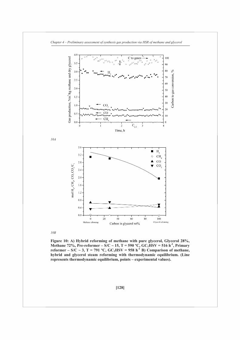
Chapter 4 – Preliminary assessment of synthesis gas production via HSR of methane and glycerol
[128]
10A
10B
Figure 10: A) Hybrid reforming of methane with pure glycerol, Glycerol 28%, Methane 72%, Pre-reformer – S/C ~ 15, T = 590 ºC, GC1HSV = 516 h-1, Primary reformer – S/C ~ 3, T = 791 ºC, GC1HSV = 958 h-1 B) Comparison of methane, hybrid and glycerol steam reforming with thermodynamic equilibrium. (Line represents thermodynamic equilibrium, points – experimental values).

Chapter 4 – Preliminary assessment of synthesis gas production via HSR of methane and glycerol
[129]
4.3.8 Performance of Catalyst A (Ni/K-Mg-Al2O3) and Catalyst B (Ni/Al2O3) catalysts during HSR of methane and crude glycerol
Crude glycerol 2 was also studied in HSR process. Figure 11 shows the amount of the
gas produced in moles per mol carbon of the crude glycerol and methane in the
primary reformer and the bio-liquid refomer, when Catalyst A was used in the bio-
liquid reformer and Catalyst B was used in the primary reformer (HSR) as shown in
Figure 2. The pre-reformer was operated at 800 ºC, S/C ~8 and 28 weight% carbon
contribution from crude glycerol. As shown in Figure 11, for the first 10 hours, gas
production in the pre-reformer was constant. The carbon conversion to gas was stable
at ~90% (not shown in figure). After 10 h, the gas productions and CG started to
decrease and remained stable after 20 hours. The CG was constant at ~70% from 20
till 35 h (not shown in Figure) in the bio-liquid reformer. This means after 20 h ~30%
of oxygenates (on carbon basis) from 28 wt% of crude glycerol break-through from
the pre-reformer.
In the primary reformer, catalyst B is in contact with gases produced from the pre-
reformer, oxygenates (from crude glycerol) and CH4 (added to the primary reformer).
For first 25 h in the primary reformer, H2, CO and CO2 were found to be stable. This
is expected because ~90% carbon was in the product gas from the crude glycerol. This
product gas together with methane would not be a problem to reform into synthesis
gas. After 25 h, CH4 started to appear and other gases started to decrease in the
primary reformer. However, CG remained constant at ~1.02±0.02 and within the error
limitations of gas measurement. This means that catalyst B able to handle a fraction of
unconverted oxygenates for short period (~25 h) and when the oxygenates break-
through increased to ~30% on carbon basis, Ni/Al2O3 catalyst started to lose its
methane reforming activity. This means that coke deposition (due to oxygenates) may
play a role in decreasing the methane reforming activity of potassium free Ni/Al2O3
catalyst. This also means that catalyst A act as “guard bed” by protecting catalyst B
from activity loss.

Chapter 4 – Preliminary assessment of synthesis gas production via HSR of methane and glycerol
[130]
Figure 11: Performance of Catalyst A (Ni/K-Mg-Al2O3) and Catalyst B (Ni/Al2O3) during HSR of methane and crude glycerol. Primary reformer (CH4:crude glycerol= 0.72:0.28 (carbon basis), – Tprimary ~820 ºC, S/Cprimary reformer = 2.8, Bio-liquid reformer (crude glycerol alone) (or pre-reformer) H2/steam = 0.1 mol/mol, GC1HSV = 930 h-1. Tbio-liquid reformer ~ 800 ºC, S/Cbio-liquid reformer ~ 8, GC1HSV = 260 h-1 (Empty boxes and lines represent bio-liquid reformer and HSR respectively)
Chapter 4 – Preliminary assessment of synthesis gas production via HSR of methane and glycerol
[131]
4.4 Implications on glycerol steam reforming
The gasification of crude glycerol is summarized in Figure 12. Crude glycerol 1 from
the transesterifcation unit can be directly vaporized above 300 ºC to produce
vapors/gases. Due to the presence of KOH in the crude, carbon loss in the form of
char ~ 10% is inevitable. The solid residue primarily consists of char and inorganics.
On the other hand, crude glycerol 1 can be neutralized using an acid and evaporated
further to prevent polymerization. In both the options, solid handling becomes
mandatory; nevertheless, in option 1 there are possibilities of converting the char by
steam gasification, since the activity of char may be high due to the presence of salts
[21, 22] or can be combusted to produce energy. To avoid solid handling in the steam
reformer, catalyst for transesterification has to be changed to a heterogeneous catalyst
instead of KOH.
Based on the process conditions used (1 bar, ~800 ºC and τ ~3 s) for gasification
experiments, the complete conversion of glycerol to gases is possible only at higher
temperatures (~ 800 ºC). Therefore, in hybrid reforming process, gasification of
glycerol can be combined with primary reformer, where methane is co-reformed with
gases produced from the gasification step, only when complete conversion is achieved
via gasification. This may eliminate the pre-reforming process. Therefore, the choice
should be made between the high temperature gasification or low temperature steam
reforming. However, results from pre-reforming at low temperature using commercial
steam reforming catalyst were promising to use as an upstream step for primary
reforming. Moreover, the catalyst in the pre-reformer acts as a “guard bed” and may
protect the primary reforming catalyst. To utilize these liquids on a larger scale, a
flexible pre-reformer that handles crude glycerol (treated or untreated) is required.
From the catalyst point of view, the promoted Ni/Al2O3 catalyst suffers initial activity
loss, which was not retained after regeneration. However, the unpromoted catalyst has
retained its activity after regeneration. The dominant impurities present in the crude
glycerol are FAMEs, tri,di glycerides and alkali salts. Our experimental results
indicated that reforming pure glycerol or glycerol with chlorides does not affect the
activity of the catalyst, whereas organic impurities affected the initial activity of

Chapter 4 – Preliminary assessment of synthesis gas production via HSR of methane and glycerol
[132]
commercial promoted Ni/Al2O3 catalyst. However, commercial unpromoted Ni/Al2O3
catalyst also loses its activity. Therefore, a frequent regeneration step is necessary to
utilize crude glycerol for methanol production. However, the role and choice of
promoters on the commercial catalyst to reform crude glycerol has to be investigated
further.
Figure 12: Mechanism of glycerol gasification.
4.5 Conclusions
The various stages of HSR such as gasification of crude glycerol, low temperature
steam reforming (pre-reforming) and co-reforming glycerol with methane were
studied. The main conclusions can be summarized as follows:
Presence of alkali hydroxides (NaOH and KOH) in the glycerol enhances the char
formation via polymerizing the intermediates in the liquid phase. Higher molecular
mass intermediates formed near the boiling point of glycerol are responsible for char
formation.
Pure glycerol and neutralized crude glycerol can be gasified with no loss of carbon as
char. Solid handling, in processing neutralized glycerol (salts) and untreated glycerol
(inorganics and char), becomes mandatory to scale up evaporator/gasifer.
Crude glycerol
Gasification
> 300 ºC
Vapours + Gas Gas
Inorganics + char
Neutralized crude glycerol Inorganics
Gas
Gasification
> 300 ºCNeutralization
> 500 ºC
> 500 ºCVapours + Gas
Catalyst
Catalyst
Chapter 4 – Preliminary assessment of synthesis gas production via HSR of methane and glycerol
[133]
To upgrade realistic feedstocks such as crude glycerol to produce synthesis gas via
steam reforming, a flexible steam reformer is required.
Pure glycerol can be reformed using commercial catalyst with no loss in the activity.
For a realistic feedstock such as crude glycerol, organic impurities such as FAME, di
and tri glycerides deteriorate the initial activity of the commercial steam reforming
catalyst.
References
1. M.Pagliaro, M.Rossi, The Royal Society of Chemistry (2008), ISBN 978-0-
85404-124-4
2. S.Adhikari, S.D.Fernando, S.D.Filip To, R.M.Bricka, P.H.Steele, A.Haryanto,
Energy & Fuels (2008), vol 22, 1220-1226
3. G.van Rossum, B.Potic, S.R.A.Kersten, W.van Swaaij, Catalysis today (2009),
vol 145, 10-18
4. G.van Rossum, S.R.A.Kersten, W.P.M.van Swaaij, Ind. Eng, Chem, Res,
(2007), vol 46, 3959-3967
5. G.van Rossum, S.R.A. Kersten, W.P.M.van Swaaij, Ind. Eng, Chem, Res,
(2009), vol 48, 5857-5866
6. T.Hirai, N.Ikenaga, T.Miyake, T.Suzuki, Energy & Fuels (2005), vol 19,
1761-1762
7. D.C.Rennard, J.S.Kruger, B.C.Michael, L.D.Schmidt, Ind. Eng, Chem, Res.,
(2010), vol 49, 8424-8432
8. S.R.A.Kersten, B.Potic, W.Prins, W.P.M.van Swaaij, Ind. Eng, Chem, Res,
(2006), vol 45, 4169-4177
9. A.G.Chakinala, D.W.F.Brilman, W.P.M.van Swaaij, S.R.A.Kersten; Ind. Eng,
Chem, Res (2010) vol 49, 1113-1122
10. G.W.Huber, S.Iborra, A.Corma, Chem. Rev (2006), vol 106, 4044-4098
11. A.Iriondo, V.L.Barrio, J.F.Cambra, P.L.Arias, M.B.Güemez, R.M.Navarro,
M.C.Sánchez-Sánchez, J.L.G.Fierro, Top Catal (2008), vol 49, 46-58

Chapter 4 – Preliminary assessment of synthesis gas production via HSR of methane and glycerol
[134]
12. J.A.Medrano, M.Oliva, M.Ruiz, L.Garcia, J.Arauzo, International journal of
hydrogen energy (2008), vol 33, 4387-4396
13. F.Bimbela, M.Oliva, M.Ruiz,, L.Garcia, J.Arauzo, Journal of analytical and
applied pyrolysis (2009), vol 85, 204-213
14. B.M.Güell, I.Babich, K.P.Nichols, L.Gardeniers, L.Lefferts, K.Seshan,
Applied catalysis B:Environmental (2009) vol 90, 38-44
15. S.Czernik, R.French, C.Feik, E.Chornet, Ind. Eng, Chem, Res., (2002), vol 41,
4209-4215
16. G.van Rossum, B.M.Güell, R.P.B.Ramachandran, K.Seshan, L/Lefferts,
W.P.M.Swaaij, S.R.A.Kersten, AIChe journal (2010) vol 56, 2200-2210
17. R.P.B.Ramachandran, G.van Rossum, W.P.M.van Swaaij, S.R.A.Kersten,
Environmental Progress & Sustainable energy (2009) vol 28, 410-417
18. B.Dou, G.L.Rickett, V.Dupont, P.TWilliams, H.Chen, Y.Ding, M.Ghadiri,
Bioresouce technology (2010), vol 101, 2436-2442
19. Y.Krishnandi, R.Eckelt, M.Schneider, A.Martin, M.Richter, ChemSusChem,
(2008), vol 1, 835-844
20. J.Sehested, A.Carlsson, T.V.W.Janssens, P.L.Hansen, A.K.Datye, Journal of
Catalysis (2001), vol 197, 200-209
21. P.Nanou, G.van Rossum, W.P.M.van Swaaij, S.R.A.Kersten, Energy & Fuels,
(2011), vol 25, 1242-1253
22. C.Di Blasi, A.Galgano, C.Branca, Ind. Eng. Chem. Res (2011), vol 50, 3864-3

[135]

[136]

[137]
Chapter 5
Synthesis gas production
via steam reforming of
pyrolysis oil Assessment of catalyst performance and hybrid reforming
with methane

Chapter 5 – Synthesis gas production via steam reforming of pyrolysis oil
[138]
Abstract
The objective of the present investigation is to evaluate the performance of a
commercial naphtha pre-reforming Ni/Al2O3 catalyst and an in-house Mg promoted
Ni/Al2O3 catalyst during steam reforming of pyrolysis oil. Both these catalysts
presented a different deactivation behavior during steam reforming of pyrolysis oil.
The commercial naphtha pre-reforming Ni/Al2O3 catalyst showed an irreversible loss
in methane reforming activity during pyrolysis oil reforming while magnesium
promoted Ni/Al2O3 catalysts presented reversible loss of methane reforming activity.
After the coke removal step (regeneration), carbon conversion to gas remained more
or less constant for the commercial naphtha pre-reforming catalyst, indicating that
potassium enhanced coke gasification. For Mg promoted Ni/Al2O3 catalyst, carbon
conversion to gases and gas productions dropped much faster after regeneration than
for the initial period of the experiment. The effect of potassium on glycerol reforming
is investigated by impregnating K on Ni/Al2O3 catalyst. For the potassium
impregnated catalysts, methane was observed in quantities, increasing with potassium
loading while C2-3 gases were observed only for the catalyst with high potassium
loading. From the hybrid steam reforming (HSR) experiments, it is concluded that the
bio-liquid pre-reforming catalyst acts as a ‘guard bed’ to protect the primary
reforming catalyst which is supposed to reform methane and pre-reformed pyrolysis
oil gases and vapors. However, in terms of performance, the HSR process still
requires frequent regeneration of this primary reformer.
Chapter 5 – Synthesis gas production via steam reforming of pyrolysis oil
[139]
5.1 Introduction
Presently, the oil and gas industries are showing interest to replace part of the raw
materials base from fossil to renewable in a way adapted to the existing infrastructure.
This is mainly due to the increase in fossil fuel price, global CO2 emissions and desire
of security of supply. To meet this demand, thermal and biological conversion of
biomass processes may provide a platform to make a significant impact on the
production of fuels, bulk chemicals such as methanol, ethanol, hydrogen etc. within
the next few decades. Several authors investigated the utilization of bio-based
materials such as pyrolysis oil [1-4], aqueous sugar streams [2, 5] and glycerol [6, 7]
to produce synthesis gas or hydrogen via steam reforming.
To integrate bio-based processes with a fossil refinery, biomass streams should be
available near a refinery or bio-based intermediates can possibly be produced
elsewhere and transported to the refinery for the applications mentioned before [2]. To
bridge the gap between dispersed availability and demand for large-scale utilization,
biomass fast pyrolysis is proposed as an intermediate step, where solid biomass is
converted into pyrolysis oil that can more easily be transported over long distances
and pressurized compared to the original feed. Another interesting liquid that can be
utilized in steam reforming is glycerol [7], a by-product from the transesterification
process (bio-diesel production). The present article focuses on converting these bio-
liquids in to synthesis gas via steam reforming and co-processing them with
hydrocarbon feeds like natural gas.
During steam reforming of oxygenates, the following reactions play a vital role on
carbon distribution to gases, vapors and solid. They are:
Cracking of oxygenates
CnHmOk gases (CO+CO2+CH4+C2-4+H2) + vapors (CaHbOc) + solid char
Steam reforming of oxygenates
CnHmOk + (n-k) H2O nCO + (n + m/2 – k) H2
Chapter 5 – Synthesis gas production via steam reforming of pyrolysis oil
[140]
Dry reforming of oxygenates
CnHmOk + (n-k) CO2 (2n-k) CO + (m/2) H2
Polymerization of oxygenates (liquid and vapor)
CnHmOk CaHbOc + dH2O + eCO2
Methanation
CO + 3H2 CH4 + H2O (ΔH=-206 kJ/mol)
Water-gas shift
CO + H2O CO2 + H2 (ΔH=-41.1 kJ/mol)
Boudouard
C(S) + CO2 2 CO (ΔH=170.7 kJ/mol)
Water-gas reaction
C(S) + H2O CO + H2 (ΔH=131 kJ/mol)
At targeted oxygenates steam reforming temperatures (≤ 900 C), steam and dry
reforming, methanation and water gas shift need a catalyst to attain sufficient high
reaction rates while cracking, polymerization and Boudouard can occur both
catalytically and non-catalytically. In our earlier articles [7-9], thermal cracking of
bio-liquids such as pyrolysis oil and glycerol was extensively studied by injecting the
liquids as droplets into a hot environment. In this process, the bio-liquids are
evaporated and the vapors are then converted to gases via thermal cracking.
Additionally to char formation in the gas phase, solid char is formed via liquid phase
polymerization which takes place in parallel during the evaporation/cracking of
pyrolysis oil [8]. The combined processes of evaporation, thermal cracking and
polymerization can be named gasification. The initial carbon product distribution
between solids (char) and vapors/gasses for pyrolysis oil gasification was found to be
only dependent on the liquid heating rate while temperature variation (550 - 850ºC)
had an impact on the ratio of vapors and gases being formed [8, Chapter 2]. With pure
and alkali neutralized crude glycerol, no char formation was observed during
gasification [7].
Van Rossum et al. [1] extensively investigated steam reforming of whole pyrolysis oil
in a fluidized bed using potassium/lanthanum promoted Ni/Al2O3 catalyst at ~815ºC
and S/C~3. A decrease in H2, CO production and a steady increase in the CH4

Chapter 5 – Synthesis gas production via steam reforming of pyrolysis oil
[141]
production were observed over time. Similar behavior, however to lesser extent, was
reported by Czernik et al. [2] for steam reforming of the aqueous fraction of pyrolysis
oil and a hemi-cellulose rich solution. The formation of hydrocarbons (CH4, C2H4)
was related to thermal cracking of oxygenates which always accompanies catalytic
reforming [2]. Van Rossum et al. [1] demonstrated steam reforming of pyrolysis oil in
a staged concept (fluidized bed for the evaporation of pyrolysis oil followed by syngas
production in a fixed bed of both Ni/K-Mg-Al2O3 and Ni/Al2O3 catalysts), where
methane free synthesis gas was continuously produced for ~12 h. However, a large
amount of catalyst was used (GHC1SV ~ 100 h-1), which means that the possible loss
in activity could have not been observed due to the time frame studied.
In this Chapter, catalytic performance of two catalysts, one commercial naphtha pre-
reforming catalyst and one in-house made catalyst, for bio-liquid reforming is
evaluated from a process development point of view at a commercial comparable gas
hourly space velocity (GHC1SV ~ 1500 h-1). Both (pre-) reforming of the bio-liquids
and co-reforming of gases and vapors from pre-reformed bio-liquids with methane is
reported. The latter concept is called hybrid steam reforming (HSR). At the level of
the chemistry/catalysis, co-reforming may minimize the adverse characteristics of the
bio-liquid, as has been observed for co-feeding upgraded pyrolysis oil with long
residue in a micro FCC unit [11]. The role of potassium as a promoter on a catalyst is
investigated by using glycerol as a model compound. One typical long duration run is
presented for hybrid reforming of pyrolysis oil with methane using our lab scale pilot
plant set-up.
Chapter 5 – Synthesis gas production via steam reforming of pyrolysis oil
[142]
5.2 Experimental
5.2.1 Materials
The pyrolysis oil used was produced by VTT (Finland) from forest residue [10]. The
elemental composition of the pyrolysis oil was 41% carbon, 8 % hydrogen and 51%
oxygen including 24% water by weight. Pure glycerol (>99.99%) was obtained from
Sigma Aldrich. Two Ni based catalysts were used for pyrolysis oil conversion: i) a
commercial naphtha pre-reforming catalyst, named Ni/K-Mg-Al2O3 which consisted
of Ni promoted with K, Ca, Mg and Si (all oxides) on a Al2O3 support and ii) an in-
house prepared catalyst, named Ni/Mg-Al2O3 which was composed of Ni on Al2O3
and promoted with only MgO. The procedure to prepare the later catalyst was
described by Medrano et al. [12]. Both the catalysts were ground and sieved to a
particle size ranging between 160 and 320 μm. For steam reforming of pure glycerol,
a commercial methane steam reforming catalyst, named Ni/Al2O3 which consisted of
mainly Ni on Al2O3 was used directly and via K2O impregnating with two different
K/Ni molar ratios (0.04 and 0.32). The catalysts thus obtained are denoted as Ni/K1-
Al2O3 and Ni/K2-Al2O3 respectively. For HSR experiments, Ni/K-Mg-Al2O3 catalyst
is used.
5.2.2 Experimental set up
A schematic overview of the hybrid steam reforming (HSR) set-up is shown in Figure
1. The set-up consists of three stages: gasification of pyrolysis oil, followed by
catalytic pre-reforming of vapors and catalytic reforming of methane together with the
gas/vapor produced from the pre-reforming. The latter is called HSR or co-reforming.
All the equipment components were made of stainless steel (type:R543). The set-up
was operated at near atmospheric pressure.
Gasification section: The gasifier has an internal diameter of 40 mm and a height of
350 mm. It consists of an ultrasonic atomizer that sprays droplets of ~100 m with a
liquid flow rate ranging from 0.2 to 0.4 ml/min, using a HPLC pump (Instrument
Solutions). Nitrogen stream (flow rate: 0.2 Nl/min) was used to facilitate atomization.
The atomizer was fitted in a copper ring in which water was circulated to keep the
Chapter 5 – Synthesis gas production via steam reforming of pyrolysis oil
[143]
temperature below 70ºC. This is to protect the piezo-electric parts of the atomizer
from thermal damage. A pre-heater (temperature 450ºC) was attached to the top of the
gasifier to supply additional nitrogen (flow rate: 0.4 Nl/min) and steam required for
the reaction. This added stream kept the top of the gasifier at ~400ºC to minimize
vapor condensation at the upper part of the gasifier. A filter was placed at the bottom
of the gasifier to collect the solids. Temperatures were measured at the top, middle
and bottom section of the gasifer. The reported gasification temperature was the
average temperature of the middle and the bottom section of the gasifier.
Pre-reforming section (location 1): Beneath the evaporator, the fixed bed pre-
reformer (40 mm internal diameter and 150 mm height) was placed, where the
gas/vapor mixture from the gasifier is catalytically converted using a commercial
steam reforming catalyst. The catalyst was placed in an inconel distribution plate at
the bottom of the pre-reformer. This section was only used in the HSR experiment.
Methane was supplied at the exit of the pre-reformer for HSR experiments.
Primary reforming section (location 2): The fixed bed primary reformer (35 mm
internal diameter and 300 mm height) was fitted with an inconel distribution plate at
the middle of the reactor. The bed consists of a mixture of quartz and catalyst particles
(3:1, quartz: catalyst), which was placed on top of the plate with a bed height of ~100
mm.
Both the pre-reforming and primary reforming catalyst were reduced in situ with
hydrogen (0.2 Nl/min) diluted with Nitrogen (0.4 Nl/min) at 800ºC for ~8 h before
each experiment. Temperatures of the reformers were measured at the bottom and also
at the middle of the catalyst bed, which was the reported temperature.
For HSR experiments, the pre-reformer (location 1) was used together with the
primary reformer (location 2), whereas for tests investigating steam reforming of
“pure” pyrolysis oil, the catalyst was placed in the primary reformer (location 2).
Ni/K-Mg-Al2O3 was used as both pre-reforming and primary reforming catalyst for
HSR experiments whereas for steam reforming experiments, Ni/K-Mg-Al2O3 and
Ni/Mg-Al2O3 were used.

Chapter 5 – Synthesis gas production via steam reforming of pyrolysis oil
[144]
The products from the reformer were immediately cooled after the cyclone to collect
the condensables. A micro-GC (Varian CP-4900; 10 m mol sieve 5A Ar, 10 m mol
sieve 5A He, 10 m PPQ He, 8 m Sil-5CB He) was used to detect H2, O2, N2, CH4, CO,
CO2, C2H4, C2H6, C3H6 and C3H8. For HSR experiments, the gas samples were taken
manually after the pre-reformer and for the hybrid reformer gas measurement was
performed continuously using a micro gas chromatography (Varian CP-4900). The
integral carbon balance and gas production for both the gasification and catalytic
reforming and HSR experiments were made based on nitrogen as an internal standard,
which was fed to the atomizer and pre-heater. The gas production from the primary
reformer is reported as Nm3 of H2 or CH4 or CO or CO2 per kilogram of the dry
feedstock.
The catalysts were regenerated using 100 ml/min of air to estimate the amount of
carbon deposited (coke) on the catalyst. The carbon to gas conversion or fraction of
carbon converted to gases was calculated at the steady-state operation that excludes
the start-up profile. Gas hourly space velocity on C1 basis is defined as the volume of
C1 equivalent species in the feed at the STP (standard temperature and pressure) per
unit volume of the catalyst. C1 equivalent is used to compare feedstocks containing
different number of carbon atoms per molecule. The carbon closure of experimental
set-up was found to be adequate (i) 100 ± 3 % using methane and steam at 795 ºC,
S/C =3, (ii) 99±3 % using pure glycerol at 805 ºC, S/C =3. There is a degree of
fluctuation in the gas production due to pyrolysis oil, steam and nitrogen flows.

Cha
pter
5 –
Syn
thes
is g
as p
rodu
ctio
n vi
a st
eam
refo
rmin
g of
pyr
olys
is o
il
[145
]
F
igur
e 1:
Sch
emat
ic o
verv
iew
of
the
hybr
id s
team
ref
orm
ing
set-
up.
Pre
-ref
orm
er =
loca
tion
1, p
rim
ary
refo
rmer
= lo
cati
on 2

Chapter 5 – Synthesis gas production via steam reforming of pyrolysis oil
[146]
5.3 Results and Discussion
5.3.1 Non catalytic results and the first 1 hour of catalytic reforming
Table 1 summarizes the product distribution (averaged for 0.5 hour for non-catalytic
and 1 hour for catalytic, both excluding the start-up profile) and carbon to gas
conversion, char and coke production obtained from the non-catalytic and catalytic
gasification of pyrolysis oil using Ni/K-Mg-Al2O3. The non-catalytic gasification
experiments were performed in the dedicated continuous gasification set-up (see
Chapter 2). From the non-catalytic gasification experiments, it is observed that by
increasing the temperature from 649 to 828ºC, a significant increase in the carbon to
gas conversion was noticed (37.2% to 62.3%). This significant increase is due to the
thermal cracking of pyrolysis oil to gases at high temperature. From the selectivity of
the gases, a significant increase in CH4 by increasing the temperature from 649 to
828ºC can be seen. As reported in Chapters 2&3, the increase in CH4 may be via the
thermal cracking of vapors (oxygenates). Summarizing: i) at low
atomization/gasification temperature most of the fed pyrolysis is in the vapor phase
but methane levels are low and ii) at high atomization temperature much more gases
are produced including methane, but vapors are still present.
By increasing the S/C ratio from 0.4 to 10 at constant temperature 820ºC, only a slight
increase in the carbon to gas conversion from 62.3% to 68.5% was observed.
Considering the error of measurement, this increase in carbon to gas conversion (CG)
is not significant. The increase in H2 and CO2 cannot be explained by water-gas shift
reaction because CO is almost constant by increasing S/C from 0.4 to 10. Also, CH4 is
relatively constant at high temperature (~820ºC). It is noticeable that even at high S/C,
steam reforming of methane is not happening in the absence of catalyst.
Comparing the non-catalytic and catalytic results shows that the catalyst is, initially,
able to reform the pyrolysis vapors to gases. This becomes particularly clear from the
experiments performed at ~600 ºC for which the carbon to gas conversion increases
from ~40 to ~75-80 % when applying catalysis. At a reform temperature of 800 ºC,
the S/C seems to only effect the water gas shift reaction: a S/C of 1 and 15 have
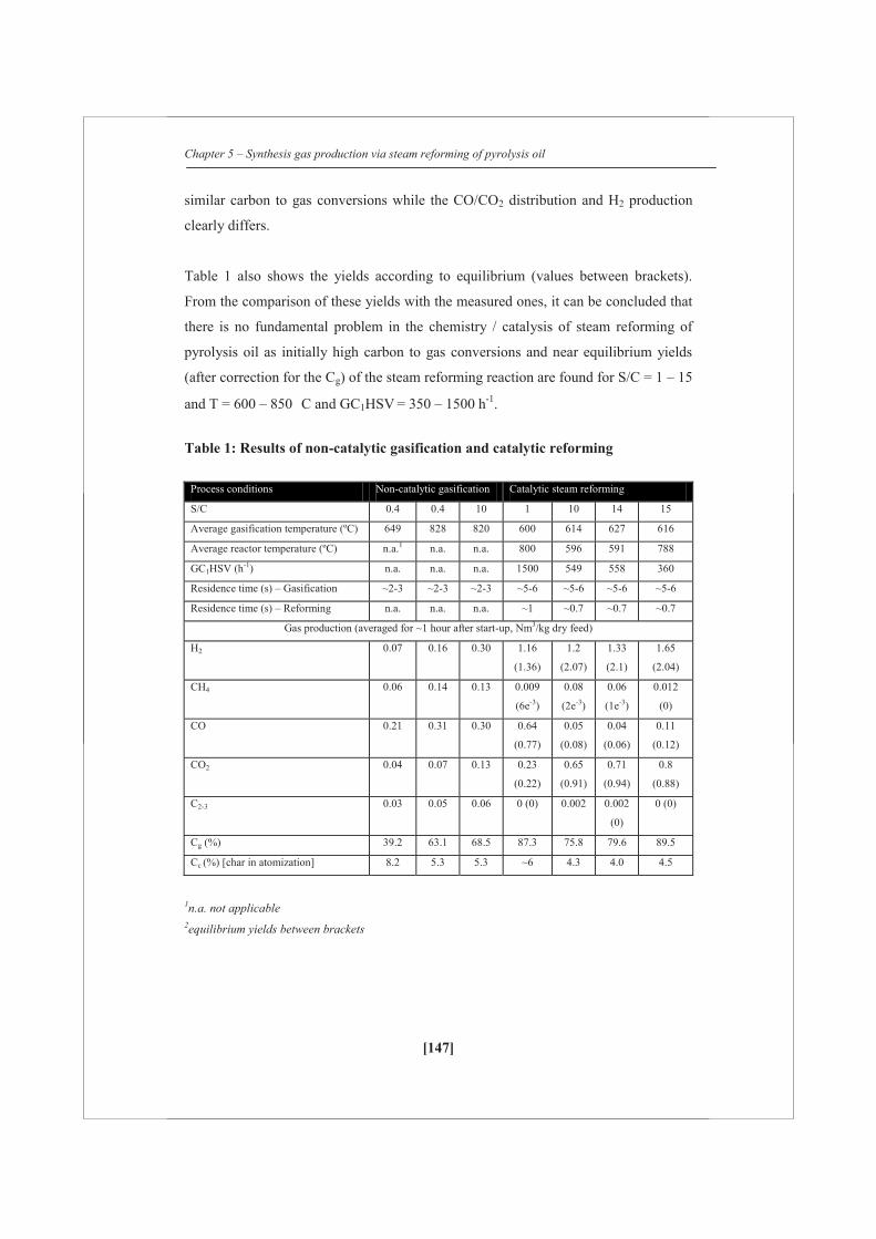
Chapter 5 – Synthesis gas production via steam reforming of pyrolysis oil
[147]
similar carbon to gas conversions while the CO/CO2 distribution and H2 production
clearly differs.
Table 1 also shows the yields according to equilibrium (values between brackets).
From the comparison of these yields with the measured ones, it can be concluded that
there is no fundamental problem in the chemistry / catalysis of steam reforming of
pyrolysis oil as initially high carbon to gas conversions and near equilibrium yields
(after correction for the Cg) of the steam reforming reaction are found for S/C = 1 – 15
and T = 600 – 850 C and GC1HSV = 350 – 1500 h-1.
Table 1: Results of non-catalytic gasification and catalytic reforming
Process conditions Non-catalytic gasification Catalytic steam reforming
S/C 0.4 0.4 10 1 10 14 15
Average gasification temperature (ºC) 649 828 820 600 614 627 616
Average reactor temperature (ºC) n.a.1 n.a. n.a. 800 596 591 788
GC1HSV (h-1) n.a. n.a. n.a. 1500 549 558 360
Residence time (s) – Gasification ~2-3 ~2-3 ~2-3 ~5-6 ~5-6 ~5-6 ~5-6
Residence time (s) – Reforming n.a. n.a. n.a. ~1 ~0.7 ~0.7 ~0.7
Gas production (averaged for ~1 hour after start-up, Nm3/kg dry feed)
H2 0.07 0.16 0.30 1.16
(1.36)
1.2
(2.07)
1.33
(2.1)
1.65
(2.04)
CH4 0.06 0.14 0.13 0.009
(6e-3)
0.08
(2e-3)
0.06
(1e-3)
0.012
(0)
CO 0.21 0.31 0.30 0.64
(0.77)
0.05
(0.08)
0.04
(0.06)
0.11
(0.12)
CO2 0.04 0.07 0.13 0.23
(0.22)
0.65
(0.91)
0.71
(0.94)
0.8
(0.88)
C2-3 0.03 0.05 0.06 0 (0) 0.002 0.002
(0)
0 (0)
Cg (%) 39.2 63.1 68.5 87.3 75.8 79.6 89.5
Cc (%) [char in atomization] 8.2 5.3 5.3 ~6 4.3 4.0 4.5
1n.a. not applicable 2equilibrium yields between brackets

Chapter 5 – Synthesis gas production via steam reforming of pyrolysis oil
[148]
5.3.2 Long duration runs
Figure 2 shows the gas productions and carbon to gas conversion versus time on
stream (excluding start-up) for two catalysts, namely (A) Ni/K-Mg-Al2O3 and (B)
Ni/Mg-Al2O3. The pyrolysis oil was first gasified at ~ 600 C en then converted over a
catalytic bed (Figure 1: location 2) at ~ 800 C. The catalytic bed temperature was set
to a value similar to methane steam reforming since lower temperatures (~600 C)
results in excessive coking on the catalyst [13]. A low steam over carbon (~1) ratio
and commercial comparable gas hourly space velocity of ~1500 h-1 were used to
evaluate the catalytic performance under harsh conditions. In the evaluation, also a
regeneration step was included where possible carbon deposits were burnt off using
air after which the catalyst was activated again via hydrogen reduction (not shown in
Figure 2A).
When the commercial Ni/K-Mg-Al2O3 catalyst was used (Figure 2A) initially, for a
period of 1 h, the amounts of H2, CO2, CO and carbon to gas conversion (CG) were
stable with H2/CO molar ratio ~2. After approximately 1.5 h, CH4 and low amount of
C2-3 hydrocarbons gases were observed in the product stream. The gas production of
H2 and CO started to decrease and CH4 reached a stable value of around 0.11 Nm3/kg
dry pyrolysis oil, which is similar to the one obtained via only gasification of
pyrolysis oil at similar conditions (~0.14 Nm3/kg dry pyrolysis oil, see Table 1). The
production of CO2 was found to be stable all through the run. Despite the increase in
CH4, the CG (~80%) was higher than for gasification of pyrolysis oil which was only
~65% (see Table 1) and moreover, CG is stable with time on stream. Since the
catalytic methane conversion, as compared to only gasification, dropped from full
conversion to ~ 25%, the Ni/K-Mg-Al2O3 catalyst was regenerated using 100 mL/min
of air and again reactivated using 100 mL/min of pure H2.
As observed from the Figure 2A, the methane reforming activity was not recovered
but instead seems to be totally lost. The average CG was 78% after regeneration which
is still ~13% above thermal cracking of pyrolysis oil. What is important to note is that
hydrogen production is still higher as compared to gasification (see Table 1) which
Chapter 5 – Synthesis gas production via steam reforming of pyrolysis oil
[149]
indicates that the catalyst only maintains activity for the water gas shift reaction or
steam gasification.
The performance of Ni/Mg-Al2O3 catalyst is presented in Figure 2B. For the first 2 h,
the gas productions and carbon to gas conversion were constant. After 2 h, the
hydrogen, carbon monoxide and subsequently carbon to gas conversion started to
drop. The carbon to gas conversion (CG) for instance decreases from 86% to 65%,
which is being the non-catalytic CG. However, unlike Ni/K-Mg-Al2O3 catalyst, no
CH4 and C2-3 were observed for a period of 5 h. CH4 production was stable around
0.02 Nm3/kg dry pyrolysis oil, which is much lower than reforming using Ni/K-Mg-
Al2O3 catalyst. Due to activity drop, which is mainly expressed here for CG, the
catalyst was regenerated at 800ºC using 100 mL/min of air and reactivated using pure
H2. Unlike the commercial Ni/K-Mg-Al2O3, the in house made catalyst Ni/Mg-Al2O3
regained its full methane conversion and carbon to gas conversion. However, an
immediate loss in carbon conversion was now observed when pyrolysis oil conversion
was started again.
To summarize above experiments, both catalysts exhibited different performance for
steam reforming of pyrolysis oil. The commercial Ni/K-Mg-Al2O3 catalyst showed
irreversible activity loss for methane reforming while maintaining better its carbon to
gas conversion during 10 h. Similar behavior, however in a fluidized bed, was
reported by Van Rossum et al. [1]. The in-house made Ni/Mg-Al2O3 catalyst showed
reversible activity loss for the carbon to gas conversion and methane reforming. For
this catalyst methane activity remains for several hours while carbon to gas activity
starts to drop faster.
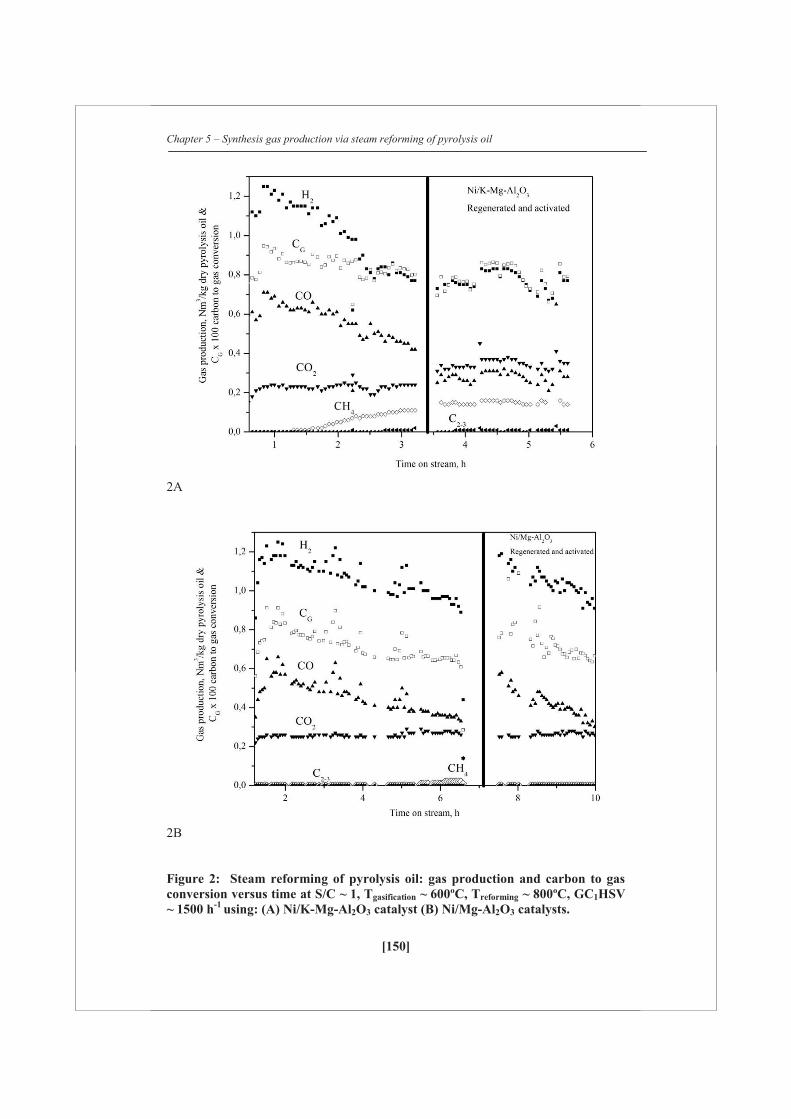
Chapter 5 – Synthesis gas production via steam reforming of pyrolysis oil
[150]
2A
2B
Figure 2: Steam reforming of pyrolysis oil: gas production and carbon to gas conversion versus time at S/C ~ 1, Tgasification ~ 600ºC, Treforming ~ 800ºC, GC1HSV ~ 1500 h-1 using: (A) Ni/K-Mg-Al2O3 catalyst (B) Ni/Mg-Al2O3 catalysts.

Chapter 5 – Synthesis gas production via steam reforming of pyrolysis oil
[151]
5.3.3 The role of potassium as promoter on steam reforming catalyst
Composition wise, the main difference between the commercial Ni/K-Mg-Al2O3 and
in- house Ni/Mg-Al2O3 catalysts is the usage of potassium as a promoter. The
potassium is added presumably to suppress excessive coking of the catalyst via
enhancing its gasification [14] which is indirectly seen in Figure 2A, where the carbon
to gas conversion remained more or less constant over time. However, the conversion
of methane seemed to be negatively affected by the presence of potassium. This effect
of potassium addition was investigated further via glycerol steam reforming
experiments. With glycerol steam reforming, a full carbon to gas conversion could be
obtained when pure glycerol was being converted [7, Chapter 4]. By using glycerol as
a model compound, the effect of combined gasification and steam reforming can be
decoupled and methane reforming ability can be studied separately. This was done by
loading different amounts of potassium on the unpromoted Ni/Al2O3 catalyst with two
different K/Ni molar ratios of 0.04 and 0.32 (catalysts named Ni/K1-Al2O3 and
Ni/K2-Al2O3 respectively).
Figure 3 shows the methane production obtained for ~7 hours from steam reforming
of pure glycerol using Ni/Al2O3, Ni/K1-Al2O3 and Ni/K2-Al2O3 catalysts. Table 2
summarizes the average gas productions and carbon to gas conversion values of pure
glycerol steam reforming using potassium impregnated catalysts. No activity loss was
observed for all the catalysts for 7 h and nearly complete carbon to gas conversions
was obtained. Neither methane nor C2-3 gases were observed for the Ni/Al2O3 catalyst.
However, for the potassium impregnated catalysts, methane was observed, increasing
with potassium loading, and C2-3 gases were observed only for the catalyst with high
potassium loading. The effect which potassium can have on steam reforming was
reported by Rostrup et al. [13]. The possible explanations for this phenomenon are:
Potassium present in the bulk reaches the surface via volatilization at high
temperature and interacts with active Ni phase [15-17]. This interaction disturbs CHx
adsorption on the active phase [17]. Due to increase in methane apparent activation
energy for dissociation which slowed down methane reforming activity [15, 17] and
CO and CxHyOz (glycerol vapors and coke) may have adsorbed on the active phase
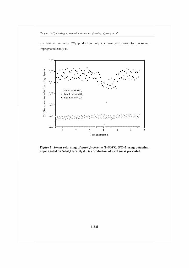
Chapter 5 – Synthesis gas production via steam reforming of pyrolysis oil
[152]
that resulted in more CO2 production only via coke gasification for potassium
impregnated catalysts.
Figure 3: Steam reforming of pure glycerol at T=800ºC, S/C=3 using potassium impregnated on Ni/Al2O3 catalyst. Gas production of methane is presented.

Chapter 5 – Synthesis gas production via steam reforming of pyrolysis oil
[153]
Table 2: Performance of potassium impregnated catalysts on Ni/Al2O3 during steam reforming of glycerol
Average Gas
production (~7 hours):
(mol/mol glycerol)
Ni/Al2O3 Ni/K1-Al2O3 Ni/K2-Al2O3
H2 5.03 4.88 4.40
CH4 0.00 0.04 0.18
CO 1.44 1.52 1.23
CO2 1.44 1.49 1.49
C2-3 0.00 0.00 0.03
CG 97% 101.7% 98.5%
5.3.4 Hybrid steam reforming of methane and pyrolysis oil
From the tested catalysts, the commercial Ni/K-Mg-Al2O3 catalyst seemed to be most
promising, at least for the initial pre-reforming step to be used in a hybrid
configuration for combined pyrolysis oil and methane steam reforming. This is
because a steady operation is needed where most of the pyrolysis oil is transferred to
permanent gas. The hybrid reforming concept was successfully demonstrated for pure
glycerol in Chapter 4 [7]. Figure 4 shows a typical long duration run for pyrolysis oil
and methane hybrid reforming, where the gas production after the primary reformer
(moles gases/carbon of combined feed) as well as after the pre-reformer (moles of
gases/carbon from pyrolysis oil) are plotted versus time on stream. The horizontal
dash line in Figure 4 represents the equilibrium gas productions for MSR.
Stage 1 (MSR): For the first 10 hours, MSR was performed in the primary reformer.
Together with the steam, some hydrogen (H2/steam = 0.1 mol/mol) was added to
avoid oxidation the catalyst in the primary reformer when running on methane only
[18]. For the first 5 h, gas production was close to equilibrium. Thereafter, the gas
production decreased slightly and then reached a steady-state from 5th till 10th hour.
The average unconverted methane in the product stream was found to be 0.13 mol per
mol C1 over the period of 10 h (which means ~87% conversion of methane with

Chapter 5 – Synthesis gas production via steam reforming of pyrolysis oil
[154]
carbon recovery of CG of ~101% = 1.01. The permanent loss in methane reforming
activity is probably caused by the potassium loading as mentioned previously and was
also reported by Juan-Juan et al. [19] and Graf et al. [20] on dry reforming of
methane.
Stage 2 (HSR): MSR was stopped and N2 flow of ~0.4 Nl/min was supplied over the
catalyst placed in the primary reformer. Prior to the HSR experiment, H2 flow of 0.1
Nl/min was supplied to the pre-reformer and the N2 flow position was altered to pre-
reformer. When the GC measured no carbon gases, a required amount of methane and
steam was supplied to the primary reformer. After few measurements, when the gas
production was similar to stage 1, pyrolysis oil was injected in the gasifier by
reducing the appropriate amount of methane supplied to the primary reformer. This
means that the amount of the carbon supplied for both stage 1&2 are similar. A
decrease in H2 and CO was observed while CH4 and CO2 were stable for ~5 hours.
Also, there is a slight degree of fluctuation that was observed in the carbon recovery
to gases. After 17 hours, methane started to increase in the product gas of the primary
reformer. During this stage, H2, CO and CO2 productions dropped in the pre-reformer,
while CH4 was relatively constant. The drop in effectiveness of methane conversion
or methane break-through occurs in the primary reformer when the carbon to gas
conversion in the bio-liquid pre-reformer decreases from ~85% to ~60%.
Stage 3: Pyrolysis oil flow was stopped and both the catalysts were regenerated by
first using 100 ml/min of air at 800 ºC to burn-off coke. After reducing the catalysts
using H2 at 800 ºC, MSR was continued from the 27th hour after stage 2. It was
observed that the MSR activity of the catalyst in the primary reformer was slowly
retained and reached a new steady-state value after 40 h for all the gases, having a
CH4 conversion of ~60%. The methane reforming activity of the Ni/K-Mg-Al2O3 was
somewhat recovered. Nevertheless, the gas production was far away from the
equilibrium values. The slow regain in MSR activity during dry reforming of methane
was reported by El-Bousiffi et al. [18]. Possible explanations for this may be i) slight
oxidation of active Nickel due to drop in temperature from 800 ºC may decrease the
gas production [18] and ii) initial formation of Nickel micro-crystallites and their
disappearance due to the formation of spinel phase [18] may have caused permanent

Chapter 5 – Synthesis gas production via steam reforming of pyrolysis oil
[155]
loss. Other possible explanation for oxidation would be continuous exposure of steam
over pre-reforming catalyst.
Stage 4: Similar to stage 2, HSR experiment was again performed. Approximately for
3 hours, the individual gas productions were almost constant and similar to the gas
productions of stage 3. However, the gas productions were low by comparing it with
the initial high gas production and first HSR experiment. After 53 hours, methane
started to break-through from the primary reformer and other gases such as H2, CO
and CO2 dropped. It should be noted that the catalyst maintained its MSR activity for
a short period even though the gas production in the pre-reformer decreased
significantly, indicating that HSR in fixed bed for this specific catalyst at the
experimental conditions studied is not viable for long term operation.
Stage 5: After the drop in the gas production, pyrolysis oil injection was stopped and
Ni/K-Mg-Al2O3 catalyst was regenerated using 100 ml/min of air at 800 ºC to burn-
off coke as CO2. MSR was continued after 62 h time on stream. A slow recovery in
the MSR activity of the catalyst was observed during this stage and obtained CH4
conversion similar to stage 3. As shown in Figure 2A, carbon recovery to gas was still
around ~100%. Methane was found to be 0.37 mol per mol C1 (overall 63% methane
conversion) at the end of this stage.

Chapter 5 – Synthesis gas production via steam reforming of pyrolysis oil
[156]
Figure 4: Performance of Ni/K-Mg-Al2O3 catalyst during MSR and HSR. Horizontal dash lines represent equilibrium gas yield for MSR and HSR), MSR – Tprimary ~820 ºC, S/Cprimary reformer = 2.8, H2/steam = 0.1 mol/mol (in bio-liquid reformer), GC1HSV = 850 h-1. HSR – Tgasifier~ 600 ºC, S/Cbio-liquid reformer ~9, Tbio-liquid reformer ~ 800 ºC, GC1HSV = 390 h-1, CH4:pyrolysis oil = 0.7:0.3 (carbon basis).
In the HSR concept, the critical unit operation is the bio-liquid reformer because the
catalyst is in direct contact with the pyrolysis oil vapors (oxygenates). The primary
reformer deals with high temperature (~800ºC) vapors and methane. Both the catalyst
beds (Ni/K-Mg-Al2O3) were burnt off using air at 800ºC at different time-on-stream.
First, the catalyst of the primary reformer was burnt by supplying air directly in to the
primary reformer. CO2 was measured continuously using a micro-GC. Then,
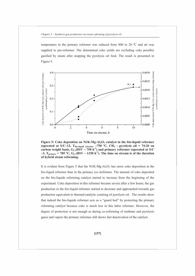
Chapter 5 – Synthesis gas production via steam reforming of pyrolysis oil
[157]
temperature in the primary reformer was reduced from 800 to 20 ºC and air was
supplied to pre-reformer. The determined coke yields are excluding coke possibly
gasified by steam after stopping the pyrolysis oil feed. The result is presented in
Figure 5.
Figure 5: Coke deposition on Ni/K-Mg-Al2O3 catalyst in the bio-liquid reformer (operated at S/C~12, Tbio-liquid reformer ~750 ºC, CH4 : pyrolysis oil = 74:26 on carbon weight basis, GC1HSV ~ 750 h-1) and primary reformer (operated at S/C ~3, Tprimary = 785 ºC, GC1HSV ~ 1150 h-1). The time on stream is of the duration of hybrid steam reforming.
It is evident from Figure 5 that the Ni/K-Mg-Al2O3 has more coke deposition in the
bio-liquid reformer than in the primary (co-)reformer. The amount of coke deposited
on the bio-liquids reforming catalyst started to increase from the beginning of the
experiment. Coke deposition in this reformer became severe after a few hours; the gas
production in the bio-liquid reformer started to decrease and approached towards gas
production equivalent to thermal/catalytic cracking of pyrolysis oil. The results show
that indeed the bio-liquids reformer acts as a “guard bed” by protecting the primary
reforming catalyst because coke is much less in this latter reformer. However, the
degree of protection is not enough as during co-reforming of methane and pyrolysis
gases and vapors the primary reformer still shows fast deactivation of the catalyst.
Chapter 5 – Synthesis gas production via steam reforming of pyrolysis oil
[158]
5.4 Conclusions
The main conclusions of this work are summarized as follows:
Pyrolysis oil steam reforming requires high temperature (~800ºC) to maximize
the carbon conversion to gases. At low temperature (~600ºC), the catalysts are
exposed to vapors (oxygenates) produced from the pyrolysis oil and as a result
more vapors have to be dealt in the down-streaming primary reforming
process.
The potassium promoted Ni/Al2O3 catalyst show an irreversible decrease in
methane reforming activity during pyrolysis oil reforming while magnesium
(Mg) promoted Ni/Al2O3 catalysts presented reversible decrease in methane
reforming activity.
After the coke removal step, carbon conversion to gas conversion remained
constant for the potassium promoted catalyst whereas for Mg promoted
Ni/Al2O3 catalyst, carbon to gas conversion dropped much faster than the
initial period of the experiment. The stable carbon to gas conversion for
potassium promoted Ni/ Al2O3 catalyst indicated that potassium enhanced
coke gasification.
The addition of potassium to Ni/Al2O3 catalyst deteriorated the methane
reforming activity because of potassium interaction with surface Nickel.
From hybrid steam reforming of pyrolysis oil and methane, it is concluded that
fixed bed reforming is not suitable for the bio-liquids which have high coking
tendencies especially in the case of pyrolysis oil. To utilize such bio-liquids in
the existing reformers, a frequent regeneration step is required.
Chapter 5 – Synthesis gas production via steam reforming of pyrolysis oil
[159]
References
1. G. van Rossum, S.R.A. Kersten, W.P.M. van Swaaij, Ind. Engg. Chem. Res.
46 (2007) 3959-3967
2. S. Czernik, R. French, C. Feik, E. Chornet, Ind. Eng. Chem. Res. 41 (2002)
4209-4215
3. D.C.Elliott , Energy & Fuels 21 (2007) 1792-1815
4. T.Davidian, N. Guilhaume, E. Iojoiu, H.Provendier, C.Mirodatos, Applied
catalysis B: Environmental 73 (2007) 116-127
5. C. Rioche, S. Kulkarni, F.C. Meunier, J.P.Breen, R.Burch, Applied catalysis B
: Environmental 61 (2005) 130-139
6. S.Adhikari, S.; Fernando, S.D.; Filip To, S.D.; Bricka, R.M.; Steele, P.H.;
Haryanto, A; Energy & Fuels 22 (2008) 1220-1226
7. R.P.B.Ramachandran, G. van Rossum, W.P.M van Swaaij, S.R.A.Kersten,
Energy & Fuels 25 (2011), 5755-5766
8. G. van Rossum, B. Matas Güell, R.P.B.Ramachandran, K.Seshan, L.Lefferts,
W.P.M van Swaaij, S.R.A.Kersten, AIChe journal 56 (2010), 2200-2210
9. R.P.B.Ramachandran, G. van Rossum, W.P.M van Swaaij, S.R.A.Kersten,
Environmental progress & Sustainable energy 28 (2009), 410-417
10. A.Oasmaa, D.Meier, Journal of Analytical and applied pyrolysis 73 (2005)
323-334
11. F de Miguel Mercader, M.J. Groeneveld, S.R.A. Kersten, N.W.J. Way, C.J.
Schaverien, J.A. Hogendoorn, Applied Catalysis B: Environmental 96 (2010)
57-66
12. J.A.Medrano, M.Oliva, J.Ruiz, L.Garcia, J.Arauzo, Journal of analytical and
applied pyrolysis 85 (2009), 214-225
13. G. van Rossum, S.R.A.Kersten W.P.M van Swaaij, Ind. Eng. Chem. Res 46
(2007), 3959-3967
14. J.R.Rostrup-Nielsen, J.Sehested, Adv. Catal 47 (2002), 65-139
15. J.R.Rostrup-Nielsen, Journal of Catalysis 33 (1974), 184-201
16. J.R.Rostrup-Nielsen, Catalysis today 63 (2000), 159-164
17. J.R.Rostrup-Nielsen, J.Sehested, J.K. Nørskov, Advances in Catalysis 47
(2002) 65-139
Chapter 5 – Synthesis gas production via steam reforming of pyrolysis oil
[160]
18. J. Juan-Juan, M.C. Román-Martínez, M.J. Illán-Gómez. Applied Catalysis A:
General 301 (2006) 9-15.
19. P.O. Graf, B.L. Mojet, L.Lefferts, Applied catalysis A:General 346 (2008), 90-
95
20. M.A. El-Bousiffi, D.J.Gunn, International Journal of Heat and Mass transfer
50 (2007), 723-733

[161]

[162]
Chapter 6 – Techno-economic assessment of methanol production via HSR
[163]
Chapter 6
Techno-economic assessment of
methanol production via hybrid
steam reforming of bio-liquids with
natural gas

Chapter 6 – Techno-economic assessment of methanol production via HSR
[164]
Abstract This Chapter deals with the techno-economic assessment of the hybrid steam
reforming (HSR) process of glycerol (obtained via transesterification) together with
natural gas to produce bio-methanol via the synthesis gas route. In this techno-
economic assessment, a model is developed in the UniSim® Design Suite process
simulator using different glycerol amounts up to ~54% (on carbon basis) together
with natural gas to produce synthesis gas at reforming conditions of 900 C, S/C~3.
The techno-economic analysis shows that at the current market scenario (2012) with
a natural gas price of 0.2 €/Nm3 and with an assumed glycerol price of 200 €/tonne,
the average cost of (bio)methanol is estimated as ~432 €/tonne for a feed of ~54 wt%
of glycerol (on carbon basis) with natural gas, which is ~75 €/tonne higher than for
the methanol obtained via only natural gas steam reforming. It is concluded that
(bio)methanol from a hybrid steam reforming process becomes more attractive when
the natural gas price exceeds 0.45 €/Nm3 or when glycerol is available at lesser than
90 €/tonne. Splitting the production capacity in methanol and bio-methanol according
to the feed composition would result in a price of 358 €/tonne and 470 - 500 €/tonne
of methanol and bio-methanol respectively depending on the amount of glycerol in the
feed. This means that currently bio-methanol is not competitive with methanol unless
special arrangements are made (regulations, subsidies) to promote the use of bio-
methanol. For example, the EC Renewable Energy Directive [1] states that the energy
content of biofuels from wastes and residues (for instance crude glycerol) counts
double.
From the sensitivity analysis, it is concluded that feedstock prices and total capital
investment have major influence on the final product value of bio-methanol.
Furthermore, it is concluded that at the current price scenario, utilizing glycerol
either in the furnace or in reformer has no effect on the cost price. However, burning
is not an option since the bio-methanol will not contain the required C14 isotopes

Chapter 6 – Techno-economic assessment of methanol production via HSR
[165]
6.1 Introduction
Methanol is considered to be one of the highly versatile chemicals, which is used as a
starting raw material to synthesize several chemicals such as formaldehyde, gasoline,
di-methyl ether, acetic acid, olefins, methyl tertiary butyl ether etc. Apart from being
used for the production of chemicals, methanol is also used as solvent, anti-freeze,
denaturing agent, energy carrier etc. The global production of methanol exceeded 40
million tons in 2010 and the demand is increasing every year because of its various
applications [2]. The primary raw materials for methanol synthesis are fossil reserves
such as coal, natural gas, naphtha, petroleum residue, light oil etc [3]. Despite some
reduction in the crude oil prices in the recent months/years, global energy costs
remain high when compared to the average price over the last 10 years. Figure 1
shows the price development of methanol (Free on board Rotterdam port, The
Netherlands) in €/tonne and crude oil €/barrel since the first quarter of 2010 till the
first quarter of 2012 [4]. Also, as shown in Figure 1, the methanol price is related to
the crude oil price and in the current situation any increase in feedstock price will
have an impact on the methanol price.
Figure 1: Methanol and crude oil price trend since the first quarter of 2010 [4].
Chapter 6 – Techno-economic assessment of methanol production via HSR
[166]
In 2011, EU’s renewable energy directive has set targets to utilize at least 10% of bio-
based feed stocks by 2020 especially in the transport sector which is already a few
million barrels per day [5]. This implies that to produce methanol (as a gasoline
additive) in the future, an appropriate technology has to be chosen to efficiently
exploit the existing infrastructure and to search for alternative feed stocks. Almost all
commercial methanol production processes such as (1) steam methane reforming
(SMR); (2) two-step reforming with SMR and auto-thermal reforming (ATR) and (3)
stand-alone ATR are based on a synthesis gas (CO+H2) production route [6]. The
aforementioned process routes are selected based on the total capital cost investment,
availability of specific feedstock locally and plant efficiency [3, 6, and 7]. SMR has
been used for decades to convert different hydrocarbon feeds to synthesis gas at
900ºC, 20–30 bar with steam supplied in a molar (Steam/Carbon) feed ratio of ~1–2
using a Nickel on alumina catalyst [8]. The synthesis gas is further converted to
methanol at 250–300ºC and 75–80 bar using a Cu/ZnO catalyst [6]. These two
processes are very mature and the technology is well known for decades.
The stand-alone tubular steam reformer is a predominant choice for methanol plants
up to 3000 metric tons per day (MTPD) [3]. It is necessary to get a stoichiometric
value S = ([H2]-[CO2])/([CO]+[CO2]) = 2 in the synthesis gas [6]. This value is
optimal for the methanol synthesis, which is 2 H2 + CO CH3OH at the appropriate
conditions (T=250-275ºC, P=70-80 bar). To make this ratio 2, the process conditions
such as temperature are adjusted [6]. In the case of an H2-rich stream, the ratio can be
adjusted either by purging from the recycle stream or by adding a required amount of
CO2 [5]. It is also well known that ATR becomes more attractive for plant capacities
above 5000 MTPD of methanol [3].
Over the last two decades, research in renewable energy focuses on replacing fossil
reserves by an alternative feedstock for synthesis gas and hydrogen production [8, 9].
Considering the fact that the synthesis gas can be generated from any carbon-based
feedstock, ligno-cellulosic biomass and other waste biomass streams such as glycerol
may provide an excellent platform as they are the main carbon based renewable
source. However, the biomass from agriculture and forestry are resources with
variable composition, wide geographical distribution and low energy density [11].

Chapter 6 – Techno-economic assessment of methanol production via HSR
[167]
Especially, considering biomass, it is very important to take into account its
availability for large-scale production (few hundred/thousand tons per day), which
may decide the selection of either ATR or SMR.
Considering the availability of biomass, it has a potential to replace a part of the fossil
feed like natural gas for methanol production via steam reforming (<3000 MTPD
methanol). In our earlier articles and in Chapter 4, this concept is proposed as “hybrid
steam reforming (HSR)” [12, 13]. For large-scale utilization of biomass, fast pyrolysis
is proposed because it produces a bio-oil, which can be transported over long
distances, pressurized and possibly utilized in a reformer, cracker or furnace. Crude
glycerol, another bio-liquid obtained as a by-product from the transesterification
process for bio-diesel, is also an interesting source to be utilized in a steam reformer.
This is currently demonstrated on an industrial scale by BioMCN [14].
The aim of the present study is to design and evaluate a process, which utilizes pure
glycerol in a large-scale steam reformer to produce methanol via the synthesis gas
route. Glycerol is selected instead of pyrolysis oil because the reforming on laboratory
scale of pure and well refined glycerol technically works [12]. Following the
description of the HSR concept, a brief summary on process conditions (T, Steam
over carbon ratio (S/C) etc.), utilities and feedstocks required for HSR is given. The
HSR process is designed according to a systematic procedure [15] and simulated in
the commercial flowsheeter UniSim® Design. The operation window for the HSR
process is based on the stoichiometric ratio (S) necessary for the methanol synthesis
with the option of only CO2 addition to make S=2. Based on this window of
operation, mass and energy balances for different amounts of glycerol in the HSR
concept and a techno-economic evaluation (TEE) were performed. From the TEE, the
cost price of (bio)methanol produced via the HSR process was estimated. A
sensitivity analysis is performed to study the impact of several parameters such as
feed stock prices (natural gas, glycerol), capital cost, utilities and labor cost on the
(bio)methanol cost price. Also the option of feeding the glycerol to the furnace is
investigated and compared to the glycerol reform option.
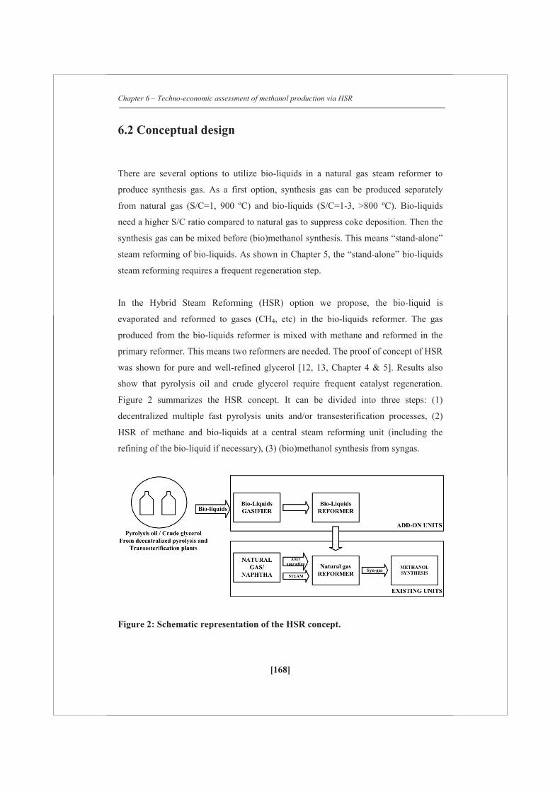
Chapter 6 – Techno-economic assessment of methanol production via HSR
[168]
6.2 Conceptual design
There are several options to utilize bio-liquids in a natural gas steam reformer to
produce synthesis gas. As a first option, synthesis gas can be produced separately
from natural gas (S/C=1, 900 ºC) and bio-liquids (S/C=1-3, >800 ºC). Bio-liquids
need a higher S/C ratio compared to natural gas to suppress coke deposition. Then the
synthesis gas can be mixed before (bio)methanol synthesis. This means “stand-alone”
steam reforming of bio-liquids. As shown in Chapter 5, the “stand-alone” bio-liquids
steam reforming requires a frequent regeneration step.
In the Hybrid Steam Reforming (HSR) option we propose, the bio-liquid is
evaporated and reformed to gases (CH4, etc) in the bio-liquids reformer. The gas
produced from the bio-liquids reformer is mixed with methane and reformed in the
primary reformer. This means two reformers are needed. The proof of concept of HSR
was shown for pure and well-refined glycerol [12, 13, Chapter 4 & 5]. Results also
show that pyrolysis oil and crude glycerol require frequent catalyst regeneration.
Figure 2 summarizes the HSR concept. It can be divided into three steps: (1)
decentralized multiple fast pyrolysis units and/or transesterification processes, (2)
HSR of methane and bio-liquids at a central steam reforming unit (including the
refining of the bio-liquid if necessary), (3) (bio)methanol synthesis from syngas.
Figure 2: Schematic representation of the HSR concept.

Cha
pter
6 –
Tec
hno-
econ
omic
ass
essm
ent o
f met
hano
l pro
duct
ion
via
HSR
[169
]
F
igur
e 3:
Mod
el f
low
shee
t of
HSR
and
(bi
o)m
etha
nol s
ynth
esis
pro
cess
(on
ly im
port
ant
unit
ope
rati
ons
are
show
n in
fig
ure)
.
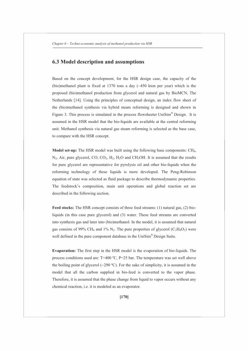
Chapter 6 – Techno-economic analysis of methanol production via HSR
[170]
6.3 Model description and assumptions
Based on the concept development, for the HSR design case, the capacity of the
(bio)methanol plant is fixed at 1370 tons a day (~450 kton per year) which is the
proposed (bio)methanol production from glycerol and natural gas by BioMCN, The
Netherlands [14]. Using the principles of conceptual design, an index flow sheet of
the (bio)methanol synthesis via hybrid steam reforming is designed and shown in
Figure 3. This process is simulated in the process flowsheeter UniSim® Design. It is
assumed in the HSR model that the bio-liquids are available at the central reforming
unit. Methanol synthesis via natural gas steam reforming is selected as the base case,
to compare with the HSR concept.
Model set-up: The HSR model was built using the following base components: CH4,
N2, Air, pure glycerol, CO, CO2, H2, H2O and CH3OH. It is assumed that the results
for pure glycerol are representative for pyrolysis oil and other bio-liquids when the
reforming technology of these liquids is more developed. The Peng-Robinson
equation of state was selected as fluid package to describe thermodynamic properties.
The feedstock’s composition, main unit operations and global reaction set are
described in the following section.
Feed stocks: The HSR concept consists of three feed streams: (1) natural gas, (2) bio-
liquids (in this case pure glycerol) and (3) water. These feed streams are converted
into synthesis gas and later into (bio)methanol. In the model, it is assumed that natural
gas consists of 99% CH4 and 1% N2. The pure properties of glycerol (C3H8O3) were
well defined in the pure component database in the UniSim® Design Suite.
Evaporation: The first step in the HSR model is the evaporation of bio-liquids. The
process conditions used are: T=400 ºC, P=25 bar. The temperature was set well above
the boiling point of glycerol (~290 ºC). For the sake of simplicity, it is assumed in the
model that all the carbon supplied in bio-feed is converted to the vapor phase.
Therefore, it is assumed that the phase change from liquid to vapor occurs without any
chemical reaction, i.e. it is modeled as an evaporator.
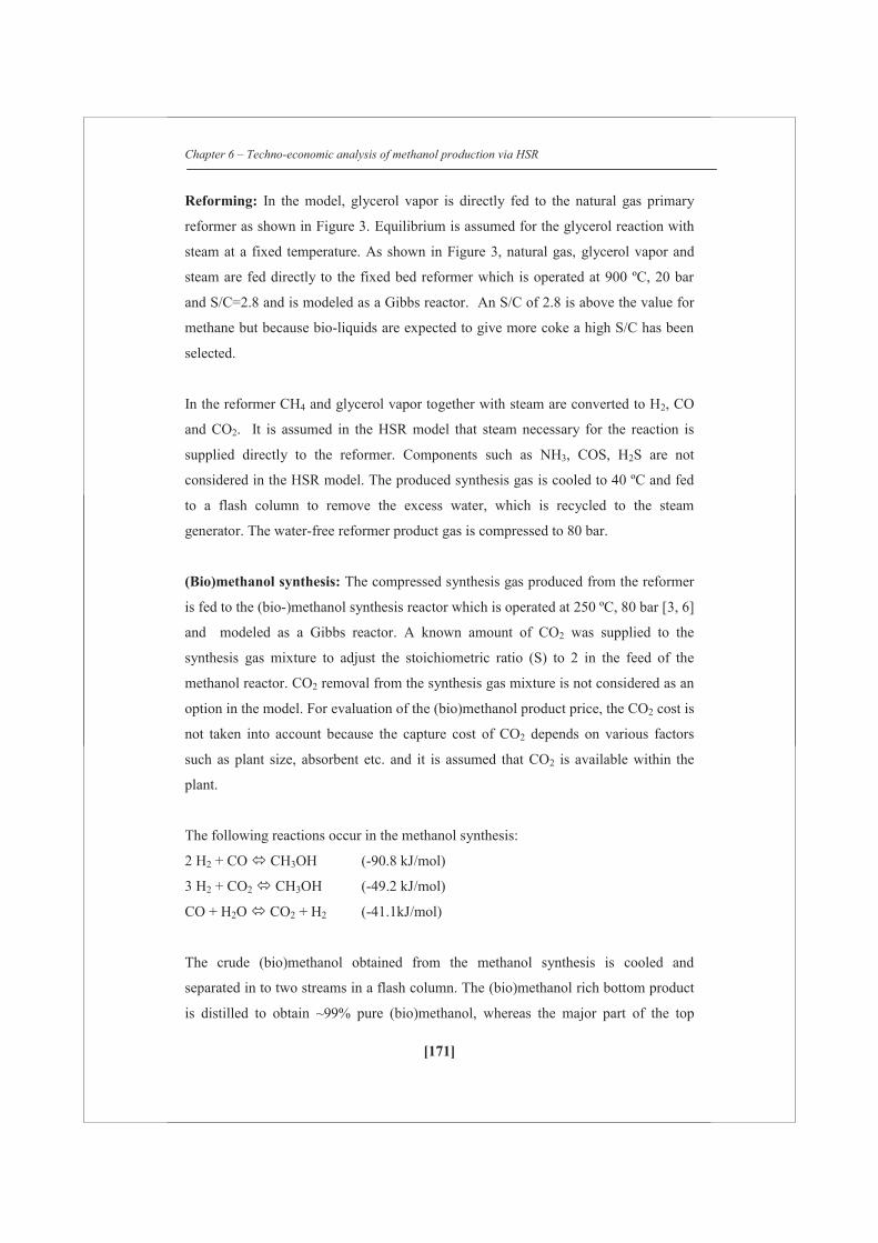
Chapter 6 – Techno-economic analysis of methanol production via HSR
[171]
Reforming: In the model, glycerol vapor is directly fed to the natural gas primary
reformer as shown in Figure 3. Equilibrium is assumed for the glycerol reaction with
steam at a fixed temperature. As shown in Figure 3, natural gas, glycerol vapor and
steam are fed directly to the fixed bed reformer which is operated at 900 ºC, 20 bar
and S/C=2.8 and is modeled as a Gibbs reactor. An S/C of 2.8 is above the value for
methane but because bio-liquids are expected to give more coke a high S/C has been
selected.
In the reformer CH4 and glycerol vapor together with steam are converted to H2, CO
and CO2. It is assumed in the HSR model that steam necessary for the reaction is
supplied directly to the reformer. Components such as NH3, COS, H2S are not
considered in the HSR model. The produced synthesis gas is cooled to 40 ºC and fed
to a flash column to remove the excess water, which is recycled to the steam
generator. The water-free reformer product gas is compressed to 80 bar.
(Bio)methanol synthesis: The compressed synthesis gas produced from the reformer
is fed to the (bio-)methanol synthesis reactor which is operated at 250 ºC, 80 bar [3, 6]
and modeled as a Gibbs reactor. A known amount of CO2 was supplied to the
synthesis gas mixture to adjust the stoichiometric ratio (S) to 2 in the feed of the
methanol reactor. CO2 removal from the synthesis gas mixture is not considered as an
option in the model. For evaluation of the (bio)methanol product price, the CO2 cost is
not taken into account because the capture cost of CO2 depends on various factors
such as plant size, absorbent etc. and it is assumed that CO2 is available within the
plant.
The following reactions occur in the methanol synthesis:
2 H2 + CO CH3OH (-90.8 kJ/mol)
3 H2 + CO2 CH3OH (-49.2 kJ/mol)
CO + H2O CO2 + H2 (-41.1kJ/mol)
The crude (bio)methanol obtained from the methanol synthesis is cooled and
separated in to two streams in a flash column. The (bio)methanol rich bottom product
is distilled to obtain ~99% pure (bio)methanol, whereas the major part of the top

Chapter 6 – Techno-economic analysis of methanol production via HSR
[172]
(bio)methanol lean vapor stream is recycled back to the methanol synthesis step. A
small fraction of the recycle stream (5%) is fed to the furnace and used for heat
generation. Besides the main feed streams, there is also a stream of natural gas, which
is mixed with air and combusted in the furnace. The energy generated from the
furnace supplies heat to the evaporator, primary reforming and steam generation
section. The total natural gas consumption is a sum of natural gas supplied to the
reformer and the furnace. In this study, based on all the assumptions mentioned
before, the HSR model was simulated using different amounts of glycerol (on carbon
basis) at fixed process conditions. A detailed equipment cost evaluation is given in
Table 4 and explained at the end of this Chapter (Appendix 1).
6.4 Methodology for the techno-economic assessment
From the mass and energy balances, the techno-economic analysis of the HSR process
using different amounts of glycerol was accomplished. Based on mass and energy
balances, the total bare equipment cost was estimated. Based on the total equipment
cost, the capital cost investment was calculated. The average (bio)methanol cost price
was estimated based on a fixed natural gas and glycerol price. This value was
compared with the methanol cost price for a conventional process via steam reforming
of natural gas (base case). Furthermore, a sensitivity analysis was performed to study
the effect of different parameters such as feed stock prices (natural gas, glycerol),
utilities cost (mainly electricity), total capital investment, labor cost etc. on the
(bio)methanol cost price. Also the option of feeding the glycerol to the furnace is
investigated and compared to the glycerol reform option.
Chapter 6 – Techno-economic analysis of methanol production via HSR
[173]
6.4.1 Net Present Value (NPV) analysis
Based on the fixed capital investment cost and the cash flow at each successive year,
the NPV of the project is calculated. The two widely used measures for evaluating an
investment are based on calculating NPV and the internal rate of return (IRR). The
NPV is calculated using this formula
nIRR)(1amount Income
luePresent va
Where, n is the corresponding year.
NPV = nn
221
0 IRR)(1CF
.... IRR)(1
CF
IRR)(1CF
I
where, CF’s is the constant Cash Flow after tax for each year. I0 represents the capital
investment at the start of the project. In this case the internal rate of return (IRR) is
chosen and assumed to be constant in the future i.e. till n years. For the NPV
calculation, the pay- back period is assumed to be 10 years with an IRR of 15%. The
rate between 10 and 15% is generally assumed for refinery operations [16]. The bio-
methanol cost price is calculated for the situation that NPV=0 at n=10 and IRR=15%
which are reasonable values to evaluate a business case.
6.4.2 Methodology
1. Design major equipment based on mass and energy balances. The level of
detail is related to the evaluation accuracy. The result will be an equipment list
with the values of the important cost drivers.
2. The bare equipment cost is estimated based on the major unit dimensions (for
e.g. heat transfer area, flow rate etc), process conditions (pressure,
temperature) and material selection.
3. The total capital investment is obtained from the total bare equipment cost
using a factor estimation method
4. The raw material and utilities cost are calculated based on mass and energy
balances

Chapter 6 – Techno-economic analysis of methanol production via HSR
[174]
5. Maintenance cost is assumed to be 5% of the total capital investment [17].
6. Labor cost is estimated based on 25 employees at an average salary of 100,000
€ p.a. However, in the sensitivity analysis, this parameter is varied to study the
effect on bio-methanol product value.
7. Other costs such as insurance and miscellaneous costs are assumed to be 2%
of the total capital investment [17].
8. License fees, royalty payments and research costs are assumed to be 2% of the
total capital investment [17].
9. The calculated cost price of the bio-methanol is based on a constant cash flow
after Tax necessary to obtain a NPV=0 after 10 years assuming an IRR of
15%.
Cash flow = Sales – (Raw materials + Utilities +
Maintenance + Labor + Others)
Depreciation = 10% of total capital investment
Taxable income (Profit) = Cash flow – Depreciation
Tax = % Taxation x Taxable income (Profit)
Profit after tax = Taxable income – Tax
Cash flow after tax = Profit after tax + Depreciation
The cash flow after tax (assumed constant for each year during a 10 years period) can
be calculated for a given I0 and NPV=0. Based on this cash flow, the average cost
price of the (bio)methanol is calculated. Average here means the price based on the
total production including natural gas and glycerol as feed. The raw material and
utilities cost price are summarized in Table 1.

Chapter 6 – Techno-economic analysis of methanol production via HSR
[175]
Table 1: Summary of raw materials and utilities cost price
Raw materials/Utilities cost Value
Natural gas 0.2 €/m3 [18]
Glycerol (initial assumption) 200 €/tonne
Steam reforming & Methanol synthesis catalyst 10 €/kg each (assumption)
Process water (distilled)
(2.25-4 $/1000 gallon - 1990)
(0.79-1.4 €/Nm3 – 2010)
1 €/tonne [17]
Cooling water (tower)
(0.06-0.26 $/1000 gallon - 1990)
(0.02-0.09 €/Nm3 – 2010)
0.1 €/tonne [17]
Electricity
100 €/MWh [18]
Compressed air
(0.06-0.20 $/1000 ft3- 1990)
(0.003-0.009 €/Nm3 – 2010)
0.0066 €/Nm3 [17]

Chapter 6 – Techno-economic analysis of methanol production via HSR
[176]
6.5 Results and discussions
This section summarizes the results of the mass and energy balance calculations of the
different process configurations modeled in the UniSim® Design process simulator.
The results are presented in Table 2 and 3 respectively.
Table 2: Mass balance for various HSR process cases Mass Balance Case 1
(Base)
Case 2 Case 3 Case 4 Case 5 Case 6
Reformer input (kg/h)
Glycerol 0 14276 20317 26905 32203 40143
Natural gas (99% CH4, 1%N2)
To reformer 27901 22552 20317 17937 16102 13381
To furnace 5628 5613 5527 5389 5257 5010
Total Natural gas supplied 33529 28165 25844 23326 21359 18391
Process water 22031 19992 19069 18142 17555 17196
Reformer output without steam (kmol/h)
H2 5078 4983 4940 4898 4875 4843
CO 1082 1139 1158 1177 1193 1216
CO2 463 591 649 713 768 851
CH4 180 133 118 103 93 80
S value of reformer product 2.99 2.54 2.38 2.21 2.09 1.93
Methanol reactor input (kmol/h)
H2 15841 14992 14676 14345 14126 13843
CO 1606 1626 1631 1641 1649 1660
CO2 (including extra CO2 added) 4213 3907 3788 3683 3605 3499
CH4 3462 2561 2242 1952 1758 1510
CO2 added (kmol/h) 617 425 344 255 184 80
S value at methanol reactor input 2.00 2.00 2.01 2.00 2.00 2.01
Methanol after purification (kg/h) 56739 56696 57072 57161 57439 56659
Carbon contribution from glycerol
(Cgly/(Cgly+ Cnatural gas))
0 0.21 0.29 0.38 0.44 0.54
Carbon efficiency* (%) 86 81 79 77 75 73
Green CO2* 0 0.05 0.07 0.08 0.10 0.12
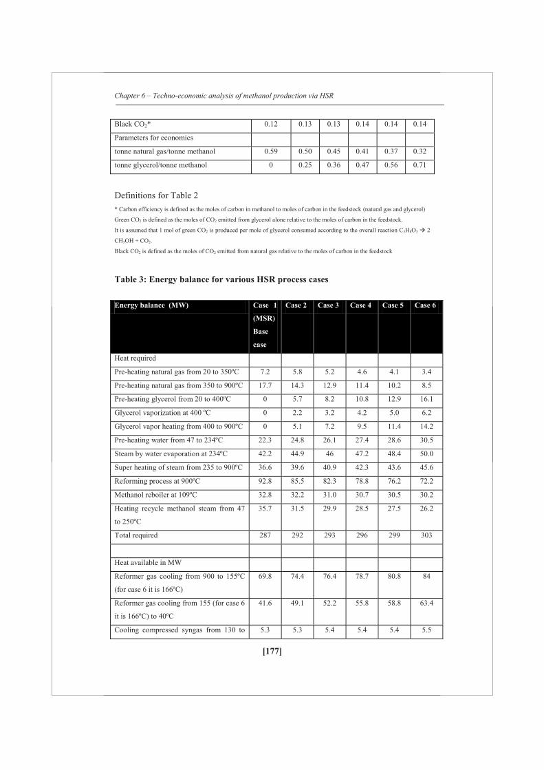
Chapter 6 – Techno-economic analysis of methanol production via HSR
[177]
Black CO2* 0.12 0.13 0.13 0.14 0.14 0.14
Parameters for economics
tonne natural gas/tonne methanol 0.59 0.50 0.45 0.41 0.37 0.32
tonne glycerol/tonne methanol 0 0.25 0.36 0.47 0.56 0.71
Definitions for Table 2 * Carbon efficiency is defined as the moles of carbon in methanol to moles of carbon in the feedstock (natural gas and glycerol)
Green CO2 is defined as the moles of CO2 emitted from glycerol alone relative to the moles of carbon in the feedstock.
It is assumed that 1 mol of green CO2 is produced per mole of glycerol consumed according to the overall reaction C3H8O3 2
CH3OH + CO2.
Black CO2 is defined as the moles of CO2 emitted from natural gas relative to the moles of carbon in the feedstock
Table 3: Energy balance for various HSR process cases Energy balance (MW) Case 1
(MSR)
Base
case
Case 2 Case 3 Case 4 Case 5 Case 6
Heat required
Pre-heating natural gas from 20 to 350ºC 7.2 5.8 5.2 4.6 4.1 3.4
Pre-heating natural gas from 350 to 900ºC 17.7 14.3 12.9 11.4 10.2 8.5
Pre-heating glycerol from 20 to 400ºC 0 5.7 8.2 10.8 12.9 16.1
Glycerol vaporization at 400 ºC 0 2.2 3.2 4.2 5.0 6.2
Glycerol vapor heating from 400 to 900ºC 0 5.1 7.2 9.5 11.4 14.2
Pre-heating water from 47 to 234ºC 22.3 24.8 26.1 27.4 28.6 30.5
Steam by water evaporation at 234ºC 42.2 44.9 46 47.2 48.4 50.0
Super heating of steam from 235 to 900ºC 36.6 39.6 40.9 42.3 43.6 45.6
Reforming process at 900ºC 92.8 85.5 82.3 78.8 76.2 72.2
Methanol reboiler at 109ºC 32.8 32.2 31.0 30.7 30.5 30.2
Heating recycle methanol steam from 47
to 250ºC
35.7 31.5 29.9 28.5 27.5 26.2
Total required 287 292 293 296 299 303
Heat available in MW
Reformer gas cooling from 900 to 155ºC
(for case 6 it is 166ºC)
69.8 74.4 76.4 78.7 80.8 84
Reformer gas cooling from 155 (for case 6
it is 166ºC) to 40ºC
41.6 49.1 52.2 55.8 58.8 63.4
Cooling compressed syngas from 130 to 5.3 5.3 5.4 5.4 5.4 5.5
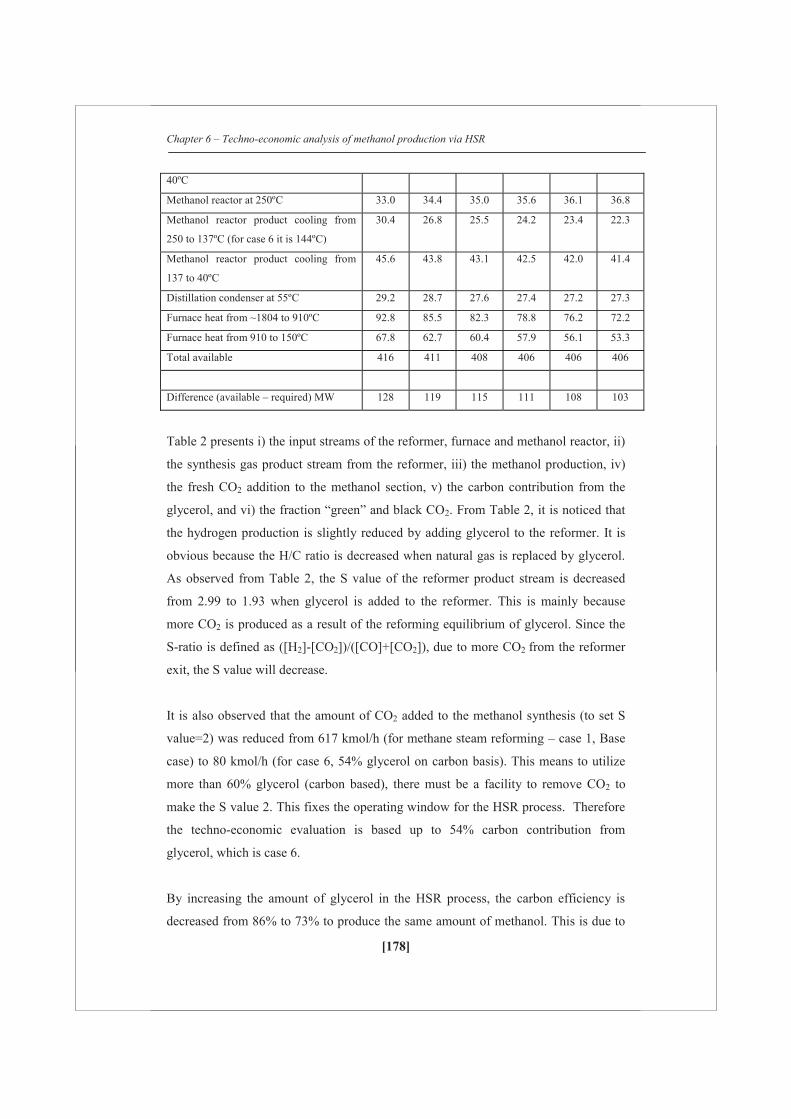
Chapter 6 – Techno-economic analysis of methanol production via HSR
[178]
40ºC
Methanol reactor at 250ºC 33.0 34.4 35.0 35.6 36.1 36.8
Methanol reactor product cooling from
250 to 137ºC (for case 6 it is 144ºC)
30.4 26.8 25.5 24.2 23.4 22.3
Methanol reactor product cooling from
137 to 40ºC
45.6 43.8 43.1 42.5 42.0 41.4
Distillation condenser at 55ºC 29.2 28.7 27.6 27.4 27.2 27.3
Furnace heat from ~1804 to 910ºC 92.8 85.5 82.3 78.8 76.2 72.2
Furnace heat from 910 to 150ºC 67.8 62.7 60.4 57.9 56.1 53.3
Total available 416 411 408 406 406 406
Difference (available – required) MW 128 119 115 111 108 103
Table 2 presents i) the input streams of the reformer, furnace and methanol reactor, ii)
the synthesis gas product stream from the reformer, iii) the methanol production, iv)
the fresh CO2 addition to the methanol section, v) the carbon contribution from the
glycerol, and vi) the fraction “green” and black CO2. From Table 2, it is noticed that
the hydrogen production is slightly reduced by adding glycerol to the reformer. It is
obvious because the H/C ratio is decreased when natural gas is replaced by glycerol.
As observed from Table 2, the S value of the reformer product stream is decreased
from 2.99 to 1.93 when glycerol is added to the reformer. This is mainly because
more CO2 is produced as a result of the reforming equilibrium of glycerol. Since the
S-ratio is defined as ([H2]-[CO2])/([CO]+[CO2]), due to more CO2 from the reformer
exit, the S value will decrease.
It is also observed that the amount of CO2 added to the methanol synthesis (to set S
value=2) was reduced from 617 kmol/h (for methane steam reforming – case 1, Base
case) to 80 kmol/h (for case 6, 54% glycerol on carbon basis). This means to utilize
more than 60% glycerol (carbon based), there must be a facility to remove CO2 to
make the S value 2. This fixes the operating window for the HSR process. Therefore
the techno-economic evaluation is based up to 54% carbon contribution from
glycerol, which is case 6.
By increasing the amount of glycerol in the HSR process, the carbon efficiency is
decreased from 86% to 73% to produce the same amount of methanol. This is due to

Chapter 6 – Techno-economic analysis of methanol production via HSR
[179]
the oxygen present in the glycerol, which will be emitted as extra CO2. Therefore, the
net mole of CO2 emitted from the process (from furnace) is doubled (0.12 to 0.26).
However, “black CO2” (CO2 emitted from natural gas alone) remains almost constant
while the “green CO2” (assumed one CO2 produced per glycerol converted) is
increased when glycerol is added to the process. Overall the amount of CO2 emitted
will be constant since the “green CO2” (considering “green CO2” is from biomass)
will be recycled via photosynthesis. Table 2 also reports some important parameters
for the economic evaluation such as tonne of natural gas and glycerol required to
produce a tonne of methanol. It requires 0.59 tonne of natural gas per tonne of
methanol of which 0.5 tonne of methane for the reforming. These data obtained for
the SMR (base case) is in agreement with the data given in the literature (which is 0.5
tonne of CH4 to produce a tonne of methanol) [19].
Table 3 summarizes the energy balance for all the six cases. It is observed that the
overall heat required is slightly increased for the hybrid steam reforming process
(relative to the base case). The rise is due to i) glycerol heating and vaporization and
ii) additional water heating and vaporization since more water (including recycle) is
required for the HSR process than the MSR (base case). This is partly compensated by
less consumption of natural gas in the HSR process and furthermore, the glycerol
addition makes the overall reforming less endothermic than in the SMR case. The
overall excess heat available for all the cases remained almost the same. This excess
heat can partly be utilized elsewhere.
Pinch technology was applied to analyze the energy flows in the system and to
optimize the heat integration for the HSR concept. As an example, the composite
curve for the cold and hot streams is presented for case 6 in Figure 4. The composite
curves represent the heating and cooling demands of the entire system and identify
minimum utility requirements. The pinch point is defined as the closest temperature
difference between the hot and cold streams (ΔTmin). In this case, the pinch point (ΔT)
was set to 10 ºC. From the composite curve, it is identified that the minimum hot and
cold utility requirements were found to be 0.4 MW and 103.5 MW respectively at the
pinch temperature of 900 ºC. The small amount of hot utility is obtained through a
slight increase of furnace duty. The waste heat of ~103 MW (case 6) and a closed

Chapter 6 – Techno-economic analysis of methanol production via HSR
[180]
cooling circuit of water at ΔT=20 K will lead to cooling of ~4285 tonne/hr of water or
~75 m3 of cooling water per tonne of methanol. The high temperature heat available
from the furnace (~1804 to 910 ºC) can be supplied to the reformer and the heat
available from the methanol reactor can be used to make steam by evaporating water
at 234 ºC. In principle, it is always possible to design a heat exchanger network to
achieve the energy targets from the pinch analysis. However, this is not the focus of
the present investigation.
Figure 4: Pinch analysis for (bio)methanol production via hybrid steam reforming of glycerol with methane (Case 6).
6.5.1 Estimation of total capital investment cost for HSR process
The total equipment cost was estimated based on the costs of the major unit
operations with dimensions and cost drivers for the HSR process for Case 6. It is
summarized in Table 4 and explained in Appendix 1 at the end of this Chapter. The
purchased process equipment cost is estimated with Peter’s cost estimator tool
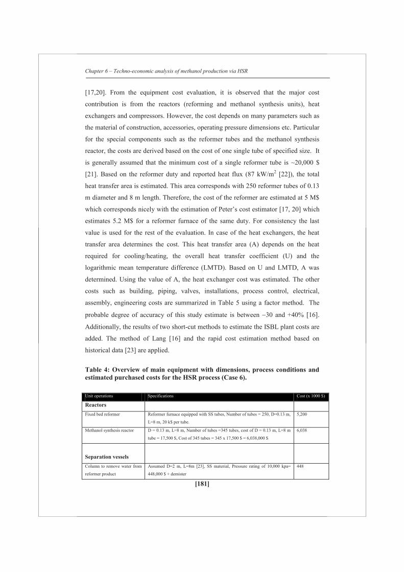
Chapter 6 – Techno-economic analysis of methanol production via HSR
[181]
[17,20]. From the equipment cost evaluation, it is observed that the major cost
contribution is from the reactors (reforming and methanol synthesis units), heat
exchangers and compressors. However, the cost depends on many parameters such as
the material of construction, accessories, operating pressure dimensions etc. Particular
for the special components such as the reformer tubes and the methanol synthesis
reactor, the costs are derived based on the cost of one single tube of specified size. It
is generally assumed that the minimum cost of a single reformer tube is ~20,000 $
[21]. Based on the reformer duty and reported heat flux (87 kW/m2 [22]), the total
heat transfer area is estimated. This area corresponds with 250 reformer tubes of 0.13
m diameter and 8 m length. Therefore, the cost of the reformer are estimated at 5 M$
which corresponds nicely with the estimation of Peter’s cost estimator [17, 20] which
estimates 5.2 M$ for a reformer furnace of the same duty. For consistency the last
value is used for the rest of the evaluation. In case of the heat exchangers, the heat
transfer area determines the cost. This heat transfer area (A) depends on the heat
required for cooling/heating, the overall heat transfer coefficient (U) and the
logarithmic mean temperature difference (LMTD). Based on U and LMTD, A was
determined. Using the value of A, the heat exchanger cost was estimated. The other
costs such as building, piping, valves, installations, process control, electrical,
assembly, engineering costs are summarized in Table 5 using a factor method. The
probable degree of accuracy of this study estimate is between 30 and +40% [16].
Additionally, the results of two short-cut methods to estimate the ISBL plant costs are
added. The method of Lang [16] and the rapid cost estimation method based on
historical data [23] are applied.
Table 4: Overview of main equipment with dimensions, process conditions and estimated purchased costs for the HSR process (Case 6). Unit operations Specifications Cost (x 1000 $)
Reactors
Fixed bed reformer Reformer furnace equipped with SS tubes, Number of tubes = 250, D=0.13 m,
L=8 m, 20 k$ per tube.
5,200
Methanol synthesis reactor D = 0.13 m, L=8 m, Number of tubes =345 tubes, cost of D = 0.13 m, L=8 m
tube = 17,500 $, Cost of 345 tubes = 345 x 17,500 $ = 6,038,000 $
6,038
Separation vessels
Column to remove water from
reformer product
Assumed D=2 m, L=8m [23], SS material, Pressure rating of 10,000 kpa=
448,000 $ + demister
448

Chapter 6 – Techno-economic analysis of methanol production via HSR
[182]
Second column to remove
water from reformer product
Assumed D=2 m, L=6m [23], SS material, Pressure rating of 10,000 kpa =
360,000 $ + demister
360
Column after methanol
synthesis
Assumed D=2.5 m, L=9m [23], SS material, Pressure rating of 10,000 kpa=
760,000 $ in case of D = 3 m and 492,000 $ in case of D=2 m, Assume the
column will cost 625,000 $ + Demister
625
Column to remove lights Assumed D=2 m, L=10m, SS material, Pressure rating of 1035 kpa = 186,000
$
186
Column to purify methanol Active area necessary for gas flow is 8 m2. Total cross-sectional area is about
10 m2.Diameter is 3.5 m, Number of stages: 16 ideal, 23 real stages (70% eff.).
Height of column about 15 m.
570
Heat exchangers
Natural gas pre-heating (20 to
350 ºC
Floating head heat exchangers, Area 680 m2, Shell is CS, tube is SS, Design
pressure = 31 bar
135
Natural gas heating (350 to
900 ºC
Floating head heat exchangers, Area 1700 m2, Shell is CS, tube is SS, Design
pressure = 30 bar
336
Glycerol gasification (20 to
400 ºC)
Floating head heat exchangers, Area 1600 m2, Shell is CS, tube is SS, Design
pressure = 30 bar
320
Glycerol vaporization at 400
ºC
Floating head heat exchangers, Area 600 m2, Shell is CS, tube is SS, Design
pressure = 30 bar
120
Glycerol vapor heating from
400 to 900 ºC
Floating head heat exchangers, Area 3000 m2, Shell is CS, tube is SS, Design
pressure = 30 bar
610
Water heating from 47 to 234
ºC
Floating head heat exchangers, Area 3000 m2, Shell is CS, tube is SS, Design
pressure = 30 bar
610
Water evaporation to steam at
235 ºC
Floating head heat exchangers, Area 5000 m2, Shell is CS, tube is SS, Design
pressure = 30 bar
1,015
Steam heating from 235 to 900
ºC
Floating head heat exchangers, Area 10000 m2, Shell is CS, tube is SS, Design
pressure = 30 bar
2,030
Heating recycle methanol
stream from 47 to 250 ºC
Floating head heat exchangers, Area 1200 m2, Shell is CS, tube is SS, Design
pressure = 70 bar
320
Cooling reformer gas 900 to
155 ºC
3 floating head heat exchangers of
62 MW: 900 ºC 350 ºC, A=1400 m2
11 MW: 350 ºC 250 ºC, A=915 m2
11 MW 250 ºC 155 ºC, A=1000 m2
847
Cooling reformer gas from 155
to 40 ºC
Floating head heat exchangers, Area 6000 m2, Shell is CS, tube is SS, Design
pressure = 30 bar
1,200
Cooling compressed gas 130 to
40 ºC
Floating head heat exchangers, Area 713 m2, Shell is CS, tube is SS, Design
pressure = 70 bar
181
Cooling methanol product 250
to 137 ºC
Floating head heat exchangers, Area 2700 m2, Shell is CS, tube is SS, Design
pressure = 70 bar
690
Cooling methanol product 137
to 40 ºC
Floating head heat exchangers, Area 5200 m2, Shell is CS, tube is SS, Design
pressure = 70 bar
1,300
Condenser for methanol
distillation column
Floating head heat exchangers, Area 1700 m2, Shell is CS, tube is SS, Design
pressure = 7 bar
200
Reboiler for methanol
distillation column
Floating head heat exchangers, Area 300 m2, Shell is CS, tube is SS, Design
pressure = 7 bar
60
Compressors and
pumps
Synthesis gas compressor from Two centrifugal turbine compressors each 5.2 MW power rating, Material CS 6,400

Chapter 6 – Techno-economic analysis of methanol production via HSR
[183]
20 to 80 bar
Methanol recycle compressor
from 75 to 80 bar
Centrifugal rotary motor, Power rating 900 KW, Material CS 634
Bio-liquid pump Centrifugal cast iron pump (water duty), volumetric flow = 0.009 m3/s 11
Water pump Centrifugal cast iron pump (water duty), volumetric flow = 0.005 m3/s 11
Total equipment cost (Million US$) 2002 31
Total equipment cost (Million US$) 2012
CECPI in 2002 = 390 [24] and CECPI in 2012 (April) = 596 [24]
47
Total equipment cost (Million €) 2012
€:$ exchange rate in 2012 = 1:1.34
36
Table 5: Summary of total capital investment for the HSR process; capacity = 450,000 tonne/year (bio)methanol Group Capital cost items Comment/Definition Million EUR
I Production building For fluid processing plant it is
5-18% of equipment cost at existing site
new unit [17] It is assumed ~5% in this calculation
2
II HVAC installations and
insulations
It is 10-20% of all purchased equipment or 3-10% of fixed capital
investment [17]. It is assumed 20% of total equipment cost.
7
III Total equipment cost Refer Appendix 1 36
IV Piping and valves cost This is usually 10-80% of total equipment cost [17]. For the
selected equipments it is assumed to be 80% of total equipment
cost
29
VI Process instrumentation
and analysis
~30% of total equipment cost [17] 11
VII Assembly and
installation
50% of total equipment cost [17] 18
Sum (I-VII) Direct plant costs Sum of costs from (I-VII) 103
VIII Engineering cost This is 75% of total equipment cost [17] 27
IX Contingency Unforeseen events such as strikes, storms, floods, price variations
may have an effect on the cost of the manufacturing operation
[17]. This is usually 1-5% of total capital investment or 50% of
equipment cost
18
ISBL plant costs Direct plant costs + Sum (VIII-IX) 148
OSBL plant costs Usually 30% of ISBL costs 44
Total capital investment Sum of ISBL and OSBL costs 192
Lang method Total capital investment
(in million €)
(only ISBL)
plangf C F C where,
Cf is the fixed capital cost of the plant, Σ Cp is the total delivered
cost of all the major equipment items such as reactors, heat
exchangers, furnace,
distillation columns, pumps etc.
Flang is the Lang factor. Usually for fluid processing plants, a Lang
factor between 4 and 5 is used [16]. In the model, a Lang factor of
5 is used.
180

Chapter 6 – Techno-economic analysis of methanol production via HSR
[184]
Rapid cost
estimation
method
Total capital investment
(in million €)
(only ISBL)
n
1
212 S
SC C an22 S C (million $)
C2, Capital cost of the plant with capacity S2
C1, Capital cost of the plant with capacity S1 Parameters given in
Hydrocarbon processing journal for methanol plant according to
2006 US gulf coast, a=2.775, n=0.6, S2=1370 tonne methanol a
day [23]. CEPCI in 2006 = 499.6 and in 2011 = 581.7.[24]
€:$ exchange rate = 1:1.34
185
The Lang method [16] is based only on the purchased equipment cost. However, the
equipment cost varies from place, availability of materials and plant type. The rapid
cost estimation method is based on the historical data of a methanol plant [23]. This
method is based on a conventional methanol plant and gives an approximate capital
cost with an accuracy of ±30-50%. The results in Table 5 show that the ISBL plant
costs are estimated in the range between 148 and 185 Million Euro. For further
evaluation, a total capital investment (ISBL + OSBL) of 250 Million Euro for a
production capacity of 450 ktpa of methanol is assumed.
6.5.2 Techno-economic evaluation
The cost prices of (bio)methanol produced at 450 ktpa from natural gas (MSR)
and natural gas mixed with glycerol (HSR) are estimated. The total capital investment
for all configurations was fixed as 250 million € including ISBL and OSBL (OSBL is
assumed 30% of ISBL) costs. All the cost which includes approximate natural gas
price, labor cost, utilities (electricity), equipment and taxation are related to the central
European region.
Table 6 summarizes the estimation of the (bio)methanol cost price. From the cost
comparison between the MSR and HSR process, it is observed that the raw material
costs and especially glycerol dictates the (bio)methanol product costs. The utilities
and depreciation contribute 9–11% and 13-15% respectively to the methanol
production cost. Other costs such as labor cost, maintenance cost, license and
miscellaneous (insurance) which are directly related to the total capital investment
contribute also 13-15%. The product cost of methanol for the MSR and HSR (case 6)
process differs by ~75 €/tonne assuming a raw material price of 200 €/tonne glycerol.
Glycerol is cheaper than natural gas but mass balance calculations show that each
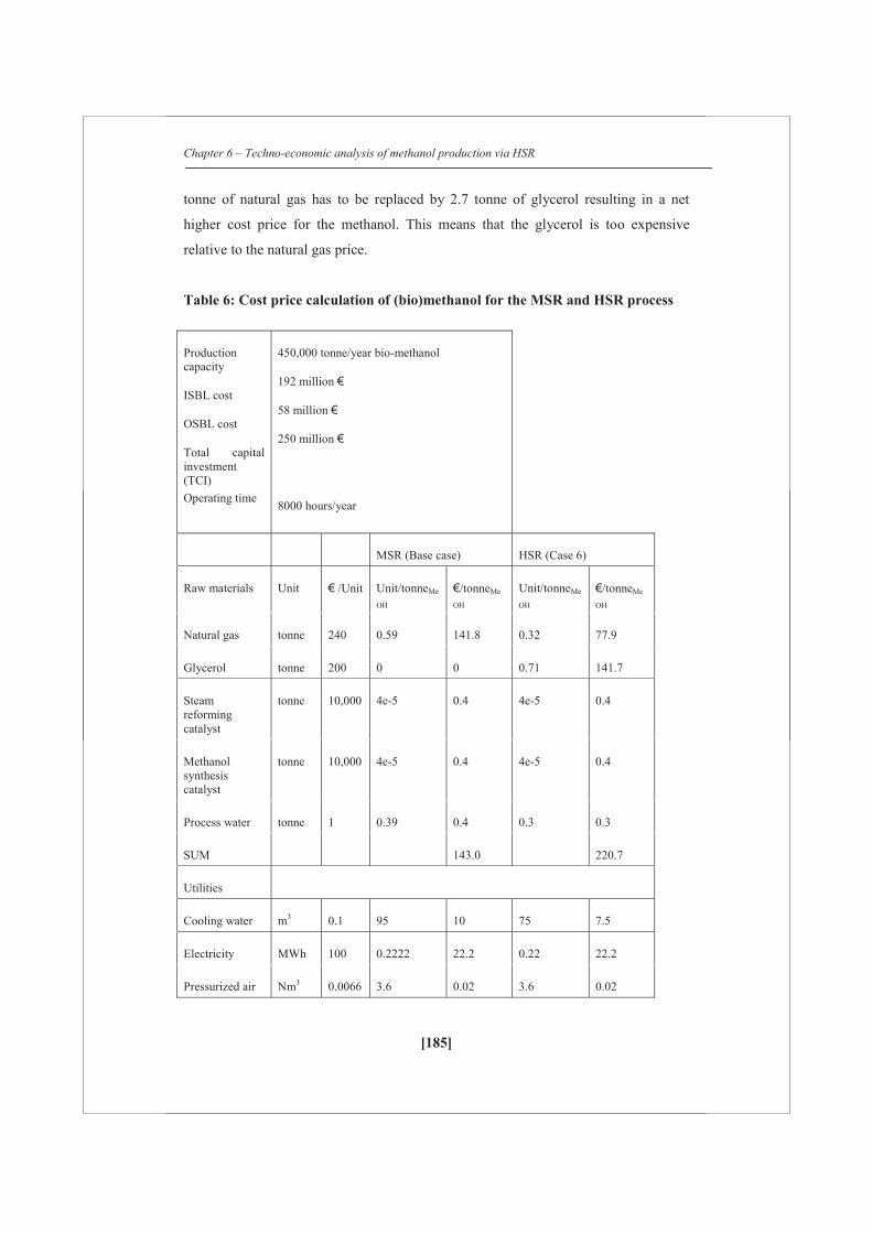
Chapter 6 – Techno-economic analysis of methanol production via HSR
[185]
tonne of natural gas has to be replaced by 2.7 tonne of glycerol resulting in a net
higher cost price for the methanol. This means that the glycerol is too expensive
relative to the natural gas price.
Table 6: Cost price calculation of (bio)methanol for the MSR and HSR process
Production capacity
ISBL cost
OSBL cost
Total capital investment (TCI) Operating time
450,000 tonne/year bio-methanol
192 million €
58 million €
250 million €
8000 hours/year
MSR (Base case) HSR (Case 6)
Raw materials Unit € /Unit Unit/tonneMe
OH
€/tonneMe
OH Unit/tonneMe
OH
€/tonneMe
OH
Natural gas tonne 240 0.59 141.8 0.32 77.9
Glycerol tonne 200 0 0 0.71 141.7
Steam reforming catalyst
tonne 10,000 4e-5 0.4 4e-5 0.4
Methanol synthesis catalyst
tonne 10,000 4e-5 0.4 4e-5 0.4
Process water tonne 1 0.39 0.4 0.3 0.3
SUM 143.0 220.7
Utilities
Cooling water m3 0.1 95 10 75 7.5
Electricity MWh 100 0.2222 22.2 0.22 22.2
Pressurized air Nm3 0.0066 3.6 0.02 3.6 0.02

Chapter 6 – Techno-economic analysis of methanol production via HSR
[186]
SUM 32.2 29.5
Labor cost
Number of employees
25 100,000
5.6 5.6
Maintenance cost
5% TCI
27.8 27.8
License 2% TCI
11.1 11.1
Insurance 2% TCI
11.1 11.1
Total cash cost 230.8 305.8
Depreciation 10% 55.6 55.6
Total production cost
286.4 361.3
NPV calculations
Rate of interest & Number of years
15%, 10 years, I0 = 250 Million Euro
Cash flow needed for NPV = 0
110.8 110.8
Profit after tax 55.2 55.2
Taxation 23% 16.5 16.5
Profit before tax 71.7 71.7
Cash flow before tax
127.3 127.3
PRODUCT COST PRICE
358 433
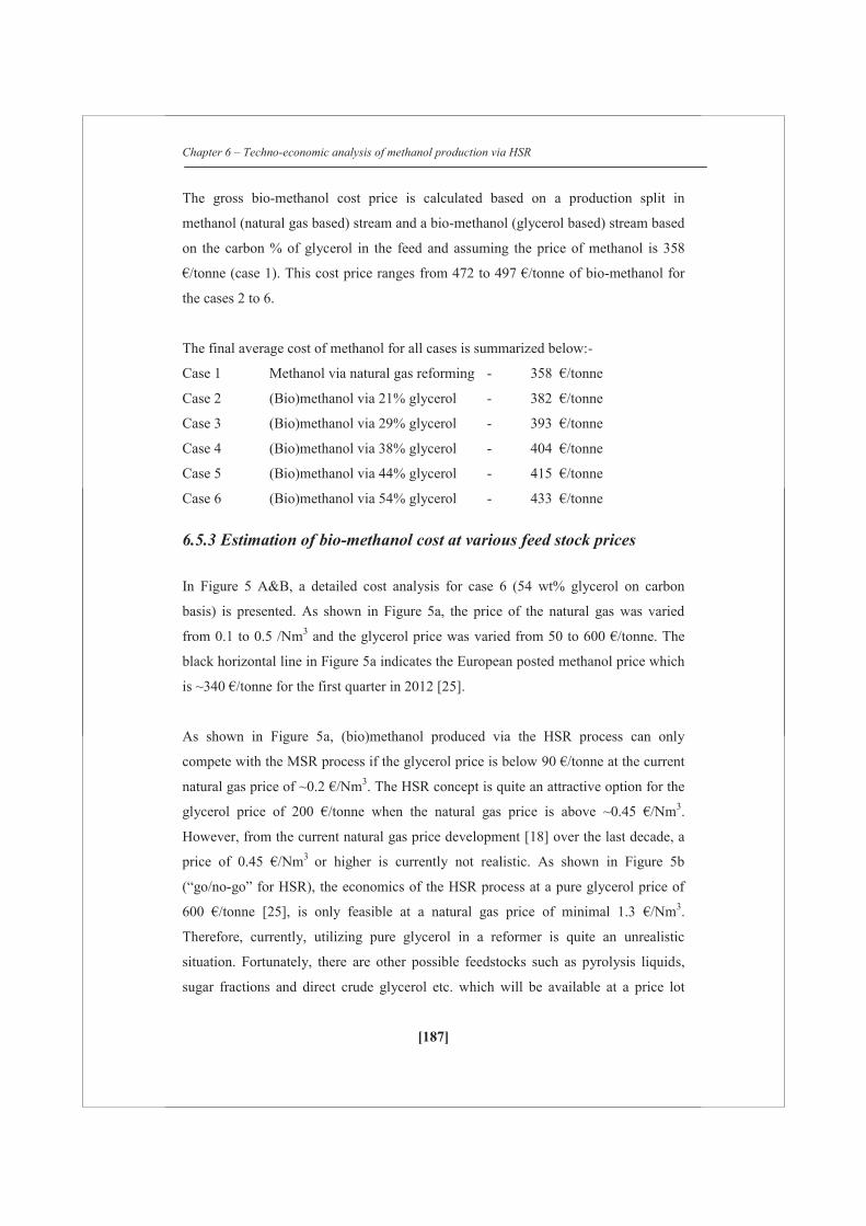
Chapter 6 – Techno-economic analysis of methanol production via HSR
[187]
The gross bio-methanol cost price is calculated based on a production split in
methanol (natural gas based) stream and a bio-methanol (glycerol based) stream based
on the carbon % of glycerol in the feed and assuming the price of methanol is 358
€/tonne (case 1). This cost price ranges from 472 to 497 €/tonne of bio-methanol for
the cases 2 to 6.
The final average cost of methanol for all cases is summarized below:-
Case 1 Methanol via natural gas reforming - 358 €/tonne
Case 2 (Bio)methanol via 21% glycerol - 382 €/tonne
Case 3 (Bio)methanol via 29% glycerol - 393 €/tonne
Case 4 (Bio)methanol via 38% glycerol - 404 €/tonne
Case 5 (Bio)methanol via 44% glycerol - 415 €/tonne
Case 6 (Bio)methanol via 54% glycerol - 433 €/tonne
6.5.3 Estimation of bio-methanol cost at various feed stock prices
In Figure 5 A&B, a detailed cost analysis for case 6 (54 wt% glycerol on carbon
basis) is presented. As shown in Figure 5a, the price of the natural gas was varied
from 0.1 to 0.5 /Nm3 and the glycerol price was varied from 50 to 600 €/tonne. The
black horizontal line in Figure 5a indicates the European posted methanol price which
is ~340 €/tonne for the first quarter in 2012 [25].
As shown in Figure 5a, (bio)methanol produced via the HSR process can only
compete with the MSR process if the glycerol price is below 90 €/tonne at the current
natural gas price of ~0.2 €/Nm3. The HSR concept is quite an attractive option for the
glycerol price of 200 €/tonne when the natural gas price is above ~0.45 €/Nm3.
However, from the current natural gas price development [18] over the last decade, a
price of 0.45 €/Nm3 or higher is currently not realistic. As shown in Figure 5b
(“go/no-go” for HSR), the economics of the HSR process at a pure glycerol price of
600 €/tonne [25], is only feasible at a natural gas price of minimal 1.3 €/Nm3.
Therefore, currently, utilizing pure glycerol in a reformer is quite an unrealistic
situation. Fortunately, there are other possible feedstocks such as pyrolysis liquids,
sugar fractions and direct crude glycerol etc. which will be available at a price lot
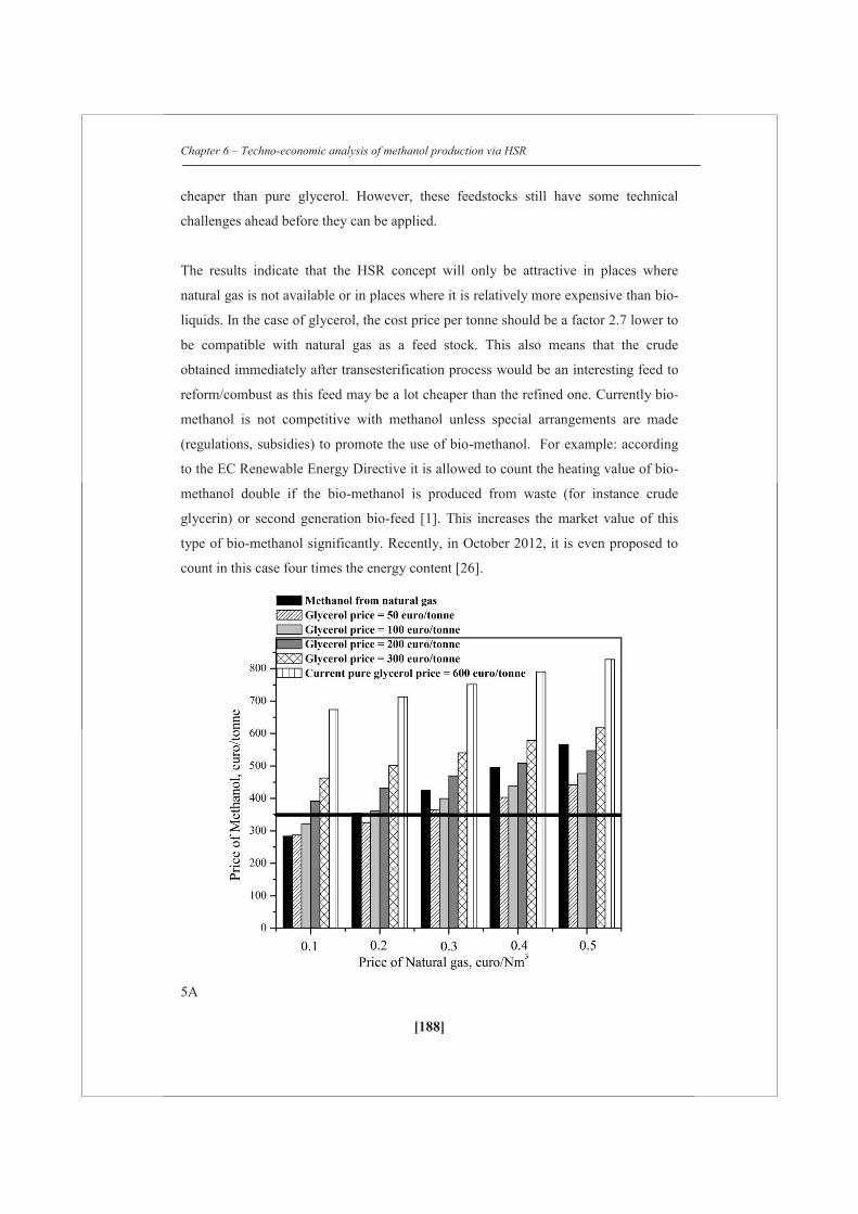
Chapter 6 – Techno-economic analysis of methanol production via HSR
[188]
cheaper than pure glycerol. However, these feedstocks still have some technical
challenges ahead before they can be applied.
The results indicate that the HSR concept will only be attractive in places where
natural gas is not available or in places where it is relatively more expensive than bio-
liquids. In the case of glycerol, the cost price per tonne should be a factor 2.7 lower to
be compatible with natural gas as a feed stock. This also means that the crude
obtained immediately after transesterification process would be an interesting feed to
reform/combust as this feed may be a lot cheaper than the refined one. Currently bio-
methanol is not competitive with methanol unless special arrangements are made
(regulations, subsidies) to promote the use of bio-methanol. For example: according
to the EC Renewable Energy Directive it is allowed to count the heating value of bio-
methanol double if the bio-methanol is produced from waste (for instance crude
glycerin) or second generation bio-feed [1]. This increases the market value of this
type of bio-methanol significantly. Recently, in October 2012, it is even proposed to
count in this case four times the energy content [26].
5A
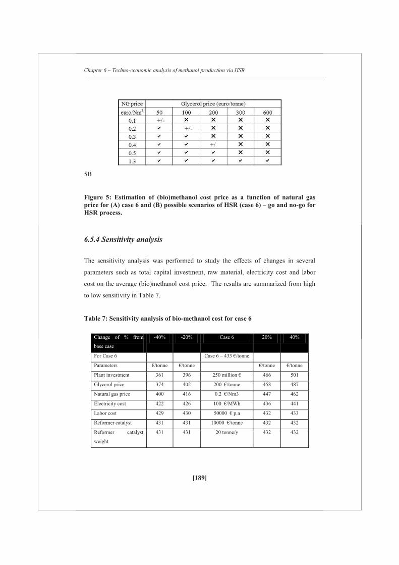
Chapter 6 – Techno-economic analysis of methanol production via HSR
[189]
5B
Figure 5: Estimation of (bio)methanol cost price as a function of natural gas price for (A) case 6 and (B) possible scenarios of HSR (case 6) – go and no-go for HSR process.
6.5.4 Sensitivity analysis
The sensitivity analysis was performed to study the effects of changes in several
parameters such as total capital investment, raw material, electricity cost and labor
cost on the average (bio)methanol cost price. The results are summarized from high
to low sensitivity in Table 7.
Table 7: Sensitivity analysis of bio-methanol cost for case 6
Change of % from
base case
-40% -20% Case 6 20% 40%
For Case 6 Case 6 – 433 €/tonne
Parameters €/tonne €/tonne €/tonne €/tonne
Plant investment 361 396 250 million € 466 501
Glycerol price 374 402 200 €/tonne 458 487
Natural gas price 400 416 0.2 €/Nm3 447 462
Electricity cost 422 426 100 €/MWh 436 441
Labor cost 429 430 50000 € p.a 432 433
Reformer catalyst 431 431 10000 €/tonne 432 432
Reformer catalyst
weight
431 431 20 tonne/y 432 432
+/- +/-
+/

Chapter 6 – Techno-economic analysis of methanol production via HSR
[190]
The sensitivity analysis shows that the glycerol price, total capital investment and
natural gas show a strong impact on the cost price of (bio)methanol. The price of
glycerol was varied between 120 and 280 €/tonne ( 40 to 40%) resulting in a
(bio)methanol price increase of ~0.7 €/tonne ((458-432)/(240-200)) for every euro
increase per tonne of glycerol starting from 200 €/tonne. To obtain a (bio)methanol
price between 340 – 370 €/tonne, the estimated crude glycerol price should be
between 70 and 110 €/tonne. At this price, glycerol is not available on the market;
nevertheless, there is no fixed price for crude glycerol obtained after the
transesterification process. At the present spot price [2012] of tallow based technical
glycerine ~600 €/tonne [25], the (bio)methanol price via the HSR (case 6) concept
would be ~713 €/tonne.
In the sensitivity analysis the capital investment was varied between 150 and 350
million € to study its effect on the (bio)methanol cost price. From the sensitivity
analysis, ±0.7 €/tonne of (bio)methanol for every ±1 million € in total capital
investment is estimated. Over the last 5 years the natural gas price fluctuated between
0.197 €/Nm3 (240 €/tonne natural gas) and 0.07 €/Nm3 (84 €/tonne natural gas) at a
peak value of 0.3 €/Nm3 in June 2008 [30]. The model predicts a (bio)methanol price
between 400 and 461 €/tonne for the natural gas price range between 0.12 and 0.28
€/Nm3, provided the crude glycerol is available at 200 €/tonne.
Among the utilities, power/electricity cost is important to predict the cost price of
(bio)methanol. However, the share of utilities has a relative small effect on the
(bio)methanol price. According to the European energy consortium, the electricity
price varies between 77 €/MWh (in Sweden, Nov 2011 [18]) and 156.5 €/MWh (in
Italy, Nov 2011 [18]) at an average cost of 110–120 €/MWh in many countries
including The Netherlands, Denmark, Belgium etc. In the sensitivity analysis,
electricity cost was varied between 60 and 140 €/MWh to evaluate the (bio)methanol
price. It increased from 422 to 441 €/tonne The sensitive to electricity costs is small
compared to other parameters like raw material costs.
In the model, the average labor cost was fixed as 100,000 €/year or ~50 €/h for ~25
employees (including shift workers, maintenance labor and control room operation
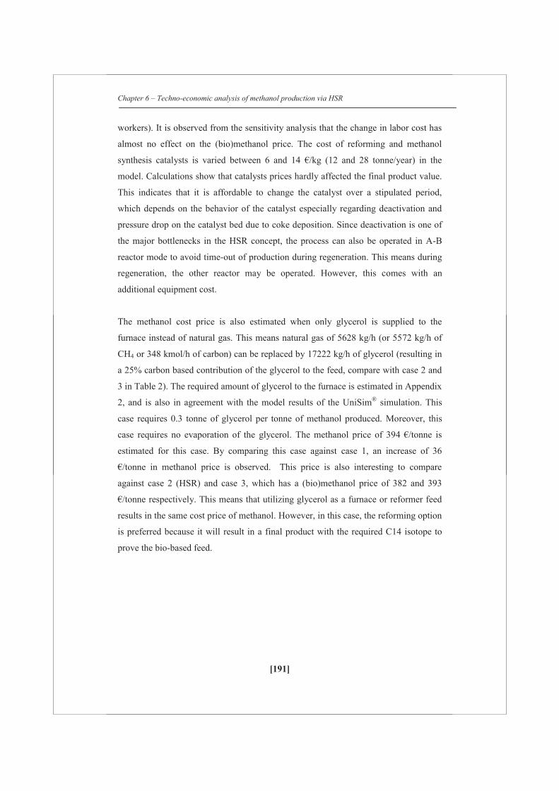
Chapter 6 – Techno-economic analysis of methanol production via HSR
[191]
workers). It is observed from the sensitivity analysis that the change in labor cost has
almost no effect on the (bio)methanol price. The cost of reforming and methanol
synthesis catalysts is varied between 6 and 14 €/kg (12 and 28 tonne/year) in the
model. Calculations show that catalysts prices hardly affected the final product value.
This indicates that it is affordable to change the catalyst over a stipulated period,
which depends on the behavior of the catalyst especially regarding deactivation and
pressure drop on the catalyst bed due to coke deposition. Since deactivation is one of
the major bottlenecks in the HSR concept, the process can also be operated in A-B
reactor mode to avoid time-out of production during regeneration. This means during
regeneration, the other reactor may be operated. However, this comes with an
additional equipment cost.
The methanol cost price is also estimated when only glycerol is supplied to the
furnace instead of natural gas. This means natural gas of 5628 kg/h (or 5572 kg/h of
CH4 or 348 kmol/h of carbon) can be replaced by 17222 kg/h of glycerol (resulting in
a 25% carbon based contribution of the glycerol to the feed, compare with case 2 and
3 in Table 2). The required amount of glycerol to the furnace is estimated in Appendix
2, and is also in agreement with the model results of the UniSim® simulation. This
case requires 0.3 tonne of glycerol per tonne of methanol produced. Moreover, this
case requires no evaporation of the glycerol. The methanol price of 394 €/tonne is
estimated for this case. By comparing this case against case 1, an increase of 36
€/tonne in methanol price is observed. This price is also interesting to compare
against case 2 (HSR) and case 3, which has a (bio)methanol price of 382 and 393
€/tonne respectively. This means that utilizing glycerol as a furnace or reformer feed
results in the same cost price of methanol. However, in this case, the reforming option
is preferred because it will result in a final product with the required C14 isotope to
prove the bio-based feed.

Chapter 6 – Techno-economic analysis of methanol production via HSR
[192]
6.6 Conclusions
This study focused on the techno-economic evaluation of the HSR concept in which
part of the natural gas is replaced by (pure) glycerol to produce (bio)methanol via
synthesis gas production. At laboratory scale it has been shown that this works
technically for pure and well-refined glycerol. For other liquids such as crude glycerol
and pyrolysis there are still technical challenges ahead. In this paper, mass and energy
balances and the first estimates on the economics are presented for HSR of pure
glycerol. It is assumed that within the accuracy of the methods used these numbers
will be also indicative for crude glycerol and pyrolysis oil once reforming of these
liquids becomes technically more realistic.
The main conclusions from this work are as follows:
From the HSR model cases, it is concluded that conceptually, bio-liquids can
replace natural gas by at least 50% in the existing reformers to produce
synthesis gas. Up to this amount CO2 addition is still needed to adjust the
stoichiometric value S of the synthesis gas to 2, which is necessary for the
methanol synthesis.
For several feed combinations of the HSR concept, mass, energy balances and
a techno-economic evaluation to estimate the average (bio)methanol price
were performed. At the current natural gas price of 0.2 €/Nm3 and an assumed
crude glycerol price of ~200 €/tonne, the (bio)methanol cost price of ~433
€/tonne is estimated for a feed with 54 wt% glycerol, which is ~75 €/tonne
higher than the methanol obtained via natural gas steam reforming.
The HSR process becomes attractive when the natural gas price rises above
0.45 €/Nm3 at an assumed glycerol price of 200 €/tonne. The process becomes
attractive when glycerol is available at a price below 90 €/tonne. Pure glycerol
as a reformer feed becomes an attractive option at natural gas price of 1.3
€/Nm3. Considering the current price of natural gas, this situation is unrealistic
at present.
The sensitivity analysis of the HSR model shows that the feed stock prices
(glycerol, natural gas) and total capital investment have a major impact on the
final product cost price of (bio)methanol. Overall, to realize the HSR concept,
Chapter 6 – Techno-economic analysis of methanol production via HSR
[193]
glycerol should be available at < 100 €/tonne (for e.g. 90 €/tonne) and NG
price should rise >0.3 €/Nm3.
In case the production is split in fossil-methanol and bio-methanol based on
the carbon % of glycerol in the feed, the cost price of bio-methanol ranges
between 470 and 500 €/tonne at a methanol price of 358 €/tonne. This means
that currently bio-methanol is not competitive with methanol unless special
arrangements are made (regulations, subsidies) to promote the use of bio-
methanol. For example the EC Renewable Energy Directive, which states that
the energy content of biofuels from wastes and residues count double [1]
Model calculations show that, at the present price scenario, utilizing glycerol
either as a furnace or reformer feed has no effect on the cost price of methanol.
The reformer option is preferred since it will yield methanol with C14 isotopes
to prove the biobased feed.
References
1. Communication from the commission on the practical implementation of the
EU biofuels and bio-liquids sustainability scheme and on counting rules for
biofuels (2010/C 160/02).
2. www.methanol.org (The Methanol Institute, global trade association).
3. M.E. Dry, A.P. Steynberg, Studies in surface science and Catalysis 152
(2004), 406-581.
4. http://www.portofrotterdam.com/ (Port of Rotterdam portal).
5. Communicating from the commission to the European parliament and the
council, EU directive, Renewable energy: Progressing towards the 2020 target
(2011). Document by European commission, Brussels, Belgium,
6. K. Aasberg-Petersen, C.S. Nielsen, I. Dybkjaer, Natural gas Conversion VIII
(2007), 243-248.
7. K. Aasberg-Petersen, T.S. Christensen, I. Dybkjaer, J. Sehested, M. Ostberg,
R.M. Coertzen, M.J. Keyser, A.P. Steynberg, Studies in surface science and
Catalysis 152 (2004), 258-405.
8. J.R. Rostrup-Nielsen, J. Sehested, Advanced Catalysis 47 (2002), 65-139.

Chapter 6 – Techno-economic analysis of methanol production via HSR
[194]
9. D. Wang, S. Czernik, E. Chornet, Energy & Fuels 12 (1998), 19-24.
10. G. van Rossum, S.R.A. Kersten, W.P.M. van Swaaij, Ind. Engg. Chem. Res.
46 (2007) 3959-3967.
11. R.P. Balegedde Ramachandran, R.J.M. Westerhof, G. van Rossum, W.P.M.
van Swaaij, D.W.F. Brilman, S.R.A. Kersten, Proceedings of the 18th
European biomass conference 2010, DOI 10.5071/18thEUBCE2010-OB4.3.
12. R.P.B. Ramachandran, G. van Rossum, W.P.M. van Swaaij, S.R.A. Kersten,
Energy & Fuels 25 (2011), 5755-5766.
13. R.P.B. Ramachandran, J.A. Medrano, W.P.M. van Swaaij, K. Seshan, S.R.A.
Kersten, G. van Rossum (Article under preparation).
14. www.biomcn.eu
15. W.D. Seider, J.D. Seader, D.R.Lewin and S. Widagdo, Product and Process
Design Principles: Synthesis, Analysis and Evaluation, Third Edition, John
Wiley&Sons, 2010.
16. D.W. Green, R.H. Perry, Perry’s chemical engineer’s handbook, Eighth
edition, McGraw-Hill.
17. M. Peters, K. Timmerhaus, R. West, Plant design and economics for chemical
engineers, 5th edition, McGraw Hill Publications.
18. www.energy.eu (Europe’s energy portal).
19. Ullmann’s encyclopedia of Industrial Chemistry, Vol 23, Chapter: Methanol,
WILEY-VCH publications, DOI: 10.1002/14356007.a16_465.pub2
20. http://www.mhhe.com/engcs/chemical/peters/data/ce.html (Open source:
M.Peters, K.Timmerhaus, R.West, Plant design and economics for chemical
engineers).
21. R.D. Roberts, J. Brightling, Open source Non-destructive testing 10 (2005),
www.ndt.net.
22. Chemical engineering design fundamentals, Rice University, Online source,
http://www.owlnet.rice.edu/~ceng403/nh3ref97.html
23. Coulson and Richardson’s Chemical engineering book volume 6, Chemical
engineering design 5th edition (2005)
24. www.che.com.
25. www.icis.com (World’s largest information provider for the chemical and
energy industries)

Chapter 6 – Techno-economic analysis of methanol production via HSR
[195]
26. Proposal for a directive of the European Parliament and of the council
amending Directive 98/70/EC relating to the quality of petrol and diesel fuels
and amending Directive 2009/28/EC on the promotion of the use of energy
from renewable sources. http://ec.europa.eu/energy/renewables/targets_en.htm
27. Chemical engineering design fundamentals, Rice University, Online source,
http://www.owlnet.rice.edu/~ceng403/nh3ref97.html
28. Fixed-bed reactor design, http://www.fischer-
tropsch.org/DOE/DOE_reports/91005752/de91005752_sec2.pdf
29. www.xe.com
Appendix 1
Overview of main equipment with dimensions, process conditions and estimated
purchased costs for the HSR process (Case 6). Cost data is obtained from the website
of Peters et al. [20].
Reformer
Q = 72200 KW, Assumed heat transfer, H = 87 KW/m2 [27]
Area required, AR= Q/H = 830 m2
D = 0.13 m, L=8 m, Area of 1 tube, AT = π*D*L = 3.3 m2
Number of tubes, NT = AR/AT=250 tubes
Cost of 1 tube is 20,000 $
Cost of 250 tubes = 250 x 20,000 $ = 5,000,000 $
Cost of shell and connections are still missing.
Cost of a reformer furnace with a duty of 72 MW and equipped with stainless steel
tubes (P=13,790 kpa) = 5.2 M$ (This value is taken for the TEE)

Chapter 6 – Techno-economic analysis of methanol production via HSR
[196]
Methanol reactor
Q = 36800 KW, Assumed heat transfer, H = 18.9 KW/m2 [28]
Area required, AR= Q/H = 1947 m2
D = 0.13 m, L=8 m, Area of 1 tube, AT = π*D*L = 5.64 m2
Number of tubes, NT = AR/AT=345 tubes
Cost of 1 tube (for an assumed column tube) of D = 0.5 m, L=8 m, carbon steel,
P=10000 kpa = 69,871 $, The cost of D = 0.13 m, L=8 m tube = 17,468 $
Cost of 345 tubes = 345 x 17,468 $ = 6,026,460 $
Cost methanol reactor: 6.0 M$
Heat exchangers
Based on heat duty equation, Q=UA(LMTD)
U = Overall heat transfer coefficient, KW/m2 K
A = Area required, m2 (To determine cost)
LMTD = ((Th,in-Tc,out)-(Th,out-Tc,in)) /ln ((Th,in-Tc,out)-(Th,out-Tc,in))
F=1 (assumed)
Temperature, cooling/heating media for heat exchangers:
T>= 350 ºC flue gas (assume in this case a sufficiently high LMTD)
250<T<350 ºC heating oil
200<T<250 ºC high pressure steam
150<T<200 ºC medium pressure steam
T<150 ºC low pressure steam
1. Pre-heating natural gas from 20 to 350 ºC
Q= 3400 KW
Assume a LMTD of 100 ºC. U = 50 W/m2K, Heating gas: Flue gas
A = 680 m2
Chapter 6 – Techno-economic analysis of methanol production via HSR
[197]
Purchased cost of floating-head heat exchangers with 0.019-m OD x
0.0254-m-m (3/4-in. x 1-in.) square pitch and 4.88-m (16-ft) bundles of carbon
steel construction. 14-19. Design pressure 3100 kpa (450 psia)
Shell is CS, tubes are SS: 135,000 $
2. Pre-heating natural gas from 350 to 900 ºC
Q=8485 KW
Assume a LMTD of 100 ºC, and a U of 50 W/m2K (Assumption: flue gas to heat the
gas stream) 1700 m2
This will result in two heat exchanger of 850 m2 each.
Purchased cost of floating-head heat exchangers with 0.019-m OD x
0.0254-m (3/4-in. x 1-in.) square pitch and 4.88-m (16-ft) bundles of carbon
steel construction. 14-19. Design pressure 30 bar
Shell is CS, tubes are SS
Each will cost 168,000 $. Total 2*168 = 336,000 $
3. Glycerol gasification 20 to 400 ºC
Q=16134 KW
Assume a LMTD of 100 ºC, and a U of 100 W/m2K (Assumption: one side flue gas
and other side liquid) 1600 m2
This will result in two heat exchanger of 800 m2 each.
Purchased cost of floating-head heat exchangers with 0.019-m OD x
0.0254-m-m (3/4-in. x 1-in.) square pitch and 4.88-m (16-ft) bundles of carbon
steel construction. 14-19. Design pressure 30 bar
Shell is CS, tubes are SS
Each will cost 158,000 $. Total 2*158 = 320,000 $

Chapter 6 – Techno-economic analysis of methanol production via HSR
[198]
4. Glycerol vaporization at 400 ºC
Q=6233 KW
Assume a LMTD of 100 ºC, and a U of 100 W/m2K (Assumption: one side flue gas
and other side liquid) A 600 m2
Purchased cost of floating-head heat exchangers with 0.019-m OD x
0.0254-m-m (3/4-in. x 1-in.) square pitch and 4.88-m (16-ft) bundles of carbon
steel construction. 14-19. Design pressure 30 bar
Shell is CS, tubes are SS
This will cost 120,000 $
5. Glycerol vapor heating from 400 to 900 ºC
Q=14199.8 KW
Assume a LMTD of 100 ºC, and a U of 50 W/m2K (Assumption: one side flue gas
and other side glycerol vapors) A 3000 m2
This will result in three heat exchanger of 1000 m2 each.
Purchased cost of floating-head heat exchangers with 0.019-m OD x
0.0254-m-m (3/4-in. x 1-in.) square pitch and 4.88-m (16-ft) bundles of carbon
steel construction. 14-19. Design pressure 30 bar
Shell is CS, Tubes are SS
Each will cost 203,000 $. Total = 610,000 $
6. Water heating from 47 to 234 ºC
Q=30476 KW
Assume a LMTD of 100 ºC, and a U of 100 W/m2K (Assumption: one side flue gas
and other side water) A 3000 m2
This will result in three heat exchanger of 1000 m2 each.
Purchased cost of floating-head heat exchangers with 0.019-m OD x
0.0254-m-m (3/4-in. x 1-in.) square pitch and 4.88-m (16-ft) bundles of carbon
steel construction. 14-19. Design pressure 30 bar
Shell is CS, Tubes are SS
Chapter 6 – Techno-economic analysis of methanol production via HSR
[199]
Each will cost 203,000 $. Total = 610,000 $
7. Water evaporating to steam 235 ºC
Q=50016 KW
Assume a LMTD of 100 ºC, and a U of 100 W/m2K (Assumption: one side flue gas
and other side water) A 5000 m2
This will result in five heat exchangers of 1000 m2 each.
Purchased cost of floating-head heat exchangers with 0.019-m OD x
0.0254-m-m (3/4-in. x 1-in.) square pitch and 4.88-m (16-ft) bundles of carbon
steel construction. 14-19. Design pressure 30 bar
Shell is CS, Tubes are SS
Each will cost 203,000 $. Total = 1,015,000 $
8. Steam heating from 235 to 900ºC
Q=45600 KW
Assume a LMTD of 100 ºC, and a U of 50 W/m2K (Assumption: one side flue gas
and other side steam) A 10000 m2
This will result in 10 heat exchangers of 1000 m2 each.
Purchased cost of floating-head heat exchangers with 0.019-m OD x
0.0254-m-m (3/4-in. x 1-in.) square pitch and 4.88-m (16-ft) bundles of carbon
steel construction. 14-19. Design pressure 30 bar
Shell is CS, Tubes are SS
Each will cost 203,000 $. Total = 2,030,000 $
9. Heating recycle methanol stream from 47 to 250ºC
Q=26232 KW
Assume hot oil is used on Shell side (350 ºC and cooled to 250 ºC) have a LMTD of
150 ºC, and a U of 150 W/m2K (Assumption: one side syngas at high pressure and
other side oil) A 1200 m2
This will result in 2 heat exchangers of 600 m2 each.
Chapter 6 – Techno-economic analysis of methanol production via HSR
[200]
Purchased cost of floating-head heat exchangers with 0.019-m OD x
0.0254-m-m (3/4-in. x 1-in.) square pitch and 4.88-m (16-ft) bundles of carbon
steel construction. 14-19. Design pressure 70 bar
Shell is CS, Tubes are SS
Each will cost 160,000 $. Total = 320,000 $
10. Cooling reformer gas 900 to 155ºC
Q=83955 KW
Assumption: Cool using water to make steam at different pressure levels. For that
staged cooling is required.
62 MW: 900 ºC 350 ºC HP steam is used (250 ºC), U=150 W/m2K, LMTD =
300 ºC A= 1400 m2 2 * 700 m2 2 * 178 = 356,000 $
11 MW: 350 ºC 250 ºC with this make MP steam (at 210 ºC), U=150
W/m2K, LMTD = 80 ºC A = 915 m2 233,000 $
11 MW 250 ºC 155 ºC with this make low pressure steam (at 120 ºC), U =
150 W/m2K, LMTD = 72 ºC A = 1000 m2 = 258,000 $
Total: 847,000 $
11. Cooling reformer gas 155 to 40ºC
Q=63350 KW
LMTD 70 ºC (cooling media: Water at 20 ºC)
Tc,in and Tc,out are based on UNISIM heat exchanger calculations.
assume 150 W/m2K
A = 6000 m2
6 heat exchangers in parallel, each 1000 m2. (shell CS, tube SS)
Each will cost 200,000 $ (at P=30 bar). Total 1,200,000 $
12. Cooling compressed gas 130 to 40ºC
Q=5456 KW
LMTD = 64ºC, (cooling media: Water at 20 ºC), U =150 W/m2K, A =713 m2
Chapter 6 – Techno-economic analysis of methanol production via HSR
[201]
Purchased cost of floating-head heat exchangers with 0.019-m OD x
0.0254-m-m (3/4-in. x 1-in.) square pitch and 4.88-m (16-ft) bundles of carbon
steel construction. 14-19. Design pressure 70 bar
Shell is CS, Tubes are SS
=181,000 $
13. Cooling methanol product 250 to 137ºC
Q=22306 KW
U = = 150 W/m2K,
low pressure steam at 120 ºC, LMTD would be 55 ºC, U = 150 W/m2K (based on one
side pressurized gas, other side boiling water). A = 2700 m2 = 3*900 m2 3 * 230
= =690,000 $, Assuming floating head at 70 bar. Shell CS, Tube SS.
14. Cooling methanol product 137 to 40ºC
Q=41403 KW
LMTD = 53 ºC (cooling media: Water at 20 ºC), U = 150 W/m2K; A = 5200 m2 =
5*1000 m2 5 * 260 = 1300,000 $, Assuming floating head at 70 bar. Shell CS,
Tube SS.
15. Condenser for distillation column
Q=27,000 KW, T = 55 ºC and P=1 atm
Utility: use cooling water. Inlet T = 20 ºC, outlet T = 25 ºC
LMTD = 32 ºC, U = 500 W/m2K (combination of cooling water and condensing
organic vapor), A = 1700 m2 = 2*850 m2 2 * 100,000 $ = 200,000 $ (shell CS,
tube SS, P= 7 bar)
16. Reboiler
30 MW, T = 109 ºC and P = 1 atm
Utility: use MP steam 212 ºC
LMTD= 100 ºC, U = 1000 W/m2 K (boiling organic liquid, combined with
condensing steam) A = 300 m2 60,000 $

Chapter 6 – Techno-economic analysis of methanol production via HSR
[202]
Columns
1. Column to remove water from reformer gas product
Assumed D=2 m, L=8m [23], SS material, Pressure rating of 10,000 kpa
= 448,000 $ + demister
2. Second Column to remove water from reformer gas product
Assumed D=2 m, L=6m [23], SS material, Pressure rating of 10,000 kpa
= 360,000 $ + demister
3. Column after methanol synthesis
Assumed D=2.5 m, L=9m [23], SS material, Pressure rating of 10,000 kpa
= 760,000 $ in case of D = 3 m and 492,000 $ in case of D=2 m
Assume the column will cost 625,000 $ + Demister
4. Column to remove lights
Assumed D=2 m, L=10m, SS material, Pressure rating of 1035
kpa
= 186,000 $
5. Column to purify methanol
Active area necessary for gas flow is 8 m2. Total cross-sectional area is about 10 m2.
Diameter is 3.5 m
Number of stages: 16 ideal, 23 real stages (70% eff.).
Height of column about 15 m.
Material: SS
D = 3 m 395,000 $
D = 4 m 473,000 $ assume 440 k$
Stages:
D = 3.5 m 130,000 $
Total is 570,000 $
Chapter 6 – Techno-economic analysis of methanol production via HSR
[203]
Compressors and pumps
Two compressors used to compress from 20 to 80 bar
centrifugal turbine compressors (material :CS)
Power 5.2 MW 3.2 M$
For two 2*3.2M$ = 6.4 M$
Methanol recycle stream – compress from 75 to 80 bar
Purchased cost of compressors, including drive, gear mounting, base plate,
Centrifugal rotary motor, Power rating = 900 kW
centrifugal turbine (material :CS)
Power 900 kW 634,000 $
Bio-liquid pump, volumetric flow = 0.009 m3/s, pressure rating = 5000 kpa
Purchased cost of Centrifugal cast iron pump
= 11,373 $
Water pump from, volumetric flow = 0.005 m3/s, pressure rating = 5000 kpa
Purchased cost of Centrifugal cast iron pump for 0.009 m3/s
= 11,373 $
Reactors = 11.3 M$
Heat exchangers = 10.0 M$
Columns = 2.2 M$
Pumps and compressors = 7.1 M$
Total equipment cost of major unit operations = 30.5 M$ (2002)
The calculated costs are based on 2002. CECPI in 2002 = 390 [24]
CECPI in 2012 (April) = 596 [24]
Total equipment cost of major unit operations = 46.6 M$ (2012)
1 $ = 0.77 € (avg. 2012 value [29])
Total equipment cost of major unit operations = 35.9 € (2012)
Chapter 6 – Techno-economic analysis of methanol production via HSR
[204]
Assume a Lang factor of 5 [16] for fixed capital investment: 180 M€ ( ISBL)
OSBL is assumed 30% of ISBL: 54 M€
Total capital investment = 180 + 54 = 234 M€.
The TEE analysis are performed for 250 M€ since only major equipments was
considered.

Chapter 6 – Techno-economic analysis of methanol production via HSR
[205]
Appendix 2
Calculation of glycerol requirement to the furnace
Case 1: Methane steam reforming to produce synthesis gas
Methane requirement to the furnace = 348 kmol/h
Heat of combustion of methane = 890 kJ/mol
= 86 MW
Heat of combustion of glycerol = 1654.3 kJ/mol
To produce 85.2 MW energy
Glycerol requirement = 85200/1654.3 (kJ/sec)/(kJ/mol)
= 187.2 kmol/h
= 17222 kg/h
tonne glycerol for combustion/tonne methanol
= 17222/56739
= 0.3
By introducing these numbers in Table 6 for the base case,
The cost of methanol produced by introducing glycerol to the furnace = 394 €/tonne

[206]

Outlook
[207]
Outlook and recommendations for further work
Overall it can be concluded from the work described in this thesis that Hybrid Steam
Reforming (HSR) of purified low coking bio-liquids such as purified or neutralized
glycerol is a technically viable process and under special conditions also economically
feasible. For pyrolysis oil and crude glycerol the current available catalysts, both
commercial and newly developed ones, are not good enough when the process is
performed in fixed bed reactors. Design of stable (pre-reform) catalysts for the
efficient gasification of biomass should take into account the ability of the catalysts to
depolymerize deposits because suppressing oligomerisation is nearly impossible as it
occurs almost on any surface.
The focus of the pre-reforming catalyst should be on maximizing the stable
conversion of the bio-liquid vapors to permanent gases or hydrocarbons that can be
dealt with in the primary co-reformer. Process development should focus on i)
atomization under industrial conditions (e.g. high pressure) and the handling of the
produced solids in this stage and ii) additional systems to “protect” the catalysts as
much as possible. To protect the catalyst from a too high amount of vapors, a few
strategies can be applied; e.g. raising the temperature of gasification prior to pre-
reforming, usage of cheap catalysts for vapor cracking which can be regenerated
and/or applying a high degree of non-catalytic cracking (e.g. coking) and
subsequently gasifying the char/coke which is being formed. Fast regenerating
fluidized systems such as FCC could be an option, but such fluidized bed steam
reforming or cracking catalysts will need considerable research attention. Besides, in
case of a steam reform catalyst, if the active metal is oxidized during coke burn-off
this will result in an additional reduction step making a total cycle of catalyst possible:
reaction – deactivation – coke burn-off – reduction - reaction. A completely different
catalyst system without requiring the reduction step after coke burn off might then be
required. Another option is to carry out gasification in the presence of steam and/or
oxygen just as in the case of typical auto-thermal reforming. The role of oxygen in
this case is to help to combust coke/oligomer and keep the catalytic sites clean.

[208]

Publications and Posters
[209]
Publications
1. Ragavendra P. Balegedde Ramachandran, Guus van Rossum, Wim P.M van
Swaaij,Sascha R. A. Kersten, Evaporation of biomass fast pyrolysis oil :
Evaluation of char formation, Environment progress and sustainable energy, 2009,
28, 410-417
2. Guus van Rossum, Berta Matas Güell, Ragavendra P. Balegedde Ramachandran,
K.Seshan, L.Lefferts, Wim P.M van Swaaij, Sascha R.A. Kersten, Evaporation of
pyrolysis oil: Product distribution and residue char analysis, AIChE journal, 2010,
56, 2200-2210
3. Ragavendra P. Balegedde Ramachandran, Guus van Rossum, Wim P.M van
Swaaij,Sascha R. A. Kersten, Synthesis gas production via hybrid reforming of
methane and Glycerol, Energy & Fuels 25 (2011), 5755-5766
4. Ragavendra P. Balegedde Ramachandran, J.A. Medrano, Guus van Rossum,
K.Seshan, Wim P.M van Swaaij, Sascha R. A. Kersten, Synthesis gas production
via Steam reforming of pyrolysis oil: Assessment of catalyst performance and
hybrid reforming with methane. hybrid reforming of methane and pyrolysis oil
(article under preparation)
5. Ragavendra P. Balegedde Ramachandran, Stijn Oudenhoven, Guus van Rossum,
Wim P.M van Swaaij, Sascha R. A. Kersten, Process plant design to produce
synthesis gas via hybrid reforming of methane and bio-liquids (article under
preparation)

Publications and Posters
[210]
Posters and Presentations
1. Evaporation of biomass fast pyrolysis oil : Evaluation of char formation,
Presentation: Thermo-chemical conversion and science conference held at
Chicago, USA, between Sep 16 & 18, 2009
2. Combined optimization of fast pyrolysis and catalytic reforming of
pyrolysis oil to produce renewable syn-gas from biomass residues,
Presentation: Proceedings of the 18 th European Biomass conference held
at Lyon, France, between May 3 & 7, 2010
3. Synthesis gas production via hybrid steam reforming of methane and
pyrolysis oil, Presentation: Netherlands process technology symposium
held at Veldhoven, Netherlands, between Oct 25 & 27, 2010
4. Utilization of glycerol and pyrolysis oil in the existing reforming units to
produce syn-gas, Presentation and Poster: Bioenergy conference held at
Lanzarote, Spain, between May 23 & 27, 2011
5. Steam reforming of pyrolysis oil to produce syn-gas, Poster:Proceedings of
the 19 th European Biomass conference held at Berlin, Germany, between
June 6 & 10, 2011
[211]
About the author
R.Prasad Balegedde Ramachandran was born on 27th October, 1980 in Chennai
(formerly called as Madras), India. He studied Bachelor’s in Chemical Technology
(B-Tech) in Sri Venkateswara College of Engineering (affiliated to University of
Madras) from 1998 till 2002. He completed his B-Tech degree with first class and
distinction. After his B-Tech, he worked as a Chemical Engineer in Carborundum
Universal Limited (Murugappa Group of companies) from 2002 till 2004. In 2004, he
received scholarships from Shell, Netherlands and Bharat Petroleum Corporation,
India to study Master’s in Chemical Engineering (Process Technology track) at the
University of Twente, Enschede, The Netherlands. He performed his Master’s Thesis
in the Thermo-chemical conversion of Biomass (TCCB) group (now called as
Sustainable Process Technology group) in the University of Twente under the
supervision of Prof.dr.S.R.A.Kersten. He completed his Master’s in 2006.
Later, he joined the same group (TCCB) as a Researcher. He worked on “Modeling of
biomass gasification” project in co-operation with Energy Center of Netherlands
(ECN). Then, he continued his PhD in TCCB from January 2008 till February 2012
under the supervision of Prof. dr. S.R.A. Kersten, Prof. dr.ir. W.P.M. van Swaaij and
Dr.ir.Guss van Rossum. He worked on the topic “Synthesis gas production from
biomass”. The results of this multi-disciplinary research focused on process
engineering and catalysis. From March 2012, he is working as a Process Engineer in
BASF, Ludwigshafen, Germany.

[212]
Acknowledgements
[213]
Acknowledgements This PhD work has been kept on track and seen through to completion with the support and encouragement of numerous people including my well wishers, my friends and colleagues. I thoroughly enjoyed every moment in this journey and I would like to express my gratitude to all those who gave me the possibility to complete this Thesis. I would like to start giving my special thanks to Shell (India and The Netherlands), Bharat Petroleum (India) for scholarships and Ing. H.A.Akse (International student co-ordinator) for giving me a wonderful opportunity to study Master’s in Chemical Engineering (Process Technology track) in the University of Twente, Enschede, Netherlands) in the year 2004. Indeed, it is a very long journey. From 2004, I am associated with SPT (Sustainable Process Technology group, formerly called as TCCB (Thermo-chemical conversion of Biomass group). I would like to thank my promoters Prof.dr.ir. Wim P.M. van Swaaij and Prof. dr. Sascha Kersten who gave me the opportunity to contribute in my favorite field of research which is biomass conversion technologies. It is a dream come true for me to work in Prof.dr.ir. Wim P.M. van Swaaij’s group. It’s truly an honour to interact with the professor. His quick, witty sharp comments on any topic made me to think for hours. Sascha is truly an inspiration for me. I learnt from him everyday especially during my PhD days not only about biomass technologies but also about managing projects, self-criticism and enthusiasm to learn new things. The Master course on Sustainable development in 2005 was an eye-opener for me to continue as a Researcher in TCCB group. After he came to know about my interest to do PhD, Sascha offered me a modeling project from Energy Center of Netherlands on Biomass gasification (from 2006-2008). Thank you for your guidance throughout our research project and for the fruitful research discussions. Thanks for your understanding and support during difficult periods of my PhD life. This PhD work could not have been a reality without the contribution from Guus, Assistant promoter, daily supervisor (in person + also in Skype), guide and a good friend. I continued his work on Steam reforming of pyrolysis oil. Since I knew Guus from 2004, it became easy for me to follow the project. Initially, (in 2008) I had tough time in experimental project since I had modeling experience. It was Guus who made me comfortable working in the Lab. At this point, I would also like to thank Agnes who was very co-operative and made this project a bit easier for me to start. I would like to thank Guus for his scientific input in this work. I still remember that during one of our discussions, the concept of hybrid steam reforming concept has been proposed and we could able to implement in our lab with the help of able technicians. Thanks a lot Guus for your wonderful support and you helped me a lot in solving critical issues in the area of steam reforming. I learnt a lot especially about data interpretation from you which I am still learning to perform better. Besides work, I would like to thank you for all the wonderful gatherings, discussions, breaks, trips etc. I am sure this will continue in the future as well.
Acknowledgements
[214]
I am very grateful to Dragan who guided me during my Master’s project on Biomass liquefaction. It was Dragan who introduced me to Hoge Druk Lab and taught me how to deal with liquefaction in a small capillary tube. I lost my count but I am sure that I would have done 1000s of such tubes. I learnt a lot from Dragan during my Master´s days regarding the stages in research, life of a PhD student and mainly how research works in TCCB. It was Dragan who first encouraged me to do a PhD. Together with Dr.Wang, we shared the same office in Langezijds. Of course, we had useful political and general discussions about everything. Technicians are the backbones of our TCCB group. Without them, PhD work is almost impossible. I express my gratitude to Johan (helped me during my Master´s), Benno, Karst, Robert (built excellent experimental set ups) and Erna (for analyzing samples). I would like to express my special thanks to Benno who not only involved in building set ups but also actively involved in design of experiments and shared his knowledge and experience. It was very useful to solve critical issues. I don’t know how many times I took the atomizer and mass flow controllers to Robbert and Benno. Not only technical stuffs but also I learnt many useful “Dutch words and sentences” (which I cannot reveal here) from Benno and Robert. Special thanks to Yvonne for taking care of all official work and she translated many letters from Dutch to English in my early Master’s days. I would like to thank also my students Rahim, Yonina, Marco and Peter. Also, I would like to mention special thanks to Joram, Peter, Felix and Jan who worked part time on pyrolysis and reforming/cracking. I would also like to thank Louise and Bert from CPM group, Mark Smithers and Gerard Kip from MESA group for their characterization work. Also, special thanks to ECN (Van der Drift, Christiaan) for assisting me in Milena gasification project, BioMCN (Nanne, Ruud) for giving valuable inputs for Chapter 4 and Univeristy of Zaragoza for testing the catalysts. I would like to thank my wonderful Paranymphs Jose and Laura. I involved in catalysis work after we collaborated with Jose from the University of Zaragoza. Special thanks to Prof.dr.Jesus Arauzo for the collaboration and also he accepted to be in my PhD committee. It was really convenient for me to work together with Jose because his PhD work was similar to mine. He shared lot of his experience on catalysis and reforming and actively involved in experimental work. Besides research, we shared many things on personal level and I am sure it will continue in the future. Laura, you have been wonderful and helped me in many ways in analyzing samples and also printing my Thesis work. I cannot forget the day we met in a party. Your first question to me was `Do you know Ferran?? ….The conferences we went together are unforgettable. You took lot of efforts in taking time out of the research by organizing small coffee breaks, borrels and chit-chats. I am sure our friendship will continue in the future. I would like to express my gratitude to Louis who helped me a lot during my Master’s course on Flowsheeting and he continued his support to finish my last Chapter in Thesis which is economics. I would also like to thank all the lecturers those who taught me during my Master’s. I would like to extend my gratitude to all my colleagues from 2004 till now: Biljana, Xie, Dragan, Guus, Marieken, Roel (you made

Acknowledgements
[215]
me as your paranymph and that was the only time I performed that duty, cannot forget Barcelona experience together with Antal and Xavi), Pavlina (She is the first person I talked in The Netherlands….the girl next door in Witbreuksweg 399), Elly (we had a tough competition on number of capillaries), Ferran (thanks for all your support and the knowledge you shared with me regarding biomass), Anand (called him as Chaki …thanks Chaki for all your support and sometimes you stayed longer in the lab and over night to perform experiments…sometimes we worked on US timings like typical software engineers of India. Since we both worked on catalysis and sometimes on similar feed and catalysts we were bamboozled ! by our own outcomes), Kumar (Thanks for all your sharing about catalysis and the best thing is I can disturb him any time…It became very easy for me when we shared the same office in Meander), Rens (you are the best neighbor I have ever had and keep doing the same things to the people nearby…when I heard the word CO2 you are coming into my mind…keep up the good work), Stijn (He is a wonderful co/worker. We worked on a small project called combined pyrolysis and reforming. He has answers to all the problems in the biomass world. I would also like to express my thanks to Judith, Maria, Shushil, Samuel, Martin, Mathijs, Petra, Jothi, Cindy, Wim (Thanks for introducing me to the teaching world and it´s an unforgettable experience), Miriam, Frank and Hector. I would also like to express my thanks to TCCB family Diana, Clara, Rebeca, Dimitris, Can (thanks for giving me pacharaki and an awesome party on my 30 th birthday at Veldhoven), Roger (you are the best Spanish I have ever seen …are you happy now?), Michael, Nandana, Lavanya, Marije, Kate (the only veggie partner for me in Zaragoza). Enschede always remain as my second hometown because of Indian contingent. Many Indian friends helped me in various ways. I would like to express my special thanks to Anand Mohan who introduced me to the Indian community and to Indian cuisine. His interest on cooking made me to take cooking as a hobby. He also let me stay together with him in Westerstraat. I hope I was a good tenant. It´s because of Shankar I gained confidence in my Master track. He assisted me in various ways on course works and how to face the problems. Besides work we (Shank, Anand, Kumar) actively involved in Hengelo cricket which is my first cricketing experience abroad. It was in a Deepavali event in 2004 I met Balaji. I became friends with him the moment I met him. I know for sure it´s an everlasting one. It was Shankar and Balaji who introduced me to Seshan and Jeyanti. With Seshan, I discussed not only catalysis but also cricket (not played but only watched) and many many things. I had wonderful time with Jeyanti and learnt a lot from her cuisines. Thanks for inviting me to all religious events at your house and took time out of research. I would like to thank Pramod for making me comfortable in Enschede. When I needed a computer to work at home, he immediately solved the problem. He also introduced me to Enschede tape ball cricket in 2004. Special thanks to Enschede cricket folks: Tomar, Ravi, Kiran, Sunny, Niraj, Anurag, Khurrem, Makrand. I would like to express my thanks to Srinivas, Kavitha, Kiran, Murali, Vishaka, Chandra for introducing me to many Indian events that happened between 2004 and 2006. The karaoke singing together with Shankar, Kavitha, Rajavishnu, Sameer and Digvijay was a wonderful experience to share stage during big events.

Acknowledgements
[216]
I would like to thank both Vishnupully and Vignesh for sharing house with me. You guys are just wonderful in-mates and extremely understandable when I was coming late or when I was in crisis. I cannot forget Vishnu´s pappu and Vignesh´s kollu rasam. I still cannot get the same quality. Thanks to CP Suresh, Vishi, Dinesh, Sastry, Vijay and Jithin for organizing several “Tamil parties”. I would also like to Vishi for introducing me to Hilversum cricket club, Srikanth Akkiraju (for cricket and personal discussions), Kalai, Jeevitha (for awesome erode and coimbatore cuisines), Ranjani (for extensive long debates), Hrudaya (for nice long chats), Subhashni, Archana, Rajesh, Jigar, Falguni, Mayur, Tina, Avinash, Dinesh Rajah, Koti, Ganesh, Krishna, Gayathri, Giri, Varsha, Sandeep, Jalaja, Rajaram and Vivek. It’s incredible that I have more Indian friends abroad than in India at this moment. I made a lot of Pakistani friends as well through Cricket. It’s a memorable experience with Hammad, Waqar, Khurrem, Rahim, Adheel in Indoor table ball cricket (Sports centrum) and Kite festivals. I would also like to express my special thanks to Hengelo and Hilversum cricket board for accepting me as a member. Not only I developed my cricketing skills but also I built a good network from various cricket playing nations. This developed my social skills also outside lab work. Thanks to many borrels organized by Alembic (Chem. Eng), Stijn and Roel (in TCCB).The conference trips to Chicago, Lyon and Lanzarote are an unforgettable experience. Besides conference trips, I appreciate the effort taken by Nick, Maria, Laura, Elly and others for organizing some memorable trips. The Wadlopen trip still remains as a terrific experience. I would also like to thank my close friends outside University who spent valuable time with me: Katrina, Eghard and Wout. I would like to extend my gratitude to my college and school friends from SVCE and Vellayan Chettiar Higher Secodary School : Senthil, Ambarish, Anand and Vadivelan (SVCE), Saravanan, Senthil, Prabu, Sridhar, Narene (VCHSS) for their continuous support. I would also like to thank my best friends (tvt_hunks) Chidambaram, Asif, Palani, Sarath, Prabu, Vijay, Prem and Lavanya who are there for me anytime. Special thanks to Lavanya who read each Chapter with utmost care and proof read several times. I also extend my heartfelt thanks to Balegedde and Thottakudi family members. I would like to convey my namaskarams to my family members Mom, Dad, Guru and Subha. Without my mom’s encouragement, my dad’s and Guru’s financial support my journey to study Master’s would have been impossible. Special thanks to wonderful niece Harshnna. Finally, I would like to thank my wife Soumya. Her support and encouragement at the end of my PhD made this dissertation possible.

Notes
[217]

Notes
[218]
Copyright © 2022 FDOKUMEN