Dynamic and steady-state analysis of steam reforming of ...
9
International Journal of Low-Carbon Technologies 2021, 16, 384–392 © The Author(s) 2020. Published by Oxford University Press. This is an Open Access article distributed under the terms of the Creative Commons Attribution Non-Commercial License (http://creativecommons.org/licenses/ by-nc/4.0/), which permits non-commercial re-use, distribution, and reproduction in any medium, provided the original work is properly cited. For commercial re-use, please contact [email protected] doi:10.1093/ijlct/ctaa074 Advance Access publication 6 October 2020 384 Dynamic and steady-state analysis of steam reforming of methane to hydrogen in a reformer for electric-powered unmanned aerial vehicle .............................................................................................................................................................. Ergin Kosa* Faculty of Engineering & Architecture, Mechanical Engineering Department, Beykent University, Istanbul, 34398, Turkey ............................................................................................................................................. Abstract Hydrogen-fueled combustion systems are becoming popular in recent years. Methane is one of the significant hydrogen supplier in nature. Thus, in the study, the natural gas-fueled reactor-assisted solid oxide fuel- cell system is configured to provide a current to load the battery to turn the propeller of an unmanned aerial vehicle in the large-scale hydrogen-onboard system. The methane-fueled reactor has not been studied under a large-scale case in literature yet. To investigate the amount of products, this paper presents about the steam-reforming performance of natural gas in steady state and transient in the reactor. The influence of vital parameters such as steam/carbon, gas feed temperatures, the amount of heat transferred to the reactor in methane steam reforming for a plug flow reactor, and a continuous stirred tank-type reactor is investigated respectively. Methane conversion, yield of hydrogen gas and H 2 gas generation for different medium conditions along the reactor are studied on by using the COMSOL Multiphysics program. The steady-state and time-dependent characteristics of the steam reforming of natural gas are focused on. The high conversion ratio of methane gas is obtained by ranking the steam/carbon ratio. The released hydrogen gas molar flow rate is increasing according to the reactor volume. The achieved power provided by produced gas of H 2 is 97 hp supplying the thrust force for an unmanned aerial vehicle. Keywords: natural gas; steam reforming; UAV *Corresponding author: [email protected] Received 31 May 2020; revised 27 July 2020; editorial decision 16 September 2020; accepted 16 September 2020 ................................................................................................................................................................................. 1. INTRODUCTION Hydrogen is becoming trendy as an energy carrier due to the benefits of clean, providing a sustainable energy cycle and being environmentally friendly and being global to generate electricity [1, 2]. Also, hydrogen is used in many sectors such as chemical industries, fuel-cell applications and electric vehicles [2, 3, 4, 5]. Methane gas is one of the common carbon and hydrogen suppliers, and methane gas is a hydrocarbon which is very easy to supply and has a widespread network in the world [6, 7]. Limits in emissions have made it obligatory to investigate the use of systems including solid oxide fuel cells [2, 4]. Solid oxide fuel cells are systems that produce current for the electric motor by electrochemical means using synthesis gas. In order to produce the synthesis gas, a converter is required. This converter uses hydrocarbon fuel to produce the synthesis gas required for the solid oxide fuel cell, namely, called hydrogen and carbon monox- ide [8, 9, 10, 11]. Methane constitutes the majority of natural gas. There are many ways to produce syngas of hydrogen such as steam reforming [12], partial oxidation [13] and carbon dioxide– reforming process [14, 15]. Natural gas, which is a hydrocarbon source, can be used to produce this synthesis gas by autothermal reforming [16, 17] or steam-reforming processes [9, 12]. Still, both autothermal and steam-reforming methods are the economical ways to synthesize H 2 gas. There are several investigations of researches in autothermal and steam-reforming process [18, 19, 7, 12] and in different types of reactor models [20, 21, 22] in literature. Also, the computational fluid dynamic method has been used for modeling of reformers and other systems [23, 24]. Downloaded from https://academic.oup.com/ijlct/article/16/2/384/5918406 by guest on 08 July 2022
-
Upload
khangminh22 -
Category
Documents
-
view
1 -
download
0
Transcript of Dynamic and steady-state analysis of steam reforming of ...
International Journal of Low-Carbon Technologies 2021, 16, 384–392© The Author(s) 2020. Published by Oxford University Press.This is an Open Access article distributed under the terms of the Creative Commons Attribution Non-Commercial License (http://creativecommons.org/licenses/by-nc/4.0/), which permits non-commercial re-use, distribution, and reproduction in any medium, provided the original work is properly cited. For commercialre-use, please contact [email protected]:10.1093/ijlct/ctaa074 Advance Access publication 6 October 2020 384
Dynamic and steady-state analysis of steamreforming of methane to hydrogen in areformer for electric-powered unmannedaerial vehicle. . . . . . . . . . . . . . . . . . . . . . . . . . . . . . . . . . . . . . . . . . . . . . . . . . . . . . . . . . . . . . . . . . . . . . . . . . . . . . . . . . . . . . . . . . . . . . . . . . . . . . . . . . . . . . . . . . . . . . . . . . . . . . . . . . . . . . . . . . . . . . . . . . . . . . . . . . . . . .
Ergin Kosa*Faculty of Engineering & Architecture, Mechanical Engineering Department, BeykentUniversity, Istanbul, 34398, Turkey. . . . . . . . . . . . . . . . . . . . . . . . . . . . . . . . . . . . . . . . . . . . . . . . . . . . . . . . . . . . . . . . . . . . . . . . . . . . . . . . . . . . . . . . . . . . . . . . . . . . . . . . . . . . . . . . . . . . . . . . . . . . . . . . . . . . . . . . . . . . .
AbstractHydrogen-fueled combustion systems are becoming popular in recent years. Methane is one of the significanthydrogen supplier in nature. Thus, in the study, the natural gas-fueled reactor-assisted solid oxide fuel-cell system is configured to provide a current to load the battery to turn the propeller of an unmannedaerial vehicle in the large-scale hydrogen-onboard system. The methane-fueled reactor has not been studiedunder a large-scale case in literature yet. To investigate the amount of products, this paper presents aboutthe steam-reforming performance of natural gas in steady state and transient in the reactor. The influenceof vital parameters such as steam/carbon, gas feed temperatures, the amount of heat transferred to thereactor in methane steam reforming for a plug flow reactor, and a continuous stirred tank-type reactor isinvestigated respectively. Methane conversion, yield of hydrogen gas and H2 gas generation for differentmedium conditions along the reactor are studied on by using the COMSOL Multiphysics program. Thesteady-state and time-dependent characteristics of the steam reforming of natural gas are focused on. Thehigh conversion ratio of methane gas is obtained by ranking the steam/carbon ratio. The released hydrogengas molar flow rate is increasing according to the reactor volume. The achieved power provided by producedgas of H2 is 97 hp supplying the thrust force for an unmanned aerial vehicle.
Keywords: natural gas; steam reforming; UAV
*Corresponding author:[email protected]
Received 31 May 2020; revised 27 July 2020; editorial decision 16 September 2020; accepted 16 September2020
. . . . . . . . . . . . . . . . . . . . . . . . . . . . . . . . . . . . . . . . . . . . . . . . . . . . . . . . . . . . . . . . . . . . . . . . . . . . . . . . . . . . . . . . . . . . . . . . . . . . . . . . . . . . . . . . . . . . . . . . . . . . . . . . . . . . . . . . . . . . . . . . . . . . . . . . . . . . . . . . . . . . . . . . . . . . . . . . .
1. INTRODUCTIONHydrogen is becoming trendy as an energy carrier due to thebenefits of clean, providing a sustainable energy cycle and beingenvironmentally friendly and being global to generate electricity[1, 2]. Also, hydrogen is used in many sectors such as chemicalindustries, fuel-cell applications and electric vehicles [2, 3, 4,5]. Methane gas is one of the common carbon and hydrogensuppliers, and methane gas is a hydrocarbon which is very easy tosupply and has a widespread network in the world [6, 7]. Limitsin emissions have made it obligatory to investigate the use ofsystems including solid oxide fuel cells [2, 4]. Solid oxide fuelcells are systems that produce current for the electric motor byelectrochemical means using synthesis gas. In order to producethe synthesis gas, a converter is required. This converter uses
hydrocarbon fuel to produce the synthesis gas required for thesolid oxide fuel cell, namely, called hydrogen and carbon monox-ide [8, 9, 10, 11]. Methane constitutes the majority of naturalgas. There are many ways to produce syngas of hydrogen such assteam reforming [12], partial oxidation [13] and carbon dioxide–reforming process [14, 15]. Natural gas, which is a hydrocarbonsource, can be used to produce this synthesis gas by autothermalreforming [16, 17] or steam-reforming processes [9, 12]. Still, bothautothermal and steam-reforming methods are the economicalways to synthesize H2 gas. There are several investigations ofresearches in autothermal and steam-reforming process [18,19, 7, 12] and in different types of reactor models [20, 21, 22]in literature. Also, the computational fluid dynamic methodhas been used for modeling of reformers and other systems[23, 24].
Dow
nloaded from https://academ
ic.oup.com/ijlct/article/16/2/384/5918406 by guest on 08 July 2022
Dynamic and steady-state analysis of steam reforming of methane to hydrogen in a reformer for electric-powered unmanned aerial vehicle
Mengi designed a 2-D reformer in which heat and mass transferoccurred by steam reforming of methane. Mengi et al. examinedtransport fact and kinetics of the chemical reaction in the 2-D model [25]. Jae et al. studied on small-scaled 1-kW fuel-cellperformance by changing the fuel rate of methane. The reformerwas numerically simulated for optimizing the performance ofsmall-scale reformer [26]. Jung-Il et al. manufactured a compactreformer that is named as a heat-exchanger type reformer for CH4combustion. Jung-Il et al. used a Ni/γ -Al2O3 catalyst to synthesizehydrogen gas from CH4 [9]. Khajeh et al. optimized a reformerin which the tri-reforming process takes place by modeling 1-Dreactor [27]. Hoang et al. studied on a reactor experimentally.Performance of autothermal reforming is investigated for vari-ous air to fuel and water to fuel ratios in the study of Hoanget al. [28]. Franchi et al. compared the methane conversion ratiosattained in the steam reformer, membrane reactor and reformerand membrane module [29].
On the other hand, transducer production and testing of gasreactions have many experimental challenges. Therefore, theoret-ically, it is economic and easier to investigate. The previous studiesin the literature are mostly focused on chemical areas. Also, recentstudies have been concentrated in small-scale reactors. Herdemet al. developed the performance of steam reformer providingthe maximum power between 100 and 500 W. The improvementhas been applied on the catalyst layer configuration. Thus, themethanol conversion has been increased by 25% [30]. Foresti et al.focused on a reactor providing a small-scale hydrogen genera-tion. The fluidized bed membrane reactor producing hydrogenaround 3 Nm3/h to supply 5 kW is modeled [31]. Aslı et al.investigated the reactor performance having a capacity of 1.5 kW.Natural gas is used for the hydrogen supplier in the monolithtype reformer. Hydrogen and carbon monoxide conversions arestudied for different parameters experimentally and theoretically[32]. Han et al. used hydrogen peroxide for a 1-kW diesel reformerused in the subsea application to perform start-up [33]. One ofthe few rare studies about large-scale reactor is the work of Remziet al. Remzi et al. designed and tested a fuel processor having acapacity of 28 kW for the diesel and jet fuel autothermal reformingexperimentally [34]. In this study, natural gas was used as a sourcegas for synthesis gas production in a large-scale reactor. The large-scale reactor has not been studied in literature yet. The methanegas–fueled reactor-assisted solid oxide fuel-cell electric vehicle is aunique gas generation model. The main advantage of the reactor-assisted hydrogen-onboard system is that the reactor product ofH2 gas can be used in the electrochemical reaction in a fuel cell toproduce electrical current. Thus, the hydrogen-onboard systemwill develop efficiency. Besides, the other benefit of the systemover the electric vehicle is the use of the existing infrastructure andcharging station type. Also, the reactor-assisted system provideslow emission, and furthermore, the electric motor works muchmore silent than IC engine.
Synthesis gas production by means of steam reforming is the-oretically calculated under large-scale. The results provide a sig-nificant contribution to the literature. The results show that thelarge-scale model is feasible. The reactor-assisted methane gas
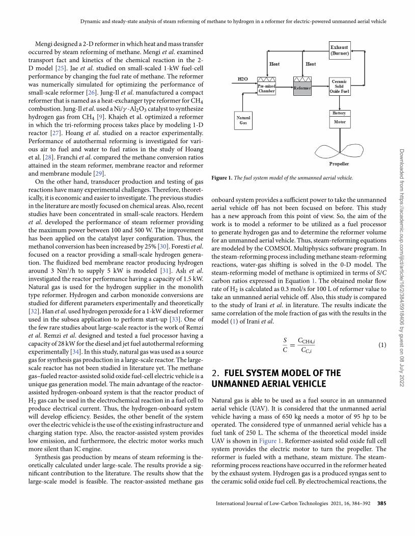
Figure 1. The fuel system model of the unmanned aerial vehicle.
onboard system provides a sufficient power to take the unmannedaerial vehicle off has not been focused on before. This studyhas a new approach from this point of view. So, the aim of thework is to model a reformer to be utilized as a fuel processorto generate hydrogen gas and to determine the reformer volumefor an unmanned aerial vehicle. Thus, steam-reforming equationsare modeled by the COMSOL Multiphysics software program. Inthe steam-reforming process including methane steam-reformingreactions, water-gas shifting is solved in the 0-D model. Thesteam-reforming model of methane is optimized in terms of S/Ccarbon ratios expressed in Equation 1. The obtained molar flowrate of H2 is calculated as 0.3 mol/s for 100 L of reformer value totake an unmanned aerial vehicle off. Also, this study is comparedto the study of Irani et al. in literature. The results indicate thesame correlation of the mole fraction of gas with the results in themodel (1) of Irani et al.
SC
= CCH4,i
CC,i(1)
2. FUEL SYSTEM MODEL OF THEUNMANNED AERIAL VEHICLENatural gas is able to be used as a fuel source in an unmannedaerial vehicle (UAV). It is considered that the unmanned aerialvehicle having a mass of 650 kg needs a motor of 95 hp to beoperated. The considered type of unmanned aerial vehicle has afuel tank of 250 L. The schema of the theoretical model insideUAV is shown in Figure 1. Reformer-assisted solid oxide full cellsystem provides the electric motor to turn the propeller. Thereformer is fueled with a methane, steam mixture. The steam-reforming process reactions have occurred in the reformer heatedby the exhaust system. Hydrogen gas is a produced syngas sent tothe ceramic solid oxide fuel cell. By electrochemical reactions, the
International Journal of Low-Carbon Technologies 2021, 16, 384–392 385
Dow
nloaded from https://academ
ic.oup.com/ijlct/article/16/2/384/5918406 by guest on 08 July 2022
E. Kosa
Table 1. Reformer initial conditions for steady-state and time-dependentanalyses.
Initial conditions in reformer
Steam/carbon (mole fraction) (7.1/3)–(10.65/3)–(14.2/3)U×A [W/m3 K] (for per volume) 1500Initial temperature [K] 600Initial flow rate of methane [m3/s] 3 × 10⁻⁴, 4.5 × 10⁻⁴, 6 × 10⁻⁴ [m3/s]Initial flow rate of steam [m3/s] 26 × 10−5 [m3/s]Heat-exchanger mediumtemperature [K]
1250
Table 2. Arrhenius kinetic parameters [35, 36].
Parameter Pre-exponential factor Activation energy andheat of adsorption ofwater [kJ/mol]
k1(mol/(gcat s bar0.5)) 9.49 × 10¹⁶ 240.1k2(mol/(gcat s bar0.5)) 4.39 × 10⁴ 67.13k3(mol/(gcat s bar−1)) 2.29 × 10¹⁶ 243.9
current accumulated the battery to make the electric motor to turnthe propeller.
3. STEAM-REFORMING MODEL OFMETHANE GASThe steam-reforming reaction model includes steam-reformingreactions and water-gas shifting reaction. Steam-reformingreactions are endothermic whereas water-gas shifting reactionis exothermic.
Steam-reforming process reactions:Steam reforming—1:
CH4 + H2O � CO + 3H2 (2)
Steam reforming—2:
CH4 + 2H2O � CO2 + 4H2 (3)
Water-gas shifting reaction:
CO + H2O � CO2 + H2 (4)
Initial conditions in the reactor and Arrhenius kinetic param-eters are described in Tables 1 and 2.
U is the overall heat transfer coefficient (W/(m2K)); A is theeffective heat transfer area per unit of reactor volume (1/m).
3.1. Model equationsIn this study, mass balance, energy, entropy and enthalpy equa-tions are expressed as follows in transient case.
Figure 2. Conversion of CH4 in steady state.
3.1.1. Mass balanceConsidering the time-dependent model, the mass balance equa-tion for a continuous stirred tank reactor is calculated by
Vr .dCi
dt=
∑vf ,m.cf ,mi − v.ci + Vr .Ri (5)
dVr
dt= 0 (6)
V =∑
mvf ,m + vp (7)
V is the reactor volume (m3), and Ri is the species net reactionrate (mol/(m3·s)).
Vr∑
ciCp,ıdTdt
= Q + Qext + Vrdpdt
+∑
m
∑i
vf ,micf ,mi(hf ,mi − hi
)(8)
Q = −Vr∑
i
Hiri (9)
p = RgT∑
ci (10)
Volumetric rate:
vp = RgTp
Vr∑
i
Ri (11)
Reactor pressure is defined as the sum of all partial gas pressuresin the reactor.
386 International Journal of Low-Carbon Technologies 2021, 16, 384–392
Dow
nloaded from https://academ
ic.oup.com/ijlct/article/16/2/384/5918406 by guest on 08 July 2022
Dynamic and steady-state analysis of steam reforming of methane to hydrogen in a reformer for electric-powered unmanned aerial vehicle
3.1.2. Energy equationAssuming that there is no pressure drop, the reactor energy bal-ance for an ideal reacting gas is defined as
∑i
FiCp,idTdV
= Eshaft + Q + Qext (12)
Q = −∑
j
Hjrj (13)
where Hj is the heat produced by reaction j.
Q = Q1+Q2+Q3+Q4+Q5 = −r1H1−r2H2−r3H3−r4H4−r5H5(14)
3.1.3. Entropy and enthalpy equationsEntropy of reactions is defined as:
Sj =∑i=1
νijsi −∑i=1
(−νij)
si (15)
Enthalpy of reactions is defined as;
Hj =∑i=1
νijhi −∑i=1
(−νij)
hi (16)
3.1.4. Thermodynamic characterThe thermodynamic parameters such as heat capacity, molarenthalpy and molar entropy of species are calculated by theChemkin file.
Governing equations:The reaction rates are defined as [37];
r1 = k1
P2.5H2
(PCH4.PH2O − P3
H2.Pco/K1
(1 + Kco.Pco + KH2.PH2 + KCH4 ∗ PCH4 + KH2O.PH2O/PH2)2
)(17)
r2 = k2
PH2
(Pco.PH2O − PH2.Pco/K2
(1 + Kco.Pco + KH2.PH2 + KCH4 ∗ PCH4 + KH2O.PH2O/PH2)2
)(18)
r3 = k3
P2.5H2
⎛⎝ PCH4.P2
h2o − P3H2.Pco2/
(K1.K2
)(1 + Kco.Pco + KH2.PH2 + KCH4 ∗ PCH4 + KH2O.PH2O/PH2)
2
⎞⎠ (19)
Table 3. Enthalpy change of reaction [35] and absorption constants [37].
Gases �H [kJ/mol] Absorption constants kj.T[1/bar]
CH4 -38.28 kCH4 6.65 × 10⁻⁶
CO -70.65 kCO 8.23 × 10⁻⁷
H2 -82.90 kH2 8.23 × 10⁻²²
H2O 88.68 kH2O 1.77 × 10⁵ (no dimension)
Equilibrium constants are defined as [35];
K1 = 10 266.76 exp(
−26 830T
+ 30.114)
(20)
K2 = exp(
4400T
− 4.036)
(21)
The enthalpy changes and adsorption constants are given inTable 3.
4. EVALUATING THE FACTORS EFFECTINGTHE PERFORMANCE OF 0-DSTEAM-REFORMING MODELThe input feed of S/C to the reactor is ranked to optimize theperformance of the reactor on the board system. The steady-state and dynamic behaviors of steam-reforming reactions in thereactor are investigated.
The assumptions in the 0-D steam-reforming reactor model:• Operation is under non-adiabatic condition.• Ideal gas law is applied.• Non-isothermal case is valid.
4.1. Steady-state analysis of the reactor under SMRThe aim is to model a reactor to produce syngas of hydrogen bya methane steam-reforming process. So, the converted amountof CH4 and H2O are focused on. High conversion rates in CH4and H2O provide high molar flow rates of H2 that is a syngas forthe ceramic solid oxide fuel cell. H2 is the main power sourcefor the thrust force of the UAV. To reach enough molar flow
International Journal of Low-Carbon Technologies 2021, 16, 384–392 387
Dow
nloaded from https://academ
ic.oup.com/ijlct/article/16/2/384/5918406 by guest on 08 July 2022
E. Kosa
rates of syngas of hydrogen, reactor volume is detected by using amultiphysics software program. The limit of the unmanned aerialvehicle is the restricted free space. Thus, the correlation betweenthe generated hydrogen molar flow rate and reactor volume isstudied on.
In modeling 0-D steam-reforming reactions of methane gas,the terms of methane conversion and steam conversion aredefined as:
a) Conversion of CH4
XCH4 =(FCH4,i − FCH4,o
)FCH4,i
× 100 (22)
FCH4,i = CCH4,i × QCH4,i (23)
FCH4,o = CCH4,o × QCH4,o (24)
b) Conversion of H2O is
XH2O =(FH2O,i − FH2O,o
)FH2O,i
× 100 (25)
FH2O,i = CH2O,i × QH2O,i (26)
FH2O,o = CH2O,o × QH2O,o (27)
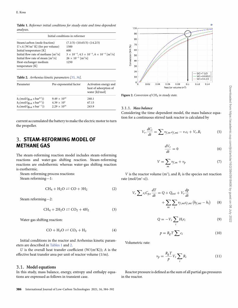
S/C is ranked from 7.1/3 to 14.2/3 ratios by providing thesame molar flow rate of methane gas in a steady state. The inputmolar flow rate is kept constant. Ninety-two percent of methaneis converted into a mixture of products at a reactor volume of100 L for the S/C ratio of 7.1/3 as shown in Figure 2. As thecarbon amount increase by rising from S/C= 14.2/3 to S/C = 7.1/3providing the same input CH4 molar flow rate in the steady statedue to the fact that a decrease in the input molar flow rate ofmethane causes a low molar flow rate of product gases. Also,due to the limited space in the aerial vehicle, to retain a highconversion ratio of methane at low reactor volumes, the S/C ratiohas a significant role in the reactor performance.
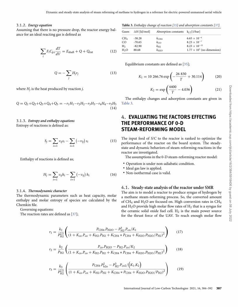
Ninety percent of steam is converted into synthesis gas of H2at 100 L of reactor volume for the S/C ratio of 7.1/3. As in themethane conversion, it is seen in Figure 3 that the increase inthe amount of carbon increases the amount of steam that can beconverted in steady state.
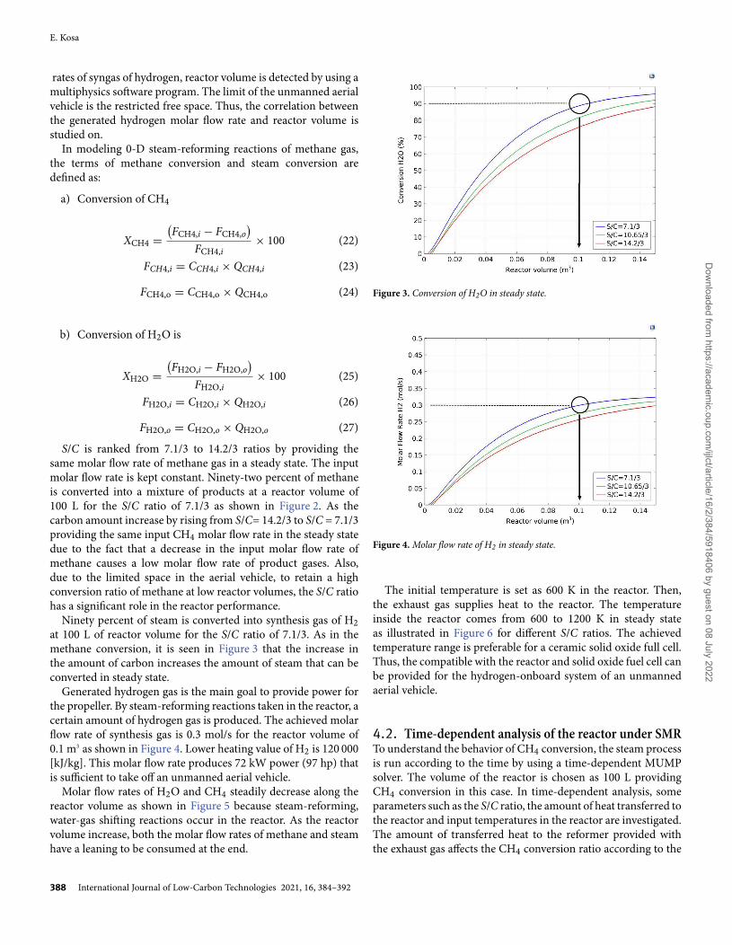
Generated hydrogen gas is the main goal to provide power forthe propeller. By steam-reforming reactions taken in the reactor, acertain amount of hydrogen gas is produced. The achieved molarflow rate of synthesis gas is 0.3 mol/s for the reactor volume of0.1 m3 as shown in Figure 4. Lower heating value of H2 is 120 000[kJ/kg]. This molar flow rate produces 72 kW power (97 hp) thatis sufficient to take off an unmanned aerial vehicle.
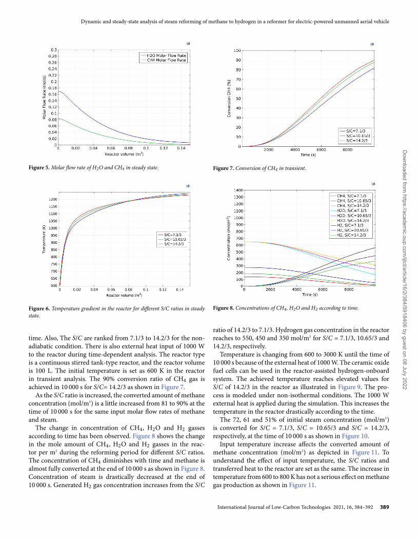
Molar flow rates of H2O and CH4 steadily decrease along thereactor volume as shown in Figure 5 because steam-reforming,water-gas shifting reactions occur in the reactor. As the reactorvolume increase, both the molar flow rates of methane and steamhave a leaning to be consumed at the end.
Figure 3. Conversion of H2O in steady state.
Figure 4. Molar flow rate of H2 in steady state.
The initial temperature is set as 600 K in the reactor. Then,the exhaust gas supplies heat to the reactor. The temperatureinside the reactor comes from 600 to 1200 K in steady stateas illustrated in Figure 6 for different S/C ratios. The achievedtemperature range is preferable for a ceramic solid oxide full cell.Thus, the compatible with the reactor and solid oxide fuel cell canbe provided for the hydrogen-onboard system of an unmannedaerial vehicle.
4.2. Time-dependent analysis of the reactor under SMRTo understand the behavior of CH4 conversion, the steam processis run according to the time by using a time-dependent MUMPsolver. The volume of the reactor is chosen as 100 L providingCH4 conversion in this case. In time-dependent analysis, someparameters such as the S/C ratio, the amount of heat transferred tothe reactor and input temperatures in the reactor are investigated.The amount of transferred heat to the reformer provided withthe exhaust gas affects the CH4 conversion ratio according to the
388 International Journal of Low-Carbon Technologies 2021, 16, 384–392
Dow
nloaded from https://academ
ic.oup.com/ijlct/article/16/2/384/5918406 by guest on 08 July 2022
Dynamic and steady-state analysis of steam reforming of methane to hydrogen in a reformer for electric-powered unmanned aerial vehicle
Figure 5. Molar flow rate of H2O and CH4 in steady state.
Figure 6. Temperature gradient in the reactor for different S/C ratios in steadystate.
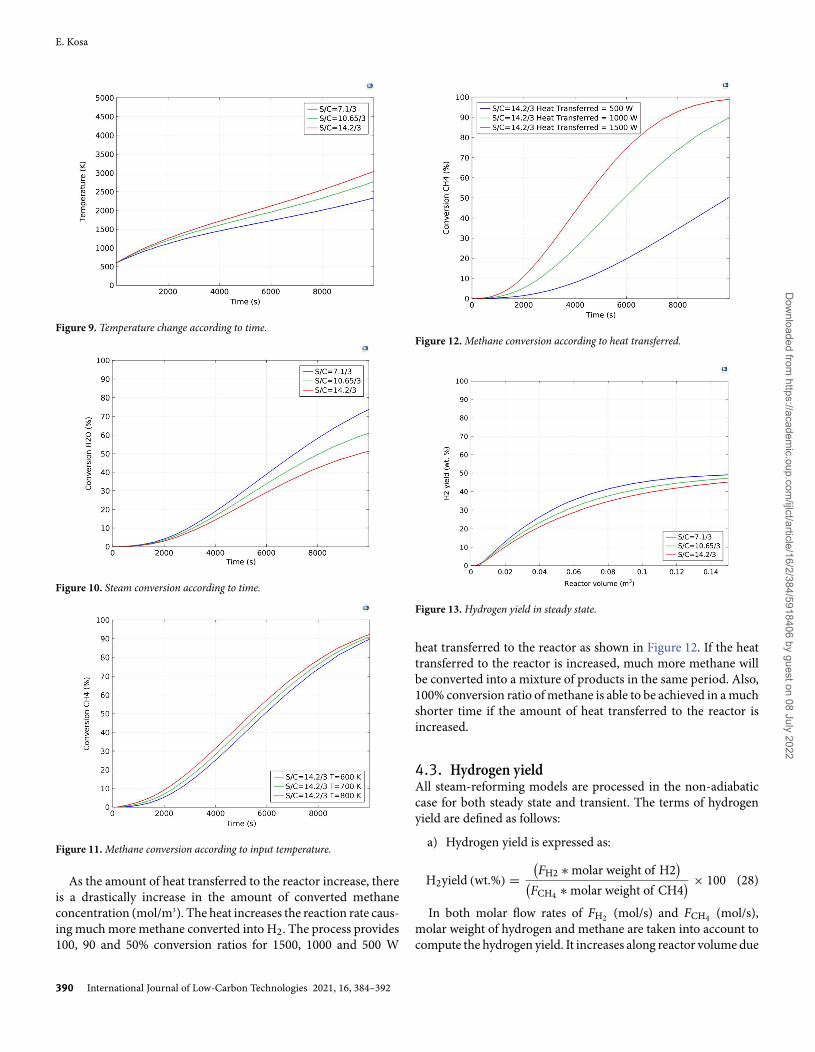
time. Also, The S/C are ranked from 7.1/3 to 14.2/3 for the non-adiabatic condition. There is also external heat input of 1000 Wto the reactor during time-dependent analysis. The reactor typeis a continuous stirred tank-type reactor, and the reactor volumeis 100 L. The initial temperature is set as 600 K in the reactorin transient analysis. The 90% conversion ratio of CH4 gas isachieved in 10 000 s for S/C= 14.2/3 as shown in Figure 7.
As the S/C ratio is increased, the converted amount of methaneconcentration (mol/m3) is a little increased from 81 to 90% at thetime of 10 000 s for the same input molar flow rates of methaneand steam.
The change in concentration of CH4, H2O and H2 gassesaccording to time has been observed. Figure 8 shows the changein the mole amount of CH4, H2O and H2 gasses in the reac-tor per m3 during the reforming period for different S/C ratios.The concentration of CH4 diminishes with time and methane isalmost fully converted at the end of 10 000 s as shown in Figure 8.Concentration of steam is drastically decreased at the end of10 000 s. Generated H2 gas concentration increases from the S/C
Figure 7. Conversion of CH4 in transient.
Figure 8. Concentrations of CH4, H2O and H2 according to time.
ratio of 14.2/3 to 7.1/3. Hydrogen gas concentration in the reactorreaches to 550, 450 and 350 mol/m3 for S/C = 7.1/3, 10.65/3 and14.2/3, respectively.
Temperature is changing from 600 to 3000 K until the time of10 000 s because of the external heat of 1000 W. The ceramic oxidefuel cells can be used in the reactor-assisted hydrogen-onboardsystem. The achieved temperature reaches elevated values forS/C of 14.2/3 in the reactor as illustrated in Figure 9. The pro-cess is modeled under non-isothermal conditions. The 1000 Wexternal heat is applied during the simulation. This increases thetemperature in the reactor drastically according to the time.
The 72, 61 and 51% of initial steam concentration (mol/m3)is converted for S/C = 7.1/3, S/C = 10.65/3 and S/C = 14.2/3,respectively, at the time of 10 000 s as shown in Figure 10.
Input temperature increase affects the converted amount ofmethane concentration (mol/m3) as depicted in Figure 11. Tounderstand the effect of input temperature, the S/C ratios andtransferred heat to the reactor are set as the same. The increase intemperature from 600 to 800 K has not a serious effect on methanegas production as shown in Figure 11.
International Journal of Low-Carbon Technologies 2021, 16, 384–392 389
Dow
nloaded from https://academ
ic.oup.com/ijlct/article/16/2/384/5918406 by guest on 08 July 2022
E. Kosa
Figure 9. Temperature change according to time.
Figure 10. Steam conversion according to time.
Figure 11. Methane conversion according to input temperature.
As the amount of heat transferred to the reactor increase, thereis a drastically increase in the amount of converted methaneconcentration (mol/m3). The heat increases the reaction rate caus-ing much more methane converted into H2. The process provides100, 90 and 50% conversion ratios for 1500, 1000 and 500 W
Figure 12. Methane conversion according to heat transferred.
Figure 13. Hydrogen yield in steady state.
heat transferred to the reactor as shown in Figure 12. If the heattransferred to the reactor is increased, much more methane willbe converted into a mixture of products in the same period. Also,100% conversion ratio of methane is able to be achieved in a muchshorter time if the amount of heat transferred to the reactor isincreased.
4.3. Hydrogen yieldAll steam-reforming models are processed in the non-adiabaticcase for both steady state and transient. The terms of hydrogenyield are defined as follows:
a) Hydrogen yield is expressed as:
H2yield (wt.%) =(FH2 ∗ molar weight of H2
)(FCH4 ∗ molar weight of CH4
) × 100 (28)
In both molar flow rates of FH2 (mol/s) and FCH4 (mol/s),molar weight of hydrogen and methane are taken into account tocompute the hydrogen yield. It increases along reactor volume due
390 International Journal of Low-Carbon Technologies 2021, 16, 384–392
Dow
nloaded from https://academ
ic.oup.com/ijlct/article/16/2/384/5918406 by guest on 08 July 2022
Dynamic and steady-state analysis of steam reforming of methane to hydrogen in a reformer for electric-powered unmanned aerial vehicle
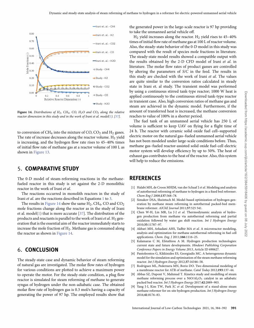
Figure 14. Distributions of H2, CH4, CO, H2O and CO2 along the relativereactor dimension in this study and in the work of Irani et al. model(1). [37].
to conversion of CH4 into the mixture of CO, CO2 and H2 gases.The rate of increase decreases along the reactor volume. H2 yieldis increasing, and the hydrogen flow rate rises to 45–40% timesof initial flow rate of methane gas at a reactor volume of 100 L asshown in Figure 13.
5. COMPARATIVE STUDYThe 0-D model of steam-reforming reactions in the methane-fueled reactor in this study is set against the 2-D monolithicreactor in the work of Irani et al.
The reactions occurred in monolith reactors in the study ofIrani et al. are the reactions described in Equations 1 to 3.
The results in Figure 14 show the same H2, CH4, CO and CO2mole fractions change along the reactor as in the study of Iraniet al. model(1) that is more accurate [37]. The distribution of theproducts and reactants is parallel to the work of Irani et al. H2 gen-eration that is the essential aim of the reactor immediately starts toincrease the mole fraction of H2. Methane gas is consumed alongthe reactor as shown in Figure 14.
6. CONCLUSIONThe steady-state case and dynamic behavior of steam reformingof natural gas are investigated. The molar flow rates of hydrogenfor various conditions are plotted to achieve a maximum powerto operate the motor. For the steady-state condition, a plug flowreactor is simulated for steam reforming of methane to generatesyngas of hydrogen under the non-adiabatic case. The obtainedmolar flow rate of hydrogen gas is 0.3 mol/s having a capacity ofgenerating the power of 97 hp. The employed results show that
the generated power in the large-scale reactor is 97 hp providingto take the unmanned aerial vehicle off.
H2 yield increases along the reactor. H2 yield rises to 45–40%times of initial flow rate of methane gas at 100 L of reactor volume.Also, the steady-state behavior of the 0-D model in this study wascompared with the result of species mole fractions in literature.The steady-state model results showed a compatible output withthe results obtained by the 2-D CFD model of Irani et al. inliterature. The molar flow rates of product gasses are controlledby altering the parameters of S/C in the feed. The results inthis study are checked with the work of Irani et al. The valuesare quite similar to the conversion ratios calculated in steadystate in Irani et. al study. The transient model was performedby using a continuous stirred tank-type reactor; 1000 W heat isapplied continuously to the continuous stirred tank-type reactorin transient case. Also, high conversion ratios of methane gas andsteam are achieved in the dynamic model. Furthermore, if theamount of transferred heat is increased, the methane conversionreaches to value of 100% in a shorter period.
The fuel tank of an unmanned aerial vehicle has 250 L ofvolume is sufficient to keep UAV on flying for a flight time of24 h. The reactor with ceramic solid oxide fuel cell–supportedelectric motor on the natural gas–fueled unmanned aerial vehiclehas not been modeled under large-scale conditions before. Thus,methane gas–fueled reactor-assisted solid oxide fuel-cell electricmotor system will develop efficiency by up to 50%. The heat ofexhaust gas contributes to the heat of the reactor. Also, this systemwill help to reduce the emissions.
REFERENCES[1] Halabi MH, de Croon MHJM, van der Schaaf J et al. Modeling and analysis
of autothermal reforming of methane to hydrogen in a fixed bed reformer.Chem Eng J 2008;137:568–78.
[2] Simakov DSA, Sheintuch M. Model-based optimization of hydrogen gen-eration by methane steam reforming in autothermal packed-bed mem-brane reformer. AIChE Journal 2011;57:525 541.
[3] Chen W-H, Lin MR, Lu J-J et al. Thermodynamic analysis of hydro-gen production from methane via autothermal reforming and partialoxidation followed by water gas shift reaction. Int J Hydrogen Energy2010;35:11787–97.
[4] Akbari MH, Arkadani AHS, Tadbir MA et al. A microreactor modeling,analysis and optimization for methane autothermal reforming in fuel cellapplications. Chem. Eng. J 2011;166:1116–25.
[5] Kalamaras C M, Efstathiou A M. Hydrogen production technologies:current state and future developments. Hindawi Publishing CorporationConference Papers in Energy Volume 2013, Article ID 690627.
[6] Pantoleontos G, Kikkinides ES, Georgiadis MC. A heterogenous dynamicmodel for the simulation and optimisation of the steam methane reformingreactor. Int J Hydrogen Energy 2012;37:16346–58.
[7] Rodriguez ML, Pedernera MN, Borio DO. Two dimensional modeling ofa membrane reactor for ATR of methane. Catal Today 2012;193:137–44.
[8] Abbas SZ, Dupont V, Mahmud T. Kinetics study and modelling of steammethane reforming process over a NiO/Al2O3 catalyst in an adiabaticpacked bed reactor. Int J Hydrogen Energy 2017;42:2889–903.
[9] Yang J-I, Kim TW, Park JC et al. Development of a stand-alone steammethane reformer for on-site hydrogen production. Int J Hydrogen Energy2016;41:8176–83.
International Journal of Low-Carbon Technologies 2021, 16, 384–392 391
Dow
nloaded from https://academ
ic.oup.com/ijlct/article/16/2/384/5918406 by guest on 08 July 2022
E. Kosa
[10] Azarhoosh MJ, Ebrahim HA, Pourtarah SH. Simulating and optimiz-ing auto-thermal reforming of methane to synthesis gas using a non-dominated sorting genetic algorithm II method. Chem Eng Commun 2016;203:53–63.
[11] Xu X, Li P, Shen Y. Small scale reforming of diesel and jet fuels tomake hydrogen and syngas for fuel cells: a review. Appl Energy 2013;108:202–17.
[12] Ding Y, Alpay E. Adsorption-enhanced steam methane reforming. ChemEng Sci 2000;55:3929–40.
[13] Fernandes FAN, Souza CP, Sousa JF. Modeling of partial oxidation ofmethane in a membrane reactor. Engenharia Térmica (Thermal Engineer-ing) 2006;5:40–5.
[14] Nikoo MK, Amin NAS. Thermodynamic analysis of carbon dioxidereforming of methane in view of solid carbon formation. Fuel ProcessTechnol 2011;92:678–91.
[15] Lemonidou AA, Vasalos IA. Carbon dioxide reforming of methane over 5wt.% Ni/CaO-Al2O3 catalyst. Appl Catal A Gen 2002;228:227–35.
[16] Scognamiglio D, Russo L, Maffettone PL et al. Modelling and simulation ofa catalytic autothermal methane reformer with Rh catalyst. Int J HydrogenEnergy 2012;37:263–75.
[17] Nezhad MZ, Rowshanzamir S, Eikani MH. Autothermal reforming ofmethane to synthesis gas: modeling and simulation. Int J Hydrogen Energy2009;34:1292–300.
[18] Patcharavorachota Y, Wasuleewana M, Assabumrungrata S et al. Analysisof hydrogen production from methane autothermal reformer with a dualcatalyst bed configuration. Theor Found Chem Eng 2012;46:658–65.
[19] Blakeley B, Sullivan N. Fuel processing in a ceramic microchannel reactor:expanding operating windows. Int J Hydrogen Energy 2016;41:3794–802.
[20] Behnam M, Dixon AG, Wright PM et al. Comparison of CFD simulationsto experiment under methane steam reforming reacting conditions. ChemEng J 2012;207–208:690–700.
[21] Adiya ZISG, Dupont V, Mahmud T. Steam reforming of shale gas in apacked bed reactor with and without chemical looping using nickel basedoxygen carrier. Int J Hydrogen Energy 2018;43:6904–17.
[22] Park H-G, Han S-Y, Jun K-W et al. Bench-scale steam reforming ofmethane for hydrogen production. Catalysts 2019;9:615.
[23] Atmaca M, Girgin I, Ezgi C. CFD modeling of a diesel evaporator used infuel cell systems. Int J Hydrogen Energy 2016;41:6004–12.
[24] Atmaca M, Ezgi C. Three-dimensional CFD modeling of a steam ejector.Energy Sources Part A 2019;1–12.
[25] Ni M. 2D heat and mass transfer modeling of methane steam reforming forhydrogen production in a compact reformer. Energy Convers and Manag2013;65:155–63.
[26] Lee JS, Seo J, Kim HY et al. Effects of combustion parameters on reformingperformance of a steam–methane reformer. Fuel 2013;111:461–71.
[27] Khajeh S, Aboosadi ZA, Honarvar B. Optimizing the fluidized-bed reac-tor for synthesis gas production by tri-reforming. Chem Eng Res Des2015;94:407–16.
[28] Hoang DL, Chan SH. Experimental investigation on the effect of naturalgas composition on performance of autothermal reforming. Int J HydrogenEnergy 2007;32:548–56.
[29] Franchi G, Capocelli M, De Falco M et al. Hydrogen production via steamreforming: a critical analysis of MR and RMM technologies. Membranes2020;10:10.
[30] Herdem MS, Mundhwa M, Siamak F et al. Catalyst layer design andarrangement to improve the performance of a microchannel methanolsteam reformer. Energy Convers and Manag 2019;180:149–61.
[31] Foresti S, Marcoberardino GD, Manzolini G et al. A comprehensive modelof a fluidized bed membrane reactor for small-scale hydrogen production.Chem Eng Process 2018;127:136–44.
[32] Sayar A, Eskin N. Experimental and theoretical analysis of a monolith typeauto-thermal reforming reactor. Int J Hydrogen Energy 2019;44:10232–49.
[33] Samsun RC, Prawitz M, Tschauder A. An autothermal reforming systemfor diesel and jet fuel with quick start-up capability. Int J Hydrogen Energy2019;44:27749–64.
[34] Han G, Bae M, Cho S et al. Start-up strategy of a diesel reformer usingthe decomposition heat of hydrogen peroxide for subsea applications. J ofPower Sources 2020;444:1–6.
[35] Xu J, Froment GF. Methane steam reforming, methanation and water gasshift: I. intrinsic kinetics. AIChE J 1989;35:88–96.
[36] Dehkordi AM, Memari M. Compartment model for steam reforming ofmethane in a membrane-assisted bubbling fluidized-bed reactor. Int JHydrogen Energy 2009;34:1275–91.
[37] Irani M, Alizadehdakhel A, Pour AN et al. CFD modeling of hydrogen pro-duction using steam reforming of methane in monolith reactors: Surfaceor volume-base reaction model? Int J Hydrogen Energy 2011;36:15602–19.
392 International Journal of Low-Carbon Technologies 2021, 16, 384–392
Dow
nloaded from https://academ
ic.oup.com/ijlct/article/16/2/384/5918406 by guest on 08 July 2022