Methanol steam reforming in single-fiber packed bed Pd–Ag membrane reactor: Experiments and modeling
This article appeared in a journal published by Elsevier. The attachedcopy is furnished to the author for internal non-commercial researchand education use, including for instruction at the authors institution
and sharing with colleagues.
Other uses, including reproduction and distribution, or selling orlicensing copies, or posting to personal, institutional or third party
websites are prohibited.
In most cases authors are permitted to post their version of thearticle (e.g. in Word or Tex form) to their personal website orinstitutional repository. Authors requiring further information
regarding Elsevier’s archiving and manuscript policies areencouraged to visit:
http://www.elsevier.com/copyright
Author's personal copy
Exergoenvironmental analysis of a steam methane reforming process forhydrogen production
A. Boyano a, A.M. Blanco-Marigorta b, T. Morosuk c,*, G. Tsatsaronis a
a Institute for Energy Engineering, Technische Universität Berlin, Marchstr 18, 10587 Berlin, GermanybDepartment of Process Engineering, University of Las Palmas de Gran Canaria, Edificio de Ingenierías-Tafira Baja, 35017 Las Palmas de Gran Canaria, SpaincMaritime Academy of Szczecin, Institute of Marine Propulsion Plants Operation, Waly Chrobrego 1-2, 70500 Szczecin, Poland
a r t i c l e i n f o
Article history:Received 30 October 2009Received in revised form7 May 2010Accepted 11 May 2010Available online 31 July 2010
Keywords:Hydrogen productionSteam methane reforming processExergoenvironmental analysisExergy analysisLife cycle assessmentEco-indicator 99
a b s t r a c t
Steam methane reforming (SMR) is one of the most promising processes for hydrogen production.Several studies have demonstrated its advantages from the economic viewpoint. Nowadays processdevelopment is based on technical and economical aspects; however, in the near future, the environ-mental impact will play a significant role in the design of such processes. In this paper, an SMR process isstudied from the viewpoint of overall environmental impact, using an exergoenvironmental analysis.This analysis presents the combination of exergy analysis and life cycle assessment. Components wherechemical reactions occur are the most important plant components from the exergoenvironmental pointof view, because, in general, there is a high environmental impact associated with these components.This is mainly caused by the exergy destruction within the components, and this in turn is mainly due tothe chemical reactions. The obtained results show that the largest potential for reducing the overallenvironmental impact is associated with the combustion reactor, the steam reformer, the hydrogenseparation unit and the major heat exchangers. The environmental impact in these components canmainly be reduced by improving their exergetic efficiency. A sensitivity analysis for some importantexergoenvironmental variables is also presented in the paper.
� 2010 Elsevier Ltd. All rights reserved.
1. Introduction
In the context of environment protection, reduction of thedifferent pollutants associated with a process is an ecological andfinancial issue. Therefore, the application of a successful method-ology to reduce the overall environmental impact of a future energycarrier such as hydrogen could be very promising [1].
An energy economy based on hydrogen has been proposed asa possible option to reduce the greenhouse effect, global climaticchanges and other pollution effects. However, in order to obtain aneffective mitigation of pollution, hydrogen production should bevery low in CO2 emissions as well as other pollutants. This goal isexpected to be reached in the long term, whereas in the short termit is reasonable to suppose that hydrogen produced from fossil fuels(mainly coal and natural gas) will play an important role during thistransition to hydrogen economy. Among all current technologies
for hydrogen production, steam reforming of natural gas (SMR) isnowadays the source of 80e85% of the world’s total hydrogenproduction [2], even though one of the main problems associatedwith this activity is its great impact on the environment. Most ofthe remaining hydrogen production is accomplished via othermethane reforming processes, coal gasification and water elec-trolysis (at a smaller scale). This last process is considered to be the“cleaner” option for hydrogen production, particularly whenrenewable energy resources are used to generate the electricity;nevertheless, such water electrolysis is not economically competi-tive with the present-day technologies [3].
As SMR process is the most commercial process for hydrogenproduction, in the last 20 years, remarkable efforts were addressedto understand and assess the sustainability (understanding underthis concept: safety, environmental impact and process efficiency)of hydrogen production [4]. This fact is confirmed by the highamount of studies that focused on single aspects of the problem, aseconomic aspects [5], energy and exergy balances [2], or even onoperational aspects such as the development of new reactors orcatalysts [6e9]. However, to the best of our knowledge, there isa scarcity of studies dealing with a combination of differentaspects in order to achieve an overall improved/optimized process.
* Corresponding author. Tel.: þ49 30 314 24765; fax: þ49 30 314 21683.E-mail addresses: [email protected] (A. Boyano), [email protected]
(A.M. Blanco-Marigorta), [email protected] (T. Morosuk), [email protected] (G. Tsatsaronis).
URL: http://www.energietechnik.tu-berlin.de
Contents lists available at ScienceDirect
Energy
journal homepage: www.elsevier .com/locate/energy
0360-5442/$ e see front matter � 2010 Elsevier Ltd. All rights reserved.doi:10.1016/j.energy.2010.05.020
Energy 36 (2011) 2202e2214
Author's personal copy
Hydrogen production will in the long run be based on the use ofrenewable resources, but, when considering a shorter timeperspective, a transitory period will be needed, inwhich large-scalehydrogen production will be based on current technologies [5,10].For this reason, detailed simulations of SMR processes are alsorequired to analyze and evaluate possible plant modifications suchas operation temperatures, feedstocks, etc in order to minimize thecost and environmental impact caused by such processes.
Industrial activities in the last decades have induced anincrease of emissions of several pollutants and a fast depletion ofnatural resources that from the environmental point of view canbe assessed by methods using a life cycle assessment (LCA) [10].LCA is a method that takes into account the environmentalimpact of a product or a process over its full life cycle. Thismethodology together with other analyses (for example, [11]) isincreasingly used to analyze chemical processes includinghydrogen production. For example, in [12], an LCA of differentprocesses for hydrogen production such as SMR, SMR with CO2capture and storage, methane autothermal decomposition, andmethane thermal cracking are analysed in order to find the mostenvironmentally friendly process. The conclusion of this work isthat the autothermal decomposition is the most environmentallyfriendly process although it depends on the estimated catalyticactivity as well as on the energetic scenario used in the analysis.A comparative analysis based on LCA for hydrogen productionusing SMR or using renewable sources (solar thermal, photo-voltaic, wind power, hydropower and biomass) has been pub-lished in [13]. The conclusion is that although CO2 emissionscoming from SMR are relatively high, they are smaller that thetotal environmental impact of hydrogen production usingphotovoltaics or biomass.
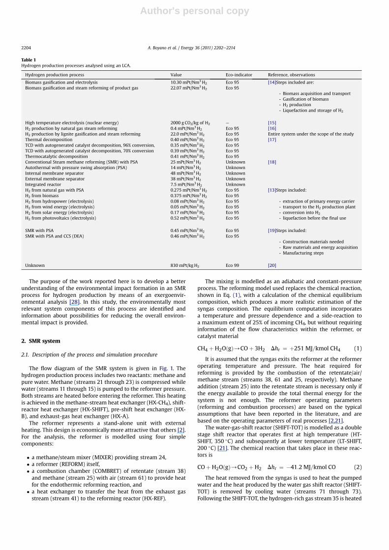
Table 1 shows some data obtained from the publications wherethe analysis of different hydrogen production processes was con-ducted based on LCA.
Results from the energy and exergy analyses of the SMR processhave also been discussed: Ref. [2] discusses results obtained notonly fromwork by the authors, but also results obtained from otherpublications, for example [21,22], where different configurations ofan SMR plant have been discussed. Based on these data, the ener-getic efficiency of different configurations of SMR plants variesbetween 77 and 86% whereas the exergetic efficiency variesbetween 71 and 78.5%. In Ref. [2] a sensitivity analysis is conducted,in order to estimate the optimal operating conditions for an SMRplant from thermodynamic point of view.
Publications where exergetic analysis and environmentalassessment are discussed simultaneously are really scarce (forexample, [11,23,24]). However, different approaches have beendeveloped to combine these analyses. A detailed overview of theseapproaches (for example, cumulative exergy consumption [25],exergoecological analysis [26], extended exergy accounting [27],etc.) has been given in [28]. In the last publication a recentlydeveloped exergoenvironmental analysis has been introduced.
In Ref. [29] the methodology of extended exergy accounting [27]is used to analyze an innovative hydrogen-fed steam power plant,in which the hydrogen is produced by a “zero-CO2-emission” coal-gasification process; furthermore, a comparison with otherconventional processes is conducted. This approach allows users toidentify the highest pollutant and the more environmentalexpensive process, but it did not permit identification and alloca-tion of the greatest environmental impacts inside the wholeprocess, thus preventing users from an environmental optimizationof the overall process.
Nomenclature
b environmental impact per unit of exergy (Pts/J)_B environmental impact rate associated with exergy
(Pts/s)e specific exergy (J/kg)_E exergy rate (W)i ith pollutant streamj jth streamfb exergoenvironmental factor (%)k kth component_m mass flow rate (kg/s)p pressure (bar)_Q heat rate (W)rb relative environmental impact difference
(dimensionless)T temperature (�C)U overall heat-transfer coefficient (W/m2$K)_W power (W)y exergy destruction ratio (%)_Y environmental impact (Pts/s)
AbbreviationsCOMBRET combustion chamber of retenate stream and
methaneCOMP compressorHT-SHIFT high-temperature water-gas-shift reactorHX heat exchangerH2-SEP hydrogen separation unitLCA life cycle assessment
LT-SHIFT low-temperature water-gas-shift reactorMIXER mixerPUMP pumpREFORM reformerSHIFT-TOT water-gas-shift reactorSEP separatorSMR steam methane reformingTV throttling valve
Greek symbolsD difference3 exergetic efficiency (%)h energetic efficiency (%)
SuperscriptsCO refers to CO mass fraction in a mixtureCO2 refers to CO2 mass fraction in a mixtureCH4 refers to CH4 mass fraction in a mixtureCH chemicalH2O refers to H2O mass fraction in a mixtureH2 refers to H2 mass fraction in a mixturePH physical
SubscriptsD exergy destructionF exergy of fuelj jth streamk kth componentP exergy of product0 thermodynamic environment (reference state)
A. Boyano et al. / Energy 36 (2011) 2202e2214 2203
Author's personal copy
The purpose of the work reported here is to develop a betterunderstanding of the environmental impact formation in an SMRprocess for hydrogen production by means of an exergoenvir-onmental analysis [28]. In this study, the environmentally mostrelevant system components of this process are identified andinformation about possibilities for reducing the overall environ-mental impact is provided.
2. SMR system
2.1. Description of the process and simulation procedure
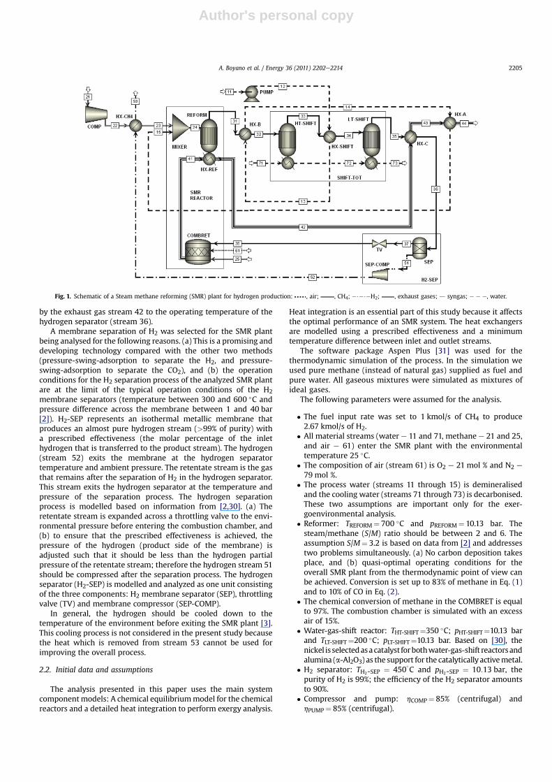
The flow diagram of the SMR system is given in Fig. 1. Thehydrogen production process includes two reactants: methane andpure water. Methane (streams 21 through 23) is compressed whilewater (streams 11 through 15) is pumped to the reformer pressure.Both streams are heated before entering the reformer. This heatingis achieved in the methane-stream heat exchanger (HX-CH4), shift-reactor heat exchanger (HX-SHIFT), pre-shift heat exchanger (HX-B), and exhaust-gas heat exchanger (HX-A).
The reformer represents a stand-alone unit with externalheating. This design is economically more attractive that others [2].For the analysis, the reformer is modelled using four simplecomponents:
� a methane/steam mixer (MIXER) providing stream 24,� a reformer (REFORM) itself,� a combustion chamber (COMBRET) of retentate (stream 38)and methane (stream 25) with air (stream 61) to provide heatfor the endothermic reforming reaction, and
� a heat exchanger to transfer the heat from the exhaust gasstream (stream 41) to the reforming reactor (HX-REF).
The mixing is modelled as an adiabatic and constant-pressureprocess. The reforming model used replaces the chemical reaction,shown in Eq. (1), with a calculation of the chemical equilibriumcomposition, which produces a more realistic estimation of thesyngas composition. The equilibrium computation incorporatesa temperature and pressure dependence and a side-reaction toa maximum extent of 25% of incoming CH4, but without requiringinformation of the flow characteristics within the reformer, orcatalyst material
CH4 þH2OðgÞ/COþ 3H2 Dhr ¼ þ251 MJ=kmol CH4 (1)
It is assumed that the syngas exits the reformer at the reformeroperating temperature and pressure. The heat required forreforming is provided by the combustion of the retentate/air/methane stream (streams 38, 61 and 25, respectively). Methaneaddition (stream 25) into the retentate stream is necessary only ifthe energy available to provide the total thermal energy for thesystem is not enough. The reformer operating parameters(reforming and combustion processes) are based on the typicalassumptions that have been reported in the literature, and arebased on the operating parameters of real processes [2,21].
The water-gas-shift reactor (SHIFT-TOT) is modelled as a doublestage shift reactor that operates first at high temperature (HT-SHIFT, 350 �C) and subsequently at lower temperature (LT-SHIFT,200 �C) [21]. The chemical reaction that takes place in these reac-tors is
COþ H2OðgÞ/CO2 þ H2 Dhr ¼ �41:2 MJ=kmol CO (2)
The heat removed from the syngas is used to heat the pumpedwater and the heat produced by the water gas shift reactor (SHIFT-TOT) is removed by cooling water (streams 71 through 73).Following the SHIFT-TOT, the hydrogen-rich gas stream 35 is heated
Table 1Hydrogen production processes analysed using an LCA.
Hydrogen production process Value Eco-indicator Reference, observations
Biomass gasification and electrolysis 10.30 mPt/Nm3H2 Eco 95 [14]Steps included are:
- Biomass acquisition and transport- Gasification of biomass- H2 production- Liquefaction and storage of H2
Biomass gasification and steam reforming of product gas 22.07 mPt/Nm3H2 Eco 95
High temperature electrolysis (nuclear energy) 2000 g CO2/kg of H2 e [15]H2 production by natural gas steam reforming 0.4 mPt/Nm3H2 Eco 95 [16]
Entire system under the scope of the studyH2 production by lignite gasification and steam reforming 22.0 mPt/Nm3H2 Eco 95Thermal decomposition 0.40 mPt/Nm3H2 Eco 95 [17]TCD with autogenerated catalyst decomposition, 96% conversion, 0.35 mPt/Nm3H2 Eco 95TCD with autogenerated catalyst decomposition, 70% conversion 0.39 mPt/Nm3H2 Eco 95Thermocatalytic decomposition 0.41 mPt/Nm3H2 Eco 95Conventional Steam methane reforming (SMR) with PSA 25 mPt/Nm3H2 Unknown [18]Autothermal with pressure swing absorption (PSA) 14 mPt/Nm3H2 UnknownInternal membrane separator 48 mPt/Nm3H2 UnknownExternal membrane separator 38 mPt/Nm3H2 UnknownIntegrated reactor 7.5 mPt/Nm3H2 UnknownH2 from natural gas with PSA 0.275 mPt/Nm3H2 Eco 95 [13]Steps included:
- extraction of primary energy carrier- transport to the H2 production plant- conversion into H2
- liquefaction before the final use
H2 from biomass 0.375 mPt/Nm3H2 Eco 95H2 from hydropower (electrolysis) 0.08 mPt/Nm3H2 Eco 95H2 from wind energy (electrolysis) 0.05 mPt/Nm3H2 Eco 95H2 from solar energy (electrolysis) 0.17 mPt/Nm3H2 Eco 95H2 from photovoltaics (electrolysis) 0.52 mPt/Nm3H2 Eco 95
SMR with PSA 0.45 mPt/Nm3H2 Eco 95 [19]Steps included:
- Construction materials needed- Raw materials and energy acquisition- Manufacturing steps
SMR with PSA and CCS (DEA) 0.46 mPt/Nm3H2 Eco 95
Unknown 830 mPt/kg H2 Eco 99 [20]
A. Boyano et al. / Energy 36 (2011) 2202e22142204
Author's personal copy
by the exhaust gas stream 42 to the operating temperature of thehydrogen separator (stream 36).
A membrane separation of H2 was selected for the SMR plantbeing analysed for the following reasons. (a) This is a promising anddeveloping technology compared with the other two methods(pressure-swing-adsorption to separate the H2, and pressure-swing-adsorption to separate the CO2), and (b) the operationconditions for the H2 separation process of the analyzed SMR plantare at the limit of the typical operation conditions of the H2
membrane separators (temperature between 300 and 600 �C andpressure difference across the membrane between 1 and 40 bar[2]). H2-SEP represents an isothermal metallic membrane thatproduces an almost pure hydrogen stream (>99% of purity) witha prescribed effectiveness (the molar percentage of the inlethydrogen that is transferred to the product stream). The hydrogen(stream 52) exits the membrane at the hydrogen separatortemperature and ambient pressure. The retentate stream is the gasthat remains after the separation of H2 in the hydrogen separator.This stream exits the hydrogen separator at the temperature andpressure of the separation process. The hydrogen separationprocess is modelled based on information from [2,30]. (a) Theretentate stream is expanded across a throttling valve to the envi-ronmental pressure before entering the combustion chamber, and(b) to ensure that the prescribed effectiveness is achieved, thepressure of the hydrogen (product side of the membrane) isadjusted such that it should be less than the hydrogen partialpressure of the retentate stream; therefore the hydrogen stream 51should be compressed after the separation process. The hydrogenseparator (H2-SEP) is modelled and analyzed as one unit consistingof the three components: H2 membrane separator (SEP), throttlingvalve (TV) and membrane compressor (SEP-COMP).
In general, the hydrogen should be cooled down to thetemperature of the environment before exiting the SMR plant [3].This cooling process is not considered in the present study becausethe heat which is removed from stream 53 cannot be used forimproving the overall process.
2.2. Initial data and assumptions
The analysis presented in this paper uses the main systemcomponentmodels: A chemical equilibriummodel for the chemicalreactors and a detailed heat integration to perform exergy analysis.
Heat integration is an essential part of this study because it affectsthe optimal performance of an SMR system. The heat exchangersare modelled using a prescribed effectiveness and a minimumtemperature difference between inlet and outlet streams.
The software package Aspen Plus [31] was used for thethermodynamic simulation of the process. In the simulation weused pure methane (instead of natural gas) supplied as fuel andpure water. All gaseous mixtures were simulated as mixtures ofideal gases.
The following parameters were assumed for the analysis.
� The fuel input rate was set to 1 kmol/s of CH4 to produce2.67 kmol/s of H2.
� All material streams (water e 11 and 71, methane e 21 and 25,and air e 61) enter the SMR plant with the environmentaltemperature 25 �C.
� The composition of air (stream 61) is O2 e 21 mol % and N2 e
79 mol %.� The process water (streams 11 through 15) is demineralisedand the cooling water (streams 71 through 73) is decarbonised.These two assumptions are important only for the exer-goenvironmental analysis.
� Reformer: TREFORM¼ 700 �C and pREFORM¼ 10.13 bar. Thesteam/methane (S/M) ratio should be between 2 and 6. Theassumption S/M¼ 3.2 is based on data from [2] and addressestwo problems simultaneously. (a) No carbon deposition takesplace, and (b) quasi-optimal operating conditions for theoverall SMR plant from the thermodynamic point of view canbe achieved. Conversion is set up to 83% of methane in Eq. (1)and to 10% of CO in Eq. (2).
� The chemical conversion of methane in the COMBRET is equalto 97%. The combustion chamber is simulated with an excessair of 15%.
� Water-gas-shift reactor: THT-SHIFT¼350 �C; pHT-SHIFT¼10.13 barand TLT-SHIFT¼200 �C; pLT-SHIFT¼10.13 bar. Based on [30], thenickel is selectedasacatalyst forbothwater-gas-shift reactorsandalumina (a-Al2O3) as the support for the catalytically activemetal.
� H2 separator: TH2-SEP ¼ 450�C and pH2-SEP ¼ 10:13 bar, the
purity of H2 is 99%; the efficiency of the H2 separator amountsto 90%.
� Compressor and pump: hCOMP¼ 85% (centrifugal) andhPUMP¼ 85% (centrifugal).
Fig. 1. Schematic of a Steam methane reforming (SMR) plant for hydrogen production: , air; , CH4; e$e$eH2; , exhaust gases; d syngas; e e e, water.
A. Boyano et al. / Energy 36 (2011) 2202e2214 2205
Author's personal copy
� The effectiveness of all heat exchangers is equal to 90% and thereare no pressure losses across the heat exchangers. The lastassumption is very widely used in publications related to ther-modynamic analysis of SMR processes because introduction ofpressure losses in the heat exchangers increases the complexityof the analysis without significantly affecting the results andconclusions. Since theanalyzedSMRplant isa theoreticalone, thedesign of all heat exchangers is assumed according to therecommendations for the pre-design of heat exchangers withthe following values of the overall heat-transfer coefficients [32]:UHX-C and UHX-CH4
are equal to 300W/m2 K, and UHX-
SHIFT¼200W/m2K. The two heat exchangers HX-A and HX-Bshould be split into two parts each. The HX-A represents thecombination of (a) a gas to steam heat exchanger withU¼ 150W/m2 K where 44% of the heat transfer occurs(40.2 MW) and (b) an evaporator with U¼ 1800W/m2 K where56% of the heat transfer occurs (51.7 MW). The HX-B representsthe combination of (a) a gas to water heat exchanger withU¼ 200W/m2K where 11% of the heat transfer occurs (7.9 MW)and (b) an evaporator with U¼ 1800W/m2 K where 89% of theheat transfer occurs (64.5 MW).
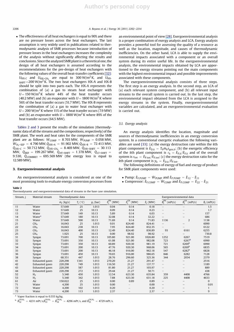
Tables 2 and 3 present the results of the simulation (thermody-namicdata of all the streams and the compositions, respectively) of theSMR plant. The work and heat rates for the components of the SMRplant are as follows: _WCOMP ¼ 8:703 MW, _WPUMP ¼ 0:058 MW,_WH2-SEP ¼ 4:790 MW, _QHX-A ¼ 91:902 MW, _QHX-B ¼ 72:413 MW,_QHX-C ¼ 50:712 MW, _QHX-CH4
¼ 8:469 MW, _QHX-SHIFT ¼ 30:113MW, _QREF ¼ 199:267 MW, _QHT-SHIFT ¼ 1:378 MW, _QLT-SHIFT ¼9:530, _QCOMBRET ¼ 695:569 MW (the energy loss is equal to12.589MW).
3. Exergoenvironmental analysis
An exergoenvironmental analysis is considered as one of themost promising tools to evaluate energy conversion processes from
an environmental point of view [28]. Exergoenvironmental analysisis a proper combination of exergy analysis and LCA. Exergy analysisprovides a powerful tool for assessing the quality of a resource aswell as the location, magnitude, and causes of thermodynamicinefficiencies. On the other hand, LCA is able to supply the envi-ronmental impacts associated with a component or an overallsystem during its entire useful life. In the exergoenvironmentalanalysis, the environmental impacts obtained by LCA are appor-tioned to the exergy streams pointing out the main componentswith the highest environmental impact and possible improvementsassociated with these components.
The exergoenvironmental analysis consists of three steps.The first step is an exergy analysis. In the second step, an LCA of(a) each relevant system component, and (b) all relevant inputstreams to the overall system is carried out. In the last step, theenvironmental impact obtained from the LCA is assigned to theexergy streams in the system. Finally, exergoenvironmentalvariables are calculated, and an exergoenvironmental evaluationis carried out.
3.1. Exergy analysis
An exergy analysis identifies the location, magnitude andsources of thermodynamic inefficiencies in an energy conversionsystem. In a conventional exergetic evaluation the following vari-ables are used [33]: (a) the exergy destruction rate within the kthplant component is _ED;k ¼ T0 _mksgen;k; (b) the exergetic efficiencyof the kth plant component is 3k ¼ _EP;k= _EF;k and of the overallsystem is etot ¼ _EP;tot= _EF;tot; (c) the exergy destruction ratio for thekth plant component is yk ¼ _ED;k= _EF;tot.
The following definitions of exergy of fuel and exergy of productfor SMR plant components were used:
� Pump: _EF;PUMP ¼ _WPUMP and _EP;PUMP ¼ _E12 � _E11� Compressor: _EF;COMP ¼ _WCOMP and _EP;COMP ¼ _E22 � _E21
Table 2Thermodynamic and exergoenvironmental data of streams in the base case simulation.
Stream, j Material stream Thermodynamic data Exergoenvironmental data
_mj (kg/s) Tj (�C) pj (bar) _EPHj (MW) _E
CHj (MW) _Ej (MW) _B
PHj (mPt/s) _B
CHj (mPt/s) _Bj (mPt/s)
11 Water 57.649 25 1.013 0.04 0.14 0.18 e e 1.512 Water 57.649 25 10.13 0.09 0.14 0.23 e e 1.713 Water 57.649 149 10.13 5.89 0.14 6.03 e e 15714 Watera 57.649 180 10.13 32.08 0.14 32.22 e e 68615 Water 57.649 500 10.13 71.69 0.14 71.83 1136 2 113821 CH4 16.043 25 1.013 0.01 824.40 824.41 e e 609022 CH4 16.043 238 10.13 7.95 824.40 832.35 e e 612223 CH4 16.043 400 10.13 12.49 824.40 836.89 93 6161 625525 CH4 1.925 25 10.13 0.00 98.92 98.92 e e 730.831 Syngas 73.691 700 10.13 105.80 921.00 1026.80 1252 6267 751932 Syngas 73.691 350 10.13 61.08 921.00 982.08 723 6267b 699033 Syngas 73.691 350 10.13 60.89 920.30 981.19 721 6269b 699034 Syngas 73.691 200 10.13 47.76 920.30 968.06 565 6269b 683535 Syngas 73.691 200 10.13 46.18 916.00 962.18 547 6282b 682836 Syngas 73.691 450 10.13 70.65 916.00 986.65 846 6282 712838 Syngas 68.351 447 1.013 28.76 296.60 325.36 344 2034 237941 Exhausted gases 220.298 1341 1.013 270.20 21.27 291.47 e e 251642 Exhausted gases 220.298 749 1.013 116.50 21.27 137.77 e e 118943 Exhausted gases 220.298 587 1.013 81.80 21.27 103.97 e e 88944 Exhausted gases 220.298 272 1.013 29.44 21.27 50.71 e e 43852 H2 5.340 450 1.013 12.54 623.30 635.84 359 4408 476653 H2 5.340 342 1.013 7.88 623.30 631.18 225 4408 463361 Air 150.022 25 1.013 0.00 0.89 0.89 e e 071 Water 4.200 25 1.013 0.00 � 0.00 e e 0.0172 Water 4.200 102 1.013 0.20 � 0.20 e e 173 Water 4.200 113 1.013 2.37 � 2.37 e e 9
a Vapor fraction is equal to 0.555 kg/kg.b _B
CH;H2
32 ¼ 4231 mPt=s, _BCH;H2
33 ¼ _BCH;H2
34 ¼ 4296 mPt=s, and _BCH;H2
35 ¼ 4729 mPt=s.
A. Boyano et al. / Energy 36 (2011) 2202e22142206
Author's personal copy
� Heat exchangers (all heat exchangers operate above thetemperature of the environment): _EF;HX ¼ _Ehot;in � _Ehot;out and_EP;HX ¼ _Ecold;out � _Ecold;in
� Reformer: _EF;REFORM ¼ _E41 � _E42 and _EP;REFORM ¼ _E31 � ð _E23 þ_E15Þ (stream 24 is the internal stream within the reformer)
� Combustion chamber: _EF;COMBRET ¼ _E25 þ _E38 and _EP;COMBRET¼ _E41 � _E61
� Hydrogen separator: _EF;H2-SEP ¼ _WH2-SEP þ _m38ðePH36 � ePH38 Þand _EP;H2-SEP ¼ ð _ECH52 þ _E
CH38 � _E
CH36 Þ þ _m52ðePH52 � ePH36 Þ (streams
37 and 51 are the internal streams within the hydrogenseparator)
� High-temperature water-gas-shift reactor:
_EF;HT-SHIFT ¼h�
_mCO32 e
CO32 � _mCO
33 eCO33
�þ�_mH2O32 eH2O
32 � _mH2O33 eH2O
33
�
þ�_mCH432 eCH4
32 � _mCH433 eCH4
33
�þ�_mCO233 eCO2
33
� _mCO232 eCO2
32
�iCHþ�_EPH32 � _E
PH33
�
or the same equation with less variables
_EF;HT-SHIFT ¼h�
_ECH32 � _E
CH33
���_mH233e
CH;H233 � _mH2
32eCH;H232
�i
þ�_EPH32 � _E
PH33
�
and
_EP;HT-SHIFT ¼�_mH233e
CH;H233 � _mH2
32eCH;H232
�þ �
_E72 � _E71�
� Low-temperature water-gas-shift reactor:
_EF;LT-SHIFT ¼h�
_ECH34 � _E
CH35
���_mH235e
CH;H235 � _mH2
34eCH;H234
�i
þ�_EPH34 � _E
PH35
�and
_EP;LT-SHIFT ¼�_mH235e
CH;H235 � _mH2
34eCH;H234
�þ �
_E73 � _E72�
The exergy balances are for the kth component _EF;k ¼ _EP;kþ _ED;k, and for the overall system _EF;tot ¼ _EP;tot þ
Pk
_ED;k þ _EL;tot.The exergetic efficiency of the overall SMR system is
3 ¼_EP;tot_EF;tot
¼_E53�
_E11 þ _E21 þ _E61 þ _E25 þ _WCOMP þ _WPUMP þ _WH2-SEP� (3)
The exergy losses from the overall SMR plant are equal to thesum of the exergy of exhaust gases and exergy difference betweenoutlet and inlet streams of the cooling water of the SHIFT-TOT, i.e._EL;tot ¼ _E44 þ ð _E73 � _E71Þ:
The exergy of the flow streams was calculated according to [33].The reference state for the exergetic analysis is: T0¼ 25 �C andp0¼1.013 bar. The values of the standard chemical exergy ofchemical components were taken from Model I in [33].
The physical, chemical and total exergy rates for the materialsstreams of the SMR plant are given in Table 2, while Table 3 shows
Table 3Composition of gaseous material streams (x) and mass flow rate (given in parentheses) of each chemical substance for streams 31 through 38.
Chemicalsubstance
Stream, j
31¼ 32 33¼ 34 35¼ 36 37¼ 38 41¼ 42¼ 43¼ 44
H2O xH2O ¼ 0:357 mol%
ð _mH2O ¼ 36:673 kg=sÞxH2O ¼ 0:351 mol%
ð _mH2O ¼ 36:025 kg=sÞxH2O ¼ 0:308 mol%
ð _mH2O ¼ 31:634 kg=sÞxH2O ¼ 0:576 mol%
ð _mH2O ¼ 31:634 kg=sÞxH2O ¼ 0:337 mol%
CH4 xCH4 ¼ 0:044 mol%ð _mCH4 ¼ 4:011 kg=sÞ
xCH4 ¼ 0:044 mol%ð _mCH4 ¼ 4:011 kg=sÞ
xCH4 ¼ 0:044 mol%ð _mCH4 ¼ 4:011 kg=sÞ
xCH4 ¼ 0:082 mol%ð _mCH4 ¼ 4:011 kg=sÞ
e
CO xCO ¼ 0:059 mol%ð _mCO ¼ 9:403 kg=sÞ
xCO ¼ 0:052 mol%ð _mCO ¼ 8:396 kg=sÞ
xCO ¼ 0:010 mol%ð _mCO ¼ 1:568 kg=sÞ
xCO ¼ 0:018 mol%ð _mCO ¼ 1:568 kg=sÞ
e
CO2 xCO2 ¼ 0:073 mol%ð _mCO2 ¼ 18:233 kg=sÞ
xCO2 ¼ 0:079 mol%ð _mCO2 ¼ 19:816 kg=sÞ
xCO2 ¼ 0:122 mol%ð _mCO2 ¼ 30:544 kg=sÞ
xCO2 ¼ 0:228 mol%ð _mCO2 ¼ 30:544 kg=sÞ
xCO2 ¼ 0:137 mol%ð _mCO2 ¼ 48:776 kg=sÞ
H2 xH2 ¼ 0:467 mol%ð _mH2 ¼ 5:371 kg=sÞ
xH2 ¼ 0:474 mol%ð _mH2 ¼ 5:443 kg=sÞ
xH2 ¼ 0:516 mol%ð _mH2 ¼ 5:934 kg=sÞ
xH2 ¼ 0:096 mol%ð _mH2 ¼ 0:594 kg=sÞ
e
N2 e e e e xN2 ¼ 0:501 mol%O2 e e e e xO2 ¼ 0:025 mol%
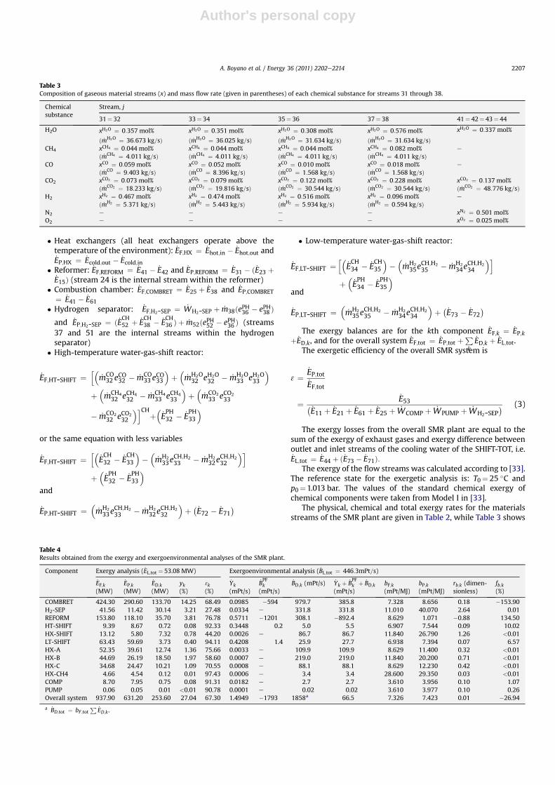
Table 4Results obtained from the exergy and exergoenvironmental analyses of the SMR plant.
Component Exergy analysis ( _EL;tot ¼ 53.08 MW) Exergoenvironmental analysis ( _BL;tot ¼ 446:3mPt=s)
_EF;k(MW)
_EP;k(MW)
_ED;k(MW)
yk(%)
3k(%)
_Yk(mPt/s)
_BPFk
(mPt/s)
_BD;k (mPt/s) _Yk þ _BPFk þ _BD;k
(mPt/s)bF;k(mPt/MJ)
bP;k(mPt/MJ)
rb;k (dimen-sionless)
fb;k(%)
COMBRET 424.30 290.60 133.70 14.25 68.49 0.0985 �594 979.7 385.8 7.328 8.656 0.18 �153.90H2-SEP 41.56 11.42 30.14 3.21 27.48 0.0334 e 331.8 331.8 11.010 40.070 2.64 0.01REFORM 153.80 118.10 35.70 3.81 76.78 0.5711 �1201 308.1 �892.4 8.629 1.071 �0.88 134.50HT-SHIFT 9.39 8.67 0.72 0.08 92.33 0.3448 0.2 5.0 5.5 6.907 7.544 0.09 10.02HX-SHIFT 13.12 5.80 7.32 0.78 44.20 0.0026 e 86.7 86.7 11.840 26.790 1.26 <0.01LT-SHIFT 63.43 59.69 3.73 0.40 94.11 0.4208 1.4 25.9 27.7 6.938 7.394 0.07 6.57HX-A 52.35 39.61 12.74 1.36 75.66 0.0033 e 109.9 109.9 8.629 11.400 0.32 <0.01HX-B 44.69 26.19 18.50 1.97 58.60 0.0007 e 219.0 219.0 11.840 20.200 0.71 <0.01HX-C 34.68 24.47 10.21 1.09 70.55 0.0008 e 88.1 88.1 8.629 12.230 0.42 <0.01HX-CH4 4.66 4.54 0.12 0.01 97.43 0.0006 e 3.4 3.4 28.600 29.350 0.03 <0.01COMP 8.70 7.95 0.75 0.08 91.31 0.0182 e 2.7 2.7 3.610 3.956 0.10 1.07PUMP 0.06 0.05 0.01 <0.01 90.78 0.0001 e 0.02 0.02 3.610 3.977 0.10 0.26Overall system 937.90 631.20 253.60 27.04 67.30 1.4949 �1793 1858a 66.5 7.326 7.423 0.01 �26.94
a _BD;tot ¼ bF;totP _ED;k .
A. Boyano et al. / Energy 36 (2011) 2202e2214 2207
Author's personal copy
the chemical composition of selected material streams. Table 4presents the results of the exergetic analysis.
The exergetic efficiency of the overall SMR system is 67%. Theexergy losses _EL;tot are equal to 6% of the exergy of the fuel of theoverall system. The combustion chamber has by far the highestexergy destruction value; this means that this component shouldhave the highest priority for improvement from the thermodynamicviewpoint. The values of the exergydestructionwithin thehydrogenseparation unit (H2-SEP) and the reformer are comparable. Thesecomponents have the second highest priority for improvement. Theheat exchangersHX-A, HX-B andHX-C aswell as the SHIFT-TOThavea lower priority for improvement. The lowest priority is associatedwith the components compressor, HX-CH4 and pump.
3.2. LCA
LCA is a technique for assessing the environmental aspectsassociated with a product over its life cycle. The LCA processconsists of goal definition and scoping (defining the system underconsideration), inventory analysis (identifying and quantifying theconsumption and release of materials), and interpretation (evalu-ation of the results). The guidelines of international standardapproaches [10] are followed in the compilation of inventories ofelementary flows. The assumptions taken to carry out the LCA thatinclude air emissions, energy requirements and resourceconsumption are presented here. Because most of these data arefunctions of the size of the plant and the technology, care should betaken in scaling results from larger or smaller facilities, or whenapplying them to other hydrogen production systems.
In order to identify the raw material inlet flows, it is firstnecessary to perform a sizing of the plant components and tocollect information about the weights, main materials, produc-tion processes and scrap outputs of all relevant pieces of equip-ment needed to assemble the plant. Note that this information isusually not very widely published (comparing with the
corresponding cost information) neither is explained whatmaterials are used in the drawing figures of equipment. In thisway, only rough calculations of the employed main materials canbe conducted.
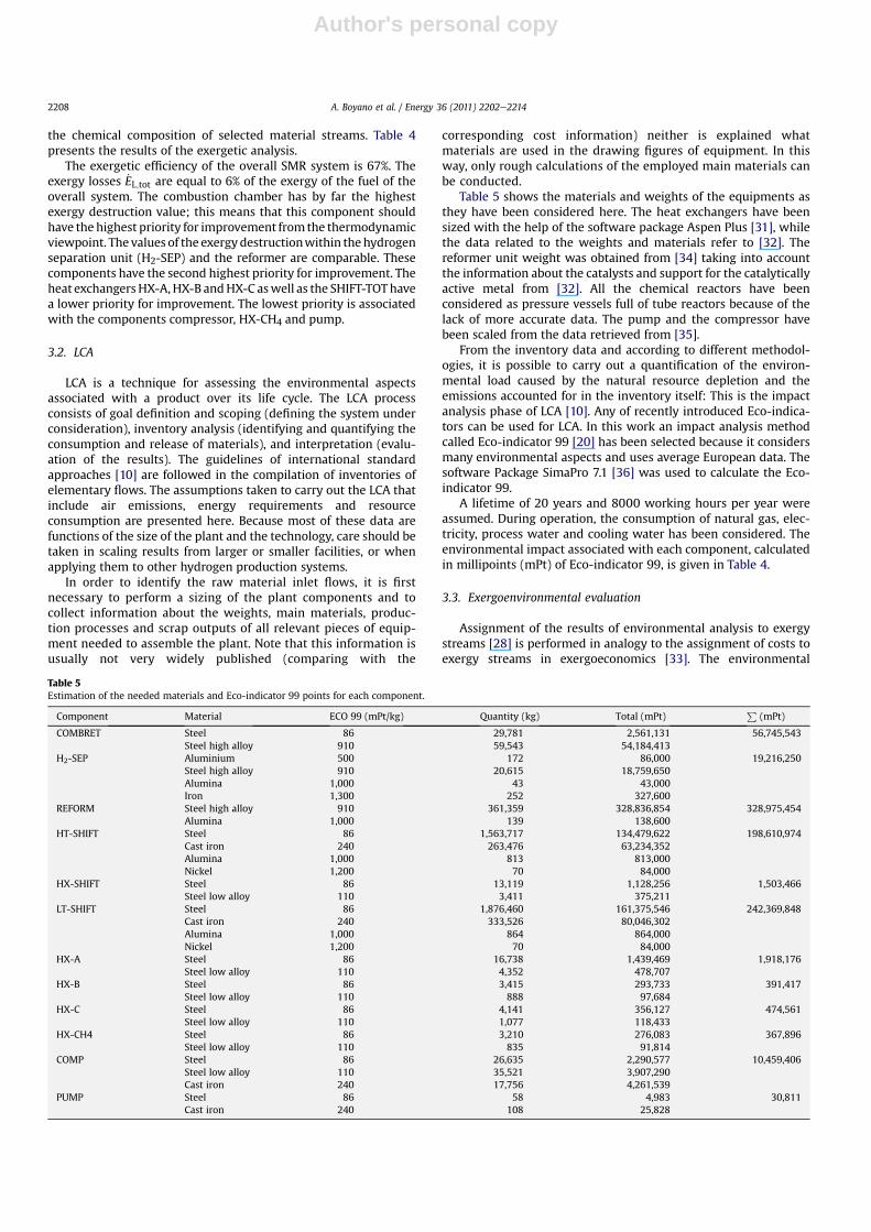
Table 5 shows the materials and weights of the equipments asthey have been considered here. The heat exchangers have beensized with the help of the software package Aspen Plus [31], whilethe data related to the weights and materials refer to [32]. Thereformer unit weight was obtained from [34] taking into accountthe information about the catalysts and support for the catalyticallyactive metal from [32]. All the chemical reactors have beenconsidered as pressure vessels full of tube reactors because of thelack of more accurate data. The pump and the compressor havebeen scaled from the data retrieved from [35].
From the inventory data and according to different methodol-ogies, it is possible to carry out a quantification of the environ-mental load caused by the natural resource depletion and theemissions accounted for in the inventory itself: This is the impactanalysis phase of LCA [10]. Any of recently introduced Eco-indica-tors can be used for LCA. In this work an impact analysis methodcalled Eco-indicator 99 [20] has been selected because it considersmany environmental aspects and uses average European data. Thesoftware Package SimaPro 7.1 [36] was used to calculate the Eco-indicator 99.
A lifetime of 20 years and 8000 working hours per year wereassumed. During operation, the consumption of natural gas, elec-tricity, process water and cooling water has been considered. Theenvironmental impact associated with each component, calculatedin millipoints (mPt) of Eco-indicator 99, is given in Table 4.
3.3. Exergoenvironmental evaluation
Assignment of the results of environmental analysis to exergystreams [28] is performed in analogy to the assignment of costs toexergy streams in exergoeconomics [33]. The environmental
Table 5Estimation of the needed materials and Eco-indicator 99 points for each component.
Component Material ECO 99 (mPt/kg) Quantity (kg) Total (mPt)P
(mPt)
COMBRET Steel 86 29,781 2,561,131 56,745,543Steel high alloy 910 59,543 54,184,413
H2-SEP Aluminium 500 172 86,000 19,216,250Steel high alloy 910 20,615 18,759,650Alumina 1,000 43 43,000Iron 1,300 252 327,600
REFORM Steel high alloy 910 361,359 328,836,854 328,975,454Alumina 1,000 139 138,600
HT-SHIFT Steel 86 1,563,717 134,479,622 198,610,974Cast iron 240 263,476 63,234,352Alumina 1,000 813 813,000Nickel 1,200 70 84,000
HX-SHIFT Steel 86 13,119 1,128,256 1,503,466Steel low alloy 110 3,411 375,211
LT-SHIFT Steel 86 1,876,460 161,375,546 242,369,848Cast iron 240 333,526 80,046,302Alumina 1,000 864 864,000Nickel 1,200 70 84,000
HX-A Steel 86 16,738 1,439,469 1,918,176Steel low alloy 110 4,352 478,707
HX-B Steel 86 3,415 293,733 391,417Steel low alloy 110 888 97,684
HX-C Steel 86 4,141 356,127 474,561Steel low alloy 110 1,077 118,433
HX-CH4 Steel 86 3,210 276,083 367,896Steel low alloy 110 835 91,814
COMP Steel 86 26,635 2,290,577 10,459,406Steel low alloy 110 35,521 3,907,290Cast iron 240 17,756 4,261,539
PUMP Steel 86 58 4,983 30,811Cast iron 240 108 25,828
A. Boyano et al. / Energy 36 (2011) 2202e22142208
Author's personal copy
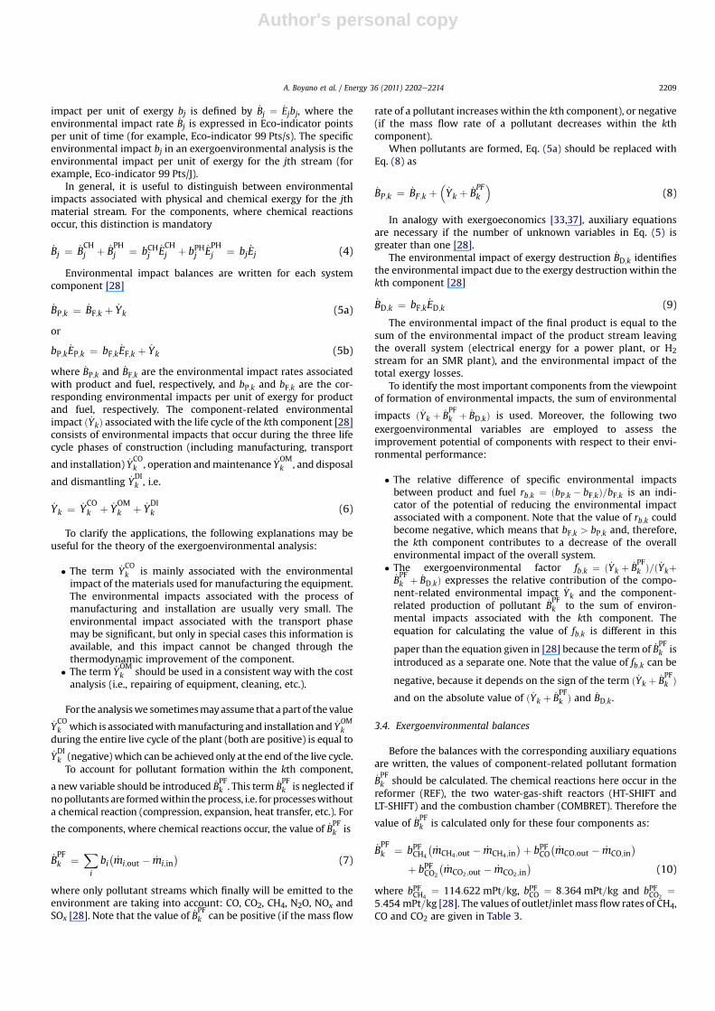
impact per unit of exergy bj is defined by _Bj ¼ _Ejbj, where theenvironmental impact rate _Bj is expressed in Eco-indicator pointsper unit of time (for example, Eco-indicator 99 Pts/s). The specificenvironmental impact bj in an exergoenvironmental analysis is theenvironmental impact per unit of exergy for the jth stream (forexample, Eco-indicator 99 Pts/J).
In general, it is useful to distinguish between environmentalimpacts associated with physical and chemical exergy for the jthmaterial stream. For the components, where chemical reactionsoccur, this distinction is mandatory
_Bj ¼ _BCHj þ _B
PHj ¼ bCHj
_ECHj þ bPHj
_EPHj ¼ bj _Ej (4)
Environmental impact balances are written for each systemcomponent [28]
_BP;k ¼ _BF;k þ _Yk (5a)
or
bP;k _EP;k ¼ bF;k _EF;k þ _Yk (5b)
where _BP;k and _BF;k are the environmental impact rates associatedwith product and fuel, respectively, and bP;k and bF;k are the cor-responding environmental impacts per unit of exergy for productand fuel, respectively. The component-related environmentalimpact ð _YkÞ associated with the life cycle of the kth component [28]consists of environmental impacts that occur during the three lifecycle phases of construction (including manufacturing, transport
and installation) _YCOk , operation andmaintenance _Y
OMk , and disposal
and dismantling _YDIk , i.e.
_Yk ¼ _YCOk þ _Y
OMk þ _Y
DIk (6)
To clarify the applications, the following explanations may beuseful for the theory of the exergoenvironmental analysis:
� The term _YCOk is mainly associated with the environmental
impact of the materials used for manufacturing the equipment.The environmental impacts associated with the process ofmanufacturing and installation are usually very small. Theenvironmental impact associated with the transport phasemay be significant, but only in special cases this information isavailable, and this impact cannot be changed through thethermodynamic improvement of the component.
� The term _YOMk should be used in a consistent way with the cost
analysis (i.e., repairing of equipment, cleaning, etc.).
For the analysiswe sometimesmayassume that apartof the value_YCOk which is associatedwithmanufacturing and installation and _Y
OMk
during the entire live cycle of the plant (both are positive) is equal to_YDIk (negative) which can be achieved only at the end of the live cycle.To account for pollutant formation within the kth component,
a new variable should be introduced _BPFk . This term _B
PFk is neglected if
nopollutants are formedwithin theprocess, i.e. for processeswithouta chemical reaction (compression, expansion, heat transfer, etc.). For
the components, where chemical reactions occur, the value of _BPFk is
_BPFk ¼
Xi
bi�_mi;out � _mi;in
�(7)
where only pollutant streams which finally will be emitted to theenvironment are taking into account: CO, CO2, CH4, N2O, NOx andSOx [28]. Note that the value of _B
PFk can be positive (if the mass flow
rate of a pollutant increases within the kth component), or negative(if the mass flow rate of a pollutant decreases within the kthcomponent).
When pollutants are formed, Eq. (5a) should be replaced withEq. (8) as
_BP;k ¼ _BF;k þ�_Yk þ _B
PFk
�(8)
In analogy with exergoeconomics [33,37], auxiliary equationsare necessary if the number of unknown variables in Eq. (5) isgreater than one [28].
The environmental impact of exergy destruction _BD;k identifiesthe environmental impact due to the exergy destruction within thekth component [28]
_BD;k ¼ bF;k _ED;k (9)
The environmental impact of the final product is equal to thesum of the environmental impact of the product stream leavingthe overall system (electrical energy for a power plant, or H2stream for an SMR plant), and the environmental impact of thetotal exergy losses.
To identify the most important components from the viewpointof formation of environmental impacts, the sum of environmental
impacts ð _Yk þ _BPFk þ _BD;kÞ is used. Moreover, the following two
exergoenvironmental variables are employed to assess theimprovement potential of components with respect to their envi-ronmental performance:
� The relative difference of specific environmental impactsbetween product and fuel rb;k ¼ ðbP;k � bF;kÞ=bF;k is an indi-cator of the potential of reducing the environmental impactassociated with a component. Note that the value of rb;k couldbecome negative, which means that bF;k > bP;k and, therefore,the kth component contributes to a decrease of the overallenvironmental impact of the overall system.
� The exergoenvironmental factor fb;k ¼ ð _Yk þ _BPFk Þ=ð _Ykþ
_BPFk þ _BD;kÞ expresses the relative contribution of the compo-
nent-related environmental impact _Yk and the component-related production of pollutant _B
PFk to the sum of environ-
mental impacts associated with the kth component. Theequation for calculating the value of fb;k is different in this
paper than the equation given in [28] because the term of _BPFk is
introduced as a separate one. Note that the value of fb;k can be
negative, because it depends on the sign of the term ð _Yk þ _BPFk Þ
and on the absolute value of ð _Yk þ _BPFk Þ and _BD;k.
3.4. Exergoenvironmental balances
Before the balances with the corresponding auxiliary equationsare written, the values of component-related pollutant formation_BPFk should be calculated. The chemical reactions here occur in the
reformer (REF), the two water-gas-shift reactors (HT-SHIFT andLT-SHIFT) and the combustion chamber (COMBRET). Therefore the
value of _BPFk is calculated only for these four components as:
_BPFk ¼ bPFCH4
�_mCH4;out � _mCH4;in
�þ bPFCO�_mCO;out � _mCO;in
�
þ bPFCO2
�_mCO2;out � _mCO2;in
�(10)
where bPFCH4¼ 114:622 mPt=kg, bPFCO ¼ 8:364 mPt=kg and bPFCO2
¼5:454 mPt=kg [28]. The values of outlet/inlet mass flow rates of CH4,CO and CO2 are given in Table 3.
A. Boyano et al. / Energy 36 (2011) 2202e2214 2209
Author's personal copy
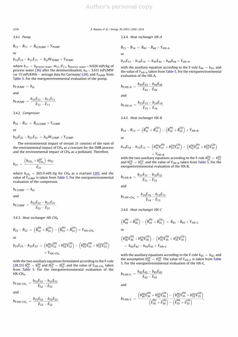
3.4.1. Pump
_B12 � _B11 ¼ _Bel;PUMP þ _YPUMP
or
b12 _E12 � b11 _E11 ¼ bel _WPUMP þ _YPUMP;
where b11 ¼ bprocess water$ _m11=_E11, bprocess water¼ 0.026 mPt/kg of
process water [36] after the demineralisation, bel¼ 3.611 mPt/MW(or 13 mPt/kWh e average data for Germany) [28], and _YPUMP fromTable 5. For the exergoenvironmental evaluation of the pump,
bF;PUMP ¼ bel
and
bP;PUMP ¼ b12 _E12 � b11 _E11_E12 � _E11
:
3.4.2. Compressor
_B22 � _B21 ¼ _Bel;COMP þ _YCOMP
or
b22 _E22 � b21 _E21 ¼ bel _WCOMP þ _YCOMP
The environmental impart of stream 21 consists of the sum ofthe environmental impact of CH4 as a reactant for the SMR processand the environmental impact of CH4 as a pollutant. Therefore,
b21 ¼�bCH4
þ bFPCH4
�$ _m21
_E21
where bCH4¼ 265:0 mPt=kg for CH4 as a reactant [20], and the
value of _YCOMP is taken from Table 5. For the exergoenvironmentalevaluation of the compressor,
bF;COMP ¼ bel
and
bP;COMP ¼ b22 _E22 � b21 _E21_E22 � _E21
:
3.4.3. Heat exchanger HX-CH4
_B23 � _B22 ¼�_BPH52 þ _B
CH52
���_BPH53 þ _B
CH53
�þ _YHX-CH4
or
b23 _E23 � b22 _E22 ¼�bPH52 _E
PH52 þ bCH52 _E
CH52
���bPH53 _E
PH53 þ bCH53 _E
CH53
�
þ _YHX-CH4
with the two auxiliary equations formulated according to the F-rule[28,33] bPH53 ¼ bPH52 and bCH53 ¼ bCH52 , and the value of _YHX-CH4
takenfrom Table 5. For the exergoenvironmental evaluation of theHX-CH4,
bF;HX-CH4¼ b52 _E52 � b53 _E53
_E52 � _E53
and
bP;HX-CH4¼ b23 _E23 � b22 _E22
_E23 � _E22:
3.4.4. Heat exchanger HX-A
_B15 � _B14 ¼ _B43 � _B44 þ _YHX-A
or
b15 _E15 � b14 _E14 ¼ b43 _E43 � b44 _E44 þ _YHX-A;
with the auxiliary equation according to the F-rule b44 ¼ b43, andthe value of _YHX-A taken from Table 5. For the exergoenvironmentalevaluation of the HX-A,
bF;HX-A ¼ b43 _E43 � b44 _E44_E43 � _E44
and
bP;HX-A ¼ b15 _E15 � b14 _E14_E15 � _E14
:
3.4.5. Heat exchanger HX-B
_B14 � _B13 ¼�_BPH31 þ _B
CH31
���_BPH32 þ _B
CH32
�þ _YHX-B
or
b14 _E14 � b13 _E13 ¼�bPH31 _E
PH31 þ bCH31 _E
CH31
���bPH32 _E
PH32 þ bCH32 _E
CH32
�
þ _YHX-Bwith the two auxiliary equations according to the F-rule bPH32 ¼ bPH31and bCH32 ¼ bCH31 , and the value of _YHX-B taken from Table 5. For theexergoenvironmental evaluation of the HX-B,
bF;HX-B ¼ b31 _E31 � b32 _E32_E31 � _E32
and
bP;HX-CH4¼ b14 _E14 � b13 _E13
_E14 � _E13:
3.4.6. Heat exchanger HX-C
�_BPH36 þ _B
CH36
���_BPH35 þ _B
CH35
�¼ _B42 � _B43 þ _YHX-C
or
�bPH36 _E
PH36 þ bCH36 _E
CH36
���bPH35 _E
PH35 þ bCH35 _E
CH35
�
¼ b42 _E42 � b43 _E43 þ _YHX-C
with the auxiliary equations according to the F-rule b43 ¼ b42, andthe assumption bCH36 ¼ bCH35 . The value of _YHX-C is taken from Table5. For the exergoenvironmental evaluation of the HX-C,
bF;HX-C ¼ b42 _E42 � b43 _E43_E42 � _E43
and
bP;HX-C ¼�bPH36
_EPH36 þ bCH36
_ECH36
���bPH35
_EPH35 þ bCH35
_ECH35
��_EPH36 þ _E
CH36
���_EPH35 þ _E
CH35
� :
A. Boyano et al. / Energy 36 (2011) 2202e22142210
Author's personal copy
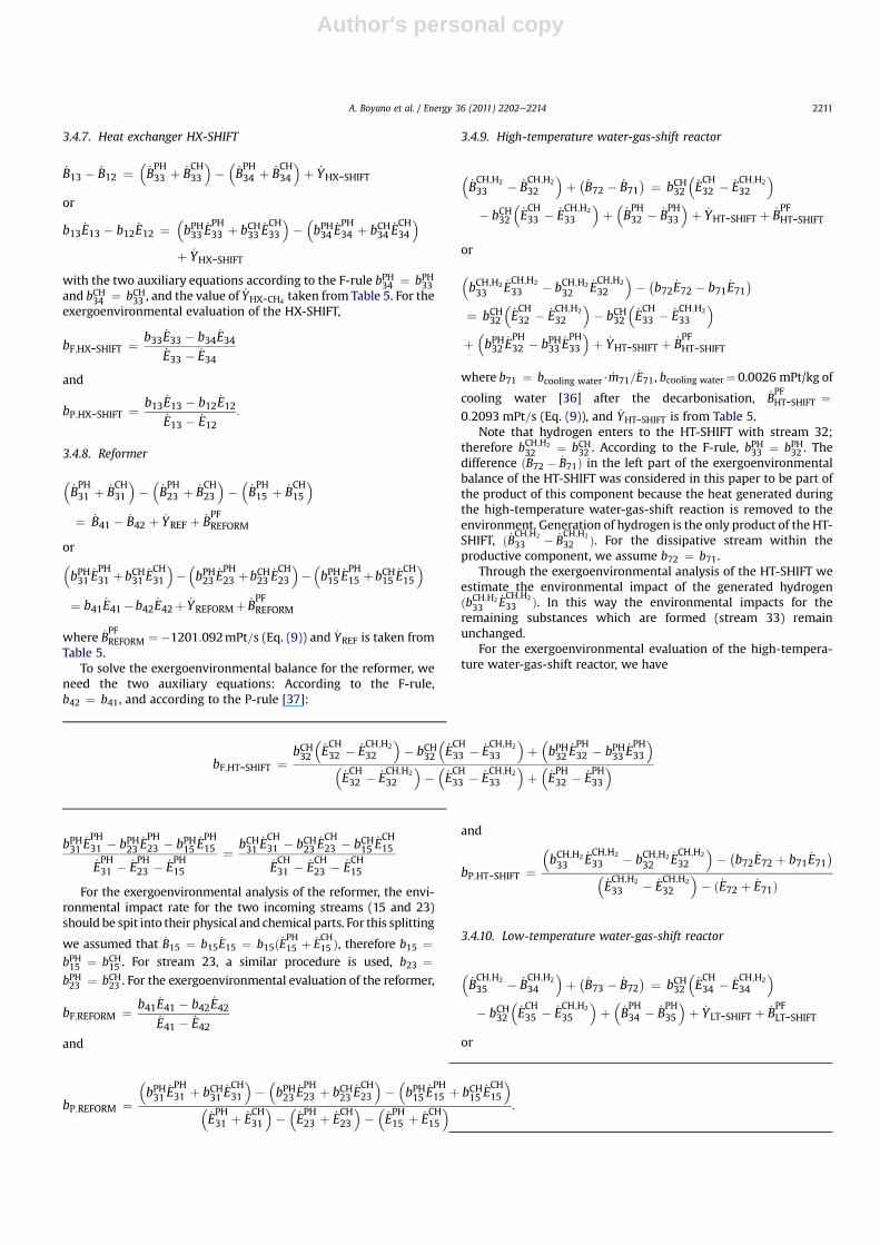
3.4.7. Heat exchanger HX-SHIFT
_B13 � _B12 ¼�_BPH33 þ _B
CH33
���_BPH34 þ _B
CH34
�þ _YHX-SHIFT
or
b13 _E13 � b12 _E12 ¼�bPH33 _E
PH33 þ bCH33 _E
CH33
���bPH34 _E
PH34 þ bCH34 _E
CH34
�
þ _YHX-SHIFT
with the two auxiliary equations according to the F-rule bPH34 ¼ bPH33and bCH34 ¼ bCH33 , and the value of _YHX-CH4
taken from Table 5. For theexergoenvironmental evaluation of the HX-SHIFT,
bF;HX-SHIFT ¼ b33 _E33 � b34 _E34_E33 � _E34
and
bP;HX-SHIFT ¼ b13 _E13 � b12 _E12_E13 � _E12
:
3.4.8. Reformer
�_BPH31 þ _B
CH31
���_BPH23 þ _B
CH23
���_BPH15 þ _B
CH15
�
¼ _B41 � _B42 þ _YREF þ _BPFREFORM
or�bPH31 _E
PH31 þbCH31 _E
CH31
���bPH23 _E
PH23 þbCH23 _E
CH23
���bPH15 _E
PH15 þbCH15 _E
CH15
�
¼ b41 _E41�b42 _E42þ _YREFORMþ _BPFREFORM
where _BPFREFORM ¼ �1201:092mPt=s (Eq. (9)) and _YREF is taken from
Table 5.To solve the exergoenvironmental balance for the reformer, we
need the two auxiliary equations: According to the F-rule,b42 ¼ b41, and according to the P-rule [37]:
bPH31_EPH31 � bPH23
_EPH23 � bPH15
_EPH15
_EPH31 � _E
PH23 � _E
PH15
¼ bCH31_ECH31 � bCH23
_ECH23 � bCH15
_ECH15
_ECH31 � _E
CH23 � _E
CH15
For the exergoenvironmental analysis of the reformer, the envi-ronmental impact rate for the two incoming streams (15 and 23)should be spit into their physical and chemical parts. For this splitting
we assumed that _B15 ¼ b15 _E15 ¼ b15ð _EPH15 þ _E
CH15 Þ, therefore b15 ¼
bPH15 ¼ bCH15 . For stream 23, a similar procedure is used, b23 ¼bPH23 ¼ bCH23 . For the exergoenvironmental evaluation of the reformer,
bF;REFORM ¼ b41 _E41 � b42 _E42_E41 � _E42
and
3.4.9. High-temperature water-gas-shift reactor
�_BCH;H2
33 � _BCH;H2
32
�þ �
_B72 � _B71� ¼ bCH32
�_ECH32 � _E
CH;H2
32
�
� bCH32�_ECH33 � _E
CH;H2
33
�þ�_BPH32 � _B
PH33
�þ _YHT-SHIFT þ _B
PFHT-SHIFT
or
�bCH;H233
_ECH;H2
33 � bCH;H232
_ECH;H2
32
�� �
b72 _E72 � b71 _E71�
¼ bCH32�_ECH32 � _E
CH;H2
32
�� bCH32
�_ECH33 � _E
CH;H2
33
�
þ�bPH32 _E
PH32 � bPH33 _E
PH33
�þ _YHT-SHIFT þ _B
PFHT-SHIFT
where b71 ¼ bcooling water$ _m71=_E71, bcooling water¼ 0.0026 mPt/kg of
cooling water [36] after the decarbonisation, _BPFHT-SHIFT ¼
0:2093 mPt=s (Eq. (9)), and _YHT-SHIFT is from Table 5.Note that hydrogen enters to the HT-SHIFT with stream 32;
therefore bCH;H232 ¼ bCH32 . According to the F-rule, bPH33 ¼ bPH32 . The
difference ð _B72 � _B71Þ in the left part of the exergoenvironmentalbalance of the HT-SHIFT was considered in this paper to be part ofthe product of this component because the heat generated duringthe high-temperature water-gas-shift reaction is removed to theenvironment. Generation of hydrogen is the only product of the HT-SHIFT, ð _BCH;H2
33 � _BCH;H2
32 Þ. For the dissipative stream within theproductive component, we assume b72 ¼ b71.
Through the exergoenvironmental analysis of the HT-SHIFT weestimate the environmental impact of the generated hydrogenðbCH;H2
33_ECH;H2
33 Þ. In this way the environmental impacts for theremaining substances which are formed (stream 33) remainunchanged.
For the exergoenvironmental evaluation of the high-tempera-ture water-gas-shift reactor, we have
and
bP;HT-SHIFT ¼�bCH;H233
_ECH;H2
33 � bCH;H232
_ECH;H2
32
�� �
b72 _E72 þ b71 _E71�
�_ECH;H2
33 � _ECH;H2
32
�� ð _E72 þ _E71Þ
3.4.10. Low-temperature water-gas-shift reactor
�_BCH;H2
35 � _BCH;H2
34
�þ �
_B73 � _B72� ¼ bCH32
�_ECH34 � _E
CH;H2
34
�
� bCH32�_ECH35 � _E
CH;H2
35
�þ�_BPH34 � _B
PH35
�þ _YLT-SHIFT þ _B
PFLT-SHIFT
or
bP;REFORM ¼�bPH31
_EPH31 þ bCH31
_ECH31
���bPH23
_EPH23 þ bCH23
_ECH23
���bPH15
_EPH15 þ bCH15
_ECH15
��_EPH31 þ _E
CH31
���_EPH23 þ _E
CH23
���_EPH15 þ _E
CH15
� :
bF;HT-SHIFT ¼bCH32
�_ECH32 � _E
CH;H2
32
�� bCH32
�_ECH33 � _E
CH;H2
33
�þ�bPH32
_EPH32 � bPH33
_EPH33
��_ECH32 � _E
CH;H2
32
���_ECH33 � _E
CH;H2
33
�þ�_EPH32 � _E
PH33
�
A. Boyano et al. / Energy 36 (2011) 2202e2214 2211
Author's personal copy
�bCH;H235
_ECH;H2
35 � bCH;H234
_ECH;H2
34
�� �
b73 _E73 þ b72 _E72�
¼ bCH32�_ECH34 � _E
CH;H2
34
�� bCH32
�_ECH35 � _E
CH;H2
35
�
þ�bPH34
_EPH34 � bPH35
_EPH35
�þ _YLT-SHIFT þ _B
PFLT-SHIFT
with _BPFLT-SHIFT ¼ 1:401 mPt=s (Eq. (9)), and _YLT-SHIFT taken from
Table 5.In analogy with the HT-SHIFT, the following equations are used
for the LT-SHIFT: bPH35 ¼ bPH34 (F-rule), and b73 ¼ b72 for the stream72e73. Since no chemical reaction occurs in the SHIFT heatexchanger (HX-SHIFT), then: (a) The specific environmentalimpacts of the hydrogen within stream 34 remains the same as
within stream 33, bCH;H234 ¼ bCH;H2
33 , and (b) the specific environ-mental impact of the of remaining substances which are formed
(stream 34) remains also unchanged, bCH32 ð _ECH34 � _E
CH;H2
34 Þ. Throughthe exergoenvironmental analysis of the LT-SHIFT we should esti-mate the environmental impact of the generated hydrogen
ðbCH;H235
_ECH;H2
35 Þ. The specific environmental impact of the remaining
substances in stream 34 remains equal to bCH32 .At the outlet of the LT-SHIFT, the specific environmental
impact per unit of exergy is calculated using the following fourequations:
b35 ¼_B35_E35
where _B35 ¼ _BPH35 þ _B
CH35 with _B
PH35 ¼ bPH35
_EPH35 and
_BCH35 ¼ bCH32 ð _E
CH35 � _E
CH;H2
35 Þ þ bCH;H235
_ECH;H2
35 .For the exergoenvironmental evaluation of the low-temperature
water-gas-shift reactor,
bF;LT-SHIFT ¼bCH32
�_ECH34 � _E
CH;H2
34
��bCH32
�_ECH35 � _E
CH;H2
35
�þ�_BPH34 � _B
PH35
��_ECH34 � _E
CH;H2
34
���_ECH35 � _E
CH;H2
35
�þ�_EPH34 � _E
PH35
�
and
bP;LT-SHIFT ¼�bCH;H235
_ECH;H2
35 � bCH;H234
_ECH;H2
34
�� �
b73 _E73 þ b72 _E72�
�_ECH;H2
35 � _ECH;H2
34
�� ð _E73 þ _E72Þ
3.4.11. Hydrogen separator
�_BCH52 þ _B
CH38 � _B
CH36
�þ _m52
�bPH52 e
PH52 � bPH36 e
PH36
�
¼ _Bel;H2-SEP þ _m38
�bPH36 e
PH36 � bPH38 e
PH38
�þ _YH2-SEP
or
�bCH52 _E
CH52 þ bCH38 _E
CH38 � bCH36 _E
CH36
�þ _m52
�bPH52 e
PH52 � bPH36 e
PH36
�
¼ bel _Wel;H2-SEP þ _m38
�bPH36 e
PH36 � bPH38 e
PH38
�þ _YH2-SEP
where _YH2-SEP is taken from Table 5. The two auxiliary equations arewritten for the H2-SEP: bPH38 ¼ bPH36 according to the F-rule, and
�bCH52
_ECH52 þ bCH38
_ECH38 � bCH36
_ECH36
��_ECH52 þ _E
CH38 � _E
CH36
� ¼_m52
�bPH52 e
PH52 � bPH36 e
PH36
�
_m52�ePH52 � ePH36
�
according to the P-rule.For the hydrogen separator we assumedthat _YH2-SEP is equal to zero in the exergoenvironmental balance,and that bCH38 ¼ bCH36 .
For the exergoenvironmental evaluation of the hydrogenseparator,
bF;H2-SEP ¼bel _Wel;H2-SEP þ _m38
�bPH36 e
PH36 � bPH38 e
PH38
�
_Wel;H2�SEP þ _m38�ePH36 � ePH38
�
and
bP;H2-SEP ¼�bCH52
_ECH52 þbCH38
_ECH38 �bCH36
_ECH36
�þ _m52
�bPH52 e
PH52 �bPH36 e
PH36
��_ECH52 þ _E
CH38 � _E
CH36
�þ _m52
�ePH52 �ePH36
�
3.4.12. Combustion chamber
_B41 � _B61 ¼ _B25 þ _B38 þ _YCOMBRET þ _BPFCOMBRET
or
b41 _E41 � b61 _E61 ¼ b25 _E25 þ b38 _E38 þ _YCOMBRET þ _BPFCOMBRET
Stream 25 should be considered in analogy with stream 21 (inletto the compressor) as
b25 ¼�bCH4
þ bFPCH4
�$ _m25
_E25:
The value of _BPFCOMBRET is estimated with the help of Eq. (9) and is
equal to �594.016 mPt/s, whereas the value of _YCOMBRET is takenfrom Table 5. The environmental impact of air incoming to thecombustion chamber is equal to zero (b61¼0). For the exer-goenvironmental evaluation of the COMBRET,
bF;COMBRET ¼ b25 _E25 þ b38 _E38_E25 þ _E38
and
bP;COMBRET ¼ b41 _E41 � b61 _E61_E41 � _E61
:
3.4.13. Overall systemThe specific environmental impact per unit of exergy for stream
53 (which is obtained by solving simultaneously the exergoenvir-onmental balances for all components with the correspondingauxiliary equations and assumptions) represents the “net” value. Tocalculate the real value of the specific environmental impactassociated with the hydrogen production using the SMR process,we should charge the environmental impact associated with theexergy losses of the overall system to the stream 53 as
bP;tot ¼ bH2¼
_B53 þ _BL;tot_E53 þ _EL;tot
¼_B53 þ _B44 þ
�_B73 � _B71
�_E53 þ _E44 þ ð _E73 � _E71Þ
(11)
The data obtained from the exergoenvironmental analysis aregiven in Tables 2 and 4.
3.5. Results
If the analysis is based only on the value of the component-related environmental impact ð _YkÞ, then we have two majorcandidates for improvement: The reformer and the SHIFT-TOT,which consists on HT-SHIFT, HX-SHIFT and LT-SHIFT (the
A. Boyano et al. / Energy 36 (2011) 2202e22142212
Author's personal copy
contribution of HX-SHIFT is almost negligible). All other compo-nents have much lower values of _Yk.
An exergoenvironmental evaluation is based on the values of _Yk,_BD;k, _B
PFk , rb;k and fb;k (Table 4).
The contribution of the component-related environmentalimpact _Yk to the total environmental impact associated with the
kth component ð _Yk þ _BPFk þ _BD;kÞ is very small. For the HT-SHIFT, the
value of _YHT-SHIFT is equal to 7% of the value
ð _YHT-SHIFT þ _BPFHT-SHIFT þ _BD;HT-SHIFTÞ. For other components the
contribution of _Yk is much smaller. Based on this information, wemay conclude that we do not necessarily need to calculate the valueof _Yk for the environmental analysis of the SMR plant.
The environmental impact associatedwith the exergy destruction_BD;k is a bigger contributor to the sum ð _Yk þ _B
PFk þ _BD;kÞ almost for all
components. The high values of _BD;k for COMBRET, H2-SEP andREFORM indicate, that these components should be componentsshould be considered first when the overall environmental impactshould be reduced. Interesting information can be found for thecombustion chamber (COMBRET) and the reformer (REFORM). The
values of _BPFCOMBRET and _B
PFREFORM are negative, because CH4 was
included among the chemical components for which pollutant
formation ( _BPFk ) was calculated; therefore both COMBRET and
REFORM contribute to a decrease of the environmental impact
associatedwith theoverall system. The analysis of values ð _YCOMBERT þ_BPFCOMBERT þ _BD;COMBERTÞ and ð _YREFORM þ _B
PFREFORM þ _BD;REFORMÞ show,
that this sum ispositive for theCOMPRET (because the contributionof_BD;COMBRET is higher than the contribution of _B
PFCOMBRET) and negative
for theREFORM(because thecontributionof _BD;REFORM is less than the
contribution of _BPFREFORM). For future publications and as long as CH4 is
notemittedto theenvironment, it isnot recommended to includeCH4
in the calculation of _BPFk (Eq. (7)).
From the exergoenvironmental point of view, the decision aboutimprovement of the components is based on the value of the termsð _Yk þ _B
PFk þ _BD;kÞ: The combustion chamber and the hydrogen
separator have the highest priority, followed by the HX-B, and HX-A, HX-SHIFT, HX-C. An improvement of the other components doesnot significantly affect the emissions from the improving of theoverall system.
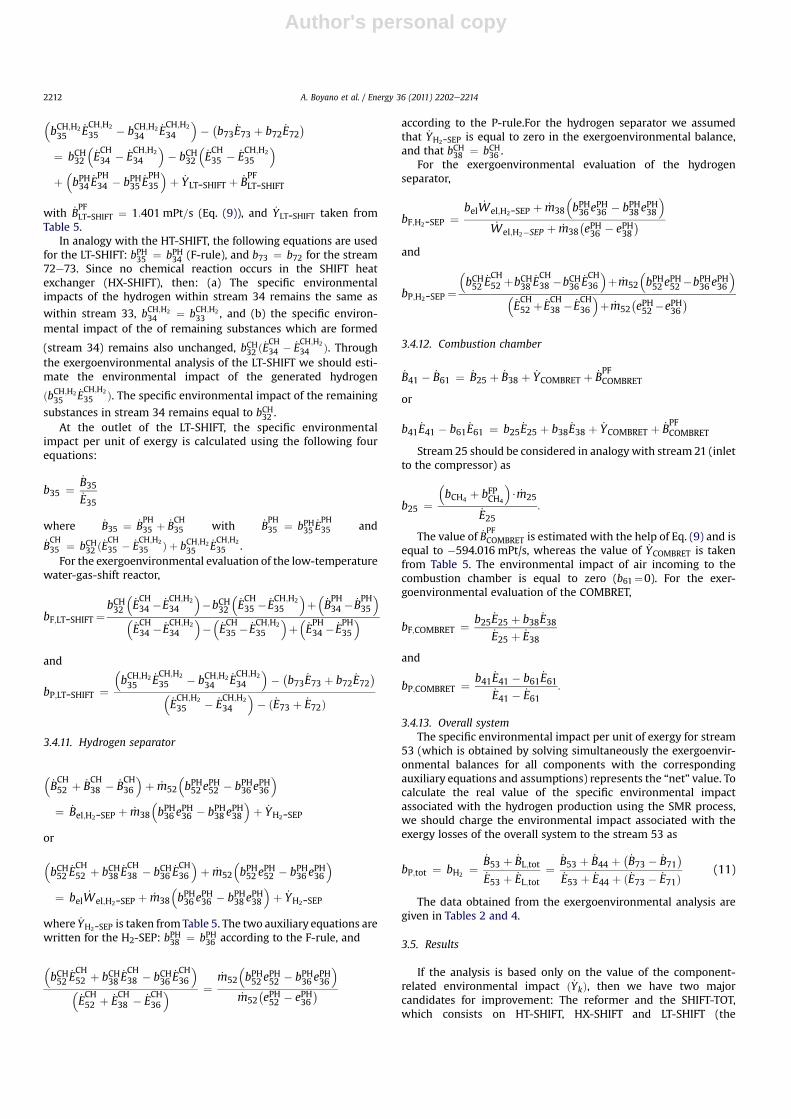
3.6. Exergoenvironmental sensitivity analysis
The environmental impact of the generated hydrogen using anSMR process discussed in this paper is equal to 951 mPt/kg. Thisvalue is by 15% higher than the value reported in [20] (Table 1).However, the specific process which was used in [20] is unknown.
The exergoenvironmental analysis for the SMR plant wasrepeated using different assumptions:
� When the term _BPFk is equal to zero for all components and the
environmental impact associated with the exergy losses of theoverall system is charged to the product, the environmentalimpact of the generated hydrogen is equal to 900 mPt/kg.
� When the term _BPFk is equal to zero for all components and the
environmental impact associated with the exergy losses of theoverall system is not charged to the product, i.e. bP;tot ¼ b53,then the environmental impact of the generated hydrogen isequal to 807 mPt/kg.
The second set of assumptions is closer to the analysis of theoverall system using exclusively LCA. Based on this number
(807 mPt/kg H2), the SMR plant discussed in the paper is attractivecompared with the average European statistical data for hydrogenproduction systems [20].
Since an LCA analysis involves high uncertainties, a sensitivitystudy was carried out to investigate the effect of major assumptionsto the final environmental impact of the generated hydrogen ðbH2
Þ.The component-related environmental impact of the constructionphase of the components, electricity, natural gas and the compo-nent-related environmental impact associated with the pollutantsformation were varied from 25% to 200% of their base values while(a) the remaining variables remain constant, and (b) all valuesvaried simultaneously.
The results of the exergoenvironmental sensitivity analysis(Fig. 2) show, that the environmental impact of the methane as thereactant ð�70% < bH2
< 98Þ has the highest effect on the results.This means that special attention should be payed to the origin andproduction process of natural gas and consequently its environ-mental impact. The variations in the environmental impact of theremaining parameters are relatively small. Calculations conductedwith the assumption _Yk ¼ 0 for all components lead to a value ofbH2
¼ 950:7 mPt=kg H2. The comparison with the base case valueðbH2
¼ 951 mPt=kg H2Þ shows that here the component relatedenvironmental impact may be left out from the calculations.
4. Conclusions
This paper is part of thework that analyzes various processes forgenerating hydrogen from natural gas. Here, the exergoenvir-onmental analysis is applied for the first time to a steam methanereforming process for hydrogen production. Generally, an exer-goenvironmental analysis demonstrates the formation of environ-mental impacts associated with energy conversion systems at thecomponent level, and provides useful information for designingsystems with a lower overall environmental impact.
The components in which chemical reactions occur have highexergy destruction. The exergoenvironmental analysis shows thatthe environmental impact of the exergy destruction within allcomponents of the SMR plant is significantly higher than thecomponent-related environmental impact. This means thatthe overall environmental impact can be reduced by reducing theexergy destruction within components, even if this would requireefficient modern equipment items where expensive materials anda very efficient design are used.
0
200
400
600
800
1000
1200
1400
1600
1800
2000
25% 50% 75% Base Case 125% 150% 175% 200%
Variation of parameter
En
viro
nm
en
tal im
pact o
f H
2 [m
Pts/kg
]
Fig. 2. Sensitivity analysis of the environmental impact associated with constructionphase, methane and electricity environmental impacts.
A. Boyano et al. / Energy 36 (2011) 2202e2214 2213
Author's personal copy
With the aid of the variable _BPFk that was introduced in this paper
changes in the environmental impact are justly assigned to thecomponents that cause them.
The results show that the largest potential for reducing theoverall environmental impact is associated with the chemicalreactors COMPRET and REFORM, the H2-SEP unit, and the heatexchangers HX-SHIFT, HX-A and HX-B.
To better understand the interconnections among componentsand to develop additional suggestions for reducing the overallenvironmental impact of the SMR plant, an advanced exergeticanalysis [38] should be applied to the SMR plant. Finally, exer-goeconomic analyses [39,40] conducted in parallel with exer-goenvironmental analyses provide important information on costreduction, in parallel with the reduction of environmental impact.
Acknowledgments
The authors wish to thank the European Commission for itsfinancial support within the Framework of the INSPIRE Network(MRTN CT-2005-019296 e INSPIRE). A. Boyano is indebted to TU-Berlin and the Institute for Energy Engineering for her post-doctoral position.
References
[1] Simbeck DR. Hydrogen costs with CO2 capture. In: Proceedings of the 7thInternational conference on greenhouse gas control technologies, September6e10 2004, Vancouver, British Columbia, Canada, http://uregina.ca/ghgt7/PDF/papers/nonpeer/407.pdf; 2004.
[2] Simpson AP, Lutz AE. Exergy analysis of hydrogen production via steammethane reforming. Int J Hydrogen Energy 2007;32:4811e20.
[3] Carrara A, Perdichizzi A, Barigozzi G. Simulation of an hydrogen productionsteam reforming industrial plant for energetic performance prediction. Int JHydrogen Energy 2010;35(8):3499e508.
[4] Tugnoli A, Landucci G, Cozzani V. Sustainability assessment of hydrogenproduction by steam reforming. Int J Hydrogen Energy 2008;33:4345e57.
[5] Mueller-Langer F, Tzimas E, Kaltschmitt M, Peteves S. Techno-economicassessment of hydrogen economy for the short and medium term. Int JHydrogen Energy 2007;32:3797e810.
[6] Dybkjaer I. Tubular reforming and autothermal reforming of natural gas e anoverview of the available processes. Fuel Proc Tech 1995;42:85e107.
[7] Rakass S, Oudghiri-Hassani H, Rowntree P, Abatzoglou N. Steam reforming ofmethane over unsupported nickel catalysts. J Power Sources 2002;108:213e25.
[8] Tong J, Matsumura Y. Pure Hydrogen production by methane steam reformingwith hydrogen-permeable membrane reactor. Catal Today 2006;11:147e52.
[9] Adhikari S, Fernando S, Gwaltney SR, To SDF, Bricka RM, Steele PH,Haryanto A. A thermodynamic analysis of hydrogen production by steamreforming of glycerol. Int J Hydrogen Energy 2007;32:2875e80.
[10] International Organization for Standardization (ISO). Environmentalmanagement e life cycle assessment. European Standard ENISO14040 and14044. Geneva, Switzerland: ISO; 2006.
[11] Portha JF, Louret S, Pons MN, Jaubert JN. Estimation of the environmentalimpact of a petrochemical process using coupled LCA and exergy analysis. ResConserv Recycling 2010;54:291e8.
[12] Dufour J, Serrano DP, Galvez JL, Moreno J, Garcia C. Life cycle assessment ofprocesses for hydrogen production. Environmental feasibility and reduction ofgreenhouse gases emissions. Int J Hydrogen energy 2009;34:1370e6.
[13] Koroneos C, Dompors A, Roumbas G, Moussiopoulos N. Life cycle assessmentof hydrogen fuel production processes. Int J Hydrogen Energy2004;29:1443e50.
[14] Koroneos C, Dompros A, Roumbas G. H2 production via biomass gasification e
a LCA approach. Chem Eng Proc 2008;47:1261e8.
[15] Utgikar V, Thiesen T. LCA of high temperature electrolysis for H2 productionvia nuclear energy. Int J Hydrogen Energy 2006;31:939e44.
[16] Koroneos C, Dompros A, Roumbas G, Moussiopoulos N. H2 production fromfossil fuels e a LCA approach. In: Proceedings of the international hydrogenenergy congress and exhibition. Instanbul, Turkey: IHEC; July 2005. p.13e5.
[17] Dufour J, Galvez JL, Serrano DP, Moreno J, Martinez G. LCA of H2 production bymethane decomposition using carbonaceous catalysts. Int J Hydrogen Energy2010;35:1205e12.
[18] Tugnoli A, Landucci G, Cozzani V. Sustainability assessment of H2 productionby steam reforming. Int J. Hydrogen Energy 2008;33:4345e57.
[19] Dufour J, Serrano DP, Galvez JL, Moreo J, Garcia C. LCA of processes for H2production. Environmental feasibility and reduction of greenhouse gasesemissions. Int J Hydrogen Energy 2009;34:1370e6.
[20] Goedkoop M, Spriensma R. The Eco-indicator 99: a damage oriented methodfor life cycle impact assessment. Methodology report. Amersfoort,Netherlands, www.pre.nl; 2000.
[21] Rosen MA. Thermodynamic investigation of hydrogen production by steam-methane reformation. Int J Hydrogen Energy 1991;16(3):207e17.
[22] Lambert J, Sorin M, Paris J. Analysis of oxygen enriched combustion for steammethane reforming SMR. Energy 1997;22:817e25.
[23] Bargigli S, Raugei M, Ulgiati S. Comparison of thermodynamic and environ-mental indexes of natural gas, syngas and hydrogen production processes.Energy 2004;29:2145e59.
[24] Cornelissen RL. Thermodynamics and sustainable development, the use ofexergy analysisi and the reduction of irreversibility, PhD dissertation, TheNetherlands: Enshede; 1997.
[25] Szargut J. Minimization of the consumption of natural resources. Bull Pol AcadSci: Tech Sci 1978;26(6):41e6.
[26] Valero A. Thermoeconomics as a conceptual basis for energy � ecologicalanalysis. In: Ulgiati S, editor. Proceedings of the international workshop onadvances in energy studies, Portovenere, Siena, Italy; 1998. p. 415e44.
[27] Sciubba E. Extended exergy accounting: towards an exergetic theory of value.In: Proceedings of the ECOS ’99, Tokyo, Japan, 1999. p. 85e94.
[28] Meyer L, Tsatsaronis G, Buchgeister J, Schebek L. Exergoenvironmental anal-ysis for evaluation of the environmental impact of energy conversion systems.Energy Int J 2009;34:75e89.
[29] Corrado A, Fiorini P, Sciubba E. Environmental assessment and extendedexergy analysis of a “zero CO2 emission”, high-efficiency steam power plant.Energy 2006;31:3186e98.
[30] Adhikari S, Fernando S. Hydrogen membrane separation techniques. Ind EngChem Res 2006;45:875e81.
[31] Aspen plus getting started. Version 10, www.scribd.com/doc/6847596/Aspen-Plus-Manual.
[32] Kakac S, Liu H. Heat exchangers: selection, rating, and thermal design. LLC:CRC Press; 1998.
[33] Bejan A, Tsatsaronis G, Moran M. Thermal design and optimization. New York,NY: Wiley; 1996.
[34] Equipment design and cost estimation for small modular biomass systems,synthesis gas cleanup and oxygen separation equipments. NERL subcontractreport. NREL/SR-519e39943, http://www.nrel.gov/docs/fy06osti/39946.pdf;May 2006.
[35] Gas turbine catalogue, www.ge.com.[36] Sima Pro. Users manual. Amersfoort (NL): Pre Consultants BV; 2007.[37] Lazzaretto A, Tsatsaronis G. SPECO: a systematic and general methodology for
calculating efficiencies and costs in thermal systems. Energy 2006;31(8e9):1257e89.
[38] Morosuk T, Tsatsaronis G. Advanced exergy analysis for chemically reactingsystems e application to a simple open gas-turbine system. Int J Thermodyn2009;12(3):201e7.
[39] Tsatsaronis G, Morosuk T. A general exergy-based method for combininga cost analysis with an environmental impact analysis. Part I e theoreticaldevelopment. In: Proceedings of the ASME international mechanical engi-neering congress and exposition, November 2e6, 2008. Boston, Massachu-setts, USA, file IMECE2008-67218.
[40] Tsatsaronis G, Morosuk T. A general exergy-based method for combininga cost analysis with an environmental impact analysis. Part II e Application toa cogeneration system. In: Proceedings of the ASME international mechanicalengineering congress and exposition, November 2e6, 2008. Boston, Massa-chusetts, USA, file IMECE2008-67219.
A. Boyano et al. / Energy 36 (2011) 2202e22142214
Copyright © 2022 FDOKUMEN