Hydrogen production by methanol steam reforming in a membrane reactor: Palladium vs carbon molecular...
12
This article appeared in a journal published by Elsevier. The attached copy is furnished to the author for internal non-commercial research and education use, including for instruction at the authors institution and sharing with colleagues. Other uses, including reproduction and distribution, or selling or licensing copies, or posting to personal, institutional or third party websites are prohibited. In most cases authors are permitted to post their version of the article (e.g. in Word or Tex form) to their personal website or institutional repository. Authors requiring further information regarding Elsevier’s archiving and manuscript policies are encouraged to visit: http://www.elsevier.com/copyright
-
Upload
independent -
Category
Documents
-
view
1 -
download
0
Transcript of Hydrogen production by methanol steam reforming in a membrane reactor: Palladium vs carbon molecular...
This article appeared in a journal published by Elsevier. The attachedcopy is furnished to the author for internal non-commercial researchand education use, including for instruction at the authors institution
and sharing with colleagues.
Other uses, including reproduction and distribution, or selling orlicensing copies, or posting to personal, institutional or third party
websites are prohibited.
In most cases authors are permitted to post their version of thearticle (e.g. in Word or Tex form) to their personal website orinstitutional repository. Authors requiring further information
regarding Elsevier’s archiving and manuscript policies areencouraged to visit:
http://www.elsevier.com/copyright
Author's personal copy
Journal of Membrane Science 339 (2009) 160–170
Contents lists available at ScienceDirect
Journal of Membrane Science
journa l homepage: www.e lsev ier .com/ locate /memsci
Hydrogen production by methanol steam reforming in a membrane reactor:Palladium vs carbon molecular sieve membranes
Sandra Sá a, Hugo Silva a, José M. Sousa a,b, Adélio Mendes a,∗
a LEPAE-Departamento de Engenharia Química, Faculdade de Engenharia, Universidade do Porto, Rua Dr. Roberto Frias, s/n 4200-465 Porto, Portugalb Departamento de Química, Universidade de Trás-os-Montes e Alto Douro, Apartado 202, 5001-911 Vila-Real Codex, Portugal
a r t i c l e i n f o
Article history:Received 17 February 2009Received in revised form 13 April 2009Accepted 24 April 2009Available online 3 May 2009
Keywords:HydrogenMethanol steam reformingCarbon molecular sieve membranesPalladium membranesModelling
a b s t r a c t
In this study, the production of hydrogen by methanol steam reforming in a membrane reactor (MR) wassimulated using a one-dimensional mathematical model. The model assumes axially dispersed plug-flow with pressure drop for the retentate side, and plug-flow behaviour with no axial dispersion andno pressure drop for the permeate side. The finite volume method was used for space discretization,being the dependent variables determined with high-resolution schemes. Two types of membranes weresimulated, namely a carbon molecular sieve membrane (CMS) and a palladium membrane (Pd). Thesimulation results showed that the CMS membrane reactor presents higher hydrogen recoveries, whilethe Pd membrane reactor has the advantage of producing a pure hydrogen stream. It was also studied amembrane reactor with two membrane sections, one made of CMS and the other made of palladium. Thisnew configuration revealed some advantages compared to the reactor equipped with either membranetype, and namely it showed the highest hydrogen recovery.
© 2009 Elsevier B.V. All rights reserved.
1. Introduction
Nowadays, worldwide environmental concerns are triggeringthe search for clean energy sources. Lowering the emissions of gasesthat contributes to the greenhouse effect and global warming isimperative, and fuel cells are providing an attractive solution to thisproblem. Presenting only heat and water as emissions, hydrogenfuel cells are an important source of clean electrical power [1–4]. Togenerate power, polymer electrolyte membrane fuel cells (PEMFC)require hydrogen as fuel. However, direct use of hydrogen in thePEMFC presents distribution and storage problems caused by itslow energy density per normal volume. Hydrogen production insitu from hydrocarbon fuels comes as a possible solution to thisproblem [5–7]. Methanol presents several advantages compared toother fuels, namely: is liquid at atmospheric conditions, has highhydrogen to carbon ratio, and its reforming temperature is relativelylow (200–300 ◦C) [8–10]. In what concerns methanol supply, it canbe produced from a variety of sources, including natural gas, coaland biomass. Alternatively to steam reforming, methanol can be feddirectly to a fuel cell (DMFC—direct methanol fuel cell) in order togenerate power. However, compared to the PEMFC, these devicespresent lower efficiency, lower power density and higher catalystusage, which results in higher costs [11]. Taken all into concern,
∗ Corresponding author. Tel.: +351 22 508 1695; fax: +351 22 508 1449.E-mail address: [email protected] (A. Mendes).
methanol steam reforming is seen as a reliable source of hydrogenfor fuel cell applications.
According to the literature [12,13], three chemical reactionscan be considered in the methanol steam reforming process: themethanol steam reforming itself (SR, Eq. (1)), the main reaction,and the side reactions methanol decomposition (MD, Eq. (2)) andwater gas shift (WGS, Eq. (3)):
CH3OH + H2O � CO2 + 3H2 �H = 49.7 kJ mol−1 (1)
CH3OH � CO + 2H2 �H = 92.0 kJ mol−1 (2)
CO + H2O � CO2 + H2 �H = 41.2 kJ mol−1 (3)
Besides the non-reacted methanol and water, the reaction prod-ucts are hydrogen (desired product), carbon dioxide and carbonmonoxide. To feed a fuel cell, the hydrogen stream needs purifica-tion, mainly because carbon monoxide poisons the anodic catalystof the fuel cell and its concentration must be lower than 10 ppm[14]. This could be done in several ways, namely using a permse-lective membrane. Combining in the same device both operations,reaction and separation, membrane reactors present several advan-tages towards conventional reactors. Besides reducing the numberof process units, a MR could also achieve conversions higher thanthe ones obtained in a conventional reactor at the same operatingconditions. Gallucci et al. [15], for example, showed how methanolconversion, hydrogen production and hydrogen selectivity can beenhanced by using a membrane reactor over the values obtainedin a traditional reactor. Matzakos et al. [16] also used a membrane
0376-7388/$ – see front matter © 2009 Elsevier B.V. All rights reserved.doi:10.1016/j.memsci.2009.04.045

Author's personal copy
S. Sá et al. / Journal of Membrane Science 339 (2009) 160–170 161
reactor for hydrogen production, and presented an integrated pro-cess with a steam reformer and a fuel cell. In their work, the authorsdescribe an overall process-flow diagram, showing that an inte-grated system is viable.
The choice of the membrane kind to use in a membranereactor must consider both cost and performance. Several stud-ies have been published concerning the use of palladium basedmembrane reactors [9,17–20]. Palladium membranes are highlyselective to hydrogen and allow the production of a pure H2stream, at least theoretically. However, these membranes suf-fer from hydrogen-embrittlement cracking during thermal cyclingand readily evidence surface contamination by sulphur-containingspecies [21]. Moreover, they are expensive, so a cheaper solu-tion is strongly needed. Although these membranes are onlypermeable to hydrogen, they have limited applications due totheir low permeability compared to porous inorganic membranes[22,23]. As a possible alternative, CMS membranes are less expen-sive and present higher permeabilities than Pd membranes. Asa drawback, they are brittle and present lower selectivities tohydrogen.
The use of carbon molecular sieve membranes in methanolsteam reforming reactors has not been extensively studied. Zhanget al. [10], for example, presented an experimental study com-paring a traditional reactor with a CMS membrane reactor forthis reaction. They concluded that higher methanol conversionand lower carbon monoxide yield were achieved, enhancing thepotential of these membranes. Harale et al. [24] studied a CMSmembrane reactor for another application: the water gas shiftreaction. The membranes presented very high hydrogen per-meation fluxes, reinforcing the idea that higher flow rates andlower membrane areas can be used with such membrane reac-tors.
These promising results justify the need of a detailed study ofthe potential advantages of CMS membranes over the palladiummembranes. In this thought line, the present work aims to ana-lyze and compare the advantages and disadvantages of both Pd andCMS membrane reactors to conduct the methanol steam reform-ing. Its main objective is to analyze in which conditions each of themembranes perform better than the other and how can both mem-branes be integrated simultaneously in the same reactor in orderto get a synergy. To perform such study, it was developed a one-dimensional comprehensive mathematical model of a packed-bedmembrane reactor. A set of simulation results are then providedwhich illustrate some key points about the use of this membranereactor, namely the methanol conversion, carbon monoxide con-centration in the hydrogen rich stream and hydrogen recovery. Thegoal is to maximize the methanol conversion and the hydrogenrecovery, keeping the CO concentration at the permeate side below10 ppm.
2. Development of the membrane reactor model
Fig. 1 shows the scheme of the simulated membrane reactor.It consists of a tubular membrane with surface area AM, housing apacked-bed of catalyst in the inner side and a permeate chamber onthe outer side. A gas phase stream of methanol and water is fed tothe reaction side, producing hydrogen, carbon dioxide and carbonmonoxide. At the permeate side, water vapour is used as sweep gas.
Fig. 1. Scheme of the simulated membrane reactor.
Two types of membranes are considered in this work: a palladiummembrane and a carbon molecular sieve membrane.
The mathematical model proposed comprises the steady-statemass balance equations for the reaction and permeation sides, aswell as the respective boundary conditions. This model consid-ers isothermal conditions and ideal gas behaviour. The retentateis assumed to follow an axially dispersed plug-flow pattern, withpressure drop described by the Ergun equation [25] and filledwith a methanol steam reforming catalyst with an uniform cross-sectional void fraction. The permeate is assumed to be plug-flowwith no axial dispersion, with no pressure drop and flowing inco-current.
2.1. Retentate (reaction) side
Partial mass balance
− ddz
(uRpRi )−Dax
ddz
(PR d
dz
(PR
i
PR
))− 2�rM
εAR�TNi+
mcat
εVR�TRi = 0
(4)
Total mass balance
− ddz
(uRPR) − 2�rM
εAR�T
∑i
Ni + mcat
εVR�T�catRi = 0 (5)
Pressure drop
− dPR
dz= 150
�uR
d2p
(1 − ε)2 + 74
�gas(uR)2
dP
1 − ε
ε(6)
Boundary conditionsThe partial mass balance is a second order differential equation,
thus, two boundary conditions are needed [26]. When the pres-sure drop cannot be considered negligible, it must be imposed oneboundary condition in z = 0 and other in z = 1, as follows:
z = 0 : εDaxddz
(pR
i
PR
)= uR
pRi
− pR,ini
PRand uR = uR,in (7)
z = 1 :ddz
(pR
i
PR
)= 0 and PR = PR,out (8)
where the superscript R stands for retentate side, i refers to the ithcomponent, z is axial coordinate, u is the interstitial velocity, p isthe partial pressure, P is the total pressure, Dax is the effective axialdispersion coefficient, rM is the internal radius of the membrane,AR is the cross-sectional area of the retentate chamber, VR is thevolume of the retentate chamber, ε is the void fraction of the cat-alyst bed, � is the gas constant, T is the absolute temperature, N isthe flux through the membrane, and mcat is the mass of catalyst,dP is the catalyst particle diameter, � is the gas viscosity and �gas
is the gas density. R is the rate of consumption or formation of theindividual species, which is given by:
Ri =∑
j
�ijrj (9)
where rj is the reaction rate of reaction j (described below) and �ijis the stoichiometric coefficient for species i in the reaction j, takennegative for reactants, positive for reaction products, and null forthe components that do not take part in the reaction.Kinetic model
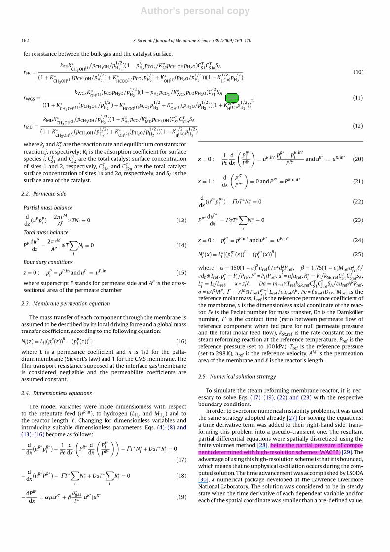
The reaction rate expressions used in this model are the onesdeveloped by Peppley et al. [13]. It is assumed that the reactionoccurs only at the catalyst surface, and that there is no mass trans-
jmsousa
Highlight
pressure drop described by the Ergun equation
jmsousa
Sticky Note
falta dividir por e^2 A velocidade não é superficial, mas intersticial (efectiva)
Author's personal copy
162 S. Sá et al. / Journal of Membrane Science 339 (2009) 160–170
fer resistance between the bulk gas and the catalyst surface.
rSR =kSRK∗
CH3OH(1) (pCH3OH/p1/2H2
)(1 − p3H2
pCO2 /KeSRpCH3OHpH2O)CT
S1CTS1aSA
(1 + K∗CH3OH(1) (pCH3OH/p1/2
H2) + K∗
HCOO(1) pCO2 p1/2H2
+ K∗OH(1) (pH2O/p1/2
H2))(1 + K1/2
H(1a) p1/2H2
)(10)
rWGS =kWGSK∗
OH(1) (pCOpH2O/p1/2H2
)(1 − pH2 pCO2 /KeWGSpCOpH2O)CT2
S1 SA
((1 + K∗CH3OH(1) (pCH3OH/p1/2
H2) + K∗
HCOO(1) pCO2 p1/2H2
+ K∗OH(1) (pH2O/p1/2
H2))(1 + K1/2
H(1a) p1/2H2
))2
(11)
rMD =kMDK∗
CH3OH(2) (pCH3OH/p1/2H2
)(1 − p2H2
pCO/KeMDpCH3OH)CT
S2CTS2aSA
(1 + K∗CH3OH(2) (pCH3OH/p1/2
H2) + K∗
OH(2) (pH2O/p1/2H2
))(1 + K1/2
H(2a) p1/2H2
)(12)
where kj and Kej
are the reaction rate and equilibrium constants forreaction j, respectively; Ki is the adsorption coefficient for surfacespecies i, CT
S1 and CTS2 are the total catalyst surface concentration
of sites 1 and 2, respectively, CTS1a and CT
S2a are the total catalystsurface concentration of sites 1a and 2a, respectively, and SA is thesurface area of the catalyst.
2.2. Permeate side
Partial mass balance
ddz
(uPpPi ) − 2�rM
AP�TNi = 0 (13)
Total mass balance
PP duP
dz− 2�rM
AP�T
∑i
Ni = 0 (14)
Boundary conditions
z = 0 : pPi = pP,in and uP = uP,in (15)
where superscript P stands for permeate side and AP is the cross-sectional area of the permeate chamber
2.3. Membrane permeation equation
The mass transfer of each component through the membrane isassumed to be described by its local driving force and a global masstransfer coefficient, according to the following equation:
Ni(z) = Li{(pRi (z))
n − (pPi (z))
n} (16)
where L is a permeance coefficient and n is 1/2 for the palla-dium membrane (Sievert’s law) and 1 for the CMS membrane. Thefilm transport resistance supposed at the interface gas/membraneis considered negligible and the permeability coefficients areassumed constant.
2.4. Dimensionless equations
The model variables were made dimensionless with respectto the retentate feed (uR,in), to hydrogen (LH2 and MH2 ) and tothe reactor length, . Changing for dimensionless variables andintroducing suitable dimensionless parameters, Eqs. (4)–(8) and(13)–(16) become as follows:
− ddx
(uR∗pR∗
i ) + 1Pe
ddx
(PR∗ d
dx
(pR∗
i
PR∗
))− T∗N∗
i + DaT∗R∗i = 0
(17)
− ddx
(uR∗PR∗
) − T∗∑
i
N∗i + DaT∗
∑i
R∗i = 0 (18)
− dPR∗
dx= ˛�uR∗ + ˇ
�∗gas
T∗ |uR∗ |uR∗(19)
x = 0 :1Pe
ddx
(pR∗
i
PR∗
)= uR,in∗ pR∗
i− pR,in∗
i
PR∗ and uR∗ = uR,in∗(20)
x = 1 :d
dx
(pR∗
i
PR∗
)= 0 and PR∗ = PR,out∗ (21)
ddx
(uP∗pP∗
i ) − �T∗N∗i = 0 (22)
PP∗ duP∗
dx− �T∗
∑i
N∗i = 0 (23)
x = 0 : pP∗i = pP,in∗
and uP∗ = uP,in∗(24)
N∗i (x) = L∗
i [(pR∗i (x))
n − (pP∗i (x))
n] (25)
where ˛ = 150(1 − ε)2uref/ε2d2pPref, ˇ = 1.75(1 − ε)Mrefu
2ref/
εdp�Tref, p∗i
= Pi/Pref, P* = Pi/Pref, u* = u/uref, R∗i
= Ri/kSR,refCTS1CT
S1aSA,L∗
i= Li/Lref, x = z/, Da = mcat�TrefkSR,refC
TS1CT
S1aSA/εurefARPref,
� = εAR/AP, = AM�TrefPn−1ref Lref/εurefA
R, Pe = uref/Dax, Mref is thereference molar mass, Lref is the reference permeance coefficient ofthe membrane, x is the dimensionless axial coordinate of the reac-tor, Pe is the Peclet number for mass transfer, Da is the Damköllernumber, is the contact time (ratio between permeate flow ofreference component when fed pure for null permeate pressureand the total molar feed flow), kSR,ref is the rate constant for thesteam reforming reaction at the reference temperature, Pref is thereference pressure (set to 100 kPa), Tref is the reference pressure(set to 298 K), uref is the reference velocity, AM is the permeationarea of the membrane and is the reactor’s length.
2.5. Numerical solution strategy
To simulate the steam reforming membrane reactor, it is nec-essary to solve Eqs. (17)–(19), (22) and (23) with the respectiveboundary conditions.
In order to overcome numerical instability problems, it was usedthe same strategy adopted already [27] for solving the equations:a time derivative term was added to their right-hand side, trans-forming this problem into a pseudo-transient one. The resultantpartial differential equations were spatially discretized using thefinite volumes method [28], being the partial pressure of compo-nent i determined with high-resolution schemes (WACEB) [29]. Theadvantage of using this high-resolution scheme is that it is bounded,which means that no unphysical oscillation occurs during the com-puted solution. The time advancement was accomplished by LSODA[30], a numerical package developed at the Lawrence LivermoreNational Laboratory. The solution was considered to be in steadystate when the time derivative of each dependent variable and foreach of the spatial coordinate was smaller than a pre-defined value.
jmsousa
Highlight
being the partial pressure of compo- nent i determined with high-resolution schemes (WACEB)
jmsousa
Sticky Note
Este termo (1+...) não está a mais? Na tese não aparece.
Author's personal copy
S. Sá et al. / Journal of Membrane Science 339 (2009) 160–170 163
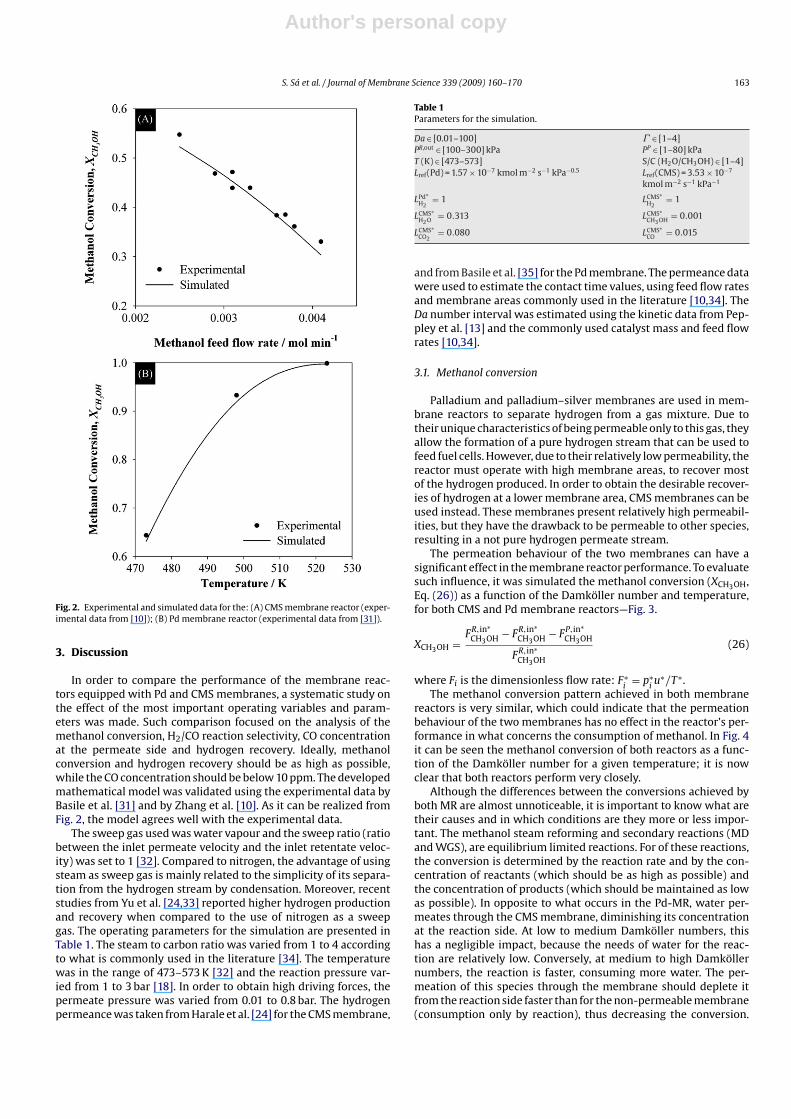
Fig. 2. Experimental and simulated data for the: (A) CMS membrane reactor (exper-imental data from [10]); (B) Pd membrane reactor (experimental data from [31]).
3. Discussion
In order to compare the performance of the membrane reac-tors equipped with Pd and CMS membranes, a systematic study onthe effect of the most important operating variables and param-eters was made. Such comparison focused on the analysis of themethanol conversion, H2/CO reaction selectivity, CO concentrationat the permeate side and hydrogen recovery. Ideally, methanolconversion and hydrogen recovery should be as high as possible,while the CO concentration should be below 10 ppm. The developedmathematical model was validated using the experimental data byBasile et al. [31] and by Zhang et al. [10]. As it can be realized fromFig. 2, the model agrees well with the experimental data.
The sweep gas used was water vapour and the sweep ratio (ratiobetween the inlet permeate velocity and the inlet retentate veloc-ity) was set to 1 [32]. Compared to nitrogen, the advantage of usingsteam as sweep gas is mainly related to the simplicity of its separa-tion from the hydrogen stream by condensation. Moreover, recentstudies from Yu et al. [24,33] reported higher hydrogen productionand recovery when compared to the use of nitrogen as a sweepgas. The operating parameters for the simulation are presented inTable 1. The steam to carbon ratio was varied from 1 to 4 accordingto what is commonly used in the literature [34]. The temperaturewas in the range of 473–573 K [32] and the reaction pressure var-ied from 1 to 3 bar [18]. In order to obtain high driving forces, thepermeate pressure was varied from 0.01 to 0.8 bar. The hydrogenpermeance was taken from Harale et al. [24] for the CMS membrane,
Table 1Parameters for the simulation.
Da ∈ [0.01–100] ∈ [1–4]PR,out ∈ [100–300] kPa PP ∈ [1–80] kPaT (K) ∈ [473–573] S/C (H2O/CH3OH) ∈ [1–4]Lref(Pd) = 1.57 × 10⁻⁷ kmol m−2 s−1 kPa−0.5 Lref(CMS) = 3.53 × 10⁻⁷
kmol m−2 s−1 kPa−1
LPd∗H2
= 1 LCMS∗H2
= 1
LCMS∗H2O = 0.313 LCMS∗
CH3OH = 0.001
LCMS∗CO2
= 0.080 LCMS∗CO = 0.015
and from Basile et al. [35] for the Pd membrane. The permeance datawere used to estimate the contact time values, using feed flow ratesand membrane areas commonly used in the literature [10,34]. TheDa number interval was estimated using the kinetic data from Pep-pley et al. [13] and the commonly used catalyst mass and feed flowrates [10,34].
3.1. Methanol conversion
Palladium and palladium–silver membranes are used in mem-brane reactors to separate hydrogen from a gas mixture. Due totheir unique characteristics of being permeable only to this gas, theyallow the formation of a pure hydrogen stream that can be used tofeed fuel cells. However, due to their relatively low permeability, thereactor must operate with high membrane areas, to recover mostof the hydrogen produced. In order to obtain the desirable recover-ies of hydrogen at a lower membrane area, CMS membranes can beused instead. These membranes present relatively high permeabil-ities, but they have the drawback to be permeable to other species,resulting in a not pure hydrogen permeate stream.
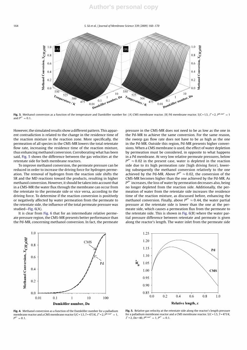
The permeation behaviour of the two membranes can have asignificant effect in the membrane reactor performance. To evaluatesuch influence, it was simulated the methanol conversion (XCH3OH,Eq. (26)) as a function of the Damköller number and temperature,for both CMS and Pd membrane reactors—Fig. 3.
XCH3OH =FR,in∗
CH3OH − FR,in∗CH3OH − FP,in∗
CH3OH
FR,in∗CH3OH
(26)
where Fi is the dimensionless flow rate: F∗i
= p∗iu∗/T∗.
The methanol conversion pattern achieved in both membranereactors is very similar, which could indicate that the permeationbehaviour of the two membranes has no effect in the reactor’s per-formance in what concerns the consumption of methanol. In Fig. 4it can be seen the methanol conversion of both reactors as a func-tion of the Damköller number for a given temperature; it is nowclear that both reactors perform very closely.
Although the differences between the conversions achieved byboth MR are almost unnoticeable, it is important to know what aretheir causes and in which conditions are they more or less impor-tant. The methanol steam reforming and secondary reactions (MDand WGS), are equilibrium limited reactions. For of these reactions,the conversion is determined by the reaction rate and by the con-centration of reactants (which should be as high as possible) andthe concentration of products (which should be maintained as lowas possible). In opposite to what occurs in the Pd-MR, water per-meates through the CMS membrane, diminishing its concentrationat the reaction side. At low to medium Damköller numbers, thishas a negligible impact, because the needs of water for the reac-tion are relatively low. Conversely, at medium to high Damköllernumbers, the reaction is faster, consuming more water. The per-meation of this species through the membrane should deplete itfrom the reaction side faster than for the non-permeable membrane(consumption only by reaction), thus decreasing the conversion.
Author's personal copy
164 S. Sá et al. / Journal of Membrane Science 339 (2009) 160–170
Fig. 3. Methanol conversion as a function of the temperature and Damköller number for: (A) CMS membrane reactor. (B) Pd membrane reactor. S/C = 1.5, = 2, PR,out∗ = 1and PP∗ = 0.1.
However, the simulated results show a different pattern. This appar-ent contradiction is related to the change in the residence time ofthe reaction mixture in the reaction zone. More specifically, thepermeation of all species in the CMS-MR lowers the total retentateflow rate, increasing the residence time of the reaction mixture,thus enhancing methanol conversion. Corroborating what has beensaid, Fig. 5 shows the difference between the gas velocities at theretentate side for both membrane reactors.
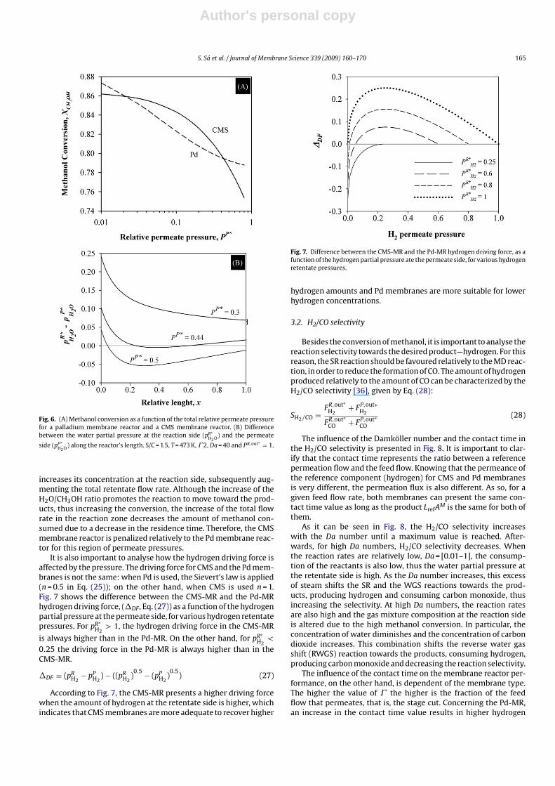
To improve methanol conversion, the permeate pressure can bereduced in order to increase the driving force for hydrogen perme-ation. The removal of hydrogen from the reaction side shifts theSR and the MD reactions toward the products, resulting in highermethanol conversion. However, it should be taken into account thatin a CMS-MR the water flux through the membrane can occur fromthe retentate to the permeate side or vice versa, according to thedriving force. To determine if the reaction conversion is positivelyor negatively affected by water permeation from the permeate tothe retentate side, the influence of the total permeate pressure wasstudied—Fig. 6(A).
It is clear from Fig. 6 that for an intermediate relative perme-ate pressure region, the CMS-MR presents better performance thanthe Pd-MR, concerning methanol conversion. In fact, the permeate
Fig. 4. Methanol conversion as a function of the Damköller number for a palladiummembrane reactor and a CMS membrane reactor S/C = 1.5, T = 473 K, = 2, PR,out∗ = 1,PP∗ = 0.1.
pressure in the CMS-MR does not need to be as low as the one inthe Pd-MR to achieve the same conversion. For the same reason,the sweep gas flow rate does not have to be as high as the onein the Pd-MR. Outside this region, Pd-MR presents higher conver-sions. When a CMS membrane is used, the effect of water depletionby permeation must be considered, in opposite to what happensin a Pd membrane. At very low relative permeate pressures, belowPP∗ ≈ 0.02 in the present case, water is depleted in the reactionside due to its high permeation rate (high driving force), lower-ing subsequently the methanol conversion relatively to the oneachieved by the Pd-MR. Above PP∗ ≈ 0.02, the conversion of theCMS-MR becomes higher than the one achieved by the Pd-MR. AsPP∗
increases, the loss of water by permeation decreases also, beingno longer depleted from the reaction side. Additionally, the per-meation of water from the retentate side increases the residencetime of the reaction mixture, as discussed before, enhancing themethanol conversion. Finally, above PP∗ ≈ 0.44, the water partialpressure at the retentate side is lower than the one at the per-meate side, which causes a permeation flux from the permeate tothe retentate side. This is shown in Fig. 6(B) where the water par-tial pressure difference between retentate and permeate is givenalong the reactor’s length. The water inlet from the permeate side
Fig. 5. Relative gas velocity at the retentate side along the reactor’s length pressurefor a palladium membrane reactor and a CMS membrane reactor. S/C = 1.5, T = 473 K, = 2, Da = 40, PR,out∗ = 1, PP∗ = 0.1.
Author's personal copy
S. Sá et al. / Journal of Membrane Science 339 (2009) 160–170 165
Fig. 6. (A) Methanol conversion as a function of the total relative permeate pressurefor a palladium membrane reactor and a CMS membrane reactor. (B) Differencebetween the water partial pressure at the reaction side (pR∗
H2O) and the permeate
side (pP∗H2O) along the reactor’s length. S/C = 1.5, T = 473 K, 2, Da = 40 and PR,out∗ = 1.
increases its concentration at the reaction side, subsequently aug-menting the total retentate flow rate. Although the increase of theH2O/CH3OH ratio promotes the reaction to move toward the prod-ucts, thus increasing the conversion, the increase of the total flowrate in the reaction zone decreases the amount of methanol con-sumed due to a decrease in the residence time. Therefore, the CMSmembrane reactor is penalized relatively to the Pd membrane reac-tor for this region of permeate pressures.
It is also important to analyse how the hydrogen driving force isaffected by the pressure. The driving force for CMS and the Pd mem-branes is not the same: when Pd is used, the Sievert’s law is applied(n = 0.5 in Eq. (25)); on the other hand, when CMS is used n = 1.Fig. 7 shows the difference between the CMS-MR and the Pd-MRhydrogen driving force, (�DF, Eq. (27)) as a function of the hydrogenpartial pressure at the permeate side, for various hydrogen retentatepressures. For pR∗
H2> 1, the hydrogen driving force in the CMS-MR
is always higher than in the Pd-MR. On the other hand, for pR∗H2
<
0.25 the driving force in the Pd-MR is always higher than in theCMS-MR.
�DF = (pRH2
− pPH2
) − ((pRH2
)0.5 − (pP
H2)0.5
) (27)
According to Fig. 7, the CMS-MR presents a higher driving forcewhen the amount of hydrogen at the retentate side is higher, whichindicates that CMS membranes are more adequate to recover higher
Fig. 7. Difference between the CMS-MR and the Pd-MR hydrogen driving force, as afunction of the hydrogen partial pressure ate the permeate side, for various hydrogenretentate pressures.
hydrogen amounts and Pd membranes are more suitable for lowerhydrogen concentrations.
3.2. H2/CO selectivity
Besides the conversion of methanol, it is important to analyse thereaction selectivity towards the desired product—hydrogen. For thisreason, the SR reaction should be favoured relatively to the MD reac-tion, in order to reduce the formation of CO. The amount of hydrogenproduced relatively to the amount of CO can be characterized by theH2/CO selectivity [36], given by Eq. (28):
SH2/CO =FR,out∗
H2+ FP,out∗
H2
FR,out∗CO + FP,out∗
CO
(28)
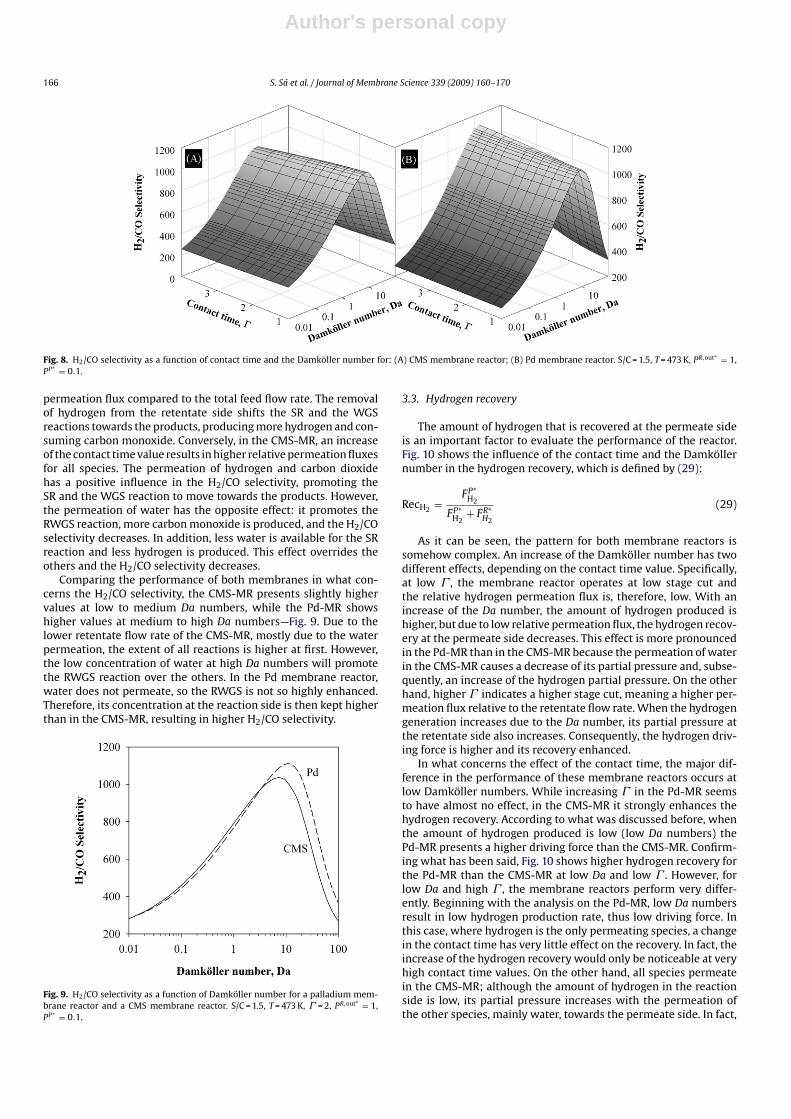
The influence of the Damköller number and the contact time inthe H2/CO selectivity is presented in Fig. 8. It is important to clar-ify that the contact time represents the ratio between a referencepermeation flow and the feed flow. Knowing that the permeance ofthe reference component (hydrogen) for CMS and Pd membranesis very different, the permeation flux is also different. As so, for agiven feed flow rate, both membranes can present the same con-tact time value as long as the product LrefAM is the same for both ofthem.
As it can be seen in Fig. 8, the H2/CO selectivity increaseswith the Da number until a maximum value is reached. After-wards, for high Da numbers, H2/CO selectivity decreases. Whenthe reaction rates are relatively low, Da = [0.01–1], the consump-tion of the reactants is also low, thus the water partial pressure atthe retentate side is high. As the Da number increases, this excessof steam shifts the SR and the WGS reactions towards the prod-ucts, producing hydrogen and consuming carbon monoxide, thusincreasing the selectivity. At high Da numbers, the reaction ratesare also high and the gas mixture composition at the reaction sideis altered due to the high methanol conversion. In particular, theconcentration of water diminishes and the concentration of carbondioxide increases. This combination shifts the reverse water gasshift (RWGS) reaction towards the products, consuming hydrogen,producing carbon monoxide and decreasing the reaction selectivity.
The influence of the contact time on the membrane reactor per-formance, on the other hand, is dependent of the membrane type.The higher the value of the higher is the fraction of the feedflow that permeates, that is, the stage cut. Concerning the Pd-MR,an increase in the contact time value results in higher hydrogen
Author's personal copy
166 S. Sá et al. / Journal of Membrane Science 339 (2009) 160–170
Fig. 8. H2/CO selectivity as a function of contact time and the Damköller number for: (A) CMS membrane reactor; (B) Pd membrane reactor. S/C = 1.5, T = 473 K, PR,out∗ = 1,PP∗ = 0.1.
permeation flux compared to the total feed flow rate. The removalof hydrogen from the retentate side shifts the SR and the WGSreactions towards the products, producing more hydrogen and con-suming carbon monoxide. Conversely, in the CMS-MR, an increaseof the contact time value results in higher relative permeation fluxesfor all species. The permeation of hydrogen and carbon dioxidehas a positive influence in the H2/CO selectivity, promoting theSR and the WGS reaction to move towards the products. However,the permeation of water has the opposite effect: it promotes theRWGS reaction, more carbon monoxide is produced, and the H2/COselectivity decreases. In addition, less water is available for the SRreaction and less hydrogen is produced. This effect overrides theothers and the H2/CO selectivity decreases.
Comparing the performance of both membranes in what con-cerns the H2/CO selectivity, the CMS-MR presents slightly highervalues at low to medium Da numbers, while the Pd-MR showshigher values at medium to high Da numbers—Fig. 9. Due to thelower retentate flow rate of the CMS-MR, mostly due to the waterpermeation, the extent of all reactions is higher at first. However,the low concentration of water at high Da numbers will promotethe RWGS reaction over the others. In the Pd membrane reactor,water does not permeate, so the RWGS is not so highly enhanced.Therefore, its concentration at the reaction side is then kept higherthan in the CMS-MR, resulting in higher H2/CO selectivity.
Fig. 9. H2/CO selectivity as a function of Damköller number for a palladium mem-brane reactor and a CMS membrane reactor. S/C = 1.5, T = 473 K, = 2, PR,out∗ = 1,PP∗ = 0.1.
3.3. Hydrogen recovery
The amount of hydrogen that is recovered at the permeate sideis an important factor to evaluate the performance of the reactor.Fig. 10 shows the influence of the contact time and the Damköllernumber in the hydrogen recovery, which is defined by (29):
RecH2 =FP∗
H2
FP∗H2
+ FR∗H2
(29)
As it can be seen, the pattern for both membrane reactors issomehow complex. An increase of the Damköller number has twodifferent effects, depending on the contact time value. Specifically,at low , the membrane reactor operates at low stage cut andthe relative hydrogen permeation flux is, therefore, low. With anincrease of the Da number, the amount of hydrogen produced ishigher, but due to low relative permeation flux, the hydrogen recov-ery at the permeate side decreases. This effect is more pronouncedin the Pd-MR than in the CMS-MR because the permeation of waterin the CMS-MR causes a decrease of its partial pressure and, subse-quently, an increase of the hydrogen partial pressure. On the otherhand, higher indicates a higher stage cut, meaning a higher per-meation flux relative to the retentate flow rate. When the hydrogengeneration increases due to the Da number, its partial pressure atthe retentate side also increases. Consequently, the hydrogen driv-ing force is higher and its recovery enhanced.
In what concerns the effect of the contact time, the major dif-ference in the performance of these membrane reactors occurs atlow Damköller numbers. While increasing in the Pd-MR seemsto have almost no effect, in the CMS-MR it strongly enhances thehydrogen recovery. According to what was discussed before, whenthe amount of hydrogen produced is low (low Da numbers) thePd-MR presents a higher driving force than the CMS-MR. Confirm-ing what has been said, Fig. 10 shows higher hydrogen recovery forthe Pd-MR than the CMS-MR at low Da and low . However, forlow Da and high , the membrane reactors perform very differ-ently. Beginning with the analysis on the Pd-MR, low Da numbersresult in low hydrogen production rate, thus low driving force. Inthis case, where hydrogen is the only permeating species, a changein the contact time has very little effect on the recovery. In fact, theincrease of the hydrogen recovery would only be noticeable at veryhigh contact time values. On the other hand, all species permeatein the CMS-MR; although the amount of hydrogen in the reactionside is low, its partial pressure increases with the permeation ofthe other species, mainly water, towards the permeate side. In fact,
Author's personal copy
S. Sá et al. / Journal of Membrane Science 339 (2009) 160–170 167
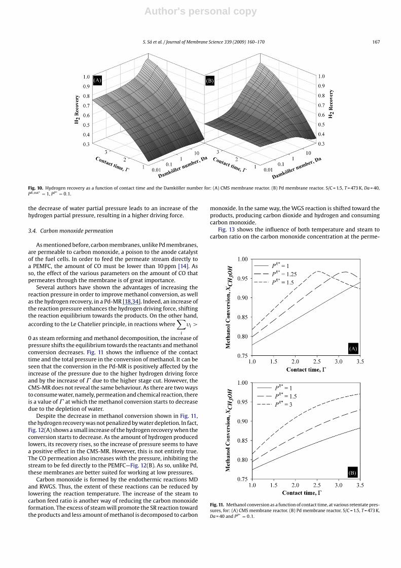
Fig. 10. Hydrogen recovery as a function of contact time and the Damköller number for: (A) CMS membrane reactor. (B) Pd membrane reactor. S/C = 1.5, T = 473 K, Da = 40,PR,out∗ = 1, PP∗ = 0.1.
the decrease of water partial pressure leads to an increase of thehydrogen partial pressure, resulting in a higher driving force.
3.4. Carbon monoxide permeation
As mentioned before, carbon membranes, unlike Pd membranes,are permeable to carbon monoxide, a poison to the anode catalystof the fuel cells. In order to feed the permeate stream directly toa PEMFC, the amount of CO must be lower than 10 ppm [14]. Asso, the effect of the various parameters on the amount of CO thatpermeates through the membrane is of great importance.
Several authors have shown the advantages of increasing thereaction pressure in order to improve methanol conversion, as wellas the hydrogen recovery, in a Pd-MR [18,34]. Indeed, an increase ofthe reaction pressure enhances the hydrogen driving force, shiftingthe reaction equilibrium towards the products. On the other hand,
according to the Le Chatelier principle, in reactions where∑
i
�i >
0 as steam reforming and methanol decomposition, the increase ofpressure shifts the equilibrium towards the reactants and methanolconversion decreases. Fig. 11 shows the influence of the contacttime and the total pressure in the conversion of methanol. It can beseen that the conversion in the Pd-MR is positively affected by theincrease of the pressure due to the higher hydrogen driving forceand by the increase of due to the higher stage cut. However, theCMS-MR does not reveal the same behaviour. As there are two waysto consume water, namely, permeation and chemical reaction, thereis a value of at which the methanol conversion starts to decreasedue to the depletion of water.
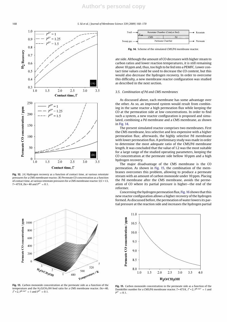
Despite the decrease in methanol conversion shown in Fig. 11,the hydrogen recovery was not penalized by water depletion. In fact,Fig. 12(A) shows a small increase of the hydrogen recovery when theconversion starts to decrease. As the amount of hydrogen producedlowers, its recovery rises, so the increase of pressure seems to havea positive effect in the CMS-MR. However, this is not entirely true.The CO permeation also increases with the pressure, inhibiting thestream to be fed directly to the PEMFC—Fig. 12(B). As so, unlike Pd,these membranes are better suited for working at low pressures.
Carbon monoxide is formed by the endothermic reactions MDand RWGS. Thus, the extent of these reactions can be reduced bylowering the reaction temperature. The increase of the steam tocarbon feed ratio is another way of reducing the carbon monoxideformation. The excess of steam will promote the SR reaction towardthe products and less amount of methanol is decomposed to carbon
monoxide. In the same way, the WGS reaction is shifted toward theproducts, producing carbon dioxide and hydrogen and consumingcarbon monoxide.
Fig. 13 shows the influence of both temperature and steam tocarbon ratio on the carbon monoxide concentration at the perme-
Fig. 11. Methanol conversion as a function of contact time, at various retentate pres-sures, for: (A) CMS membrane reactor. (B) Pd membrane reactor. S/C = 1.5, T = 473 K,Da = 40 and PP∗ = 0.1.
Author's personal copy
168 S. Sá et al. / Journal of Membrane Science 339 (2009) 160–170
Fig. 12. (A) Hydrogen recovery as a function of contact time, at various retentatepressures for a CMS membrane reactor. (B) Permeate CO concentration as a functionof contact time, at various retentate pressures for a CMS membrane reactor. S/C = 1.5,T = 473 K, Da = 40 and PP∗ = 0.1.
Fig. 13. Carbon monoxide concentration at the permeate side as a function of thetemperature and the H2O/CH3OH feed ratio for a CMS membrane reactor. Da = 40, = 2, PR,out∗ = 1 and PP∗ = 0.1.
Fig. 14. Scheme of the simulated CMS/Pd membrane reactor.
ate side. Although the amount of CO decreases with higher steam tocarbon ratios and lower reaction temperatures, it is still remainingabove 10 ppm and, thus, too high to be fed into a PEMFC. Lower con-tact time values could be used to decrease the CO content, but thiswould also decrease the hydrogen recovery. In order to overcomethis difficulty, a new membrane reactor configuration was studiedas described in the next section.
3.5. Combination of Pd and CMS membranes
As discussed above, each membrane has some advantage overthe other. As so, an improved system would result from combin-ing in the same reactor a high permeation flux while keeping theCO at the permeation side at low concentrations. In order to findsuch a system, a new reactor configuration is proposed and simu-lated, combining a Pd membrane and a CMS membrane, as shownin Fig. 14.
The present simulated reactor comprises two membranes. Firstthe CMS membrane, less selective and less expensive with a higherpermeation flux; afterwards, the highly selective Pd membranewith lower permeation flux. A preliminary study was made in orderto determine the most adequate ratio of the CMS/Pd membranelength. It was concluded that the value of 1.2 was the most suitablefor a large range of the studied operating parameters, keeping theCO concentration at the permeate side bellow 10 ppm and a highhydrogen recovery.
The major disadvantage of the CMS membrane is the COpermeation. As shown in Fig. 15, the combination of the mem-branes overcomes this problem, allowing to produce a permeatestream with an amount of carbon monoxide under 10 ppm. Placingthe Pd membrane after the CMS membrane, avoids the perme-ation of CO where its partial pressure is higher—the end of thereformer.
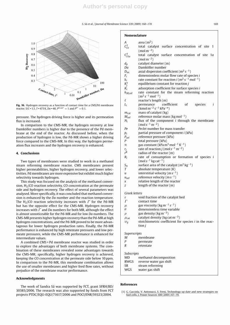
Concerning the hydrogen permeation flux, Fig. 16 shows that thisnew reactor configuration allows a higher recovery of the hydrogenformed. As discussed before, the permeation of water lowers its par-tial pressure at the reaction side and increases the hydrogen partial
Fig. 15. Carbon monoxide concentration in the permeate side as a function of theDamköller number for a CMS/Pd membrane reactor. T = 473 K, = 2, PR,out∗ = 1 andPP∗ = 0.1.
Author's personal copy
S. Sá et al. / Journal of Membrane Science 339 (2009) 160–170 169
Fig. 16. Hydrogen recovery as a function of contact time for a CMS/Pd membranereactor. S/C = 1.5, T = 473 K, Da = 40, PR,out∗ = 1 and PP∗ = 0.1.
pressure. The hydrogen driving force is higher and its permeationflux is increased.
In comparison to the CMS-MR, the hydrogen recovery at lowDamköller numbers is higher due to the presence of the Pd mem-brane at the end of the reactor. As discussed before, when theproduction of hydrogen is low, the Pd-MR shows a higher drivingforce compared to the CMS-MR. In this way, the hydrogen perme-ation flux increases and the hydrogen recovery is enhanced.
4. Conclusions
Two types of membranes were studied to work in a methanolsteam reforming membrane reactor. CMS membranes presenthigher permeabilities, higher hydrogen recovery, and lower selec-tivities. Pd membranes are more expensive but exhibit much higherselectivity towards hydrogen.
This study was focused on the analysis of the methanol conver-sion, H2/CO reaction selectivity, CO concentration at the permeateside and hydrogen recovery. The effect of several parameters wasanalysed. More specifically, it was concluded that methanol conver-sion is enhanced by the Da number and the reaction temperature.The H2/CO reaction selectivity increases with for the Pd-MRbut has the opposite effect for the CMS-MR. Hydrogen recoveryincreases with and Da numbers for both MR, although the effectis almost unnoticeable for the Pd-MR and for low Da numbers. TheCMS-MR presents higher hydrogen recovery than the Pd-MR at highhydrogen concentrations, and the Pd-MR proved to be more advan-tageous for lower hydrogen production rates. Finally, the Pd-MRperformance is enhanced by high retentate pressures and low per-meate pressures, while the CMS-MR performance is enhanced forintermediate values.
A combined CMS + Pd membrane reactor was studied in orderto explore the advantages of both membrane systems. The com-bination of these membranes revealed some advantages towardsthe CMS-MR; specifically, higher hydrogen recovery is achieved,keeping the CO concentration at the permeate side below 10 ppm.In comparison to the Pd-MR, this membrane combination allowsthe use of smaller membranes and higher feed flow rates, withoutprejudice of the membrane reactor performance.
Acknowledgments
The work of Sandra Sá was supported by FCT, grant SFRH/BD/30385/2006. The research was also supported by funds from FCTprojects PTDC/EQU-EQU/71617/2006 and POCI/ENR/59323/2004.
Nomenclature
A area (m2)CT
S1 total catalyst surface concentration of site 1(mol m−2)
CTS1a total catalyst surface concentration of site 1a
(mol m−2)dp catalyst diameter (m)Da Damköller numberDax axial dispersion coefficient (m2 s−1)Fi dimensionless molar flow rate of species iki rate constant for reaction i (m2 s−1 mol−1)Ke
jequilibrium constant for reaction j
Ki adsorption coefficient for surface species ikSR,ref rate constant for the steam reforming reaction
(m2 s−1 mol−1) reactor’s length (m)Li permeance coefficient of species i
(kmol m−2 s−1 kPa−n)mcat mass of catalyst (kg)Mref reference molar mass (kg mol−1)Ni flux of the component i through the membrane
(mol s−1 m−2)Pe Peclet number for mass transferpi partial pressure of component i (kPa)Pref reference pressure (kPa)P total pressure (kPa)� gas constant (kPa m3 mol−1 K−1)rj rate of reaction j (mol s−1 m−2)rR radius of the reactor (m)Ri rate of consumption or formation of species i
(mol s−1 kg cat−1)SA surface area of the catalyst (m2 kg−1)T absolute temperature (K)u interstitial velocity (m s−1)uref reference velocity (m s−1)x relative length of the reactorz length of the reactor (m)
Greek lettersε void fraction of the catalyst bed contact time� gas viscosity (kg m−1 s−1)� dimensionless time variable� gas density (kg m−3)�cat catalyst density (kg cat m−3)�ij stoichiometric coefficient for species i in the reac-
tion j
SuperscriptsM membraneP permeateR retentate
SubscriptsMD methanol decompositionRWGS reverse water gas shiftSR steam reformingWGS water gas shift
References
[1] G. Cacciola, V. Antonucci, S. Freni, Technology up date and new strategies onfuel cells, J. Power Sources 100 (2001) 67–79.
Author's personal copy
170 S. Sá et al. / Journal of Membrane Science 339 (2009) 160–170
[2] J.M. King, M.J. O’Day, Applying fuel cell experience to sustainable power prod-ucts, J. Power Sources 86 (2000) 16–22.
[3] D. Ramirez, L.F. Beites, F. Blazquez, J.C. Ballesteros, Distributed generationsystem with PEM fuel cell for electrical power quality improvement, Int. J.Hydrogen Energy 33 (2008) 4433–4443.
[4] C. Stone, A.E. Morrison, From curiosity to “power to change the world”, SolidState Ionics 152–153 (2002) 1–13.
[5] A.S. Damle, Hydrogen production by reforming of liquid hydrocarbons n amembrane reactor for portable power generation–model simulations, J. PowerSources 180 (2008) 516–529.
[6] D.G. Löffler, K. Taylor, D. Mason, A light hydrocarbon fuel processor producinghigh-purity hydrogen, J. Power Sources 117 (2003) 84–91.
[7] T.L. Reitz, S. Ahmed, M. Krumpelt, R. Kumar, H.H. Kung, Characterization ofCuOrZnO under oxidizing conditions for the oxidative methanol reformingreaction, J. Mol. Catal. A: Chem. 162 (2000) 275–285.
[8] J.C. Telotte, J. Kern, S. Palanki, Miniaturized methanol reformer for fuel cellpowered mobile applications, Int. J. Chem. Reactor Eng. 6 (2008).
[9] A. Basile, A. Parmaliana, S. Tosti, A. Iulianelli, F. Gallucci, C. Espro, J. Spooren,Hydrogen production by methanol steam reforming carried out in membranereactor on Cu/Zn/Mg-based catalyst, Catal. Today 137 (2008) 17–22.
[10] X. Zhang, H. Hu, Y. Zhu, S. Zhu, Methanol steam reforming to hydrogen in acarbon membrane reactor system, Ind. Eng. Chem. Res. 45 (2006) 7997–8001.
[11] D.R. Palo, R.A. Dagle, J.D. Holladay, Methanol steam reforming for hydrogenproduction, Chem. Rev. 107 (2007) 3992–4021.
[12] B.A. Peppley, J.C. Amphlett, L.M. Kearns, R.F. Mann, Methanol steam reformingon Cu/ZnO/Al2O3. Part 1: the reaction network, Appl. Catal., A 179 (1999) 21–29.
[13] B.A. Peppley, J.C. Amphlett, L.M. Kearns, R.F. Mann, Methanol steam reformingon Cu/ZnO/Al2O3 catalysts. Part 2. A comprehensive kinetic model, Appl. Catal.,A 179 (1999) 31–49.
[14] H.P. Dhar, L.G. Christner, A.K. Kush, Nature of CO adsorption during H2 oxidationin relation to modeling for CO poisoning of a fuel cell anode, J. Electrochem. Soc.134 (1987) 3021–3026.
[15] F. Gallucci, L. Paturzo, A. Basile, Hydrogen recovery from methanol steamreforming in a dense membrane reactor: simulation study, Ind. Eng. Chem. Res.43 (2004) 2420–2432.
[16] A.N. Matzakos, S.L. Wellington, T. Mikus, J.M. Ward, Integrated flamelessdistributed combustion/steam reforming membrane reactor for hydrogen pro-duction and use thereof in zero emissions hybrid power system, US patent6,821,501 (2004).
[17] C.-H. Fu, J.C.S. Wu, Mathematical simulation of hydrogen production viamethanol steam reforming using double-jacketed membrane reactor, Int. J.Hydrogen Energy 32 (2007) 4830–4839.
[18] A. Iulianelli, T. Longo, A. Basile, Methanol steam reforming in a dense Pd–Agmembrane reactor: the pressure and WHSV effects on CO-free H2 production,J. Membr. Sci. 323 (2008) 235–240.
[19] F. Gallucci, A. Basile, S. Tosti, A. Iulianelli, E. Drioli, Methanol and ethanolsteam reforming in membrane reactors: an experimental study, Int. J. HydrogenEnergy 32 (2007) 1201–1210.
[20] B.K.R. Nair, M.P. Harold, Hydrogen generation in a Pd membrane fuel proces-sor: productivity effects during methanol steam reforming, Chem. Eng. Sci. 61(2006) 6616–6636.
[21] L. Shao, B.T. Low, T.-S. Chung, A.R. Greenberg, Polymeric membranes for thehydrogen economy: contemporary approaches and prospects for the future, J.Membr. Sci. 327 (2009) 18–31.
[22] A.F. Ismail, L.I.B. David, A review on the latest development of carbon mem-branes for gas separation, J. Membr. Sci. 193 (2001) 1–18.
[23] G.A. Sznejer, I. Efremenko, M. Sheintuch, Carbon membranes for high temper-ature gas separations: experiment and theory, AIChE J. 50 (2004).
[24] A. Harale, H.T. Hwang, P.K.T. Liu, M. Sahimi, T.T. Tsotsis, Experimental studies of ahybrid adsorbent-membrane reactor (HAMR) system for hydrogen production,Chem. Eng. Sci. 62 (2007) 4126–4137.
[25] S. Ergun, Fluid flow through packed columns, Chem. Eng. Prog. 48 (1952) 89–94.[26] P.V. Danckwerts, Continuous flows systems—distribution of residence times,
Chem. Eng. Sci. 2 (1953) 1.[27] J.M. Sousa, A. Mendes, Simulation study of a dense polymeric catalytic mem-
brane reactor with plug–flow pattern, Chem. Eng. J. 95 (2003) 67–81.[28] P. Cruz, J.C. Santos, F.D. Magalhães, A. Mendes, Simulation of separation pro-
cesses using finite volume method, Comput. Chem. Eng. 30 (2005) 83–98.[29] B. Song, G.R. Liu, K.Y. Lam, R.S. Amano, On a higher-order bounded discretization
scheme, Int. J. Num. Methods Fluids 32 (2000) 881–897.[30] L. Petzold, Automatic selection of methods for solving stiff and nonstiff sys-
tems of ordinary differential equations, Siam. J. Sci. Stat. Comput. 4 (1983)136–148.
[31] A. Basile, G.F. Tereschenko, N.V. Orekhova, M.M. Ermilova, F. Gallucci, A.Iulianelli, An experimental investigation on methanol steam reforming withoxygen addition in a flat Pd–Ag membrane reactor, Int. J. Hydrogen Energy 31(2006) 1615–1622.
[32] F. Gallucci, A. Basile, Pd–Ag membrane reactor for steam reforming reac-tions: a comparison between different fuels, Int. J. Hydrogen Energy 33 (2008)1671–1687.
[33] W. Yu, T. Ohmori, S. Kataoka, T. Yamamoto, A. Endo, M. Nakaiwa, N. Itoh, Acomparative simulation study of methane steam reforming in a porous ceramicmembrane reactor using nitrogen and steam as sweep gases, Int. J. HydrogenEnergy 33 (2008) 685–692.
[34] F. Gallucci, A. Basile, Co-current and counter-current modes for methanol steamreforming membrane reactor, Int. J. Hydrogen Energy 31 (2006) 2243–2249.
[35] A. Basile, F. Gallucci, L. Paturzo, A dense Pd/Ag membrane reactor for methanolsteam reforming: experimental study, Catal. Today 104 (2005) 244–250.
[36] H.S. Fogler, Elements of Chemical Reaction Engineering, fourth ed., PrenticeHall, Upper Saddle River, NJ, 2005.
jmsousa
Highlight
[25] S. Ergun, Fluid flow through packed columns, Chem. Eng. Prog. 48 (1952) 89–94.