Platinum and Palladium Printing
257
-
Upload
khangminh22 -
Category
Documents
-
view
4 -
download
0
Transcript of Platinum and Palladium Printing


ELSEVIER
DICK ARENTZ
With contributions by:
Bob Herbst Sandy King Stan Klimek Mark Nelson Keith Schreiber
AMSTERDAM BOSTON HEIDELBERG LONDON NEW YORK OXFORD PARIS SAN DIEGO
SAN FRANCISCO SINGAPORE SYDNEY TOKYO Focal Press is an imprint of Elsevier

Copyright C 2005, Dick Arentz. All rights reserved. All photographs 8 Dick Arentz, unless otherwise specified.
No part of this publication may be reproduced, stored in a retrieval system, or transmitted in any form or by any means, electronic, mechanical, photocopying, recording, or otherwise, without the prior written permission of the publisher.
Permissions may be sought directly from Elsevier’s Science 8i Technology Rights Department in Oxford, UK: phone: (+44) 1865 843830, fax: (+44) 1865 853333, e-mail: permissions@elsevier. corn.uk. You may also complete your request on-line via the Elsevier homepage (http://elsevier.com), by selecting “Customer Support” and then “Obtaining Permissions.”
Recognizing the importance of preserving what has been written, Elsevier prints its books on acid- @ free paper whenever possible.
Library of Congress Cataloging-in-Publication Data Application submitted
British Library Cataloguing-in-Publication Data A catalogue record for this book is available from the British Library.
ISBN: 0-240-80606-9
For information on all Focal Press publications visit our website a t www.books.elsevier.com
04 05 06 07 08 09 10 9 8 7 6 5 4 3 2 1
Printed in China

To Phil Davis Professor Emeritus, University of Michigan
Teacher, Mentor, and Friend
In 1970, I was an Assistant Professor at the University of Michigan in a discipline far removed from art or photography. I was also an advanced amateur photographer, having taken a number of Ansel Adams workshops. Phil Davis was, at that time, head of the Department of Photography. One winter weekend, I hitched a ride with Phil and his students to a Society of Photographic Education meeting in Rochester, NY. For some reason, Phil and I were billeted at a motel removed from the rest. A typical Rochester snowfall came to bury the city, completely removing parked cars from sight, and confining us to our rooms . . . and the bar. It was there that Phil finally suggested that I knew practically nothing about photography. If, however, I would be willing to make the effort, he would tutor me.
Almost thirty-five years later, Phil, the source of one of the most significant changes in my life, is still my teacher. A good portion of this text, and the entire basis for Part Two, come from Phil’s research, his book Beyond the Zone System, and his Plotter ProgramR . He has read and, mercifully, graciously criticized only those sections of this book.

Preface to the Second Edition and Acknowledgments Preface and Acknowledgments Introduction
PART ONE THE PROCESS
CHAPTER 1 P l A T i N U M A N d P A 1 l A d i U M
Platinum Printing in the Twentieth Century The PlatinurdPalladium and Silver Processes Compared Platinum and Palladium Compared
SETTiNCj up A L A b O R A T O R y
The Wet Space and Coating Area The Drying and Exposure Area Materials
CHAPTER 2
The Wet Area The Coating Area The Exposure and Finishing Area
Contact Printing Frames The Ultraviolet Light Source
The Sun Mercury Vapor, Metal Halide, and UV Fluorescent Lights Commercial Plate Burner
Modifying a Light Meter Inexpensive Table-Model Densitometers Hand-Held Densitometers The Professional Models
Photographic Sensitometry
Densitometers
CHAPTER 3 T h E N E C j A T i v E
Definitions Transmission Densities The Logarithmic System The Density Range for a Platinum or Palladium Negative
Exposure Development The Negative Density Range
Negative Contrast Versus Negative Density
xiv xvii
x x
1
3 4 4 5
7 8 9
10 10 10 10 11 12 12 13 13 13 13 14 14 14
1 5 16 17 17 17 18 18 18 19 19
vi

CONTENTS vii
Exposing and Developing the Platinum or Palladiuin Negative Zone System Development Compared to Subject Brightness Range Development for Subject Brightness Ranges Average Gradient Effective Film Speed
Sharpness Graininess Scratches and Pinholes The Circle of Confusion
The Pyro Negative
Characteristics of the Platinum/Palladium Negative
The Use of Selenium Toner to Increase Negative Contrast
CHAPTER 4 C k E M i C A l S
The Reasonable and Prudent Use The Material Safety Data Sheet
Health Contact
Monochromatic Film Developing Agents (MSDS 2 ) About Measurement Units The Metric System Purity of Chemicals and Water Sizing of Paper Solutions Used for Paper Coating, Developing, and Clearing
The Coating Solutions Oxidizing Agents Developers Clearing Agents
Coating Solutions Sensitizers (MSDS 2-3) The Restrairiers (Oxidizers) (MSDS 3-4) The Metal Salts (MSDS 2-3) The Use of Metal Utensils
Formulas The pH Filtering of Deueloper Temperature of Developer
Choosing a Clearing Agent Etylene Diamiiie Tetraacetic Acid and the Sulfites (MSDS 1 ) The Dilute Acids ( M S D S 2-3) Formulas A Matter of Print pH Bit ffering S o h tions
Negative Toning for Contrast Print Toning
Developers (MSDS 1-2)
Clearing Agents
Toners
Sources of Chemicals
CHAPTER 5 PAPER Platinotype Papers
Practical Matters
20 21 21 22 22 24 24 24 24 2.5 25 2.5
27 28 28 28 28 29 29 29 30 30 30 30 30 31 31 31 31 32 32 33 33 33 34 34 34 34 34 34 3 5 3.5 36 36 36 36 36 38
39 40 41

... viii CONTENTS
CHAPTER 6
CHAPTER 7
CHAPTER 8
CHAPTER 9
Some Characteristics Required of a PlatinudPalladium Paper A Word About Paper Weight Measurements Selected Platinotype Papers and Their Characteristics
Notes on Suitable Papers for the PlatinumPalladium Process
Acidification
Testing Techniques
Papers for Single Coating
Papers Ainenable to Acidification Papers for Double Coating
T k t F i R S T PRiNT
The Sun Print The Basics
Chemicals Paper Utensils Negative
Procedure Assessment of the Print
CkoosE YOUR M d o d Methods of Contrast Control
The Ratio Method Sodium Chloroplatinate (Na2) Combining the Ratio and Na2 Methods The Dichromate Method: Contrast Control Ingredient in the Developer
Standard Negative Contrast Ranges: The Dichromate Method A Standard
CAli bRATiON
Calibrating the Light Source Choosing a Pririt-to-Light Distance with a Point Light Source Choosing a Print-to-Light Distance with a Fluorescent Tube Bank The Step Tablet The Visual Comparison Densitonieter
Methods of Contrast Control Supplies
Technique: Time/Distance Technique: Contrast Control Palladium Printing with the Ratio Method Standard Negative Contrast Ranges Calibrating with the Dichromate Method
T k t PlATiNUM ANd PA11AdiuM PRiNT
Utensils The Test Strip
Materials Used for Developing and Clearing the Test Strip
The Final Print
Notes on the Making of Test Strips
Coating the Test Strip
Developing and Clearing
The Coating Instruments Brushes Coating Rods
41 42 42 42 44 44 47 47 48
4 9 50 50 50 50 50 so 50 52
5 3 54 54 56 58 60 61 61
6 3 64 64 64 64 66 66 66 67 68 68 72 73 73
75 76 76 76 78 78 78 78 79 82

CONTENTS 9 ix
The Brush Versus the Coating Rod
Coating Drying Exposure Dodging and Burning Developing aiid Clearing Dry Down
The Visual Comparison Densitonzeter Both Shadows aitd Highlights Are Too Dark Both Shadows and Highlights Are Too Light Shadotus Are Good, Highlights Are Too Dark Shadows Are Good, Highlights Are Too Light Shadows Are Too Dark, Highlights Are Good Shadows Are 7-00 Light, Highlights Are Good More Combinations
CHAPTER 10 A d v A N c E d T E C k N i Q u E
Making the Final Print
Using the Combined Step Tablet and Print to Adjust Printing Time and Contrast
Masking of Negatives Materials Process
Working Light Relative Humidity in the Laboratory The Effects of High Paper Humidity
Prevention of Solarization The Elusive Dinax Observations
Hydrogen Peroxide Brushes The Use of Sizing Medium in the Sensitizer Image Hue
Sizing Developer and Tenzperature Controls Metal loiis in the Developer Combinations of Platinum and Palladium Toning
Glycerin Materials
Double Coating Drying of the Coating
Materials Method
Drying Principles of Etching and Spotting Platini~nzlPalludiicln Prints Materials
The “Black Plague” Cure Presentation
Lighting Matting Framing
Preparation of the Final Print
83 83 83 84 85 85 85 87 87 87 88 89 89 89 90 90 90
91 92 92 92 92 92 93 93 93 94 95 95 95 95 95 95 96 96 96 97 97 97 97 98 98 99 99 99 99
100 101 201 2 01 201

x CONTENTS
CHAPTER 1 1
PART Two
CHAPTER 12
CHAPTER 1 3
Numbering of Editions Handling and Storage of Negatives
P R o b k M s
Chalky or Anemic Prints Uneven Coating Graininess Black Spots on the Print (The "Black Plague") Streaking Blacks Fog Versus Stain Solarization with Palladium
SENSilOMETRY FOR ThE PlATiNUM/PA"AdiUM PROCESS
ThE F i lM ANd PAPER CURVES Silver and Platinunflalladium Curves Compared
The Individual Silver Curve The Negative for Silver Paper Steepness of the Curve The Individual PlatinumlPalladium Curve The Negative for a PlatinumlPalladium Print
A PlatinunzlPalladium Curve for a High-Contrast Negative Effect of Fog A PlatinumIPalladium Curve for a Low-Contrast Negative When the Negative Has Inadequate Contrast The Family of PlatinunzlPalladium Curves
The Palladium Print The Families of Palladium Curves
The Characteristics of Palladium Curves A Palladium Curve for a Normal-Contrast Negative A Palladium Curve for a High-Contrast Negative
The Matcher PrograniR Negative Development for the Long Toe
Contrast Control
Let There Be Light
USiNq T h E PRiNT CURVES
Refining the Standards Shadow Values Factoring in the Effects of Contrast Control
A Guide to the Families of Curves Analyzing the Print Curve
The Na2 Method Graphic Illustrations of Speed Changes Produced by Contrast Mixtures Using the Algorithm Examples of Various Negative Density Values
The Normal Negative The Speed Bar The High- Contrast Negative The Low-Contrast Negative
101 103
105 106 106 107 107 107 107 108
109
1 1 1 112 112 113 114 114 115 115 115 116 116 118 118 118 118 119 119 120 120 121 124
127 128 128 129 129 130 130 130 134 135 135 135 138 139

CONTENTS xi
Being Practical The Speed Point and the Corrected Speed Point Papers The Interpretive Process
Palladium Using Portions of the Paper Curve
Using Intermediate Tonal Values To Use a Portion of the Curue
APPENDIX A TkE C k E M i S T R Y 01 D E v E \ o p i N q , CONTRAST C O N T R O I , A N d C k A R i N G PROCESSES
The Oxidation-Reduction Reaction The Reduction of Metals in Photographic Print Making Berkeley’s Formula Oxidizers
Oxidation Reduction
Using Na2 in the Traditional PlatinumlPalladium Print Palladium Printing with Sodium Chloroplatinate
In Summary Clearing
APPENDIX B TkE LARGE N E G A T i V E
The In-Camera Negative Perfect, but Sterile Darkroom Magic The Clinical Print The Interpretive Process The Contemplative Image The View Camera Tradition “In this Best of All Possible Worlds”-Voltaire, 1759 A Need for Subtlety The Report of the Death of the View Camera is an Exaggeration
The Camera-Exposed Negative Camera Size The Ultra-Large Format
Organization of Exposed Film First Phase Second Phase Last Phase
Tray Processing Drum Processing BTZS Tubes Film Ha nge rlO p en Tank Daylight Plastic Tanks
Processing the Large Negative
APPENDIX c S O M E F i h / D E v E [ O p E R C O M b i N A T i O N S TO P R o d U C E A P 1 A T i N U M / P A 1 1 A d i U M N E q A T i v E
Choosing a Film 400Tmax Delta 100 Efke 100 FP4 plus HP5 plus
141 141 141 142 142 142 142 143
145 146 146 146 147 147 147 147 148 148 148
1 4 9 150 150 150 150 150 151 151 151 151 152 152 152 152 153 154 154 154 154 155 156 156 157 157
1 5 9 160 160 160 160 161 161

xii CONTENTS
320 TXP Bergger 200 BPF Classic 400
Twelve Film/Developer Combinations Effective Film/Developer Combinations for Selective Processing of
Platinum and Palladium Negatives Rotary or Tray Development
TubelJOBO Development Data
APPENDIX D P y R O ANd PLATiNUM PRiNTiNq
The Sensitometric Effects of Pyro Stain: “Spectral Density” Observations Advantages of Pyro: “Stain Is Your Friend” Disadvantages of Pyro: “Stain Is Your Enemy” Densitometers for Reading Pyro Negatives Film Response to Pyro Pyro Formulas
Pyro Processing Information and Tips Alternative Processing Controls with Pyro Conclusion
Other Pyro Formidas
APPENDIX E C R A h i N q DiqiTAl NEqATivEs FOR CONTACT PRiNTiNq PlATiNUM ANd P A l I A d i u M
Glossary of Terms The Digital Versus In-Camera Negative Controversy Materials and Equipment List Some Digital Basics
Pixels Versus Dots Digital linage Tones
Digital linage File Capture Digital linage File Preparation
How lmagesetter Negatives Work
How Inkjet Negatives Work Printer Settings for Inkjet Negatives
Contrast Mixture Determining the Standard Printing or Exposure Time The Digital Negative Density Range The Tonal Palette The Process Adjustment Curve
Adjusting the Image File Based on the Tonal Palette Creating the Imagesetter Negative Creating the Inkjet Negative Making the Print Evaluating the Print
The Digital Image File
Imagesetter Negatives
Inkjet Negatives
Calibration for Platinum and Palladium Printing with Digital Negatives
Making a Digital Negative and a Pt/Pd Print
Chemistry or Curve: When to Use One or the Other About Precision Digital Negatives for Alternative Photographic Processes
161 161 162 162
162 162 163 163
1 7 3 174 174 176 177 178 180 182 182 182 184 184
185 186 187 188 188 188 189 190 190 190 192 192 192 192 193 194 195 195 195 196 196 199 199 199 200 200 2 00 201 201

... CONTENTS XIII
APPENDIX F UlTRAViOlET LiqkT SOURCES fOR PALLAdiUM ANd PlATiNUM PRiNTiNq
Ultraviolet Printing Lights The Sun Ballasted HID Lamps (Mercury Vapor and Metal Halide) UV Fhiorescent T d e Bank
Building Your Own UV Printer Tube Nomenclature
Plate-Burners, or Graphic Arts Printers Testing of UV Light Sources Test Conditions General Remarks About Results Conclusions The Question of Sharpness UV Blockers
Window Glass Specialty Glasses
APPENDIX G E ~ E M E N T S Of PlATiNUM PRiNTiNq
The Negative Duplicating Materials
Paper PlatinundPalladium Solution Contrast Control
Technique Sizing Humidify ing Coating Exposing Developing and Clearing
Spotting Out Filling In Etching Flattening Waxing
Finishing
SOURCES
BIBLIOGRAPHY
INDEX
203 204 2 04 2 04 2 05 205 2 06 206 206 206 207 207 208 208 208 208
21 1 212 212 213 213 213 224 214 214 215 215 216 216 217 217 217 217 217 217
21 9
223
227

xiv

The First Edition of Platinum & Palladium Printing was published in 2000. It summarized and presented techniques, most of which had been practiced for the entire 130 year history of the platinum process. Now, just four years later, I decided that a Second Edition was due. In that relatively short time, advances occurred in three specific fields, which have had an unprecedented impact on this medium.
As with the acidification of paper, platinum printers, including Keith Schreiber, exchanged information among themselves and on the internet. For the first time, platinum printers could increase paper contrast to accommodate less contrasty negatives without the destructive side effect of paper flocculation associated with the more traditional oxidizers. Moreover, the platinum could be eliminated entirely in favor of the less costly and supremely elegant palladium.
THE ACIDIFICATION OF PAPER THE DIGITAL NEGATIVE
As chronicled in this text, 1985 was not a good year for platinum printers. Without prior warning and working in a secretive fashion, the majority of paper makers used carbonates and other additives to change their papers from an acidic to an alkaline pH. This was done to conform with the “acid free” recommendations of preservationists. The chemical makeup of the acidic platinum and palladium coating agents cannot be spread on to an alkaline surface. A typical acid-base reaction occurs resulting in precipitation of unwanted salts. Many fine papers, such as Rives BFK, Arches, Fabriano Artistico, Uno, and other thick watercolor papers could no longer be used for platinum and palladium printing.
Shortly after the publication of the First Edition of this text, platinum printers began to experiment with methods to acidify the alkaline coating of some papers. Dilute oxalic acid was found to be the best agent, usually a 1% or 2% solution. The paper either was coated by or soaked in this solution. When this technique was described on the internet, papers of all types immediately became suitable for platinum and palladium printing. As a result, Chapter 5: Paper, was re-written to introduce and classify papers which had been excluded from the First Edition.
SODIUM CHLOROPLATINATE ( N A ~ )
I consider sodium chloroplatinate to be the most startling “rediscovery” in the 25 years that I have been engaged in platinum printing: more important, in many ways, than the “digital revolution.” While perusing historic literature, Richard Sullivan came across the mention of sodium hexachloroplatinate IV as a possible oxidizer for use as a contrast control agent. (This compound, when used in the coating material for platinum and palladium printing, has entirely different properties than potassium chloroplatinite, the source of the elemental platinum which defines the image.)
For the short time that digital techniques have been available to the photographer, the influence has been enormous.
The tools for the making of digital images are now easily acquired, and the equipment is inexpensive. It has, however, generated a divide between commercial and “fine art” photography. Today’s commercial photographer cannot survive without digital capabil- ities. However, while some digital manipulations have entered the art scene, historic processes have more or less remained a hands-on endeavor. That is, with the exception of the digitally enlarged negative.
Here, there is a cause for concern. In some hands the simple process of exposing a generic PtPd coating to UV light could just be the final step of realizing an image conceived on the computer monitor.
With that in mind, Mark Nelson has designed a program that uses digital imaging not as a substitute for time-honored photographic techniques, but as an adjunct to image making, allowing all the printing controls outlined in this text. This is presented in Appendix E: Crafting Digital Negatives for Contact Printing Platinum and Palladium.
THE REVISION OF PLATINUM & PALLADIUM PRINTING
The early chapters: Setting Up a Laboratory, The Negative, and Chemicals, were revised only to the extend of adding new equipment and introducing sodium chloroplatinate (Na2) to the list of chemicals. The chemical reactions involving Na2 were added to Appendix A: The Chemistry of Developing, Contrast Control, and Clearing Processes. This was accomplished under the guidance of chemist Howard F. Efner, who did the initial studies on chloroplatinate.
Chapter 5: Paper, was completely rewritten to include acidification techniques and re-introduction of many

xvi PREFACE TO THE SECOND EDITION AND ACKNOWLEDGMENTS
fine alkaline papers that now can be used with the P tPd process. The introduction of Na2 to the chapters on the making of the Pt/Pd print presented a challenge. The Ratio (A+B) method of contrast control presented in the First Edition is still the method of choice for many Pt/Pd printers and will remain so in the future. I, therefore, had to present the Ratio and Na2 contrast control methods in a parallel fashion, not unlike writing about computer software for two different operating systems.
I facilitated this by adding a new chapter in the center of the text, Chapter 7: Choose Your Method. Here the two methods of contrast control, as well as the Dichromate method are presented in detail. Chapter 8, Calibration and Chapter 9: The Platinum and Palladium Print, were rewritten to accommodate the Na2 method.
For Chapter 10: Advanced Technique, and Chapter 11: Problems, I am indebted to my many former students and colleagues for material. Stan Klemik and I compared notes and incorporated many new concepts into these chapters. He also authored Appendix G: Elements of Platinum Printing, presenting his unique way of printing on humidified paper. As a supplement to this, I conducted some studies on the effects of humidity, which are summarized in Chapter 10.
Part 2: Sensitometry for the PlatinudPalladiuin Process, was condensed from three chapters to two. During the four intervening years between editions, I covered this topic with many workshop students. I hope that from learning from them I made this difficult subject easier to grasp. Chapter 13: Using the Print Curves, was supplemented with new graphics and the introduction of the Speed Bar, a slide rule device that makes the calculation of printing times less demanding. I have included Let There be Light, which I first presented at the APIS meeting in 2003. Here, a way of “previsualization” is presented to capitalize on the exception qualities of the pure palladium print.
Appendix B: The Large Negative, and C: Some Film/ Developer Combinations to Produce a Platinum/ Palladium Negative, were revised to reflect the current controversies regarding enlarged digital negatives in respect to the traditional in camera view camera negative. In Appendix B, for the first time in the writing about Pt/Pd printing, I interjected my personal opinions on the subject.
The platinum printing process and the view camera have existed side by side for almost the entire period after the invention of photography and have largely defined a way of seeing. It is not likely that either will
be replaced by digital technology. In fact, it may very well be that the “hands on” alternative photographic processes, such as platinum and palladium printing may be most instrumental in preserving many of the traditions of fine photography. For those committed to digital imaging, there are far more exciting avenues, such as the motion picture and holography where the fruits of technical innovation can be applied.
Unfortunately, some film manufacturers have not shared my views and have jumped on to the digital bandwagon. As a result, some very good films have either been discontinued in certain sizes or made available on outrageously priced minimum orders. In response, I have tested many films which can be substituted for those recently made unavailable. Appendix C: Some Film/Developer Combinations to Produce a Platinum/Palladium Negative, lists 12 film/ developer combinations, emphasizing films from com- panies still dedicated to meeting the requirements of view camera photography.
Knowing that “cutting edge” technology is readily available on the web, I eliminated some of the subjects from the appendices in the First Edition. Instead I included subjects based on solid investigative work and of value to the Pt/Pd printer. In Appendix D: Pyro and Platinum Printing, Bob Herbst, using a UV trans- mission densitometer, shares his results in quantifying the characteristics of a pyro negative in regards to PdPd printing.
In Appendix F: Ultraviolet Light Sources for Palladium and Platinum Printing, Sandy King has written a complete summary of the effects of various UV light sources on the reduction of platinum and palladium salts.
ACKNOWLEDGEMENTS
There is little information in this text that was not gleaned from the work of others. I simply subjected the information to investigative testing and codified it in what I hope is a logical manner. A special amount of gratitude is due to those previously mentioned, as well as the proof readers par excellence: Stanley Swarts, Professor Emeritus of Geography and Ernest Fokes, MD retired, who reviewed the chapters on sensitometry. As I recently told Ernest: “When a brain surgeon doesn’t understand what I have written, I had better redo it.”
- Dick Arentz 2004

xvii

xviii PREFACE AND ACKNOWLEDGMENTS
This is a book is about the craft and science of platinum and palladium printing. For the most part, creativity or “Art” cannot be taught in a text or in the classroom-it must come from within. The teacher can only plant the seed and, if there is any growth, nurture it a bit. My goal, therefore, is simply to provide some of the tools needed for the artist to express and communicate his or her vision to others.
My first tasks in planning this text were the matters of inclusion and exclusion. Although I easily could have included more than I have, a seemingly endless recita- tion of photographic technology would have defeated the purpose of a practical guide for the platinum and palladium printer. Nevertheless, to exclude vital infor- mation out of the fear that some might be scared away by “science” would be a disservice to all who wish to master this unique process.
Here, I was guided by my contact with hundreds of workshop students. Their backgrounds varied from health science professionals and individuals with a Ph.D., to art students with only a minimum of high school science. In response to their questions and needs, the first Outline for Platinum and Palladium Printing was written over ten years ago. It is from that Outline that this text is constructed. Some presentation of elementary physics, mathematics, and chemistry is essential. It was necessary to find a middle ground- not too complicated, yet not too simplistic. Fortunately, those who are attracted to platinum printing possess the innate intelligence and curiosity to grasp the fundamental concepts quickly.
I also benefited in writing this book from my students. Because of the varied backgrounds represented by workshop participants, I gained as much or more than I imparted. Without their input, I would not have had the temerity to attempt a project of this nature.
Most importantly, I have made the effort to connect scientific subject matter and technique to the ultimate purpose of platinum and palladium printmaking. Consequently, images made using the concepts pre- sented here are reproduced throughout this text.
Platinum and Palladium Printing is divided into two parts. Part One: The Process, provides the theory and practical applications indispensable to the platinum and palladium printer. Part Two: Sensitometry for the Platinum/Palladium Process, presents the actions of light on platinum and palladium materials.
For my discussions of platinum and palladium in Part One, I chose to make comparisons to the more ubi- quitous silver gelatin process. The platinudpalladium (Pt/Pd) laboratory is different from the traditional photo darkroom, and I have made some effort to
cover the distinctions between the two, as well as discussing the equipment that is unique to this form of photographic printmaking. I wish to thank dermatolo- gist Fred McElveen, M.D., for providing me with the practical understanding of the properties of ultraviolet light I have presented.
The making of the photographic negative is an essential part of the platinudpalladium process and is covered in detail. The subject of the pyrogallol nega- tive is one of the more elusive topics in photography. Although we were not able to reach any dramatic conclusions, I am indebted to Bob Herbst, Grant Evens, and Eric Marler for their help in this area.
Of all the sciences involved with photography and photographic printmaking, chemistry is most funda- mental. For the optimum practice of this medium, the basic chemical reactions involved should be understood. While I had at one time taken some advanced college chemistry, much had faded away with time. Drs. John P. Schaefer and Richard Foust patiently disassembled my original chapters and offered the necessary sugges- tions for me to attain a reasonable degree of accuracy. One of the more pleasant experiences of writing this book came when my daughter, Pamela Motley, a graduate student in chemistry, invited her old man to her office and brought him up to speed-at the college freshman level-on the redox reaction.
Recently, the deleterious effects of many chemical substances have come to be more appreciated. The careless practices of the past are no longer tolerated. Unfortunately, with this surge of new information and regulations, those who have applied indiscriminate interpretation of data to many essentially safe photo- graphic processes have victimized platinudpalladium (PtPd) printmaking. I have made the effort to find a logical middle ground by describing the Reasonable and Prudent Use of chemicals. Safe alternatives have been offered in place of the few truly harmful agents used in the Pt/Pd process. One, formaldehyde, has been eliminated in James Hajicek’s formula for gelatin paper-sizing.
But perhaps the greatest effort was made in untangling the frustrating problem of finding papers appropriate to this process. I am indebted to Kathryn Clark of Twinrocker, a paper company in Indiana, for her generosity in assisting me in understanding the basics of papermaking in 1988-and allowing me to spend two days making feeble efforts at dipping the moulde into the vat of pulp to make paper.
Keith Schreiber, formerly at The Center for Creative Photography in Tucson, was one of my workshop students in 1991. Years later, unbeknownst to me, he had

quietly assembled a comprehensive series of paper tests that now serve as the basis for Chapter 5: Paper, which he also coauthored. Many of his exceptional palladium prints are reproduced in this text. We have presented a list of papers that many will find helpful. We have continued our dialogue with paper companies with the hope that some of the mysteries of papermaking may become decoded.
Chapters 6 through 8 delve into the process of platinudpalladium printing from the simple sun print, to calibration of equipment and the making of the final print. Here I present the many practices that I have accumulated over a twenty-five-year career. Two meth- ods are discussed in detail: the traditional “A + B” method, which utilizes the contrast control ingredient in the paper coating, and the dichromate method of controlling contrast by developer. Two of the fine ammonium-based processes, the MaldeKUare process and the Ziatype are introduced in Appendix D: The Ammonium-Based Process.
In presenting methods for making a Pt/Pd print, some degree of editorial selection was necessary. Today, hundreds of fine photographers have described dozens of methods of making platinum and palladium prints. Since it would be impossible to cover even a small segment of this information, the reader is encouraged to “surf the net” for discussion groups and Web sites.
In Part Two: Sensitometry for the Platinum/ Palladium Process, the actions of light on platinum and palladium materials are presented for practical application with the inclusion of various exercises. I introduced sensitometers in Part One, but they were not required for the making of a Pt/Pd print. In Part Two, the transmission densitometer is presented as an essential tool in the making of predictable and duplic- able platinum and palladium prints. For some, this may be a quantum leap, for it requires some effort and
consultation of recommended texts. Even if some of these practices are not completely adopted, reading the section will give the reader a better understanding of the process.
As other helpful information is available, but not necessarily essential to the development of the text, I have included an extensive set of appendices. Most significantly, the making of a large negative is described, either made directly in camera or though photomecha- nical means. As a large camera user, I have had limited experience in negative enlargement. Rod Klukas, Richard Lohmann, Kevin Martini-Fuller, and Norma Smith shared their knowledge of the photomechanical pro- cesses. Since I am also somewhat of a computer illiterate, I am grateful to John Schaefer and Dan Burkholder for providing their input on the subject of negative computerization. As many comprehensive guides to the computerized negative exist in book form, and on the Internet, a complete guide here would be redundant. Instead, I provide an introduction with source material.
I wish to thank Phil Davis, Darkroom Innovations, and Kieth Schreiber for sharing the Plotter Program’ files used to compile the film/developer combinations listed in Appendix B: Some FildDeveloper Combinations to Produce a Platinum/Palladium Negative.
While compiling the basics of the ammonium-base processes, I was in constant E-mail contact with Professor Mike Ware of Buxton, England. Due to his generosity, we have presented an outline of the Malde/ Ware process. And during the summer of 1998, Richard Sullivan and Carl Weese supervised me in making my first Ziatype.
Kevin Martini-Fuller and Alan Spiegler read and provided corrections for the manuscript. In addition to sharing their expertise, Alan Spiegler and Keith Schreiber used their other talents to make the transparencies used for all the photo illustrations and plates.

xx

lNTROdUCTiON XXi ~ ~~~ ~~ ~
Today, in the field of monochromatic photography, platinum printing has been categorized as one of the alternate processes. With a myriad of other photo- graphic printing methods available today, the appli- cation of other nonsilver metals, inks, pigments, and dyes with a bas-relief matrix are now considered an alternative to the silver gelatin print.
It was not always so. In the nineteenth century, although Fox Talbot’s first photographs were based on the reactions of silver chemicals to light, printing procedures utilizing different materials and techniques soon became available. Within a generation, silver was frequently considered a second choice to the more elegant examples of carbon, gum bichromate, bromoil, photogravure, Woodburytype, and platinum.
At that time, all processes required a large negative for contact printing. By the early twentieth century, however, with the development of faster film for the hand-held camera and enlarging paper-both of which rely on silver emulsions-the silver gelatin print became the predominant printing process in monochromatic photography, a position it still occupies today.
Nevertheless, the nonsilver photographic processes have endured and have recently undergone a resurgence. Some are practiced out of academic interest. A few, including platinum, have resumed their place among the finest of artistic media.
Platinum, as did other early processes, originally required hand preparation of the paper. Then, by the turn of the century, platinum and its sister metal palladium were available in many commercially pre- pared forms, only to disappear during the next twenty years as styles and techniques changed and the minia- ture camera gained popularity. Today platinum printers practice it as it was originally described in 1872-a hands-on printmaking process.
A platinum worker must still contact print with standard commercial silver-based film; if enlarging is desired, it must be done through internegatives or with the aid of computerization. The film is processed for greater contrast than is suitable for modern silver gelatin. Working in low incandescent light, a platinum and/or palladium salt mixed with a sensitizing ingredient is brushed on to a compatible, well-sized paper. Contrast control equivalent to a dozen silver paper grades is achieved through the use of minute amounts of oxidizers. After drying the paper in heated air, a negative is sand- wiched between glass and the dried, coated paper. Approximately five minutes of intense ultraviolet light, either directly from the sun or a specific light source, is passed through the negative to the sensitized platinum and/or palladium salt. The print is then
developed in a solution of naturally occurring organic salts and cleared in dilute acid or sulfite compounds. Minimal washing is required. The print is allowed to dry on a screen.
The finished hand-coated print consists of pure platinum and/or palladium metal imbedded upon and inside the paper at a considerably greater thickness than can be laid on the surface by machine. A well-made platinum or palladium print excels in the delicacy of the tonal scale, image color, and depth. Papers of different texture, hue, and weight can be used, so interpretation is not limited to the dictates of a uniformly manufactured product.
Depending on the market costs of precious metals, palladium is more often less expensive than platinum. Contemporary workers frequently combine platinum and palladium metals (Pt/Pd), or print with pure pallad- ium. With a mixture of both metals, the characteristics of a pure platinum print can be essentially duplicated at less cost. Depending on available techniques, the print color of a platinudpalladium print can range from neutral gray to sepia. The midtones, rather than being compressed as with modern silver paper, are evenly distributed, allowing for great subtlety in print values.
Pure palladium particularly captures the nuances of the mid- to high-tones. It is frequently possible to print brilliant highlights directly while still maintaining texture.
As one of the most permanent of photographic processes, platinum is also one of the most environmen- tally safe. The chemicals used are relatively inert metals, common cations (sodium and potassium), iron oxalates (rust), and weak acids. The oxidizing compounds, while hazardous, are used in infinitesimal quantities. For some compounds described in the literature that are now found to be hazardous, satisfactory alternatives exist.
In choosing platinum, the drawbacks must also be considered. It is a process made cumbersome by camera size or negative enlargement. Platinum and palladium salts are expensive. Technical control is necessary to minimize waste. Despite attempts to capitalize on the novelty or “preciousness” of platinum, some imagery does not do well in platinum or palladium. Simply put, platinum does not make bad photography acceptable.
Perhaps these latter characteristics should be con- sidered the greatest advantage of platinum and other alternate processes. In a way, to do them well, one must return to the inquisitiveness and noncommercial incen- tives of the nineteenth-century amateur photographer and inaster a craft for the purposes of personal satisfaction and achievement. Platinum printing is one

xxii INTRODUCTION
of the easiest of the nonsilver processes to learn. The platinudpalladium process also offers a number of variations, which the photographer can closely control. The advantage, however, makes the process a bit like chess: it is easy to learn the basic moves, but because of the options available to the skillful player, the complexity increases as the subject is mastered.
This book is flexibly bound with the intent that it be used as a laboratory manual rather than a library text.
The step-by-step format is meant to guide the platinum or palladium printer through the multiple sensitometric, chemical, and mechanical tasks that must be mastered for consistent and predictable results. If, in the near future, the pages are dog- eared and liberally marked with notations and various chemical stains, then it will have served its purpose well.
Communication with the author can be done by e-mail at [email protected] or www.dickarentz.com.


This page intentionally left blank

CHAPTER 1
PLATINUM A Y D
PALL-ADIIJM
PLATE 1 . I L t \ t N S , E N C , ( ~ N ~ LOOO I L X 20 I N t k Pd
3

4 THE PROCESS
PLATINUM PRINTING IN THE TWENTIETH CENTURY
The first patent for the platinum process was obtained by William Willis in 1873. Improvements and modifica- tions followed during the remainder of the nineteenth century (Pizzighelli and Hubl, 1886; Abney, 1895; Nadeau, 1994; Sullivan and Weese, 1998).
By 1900, dozens of commercially made platinum and palladium (Pt/Pd) papers were available in England and the United States. However, within two decades, as the result of two unrelated occurrences, platinum print- ing was brought to the verge of extinction. First of all, World War I started in 1914. The need for platinum in the manufacture of munitions (it was used as a hardener for the tips of cannon shells) caused the market price of the element to reach astronomic highs during that time. Manufacturers discontinued the papers. Secondly, recent developments in photography allowed for an increase in the speed of lenses and film. Similar increases in the printing speed of silver paper led to the design of a practical enlarger. Smaller, hand-held cameras could be used; the photographer could later enlarge the image to any size desired. Platinum, as with most of the nonsilver processes, did not have the light sensitivity to react to the relatively dim light of the enlarger. Many elegant nineteenth-century processes, as well as the traditional tripod-mounted camera, fell into disuse.
By 1920, no commercially made platinum papers were available in the United States. Some photogra- phers, such as Laura Gilpin, imported their paper directly from England.
In the mid-1960s a resurgence in platinum printing began. Because no commercially prepared papers had been available since 1941, photographers went to the literature to repeat the processes described by Willis, Pizzighelli, and others. By 1970, Irving Penn and George Tice were making hand-coated platinum and palladium prints. With the explosion of university photography programs at the time came a renewed academic interest in all nonsilver processes. Also, with photographic education, a new, sophisticated audience for fine art photographs was born. Galleries dedicated to the sale of photographs to connoisseurs and collectors opened throughout the country. Custom printers discovered that established photographers in the fields of fashion, advertising, portraiture, and photojournalism wanted their images rendered in platinum and palladium.
For a brief period following this major entry of photography into the art markets, platinum, along with other recently reintroduced processes, was judged more by its status as a novelty than by its content. Today, platinum printing has found its proper place. It is
practiced by hundreds of photographers, covering the spectrum from the amateur to the significant photog- raphers of our time.
THE PLATINUM/PALLADIUM AND SILVER PROCESSES COMPARED
PLATE 1 . 3 P T / P d
B F ( ~ L S F 01 I h [ p R O V O L N C t d \ b l l l f ) TO 5 E p A R A T E klc,li \ 4 [ I l t S . IkF
b A t k l l G k T l N 6 15 NOU MORt A S 5 I M I I 3 T E d INTO rk r I M A C i E
C L ~ R F S S . POINT Lobes, C A ~ I f O R N l 4 1 9 7 7 5 X 7 l N t k
TIit 1 0 N f 5 01 T I I F P R I N T d A \ E b r f k MORI i b E h l \ d l s l R l b t I r F d
Most significantly, silver gelatin paper is a manufac- tured item. Minute particles of silver are imbedded in a microscopic layer of gelatin. The glossy or semigloss silver print is capable of reflective densities greater than

any matte-finish, hand-coated process. Also, the amount of detail or “sharpness” in the print is enhanced by the slick, thin surface of the paper.
Pt/Pd printing, when practiced as a hand-coated procedure, has a surface of metal granules many times thicker than any mechanically made paper. As such, it takes on many of the characteristics of the hands-on printmaking processes.
Considering the many unique properties of each process, the platinum or palladium print is no more superior to a silver print than the cello is to the violin; it simply has characteristics that make it different. With certain imagery, the platinum or palladium print offers a refreshing, complimentary change from the traditional monochromic silver print. To carry the analogy a step further, some music will be amenable for transposition from one instrument to the other, and some may not. Similarly, in imagery, some images can succeed in either media; most will work in only one.
Compared with commercial silver papers, the Pt/Pd process has the following attributes:
1.
2. 3.
4.
5 .
6.
It is one of the most stable of the photographic processes-as stable as the paper it is printed on. It has a delicate response to highlights. The midtones of the print are more evenly dis- tributed, creating a distinctive “platinum” image. The process of hand coating allows the printer to increase the depth of metal particles, resulting in an image with extreme physical presence. There is a wider exposure range of paper contrast, allowing the use of a rich, “contrasty” negative. There is considerable choice of papers, allowing for variations in image tone, paper hue, and texture. As a hand-coated process, platinum or palladium can also be placed on materials other than traditional artists’ paper.
Despite some deterioration in manufacturing tech- niques, silver gelatin paper has a distinct set of advan- tages that have made it the most popular of the monochromic printing processes. Compared with plati- num, silver exhibits the following characteristics:
1. I t is less expensive than platinum or palladium. (A typical small silver print can be made for about $1.00, while Pt/Pd print of equal size will cost at least $5.00 in materials.)
2. A silver print can be made from an enlarger, using a much smaller negative. The printing speed of platinum or palladium is much slower; conse- quently, a projected image cannot be used for
printing. A contact print is required. Unless the negative is reprocessed to a larger size, the size of the platinum or palladium print is determined by the format of the camera.
3. The maximum reflection density (depth of black) is much greater with silver than with platinum.
4. Optical detail or “sharpness” is greater on commercially prepared silver paper than what is usually found in any hand-coated process.
specifically made for the silver gelatin process and the use of the enlarger to compose and expose, silver printing is generally easier to learn and practice than the Pt/Pd process.
6. Silver is capable of producing a black, cool, or bluish black not possible with traditional platinum images. (For an exception, see the Ziatype at http://www. bostick-sidlivan.com)
5 . Because of the myriad of commercial materials
As you can see, neither process is superior. For the beginning photographer in particular, I believe that many nonsilver processes should be explored in addition to platinum. If a decision is made to concentrate on a process other than silver, taking into account the added difficulty and expense, it should be made based on factors other than the desire to be different. In many ways, silver is still the most versatile and effective medium for photographic expression.
PLATINUM AND PALLADIUM COMPARED
For many years, my “platinum” prints have actually been equal parts each of platinum and palladium. My tests have shown little discernible difference between a platinum and a Pt/Pd print. (See the section “Image Color” in Chapter 10: Advanced Technique.)
The pure platinum print is cooler and more ame- nable to certain toning techniques; however, the tone of a print made from both metals can be controlled by the choice of developer. The cost advantage of this technique is usually significant. In fact, most “platinum” prints made today are actually a combination of platinum and palladium.’
’ . This preference map change with the introduction of sodium chloroplatinate (Na2) as a contrast control agent. As will be discussed throughout this text, by using Na2 as part of the coating solution, many of the disadvantages associated with a pure palladium print have been overcome. I predict that soon the use of pliitinum as part of the PtlPd print will decline.

6 THE PROCESS
Platinum and palladium are both relatively inert noble metals of great similarity. With minor variations, the mixing, coating, and developing are identical. The prints produced by each of the metals are similar but have some individual differences.
When compared to Pt/Pd, palladium is:
1. Usually less expensive (approximately one-half
2. Warmer (more sepia) in tone 3 . More easily solarized. This is true solarization, as
the cost)
compared to the Sabattier effect. (See Solarization in Chapter 11: Problems.)
4. More susceptible to bleaching in the clearing process, unless care is taken
5. Characterized by a greater latitude (a more contrasty negative is needed)
6. Deeper blacks and a higher Dmax can be obtained compared to those of platinum alone or a PdPd mixture
palladium print often exhibits smoother tones. 7. With a given paper and contrast range, the
Printing with pure palladium may be precarious, but it is often worth the effort. If well done, it is the most exquisite of printing processes.
PLATE 1.4 MORETON Fic, TRFF, HLIVAIEI. Hi \ \u i i I Y 9 0 7 x I 7 i nch P1iPd
CHAPTER 2
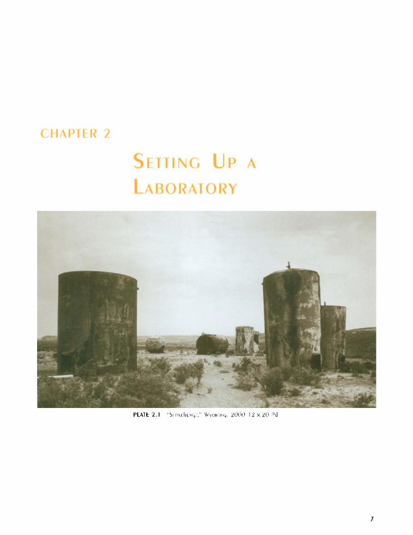
PLATE 2.1 " ~ i ~ ~ r h t ~ , ~ , ' WYC)MIN(, 2000 I 2 x LO Pd
7
8 THE PROCESS
It is best that a separate, well-ventilated space be planned for any photographic process, including platinum print- ing. For designing a laboratory, the following guide is recommended: Kodak: Building a Home Darkroom (Publication KW-14, 1986). Calumet Photo, Inc. has extensive choices for sinks, plumbing, filters, tempera- ture-control units, and exhaust systems. (Source: CPI) ’
When designing modifications to a typical photo- graphic laboratory for the purpose of platinum and palladium (Pt/Pd) printing, the decision must be made as to whether silver or color printing is contemplated for the present or future. If not, considerable changes in the design normally recommended for a darkroom may be incorporated.
Most significantly, unless photomechanical enlarge- ment of negatives is planned, safelights or an enlarger are not needed. Because the actual exposure is best done in another space, the “wet” area of the laboratory can be mostly occupied by the working sink, designed to accommodate the largest negatives and prints you think you might make. (Plan ahead; do not be disappointed when your sink will not take the 12 x 20 trays.) An adequate flat surface for coating the platinum and/or palladium solutions onto the paper should also be set aside in this room.
THE WET SPACE AND COATING AREA
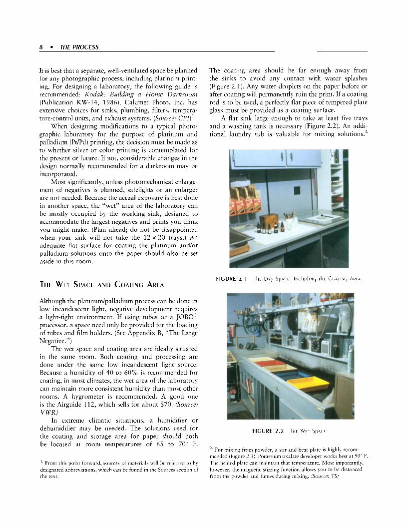
The coating area should be far enough away from the sinks to avoid any contact with water splashes (Figure 2.1). Any water droplets on the paper before or after coating will permanently ruin the print. If a coating rod is to be used, a perfectly flat piece of tempered plate glass must be provided as a coating surface.
A flat sink large enough to take at least five trays and a washing tank is necessary (Figure 2.2). An addi- tional laundry tub is valuable for mixing solutions.2
Although the platinudpalladium process can be done in low incandescent light, negative development requires a light-tight environment. If using tubes or a JOBO’K processor, a space need only be provided for the loading of tubes and film holders. (See Appendix B, “The Large Negative.”)
The wet space and coating area are ideally situated in the same room. Both coating and processing are done under the same low incandescent light source. Because a humidity of 40 to 60% is recommended for coating, in most climates, the wet area of the laboratory can maintain more consistent humidity than most other rooms. A hygrometer is recommended. A good one is the Airguide 112, which sells for about $70. (Source: VWR)
In extreme climatic situations, a humidifier or dehumidifier may be needed. The solutions used for the coating and storage area for paper should both be located at room temperatures of 65 to 70’ F.
FIGURE 2 . 2 Tlir Wrr S P A C E .
, -. For mixing from powder, a stir-and-heat plate is highly reconi- mended (Figure 2.3). Potassium oxalate developer works best a t 90- F. The heated plate can maintain that temperature. Most importantly, however. the magnetic stirring function allows you to be distanced from the powder and fumes during mixing. (Source: TS)
’. From this point forward, sources of materials will be referred to by designated abbreviations, which can be found in the Sources section of the text.

light-blocking drapery can be constructed. Then, if the exposure unit is on a timer, additional prints can be coated while another is “cooking” under the light source.
This drying and exposure room is the best place for handling negatives. A light table and densitometer can be situated here, as well as a vault for storage of negatives. Fiberglass drying screens and a retouching table can also be located in this room (Figures 2.4 and 2.5).
I use both sides of the film holder for identical exposure of each image. To supply “insurance” in
Two light sources are recommended: a set of 40-watt bulbs at least 4 feet from the coating area and devel- oping trays, and a standard fixture with adequate wattage to view prints after development.
Because most of your time in the darkroom will be spent standing, purchase antifatigue rubber mats.
THE DRYING AND EXPOSURE AREA
Ideally, the working areas should consist of two separate rooms. Practically, many do not have the available space or means to construct such a facility. A compromise can be achieved by dividing the laboratory into two distinct areas, by utilizing a room divider, for example. The following recommendations are based on “ideal” circumstances.
Drying is usually done with a hair dryer. Because particles of the coating may conceivably be blown into the air, a larger, more open space is recommended. Also, continuous use of a hair dryer in a confined space will alter temperature and humidity. For smaller prints, if budget and space allow, a drying cabinet is a preferable alternative. A specific paper dryer for platinum and palladium prints is available from Edwards Engineering. (Source: E E ) Also, see Chapter 10: Advanced Technique for a description of the drying apparatus.
The light source, unless well shielded, will emit ultra- violet (UV) rays beyond the print to be exposed (usually 3-15 minutes). Freshly coated paper or chemicals used for coating are best protected from UV light. Anti- actinic glasses should be worn for eye protection, and children should be kept away. (Source: PS) A curtain of
FIGURE 2.4 Tkt Llclkr T A b l F
FIGURE 2.5 T l i t DRLINC~ S C R E E I L S

10 THE PROCESS
case of a scratch, light leak, or blunder in develop- ing, I produce an extra set of negatives. The original set is stored in a fire-retardant cabinet. The extra set is kept in another building. 112 any lab, provide for escape in the everit of fire. If there are no windows, consider putting one in, covering it with thin Masonite, and keeping a tool accessible for rapid removal. If the space is later sold, the presence of a window will increase the value to a nonphotographer. For spaces in a windowless area away from the main living area, check with the fire department for remote access to smoke alarms.
M ATE RI ALS
Items needed for the lab are listed in the following sections according to where they may be purchased.
THE WET AREA
PHOTO SUPPLIER
Clean towels Clock timer Five ml measuring graduates (3) Hot plate (use wire-mesh insulator over coils if a glass container is used) Latex gloves, lightly lubricated with silicon Print tongs not previously used for other processes Sponges Stirring rods Trays not previously used for silver, at least one size larger than print paper Two-liter stainless steel or Pyrex container for developer
THE COATING AREA
ART SUPPLY
Black felt-tip marking pen Drafting tape Plastic pushpins Scissors Single-edged razor blades
PHOTO SUPPLIER
Camel hair negative-dusting brushes, 1- and 2-inch sizes
For the ultra-large camera worker, 3-inch Purdy natural bristle brushes For coating in humidity, a Richeson brush Clean blotters
PHARMACY
One-ounce dropper bottles (at least 4) One-ounce plastic medicine cups Cotton applicators Hypodermic syringes for rod coating. (In some states, you may need a prescription from a doctor. Discard the needle after securing it in the plastic cover.)
CHEMICAL SUPPLY HOUSE
Chemical balance (optional) Stir-and-heat plate (optional) Filter paper, student grade Glass funnel (for filtering metal salts) Hygrometer (Source: VWR) p H 0-14 paper strips (Sources: VWR, Ll , TS)
SPECIALTY SUPPLIER
Antistatic solution (Source: MD) Coating rods One sheet of tempered double-thickness glass pH pen (Sowce: L l ) Anti-actinic glasses (Source: Ski shop, PS)
THE EXPOSURE AND FINISHING AREA
SPECIALIY SUPPLIER
Printers' Rubylith" material (from printing shop) Step tablets (see Chapter 8: Calibration) (Sources: Dl , GAS, BS)
PHOTO SUPPLIER
Air syringe or canned air Cotton gloves
B E A U ~ Y SUPPLIER
Hair dryer (Buy a professional model. Diffuser is optional.)

GENERAL SUPPLY CONTACT PRINTING FRAMES
11 x 14 thick corrugated cardboard There are alternatives to using a contact printing frame. A vacuum easel is superior. If the light is coming from above, a heavy sheet of plate glass over foam rubber is
If you use a contact printing frame, choose one of high quality. Most frames available from photo supply houses are inadequate: The springs are not strong enough, and the inexpensive wood flakes off between the negative and glass (on the sky in the photograph, of course). The older ones are best. Check catalogues of
ART SUPPLY quite adequate.
#OOO fine camel-hair brushes Light table Watercolors in ivory, black, burnt umber (tubes) and titanium white (powder) Watercolor dish

12 THE PROCESS
FIGURE 2.6 T k f CONTACT PRINTING FRAME^
used photo equipment. Otherwise, good sources exist for new and better contact printing frames (Figure 2.6). (Sources: BS, VCS)
THE ULTRAVIOLET LIGHT SOURCE
\()I! sources, see Appendix F: Ultraviolet Light Sources for Platinum and Palladium Printing, by Sandy King.
For a more complete discussion of UV light
The light needed to convert the sensitized salt used in PdPd printing is in a rather narrow region of the UV spectrum. Light from other spectra is inadequate or useless. Frequencies of light waves are measured in nanometers. A nanometer (nm) is one-billionth of a meter. The UV spectrum is defined as the range of emissions from 200 to 400 nm, although wavelengths from 100 nm exist in a vacuum (Figure 2.7). UV light is further divided into bands of UV-A (320 to 400 nm), UV-B (250 to 313 nm), and UV-C (200 to 250 nm). The actinic conversion of the iron salts used for platinum and palladium printing occurs most often in the UV-A and the upper ranges of the UV-B spectra. Fortunately, the health hazards of UV light are less at these higher frequencies, whereas the nanometer range of UV-C and the lower UV-B is highly destructive to the skin and is carcinogenic. Equally fortunate, most of it is filtered out by the atmosphere. For personal protection, the UV sources used in platinum printing are such that severe measures need not be taken. Sunglasses used for skiing help to cut the annoying glare and filter some of the UV spectrum. However, shielding the eyes with glasses
VK””Il3 uv
100 200 250 320 380 400
Nanometers
FIGURE 2 .7 Tki U ~ T R A V I O ~ E I SPEC IRIIM. SkOwN4 r I i F A C T I N I C R A N ~ E AT Wklck P l A T l N U M A N d P A l l A d l l l M S A l T 5 A R E C O N L E R l E d
specifically designed for the UV spectrum3 is a better choice if there will be continuous contact. Further cov- ering of the light source is also advisable, particularly if others will be in the vicinity.
The following types of UV light sources are available. Most will need a printing frame or heavy glass to hold the negative and coated paper in register. Some of the more expensive commercial “plate burners” come with a vacuum easel.
THE SUN
The sun was the first light source for all photographic printing and remained so for most of the nineteenth century. Because sunlight contains all of the spectra, more portions of the sensitized salts darken to form a distinct “provisional” image. By using a hinged printing frame, one can-with practice-gauge the exposure process by opening one side of the back, keeping the negative in register. A well-made platinum or palladium print will require from 5 to 15 minutes of direct midday sun (see Chapter 6: The First Print).
Obviously, the amount and type of sunlight is contingent on climate, atmospheric conditions, season, and time of day. Although these variables are fascinat- ing while learning the P tPd printing process, eventually a more dependable source of light will be needed.
x Solar Specs”, designed specifically for protection from the UV spectrum of light, are manufactured by Psoralight Corporation. They are available in clear (10811’C) and gray (1082PC). They sell for $8.50 each. (Source: PS)

MERCURY VAPOR, METAL HALIDE, AND UV FLUORESCENT LIGHTS
This section discusses the materials available from various sources (see also Appendix F). In that section directions are included to build your own luminaire or UV fluorescent tube box (Figure 2.8).
If possible, plan the fluorescent tube box so it works by directing the light downward onto a flat surface. Either the light box can be suspended over adjustable shelves, or the legs can be modified to suit. The optimum distance from the light to the printing frame can be easily adjusted. Additional advantages are that dodg- ing and burning in can be done by placing printers’ Rubylith material on the glass. Heavy glass plates can be substituted for the printing frame. Due to uneven lighting, many homemade fluorescent light sources will produce scalloping effects on skies. Simply move the printing frame sideways every few minutes to avoid this.
It is also possible to purchase manufactured UV light boxes. Some are available with vacuum easels. Sources of well-made, professionally constructed light boxes are listed in the “Sources” section. (Sources: AR, BS, E E , PC, VCS) Sizes range from 11 x 14 to 20 x 24. Prices vary from $400 to $3,000.
COMMERCIAL PLATE BURNER
The commercial plate burners used in the graphic arts industry-if one is within your budget-are the ideal choice. (See Chapter 9: The Platinum and Palladium Print, Figure 9.17.) Many come with a vacuum easel. The light is collimated from a reflecting surface to give even distribution over the entire field. Most come with light integrators, which are timers based on units of light, so fluctuations in current do not affect printing times. They draw considerable 110-volt power and, therefore, require a separate circuit breaker. A perfect choice is the NuArc 26-1K or table 26-1KS model,4 each of which comes with a 24 x 26-inch vacuum easel, for approximately $1,500 to $2,000.
transmission densitometer. However, unless research is contemplated, a reflection densitometer is not needed, nor are the filters. After delving into Part Two: Sensitometry for the PlatinudPalladium Process, you might consider a purchase, or at least share one with a photographer friend.
Some models come with both modes, as well as a bank of filters for color separation work? Many print shops are going totally digital and are purchasing den- sitometers that link directly to computers. Therefore, there are many fine older-model densitometers on the used market. A good source is eBay (http:lliuww. eba y. corn).
There is also a separate class of densitometer that reads the UV spectrum of light. This is particularly important for photographers who develop their nega- tives in pyro, because the yellow stain does not accurately register on normal densitometers, which read the entire spectrum, negating the effect of the stain (see Appendix D: Pyro and Platinum Printing).
MODIFYING A LIGHT METER
DENSITOMETERS Using the instructions in Phil Davis’ book Beyond the Z o n e System (1998), you can convert a Pentax or
Densitometers read either transmission or reflective Minolta 1’ spot meter to both a transmission and densities. To maintain control in this costly process, reflection densitometer. many platinum printers eventually find that they need a
’. NuArc has now replaced the mercury vapor light in the 26-1K model with a metal halide bulb, calling it the 26-IKS. The 26-IK will still be made on special order and parts remain available. (Source: N A )
.’. An important consideration is the length of the densitometer’s arm. which must reach to the center of your largest negative. hfany of the less-espensive models will only read full negatives up to 8 x 10 inches.

14 THE PROCESS
INEXPENSIVE TABLE~MODEL DENSITOMETERS
Transmission densitometers costing from $400 to $1,500 are available. Some are quite flimsy. The German-made Heiland TRD 2 is both a trans- mission and reflection densitometer for $995. The measuring-throat length is four inches, which allows it to be used only with negatives 8 x 10 and smaller. (Source: VCS)
HAND~HELD DENSITOMETERS
X-Rite makes portable, battery-operated units (Source: XR):
Transmission Model 331 $1,000 Refection Model 504 $1.890
(The older 400 model may be available in the used market.)
Hand-held densitometers are quite convenient, but they come with only a 6-inch arm that makes the reading of ultra-large negatives difficult. Because of their compactness, the reading circle is quite small. At times it is hard to position the area to be read (Figure 2.9). (Source: 01)
THE PROFESSIONAL MODELS
Eseco Speedmaster densitometer leads the industry (Figure 2.9). The units come with extensive warranties, as well as an efficient customer-support service. Models starting from $500 will attach to your computer. Eseco’s table models are more expensive, but they are worth every penny. I recommend a used Model T-85D. They are made so well that if you can find a used one- particularly the TRC-60D dual model-snatch it up. (Source: ES)
Other suggested choices are as follows:
X-Rite 810 (This is a transmission and reflection densitometer that costs $3,620 new.) Gretag D-200 I1 (Made by Gretag-Macbeth, this UV transmission densitometer costs $2,663 new. (Source: GR) Optional tubes are available, includ- ing a UV head. This model reads at 373 nm.) Ortec Model 4310 UVNIS densitometer (Source: 01) X-Rite 369 (339 in Europe) X-Rite 361T transmission densitometer UV & Ortho (This comes in transmission only and costs $2,750 new. It reads at 380 nm. See also Appen- dix D: Pyro and Platinum Printing, Figure D.7.)

1 5

16 9 THE PROCESS
For the negative-positive printing process, Ansel Adams used a musical analogy to refer to the negative as the score and the print as the performance. No amount of technical skill or virtuosity can redeem a poorly written musical composition, and the same can be said for photography. In the parlance of our times, we can use the computer term “garbage in, garbage out” to convey the same meaning.
Becoming a successful platinum or palladium (PtPd) printer demands that the production of negatives be under control.’ Unless one is into more avant-garde methods of expression, or relying on a totally computer- generated negative, there are no shortcuts to this. A basic knowledge of the properties of light-sensitive materials is required. This involves a working knowledge of photographic sensitometry. While the very concept may be intimidating to some, the principles needed for the basic practice of photography are surprisingly simple.
The printing speed of hand-coated platinudpalla- dium emulsion is approximately one million times slower than modern silver paper. No practical enlarging units are capable of producing enough light to properly expose PdPd paper. It is, therefore, a contact printing process. Unless steps are taken to produce an enlarged copy negative, the size of the finished print is determined by the format of the camera used.
The PtPd process shares another characteristic common to the nineteenth- and early twentieth-century photographic printing processes. The negative densities to produce both shadow and highlight print values must be of a greater range than those required by modern silver gelatin paper. Pt/Pd paper, therefore, has a greater exposure scale (ES) than silver gelatin paper (Todd and Zakia, 1969; Crawford, 1979; Davis, 1998; Kodak, 1998).
As the print is the final product of the negative- positive photographic process, the exposure and develop- ment of the negative must be tailored to fit the exposure scale of the paper. The relative amounts of light passed through the negative during the exposure of the paper is measured in multiples or divisions of two. This concept is also used during the exposure of the negative to light,
’. As discussed in Appendix E: Crafting Digital Negatives for Contact Printing Platinum and Palladium, even if contemplating the generation of digitally enlarged negatives, the making of a good original negative is no less important. Relying on Photoshop” to salvage inadequate negatives may result in considerable loss of data as well as the need to generate artificial imagery to compensate for information lost due to improper exposure and/or development.
since camera settings of the length of exposure and aperture are spaced in the same intervals. The range of light transmitted by the shadow and highlight portions of the negative is the density range (DR).
\( 1 I I : For a full tonal range print, the DR of the negative must match the ES of the particular paper grade to be used.
An appeal: One of the pitfalls in the study of any photographic science is the tendency to produce some “techno-fascists’’ who are more interested in nianipulat- ing materials than engaging in visual expression. Photo- graphy is, however, an inexact science because of the many variables beyond our control. If we keep sight of the purpose of our endeavors-to produce photographic images by the exercise of the right side of our brain- we can allow the left side to help out without taking over.
PHOTOGRAPHIC S EN s ITOM ETRY
Photographic sensitometry is the science related to the reaction of light-sensitive materials to exposure and development. Anyone who pushes the button on a camera engages in the application of sensitometry. If one were to go into the collection archives of any great photographic museum and choose six photographers at random, the chances are overwhelming that each has mastered the sensitometry necessary for their art. As with accomplished painters, sculptors, and musicians, each has studied and become proficient in the char- acteristics of their materials, be they paint, structure, or the timbre of the musical instrument. Strangely, some photography students, particularly if they have not had some basic math and chemistry courses, are reluctant to learn the technical aspects necessary for control of light- sensitive materials. Fortunately, most young photogra- phers, as they become immersed in their forms of expression and are confronted by the cost of wasted materials, will learn sensitometry indirectly by problem solving.
The following is a rather elementary discussion of the principles of sensitometry as applied to the PtPd process. Purists may find that some of the informa- tion presented is not entirely accurate. However, photography when practiced as an art form is an imprecise science. Most of the materials and equip- ment we use are only accurate within tolerances of plus or minus 10%. (Check the guarantee of the shutter speeds of your lens.) It is our goal to control

the process to the best of our ability, so that the errors inherent in the process are not compounded. For this purpose, it is highly desirable to have a working knowledge of sensitometry.
DEFINITIONS
Average Gradient (G): One of the measurements used to determine the slope of the characteristic curve made by plotting the transmission density of a film in relation to the amount of exposure to light. Other methods used are the Contrast Index (CI) and Gamma (y) . They are discussed in the recommended texts (Davis, 1998; Todd and Zakia, 1969).
Base plus Fog ( B + F or b + f): The transmission density of portions of the negative unexposed to subject light.
Subject Brightness Range (SBR):’ The range of reflected light produced by the subject to be photo- graphed. It is generally determined by the use of a spot meter to measure the limits of textured shadow values and highlight areas. The difference is nor- mally expressed in stops or logs (multiples of 0.3). When measured as a ratio, it is referred to as the Subject-Luminance Ratio.
Density Range (DR): The transmission densities of a negative, which represent the image to be exposed to photographic paper. It is determined by subtracting the shadow density from the highlight density.
Effective Film Speed (EFS): The optimum film speed when adjusted for variations in development.
Exposure Scale (ES): When applied to photographic paper, it is the range of light needed to produce a full tonal scale print for a particular process and contrast grade. It is also referred to as exposure range (ER).
IS0 (International Organization for Standardization): A value for film speed assigned by the manufacturer relating to exposure at a given
’. The use of a spot meter to identify and place “Zones” is beyond the scope of this text. Nevertheless, unless one is photographing in a set lighting system (i.e., a studio), some method must be used to accom- modate varying lighting conditions. Most often, this involves reading selected areas of reflected luminance with a spot meter. These values are “placed” in values of black. gray, and white to plan the finished print; this is the process of p m k d i z i l t i o n . Differences in the SBR will dictate development times and concentrations so a standardized, usable negative can he made (Davis, 1998; Schaefer, 1998).
subject brightness range. Replaces ASA (American Standards Association).
Lens Flare: The effect of extraneous light within the photographic image caused by lens elements and reflected from within the camera. The flare effect, added to base fog, determines the beginning of minimum useful shadow density of a negative.
Logarithm (log): An exponent of the number 10.
TRANSMISSION DENSITIES
The amount of light passed through a negative can be measured quite simply with a traizsmission deiisit- ometer (see Figure 2.9). The portion of the negative to be read (usually a 1-mm circle) is placed over a pin- sized light source, and a button is pushed. A number is given either by dial or digital readout. Numbers are interpreted based on the Logarithmic System of Measurement.
LOII A good transmission densitometer can be obtained for the same amount as a good enlarging lens. (See Sources section.) Its use allows technical control, which greatly cuts down on the number of prints destined for the “round file.” If one delves into Pt/Pd printing for any period of time, the resulting savings will shortly pay for a transmission densitometer. For those not inclined to purchase a densitometer, a “Visual Comparison Densitometer” can be utilized. This is simply a portion of dark cardboard through which a small round hole has been punched. It is used for assessing transmission densities with a step tablet for reference (see Chapter 8: Calibration, Figures 8.4 and 8.5).
THE LOGARITHMIC SYSTEM
If DR and ES were to be expressed with actual arithmetic numerical values, such as 2, 4, 8, 16, 32, 64, 128, and so on, the numbers would soon become unwieldy. We use the shorthand system of logarithms (logs). A logarithm is a power of 10 rather than a numerical value.
For example, we know that 10 times 1 0 is 100. This is 10 squared and is expressed in logs as 10’ Also, 10 x 10 x 1 0 = 1000, which is 10 cubed, or lo3. The superscript number is the exponent or power.

18 THEPROCESS
If decimals are used to denote fractions, a number can be found to represent multiples of two:
If the number is is twice the value of 10.’ and, therefore, equals 4.
10.’ is three times the value of 10.’ and equals 8, and so on.
If we now drop the 10, logs can be expressed in a simpler manner:
the numerical value is 2.
becomes 0.3 10 becomes 0.6 10 becomes 0.9
becomes 1.2
Using this system, large numbers such as 10,000 can be expressed as 4.0, and 100,000 as 5.0. Note that to multiply or divide by 2, one simply adds or subtracts 0.3 t o or from the log.
A lens aperture or stop of fl5.6 lets in twice the amount of light as f/X. F/11 lets in half the amount of light of f/8, and so on. Thus, in photography, the word stop is also used to represent multiplications or divisions of 2.
Using this system, paper ES and negative DR can be expressed in logs. The ES of grade 2 silver paper expressed in logs is approximately 1.1, or 3 and 2/3 stops. Therefore, the shadow areas of the paper require 3 and 2/3 the amount of light as the highlights. The ES of grade 3 paper may be 0.9, which requires three ranges of stops. The DR or contrast of the negative must match these values to produce a full tonal value print.
TABLE 3 . 1 Tkt LOG E Q L ~ I V A ~ V T ~
Lon Nirmerical Value stops
0 0.3 0.6 0.9 1.2 1.5 1.8 2.1 2.4 2.7 3.0 4.0 5.0
0 2 4 8 16 32 64 128 256 512 1,000 10,000 100,000
1 2 3 4 5 6 7 8 9 10 100 1,000
THE DENSITY RANGE FOR A PLATINUM OR
PALLADIUM NEGATIVE
Platinum or palladium paper has a greater ES. The average or “grade 2” equivalent paper has an ES of 1.4 for a Pt/Pd mixture and 1.65 for pure palladium. Therefore, to make a full tonal value print, we must match the negative DR to the paper ES. As with silver printing, a less contrasty negative will require a higher grade paper, and a more contrasty negative a lower grade.3 For those new to the process, however, it is better to make a negative suitable for a middle grade of any paper and only use the other grades to compensate for the many variables in photography that may account for a less than “perfect” negative.
NEGATIVE CONTRAST VERSUS NEGATIVE DENSITY
EXPOSURE
The working negative contrast is derived by subtracting the shadow values from the highlight values. The inherent transmission density of the Estar base of a negative and the minute portions of the unexposed silver salts reduced at development is called base plus fog (B + F). This will be found at the edges outside the image frame.
Within the image area, lens flare must be added to the inherent B + F density of a negative. At the instant the image is projected onto the film, lens flare from reflections within lens elements and the camera body adds a diffuse halo of light to that of the image. The amount of lens flare is dependent on the lens and camera design. View cameras and lenses contribute enough flare that this must be taken into account when calculating exposure and development. Once the film becomes sensitized to where the silver salts become reactive to increases in light, the actual image projected by the lens begins to register, and a Threshold is reached. It is at this point that useful shadow density begins.
Base + Fog Usually 0.1 to 0.2 + Lens Flare Factor
Threshold for Shadow Density
Usually 0.02 to 0.04
Usually 0.15 to 0.25
3 . More than 1s platinum and palladium “paper grades” can he achieved by varying the concentrations of restrainer and the combinations of metal.

Since B + F and lens flare contain no information, for most imagery they are not considered in planning a print. Depending on film and development, it is not until a shadow density of 0.2 to 0.4 is reached that it becomes useful. Since this “magic number” determines printing time for both silver and platinum, it should be our goal. This is accomplished by proper exposure in the field or studio. Correcting shadow areas by altered development techniques is difficult to impossible. Too little exposure results in the valueless areas just discussed; too much will result in lengthy printing times. For the purposes of this text, we have chosen 0.3 to be an ideal shadow density.
While silver paper exposures are measured in seconds, platinum exposures are calculated in minutes. A two-stop error in the exposure of a platinum negative may easily result in a 45-minute printing time!
DEVELOPMEN]
It is in the highlight areas that negatives are “con- structed” by selective development for the chosen print media. As all photographers learn, this is accomplished by changing developing time and/or concentration.
Increasing development time and developer concen- tration will increase the transmission densities of negative^.^ The thinner shadow densities will be less affected. The more dense, or highlight, areas will be changed far more significantly. (See Appendix B: The Large Negative, and Appendix C: Some Film/ Developer Combinations to Produce a Platinum/Palla- dium Negative.)
If a film is given a series of developer/time combinations, the changes can be plotted to produce a Family of Curves (Figure 3.1).
Note in Figure 3.1 that as the development times increase from 4 to 20 minutes, the lower shadow areas remain relatively unaffected, but the more dense highlight areas change considerably. By increasing development over that usually used for silver negatives, we achieve the contrasts necessary for the PtPd negative.
THE NEGATIVE DENSITY RANGE
In addition to the advantage of faster speeds, modern films allow control over the DR by either decreasing or
4. This will be discussed in more detail in Chapters 12 and 13 of Part Two: Sensitometry for the PlatinumlPalladium Process. You may wish to peek ahead if you are curious about this phenomenon.
Film. TXT Developer: D-76
Temperature. 7 0 F
Time, (minutes)’ 4.6.9.14.20.20885‘F 2 1
1.2
0.9 2 s
0.6 $
03 p
0.0
0
3 0 2 7 2 4 2 1 1 8 1 5 1.2 09 06 0.3 0.0 Light Increase b
FIGURE 3 . 1 A FAMIIY of CURVES APPROPRIATE TO PLATINLIM/ PA[[AdIuhi PAPER ( COLIRTESV of Phil DAVIS PIOTTER P R O ~ R A M ~ )
increasing the normal development procedure. In densi- tometric terms, less development will produce a lower contrast, or average gradient. This is done to compen- sate for a subject brightness range of more contrast (from eight to 12 or more stops). Conversely, a negative made from a “flat” subject, with a range of four to six stops, can be structured to fit photographic paper by overdeveloping. This is the basis of Z o n e System photography.
. I A word about the Zone System: Ansel Adams did not invent photographic sensitometry. He and his colleagues simply implemented a language to measure the reflective values of the subject matter that will be translated by way of a negative to the reflected grays of a monochromatic photographic print (Schaefer, 1998).
In calculating negative values with a transmission densitometer, both the useful highlight (Zone VIII) and the useful shadow densities (Zone 111) are measured. After simple subtraction, the difference is determined, which represents all the intermediate values. This is the DR of the negative.
Useful highlight density -Useful shadow density = DR
While the “ideal” silver negative may be 1.4-0.3 = 1.1, the Pt/Pd negative will be 1.7 - 0.3 = 1.4. The nega- tive for a palladium print should be 1.95 - 0.3 = 1.65. Note that regardless of the process and negative requirements, the shadow densities should remain approximately the same.

20 THE PROCESS
OVER, AND UNDEREXPOSED NEGArlVES
The negatives previously discussed have proper contrast for the paper to be employed. If, in the construction of a Pt/Pd negative shadow values are overexposed, and then the film is subjected to the increased development necessary for greater contrast, the minimal effect noted by development on shadow areas will rapidly become significant. A totally dense or “bulletproof” negative may result. This negative may be worthless, even using reduction techniques. Conversely, a grossly under- exposed negative, contrary to the claims made by manu- facturers, cannot be “pushed” to the point where shadow values become adequate.
USING A PORrlON OF THE PAPER SCALE
Until now, we have been discussing the requirements to make a negative that will exploit the complete range of values available for each particular paper: the full tonal value print. For more accomplished photogra- phers, this may not be the goal, and they may plan accordingly.
Many subjects, particularly portrait subjects, can be better expressed using only a portion of the tonal scale. Platinum and, in particular, palladium are quite adap- table to images that occupy the elegant high- and mid- values that the paper is capable of rendering. For this, the DR of the negative may be less than the ES of a particular grade of platinum or palladium paper. A DR of a typical negative for silver paper (1 . l) or less can be used with exquisite results. (See Using Portions of the Paper Curve in Chapter 13: Using the Print Curves.)
EXPOSING AND DEVELOPING THE PLATINUM OR PALLADIUM NEGATIVE
Manufacturers of photographic film have determined that the brightness range of a typical outdoor subject is seven stops, which is a logarithmic value of 2.1 or a subject-luminance ratio of 128:l. When transferred to a transparent negative, the range must be compressed to match the photographic paper to be used. For modern silver paper, the compression must be extreme, down to a DR of 0.9 to 1.05, or an opacity range of 11:1 (Davis, 1998; Kodak, 1998; Schaefer, 1998). This is illustrated in Figure 3.2.
The subject is measured in stops, SBR, or subject- luminance ratio. The resulting compression of the negative is measured in stops, DR, or opacity ratio. The final print is measured in reflective density range or reflection opacity ratio.
SBR 7 (Stops)
II 111 IV V VI VII Vl l l IX
Density Range 1.05 - Opacity Ratio 11 . I
THE SILVER NEGATIVE
/ SILVER PHOTOGRAPHIC PAPER \
Note that the negative must be constructed to match the ES of silver gelatin paper. In this case, it is contrast grade 2. The reflective density5 of the final silver gelatin print is 1.8 (six stops), considerably more than can be obtained with Pt/Pd. Under certain conditions, and with toning, a silver gelatin print can be brought to a reflective density of 2.1!
For a typical platinum or palladium paper with an ES of 1.4, the required opacity range of the negative is 30:1 (Figure 3.3).
As the ES of Pt/Pd paper is greater than that of silver gelatin, a negative of more contrast is required. At a given subject brightness range, proportionately more development is needed. Because of the greater DR of the negative, the values of transmission densities are spread over a greater useful portion of the negative silver emulsion. This allows for more subtle tones to be transferred to the paper. This is seen in the final print as a smoother distribution of rnidtones and whites. Also,
‘. The reflected grays of a photographic print can also be measured with a ref7ectiiv drizsifovzefer. This machine is considerahly more expensive than its transmission counterpart. Unless one is doing studies of photographic papers. a reflective densitometer is not necessary, as the human eye is much more sensitive and can he trained to identify reflected values. For a discussion of this phenomenon, consult Chapter 8: Calihration.

SBR 7 (Stops)
111 \I \ I 1 1 \1111 I”
4- Density Range 1.4 -b - Opacity Ratio 30:l - \ THE PVPd NEGATIVE
PVPd PHOTOGRAPHIC PAPER
Reflection Density Range 1.5
Reflection Opacity Ratio 321
because of this property, the medium-low and midtones of the subject (Zones IV and V) are more accurately placed in the Pt/Pd print. (They tend to be depressed in the silver gelatin print. See Chapter 12: The Film and Paper Curves, Figures 12.14, 12.15, and 12.16.)
palladium paper are two to three stops less than that of the silver gelatin print. This characteristic is more than compensated for by the depth of the hand-coated image and the qualities described previously.
At best, the reflective densities of platinum or
N O l l : Minor White, teacher and photographer, used the term convincing black to describe maximum paper blacks. When looking at a monochromatic print, the viewer interprets all tones in comparison to the others. Thus, a well-printed black will be seen by the mind as black, even though it might register poorly on a machine (Todd and Zakia, 1969; Adams, 1981).
ZONE SYSTEM DEVELOPMENT COMPARED TO SUBJECI BRIGHTNESS RANGE
For those using the Zone System, there may be some confusion regarding the “N” designation and the SBR. With N development, N = SBR 7. Some, however, might
SBR 5 6 (Stops) -t
+- Subject Luminance Ratio 60 1 - t Subject Luminance Range 1.68 V
SUBJECTWITH LOW SBR
\ More Development (N+I)
1 THE 1.4 DR PffPd NEGATIVE . /’ -\ / Less Develonment IN-1) \
IX x XI
SBR 8 6 (Slops) b
t
b
VI VII Vlll
Subject Luminance Ratio 425 1
Subject Luminance Range 2 6
SUBJECT WITH HIGH SBR
conclude that N + 1 would be synonymous with an SBR of 6 (6 + 7 = N + 1). That is not the case. With expansion development, one zone is simply not kicked into the next. All zones are expanded proportionally. Therefore, the SBR for N + 1 development is somewhat lower than 6. If N + 1 development is indicated, the actual modification would be SBR 5.6 -+ 7. For N + 1.5,6 it would not be 5 -+ 7, but SBR 4.2 + 7.
With contraction development, the same principles apply. N - 1 development is not 8 + 7 = N-1, but SBR 8.6 + 7. An N-2 is SBR 10.5 + 7. N-3 is SBR 12 + 7. A more complete presentation may be found in Davis’ Beyond the Z o n e System (1998).
DEVELOPMENT FOR SUBJECT BRIGHTNESS RANGES
The low 5.6 SBR requires more development than the normal 7 SBR to make a negative with a 1.4 DR. In Zone System terms, this is an N + l development (Figure 3.4). The high 8.6 SBR requires less development (N-1) than does the normal 7 SBR to make the same negative. With proper technique, both extremes of SBR can be managed to produce negatives with essentially identical transmission characteristics.
‘. Because Pt/Pd negatives must be developed at a high average gradient to accommodate the high ES of the paper, unless special techniques are used, it is generally not possible to increase the slope of the curve to a full N+ 2. (For selenium toning of the negative, see the end of this chapter and Chapter 4: Chemicals.)

22 9 THEPROCESS
THE LOW SlJ6lECl BRICHINESS RANGE We have referred to platinum printing as the art of adapting today’s materials to a historical process. With all its remarkable characteristics, contemporary film does not have the silver content exhibited in older films. Therefore, many films that are perfectly adapted for modern silver paper cannot be expanded sufficiently by development to produce negatives in the 1.4 to 1.8 DR necessary for platinum or palladium printing. These films reach a ganima infinity at which further development only increases overall density rather than DR. A list of recommended films may be found in Appendix C: Some FildDeveloper Combi- nations to Produce a PlatinumPalladium Negative.
THE HIGH SU6lECT BRlGH7NESS RANGE Because of the broader scale of the negative needed, it is less of a challenge with Pt/Pd to manage a high-contrast subject by using less development. When exposing at an EFS and using diluted developer, SBR as high as 14 can be recorded on the PtPd negative (see Plate 3.2).
AVERACE GRADIENT
A most effective means of quantifying the effect of development is to calculate the slope of the film curve. As indicated in the section of definitions provided earlier,
a number of methods may be used. Comprehensive cover- age of such methods is beyond the scope of this text; however, I will make some reference to the average gradient to compare the effects of altering film develop- ment.
Increasing development time and/or concentration steepens the slope of the curve and increases the average gradient (see Figure 3.1). If one were to refer to average gradient numbers to compare slopes of the curve, a typical negative developed for silver paper would be at approximately .60. Platinum or palladium paper requires an average gradient of .70 to .SO. If one needed to tailor an overdeveloped “N + 2” negative for platinum, an average gradient of 1.10 might be needed. No film/ developer combination can accomplish this. Some cannot be developed to N + 1. Graphic reference to this will be provided in Part Two: Sensitometry for the PlatinudPalladium Process.
EFFECTIVE FILM SPEED
Manufacturers assign each film an ISO. This I S 0 is only applicable when the film is developed for a seven- stop SBR for silver gelatin paper. If the film is overdeveloped or underdeveloped to increase or decrease the slope of the curve, shadow density is also affected. It happens to a lesser extent, but since shadow

Film: TXT Developer: D-76 Time (Minutes): 4,6,14.20,20@85~ F
2 1
1 5
1 2
0 9 2 m 3
0 6 g
03:
0
v)
0 o2 30 2.7 2 4 ~ 2 1 1 1 8 1 1 . 5 1.2 0 9 0.6 0.3 0.0
EFS 640 320 160 Exposure change needed to maintain textured shadows Decrease - LIGHT - Increase
density determines printing time, small changes may be critical.
In Figure 3.5, a slightly diagonal line is plotted to identify the portion of the film curve where enough changes occur relative to light increases to cause tex- tured shadows (at about a transmission density of 0.3.). As development times are changed to compensate for various SBRs, exposure must be modified to keep shadow densities under control. This is most easily done by
assigning an EFS other than the I S 0 determined by the manufacturer.
I S 0 is set by the manufacturer at a specific SBR and development time. If either is changed, a new value of film speed, the EFS, must be used.
Overdeveloping film can increase the shadow values by more than one stop. This must be taken into account. For overdevelopment, shadow densities are controlled by decreasing the exposure. This is best accomplished by increasing the ISO. The new value is referred to as EFS. Therefore, although the I S 0 of Tri-X Pan Professional Film (TXT) is listed as 320,’ it must be understood that this value does not apply to the increased development needed for a platinum or palladium negative. For that processing, an EFS from 400 to 600 may be needed.
At a high SBR, exposure must be increased to prevent the shadows from falling on the horizontal portion of the film curve (and producing no separation of values). With TXT, an EFS of 160 may be necessary. While some films may not require such pronounced changes, the same principles apply. Over- or under- exposure by as much as one stop can significantly
’. Kodak Tri-X Pan Professional Film (TXT) has been replaced by 320 Tri-X Professional (TXP). The exposure characteristics are similar, but development times are increased. See Appendix C: Some Film/ Developer Combinations to Produce a PlatinundPalladium Negative.

24 THE PROCESS
affect the Pt/Pd image. The extent of the film speed change needed is largely dependent on the film used. (See Appendix C: Some Film/Developer Combinations to Produce a PlatinudPalladium Negative, Tables C.3 to C.12.)
\ ( ) I i A simple rule for making a platinum negative is to increase development 1.5 times over what is required of a negative for silver paper. Concurrently, an increase of EFS of 1/3 to 2/3 over the published I S 0 is required to control shadow value by reducing exposure. For a palladium negative, double both the development and the IS0 .
CHARACTERISTICS OF THE PLATINUM/PALLADIUM NEGATIVE
We have discussed some of the difficulties of making Pt/ Pd negatives and the measures that must be taken to produce them; however, when a Pt/Pd negative of the desired DR is produced, most of the other characteristics that often plague silver photographers become relatively negligible.
SHARPNESS
Many platinum photographers will eventually find that a larger camera is more suitable to their needs. Large cameras require lenses of longer focal length, frequently with extended image circles to allow for view camera movements. Unless one is willing to pay a small fortune for a monstrous piece of glass, less resolution and more aberrations are generally found in direct propor- tion to the length of the lens. Moreover, for satisfac- tory depth of field, small apertures of f/45 to f/90 are frequently used, further increasing the degree of aberrations.
\ ( ) I f : Some process lenses work remarkably well at apertures from f/64 to W128. Their maximum apertures, however, are usually quite small, in the f/9 to f/11 range, which makes focusing difficult. For my big cameras, I use a Fresnel lens. Good, inexpensive varieties can be found at Edmund Scientific (ES). Placing the Fresnel lens behind the ground glass will not significantly affect the focus at small apertures, and this will protect the glass from breakage as well.
Fortunately, with the increase in negative size, less enlargement is practiced, negating the visual effects of these disparities-particularly when the final presenta- tion is in one of the nonsilver processes.
Pt/Pd printing-when practiced as a hand-coated, print-making process-produces an image that becomes wedded to the structure and characteristic of the paper. Sharpness, or lack thereof, is not generally noticeable, except through magnification.8 Even if it is, the other qualities previously described do not rely on mechanical sharpness to convey a message.
GRAININESS
At the smaller apertures needed for large format photo- graphy, a faster film is needed if one wishes to avoid longer exposures and the resultant reciprocity failure. For cameras larger than 5 x 7 inches, higher speed films of I S 0 320 or greater are desirable. The structure of the silver halide emulsion in films of higher I S 0 affects the graininess. Also, the high-energy developers and increased concentrations and time we must use to produce a platinum negative further increases the “grain.”
With a hand-coated process, the increase of size and clumping of silver particles responsible for an increase in film grain are simply not discernible under normal view- ing conditions. Visible film grain is also related to the degree of enlargement. Pt/Pd printers do not enlarge, unless larger negatives are generated from smaller negatives. Even in that case, the qualities described in the previous paragraph more than compensate for the graininess produced by the negative.
Graininess from the negative should not be confused with granularity found in the platinum or palladium emulsion. This can be a serious problem, to the point of degrading certain images. Methods to avoid this are covered in Chapter 7: Choose Your Method, Chapter 10: Advanced Technique, and Chapter 11: Problems.
SCRATCHES AND PINHOLES
It is best to avoid scratches and pinholes by handling film carefully and keeping the camera as free of dust as possible. However, if either a scratch or a pinhole occurs, one learns to further appreciate the many advantages of contact printing. Since these defects will not be enlarged, treatment with Crocein Scarlet will take care of all but the most severe. (Its use is discussed in Chapter 10: Advanced Technique). When using photomechanical
If negatives are to he enlarged, either by photomechanical or digital means, ir may be necessary to avoid some of the lens aberrations characteristic of siiialler apertures. A compromise may be necessary to plan less depth of field in favor of choosing an aperture closer to the optimum for a particular lens (usually f/16 - f/32).

enlargement techniques requiring multiple steps, the problem may be acute, as each step adds a new layer of blemishes.
THE CIRCLE OF CONFUSION
The ability to discern “sharpness” and “grain” is related to the ability of the naked eye, at a certain distance, to distinguish a circle from a point. This is called the circle of confusion (Stroebel, 1993). As the distance from the viewer to the print increases, this distinguishing ability is diminished. Studies have shown that, in an exhibit space, viewers tend to establish a distance twice that of the diagonal dimension of the artwork. It is from this posi- tion that (it is hoped) the content of that work becomes more significant than the degree of technical perfection.
THE USE OF SELENIUM TONER TO INCREASE NEGATIVE CONTRAST
Negative DR can be increased by 0.1 to 0.3 by selenium toning,’ without an appreciable effect on shadow den- sity. This may be enough to bring a marginal negative into platinum range, or move a Pt/Pd negative into palladium range (see Plate 3.3).
After washing, immerse the wet negative in a 1:3 solution of Rapid Selenium Toner to distilled water. Agitate constantly for 5 minutes and rewash. Take care before subjecting an unread negative to selenium toning. A wet negative viewed through a ceiling bulb looks a lot thinner than it will eventually test after dry-down. Injudicious selenium toning may blow the negative even beyond the capabilities of palladium paper. Until consi- derable experience is obtained, it may be more prudent to study the dried negative before selenium toning. Simply soak it in water for 5 minutes before toning. The effect may not be as pronounced as immediately following development, but it is much more judicious.
THE PYRO NEGATIVE
\ ( ) I ! See Appendix D: Pyro and Platinum Printing.
The use of pyrogallol for developing negatives is at least as old as the platinum process. The yellow-green
stain produced is approximately the same as the complementary color used to selectively block transmis- sion to the blue-sensitive paper. Consequently, negatives of much less development can be used over their unstained counterparts. Since less density is required in highlight areas, graininess is diminished. Pyro negatives are also said to produce more edge sharpness.
The negative, when developed in a solution con- taining both pyrogallol and the conventional Metol developing agent, is doubly developed. The transmission density is produced by both the selective reduction of silver particles as well as a “tanning” effect produced by pyrogallol. In the thinner areas of the negative, little effect is noted, but as the midtones and highlights are reached, the yellowish stain adds as much as 50 to 100% more effective transmission density (Hutchens, 1991).
One must bear in mind, however, that a properly developed negative made by more traditional means may accomplish the same purpose. Nevertheless, in low SBR, the pyro stain may more efficiently bring a nega- tive into the Pt/Pd printing range. In an extreme N+2 situation when even more strenuous development may be required, pyrogallol staining may solve the problem.
The final assessment as to the superiority of pyrogallol must remain in the hands of the photogra- pher. For some, the use of the pyrogallol negative is the route to effective image making.
However, those just investigating the Pt/Pd process are urged to first spend sufficient time learning to effectivelyuse one of the appropriate filddeveloper combinations ’” (see Appendix C: Some FildDeveloper Combinations to Produce a PlatinudPalladium Nega- tive). Once an effective filddeveloper combination is found using standard developers, pyro can be investi- gated for comparison. Many Pt/Pd printers, the author included, have found that with Pt/Pd printing, many of the reported advantages of pyro development can be duplicated using more traditional methods.
As Rob Herbst states in Appendix D: Pyro and Platinum Printing, “Stain is your friend. Stain is your enemy.” Pyro development for a Ptl Pd negative requires a hit more finesse than that for a silver print. A slight error in staining can raise the ultraviolet (UV) blocking effect of shadow density to printing times of more than an hour.
111.
’. Selenium is a tosic heavy metal. Use only in a well-ventilated space. The use of ruhher gloves or print tongs is strongly recommended.

This page intentionally left blank

PLATE 4.1 6 A I C k A w A N A BAY h l r h REFds, ONTARIO. C A N A d A 1 9 9 7 12 x 20 I N C ~ Pd
27

28 THE PROCESS
THE REASONABLE AND PRUDENT USE
Chemical safety is based on a reasonable and prudent use of chemicals. Platinundpalladium (PtPd) printing is one of the safest of all the photographic processes. The chemicals used in significant quantities are inorganic salts, oxalates, and high dilutions of weak acids. More hazardous compounds are used in infinitesimal amounts, most often measured by eyedropper. For the most dangerous substances listed in the literature, satisfactory substitutes exist.
THE MATERIAL SAFETY DATA SHEET
Each chemical is accompanied by a Material Safety Data Sheet (MSDS). Although the information therein is of considerable value to the PdPd printer, i t is f rom the indiscriminate use of this data that many of the scare tactics about our process have been formulated. If each chemical used in Pt/Pd photography is intelligently analyzed with photographic practice in mind, safe guidelines can be set up individually without a “one solution fits all” mentality.
WARNING AND DISCLAIMER
The following material in no way constitutes a recommendation to deviate from standard regulations and requirements for the safe handling of chemicals. I t represents the author’s own personal philosophy and procedures. All of the chemicals described in this text can be potentially harmful, particularly if misused. The reader is advised to inform him or herself in advance of any dangers and to take appropriate precautions. Such information can be obtained from the MSDS of each substance or by consulting any reference manual on che- mical safety. Furthermore, for any person to be in contact with these chemicals, a thorough review of personal health should be obtained to rule out allergies and to be aware of possible teratogenic effects in the case of pregnancy. With chronic smokers, many of the natural defense mechanisms of the body are seriously impaired, aggravating the effects of exposure to chemicals. It is also assumed that children and irrespon- sible adults will be shielded from contact with these agents.
The author hereby denies liability for any subse- quent injuries resulting from the use of the information contained in this text.
Four categories of potential hazards are outlined in
Health: Toxic effects of a substance if inhaled, ingested, or absorbed
Flammability: Tendency of a substance to burn
Reactivity: Potential of a substance to react violently with air, water, or other substances
Contact: The danger a substance presents when it comes into contact with skin, eyes, or mucous membranes
Of these categories, the platinum printer will be most concerned about the following. A numbering system from 0 to 4 is used in MSDS data to designate the degree of hazard.
the MSDS information:
HEALTH
0. No hazard 1. Slight hazard 2. Moderate hazard 3. Severe danger 4. Deadly, life threatening
CONTACT
0. No contact hazard to normal, healthy tissues 1. Slight hazard: irritant to sensitive tissues 2. Moderate hazard: irritant to sensitive tissues;
3. Severe danger: destroys tissue, including skin 4. Extreme danger: life threatening
damages tissue
In addition, the chemicals are indexed by relative toxi- city: The lower the LD50 (which is the oral dose that will kill 50% of laboratory animals) for a particular chemi- cal, the more the potential risk.
Here is a helpful classification and summary of the MSDS system and categories incorporating the various MSDS ratings for chemicals:
MSDS 1-Those that, under normal usage, are basically harmless
MSDS 2-Those that require some degree of caution in handling
MSDS 3-Those that can cause considerable harm through some or all the routes by which a chemical can enter the body
MSDS 4-Those that are extremely dangerous; it is recommended that they not be used in the PdPd process

As each chemical group is discussed in this text, these classifications will appear with pertinent informa- tion and precautions in italics. If questions exist, the reader is encouraged to check the MSDS data for specific chemicals.
M o N oc H RO M AT I c AGENTS (MSDS
FILM DEVELOPING 2)
Although not specifically part of the PtRd process, some discussion is in order regarding monochromatic film developers. It is beyond the scope of this text to list all of the organic agents used for this purpose; therefore, generalities must be made.
The most common agents are Metol (Elon, mono- methyl para-aminophenol sulfate), and Hydroquinone (para-hydroxy benzene). Many similar phenolic and benzene compounds are also found in developing agents.
As a group, monochromatic film deueloping agents represent more cause for concern than most of the chemicals used in the PtlPd process. Contact with skin should be avoided. When using the slightly alkaline film developers, surgical gloves are quite effective (see Appendix A: The Chemistry of Developing, Contrast Control, and Clearing Processes). I t is entirely possible, following continued skin contact, that contact dermatitis may develop, which may necessitate a change to other agents. Full-time workers should consider the use of tube or JOBO methods (see Appendix B: The Large Negative).
In some literature, pyrogallic acid (pyrogallol, 1,2,3-trihydroxybenzene) has been listed as more toxic than it may actually be. Utilize the same precautions as listed previously. A Rollo Pyro is now available from Bostick and Sullivan (BS) , which can be used with a JOBO processor. See Appendix D: Pyro and Platinum Printing for pyro formulas.
For a brief description of the chemical reactions involved in the Ptffd process, see Appendix A: The Chemistry of Developing, Contrast Control, and Clear- ing Processes.
ABOUT MEASUREMENT UNITS
The Pt/Pd processes were developed in England, so it is natural that many measurements are expressed in the British as well as U.S. units of measure. Some
formulas have retained the British units; however, for ease of mixing and determination of concentrations, the metric system is superior and has been used here whenever possible. A short guide to the more common conversions follows (Anchell, 1994).
WEIGHT VOLUME
16 ounces = 1 pound 453 grams = 1 pound 2.2 pounds = 1 kilogram 1 ounce = 28.35 grams 1 gram = 0.03527 ounces
32 ounces = 1 quart 1 quart = 0.95 liters 1 gallon = 3.78 liters 1 ounce = 29.5 milliliters
TEMPERATURE C =CELSIUS F = FAHRENHEIT
Boiling (at sea level) 100' 212" Freezing 0" 32
20' 6 8' 38" 100'
(C x 9/5) + 32 = degrees F (F - 32) x 5/9 = degrees C
THE METRIC SYSTEM
The metric system encompasses measurements of weight, volume, and length. All terminology is interrela- ted and expressed in units of 10. In the case of distilled water, for example:
1 cubic centimeter (cc) of distilled water = 1 milliliter (ml) and weighs 1 gram (8) 1,000 g = 1 liter ( I ) and weighs 1 kilogram (kg) 1 g or 1 ml = 0.001 or 1/1000 of a liter or 0.001 of 1 kg
A simple but effective way of determining concentra- tions is to work in units of 1,000 rnl (1 liter). Realizing that a percent is units/100, simply put the weight in grams of volume in milliliters over 1,000, and remove one zero from each side of the equation. For example:
1000 g = 1000 ml
This method, although not exactly precise, is
For a more chemically correct method, the for- adequate for most photographic processes.
mula is:
weight of compound total weight of solution
% = 100 x
'. As solutions are mixed, variations between volume and weight measurements occur; however, for most photographic processes they are negligible.

30 THEPROCESS
PURITY OF CHEMICALS AND WATER
Chemicals are available in differing grades of purity. For coating paper and toning techniques, reagent or analytic grade should be used. It is recommended that these chemicals be obtained from specific suppliers of plati- num and palladium materials (see Sources section for suggestions). For the chemicals used in larger quantities for developing and clearing, technical grades may be used.
Distilled water should be used for the mixing of coating agents and developers. If tap water is relatively free of impurities, it can be used for the clearing agents and wash. If you have significant impurities in your water supply, consider a water softener, as conventional photographic filters may not do the job.
SIZING OF PAPER
Presently, a wide choice of papers are available that do not need sizing (see Chapter 5 : Paper). For those who wish to experiment with papers not completely amenable to the Pt/Pd process, many undesirable char- acteristics can be overcome with starch or gelatin sizing. The starch used is simple arrowroot starch (MSDS 1).
For gelatin sizing, Knox or Bloom gelatin is used. (See Appendix G: Elements of Platinum and Palladium Printing.) Be aware that gelatin can burn severely if allowed to contact skin when at high temperatures. More significantly, Formalin is used for a final “fix” to harden and make the gelatin impervious to microbial growth.
In some cases, alum can be substituted for Formalin in the sizing process. (See Platinum 6 Palladium Printing, 1st edition, Appendix E: Sizing of Paper.)
FORMALDEHYDE 23% (FORMALIN) (MSDS 3-4) Formaldehyde is extremely caustic to the skin and respiratory tract.
SOLUTIONS USED FOR PAPER COATING, DEVELOPING, AND CLEARING
For those unfamiliar with the PdPd process, see Table 9.1: Algorithm for Platinum and Palladium Printing for a brief summary of steps in the making of a platinum or palladium print.
THE COATING SOLUTIONS
Usually for the paper coating, equal parts of sensitizer (ferric oxalate) and metal salts are combined. In addi- tion, a restrainer (oxidizer) may be incorporated to control contrast.
The most common method is to place minute amounts of oxidizer (restrainer) into a second solution of sensitizer (A+B or Ratio Method). (See Chapter 7: Choosing Your Method.) By varying the proportions of pure ferric oxalate (A) and a similar solution with restrainer (B), more than 13 contrast grades are possible for each metal or combination. One may also control contrast by putting the restrainer in the developer, thereby eliminating the use of sensitizer B (Dichromate Method). Recently, another contrast control agent, sodium hexachloroplatinite (Na2 or Pt IV) has been added to the list of oxidizers amenable to the PdPd process. Its use will be discussed in detail throughout this text.
The metal salts (C), are either platinum, palladium, or a mixture. Most “platinum” prints made today are actually a mixture of platinum and palladium. Pure platinum salts are not entirely amenable to a ferric oxalate sensitizer, but they may work better with ferric ammonium oxalate in the presence of moisture. Since print tone or color is largely determined by the choice of developer (see Chapter 10: Advanced Technique), for most practical purposes, a mixture of platinum and palladium salts will be indistinguishable from a pure platinum print. A further advantage of combining metal salts lies in the cost of materials: Depending on market prices, palladium is usually approximately 1/4 to 1/2 the price of platinum.
A print made with pure palladium is unique in tone and character. It is best developed in potassium oxalate and is most responsive to restrainer placed in the sensitizer. In this text, only pure palladium printing and 50% combinations of platinum and palladium will be covered in detail. Reference is made to varying proportions of platinum and palladium in Chapter 10: Advanced Technique.
OXIDIZING AGENTS*
Oxidizers are used in the PdPd process to decrease the exposure scale (ES) of PdPd or palladium prints.
Much of this discussion is derived from Contrast Control for Iron Based Printing Processes by Howard F. Efner (2002). It is presented with his kind permission.

HYDROGEN PEROXIDE
Hydrogen peroxide 3% can be used in the PtPd process. Unfortunately, it is unstable in solution, slowly decom- posing to water. It can be used in small amounts to “clean up” a ferric oxalate solution by reoxidizing trace amounts of ferrous oxalate back to the ferric form. It is not recommended for general contrast control.
CHLORATEES Potassium chlorate is a powerful oxidizer, which is added in minute quantities to the ferric oxalate coating sensitizer B (either 0.6% or 1.2%). In the A+B Ratio Method, by changing the relative amounts of ferric oxalate A (no chlorate) and ferric oxalate B (miniscule amounts of chlorate), precise contrast control is possible.
Unfortunately, chlorates act differently based on the size of the cellulose paper fibers. In higher concentra- tions, graining or flocculation of the smoother tonal areas of the image may be noted. When less chlorate is used in paper grades of longer exposure scales, the graining may be negligible, particularly in a pure palladium print. When one attempts to use a negative of less contrast (typically a negative made for the silver gelatin process), the amounts of chlorate required can badly deteriorate an image.
DICHROMA TEES
Potassium dichromate and sodium dichromate are effective oxidizers. Unfortunately, they are unstable in the coating solution. They are added in varying con- centrations to different containers of potassium oxalate developer. This necessitates a different developer for each contrast grade desired. As with the chlorates, larger concentrations will flocculate the final image.
SODIUM CHLOROPLATINATE
Sodium chloroplatinate (Na2PtCl6) differs from the potassium chloroplatinite (K2PtC14) used to make a platinum or Pt/Pd print.
Richard Sullivan of Bostick and Sullivan noted the mention of sodium chloroplatinate while perusing the historic literature. Although this form of platinum salt is not suitable for providing the platinum to make a print, it showed promise as an oxidizing agent. He named it NaZ3 because the sodium form is used rather than the potassium as with traditional platinum salts. Although not amenable to platinum
3. The chemically correct term for this compound is sodium hexachloroplatinate IV. Perhaps a better abbreviation would be Pt IV.
printing, it was found to be an effective source of oxidation in pure palladium printing. (See Chapter 8: Calibration for the use of Na2 and Appendix A: The Chemistry of Developing, Contrast Control, and Clearing Processes for the chemical reactions involving Na2.)
DEVELOPERS
Several developing agents are available, including potassium oxalate (warm tones) and ammonium citrate or Sullivan’s cold tone developer (cooler tones). In some processes, ethylene diamine tetraacetic acid (EDTA) and sodium citrate can be used for development.
CLEARING AGENTS
Most early literature discusses hydrochloric acid as a clearing agent; however, because of the danger in handling this caustic material, I believe there are satisfactory alternatives.
Dilute solutions of phosphoric, oxalic, and citric acids will be discussed, but further research into the effectiveness and archival properties of sulfiteEDTA makes them, in my opinion, the clearing agent of choice for most papers.
COAT I N G So LU T I o N s
SENSITIZERS (MSDS 2.3)
FERRIC (FERROUS) OXALATE 27% FE2 ( c 2 0 2 ) 3 . 5 H 2 0
FERRIC AMMONIUM OXALATE ( N H ~ ) T F E ( C ~ O ~ ) ~ . H 2 0
(MALDE/WARE PROCESS, ZIATYPE)
Sensitizers are salts of unstable iron compounds, some containing oxidizing agents. Although it is possible to make your own ferric oxalate it can be a hazardous procedure. I t is safer to buy it already formulated. The salts can be quite toxic, but they are used in minuscule quantities;
For making your own ferric oxalate, 30% hydrogen peroxide H202
is used. It is highly reactive in concentrated form. Do not use it. Purchase ferric oxalate already formulated from a platinum supplier. Hydrogen peroside is also used at 3% concentrations for contrast control. At this concentration, it is quite safe. Buy it premised from the pharmacy.
4.

32 THE PROCESS
consequently, absorption of significant quantities through any route is unlikely. The salts can also be purchased premixed, but their shelf life is limited. In powdered form, they last indefinitely.
Solution A: ferric oxalate 27%
Ferric oxalate 15 g Oxalic acid‘ 1 g Water at 150 F 55 ml
Continuous mixing and heating may be required.
In a ferric oxalate solution, there are always some molecules of ferrous oxalate present. In “fresh” ferric oxalate, the ferrous portion is minimal; nonetheless, even infinitesimal amounts can reduce an equal amount of metal salt to create “fog.” (See Chapter 11: Problems.) This can usually be controlled by adding a trace of oxidizer. With age, however, the ferrous oxalate increases to the point that the solution should be discarded.
To test for the presence of ferrous ions use the following procedure (Photographer’s Formulary).
Place two crystals of potassium ferricyanide in a test tube with 2 ml of distilled water. Stir until dissolved. In the darkroom under a red light, add one drop of the ferric oxalate solution. Hold it up to the red light in such a way that you can see through it. If there are no excess ferrous ions, you will observe only a slight darkening. If excess ferrous ions are present, the test mixture will turn very dark or black. Step out of the darkroom and quickly look at the test container. The solution should appear yellowish-brown to orange. If a trace of ferrous oxalate is present, it will look green. When more ferrous ions are present, the color goes to blue; the deeper the blue, the poorer the quality of ferric oxalate.
Solution B: ferric oxalate with 0.6% restrainer (oxidizer)
Solution A 55 nil Potassium chlorate (KC103) 0.33 g (will need
custom scaling)
This formula makes 0.6% potassium chlorate. It is used for Pt/Pd printing. Pure palladium has a longer exposure scale. If you want to simulate the PdPd
’. I use 2 g of oxalic acid per 55 ml. When mixing ferric oxalate from powder, the extra oxalic acid facilitates getting the powder into solution. Also, it decreases printing time. (Be careful of fog.)
sensitometry, use 0.66 g for a 1.2% solution (BS ferric oxalate No. 2 Pd). If you want to take advantage of the longer printing scale, as I do, use the 0.6% solution (BS ferric oxalate No. 2 Pt).
THE RESTRAINERS (OXIDIZERS) (MSDS 3.4)
POIASSIUM CHLORAIE KC LO^
POTASSIUM DICHROMATE K 2 C R 7 O 7
SODIUM DICHROMATE N A 2 C R 7 O 7
SODIUM CHLOROPLAIINATE ( N A 2 P I C L b )
The restrainers are powerful oxidizing agents used for contrast control in the coating material or developer. They are highly toxic by ingestion or inhalation. Under certain conditions, they can be extremely reactive and explosive. They are used in minute quantities and are highly diluted in the Ptl Pd process (0.6 to 1.2%). I t is advisable to purchase restrainers in premixed liquid form or to have the powder quantities preweighed and placed in gelatin capsules by a lab utilizing a ventilation hood. Restrainers are a human carcinogen. They caii be fiital if inhaled.
THE METAL SALTS (MSDS 2.3)
POIASSIUM CHLOROPLATINIIE 20% K 2 P ~ C ~ 4
SODIUM TEIRACHLOROPALLADAIE I 5% N A ~ P D C L ~
PALLADIUM CHLORIDE P D c L 2
Platinum and palladium are salts used in con- junction with a sensitizer for coating. Use the same precautions as listed with the sensitizers. When drying in heated air, avoid close contact. Note the recommended commercial print dryers in Chapter 2: Setting Up a Laboratory, or see the drying apparatus in Chapter 10: Advanced Technique.
Solution C
To make 20% potassium chloroplatinite, mix: ‘ Distilled water a t 100‘ F 50 ml Potassium chloroplatinite powder 10 g
’. Technically, this is not a 20% solution; however, it has been listed as such in the literature for over 100 years-and it works.

Or.. . To make 15% tetrachloropalladate, mix: Distilled water at 100“ F 55 ml Palladium chloride 5 g Sodium chloride 3.5 g
Both platinum and palladium salts are mixed to a near-saturated solution. Prior to their use, do not stir or shake the solution, as particulate metal may be transferred to the image.
THE USE OF METAL UTENSILS
It is difficult to determine when and where the caveat that metal shall not be in contact with platinum materials started. The type of metal is not specified; nonetheless, the same adage is repeated in much of the platinum literature. It undoubtedly refers to the potential for iron and platinum metals to go into solution and plate onto one another.
Today, most good laboratory equipment is made of stainless steel, a substance considered essentially inert for many photographic processes. With high-quality stainless steel, if any metallic elements were to escape the bounds of your utensils, they would be in such infinitesimal amounts as to be insignificant. I have used the same stainless steel beaker and brushes with metal ferules for 20 years. I suspect that they are well plated with platinum and palladium. I would not, however, push the phenomena by developing prints in stainless steel trays. I use plastic trays or those of baked enamel.
DEVELOPERS (MSDS 1 ~ 2 )
FORMULAS
POTASSIUM OXALATE K2C202 (MSDS 2.3)
Potassium oxalate is mixed from powder to 35% solution. In some literature, its use has been discouraged because of toxicity; however, with normal precautioiis, it presents no inore hazards than the inore-benign developers. This chemical occurs naturally in leafy green vegetables, partic- ularly spinach. However, decomposition products of carbon monoxide and carbon dioxide may be formed. Use only in a well-ventilated area. Skin contact should be kept to a minimum.
AMMONIUM CITRATE (NH4)2HC6H507 (MSDS I )
SODIUM CITRAIE C 6 H 5 N ~ 3 . 2 H 2 0
Since relatively large amounts (1 to 3 liters) are used, take precautions regarding skin contact and inhalation. Use in well-ventilated areas. A stan- dard surgical mask will not prevent inhalation of vapors from exposed liquid form.
Potassium oxalate Potassium oxalate 66 g Distilled water a t 120” F
Potassium oxalate Distilled water a t 120 F
200 ml
454 g (1 Ib) 1350 ml
O r . . .
Developer is never discarded. The developer that is absorbed by the paper or evaporated is simply replaced with fresh developer solution. As with sherry, a portion of the original mixture, no matter how old, remains. Paul Anderson used “30-year-old’’ developer. My developer’s age is over 20 years. To account for water lost due to evaporation, occasionally add distilled water when crystallization appears. This may also help to prevent streaking of black tones into highlight areas. (See Chapter 11: Problems.)
Ammonium citrate
(Available in solution from BS) Ammonium citrate 250 g Water a t 15‘ C 100 ml Make syrupy, add to 900 ml water
Sullivan’s cold bath developer
(Available as solution) Potassium oxalate 150 g Potassium monobasic phosphate 75 mg Water to make 1 liter
Sodium citrate, potassium sodium tartrate, and sodium acetate are also used as developers (Nadeau, 1994).
An interesting observation is that image color is influenced by the content o f metallic ions in the developer. If, for example, a Pt/Pd print is made following a previous session of palladium printing, the image color will be slightly warmer. The reverse is true going from platinum to palladium. Some may object to this. I find it desirable. Pt/Pd is a printmaking process. I limit my work to editions of SO. Each print is identified and distinct. I would not prefer the mechanical perfection obtained by some other photographic processes.

3 4 THE PROCESS
THE PH
The pH is defined in simple terms as the acidity or alkalinity of a solution. The p H progresses from the most acid (1) to a neutral (7). Alkalinity is expressed to the extreme of 14.
PH 1 PH 7 PH 14
Acidic - Neutral - Alkaline
Each whole number change represents an increase or decrease of a factor of 10. The issue of pH cannot be ignored, as many reactions in the Pt/Pd process are altered by changes in pH. It is recommended that pH 0-14 paper strips be used to monitor and record the pH of solutions.
' ~ t It is possible that, with an alkaline developer, insoluble crystals of iron hydroxide may form to participate on the paper. For that reason, it is wise to monitor the p H of the developer, particularly if stains are found on the print following clearing. Citric or oxalic acid can be occasionally added to bring the developer to a slightly acidic state. For those who use an acidic alum-rosin-sized paper, the internal paper sizing in the developer usually keeps it at a pH of 6.5.
FILTERING OF DEVELOPER
Eventually, if developer is reused, crystals and undis- solved debris can form in the solution. If the developer is stored for a period in a glass jug, particularly at cooler temperatures, large crystals may form that cannot be removed through the opening. As developer is close to a saturated solution, this is to be expected. It is not significant. Try heating and agitation. Eventually, pour off the liquid into a new container. The sludge can now be dissolved in a weak acid (clearing bath) and dis- carded. Some PtPd printmakers occasionally filter the developer before use. In that case, a coarse coffee filter can be used. Instead of filtering, I simply carefully decant at the first print of the day and throw out the sludge.
TEMPERATURE OF DEVELOPER
The early literature refers to a heated developer. I have found that with potassium oxalate a temperature of 90" F results in a quick reduction of the image with a pleasing tone. Regardless of the temperature selected, it should be consistent; higher temperatures result in faster
printing speeds and a slight loss of contrast. The reverse is true for developers used at room temperature. Image color can be greatly modified by developer temperature (see Chapter 10: Advanced Technique). Care should be taken with extreme temperatures. Cold developer may result in granularity. Hot developer (over 120" F) can affect the internal sizing of some papers and produce mottling of tones.
CLEARING AGENTS
Clearing agents release and dissolve the remaining iron salts from the paper. Failure to adequately clear paper results in a yellowish stain in white areas. This represents contamination and will shorten the archival life of the print. See the section on fog versus stain in Chapter 11: Problems.
CHOOSING A CLEARING AGENT
Choosing a clearing agent is best done by testing with a step tablet (see Chapter 8: Calibration). Pay particular attention to the clearing action with coating that contains little or no restrainer; it is the last to clear. Palladium is more difficult to clear. Use only enough concentration and time to allow the whites produced by the step tablet to match the uncoated paper white. Too much of either may cause bleaching of the image, particularly with pure palladium.
ETHYLENE DIAMINE TETRAACETIC ACID AND THE
SULFITES (MSDS 1 )
EDTA in a 3 to 8% solution is a chelating agent used for developing and clearing. It is found in some foods. Contact with powder to eyes or inhalation can he harmful. Ingestion of large quantities can he harmful.
hypo clearing agent. It should be mixed to a 20% solution with water. Avoid skin contact with powder.
Sodium sulfite (Na2S0,) is the active ingredient in
When clearing with the EDTMsulfite agents, the print should be rinsed in a bath of warm running water before clearing. After that, the procedure for any of the clearing agents is similar, requiring three baths of 5 minutes each with intermittent rinses. When the first bath becomes cloudy (after not more than two or three prints), discard, mix fresh agent, and move to the third position.

THE DILUTE ACIDS (MSDS 243)
The acidic clearing baths are composed of highly diluted acids. All are hazardous in concentrated form and should be handled carefully. However, if proper precautions are taken with the acids, the differences are largely academic. Even hydrochloric acid, once mixed to its 1 % concen- tration, is relatively safe.
tion. Take reasonable care. Add acid to water and protect eyes when mixing. I f some acid gets in contact with skin or clothing, immediately rinse. Seventy-five percent phosphoric acid solution will not burn unless held against skin for an extended period. The 2 to 4 % solution used for clearing is safe unless carelessly used.
Oxalic acid (C2H204) is mixed from powder to a 1 % solution for clearing. I t is also used in minute amounts in ferric oxalate sensitizer. The powder is relatively safe unless it is allowed to contact the skin or is inhaled. I n solution, it is dilute enough to be harmless unless carelessly used. Do not splash on skin or clothing.
Citric acid (H3C6Hg07. HZO) is a powder that is mixed in dilute form for clearing and develop- ing. I t is found in citrus fruits.
Phosphoric acid ( H 3 P O ~ ) ~ c o m e s in a 75% solu-
HYDROCHLORIC OR MURIATIC ACID (MSDS 4)
Hydrochloric (muriatic) acid (HC1) is mentioned in historic and contemporary literature and is still used by many as a clearing agent. I t is extremely
TABLE 4.1 RELATIVE E f f l C l E N C V (Jf C~EARINI, A q E N r 5 Tk15 p R U p t R T V
VARIES W l T k CkOlLE Of P A P E R A N d d E L t L O P t R
Weakest 11 EDTA 8%
EDTA 8% with sodium sulfite Hypo clearing agent Citric acid 1% Phosphoric acid 2% Oxalic acid 1%
Strongest U Hydrochloric acid 0.5-1 %
'. Using phosphoric acid and hypo clearing agent (sodium sulfite) in the same sink or drain may release sulfurous acid and caustic sulfur dioxide gas. The noxious odor is quite unmistakable, as the eyes water and the bronchioles contract. Evacuate the lab until the air clears; then, run water into the sink and drain.
caustic. It burns skin, eyes, and clothing. When fumes are inhaled, it damages the cilia of the respiratory tract and the covering of the bronchi- oles in the lungs. I t will also corrode the stainless steel in your darkroom. 1 do not use it. Never- theless, some professional printers with consider- able experience in handling toxic chemicals use a dilute solution of HC1 as part of the clearing process with heavy, loosely woven papers. See Appendix G: Elements of Platinum Printing.
WARNING:
In mixing any dilute acidic clearing agent, always add acid slowly to water. Protect skin and eyes. Adding water to acid may cause a splattering of concentrated acid when it comes into contact with water (as adding a drop of water to hot grease does).
FORMULAS
EDTA 8%'
EDTA 1 tablespoon (30 g) Water 750 ml
Our (the author and Keith Schreiber's) research has shown that EDTA alone does not work well with potassium oxalate developer with some papers, particu- larly with palladium prints. However, if sodium sulfite is added, it is quite satisfactory for most papers.
EDTA 8% with sodium sulfite
EDTA 1 tablespoon (30 g) Sodium sulfite Water 1 liter
1.5 tablespoon (25 g)
Hypo clearing agent Normally, if a clearing agent is to remove the
iron salts, it must be acidic. However, because of the chelating properties of EDTA, the EDTNsulfite solutions can be effective while remaining in an alkaline state. Hypo clearing agents contain sodium metabisulfite to produce acidity. For this reason, they may be more effective with some papers. With papers resistant to clearing, add 1 tablespoon of EDTA per liter of hypo clearing agent. Use with care, as it may bleach a pure palladium image.
'. EDTA is normally supplied in the tetrasodium form. Some workers have found that alternating it with the disodium form helps to prevent black streaking. (See Chapter 11: Problems.)

36 THE PROCESS
Follow directions to mix Kodak Hypo Clearing Agent from powder to stock solution. Dilute stock solution 1:4.9
Or you can mix stock solution from chemicals:
Water at 125 F 750 nil Sodium sulfite, anhydrous 200 g
Sodium inetabisulfite 50 g Water to make 1 liter
Phosphoric acid 2%”
Phosphoric acid (75%) 24 ml Water 1 liter
Oxalic acid 1%
Oxalic acid 10 g Water 1 liter
Oxalic acid is a fine alternative to phosphoric acid. It does come in powder form, however, and may be difficult to get into and maintain in solution. If it crystallizes, it is hard to wash off the finished print.
Citric acid (CGHsO,)
Citric acid 30 g Water 1500 ml
Hydrochloric acid 1 %
Water 1 qt Hydrochloric acid 37% 112 0 2 Use 1/2% with pure palladium.
A MATTER OF PRINT PH
While the print may be free of iron salts after clearing and washing, some acidic clearing agents may affect the pH of the finished print. This is best checked by using a pH pen on the dried print. As the debate over the necessity of “acid-free’’ platinum paper continues (see Chapter 5: Paper), the photographer can take measures in the laboratory to raise the p H of the finished print. My studies have shown that if you are
’. While EDTNsulfite solutions are quite effective clearing agents, they are usually not adequate to clean brushes between coatings. (See Chapter 9: The Platinum and Palladium Print.) For this it is advisable to have a small beaker of 2% phosphoric acid.
A 4% solution may be needed to clear palladium salts. 10.
using an acid-clearing bath, a final treatment in a buffering solution will give the finished print a quite respectable pH of 6.5.
BUFFERING SOLUTIONS
SODIUM CARBONATE ( N A ~ C O ~ ) (MSDS 1 )
SODIUM ACETATE ( N A C H ~ O O ) (MSDS 1 )
These are used as bufferirig agents arid are similar to household sodium bicarbonate.
Sodium carbonate 3% 30 g Water to make 1 liter
O r . . .
Sodium acetate 1% 10 g Water to make 1 liter
After clearing, soak the print, with agitation, for 3 to 5 minutes.
While buffering may be a satisfactory solution, my studies have further shown that using one of the nonacidic clearing baths may ensure a final print with an alkaline pH. It seems reasonable that if a nonacidic bath will pass your tests, why not use it? If purchased in bulk form, the EDTA, sulfite, and hypo clear formulas are no more expensive than acids.
TONERS
NEGATIVE TONING FOR CONTRAST
SELENIUM (MSDS 3)
Avoid inhalation and skin contact. Use only in well-ventilated area.
Selenium is a heavy metal used for negative toning and is marketed as Rapid Selenium Toner, containing sodium selinite, ammonium thiosulfate, and sodium sulfite. To increase negative contrast, it is used in a ratio of 1:3 with water (see Chapter 3 : The Negative). When direct-positive copy film is used to enlarge negatives, it is used at a ratio of 1:30 for archival permanence.
PRINT TONING
Print color can be modified by a number of procedures, including the combination of metals and the type and temperature of the developer (see Chapter 10: Advanced

Technique). Nevertheless, particularly in the historic literature, compounds containing gold, lead, mercury, uranium, silver, pyrogallic acid, and copper are described for this purpose.
GOLD CHLORIDE (MSDS 2)
H(AuC14) Gold salt used for toning can be purchased as 1 % or 5% solution. Becmse of the concerns expressed previously regarding lead arid mercury, 1 consider gold to be the safest and mos t efficacious of toiiiiig methods.
Gold chloride toning intensifies the image and gives it a cool, bluish tone. Gold chloride can be placed in the sensitizer, applied as a separate bath, or brushed on through a film of glycerin (see Chapter 10: Advanced Technique).
Gold chloride 5% 1 g Distilled water 26 ml
For a separate bath, see Sullivan’s gold tone in the BS catalogue. The formula is not presented here. It contains sodium formate and is more conveniently purchased premixed with instructions (Sullivan and Weese, 1998).

58 THE PROCESS
GLYCERIN C,H5 (OH), (MSDS I )
Glycerin is an oily substance used for selective development of platinum or palladium images. I t is harmless by any route and can be ingested.
LEAD OXALATE (PB H204) (OXIDE) (MSDS 4 )
This substance is extremely toxic by all routes. Use with care, or d o not use a t all. I t is used a t 0.65% for toning. As a heavy metal, doses will accumu- late in the body over repeated exposures.
MERCURIC CHLORIDE ( H G C L ~ ) (MSDS 4 )
WARNING: Mercuric chloride is extremely toxic by all routes and is the most hazardous of chemicals used in the Pt/Pd process. Use with care, or do not use at all. Avoid all contact. It is used as a 10% solution for toning. As a heavy metal, doses will accumulate in the body over repeated exposures.
SOURCES OF CHEMICALS
From 1998, the time of the first edition of this text, to 2004, the World Wide Web has expanded to the point that all chemical suppliers have online catalogues. For that reason, and because prices fluctuate rapidly (particularly for platinum and palladium), a specific source list for chemicals is not provided. See Sources at the end of this text for the various suppliers. Developing and clearing agents need not be of high purity, so industrial grades may be used. These can be found in chemical supply houses and at university chemistry
stores. Those that offer discounts for bulk chemicals, such as developers and clearing agents, are specified in Sources. Shipping costs for acids in liquid form, such as phosphoric and hydrochloric acids, are high. If you live in a metropolitan area, buy these substances directly from a supplier.
The coating agents used in Pt/Pd printing must be of reagent quality. It is recommended that they be pur- chased from specialty suppliers. At the time of publica- tion, platinum salt was selling for about $20.00 a gram and palladium salt for $15.00 a gram. (In the standard mixtures as described in the chapter, given amounts of palladium chloride will produce twice as much liquid salts as platinum, so it is less expensive than platinum.) Twenty-five ml of platinum salt costs $113.00 and 25 ml of palladium salt costs $62.50. Each supplies enough to make approximately 20 8 x 10 inch prints.
Arrangements have been made with two suppliers (BS, PF; see Sources) to have a “Dick Arentz kit” available, which contains the following items:
15 ml of 20% sodium chlotoplatinate (Na2) for contrast control
25 ml palladium salt
25 ml each of sensitizers 1 and 2 Pt
Potassium oxalate developer
Sodium sulfite and EDTA clearing agents
This kit cost approximately $130.00 in 2004. With any kit, you should request platinum sensitizer #2 Pt (0.6% potassium chlorate) instead of #2 Pd (1.2% potassium chlorate), which is normally supplied with palladium kits.

Dick Areiitz and Keith Schreiber
39

40 THE PROCESS
Most artists’ papers are composed of relatively long, uniform fibers of plant cellulose. In Western countries, cotton and linen (flax) are the most common choices; however, many other plant fibers can be utilized, including hemp, jute, and gampi. Treated wood pulp can also be used for good papers. In this case, the wood pulp is processed so that only the high, alpha fibers remain.
For true rag paper, new cloth cuttings or “rags” are used. Now, however, portions of the cotton plant left over from thread-making, called linters, are often substituted. Linters of varying quality are available. The quality (and cost) of a paper is, in part, based on the amount of cotton or linen and/or the quality of the linters used.
Until the nineteenth century, all paper was hand- made. Today, although the process of hand-making paper continues and has hardly changed from its historic processes, most contemporary papers are either mould- made or machinemade. Nevertheless, the handmade process existed for centuries before mechanization and is responsible for most of the principles of papermaking and its nomenclature (Hunter, 1974; Airey, 1996). Handmade paper is still used by artists who demand the best papers available. Unfortunately, a t this time, only a few handmade papers may be adaptable for the platinum/palladium (Pt/Pd) printing process. Most have been replaced by mouldmade or machinemade varieties.
PLAT I N OTY PE PAPERS
When considering materials for purposes other than those intended (see Chapter 11: Problems), finding suitable papers for platinum printing remains a con- tinuous challenge. While it may be fascinating to visit an artists’ supply store and examine the lovely texture and patina of the finer papers, you must keep in mind that few paper manufacturers intend that their products be immersed in chemicals and water for over an hour. Moreover, it hardly occurs to paper designers that less than 1% of their purchasers will place an acid salt on their papers to react unfavorably with the “acid-free” alkaline surface.
At the time of this publication, only one paper is made expressly for platinum printing: Arches Platine. Fortunately, many other papers are adaptable for our process. Most platinum printers prefer a 100% cotton paper. Excellent papers are made from cotton linters. The treated alpha cellulose wood papers are considered
to be archivally sound and are used for commercial photographic paper.
Up to now, our studies have shown that, with some exceptions, the best papers for the PtPd process have tested acidic. Many most likely have alum rosin internal sizing. Prior to 1985, some of the best Platinotype papers were internally sized with an alum rosin material, which made a slightly acidic (pH 4.5) paper. Combined with a good external sizing of starch or gelatin, this paper took a coating of PtPd salt and sensitizer (pH 1 to 2) and maintained a creamy consistency that produced the continuous tones desirable in some platinum prints (most noticeable in the areas of skies and flesh tones).
Then, around 3985, paper manufacturers began to follow the trend toward “acid-free” products. The internal sizing was changed to an alkylketone dimer product, sometimes with carbonates added. Many of these “neutral” or alkaline papers, in our opinion, react with the acid platinum coating to produce a typical acid- base reaction with precipitation that causes a reticula- tion or “flocculation,” which produces granularity in the image. The alkalinity also tends to neutralize the ferric oxalate in the sensitizer.
Now, the situation has improved. Many papers have regained usefulness for the Pt/Pd process due to improved quality control and the adjustment of internal sizing. Many papers that test alkaline, but otherwise have satisfactory characteristics, can be acidified prior to coating. (See Acidification, page 47.)
Still, the platinum printer is in a bit of a quandary. While archival “permanence” is desirable, the sacrifice of image quality for permanence hardly justifies the use of an unsatisfactory paper. For many, it is a tradeoff.
When deliberating the choices we must make, it is heartening to consider that the “acid-free” tenets are a recent concept, and many papers made centuries ago of good materials-and properly stored-remain in excel- lent condition. One must also consider that unlike media, where the pigment or ink is laid onto the surface, the PdPd process alters the chemistry of the paper significantly. Most likely, after processing an acid paper, much of the internal sizing, either acid or buffered, still remains. However, most of the surface sizing has been removed. If a neutral or alkaline paper was used, the carbonate buffers, if present, may have been partially dissolved.
If, after processing, an acid-free print is desired, certain procedures during the clearing cycle can be followed. It is best to avoid acid clearing baths entirely. Our testing of papers has shown that most cleared satisfactorily in hypo clearing agent, or in a bath of ethylene diamine tetraacetic acid (EDTA) and sodium

sulfite. For these, the pH after drying was alkaline. (See Chapter 4: Chemicals.)
The proprietary “secrets” held by some paper manufacturers have made the search for suitable papers even more perplexing. Our most recent tests have indicated that other properties besides p H may influence compatibility with platinum printing. Some pH-neutral papers tested well; others did not. Those well into the alkaline range tested poorly. We suspect that the presence of a calcium carbonate buffer inter- feres with the platinum coating material. Perhaps the formation of the cellular fibers (the size and configura- tion of fibers) and the character of the surface sizing are significant factors. Certainly more “dwell time” in the sizing tub and p H adjustment of the surface sizing can be significant. As we continue to understand the characteristics of a good platinum paper, we may be able to identify papers that are both superb and archival.
PRACTICAL MATTERS
As indicated, there are considerable variables involved in producing hand-coated photographic prints, many of which we cannot control. Most art papers are simply unsuitable and are best left for other processes. Double coating or acidification in an oxalic acid solution can improve others.
If the PdPd printer finds a suitable paper, slight changes in the manufacturing processes between lots can have serious ramifications on its continued use for platinum printing. A change in pH, sizing, or any number of other factors from one batch to the next may render your favorite paper useless, or at least force you to make changes in your printing methods. It is, therefore, advisable to record lot numbers on all paper purchases. If a good paper is found, buy up what you can. There is no assurance that the next run will be the same.
Local climatic conditions and tap water chemistry can also have significant effects on the printing characteristics of different papers. A myriad of “per- sonal variables” can also play a role in whether a paper will work or not. Some papers work better with brush coating, others with the rod. Some give equal results with both coating instruments. It has been found that many of the heavier papers and/or those with alkaline pH work better with acidification or double coating. With those papers, it may be more advan- tageous to first try acidification before using what may be an unnecessary second coat of ferric oxalate and metal salt.
The choice of clearing agent is often dependent on the paper used. (See Chapter 4: Chemicals.) Most clear satisfactorily in EDTNsodium sulfite solutions after an initial bath in warm water. There may be some for which clearing is sluggish. Before going to an acid clearing bath, it may wise to try a hypo clearing agent with various concentrations of an EDTA additive.
The time from coating to heat drying: Each paper appears to have an optimum time during which it should be allowed to air dry before subjecting it to heated air. (See Chapter 9: The Platinum and Palladium Print and Chapter 10: Advanced Technique.)
Platinum printers are versatile people and, in spite of the difficulties, they are producing exceptional prints with the materials available. Each successful printer seems to have his or her own formula and paper. Many size their own paper, some double coat or acidify, experiment with temperature and humidity, manipulate the surface, and so on. Some do not work with continuous tone images, so granularity is not noticeable. No doubt, considering the popularity of the PtRd process, dozens of papers we have not tested are presently being used to produce excellent platinum and palladium prints. In the near future, other papers will be found by diligent Pt/Pd printers to be amenable to our process.
SOME CHARACTERISTICS REQUIRED OF
1.
2. 3 .
4.
5.
A PLAT I N u M/ PA LLAD I u M PAPER
A firm surface is required with enough “tooth” to hold the emulsion. The coating tends to slide off of slick or glossy papers. Choose a vellum’ surface. Permanence is required, usually 100% rag cotton. The paper must be adequately sized, internally and externally. The paper must not be multi-plyed, unless you plan to separate the sheets during processing. (The two-plyed Rising Drawing Bristol may be an exception. It has held up well under clearing and washing procedures.) The paper must hold up after at least 30 minutes of immersion in water.
’ . The term vellum should accurately be vellum-like. True vellum is made from calfskin.

42 THE PROCESS
A WORD ABOUT PAPER WEIGHT MEASUREMENTS
The standard unit of measure for artists’ papers is gram weight, or the weight of one square meter of the paper. It is expressed in grams/meter2 or g/m2. It can also be abbreviated as gsm.
Unfortunately, there is another standard using the English system of measurements, which is expressed as pounds/ream for the basis weight. A ream consists of 500 sheets of paper. What size? The size is expressed as basis size. To complicate matters, each type of paper has defined its own basis size: bond is 17 x 22 inches; text is 25 x 38 inches; cover (a common category for many platinum papers) is 20 x 26 inches. Therefore, a ream of Platinotype paper listed as 250 glm’ may exhibit a sticker on the package indicating that it is a 90-pound paper. Watercolor papers, many of which are listed here, vary so much in size that they are mercifully listed as grams/meter’.
SELECTED PLATINOTYPE PAPERS AND THEIR CHARACTERISTICS
Dick Arentz and Keith Schreiber have continued the testing of papers following the first edition of Platinum 6 Palladium Printing in 2000. Suitable papers were placed in three categories:
1. Those that responded well to a single coat without a need for pre-treatment (Table 5.1)
2. Papers that improved by acidification in oxalic acid
3 . Papers that need double coating (Table 5.3) (Table 5.2)
Because of the rapid changes and irregular manu- facturing techniques, by the time of publication, many of those listed may no longer be suitable, while others may have entered the market or become modified to be of value for this process.
Other methods, such as Sullivan’s Ziatype or the MaldeNare ammonium printing-out method, may have very different paper requirements.
TESTING TECHNIQUES
PH Papers were tested prior to exposure utilizing the p H marking pen marketed by Light Impressions. Based on indicator colors, papers were identified as at or below p H 6 (A, acid), at p H 7 (N, neutral), and at or over pH 8 (B, basic).
STEP TABLET
All papers were exposed with a Stouffer 4 x 5 inch step tablet.
COAlING SOLUlION
Papers were tested with a 50/50 mixture of platinum and palladium, and with 100% palladium, using a coating mixture of 50% metal salt and sensitizer, and
Paper Name PH Coating Tool Tone Quality Speed Index So UY ce
Arches Platine Bienfang Graphics 360 Bergger Crane’s Kid Finish Crane’s Platinotype Fabriano Murillo Fabriano Perusia Gampi Lenox 100 (Parsons) Masa, Smooth Side Masa, Rough Side Opaline Rising Drawing Bristol Strathmore Series 500 Bristol Van Gelder Simili Japon
A/N A N N A A A A A A A A A A AIN
brush or rod brush brush or rod brush or rod brush or rod brush brush brush or rod brush or rod brush brush brush brush or rod brush or rod brush or rod
9 10 10 10 10 8 9 10 10 8 8 10 10 10 9
1 .0 0.66 1 .o 1 .0 1 .0 1 .0 1 .0 1 .0 1 .0 1 .o 1 .o 1.0 1 .o 1 .o 1 .0
DS, MA, NYC SS, NYC BS SS, BS BS, NYC G, DS, NYC NYC, G DS, NYC G, DS G, DS, NYC G, DS, NYC NYC DS NYC BS, NYC
Abbreviations: A, alkaline; N, neutral.

Paper Name PH Coating Tool Tone Quality Speed lndex Source
Arches Cover B brush or rod 9 Fabriano Artistico Extra White HP B brush or rod 9 Fabriano Classico CP B brush or rod 8 Fabriano New Artistico B brush or rod 9
Rives BFK B brush or rod 8 Rising Gallery 100 B brush or rod 9
1 .0 DS, NYC 1.5 DS, NYC
0.66 DS 1 .0 DS, NYC 1 .o DS 1.5 DS
Abbrevr&orzs: B, basic; CP, cold press; HP, hot press.
TABLE 5. 5 PAPERS fol? D o h k COATIN,
Pnper Name Couting Tool Tone Qunlity Speed Index Soiirce
Arches Cover Arches Platine Fabriano Classico Fabriano New Artistico Fabriano Murillo Rives BFK Rising Gallery 100 Twinrocker Watercolor Van Gelder Simili Japon, 225 gsm
B N B B B B B N N
brush or rod brush or rod brush brush or rod brush or rod brush or rod brush or rod brush brush or rod
9 10 8 9 10 8 5 9 9
1.5 1.5 1 .o 2.0 1.0 1.5 1 .0 2.0 2.0
DS, NYC DS, MA, NYC DS DS, NYC DS DS DS DS, NYC BS, NYC, PT
Abbrezwtiorzs: B, basic; N, neutral.
1:1 solutions of A and B. (See Chapter 7: Choosing Your Method.)
SURFA CTI N
After printing with the standard coating solution, each paper was tested with one drop of 10% Tween 20K, a surfactant and spreading agent, per 2 ml of coating solution. For most papers, its use was either ineffective or detrimental. With a few papers, the use of Tween 20R improved the final result. It is mentioned specifically in these paper's descriptions.
COA TING INS TRUMEN TS
All papers were coated with a brush or a glass rod. In general, the glass rod was best suited to the firmer papers, which did not wrinkle at the first pass.'
DRYING Papers were allowed to air dry 2 minutes before being subjected to heated air.
'. When using a glass rod with larger images ( 1 1 x 14 to 12 x l o ) , puddling m a y occur, making it difficult to maintain consistent passes. Some printers use a rod and then a brush to smooth out puddles. (See Chapter 9: The Platinum and Palladium Print.)
EXPOSURE Exposure was done with the NuArc 26K mercury vapor commercial printer.
DEVELOPER All test prints were developed in potassium oxalate at 90' F.
CLEARING AGENTS Papers were cleared in an EDTNsodium sulfite solution. (See Chapter 4: Chemicals.) Perma Wash and Ilford Archival Wash Aid may also be effective.
READING The smoothness of tone was assessed by visual inspec- tion. In all cases, pure palladium exceeded a Pt/Pd mixture in this category.' Crane's Crest Natural White Wove (Platinotype) was used as a standard and assigned the number 10. Other papers were assigned values from 10 to 1. Those falling below 8 were subjected to acidifi- cation or double coating.
1. Th' I S IS one of the many attributes of using palladium with the
sodium chloroplatinatr (Na2) contrast control agent. (See Chapter 7: Choosing Your Method.)

44 THEPROCESS
PLATE 5.2 BURNT TREES, MOC,OIION RIM. AZ 5 x 7 i N r k
P A l l A d l U M P R I N T O N F A b R l A N O P t R L l S l A U N M A S k L d EdGFS ( k r k S C k R E l b t R )
Reflection densities were read using a Speedmaster T-85D. Maximum black (Dmax) and 90% of maxi- mum black (IDmax) were recorded. Exposure scales between papers were found to vary too little to be of practical use.
PRINTING SPEED
All papers were assigned a Speed Index number to indicate approximate printing speed compared to Platinotype, which was used as a standard with a speed index of 1.0. A lower number, such as 0.66, indicates that the paper is 50% faster (or requiring 0.66 the printing time as a paper at 1.0). Higher speed indexes indicate a slower printing speed. (A 2.0 speed index would require twice the printing time of the standard of 1.0.) Usually the thinner papers (100 to 200 g/m2) had a faster printing speed than the thicker watercolor papers (200 to 300 g/m2). Also, the watercolor papers tended to be alkaline and responded best to acidification or double coating. Some are listed in both Table 5.2 and 5.3 as being equally responsive to either treatment. Treatment with oxalic acid tended to increase the printing speed of an individual paper, while double coating slowed it.
THE ACTUAL PRINT
While testing techniques may be interesting, a lot of the data simply does not translate when a platinum or palladium print is made from a camera negative. We gave all papers this final assessment and incorporated our observations into our survey.
NOTES ON SUITABLE PAPERS FOR THE PLATINUM/ PALLADI u M PROCESS
PAPERS FOR SINGLE COATING
ARCHES PLATINE Mouldmade in France of 100% cotton, Platine has a neutral pH, a hot-pressed surface, and a pure white color. Its weight is 310 gsm (grams per square meter). Sizes are 30 x 4 4 inches with four deckled edges and 22 x 30 inches with two deckled and two torn edges. Martin Axon worked with Arches to design this paper specifi- cally for platinum printing. Double coating seems to be beneficial; however, some printers have reported good results with a single heavy coat on a well-humidified sheet. The paper is surface sized on only one side. Coating the wrong side will result in blotchy defects. If any coating material at all is allowed onto the back side, it may creep into the paper and affect the surface sizing from beneath.
BIENFANG GRAPHICS 3 6 0 A very thin U.S.-made 100% rag translucent marker paper, Bienfang is available in 50-sheet pads of 8 x 11 inches, 11 x 14 inches, 14 x 17 inches, and 19 x 24 inches. It is machinemade, smooth, white, and slightly acidic. Bienfang is a favorite of well-known platinum printer Lois Conner. It clears easily, but coating should best be done with a brush, since the paper quickly expands and wrinkles as it absorbs the solution. Tonal quality is excellent, but maximum density can be a bit weak.4
4. There are other tracing vellums such as Clearprint and Staedtler- Mars. They have qualities similar to Bienfang or Opaline/Opalux.

BERGGER COT 320 This 100% cotton paper has a gum arabic surface sizing. Originally designed as the fiber base for Bergger’s silver gelatin enlarging paper, this uncoated version is 320- gsm weight (120-lb stock in U.S. measurements), with a bright-white surface. It is thicker and more textured than Crane’s Platinotype; however, it shares character- istics such as Dmax, printing speed, and contrast. Bergger COT 320 may require more effort in clearing (possibly requiring hypo clear with EDTA) and is fragile in the wash. Its pH is neutral, and there is no watermark.
CRANE’S KID FINISH Machinemade in the U.S. of 100% cotton fiber, Crane’s Kid Finish is found as 32-pound white (AS81 11) or ecru (8116), as well as a variety of other shades and patterns. The paper is 8 x 11 inches with cut edges. Larger sheets (21 x 33 in) are available from Bostick and Sullivan
(BS). The pH is slightly acidic. This fine writing paper, found in many stationery stores, is often recommended as a good paper to start with in exploring P f l d and other hand-coated photographic processes. It is very easy to work with, but small watermarks scattered throughout each sheet, about 6 to 8 inches apart, can be problematic when printing negatives larger than 5 x 7 inches.
CRANE’S PLAIINOTYPE (NATURAL CRESI WOVE, ARTIFICIAL PARCHMENI, COVER) Machinemade in the United States of 100% cotton, Platinotype is available in brilliant white, creamy white (I use the creamy white), and Ecru 171 gsm, and 23 x 29 inches with a smooth surface and cut edges. It is slightly acidic. Dick Arentz worked with Crane’s to design the specifications for this paper, which replaced Crane’s Artificial Parchment. This paper is the standard or baseline to which we compared all the others. It is

46 THE PROCESS
marketed by BS as Platinotype, while the label on a factory-packaged ream reads Crest Natural White Wove.’ Although both sides appear to be hot-pressed before wetting, after the print has dried, one side has noticeably more texture than the other does.
‘b( 1 1 i All platinum and palladium prints reproduced in this text were made on Crane’s Platinotype unless otherwise indicated.
FABRIANO M u R l L L o
Mould-made in Italy of 25% cotton with 100% high alpha cellulose, Fabriano Murillo is available as 360 gsm, 27 x 39 inches or 19 x 27 inches. It has a rough texture, cut edges, and is slightly acidic. It is available in cream from Daniel Smith or a range of 12 colors from New York Central Art Supply.
FABRlANO PERUSlA
Handmade in Italy from 100% cotton, Perusia is a laid sheet with a cold-pressed surface and distinctive griffin watermark. Its color is cream. The size is 19 x 26 inches, and the weight is 100 gsm. It has four deckled edges and a neutral pH. This is a paper of strong character, which can easily overwhelm an image. It must be coated by brush due to the texture and needs about 50% more coating solution than normally used. It is slightly acidic.
C A M P 1 ( C A M P I TORINOKO)
Handmade in Japan from 100% gampi fiber, Gampi has a pearlescent, satiny smooth surface. This 96 gsm, 20 x 30-inch sheet with four deckled edges is available in white or cream. In the Daniel Smith catalog it is called Gampi, while New York Central calls it Gampi Torinoko. Although described as “acid free,” our test showed the pH to be slightly acidic. Gampi is another paper with a lot of character. Its long swirling fibers make tearing problematic. Drawing a bead of water along the tear bar to soften the fibers makes it much easier. Coating can be done either by brush or rod, and a single coat yields excellent results. This paper is rather expensive, however, at around $10.00 per sheet. A drop of Tween 20“ per 2 ml of coating solution will greatly improve coating smooth- ness and also increases Dmax.
’. We have noted some problems with the consistency of the Crest Natural White Wove paper runs. We will continue to work the Crane’s Company; however, it is advisable that sample sheets be tested and batch numbers recorded before ordering a large amount of this paper.
LENOX Lenox is machinemade in the United States from 100% cotton by the Parsons Paper Company. (It may also come from mills other than Parsons.) The Lenox from Daniel Smith is a slightly creamy white, 250-gsm sheet, which is available in 22 x 30 inch, 26 x 40 inch, and 38 x 50 inch sizes. It has four trimmed edges and a slightly acidic pH. It has a fairly smooth surface, but a bit more tooth than Platinotype. It yields perhaps the smoothest tone quality of any paper tested.
MA SA
Machinemade in Japan of 100% sulfite pulp, Masa is bright white, 70 gsm, and available in 21 x 31 inch sheets or 42 inch x 30 yard rolls. One side is smooth and the other is cold pressed. It has an acidic pH. Masa has a very soft surface and is prone to wrinkling when wet. It is best coated by brush. It clears easily, but has poor wet strength. Either side may be used, each having a distinctive look. Tween 20” helps to even out the absorption.
S W I S S (OPALINE) PARCHMENT
Machinemade in Switzerland of 100% sulfite, Opaline comes in 22 x 28-inch sheets. It is 165 gsm and has an acidic pH. It is a translucent paper with a very smooth plate surface, making it difficult to apply a sufficient coating. The final print exhibits a delicacy that makes it unique from the other papers tested.
R l S l N G DRAWING BRlSrOL
Machinemade in the United States of 100% sulfite pulp, Rising Drawing Bristol is white, single ply, 121 gsm, and 22 x 30 inches with vellum or plate surface and cut edges; it has an acidic pH. It comes in two-, three-, or four-ply for larger prints. The use of Tween 20’ improves the coating. The two ply generally does not separate during clearing and washing. (Source: DS)
STRATHMORE 500 BRlSrOL
Machinemade in the United States of 100% cotton, Bristol Series 500 is white, 125 gsm (one ply), and comes in 23 x 29-inch and 30 x 40-inch sizes. It also comes in plate or vellum (kid) and has no deckles and an acidic pH. Tween 20R may improve coating but lowers Dmax. This is a good, but undistinguished paper suitable for students and beginners. The multi- plyed varieties tend to separate in solution. (Note that the Strathmore 400 Bristol series is made of treated wood pulp fiber.)

VAN GELDER S l M l L l JAPON Mouldmade in Holland of cotton and high alpha cellulose, Van Gelder Simili Japon is off-white and is available at 130 gsm in 18 x 25-inch and 25 x 37-inch sizes, and at 225 gsm in the 25 x 37-inch size. It has a smooth-wove surface with two deckled edges and an acidic-to-neutral pH. Simili Japon at 130 gsm can be singled coated; however, the heavier 225 gsm improves with double coating. (See Papers for Double Coating, page 48.) It has also more contrast than most papers. The paper has a large fleur-de-lis watermark (a stylization of the initials VG) at the lower right, which can be a nuisance if you do not print with wide borders. (Simili Japon is Schreiber’s favorite paper, but there have been inconsistencies in paper quality.) A paper offered by BS called Socorro Platinum is said to be a modified version of Simili Japon without the watermark; one side is smoother than the other. It comes in a sheet size of 23 x 29 inches.
\< >I i A Note on Sources: Unlike chemicals, the cost of papers is fairly consistent among suppliers. Many papers are available from many sources and are indicated with the code (G). Writing and drawing papers are found at stationary stores (SS) . For those papers available from specific suppliers, the code is given for reference in Sources.
A c I D I F I CAT I o N
A 1 to 2% oxalic acid solution can be used to acidify the paper surface and prevent the acid-base reaction commonly observed when an acid ferric oxalate solution (pH 1 to 2) reacts with an alkaline paper surface. The oxalic acid can be applied by brush, rod, or by soaking the entire paper in the solution. The normal time allowed is 1 to 3 minutes, although this may vary depending on the paper. Brush or rod coating may be less destructive to the surface sizing of the paper. Usually, the brush is more effective for a larger paper size. The paper can be dried with heat or allowed to dry naturally. Some papers, such a Fabriano Classico, may require soaking. In this case, it is best to place the print overnight on a drying screen. Working with a particular paper will require some experimentation before attempt- ing to print a complete image.
A 4 x 5 step tablet is handy. As well as determining the smoothness of the tone, defects such as those that might interfere with the final coating can be detected. If a paper is soaked in oxalic acid, an optimum time can be established. If left too long, breakup of the surface sizing
can be observed, indicating that a shorter “dwell time” in the acid solution may be necessary.
If a step tablet print is compared to one made from untreated paper, relative speed changes can be observed. (See Chapter 8: Calibration.) It is generally found that creating an acid surface accelerates the inherent slower printing speed exhibited by many heavier papers.
PAPERS AMENABLE TO ACIDIFICATION
ARCHES COVER Mouldmade in France of 100% cotton rag, this paper comes in white or buff and in sizes from 19.5 x 25.5 to 40 x 60 inches. Weights from 250 to 300 gsm are available. There are two natural deckled edges and two torn edges. Judging from the many available sizes and weights, Arches Cover is one of the most popular rag papers in the catalogue. Arches Cover, as well as Rives BFK, were two of the many papers that went to an alkaline state in 1986. PtPd printers sorely missed them. Now, with acidification techniques, they can once again be used for our process. We tested the 270-gsm weight and found the tonality, particularly with pure palladium, to be exceptionally smooth. As with most of the heavier watercolor papers, it has an alkaline pH.
FABRIANO ART/Sr/scO EXTRA WHITE (FORMERLY FABRIANO U N O )
This paper is mouldmade in Italy of 100% cotton. It comes as both 300 and 600 gsm in a 22 x 30-inch size. It is very white with a special surface sizing that gives the hot press a light texture. Fabriano Uno has long been the favorite of custom printer Stan Klimek and is quite amenable to humidification and double coating. (See Appendix G: Elements of Platinum and Palladium Printing.) This paper has an alkaline pH.
FABRlANO NEW A R r / S r / C O (FORMERLY FABRIANO ARTISJICO)
Handmade Fabriano papers are based on traditional Italian techniques, which can be traced to Renaissance artists. Artistico is mouldmade and has a distinctive watermark. Fabriano has made some changes in the cold press (CP) version, calling it Artistico Extra White Soft Press. The hot press (HP) version has remained the same. We tested the 140-gsm white HP, which is available in a 20 x 30 inch size. Surface acidification was not as effective as soaking the paper. It has an alkaline pH.

48 THE PROCESS
FABRIANO CLASSICO Classic0 is mouldmade of 50% cotton and 50% high alpha cellulose. It also has a distinctive watermark and comes in a 27.5 x 39-inch size with four deckled edges. It has a hard surface with a distinctive texture. We tested the 115-lb white CP. Soaking was the preferred method of acidification for this alkaline paper.
RIVES BFK Mouldmade in France of 100% cotton, Rives BFK is likely the most popular of printing papers. We tested the 250-gsm white in the 19.5 x 25.5-inch size.
RISING GALLERY 100 Machinemade in the United States of 100% cotton, Gallery 100 comes in white, weighing 245 gsm, and in 23 x 29-inch and 26 x 40-inch vellum or plate finishes with cut edges. It has an alkaline pH. Gallery 100 has been a favorite of many printers. Acidification will smooth out what is normally a chalky, flocculated surface.
PAPERS FOR DOUBLE COATING
As stated, double coating has been often used to allow the first coat of ferric oxalate to acidify an alkaline paper. For this reason, with the advent of acidification techniques, it is recommended that oxalic acid first be tried before double coating. Although it has been found with some papers that double coating increases the Dmax, this is not observed in all papers. In fact, the second coat may partially dissolve the first, diluting and muddying up the entire surface, with a decrease in printing speed and Dmax. Even in the case of a good double coating, printing speed is usually slowed.
Double coating techniques vary with many printers. Some dilute each coat, allowing them to dry naturally. Some speed dry. In our testing, we found that some papers previously discussed for acidification also may improve with double coating. They are included in Table 5.3.
Other papers clearly benefited from double coating and were worthy of inclusion in this text.
FABRIANO MURILLO Murillo is mouldmade of 25% cotton and sulfite. It is acid free and measures 27.5 x 39 inches. It is a heavy, rough paper, possibly amenable only to certain imagery. It has a hard surface with a distinctive texture and is available in many colors. We tested the 360-gsm ivory.
TWINROCKER WATERCOLOR This paper is handmade in Indiana of 100% cotton and cotton rag. It comes in white, 200 or 400 gsm, in a wide range of sizes from 6 x 8 inch to 30 x 40 inch, hot- or cold-pressed, with four deckled edges that are either regular or an exaggerated “feather” deckle. It has a neutral pH. The use of Tween 20R improves both coating and Dmax.
TWINROCKER WHITE FEATHER WATERCOLOR DECKLE Like Gampi and Perusia, Twinrocker White Feather Watercolor Deckle is a paper with considerable char- acter, primarily due to the exaggerated deckled edges. It is available in a wide range of sizes. Small sizes, such as 6 x 8 inch and 9 x 12 inch, make it particularly useful for smaller prints using the entire sheet. (See Plate 10.6.) The surface can be susceptible to abrasion, so brushing should be kept to a minimum. Clearing should be done using hypo clearing agent with EDTA.
This paper should be coated by brush, using about 50% more solution than normal. With Twinrocker papers, printing times may be 50 to 100% longer. Tween 20 gives much improved absorption and Dmax.
VAN GELDER SIMILI JAPON The 225-gsm version of this paper is particularly amenable to double coating. Two thin coats, the first with a drop of Tween 20’”, consistently yield smoother, richer prints.

CHAPTER 6
PLATE 6.1 R i o d t l C ~ E I T O . I T A ~ ~ I 9 9 6 I 2 x L O i N C k Pd
49

50 THE PROCESS
If you have made some platinum or palladium prints, you may want to skip this section and go on to Chapters 7,8, and 9. If you have not, now may be the time to cast theory aside for awhile and simply enjoy the thrill of seeing-for the first time-a palladium print come immediately to life after contact with the developer. However imperfect it may be, do it! If you do not have an ultraviolet (W) light source, do it in the sun!
THE SUN PRINT
The sun was the first source of light for photographic printmaking. It is still the primary UV light used by many platinudpalladium (PdPd) photographers.
Complete supplies are not needed. Later on, you can supplement the basics as necessary. Review Chapter 2: Setting Up a Laboratory regarding workspace. Scan Chapters 7, 8, and 9 for a general idea of procedure. See Table 9.1: Algorithm for Platinum and Palladium Printing for the basic procedures in the making of platinum and palladium prints. You can read these chapters in more detail later.
THE BASICS
CHEMICALS
Purchase a basic Arentz kit from Bostick and Sullivan (BS) or Photographer’s Formulary (PF). It should contain the following items:
Palladium salt, 25 ml
Contrast control agent: sodium chlotoplatinate (Na2), 15 ml of a 20% concentration
Two sensitizers:’ ferric oxalate with and without restrainer
Developer: potassium oxalate
Clearing agents: ethylene diamine tetraacetic acid (EDTA) and sodium sulfite (You can also use hypo clear.)
For our first palladium print, we will use Na2 as a contrast control agent. The second, ferric oxalate #2 or B, contains chlorate oxidizer. This will not be used now, but it can be used later if you wish to experiment with the Ratio Method. (See Chapter 7: Choosing a Method.)
’. With any kit, request platiizuri? sensitizer #2 Pt (0.6% potassium chlorate) instead of #2 Pd (1.2% potassium chlorate), which is normally supplied with palladium kits.
PAPER
Purchase 25 sheets of 11 x 14 Platinotype from BS or PF, or get a pad or box of Crane’s Kid Finish from the stationary store.
UTENSILS
11 x 14 corrugated cardboard
4 oz. glass beaker containing distilled water and dropper
Blotter or fiberglass drying screen
Blow dryer
Brush (Start with a 1-inch camel hair negative dusting brush. The coating rod or Puddle PusherK will be discussed later in Chapter 9: The Platinum and Palladium Print, under Coating Instruments.)
Clean blotter
Clock-timer
Cotton gloves
Five trays not previously used for silver
Four 1-02 dropper bottles with identical droppers
Plastic 1-02 medicine cups
Plastic pushpins
Print washer
Printing frame with a hinged back (Souyces: BS, VCS)
Scissors and drafting tape (not masking tape)
Thermometer
NEGATIVE
Go through your stack of negatives to find the one with the most contrast (the shadow density must be almost transparent, but still show detail), or follow the instructions in Chapter 3: The Negative to produce one.
PROCEDU RE * 1. Pick a sunny day; work between 12:OO a.m. and
3:OO p.m. Choose an indoor space with soft incandescent lighting as your “laboratory.”
‘. At this stage, you can rely on the instructions that come with the kit, or you can read ahend in this text to get a better handle on the process. For the mixing of developing and clearing agents, you can find the directions in Chapter 4: Chemicals. Check the illustrations in Chapters 8 and 9 for more information on coating.

CkAPTER 6 T k t Fins1 PRiNT 51
2. For the paper coating, work in proportions of 6 drops of ferric oxalate sensitizer (No. 1 or A without oxidizer) added to 6 drops of palladium salt. Depending on the size of the area to be coated, the total of 1 2 drops can be divided or multiplied as needed. If your first print is from a 4 x 5-in negative (or two 2 U4-h negatives), a total of 12 to 24 drops should do. If not sure, err on the side of too much rather than not enough coating.
3 . Using the dropper, put the solution in a plastic medicine cup or shot glass.
4. Examine your negative. If it appears thin (if you are a silver printer, it most likely will be), add 2 drops of 20% Na2 to the total of 12 drops of sensitizer and palladium salt. If the negative has more contrast (grade 1 silver paper), use just one drop of 20% Na2.
5. Anchor the paper to a smooth surface with drafting tape. Lightly scribe the area to be coated with a hard pencil. Allow at least 1/2 inch beyond the negative on all sides.
6. Hold the brush in your working hand and use the other to pour the mixture onto the center of the area to be coated. Brush quickly to cover the image area completely. Make only two or three passes, then stop. Streaks may show; this is not of consequence (see Figures 9.1 to 9.8).
hair dryer set at medium, position it 8 to 12 inches from the paper (see Figure 9.16). Dry by constantly moving the dryer. Dry the back side. The coating should take on an orange color. Do not burn; burning will show as a deep orange or rust color. Avoid breathing in the direct vicinity. Turn your head to the side, or wear a mask. (See Chapter 2: Setting Up a Laboratory for suggested drying units.)
8. Clean the glass of the printing frame. Position the dull side of the negative on the coated paper, and orient it in the center of the glass so the hinge of the back will fall midway across the negative. Lock in position. You may want to include a small step tablet (see The Step Tablet in Chapter 8: Calibration). Open one side of the back and peel back the paper to check that the negative does not shift. If there is a problem, the pressure can be increased by the addition of felt between the paper and back.
9. Lock the holder and place it in the sun (Figure 6.2). Set a timer. After 3 minutes, stop the timer, move to a shady area, unlock one half of the frame, and peel back the paper (Figure 6.3). For assessment, concentrate on the highlight and shadow areas of
7. Tape the paper to corrugated cardboard. Using a
FIGURE 6 . 2 EkposuRt IN i k t Sulu
the print. Most likely, you will see a printing-out image of the shadows but nothing in the highlights. Lock the frame, place it in the sun, and restart the timer. Repeat this process every minute until a barely discernible image appears in the highlight area. Stop and record the time.
10. In the wet area of your lab, divide the clearing agent into three trays. Fill one tray with room temperature water. Position a clean, dry tray at one end. Work in soft incandescent light, such as a 40-watt bulb placed 4 feet from the trays. Pour the developer into a beaker. For now, use it at room temperature. Put the print face up in the dry tray. Prepare yourself (and any companion) for one of the profound joys of photography.
5 1

52 THE PROCESS
11.
FIGURE 6 . 3 CkEckiNC, EXPOSURE
Refer to Figures 9.8 through 9.20 in Chapter 9: The Platinum and Palladium Print. Quickly pour the entire amount of developer (at least 1 liter) onto the print. The full image will appear immediately. Set the timer for 2 minutes and agitate. When the timer goes off, carefully remove the print from the d e ~ e l o p e r , ~ slowly rock it for about 30 seconds in the tray of water, and then place it into the first of the clearing trays. Agitate for 5 minutes. Keep the print face up. Repeat this
12.
agitation for 5 minutes each in the other two trays. The paper will become quite fragile at this time; it is probably wise not to use print tongs. The print will bleach slightly, but don’t worry. There will be considerable dry down. Wash the print for 15 minutes in rapidly changing water. Avoid direct contact with the water stream, as it may punch a hole in the print. Place the print face up to dry on a blotter or drying screen.
ASSESSMENT OF THE P R I N ~
If the negative is somewhat within the range of the paper coating, the print may be quite satisfactory. Using the basic controls of contrast control and printing time, the image can be fine-tuned to display many of the unique characteristics of the palladium print. Test strips can be made, printing only a portion of the negative. (For drying with the hair dryer, pin them to the corrugated cardboard.) It is likely that many platinum printers work with this trial-and-error method, gaining intuitive experience with time.
As appealing as printing by intuition may be, for many the time comes when more controls are needed for this costly process, particularly in the duplication of prints and the management of problematic negatives. As with a myriad of endeavors, mastery is based on the understanding and practice of technique.
Do not discard the developer. As you will discover, it is reused and brought to the original volume b y adding more fresh developer.

CHAPTER 7
CHOOSE Yourz METHOD
53

54 THE PROCESS
Three of the commonly used methods of contrast control for platinum and palladium printing are covered in this chapter. Each uses a different oxidizer to “restrain” the reduction of platinum or palladium metal salts to their elemental form. For a more complete discussion, see Appendix A: The Chemistry of Developing, Contrast Control, and Clearing Processes.
In the planning of a platinudpalladium print, one of the first steps should be the selection of the metal or combination of metals. (See Chapter 9: The Platinum and Palladium Print, Table 9.1: The Algorithm.) For the beginner, this choice will most likely be arbitrary; however, for the more advanced worker, the choice will depend on the previsualization of the final image and examination of the negative. The type of paper to be used will also become a factor in this decision.
Following these choices, a method of contrast control must be decided upon. Here the options become some- what interdependent. Not all contrast control methods are amenable to particular metal combinations. For example, all of the methods described here will work with pure palladium; however, if one wishes to combine palladium with platinum, the Na2 Method is not an option.
The negative and type of project are important in making these decisions. If the’ negative is less contrasty than optimum, Na2 may very well work the best of the following options, as its oxidation properties do not cause the excessive flocculation seen with the other methods (see Chapter 4: Chemicals). If the job is going to involve numerous prints, without the time to care for each image, the dichromate method has the advantage that all of the papers can be coated at once with the same coating ingredients. Furthermore, if you want the “platinum” look and the image is busy enough with no smooth tonal areas, by all means use Pt/Pd. Even with the lowest paper exposure scale (ES) (No. 13) mixture, the grain will not show.
If the initial goal is to calibrate the light source and visually observe the effects of the contrast control agents, as will be described in the next chapter, either the Ratio or the Na2 Methods are applicable. The steps in cali- brating a light source are presented for both methods in Chapter 8: Calibration.
All of this may a bit daunting to the beginner or hobbyist. However, if one becomes immersed in the Pt/ Pd process, as many do, much of the information presented here will begin to make more sense. Most will find themselves coming back to particular sections of this book, sometimes years later, to review their readings and put theory into the act of obtaining solid results.
METHODS OF CONTRAST CONTROL
1. The Ratio Method (formerly the A + B Method) 2. Sodium chloroplatinate (Na2 Method)
a. The Serial Dilution Method i. Using droppers ii. Using pipettes
b. Percentage Method 3 . The Dichromate Method
i, 4 :! i . The ammonium-based processes, the Ziatype and the MaldeWare Methods, as outlined in the Platinum & Palladium Printing, 1st edition, are unique and not amenable to the contrast control methods as presented in this 2nd edition. It is my opinion that with the advent of Na2 and controlled humidification (see Chapter 10: Advanced Technique, and Appendix G: Elements of Platinum and Palladium Printing), the ammonium-based processes are somewhat divorced from the advances in the more traditional methods. If interested in the ammonium based process, the reader is referred to the excellent sources:
For the MaldeIWare Method: http://mikeware.demon. co.uk For the Ziatype’ : http://www.bostick-su1livan.com Sullivan and Weese: The New Platinum Print 1998
THE RATIO METHOD
The Ratio Method uses two solutions of ferric oxalate sensitizer, the first (A) is 27% ferric oxalate. The second (B) also is 27% ferric oxalate, but it also contains the oxidizer potassium chlorate at either a 0.6 or 1.2% concentration. By altering the ratio of solutions A and B to make 12 drops total (or multiples thereof), ES can be modified over a range of approximately f0 .9 . ’ This total of 12 drops is added to an equal amount of platinum, platinudpalladium, or palladium salts.
The Ratio Method is the original and most versatile of contrast control methods, and is the most commonly used. The ability to titrate minuscule amounts of oxidizer by using two solutions makes it the most accurate, particularly when printing long-scale negatives in which slight errors in the contrast control ingredient can distort the refinements needed for the final presentation.
This method’s chief disadvantage lies in the property of chlorates, in sufficient amounts, to cause flocculation
For an introduction to the basic sensitometry as related to negatives, see Chapter 3: The Negative.

ChAprER 7 CkoosE YOUR METhod 5 5
by acting unevenly on the paper fibers. (See Chapter 4: Chemicals.) This effect is observed in smooth areas of the print as “grain” and is proportional to the concentration of the chlorate in the coating mixture. When using negatives of great density range (DR) (2.0 to 1.7), the effect is hardly noticeable. With negatives of DR 1.65 to 1.1, however, the grain is increasingly severe to the point where the smooth tones of sky or flesh, when printed with a negative of DR 1.1, are notably degraded.
PLAlINUM OR PALLADIUM?
The Ratio and Dichromate Methods are the only processes that allow the use of platinum, either alone or in combination with palladium. With pure platinum, some form of hydration or the use of glycerin is necessary to facilitate the reduction and precipitation of the platinum metal. (See Chapter 10: Advanced Technique.) The use of various proportions of platinum and palladium is still the combination of choice for many printers. While most use the metals in 1:l combinations, some vary the proportions. As time goes on, more and more printers are finding pure palladium to be an elegant and subtle means of expression.
Pure palladium can be used with all of the three contrast control methods. When used with the Ratio or Dichromate Methods, it is quite amenable to high DR negatives (2.0 to 1.7). Unfortunately, with negatives of less contrast, the longer inherent scale of the palladium print requires contrast mixtures containing significant amounts of oxidizer. Here, the advent of sodium chloroplatinate has been a revelation.
THE STANDARD CONTRAST RANGE CHART If one were to run the calibration tests described in Chapter 8, a Standard Contrast Range Chart could be constructed for each method, which would match negative DR to the ES of possible contrast mixtures. After studying the various choices, the reader can decide which method to use in calibrating his or her laboratory equipment.
1.1 * : I After years of working and teaching in various environments and using different light sources, I have found that the negative DR charts presented here are uncannily accurate and are applicable to most situa- tions. If the calibrations described are done with care, it is highly likely that a chart will be constructed nearly identical to the one shown in Table 7.1.
About the standard negative contrast range chart
Ferric oxalate with 0.6% restrainer was used with both Pt/Pd and palladium.
Mixture Negative Contrast Solution Drops
No. 1 Very Contrasty” A 12
Pt/Pd PlatinudPalladium 6 Pt/6 Pd 12
Pd Palladium (2.1) 12 Pd 12
B 0
(1.8)
No. 2 Very Contrasty A 11 B 1
PdPd PlatinumPalladium 6 Pd6 Pd 12 (1.7)
~
Pd Palladium (1.9) 12 Pd 12
No. 3 Contrasty A 10
PdPd PlatinudPalladium 6 Pd6 Pd 12 B 2
(1.6) ~~
Pd Palladium (1.8) 12 Pd 12
No. 5 High Medium A 8 B 4
PdPd Platinum/Palladium 6 Pt/6 Pd 12 (1.5)
Pd Palladium (1.7) 12 Pd 12
No. 7 Medium A 6 B 6
Pt/Pd PlatinumA’alladium 6 Pt/6 Pd 12 (1.4)
Pd Palladium (1.6) 12 Pd 12
No. 9 Low Medium A 4 B 8
Pt/Pd PlatinudPalladium 6 Pt/6 Pd 12 (1 .3)
Pd Palladium (1.5) 12 Pd 12
No. 11 Thin A 2 B 1 0
PdPd PlatinudPalladium 6 Pd6 Pd 12 (1.2)
Pd Palladium (1.4) 12 Pd 12
No. 13 Very Thin A 0 B 12
PtIPd PlatinumPalladium 6 Pd6 Pd 12 (1.1)
Pd Palladium (1.35) 12 Pd 12
*Expect fog with the No. 1 mixture. Fogging should not occur with intermediate mixture No. 2.
For teaching purposes, the DR of a No. 7 Pt/Pd mixture has been changed from 1.352 to 1.40.
’. In Chapter 8: Calibration, it will be seen that the ES of a No. 7 mixture is actually 1.35 (see Figure 8.7). For teaching purposes, 1.40 will be substituted here.

56 THE PROCESS
The Pt/Pd mixture is 50% of each metallic salt and is presented in normal type. Equivalently numbered palladium mixtures are directly below Pt/Pd and are presented in bold italic type. The numbers in the chart are divisible by two, making the use of small test strips more economical. Note that intermediate, even-numbered mixtures may also be used in printing. A No. 13+ mixture can be employed by using all ferric oxalate B with 1.2% chlorate (BS No. 2 Pd). The DR for P tPd will be 1.0. The DR for palladium will be approximately 1.2. Using a brush, a total of 24 drops should be enough for a 5 x 7 print. Use 48 drops for an 8 x 10 print. With a coating rod and sufficient practice, 1/3 less material can be used.
KO11 : Because of the accuracy and versatility of the Ratio Method, it will used as a basis for the seiisitometry discussed in Chapter 12: The Film and Paper Curves. For the practical applicatioiis that follow in Chapter 13: Using the Print Curues, both the Ratio and Na2 Methods will be presented.
SODIUM CHLOROPLATINATE' ( N A ~ )
Richard Sullivan of Bostick and Sullivan (BS), while perusing the historic literature, noted the mention of sodium chloroplatinate. Although not amenable to platiiaum or PtPd printing, it was found to be an effective source of oxidation when using pure palladium. (See Appendix A: The Chemistry of Developing, Contrast Control, and Clearing Processes, for the chemical reactions involving Na2.)
While this form of platinum salt is not suitable for providing the platinum to make a print, it showed promise as an oxidizing agent. Sullivan named it because the sodium form is used rather than the potassium as with traditional platinum salts.
There are distinct advantages, as well as some disadvantages and limitations, in using sodium chlo- roplatinate for contrast control.
'. Much of this discussion is derived from Contrast Contra[ for Iron Bmed Printing Processes by Howard F. Efiier (2001). It is presented with his kind permission. 4. The chemically correct term for this compound is sodium hexachloroplatinate IV. Perhaps a better abbreviation would be Pt 1V.
ADVANTAGES
1.
2.
3 .
4.
5.
6.
The palladium ES can be decreased without the flocculation associated with the chlorates and dichromates. A single family of palladium curves can be used throughout the typical ES normally displayed by Ptl Pd and palladium. The sepia palladium hue is maintained throughout the ES, only graying slightly at the higher concen- trations of Na2.5 All prints can be made with the less expensive palladium salt, rather than combining it with the more costly platinum. Pure ferric oxalate is used with Na2. It has a longer shelf life alone than when mixed with potassium chlorate in the Ratio (A+B) Method. Pure palladium prints have an inherently smoother tonal scale than that of PtPd prints.
DlSADVANlAGES
1.
2.
Na2 is so potent that exact concentrations are necessary for predictable results. At the lower concentrations for longer scale prints, there is difficulty in obtaining a precise measurement with- out the use of a pipette. Our studies have tentatively shown that at the most dilute concentrations of Na2, even a pipette does not provide the accuracy of the traditional Ratio (A + B) Method based on 12-drop (or ml) proportions. This is most obvious at the longer-scale palladium mixtures (ES 1.90' to 1.75). In the Serial Dilution Method (to be discussed), there are only eight practical standard contrast ranges for Na2, compared to 17 available by combining the families of PdPd and palladium curves using the A + B Method.
LIMITATIONS
1. Our initial studies have shown that with a given developer, regardless of the oxidizer used, palladium ES and printing speeds are essentially the same.
'. These tests were done with fresh potassium oxalate developer. With used developer, the print color may vary between PdPd and palladium hues hecause of the presence of molecules residual from previous print processing. Cooler hues, similar to those of the traditional Pt/Pd print, can also be obtained with the use of ammonium citrate developer. '. It fog is kept under control, an ES of up to 2.10 can be achieved with the use of palladium and sensitizers without oxidizers (the No. 1 Ratio Method contrast mixture).

With all oxidizers, ES less than 1.10 to 1.0 are generally not possible. With increased concentra- tions beyond that point, a Gamma Infinity occurs, simply slowing printing speed without changes in contrast. The shapes of individual curves for each contrast mixture are the same for Na2, chlo- rate, and dichromate. In going from long-scale to short-scale prints, the toe of the curve is uniformly shortened. (See Chapter 13: Using the Print Curves.) Printing speeds of individual curves for each contrast mixture are approximately the same. Shadow separation of individual curves for each contrast mixture is the same for Na2, chlorate, and dichromate.
7
The property of minimizing grain in shorter-scale prints makes Na2 one of the major improvements in palladium printing. The simplification of using just one less costly metal for all contrast grades is a great advantage. The typically smoother tone of the pure palladium print is only marginally affected by the addition of significant amounts of Na2.
One of the disadvantages is that measuring propor- tions of lower concentrations with the dropper method is imprecise. However, with smaller prints and test strips, it still may be the most practical method. Nevertheless, when more accuracy is needed, a pipette (or syringe) is recommended. For larger prints, propor- tions can be calculated for the pipette using only the 20% stock Na2.
ThE M q i c Bu l l t i ? The basic reduction-oxidation reactions of palladium salts and ferric oxalate appear to be the same regardless of the oxidizer used. As such, Na2 is not the “magic bullet” that many of us had initially hoped for. It is still a pretty good bullet, but its use still requires basic negative control as described in Chapter 3: The Negative. Despite early promise, the palladium printer still needs a negative of at least a 1.10 DR unless it has been developed in pyrogallic acid. (See Appendix D: Pyro and Platinum Printing.) Also, as print shadow separation is consistent with all oxidizers (uniformly poor in the Zone 11-IV range), sufficient shadow separation must be recorded in the negative by using proper exposure.
’. The use of ammonium citrate developer at room temperature will yield a printing time 1/2 stop slower than with potassium oxalate a t 9 0 F. This variation has also been observed using the more traditional oxidizers: the chlorates and dichromates.
THE SER14L DILUTION METHOD’
USINC, D ~ o p p t R S
Droppers may be the most practical measurement tools for the student or casual palladium printer. Droppers should be of the same manufacture. This is generally within our tolerances. To check, simply measure the number of drops per ml of each dropper. It will usually be 12 to 18. For the more advanced worker, pipettes offer more accurate controls.
To use serial dilutions of palladium salt using droppers, ferric oxalate, and Na2, various dilutions of the oxidizer must be prepared. Sodium chloroplatinate is usually supplied as a 20% concentration. For effective use, a portion should be diluted by 50% with distilled water to make a 10% concentration. This in turn is diluted again by 50% to make a 5% mixture. In some cases, this can be diluted once more to reach 2.5%.
Using data entered into the Plotter Program’, a standard contrast range chart can be constructed (Table 7.2). Because the 12-drop system is traditionally used in platinum and palladium printing, I have kept with that format. Each supplement of Na2 is in addition to the 12 drops of coating (6 drops of palladium salt and 6 drops of ferric oxalate A). Note that ferric oxalate A contains no chlorate. Na2 concentrations of 2.5%, 5 % , lo%, and 20% are used. The 5% and 10% concentrations are doubled in some cases to two drops per 12 to reach intermediate contrast ranges. For the greatest contrast, 20% is doubled or tripled to two or three drops per 12 drops of coating.
. In the standard contrast range charts, two numbering systems are introduced. For the traditional Ratio (A+B) Method, contrast grade numbers 1 through 13 are used. For Na2 serial dilutions, the contrast num- bers 1 through 8 are followed with the s suffix: Is, 2s, 3s, etc.
10 I The Serial Dilution Method does not approach the accuracy needed for precise control of chemical reactions. However, as previously stated, photography is an inexact science. Most steps of the photographic process encounter an error rate of f10%. Serious photographers are not interested in turning their dark- rooms into analytic labs. Nevertheless, steps should be taken to minimize the compounding of errors.
’. Keith Schreiber and other PdPd printers formulated the basics of the Serial Dilution Method.

58 THE PROCESS
No. 1s"
No. 2s
No. 3s
No. 4s
No. 5s
No. 6s
No. 7s
No. 8s
Very Contrasty (1.85) Palladium Na2 (Sodium Chloroplatinate) Very Contrasty (1.75) Palladium Na2 Contrasty (1.60) Palladium Na2 High Medium (1.50) Palladium Na2 Medium (1.40) Palladium Na2 Low Medium (1.30) Palladium Na2 Thin (1.20) Palladium Na2 Very Thin (1.25-1.10) Palladium Na2
A Pd 2.5%
A Pd 5 Y" A Pd 10% A Pd 5 Yo A Pd 20 Yo A Pd 10% A Pd 20% A Pd 20%
6 6 1
6 6 1 6 6 1 6 6 3 6 6 1 6 6 3 6 6 2 6 6 3
*May need one drop of 3% hydrogen peroxide to prevent fogging.
USING, T k E PIPETTE
One can match the proportions of coating material and Na2 by using a pipette. Note that the various dilutions of Na2 that have been discussed can be used. For more accuracy, simple calculations can be made to use only the 20% solution of Na2. In measuring milliliters, for a proportion of 12:1, 12 ml of coating solution would call for 1 ml of Na2 of a particular concentration. Lesser amounts can be calculated by using portions of 1 ml.
For larger prints, a graduated cylinder and pipette' may be the best choice. The palladiudferric oxalate coating material can be measured in a graduated cylinder, while the portions of ml(s) are more accurately
'. Graduated cylinders and pipettes can be purchased from any chemical supply house. (Source: TE) Generally, depending on the size of the print, a 5- or 10-nil cylinder is adequate. It is recommended that a number of 1-ml pipettes be obtained, as they are fragile. A glass S-ml syringe can be attached to the pipette with a rubber catheter, facilitating the withdrawal of fractions of a milliliter of 20% Na2 without it entering your mouth (Figure 7.1).
dispensed with a pipette (or a 1-ml syringe). For example, a unit of 12 may call for one unit of 20% Na2. Six ml of coating solution at a 12:l ratio would call for .5 ml of Na2. If, instead, a 10% solution is called for, simply pipette half the amount of the 20% solution (see Tables 7.4. and 7.5).
Using two factors, the total amount of coating and the concentration of Na2 needed, calculations can be made for pipette volumes of 20% (Table 7.3).
PERCENTAGES Accurate percent figures are simply metric calculations of W100. However, when adding to an existing volume, the correct formula is 100 x weight of compound/total weight of solution.
Considering the error rate in photography, using these more precise calculations with Na2 is unwieldy and unnecessary. Rather than recalculate the total weight or volume of Na2 added, I use the term Plus Percent (+X%). Obviously, when adding one drop to 12, the total is 13. When 2 drops are added the total is 14 and so on. Whatever the deviation from precise chemical accuracy, it is reproducible.
Nevertheless, this may become a problem in mixtures calling for dilute concentrations of Na2, as more fluid is needed to introduce a miniscule amount of the oxidizer. Using a more concentrated solution of Na2 will obviate some of the volume discrepancies found in the Serial Dilution Method. Table 7.4 shows the ES of palladium papers plotted for dropdl2 and +Yo. The percentage figures across the top represent those of both 100% and 20% Na2 solutions.
Standard Negative Contrast Ranges can also be presented for the Na2 Method using percent values (Table 7.5). For convenience, the percent figures have been adjusted for a 20% solution of Na2.
COMBINING THE RATIO AND NA2 METHODS
The method I use combines the attributes of both the Ratio and Na2 Methods while avoiding their disadvan- tages.
For the subtle controls required for palladium prints from long-scale negatives, much greater accuracy is possible with the Ratio Method because the extremely minute amounts of oxidizer needed can be controlled with precision. Because of the infinitesimal amounts of chlorate in the coating material, flocculation is not a problem. When examining the Ratio Method Stmdard Negative Coiztrast Raizge chart (see Table 7.1), one will note that for the longer ES of palladium (2.0 to 1.70), ratios of 12A:OB to 10A:2B are used. Using the

TABLE 7.3 VO~UMES Of NA2 P E R MI Of COAl iNG SO~uTiON BAsEd ON NEquivE DR
Coating
1.0 ml. .010 .015 .020 .025 .033 .040 .050 .065 .075 .085 .lo5 .125 .145 .165 .235 .335 1.5 ml. .015 .025 .030 .040 .050 .060 .080 .095 .110 .125 .155 .180 .220 .250 .350 500 2.0 ml. .020 .030 .040 .055 .066 .085 .lo5 .125 .145 .165 .210 .250 .290 .330 .466 .665 2.5 ml. .025 .040 .050 .070 .083 .lo5 .130 .155 .185 .210 .260 .315 .365 .415 583 A35 3.0ml. .030 .050 .060 .080 . lo0 .125 .155 .190 .220 .250 .310 .375 .430 300 .699 1.00 3.5 ml. .035 .055 .075 .095 .120 .145 .180 .220 .255 .290 .365 .440 510 5 8 0 .816 1.15 4.0 ml. .040 .060 .085 .110 .130 .165 .210 .250 .290 .330 .415 500 5 8 0 .665 .932 1.35 4.5 ml. .045 .070 .095 .120 .150 .185 .235 .280 .330 .375 .465 365 .650 .745 1.05 1.50 5.0ml. .050 .080 . lo5 .135 .165 .210 .260 .315 .365 .415 320 .625 .730 330 1.17 1.65 5.5 ml. .055 .085 .115 .150 .180 .230 .285 .345 .400 .455 370 .690 .800 .915 1.28 1.85 6.0 ml. .060 .095 .125 .160 .20 .250 .310 .375 .440 500 .620 .750 375 .995 1.40 2.00 Negative DR + 1.85 1.80 1.75 1.70 1.65 1.60 1.55 1.50 1.45 1.40 1.35 1.30 1.25 1.20 1.15 1.10
Volumes of the palladium/ferric oxalate coating material are listed from 1 .O to 6.0 ml. For larger prints, the amounts can be multiplied. l h e volume of 20% Na2 needed is found by looking up the DR of the negative to be printed. These have been carried to the 0.005 levels. This provides greater accuracy than the photographic process allows; however, in the case of multiplication or division, any inaccuracies will not be compounded. For practical purposes, measurements to the nearest 0.05 are adequate. For smaller prints, more care should be taken in dispensing the Na2 solution.
1 X2.5% 1 X 5 % 1X10% 3 X 5 % 1X20% 3X10% 2X20% 3X20% 4X20%
Note that the +% numbers across the top bar are for both 100% and 20% dilutions of Na2.
laboratory equipment available to most photographers, this equates to virtually immeasurable amounts of chlorate.
However, when ES of 1.70 or less are required, the amounts of chlorate used rapidly accelerate from the ratios 8A:4B to OA:12B. Also, note that with pure palladium, the shortest ES is limited to 1.30. In the past, for thin negatives between 1.25 and 1.10 ES, we had to resort to the PtEd metal combinations.
If one were to examine the Standard Negative Contrast Range chart for Na2 (see Table 7.2), it can be seen that palladium exposure scales from 1.75 to 1.10 are easily accommodated, with the added advantage that there will be little or no flocculation from the extra oxidizer needed.
Therefore, I propose that palladium prints can best be made by combining the attributes of the Ratio Method with the Na2 (serial) Method.
In the longer-scale palladium print (ES 2.00 to 1.70), where measurements of Na2 are most difficult, chlorate or dichromate (either in the sensitizer or developer) can be used more effec- tively with the assurance that the infinitesimal amounts used will not appreciably degrade the print. For shorter-scale palladium prints from negatives with less contrast (ES 1.65-1.10), the Na2 Serial Method numbers 3s to Ss, either by dropper or pipette, can be used with minimal deterioration of image tone.

60 THEPROCESS
TABLE 7.5 SolbTioN of Nn2
Mixture Negative Contrast Na2 Solution Voltrnze
s T 4 N d ~ ~ d CONTRAST RANGES fm N A ~ CONCENTRATIONS AS 4 Plus PERCENTAGF, Adjusrtd foR i k t Ust of A 20%
No. Is" Very Contrasty (1.85) +.208% Na2 20% Na2 +1.04% No. 2s Very Contrasty (1.75) +.416% Na2 20% Na2 +2.08% No. 3s Contrasty (1.60) +.833% Na2 20% Na2 +4.16% No. 4s High Medium (1.50) +1.25% Na2 20% Na2 +6.25% No. 5s Medium (1.40) +1.66% Na2 20% Na2 +8.3% No. 6s Low Medium (1.30) +2.50% Na2 20% Na2 + 12.5 %
+ 16.6 % No. 7s Thin (1.20) +3.33% Na2 20% Na2 No. 8s Very Thin (1.15 to 1.10) +5.0% Na2 20% Na2 +25%
"May need hydrogen peroxide to prevent fogging.
THE DICHROMATE METHOD: CONTRAST CONTROL INGREDIENT IN THE DEVELOPER
The following information is presented courtesy of Phil Davis.
PRINTING WITH THE DICHROMATE METHOD The main advantage of this technique is that all papers and test strips can be coated at the beginning of the printing session. Either PtPd or pure palladium can be used with this process. The disadvantages are as follows:
You will need a separate bottle of developer for each
Only potassium oxalate developer can be used. contrast range.
With this method, you should mix the developer/ restrainer combination as needed for the tests
Drops of 50% sodium dichromate per 200 ml of potassium oxalate Negative Contrast for PtlPd
Very Contrasty Platinudpalladium (1 .SO) Palladium (1.95) Contrasty Platinudpalladium (1.60) Palladium (1.85) High Medium Platinudpalladium (1 3 0 ) Palladium (1.60) Medium Platinudpalladium (1.40) Palladium (1.55) Low Medium Platinudpalladium (1.30) Palladium (1.50) Thin Platinurdpalladium (1.20) Palladium (1.35) Very Thin Platinudpalladium (1.10) Palladium (1.25)
1
2
4
6
8
16
32
(Table 7.6). At least 1000ml should be mixed for each, with the appropriate number of drops of sodium dichromate added to each 200-ml quantity. Very shortly, you will have at least six developers.
For my 12 x 20 prints, I use 3 liters of developer. This method is, therefore, impractical for users of

ChADTER 7 ChoosE YOUR METhod 61
ultra-large formats, unless you have the space and the checkbook for at least six 1-gallon jugs of potassium oxalate.
STANDARD NEGATIVE CONTRAST RANGES: THE DICHROMATE METHOD
A standard negative contrast range chart for the Dichromate Method can be similarly constructed (Table 7.6). Note that the DR for appropriate negatives approximate those used with the Ratio and Na2 Methods. Although contrast may be increased by using a 64-drop solution, the extensive graining that results makes it impractical.
A STANDARD
In the earlier calibration procedures described in Platinum & Palladium Printing, 1st edition, a No. 7 con- trast mixture of the Pt/Pd Ratio Method using chlorate oxidizer was used as a standard. This has equal amounts of ferric oxalate A, ferric oxalate B, and palladium and platinum salts. The ES is 1.40, in the middle of the possible ES (the equivalent of silver grade 2 paper).
When using Na2, this same ES is reached by using one drop of 20% per 12 drops of coating. Any calculations, calibrating the light source, and working out printing speed can be based on this standard. The subsequent changes in contrast can be charted in both number of drops and +%. For each, the mixture for calibration is 5s.
PLATE 7.2 BOG, T ~ O M A S , WV. 1 9 8 9 1 2 x 20 Pd

This page intentionally left blank

CHAPTER 8
CALIBRATION
63

64 THE PROCESS
The main difficulty encountered in preparing this second edition is that we are in a transitional period in the use of contrast control methods. The traditional Ratio (A+B) Method was used entirely throughout the first edition. It remains the method of choice for many platinudpalladium printers. However, the advent of the Na2 method will prompt many printers to either abandon the Ratio Method or, better yet, become proficient in both. Furthermore, some teachers of this process favor one particular method and will instruct accordingly, since both yield excellent results.
To accommodate both methods, I will present the following steps using the traditional Ratio Method using PdPd metals. Also, the equivalents using Nu2 will be shown in italics.
CALIBRATING THE LIGHT SOURCE
The sun may be appealing as a source of ultraviolet light; however, it is quite inconsistent. For the more committed platinum printer, an indoor artificial light source is a necessity. The various types available are discussed in Chapter 2: Setting Up a Laboratory and Appendix F: Ultraviolet Light Sources for Platinum and Palladium Printing.
For reproducible results, the intensity of effective ultraviolet light should be standardized. With an “ideal” platinum or palladium negative and a coating of materials mixed for medium contrast, the printing time should be approximately 5 minutes. This amount of time is not long enough to be burdensome and still allows for burning and dodging procedures.
Specific types of light sources present other con- siderations. With a point source, such as a mercury vapor or metal halide bulb HID (high intensity discharge) Luminaire, the print must be placed at a distance far enough to avoid noticeable vignetting at the corners. With a bank of fluorescent tubes, since the intensity is consistent throughout a reasonable range of light to print distance, an ideal distance may be anywhere from 6 to 12 inches. There may be problems with the “scalloping” effect of uneven light from the tubes and the spaces between them. Increasing the distance to the print or moving the printing frame occasionally during printing can solve this. This, and the ability to more easily dodge and burn using RubylithB material, is another reason for designing the light box to radiate down from a horizontal position.
Following the determination of a time/distance factor, the contrast controls available with the combina- tions of light, sensitizers, and paper can be analyzed.
CHOOSING A PRINT.TO.LIGHT DISTANCE WITH A POINT
LIGHT SOURCE
Adjustment of most light sources will begin by choosing an optimum light-to-print distance. The intensity of light is a function of the square of the distance from the light source. Therefore, a print placed 2 inches from the light source will receive four times the light as a print placed 4 inches away. The same effect would be achieved between distances of 5 and 10 inches. A doubling of the distance decreases the light fourfold, while a halving of the distance increases the light fourfold.
( 2 x 2 ) - 4 1 ( 5 x 5 ) - 2s - 1 ~- ( 4 x 4 ) - 1 6 = 4 ( ~ O X lo ) -%%-?
To calculate less-convenient proportions, use the same formula. For the difference between 6 and 9 inches, do the following:
0.44 or 4 9
- (6 x 6) - 36 ~- ~
(9 x 9) - 81 -
Therefore, a print placed 9 inches would receive 4/9 or 44% the amount of light as a print placed at 6 inches.
CHOOSING A PRINT#TO.LIGHT DISTANCE WITH A
FLUORESCENT TUBE BANK
When determining a print-to-light distance for a bank of fluorescent tubes, the calculations are not as simple as with a point light source. The mathematical formulas needed are beyond the scope of this text, and it is best to use trial and error to determine the optimum distance. Suffice to say that with a proper construction and UV tubes, the ideal distance will lie somewhere in the previously mentioned 6-to-12-inch range.
In practice, once this general concept is understood, the light source can be optimized by experiments with a negative of known values: the step tablet.
THE STEP TABLET
A step tablet is a manufactured negative with 21 steps or “wedges” of transmission densities. Starting at a transmission density of 0.05, each successive step increases by one half stop (0.15) (Table 8.1). Each step is numbered, so by contact printing the negative, the numbered transmission density can be matched to the reflective density produced on the print.

C k A D T E R 8 C A l i b R A l i O N 6
Transmission step Transmission Step Nr.* Density NY. Density
1 2 3 4 5 6 7 8 9 10
.05
.20
.35 S O .65 .80 .95 1.10 1.25 1.40
11 12 13 14 15 16 17 18 19 20 21
1.55 1.70 1.85 2.00 2.15 2.30 2.45 2.60 2.75 2.90 3.05
"To avoid confusion regarding the mixture and step tablet numbers, I will use No. for contrast mixtures and the European abbreviation Nr. for the step tablet number.
TRANSMISSION DENslriEs
Step tablets come calibrated or uncalibrated. The calibrated version is more expensive and not generally necessary. The uncalibrated versions are accurate enough for any use in normal photography. Simply assign the transmission densities listed to each numbered step (see Table 8.1). The range of transmission densities (the density range [DR]) of the step tablet far exceeds the reproduction capabilities of any photographic print material.
A variety of step tablets are available: 0.5 x 5 inches (Figure 8.1)
Kodak Photographic Step Tablet #2, uncalibrated and calibrated $25.00-$45.00 Stouffer T2115 $6.00
4 xS inches (Figure 8.2)
Stouffer TP 4 x 5 $25.00 (Sources: Photo Supply, VCS, GAS)
The smaller step tablets are good for beginning work and for placing alongside of prints for "fine tuning." For more extensive work, such as paper or film testing, the 4 x 5 inch is recommended.
/?mEcr IvE Dmsrrm The print made from a step tablet can be quantitatively measured with a reflection densitometer (Figure 8.3). When comparing relative densities, however, the eye can be quite sufficient. In fact, the eye is more sensitive than the densitometer when noting barely discernible changes in whites.
1 2 3 4 5 6 7 8 9 10 11 12 13 14 15 16 17 18 19 20 21
I
21
20
19
18
17
16
15
14
13
12
11
1
2
3
4
5
6
7
8
9
10
11
1 2 3 4 5 6 7 8 9 10 11 12 13 14 15 16 17 16 19 20 21
FIGURE 8.3 Tkr PRlNTEd S T E P TnblET S k O h l N q REfLEcTEd
D E N S l T l E5
Note in Figure 8.3 that only a portion of the step tablet is printed. The number of steps that can be printed represents the latitude or exposure scale (ES) of the photographic paper. Changing contrast grades and paper development techniques can alter this. The portion of the step tablet printed is a function of printing time and the speed of the photographic paper. Therefore, if in Figure 8.3, for example, more printing time was given or a faster material was used, the darker steps would move from left to right, that is, from lower to higher (more dense) step numbers.

66 THE PROCESS
If, when a negative is printed, a step tablet is also included alongside, similar transmission densities of the negative and step tablet can be compared to the printed image. Using the step tablet values as a known entity, adjustments can be made in printing time and contrast to improve the image.
At the end of Chapter 9: The Platinum and Palladium Print, see the section entitled Using the Combined Step Tablet and Print to Adjust Printing Time and Contrast; consult Plates 9.3 to 9.9 as well. With practice, printing speed and paper contrast can be determined with this method. A reflective densitometer is not needed.
THE VISUAL COMPARISON DENSITOMETER
If transmission density values are placed for comparison, the human eye is capable of distinguishing subtle rela- tive differences. The visual comparison densitometer is simply a dark cardboard through which a small circular hole has been cut. Looking through the aperture, shades of gray can be isolated from others. Comparisons can be made from a known transmission density to match print values (Figures 8.4 and 8.5). If, for example, one wishes to know the shadow transmission density of a negative, isolate it, and using the data in Table 8.1, find the matching value in the step tablet. If it is step Nr. 3, that transmission density is 0.35.
METHODS OF CONTRAST CONTROL
Three of the commonly used methods of contrast control for platinum and palladium printing will be covered in this text. Each uses a different oxidizer to “restrain” the reduction of platinum or palladium metal
FIGURE 8.5 COMPARISON DENSITOMETER
EXAM IN IN^ TRANSMISSION DENSITY WIT^ T ~ E V ISUA~
salts to elemental form. (See Chapter 7: Choose Your Method, and for a more complete discussion, see Appendix A: The Chemistry of Developing, Contrast Control, and Clearing Processes.)
SUPPLIES
The basic supplies used for the first print, covered in Chapter 6, are applicable here. However, since standar- dization is the goal, you must choose a metal:
Platinudpalladium using the Ratio Method, or . . . Palladium’ using the Ratio Method, or. . . Pure palladium using the Na2 Method,
And then choose the appropriate:
Paper Developer
Using the notes in Chapter 6: The First Print, you may want to experiment a bit to determine the best choice. Also, you can check with other platinum printers and/or take a workshop. At this point, it is highly recommended that detailed notes regarding metal and sensitizer combinations, paper, light and distance, developer and temperature, and clearing agents be kept. It is best that they are recorded on the paper next to the printed image.
’. For those wanting to use palladium with the Ratio Method, the same principles apply; however, instead of using the ES 1.40 midpoint applicable to the P f l d Ratio or Pd Na2 Methods, a Pd ES of 1.60 can be substituted.

C k A p l E R 8 C A h b R A T i O N 67
As a start, I would recommend one of the following:
zers-A and B2; Crane’s Crest Natural White Wove (Platinotype) paper from Bostick and Sullivan (BS); Potassium oxalate developer (90’ F, 32” C)3
2.5%. 5%. lo%, and 20%; Crane’s Natural Crest White Wove (Platinotype) paper from BS; Potassium oxalate developer (90” F, 32” C)
Review the section on clearing agents in Chapter 4: Chemicals. As well as calibrating the light source, the effectiveness of clearing agents can be checked on the step tablet prints. Too strong a clearing agent will bleach the print. Too little action will not clear the highlights.
The goal in this procedure is to establish a light- to-print distance that will cause at least steps Nr. 1 and Nr. 2 of the step tablet to merge with the portions of the print not covered by the step tablet at a printing time of 10 minutes4 (400 units for the NuArc printer5). The merging of maximum blacks will show that the printing distance has the capability or “horsepower” to reach a maximum paper black at a reasonable time. If more than three blacks merge, the print-to-light distance is probably too short.
A standard time of 10 minutes will allow easy divisions and multiplication for advanced sensitometry. In actuality, when following this standardization, an “ideal” negative with a shadow density of 0.3 will print in 5 minutes with a No. 7 mixture of 3Pt, 3Pd, 3ferric oxalate A, and 3ferric oxalate B.
1. Platinudpalladium salts mixed 1:1; two sensiti-
2. Palladium; one sensitizer (A only); Na2 solutions:
’. Bostick and Sullivan produces two No. 2 ferric oxalate mixtures containing different amounts of the potassium chlorate restrainer: 0.6% (No. 2 Pt) and 1.2% (No. 2 Pd). The 1.2% produces a shorter paper exposure scale and is made to compensate for the greater scale of Pd over Pt/Pd mixtures. At this time, I recommend the No. 2 Pt 0.6% sensitizer. For reasons to be subsequently discussed, I also prefer this mixture for the pure Pd print. 3 . Potassium oxalate, in my opinion, is the most natural and versatile of developers. With Pt/Pd mixtures it produces a slightly warm tone. In the pure Pd print, the warmth of tone is accentuated, particularly at higher developer temperatures. Slightly heating the developer facilitates its action, enhances the print tone, and produces a slight increase in printing speed. 4. If you intend to use the information presented in Part 2: Sensitometry for the Platinum Palladium Process, print to merge steps 1, 2, and 3 . Step Nr. 4 should show a slight lightening of tone and step Nr. 5 a distinct lightening. (Figure 8.6). 5 . Light integrators, which measure light in units, are part of most commercial plate burners. I t is best if they are adjusted to allow for exposures from 4 to 1 0 minutes, allowing enough time for dodging and burning. For the NuArc 26-1K or 26-1KS, it may be 400 units. For other types, some experimentation may be necessary.
\JL: A 5s mixture of 6 drops Pd, 6 drops ferric oxa- late, and 1 drop 20% N a 2 will have the same properties.
\ ( ) I I : Before any calibration, it is best to standardize the relative humidity of your laboratory. I recommend that it be between 40 and 60%. Too high or too low humidity will affect the properties of the paper tested. (See Chapter 10: Advanced Technique.)
NOTES ON THE MAKING OF TEST STRIPS
The making of a test strip, whether it be a printed step tablet or a portion of a print, is no less critical than the final printing of an image. Any shortcuts in technique here may be compounded into a series of inaccuracies, which may become imbedded into your permanent records. In addition to using paper from the same batch as will be used for the final print, special attention should be paid to the coating so that an optimum amount of solution is used. For step tablets, I prefer the Stouffer 4 x s . ~ 1. Cut the paper to a size of 4.5 x5.5 inches (this
works well when cutting an 11 x 14 sheet of paper). For use with the 0.5 x 5-inch step tablet, cut the paper to 1.5 x 7 inches.
2. Tape it to an 11 x 14-inch legal pad. 3. When using a S-inch Puddle Pusher’D, inject 0.5 ml of
solution under the rod at one side of the paper and slowly coat. (Look ahead to Chapter 9, Figures 9.10 to 9.14.) Note that some papers have a preferred printing side. For the smaller step tablets, a brush works best.
4. Tear off the page, leaving the strip attached. 5. If you are a beginner, I recommend letting the paper
dry naturally for 5 minutes before applying the hair dryer.
6. Use exactly the same drying technique as you will for the final print. The strip can remain taped until it is almost dry. Then remove the tape and gently finish the process drying the test strip front and back. The paper can be pinned to corrugated cardboard for this step, but be careful as the pins can get hot.
7. Take care not to burn the paper. The small strips take much less heat than a larger piece of paper. Too much heat will speed the reduction process and darken the burned area.
‘. With the 4 x 5 step tablet, it is helpful to trim the borders on one side until the clear portions are at the edge. Then the blacks produced by the scale can easily be seen as they merge with the maximum paper black.

68 THEPROCESS
T ECH N I Q u E : T I M E/ D I STANCE
1. Coat paper with a mixture’ of 50% each of sensitizers A and B with an equal amount of 50% each of the platinum and palladium salt solutions (see next section for coating techniques). Mark the back with pencil: Mixture No. 7 PtlPd.
Use mixture No. 5s: 6 drops oxalic acid, 6 drops palladium salt, and 1 drop 20% Na2. Mark the back with pencil: Mixture No. 5s.
\ ’ 1 1 I Hereafter, I will use “A” for ferric oxalate with no restrainer and “B” for the one containing potassium 0.6% chlorate.
2. Follow the steps for drying presented in the previous section on the making of test strips.
3 . Tape the step tablet, shiny side up, to the paper with two small pieces of drafting tape. (Avoid masking tape, as it has more adhesive.) You should be able to read the numbers. It is helpful to place and remove the tape from clothing a few times to remove the excess adhesive.
4. Place the paper in the printing frame and choose a print-to-light distance. Set the NuArc at 400 units.
5. Expose for 10 minutes, or 400 units with a NuArc printer.
6.
7.
8.
19 l 18 Hl l 7 I I PAPERWHITE
13 1-1 C- DISCERNIBLEWHITE
12
1 1
10
9
8
7
6
5
4
3
2
1
90% BLACK
NEAR BLACK
TOTAL BLACK. AT TWO STEPS MUST
LEAST MERGE
Develop, clear, and dry the strip. You can also dry the strip in a microwave at a 50% setting. Look at the printed steps (Figure 8.6). There should be two to three black wedges that are maximum
FIGURE 8 . 6 TIME
REndiNc, T k E STEP TAblEr TO D E T t R M l N E PRINTING
black, indistinguishable from each other. If there are too many, increase the distance to the light. If you do not have enough, decrease the distance or reset the light integrator on your plate burner. Do not worry about clear steps on the print at this time. When print distance is established (try to keep the exposure time at 10 minutes, particularly if you plan to use advanced sensitometric techniques), go on to contrast control.
TECHNIQUE: CONTRAST CONTROL
The step tablet print obtained in the previous test represents the contrast obtained with a “normal”
7. If you are committed to using the Ratio Method with pure palladium, standardize with the palladium salt and sensitizers. (See Table 7.1.) The DR for the No. 7 mixture is 1.60. Note that Figures 8.6 to 8.11 pertain to a standardized DR of 1.35 (1.40). Some interpolation will be necessary to adapt to a “mid” DR of 1.60.
mixture of sensitizers, comparable to a “Grade 2” paper. Now, it will be seen that we have at least 12 more varying contrast grades available in Pt/Pd. Six have less contrast than the 1:l mixture of sensitizers A and B, and six have more contrast, for a total of 13. They will be identified as contrast grades No. 1 through No. 13. The “normal” mixture of 50% each of A and B will be termed contrast mixture No. 7.
Ratio Method Contrast Mixture Least Contrast Normal Contrast Most Contrast
No. 1 -No. 7- No. 13
The step tablet print obtained in the previous test represents the contrast obtained with a “normal” mixture of sensitizers, comparable to a “Grade 2” paper. With Nu2 we have at least seven more varying contrast grades. Four have less contrast than the 5s Nu2 mixture, and three have more contrast, for a total of

C h A p I E R 8 C A b b R A I i O N 6 9

70 THEPROCESS
eight. They will be identified as contrast grades No. 1 s through No. 8s.
Na2 Method Contrast Mixture
Least Contrast Normal Contrast Most Contrast No. 1 s 7 5s - No. 8s
Contrast is determined by mixing proportions of A and B up to a total of 12 drops. (You may want to look back at Table 7.1: Standard Negative Contrast Ranges for Platinum/Palladium Prints to understand this con- cept.) Because of the smaller area to be coated, I chose those combinations of 12 drops that can be divided by
X<i.!: Contrast is determined by adding different dilu- tions of Na2 to 12 drops total of ferric oxalate and palladium salt. (You may want to look back at Table 7.2: Standard Negative Contrast Ranges for Palladium Prints for Na2, to understand this concept.)
two.
1. Cut seven strips of paper, each to the same size as before. Mark them 1, 3, 5, 7, 9, 11, and 13. Here it helps to have a number of step tablets.
2. Refer to A-B contrast mixtures in Table 7.1. Use mixture Nos. 1 ,3 ,5 ,7 ,9 ,11, and 13. Note that since all drops are even numbered, you can divide all proportions in half; for example, mixture No. 3 is A - 5 drops, B - 1 drop, and C - 6 drops. Coat each strip as before. If using a brush, you must start with a clean, dry brush or use the coating rod described above.
5 ~ 2 : Cut seven strips of paper, each to the same size as before. Mark them 1 s, 2s, 3s, Ss, 6s, 7s, and 8s. Here it helps to have a number of step tablets. Refer to contrast mixtures in Table 7.2. Here, if 1/2 portions are wanted, simply divide the amount of sensitizer in half and substitute 10% Na2 for the 20%.
1. Print each strip at the predetermined time/distance or units of light. Develop, clear, and dry all strips.
2. Align the strips side by side in good light, black on bottom.
3. Following Figure 8.7, find the blackest step and go up two steps to near black (step Nr. 4). The next step will be the 90% black. In the illustration, it is step Nr. 5. This should be at a point where the shade is easily discernible from maximum black (Dmax). It usually lies two steps from maximum black. The 90% black is called IDmax. Starting at the 90% black step, count steps until you reach the barely discernible white step.
- DISCERNIBLE WHITE
2 \
t c-
THERE ARE NINE STEPS FROM 90% BLACKTO DISCERNIBLE WHITE. 9 X 0.15 = 1.35
90% BLACK
NEAR BLACK
TOTAL BLACK. AT LEAST TWO STEPS MUST MERGE
NOlt : The concept of the 90% black will be further discussed in Part Two: Sensitometry for the Platinum/ Palladium Process. Briefly, the blackest portion of the characteristic paper curve does not separate easily, producing shadow areas that are blocked. When viewing a monochromatic print without another tone for comparison, the human eye will translate any reasonable black tone to its designed place in the total scale. The 90% black meets this criterion and utilizes the more vertical portion of the paper curve that is capable of separating tones of black. This phenomenon was defined by Minor White to be a convincing black. (See Chapter 3: The Negative.) Also see Davis, Beyond the Zone System (1998).
~ 0 t I : I have already noted that a reflection densitometer is not necessary for platinum printing. At this time, you may discover the sensitivity of the human eye, particu- larly in its ability to discern tones of white. In this aspect, it is more accurate than the machine.

ChADTER 8 CAlibnATioN 71
6. Each step of the step tablet represents 1/2 stop of negative transmission density, or a 0.15 density increase or decrease (see Table 8.1). Each two steps represent one stop or a 0.3 density change. If you count nine steps for mixture No. 7, the ideal negative for that contrast mixture is 1.35 (9 x .15 = 1.35) (Figure 8.7).
3 ~ 2 : f f you count nine steps for mixture No. Ss, the ideal negative for that contrast mixture is 1.35 (9 x .1S= 1.35) (Figure 8.7).
Under normal conditions, Pt/Pd mixture No.1 should produce 12 steps between 90% black and discernible white. This mixture can be used with a negative of 1.8 density range (12 x 0.15 = 1.8). Unfortunately, without any restrainer, it is subject to fog.
More practical is a No. 3 mixture that provides nearly as much density range with minimum fog: 1.6' (Figure 8.8). Note that the 90% black step has moved from step Nr. 5 to step Nr. 6, indicating that the No. 3 mixture has a faster printing speed (112 stop). Step Nr. 6 has 0.15 or 1/2 a stop more density than Step Nr. 5; therefore, since the same 90% black is printed though more density with mixture No. 3 , it is 1/2 a stop faster than mixture No. 7.
3.12: The No. 3s mixture provides nearly as much density range with minimum fog: 1.6' (Figure 8.8). Note that the 90% black step has moved from step Nr. 5 to step Nr. 6, indicating that the No. 3 mixture has a faster printing speed (1/2 stop). Step Nr. 6 has 0.15 or 1/2 a stop more density than Step Nr. 5; therefore, since the same 90% black is printed though more density with mixture No& it is 112 a stop faster than mixture No. 7.
For a useful test, use the full 12 drops to make a No. 2 step tablet print (11A and 1B). There should be no fog and you should get a contrast of 1.7 (Figure 8.9). If you have fog with this mixture, check your laboratory lights by doing the same coating in the dark. Forty-watt lights at a distance of 4 feet should produce no fog. If you get fog while coating in complete darkness, the ferric oxalate is probably old, and a significant portion has gone to ferrous. (See Fog versus Stain in Chapter 11: Problems.)
\ ~ 2 : For a useful test, use the 1s Na2 mixture (see Table 7.2). There should be no fog and you should get a contrast of 1.85 (Figure 8.1 0). f f you have fog with this
*. It is actually 1.57. In reading densities, we round off to the nearest 0.05.
21 I I 7
zoB I l7 I I PAPER WHITE
16 1 1 DISCERNIBLE WHITE 15
I\ 14
13
12
11
10
9
8
7
6
5
4
3
2
1
\ THERE ARE 10.5 STEPS FROM 90% BLACKTO DISCERNIBLE WHITE. 10.5 X 0.15 = 1.57 (1.6)
i t
t
90% BLACK
NEAR BLACK
TOTAL BLACK
J FIGURE 8.8 No 3s MIXTURE.
T k t STEP TAbltr fnoM A RATIO No 3 OR A N A ~
mixture, check your laboratory lights by doing the same coating in the dark. Forty-watt lights at a distance of 4 feet should produce no fog. f f you get fog while coating in complete darkness, the ferric oxalate is probably old, and a significant portion has gone to ferrous. See Fog versus Stain in Chapter 1 I: Problems.
Mixture No. 13 should produce seven steps from 90% black to discernible white for a 1.05 to 1.10 negative density range (Figure 8.11). Note that in this case the increased amount of restrainer used has slowed the printing speed one full stop. The 90% black is now in step Nr. 3. Therefore, since the same 90% black is printed with less density with mixture No. 13, it is 0.3 or a full stop slower than mixture No. 7. Note that with this mixture, two maximum black steps may not merge. This is not significant; we know that this mixture is capable of producing a maximum black.

72 THE PROCESS
PAPER WHITE
DISCERNIBLE WHITE : f THERE ARE 12.5 STEPS
FROM 90% BLACKTO
21
20
19
18
17
16
15
14
13
PAPER WHITE HI
+ J t t
~J
DISCERNIBLE WHITE
THERE ARE 11.5 STEPS FROM 90% BLACKTO DISCERNIBLE WHITE. 11.5X0.15=1.725(1.7)
90% BLACK
NEAR BLACK
TOTAL BLACK
Mixture No. 8s should produce seven steps from 90% black t o discernible white for a 2.0.5 to 1.10 negative density range (Figure 8.1 1). Note that in this case the increased amount of restrainer used has slowed the printing speed one full stop. The 90% black is now in step Nr. 3. Therefore, since the same 90% blirck is printed through less density with mixture No. 13, it is 0.3 or a full stop slower than mixture No. 7. Note that with this mixture, two maximtun black steps may not merge. This is not sigrzificant; we know that this mixture is capable of producing a maximum black.
Compared to the standard No. 7 (normal) contrast mixture, the lower-numbered contrast mixtures exhibit faster printing speeds. The higher-numbered contrast mixtures have slower printing speeds. These differences will be quantified in Chapter 13: Using the Print Curves.
21
20
19
18
17
16
15
14
13
12
11
10
9
8
7
6
5
4
3
2
1
90% BLACK
NEAR BLACK
TOTAL BLACK
FIGURE 8.10 M I X T ~ I R E
TIIE S T F ~ T A b l t l ~ R O M A No I S Nn2 CONTRAST
PALLADIUM PRINTING WITH THE RATIO METHOD
When using pure palladium, similar tests should be done for printing speed and contrast mixtures. If the same sensitizer BS No. 2 Pt is used (0.6% chlorate), printing speed should be approximately the same as with PtPd. Realize, however, that palladium has an inherently greater latitude (exposure scale). With a negative at a given density range, palladium will require more restrainer than PtPd to produce a comparable image and will, therefore, exhibit a slower printing speed. A negative with a 1.4 DR can print with a No. 7 Pt/Pd mixture. The same negative will require a No. 11 contrast mixture with Pd.
If BS Sensitizer No. 2 Pd is used (1.2% chlorate), pure Pd will approximate the contrast found with PtPd. But the increased concentration of chlorate will sig- nificantly slow printing speed (as well as increase

ChAplER 8 CAbbRATiON 73
21
20
19
18
17
16
15
14
13
12
11
10
9
1 s
STANDARD NEGATIVE CONTRAST RANGES
If the tests are done correctly, there will be surprisingly few differences found between one laboratory and another. The characteristics are reproducible to the point that Standard Negative Contrast Ranges can be listed for each combination of metal and sensitizer (see Tables 7.1 and 7.2).
- PAPER WHITE
DISCERNIBLE WHITE
THEREARESEVENSTEPS FROM 90% BLACKTO DISCERNIBLE WHITE. 7 X0.15 = 1.05
\
90% BLACK C- NEARBLACK c-
TOTAL BLACK
anularity). If this is your choice, tests must be done th this concentration.
The choice of paper and developer may affect printing speed. Extreme variations of developer tem- perature and room humidity may cause perceptible changes in paper contrast.
CALIBRATING WITH THE DICHROMATE METHOD
1. Coat seven test strips as you would with Ratio A+B
2. Mark the strips 1, 2, 4, 6, 8, 16, and 32. These Method No. 1. Use only sensitizer A.
numbers refer to the number of drops of 50% sodium dichromate per 200 ml of potassium oxalate developer. (See Chapter 7.)
3 . The rest is the same as the A + B Method. Develop at 90' F. Keep developers in marked bottles. Do not discard the developer; replenish in increments of 200 rnl with the proper number of drops of dichromate/200 ml. (See Table 7.6.)
If the tests are done correctly, you should come very close to Table 7.6: Standard Negative Contrast Range for the Dichromate Method.

This page intentionally left blank

CHAPTER 9
PLATE 9.1 I M p E R I A [ D U N F S , C A l l f O R N l A 2001 I , ? X 20 I N C k PTiPd T k l s IMACIE I S b A s E d O N T k E TONES I N T k E CENTER p O R T l O N IT WAS
P l A N N F d I k A T T k E V bF I N rht Z O N E Ix TO x RANGE
P R l N l E d TOO hGkT TO CONTRIN TEXTURE
KNOWING T k A T "dRY d O W N " w o t l l d OCCUR f O [ [ O W I N q PROCESSING, MOST Of T k l S P O R r l O N WAS
AITER d R Y I N G . A l l O f T k E TONES WERE L I S l b l F , JUST A b O V E PAPER W k l T E
75

76 THE PROCESS
The following is a comprehensive guide to the making of platinudpalladium (PtPd) or palladium (Pd) prints using the Ratio, Na2, or Dichromate Methods. Additional variations to the basic processes are covered in Chapter 10: Advanced Technique. An algorithm of the basic procedures for making a PdPd and Pd print is provided in Table 9.1. Until you become familiar with the process, I recommend that you copy Table 9.1 and Table 7.1 or 7.2: Standard Negative Contrast Ranges and keep them in your laboratory.
Discussions of the test strip and the final print are presented separately, in sequence, in two later sections of this chapter. Reread the section on the making of a test strip in Chapter 8: Calibration.
Additional equipment will be required beyond that needed for the first print. For the sake of completeness, I provide the entire list here.
UTENSILS
11 x 14 corrugated cardboard
Black felt tip marker
Blow dryer
Brush or coating rod (Puddle Pusher”)
Canned air’ or air syringe
Clean blotter
Clean kraft paper or newsprint
Clean towels
Clock-timer
Cotton applicators (Q-tips@)
Cotton gloves
Distilled water, 1 gallon
Drafting tape
Glass beaker containing distilled water and dropper, 4 oz
Glass beakers or graduates
Hypodermic syringe for the coating rod, 1 to 10 ml based on print size
For the Na2 Method, 5- and 10-ml graduates and l-ml pipettes with catheters (see Figure 7.1)
Kodak or Stouffer’s photographic step tablets
’. Due to environmental concerns, many photographers prefer not to use canned air. If your laboratory has the space, or if you are adjacent to a storage area, you can rent a “C” tank of nitrogen gas. You must use a reducing valve to control gas pressure.
Paper
Pencil
Plastic l-oz medicine cup or shot glass
Plastic pushpins
Plate glass working surface (for coating rods)
Printing frame, plate glass sandwich, or vacuum easel
Printers’ Rubylith’, either paper or acetate
Scissors
Thermometer
With all but the smallest negatives, it is desirable to make a preliminary test strip. It is also valuable to concurrently print the smaller 0.5 x S-inch step tablet along with the test strip. Each step represents a 0.15 or 1/2 stop density difference. If the test strip is not satis- factory, make adjustments in contrast and printing time by referring to the step tablet image. See Using the Combined Step Tablet and Print to Adjust Printing Time and Contrast at the end of this chapter.
THE TEST STRIP
COATING THE TEST STRIP
1. Cut a 1 x 3-inch section of the paper you will use. If you plan to also print the step tablet, cut two pieces. Note the data in pencil on the back of the strips.
See The Test Strip in Chapter 8: Calibration for guides in the making of test strips.
2. Choose a contrast mixture and printing time. Refer to Chapter 3: The Negative and Table 7.1 or 7.2: Standard Negative Contrast Ranges. If you are reasonably certain of the contrast mixture, you can mix enough material, or even coat the paper for the final print at this time. With larger negatives, I would resist this temptation.
3. Each extreme of mixture has disadvantages. Ratio Mixture No. 1 has a tendency to fog (no restrainer). Mixture No. 13 tends to be grainy (too much restrainer). As discussed in Chapters 4 and 7, the Na2 mixture 8s will provide the same ES with far less graining.
newsprint. When coating the test strip, place it over scrap paper that can be discarded. A 8.5 x 14-inch
4. Work on a clean blotter over kraft paper or

Read Negative
1 or Transmission Densities
1 Visual Assessment
Choose Metal Salt (C) 1 or 12 Drops Pd
1 6 Drops Pt and 6 Drops Pd
I Contrast Mixture A:B
I t High - Contrast Negative Medium - Contrast Negative Low - Contrast Negative +
Contrast Mixture No. I I 1 1 1 1 1 1 1 1 1 1 1 1 1
1 2 3 4 5 6 7 8 9 10 11 12 13 I (See Table 7.1 : Standard Negative Contrast Ranges for the Ratio Method)
Na2 Contrast Mixture
I Na2 Mixture No. (Palladium only)
I 1 1 1 1 1 1 1 1 1s 2s 3s 4s 5s 6s 7s 8s
(See Table 7.1 : Standard Negative Contrast Ranges for the Ratio Method)
Choose Printing Time
1 4 k 1 Minus 1 Stop Normal Plus 213 Stop
Mix Sensitizers A+B 12 Drops and Metal Salts 12 Drops = 24 Drops or Equivalent
Na2 6 Drops Ferric Oxalate A + 6 Drops Palladium Salt + 1 to 3 Drops Nu2 = 13 to 1.7 Drops
1 1 Coat Paper
or Coating Rod 1
Brush Dry Coating
1 Expose to UV Light
or 1
NuArc 200 to 500 Units Normal 1
Light Box. 3 to 12 Minutes Normal
I Develop 2 Minutes I I
.L .L Potassium Oxalate or Ammonium Citrate
Clear in One of the Baths, Three Times for 5 Minutes Each
1 1 1 Dilute Acid or Hypo Clearing Agent or Sulfite/EDTA
Wash 15 to 20 Minutes
1 Screen - Dry Print

78 THE PROCESS
5.
6.
7.
8.
9.
10.
11.
legal pad works well. After each test strip is coated, the top page can be torn off. The sensitizer (ferric oxalate) will go to ferrous oxalate with time or exposure to ultraviolet (W) light. The ferrous oxalate causes the platinum or palladium to convert to the metallic state, which makes the print. (See Appendix A: The Chemistry of Developing, Contrast Control, and Clearing Processes.) DEVELOPING AND CLEARING
Thermometer
Tongs or (if you prefer) rubber gloves
Trays (5) in sink, the first empty to receive the developer and the second attached to running water; the last three should contain 2 quarts each of clearing agent
Place proportions from droppers in a 1-02 plastic cup or shot glass. Do not agitate the metal solutions. They are in a supersaturated state. Shaking causes the particulate metal salts at the bottom of the bottle to rise to the surface and onto your paper-on the sky, naturally. Place all droppers back in the bottles. Never leave an open bottle on the table. Wet the brush with one or two drops of distilled water. Work it into the brush or follow the directions for the coating rod. Using a separate dropper stored in distilled water, place six to eight drops of coating material on strip(s) and immediately coat the paper. Pin the strips to the cardboard and dry in your usual manner. Use the dryer 8 to 12 inches away from paper and constantly moving. Do not burn the paper coating. (See the next section The Final Print.) It is at this point that the most hazardous exposure to the metal and sensitizer salts may occur. To prevent the particulate matter from entering the respiratory system, do this in a well-ventilated area. Keep the dryer at arm's length. Place one strip with its emulsion side against the dull side of the negative, choosing an area that has a representation of shadows and highlights. At the side, place the other strip in contact with the step tablet. Print at a predetermined exposure time. For printing in the horizontal position, printers' Rubylith@ can be used to add or subtract different times.
MATERIALS USED FOR DEVELOPING AND CLEARING THE TEST STRIP
1. Heat the developer to 90" F, and pour into first tray. With ammonium citrate, you may wish to use it at room temperature for cooler tones. More printing time will be required than with heated potassium oxalate. The last three trays will have equal amounts of clearing agent (2 qts each).
2. Immerse strip( s) in developer quickly. Development will be instantaneous. Develop for 1.5 to 2 minutes. Drain the strip, rinse in running water, and place it in the first clearing bath. Gauge the contrast and printing time. Due to dry down, the final print will be slightly darker than the strip. This part takes time and practice. The print will continue to lighten in the clearing agents; don't worry, it will darken when dry. A microwave can be used to dry the test strip. Try 30 to 50% power for 10 minutes.
3 . Examine the dry strip. Make sure that the highlight areas of the image and the step tablet have completely cleared. If not, change the concentration or type of clearing agent. Check the shadow values. Compare to the print of the adjacent test strip. (Refer to Using the Combined Step Tablet and Print to Adjust Printing Time and Contrast at the end of this chapter.)
4. When the strip is satisfactory, coat the paper for the final print.
THE FINAL PRINT
THE COATING INSTRUMENTS
One of the secrets of good coating is to use the right amount of material (approximately eight to ten drops for each 10 square inches). Many printers err by not using enough coating material.
The method used to measure the coating solution varies with the size of the negative. Remember, the relationships are proportional; while single drops may be significant for a 4 x 5-inch image, they are of less consequence for 11 14- or 12 20-inch sizes. Use droppers of the same manufacture, particularly when measuring the ferric oxalate. For absolute measurements
Clock timer
Developer in stainless steel or Pyrex beaker (1 qt for 11 x 14 paper)
Hot plate or heated stir plate

Image Size in Inches Total Volume of Solution
4 x 5 5 x 7 8 x 1 0 7 x 17 11 x 14 12 x 20
< 24 drops 24 to 36 drops (1.5 to 2ml) 45 to 60 drops (2.5 to 3 ml) 6 ml 8 to 10ml 12 to 14ml
of minute amounts, a pipette or l-ml syringe can be used.
Generally, images 8 x 10 and smaller are measured in drops. For 7 x 17 and larger, it is easier to measure in milliliters (ml), using calibrated graduates of 5- to 10-ml size. Normally, 1 ml equals 12 to 18 drops. This is easily tested using your droppers. Table 9.2 lists suggested volumes for each print size using a brush. These volumes must be adjusted for paper type, humidity, and your technique. I f you err, use too much, rather than too little solution. For a coating rod, reduce the amount by approximately 1/3.
Brushes or coating rods may be used. Consult Chapter 5: Paper to find the best method for particular papers. The use of foam brushes is not recommended, as they abrade the paper surface.
BRUSHES
Camel hair or Haki brushes are best for smaller prints (Figure 9.1). Purchase those of good quality with ferules made of plastic or stainless steel. During coating, loose bristles are a nuisance. For larger (11 x 14 and up) prints, the flexible bristles of these brushes may leave areas uncoated, necessitating more passes to cover the paper. I use a high-quality, China bristle three-inch, house brush2 (hog bristle) for more body. Overly expensive watercolor brushes are not ne~essary .~
The brush should not be too wet or bone dry. Each extreme causes the material to be drawn into the bristles instead of reaching the paper. For normal darkroom humidity, I place one or two drops of distilled water on the brush and work it in by rubbing it in a dry palm.
'. Note that some China bristle brushes available in paint stores have been pre-oiled b y the manufacturer for ease with oil-based paints. Avoid these, or remove the oils with solvents before use with P f l d . 3. For the use of a wet Richeson brush on prehumidified paper, see Appendix G: Elements of Platinum and Palladium Printing.
FIGURE 9.1 B R U S ~ E S
(During this manipulation, take care not to splash on the paper; one drop of water on the surface will produce a permanent mark.)
Brushes are cleaned and recycled by first rinsing them in water, followed by a soak in the clearing agent. (When using hypo clear or sulfite/ethylene diamine tetraacetic acid (EDTA) agents, it is still more efficient to use 2-percent phosphoric acid to clean the brush.) After a thorough rinse, they can be hung to dry. Do not reuse u brush until it is dry. Some larger natural-bristle brushes come in a cardboard cover. Do not discard it, but replace it over the bristles before they are completely dry. This will ensure a tight grouping of the bristle tips for the next coating.
M I I A number of methods have been used to indicate the area to be coated on the paper. Some platinum printers scribe and outline with a hard pencil. Once a pencil mark has gone through processing, it cannot be erased. Others outline the area with masking tape. A method I have found useful with thinner papers is to place a template of black construction paper, or a rectangle drawn with a felt marker, directly under the paper to be coated. Its outline can be seen through the paper to determine the coating area.
With most papers, regardless of how well sized, a water spot will form around the stagnant solution a few seconds after the solution contacts the paper. Therefore, it is essential that the solution be dispersed, however imperfectly, as quickly as possible. After the borders have been reached, the coating can be refined.
COArlNG TECHNIOUE: BRUSH

80 THEPROCESS
Put the liquid in a beaker or plastic cup (Figures the material in all directions with the brush until a film 9.2 and 9.4). Inspect the brush for any particles or covers the entire coating area. loose bristles. Examine the paper surface, blowing off Take a cotton applicator in the other hand. Now, any dust. If there is a defect, discard the paper. using only the weight of the brush, slowly pass it Holding the brush in your working hand, pour the across the image area (Figure 9.7). If a particle or free entire solution, forming a bead in the center of the bristle appears, lightly take a swipe at it with the coating area (Figures 9.5 and 9.6). Immediately sweep cotton applicator (Figure 9.8). I f unsuccessful after

two tries, quit. Otherwise, the cotton applicator will readily mark the softening paper nap. The particle can be dealt with later, after drying, by flicking it off with a razor blade. An undissolved metal salt (precipitant) may present problems. It may not be possible to remove it with a razor blade. Don’t dig a
hole in the paper; it can likely be covered during spotting (Chapter 10: Advanced Technique). To decrease the chances of this occurring, take care not to shake or stir up the bottle of metal salt.
Keep in mind that this should not be the artistic part of platinum printing. Trying to perfect the coating after the paper nap has softened can ruin an image. (Softening begins 5 seconds following the introduction of liquid.) If the paper is well sized and suitable for platinum, what appear to be streaks of uneven coating will disappear during development.
Skies: If you have a landscape with a difficult “Zone VI” sky, a number of precautions can be taken to increase the odds of a satisfactory coating. After examining the paper, rather than using the center of the paper, pour the liquid onto the foreground area below the sky. Then sweep the material to the sky, making sure that it is completely covered before working in other areas. This will reduce the chance of a water spot affecting the more diffuse areas of the print. If a particle appears that cannot be immediately removed with the cotton applicator, make sure it will be positioned in the foreground. Rotate the paper if necessary. Note the area at the corner of the paper with a light pencil mark, because once the emulsion is dry, you may not be able to find the defect. If you do not want the pencil mark on the final print, erase it before development.

82 THE PROCESS
FIGURE 9.9 T k E COATING Rods
COATING RODS
Various forms of glass rods were available in the past; now, some have been produced with a handle, facilitat- ing ease of coating. A number are available, including the Puddle Pusher’, which comes in sizes from 4.5 to 12 inches (Figure 9.9). (Sources: BS, EE)
The length of rod should be slightly more than the width of your coating area. The coating rod requires practice. It is not applicable for all papers (see Chapter 5: Paper), so do some tests using only sensitizer. The thinner papers may wrinkle too soon to allow sufficient passes with the rod. A sheet of plate glass that is completely level is required as a coating surface. The emulsion is best “injected” under the rod with a hypodermic syringe. FIGURE 9.1 1 LALINC, DOUN A B t ~ d 01 COATING MATE RIA^
I : The use of a coating rod is particularly difficult for larger images (7 x 17 to 16 x 20). Even with thicker papers, there is a tendency to wrinkle before adequate coating is achieved. If this happens, do not continue with the rod, but keep a slightly moistened brush handy to finish the job.
handy. If you are right-handed, balance the rod on the left side, just outside of the coating area (Figure 9.10). Stabilize the rod with your left hand while you inject a bead of liquid along the contact area between the rod and paper (Figure 9.11). The liquid should be thoroughly drawn in to create a continuous film between the rod and paper along the width of the coating area. Now, using your right hand, manipulate the rod so the volume of material (which should be a continuous bead) is still in contact with the rod but adjacent to the coating area. With slight pressure, draw the bead slowly across the coating area (Figure 9.12).
COATING TECHNIOUE: ROD Determine how much solution is necessary. Generally the rod will require only 2/3 the amount needed for a brush. Draw the solution into a syringe of appropriate size. Do not use the needle. Have a cotton applicator

If done properly, the paper should be completely coated. There should now be a bead on the other side (Figure 9.13). Using your left hand, “capture” it by repositioning the rod, and slowly draw it to the other side (Figure 9.14). If bare areas remain, it may be necessary to draw the material vertically across the image area. This is best avoided.
You will note that the paper soon begins to wrinkle. This is the time to stop. Sop up the excess solution at the edges with a cotton applicator (Figure 9.15). Do not attempt to introduce it into the image.
THE BRUSH VERSUS THE COATING ROD
Work with both a brush and a coating rod before you make a decision. There have been some questions regarding too light a coating produced by the rod. Our testing (Keith Schreiber and the author), which involves the reading of Dmax produced by the brush or rod, does not confirm this. With good technique, equal results can be obtained in most cases. It is important, however, to use adequate solution with the rod. Although the rod may be more economical, do not skimp to save costs. Move the rod slowly and steadily to allow for maximum penetration of the coating material into the paper.
MAKING THE FINAL PRINT
COATING 1. Measure the coating solutions in a beaker or plastic
medicine cup (see Figure 9.4). Until a level of
FIGURE 9.14 “ C A ~ I I J R I N ~ ” T k E B E A ~ [OR A N O T ~ E R P A 5 5
competence is reached, or unless the print had been made previously, it is best to include a step tablet adjacent to the print in case minor adjustments need to be made. See Using the Combined Step Tablet and Print to Adjust Printing Time and Contrast at the end of this chapter.
NO1 f - : Filtering coating solutions: Precipitated metal salts in the image are an annoyance that seems to vary with the phase of the moon. It is best to take precautions to avoid them at all times, as some may be impossible to remove from the final print. (See Spotting
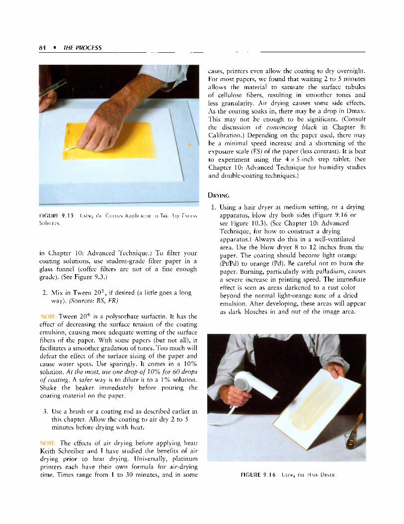
84 THE PROCESS
3 FIGURE 9.1 5 Usiuc, rl ir Corrolv A ~ ~ I C A T O R T O TALE Up Ekc E S S
S U l U r l U N
cases, printers even allow the coating to dry overnight. For most papers, we found that waiting 2 to 5 minutes allows the material to saturate the surface tubules of cellulose fibers, resulting in smoother tones and less granularity. Air drying causes some side effects. As the coating soaks in, there may be a drop in Dmax. This may not be enough to be significant. (Consult the discussion of convincing black in Chapter 8: Calibration.) Depending on the paper used, there may be a minimal speed increase and a shortening of the exposure scale (ES) of the paper (less contrast). It is best to experiment using the 4 x 5-inch step tablet. (See Chapter 10: Advanced Technique for humidity studies and double-coating techniques.)
DRYING
in Chapter 10: Advanced Technique.) To filter your coating solutions, use student-grade filter paper in a glass funnel (coffee filters are not of a fine enough grade). (See Figure 9.3.)
2. Mix in Tween 20”, if desired (a little goes a long way). (Sources: BS, FR)
‘x: 1 ; I Tween 20“ is a polysorbate surfactin. It has the effect of decreasing the surface tension of the coating emulsion, causing more adequate wetting of the surface fibers of the paper. With some papers (but not all), it facilitates a smoother gradation of tones. Too much will defeat the effect of the surface sizing of the paper and cause water spots. Use sparingly. It comes in a 10% solution. At the most, use one drop of 10% for 60 drops of coating. A safer way is to dilute it to a 1% solution. Shake the beaker immediately before pouring the coating material on the paper.
3. Use a brush or a coating rod as described earlier in this chapter. Allow the coating to air dry 2 to 5 minutes before drying with heat.
tr ) i t The effects of air drying before applying heat: Keith Schreiber and I have studied the benefits of air drying prior to heat drying. Universally, platinum printers each have their own formula for air-drying time. Times range from 1 to 30 minutes, and in some
Using a hair dryer at medium setting, or a drying apparatus, blow dry both sides (Figure 9.16 or see Figure 10.3). (See Chapter 10: Advanced Technique, for how to construct a drying apparatus.) Always do this in a well-ventilated area. Use the blow dryer 8 to 12 inches from the paper. The coating should become light orange (PdPd) to orange (Pd). Be careful not to burn the paper. Burning, particularly with palladium, causes a severe increase in printing speed. The immediate effect is seen as areas darkened to a rust color beyond the normal light-orange tone of a dried emulsion. After developing, these areas will appear as dark blotches in and out of the image area.
FIGURE 9.1 6 USING T k E H A I R DRYER

2.
Inadequately drying the paper is the surest way I know of ruining your negative, short of stepping on it. Once the wet ferric oxalate/platinum salt attaches to the emulsion side of the negative, it creates a permanent stain for which I have never found a remedy. Examine the dry coating with a dim light. Any spots or bristles can be scratched away using a single- edged razor blade. (It is much easier to deal with the problem now than to try to etch or spot the developed print.) Metal precipitant generally cannot be removed. Save it for spotting.
EXPOSURE
1. Sandwich the paper and the negative in the printing frame (see the discussion of printing frames in Chapter 6: The First Print, as well as Figures 6.1 and 6.3). Handle the negative with cotton gloves. Use compressed air or an air syringe to clean the glass of the printing frame and to dust off the negative. If dust is continuously attracted by static charges, use an antistatic solution (see Sources). Check the contact of negative and paper in the printing frame before placing under UV light. While looking through the glass, squeeze the center of the back. If you see movement, the contact is bad. To remedy the problem, add layers of felt between the paper and the back.
Mylar: There may be a tendency for bits of paper coating to come off on the negative. If found immedi- ately, many can be removed using the tip of the finger covered by a cotton glove. If this problem is a concern, particularly with multiple printings, place a l-mil piece of Mylar between the negative and the paper before printing. With larger negatives, however, the Mylar can difficult to handle.
2.
4. If
Set the timer for the determined time and expose the print4 (Figure 9.17). While this is occurring, you can begin to heat the developer and clean up. Discard the plastic cup and wash the brush, soaking it in 2 % phosphoric acid for 1 minute and washing again. Now squeeze it dry with a clean towel and hang up to dry.
I fluorescent bank of lights IS used as a UV light source, it mav be best to leave it on during the entire printing session. The intensity of W light is quite inconsistent for a period after lighting the bulbs. Simply shield it when not in use. (See Appendix F: Ultraviolet Light Sources for Platinum and Palladium Printing.)
FIGURE 9.1 7 Dodqr A U ~ B ~ I R N
E ~ ~ O S I J R E I N i l i c PIATE BLIRNFR Usiruq R tb ) I i r l iK Tr)
DODGING AND BURNING
The platinum printer will find that routine dodging and burning IS not generally needed. Unlike the making of a silver gelatin print, the extreme latitude and long toe (explained in Chapter 12: The Film and Paper Curves) of the platinum or palladium print carries tonal values throughout the scale of the image. Nevertheless, some areas, such as a disproportionately light sky, may be improved with a simple increase in exposure. It is here that a horizontal printing surface facing upward is appreciated. Sheets of RubylithR material can be placed on the glass (see Figure 9.17). If you followed the recommendations for standardizing a 10-minute printing time (usually 5 minutes for a good negative), the RubylithR can be allowed to remain in position from 5 to 10 seconds, lessening the exposure to your hands and eyes. Use anti-actinic glasses (see Sources). When the print is removed from the frame, you will see a printing-out image (Figure 9.18).
DEVELOPING AND CLEARING
1. Quickly slide the print into preheated potassium oxalate developer at 90 F. Another method is to place the print face up in the dry tray and rapidly pour the developer over it. Development will be instantaneous (Figure 9.19). Any portion of the print not receiving immediate development will permanently streak. Never develop a print face down. Ammonium citrate developer can be used at room temperature for cooler tones. Printing time

86 THE PROCESS
FIGURE 9.1 8 T k F P R I N l I N C + - O U T I M A G t
is decreased approximately 1/2 a stop (O.IS), requiring about 30 to 50% more exposure.
w i t : Although we generally can work safely under a 40-watt bulb, the metal salts are extremely sensitive to light at the instant of reduction. This may cause black streaking from areas of intense black to extreme white. Following the suggestion of Jim Enyeart, I turn off all lights except for a distant reference light before applying the developer. The room can be fully lighted after the first few seconds. (See Chapter 11: Problems for other suggestions to avoid this.)
2. Develop, with constant agitation, for 1.5 to 2 minutes.
3 . Lift print by grasping generous parts of two corners and allow it to drain into the developer tray. (Take care with tongs; you may tear off a corner.)
4. With acid clearing agents, the print can be placed directly into the first clearing bath. If a sulfate or EDTA clearing bath is used, rinse in running water before the first bath. Clear for 5 minutes with constant agitation (Figure 9.20).
5. Clearing in the second and third baths will also be 5 minutes each. As the paper becomes soaked, more care is needed in transferring it to avoid tearing. The final two baths require only intermittent agita- tion. When the first bath becomes cloudy, empty it and move the second and third baths over. Refill the first clearing tray with new solution, now making it the third bath. For an exhibition-quality print, the last bath should always be completely clear.
6. If residual print acidity is a concern, a final soak for 5 minutes in sodium carbonate or sodium acetate can be done before washing. (See Chapter 4: Chemicals.)
water. Either a hose or siphon can be used. Avoid having water strike the print directly from the top (you will punch a hole in the print). Generally, platinum prints do not require as much washing as silver prints, but intermittent complete changing of water is recommended.
blotter or drying screen (see Figure 2.5).
7. The final step is a 15- to 30-minute wash in running
8. After washing, place the print, face up, on a clean

DRY DOWN
During the tests in Chapter 8: Calibration, you may have noticed that the prints darkened during the drying phase. Silver printers know this phenomenon as “dry down” and plan on it during the printing of an image. Dry down in PdPd printing is even more pro- nounced, particularly with pure palladium. When plan- ning white textures to be just above paper white, it is necessary to base the printing time on a dried test strip. In many cases the textures will not be evident until the next morning. (See Plates 9.1 and 9.2; see also Chapter 10: Advanced Technique for print finishing.)
USING THE COMBINED STEP TABLET AND PRINT TO ADJUST PRINTING TIME AND CONTRAST
I have recommended that a small, 0.5 x 5-inch step tablet be included adjacent to the print. The following sections represent examples of how printing time and contrast can be modified using the step tablet as a reference. A transmission or reflection densitometer is not required to use this technique.
THE VISUAL COMPARISON DENSITOMETER
As shown in Chapter 8: Calibration, if transmission density values are in place for comparison, the human eye is capable of distinguishing subtle relative differences (see Figures 8.4 and 8.5). The same principles can be applied to reflective densities. Looking at a value through
the small aperture in the visual comparison densitometer, the values can be isolated from others. Comparisons can be made to match print and step tablet shades of gray.
Use the following principles:
Shadow values are changed by printing time. Highlight ilalttes are changed by contrast mixture.
When both shadows and highlights are too dark, reduce printing time. When both shadows and highlights are too light, increase printing time. When shadows are good and highlights are too dark, shorten the scale by going to a higher contrast mixture. Use approximatelys the same printing time.
light, lengthen the scale by going to a lower contrast mixture. Use approximately the same printing time. When shadows are dark and highlights are good, shorten the scale by going to a higher contrast mixture. Use less printing time. When shadows are light and highlights are good, lengthen the scale by going to a lower contrast mixture. Use more printing time. When both shadows and highlights need correction, alter the scale by going to a different contrast mix- ture. Change the shadows by altering printing time.
When shadows are good and highlights are too
’. We know that changing the contrast mixture will have a small effect on printing time. Therefore, printing is slightly altered by contrast mixture. I t may be not enough to notice, hut use a test strip. As we shall see in Chapter 13: Using the Print Curves we can accurately calculate both variables.

For the purposes of illustration, I have placed seven printing combinations together (Table 9.3). A “good” print has been located in the center for
visual comparison densitometer is helpful to isolate print tones.
BOTH SHADOWS AND HIGHLIGHTS ARE Too DARK reference (Plate 9.3). Although the limitations in reproduction may not convey the nuances found in the actual prints iPlates 9.3 to 9.9), using the following graphic examples will allow you to visualize the differences between the reproductions. When doing these corrections on actual prints, the
1. Find the textured shadow area. In this case, it is too
2. Find the print shadow value in the step tablet. It is dark (Figure 9.21. Plate 9.4).
step Nr. 3 .
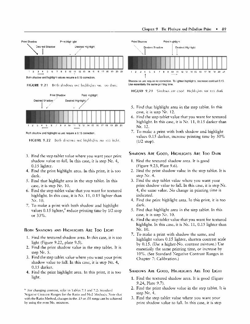
Print Shadow Print Highlight
1 2 3 4 5 6 7 8 9 10 11 12 13 14 15 16 17 18 19 20 21 - d
Both shadow and highlight values require a 0.15 correction.
Print Shadow Print Highlight
Desire[ S h y Desired , Highlight /
- c
Both shadow and highlight values require a 0 15 correction
FIGURE 9 . 2 2 Bork s k ~ d o u s and l-ii(,ljlic,liis A R C ioo l ic ,kr
3 .
4.
5.
6.
7.
Find the step tablet value where you want your print shadow value to fall. In this case, it is step Nr. 4, 0.15 lighter. Find the print highlight area. In this print, it is too dark. Find that highlight area in the step tablet. In this case, it is step Nr. 10. Find the step tablet value that you want for textured highlight. In this case, it is Nr. 11, 0.15 lighter than Nr. 10. To make a print with both shadow and highlight values 0.15 lighter,6 reduce printing time by 1/2 stop or 33%.
BOTH SHADOWS AND HIGHLIGHTS ARE Too LIGHT
1. Find the textured shadow area. In this case, it is too light (Figure 9.22, plate 9.5).
2. Find the print shadow value in the step tablet. It is step Nr. 5.
3 . Find the step tablet value where you want your print shadow value to fall. In this case, it is step Nr. 4, 0.15 darker.
light. 4. Find the print highlight area. In this print, it is too
'. For changing contrast, refer to Tables 7.1 and 7.1: Standard Negative Contrast Ranges for the Ratio and Na2 Methods. Note that with the Ratio Method, changes in the .15 or .OS range can be achieved by using the even-No. mixtures.
Print Shadow Print Highlight
Desired Shadow Desired Highlight
1 2 3 4 5 6 7 8 9 10 11 12 13 14 15 16 17 I8 19 20 21 + T
Shadow values require no correction To lighten highlights, decrease contrast 0.15 Use essentially the same printing time
FIGURE 9 . 2 3 Skadous ,IRE c,ood Hic,hlic,krs RE Too dnRk
5. Find that highlight area in the step tablet. In this case, it is step Nr. 12.
6. Find the step tablet value that you want for textured highlight. In this case, it is Nr. 11, 0.15 darker than Nr. 12.
7. To make a print with both shadow and highlight values 0.15 darker, increase printing time by 50% (1/2 stop).
SHADOWS ARE GOOD, HIGHLIGHTS ARE Too DARK
1. Find the textured shadow area. It is good (Figure 9.23, Plate 9.6).
2. Find the print shadow value in the step tablet. It is step Nr. 4.
3. Find the step tablet value where you want your print shadow value to fall. In this case, it is step Nr. 4, the same value. N o change in printing time is indicated.
4. Find the print highlight area. In this print, it is too dark.
5. Find that highlight area in the step tablet. In this case, it is step Nr. 10.
6. Find the step tablet value that you want for textured highlight. In this case, it is Nr. 11, 0.15 lighter than Nr. 10.
highlight values 0.15 lighter, shorten contrast scale by 0.15. (Use a higher-No. contrast mixture.) Use essentially the same printing time, or increase by 10%. (See Standard Negative Contrast Ranges in Chapter 7: Calibration.)
7. To make a print with shadow the same, and
SHADOWS ARE GOOD, HIGHLIGHTS ARE Too LIGHT
1. Find the textured shadow area. It is good (Figure 9.24, Plate 9.7).
2. Find the print shadow value in the step tablet. It is step Nr. 4.
3 . Find the step tablet value where you want your print shadow value to fall. In this case, it is step

90 THE PROCESS
Print Shadow Print Highlight
Desired Shadow Desired Highlight
1 2 3 4 5 6 7 8 9 10 11 12 13 14 15 16 17 18 19 20 21 c T
Shadow values require no correction. To darken highlights, increase contrast 0.15. Use essentially the same printing time.
Print Shadow Print Highlight
Desired Shadow Desired Highlight
\ I
1 2 3 4 5 6 7 8 9 10 11 12 13 14 15 16 17 18 19 20 21
T - Shadow values require a 0.15 correction. To keep highlights the same, decrease contrasr 0.15. Use less printing time.
4.
5.
6.
7.
Nr. 4, the same value. N o change in printing time is indicated. Find the print highlight area. In this print, it is too light. Find that highlight area in the step tablet. In this case, it is step Nr. 12. Find the step tablet value that you want for textured highlight. In this case, it is Nr. 11, 0.15 darker than Nr. 12. To make a print with shadow the same, and highlight values 0.15 darker, lengthen the contrast scale by 0.15. (Use a lower-No. contrast mixture.) Use essentially the same printing time, or decrease by 10%.
SHADOWS ARE Too DARK, HIGHLIGHTS ARE GOOD
1.
2.
3.
4.
Find the textured shadow area. It is too dark (Figure 9.25, Plate 9.8). Find the print shadow value in the step tablet. It is step Nr. 3. Find the step tablet value where you want your print shadow value to fall. In this case, it is step Nr. 4. Printing time must be decreased 33%. Find the print highlight area. In this print, it is good.
Print Shadow Print Highlight
Desired Shadow Desired Highlight
1 1
T Shadow values require a 0 15 correction To keep highlights the same, decrease contrast 0 15 Use less printing time
FIGURE 9.26 S k A d m s A R t roo Iiqkr Hic,kliqkrs A R F Good
5. Find that highlight area in the step tablet. In this case, it is step Nr. 11.
6. To keep the highlights at step Nr. 11 while raising shadow values, the contrast scale must be shortened by 0.15.
7. Printing time must be decreased 33% and contrast shortened by 0.15.
SHADOWS ARE Too LIGHT, HIGHLIGHTS ARE GOOD
1. Find the textured shadow area. It is too light (Figure 9.26, Plate 9.9).
2. Find the print shadow value in the step tablet. It is step Nr. 5.
3. Find the step tablet value where you want your print shadow value to fall. In this case, it is step Nr. 4. Printing time must be increased 50%.
4. Find the print highlight area. In this print, it is good. 5. Find that highlight area in the step tablet. In this
6. To keep the highlights at step Nr. 11, while case, it is step Nr. 11.
lowering shadow values, the contrast scale must be lengthened by 0.15.
lengthened by 0.15. 7. Printing time must be increased 50% and contrast
M o R E COMB I N AT I o N s
We have been working in half-stop increments. For each two-step correction, one full stop is needed, either halving or doubling printing times or contrast mixtures, and so on. When there are more extensive discrepancies between desired shadow and print values, the principles discussed must be brought together to make the final print. As corrections get more complicated, more test strips are needed before the final print is made. When the principles discussed in Chapter 13: Using the Print Curves are utilized, the initial test prints can be made with more accuracy.

’. Also see Appendix G: Elements of Platinum Printing.
91

92 THE PROCESS
MASKING OF NEGATIVES
The material presented here is courtesy of Tom Millea. The methods previously described will show the black brush strokes around the print. If you prefer a white border, you must mask the negative before printing.
MATE RIALS
Metal straight edge
Printer’s red masking paper (Rubylith@)
Ruby tape, 1/4 inch (available from any print shop)
Self-healing cutting base (Source: LI)
X-ACT0 No. 16 blade (Sources: GA, LI)
PROCESS
1. Scribe on the red masking paper the borders you wish to create for the final image. Usually, this is done to just eliminate the base + fog portion of the negative; however, the image can be cropped if desired. This is a delicate operation. For the first time, you may want to ask to watch a printer to do it.
2. Working over the cutting base, carefully cut along the lines. Take great care at the corners, as any defects will show at the corners of the final print.
3 . In coating the paper, you may not want to show pencil marks. (They will not erase after develop- ment.) It is best to use the black construction paper or felt marker template (discussed in Chapter 9: The Platinum and Palladium Print) to demarcate the
4. Place the negative, dull side up, over the opening coating borders.
and tack down two sides (the base +fog area) with two or more pieces of ruby tape (Figure 10.1). At this time, the image can be cropped if so desired.
coated paper. In a printing frame you will have the items listed in Table 10.1.
6. Print accordingly. If a border is visible around the image, you have fogging or staining problems (see Chapter 11: Problems).
5. Place the negative with the dull side against the
WORKING LIGHT
Some platinum printers have recommended the use of a yellow safelight during coating. My tests have shown no difference between a safelight, a low incandescent light, and complete darkness. Avoid fluorescent light, bright
FIGURE 10.1 M A s k i N G of T k E NEGATIVE
TABLE 10.1 ORdtR of MATERIALS IN rkt MnsklNq of A NE~AIIVE
Masking of the Negative
h Glass Printer’s Mask Negative Paper
U Back or Base
light or daylight. Have enough light to see well for coating. Dry the paper under a dim incandescent light (two 40-watt bulbs at least 4 feet away). During the first instant of development, turn off the lights (see Chapter 9: The Platinum and Palladium Print). The efficacy of the safelight is easily tested (see Chapter 11: Problems).
RELATIVE HUMIDITY IN THE LABORATORY
Relative humidity that is too high or low may affect the absorbency of the paper to be coated. My laboratory is maintained at a humidity of 50 to 60%, which gives consistent results with minimum solarization. For reproducible results, once a satisfactory humidity has been found, it is recommended that you maintain it. It is also recommended that you use this environment to store the paper at least 8 hours before coating. Coating

should be done in the wet area of your lab (see Chapter 2: Setting Up a Laboratory). Providing that you do not have forced-air heating, the dampness from the sinks tends to stabilize a moderate amount of moisture in the environment. Also, as 40-watt safelights must be in the developing area, it is the most convenient space to work. If you find unusual absorbency or graininess in your paper, you can correct the situation by exposing the paper overnight to a humidifier or dehumidifier, depending on conditions. Be aware that extremes of humidity will change the printing speed and the exposure scale (ES) of a particular paper. (See the next section.)
For contrast control by humidity, see the references to the Maldemare and Ziatype Web sites in Chapter 7: Choosing a Method.
THE EFFECTS OF HIGH PAPER HUMIDITY
Many printers humidify their paper before coating. Some processes, such as the Ziatype and the Malde/ Ware process depend on humidity during the exposure to ultraviolet (W) light to get a printing-out image, which can be examined before actual development. In place of the standard ferric oxalate described in the text, they use the hygroscopic effects of ammonium ferric oxalate to retain moisture. The water within the paper fibers provides a vehicle for the reduced platinum and palladium to coalesce, thus forming the image. (See Appendix A: The Chemistry of Developing, Contrast Control, and Clearing Processes.) There are many reported advantages of paper humidification.
PREVENTION OF SOLARIZATION
Solarization differs from the Sabattier effect. The Sabattier effect involves the reversal of the silver image upon introduction of light during the development process. True solarization is based on the concept that, given a layer of metal salts, reduction may occur first on the surface, blocking the deeper layers from receiving as much light as adjacent areas (known as plating). Unlike processes such as albumin, where the coating is held in the surface by a substrate, the platinudpalladium (Pt/ Pd) coating has been absorbed into the paper with too little on the surface to produce any “self-masking” effect.
Palladium, most commonly, has a tendency to solarize under supermaximum exposure. The areas
”. L. I
11.8
IDmax=l35
DR=129
. IDmin = 0 06
30 27 2 4 21 1 6 1.5 1.2 0.9 0.6 0.3 0.0
FIGURE 10.2 E f f F C T S O f H U M i d i f l c A T i o N O N F A b R I A N O ARTIST iCO
PAPER CURVES.
ES 01 I 20; DMAX 1 . 3 5 CURVE 1 : CONTRO[. Rod C O A T i N q ; A Typicnl PAPER CURLE w i T k AN
CLIRVE 2: Rod W l T k H U M i d i f i c A T i o N ; NOTE T k A T T k E PRINTING, SPEEd
\#AS I N C R E A S t d by 213 STOp, A N d T k E ES dECREASEd TO 0 . 9 5 WTII SkORTENIN( , O f T k E p A p E R TOE; DMAY I .30 CGRVE 3 b R u s k \LA5 U s t d TO \LORk T h E COATINC, I N T O T k E p A p E R f i bERS;
C O M P A R E d TO T k E R o d , TWICE T k E V O l U M t O f COATING WAS UsEd; NOTE
B ~ i s k wlTk H u M i d l f i c A T i o N . HERE, 4 d A M p R i c k E s o u
r k t 1.50 DMAX. This EQUATES TO A I . 3 5 ES 90% b h c k . S k A d o w
VALUES CAN b E M A i N T A i N E d AT T k l 5 [EVE[, w k i l E wlTk O T k E R
TECkNiQUES. 1 5 5 bould R t p R E s E N T UNTEXTUREd DMAX. 1 .20 ES (SAME AS T k E C O N T R O I ) .
C V R ~ E 4 : I N A d E Q i i A T E COAIIN~ w i r k Rod; T k E COATING k A S b E t N
A b S O R b E d iNTO Tkf p A p E R f l bERS; DMAX IS ON[).’ 1 .20, A N d
S i C i N l f i C A N I SO[AR iZAT iON k A S OCCURREd.
that receive the most light, usually the brush strokes around the image, may actually end up lighter than the shadow areas of the image. (See Figure 10.2, Curve 4.) If the print is to be matted, this should be of little consequence-particularly if the shadows are planned as 90% black.
Solarization can also occur when the coating is too thin or the paper too dry. Using a heavy coating on pre- humidified paper will greatly diminish this reaction. Some printers re-humidify the coated paper before exposure. (See Appendix G: Elements of Platinum and Palladium Printing.)
THE ELUSIVE DMAX
As defined in Chapter 3: The Negative, Dmax is the maximum black a particular metal-paper combination reaches. It is usually found in the brush strokes where the W light has not been blocked by film base plus fog (B+F). This is read by a reflection densitometer and is

94 THEPROCESS
reported in logarithmic values. In the PdPd process, this usually is 1.30 to 1.40, although a 1.50 density can be obtained with special techniques. IDrnax is defined as the darkest areas within the image and is represented in the Zone I11 shadow values. This would generally be a 90% black.
One of the benefits reported for paper humidifica- tion is an elevation of Dmax. Using the laboratory and a reflection densitomer, I duplicated some of the proce- dures followed for paper humidification to obtain measurable data.
HUMlDlFlCATlON
I constructed a humidification chamber at 75% humid- ity and humidified paper at that level for 10 minutes. I used three papers: Crane’s Platinotype, and the heavier papers Platine and Fabriano Artistico. I acidified the Artistico with 1% oxalic acid. One set of the three papers was humidified before coating, and it was air dried. Another set was re-humidified after coating and before exposure. A third set, to serve as a control, was coated and heat dried in the normal manner.
COATING
The papers were coated using two methods: rod coating and with a moistened Richeson brush. Manipulating the brush took twice the volume of coating material as the rod.
EXPOSURE All papers were exposed to a Stouffer Step Tablet at 350 units on a NuArc 26.1K plate burner. The re-humidified papers were protected from the step tablet by a sheet of 1-mil Mylar.
CRANE’S PLATINOTYPE
When compared to the control, Crane’s Platinotype, whether humidified one time or re-humidified a second time, exhibited the same results. There was a 2/3-stop increase in printing speed with a consistent exposure scale. There was no increase in Dmax. In fact, in some cases, it decreased from 1.35 to 1.30. The same results were obtained when the paper was allowed to air dry without humidification. No solarization was observed.
PLATINE
Dmax was the same on Platine paper regardless of the presence or absence of humidification. Notably, the curve from rod coating increased the printing speed 2/3 of a stop, with a corresponding decrease of 0.2 of the
exposure scale and subsequent shortening of the toe. Therefore, in the printing of a set negative, the highs would be consistently at the toe with all three methods. However, with the rod, the shadows were depressed by 2/3 of a stop, well into the Zone I1 range. No solarization was observed.
A Rrisr ico
Here, the greatest changes were observed (Figure 10.2). The process of humidification increased paper absor- bency due to hygroscopic effect. Therefore, more coat- ing was needed to compensate for that absorbed by the paper fibers.
0 B s E RVAT I o N s
1. Humidification can prevent solarization; however, adequate amounts of coating material must be used to compensate for the increased absorbency of the paper. In humidified paper, the ferric oxalate and palladium salt molecules, due to hygroscopic effect of the wet paper, become suspended in the ‘‘gel’’ of the moistened paper fibers. At the time of UV exposure, the ferrous oxalate bonds with the reduced palladium below the surface and immedi- ately coalesces. Since this occurs within the paper, leaving less palladium on the surface, there is little chance of plating. Also, as shown by tests, more coating material is needed to compensate for that absorbed by the paper.
2. Other than the prevention of solarization, thinner papers, such as Crane’s Platinotype, do not benefit considerably from humidification. This is substan- tiated by the modest Dmax of prints made with the ammonium-based processes, such as the Ziatype, where considerable humidity is maintained by the ammonium ferric oxalate. Crane’s Platinotype exhibited a printing speed increase upon humidifi- cation.
sizing may not benefit as much from humidification as previously reported. Instead, the printing speed increase, with the decrease in ES, compacts the tonal values and simply produces untextured blacks more into the Zone I1 range. Considering the absence of solarization and metal molecules imbedded well into the heavier paper fibers, some images may take on a more dramatic effect, approaching posterism.
4. Heavy watercolor papers, after acidification, are indeed capable of taking on an increased Dmax of about 0.10 to 0.15 above that obtained with more
3. Platine and other papers with adequate surface

traditional techniques. However, using a moistened, non-abrasive brush, excess coating material must be worked into the paper fibers.
HYDROGEN PEROXIDE
The use of hydrogen peroxide to prevent fogging has been suggested. Some workers also use it as an oxidizer for contrast control. Expect some fogging when no restrainer has been used.
If you are using only ferric oxalate solution A with no restrainer, one drop of 3% hydrogen peroxide per ml of coating material will prevent some fogging by temporarily converting the minimal amounts of ferrous oxalate to the ferric form. This slightly decreases the exposure scale (the same as adding one drop of solution B). (See Appendix A: The Chemistry of Developing, Contrast Control, and Clearing Processes.)
With one drop of sensitizer B per 11 drops sensitizer A, or one drop per 12 of 2.5% Na2, no fogging should occur. If you routinely need hydrogen peroxide to prevent fogging, you may have problems. (See Chapter 11: Problems.)
BRUSHES
Early in my tests, I tried dozens of different brushes, hoping to solve coating problems. Eventually, I found that most problems were related to papers. Today, many papers have inadequate surface and internal sizing or pH to make them suitable for platinum printing (see Chapter 5: Paper). With suitable paper, many brushes will work. I believe that some unusual coating methods are used because of inappropriate paper. Don't waste time and chemicals on bad paper. (See Brushes in Chapter 9: The Platinum and Palladium Print.)
'%: : i For instructions on the use of a wet Richeson brush, see Appendix G: Elements of Platinum and Palladium Printing.
THE USE OF SIZING MEDIUM IN THE SENSITIZER
Technically, the coating material is not an emulsion unless it contains an emulsifying ingredient. An emulsifier will theoretically add body to the coating, keeping more of it on the surface of the paper. The best product, Liquitex acrylic sizing medium (made by Binney Smith), is, unfortunately, no longer applicable as they have changed the formula.
A sizing medium will provide a body to the coating material. My tests show that it makes coating easier because it holds the emulsion more on the surface and prevents wash off during development. Dmax is increased (+ 0.1 reflective density).
While many sizing agents will go into solution with distilled water, at this time I have found no medium other than polyvinyl alcohol that will go into complete solution when added to the acid-coating material. If you plan to test any ingredient, add it to only the ferric oxalate and examine the effect before adding the metal salt. (While some ingredients will go into solution at a neutral pH, most will congeal in the acidic ferric oxalate.)
Polyvinyl alcohol 5 % is available as a sizing agent. Used at 1 to 2 drops per ml of coating material, it will provide some body to the coating. Its effectiveness is dependent on the paper, so it is necessary to do visual tests. (Source: BS)
IMAGE HUE
In addition to the effect of the platinum and/or palladium metals, image hue2 can be controlled by the sizing, choice of developer, temperature, and toning. Paper base hue will also affect the image.
SIZING
Gelatin sizing produces blue-black hues, particularly with platinum. Starch sizing (used by most paper manufacturers) produces warmer, brownish hues.
DEVELOPER AND TEMPERATURE CONTROLS
When doing the paper tests for this second edition, I noted that new developer produced a predictable sepia hue, modified only by the choice of metal and paper. However, I also noted the changes when using the same developer a second time. This effect became more pronounced with each subsequent use.
At a certain point, the platinum and/or palladium ions residual in the developer exert a profound effect on the hue of the print, more so than many other procedures used to modify image color. Since Pt/Pd printing is basically a print-making process, we do
For the purposes of this text, hue is generally used to denote the color changes related to metal choice, sizing, developer, and toners. (Blame Photoshop"'.) Tone is generally used to describe the smoothness of texture or lack thereof. However, it will also be used in the section on spotting to describe progressions from paper white to black.
2.

96 THE PROCESS
not expect (or welcome) the predictable mechanical perfection noted with the silver gelatin print. The probability that each image from the same negative may have subtle differences gives our process one of its many charms.
METAL IONS IN THE DEVELOPER
Richard Sullivan has raised a number of questions about the reuse of developer. If one uses the same developer for both PtPd and pure palladium prints, the developer becomes loaded with both platinum and palladium molecules. When using this developer, therefore, you cannot produce either a “pure” platinum or “pure” palladium print; each has a minuscule amount of the other metal. In the case of pure platinum prints, if toning, redevelopment, or intensification is anticipated, it may be wise to do some tests with prints processed in new developer.
COMBINATIONS OF PLATINUM AND PALLADIUM
By combining proportions of metal salts with developer and temperature variations, image hues from neutral gray to warm sepia can be obtained (Table 10.2). When printing in palladium with the Na2 method, the characteristic palladium hue is maintained throughout most contrast grades. Only when multiple drops of 20% Na2 are added to the basic 12 drops, will the image take on some of the platinum characteristics. As stated, substituting a citrate developer for the potassium oxalate will produce hues quite similar to the traditional 50% platinum-50% palladium print (see Table 10.2).
For combinations of platinum and palladium other than the standard 50% ratios, a number of effects on hue
have been reported. Variations between workers are probably explained by differences in technique, paper, and developer. For our tests, we used the Ratio Method with Crane’s Crest Natural White Wove paper, devel- oped in potassium oxalate at 90” F. Proportions of pla- tinum/palladium at 5:1,3:2, 3:3,2:3, and 1 5 were used.
Contrary to some findings that the same hue of a 50% mixture can be reached by using 1:5 platinum/ palladium blend, we observed that the 1:5 hue was considerably warmer and more closely approximated a pure palladium print. There were visible changes from the extremes of mixtures, providing increments between the pure platinum, 50% PtPd, and the pure palladium print. Perhaps others have produced different results and have found a way to economize in the PtPd ratios.
TONING
Gold chloride, mercuric chloride, potassium phosphate, uranium nitrate, lead oxalate, and other substances can be used to alter image color, either in the sensitizer or as a toning bath. Of these, I will be discussing only gold chloride. (See also Gold Chloride in Chapter 4: Chemicals.)
Gold chloride 5 % may be used in the sensitizer or as a direct toner to cool the image hue of a platinum or PtPd print. In the sensitizer, place one drop of gold chloride per ml of coating material. This may also reduce granularity. As a toner, brush gold chloride directly onto the wetted print, usually with glycerin to control application (Crawford, 1979; Nadeau, 1994; Sullivan and Weese, 1998). When the desired hue is reached, rinse the print and place for 1 minute in Dektol; then wash. (See Chapter 4: Chemicals, for gold-toning formulas.)
TABLE 10.2 PRINT HUE AS RtlATEd TO META~ SALT. DEV~OPER, ANd DELELOPER TEMPERATURE
Hue Metal Developer
Cool fi Platinum 50% PlatinundPalladium Platinum 50% PlatinundPalladium Palladium Platinum Platinum 50% Platinum/Palladium Palladium
Warm Palladium
Ammonium citrate 68 F Ammonium citrate 68” F Ammonium citrate 90” F Ammonium citrate 90” F Ammonium citrate 100 F Potassium oxalate 68” F Potassium oxalate 90 F Potassium oxalate 90 F Potassium oxalate 90” F Potassium oxalate 100 to 110 F

C LY CE R I N
At the turn of the century, many pictorialists used glycerin to selectively develop the platinum print. Much of the historic literature, including the writings of Alfred Stieglitz, contains references to this technique. While the most grievous practices of romantic expression might not fit in with our time, this practice can be a valuable tool for those who wish another method of image manipulation.
Glycerin can be obtained from a pharmacy or any chemical supplier. It is mixed with developer, either in a single bath or in various concentrations. Because proficiency requires some practice, it is best to start with only one concentration of SO% glycerin and 50% developer, which will be used in conjunction with 100% developer. After beginning with this concentration, other ratios can be tried.
M ATE R I A LS
Brushes to apply glycerin and developer
Developer
Glass sheet, slightly larger than the paper
Glycerin
Jars to contain the various concentrations of glycerin and developer
Running water
1. The print is exposed to UV light in the usual way.
2. Arrange three jars: one with 100% glycerin, one Some recommend overexposure.
with SO% each of glycerin and developer, and one with 100% developer.
3. Wet the glass with pure glycerin and “stick” the print onto it, face up. Immediately cover the print with pure glycerin. You will see the printing-out image.
4. Using the two solutions containing developer, paint the image to enhance selected areas. The process can be arrested at any time by flooding the area with pure glycerin or using blotting paper.
running water and clear. 5. When satisfied, thoroughly flush the print with
DOUBLE COATING
Keith Schreiber’s and my studies have demonstrated that the efficacy of double coating is dependent on the paper used. With many papers, if well coated, a single coating is equal to, and frequently superior to, a double coat. The observation that some of the more alkaline papers improve by double coating may be explained by the fact that the first coat simply acidifies the paper to better receive a second coat; the same result may be more economically achieved by acidifying the paper with a pre-coat of 1 % oxalic acid. (See Chapter 5: Paper.)
Some papers, usually the heavier ones, may benefit from double coating with a smoother tone and a deeper Dmax. With most, the double coat mucks up what could have been a good coating, creating blotches and a diminished Dmax.
You must test the paper using your own technique. Here, the Stouffer 4 x 5 step tablet is valuable. The steps are large enough to gauge the smoothness of tone and Dmax. You do not need sensitometric machinery to visually assess the differences.
For double coating, some printers dilute each application of coating agent with 30 to 50% distilled water. Allow the first coating to air dry for 3 to 5 minutes, then heat dry and recoat. If you decide to double coat your final print, you must anticipate a change in printing speed and do the appropriate tests.
Simili Japon and Platine papers both can benefit from double coating. With these papers, Keith Schreiber uses the standard concentrations of ferric oxalate and metal salts. With the Simili paper, a few drops of Tween 20‘ are added to the coating material. (See Tween 20@’ in Chapter 9: The Platinum and Palladium Print.) The first coating is allowed to air dry only for 1 hour. Following the second coating, the paper is heat dried in the normal manner. The Dmax of both papers is increased significantly, as well as smoothness of tone. Because of the increased intensity of black, the ES of the paper is somewhat shortened.
Platinum printers throughout the world have devel- oped many other unique variations for double coating. For more information, the reader is encouraged to explore the many Web sites available on this subject.
Richard Sullivan and Carl Weese describe a brush development that utilizes ammonium ferric oxalate and potassium chloroplatinite. The technique is similar to the one just described, but uses only a cold bath or potassium oxalate developer and glycerin (Sullivan and Weese, 1998).
DRYING OF THE COATING
Natural drying in room air can be precarious; times are dependent on temperature, humidity, and the choice of paper. Also, with some papers, air drying may change

98 THE PROCESS
the printing characteristics. (See Relative Humidity in the Laboratory and The Effects of High Paper Humidity in this chapter.) It could take long enough to cause some of the ferric oxalate in the coating to go to ferrous and result in fogging. Here, an alternative to overnight drying is to allow the paper to set for 1 hour, and then dry with a blow dryer with the heat turned off.
Most platinum printers use an application of heat to dry the emulsion. As discussed in Chapter 5: Paper, the paper should be allowed to air dry at least 5 minutes (or more) before heat is applied. The common method is to use a hair dryer or a drying cabinet. With a hair dryer, there is always the tendency for uneven drying and the possibility of burning the coating. Also, the close proximity needed to operate the hair dryer may expose the respiratory system to the bits of coating material that can enter the air when in the dry state. The drying cabinet is superior for even drying, but few people have access to one of sufficient size. A commercial dryer is available from Edwards Engineering. (Source: E E )
To help solve these problems, I have devised a method utilizing two commercial hair dryers and diffusing cones, both available at a beauty supply store.
MATE RIALS
Fiberglass window screen, 2 x 3 feet
Lumber, 1 x 4 inches and eight 1-inch, round- headed wood screws
Particleboard, 5/8 x 12 x 24 inches
Two high-quality commercial hair dryers ( 1200- 1400 watts) and diffusing cones3
Two swag hooks and cord
METHOD
1. Tape the handles of the hair dryers together, overlapping them so that the nozzles are at opposite ends and both are pointing the same direction (Figure 10.3).
2. With the diffusers installed on the dryers, place them on the board, open end down. Measure the distance between the centers of the cones (it should be about 10 inches).
3. High-quality dryers, usually special-ordered from beauty shops, are in the $60.00 range. Unlike the less expensive variety, they can be quite efficient a t medium power, which extends the life of the diffuser and minimizes the chance of burning the print.
P a r t i c l e
- gaard - s c r c c r
2aarc
FIGURE 10.5 T ~ E DRY IN^ A ~ ~ A R A T U S
3. Cut two holes 1 inch smaller than the outer diameter of the diffuser cones along the center of the long axis of the particleboard. Place the centers of the holes at the measured distance between the centers of the cones. The dryers should sit over the board with the cones pointing downward over the holes.
4. Attach the dryers and diffusing cones with the wood screws. You may want to catch the lip of the cones with the heads of the screws rather than puncture the plastic.
5. Make a rectangular base with the lumber to support the window screen. Cut away some wood to allow for ventilation. Place the support and the screen on your counter.
6. Place the swag hooks on the ceiling directly over the screen, about 20 inches apart. Center their position with the axis between the dryers. Making loops with the cord, pass each one around one end of the board. Notch the board 2 inches from the ends to prevent slippage. Suspend the entire apparatus from the ceiling so that the board rests 3 to 4 inches over the screen.
the screen, the board with the attached dryers is gently rocked back and forth over the paper. By periodically maintaining that motion and rotating the print, even drying should occur in 3 to 5 minutes. The combined current draw of 2400 to 2800 watts will strain the circuit breakers, so you will probably want to choose a circuit with no other load.
7. With the freshly coated paper lying face up on

PREPARATION OF THE FINAL PRINT
DRYING
If you are in a low-humidity environment, remove the print from the drying screen before it is bone dry and press it under a heavy object. (An old chemistry book will do.) After a few hours, flatten the print under a mounting press set at 200" F. Protect both sides of the print with archival board.
PRINCIPLES OF ETCHING AND SPOTTING PLATINUM/ PALLADIUM PRINTS
M ATE R I A LS
#000 Spotter brushes
Burnishing tool (plastic)
Etching blade
Grumbacher Academy or Windsor Newton Burnt Umber Watercolor (tube)
Grumbacher Academy or Windsor Newton Ivory Black Watercolor (tube)
Spotting lamp (a circular fluorescent tube and magnifying glass combination is best)
Watercolor dish
Windsor Newton Dry Ground Titanium White (powder) (Source: Art Supply)
It is very difficult to etch or spot black defects caused by negative pinholes or scratches from a platinum and/or palladium print. The coating of a print extends deeply into the paper, and black defects may be equally imbedded. It is best to cover pinholes and scratches on the negative with retouching material, such as Crocein Scarlet (Kodak 1463751), before printing (see Chapter 3 : The Negative). Use the shiny side of the negative so that the material will be slightly out of register with the image. It is equally difficult to cover traces of precipitated metal. If this is a problem, strain the metal salt before coating (see Figure 9.3).
Spotting with watercolors in an undiluted form will match only the whitest and blackest hues of the print. If it is placed on the midtones, a disagreeable black or white spot will form, many times ruining the print. Therefore, one must work from both extremes, black and white, to the midtone areas, diluting with distilled water as needed until very little pigment is applied. Work from three wells in the watercolor dish in which
watercolors have been blended: white, Pt/Pd blend, and Pd blend. During the time between spotting sessions, the liquid colors will have returned to a dry, caked form (Figure 10.4). Simply add water before spotting.
Generally, a brush size larger than one might anticipate is best. It holds more pigment, allowing more control. A good practice is to use the brush almost dry, with more pigment than appears necessary. The danger in having pigment too thin and wet is that it will not completely cover the spot but bleed a halo over the satisfactory print tones. Dip the brush and mark some scratch paper until hardly any pigment remains. Practice on scrap prints. (Platinum printers have lots of those.)
BLACK DEFECTS First examine the print under a magnifying glass that allows for binocular vision (Figure 10.5). If the defect is superficial, it may be possible to flick it off with an etching blade. If, during this process, the paper nap has been penetrated, it becomes highly absorbent to pigment. Dilute mixtures must be used to restore image tone.
For deeper defects, use Titanium White powder mixed with a small amount of distilled water in the watercolor tray. A thicker mixture will be used against a white background. As the underlying tone approaches light and then mid-gray, add water drop by drop to make the pigment more translucent. You will note that if properly mixed, it may appear to be too strong, but it rapidly seeps into the now unsized paper. A heavier coating of Titanium White may cause an annoying bulge on the surface of the print. After it has thoroughly dried,

100 TH€PROC€SS
place a piece of glassine over it and lightly rub with a plastic burnishing tool.
If the etching or white spotting has been overdone, showing a white defect, save the print for spotting of white defects. The deeper levels of unsized paper surface or Titanium White will both be extremely absorbent. Use only the most dilute mixture of the dark watercolor.
WHITE DEFECTS Usually, these defects are easier to handle. First, one must blend the colors of Burnt Umber and Ivory Black in the watercolor tray with a bit of water to match the print tone. For PdPd prints, start with a 50% portion of each. With palladium, use two parts Burnt Umber to one part Ivory Black. Try the mixtures on old prints until the ratio is reached, then record it.
Arrange the prints in an order so that those with the defects in the blackest portions are first. Continue to sort in order of tones until the defects are in the lightest gray areas. Start at the blackest areas with a barely diluted mixture. If, after these are finished, defects remain in lighter areas, place the prints in the stack so that they may be done later with the more dilute solutions. Now, choose the defects in a near-black (Zone 111) area. Dilute the mixture in the tray with distilled water until the proper concentration is reached. Paint the scratch pad until the brush is almost dry. Then, holding the pad under
the light next to the print defect, spot the pad. Check the match through the magnifying glass. Continue through the tonal scales, diluting, until the lightest areas (Zone VII-VIII) are reached. Lastly, spot the defects you have created by etching them or using Titanium White.
THE “BLACK PLAGUE” CURE
Michael Mutmansky has shared his technique for removing those dreaded black spots that sometimes happen in platinum and palladium print^.^
Acid and bleach react together to make PURE CHLORINE. In small quantities, chlorine is fairly harmless, as we know it is used in drinking water, swimming pools, and laundry without any problem. But NEVER mix concentrated bleach and acid together directly! That could result in large quantities of chlorine gas being generated, and is very dangerous. Do not pour the two solutions into a drain at the same time. Better yet, discard them outdoors, away from vegetation.
Always work in a well-ventilated area. Do not “improvise” or think that mixing the solution stronger will be of any benefit.
Review the safety procedures in Chapter 4: Chemicals. The authors hereby deny liability for any subsequent injuries resulting from the use of this information.
This process requires very small amounts of hydro- chloric (also called muriatic) acid and regular household laundry chlorine bleach. Hydrochloric or muriatic acid can be purchased at hardware stores and swimming pool supply stores. It is used to clean driveways and other concrete surfaces. Also needed are two small 1-02 (30 ml) bottles.
1.
2.
3 .
4.
Put 20 ml of distilled water in a bottle and add 5 ml hydrochloric acid. Always add acid to water. In a separate bottle, add 5 ml of bleach to 20 ml of distilled water. Set out a capful of the acid solution and a second capful of the bleach solution. In between the two, place a dish of clean water for rinsing your brush. Find a finished print with a black spot. Use a fine, natural fiber brush and put a small drop of the acid
This technique is actually the product of a group effort. Richard Sullivan noted a reference to the bleaching properties of hydrochloric acid (HCI) and chlorine in the literature. Michael Mutmansky did the practical tests, and the results were posted by Kevin Sullivan on the Bostick and Sullivan Web site.
4.

solution on the black spot. It won't take much and you don't want the solution to spread farther than your spot. Rinse the brush in the clean water, then dip the brush in the bleach and lightly touch the bleach to the same area to which you applied the hydrochloric acid. Almost immediately the spot should start to dissolve away. Repeat the steps if necessary; each time the spot will get smaller. Always rinse your brush in between the acid and bleach steps. When done, wash the print again for 10 minutes or so to remove leftover chemicals. With some off-white papers, such as Crane's Platinotype, the white area of bleaching may show. This may be corrected by judicious spotting.
P R ES E NTATI o N
LIGHTING
The delicate hues of the platinum and palladium prints change with the color temperature of the lighting. The light in the finishing room should approximate the lighting that will be given the framed and displayed print. Most frequently, some daylight quartz or fluor- escent tubes are desirable. For a little more cost, full spectrum, color-corrected daylight fluorescent tubes can be used in place of the standard, ugly, green hardware bulbs.
If one prints for exhibition, the galleries must be visited with attention to the intensity of the lighting given to the artwork. For most galleries, the ceiling spots are more intense than standard room light. Anticipate that the serious collector will have similar lighting, and print accordingly. In most cases, the prints will be made darker than what looks good under normal room light. Otherwise, they will appear anemic under gallery lighting. Unfortunately, in the interest of conserving more precarious forms of art, many museums provide inadequate lighting for photographs.
MATTING
Most conservators now discourage dry mounting of all artwork. I do not recommend mounting of platinum prints. (Gelatin-sized prints will not stick.) Instead, use the corners available from Light Impressions with archival tape. I also do not recommend waxing, lacquering, or coating the final print with any substance. (For another opinion regarding waxing, see Appendix G: Elements of Platinum and Palladium Printing.)
With all methods of presentation, if glass is to be used, a mat should be inserted to keep the print from touching the glass. The mat should also be composed of archival material-either rag or one of the alpha- cellulose-treated wood pulp materials. I prefer that the tone of the mat approximate that of the paper used for printing, so as not to detract from the image.
As with many printing processes, the portions of the image to be shown are determined by the artist and, at times, the client (Table 10.3). The more traditional form of matting has been to stop the mat at the borders of the image. The brush stokes are then covered from view.
With an image made from an unmasked negative, a decision can be made to show the entire effects of the brush strokes (Plate 10.4). In this case, the mat would only cover the edges of the print paper. If the negative has been masked during printing, the borders will be that of the printing paper and the edge of the mat (Plate 10.3). An effective variation is to allow only a portion of the black border to show (Plate 10.2). Many platinum printers allow the margins made by the coating material to determine the borders of the print (Plate 10.5). Small Twinrocker Feather Deckle paper can be combined with visible brush strokes to present a contiguous image (Plate 10.6).
As with any art form, there are no rules. If it feels good, do it.
FRAMING
The choice of frames is a personal matter, generally decided by the owner of the print. However, if a framing shop becomes involved, they can be encouraged to avoid the more decorative varieties of frames that may overpower the image.
There are a number of choices for glass. The best is the rather expensive neutral glass made for artwork (Image Perfect' and PerfectGlass" ). It does not have the greenish tint of ordinary window glass. For most instal- lations, however, the difference between the two is hardly noticeable. Avoid plastic or nonglare glass, as the tones of the print will be veiled.
NUMBERING OF EDITIONS
Platinudpalladium printing is essentially a print-making process. If Pt/Pd printing represents a new endeavor for the photographer, this may be the time to begin numbering and limiting editions. (When I began PtPd printing and editioning, it was too late for me to go back and number my silver gelatin prints; there were simply


too many in circulation.) The advantages of numbered editions far outweigh any reasons for objection.
An accurate database can identify the location of any print. In the event of theft, fraud, or loss, the print can be quickly accounted for. Most collectors of art would like to know how many copies have been and will be produced before they invest in your print. (Just exactly how many copies of Moonrise are out there?) Many artists, the author included, use an escalated price structure based on edition numbers. As the number goes up and fewer copies are available, so does the price. A collector owning an early edition number can be comforted by the rising market value.
HANDLING AND STORAGE OF NEGATIVES
Every photographer has his or her own system for negative storage. For the beginner, however, some suggestions may be in order.
Use cotton gloves when handling negatives. Never leave an uncovered negative in the lab. Due to
electromagnetic forces that are not fully understood, a single drop of water will find its way more than 20 feet to land on the sky of your negative. Take care in the selection of negative sleeves. Do not use glassine. Light Impressions has a complete collection of archival negative sleeves. Keep the complete data with the negative so that reprinting is possible. Record the date, proportions of metal and Nos. A and B ferric oxalate or Na2 concentrations, amount of substances used, light source (distance), exposure time, paper, and type of developer and temperature. I have some preprinted forms that I use. Never keep these forms in contact with the negative. I tape them to the outside of the sleeve. Devise some cataloging system that records format, date and/or chronology, and other pertinent infor- mation. This number can be entered into a database system. Store negatives in a dry, cool place, away from environmental hazards. (A garage is not a good place.) Consider a fireproof safe or file. Keep duplicates at another location.

This page intentionally left blank

I3 I.. E M s
PLATE 1 1 . 1 J u N k 1 4 R d . Ounkn, NEL\ Zcnlmd I ,? x 20 I N C ~ Pd
Pride goeth before destruction, and an haughty spirit before LI fall , P R O \ E R b S 16 1 8
1 0 5

106 THE PROCESS
Platinum printing is an art wherein a historical process is practiced with materials used for purposes for which they were not intended. The platinum printer must be prepared to deal with failure, and when a solution is apparently at hand, the Gods will see that you are put into your proper place. The process is, above all, a character builder.
Every platinum printer I know has a shelf loaded with imperfect prints that are not good enough to show, but too valuable to throw away. As the years go on, the stack becomes higher, and the problems continue.
Platinum Printev‘s Prayer O h Lord, when a product changes, in the matter of course, I pray, that only once, it be better, instead of worse.
CHALKY OR ANEMIC PRINTS
6. Too Much Moisture in the Brush: If the brush is too wet, the coating material is drawn into the bristles by capillary action.
amount of solution is used, the coating material may be drawn into the deeper paper fibers by the same capillary action. Humidified paper will take more coating solution (see Chapter 10: Advanced Technique).
8. The Paper Is Too Dry: Without adequate moisture, the coating material may not be drawn into the paper fibers.
9. The Paper Surface Is Too Rough: Unless you plan to use a lot of solution or double coat, avoid matte surface or cold pressed papers.
7. The Paper Is Too Damp: Unless an adequate
UNEVEN COATING
1.
2.
3 .
4.
5.
1. Inadequate Sizing or Too Little Coating Material: See previous section.
2. Wrong Coating Instrument: As with papers, some of the most elegant (and expensive) brushes are meant for other processes and fail miserably with platinum. (See Coating Instruments in Chapter 9: The Platinum and Palladium Print.)
Of all the defective platinudpalladium (PtPd) prints that I have viewed, this is the most common problem. Prints made from negatives of insufficient density range (DR) and/or on paper with inadequate coating have given many the impression that the P f l d process is characterized by dull and lifeless images.
Negative Is Not Optimized for PdPd: To get textured whites and sufficient shadow density, the density range of the negative must match the exposure scale (ES) of the paper. Outdated Ferric Oxalate: Old ferric oxalate may contain a sufficient amount of ferrous oxalate to inhibit the full reduction of the metal salts. This is also the chief cause of fog. Inadequate Sizing: Without proper sizing, the coat- ing sinks from the surface into the paper fibers. Of the papers listed in any art supply catalogue, the vast majority-particularly those for print making-are not suitable for platinum or palla- dium. Concentrate your experimentation on high- quality, hot-pressed watercolor or drawing papers. Not Enough Coating Material: This is the most common cause for anemic or chalky prints. Take particular care when using the coating rod. It is capable of spreading a quite thin (and inadequate) layer of material. Inadequate Printing Time: This is a most common finding when the light source has not been calibrated, and the print was simply too far from the source to achieve an optimum Dmax for the paper.
3. Too Much Brushing: Too much brushing will abrade the paper where there is uneven absorption of the solution. Avoid foam brushes.
allow for even penetration of the solution into the paper fibers.
a particular problem when using the coating rod. Make sure that there is enough solution to completely cover the image area at the first pass. With larger images, there is a chance for the paper to wrinkle, so keep a slightly wetted brush handy to coat the recesses not reached by the rod.
work if it is too alkaline or has too much carbonate in the sizing. (See Chapter 5: Paper.)
generally prefer a medium vellum surface. Many “plate” finishes repel the coating, forming a useless pool at the side of the image area. The same phenomena would be observed with papers that have been over-sized with gelatin. In that case, many times portions of the image float off in the developer.
4. Too Little Brushing: Too little brushing may not
5. Inadequate Amount of Coating Solution: This is
6. Unsuitable Paper: The paper you select may not
7. Paper Surface Is Too Slick: Platinum printers

C RAI N I NESS Metal Salt Precipitant: Unquestionably, this is the
1. 2.
3 .
4.
5.
6.
Materials at Too Low a Temperature Too Much Restrainer (chlorate or dichromate): As discussed in Chapter 4: Chemicals, excessive amounts of chlorate or dichromate react unevenly on the paper fibers, producing a “flocculation,” which is perceived as grain. Too Much Platinum in Relation to Palladium: The platinum metal has more tendencies to produce a granular image than does palladium. The greater the amount of palladium used in proportion to platinum, the smoother the image. Pure palladium will produce the best results. Too Much Work with the Brush: Over-brushing causes the paper nap to rise. Use high-quality brushes. The cheap ones are too abrasive. Do not use foam brushes. Remember, some papers are simply unsuitable. Don’t waste time and money trying to make them work. Unsuitable Paper: If your paper is too alkaline or has too much carbonate in sizing, it will not be useful for print making. (See Chapter 5: Paper.) Too Much Ferric Oxalate: Phil Davis has found that too much ferric oxalate in the sensitizer may increase grain. Decreasing the proportion of sensi- tizer to metal may also improve granularity as well as warm the tones.
BLACK SPOTS ON THE PRINT (THE “BLACK PLAGUE”)
I know of no other problem that plagues platinum printers as the mysterious appearances of black spots (usually in the sky). While the following steps may prevent some spots, they will still appear when least expected. The bigger ones (1 mm in diameter) are impossible to spot or etch. The resultant prints are then added to the drawer “problems.” (See Black Plague in Chapter 10: Advanced Technique.)
1.
2.
most difficult to remove, as it frequently pene- trates deeply into paper fibers. Do not agitate the bottles of metal salts. Filter if necessary. (See the discussions of coating techniques in Chapter 9: The Platinum and Palladium Print.)
Some of these defects can be removed by etching the dried print before exposure with a single edged razor blade, or during spotting. (See Principles of Etching and Spotting Platinum/ Palladium Prints in Chapter 10: Advanced Technique.)
Negative Pinholes: Pinholes are caused by dust in the camera or the film holder during exposure. This is particularly annoying in low humidity. Frequently dust or vacuum the insides of film holders and cameras. Store holders and camera in plastic or Nylon bags. Thoroughly examine the negative on a light table. Cover the pinholes with Crocein Scarlet before printing. (See Chapter 10: Advanced Technique.)
STREAKING BLACKS
This occurs at the border of maximum black and textured white. The black reduced metal will streak onto the white, creating a blurred gray obscuring highlights. To help prevent this:
1. The action of ferrous oxalate to reduce the metal is at its most sensitive at the moment of hydration (development). Before putting the print in the developer, turn off all the laboratory lights except for a small one far from the sink.
saturated solution. It is also loaded with reduced metal molecules, which can plate out at the moment of hydration. As water evaporates, it becomes more so. Periodically decant the solution and arbitrarily
2. Potassium oxalate developer is close to a super-
Particulate Matter from Bristles or Coating Material: To prevent this:
Inspect the paper under bright light before
add distilled water to replace that lost to evapora- tion. This procedure may also help to prevent the “black plague.”
coating. If the black dots become a frequent occurrence, change paper stock. Vigorously manipulate the bristles to remove any
Inspect the coating material while it is in the foreign matter. FOG VERSUS STAIN
beaker. Particles usually float to the surface and Fog (a light coating of metal where it should not be) are easily removed with a cotton applicator. should be distinguished from staining (unremoved

108 THEPROCESS
iron salts). Generally, fogging is uniform and staining is spotty. Remember that some fogging will most likely occur when no restrainer is used. This is due to minute amounts of reduced ferric oxalate (ferrous) found in the freshest of sensitizers. A drop of hydrogen peroxide may help (see Appendix A: Chemistry of Developing, Contrast Control, and Clearing Processes), but don’t use it to mask bad sensitizer or poor working conditions.
Fog can be due to too much ultraviolet (W) light in the coating area or too high a concentration of ferrous oxalate in your sensitizer. Test this by coating some strips in the dark and compare fogging areas to strips done in your normal coating light. If you get fog in both strips, the sensitizer is probably bad. Levels of ferrous oxalate can also be tested chemically. (See Chapter 4: Chemicals.) If fog occurs only when coated under your lighting conditions, there is too much W light.
Ferric oxalate is not expensive. Only use analytical grade from platinum suppliers. Store ferric oxalate in the refrigerator. When in doubt, discard it. If fog persists, try a new brush.
Some workers who must have consistent, repro- ducible results, mix the sensitizer from powder the night before printing. The potassium chlorate restrainer in solution B is also somewhat unstable, causing a reduction in paper contrast and, eventually, fogging.
Stain is due to uncleared iron salts or ferric oxalate contamination. To avoid this, agitate constantly in the first clearing bath. Make sure fingers or tongs are clean before touching the print. (See Clearing Agents in Chapter 4: Chemicals.) If a problem exists with a particular paper, the paper fibers could be softened
first in a solution of EDTA before clearing. In this case, subsequent baths of hypo clearing agent may be more effective. (See Chapter 5: Paper, for the recommended clearing agents for each paper.)
Residual iron salts may not be visible to the eye. Examine the dried print under a blue light to detect stain.
Remember: Fog is archival; stain is most likely not.
If a stain occurs that is resistant to any clearing agents, it may be insoluble iron hydroxide formed either in an alkaline developer or clearing bath. (See Appendix A: Chemistry of Developing, Contrast Control, and Clearing Processes). Check the level with pH paper. Add citric or oxalic acid to bring the developer to an acid state.
Most papers clear adequately in a sulfite/EDTA bath. Some of the thicker papers are more resistant. Adding sodium bisulfite to the sulfiteEDTA clearing bath will simulate hypo clearing agent and may help. A few papers may require an intermediate bath of hydrochloric acid. (See Appendix G: Elements of Platinum and Palladium Printing.)
SOLARIZATION w ITH PALLADI u M
This occurs most frequently with insufficient coating of pure palladium. It is also found in conditions of low relative humidity. Keep the lab at at least 50% humidity. (See Humidification of Paper in Chapter 10: Advanced Technique.)

109

KEYSTONE, WEST VlRC,iNiA. 1 9 8 9 12 X 20 PT/Pd
HiNTonr, Wtsr ViRc,iNin. I 9 8 9 I 2 x 20 Pd

CHAPTER 12
LM AND
PAPER CURVES
1 1 1

1 12 SENSITOMETRY FOR THE PLATINUM/PALLADIUM PROCESS
It is not within the scope of this text to provide the background necessary to achieve a mastery of the sensitometric techniques applicable to the platinum/ palladium (Pt/Pd) processes. Therefore, it is necessary that you read the sections on film and paper in the books recommended in the bibliography, particularly Phil Davis’ Beyond the Zone System (1998). Better yet, take a BTZS (Beyond the Zone System) workshop. They are scheduled through the View Camera Store. (See Sources.)
Before we can add information to the concepts discussed in the Chapter 3: The Negative, we must understand the essentials of plotting, on a graph, the characteristics of how film and paper react to light. For the study of film, transmission densities are read following exposure to a step tablet. With paper, reflective densities are read from an exposure to the same step tablet. By these methods, the properties of both materials can be analyzed. In each case, the amounts of light directed to the material are plotted, from left to right in increasing increments, on the horizontal or “x” axis. The increases in density of either film or paper are plotted on the vertical, or “y” axis. (Look ahead to Figure 13.1.)
If the density of materials increased in direct proportion to the light, the registration of data would form a straight line. This is not the case. The uneven behavior of metal salts does not produce a straight line but rather a characteristic curve-one that elevates from left to right in response to the increase in light.’
Since the vast majority of readers have some experience with silver printing, I will provide the essentials of that process so that they may be compared later to platinum and palladium printing.
S I LVE R AN D PLAT IN u M/ PA LLADI u M CURVES COMPARED
The curves presented are courtesy of Phil Davis Plotter Program‘.
Other sources on the subject of sensitometry may use different designations in describing reference points on the paper and film graphs. Since the graphics for this text were derived from the Plotter ProgramE’, I will present the terminology programmed into that software
Photographic processes that do not rely on the reduction of metal salts produce a straight-line response to increases in light. This would include carbon printing, as well as the various methods creating a bas-relief as a reservoir to hold ink, such as gravure. In the digital realm, any curve is possible, including a straight line.
Dmin IDmin IDmax Dmax
Minimum Density of Materials Image Density Minimum Image Density Maximum Maximum Density of Materials
TABLE 12.1 B fOR PAPER ANd T k E NEqATiVt
TERMINO~O~Y fOR MAXIMUM ANd M I N I M U M DtNSiTy VAlLIES
Paper Reflective Negative Transmission Density Density
Paper White Dmin Base + Fog Dmin Threshold of IDmin Threshold of IDmin Textured White Textured Shadow Threshold of IDmax Threshold of IDmax Textured Textured Highlight Black (90%) Maximum Dmax Paper Black
(Table 12.1). Note that both paper and negatives have extremes of density that are not normally used in the planning of an image. These are referred to as Dmin and Dmax. More important are the limits for textured values. These are called the image densities, IDmin and IDmax.
THE INDIVIDUAL SILVER CURVE
The value of light reflected from paper is measured by reading reflective densities. In analyzing an individual silver curve (Figure 12.1), one will see that it is indeed not a straight bar, but shows disproportionate response to light, particularly in the shadow and highlight areas.
1. The highlight areas are represented closest to the x axis. The 0.0 marker on the y axis represents paper white (Dmin) . A horizontal line drawn just above the base indicates minimum image density (IDmin),‘ the level at which paper begins to respond to light. In this case, it is 0.04. Note that on the left,
’. The 0.0 setting here is based on the paper white. This representation will vary according to the white of the paper stock. Many silver gelatin papers contain a whitening agent that further lightens this value. Papers used for platinum do not. The irnportant point is to understand that IDinin is the beginning of textitred white for a particular paper. (See Tables 12.1A and 12.1B.)

2.
3.
4.
Oriental Seagull #2 Cond. Projector 2.4 D-72 diluted 1 :2
IDrnax = 1.84
DR=1.8
IDrnin = 0.04
30 2 7 2.4 2.1 1.8 1 5 1 2 0.9 0.6 0.3 0.0
Emin =2.17 ES = 0.96 Ernax = 1.21
initially there is little movement when the paper reaches its “threshold.” However, once activated, this toe portion at the lower left of the graph elevates very abruptly, indicating at IDmin a rapid change from blank white to texture, leaving little latitude for representation of whites. In Figure 12.1, note the beginning of texture in the white areas of the “Paper Range and Densities” bar. The middle portion of the graph is quite straight, indicating an even response to increases in light, and good separation in the midtones of a silver print. The upper portion, or shoulder, also shows a sluggish response to light increase. This poor separation in the area of maximum blacks is seen with monochromatic photographic papers, platinum or palladium included. Note the blockage of black tones represented in the “Paper Range and Densities” bar in Figure 12.1. This characteristic has prompted the American National Standard Institute (ANSI), to eliminate the maximum 10% of black in the standardization of photographic paper. This leaves an approximately 90% range between perceptible white (IDmin) and 90% black (IDmax). This is obviously not a hard and fast rule; it is simply a tool for paper calibration. The photo- grapher can use this knowledge to deviate from the norm, if so desired. (See the discussion of convincing black in Chapter 3: The Negative and Chapter 8:
density (or IDmax) of 1.84, showing that silver gelatin paper is capable of reaching one of the deepest blacks seen in any medium.
5. Observe that the entire silver curve is steep. There is considerable increase in paper density in response to very little change in light. The negative, therefore, must be of low contrast. One can see, at the base, the range of light responsible for the full-range silver print: the exposure scale (ES). Since the light was provided to the film by way of a step tablet, the numbers along the x axis represent step tablet transmission densities. This particular ES indicates the need for a photographic negative with a density range of 0.96, corrected to 0.95?
THE NEGATIVE FOR SILVER PAPER
As I indicated in Chapter 3: The Negative, the transfer of information from the subject to photographic paper necessitates considerable compression of the density range (DR) of the negative. Note in Figure 12.2 that although the subject brightness range (SBR) of the object photographed is 6.5, the DR of the negative is considerably less. This is represented in the “Negative Range and Densities” bar. To calculate the useful values of a negative, the effective shadow density is obtained
Calibration.) Note that even with the elimination of the 10% blackest portion, the 90% black is at a reflective
3. With the understanding that the photographic process need not be practiced to impractical tolerances, we round off all density readings to the nearest 0.05.

1 14 SENSITOMETRY FOR THE PLATINUM/PALLADIUM PROCESS
Film: TXT Curve # 3
Developer: D-76
Dilution: 1:l Average Gradient. 0.48
Dev. for 9 rnins. @ 70’F
Speed Point Location: GI9
SBR: 6.5
2.1
1.8
3.0 2.7 2.4 2.1 1.8 1.5 1.2 0.9 0.6 0.3 0.0
Emin - 2.38 LogE - 1.96 Emax - 0.42
by adding the base + fog (B + F) and lens flare (Dmin) to the density at which the curve begins an effective rise. The point at which effective shadow density begins is IDmin (see Table 12.1).
For highlights, modern film has essentially no limit of Dmax, since most films will continue the projection upward off to beyond the confines of the graph. The point, however, where effective highlights end is termed IDrnax. In Figure 12.2, this is the dark edge of the “Negative Range and Densities” bar.
To further interpret Figure 12.2, The film B+F of 0.06 is added to the density (0.16) at which the curve begins an effective rise. The total is 0.22. This number, which can be easily read by a transmission densitometer, is the threshold of shadow detail, or the IDmin for this filddeveloper combination. This is seen as the begin- ning of texture at the lower end of the “Negative Range and Densities” bar. IDmin is subtracted from the IDmax of 1.17 (the threshold of textured highlight) to give a DR of 0.95. This negative has, therefore, been constructed to print on a paper with an ES of 0.95, a little over three stops. In this case, D-76 was used at a 1:1 dilution.
STEEPNESS OF THE CURVE
The steepness of the film curve determines the amount of transmission density the negative will acquire in response to increases in light. As the steepness of the film curve increases, more DR is formed for a given
SBR of light. This, in practical terms, is translated to negative contrast. A number of methods are used to measure the steepness of the curve. Here, it is the average gradient. Note that in Figure 12.2 it is 0.48 (Kodak, 1998).
T H E I N D I v I DUAL P LATI NU M/ PA LLAD I u M C u RV E
In examining a PdPd paper curve, note that the terminology is the same. Variations in the numbers and graphic representations, however, can be used to note the characteristics of Pt/Pd paper.
A mixture of six drops of A (27% ferric oxalate) and six drops of B (27% ferric oxalate and 0.6% potassium chlorate) will produce a medium contrast. PtPd curve (Figure 12.3). An identical medium contrast curve can be observed with a No. 5s mixture of palladium with Na2. In examining a Pt/Pd curve (Figure 12.3), note the following:
The paper curves illustrated in this chapter were generated from PdPd and Pd mixtures using the Ratio (A + B) Method of contrast control. When appropriate, I will refer to the comparable mixtures using the Na2 Method. As in the previous chapters, I will use italics to indicate that method.
In the toe portion of the graph, the transition through the values of textured white is gradual,

2.1
1.8
1.5
IDrnax = 1.35
1.2
0.9
DR = 1.29 0.6
0.3
IDrnin = 0.06
3 0 2 7 2 4 2 1 1 8 1 5 1 2 0 9 0 6 0 3 0 0
Ernin = 1 98 ES=142 Emax = 0 56
FIGURE 12.3 I D W Z U X O N T h E ” P A P E R RANGE A N d DENSITIES” b A R A N d TkE GREATER E X p O 5 U R E SCALE O N l k t k O R l Z O N T A l AXIS
A C U R V E fOR A M E d l U M - C O N T R A S T P l A T l N U M / P A L L A d l U M MIXT~IRE W k E N C O M P A R E d TO T k E 5 l l V E R P A P t R C U R L € . NOTE T k E LOWER
allowing for great subtlety in the rendition of whites4 The gradation of midtones is uniform. These last two characteristics help produce the typical platinum print appearance. As with silver paper, the leveling at the shoulder indicates that black separation is poor when close to maximum, thus the need for ANSI specifica- tions of 90% black.
maximum black reflective density (Dmax) com- pared to a 2.0 silver Dmax. The IDmax is 1.35 compared to an IDmax of 1.84 for silver. (Remember, convincing black.)
that a negative of a density range of 1.4 is needed for a print exhibiting a full tonal scale.
The blacks are not nearly as intense: a 1.50
There is a wider spread of ES, indicating
D-76 was used undiluted. Note that the average gradient is 0.72. With an SBR of 6.5, the steepness of the curve now shows an IDmax of 1.66. When the IDiniiz of 0.25 is subtracted from the IDmax, a DR of 1.41 (1.40) is obtained. Note the comparative range of densities between the “Negative Range and Densities” bars for silver and PtPd (see Figures 12.2 and 12.4).
CONTRAST CONTROL
Not all negatives will fall into the “ideal” 1.4 DR. Also, a desired interpretation may call for a negative of less or more than that which would produce a full tonal value print. Paper contrast control is possible by adjusting the amount of restrainer (oxidizer) using
THE
The ably
the various methods of contrast control. (See Chapter 7: Choose your Method.)
NEGATIVE FOR A PLATINUM/PALLADIUM PRINT
PtPd negative must be processed with consider- more energy than one for silver. In Figure 12.4, A PLATINUM/PALLADIUM cuRvE FOR
A HIGHLONTRAST NEGATIVE
If one uses a No. 2 mixture (12 parts A and 1 part B) to approximate maximum P t P d paper latitude (Nu2 No. 2 s ) ~ a negative with a DR of l . 7 can now be used to match the paper ES of 1.7 (Figure 12.5). Remember,
4. The characteristics of the Pt/Pd and Pd paper toes will be discussed at length in this chapter. Of all the attributes of this process, I consider the extended toe to be the most unique.

1 16 9 SENSITOMETRY FOR THE PLATINUM/PALLADIUM PROCESS
I B+F = Dmin 0.17 -
3.0 2.7 2.4 2.1 1.8 1.5 1.2 0.9 0.6 0.3 0.0
Emin . 2.19 Log€ - 1.95 Emax - 0.24
2 4
2 1
1 8
5 P
1 2 m
15
B
f
s 0 9 P
0 6 n
03
0.0
2
c!? rr w
Cranes Parchment WPd No. 2 nuArc Brush KOX 9O'F Average Gradient: 0.75 IS0 Range: 1.70
I
2.4
2 1
1.8
1.5
~ IDmax = 1.35
1.2
0.9
o.6 DR = 1.28
0.3
~ o,o IDmin = 0.07
3.0 2.7 2 4 2.1 1.8 1.5 1 2 0.9 0 6 0.3 0.0
Emin = 2.32 ES=1.71 Emax = 0.61
a straight A mixture will likely fog. Note the accentuated toe at this contrast mixture.
EFFECT OF FOG
sufficiently above the reflective density of paper white to be annoying in many images. Because of the effect of fog, only an ES of 1.75 could be reached.
A PLATINUM/PALLADIUM CURVE FOR
A LOWXONTRAST NEGATIVE When ferric oxalate solution A is used alone with the metal salts, no restrainer is incorporated in the mixture (Figure 1216). While the Dmin of 0.10 may appear to be infinitesimal, it is readily visible to the eye. It is
A negative with a DR of 1.0 to 1.1 represents the least usable contrast for the contrast mixtures typically

:ranes Parchment PVPd No. 1 iuArc Brush COX 9O~F 4verage Gradient: 0.73 SO Range. 1.80
I Speed Point
30 2 7 2 4 2 1 1 8 1 5 1 2 0 9 0 6 0 3 0 0
Emin = 2 40 ES=175 Emax = 0 65
2.4
2.1
1 .a
1.5
- IDmax = 1.37
1.2
0.9
o,6 DR= 1.27
0.3
- IDrnin = 0.10 0.0
Cranes Parchment WPd No. 11 nuArc BNsh KOX 9 O ~ F Average Gradient: 1 .I8 IS0 Range 1 .I 0
2.4
2.1
1.8
1.5
- IDmax = 1.35
1.2
0.9
o.6 DR = 1.29
0.3
- o.o IDrnin =006
3.0 2.7 2.4 2 1 1.8 1 5 1.2 0.9 0.6 0.3 0.0
Emin = 1.58 ES = 1.09 Emax = 0.49
FIGURE 12.7 A P l A l l N U F v l / P A l l A d I U M N F G A T i V F fOR A L O \ * - C O N T R A 5 T N E G A T I V E
employed. Figure 12.7 represents a mixture of all ferric oxalate B (Na2 No. 8s) . In this case, a negative with a density range of 1.09 (1.1) is indicated. When using the Ratio Method, because of the amount of chlorate used, there will be an increase in printing time, as well as granularity. With the Na2 mixture No. 8s, the identical curve can be observed, but the amount of granularity in the print will be greatly reduced.
I\( ) I I Although a satisfactory print can be made from a negative of low DR by using a high-contrast mixture containing more oxidizer, the image will not be the same as one from a high DR negative and a contrast mixture containing a minimal amount of oxidizer. When the ES of the print is compressed to accommodate a thin negative, it occurs most prominently in the toe section of the curve. Conversely, a print made with a high ES to fit a contrasty negative will exhibit the attributes of an

1 18 8 SENSITOMETRY FOR THE PLATINUM/PALLADIUM PROCESS
Cranes Parchment PtJPd No. 13+ nuArc Brush I KOX 9O'F Average Gradient: 1.33 IS0 Range: 1 .XI
Speed Point
I 4
2.4
2.1
1.8
1.5
IDmax = 1.35
1.2
0.9
o,6 DR = 1.29
0 3
IDrnin=0.06
3.0 2.7 2.4 2 1 1.8 1.5 1.2 0 9 0.6 0.3 0.0
Emin = 1 .A6 ES = 0.97 Emax = 0.49
FIGURE 12.8 1 3 + O b T A l N E d W T k FERRIC O X A ~ A T F S O ~ U T I O N B C O N T A I N I N q D O U ~ ~ E T h E C O N C E N T R A T I O N
O f P O T A 5 5 i U M C k l O R A T E ( 1 .2% iP jSTEAd O f 0.6%). NOTE T k E R E ~ F M ~ I A N C E T O F i q u R E 12. 1 , A T y p i c A l SILVER C L R V E . 6 O T k CKRVES E x k i b i r
A N EXTREMEIV S k O R l E N E d TOE
A P l A T i N U M / P 4 l l A d I U M CURVE N O .
extended toe. (See upcoming section: Let There be Light, on the subject of the expansion of the Zone VII through IX areas.)
WHEN THE NEGATIVE HAS INADEOUATE CONTRAST
When the DR of a negative is still inadequate, even after intensification, such as with selenium toning, it is possible to further shorten the paper scale by an increment of 0.1 to 0.15 by doubling the amount of potassium chlorate in the sensitizer from 0.6% to 1.2%. We refer to this contrast mixture as 13+, since it exceeds the No. 13 contrast grade introduced in Chapter 8: Calibration. The resultant granularity will be further exaggerated. Note that the ES is now 0.97 (0.95) (Figure 12.8). A comparable curve can be generated by using extreme mixtures of Na2 (four drops of 20% Na2 and 12 drops of palladium and ferric oxalate.) Compared to the Ratio Method's No. 13+, granularity will be greatly reduced. With either method, as a result of the extreme shortening of the paper ES, the curve will begin to resemble that of a silver gelatin print.
THE FAMILY OF PLATINUM/PALLADIUM CURVES
By adjusting the amounts of ferric oxalate solutions A and B, 13 paper grades can be obtained. (See Standard Negative Contrast Ranges in Chapter 8: Calibration.)
When the resultant curves are plotted simultaneously, a family of curves is obtained (Figure 12.9). When these are analyzed, it can be found that for PtPd paper, exposure scales from 1.1 to 1.7 can be obtained. (See Chapter 13: Using the Print Curves.) Using these methods, the changes in printing speed related to the amount of restrainer used can also be calculated. Read on!
THE PALLADIUM PRINT
THE FAMILIES OF PALLADIUM CURVES
THE FAMILY OF PALLADIUM CURVES USING THE RATIO METHOD When comparing the Family of Curves produced by pure palladium to that of Pt/Pd (Figure 12.10), some of the features discussed in Chapter 1: Platinum and Palladium, can be visualized.
Note that although the vertical placements are approximately the same as Pt/Pd, the Pd curves are spread over a greater horizontal distance, indicating the need for a negative of even greater density range. The toe portions indicate a more gradual elevation than with Pt/Pd. Translated to practical terms, we see that with palladium, the distribution of textured whites is more broadly dispersed.
The tests for the family of palladium curves were done using ferric oxalate B containing the same 0.6%

FIGURE 12.1 I N A ~ Mtrkod.
concentration curves. 5
A FAMILY Of P A l l A d l U M C U R V E S U S I N 4 T k F
of potassium chlorate as with the Pt/Pd
Note also in Table 7.1 that the shortest ES is 1.3. While it is possible to reach 1.1 by using ferric oxalate with 1.2% of potassium chlorate (Bostick and Sullivan [BS] sensitizer No. 2 Pd), the resultant granularity makes it a poor choice. The same effect can be achieved with the use of Na2.
'. Bostick and Sullivan market a special sensitizer B (No. 2 Pd) with double the restrainer (1.2%) for use with palladium. With this, the exposure scales approximate those of Pt/Pd used with the 0.6% (No. 2 Pt). When printing with pure palladium, however, I prefer to USK the ferric oxalate B with 0.6% restrainer. With the resultant expansion of the exposure scale, a more contrasty negative can be used. A longer scale negative allows a ferric oxalate mixture containing less restrainer to be utilized, resulting in a print of smoother tones. The toe is accentuated to the point where the textured whites continue for several stops of exposure. These properties, added to the exquisite hue of the pure palladium print, make it unique among the photographic printing processes.
I I I I t
THE FAMILY OF PALLADIUM CURVES USING
Compare the palladium family of curves using Na2 to Figures 12.9 and 12.10. Note that, while there are only eight curves, they cover the exposure scales of both the PtPd and Pd families using chlorate as a restrainer.
THE N A 2 METHOD
THE CHARACTERISTICS OF PALLADIUM CURVES
We will now return to the palladium curves generated by using the Ratio (A + B) Method. As will be seen, they are characterized by having a long toe. As the amount of restrainer is decreased to accommodate negatives of greater ES, the toe proportion increases until it becomes a major portion of the tonal scale.
A PALLADIUM CURVE FOR A NORMAL. CONTRAST NEGATIVE
For more information we can analyze a single curve produced by a mixture of 50% each of ferric oxalate A and B, with an equal amount of palladium salt (Figure 12.12). Note the gradual toe. Note that the same No. 7 mixture calling for equal proportions of ferric oxalate A and B produced an ES is 1.59 (1.60) with pure palladium. Compare this to the 1.4 ES found with a similar mixture for Pt/Pd (see Figure 12.3). Therefore, the construction of an "ideal" negative for a middle "Grade 2" contrast mixture depends also upon the combination of metal salts to be used. Additionally, to a lesser extent, the type of paper and developer must be factored in.

120 SENSITOMETRY FOR THE PLATINUM/PALLADIUM PROCESS
Cranes Parchment Pd No. 7 nuArc BNsh KOX 9OF Averaae Gradient: 0.80 IS0 Range: 1 60
3.0 2.7 2.4 2.1 1.8 1 5 1 2 0.9 0.6 0.3 0.C
Emin = 2.21 ES=1.59 Emax = 0.65
2.4
2.1
1.8
1.5
- IDmax = 1.33 1.2
0.9
o 6 DR= 1.25
0.3
0.0 IDmin = 0 08
FIGURE 12.1 2 A PAllAdluM CURLI fon A NORMAL CONTRAST NEGATIVE F E R R I C O X A ~ A T E B w i r k 0 6 % ~ O T A S S I U M C ~ ~ O R A T E W A S usEd
A PALLADIUM CURVE FOR A HIGHXONTRAST NEGATIVE
Figure 12.13 demonstrates, graphically, the remarkable properties of a pure palladium print when minute amounts of oxidizer are used. Note particularly the rise of the curve from the toe to the mid-portion. This may easily be visualized as print tones undergoing an almost endless transition from barely textured white to the upper midtones of the print. It is from negatives such as these that the uniqueness of the palladium printing process is unsurpassed.
LET THERE BE LIGHT
In Chapter 1: Platinum and Palladium, I made reference to the importance of learning to “see” in a particular medium. I also mentioned some of the attributes of the Pt/Pd print that make it a unique art form. I have also discussed, throughout this book, the properties of the extended toe of a palladium print. Now, I would like to delve into this remarkable characteristic in more depth.
During the process of previsualization as taught by Ansel Adams and Minor White, a three dimensional color entity is transformed in the brain to an image on a flat surface, and in many cases, to shades of mono- chromatic tones. (See Chapter 3: The Negative.) One learns by practicing the Zone System that while many shapes of different colors and lighting can effectively
be transmitted to monochrome, others will suffer in the translation when conveyed to a flattened surface devoid of color. For example, what appear to be vivid shadows will many times become “mud” in the print. When printing in either silver or PtPd, we take into account the inability of either process to separate low tones. Therefore, when metering, we these values well into the Zone 111 range, avoiding the Zone I1 shoulder of the paper curve.
It is in the metering of highlights that silver and Pt/Pd differ in a remarkable fashion. In previsualization with the Zone System, silver photographers generally avoid placing the brightest areas above Zone VII knowing, unless particular techniques are used in the development of the negative, the silver paper will not be able to retain any textured values beyond this. Some learn to avoid the harsh lighting of mid day and prefer to work in the soft light of morning and evening.
When printing with Pt/Pd and pure palladium, the opposite may be the case. Palladium photographers particularly learn to meter and plan images well into the Zone VIII range and, because of the extended toe, well into Zone IX and X! (See Plate 12.2.) We are indeed photographing the essence of light!
6 . In Zone System photography, one chooses a light value when metering a subject (usually Zone 111) and places it in a segment of the grayscale. Other values (Zones) will “fall” and be distributed in the print based on the type of negative development, printing materials, and technique (Davis, 1998; Schaefer, 1998).

:ranes Parchment Pd No. 2 iuArc Brush <OX 9O’F tverage Gradient: 0.65 SO Range: 190
Speed Point
I I
2.4
2.1
1.8
1.5
- IDmax = 1 . 2 4 1.2
0.9
o 6 D R = 1.26
0.3
- o.o IDmin = 0.08
3 0 2 7 2.4 2.1 1.8 1 5 1.2 0.9 0.6 0 3 0 0
Emin = 2.63 ES=1.91 Emax = 0.72
In examining the Matcher illustrations, Figures 12.14 and 12.15, the Zone values at the x axis are the light values that have been compressed into a negative suitable for silver and palladium printing (see Figures 3.2 and 3.3). The density ranges of the negatives demon- strated here are 1.00 (silver) and 1.91 (palladium). The y axis shows the reflective densities of the print made
THE MATCHER PROGRAM@
The Matcher Program’&’ is part of the Plotter Program’” used to create the film and paper curves in Part Two of this text. By “matching” a film curve to a particular paper, the reflective values that were metered and assigned to different Zones are projected to the reflective tones of the print (Figures 12.14 and 12.15).
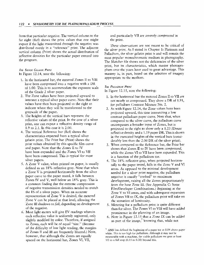
122 SENSITOMETRY FOR THE PLATINUM/PALLADIUM PROCESS
from that particular negative. The vertical column to the far right (Ref) shows the print values that one might
and particularly VII are severely compressed in the print.
expect if the light transmitted through the negative was distributed evenly in a “reference” print. The adjacent vertical column (Print) shows the actual distribution of reflective densities for the particular paper entered into the program.
These observations are not meant to be critical of the silver print. As I stated in Chapter 1: Platinum and Palladium, the silver gelatin print is and will remain the most popular monochromatic medium in photography. The Matcher file shows not the deficiencies of the silver
THE S I L V E R GELATIN PRINT In Figure 12.14, note the following:
1.
2.
3 .
4.
5.
6.
In the horizontal bar, the metered Zones I1 to VIII have been compressed into a negative with a DR of 1.00. This is to accommodate the exposure scale of the Grade 2 silver paper. The Zone values have been projected upward to intersect a typical silver paper curve. Note that their values have then been projected to the right to indicate where they will be transformed to the grayscale of the paper. The heights of the vertical bars represent the reflective values of the print. In the case of a silver print, one can expect a reflective density range of 1.9 to 2.1. In this case it is 2.00. The vertical Reference bar (Ref) shows the characteristics expected from a typical silver gelatin print. The Print bar (Print) shows the print values obtained by this specific film curve and paper. Note that the Zones I1 to IV have been expanded and the Zones VI to VII have been compressed. This is typical for most silver papers. A Zone V value, when printed on paper, is usually defined as an 18% reflective gray. Note that when a Zone V is projected horizontally from the silver paper curve to the paper tested, it falls between Zones IV and V, well below an 18% gray. This is a common finding due the extreme compression of negative transmission densities needed to match the ES of a silver paper. When an accurate representation of Zone V is desired, the metered Zone V can be placed at that level, allowing the Zone I11 shadows to full, depending on development of the negative. Most light meters will give EV readings wherein each reflective value is uniformly registered, only slightly modified by color. Therefore, if assigned to Zones, each will be of equal “size.” (Because of the difficulty of low light reading, the margins of Zones I1 and I11 are frequently blurred.) Note, however, that although the Zones are equally spaced on the horizontal bar, Zones VI, VII,
print, but its characteristics, which master photogra- phers over the years have used to great advantage. This mastery is, in part, based on the selection of imagery appropriate to the medium.
THE PALLADIUM PRINT In Figure 12.15, note the following:
1. In the horizontal bar the metered Zones I1 to VII are not nearly as compressed. They show a DR of 1.91, for palladium Contrast Mixture No. 2.
2. As with Figure 12.14, the Zone values have been projected upward, this time intersecting a low contrast palladium paper curve. Note that, when compared to the silver curve, the palladium curve encompasses a broader input of Zones, but is projected to the right to show only a 1.23 IDmax reflective density and a 1.19 paper DR. This is shown in the truncated heights of the vertical bars (consi- derably less than the 2.00 DR of the silver print).
3 . When compared to the Reference bar, the Print bar shows that Zones I1 to IV have been compressed, while the Zones VI to VII have been expanded. This is a function of the palladium toe.
4. The 18% reflective gray, when projected horizon- tally to the paper tested, falls in the Zone V and VI areas. As opposed to the minimal development needed for a silver print negative, the palladium negative is usually “cooked” to maximum development, raising all the Zones proportionately from the base Zone 111. (See Appendix C: Some FilmDeveloper Combinations.) Beginning at the Zone V to VI areas, and with subsequent expansion of Zones VII to IX, the palladium print will take on the sensation of luminosity.
than for silver. The Zones VI to VIII will have added prominence in the planning of an image.
6. Note in Figure 12.15 that a Zone I X can be added as part of the image,’ knowing that, while not
5. Metering for a palladium print is quite different
’. ANSI has defined the beginning of a paper toe at 0.04 above paper white. This is too high for palladlum. Although it may not be measurable with a machine, the visible palladium toe goes at least 1/2 to a full stop (0.15 to 0.30) beyond this.

2.4
o n P R R I f N f T
/; - - 1 - - - - -
I D R = ' . 1 9
1 2
P
19 I n
I
I
D R
3 6
13 0
9 9
o n P R
technically part of a film curve, it will appear, COMBINING THE MATCHER FILES particularly after dry down of the wet print. In some cases, as shown in Plates 12.3 and 12.4, the flair from intense sun can be included as a Zone X ! This phenomenon is equally advantageous with all extremes of lighting (as with window light in an interior space).
By flipping the Matcher file for Grade 2 silver paper and placing it adjacent to the palladium file, the two illustrations can be directly compared (Figure 12.16). Here, the relative reflective densities of the two papers are graphically displayed side by side. While the Pd paper conveys the lighter tones, well into Zones VI to

124 SENSITOMETRY FOR THE PLATINUM/PALLADIUM PROCESS
IX, the silver paper accentuates the darker tones of Zones 111 to V. Add to this the intense black obtainable with silver paper. They are indeed two distinct visual media.
NEGATIVE DEVELOPMENT FOR THE LONG TOE
The palladium examples shown require a negative of considerable density range (1.80-2.00). Any DR beyond this (2.1+), cannot be printed to a full tonal value on any palladium contrast mixture. Therefore, in planning for a 1.9 negative, there is little room for error in development. In the earlier portions of this text, I recommended a negative DR of 1.40 for PdPd and 1.60 for Pd. These “mid points” allow for considerable error in either underdeveloping or overdeveloping.
However, if one wishes to maximize the effect of the palladium toe, a negative DR of at least 1.8 should be
the goal, allowing for a slim margin of error in overdeveloping.
As discussed, when working with palladium contrast mixtures Nos. 1, 2, or 3 , the effect of the potassium chlorate used is negligible. Therefore, I would recommend the Ratio (A+B) Method.
In Appendix C: Some Film/Developer Combina- tions, I give recommended development times for various filddeveloper combinations. Also, times are given for negatives of 1.40, 1.60, and 1.80 density ranges. I have found that if one wishes to work at the “edge” for a 1.80 negative, expose at least two sheets of film identically. Develop only one, and read its density so minor changes can be made to the second if necessary. I describe my method of sorting film for development in Appendix B: The Large Negative.

Paper Test: Pd Curve No. 2 Cranes Platinotype nuArc Brush ES 1.90 KOX IOOirF Film Test TMY 8 rnm D-76 1 1
G = 55 S B R = 1 1 . 5
3.0 2.7 2.4 2.1 1.8 1.5 1 2 0.9 0.6 0 3 0.0
t l X I Vlll I VII I VI I v I IV I 1 1 1 I II I
VI
VII Vlll
I
0.0 0.3 0.6 0.
Paper Test: Ilford Galerie 2 ES .95 4 D-I2 1:2
5:45 tnins TMax RS G = .61 SBR = 5. I
l l . 7 ll.f31 2.1 2.4
111 IV v VI VIIVl l l
:4 5:45 tnins TMax RS :4 G = .61 SBR = 5. I
I 1.7 I 1.7 I 1.r I 2.1 2.4 2.7 3.0
111 IV v VI VIIVl l l
- 2.7 - 3.0
FIGURE 12.16 M A T t k E R " PROGRAMS C C J M ~ A R I N ~ PAPER S c A l F S o f N O 2 CONTRAST MIXTURE P A l l A d l U M A N d GRAdE 2 SILVER PAPER

This page intentionally left blank

CHAPTER 1 3
U S I N G T H E
CU RVE.S
PLATE 1 3 . 1 O R ~ A N PipF C A C I U S , Diablo M O U N T A I N S . A R ~ Z O N A . 2001 12 X 'Lo I N C k Pd. ThE S O N O R A N d E S E R T k A s A pARTiCUlAR
S k i M M E R i N 4 Q U A l l T y I N &INTER MORNINGS This I IGhTiNc, CAN br CApTUREd EXQUiSiTElL O N A p A l l A d i U M p R i N T WkiLE ThE LOWER TONES ARE krpT NATURAL bv NFAR NORMA1 P A P E R CONTRAST, T k E p d h d i u M TOE AllO!NS ThE A M b i E N T kic,kliqhrs TO REACk WE" INTO Z O N E S vlll A N d Ix.
127

128 SENSITOMETRY FOR THE PLATINUM/PALLADIUM PROCESS
In choosing the contrast mixture for a particular negative, many platinum and palladium printers use guides similar to those presented in the Standard Negative Contrast Ranges provided in Chapter 7: Choosing Your Method. They may analyze a concur- rently printed step tablet or simply resort to trial and error. It is, however, possible to customize your own work, incorporating your coating technique, paper, light source, and developer.
While the curves generated by the Plotter ProgramR (see Chapter 12: The Film and Paper Curves) are illuminating, more useful information can be obtained from a detailed analysis of the information provided in a graphic representation of platinum and palladium paper characteristics. In the earlier portions of this text, I showed that a reflection densitometer was not necessary for basic calibration. At this point, one will be of value. However, once your technique is fine-tuned, it will no longer be needed. So, unless you intend to extensively study these matters, it is best to arrange for the temporary use of a reflection densitometer by borrowing or renting (a print shop is a good source). At the time of publication, used ones have been available on eBay (www.ebay.com).
REFINING THE STANDARDS
When compared to the standard enlargement procedure used in the printing of silver paper, contact printing from a set light source allows the elimination of two variables. The distance of the light source to the paper (the height of the enlarger head) and the aperture of the enlarging lens do not need to be factored into any data used in calibration.
Since the light intensity is constant, the only issues we must consider are the shadow values and contrast mixture.
SHADOW VALUES
The time of paper exposure is determined by the transmission density of the Zone 111 textured shadow areas of the negative. In making the print, these values are translated to the darkest portions of the image. We now understand that these are arbitrarily defined at 90% of maximum paper black. During the analysis of the step tablet prints in Chapter 8: Calibration, we identified those values by the eye. Now, with 90% increment values accurately determined by a reflection
densitometer' and matched to a known shadow density that produced it, we can use this standard to calculate printing times for those negatives where the shadow readings match that standard. For negatives where the shadow values deviate to less or more than that standard, further calculations are possible to determine printing time.
When calibrating the light source, a standard was approximated using a 50% (No. 7) mixture of ferric oxalate A and B with a particular metal salt combina- tion at an exposure of 10 minutes or 400 units with a NuArc. That standard should now be assessed with more accuracy. Much of the reference material in this chapter will be based on the Ratio (A + B) Method with a 50% mixture of platinum and palladium. I f you are using the Na2 method, start with mixture No. Ss. See ahead to Figure 13.3 for more specific information and an Na2 family of Palladium curves.
For assistance in these exercises, refer to the depiction of step tablet values in Calibrating the Light Source in Chapter 8: Calibration.
During the light source calibration, it was recom- mended that 90% black should be produced by the Nr. 5' (0.65 density) step of the tablet. Now, this should become a requirement.
Using the reflection densitometer or the information presented in Chapter 8: Calibration, the light-to-print distance for a No. 7 contrast mixture at 10 minutes (400 units), should now be accurately stabilized to produce a 90% black on the Nr. S step.
1. The making of a No. 7 contrast mixture printed step tablet has been described in Chapter 8: Calibration. (see Figure 8.6). Read the area of maximum black (Dmax). It should be at the step Nr. 1 or the surrounding area. That reflective density should fall
'. From numerous workshops, using varied light sources, 1 have found that the Stizndird Negatizv Contrast Ranges and the Families of
Curves shown in the book are quite accurate. Therefore, it is possible to use the published data rather than draw your own curves. In this event, a reflection densitometer may not be entirely necessary. To use the information presented in this chapter, the 90% black should be in the Nr. 5 step of a step tablet. To locate the 90% black on your test prints, refer to Figure 8.6 in Chapter 8: Calibration. Adjust the light source until Step Nrs. 1 to 3 merge. If a slightly discernible change is noted in Step Nr. 4, Step Nr. 5 should represent a 90% black. '. Numbers will be used in reference to both step tablet numbers and contrast mixture numbers. For clarity, the European abbreviation (Nr.) will be used for step tablet numbers and the English (No.) for the contrast mixture.

~~
2.
3.
in the 1.40 to 1.50 range.3 If the coating is not sufficient, another print of the step tablet must be made. It is at this point that the brush and coating rod could be compared, as well as your coating technique. An anemic coating will lead to weak reflective values and mottling of the image. Multiply the Dmax value by 0.9. For example, 1.50 x 0.9 = 1.35. A reflective density of 1.35 (IDmax) will be the 90% “convincing black” of your prints. Using the reflection densitometer,’ find the tablet number on the print that most closely approximates this number. Make minor adjustments in the light- to-print distance until this becomes step Nr. 5. (Again, refer to Chapter 8: Calibration for graphic presentation of the effects of printing time and contrast mixture on a step tablet print.)
W e now k n o w that a No. 7 medium mixture of 50% ferric oxalate mixtures A and B with a particular metal salt combination a shadow value of 0.65, exposed a t 10 minutes, will give a 90% print black.
We will now offend the purists by converting the 0.65 transmission density of the Nr. 5 step to a more manageable 0.60.4 This will be your Speed Point.
FACTORING IN THE EFFECTS OF CONTRAST CONTROL
Up to now, we have been dealing with negatives that will print with a platinudpalladium (Pt/Pd) No. 7, 50% mixture of ferric oxalate A and B. They therefore have the optimum density range (DR) of 1.4.
For negatives deviating from that, we must alter the mixture of A and B, either adding or subtracting the restrainer found in the No. 7 mixture. This will change the printing speed, affecting the properties of shadow values that are being used to determine printing time. Less restrainer, as found in mixture No. 3, results in less printing time than the No. 7 mixture. More restrainer, as with mixture No. 13, adds more printing
,’. A Dmax of 1.50 is usually not attainable without special procedures, such as humidification. (See Chapter 10: Advanced Technique.) However, for purposes of clarity, a hypothetical Dmnx of 1.5 is used throughout this book. With current papers and working at 50% humidity, a more realistic Dmnx may be 1.35 (1.35 x 0.9 = 1.21). Realize that PtPd is not noted for its intense blacks. Its main attribute is a broad, subtle scale with extended whites. Reaching great Dmnx is not that important for most imagery, a coizviizcing black will do.
These techniques are intended to save considerable time and expense in producing a good test print. They will not eliminate the fine-tuning and visual interpretation needed for the final print. Therefore, a deviation of 0.05 is hardly significant.
4.
time. This can be observed in the step tablet prints in Calibrating the Light Source in Chapter 8: Calibration (see Figures 8.7 through 8.11).
If the strips were coated well and laid in order from No. l5 to No. 13, the 90% black step will move relative to the contrast mixture, thus indicating changes in printing speed.
In the strip made from the No. 2 mixture, the 90% black will have occurred at a higher number panel than the strip made with the No. 7 mixture (see Figure 8.9). If the No. 7 strip indicated a 90% black at Nr. 5 (0.60 transmission density), the same value on the No. 2 strip might occur on step Nr. 6 with a 0.8 transmission density. Therefore, the same 90% black, when printed with a No. 2 mixture, occurred at a greater negative density, showing an increase in printing speed.
In the No. 1 3 strip, the opposite is observed (see Figure 8.11). Now the 90% black is at a lower number with less transmission density. To produce the 90% black under the same amount of light, it requires that the negative be less dense. T h e printing time is slowed.
In observing strips made from contrast mixtures No. 3 and No. 5, you will note printing speeds between the No. 2 and No. 7 strips. The No. 9 and No. 11 mixtures will show slower speeds to fall between No. 7 and No. 13. The eventual calculations will show approximate linear speed changes from mixtures No. 2 through No. 13, to encompass slightly less than a one- stop increase or decrease in each direction from the No. 7 standard-a total range of almost two stops.
ANALYZING THE PRINT CURVE
To analyze and customize your own technique, you must leave the computerized arena and investigate manually drawn curves. Figure 13.1 represents the standard graph used to plot paper densities. Note that the horizontal or x axis has been marked with increases in light at 0.3 log intervals, from left to right. The numbers are falling because they represent decreasing step tablet transmission densities. The vertical or y axis is scribed with paper reflection densities, also in 0.3 log intervals, increasing from the base to the top.
Using reflection densitometer readings from the same strips that were produced during the contrast stud- ies, each contrast mixture can be plotted (Figure 13.2).
Normally, we do not analyze the No. 1 contrast mixture strip because there is no restrainer in the coating mixture. This, most likely, will result in fog.

1 TO SENSITOMETRY FOR THE PLATINUM/PALLADIUM PROCESS
2.4 2.1 1.8 1.5 1.2 0.9 0.6 0.3 0 Light Increase k
FIGURE 1 3 . 1 T k E C R A p k UsEd TO Plor L i q h A N d DENSITY. As T k E liC,kT I N C R E A S E S f R O M l E f T TO Ric,kT A I O N q T k E X A X I S . P A P E R
R t f [ E C T I V E d E N S l T l E 5 I N C R E A S E ON r k t y A X I S .
A GUIDE TO THE FAMILIES OF CURVES
The paper curves represented in Figures 13.2, 13.3, and 13.12 were generated from reflection density readings taken from Pt/Pd Ratio Method, Pd Na2, and Pd Ratio Method prints. Note that they are identified by small numbers midway on the curve, which are the contrast mixture numbers. In the case of Figure 13.3, The Family of Palladium Curves Using Na2, space limitations prevent the suffixes from being added to the mixture numbers. The horizontal x axis, or base of the graph, shows light increase from left to right. The boxed numbers are the step tablet numbers exposed to the paper. They will not be considered in planning contrast or exposure times. The log numbers 3.0 to 0 decrease from left to right and show the transmission densities of each step of the tablet. The higher log numbers to the left show ultraviolet (W) light passed through the denser steps of the step tablet. On the right, more UV light has passed through the less dense portions of the step tablet. Note that the paper curves rise in response to the light increase. The numbered vertical lines dropping a short way from the base mark the limits of each paper curve. For example, the No. 7 line on the left indicates the beginning of the No. 7 contrast mixture toe. The No. 7 line on the right indicates where the No. 7 contrast mixture crosses the 90% line. The limits of each paper curve can be identified by these sets of numbers.
On the vertical y axis the reflection densities of each paper curve are plotted starting at just above 0, superiorly to a paper density of 1.50. At 1.35 (9oy0 of 1.50), a heavier 90% line passes horizontally and intersects each paper curve at its 90% black. It is here where paper exposure speeds are calculated. On the right are columns of numbers to serve as an aid in matching negative density ranges (DR) to mixture numbers, either expressed in ratios of A to B (Figure 13.2), or drops and concentrations of Na2 per twelve drops of coating (Figure 13.3). Also in Figure 13.3 are percent volumes of Na2.
Note that except for mixture No. 2, only the odd numbers were used. Here, plotting reflective. densities, a Family of Pt/Pd Curves has been produced similar to the computer-generated Figure 12.9. Note that all of the strips have a maximum black of 1.5. When a horizontal line is drawn at the 90% black, or 1.35 reflective density, level the line intersects the film curves at different points.
THE N A ~ METHOD
Those using chloroplatinate (Na2) as a contrast control agent with palladium can refer to Figure 13.3. The basic calibration test can be done with mixture 5s. The following portions of the text are presented for the Ratio Method using 50% platinum and 50% palladium. Conversions to the Na2 Pd and Ratio Pd Method can be done using the following chart, Table 13.1. (See also Tables 7.1 and 7.2.) The dichromate method had been added for completeness (see Table 7.6).
GRAPHIC ILLUSTRATIONS OF SPEED CHANGES PRODUCED BY CONTRAST MIXTURES
In Figure 13.4, three curves are shown intersecting the line for 90% black. The vertical lines projecting down- ward represent the speed changes produced by the different contrast mixtures. By noting where these vertical lines cross the calibrated base of the graph, we can calculate printing speed changes produced by the contrast mixtures. The horizontal dotted line adjacent to the base represents the beginning of textured white.
hy( )I[ . For those not working with photographic sensitometry, the concept of speed changes tracking along the horizontal axis may initially be difficult

+
Re
flec
tion
De
ns
ity
?
o! '9
'? r
0
0
0
v! r
?
r
0
-0
Y
m4
m
-cu
g m
-r
0
m
t
-m
L
-cu a, O
D
W
h @
i-
r

13
2
SEN
SITO
MET
RY
FOR
THE
PLA
TIN
UM
/PA
LLA
DIU
M P
RO
CES
S .
..
..
..
..
..
..
..
..
..
..
..
..
..
..
..
..
..
..
..
..
.
m--
' rn
X
U 0
v)
S
A-
N-
u- a-
m-
uld
-m
Re
fle
cti
on
De
ns
ity
t
0
0
0

TABLE 1 3 . 1 ARE PRlNTEd IN Bold TEXT
EQLIIVA~ENI CONIRASI MlYTL~RES fC)R Tkt RATIO PIIPd, Pd, NA2 Pd, A d D l C k R O M A l t METhOd5 T k E Mld-CONTRAST ES VsEd fOR C A ~ I ~ R A T I O N
I I
I t I I
Textured Whte
r -rl- _ - - - - -
Negative D R Ratio Method PtlPd Na2 Method Ratio Method Pd Dichroinate Method Dropsl2OO
5 - 0.3 5 B
7 -I-- o
2.10 1.90 1.85 1 .so 1.75 1.70 1.60 1.50 1.40 1.30 1.20 1.10
- - -
No. 1
No. 2 No. 3 No. 5 No. 7 No. 9 No. 11 No. 13
-
- -
No. Is
No. 2s
No. 3s No. 4s No. 5s No. 6s No. 7s No. 8s
-
-
No. No.
No.
No. No. No. No. No.
1 2
3
5 7 9 11 13
Pt/Pd Pd 1 2
3 1
2 4 4 8 6 16 8 32 16 32
Printing Speed Faster
2.4 2.1 1.8 1.5 1.2 0.9 0.6 0.3 0
FIGURE 1 3.4 T ~ E I N T I R S E C T I ( ~ N O f P~AiiNVMiPnllAdlul\1i/PA~~Adiu~l C L I R V I ~ A T YO% b h c k
to grasp. Refer again to A Guide to the Families of Curves in this chapter. Remember that the numbers on the x axis represent light increase, from left to right. The log numbers (0.9,0.6,0.3, etc.) are the transmission densities of the step tablet. The lower the number, the more light is allowed to reach the paper.
The 90% black shown in Figures 13.2, 13.3, and 13.4 is a measurable and duplicable constant. In this case it is reflection density 1.35.
If a more dense step tablet value caused the same 90% black, the contrast mixture has a faster Printing Speed. (Due to less restrainer, the reduction of metal salts is faster when exposed to a given amount of UV light.) If a less dense step tablet value caused the same 90% black, the contrast mixture has a slower Printing
Speed. (Due to more restrainer, the reduction of metal salts is slower when exposed to a given amount of UV light.)
The step tablet densities are also a constant.
0
0
0
When tracking the vertical lines from where each curve crosses the 90% line to the x axis, going from left to right, each 0.3 change represents a halving of Printing Speed change or a doubling of exposure time. (Due to the increased restrainer, the reduction of metal salts is slower in response to a given amount of UV light.) Greater printing speed means less printing time. When going from right to left, each 0.3 change represents a doubling of Printing Speed change or a halving of exposure time. (Due to the decreased restrainer, the reduction of metal salts is faster in response to a given amount of UV light.) Lesser printing speed means more printing time.
In Figure 13.4, a portion of the No. 7 curve is shown in the center. The solid center vertical line is projected from the point where that curve intersects the 90% black to the horizontal shadow density scale. The No. 7 mixture represents the standard from which other contrast mixture corrections will be made. (When using Na2, it will be mixture 5s.)
Note in Figure 13.4 that, to the left, a portion of another curve is shown crossing the 90% black. This is drawn from a contrast mixture of a lower number containing less restrainer. The dotted vertical line crosses the horizontal axis to the left of the solid line produced by the No. 7 mixture. In this case, a shorter

1 3 4 SENSITOMETRY FOR THE PLATINUM/PALLADIUM PROCESS
Highlight Density (IDmax) - Shadow Density (IDmin) = Density Range 1
Find Contrast Mixture
c No. 7 (5s) (Nos. 1 through 6 or 1s through 4s)
-1 Corrected Speed Point
> 0.6 = 10 Minutes -1
Shadow Density Correction from 10 Minutes
-1
No. 7 (5s) -1
Speed Point 0.6 = 10 Minutes
-1 Shadow Density Correction
from 10 Minutes -1
Printing Time
> No. 7 (5s) (Nos. 8 through 13 or 6s
through 8s) -1
Corrected Speed Point < 0.6 = 10 Minutes
.1 Shadow Density Correction
from 10 Minutes -1
printing time will be needed than with the No. 7 mixture.
To the right, a portion of a curve produced by a contrast mixture containing more restrainer than the No. 7 mixture is represented. Here the projected dotted line intersects the horizontal base to the right. A longer printing time will be needed.
USING THE ALGORITHM
In learning the steps necessary-from the reading of the negative to the calculation of printing time-it is helpful to follow a planned series of steps, or an algorithm, until the process becomes more routine. A sample algorithm is presented in Table 13.2, and a series of steps follow in the text.
1. Using the transmission densitometer, read the highlight and shadow values of the negative.6 Do the subtraction to determine DR.
2. Determine the contrast mixture. Use your own data or refer to Tables 7.1 and 7.2 in Chapter 7: Choose Your Method.
a. In Table 13.2, c (less than) No. 7 refers to mixture Nos. 1 through 6 (Na2 mixture Nos. I to 4).
'. As 1 have emphasized textured values in the print, it is also necessary to read the clear and dense portions of the negative where shadow and highlight textures are desired. If the negative has been well made, these are usually the clearest and most dense areas. If either the shadows or highlight areas of the negative are without texture (a frequent occurrence with enlarged second- or third-generation negatives), the print will reflect the same absence of values.
The Corrected Speed Point is shown as > (greater than) 0.6. This means that shadow densities higher than 0.6 will still print at 10 minutes. This is due to less restrainer.
b. In Table 13.2,>(more than) No. 7 refers to mixture Nos. 8 through 13 (Nu2 mixture Nos. 6 to 8). The Corrected Speed Point is shown asc(1ess than) 0.6. This means that shadow densities less than 0.6 will still print at 10 minutes. This is due to more restrainer.
3 . Find the appropriate curve in Figure 13.2 (Ratio Pt/ Pd) or Figure 13.3 (Na2 Pd). (Later in this chapter I will present palladium with the Ratio Method. In that case the same calculations can be done using Figure 13.12.)
4. For contrast mixture No. 7 (5s ) , project a vertical
5.
line from the 90% black to the horizontal axis. It should cross at 0.6, your Speed Point.' For contrast mixtures Nos. lthrough 6 ( I s through 4s ) , see the left side of the algorithm. Note that a Corrected Speed Point will be needed. Referring to the Family of Curves for your particular metal combination, find the curve for that contrast mixture and project a vertical line from the 90% black to the horizontal axis. It will cross somewhere between 0.8 and 0.6. That density is your Corrected Speed Point. (Look ahead to Figure 13.9.)
''. If, for some reason, you choose not to calibrate at this point, use the step tablet density that gave you a 90% black at 10 minutes printing time.

6.
7.
For contrast mixtures Nos. 8 through 13 (6s through 8s), see the right side of the algorithm. Note that a Corrected Speed Point will also be needed. Find the curve for that contrast mixture and project a vertical line from the 90% black to the horizontal axis. It will cross somewhere between 0.6 and 0.4. (Look ahead to Figure 13.11.) That density is your Corrected Speed Point. Using either your Speed Point or Corrected Speed Point, do the shadow densities correction using the actual shadow value of your negative. From this, working from the 10-minute printing time stan- dard,* you will determine your printing time. This will be discussed in detail later in this chapter and examples given.
EXAMPLES OF VARIOUS NEGATIVE DENSITY VALU ES
While going through these exercises, refer the Table 13.2 algorithm and the Family of Curves for your particular metal combination (Figure 13.2, 13.3 or 13.12). After awhile, you will understand the process. Following that, you will be able to make the first test strip surprisingly close to what you have envisioned for the final image. Only reprinting the test strip for fine-tuning will be necessary. For those who have worked empirically in the past, you will be pleasantly surprised by the controls possible for sophistication of imagery.
THE NORMAL NEGATIVE
Observe the No. 7 curve in Figure 13.5. If a vertical line is drawn down from its intersection of the 90% black line to the x axis, it will fall at the 0.6 transmission density. If, from that point, the logs are counted until the curve intersects the dotted horizontal line (textured paper white), the number is 2.0, a 1.4 interval from 0.6. The exposure scale (ES) of the mixture is 1.4.
A Normal Negative with a 0.6 Shadow Density
TRANSMiSSiON DENSiTiES: 2.0 - 0.6 = 1.4
'. If you standardized at a printing time other than 10 minutes, you must calculate from that time. It is strongly suggested that the NuArc be standardized at 400 units. The NuArc and other plate burners allow for such adjustments.
4 t
0.9
0.6
P 0.3 2
9 0 ;
9 -
2.4 2.1 1.8 1.5 1.2 0.9 0.6 0.3 0 Light Increase Exposure Scale -q ___, 2.0.0.6 = 1.4
?Speed Point
FIGURE 1 3 . 5 TkE N O 7 PlATlNUM/PAl lAdlUM C U R V E OR T k E N O .
5s N n 2 CURVE
In Figure 13.5, note the vertical line intersecting the base at 0.6. It is from a No. 7 curve. We know that mixture was used for standardizing the light source; therefore, it can be used as our standard. The 0.6 shadow density represents the Speed Point.
After the IDmax and lDmin transmissions densities are read and recorded, using you own data or referring to the Standard Negative Contrast Range charts in Chapter 7: Choose Your Method, you can determine your contrast mixture. Now you can calculate printing time.
THE SPEED BAR
When examining Figures 13.2, 13.3, and 13.12, note that the transmission density numbers at the x axis are a logarithmic scale. That is, while moving a single point to the left or right, densities are halved or doubled. However, the changes in printing time produced by the density numbers are arithmetic, where the numbers are linearly spaced. For example, moving right from 0.6 to 0.3 would halve the printing time. Moving left from 0.6 to 0.9 would double the printing time. Some of us who are old enough will recall the slide rule. Scientists and engineers used it for the same purposes as the present day calculator. The slide rule is simply two sliding bars imprinted with either a logarithmic or arithmetic scale. By sliding an arithmetic scale against a logarithmic scale, numbers in a logarithmic progression can be read in an arithmetic progression.
The Speed Bar is shown in Figure 13.6 and will be used as a slide rule. Copy it to scale and place it at the

156 SENSITOMETRY FOR THE PLATINUM/PALLADIUM PROCESS
8o I i 40
Speed bar for Printing Times Based on Ten Minutes
I 2 O l I ’ O l l 5 I 1 2.5 I I 1.25 I ---
70 50 35 25 16 12.5 8 6.3 4 3.1 2 1.5
1.Find the 90% shadow dens i ty ver t ical l ine for your cont ras t mix ture . 2 .P lace the Speed Bar under the ver t ical l ine and posi t ion the arrow at that po in t . 3 .Note the shadow value of y o u r nega t ive and look down to f ind your pr in t ing t ime.
~~~~~~~~~~~ ~~~~ ~~~~~~~~~~~~ ~~~~~~~~~~~~~ ~~~~~~~~~~~~ ~ . . . ~ ~ ~ ~ ~ ~ ~ ~ ~ ~ .
4
I
8oo I I 400 I 1 2oo I I 1380 960 640 320 320 250 160 125 80 6 4
1.Find the 90% shadow densi ty ver t ical l ine for your cont ras t mix ture . 2 .P lace the Speed Bar under the ver t ical l ine and posi t ion the a r row at that po in t . 3 .Note the shadow va lue of your nega t ive and look down to f ind your pr in t ing t ime
FIGURE 1 3 . 6 Tkr SpEEd BAR Copv i k i s & ~ d TkE s E l t c i E d F A M I I ~ nf CURVES to the same scale CUT A T TkE dorrEd L I N E S T k t u p p t ~ S ( A I E I S fOR A SpEEd POINT bAstd ON 10 MlNLlTES T k E [ O W E R S C A l E I S fOR TkE NLIARC b A 5 E d ON 400 ClNlTS
base of Figure 13.2,13.3, or 13.12. Starting at the arrow at a standard 10 minutes (400NaArc units), printing times can be calculated for times less and more than the standard.
In Figure 13.7, the top section of the illustration shows a portion of Figure 13.2: Family of Platinunzl Palladium Curves Using the Ratio Method. Note that in Figure 13.7 the densities at the base of the graph match the schematic below it. The intersection of the curve for contrast mixture No. 7 and the 90% black line is projected downward where it meets at a shadow density of 0.6. This is the Speed Point. In this instance it is 10 minutes.
The light source was distanced to provide that a No. 7 mixture (Nu2 mixture 5s) exposed for 10 minutes would produce a 90% black in step Nr. 5 of the step tablet (0.6 transmission density). Therefore, a negative measuring 2.0 - 0.6 = 1.4, will duplicate this curve. Going back to the vertical line, one can deduce that this negative will require the same conditions that produced this graph: 10 minutes or 400 units of exposure. N o correction for shadow values is needed.
Note that the Speed Bar has been placed in its proper position. The arrow on the Speed Bar is at
10 minutes, the Speed Point. Since there will be no further correction, the printing time is 10 minutes.
In practice, a shadow of 0.6 is too dense, and the indicated printing time is equally too long. It has been indicated that the “ideal” negative should have shadow densities just above the base + fog (BfF). Referring to Figure 12.4 in the last chapter, note that the IDmin density is approximately 0.25, the desirable shadow density.’
The “Ideal” Negative
TRANSMiSSiON DENSiTiES: 1 . 7 - 0 . 3 ~ 1 . 4
An “ideal” negative will also use the No. 7 mixture but will require a shadow density correction. Using the logarithmic calculations presented in Chapter 3: The Negative, we know that 0.3 is half the density of 0.6.
9. For uniformity in this text, the log transmission density of 0.3 will be used to define an ideal negative shadow density. Some films, such as 400Tmax, will produce effective shadow densities lower than 0.3. Some, such as HI‘S+, will have values over 0.3. After mastery of this technique, changes can be made to accommodate different films.

90% - I I I I
x 14 i s 1 2 ii in o 8
1.8 1.5 1.2
I
I t I I I
I I I 1 1 1 1
4
I - .9 I
Exposure Increase- I 2
I
I
t I I I
I I
I I 1 1 1 1
-
i 5
I
3 2
.3
I
I
t I I I I I I I ! 1 I I l-Stei - 0
3
4
5
6
7
8
9
1 c
I 1
1 2
13
- - - - I
I 6 0
1 5 5
1 5 0
1 4 5
1 4 0
1 3 5
1 3 0
1 . 2 5
1 2 0
1 . 1 5
1 . 1 0
- - -
N urn bers
3 7 1 1
Graph Speed Point
1 2.4 2.1 1.8 1.5 1.2 0.9 0.6 0.3 0
I I I 4 I I I I 1
I - I I I I I I I I
A
I 70 50 3525 16 12.5 8 6 3 4 3.1 2 1 . 5
1 . F i n d t h e 9040 s h a d o w d e n s i t y v e r t i c a l l i n e f o r y o u r c o n t r a s t m i x t u r e . 2 .Place t h e S p e e d B a r u n d e r t h e v e r t i c a l l i n e a n d p o s i t i o n t h e a r r o w a t that p o i n t . 3 .No te t h e s h a d o w v a l u e of y o u r n e g a t i v e a n d 1004 d o w n to f i n d y o u r p r i n t i n g t ime.
Referring again to Figure 13.7, follow the directions on the Speed Bar:
1. Find the 90% shadow density vertical line for your
2. Place the Speed Bar under that line and position the
3. Note the shadow value of your negative and look
contrast mixture.
arrow at that point.
down.
In this case, you would find your shadow density to be 0.3. Look down for a printing time of 5 minutes.
The Normal Negative with High Shadow Values
TRANSMiSSiON DENSiTiES: 2.3 - 0 . 9 = 1.4
This negative, while still requiring the No. 7 mixture, will need a shadow value correction that will increase printing time. If a shadow density of 0.9 is read (0.3 +the 0.6 standard), the printing times are doubled. Refer to Figure 13.7. This time, find the 0.9 density and look down. The printing time is now 20 minutes, approaching the range of impracticality.
WORKING WITH INTERMEDIATE SHADOW VALUES When shadow density variables of 0.1 exist, we can adjust printing times in smaller increments. Instead of halving or doubling the time, times falling in between can be factored.
A Normal Negative with a 0.4 Shadow Density
TRANSMiSSiON DENSiTiES: 1.8 - 0.4 = 1.4

138 SENSITOMETRY FOR THE PLATINUM/PALLADIUM PROCESS
I I I I I I I I I I I I I I
1 4 13 1 2 11 1 0 9 8 7 6 5 4 3 2
This negative still requires the No. 7 mixture. It is close to ideal, so it will need only a minor shadow value correction. Here, a shadow density of 0.4 would fall 1/3 between 5 minutes (0.3) and 10 minutes (0.6). In Figure 13.7, find the 0.4 shadow density and look down. It is 6.3 minutes.'"
I I I I I I I I I I 1 c S t e p N u m b e r S
A Normal Negative with a 0.8 Shadow Density
TRANsMissiON DENsiTiEs: 2.2 - 0.8 = 1.4
9 1.8 1 5 1 2 Exposure Increase
In this negative, the shadow value will require a considerable increase in printing time. Following the Speed Bar, find your shadow value of 0.8 for a printing time of 16 minutes.
0
THE HIGHXONTRAST NEGATIVE
Figure 13.8 represents a curve drawn from a No. 2 Pt/Pd mixture (Na2 mixture 2s). The point at which the curve intersects the 90% line is IDmax. When a vertical line is projected from that point to the base of the graph, it intersects the line at 0.8, the shadow density used to construct this curve. This is the Corrected Speed Point for a No. 2 Contrast Mixture. It is from here that shadow value corrections must be made. Working at the base, or x axis, measure the span from the Corrected Speed Point to where the curve actually intercepts the horizontal line at textured white (IDmin). This is
1.2
0.9
0.6
0.3 3 4
-4 Exposure Scale 2 5 - 0 8 = 1 7
!Corrected Speed Point
lo. Some with a background in mathematics will observe that we are dealing with segments of a logarithmic scale, so the calculation of intervals is not entirely correct. The method presented is, however, close enough to produce very good test prints.
the exposure scale (ES) for this mixture. For example, the No. 2 curve intersects the 90% line at a 0.8 transmission density. At its intersection IDmin at 2.5, subtract 0.8 for an ES of 1.7.
\ O I I To avoid any confusion, realize that in the following sections, I will refer to medium-, high-, and low-contrast negatives. The paper contrasts to accom- modate these negatives will, of course, be medium, low, and high, in that order.
This is the first practical example of how lower- contrast mixtures increase printing speed. In corn- parison, a No. 7 PtPd contrast mixture with the same 0.8 shadow density would yield an approximate 18-minute printing time. As you will see later, a low- contrast negative with a 0.8 shadow value calling for a No. 13 mixture would require a 35-minute printing time!
A High-Contrast Negative with a 0.8 Shadow Density
TRANSMiSSiON DENsiTiEs: 2 . 5 - 0.8 = 1.7
Note in Figure 13.9 that the shadow density of the negative is 0.8. The Speed Bar has been moved to where the arrow lines up with 0.8. This negative duplicates the print made using the step tablet at the No. 2 mixture at 2 0 minutes. Therefore, the printing time is the same: 10 minutes.
A High-Contrast Negative with a 0.5 Shadow Density
TRAN5MkiON DENSiTiES: 2.2 - 0 . 5 = 1.7

Refer to Figure 13.9. The Speed Bar has been positioned at the Corrected Speed Point for this curve. Find the shadow density of the negative described. It is 0.5. Find 0.5 at the base of the Family of Curves graph. Look down. The printing time is 5 minutes.
A High-Contrast Negative with a 0.3 Shadow Density
TRANsMis5iON DENsiTiEs: 2 . 0 - 0 . 3 = 1 . 7
Again refer to Figure 13.9. The Speed Bar has been positioned at the Corrected Speed Point for this curve. Find the shadow density of the negative described. It is 0.3. Find 0.3 at the base of the Family of Curves graph. Look down. The printing time is 3.1 minutes.
By now, it is apparent that once the Speed Bar has been positioned at the Speed Point of a particular curve, it does not need to be moved again. All shadow densities can be calculated from there.
THE L O W ~ O N T R A S T NEGATIVE
To analyze the other extreme, note the No. 13 curve (Nu2 mixture 8s), found in Figures 13.2 or 13.3. It will intersect the horizontal 90% line to the right of the No. 7 curve. Drop a vertical line from where it intersects the 90% line to the x axis. It should fall at the 0.4 transmission density, indicating that it is 2/3 stops slower than the No. 7 mixture (0.6). This means that an appropriate negative with a shadow density of 0.4 will produce a 90% black at a printing time of 10 minutes. This is the Corrected Speed Point for the No.
I I I
13 (Nu2 8s) contrast mixture. Also, base, the exposure scale is 1.1 (Figure
t I I I
note that at the 13.10).
80 40 20 110 5
I/ - 1.5 90% Black
- - _ _ 2.4 2.1 1.8 1.5 1.2 0.9 0.6 0.3 0
Exposurescale 4 1 5 - 0 . 4 = 1 1
Corrected Speed Point
FIGURE 15.10 T k F No I 3 OR N A ~ MixIIiRt 8 5 C ~ i i < \ t
2 5 1 2 5 --- A
A Low-Contrast Negative with a 0.4 Shadow Density
TRANSMiSSiON DENS~T~ES: 1 . 5 - 0 . 4 ~ 1 . 1
Now the Speed Bar has been moved to the right so that the arrow lines up with the Corrected Speed point of 0.4. The printing time is 10 minutes (Figure 13.11).
A Low-Contrast Negative with a 0.6 Shadow Density
TRAN5Mi55iON DEN5iTiE5: 1 . 7 - 0 . 6 = 1 . 1
As often is the case with less contrasty negatives, if times must be adjusted for shadow density, they will be longer than 10 minutes (see Figure 13.11). With the Speed Bar in place, find the 0.6 point on the graph. Look down. The printing time is 16 minutes.
A Low-Contrast Negative with a 0.9 Shadow Density
TRAN5MiSSiON DENSiTiES: 2 . 0 - 0 . 9 = 1 . 1
It is in this area that things can rapidly get out of control. With a No. 13 mixture, a shadow density of 0.9 requires a correction of almost two stops. Find 0.9 and look down. The printing time is 35 minutes!
At some point, reciprocity failure will come to haunt you-another good reason for controlling shadow densities.
When adjusting for contrast, recognize the follow- ing factors.
INTERMEDIATE CONTRAST MIXTURES Using the above principles and referring to the Starzdard Negative Contrast Ranges in Chapter 7: Choosing Your
I I I I I I I I I I I I 1 4 1 3 1 2 11 10 9 8 7 6 5 4 3 2 1 c S t e p N u m b e r s
FIGURE 1 5 . 1 1 Tlir RATIC) No I 3 P T I P ~ O R N A ~ MIXILIRE 8 5
ClRVt f O R A LOU-CONTRA51 NEC,AII\E UlTk I h F 3 P F F d B A R Ih P14CF

140
SEN
SITO
MET
RY
FOR
THE
PLA
TIN
UM
/PA
LLA
DIU
M P
RO
CES
S
n
7
D
7
_.
N
b
m-
0
Re
fle
cti
on
De
ns
ity
b
2
2
2
x :
N
m
m ?
W
0
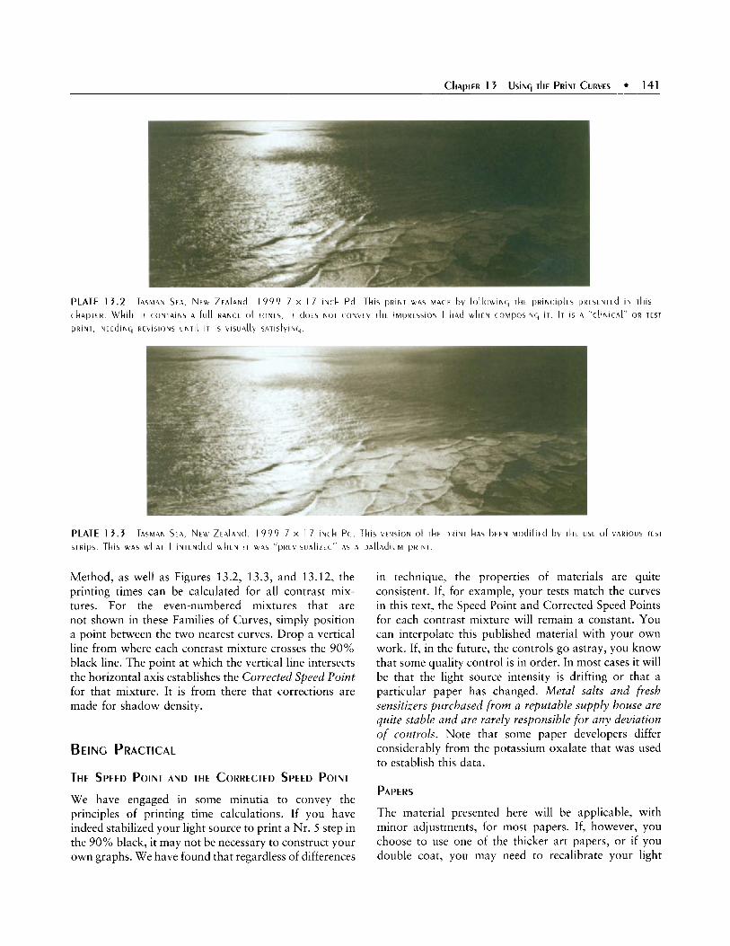
PLATE 13 .2 C k A p T E R . wkllr i T CONTAINS A f u l l RANCE Of TONES, I T d O F s h O T (ONVEV T k E iMpRESSlOY I had W h E N COMpOSiWC, i T . IT I S A "C \ iN ICA[ " OR TEST
PRINT, N E E d i N G REVISIONS UNTIL i T is \ , lSUA[[Y SATiSfVlNC,.
TASMAN S F 4 , NFW Z E A l A N d . 1 9 9 9 7 X 17 i N c k Pd This P R i N T WAS M A d E bv fOLlOWlNC, T ~ E P R i N C I p l E S PRESENTEd I N rkis
PLATE 1 3 . 3 STRIPS
T A ~ M A N S E A , NEW Z E A ~ A ~ ~ 1 9 9 9 7 X 1 7 I N C h Pd Tkls W A S W k A T I I N T E N d E d U k E N I T W A S "pRELISUA[12Ed" AS A p A l l A d l t l M PRINT
T k 1 5 VERSION Of T k E PRINT h A S b E E N M o d l f l E d T k E USE Of \ARIOUS TEST
Method, as well as Figures 13.2, 13.3, and 13.12, the printing times can be calculated for all contrast mix- tures. For the even-numbered mixtures that are not shown in these Families of Curves, simply position a point between the two nearest curves. Drop a vertical line from where each contrast mixture crosses the 90% black line. The point at which the vertical line intersects the horizontal axis establishes the Corrected Speed Point for that mixture. It is from there that corrections are made for shadow density.
BEING PRACTICAL
THE SPEED POINT AND THE CORRECTED SPEED POINT
We have engaged in some minutia to convey the principles of printing time calculations. If you have indeed stabilized your light source to print a Nr. 5 step in the 90% black, it may not be necessary to construct your own graphs. We have found that regardless of differences
in technique, the properties of materials are quite consistent. If, for example, your tests match the curves in this text, the Speed Point and Corrected Speed Points for each contrast mixture will remain a constant. You can interpolate this published material with your own work. If, in the future, the controls go astray, you know that some quality control is in order. In most cases it will be that the light source intensity is drifting or that a particular paper has changed. Metal salts and fresh sensitizers purchased f rom a reputable supply house are quite stable and are rarely responsible for any deviation of controls. Note that some paper developers differ considerably from the potassium oxalate that was used to establish this data.
PAPERS
The material presented here will be applicable, with minor adjustments, for most papers. If, however, you choose to use one of the thicker art papers, or if you double coat, you may need to recalibrate your light

142 SENSITOMETRY FOR THE PLATINUM/PALLADIUM PROCESS
source for that particular paper. See Chapter 5: Paper, for additional information.
THE INTERPRETIVE PROCESS
While working to understand densities, curves, scales, and the computations necessary to make a print contain- ing a full range of tones, we must also remember that we are dealing with a visual art form. The final print should not be the product of “number crunching” but of using the right side of the brain to produce an image that has met our visual goals. Rarely does a first print derived from sensitometric readings qualify. Referring to Plates 13.2 and 13.3, the first is what I term a clinical print. In the days when monochrome was used for illustrative purposes, such as medical photography, it would have served that purpose. For us, it should be the first of a series of test prints until it has been “tweaked” visually to our satisfaction, as in Plate 13.3. By initially under- standing the means to make a full tonal value print, and then learning to effectively modify it using visual feedback, we can save the labor and materials usually expended by those who print by trial and error.
PALLADI u M
In the last chapter, we discussed the extended toes and tonal ranges of pure palladium. Also, I recommended that the use of palladium with the Ratio Method be limited to the higher density ranges where the chlorate is not needed in sufficient amounts to cause paper floccula- tion. The speed changes related to contrast mixture are quite similar to those observed with Pt/Pd, but because of the greater DR of palladium mixtures, the speed changes may be more pronounced, particularly with the low- contrast mixtures. It is important that, regardless of the material used, you verify your own Speed Point.
In Figure 13.12, note that, except for the greater ES and more of a horizontal spread in the curves, the Palladium Family of Curves is quite similar to the other Families of Curves. The Speed Point and Corrected Speed Points for various contrast mixtures are the same. The same principles apply when calculating printing times. ’ ’
Some printers have reported palladium to have a slower printing time than Pt/Pd. This observation is based on the use of an identical negative. Due to its greater ES, palladium requires a negative of more contrast than P f l d . If negatives of the same DR were to he used for both PdPd and palladium alone, for an ES to match the DR of the negative, palladium would require more sertsitizet than WPd, thus slowing the printing speed.
11.
USING PORTIONS OF THE PAPER CURVE
USING INTERMEDIATE TONAL VALUES
Up to now, I have utilized the paper curves to calculate a full tonal range print, a print that exhibits a total scale of all possible tonal values. One of the advantages of working from curves, however, is that a print need not be placed to encompass both the absolute shadow and/or highlight values.
A perfect example of deviating from this practice is the creation of a high-key print: one that contains textured highlights, but stops short of exhibiting the darker registers. As one might conclude, if only a portion of the curve is used, the negative need not have the DR called for at a particular contrast mixture. Or, a contrast mixture may be chosen that exceeds the DR of the negative, allowing the use of only a portion of the curve.”
The steps in utilizing a portion of the curve are a bit more complicated in that two steps are involved: the calculation of printing time for a full tonal value print and, then, recalculation for the printing time of a less than full tonal value print. For printing at a portion of the curve, the following steps are needed:
Compute the DR of the negative. Choose the contrast control method and metal. (I recommend Ratio Pd.) Using the previous exercises, calculate printing time. By means of a marked piece of paper representing the DR of the negative, slide it laterally under the base of the Family of Curves to find a new curve of greater DR. Continue to slide the paper until a portion of that curve is chosen. Recalculate a new printing time. (This usually will be less than the original time.)
Figure 13.13 represents a curve for a Ratio Pd No. 2 mixture. A negative with a 1.4 DR would normally call for a No. 1 1 Pd Ratio Method contrast mixture. By positioning it toward the high end of the curve (to the left, therefore, decreasing exposure), we have kept the highlights near paper white. Note, however, that the blacks now fall in the low midrange of the paper scale at a reflected density of 0.8 (Zone IV).
12. One of the joys of teaching workshops is to find a negative from a talented student that has been made for silver and, therefore, has a short DR. When such a negative ( L I S L I ~ I I ~ a portrait or nude), is placed in the upper registers of a palladium curve. the result, many times, is exquisite.

I I 2.1 1.8 1.5 I 1.2 0.9 0.6 0.3 0 - A 1 4 DR Negative d I
Exposure Scale 2 7 .0 8 = 1 9 I Y New Speed Paint i-fnrrected Speed Point
80
To
1.
2.
3.
4.
40 20 10 5 2.5 1.25 ---
0.9
0.6
0.3; - 3
3 O I
USE A PORTION OF THE CURVE
Read the negative on the transmission densitometer. Record the highlight and shadow densities. Perform the subtraction to determine the DR. Note the numbers in the right columns in Figure 13.12. For example, a negative of 1.4 DR would call for a No. 11 Pd mixture. Place a scrap of paper at the base of Figure 13.12. Find the No. 1 1 vertical lines extending below the base. These lines are extensions from where that No. 11 curve meets IDmin on the left and a vertical line dropped from IDnzax where the curve crosses the 90% line. Mark the scrap of paper with the density values at the No. 11 vertical lines. For example, a negative with a 1.4 DR would be 1.85 for highlights and 0.45 for shadows. (0.45 is half way between 0.6 and 0.3.) The left portion should match where the curve intercepted the line for textured paper white (IDnzin). The right side of the paper will lie at the point where a vertical drawn from the curve interception with 90% black would fall. Using the Speed Bar as before, calculate the printing time for a full tonal value print. For a negative 1.85 - 0.45 = 1.40, the printing time would be 10 minutes. For a negative 1.70 - 0.30 = 1.40, the printing time would be about 6.3 minutes (actually, 6.5). Now, sliding to the left and right, see how the paper markings fit in the other curves. If you are planning a high-key print, find a curve to the left, one that
5.
6.
7.
calls for more contrast in the negative. You may find that your paper markings will incorporate only the toe and mid portions of the curve. You can visualize your print by imagining the “Zones” that might be displayed. While doing these exercises, it is helpful to refer to Figure 12.15, the MatcherR File for palladium in the last chapter. Also note that Plate 12.2: Salmon River has been printed emphasizing high values to accentuate the sun and its halo. The dock, while appearing black, falls in the Zone IV to V areas. If you are satisfied, note the new contrast mixture and compare, as before, your shadow value with the density indicated on the graph. Look at Figure 13.13. Here, the negative has a DR of 1.4. To print as a full tonal value print, it would need palladium Ratio Mixture No. 11. However, palladium mixture No. 2 was chosen. Slide the paper to the left until the negative reaches the end of the toe at 2.7. Now the other end, which should produce paper black, is now at 1.3 on the horizontal scale. This is the New Speed Point. If projected upward to intersect the curve, and then right to the y axis, it intersects at about 0.95. If the 90% black line was in Zone 111, it is now in Zone IV (see Figure 12.15). Therefore, a print will be made with a textured long toe with shadows only in the Zone IV area, just like Plate 12.2: Salmon River. Calculating printing speed is the reverse of the previous exercises. Keep in mind that as you are going to the “high key” part of the curve, the printing time should be less than needed for a print showing Zone I11 shadows. This time, use the Speed Bar as an aid to negotiate the printing time changes along the logarithmic scale at the base of the graph.’j
a. Find the New Speed Point. Line up the Speed Bar so the previously calculated printing time for a full tonal ualue print is at that point.
b. Referring again to a 1.85 - 0.45 = 1.40 nega- tive, note that printing time was 10 minutes.
c. Knowing that the printing time will be less than the 10 minutes shown by the arrow, we travel to a Corrected speed Point of the No. 2 curve. Look down. the printing time is 3.1 minutes. (See Figure 13.13)
d. For the second example, 1.70 - 0.30 = 1.40. The printing time for a full tonal value print was 6.5 minutes. Line up 6.5 with the New Speed
As the Speed Bar allows for arithmetic calculations from a logarithmic scale, it also can be used to track printing time changes from one shadow density on the Family of Curves to another.

144 SENSITOMETRY FOR THE PLATINUM/PALLADIUM PROCESS
Point. Look to the Corrected Speed Point and down. The new printing time is 2.5 minutes.
From the calculations shown, printing times have ranged from 10 to 2.5 minutes, a factor of four. If working from trial and error, how many prints would be necessary before an accurate printing time was discovered?
This technique takes a little practice, but it is quite valuable for prints that are to be less than full tonal range. This is most useful when calculating the printing
of a nude or portrait. We can choose a curve at random. By sliding the marked piece of paper laterally, we can pinpoint the portion of that curve where we want the flesh tones to appear (usually on the left side of the mid portion, Zone VI). If that is not satisfactory, we can choose another curve.
Conversely, the same procedures can be used to plan a darker, more somber image using the darker tones and eliminating the higher values. In this case, the pencil markings would be shifted to the right portions of the curve, calling for mow printing time.

145

146 APPENDIXA
THE 0 x 1 DATION RE DUCT ION REACTION
As with many types of photographic printmaking, including the silver gelatin process, the platinum/ palladium image is dependent upon the reduction of electrically charged metal salts to the uncharged metallic state. In this oxidation-reduction or redox reaction, there is a change in the oxidation number of one or more elements. The oxidation number, or oxidation state, is determined by the transfer of negatively charged electrons.
Oxidatioiz is the loss of electrons, or an increase in the oxidation number.
Reduction is the gain of electrons, or a decrease in the oxidation number.
THE REDUCTION OF METALS IN PHOTOGRAPHIC PRINT MAKING
Chemical equations must be electrically balanced. If one or more elements are reduced, other elements must be equally oxidized. In the case of the reduction of silver, the silver salt Ag+ is reduced by the addition of one negatively charged electron to metallic Ag . In the process, the developer is oxidized.
The platinudpalladium process is only a bit more complicated. The metallic salts contain more than two elements, but the principle is the same. In the case of platinum, three elements comprise the salt: potassium (K+) , platinum (Pt2+), and chloride (Cl-). The com- pound is called potassium chloroplatinite and is depicted as K1PtC14.
The palladium salt contains sodium (Na+) in place of the potassium and is termed sodium tetrachloro- palladate, or NalPdC14.
The platinum or palladium process uses another salt, or sensitizer, as part of the coating to facilitate the reduction process. Iron is one of many compounds to exist in more than one positive oxidation state:
Ferric Fe3+ Ferrous Fez+
The seizsitizer salt, ferric oxalate, or Fez (C204)3 contains iron (Fe) in a state that easily accepts an electron to change to the ferrous state, or ferrous oxalate, Fe (Cl0,). This reduction occurs with time, or is rapidly expedited by ultraviolet (UV) light in the 200 to 400 nanometer range. (See The Ultraviolet Light Source in Chapter 2: Setting Up a Laboratory and
Appendix F: Ultraviolet Light Sources for Palladium and Platinum Printing.) Since the process is directly related to the amount of exposure to UV light, the photographic negative serves as a vehicle to selectively filter the light to create an image. After exposure to UV light, the converted iron salts can be observed as a yellowish printing-out image. The following demonstrates the reduction of ferric oxalate to the ferrous form. This is a portion of a complete equation and is, therefore, not balanced.
UV light or
Fez (clod3 Fe (CZ04) Ferric oxalate (Fe’+) time Ferrous oxalate (Fe”)
Note that, as time is also a factor in facilitating reduction, outdated mixtures of ferric oxalate will contain excessive amounts of the ferrous salt. If used, the ferrous oxalate will cause a diffuse amount of the metal salt to be precipitated as fog. For this reason, it is best to use only fresh ferric oxalate.
In a second reaction, this reduced form of iron (ferrous) is then oxidized to ferric oxalate, which serves as a reducing agent for the platinum or palladium salts. In the process of reverting to the ferric state, it gives off an electron. In this phase, the Pt or Pd salt loses its positive valence state and is reduced from Pt+’ or I’d+’ to Pto or Pd”, the elemental state, which precipitates on and into the paper.
This can be expressed with Berkeley’s Formula.
BERKELEY’S FORMULA
6 Fe(CLO4) + 3 K~Ptc14 1 2 FeL(CZ04),3 + 2 (FeCI3) Ferrous Potassium Ferric Ferric oxalate chloro- oxalate chloride
platinite + 6 KCI + 3 Pt’
Potas- Elemental sium platinum chloride
With palladium, the equation can be expressed as such:
6 Fe(C2O4) + 3 NalPdCl4 +2Fe2(CZ04)3 + 2(FeC13) Ferrous Sodium Ferric Ferric oxalate tetrachloro- oxalate chloride
palladate + 6 NaCl + 3 Pd-
Potas- Elemental sium palladium chloride

A developer facilitates the process, causing the platinum (and palladium) in the coating to convert to pure metal. Much of this process is one of electron transfer that requires moisture for conductivity. This is further affected by humidity, pH, temperature, and developer composition. The relative insolubility of ferrous oxalate, while in the developer, attaches to the metal salt until the process of reduction is complete. The sensitizer not exposed to UV light remains in the ferric state, which is highly soluble and amenable to clearing procedures (Schaefer, 1998).
Platinum and palladium are referred to as "noble" metals: As metallic elements, they are highly resistant to combining with any other chemical element or compound. The archival permanence of the platinum and palladium print is due to this phenomenon.
OXIDIZERS
Oxidizing agents gain electrons, thereby oxidizing elements by acquiring their electrons. One of the most common is hydrogen peroxide (HLOl), which is capable of accepting an electron to be reduced to H20. To balance this process, the extra oxygen atoms (0) are converted to naturally occurring oxygen gas ( 0 2 ) .
Compounds of chlorate, dichromate, and sodium chloroplatinate have the same effect of strongly attract- ing electrons.
OXIDATION
2H202 +2H20 + 0 2
When an oxidizer is introduced into photographic chemicals, the effect will be to arrest the process of reduction from a metallic salt to its elemental form. In photographic paper, two reactions are observable. The printing speed of the photographic paper is slowed proportional to the amount of oxidizer added. Also, since the blocking of the reduction of the metallic salt is related to the concentration reacted upon, the slowing of the reaction is not linear, but causes a disproportionate slowing of reduction in the shadow and highlight areas. (The highlights, containing fewer salts, are more profoundly affected). The net effect is that of shortening the latitude, or the exposure scale (ES) of the paper. When an oxidizer is used photographically, it is referred to as a restrainer.
Contrast control for the platinum or palladium print can be achieved in a number of ways. An oxidizer
(restrainer) can be introduced to allow for contrast control, either as part of the sensitizing ingredients used in coating the paper or in the developer. The ferric- ferrous equation can be used to demonstrate the effect of a small amount of hydrogen peroxide to re-oxidize a portion of the ferrous oxalate.
REDUCTION
UV light (Reduction)
Fez ( C Z O ~ ) ~ - Fe (C204)
Ferric oxalate (Fe")-Ferrous oxalate (Fez+) H202
(Oxidation)
PALLADIUM PRINTING WITH SODIUM c H LO ROP LATI N AT E ' * As discussed, the palladium salt in sodium chloropall- adite (Na2PdCI4) commonly used in palladium print making, is in the +2 Oxidation State (Pd+'). As with platinum, it is reduced to the elemental state (Pd') by the reoxidation of ferrous oxalate. In oversimplified terms, one can assume that since a single electron is transferred in the reaction, two equivalents of ferrous are needed for each of the two electrons transferred in the reduction of palladium salt to the element.
2 Ferrous oxalate (Fet2) 1-2 Ferric oxalate (Fe+3) Pd+' + Pd"
The platinum in sodium chloroplatinate (NalPtCI,) is in the +4 oxidation state (Pt t4)[+4]. When combined with ferrous oxide, two more units of ferrous are consumed. Howard Efner has described the double reaction as follows.
*[PtC16]-' + 2 Fe+' -[PtC14]p2 *[PtC14]-' + 2 Fe+' -Pdo + 4 Fef3
As each equivalent of Na2PtC16 consumes four of the ferrous salt, the salt is not available for the reduction of the palladium salt to the metal state. The result is a retardation of the reaction similar to that effected by other oxidizers. As with the more commonly used
'. This is hased on Howard F. Efner's discussion from Contrast Control for I r o n Based Prrriting (2001). It is presented with his kind permission. '. More accurately, the compound is sodium hesuchloroplatinum (IV).

148 APPENDIXA
oxidizers, the slowing is not linear, causing a decrease in the exposure scale of the print.
USING NA2 IN THE TRADITIONAL PLAT IN u M/ PALLADI u M P RI NT
I did one test using a 50% mixture each of potassium chloroplatinite and sodium tetrachloropalladite com- bined with an equal measure of ferric oxalate. To this was added 20% Na2 (sodium chloroplatinate) in various proportions. Regardless of the concentration of Na2 used, every restraining effect was noted with a constant ES of 1.5 for each mixture.
Another test was done varying the proportions of potassium chloroplatinite and sodium tetrachloropal- ladite in 4:0, 3:1, 2:2, 1:3, and 0:4 ratios. Little difference of image color was observed between the various Pt/Pd mixtures.
Howard Efner has explained these observations by suggesting that the platinum I1 salt (KlPtC14) will exchange with the platinum IV salt (NalPtC1,) yielding insoluble KZPtCI,. This effectively takes the Pt IV salt (Na2) out of the solution, making it relatively unreactive.
IN SUMMARY
Sodium chloroplatinate (Na2PtC16), when used with the palladium salt (Na2PtC14), has the effect of consuming the ferrous oxalate, which normally would reduce the palladium salt to metallic palladium. The net result is a dispropovtional slowing of the process of reduction,
more at the highlights than the shadow areas of an image. This decreases the exposure scale of the paper, increasing its contrast.
CLEARING
While the platinum and palladium metals are permanent, the salts remaining after reduction are not. They will continue to react with one another and with impurities in the environment. They must, therefore, be removed. The clearing agents used in the platinum/palladium process are either dilute acids or ethylene diamine tetraacetic acid (EDTA)/ sulfite compounds. Both facilitate the removal of the metal and iron salts from the paper. When in solution, these salts can be eliminated by successive clearing baths and washing. Inadequate removal of the salts results in stain.
Under most conditions, the clearing bath must remain acidic to keep the iron salts in the soluble oxalate state. If the clearing agent (or developer) is allowed to become alkaline, insoluble iron hydroxide may form, which resists further attempts at removal. The traditional dilute acid baths and hypo clearing agents (because of the presence of acidifying sodium metabisulfite) accomplish this purpose.
Nevertheless, an alkaline clearing bath may be used if EDTA is employed. EDTA is a powerful chelating agent that dissolves the iron salts from the paper without the necessity of an acidic solution. It is commonly used with sodium sulfite.

149

1 50 9 APPENDlX B
The report of my death was an exaggeratioon. -Mmk TwAiN. I 8 9 7
THE I N ~ A M E R A NEGATIVE
Since the publication of the first edition of this text, advances in computer technology have accelerated to the point where only the most dedicated professional can stay at the cutting edge. The making of computer- generated negatives has now become the norm for enlargement of negatives, mostly displacing the art of photomechanical reproduction. Now, there is little discernible technical difference between a negative made in-camera and one generated from a computer. I have no doubt that in the near future, the gap will close to where the two become indistinguishable.
With a little knowledge of Photoshop”’ and a decent ink-jet printer, the photographer can manipulate the image to his or her satisfaction and then print perfect negatives, each with identical contrasts and densities and matched to a single contrast mixture and printing time. In fact, decent enlarged negatives can be made from 35mm color transparencies.
With this preamble, the reader may ask why I have devoted a significant portion of this text to the in-camera negative?
PERFECT, BUT STERILE
The computer is only one more tool to be used in the photographic process. As such, it should be approached as an adjunct to, and not a replacement for, traditional photographic technique, particularly as applied to an historic alternative process. In particular, those platinum/ palladium photographers who rely solely on the com- puter, without learning the nuances of previsualization and printing, are at risk of producing uninspired, “cookie cutter” prints from “cookie cutter” negatives.
In photographic terms, Ansel Adams compared the negative to the score, and the print to the performance. Today’s computer technology, with musical software, has made the composing of a score a series of computerized notations on the monitor, bypassing the laborious task of penciling in the key, clef, signature, notes, meter, dynamics, and other guides to perfor- mance. To carry the analogy further, it would be a rather simple task to create a computer model that could program a piano or an automaton “conductor” to carry out the performance of the score to perfection.
If, upon performance, the desired effect was not achieved, the composer could go back to the computer
and revise the score. Would this combination ever go beyond initial rehearsals? Obviously, never! The net outcome may be perfect, but sterile.’
Using available digital technology, it is easy to program the performance to perfection (the Epson printer). However, regardless of the Photoshop ’ wiz- ardry employed, there remains the intangible perception of a contrived image.
DARKROOM MAGIC
In defense of the computer image, it has been said the most traditional photographers have used “darkroom magic” to manipulate their images to no lesser extent than that available via computer technology. This, however, occurs during and after the visual inter- pretation of the image-after the final product has been viewed on numerous occasions over time, under different lighting, and with various audiences.
Prominent musical performers, either conductors or soloists, follow the same process. All have continually honed their interpretation, based on years of study, reflection, and feedback, until they are capable of a unique personal expression of the score set before them.
THE CLINICAL PRIN~
Those who have mastered negative control often can return from a project with a complete series of technically perfect in-camera negatives. It would be quite possible to train a laboratory assistant to mix a standard palladium coating and use a predetermined printing time to make a print from each negative that covers a full of range of tonalities and would meet the criteria of what I have termed a clinical print. (See Chapter 13: Using the Print Curves.)
THE INTERPRETIVE PROCESS
A clinical print, however, should only represent the starting point for a series of interpretations using the techniques described in this text, until satisfaction is achieved. Moreover, if one were to study the work of legendary photographers, it will be noted that, over the years, the printing of individual images has under- gone a series of refinements so that early prints may be notably different from those made later on.
’. In fact. a t this time, the composing and scoring of some movie and pop music is entirely computer-generated, even to the point of eliminating live musicians. Here, there is no better example of a sterile and contrived product.

Thus far, a position can be taken that, in the hands of an experienced printer, it does not matter whether a good negative is made in-camera or with a computer, as long as he or she has the skills to modify the printing process to attain satisfaction. That is true. . . up to a point.
THE CONTEMPLATIVE IMAGE
The chapter-heading image (Plate B.l Tennis Courts, Gregynog, Wales. 1993) was made during a four-week visit to the British Isles. Before this exposure, I had spent 1 0 days without setting up the 7 x 17 inch camera. During the entire visit, I had exposed negatives for approximately 12 images (two sheets of film each). Of those, only this image and one more made the “final cut.”
For my longest trips overseas, I have never packed over 60 sheets of film (again, two sheets per image). Does that mean that I lack inspiration? Possibly.
THE VIEW CAMERA TRADITION
The platinum/palladium process originated and flour- ished during the late nineteenth and early twentieth centuries. The images were, without exception, done with a view camera. Although I do not suppose to put myself in their place, the notable platinum photogra- phers of the time, from P.H. Emerson and Frederick Evans to Paul Strand, produced images of a contempla- tive nature. Many times, the number of film holders they owned or could carry limited the exposures they could do in one session.
This has not changed with time. View camera workers have learned that when the camera is set up, care needs to be taken before each exposure, lest they run out of film and miss a better opportunity just around the corner. This selectivity is reinforced by the laborious task of setting up and focusing the camera. Even if the setting is in the studio, where film may be available in abundance, the film holders still must be inserted, the lens prepared, and the dark slide removed, giving time for thought and contemplation. One learns by necessity to refine one’s vision. Film is not wasted on careless or thoughtless endeavors.
Does that mean that small- or medium-format photographers cannot, following photomechanical or computerized enlargement of their negatives, produce images equally suited to the Pt/Pd process? Perhaps, but their photographs may not be the same as those composed carefully on the ground glass of a view camera (upside down, no less). Unless care is taken, their
images will almost invariably reflect the attributes of speed and efficiency inherent in roll film (or digital) camera.
“IN THIS BEST OF ALL POSSIBLE WORLDS” -VOLTAIRE, 1759
Can the computer-oriented photographer produce work of a contemplative nature? Most certainly! In Appendix E: Crafting Digital Negatives for Contact Printing Platinum and Palladium, Mark Nelson describes a technique where, through constant visual feedback from the monitor, to the ink jet negative, to the study print, and back again, a careful worker has the options to integrate the computerized image into the whole palladium printing process. Then, Nelson introduces the technique to modify the palladium printing options, such as contrast and printing time, to achieve the final print. This is not a “cookie cutter” approach to photo- graphy. In fact, having these controls may very well discourage the temptation to plunge into the limitless basket of Photoshop’ goodies. If the photographer starts with a scan of a well-previsualized view camera negative, it may be the “Best of All Possible Worlds”’
Regardless of the format used, in this frantic and frenetic beginning of the twenty-first century, it might be wise to appreciate a time when photographs were made for serious reflection (perhaps over a glass of Scotch while listening to J.S. Bach). Despite attempts by some photographers to capitalize on the title PLATINUM, the process does not lend itself well to images designed for the 30-second attention span.
A NEED FOR SUBTLETY
Time magazine ran an obituary for the great British actor Sir Alec Guinness that said: “In an era when grossness is king, subtlety needs to be honored.”
Perhaps this may also define the attributes of a good photograph-one that takes a bit of sensitivity and effort on the part of the viewer to be understood and is,
’. Having recently learned Mark’s method of digital negative enlargement, I am more firmly convinced that it, or any other digital program, is optimized when starting from well-seen and perfectly exposed and processed negative. When the negative is scanned at 16 bits, it can be prepared at that level in Photoshop CS’ with minimal loss of information. Relying on Photoshop” to repair a casually made negative will seriously deteriorate the image file, as well as add a measure of artificiality that can be perceived in the final PtPd print. Moreover, to produce a finished Pt/Pd print of any substance from a digitized negative, one must have mastered the techniques inherent in the medium.

152 APPENDIX B
for the most part, antithetical to much of the current art scene.
The Report of the Death of the View Camera is an Exaggeration.
Given that platinudpalladium is, by necessity, a contact printing process, three choices of negative construction are available:
The original negative exposed directly in the
Photomechanical methods to enlarge negatives Computer-generated enlarged negatives
camera
Of these, I will discuss only the in-camera negative. While photomechanical enlargement methods are still practiced by experts in their field,’ this tech- nique has generally given way to the making of computer-generated enlarged negatives. (See Appendix E: Crafting Digital Negatives for Contact Printing Platinum and Palladium.) FIGURE B.1 Tkt 5 x 7 sud 12 x L O I v t k C ~ M E R A S ( A 3 5 MM
CAMERA I S IIL( LIldEd f O R 5CAlt )
THE CAMERA.EXPOSED NEGATIVE
TO directly expose the negative in the camera, the actual size of the image to be reproduced must be taken into account. While effective prints can be made from medium format cameras, including 120 roll film, many photographers will find the large format view camera to be most ideal. In addition to the increased image size and authenticity, sheet film allows for individual processing.
experience before letting yourself be tempted to move to 8 x 10 or the “Ultra-Large’’ cameras. It would be better to spend the extra money on a transmission densitometer. Most likely, once you form an attach- ment to the half-frame, you may not want to discard it (Figure B.1).
THE ULTRA~LARGE FORMAT
CAMERA SIZE
In considering the format of a first view camera, my personal recommendation for PdPd printing would be to skip the 4 x 5 inch format in favor of the S x 7. Most 4 x 5 cameras sold are actually 5 x 7 sizes with a reducing back. The 5 x 7 format is a cousin to the English “half frame” used by early photographers to produce many of the platinum prints we see in museum collections. If S x 7 is found to be impractical, or if you wish also to make silver gelatin prints via the more ubiquitous 4 x 5 enlarger, all 5 x 7 cameras come with a 4 x S reducing back.
Since practically all difficulties in working with larger cameras are exponentially related to the size of the format, I would also recommend at least a few years
For those who have a strong back and a weak mind, as I do, and who might have an interest in the ultra-large format, a brief description follows. Most cameras of this nature are related to the standard sizes of the banquet cameras used 80 to 100 years ago. Due to the low resolution of camera and enlarging lenses of that time, when large groups of people were photographed (at a banquet, for example), their features were not recognizable in the final enlarged print. Therefore, a negative was needed that was large enough to be contact-printed at the size desired. It was also preferable that it be formatted to accommodate the usual grouping of the subjects. Consequently, the long rectangles of the banquet camera format were developed and per- sist to this day. They are: 7 x 17,s x 20,12 x 20,4 and to a lesser extent, 14 x 17 inches. Many original examples made by Korona and Folmer Schwing still exist and

are used today. Several manufacturers will make a new camera on special order (see Sources). Film holders’ can also be ordered. Film is available in special-order quantities. (See Appendix C: Some FilmDeveloper Com- binations to Produce a Plat inudal ladium Negative.)
ORGANIZATION OF EXPOSED FILM
When away from their labs, few view camera photo- graphers develop sheet film while “on the road.” Most have devised a system of organizing their latent images in boxes after removal from the film holders. As each sheet may require a specific development, it is important that it be properly identified when removed from the box for processing.
Many Zone System photographers carry boxes marked, N, N + 1, N - 1, and so on, depending on the variance of light conditions they encounter.
Referring to the next section, Appendix C: Some FildDeveloper Combinations to Produce a Platinum/
.’. Note that the Korona and Folmer Schwing cameras and their descendants do not take the same type of film holders. With Folmer Schwing, the light trap is a slot; with Korona it is a positive ridge. Better yet, your camera back should he at hand when the film holders are made, or vice versa. Never take any view camera in the field without first giving it the “flashlight test,” wherein a flashlight is placed in the camera, with holders inserted. After two minutes in a totally dark environment, a bad fit as well as other light leaks can be detected by the slits of light escaping from the camera. At the same time, by removing the dark slide you can check the light traps.
Palladium Negative, you will note that there may easily be a dozen different processing requirements, particu- larly from a project that involves extended time away from the lab. Having one box for each development time or concentration could require 10 to 12 boxes to arrange in the dark for film transfer.6
The following is a method that I devised during my many projects that took me away from my lab for periods of 4 to 8 weeks. I carry two sets of 12 film holders. I label them with Roman numerals I (red) and I1 (blue). Each side of a film holder is given an Arabic number from 1 to 12. Therefore, each sheet of film is identified: 1-1, 1-2, 1-3 to 1-12, and 11-1, 11-2, 11-3 to 11-12. Following the numbers in sequence, I expose two sides of a film holder identically and record all data, including development time and concentration of developer. I mark one side with :’ for first development. This may be side 1 of a holder, leaving side 2 for later develop- ment. This sequence may change if one exposure is felt to be inferior to the other. For example, I may expose one side only to find a busload of tourists swarming
‘. A particularly valuable accessory for the traveling view camera photographer is the Harrison Film Changing Tent. It is basically a scaled down version of a North Face tent with external collapsible nylon supports. Two ports for the arms allow the photographer to change film in a light tight environment. Sizes vary from the “Pup” tent (26 x 19 x 12 inches), to the Jumbo sizes for ultra large film up to 12 x 20. The Jumbos have optional “chutes” at each end to store film hoxes and film holders out of the way when not being accessed. (Source: any photographic supplier.)

154 APPENDIXB
TABLE B. 1 A SEl Of TUE[\E
SEQUENCES Of DEVEIOPIN~ S k E E T S Of FILM fROM
First Phase Second Phase Last Phase
1-1-1 l+l-
3+2+2 2- 1 2"+2
4"+3+3 S*+S
6+4-3 3-3 7"+5+5
8-6-4 4+2 9:1+9
10-7-5 5-3 11-+8+6 6 - 6
12" + 9- 9
around my camera before I can do the second. I will expose it anyway and mark it " for first development.
I wait until the entire set of 12 has been exposed before transferring the film to a box (the original film box with three covers). I arrange the holders with the No. 12 on the top following sequentially to No. 1 on the bottom. In the dark, I transfer each sheet, one at a time, to the box. Therefore, the film is finally oriented with No. 1 on the top and No. 12 on the bottom. The box is labeled and sealed with tape. The next box, containing unexposed film, is emptied when that film is transferred to the film holders. That becomes the box to receive the next set of exposed film.
In the lab, I will start developing the films marked '-. When they are removed from the stack of twelve, the remaining films are in a new sequence, again numbered with No. 1 on the top and on down to the bottom.
I work in phases. (Table B . l ) Note that each single side of a holder has been marked '- for first develop- ment. In the dark, the sheets of film are easily "fanned" so that I can count down from the top to identify and remove all films that will receive the same processing. (I wear Latex gloves under cotton gloves. I use my teeth to remove the cotton gloves before processing.) Table
FIRST
0
0
- B.l shows some examples of the workflow.
PHASE
Film sheets Nos. 2+, 5*, and 9" are removed and developed. They are crossed out (2.4. 9). The remaining film is numbered in a new sequence (second column). Films No. 4", 7", and 12'k require a different time or concentration than the first three. They have become 3 , 5 , and 9 . They are removed from the
stack and developed. The numbers are crossed ou t (&, 5. 9). The six sheets (or more if there are more sets of 12) are dried and read with a transmission densitometer. Modifications in development, if necessary, are made for the second set of six.
SECOND PHASE
The remaining sheets have become Nos. 1, 2, 3 , 4, 5 , and 6. In this example, Nos. 1, 3 , and 6 are to be processed the same way. They are pulled for development and crossed out (4, 3, 6).
LAST PHASE
A new set of numbers, 1, 2, and 3 remain. Nos. 1 and 3 are removed and processed, leaving No. 2, which has become No. 1. That is processed last.
Having a "second chance" at developing each image allows for fine tuning. For example, if I am going for a negative density range (DR) of 1.80, there is little room for error. If the first negative reads 2.0 or 1.6, I can slightly modify the development for the second. (See Appendix C: Some FilmDeveloper Combinations to Produce a Platinum/Palladium Negative.) If both negatives are suitable for printing, I store one set in another location. (See Chapter 10: Advanced Technique.)
PROCESSING THE LARGE NEGATIVE
Large sheet film negatives can be processed individually or in small sets of no more than six. A number of choices are available:
Tray
Rotary processing:
Drum (JOBO' )
BTZS tube development
Film holdedopen tank
Daylight plastic tanks
Recently, rotary systems of development (and print processing) have gained in popularity. There are con- siderable advantages:
It is primarily a closed system, minimizing skin or respiratory contact with chemicals. Although film must be loaded in the dark, processing is done in normal room light.

Smaller amounts of solutions are used. Since processing is done in a water bath, precise temperature control is possible. As the entire surface of film is in equal contact with developer, mottling or uneven development is less likely. Sheets of film do not contact each other, reducing the chance for scratches. Multiple sheets of film can be processed utilizing larger tanks.
Nevertheless, tray processing is still practiced by the majority of large format photographers and is unlikely to be displaced in the near future for the following reasons:
It is simple and dependable. It is less expensive. A mechanized rotary system can cost more than $l,OOO.OO.’ Tray processing can more easily be done in alternative spaces, such as a kitchen or bathroom. Trays take less storage space. Although ultra-large film can be rotary processed, the monstrous size and expense of the drums and tubes make it impractical. Also, uneven develop- ment in sizes greater than 11 x 14 has been reported.
TRAY PROCESSING
Since the majority of readers will, at least initially, tray process, I will present this procedure first. This is my choice,’ partly because it is most amenable to my ultra-large format photography. In experienced hands, there is little chance of uneven development or scratching.
For tray development, the use of latex gloves is recommended. Regardless of any opinions about the relative toxicity of photographic chemicals, it is best that hands not be immersed in any solution constantly for multiple periods of 20 to 30 minutes. Also, gloves give an added advantage of shielding the softened emulsion surfaces from fingernails and rough skin particles. When you are choosing latex gloves, first determine whether or not you have an allergy to latex. It is quite common. Most disposable gloves come lubricated, either with powder or silicon. Each brand differs. Look for gloves
’. In matters of size and expense, BTZS Tubes are compact and relatively inexpensive. They are an economical alternative to the mechanized rotary processors. See View Camera Store (VCS) in Sources. *. Tray processing is also the choice of Bob Herbst for the processing of pyro negatives. (See Appendix D: Pyro and Platinum Printing.)
lightly covered with silicon. Too much silicon will grease the hands to the point that wet film cannot be held securely.
Surprisingly, little information is available in the literature adequately covering this most basic of photo- graphic procedures. Therefore, I present the following as my recommended method:
1. Prepare trays of developer, stop bath, and fixer. To prevent the uneven development of edges by splash back, choose trays at least one size larger than will accommodate the film. Darkroom mod- ifications such as space heaters, coolers, or water baths may be utilized if the area is subject to air temperature changes. If a presoak’ is desired, add an additional tray of distilled water that is the same temperature as the developer. Set the clock for the indicated development time.
A mechanical tray agitation system is made by Edwards Engineering. (Source: E E )
2.
3 .
If the pungent odor of the acetic acid stop bath is bothersome, other alternatives exist. See Anchell’s Darkroom Cookbook, or purchase the TS-4 stop bath from Photographers’ Formulary or Clayton’s “odor- free” stop bath and fixer from a photographic supplier.
Lay out the film holders and put on the gloves before turning off the light. I use cotton gloves whenever handing film. In this case, it is advisable to place cotton gloves temporarily over the latex gloves until just before the film is immersed. You can remove the cotton gloves with your teeth. If more than one sheet is to be processed, hold the film as a deck of cards. Immerse one at a time, emulsion side up, either in developer or presoak, allowing each to become somewhat moistened. Set the clock and immediately separate the film.
I prefer not to have more than two sheets stacked at a time. If more sheets are to be processed, choose a tray that will hold two, four, or six sheets of film spread across the bottom. Purchase 2-inch suction cups used for window decorations from a party store. Be sure they have a small hole at the nib. Remove the metal hook and cut a wooden cotton applicator
9. If more than one sheet is included in a tray, a presoak in distilled water will lessen the chances of film adhering in the developer. It also facilitates even absorption of developer into the film emulsion. Most photographers add 30 seconds to the development time to allow for replacement of water by the developer.

156 APPENDIXB
midpoint in the shaft. Insert the wooden end in the hole opposite the suction area with the cotton end protruding. Moisten the suction cups and place them to serve as dividers in the tray. When solution is added, a single sheet of film is placed in each “compartment.” If properly done, the film should move freely without touching. The cotton tips prevent scratching of the base side of the film. Similar dividers can be placed in the trays for stop, fix, and wash. This method is particularly useful for developing two sheets of 7 x 17 film placed side by side in the same tray.
’ . Another option is a manufactured tray: The “Slosher,” a dipping mechanism based on the fast-food process of deep frying food. (Source: SL) The negatives are placed in separated compartments and “dipped” into the developing solutions.
4. During the first minute, agitate vigorously with constant jarring to dislodge air bubbles. Following this, the cycle can be slowed. After two or three minutes, allow the film to remain still for 30-second periods. At each interval, lift the film from the tray and drain for at least two seconds. Agitate for the first five seconds following reimmersion. Halfway through the development period, rotate each sheet 180 degrees for the remaining time.
i Landscape photographers may wish to consider the following: Whether oriented horizontally or verti- cally, the notch is always in the area occupied by the sky. When touching the film, use the opposite corner. Any fingerprints or abrasions will most likely end up in the foreground.
5. When the developing time is up, drain and transfer film immediately to the stop bath. If the developer is to be reused with replenisher, take care not to introduce stop bath into the developer tray.
6. Follow the manufacturer’s instructions for fixing, Hypo Clearing Agent or Hypo Eliminator, and wash.
7. After the wash cycle, rinse vigorously and place the film in distilled water into which the recommended amount of Photo-flo@ has been added. Sponge both surfaces in the soak, as well as after the sheet is hung to dry.
DRUM PROCESSING
The advantages of a drum (JOBO“) processor have been listed. Although for many purposes it may be the preferred method, it is hardly an absolute necessity for the hobbyist. The actual unit is bulky, but light enough
to be stored when not in use. When functioning, it must be attached to running water and a drain. Individual drums must be purchased based on film or print size.”
Detailed instructions come with purchase. For processing sheet film while working in the dark, the negatives are inserted along slots into a cylindrical drum. Drum designs allow for single or multiple films to be processed simultaneously. Following placement of the cap, processing is done in room light. Solutions are injected into and drained from the drum, which is constantly revolving in a temperature-controlled water bath. Washing and drying are done by conventional means.
BTZS TUBES
Originated by Phil Davis, BTZS Tubes are now marketed as BTZS‘ Film Tubes by View Camera Store (VCS).l’ They come is sizes from 4 x 5 to 8 x 10, as well as odd sizes of 4 x 10, 7 x 17, 8 x 20, and 12 x 20 (Figure B.2). Other BTZS products include:
Plotter Program’@: A computerized program for plotting and analyzing film and paper data for personalized metering and development techniques Portable computer programs: Software for prac- tical use of personalized data in the field, either with PC6 or Palm Pilotm computers. The PowerDial‘ is a fabricated, noncomputerized guide to film exposure in the field. BTZS development tubes containing detailed instructions. Their use is also completely dis- cussed in Beyond the Zone System (Davis, 1998).
The original “tubes” were PVC pipe with a seal at one end and a removable cap at the other. Now they are commercially manufactured to last a lifetime (and most likely that of your heirs as well).
1. Working in a lighted wet space, a measured amount of developer is placed in a threaded cap, which is placed upwards in a water bath of a
lo- Another JOBO‘ disadvantage is that all films in a cycle will be developed the same. While this may be useful for those doing panoramas or other projects that require identical development, many view camera workers will specify a different time and/or concentration for each single sheet of film. The BTZS tubes allow for this choice. ‘ I . About BTZS: Phil Davis published the first edition of Beyond the Zone System in 1981. A fourth edition is now available from Focal Press (see Bibliography). The View Camera Store is now marketing a number of his inventions, along with scheduled workshops. (Source: VCS)

containing the developer. The new cap is still oriented down, so no developer has yet entered the tube.
4. The rest of the process can be done with the lights on.
5. In the wet space, the sealed tubes are turned cap up and agitated to allow the developer to contact the film. They are “log rolled” in a tray of temperature- controlled water (usually 70 or 75” F).
6. When the developing time is up, in rapid motions, without turning off the lights, the cap is quickly removed, the developer is discarded, and the tube is immersed in a tray of stop bath.
7. Immediately remove the film from the tube while it is in the stop bath. The film is now ready for traditional tray fixing, clearing, and washing. While in the fixer, to avoid scratching, I transfer the film to film hangers for the rest of the steps.
predetermined temperature. The 4 x 5 sizes come with a customized tray, containing receptacles to hold the caps in the water bath.
2. In a dark space, the film is rolled and placed lengthwise into the tube, emulsion side to the interior. Another dry threaded cap is placed on the end. Mark the development time on masking tape and stick it to the tube. As each tube will be removed from the developer and fixed individually, it is possible to develop as much as six sheets at different times.
3 . Again, turn off the lights and hold the tube cap side down; the cap is removed and replaced by the cap
FILM HANGER/OPEN TANK
The use of film hangers is well described in Kodak’s Kodak Professional: Black-and-white Films (1998). Some problems inherent with tank development should be considered. The tanks take a significant amount of solution: 1 gallon for 4 x 5 or 5 x 7 sizes. The perforated sides of the holders are notorious for producing uneven scalloping at the edges of the negative. Unless one is equipped with a nitrogen burst system, this method should be used with care.
DAYLIGHT PLASTIC TANKS
I absolutely do not recommend daylight plastic tanks. The disadvantages listed for tank development are multiplied to unmanageable levels.

This page intentionally left blank

159

160 APPENDIX C
Based on my personal experience and studies from Phil Davis’ Plotter Program” I recommend the follow- ing filddeveloper combinations as a starting point to be further refined by testing and work in the studio and field.’ In the making of platinum or palladium negatives, the choice of the film and developer is largely dependent upon the characteristics found in the Family of Curves produced by each combination.
The Family of Curves expresses the differences in EFS (Effective Film Speed) and the slope of the curve (average gradient) when the film is subjected to varying times and concentrations of development. This is dis- cussed more thoroughly in Part Two: Sensitometry for the PlatinumiI’alladium Process (Chapters 12 and 13).
A platinum or palladium negative must be given considerably more development to reach the steepness of curve necessary to produce sufficient contrast. With many filddeveloper combinations, a limit is reached- a Gamma Infinity, where more time or concentration of developer does not increase the slope, but simply raises shadow and highlight densities equally. This is found in many fine-grain films and compensating-type de- velopers, neither of which is suitable for a platinum or palladium negative.
The combinations I have chosen here include films of I S 0 between 100 and 400 that have been developed in solutions of sufficient “energy” to produce a family of curves applicable to our process. In many cases, two or more dilutions of developer are given to cover the extremes of subject brightness range (SBR). The izumbers o d y serve as a starting point and will require nzodifi- cation based on your personal practices of metering and development techniques. Later, you may discover other combinations that are more suitable to your needs.
Generally, those with medium-format cameras (2 114 to 4 x 5 inches) can use the slower speed films. For cameras 5 x 7 and larger, due to the smaller apertures required for depth-of-field focus, the 320 to 400 I S 0 films may be more appropriate.
At the time of the publication of this book, the users of ultra-large format find their choices limited. Moreover, while rotary development techniques are gaining in popularity, their uses for film sizes from
Note that negatives in the 1.4 density range (DR) or higher are also required for the nonsilver processes of Cyanotype, Kallitype, Carbon, Bromoil, and others. The information contained in this section can be readily adapted for those processes.
7 x 17 and up may be impractical. For this reason, developing times for 320TXP, FP4 plus, HP5 plus Classic 400 are given for tray development. See Table C.l for some suitable films for the platinudpalladium (PtPd) process and format sizes available.
The very popular Kodak TMX film has been renamed 100Tmax. 1OOTmax most recently has come with a ultraviolet (W) light blocker, making the film totally inappropriate for any printing process using W light for exposure.
CHOOSING A FILM
Available only in 4 x 5 and 8 x 10 sizes Very stable EFS and little reciprocity failure Straight curve with little dip in shadow values
Quite sensitive to inaccuracies in development times Medium rise in base + fog (B + F) with higher development Family of curves very responsive to development changes 400Tmax developed in D-76 1:1 may be the most appropriate filddeveloper combination for PtPd photography
(belly)
DELTA 100
Available only in 4 x 5 and 8 x 10 sizes Relatively stable EFS and moderate reciprocity
Medium rise in B + F from higher development Straight curve with little dip in shadow values A good substitute for 1OOTmax sheet film, which no longer can be used in the PdPd process
failure
EFKE 100
Available in all popular sizes Very responsive to development changes Stable I S 0 with extreme development changes Straight curve with little dip in shadow values Another good substitute for 100Tmax sheet film, which no longer can be used in the Pt/Pd process Although available in ultra-large sizes, the 100 I S 0 makes it difficult to manage with small lens apertures

Film 4 x 5 4 x 1 0 5 x 7 8 x 1 0 7 x 1 7 S x 2 0 1 1 x 1 4 1 2 x 2 0 1 6 x 2 0 1 2 x 2 4
Kodak 400Tmax Kodak 320 TXP Ilford 125 FP4f Ilford 400 HP5+ Ilford 100 Delta Bergger 200 BPF E k e 100 PL J & C 200 Classic J & C 400 Classic
50 50 251100 251100 251100 25 25 50 25
50 50 50 10' 25* 25' 25' 25" 25 25 25 25 25 25 25 25 25 25 25 25 25
25 25 25 25 25 25 25 25 50 50 25 25 50 10 10 10 25 25 25 25 25 25 25 25 25 25 25 25
25
*These Kodak films are available only by purchasing a minimum order, usually in the range of $lS,OOO.OO! Also, the very popular TMY (now 400Tmax) in the 5 x 7 size has been discontinued. At this time, the Kodak films 400Tmax and 320 TXP still are most suited for the PtPd process. Nevertheless, it may be prudent to become familiar with films from other manufacturers, particularly if you work in 5 x 7. Considering the current Kodak business practices, any or all of their sheet films may disappear overnight!
Efke and Classic films are manufactured in Considerable reciprocity failure Little increase in B+F with overdevelopment Distinct rise in highlight portions of the curves compliments the extended toe of the platinum
Eastern Europe and can be ordered directly online. (Source: /C)
FP4 PLUS and palladium print
Available in all popular sizes, including ultra-
Relatively stable EFS and moderate reciprocity
Medium rise in B + F from higher develop-
Straight curve with little dip in shadow
Low I S 0 makes it problematic for ultra-large
large format
failure
ment
values
format photography
Family of curves very responsive to development changes
320 TXP has replaced Kodak TXT. Our studies have shown it to have basically the same characteristics as the older TXT; however, more development energy is needed to reach the required negative contrast. The newer TXP does not appear to have the drastic alteration of I S 0 with development change as noted with the older TXT. This information is represented in the following filddevelopment tables.
, Despite the drawbacks, 320 TXP is my choice for my 7 x 17 and 12 x 20 cameras. The changes in EFS and reciprocity failure are easily calculated in the field using BTZSF computer programs or the PowerDial" available from Darkroom Innovations.
HP5 PLUS
Available in all popular sizes, including ultra-
Straight curve with little dip in shadow values Relatively stable EFS and moderate reciprocity
Considerable rise in B + F from higher develop-
large format
failure
ment (between 0.2 and 0.3) BERGGER 200 BPF Expansion development over SBR 5.6 (N + 1) is difficult
Available in all popular sizes, including ultra- large format Basically unresponsive to changes in time and/or concentration using traditional developers
formulas (See Appendix D: Pyro and Platinum
320 TXP
Available in all sizes Minimum order required for ultra-large film sizes Dip in shadow values (belly) causing some EFS
Popular with photographers using pyro
changes Printing.)

162 APPENDIXC
CLASSIC 400 TABLE c.2 T ~ V E FIIM/DEVEIOPER ANd TEMPERATURE COM~INATIONS
Available in all popular sizes, including ultra-
May be logical choice for ultra-large format large format
photographers who cannot handle the minimum order required for Kodak films Somewhat unresponsive to increases in develop- ment required for low SBR
TWELVE FILM/DEVELOPER COMBINATIONS
Tubell0 B 0' Development
Film I S 0
Constant Agitation
Developer Temperature
EFKE 100 DELTA 100 100 FP4 PLUS 125 TMY 400 HP5-t 400 320 TXP 320 Classic 400 400
D-76 70°F D-76 75°F DDX 70°F D-76 70°F D-76 70'F D-76 70°F D-76 70°F
Tray Development Intermittent Agitation Table C.2 lists 12 filddeveloper combinations2 for your consideration. Film I S 0 Developer Temperature
E F F E CT I v E F I LM / D EVE LOPE R Co M B I N AT I o N s FOR SELECTIVE PROCESSING OF PLATINUM AND PALLADIUM NEGATIVES
FP4 PLUS 125 D-76 70°F TXT 320 D-76 70' F HPS PLUS 400 D-76 70°F Classic 400 400 D-76 70°F
The following data is based on my personal experience and is analyzed from Plotter Program@ data. Special thanks to Phil Davis, Keith Schreiber, and View Camera Store.
DR = density range
SBR = subject brightness range
DR (LogE) = 1.40, 1.60, and 1.80 EFS =effective film speed
For those using the Zone System, see Chapter 3: The Negative, for correlations with SBR readings Film/developer combinations are listed for two methods of processing:
Tube or JOBO"-constant agitation at 70°F Tray-intermittent agitation at 70°F
Developing times and/or concentrations are given
DR 1.4: the mid-range contrast for No. 7 PtPd
for:
using the Ratio Method and No. 5s using the Na2 Method
using the Ratio Method DR 1.6: the mid-range contrast for No. 7 Pd
'. Film developers for the Pt/Pd process must have the energy to increase the slope of film curves with minimal effect on B+F. D-76 (Ilford ID1 1 ) meets these requirements. It is simply compounded from readily available chemicals and is available throughout the world. For this reason, D-76 is the developer of choice for the following film/ developer combinations, either at a 1:l dilution or straight.
DR 1.8: the extreme contrast for Nos. 1, 2 Pd using the Ratio Method
ROTARY OR TRAY DEVELOPMENT:
Generally, the choice of tray or tube/JOBO" is based on personal preference, laboratory space, and negative size. If one set of data is to be used for the other method, tray to tube/JOBO proces- sors or vice versa, the following should be factored in: Constant agitation and/or higher temperatures used with tube/JOBOg' result in shorter development times. To convert from tray to tube/JOBOB, subtract 15 to 20% from the development times. For the reverse, add 10 to 15%. These conversion factors are only approx- imate. For accurate development times, analysis of the average gradients of specific films, devel- opers, and methods are necessary (Davis, 1998). This is outside the scope of this text. Note that in many cases, it is desirable to change dilutions rather than time. For tray development, times are best kept over 5 minutes, so higher dilutions may be necessary with high SBR. With drums or tubes, development times of 3 to 4 minutes are possible. When you dilute more than the recommended concentration of developer in a tray, add more

solution to keep the same amount of active DATA
TU BE/J 0 BO@ DEVELOPMENT ingredient available.
development may only be obtained by special processing: heating of developer, high energy developer, or selenium toning. Effective Film Speed is calculated to the nearest 1/3 value.
Note that for PtDd negatives, an “N + 2”
The reader is welcome to communicate with me via email regarding other filddeveloper choices. I can be reached at:
Dick. [email protected]
TABLE C.3 DELTA I00 ANd D-76
Film: DELTA 100 Developer 0-76 Temperature 70“ F
Sheet Film Tube Development Constaizt Agitation Time in Minutes
ZONE DEV SBR EFS DR CO NCENTRA T I 0 N
N 7 100 100 100
- 6 100 12s 12s
N + l 5.6 100 12s 12s
N + l 1/2 4.2 125 12s 12s
1.4 1.6 1.8 1.4 1.6 1.8 1.4 1.6 1.8 1.4 1.6 1.8
STR 1:l
7 8
10.5 8.5
11 13.5 10 12 15 15.5 20
k
10 13 16 13.5 16 20
-
N - 1
N - 2
N - 3
8 80 100 100
8.6 80 80
100 10.5 so
64 80
12 50 64 64
1.4 1.6 1.8 1.4 1.6 1.8 1.4 1.6 1.8 1.4 1.6 1.8
8 10 12 7 9
10.5 5 6.5 7.5 4 5.5 6.5
*May need selenium toning to reach this film curve gradient. (See Chapter 3: The Negative.)

164 APPENDIXC ~
TABLE C.4 Efkt 100 ANd D-76
Film: Efke 100 Developer 0-76 Temperature 70" F
Sheet Film Tube Development Constant Agitation Time in Minutes
ZONE DEV S B R E FS DR CONCENTRATION
N 7 100 100 100
- 6 125 125 125
N + l 5.6 125 125 125
N + l 112 4.2 125 125 125
1.4 1.6 1.8 1.4 1.6 1.8 1.4 1.6 1.8 1.4 1.6 1.8
STR 1:1
6.5 8.5 8.5 11
10.5 14.5 8.5 11.5
11 15 12 20 9.5 13
11.5 16 13.5 14 16 20
-
N - 1
N - 2
N - 3
8 100 100 100
8.6 100 100 100
10.5 80 80 80
12 80 80 80
1.4 1.6 1.8 1.4 1.6 1.8 1.4 1.6 1.8 1.4 1.6 1.8
7.5 9
11.5 7 8
10 5.5 7 8 5 6 7

TABLE C.5 FP4+ m d DDX
Film: FP4+ Developer DDX Temperature 7 0 F
Sheet Film Tube Development Constilnt Agitation Time in Minutes
Z O N E DEV SBR EFS D R CONCENTRATION
N + l
-
N 7 125 125 125
- 6 125 125 125
5.6 125 125 125
5 125 125 125
N + l 112 4.2 125 125 125
1 :2 1 :4 1:6
1.4 4 6 11 1.6 5 7.5 15 1.8 7 10 1.4 5.5 8 15 1.6 7 10.5 1.8 10 16 1.4 6 11 1.6 8 18 1.8 12 1.4 7.5 1.6 11 1.8 1.4 12 1.6 20 1.8
it
i
N - 1
N - 2
N - 3
8 100 100 125
8.6 80 100 100
10.5 80 80
100 12 64
80 80
1.4 1.6 1.8 1.4 1.6 1.8 1.4 1.6 1.8 1.4 1.6 1.8
6 7
8.5 11 14 7 9.5
12 5 6.5 7.5 4.3 5.5 6.6
“May need selenium toning to reach this film curve gradient. (See Chapter 3: The Negative.)

166 APPENDIXC
TABLE C . 6 400TMAX ANd D-76
Film: 400Tmax Developer 0-76 Temperature 70°F
Sheet Film Tube Development Constant Agitation Time in Minutes
ZONE DEV SBR E FS DR CO NCE NTRA T I 0 N
N
-
N + 1
7
6
5.6
5 -
N + l 1/2 4.2
400 400 400 400 400 400 400 400 400 400 400 400 400 400 400
1.4 1.6 1.8 1.4 1.6 1.8 1.4 1.6 1.8 1.4 1.6 1.8 1.4 1.6 1.8
STR 1:l
7 8 9 8
10 11 9
10 12 10.5 13 20 20
b
12 13.5 15.5 14 16
15
-
N - 1
N - 2
N - 3
8 400 400 400
8.6 400 400 400
10.5 320 320 320
12 250 250 250
1.4 1.6 1.8 1.4 1.6 1.8 1.4 1.6 1.8 1.4 1.6 1.8
10 11.5 13 9.5
10.5 12 7.5 8.5 9.5 6.5 7.5 8.5
‘May need selenium toning to reach this film curve gradient. (See Chapter 3: The Negative.)

TABLE C.7 HP5+ ANd D-76
Film: HPS+ Developer 0 -76 Temperature 70°F
Sheet Film Tube Development Constant Agitation Time in Minutes
ZONE DEV SB R E FS DR CONCENTRATION
N 7
6 -
N + l 5.6
5 -
N + l 1/2 4.2
400 400 400 400 400 400 400 400 400 400 400 400 400 400 400
1.4 1.6 1.8 1.4 1.6 1.8 1.4 1.6 1.8 1.4 1.6 1.8 1.4 1.6 1.8
STR 1:1
8.5 14 11 17 15 11 17 15 20 13 16
16 20
x-
.+
20+' x-
x-
-
N - 1
N - 2
N - 3
8 400 400 400
8.6 400 400 400
10.5 320 320 320
12 250 320 320
1.4 1.6 1.8 1.4 1.6 1.8 1.4 1.6 1.8 1.4 1.6 1.8
11 14 17 10 12 15
12 15
7.5
6.5 7.5 9
'May need selenium toning to reach this film curve gradient. (See Chapter 3: The Negative.) '20+ = 20 minutes in developer heated to 85°F.

168 APPENDIXC
TABLE C.8 C~ASIC 400 ANd ID1 1
Film: Classic 400 Developer ID 1 1 Temperature 70" F
Sheet Film Tube Development Constant Agitation Time in Minutes
ZONE DEV SBR EFS D R CONCENTRATION
STR 1:1
N 7 400 1.4 6.5 14 500 1.6 8.5 19 500 1.8 16
- 6 500 1.4 9 20 500 1.6
1.8
1.6 1.8
1.6 1.8
N + l 5.6 500 1.4 10.5
- 5 640 1.4 16
-
N - 1
N - 2
N - 3
8
8.6
10.5
12
320 400 500 320 320 400 250 320 320 200 250 320
1.4 1.6 1.8 1.4 1.6 1.8 1.4 1.6 1.8 1.4 1.6 1.8
6.5 8
5.5 7
5
10.5 14 19 8
12 15 6.5 8
10.5 5 6.5 8

TABLE C . 9 FP4+ ANd D-76
Film: FP4+ Developer 0 - 7 6 Temperature 70°F
Sheet Film Tray Development Intermittent Agitation Time in Minutes
Z O N E DEV SB R EFS D R CONCENTRATION
N 7
-
N f l
6
5.6
5 -
N f l 1/2 4.2
125 125 125 125 125 125 125 125 125 125 125 125 125 125 125
1.4 1.6 1.8 1.4 1.6 1.8 1.4 1.6 1.8 1.4 1.6 1.8 1.4 1.6 1.8
STR 1:1
8 10 12.5 15 15 19 13 17 16 20 20 14 18.5 19
18 2 0 + +
2 0 + +
-
N - 1
N - 2
N - 3
8 100 125 125
8.6 100 100 100
10.5 100 100 100
12 100 100 100
1.4 1.6 1.8 1.4 1.6 1.8 1.4 1.6 1.8 1.4 1.6 1.8
7.5 10.5 15 7 8
13.5 5.5 6.5 7.5 4.3 5.5 7
"May need selenium toning to reach this film curve gradient. (See Chapter 3: The Negative.) '201 = 20 minutes in developer heated to 85°F.

170 APPENDIX C
TABLE C . 10 HP5+ ANd D-76
Film: HP5 + Developer 0-76 Temperature 70" F
Sheet Film Tray Developmetit Intermittent Agitation Time in Minutes
ZONE DEV SB R EFS DR CONCENTRATION
N 7
6 -
N + 1 5.6
5 -
N + 1 1/2 4.2
400 400 400 400 400 400 400 400 400 400 400 400 400 400 400
1.4 1.6 1.8 1.4 1.6 1.8 1.4 1.6 1.8 1.4 1.6 1.8 1.4 1.6 1.8
STR 1:1
9 16 12 20 15 12.5 20 15.5 20 13.5 18
16 20
.+
i
>
-
N - 1
N - 2
N - 3
8 400 400 400
8.6 400 400 400
10.5 320 320 320
12 320 320 320
1.4 1.6 1.8 1.4 1.6 1.8 1.4 1.6 1.8 1.4 1.6 1.8
15 16 19 14 15 16 11.5 13.5 14.5 10 12.5 13.5
*May need selenium toning to reach this film curve gradient. (See Chapter 3: The Negative.)

TABLE C . l 1 720 TXP ANd D-76
Film: 320 TXP Developer 0-76 Temperature 70°F
Sheet Film Tray Development Intermittent Agitation Time in Minutes
ZONE DEV SBR EFS DR CONCENTRATION
N 7
6 -
N S 1
-
5.6
5
N + I 1/2 4.2
320 320 320 320 320 100 320 320 320 320 320 320 320 320 320
1.4 1.6 1.8 1.4 1.6 1.8 1.4 1.6 1.8 1.4 1.6 1.8 1.4 1.6 1.8
STR 1:l
9 16 10 19 11.5 11.5 20 14 20 11.5 17
20
*
20+t 2 0 f t 2 0 f '
* *
-
N - 1
N - 2
N - 3
N - 4
8
8.6
10.5
12
14
320 320 320 320 320 320 320 320 320 250 250 320 200 250 250
1.4 1.6 1.8 1.4 1.6 1.8 1.4 1.6 1.8 1.4 1.6 1.8 1.4 1.6 1.8
12.5 15 18 11 12.5 15 7.5 9.5
11.5 6 7.5 9 5 6 7
*May need selenium toning to reach this film curve gradient. (See Chapter 3: The Negative.) '2O+ = 20 minutes in developer heated to 85°F.

172 APPENDIX C
TABLE C. l 2 CIAssic 400 ANd D-76
Film: Classic 400 Developer 0 - 7 6 Temperature 70" F
Sheet Film Tray Development Intermittent Agitation Time in Minutes
Z O N E DEV SB R EFS D R CONCENTRATION
STR 1:1
N 7 400 1.4 7 13.5 500 1.6 8.5 20 500 1.8 16
- 6 500 1.4 9 20 500 1.6 16
1.8
1.6 1.8
1.6 1.8
N f l 5.6 500 1.4 10.5
- 5 1.4 16
-
N - l
N - 2
N - 3
8 320 400 500
8.6 320 320 400
10.5 250 320 320
12 160 250 320
1.4 1.6 1.8 1.4 1.6 1.8 1.4 1.6 1.8 1.4 1.6 1.8
6.5 8
5.5 7
10.5 13 20
9.5 11.5 15.5 6.5 8.5
10.5 5 7 8

APPENDIX D
Bob Hevbst
PLATE D.l H E A ~ IN t i w d s 2003 12 x 20 I N C k Pr iPd (Lo Bob HERbST)
173

174 APPENDIXD
Pyro, also known as pyrogallol or pyrogallic acid, has been used as a developing agent for film for well over 100 years. Boxes of glass dry plate negatives from the late nineteenth century often came with a “pyro- soda” formula pasted on the front of the box. Pyro is a staining developer, meaning its developing action stains the reduced silver in proportion to the amount of silver reduced in the negative. The color of the stain can vary from brown to yellow to green depending on which formula is used. There are a number of variations of pyro formulas, including ABC, John Wimberley’s WD2D, Gordon Hutchings’ PMK, and Rollo-Pyro. Pyro has been used throughout the history of photography. Pyro formulas were included in U.S. military manuals for field photography during the World Wars. Many anecdotes, claims, and lore about pyro exist. It has been praised as having “mystical qualities” that ensure a perfect print and cursed by those not used to its effects in platinum printing.
THE SENSITOMETRIC EFFECTS OF PYRO STAIN: “ S PECTR AL D EN s ITY”
In order to fully comprehend the role and behavior of pyro stain in platinum printing, you must understand how the stain affects light passing through the negative. Traditional developers create an image on film by reducing exposed silver salts in the film emulsion into metallic silver. The reduced silver and the film base are completely neutral in color and therefore present only “neutral density” to the light passing through it. The negative presents the same density to all colors or frequencies of light. To illustrate this concept, each step of a standard 4 x 5 Stouffer step tablet was read with an X-Rite model 820TR color densitometer, yielding density readings for the red, green, and blue channels.
Readings were also taken with a Speed Master Universal black and white densitometer, which was calibrated with the same calibration reference standard traceable to the National Bureau of Standards. The density values of each step are in the table at the top of the chart in Figure D.l, and the values are plotted in the corresponding graph.
The Stouffer step tablet is an ideal tool for this experiment. It contains 21 steps, each 1/2 stop apart, or indicating 0.15 difference in silver density. One stop or Zone of density equals 0.3, 1.5 stops equals 0.45 of density, 2 stops equals 0.6, and so on. The base is completely clear with a zero value for film base plus fog (FB + F).
In order to demonstrate how this concept also applies to black and white films processed in traditional and pyro developers, I contact printed the 4 x 5 Stouffer step tablet onto several sheets of 4 x 5 TMAX 400 film with identical exposures. I processed the film in D-76 and my standard WD2D pyro formula. The goal was to produce a reversed image of the step tablet. The Stouffer step wedge and the pyro negative are shown in Figures D.2 and D.3.
The chart in Figure D.4 shows the results for the D-76 negative. As with the Stouffer step tablet, the density readings for red, green, and blue channels are virtually identical. The slight offset between the black and white readings and color readings is likely due to calibration drift on the black and white densitometer, since all other measurements yielded similar values for the red channel and the black and white.
The next step was to read the densities of the pyro negative with the same densitometers and also with an X-Rite 361T densitometer. The 361T is a model used in the graphic arts and printing industries, and it has a “UV channel.” It is therefore capable of measuring density presented to ultraviolet (W) light. The graph of the pyro negative in Figure D.5 tells a very different story. There is a pronounced divergence of the data for the red, green, blue, and W filters, clearly showing the additive effect of the stain in total negative density as the color of the light changes from red to ultraviolet.
Because pyro stain has color, it behaves like a filter and affects light according to the frequency or color of the light source. This effect is sometimes called “spectral density” because the density presented is directly related to the spectral characteristics (frequencykolor) of the light source.
The total density is the sum of the neutral density of the reduced silver in the emulsion plus the spectral density resulting from the effect of the stain on the color of the light passing through the negative.
TOTAL DENSITY = SILVER DENSITY + SPECTRAL DENSITY OF STAIN
This is an important concept and the foundation the effects of pyro stain in platinum printing.
of
0 BS E RVATI ON s
The amount of stain in a pyro negative is proportional to the silver density. This means highlights take on more stain than shadows, and this can be seen by looking at the step tablet densities in Figure D.5. The W density of step 18 is 0.26, which is about where I would

Stouffer Step Wedge TP4x5 RGB and B&W Densities (B+f = zero)
3.50
3.00
2.50
3 2.00 - v) 5
a 1.50
1 .oo
0.50
0.00 1 2 3 4 5 6 7 8 9 10 1 1 12 13 14 15 16 17 18 19 20 21
Tablet Step
FIGURE D. 1 8 2 0 T R C O L O R DENSITOMLTER blockEd r g i i A L l y
S T O U f f E R STEP T A b l E T DENSITIES AS M E A s u R E d ON A S p E E d M A S ~ F R UNIVERSAL BIM k A N d W k l T F DENSITOMETER A N d 4~ X - R I T E ACIUA~ b A [ U E S f O R F A C k S T E P A R E t 0 N I A l N E d I N r k t T A b l E A T T k E T o p 01 T k E C k A R T All C O L O R S Of 1 1 q k T A R E

176 9 APPENDIXD
D-76 RGB and B&W Densities (fb+f subtracted)
3.00
2.50
2.00
E 1.50
0
1 .oo
0.50
0.00 21 20 19 18 17 16 15 14 13 12 11 10 9 8 7 6 5 4 3 2 1
Tablet Step
normally place my shadows. The black and white density is 0.16, so the stain is adding 0.10 in spectral density, or 1/3 stop. The UV density of step 1 is 1.89, which is about where I would normally place my brightest highlights. The black and white density is 1.32, so the stain is adding 0.57 in spectral density-almost 2 full stops! Figure D.6 shows both the silver density and spectral density of each step. Perhaps this helps clarify why a heavy stain is not necessarily preferred or even beneficial in platinum printing. Printing exposure times can become exceedingly long because of the extra spectral density that comes along with a heavy stain.
At first glance, I found it curious that the black and white readings generally matched those of the red channel on the 820TR. Many photographic materials have little or no sensitivity to red light, but a look at the density graphs for the Stouffer step tablet and the D-76 negative explains why this does not matter. Negatives developed in traditional nonstaining developers have virtually equal density values for red, green, blue, and black and white channels. So if you measure one color
of light, the others will be the same. The density presented by silver in the emulsion is frequency or color independent, a truly neutral density.
ADVANTAGES OF PYRO: “STAIN Is YOUR FRIEND”
A major benefit of pyro is being able to obtain a good platinum print and a good silver print from the same negative. This is very difficult when traditional negative developers are used because the platinum negative must be ‘‘overdeveloped’’ relative to the silver negative with the same developer to obtain the necessary density range (DR) for a platinum print. This characteristic of pyro comes in very handy when you need to provide glossy silver prints for exhibition announcements, press releases, and for other promotional purposes, or if you just want to work in both mediums. You do not have to develop two negatives differently for silver and platinum printing. Plates D.2 and D.3 illustrate this characteristic of pyro.

2.00
1.80
1.60
PYRO UV, RGB, and B&W Densities (fb+f subtracted)
1.40
1.20 2 5 1.00 cn
0 0.80
0.60
0.40
0.20
0.00 21 20 19 18 17 16 15 14 13 12 11 10 9 8 7 6 5 4 3 2 1
Tablet Step
FIGURE D.5 P y R O NECiATIbjE STEP D E N S I T I E S A5 M E A S U R E d O N A S p E E d MASTER U N i V E R S A l B l A c k 4 ~ d WkiTE DENSITOMETER, AN X-RITE 820TR C O l U R DENSITOMETER, A N d AN X - R i T E 3 6 1 T uv DENSITOMETER. ACTUAL VALUES fOR E A C k 5 T E p ARE C O N T A l N E d I N T k E T A b l E A T T k E T O P O f T k E
C k A R T
Pyro provides very fine separation of highlights because you are not pushing the silver density to the edge of the shoulder of the film curve. Plate D.4 is an image that demonstrates the ability of pyro to produce finely separated highlights. Silver densities of highlights in a pyro negative are relatively low compared to negatives processed in traditional developers. Consequently, the subject brightness range (SBR) is distributed evenly along the straight-line portion of the film curve and rarely reaches the shoulder of the curve.
DISADVANTAGES OF PYRO: “STAIN I s YOUR ENEMY”
Pyro stains the film base slightly, and it is enough to add 1/2 a stop (0.15) to the FB+F baseline density of the negative. This means platinum printing exposure times will be at least 50% longer for a pyro negative. This effect becomes even more pronounced when using low intensity UV light sources.
While pyro can be a valuable tool for the platinum printing, it can get out of control very quickly. Heavy stain can result in exceedingly long print exposure times of 30 minutes to an hour. Because of the greater effect of the stain on ultraviolet light than visible light, a very small amount of stain yields a large amount of spectral density.
Another major disadvantage of pyro is that the staining action does not lend itself well to using rotary processors or dip-and-dunk tanks for development. Many people are uncomfortable with tray development, which is the best method for processing negatives in pyro.
Any densitometer is a luxury to most photogra- phers. Pyro negatives require a special UV densitometer such as the 361T. They are very expensive when purchased new, and used units will become scarce due to their declining use in the graphic arts and printing industries.
Pyro is a very toxic chemical. You must avoid breathing the powder and any skin contact with the solution. Wear an appropriate approved dust mask and

178 APPENDIXD
Silver Density and Total Density of Pyro Negative (fb+f subtracted)
Tablet Step
use ventilation when working with the powder. Latex or equivalent gloves are absolutely required when tray processing, and the darkroom must have good ventila- tion. With good darkroom and chemical handling practices, pyro is no more dangerous than other common developing agents or chemicals such as metol or ferricyanides.
Pyro stains clothing badly and permanently. Chlorine bleach barely touches it, so wear old clothes. A friend had to stop using pyro because it was staining the tops of the washing machines in the laundry area where he did his film processing.
FIGURE 0.7 ( R i q h T ) DENSIlOMETtRS Ustd foR R E A d l N q All N E G A T I V E S
X-RITE Modt l 7617 ( I t f r ) A N d ModEl 820TR
DENSITOMETERS FOR READING PYRO NEGATIVES
Traditional black and white and color densitometers are useless for reading pyro negatives for platinum printing because they cannot detect the spectral density added by the stain for UV light. The light source and the light sensor of these densitometers do not emit or measure UV light. They are designed for use with visible light for traditional black and white silver materials.
It is a fallacy that you can use a blue filter with a black and white densitometer to try to approximate the response to UV light. While a filter can be designed to pass the same frequency of UV light used in platinum printing, the light sensor of the densitometer must also be sensitive to UV light and therefore be able to read density at that frequency. As noted previously,

black and white densitometers tend to read light in the red range-the opposite end of the spectrum from W range-so putting the right filter in the light path doesn’t make the sensor able to read UV light. It is “blind” to W light.
Color densitometers such as the model 820TR are also of little value for reading pyro negatives for platinum printing. While the blue channel readings do show the increased spectral density added by the stain, there is a significant difference between blue channel and W density values-1/2 stop in the mid-tones and a full stop in the highlights.
Since the platinum process uses UV light, a densitometer must be able to emit and read W light to be of any value in reading pyro negatives for platinum printing. The X-Rite model 361T was designed for the graphic arts and printing industries where many of the
processes use UV-sensitive materials. The 361T has two color channels: “ortho” and W. The ortho channel is essentially reading green light. A comparison of density values between the ortho channel of the 361T and the green channel of the 820TR showed all values within 0.02-statistically identical. Therefore, direct correla- tions can be drawn between the data from the two units, as I have done in the graphs in Figure D.5. The UV channel reads light in the 350 to 420 nm UV range, the same frequency of light to which platinum materials are sensitive. The most common BL fluorescent tubes used for platinum printing light sources emit W at a peak of 350 nm, so the 361T is ideal for use in platinum printing.
The X-Rite model 36 1T densitometer has been standard equipment in the graphic arts industry for decades. (Source: X R ) There may be other models
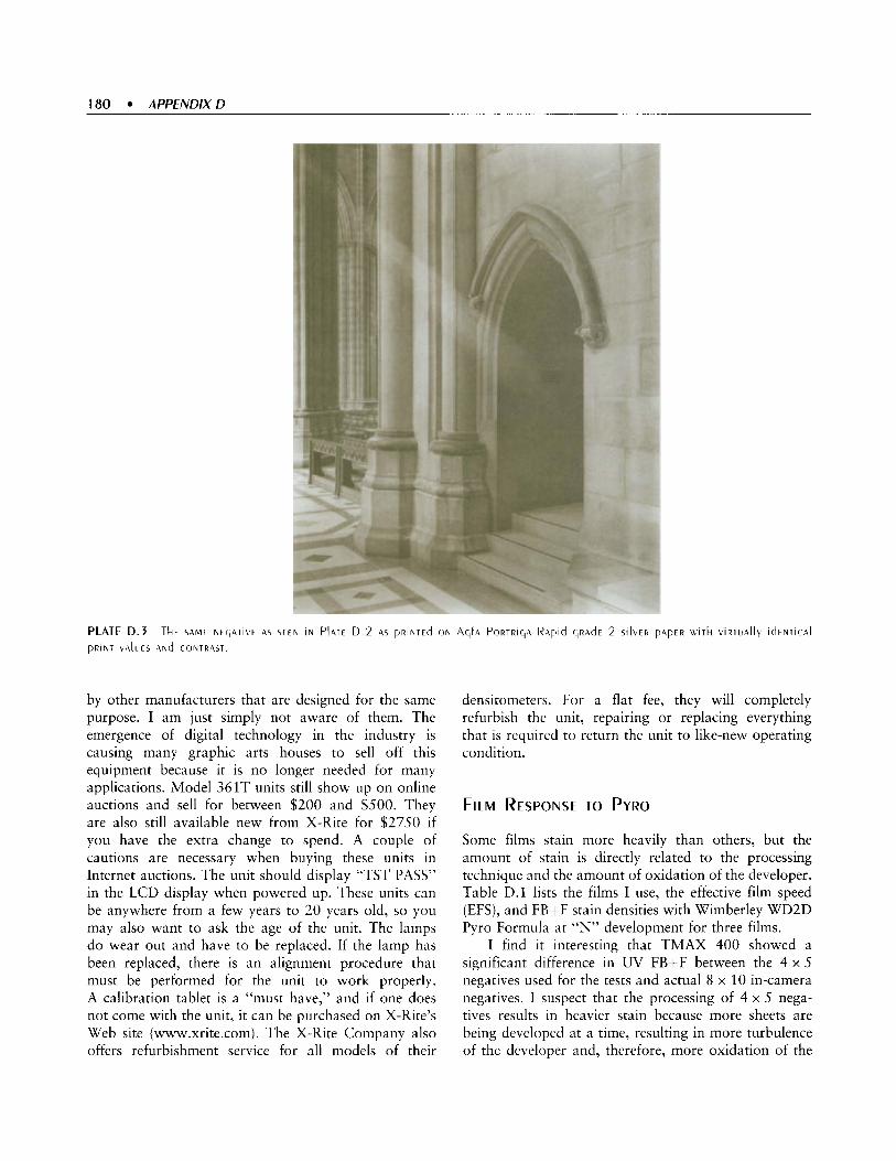
180 APPENDIX D
by other manufacturers that are designed for the same purpose. I am just simply not aware of them. The emergence of digital technology in the industry is causing many graphic arts houses to sell off this equipment because it is no longer needed for many applications. Model 361T units still show up on online auctions and sell for between $200 and $500. They are also still available new from X-Rite for $2750 if you have the extra change to spend. A couple of cautions are necessary when buying these units in Internet auctions. The unit should display “TST PASS” in the LCD display when powered up. These units can be anywhere from a few years to 20 years old, so you may also want to ask the age of the unit. The lamps do wear out and have to be replaced. If the lamp has been replaced, there is an alignment procedure that must be performed for the unit to work properly. A calibration tablet is a “must have,” and if one does not come with the unit, it can be purchased on X-Rite’s Web site (www.xrite.com). The X-Rite Company also offers refurbishment service for all models of their
densitometers. For a flat fee, they will completely refurbish the unit, repairing or replacing everything that is required to return the unit to like-new operating condition.
FILM RESPONSE TO PYRO
Some films stain more heavily than others, but the amount of stain is directly related to the processing technique and the amount of oxidation of the developer. Table D.l lists the films I use, the effective film speed (EFS), and FB+F stain densities with Wimberley WD2D Pyro Formula at “N” development for three films.
I find it interesting that TMAX 400 showed a significant difference in UV FB+F between the 4 x 5 negatives used for the tests and actual 8 x 10 in-camera negatives. I suspect that the processing of 4 x 5 nega- tives results in heavier stain because more sheets are being developed at a time, resulting in more turbulence of the developer and, therefore, more oxidation of the

F i l m E F S UV FB+F Ortho FB+F
Bergger BFP200 (12 x 20) Ilford HPS (12 x 20) Kodak TMAX 400 (4 x 5 ) Kodak TMAX 400 (8 x 10)
100 200 200 200
0.20 0.26 0.36 0.20
0.10 0.13 0.14 0.08
developer. The key observation from this data is that the stain adds about 1/2 a stop of additional FB+F, resulting in at least 50% longer exposure times in platinum printing.
For 12 x 20 images, I use Ilford HP5 and Bergger BFP200, the only two commonly available films in this format at this time. I rate HP5 at 200 and BFP200 at 100. I use TMAX 400 exclusively for 4 x 5 and 8 x 10 formats. Its pronounced contrast and beautiful edge
effects are a perfect combination for platinum. Tri-X yields similar results as TMAX, but the reciprocity characteristics requiring ever increasing exposure in low light situations make long exposures difficult to manage. Many of the exposures inside the cathedrals required 10 to 30 minutes on TMAX 400, which would have been at least an hour or two with Tri-X. Also, edge effects do not seem nearly as pronounced with Tri-X as with TMAX. I rate TMAX 400 at 200 and reduce

182 APPENDIX D
development to maintain good, fat shadow detail, yet printable highlights.
A particularly interesting aspect of the Bergger film is that is seems to require longer development times and higher concentrations of developer than other films. I do not know if this is also true of the Bergger film with traditional film developers.’ It may not be a character- istic of the film at all, but rather a result of using lower contrast, single coated process lenses on the 12 x 20 camera. I have not used any of those lenses with TMAX film in the 8 x 10 camera, so I have no common reference from which to draw any conclusions.
PYRO FORMULAS
There are a variety of pyro formulas dating back well over 100 years. The ABC formula was extremely popular for many decades in the early and mid- twentieth century and was used by Edward Weston. It was the first pyro formula I tested. The ABC formula does not contain any metol. Pyro is the sole developing agent and because of this, shadow density is reduced significantly. This has the effect of a loss of about 1/2 to 1 full stop in film speed. More recent formulas such as John Wimberley’s WD2D and Gordon Hutchings’ PMK include metol to enhance shadow detail and avoid the loss in film speed that is characteristic of the ABC formula. The Rollo-Pyro formula was recently introduced and is designed specifically for use in rotary processors and is essentially an adaptation of PMK.
The color of pyro stain varies with the developer formula. Formulas that use sodium carbonate as the alkali-Wimberley and ABC-produce a stain that is yellowish-brown. The PMK and Rollo-Pyro formulas use sodium metaborate as the alkali and produce a pronounced green stain. It is primarily the yellow portion of the stain that has the greatest effect on UV light. The blue component of the PMK green stain will pass most UV light, but the yellow portion of the green stain will block W light.
The pyro-metol formula that I use for all film processing is identical to John Wimberley’s original WD2D formula, except for removal of the restraining agent in solution B. Originally, I included 1.1 g of
Editor’s Note: Testing Bergger film BFP200 using the Plotter Program” I have found the film to be basically unresponsive to changes in development with D76 developer. (See Appendix C: Some FildDeveloper Combinations to Produce a Platinum/Palladium Negative.) D.A.
potassium bromide in Solution B as a substitution for Kodak Anti-Fog (benzotriazole), which was in the original WD2D formula. I had difficulty obtaining sufficient contrast in the resulting negatives, and development times were exceedingly long. I eliminated the bromide, which solved both problems, and I have not noticed any fogging problems after several thousand 4 x 5, 8 x 10, and 12 x 20 negatives on a variety of films. Be aware that the WD2D formula has been formulated both with and without the Kodak Anti-Fog or benzotriazole. The formula published in Petersen’s Photographic in 1978 included Kodak Anti-Fog. The first edition of The Book of Pyro (Hutchings, 1991) included benzotriazole in the for- mula, but later editions did not. The formula that I use is as follows:
John Wimberley’s WDZD Pyro-Metol Formula Solution A Distilled Water (at 125 F) 1 liter Met01 3 g Sodium Bisulfite 10 g Pyrogallol 30 g
Solution B Distilled Water 1 liter Sodium Carbonate (monohydrate) 40 g
John has since reformulated WD2D as “WD2D+” and is selling it through a retail photography chemical supplier. The new WD2D+ formula is proprietary and is not the same as the original WD2D formula. Adjustments in development will be necessary with this version of the formula.
OTHER PYRO FORMULAS
Other pyro formulas can be found in The Book of Pyro by Gordon Hutchings (1991) or Ansel Adams’ The Negative (1981).
PYRO PROCESSING INFORMATION AND TIPS
The most important factor in obtaining consistent negatives and prints is a consistent processing regimen and timing of each step of the process. Pyro quickly begins to oxidize as soon as the developer and alkali are mixed (parts A and B). The longer the developer is exposed to air, the darker it becomes, and the deeper the resulting stain. Pyro that has been sitting in an exposed tray for 30 minutes before use will yield a very deep stain and will also result in a much darker silver image

from increased developer activity. The resulting nega- tives are what would be described as “bulletproof,” both because of the higher silver density but mostly because the deep stain presents a very high spectral density to the UV light used in platinum printing.
The developing action of pyro and the associated stain effects are very sensitive to small variations in developer temperature. Pyro oxidizes more rapidly as the temperature of the solution increases. If you tray develop, use a water bath around the trays. Without a water bath, a 68” F solution will easily climb to 70 or 72“ during development just from heat transfer from your fingers. If the air temperature in the room is higher than the developing temperature, the solution tempera- tures will gradually rise as well without a water bath. A two-degree increase in developing temperature can have a significant effect on total negative density for a pyro negative. The accelerated action of pyro on both silver density and increased stain is additive in the resulting negative and therefore has an almost doubling effect, as if the negative had actually been developed even longer.
The increase in stain has the greatest impact for platinum printing. Pyro does not oxidize as quickly in a full closed tank because there is a limited amount of oxygen in the tank. The staining effects are less pronounced for the same development time, which must be taken into account when developing roll film intended for platinum printing in pyro.
My formula and processing practices do not follow the philosophy of maximum stain/minimum silver. It is worth repeating again that in platinum printing, stain is your friend and stain is your enemy. Only a very small amount of stain goes a very long way in terms of the amount of density it presents to UV light. A heavy stain only increases the print exposure time, so practices such as “post-staining” should never be employed on negatives for platinum printing. The post-stain bath only increases the overall stain of the negative and therefore baseffog density, by as much as 0.30 to 0.45 in density. That equates to a full stop or 1.5 stops in printing time-a 7-minute exposure becomes 14 to 21 minutes. Since development of the image has been stopped and unexposed silver fixed out, a post-stain step does not add stain in proportion to the silver density. It only moves the existing tones up the curve. Consequently, printing times can easily be doubled or tripled by a heavy post-stain step, with no real improvement in tonal separation.
Traditional development methods, such as dip- and-dunk tanks with stainless steel hangers, do not work with pyro. The turbulence and eddying currents
of the developer flowing through the holes on the hanger edges causes extra staining and uneven devel- opment. Other methods, such as rotary processors, also have their share of problems. They tend to overly oxidize the developer because air is constantly being inserted into the solution by the equipment action. Greater oxidation of the developer results in deeper stain and more reducing action of the developer. Many people also report streaking from the rotary action.
The best methods for pyro development are tray development and nitrogen burst. Few people have nitrogen burst equipment, which means tray develop- ment is the best option. Roll film can be developed in tanks, but the agitation method must include both inversion and rotation. Pure rotational agitation will cause extra turbulence along the reel edges and result in uneven development and stain along the film edges. Difficulty in maintaining processing consistency has been one of the major criticisms of pyro over the decades. These are reasons why many people, including Ansel Adams, felt that pyro was just too difficult to work with or control.
Negatives are developed in trays-eight to twelve 4 x 5 sheets, six to eight 8 x 10 sheets, or four to five 12 x 20 sheets at a time. The number of sheets is based on how many I can comfortably shuffle through in a 30 to 45 second cycle without scratching negatives. Agitation is constant in that I am constantly moving the bottom sheet to the top of the pile-throughout the development process without pause. The negatives are presoaked in water for 3 minutes and then transferred to the pyro.
My standard developer dilution for TMAX 4 x 5 and 8 x 10 films is 1:1:15 for solution A, solution B, and water, respectively. I use a 1:1.1:10 dilution for Bergger and HP.5 12 x 20 films. These dilutions work well for normal and both “minus” and “plus” development of negatives. For normal negatives, I develop TMAX 400 at 68” F for 15.5 minutes, plus 30 seconds to displace the water from the presoak. BFP200 and HP5 are developed for the same time but at 70” F. I have not conducted extensive tests, but I suspect the differences in developer concentration and temperature for the Bergger and HP5 films is actually compensation for the lenses I use on the 12 x 20 camera and not indicative of any difference in those films. Most of my lenses are Artar designs with air spaced elements and therefore are lower-contrast lenses. The higher developer tem- perature and concentrations are likely just compensating for the lower-contrast lenses.
The negatives are developed emulsion side up, and halfway through the development time I rotate the

184 APPENDIXD
stack 180 degrees to even out development. Otherwise, the end of the negatives that are lifted to remove the bottom negative from the stack tend to get slightly less development since they are repeatedly lifted above the surface of the solution, even if only for a brief moment. I have tried emulsion side down development but had too many scratches in the negatives, which I cannot completely explain.
A tray of distilled water is used instead of an acid fixing bath. Any developing action that continues before the negatives are immersed in the fixer will only enhance the shadow detail with very little effect on the highlights. I started this practice when I was having some problems with my development process and was trying to eliminate variables. I saw no signifi- cant differences between an acid stop and a water stop bath, so I stayed with the water. It is cheaper since the stop bath must be discarded after each process cycle because of the oxidized pyro carryover from the developer tray-plus the acetic acid odor is eliminated.
Contrary to most of the experts’ recommendations, for over 15 years I used a prepackaged hardening fixer, Kodak Fixer, for my pyro negatives. It undoubtedly removed some of the stain, as does the hypo clearing agent, but I have never had a problem with too little stain. A very small amount of stain goes a long way in platinum printing. I have since changed to using the non-hardening F-24 fixer formula, but purely to elimi- nate the strong and irritating odor from the boric acid in Kodak Fixer. Even with good ventilation in the darkroom, the boric acid odor is irritating to the nose and lungs in even tiny doses. I have not noticed any difference in the amount of stain on negatives after changing fixer formula. I do not recommend the use of ammonium-based “rapid” fixers with pyro. I believe they slightly bleach the highlights in the shadows of negatives, although I have not run controlled tests.
Film is fixed for 10 minutes and then run through hypo clearing agent, washed for 20 minutes, soaked in Photo Flo“, and hung to dry.
ALTERNATIVE PROCESSING CONTROLS WITH PYRO
When using traditional developers on film, most development manipulations (e.g., N-1, N+1, etc.) are done through adjustments to the developing time or developer concentration. With two-part pyro devel- opers, further control is possible by increasing or decreasing the amount of the alkali in part B or the amount of part B in the working solution. It is the alkali (sodium carbonate/sodium metaborate) that accelerates
the reactivity of the developing agent, and therefore the oxidation of the pyro. The oxidation causes the developer solution to turn dark, which is what stains the reduced silver of the image. Increasing the amount or concentration of part B increases developer activity, and decreasing either one does the opposite. Once you understand how part B affects the developer, you can use this knowledge to make fine controls in the development process.
A second form of development manipulation and control available with pyro and not traditional devel- opers is intentionally allowing the developer solution to oxidize for 5 to 15 minutes in the tray, after being mixed but before developing negatives. This form of control should only be attempted after considerable experience with a particular formula and a thorough working knowledge of the other processing controls used with pyro. Using a highly oxidized developer will result in a much heavier stain in the negative, and therefore very long printing times for platinum. A highly oxidized pyro developer is also more active in terms of silver reduction, so it is very easy to overdevelop the negative to the point of being “bulletproof.” Repeat the mantra: Stain is your friend and stain is your enemy.
Because pyro developer oxidizes unevenly in the tray, it is important to maintain regular agitation. Longer development times are recommended to help ensure even development, especially in tray develop- ment. Development time should never be less than 7 minutes. I adjusted my developer concentrations and temperatures to keep N development around 15 minutes, which keeps “minus” development no lower than 13 minutes.
CONCLUSION
Pyro has seen resurgence in recent years. Using pyro requires good control of the development process and consistency in processing practices. Experience is necessary to fully understand the behavior of pyro and resulting stain in the development process and the role that the stain plays in platinum printing. While pyro is an old and dependable developing agent, lack of attention to consistency in developing practices can have dramatic effects on the resulting negatives. Excellent platinudpalladium (PtPd) prints can be made from negatives developed in any developer, given that proper care is taken in learning the materials and controlling the exposure and development process. Pyro can provide benefits for the platinum printer regardless of the formula used.

APPENDIX E
CRAFTING DIGITAL NEGATIVES FOR CONTACT PRINTING PLATINUM AND PALLADIUM M a r k I. Nelsoii
185

186 APPENDIX€
When Dick Arentz asked me to write this appendix, I thought for some time about what would be the most important contribution I could make. I decided that rather than give very specific "how to" instructions, which is a whole book in itself, I would present important concepts by covering the following:
Digital image file capture and preparation that
An understanding of how digital negatives really
Methods of achieving precise control of the print
A standard workflow for making p la t inud
will produce better negatives
work and why they often fail
with a digital negative
palladium (Pt/Pd) prints using digital negatives rendered with imagesetters and inkjet printers-the two most commonly used digital negatives
If you are currently printing platinudpalladium with digital negatives, or are considering doing so, you should find this information extremely helpful. I think I can safely say that the methods I have developed will give you more control than ever before possible, thus allowing you to make a print that is superior to what has been standard practice until now. These skills give you freedom to create and print images that match your vision.
GLOSSARY OF TERMS
Standard 21 -Step Test Tablet or Step Wedge: A commercially available transmissive step tablet with 21 steps of increasing density in increments of log .15, which is equivalent to 1/2 stop exposure. When contact printed next to digital negatives and targets, this provides a check for consistency of contrast mix, exposure, and other printing variables.
Digital 21-Step Test Tablet: A file created in PhotoshopE' with 21 equally spaced steps of tones with an increment of 12.8 from 0 (black) to 255 (white). This test tablet is used for visual evaluation of the negative's relative printed densities. The steps will have different density values than a Standard 21-Step Test Tablet and will only print in a linear fashion if the correct Process Adjustment Curve has been applied to the digital file.
Of
Smooth Gradient Test Tablet: A tablet with levels 0 through 255 created by using the gradient feature of Photoshop".'
Color Density Range Control (patent pending): The use of varying colors in digital negatives to match the density of the negative to contrast range requirement of the alternative process.
Standard Color Density: The color or hue that prints with just enough density to produce paper white with a given Pt/Pd contrast mix when printed with the Standard Exposure Time.
Color Density Range Palette: A file created in Photoshop'p that generates a step tablet with steps of changing color in graduated increments that is used to determine the Standard Color Density.
Tonal Palette: A digital step tablet made using the Standard Color Density that has enough steps to be used to determine the Process Adjustment Curve for a given contrast mixture. Once printed in Pt/Pd with the Process Adjustment Curve applied, the Tonal Palette provides a visual tonal index that can be used for planning and predicting the tonal values of a print.
Process Adjustment Curve: A curve adjustment that is derived from measuring the printed steps of the Tonal Palette. The Process Adjustment Curve adjusts the ink densities of all the 256 tones in a digital negative relative to each other such that the tones print in a linear fashion with Pt/Pd.
the information presented, there are two basic con- cepts that I consider the most important to understand:
1. The Density Range of digital negatives produced with color output devices can be precisely controlled prior to the application of the Process Adjustment Curve. This is a key factor in taking control of the process. Subsequently, the curve required to adjust the relative tonal values is far less drastic and less destructive to the tonal information in the image file. Previously the Process Adjustment Curve alone has been used to account for the density range adjustments of digital negatives. Figure E.l shows the relationship between the Exposure Scale of an Alternative Process and the Density Ranges of three negatives. In one case (shown in Green), the negative with the higher Density Range will result in an exaggerated Process Adjustment Curve, which will reduce the number of tones in the negative.
'. Precisiotz Digital Negatiiies for Sihler arid Other Altertiative Photographic Processes by Mark I. Nelson (2004).

In this case, the Process Adjustment Curve must compensate for the gap between the end of the Exposure Scale and the extreme Density Range of the negative. The second mismatched example (shown in Blue) is a negative with too low a Density Range. This negative will clip the Toe of the Exposure Scale and print the highlights darker than desired. The third example (shown in Orange) is an exact match of the negative’s Density Range with the Alternative Process’s Exposure Scale. This exact match will minimize the Process Adjustment Curve, preserve more tones in the negative, and print the entire tonal range of the negative.
2. The primary variables you can manipulate when printing platinum and palladium with digital negatives are the Contrast of the mix, the Density Range of the negative, the Standard Exposure Time, and the Process Adjustment Curve. Once you understand the relationship between these four variables shown in Figure E.2, you can explore creative manipulation of these variables to create prints that match your vision for your images.
While technical skill may lead to a “perfect print,” the exercise is futile if there is no content in the image. Ultimately, what matters most is the final image and the impact it has on the viewer. All the expensive equipment and all the technical knowledge and skill in the world does not a great print make. I think the most important ingredient is that which comes from deep inside the artist-an artist who is willing to risk looking within as he or she studies the subject and forms a connection with it prior to taking the photograph. This connection
continues to grow stronger and reach deeper as the photographer continues the journey with this image to
nt. the final pi
THE DIGI NEGATIVE
AL VERSUS INXAMERA CONTROVERSY
There are topics in every field of endeavor that are likely to bring on a heated debate. Imagine the “discussions” that took place between the first photographers and the painters of that time. The rapid development of digital imaging and digital photography has led to another such debate. This chapter is not intended to. fuel this debate nor be the final word.
I do not see either traditional in-camera negatives or digital negatives as preferable or one as being
188 APPENDIX€
superior to the other. I see them both as tools to be used in slightly different workflows to achieve the same end- a beautiful image rendered on fine paper by a photo- graphic process that is capable of making that image sing to the viewer.
I do not hope that everyone will start making digital negatives to craft their platinudpalladium prints. I do hope that many people will continue to improve and use in-camera negatives to make fine prints. The photographic community benefits from having this variety. Each method has its own benefits and pitfalls. To truly master each is equally challenging. Experi- mentation with each method adds to the knowledge base for alternative photographic processes.
I was fortunate to begin my photographic journey at a time when so many options were opening up. I was introduced to computer graphics through my professional work. Since I had settled on the 35 mm format years ago, it was only natural that I turned to enlarging negatives digitally. My first efforts were with imagesetter negatives. Soon I heard about the pioneering work being done by Dan Burkholder and David Fokos.
For over a year prior to writing Precision Digital Negatives for Silver and Other Alternative Photographic Processes and subsequently this chapter, I spent the majority of my time researching digital negatives. My desire for a better understanding of how they work led to experimenting with ways to improve them. I did so because I wanted the technical ability to make the best possible prints using digital negatives. I was not convinced when I started my research that it was even possible to make a great print using a digital negative. If I found it couldn't be done, I was resigned to using traditional methods for my enlarged negatives. Fortunately, I think I was successful. Each day I feel I am learning more about these wonderful processes, such as platinudpalladium, which in turn leads me to new methods for improving my workflow.
I would like to thank Dick Arentz, Phil Davis, Sam Wang, Sandy King, and Bruce Starrenburg for their help in writing this appendix.
MATERIALS AND EQUIPMENT LIST
You will find an excellent list of materials required for platinum/palladium printing in the main body of this book. Specific materials required for making digital negatives are as follows:
Computer Digital image file
Scanner or reflective densitometer for determining Process Adjustment Curve PhotoshopR or other image editing software and a working knowledge of image preparation Excelrh' or other spreadsheet software Light table (optional) Loupe (a 3 x and a 1Ox are nice to evaluate at different magnifications) Hygrometer for monitoring humidity A working knowledge of PdPd printing, including methods of contrast control Stouffer or Kodak Standard 21-Step Tablet (the most important item on this list-and the cheapest)
And, if you are making inkjet negatives:
Inkjet printer Film substrate for printing negatives
SOME DIGITAL BASICS
In order to understand the content in this appendix, it is important to be familiar with a few terms that are used in digital imaging.
PIXELS VERSUS DOTS
One important aspect of digital imaging that confuses many beginners is the relationship between image size, file resolution, and the resolution of inkjet printers and other output devices-the difference between pixels and dots.
Image files are defined by pixels, or points of different tones and hues. The resolution of capture devices, such as cameras and scanners, or the resolution of monitors are all defined by how many pixels per inch (PPI) or millimeter they resolve.
Output device resolution is determined by how many dots they can print in an inch (DPI) or millimeter. Dots are not the same as pixels. Output devices such as imagesetters and inkjet printers need to print a pattern or matrix of more than one dot to render each pixel in an image file with the appropriate tone and/or color. There is usually a ratio for each device of how many dots are needed to accurately represent pixels.
Imagesetters come in different native resolutions of 2400, 3600, and 4800f dots per inch. Imagesetters require a 16 x 16 matrix of dots to represent the 256 possible tones in a pixel. Thus, you can calculate the maximum number of pixels per inch the imagesetter

can render and still give 256 tones by dividing the native resolution by 16 (e.g., 3600 dpi/l6 dots = 225 pixels per inch maximum resolution with 256 tones).
The exceptions to the pixel/dot ratio requirement are the high end imaging devices such as Lightjet'", Lambda"', and ChromiraT" that use lasers or LEDs to image on paper and film. These devices can vary the tone and color of each dot printed in a one-to-one relationship to the pixels in the image file. This feature provides output that appears to be continuous tone to the human eye and even holds up well under close examination with a loupe.
DIGITAL IMAGE TONES
One of the virtues of platinum and palladium printing is the wonderful, extended tones you can achieve with the process. Digital negatives can render beautiful tonality, but, as you will see, they have their limits, and all effort should be made to avoid going beyond those limits.
The range of tonal values of the pixels in an image file is limited by the "bit depth" of the file. You have probably heard the terms 8-bit and 16-bit images. Bit depth is determined by the software and/or device used in capture. The bit depth numbers, such as 8 ,10, 12, 14, or 16, refer to the number of possible tones that the file, software, or device can accommodate. This number is actually applied as the exponent of the number 2. Thus, an %bit image is 2 to the power of 8, or 256 possible tones from black to white. Sixteen-bit images have 2 raised to the power of 1 6 or 65,536 possible tones-a big difference. Thus, 16-bit images give you much more room to make tonal adjustments to a file. Though some tones will be lost, a large number will survive. When tonal adjustments are applied to %bit files, gaps will appear at some tonal ranges (poster- ization), and other tonal ranges will be compressed (loss of contrast) as shown in the comparison in Figure E.3.
Since color or RGB (red/green/blue) files have three channels, one for each color, they may be referred to as 24-bit, 36-bit, or 48-bit files. For the most part, this appendix refers to 16-bit grayscale files. The only exception to that is when printing negatives on a color output device. At that point, it is necessary to convert the file to RGB just for printing. Files that are used for printing negatives on imagesetters should remain in grayscale mode.
Notice I used the term possible tones. An image may not fill up the entire range of tones for a given bit depth, depending on how the image was captured
or how the image was manipulated after capture. The best practice is to capture and work with images at the highest possible bit depth to preserve as many tones as possible. Every time you make an adjustment to an image, the image loses some tones because almost all image adjustment tools are destructive in nature.
This issue becomes very important when you print your negative. All current imaging devices render images in only 256 tones or %bit images. While you can send a 16-bit image to an inkjet printer, it is converted to 8 bits or 256 tones during the printing process.

190 APPENDIX€
THE DIGITAL IMAGE FILE
The digital image file may originate from film that is scanned or a digital camera. The process prior to converting the image to a negative and making a print can be divided into two phases: the Capture Phase and the Image File Preparation Phase.
DIGITAL IMAGE FILE CAPTURE
The following suggestions cover just a few of the more important issues related to capturing a digital image with a scanner or digital camera. There are whole books written on these topics. In them you will find more in-depth coverage than possible in this chapter. One of my favorites is Real World Adobe Photoshop CS, by Bruce Fraser and David Blatner (Peachpit Press, 2004).
Regardless of whether you are using a scanner with film or a digital camera, work in 16-bit mode if possible. If you are using a digital camera, and it has RAW file capability, use that format at the highest resolution. Avoid JPEG file format or any file format that uses compression techniques. This creates artifacts in the image that will show up in the print. Use “lossless” file formats such as Photoshop’”, PSD, or TIFF. If you are using a digital camera that does not have a 16-bit mode, expose your images in color in TIFF format. Import the file into PhotoshopR and immediately convert it to a 16-bit RGB file. Then use the channel mixer to convert the file to grayscale mode. This will give you a much richer grayscale file, since information from all the color channels is being used for the conversion.
very careful of your settings. A common mistake is clipping the highlights or shadows of an image, which will lead to blown out highlights or blocked up shadows in the print. This process is referred to as setting the Black Point and White Point in the Levels Adjustment. The image histogram will show if this has happened, since there will be a spike of data on either the black value (0) or white value (255). Most scanner manufacturers use inflated values for the “Dmax” capability of their products. Be sure you know what the actual capability of your scanner is. If you are exposing film with a greater density than your scanner is capable of managing, then either get a better scanner or modify the density range of your negatives.
When scanning or using the digital camera, be
Cameras and scanner software usually both have a sharpening feature. Turn it off and do your sharpening later in Photoshop’-you will get better results. If your digital camera has a contrast setting, set it to the lowest value to keep tonality smoother. Contrast adjustments should be made later in Photoshop”. If you are faced with photographing a scene with an extreme subject brightness range that is beyond the capability of your digital camera, you may be able to capture the scene by making three exposures-one exposed for the highlights, one exposed for the shadows, and one exposed in between. Use a tripod. Later, in Photoshop ‘, you can combine the three into one image that renders the full tonal values of the scene. Similarly, if you are having difficulty scanning a negative that has a high density range, you can make bracketed scans to combine into one image in PhotoshopR.
DIGITAL IMAGE FILE PREPARATION
This is where you further prepare the digital image to match your visualization of the subject when you captured it with your camera. While there are some important printing techniques that will be covered later to fine tune this, you are now at the point where you will do most of the adjustments that make the image look the way you want it to print. It is very important that your computer monitor be calibrated so that the image file is rendered accurately on the screen. If the monitor is not calibrated, you will not be able to make prints that look like what you see on the screen.
Open your image file and only apply enough sharpening to recover any softness in resolution resulting from scanning or the digital camera. Do this while observing the image at 100% resolution on the monitor. Do not oversharpen here. You are not sharpening at this point for printing. Sharpening, as you will learn later, is best done in three steps, each for a different purpose. The other advantage of doing this “recovery” sharpening is that it will make it easier to see unwanted artifacts when you clean the file. Now it is time to clean up the image. Like a crime scene detective “walking the grid,” go over the entire image at 100% resolution and touch up any dust spots, film scratches, or other problems stemming from the file capture. Use primarily the Clone Tool or, my favorite, the Healing Brush

to do this. Sample from a nearby area having similar texture and tone before clicking on the offending spot with the tool. Avoid using the Global tools, such as Dust and Scratches, to accomplish this task. If you have a really serious problem, you might be able to use the Dust and Scratches tool locally in combination with the History Brush to clean up a problematic area of the image. Applying a tool like this to the entire image may get rid of a lot of tiresome dust spots, but it is also going to get rid of important detail in the image. Just imagine what a tool like this is going to do to all the detail around the eyes in a portrait! Once the file is cleaned to your satisfaction, save it then use Save As with a new file name. This new file is your working file. If something happens to it, you still have the original file to go back to, and you will not have to repeat the tedious cleaning process. If you need to crop the image, this is a good time to do it. Some photographers, especially when working with sheet film, like to show the entire negative, including the borders. If you are not doing this, be sure to crop the non-image area out since it will introduce false data into your histogram when you evaluate it. Assuming you are using PhotoshopR CS (version 8) or later (if you aren’t using it, get it!), you will be able to do much of the adjustments in Layers, which are nondestructive and can be tweaked as needed while you work. Create an adjustment layer for Levels. Set the endpoints (black and white points) where you think they should be without clipping any of the data. Create an adjustment layer for Curves. Here you really want to take your time and tweak the image slowly until you are satisfied with the tonal relationships of the image. Now sit back and look at the image. How does it look? Study it for a while. Slowly you will begin to see things you would like to adjust- mostly in local areas of the image. This is where you can really begin to make your image sing. Local changes to an image, or changes that affect only one area of the image rather than the entire image, are easily accomplished with the History Brush tool. This ingenious tool allows you to make any global change to an image, take
a snapshot of that change, undo the global change to the image or revert to the previous state, then by targeting the snapshot you just made as the source for the History Brush, paint into the image the changes just for the local area you want to affect. You can even adjust the percentage of change you want to make and by brushing over the area a number of times add the change in small increments. A powerful tool! The first local adjustments made will probably be tonal adjustments, as one would burn and dodge a print in a traditional darkroom. Using the eyedropper to sample areas, you can determine what tones you will need to adjust and use the Curves Adjustment to adjust precisely those tones, and then paint the changes in with the History Brush. This is a great method for burning and dodging the image. Local sharpening can be accomplished in the same manner with the History Brush. This allows you to emphasize a portion of the image.
de-emphasize an area of the image or rid it of unwanted noise by using the Dust and Scratches filter in combination with the History Brush.
Like sharpening, only in reverse, you can
If the image “feels” finished, save it.
Remember I mentioned that sharpening should be done in three stages? So far you have applied a small amount of global sharpening to restore image sharp- ness lost in the capture process. You have also applied some local sharpening in areas you wanted to emphasize. The final sharpening, using one of the more complex sharpening techniques, such as High Pass Sharpening, should only be applied when you print the negative. The reason for waiting is this sharpening should be applied “temporarily,” only after the output size of the image has been determined. This type of sharpening is size dependent and should be done carefully so that your image does not have the unsightly halo affect that makes people point and shout “Digital!” This method of three-stage sharpening is covered in depth by Bruce Fraser on his Web site: www. pixe1boy.com.
If you have worked an image file so much that it begins to lose the rich tonal values you started with, delete it and start over. One sure indication you should start over is if the image histogram resembles a comb with broken teeth or a molting porcupine.

1 92 APPENDIX E
IMAGESETTER NEGATIVES
The first digital negatives were rendered with image- setters. Imagesetters are used in the printing industry to produce the film used to burn printing plates. Since many printing companies are shifting to direct computer-to-plate workflows, service bureaus with imagesetters are becoming more difficult to locate.
How IMAGESETTER NEGATIVES WORK
Imagesetters are unique in the way they reproduce tone in negatives. Unlike most other devices, they produce only two tones, clear film and solid black. The black is very dense, measuring in the neighborhood of log 4.0 transmissive density or higher. The way imagesetters achieve the appearance of continuous tone is by spacing very tiny dots close together or further apart. This fools the eye, but in fact, a PtPd print made with an imagesetter negative only has two tones in it! One is paper white and the other is the printed dots that are in the area of log 1.5 reflective density. This does not mean that you cannot make a very fine print with an imagesetter negative. In fact, this characteristic makes it rather easy to make a print-almost foolproof.
Imagesetters can render tone by two methods. One, the line screen, is an ordered series of variable sized and shaped dots. Most people do not use this screening method because it can appear too mechanical when viewed with a loupe, however it may provide smoother tones and less artifacts at certain critical tonal transitions. The alternative to the line screen is stochastic screening. This method uses a “random” pattern of tiny dots to render tone. This fine random pattern of dots simulates film grain.
As mentioned previously, imagesetters come in varying native resolutions. The higher resolution iniage- setters are usually difficult to locate. It is important to find out what resolution the service bureau’s imagesetter is capable of rendering so that you can size your file accordingly.
For stochastic screening, the two most commonly used resolutions are a 1200 dpi bitmap or a finer 1800 dpi bitmap. PhotoshopK can be used to convert an %bit grayscale file to a bitmap file of one of these resolutions. Go to IMAGE>MODE>BITMAP, and enter 1200 or 1800 as the output resolution with DIFUSION DITHER selected, as shown in Figure E.4. If you look at the image at loo%, you will easily see the stochastic screening effect. Notice that the image is now made up of black and white dots, which is exactly what an imagesetter prints.
FIGURE E.4 BIT MA^ Wivdo\i
It is important to discuss your requirements with the service bureau before you send them your file. It is often preferable to have the service bureau convert your file to a bitmap. They may have software for bitmap con- version that is more compatible with their imagesetter. If so, you will give them an 8-bit grayscale file of the dimensions for your negative at 300 ppi and they will bitmap the image to 1200 dpi or 1800 dpi.
I NKJET NEGATIVES
The quality of inkjet printers has greatly improved in the past few years, making them an excellent choice for rendering high quality digital negatives. Each month the major manufacturers are announcing new inkjet printers with smaller picoliter dot sizes and improved capabilities for rendering smooth tones. Once you understand how they work, you can control the output to the extent that the negatives print with little or no digital artifacts.
How I NKJET NEGATIVES WORK
Inkjet printers are designed to make very good positive prints, not negatives. Inkjet printers use the CMYK model, which employs cyan (C), magenta (M), yellow (Y) and black (K) inks to form colors and tones. In order to print good shadow detail and a dense black, inkjet printers add the black ink to the CMY in the lower tones. This is great for making good inkjet prints, but it is terrible for making good negatives. The black ink behaves differently than the C, M, or Y inks- it is opaque rather than translucent and has a very high ultraviolet (UV) density, in some cases over log 4.0.
Inkjet negatives and negatives rendered with other color capable digital output devices function in a different way than imagesetter negatives. In a way, they are more like traditional film negatives, and you
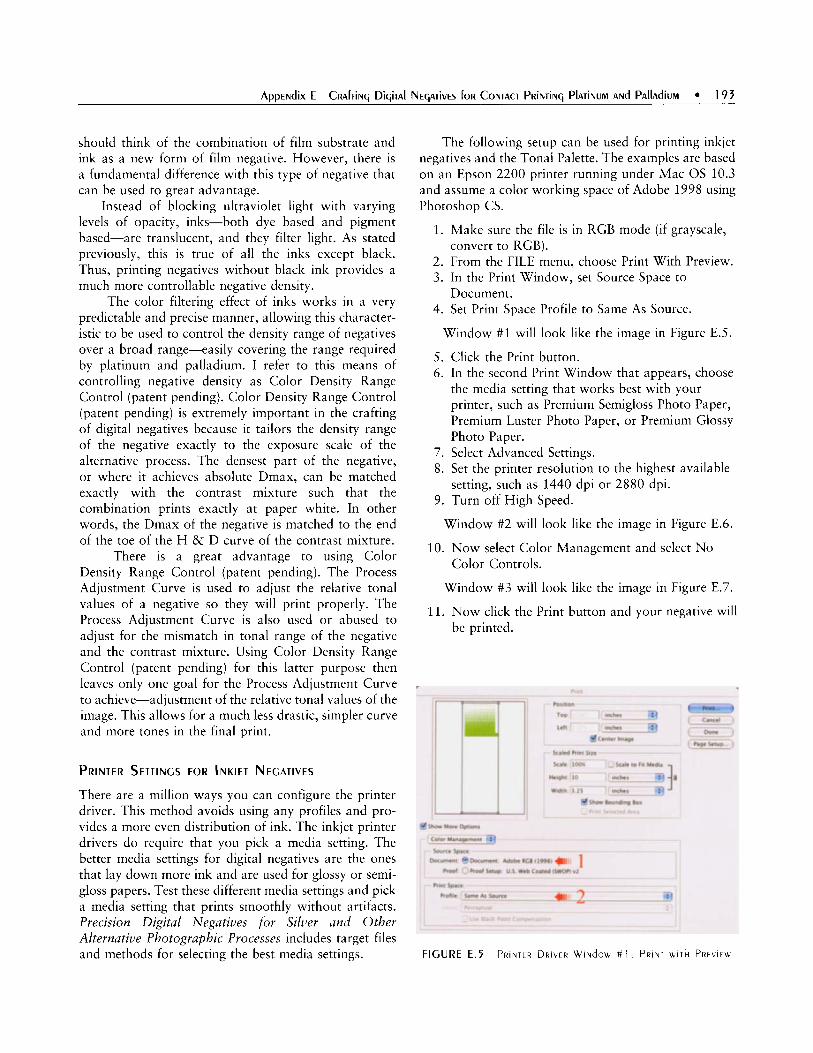
should think of the combination of film substrate and ink as a new form of film negative. However, there is a fundamental difference with this type of negative that can be used to great advantage.
Instead of blocking ultraviolet light with varying levels of opacity, inks-both dye based and pigment based-are translucent, and they filter light. As stated previously, this is true of all the inks except black. Thus, printing negatives without black ink provides a much more controllable negative density.
The color filtering effect of inks works in a very predictable and precise manner, allowing this character- istic to be used to control the density range of negatives over a broad range-easily covering the range required by platinum and palladium. I refer to this means of controlling negative density as Color Density Range Control (patent pending). Color Density Range Control (patent pending) is extremely important in the crafting of digital negatives because it tailors the density range of the negative exactly to the exposure scale of the alternative process. The densest part of the negative, or where it achieves absolute Dmax, can be matched exactly with the contrast mixture such that the combination prints exactly at paper white. In other words, the Dmax of the negative is matched to the end of the toe of the H & D curve of the contrast mixture.
There is a great advantage to using Color Density Range Control (patent pending). The Process Adjustment Curve is used to adjust the relative tonal values of a negative so they will print properly. The Process Adjustment Curve is also used or abused to adjust for the mismatch in tonal range of the negative and the contrast mixture. Using Color Density Range Control (patent pending) for this latter purpose then leaves only one goal for the Process Adjustment Curve to achieve-adjustment of the relative tonal values of the image. This allows for a much less drastic, simpler curve and more tones in the final print.
PRINTER SETTINGS FOR INKJET NEGATIVES
There are a million ways you can configure the printer driver. This method avoids using any profiles and pro- vides a more even distribution of ink. The inkjet printer drivers do require that you pick a media setting. The better media settings for digital negatives are the ones that lay down more ink and are used for glossy or semi- gloss papers. Test these different media settings and pick a media setting that prints smoothly without artifacts. Precision Digital Negatives for Silver and Other Alteriiative Photographic Processes includes target files and methods for selecting the best media settings.
The following setup can be used for printing inkjet negatives and the Tonal Palette. The examples are based on an Epson 2200 printer running under Mac 0s 10.3 and assume a color working space of Adobe 1998 using Photoshop CS.
1. Make sure the file is in RGB mode (if grayscale,
2. From the FILE menu, choose Print With Preview. 3 . In the Print Window, set Source Space to
4. Set Print Space Profile to Same As Source.
convert to RGB).
Document.
Window #1 will look like the image in Figure E.5.
5. Click the Print button. 6. In the second Print Window that appears, choose
the media setting that works best with your printer, such as Premium Semigloss Photo Paper, Premium Luster Photo Paper, or Premium Glossy Photo Paper.
7. Select Advanced Settings. 8. Set the printer resolution to the highest available
9. Turn off High Speed. setting, such as 1440 dpi or 2880 dpi.
Window #2 will look like the image in Figure E.6.
10. Now select Color Management and select No Color Controls.
Window #3 will look like the image in Figure E.7.
11. Now click the Print button and your negative will be printed.
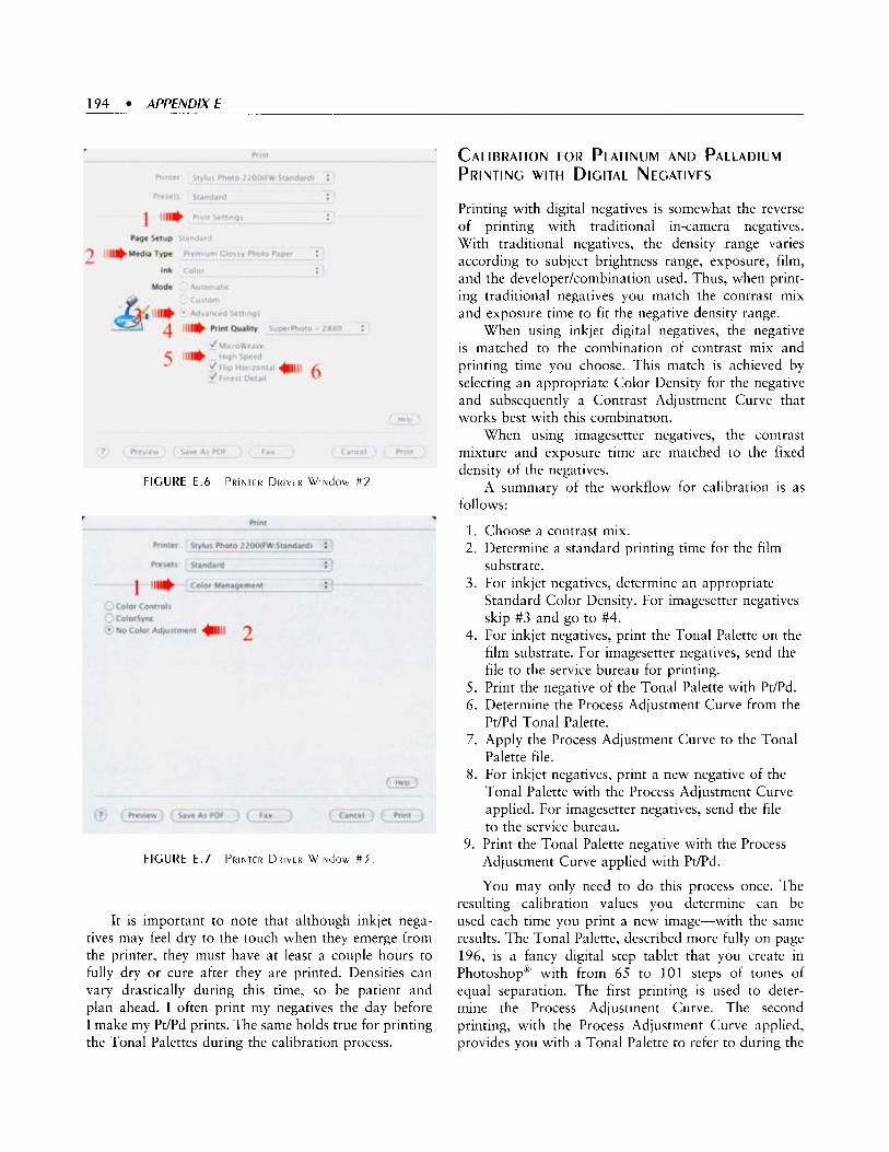
194 APPfNDlXE
CALIBRATION FOR PLATINUM AND PALLADIUM PRINTING WITH DIGITAL NEGATIVES
FIGURE E.6 PRINTER DRIVER W I N ~ O U #2
FIGURE E.7 PRINTER DRIVER W I N ~ O W # 3
It is important to note that although inkjet nega- tives may feel dry to the touch when they emerge from the printer, they must have at least a couple hours to fully dry or cure after they are printed. Densities can vary drastically during this time, so be patient and plan ahead. I often print my negatives the day before I make my Pt/Pd prints. The same holds true for printing the Tonal Palettes during the calibration process.
Printing with digital negatives is somewhat the reverse of printing with traditional in-camera negatives. With traditional negatives, the density range varies according to subject brightness range, exposure, film, and the developerkombination used. Thus, when print- ing traditional negatives you match the contrast mix and exposure time to fit the negative density range.
When using inkjet digital negatives, the negative is matched to the combination of contrast mix and printing time you choose. This match is achieved by selecting an appropriate Color Density for the negative and subsequently a Contrast Adjustment Curve that works best with this combination.
When using imagesetter negatives, the contrast mixture and exposure time are matched to the fixed density of the negatives.
A summary of the workflow for calibration is as follows:
1. Choose a contrast mix. 2. Determine a standard printing time for the film
3 . For inkjet negatives, determine an appropriate substrate.
Standard Color Density. For imagesetter negatives skip #3 and go to #4.
4. For inkjet negatives, print the Tonal Palette on the film substrate. For imagesetter negatives, send the file to the service bureau for printing.
5. Print the negative of the Tonal Palette with Pt/Pd. 6. Determine the Process Adjustment Curve from the
7. Apply the Process Adjustment Curve to the Tonal
8. For inkjet negatives, print a new negative of the
Pt/Pd Tonal Palette.
Palette file.
Tonal Palette with the Process Adjustment Curve applied. For imagesetter negatives, send the file to the service bureau.
Adjustment Curve applied with Pt/Pd.
You may only need to do this process once. The resulting calibration values you determine can be used each time you print a new image-with the same results. The Tonal Palette, described more fully on page 196, is a fancy digital step tablet that you create in PhotoshopR with from 65 to 101 steps of tones of equal separation. The first printing is used to deter- mine the Process Adjustment Curve. The second printing, with the Process Adjustment Curve applied, provides you with a Tonal Palette to refer to during the
9 . Print the Tonal Palette negative with the Process

image file preparation phase and when making your prints.
CONTRAST MIXTURE
It is important to first determine the contrast mix (I will be referring to the Na2 method discussed earlier in this book) you wish to use since the Standard Printing Time, Standard Color Density, and the Process Adjustment Curve are dependent upon this variable. This is the reverse of the method used when working with traditional negatives, since the density range of the traditional negative is predetermined.
In general, it is best to start with the lowest contrast mix when calibrating. Doing so tends to reduce digital artifacts in prints and establishes a boundary in calibration regarding the standard Color Density Range required. This is true both with negatives from color capable devices and imagesetters. With image- setters, since the only control available is the Process Adjustment Curve, the low contrast mix will reduce the amount of curve correction required.
DETERMINING THE STANDARD PRINTING OR EXPOSURE TIME
The determination of the standard printing or exposure time for digital negatives is the same as Dick Arentz has described in Chapter 8: Calibration. The goal is also to determine a printing time where a t least two of the darkest steps merge. I make one modification to the method for inkjet negatives. The substrate or film that inkjet negatives are printed on may have a higher UV density than standard film negatives, or it may have a higher base plus fog (B+F). This can be factored in to the standard printing time by taking a clear strip of substrate and lapping the Standard 21-Step Test Tablet over it when printing as shown in Figure E.8. This is not necessary to do when the negative will be rendered with an imagesetter, since the base plus fog of the imagesetter
negative (about log .05) is usually the same as that of the standardized 21-step test tablet. This can be confirmed by checking with the service bureau that will be printing the negative.
The printed steps of the Standard 21-Step Tablet that lap over the clear substrate will show two steps merging up to half a stop (one step) lower than the printed steps not lapped over the film. Thus, you can adjust your Standard Printing Time accordingly for the negative substrate you are using. You may have to adjust printing times until you duplicate this using your materials and light source. If you change to a different brand of substrate, then you should recalibrate the standard printing time.
Be sure to save the printed Standard 21-Step Tablet for reference in the following steps.
THE DIGITAL NEGATIVE DENSITY RANGE
The standard definition of density range of a traditional negative is found in Chapter 3: The Negative.
Imagesetter negatives, as mentioned before, have a standard density range that cannot be modified. This density may vary some between service bureaus, depending on how they calibrate their machines. It is most important that they do calibrate their machines regularly for consistent output. This is a good issue to inquire about. Since the density range of imagesetter negatives is fixed, the only means of correcting them to print properly is by using the Process Adjust- ment Curve. If the imagesetter gives inconsistent results, the Process Adjustment Curve will not work accurately.
Inkjet negatives are unique in that the density range of the digital negative can be varied for any printing situation.
Once you have determined both your contrast mix and Standard Printing Time, you can now determine the density range you need for your negative. This will be evident by the print of the 21-step tablet you used in determining the Standard Printing Time. This is easily accomplished by using this same contrast mix and Standard Printing Time to print a Color Density Range Palette in Pt/Pd.
The Color Density Range Palette is a series of graduated color swatches. For this example, I am using a variation of green. The color green is set in the color picker with the values Red = 0, Green = 255, and Blue = 0. Green is a mix of yellow and cyan ink. The relative amount of cyan and yellow ink in the printed color can be controlled by increasing the blue value in the color picker from 0 up to 255. For example, a color

196 APPENDIX€
of Red = 0, Green = 255, Blue = 100 would print with more cyan and less yellow. This would provide a negative of less color density than a pure green negative.
A series of quarter-inch square color steps, with a precisely graduated change in color from pure green to cyan, can be easily constructed by using the following Color Picker values to fill the steps in the following manner:
Red = 0, Green = 255, Blue = 0
Red = 0, Green = 255, Blue = 10
Red = 0, Green = 255, Blue = 20
Red = 0, Green = 255, Blue = 30
Red = 0, Green = 255, Blue = 40 Red = 0, Green = 255, Blue = 50
Etc.
Once the Color Density Range Palette has been printed with the calibrated contrast mix and Standard Printing Time, the correct Color Density for this combination is determined by the first step of this Color Density Range Palette that prints with PdPd at paper white. This color, the Standard Density Color, is then used to print the Tonal Palette and subsequent negatives. To make a negative using the Standard Density Color, follow this procedure:
1. Open an image file of the Tonal Palette or the image
2. Create a new empty top layer and set the mode of
3. Name the new layer with the values for the Standard
4. Using the Color Picker, set the foreground color
5. Using the Paint Bucket Tool, fill the new layer with
you wish to print.
the layer to Screen Mode.
Density Color.
to the Standard Density Color values.
the Standard Density Color.
THE TONAL PALETTE
The Tonal Palette, the digital step tablet used to determine the Process Adjustment Curve, is made up of a sampling of the 256 possible printing tones. The number of tones or steps used to create the Tonal Palette should be sufficient so that there are not significant gaps in densities between the tones. The smallest number of tones that would still give decent information would be a 65-step Tonal Palette. This series would include steps of every fourth level from 0 through 255, or 0, 3, 7, 11, . . . 243, 247, 251, 255. I use a Tonal Palette with 101 steps. Label the steps in
PhotoshopR (using a text layer) with the level value each represents (0-255). All steps should be an equal value apart.
I use a Tonal Palette that also includes a digital version of a 21-step tablet and a smooth gradient from levels 0 through 255. These are very helpful in the visual assessment of the Process Adjustment Curve’s effect on the Tonal Palette and subsequent prints.
With this workflow, the Tonal Palette is not inverted to the negative state prior to printing as will be done with image files. There is no need to, since you would just end up with the same tones in reverse order and an extra step in the workflow to reverse all the values in calculations. Figure E.9 shows a Tonal Palette with 101 steps.
THE PROCESS ADJUSTMENT CURVE
The Process Adjustment Curve is an adjustment curve that is applied to a digital image file after all other image adjustments are complete. The purpose of this curve is to adjust the negative’s relative tonal density such that the image will print properly with the alternative process. This adjustment of the negative’s densities causes the printed tonal values to be linearized, so they appear the same as the image displayed on the calibrated monitor.

There are various imagesetter and inkjet “curves” floating around in cyberspace. However, these “Cookie Cutter Curves,” as Dick Arentz calls them, are usually more frustrating than helpful. I often hear someone say “I tried so-and-so’s curve and it worked great!” Well, sure it did, sort of. All Process Adjustment Curves have roughly the same shape. The curve is a reverse “S” shaped curve that opens up the shadows and adds texture to the highlights of the print. It is easy to prove that such generic versions of a curve will only work best by chance. What paper and contrast mix was the curve based on? What humidity level? What workflow? What alternative process? Determine your own custom curve for your workflow and avoid wasting fine paper, expensive chemicals, and your time.
There are some workflows that apply this curve to the image file in its positive state. I prefer to develop the curve and apply it to the image file in the negative state. Either method will work and result in the same print. However, I find it much easier to think of how I want to change the negative’s tonal densities to affect the print densities. This also keeps separate the two distinct workflow segments of image file preparation and nega- tive preparation.
Once you have created the Tonal Palette, print it on the film substrate using the printer settings described previously. Be sure to flip it horizontally first so the information identifying the tonal steps will read correctly when you contact print it with Pt/Pd.
Print the Tonal Palette with the same contrast mix, paper, and exposure time you used previously to determine the standard exposure time. Be sure to print a standard 21-step tablet alongside the Tonal Palette. Let the print dry sufficiently, since the densities will change as it dries. It is not a bad idea to wait until the following day before taking measurements.
Using a densitometer or a scanner, measure the values of each step and record them in a column in a spreadsheet, from the darkest tone to the lightest.
If you are using a reflection densitometer, the values you enter will be log values with Dmax at the top and Dmin at the bottom. Next, create a second column next to the first and fill it with the same values as the endpoints as your measured values-Dmax at the top and Dmin at the bottom. Now divide the Dmax value by the number of steps in the Tonal Palette minus 1. We will call this value Log Increment. The formula is: Log Increment = Dmax/(TP Steps-1). Round the value to two decimal places. Starting at the cell just below Dmax, set the value of this cell to Dmax - Log Increment. The value of the next cell down will then be Dmax-(2 x Log Increment) and so on until you
reach the cell containing Dmin. The graphing of this data will produce a straight-line Turget Log Density.
If you are using a scanner instead of a densitometer, make a good scan of the Tonal Palette and then use Levels to set the Black point equal to the darkest step and the White point equal to the lightest step. With the scanner method, you use the same system as with the densitometer, except the values will be in tonal levels from 0 through 255 instead of log values. Remember, O=black and 255 =white. This is a very simple representation of the scanner method. I have a more involved process that I use that is quite accurate, but it is too lengthy to describe in this appendix.
Now graph the two columns. The x axis represents the input densities of the 101-step Tonal Palette. The y axis shows the reflective densities of the print made from the Tonal Palette steps. The values plot as a curve. You will also see a straight line connecting the endpoints of the density curve. This straight line represents the target density of the Process Adjustment Curve, or how the densities of the Tonal Palette will print after the proper Process Adjustment Curve has been applied.
The basic idea behind the graph of actual printed densities and target densities is fairly simple (Figure E.lO). This graph shows the log reflection density values (solid line) o f the readings from a 101-step Tonal Palette printed with palladium without a Process Adjustment Curve applied. The target densities are represented by the straight, diagonal, dotted line. If the proper Process Adjustment Curve were to be applied to the Tonal Palette, the measured reflective values, instead of being a sweeping curve, would merge with the dotted line of the target values and become a straight line. This graph can be used to determine what the input values and output values are for a Process Adjustment Curve that will achieve this linearization.
Most output devices print a negative with a maximum of 256 tones. Given the same output device, each tone in the negative or the Tonal Palette will result in a specific printed tone in Pt/Pd. Ideally, the printed tones should be equal values apart, just as the tonal values in the Tonal Palette are. But alas, they aren’t- not without the appropriate Process Adjustment Curve to correct them.
Refer to Figure E. 11. If the projected tone at step 7 of the Target Density Line as indicated by the horizontal straight line in the chart to the vertical axis on the left has a log reflective density of X (here it is 1.31), and the actual printed log reflective density, as indicated by the Measured Log Density curved line in the graph, was Y, a different value, then the adjustment for that point on the curve can be found by determining what step

198 APPENDIXE
1 6 11 16 21 26 31 36 41 46 51 56 61 66 71 76 81 86 91 96 101
101 Steps of Density
FIGURE E . 1 0 I N C R E M E N T S i R O M DMAX T O DMIN
P R l N l E d A N d TARC,ET DENSITIES T k E S T R A I q k T R E d L I N E R E p R E S E N l S TkE TARf.,El LO(, D E N S I T I E S d E R l \ i E d f R O M C A l t U l A I l V q 106 Tkt C l l R \ t d G R F t N [ I N [ I S d R A W N i R O M R t f [ t C T l \ t d E N S l T l t 5 R E 4 d I R O M A P R l N l M a d € f R C ) R I T k F 101 YSrtp T O N A ~
P A ~ E T T F
actually printed with a log reflective density of X. Referring to Figure E.lO, it would be about step 23 on the horizontal axis. Thus, to adjust this point on the Process Adjustment Curve, the Input Value is equal to the tonal value of step 1 1 , and the Output Value is equal to the tonal value of the step that actually produced a log reflective density of X .
Figure E . l l is an enlarged section of the chart in Figure E.9.
In Figure E . l l , the input of the Target Density Line step number 6 gave a reflective density of 1.38. For the Measured Density curve to produce that same reflective density, one must project over from that point to the portion of the curve that produced that reflective density of 1.38 and downward to find the corresponding step.
It is step 23. To the adjust the density curve to match the linear Target Density Line, a point representing step 6 should have an input value equal to step 6 and an output value equal to step 23.
These adjustments will be made by changing the input and output values in the Photoshop’ Curves Function window. By examining regularly spaced steps, such as every fifth step, on the Tonal Palette, this method can provide a series of adjustments that will define the entire Process Adjustment Curve. Photoshop only allows a maximum of 16 adjustment points in a curve, including the endpoints of black (0) and white (255). Thus, it is important to use what few points you have wisely. The most critical adjustment regions are at each end of the tonal range, the deep shadows and the

1.45
1.38
1.31
1.23
1.16
1.09
1.02
0.94
’ - Target Density for Step #6 Printed at Step #23
Cuwes
Channel. RCB 3 - Cancel
< Options ... j
rpi 91 @I Preview
---- ‘“put I lS3 1 *,I, Adjustment Point
Output Input/Output Values ...... .- - - . . . . . . . . . . .
iQ1 L J
extreme highlights-the toe and shoulder of the curve. You will want to use more of your adjustment points in these areas. Figure E.12 shows the Photoshop@’ Curves Function window and the input and output values of the adjustment point being added to the curve.
MAKING A DIGITAL NEGATIVE AND A PT/PD PRINT
Now the careful work you did in calibration begins to pay off! This section describes the steps to follow each
time you make a new negative and print. Should you want to experiment by changing any of the basic variables of contrast mixture, exposure time, negative density range, or Process Adjustment Curve, you should repeat the calibration steps.
ADJUSTING THE IMAGE FILE BASED ON
THE TONAL PALETTE
The Tonal Palette, printed in Pt/Pd, with the Process Adjustment Curve applied, can be used as a “pre- proofing” aid in planning your negative and print.
You can check the tonal values of the image and compare those with the second printing of the Tonal Palette to make sure that the final print will have the printed tones you desire.
CREATING THE IMAGESETTER NEGATIVE
The workflow for preparing an image to create an imagesetter negative is fairly simple. You prepare the image in PhotoshopR just as you would prepare it for making an inkjet print. Remember, there is no way to adjust the overall density of the negative other than by using the Process Adjustment Curve.
Once your image is prepared to your satisfaction, you do the following:
1. Make a working copy of the image file and save it in a folder for negatives.
2. Merge all layers of the image, including adjustment layers.
3 . Size the image to the dimensions requirements of your final negative.
4. When sizing the image, set the resolution of the image to 300, 400, or 450 ppi for stochastic screens.
5. Based on the desired size of the print, apply final sharpening.
6. Add a digital gradient and 21-step tablet to your file for evaluation.
7. Invert the image to the negative state. 8. Apply the Process Adjustment Curve to the entire
9. Invert image back to the positive state. image file.
10. Convert the file to 8-bit grayscale. 11. If you wish a border to keep brush strokes from
printing, set the background color to black and using Canvas Size, add a border of appropriate width.
12. Deliver the file to the service bureau and ask that your file be printed “as a negative on film, emulsion side down, right side reading.”

200 APPENDIX€
CREATING THE INKJET NEGATIVE
1. Make a working copy of the image file and save it
2. Merge all the layers, including adjustment layers. 3. Size the image to the dimensions for your negative
4. Based on the desired size of the print, apply final
5. Add a digital gradient and digital 21-step tablet to
6. If the file is in grayscale mode, convert it to RGB
7. Invert the image to negative state. 8. Apply the Process Adjustment Curve derived
during the Calibration Process. 9. Create a new layer and set the Layer Mode to
Screen. 10. Using the Paint Bucket Tool, fill the new layer with
the Standard Density Color determined during the Calibration Process.
printing, set the background color to black and using Canvas Size, add a border of appropriate width.
12. Load the sheet of film substrate into the printer and make sure the emulsion side will be the printing side.
13. From the FILE menu, choose Print With Preview. 14. Follow the instructions in the previous section on
in a folder for negatives.
at 360 ppi.
sharpening.
your file for evaluation.
mode.
11. If you wish a border to keep brush strokes from
Printer Setup and print the negative.
MAKING THE PRINT
You now have a negative ready to print. Be sure to include a standard 21-step tablet alongside the negative. This will be extremely important later in evaluating the results. Print the negative using the same contrast mixture and exposure time that you determined during the calibration process. Remember, changing paper, humidity, or other variables can cause your print to vary from the expected outcome. Be sure to let the print dry completely before evaluating it. A print that appears and feels dry can look different the next day because of the dry-down effect.
EVALUATING THE PRINT
I divide the print evaluation into three areas: the Process Evaluation, the Negative Evaluation, and the overall Print Evaluation.
PROCESS EVALUArlON
The Process Evaluation focuses primarily on the standard 21-step tablet. If the step tablet printed with the same number of steps as predicted, you know that any problems with the print are related to the negative or the original image file. Compare this printed step tablet with the one printed during the Calibration Process-it should be identical to the one printed with the second Tonal Palette. If not, then examine the two and see what process printing variable may have gone wrong.
NEGATIVE EVALUATION The Negative Evaluation is a bit more complex:
The digital 21-step tablet will not print the same as the Standard 21-Step Tablet. The two step tablets have different densities at like-numbered steps. The digital step tablet should print with tone at all but the highest step. The standard step tablet should print without totie in the higher steps. Examine the digital gradient you included next to the image to see if it printed with smooth tonality and good, even tonal distribution. It should look like the image in Figure E.13. Examine the digital 21-step tablet you included with the image to see if it printed with even separation between the tones. It should look like the image in Figure E.14.
Process Adjustment Curve was accurate. If not, compare the print to the second printing of the Tonal Palette to see if the Process Adjustment Curve gave the same results in both cases. If not, you will most likely need to recalibrate the curve. If the digital gradient and the digital step tablet look fine, examine the printed image. Look for
If both of these indicators look fine, then the
FIGURE E . 1 4 T k t P R I N I E ~ D I C I T A ~ S l t p T A b l t l

blocked up shadows, blown out highlights, or flattened mid-tones. If you see problems in any of these areas, then examine the original image file carefully on the monitor. Examine the areas where the print exhibits problems. Most likely you will see a similar problem in the image. This is due to incorrect local tonal values in the image file that resulted from an error in correc- tion during the Image File Preparation phase, or the monitor may not be calibrated correctly. If the latter is the case, then recalibrate the monitor.
CHEMISTRY OR CURVE: WHEN TO USE ONE OR THE OTHER
The resulting print may be exactly what you hoped to achieve. It may perfectly match your vision of the printed image and have the exact “feel” you were looking for. Or, it may not. If you wish to achieve a different look and feel in the printed image, then you may want to consider altering the Process Adjustment Curve or the Process Chemistry.
If you are having difficulty deciding whether to adjust the curve or the chemistry, decide whether the change in tonal representation you wish to achieve is possible by adjusting the chemistry. If so, it is better to do it this way than with the curve-if the adjustment would require a more radical curve. If the adjustment can be made with a less radical curve, then adjust the curve. This rule will give richer tonality in your prints, since you are destroying fewer tones with the Process Adjustment Curve.
You can easily learn to make a “perfect” Process Adjustment Curve, however, if you stop there, you lose all the wonderful characteristics that platinum/ palladium prints are prized for. All your prints will have the same tonal relationships regardless of what contrast mix you use. If you make a perfect curve for each contrast mix, which linearizes the printed tones
to exactly match the image on the monitor, the prints will be indistinguishable. The Calibration System is thus intended as a starting point. True mastery of the digital negative occurs when you are able to go beyond the perfect curve and use the interaction of printing time, contrast mix, negative contrast range, and the curve to make a print. Then you have reached the point where you truly have command of the process and are using it creatively-allowing the unique characteristics of platinum and palladium to emerge and blend with your treatment of the print image.
ABOUT PRECISION DIGITAL NEGATIVES FOR ALTERNATIVE PHOTOGRAPHIC PROCESSES
The material presented in this appendix is a brief overview of some of the material that is covered in my book, Precision Digital Negatives for Silver and Other Alternative Photographic Processes, 0 Mark I. Nelson 2004. The book, available in PDF format, describes the method in detail and how the system works with all alternative process. A variety of intricate and precisely designed digital palettes for both inkjet printers and other output devices are included that make it very easy to create stunning work with digital negatives. The system includes methods and targets for profiling densities and testing printer settings. A Curve Calculator spreadsheet is provided that facilitates development of the Process Adjustment Curves and the analysis and comparison of results. More information is available at www.PrecisionDigitalNegatives.com.
If you would like to see more photographic work by Mark Nelson, go to www.MarkINelsonPhoto.com.
This manuscript contains excerpts and summaries from Precision Digital Negatives for Alternative Photographic Processes. The entire content of this document, including text and illustrations, is copy- righted by Mark I. Nelson, unless otherwise indicated. 0 Mark I. Nelson 2004.

This page intentionally left blank

Sandy Kii ig
PLATE F . l Onk ON PERIMETER Rond. C ~ E M S O N . SC 2 0 0 2 20 x 24 Pd

204 APPENDIXF
ULTRAVIOLET PRINTING LIGHTS
Printing with the palladium/platinum (Pt/Pd) salts requires a light source that emits much of its radiation in the ultraviolet (UV). A range (320 to 400 nm) and in the violet and blue range up to about 420 nm. Palladium and platinum salts, when combined with those of ferric oxalate, are also very sensitive to ultraviolet B rays between 254 and 313 nm, but sources of this type should be avoided because of the severe risk of skin cancer and cataracts. It should also be noted that approximately 95% of ultraviolet B light is absorbed by the ordinary plate glass typically found in contact printing frames and vacuum easels; so in practice, most UV B radiation is useless to palladium and platinum printers. Ultraviolet C is radiation in the 200 to 253 nm range. Lights in this wavelength are produced for the purpose of sterilization and for killing bacteria. They can be extremely harmful to humans at medium and high levels of exposure. Such light sources should be absolutely avoided for printing with Pt/Pd. They are extremely dangerous to use, and ineffective as well because virtually all of the radiation below 253 nm is absorbed by ordinary plate glass. Above about 436 nm, the sensitivity of both palladium and platinum is extremely small.
When using the UV light sources recommended in this book, no extraordinary safety features are required since most of their radiation is in the UV A range, which is much less harmful than W B. However, a few prudent safety steps are advised. One should avoid direct contact with the UV light by wearing glasses designed for protection from UV light,l and the light itself should be covered or shielded.
There are many sources of UV light: the sun, high intensity discharge (HID) mercury vapor and metal halide bulbs, fluorescent tube banks, and plate-burners manufactured for the graphic arts. Any of these light sources is capable of giving good results in palladium and platinum printing.
THE SUN
The sun is one of the strongest sources of ultraviolet light, but it varies greatly in intensity according to season, time of day, atmospheric conditions, and geographic location. Its output is especially consistent on clear days between 1 0 a.m. and 2 p.m., but in many locations in the United States printing is not possible
' A full line of UV blocking glasses is available under the name Solar Specs. See uiii'iii.soI~r-specs.cont.
from late fall to early spring because of the shortness of the days and because the sun is so low in the sky.
It is possible to print in direct sun or in open shade. It should be noted that with most processes, images of greater contrast will result from printing in the shade rather than in direct sun. Direct sun is of course much faster, by around 2 to 4 stops.
BALLASTED HID LAMPS (MERCURY VAPOR AND METAL HALIDE)
Ballasted HID lamps are commonly available in sizes from 175 watts up to 1000 watts. Such lights have a discontinuous spectrum, but much of the radiation they produce is in the useful ultraviolet A range.
Large HID lamps of 1000 watts are an inexpensive option for alternative printing. To set up an HID unit you will need what is known as a Luminaire- a complete lighting unit consisting of a lamp, ballast, and reflector. For a standard 1000-watt Luminaire, the ballast will be American National Standard Institute (ANSI) specification M47 for metal halide lamps or H36 for mercury vapor lamps, with a Mogul E39 base for the lamp. The reflector for this unit will typically be 23 inches in diameter. The size lamp required for this application is designated BT56, which is 56-eighths of an inch in diameter.
The fixture is very easy to assemble and set up. The ballast supply voltage, which is known as a Quad Tap, has several wires coming out of the unit: one green for ground, a common (white), and four black wires, one each for 120 VAC, 208 VAC, 240 VAC, and 277 VAC. Have an electrician connect the unit to an extension cord rated for the amperage for your outlet. You will need to suspend the unit about 30 inches from the printing frame in order to get even coverage over a circle of about 22 to 23 inches. The 30 inches is measured from the light pod at the tip of the bulb to the plane of the negative to be exposed.
Metal Halide lamps are available with Kelvin ratings from 3200 to 6200K. In general, lamps with a higher Kelvin rating radiate more energy in the UV and violet range. Although these lamps are broad spectrum and radiate considerable energy outside of the useful UV and violet zone in actual practice, I found them to print about as fast as the NuArc 26-IK platemaker, with about the same area of even illumination, when set up at about 30 inches from the printing frame.
Once you screw in the bulb and turn on the power, the lamp will need about 2 minutes of warm-up time to reach full output. And, if you shut the lamp off, you will need to wait a minute or so for the lamp to cool before
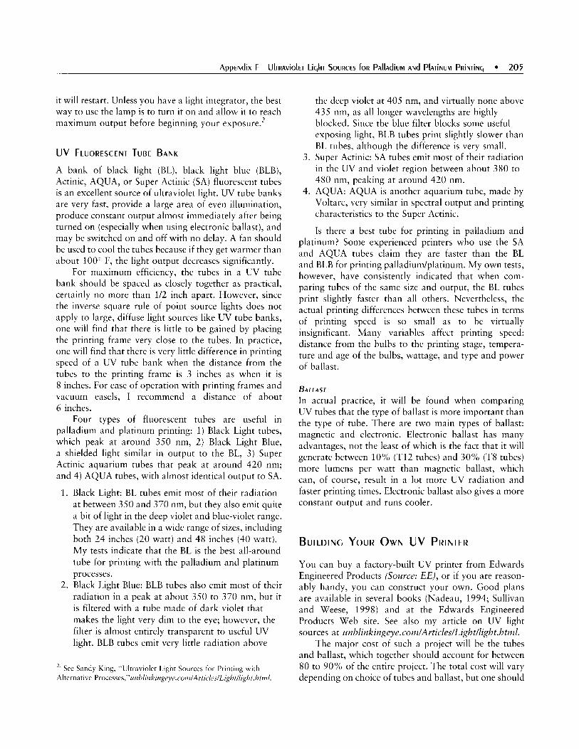
it will restart. Unless you have a light integrator, the best way to use the lamp is to turn it on and allow it to reach maximum output before beginning your exp0sure.l
UV FLUORESCENT TUBE BANK
A bank of black light (BL), black light blue (BLB), Actinic, AQUA, or Super Actinic (SA) fluorescent tubes is an excellent source of ultraviolet light. UV tube banks are very fast, provide a large area of even illumination, produce constant output almost immediately after being turned on (especially when using electronic ballast), and may be switched on and off with no delay. A fan should be used to cool the tubes because if they get warmer than about 100‘ F, the light output decreases significantly.
For maximum efficiency, the tubes in a UV tube bank should be spaced as closely together as practical, certainly no more than 1/2 inch apart. However, since the inverse square rule of point source lights does not apply to large, diffuse light sources like W tube banks, one will find that there is little to be gained by placing the printing frame very close to the tubes. In practice, one will find that there is very little difference in printing speed of a UV tube bank when the distance from the tubes to the printing frame is 3 inches as when it is 8 inches. For ease of operation with printing frames and vacuum easels, I recommend a distance of about 6 inches.
Four types of fluorescent tubes are useful in palladium and platinum printing: 1) Black Light tubes, which peak at around 350 nm, 2 ) Black Light Blue, a shielded light similar in output to the BL, 3) Super Actinic aquarium tubes that peak at around 420 nm; and 4 ) AQUA tubes, with almost identical output to SA.
1. Black Light: BL tubes emit most of their radiation at between 350 and 370 nm, but they also emit quite a bit of light in the deep violet and blue-violet range. They are available in a wide range of sizes, including both 24 inches (20 watt) and 48 inches (40 watt). My tests indicate that the BL is the best all-around tube for printing with the palladium and platinum processes.
2. Black Light Blue: BLB tubes also emit most of their radiation in a peak at about 350 to 370 nm, but it is filtered with a tube made of dark violet that makes the light very dim to the eye; however, the filter is almost entirely transparent to useful UV light. BLB tubes emit very little radiation above
’. See Sandy King, “Ultraviolet LiSht Sources for Printing with Alternative Processes,”r~rzl~/itikitzge~e.cut~i/Artrc/es/Li~~~t//I~ht.htrn/.
the deep violet a t 405 nm, and virtually none above 435 nm, as all longer wavelengths are highly blocked. Since the blue filter blocks some useful exposing light, BLB tubes print slightly slower than BL tubes, although the difference is very small.
3 . Super Actinic: SA tubes emit most of their radiation in the UV and violet region between about 380 to 480 nm, peaking at around 420 nm.
4. AQUA: AQUA is another aquarium tube, made by Voltarc, very similar in spectral output and printing characteristics to the Super Actinic.
Is there a best tube for printing in palladium and platinum? Some experienced printers who use the SA and AQUA tubes claim they are faster than the BL and BLB for printing palladium/platinum. My own tests, however, have consistently indicated that when com- paring tubes of the same size and output, the BL tubes print slightly faster than all others. Nevertheless, the actual printing differences between these tubes in terms of printing speed is so small as to be virtually insignificant. Many variables affect printing speed: distance from the bulbs to the printing stage, tempera- ture and age of the bulbs, wattage, and type and power of ballast.
BALLAST In actual practice, it will be found when comparing UV tubes that the type of ballast is more important than the type of tube. There are two main types of ballast: magnetic and electronic. Electronic ballast has many advantages, not the least of which is the fact that it will generate between 1 0 % (T12 tubes) and 30% (T8 tubes) more lumens per watt than magnetic ballast, which can, of course, result in a lot more UV radiation and faster printing times. Electronic ballast also gives a more constant output and runs cooler.
BUILDING YOUR OWN UV PRINTER
You can buy a factory-built UV printer from Edwards Engineered Products (Source: E E ) , or if you are reason- ably handy, you can construct your own. Good plans are available in several books (Nadeau, 1994; Sullivan and Weese, 1998) and at the Edwards Engineered Products Web site. See also my article on UV light sources a t i~nblinkingeye.cotnlArticleslli~htllight.htn~1.
The major cost of such a project will be the tubes and ballast, which together should account for between 80 to 90% of the entire project. The total cost will vary depending on choice of tubes and ballast, but one should

206 APPENDIXF
be able buy all of the materials necessary for a 10 to 12 bank of 24-inch tubes that will provide even coverage for prints up to 16 x 20 inches for around $250. The cost would be much greater to construct a unit with high output (HO) or very high output (VHO) tubes due not only to the extra cost of the tubes but also to the fact that heavier ballast is required than with standard wattage tubes.
T u B E N OM E N c LAT u R E
For those contemplating building a W printer with fluorescent tubes, here is a little information on the nomenclature of fluorescent tubes. They are usually designated by a series of letters and numbers. For example, the GE Black Light Blue tube carries the designation F20T12.BL.
The F stands for fluorescent. The next number, 20, indicates the wattage of this particular tube. The T number indicates the diameter of the tube in eighths of an inch. A T 12 tube, for example, is 12/8 or 1 1/2 inches in diameter. The letters describe the lighting characteristics of the tube. In this case, BL designates a Black Light tube. Tubes sometime carry further indicators, such as IS (Instant Start), RS (Rapid Start), or even letters showing the kind of usage for which the tube is intended, for example, R for reptiles, A for Aquarium, etc.
Standard wattage tubes vary in wattage according to size. For example, a regular output 24-inch tube is rated at 20 watts, while a regular output 48-inch tube of the same type is rated at 40 watts. Some fluorescent tubes are also available in H O and VHO. When using tubes of the same type and wattage, there is no difference in printing characteristics between a 24- and 48-inch tube.
PLATE#BURNERS, OR GRAPHIC ARTS PRINTERS
The light source of modern plate-burners is usually a metal halide discharge lamp, but some older units may be equipped with mercury vapor, carbon-arc, or pulsed- xenon lamps. Plate-burners, which usually come with integral vacuum frames and light integrators, make excellent UV printers for palladium platinum printing. Because of the changeover in the prepress industry to
digital, this is a very good time to purchase used plate-burners. For example, NuArc 26-1K and 26-1KS plate-burners that sold new for $1700 to $2200 just a few years ago are available on the used market for just a fraction of the original selling cost. The source for this estimate is the completed auction section on eBay. The same is true of high quality plate-burning equipment by other manufacturers, including Olec. (Source: 0)
TESTING OF UV LIGHT SOURCES
In preparing data, I ran a series of tests using sensitizers of pure platinum, a mix of palladium and platinum, and pure palladium with three different W fluorescent tubes and with a NuArc 26-Ik platemaker with a USHIO metal halide lamp. The lights tested were:
1. 24-inch Philips Super Actinic, TLK/03, 20 watts 2. 24-inch Sylvania BL (Black Light), 20 watts 3 . 24-inch Sylvania BLB (Black Light Blue), 20 watts 4. NuArc 26-IK, with USHIO Metal Halide Lamp
Spectral Power Distribution charts for these four sources of UV light are reproduced in Figures F.l through F.4. The tests with all three of the fluorescent tubes were made with a four-tube bank using the same electronic ballast unit.
TEST CONDITIONS
1. The exposing negative was a Stouffer TP 4 x 5 step wedge.
2. Tests were repeated three times to verify consistency and to ensure that small fluctuations in voltage did not skew the results.
0.30
0.25
0.20
0.1 5
0.10
0.05
0.00 300 350 400 450 500 550 600
NANOMETERS
FIGURE F. 1 Sptc T R A ~ POUER DisrnibLiioN fm Philips T L K I 0 3

Distance from tubes to printing frame was 6 inches for the fluorescent tubes, and standard printing distance for the NuArc 26-IK.
6. Three different sensitizing mixes were tested: 1) 100% platinum; 2) 50% platinum plus 50% palladium; and 3 ) 100% palladium. Each was mixed 1:l with a 25% solution of ferric oxalate.
7. Development of all tests was carried out in a 30% solution of potassium oxalate, used at 120" F.
300 350 400 450 500 550 600
NANOMETERS
300 350 400 450 500 550 600
NAN OM ETE RS
0.30
0.25
0.20
0.1 5
0.1 0
0.05
0.00 300 350 400 450 500 550 600
NAN OM ETERS
FIGURE F.4 SPECTRAL POUER D l S T R l b U T l O N fOR NUARC 26-IK. wirk USHI0 M E T A ~ HnlidE L A M P
3 . The same paper, Platinotype, was used for all tests. 4. All tests were carried out with room conditions at
about 70" F and 55% relative humidity. 5. All tests received 5 minutes of exposure. The
fluorescent tubes were allowed to warm up for 1 minute prior to the beginning of exposure, while the NuArc was allowed to warm up for 2 minutes.
GENERAL REMARKS ABOUT RESULTS
Several conclusions can be drawn from a comparison of the three families of curves. First, there is very little difference in printing speed between the four UV light sources tested. Second, contrast, as measured by exposure scale (ES), is virtually identical with all of the lights. Third, palladium is by far the dominant metal when it is mixed in a 50/50 ratio with platinum. And finally, pure palladium is a lot faster than pure platinum.
Further analysis of individual curves is required to discern the subtle differences between light sources. Table F.l highlights the slight differences in speed. For the purpose of this analysis the Speed Point of PtPd is taken to be the point on the curve where 90% of Dmax is reached. Although the differences are quite small, the BL tubes print faster than any of the other lights with pure platinum, pure palladium, and with a combination of the two metal salts. The higher the number expressed in log units, the faster the exposing light.
CONCLUSIONS
All of the UV light sources used in testing for this article are capable of excellent results with any of the processes. They all print with about the same contrast, and although the BL tubes are on the whole faster than the others, the practical difference is very small.
Nevertheless, it was noted that the Super Actinic curve has much less toe and, for that reason, has a longer area of straight line than the curves produced by the other lights. This characteristic of the SA is true with pure platinum, pure palladium, and with a combina- tion of the two metal salts. Although I don't know the physical cause of this phenomenon, it is most likely due to the fact that the Super Actinic tubes produce most of their useful radiation at a different wavelength than

208 APPENDIXF
Platinitnil UV Source Platinum Palladiuni Palladitrin
SA 0.60 0.70 0.92 BLB 0.55 0.80 0.85 BL 0.65 0.95 0.95 NuArc 0.52 0.82 0.88
1.5
- 1.2
0.9
06
0.3
- 0.0
the other lights: The BL and BLB tubes, and the NuArc 26-IK metal halide lamp, produce most of their UV radiation at around 36.5 nm, while virtually all of the radiation of the Super Actinic tube is in a spike at around 420 nm. In an effort to better illustrate this characteristic, I have isolated from the family of palladium curves shown previously just the curves made by the Super Actinic and the NuArc 26-IK, as seen in Figure F.S.
THE QUESTION OF SHARPNESS
There have also been claims made that the prints made with plate-burners and other HID lamps are sharper than those made with fluorescent tubes. In my own work, in which I use both types of light sources with vacuum frames, I can see no difference in apparent sharpness. When using a vacuum frame, perfect contact is ensured between the negative and paper during exposure. On the other hand, when making large prints in a contact printing frame, where it is very difficult to maintain good contact over the entire sur- face area of the negative and paper, I have found that prints made with HID lamps often have greater apparent sharpness than those made with fluorescent tubes. The reason is obvious. Most contact printing frames in large sizes are not capable of maintaining perfect contact between the negative and printing paper, and a lack of contact leads to scattering of the light (and loss of sharpness) with a diffuse printing source where many of the light rays pass through the negative at very low angles. With a semi-collimated unit such as a plate- burner-where the rays pass through the negative at relatively high angles- there is much less scattering of light.
UV BLOCKERS
WINDOW GLASS
Ordinary window glass, or crown glass, absorbs a significant percentage of radiation in the useful UV A range. I measured the transmission loss of ordinary glass in one of my UV printers, fitted with ordinary plate glass, by taking a reading in UV mode through a Gretag D-200 I1 densitometer, with sensitivity at 373 nm. The density readings transmitted to a loss of log 0.16 for a 1/4-inch thick piece of glass. That figure represents a loss in transmittance of around 30%, which amounts to a speed loss in printing speed of a full 1/2 stop.
SPECIALTY GLASSES
Some specialty glasses allow a higher percentage of transmittance of UV light. Starfire is a glass that is advertised to transmit between about 3 to 6% more light than regular glass in the range of 400 to SO0 nm, and perhaps an even higher percentage below 400 nm. I acquired a few sample pieces of Starfire glass and made some tests with it in a small contact printing frame. In my tests I was not able to detect any difference

in printing speed between the Starfire glass and ordinary crown glass with either dichromate or iron processes. It should be noted that the glass used in my tests was only 1/16-inch thick, and if one were to make the same test in a large printing frame with 1/4- or 3/8-inch thick glass, the results might very well be different. However, even assuming that the Starfire glass increased trans- mittance in the UV range by 10% over regular glass of the same thickness, this would translate into a speed gain of less than about log 0.5, or 1/3 of a stop.
It is almost certain that one could reduce printing times slightly by replacing the ordinary plate glass in our vacuum frames or contact printing frames with specialty glasses that allow the transmittance of a higher percentage of UV radiation. However, these glasses tend to be quite expensive and it is debatable whether or not the considerable additional expense can be justified on a practical basis. I have considered the matter carefully in my own case and determined that it is not worth the trouble.

This page intentionally left blank

Stan Klimek
21 1

212 APPENDIXG
Having spent a couple of decades in commercial photography in Los Angeles, I started to become bored and decided to re-examine what photography meant to me. In 1991, I came across platinum printers John Richardson and Norma Smith, who were giving work- shops on platinum printmaking. Platinum printing reaffirmed my love for photography by combining it with printmaking, also a fascination during my art school days. Once again I had the energy to create new work, but this time it would be all mine, with its own signature. One of the rewards of a lifelong pursuit of the arts is the accumulation of the artist's life experiences in his work, creating a fingerprint as unique as the artist him or herself.
Platinum printing has been in existence for over 100 years, but it fell out of favor in the second decade of the twentieth century. Over the past 15 years, however, it has experienced a revival through a small and dedicated coterie of artists from around the world, Dick Arentz chief among them. Having studied the original literature on platinum printing technique, these contemporary printers have engaged in extensive testing of new techni- ques and modern materials, sharing discoveries and building on each other's findings. As a result, the plati- num/palladium process we know today is safer, more reliable, and more successful than the early process on which it is based.
Like most people, I was sold on printing in modern platinum when I made my first print in 1991. In my case, I used a 665 negative from an old Polaroid 180 camera, slopped the solution with my foam brush onto Crane's Ecru and slapped on a negative-wow, I was hooked! It was a delicate, warm-toned image that gracefully melded with the paper. Years later, I reprinted that image and compared it to the first. I realized how my printing skills had improved; still, I love that first print.
There are many factors that must be controlled to make a good platinum print. They must be tested and refined for each image printed. It is a time-consuming, laborious, and expensive process, made worthwhile by the result. To minimize effort, keep detailed notes of the variables tested. Also, by standardizing procedures, many of the problems that can waste a day of printing can be eliminated.
THE NEGATIVE
The negative used for printing in platinum/palladium must be more contrasty than that used for silver printing. As a general rule, a negative that is optimized
Solution A Elon (Metol) 30 g
Solution B Kodalk (balanced alkali) 40 g
Sodium sulfite, desiccated 400 g Water 4 liters
Water 4 liters
for a grade 0 or 1 on silver-based paper is suitable. For my purposes, I use HPS, which is rated ASA 400, at a working speed of 160. After unloading my exposed film into a JOBOR drum, I presoak for 5 minutes in water at 70' F. To develop, I use the two-bath compensating method (Table G. l ) . Solution A is Kodak D-23, which is similar to Kodak D-76 without the hydroquinone, an accelerator for the highlights. Solution A develops the values. Solution B is an alkali bath that works further into the shadows without disrupting the highlights. The film is developed for 7 to 10 minutes in solution A and 3 minutes in solution B.
D u PLICATI NG
In order to contact print a negative at other than its original size, the negative must be duplicated to the size at which the image is to be printed. In the past I have duped traditionally by making a pyro positive on Bergger BPF 200 film, and from that, a negative on APHS litho film. The method I use was developed by Stuart Melvin.
More recently I have had success with the digital duping process with a stochastic negative output on the Agfa Imagesetter, with the help of Peter Ellzey of Copygraphics in Santa Fe (Source: CG). After adjusting the RGB scan file in Photoshop'R and converting to grayscale, I interpolate the file to the desired resolution with Genuine Fractals" (Soztrce: AG). I have used Telegraphics Software's Rustus plug-in for Photoshop to create the stochastic screen for the imagesetter as a workaround for Photoshop's 30,000 pixel limit.
With the release of Photoshop CS in October 2003, Photoshop'sR pixel limit was increased to 300,000 x 300,000. As of this writing, however, I am unaware of any raster image processor (RIP) that is yet able to take advantage of that change.
Because a stochastic negative is printed using random dots instead of the gridded dots of the more common halftone negative, it is more like film. As an example of the capabilities of this technology, recently

Appmdix c E~EMENTS Of Pkl iNUM PRiNTiNq 21 3
I digitally created a 20-inch negative from a 3Smm Tri-X film original for a client. The imagesetter output retained the look of a similarly enlarged film negative and grain structure, with no discernable digital dot and no moire in multiple registrations. Additionally, digital duping has an important advantage over film dupes: One negative can be taken in-camera and used for any printing process, silver or alternative, by modifying it in Photoshop and applying the appropriate character- istic curve.
M AT E R I A LS
PAPER
Paper is one of the most problematic elements of the platinum printing process. Papers used for printing in platinum are not made for this process, with few exceptions (Platine being one). (See Chapter 5: Paper.) They can contain sizing and additives that interfere with the platinum printing process. Also, it can be difficult to get in the size or weight required, when needed. Papers vary in how they print; the same paper can even vary among batches or weights. They are discontinued by the mills without notice, or their formulations are changed without announcement. They often harbor unknown paper gremlins that ruin prints for reasons that can never be ascertained.
Printing in platinum is most often done on water- color or printmaking paper. Each paper has a distinct signature. Exploring the various papers can take a lot of time and be a source of frustration, but is critical in honing printing skills. Experiment, find one or two suitable papers, and come to know them well.
The following outlines my own experience with papers commonly used for platinum printing:
Fabriano Artistic0 Extra White (aka Fabriano Uno): It produces medium blacks, sharp detail, and coats and clears easily. It is readily available and has a tight weave, good for large prints and multiple coatings.
Rives BFK: It is noted for a beautiful texture and is challenging to work with, but worth the effort. This paper is readily available.
Stonehenge Rising: It coats well, clears well, has a reddish brown warm tone and has a low cost.
Platinotype: It coats well, has good detail and good blacks, and is lightweight.
Somerset: It has a heavy texture, good blacks, and coats well.
Clearprint vellum: It demonstrates sharp detail and has great blacks, but it must be handled delicately. I t is translucent and economical.
Arches Platine: It has good blacks, coats well, is very white, has tight weave, and is good for large prints and multiple coats. It has been very inconsistent.
Additionally, most modern papers have buffering agents added to them that can interfere with the platinum printing process. One paper in particular, Rives BFK, has so much buffering agent added that it feels chalky when handled. To remove them, soak the paper in a 1% solution of oxalic acid for 3 minutes and dry naturally. This presoak also adds a slight acidity to the paper, which will improve the blacks.
PLATI N u M/ PALLADI u M SOLUTION
The basic solution used to coat paper for a platinum/ palladium print consists of metal salts in solution with ferric oxalate. Other substances can be added to the solution to accomplish various objectives (e.g., ethylene diamine tetraacetic acid [EDTA] to aid dissolving), but I use only a contrast agent. Experimenting with the chemicals and ratios is crucial in improving platinum printing skills.
In comparing the metals, palladium produces a warmer tone, lower contrast, and a wider range of values. It does best in the mid-tones and the shadows of the print. Platinum has a cooler tone and more contrast. It excels at bringing out delicate highlights but has a tendency to grain up when platinum is used in a greater than I:1 ratio in the solution. I almost always use a S:1 ratio of palladium to platinum; I find this formula gives a warm tone with the range of values I seek. I use Na2 to increase contrast and choose papers or developers to change tone. (See Chapter 8: Calibration, and Chapter 9: The Platinum and Palladium Print.)
I use a 1:l ratio of ferric oxalate to metal. I always mix the ferric oxalate from powder the night before the next day’s printing. Caution must be observed with the powder as it can become airborne; use a respirator. Mix in a low light environment, preferably with a low watt tungsten bulb. I use a formula of 26 grams ferric oxalate to 100 ml of distilled water with no other additive. Shake it for S seconds in an amber bottle and allow it to set up (become clear) overnight at room temperature or with a microwave oven dedicated to chemicals only. After shaking, loosen the cap of the bottle and microwave at medium power for 4.5 seconds. Tighten the cap and shake for 5 seconds, then loosen the

214 APPENDIXG
cap and put it back in the microwave for 45 seconds. Monitor to prevent boiling. By this method it will clear in about an hour, but it will still be hot. Cool it to room temperature before use.
CONTRAST CONTROL
For contrast control, I use Na2 (sodium chloroplati- nate). Na2 works to increase contrast without the graining found with other agents. (See Chapter 4: Chemicals.) I keep on hand dilutions of 2.5, 5 , 10, and 20%. To determine the amount of Na2 to add to the metal solution for a specific print, run a test strip without Na2 in the ferridmetal solution to estimate exposure time (many platinum printers use a densit- ometer for this task; I prefer to use my eye). Using the time determined from that test, expose a part of the print with a full range of values with a solution that contains no Na2. Allow that test to completely dry down, either naturally or with blotting and a dryer; a dry print appears cooler and about 15% darker when it is fully dried down.
When the print is dry, judge how much is needed to increase the contrast. Knowing the amount of Na2 that is needed to add a specific degree of contrast is the product of experience. As a rough guide, if the contrast of an 8 x 10 print is close, add one drop of 20% Na2 solution; if the contrast is far off, add two drops of 20%, expose, and evaluate. It is helpful to write on the back of the print the variables being tested. Repeat the testing process until the contrast is correct. The bad news about this testing process: It will only provide a starting point, as the full sized print often requires further contrast adjustment. The good news: A negative perfectly crafted for platinum printing may not need any Na2 at all.
Besides adding a contrast controller to the platinum solution, I also extend it with distilled water. This wetter solution makes for a smoother coat. Some guidelines for amounts to add to the ferric oxalate/metal solution are listed in Table G.2.
TECHNIOUE
SIZING
Most advanced platinum printers don’t size unless using a specific paper that requires it. When sizing is done, 250-bloom gelatin in a 2, 3 , or 4% solution is used. Each paper must be tested for the correct solution. For example, I found that on Fabriano Artistic0 EW sized
Extending Solzition for Coating
In milliliters In drops
Solution Water to add Solution Water to add 2 nil 0 40 drops 0 3 in1 1.5 rnl 60 drops 30 drops 8 ml 3.5 ml 160 drops 70 drops 12 ml 7.5 ml 240 drops 150 drops
with a 4 % solution, the platinum print started to take on a reflective quality. A 2 % solution showed no benefit to the print, but a 3% solution was just right. However, 2 % seemed to work well for Stonehenge, while 3% was too much.
1.
2.
3 .
4.
5.
Preshrink paper at 120” F for 30 minutes with a 1 % solution of oxalic acid added to the water. Lay down the warm paper on a sheet of glass and blot the excess water. The paper should still be warm and wet. Warm gelatin solution to 125” F. Add formalin to the gelatin solution at a 1 5 0 ratio. This works out to roughly six drops of formalin to 1 0 ml of gelatin solution; for an 11 x 14, add 9 drops of formalin to 15 ml of gelatin. Use caution when handling formalin; it is a formaldehyde solution and therefore flammable and toxic with a strong pungent odor that will irritate eyes and throat. It is nasty stuff, but the most effective alternative for hardening the gelatin. Brush the solution onto the paper with a good quality, flat, 4-inch watercolor wash brush that has been warmed in water and shaken of excess water before use. A smooth even coat is critical; anything short of that can ruin a print. Technique is all-important.
a. Dip the brush in the solution. The brush will soak up about 7 ml of solution on the first dip.
b. Starting at the top, brush across the entire sheet horizontally; the coat will be thick. Re-dip the brush if the coating becomes noticeably thinner.
c. Next, without recharging the brush, smooth the horizontal coat with vertical strokes.
d. Lastly, lightly feather the coating with horizontal strokes across the entire sheet.
Allow to dry down naturally. Use the sheet within a few days.

H u MIDI FYI NG
Introducing moisture into the paper before coating improves blacks and makes the coat more consistent and easier to lay down. I introduce 75% humidity from an ultrasonic humidifier for 1 0 minutes prior to coating. Instead of humidifying the entire studio, I built a box that measures 40 x 28 x 16 inches; this large box humidifies more quickly and permits more control of the moisture content of the paper. It also accommodates paper for large prints and prevents the studio from becoming a sauna. Introducing humidity will increase the contrast and narrow the value scale for some papers; testing is recommended. Humidity gauges are readily available at general merchandise stores at low cost.
COATING
A good coat of platinudpalladium solution is even more critical than a good coat of sizing. I still hear in my mind every time I coat: “Brush slowly, brush lightly, brush wet, and take your time brushing,” Stuart Melvin’s coating mantra. There are many mistakes to be made with laying a coat. It may be laid down too quickly or too slowly, too softly or too hard, and with too much or too little solution. Another problem may be the paper. The paper may not have enough internal sizing or may not be properly humidified. Most coating problems, I believe, are either from the paper or the coating technique, not the chemistry.
I coat on a light table lit from below with low wattage tungsten bulbs. This allows evaluation of the coating while it is still wet. It shows coating over- saturation, undersaturation, brushing problems, and flaws in internal paper sizing. These problems cannot be fixed at this point, but the lighting will reveal errors in the coat that can be corrected on the next go. Also, occasionally these errors will not be visible on the final print and the paper can be salvaged in time to produce a fine print.
To show a clean print edge instead of brush strokes, use Rubylith@ D3R. Rubylith‘“ is a mylar with a lacquered red orthochromatic mask that is easily separated after cutting. The RubylithR is clear, tough, and stable, and the coating is translucent, enabling precise stripping in of the negative on a light table. My procedure for registration of the negative to RubylithE is as follows:
1. Cut a piece of RubylithR larger on all four sides than the paper being used. The extension will help with quick registration in the exposure unit and for
covering any fugitive solution spots that might have found their way to the print border during coating.
side up. Place the negative emulsion side up on the Rubylith’$’ and center it with a ruler on all four sides. Tape all four sides down with either lithographer’s tape or black photographer’s tape.
3. Turn the taped sheets over so that the red mask is facing up. The negative should be centered on the RubylithR and oriented as the print will be.
4. With the light table on, place a cork-backed metal ruler on an edge. Take an X-ACT0 knife with a new #11 blade and lightly cut through the red mask without cutting the mylar, scoring down the ruler. This will take a bit of practice to master. Overcut the corners by 1/4 inch; it is difficult to get a perfect corner without overcutting.
5. Cut the remaining three sides and gently lift up the red mask at a corner with the tip of the knife. Once the corner is up, grab the red mask and strip away the cut area.
6. Cover the overcuts on each corner with a 1-inch strip of Rubylith’“ tape at a 45-degree angle to each corner. This Rubylith”/negative sandwich will hold together well and can be stored as is for future printings. If brush marks are desired at a later date, simply strip off the red mask.
Now that the negative is ready, it is time to coat.
1. Dip a 4-inch Richeson brush in distilled water and remove the excess by dragging it across the lip of the bowl. After two easy shakes, the brush is ready for coating.
2. Pour a bead of the ferridmetal solution at the top of the area to be coated. Brush it quickly in a rough rectangle 10 to 15% larger than the print area.
3. After the rough in, slowly move in horizontal and vertical patterns until the coat appears smooth, using only the weight of the brush.
4. Blow dry on a medium-warm setting or with fans. Different papers have different drying requirements. Stonehenge should set-up for a few minutes before drying. Rives BFK should be brushed and dried quickly. Fabriano Artistic0 has a better black if dried immediately. If masking for a clean edge, blot the edges of the coat with tissue. This will make clearing easier and erases the small faint gray line that appears on the more absorbent papers.
2. On a glass light table, place the Rubylith” glossy
5 . Humidify again at 75% for 8 to 10 minutes.

216 APPENDIXG
After these steps, the paper should have a translu- cent and smooth orange coat that appears flawless on the light table. It is now ready for exposure.
EXPOSING
Exposure equipment for platinum printing is usually adapted from equipment designed for a wide range of other uses. I use a 36 x 45-inch vacuum frame from a frame maker and a 1 k metal halide Olite from a commercial printer. I find the metal halide produces better blacks and sharper detail than the fluorescents I have used.
The print should be exposed immediately after the post-coating humidification. I believe maintaining humidity in the paper during exposure deepens the blacks and increases contrast. In order to preserve the moisture in the paper during the exposure process, I sandwich the coated paper and the negative between a piece of mylar the size of the exposure unit's surface and the glass. Caution must be used that the paper not be humidified to greater than 85% when using this technique, because the excess moisture can irreparably scorch the emulsion of the negative. To guard against this, 1 mil mylar can be placed between the paper and the negative without interfering with the quality of the print being exposed.
After laying the coated paper in the frame on the mylar, register the negative on the paper. Secure the glass and start the exposure. Platinum/palladium prints can be burned and dodged to a maximum 10 to 20%. When the exposure is complete, remove the print immediately to the developer; it is especially delicate and light sensitive at this point.
DEVELOPING AND CLEARING
I use either potassium oxalate or ammonium citrate to develop prints. Potassium oxalate produces redder, warmer brown tones. Ammonium citrate yields a yellow-brown hue that is cooler than the potassium oxalate's, but it still has a warm hue. When heated, the tone becomes warmer and deepens. Do not heat the developer to more than 120 F. This higher temperature will cause varying results, as each paper responds differently to the developer. For example, Stonehenge developed in potassium oxalate heated to 120 F has a very warm reddish-brown tone, whereas Fabriano Artistico EW developed the same way will have a cooler tone than the Stonehenge.
1.
2.
3.
4.
5. 6.
7. 8.
9. 10.
Mix the developer. It is preferable to overestiniate the amount needed to develop a print than to underestimate. If part of the print is not covered in the first pour it could leave a mark on the print that cannot be worked around, especially on a highlight. A quart for an 8 x 10 and 1.5 gallons for a 20 x 24 should suffice. Pour the developer over the print in a tray quickly. Though the latent image is immediately apparent, develop for at least 3 but no more than 4 minutes to allow complete conversion of the ferric oxalate and to facilitate clearing. After complete development, wash for 10 seconds in 7 0 ~ F water. Repeat. Follow with 4 minutes in Kodak Hypo Clear in a 1:l ratio from stock solution. Wash for 10 seconds in 70- F water. Repeat. Agitate for 3 minutes in a 3 % solution of muriatic acid'-3 minutes exactly. Wash for 10 seconds in 70' F water. Repeat. Soak for 5 minutes in Kodak Hypo Clear in a 1:l ratio from stock solution, agitating intermittently. Wash for 15 minutes. Dry naturally.
Inadequate clearing is a common problem. Besides making for muddy highlights, failure to completely clear a print will cause it to stain over time. It is difficult to judge when a platinum print is cleared; the color of undissolved ferric oxalate is easily mistaken for print tone. In this case, trust the formula instead of the eye. However, a print that has been masked in Rubylith" as described previously will readily reveal to the eye a poorly cleared print, as it will have a slight discoloration or yellow tint in the border area where the Rubylith" was.
'. Mttriatic uc-id is an older term for hydrochloric acid. Hydrochloric acid, MSDS 4, is extremely caustic. See the precautions for handling and mixing acids in Chapter 4: Chemicals. I have tried different clearing methods and, in some cases, the muriatic acid step can be dispensed with i f the paper is a tight weave like Fahriaiio Artistico and Platine. However, with Rives and Stonehenge, due to their soft weave and minimal internal sizing, the acid is needed. I have seen no delicate highlight etching occurring from the use of muriatic acid, and it guarantees complete clearing. The clearing agents like Hypo clear, EDTA, and sulfites do a great job in dissolving unexposed ferric, but when combined with an acidic etch from an acidlike muriatic, it removes mnst of the remaining vestibules of rust.

FIN I SH I NG
SPOTTING Our
Though Spotone’ is the traditional medium for spot- ting, I prefer watercolors. The dyes in Spotone are less stable than the pigments in watercolors. I have found that lamp black with a bit of burnt umber works well for 90% of spots on the platinum print. To prepare, squeeze out a small dab of lamp black, mix in the burnt umber with a mixing knife, and let it dry. After it is mixed, it can be stored for future use. If dried out, rewet with a spotting brush that is charged with water. Additionally, Chinese white works on some small dark spots in white areas. A high quality sable brush, size 3 to 5 aught, works well for spotting out. After careful practice, even delicate highlights can be blended seamlessly.
FILLING IN
Sometimes values can be drawn in using high quality artist’s charcoal and a smoothing stump. This can be useful in saving a difficult-to-print image by adding a bit of value to a small flawed area. The materials necessary for this technique can be found at the art store: sticks of charcoal in black, burnt umber, and burnt sienna; fine grit sandpaper; a kneadable eraser; and paper stumps for blending.
1.
2.
3.
4.
Determine what combination of the three hues of charcoal sticks will match the tone of the print. Grind up a small amount of charcoal dust with sand paper from the chosen sticks. Pick up this blended dust with the tip of a stump and remove most of it. Only a slight amount of charcoal dust needs to be on the tip. Lightly test on a scrap of the same kind of paper the image is printed on to get a feel of how much to lie down. In this case, less is more. Draw in the flawed area of the print, then gently smooth it with a stump. Continue to draw and smooth until the area blends into the print. Small mistakes can be corrected with a piece of the kneadable eraser. Warm it in the hand until it is pliable enough to roll out a fine point. Take the mistake out with this point and redraw. No need to protect or fix this charcoal dust; it is bonded to the paper fibers.
It takes practice to become proficient in this
ETCH I NG
In some cases, imperfections that lay below the surface of the paper can be repaired. The smallest can be spotted with Chinese white watercolor. On a heavier weight paper with a tight weave, such as Fabriano Artistico, flaws in the border area can be lightly sanded out with a small piece of fine grit sandpaper. Irregular particles imbedded in the paper can carefully be picked out with the tip of a sharp #11 X-ACT0 blade and lightly mended with a bone burnisher.
Occasionally a print will be affected by the notorious Black Dot Plague. This is characterized by several or many black dots occurring at random in the coated area of the print. The prints of every experienced platinum printer have been infected by this scourge at some point, and the cause is unknown. In mild cases, etching the dots out with the tip of a #11 X-ACT0 and spotting with Chinese white helps. If they persist in subsequent prints, a change of paper can help.
FLATTEN I NG
I flatten prints in a dry mount press between two sheets of rag board on moderate heat for 3minutes. Then I place them under a heavy sheet of plate glass until the heat dissipates.
WAXING
Waxing a platinum print can deepen the blacks, give a pleasing tone to the highlights, and can impart a pleasing sheen to the print if done correctly. Waxing is not without its detractors, however. Some do not like the look. Others worry that it may not be archival. Still others fret about gilding the lily. Ultimately, the decision to wax or not lies with the judgment of the printer.
Materials needed for waxing are Gamblin cold wax medium, a 2-inch stencil brush, a stiff shoe polish brush, and a soft shoe brush. To wax:
1. Tape the print to a sheet of glass with drafting tape. Mask off the edges of the print. (3M Low-Tack Painter’s Tape works well.)
2. Place a light next to the print and position it so the light falls across the print. This will aid in laying down an even application by allowing the mon- itoring of the coat as it goes down.
3. Take a quarter-size dab of wax with the stencil brush. Using short strokes, cover a 3-inch by 3-inch area. Smooth that area with the stencil brush twice. Take another dab of wax and reDeat on an adjacent
technique, but- the reward for persistence is an invalu- able tool for finishing that could save a print.
area. Slowly work up the print. Platinudpalladium prints are tough and can withstand this. When

218 APPENDIXG
finished, examine the evenness of the entire coat of wax in the oblique light. Make any necessary adjustments.
4. With the stiff shoe brush, brush out to smooth and pick up the excess wax, using horizontal semicir- cular movements. Keep the brush clean while working the coat.
not smooth enough at this point, use the soft shoe brush to smooth it out. If it is already smooth enough, do not brush further. Overbrushing creates a gloss. Remove the tape mask from the print and blend the edge of the wax with your thumb. Let the wax set up for 2 days.
5. Examine the wax coat in oblique light again. If it is
A good way to see the effects of waxing is to lay down a strip of low-tack painters tape down the middle of a rejected print and wax one side. This allows direct comparison of the wax’s effect.
The quest for the perfect platinum print is similar to aiming at a moving target. After all these years, I still learn something new every time I print. Techniques I’ve been using become ineffective. Materials change or another printer comes up with an improved procedure. But after I chase it down, work it through, and come through with an image with which I am satisfied, I am allowed to relive the moment that I made my first platinum print.

21 9

220 SOURCES
AN TI STAT I c So LUT I o N s
MD Modern Solutions. 6370 Copps Ave., Madison, WI 53716 Tel: (800) 288-2023 Fax: (608) 222-2704 http://www .modernsolutionsinc.com
ARCHIVAL PRODUCTS
CR Conservation Resources. 5532 Port Royal Rd., Springfield, VA 22151 Fax: (703) 321-0629 http://www.conservationresources.com Gaylord Brothers. P.O. Box 4901, Syracuse, NY
Tel: (800) 448-6160 Fax: (800) 272-3412 http://www.gaylord.com Light Impressions. P.O. Box 940, P.O. Box 787, Brea, CA 92822-0787 Tel: (800) 828-6216 Fax: (800) 828-5539 http://www.lightimpressionsdirect.com
GA 1322 1-490 1
LI
BEYOND THE ZONE SYSTEM ( B T Z S ) PRODUCTS
VCS View Camera Store. P.O. Box 19450, Fountain Hills, AZ 85269 Tel: (480) 767-7105 Fax: (480) 767-7106 http://www.viewcamerastore.com [email protected] (Also a source for large format film, cameras, and densitometers)
CAMERA MAKERS
KC K.B. Canham. 2038 East Downing, Mesa, AZ 85213 Tel: (480) 964-8624 Fax: (480) 892-4146 http://canhamcameras.com
HC Hoffman Camera Company. 19 Grand Ave., Farmingdale, NY 11735 Tel: (516) 694-4470 Fax: (516) 935-0748 hi20301 [email protected] R.H. Phillips & Sons. P.O. Box 1281, Midland,
Tel: (517) 835-7897 Fax: (517) 839-9745 [email protected]
WC Wisner Company. P.O. Box 21, Marion, MA 02738 Tel: (800) 848-0448 Fax: (508) 748-2733 http://www.wisner.com
PC MI 48641-1281
CH EM ICALS
AC Artcraft Chemicals. Box 583 Schenectady,
Fax: (518) 355-9121 NY 12301 Tel: (800) 682-1730 http://www.artcraftchemicaIs.com j acobson@juno .com Bryant Laboratory, Inc. 1101 Fifth St., Berkeley, CA 94710 Tel: (800) 367-3141 Fax: (510) 528-2948 http://www.us.chemnet.com/dir/Glass/ index2. html (A good source for bulk chemicals) Bostick & Sullivan. Box 16639, 1541 Center Dr., Santa Fe, NM 87505 Tel: (505) 474-0890 Fax: (505) 474-2857 http://www. bostick-sullivan.com [email protected] [email protected] (Arentz Kit: One of two suppliers of PtRd coat- ing solutions; also paper, printing supplies, print- ing frames) Photographer’s Formulary. Box 950, Condon, MT 59826 Tel: (800) 922-5255 Fax: (406) 754-2896 http://www.montana.com/formulary [email protected] (Arentz Kit: One of two suppliers of PtPd coating solutions) Quality Camera Company. 382 Trabert Ave., Atlanta, GA 30309 Tel: (404) 881-8700 Fax: (404) 881-9010 (Ammonium platinum and palladium salts) Spectrum Labs, Sales Department. 14422 S. San Pedro Street Gardena, CA 90248 Tel: (310) 516-8000 or (800) 772-8786 Fax: (310) 516-7512 [email protected] (A good source for bulk chemicals)
BL
BS
PF
QC
SL
CO~TACT PRINTING FRAMES AND FILM HOLDERS
AWB AWB Enterprises. 33320 Gafford Rd., Wildomar, CA 92595 Tel and Fax: (909) 674-0466 http://www.cosmoaccess.net/--awbent [email protected] Bostick & Sullivan. Box 16639, 1541 Center Dr., Santa Fe, NM 87505 Tel: (505) 474-0890 Fax: (505) 474-2857 http://www. bostick-sullivan.com
BS

SOURCES 9 221
DENSITOMETERS
DI
ES
GM
XR
Diversified Equipment Company, Inc. 7213 Lockport Place, Lorton, VA 22079 Tel: (703) 550-1994 Fax: (703) 354-9047 http://www.diversified-equipment.com (Used densitometers) Eseco Speedmaster. One Eseco Road, Cushing,
Tel: (800) 331-5904 Fax: (918) 225-1284 [email protected] Gretag-Macbeth Tel: (800) 622-2384 http://www.gretagmacbeth.com
Tel: (800) 292-4435 http://www.xrite.com
OK 74023-9912
X-RITE
DIGITAL SERVICES
AG
CG
EC
PW
RA
LIZARDTECH Tel: (206) 902-2500 http://www.lizardtech.com (Genuine Fractals interpolation and compression software) Copygraphics (Peter Ellzey). 314 Read St., Santa Fe, N M 87501 Tel: (505) 988-1438 http://www.creativepro.com/outputresource/ home11 643.html (Digital scans and imagesetter negatives) Evercolor. 70 Webster St., Worcester, MA 01603 Tel: (508) 757-2216 or (800) 533-5050 Fax: (508) 757-2216 http://www.treeo.com/out-optdevercolor.htm1 light@evercolor .com Photographic Works. 3550E. GrantRoad,Tucson, AZ 85716 Tel: (520) 327-7291 http://www.photographicworks.com (Digital scans) RASTUS http://www.telegraphics.com.au/sw/info/ rastus.htm1 (A plug-in for Adobe Photoshop that creates stochastically screened bitmaps; available for Mac and PC)
FILM, ULTRA.LARGE FORMAT
JC
PM
VCS
J and C Photo. P.O. Box 366, Grover, MO 63040 Fax (for orders): (702) 920-8826 http://www.jandcphotography.com sales@jandcphotography .com ( E k e and Classic film) Photomark. 2202 E. McDowell, Phoenix, AZ 85006 Tel: (800) 777-6627 Fax: (602) 273-0928 http://www.photomark.com View Camera Store. P.O. Box 19450, Fountain Hills, AZ 85269 Tel: (480) 767-7105 Fax: (480) 767-7106 http://www.viewcamerastore.com [email protected] (Also a source for large format film, printing frames, cameras, and densitometers)
LABORATORY Eou I PMENT
CLS
CPI
ESc
GAS
SL
TS
Chem Lab Supplies. 1060 Ortega Way, Unit “C”, Placentia, CA 92670 Tel: (714) 630-7902 Fax: (714) 630-3553 http://www.chemlab.com Calumet Photographic. 890 Supreme Dr., Bensonville, IL 60106 Tel: (800) 225-8638 Fax: (800) 828-5539 http://www.calumetphoto.com Edniund Scientifics. 101 E. Glouster Pike, Barrington, NJ 08007 Tel: (800) 728-6999 Fax: (609) 547-3292 [email protected] Graphic Arts Supermarket. 9701 Canoga Ave., Chatsworth, CA 91311 Tel: (818) 997-7771 or (818) 882-0168 http://www.magicyellow.com (Stouffer’s Step Tablets) Slosher by John Sexton http://www.photo.net/bboard/q-and-a-fetch- msg?msg-id=003q8Q Tri-Ess Sciences, Inc. 1020 W. Chestnut St., Burbank, CA 91506 Tel: (800) 274-6910 http://www.tri-esssciences.com (Almost everything for the alchemist)
VRW VRW Science Products. P.O. Box 1002,
Fax: (908) 757-0313 S. Plainfield, NJ 07080 Tel: (800) 932-5000 http://www.vrwsp.com (Hygrometers)

222 SOURCES
PAPER UNITS
MA
ASW
DS
NYC
PT
ss SK
TR
uv
Martin Axon Tel: 203-245-7674 Art Supply Warehouse. 5325 Departure Dr., North Raleigh, NC 27616-1835 Tel: (800) 995-6778 Fax: (919) 878-5075 http://www.aswexpress.com [email protected] Daniel Smith. 4130 First Avenue, S., Seattle, WA 98124-5568 Tel: (800) 426-6740 Fax: (800) 238-4065 [email protected] New York Central Art Supply. 62 Third Ave., New York, NY 10003 Tel: (800) 950-6111 Fax: (212) 477-0400 http://www .nycentral.com Paper Technologies, Inc. 6333 Chalet Dr., Commerce, CA 90040 Tel: (562) 928-5600 Fax: (562) 927-6100 http://www.papertech.com Stationery Store Stephen Kinsella, Inc. P.O. Box 32420, Olivette, MO 63132
AR
BS
EE
NA
Olec PS
Aristo Grid Lamp Products. 35 Lumber Rd., Roslyn, NY 11576 Tel: (516) 484-6141 Fax: (516) 484-6992 http://www.aristogrid.com Bostick & Sullivan. Box 16639, 1541 Center Dr., Santa Fe, NM 87505 Tel: (505) 474-0890 Fax: (505) 474-2857 http://www. bostick-sullivan.com Edwards Engineering. 5304 Arrowhead Dr., Lago Vista, TX 78645-5803 Tel and Fax: (512) 267-4274 http://www.eepjon.com (Also print dryers) NuArc Company, Inc. 6200 W. Howard St., Niles, IL 60714 Tel: (800) 962-8883 Fax: (847) 967-9664 http://www.mrprint.com/nuarc/default.asp http://www.olec.com Psoralight Corp. 2806 William Puller Dr., Columbia, SC 29205 Tel: (800) 331-3534 Fax: (803) 748-9985 (Solar Specs)
Tel: (800) 445-8865 Fax: (314) 991-8090 Twinrocker. 100 East Third St., P.O. Box 413, METAL HALIDE FIXTURES AND LAMPS Brookstone, IN 47923 Tel: (800) 757-8946 http://www. twinrocker.com [email protected]
http://www.grainger.com/Grainger/start.jsp http://www. bulbman.com http://www.olec.com/graphicarts/OLEC-
Fax: (765) 563-8946
SpectramatchTM-Lampslolec-spectramatchtm-
LIGHT SOURCES
Ru BY L I T H ~
UL Mister Art: Ulano Masking Films Tel: (866) 762-7811 http://www .misterart.com
lamps.htm1
TUBES AND BALLAST
http://www.aquadirect.com/lighting/flourescent. html http://www.americanlight.com/americanlight/home.htm http://www.topbulb.com/default.asp http://www.fullspectrumsolutions.com/UltraLux-
http://www.afforda blelighting.com/blowout.html http://www.uriworld.com/PRODUCTS/mlam.htm http://www.hamiltontechnology.com/shop http://www . bulbman.com
Ballast.htm

RIMINI. I T A I ~ 1 9 9 6 12 x L O l N c k PriPd

224 BIBLIOGRAPHY
HISTORIC
Abney, William Platiiiotype: Its Preparation and Manipulation. London: Sampson, Low Marston, 1895.
Anderson, Paul L. Technique of Gum-Platinum: The Technique of Pictorial Photography. New York: J.B. Lipponcott, 1939.
Newhall, Beaumont. The History of Photography. New York: Museum of Modern Art, 1982.
Pizzighelli, Captain, and Hubl, Baron A. Platinotype. London: Harrison and Sons, 1886. Reprinted from The Photographic ]ourrial. 1883,
Steiglitz, Alfred. Platinum Printing: The Modern Way in Picture Making. Rochester, NY: Eastman Kodak, 1905.
pp. 5-59.
CURRENT
Arnow, Jan. Handbook of Alternative Photographic Processes. New York: Van Nostrand Reinhold, 1982.
Crawford, William. The Keepers of the Light. New York: Morgan and Morgan, 1979.
Farber, Richard. Historic Photographic Process. New York: Allworth Press, 1998.
James, Christopher. The Book of Alternative Photographic Processes. New York: Delmar, 200 1.
Malde, Pradip, and Ware, Michael. The Ammonium System: A Contemporary Method for Making Platinum and Palladium Prints. http://mikeware. demon.co.uk
Nadeau, Luis. History and Practice of Platinum Printing. New Brunswick, Canada: Atelier Luis Nadeau, 1994.
Rexroth, Nancy. The Platinotype 1977. Condon, MT: Formulary Press, 1977. (Available from Photograph- ers Formulary.)
Shellea, Thomas J. Instruction Manual for the Platinum Printing Process. Philadelphia: Thomas J. Shellea, 1982. (Available from Photographers’ Formulary)
Sullivan, Richard, and Weese, Carl. The New Platinum Print. Santa Fe, NM: Working Picture Press, 1998. (Available from Bostick Sullivan: www.bostick- sullivan.coni)
CHEMISTRY
Anchell, Stephen G. The Darkroom Cookbook. Boston: Focal Press, 1994.
Bunting, Roger K. The Chemistry of Photography. Normal, IL: Photoglass Press, 1987. (Available from www.photoglass. coin )
Rempel, Siegfried, and Rempel, Wolfgang. Health Hazards for Photographers. New York: Lyons and Burford, 1992.
DIGITAL
Blatner, David, and Fraser, Bruce. Real World Photoshop CS, 6th Ed. Peachpit Press, 2004.
Burkholder, Dan. Making Digital Negatives for Contact Printing. San Antonio, TX: Bladed Iris Press, 1998. (Available from tuzuw.cinnburkholder.com)
Fokos, David. www.wovkingpictures.com
GENERAL
Davis, Phil. Photography, 7th Ed. Dubuque, WI: Brown and Benchmark, 1995.
Edwards, Betty. Drawing on the Right Side of the Brain. Los Angeles: J.P. Tarcher, 1979.
Kodak. Building a Home Darkroom. Kodak Publication KW-14. New York: Eastman Kodak, 1996.
Schaefer, John P., ed. An Ansel A d a m Guide. Basic Techniques of Photography, Book Two. Boston: Little, Brown, 1998.
Simmons, Steve. Using the View Camera. New York: Amphoto, 1992.
Stroebel, Leslie. View Camera Technique, 6th Ed. Boston: Focal Press, 1993.
S EN SITOM FTRY
Adams, Ansel. The Negative. Book 2. Boston: Little, Brown, 1981.
Davis, Phil. Beyond the Zone System, 4th Ed. Boston: Focal Press, 1998.
Kodak. Professional Black and White Films. Kodak Publication F-5. New York: Eastman Kodak, 1998.

Bibboqnnpky 225
Todd, Hollis N., and Richard D. Zakia. Photo- Hunter, Darth. Paper Making: T h e History and Tech- graphic Sensitometry. New York: Morgan & Morgan, 1969.
nique o f a n Ancient Craft. New York: Dover, 1974.
P Y RO
Hutchings, Gordon. T h e Book of Pyro. (1991) Available from: Gordon Hutchings, P.O. Box 2324, Granite Bay, CA 95746.
PAPER
Airey, Theresa. Creative Photo Printmaking. New York: Amphoto, 1996.

This page intentionally left blank

Acidification, 47 Adams, Ansel, 16, 19, 120, 150,
Advanced technique, 91-103 182, 183
“black plague” cure, 100-101 double coating, 97 drying of the coating, 97-99 final print preparation, 99-100 glycerin, 97 humidification, 93-95 image hue, 95-96 masking negatives, 92 negative handlinghtorage, 103 presentation, 101 working light, 92
Albumin, 93 Alcohol, polyvinyl, 95 Alum, 30 Ammonium citrate, 31, 33
developing and clearing with,
print hue and, 96 85,216
Anderson, Paul, 33 Anemic prints, 106 ANSI (American National
Standard Institute), 113, 1221-1
AQUA tubes, 205 Arches Cover, 43, 47 Arches Platine, 40,42,43, 44, 213
double coating, 97 humidified, 94
Arentz, Dick, 35,42,45, 188, 195, 197, 212
ASA (American Standards Association), 17
Average gradient, 17, 19, 22, 114 Axon, Martin, 44
Ballast, 205 Ballasted HID lamps, 204-205,
Banquet cameras, 152-153 Base + fog (BSF), 17, 18, 114 Basis size, 42 Basis weight, 42 Bergger 200 BPF, 161 Bergger BFP200, response to pyro,
181, 182, 182n Bergger COT 320, 42, 45 Berkeley’s formula, 146-147 Beyond the Zone System (1998),
13, 21, 70, 112, 156, 15611, 157
208
Bienfang Graphics 360, 42, 44-45 Black
convincing, 21, 70 streaking, 107
Black defects, 99-100 Black light blue (BLB) tubes, 205,
Black light (BL) tubes, 205 “Black plague”, 21 7 “Black plague” cure, 100 Black spots, 107 Blamer, David, 190 Bloom gelatin, 30 The Book ofPyro (1991), 182 Brush development, 97 Brushes, 95
coating, 79-81, 83 Richeson, 10
206
BTZS tubes, 1SSn, 156-157 Buffering solutions, 36 Burkholder, Dan, 188
Calibration, 63-73 contrast control technique,
dichromate method, 73 light source, 64-66 printing with digital
ratio method, 72-73 standard negative contrast
ranges, 73 supplies, 66-67 time/distance technique, 68
Calumet Photo, Inc., 8 Cameras
banquet, 152-153 size of, 152-153 view, 151, 152, 153
Chalky prints, 106 Chemicals, 27-38
68-72
negatives, 194-199
clearing agents, 31, 34-36 coating solutions, 30, 31-33 developers, 3 1, 33-34 measurement units, 29 monochromatic film
developing agents, 29
MSDS and, 28-29 oxidizing agents, 30-3 1 paper sizing, 30 purity of, 30 sources of, 38 toners, 36-38
227

Chemistry, 145-148 Berkeley’s formula, 146-147 clearing, 148 oxidation, 146, 147 oxidation-reduction reaction
(redox), 146 oxidizers, 147 palladium printing with Na2,
reduction, 146, 147 147-148
Chlorates, 3 1 Chlorine, 100 Circle of confusion, 25 Citric acid, 35, 36 Clearing, 85-86
chemistry of, 148 technique, 216 test strips, 78
Clearing agents, 31, 34-36, 41 Clearprint vellum, 21 3 Clinical print, 142, 150 Coating, 83-84
drying of, 97-99 papers for double coating, 43 papers for single coating, 42 technique, 215-216 uneven, 106
Coating area, 8-9, 10 Coating brushes, 79
coating rods versus, 83 technique, 79-81
coating brushes versus, 83 technique, 82-83
Coating solutions, 30, 31-33 filtering, 84 metal salts, 32-33 metal utensils and, 33 restrainers, 32 sensitizers, 31-32
Coating rods, 82
Color density range control, 186,
Color density range palette, 186,
Commercial plate burners, 13 Compression of brightness ranges,
Computer-generated negatives,
193
195-196
20-21
in-camera negatives versus, 150-1 5 1
Conner, Lois, 44 Contact hazard, 28
Contact printing frames, 11-12 Contrast, 20
adjusting, 87-90 negative, 18-24
Contrast control, 214 calibration, 68-72 combining ratio and Na2
dichromate method, 60-6 1 methods of, 53-61 percentage method, 58, 60 platinudpalladium curves and,
print curves and, 129 ratio method, 54-56 serial dilution method, 57-58 sodium chloroplatinate, 56-58
Contrast Control in Iron Based Printing Processes (2001), 56, 14711
methods, 58-59, 60
115-118
Contrast index (CI), 17 Contrast mixtures
digital negatives and, 195 speed changes produced by,
130, 133-134 Convincing black, 21, 70 Corrected speed point, 134, 135,
Crane’s Kid Finish, 42, 45 Crane’s Natural Crest White
contrast control and, 67 humidified, 94
Crane’s Platinotype, 42, 43, 45-46, 46n, 213
139
Wove, 42, 43, 45-46, 46n
contrast control and, 67 humidified, 94
Crocein Scarlet, 24, 99 Crown glass, 208
Darkroom Cookbook, 155 Davis, Phil, 13, 60, 107, 112, 156,
Daylight plastic tanks, 157 Defects
15611, 157, 160, 162, 188
black, 99-100 white, 100
hand-held, 14 professional models, 14 pyro negatives and, 178-1 80 reflective, 201-1, 65
Densitometers, 9, 13-14
table-model, 14 transmission, 17, 19 visual comparison, 66, 87-88
Density, negative contrast versus,
Density range (DR), 16, 17, 19-20 18-24
digital negatives, 186-187 film curves and, 113, 114
film combinations with,
filtering of, 34 formulas, 33 metal ions, 96 PH, 34 potassium oxalate, 8 reuse of, 96 temperature controls and, 34,
Developers, 3 1, 33-34
159-172
95-96 Development, 85-86
average gradient and, 22 brush, 97 effective film speed and, 22 glycerin and, 97 paper toe and, 124 pyro, 182-184 shadow density and, 19 technique, 216 test strips, 78 zone system versus SBR, 21
Dichromate method calibration with, 73 contrast control, 60-61 contrast mixtures for, 133
Dichromates, 3 1 Dick Arentz Kit, 38 Digital 21-Step Tablet, 186, 200 Digital imaging, 185-202
calibration for Pt/Pd printing,
glossary, 186 image file, 190-191 imagesetter negatives, 192 in-camera negatives versus,
inkjet negatives, 192-194 making a digital negative,
making a PtRd print, 200-201 materials list, 188 pixels versus dots, 188-189 tones, 189
194-199
1 8 7-1 8 8
199-201

Dilute acids, 35 Distilled water, 30 Dmax, 112
double coating and, 97 paper curves and, 112, 115 paper humidification and, 94 shadow values and, 129, 129n
film curves and, 112, 114 paper curves and, 112
Dodging and burning, 85 Dots, pixels versus, 188-1 89 Double coating, 43, 48, 97 Droppers, serial dilution method
Drum processing
Dmin, 112
using, 57
filddeveloper combinations, 162
large negatives, 156 Dry down, 87 Drying, 84-85
of coating, 97-99 of the final print, 99
Drying area, 9 Dry mounting, 101 Duplicating negatives, 212-213
Editions, 101 EDTA (Ethylene diamine
tetraacetic acid), 31, 34, 3.5, 3611, 148
Effective film speed (EFS), 17,
Efke 100 PL, 160-161, 162, 164 Efner, Howard, 30n, 5 6 4 147n,
Electronic ballasts, 205 Ellzey, Peter, 212 Emerson, P.H., 151 Emulsifiers, 95 Enyeart, Jim, 86 Equipment, digital imaging, 188 Etching, 99, 100, 217 Evaluation
22-24
147- 14 8
negative, 200-201 process, 200
Evans, Frederick, 151 Exposure, 18-1 9
digital negatives and, 195 negatives and, 85 technique, 216
Exposure area, 9-10, 11
Exposure range (ER).
Exposure scale (ES), 16, 65 definition of, 17 paper curves and, 11 3 UV light sources and, 208
See exposure scale (ES).
Eye protection, 9, 10
Fabriano Artistico, 43, 47, 93, 94 Fabriairo Artistico Extra White,
Fabriano Classic0 CP, 43, 47, 48 Fabriano Murillo, 42, 43, 46, 48 Fabriano Perusia, 42, 46 Fabriano Uno HP, 43, 47 Ferric oxalate, 30, 3111, 31-32
humidification and, 94 hydrogen peroxide and, 95 reduction of, 78, 146, 147
Ferric oxalate ratio method, 54 File capture, digital image, 190 File preparation, digital image,
Filling in, 217 Film
213, 214
190-191
320 TXP, 161, 162, 171 400T max, 160, 161, 166 Bergger 200 BPF, 161 choosing, 160-1 62 Classic 400, 162, 168, 172 Delta 100, 160, 161, 162, 163 developer combinations with,
Efke 100, 160-161, 162, 164 FP4 plus, 161, 162, 165, 169 HP5 plus, 161, 162, 167, 179 organization of, 153-154 response to pyro, 180-182
Film curve, 19, 23 platinum/palladium, 115 silver, 113-1 14
Film hangers, 157 Filtering
159-172
coating solutions, 84 developer, 34
Final print, preparation of, 99-100 Finishing
etching, 217 filling in, 217 flattening, 2 17 spotting out, 217 waxing, 217-218
Flammability hazard, 28 Flashlight test, 153n Flattening, 217 Flocculation, 3 1, 40, 54-55 Fluorescent lights, 13
choosing print-to-light distance with, 64
exposure and use of, 8Sn Fluorescent tube bank, 205 Fog, 146, 147
causes of, 106 controlling, 32 hydrogen peroxide and, 95 platinum/palladium curves and,
116, 117 versus stain, 107-108
Fokos, David, 188 Formaldehyde, 30 Framing, 101 Fraser, Bruce, 190, 191 Fresnel lens, 24 Full tonal range print, 142
Gamma ( y ) , 17 Gamma infinity, 22, 57, 160 G'impi, 42, 46 Gelatin sizing, 95 Gilpin, Laura, 4 Glass, 208-209 Glasses, anti-actinic, 9, 10 Glycerin, 38, 97 Gold chloride, 37, 96 Graininess, 24, 107 Graining, chlorates and, 3 1 Gram weight, 42 Guinness, Sir Alec, 151
Hand-held densitometers, 14 Handling, of negatives, 103 Harrison Film Changing Tent,
Heated developer, 34 Herbst, Bob, 2Sn, 1551-1, 173, 179,
High-contrast negative
153n
181
palladium curve, 120 platinudpalladium curve,
print curves, 138-139 115-116
High intensity discharge (HID) lamps, 204-205,208
High-key print, 142
Highlights IDmax and, 114 pyro and, 177
Hue, 9Sn, 95-96 Humidification, 93-95, 215 Humidity, in the laboratory, 92-93 Hutchings, Gordon, 174, 182 Hydrochloric acid, 31, 35, 36,
Hydrogen peroxide, 31, 95, 147 Hydroquinone, 29 Hygrometer, 8, 10 Hypo clearing agent, 35-36
100,216n
IDmax, 70, 93-94, 112, 113 film curves and, 112, 114, 115 paper curves and, 112,113,115
film curves and, 112, 114, 115 paper curves and, 11211,
IDmin, 112n, 112-113
1 12-1 13 Ilford 100 Delta, 160, 161, 162,
Ilford 125 FP4+, 161, 162, 165,
Ilford 400 HP5+, 161, 162, 167,
Image densities, 112, 113 Image hue, 95-96 Image Perfect R, 10 1 Imagesetter negatives, 192
creating, 199 density range, 195
163
169
179, 181
In-camera negatives, digital
Inkjet negatives, 192-1 94 negatives versus, 187-1 88
creating, 200 printer settings, 193-1 94
I S 0 (International Organization for Standardization), 17, 22-24
J & C 400 Classic, 162, 168, 172 JOBOR processor, 156, 1.5611
advantages of, 154-155 filddeveloper combinations,
162, 163
King, Sandy, 12, 188, 203, 205 Klimek, Stan, 47, 211 Knox gelatin, 30 Kodak 320 TXP, 161, 162, 171
Kodak 400Tmax, 160, 161, 166, 180-181
Kodak: Building a Home Darkroom, 8
Kodak Professional: Black-and- White Films (1998j, 157
Laboratory coating area, 8-9, 19 contact printing frames, 11-12 densitometers, 13-14 drying and exposure area, 9-10,
materials needed for, 10, 11 relative humidity in, 92-93 ultraviolet light source, 12-13 wet space, 8, 10
Lamps, ballasted HID, 204-205,
Large negative, 149-157
11-12
208
BTZS tubes and, 156-157 camera size and, 152 film hangers, 157 in-camera versus computer-
generated, 150-151 organization of exposed film,
processing, 154-156 ultra-large format, 152-153
153-1 54
Lead oxalate, 38 Lenox ZOO, 42, 46 Lens aperture, 18 Lens flare, 17, 18, 114 Light
calibration, 64-66 ultraviolet, 203-209 working, 92
Lighting, presentation, 101 Light integrators, 13, 67n Lights
fluorescent, 13, 205 mercury vapor, 13 metal halide, 13
Light table, 9 Linters, 40 Liquitex acrylic sizing medium, 95 Logarithmic system, 17-1 8 Low-contrast negative
platinudpalladium curve, 116-1 18
print curves, 138-139
Luminaire, 64, 204
Magnetic ballasts, 205 Malde-Ware Method, 54, 93 Masa, 42, 46 Masking of negatives, 92 Matcher Program', 121
combining matcher files,
palladium print, 122-123 silver gelatin print, 121-122,
123-124, 125
123 Materials
calibration, 66-67 digital imaging, 188 laboratory, 10, 11 masking negatives, 92
Material Safety Data Sheet
Matting, 101 Measurement units, 29 Melvin, Stuart, 212, 215 Mercuric chloride, 38 Mercury vapor lights, 13, 204 Metal halide lights, 13, 204-205 Metal ions, in developer, 96 Metal salts, 30, 32 Metals, noble, 147 Metal utensils, 33 Metol, 25, 29 Metric system, 29 Millea, Tom, 92 Monochromatic film developing
agents, 29 Mounting, 101 Muriatic acid. See hydrochloric
acid. Mutmansky, Michael, 100, 100n Mylar, 85
(MSDS), 28-29
Na2 method. See sodium
Nanometer, 12 The Negative (1981 j, 182 Negative contrast, 18
chloroplatinate method.
negative density versus, 18-24 selenium toning and, 25 toner and, 36
Negatives, 15-25, 212. See also
average gradient and, 22 circle of confusion, 25
sensitometry, photographic.

computer-generated, 150, 15 1 contrast versus density, 18-24 density range, 19-20, 195-1 96 density values, 135-139 development, 19, 20-21, 124 duplicating, 212-213 effective film speed and,
exposing, 18-1 9, 20-21 graininess, 24 handling of, 103 high-contrast, 115-116, 120,
imagesetter, 192, 195, 199 inadequate contrast in, 11 8 in-camera versus digital,
inkjet, 192-194, 200 low-contrast, 116-1 18,
masking of, 92 overexposed, 20 pinholes, 24-25, 107 platinudpalladium prints, 115 processing large, 154-157 pyro, 25, 178-180, 183-184 scratches, 24-25 selenium toning, 25 sharpness, 24 silver paper, 113-1 14 storage of, 103 subject brightness range (SBR),
underexposed, 20
22-24
138-1 39
1 8 7-1 8 8
139-141
2 1-24
Nelson, Mark, 151, 185, 18511, 201
Noble metals, 147 NuArc, 13, 13n Numbering, of editions, 101
Opacity range, 20 Opaline, 42, 46 Overexposure, 23 Oxalic acid, 35, 36, 43 Oxidation, 31, 146, 147 Oxidizers, 30-31, 32, 147
Palladium combinations of platinum and,
contrast control and, 55 print curves and, 140, 142
96
PdPd comparison, 5-6 solarization and, 108
Palladium chloride, 32, 33 Palladium curves, 118-121
high-contrast negative, 120 Na2 method, 119 normal contrast negative, 119 previsualization and, 120 ratio method, 11 8-1 19
matching film to paper,
ratio method, 72-73 with sodium chloroplatinate
Palladium printing
122-123
(Na2), 147-148
acidification, 43, 47-48 characteristics of, 41-48 double coating, 43, 48 humidity and, 93-95 platinotype, 40-41 platinum, 4 print curves and, 139, 141 silver gelatin, 4-5, 20-22 single coating, 42, 44-47 sizing of, 30 variations in, 41 weight measurements, 42
platinurdpalladium curve,
silver curve, 112-1 14 silver versus Pt/Pd, 112 using portions of, 141-144
Paper, 39-48, 213
Paper curves
114-115
Paper testing techniques,
Paper toe, 113, 122n, 124 Penn, Irving, 4 Percentage method, contrast
PerfectGlassm, 101 PH
of developer, 34 of paper, 42, 43 of prints, 36
42-44
control, 58, 60
Phosphoric acid, 35, 3511, 36 Photographic sensiometry.
See sensiometry, photographic.
Photoshop"", 151, 15111, 191 duplicating negatives with, 212 imagesetter negatives and, 192
process adjustment curve and, 198
sharpening with, 190 Pinholes, 24-25, 107 Pipettes, serial dilution method
using, 58 Pixels, dots versus, 188-1 89 Pizzighelli, Giuseppi, 4 Plate burners, 13, 206 Plating, 93 Platinotype papers, 40-41
acidification, 43, 47-48 characteristics of, 41-48 double coating, 43, 48 single coating, 42, 44-47
combinations of palladium and,
contrast control and, 55
Platinum
96
Platinudpalladium curve,
family of, 118, 119 high-contrast negative,
inadequate contrast negative,
low-contrast negative, 116-1 18 Platinudpalladium printing
adjusting contrast, 87-90 algorithm for, 77 calibration for digital negatives,
coating, 83-84 coating brushes, 79-81, 83 coating rods, 82-83 contrast control, 53-61, 214 developing and clearing, 85-86 dodging and burning, 85 dry down, 87 drying, 84-85 duplicating, 212-213 etching, 99, 100 exposure, 85 finishing, 217-218 first print, 49-52 laboratory set-up, 7-14 negatives, 212 paper, 213 photographic sensiometry and,
16 printing history of, 4 PdPd comparison, 5-6
114-115
115-116
118
194-199

Platinundpalladium printing (continued)
Pt/Pd solution, 213-214 silver process compared with,
4-5 spotting, 99-1 00 technique, 2 14-2 16 test strip, 76-78 utensils for, 76
Plotter Program'"', 112, 121, 156, 160
Plus percent, 58 Point light source, choosing
print-to-light distance with, 64
Polyvinyl alcohol, 95 Posterization, 189 Potassium chlorate, 31, 32 Potassium chloroplatinite, 32, 146 Potassium dichromate, 3 1, 32 Potassium oxalate, 31, 6711, 216
developing solutions with, 33 EDTA and, 35 print hue and, 96 temperature of, 8n, 34
PowerDial", 156, 161 Power J & C Classic, 161 Precision Digital Negatives for
Alternative Photographic Processes (2004), 186n, 193, 20 1
Presentation, 101 Previsualization, 1711, 120 Print curves, 127-144
algorithm use, 134-135 analyzing, 129-130 contrast control, effects of, 129 Na2 method, 130, 132, 133 negative density values and,
shadow values, 128-129 speed changes, 130, 133-134 speed point, 141 using portions of, 142-144
building, 205-206 settings for inkjet negatives,
135-1 39
Printers
193-194 Printing
digital imaging, 200-201 first print, 49-52 pyro, 173-1 84
Prints anemic, 106 assessments of, 52 black spots on, 107 chalky, 106 clinical, 142, 150 evaluating, 200-201 full tonal range, 142 high-key, 142 hue, 95-96 pH of, 36 presentation of, 10 1 sun print, 50-52 toning, 36-38
contrast control and, 129 contrast mixtures and, 130,
pyro and, 177 UV light sources and, 208
Print speed
133-1 34
Print-to-light distance, choosing, 64 Problems, 105-108
black spots, 107 chalky or anemic prints, 106 fog versus stain, 107-108 graininess, 107 solarization with palladium,
108 streaking blacks, 107 uneven coating, 106
Process adjustment curve, 186,
Process evaluation, 200 Processing
187, 196-199
large negatives, 154-157 pyro, 182-1 84
Psoralight Corporation, 12n PtIPd printing. See platinum/
palladium printing. Puddle Pusher R , 82 Purity, of chemicals, 30 Pyrogallol (pyro), 25,29, 173-184
advantages of, 176-177 characteristics of, 174, 176 densitometers for reading
negatives, 178-180 disadvantages of, 177-178 film response to, 180-1 82 formulas, 182 processing, 182-1 84 sensitometric effects of, 174,
175
Pyro negative, 25
Quad tap, 204
Rapid Selenium Toner, 36 Ratio method, 64
calibration and, 72-73 contrast control, 54-56 contrast mixtures for, 133 palladium curves and,
platinundpalladium curves and,
print curves using, 129-130,
118-119
117
131 Reactivity hazard, 28 Real World Adobe Photoshop CS
Ream, 42 Redox reaction, 146 Reduction, 146, 147 Reflection opacity ratio, 20 Reflective densitometer, 2011, 65 Reflective density, 64, 65-66,
Reflective density range, 20, 21 Relative humidity, 92-93 Restrainers, 30, 32, 147 Richardson, John, 212 Richeson brush, 10 Rising Drawing Bristol, 41, 42, 46 Rising Gallery 100, 43, 48 Rives BFK, 43, 47, 48, 213 Rods, coating, 82-83 Rotary development
(2004), 190
112-1 13
advantages of, 154-155 filddeveloper combinations,
Rubylith", 64, 78, 85, 92, 215 162-1 63
Sabattier effect, 93 Safelight, 92 Schreiber, Keith, 35, 39, 42, 44,
45, 47, 57n, 83, 84, 97, 102, 162
Scratches, 24-25 Selenium toner, 25, 36 Sensitizer
contrast control and, 30 reduction of metals and, 146 sizing medium in, 95 solutions, 31-32

Sensitometry, photographic, 16 definitions, 1 7 density range for negatives, 18 film and paper curves, 109-125 logarithmic system, 17-1 8 negative contrast versus density,
print curves, 127-144 transmission densities, 17
Serial dilution method, contrast
Shadow density, 18-19. See also
effective film speed and, 22 film curves and, 114
Shadow values, print curves and,
Sharpening, digital images, 190,
Sharpness, 24, 208 Shoulder, of paper curves, 113 Silver gelatin prints, 20, 22 Silver process
film curve, 113-1 14 matching film to paper,
paper curve, 112-1 13 previsualization and, 120 Pt/Pd comparison with, 4-5
Simili Japon, double coating, 97 Sizing
18-24
control, 57-58
print curves.
128-129
191
121-122, 123
acid paper and, 40 image hue and, 95 technique, 214 use in sensitizers, 95
Skies, coating and, 81 Slosher, 156 Smith, Norma, 212 Smooth gradient test tablet, 186 Socorro Platinum, 47 Sodium acetate, 36, 87 Sodium carbonate, 36, 87 Sodium chloroplatinate (Na2), 5n,
Sodium chloroplatinate (Na2) 31, 32, 43n
method contrast control, 56-58, 68, 70,
71, 214 palladium printing with,
print curves using, 130,132,133 time/distance technique, 68
147- 14 8
Sodium citrate, 31, 33 Sodium dichromate, 31, 32 Sodium hexachloroplatinite, 30 Sodium sulfite, 34, 35 Sodium tetrachloropalladate, 32,
Solarization 33, 146
humidification and, 93, 94 palladium and, 6, 108 prevention of, 93
Solar Specs“, 1211, 20411 Solution
buffering, 36 coating, 30, 31-33, 84 PtIPd, 213
Somerset, 213 Specialty glasses, 208-209 Spectral density, 174 Speed
contrast control and, 129 contrast mixtures and, 130,
pyro and, 177 UV light sources and, 208
Speed bar, 135-138, 143, 143n Speed index, of paper, 42, 43 Speed point, 129, 135, 141 Spot meter, 1711 Spotone”, 2 17 Spotting, 99-100, 217 Stain, versus fog, 107-108 Standard 21-Step Test Tablet,
Standard Contrast Range Chart,
Standard density color, 196 Standard Negative Contrast
Ranges, 73 Starch sizing, 95 Starfire, 208-209 Starrenburg, Bruce, 188 Step tablet, 34, 47
133-1 34
186,200
55-56
calibration with, 64-65 color density range palette,
contrast adjustment using,
Digital 21-Step Test Tablet, 186 smooth gradient test tablet, 186 Standard 21-Step Test Tablet,
Stouffer, 174, 175
186
87-90
186, 200
Stouffer TP, 65, 67, 6711 tonal palette, 186
Step wedge, 186 Stieglitz, Alfred, 97 Stir-and-heat plate, 8n, 9, 10 Stochastic screening, 192 Stonehenge Rising, 213, 214
Storage, of negatives, 103 Stouffer step tablet, 174, 175 Stouffer TP step tablet, 65, 67, 67n Strand, Paul, 151 Strathmore Series 500 Bristol, 42,
Streaking blacks, 107 Subject brightness range (SBR), 17
stop, 18, 20
46
compression of, 20, 21 development for, 21-24 effective film speed and, 22-24 film curves and, 113-1 14 high, 22 low, 21-22 zone system development
versus, 21 Subject-luminance ratio, 17, 20 Sulfites, 34, 36n Sullivan, Kevin, 100n Sullivan, Richard, 31, 56, 96, 97,
Sullivan’s cold water developer, 33 Sullivan’s gold tone, 37 Sunlight, 12, 204 Sun prints, 50-52 Super actinic (SA) tubes, 205,
Supplies
1 OOn
20 7-20 8
calibration, 66-67 digital imaging, 188 laboratory, 10, 11 masking negatives, 92
Swiss Opaline Parchment, 42, 46
Tank development, 157 Target log density, 197, 198 Technique
advanced, 91-103 buffering, 36 coating, 30, 31-33, 84,
coating, with brushes, 79-81 coating, with rods, 82-83 developing and clearing, 216
21 5-216

Technique (continued) exposing, 21 6 humidifying, 215 paper testing, 42-44 sizing, 214 time/distance, 68 toning, 96-96
Temperature, developer and, 8n,
Test strips 34, 95-96
coating, 76-78 developing and clearing, 78 making of, 67
Threshold, 18 Tice, George, 4 Time/distance A+B method,
Toe, paper curves, 113 Tonal palette, 186, 196
calibration, 68
adjusting image file using, 199 process adjustment curve and,
197 Tone, 9511, 189 Toners, 36-38 Toning, advanced technique,
Transmission densities, 17, 64, 65, 96-96
66. See also print curves.
Transmission densitometer, 17, 19 Tray development
filddeveloper combinations,
large negatives, 156 pyro and, 183
23,2311, 25
162-163
Tri-X Pan Profession Film (TXT),
Tubes, fluorescent, 205, 206 Tween 20'", 84, 97 Twinrocker Watercolor, 43, 48 Twinrocker Whi te Feather
Watercolor Deckle, 48
Ultra-large format cameras,
Ultraviolet (W) light, 12-13, 152-153
203-209 ballasted HID lamps, 204-205 building a UV printer, 205-206 fluorescent tube bank, 205 plate-burners, 206 printing lights, 204 pyro negatives, 178-179 the sun, 204 testing, 206-207 UV blockers, 208-209
Underexposure, 23
Vacuum easel, 11, 12 Vacuum frames, 208 V a n Gelder Simili Japon, 42, 43,
47 ,48 Vellum, 41, 41n View cameras, 151, 152, 153 Visual comparison densitometer,
17, 66, 87-88
Wang, Sam, 188 Water, distilled, 30 Waxing, 217-218 Weese, Carl, 97 Weight, paper, 42 Weston, Edward, 182 Wet space, 8, 10 White defects, 100 White, Minor, 21, 70, 120 Willis, William, 4, 145 Wimberley, John, 174, 182 Window glass, 208 Working light, 92
X-Rite densitometers, 178-180
Ziatype'" process, 5, 54, 93 Zone system photography, 19, 20,
120, 1201-1