Sieve plates and distillation columns - European Patent Office
17
J Europaisches Patentamt European Patent Off ice © Publication number: 0 056 298 Office europeen des brevets ^ ^ © EUROPEAN PATENT APPLICATION ® Application number: 82300044.3 (§) Int. CI.3: B 01 D 3/22 @ Date of filing: 06.01.82 @) Priority: 08.01.81 GB 8100606 @ Applicant: BP Chemicals Limited, Belgrave 03.1 0.81 GB 8129924 House 76 Buckingham Palace Road, London, SW1W0SU (GB) @ Inventor: Lynn, Malcolm, BP Chemicals Limited Saitend, ® Date of publication of application: 21.07.82 Hedon Hull, HU128DS (GB) Bulletin 82/29 Inventor: May, Peter Edwin, BP Chemicals Limited Saitend, Hedon Hull, HU12 8DS (GB) © Representative: Harry, John et ai, BP INTERNATIONAL _^ LIMITED Patents and Licensing Division Chertsey Road, <§$ Designated Contracting States : DE FR GB Sunbury-on-Thames Middlesex TW16 7LN (GB) Sieve plates and distillation columns. 00 d 10 o The present invention relates to sieve plates made of po- lymeric material suitable for use in distillation columns. The sieve plate of polymeric material comprises: (a) a circular base provided with (i) a central axial aperture for receiving a shaft, (ii) an additional aperture for receiving a tubular member, and (iii) perforations of uniform average diameter which represent in total a free area of between 3 and 20%, (b) a flexible, flared-lip around the circumference of the base to form a sealing contact with the inner walls of a column, and (c) means for retaining the sieve plate on a shaft. The sieve plate affords great flexibility because the number of plates and the spacing between the plates in a column can be adjusted as desired and the plates can be mass produced.
-
Upload
khangminh22 -
Category
Documents
-
view
2 -
download
0
Transcript of Sieve plates and distillation columns - European Patent Office

J Europaisches Patentamt
European Patent Off ice © Publication number: 0 0 5 6 2 9 8
Office europeen des brevets ^ ̂
© EUROPEAN PATENT APPLICATION
® Application number: 82300044.3 (§) Int. CI.3: B 01 D 3 / 2 2
@ Date of filing: 06.01.82
@) Priority: 08.01.81 GB 8100606 @ Applicant: BP Chemicals Limited, Belgrave 03.1 0.81 GB 81 29924 House 76 Buckingham Palace Road, London, SW1 W 0SU
(GB)
@ Inventor: Lynn, Malcolm, BP Chemicals Limited Saitend, ® Date of publication of application: 21.07.82 Hedon Hull, HU128DS (GB)
Bulletin 82/29 Inventor: May, Peter Edwin, BP Chemicals Limited Saitend, Hedon Hull, HU1 2 8DS (GB)
© Representative: Harry, John et ai, BP INTERNATIONAL _̂ LIMITED Patents and Licensing Division Chertsey Road, <§$ Designated Contracting States : DE FR GB Sunbury-on-Thames Middlesex TW1 6 7LN (GB)
Sieve plates and distillation columns.
00
d
10 o
The present invention relates to sieve plates made of po- lymeric material suitable for use in distillation columns. The sieve plate of polymeric material comprises: (a) a circular base provided with
(i) a central axial aperture for receiving a shaft, (ii) an additional aperture for receiving a tubular member, and (iii) perforations of uniform average diameter which represent in total a free area of between 3 and 20%,
(b) a flexible, flared-lip around the circumference of the base to form a sealing contact with the inner walls of a column, and
(c) means for retaining the sieve plate on a shaft. The sieve plate affords great flexibility because the number of plates and the spacing between the plates in a column can be adjusted as desired and the plates can be mass produced.

The p re sen t i n v e n t i o n r e l a t e s to s ieve p l a t e s made of p o l y m e r i c
m a t e r i a l , s u i t a b l e for use in d i s t i l l a t i o n co lumns .
In the pas t , d i s t i l l a t i o n s have been c a r r i e d out, e s p e c i a l l y on
a l a b o r a t o r y s ca l e , in columns with g lass p l a t e s e .g. columns of t h e
Oldershaw type. These d i s t i l l a t i o n s are normal ly r e s t r i c t e d t o
a tmospher ic or s u b - a t o m o s p h e r i c p r e s s u r e s which are the s a f e
working p r e s s u r e s for columns with g lass p l a t e s . Apart from t h i s
r e s t r i c t i o n , columns with g lass p l a t e s have o ther l i m i t a t i o n s .
For i n s t a n c e , in c o n v e n t i o n a l columns with g lass p l a t e s the number
of p l a t e s and the p l a t e - s p a c i n g are both f ixed and n e i t h e r of t h e s e
can be a l t e r e d to su i t the s p e c i f i c d i s t i l l a t i o n r equ i r emen t s o f
a given f l u i d . Moreover, g lass p l a t e s for such columns are n o t
e a s i l y mass p r o d u c e d .
It is an ob jec t of the p resen t i n v e n t i o n to design a s i e v e
p l a t e and a d i s t i l l a t i o n column which m i t i g a t e s the d i s a d v a n t a g e s
of the p r io r art columns wi thout any s u b s t a n t i a l loss of e f f i c i e n c y .
Accord ing ly , the p r e sen t i n v e n t i o n comprises a s ieve p l a t e o f
polymeric m a t e r i a l for use in a d i s t i l l a t i o n column, c h a r a c t e r i s e d
in tha t said p l a t e c o m p r i s e s :
(a) a c i r c u l a r base p o r t i o n provided w i t h
(i) a c e n t r a l ax ia l a p e r t u r e adapted to r e c e i v e a s h a f t ,
( i i ) an a d d i t i o n a l a p e r t u r e capable of r e c e i v i n g a t u b u l a r
member, and
( i i i ) a p l u r a l i t y of p e r f o r a t i o n s such tha t the p e r f o r a t i o n s
r e p r e s e n t in t o t a l a f ree area of between 3 and 20%, t h e
p e r f o r a t i o n s having a uniform average d iameter be tween
0.6 and 4.0 mm, (b) a f l e x i b l e , f l a r e d - l i p p o r t i o n around the c i r c u m f e r e n c e of t h e
base p o r t i o n capable of s e a l i n g con tac t with the i n n e r
walls of a column, and
(c) means for r e t a i n i n g the s ieve p l a t e on a s h a f t .
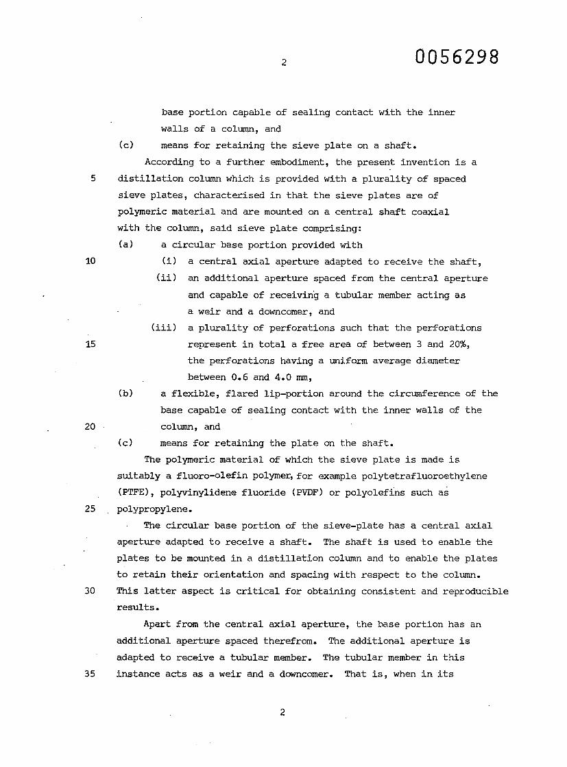
According to a f u r t h e r embodiment, the p r e s e n t i n v e n t i o n is a
d i s t i l l a t i o n column which is provided with a p l u r a l i t y of s p a c e d s ieve p l a t e s , c h a r a c t e r i s e d in t h a t the s ieve p l a t e s are o f
polymeric m a t e r i a l and are mounted on a c e n t r a l sha f t c o a x i a l
with the column, said s ieve p l a t e c o m p r i s i n g : (a) a c i r c u l a r base p o r t i o n provided w i t h
(i) a c e n t r a l ax ia l a p e r t u r e adapted to r e c e i v e the s h a f t , ( i i ) an a d d i t i o n a l a p e r t u r e spaced from the c e n t r a l a p e r t u r e
and capable of r e c e i v i n g a t u b u l a r member a c t i ng a s
a weir and a downcomer, and
( i i i ) a p l u r a l i t y of p e r f o r a t i o n s such tha t the p e r f o r a t i o n s
r e p r e s e n t in t o t a l a f r ee area of between 3 and 20%,
the p e r f o r a t i o n s having a uniform average d i a m e t e r
between 0.6 and 4.0 mm, (b) a f l e x i b l e , f l a r e d l i p - p o r t i o n around the c i r cumfe rence of t h e
base capable of s e a l i n g con tac t with the inner wal ls of t h e
column, and
(c) means for r e t a i n i n g the p l a t e on the s h a f t .
The polymeric m a t e r i a l of which the s ieve p l a t e is made i s
s u i t a b l y a f l u o r o - o l e f i n polymer, for example p o l y t e t r a f l u o r o e t h y l e n e
(PTFE), p o l y v i n y l i d e n e f l u o r i d e (PVDF) or p o l y o l e f i n s such a s
p o l y p r o p y l e n e .
The c i r c u l a r base p o r t i o n of the s i e v e - p l a t e has a c e n t r a l a x i a l
a p e r t u r e adapted to r e c e i v e a s h a f t . The shaf t is used to enable t h e
p l a t e s to be mounted in a d i s t i l l a t i o n column and to enable the p l a t e s
to r e t a i n t h e i r o r i e n t a t i o n and spacing with r e s p e c t to the column.
This l a t t e r aspect is c r i t i c a l for o b t a i n i n g c o n s i s t e n t and r e p r o d u c i b l e
r e s u l t s .
Apart from the c e n t r a l ax ia l a p e r t u r e , the base p o r t i o n has an
a d d i t i o n a l a p e r t u r e spaced t he re f rom. The a d d i t i o n a l a p e r t u r e i s
adapted to r e ce ive a t u b u l a r member. The t u b u l a r member in t h i s
i n s t a n c e acts as a weir and a downcomer. That i s , when in i t s

u p r i g h t p o s i t i o n , the pa r t of the t ubu l a r member p r o j e c t i n g above
the base p o r t i o n acts as a weir and tha t p r o j e c t i n g below the b a s e
p o r t i o n acts as a downcomer for the next p l a t e below. The l e n g t h
of the t ubu la r member may be va r i ed on e i t h e r side of the p l a t e
to a d j u s t the weir he igh t or the length of the downcomer. The
t ubu l a r member is p r e f e r a b l y c o n s t r u c t e d of a d i f f e r e n t m a t e r i a l
to tha t of which the s ieve p l a t e is made, such as g l a s s . A
combinat ion of PTFE s ieve p l a t e s and g lass t ubu l a r members i s
p a r t i c u l a r l y p r e f e r r e d .
The base p o r t i o n also has s eve ra l p e r f o r a t i o n s . The number
and d iameter of p e r f o r a t i o n s on the base p o r t i o n wi l l be d e t e r m i n e d
by the "pe r cen t age free area" d e s i r e d . The pe rcen t age f ree a r e a
is def ined as the f r a c t i o n of a v a i l a b l e column c r o s s - s e c t i o n a l
area a v a i l a b l e for bubbl ing , i . e .
wherein n is the number of p e r f o r a t i o n s in the s ieve p l a t e
Ao is the area of one p e r f o r a t i o n
Ac is the i n t e r n a l c r o s s - s e c t i o n a l area of the column
Ad is the area of a c r o s s - s e c t i o n of the downcomer, and
A is the area of a c r o s s - s e c t i o n of the c e n t r a l s h a f t . s
The p e r f o r a t i o n s r e p r e s e n t a f ree area of between 3 and 20%,
s u i t a b l y between 8 and 15%, p r e f e r a b l y between 10 and 12%.
The average d iamete r of the p e r f o r a t i o n s is between 0.6 and
4.0 mm, p r e f e r a b l y between 0.9 and 3.0 mm.
The p e r f o r a t i o n s are s u i t a b l y d i s t r i b u t e d in such a manner t h a t
a small segment of the base p o r t i o n is l e f t u n p e r f o r a t e d . In t h e
column a l t e r n a t e p l a t e s are p r e f e r a b l y a r ranged so tha t the l i q u i d
descending from the p l a t e immediate ly above through the downcomer
is d i r e c t e d to th i s u n p e r f o r a t e d area so as to d i s t r i b u t e g r a d u a l l y
and s u b s t a n t i a l l y evenly the l i qu id over the p e r f o r a t e d b u b b l i n g
area. Such an a r rangement minimises the i n t e r f e r e n c e to t h e
bubbl ing e f f i c i e n c y of the p l a t e caused by the downcoming l i q u i d .
The t l e x i b l e , f l a r e d - l i p p o r t i o n is des igned to make a s e a l i n g
c o n t a c t between the inner wall of the column and the p l a t e and t o

allow for i r r e g u l a r i t i e s in the wall of the column.
The means for r e t a i n i n g the s i e v e - p l a t e on the s h a f t may b e
any c o n v e n t i o n a l type known to those s k i l l e d in the a r t . F o r
example, i t may be a combinat ion of a coax ia l boss with a p a i r
of opposing holes on the p l a t e s and c o r r e s p o n d i n g l y a l igned h o l e s
on the sha f t so tha t a c r o s s - p i n or l ock -p in can be i n s e r t e d
through the holes in the boss and the s h a f t to r e t a i n the p l a t e
in p o s i t i o n . The boss in such a case is p r e f e r a b l y on the s i d e
of the p l a t e oppos i t e tha t bear ing the l i p - p o r t i o n , i . e . on t h e
lower side of the p l a t e as i n s t a l l e d in the column.
A l t e r n a t i v e l y , the s h a f t and the ax ia l a p e r t u r e in the p l a t e
may have between them a combinat ion of an annula r s l o t and a f l a n g e
which mate to form the r e t a i n i n g means. The f lange may be e i t h e r
an O-ring or an i n t e g r a l p r o j e c t i o n on the a p p r o p r i a t e s h a f t o r
p l a t e a p e r t u r e .
Whichever r e t a i n i n g means is used, i t is p r e f e r a b l e t ha t t h e
sha f t and the p l a t e form a s e a l i n g c o n t a c t so tha t the v a p o u r / l i q u i d
c o n t a c t through the bubbl ing area of the p l a t e is maximised .
For the purposes of mounting s eve ra l such p l a t e s on the s h a f t
and in order to provide the added f l e x i b i l i t y of a d j u s t i n g t h e
space between the p l a t e s as nece s sa ry , the sha f t may be p r o v i d e d
along i t s l ength with a s e r i e s of such means e .g. f l ange , a n n u l a r
s l o t s or ho les . This f e a t u r e t o g e t h e r with the a d j u s t a b i l i t y of t h e
weir he igh t and downcomer l ength p rov ides a d i s t i l l a t i o n column
adap t ab l e for d i s t i l l i n g a v a r i e t y of l i q u i d s .
The d i s t i l l a t i o n column is formed by mounting on a c e n t r a l
s h a f t a s e r i e s of s ieve p l a t e s accord ing to the p r e s e n t i n v e n t i o n
equipped with downcomers and i n s e r t i n g the s h a f t i n a c y l i n d r i c a l tube of a p p r o p r i a t e d imens ions . S u i t a b l e i n t e r n a l column d i a m e t e r s
are for i n s t a n c e from 20 mm to 75 mm, p r e f e r a b l y from 40 mm t o
60 mm. The columns may be made of any s u i t a b l e m a t e r i a l such a s
g lass or m e t a l .
The s i e v e - p l a t e s and the d i s t i l l a t i o n columns c o n t a i n i n g such
p l a t e s are d e s c r i b e d below with r e f e r e n c e to the accompanying
d r a w i n g s .

In the d r a w i n g s ,
Figure 1 shows a plan view o f t h e s ieve p l a t e with the t u b u l a r
member;
Figure 2 shows a s e c t i o n a l view of Figure 1 along the l ine A-A;
Figure 3 shows a s e c t i o n a l view of the p l a t e s mounted on a s h a f t
and i n s e r t e d into a d i s t i l l a t i o n column.
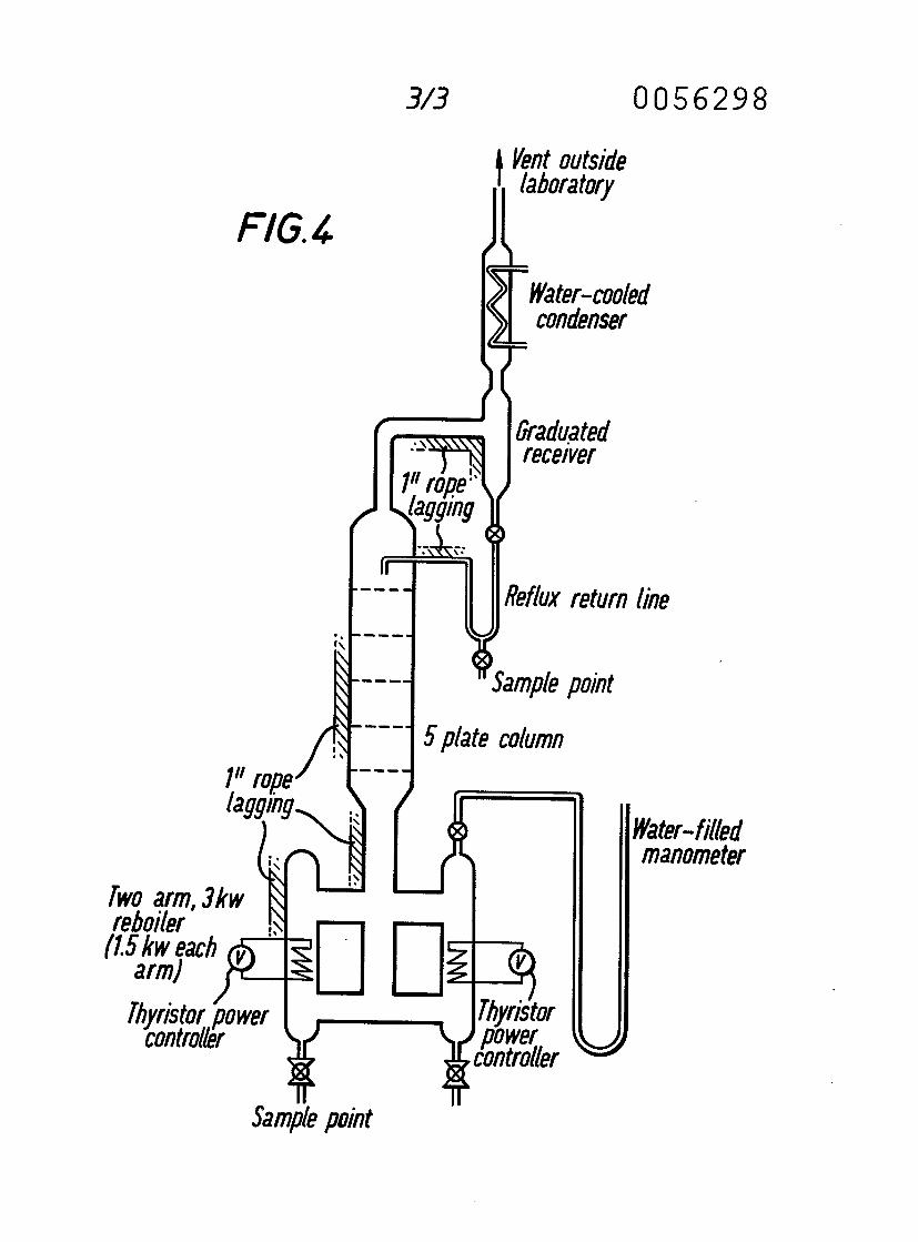
Figure 4 shows a sketch of a t e s t r ig used for e v a l u a t i n g t h e
performance of the p l a t e s .
In the drawings, the s ieve p l a t e made of p o l y t e t r a f l u o r o e t h y l e n e
has a c i r c u l a r base p o r t i o n 1 of about 47 mm d i ame te r , a f l a r e d ,
f l e x i b l e l i p - p o r t i o n 2 of he igh t about 10 mm, a c e n t r a l ax ia l a p e r t u r e
3 of 6 mm i n t e r n a l d iamete r and an a d d i t i o n a l a p e r t u r e 4 s p a c e d
from the c e n t r a l a p e r t u r e of d iamete r 9 mm. The base p o r t i o n a l s o
has a number of p e r f o r a t i o n s 5, 1.1 mm in d iamete r on a p i t ch o f
approx ima te ly 2 mm. A segment 6 of the base p o r t i o n is f ree o f
p e r f o r a t i o n s . The side of the base p o r t i o n oppos i t e the l i p - p o r t i o n
has an ax ia l boss 14 which is provided with a pa i r of opposing h o l e s
10 for r e c e i v i n g the lockpin 13. In the a d d i t i o n a l a p e r t u r e 4 i s
i n s e r t e d a g lass tube 9 of e x t e r n a l d iamete r 9 mm and i n t e r n a l
d iameter 6 mm which in i t s u p r i g h t p o s i t i o n p r o j e c t s above t h e
base p o r t i o n to form a weir 7 and p r o j e c t s below the base p o r t i o n
to form a downcomer 8. The p l a t e is mounted by means of t h e
lockpin -13 on a s h a f t 12, which is also provided with opposing h o l e s
across the axis t h e r e o f . The p l a t e s on the sha f t are i n s e r t e d i n
a column 11 in such a manner t ha t the downcomer from each p l a t e is p o s i t i o n e d over the n o n - p e r f o r a t e d segment 6 of the p l a t e
beneath as shown in Figure 3.
In order to compare the performance of the p l a t e s of t h i s
i n v e n t i o n with those of a conven t iona l Oldershaw column, t h e
fo l lowing d i s t i l l a t i o n s were c a r r i e d o u t .
Three 50 mm d iameter s ieve p l a t e columns were compared f o r
t h e i r e f f i c i e n c y in s e p a r a t i n g a mixture of ca. 20% m e t h y l -
cyc lohexane , 80% to luene . One column was a 5 - p l a t e Oldershaw
column (1.1 mm p e r f o r a t i o n s ) , and the o ther two columns were
columns accord ing to the p r e s e n t i n v e n t i o n each compris ing a s e t

of 5 PTFE p l a t e s (1.1 mm p e r f o r a t i o n s ) i n s e r t e d in to a 400 mm l o n g
s e c t i o n of DN 50 QVF g l a s s . The two se ts of PTFE s ieve p l a t e s a r e
d e s i g n a t e d Mark I and Mark II r e s p e c t i v e l y .
A two-arm, 3kW metal r e b o i l e r c o n t r o l l e d by two t h y r i s t o r power
c o n t r o l l e r s was used to b o i l - u p a charge of ca. 1500 ml of t h e
t e s t mix ture . The overhead vapour was fed into the base of a
w a t e r - c o o l e d condenser and the condensa te was r e t u r n e d to t h e
s t i l l - h e a d by g r a v i t y feed via a g radua ted r e c e i v e r (see Figure 4 ) .
Sample po in t s were a t t a c h e d to the r e f l u x l ine and the r e b o i l e r . The
p r e s su re drop through the column was measured using a water f i l l e d
manometer U-tube connected to the vapour space over the r e b o i l e r .
For a given t e s t column, the t h y r i s t o r s were se t to a
s p e c i f i c v o l t a g e and the appa ra tus l e f t to run for ca. 20 h o u r s .
After t h i s time samples of l i q u i d were drawn off hour ly from t h e
r e f l u x l ine and the r e b o i l e r for a n a l y s i s by gas c h r o m a t o g r a p h y .
Readings of the p r e s s u r e drop in the column were a lso taken. When
c o n s i s t e n t ana lyses were ob t a ined , the r e c e i v e r tap was c losed and
the b o i l - u p r a t e was de termined by c o l l e c t i n g the r e f l u x . The
exper iment was then r epea t ed using a new t h y r i s t o r s e t t i n g .
For a given pa i r of heads and bottoms ana lyses the s e p a r a t i o n
e f f i c i e n c y was de te rmined , employing Fenske ' s equa t ion . For e a c h
run a mean e f f i c i e n c y was c a l c u l a t e d along with a " d e v i a t i o n " which
i n d i c a t e s the v a r i a t i o n s in e f f i c i e n c y during each r u n .
The r e s u l t s for each column are p r e sen t ed in the Tables 1, 2
and 3, and are d i s cus sed be low.
Table 1 - S tandard Oldershaw column (not accord ing to the i n v e n t i o n ) .
Table 2 - Mark I P T F E p l a t e s .
From the comparison of the two types of p l a t e column i t c a n
be seen tha t the PTFE p l a t e s have a h igher e f f i c i e n c y which i s
less dependent on b o i l - u p r a t e than is the case with the O lde r shaw
column.
The weep po in t of the Mark I PTFE p l a t e s could not be d e t e c t e d .
This is a d i s t i n c t advantage in d i s t i l l a t i o n o p e r a t i o n p a r t i c u l a r l y
where f l e x i b i l i t y is r e q u i r e d in e x p l o r a t o r y work. However, t h e
o p e r a t i n g range of the Mark I PTFE p l a t e s was c u r t a i l e d by a low

flood p o i n t .
Table 3 - Mark II PTFE p l a t e s .
In the Mark II p l a t e s , in order to i n c r e a s e the flood p o i n t
and to reduce the p r e s s u r e drop, the number of holes was i n c r e a s e d
and the weir h e igh t reduced to compare with the Oldershaw d e s i g n .
The p l a t e s s t i l l r e t a i n the very low weep po in t w h i l s t having an
i n c r e a s e d flood po in t comparable with the Oldershaw p l a t e column.

Dimens ions
Hole s ize (d iameter ) 1.1 mm
Number of holes 168
Free area 9.8%
Weir he igh t 2 mm
Opera t ion C o n d i t i o n s
Weep po in t ca. 2.8 l i t r e s / h o u r
Flood po in t ca .10 .8 l i t r e s / h o u r
Maximum e f f i c i e n c y ca. 82%
Optimum b o i l - u p r a t e ca. 7.2 l i t r e s / h o u r
P ressu re d r o p / p l a t e ca. 0.96 cm water gauge

Dimens ions
Hole s ize (d iameter ) 1.1 mm
Number of holes 68
Free area 3.4%
Weir he igh t 5 mm
Opera t ion C o n d i t i o n s
Weep po in t ca. 0 l i t r e s / h o u r
Flood Point ca. 3.6 l i t r e s / h o u r
Maximum e f f i c i e n c y ca. 113%
Optimum b o i l - u p r a t e ca. 3.2 l i t r e s / h o u r
P ressu re d r o p / p l a t e ca. 1-1.8 cm water gauge .

Dimens ions
Hole s ize (d iameter ) 1.1 mm
Number of holes 233
Free area 11.6%
Weir he igh t 2 mm
Operat ing C o n d i t i o n s
Weep po in t ca. 0 l i t r e s / h o u r
Flood po in t c a . 9 - 9 . 5 l i t r e s / h o u r
Maximum e f f i c i e n c y ca. 88%
Optimum b o i l - u p r a te ca. 8-9 l i t r e s / h o u r
Pressure d r o p / p l a t e not measured

1. A s ieve p l a t e of polymeric m a t e r i a l for use in a d i s t i l l a t i o n column, c h a r a c t e r i s e d in tha t said p l a t e c o m p r i s e s : (a) a c i r c u l a r base p o r t i o n provided w i t h
(i) a c e n t r a l ax ia l a p e r t u r e adapted to r e c e i v e a s h a f t , ( i i ) an a d d i t i o n a l a p e r t u r e capable of r e c e i v i n g a t u b u l a r
member, and
( i i i ) a p l u r a l i t y of p e r f o r a t i o n s such tha t the p e r f o r a t i o n s
r e p r e s e n t in t o t a l a f ree area of between 3 and 20%, t h e
p e r f o r a t i o n s having a uniform average d iameter be tween
0.6 and 4.0 mm, (b) a f l e x i b l e , f l a r e d - l i p p o r t i o n around the c i r cumfe rence of t h e
base p o r t i o n capable of s e a l i n g con tac t with the inner w a l l s
of a column, and
(c) means for r e t a i n i n g the s ieve p l a t e on a s h a f t .
2. A s ieve p l a t e accord ing to claim 1 wherein the p e r f o r a t i o n s a r e
d i s t r i b u t e d in such a manner tha t a small segment of the b a s e
p o r t i o n is l e f t u n p e r f o r a t e d .
3 . A d i s t i l l a t i o n column which is provided with a p l u r a l i t y of s p a c e d
s ieve p l a t e s , c h a r a c t e r i s e d in tha t the s ieve p l a t e s are of p o l y m e r i c
m a t e r i a l and are mounted on a c e n t r a l sha f t coax ia l with the column, said s ieve p l a t e c o m p r i s i n g :
(a) a c i r c u l a r base p o r t i o n provided w i t h
(i) a c e n t r a l ax ia l a p e r t u r e adapted to r e c e i v e the s h a f t , ( i i ) an a d d i t i o n a l a p e r t u r e spaced from the c e n t r a l a p e r t u r e
and capable of r e c e i v i n g a t u b u l a r member ac t ing as a
weir and a downcomer, and
( i i i ) a p l u r a l i t y of p e r f o r a t i o n s such tha t the p e r f o r a t i o n s
r e p r e s e n t in t o t a l a f ree area of between 3 and 20%, t h e
p e r f o r a t i o n s having a uniform average d iameter b e t w e e n

0.6 and 4.0 mm, (b) a f l e x i b l e , f l a r e d l i p : p o r t i o n around the c i r c u m f e r e n c e of t h e
base capable of s e a l i n g con tac t with the inner wal ls of t h e
column, and
(c) means for r e t a i n i n g the p l a t e on the s h a f t .
4. A d i s t i l l a t i o n column accord ing t o c l a i m 3 wherein the t u b u l a r member
is c o n s t r u c t e d of a d i f f e r e n t m a t e r i a l to tha t of which the s i e v e
p l a t e is made,
5. A d i s t i l l a t i o n column accord ing to claim 3 or 4 wherein the means
for r e t a i n i n g the s i e v e - p l a t e on the sha f t is a combinat ion of a
coax ia l boss with a pa i r of opposing holes on the p l a t e s and
c o r r e s p o n d i n g l y a l igned holes on the sha f t enab l ing a c r o s s - p i n o r
l ock -p in to be i n s e r t e d through the holes in the boss and the s h a f t
to r e t a i n the p l a t e in p o s i t i o n .
6. A d i s t i l l a t i o n column accord ing to claim 5 wherein the boss is on
the s ide of the p l a t e oppos i t e t h a t bea r ing the l ip p o r t i o n .
7. A d i s t i l l a t i o n column accord ing to claim 3 or 4 wherein the s h a f t
and the ax ia l a p e r t u r e in the p l a t e have between them a c o m b i n a t i o n
of an annular s l o t and a f l ange which mate to form the r e t a i n i n g
means .
8. A d i s t i l l a t i o n column accord ing to claim 7 wherein the f l ange i s
e i t h e r an O-ring or an i n t e g r a l p r o j e c t i o n on the a p p r o p r i a t e s h a f t
or p l a t e a p e r t u r e .
9. A d i s t i l l a t i o n column accord ing to any one of the p reced ing c l a i m s
3 to 8 wherein the sha f t is p rovided along i t s l ength with a s e r i e s
of means for the purpose of mounting s e v e r a l s ieve p l a t e s on t h e
sha f t said means being adapted to ad ju s t the spacing between t h e
p l a t e s and/or the weir he igh t and downcomer l e n g t h .