Distillation-Based Semi-Supervised Federated Learning for ...

MULTIVESSEL BATCH DISTILLATION 1
SIGURD SKOGESTAD 2 , BERND WITTGENS,EVA S�RENSEN 3 and RAJAB LITTO
Norwegian University of Science and Technology (NTNU),Department of Chemical Engineering,
7034 Trondheim, Norway
Submitted for publication in AIChE Journal, 21 May 1996Revised version: 9 October 1996
Abstract - The multivessel batch column consists of a reboiler, several column sections and inter-
mediate vessels and a condenser vessel. This con�guration provides a generalization of previously
proposed batch distillation schemes, including the inverted column and the middle vessel column.
The total re ux operation of the multivessel batch distillation column was presented recently, and
the main contribution of this paper is to propose a simple feedback control strategy for its oper-
ation. We propose to adjust the vessel holdups indirectly, by manipulating the re ux ow out of
each vessel to control the temperature at some location in the column section below. The feasibility
of this strategy is demonstrated by simulations.
1 Introduction
Although batch distillation generally is less energy e�cient than continuous distillation, ithas received increased attention in the last few years because of its simplicity of operation, exibility and lower capital cost. For many years academic research on batch distillationwas focused primarily on optimizing the re ux policy for the conventional batch distillationcolumn (also called the batch recti�er, where the feed is charged to the reboiler and theproducts are drawn from the top of the column).
More recently, one has started re-examining the operation of batch distillation as a whole. Atotal re ux strategy, where the �nal products are collected in the condenser drum and in thereboiler, was suggested independently by Treybal (1970) and Bortolini and Guarise (1971).S�rensen and Skogestad (1994) found the total re ux operation to be better for separationswith a small amount of light component. A generalization of the total re ux strategy isthe cyclic operation described by S�rensen and Skogestad (1994). Here, the operation is
1The paper was originally presented at the AIChE Annual Meeting, Nov. 1995, Paper 184i.2Author to whom correspondence should be addressed, fax: +47 7359 4080; E-mail: [email protected] of Chemical and Biochemical Engineering, University College London, WC1E 7JE, Great
Britain
1

switched between total re ux operation and dumping of the product (i.e.: the condenserholdup is introduced as an additional degree of freedom).
L
V
D
Qb
1
L
L
D1
D2
3
V
D 4
V
2
V
Q
3
c
3
1
2
M1
3M
2M
M 4
Figure 1: General multivessel batch distillation column for a case with 4 vessels
Robinson and Gilliland (1950) proposed an inverted batch column, also called the batchstripper, where the feed is charged to the top and the heavy products are drawn from thebottom of the column. S�rensen and Skogestad (1995) found that, also in this case, theinverted column is better than the conventional column for separations with a small amountof light component. Bernot et al. (1991) studied the use of this column for separatingazeotropic mixtures.
A further generalization of the inverted column is the middle vessel column, which has botha rectifying and stripping section. This con�guration was �rst mentioned by Robinson andGilliland (1950, p. 388) and was �rst analyzed for binary mixtures by Bortolini and Guarise(1971) and later studied in the Russian literature (e.g. Davidyan et al., 1991; see the updatedEnglish translation in Davidyan et al, 1994). The middle vessel column is also sometimesreferred to as the \complex" batch distillation column (Mujtaba and Macchietto, 1992).Bortolini and Guarise (1971) proposed to charge a binary feed mixture to the middle vesseland draw products from both the top and the bottom, such that the composition in themiddle vessel was approximately constant during the operation, and operation stops when
2

the middle vessel is empty.This mode of operation is found to be optimal in some cases(Meski and Morari, 1995).
Hasebe et.al. (1992) proposed to charge a ternary mixture to the middle vessel, and let thelight and heavy impurities be drawn from the top and the bottom of the column. In thiscase the operation stops when the intermediate component in the middle vessel has reachedits desired purity. Mujtaba and Macchietto (1992, 1994) studied the case where a chemicalreaction takes place in the middle vessel, and conversion can be increased by removing theproducts.
A further generalization is the multivessel column suggested by Hasebe et.al. (1995). Theyproposed a total re ux operation where the products are collected in vessels along the column.Because one may view this column as a stacking of several columns on top of each other,they denote this process a \multi-e�ect batch distillation system" (MEBAD).
All the above designs and strategies can be realized in the multivessel batch distillation
column shown in Figure 1, where both the holdups, Mi(t), and product ows, Di(t), aredegrees of freedom. With Nc vessels along the column and with given pressure and heatinput, this column has 2Nc � 1 degrees of freedom for optimization; namely the Nc � 1holdups Mi(t) (e.g.: controlled by the Nc�1 re ux streams) and the Nc product rates Di(t).
Further generalizations are possible, for example, by adding feed streams (semi-batch op-eration), by taking out liquid or vapor streams other places in the column, or by usingintermediate heaters or coolers.
The simplest strategy for operating the multi-vessel column, which is the focus of this paper,is the total re ux operation suggested by Hasebe et.al. (1995) where the Nc product ratesare set to zero (Di = 0). There are at least two advantages with this multivessel columncompared to conventional batch distillation where the products are drawn over the top, oneat a time. First, the operation is simpler since no product change-overs are required duringoperation. Second, the energy requirement may be much less due to the multi-e�ect natureof the operation. In fact, Hasebe et.al. (1995) found that for some separations with manycomponents the energy requirement may be similar to that for continuous distillation usingNc � 1 columns.
Hasebe et.al. (1995) propose to \control" the total re ux multivessel batch distillationcolumn by calculating in advance the �nal holdup in each vessel and then using a level controlsystem to keep the holdup in each vessel constant. For cases where the feed composition isnot known exactly they propose to, after a certain time, adjust the holdup in each vesselbased on composition measurements. Their scheme, involving the optimization of the vesselholdups and their adjustment based on composition measurement in these vessels, is rathercomplicated to implement and it requires an advanced control structure to implement thecontrol law.
The main contribution of our paper is to propose, for the total re ux operation of themultivessel column, a feedback control structure based on Nc � 1 temperature controllers
3

(see Fig. 2). The idea is to adjust the re ux ow out of each of the upper Nc � 1 vesselsby controlling the temperature at some location in the column section below. There is noexplicit level control, rather the holdup, Mi, in each vessel is adjusted indirectly by varyingthe re ux ow to meet the temperature speci�cations.
4
3TC
TC
TC2
1
Qb
L3
2L
1L
1
2
3
3M
2M
1
M
Qc
V
V
V
V
M
23
22
17
12
11
6
1
28
33
Figure 2: Feedback control structure for multivessel batch distillation column under totalre ux
In addition to the dynamic simulations which show the feasibility of the proposed scheme,we present the steady-state values which would be achieved if we were to let the batchtime approach in�nity (t ! 1). Of course, in practice we want the batch time to be asshort as possible, and we would terminate the batch when the speci�cations are met or theimprovement in purity is too small. Nevertheless, the steady-state values are interestingbecause they give the achievable separation for a given case.
4

2 Simulation model
All the results in this paper are based on simulations using the dynamic model describedin the Appendix. We have made a number of simplifying assumptions, such as constantmolar ows, constant relative volatility, linear boiling point curve, constant stage holdupand constant pressure. These assumptions are introduced to simplify the model similarresults are obtained when the assumptions are relaxed. The dynamic model is implementedusing the SPEEDUP software package (Speedup, 1993). In all simulations we neglect thetime to heat up the column and feed mixture to the boiling temperature (i.e. \hot" startupis assumed).
In the simulations we consider a four-component mixture, the column consists of threesections and four vessels (including reboiler and condenser). The data for the mixture andthe column are summarized in Table 1. The numerical values of the relative volatility arechosen to be close to those of the systemmethanol-ethanol-propanol-butanol. As mentioned,we assume the mixture temperature, Tk, on stage k to be the molar average of the boilingtemperatures of the pure components 4
Tk =NcXj=1
xj � Tb;j (1)
where Tb;j = [64:7; 78:3; 97:2; 117:7]oC.
In the simulations we consider two feed mixtures; one equimolar (zF1), and one with smalleramounts of components 2 and 4 (zF2). In all cases the initial (at t = 0) vessel holdup is thesame (Mi = 2:5 kmol) in all four vessels, and the initial composition in all vessels is equalto that of the feed mixture. We start the simulations with a \hot" column, that is, the timeneeded to heat up the column and the feed mixture is not considered. In all simulations, thevapor ow is kept constant at V = 10 kmol=h.
Table 1: Summary of column data and initial conditions
4The linear boiling point curve assumptionmay seem very crude. However, we have performed simulationswhere temperatures are computed from Raoults law for ideal mixtures, ptot =
PNc
j=1 xj � psati (T ), and the
Clausius-Clapeyron equation for the pure component vapor pressures, psatj (T ) = exp
��
�Hvap;j
R
�1
T�
1
Tb;j
��,
and the results show only minor deviations.
5

Number of components Nc = 4Relative volatility �j = [10:2; 4:5; 2:3; 1]Total number of stages Ntot = 33Number of sections 3Number of stages per section Ni = 11Vessel holdups Mi;0 = 2:5 kmolTray holdups (constant) Mk = 0:01 kmolTotal initial charge Mtot = 10:33 kmolRe ux owrs Li;0 = 10 kmol=hVapor ow (constant) V = 10 kmol=h
3 Total re ux operation with constant vessel holdups
In this section we follow Hasebe et.al. (1995) and present simulations which demonstratethe feasibility of the multivessel batch distillation under total re ux. The holdup of eachvessel is calculated in advance by taking into account the amount of feed, feed compositionand product speci�cations. After feeding the predescribed amount of raw material to thevessels, total re ux operation with constant vessel holdup is carried out until the productspeci�cations are achieved, or until the improvement in product purity with time is too slowto justify further operation.
The simulated composition pro�les as a function of time are shown in Figure 3 for theequimolar feed mixture
zF1 = [0:25; 0:25; 0:25; 0:25] (2)
The holdup in each vessel is kept constant at Mi = 2:5 kmol during the simulation. Thepurity of the main component in each of the vessels is seen to improve nicely and levels o�after about 2 hours. As time goes to in�nity the steady-state compositions presented inTable 2 are achieved. The steady state purity of the main component is better than 99% inthe top and bottom vessels, and is about 96% in the two intermediate vessels.
However, in practice, it may be di�cult to keep the vessel holdups constant, and the compo-sition of the feed mixture may be uncertain. The results may be sensitive to holdup errorsas is illustrated by considering a case where the actual feed composition is
zF2 = [0:30; 0:10; 0:40; 0:20] (3)
but the holdup of each vessel is kept constant at Mi = 2:5 kmol, which are the vessel holdupscorresponding to the equimolar feed composition, zF1. This results in large changes in the�nal vessel compositions as seen from Table 3. For example, the purity in vessel 2 is reducedfrom about 96% to 40%, whereas the purity in vessel 3 is improved from 96% to 99:9%.
6

x1 in M1 x2 in M2 x3 in M3 x4 in M4
0
0.25
0.5
0.75
1 (a) Composition profile, main component
x2 in M1 x3 in M2 x2 in M3 x3 in M4
0 0.5 1 1.5 2 2.5 3 3.50.0
0.15
0.3
0.45
time [h]
(b) Composition profile, main impurity
Figure 3: Constant vessel holdup for feed mixture zF1: Composition response in accumulator(1), vessel 2, vessel 3 and reboiler (4)
Table 2: Constant vessel holdups for feed mixture zF1: Steady-state compositions
Vessel 1 Vessel 2 Vessel 3 Vessel 4
Mi [kmol] 2.5 2.5 2.5 2.5x1 0.993 0.017 0.0 0.0x2 0.007 0.959 0.025 0.0x3 0.0 0.024 0.963 0.004x4 0.0 0.0 0.012 0.996
Table 3: Constant vessel holdups for feed mixture zF2: Steady-state compositions
7
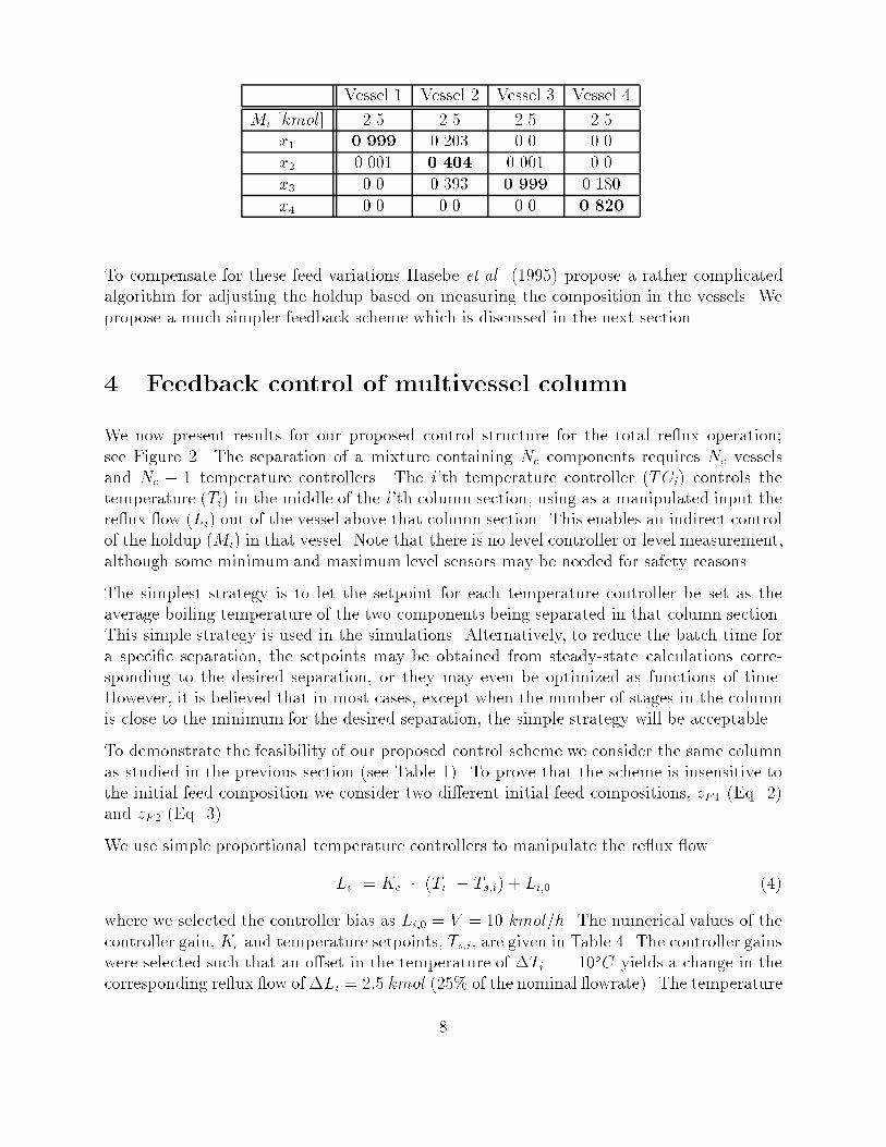
Vessel 1 Vessel 2 Vessel 3 Vessel 4
Mi [kmol] 2.5 2.5 2.5 2.5x1 0.999 0.203 0.0 0.0x2 0.001 0.404 0.001 0.0x3 0.0 0.393 0.999 0.180x4 0.0 0.0 0.0 0.820
To compensate for these feed variations Hasebe et.al. (1995) propose a rather complicatedalgorithm for adjusting the holdup based on measuring the composition in the vessels. Wepropose a much simpler feedback scheme which is discussed in the next section.
4 Feedback control of multivessel column
We now present results for our proposed control structure for the total re ux operation;see Figure 2. The separation of a mixture containing Nc components requires Nc vesselsand Nc � 1 temperature controllers. The i'th temperature controller (TCi) controls thetemperature (Ti) in the middle of the i'th column section, using as a manipulated input there ux ow (Li) out of the vessel above that column section. This enables an indirect controlof the holdup (Mi) in that vessel. Note that there is no level controller or level measurement,although some minimum and maximum level sensors may be needed for safety reasons.
The simplest strategy is to let the setpoint for each temperature controller be set as theaverage boiling temperature of the two components being separated in that column section.This simple strategy is used in the simulations. Alternatively, to reduce the batch time fora speci�c separation, the setpoints may be obtained from steady-state calculations corre-sponding to the desired separation, or they may even be optimized as functions of time.However, it is believed that in most cases, except when the number of stages in the columnis close to the minimum for the desired separation, the simple strategy will be acceptable.
To demonstrate the feasibility of our proposed control scheme we consider the same columnas studied in the previous section (see Table 1). To prove that the scheme is insensitive tothe initial feed composition we consider two di�erent initial feed compositions, zF1 (Eq. 2)and zF2 (Eq. 3).
We use simple proportional temperature controllers to manipulate the re ux ow
Li = Kc � (Ti � Ts;i) + Li;0 (4)
where we selected the controller bias as Li;0 = V = 10 kmol=h. The numerical values of thecontroller gain, Kc and temperature setpoints, Ts;i, are given in Table 4. The controller gainswere selected such that an o�set in the temperature of �Ti = 10oC yields a change in thecorresponding re ux ow of �Li = 2:5 kmol (25% of the nominal owrate). The temperature
8

sensors are located in the middle of each column section, and, as already mentioned, thesetpoint, Ts;i, for each section is the average boiling temperature of the components beingseparated in that section.
Table 4: Data for temperature controllers
Ts;i [oC] Kc [oC=kmol] location �
TC1 71.5 -0.25 6TC2 87.75 -0.25 17TC3 107.2 -0.25 28
* stage no. from top of column
Table 5: Temperature control (independent of feed composition): Steady-state compositions
Vessel 1 Vessel 2 Vessel 3 Vessel 4
x1 0.993 0.016 0.0 0.0x2 0.007 0.967 0.034 0.0x3 0.0 0.017 0.960 0.007x4 0.0 0.0 0.006 0.993
With these temperature controllers (see Table 4), we achieve for both feed mixtures thesame steady-state compositions (t!1) given in Table 5. These steady state compositionsare very close to those found earlier for feed mixture zF;1 with constant vessel holdups ofMi = 2:5 kmol; compare Tables 2 and 5.
As expected, for feed mixture zF1, the steady-state vessel holdups are close to 2:5 kmol;see the �rst row in Table 6. The composition time responses for feed mixture zF1 is shownin Figure 4 (a) and (b). The responses are similar to those with constant vessel holdupsshown in Figure 3 (a) and (b); the di�erence is that the approach to steady state is faster invessels 1 and 4 and slower in vessels 2 and 3 for the control structure employing temperaturecontrol.
Table 6: Temperature control for feed mixtures zF1 and zF2: Steady-state vessel holdups
Vessel 1 Vessel 2 Vessel 3 Vessel 4
feed M1 [kmol] M2 [kmol] M3 [kmol] M4 [kmol]zF1 2.506 2.452 2.512 2.530zF2 3.053 0.788 4.159 2.000
9

x1 in M1 x2 in M2 x3 in M3 x4 in M4
0
0.25
0.5
0.75
1 (a) Composition profile, main component
x2 in M1 x3 in M2 x2 in M3 x3 in M4
0 0.5 1 1.5 2 2.5 3 3.50.0
0.15
0.3
0.45
(b) Composition profile, main impurity
time [h]
M 1 M 2 M 3 M 4 0
3
6(c) Holdup Mi [kmol]
L 1 L 2 L 3 V 5
10
15(d) Reflux flow Li [kmol/h]
T6 T17 T28
0 0.5 1 1.5 2 2.5 3 3.570
90
110
time [h]
(e) Tray temperature, Tk [C]
Figure 4: Temperature control for feed mixture zF;1: Vessel compositions (a), impurities (b),holdups (c), re ux ows (d) and tray temperatures (e) as a function of time
10

x1 in M1 x2 in M2 x3 in M3 x4 in M4
0
0.25
0.5
0.75
1 (a) Composition profile, main component
x2 in M1 x3 in M2 x2 in M3 x3 in M4
0 0.5 1 1.5 2 2.5 3 3.50.0
0.15
0.3
0.45
(b) Composition profile, main impurity
time [h]
M 1 M 2 M 3 M 4 0
3
6(c) Holdup Mi [kmol]
L 1 L 2 L 3 V 5
10
15(d) Reflux flow Li [kmol/h]
T6 T17 T28
0 0.5 1 1.5 2 2.5 3 3.570
90
110
time [h]
(e) Tray temperature, Tk [C]
Figure 5: Temperature control for feed mixture zF;2: Vessel compositions (a), impurities (b),holdups (c), re ux ows (d) and tray temperatures (e) as a function of time
In Figures 4 we also present for the time responses for the holdups in the vessels (c), there ux ows out of the vessels (d), and the controlled temperatures (e). The simulationsdemonstrate how the action of the temperature controllers adjust the re ux ows, whichindirectly adjust the vessel holdups such that the �nal products are of high purity.
Similar results for feed mixture zF2 are shown in Figure 5. The initial vessel holdups areas for feed mixture zF1, but the simulations demonstrate how the temperature controllersindirectly adjust the vessel holdups such that the steady-state vessel compositions are thesame as for feed mixture zF1. From the second row in Table 6 we see that the steady stateholdups with feed mixture zF2 vary from 0.788 kmol in vessel 2 to 4.159 kmol in vessel 3.
Two remarks about the results are in order.
1. From Figures 4(e) and 5(e) we observe that the controlled temperatures reach theirsetpoint with no o�set (T ! Ts as t ! 1), even though only proportional controllers
11

are used. The reason is that the model from Li to Ti contains an integrating element,since the system is closed. More speci�cally, consider the re ux Li to a column sectionand the temperature Ti in the that section. We know that we can change the steady-state value of Ti by changing Li. We also know that a steady-state change in Li is notallowed, since we must have Li ! Vi as t ! 1 (total re ux operation). Thus thetransfer function from Li to Ti must contain an integrator.
2. With temperature control we achieve the same steady-state compositions in the vesselsindependent of the initial feed composition (only the vessel holdups di�er at steadystate). The reason is that the column has only three degrees of freedom at steady stateand if we �x three temperatures at three locations in the column, then the temperaturepro�le over the column at total re ux is determined. (This assumes that we do nothave multiple steady states. Multiple solutions are not likely when temperatures arespeci�ed, but may be encountered if we specify the composition of a given component.)
We have also performed some simulations to study the start-up for the case when the entirefeed mixture is charged to the reboiler (and not distributed to the vessels as in Figure 4).The composition responses for feed mixture zF;1 are presented in Figure 6 (a) and (b). Theresults indicate that the temperature controllers can be activated immediately after start-up;possibly with some strategy to ensure that the vessels are not emptied. The vessels are thenslowly �lled up by action of the temperature controllers which reduce the re ux ows for atransient period (see Figure 6 (c) and (d)). The simulations indicate that, except for theinitial 2 to 3 hours, the required time to reach a desired separation is similar to that foundwhen the feed is initially distributed to the vessels.
12

x1 in M1 x2 in M2 x3 in M3 x4 in M4
0
0.25
0.5
0.75
1
(a) Composition profile, main component
x1 in M2 x1 in M3 x2 in M3 x3 in M4
0.0 0.5 1 1.5 2 2.5 3 3.50.0
0.25
0.5
0.75
1 (b) Composition profile, main impurity
time [h]
M 1
M 3 M 4
M 2
L 1
L 3 V
L 2
T6 T17 T28
0.0 0.5 1 1.5 2 2.5 3 3.560
80
100
120
time [h]
(e) Tray temperature, T_i [C]
0
5
10
(c) Holdup Mi [kmol]
0
5
10
(d) Reflux flow Li [kmol/h]
Figure 6: Temperature control for feed mixture zF;1 with all liquid initially in the reboiler:Vessel compositions (a), impurities (b), holdups (c), re ux ows (d) and tray temperatures(e) as a function of time
5 Achievable separation
Table 7: Temperature control (independent of feed composition): Steady-state vessel com-positions (main component) as a function of number of stages Ni in each section.
13

Ni Vessel 1 Vessel 2 Vessel 3 Vessel 4x1 x2 x3 x4
7 0.965 0.864 0.856 0.9659 0.984 0.932 0.923 0.984
11 (base case) 0.993 0.967 0.960 0.99315 0.998 0.992 0.990 0.99919 0.9997 0.9982 0.9974 0.999725 0.9999 0.9998 0.9997 0.9999
The achievable separation is limited by the number of theoretical stages in the columnsections. Or, stated in another way, if there are no thermodynamic limitations caused byazeotropes etc., then we can achieve any desired purity in a multivessel column if we have asu�cient number of stages. This is demonstrated in Table 7 where we present the steady-state product compositions for di�erent numbers of theoretical stages, Ni, in the three columnsections. The total number of stages is 3 � Ni. We use the same components as before (thefeed composition does not matter), and use temperature controllers with the setpoints givenin Table 4. With 7 stages in each section we achieve a purity of about 86% in vessels 2 and3, with 11 stages (base case used in rest of paper) about 96%, with 15 stages about 99%,and with 25 stages about 99.97%.
6 Discussion
One justi�cation for using multivessel distillation instead of conventional batch distillationis to save energy, or equivalently, for a given heat input the batch time may be signi�cantlyshorter. Another advantage is the simple operation of the multivessel column under totalre ux. A third advantage is that it may be easier to operate the column close to optimumwith the multivessel column. In conventional batch distillation the optimal operation maydepend on the re ux policy and quite strongly on the use of o�-cuts to achieve the desiredproduct composition. On the other hand, in the multivessel batch column there are fewerdegrees of freedom and this simpli�es the operation considerably; the re ux ow is adjustedwith simple temperature controllers such that the desired products are accumulated in thevessels.
One disadvantage with the multivessel column compared with the conventional batch distil-lation is that the column itself is more complicated. Also, whereas in a conventional batchcolumn one only has to make decision on the length of one single column section, one hasto decide on the number of sections and their length for a multivessel column. The designof the multivessel columns is therefore more closely linked to a speci�c feed mixture, in par-ticular the relative volatility and the product speci�cations. Thus, the design process of amultivessel column is similar to the design of a sequence of continuous distillation columns.
14

A simple practical implementation, which is used in our lab-scale column, is to place thesections and stages on top of each other as indicated in Figure 1. The liquid then owsby the in uence of gravity and there is no need for pumps. However, this design is ratherin exible, and it cannot be used if a large number of stages is required. For an industrialmulti-purpose separation facility, it is probably better to place the column sections in serieswith the vessels at ground level as indicated by Hasebe et.al. (1995). Re ux pumps are thenneeded to bring the liquid from the vessels to the column sections. In this case, one canquite easily put several column sections in series to meet the separations requirements for agiven feed mixture.
Although the results presented in this paper on the temperature controlled multi-vesselcolumn are most encouraging, a number of questions are open for further research.
1. The simulations need to be veri�ed experimentally. This work is in progress, and pre-liminary results (Wittgens et.al. 1996) show very good agreement with the simulations.
2. The start-up procedure needs to be studied in more detail, including the initial distri-bution of the feed mixture.
3. In this study the setpoints for the temperature controllers were set such that thetemperature in the middle of the section should equal the average of the boiling pointsof the components separated in that section. In general, this is not optimal, especiallyif the requirements for product purities are very di�erent.
4. It should be established for what type of mixtures and conditions the new multivesselbatch column is most suited.
5. Reasonable criterions for aborting the total re ux operation should be established, thatis, when is the improvement in product purity too slow to justify further operation,and how should this be detected.
6. Finally, the total re ux operation may be generalized by also allowing withdrawal ofproducts (continuous or discontinuous) from the vessels. In this way the multivesselcolumn forms a \super structure" which has as special cases all the previously proposedbatch schemes mentioned in the introduction.
7 Conclusions
A general multivessel batch distillation column is proposed, along with a new control strategyfor its total re ux operation. It is shown that the proposed control scheme is easy toimplement and operate, in particular, for for widely varying feed compositions.
15

Notation
D Distillate ow rate [kmol/h]K Controller gainL Re ux ow rate [kmol/h]M Holdup [kmol]Nc Number of componentsNi Number of stages in section it time [h]
T Temperature [C]Tb Boiling temperature [C]V Vapor ow [kmol/h]x Liquid compositiony Vapor compositionzF Feed composition� Relative volatility
Subscriptsi section identi�erj component identi�erk stage identi�ers setpoint
References
[1] Bernot, C., M.F. Doherty and M.F. Malone, "Feasibility and Separation Sequencing inMulticomponent Batch Distillation", Chemical Engineering Science, 1311-1326, 1991
[2] Bortolini, P. and Guarise, G.B., \Un nuovo metodo di distillazione discontinua (InItalian; A new practice of Batch Distillation)", Quad. Ing. Chim. Ital., Vol. 6, No. 9,150-159, 1970
[3] Davidyan, A.G., V.N. Kiva, V.M. Platonov, \Batch Distillation in Column with MiddleReservoir", Theo. Found. of Chem. Eng. (In Russian), 467-475, 771-781, 1991
[4] Davidyan, A.G., V.N. Kiva, G.A. Meski and M. Morari, "Batch distillation in a columnwith a middle vessel", Chem. Eng. Sci., Vol. 49(18), 3033-3051, 1994
[5] Hasebe, S., B. Abdul Aziz, I. Hashimoto and T. Watanabe, "Optimal Design and Op-eration of Complex Batch Distillation Column", Preprint of the IFAC Workshop on
Interaction between Process Design and Process Control, London, 1992, 177-182
[6] Hasebe, S., T. Kurooka and I. Hashimoto, "Comparison of the Separation Performancesof a Multi-e�ect Batch Distillation System and a Continuous Distillation System", Proc.IFAC-symposium DYCORD'95, Denmark, June 1995, 249-255
[7] Meski, G.A. and Morari, M., \Design and operation of a batch distillation column witha middle vessel", Com. Chem. Engng., Vol. 19, S597-S602, 1995
[8] Mujtaba, I.M. and S. Macchietto, "Optimal operation of reactive batch distillation",AIChE 1992 Annual Meeting, Miami Beach, November 1992.
16

[9] Mujtaba, I.M. and S. Macchietto, "Optimal operation of multicomponent batch distilla-tion - a comperative study using conventional and unconventional columns", PreprintsIFAC Symposium ADCHEM'95, Kyoto (Japan), 415-420, May 1994.
[10] Robinson, C.S. and E.R. Gilliland, \Elements of Fractional Distillation", McGraw Hill
Book Company, New York, 4th ed., 1950
[11] SPEEDUP Release 5.4 User Manual, Prosys Technology Ltd., 1993
[12] S�rensen, E. and S. Skogestad, \Optimal Operating Policies of Batch Distillation", Proc.Symposium PSE'94, Kyongju, Korea, June 1994, 449-456
[13] S�rensen, E. and S. Skogestad, \Comparison of Inverted and Regular Batch Distilla-tion",Proc. IFAC-symposium DYCORD'95, Denmark, June 1995, 141-146
[14] Treybal, R.E., "A Simple Method of Batch Distillation", Chemical Engineering, 1970,95-98
[15] Wittgens, B., Litto, R., S�rensen, E. and S. Skogestad, \Total Re ux Operation ofMultivessel Batch Distillation", ESCAPE-96, Computers chem. Engng., Vol. 20, S1041-1046, 1996
Appendix
Mathematical model of multivessel column
The model used in the simulations is based on the following assumptions:
� constant relative volatility
� constant molar liquid holdups on the stages (liquid ow dynamics neglect)
� constant molar vapor ows Vi (energy balance neglected)
� constant pressure
� constant tray e�ciency (100 %)
� negligible vapor holdup
� perfect mixing on all trays and in all vessels
� total condenser
17

The distillation column is modeled as a stack of stages (counted from the top). Note thatthe vapor ow V does not pass through the intermediate vessels so these do not contributeto the number of theoretical stages. The model for stage k in section i consists of a materialbalance for each component j (Mk is assumed constant)
Mk
d xj;kdt
= Li (xj;k�1 � xj;k) + V (yj;k+1 � yj;k) (5)
and the vapor liquid equilibrium
�j =yj;k=xj;kyH;k=xH;k
(6)
where H denotes the heaviest component in the mixture.
iLV
i-1
i-1
L
i-1L
i
iDvessel i
i-1
V
stage l
L
sect
ion
ise
ctio
n i-
1
L
L
V
stage k-1
stage k
V
stage k+1
Figure 7: Connection of trays and vessels
The material balance for the condenser (i = 1) is
d (Mi xj;i)
dt= V yj+1;i � Li xj;i (7)
and its mass balanced Mi
dt= V � Li (8)
For intermediate vessels (i)
d (Mi xj;i)
dt= Li�1 xj�1;i � Li xj;i (9)
18

withd Mi
dt= Li�1 � Li (10)
where xi is the composition in vessel i and xj�1;i is the liquid composition at the bottom ofthe section above. The liquid ow Li leaving vessel i is set by a control valve.
The reboiler (i = R)d (Mi xj;i)
dt= Li�1 xj;i � V yj;i (11)
whered Mi
dt= Li�1 � V (12)
where again the vapor liquid equilibrium is described by Equation 6.
19
Copyright © 2022 FDOKUMEN