Pakistan's Recent Experience in Reforming Religious Education
Upload
independentCategory
view
0download
0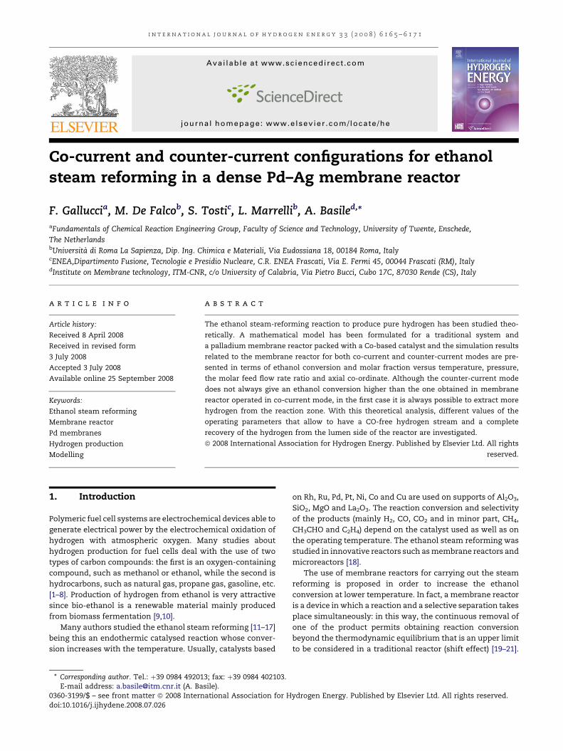
i n t e r n a t i o n a l j o u r n a l o f h y d r o g e n e n e r g y 3 3 ( 2 0 0 8 ) 6 1 6 5 – 6 1 7 1
Avai lab le a t www.sc iencedi rec t .com
j ourna l homepage : www.e lsev ier . com/ loca te /he
Co-current and counter-current configurations for ethanolsteam reforming in a dense Pd–Ag membrane reactor
F. Galluccia, M. De Falcob, S. Tostic, L. Marrellib, A. Basiled,*aFundamentals of Chemical Reaction Engineering Group, Faculty of Science and Technology, University of Twente, Enschede,
The NetherlandsbUniversita di Roma La Sapienza, Dip. Ing. Chimica e Materiali, Via Eudossiana 18, 00184 Roma, ItalycENEA,Dipartimento Fusione, Tecnologie e Presidio Nucleare, C.R. ENEA Frascati, Via E. Fermi 45, 00044 Frascati (RM), ItalydInstitute on Membrane technology, ITM-CNR, c/o University of Calabria, Via Pietro Bucci, Cubo 17C, 87030 Rende (CS), Italy
a r t i c l e i n f o
Article history:
Received 8 April 2008
Received in revised form
3 July 2008
Accepted 3 July 2008
Available online 25 September 2008
Keywords:
Ethanol steam reforming
Membrane reactor
Pd membranes
Hydrogen production
Modelling
* Corresponding author. Tel.: þ39 0984 49201E-mail address: [email protected] (A. Ba
0360-3199/$ – see front matter ª 2008 Interndoi:10.1016/j.ijhydene.2008.07.026
a b s t r a c t
The ethanol steam-reforming reaction to produce pure hydrogen has been studied theo-
retically. A mathematical model has been formulated for a traditional system and
a palladium membrane reactor packed with a Co-based catalyst and the simulation results
related to the membrane reactor for both co-current and counter-current modes are pre-
sented in terms of ethanol conversion and molar fraction versus temperature, pressure,
the molar feed flow rate ratio and axial co-ordinate. Although the counter-current mode
does not always give an ethanol conversion higher than the one obtained in membrane
reactor operated in co-current mode, in the first case it is always possible to extract more
hydrogen from the reaction zone. With this theoretical analysis, different values of the
operating parameters that allow to have a CO-free hydrogen stream and a complete
recovery of the hydrogen from the lumen side of the reactor are investigated.
ª 2008 International Association for Hydrogen Energy. Published by Elsevier Ltd. All rights
reserved.
1. Introduction on Rh, Ru, Pd, Pt, Ni, Co and Cu are used on supports of Al2O3,
Polymeric fuel cell systems are electrochemical devices able to
generate electrical power by the electrochemical oxidation of
hydrogen with atmospheric oxygen. Many studies about
hydrogen production for fuel cells deal with the use of two
types of carbon compounds: the first is an oxygen-containing
compound, such as methanol or ethanol, while the second is
hydrocarbons, such as natural gas, propane gas, gasoline, etc.
[1–8]. Production of hydrogen from ethanol is very attractive
since bio-ethanol is a renewable material mainly produced
from biomass fermentation [9,10].
Many authors studied the ethanol steam reforming [11–17]
being this an endothermic catalysed reaction whose conver-
sion increases with the temperature. Usually, catalysts based
3; fax: þ39 0984 402103.sile).ational Association for H
SiO2, MgO and La2O3. The reaction conversion and selectivity
of the products (mainly H2, CO, CO2 and in minor part, CH4,
CH3CHO and C2H4) depend on the catalyst used as well as on
the operating temperature. The ethanol steam reforming was
studied in innovative reactors such as membrane reactors and
microreactors [18].
The use of membrane reactors for carrying out the steam
reforming is proposed in order to increase the ethanol
conversion at lower temperature. In fact, a membrane reactor
is a device in which a reaction and a selective separation takes
place simultaneously: in this way, the continuous removal of
one of the product permits obtaining reaction conversion
beyond the thermodynamic equilibrium that is an upper limit
to be considered in a traditional reactor (shift effect) [19–21].
ydrogen Energy. Published by Elsevier Ltd. All rights reserved.
FeedRetentate OUT
Permeate OUT
Co-current
Sweep Gas
Sweep Gas Permeate OUT
a
b
Nomenclature
D reactor diameter, m
Ji membrane flux of component i, mol/m2 s
MR membrane reactor
Ni molar flow rate component i, mol/s
p pressure, bar
rj reaction rate of reaction j, mol/m2 s
T temperature, K
TR traditional reactor
z reactor co-ordinate, m
DH enthalpy of reaction, kJ/mol
ni,j coefficient of component i in reaction j
i n t e r n a t i o n a l j o u r n a l o f h y d r o g e n e n e r g y 3 3 ( 2 0 0 8 ) 6 1 6 5 – 6 1 7 16166
The palladium and its alloys are permeable to the hydrogen
and are used for manufacturing permeators and membrane
reactors aimed at separating and producing hydrogen: several
studies report the use of these membranes [22–24]. Especially,
the use of dense Pd–Ag membranes allows maximizing the
shift effect and producing directly ultra pure hydrogen
without using any other purification unit.
The application of dense Pd–Ag membrane reactors was
also suggested for carrying out methanol and ethanol steam
reforming reactions [25–32].
In a previous work [33], the authors studied the ethanol
steam reforming reaction in a TR and in an MR confirming that
the MR is able to give better results in terms of ethanol
conversion than the TR. Moreover, by using an MR a COx-free
stream can directly be produced and used in a fuel cell system.
When using an MR, an important parameter to be taken into
account is the relative direction of both the retentate and
permeate streams. In particular, there are differences in terms
of both ethanol conversion and hydrogen recovery when the
co-current mode or the counter-current one is used. The use of
the counter-current mode was already studied from a theo-
retical point of view in reaction systems such as methane
steam reforming [34], methanol steam reforming [29,31] and
water gas-shift reaction [30], carried out in Pd–Ag membrane
reactors. These studies found that the counter-current mode is
able to increase the hydrogen recovery with respect to the co-
current one for a wide range of operative conditions. Differ-
ences between the performances of MR operated in co-current
and counter-current modes have also been observed for other
reaction systems [31,35,36]. In the present work, a theoretical
model has been used for simulating, the first time for the
ethanol steam reforming reaction, the behaviour of a dense Pd–
Ag membrane reactor operated in both co-current and
counter-current modes. The performances in terms of ethanol
conversion and hydrogen recovery of both the configurations
have been compared taking into account the effect of the
various operating conditions (temperature, pressure, sweep
gas mode and the water/ethanol feed molar ratio).
FeedRetentate OUTCounter-current
Fig. 1 – Sketch of a membrane reactor in co-current mode
(a) and counter-current mode (b).
2. Theoretical model of ethanol steamreforming
The model has been developed using all the thermodynamic
values for the reaction species and the kinetic expressions;
hydrogen removal has been calculated using experimental
permeabilities [30].The equations considered in the ethanol
reaction system carried out on a Co-based catalyst are as
follows:
C2H5OHþ 3H2O52CO2 þ 6H2 DH298k ¼ 157:09 kJ=mol (1)
COþH2O5CO2 þH2 DH298k ¼ �41:19 kJ=mol (2)
C2H5OH5COþ CH4 þH2 DH298k ¼ 33:18 kJ=mol (3)
In particular, reactions (1) and (3) are both reversible and
endothermic reactions and proceed under increased volume,
suggesting that the highest ethanol conversions are obtained
at high temperature and low pressures. The reaction (2) is the
(exothermic) water gas-shift reaction, which proceeds simul-
taneously with the ethanol steam reforming, and with no
volume change.
A mass balance for a differential reactor volume along the
z-axis (Fig. 1) of MR for both co-current and counter-current
mode has been written for the reaction zone (lumen) and for
the permeating zone (the last mass balance changes for the
two modes).The following common hypotheses have been
considered for the model formulation:
� plug flow,
� kinetic control of the reaction system,
� isothermicity,
� constant catalyst bed density through the reactor.
The model consists of the following equations:
Mass balances:
Reaction zonedNi
dz¼ pD
X3
j¼1
vijrj � JipD (4)
nversio
n, %
60
80
100
i n t e r n a t i o n a l j o u r n a l o f h y d r o g e n e n e r g y 3 3 ( 2 0 0 8 ) 6 1 6 5 – 6 1 7 1 6167
Permeation zonedNi
dz¼ �JipD ½þ for co-current mode;
� for counter-current mode� (5)
where the reactions rates ri are calculated according to Sahoo
et al. [37].
Boundary conditions (z¼ 0).
Reaction zone (lumen side):
N10 CH3CH2OH molar flow rate at the inlet side of the lumen
N20¼mN1
0 H2O molar flow rate at the inlet side of the lumen
N30¼ 10�7 N1
0 H2 molar flow rate at the inlet side of the
lumen1
N40¼ 10�7 N1
0 CO2 molar flow rate at the inlet side of the
lumen
N50¼ 10�7 N1
0 CO molar flow rate at the inlet side of the
lumen
N60¼ 10�7 N1
0 CH4 molar flow rate at the inlet side of the
lumenwhere m is the H2O/CH3CH2OH molar feed flow ratio.
Permeation zone (shell side):
N70¼NSweep gas
0 Sweep gas (H2O or N2) flow rate at the inlet
side of the shell
N80¼N8
0 H2 flow rate at the inlet side of the shell (co-current)
or outlet side of the shell (counter-current).For the co-current
mode, N80 is zero, whereas for the counter-current mode N8
0 is
found by a shooting procedure, being N8jz¼L ¼ 0.
The set of differential equations has been solved using a IV
order Runge–Kutta method with variable step in order to over-
come the instabilities in the first part of the reactor. In addition,
the counter-current mode has been solved using the shooting
method. In fact, for the counter-current mode, the initial value
N80 is unknown, whereas the final value N8 is known to be zero.
The solution for the counter-current mode is possible by
guessing a value for N80, by solving the equation system after-
wards with the Runge–Kutta method and finally controlling the
final solution for N80. When this solution for N8 is zero, the whole
solution can be considered as the right solution, otherwise
a new guess value for N80 is necessary. Of course, during the
shooting procedure N8 can reach zero before z¼ L and in this
case a new guess value is automatically chosen. The code was
written by using the Salford Plato3 FORTRAN95 platform.In
order to compare the results of the two reactors, the ethanol
conversion and the hydrogen recovery are defined as follows:
CH3CH2OH conversion; % ¼ CH3CH2OHIN � CH3CH2OHOUT
CH3CH2OHIN100
(6)
H2 recovery; % ¼ H2;out-shell
H2;out-lumen þH2;out-shell100 (7)
W/F, kg cat/(mol/s)
0 2 4 6 8 10 12 14 16 18
Eth
an
ol C
o
0
20
40 673 K773 K873 K773 K model 873 K model673 K model
3. Results and discussion
3.1. Validation of the model
The model was validated by using the experimental results
reportedbySahooetal. [37] for theTR.Unfortunately, thereareno
1 N03 ¼ 00ri/N:
data in literature regarding the use of membrane reactors for the
ethanol steam reforming on Co-based catalyst. For this reason,
a direct comparison of the modelling results and membrane
reactor experimental results at the moment is not possible. The
results of the model validation are reported in Fig. 2 where a very
good agreement can be seen between the experimental results
reported by Sahoo et al. [37] and the theoretical model presented
in the whole range of parameters investigated.
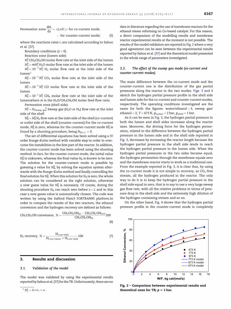
3.2. The effect of the sweep gas mode (co-current andcounter-current modes)
The main difference between the co-current mode and the
counter-current one is the distribution of the gas partial
pressures along the reactor in the two modes. Figs. 3 and 4
sketch the hydrogen partial pressure profile in the shell side
and lumen side for the co-current and counter-current modes,
respectively. The operating conditions investigated are the
same for both the figures: water/ethanol¼ 3, sweep gas/
ethanol¼ 2, T¼ 673 K, plumen¼ 2 bar, pshell¼ 1 bar.
As it can be seen in Fig. 3, the hydrogen partial pressure in
both the lumen and shell sides increases along the reactor
axes. Moreover, the driving force for the hydrogen perme-
ation, related to the difference between the hydrogen partial
pressure in the lumen side and in the shell side reported in
Fig. 3, decreases by increasing the reactor length because the
hydrogen partial pressure in the shell side tends to reach
the hydrogen partial pressure in the lumen side. When the
hydrogen partial pressures in the two sides became equal,
the hydrogen permeation through the membrane equals zero
and the membrane reactor starts to work as a traditional one.
From the example reported in Fig. 3, it is clear that, by using
the co-current mode it is not simple to recovery, as COx-free
stream, all the hydrogen produced in the reactor. The only
way to do it is to keep the hydrogen partial pressure in the
shell side equal to zero, that is to say to use a very large sweep
gas flow rate, with all the relative problems in terms of pres-
sure drop in the shell side and the extremely high dilution of
the hydrogen containing stream and so on.
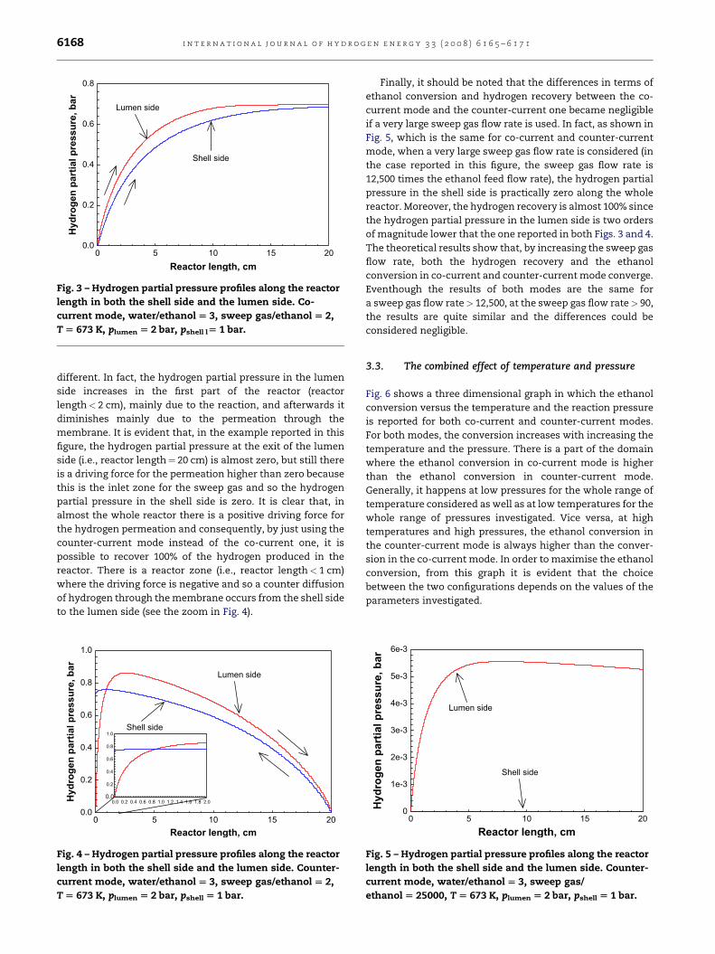
On the other hand, Fig. 4 shows that the hydrogen partial
pressure profile in the counter-current mode is completely
Fig. 2 – Comparison between experimental results and
theoretical ones for TR; p [ 1 bar.
Reactor length, cm
0 10 15 20
Hyd
ro
gen
p
artial p
ressu
re, b
ar
0.0
0.2
0.4
0.6
0.8
Lumen side
Shell side
5
Fig. 3 – Hydrogen partial pressure profiles along the reactor
length in both the shell side and the lumen side. Co-
current mode, water/ethanol [ 3, sweep gas/ethanol [ 2,
T [ 673 K, plumen [ 2 bar, pshell l[ 1 bar.
i n t e r n a t i o n a l j o u r n a l o f h y d r o g e n e n e r g y 3 3 ( 2 0 0 8 ) 6 1 6 5 – 6 1 7 16168
different. In fact, the hydrogen partial pressure in the lumen
side increases in the first part of the reactor (reactor
length< 2 cm), mainly due to the reaction, and afterwards it
diminishes mainly due to the permeation through the
membrane. It is evident that, in the example reported in this
figure, the hydrogen partial pressure at the exit of the lumen
side (i.e., reactor length¼ 20 cm) is almost zero, but still there
is a driving force for the permeation higher than zero because
this is the inlet zone for the sweep gas and so the hydrogen
partial pressure in the shell side is zero. It is clear that, in
almost the whole reactor there is a positive driving force for
the hydrogen permeation and consequently, by just using the
counter-current mode instead of the co-current one, it is
possible to recover 100% of the hydrogen produced in the
reactor. There is a reactor zone (i.e., reactor length< 1 cm)
where the driving force is negative and so a counter diffusion
of hydrogen through the membrane occurs from the shell side
to the lumen side (see the zoom in Fig. 4).
Reactor length, cm
0 5 10 15 20
Hyd
ro
gen
p
artial p
ressu
re, b
ar
0.0
0.2
0.4
0.6
0.8
1.0
Lumen side
Shell side
Fig. 4 – Hydrogen partial pressure profiles along the reactor
length in both the shell side and the lumen side. Counter-
current mode, water/ethanol [ 3, sweep gas/ethanol [ 2,
T [ 673 K, plumen [ 2 bar, pshell [ 1 bar.
Finally, it should be noted that the differences in terms of
ethanol conversion and hydrogen recovery between the co-
current mode and the counter-current one became negligible
if a very large sweep gas flow rate is used. In fact, as shown in
Fig. 5, which is the same for co-current and counter-current
mode, when a very large sweep gas flow rate is considered (in
the case reported in this figure, the sweep gas flow rate is
12,500 times the ethanol feed flow rate), the hydrogen partial
pressure in the shell side is practically zero along the whole
reactor. Moreover, the hydrogen recovery is almost 100% since
the hydrogen partial pressure in the lumen side is two orders
of magnitude lower that the one reported in both Figs. 3 and 4.
The theoretical results show that, by increasing the sweep gas
flow rate, both the hydrogen recovery and the ethanol
conversion in co-current and counter-current mode converge.
Eventhough the results of both modes are the same for
a sweep gas flow rate> 12,500, at the sweep gas flow rate> 90,
the results are quite similar and the differences could be
considered negligible.
3.3. The combined effect of temperature and pressure
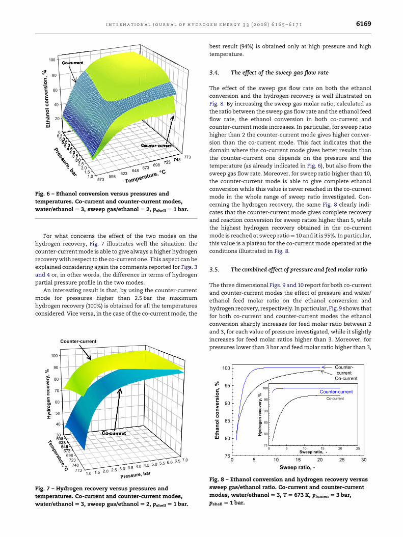
Fig. 6 shows a three dimensional graph in which the ethanol
conversion versus the temperature and the reaction pressure
is reported for both co-current and counter-current modes.
For both modes, the conversion increases with increasing the
temperature and the pressure. There is a part of the domain
where the ethanol conversion in co-current mode is higher
than the ethanol conversion in counter-current mode.
Generally, it happens at low pressures for the whole range of
temperature considered as well as at low temperatures for the
whole range of pressures investigated. Vice versa, at high
temperatures and high pressures, the ethanol conversion in
the counter-current mode is always higher than the conver-
sion in the co-current mode. In order to maximise the ethanol
conversion, from this graph it is evident that the choice
between the two configurations depends on the values of the
parameters investigated.
Reactor length, cm
0 10 15 20
Hyd
ro
gen
p
artial p
ressu
re, b
ar
0
1e-3
2e-3
3e-3
4e-3
5e-3
6e-3
Lumen side
Shell side
5
Fig. 5 – Hydrogen partial pressure profiles along the reactor
length in both the shell side and the lumen side. Counter-
current mode, water/ethanol [ 3, sweep gas/
ethanol [ 25000, T [ 673 K, plumen [ 2 bar, pshell [ 1 bar.
0
20
40
60
80
100
573598
623648
673698 723 748 773
1.01.5
2.02.5
3.03.5
4.04.5
5.05.5
6.06.5
Eth
an
ol co
nversio
n, %
Temperature, °C
Pressure, b
ar
Co-current
Counter-current
Fig. 6 – Ethanol conversion versus pressures and
temperatures. Co-current and counter-current modes,
water/ethanol [ 3, sweep gas/ethanol [ 2, pshell [ 1 bar.
i n t e r n a t i o n a l j o u r n a l o f h y d r o g e n e n e r g y 3 3 ( 2 0 0 8 ) 6 1 6 5 – 6 1 7 1 6169
For what concerns the effect of the two modes on the
hydrogen recovery, Fig. 7 illustrates well the situation: the
counter-current mode is able to give always a higher hydrogen
recovery with respect to the co-current one. This aspect can be
explained considering again the comments reported for Figs. 3
and 4 or, in other words, the difference in terms of hydrogen
partial pressure profile in the two modes.
An interesting result is that, by using the counter-current
mode for pressures higher than 2.5 bar the maximum
hydrogen recovery (100%) is obtained for all the temperatures
considered. Vice versa, in the case of the co-current mode, the
30
40
50
60
70
80
90
100
598623
648673
698723
748773
1.0 1.5 2.0 2.5 3.0 3.5 4.0 4.5 5.0 5.5 6.0 6.5 7.0
Hyd
ro
gen
reco
very, %
Tem
perature,°
C
Pressure, bar
Co-current
Counter-current
Fig. 7 – Hydrogen recovery versus pressures and
temperatures. Co-current and counter-current modes,
water/ethanol [ 3, sweep gas/ethanol [ 2, pshell [ 1 bar.
best result (94%) is obtained only at high pressure and high
temperature.
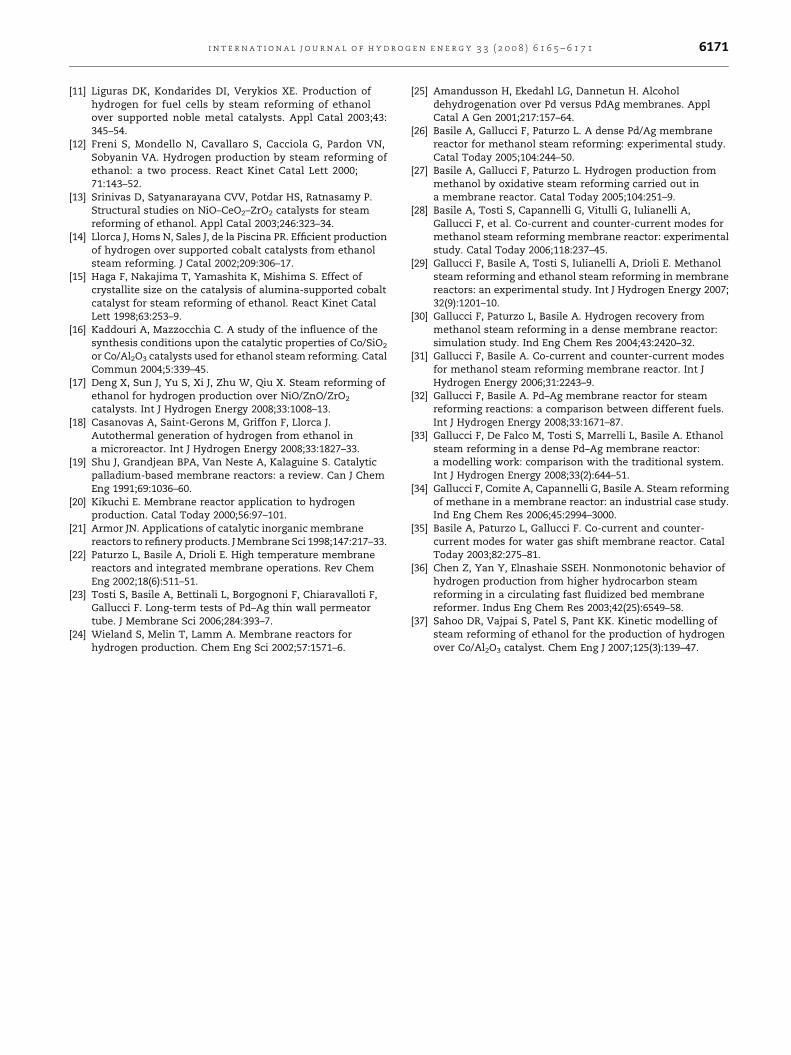
3.4. The effect of the sweep gas flow rate
The effect of the sweep gas flow rate on both the ethanol
conversion and the hydrogen recovery is well illustrated on
Fig. 8. By increasing the sweep gas molar ratio, calculated as
the ratio between the sweep gas flow rate and the ethanol feed
flow rate, the ethanol conversion in both co-current and
counter-current mode increases. In particular, for sweep ratio
higher than 2 the counter-current mode gives higher conver-
sion than the co-current mode. This fact indicates that the
domain where the co-current mode gives better results than
the counter-current one depends on the pressure and the
temperature (as already indicated in Fig. 6), but also from the
sweep gas flow rate. Moreover, for sweep ratio higher than 10,
the counter-current mode is able to give complete ethanol
conversion while this value is never reached in the co-current
mode in the whole range of sweep ratio investigated. Con-
cerning the hydrogen recovery, the same Fig. 8 clearly indi-
cates that the counter-current mode gives complete recovery
and reaction conversion for sweep ratios higher than 5, while
the highest hydrogen recovery obtained in the co-current
mode is reached at sweep ratio¼ 10 and it is 95%. In particular,
this value is a plateau for the co-current mode operated at the
conditions illustrated in Fig. 8.
3.5. The combined effect of pressure and feed molar ratio
The three dimensional Figs. 9 and 10 report for both co-current
and counter-current modes the effect of pressure and water/
ethanol feed molar ratio on the ethanol conversion and
hydrogen recovery, respectively. In particular, Fig. 9 shows that
for both co-current and counter-current modes the ethanol
conversion sharply increases for feed molar ratio between 2
and 3, for each value of pressure investigated, while it slightly
increases for feed molar ratios higher than 3. Moreover, for
pressures lower than 3 bar and feed molar ratio higher than 3,
Sweep ratio, -
0 5 10 15 20 25 30
Eth
an
ol co
nversio
n, %
75
80
85
90
95
100 Counter-current
Co-current
Sweep ratio, -
0 5 10 15 20 25
Hyd
ro
gen
reco
very, %
75
80
85
90
95
100
Co-current
Counter-current
Fig. 8 – Ethanol conversion and hydrogen recovery versus
sweep gas/ethanol ratio. Co-current and counter-current
modes, water/ethanol [ 3, T [ 673 K, plumen [ 3 bar,
pshell [ 1 bar.
50
60
70
80
90
100
2 3 4 5 6 7 8 9 10 11
23
45
67
Eth
an
ol co
nverstio
n, %
Water/Ethanol feed ratio, -
Pressure, b
ar
Counter-current
Co-current
Fig. 9 – Ethanol conversion versus pressures and water/
ethanol feed ratio. Co-current and counter-current modes,
sweep gas/ethanol [ 2, T [ 673 K, pshell l[ 1 bar.
i n t e r n a t i o n a l j o u r n a l o f h y d r o g e n e n e r g y 3 3 ( 2 0 0 8 ) 6 1 6 5 – 6 1 7 16170
the co-current mode is able to give better results in terms of
ethanol conversion than the counter-current one does.
Considering the effect of the molar feed ratio on the
hydrogen recovery, it is evident in Fig. 10 that the hydrogen
recovery in counter-current mode is not influenced by the
feed molar ratio while the co-current mode is strongly influ-
enced by this parameter. In fact, in co-current mode, for the
whole range of pressure investigated, the hydrogen recovery
decreases by increasing the feed molar ratio, even though this
decrease is lower at higher pressures.
On the one hand, by increasing the feed molar ratio part of
the excess of water dilutes the hydrogen produced in the
50
60
70
80
90
100
23
45
67
89
1011
23
45
67
Hyd
ro
gen
reco
very, %
Counter-current
Co-current
Wate
r/Eth
anol feed ra
tio, -
Pressure, b
ar
Fig. 10 – Hydrogen recovery versus pressures and water/
ethanol feed ratio. Co-current and counter-current modes,
sweep gas/ethanol [ 2, T [ 673 K, pshell [ 1 bar.
reaction zone resulting in a lower hydrogen partial pressure
difference between the lumen side and the shell side of the
reactor and so in a lower hydrogen recovery. On the other
hand, from Fig. 10 it seems that the counter-current mode
does not suffer by this aspect and this fact could be related to
the different partial pressure profiles between the two modes.
Therefore, it is also worth noting that, at low pressures the
counter-current mode is able to give an increase at least of
30% on the hydrogen recovery with respect to the co-current
mode for each feed molar ratio considered, while at high
pressure the difference between the co-current mode and the
counter-current one decreases up to 5% at 8 bar and water/
ethanol¼ 2.
4. Conclusions
The ethanol steam-reforming reaction to produce pure
hydrogen has been studied theoretically in a Pd-based
membrane reactor for both co-current and counter-current
modes. The results indicate that the counter-current mode is
able to give higher hydrogen recovery than the co-current
mode in the whole range of operative conditions investigated.
For what concerns the ethanol conversion, this theoretical
study also indicates that attentions should be paid in order to
identify the set of parameters able to maximise it in the
counter-current mode. In fact, low pressures and low
temperatures give higher ethanol conversion in the co-current
mode while high pressures and high temperatures give higher
ethanol conversion in the counter-current mode.
r e f e r e n c e s
[1] de Wild PJ, Verhaak MJFM. Catalytic production of hydrogenfrom methanol. Catal Today 2000;60:3–10.
[2] Wiese W, Emonts B, Peters R. Methanol steam reforming ina fuel cell drive system. J Power Source 1999;84:187–93.
[3] Breen JP, Burch R, Coleman HM. Metal-catalysed steamreforming of ethanol in the production of hydrogen for fuelcell applications. Appl Catal B Environ 2002;39:65–74.
[4] Cavallaro S, Chiodo V, Vita A, Freni S. Hydrogen productionby auto thermal reforming of ethanol on Rh–Al2O3 catalyst. JPower Source 2003;123:10–6.
[5] Maggio G, Freni S, Cavallaro S. Light alcohols/methanefuelled molten carbonate fuel cells: a comparative study. JPower Source 1998;74:17–23.
[6] Heinzel A, Vogel B, Hubner P. Reforming of naturalgas–hydrogen generation for small scale stationaryfuel cell systems. J Power Source 2002;105:202–7.
[7] Shen JP, Song C. Influence of preparation methodperformance of Cu/Zn-based catalysts for low-temperaturesteam reforming and oxidative steam reforming of methanolfor H2 production for fuel cells. Catal Today 2002;77:89–98.
[8] Lindstrom B, Pettersson LJ. Hydrogen generation by steamreforming of methanol over copper-based catalysts for fuelcell applications. Int J Hydrogen Energy 2001;26:923–33.
[9] Badmaev SD, Snytnikov PV. Hydrogen production fromdimethyl ether and bioethanol for fuel cell applications. Int JHydrogen Energy 2008;33:3026–30.
[10] Ni M, Leung DYC, Leung MKH. A review on reforming bio-ethanol for hydrogen production. Int J Hydrogen Energy 2007;32:3238–47.
i n t e r n a t i o n a l j o u r n a l o f h y d r o g e n e n e r g y 3 3 ( 2 0 0 8 ) 6 1 6 5 – 6 1 7 1 6171
[11] Liguras DK, Kondarides DI, Verykios XE. Production ofhydrogen for fuel cells by steam reforming of ethanolover supported noble metal catalysts. Appl Catal 2003;43:345–54.
[12] Freni S, Mondello N, Cavallaro S, Cacciola G, Pardon VN,Sobyanin VA. Hydrogen production by steam reforming ofethanol: a two process. React Kinet Catal Lett 2000;71:143–52.
[13] Srinivas D, Satyanarayana CVV, Potdar HS, Ratnasamy P.Structural studies on NiO–CeO2–ZrO2 catalysts for steamreforming of ethanol. Appl Catal 2003;246:323–34.
[14] Llorca J, Homs N, Sales J, de la Piscina PR. Efficient productionof hydrogen over supported cobalt catalysts from ethanolsteam reforming. J Catal 2002;209:306–17.
[15] Haga F, Nakajima T, Yamashita K, Mishima S. Effect ofcrystallite size on the catalysis of alumina-supported cobaltcatalyst for steam reforming of ethanol. React Kinet CatalLett 1998;63:253–9.
[16] Kaddouri A, Mazzocchia C. A study of the influence of thesynthesis conditions upon the catalytic properties of Co/SiO2
or Co/Al2O3 catalysts used for ethanol steam reforming. CatalCommun 2004;5:339–45.
[17] Deng X, Sun J, Yu S, Xi J, Zhu W, Qiu X. Steam reforming ofethanol for hydrogen production over NiO/ZnO/ZrO2
catalysts. Int J Hydrogen Energy 2008;33:1008–13.[18] Casanovas A, Saint-Gerons M, Griffon F, Llorca J.
Autothermal generation of hydrogen from ethanol ina microreactor. Int J Hydrogen Energy 2008;33:1827–33.
[19] Shu J, Grandjean BPA, Van Neste A, Kalaguine S. Catalyticpalladium-based membrane reactors: a review. Can J ChemEng 1991;69:1036–60.
[20] Kikuchi E. Membrane reactor application to hydrogenproduction. Catal Today 2000;56:97–101.
[21] Armor JN. Applications of catalytic inorganic membranereactors to refinery products. J Membrane Sci 1998;147:217–33.
[22] Paturzo L, Basile A, Drioli E. High temperature membranereactors and integrated membrane operations. Rev ChemEng 2002;18(6):511–51.
[23] Tosti S, Basile A, Bettinali L, Borgognoni F, Chiaravalloti F,Gallucci F. Long-term tests of Pd–Ag thin wall permeatortube. J Membrane Sci 2006;284:393–7.
[24] Wieland S, Melin T, Lamm A. Membrane reactors forhydrogen production. Chem Eng Sci 2002;57:1571–6.
[25] Amandusson H, Ekedahl LG, Dannetun H. Alcoholdehydrogenation over Pd versus PdAg membranes. ApplCatal A Gen 2001;217:157–64.
[26] Basile A, Gallucci F, Paturzo L. A dense Pd/Ag membranereactor for methanol steam reforming: experimental study.Catal Today 2005;104:244–50.
[27] Basile A, Gallucci F, Paturzo L. Hydrogen production frommethanol by oxidative steam reforming carried out ina membrane reactor. Catal Today 2005;104:251–9.
[28] Basile A, Tosti S, Capannelli G, Vitulli G, Iulianelli A,Gallucci F, et al. Co-current and counter-current modes formethanol steam reforming membrane reactor: experimentalstudy. Catal Today 2006;118:237–45.
[29] Gallucci F, Basile A, Tosti S, Iulianelli A, Drioli E. Methanolsteam reforming and ethanol steam reforming in membranereactors: an experimental study. Int J Hydrogen Energy 2007;32(9):1201–10.
[30] Gallucci F, Paturzo L, Basile A. Hydrogen recovery frommethanol steam reforming in a dense membrane reactor:simulation study. Ind Eng Chem Res 2004;43:2420–32.
[31] Gallucci F, Basile A. Co-current and counter-current modesfor methanol steam reforming membrane reactor. Int JHydrogen Energy 2006;31:2243–9.
[32] Gallucci F, Basile A. Pd–Ag membrane reactor for steamreforming reactions: a comparison between different fuels.Int J Hydrogen Energy 2008;33:1671–87.
[33] Gallucci F, De Falco M, Tosti S, Marrelli L, Basile A. Ethanolsteam reforming in a dense Pd–Ag membrane reactor:a modelling work: comparison with the traditional system.Int J Hydrogen Energy 2008;33(2):644–51.
[34] Gallucci F, Comite A, Capannelli G, Basile A. Steam reformingof methane in a membrane reactor: an industrial case study.Ind Eng Chem Res 2006;45:2994–3000.
[35] Basile A, Paturzo L, Gallucci F. Co-current and counter-current modes for water gas shift membrane reactor. CatalToday 2003;82:275–81.
[36] Chen Z, Yan Y, Elnashaie SSEH. Nonmonotonic behavior ofhydrogen production from higher hydrocarbon steamreforming in a circulating fast fluidized bed membranereformer. Indus Eng Chem Res 2003;42(25):6549–58.
[37] Sahoo DR, Vajpai S, Patel S, Pant KK. Kinetic modelling ofsteam reforming of ethanol for the production of hydrogenover Co/Al2O3 catalyst. Chem Eng J 2007;125(3):139–47.
Copyright © 2022 FDOKUMEN