Surface roughening and dendritic growth in pulsating overpotential copper electrodeposition
13
Surface and Coatings Technology, 27 (1986) 117 - 129 117 SURFACE ROUGHENING AND DENDRITIC GROWTH IN PULSATING OVERPOTENTIAL COPPER ELECTRODEPOSITION K. I. POPOV, M. D. MAKSIMOVli~, S. K. ZE~EVIO and M. R. STOJIO Faculty of Technology and Metallurgy, University of Beograd, Beograd (Yugoslavia) (Received April 30, 1985) Summary The mechanism of surface roughening and the initiation of dendritic growth in pulsating overpotential electrodeposition of metals is proposed. Good agreement between theory and experiment is obtained for copper elec- trodeposition. 1. Introduction It is known that the application of periodically varying currents leads to improvements in the quality of the electrodeposits obtained [1]. In recent years some aspects of the effect of pulsating current [2, 3] reversing current [4] and superimposed alternating current on direct current [5] on the morphology of metal deposits have been treated quantitatively. The purpose of this paper is to discuss in a similar way the effect of pulsating overpoten- tial (P0) metal electrodeposition on the morphology of deposits. 2. Experimental details A controlled P0 was applied to the electrode to be investigated by a potentiostat PARC M173 driven by a function generator PARC M175. The shape of the P0 was controlled by a digital oscilloscope Nicolet 206 and the average values of current and overpotential were measured by appropriate d.c. instruments. The electrolyte was 0.2 M CuSO 4 in 0.5 M H2S04. All experiments were carried out at room temperature. The working, counter- electrode and reference electrode were of electrolytic copper. P0 metal deposition was simulated using the equivalent cell shown in Fig. 1. In order to determine the quality of the deposit obtained, copper was deposited on a copper-wire electrode plated with nickel. After the copper deposition had been finished, the wire was rinsed with water, dried in air and sealed in wax. Metallographic samples of the wire cross section were made by cutting and polishing in the usual manner. Photomicrographs have been made using magnification 200X. 0257-8972/86/$3.50 © Elsevier Sequoia/Printed in The Netherlands
-
Upload
independent -
Category
Documents
-
view
0 -
download
0
Transcript of Surface roughening and dendritic growth in pulsating overpotential copper electrodeposition

Surfaceand CoatingsTechnology,27 (1986)117 - 129 117
SURFACEROUGHENING AND DENDRITIC GROWTH IN PULSATINGOVERPOTENTIAL COPPERELECTRODEPOSITION
K. I. POPOV,M. D. MAKSIMOVli~,S. K. ZE~EVIOandM. R. STOJIO
Facultyof TechnologyandMetallurgy, University of Beograd,Beograd(Yugoslavia)
(ReceivedApril 30, 1985)
Summary
The mechanismof surfacerougheningand the initiation of dendriticgrowth in pulsatingoverpotentialelectrodepositionof metalsis proposed.Good agreementbetweentheoryandexperimentis obtainedfor copperelec-trodeposition.
1. Introduction
It is knownthat the applicationof periodicallyvaryingcurrentsleadstoimprovementsin the quality of the electrodepositsobtained[1]. In recentyearssomeaspectsof the effect of pulsatingcurrent [2, 3] reversingcurrent[4] and superimposedalternatingcurrent on direct current [5] on themorphology of metal depositshavebeentreatedquantitatively.Thepurposeof this paperis to discussin asimilar way the effect of pulsatingoverpoten-tial (P0)metalelectrodepositionon the morphologyof deposits.
2. Experimentaldetails
A controlledP0 was applied to the electrodeto be investigatedby apotentiostatPARCM173 driven by a function generatorPARC M175. Theshapeof the P0 was controlledby adigital oscilloscopeNicolet 206 andtheaveragevalues of current and overpotentialwere measuredby appropriated.c. instruments.The electrolyte was 0.2 M CuSO4in 0.5 M H2S04. Allexperimentswere carried out at room temperature.The working, counter-electrodeand referenceelectrodewere of electrolytic copper. P0 metaldepositionwas simulatedusingthe equivalentcell shownin Fig. 1. In orderto determinethe quality of the depositobtained,copperwas depositedon acopper-wireelectrodeplated with nickel. After the copperdepositionhadbeenfinished,the wire was rinsedwith water,dried in air andsealedin wax.Metallographic samplesof the wire crosssectionwere madeby cutting andpolishing in the usual manner. Photomicrographshave been madeusingmagnification200X.
0257-8972/86/$3.50 © ElsevierSequoia/Printedin TheNetherlands
118
16~.jF
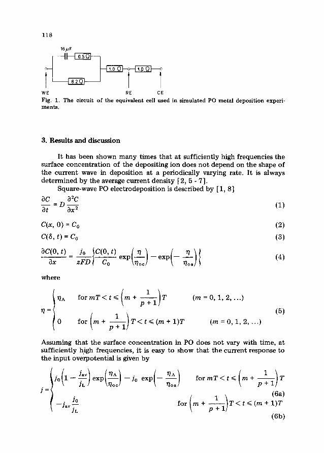
Fig. 1. The circuit of theequivalentcell used in simulatedP0 metaldepositionexperi-ments.
3. Resultsanddiscussion
It hasbeenshownmany times thatat sufficiently high frequenciesthesurfaceconcentrationof the depositingion doesnot dependon the shapeofthe current wave in depositionat a periodically varying rate. It is alwaysdeterminedby the averagecurrentdensity[2, 5 - 7].
Square-waveP0electrodepositionis describedby [1, 8]ac a2c
(1)at ax
C(x, 0) = C0 (2)
C(6, t) = C0 (3)
aC(0,t) Jo C(0, t) I ~ I ~?\______ = — exp(—J—expl——I (4)
ax zFD C0 \fl~~J \ 77oaJ
where
/ __77A formT<t~(m+ IT (m0,1,2,...)\ p+l/77= / (5)
0 forlm+ JT<t~(m+1)T (m=0,1,2,...)
\ p+].j
Assumingthat the surfaceconcentrationin P0 doesnot vary with time, atsufficiently high frequencies,it is easyto show that the currentresponsetothe inputoverpotentialis given by
Jo(1_4”)exp(~~~)—jo exp(-_-~-) formT<t~(m+ 1 )Tfloe floa P~1
1 1 (6a)
Jav for(m+ ~+1)T<t~m÷1T
(6b)
119
andthe averagecurrentdensityis given by
I Jav\ (‘iA \ PJoJav~~l— —; exp~—j— _____
\ IL! \flocI IL)av (7)
if the anodiccurrentdensity is neglectedduringoverpotentialpulses.Over-potentialamplitudecanbe obtainedfrom eqn.(7) in theform
?7A=flDc+flOCln(P+1+—~ (8)IL!
because
(Jay 1 \7IDC = floe ml . . I (9)\Io 1 lavIiL!
andaverageoverpotentialas
77DC 77~ I P)O’~flav + lnlp+1~—! (10)p+l p+l \ IL!
For the caseof copperdepositionwhereJ0 ‘~JL, eqn. (10) can be rewritten
in the form
flav 77DC + -~—1n(p+1) (11)p+l p+l -
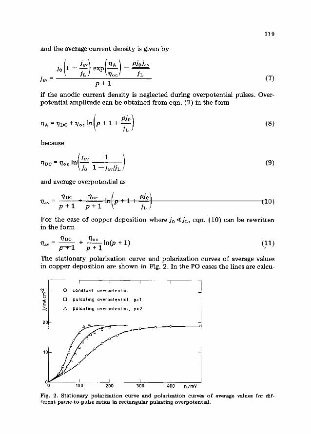
The stationarypolarizationcurve andpolarizationcurvesof averagevaluesin copperdepositionare shownin Fig. 2. In the P0casesthelines arecalcu-
I I
0 constant overpotential -
E0 pulsating overpotential, p=1
a~ pulsating overpotentiol. p~2
20
0 100 200 300 400 rj/mV
Fig. 2. Stationary polarizationcurve and polarizationcurves of averagevalues for dif-ferentpause-to-pulseratiosin rectangularpulsatingoverpotential.
120
lated using values from the stationarypolarization curve and eqn. (11),whereasthe points representexperimentalvalues.Thereis seento be goodagreementbetweenexperimentand theory andwith earlier resultsobtainedby digital simulationof copperdepositionby P0 [8]. The aboveresultsaregood proofthat masstransferin P0 depositionfollows the samelaws as inothercasesof electrodepositionat aperiodically varyingrate at similar fre-quencies.This meansthat a more realistic analysisof masstransferin P0electrodepositionis given than the earlier one basedon the conceptof anideal reversiblereactionin non-stirredelectrolyte[1, 9, 10].
The non-dendriticgrowth of a protrusion ~ ~ h is then describedby[2]
VfavTonh=ho’exP( zF5 ) (12)
for anarbitrarily chosenpulseif integrationis carriedout between0 andT0~,taking the height h0’ at the beginning of the mth pulse (zerotime) as theinitial heightof theprotrusion.If the period is T the pulsedurationis
T= (13)
p+1
andsubstitutionof T0~from eqn.(13) in eqn.(12) gives
( VjavT 14h=h0 exP~F8~,l) ( )
Taking the final h from the previousperiodof P0 as theinitial for thenext,onecan show that the following equationwill be satisfiedatthe endof thenth period
/ VjavflT \h = h0 expi (15)
\zF~(p+ 1)!
Taking into accountthat
n = t/T (16)
eqn.(15) can be rewritten in the form
h=hoexP( Vfavt ) (17)zFö(p + 1)
which allows the coarsenessof the depositobtainedunderdifferent condi-tionsto be comparedfor t ~ T. Equation(17)can be written as
h=hoexp( ~ (18)\r(p + 1)/

121
ifzF6
(19)V lay
Obviously, the relationsaboveare valid if the depositdissolvesuniformlyduring the off period. It follows from eqn. (18) that for the samedeposi-tion time andaveragecurrentdensity
h~0>h~>0 (20)
andfor thesameaveragecurrentdensityit shouldbe
h~0=h~>0 (21)
at
1~ —t,,>~ (22)p+
1
Photomicrographsof coppershown in Fig. 3 illustrate well the aboverela-tions. Copperwas depositedat 400mV for 40 mm at constantoverpotential
-- ~ .
~ __ :~• T
— ~ - - - ~ . ____f . __ .
-s,- ~-‘-‘ ~ . - - .- - -S ~
(a) (b)
S__,_-_-z ~~-‘-~ —
- ~ ~
/.;
~ -,. .;-~‘1’~ -< ..
- ,=-.- I I ~t- -. -
(c)
Fig. 3. Copper depositsobtainedunderdifferent conditions: (a) constantoverpotential400 mV, depositiontime 40 mm; (b) square-wavepulsatingoverpotentialamplitudevalue400 mV, p = 1, 50 Hz, depositiontime 40 mm; (c) thesameas in (b), but for adeposi-tion time of 80 mm.
122
(CO) andat overpotentialamplitude400mV, p = 1 andfrequency50 Hz inP0 depositionfor 40 and80 mm. In bothcases,as canbe seenfrom Fig. 2,the averagecurrent density is equalto the limiting diffusioncurrentdensity.It should be notedthat the depositiontime in CO depositionis lower thanthe induction time for the initiation of dendnticgrowth in copperdeposi-tion at 400mY in this system[11].
The overpotential and current density on the tip of the dendritegrowinginsidethe diffusion layerarerelatedby [11]
h (~\Id 1o — expi —-—I (23)
~
or
hId,av Io exP(~_) (24)~(p+1) floe
in P0 conditions, assumingthat the current density during the pauseisnegligible. The height of protrusionvaries with time accordingto eqn.(18),andthe condition
Jd,av>JL (25)which is necessaryfor transformationof the growth mechanismfrom non-dendritic to dendritic [11] is fulfilled at
tjr(p+1)~kfl~~+ln(p+l) (26)floc
if
(~JL \flcfloc1fl(~1 (27)and
= h0 exp (28)
r(p+1)
The rateof propagationof the tip of the dendrite insidethe diffusion layerrelativeto the flat surfaceis given by
dh Vj0h I77A\exp~—j (29)dt zF6(p + 1) \‘1~~!
accordingto ref. 11, if the current density to the flat surfaceis negligiblebecauseof branchingof dendrites.The heightof adendritevarieswith timeaccordingto
123
VJ0t /flA\ (77A\
h = h~exp expi— i expi— i (30)zF6(,p+ 1) \flocJ \flocl
andthe currentdensityon the tip of the dendrite
h, Vj0t (flA\ /71A\Id,av 1o’ exp expl—, exp~—J (31)
6 zF*5(p + 1) \fl~~! \7locJ
Following the samereasoningaspreviously [11] it is easyto showthat
d(lflJd,av) VJ0 /71A\dt = zF6(p + 1) eXP~17) (32)
in the region of dominantdendnticgrowth. It should be notedthat in theconsiderationof dendritic growth initiation according to the proposedmechanism,the surfaceenergy term can be neglected.This is so becauseprotrusionswith a largetip radius(linear diffusion control to the tip) trans-form to dendritesin this case.
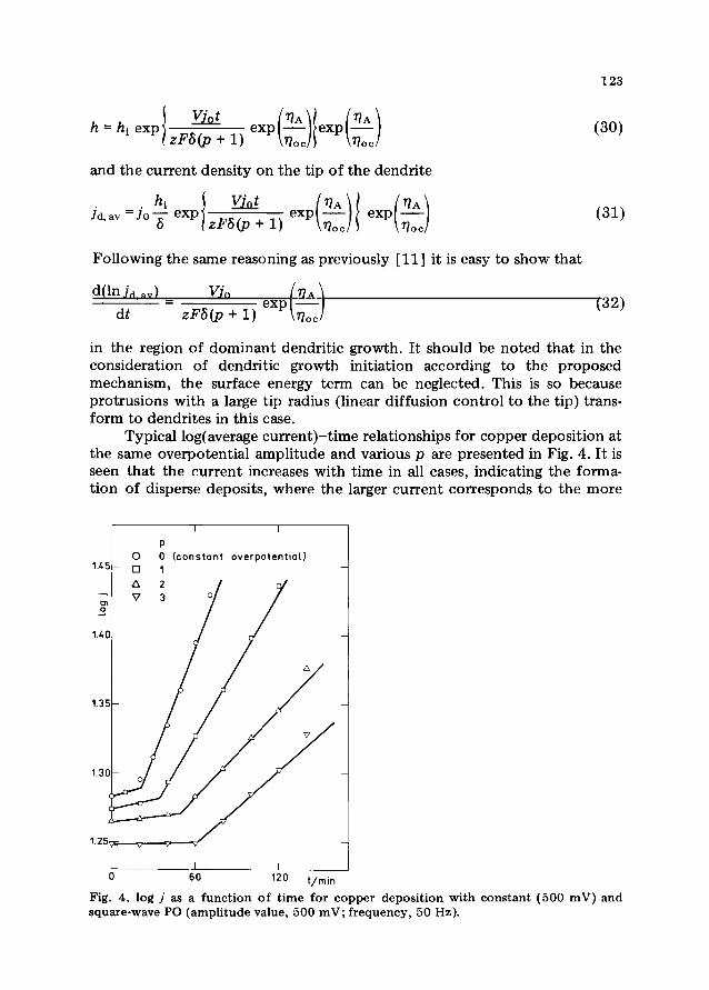
Typical log(averagecurrent)—timerelationshipsfor copperdepositionatthe sameoverpotentialamplitudeandvariousp arepresentedin Fig. 4. It isseenthat the currentincreaseswith time in all cases,indicating the forma-tion of dispersedeposits,wherethe larger current correspondsto the more
p0 0 (constant overpotential)
1.45- 0 1 -
/V3 7 /
1.40-
1.35- -
0 60 120 1,/nun
Fig. 4. log j as a function of time for copper depositionwith constant(500 mV) andsquare-waveP0 (amplitudevalue,500 mV; frequency,50 Hz).

124
1.45— -
C
0
1.40— -
1.25 - V constant - -o square-wave 500 square-wave 5000
i~ triangular-wave 50
0 60 120 tlmin
Fig. 5. log j as a function of time for copperdepositionwith square-wave(p = 1) andtri-
angular-waveP0 (amplitudevalue, 500mV).
disperseddeposit.As shownpreviously [11] the intersectionpoint of thetwo linearpartsof eachgraphdeterminesthe inductiontime of the initiationof dendnticgrowth. As expectedfrom eqns.(26) and (32), the inductiontime for dendritic growth increasesand the slopeof logJd avt plots in theregion of dominantdendritic growth decreaseswith increasingp. A similareffect is seenfrom Fig. 5 for depositionwith high frequencysquare-waveand triangular-wavePD, which can be explainedas follows. In the caseoftriangular-waveP0 the overpotentialas a function of time during the firsthalf of theperiod is given by
2t
(33)andeqn. (6a)canbe rewritten in theform
/ Jav\ /2flAt\ / 2flAt ~11o11—Jexpl I —j0exp~— i (34)
\ IL! \770~T/ \ floaT /
It follows from eqn. (34) that J < 0 (assuming+ sign for cathodiccurrent)andsurfacecoarsenessdoesnot increaseif
0<t~t’-~-~ln 1 , (35)277A 1 Jay/IL

125
It is obvious that the rate of surface coarsenessincrease is less than inconstantoverpotential deposition at all current densities lower than theaverage.It is easyto showthatcurrentdensityin triangular-waveP0deposi-tion is largerthanthe averageif
T T77DC—~at>t”= (36)2 2flA
assumingthat the anodic term can be neglected.77DC in eqn. (36) denotesthe overpotentialcorrespondingto the averagecurrentdensityin constantoverpotentialdeposition.Hence,the sameeffect on the increasein thenon-dendritic surfacecoarsenessis expectedas in rectangular-waveP0atp givenby
t’
<E~< ~ (37)
Dendritic growth is possibleif ~ > ~ and the currentdensityat the tip ofdendritegrowinginsidethe diffusion layeris given by
h /2flAt\Id 1o exp~ I (38)6
if at fl > 77~the anodicterm canbeneglected.Averagecurrentdensityis thengiven by
2h T12Jd,av Jo f exp~ ) dt (39)6T nIT/nA
or
hfl0~ /flA\
Id,av Jo~ expl—! (40)671A \Ti0~I
if
I77A\exp~—-exp~—~ (41)\fl~~/
In thesameway aspreviously [11] it is easyto showthat
d(lnJd av) VJofloe /ilA \_______ = expu—l (42)
dt ZFt577A \n
0~/
It follows from eqns.(32) and (42) that the rate of dendritic growth intriangular-waveP0 depositionis lower comparedwith that in rectangular-waveP0 if
71A>flOC(P+l) (43)
126
(a) (b)
- - r
(c) (d)
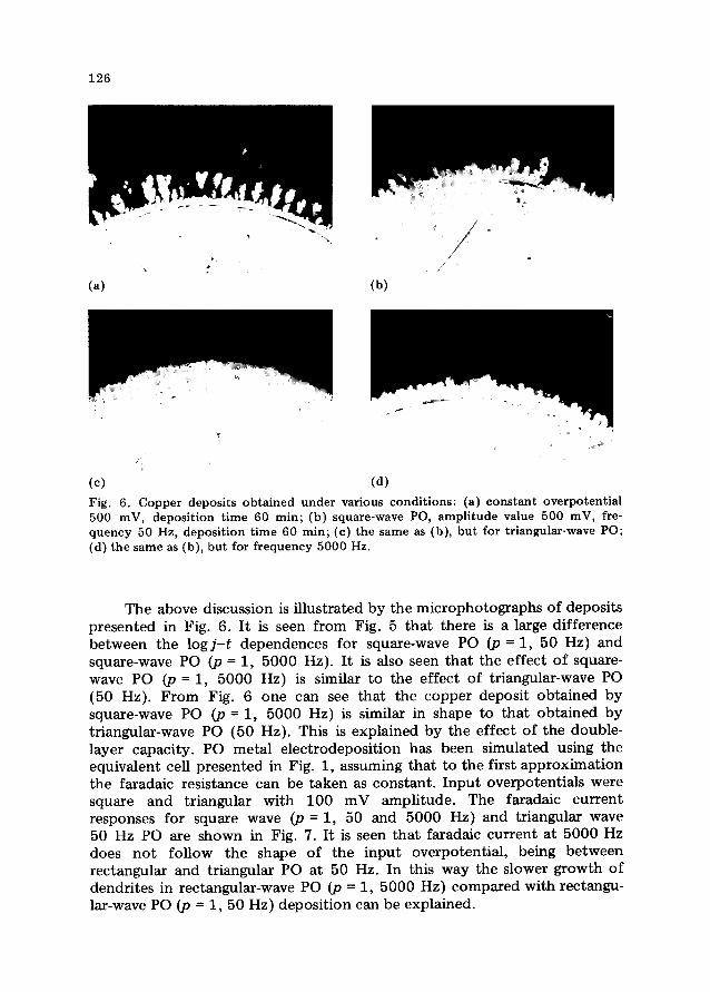
Fig. 6. Copper depositsobtainedunder various conditions: (a) constantoverpotential500 mV, depositiontime 60 mm; (b) square-waveP0, amplitude value 500 mV, fre-quency50 Hz, depositiontime 60 mm; (c) thesameas (b), but for triangular-waveP0;(d) thesameas(b), but for frequency5000 Hz.
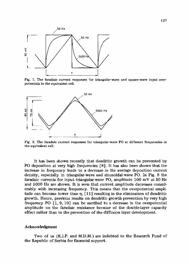
The abovediscussionis illustrated by the microphotographsof depositspresentedin Fig. 6. It is seenfrom Fig. 5 that thereis a largedifferencebetweenthe logJ—t dependencesfor square-waveP0 (p = 1, 50 Hz) andsquare-waveP0 (p = 1, 5000 Hz). It is also seenthat the effect of square-wave PD (p = 1, 5000 Hz) is similar to the effect of triangular-waveP0(50 Hz). From Fig. 6 one can see that the copperdepositobtainedbysquare-waveP0 (p = 1, 5000 Hz) is similar in shapeto that obtainedbytriangular-waveP0 (50 Hz). This is explainedby the effect of the double-layer capacity. P0 metal electrodepositionhas been simulatedusing theequivalentcell presentedin Fig. 1, assumingthat to the first approximationthe faradaic resistancecan be takenas constant.Input overpotentialsweresquare and triangular with 100 mV amplitude. The faradaic currentresponsesfor squarewave (p = 1, 50 and 5000 Hz) and triangular wave50 Hz PD are shown in Fig. 7. It is seenthat faradaiccurrent at 5000Hzdoes not follow the shape of the input overpotential, being betweenrectangularand triangular P0 at 50 Hz. In this way the slower growth ofdendritesin rectangular-wavePD (p = 1, 5000Hz) comparedwith rectangu-lar-wavePD (p = 1, 50 Hz) depositioncanbe explained.
127
Hz
Fig. 7. The faradaiccurrentresponsesfor triangular-waveand square-waveinput over-potentialsin theequivalentcell.
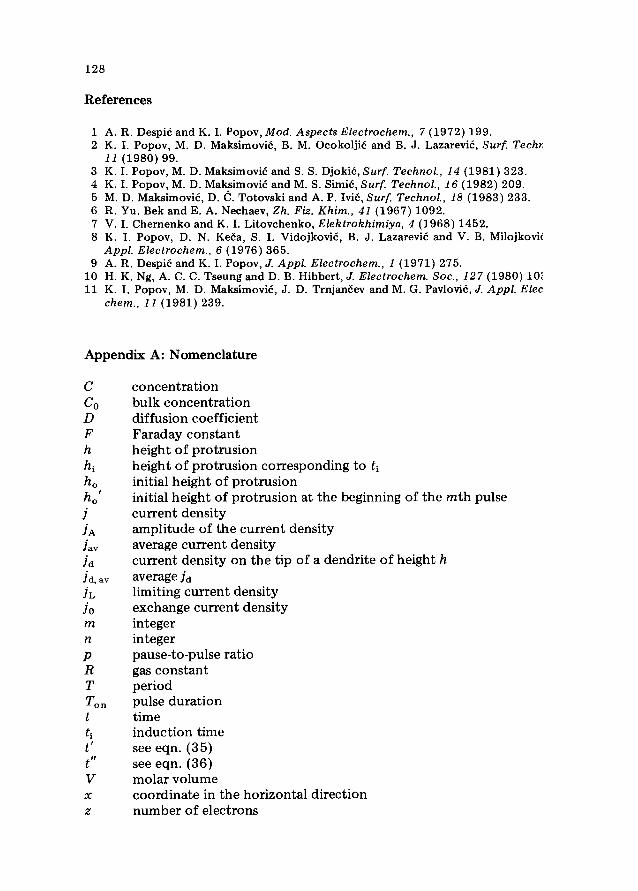
Fig. 8. The faradaiccurrentresponsesfor triangular-waveP0 at different frequenciesintheequivalentcell.
It has beenshownrecently that dendritic growth canbe preventedbyP0depositionat very high frequencies[8]. It hasalso beenshownthat theincreasein frequency leads to adecreasein the averagedepositioncurrentdensity, especiallyin triangular-waveandsinusoidal-wavePD. In Fig. 8 thefaradaiccurrentsfor input triangular-waveP0, amplitude 100mV at 50 Hzand5000 Hz are shown.It is seenthat current amplitudedecreasesconsid-erably with increasingfrequency.This meansthat the overpotentialampli-tudecan becomelower than~j [11] resultingin the eliminationof dendriticgrowth.Hence,previousresultson dendriticgrowth preventionby veryhighfrequencyPD [1, 9, 10] can be ascribedto adecreasein the overpotentialamplitude on the faradaic resistancebecauseof the double-layercapacityeffect ratherthanto thepreventionof thediffusion layerdevelopment.
Acknowledgment
Two of us (K.I.P. andM.D.M.) are indebtedto the ResearchFund ofthe Republicof Serbiafor financialsupport.
128
References
1 A. R. DespiéandK. I. Popov,Mod. AspectsElectrochem.,7 (1972)199.2 K. I. Popov,M. D. Maksimovié,B. M. OcokoljiéandB. J. Lazarevié,Surf. Techr
11(1980)99.3 K. I. Popov,M. D. MaksimoviéandS. S.Djokié, Surf. Technol.,14 (1981)323.4 K. I. Popov,M. D. Maksimovié andM. S. Simié,Surf. Technol.,16 (1982)209.5 M. D. Maksimovié,D. C. Totovski andA. P. Ivié, Surf. Technol.,18 (1983)233.6 R. Yu. Bek andE. A. Nechaev,Zh. Fiz. Khim., 41(1967)1092.7 V. I. ChernenkoandK. I. Litovchenko,Elektrokhimiya,4 (1968)1452.8 K. I. Popov, D. N. Ke~a,S. I. Vidojkovié, B. J. LazareviéandV. B. Milojkovk
App!. Electrochem.,6 (1976)365.9 A. R. DespiéandK. I. Popov,J. Appl. Electrochem.,1 (1971)275.
10 H. K. Ng, A. C. C. TseungandD. B. Hibbert,J. Electrochem.Soc.,127 (1980)1011 K. I. Popov, M. D. Maksimovié,J. D. Trnjan~evandM. G. Pavlovié,J. Appl. Elec
chem., 11(1981)239.
Appendix A: Nomenclature
C concentrationC0 bulk concentrationD diffusion coefficientF Faradayconstanth heightof protrusion
heightof protrusioncorrespondingto t1initial heightof protrusion
h0’ initial height of protrusion at the beginningof the mthpulseJ currentdensityJA amplitudeof the currentdensityJay averagecurrentdensityhi currentdensityon the tip of adendriteof heighth
fri. av averagehiJL limiting currentdensityJo exchangecurrentdensitym integern integerp pause-to-pulseratioR gasconstantT periodT0~ pulsedurationt timetl induction timet’ seeeqn.(35)t” seeeqn.(36)V molarvolumex coordinatein the horizontaldirectionz numberof electrons
129
Greeksymbols6 thicknessof the diffusion layer77 overpotentialflA amplitudeoverpotentialflay averageoverpotentialflc critical overpotentialfor powderformationflDc d.c. overpotentialfl, critical overpotentialfor the initiation of dendritegrowth2.3fl~~slope of the cathodicTafel line2.3floa slopeof the anodicTafel line0 temperature~o R0/zFr time constant