Synthesis and Electrodeposition of Mixed Metal Trinuclear ...
Upload
independentCategory
view
1download
0
Surface & Coatings Technology 203 (2009) 3692–3700
Contents lists available at ScienceDirect
Surface & Coatings Technology
j ourna l homepage: www.e lsev ie r.com/ locate /sur fcoat
Electrodeposition of CoMoP thin film as diffusion barrier layer for ULSI applications
Z. Abdel Hamid a,⁎, A. Abdel Aal a, Ali Shaaban a, H.B. Hassan b
a Central Metallurgical Research & Development Institute (CMRDI), Helwan, Egyptb Chemistry Department, Faculty of Science, Cairo University, Giza, Egypt
⁎ Corresponding author. Surface Protection & Corrosiongical Research&Development Institute, CMRDI, P.O.87Helwfax: +20 25010639.
E-mail address: [email protected] (Z.A. Hamid).
0257-8972/$ – see front matter © 2009 Elsevier B.V. Adoi:10.1016/j.surfcoat.2009.06.004
a b s t r a c t
a r t i c l e i n f oArticle history:Received 5 April 2009Accepted in revised form 2 June 2009Available online 9 June 2009
Keywords:Electrodepostion CoMoPBarrier layersCapping layersThin filmsFerromagneticCorrosion
CoMoP thin films were fabricated by electrodeposition technique from citrate based bath onto Cu sheets forthe application as diffusion barriers and metal capping layers in the copper interconnect technology. Thestudy focused on the effect of (NH4)6Mo7O24·4H2O concentrations in the plating solution on the plating rateand chemical composition of the deposited layer. It was found that the Mo wt.% in the deposited layerincreased from 13 to 22 wt.% with increasing (NH4)6Mo7O24·4H2O concentration. The influence of depositioncurrent density, solution pH and deposition temperature at certain (NH4)6Mo7O24·4H2O concentration in theplating bath on the plating rate and chemical composition was studied. Polarization behavior of induced co-deposition of CoMoP at various electrolyte pH values was studied using cyclic voltammetry andchronoamperometry to estimate the current efficiency (CE%) of the plating solutions and the optimum pHfor the plating process. Scanning electron microscopy (SEM) and energy dispersive X-ray (EDX) techniqueshave been applied to characterize the morphology and chemical composition of the deposited layer. CoMoPalloys of high P wt.% as-deposited films showed irregular microcracks amorphous structure and of low P wt.%showed amorphous/nanocrystalline structure while, after annealing at 400 °C for 1 h, the films depositedwith low and high P wt.% converted into polycrystalline structure. The results of oxidation property showedthat, the Co–13.2 wt.% Mo–10.3 wt.% P alloy has highest stability against oxidation and lowest electricalresistance values (100–150 µΩ). The ferromagnetism nature of coated materials has been studied byhysteresis loop measurements. The electrochemical corrosion results were calculated from polarizationstudies for as-plated and annealed CoMoP coatings in 3.5% NaCl solution.
© 2009 Elsevier B.V. All rights reserved.
1. Introduction
Recently, the focus of the interest is moving into integrationtechnologies of copper and low dielectric constant materials. Theproblem of the usage of Cu is its oxidation and diffusion into SiO2 layer;which degrades the electrical performance of the microelectronicdevices. To prevent this problem, barrier layers with dielectric ormetallicmaterials have been introduced. Among them,nickel and cobaltare commonly used as barrier materials because of its better barriercapacity and performance at high temperature [1]. The co-deposition ofP atoms can stuff the voids in the grain boundaries of Ni films, therebyimproving their barrier function [2]. However, amorphousNi–Pfilm is ofonly moderate mechanical strength and it has a high enough magneticsusceptibility to be classified as ferromagnetic [3] after its structuraltransformation into crystalline phase. The addition of MoO4
2− isexpected to solve the above problem and eliminate the film stressgenerated in Ni serving as efficient inhibitors for electroless deposition.The incorporation of molybdenum oxide MoO4
2− as a consequence of
Control Lab., Central Metallur-an, Egypt. Tel.:+2012340792;
ll rights reserved.
cobalt–molybdenum induced co-deposition has been demonstrated byGómez et al. [4]. Furthermore, the introduction of molybdenum to thecobalt coating producing a material has good soft-magnetic properties[5]. Additionally, Mo has a high melting point (2623 °C), high thermalstability, high thermal conductivity (1.246 W/cm/°C), good electricalconductivity and a very low diffusivity. Among these advantages, themost important factor is that Mo has varied workability for the patternfabrication. Line patterns or structures can easily be obtained from Moby using dry or wet etching. In addition, there are no intermetalliccompoundsbetweenCu andMowhile the temperature is below1000 °C[6]. This implies that, the electrical resistance does not rise rapidly, as Cuand Mo come into contact. Although a lot of literatures have beenreported about interfacial phenomena between Cu and Mo or Mo-nitride [7–9], there is still some information lacking about the Cu/Mo/Simulti-layer structure. Thus, the applicability of Mo buffer layers to Cu-based interconnects should be urgently investigated.
Barrier layers can be deposited by several techniques such asphysical vapor deposition (PVD), chemical vapor deposition (CVD),and wet methods by electrochemical or electroless technique [10–12].However, electroless deposition method can be considered moresuitable than electrolytic one due to the possibility of achievinguniform surface coverage and plating micromagnetic patterns onvarietyof substrates [13]. On theother hand, the electrodeposition is one
3693Z.A. Hamid et al. / Surface & Coatings Technology 203 (2009) 3692–3700
of the most cost-effective techniques for the fabrication of nanostruc-tured materials. The advantage of electrodeposition includes: roomtemperature operation; thus reducing problems with thermal stress;low equipment cost, high deposition rates, and easy scalability.Furthermore, electrodeposition is the appropriatemethod for preparingboth low and high coating thickness.
Many studies have been done by our group on electroless cobalt-based ternary alloys for electronic applications [14] and for magneticapplication [15]. In the present work, efforts have been done to depositdiffusion barrier layers for copper metallization. So, the central goal ofthis study is to fabricate an excellent antioxidant CoMoP layer usingelectroplating technique. Theworkmainly focused on the developmentof a bath and optimization of deposition conditions for electroplatingCoMoP thin filmwith required barrier layer properties. The influence ofvarious factors on the current efficiency, the deposition rate, thechemical composition, surface morphology, microstructure, corrosionresistance, electrical and magnetic properties have been examined. Inaddition, theworkpresents the effect of annealing in air on the thinfilmscharacteristics.
2. Experimental procedures
2.1. CoMoP electrodeposition
Electrodeposition was performed on copper substrates of 0.6 mmthickness. Prior to the deposition, the substrates were degreased inalkaline solution to remove oil and greases then pickled in dilutenitric acid for 30 s to remove the native oxide layer from the coppersheet surface. For electrodeposition of Co alloy, the citrate bath wasselected which has the following composition CoSO4·7H2O, 25 g l−1;(NH4)6Mo7O24·4H2O, 2.5–12.5 g l−1 and NaH2PO2·H2O, 25 g l−1; asmetals sources and Na3C6H5O7·2H2O, 80 g l−1; as a complexingagent to control the rate of release of free metal ions for thereduction reaction. Tri-sodium citrate was chosen as a complexingagent because it is non-toxic and has brightening, leveling andbuffering actions. The plating process took place under the followingconditions: 25–50 °C, 6.1–9.3 pH, 1–10 A dm−2 and at plating time15 min. For pH-dependent experiments the pH was adjusted by theaddition of either NH3 solution or H2SO4. After deposition thesamples were washed with distilled water and dried.
2.2. CoMoP characterization and analysis
Polarization behavior of induced co-deposition of CoMoP on copperelectrode at various electrolyte pH values was studied using cyclicvoltammetry and chronoamperometry to estimate the current effi-ciency (CE%) of theplating solutions and theoptimumpH for the platingprocess. The electrochemical measurements were conducted using acomputer-controlled potentiostat (Amel 5000) driven by an IBM PC fordata processing. Electrochemicalmeasurementswere performed on theelectrode surface area of 1 cm2. The electrode was immersed in CoMoPelectrolyte in the electrolytic cell at the room temperature. A saturatedHg/Hg2SO4/1 M H2SO4 (MMS) which is (680 mV vs NHE) was used asreference electrode and Pt wire was used as counter electrode.
The phase structure of the films was characterized by X-raydiffraction analysis using Bruker AXS X-ray diffractometer with Cu Kα1
target of wavelength 1.5046 Å. The scanning step, rate and range were0.02°, 0.05° s−1 and 10–100°, respectively. A scanning electronmicroscope (SEM) equipped with energy dispersive X-ray system(EDX) model JEOL, JSM-5410 was used to study surface morphologiesand elemental analysis of the coating layers.
The oxidation test was performed by annealing the coated samples at400 °C. The electrical resistance of the films was measured before andafter oxidation as a function of time up to 2 h in air. The electrical currentandpotential differenceweremeasuredusing a four probe approximatedVanderPauwtechnique [16]. Vander Pauw, oneuses anarbitrarily shape,
thin-plate sample containing four very small ohmic contacts placed onthe periphery, preferably in the corners, of the plated Cu sheet.
The magnetic properties of electroplating CoMoP ternary alloydeposits were studied using a vibrating magnetometer device (9600-VSM) at an applied field of 16 kOe. The magnetic parameters, viz.saturation magnetizationMS, remanenceMr, coercivity Hc, squarenessS, uniaxial anisotropy K and anisotropy angle θ derived from thehysteresis loop parallel and perpendicular with respect to the filmsurface with 16 kOe magnetic field.
Potentiodynamic polarization tests were carried out on CoMoPworking electrodes (as-deposited and annealed) to study the generalcorrosion resistance of the samples at room temperature using anAuto lab1 Pgstate 30 with corrware software. The electrochemicalmeasurementsweremade in a conventional three-electrode cell usinga saturated calomel electrode (SCE) as a reference electrode and aplatinum wire was used as an auxiliary electrode. Cleaned couponswere dipped in 3.5% NaCl solution and the change in the potentialwith respect to SCE was monitored continuously at regular intervals.
3. Results and discussion
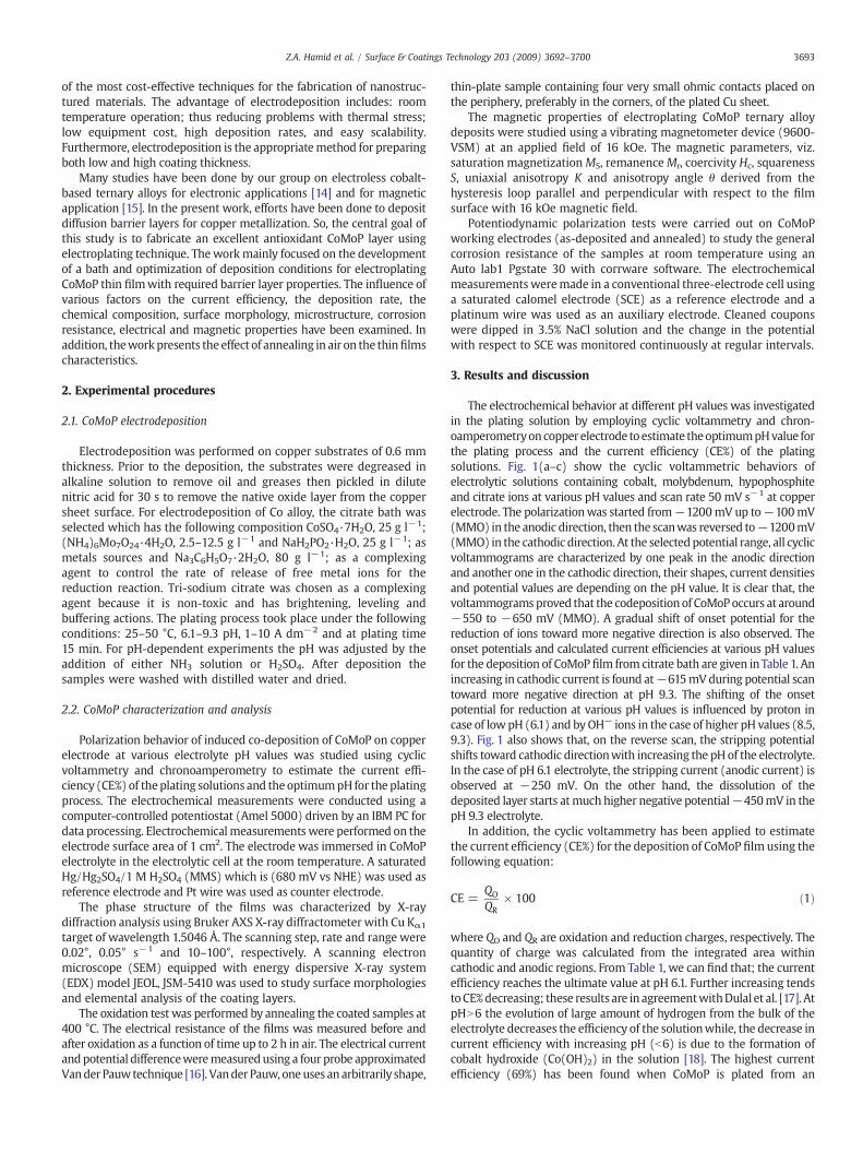
The electrochemical behavior at different pH values was investigatedin the plating solution by employing cyclic voltammetry and chron-oamperometryoncopperelectrode toestimate theoptimumpHvalue forthe plating process and the current efficiency (CE%) of the platingsolutions. Fig. 1(a–c) show the cyclic voltammetric behaviors ofelectrolytic solutions containing cobalt, molybdenum, hypophosphiteand citrate ions at various pH values and scan rate 50 mV s−1 at copperelectrode. The polarizationwas started from−1200mV up to−100mV(MMO) in the anodic direction, then the scanwas reversed to−1200mV(MMO) in the cathodic direction. At the selectedpotential range, all cyclicvoltammograms are characterized by one peak in the anodic directionand another one in the cathodic direction, their shapes, current densitiesand potential values are depending on the pH value. It is clear that, thevoltammogramsproved that the codeposition of CoMoPoccurs at around−550 to −650 mV (MMO). A gradual shift of onset potential for thereduction of ions toward more negative direction is also observed. Theonset potentials and calculated current efficiencies at various pH valuesfor the deposition of CoMoP film from citrate bath are given inTable 1. Anincreasing in cathodic current is found at−615mVduring potential scantoward more negative direction at pH 9.3. The shifting of the onsetpotential for reduction at various pH values is influenced by proton incase of lowpH (6.1) and byOH− ions in the case of higher pH values (8.5,9.3). Fig. 1 also shows that, on the reverse scan, the stripping potentialshifts toward cathodic directionwith increasing the pH of the electrolyte.In the case of pH 6.1 electrolyte, the stripping current (anodic current) isobserved at −250 mV. On the other hand, the dissolution of thedeposited layer starts atmuch higher negative potential−450mV in thepH 9.3 electrolyte.
In addition, the cyclic voltammetry has been applied to estimatethe current efficiency (CE%) for the deposition of CoMoP film using thefollowing equation:
CE =QO
QR× 100 ð1Þ
where QO and QR are oxidation and reduction charges, respectively. Thequantity of charge was calculated from the integrated area withincathodic and anodic regions. From Table 1, we can find that; the currentefficiency reaches the ultimate value at pH 6.1. Further increasing tendstoCE%decreasing; these results are in agreementwithDulal et al. [17]. AtpHN6 the evolution of large amount of hydrogen from the bulk of theelectrolyte decreases the efficiency of the solutionwhile, the decrease incurrent efficiency with increasing pH (b6) is due to the formation ofcobalt hydroxide (Co(OH)2) in the solution [18]. The highest currentefficiency (69%) has been found when CoMoP is plated from an
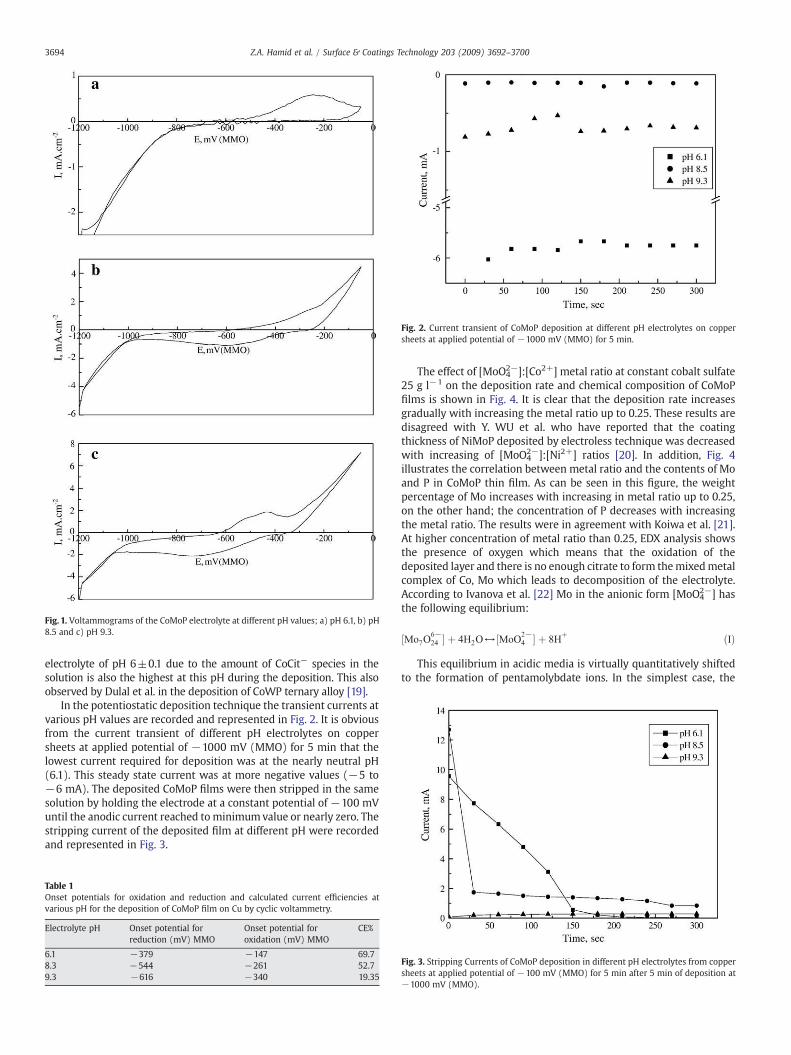
Fig. 1. Voltammograms of the CoMoP electrolyte at different pH values; a) pH 6.1, b) pH8.5 and c) pH 9.3.
Fig. 2. Current transient of CoMoP deposition at different pH electrolytes on coppersheets at applied potential of −1000 mV (MMO) for 5 min.
3694 Z.A. Hamid et al. / Surface & Coatings Technology 203 (2009) 3692–3700
electrolyte of pH 6±0.1 due to the amount of CoCit− species in thesolution is also the highest at this pH during the deposition. This alsoobserved by Dulal et al. in the deposition of CoWP ternary alloy [19].
In the potentiostatic deposition technique the transient currents atvarious pH values are recorded and represented in Fig. 2. It is obviousfrom the current transient of different pH electrolytes on coppersheets at applied potential of −1000 mV (MMO) for 5 min that thelowest current required for deposition was at the nearly neutral pH(6.1). This steady state current was at more negative values (−5 to−6 mA). The deposited CoMoP films were then stripped in the samesolution by holding the electrode at a constant potential of −100 mVuntil the anodic current reached tominimumvalue or nearly zero. Thestripping current of the deposited film at different pH were recordedand represented in Fig. 3.
Table 1Onset potentials for oxidation and reduction and calculated current efficiencies atvarious pH for the deposition of CoMoP film on Cu by cyclic voltammetry.
Electrolyte pH Onset potential forreduction (mV) MMO
Onset potential foroxidation (mV) MMO
CE%
6.1 −379 −147 69.78.3 −544 −261 52.79.3 −616 −340 19.35
The effect of [MoO42−]:[Co2+] metal ratio at constant cobalt sulfate
25 g l−1 on the deposition rate and chemical composition of CoMoPfilms is shown in Fig. 4. It is clear that the deposition rate increasesgradually with increasing the metal ratio up to 0.25. These results aredisagreed with Y. WU et al. who have reported that the coatingthickness of NiMoP deposited by electroless technique was decreasedwith increasing of [MoO4
2−]:[Ni2+] ratios [20]. In addition, Fig. 4illustrates the correlation between metal ratio and the contents of Moand P in CoMoP thin film. As can be seen in this figure, the weightpercentage of Mo increases with increasing in metal ratio up to 0.25,on the other hand; the concentration of P decreases with increasingthe metal ratio. The results were in agreement with Koiwa et al. [21].At higher concentration of metal ratio than 0.25, EDX analysis showsthe presence of oxygen which means that the oxidation of thedeposited layer and there is no enough citrate to form themixedmetalcomplex of Co, Mo which leads to decomposition of the electrolyte.According to Ivanova et al. [22] Mo in the anionic form [MoO4
2−] hasthe following equilibrium:
½Mo7O6−24 � þ 4H2O↔½MoO
2−4 � þ 8H
þ ðIÞ
This equilibrium in acidic media is virtually quantitatively shiftedto the formation of pentamolybdate ions. In the simplest case, the
Fig. 3. Stripping Currents of CoMoP deposition in different pH electrolytes from coppersheets at applied potential of −100 mV (MMO) for 5 min after 5 min of deposition at−1000 mV (MMO).
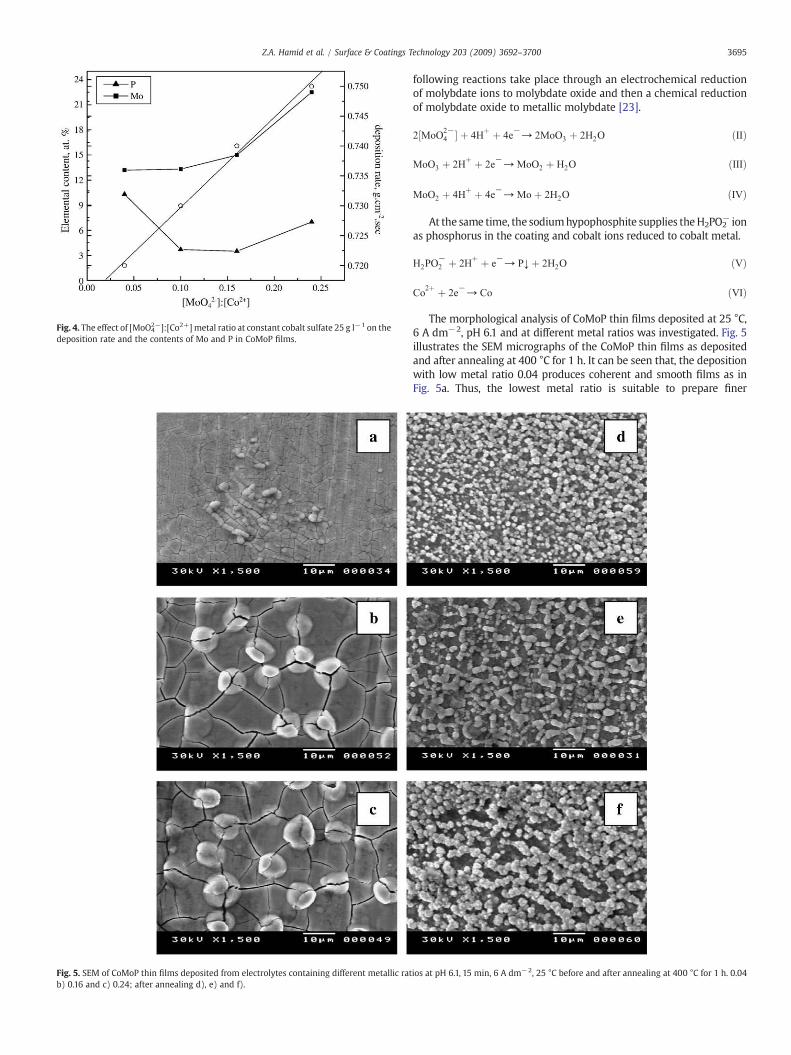
Fig. 4. The effect of [MoO42−]:[Co2+]metal ratio at constant cobalt sulfate 25 g l−1 on the
deposition rate and the contents of Mo and P in CoMoP films.
Fig. 5. SEM of CoMoP thin films deposited from electrolytes containing different metallic ratb) 0.16 and c) 0.24; after annealing d), e) and f).
3695Z.A. Hamid et al. / Surface & Coatings Technology 203 (2009) 3692–3700
following reactions take place through an electrochemical reductionof molybdate ions to molybdate oxide and then a chemical reductionof molybdate oxide to metallic molybdate [23].
2½MoO2−4 � þ 4H
þ þ 4e−→ 2MoO3 þ 2H2O ðIIÞ
MoO3 þ 2Hþ þ 2e
−→MoO2 þ H2O ðIIIÞ
MoO2 þ 4Hþ þ 4e
−→Mo þ 2H2O ðIVÞ
At the same time, the sodiumhypophosphite supplies theH2PO2− ion
as phosphorus in the coating and cobalt ions reduced to cobalt metal.
H2PO−2 þ 2H
þ þ e−→ P↓ þ 2H2O ðVÞ
Co2þ þ 2e
−→ Co ðVIÞ
The morphological analysis of CoMoP thin films deposited at 25 °C,6 A dm−2, pH 6.1 and at different metal ratios was investigated. Fig. 5illustrates the SEM micrographs of the CoMoP thin films as depositedand after annealing at 400 °C for 1 h. It can be seen that, the depositionwith low metal ratio 0.04 produces coherent and smooth films as inFig. 5a. Thus, the lowest metal ratio is suitable to prepare finer
ios at pH 6.1, 15 min, 6 A dm−2, 25 °C before and after annealing at 400 °C for 1 h. 0.04
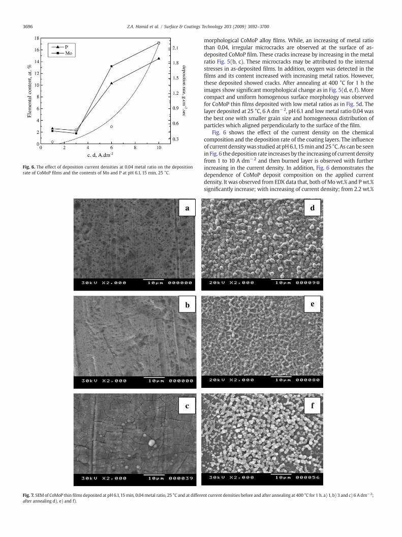
Fig. 6. The effect of deposition current densities at 0.04 metal ratio on the depositionrate of CoMoP films and the contents of Mo and P at pH 6.1, 15 min, 25 °C.
Fig. 7. SEM of CoMoP thin films deposited at pH 6.1,15min, 0.04metal ratio, 25 °C and at differeafter annealing d), e) and f).
3696 Z.A. Hamid et al. / Surface & Coatings Technology 203 (2009) 3692–3700
morphological CoMoP alloy films. While, an increasing of metal ratiothan 0.04, irregular microcracks are observed at the surface of as-deposited CoMoP film. These cracks increase by increasing in the metalratio Fig. 5(b, c). These microcracks may be attributed to the internalstresses in as-deposited films. In addition, oxygen was detected in thefilms and its content increased with increasing metal ratios. However,these deposited showed cracks. After annealing at 400 °C for 1 h theimages show significant morphological change as in Fig. 5(d, e, f). Morecompact and uniform homogenous surface morphology was observedfor CoMoP thin films deposited with low metal ratios as in Fig. 5d. Thelayer deposited at 25 °C, 6 A dm−2, pH 6.1 and lowmetal ratio 0.04 wasthe best one with smaller grain size and homogeneous distribution ofparticles which aligned perpendicularly to the surface of the film.
Fig. 6 shows the effect of the current density on the chemicalcomposition and the deposition rate of the coating layers. The influenceof current densitywas studied at pH6.1,15min and 25 °C. As can be seenin Fig. 6 thedeposition rate increases by the increasingof current densityfrom 1 to 10 A dm−2 and then burned layer is observed with furtherincreasing in the current density. In addition, Fig. 6 demonstrates thedependence of CoMoP deposit composition on the applied currentdensity. It was observed from EDX data that, both ofMowt.% and Pwt.%significantly increase; with increasing of current density; from 2.2 wt.%
nt current densities before and after annealing at 400 °C for 1 h. a) 1, b) 3 and c) 6 A dm−2;
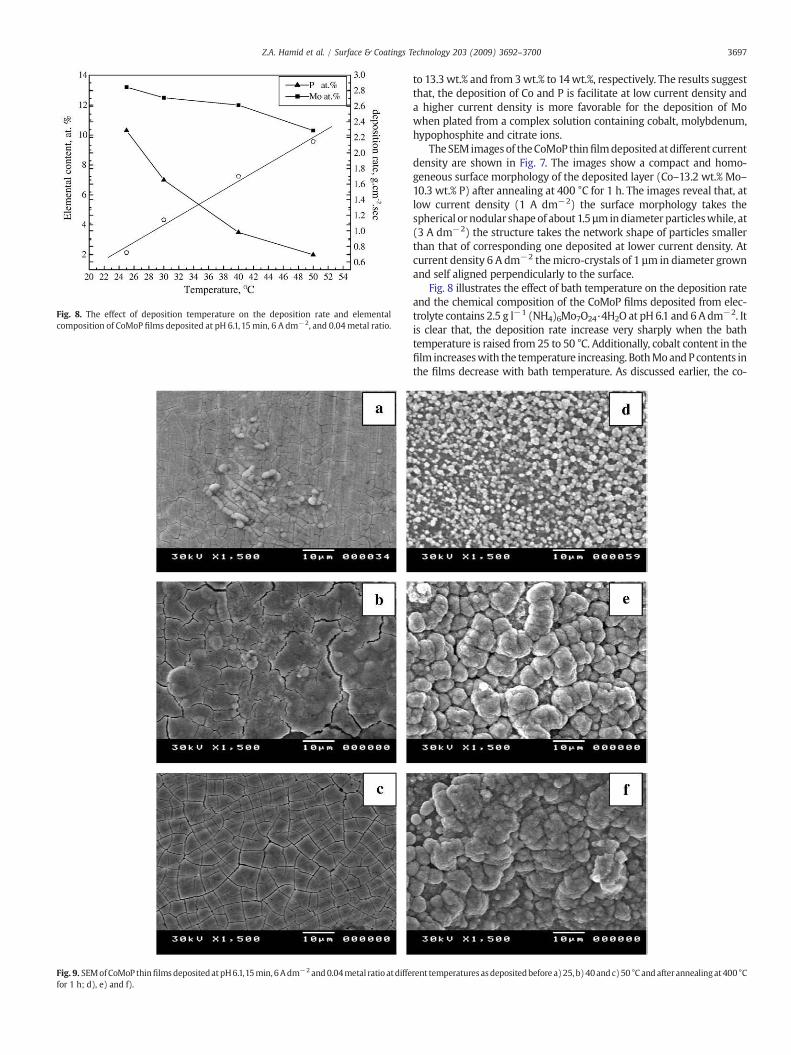
Fig. 8. The effect of deposition temperature on the deposition rate and elementalcomposition of CoMoP films deposited at pH 6.1,15min, 6 A dm−2, and 0.04metal ratio.
Fig. 9. SEMofCoMoP thinfilmsdepositedatpH6.1,15min, 6Adm−2 and0.04metal ratio atdiffefor 1 h; d), e) and f).
3697Z.A. Hamid et al. / Surface & Coatings Technology 203 (2009) 3692–3700
to 13.3 wt.% and from 3wt.% to 14wt.%, respectively. The results suggestthat, the deposition of Co and P is facilitate at low current density anda higher current density is more favorable for the deposition of Mowhen plated from a complex solution containing cobalt, molybdenum,hypophosphite and citrate ions.
TheSEM imagesof theCoMoP thinfilmdeposited atdifferent currentdensity are shown in Fig. 7. The images show a compact and homo-geneous surface morphology of the deposited layer (Co–13.2 wt.% Mo–10.3 wt.% P) after annealing at 400 °C for 1 h. The images reveal that, atlow current density (1 A dm−2) the surface morphology takes thespherical or nodular shapeof about 1.5 µm indiameter particleswhile, at(3 A dm−2) the structure takes the network shape of particles smallerthan that of corresponding one deposited at lower current density. Atcurrent density 6 A dm−2 themicro-crystals of 1 µm in diameter grownand self aligned perpendicularly to the surface.
Fig. 8 illustrates the effect of bath temperature on the deposition rateand the chemical composition of the CoMoP films deposited from elec-trolyte contains 2.5 g l−1 (NH4)6Mo7O24·4H2O at pH 6.1 and 6 Adm−2. Itis clear that, the deposition rate increase very sharply when the bathtemperature is raised from 25 to 50 °C. Additionally, cobalt content in thefilm increaseswith the temperature increasing. BothMoandPcontents inthe films decrease with bath temperature. As discussed earlier, the co-
rent temperaturesasdepositedbefore a)25, b)40andc)50 °C andafterannealingat400 °C
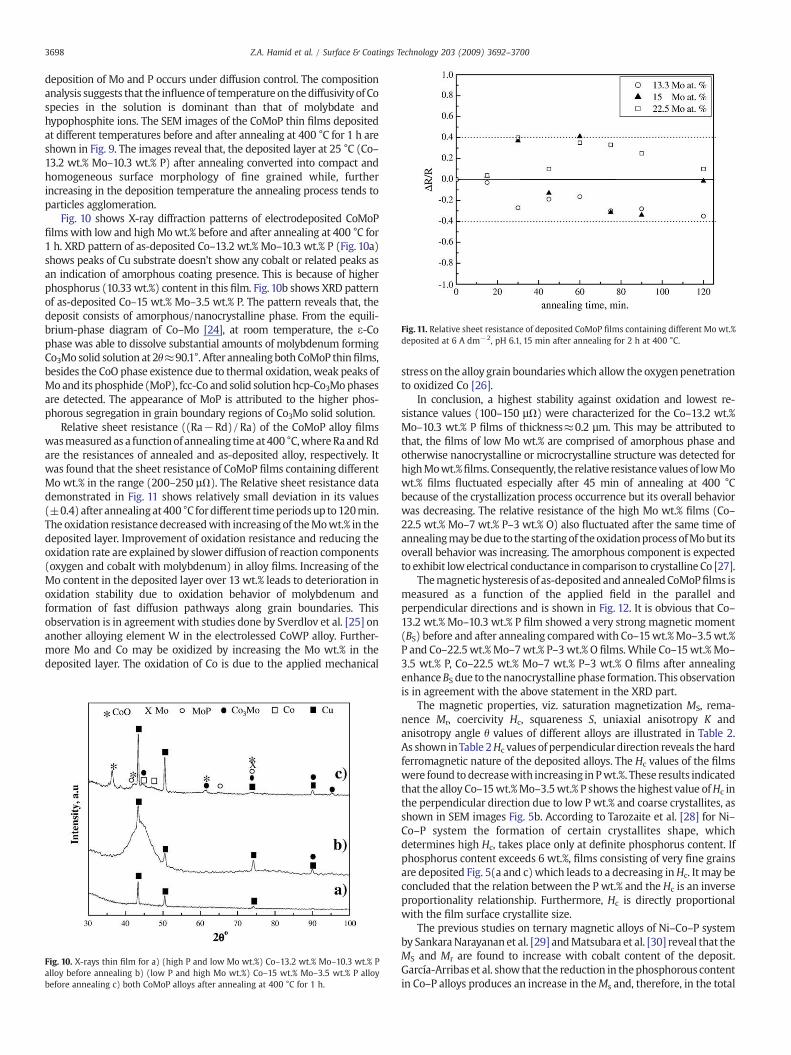
Fig. 11. Relative sheet resistance of deposited CoMoP films containing different Mo wt.%deposited at 6 A dm−2, pH 6.1, 15 min after annealing for 2 h at 400 °C.
3698 Z.A. Hamid et al. / Surface & Coatings Technology 203 (2009) 3692–3700
deposition of Mo and P occurs under diffusion control. The compositionanalysis suggests that the influence of temperature on thediffusivity of Cospecies in the solution is dominant than that of molybdate andhypophosphite ions. The SEM images of the CoMoP thin films depositedat different temperatures before and after annealing at 400 °C for 1 h areshown in Fig. 9. The images reveal that, the deposited layer at 25 °C (Co–13.2 wt.% Mo–10.3 wt.% P) after annealing converted into compact andhomogeneous surface morphology of fine grained while, furtherincreasing in the deposition temperature the annealing process tends toparticles agglomeration.
Fig. 10 shows X-ray diffraction patterns of electrodeposited CoMoPfilms with low and highMowt.% before and after annealing at 400 °C for1 h. XRD pattern of as-deposited Co–13.2 wt.% Mo–10.3 wt.% P (Fig. 10a)shows peaks of Cu substrate doesn't show any cobalt or related peaks asan indication of amorphous coating presence. This is because of higherphosphorus (10.33 wt.%) content in this film. Fig. 10b shows XRD patternof as-deposited Co–15 wt.% Mo–3.5 wt.% P. The pattern reveals that, thedeposit consists of amorphous/nanocrystalline phase. From the equili-brium-phase diagram of Co–Mo [24], at room temperature, the ε-Cophase was able to dissolve substantial amounts of molybdenum formingCo3Mo solid solution at 2θ≈90.1°. After annealing bothCoMoP thinfilms,besides the CoO phase existence due to thermal oxidation, weak peaks ofMo and its phosphide (MoP), fcc-Co and solid solutionhcp-Co3Mophasesare detected. The appearance of MoP is attributed to the higher phos-phorous segregation in grain boundary regions of Co3Mo solid solution.
Relative sheet resistance ((Ra−Rd)/Ra) of the CoMoP alloy filmswasmeasured as a functionof annealing timeat400 °C,whereRaandRdare the resistances of annealed and as-deposited alloy, respectively. Itwas found that the sheet resistance of CoMoP films containing differentMo wt.% in the range (200–250 µΩ). The Relative sheet resistance datademonstrated in Fig. 11 shows relatively small deviation in its values(±0.4) after annealingat400 °C fordifferent timeperiodsup to120min.The oxidation resistancedecreasedwith increasing of theMowt.% in thedeposited layer. Improvement of oxidation resistance and reducing theoxidation rate are explained by slower diffusion of reaction components(oxygen and cobalt with molybdenum) in alloy films. Increasing of theMo content in the deposited layer over 13 wt.% leads to deterioration inoxidation stability due to oxidation behavior of molybdenum andformation of fast diffusion pathways along grain boundaries. Thisobservation is in agreement with studies done by Sverdlov et al. [25] onanother alloying element W in the electrolessed CoWP alloy. Further-more Mo and Co may be oxidized by increasing the Mo wt.% in thedeposited layer. The oxidation of Co is due to the applied mechanical
Fig. 10. X-rays thin film for a) (high P and low Mo wt.%) Co–13.2 wt.% Mo–10.3 wt.% Palloy before annealing b) (low P and high Mo wt.%) Co–15 wt.% Mo–3.5 wt.% P alloybefore annealing c) both CoMoP alloys after annealing at 400 °C for 1 h.
stress on the alloy grain boundarieswhich allow the oxygenpenetrationto oxidized Co [26].
In conclusion, a highest stability against oxidation and lowest re-sistance values (100–150 µΩ) were characterized for the Co–13.2 wt.%Mo–10.3 wt.% P films of thickness≈0.2 µm. This may be attributed tothat, the films of low Mo wt.% are comprised of amorphous phase andotherwise nanocrystalline or microcrystalline structure was detected forhighMowt.%films. Consequently, the relative resistancevaluesof lowMowt.% films fluctuated especially after 45 min of annealing at 400 °Cbecause of the crystallization process occurrence but its overall behaviorwas decreasing. The relative resistance of the high Mo wt.% films (Co–22.5 wt.% Mo–7 wt.% P–3 wt.% O) also fluctuated after the same time ofannealingmaybedue to the startingof theoxidationprocess ofMobut itsoverall behavior was increasing. The amorphous component is expectedto exhibit lowelectrical conductance in comparison to crystalline Co [27].
Themagnetic hysteresis of as-deposited andannealedCoMoPfilms ismeasured as a function of the applied field in the parallel andperpendicular directions and is shown in Fig. 12. It is obvious that Co–13.2 wt.% Mo–10.3 wt.% P film showed a very strong magnetic moment(BS) before and after annealing comparedwith Co–15wt.%Mo–3.5wt.%P and Co–22.5wt.%Mo–7wt.% P–3wt.% O films.While Co–15wt.%Mo–3.5 wt.% P, Co–22.5 wt.% Mo–7 wt.% P–3 wt.% O films after annealingenhanceBS due to thenanocrystalline phase formation. This observationis in agreement with the above statement in the XRD part.
The magnetic properties, viz. saturation magnetization MS, rema-nence Mr, coercivity Hc, squareness S, uniaxial anisotropy K andanisotropy angle θ values of different alloys are illustrated in Table 2.As shown inTable 2Hc values of perpendiculardirection reveals the hardferromagnetic nature of the deposited alloys. The Hc values of the filmswere found to decreasewith increasing in Pwt.%. These results indicatedthat the alloy Co–15wt.%Mo–3.5wt.% P shows the highest value ofHc inthe perpendicular direction due to low P wt.% and coarse crystallites, asshown in SEM images Fig. 5b. According to Tarozaite et al. [28] for Ni–Co–P system the formation of certain crystallites shape, whichdetermines high Hc, takes place only at definite phosphorus content. Ifphosphorus content exceeds 6 wt.%, films consisting of very fine grainsare deposited Fig. 5(a and c)which leads to a decreasing inHc. It may beconcluded that the relation between the P wt.% and the Hc is an inverseproportionality relationship. Furthermore, Hc is directly proportionalwith the film surface crystallite size.
The previous studies on ternary magnetic alloys of Ni–Co–P systemby SankaraNarayanan et al. [29] andMatsubara et al. [30] reveal that theMS and Mr are found to increase with cobalt content of the deposit.García-Arribas et al. show that the reduction in thephosphorous contentin Co–P alloys produces an increase in theMs and, therefore, in the total
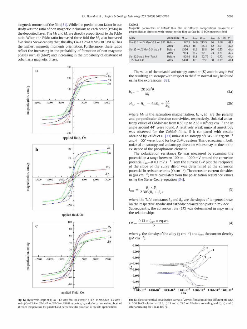
Table 2Magnetic parameters of CoMoP thin film of different compositions measured atperpendicular direction with respect to the film surface in 16 kOe magnetic field.
Alloy Annealing HcPer BrPer BsPer SPer K, ×E6 θ°
Co–13.2 wt.% Mo–10.3 wt.% P Before 742.3 34.9 213.5 16 2.68 41.9After 356.2 18 155.3 12 2.01 42.8
Co–15 wt.% Mo–3.5 wt.% P Before 1366 11.6 38.8 30 0.53 44.4After 983 31.2 132 23 1.70 42.7
Co–22.5wt.% Mo–7wt.%P–3wt.% O
Before 808.6 11.1 52.75 21 0.72 44.4After 1490 17.3 57.2 30 0.77 44.1
3699Z.A. Hamid et al. / Surface & Coatings Technology 203 (2009) 3692–3700
magnetic moment of the film [31]. While the predominant factor in ourstudy was the ratio of non magnetic inclusions to each other (P:Mo) inthe deposited layer. TheMS andMr are directly proportional to the P:Moratio. When the P:Mo ratio increased three-fold the MS also increasedfive times. Sowe can say that, the alloy Co–13.2wt.%Mo–10.3wt.% P hasthe highest magnetic moments orientation. Furthermore, these ratiosreflect the increasing in the probability of formation of non magneticphases such as (MoP) and increasing in the probability of existence ofcobalt as a magnetic phase.
Fig. 12. Hysteresis loops of a) Co–13.2 wt.% Mo–10.3 wt.% P, b) Co–15 wt.% Mo–3.5 wt.% Pand c) Co–22.5wt.%Mo–7wt.% P–3wt.%Ofilms before; b; and after; a; annealingobtainedat room temperature for parallel and perpendicular direction of 16 kOe applied field.
The value of the uniaxial anisotropy constant (K) and the angle θ ofthe resulting anisotropy with respect to the film normal may be foundusing the expressions [32]:
Hc== =2K cos2θ
MSð2aÞ
Hc== + Hc8 = 4πMS +2KMS
ð2bÞ
where MS is the saturation magnetization, Hc//, Hc are the paralleland perpendicular direction coercivities, respectively. Uniaxial aniso-tropy values of CoMoP are from 0.53 up to 2.68×10⁶ erg cm−1 and inangle around 44° were found. A relatively weak uniaxial anisotropywas observed for the CoMoP films, if it compared with resultsobtained by Vallés et al. [33] uniaxial anisotropy of 6.4×10⁶ erg cm−1
and θ=55° were found for hcp CoMo system. This decreasing in bothuniaxial anisotropy and anisotropy direction values may be due to theexistence of the phosphorous element.
The polarization resistance Rp was measured by scanning thepotential in a range between 100 to −1000 mV around the corrosionpotential Ecorr at 0.1 mV s−1. From the current C–V plot the reciprocalof the slope of the curve dE/dI was determined at the corrosionpotential in resistance units (Ω cm−2). The corrosion current densitiesin (μA cm−2) were calculated from the polarization resistance valuesusing the Stern–Geary equation [34]:
Icorr =Ba × Bc
2:303 Ba + Bcð Þ ð3Þ
where the Tafel constants Ba and Bc, are the slopes of tangents drawnon the respective anodic and cathodic polarization plots in mV dec−1.Subsequently, the corrosion rate (CR) was determined in mpy usingthe relationship:
CR =0:13 × Icorr × eq:wt:
ρð4Þ
where ρ the density of the alloy (g cm−3) and Icorr the current density(μA cm−2).
Fig. 13. Electrochemical polarization curves of CoMoP films containing differentMowt.%in 3.5% NaCl solution a) 13.3, b) 15 and c) 22.5 wt.% before annealing and d), e) and f)after annealing for 1 h at 400 °C.
Table 3Electrochemical corrosion data related to polarization curves of coated Cu sheet withthin films of different composition in 3.5% NaCl solution before and after heat treatmentat 400 °C for 1 h.
Alloy βa βc Rp,Ω cm−2 Icorr, μA cm−2 Ecorr, V CR,mpy
Co–13.2 wt.% Mo–10.3 wt.% P 0.196 0.107 964.6 30.79 −0.567 14.220.253 0.122 886.0 37.38 −0.430 17.26
Co–15 wt.% Mo–3.5 wt.% P 0.179 0.074 801.0 28.05 −0.547 12.960.147 0.091 505.0 47.76 −0.407 22.07
Co–22.5 wt.% Mo–7 wt.%P–3 wt.% O
0.141 0.077 1421 15.04 −0.557 7.2260.182 0.165 989.0 37.55 −0.414 18.04
3700 Z.A. Hamid et al. / Surface & Coatings Technology 203 (2009) 3692–3700
Fig. 13 shows the electrochemical results obtained from polariza-tion studies of CoMoP coatings in 3.5% sodium chloride solution beforeand after heat treatment. The electrochemical corrosion parametersobtained by Tafel polarization curves are listed in Table 3. The Tafelslopes Bc and Ba were determined by fitting of a theoreticalpolarization curve to the experimental polarization curve. Thecorrosion current Icorr is representative of the degree of degradationof the alloy. An alloy with a tendency toward passivation will have avalue of Ba greater than Bc, whereas an alloy that corrodes will have aBa lower than Bc [35]. As shown in Table 3 and Fig. 13, the increasing inMowt.% slightly moved the potentiodynamic polarization curve in thenoble direction, i.e. the corrosion potential slightly changed positivelyfrom−0.567 to−0.557 V Fig. 13(a, b and c) and downed positively toaround −0.414 V after annealing Fig. 13(d, e and f). Furthermore thelower current density in the anodic polarization curve of Co–22.5 wt.%Mo–7 wt.% P–3 wt.% O coating suggests a lower corrosion rate for thecoatings containing high Mo wt.%.
In the present study, the improvement of the corrosion resistancearises from two effects; increasing Mo wt.% in the as-deposited anddecreasing crystallite size by heat treatment. Increasing the Mo contentin the alloy initially increased the corrosion resistance owing topreferentially migrated of Mo toward the surface and formed oxides.Momodifies the polarity of the passive film by formation ofmolybdates.The presence of negative MoOn− ions in the outer part of the filmchanges its intrinsically anionic selectivity into a cationic one, inducingthe formation of a bipolar layer which, promotes the migration of O2
−
[36–41], as well as prevents Cl− ingress making the passive film morestable against breakdown [42–45]. While, after heat treatment theamorphous coated layer transformed into crystalline. Consequently thecorrosion resistance decreased by decreasing in the crystallite sizeowing to the increasing in the volume of the intercrystalline region ofthe triple junction [46]. The high intercrystalline surface fraction ordefect density provides the increase in the overall corrosion currentfrom as-deposited alloys (15.04–30.79 µA cm−2) to annealed alloys(37.38–47.76 µA cm−2). Even though the corrosion current is high,owing to uniformly distributed grains the corrosion is not concentratedat one point, i.e. uniform corrosion is taking place in case ofnanocrystalline materials rather than the localized corrosion.
4. Conclusion
1. Ternary CoMoP films of thickness≈200 nm were deposited ontoCu sheets from cobalt-citrate bath of CE≈69% at pH 6.1, 6 A dm−2
and 25 °C.2. The film composition, microstructure and surface morphology are
strongly depending on the [MoO42−]:[Co2+] ratio in the electrolyte.
Before annealing the low metal ratio bath showed the amorphousstructure of Co–13.2 wt.% Mo–10.3 wt.% P alloy which crystallizedafter 1 h of annealing at 400 °C to give smaller grain size andhomogeneous distribution of particles.
3. The film surface of Co–13.2 wt.% Mo–10.3 wt.% P alloy showed thehighest stability against oxidation and lowest electrical resistancevalues (100–150 µΩ).
4. The variety of the film's magnetic nature between soft and hardferromagnetic films would be expected to enlarge its applicationsin both R/W and storage devices.
5. Mo wt.% incorporation strongly improved the corrosion resistanceof the amorphous structure alloys in 3.5% NaCl solution. Further-more, the corrosion rate slightly increased; after annealing; due tothe transformation of the corrosion state from localized corrosionto uniform corrosion by the action of the grain refinement.
6. It is necessary to adjust the amount of alloying element (Mo) in thedeposited alloy in order to balance between existence of good anti-diffusion layer and good anti-corrosion layer which is accom-plished in the Co–13.2 wt.% Mo–10.3 wt.% P alloy.
References
[1] M. Paunovic, M. Schlesinger, Fundamentals of Electrochemical Deposition, JohnWiley & Sons, Inc., New York, 1998, p. 157.
[2] M.A. Nicolet, Thin Solid Films 52 (1978) 415.[3] A.F. Cotton, G. Wilkinson, Advanced Inorganic Chemistry, 5th ed., John Wiley &
Sons, Inc., New York, 1988, p. 686.[4] E. Gómez, E. Pellicer, E. Vallés, J. Appl. Electrochem. 33 (2003) 245.[5] W.P. Taylor, M. Schneider, H. Baltes, M.G. Allen, Proceedings of the International
Conference on Solid-State Sensors and Actuators, Transducers '97, Chicago, 1997.[6] P.R. Subramanian, D.E. Laughlin, Bull. Alloy Phase Diagr. 11 (1990) 169.[7] Y. He, J.Y. Fen, J. Cryst. Growth 263 (2004) 203.[8] Y.L. Kuo, H.H. Lee, C. Lee, J.C. Lin, S.L. Shue, M.S. Liang, B.J. Dianiels, Electrochem.
Solid-State Lett. 7 (2004) C35.[9] Y.L. Kuo, C. Lee, J.C. Lin, Y.W. Yen, W.H. Lee, Thin Solid Films 484 (2005) 265.[10] L. Vanasupa, Y.C. Joo, P.R. Besser, S. Pramanick, J. Appl. Phys. 85 (1999) 2583.[11] G. Oksam, P.M. Vereecken, P.C. Searson, J. Electrochem. Soc. 146 (1999) 1436.[12] V.M. Dubin, Y. Shacham-Diamand, B. Zhao, P.K. Vasudev, C.H. Ting, J. Electrochem.
Soc. 144 (1997) 898.[13] K. Yoshino, M. Paunovic, I. Ohno, Y. Migoshi (Eds.), PV 93-26, The Electrochemical
Society Proceedings Series, Pennington, NJ, 1993, p. 370.[14] A. Abdel Aal, H. Barakat, Z. Abdel Hamid, Surf. Coat. Technol. 202 (2008) 4591.[15] A. Abdel Aal, A. Shaaban, Z. Abdel Hamid, Appl. Surf. Sci. 254 (2008) 1966.[16] Yicai Sun, Semicond. Sci. Technol. 11 (1996) 805.[17] S.M.S.I. Dulal, E.A. Charles, J. Alloys Compd. 455 (2008) 274.[18] N. Petrov, Y. Sverdlov, Y. Shacham-Diamand, J. Electrochem. Soc. 149 (2002) 187.[19] S.M.S.I. Dulal, E.A. Charles, S. Roy, J. Appl. Electrochem. 34 (2004) 151.[20] Y. Wu, C.C. Wan, Y.Y. Wang, J. Electron. Mater. 34 (2005) 541.[21] I. Koiwa, M. Usudo, K. Yamada, T. Osaka, J. Electrochem. Soc. 135 (1988) 718.[22] N. Ivanova, S. Ivanov, E. Boldyrev, O. Stadnik, ISSN 0033 1732, Prot. Met. 42 (2006)
354.[23] R. Saifullin, R. Fomina, G. Mingazova, R. Khaidarov, Prot. Met. 38 (2002) 471.[24] M. Hansen, Constitution of Binary Alloys, Mc Graw Hill, New York, 1958.[25] Y. Sverdlov, V. Bogush, Y. Shacham-Diamand, Microelectron. Eng. 83 (2006) 2243.[26] Y. Shacham-Diamand, Y. Sverdlov, V. Bogush, R. Ofek-Almog, J. Solid State
Electrochem. 11 (2007) 929.[27] K.I. Chopra, Thin Film Phenomena, McGraw-Hill, New York, 1969.[28] R. Tarozaite, G. Stalnionis, A. Sudavicius, M. Kurtinaitiene, Surf. Coat. Technol. 138
(2001) 61.[29] T.S.N. Sankara Narayanan, S. Selvakumar, A. Stephen, Surf. Coat. Technol. 172
(2003) 298.[30] H. Matsubara, A. Yamada, J. Electrochem. Soc. 141 (1994) 2386.[31] A. García-Arribas, J.M. Barandiarán, y J. Herreros, J. Magn. Magn. Mater. 131 (1994)
129.[32] J.Q. Xiao, C.L. Chien, A. Gavrin, J. Appl. Phys. 79 (1996) 5309.[33] E. Gómez, E. Pellicer, X. Alcobe, E. Vallés, J. Solid State Electrochem. 8 (2004) 497.[34] M. Stern, A.L. Geary, J. Electrochem. Soc. 104 (1957) 56.[35] F. Mansfeld, J. Electrochem. Soc. 120 (1973) 515.[36] C.R. Clayton, Y.C. Lu, Corros. Sci. 29 (1989) 881.[37] M.A. Ameer, A.M. Fekry, F. El-Taib Heakal, Electrochim. Acta 50 (2004) 43.[38] N. Boucherit, A. Hugot-le Goff, S. Joiret, Corrosion 48 (1992) 569.[39] W.J. Tobler, S. Virtanen, Corros. Sci. 48 (2006) 1585.[40] J.M. Bastidas, C.L. Torres, E. Cano, J.L. Polo, Corros. Sci. 44 (2002) 625.[41] M. Sakashita, N. Sato, in: Kruger Frenkental (Ed.), Passivity of Metals, The
Electrochem. Soc., Pennington, 1978, p. 479.[42] C.R. Clayton, Y.C. Lu, J. Electrochem. Soc. 133 (1986) 2465.[43] W.D. Robertson, J. Electrochem. Soc. 98 (1951) 94.[44] Y.C. Lu, C.R. Clayton, R. Brooks, Corros. Sci. 29 (1989) 863.[45] K. Ogura, T. Ohama, Corrosion 40 (1984) 47.[46] K.R. Sriraman, S. Ganesh Sundara Raman, S.K. Seshadri, Mater. Sci. Eng. A 460–461
(2007) 39.
Copyright © 2022 FDOKUMEN