Synthesis and Electrodeposition of Mixed Metal Trinuclear ...
73
Wright State University Wright State University CORE Scholar CORE Scholar Browse all Theses and Dissertations Theses and Dissertations 2013 Synthesis and Electrodeposition of Mixed Metal Trinuclear Synthesis and Electrodeposition of Mixed Metal Trinuclear Clusters of Molybdenum and Chromium in Ionic Liquid onto a Clusters of Molybdenum and Chromium in Ionic Liquid onto a Platinum Electrode Platinum Electrode Lynn Renee Frock Wright State University Follow this and additional works at: https://corescholar.libraries.wright.edu/etd_all Part of the Chemistry Commons Repository Citation Repository Citation Frock, Lynn Renee, "Synthesis and Electrodeposition of Mixed Metal Trinuclear Clusters of Molybdenum and Chromium in Ionic Liquid onto a Platinum Electrode" (2013). Browse all Theses and Dissertations. 679. https://corescholar.libraries.wright.edu/etd_all/679 This Thesis is brought to you for free and open access by the Theses and Dissertations at CORE Scholar. It has been accepted for inclusion in Browse all Theses and Dissertations by an authorized administrator of CORE Scholar. For more information, please contact [email protected].
-
Upload
khangminh22 -
Category
Documents
-
view
1 -
download
0
Transcript of Synthesis and Electrodeposition of Mixed Metal Trinuclear ...
Wright State University Wright State University
CORE Scholar CORE Scholar
Browse all Theses and Dissertations Theses and Dissertations
2013
Synthesis and Electrodeposition of Mixed Metal Trinuclear Synthesis and Electrodeposition of Mixed Metal Trinuclear
Clusters of Molybdenum and Chromium in Ionic Liquid onto a Clusters of Molybdenum and Chromium in Ionic Liquid onto a
Platinum Electrode Platinum Electrode
Lynn Renee Frock Wright State University
Follow this and additional works at: https://corescholar.libraries.wright.edu/etd_all
Part of the Chemistry Commons
Repository Citation Repository Citation Frock, Lynn Renee, "Synthesis and Electrodeposition of Mixed Metal Trinuclear Clusters of Molybdenum and Chromium in Ionic Liquid onto a Platinum Electrode" (2013). Browse all Theses and Dissertations. 679. https://corescholar.libraries.wright.edu/etd_all/679
This Thesis is brought to you for free and open access by the Theses and Dissertations at CORE Scholar. It has been accepted for inclusion in Browse all Theses and Dissertations by an authorized administrator of CORE Scholar. For more information, please contact [email protected].

SYNTHESIS AND ELECTRODEPOSITION OF MIXED METAL TRINUCLEAR
CLUSTERS OF MOLYBDENUM AND CHROMIUM IN IONIC LIQUID ONTO A
PLATINUM ELECTRODE.
A thesis submitted in partial fulfillment
of the requirements for the degree of
Master of Science
By
Lynn Renee Frock
A.S., Chemistry, Sinclair Community College, 1996
B.S., Psychology, Kennesaw State University, 2003
2012
Wright State University

WRIGHT STATE UNIVERSITY
GRADUATE SCHOOL
DECEMBER 14, 2012
I HEREBY RECOMMEND THAT THE THESIS PREPARED UNDER
MY SUPERVISION BY Lynn Renee Frock ENTITLED Synthesis and
Electrodeposition of Mixed Metal Trinuclear Clusters of Molybdenum
and Chromium in Ionic Liquid onto a Platinum Electrode BE
ACCEPTED IN PARTIAL FULFILLMENT OF THE
REQUIREMENTS FOR THE DEGREE OF Master of Science.
____________________________
Vladimir Katovic, Ph.D.
Thesis Director
___________________________
David A. Grossie, Ph.D., Chair
Department of Chemistry
Committee on Final Examination
____________________________
Vladimir Katovic, Ph.D.
____________________________
David A. Grossie, Ph.D.
____________________________
Suzanne K. Lunsford, Ph.D.
____________________________
Andrew Hsu, Ph.D.
Dean, Graduate School.

iii
ABSTRACT
Frock, Lynn R. M.S., Department of Chemistry, Wright State University, 2012. Synthesis
and Electrodeposition of Mixed Metal Trinuclear Clusters of Molybdenum and
Chromium in Ionic Liquid onto a Platinum Electrode
Electrochemical properties of [Mo3O2(O2CCH3)6(H2O)(CF3SO2H)2 and
[Cr2Mo(u2-CH3COO)6(u3-O)(H2O)3][CF3SO3] in 1-ethyl-3-methylimidazolium
bis(pentafluoroethanesulfonyl)-imide ionic liquid was investigated. Cyclic
voltammograms using a Platinum electrode indicated deposition had occurred for the
[Mo3O2(O2CCH3)6(H2O)(CF3SO2H)2 metal cluster but had not for the polynuclear
complex [Cr2Mo(u2-CH3COO)6(u3-O)(H2O)3][CF3SO3]. Constant potential electrolysis
of -1.23 V using a platinum foil electrode was performed. Scanning electron microscopy
in combination with energy dispersion spectroscopy confirmed that deposition had
occurred.
iv
TABLE OF CONTENTS
PAGE
I. INTRODUCTION ……………………………………………………. 1
MOLTEN SALTS …….………………………………….…………. 1
IONIC LIQUIDS …...………………………………………………. 1
METAL CLUSTER CHEMISTRY ………………………………… 4
Early transition metals ……………………………………………... 5
Late transition metals ……..………………………………………... 7
STRUCTURES OF TRANSITION METAL CLUSTERS …………… 8
Binuclear Metal Clusters ……….……………………………………. 8
Trinuclear Metal Clusters …………………………………………… 11
Tetranuclear Metal Clusters ……….………………………………... 15
Hexanuclear Metal Clusters …………………………………………. 15
Polynuclear Metal Complexes ……………...………………………. 16
METAL CLUSTER COMPOUNDS AS CATALYST …………………..17
ELECTROCHEMICAL METHODS……………………………………..18
Linear Sweep Voltammetry ……………………………………………19
Cyclic Volyammetry ………………………………………………………21
EXPERIMENTAL …………………………………………………….…… 28
Materials ………………………………………………………………….. 28
Instrumentation ……………………………………………………………. 28
Preparation of 1-ETHYL-3-METHYLIMIDAZOLIUM Bis(pentafluoroethane
sulfonyl) imide .............................................................................................. 30
SYNTHESIS OF METAL CLUSTERS ………….………………………… 30
Synthesis of Mo2(O2CCH3)4 -tetra (acetato) dimolybdenum(II) …………….30
v
TABLE OF CONTENTS (CONTINUED)
Synthesis of [Mo3O2(O2CCH3)6(H2O)3](F3CCOOH) ..……………….……. 31
Synthesis of Cr2(O2CCH3)4 ………………………………………………….32
Synthesis of [Cr2Mo(u2-CH3Coo)6(u3-O)(H2O)3][CF3SO3] ………………….34
III. RESULTS AND DISCUSSION ...…………………………………………. 36
ELECTROCHEMISTRY OF EMIBeti ……………………………………. 36
ELECTROCHEMISTRY OF TINUCLEAR METAL COMPLEXES …….. 40
ELECTROCHEMISTRY OF [Mo3O2(O2CCH3)6(H2O)3](F3CCOOH) ……. 44
ELECTROCHEMISTRY OF [Cr2Mo(u2-CH3Coo)6(u3-O)(H2O)3][CF3SO3] .45
ELECTROCHEMICAL DEPOSITION OF [Mo3O2(O2CCH3)6(H2O)(CF3SO2H)2
and [Cr2Mo(u2-CH3COO)6(u3-O)(H2O)3][CF3SO3] ONTO A Pt ELECTRODE ………49
IV. CONCLUSION .………………………………………………………………….. 58
V. REFERENCES ……………………………………………….………………….. 59
vi
LIST OF FIGURES FIGURE
PAGE
1. Five Commonly Used Cations in The Synthesis of Ionic Liquids …………3
2. One of the most common cations used in the synthesis of ionic liquids 1,3-
dialkylimidazolium cation ………………………………………………… 3
3. Octahedral and triangular geometries of Early Transition Metal
clusters.…………………………...……………………………...………… 7
4. Late transition metal, [Mn2(CO)10]………………………………………… 8
5. Structure of the Octachloridirhenate (III) ion The Re2X8………………….. 9
6. Multiple bonding between rhenium atoms, (a) Sigma bonding between Re atoms, (b)
Two π bonds between Re atoms ………………….……………………….. 10
7. The structure of the the M2(O2CR)4 dimer (where M= Mo, W, Cr).………. 11
8. Structures of trinuclear rhenium metal clusters, (a) Re3X9, (b) polymeric structure of
Re3Xy, (c) Re3Cl123-
ion ………………………………………………….… 12
9. Structure type (a) [M3X6(C6Me6)3]n+
(no μ3 ligand)……………………….. 13
10. Structure type (b) [M3( μ3-X)( μ-Y)3L9)] (one μ3 ligand)……………….…. 14
11. Structure type (c) [M3( μ3-X)2( μ-O2Y)6L3)] ( two μ3-ligands)………….… 14
12. Quadruply bonded binuclear compound as a result of dimerization …….... 15
13. Examples of hexanuclear structure types …...……………………………… 16
14. Polynuclear complex, Cr3O(CH3CO2)6(H2O)3+……………………………. 17
15. Typical electrochemical cell used for potential sweep voltammetry …..….. 19
16. Bulk solution as no potential applied ……………………………………… 20
17. Potential applied…………………... ……………………………………… 20
18. Formation of the Helmholtz double layer in the electrochemical cell .……... 21
19. The excitation function for a LVS experiment ……...……………………… 22
LIST OF FIGURES (CONTINUED)
vii
20. The excitation function for a CV experiment ………………….................. 23
21. Reversible redox reaction of ferrocene ferricenium …..……………….. 24
22. Cyclic voltammagram of a reversible Fe +3/+2
electron redox couple, E1/2 = 0 V
……………………………………………………………………………… 25
23. Cyclic voltammagrams of: A. Reversible system and B. Quasi reversible system
………………………………………………………….………………….. 27
24. Example of electrochemical cell ………………………………………….. 29
25. Structure of a Cr2(OAc)4(H2O)2 molecule………………………………… 32
26. MO diagram for Cr (II) acetate complex ………………………………… 34
27. Infared spectrum of EMIBeti…….………………………………………… 37
28. CV scan of EMIBeti with before purification ……………..……………… 38
29. CV scan of EMIBeti after purification …………………………………… 38
30. CV scan of Ferrocene in acetonitrile ………………………………….… 39
31. CV scan of Ferrocene in EMIBeti …………………………………..….... 39
32. A) [Mo3O2(O2CCH3)6(H2O)(CF3SO2H)2 and B) [Cr2Mo(u2-CH3COO)6(u3-
O)(H2O)3][CF3SO3]………………………………………………………… 41
33. UV-Vis [Mo3O2(O2CCH3)6(H2O)(CF3SO2H)2 in H2O ………..…………… 41
34. UV-Vis scan [Mo3O2(O2CCH3)6(H2O)(CF3SO2H)2 in EMIBeti ….………. 42
35. UV-Vis[Cr2Mo(u2-CH3COO)6(u3-O)(H2O)3][CF3SO3] in H2O ………….. 42
36. UV-Vis scan [Cr2Mo(u2-CH3COO)6(u3-O)(H2O)3][CF3SO3] in EMIBeti .. 43
37. Forward CV scan [Mo3O2(O2CCH3)6(H2O)(CF3SO2H)2 in EMIBeti ..……..44
38. Reverse CV scan of [Mo3O2(O2CCH3)6(H2O)(CF3SO2H)2 in EMIBeti ….. 44
39. Structural solved for [Cr2Mo(u2-CH3COO)6(u3-O)(H2O)3][CF3SO3]……... 46
viii
LIST OF FIGURES (CONTINUED)
40. CV scan of [Cr2Mo(u2-CH3COO)6(u3-O)(H2O)3][CF3SO3] in EMIBeti .... 47
41. Reverse CV scan of [Cr2Mo(u2-CH3COO)6(u3-O)(H2O)3][CF3SO3]
in EMIBeti ……………………………………………………………….. 47
42. IR scan of [Cr2Mo(u2-CH3COO)6(u3-O)(H2O)3][CF3SO3] ………………. 48
43. IR scan [Mo3O2(O2CCH3)6(H2O)(CF3SO2H)2 …………..………………..48
44. Proposed bonding between the M3 cluster and platinum electrode ……….49
45. SEM 5000x of Pt electrode A.) Pre-electrochemical deposition , B.) Post-
electrochemical deposition of [Mo3O2(O2CCH3)6(H2O)(CF3SO2H)2 ……..51
46. Data from Energy Dispersion x-ray diffraction scans for PT electrode post
[Mo3O2(O2CCH3)6(H2O)(CF3SO2H)2 electrochemical deposition ………. 52
47. CV scan post electrochemical deposition of [Mo3O2(O2CCH3)6(H2O)
in EMIBeti ………………………………………………………...……... 53
48. UV-Vis scan of [Mo3O2(O2CCH3)6(H2O)(CF3SO2H)2
post electrochemical deposition ……………………………………….… 54
49. SEM scan 5000x of Pt electrode A.) Pre-electrochemical deposition
B.) Post- electrochemical deposition of [Cr2Mo(u2-CH3COO)6(u3-
O)(H2O)3][CF3SO3] …………………………………………………...…. 55
50. Data from Energy Dispersion x-ray diffraction scans for PT electrode
post [Cr2Mo(u2-CH3COO)6(u3-O)(H2O)3][CF3SO3] electrochemical
deposition attempt ………………………………………………………. 56
51. CV scan of of [Cr2Mo(u2-CH3COO)6(u3-O)(H2O)3][CF3SO3] post
electrochemical deposition ……………………………………………… 57
52. UV-Vis scan of of [Cr2Mo(u2-CH3COO)6(u3-O)(H2O)3][CF3SO3] post
electrochemical deposition ………………………………………………. 57

ix
LIST OF TABLES
TABLE PAGE
1. Cationic portions used to vary physical properties ………………………………… 4
2. Some of the commonly used anions ………………………………………………. 4
3. Bond Strengths for Transition Metals ………….………………………………….. 6

x
ACKNOWLEDGEMENT
I would like to express my most earnest of gratitude to Dr. Vladimir Katovic, my
research advisor during the duration of my graduate work. His advice, patients and
encouragement, throughout my research project has been the key to my success in completing
my degree. The values he has instilled in me will remain with me for the rest of my life.
I would also like to thank my committee members, Dr. David Grossie and Dr. Suzanne
Lunsford for their guidance, wisdom and assistance. Thank you for always taking the time to
discuss the details of my project.
I would like to thank my fellow research students especially Linda Ubadigbo for giving
me advice, clarification and always helping me if I needed it. You have been a wonderful friend.
I would also like to thank Brandon Yocum, Markeata Lee, Tahiru Sulley and Denis Lennarts for
all their support thought out my time in the graduate program.
I would like to thank my parents for all their love, support and for teaching me the values
of diligence and integrity.
I would like to thank my husband who has made many sacrifices in order for me to
receive my degree. I love you dearly.

xi
DEDICATION
To the four strongest women in my life, my mother Myra kegley, my two former supervisors,
Donna Brandelik and Michelle Harris and my best friend of thirty years, Rebecca Sparks. You
all have been a huge part in my journey through life and have given me inspiration, wisdom and
courage in knowing I can do anything I set my mind to do. Thank you from the bottom of my
heart. In a collective effort you have made me the woman I am today.
1
I. INTRODUCTION
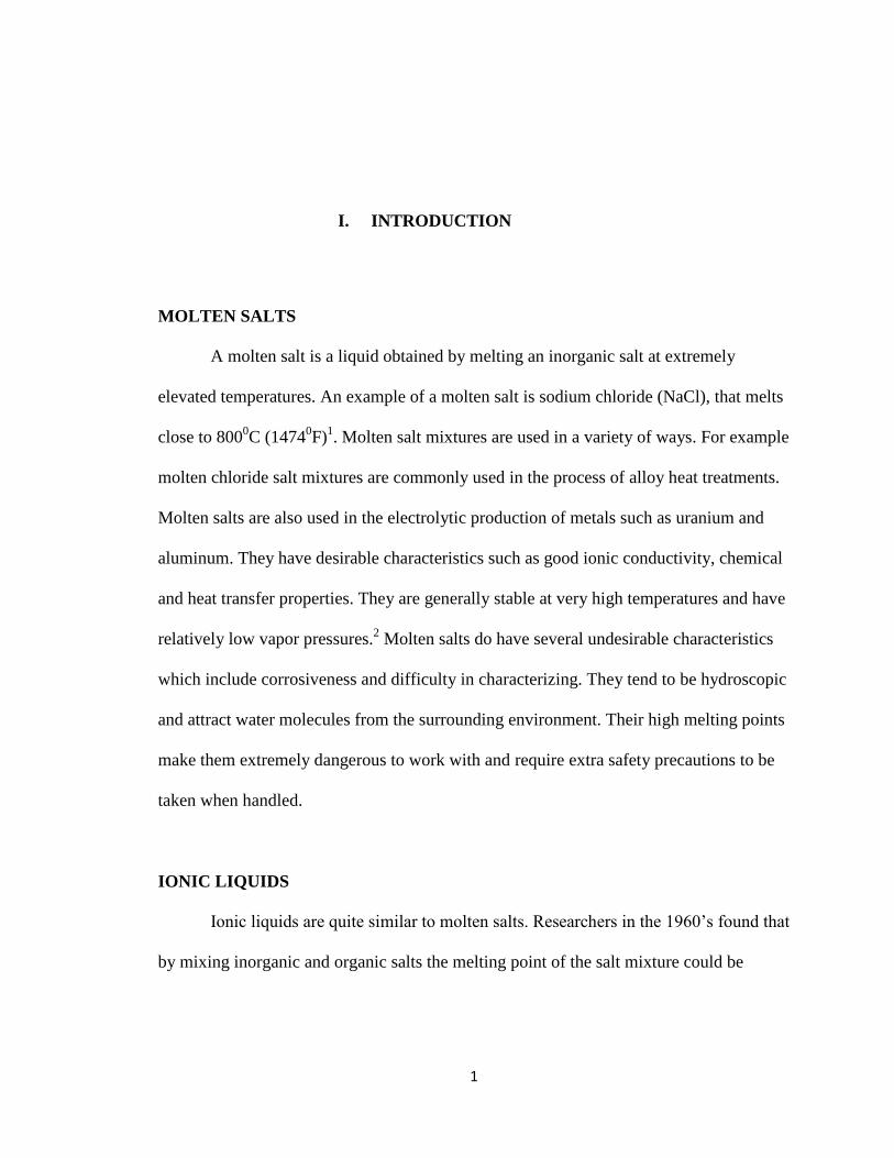
MOLTEN SALTS
A molten salt is a liquid obtained by melting an inorganic salt at extremely
elevated temperatures. An example of a molten salt is sodium chloride (NaCl), that melts
close to 8000C (1474
0F)
1. Molten salt mixtures are used in a variety of ways. For example
molten chloride salt mixtures are commonly used in the process of alloy heat treatments.
Molten salts are also used in the electrolytic production of metals such as uranium and
aluminum. They have desirable characteristics such as good ionic conductivity, chemical
and heat transfer properties. They are generally stable at very high temperatures and have
relatively low vapor pressures.2 Molten salts do have several undesirable characteristics
which include corrosiveness and difficulty in characterizing. They tend to be hydroscopic
and attract water molecules from the surrounding environment. Their high melting points
make them extremely dangerous to work with and require extra safety precautions to be
taken when handled.
IONIC LIQUIDS
Ionic liquids are quite similar to molten salts. Researchers in the 1960’s found that
by mixing inorganic and organic salts the melting point of the salt mixture could be
2
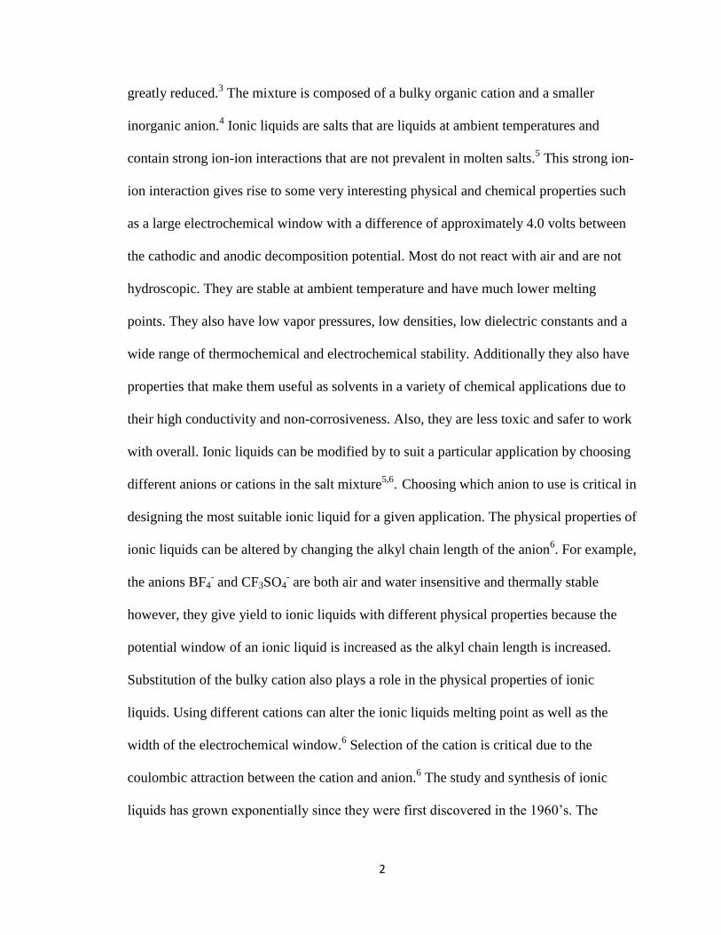
greatly reduced.3 The mixture is composed of a bulky organic cation and a smaller
inorganic anion.4 Ionic liquids are salts that are liquids at ambient temperatures and
contain strong ion-ion interactions that are not prevalent in molten salts.5 This strong ion-
ion interaction gives rise to some very interesting physical and chemical properties such
as a large electrochemical window with a difference of approximately 4.0 volts between
the cathodic and anodic decomposition potential. Most do not react with air and are not
hydroscopic. They are stable at ambient temperature and have much lower melting
points. They also have low vapor pressures, low densities, low dielectric constants and a
wide range of thermochemical and electrochemical stability. Additionally they also have
properties that make them useful as solvents in a variety of chemical applications due to
their high conductivity and non-corrosiveness. Also, they are less toxic and safer to work
with overall. Ionic liquids can be modified by to suit a particular application by choosing
different anions or cations in the salt mixture5,6
. Choosing which anion to use is critical in
designing the most suitable ionic liquid for a given application. The physical properties of
ionic liquids can be altered by changing the alkyl chain length of the anion6. For example,
the anions BF4- and CF3SO4
- are both air and water insensitive and thermally stable
however, they give yield to ionic liquids with different physical properties because the
potential window of an ionic liquid is increased as the alkyl chain length is increased.
Substitution of the bulky cation also plays a role in the physical properties of ionic
liquids. Using different cations can alter the ionic liquids melting point as well as the
width of the electrochemical window.6 Selection of the cation is critical due to the
coulombic attraction between the cation and anion.6 The study and synthesis of ionic
liquids has grown exponentially since they were first discovered in the 1960’s. The
3
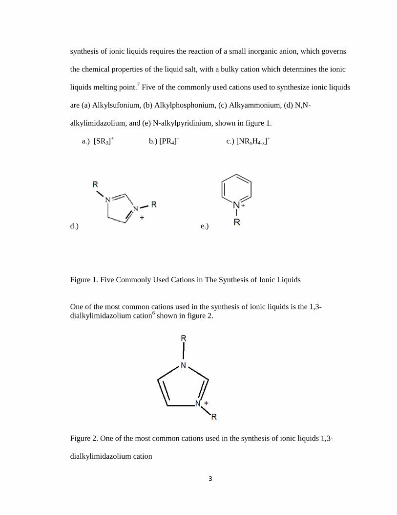
synthesis of ionic liquids requires the reaction of a small inorganic anion, which governs
the chemical properties of the liquid salt, with a bulky cation which determines the ionic
liquids melting point.7 Five of the commonly used cations used to synthesize ionic liquids
are (a) Alkylsufonium, (b) Alkylphosphonium, (c) Alkyammonium, (d) N,N-
alkylimidazolium, and (e) N-alkylpyridinium, shown in figure 1.
a.) [SR3]+ b.) [PR4]
+ c.) [NRxH4-x]
+
d.) e.)
Figure 1. Five Commonly Used Cations in The Synthesis of Ionic Liquids
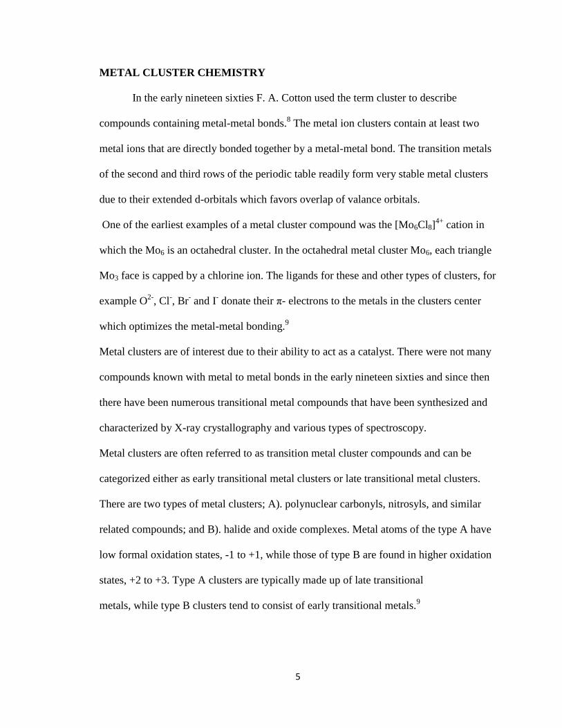
One of the most common cations used in the synthesis of ionic liquids is the 1,3-
dialkylimidazolium cation6 shown in figure 2.
Figure 2. One of the most common cations used in the synthesis of ionic liquids 1,3-
dialkylimidazolium cation

4
The 1,3-dialkyimidazolium salts are made up of dialkylimidazolium halides. The R is
almost always a methyl group and R’can be varied to desired physical properties7. Table
1 is a list of cationic portions used to vary physical properties and table 2 lists some of the
commonly used anions.
R’ = Methyl MMImCl - C5H9N2Cl
Ethyl EMImCl - C6H11N2Cl
Propyl PMImCl - C7H13N2Cl
Isopropyl iPMImCl - C7H13N2Cl
Table 1. Cationic portions used to vary physical properties
Hexafluorophosphates - PF6
Tetrafluoroborate - BF4
Aluminate Halide - AlX4 (X = [Cl, Br, or I]
Bis((pentfluoroethane)sulfonyl)imide – Beti
Table 2. Some of the commonly used anions
*anions are listed in order of increasing water solubility
Ionic liquids are currently being used in various processes such as batteries, metal
electrodeposition, and photoelectrochemical cells.
5
METAL CLUSTER CHEMISTRY
In the early nineteen sixties F. A. Cotton used the term cluster to describe
compounds containing metal-metal bonds.8 The metal ion clusters contain at least two
metal ions that are directly bonded together by a metal-metal bond. The transition metals
of the second and third rows of the periodic table readily form very stable metal clusters
due to their extended d-orbitals which favors overlap of valance orbitals.
One of the earliest examples of a metal cluster compound was the [Mo6Cl8]4+
cation in
which the Mo6 is an octahedral cluster. In the octahedral metal cluster Mo6, each triangle
Mo3 face is capped by a chlorine ion. The ligands for these and other types of clusters, for
example O2-
, Cl-, Br
- and I
- donate their π- electrons to the metals in the clusters center
which optimizes the metal-metal bonding.9
Metal clusters are of interest due to their ability to act as a catalyst. There were not many
compounds known with metal to metal bonds in the early nineteen sixties and since then
there have been numerous transitional metal compounds that have been synthesized and
characterized by X-ray crystallography and various types of spectroscopy.
Metal clusters are often referred to as transition metal cluster compounds and can be
categorized either as early transitional metal clusters or late transitional metal clusters.
There are two types of metal clusters; A). polynuclear carbonyls, nitrosyls, and similar
related compounds; and B). halide and oxide complexes. Metal atoms of the type A have
low formal oxidation states, -1 to +1, while those of type B are found in higher oxidation
states, +2 to +3. Type A clusters are typically made up of late transitional
metals, while type B clusters tend to consist of early transitional metals.9

6
Early transition metals
Early transition metals attributes include high stability, very strong M-ligand
bonds, and are typically inert. The metal atoms they contain are in higher oxidation states
and typically bond with Π-donor ligands 9. The higher oxidation states helps to stabilize
the metal cluster. The early transition metal homoleptic carbonyls have bond strengths
that are stronger then late transition metals, as seen in Table 3.26
Compound D, kj/mol Compound D, kj/mol
Cr(CO)6 108 Re(CO)6 192
Mo(CO)6 152 Fe(CO)6 117
W(CO)6 178 Co(CO)6 136
Mn(CO)6 99 Ni(CO)6 147
Table 3. Bond Strengths for Transition Metals
Early transition metals, also known as electron poor transition metal clusters or lower
halides, are thought to contribute their excess electrons to the core metal due to
contributions from their π - donor ligands, such as oxygen, chlorine, sulfur, bromine,
iodine, and alkoxy molecules. The second and third transition metals specifically
molybdenum, tungsten, tantalum and niobium have a formal oxidation state of +2 and +3.
Maximum metal-metal bonding is achieved with higher oxidation states that help
stabilize the metal cluster. Early transition metals strongly prefer to have a
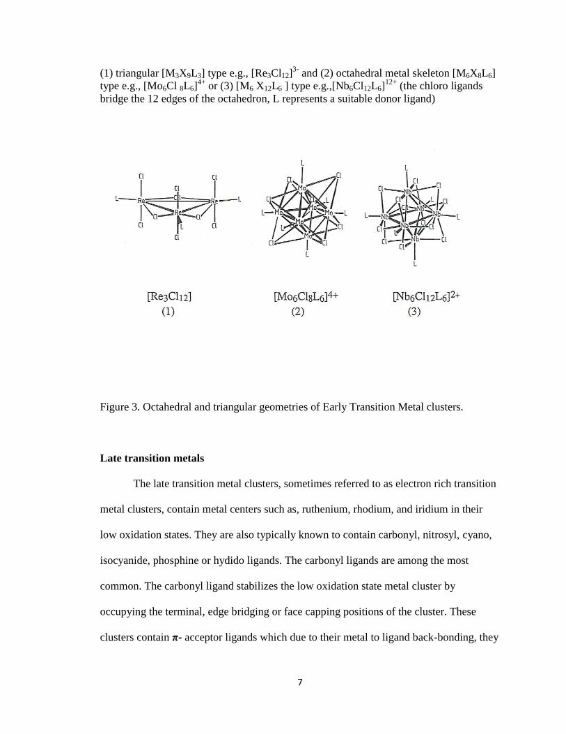
triangular and octahedral geometry. Figure 3 shows three examples of these geometries13
7
(1) triangular [M3X9L3] type e.g., [Re3Cl12]3-
and (2) octahedral metal skeleton [M6X8L6]
type e.g., [Mo6Cl 8L6]4+
or (3) [M6 X12L6 ] type e.g.,[Nb6Cl12L6]12+
(the chloro ligands
bridge the 12 edges of the octahedron, L represents a suitable donor ligand)
Figure 3. Octahedral and triangular geometries of Early Transition Metal clusters.
Late transition metals
The late transition metal clusters, sometimes referred to as electron rich transition
metal clusters, contain metal centers such as, ruthenium, rhodium, and iridium in their
low oxidation states. They are also typically known to contain carbonyl, nitrosyl, cyano,
isocyanide, phosphine or hydido ligands. The carbonyl ligands are among the most
common. The carbonyl ligand stabilizes the low oxidation state metal cluster by
occupying the terminal, edge bridging or face capping positions of the cluster. These
clusters contain π- acceptor ligands which due to their metal to ligand back-bonding, they
8
draw electrons from the metals. Late transition metals contain metals in low oxidization
states, mostly zero, -1, or +1. They contain Π-acceptor ligands that withdraw electrons by
Π-back-bonding. Late transition metals are highly reactive oxidizing agents that have
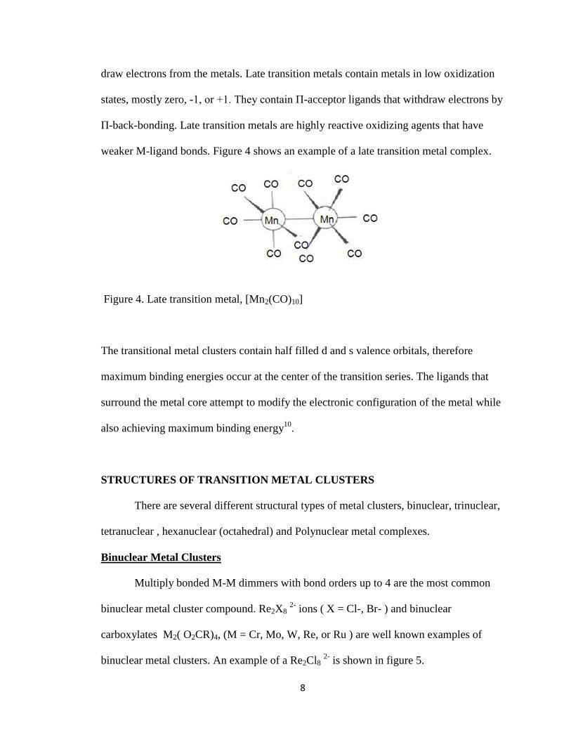
weaker M-ligand bonds. Figure 4 shows an example of a late transition metal complex.
Figure 4. Late transition metal, [Mn2(CO)10]
The transitional metal clusters contain half filled d and s valence orbitals, therefore
maximum binding energies occur at the center of the transition series. The ligands that
surround the metal core attempt to modify the electronic configuration of the metal while
also achieving maximum binding energy10
.
STRUCTURES OF TRANSITION METAL CLUSTERS
There are several different structural types of metal clusters, binuclear, trinuclear,
tetranuclear , hexanuclear (octahedral) and Polynuclear metal complexes.
Binuclear Metal Clusters
Multiply bonded M-M dimmers with bond orders up to 4 are the most common
binuclear metal cluster compound. Re2X8 2-
ions ( X = Cl-, Br- ) and binuclear
carboxylates M2( O2CR)4, (M = Cr, Mo, W, Re, or Ru ) are well known examples of
binuclear metal clusters. An example of a Re2Cl8 2-
is shown in figure 5.
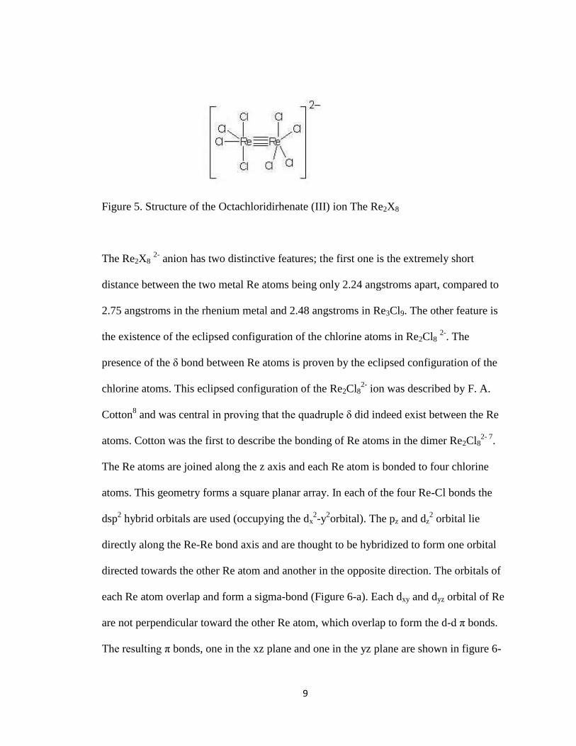
9
Figure 5. Structure of the Octachloridirhenate (III) ion The Re2X8
The Re2X8 2-
anion has two distinctive features; the first one is the extremely short
distance between the two metal Re atoms being only 2.24 angstroms apart, compared to
2.75 angstroms in the rhenium metal and 2.48 angstroms in Re3Cl9. The other feature is
the existence of the eclipsed configuration of the chlorine atoms in Re2Cl8 2-
. The
presence of the δ bond between Re atoms is proven by the eclipsed configuration of the
chlorine atoms. This eclipsed configuration of the Re2Cl82-
ion was described by F. A.
Cotton8 and was central in proving that the quadruple δ did indeed exist between the Re
atoms. Cotton was the first to describe the bonding of Re atoms in the dimer Re2Cl82- 7
.
The Re atoms are joined along the z axis and each Re atom is bonded to four chlorine
atoms. This geometry forms a square planar array. In each of the four Re-Cl bonds the
dsp2 hybrid orbitals are used (occupying the dx
2-y
2orbital). The pz and dz
2 orbital lie
directly along the Re-Re bond axis and are thought to be hybridized to form one orbital
directed towards the other Re atom and another in the opposite direction. The orbitals of
each Re atom overlap and form a sigma-bond (Figure 6-a). Each dxy and dyz orbital of Re
are not perpendicular toward the other Re atom, which overlap to form the d-d π bonds.
The resulting π bonds, one in the xz plane and one in the yz plane are shown in figure 6-
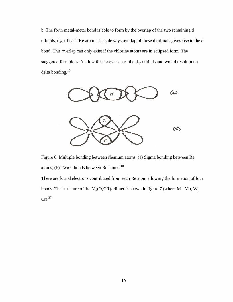
10
b. The forth metal-metal bond is able to form by the overlap of the two remaining d
orbitals, dxy, of each Re atom. The sideways overlap of these d orbitals gives rise to the δ
bond. This overlap can only exist if the chlorine atoms are in eclipsed form. The
staggered form doesn’t allow for the overlap of the dxy orbitals and would result in no
delta bonding.10
Figure 6. Multiple bonding between rhenium atoms, (a) Sigma bonding between Re
atoms, (b) Two π bonds between Re atoms.10
There are four d electrons contributed from each Re atom allowing the formation of four
bonds. The structure of the M2(O2CR)4 dimer is shown in figure 7 (where M= Mo, W,
Cr).27

11
Figure 7. The structure of the the M2(O2CR)4 dimer (where M= Mo, W, Cr).
The formal oxidation state of Mo in Mo2(O2CR)4 is +2. The quadruply Mo dimers are
easily oxidized by 1e- to give rise to dimers with a bond order of 3.5.
Mo2(O2CR)4 -e- Mo2(O2CR)4
+ -e
- Mo2(O2CR)4
2+
Trinuclear Metal Clusters
One of the best known examples of noncarbonyl clusters containing three metal
atoms are the rhenium trihalides [(ReCl3)3] and their derivatives. First discovered in 1932
by Geilnann, Wriuce, and Biltz12
, Each rhenium atom is bonded together both directly to
the other by metal to metal bonds and indirectly by a bridging halogen ligand.
In addition each rhenium atom in the triangular geometry is coordinated by two or more

12
halide ligands below and above the plane defined by the three rhenium atoms (figure 8
a)10
. The rhenium atoms of the diamagnetic Re3Cl8 cluster are bridged by halide ions with
adjacent Re3Cl8 clusters which gives rise to a polymeric structure11
(figure 8 b). A
dodecahalotrirhenate(III) ion Re3X123-
is produced when Re3X8 is dissolved in a
hydrochloric acid solution (figure 8 c)11
. The behavior of other halides is the same as Cl.
Figure 8. Structures of trinuclear rhenium metal clusters, (a) Re3X9, (b) polymeric
structure of Re3X8, (c) Re3Cl123-
Trinuclear triply-bonded compounds of the type M3X6 constitute an important and
extensive area of chemistry.14
Trinuclear metal clusters with bond orders between 2/3 and
1 are generally formed by the early transition metals in their lower oxidation states such
as molybdenum, tungsten, niobium, and titanium. Their geometry is a triangular M3 unit.
The basic structures of this type of clusters are known as; (M3X6 type), without μ3-
ligands (figure 9) is given by the cluster [M3X6 (C6Me6)3]n+
where M = Nb, Ti, Ta and X
= Cl, or Br. The three metal atoms have direct metal-metal bonds to each other and are

13
surrounded by four chloride ligands in a square planar formation with three C6Me6
molecules coordinating on the axial plane. The second type (M3X13 type), with one μ3-
ligand (figure 10) M3 X13 structure type is given by the formula [M3( μ3-X)( μ-Y)3L9)]
where M = Ti, Nb, Mo, and W. X= μ3 capping ligands can be Cl-, Br
-, I
-, O2
-, OCH2
CMe3-, and S2
-. Y = μ2 bridging ligands can be Cl
-, Br
-, I
-, O2, S2
-. The terminal ligands L
can be OEt-, O2CCME3, CN
-, H20, and the halide ions. The third type (M3X17 type), with
two μ3-ligands, M3X17 structure (figure 11) with two ligands is given by formula [M3(μ3 -
X)2 ( μ-O2Y)6L3)]. The metals are Mo and W while the X can be O2- or OEt
-. The
bridging bidentate ligands O2Y can be MeCO2, EtCO2, tBuCO2 and monodentate ligands
L can be, MeCO2, tBuCO2 and H20.
Figure 9. Structure type (a) [M3X6(C6Me6)3]n+
(no μ3 ligand)
14
Figure 10. Structure type (b) [M3( μ3-X)( μ-Y)3L9)] (one μ3 ligand)
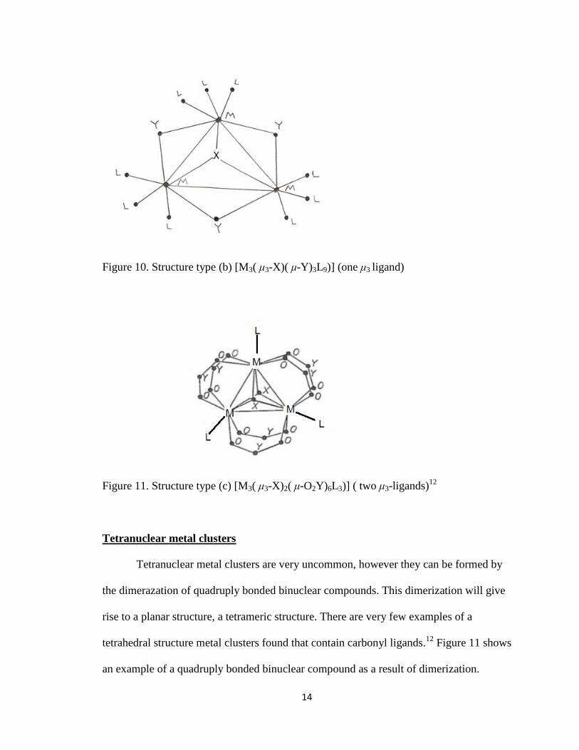
Figure 11. Structure type (c) [M3( μ3-X)2( μ-O2Y)6L3)] ( two μ3-ligands)12
Tetranuclear metal clusters
Tetranuclear metal clusters are very uncommon, however they can be formed by
the dimerazation of quadruply bonded binuclear compounds. This dimerization will give
rise to a planar structure, a tetrameric structure. There are very few examples of a
tetrahedral structure metal clusters found that contain carbonyl ligands.12
Figure 11 shows
an example of a quadruply bonded binuclear compound as a result of dimerization.
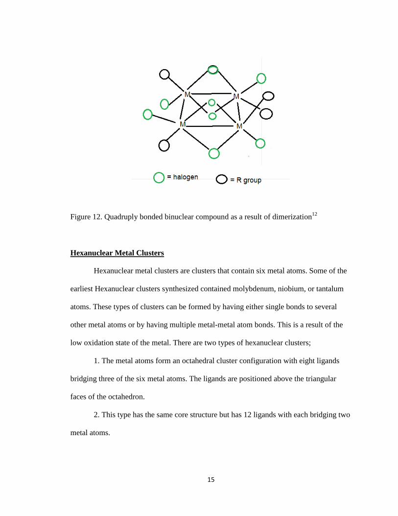
15
Figure 12. Quadruply bonded binuclear compound as a result of dimerization12
Hexanuclear Metal Clusters
Hexanuclear metal clusters are clusters that contain six metal atoms. Some of the
earliest Hexanuclear clusters synthesized contained molybdenum, niobium, or tantalum
atoms. These types of clusters can be formed by having either single bonds to several
other metal atoms or by having multiple metal-metal atom bonds. This is a result of the
low oxidation state of the metal. There are two types of hexanuclear clusters;
1. The metal atoms form an octahedral cluster configuration with eight ligands
bridging three of the six metal atoms. The ligands are positioned above the triangular
faces of the octahedron.
2. This type has the same core structure but has 12 ligands with each bridging two
metal atoms.
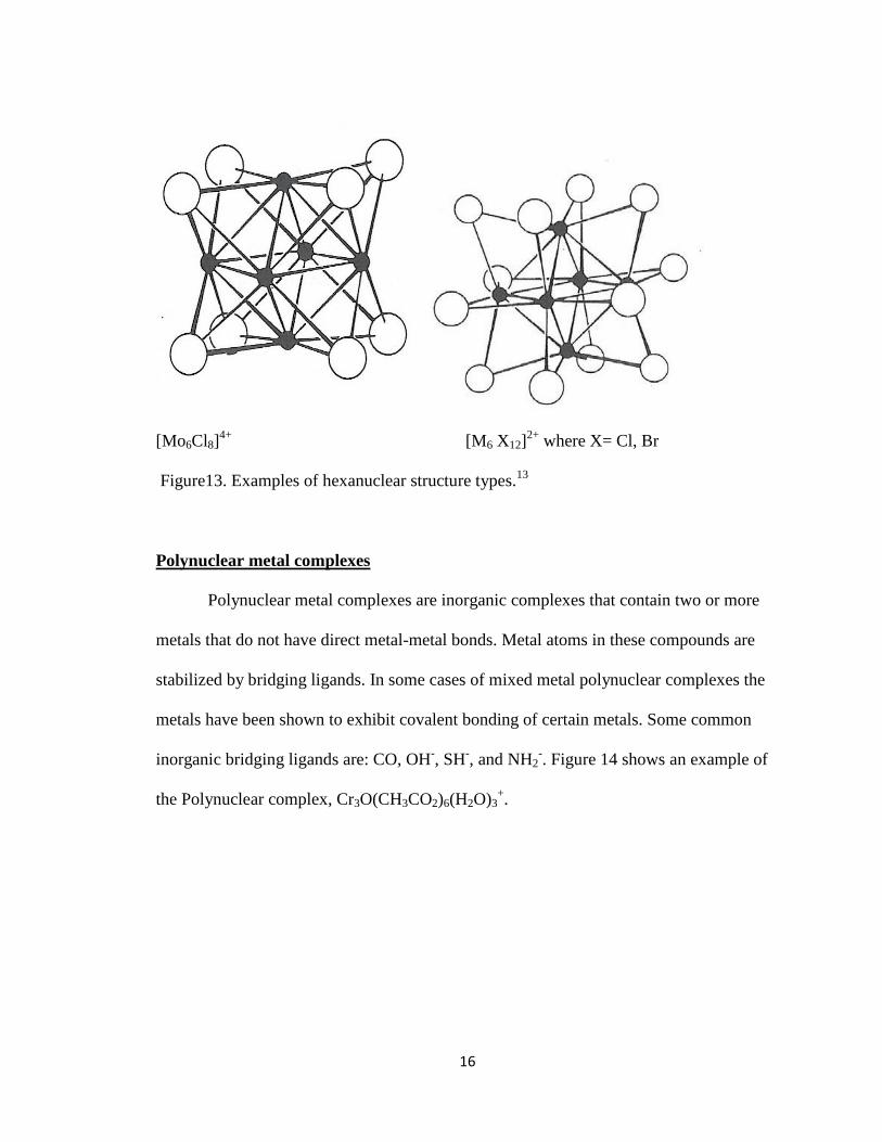
16
[Mo6Cl8]4+
[M6 X12]2+
where X= Cl, Br
Figure13. Examples of hexanuclear structure types.13
Polynuclear metal complexes
Polynuclear metal complexes are inorganic complexes that contain two or more
metals that do not have direct metal-metal bonds. Metal atoms in these compounds are
stabilized by bridging ligands. In some cases of mixed metal polynuclear complexes the
metals have been shown to exhibit covalent bonding of certain metals. Some common
inorganic bridging ligands are: CO, OH-, SH
-, and NH2
-. Figure 14 shows an example of
the Polynuclear complex, Cr3O(CH3CO2)6(H2O)3+.
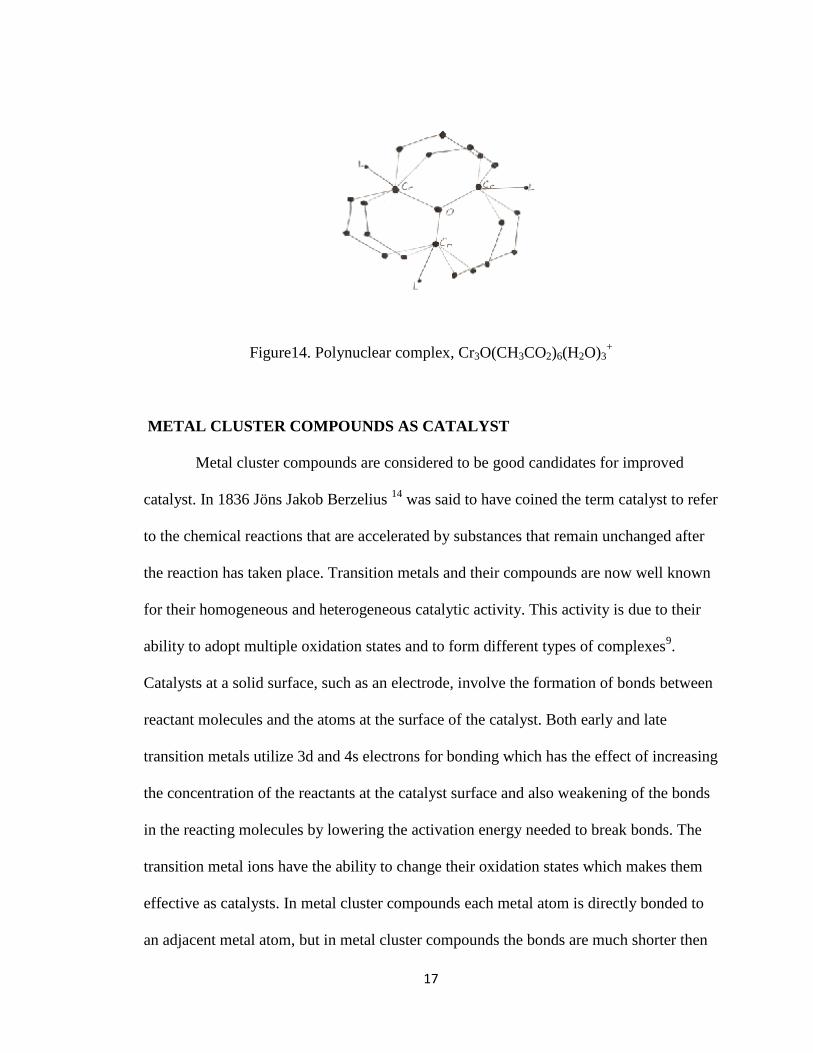
17
Figure14. Polynuclear complex, Cr3O(CH3CO2)6(H2O)3+
METAL CLUSTER COMPOUNDS AS CATALYST
Metal cluster compounds are considered to be good candidates for improved
catalyst. In 1836 Jöns Jakob Berzelius 14
was said to have coined the term catalyst to refer
to the chemical reactions that are accelerated by substances that remain unchanged after
the reaction has taken place. Transition metals and their compounds are now well known
for their homogeneous and heterogeneous catalytic activity. This activity is due to their
ability to adopt multiple oxidation states and to form different types of complexes9.
Catalysts at a solid surface, such as an electrode, involve the formation of bonds between
reactant molecules and the atoms at the surface of the catalyst. Both early and late
transition metals utilize 3d and 4s electrons for bonding which has the effect of increasing
the concentration of the reactants at the catalyst surface and also weakening of the bonds
in the reacting molecules by lowering the activation energy needed to break bonds. The
transition metal ions have the ability to change their oxidation states which makes them
effective as catalysts. In metal cluster compounds each metal atom is directly bonded to
an adjacent metal atom, but in metal cluster compounds the bonds are much shorter then
18
in homogeneous metals. There are several advantages of metal cluster compound catalyst
over traditional mononuclear catalyst. The properties of metal cluster compounds can be
altered by changing the type of ligands, the structural configuration and by incorporating
different metals into the cluster. They are soluble in an array of common solvents. They
have the ability to bind to very small molecules through multiple metal ligand bonds. Due
to these abilities metal clusters should work well as catalyst for the reduction of small
molecules such as CO, N2, and O2. An example being the hydrogenation of carbon
monoxide cannot be catalyzed by mononuclear metal catalyst,16
however the metal
cluster compounds have been shown to catalyze the reduction17
of CO to CH4 and H2O.
ELECTROCHEMICAL METHODS
Electrochemical methods provide efficient and straightforward assessment of the
redox behavior of molecular systems. The most common electrochemical method used by
chemist today is the voltammetric or potential sweep method. Voltammetry is a
correlation between applied potential and current. In all potential sweep methods, the
potential (V) of the working electrode is varied continuously with time according to a
predetermined potential waveform or excitation function, while the current (I) is
concurrently measured as a function of the potential. The applied potential at the working
electrode is measured against a reference electrode of choice, while a counter electrode or
auxiliary is required to balance the I-V applied. Thus, three electrodes are required, a
working electrode, a reference electrode and an auxiliary electrode. An electrolyte salt
must also be dissolved in solution to maintain sufficient conductivity in the bulk solution.
Common types of working electrodes include glassy carbon, platinum, silver and gold.

19
Common types of auxiliary electrodes include Pt wire, and glassy carbon rods. Common
types of reference electrodes include Ag/AgCl, Normal hydrogen electrode (NHE),
saturated calomel electrode and Ag/Ag/NO3. Figure 15 shows a typical electrochemical
cell used for potential sweep voltammetry.
Figure15. Typical electrochemical cell used for potential sweep voltammetry.
Linear Sweep Voltammetry
Linear sweep voltammetry (LSV) is the most basic potential sweep method. In
LSV the potential of the working electrode is varied linearly with time between two
values for example, the initial (Ei) and final (Ef) potentials. While the electrode potential
is steadily increasing or decreasing during the experiment, a level of ohmic current flows
continuously. The currents are due to the capacitive charging of the working electrodes
double layer or Helmholtz layer. When the potential reaches a value in which the
chemical species in the solution undergo electrochemical conversions Faradaic current
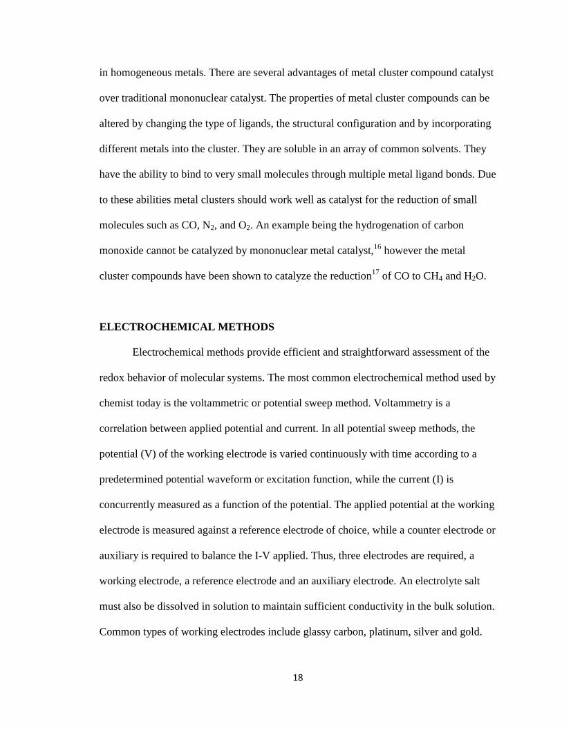
will also flow. Figure 15 shows bulk solution when no potential is applied. Figure 16
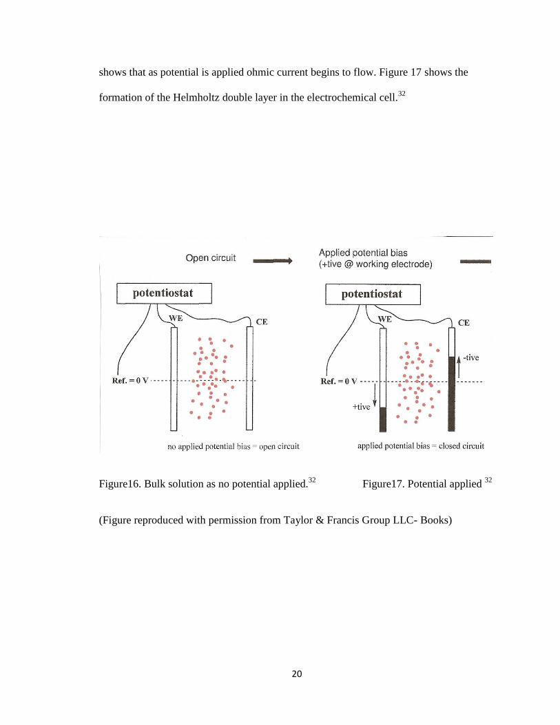
20
shows that as potential is applied ohmic current begins to flow. Figure 17 shows the
formation of the Helmholtz double layer in the electrochemical cell.32
Figure16. Bulk solution as no potential applied.32
Figure17. Potential applied 32
(Figure reproduced with permission from Taylor & Francis Group LLC- Books)
21
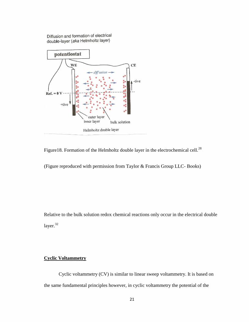
Figure18. Formation of the Helmholtz double layer in the electrochemical cell.28
(Figure reproduced with permission from Taylor & Francis Group LLC- Books)
Relative to the bulk solution redox chemical reactions only occur in the electrical double
layer.32
Cyclic Voltammetry
Cyclic voltammetry (CV) is similar to linear sweep voltammetry. It is based on
the same fundamental principles however, in cyclic voltammetry the potential of the
22
working electrode is varied linearly with time between three values, EiEspEf. In CV
the potential of the working electrode is scanned back after reaching a chosen value, the
switching potential (Esp). During the forward scan or reduction sweep, the Ei is more
positive than the Ef and the current is a result of the reduction of species. After reaching
Esp the reverse scan begins and the anodic current is a result of the re-oxidation of the
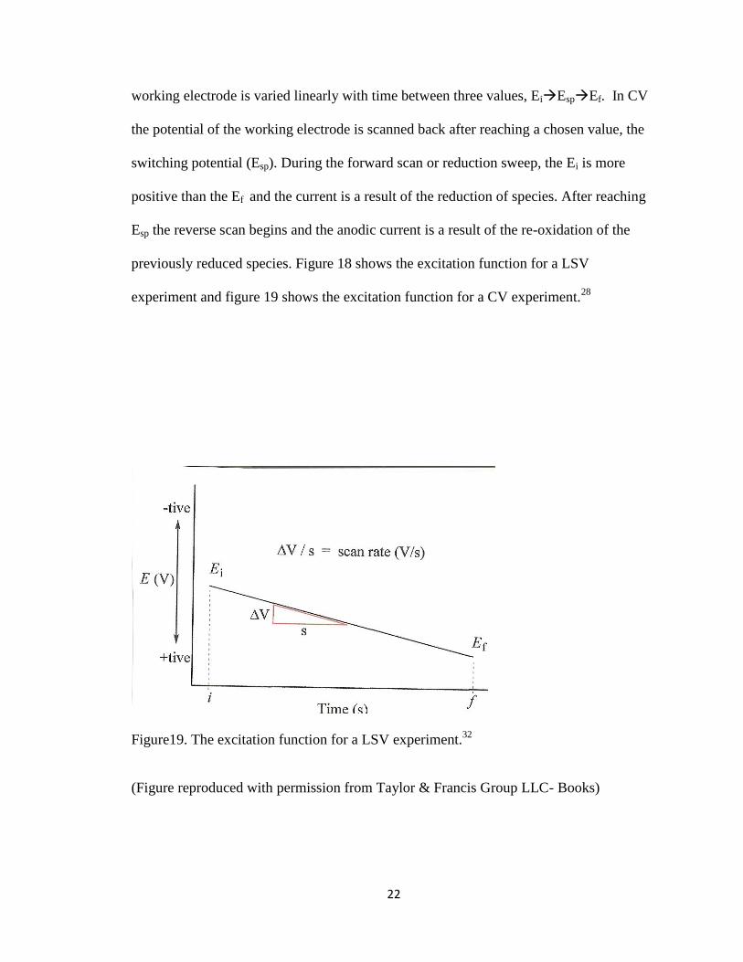
previously reduced species. Figure 18 shows the excitation function for a LSV
experiment and figure 19 shows the excitation function for a CV experiment.28
Figure19. The excitation function for a LSV experiment.32
(Figure reproduced with permission from Taylor & Francis Group LLC- Books)

23
Figure20. The excitation function for a CV experiment.32
(Figure reproduced with permission from Taylor & Francis Group LLC- Books)
Cyclic voltammetry can be used to study the redox properties of a large variety of
organic and inorganic chemical species. Modern instruments allow the experimentalist to
choose multiple switching potentials in order to carry out tailored CV scans over a chosen
potential window which allows for rapid location of redox potentials as well as the
kinetics of heterogeneous electron transfer reactions. It is also a simple method to
analyze the electrolyte solutions effect on the overall redox reaction. The potentials at
which the maximum peak currents occur are called Ep values. The potentials for the
oxidizing anodic and reducing cathodic sweep directions are referred to as Epa and Epc
respectively. If the scan rate is varied and the effect on the relative magnitude of both the
24
anodic current Ipa, and the cathodic current Ipc, are determined, the rate constants for
decomposition of the process can be deduced. The potential E1/2 for an electrical process
is determined by (Epa + Epc) / 2. The value of E1/2 corresponds to the redox potential of
the complex provided the diffusion properties of both the reduced and oxidized species
are very similar. In an ideal redox process ΔEp =|Epa – Epc| = 0.059 V for an one electron
redox reaction process. The characteristic half wave potential E1/2 of a redox couple is
usually within a few mV of the formal potential Eo for the couple according to the Nernst
equation shown below.28
E1/2 = E0 – (RT/2nF) ln(Dox/Dred)
The ratio of the diffusion coefficients Dox and Dred is usually close to unity. The ease of
determining half wave potentials and close approximation of formal potentials makes CV
an attractive method in the study of redox processes.
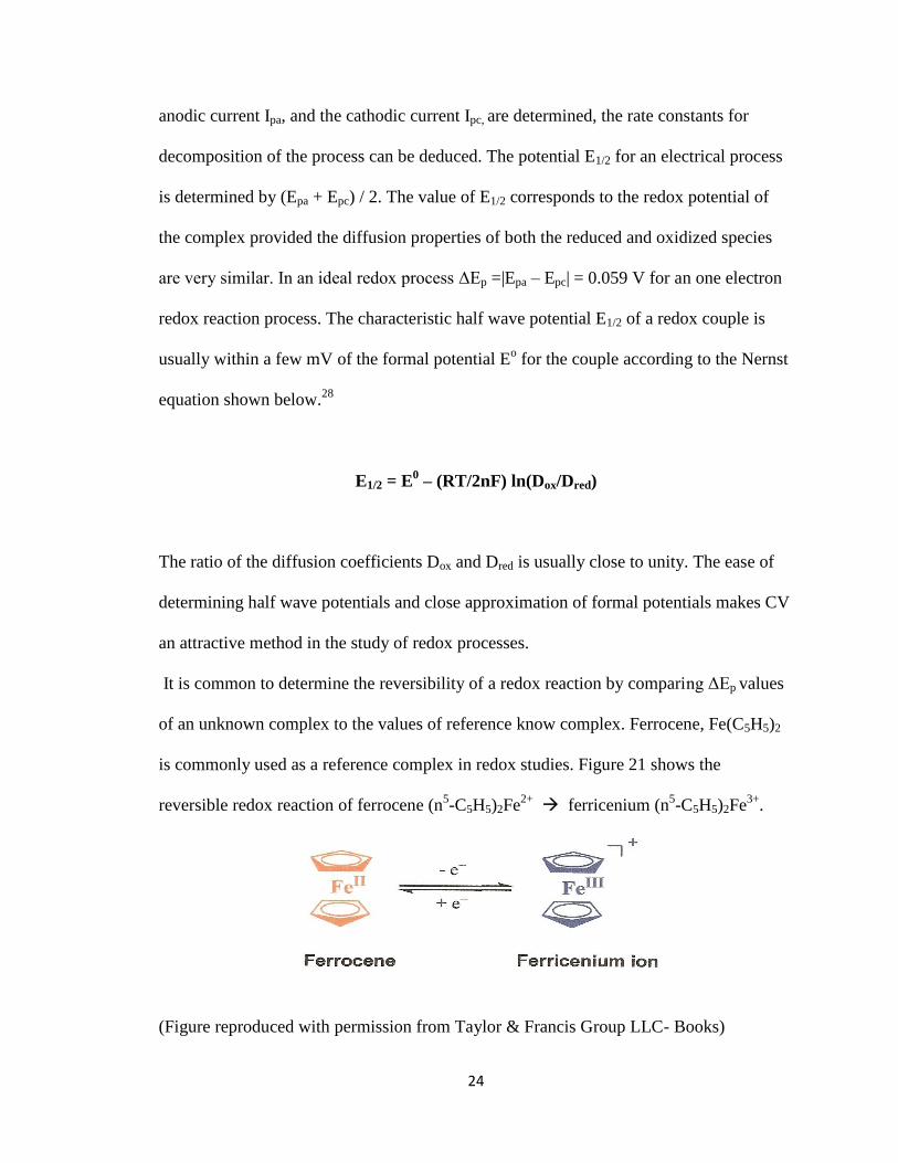
It is common to determine the reversibility of a redox reaction by comparing ΔEp values
of an unknown complex to the values of reference know complex. Ferrocene, Fe(C5H5)2
is commonly used as a reference complex in redox studies. Figure 21 shows the
reversible redox reaction of ferrocene (n5-C5H5)2Fe
2+ ferricenium (n
5-C5H5)2Fe
3+.
(Figure reproduced with permission from Taylor & Francis Group LLC- Books)
25
Figure 21. Reversible redox reaction of ferrocene ferricenium28
(n5-C5H5)2Fe
2+ (n
5-C5H5)2Fe
3+
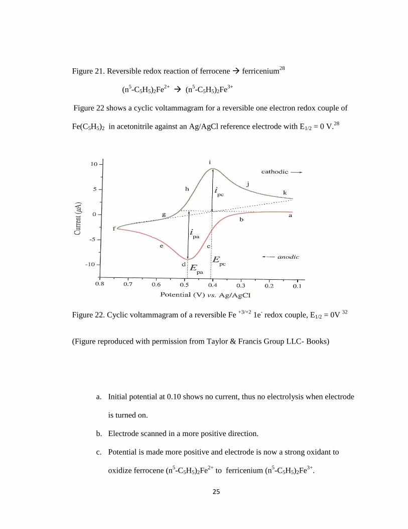
Figure 22 shows a cyclic voltammagram for a reversible one electron redox couple of
Fe(C5H5)2 in acetonitrile against an Ag/AgCl reference electrode with E1/2 = 0 V.28
Figure 22. Cyclic voltammagram of a reversible Fe +3/+2
1e- redox couple, E1/2 = 0V
32
(Figure reproduced with permission from Taylor & Francis Group LLC- Books)
a. Initial potential at 0.10 shows no current, thus no electrolysis when electrode
is turned on.
b. Electrode scanned in a more positive direction.
c. Potential is made more positive and electrode is now a strong oxidant to
oxidize ferrocene (n5-C5H5)2Fe
2+ to ferricenium (n
5-C5H5)2Fe
3+.
26
d. As anodic current increases the concentration of ferrocene decreases rapidly at
the electrode surface causing the current to peak.
e. Current decays as ferricenium surrounds the electrode and ferrocene
concentration is depleted.
f. Scan is now reversed at the switching potential Esp of 0.75 V In between
points f and g anodic current continues as potential is sufficiently positive to
oxidize ferrocene.
g. At point h the electrode is now a strong reductant able to reduce the
ferricenium that has accumulated adjacent to the electrode surface and the
reversible redox reaction of ferricenium (n5-C5H5)2Fe
3+ ferrocene (n
5-
C5H5)2Fe2+
takes place.
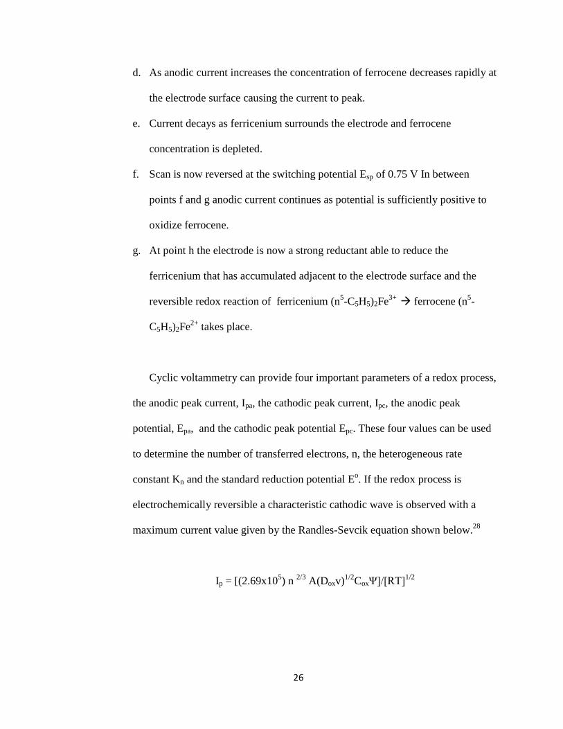
Cyclic voltammetry can provide four important parameters of a redox process,
the anodic peak current, Ipa, the cathodic peak current, Ipc, the anodic peak
potential, Epa, and the cathodic peak potential Epc. These four values can be used
to determine the number of transferred electrons, n, the heterogeneous rate
constant Kn and the standard reduction potential Eo. If the redox process is
electrochemically reversible a characteristic cathodic wave is observed with a
maximum current value given by the Randles-Sevcik equation shown below.28
Ip = [(2.69x10⁵) n
2/3 A(Doxv)
1/2CoxΨ]/[RT]
1/2
27
Ip= peak current; n = number of electrons; A= working electrode area (cm2); C =
analyte concentration (m/cm3); v= potential scan rate (V/s) D = diffusion
coefficient (cm2/s).
32
The three types of systems that are prevalent in cyclic voltammetry are a
reversible system, a quasi-reversible system, and an irreversible system. The type of
system depends on the rate constant of the process. Slow electron exchange (very small
K0) during the redox process will cause the system to be irreversible. If the current from
the reverse sweep is not displayed in a CV scan then a system is irreversible. If the peak
potential separation is greater than 59.2 V than the system is quasi-reversible and will
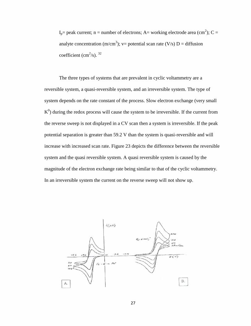
increase with increased scan rate. Figure 23 depicts the difference between the reversible
system and the quasi reversible system. A quasi reversible system is caused by the
magnitude of the electron exchange rate being similar to that of the cyclic voltammetry.
In an irreversible system the current on the reverse sweep will not show up.

28
Figure 23. Cyclic voltammagrams of: A. Reversible system and B. Quasi reversible
system.23
II. EXPERIMENTAL
Materials
The following materials were purchased from Alfa Aesar company: Acetic
Anhydride (97+%) Trifluoroacetic acid (99%), Trifluoromethanesulfonic acid (98+%),
Hexacarbonyltungsten (97%), and Dowex 50wx2 100-200 (H). Molybdenum
hexacarbonyl technical grade was purchased from Fluka Chemical Company. Sodium
tungstate dehydrate (99%) , and Chromium(II) acetate dimer monohydrate was purchased
Aldrich Chemical Company. Acetonitrile, gradient grade +99.0% and triethylamine was
purchased from Fisher Scientific and used as received. Trifluoromethanesulfonic acid
(99.5%) was obtained from Alfa Aesar.
Instrumentation
UV-VIS electronic absorption spectra were obtained using an Ocean Optics 4000
spectrophotometer interfaced with an Apple computer and a HP 8100 printer. The UV-
Vis scans of samples were taken using ionic liquid or water as a solvent blank in 1-cm
quartz cell. IR spectra were obtained from a Themo Scientific Nicolet 6700 FTIR
interfaced with a Dell computer and a HP printer. Crystallography data was obtained
29
using a Bruker/Mitigen sample mount and ran in a Smart X2S Bruker/Mitigen
instrument.30
Crystallography data was analyzed with Apex 2 and Oscail software.31
The amount of water in the ionic liquid was determined using a Denver
Instrument Coulometric Karl Fisher Titrator interfaced with a Model 260 titrator
controller. Approximately 20 microliters of liquid was injected into the titrator using a
stainless steel needle and a glass syringe. The syringe was washed in ethanol and the
dried in an oven with temperatures from 60 to 80 degrees Celsius between uses.
Cyclic Voltammetry experiments were performed using an EG+G Princeton applied
Research (PAR) 173 Potentiostat/Galvanostat System with a PAR 75 universal
Programmer. A MacLab/4 analog digital converter was used to convert analog data
recorded using Scope V3 software. Scanning electron microscopy was performed on a
FEI Quanta SEM equipped with an Electron energy dispersion scope.
The cyclic voltammograms were obtained using a platinum disk working electrode, an
Ag/AgCl reference electrode, and a platinum auxiliary electrode. The platinum disc
electrodes (1mm) were obtained from Cypress Systems Inc. The cell volume ranged from
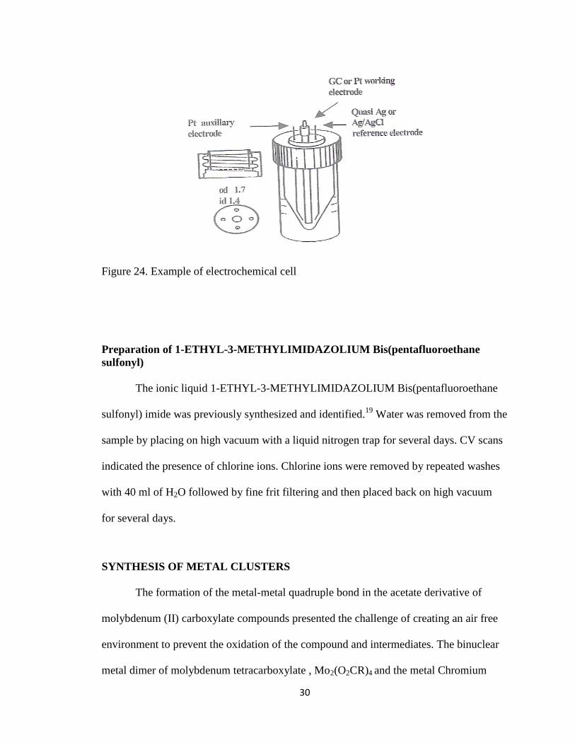
0.5mm to 1ml. The electrochemical cell is shown in Figure 24.
30
Figure 24. Example of electrochemical cell
Preparation of 1-ETHYL-3-METHYLIMIDAZOLIUM Bis(pentafluoroethane
sulfonyl)
The ionic liquid 1-ETHYL-3-METHYLIMIDAZOLIUM Bis(pentafluoroethane
sulfonyl) imide was previously synthesized and identified.19
Water was removed from the
sample by placing on high vacuum with a liquid nitrogen trap for several days. CV scans
indicated the presence of chlorine ions. Chlorine ions were removed by repeated washes
with 40 ml of H2O followed by fine frit filtering and then placed back on high vacuum
for several days.
SYNTHESIS OF METAL CLUSTERS
The formation of the metal-metal quadruple bond in the acetate derivative of
molybdenum (II) carboxylate compounds presented the challenge of creating an air free
environment to prevent the oxidation of the compound and intermediates. The binuclear
metal dimer of molybdenum tetracarboxylate , Mo2(O2CR)4 and the metal Chromium

31
tetracarboxylate dimer ,Cr2(O2CR)4 , were prepared and handled under a nitrogen purge
utilizing the Schlenk technique. Synthesis of the trinuclear metal clusters were all done
under a nitrogen purge to prevent the air oxidation of the reactants.20,27
Synthesis of Mo2(O2CCH3)4 - tetra (acetato) dimolybdenum (II)
MO2(O2CCH3)4 was synthesized by heating the triply bonded +3 dimer of
2Mo(CO)6 in solution with a stoichiometric amount of acetic acid. The process strips CO
ligands from Mo(CO)6 and allows for the oxidation of Mo atoms by the acetic acid.20
The
resulting product is the quadruply bonded +2 dimer MO2(O2CCH3)4 .27
The extremely air
sensitive dimer product was filtered in a glove box under N2 purge using a schlenk filter.
The final product was stored in sealed vials and left in N2 purged desiccator containing
Phosphorous pentoxide (P2O5) for later use.
Mo2(CO)6 + 4HO2CCH3 ---- Mo2(O2CCH3)4 + 12CO + H2
Synthesis of [Mo3O2(O2CCH3)6(H2O)3](F3CCOOH) – Hexa-µ2-acetato-di- µ3-oxo-
tris(aqua-molybdenum (IV)- trifluoromethylacetate
This synthesis was accomplished by finely grinding 1.21 g (5.0 mmol) of Na2MoO4
and placing into a 200 ml schlenk flask which contained a mixture of 70 ml of acetic
acid, I ml of triethyl amine and 7 ml of acetic anhydride. The mixture was deareated with
N2 and placed under heat with a constant N2 purge. The mixture was allowed to reflux for
30 minutes after which 12.0 g (2.0 mmol) of Mo2(O2CCH3)4 was quickly added. The
32
mixture was refluxed for 72 hours while stirring under a N2 purge. A color change was to
dark brown observed when all the solids had dissolved. After refluxing the solution was
allowed to cool to room temperature and diluted with 200 ml of H2O. The diluted mixture
was then filtered. The filtrate was then poured into a Dowex 50x2-200 cation exchange
resin column previously prepared with HCl. After rinsing the column with H2O the
filtrate was slowly eluted using 1.0M Trifluoromethyl acetic acid. Four layers were
developed in the column from top to bottom, one blue green, one dark blue, one yellow
and one light pink. The solution was, then, evaporated on the rotatory evaporation system
at 80 oC under vacuum to remove the excess H2O. The remaining eluent was allowed to
slowly evaporate and produced dark red crystals of the product
[Mo3O2(O2CCH3)6(H2O)(CF3CO2H)2.20,27
Synthesis of Cr2(O2CCH3)4
An aqueous solution of a Cr3+
compound is first reduced to the chromous state
using zinc according to the following reaction.20
2Cr3+
+ Zn 2Cr2+
+ Zn 2+
The resulting blue product is then treated with sodium acetate which results in the rapid
participation of chromous acetate as a bright red powder according to the following
reaction.20
2Cr2+
+ 4OAc + 2H2O Cr2(OAc)4(H2O)2

33
Any introduction of air into the apparatus is indicated by a discoloration of the bright red
product.21
Figure 25 shows the structure of a Cr2(OAc)4(H2O)2 molecule.
Figure 25. Structure of a Cr2(OAc)4(H2O)2 molecule
The red colored compound of Cr2(OAc)4(H2O)2 , like that of Mo2(OAc)4, contains a
quadruple bond between the two metal atoms. The molecule contains two chromium
atoms, four monoanionic acetate ligands and two ligated molecules of water. The
coordination environment surrounding each chromium atoms consists of a total of four
oxygen atoms coming from each acetate ligand, one water molecule in the axial position
and the second chromium atom being opposite of the water molecule. This environment
gives the chromium center an octahedral geometry. The molecule has D4h symmetry. The
same structure as a molecule of the Molybdenum(II) acetate dimer. The main difference
between the two structures are the reported bond lengths between each molecules central
metal atoms, with Mo-Mo reported as 2.093Å and Cr-Cr reported as 2.36 Å10
. The
quadruple bond found between the two chromium atoms arises from the overlap of its
four d- orbitals of each metal atom with the same orbitals of the other metal atom. The
sigma bond comes from the overlap of the z2 orbitals and the overlapping orbitals of the

34
xz and yz gives rise to two pi bonds. The fourth bond, the delta bond is from the xy
orbitals overlapping. Because the Cr is in a 2+ oxidation state it is a good reducing agent.
The formation of the quadruple bonds on the two Cr atoms is shown in the MO diagram
in figure 26.
Figure 26. MO diagram for Cr (II) acetate complex29
Synthesis of [Cr2Mo(u2-CH3COO)6(u3-O)(H2O)3][CF3SO3]
This preparation was very similar to that of [Mo3O2(O2CCH3)6(H2O)(CF3SO2H)2
with the exception of using excess Cr2(OAc)4 in place of Mo2(O2CCH3)4. Finely ground
Na2MoO4.2H2O (1.20 g, 4.66 mmol) was placed in a solution of 70 ml acetic acid, 7 ml
acetic anhydride and 1 ml triethyl amine utilizing the schlenk method. The suspension
was deareated by purging with N2 and brought to a reflux. The Cr2(OAc)4 dimer (2.0 g,

35
5.32 mmol) was added quickly under N2 and refluxed for 11 days. After about 24 hours
the solution changed to a dark brown color and all the solids had dissolved. After 4 days
the solution changed to a medium purple color which indicated that product underwent
oxidation. The synthesis was attempted again at increased temperature and longer
reaction time. A green solution was achieved at higher temperature and 7 days of reflux.
The solution was then vacuum filtered through a glass frit funnel and eluted through an
acidified Dowex 50x2-200 cation exchange 15 cm height resin column. The eluent was
slowly evaporated and produced a very small quantity of trigonal faced dark green
octahedral crystals. The product was analyzed by utilizing three dimensional diffraction
using Mo Kα radiation. The structure was confirmed to be crystals of the hetero-
polynuclear metal complex [Cr2Mo(u2-CH3COO)6(u3-O)(H2O)3][CF3SO3]. The complex
was also analyzed using FTIR, CV and UV-VIS characterization methods.
36
III. RESULTS AND DISCUSSION
Electrochemistry of EMIBeti
EMIBeti is prepared by utilizing an ion exchange reaction with EMICl and
LiBeti. EMICl is dissolved in 200 ml of H2O after which an equal molar amount of
lithium bis((pentafluoroethane)sufonyl)imide (LiBeti) dissolved in 200 ml of H2O is
added. After the reaction in solution has taken place the LiCl must be removed from the
final product. The LiCl was completely removed by washing the solution with 40 ml of
H2O approximately 15 times. The solution was determined to be free of LiCl when it no
longer tested positive when reacted with Ag+. Once the solution was free of LiCl it was
dried using high vacuum for removal of excess H2O. IR spectra confirmed the identity of
the ionic liquid. CV scans taken before and after washing the ionic confirmed all
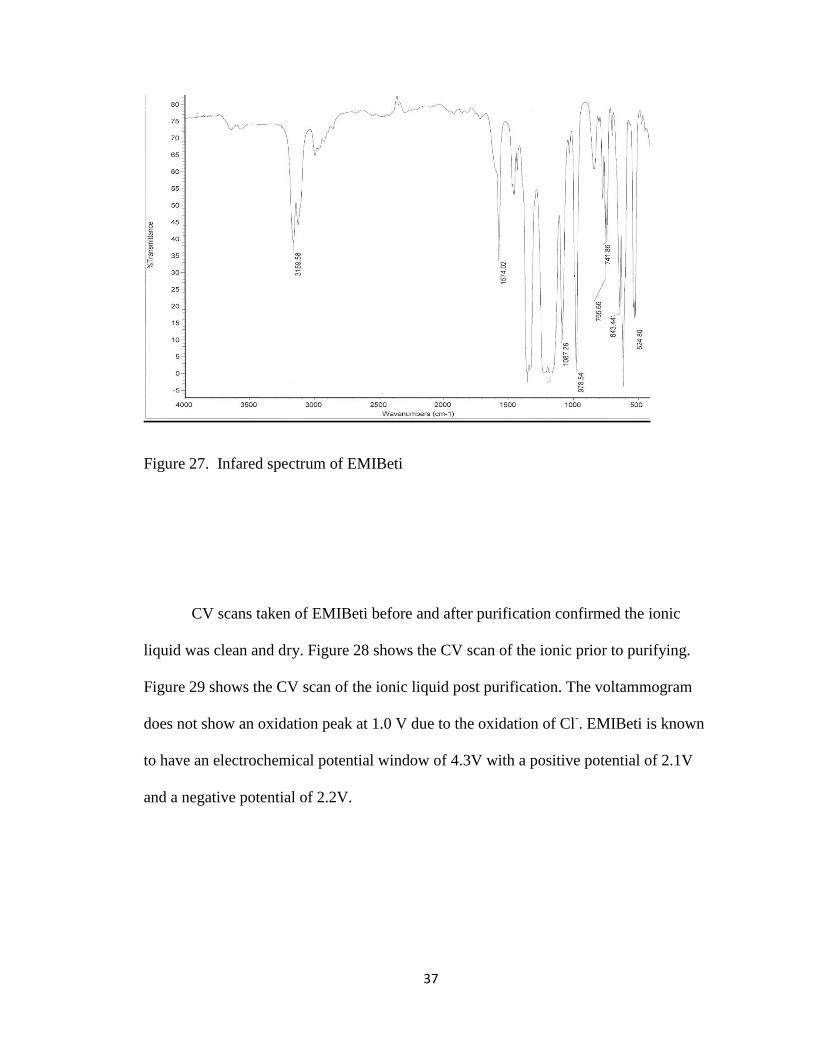
impurities had been removed. Figure 27 shows the inferred spectrum of EMIBeti after
washing and drying the solution. The relatively small bands of H2O stretching, at ~3600
cm-1
is observed. The two bands correspond to symmetric and antisymmetric stretching
of H2O. If a larger amount of H2O were present (> 300 ppm) a broad band at ~3400 cm-1
would be observed characteristic of the presence of hydrogen bonding.
37
Figure 27. Infared spectrum of EMIBeti
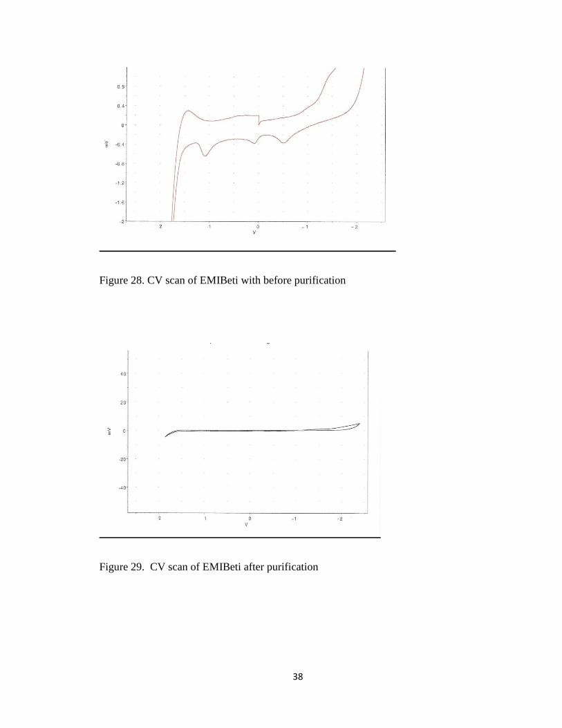
CV scans taken of EMIBeti before and after purification confirmed the ionic
liquid was clean and dry. Figure 28 shows the CV scan of the ionic prior to purifying.
Figure 29 shows the CV scan of the ionic liquid post purification. The voltammogram
does not show an oxidation peak at 1.0 V due to the oxidation of Cl-. EMIBeti is known
to have an electrochemical potential window of 4.3V with a positive potential of 2.1V
and a negative potential of 2.2V.
38
Figure 28. CV scan of EMIBeti with before purification
Figure 29. CV scan of EMIBeti after purification
39
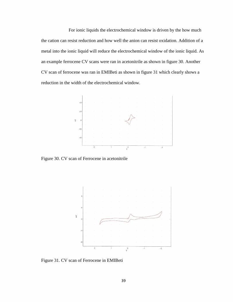
For ionic liquids the electrochemical window is driven by the how much
the cation can resist reduction and how well the anion can resist oxidation. Addition of a
metal into the ionic liquid will reduce the electrochemical window of the ionic liquid. As
an example ferrocene CV scans were ran in acetonitrile as shown in figure 30. Another
CV scan of ferrocene was ran in EMIBeti as shown in figure 31 which clearly shows a
reduction in the width of the electrochemical window.
Figure 30. CV scan of Ferrocene in acetonitrile
Figure 31. CV scan of Ferrocene in EMIBeti
40
Electrochemistry of trinuclear metal complexes
The electrochemical properties of [Mo3O2(O2CCH3)6(H2O)(CF3SO2H)2 and
[Cr2Mo(u2-CH3COO)6(u3-O)(H2O)3][CF3SO3] trinuclear metal complexes in ionic liquids
were compared to their electrochemical properties in H2O. The differences of structures
of these two metal complexes are clearly shown in figure 32. The metal clusters,
[Mo3O2(O2CCH3)6(H2O)(CF3SO2H)2 and [Cr2Mo(u2-CH3COO)6(u3-O)(H2O)3][CF3SO3]
do not readily dissolve in H2O or EMIBeti. A small amount of each complex was placed
in separate electrochemical cells equipped with tiny stir bars. Two samples of each metal
complex were prepared, one containing H2O and one containing EMIBeti. The samples
were place on a stir plate at a temperature of 600 C for several days to dissolve the metal
complexes. Electronic spectra of the metal complexes confirmed the structure of the
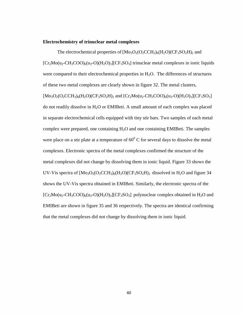
metal complexes did not change by dissolving them in ionic liquid. Figure 33 shows the
UV-Vis spectra of [Mo3O2(O2CCH3)6(H2O)(CF3SO2H)2 dissolved in H2O and figure 34
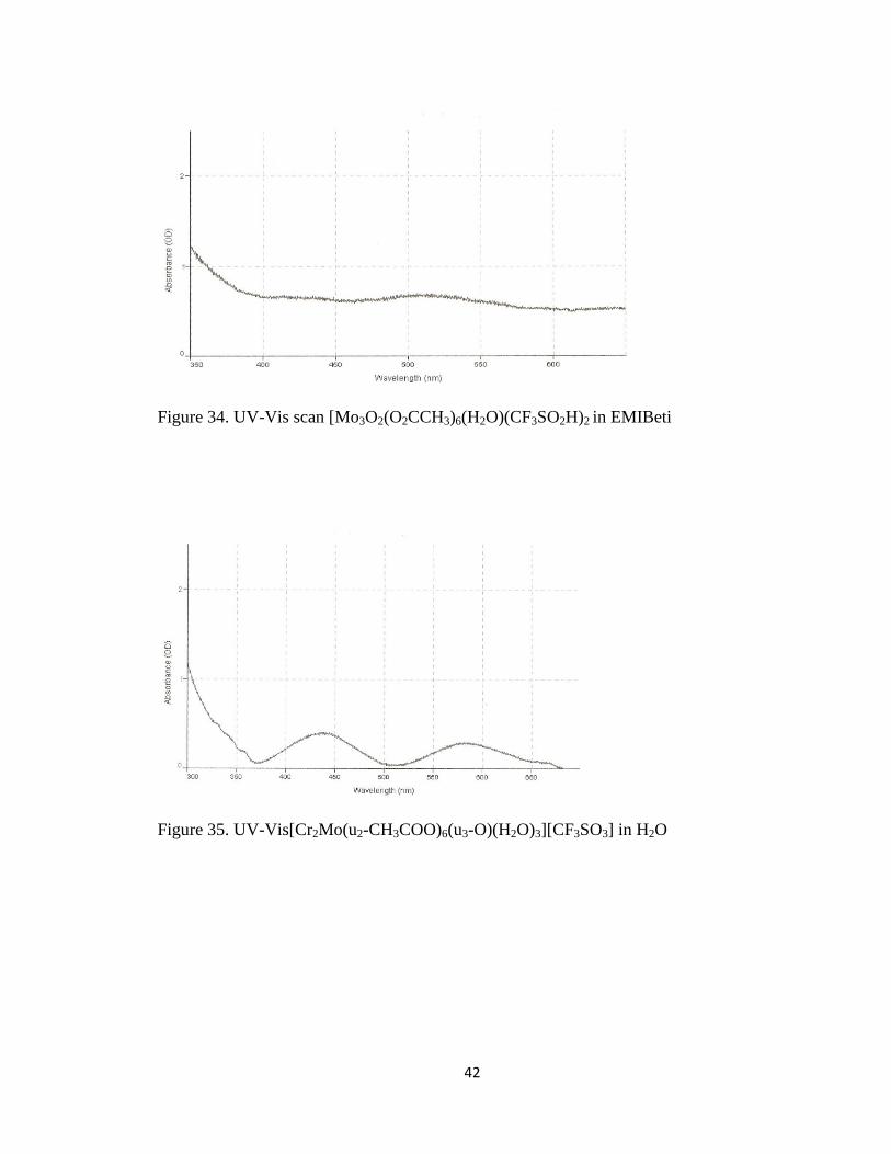
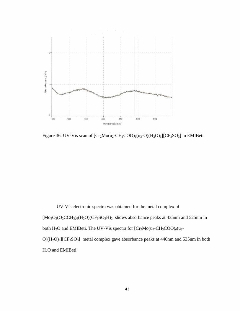
shows the UV-Vis spectra obtained in EMIBeti. Similarly, the electronic spectra of the
[Cr2Mo(u2-CH3COO)6(u3-O)(H2O)3][CF3SO3] polynuclear complex obtained in H2O and
EMIBeti are shown in figure 35 and 36 respectively. The spectra are identical confirming
that the metal complexes did not change by dissolving them in ionic liquid.

41
A. B.
Figure 32. A) [Mo3O2(O2CCH3)6(H2O)(CF3SO2H)2 and B) [Cr2Mo(u2-CH3COO)6(u3-
O)(H2O)3][CF3SO3].
Figure 33. UV-Vis [Mo3O2(O2CCH3)6(H2O)(CF3SO2H)2 in H2O
42
Figure 34. UV-Vis scan [Mo3O2(O2CCH3)6(H2O)(CF3SO2H)2 in EMIBeti
Figure 35. UV-Vis[Cr2Mo(u2-CH3COO)6(u3-O)(H2O)3][CF3SO3] in H2O
43
Figure 36. UV-Vis scan of [Cr2Mo(u2-CH3COO)6(u3-O)(H2O)3][CF3SO3] in EMIBeti
UV-Vis electronic spectra was obtained for the metal complex of
[Mo3O2(O2CCH3)6(H2O)(CF3SO2H)2 shows absorbance peaks at 435nm and 525nm in
both H2O and EMIBeti. The UV-Vis spectra for [Cr2Mo(u2-CH3COO)6(u3-
O)(H2O)3][CF3SO3] metal complex gave absorbance peaks at 446nm and 535nm in both
H2O and EMIBeti.
44
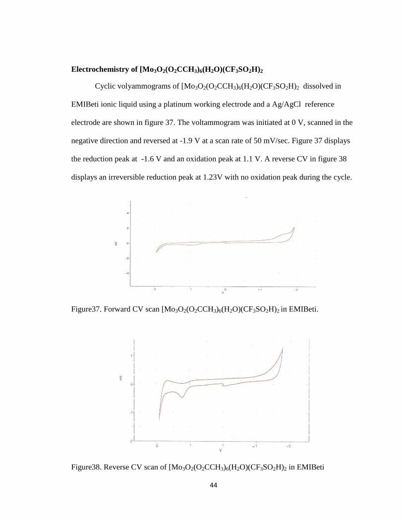
Electrochemistry of [Mo3O2(O2CCH3)6(H2O)(CF3SO2H)2
Cyclic volyammograms of [Mo3O2(O2CCH3)6(H2O)(CF3SO2H)2 dissolved in
EMIBeti ionic liquid using a platinum working electrode and a Ag/AgCl reference
electrode are shown in figure 37. The voltammogram was initiated at 0 V, scanned in the
negative direction and reversed at -1.9 V at a scan rate of 50 mV/sec. Figure 37 displays
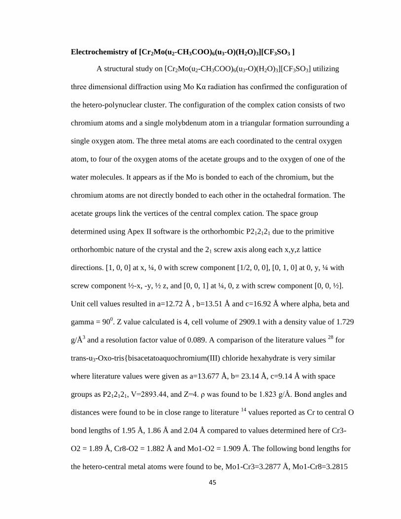
the reduction peak at -1.6 V and an oxidation peak at 1.1 V. A reverse CV in figure 38
displays an irreversible reduction peak at 1.23V with no oxidation peak during the cycle.
Figure37. Forward CV scan [Mo3O2(O2CCH3)6(H2O)(CF3SO2H)2 in EMIBeti.
Figure38. Reverse CV scan of [Mo3O2(O2CCH3)6(H2O)(CF3SO2H)2 in EMIBeti
45
Electrochemistry of [Cr2Mo(u2-CH3COO)6(u3-O)(H2O)3][CF3SO3 ]
A structural study on [Cr2Mo(u2-CH3COO)6(u3-O)(H2O)3][CF3SO3] utilizing
three dimensional diffraction using Mo Kα radiation has confirmed the configuration of
the hetero-polynuclear cluster. The configuration of the complex cation consists of two
chromium atoms and a single molybdenum atom in a triangular formation surrounding a
single oxygen atom. The three metal atoms are each coordinated to the central oxygen
atom, to four of the oxygen atoms of the acetate groups and to the oxygen of one of the
water molecules. It appears as if the Mo is bonded to each of the chromium, but the
chromium atoms are not directly bonded to each other in the octahedral formation. The
acetate groups link the vertices of the central complex cation. The space group
determined using Apex II software is the orthorhombic P212121 due to the primitive
orthorhombic nature of the crystal and the 21 screw axis along each x,y,z lattice
directions. [1, 0, 0] at x, ¼, 0 with screw component [1/2, 0, 0], [0, 1, 0] at 0, y, ¼ with
screw component ½-x, -y, ½ z, and [0, 0, 1] at ¼, 0, z with screw component [0, 0, ½].
Unit cell values resulted in a=12.72 Å , b=13.51 Å and c=16.92 Å where alpha, beta and
gamma = 900. Z value calculated is 4, cell volume of 2909.1 with a density value of 1.729
g/Å3 and a resolution factor value of 0.089. A comparison of the literature values
28 for
trans-u3-Oxo-tris{bisacetatoaquochromium(III) chloride hexahydrate is very similar
where literature values were given as a=13.677 Å, b= 23.14 Å, c=9.14 Å with space
groups as P212121, V=2893.44, and Z=4. ρ was found to be 1.823 g/Å. Bond angles and
distances were found to be in close range to literature 14
values reported as Cr to central O
bond lengths of 1.95 Å, 1.86 Å and 2.04 Å compared to values determined here of Cr3-
O2 = 1.89 Å, Cr8-O2 = 1.882 Å and Mo1-O2 = 1.909 Å. The following bond lengths for
the hetero-central metal atoms were found to be, Mo1-Cr3=3.2877 Å, Mo1-Cr8=3.2815

46
Å. The angles between each metal atom found in the literature 28
were reported as Cr3-
O4-Cr2=119.6 º, Cr2-O4-Cr1=118.9º and Cr1-O4-Cr3=121.6 º, compared to values
reported here, found to be Cr3-O2-Mo1=119.3 º, Cr8-O2-Mo1=119.9 º, and Cr3-O2-
Cr8=120.2 º. The solved structure is shown in figure 39.
Figure 39. Structural solved for [Cr2Mo(u2-CH3COO)6(u3-O)(H2O)3][CF3SO3]
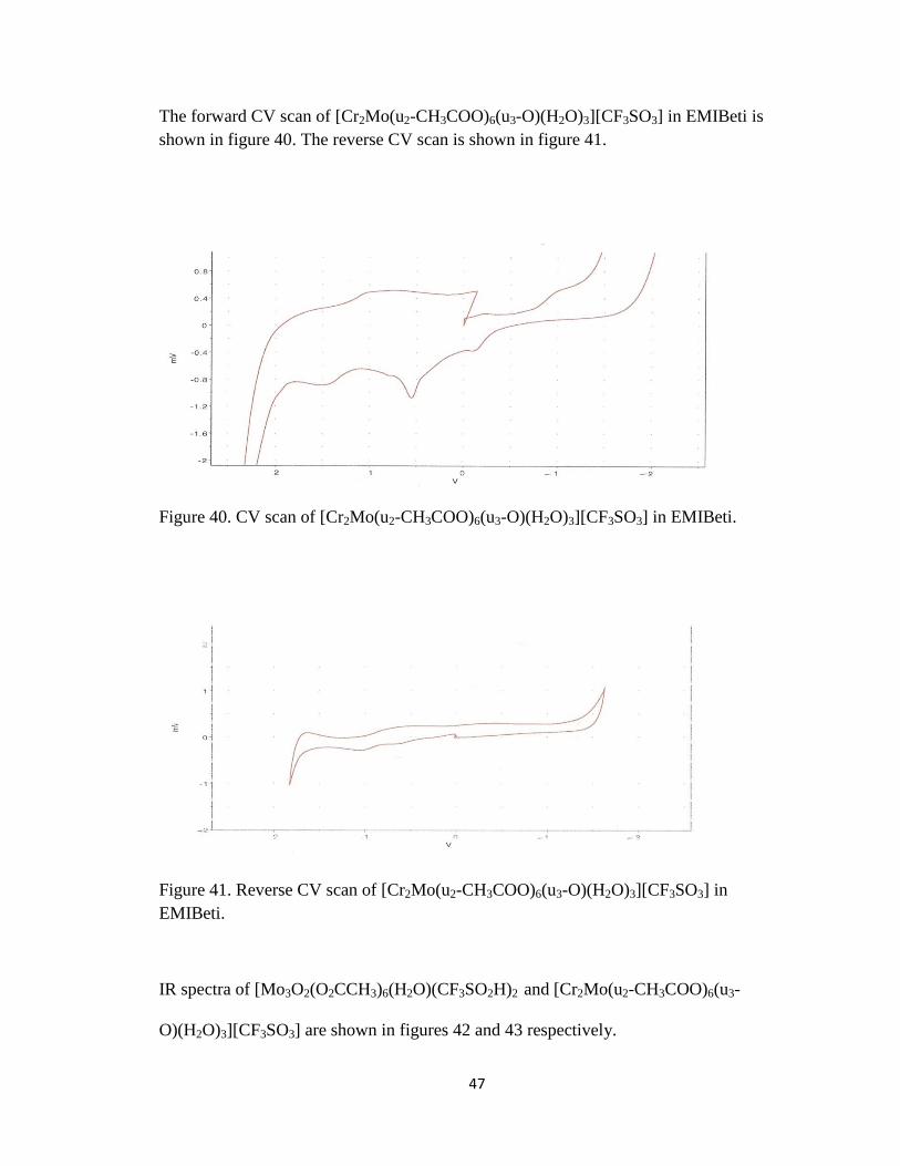
Cyclic volyammograms of [Cr2Mo(u2-CH3COO)6(u3-O)(H2O)3][CF3SO3] dissolved in
EMIBeti ionic liquid using a platinum electrode and a Ag/AgCl electrode are shown in
figure 40. The voltammogram was initiated at 0, scanned in the negative direction and
reversed at -1.9 V at a scan rate of 50 mV/sec and displays two reduction peaks at 0.85 V
and 0.39 V. A single oxidation peak at -1.1 V appeared for the cycle. A reverse CV in
figure 41 displays two irreversible reduction peaks at 1.05 V and 0.65 V, with no
oxidation peak during the cycle.
47
The forward CV scan of [Cr2Mo(u2-CH3COO)6(u3-O)(H2O)3][CF3SO3] in EMIBeti is
shown in figure 40. The reverse CV scan is shown in figure 41.
Figure 40. CV scan of [Cr2Mo(u2-CH3COO)6(u3-O)(H2O)3][CF3SO3] in EMIBeti.
Figure 41. Reverse CV scan of [Cr2Mo(u2-CH3COO)6(u3-O)(H2O)3][CF3SO3] in
EMIBeti.
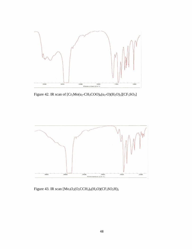
IR spectra of [Mo3O2(O2CCH3)6(H2O)(CF3SO2H)2 and [Cr2Mo(u2-CH3COO)6(u3-
O)(H2O)3][CF3SO3] are shown in figures 42 and 43 respectively.
48
Figure 42. IR scan of [Cr2Mo(u2-CH3COO)6(u3-O)(H2O)3][CF3SO3]
Figure 43. IR scan [Mo3O2(O2CCH3)6(H2O)(CF3SO2H)2
49
Electrochemical deposition of [Mo3O2(O2CCH3)6(H2O)(CF3SO2H)2 and [Cr2Mo(u2-
CH3COO)6(u3-O)(H2O)3][CF3SO3] onto a Pt electrode
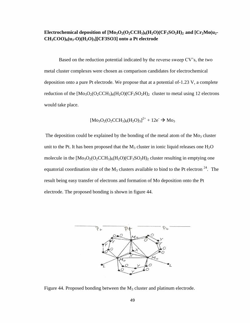
Based on the reduction potential indicated by the reverse sweep CV’s, the two
metal cluster complexes were chosen as comparison candidates for electrochemical
deposition onto a pure Pt electrode. We propose that at a potential of-1.23 V, a complete
reduction of the [Mo3O2(O2CCH3)6(H2O)(CF3SO2H)2 cluster to metal using 12 electrons
would take place.
[Mo3O2(O2CCH3)6(H2O)3]2+
+ 12e- Mo3
The deposition could be explained by the bonding of the metal atom of the Mo3 cluster
unit to the Pt. It has been proposed that the M3 cluster in ionic liquid releases one H2O
molecule in the [Mo3O2(O2CCH3)6(H2O)(CF3SO2H)2 cluster resulting in emptying one
equatorial coordination site of the M3 clusters available to bind to the Pt electron 24
. The
result being easy transfer of electrons and formation of Mo deposition onto the Pt
electrode. The proposed bonding is shown in figure 44.
Figure 44. Proposed bonding between the M3 cluster and platinum electrode.
50
The [Mo3O2(O2CCH3)6(H2O)3] metal species is made up of three direct metal-metal
bonds and has a cation charge of +12. Each Mo atom has a formal oxidation state of +4.
However, in the metal complex of [Cr2Mo(u2-CH3COO)6(u3-O)(H2O)3] species the Mo is
directly bonded to each of the Cr atoms but the Cr atoms do not bond to each other. There
is also a difference in the charge of the cation for of [Cr2Mo(u2-CH3COO)6(u3-O)(H2O)3]
where the Mo has an oxidation state of +4 but each of the Cr atoms only carry a charge of
+3 which gives an formal oxidation state of 3.33 for the metal center. The bond distances
found for the Mo3 species are also different. Mo3 complexes are reported as 2.46 Å to
2.55 Å17
. According to the crystallography data obtained for [Cr2Mo(u2-CH3COO)6(u3-
O)(H2O)3] the bond distance between the Mo atom and each of the two Cr atoms was
found to be approximately 3.3 Å which would result in a much weaker bond 23
. To
investigate the deposition of each metal complex onto a Pt electrode, a constant reduction
potential on a small Pt foil electrode was performed. A two compartment electrochemical
cell was used for the electrodeposition of each species. A pure Pt foil working electrode
and an Ag/AgCl reference electrode were placed in the cathodic compartment. The
auxiliary Pt electrode was placed in the anodic compartment. A solution of
[Mo3O2(O2CCH3)6(H2O)3] metal species dissolved in EMIBeti was electrolyzed at -1.23
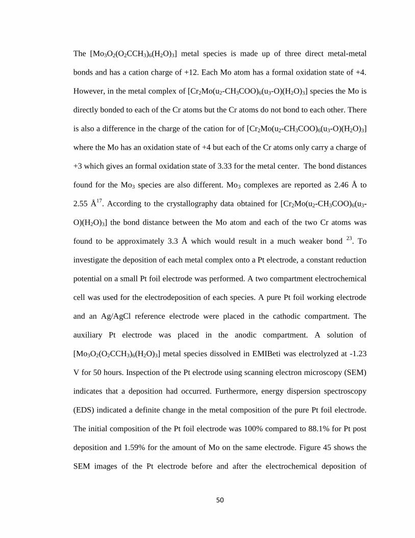
V for 50 hours. Inspection of the Pt electrode using scanning electron microscopy (SEM)
indicates that a deposition had occurred. Furthermore, energy dispersion spectroscopy
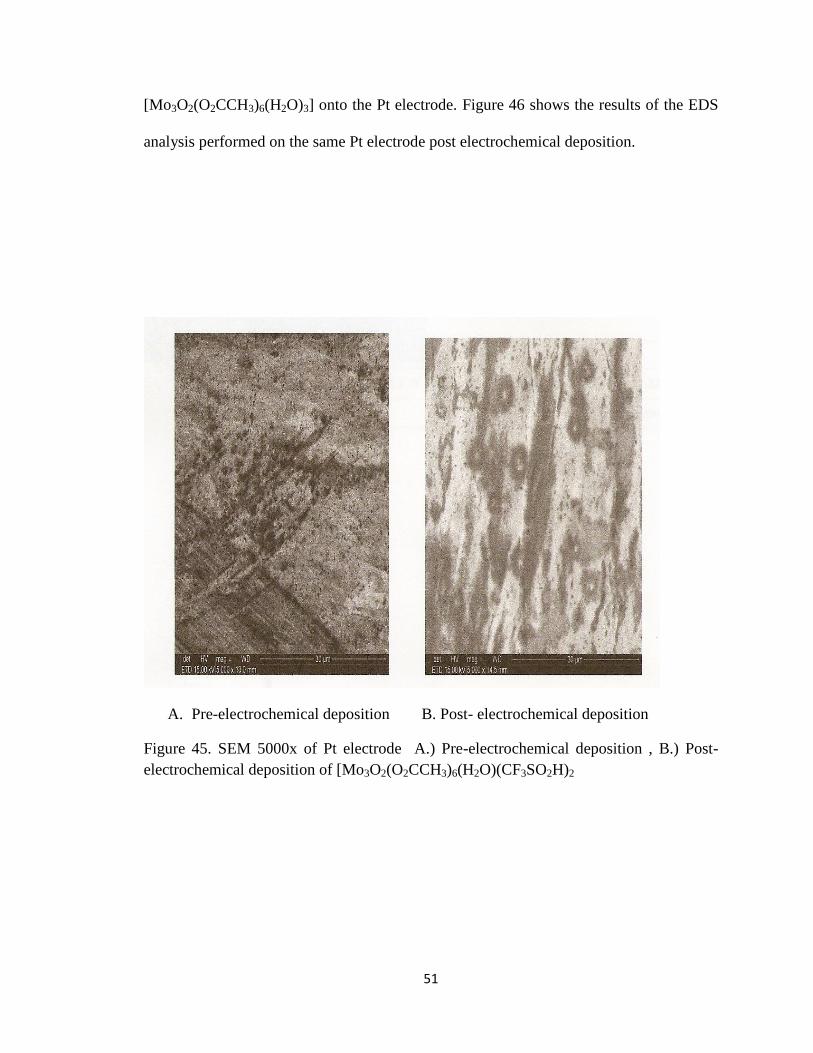
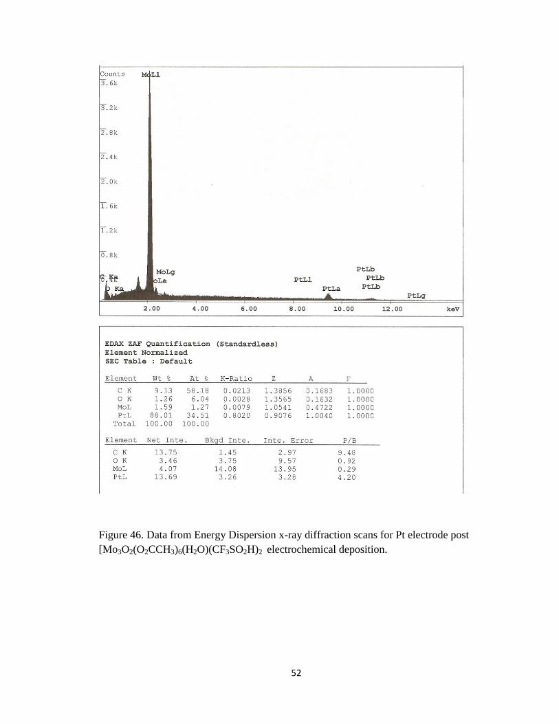
(EDS) indicated a definite change in the metal composition of the pure Pt foil electrode.
The initial composition of the Pt foil electrode was 100% compared to 88.1% for Pt post
deposition and 1.59% for the amount of Mo on the same electrode. Figure 45 shows the
SEM images of the Pt electrode before and after the electrochemical deposition of
51
[Mo3O2(O2CCH3)6(H2O)3] onto the Pt electrode. Figure 46 shows the results of the EDS
analysis performed on the same Pt electrode post electrochemical deposition.
A. Pre-electrochemical deposition B. Post- electrochemical deposition
Figure 45. SEM 5000x of Pt electrode A.) Pre-electrochemical deposition , B.) Post-
electrochemical deposition of [Mo3O2(O2CCH3)6(H2O)(CF3SO2H)2
52
Figure 46. Data from Energy Dispersion x-ray diffraction scans for Pt electrode post
[Mo3O2(O2CCH3)6(H2O)(CF3SO2H)2 electrochemical deposition.
53
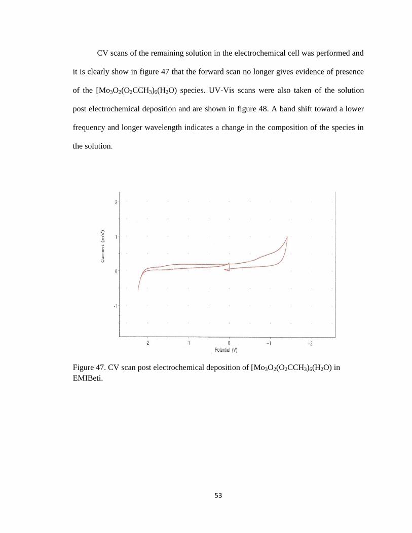
CV scans of the remaining solution in the electrochemical cell was performed and
it is clearly show in figure 47 that the forward scan no longer gives evidence of presence
of the [Mo3O2(O2CCH3)6(H2O) species. UV-Vis scans were also taken of the solution
post electrochemical deposition and are shown in figure 48. A band shift toward a lower
frequency and longer wavelength indicates a change in the composition of the species in
the solution.
Figure 47. CV scan post electrochemical deposition of [Mo3O2(O2CCH3)6(H2O) in
EMIBeti.

54
Figure 48. UV-Vis scan of [Mo3O2(O2CCH3)6(H2O)(CF3SO2H)2 post electrochemical
deposition.
Similarly, using the same type of electrochemical cell, an attempt was made to
electrochemically deposit [Cr2Mo(u2-CH3COO)6(u3-O)(H2O)3 in EMIBeti onto the Pt
electrode. The only difference being the value of the applied potential, -1.05 V at which
the [Cr2Mo(u2-CH3COO)6(u3-O)(H2O)3 species was electrolyzed. The Inspection of the
Pt electrode using scanning electron microscopy (SEM) indicates that no deposition of
[Cr2Mo(u2-CH3COO)6(u3-O)(H2O)3 had occurred. Furthermore, energy dispersion
spectroscopy (EDS) indicated a change in the metal composition of the pure Pt foil
electrode had not occurred. The initial composition of the Pt foil electrode was 100% and
remained the same for the Pt electrode post attempted electrodeposition. Figure 49 shows
the SEM images of the Pt electrode before and after the electrochemical deposition of
[Cr2Mo(u2-CH3COO)6(u3-O)(H2O)3 . There is a difference of appearance for the Pt
electrode, however the EDS in figure 50 shows no signs of the presence of either Cr or
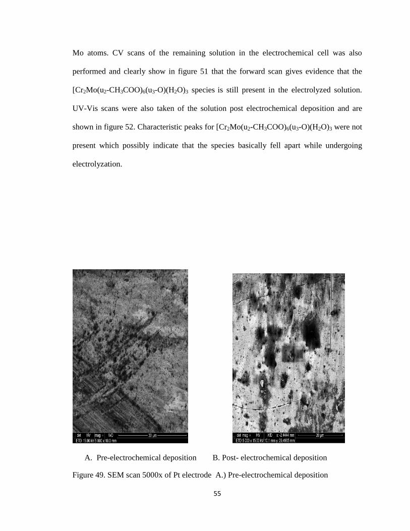
55
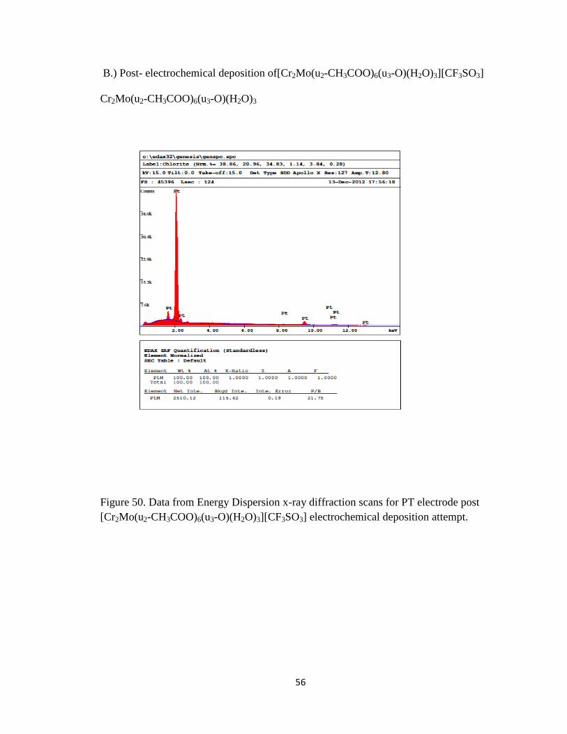
Mo atoms. CV scans of the remaining solution in the electrochemical cell was also
performed and clearly show in figure 51 that the forward scan gives evidence that the
[Cr2Mo(u2-CH3COO)6(u3-O)(H2O)3 species is still present in the electrolyzed solution.
UV-Vis scans were also taken of the solution post electrochemical deposition and are
shown in figure 52. Characteristic peaks for [Cr2Mo(u2-CH3COO)6(u3-O)(H2O)3 were not
present which possibly indicate that the species basically fell apart while undergoing
electrolyzation.
A. Pre-electrochemical deposition B. Post- electrochemical deposition
Figure 49. SEM scan 5000x of Pt electrode A.) Pre-electrochemical deposition
56
B.) Post- electrochemical deposition of[Cr2Mo(u2-CH3COO)6(u3-O)(H2O)3][CF3SO3]
Cr2Mo(u2-CH3COO)6(u3-O)(H2O)3
Figure 50. Data from Energy Dispersion x-ray diffraction scans for PT electrode post
[Cr2Mo(u2-CH3COO)6(u3-O)(H2O)3][CF3SO3] electrochemical deposition attempt.

57
Figure 51. CV scan of of [Cr2Mo(u2-CH3COO)6(u3-O)(H2O)3][CF3SO3] post
electrochemical deposition.
Figure 52. UV-Vis scan of of [Cr2Mo(u2-CH3COO)6(u3-O)(H2O)3][CF3SO3] post
electrochemical deposition.
58
IV. CONCLUSION
In this work the electrochemical properties of two different types of metal
clusters was investigated in an attempt to modify a Pt electrode. The trinuclear
homogeneous metal cluster of [Mo3O2(O2CCH3)6(H2O)(CF3SO2H)2 and the
polynuclear metal complex [Cr2Mo(u2-CH3COO)6(u3-O)(H2O)3][CF3SO3] in
EMIBeti ionic liquid were both thought to be good candidates due to thier
early transition metal and electrochemical potential characteristics. EMIBeti
was chosen as a suitable electrolyte solution due to its stability and wide
electrochemical potential window. Modification of a Pt electrode using metal
cluster compounds is thought to enhance the catalytic properties of the Pt
electrode.
It was shown by UV-Vis that the species of both the metal complexes
maintain their chemical integrity when dissolved in EMIBeti. After
electrochemical deposition experiments of both metal complexes it was found
that the trinuclear metal cluster of [Mo3O2(O2CCH3)6(H2O)(CF3SO2H)2
could be successfully deposited onto a Pt electrode but the polynuclear
complex of [Cr2Mo(u2-CH3COO)6(u3-O)(H2O)3][CF3SO3] could not be
deposited. The successful deposition was proven by SEM and EDS
spectroscopy methods.
Research could be extended further by actually using the modified Pt
electrode in a fuel cell such as an ethanol fuel cell to enhance the fuel cells
ability to make the reaction that takes place procede to completion. This

59
would be a benefit for the utilization of ethanol as an alternative energy
resource.
I. REFERENCES
1. Wilkies, J.S.; Zaaworotko, M.J. J. Chem.Soc.Chem.Commum. 1992, 965.
2. Hussey, C.L. and Marassi, R. Techniques for characterization of electrodes
and electrochemical processes. John Wiley& Sons, Inc., New York, 1991
3. Freemantle, M. Chem. Eng. News, (March 30) 1998, 76, 32.
4. Dancevic, A. Synthesis and Purification of Imidazolium and Pyrazolium based
Ionic liquids and their Applications in Electrochemistry. WSU, 2003
5. Earle, M. J; Seddon, K.R. Pure Appl. Chem. 2000, 1391.
6. Wasserscherd, P.; Welton, T. Ionic liquid synthesis. Wiley –Vch, Verlag, 2003
7. Chen, Po-Yu; Sun,I-Wen,”Electrochemistry of Cd(II) in the basic 1-ethyl-3-
methylimidazolium chloride/tetrafluoroborae Room Temperature Molten Salt”
Electrochimica Acta 2000, 3163-3170
8. F. A. Cotton, Accounts Chem. Res., 2,240 (1969).
9. Huheey, J.E;. Keiter, E.A.; Keiter; R.L. “Inorgnic Chemistry” forth edition
1993
10. L. Pauling, “ The Nature of the Chemical Bond” , 3rd. , Cornell University
Press, Ithaca N.Y., 1960
11. Geilnann, W.; Wriuce, F. W.; Biltz. W.: Nachr. Ges. Wiss. Gottingen 1932,
579.

60
12. Syzuki,T.,TriNuclear Mixed Metal Clusters of Molybdenum and
Tungsten,WSU 1985
13. Annu. Rep. Prog. Chem., Sect. A, 2002, 98, 153-17
14. Keith J. Laidler and J.H. Meiser, Physical Chemistry, Benjamin/Cummings
(1982), p.423
15. M. G.Thhomas, B. F. Beier, E. L. Muetteries, J. Am. Chem. Soc., 98, 24, 241,
(1985).
16. A. Bino, F.A. Cotton, Z. Dori, S. Koch, H. Kruppers, M. Miller, Inorg. Chem.,
17, 3245, (1978).
17. . F. A. Cotton, Z. Dori, D. O. Marler, W. Schwotzer, Inorg. Chem., 1983, 22,
3104-3106.
18. Williams, M. H., Electrochemical Investigation of Transition Metal Complexes
in Imidazolium based Ionic Liquids, WSU, 2006
19. R. E. McCarley, J. L. Templeton, T. J. Colburn, V. Katovic, R. J. Hoxeier, Adv.
Chem. Ser. No. 150, 318, (1976)
20. Jolly,William L., “The Synthesis and Characterization of inorganic
Compounds”, Princeton-Hall, Inc. – Library of Congress II, 78-100587, 442-44
REFERENCES CONTINUED
21. Harris, T. Electrochemistry of Trinuclear Metal Clusters of Molybdenum and
Tungsten in 1-Ethyl-3-Methylimidazolium Tetrafluoroborate. WSU, 2008.
22. D. M. P. Mingos, David J Wales , Introduction to cluster chemistry, Prentice-
Hall, 1990, ISBN 0-413-499049-9
61
23. Woods ,C. J., Electrochemical Deposition Of Molybdenum And Tungsten From
Trinuclear Metal Clusters Mo3O2(OAc)6(H2O)3(CF3SO3)2 In 1-Ethyl-3-
Methylimidazolium Tetrafluoroborate Ionic Liquid. WSU, 2010.
24. Scanning Electron Microscopy images and profile measurements provided by
WPAFB.
25. Conner, J. A. Top. Curr. Chem. 1977, 71, 71.
26. Kubas, G. J. and van der Sluys, L. S., “TriscarbonlylTris(nitrile) Complexes of
Cr, Mo, and W”, Inorganic Synthesis, 1990, 28, 29-33, ch6.
27. Girolami, S. G., Rauchfuss T. B., Angelica,R. J., “Synthesis and Technique in
inorganic Chemistry”: A laboratory manual- 3rd
ed., University Science Books,
1999, 11, 111.
28. Chang, S. C., Jeffery, G. A., “The Crystal Structure of a Basic Chromium
Acetate Compound, [OCr3(CH3COO)6.3H2O]+Cl
-.6H2O, havinf feeble
Paramagnetism” Acta Cryst. 1970, B26, 673.
29. F. A., Cotton, Murillo C. A., Walton R. A., “Multiple Bonds between Metal
Atoms” Springer Science and Business Media Inc., New York 2005, 31,3.13.
30. Bruker (2007). APEX2. Bruker AXS Inc., Madison, Wisconsin, USA.
31. Patrick McArdle, Karen Gilligan, Desmond Cunningham, Rex Dark and Mary
Mahon CrystEngComm, 2004, 6, 303 – 309
32. Kissinger, P. T., Heineman, W. R., “Laboratory Techniwues in
Electroanalytical Chemistry” Marcel Dekkar Inc. New York, New York 1984,
82-100.