
Simulations of pulsating one-dimensional detonations with ...
Heat Transfer Engineering, 33(14):1177–1187, 2012Copyright C©© Taylor and Francis Group, LLCISSN: 0145-7632 print / 1521-0537 onlineDOI: 10.1080/01457632.2012.677695
Thermal Simulation of a PulsatingHeat Pipe: Effects of Different LiquidProperties on a Simple Geometry
MAURO MAMELI,1 MARCO MARENGO,1 and STEFANO ZINNA2
1Department of Industrial Engineering, University of Bergamo, Dalmine (BG), Italy2Uniheat S.r.l., Bagnatica (BG), Italy
The pulsating heat pipe (PHP) is essentially a two-phase heat transfer device for low heat power applications (heat sinks,electronic cooling, etc.). Although it is a simple, cheap, and flexible structure, it is ruled by very complex physics, and arobust, validated simulation tool is still missing. In the present work the basic numerical model by Holley and Faghri (2005)has been updated with the latest fluid properties database and with the latest nondimensional heat transfer correlations inorder to make it suitable for different working fluids. Good agreement between numerical results and experimental datacoming from a single-loop PHP operating with ethanol is shown and, using a single “tuning” parameter, that is, the liquidfilm thickness around a vapor slug, which needs to be further experimentally investigated, the final goal of building a designtool for the PHP construction and implementation is getting closer.
INTRODUCTION
The sintered porous wick heat pipe technology is alreadysuccessfully implemented in many industrial thermal manage-ment applications [1], but since the early 1990s a new type ofwickless heat pipe prototype has been introduced by Akachi andco-workers [2–4]: the pulsating heat pipe (PHP).
It usually consists of a small-diameter meandering coppertube that can be closed in a loop (CLPHP) or with closed ends(CEPHP), evacuated, and then filled with a working fluid. Dueto the capillary diameter (usually between 1 and 2 mm) thefluid fills the tube with an alternation of liquid slugs and vaporbubbles. Once the device gets in contact with a heat source,evaporation occurs and the fluid starts oscillating and circulatingchaotically, allowing heat to be transported to the colder zone.
Many experimental works in literature show that a PHP couldmanage a wide range of industrial applications with the unques-tionable advantage of being cheaper and more flexible.
Table 1 shows the comparison between the PHP and thewicked heat pipes features.
Address correspondence to Professor Marco Marengo, Department of In-dustrial Engineering, University of Bergamo, Viale Marconi 5, 24044 Dalmine(BG), Italy. E-mail: [email protected]
Yang et al. [5] showed the possibility of embedding the PHPas an integrated structure or heat spreader, in order to provide ahigher overall thermal conductance to the host substrate. The in-fluences of various operating parameters, including volumetricfilling ratio of the working fluid, input heat flux, and operatingorientation, on the thermo-hydrodynamic performance, wereinvestigated and a successful operation at all orientations withrespect to gravity was achieved.
Miyazaki [6] developed a series of flexible CLPHP for note-book cooling able to dissipate heat from the central processingunits (CPUs) to the rear surface of the foldable display. Thewing type design with 1.2-mm channel diameter and 12 turnsachieved a thermal conductance of 3.5 W/K and a maximum heattransport capability of 100 W, which are reasonably thought tobe of sufficient potential for such application.
Rittidech and Wannapakne [7] investigated a flat-plate solarcollector in conjunction with a CEPHP operating with R134a asa working fluid, suggesting that this solution represents a reason-ably efficient and cost-effective alternative to the conventionalheat pipe solar collector system with the additional advantagesof corrosion-free operation and absence of icing problems dur-ing winter.
Khandekar [8] analyzed two kinds of PHP-based heat ex-changers: a temperature-controlled liquid–liquid module suit-able for process waste heat recovery, and a heat flux-controlled
1177
Dow
nloa
ded
by [
Uni
vers
ita S
tudi
la S
apie
nza]
at 0
6:24
15
Nov
embe
r 20
12
1178 M. MAMELI ET AL.
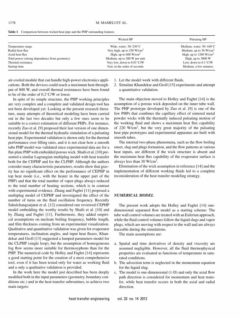
Table 1 Comparison between wicked heat pipe and the PHP outstanding features
Wicked HP Pulsating HP
Temperature range Wide, water: 30–230◦C Medium, water: 50–160◦CRadial heat flux Very high, up to 250 W/cm2 Medium, up to 30 W/cm2
Axial heat flux High, up to 600 W/cm2 High, up to 1200 W/cm2
Total power (strong dependence from geometry) Medium, up to 200 W per unit High, up to 3000 WThermal resistance Very low, down to 0.01◦C/W Low, down to 0.1◦C/WStartup time Fast, in the order of seconds Medium, a few minutes
air-cooled module that can handle high-power electronics appli-cations. Both the devices could reach a maximum heat through-put of 800 W, and overall thermal resistances have been foundto be of the order of 0.2◦C/W or lower.
In spite of its simple structure, the PHP working principlesare very complex and a complete and validated design tool hasnot been developed yet. Looking at the present research litera-ture, many attempts of theoretical modeling have been carriedout in the last two decades but only a few ones seem to besuitable to a correct estimation of different PHPs. For instance,recently Zuo et al. [9] proposed their last version of one dimen-sional model for the thermal hydraulic simulation of a pulsatingheat pipe. Experimental validation is shown only for the thermalperformance over filling ratio, and it is not clear how a smoothtube PHP model was validated since experimental data are for aflat-plate PHP with embedded porous wick. Shafii et al. [10] pre-sented a similar Lagrangian multiplug model with heat transferboth for the CEPHP and for the CLPHP. Although the authorsconsider many characteristic parameters, results show that grav-ity has no significant effect on the performance of CEPHP intop heat mode (i.e., with the heater in the upper part of thePHP) and that the total number of vapor plugs always reducedto the total number of heating sections, which is in contrastwith experimental evidence. Zhang and Faghri [11] proposed amultiplug model of CEPHP and investigated the effect of thenumber of turns on the fluid oscillation frequency. RecentlySakulchangsatjatai et al. [12] considered one reviewed CEPHPmodel embedding the worthy results by Shafii et al. [10] andby Zhang and Faghri [11]. Furthermore, they added empiri-cal assumptions on nucleate boiling frequency, bubble length,and film thickness coming from an experimental visualization.Qualitative and quantitative validation was given for evaporatortemperatures, inclination angles, and input heat fluxes; Khan-dekar and Groll [13] suggested a lumped parameters model forthe CLPHP (single loop), but the assumption of homogeneousfog flow seems more suitable for thermosyphons than for thePHP. The numerical code by Holley and Faghri [14] representsa good starting point for the creation of a most comprehensivetool, even if it has been tested only for water as working fluidand a only a qualitative validation is provided.
In the work here the model just described has been deeplymodified both in the input parameters (geometry, boundary con-ditions etc.) and in the heat transfer subroutines, to achieve twomain targets:
1. Let the model work with different fluids.2. Simulate Khandekar and Groll [15] experiments and attempt
a quantitative validation.
The main objection moved to Holley and Faghri [14] is theassumption of a porous wick deposited on the inner tube wall.The PHP prototype developed by Zuo et al. [9] is one of thefew PHPs that combines the capillary effect of sintered metalpowder wicks with the thermally induced pulsating motion ofthe working fluid and shows a maximum heat flux capabilityof 220 W/cm2, but the very great majority of the pulsatingheat pipe prototypes and experimental apparatus are built withsmooth tubes.
The internal two-phase phenomena, such as the flow boilingonset, slug and plugs formation, and the flow patterns at variousheat inputs, are different if the wick structure is absent andthe maximum heat flux capability of the evaporator surface isalways less than 30 W/cm2.
Elimination of the wick assumption in reference [14] and theimplementation of different working fluids led to a completereconsideration of the heat transfer modeling strategy.
NUMERICAL MODEL
The present work adopts the Holley and Faghri [14] one-dimensional separated flow model as a starting scheme: Thetube wall control volumes are treated with an Eulerian approach,while the fluid control volumes follow the liquid slugs and vaporplugs, which are moving with respect to the wall and are alwaystraceable during the simulations.
The main assumptions are:
a. Spatial and time derivatives of density and viscosity areassumed negligible. However, all the fluid thermophysicalproperties are evaluated as functions of temperature in satu-rated conditions.
b. The advection term is neglected in the momentum equationfor the liquid slug.
c. The model is one-dimensional (1-D) and only the axial flowpath direction is considered for momentum and heat trans-fer, while heat transfer occurs in both the axial and radialdirection.
heat transfer engineering vol. 33 no. 14 2012
Dow
nloa
ded
by [
Uni
vers
ita S
tudi
la S
apie
nza]
at 0
6:24
15
Nov
embe
r 20
12
M. MAMELI ET AL. 1179
d. The forward and backward menisci of the liquid slugs areassumed to maintain a spherical meniscus shape with zerocontact angles at the wall.
e. Surface tension is evaluated at the vapor plugs temperature.f. The pressure within each vapor plug is assumed uniform.g. Vapor exists at saturated conditions; each vapor plug (VP) is
treated as an ideal gas and has negligible flow friction.h. The liquid film that surrounds each VP is only considered
for thermodynamic purposes but does not play any role inthe hydrodynamics behavior.
The governing equations are listed next.
Momentum Equation for the i-th Liquid Slug
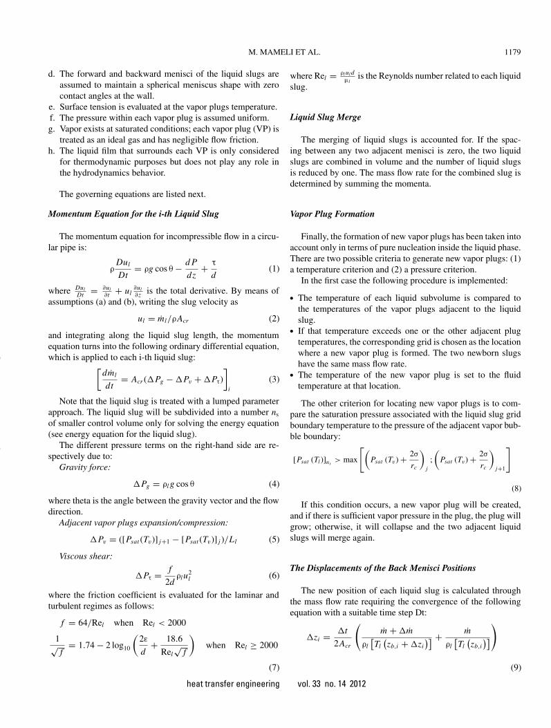
The momentum equation for incompressible flow in a circu-lar pipe is:
ρDul
Dt= ρg cos θ − d P
dz+ τ
d(1)
where DulDt = ∂ul
∂t + ul∂ul∂z is the total derivative. By means of
assumptions (a) and (b), writing the slug velocity as
ul = ml/ρAcr (2)
and integrating along the liquid slug length, the momentumequation turns into the following ordinary differential equation,which is applied to each i-th liquid slug:[
dml
dt= Acr (�Pg − �Pv + �Pτ)
]i
(3)
Note that the liquid slug is treated with a lumped parameterapproach. The liquid slug will be subdivided into a number ns
of smaller control volume only for solving the energy equation(see energy equation for the liquid slug).
The different pressure terms on the right-hand side are re-spectively due to:
Gravity force:
�Pg = ρl g cos θ (4)
where theta is the angle between the gravity vector and the flowdirection.
Adjacent vapor plugs expansion/compression:
�Pv = ([Psat (Tv)] j+1 − [Psat (Tv)] j )/Ll (5)
Viscous shear:
�Pτ = f
2dρlu
2l (6)
where the friction coefficient is evaluated for the laminar andturbulent regimes as follows:
f = 64/Rel when Rel < 2000
1√f
= 1.74 − 2 log10
(2ε
d+ 18.6
Rel√
f
)when Rel ≥ 2000
(7)
where Rel = ρl ul dµl
is the Reynolds number related to each liquidslug.
Liquid Slug Merge
The merging of liquid slugs is accounted for. If the spac-ing between any two adjacent menisci is zero, the two liquidslugs are combined in volume and the number of liquid slugsis reduced by one. The mass flow rate for the combined slug isdetermined by summing the momenta.
Vapor Plug Formation
Finally, the formation of new vapor plugs has been taken intoaccount only in terms of pure nucleation inside the liquid phase.There are two possible criteria to generate new vapor plugs: (1)a temperature criterion and (2) a pressure criterion.
In the first case the following procedure is implemented:
• The temperature of each liquid subvolume is compared tothe temperatures of the vapor plugs adjacent to the liquidslug.
• If that temperature exceeds one or the other adjacent plugtemperatures, the corresponding grid is chosen as the locationwhere a new vapor plug is formed. The two newborn slugshave the same mass flow rate.
• The temperature of the new vapor plug is set to the fluidtemperature at that location.
The other criterion for locating new vapor plugs is to com-pare the saturation pressure associated with the liquid slug gridboundary temperature to the pressure of the adjacent vapor bub-ble boundary:
[Psat (Tl )]ns> max
[(Psat (Tv) + 2σ
rc
)j
;
(Psat (Tv) + 2σ
rc
)j+1
]
(8)
If this condition occurs, a new vapor plug will be created,and if there is sufficient vapor pressure in the plug, the plug willgrow; otherwise, it will collapse and the two adjacent liquidslugs will merge again.
The Displacements of the Back Menisci Positions
The new position of each liquid slug is calculated throughthe mass flow rate requiring the convergence of the followingequation with a suitable time step Dt:
�zi = �t
2Acr
(m + �m
ρl[Tl(zb,i + �zi
)] + m
ρl[Tl(zb,i)])
(9)
heat transfer engineering vol. 33 no. 14 2012
Dow
nloa
ded
by [
Uni
vers
ita S
tudi
la S
apie
nza]
at 0
6:24
15
Nov
embe
r 20
12
1180 M. MAMELI ET AL.
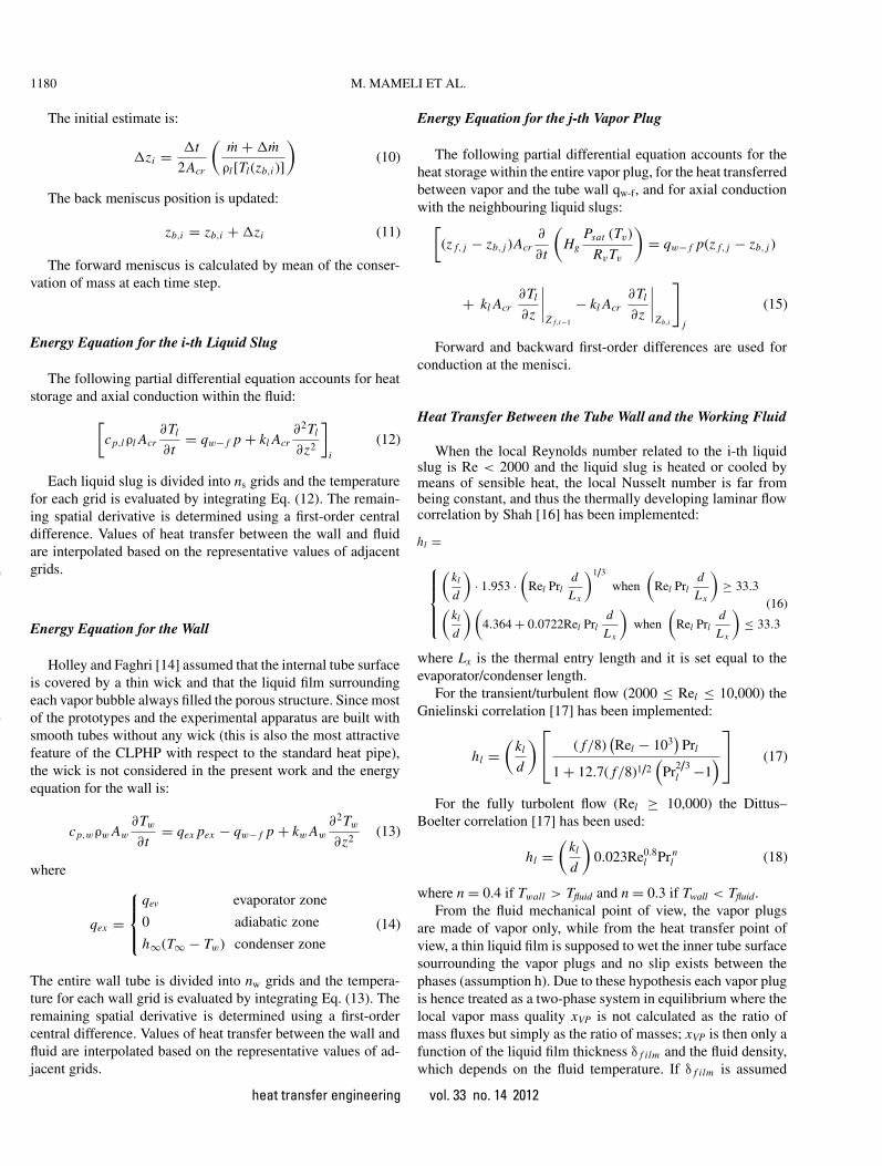
The initial estimate is:
�zi = �t
2Acr
(m + �m
ρl[Tl(zb,i )]
)(10)
The back meniscus position is updated:
zb,i = zb,i + �zi (11)
The forward meniscus is calculated by mean of the conser-vation of mass at each time step.
Energy Equation for the i-th Liquid Slug
The following partial differential equation accounts for heatstorage and axial conduction within the fluid:
[cp,lρl Acr
∂Tl
∂t= qw− f p + kl Acr
∂2Tl
∂z2
]i
(12)
Each liquid slug is divided into ns grids and the temperaturefor each grid is evaluated by integrating Eq. (12). The remain-ing spatial derivative is determined using a first-order centraldifference. Values of heat transfer between the wall and fluidare interpolated based on the representative values of adjacentgrids.
Energy Equation for the Wall
Holley and Faghri [14] assumed that the internal tube surfaceis covered by a thin wick and that the liquid film surroundingeach vapor bubble always filled the porous structure. Since mostof the prototypes and the experimental apparatus are built withsmooth tubes without any wick (this is also the most attractivefeature of the CLPHP with respect to the standard heat pipe),the wick is not considered in the present work and the energyequation for the wall is:
cp,wρw Aw
∂Tw
∂t= qex pex − qw− f p + kw Aw
∂2Tw
∂z2(13)
where
qex =
⎧⎪⎨⎪⎩
qev evaporator zone
0 adiabatic zone
h∞(T∞ − Tw) condenser zone(14)
The entire wall tube is divided into nw grids and the tempera-ture for each wall grid is evaluated by integrating Eq. (13). Theremaining spatial derivative is determined using a first-ordercentral difference. Values of heat transfer between the wall andfluid are interpolated based on the representative values of ad-jacent grids.
Energy Equation for the j-th Vapor Plug
The following partial differential equation accounts for theheat storage within the entire vapor plug, for the heat transferredbetween vapor and the tube wall qw-f, and for axial conductionwith the neighbouring liquid slugs:[
(z f, j − zb, j )Acr∂
∂t
(Hg
Psat (Tv)
RvTv
)= qw− f p(z f, j − zb, j )
+ kl Acr∂Tl
∂z
∣∣∣∣Z f,i−1
− kl Acr∂Tl
∂z
∣∣∣∣Zb,i
]j
(15)
Forward and backward first-order differences are used forconduction at the menisci.
Heat Transfer Between the Tube Wall and the Working Fluid
When the local Reynolds number related to the i-th liquidslug is Re < 2000 and the liquid slug is heated or cooled bymeans of sensible heat, the local Nusselt number is far frombeing constant, and thus the thermally developing laminar flowcorrelation by Shah [16] has been implemented:
hl =⎧⎪⎪⎪⎨⎪⎪⎪⎩
(kl
d
)· 1.953 ·
(Rel Prl
d
Lx
)1/3
when
(Rel Prl
d
Lx
)≥ 33.3
(kl
d
)(4.364 + 0.0722Rel Prl
d
Lx
)when
(Rel Prl
d
Lx
)≤ 33.3
(16)
where Lx is the thermal entry length and it is set equal to theevaporator/condenser length.
For the transient/turbulent flow (2000 ≤ Rel ≤ 10,000) theGnielinski correlation [17] has been implemented:
hl =(
kl
d
)⎡⎣ ( f/8)(Rel − 103
)Prl
1 + 12.7( f/8)1/2(
Pr2/3l −1
)⎤⎦ (17)
For the fully turbolent flow (Rel ≥ 10,000) the Dittus–Boelter correlation [17] has been used:
hl =(
kl
d
)0.023Re0.8
l Pr nl (18)
where n = 0.4 if Twall > Tfluid and n = 0.3 if Twall < Tfluid.From the fluid mechanical point of view, the vapor plugs
are made of vapor only, while from the heat transfer point ofview, a thin liquid film is supposed to wet the inner tube surfacesourrounding the vapor plugs and no slip exists between thephases (assumption h). Due to these hypothesis each vapor plugis hence treated as a two-phase system in equilibrium where thelocal vapor mass quality xVP is not calculated as the ratio ofmass fluxes but simply as the ratio of masses; xVP is then only afunction of the liquid film thickness δ f ilm and the fluid density,which depends on the fluid temperature. If δ f ilm is assumed
heat transfer engineering vol. 33 no. 14 2012
Dow
nloa
ded
by [
Uni
vers
ita S
tudi
la S
apie
nza]
at 0
6:24
15
Nov
embe
r 20
12
M. MAMELI ET AL. 1181
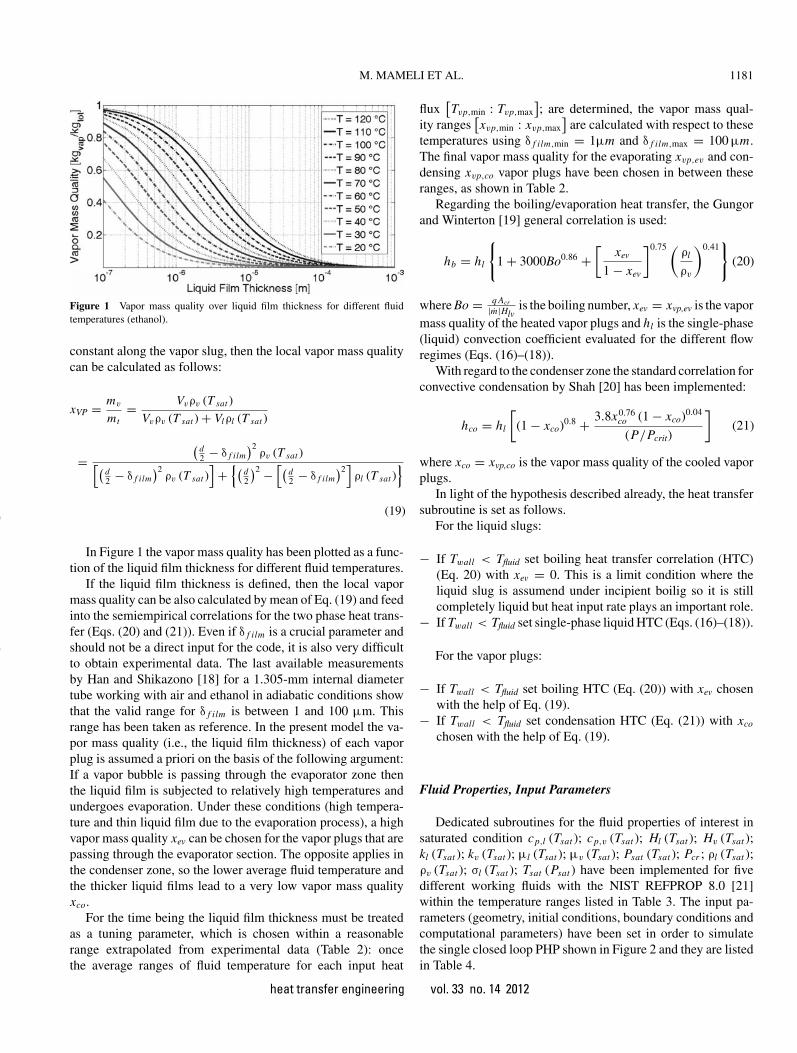
Figure 1 Vapor mass quality over liquid film thickness for different fluidtemperatures (ethanol).
constant along the vapor slug, then the local vapor mass qualitycan be calculated as follows:
xVP = mv
mt= Vvρv (T sat )
Vvρv (T sat ) + Vlρl (T sat )
=(
d2 − δ f ilm
)2ρv (T sat )[(
d2 − δ f ilm
)2ρv (T sat )
]+{(
d2
)2 −[(
d2 − δ f ilm
)2]ρl (T sat )
}
(19)
In Figure 1 the vapor mass quality has been plotted as a func-tion of the liquid film thickness for different fluid temperatures.
If the liquid film thickness is defined, then the local vapormass quality can be also calculated by mean of Eq. (19) and feedinto the semiempirical correlations for the two phase heat trans-fer (Eqs. (20) and (21)). Even if δ f ilm is a crucial parameter andshould not be a direct input for the code, it is also very difficultto obtain experimental data. The last available measurementsby Han and Shikazono [18] for a 1.305-mm internal diametertube working with air and ethanol in adiabatic conditions showthat the valid range for δ f ilm is between 1 and 100 µm. Thisrange has been taken as reference. In the present model the va-por mass quality (i.e., the liquid film thickness) of each vaporplug is assumed a priori on the basis of the following argument:If a vapor bubble is passing through the evaporator zone thenthe liquid film is subjected to relatively high temperatures andundergoes evaporation. Under these conditions (high tempera-ture and thin liquid film due to the evaporation process), a highvapor mass quality xev can be chosen for the vapor plugs that arepassing through the evaporator section. The opposite applies inthe condenser zone, so the lower average fluid temperature andthe thicker liquid films lead to a very low vapor mass qualityxco.
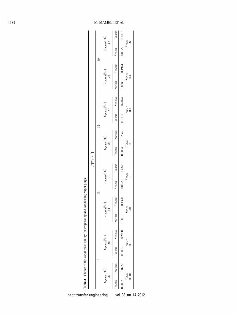
For the time being the liquid film thickness must be treatedas a tuning parameter, which is chosen within a reasonablerange extrapolated from experimental data (Table 2): oncethe average ranges of fluid temperature for each input heat
flux[Tvp,min : Tvp,max
]; are determined, the vapor mass qual-
ity ranges[xvp,min : xvp,max
]are calculated with respect to these
temperatures using δ f ilm,min = 1µm and δ f ilm,max = 100 µm.The final vapor mass quality for the evaporating xvp,ev and con-densing xvp,co vapor plugs have been chosen in between theseranges, as shown in Table 2.
Regarding the boiling/evaporation heat transfer, the Gungorand Winterton [19] general correlation is used:
hb = hl
{1 + 3000Bo0.86 +
[xev
1 − xev
]0.75 (ρl
ρv
)0.41}
(20)
where Bo = q Acr
|m|Hlvis the boiling number, xev = xvp,ev is the vapor
mass quality of the heated vapor plugs and hl is the single-phase(liquid) convection coefficient evaluated for the different flowregimes (Eqs. (16)–(18)).
With regard to the condenser zone the standard correlation forconvective condensation by Shah [20] has been implemented:
hco = hl
[(1 − xco)0.8 + 3.8x0.76
co (1 − xco)0.04
(P/Pcrit)
](21)
where xco = xvp,co is the vapor mass quality of the cooled vaporplugs.
In light of the hypothesis described already, the heat transfersubroutine is set as follows.
For the liquid slugs:
− If Twall < Tfluid set boiling heat transfer correlation (HTC)(Eq. 20) with xev = 0. This is a limit condition where theliquid slug is assumend under incipient boilig so it is stillcompletely liquid but heat input rate plays an important role.
− If Twall < Tfluid set single-phase liquid HTC (Eqs. (16)–(18)).
For the vapor plugs:
− If Twall < Tfluid set boiling HTC (Eq. (20)) with xev chosenwith the help of Eq. (19).
− If Twall < Tfluid set condensation HTC (Eq. (21)) with xco
chosen with the help of Eq. (19).
Fluid Properties, Input Parameters
Dedicated subroutines for the fluid properties of interest insaturated condition cp,l (Tsat ); cp,v (Tsat ); Hl (Tsat ); Hv (Tsat );kl (Tsat ); kv (Tsat ); µl (Tsat ); µv (Tsat ); Psat (Tsat ); Pcr ; ρl (Tsat );ρv (Tsat ); σl (Tsat ); Tsat (Psat ) have been implemented for fivedifferent working fluids with the NIST REFPROP 8.0 [21]within the temperature ranges listed in Table 3. The input pa-rameters (geometry, initial conditions, boundary conditions andcomputational parameters) have been set in order to simulatethe single closed loop PHP shown in Figure 2 and they are listedin Table 4.
heat transfer engineering vol. 33 no. 14 2012
Dow
nloa
ded
by [
Uni
vers
ita S
tudi
la S
apie
nza]
at 0
6:24
15
Nov
embe
r 20
12
1182 M. MAMELI ET AL.
Tabl
e2
Cho
ice
ofth
eva
por
mas
squ
ality
for
evap
orat
ing
and
cond
ensi
ngva
por
plug
s
q′′ [
W/cm
2]
48
1216
T vp,
min
[◦C
]T v
p,m
ax[◦
C]
T vp,
min
[◦C
]T v
p,m
ax[◦
C]
T vp,
min
[◦C
]T v
p,m
ax[◦
C]
T vp,
min
[◦C
]T v
p,m
ax[◦
C]
2355
3470
5487
7611
7
x vp,
min
x vp,
max
x vp,
min
x vp,
max
x vp,
min
x vp,
max
x vp,
min
x vp,
max
x vp,
min
x vp,
max
x vp,
min
x vp,
max
x vp,
min
x vp,
max
x vp,
min
x vp,
max
0.00
070.
0772
0.00
360.
2960
0.00
130.
1320
0.00
650.
4343
0.00
340.
2867
0.01
300.
6074
0.00
830.
4944
0.03
550.
8116
x vp,
cox v
p,ev
x vp,
cox v
p,ev
x vp,
cox v
p,ev
x vp,
cox v
p,ev
0.00
10.
010.
010.
10.
10.
50.
40.
8
heat transfer engineering vol. 33 no. 14 2012
Dow
nloa
ded
by [
Uni
vers
ita S
tudi
la S
apie
nza]
at 0
6:24
15
Nov
embe
r 20
12
M. MAMELI ET AL. 1183
Table 3 List of the working fluids temperature ranges implemented in thenumerical code
Fluid T min (◦C) T max (◦C)
Ethanol −18 202FC-72 2 152Methanol −53 197R123 −73 167
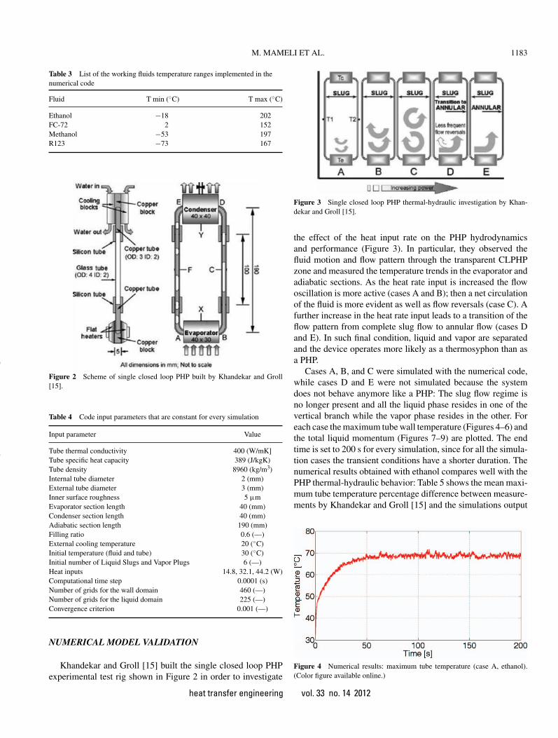
Figure 2 Scheme of single closed loop PHP built by Khandekar and Groll[15].
Table 4 Code input parameters that are constant for every simulation
Input parameter Value
Tube thermal conductivity 400 (W/mK]Tube specific heat capacity 389 (J/kgK)Tube density 8960 (kg/m3)Internal tube diameter 2 (mm)External tube diameter 3 (mm)Inner surface roughness 5 µmEvaporator section length 40 (mm)Condenser section length 40 (mm)Adiabatic section length 190 (mm)Filling ratio 0.6 (—)External cooling temperature 20 (◦C)Initial temperature (fluid and tube) 30 (◦C)Initial number of Liquid Slugs and Vapor Plugs 6 (—)Heat inputs 14.8, 32.1, 44.2 (W)Computational time step 0.0001 (s)Number of grids for the wall domain 460 (—)Number of grids for the liquid domain 225 (—)Convergence criterion 0.001 (—)
NUMERICAL MODEL VALIDATION
Khandekar and Groll [15] built the single closed loop PHPexperimental test rig shown in Figure 2 in order to investigate
Figure 3 Single closed loop PHP thermal-hydraulic investigation by Khan-dekar and Groll [15].
the effect of the heat input rate on the PHP hydrodynamicsand performance (Figure 3). In particular, they observed thefluid motion and flow pattern through the transparent CLPHPzone and measured the temperature trends in the evaporator andadiabatic sections. As the heat rate input is increased the flowoscillation is more active (cases A and B); then a net circulationof the fluid is more evident as well as flow reversals (case C). Afurther increase in the heat rate input leads to a transition of theflow pattern from complete slug flow to annular flow (cases Dand E). In such final condition, liquid and vapor are separatedand the device operates more likely as a thermosyphon than asa PHP.
Cases A, B, and C were simulated with the numerical code,while cases D and E were not simulated because the systemdoes not behave anymore like a PHP: The slug flow regime isno longer present and all the liquid phase resides in one of thevertical branch while the vapor phase resides in the other. Foreach case the maximum tube wall temperature (Figures 4–6) andthe total liquid momentum (Figures 7–9) are plotted. The endtime is set to 200 s for every simulation, since for all the simula-tion cases the transient conditions have a shorter duration. Thenumerical results obtained with ethanol compares well with thePHP thermal-hydraulic behavior: Table 5 shows the mean maxi-mum tube temperature percentage difference between measure-ments by Khandekar and Groll [15] and the simulations output
Figure 4 Numerical results: maximum tube temperature (case A, ethanol).(Color figure available online.)
heat transfer engineering vol. 33 no. 14 2012
Dow
nloa
ded
by [
Uni
vers
ita S
tudi
la S
apie
nza]
at 0
6:24
15
Nov
embe
r 20
12
1184 M. MAMELI ET AL.
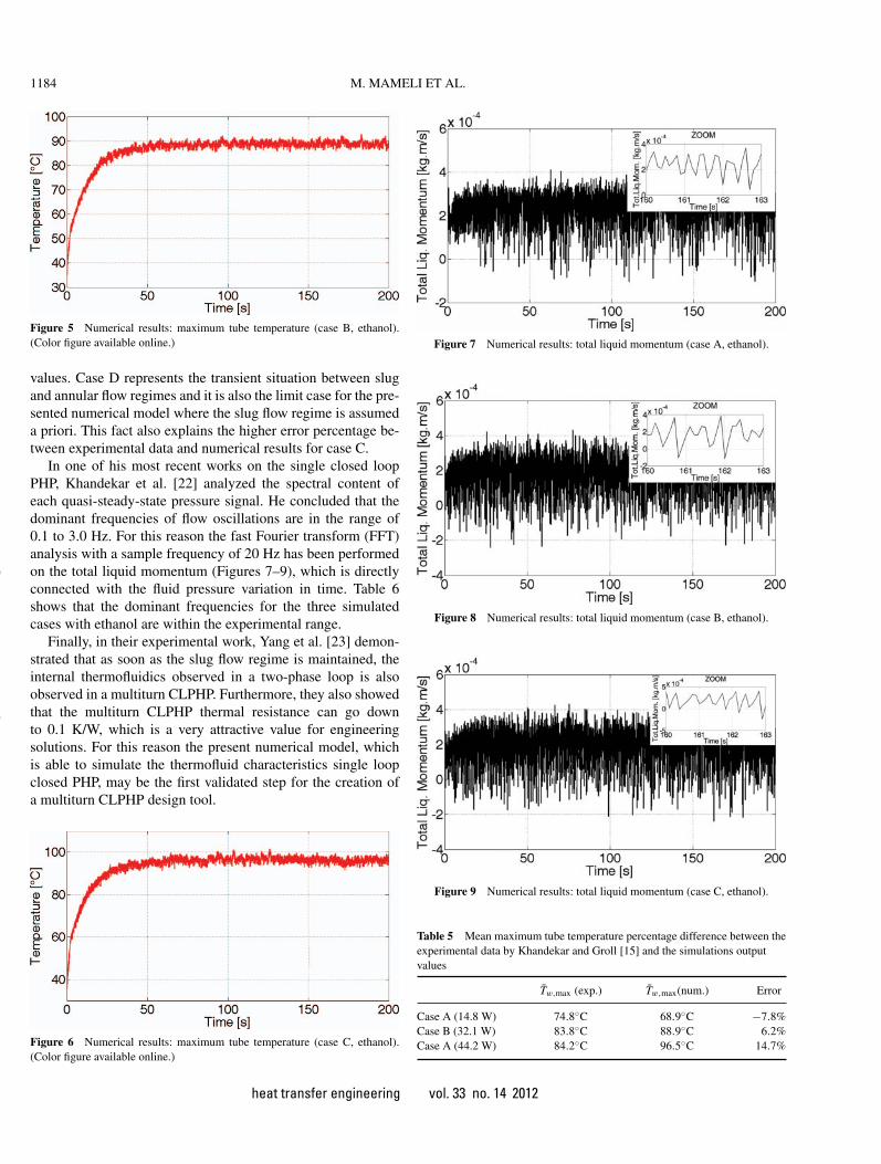
Figure 5 Numerical results: maximum tube temperature (case B, ethanol).(Color figure available online.)
values. Case D represents the transient situation between slugand annular flow regimes and it is also the limit case for the pre-sented numerical model where the slug flow regime is assumeda priori. This fact also explains the higher error percentage be-tween experimental data and numerical results for case C.
In one of his most recent works on the single closed loopPHP, Khandekar et al. [22] analyzed the spectral content ofeach quasi-steady-state pressure signal. He concluded that thedominant frequencies of flow oscillations are in the range of0.1 to 3.0 Hz. For this reason the fast Fourier transform (FFT)analysis with a sample frequency of 20 Hz has been performedon the total liquid momentum (Figures 7–9), which is directlyconnected with the fluid pressure variation in time. Table 6shows that the dominant frequencies for the three simulatedcases with ethanol are within the experimental range.
Finally, in their experimental work, Yang et al. [23] demon-strated that as soon as the slug flow regime is maintained, theinternal thermofluidics observed in a two-phase loop is alsoobserved in a multiturn CLPHP. Furthermore, they also showedthat the multiturn CLPHP thermal resistance can go downto 0.1 K/W, which is a very attractive value for engineeringsolutions. For this reason the present numerical model, whichis able to simulate the thermofluid characteristics single loopclosed PHP, may be the first validated step for the creation ofa multiturn CLPHP design tool.
Figure 6 Numerical results: maximum tube temperature (case C, ethanol).(Color figure available online.)
Figure 7 Numerical results: total liquid momentum (case A, ethanol).
Figure 8 Numerical results: total liquid momentum (case B, ethanol).
Figure 9 Numerical results: total liquid momentum (case C, ethanol).
Table 5 Mean maximum tube temperature percentage difference between theexperimental data by Khandekar and Groll [15] and the simulations outputvalues
Tw,max (exp.) Tw,max(num.) Error
Case A (14.8 W) 74.8◦C 68.9◦C −7.8%Case B (32.1 W) 83.8◦C 88.9◦C 6.2%Case A (44.2 W) 84.2◦C 96.5◦C 14.7%
heat transfer engineering vol. 33 no. 14 2012
Dow
nloa
ded
by [
Uni
vers
ita S
tudi
la S
apie
nza]
at 0
6:24
15
Nov
embe
r 20
12
M. MAMELI ET AL. 1185
Table 6 Mass flow rate dominant frequencies for the three simulated caseswith ethanol
Dominant frequencies (Hz)
Case A (14.8 W) 2.54Case B (32.1 W) 2.30Case A (44.2 W) 2.24
The model input parameters were then set on the basis ofthe good results obtained with ethanol and the same simulationswere carried forward with the fluids listed in Table 3.
Numerical results are resumed in only two plots: Figure 10shows the mean maximum tube temperature in quasi-steady-state conditions and Figure 11 shows the PHP equivalent thermalresistance obtained with the following equation:
Req = (Tw,max − Tw,min
)/Q (22)
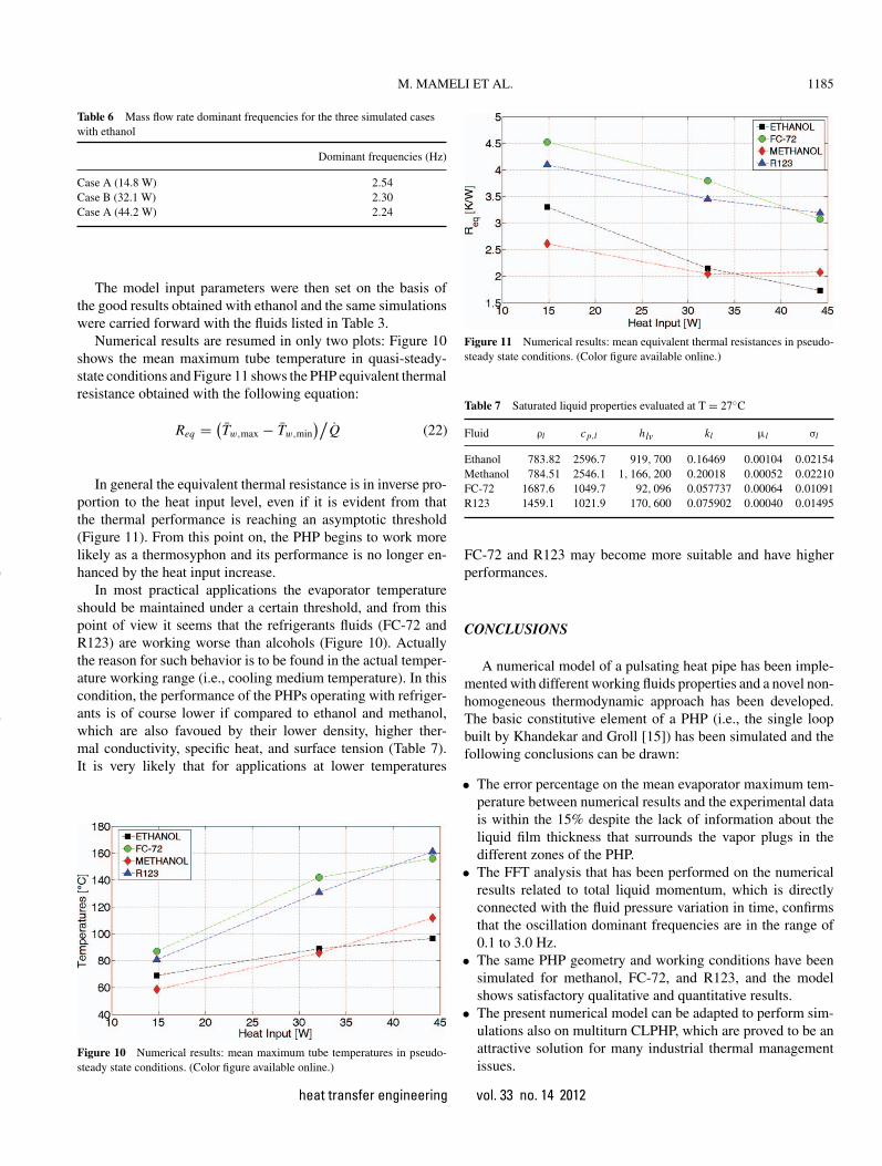
In general the equivalent thermal resistance is in inverse pro-portion to the heat input level, even if it is evident from thatthe thermal performance is reaching an asymptotic threshold(Figure 11). From this point on, the PHP begins to work morelikely as a thermosyphon and its performance is no longer en-hanced by the heat input increase.
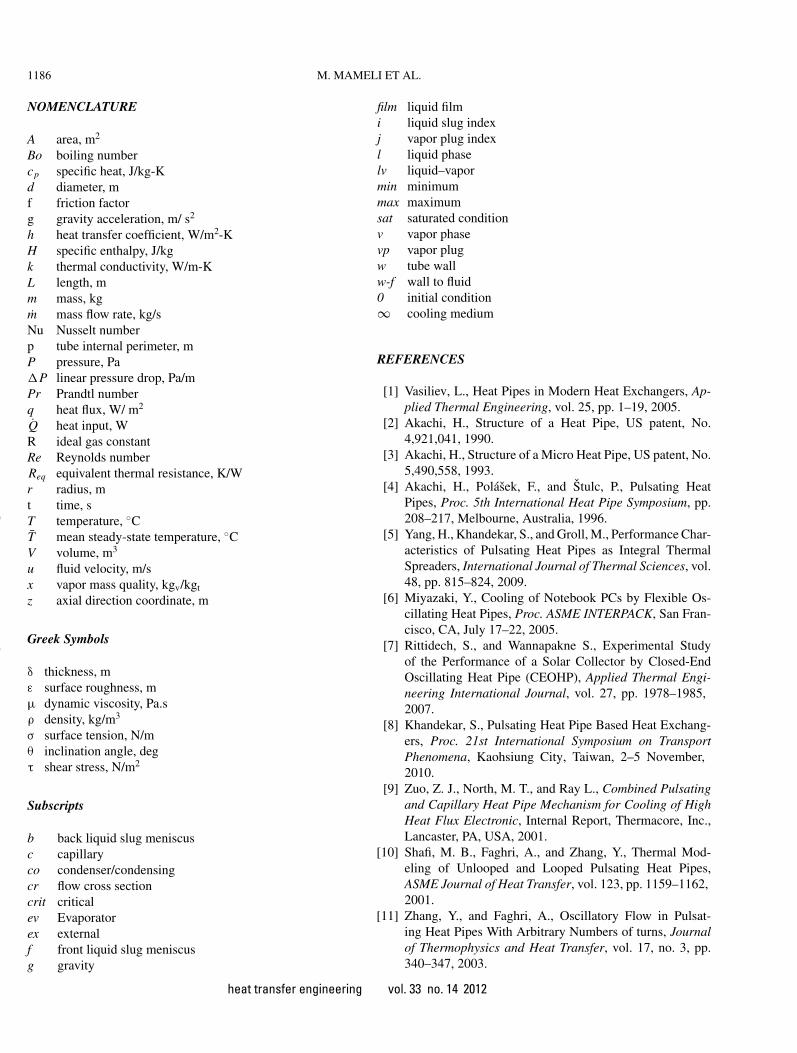
In most practical applications the evaporator temperatureshould be maintained under a certain threshold, and from thispoint of view it seems that the refrigerants fluids (FC-72 andR123) are working worse than alcohols (Figure 10). Actuallythe reason for such behavior is to be found in the actual temper-ature working range (i.e., cooling medium temperature). In thiscondition, the performance of the PHPs operating with refriger-ants is of course lower if compared to ethanol and methanol,which are also favoued by their lower density, higher ther-mal conductivity, specific heat, and surface tension (Table 7).It is very likely that for applications at lower temperatures
Figure 10 Numerical results: mean maximum tube temperatures in pseudo-steady state conditions. (Color figure available online.)
Figure 11 Numerical results: mean equivalent thermal resistances in pseudo-steady state conditions. (Color figure available online.)
Table 7 Saturated liquid properties evaluated at T = 27◦C
Fluid ρl cp,l hlv kl µl σl
Ethanol 783.82 2596.7 919, 700 0.16469 0.00104 0.02154Methanol 784.51 2546.1 1, 166, 200 0.20018 0.00052 0.02210FC-72 1687.6 1049.7 92, 096 0.057737 0.00064 0.01091R123 1459.1 1021.9 170, 600 0.075902 0.00040 0.01495
FC-72 and R123 may become more suitable and have higherperformances.
CONCLUSIONS
A numerical model of a pulsating heat pipe has been imple-mented with different working fluids properties and a novel non-homogeneous thermodynamic approach has been developed.The basic constitutive element of a PHP (i.e., the single loopbuilt by Khandekar and Groll [15]) has been simulated and thefollowing conclusions can be drawn:
• The error percentage on the mean evaporator maximum tem-perature between numerical results and the experimental datais within the 15% despite the lack of information about theliquid film thickness that surrounds the vapor plugs in thedifferent zones of the PHP.
• The FFT analysis that has been performed on the numericalresults related to total liquid momentum, which is directlyconnected with the fluid pressure variation in time, confirmsthat the oscillation dominant frequencies are in the range of0.1 to 3.0 Hz.
• The same PHP geometry and working conditions have beensimulated for methanol, FC-72, and R123, and the modelshows satisfactory qualitative and quantitative results.
• The present numerical model can be adapted to perform sim-ulations also on multiturn CLPHP, which are proved to be anattractive solution for many industrial thermal managementissues.
heat transfer engineering vol. 33 no. 14 2012
Dow
nloa
ded
by [
Uni
vers
ita S
tudi
la S
apie
nza]
at 0
6:24
15
Nov
embe
r 20
12
1186 M. MAMELI ET AL.
NOMENCLATURE
A area, m2
Bo boiling numbercp specific heat, J/kg-Kd diameter, mf friction factorg gravity acceleration, m/ s2
h heat transfer coefficient, W/m2-KH specific enthalpy, J/kgk thermal conductivity, W/m-KL length, mm mass, kgm mass flow rate, kg/sNu Nusselt numberp tube internal perimeter, mP pressure, Pa�P linear pressure drop, Pa/mPr Prandtl numberq heat flux, W/ m2
Q heat input, WR ideal gas constantRe Reynolds numberReq equivalent thermal resistance, K/Wr radius, mt time, sT temperature, ◦CT mean steady-state temperature, ◦CV volume, m3
u fluid velocity, m/sx vapor mass quality, kgv/kgt
z axial direction coordinate, m
Greek Symbols
δ thickness, mε surface roughness, mµ dynamic viscosity, Pa.sρ density, kg/m3
σ surface tension, N/mθ inclination angle, degτ shear stress, N/m2
Subscripts
b back liquid slug meniscusc capillaryco condenser/condensingcr flow cross sectioncrit criticalev Evaporatorex externalf front liquid slug meniscusg gravity
film liquid filmi liquid slug indexj vapor plug indexl liquid phaselv liquid–vapormin minimummax maximumsat saturated conditionv vapor phasevp vapor plugw tube wallw-f wall to fluid0 initial condition∞ cooling medium
REFERENCES
[1] Vasiliev, L., Heat Pipes in Modern Heat Exchangers, Ap-plied Thermal Engineering, vol. 25, pp. 1–19, 2005.
[2] Akachi, H., Structure of a Heat Pipe, US patent, No.4,921,041, 1990.
[3] Akachi, H., Structure of a Micro Heat Pipe, US patent, No.5,490,558, 1993.
[4] Akachi, H., Polasek, F., and Stulc, P., Pulsating HeatPipes, Proc. 5th International Heat Pipe Symposium, pp.208–217, Melbourne, Australia, 1996.
[5] Yang, H., Khandekar, S., and Groll, M., Performance Char-acteristics of Pulsating Heat Pipes as Integral ThermalSpreaders, International Journal of Thermal Sciences, vol.48, pp. 815–824, 2009.
[6] Miyazaki, Y., Cooling of Notebook PCs by Flexible Os-cillating Heat Pipes, Proc. ASME INTERPACK, San Fran-cisco, CA, July 17–22, 2005.
[7] Rittidech, S., and Wannapakne S., Experimental Studyof the Performance of a Solar Collector by Closed-EndOscillating Heat Pipe (CEOHP), Applied Thermal Engi-neering International Journal, vol. 27, pp. 1978–1985,2007.
[8] Khandekar, S., Pulsating Heat Pipe Based Heat Exchang-ers, Proc. 21st International Symposium on TransportPhenomena, Kaohsiung City, Taiwan, 2–5 November,2010.
[9] Zuo, Z. J., North, M. T., and Ray L., Combined Pulsatingand Capillary Heat Pipe Mechanism for Cooling of HighHeat Flux Electronic, Internal Report, Thermacore, Inc.,Lancaster, PA, USA, 2001.
[10] Shafi, M. B., Faghri, A., and Zhang, Y., Thermal Mod-eling of Unlooped and Looped Pulsating Heat Pipes,ASME Journal of Heat Transfer, vol. 123, pp. 1159–1162,2001.
[11] Zhang, Y., and Faghri, A., Oscillatory Flow in Pulsat-ing Heat Pipes With Arbitrary Numbers of turns, Journalof Thermophysics and Heat Transfer, vol. 17, no. 3, pp.340–347, 2003.
heat transfer engineering vol. 33 no. 14 2012
Dow
nloa
ded
by [
Uni
vers
ita S
tudi
la S
apie
nza]
at 0
6:24
15
Nov
embe
r 20
12
M. MAMELI ET AL. 1187
[12] Sakulchangsatjatai P., Chareonsawan, P., Waowaew, T.,Terdtoon, P., and Murakami, M., Mathematical Modellingof Closed-End Pulsating Heat Pipes Operating With a Bot-tom Heat Mode, Heat Transfer Engineering, vol. 29, no.3, pp. 239–254, 2008.
[13] Khandekar S., and Groll, M., Roadmap to Realistic Mod-eling of Closed Loop Pulsating Heat Pipes, Proc. 9th Inter-national Heat Pipe Symposium, Kuala Lumpur, Malaysia,November 2008.
[14] Holley, B., and Faghri, A., Analysis of Pulsating HeatPipe with Capillary Wick and Varying Channel Diameter,International Journal of Heat and Mass Transfer, vol. 48,pp. 2635–2651, 2005.
[15] Khandekar, S., and Groll, M., An Insight Into Thermo-Hydrodynamic Coupling in Closed Loop Pulsating HeatPipes, International Journal of Thermal Sciences, vol. 43,pp. 13–20, 2004.
[16] Shah, R. K., Thermal Entry Length Solutions for the Cir-cular Tube and Parallel Plates, Proc. 3rd National Heatand Mass Transfer Conference, IIT Bombay, vol. I, PaperHMT-11–75, 1975.
[17] Incropera, F. P., and DeWitt, D. P., Fundamentals of Heatand Mass Transfer, 6th ed., Wiley, USA, 2007.
[18] Han Y., and Shikazono N., Measurement of the Liquid FilmThickness in Micro Tube Slug Flow, International Journalof Heat and Fluid Flow, vol. 30, pp. 842–853, 2009.
[19] Gungor K. E., and Winterton, R. K. S., Simplified Gen-eral Correlation for Saturated Flow Boiling and Compar-isons of Correlations With Data, Chemical EngineeringResearch and Design, vol. 65, pp. 148–166, 1987.
[20] Shah, M. M., A General Correlation for Heat TransferDuring Film Condensation Inside of Pipes, InternationalJournal of Heat and Mass Transfer, vol. 22, pp. 547–556,1079.
[21] Lemmon, E. W., Huber, M. L., and McLinden, M. O., NISTStandard Reference Database 23: Reference Fluid Thermo-dynamic and Transport Properties-REFPROP, Version 8.0,
National Institute of Standards and Technology, StandardReference Data Program, Gaithersburg, 2007.
[22] Khandekar, S., Gautam, A. P., and Sharma, P. K., MultipleQuasi-Steady States in a Closed Loop Pulsating Heat Pipe,International Journal of Thermal Sciences, vol. 48, pp.536–546, 2009.
[23] Yang, H., Khandekar, S., and Groll, M., Operational Limitof Closed Loop Pulsating Heat Pipe, Applied Thermal En-gineering, vol. 28, pp. 49–59, 2008.
Mauro Mameli has been a Ph.D. student in energyand environment technologies at Bergamo Universitysince 2009. He received his master’s degree in me-chanical engineering at Bergamo University and he iscurrently working on the numerical and experimentalinvestigation of closed loop pulsating heat pipes.
Marco Marengo is an associate professor of indus-trial engineering, scholar of spray, injection, and liq-uid interfaces from 1993, directorate member of theEuropean Institute for Liquid Atomization and SpraySystem (ILASS), European editor for the ILASSnewsletter, local coordinator of national and Euro-pean research projects in spray and micro heat ex-changers topics, founder of the microfluidics labo-ratory at the Bergamo University, and author of 70scientific papers.
Stefano Zinna is an expert in simulations of thermalcontrol two-phase systems by using lumped param-eter and distributed codes. He received his master’sdegree in mechanical engineering at Brescia Univer-sity and his Ph.D. degree in energy and environmenttechnologies at Bergamo University. Since 2004 hehas been involved in many European and nationalprojects, among them the AMS (alpha magnetic spec-trometer) experiment. Since 2008 he has been thetechnical director for Uniheat S.r.l.
heat transfer engineering vol. 33 no. 14 2012
Dow
nloa
ded
by [
Uni
vers
ita S
tudi
la S
apie
nza]
at 0
6:24
15
Nov
embe
r 20
12
Copyright © 2022 FDOKUMEN