Surface modification of a medical grade Co-Cr-Mo alloy by low-temperature plasma surface alloying...
6
Surface modification of a medical grade Co‐Cr‐Mo alloy by low-temperature plasma surface alloying with nitrogen and carbon ☆ Ran Liu, Xiaoying Li ⁎, Xiao Hu, Hanshan Dong School of Metallurgy and Materials, The University of Birmingham, Edgbaston, Birmingham, B15 2TT, UK abstract article info Article history: Received 18 January 2013 Accepted in revised form 26 June 2013 Available online 6 July 2013 Keywords: Co‐Cr alloy Low-temperature plasma surface alloying S-phase layer Characterisation Cobalt‐chromium (Co‐Cr) alloys are one of the best materials for biomedical applications owing to their fairly good wear resistance, high mechanical properties, adequate corrosion resistance and acceptable bio-compatibility. How- ever, recently, there are concerns over the wear behaviour of metal-on-metal artificial hip joints and the formation of numerous nano-sized wear debris from the articulating Co‐Cr surfaces. This is mainly because such extremely fine wear debris could release chromium and cobalt ions into the host body, which can cause potential toxicity. Therefore, how to improve the wear resistance of Co‐Cr alloys is a scientifically interesting and clinically important research topic. This study aimed to improve the hardness, wear, corrosion and corrosion–wear properties of medical grade Co‐Cr by plasma surface alloying with nitrogen and with both nitrogen and carbon at very low temperatures (between 300 and 400 °C). The metallurgy, mechanical, chemical and wear properties of the surface alloyed layers were characterised and the results demonstrate that the optimised treatment conditions have pro- duced very promising surface layers on Co‐Cr alloy for biomedical applications. © 2013 The Authors. Published by Elsevier B.V. All rights reserved. 1. Introduction Cobalt–chromium (Co‐Cr) alloys have been considered as materials- of-choice for biomedical applications since these alloys feature good wear resistance, high mechanical properties, adequate corrosion resis- tance and acceptable bio-compatibility [1]. For example, they have been used for metal-on-metal hip joints in recent years [2,3]. However, both clinical and laboratory research has shown that the principle constraint to such metal-on-metal bearing surfaces made from Co‐Cr alloys is very fine wear debris from articulating surfaces [4,5]. This is mainly because small wear particles have a large surface-to-volume ratio, thus promoting metal ion release. The release of chromium and cobalt ions into the host body has been a major concern because of their potential cytoxicity [6–8]. Low-temperature plasma nitriding and carburizing can improve the surface hardness and tribological properties of austenite stainless steel without losing its corrosion resistance by forming C or N super- saturated face-centred cubic (fcc) expanded austenite phase, so called S-phase [9–11]. More recently, Dong et al. [12,13] have discovered that S-phase could be generated in Co‐Cr alloys by low-temperature plasma surface alloying with carbon (i.e. carburising) to improve their wear resistance in air and corrosion–wear resistance in Ringers' solution. However, to date, little work has been reported on low- temperature surface alloying with nitrogen (i.e. plasma nitriding) and no research has been reported on low-temperature plasma sur- face alloying with both nitrogen and carbon (i.e. carbonitriding) to improve the corrosion–wear resistance of Co‐Cr alloys. Hence, the present study was aimed at improving hardness, wear and corrosion properties of medical grade Co‐Cr alloys by plasma sur- face alloying with N (nitriding) and with both N and C (carbonitriding) at very low temperatures (between 300 and 400 °C). The metallurgical, mechanical and chemical properties of the surface alloyed layers were characterised and the optimised treatment conditions have produced very promising surface layers on Co‐Cr alloy potentially for biomedical applications. 2. Experimental procedure The alloy used in this investigation was a wrought high carbon ASTM F-1537 (UNSR31538) medical grade Co‐Cr‐Mo alloy and the chemical composition of the material is shown in Table 1. The sam- ples were cut from a 29 mm diameter bar into discs of 6.5 mm thick, which were ground up to a 1200 grit SiC paper. All the samples were then mirror polished using a solution with a 1 μm diamond sus- pension and ultrasonically cleaned in acetone and dried by hot air prior to plasma treatments. Plasma nitriding and carbonitriding were carried out in a 60 kw Klöckner DC plasma unit. Treatment temperatures were between 300 and 400 °C for 20 h and the pressure for all the experiments Surface & Coatings Technology 232 (2013) 906–911 ☆ This is an open-access article distributed under the terms of the Creative Commons Attribution License, which permits unrestricted use, distribution, and reproduction in any medium, provided the original author and source are credited. ⁎ Corresponding author. Tel.: +44 1214147105. E-mail address: [email protected] (X. Li). 0257-8972/$ – see front matter © 2013 The Authors. Published by Elsevier B.V. All rights reserved. http://dx.doi.org/10.1016/j.surfcoat.2013.06.122 Contents lists available at ScienceDirect Surface & Coatings Technology journal homepage: www.elsevier.com/locate/surfcoat
Transcript of Surface modification of a medical grade Co-Cr-Mo alloy by low-temperature plasma surface alloying...

Surface & Coatings Technology 232 (2013) 906–911
Contents lists available at ScienceDirect
Surface & Coatings Technology
j ourna l homepage: www.e lsev ie r .com/ locate /sur fcoat
Surface modification of a medical grade Co‐Cr‐Mo alloy bylow-temperature plasma surface alloying with nitrogen and carbon☆
Ran Liu, Xiaoying Li ⁎, Xiao Hu, Hanshan DongSchool of Metallurgy and Materials, The University of Birmingham, Edgbaston, Birmingham, B15 2TT, UK
☆ This is an open-access article distributed under the tAttribution License, which permits unrestricted use, distrimedium, provided the original author and source are cred⁎ Corresponding author. Tel.: +44 1214147105.
E-mail address: [email protected] (X. Li).
0257-8972/$ – see front matter © 2013 The Authors. Puhttp://dx.doi.org/10.1016/j.surfcoat.2013.06.122
a b s t r a c t
a r t i c l e i n f oArticle history:Received 18 January 2013Accepted in revised form 26 June 2013Available online 6 July 2013
Keywords:Co‐Cr alloyLow-temperature plasma surface alloyingS-phase layerCharacterisation
Cobalt‐chromium (Co‐Cr) alloys are one of the bestmaterials for biomedical applications owing to their fairly goodwear resistance, highmechanical properties, adequate corrosion resistance and acceptable bio-compatibility. How-ever, recently, there are concerns over thewear behaviour ofmetal-on-metal artificial hip joints and the formationof numerous nano-sized wear debris from the articulating Co‐Cr surfaces. This is mainly because such extremelyfine wear debris could release chromium and cobalt ions into the host body, which can cause potential toxicity.Therefore, how to improve thewear resistance of Co‐Cr alloys is a scientifically interesting and clinically importantresearch topic.This study aimed to improve the hardness, wear, corrosion and corrosion–wear properties of medical gradeCo‐Cr by plasma surface alloying with nitrogen and with both nitrogen and carbon at very low temperatures(between 300 and 400 °C). The metallurgy, mechanical, chemical and wear properties of the surface alloyedlayers were characterised and the results demonstrate that the optimised treatment conditions have pro-duced very promising surface layers on Co‐Cr alloy for biomedical applications.
© 2013 The Authors. Published by Elsevier B.V. All rights reserved.
1. Introduction
Cobalt–chromium (Co‐Cr) alloys have been considered asmaterials-of-choice for biomedical applications since these alloys feature goodwear resistance, high mechanical properties, adequate corrosion resis-tance and acceptable bio-compatibility [1]. For example, they havebeen used for metal-on-metal hip joints in recent years [2,3]. However,both clinical and laboratory research has shown that the principleconstraint to such metal-on-metal bearing surfaces made from Co‐Cralloys is very fine wear debris from articulating surfaces [4,5]. Thisis mainly because small wear particles have a large surface-to-volumeratio, thus promoting metal ion release. The release of chromium andcobalt ions into the host body has been a major concern because oftheir potential cytoxicity [6–8].
Low-temperature plasma nitriding and carburizing can improvethe surface hardness and tribological properties of austenite stainlesssteel without losing its corrosion resistance by forming C or N super-saturated face-centred cubic (fcc) expanded austenite phase, so calledS-phase [9–11]. More recently, Dong et al. [12,13] have discoveredthat S-phase could be generated in Co‐Cr alloys by low-temperatureplasma surface alloying with carbon (i.e. carburising) to improve
erms of the Creative Commonsbution, and reproduction in anyited.
blished by Elsevier B.V. All rights re
their wear resistance in air and corrosion–wear resistance in Ringers'solution. However, to date, little work has been reported on low-temperature surface alloying with nitrogen (i.e. plasma nitriding)and no research has been reported on low-temperature plasma sur-face alloying with both nitrogen and carbon (i.e. carbonitriding) toimprove the corrosion–wear resistance of Co‐Cr alloys.
Hence, the present study was aimed at improving hardness, wearand corrosion properties of medical grade Co‐Cr alloys by plasma sur-face alloying with N (nitriding) and with both N and C (carbonitriding)at very low temperatures (between 300 and 400 °C). Themetallurgical,mechanical and chemical properties of the surface alloyed layers werecharacterised and the optimised treatment conditions have producedvery promising surface layers on Co‐Cr alloy potentially for biomedicalapplications.
2. Experimental procedure
The alloy used in this investigation was a wrought high carbonASTM F-1537 (UNSR31538) medical grade Co‐Cr‐Mo alloy and thechemical composition of the material is shown in Table 1. The sam-ples were cut from a 29 mm diameter bar into discs of 6.5 mmthick, which were ground up to a 1200 grit SiC paper. All the sampleswere then mirror polished using a solution with a 1 μm diamond sus-pension and ultrasonically cleaned in acetone and dried by hot airprior to plasma treatments.
Plasma nitriding and carbonitriding were carried out in a 60 kwKlöckner DC plasma unit. Treatment temperatures were between300 and 400 °C for 20 h and the pressure for all the experiments
served.
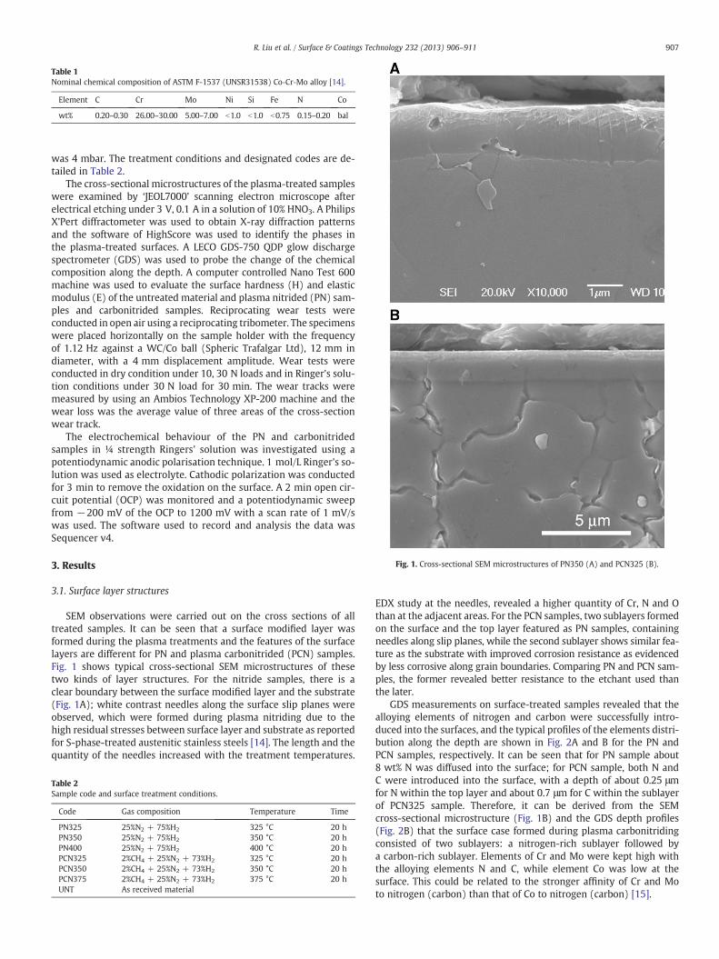
Table 1Nominal chemical composition of ASTM F-1537 (UNSR31538) Co‐Cr‐Mo alloy [14].
Element C Cr Mo Ni Si Fe N Co
wt% 0.20–0.30 26.00–30.00 5.00–7.00 b1.0 b1.0 b0.75 0.15–0.20 bal
Fig. 1. Cross-sectional SEM microstructures of PN350 (A) and PCN325 (B).
907R. Liu et al. / Surface & Coatings Technology 232 (2013) 906–911
was 4 mbar. The treatment conditions and designated codes are de-tailed in Table 2.
The cross-sectional microstructures of the plasma-treated sampleswere examined by ‘JEOL7000’ scanning electron microscope afterelectrical etching under 3 V, 0.1 A in a solution of 10% HNO3. A PhilipsX'Pert diffractometer was used to obtain X-ray diffraction patternsand the software of HighScore was used to identify the phases inthe plasma-treated surfaces. A LECO GDS-750 QDP glow dischargespectrometer (GDS) was used to probe the change of the chemicalcomposition along the depth. A computer controlled Nano Test 600machine was used to evaluate the surface hardness (H) and elasticmodulus (E) of the untreated material and plasma nitrided (PN) sam-ples and carbonitrided samples. Reciprocating wear tests wereconducted in open air using a reciprocating tribometer. The specimenswere placed horizontally on the sample holder with the frequencyof 1.12 Hz against a WC/Co ball (Spheric Trafalgar Ltd), 12 mm indiameter, with a 4 mm displacement amplitude. Wear tests wereconducted in dry condition under 10, 30 N loads and in Ringer's solu-tion conditions under 30 N load for 30 min. The wear tracks weremeasured by using an Ambios Technology XP-200 machine and thewear loss was the average value of three areas of the cross-sectionwear track.
The electrochemical behaviour of the PN and carbonitridedsamples in ¼ strength Ringers' solution was investigated using apotentiodynamic anodic polarisation technique. 1 mol/L Ringer's so-lution was used as electrolyte. Cathodic polarization was conductedfor 3 min to remove the oxidation on the surface. A 2 min open cir-cuit potential (OCP) was monitored and a potentiodynamic sweepfrom −200 mV of the OCP to 1200 mV with a scan rate of 1 mV/swas used. The software used to record and analysis the data wasSequencer v4.
3. Results
3.1. Surface layer structures
SEM observations were carried out on the cross sections of alltreated samples. It can be seen that a surface modified layer wasformed during the plasma treatments and the features of the surfacelayers are different for PN and plasma carbonitrided (PCN) samples.Fig. 1 shows typical cross-sectional SEM microstructures of thesetwo kinds of layer structures. For the nitride samples, there is aclear boundary between the surface modified layer and the substrate(Fig. 1A); white contrast needles along the surface slip planes wereobserved, which were formed during plasma nitriding due to thehigh residual stresses between surface layer and substrate as reportedfor S-phase-treated austenitic stainless steels [14]. The length and thequantity of the needles increased with the treatment temperatures.
Table 2Sample code and surface treatment conditions.
Code Gas composition Temperature Time
PN325 25%N2 + 75%H2 325 °C 20 hPN350 25%N2 + 75%H2 350 °C 20 hPN400 25%N2 + 75%H2 400 °C 20 hPCN325 2%CH4 + 25%N2 + 73%H2 325 °C 20 hPCN350 2%CH4 + 25%N2 + 73%H2 350 °C 20 hPCN375 2%CH4 + 25%N2 + 73%H2 375 °C 20 hUNT As received material
EDX study at the needles, revealed a higher quantity of Cr, N and Othan at the adjacent areas. For the PCN samples, two sublayers formedon the surface and the top layer featured as PN samples, containingneedles along slip planes, while the second sublayer shows similar fea-ture as the substrate with improved corrosion resistance as evidencedby less corrosive along grain boundaries. Comparing PN and PCN sam-ples, the former revealed better resistance to the etchant used thanthe later.
GDS measurements on surface-treated samples revealed that thealloying elements of nitrogen and carbon were successfully intro-duced into the surfaces, and the typical profiles of the elements distri-bution along the depth are shown in Fig. 2A and B for the PN andPCN samples, respectively. It can be seen that for PN sample about8 wt% N was diffused into the surface; for PCN sample, both N andC were introduced into the surface, with a depth of about 0.25 μmfor N within the top layer and about 0.7 μm for C within the sublayerof PCN325 sample. Therefore, it can be derived from the SEMcross-sectional microstructure (Fig. 1B) and the GDS depth profiles(Fig. 2B) that the surface case formed during plasma carbonitridingconsisted of two sublayers: a nitrogen-rich sublayer followed bya carbon-rich sublayer. Elements of Cr and Mo were kept high withthe alloying elements N and C, while element Co was low at thesurface. This could be related to the stronger affinity of Cr and Moto nitrogen (carbon) than that of Co to nitrogen (carbon) [15].
0
4
8
12
16
20
0
10
20
30
40
50
60
70
0.0 0.3 0.6 0.9 1.2 1.5 1.8
N, w
t%C
,N, w
t%
Co,
Cr,
Mo,
wt%
Co,
Cr,
Mo,
wt%
Distance from Surface, µm
Distance from Surface, µm
Co Cr Mo N
0
10
20
30
40
50
60
70
80
0
2
4
6
8
10
12
14
16
18
20
0.0 0.3 0.6 0.9 1.2 1.5 1.8
Co Cr Mo N C
A
B
Fig. 2. GDS depth profiles of PN350 (A) and PCN325 (B).
908 R. Liu et al. / Surface & Coatings Technology 232 (2013) 906–911
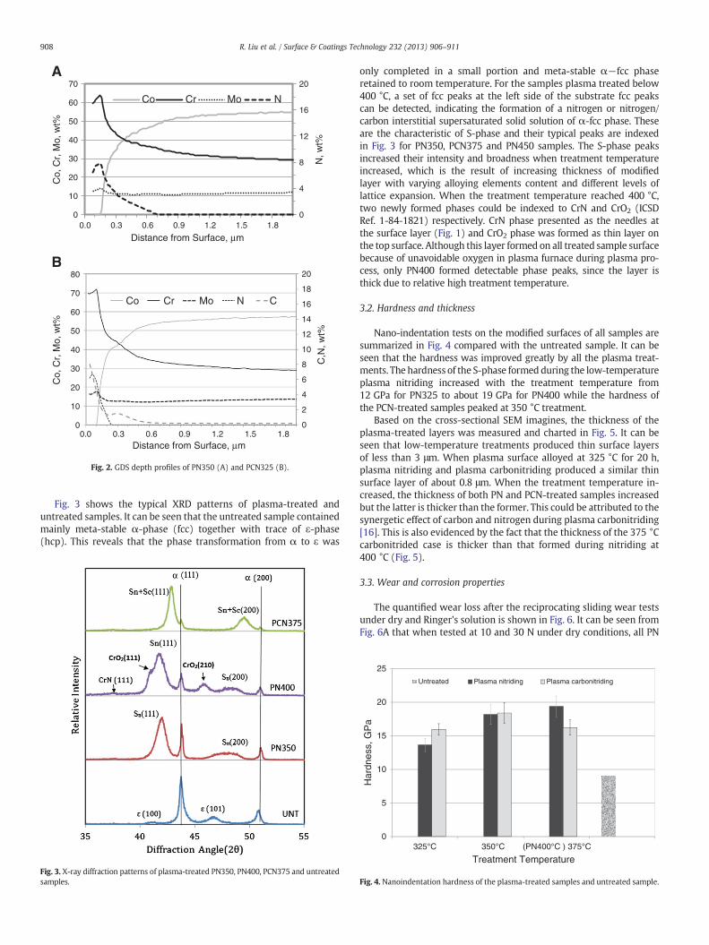
Fig. 3 shows the typical XRD patterns of plasma-treated anduntreated samples. It can be seen that the untreated sample containedmainly meta-stable α-phase (fcc) together with trace of ε-phase(hcp). This reveals that the phase transformation from α to ε was
Fig. 3. X-ray diffraction patterns of plasma-treated PN350, PN400, PCN375 and untreatedsamples.
only completed in a small portion and meta-stable α−fcc phaseretained to room temperature. For the samples plasma treated below400 °C, a set of fcc peaks at the left side of the substrate fcc peakscan be detected, indicating the formation of a nitrogen or nitrogen/carbon interstitial supersaturated solid solution of α-fcc phase. Theseare the characteristic of S-phase and their typical peaks are indexedin Fig. 3 for PN350, PCN375 and PN450 samples. The S-phase peaksincreased their intensity and broadness when treatment temperatureincreased, which is the result of increasing thickness of modifiedlayer with varying alloying elements content and different levels oflattice expansion. When the treatment temperature reached 400 °C,two newly formed phases could be indexed to CrN and CrO2 (ICSDRef. 1-84-1821) respectively. CrN phase presented as the needles atthe surface layer (Fig. 1) and CrO2 phase was formed as thin layer onthe top surface. Although this layer formed on all treated sample surfacebecause of unavoidable oxygen in plasma furnace during plasma pro-cess, only PN400 formed detectable phase peaks, since the layer isthick due to relative high treatment temperature.
3.2. Hardness and thickness
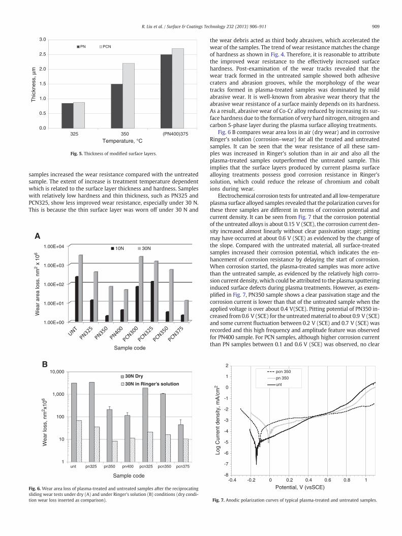
Nano-indentation tests on the modified surfaces of all samples aresummarized in Fig. 4 compared with the untreated sample. It can beseen that the hardness was improved greatly by all the plasma treat-ments. The hardness of the S-phase formed during the low-temperatureplasma nitriding increased with the treatment temperature from12 GPa for PN325 to about 19 GPa for PN400 while the hardness ofthe PCN-treated samples peaked at 350 °C treatment.
Based on the cross-sectional SEM imagines, the thickness of theplasma-treated layers was measured and charted in Fig. 5. It can beseen that low-temperature treatments produced thin surface layersof less than 3 μm. When plasma surface alloyed at 325 °C for 20 h,plasma nitriding and plasma carbonitriding produced a similar thinsurface layer of about 0.8 μm. When the treatment temperature in-creased, the thickness of both PN and PCN-treated samples increasedbut the latter is thicker than the former. This could be attributed to thesynergetic effect of carbon and nitrogen during plasma carbonitriding[16]. This is also evidenced by the fact that the thickness of the 375 °Ccarbonitrided case is thicker than that formed during nitriding at400 °C (Fig. 5).
3.3. Wear and corrosion properties
The quantified wear loss after the reciprocating sliding wear testsunder dry and Ringer's solution is shown in Fig. 6. It can be seen fromFig. 6A that when tested at 10 and 30 N under dry conditions, all PN
0
5
10
15
20
25
325°C 350°C (PN400°C ) 375°C
Har
dnes
s, G
Pa
Treatment Temperature
Untreated Plasma nitriding Plasma carbonitriding
Fig. 4. Nanoindentation hardness of the plasma-treated samples and untreated sample.
0.0
0.5
1.0
1.5
2.0
2.5
3.0
325 350 (PN400)375
Thi
ckne
ss, µ
m
Temperature, °C
PN PCN
Fig. 5. Thickness of modified surface layers.
909R. Liu et al. / Surface & Coatings Technology 232 (2013) 906–911
samples increased the wear resistance compared with the untreatedsample. The extent of increase is treatment temperature dependentwhich is related to the surface layer thickness and hardness. Sampleswith relatively low hardness and thin thickness, such as PN325 andPCN325, show less improved wear resistance, especially under 30 N.This is because the thin surface layer was worn off under 30 N and
1.00E+00
10,000
1,000
100
10
1
1.00E+01
1.00E+02
1.00E+03
1.00E+04
Wea
r ar
ea lo
ss. n
m2
x 10
6
Wea
r lo
ss, n
m2 x
106
Sample code
Sample code
10N 30N
unt pn325 pn350 pn400 pcn325 pcn350 pcn375
A
B30N Dry
30N in Ringer’s solution
Fig. 6. Wear area loss of plasma-treated and untreated samples after the reciprocatingsliding wear tests under dry (A) and under Ringer's solution (B) conditions (dry condi-tion wear loss inserted as comparison).
the wear debris acted as third body abrasives, which accelerated thewear of the samples. The trend of wear resistance matches the changeof hardness as shown in Fig. 4. Therefore, it is reasonable to attributethe improved wear resistance to the effectively increased surfacehardness. Post-examination of the wear tracks revealed that thewear track formed in the untreated sample showed both adhesivecraters and abrasion grooves, while the morphology of the weartracks formed in plasma-treated samples was dominated by mildabrasive wear. It is well-known from abrasive wear theory that theabrasive wear resistance of a surface mainly depends on its hardness.As a result, abrasive wear of Co‐Cr alloy reduced by increasing its sur-face hardness due to the formation of very hard nitrogen, nitrogen andcarbon S-phase layer during the plasma surface alloying treatments.
Fig. 6 B compares wear area loss in air (dry wear) and in corrosiveRinger's solution (corrosion–wear) for all the treated and untreatedsamples. It can be seen that the wear resistance of all these sam-ples was increased in Ringer's solution than in air and also all theplasma-treated samples outperformed the untreated sample. Thisimplies that the surface layers produced by current plasma surfacealloying treatments possess good corrosion resistance in Ringer'ssolution, which could reduce the release of chromium and cobaltions during wear.
Electrochemical corrosion tests for untreated and all low-temperatureplasma surface alloyed samples revealed that the polarization curves forthese three samples are different in terms of corrosion potential andcurrent density. It can be seen from Fig. 7 that the corrosion potentialof the untreated alloys is about 0.15 V (SCE), the corrosion current den-sity increased almost linearly without clear passivation stage; pittingmay have occurred at about 0.6 V (SCE) as evidenced by the change ofthe slope. Compared with the untreated material, all surface-treatedsamples increased their corrosion potential, which indicates the en-hancement of corrosion resistance by delaying the start of corrosion.When corrosion started, the plasma-treated samples was more activethan the untreated sample, as evidenced by the relatively high corro-sion current density, which could be attributed to the plasma sputteringinduced surface defects during plasma treatments. However, as exem-plified in Fig. 7, PN350 sample shows a clear passivation stage and thecorrosion current is lower than that of the untreated sample when theapplied voltage is over about 0.4 V(SCE). Pitting potential of PN350 in-creased from0.6 V (SCE) for the untreatedmaterial to about 0.9 V (SCE)and some current fluctuation between 0.2 V (SCE) and 0.7 V (SCE) wasrecorded and this high frequency and amplitude feature was observedfor PN400 sample. For PCN samples, although higher corrosion currentthan PN samples between 0.1 and 0.6 V (SCE) was observed, no clear
-8
-7
-6
-5
-4
-3
-2
-1
0
1
2
-0.4 -0.2 0 0.2 0.4 0.6 0.8 1
Log
Cur
rent
den
sity
, mA
/cm
2
Potential, V (vsSCE)
pcn 350
pn 350
unt
Fig. 7. Anodic polarization curves of typical plasma-treated and untreated samples.
910 R. Liu et al. / Surface & Coatings Technology 232 (2013) 906–911
pitting potential could be identified until the applied voltage terminat-ed at 1.1 V (SCE), as evidenced for PCN350 sample in Fig. 7.
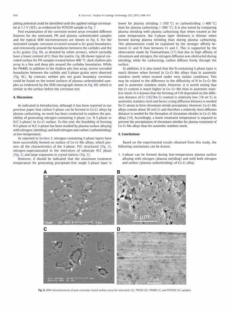
Post-examination of the corrosion tested areas revealed differentfeatures for the untreated, PN and plasma carbonitreded samplesand the typical SEM microstructures are shown in Fig. 8. For theuntreated sample, corrosion occurred around α-fcc grain boundaries,and extensively around the boundaries between the carbides and theα-fcc grains (Fig. 8A, as denoted by white arrows), which normallyhave a lower content of Cr than the matrix. Fig. 8B shows typical cor-roded surface for PN samples treated below 400 °C: dark shallow pitsarray in a line and deep pits around the carbides boundaries. Whilefor PN400, in addition to the shallow pits line array, severe corrodedboundaries between the carbide and S-phase grains were observed(Fig. 8C). By contrast, neither pits nor grain boundary corrosioncould be found on the tested surfaces of plasma carbonitreded sam-ples as evidenced by the SEM micrograph shown in Fig. 8D, which issimilar to the surface before the corrosion test.
4. Discussion
As indicated in Introduction, although it has been reported in ourprevious paper that carbon S-phase can be formed in Co‐Cr alloys byplasma carburising, no work has been conducted to explore the pos-sibility of generating nitrogen-containing S-phase (i.e. N S-phase orN/C S-phase) in Co‐Cr surface. To this end, the feasibility of formingN S-phase or N/C S-phase has been studied by plasma surface alloyingwith nitrogen (nitriding) andboth nitrogen and carbon (carbonitriding)at low-temperature.
As reported in Section 3, nitrogen-containing S-phase layers havebeen successfully formed on surface of Co‐Cr‐Mo alloys, which pos-sess all the characteristics of the S-phase: FCC structured (Fig. 3),nitrogen-supersaturated in the interstices of substrate FCC phase(Fig. 2) and large expansion in crystal lattices (Fig. 3).
However, it should be indicated that the maximum treatmenttemperature for generating precipitate-free single S-phase layer is
Fig. 8. SEM microstructures of post-corrosion tested surface areas for
lower for plasma nitriding (b350 °C) or carbonitriding (b400 °C)than for plasma carburising (b500 °C). It is also noted by comparingplasma nitriding with plasma carburising that when treated at thesame temperature, the S-phase layer thickness is thinner whenformed during plasma nitriding than during plasma carburising.This phenomenon could be explained by the stronger affinity be-tween Cr and N than between Cr and C. This is supported by theobservation made by Thaiwatthana [17] that due to high affinity ofchromium and nitrogen, the nitrogen diffusion was obstructed duringnitriding, while for carburising, carbon diffuses freely through thesurface.
In addition, it is also noted that the N-containing S-phase layer ismuch thinner when formed in Co‐Cr‐Mo alloys than in austeniticstainless steels when treated under very similar conditions. Thismay be related to the difference in the diffusivity of N in Co‐Cr‐Moand in austenitic stainless steels. However, it is worth noting thatthe Cr content is much higher in Co–Cr–Mo than in austenitic stain-less steels. It is known that the forming of CrN depended on the diffu-sion distance of Cr [18].The Cr content is relatively low (18 wt %) inaustenitic stainless steel and hence a long diffusion distance is neededfor Cr atoms to form chromium nitride precipitates. However, Co‐Cr‐Moalloys contain about 30 wt% Cr and therefore a relatively short diffusiondistance is needed for the formation of chromium nitrides in Co‐Cr‐Moalloys [19]. Accordingly, a lower treatment temperature is required toprevent the precipitation of chromium nitrides for plasma treatment ofCo‐Cr‐Mo alloys than for austenitic stainless steels.
5. Conclusions
Based on the experimental results obtained from this study, thefollowing conclusions can be drawn:
1. S-phase can be formed during low-temperature plasma surfacealloying with nitrogen (plasma nitriding) and with both nitrogenand carbon (plasma carbonitriding) of Co‐Cr alloy;
untreated (A); PN350 (B); PN400 (C) and PCN350 (D) samples.
911R. Liu et al. / Surface & Coatings Technology 232 (2013) 906–911
2. A hardened S-phase layer of about 0.8 to 2.7 μm in thickness canbe obtained by low-temperature plasma surface alloying and thethickness of the S-phase layer is temperature dependent;
3. When treated at the same temperature for the same time period,plasma carbonitriding can produce a thicker hardened layer thanplasma nitriding.
4. The hardness and the wear resistance of Co‐Cr alloy can be signif-icantly improved by plasma nitriding and plasma carbonitriding;
5. The corrosion resistance of low-temperature (≤350 °C) plasmasurface alloyed Co‐Cr is similar to the untreated material andPCN samples show better corrosion resistance than PN samples.
6. The corrosion–wear resistance of Co‐Cr alloy can be effectivelyimproved by low-temperature plasma nitriding and plasmacarbonitriding.
References
[1] N. Gibson, H. Stamm, Med. Device Manuf. Technol. (2002) 48–51.[2] J. Black, Clin. Orthop. 329 (1996) 244–255.
[3] A. Marti, Injury 31 (2000) 18–21.[4] http://www.fda.gov/MedicalDevices/ProductsandMedicalProcedures/Implantsand
Prosthetics/MetalonMetalHipImplants/ucm241604.htm, (accessed on 25 August2012).
[5] W. Brodner, P. Bitzan, V. Meisinger, A. Kaider, F. Gottsauner Wolf, R. Kotz, J. BoneJoint Surg. Am. 85A (2003) 2168–2173.
[6] F.W. Sunderman Jr., Fundam. Appl. Toxicol. 13 (1989) 205–216.[7] T. Visuri, E. Pukkala, P. Paavolainen, P. Pulkkinen, E.B. Riska, Clin Orthop 329 (1996)
280–289.[8] E. Ingham, J. Fisher, Proc. Inst. Mech. Eng. H 214 (2000) 21–37.[9] Z.L. Zhang, T. Bell, Surf. Eng. 1 (1985) 131–136.
[10] M. Gillham, R. Van der Jagt, B. Kolsteret, Mater. World (Aug. 1996) 460–462.[11] H. Dong, Int. Mater. Rev. 55 (2010) 65–98.[12] H. Dong, T. Bell and C. X. Li: European patent no. EP1499755, Priority 29 April
2002, granted 21 May 2008.[13] X. Luo, X. Li, Y. Sun, H. Dong, Wear. 302 (1–2) (2013) 1615–1623.[14] J. Buhagiar, X.Y. Li, H. Dong, Surf. Coat. Technol. 204 (2009) 330–345.[15] Pearson and Ends, J. Iron Steel Inst. (1953) 52–57, (September).[16] X.Y. Li, J. Buhagiar, H. Dong, Surf. Eng. VOL 26 (2010) 1–2.[17] S. Thaiwatthana, Mechanical and chemical characterisation of low-temperature
plasma alloyed austenitic stainless steels. , PhD thesis TheUniversity of Birmingham,2005.
[18] X.Y. Li, N. Habibi, T. Bell, H. Dong, Surf. Eng. 23 (2007) 45–51.[19] J.H. Downing, P.D. Deeley, Rudolf Fichte (2000), http://dx.doi.org/10.1002/
14356007.a07_043.