OPERATION MANUAL for MO-150-5A Mechanical Oscillator
48
OM-MO-150-5A-05-2010 Revised August 2013 Effective with Serial Number 100124 IMPORTANT Read this manual carefully before installing, commissioning or operating this product. Miller Welding Automation, 281 E. Lies Rd., Carol Stream, Il 60188•Telephone: (949) 951-1515•Fax: (949) 951-9237 Web site: www.jetline.com•E-mail: [email protected] OPERATION MANUAL for MO-150-5A Mechanical Oscillator
-
Upload
khangminh22 -
Category
Documents
-
view
2 -
download
0
Transcript of OPERATION MANUAL for MO-150-5A Mechanical Oscillator

OM-MO-150-5A-05-2010
Revised August 2013
Effective with Serial Number 100124
IMPORTANT
Read this manual carefully before installing,
commissioning or operating this product.
Miller Welding Automation, 281 E. Lies Rd., Carol Stream, Il 60188•Telephone: (949) 951-1515•Fax: (949) 951-9237
Web site: www.jetline.com•E-mail: [email protected]
OPERATION MANUAL for MO-150-5A
Mechanical Oscillator

MO-150-5A Mechanical Oscillator
ii
LIMITED WARRANTY Components or parts manufactured directly by Miller Electric Mfg. Co. are subject to Miller’s True Blue® Warranty set forth at www.millerwelds.com/support/warranty. Seller does not make any warranties for components or parts not manufactured directly by Jetline Engineering, Miller Welding Automation, and Panasonic Welding Systems Company; such components or parts are subject to the warranty terms of the respective manufacturer. Components and parts manufactured by Jetline Engineering, Miller Welding Automation, and Panasonic Welding Systems Company are subject to the following warranty terms. Terms and Conditions of Sale Seller warrants to Purchaser that the components or parts manufactured by Seller or Panasonic Welding Systems Company shall be free from defects in material and workmanship, and shall conform to the Seller’s specifications for the following periods:
a. 12 months from the date of shipment of the Products for components and equipment manufactured by Panasonic Welding Systems Company including robot manipulator, controller and connecting cables; external axis components (external axis base unit, servo amplifiers, motors, connecting cables and pre-engineered positioners); peripheral devices (high voltage touch sensors, thru arc seam trackers); welding power sources (internally built into the robot controller cabinet); wire feeders (separated design or integrated design, i.e. Active Wire Torch/Feeder); or
b. 12 months from date of shipment of the Products for equipment manufactured by Jetline Engineering or Miller Welding Automation.
In the event of a breach of the warranties set forth above, Seller will, at Seller’s option and as Seller’s sole liability and Purchaser’s sole remedy, repair, replace or credit Purchaser’s account for, any Product that fails to conform to the above warranty, provided that (i) during the applicable warranty period Seller is promptly notified in writing upon discovery of such failure with a detailed explanation of any alleged deficiencies; (ii) Seller is given a reasonable opportunity to investigate all claims; and (iii) Seller’s examination of such Product confirms the alleged deficiencies and that the deficiencies were not caused by accident, misuse, neglect, improper installment, unauthorized alteration or repair or improper testing. No Products may be returned to Seller until inspection and approval by Seller. All warranty work performed shall be FOB Seller’s facility (Incoterms 2010) and freight for returned Products shall be paid for by Purchaser. The above warranty against defects does not apply to: (1) consumable components or ordinary wear items including but not limited to torches; or (2) defects due to (i) failure to install and perform maintenance set forth in Product documentation, (ii) the use of components, parts, peripherals, attachments, accessories, or perishable tooling not approved by Seller, (iii) accident, misuse, neglect, abuse, mishandling, misapplication, modification, alteration, acts of God, or (iv) improper installation, service or maintenance. Purchaser and/or the operator of the Products are in full control of the weld process. Seller makes no warranty regarding the quality or the success of the welds on the Products due to factors under Purchaser’s and/or operator’s control including but not limited to welding procedures, material types, material coatings, joint/part fit, part geometry, metallurgy, welding gases, proper machine/process maintenance, and operator skill. EXCEPT AS SET FORTH ABOVE, SELLER MAKES NO WARRANTY OR REPRESENTATION OF ANY KIND, EXPRESS OR IMPLIED (INCLUDING NO WARRANTY OF MERCHANTABILITY OR FITNESS FOR ANY PARTICULAR PURPOSE).
- See more at: https://www.millerwelds.com/automation-terms-of-sale#sthash.l5oRebWB.dpuf

iii
MO-150-5A Mechanical Oscillator
NOTICE
The installation, operation and maintenance guidelines set out in this manual will enable you to
maintain the equipment in peak condition and achieve maximum efficiency with your welding operation. Please read these instructions carefully to become aware of every advantage.
CAUTION
Only experienced personnel familiar with the operation
and safe practice of welding equipment should install and/or use this equipment.

MO-150-5A Mechanical Oscillator
vi
CONTENTS
SECTION I ............................................................................................................................................................ 1
SAFETY PRECAUTIONS – READ BEFORE USING (som 2013-09) ................................................................. 1
1.1 Symbol Usage ........................................................................................................................ 1
1.2 Arc Welding Hazards .......................................................................................................................... 1
1.3 Additional Symbols for Installation, Operation, And Maintenance ................................................. 4
1.4 California Proposition 65 Warnings .................................................................................................. 6
1.5 Principal Safety Standards ................................................................................................................. 6
1.6 EMF Information ................................................................................................................................. 6
Section II ................................................................................................................................................................ 7
Introduction .......................................................................................................................................................... 7
Section III ............................................................................................................................................................... 8
Initial Inspection .................................................................................................................................................... 8
A. Packing List ............................................................................................................................. 8
Section IV ............................................................................................................................................................. 10
Specifications ...................................................................................................................................................... 10
Section V .............................................................................................................................................................. 11
Mechanical Installation ....................................................................................................................................... 11
A. Slide Assembly ...................................................................................................................... 11
B. Oscillator Control ................................................................................................................. 12
Section VI ............................................................................................................................................................. 12
Electrical Installation ........................................................................................................................................... 12

MO-150-5A Mechanical Oscillator
A. Input Power .......................................................................................................................... 12
B. Slide/Control Cable .............................................................................................................. 12
C. Remote Pendant Connector ................................................................................................. 12
D. Remote Digital I/O Connector .............................................................................................. 12
Section VII ............................................................................................................................................................ 13
Theory of Operation ............................................................................................................................................ 13
A. Power Panel ......................................................................................................................... 13
B. Stepper Driver Unit, MH10 ................................................................................................... 13
C. Mother Board, 9211 ............................................................................................................. 14
D. Generator Board, 9220 ........................................................................................................ 14
E. Control Board, 9221 ............................................................................................................. 14
Section VIII ........................................................................................................................................................... 15
Functions ............................................................................................................................................................. 15
Section IX ............................................................................................................................................................. 17
Optional Features ................................................................................................................................................ 17
Section X .............................................................................................................................................................. 18
Maintenance ....................................................................................................................................................... 18
A. Maintenance Schedule ........................................................................................................ 18
B. Pot (R1) Replacement .......................................................................................................... 18
Section XI ............................................................................................................................................................. 20
Parts List .............................................................................................................................................................. 20

SECTION I
SAFETY PRECAUTIONS – READ BEFORE USING (som 2013-09)
1.1 Symbol Usage
DANGER! − Indicates a hazardous situation which, if not avoided, will result in death or serious injury. The possible hazards are shown in the adjoining symbols or explained in the text.
Indicates a hazardous situation which, if not avoided, could result in death or serious injury. The possible hazards are shown in the adjoining symbols or explained in the text.
NOTICE − Indicates statements not related to personal injury.
Indicates special instructions.
This group of symbols means: Warning! Watch Out! ELECTRIC SHOCK, MOVING PARTS, and HOT PARTS hazards. Consult symbols and related instructions below for necessary actions to avoid the hazards.
1.2 Arc Welding Hazards
The symbols shown below are used throughout this manual to call attention to and identify possible hazards. When you see the symbol, watch out, and follow the related instructions to avoid the hazard. The safety information given below is only a summary of the more complete safety information found in the Safety Standards listed in Section 1-5. Read and follow all Safety Standards.
Only qualified persons should install, operate, maintain, and repair this unit.
During operation, keep everybody, especially children, away.
Touching live electrical parts can cause fatal shocks or severe burns. The electrode and work circuit is electrically live whenever the output is on. The input power circuit and machine internal circuits are also live when power is on. In semiautomatic or automatic wire welding, the wire, wire reel, drive roll housing, and all metal parts touching the welding wire are electrically live. Incorrectly installed or improperly grounded equipment is a hazard.
• Do not touch live electrical parts. • Wear dry, hole-free insulating gloves and body protection. • Insulate yourself from work and ground using dry insulating mats or covers big enough to prevent any physical contact with the work
or ground. • Do not use AC output in damp areas, if movement is confined, or if there is a danger of falling. • Use AC output ONLY if required for the welding process. • If AC output is required, use remote output control if present on unit. • Additional safety precautions are required when any of the following electrically hazardous conditions are present: in damp locations
or while wearing wet clothing; on metal structures such as floors, gratings, or scaffolds; when in cramped positions such as sitting, kneeling, or lying; or when there is a high risk of unavoidable or accidental contact with the work piece or ground. For these conditions, use the following equipment in order presented: 1) a semiautomatic DC constant voltage (wire) welder, 2) a DC manual (stick) welder, or 3) an AC welder with reduced open-circuit voltage. In most situations, use of a DC, constant voltage wire welder is recommended. And, do not work alone!
• Disconnect input power or stop engine before installing or servicing this equipment. Lockout/tagout input power according to OSHA 29 CFR 1910.147 (see Safety Standards).
• Properly install, ground, and operate this equipment according to its Owner’s Manual and national, state, and local codes. • Always verify the supply ground − check and be sure that input power cord ground wire is properly connected to ground terminal in
disconnect box or that cord plug is connected to a properly grounded receptacle outlet. • When making input connections, attach proper grounding conductor first − double-check connections. • Keep cords dry, free of oil and grease, and protected from hot metal and sparks. • Frequently inspect input power cord and ground conductor for damage or bare wiring – replace immediately if damaged – bare
wiring can kill. • Turn off all equipment when not in use.
Protect yourself and others from injury – read, follow and save these important safety precautions and operating instructions.
ELECTRIC SHOCK can kill.

MO-150-5A Mechanical Oscillator
vi
• Do not use worn, damaged, undersized, or repaired cables. • Do not drape cables over your body. • If earth grounding of the workpiece is required, ground it directly with a separate cable. • Do not touch electrode if you are in contact with the work, ground, or another electrode from a different machine. • Do not touch electrode holders connected to two welding machines at the same time since double open-circuit voltage will be
present. • Use only well-maintained equipment. Repair or replace damaged parts at once. Maintain unit according to manual. • Wear a safety harness if working above floor level. • Keep all panels and covers securely in place. • Clamp work cable with good metal-to-metal contact to workpiece or worktable as near the weld as practical. • Insulate work clamp when not connected to workpiece to prevent contact with any metal object. • Do not connect more than one electrode or work cable to any single weld output terminal. Disconnect cable for process not in use. • Use GFCI protection when operating auxiliary equipment in damp or wet locations.
SIGNIFICANT DC VOLTAGE exists in inverter welding power sources AFTER removal of input power.
• Turn Off inverter, disconnect input power, and discharge input capacitors according to instructions in Maintenance Section before touching any parts.
• Do not touch hot parts bare handed. • Allow cooling period before working on equipment. • To handle hot parts, use proper tools and/or wear heavy, insulated welding gloves and clothing to prevent burns.
Welding produces fumes and gases. Breathing these fumes and gases can be hazardous to your health. • Keep your head out of the fumes. Do not breathe the fumes. • If inside, ventilate the area and/or use local forced ventilation at the arc to remove welding fumes and gases. The recommended way
to determine adequate ventilation is to sample for the composition and quantity of fumes and gases to which personnel are exposed.
• If ventilation is poor, wear an approved air-supplied respirator. • Read and understand the Safety Data Sheets (SDSs) and the manufacturer’s instructions for adhesives, coatings, cleaners,
consumables, coolants, degreasers, fluxes, and metals. • Work in a confined space only if it is well ventilated, or while wearing an air-supplied respirator. Always have a trained watch-person
nearby. Welding fumes and gases can displace air and lower the oxygen level causing injury or death. Be sure the breathing air is safe.
• Do not weld in locations near degreasing, cleaning, or spraying operations. The heat and rays of the arc can react with vapors to form highly toxic and irritating gases.
• Do not weld on coated metals, such as galvanized, lead, or cadmium plated steel, unless the coating is removed from the weld area, the area is well ventilated, and while wearing an air-supplied respirator. The coatings and any metals containing these elements can give off toxic fumes if welded.
Arc rays from the welding process produce intense visible and invisible (ultraviolet and infrared) rays that can burn eyes and skin. Sparks fly off from the weld.
• Wear an approved welding helmet fitted with a proper shade of filter lenses to protect your face and eyes from arc rays and sparks when welding or watching (see ANSI Z49.1 and Z87.1 listed in Safety Standards).
• Wear approved safety glasses with side shields under your helmet. • Use protective screens or barriers to protect others from flash,glare and sparks; warn others not to watch the arc. • Wear body protection made from durable, flame−resistant material (leather, heavy cotton, wool). Body protection includes oil-free
clothing such as leather gloves, heavy shirt, cuffless trousers, high shoes, and a cap.
HOT PARTS can burn.
ARC RAYS can burn eyes and skin.
FUMES AND GASES can be hazardous.
Welding on closed containers, such as tanks, drums, or pipes, can cause them to blow up. Sparks can fly off from the welding arc. The flying sparks, hot workpiece, and hot equipment can cause fires and burns. Accidental contact of electrode to metal objects can cause sparks, explosion, overheating, or fire. Check and be sure the area is safe before doing any welding.
• Remove all flammables within 35 ft (10.7 m) of the welding arc. If this is not possible, tightly cover them with approved covers. • Do not weld where flying sparks can strike flammable material. • Protect yourself and others from flying sparks and hot metal. • Be alert that welding sparks and hot materials from welding can easily go through small cracks and openings to adjacent areas. • Watch for fire, and keep a fire extinguisher nearby. • Be aware that welding on a ceiling, floor, bulkhead, or partition can cause fire on the hidden side. • Do not weld on containers that have held combustibles, or on closed containers such as tanks, drums, or pipes unless they are
properly prepared according to AWS F4.1 and AWS A6.0 (see Safety Standards). • Do not weld where the atmosphere may contain flammable dust, gas, or liquid vapors (such as gasoline). • Connect work cable to the work as close to the welding area as practical to prevent welding current from traveling long, possibly
unknown paths and causing electric shock, sparks, and fire hazards. • Do not use welder to thaw frozen pipes. • Remove stick electrode from holder or cut off welding wire at contact tip when not in use. • Wear body protection made from durable, flame−resistant material (leather, heavy cotton, wool). Body protection includes oil-free
clothing such as leather gloves, heavy shirt, cuffless trousers, high shoes, and a cap. • Remove any combustibles, such as a butane lighter or matches, from your person before doing any welding. • After completion of work, inspect area to ensure it is free of sparks, glowing embers, and flames. • Use only correct fuses or circuit breakers. Do not oversize or bypass them. • Follow requirements in OSHA 1910.252 (a) (2) (iv) and NFPA 51B for hot work and have a fire watcher and extinguisher nearby.
Read and understand the Safety Data Sheets (SDSs) and the manufacturer’s instructions for adhesives, coatings, cleaners, consumables, coolants, degreasers, fluxes, and metals.
• Welding, chipping, wire brushing, and grinding cause sparks and flying metal. As welds cool, they can throw off slag. • Wear approved safety glasses with side shields even under your welding helmet.
• Shut off compressed gas supply when not in use. • Always ventilate confined spaces or use approved air-supplied respirator.
• Wearers of Pacemakers and other Implanted Medical Devices should keep away. • Implanted Medical Device wearers should consult their doctor and the device manufacturer before going near arc welding, spot
welding, gouging, plasma arc cutting, or induction heating operations.
• Noise from some processes or equipment can damage hearing. • Wear approved ear protection if noise level is high.
WELDING can cause fire or explosion.
FLYING METAL or DIRT can injure eyes.
BUILDUP OF GAS can injure or kill.
ELECTRIC AND MAGNETIC FIELDS (EMF) can affect Implanted Medical Devices.
NOISE can damage hearing.

MO-150-5A Mechanical Oscillator
vi
Compressed gas cylinders contain gas under high pressure. If damaged, a cylinder can explode. Since gas cylinders are normally part of the welding process, be sure to treat them carefully.
• Protect compressed gas cylinders from excessive heat, mechanical shocks, physical damage, slag, open flames, sparks, and arcs. • Install cylinders in an upright position by securing to a stationary support or cylinder rack to prevent falling or tipping. • Keep cylinders away from any welding or other electrical circuits. • Never drape a welding torch over a gas cylinder. • Never allow a welding electrode to touch any cylinder. • Never weld on a pressurized cylinder − explosion will result. • Use only correct compressed gas cylinders, regulators, hoses, and fittings designed for the specific application; maintain them and
associated parts in good condition. • Turn face away from valve outlet when opening cylinder valve. Do not stand in front of or behind the regulator when opening the
valve. • Keep protective cap in place over valve except when cylinder is in use or connected for use. • Use the right equipment, correct procedures, and sufficient number of persons to lift and move cylinders. • Read and follow instructions on compressed gas cylinders, associated equipment, and Compressed Gas Association (CGA) publication
P-1 listed in Safety Standards.
1.3 Additional Symbols for Installation, Operation, And Maintenance
• Do not install or place unit on, over, or near combustible surfaces. • Do not install unit near flammables. • Do not overload building wiring − be sure power supply system is properly sized, rated, and protected to handle this unit.
• Use lifting eye to lift unit only, NOT running gear, gas cylinders, or any other accessories. • Use equipment of adequate capacity to lift and support unit. • If using lift forks to move unit, be sure forks are long enough to extend beyond opposite side of unit. • Keep equipment (cables and cords) away from moving vehicles when working from an aerial location. • Follow the guidelines in the Applications Manual for the Revised NIOSH Lifting Equation (Publication No. 94−110) when manually
lifting heavy parts or equipment.
• Allow cooling period; follow rated duty cycle. • Reduce current or reduce duty cycle before starting to weld again. • Do not block or filter airflow to unit.
• Wear a face shield to protect eyes and face. • Shape tungsten electrode only on grinder with proper guards in a safe location wearing proper face, hand, and body protection. • Sparks can cause fires — keep flammables away.
• Put on grounded wrist strap BEFORE handling boards or parts. • Use proper static-proof bags and boxes to store, move, or ship PC boards.
CYLINDERS can explode if damaged.
FIRE OR EXPLOSION hazard.
FALLING EQUIPMENT can injure.
OVERUSE can cause OVERHEATING
FLYING SPARKS can injure.
STATIC (ESD) can damage PC boards.
MOVING PARTS can injure.

• Keep away from moving parts. • Keep away from pinch points such as drive rolls.
• Do not press gun trigger until instructed to do so. • Do not point gun toward any part of the body, other people, or any metal when threading welding wire.
• Do not use welder to charge batteries or jump start vehicles unless it has a battery charging feature designed for this purpose.
• Keep away from moving parts such as fans. • Keep all doors, panels, covers, and guards closed and securely in place. • Have only qualified persons remove doors, panels, covers, or guards for maintenance and troubleshooting as necessary. • Reinstall doors, panels, covers, or guards when maintenance is finished and before reconnecting input power.
• Read and follow all labels and the Owner’s Manual carefully before installing, operating, or servicing unit. Read the safety information at the beginning of the manual and in each section.
• Use only genuine replacement parts from the manufacturer. • Perform maintenance and service according to the Owner’s Manuals, industry standards, and national, state, and local codes.
• High-frequency (H.F.) can interfere with radio navigation, safety services, computers, and communications equipment. • Have only qualified persons familiar with electronic equipment perform this installation. • The user is responsible for having a qualified electrician promptly correct any interference problem resulting from the installation. • If notified by the FCC about interference, stop using the equipment at once. • Have the installation regularly checked and maintained. • Keep high-frequency source doors and panels tightly shut, keep spark gaps at correct setting, and use grounding and shielding to
minimize the possibility of interference.
• Electromagnetic energy can interfere with sensitive electronic equipment such as computers and computer-driven equipment such as robots.
• Be sure all equipment in the welding area is electromagnetically compatible. • To reduce possible interference, keep weld cables as short as possible, close together, and down low, such as on the floor. • Locate welding operation 100 meters from any sensitive electronic equipment. • Be sure this welding machine is installed and grounded according to this manual. • If interference still occurs, the user must take extra measures such as moving the welding machine, using shielded cables, using line
filters, or shielding the work area.
WELDING WIRE can injure.
BATTERY EXPLOSION can injure.
MOVING PARTS can injure.
READ INSTRUCTIONS.
H.F. RADIATION can cause interference.
ARC WELDING can cause interference.

MO-150-5A Mechanical Oscillator
vi
1.4 California Proposition 65 Warnings Welding or cutting equipment produces fumes or gases which contain chemicals known to the State of California to cause birth defects
and, in some cases, cancer. (California Health & Safety Code Section 25249.5 et seq.) This product contains chemicals, including lead, known to the state of California to cause cancer, birth defects, or other reproductive
harm. Wash hands after use.
1.5 Principal Safety Standards Safety in Welding, Cutting, and Allied Processes, ANSI Standard Z49.1, is available as a free download from the American Welding Society at http://www.aws.org or purchased from Global Engineering Documents (phone: 1-877-413-5184, website: www.global.ihs.com). Safe Practices for the Preparation of Containers and Piping for Welding and Cutting, American Welding Society Standard AWS F4.1, from Global Engineering Documents (phone: 1-877-413-5184, website: www.global.ihs.com). Safe Practices for Welding and Cutting Containers that have Held Combustibles, American Welding Society Standard AWS A6.0, from Global EngineeringDocuments (phone: 1-877-413-5184, website: www.global.ihs.com). National Electrical Code, NFPA Standard 70, from National Fire Protection Association, Quincy, MA 02269 (phone: 1-800-344-3555, website: www.nfpa.org and www. sparky.org). Safe Handling of Compressed Gases in Cylinders, CGA Pamphlet P-1, from Compressed Gas Association, 14501 George Carter Way, Suite 103, Chantilly, VA 20151 (phone: 703-788-2700, website:www.cganet.com). Safety in Welding, Cutting, and Allied Processes, CSA Standard W117.2, from Canadian Standards Association, Standards Sales, 5060 Spectrum Way, Suite 100, Ontario, Canada L4W 5NS (phone: 800-463-6727, website: www.csa-international.org). Safe Practice For Occupational And Educational Eye And Face Protection, ANSI Standard Z87.1, from American National Standards Institute, 25 West 43rd Street, New York, NY 10036 (phone: 212-642-4900, web-site: www.ansi.org). Standard for Fire Prevention During Welding, Cutting, and Other Hot Work, NFPA Standard 51B, from National Fire Protection Association, Quincy, MA 02269 (phone: 1-800-344-3555, website: www.nfpa.org. OSHA, Occupational Safety and Health Standards for General Industry, Title 29, Code of Federal Regulations (CFR), Part 1910, Subpart Q, and Part 1926, Subpart J, from U.S. Government Printing Office, Superintendent of Documents, P.O. Box 371954, Pittsburgh, PA 15250-7954 (phone: 1-866-512-1800) (there are 10 OSHA Regional Offices— phone for Region 5, Chicago, is 312-353-2220, website: www.osha.gov). Applications Manual for the Revised NIOSH Lifting Equation, The National Institute for Occupational Safety and Health (NIOSH), 1600 Clifton Rd, Atlanta, GA 30333 (phone: 1-800-232-4636, website: www.cdc.gov/NIOSH).
1.6 EMF Information Electric current flowing through any conductor causes localized electric and magnetic fields (EMF). The current from arc welding (and allied processes including spot welding, gouging, plasma arc cutting, and induction heating operations) creates an EMF field around the welding circuit. EMF fields may interfere with some medical implants, e.g. pacemakers. Protective measures for persons wearing medical implants have to be taken. For example, restrict access for passers−by or conduct individual risk assessment for welders. All welders should use the following procedures in order to minimize exposure to EMF fields from the welding circuit:
1. Keep cables close together by twisting or taping them, or using a cable cover. 2. Do not place your body between welding cables. Arrange cables to one side and away from the operator. 3. Do not coil or drape cables around your body. 4. Keep head and trunk as far away from the equipment in the welding circuit as possible. 5. Connect work clamp to workpiece as close to the weld as possible. 6. Do not work next to, sit or lean on the welding power source. 7. Do not weld whilst carrying the welding power source or wire feeder.
About Implanted Medical Devices: Implanted Medical Device wearers should consult their doctor and the device manufacturer before performing or going near arc welding, spot welding, gouging, plasma arc cutting, or induction heating operations. If cleared by your doctor, then following the above procedures is recom-mended.

7
SECTION II
INTRODUCTION
Congratulations on the purchase of your Miller Welding Automation MO-
150 Mechanical Oscillator System. Its quality, workmanship and parts should bring many years of dependable service.
The MO-150 is designed primarily to oscillate the torch mechanically over a set distance above the piece part. The standard MO-150 is designed to handle a maximum stroke of 4" (100 mm) when oscillating. The single axis slide is capable of working with loads of up to 150 lbs (68 kg).
The welding torch, necessary brackets and accessories are normally mounted on the oscillator slide assembly. The slide is mounted to the main fixture so that the slide motion occurs in the horizontal plane.
The MO-150 system is designed to handle most welding procedures, including TIG, Plasma, MIG and Sub-Arc. Adequate filtering and isolation have been designed into the system to handle the high frequency associated with TIG and Plasma processes.
The standard MO-150 system comprises of the 9200A oscillator control, the MO-150-101-5D slide assembly, and the necessary interconnecting cables and connectors.
The 9200A control includes circuitry to start and stop oscillation, set oscillation speeds for each direction, and set dwell times at the end of each stroke. The circuitry allows the operator to adjust the oscillation width and adjust the center point of oscillation. These functions can all be adjusted while in operation.
The system’s circuitry can also be operated by a remote pendant or control signals through connector J3 on the side of the control. The system can send out signals to other equipment to let this equipment know when the oscillator system is currently at left or right dwell, traveling left or right, if it is oscillating, and communicate its present position in terms of voltage.

MO-150-5A Mechanical Oscillator
8
SECTION III
INITIAL INSPECTION
Upon receipt of the equipment, examine the shipping container for freight damage.
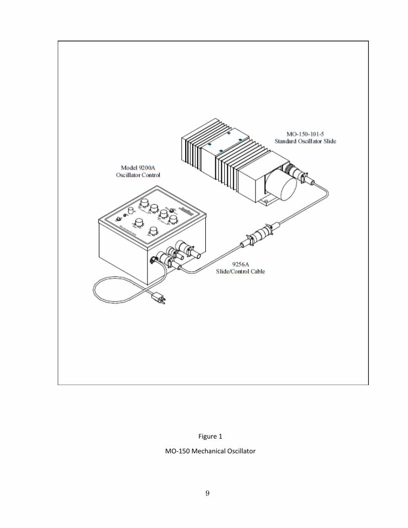
Unpack the carton and check its contents against the packing list that is included in this manual (following Figure 1). If parts are missing, notify Miller Welding Automation promptly. Examine the general arrangement diagram in Figure 1 for familiarization of the system.
Although Miller Welding Automation has packaged your equipment adequately, long and/or rough shipping can still take its toll on the equipment. As a result, please spend a few extra minutes to insure your system has arrived in good working order.
Start off by checking the slide assembly. The stepper motor should be checked to ensure it is still securely mounted to the slide body. Also check the amphenol connector attached to the slide for its integrity.
The control should also be briefly inspected before applying the power to the unit. Simply remove the two screws which are holding the control doors closed. Open the door for a brief inspection. Verify the circuit boards are still in place as well as the “hold-down” bars retaining them. Make sure that all of the connectors are securely in place and that the terminal strip connections are still tight. Consult factory if damage is apparent.
After this initial inspection has been completed, you are ready to begin installing your MO-150 system. The installation instructions which follow are for your benefit. Following them will help insure that the equipment will operate correctly and at its maximum efficiency.
A. Packing List Shipment includes one each of the following:
1. MO-150-101-5D Oscillator Slide Assembly 2. 9200A Oscillator Control 3. 9256A Slide/Control Cable 4. 3106A-20-27P Remote Pendant Plug (J3)
5. 97-3057-1012-1 Cable Clamp (J3)
9
Figure 1
MO-150 Mechanical Oscillator

MO-150-5A Mechanical Oscillator
1
SECTION IV
SPECIFICATIONS
Slide
Weight Capacity: 150 lb (68 kg) out 2"
(50 mm)
Mechanical Stroke: 4.875" (123 mm)
maximum
Electrical Stroke: 4.625" (117.5 mm) maximum
Operating Parameters
Outputs (Optional)
Direction Left: Open Collector OPTO Isolated
Direction Right: Open Collector OPTO Isolated
Direction Left: Open Collector OPTO Isolated
Direction Right: Open Collector OPTO Isolated
Speed 1: 100 to 1.0 IPM
Speed 2: 100 to 1.0 IPM
Dwell 1: .01 to 3 seconds
Dwell 2: .01 to 3 seconds
Oscillation Width: 0.1" to 4.00" (2.5 to
101 mm)
Center: +2.3" (58 mm) from center of electrical stroke
Control Remote Functions
Start/Stop: Contact Closure Start/Stop (optional): +24 to 0 VDC
Stop (optional): +24 to 0 VDC
Center: 10K -3 wire
Width: 10K -3 wire
Speed: 0 to +5 VDC
Dwell: 0 to +5 VDC
Power
120/240 VAC, 1 Phase, 50/60 Hz, at 3 amps
Shipping Weight
Control: 30 lb (13.6 kg)
Slide: 26 lb (11.8 kg)
1
SECTION V
MECHANICAL INSTALLATION
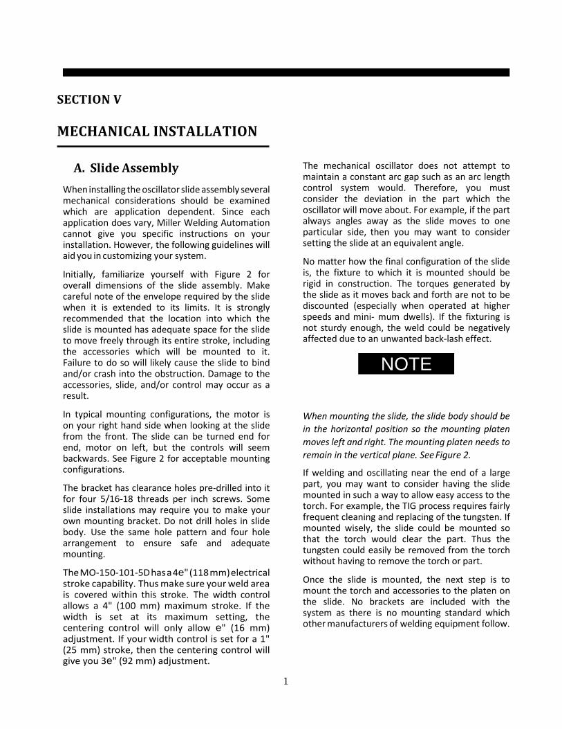
A. Slide Assembly When installing the oscillator slide assembly several mechanical considerations should be examined which are application dependent. Since each application does vary, Miller Welding Automation cannot give you specific instructions on your installation. However, the following guidelines will aid you in customizing your system.
Initially, familiarize yourself with Figure 2 for overall dimensions of the slide assembly. Make careful note of the envelope required by the slide when it is extended to its limits. It is strongly recommended that the location into which the slide is mounted has adequate space for the slide to move freely through its entire stroke, including the accessories which will be mounted to it. Failure to do so will likely cause the slide to bind and/or crash into the obstruction. Damage to the accessories, slide, and/or control may occur as a result.
In typical mounting configurations, the motor is on your right hand side when looking at the slide from the front. The slide can be turned end for end, motor on left, but the controls will seem backwards. See Figure 2 for acceptable mounting configurations.
The bracket has clearance holes pre-drilled into it for four 5/16-18 threads per inch screws. Some slide installations may require you to make your own mounting bracket. Do not drill holes in slide body. Use the same hole pattern and four hole arrangement to ensure safe and adequate mounting.
The MO-150-101-5D has a 4e" (118 mm) electrical stroke capability. Thus make sure your weld area is covered within this stroke. The width control allows a 4" (100 mm) maximum stroke. If the width is set at its maximum setting, the centering control will only allow e" (16 mm) adjustment. If your width control is set for a 1" (25 mm) stroke, then the centering control will give you 3e" (92 mm) adjustment.
The mechanical oscillator does not attempt to maintain a constant arc gap such as an arc length control system would. Therefore, you must consider the deviation in the part which the oscillator will move about. For example, if the part always angles away as the slide moves to one particular side, then you may want to consider setting the slide at an equivalent angle.
No matter how the final configuration of the slide is, the fixture to which it is mounted should be rigid in construction. The torques generated by the slide as it moves back and forth are not to be discounted (especially when operated at higher speeds and mini- mum dwells). If the fixturing is not sturdy enough, the weld could be negatively affected due to an unwanted back-lash effect.
NOTE
When mounting the slide, the slide body should be in the horizontal position so the mounting platen moves left and right. The mounting platen needs to remain in the vertical plane. See Figure 2.
If welding and oscillating near the end of a large part, you may want to consider having the slide mounted in such a way to allow easy access to the torch. For example, the TIG process requires fairly frequent cleaning and replacing of the tungsten. If mounted wisely, the slide could be mounted so that the torch would clear the part. Thus the tungsten could easily be removed from the torch without having to remove the torch or part.
Once the slide is mounted, the next step is to mount the torch and accessories to the platen on the slide. No brackets are included with the system as there is no mounting standard which other manufacturers of welding equipment follow.
MO-150-5A Mechanical Oscillator
10
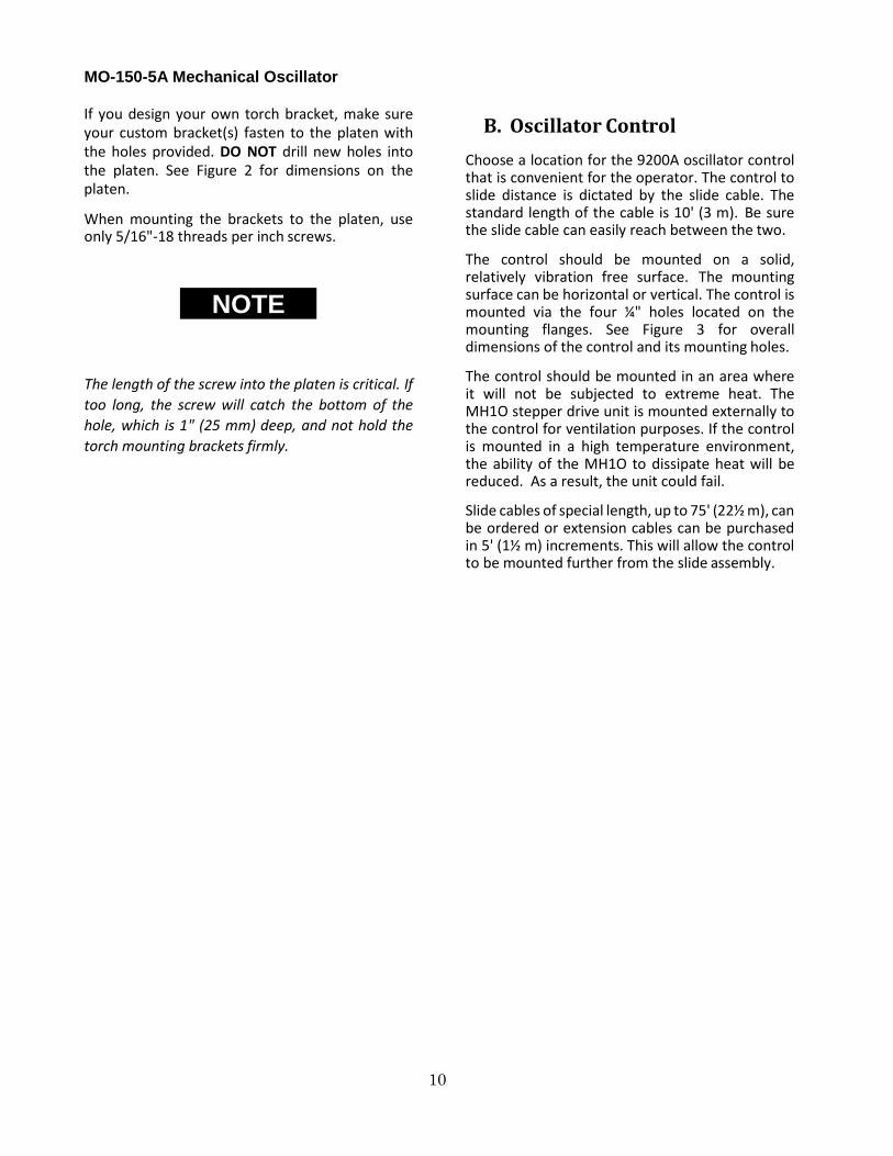
If you design your own torch bracket, make sure your custom bracket(s) fasten to the platen with the holes provided. DO NOT drill new holes into the platen. See Figure 2 for dimensions on the platen.
When mounting the brackets to the platen, use only 5/16"-18 threads per inch screws.
NOTE
The length of the screw into the platen is critical. If too long, the screw will catch the bottom of the hole, which is 1" (25 mm) deep, and not hold the torch mounting brackets firmly.
B. Oscillator Control Choose a location for the 9200A oscillator control that is convenient for the operator. The control to slide distance is dictated by the slide cable. The standard length of the cable is 10' (3 m). Be sure the slide cable can easily reach between the two.
The control should be mounted on a solid, relatively vibration free surface. The mounting surface can be horizontal or vertical. The control is mounted via the four ¼" holes located on the mounting flanges. See Figure 3 for overall dimensions of the control and its mounting holes.
The control should be mounted in an area where it will not be subjected to extreme heat. The MH1O stepper drive unit is mounted externally to the control for ventilation purposes. If the control is mounted in a high temperature environment, the ability of the MH1O to dissipate heat will be reduced. As a result, the unit could fail.
Slide cables of special length, up to 75' (22½ m), can be ordered or extension cables can be purchased in 5' (1½ m) increments. This will allow the control to be mounted further from the slide assembly.

11
Figure 2
MO-150-101-5D Sealed Oscillator Slide

MO-150-5A Mechanical Oscillator
12
SECTION VI
ELECTRICAL INSTALLATION
A. Input Power The MO-150 system was designed with both domestic and foreign markets in mind. Thus the 9200A control requires 115 VAC, 50/60 Hz or 230 VAC, 50/60 Hz. At maximum load, the system pulls 300 Va, which means approximately 3 amps at 120 VAC or 2 amps at 240 VAC.
The system is wired for 115 VAC operation when it leaves the factory. If you desire to connect up to 230 VAC, you will have to rearrange the input power jumper configuration located on terminal block #1 (TB1). See the electrical diagram 9252A in the Parts List section for details.
If you know before ordering the system that it will be connected to 230 VAC, you can request that it be modified at the factory. Once changed, the control should be clearly marked for 230 VAC operation.
B. Slide/Control Cable The 9256A cable connects the slide to the control at connector J1. The cable is a standard 10' (3 m) long. Special length cables or extension cables can be ordered through Miller Welding Automation. The cable is actually made up of two cables. One cable carries the motor signals while the other carries the reference potentiometer signal. They are separated for noise consideration.
C. Remote Pendant Connector If a remote pendant is to be installed, it will be connected at connector J3 on the 9200A control enclosure. The mating plug to the remote pendant connection is provided. A typical use for this connector is a remote start/stop signal. See the Interfacing section and Drawing 9232B for more details. When using this connector, use only shielded cable, with the shield being connected to the amphenol connector (chassis ground). This will help prevent unwanted noise from entering the control.
D. Remote Digital I/O Connector The remote digital, I/O connector, J2, is only meaningful if the optional 9222 board is installed. The mating plug for connector J2 is not provided with the control unless the optional 9222 board is included in the initial sale of the control. For details on the signals available on this connector, see the section on Functions.
Again, if you do connect up to this connector, use only shielded cable. The shield should be connected to the chassis of the amphenol connector (chassis ground).

13
SECTION VII
THEORY OF OPERATION
The MO-150 mechanical oscillator is designed to provide a welding system the ability to oscillate the torch reliably and consistently over a weld joint. However, the oscillator will not automatically compensate for part height deviation. As a result, the actual arc gap can vary as the torch moves back and forth across the part with varying heights.
Typical oscillation widths are from 4" to 1/4" (25 to 6 mm). If less than 1/4" (6 mm) stroke is required on a full time basis, the application may be better suited for a magnetic arc oscillator.
The main mechanical portion of the system is the MO-150-101-5D slide assembly. The slide’s design is based on a linear guide rail on which a platen, riding on linear guide rail bearing blocks, is driven back and forth.
The platen is motorized via a screw and ball nut assembly. In turn, this screw and nut assembly is rotated by a high torque stepper motor. Connected to the motor end of the screw, through a pair of gears, is a high reliability potentiometer which feeds the slide’s position back to the control.
The internal parts of the 9200A control consist of an overall power panel, a mother board (9211), a dwell and frequency generator board (9220), a positioning control board (9221), and an MH10 micro-stepper driver unit.
A. Power Panel The power panel serves two main purposes. One is to receive incoming signals and distribute them to the correct location. This distribution point is Terminal Block #2 (TB2). The second purpose of the power panel is to receive an inputted AC voltage and convert it into two isolated DC voltage circuits. The power distribution is handled by Terminal Block #1 (TB1).
The inputted 115 or 220 VAC is passed through a line filter and onto TB1. From here the line voltage goes to two transformers. One transformer, T1, reduces the voltage to 24 VAC. The other transformer, T2, reduces down the line voltage to two 12 VAC lines (a 24 VAC output with center tap).
The 24 VAC off of T1 is rectified by a bridge rectifier (BR1). This DC voltage out of BR1 is filtered and charged up by the capacitor C1. This DC voltage, now at approximately 34 volts, is fed to the MH10 drive unit which drives the stepper motor.
The dual 12 VAC circuit is passed onto the 9224 power board. This board rectifies the AC lines and creates a filtered, regulated positive and negative 12 VDC. This +12 VDC is used to operate the control circuitry for the rest of the system. It is distributed on TB1, terminals 6, 7 and 8.
B. Stepper Driver Unit, MH10 The MH1O unit is a micro-stepper drive unit. This particular unit is a "10 Step Per Step" device. Some drives work on a full step, some on half step; but by going with a one-tenth step drive, the MO-150 system is able to achieve very accurate motion.
This unit takes the control signals and generates a sequential drive signal to the stepper motor. The motor signals are opto-isolated from the motor signals in the MH1O. This advantage keeps motor noise and welding noise from entering the control circuitry. Miller Welding Automation further increased noise immunity by having the MH1O powered by a separate power supply. Thus the control voltage is not susceptible to voltage and current spikes due to the motor starting, stopping and setting idle.

MO-150-5A Mechanical Oscillator
14
C. Mother Board, 9211 The mother board acts as a major distribution network. Almost all of the signals come in, go out, and are transferred within this board.
Both front panel speed and dwell signals enter the mother board at connector J6. The front panel center and width signals enter through connector J9. The
+12 VDC power enters the board through connector J5. The control signals to the MH10 come out of connector J6. These and other signals are distributed from and to the two boards which plug into connector J1 and J2.
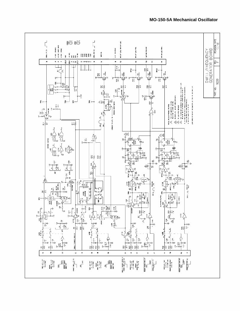
D. Generator Board, 9220 The generator board has two main purposes. One is to take the voltages from the speed potentiometers and turn them into a frequency. This frequency is then used to control speed (steps) in the MH10 driver.
The other function of this board is to handle the generation of dwell times. These dwells are created by two linear RC (resistant/capacitant) timing circuits.
In both functions, the initial signals go through a conditioning stage before they go into the voltage-to-frequency or RC timing stages.
E. Control Board, 9221 The control board has one main purpose. This is to control the position of the slide. The control is obtained by a summing (creating the high reference point) and a differential circuit (creating a low reference point).
The slide is either allowed to oscillate between these two points or come to rest between them.
The high and low reference points are determined in two ways. When oscillating, the points are determined by taking the center position voltage and adding/subtracting the width setting voltage. The slide will oscillate between these two voltages.
When not oscillating, the reference points are determined by taking the center position voltage and adding/subtracting the "center band gap" voltage (this band gap is adjustable via P4 on the 9221 board). Once the slide's reference feedback signal falls within this gap, the slide will stop. Changing the center position will cause the "band gap" to change, thus the slide will move to this new position and stop again.

15
SECTION VIII
FUNCTIONS
Refer to Figure 3.
1. On/Off Switch
This switch controls the 115/220 VAC entering the control. After the switch, the input power passes through the fuse before being distributed to the control.
2. Power Light
When illuminated, the light indicates that power is on in the control. The light is powered by the
+12VAC supply; this is a good indicator that the control circuitry voltage is working.
3. Width
Adjust width of oscillation:
Maximum width: 4 5/8" (118 mm)
Minimum width: 5/8" (16 mm)
NOTE
Extensive use of minimum oscillation width and the associated high speeds of oscillation can cause excessive vibration and wear to the welding system. Magnetic arc oscillation can be used for this type of situation to eliminate mechanical vibration.
4. Center
Always active.
Use during oscillation to adjust center position of oscillation.
Use in MANUAL mode to adjust cross slide position.
5. Dwell Left/Right
Sets dwell or pause time which occurs at the end of each oscillation stroke.
Dwell times: 0-3 seconds
6. Speed Left/Right
Speed range: 1-100 IPM (25-2,540 mm/min)
7. MANUAL Mode
No oscillation.
Control motorized cross slide with the CENTER knob.
Control cross slide stroke with the WIDTH knob. Minimum WIDTH of oscillation allows maximum stroke of 4 5/8" (118 mm). Maximum WIDTH of oscillation allows minimum stroke of 5/8" (16 mm).
8. REMOTE Mode
System will accept a remote signal to activate oscillation. When no remote signal is present, the system operates in “MANUAL” mode with WIDTH and CENTER knobs remaining active.
The system will oscillate according to the settings until the remote signal is lost or the system is switched to MANUAL.
9. SETUP Mode
The SETUP mode manually turns the oscillator on and is used for setting up oscillation parameters as well as for manual operation of the oscillator.
The oscillator operates according to the settings until switched to MANUAL mode.

MO-150-5A Mechanical Oscillator
16
Figure 3
Model 9200A Oscillator Control

17
SECTION IX
OPTIONAL FEATURES
1. Remote Interface Connector and Remote Pendant
Speed and dwell adjustments can be controlled by 0 to 5 VDC inputs.
2. Step Oscillation
Can be integrated with travel mechanism to step during dwell or travel.
When used in conjunction with an arc length control, can lock out oscillation during dwell or travel.

MO-150-5A Mechanical Oscillator
18
SECTION X
MAINTENANCE
A. Maintenance Schedule Daily
Wipe outer surface of unit with soft cloth to remove foreign matter (oil, grease, etc.).
Weekly
Check all cables for cuts, burns or cracks. Replace if necessary.
Monthly
Check for any loose screws and tighten if necessary. Inspect screw cover (bellows) for cuts or cracks. Replace if necessary.
B. Pot (R1) Replacement Refer to drawings MO-150-101-5D (mechanical, items 7, 15, 23) and MO-150-100-5 (electrical). The oscillator slide incorporates a ten turn servo pot for position feedback to the controller. This is a special hi-reliability type pot that normally lasts for years, but will eventually fail with continued usage. To replace:
1. Remove power. Using 1/8 inch hex wrench, remove the sheet metal cover at the motor- end of the slide assembly.
2. With soldering iron, remove the three wires attached to the servo pot. Record their positions for attaching to the replacement pot.
3. With 1/8 inch hex wrench, remove the two screws securing the pot bracket (item 7). Use
0.030 inch hex wrench to loosen the pot gear set screw, then remove the pot gear (item 15). Using a flat blade screwdriver, loosen the two retaining screws securing the pot, rotate the eccentrics and remove pot.
4. Install the replacement pot onto the bracket by seating the pot in the mounting
hole, rotating the pot so that the electrical terminals are facing away from the mounting bracket foot, then rotating the retaining eccentrics to secure pot and tighten the retaining screws.

19
5. Install the pot gear onto the pot shaft by sliding the gear on the pot shaft until 0.005" to 0.010" (.1 to .3 mm) spacing is achieved between gear hub and pot mounting bracket. Tighten the pot gear set screw.
6. Push the slide platen (mounting face for welding torch) until fully seated against mechanical stop at motor end. Install the pot assembly back onto the slide body and tighten the two mounting screws just enough so that the pot bracket can slide back and forth in the mounting slots. Slide the pot gear away from the driving gear. Rotate pot gear fully clockwise (as viewed from the end of the slide that does not have the motor). Slide the pot bracket towards the driver gear until the gear teeth are engaged. Carefully slide the bracket away from the driver gear, rotate the pot gear one tooth counter clockwise, then re- engage the gear teeth. Make sure that the two gears are fully meshed and aligned, then tighten the two pot bracket mounting screws.
7. Solder the three wires onto the pot terminals maintaining the original connection points.
8. Power up the 9200 slide controller in the MANUAL mode. Set Width to Min, set speeds to Max. Turn the Center pot to the full Left position. When slide stops, turn the Center pot to the full Right position. The slide should move smoothly to the full left and right positions without encountering any mechanical stops. If the slide “slams” into a mechanical stop at the end of travel, the pot is not rotationally oriented correctly. Remove power, loosen the two pot bracket mounting screws, slide pot gear away from driving gear, then repeat Step 6.
9. When satisfied with operation, replace sheet metal cover.

MO-150-5A Mechanical Oscillator
20
SECTION XI
PARTS LIST
The following pages provide a detailed parts list of all the elements of the Mechanical Oscillator. They are arranged so the parts list on the left hand page correspond to the assembly illustrated on the right hand page. Item numbers shown in the parts list refer to those numbers contained in the balloon in the drawing. The quantities shown are the number of items used in that particular assembly.
Two columns are included in the list to show the spare parts which are recommended to be stocked by the user. The two levels can be defined as follows:
Level 1 These are the spares recommended for US domestic users whose use of the product does not exceed 2000 hours per year.
Level 2 These are the spares recommended for international use of the product or for US domestic users who will use the product in excess of 2000 hours per year.
The following parts lists are included in this manual. Their appropriate page numbers are listed:
MO-150-101-5D Slide Assembly . . . . . . . . 20/21
9200A Control . . . . . . . . . . . . . . . . . . . . . . . 22/23
9251A-B Door Assembly . . . . . . . . . . . . . . . 24/25
9252A Power Panel Assembly . . . . . . . . . . . 26/27
9256A Drive Cable . . . . . . . . . . . . . . . . . . . 28/29

21
MECHANICAL OSCILLATOR SLIDE MO-150-
101-5D
Recommended Spares
Item Part Level Level
No. No. Description Qty I II
2 MO-150-2 Base ............................................................................ 1 3 MO-150-3 End Plate, with slot ..................................................... 1 4 MO-150-4 End Plate, without slot ............................................... 1 5 MO-150-5 Bellows Plate .............................................................. 1 6 MO-150-6 Lead Screw Assembly ................................................. 1
Includes R-0502-2 Nut ................................................ 1 7 MO-150-7 Pot Mount Angle ........................................................ 1 8 MO-150-8 Motor Mount Plate .................................................... 1 9 MO-150-9 Foot Plate ................................................................... 2
10 MO-150-10 Slide Mount ................................................................ 1 11 MO-150-11 Nut Plate ..................................................................... 1 12 MO-150-12 Cover .......................................................................... 1 13 MO-150-13 Gear Hub .................................................................... 1 1 1 14 MO-150-14 Bellows Clamp ............................................................ 4 15 MO-150-15 Pot Gear ...................................................................... 1 16 MO-150-16 Pot Drive Gear ............................................................ 1 1 1 17 MO-150-17 Bellows ....................................................................... 2 18 MO-150-18 Stop Stud .................................................................... 2 19 MO-150-19 Guard Block ................................................................ 2 20 SM2861-5152 Stepping Motor (replaces M092-LS09) ...................... 1 21 11730 Coupling ...................................................................... 1 1 1 22 455500 Ball Bearing ................................................................. 2 1 1 23 MH20S-2464-5K Potentiometer, 5K, 10 Turn ........................................ 1 1 1 24 HGH-15-CA-1R0220Z0-H Linear Guide Way ............................................... 1

MO-150-5A Mechanical Oscillator


MO-150-5A Mechanical Oscillator
22
MECHANICAL OSCILLATOR CONTROL 9200A
Recommended Spares
Item Part Level Level
No. No. Description Qty I II
1 ALC-201E-120 Enclosure .................................................................... 1 2 9251A Door Assembly ........................................................... 1 3 9252A Power Panel Assembly ............................................... 1 4 9231A Drive Harness Assembly, J1 ........................................ 1 5 9232A Remote Harness Assembly, J2 & J3 ............................ 1 6 9233A Remote Harness Assembly, P9 ................................... 1 7 9234A Interconnect Harness Assembly, P8 & P10 ................ 1 8 9220 P.C. Board, Generator Board ...................................... 1 1 9 9221 P.C. Board, Control Board........................................... 1 1
10 9224 P.C. Board, Power Board ............................................ 1 11 44F3095 Transformer, P8575, T2 .............................................. 1 12 MH10 Micro Step Drive Assembly ........................................ 1 13 9229 Cover .......................................................................... 1 14 81F4550 Filter, Power Line ........................................................ 1 15 C-1318-006-BL Power Cord ................................................................. 1 16 3302 Cord Grip .................................................................... 1 17 64-250 Insulated Disconnects. ............................................... 5 18 RA14-6F Crimp Terminal ........................................................... 4 19 6-32x1/4" Self-Taping Screw, 6-32 Thread ................................ 12 20 3106A-20-27P Remote Connector, J3 ................................................ 1 21 10-32x1/2" Screw,10-32 Thread ................................................... 4 22 8-32x1/2" Screw, 8-32 Thread ..................................................... 2 23 #8 Lock Washer .......................................................... 2 24 #8 Nut ......................................................................... 2 25 3106A-16S-01P Remote Connector, J2 ................................................ 1 26 9760-16 Dust Cap ..................................................................... 1 27 9760-20 Dust Cap ..................................................................... 1 28 97-3057-1012-1 Cable Clamp, J3........................................................... 1 29 97-3057-8 Cable Clamp, J2........................................................... 1


MO-150-5A Mechanical Oscillator
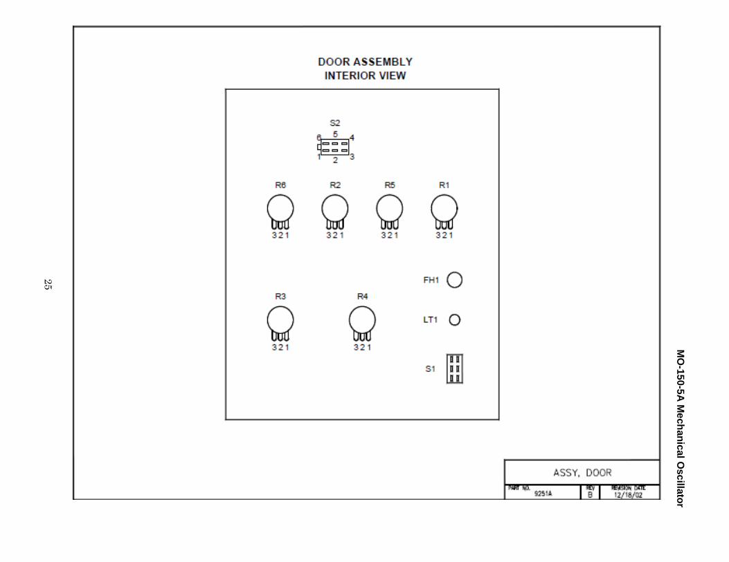
24
DOOR ASSEMBLY
9251A
Recommended Spares
Item Part Level Level
No. No. Description Qty I II
1 9260 Door Panel .................................................................. 1 2 10F468 Potentiometer, 10K ohm ............................................ 6 1 1
(R1, R2, R3, R4, R5, R6) 3 M1432 Knob ........................................................................... 6 1 1 4 39F2451 Lamp, Green (LT1) ...................................................... 1 1 5 25F1253 Mounting Clamp (for lamp) ........................................ 1 1 6 28F1803 Connector (for lamp) .................................................. 1 1 7 23F236 Switch (Power On/Off S1) .......................................... 1 1 8 AGC-3A Fuse, 3 Amp - Fast Blo ................................................ 1 5 5 9 27F794 Fuse Holder (F1) ......................................................... 1
10 RA14-6F Crimp Terminal ........................................................... 9 11 22-01-2147 Molex Connector, 14 Pin ............................................ 1 12 08-50-0114 Molex Terminal .......................................................... 6 13 Cable Mount ............................................................... 2 14 HWN-02 Protective Wrap . . . . . . . . . . . . . . . . . . . . . . . . . . . 6" 15 23F237 Switch (Mode Selector) S2 ......................................... 1 1
MO
-150-5A Mechanical O
scillator
25

MO-150-5A Mechanical Oscillator
26
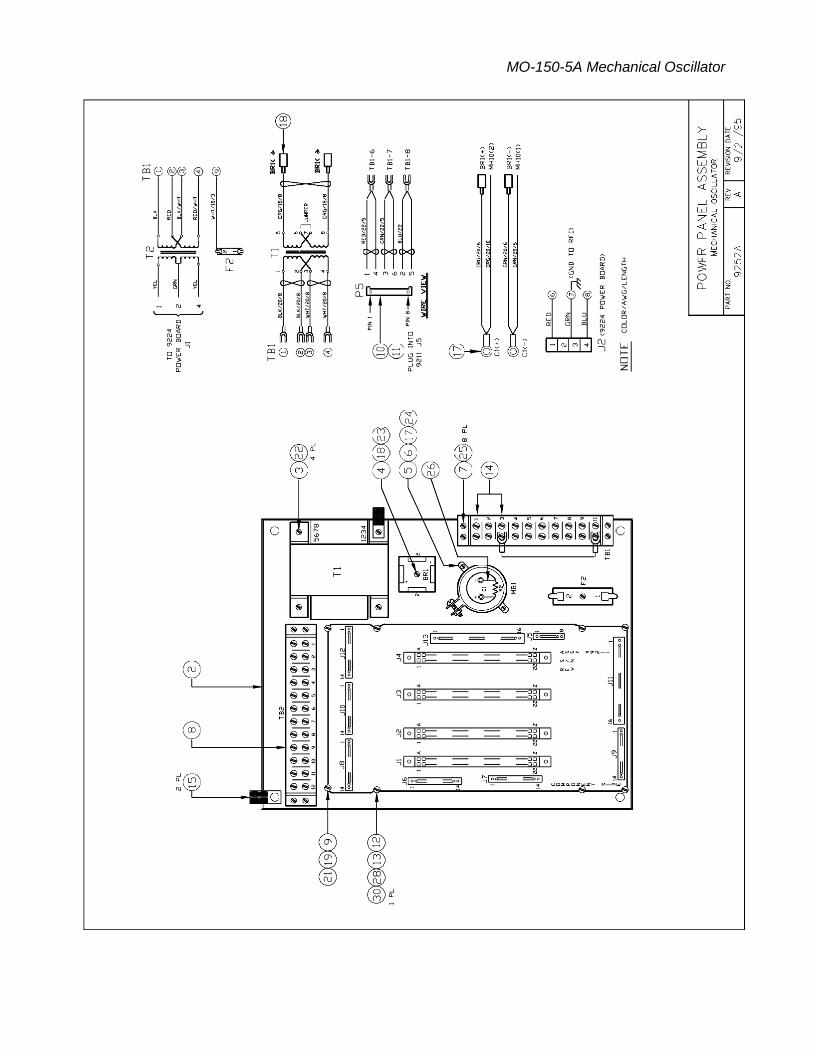
POWER PANEL ASSEMBLY
9252A
Recommended Spares
Item Part Level Level
No. No. Description Qty I II
2 ALC-201EP Panel ........................................................................... 1 3 01F820 Transformer, P6378, T1 .............................................. 1 1 4 KBPC-2506 Bridge Rectifier, BR1 ................................................... 1 1 5 47F2052 Capacitor, C1, 8700MFD, 40 V.................................... 1 6 14F410 Mounting Bracket for C1 ............................................ 1 7 65F1236 Terminal Block, TB1 .................................................... 1 8 65F1237 Terminal Block, TB2 .................................................... 1 9 9211 P.C. Board, Mother Board .......................................... 1
10 22-01-2085 Molex Connector, 8 Pin, P5 ........................................ 1 11 08-50-0114 Molex Pin for P5 ......................................................... 6 12 9265 Holding Bar ................................................................. 2 13 ALC-101-130 Spacer ......................................................................... 8 14 28F833 Terminal Jumper......................................................... 2 15 32N1271 Cable Clamp ................................................................ 2 16 RA14-6F Crimp Terminal ......................................................... 12 17 RA18-10 Crimp Terminal ........................................................... 4 18 TFFDN564-250 Crimp Terminal ........................................................... 4 19 16505BR1032NF Stand-Off .................................................................... 8 20 TA250-5D Adaptor, Male ............................................................ 2 21 6-32x1/4" Screw, 6-32 thread ..................................................... 4 22 8-32x1/4" Screw, 8-32 thread ..................................................... 6 23 8-32x3/4" Screw, 8-32 thread ..................................................... 1 24 6-32x1/4" Screw, 6-32 thread ..................................................... 2 25 6-32x1/2" Screw, 6-32 thread ..................................................... 8 26 13F3502 Power Resistor, 5K ohm, 3 W ..................................... 1 27 AGC-2A Fuse, 2A Fast Blo, F1 ................................................... 1 5 5 28 10-32x3/8" Screw, 10-32 Thread ................................................... 8 29 #10 Lock Washer ........................................................ 4 30 #10 Nylon Washer ...................................................... 4 31 3823-1 Fuse Holder ................................................................ 1
MO-150-5A Mechanical Oscillator

MO-150-5A Mechanical Oscillator
28
DRIVE CABLE
9256A
Recommended Spares
Item Part Level Level
No. No. Description Qty I II
1 3106A-20-33S J1 Connector, 11 Pin ................................................... 1
2 3106A-20-33P P1 Connector, 11 Pin .................................................. 1
3 2464 Cable, 4 cond., 18 G. . . . . . . . . . . . . . . . . . . . . . . . 10'
4 #20 Wire, Green . . . . . . . . . . . . . . . . . . . . . . . . . . . 4"
5 RB14-8 Crimp Terminal ........................................................... 2
6 97-3057-1012-1 Cable Clamp ................................................................ 2
7 Cable, 3 cond., 18 G. . . . . . . . . . . . . . . . . . . . . . . . 10'


MO-150-5A Mechanical Oscillator
30
Section XII
Electrical Drawings Interconnect Diagram, 9270A
Mother Board, 9271A
Wiring Diagram, 9255-150
Wiring Diagram, MH10 WIR
Control Board, 9221
Wiring Diagram Drive Cable, 9222
Dwell/Frequency Board, 9220 F
Pendant, 9200A-100

MO
-150-5A Mechanical O
scillator
31

MO-150-5A Mechanical Oscillator
32


MO-150-5A Mechanical Oscillator
34

U7
MO
-150-5A Mechanical O
scillator
35

MO
-150-5A Mechanical O
scillator
MO-150-5A Mechanical Oscillator