Tribological and surface analysis of 38 mm alumina–as-cast Co–Cr–Mo total hip arthroplasties
15
• • •
-
Upload
independent -
Category
Documents
-
view
0 -
download
0
Transcript of Tribological and surface analysis of 38 mm alumina–as-cast Co–Cr–Mo total hip arthroplasties
Durham Research Online
Deposited in DRO:
15 February 2010
Version of attached �le:
Published Version
Peer-review status of attached �le:
Peer-reviewed
Citation for published item:
Williams , S. R. and Wu, J. J. and Unsworth, A. and Khan, I. (2009) 'Tribological and surface analysis of38mm alumina-as-cast Co-Cr-Mo total hip arthroplasties.', Proceedings of the Institution of MechanicalEngineers, part H : journal of engineering in medicine., 223 (8). pp. 941-954.
Further information on publisher's website:
http://dx.doi.org/10.1243/09544119JEIM590
Publisher's copyright statement:
c© Williams , S. R. and Wu, J. J. and Unsworth, A. and Khan, I., 2009. The de�nitive, peer reviewed and editedversion of this article is published in Proceedings of the I MECH E part H : journal of engineering in medicine, 223, 8,pp. 941-954, 10.1243/09544119JEIM590
Additional information:
Use policy
The full-text may be used and/or reproduced, and given to third parties in any format or medium, without prior permission or charge, forpersonal research or study, educational, or not-for-pro�t purposes provided that:
• a full bibliographic reference is made to the original source
• a link is made to the metadata record in DRO
• the full-text is not changed in any way
The full-text must not be sold in any format or medium without the formal permission of the copyright holders.
Please consult the full DRO policy for further details.
Durham University Library, Stockton Road, Durham DH1 3LY, United KingdomTel : +44 (0)191 334 3042 | Fax : +44 (0)191 334 2971
http://dro-test.dur.ac.uk
Tribological and surface analysis of 38 mmalumina–as-cast Co–Cr–Mo total hip arthroplastiesS R Williams1, J J Wu1*, A Unsworth1, and I Khan2
1Centre for Biomedical Engineering, School of Engineering, Durham University, Durham, UK2Biomet UK Ltd, Swindon, UK
The manuscript was received on 8 February 2009 and was accepted after revision for publication on 26 June 2009.
DOI: 10.1243/09544119JEIM590
Abstract: There is currently much discussion over the use of ceramic femoral componentsagainst metal acetabular cups, for use in total hip arthroplasty. The current study investigatessix hot isostatically pressed alumina femoral heads of 38 mm diameter articulating against sixas-cast Co–Cr–Mo metallic acetabular cups. Standard walking-cycle simulator wear testing wascarried out to 56106 cycles using the Durham Mark II hip wear simulator, and wear wasdetermined gravimetrically. In addition, surface topography, using a non-contacting pro-filometer, an atomic force microscope, and an optical microscope, was monitored throughoutthe wear test. The wear of the ceramic heads was found to be undetectable using the currentgravimetric method; however, a change in the surface topography was seen, as grain removalon the pole was observed through atomic force microscopy analysis. A biphasic wear patternwas found for the metallic cups, with low wear rates of 1.04 ¡ 0.293 mm3/106 cycles (mean,¡95 per cent confidence interval) and 0.0209 ¡ 0.004 mm3/106 cycles (mean, ¡95 per centconfidence interval) for running-in and steady state wear phases respectively. Frictionalmeasurement revealed that the joints were tending towards full fluid-film lubrication in partsof the walking cycle. The results show that the combination of hot isostatically pressed aluminaand as-cast Co–Cr–Mo is a promising alternative for total hip arthroplasties.
Keywords: ceramic on metal, hip, alumina, wear, friction, surface analysis, protein
1 INTRODUCTION
The design and material combination of total hip
replacements has been investigated for over 70
years, with the desire to develop the ‘perfect joint
replacement’. Charnley’s low-frictional-torque small-
diameter metallic head articulating against a poly-
ethylene liner has been successfully implanted for
many years [1–3]. However, periprosthetic osteoly-
sis, caused by polyethylene particles released dur-
ing the wear process, has emerged as a major factor
resulting in the need for revision surgery [4–8].
Hard-on-hard bearings are thought to reduce the
problems associated with osteolysis by eliminating
polyethylene wear particles. An increased desire for
implantation into younger patients has resulted in a
surge of interest in hard-on-hard bearings, which
have emerged as a promising alternative bearing
combination. The first-generation metal total hip
replacements implanted in the 1960s initially indi-
cated low wear but they were found to produce
high frictional torque due to the lack of knowledge
of tribological factors such as joint clearance and
the requirement for high-quality metallurgical pro-
perties. Improved manufacturing techniques and
the correct choice of clearances resulted in im-
plants of superior designs during the 1990s such as
the Birmingham Hip Resurfacing, which has had
excellent medium-term success in young patients
over a 10 year period [9]. Reports have suggested an
inherent stability of the device and the likelihood
that it will perform well over time [10]. However,
concerns regarding the dispersion of metal ions
throughout the body are also being voiced. Carci-
nogenic effects and hypersensitivity reactions have
*Corresponding author: Centre for Biomedical Engineering,
School of Engineering, Durham University, South Road, Durham
DH1 3LE, UK.
email: [email protected]
941
JEIM590 Proc. IMechE Vol. 223 Part H: J. Engineering in Medicine
been discussed as potential adverse effects [11] but
currently little evidence has been found to show
that elevated metal ions result in a statistically
significant increase in risk of cancer [12] or other
undesirable conditions.
Because of the lack of long-term knowledge
regarding metal ions, researchers are continuing to
investigate material combinations in the quest to
reduce the wear and volume of metal ions released.
First-generation ceramic-on-ceramic (CoC) pros-
theses implanted in the 1970s [13] were unsuccessful
owing to the large grain size, high porosity, and poor
surface finish, all of which had a negative impact on
the already low fracture toughness of ceramics.
However, improvements in manufacturing such as
hot isostatic pressing allowed more recent ceramic
prostheses to be successful because of the enhanced
surface finish and a reduced grain size and porosity.
This promoted full fluid-film lubrication and lower
coefficients of friction, both of which act to reduce
wear and particle formation. Nevertheless the under-
lying problem of the inherent brittleness of the
ceramic remains, and there are reports in the
literature of catastrophic failures in vivo [14–16].
In recent years, ceramic-on-metal (CoM) combina-
tions have been tested in vitro [17–28], with a limited
number being implanted in vivo [29–31]. Advantages
of CoM over metal-on-metal (MoM) and CoC pros-
theses included a reduced volume of metal wear
particles [26, 31] and a reduced tendency for fracture
of the ceramic component due to the softer metallic
cup. The observed reduction in adhesive wear is also
beneficial. An additional advantage over a polyethy-
lene acetabular cup is that increased hardness of the
cup is expected to promote a reduction in wear, since
wear is inversely proportional to hardness.
The available literature regarding CoM pairings
has covered a range of diameters (namely 22 mm,
28 mm, 32 mm, 36 mm, 38 mm), and 54 mm compo-
nents [17–24, 28], with a range of radial clearances.
Wear, friction, and particles produced during simu-
lation have all been investigated [17–28, 31, 32].
Firkins et al. [20] in 2000 reported the first
simulator study investigating the CoM combination.
Overall for alumina of 28 mm diameter against Co–
Cr alloy, a very low wear rate of 0.01 mm3/106 cycles
was found. A higher rate of 0.04 mm3/106 cycles was
found in one component after 0.56106 cycles. Dif-
ficulties in measuring the wear using gravimetric
techniques were noted and attributed to material
transfer and the very small amount of wear itself.
Low wear rates have also been found for alumina
heads of 38 mm diameter against Co–Cr–Mo cups
[17] with running-in (RI) and steady state (SS) wear
rates of 1.01 mm3/106 cycles and 0.10 mm3/106 cycles
respectively. The overall wear rate was 0.39 mm3/106
cycles, with the majority of the wear due to the
metallic cup. In comparison with their standard
32 mm MoM joints, the wear of the CoM was seen
to give a fourfold reduction.
A recent study [28] compared larger-diameter
(54 mm) MoM and CoM implant bearings. The com-
bination of an alumina head against as-cast Co–Cr–
Mo alloy was found to exhibit the least wear, namely
0.018 mm3/106 cycles. In addition a differential-
hardness MoM joint was investigated and compared
with a ‘like’-hardness MoM pairing. The differential-
hardness MoM joint was found to exhibit 68 per cent
less volumetric wear than the ‘like’-hardness MoM
pairing (steady state rates of 0.060 mm3/106 cycles
and 0.011 mm3/6106 cycles for differential-hardness
and ‘like’-hardness MoM pairings respectively). This
suggests that it is advantageous to have a femoral
head with a greater hardness than the cup.
Experiments other than simulator wear tests have
also provided corroborative evidence. A very short
study investigating a Co–Cr–Mo pin articulating
against an alumina plate over 90 000 cycles [25]
and a further pin-on-plate study [32] testing both
MoM and CoM combinations found a decreased
overall wear rate and metallic ion release for the
CoM combination compared with the MoM pairing.
Two retrieval studies have been published regard-
ing CoM pairings. These were a Metasul cup against
a Biolox alumina head [29] and a stainless steel head
against an alumina cup [30], both of which were
revised owing to pain. The latter was replaced 1 year
after the primary operation by a metal-on-polyethy-
lene (MoP) joint owing to pain and a growing mass on
the proximal thigh. The Biolox head of the Metasul–
Biolox combination was inserted on revision 1 year
after the primary operation. After 1 year and 6
months, a polyethylene inlay and metal head were
inserted owing to pain and the detection of noises by
the physician on examination. Following the failure
of the Metasul socket against the Biolox aluminium
oxide ceramic head, Hinrich and Griss [29] ex-
pressed concerns over a number of issues regarding
CoM combinations. They felt that the wear pattern
raised suspicions that sphericity and matching of the
heads and cups may be more important than in
MoM and CoC. They also questioned what would
happen to CoM components when an incorrectly
positioned component was implanted, and recom-
mended that further research and development of
CoM components should be undertaken. Although
942 S R Williams, J J Wu, A Unsworth, and I Khan
Proc. IMechE Vol. 223 Part H: J. Engineering in Medicine JEIM590
these reports highlighted negative results for CoM
combinations, a detailed study by Williams et al.
[31] has revealed promising in-vitro and in-vivo
wear results for the CoM combinations. Short-term stud-
ies of 31 people at 6 months after implantation
showed lower metal ion levels in those with a CoM
joint in comparison with those having MoM bear-
ings. Also the cumulative volumetric wear of MoM
was found to be greater than those of CoC and CoM
pairings where no difference in volumetric wear was
found.
2 MATERIALS AND METHODS
2.1 Materials
The prostheses used in this study consisted of six
RecapH Co–Cr–Mo as-cast acetabular cups of 38 mm
diameter, and six hot isostatically pressed alumina
femoral heads supplied by Biomet UK. The heads
were mounted onto poly(methyl methacrylate)-
coated stainless steel tapered stems, and the cups
mounted into ultra-high molecular weight polyethy-
lene (UHMWPE) holders for simulator and friction
measurement. Components were matched to give
similar radial clearances of approximately 100 mm, as
shown in Table 1.
2.2 Lubricant
A solution of new-born calf serum (Harlan Sera-Lab
Limited; total protein content, 7.5 g/dl) was diluted
to 25 per cent using distilled water with additions of
both 0.2 per cent sodium azide to prevent bacterial
growth and 20 mM ethylenediaminetetraacetic acid
(EDTA) to prevent calcium phosphate precipitation
onto the bearing surfaces [33]. Friction tests were
carried out using viscosities of bovine serum (BS)
mixed with carboxymethyl cellulose (CMC) of
0.125 Pa s, 0.0315 Pa s, 0.0085 Pa s, and 0.0039 Pa s,
and 25 per cent diluted BS with a viscosity of
0.0013 Pa s. Aqueous solutions of CMC were also
used as a lubricant at viscosities of 0.092 Pa s,
0.0275 Pa s, 0.0095 Pa s, 0.0030 Pa s, and 0.001 Pa s.
CMC was chosen because of its similar rheological
properties to synovial fluid. The joints were cleaned
between friction tests using a weak solution of
Neutracon, followed by propan-2-ol. The same batch
of lubricant was used throughout all tests to reduce
variability.
2.3 Wear simulator experiments
Wear experiments were carried out on the Mark II
Durham hip wear simulator, which has two axes of
motion: flexion–extension and internal–external ro-
tation. This was achieved using a crank and con-
necting-rod arrangement driven by an a.c. motor at
1 Hz, to oscillate the femoral component with an
approximate sinusoidal motion through +30u and
215u. A second similar mechanism directly drove the
internal–external rotation drive bar, causing the
acetabular component to oscillate with approximate
sinusoidal motion in the internal–external rotation
plane through ¡5u. A square-wave loading cycle (a
minimum and a maximum of 300 N and 2600 N res-
pectively) was applied across the joint. The direction
of load varied as the angle of flexion–extension.
Acetabular components were mounted at 33u to the
horizontal in all five articulating wear stations as well
as the loaded soak control station.
Wear tests were carried out to 56106 cycles,
interrupted at 0.56106 cycle intervals to measure
gravimetric wear of both the acetabular and the
femoral components. The protocol to clean the pro-
stheses ensured total protein removal from the
components between measurements. Briefly, the
components were removed from the wear simulator,
and bulk contaminants removed by flushing with
water. Following this a series of washes in an
ultrasonic bath was carried out. The middle time
period used a weak solution of Neutracon to remove
any grease or dirt from the surfaces. After this, the
joints were rinsed in propan-2-ol and dried in a
vacuum oven at 40 uC for 30 min. The components
were allowed to acclimatize to room temperature in
the metrology laboratory before being weighed using
a precision balance. Throughout the cleaning pro-
tocol a soft brush was used on the back of the
Table 1 Ceramic heads against metal cup pairings and clearances
Station Co–Cr cup number Alumina head number Clearance (mm)
1 9 4 1002 6 2 983 5 9 994 2 35 985 3 6 97Control 4 10 99
Tribological and surface analysis of total hip arthroplasties 943
JEIM590 Proc. IMechE Vol. 223 Part H: J. Engineering in Medicine
acetabular cups, and lint-free paper on the head and
cup bearing surfaces to remove protein adsorbed on-
to the surfaces. The loaded soak control was used to
take account of any variation due to fluid absorption
and environmental changes such as changes in
humidity and temperature. Volumetric wear rates
were calculated using 3.98061023 g/mm3 and 8.28761023 g/mm3 for the densities of the alumina fem-
oral head and the Co–Cr–Mo alloy acetabular cup
respectively.
2.4 Friction: theoretical and practical
Results of friction measurements using the Durham
hip function simulator were used to indicate the
lubrication regime under which the joints were
operating, through Stribeck analysis. The friction
factor was plotted against a modified version of the
Sommerfeld number which was calculated using
z~gur
Lð1Þ
where g is the viscosity of the lubricant, u is the
entraining velocity, L is the load, and r is the radius
of the femoral head. A falling trend in friction factor
is indicative of mixed lubrication, and a rising trend
of full fluid-film lubrication. The friction factor itself
is given by
f ~T
rLð2Þ
where T is the frictional torque generated between
the bearing surfaces, r is the radius of the femoral
head, and L is the applied load.
Tests were performed with flexion–extension of
¡23u at a frequency of 1 Hz. Tests were performed
using simple harmonic motion of amplitude 25u and
a frequency of 1 Hz. The load cycle was approxi-
mately a square wave with a maximum and mini-
mum of 2000 N and 100 N respectively. Each test was
performed in the normal and inverse directions in
order to eliminate any residual error from misalign-
ment of the bearing components. Data were logged
at the 21st and 41st cycles, providing six data points
each of which were an average of five points taken at
the peak-load and high-velocity phase of the cycle.
Each joint was tested three times and an average and
standard deviation calculated for each data point
[34, 35].
The theoretical lubrication mode was also calcu-
lated using the predicted minimum film thickness
and recorded the average r.m.s. roughness of the
bearing surfaces, as recorded using the Zygo non-
contacting three-dimensional profilometer. This
yields a dimensionless parameter l given by
l~hmin
(r:m:s:2q1zr:m:s:2q2)0:5ð3Þ
where, for l , 3, mixed lubrication is likely and, if
l . 3, full fluid-film lubrication is predicted [36]. If
l , 1, then the bearing would theoretically operate in
boundary lubrication.
The minimum-film-thickness calculation, taking
into account the importance of elastic deformation
of the bearing surfaces as determined by Hamrock
and Dowson [37], is
hmin
Rx~2:798
gu
E0Rx
� �0:65L
E0R2
x
� �{0:21
ð4Þ
2.5 Wear track experimental detection
During wear testing, a deposit formed on the bear-
ing surfaces surrounding the contact area. Digital
images of the Co–Cr–Mo acetabular cups were taken
to visualize the deposition; however, it was not
visible using a digital camera on the alumina fem-
oral heads. Because of the fluorescent nature of
the deposit, an ultraviolet (UV) source and charge-
coupled device (CCD) camera were used to image
the heads. Images were taken through 360u to
visualize the complete head and then analysed using
LabVIEW 8 and a program written by the School of
Chemistry, Durham University.
2.6 Surface analysis
Several surface-analytical techniques were used to
monitor changes in the surface topography of the
components.
Surface topography was measured throughout the
test using a three-dimensional non-contacting op-
tical interference Zygo profilometer (NewView 100,
Zygo, Middlefield, Connecticut, USA). Measure-
ments were taken at 06106 cycles, 26106 cycles,
36106 cycles, and 56106 cycles. At least ten meas-
urements were taken in the contact area for both
the head and the cups, with additional measure-
ments taken at 26106 and 56106 cycles in the non-
contact areas.
Optical micrographs were taken at 2.56106 cycles,
36106 cycles, and 56106 cycles to monitor the top-
ography of the surface throughout the wear test.
944 S R Williams, J J Wu, A Unsworth, and I Khan
Proc. IMechE Vol. 223 Part H: J. Engineering in Medicine JEIM590
Environmental scanning electron microscopy
(ESEM) and atomic force microscopy (AFM) were
carried out on the alumina femoral heads after
56106 cycles. Images were taken at the pole and on
an unworn surface for comparison. An accelerator
voltage of 20 kV and a spot size of 5 were used during
imaging using ESEM.
AFM images were analysed using the WSxM image
browser [38].
3 RESULTS
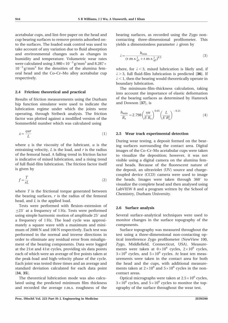
3.1 Wear
The volume change for the individual Co–Cr–Mo
cups and alumina heads is summarized in Fig. 1.
The volume losses and standard deviations for the
heads were lower than the cups with greater varia-
tion in wear rates between the metal samples likely
to be due to the differences in cup RI wear rates
between 0 cycles and 0.56106 cycles. The overall RI
wear rate of 1.04¡0.293 mm3/106 cycles (mean,
¡95 per cent confidence interval) was measured;
however, the heads experienced a gravimetrically
non-detectable change in wear throughout the
56106 cycle test. After the initial higher wear rate
experienced by the cups a wear rate of 0.0209¡
0.004 mm3/106 cycles (mean, ¡95 per cent con-
fidence interval) was seen from 0.56106 cycles to
56106 cycles. The greater wear seen by cup 9 at
36106 cycles arose because the joint ran dry, after
which the joint returned to the lower wear rate.
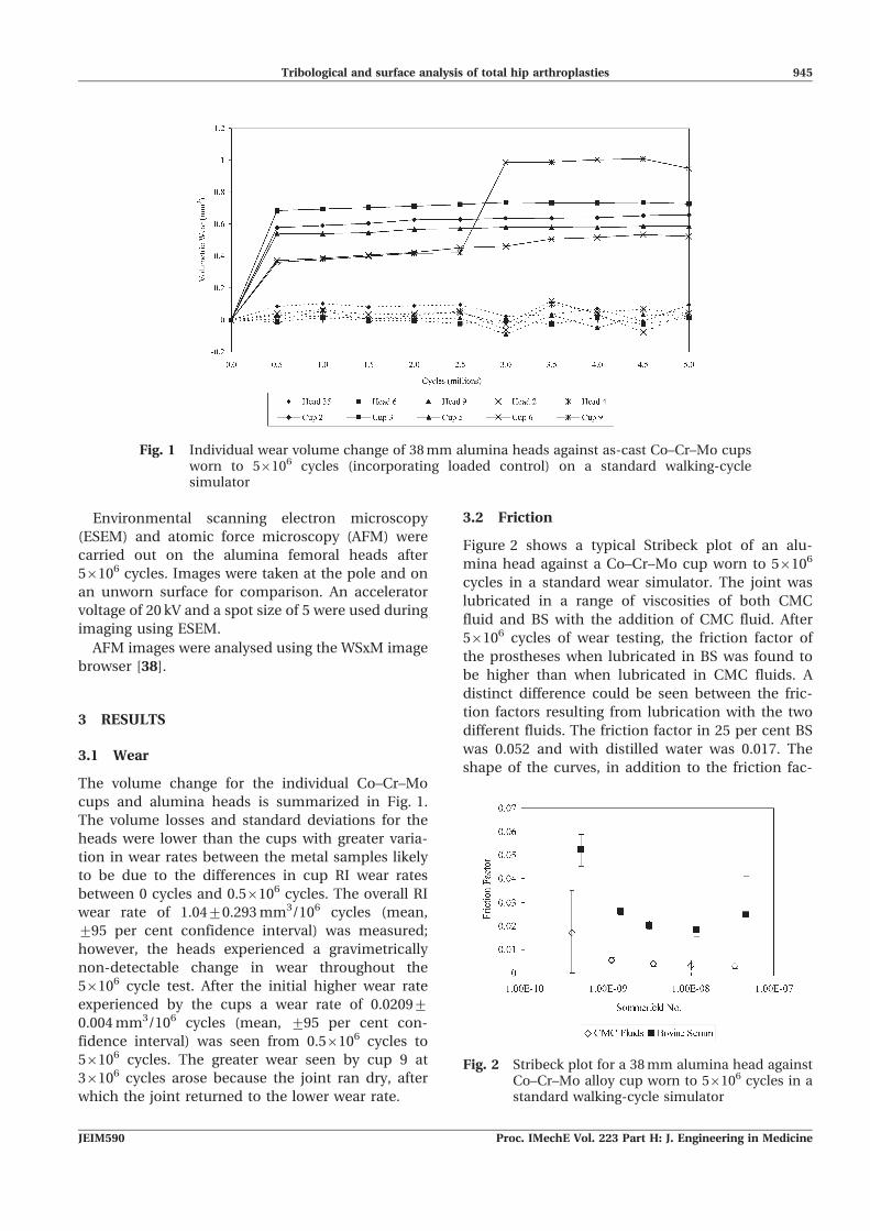
3.2 Friction
Figure 2 shows a typical Stribeck plot of an alu-
mina head against a Co–Cr–Mo cup worn to 56106
cycles in a standard wear simulator. The joint was
lubricated in a range of viscosities of both CMC
fluid and BS with the addition of CMC fluid. After
56106 cycles of wear testing, the friction factor of
the prostheses when lubricated in BS was found to
be higher than when lubricated in CMC fluids. A
distinct difference could be seen between the fric-
tion factors resulting from lubrication with the two
different fluids. The friction factor in 25 per cent BS
was 0.052 and with distilled water was 0.017. The
shape of the curves, in addition to the friction fac-
Fig. 1 Individual wear volume change of 38 mm alumina heads against as-cast Co–Cr–Mo cupsworn to 56106 cycles (incorporating loaded control) on a standard walking-cyclesimulator
Fig. 2 Stribeck plot for a 38 mm alumina head againstCo–Cr–Mo alloy cup worn to 56106 cycles in astandard walking-cycle simulator
Tribological and surface analysis of total hip arthroplasties 945
JEIM590 Proc. IMechE Vol. 223 Part H: J. Engineering in Medicine
tors, indicate that the joint is working close to full
fluid-film lubrication in parts of the walking cycle.
The theoretical lubrication modes shown in
Table 2 support the experimental results. The calcu-
lations show that the joints were operating close to
or within full fluid-film lubrication for the majority
of 56106 cycles of standard walking-cycle wear. This
is supported by both the wear rates and the top-
ography images, which show low wear on both the
bearing surfaces.
3.3 Surface analysis
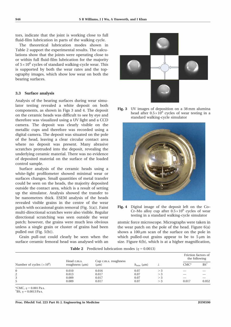
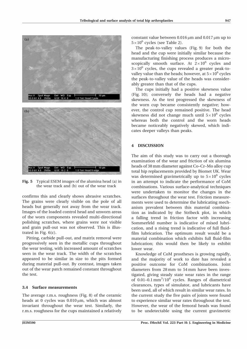
Analysis of the bearing surfaces during wear simu-
lator testing revealed a white deposit on both
components, as shown in Figs 3 and 4. The deposit
on the ceramic heads was difficult to see by eye and
therefore was visualized using a UV light and a CCD
camera. The deposit was clearly visible on the
metallic cups and therefore was recorded using a
digital camera. The deposit was situated on the pole
of the head, leaving a clear circular contact area
where no deposit was present. Many abrasive
scratches protruded into the deposit, revealing the
underlying ceramic material. There was no evidence
of deposited material on the surface of the loaded
control sample.
Surface analysis of the ceramic heads using a
white-light profilometer showed minimal wear or
surfaces changes. Small quantities of metal transfer
could be seen on the heads, the majority deposited
outside the contact area, which is a result of setting
up the simulator. Analysis showed the transfer to
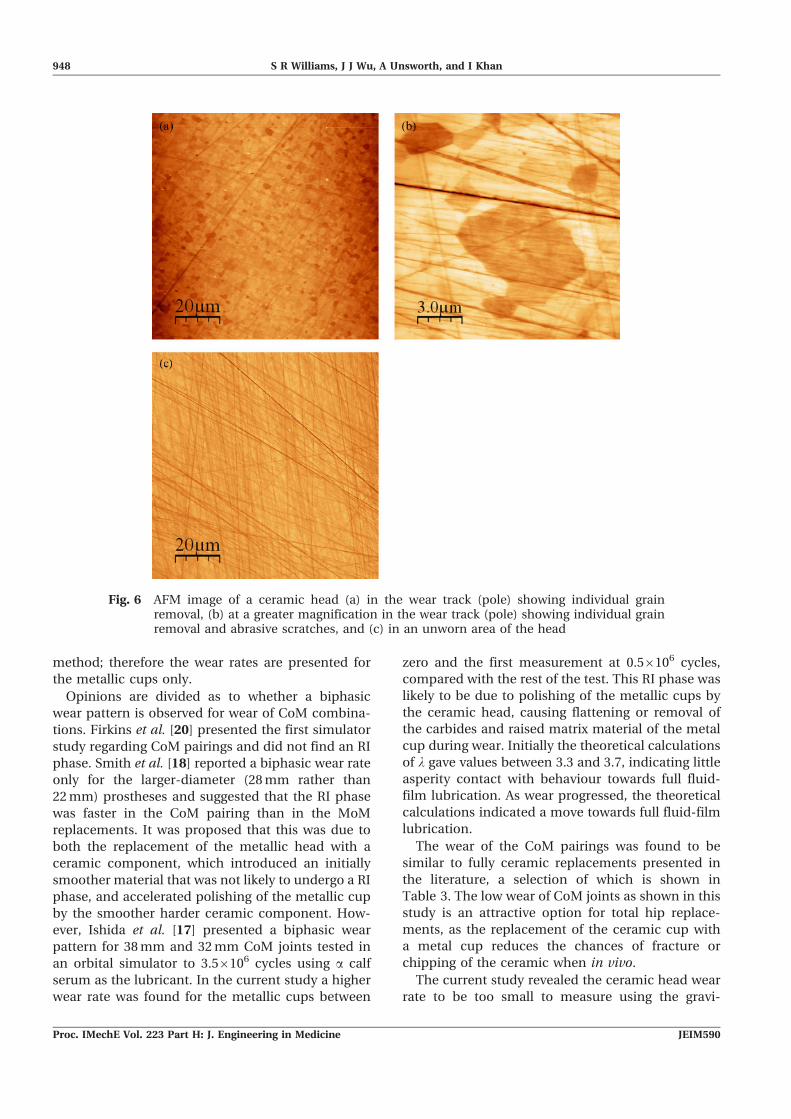
be nanometres thick. ESEM analysis of the heads
revealed visible grains in the centre of the wear
patch with occasional grain removal (Fig. 5(a)). Faint
multi-directional scratches were also visible. Regular
directional scratching was seen outside the wear
patch; however, the grains were much less obvious
unless a single grain or cluster of grains had been
pulled out (Fig. 5(b)).
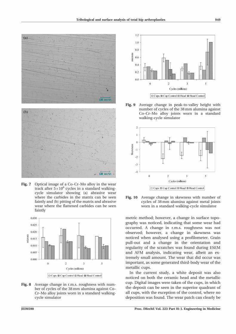
Grain pull-out could clearly be seen when the
surface ceramic femoral head was analysed with an
atomic force microscope. Micrographs were taken in
the wear patch on the pole of the head. Figure 6(a)
shows a 100 mm scan of the surface on the pole in
which pulled-out grains appear to be to 5 mm in
size. Figure 6(b), which is at a higher magnification,
Table 2 Predicted lubrication modes (g 5 0.0013)
Number of cycles (6106)Head r.m.s.roughness (mm)
Cup r.m.s. roughness(mm) hmin (mm) l
Friction factors ofthe following
CMC* BS{
0 0.010 0.016 0.07 . 3 — —2 0.013 0.017 0.07 . 3 — —3 0.009 0.017 0.07 . 3 — —5 0.009 0.017 0.07 . 3 0.017 0.052
*CMC, g 5 0.001 Pa s.{BS, g 5 0.0013 Pa s.
Fig. 3 UV images of deposition on a 38 mm aluminahead after 0.56106 cycles of wear testing in astandard walking-cycle simulator
Fig. 4 Digital image of the deposit left on the Co–Cr–Mo alloy cup after 0.56106 cycles of weartesting in a standard walking-cycle simulator
946 S R Williams, J J Wu, A Unsworth, and I Khan
Proc. IMechE Vol. 223 Part H: J. Engineering in Medicine JEIM590
confirms this and clearly shows abrasive scratches.
The grains were clearly visible on the pole of all
heads but generally not away from the wear track.
Images of the loaded control head and unworn areas
of the worn components revealed multi-directional
polishing scratches, where grains were not visible
and grain pull-out was not observed. This is illus-
trated in Fig. 6(c).
Pitting, carbide pull-out, and matrix removal were
progressively seen in the metallic cups throughout
the wear testing, with increased amount of scratches
seen in the wear track. The width of the scratches
appeared to be similar in size to the pits formed
during material pull-out. By contrast, images taken
out of the wear patch remained constant throughout
the test.
3.4 Surface measurements
The average r.m.s. roughness (Fig. 8) of the ceramic
heads at 0 cycles was 0.010mm, which was almost
invariant throughout the wear test. Similarly, the
r.m.s. roughness for the cups maintained a relatively
constant value between 0.016 mm and 0.017mm up to
56106 cycles (see Table 2).
The peak-to-valley values (Fig. 9) for both the
head and the cup were initially similar because the
manufacturing finishing process produces a micro-
scopically smooth surface. At 26106 cycles and
36106 cycles, the cups revealed a greater peak-to-
valley value than the heads; however, at 56106 cycles
the peak-to-valley value of the heads was consider-
ably greater than that of the cups.
The cups initially had a positive skewness value
(Fig. 10); conversely the heads had a negative
skewness. As the test progressed the skewness of
the worn cup became consistently negative; how-
ever, the control cup remained positive. The head
skewness did not change much until 56106 cycles
whereas both the control and the worn heads
became noticeably negatively skewed, which indi-
cates deeper valleys than peaks.
4 DISCUSSION
The aim of this study was to carry out a thorough
examination of the wear and friction of six alumina
heads of 38 mm diameter against Co–Cr–Mo alloy cup
total hip replacements provided by Biomet UK. Wear
was determined gravimetrically up to 56106 cycles
in an attempt to indicate the performance of CoM
combinations. Various surface-analytical techniques
were undertaken to monitor the changes in the
surfaces throughout the wear test. Friction measure-
ments were used to determine the lubricating mech-
anism prevalent between this material combina-
tion as indicated by the Stribeck plot, in which
a falling trend in friction factor with increasing
Sommerfeld number is indicative of mixed lubri-
cation, and a rising trend is indicative of full fluid-
film lubrication. The optimum result would be a
material combination which exhibits full fluid-film
lubrication; this would then be likely to exhibit
lower wear.
Knowledge of CoM prostheses is growing rapidly,
and the majority of work to date has revealed a
positive outcome for CoM combinations. Joint
diameters from 28 mm to 54 mm have been inves-
tigated, giving steady state wear rates in the range
of 0.01–0.1 mm3/106 cycles. Ranges of diametrical
clearances, types of simulator, and lubricants have
been used, all of which result in similar wear rates. In
the current study the five pairs of joints were found
to experience similar wear rates throughout the test.
However, the wear of the femoral heads was found
to be undetectable using the current gravimetric
Fig. 5 Typical ESEM images of the alumina head (a) inthe wear track and (b) out of the wear track
Tribological and surface analysis of total hip arthroplasties 947
JEIM590 Proc. IMechE Vol. 223 Part H: J. Engineering in Medicine
method; therefore the wear rates are presented for
the metallic cups only.
Opinions are divided as to whether a biphasic
wear pattern is observed for wear of CoM combina-
tions. Firkins et al. [20] presented the first simulator
study regarding CoM pairings and did not find an RI
phase. Smith et al. [18] reported a biphasic wear rate
only for the larger-diameter (28 mm rather than
22 mm) prostheses and suggested that the RI phase
was faster in the CoM pairing than in the MoM
replacements. It was proposed that this was due to
both the replacement of the metallic head with a
ceramic component, which introduced an initially
smoother material that was not likely to undergo a RI
phase, and accelerated polishing of the metallic cup
by the smoother harder ceramic component. How-
ever, Ishida et al. [17] presented a biphasic wear
pattern for 38 mm and 32 mm CoM joints tested in
an orbital simulator to 3.56106 cycles using a calf
serum as the lubricant. In the current study a higher
wear rate was found for the metallic cups between
zero and the first measurement at 0.56106 cycles,
compared with the rest of the test. This RI phase was
likely to be due to polishing of the metallic cups by
the ceramic head, causing flattening or removal of
the carbides and raised matrix material of the metal
cup during wear. Initially the theoretical calculations
of l gave values between 3.3 and 3.7, indicating little
asperity contact with behaviour towards full fluid-
film lubrication. As wear progressed, the theoretical
calculations indicated a move towards full fluid-film
lubrication.
The wear of the CoM pairings was found to be
similar to fully ceramic replacements presented in
the literature, a selection of which is shown in
Table 3. The low wear of CoM joints as shown in this
study is an attractive option for total hip replace-
ments, as the replacement of the ceramic cup with
a metal cup reduces the chances of fracture or
chipping of the ceramic when in vivo.
The current study revealed the ceramic head wear
rate to be too small to measure using the gravi-
Fig. 6 AFM image of a ceramic head (a) in the wear track (pole) showing individual grainremoval, (b) at a greater magnification in the wear track (pole) showing individual grainremoval and abrasive scratches, and (c) in an unworn area of the head
948 S R Williams, J J Wu, A Unsworth, and I Khan
Proc. IMechE Vol. 223 Part H: J. Engineering in Medicine JEIM590
metric method; however, a change in surface topo-
graphy was noticed, indicating that some wear had
occurred. A change in r.m.s. roughness was not
observed; however, a change in skewness was
noticed when analysed using a profilometer. Grain
pull-out and a change in the orientation and
regularity of the scratches was found during ESEM
and AFM analysis, indicating wear, albeit an ex-
tremely small amount. The wear that did occur was
important, as some generated third-body wear of the
metallic cups.
In the current study, a white deposit was also
noticed on both the ceramic head and the metallic
cup. Digital images were taken of the cups, in which
the deposit can be seen in the superior quadrant of
all cups, with the exception of the control, where no
deposition was found. The wear patch can clearly be
Fig. 7 Optical image of a Co–Cr–Mo alloy in the weartrack after 56106 cycles in a standard walking-cycle simulator showing (a) abrasive wearwhere the carbides in the matrix can be seenfaintly and (b) pitting of the matrix and abrasivewear where the flattened carbides can be seenfaintly
Fig. 8 Average change in r.m.s. roughness with num-ber of cycles of the 38 mm alumina against Co–Cr–Mo alloy joints worn in a standard walking-cycle simulator
Fig. 9 Average change in peak-to-valley height withnumber of cycles of the 38 mm alumina againstCo–Cr–Mo alloy joints worn in a standardwalking-cycle simulator
Fig. 10 Average change in skewness with number ofcycles of 38 mm alumina against metal jointsworn in a standard walking-cycle simulator
Tribological and surface analysis of total hip arthroplasties 949
JEIM590 Proc. IMechE Vol. 223 Part H: J. Engineering in Medicine
seen in the centre, where contact has occurred and
no deposit is observed. Scratches protrude into the
deposit, showing that abrasive wear was occurring;
however, these scratches are not noticeable on the
underlying metallic surface. The deposit was located
on the top of the ceramic heads in a u-shaped
pattern which was evident on all heads except the
control. As with the cups, scratches were visible in
the deposit but not the actual ceramic surface. The
area with no deposition on the cup corresponded to
the area on the head and was therefore expected to
be the wear patch. On the cups, the wear patch was
evident owing to visible carbide pull-out and
abrasive wear. This can be seen from the optical
images of the cup where the carbide and matrix
material was pulled out, and corresponding scratch-
ing of the matrix material is obvious (Fig. 7(a)). It
could be concluded that third-body particles may
have caused the damage, as these are possibly due
to carbides or alumina grains removed from the
femoral heads. The scratches seen were continuous
over the harder carbide components within the
matrix; therefore a material of similar or greater
hardness is likely to have caused the damage. The
parallel regular scratches in the pole indicated that
wear was due to repetitive movement during
simulation, which was not present outside the wear
patch (Figs 7(a) and (b)).
For the ceramic femoral heads, no noticeable
changes in surface roughness were found through-
out the tests, indicating little wear. Although ESEM
and AFM images showed occasional grain pull-
out in the wear track (e.g. Figs 6(a) and (b)), there
was no macroscopic damage on any worn head.
Grains were visible on the wear patch but, outside
the wear patch, multi-directional polishing marks res-
ulting from manufacture were observed (Fig. 6(c)).
Changes in the surface topography were found.
The peak-to-valley value of the cups was greatest at
26106 cycles (Fig. 9). This may be due to carbide
pull-out during the first stages of the wear testing. A
small decrease between 36106 cycles and 56106
cycles was probably caused by polishing of the metal
cup by the harder ceramic head. Conversely the
ceramic heads were found to have their greatest
peak-to-valley value at 56106 cycles, possibly owing
to grain pull-out in the wear track. As polishing is
less likely to occur on the ceramics, the holes left by
pulled-out grains would remain at the original depth,
therefore resulting in a large peak-to-valley value.
However, it must be noted that small defects on the
surface can lead to artificially large peak-to-valley
values; the peak-to-valley value is not an average of
the surface, but the largest distance between the
highest and lowest points within the examination
area. A low surface roughness with a large peak-to-
valley value can indicate an individual feature on the
head, rather than the large peak-to-valley value
representing the dominant surface feature. The
skewness values were as expected, with initially both
head and cup showing skewness values close to zero
(Fig. 10), indicating that the surface is equally as
likely to have asperities above and below the mean
line. However, as the test progressed, the skewness
values for the metallic cups became more negative,
indicating deep troughs compared with shallow
peaks. This is consistent with the proposal that
carbides are pulled out of the surface during wear
testing. The ceramic heads produced low skewness
values throughout testing until 56106 cycles, where
the worn heads became largely negatively skewed.
This is consistent with the increase in the peak-to-
valley value, and the observation of some grain pull-
out, causing an increased change in the surface
topography generally below the mean line. The
standard deviation of the skewness of the worn
heads at 56106 cycles is large, and some heads had
positive skewnesses. The result for the control at
56106 cycles is surprising.
The present study observed some material transfer
onto the ceramic heads; however, currently no
analysis of the elemental composition has been
undertaken. It is thought that the deposition re-
vealed in the current study is not composed of
calcium phosphate, owing to the addition of EDTA
to the BS which acts to bind the calcium in solution,
therefore preventing deposition of calcium onto the
surfaces. Thus deposition is likely to be predomi-
nantly due to albumin and a, b, and c globulins.
Scholes [43] reported the deposition of protein on
MoM, MoP, and CoC material combinations, which
was analysed using sodium dodecyl sulphate poly-
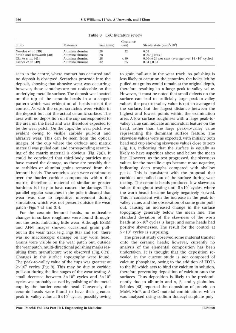
Table 3 CoC literature review
Study Materials Size (mm)Clearance(mm) Steady state (mm3/106)
Nevelos et al. [39] Alumina:alumina 28 32 0.08Smith and Unsworth [40] Alumina:alumina 28 0.097¡0.039Clarke et al. [41] Alumina:alumina 28 (80 0.004¡26 per cent (average over 146106 cycles)Essner et al. [42] Alumina:alumina 32 25 0.04¡0.03
950 S R Williams, J J Wu, A Unsworth, and I Khan
Proc. IMechE Vol. 223 Part H: J. Engineering in Medicine JEIM590
acrylamide gel electrophoresis [43]. However, the
analysis was carried out on the deposition which
occurred during soaking in bovine serum for 24 h,
and not on the deposition caused during wear
simulation. Therefore the composition of the two
depositions may differ. In previous studies, Firkins et
al. [20] reported that surface analysis showed no
signs of wear or changes in surface roughness after
testing; however, metal transfer (less than 20 nm
thick) and calcium phosphate deposits were found at
the edge of the contact area. It was concluded that,
as this was not in the wear track, it had no effect on
the wear of the bearing surfaces. Energy-dispersive
X-ray analysis confirmed that it was Co–Cr alloy with
an elemental composition similar to that of the main
matrix; however, it was found that it did not appear
to accelerate the wear of the metal cups.
Friction was used to indicate the lubrication
regime which was prevalent in the joints under
investigation. The CoM combinations worn to 56106
cycles showed low friction factors below 0.052 with a
curve shape indicating that the joints were likely to
be operating in full fluid-film lubrication. The joint
showed a decrease in friction factor from 0.052¡
0.007, when proteins were present, to 0.017¡0.017
in the absence of protein (Fig. 2). The results when
employing CMC fluids as a lubricant are similar to
that found for CoC joints, which typically produced
friction factors of 0.002 compared with 0.004 for
CoM (except for distilled water, which was 0.017 ¡
0.017) [44, 45].
It has been hypothesized that the proteins which
adsorb onto the surface are responsible for the
change in lubrication, in addition to the surface
topography of the bearing contact. Scholes and
Unsworth [46] investigated the effects of proteins
on the friction and lubrication of hip joints. They
compared the hip material prostheses of MoP, MoM,
and CoC lubricated in CMC fluids, and BS, with
the addition of CMC. Their results showed that,
for MoM, BS produced the lower friction factors
between 0.09 and 0.15, while the CMC fluids pro-
duced friction factors between 0.2 and 0.3. Con-
versely the CoC components produced friction
factors less than a hundredth (0.001–0.006) of the
values given by MoM pairings when proteins were
absent. When proteins were present, the friction
factors were found to be between 0.02 and 0.06.
Their reasoning for the CoC result was that, when
protein was absent, the bearing surfaces, having
l . 3, allowed full fluid-film lubrication, and so the
friction in the joint was due to shearing of the
lubricant film. When proteins were introduced into
the lubricant, they adsorbed onto the surface,
introducing a molecule which is greater in size than
the fluid film thickness; therefore the proteins
adsorbed to the surface were sheared in addition to
the proteins and constituents of the lubricant film.
Currently, to the present authors’ knowledge, there
are no published data which quantify the size of the
protein layer which adsorbs to the surface during
simulator testing that uses BS as a lubricant. A report
by Spikes [47] in 1996 discussed that adsorbing
polymer solutions are able to form viscous surface
layers at least 20 nm thick, which is thought to
interact during boundary lubrication conditions.
Although these data are not known, it can be
hypothesized that the adsorbed proteins created a
greater friction factor than when the friction was
solely caused by shearing of the CMC lubricant film.
In addition, adsorption of proteins onto the surface
may act to alter the surface properties, reducing the
hydrophilic nature of the ceramic surfaces, and
therefore reducing the effectiveness of the lubri-
cation. By contrast, the MoM joints were found to
have lower friction factors when the proteins were
present. The interactions between asperities was a
mixture of metal against metal and protein against
protein, which lowered the friction produced (com-
pared with just metal-against-metal contact).
The results of the present study support these
hypotheses. The metallic cups had a low average
surface roughness; therefore the CoM pairing showed
results with the same trend as CoC pairings, with an
increase in friction factor when proteins were present.
Grain pull-out seen on the alumina femoral head
and carbide pull-out of the metallic acetabular cup
provided a topography with a negative skewness,
which is more favourable than a positive skewness
towards fluid-film lubrication. The friction factors for
CoM are higher than CoC joints, owing to the small
amount of metal-against-ceramic asperity interaction
which occurred. These friction factors were lower
than with MoM joints as the adhesive forces between
metal-against-metal interactions are much greater
than those of ceramic-against-metal interactions. It
must be noted, however, that the difference between
the friction factors when protein is or is not present is
considerably less than that seen for other material
combinations
5 CONCLUSIONS
The wear rate of the metallic cups was discovered
to be 1.04¡0.293 mm3/106 cycles and 0.0209¡0.004
mm3/106 cycles for the RI and SS phases respec-
Tribological and surface analysis of total hip arthroplasties 951
JEIM590 Proc. IMechE Vol. 223 Part H: J. Engineering in Medicine
tively. The as-cast metallic cups showed very low
wear, with small amounts of carbide pull-out. This
pull-out is likely to cause the decreased surface
roughness and the scratching in the wear track. The
smooth surface finish and greater hardness of the
ceramic component are likely to have caused polish-
ing of the scratches during continued wear testing,
therefore resulting in a lower surface roughness
than may be expected for metal in MoM combina-
tions. The friction results of joints tested at 56106
cycles suggested that the joints were tending
towards full fluid-film lubrication, with the results
showing a similar trend to CoC combinations with
an increase in friction found when lubricated in BS
compared with CMC fluids. A white deposit was
seen on both components after each phase of wear
testing, which was removed every 0.56106 cycles to
allow for gravimetric analysis. In summary, the
wear of CoM components was found to be gra-
vimetrically undetectable on the ceramic compo-
nent, and very low on the as-cast metallic cups.
ACKNOWLEDGEMENTS
The authors thank the Engineering and PhysicalSciences Research Council and Biomet UK Ltd forfunding this research, and also thank the latter formaterial provision. They are grateful to DurhamUniversity technical staff, especially Mr Arthur New-man and Ms Helen Riggs, for their technical andESEM contributions respectively.
F Authors 2009
REFERENCES
1 Nercessian, O. A., Martin, G., Joshi, R. P., Su,B. W., and Eftekhar, N. S. A 15- to 25-year follow-up study of primary Charnley low-friction arthro-plasty: a single surgeon series. J. Arthroplasty, 2005,20(2), 162–167.
2 Wroblewski, B. M. and Siney, P. Charnley low-friction arthroplasty of the hip. Clin. Orthop.Related Res., 1993, 292, 191–201.
3 Wroblewski, B. M., McCullagh, P. J., and Siney, P.Quality of the surface finish of the head of thefemoral component and the wear rate of the socketin long-term results of the Charnley low-frictionarthroplasty. Proc. IMechE, Part H: J. Engineeringin Medicine, 1992, 206(3), 181–183. DOI: 10.1243/PIME_PROC_1992_206_286_02.
4 Howie, D. W., Haynes, D. R., and McGee, M. A.The response to particulate debris. Orthop. Clin. N.Am., 1993, 24(4), 571–581.
5 Howie, D. W., Vernon-Roberts, M. D., Oakeshott,R., and Manthey, B. A rat model of resorption ofbone at the cement–bone interface in the presenceof polyethylene wear particles. J. Bone Jt Surg. Am.,1988, 70(2), 257–263.
6 Harris, W. H. The problem is osteolysis. Clin.Orthop. Related Res., 1995, 311, 46–53.
7 Harris, W. H. Osteolysis and particle disease in hipreplacement – a review. Acta Orthop. Scand., 1994,65(1), 113–123.
8 Ingham, E. and Fisher, J. Biological reactionsto wear debris in total joint replacement. Proc.IMechE, Part H: J. Engineering in Medicine, 2000,214(1), 21–37. DOI: 10.1243/0954411001535219.
9 Daniel, J., Pynsent, P. B., and McMinn, D. J. W.Metal-on-metal resurfacing of the hip in patientsunder the age of 55 years with osteoarthritis. J.Bone Jt Surg. Br., 2004, 86(2), 177–184.
10 Glyn-Jones, S., Gill, H. S., McLardy-Smith, P., andMurray, D. W. Roentgen stereophotogrammetricanalysis of the Birmingham hip resurfacing arthro-plasty. J. Bone Jt Surg. Br., 2004, 86(2), 172–176.
11 MacDonald, S. J., Brodner, W., and Jacobs, J. J. Aconsensus paper on metal ions in metal-on-metalhip arthroplasties. J. Arthroplasty, 2004, 19(8,Suppl.), 12–16.
12 MacDonald, S. J. Can a safe level for metal ions inpatients with metal-on-metal total hip arthroplas-ties be determined? J. Arthroplasty, 2004, 19(8,Suppl. 3), 71–77.
13 Boutin, P., Christel, P., Dorlot, J.-M., Meunier,A., Roquancourt, A. D., Blanquaert, D., Herman,S., Sedel, L., and Witvoet, J. The use of densealumina–alumina ceramic combinations in totalhip replacements. J. Biomed. Mater. Res., 1988, 22,1203–1232.
14 Panagiotopoulos, E. C., Kallivokas, A. G., Kou-lioumpas, I., and Mouzakis, D. E. Early failure ofa zirconia femoral head prosthesis: fracture orfatigue? Clin. Biomech., 2007, 22(7), 856–860.
15 Rhoads, D. P., Baker, K. C., Israel, R., and Greene,P. W. Fracture of an alumina femoral head usedin ceramic-on-ceramic total hip arthroplasty. J.Arthroplasty, 2008, 23(8), 1239.e25–1239.e30.
16 McLean, C. R., Dabis, H., and Mok, D. Delayedfracture of the ceramic femoral head after trauma.J. Arthroplasty, 2002, 17(4), 503–504.
17 Ishida, T., Clarke, I. C., Sorimachi, T., Shirasu, H.,Shishido, T., and Yamamoto, K. Ceramic-on-metalvs. metal-on-metal bearings in hip simulatorstudies. In Transactions of the 54th Annual Meet-ing of the Orthopaedic Research Society, SanFrancisco, California, USA, 2–5 March 2008, poster1915 (Orthopaedic Research Society, Rosemont,Illinois).
18 Smith, S. L., Goldsmith, A. A. J., and Dowson, D.Lubrication and wear of zirconia-on-metal totalhip replacements. In Boundary and mixed lubri-cation: science and applications, Proceedings ofthe 28th Leeds–Lyon Symposium on Tribology, Else-vier Tribology Series, vol. 40 (Eds G. Dalmaz, D.
952 S R Williams, J J Wu, A Unsworth, and I Khan
Proc. IMechE Vol. 223 Part H: J. Engineering in Medicine JEIM590
Dowson, M. Priest, and A. Lubrecht), Vienna, Austria,4–7 September 2001, 2002, pp. 377–386 (Elsevier,Amsterdam).
19 Brockett, C., Williams, S., Zhongmin, J., Isaac, G.,and Fisher, J. Friction of total hip replacements. J.Biomed. Mater. Res. Part B: Appl. Biomater., 2007,81, 508–515.
20 Firkins, P. J., Tipper, J. L., Ingham, E., Stone, M.H., Farrar, R., and Fisher, J. A novel low wearingdifferential hardness ceramic-on-metal hip jointprosthesis. J. Biomech., 2001, 34, 1291–1298.
21 Brown, C., Williams, S., Tipper, J. L., Fisher, J.,and Ingham, E. Characterisation of wear particlesproduced by metal on metal and ceramic on metalhip prostheses under standard and microsepara-tion simulation. J. Mater. Sci.: Mater. Med., 2007,18(5), 819–827.
22 Haider, H., Weisenburger, J. N., Naylor, M. G.,Schroeder, D. W., Croson, R. E., and Garvin, K. L.Bearing diameter, radial clearance and their effecton wear in ceramic-on-metal total hip replace-ments. In Transactions of the 54th Annual Meetingof the Orthopaedic Research Society, San Franci-sco, California, USA, 2–5 March 2008, poster 1792(Orthopaedic Research Society, Rosemont, Illinois).
23 Williams, S., Brockett, C., Isaac, G., and Fisher, J.A comparison of ceramic-on-metal and metal-on-ceramic hip replacements under severe test con-ditions. In Transactions of the 54th Meeting ofthe Orthopeadic Research Society, San Francisco,California, USA, 2–5 March 2008, poster 1914(Orthopaedic Research Society, Rosemont, Illinois).
24 Bal, B. S., Khandkar, A., Lakshminarayanan, R.,Clarke, I., Hoffman, A. A., and Rahaman, M. N.Fabrication and testing of silicon nitride bearingsin total hip arthroplasty: winner of the 2007 ‘HAP’PAUL Award. J. Arthroplasty, 2009, 24(1), 110–116.
25 Figueiredo-Pina, C. G., Yan, Y., Neville, A., andFisher, J. Understanding the differences betweenthe wear of metal-on-metal and ceramic-on-metaltotal hip replacements. Proc. IMechE, Part H: J.Engineering in Medicine, 2008, 222(3), 285–296.DOI: 10.1243/09544119JEIM363.
26 Liao, Y.-S. Comparison of metal ion release in theserum lubricants from multiple hip simulationstudies using bearings of metal-on-metal, metal-on-poly and ceramic-on-metal. In Proceedings ofthe Eighth World Biomaterials Congress, Amster-dam, The Netherlands, 28 May–1 June 2008.
27 Liao, Y.-S. Effects of high diametrical clearance onthe wear of ceramic-on-metal hip system in a hipsimulation study. In Proceedings of the EighthWorld Biomaterials Congress, Amsterdam, TheNetherlands, 28 May–1 June 2008.
28 Barnes, C. L., DeBoer, D., Corpe, R. S., Nambu, S.,Carroll, M., and Timmerman, I. Wear perfor-mance of large-diameter differential-hardness hipbearings. J. Arthroplasty, 2008, 23(6, Suppl. 1),56–60.
29 Hinrichs, F. and Griss, P. Retrieved wear coupleceramic-on-metal: case study. In Proceedings of
the Sixth International Biolox Symposium, 2001,pp. 99–102 (George Thieme Verlag, Stuttgart).
30 Valenti, J. R., Rio, J. D., and Ammillo, S.Catastrophic wear in a metal-on-ceramic total hiparthroplasty. J. Arthroplasty, 2007, 22(6), 920–922.
31 Williams, S., Schepers, A., Isaac, G., Hardaker, C.,Ingham, E., Van Der Jagt, D., Breckon, A., andFisher, J. Ceramic-on-metal hip arthroplasties; acomparative in vitro and in vivo study. Clin.Orthop. Related Res., 2008, 465, 23–32.
32 Yan, Y., Neville, A., Dowson, D., Williams, S., andFisher, J. Tribo-corrosion analysis of wear andmetal ion release interactions from metal-on-metaland ceramic-on-metal contacts for the applicationin artificial hip prostheses. Proc. IMechE, Part J: J.Engineering Tribology, 2008, 222(3), 483–492. DOI:10.1243/13506501JET366.
33 ASTM F1714-96. Standard guide for gravimetricwear assessment of prosthetic hip designs insimulator devices, 2008 (ASTM International, WestConshohocken, Pennsylvania).
34 Unsworth, A., Pearcy, M. J., White, E. F., andWhite, G. Frictional properties of artificial hipjoints. Engng Med., 1988, 17(3), 101–104. DOI:10.1243/EMED_JOUR_1988_017_028_02.
35 Hall, R. M., Unsworth, A., Wroblewski, B. M., andBrugess, I. C. Frictional characterisation of ex-planted Charnley hip prostheses. Wear, 1994, 175,159–166.
36 Johnson, K. L., Greenwood, J. A., and Poon, S. Y. Asimple theory of asperity contact in elastohydro-dynamic lubrication. Wear, 1972, 19, 91–108.
37 Hamrock, B. J. and Dowson, D. Elastohydrody-namic lubrication of elliptical contacts for materi-als of low elastic modulus. I – fully flooded con-junction. J. Lubric. Technol., 1978, 100, 236–245.
38 Horcas, I., Fernandez, R., Gomez-Rodriguez, J.M., Colchero, J., Gomez-Herrero, J., and Baro, A.M. WSXM: a software for scanning probe micro-scopy and a tool for nanotechnology. Rev. Scient.Instrum., 2007, 78(1), 013705.
39 Nevelos, J. E., Ingham, E., Doyle, C., Nevelos, A.B., and Fisher, J. Wear of HIPed and non-HIPedalumina–alumina hip joints under standard andsevere simulator testing condition. Biomaterials,2001, 22, 2191–2197.
40 Smith, S. L. and Unsworth, A. An in vitro wearstudy of alumina–alumina total hip prostheses.Proc. IMechE, Part H: J. Engineering in Medicine,2001, 215(5), 443–446. DOI: 10.1243/0954411011536037.
41 Clarke, I. C., Good, V., Williams, P., Schroeder, D.,Asnissian, L., Stark, A., Oonishi, H., Schuldies, J.,and Gustafson, G. Ultra-low wear rates for rigid-on-rigid bearings in total hip replacements. Proc.IMechE, Part H: J. Engineering in Medicine, 2000,214(4), 331–347. DOI: 10.1243/0954411001535381.
42 Essner, A., Sutton, K., and Wang, A. Hip simulatorwear comparison of metal-on-metal, ceramic-on-ceramic and crosslinked UHMWPE bearings. Wear,2005, 259, 992–995.
Tribological and surface analysis of total hip arthroplasties 953
JEIM590 Proc. IMechE Vol. 223 Part H: J. Engineering in Medicine
43 Scholes, S. C. The tribology of hard bearing surfacesfor use in hip protheses. PhD Thesis, School ofEngineering, Durham University, Durham, UK,1999.
44 Scholes, S. C., Unsworth, A., Hall, R. M., andScott, R. The effects of material combination andlubricant on the friction of total hip prostheses.Wear, 2000, 241(2), 209–213.
45 Scholes, S. and Unsworth, A. Comparison of fric-tion and lubrication of different hip prostheses.Proc. IMechE, Part H: J. Engineering in Medicine,2000, 214(1), 49–57. DOI: 10.1243/0954411001535237.
46 Scholes, S. and Unsworth, A. The effects ofproteins on the friction and lubrication of artificialjoints. Proc. IMechE, Part H: J. Engineering in Med-icine, 2006, 220(6), 687–693. DOI: 10.1243/09544119JEIM21.
47 Spikes, H. Mechanisms of boundary lubrication. InProceedings of the Tenth International Colloquiumon Tribology – solving friction and wear problems,Esslingen, Germany, 9–11 January 1996, pp. 1737–1751 (Technische Akademie Esslingen, Esslingen).
APPENDIX
Notation
AFM atomic force microscopy
BS bovine serum
CCD charge-coupled device
CMC carboxymethyl cellulose
CoC ceramic on ceramic
CoM ceramic on metal
EDTA ethylenediaminetetraacetic acid
ESEM environmental scanning electron
microscopy
E9 elastic modulus (N/m2)
f friction factor
hmin minimum film thickness (m)
L load (N)
MoM metal on metal
MoP metal on polyethene
r radius of the femoral head (m)
RI running in
Rx equivalent radius (m)
T frictional torque (N/m2)
UHMWPE ultra-high molecular weight
polyethylene
UV ultraviolet
u entraining velocity (m/s2)
z Sommerfeld number
g viscosity (Pa s)
l lambda ratio 5 hmin/r.m.s.
954 S R Williams, J J Wu, A Unsworth, and I Khan
Proc. IMechE Vol. 223 Part H: J. Engineering in Medicine JEIM590