Tribological properties of ultra nanocrystalline diamond film-effect of sliding counterbodies
11
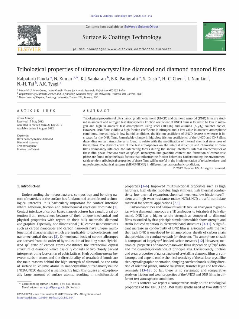
Tribological properties of ultrananocrystalline diamond and diamond nanorod films Kalpataru Panda a , N. Kumar a, ⁎, K.J. Sankaran b , B.K. Panigrahi a , S. Dash a , H.-C. Chen c , I.-Nan Lin c , N.-H. Tai b , A.K. Tyagi a a Materials Science Group, Indira Gandhi Centre for Atomic Research, Kalpakkam 603102, India b Department of Materials Science and Engineering, National Tsing-Hua University, Hsinchu 300, Taiwan, ROC c Department of Physics, Tamkang University, Tamsui 251, Taiwan, ROC abstract article info Article history: Received 17 May 2012 Accepted in revised form 23 July 2012 Available online 1 August 2012 Keywords: Ultra nanocrystalline diamond Diamond nanorod Test atmosphere Friction coefficient Tribological properties of ultra nanocrystalline diamond (UNCD) and diamond nanorod (DNR) films are stud- ied in ambient and nitrogen test atmospheres. Friction coefficient of UNCD films is found to be low in nitro- gen and high in ambient test atmospheres using steel (100Cr6) and alumina (Al 2 O 3 ) counter bodies. However, DNR films exhibit a high friction coefficient in nitrogen and a low value in ambient atmospheric conditions. Interestingly, in low humid conditions, the friction coefficient of UNCD decreases whereas it in- creases for the DNR films. Remarkable change in high/low friction coefficients of the UNCD and DNR films depending on test atmospheres is found to relate with the modification of internal chemical structures of these films. The distinct effect of the test atmospheres on the internal structure and chemistry of these films dominantly influence the interacting forces during the sliding interfaces. Internal characteristics of these film phase fractions such as sp 3 /sp 2 , nanocrystalline graphitic content and formation of carbonitrile phase are found to be the basic factors that influence the friction behaviors. Understanding the environmen- tal dependent tribological properties of these films will be useful in the implementation of reliable micro- and nanoelectromechanical systems (MEMS/NEMS) in different test atmospheric conditions. © 2012 Elsevier B.V. All rights reserved. 1. Introduction Understanding the microstructure, composition and bonding na- ture of materials at the surface has fundamental scientific and techno- logical interests. It is particularly important for contact interface where adhesion, friction and tribochemical reactions dominate [1]. Contact interface of carbon based nanostructures has caught great at- tention from researchers because of their unique mechanical and physical properties with regard to their bulk materials, diamond and graphite. Especially, one dimensional (1D) carbon nanostructures such as carbon nanotubes and carbon nanorods have unique multi- functional characteristics which are applicable to optoelectronic and nanomechanical devices [2]. Dimensional basis of carbon allotropes are derived from the order of hybridization of bonding state. Hybrid- ized sp 3 state of carbon atoms constitutes the tetrahedral crystal structure of diamond which basically consists of two closely packed interpenetrating face centered cubic lattices. High bonding energy be- tween carbon atoms and the directionality of tetrahedral bonds are the main reasons behind the high strength of diamond. As the ratio of surface to volume atoms in nanocrystalline/ultrananocrystalline (NCD/UNCD) diamond is significantly high, this causes an exception- ally large amount of surface atoms, resulting in multifunctional properties [3–6]. Improved multifunctional properties such as high hardness, high elastic modulus, high stiffness, high thermal conduc- tivity, low thermal expansion, chemical inertness, low friction coeffi- cient and high wear resistance makes NCD/UNCD a useful candidate material for several applications [7,8]. Carbon nanotubes and nanowires are 1D tubular analogous to graph- ite, while diamond nanorods are 1D analogous to tetrahedral bulk dia- mond. DNR has a higher tensile strength as compared to diamond films as studied by first principle simulations which show strength and strain induced variation in electronic band structures [9–11]. A signifi- cant increase in conductivity of DNR film is associated with the fact that each DNR is enveloped by an amorphous sheath of carbon chain that provides the conductive path for electrons. The amorphous sheath is composed of largely sp 2 -bonded carbon network [12]. However, me- chanical properties of nanorod/nanowire films depend on sp 3 /sp 2 ratio and the diameter/orientation of principle axis. Consequently, friction and wear properties of nanostructured crystalline diamond films are an- isotropic and depend on the chemical reactivity of the surface, crystallite size, crystallographic orientation, dangling covalent bonds, sliding direc- tion of oriented planes, surface roughness, transfer layer and test envi- ronments [13–18]. So far, there is no systematic and comparative study on friction and wear properties of the UNCD and DNR films, in dif- ferent test atmospheric conditions. In this context, we report a comparative study on the tribological properties of the UNCD and DNR films synthesized at two different Surface & Coatings Technology 207 (2012) 535–545 ⁎ Corresponding author. Tel./fax: +91 4427480081. E-mail address: [email protected] (N. Kumar). 0257-8972/$ – see front matter © 2012 Elsevier B.V. All rights reserved. http://dx.doi.org/10.1016/j.surfcoat.2012.07.064 Contents lists available at SciVerse ScienceDirect Surface & Coatings Technology journal homepage: www.elsevier.com/locate/surfcoat
Transcript of Tribological properties of ultra nanocrystalline diamond film-effect of sliding counterbodies
Surface & Coatings Technology 207 (2012) 535–545
Contents lists available at SciVerse ScienceDirect
Surface & Coatings Technology
j ourna l homepage: www.e lsev ie r .com/ locate /sur fcoat
Tribological properties of ultrananocrystalline diamond and diamond nanorod films
Kalpataru Panda a, N. Kumar a,⁎, K.J. Sankaran b, B.K. Panigrahi a, S. Dash a, H.-C. Chen c, I.-Nan Lin c,N.-H. Tai b, A.K. Tyagi a
a Materials Science Group, Indira Gandhi Centre for Atomic Research, Kalpakkam 603102, Indiab Department of Materials Science and Engineering, National Tsing-Hua University, Hsinchu 300, Taiwan, ROCc Department of Physics, Tamkang University, Tamsui 251, Taiwan, ROC
⁎ Corresponding author. Tel./fax: +91 4427480081.E-mail address: [email protected] (N. Kumar).
0257-8972/$ – see front matter © 2012 Elsevier B.V. Allhttp://dx.doi.org/10.1016/j.surfcoat.2012.07.064
a b s t r a c t
a r t i c l e i n f oArticle history:Received 17 May 2012Accepted in revised form 23 July 2012Available online 1 August 2012
Keywords:Ultra nanocrystalline diamondDiamond nanorodTest atmosphereFriction coefficient
Tribological properties of ultra nanocrystalline diamond (UNCD) and diamond nanorod (DNR) films are stud-ied in ambient and nitrogen test atmospheres. Friction coefficient of UNCD films is found to be low in nitro-gen and high in ambient test atmospheres using steel (100Cr6) and alumina (Al2O3) counter bodies.However, DNR films exhibit a high friction coefficient in nitrogen and a low value in ambient atmosphericconditions. Interestingly, in low humid conditions, the friction coefficient of UNCD decreases whereas it in-creases for the DNR films. Remarkable change in high/low friction coefficients of the UNCD and DNR filmsdepending on test atmospheres is found to relate with the modification of internal chemical structures ofthese films. The distinct effect of the test atmospheres on the internal structure and chemistry of thesefilms dominantly influence the interacting forces during the sliding interfaces. Internal characteristics ofthese film phase fractions such as sp3/sp2, nanocrystalline graphitic content and formation of carbonitrilephase are found to be the basic factors that influence the friction behaviors. Understanding the environmen-tal dependent tribological properties of these films will be useful in the implementation of reliable micro- andnanoelectromechanical systems (MEMS/NEMS) in different test atmospheric conditions.
© 2012 Elsevier B.V. All rights reserved.
1. Introduction
Understanding the microstructure, composition and bonding na-ture of materials at the surface has fundamental scientific and techno-logical interests. It is particularly important for contact interfacewhere adhesion, friction and tribochemical reactions dominate [1].Contact interface of carbon based nanostructures has caught great at-tention from researchers because of their unique mechanical andphysical properties with regard to their bulk materials, diamondand graphite. Especially, one dimensional (1D) carbon nanostructuressuch as carbon nanotubes and carbon nanorods have unique multi-functional characteristics which are applicable to optoelectronic andnanomechanical devices [2]. Dimensional basis of carbon allotropesare derived from the order of hybridization of bonding state. Hybrid-ized sp3 state of carbon atoms constitutes the tetrahedral crystalstructure of diamond which basically consists of two closely packedinterpenetrating face centered cubic lattices. High bonding energy be-tween carbon atoms and the directionality of tetrahedral bonds arethe main reasons behind the high strength of diamond. As the ratioof surface to volume atoms in nanocrystalline/ultrananocrystalline(NCD/UNCD) diamond is significantly high, this causes an exception-ally large amount of surface atoms, resulting in multifunctional
rights reserved.
properties [3–6]. Improved multifunctional properties such as highhardness, high elastic modulus, high stiffness, high thermal conduc-tivity, low thermal expansion, chemical inertness, low friction coeffi-cient and high wear resistance makes NCD/UNCD a useful candidatematerial for several applications [7,8].
Carbon nanotubes andnanowires are 1D tubular analogous to graph-ite, while diamond nanorods are 1D analogous to tetrahedral bulk dia-mond. DNR has a higher tensile strength as compared to diamondfilms as studied by first principle simulations which show strength andstrain induced variation in electronic band structures [9–11]. A signifi-cant increase in conductivity of DNR film is associated with the factthat each DNR is enveloped by an amorphous sheath of carbon chainthat provides the conductive path for electrons. The amorphous sheathis composed of largely sp2-bonded carbon network [12]. However, me-chanical properties of nanorod/nanowire films depend on sp3/sp2 ratioand the diameter/orientation of principle axis. Consequently, frictionandwear properties of nanostructured crystalline diamondfilms are an-isotropic and depend on the chemical reactivity of the surface, crystallitesize, crystallographic orientation, dangling covalent bonds, sliding direc-tion of oriented planes, surface roughness, transfer layer and test envi-ronments [13–18]. So far, there is no systematic and comparativestudy on friction andwear properties of the UNCD and DNR films, in dif-ferent test atmospheric conditions.
In this context, we report a comparative study on the tribologicalproperties of the UNCD and DNR films synthesized at two different
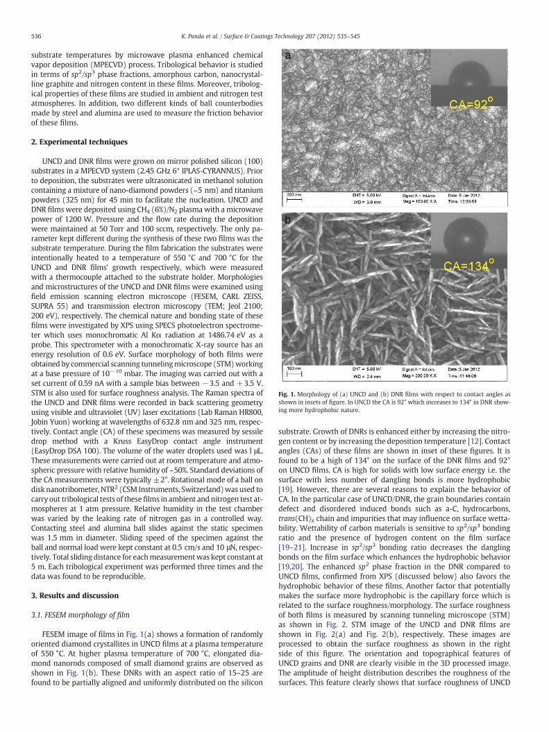
Fig. 1. Morphology of (a) UNCD and (b) DNR films with respect to contact angles asshown in insets of figure. In UNCD the CA is 92° which increases to 134° in DNR show-ing more hydrophobic nature.
536 K. Panda et al. / Surface & Coatings Technology 207 (2012) 535–545
substrate temperatures by microwave plasma enhanced chemicalvapor deposition (MPECVD) process. Tribological behavior is studiedin terms of sp2/sp3 phase fractions, amorphous carbon, nanocrystal-line graphite and nitrogen content in these films. Moreover, tribolog-ical properties of these films are studied in ambient and nitrogen testatmospheres. In addition, two different kinds of ball counterbodiesmade by steel and alumina are used to measure the friction behaviorof these films.
2. Experimental techniques
UNCD and DNR films were grown on mirror polished silicon (100)substrates in a MPECVD system (2.45 GHz 6″ IPLAS-CYRANNUS). Priorto deposition, the substrates were ultrasonicated in methanol solutioncontaining a mixture of nano-diamond powders (~5 nm) and titaniumpowders (325 nm) for 45 min to facilitate the nucleation. UNCD andDNR filmswere deposited using CH4 (6%)/N2 plasmawith a microwavepower of 1200 W. Pressure and the flow rate during the depositionwere maintained at 50 Torr and 100 sccm, respectively. The only pa-rameter kept different during the synthesis of these two films was thesubstrate temperature. During the film fabrication the substrates wereintentionally heated to a temperature of 550 °C and 700 °C for theUNCD and DNR films' growth respectively, which were measuredwith a thermocouple attached to the substrate holder. Morphologiesand microstructures of the UNCD and DNR films were examined usingfield emission scanning electron microscope (FESEM, CARL ZEISS,SUPRA 55) and transmission electron microscopy (TEM; Jeol 2100;200 eV), respectively. The chemical nature and bonding state of thesefilms were investigated by XPS using SPECS photoelectron spectrome-ter which uses monochromatic Al Kα radiation at 1486.74 eV as aprobe. This spectrometer with a monochromatic X-ray source has anenergy resolution of 0.6 eV. Surface morphology of both films wereobtained by commercial scanning tunnelingmicroscope (STM)workingat a base pressure of 10−10 mbar. The imaging was carried out with aset current of 0.59 nA with a sample bias between −3.5 and +3.5 V.STM is also used for surface roughness analysis. The Raman spectra ofthe UNCD and DNR films were recorded in back scattering geometryusing visible and ultraviolet (UV) laser excitations (Lab Raman HR800,Jobin Yuon) working at wavelengths of 632.8 nm and 325 nm, respec-tively. Contact angle (CA) of these specimens was measured by sessiledrop method with a Kruss EasyDrop contact angle instrument(EasyDrop DSA 100). The volume of the water droplets used was l μL.These measurements were carried out at room temperature and atmo-spheric pressure with relative humidity of ~50%. Standard deviations ofthe CA measurements were typically ±2°. Rotational mode of a ball ondisk nanotribometer, NTR2 (CSM Instruments, Switzerland)was used tocarry out tribological tests of thesefilms in ambient and nitrogen test at-mospheres at 1 atm pressure. Relative humidity in the test chamberwas varied by the leaking rate of nitrogen gas in a controlled way.Contacting steel and alumina ball slides against the static specimenwas 1.5 mm in diameter. Sliding speed of the specimen against theball and normal loadwere kept constant at 0.5 cm/s and 10 μN, respec-tively. Total sliding distance for eachmeasurementwas kept constant at5 m. Each tribological experiment was performed three times and thedata was found to be reproducible.
3. Results and discussion
3.1. FESEM morphology of film
FESEM image of films in Fig. 1(a) shows a formation of randomlyoriented diamond crystallites in UNCD films at a plasma temperatureof 550 °C. At higher plasma temperature of 700 °C, elongated dia-mond nanorods composed of small diamond grains are observed asshown in Fig. 1(b). These DNRs with an aspect ratio of 15–25 arefound to be partially aligned and uniformly distributed on the silicon
substrate. Growth of DNRs is enhanced either by increasing the nitro-gen content or by increasing the deposition temperature [12]. Contactangles (CAs) of these films are shown in inset of these figures. It isfound to be a high of 134° on the surface of the DNR films and 92°on UNCD films. CA is high for solids with low surface energy i.e. thesurface with less number of dangling bonds is more hydrophobic[19]. However, there are several reasons to explain the behavior ofCA. In the particular case of UNCD/DNR, the grain boundaries containdefect and disordered induced bonds such as a-C, hydrocarbons,trans(CH)x chain and impurities that may influence on surface wetta-bility. Wettability of carbon materials is sensitive to sp2/sp3 bondingratio and the presence of hydrogen content on the film surface[19–21]. Increase in sp2/sp3 bonding ratio decreases the danglingbonds on the film surface which enhances the hydrophobic behavior[19,20]. The enhanced sp2 phase fraction in the DNR compared toUNCD films, confirmed from XPS (discussed below) also favors thehydrophobic behavior of these films. Another factor that potentiallymakes the surface more hydrophobic is the capillary force which isrelated to the surface roughness/morphology. The surface roughnessof both films is measured by scanning tunneling microscope (STM)as shown in Fig. 2. STM image of the UNCD and DNR films areshown in Fig. 2(a) and Fig. 2(b), respectively. These images areprocessed to obtain the surface roughness as shown in the rightside of this figure. The orientation and topographical features ofUNCD grains and DNR are clearly visible in the 3D processed image.The amplitude of height distribution describes the roughness of thesurfaces. This feature clearly shows that surface roughness of UNCD
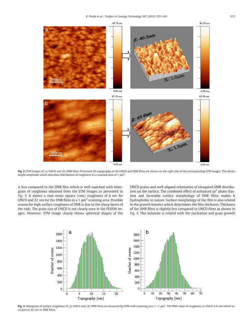
Fig. 2. STM images of (a) UNCD and (b) DNR films. Processed 3D topography of the UNCD and DNR films are shown on the right side of the corresponding STM images. This showsheight amplitude which describes distribution of roughness in a scanned area of 1 μm2.
537K. Panda et al. / Surface & Coatings Technology 207 (2012) 535–545
is less compared to the DNR film which is well matched with histo-gram of roughness obtained from the STM images as presented inFig. 3. It shows a root mean square (rms) roughness of 6 nm forUNCD and 22 nm for the DNR films in a 1 μm2 scanning area. Possiblereason for high surface roughness of DNR is due to the sharp facets ofthe rods. The grain size of UNCD is not clearly seen in the FESEM im-ages. However, STM image clearly shows spherical shapes of the
Fig. 3. Histogram of surface roughness of (a) UNCD and (b) DNR films as measured by STMcreases to 22 nm in DNR films.
UNCD grains and well aligned orientation of elongated DNR distribu-tion on the surface. The combined effect of enhanced sp2 phase frac-tion and favorable surface morphology of DNR films makes ithydrophobic in nature. Surface morphology of the film is also relatedto the growth kinetics which determines the film thickness. Thicknessof the DNR films is slightly less compared to UNCD films as shown inFig. 4. This behavior is related with the nucleation and grain growth
with scanning area 1×1 μm2. The RMS value of roughness in UNCD is 6 nm which in-
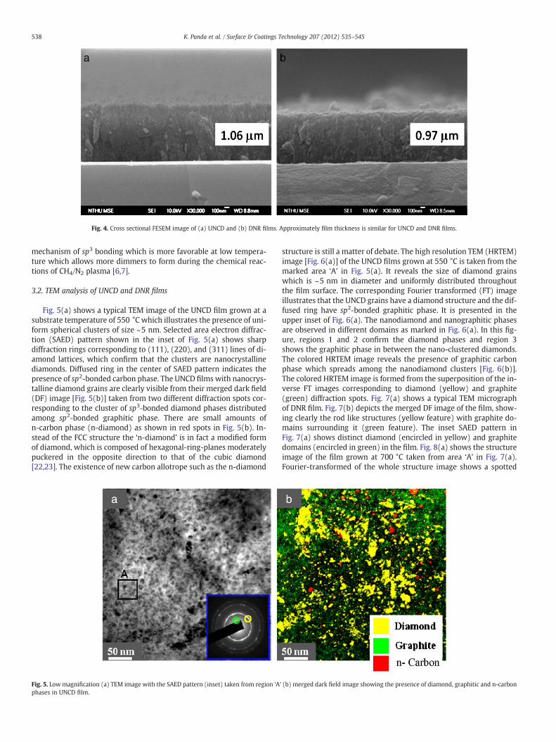
Fig. 4. Cross sectional FESEM image of (a) UNCD and (b) DNR films. Approximately film thickness is similar for UNCD and DNR films.
538 K. Panda et al. / Surface & Coatings Technology 207 (2012) 535–545
mechanism of sp3 bonding which is more favorable at low tempera-ture which allows more dimmers to form during the chemical reac-tions of CH4/N2 plasma [6,7].
3.2. TEM analysis of UNCD and DNR films
Fig. 5(a) shows a typical TEM image of the UNCD film grown at asubstrate temperature of 550 °C which illustrates the presence of uni-form spherical clusters of size ~5 nm. Selected area electron diffrac-tion (SAED) pattern shown in the inset of Fig. 5(a) shows sharpdiffraction rings corresponding to (111), (220), and (311) lines of di-amond lattices, which confirm that the clusters are nanocrystallinediamonds. Diffused ring in the center of SAED pattern indicates thepresence of sp2-bonded carbon phase. The UNCD films with nanocrys-talline diamond grains are clearly visible from their merged dark field(DF) image [Fig. 5(b)] taken from two different diffraction spots cor-responding to the cluster of sp3-bonded diamond phases distributedamong sp2-bonded graphitic phase. There are small amounts ofn-carbon phase (n-diamond) as shown in red spots in Fig. 5(b). In-stead of the FCC structure the ‘n-diamond’ is in fact a modified formof diamond, which is composed of hexagonal-ring-planes moderatelypuckered in the opposite direction to that of the cubic diamond[22,23]. The existence of new carbon allotrope such as the n-diamond
Fig. 5. Lowmagnification (a) TEM image with the SAED pattern (inset) taken from region ‘Aphases in UNCD film.
structure is still a matter of debate. The high resolution TEM (HRTEM)image [Fig. 6(a)] of the UNCD films grown at 550 °C is taken from themarked area ‘A’ in Fig. 5(a). It reveals the size of diamond grainswhich is ~5 nm in diameter and uniformly distributed throughoutthe film surface. The corresponding Fourier transformed (FT) imageillustrates that the UNCD grains have a diamond structure and the dif-fused ring have sp2-bonded graphitic phase. It is presented in theupper inset of Fig. 6(a). The nanodiamond and nanographitic phasesare observed in different domains as marked in Fig. 6(a). In this fig-ure, regions 1 and 2 confirm the diamond phases and region 3shows the graphitic phase in between the nano-clustered diamonds.The colored HRTEM image reveals the presence of graphitic carbonphase which spreads among the nanodiamond clusters [Fig. 6(b)].The colored HRTEM image is formed from the superposition of the in-verse FT images corresponding to diamond (yellow) and graphite(green) diffraction spots. Fig. 7(a) shows a typical TEM micrographof DNR film. Fig. 7(b) depicts the merged DF image of the film, show-ing clearly the rod like structures (yellow feature) with graphite do-mains surrounding it (green feature). The inset SAED pattern inFig. 7(a) shows distinct diamond (encircled in yellow) and graphitedomains (encircled in green) in the film. Fig. 8(a) shows the structureimage of the film grown at 700 °C taken from area ‘A’ in Fig. 7(a).Fourier-transformed of the whole structure image shows a spotted
’ (b) merged dark field image showing the presence of diamond, graphitic and n-carbon
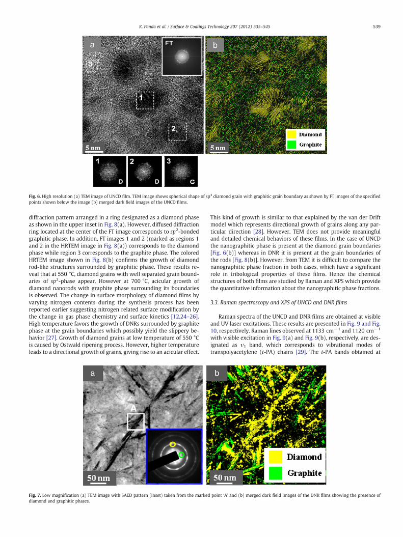
Fig. 6. High resolution (a) TEM image of UNCD film. TEM image shows spherical shape of sp3 diamond grain with graphitic grain boundary as shown by FT images of the specifiedpoints shown below the image (b) merged dark field images of the UNCD films.
539K. Panda et al. / Surface & Coatings Technology 207 (2012) 535–545
diffraction pattern arranged in a ring designated as a diamond phaseas shown in the upper inset in Fig. 8(a). However, diffused diffractionring located at the center of the FT image corresponds to sp2-bondedgraphitic phase. In addition, FT images 1 and 2 (marked as regions 1and 2 in the HRTEM image in Fig. 8(a)) corresponds to the diamondphase while region 3 corresponds to the graphite phase. The coloredHRTEM image shown in Fig. 8(b) confirms the growth of diamondrod-like structures surrounded by graphitic phase. These results re-veal that at 550 °C, diamond grains with well separated grain bound-aries of sp2-phase appear. However at 700 °C, acicular growth ofdiamond nanorods with graphite phase surrounding its boundariesis observed. The change in surface morphology of diamond films byvarying nitrogen contents during the synthesis process has beenreported earlier suggesting nitrogen related surface modification bythe change in gas phase chemistry and surface kinetics [12,24–26].High temperature favors the growth of DNRs surrounded by graphitephase at the grain boundaries which possibly yield the slippery be-havior [27]. Growth of diamond grains at low temperature of 550 °Cis caused by Ostwald ripening process. However, higher temperatureleads to a directional growth of grains, giving rise to an acicular effect.
Fig. 7. Low magnification (a) TEM image with SAED pattern (inset) taken from the markeddiamond and graphitic phases.
This kind of growth is similar to that explained by the van der Driftmodel which represents directional growth of grains along any par-ticular direction [28]. However, TEM does not provide meaningfuland detailed chemical behaviors of these films. In the case of UNCDthe nanographitic phase is present at the diamond grain boundaries[Fig. 6(b)] whereas in DNR it is present at the grain boundaries ofthe rods [Fig. 8(b)]. However, from TEM it is difficult to compare thenanographitic phase fraction in both cases, which have a significantrole in tribological properties of these films. Hence the chemicalstructures of both films are studied by Raman and XPS which providethe quantitative information about the nanographitic phase fractions.
3.3. Raman spectroscopy and XPS of UNCD and DNR films
Raman spectra of the UNCD and DNR films are obtained at visibleand UV laser excitations. These results are presented in Fig. 9 and Fig.10, respectively. Raman lines observed at 1133 cm−1 and 1120 cm−1
with visible excitation in Fig. 9(a) and Fig. 9(b), respectively, are des-ignated as ν1 band, which corresponds to vibrational modes oftranspolyacetylene (t-PA) chains [29]. The t-PA bands obtained at
point ‘A’ and (b) merged dark field images of the DNR films showing the presence of
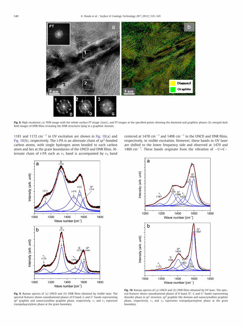
Fig. 8. High resolution (a) TEM image with the whole surface FT image (inset), and FT images at the specified points showing the diamond and graphitic phases (b) merged darkfield images of DNR films revealing the DNR structures lying in a graphitic domain.
540 K. Panda et al. / Surface & Coatings Technology 207 (2012) 535–545
1181 and 1172 cm−1 in UV excitation are shown in Fig. 10(a) andFig. 10(b), respectively. The t-PA is an alternate chain of sp2-bondedcarbon atoms, with single hydrogen atom bonded to each carbonatom and lies at the grain boundaries of the UNCD and DNR films. Al-ternate chain of t-PA such as ν1 band is accompanied by ν3 band
Fig. 9. Raman spectra of (a) UNCD and (b) DNR films obtained by visible laser. Thespectral features shows nanodiamond phases of D band, G and G* bands representingsp2 graphite and nanocrystalline graphite phase, respectively. ν1 and ν3 representtranspolyacetylene phase at the grain boundary.
centered at 1478 cm−1 and 1498 cm−1 in the UNCD and DNR films,respectively, in visible excitation. However, these bands in UV laserare shifted to the lower frequency side and observed at 1470 and1460 cm−1. These bands originate from the vibration of \C_C\
Fig. 10. Raman spectra of (a) UNCD and (b) DNR films obtained by UV laser. The spec-tral features shows nanodiamond phases of D band, D*, G and G* bands representingdisorder phase in sp2 structure, sp2 graphite like domian and nanocrystalline graphitephase, respectively. ν1 and ν3 represents transpolyacetylene phase at the grainboundary.
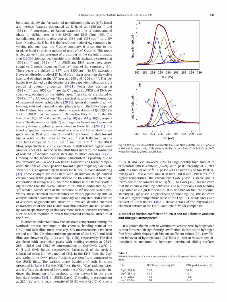
Fig. 11. XPS spectra of (a) UNCD and (b) DNR films. In UNCD and DNR, the sp2/sp3 ratiois 0.6 and 1, respectively. C\N phase is similar in both films C_N is 9.4% in UNCDwhich increases to 25.91% in DNR film.
Table 1Relative intensities of various components of C1s XPS spectra from UNCD and DNRfilms.
No. UNCD peak intensity (%) DNR peak intensity (%)
Csp2 (284.5) 31.9 34.74Csp3 (285.1) 53.8 34C\N (285.6) 5.3 5.31C_N (286.2) 9.4 25.91
541K. Panda et al. / Surface & Coatings Technology 207 (2012) 535–545
bond and signify the formation of nanodiamond phases [6,7]. Broadand intense features designated as D band at 1320 cm−1 and1331 cm−1 correspond to Raman scattering line of nanodiamondphase in visible laser in the UNCD and DNR films [29]. Thenanodiamond phase is observed at 1336 and 1338 cm−1 at a UVlaser. Notably, the D band is the breathing mode of A1g symmetry in-volving phonons near the K zone boundary. It arises due to thein-plane bond stretching motion of pairs of sp2-C atoms. This modeis also active in the presence of a disorder in the six fold aromaticring [29,30]. Spectral peak positions at visible excitation centered at1551 cm−1 and 1575 cm−1 in UNCD and DNR respectively corre-spond to G mode occurring from sp2 sites of E2g symmetry [30].These peaks are shifted to 1571 and 1556 cm−1 in UV excitation.However, disorder mode of D* band of sp2 site is absent in the visiblelaser and obtained in the UV laser at 1398 and 1304 cm−1. This be-havior is explained by the density of state dependent vibration crosssection of phonon dispersion [29–31]. Peaks that position at1591 cm−1 and 1606 cm−1 are the G* bands in UNCD and DNR, re-spectively, obtained in the visible laser. These bands are shifted to1597 cm−1 at UV excitation. These spectral features signify formationof hexagonal nanographite phase [29,31]. Spectral intensity of sp2\Cbonding, t-PA and diamond related phase is less in the DNR comparedto UNCD films. At visible excitation the spectral ratio of I(G)/I(G*) is1.92 in UNCD that decreases to 0.87 in the DNR films. In the UVlaser, the I(G)/I(G*) is 0.8 and 0.3 in Fig. 10(a) and Fig. 10(b), respec-tively. The decrease in I(G)/I(G*) ratio signifies formation of increasednanocrystalline graphite phase content in these films [29–31]. Thetrend of spectral features obtained at visible and UV excitations arequite similar. Peak positions of G and G* are found to shift towardhigher wave number sides as 1575 cm−1 and 1606 cm−1 in theDNR films compared to 1551 cm−1 and 1591 cm−1 in the UNCDfilms, respectively in visible excitation. A shift toward higher wavenumber sides of G and G* in the DNR films indicates the formationof ordered sp2-bonded nanoclusters due to lattice ordering [27,29].Ordering of the sp2-bonded carbon nanoclusters is possibly due tothe formation of C\N and C_N bonds. However, at a higher temper-ature, the shift of G band position toward higher frequency side is ob-served. This is explained by an increased lattice in-plane disordering[32]. These changes are consistent with an increase in sp2-bondedcarbon phase at the grain boundaries of the DNR films due to the in-corporation of nitrogen [12]. All these features in the Raman scatter-ing indicate that the overall structure of DNR is dominated by thesp2-bonded nanoclusters in the presence of sp3-bonded carbon net-works. These chemical characteristics are well supported by HRTEManalysis which shows that the boundary of elongated DNR consistsof a sheath of graphite like structure. However, detailed chemicalcharacteristics of the UNCD and DNR film surfaces are not possibleby Raman spectroscopy. In this case more surface sensitive techniquesuch as XPS is required to reveal the detailed chemical structure ofthe films.
In order to understand how the substrate temperature during thesynthesis process attributes to the chemical bonding state of theUNCD and DNR films more precisely, XPS measurements have beencarried out. The C1s photoemission spectrum of the UNCD and DNRfilms are shown in Fig. 11(a) and Fig. 11(b), respectively. The dataare fitted with Lorentzian peaks with binding energies at 284.5,285.1, 285.6 and 286.2 eV corresponding to Csp2C_C, Csp3C\C,C\N and C_N bonds, respectively. Background of the peak issubtracted using Shirley's method [33]. In the DNR films the Csp2
and carbonitrile C_N phase fractions are significant compared tothe UNCD films. The various phase fractions of both films arepresented in Table 1. For the DNR films, the Csp2/Csp3 ratio increasesand it affects the degree of lattice ordering of Csp2 bonding which in-duces the formation of amorphous carbon network in the grainboundary regions [34]. In UNCD, Csp3C\C bonding is predominantat 285.1 eV with a peak intensity of 53.8% while Csp2C\C is only
31.9% at 284.5 eV. However, DNR has significantly high amount ofcarbonitrile phase content (C_N) with peak intensity of 25.91%with less amount of Csp3C\C phase with an intensity of 34%. Peak in-tensity of C\N is almost similar in both UNCD and DNR films. At ahigher temperature, the carbonitrile C_N phase is stable and itforms due to the conversion of Csp3C\C to C_N [35]. This indicatesthat the chemical bonding between C and N, especially C_N bondingis possible at a high temperature. It is also known that the thermalstability of Csp2 phase is higher than Csp3 bonding [35]. This indicatesthat at a higher temperature most of the Csp3C\C bonds break andconvert to C_N bonds. Table 2 shows details of the physical andchemical natures of the UNCD and DNR films for comparison.
4. Model of friction coefficient of UNCD and DNR films in ambientand nitrogen atmospheres
It is known that in inert or vacuum test atmosphere, hydrogenatedcarbon films exhibit significantly low friction, in contrast to hydrogenfree films which shows high friction coefficient values [36]. Low fric-tion behavior of hydrogenated DLC films in inert or vacuum test at-mosphere is attributed to hydrogen terminated sliding surfaces
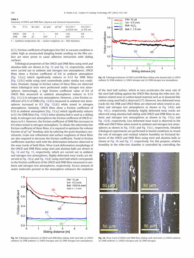
Table 2Summary of UNCD and DNR films' physical and chemical characteristics.
No. T(°C) Ra (nm) Δt (μm) sp2/sp3 I(G)/I(G*)at 632.8 nm
I(G)/I(G*)at 325 nm
UNCD 550 6 1 0.6 1.92 0.8DNR 700 22 0.97 1 0.87 0.3
T — synthesis temperature, Ra — surface roughness, Δt — film thickness.
Fig. 13. Tribological behavior of UNCD and DNR films sliding with alumina ball (a) UNCDambient (b) DNR ambient (c) UNCD nitrogen and (d) DNR nitrogen test atmospheres.
542 K. Panda et al. / Surface & Coatings Technology 207 (2012) 535–545
[6,7]. Friction coefficient of hydrogen free DLC in vacuum condition israther high as unsaturated dangling bonds residing on the film sur-face are more prone to cause adhesive interaction with slidingsurfaces.
Tribological properties of the UNCD and DNR films using steel andalumina balls are shown in Fig. 12 and Fig. 13, respectively, whichwere carried out in ambient and nitrogen test atmospheres. UNCDfilms show a friction coefficient of 0.6 in ambient atmosphere[Fig. 12(a)] which significantly reduces to 0.12 for DNR films[Fig. 12(b)] while using steel counterbody under similar test condi-tions. Dramatic change in friction values of these films are observedwhen tribological tests were performed under nitrogen test atmo-spheres. Interestingly, a high friction coefficient value of 0.6 ofUNCD film measured in ambient atmospheres reduces to 0.15[Fig. 12(c)] in nitrogen test atmospheres. However, a low friction co-efficient of 0.12 of DNRs [Fig. 12(b)] measured in ambient test atmo-spheres increased to 0.5 [Fig. 12(d)] while tested in nitrogenatmospheres. Similarly, UNCD films show a friction coefficient of0.52 in ambient atmosphere [Fig. 13(a)] which significantly reducesto 0.1 for DNR films [Fig. 13(b)] when alumina ball is used as a slidingbody. In nitrogen test atmospheres the friction coefficient of UNCD re-duces to 0.1. However, the friction coefficient of DNR film increases to0.4 when tested in nitrogen atmosphere. To obtain the inherently lowfriction coefficient of these films, it is required to optimize the volumefraction of sp2/sp3 bonding ratio by tailoring the grain boundary con-stituents. Grain size refinement and surface roughness of these filmsare also required to decrease the friction coefficient. Trend in frictioncoefficients matches well with the deformation behavior observed inthe wear tracks of both films. Wear track deformation morphology ofthe UNCD and DNR films using steel and alumina balls are shown inFig. 14 and Fig. 15, respectively, which are carried out in ambientand nitrogen test atmospheres. Highly deformed wear tracks are ob-served in Fig. 14(a) and Fig. 14(d) using steel ball which correspondsto the friction coefficient of the UNCD and DNR films measured in am-bient and nitrogen test atmospheres, respectively. Excess amount ofwater molecules present in the atmosphere enhances the oxidation
Fig. 12. Tribological behavior of UNCD and DNR films sliding with steel ball (a) UNCDambient (b) DNR ambient (c) UNCD nitrogen and (d) DNR nitrogen test atmospheres.
of the steel ball surface, which in turn accelerates the wear rate ofthe steel ball sliding against the UNCD film during the tribo-test. Ox-idation related wear in carbon based material such as in diamond likecarbon using steel ball is observed [37]. However, less deformed weartracks for the DNR and UNCD films are observed when tested in am-bient and nitrogen test atmospheres as shown in Fig. 14(b) andFig. 14(c), respectively. Similarly, highly deformed wear tracks areobserved using alumina ball sliding with UNCD and DNR films in am-bient and nitrogen test atmospheres as shown in Fig. 15(a) andFig. 15(d), respectively. Less deformed wear track is observed in theDNR and UNCD films when tested in ambient and nitrogen test atmo-spheres as shown in Fig. 15(b) and Fig. 15(c), respectively. Detailedtribological experiments are performed in humid conditions to revealthe role of nitrogen and residual relative humidity on frictional be-havior of the UNCD and DNR films using steel and alumina balls asshown in Fig. 16 and Fig. 17, respectively. For this purpose, relativehumidity in the tribo-test chamber is controlled by controlling the
Fig. 14. Wear track of UNCD and DNR films sliding with steel ball (a) UNCD ambient(b) DNR ambient (c) UNCD nitrogen and (d) DNR nitrogen.

Fig. 15. Wear track of UNCD and DNR films sliding with alumina ball (a) UNCD ambient (b) DNR ambient (c) UNCD nitrogen and (d) DNR nitrogen.
543K. Panda et al. / Surface & Coatings Technology 207 (2012) 535–545
leakage rate of pure nitrogen gas. Relative humidity of the test cham-ber is fixed at a given leakage rate of nitrogen and it is measured by ahumidity sensor with an accuracy of ±2%. At a low leakage rate of ni-trogen gas, the relative humidity in the test chamber is high. With anincrease in relative humidity (at low nitrogen content in test cham-ber) the friction coefficient of UNCD is found to increase. The frictioncoefficient is 0.25 at 10% relative humidity which increases to 0.6 at60% relative humidity with steel ball as shown in Fig 16. This trendis similarly followed when the friction coefficient is measured by alu-mina ball as shown in Fig. 17. However, the behavior of friction coef-ficient of DNR film is found to be opposite with relative humidity inthe case of both steel and alumina balls. The friction coefficient ofDNR film increases at a high nitrogen content. There is little variationin the friction coefficient of the UNCD and DNR films measured bysteel and alumina balls. In the case of steel ball, this value is highwhich is explained by plowing of the steel ball. Table 3 represents asummary of friction coefficients of Figs. 15 and 16. Plowing
Fig. 16. Tribological behavior of UNCD and DNR films with steel ball in controlledhumid conditions maintained by leaking nitrogen flow rate into the tribo-test chamber.Friction coefficient of UNCD increases and DNR film decreases with an increase in rel-ative humidity.
mechanism acts when there is a difference in hardness between slid-ing surfaces. The hardness of steel is significantly less compared toUNCD/DNR films. However, the hardness of alumina ball is com-parable to UNCD/DNR films which protect the plowing of thecounterbody. In this condition, both the sliding surfaces are foundto deform.
There are two aspects to explain such a large variation in frictionand wear behavior of DNR/UNCD films in ambient and nitrogen testatmospheres. It is known that the friction behavior of diamond filmsis basically controlled by the phase fraction of sp2/sp3 bonding, crys-tallite size, orientation, volume fraction of grain/grain boundariesand test atmospheres [13–17]. The ratio of sp2/sp3 phase fraction inDNR is 1.02 while it is 0.59 in the UNCD films as evident by XPSshown in Fig. 11. One of the basic reasons for the reduction in frictioncoefficient of DNR films is explained by the large amount of nanocrys-talline sp2-bonded phase fraction present at the grain boundaries.
Fig. 17. Tribological behavior of UNCD and DNR films with alumina ball in controlledhumid conditions maintained by a leaking nitrogen flow rate into the tribo-test cham-ber. Friction coefficient of UNCD increases and DNR film decreases with an increase inrelative humidity.
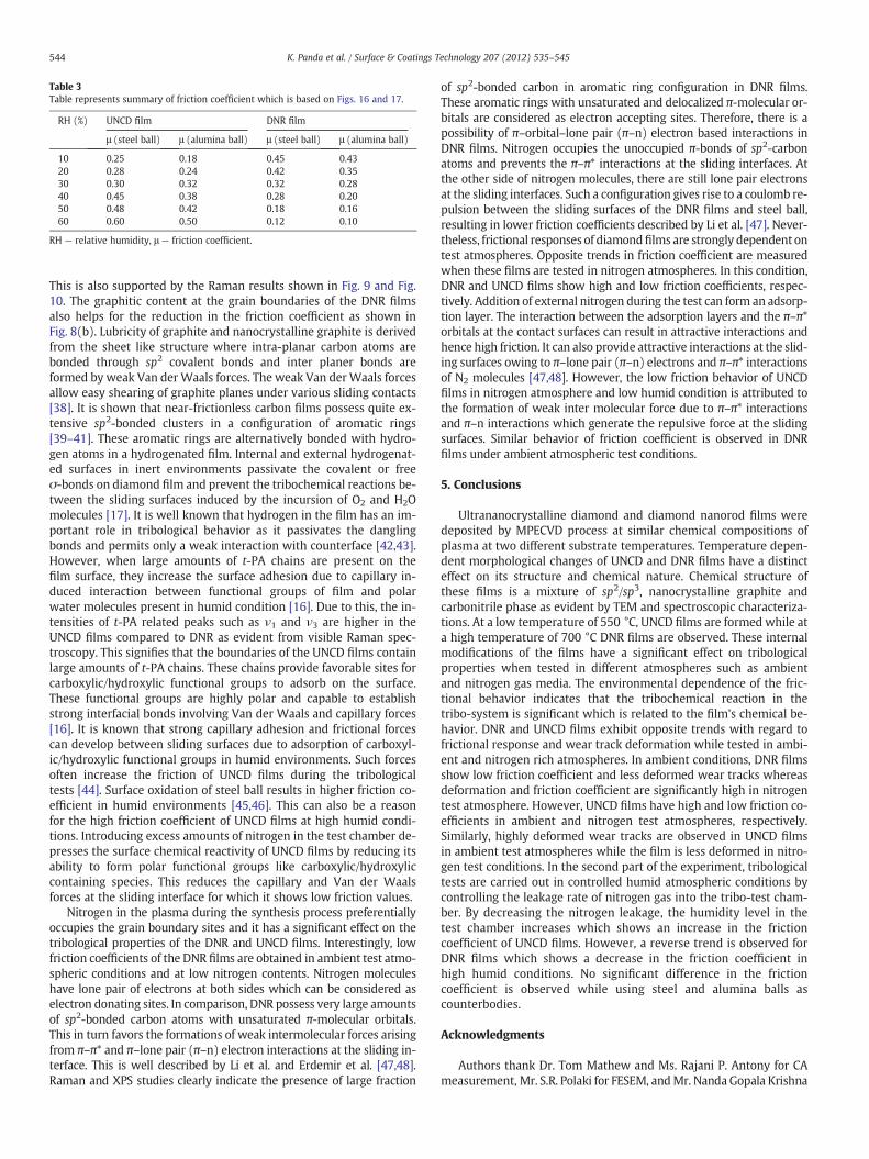
Table 3Table represents summary of friction coefficient which is based on Figs. 16 and 17.
RH (%) UNCD film DNR film
μ (steel ball) μ (alumina ball) μ (steel ball) μ (alumina ball)
10 0.25 0.18 0.45 0.4320 0.28 0.24 0.42 0.3530 0.30 0.32 0.32 0.2840 0.45 0.38 0.28 0.2050 0.48 0.42 0.18 0.1660 0.60 0.50 0.12 0.10
RH — relative humidity, μ — friction coefficient.
544 K. Panda et al. / Surface & Coatings Technology 207 (2012) 535–545
This is also supported by the Raman results shown in Fig. 9 and Fig.10. The graphitic content at the grain boundaries of the DNR filmsalso helps for the reduction in the friction coefficient as shown inFig. 8(b). Lubricity of graphite and nanocrystalline graphite is derivedfrom the sheet like structure where intra-planar carbon atoms arebonded through sp2 covalent bonds and inter planer bonds areformed by weak Van der Waals forces. The weak Van derWaals forcesallow easy shearing of graphite planes under various sliding contacts[38]. It is shown that near-frictionless carbon films possess quite ex-tensive sp2-bonded clusters in a configuration of aromatic rings[39–41]. These aromatic rings are alternatively bonded with hydro-gen atoms in a hydrogenated film. Internal and external hydrogenat-ed surfaces in inert environments passivate the covalent or freeσ-bonds on diamond film and prevent the tribochemical reactions be-tween the sliding surfaces induced by the incursion of O2 and H2Omolecules [17]. It is well known that hydrogen in the film has an im-portant role in tribological behavior as it passivates the danglingbonds and permits only a weak interaction with counterface [42,43].However, when large amounts of t-PA chains are present on thefilm surface, they increase the surface adhesion due to capillary in-duced interaction between functional groups of film and polarwater molecules present in humid condition [16]. Due to this, the in-tensities of t-PA related peaks such as ν1 and ν3 are higher in theUNCD films compared to DNR as evident from visible Raman spec-troscopy. This signifies that the boundaries of the UNCD films containlarge amounts of t-PA chains. These chains provide favorable sites forcarboxylic/hydroxylic functional groups to adsorb on the surface.These functional groups are highly polar and capable to establishstrong interfacial bonds involving Van der Waals and capillary forces[16]. It is known that strong capillary adhesion and frictional forcescan develop between sliding surfaces due to adsorption of carboxyl-ic/hydroxylic functional groups in humid environments. Such forcesoften increase the friction of UNCD films during the tribologicaltests [44]. Surface oxidation of steel ball results in higher friction co-efficient in humid environments [45,46]. This can also be a reasonfor the high friction coefficient of UNCD films at high humid condi-tions. Introducing excess amounts of nitrogen in the test chamber de-presses the surface chemical reactivity of UNCD films by reducing itsability to form polar functional groups like carboxylic/hydroxyliccontaining species. This reduces the capillary and Van der Waalsforces at the sliding interface for which it shows low friction values.
Nitrogen in the plasma during the synthesis process preferentiallyoccupies the grain boundary sites and it has a significant effect on thetribological properties of the DNR and UNCD films. Interestingly, lowfriction coefficients of the DNR films are obtained in ambient test atmo-spheric conditions and at low nitrogen contents. Nitrogen moleculeshave lone pair of electrons at both sides which can be considered aselectron donating sites. In comparison, DNR possess very large amountsof sp2-bonded carbon atoms with unsaturated π-molecular orbitals.This in turn favors the formations of weak intermolecular forces arisingfrom π–π* and π–lone pair (π–n) electron interactions at the sliding in-terface. This is well described by Li et al. and Erdemir et al. [47,48].Raman and XPS studies clearly indicate the presence of large fraction
of sp2-bonded carbon in aromatic ring configuration in DNR films.These aromatic rings with unsaturated and delocalized π-molecular or-bitals are considered as electron accepting sites. Therefore, there is apossibility of π–orbital–lone pair (π–n) electron based interactions inDNR films. Nitrogen occupies the unoccupied π-bonds of sp2-carbonatoms and prevents the π–π* interactions at the sliding interfaces. Atthe other side of nitrogen molecules, there are still lone pair electronsat the sliding interfaces. Such a configuration gives rise to a coulomb re-pulsion between the sliding surfaces of the DNR films and steel ball,resulting in lower friction coefficients described by Li et al. [47]. Never-theless, frictional responses of diamondfilms are strongly dependent ontest atmospheres. Opposite trends in friction coefficient are measuredwhen these films are tested in nitrogen atmospheres. In this condition,DNR and UNCD films show high and low friction coefficients, respec-tively. Addition of external nitrogen during the test can form an adsorp-tion layer. The interaction between the adsorption layers and the π–π*orbitals at the contact surfaces can result in attractive interactions andhence high friction. It can also provide attractive interactions at the slid-ing surfaces owing to π–lone pair (π–n) electrons and π–π* interactionsof N2 molecules [47,48]. However, the low friction behavior of UNCDfilms in nitrogen atmosphere and low humid condition is attributed tothe formation of weak inter molecular force due to π–π* interactionsand π–n interactions which generate the repulsive force at the slidingsurfaces. Similar behavior of friction coefficient is observed in DNRfilms under ambient atmospheric test conditions.
5. Conclusions
Ultrananocrystalline diamond and diamond nanorod films weredeposited by MPECVD process at similar chemical compositions ofplasma at two different substrate temperatures. Temperature depen-dent morphological changes of UNCD and DNR films have a distincteffect on its structure and chemical nature. Chemical structure ofthese films is a mixture of sp2/sp3, nanocrystalline graphite andcarbonitrile phase as evident by TEM and spectroscopic characteriza-tions. At a low temperature of 550 °C, UNCD films are formed while ata high temperature of 700 °C DNR films are observed. These internalmodifications of the films have a significant effect on tribologicalproperties when tested in different atmospheres such as ambientand nitrogen gas media. The environmental dependence of the fric-tional behavior indicates that the tribochemical reaction in thetribo-system is significant which is related to the film's chemical be-havior. DNR and UNCD films exhibit opposite trends with regard tofrictional response and wear track deformation while tested in ambi-ent and nitrogen rich atmospheres. In ambient conditions, DNR filmsshow low friction coefficient and less deformed wear tracks whereasdeformation and friction coefficient are significantly high in nitrogentest atmosphere. However, UNCD films have high and low friction co-efficients in ambient and nitrogen test atmospheres, respectively.Similarly, highly deformed wear tracks are observed in UNCD filmsin ambient test atmospheres while the film is less deformed in nitro-gen test conditions. In the second part of the experiment, tribologicaltests are carried out in controlled humid atmospheric conditions bycontrolling the leakage rate of nitrogen gas into the tribo-test cham-ber. By decreasing the nitrogen leakage, the humidity level in thetest chamber increases which shows an increase in the frictioncoefficient of UNCD films. However, a reverse trend is observed forDNR films which shows a decrease in the friction coefficient inhigh humid conditions. No significant difference in the frictioncoefficient is observed while using steel and alumina balls ascounterbodies.
Acknowledgments
Authors thank Dr. Tom Mathew and Ms. Rajani P. Antony for CAmeasurement, Mr. S.R. Polaki for FESEM, andMr. Nanda Gopala Krishna
545K. Panda et al. / Surface & Coatings Technology 207 (2012) 535–545
for XPS measurement. Authors would like to sincerely thank Dr. C.S.Sundar, Director, MSG/IGCAR, for his consistent encouragement andsupport.
References
[1] A.V. Sumant, D.S. Grierson, J.E. Gerbi, L.A. Carlisle, O. Auciello, R.W. Carpick, Phys.Rev. B 76 (2007) 235429.
[2] D. Appell, Nature 419 (2002) 553.[3] F.R. Kloss, M. Najam-Ul-Haq, M. Rainer, R. Gassner, G. Lepperdinger, C.W. Huck, G.
Bonn, F. Klauser, X. Liu, N. Memmel, E. Bertel, J.A. Garrido, D. Steinmuller-Nethl, J.Nanosci. Nanotechnol. 7 (2007) 4581.
[4] C. Popov, W. Kulisch, M. Jelinek, A. Bock, J. Strnad, Thin Solid Films 92 (2006) 494.[5] S.J. Askari, Diamond Relat. Mater. 17 (2008) 294.[6] C.S. Wang, H.C. Chen, H.F. Chen, Diamond Relat. Mater. 18 (2009) 136.[7] S.P. Hong, H. Yoshikawa, K. Wazumi, Y. Koga, Diamond Relat. Mater. 11 (2002)
877.[8] B.L. Sun, J. Gong, D. Zgu, Z. Zhu, S. He, Adv. Mater. 16 (2004) 1849.[9] P. Badziag, W.S. Verwoerd, W.P. Ellis, N.R. Greiner, Nature 343 (1990) 244.
[10] X. Jiang, J. Zhao, X. Jiang, Nanotechnology 22 (2011) 405705.[11] A.S. Barnard, S.P. Russo, I.K. Snook, Nano Lett. 3 (2003) 1323.[12] R. Arenal, P. Bruno, D.J. Miller, M. Bleuel, J. Lal, D.M. Gruen, Phys Rev B 75 (2007)
195431.[13] L. Pastewka, S. Moser, P. Gumbsch, M. Moseler, Nature Mater. 10 (2011) 34.[14] S.E. Grillo, J.E. Field, F.M. van Bouwelen, J. Phys. D: Appl. Phys. 33 (2000) 985.[15] A.R. Konicek, D.S. Grierson, P. Gilbert, W.G. Sawyer, A.V. Sumant, R.W. Carpick,
Phys. Rev. Lett. 100 (2008) 235502.[16] I.P. Hayward, Wear 157 (1992) 215.[17] G. Zilibotti, M.C. Righi, M. Ferrario, Phys. Rev. B 79 (2009) 75420.[18] S.Y. Luoa, J.K. Kuo, B. Yeh, J.C. Sung, C.W. Dai, T.J. Tsai, Mater. Chem. Phys. 72
(2001) 133.[19] L.Y. Ostrovskaya, A.P. Dementiev, I.I. Kulakova, V.G. Ralchenko, Diamond Relat.
Mater. 14 (2005) 486.[20] A.F. Azevedo, J.T. Matsushima, F.C. Vicentin, M.R. Baldan, N.G. Ferreira, Appl. Surf.
Sci. 255 (2009) 6565.[21] T. Xu, S. Yang, J. Lu, Q. Xue, J. Li, W. Guo, Y. Sun, Diamond Relat. Mater. 10 (2001)
1441.
[22] H. Hirai, K. Kondo, Science 253 (1991) 772.[23] H. Hirai, K. Kondo, Appl. Phys. Lett. 61 (1992) 414.[24] A.R. Sobia, Y. Guojun, C. Jianqing, H. Suixia, Z.J. Xingtai, Appl. Phys. 107 (2010)
114324.[25] N. Shang, P. Papakonstantinou, P. Wang, A. Zakharov, U. Palnitkar, A. Stamboulis,
ACS Nano 3 (1999) 1032.[26] G.Z. Cao, J.J. Schermer, W.J.P.V. Enckevort, W.A.L.M. Elst, L.J. Giling, J. Appl. Phys.
79 (1996) 1357.[27] C.S. Wang, G.H. Tong, H.C. Chen, W.C. Shih, Diamond Relat. Mater. 19 (2010) 147.[28] C.S. Wang, H.C. Chen, W.C. Shih, H.F. Cheng, Diamond Relat. Mater. 19 (2010) 138.[29] A.C. Ferrari, J. Robertson, Phys. Rev. B 63 (2001) 121405.[30] A.C. Ferrari, J. Robertson, Phys. Rev. B 61 (2000) 14095.[31] A.C. Ferrari, J. Robertson, Phys. Rev. B 64 (2001) 75414.[32] G. Buckley, T.D. Moustakas, L. Ye, J. Varon, J. Appl. Phys. 66 (1989) 3595.[33] V. Janos, Surf. Sci. 183 (2004) 563.[34] K.L. Ma, W.J. Zhang, Y.S. Zou, Y.M. Chong, K.M. Leung, I. Bello, S.T. Lee, Diamond
Relat. Mater. 15 (2006) 626.[35] J.J. Li, W.T. Zheng, H.H. Wu, L. Sun, G.G. Gu, H.J. Bian, X.Y. Lu, Z.S. Jin, J. Phys. D:
Appl. Phys. 36 (2003) 2001.[36] O.L. Eryilmaz, A. Erdemir, Surf. Coat. Technol. 201 (2007) 7401.[37] S. Gayathri, N. Kumar, R. Krishnan, T.R. Ravindran, S. Dash, A.K. Tyagi, Baldev Raj,
M. Sridharan, Tribol. Inter. 53 (2012) 87.[38] J.K. Lancaster, J.R. Pritchard, J. Phys. D: Appl. Phys. 14 (1981) 747.[39] A.C.Y. Liu, R. Arenal, D.J. Miller, X. Chen, J.A. Johnson, O.L. Eryilmaz, A. Erdemir, J.B.
Woodford, Phys. Rev. B 75 (2007) 205402.[40] R. Arenal, A.C.Y. Liu, Appl. Phys. Lett. 91 (2007) 211903.[41] J.A. Johnson, J.B. Woodford, X. Chen, J. Andersson, A. Erdemir, G.R. Fenske, J. Appl.
Phys. 95 (2004) 7765.[42] J. Fontaine, C. Donnet, A. Grill, T. LeMogne, Surf. Coat. Technol. 146–147 (2001)
286.[43] J.A. Heimberg, K.J. Wahl, I.L. Singer, A. Erdemir, Appl. Phys. Lett. 78 (2001) 2449.[44] K.B. Jinesh, J.W.M. Frenken, Phys Rev Lett. 96 (2006) 166103.[45] Y. Liu, A. Erdemir, E.I. Meletis, Surf. Coat. Technol. 94–95 (1997) 463.[46] S.J. Park, K.R. Lee, D.H. Ko, Tribol. Inter. 37 (2004) 913.[47] L. Ji, H. Li, F. Zhao, W. Quan, J. Chen, H. Zhou, J. Phys. D: Appl. Phys. 42 (2009)
135301.[48] A. Erdemir, C. Donnet, J. Phys. D: Appl. Phys. 39 (2006) 311.