High Surface Area Nanoporous Activated Carbons Materials ...
Upload
independentCategory
view
3download
0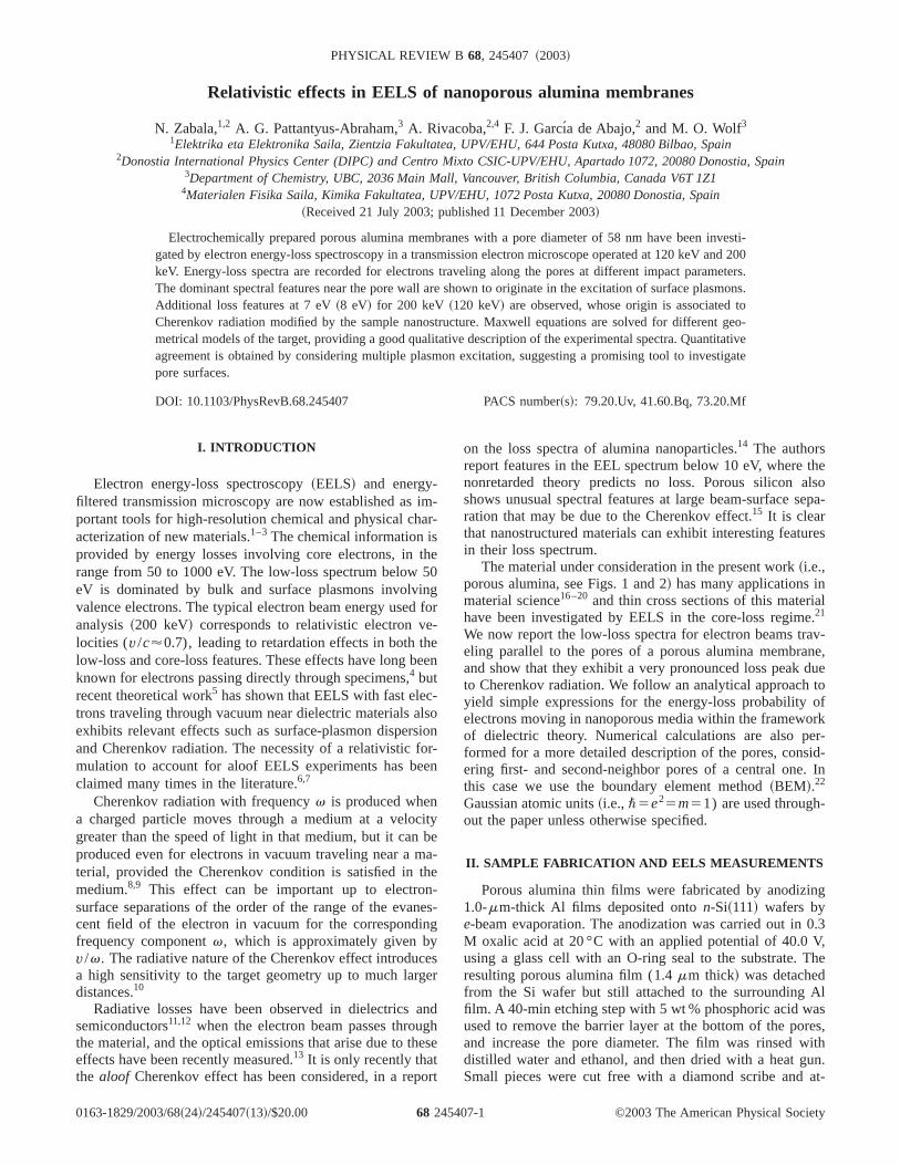
PHYSICAL REVIEW B 68, 245407 ~2003!
Relativistic effects in EELS of nanoporous alumina membranes
N. Zabala,1,2 A. G. Pattantyus-Abraham,3 A. Rivacoba,2,4 F. J. Garcı´a de Abajo,2 and M. O. Wolf31Elektrika eta Elektronika Saila, Zientzia Fakultatea, UPV/EHU, 644 Posta Kutxa, 48080 Bilbao, Spain
2Donostia International Physics Center (DIPC) and Centro Mixto CSIC-UPV/EHU, Apartado 1072, 20080 Donostia, Spain3Department of Chemistry, UBC, 2036 Main Mall, Vancouver, British Columbia, Canada V6T 1Z1
4Materialen Fisika Saila, Kimika Fakultatea, UPV/EHU, 1072 Posta Kutxa, 20080 Donostia, Spain~Received 21 July 2003; published 11 December 2003!
Electrochemically prepared porous alumina membranes with a pore diameter of 58 nm have been investi-gated by electron energy-loss spectroscopy in a transmission electron microscope operated at 120 keV and 200keV. Energy-loss spectra are recorded for electrons traveling along the pores at different impact parameters.The dominant spectral features near the pore wall are shown to originate in the excitation of surface plasmons.Additional loss features at 7 eV~8 eV! for 200 keV ~120 keV! are observed, whose origin is associated toCherenkov radiation modified by the sample nanostructure. Maxwell equations are solved for different geo-metrical models of the target, providing a good qualitative description of the experimental spectra. Quantitativeagreement is obtained by considering multiple plasmon excitation, suggesting a promising tool to investigatepore surfaces.
DOI: 10.1103/PhysRevB.68.245407 PACS number~s!: 79.20.Uv, 41.60.Bq, 73.20.Mf
ima
th5
ing
-e
be
-lssiore
cib
mhn-nein
ege
age
o
thelsoepa-
res
ale.av-ne,duetoof
orker-id-
. In
-
ng
0.3V,
he
Als
res,ith
un.at-
I. INTRODUCTION
Electron energy-loss spectroscopy~EELS! and energy-filtered transmission microscopy are now established asportant tools for high-resolution chemical and physical chacterization of new materials.1–3 The chemical information isprovided by energy losses involving core electrons, inrange from 50 to 1000 eV. The low-loss spectrum beloweV is dominated by bulk and surface plasmons involvvalence electrons. The typical electron beam energy usedanalysis~200 keV! corresponds to relativistic electron velocities (v/c'0.7), leading to retardation effects in both thlow-loss and core-loss features. These effects have longknown for electrons passing directly through specimens,4 butrecent theoretical work5 has shown that EELS with fast electrons traveling through vacuum near dielectric materials aexhibits relevant effects such as surface-plasmon disperand Cherenkov radiation. The necessity of a relativistic fmulation to account for aloof EELS experiments has beclaimed many times in the literature.6,7
Cherenkov radiation with frequencyv is produced whena charged particle moves through a medium at a velogreater than the speed of light in that medium, but it canproduced even for electrons in vacuum traveling near aterial, provided the Cherenkov condition is satisfied in tmedium.8,9 This effect can be important up to electrosurface separations of the order of the range of the evacent field of the electron in vacuum for the correspondfrequency componentv, which is approximately given byv/v. The radiative nature of the Cherenkov effect introduca high sensitivity to the target geometry up to much lardistances.10
Radiative losses have been observed in dielectricssemiconductors11,12 when the electron beam passes throuthe material, and the optical emissions that arise due to theffects have been recently measured.13 It is only recently thatthe aloof Cherenkov effect has been considered, in a rep
0163-1829/2003/68~24!/245407~13!/$20.00 68 2454
-r-
e0
for
en
oon-n
tyea-e
s-g
sr
ndhse
rt
on the loss spectra of alumina nanoparticles.14 The authorsreport features in the EEL spectrum below 10 eV, wherenonretarded theory predicts no loss. Porous silicon ashows unusual spectral features at large beam-surface sration that may be due to the Cherenkov effect.15 It is clearthat nanostructured materials can exhibit interesting featuin their loss spectrum.
The material under consideration in the present work~i.e.,porous alumina, see Figs. 1 and 2! has many applications inmaterial science16–20 and thin cross sections of this materihave been investigated by EELS in the core-loss regim21
We now report the low-loss spectra for electron beams treling parallel to the pores of a porous alumina membraand show that they exhibit a very pronounced loss peakto Cherenkov radiation. We follow an analytical approachyield simple expressions for the energy-loss probabilityelectrons moving in nanoporous media within the framewof dielectric theory. Numerical calculations are also pformed for a more detailed description of the pores, consering first- and second-neighbor pores of a central onethis case we use the boundary element method~BEM!.22
Gaussian atomic units~i.e.,\5e25m51) are used throughout the paper unless otherwise specified.
II. SAMPLE FABRICATION AND EELS MEASUREMENTS
Porous alumina thin films were fabricated by anodizi1.0-mm-thick Al films deposited onton-Si~111! wafers bye-beam evaporation. The anodization was carried out inM oxalic acid at 20 °C with an applied potential of 40.0using a glass cell with an O-ring seal to the substrate. Tresulting porous alumina film (1.4mm thick! was detachedfrom the Si wafer but still attached to the surroundingfilm. A 40-min etching step with 5 wt % phosphoric acid waused to remove the barrier layer at the bottom of the poand increase the pore diameter. The film was rinsed wdistilled water and ethanol, and then dried with a heat gSmall pieces were cut free with a diamond scribe and
©2003 The American Physical Society07-1
esuthis
n
nonieiner
loe4llee
ati-
herad
eV.d to
edam-
ionoss
ofres.na
atll asthe
eV.eakseakionsV,
fo
naTh
eVctra
ina
N. ZABALA et al. PHYSICAL REVIEW B 68, 245407 ~2003!
tached to a Cu TEM grid with a small amount of epoxy gluThe membranes obtained in this manner showed a
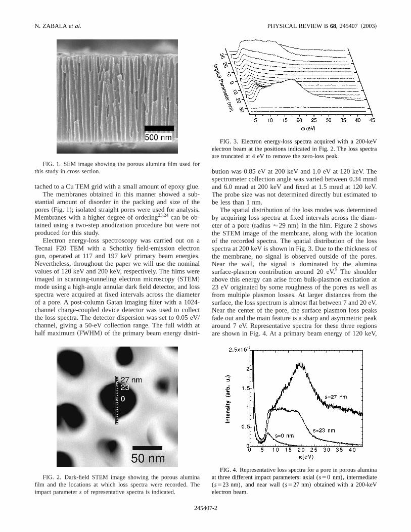
stantial amount of disorder in the packing and size ofpores~Fig. 1!; isolated straight pores were used for analysMembranes with a higher degree of ordering23,24 can be ob-tained using a two-step anodization procedure but wereproduced for this study.
Electron energy-loss spectroscopy was carried out oTecnai F20 TEM with a Schottky field-emission electrgun, operated at 117 and 197 keV primary beam energNevertheless, throughout the paper we will use the nomvalues of 120 keV and 200 keV, respectively. The films wimaged in scanning-tunneling electron microscopy~STEM!mode using a high-angle annular dark field detector, andspectra were acquired at fixed intervals across the diamof a pore. A post-column Gatan imaging filter with a 102channel charge-coupled device detector was used to cothe loss spectra. The detector dispersion was set to 0.05channel, giving a 50-eV collection range. The full widthhalf maximum~FWHM! of the primary beam energy distr
FIG. 1. SEM image showing the porous alumina film usedthis study in cross section.
FIG. 2. Dark-field STEM image showing the porous alumifilm and the locations at which loss spectra were recorded.impact parameters of representative spectra is indicated.
24540
.b-e.
ot
a
s.ale
sster-ctV/
bution was 0.85 eV at 200 keV and 1.0 eV at 120 keV. Tspectrometer collection angle was varied between 0.34 mand 6.0 mrad at 200 keV and fixed at 1.5 mrad at 120 kThe probe size was not determined directly but estimatebe less than 1 nm.
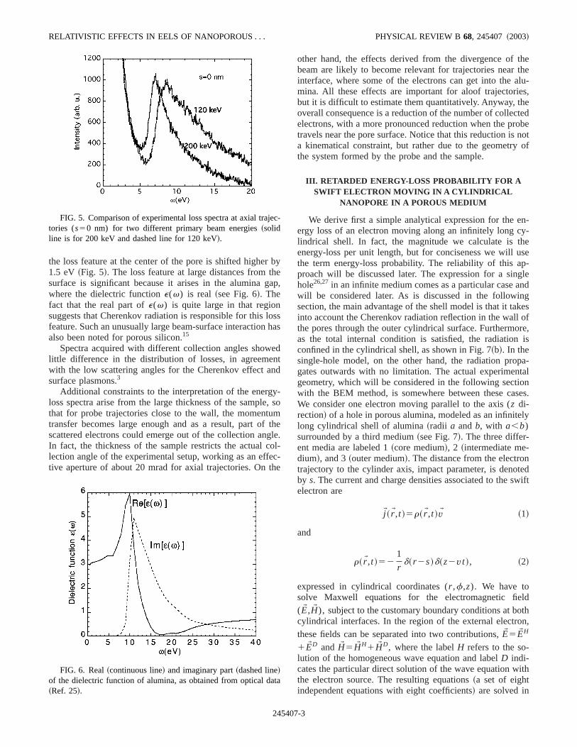
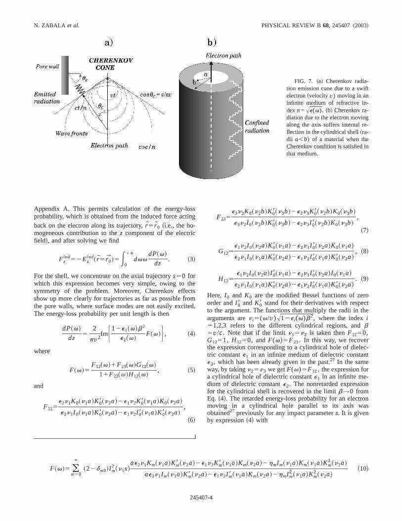
The spatial distribution of the loss modes was determinby acquiring loss spectra at fixed intervals across the dieter of a pore~radius'29 nm) in the film. Figure 2 showsthe STEM image of the membrane, along with the locatof the recorded spectra. The spatial distribution of the lspectra at 200 keV is shown in Fig. 3. Due to the thicknessthe membrane, no signal is observed outside of the poNear the wall, the signal is dominated by the alumisurface-plasmon contribution around 20 eV.5 The shoulderabove this energy can arise from bulk-plasmon excitation23 eV originated by some roughness of the pores as wefrom multiple plasmon losses. At larger distances fromsurface, the loss spectrum is almost flat between 7 and 20Near the center of the pore, the surface plasmon loss pfade out and the main feature is a sharp and asymmetric paround 7 eV. Representative spectra for these three regare shown in Fig. 4. At a primary beam energy of 120 ke
r
e
FIG. 3. Electron energy-loss spectra acquired with a 200-kelectron beam at the positions indicated in Fig. 2. The loss speare truncated at 4 eV to remove the zero-loss peak.
FIG. 4. Representative loss spectra for a pore in porous alumat three different impact parameters: axial (s50 nm), intermediate(s523 nm), and near wall (s527 nm) obtained with a 200-keVelectron beam.
7-2
r bha
loh
enn
y,umf tg
coeth
thethealu-s,etedobenotof
n-y-hese
p-glendgkesofre,is
pa-taln
ses.
ly
ntedwift
ldothn,
ith
je
ata
RELATIVISTIC EFFECTS IN EELS OF NANOPOROUS . . . PHYSICAL REVIEW B 68, 245407 ~2003!
the loss feature at the center of the pore is shifted highe1.5 eV ~Fig. 5!. The loss feature at large distances from tsurface is significant because it arises in the alumina gwhere the dielectric functione(v) is real ~see Fig. 6!. Thefact that the real part ofe(v) is quite large in that regionsuggests that Cherenkov radiation is responsible for thisfeature. Such an unusually large beam-surface interactionalso been noted for porous silicon.15
Spectra acquired with different collection angles showlittle difference in the distribution of losses, in agreemewith the low scattering angles for the Cherenkov effect asurface plasmons.3
Additional constraints to the interpretation of the energloss spectra arise from the large thickness of the samplethat for probe trajectories close to the wall, the momenttransfer becomes large enough and as a result, part oscattered electrons could emerge out of the collection anIn fact, the thickness of the sample restricts the actuallection angle of the experimental setup, working as an efftive aperture of about 20 mrad for axial trajectories. On
FIG. 5. Comparison of experimental loss spectra at axial tratories (s50 nm) for two different primary beam energies~solidline is for 200 keV and dashed line for 120 keV!.
FIG. 6. Real~continuous line! and imaginary part~dashed line!of the dielectric function of alumina, as obtained from optical d~Ref. 25!.
24540
yep,
ssas
dtd
-so
hele.l-c-e
other hand, the effects derived from the divergence ofbeam are likely to become relevant for trajectories nearinterface, where some of the electrons can get into themina. All these effects are important for aloof trajectoriebut it is difficult to estimate them quantitatively. Anyway, thoverall consequence is a reduction of the number of collecelectrons, with a more pronounced reduction when the prtravels near the pore surface. Notice that this reduction isa kinematical constraint, but rather due to the geometrythe system formed by the probe and the sample.
III. RETARDED ENERGY-LOSS PROBABILITY FOR ASWIFT ELECTRON MOVING IN A CYLINDRICAL
NANOPORE IN A POROUS MEDIUM
We derive first a simple analytical expression for the eergy loss of an electron moving along an infinitely long clindrical shell. In fact, the magnitude we calculate is tenergy-loss per unit length, but for conciseness we will uthe term energy-loss probability. The reliability of this aproach will be discussed later. The expression for a sinhole26,27in an infinite medium comes as a particular case awill be considered later. As is discussed in the followinsection, the main advantage of the shell model is that it tainto account the Cherenkov radiation reflection in the wallthe pores through the outer cylindrical surface. Furthermoas the total internal condition is satisfied, the radiationconfined in the cylindrical shell, as shown in Fig. 7~b!. In thesingle-hole model, on the other hand, the radiation progates outwards with no limitation. The actual experimengeometry, which will be considered in the following sectiowith the BEM method, is somewhere between these caWe consider one electron moving parallel to the axis (z di-rection! of a hole in porous alumina, modeled as an infinitelong cylindrical shell of alumina~radii a andb, with a,b)surrounded by a third medium~see Fig. 7!. The three differ-ent media are labeled 1~core medium!, 2 ~intermediate me-dium!, and 3~outer medium!. The distance from the electrotrajectory to the cylinder axis, impact parameter, is denoby s. The current and charge densities associated to the selectron are
jW~rW,t !5r~rW,t !vW ~1!
and
r~rW,t !521
rd~r 2s!d~z2vt !, ~2!
expressed in cylindrical coordinates (r ,f,z). We have tosolve Maxwell equations for the electromagnetic fie(EW ,HW ), subject to the customary boundary conditions at bcylindrical interfaces. In the region of the external electrothese fields can be separated into two contributions,EW 5EW H
1EW D andHW 5HW H1HW D, where the labelH refers to the so-lution of the homogeneous wave equation and labelD indi-cates the particular direct solution of the wave equation wthe electron source. The resulting equations~a set of eightindependent equations with eight coefficients! are solved in
c-
7-3
t
-
N. ZABALA et al. PHYSICAL REVIEW B 68, 245407 ~2003!
FIG. 7. ~a! Cherenkov radia-tion emission cone due to a swifelectron~velocity v) moving in aninfinite medium of refractive in-dexn5Ae(v). ~b! Cherenkov ra-diation due to the electron movingalong the axis suffers internal reflection in the cylindrical shell~ra-dii a,b) of a material when theCherenkov condition is satisfied inthat medium.
ssng
thctomite
rot
he
ec-t
n
ons
Appendix A. This permits calculation of the energy-loprobability, which is obtained from the induced force actiback on the electron along its trajectory,rW5rW0 ~i.e., the ho-mogeneous contribution to thez component of the electricfield!, and after solving we find
Fzind52Ez
ind~rW5r 0W !5E
0
1`
dvvdP~v!
dz. ~3!
For the shell, we concentrate on the axial trajectorys50 forwhich this expression becomes very simple, owing tosymmetry of the problem. Moreover, Cherenkov effeshow up more clearly for trajectories as far as possible frthe pore walls, where surface modes are not easily excThe energy-loss probability per unit length is then
dP~v!
dz5
2
pv2ImH 12e1~v!b2
e1~v!F~v!J , ~4!
where
F~v!5F12~v!1F23~v!G12~v!
11F23~v!H12~v!, ~5!
and
F125e2n1K0~n1a!K08~n2a!2e1n2K08~n1a!K0~n2a!
e2n1I 0~n1a!K08~n2a!2e1n2I 08~n1a!K08~n2a!,
~6!
24540
es
d.
F235e3n2K0~n2b!K08~n3b!2e2n3K08~n2b!K0~n3b!
e3n2I 0~n2b!K08~n3b!2e2n3I 08~n2b!K0~n3b!,
~7!
G125e1n2I 0~n2a!K08~n1a!2e2n1I 08~n2a!K0~n1a!
e2n1I 0~n1a!K08~n2a!2e1n2I 08~n1a!K08~n2a!, ~8!
H125e1n2I 0~n2a!I 08~n1a!2e2n1I 08~n2a!I 0~n1a!
e2n1I 0~n1a!K08~n2a!2e1n2I 08~n1a!K08~n2a!. ~9!
Here, I 0 and K0 are the modified Bessel functions of zeorder andI 08 andK08 stand for their derivatives with respecto the argument. The functions that multiply the radii in targuments aren i5(v/v)A12e i(v)b2, where the indexi51,2,3 refers to the different cylindrical regions, andb5v/c. Note that if the limitn15n2 is taken thenF1250,G1251, H1250, andF(v)5F23. In this way, we recoverthe expression corresponding to a cylindrical hole of dieltric constante1 in an infinite medium of dielectric constane3, which has been already given in the past.27 In the sameway, by takingn25n3 we getF(v)5F12, the expression fora cylindrical hole of dielectric constante1 in an infinite me-dium of dielectric constante2. The nonretarded expressiofor the cylindrical shell is recovered in the limitb→0 fromEq. ~4!. The retarded energy-loss probability for an electrmoving in a cylindrical hole parallel to its axis waobtained27 previously for any impact parameters. It is givenby expression~4! with
F~v!5 (m50
`
~22dm0!I m2 ~n1s!
ae2n1Km~n1a!Km8 ~n2a!2e1n2Km8 ~n1a!Km~n2a!2hmI m~n1a!Km~n1a!Km2 ~n2a!
ae2n1I m~n1a!Km8 ~n2a!2e1n2I m8 ~n1a!Km~n2a!2hmI m2 ~n1a!Km
2 ~n2a!~10!
7-4
en
-
vth
ricls
ycur
n
anth
naend
traoe
su
redwtriovn
the
theto
re
y ar asclas-atasethezi-na
,thee
redde-ctra
eded
r in
tlas-8.
00-
d
RELATIVISTIC EFFECTS IN EELS OF NANOPOROUS . . . PHYSICAL REVIEW B 68, 245407 ~2003!
and
hm5m2b2~v/v !4~e12e2!2
n12n2
2@n1I m~n1a!Km8 ~n2a!#2n2I m8 ~n1a!Km~n2a!.
~11!
The expression for nonaxial trajectories is a sum of differm terms, where the modified Bessel functions of orderm~I m , Km! and their derivatives appear. The axial cases50 isconsiderably simpler due to the vanishing of termsmÞ0,becauseI m
2 (n1s) is zero whens50 except form50, in thatcaseI 0(n10)51. Note that in the axial case, Eq.~10! givesexpression~5! with e25e3. In general, the dielectric functions e1(v), e2(v), and e3(v) are complex, so that theBessel functions have complex-number arguments. Howein order to study the Cherenkov effect, and to understandunderlying physics, it is instructive to use a real dielectfunction, in which case these arguments are either reaimaginary. The energy-loss probability then becomes aperposition of Diracd functions~see Appendix B!:
dP~v!
dz5(
if ~v!d~v2v i !, ~12!
where the energiesv i of the Cherenkov modes are given bthe zeros of a real function given in Appendix B. The funtion f (v) in also obtained there. Assuming that both srounding media are perfectly reflective (e15e25`), onecan obtain an approximate expression for these modes:
v.npv
~b2a!Ab2e221, ~13!
with n51,2,3, . . . . Note that this expression is only valid ithe alumina gap.
A. Results for a single pore
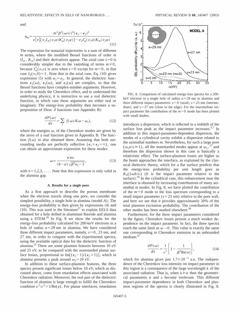
As a first approach to describe the porous membrwhen the electron travels along one pore, we considersimplest possibility, a single hole in alumina~modelA). Theenergy-loss probability is then given by expressions~4! and~10!. This was used in the literature27 to explain EELS dataobtained for a hole drilled in aluminum fluoride and alumiusing a STEM.28 In Fig. 8 we show the results for thenergy-loss probability calculated for 200-keV electrons ihole of radiusa529 nm in alumina. We have considerethree different impact parameters, namely,s50, 23 nm, and27 nm, in order to compare with the experimental specusing the available optical data for the dielectric functionalumina.25 There are some plasmon features between 10and 25 eV, to be compared with the nonretarded planarface losses, proportional to Im@(e221)/(e211)#, which inalumina presents a peak aroundvs520 eV.
In addition to these surface-plasmon features, the thspectra present significant losses below 10 eV, which ascussed above, come from retardation effects associatedCherenkov radiation. Moreover, the real part of the dielecfunction of alumina is large enough to fulfill the Cherenkconditionv2/c2.1/Re(e). For planar interfaces, retardatio
24540
t
er,e
oru-
--
ee
a
,fVr-
eis-ithc
introduces a dispersion, which is reflected in a redshift ofsurface loss peak as the impact parameter increases.5,7 Inaddition to this impact-parameter-dependent dispersion,modes of a cylindrical cavity exhibit a dispersion relatedthe azimuthal numbersm. Nevertheless, for such a large po(vsa/v@1), all the nonretarded modes appear atvs ,27 andtherefore the dispersion shown in this case is basicallrelativistic effect. The surface-plasmon losses are highethe beam approaches the interface, as explained by thesical dielectric theory, which for a flat surface predicts ththe energy-loss probability per unit length goesK0(2vb/v) (b is the impact parameter relative to thsurface!.29 In the cylindrical case, this enhancement nearinterface is obtained by increasing contributions of many amuthalm modes. In Fig. 8, we have plotted the contributioof the m50 mode to the loss spectrum corresponding tosmall impact parameter (s523 nm) relative to the pore walland here we see that it provides approximately 20% oftotal plasmon excitation probability. The contribution of thother modes has been studied elsewhere.30
Furthermore, for the three impact parameters considein the figure, Cherenkov losses present a much weakerpendence on the impact parameter. In fact, the three spereach the same limit asv→0. This value is exactly the samone corresponding to Cherenkov emission in an unbounmedium:31
dP~v!
dz5
1
c2 H 121
b2Re~e!J , ~14!
which for alumina gives just 1.731025 a.u. The indepen-dence of the Cherenkov loss intensity on impact parametethis region is a consequence of the large wavelengthl of theassociated radiation. That is, whenl@a then the geometri-cal parametersa and s become irrelevant. This differenimpact-parameter dependence in both Cherenkov and pmon regions of the spectra is clearly illustrated in Fig.
FIG. 8. Comparison of calculated energy-loss spectra for a 2keV electron in a single hole of radiusa529 nm in alumina andthree different impact parameters:s50 ~axial!, s523 nm~interme-diate!, ands527 nm ~close to the edge!. For the intermediate im-pact parameter the contribution of them50 mode has been plottewith small dashes.
7-5
nt,ti
ngrenll-of
istsnp
–1
ltetioo
hinerle
iu.thn
lose
wfo
llres
b
inif
dre, n
f t
c-e
s themostpro-estonence
ell,on.
ia-
ofrs-theoc-e
f
of
at-ss.in
h a
rv
ing
hole.
N. ZABALA et al. PHYSICAL REVIEW B 68, 245407 ~2003!
Although this simple model explains the two differemechanisms of inelastic excitations found in experimentsfails to reproduce the peak associated to Cherenkov radiaaround 7 eV. The origin of this peak seems to be relatedthe coupling of the central pore to the surrounding ones.
One simple way to introduce the effect of this coupliinside this simple model is to represent the dielectricsponse of the membrane through an effective dielectric fution. We can use, for example, the well-known MaxweGarnett formula,32 generally used to treat dilute systemsparticles with dielectric functione1 in a medium of dielectricfunction e2. If f is the volume fraction of component 1~thevacuum inside cylindrical pores! inside component 2~thealumina!, the effective dielectric function is given by
ee f f5e21f e2~e12e2!
e21~12 f !~e12e2!/2, ~15!
wheree151 ande2 corresponds to alumina. This formulavalid for the case of cylindrical particles, avoiding the effecof the borders. Thus its validity is limited to the situatiowhere the radii of the holes are much smaller than the samthickness. This model gives a loss maximum at around 9eV when choosing for instancef '0.4, but it is unable to fitboth Cherenkov and plasmon parts of the spectra simuneously. In fact, within this effective medium model, thmembrane is considered homogeneous, and all diffraceffects characteristic of the propagation of light in inhomgeneous media are neglected.
B. Results for a cylindrical shell
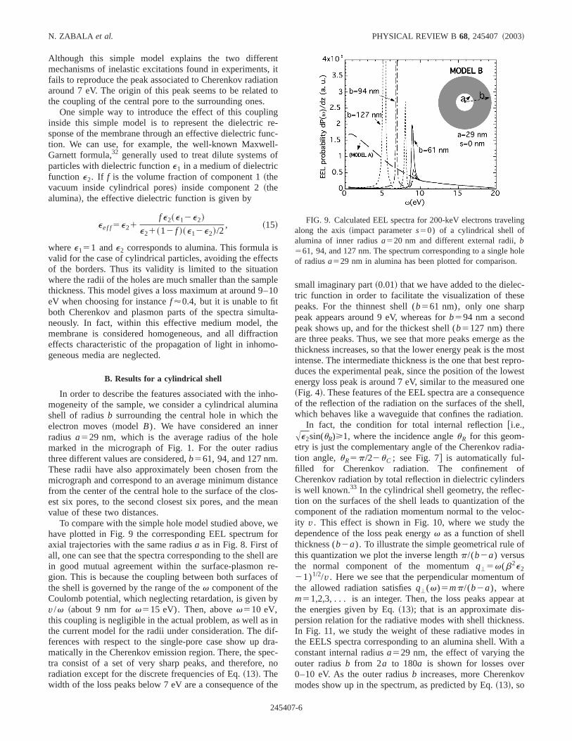
In order to describe the features associated with the inmogeneity of the sample, we consider a cylindrical alumshell of radiusb surrounding the central hole in which thelectron moves~model B). We have considered an inneradius a529 nm, which is the average radius of the homarked in the micrograph of Fig. 1. For the outer radthree different values are considered,b561, 94, and 127 nmThese radii have also approximately been chosen frommicrograph and correspond to an average minimum distafrom the center of the central hole to the surface of the cest six pores, to the second closest six pores, and the mvalue of these two distances.
To compare with the simple hole model studied above,have plotted in Fig. 9 the corresponding EEL spectrumaxial trajectories with the same radiusa as in Fig. 8. First ofall, one can see that the spectra corresponding to the shein good mutual agreement within the surface-plasmongion. This is because the coupling between both surfacethe shell is governed by the range of thev component of theCoulomb potential, which neglecting retardation, is givenv/v ~about 9 nm forv515 eV). Then, abovev510 eV,this coupling is negligible in the actual problem, as well asthe current model for the radii under consideration. The dferences with respect to the single-pore case show upmatically in the Cherenkov emission region. There, the sptra consist of a set of very sharp peaks, and thereforeradiation except for the discrete frequencies of Eq.~13!. Thewidth of the loss peaks below 7 eV are a consequence o
24540
itonto
-c-
le0
a-
n-
o-a
s
ece-an
er
are-of
y
-a-c-o
he
small imaginary part~0.01! that we have added to the dieletric function in order to facilitate the visualization of thespeaks. For the thinnest shell (b561 nm), only one sharppeak appears around 9 eV, whereas forb594 nm a secondpeak shows up, and for the thickest shell (b5127 nm) thereare three peaks. Thus, we see that more peaks emerge athickness increases, so that the lower energy peak is theintense. The intermediate thickness is the one that best reduces the experimental peak, since the position of the lowenergy loss peak is around 7 eV, similar to the measured~Fig. 4!. These features of the EEL spectra are a consequeof the reflection of the radiation on the surfaces of the shwhich behaves like a waveguide that confines the radiati
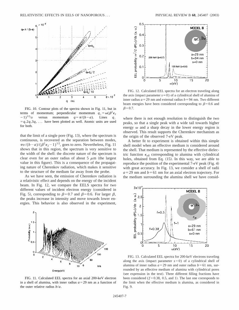
In fact, the condition for total internal [email protected].,Ae2sin(uR)>1, where the incidence angleuR for this geom-etry is just the complementary angle of the Cherenkov radtion angle,uR5p/22uC ; see Fig. 7# is automatically ful-filled for Cherenkov radiation. The confinementCherenkov radiation by total reflection in dielectric cylindeis well known.33 In the cylindrical shell geometry, the reflection on the surfaces of the shell leads to quantization ofcomponent of the radiation momentum normal to the velity v. This effect is shown in Fig. 10, where we study thdependence of the loss peak energyv as a function of shellthickness (b2a). To illustrate the simple geometrical rule othis quantization we plot the inverse lengthp/(b2a) versusthe normal component of the momentumq'5v(b2e221)1/2/v. Here we see that the perpendicular momentumthe allowed radiation satisfiesq'(v)5mp/(b2a), wherem51,2,3, . . . is aninteger. Then, the loss peaks appearthe energies given by Eq.~13!; that is an approximate dispersion relation for the radiative modes with shell thickneIn Fig. 11, we study the weight of these radiative modesthe EELS spectra corresponding to an alumina shell. Witconstant internal radiusa529 nm, the effect of varying theouter radiusb from 2a to 180a is shown for losses ove0–10 eV. As the outer radiusb increases, more Cherenkomodes show up in the spectrum, as predicted by Eq.~13!, so
FIG. 9. Calculated EEL spectra for 200-keV electrons travelalong the axis~impact parameters50) of a cylindrical shell ofalumina of inner radiusa520 nm and different external radii,b561, 94, and 127 nm. The spectrum corresponding to a singleof radiusa529 nm in alumina has been plotted for comparison
7-6
d1t
ativ
new
een
woherisas
leundlec-l
diir
sid-
in
ed
ro
ng
ing
es
oin
RELATIVISTIC EFFECTS IN EELS OF NANOPOROUS . . . PHYSICAL REVIEW B 68, 245407 ~2003!
that the limit of a single pore~Fig. 13!, where the spectrum iscontinuous, is recovered as the separation between mopv/(b2a)/(b2e221)1/2, goes to zero. Nevertheless, Fig. 1shows that in this region, the spectrum is very sensitivethe width of the shell: the discrete nature of the spectrumclear even for an outer radius of about 5mm ~the largestvalue in this figure!. This is a consequence of the propaging nature of Cherenkov radiation, which makes it sensitto the structure of the medium far away from the probe.
As we have seen, the emission of Cherenkov radiatioa relativistic effect and depends on the energy of the incidbeam. In Fig. 12, we compare the EELS spectra for tdifferent values of incident electron energy~considered inFig. 5!, corresponding tob50.7 andb50.6. For largerb,the peaks increase in intensity and move towards lowerergies. This behavior is also observed in the experim
FIG. 10. Contour plots of the spectra shown in Fig. 11, butterms of momentum; perpendicular momentumq'5v(b2e2
21)1/2/v versus momentum q5p/(b2a). Lines q'
5q,2q,3q, . . . have been plotted as well. Atomic units are usfor both.
FIG. 11. Calculated EEL spectra for an axial 200-keV electin a shell of alumina, with inner radiusa529 nm as a function ofthe outer relative radiusb/a.
24540
es,
ois
-e
isnto
n-t,
where there is not enough resolution to distinguish the tpeaks, so that a single peak with a wide tail towards higenergyv and a sharp decay in the lower energy regionobserved. This result supports the Cherenkov mechanismthe origin of the observed 7-eV peak.
A better fit to experiment is obtained within this simpshell model when an effective medium is considered arothe shell. That medium is represented by the effective dietric function eeff corresponding to alumina with cylindricaholes, obtained from Eq.~15!. In this way, we are able toreproduce the position of the experimental 7-eV peak~Fig. 4!with great accuracy. In Fig. 13, we consider a shell of raa529 nm andb561 nm for an axial electron trajectory. Fothe medium surrounding the alumina shell we have con
n
FIG. 12. Calculated EEL spectra for an electron traveling alothe axis~impact parameters50) of a cylindrical shell of alumina ofinner radiusa529 nm and external radiusb594 nm. Two differentbeam energies have been considered corresponding tob50.6 andb50.7.
FIG. 13. Calculated EEL spectra for 200-keV electrons travelalong the axis~impact parameters50) of a cylindrical shell ofalumina of inner radiusa529 nm and outer radiusb561 nm, sur-rounded by an effective medium of alumina with cylindrical por~see expression in the text!. Three different filling fractions havebeen considered (f 50.38, 0.5, and 1!. The last one corresponds tthe limit when the effective medium is alumina, as consideredFig. 9.
7-7
ns
p-tioits
erlhe
es.ysri
reuispfode
ch
hiinllyeld,hetees
ean
idobi
rath
yl-
hea-
olinerhbro
abil-m-icalhes in
heevi-
ameiors
ion
r a
es,aythe
N. ZABALA et al. PHYSICAL REVIEW B 68, 245407 ~2003!
ered an effective porous medium of different filling fractioof vacuum, f 50.38, 0.5, and 1, respectively. The casef51 corresponds to vacuum and has been included in thefor reference. The filling fractionf 50.38 corresponds exactly to the pore radius and separation considered. A fracaroundf 50.4 provides a good fit to experiment that permreproducing the peak at 7 eV.
In conclusion, despite its simplicity, the shell model prsented in this section captures the main physics that undethe experiment: when the electron moves along a hole, Cenkov radiation is emitted outwards and confined in the mdium due to total internal reflection in the cylindrical wallThe position of the peaks in the EELS spectrum then obequantization rule that involves the thickness of the cylindcal shell.
In the actual sample, the walls of the neighboring poact as radiation reflectors that are represented by the ocylindrical wall of the shell model. However, the radiationnot completely confined, but propagates throughout therous medium that extends to very large distances. In thelowing section we consider a more realistic approach toscribe the pore structure of the sample.
IV. LOSS PROBABILITY IN A PORE SURROUNDED BYHEXAGONAL PORE DISTRIBUTIONS „MODEL C…
A more realistic description of the sample is one in whithe main pore~through which the electron travels! is sur-rounded by other pores disposed in an hexagonal fas~model C). We consider here first- and second-neighborpores. This problem is too complex to be solved analyticaso we have relied on numerical simulation of the Maxwequations to solve it. In particular, the BEM has been use22
which permits solving the electromagnetic problem in tpresence of arbitrarily shaped interfaces by employing inface charge and current distributions that are solved sconsistently for a given external field by applying the cutomary boundary conditions for the fields. One finds a linset of integral equations, with the interface currents acharges as the unknowns, which are discretized by consing a set of representative points on the interfaces. Mdetails about this method and its application to EELS canfound elsewhere.22 In the present case where the geometryinvariant for translation along the pores, the surface integbecome one-dimensional and the entire problem involvesinversion of a reduced set ofN3N matrices, whereN is thenumber of discretization points. Typically, 50 points per cinder are enough to reach convergence.
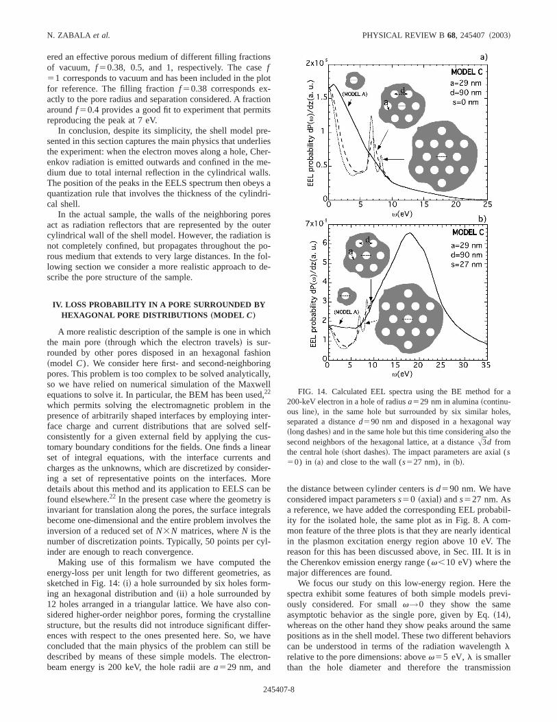
Making use of this formalism we have computed tenergy-loss per unit length for two different geometries,sketched in Fig. 14:~i! a hole surrounded by six holes forming an hexagonal distribution and~ii ! a hole surrounded by12 holes arranged in a triangular lattice. We have also csidered higher-order neighbor pores, forming the crystalstructure, but the results did not introduce significant diffences with respect to the ones presented here. So, weconcluded that the main physics of the problem can stilldescribed by means of these simple models. The electbeam energy is 200 keV, the hole radii area529 nm, and
24540
lot
n
-iesr--
a-
ster
o-l--
ong,l
r-lf--rder-ree
slse
s
n-e-aveen-
the distance between cylinder centers isd590 nm. We haveconsidered impact parameterss50 ~axial! ands527 nm. Asa reference, we have added the corresponding EEL probity for the isolated hole, the same plot as in Fig. 8. A comon feature of the three plots is that they are nearly identin the plasmon excitation energy region above 10 eV. Treason for this has been discussed above, in Sec. III. It ithe Cherenkov emission energy range (v,10 eV) where themajor differences are found.
We focus our study on this low-energy region. Here tspectra exhibit some features of both simple models prously considered. For smallv→0 they show the sameasymptotic behavior as the single pore, given by Eq.~14!,whereas on the other hand they show peaks around the spositions as in the shell model. These two different behavcan be understood in terms of the radiation wavelengthlrelative to the pore dimensions: abovev55 eV, l is smallerthan the hole diameter and therefore the transmiss
FIG. 14. Calculated EEL spectra using the BE method fo200-keV electron in a hole of radiusa529 nm in alumina~continu-ous line!, in the same hole but surrounded by six similar holseparated a distanced590 nm and disposed in a hexagonal w~long dashes! and in the same hole but this time considering alsosecond neighbors of the hexagonal lattice, at a distanceA3d fromthe central hole~short dashes!. The impact parameters are axial (s50) in ~a! and close to the wall (s527 nm), in~b!.
7-8
aiothltd,thucfleisvess
pls
figh
ua
aou
o
gyt
vei
ve-goofaentioMnntniecioh
nasplenn
ft
ebfa
c-,themu-pos-oftoof aedia-icd.ve-s
yical
atic
thed for
--tzero-ith a
RELATIVISTIC EFFECTS IN EELS OF NANOPOROUS . . . PHYSICAL REVIEW B 68, 245407 ~2003!
through the hole is small. In this case, reflection modesdominant. However, below this energy range, transmissbecomes favored, and therefore, radiation leaking out ofpores is the main mechanism for energy-loss. This resulikely to explain the fact that reflection on the seconneighbor holes does not lead to loss peaks around 4 eVpredicted by the shell model. The length associated totransverse component of the momentum would be now mlarger than the diameter of the pores and therefore the retion is weak. Finally, whenv→0 the size of the scatterersirrelevant as compared with the wavelength and one recothe infinite medium limit. The fact that the two sharp lopeaks appear around the same positions as the peaksdicted by the shell model supports this argument. It aexplains the reduction of the loss probability in the 1112pore model, in relation to the 116 pore case, as an effect othe radiation transmission through the second row of nebors.
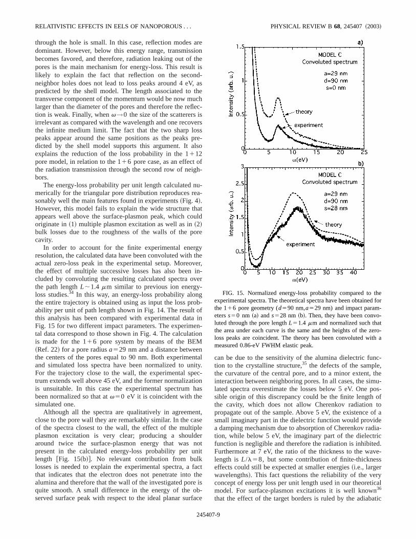
The energy-loss probability per unit length calculated nmerically for the triangular pore distribution reproduces resonably well the main features found in experiments~Fig. 4!.However, this model fails to explain the wide structure thappears well above the surface-plasmon peak, which coriginate in~1! multiple plasmon excitation as well as in~2!bulk losses due to the roughness of the walls of the pcavity.
In order to account for the finite experimental enerresolution, the calculated data have been convoluted withactual zero-loss peak in the experimental setup. Moreothe effect of multiple successive losses has also beencluded by convoluting the resulting calculated spectra othe path lengthL;1.4 mm similar to previous ion energyloss studies.34 In this way, an energy-loss probability alonthe entire trajectory is obtained using as input the loss prability per unit of path length shown in Fig. 14. The resultthis analysis has been compared with experimental datFig. 15 for two different impact parameters. The experimtal data correspond to those shown in Fig. 4. The calculais made for the 116 pore system by means of the BE~Ref. 22! for a pore radiusa529 nm and a distance betweethe centers of the pores equal to 90 nm. Both experimeand simulated loss spectra have been normalized to uFor the trajectory close to the wall, the experimental sptrum extends well above 45 eV, and the former normalizatis unsuitable. In this case the experimental spectrumbeen normalized so that atv50 eV it is coincident with thesimulated one.
Although all the spectra are qualitatively in agreemeclose to the pore wall they are remarkably similar. In the cof the spectra closest to the wall, the effect of the multiplasmon excitation is very clear; producing a shouldaround twice the surface-plasmon energy that waspresent in the calculated energy-loss probability per ulength @Fig. 15~b!#. No relevant contribution from bulklosses is needed to explain the experimental spectra, athat indicates that the electron does not penetrate intoalumina and therefore that the wall of the investigated porquite smooth. A small difference in the energy of the oserved surface peak with respect to the ideal planar sur
24540
reneis-asehc-
rs
re-o
-
--
tld
re
her,n-r
b-
in-n
alty.-nas
t,e
erotit
actheis-ce
can be due to the sensitivity of the alumina dielectric funtion to the crystalline structure,35 the defects of the samplethe curvature of the central pore, and to a minor extent,interaction between neighboring pores. In all cases, the silated spectra overestimate the losses below 5 eV. Onesible origin of this discrepancy could be the finite lengththe cavity, which does not allow Cherenkov radiationpropagate out of the sample. Above 5 eV, the existencesmall imaginary part in the dielectric function would provida damping mechanism due to absorption of Cherenkov ration, while below 5 eV, the imaginary part of the dielectrfunction is negligible and therefore the radiation is inhibiteFurthermore at 7 eV, the ratio of the thickness to the walength isL/l58, but some contribution of finite-thickneseffects could still be expected at smaller energies~i.e., largerwavelengths!. This fact questions the reliability of the verconcept of energy loss per unit length used in our theoretmodel. For surface-plasmon excitations it is well known36
that the effect of the target borders is ruled by the adiab
FIG. 15. Normalized energy-loss probability compared toexperimental spectra. The theoretical spectra have been obtainethe 116 pore geometry (d590 nm,a529 nm) and impact parameterss50 nm ~a! ands528 nm ~b!. Then, they have been convoluted through the pore lengthL51.4 mm and normalized such thathe area under each curve is the same and the heights of theloss peaks are coincident. The theory has been convoluted wmeasured 0.86-eV FWHM elastic peak.
7-9
tiot
pet
ojennaasamenthta
inpevates-sioets
cergdonge
aibeltwndre
exo
eethmen
ofs
ringeof-c-
ld,can
t
-
lveten-
N. ZABALA et al. PHYSICAL REVIEW B 68, 245407 ~2003!
length v/v ~20 nm for 7 eV!, and therefore this effect isnegligible. Nevertheless, in the case of Cherenkov radiathe nonevanescent nature of the field makes it sensitive tosize of the targets at larger distances, and one should sproperly of transition radiation. The spectra correspondingthe axial trajectory show less quantitative agreement, in bplasmon and Cherenkov loss regions. Clearly, for this tratory the effects of the finite thickness of the membrashould be more relevant. In fact, the study of EELS in plainterfaces shows that the effect of retardation is to increthe loss probability, and this is more relevant as the impparameter increases. For large impact parameters, thecontribution to the spectrum arises from very small momtum transfer, so that they are likely to be very sensitive totarget shape at large distances.5 In our problem it means thawe are overestimating the retardation effects, obtainingEEL probability larger than the measured one.
V. CONCLUDING REMARKS
We have reported EELS analysis of nanoporous alumsamples using 120- and 200-keV STEM probes. These stra reveal two different energy-loss mechanisms in thelence region:~1! above 10 eV surface plasmons are exciand ~2! below 10 eV, where the material is relatively tranparent, the main mechanism for energy loss is the emisof Cherenkov light, which is modulated by the complex prous structure. Three different simple theoretical modhave been proposed and compared with the experimensingle pore model (A), a cylindrical alumina shell (B), anda triangular pore lattice (C), all of them consisting of poresof infinite length. Even though the three models reproducorrectly the surface-plasmon excitation region of the sptra, they present substantial differences in the low-eneregion. The origin of these differences has been explaineterms of reflection and transmission of the emitted radiatiModel A allows free propagation of emitted radiation at lardistances, which leads to smooth spectra. In modelB, theemitted radiation is completely confined in the cylindricshell by total internal reflection and the loss spectra exhresonances associated to light confinement. Finally, modCencompasses to some extent a combination of the othercontaining both reflection in the neighboring holes apropagation beyond them. Comparison with experimentsults in excellent agreement, once successive plasmontations have been taken into account by self-convolutionthe spectra. In summary, Cherenkov radiation has bshown to be the origin of the 7-eV peak observed inenergy-loss spectra in porous alumina, and this peak coabout as a result of diffraction of this radiation in betweneighboring sample holes.
ACKNOWLEDGMENTS
The authors wish to thank Gianluigi Botton~CANMET,Natural Resources Canada! and Rick Humphrey~MedicalImaging Facility of the University of Calgary! for help withthe measurements and Profesor P. M. Echenique and Prsor A. Howie for many enjoyable and stimulating discu
24540
nheakothc-ere
ctain-e
n
ac--
d
on-ls: a
ec-yin.
lit
o,
-ci-fn
ees
es--
sions. Support from the Natural Sciences and EngineeResearch Council~Canada!, the Basque Departamento dEducacio´n, Universidades e Investigacin, the Universitythe Basque Country UPV/EHU~Contract No. 00206.21513639/2001!, and the Spanish Ministerio de Ciencia y Tenologa~Contract No. MAT2001-0946! is gratefully acknowl-edged.
APPENDIX A: COMPONENTS OF THEELECTROMAGNETIC FIELD
There are different ways to get the electromagnetic fiebut due to the symmetry of the homogeneous solutions itbe obtained from the Hertz vectors,37 PW 5Pek electric andPW 5Pmk magnetic, respectively, directed along thez axis, asfollows:
EW H5“3“3PW e21
c
]
]t“PW m,
HW H5e i
c
]
]t“PW e1“3“3PW m. ~A1!
We have assumed nonmagnetic media (m i51). To solve thescalar wave equation forPe(r ,f,z) andPm(r ,f,z),
¹2C2e i
c2
]2C
]t250, ~A2!
we take Fourier transforms with respect tot time andz,
C~r ,f,z,t !51
~2p2!E
2`
1`
dkE2`
1`
dvCk,v~r ,f!ei (kz2vt),
~A3!
and we solve the homogeneous Bessel equations
1
r
]
]r S r]Ck,v
]r D11
r 2
]2Ck,v
]f22n i
2Ck,v50. ~A4!
The general solutions of those equations are of the type
Ck,v~r ,f!5 (m52`
1`
@AmI m~n i r !1BmKm~n i r !#eimf,
~A5!
where the coefficientsAm50 for regionr .b andBm50 forregionr ,a. Actually, Eq.~A5! brings a set of three differensolutions, with different coefficients, for regionsr ,a, a,r ,b, andr .b. I m andKm are the modified Bessel functions of orderm and n i
25k22e i(v2/c2), where e i is the
dielectric function of the corresponding mediumi 51,2,3. Toget the direct contribution to the fields, it is enough to sothe scalar wave equation with sources for the electric potial,
7-10
ol
ehe
RELATIVISTIC EFFECTS IN EELS OF NANOPOROUS . . . PHYSICAL REVIEW B 68, 245407 ~2003!
1
r
]
]r S r]Fk,v
]r D11
r 2
]2Fk,v
]f22n i
2Fk,v
58p2
e i rd~r 2s!d~f!d~v2kv !, ~A6!
whose general solution is
Fk,v~r ,f!54p
e i(
m52`
1`
@ I m~n is!Km~n i r !u~r 2s!
1I m~n i r !Km~n is!u~s2r !#d~v2kv !eimf,
~A7!
wheres is the electron impact parameter, relative to the haxis. The vector potentialAW 5A(r ,f,z,t) k is obtained fromFk,v(r ,f), using the Lorentz condition, which in the (k,v)space means thatAk,v(r ,f)5(e iv/ck)Fk,v(r ,f). Then thedirect contribution to the fields is obtained from
EW D52“F21
c
]AW
]t, HW D5“3AW . ~A8!
When the electron is traveling inside the pore (e1), the direct
24540
e
homogeneous solution only in this region. For simplicity wwrite the electromagnetic field for the three regions, for taxial trajectory, i.e.,s50. Then only the termsm50 remainin the expressions andI 0(n1s)51:
Erk,v55ikn1I 08~n1r !a11
4pn1
e1d~v2kv !K08~n1r !,
r ,a
ikn2I 08~n2r !a21 ikn2K08~n2r !c2 , a,r ,b
ikn3K08~n2r !a3 , r .b,
Efk,v552
ivn1
cI 08~n1r !b1 , r ,a
2ivn2
cI 08~n2r !b22
ivn2
cK08~n2r !d2 ,
a,r ,b
2ivn3
cK08~n3r !b3 , r .b,
contribution to the electromagnetic field must be added to the
Ezk,v55 2n12I 0~n1r !a11 i
4p
e1d~v2kv !S k2
ve1v
c2 D K0~n1r !, r ,a
2n22I 0~n2r !a22n2
2K0~n2r !c2 , a,r ,b
2n32K0~n3r !a3 , r .b,
Hr k,v5H ikn1I 08~n1r !b1 , r ,a
ikn2I 08~n2r !b21 ikn2K08~n2r !d2 , a,r ,b
ikn3K08~n3r !b3 , r .b,
Hfk,v55ivn1
ce1I 08~n1r !a11
4pvc
e1n1d~v2kv !K08~n1r !, r ,a
ivn2
ce2I 08~n2r !b22
ivn2
cK08~n2r !c2 , a,r ,b
ikvn3vc
n3e3K08~n3r !a3 , r .b,
Hzk,v5H 2n12I 0~n1r !b1 , r ,a
2n22I 0~n2r !b22n2
2K0~n2r !d2 , a,r ,b
2n32K0~n3r !b3 , r .b.
7-11
of
itthldr
a
oe
eth
of
d
n-
il-
g to
th
er.s
N. ZABALA et al. PHYSICAL REVIEW B 68, 245407 ~2003!
By matching the boundary conditions, i.e., continuitye iEr, Ef, Ez, andHW at the cylindrical interfacesr 5a andr 5b, we get a system of eight independent equations weight coefficients. Then the energy loss experienced bymoving electron is obtained from the induced electric fieon the electron in thez direction. The system is solved fothe a1 coefficient, using theMATHEMATICA package and fi-nally we get
a15i
k
4p
e1d~v2kv !I 0~n1s!F~v!, ~A9!
where the functionF(v) has been written in Sec. III. Withthat coefficient we can obtainEzk,v and from it, the energylost by the swift beam electron moving along the cylindriccavity.
APPENDIX B: CHERENKOV MODES IN A CYLINDRICALSHELL
In the energy-loss probability given by the formula~4!,the Bessel functions have complex arguments. Let us csider an electron moving along the axis of a cylindrical shof a medium of dielectric constante, i.e., there is vacuumoutside of the shell (e15e351). Now, the expression for thenergy-loss probability per unit length can be written asratio of two real functions, as follows:
dP~v!
dz5
2g
pv2ImH G~v!
D~v!J , ~B1!
where g5A12b2 and functionsG(v) and D(v) are realand defined as follows:
G~v!5n12e2K0~n1a!K0~n1b!J1~v!
2n22K1~n1a!K1~n1b!J2~v!
1n1n2e$K0~n1a!K1~n1b!J3~v!
2K1~n1a!K0~n1b!J4~v!%,
D~v!5n12e2I 0~n1a!K0~n1b!J1~v!
1n22I 1~n1a!K1~n1b!J2~v!
1n1n2e$I 0~n1a!K1~n1b!J3~v!
1I 1~n1a!K0~n1b!J4~v!%, ~B2!
whereK1 and I 1 stand for the modified Bessel functionsorder 1, andn15(v/v)g and n25(v/v)Aeb221 in thisparticular case.J i(v), i 51,2,3,4 are real functions defineas follows:
J15J1~n2a!J1~n2b!lnS b
aD2J1~n2a!j1~n2b!
1J1~n2b!j1~n2a!,
24540
he
l
n-ll
e
J252J0~n2a!J0~n2b!lnS b
aD1J0~n2a!j0~n2b!
2J0~n2b!j0~n2a!,
J35J0~n2b!J1~n2a!H lnS b
aD1gJ1J0~n2b!j1~n2a!2J1~n2a!j0~n2b!,
J452J0~n2a!J1~n2b!H lnS b
aD2gJ1J0~n2a!j1~n2b!2J1~n2b!j0~n2a!, ~B3!
whereJ0,1 are the Bessel functions of integer order. The costantg present in the definitions of functionsJ3 andJ4 isEuler’s constant.j0,1 are real functions defined as follows:
j0~x!5 (k51
~21!kH 111
21
1
31•••1
1
kJS x
2D 2k
~k! !2,
j1~x!51
x1
x
4 (k50
~21!k$c~k11!1c~k12!%S x
2D 2k
k! ~k11!!,
wherec(k) stands for the digamma function~see Ref. 38!.In Eq. ~B1! the only contribution to the energy-loss probabity spectrum arises from the zeros of theD, and can bewritten as follows:
dP~v!
dz5
2g
v2 (i
G~v!
dD~v!
dv
d~v2v i !, ~B4!
wherev i are zeros of the functionD. Then, we get peaks inthe EELS spectra, centered at the energies correspondinthe zeros ofD(v).
Assuming that the penetration of the radiation into bomedia 1 and 3 is much smaller thana, the equation of themodes of the shell,D(v)50, can be recast as
J0~n2a!Y0~n2b!2J0~n2b!Y0~n2a!50, ~B5!
whereY0(x) stands for the Bessel function of integer ordThenth zero of this equation,n2
(n) , can be written as a serieexpansion:38
n2(n)5n
p
b2a H 121
8n2p2
~b2a!2
ab1•••J . ~B6!
The first term in Eq.~B6! is similar to the condition forstanding waves in a well.
7-12
c
on
s
to
el
err-
.
tt.
nd
i-
,
nd
c.
-
RELATIVISTIC EFFECTS IN EELS OF NANOPOROUS . . . PHYSICAL REVIEW B 68, 245407 ~2003!
1L. Reimer, Mater. Trans., JIM39, 873 ~1998!.2W. Grogger, F. Hofer, P. Warbichler, and G. Kothleitner, Micros
Microanal.6, 161 ~2000!.3R.F. Egerton,Electron Energy-loss Spectroscopy in the Electr
Microscope~Plenum Press, New York, 1996!.4C.V. Festenberg, Z. Phys.207, 47 ~1969!.5A. Rivacoba, N. Zabala, and J. Aizpurua, Prog. Surf. Sci.65, 1
~2000!.6R.H. Milne and P.M. Echenique, Solid State Commun.55, 909
~1985!.7P. Moreau, N. Brun, C.A. Walsh, C. Colliex, and A. Howie, Phy
Rev. B56, 6774~1997!.8V.L. Ginzburg, Phys. Usp.39, 973 ~1996!.9R. Garcı´a-Molina, A. Gras-Martı´, A. Howie, and R.H. Ritchie, J.
Phys. C18, 5335~1985!.10F.J. Garcı´a de Abajo, A. Rivacoba, N. Zabala, and N. Yamamo
Phys. Rev. B~to be published!.11J. Daniels, C.v. Festenberg, H. Raether, and K. Zeppenf
Springer Tracts Mod. Phys.54, 78 ~1970!.12C.H. Chen, J. Silcox, and R. Vincent, Phys. Rev. B12, 64 ~1975!.13N. Yamamoto, K. Araya, A. Toda, and H. Sugiyama, Surf. Int
face Anal.31, 79 ~2001!; N. Yamamoto, K. Araya, and F.J. Gacia de Abajo, Phys. Rev. B64, 205419~2001!.
14H. Abe, H. Kurata, and K. Hojou, J. Phys. Soc. Jpn.69, 1553~2000!.
15P. Williams, C. Levy-Clement, A. Albu-Yaron, N. Brun, and CColliex, J. Porous Mater.7, 159 ~2000!.
16C.R. Martin, Chem. Mater.8, 1739~1996!.17A.P. Li, F. Muller, A. Birner, K. Nielsch, and U. Go¨sele, Adv.
Mater.11, 483 ~1999!.18C.R. Martin, Science266, 1961~1994!.19G. Yi and W. Schwarzacher, Appl. Phys. Lett.74, 1746~1999!.20R.E. Benfield, D. Grandjean, J.C. Dore, Z. Wu, M. Kro¨ll, T. Sawi-
towski, and G. Schmid, Eur. Phys. J. D16, 399 ~2001!.
24540
.
.
,
d,
-
21D. Arayasantiparb, S. McKnight, and M. Libera, J. Adhes.76,353 ~2001!.
22F.J. Garcı´a de Abajo and A. Howie, Phys. Rev. Lett.80, 5180~1998!; Phys. Rev. B65, 115418~2002!.
23H. Masuda and K. Fukada, Science268, 1466~1995!.24D. Crouse, Y.H. Lo, A.E. Miller, and M. Crouse, Appl. Phys. Le
76, 49 ~2000!.25E.D. Palik,Handbook of Optical Constants of Solids~Academic,
London, 1985!.26C.A. Walsh, Philos. Mag. A59, 227 ~1989!.27N. Zabala, A. Rivacoba, and P.M. Echenique, Surf. Sci.209, 465
~1989!.28M.E. Mochel, C.J. Humphreys, J.A. Eades, J.M. Mochel, a
A.K. Petford, Appl. Phys. Lett.42, 392 ~1983!; M. Scheinfein,A. Murray, and M. Isaacson, Ultramicroscopy16, 233 ~1985!;J.M. Macaulay, R.M. Allen, L.M. Brown, and S.D. Berger, Mcroelectron. Eng.9, 557 ~1989!.
29P.M. Echenique and J.B. Pendry, J. Phys. C8, 2936~1975!.30N. Zabala, A. Rivacoba, F.J. Garcı´a de Abajo, and A. Pattantyus
Surf. Sci. 532, 461 ~2003!; F.J. Garcia de Abajo, A.G.Pattantyus-Abraham, N. Zabala, A. Rivacoba, M.O. Wolf, aP.M. Echenique, Phys. Rev. Lett.91, 143902~2003!.
31J. D. Jackson,Classical Electrodynamics~Wiley, New York,1975!.
32W. Lu and J. Dong, Phys. Rev. B63, 033401~2001!.33H.A. Olsen and H. Kolbenstvedt, Phys. Rev. A21, 1987~1980!.34J. Osma and F.J. Garcı´a de Abajo, Phys. Rev. A56, 2032~1997!.35R.H. French, H. Mu¨llejans, and D.J. Jones, J. Am. Ceram. So
81, 2549~1998!.36J. Aizpurua, A. Howie, and F.J. Garcı´a de Abajo, Phys. Rev. B60,
11 149~1999!.37J. A. Stratton,Electromagnetic Theory~McGraw-Hill, New York,
1941!.38A. Abramowitz and I. Stegun,Handbook of Mathematical Func
tions ~Dover, New York, 1965!.
7-13
Copyright © 2022 FDOKUMEN