Fluorescence investigation of laterally phase-separated cholesterol ...

This article was downloaded by: [University of Waterloo]On: 16 June 2015, At: 12:06Publisher: Taylor & FrancisInforma Ltd Registered in England and Wales Registered Number: 1072954 Registered office: Mortimer House,37-41 Mortimer Street, London W1T 3JH, UK
Click for updates
Geomechanics and Geoengineering: An InternationalJournalPublication details, including instructions for authors and subscription information:http://www.tandfonline.com/loi/tgeo20
Study on laterally loaded piles with rectangular andcircular cross sectionsYoon Seok Choia, Dipanjan Basub, Monica Prezzia & Rodrigo Salgadoa
a School of Civil Engineering, Purdue University, West Lafayette, IN, USAb Department of Civil and Environmental Engineering, University of Waterloo, Waterloo, ON,CanadaPublished online: 21 May 2014.
To cite this article: Yoon Seok Choi, Dipanjan Basu, Monica Prezzi & Rodrigo Salgado (2015) Study on laterally loaded pileswith rectangular and circular cross sections, Geomechanics and Geoengineering: An International Journal, 10:2, 139-152,DOI: 10.1080/17486025.2014.902119
To link to this article: http://dx.doi.org/10.1080/17486025.2014.902119
PLEASE SCROLL DOWN FOR ARTICLE
Taylor & Francis makes every effort to ensure the accuracy of all the information (the “Content”) containedin the publications on our platform. However, Taylor & Francis, our agents, and our licensors make norepresentations or warranties whatsoever as to the accuracy, completeness, or suitability for any purpose of theContent. Any opinions and views expressed in this publication are the opinions and views of the authors, andare not the views of or endorsed by Taylor & Francis. The accuracy of the Content should not be relied upon andshould be independently verified with primary sources of information. Taylor and Francis shall not be liable forany losses, actions, claims, proceedings, demands, costs, expenses, damages, and other liabilities whatsoeveror howsoever caused arising directly or indirectly in connection with, in relation to or arising out of the use ofthe Content.
This article may be used for research, teaching, and private study purposes. Any substantial or systematicreproduction, redistribution, reselling, loan, sub-licensing, systematic supply, or distribution in anyform to anyone is expressly forbidden. Terms & Conditions of access and use can be found at http://www.tandfonline.com/page/terms-and-conditions

Study on laterally loaded piles with rectangular and circular cross sections
Yoon Seok Choia, Dipanjan Basub*, Monica Prezzia and Rodrigo Salgadoa
aSchool of Civil Engineering, Purdue University, West Lafayette, IN, USA; bDepartment of Civil and Environmental Engineering, University ofWaterloo, Waterloo, ON, Canada
(Received 15 April 2013; accepted 4 March 2014)
The conventional approach in the design of laterally loaded piles with rectangular cross section involves the simplification of converting therectangular cross section of the pile to an equivalent circular cross section. An analysis to determine the response of laterally loaded rectangular orcircular piles in elastic soil is presented in which this simplification is not required. The analysis is based on the solution of differential equationsgoverning the displacements of the pile–soil system derived using energy principles. The pile geometry and the elastic constants of the soil and pileare the input parameters to the analysis. Using this analysis, comparisons are made between the response of rectangular and circular piles in elasticsoil. Based on the proposed solution scheme, a user-friendly spreadsheet program (LATPAXL) was developed that can be used to perform theanalysis. In addition, simple equations obtained by regression analysis of the pile head deflection and bending moment profiles are proposed.Examples illustrate the use of the analysis.
Keywords: lateral load; analytical solution; rectangular pile; circular pile; elasticity
Introduction
The analysis of laterally loaded piles is often carried outusing the p-y method, in which the resistance p of soilagainst the lateral pile displacement y is characterised by aseries of plots known as the p-y curves, and these curves aregiven as input to the analysis at the different discretisedsegments of the pile to obtain the lateral pile displacement(Matlock 1970, Reese et al. 1974, 1975). The standard p-ycurves widely used in practice are empirically derived from afew lateral pile load tests and associated numerical modellingby fitting the field pile response to those obtained from thenumerical modelling. As these curves were developed onlyfor a few specific site conditions, the applicability of thesecurves in different field problems all over the world arerather questionable, particularly because these curves donot mechanistically account for the important variables —e.g., the dimension and shape of the pile cross section, soilstiffness and its evolution, and soil shear strength — thatgovern the lateral pile-soil interaction. In contrast, the con-tinuum-based methods of analysis of laterally loaded pilesprovide the required flexibility by which the three-dimen-sional nature of the pile-soil interaction can be rigorouslyanalysed taking into account the exact geometry and in situproperties of the pile and soil surrounding it. However, mostcontinuum approaches rely on numerical methods, like thefinite element (FE), the boundary element and the finitedifference (FD) methods (Veruijt and Kooijman 1989,
Trochanis et al. 1991, Bransby 1999) that are computation-ally intensive for routine analysis.Recently, Basu and Salgado (2007, 2008) developed conti-
nuum-based analysis methods that can be used to quickly obtainthe response of laterally loaded piles with circular and rectan-gular cross sections. In this paper, we compare the two meth-odologies and perform a parametric study to investigate theeffects of pile length and cross-sectional shape and pile-soilmodulus ratio on the pile response. Based on this study, wedevelop equations that can be readily used in design. We provideexamples that demonstrate the use of the analyses. We alsodeveloped an Excel spreadsheet program LATPAXL based onthe analyses that can be downloaded at www.ecn.purdue.edu/~mprezzi/gallery.htm and may be used in design calculations.
Analysis
Problem definition
A single pile of length Lp is assumed to be embedded in an elasticsoil layer that extends to infinity downward and in the radialdirections. The pile cross section can be rectangular or circular(Figure 1). The cross section of the rectangular pile is described byits perpendicular dimensions 2a and 2b, while the circular crosssection is described by its radius rp. The soil medium is elastic,isotropic, and homogeneous with λs and Gs as Lame’s constants.The pile is assumed to behave as an Euler-Bernoulli beam with a
*Corresponding author. Email: [email protected]
© 2014 Taylor & Francis
Geomechanics and Geoengineering: An International Journal, 2015Vol. 10, No. 2, 139–152, http://dx.doi.org/10.1080/17486025.2014.902119
Dow
nloa
ded
by [
Uni
vers
ity o
f W
ater
loo]
at 1
2:06
16
June
201
5

constant flexural rigidity EpIp. No slippage or separation occursbetween the pile and the surrounding soil.
The pile is subjected to a lateral force Fa and a moment Ma
at the head such that Fa and Ma are orthogonal vectors lying ina horizontal plane. The analysis is performed using a Cartesian(x-y-z) coordinate system for the rectangular pile and a cylind-rical (r-θ-z) coordinate system for the circular pile, with thez-axis coinciding with the pile axis and pointing downward forboth the systems. The coordinate axes are so chosen that theapplied force vector Fa coincides with the x-axis for the rec-tangular pile, while, for the circular pile, Fa coincides with ther0 axis from where θ is measured.
Displacements, strains and stresses in soil
The analysis starts with assumptions on the displacement field inthe soil surrounding the pile. Soil displacements perpendicularto the applied force (i.e., in the y and z directions) are consider-ably smaller than the displacements in the direction of theapplied force (i.e., in the x direction). Consequently, the soildisplacements uy and uz in the y and z directions are assumed tobe equal to zero. Further, the displacement ux in the x direction isassumed to be a product of separable variables. Therefore, forthe case of rectangular piles, ux is given by (Figure 2),
ux ¼ wðzÞfxðxÞfyðyÞ (1a)
where w(z) is a displacement function (with dimension oflength) describing the lateral deflection of the pile axis withdepth z, and ϕx(x) and ϕy(y) are dimensionless displacementfunctions varying along x and y, respectively. For thecircular pile, the displacement field is equivalently describedby the radial and tangential displacements ur and uθ andexpressed as,
ur ¼ wðzÞfrðrÞ cos θ (1b)
uθ ¼ �wðzÞfrðrÞ sin θ (1c)
where ϕr(r) is a dimensionless displacement function vary-ing with r. Note that Equations (1b) and (1c) are consistentwith Equation (1a) because the vector sum of ur and uθ whenresolved in the x direction produces w(z)ϕr(r) and whenresolved in the y direction produces zero.The functions ϕx(x), ϕy(y) and ϕr(r) represent how the soil
displacement decreases in the horizontal direction from the pileaxis. These functions are assumed to be equal to one at thepile-soil interface, which ensures perfect contact between thepile and surrounding soil, and are assumed equal to zero atx ¼ �1, y ¼ �1, and at r ¼ 1, which ensures that thedisplacement in the soil at infinite horizontal distance fromthe pile is zero.Considering the displacement field described above, the
strains in the soil can be calculated as,
Figure 1. Laterally loaded rectangular and circular piles.
140 Y.S. Choi et al.
Dow
nloa
ded
by [
Uni
vers
ity o
f W
ater
loo]
at 1
2:06
16
June
201
5

εxxεyyεzzεxyεxzεyz
26666664
37777775¼
� @ux@x
� @uy@y
� @uz@z
� 12
@ux@y þ @uy
@x
� �� 1
2@ux@z þ @uz
@x
� �� 1
2@uy@z þ @uz
@y
� �
266666666664
377777777775¼
�wðzÞ dfxðxÞdx fyðyÞ00
� 12wðzÞfxðxÞ dfyðyÞ
dx
� 12dwðzÞdz fxðxÞfyðyÞ
0
266666664
377777775
(2a)
for rectangular piles and as,
εrrεθθεzzεrθεrzεθz
26666664
37777775¼
� @ur@r
� urr � 1
r@uθ@θ
� @uz@z
� 12
1r@ur@θ þ @uθ
@r � uθr
� �� 1
2@uz@r þ @ur
@z
� �� 1
21r@uz@θ þ @uθ
@z
� �
266666664
377777775¼
�w zð Þ dfr rð Þdr cos θ00
12w zð Þ dfr rð Þ
dr sin θ
� 12dw zð Þdz fr rð Þ cos θ
12dw zð Þdz fr rð Þ sin θ
266666664
377777775(2b)
for circular piles.
Assuming isotropy in soil elastic response, the strains arerelated to stresses (Figure 2) using Lame’s constants as,
σpq ¼ λsδpqεkk þ 2Gsεpq (3)
where σpq and εpq are the stress and strain tensors, respectively,expressed using indicial notations and δpq is the Kronecker’sdelta. Note that compressive stresses and contractive strains areconsidered positive in the analysis. The assumption of isotropyin the soil response is necessary to obtain a treatable analysis;even if soils do tend to be anisotropic, this assumption isacceptable because anisotropy would typically make both ana-lysis and testing required to obtain parameters for the analysisfar too impractical.
Potential energy of pile-soil system
Considering the above stress and strain fields in the soil andassuming the pile to behave as an Euler-Bernoulli beam, thetotal potential energy of the pile-soil system, including both theinternal and external energies, is expressed as,
(a)
(b)
τyx
σyyτzy
σxxτxy τzx
τyz
σzzτxz
Pile
xy
z
Displacements at a point within the
soil mass
ux
uz
uy
Stresses acting on a soil element
Displacements at a point within the soil
mass Stresses acting on a soil element
Figure 2. Displacements and stresses in the soil mass for (a) rectangular piles and (b) circular piles.
Geomechanics and Geoengineering: An International Journal 141
Dow
nloa
ded
by [
Uni
vers
ity o
f W
ater
loo]
at 1
2:06
16
June
201
5

� ¼ 1
2EpIp
ðLp0
d2w
dz2
� �2
dzþ 1
2
ðΩ0
σpqεpqdΩ� Fawjz¼0 þMadw
dz
����z¼0
(4)
where Ip is the second moment of inertia of the pile crosssection and Ω0 represents the soil domain surrounding thepile. For rectangular piles, Ω0 extends from –∞ to +∞ in thex and y directions and from 0 to +∞ in the z direction butexcludes the volume 2a × 2b × Lp occupied by the pile. Forcircular piles, the region Ω0 extends in the vertical directionfrom z = 0 to z = ∞, in the radial direction from r = rp tor = ∞ for z ≤ Lp and from r = 0 to r = ∞ for z > Lp, and inthe tangential direction from θ = 0° to θ = 360°. The firstintegral in Equation (4) represents the internal potentialenergy of the pile while the second integral represents theinternal potential energy of the soil, which depends on thefunctions w(z), ϕx(x) and ϕy(y) for rectangular piles and onthe functions w(z) and ϕr(r) for circular piles. The remain-ing two terms represent the external potential energy.
Principle of minimum potential energy
The total potential energy is minimised to obtain the equilibriumconfiguration of the pile-soil system under the externally actingforce andmoment. This is achieved by setting the first variation ofthe total potential energy equal to zero (i.e., δΠ = 0), whichproduces equations in the forms shown below separately for thedomain and at the boundaries,
ð¡0
AðwÞδwþ BðfxÞδfx þ CðfyÞδfy
h id ¡ ¼ 0 (5)
ð¡0
AðwÞδwþ DðfrÞδfr½ � d ¡ ¼ 0 (6)
where¡0 denotes the domain and also the boundaries. Equation (5)is applicable for rectangular piles while Equation (6) is applicablefor circular piles. In the above equations, A(w), B(ϕx), C(ϕy), andD(ϕr) are differential operators on w, ϕx, ϕy and ϕr, respectively. Inorder for the above equations to be valid, the individual terms mustbe equal to zero, i.e., A(w)δw = 0, B(ϕx)δϕx = 0, C(ϕy)δϕy = 0, andD(ϕr)δϕr = 0. These individual terms can each be zero if thefunctions w, ϕx, ϕy and ϕr are known a priori (in which case,their respective variations are zero, i.e., δw = 0, δϕx = 0, δϕy = 0and δϕr = 0) or if the differential operators are each equal to zero,leading to equations of the form:A(w) = 0,B(ϕx) = 0,C(ϕy) = 0, andD(ϕr) = 0. Within the domain and over a part of the boundaries(called the natural boundaries), the functions w, ϕx, ϕy and ϕr arenot known a priori and, therefore, the equations represented byA(w) = 0, B(ϕx) = 0, C(ϕy) = 0, and D(ϕr) = 0 give the differentialequations for the domain and the natural boundary conditions for
the natural boundaries. At the remaining portions of the bound-aries, w, ϕx, ϕy and ϕr are known or prescribed (e.g., ϕx = 0, ϕy = 0at x ¼ �1, y ¼ �1) and they automatically satisfy Equations(5) and (6). Since these differential equations and boundary con-ditions of the displacement functions w(z), ϕx(x), ϕy(y), and ϕr(r)are obtained by satisfying the minimum potential energy, solu-tions of these equations give the equilibrium configuration of thepile-soil system.
Pile displacement
The obtained differential equation governing the lateral piledisplacement w(z) can be expressed in terms of the normalisedvariables ~w ¼ w=Lp and ~z ¼ z=Lp as:
d4~w
d~z4� 2~t1
d2~w
d~z2þ ~k~w ¼ 0 (7)
with the following boundary conditions:
~w ¼ constant (8a)
or,
d3~w
d~z3� 2~t1
d~w
d~z¼ ~Fa (8b)
and,
d~w
d~z¼ constant (8c)
or,
d2~w
d~z2¼ ~Ma (8d)
at the pile head (i.e., at z ¼ ~z ¼ 0); and,
d3~w
d~z3� 2~t1
d~w
d~z�
ffiffiffiffiffiffiffiffiffi2~k~t2
q~w ¼ 0 (9a)
and,d2~w
d~z2¼ constant (9b)
at the pile base (i.e., at z ¼ Lp or ~z ¼ 1). The normalised forceand moment in Equations (8b) and (8d) are defined as~Fa ¼ FaL2p
.EpIp and ~Ma ¼ MaLp
EpIp, respectively. The nor-
malised soil parameters ~ti and ~k used in the above equationsare given by,
~ti ¼r2qGsL2p2EpIp
1γxγy
þ 2bγxrq
þ 2aγyrq
� �for i ¼ 1
GsL2p2EpIp
rqγxþ 2a
� �rqγyþ 2b
� �for i ¼ 2
8<: (10a)
142 Y.S. Choi et al.
Dow
nloa
ded
by [
Uni
vers
ity o
f W
ater
loo]
at 1
2:06
16
June
201
5

~k ¼ L4pEpIp
λs þ 2Gsð Þ γxrq
rqγyþ 2b
!þ Gs
γyrq
rqγxþ 2a
� �" #
(11a)
for rectangular piles and by,
~ti ¼πr2pGsL2p2EpIp
B1 γrð Þ½ �2� B0 γrð Þ½ �2B0 γrð Þ½ �2 for i ¼ 1
πr2pGsL2p2EpIp
B1 γrð Þ½ �2B0 γrð Þ½ �2 for i ¼ 2
8<: (10b)
~k ¼ π λs þ 3Gsð ÞL4p2EpIp
B1 γrð Þ þ γrB0 γrð Þ½ �2 � γ2r þ 1� �
B1 γrð Þ½ �2B0 γrð Þ½ �2
(11b)
for circular piles. In the above equations, B0(·) and B1(·) are thezeroth-order and first-order modified Bessel functions of thesecond kind. In Equations (10a) and (10b), rq ¼
ffiffiffiffiffiab
p. Note
that, for the purpose of calculating the soil parameter ~ti, thesoil mass is divided into two layers with the top layer (with i =1) extending from z = 0 to z = Lp and the bottom layer (with i =2) extending from z = Lp to z = ∞. This artificial layering isnecessary for performing the analysis because the column ofsoil beneath the pile that has the same lateral dimensions as thatof the pile contributes to ~ti and makes its value different for thesoil below the pile from that for the soil surrounding the pile.
The dimensionless parameters parameter γx and γy inEquations (10a) and (10b) are related to ϕx(x) and ϕy(y),respectively, as described later in Equations (16) and (17),and are given by,
γ2y ¼1
ψ2q
rqγxþ 2a
� �Gs
R10~w2d~zþ rq
γxþ 2a
� �Gs½~w2j~z¼1�
ffiffiffiffi~t22~k
q� �
� rqγxþ 2a
� �Gs
Z 1
0
d~w
d~z
� �2
d~z
"
þ L2pγxrq
ðλs þ 2GsÞZ 1
0~w2d~z (13)
þ rqγxþ 2a
� �Gs½~w2j~z¼1�
ffiffiffiffiffiffi~k
8~t2
s
þ L2pγxrq
ðλs þ 2GsÞ½~w2j~z¼1�ffiffiffiffiffi~t22~k
s #
where ψq (= Lp/rq) is a measure of the pile slenderness ratio.The dimensionless parameter γr is related to ϕr(r) (see Equation(20)) and is given by,
γ2r ¼2
ψ2p
Gs
R10
d~wd~z
� �2d~zþ Gs
ffiffiffiffiffi~k8~t2
q~wj~z¼1
�2λs þ 3Gsð Þ R1
0~w2d~zþ λs þ 3Gsð Þ
ffiffiffiffi~t22~k
q~wj~z¼1
�2 (14)
with the pile slenderness ratio ψp = Lp/rp.The governing differential equation for the pile displacement
(Equation (7)) resembles that of an Euler-Bernoulli beam rest-ing on an elastic foundation (the soil mass). The parameter ~ktakes into account the soil resistance due to compressive strainsin the elastic medium (it is similar to the soil spring constant)and the parameter ~ti takes into account the soil resistance dueto the shear strains in the elastic medium.The boundary conditions at the pile head ensure that the
normalised applied force is equal to the normalised shear force~S ¼ SL2p
.EpIp ¼ d3~w
d~z3 � 2~t d~w=d~zð Þ
h iand that the nor-
malised applied moment is equal to the normalised bending
moment ~M ¼ MLpEpIp ¼ d2~w
d~z2
� �if the head is free to
rotate or the normalised slope ~θsl ¼ d~w=d~zð Þ of the pile axis isa constant if the head is restrained. In case a pile cap is present,the head is assumed to be completely restrained against rota-
tion for which ~θsl = 0 is assumed. At the pile base, the shearforce at a section infinitesimally above the pile base is equal to
γ2x ¼1
ψ2q
rqγyþ 2b
� �ðλs þ 2GsÞ
Ð10~w2d~zþ rq
γyþ 2b
� �ðλs þ 2GsÞ½~w2j~z¼1�
ffiffiffiffi~t22~k
q� �
� rqγyþ 2b
!Gs
ð10
d~w
d~z
� �2
d~zþ L2pγyrq
Gs
ð10~w2d~z
"þGs½~w2j~z¼1�
rqγyþ 2b
! ffiffiffiffiffiffi~k
8~t2
sþ L2pγy
rq
ffiffiffiffiffi~t22~k
s8<:
9=;35 (12)
Geomechanics and Geoengineering: An International Journal 143
Dow
nloa
ded
by [
Uni
vers
ity o
f W
ater
loo]
at 1
2:06
16
June
201
5

that infinitesimally below it and the pile bending moment is aconstant (which is often assumed to be equal to zero because,generally, soil layers cannot restrain the rotation at the base).
The general solution of Equation (7) is given by,
~wð~zÞ ¼ C1Φ1 þ C2Φ2 þ C3Φ3 þ C4Φ4 (15)
where C1, C2, C3, and C4 are integration constants, and Φ1(~z), Φ2
(~z), Φ3(~z) and Φ4(~z) are trigonometric or hyperbolic functions thatare the individual solutions of the differential Equation (7) (seeTable 1). Using the boundary conditions expressed in Equations(8)–(9), the integration constants can be calculated and the piledisplacement can be obtained.
Soil displacement functions
The differential equations governing ϕx and ϕy are given by,
d2fx
dx2� γx
rp
� �2
fx ¼ 0 (16)
d2fy
dy2� γy
rp
� �2
fy ¼ 0 (17)
with the boundary conditions ϕx = 0 at x = ± ∞ and ϕx = 1 for –a ≤ x ≤ a; ϕy = 0 at y = ± ∞ and ϕy = 1 for –b ≤ y ≤ b. Thesolutions of ϕx and ϕy are obtained as,
fx ¼exp γx
rqðxþ aÞ
h ifor �1 < x � �a
1 for � a � x � a
exp � γxrqðx� aÞ
h ifor a � x < 1
8>><>>: (18)
fy ¼exp
γyrqðyþ bÞ
h ifor �1 < y � �b
1 for � b � y � b
exp � γyrqðy� bÞ
h ifor b � y < 1
8>><>>: (19)
The differential equation of fr is given by,
d2fr
dr2þ 1
r
dfr
dr� γr
rp
� �2
fr ¼ 0 (20)
with the boundary conditions fr ¼ 1 at r = rp and fr ¼ 0 atr = ∞. The solution of Equation (20) is given by,
fr ¼B0
γrrpr
� �B0 γrð Þ for rp < r � 11 for 0 < r � rp
8<: (21)
It is interesting to note that the displacements in soildecreases exponentially with horizontal distance from the rec-tangular pile while, for the circular pile, the decrease in thedisplacement with radial distance follows Bessel’s functions.
Modifications in soil moduli
Modifications on the Lame’s constants of the elastic soil werenecessary to counterbalance the excessively stiff pile responseobtained by solving the above equations because the assump-tion of zero soil displacements in the y and z directions artifi-cially restrained the pile movement. It was found that bysetting λs = 0 (which is equivalent to setting the soilPoisson’s ratio υs = 0) and indirectly taking its effect bymodifying the shear modulus Gs as,
G�s ¼ �Gs 1þ 0:75υsð Þ (22)
Table 1. Functions that are the individual solutions of the differential Equation (7)
RelativeMagnitudesof ~k;~t
Constants a and b Functions and TheirDerivatives (prime (′)indicates differentiation)
Individual Solutions of Equation (7)
a b Φ1 Φ2 Φ3 Φ4
~k>~t2ffiffiffiffiffiffiffiffiffiffiffiffiffiffiffiffiffiffiffiffiffiffiffiffiffiffi1=2
ffiffiffi~k
pþ~t
� �r ffiffiffiffiffiffiffiffiffiffiffiffiffiffiffiffiffiffiffiffiffiffiffiffiffiffi1=2
ffiffiffi~k
p�~t
� �r Φ sinh a~z cos b~z cosh a~z cos b~z cosh a~z sin b~z sinh a~z sin b~zΦ′ aΦ2 � bΦ4 aΦ1 � bΦ3 aΦ4 þ bΦ2 aΦ3 þ bΦ1
Φ′′ða2 � b2ÞΦ1
� 2abΦ3
ða2 � b2ÞΦ2
� 2abΦ4
ða2 � b2ÞΦ3
þ 2abΦ1
ða2 � b2ÞΦ4
þ 2abΦ2
Φ′′′aða2 � 3b2ÞΦ2
þ bðb2 � 3a2ÞΦ4
aða2 � 3b2ÞΦ1
þ bðb2 � 3a2ÞΦ3
aða2 � 3b2ÞΦ4
� bðb2 � 3a2ÞΦ2
aða2 � 3b2ÞΦ3
� bðb2 � 3a2ÞΦ1
~k<~t2ffiffiffiffiffiffiffiffiffiffiffiffiffiffiffiffiffiffiffiffiffiffiffiffi~t þ
ffiffiffiffiffiffiffiffiffiffiffiffi~t2 � ~k
pq ffiffiffiffiffiffiffiffiffiffiffiffiffiffiffiffiffiffiffiffiffiffiffiffi~t �
ffiffiffiffiffiffiffiffiffiffiffiffi~t2 � ~k
pqΦ sinh a~z cosh a~z sinh b~z cosh b~zΦ′ aΦ2 aΦ1 bΦ4 bΦ3
Φ′′ a2Φ1 a2Φ2 b2Φ3 b2Φ4
Φ′′′ a3Φ2 a3Φ1 b3Φ4 b3Φ3
144 Y.S. Choi et al.
Dow
nloa
ded
by [
Uni
vers
ity o
f W
ater
loo]
at 1
2:06
16
June
201
5

where ξ = 0.7 for rectangular piles and ξ = 0.75 for circularpiles, produced accurate results (setting the Poisson’s ratioequal to zero eliminates the Poisson effect which helps reducethe artificial stiffness in soil). The accuracy of the pile responseusing the modified shear modulus was verified against equiva-lent three-dimensional finite element analysis, as described inBasu and Salgado (2007) and (2008). These substitutions for λsand Gs were done before further results were obtained.
Iterative solution algorithm
An iterative procedure is required to solve the differentialequations described above because the dimensionless γ para-meters required to estimate the soil parameters ~k and ~ti (forsolving the differential equation of ~w) actually depends on ~wand d~w=d~z. Initial guesses on γx and γy or on γr are made, andthe pile deflection and slope are calculated in the first iteration.At the end of the iteration, γx and γy or γr values are calculatedusing the calculated pile deflection and slope values, andcompared with the assumed initial values of γx and γy or γr. Ifthe differences are more than the tolerable limits, iterations areperformed by taking the calculated values of the γ parameters
as the new initial guesses. Successive iterations are continueduntil the values of both γx and γy or γr obtained from twoconsecutive iterations fall below the prescribed limits. Aninitial value of ‘one’ for the γ parameters is assumed in thecalculations, and iterations are performed until the difference incalculated values of γ is less than 0.1% (i.e.,
γ jþ1ð Þx=y=r � γ jð Þ
x=y=r
��� ��� < 0:001) between the jth and (j+1)th iteration.
The details of the solution steps are given in the form of a flowchart in Figure 3.
Results
Comparison with three dimensional finite-element analysis
We first compare the pile deflection profiles obtained from ouranalysis for a circular and a rectangular pile, both 15 m long,with those of equivalent three-dimensional (3D) finite elementanalysis (FEA). We consider a homogeneous soil profile for boththe cases with the Young’s modulus Es = 50 MPa and Poisson’sratio υs = 0.2. The corresponding value of Gs (obtained by usingthe expression: Gs ¼ 0:5Es= 1þ υsð Þ) is 20.8 MPa. Therefore,
Figure 3. Solution algorithm.
Geomechanics and Geoengineering: An International Journal 145
Dow
nloa
ded
by [
Uni
vers
ity o
f W
ater
loo]
at 1
2:06
16
June
201
5

the value of Gs* is equal to 17.2 MPa for circular piles and equal
to 16.0 MPa for rectangular piles. The cross sectional dimensionof the rectangular pile is 0.7 m × 0.4 m (2a × 2b). The circularpile has a cross sectional diameter of 0.6 m (2rp) (note that boththe piles have approximately the same area of cross section). Aforce Fa = 300 kN is applied to both the piles. The modulusassumed for both the piles is Ep = 24 × 106 kPa. Figure 4 showsthe pile deflection profiles as obtained from our analyses andfrom the FE analyses. The deflection profiles obtained from ouranalysis and from the FE analyses match well; the difference inthe pile head deflection is less than 6%.
Comparison of rectangular and circular pile response
In order to compare the response of piles with different crosssections, we consider a rectangular (0.7 m × 0.4 m), a square(0.53 m × 0.53 m), and two circular piles (with diameters equalto 0.6 m and 0.7 m). The rectangular, square and the 0.6-m-diameter circular piles have approximately the same cross-sectional area. The 0.7 m × 0.4 m rectangular and the 0.7-m-diameter circular piles have approximately the same secondmoment of inertia; the same is true for the 0.53 m × 0.53 msquare and the 0.6-m-diameter circular piles. The piles havemodulus Ep = 25 × 106 kPa and length Lp = 15 m. The soilprofile was assumed homogeneous with Es = 40 MPa and υs =0.25, resulting in Gs
* = 13.3 MPa for the rectangular piles andGs
* = 14.25 MPa for the circular piles. All the piles weresubjected to a force Fa = 300 kN at the head.
Figures 5(a) and (b) show the deflection and bending momentprofiles; the responses of the 0.7 m × 0.4 m pile and the 0.7 mdiameter pile (having the same second moment of inertia) aresimilar, and so are the responses of the 0.53 m × 0.53 m pile and
the 0.6 m pile (which also have the same second moment ofinertia). These results show that the shape of the pile crosssection has an impact on the lateral load response of the pile.Piles with the same area of cross section but with different crosssectional shapes have different lateral load responses (assumingthat all the other factors remain the same for the piles). However,if the second moment of inertia is the same for the piles, thenthey have responses that are relatively close.We also plot ϕx and ϕy for the 0.7 m × 0.4 m pile and ϕr for
the 0.7 m diameter pile in Figure 5(c) as functions of normal-ised horizontal distance from the piles. The distances from thepile are normalised with perpendicular dimensions a, b andradius rp for ϕx, ϕy and ϕr, respectively. The initial rate ofdecrease of the function ϕr is greater than those of ϕx and ϕy.At the same time, ϕx decreases at a faster rate than ϕy.Finally, we plot in Figure 5(d) the mean stress
σmean ¼ ðσxx þ σyy þ σzzÞ=3 and the octahedral shear stress
τoct ¼ 13 σxx � σyy� �2 þ σyy � σzz
� �2 þ σzz � σxxð Þ2 þ 6 σ2xyþ�h
σ2yz þ σ2zxÞ�12 generated in the ground at the surface along the
positive x axis for the 0.7 m × 0.4 m pile and along the r0 axisfor the 0.7 m pile. The shear stresses developed in the soil nearthe piles are much greater than the mean stresses. Also, thestresses developed in the vicinity of the circular pile and theirrates of decrease with horizontal distance are greater than thosefor the rectangular pile.
Parametric study
Dimensionless head deflection and bending moment
In order to perform a systematic parametric study to gain moreinsight into the behaviour of rectangular and circular piles, wedefine three dimensionless quantities, wN,F, wN,M and MN,max.The normalised head deflection wN,F due to the applied lateralforce Fa is defined as,
wN ;F ¼ wjz¼0B�G�
s
Fa(23)
where wjz¼0 is the pile head deflection (i.e., w at z = 0) and B*
is an equivalent diameter of a pile with the same secondmoment of inertia as that of a circular pile (i.e., B* = 2rp forcircular piles and B* = ð256a3b=3πÞ1=4 for rectangular piles).The normalised pile head deflection wN,M due to the appliedmoment Ma is defined as,
wN ;M ¼ wjz¼0 B�ð Þ2G�s
Ma(24)
The normalised maximum pile bending moment MN,max isdefined as,
MN ;max ¼ Mmax
wjz¼0 B�ð Þ2G�s
(25)
0 1 2 3 4
Pile Deflection (mm)
15
12.5
10
7.5
5
2.5
0
Dep
th, z
(m
)
Analytical(rectangular pile,0.7m × 0.4m)
FEA(rectangular pile,0.7m × 0.4m)
Analytical(circular pile,diameter = 0.6m)
FEA(circular pile,diameter = 0.6m)
Figure 4. Comparison with finite element solution: deflection profile of a15-m-long rectangular pile and circular pile of equal cross sectional area.
146 Y.S. Choi et al.
Dow
nloa
ded
by [
Uni
vers
ity o
f W
ater
loo]
at 1
2:06
16
June
201
5

where Mmax is the maximum bending moment along the pilecross section.
Effect of relative stiffness of pile and soil
The lateral load response of piles is affected by the pile-soilmodulus ratio, as a stiffer soil will offer more resistance to thelateral movement of a given pile. This effect is quantified inFigures 6(a)–(c), which show the normalised parameters wN,F,wN,M and MN,max as functions of the pile-soil modulus ratioEp/Gs
* for circular and rectangular piles with Lp/B* = 5, 10
and 100. In Figure 6(a), wN,F is plotted for both free-head andfixed-head piles. In the context of laterally loaded piles, “free-head” means that the pile head is free to translate and rotate,while “fixed-head” means that the pile head is completelyrestrained against rotation (i.e., ~θsl ¼ 0 at z = 0) although itcan translate. In Figure 6(b), wN,M is plotted for free-headpiles only because, for fixed-head piles, applied moments donot cause any head deflection. In Figure 6(c), MN,max is
plotted only for the case of applied lateral force on the pile(and not for applied moment) because, for the case of appliedmoment, the maximum bending moment is always equal tothe applied moment at the head.The normalised deflection at the pile head decreases as the
pile-soil modulus ratio Ep/Gs* increases. The normalised max-
imum bending moment, on the other hand, increases withincrease in Ep/Gs
*. For rectangular piles, the results are obtainedfor 2a/2b = 1 and 5 and it is found that the normalised headdeflections are greater for 2a/2b = 5 than those for 2a/2b = 1.Figure 6(a) also shows the normalised head deflection wN,F
obtained by Randolph (1981) and Banerjee and Davies (1978).As shown, the results of our analysis match well with those byRandolph (1981) and Banerjee and Davies (1978).
Effect of pile cross sectional shape
The effect of pile cross sectional shape is further investigatedusing the normalised parameters wN,F, wN,M and MN,max. The
0 5 10 15 20 25
Pile Deflection (mm)
15
10
5
0
Dep
th, z
(m
)
Rectangular, 0.7 m × 0.4 mSquare, 0.53 m × 0.53 mCircular, diameter = 0.7 mCircular, diameter = 0.6 m
(c)(a)
(b) 0 50 100 150Bending Moment (kN-m)
15
10
5
0
Dep
th, z
(m
)
Rectangular, 0.7 m × 0.4 mRectangular, 0.53 m × 0.53 mCircular, diameter = 0.7 mCircular, diameter = 0.6 m
(d)
0 5 10 15 20 25 30
Normalized Distance from Pile
0
0.2
0.4
0.6
0.8
1
Dis
plac
emen
t Fun
ctio
ns φ
x, φ
y an
d φ r φr
(Circular; diameter = 0.7 m)
φx(Rectangular; = 0.7 m × 0.4 m)
φy(Rectangular; = 0.7 m × 0.4 m)
0 5 10 15 20 25 30Normalized Distance from Pile
0
20
40
60
80
100
Stre
ss (
kPa)
Octahedral shear stress, τoct(Circular; diameter = 0.7 m × 0.4 m)
Octahedral shear stress, τoct(Rectangular; 0.7 m × 0.4 m)
Mean stress, σmean(Circular; diameter = 0.7 m)Mean stress, σmean(Rectangular; 0.7 m × 0.4 m)
Figure 5. (a) Pile deflection and (b) bending moment profiles, (c) soil displacement functions and (d) octahedral shear stress and mean stress in soil for 15-m-longpiles.
Geomechanics and Geoengineering: An International Journal 147
Dow
nloa
ded
by [
Uni
vers
ity o
f W
ater
loo]
at 1
2:06
16
June
201
5

response of circular and rectangular piles with different crosssectional aspect ratios (2a/2b = 1–5) with Lp/B
* = 100 and withEp/Gs
* = 100, 1000 and 10,000 are shown in Figures 7(a), (b)and (c). It is observed that, for a few cases, there is a slightincrease in the pile deflection with increase in aspect ratio.
Effect of pile slenderness ratio
The response of short, stubby piles is different from that oflong, slender piles. Thus, it is important to study the effect ofpile slenderness ratio. Figure 8 shows the normalised para-meters wN,F, wN,M and MN,max as functions of the slendernessratio Lp/B
* of circular and square piles for two different
values of the pile-soil modulus ratio Ep/Gs* (= 100 and
10,000). The results show that there are threshold values ofpile slenderness ratio Lp/B
* that delineate the transition fromshort to long pile behaviour and that the threshold valuesdepend on Ep/Gs
*. For short piles, the pile response dependson Lp/B
* while, for long piles, the response is independent ofLp/B
*.
Design equations
Based on the results of the analysis presented in this paper, wedeveloped fitted algebraic equations describing the pile head
(b)
102 103 104102 103 104
Modulus ratio, Ep/Gs*
0
0.05
0.1
0.15
0.2
0.25
wN
,F
CircularRectangular: aspect ratio, 2a / 2b = 1Rectangular: aspect ratio, 2a / 2b =5
Lp/B
* = 5
fixed-head piles
Lp/B
* = 10,100
fixed-head piles Lp/B
* = 10,100
fixed-head pilesL
p/B
* = 5
fixed-head piles
Lp/B
* = 5 free-head piles
Lp/B
* = 10,100
free-head piles
Lp/B
* = 10,100
fixed-head piles
Lp/B
* = 10,100
free-head piles
Lp/B
* = 5
free-head piles
Banerjee and Davies (1978), Circular, Free-head pilesRandolph (1981), Circular, Free-head piles
(a)
Modulus ratio, Ep/Gs*
0
0.04
0.08
0.12
0.16
wN
,M
Circular
Rectangular: aspect ratio, 2a / 2b = 1 Rectangular: aspect ratio, 2a / 2b = 1Rectangular: aspect ratio, 2a / 2b = 5 Rectangular: aspect ratio, 2a / 2b = 5
Lp/B
* = 10,100
Lp/B
* = 5
Free-head
(c)
100 1000 10000
Modulus ratio, Ep/Gs*
0
5
10
15
20
25
30
35
40
45
MN
,max
Circular
Figure 6. Pile-soil modulus ratio versus (a) normalised pile head deflection wN,F due to the applied force Fa for free-head and fixed-head piles, (b) normalised pilehead deflection wN,M due to the applied moment Ma for free-head piles and (c) normalised maximum bending moment MN,max due to applied lateral force Fa forfree-head and fixed-head piles.
(a)
1 2 3 4 5Aspect ratio, 2a / 2b
0
0.05
0.1
0.15
0.2
0.25
wN
,F
Ep/Gs* = 100
Ep/Gs* = 10000
Ep/Gs* = 1000
Ep/Gs* = 100
Ep/Gs* = 10000
Ep/Gs* = 1000
Ep/Gs* = 100
Circular, Ep/Gs* = 100
Circular, Ep/Gs* = 100
Circular, Ep/Gs* = 100
Ep/Gs* =1000
Ep/Gs* =10000
Lp/B* = 100 Lp/B
* = 100 Lp/B* = 100
Free-head piles
Fixed-head piles
Free-head piles
Circular, Ep/Gs* = 100
Circular, Ep/Gs* = 1000
Circular, Ep/Gs* = 10000
Circular, Ep/Gs* = 100
Circular, Ep/Gs* = 10000
Circular, Ep/Gs* = 1000
Circular, Ep/Gs* = 100
Circular, Ep/Gs* = 10000
Circular, Ep/Gs* = 1000
Circular, Ep/Gs* = 100
Circular, Ep/Gs* = 1000
Circular, Ep/Gs* = 10000
Fixed-head piles
(b)
1 2 3 4 5Aspect ratio, 2a / 2b
0
0.04
0.08
0.12
0.16
0.2
wN
,M
Free-head piles
(c)
1 2 3 4 5
Aspect ratio, 2a / 2b
0
10
20
30
40
50
MN
,max
Free-head piles
Fixed-head piles
Free-headpiles Fixed-headpiles
Figure 7. Cross sectional aspect ratio 2a/2b of rectangular cross section versus (a) normalised pile head deflection wN,F due to the applied force Fa for free- andfixed-head piles, (b) normalised pile head deflection wN,M due to the applied moment Ma for free-head piles and (c) normalised maximum moment MN,max due toapplied lateral force Fa for free-head and fixed-head piles.
148 Y.S. Choi et al.
Dow
nloa
ded
by [
Uni
vers
ity o
f W
ater
loo]
at 1
2:06
16
June
201
5

deflection, maximum bending moment and critical length thatcan be used in design calculations.
Critical pile length
The critical length Lc of the pile is the length exceeding whichthe pile base condition does not affect the pile head displace-ment. In other words, for piles with Lp > Lc, Lp does not affectthe pile head response. The critical length can be calculatedfrom,
Lc ¼ R1 � Ep
Gs�
� �14
� B� (26)
where the regression coefficient R1 = 2.62, 2.53 and 1.57 forsquare piles, rectangular piles with aspect ratio a/b = 5, andcircular piles, respectively. Piles with length greater than Lcbehave as long slender piles.
Pile head deflection
For long slender piles, the head deflection is a function of thepile-soil modulus ratio, the pile diameter, and the applied forceand moment at the pile head. The following equation can beused to estimate the pile head deflection for long slender piles(with Lp > Lc),
wjz¼0 ¼ R2 � Ep
Gs�
� ��16
� Fa
Gs�B� þ R3 � Ep
Gs�
� �� 512
� Ma
Gs�B�2
(27)
in which the values of the regression coefficients R2 and R3 areprovided in Table 2 for both free-head and fixed-head longpiles.
For shorter piles (with Lp < Lc), the pile head deflectiondepends on pile slenderness ratio and can be approximated by,
wjz¼0 ¼ R2 � Ep
Gs�
� �� 160�ðL=B�Þ
� Fa
Gs�B� þR3
� Ep
Gs�
� �� 124�ðL=B�Þ
� Ma
Gs�B�2
(28)
Tables 3 and 4 provide the values of R2 and R3 for free- andfixed-head piles with Lp < Lc.
(a)
0 5 10 15 20
Pile Slenderness Ratio, Lp/B*
0
0.05
0.1
0.15
0.2
0.25
wN
,F
Circular,free-headSquare,free-head
Ep/Gs* = 100
Ep/Gs* = 10000
Circular,fixed-headSquare,fixed-head
(b)
0 5 10 15 20
Pile Slenderness Ratio, Lp/B*
0
0.04
0.08
0.12
0.16
wN
,M
Circular, free-headSquare, free-head
Ep/Gs* = 100
Ep/Gs* = 10000
(c)
0 10 20 30 40
Pile Slenderness Ratio, Lp/B*
0
10
20
30
40
MN
,max
Circular,free-headSquare,free-head
Ep/Gs* = 100
Ep/Gs* = 10000
Circular,fixed-headSquare,fixed-head
Figure 8. Pile slenderness ratio versus (a) normalised pile head deflection wN,F due to the applied force Fa for free-head and fixed-head piles, (b) normalised pilehead deflection wN,M due to the applied moment Ma for free-head piles and (c) normalised maximum moment MN,max due to applied lateral force Fa for free-headand fixed-head piles.
Table 2. Regression coefficients for head deflection of long piles with Lp > Lc
Cross section
R2 R3
Free-head Fixed-head Free-head Fixed-head
Square 0.432 0.243 0.887 0Rectangular, (aspect ratio,
2a/2b = 5)0.456 0.253 0.930 0
Circular 0.489 0.288 0.947 0
Table 3. Regression coefficients for head deflection of free-head short pileswith Lp < Lc
Cross section R2 and R3
Square R2 ¼ 0:004� ðL=B�Þ2 � 0:028� ðL=B�Þ þ 0:316R3 ¼ 0:021� ðL=B�Þ2 � 0:177� ðL=B�Þ þ 0:580
Rectangular (aspect ratio,2a/2b = 5)
R2 ¼ 0:005� ðL=B�Þ2 � 0:033� ðL=B�Þ þ 0:360R3 ¼ 0:022� ðL=B�Þ2 � 0:189� ðL=B�Þ þ 0:634
Circular R2 ¼ 0:005� ðL=B�Þ2 � 0:027� ðL=B�Þ þ 0:333R3 ¼ 0:022� ðL=B�Þ2 � 0:185� ðL=B�Þ þ 0:608
Geomechanics and Geoengineering: An International Journal 149
Dow
nloa
ded
by [
Uni
vers
ity o
f W
ater
loo]
at 1
2:06
16
June
201
5

Maximum bending moment
The maximum bending moment along the cross section of longslender piles (Lp > Lc), due to applied horizontal force Fa, canbe calculated from,
Mmax ¼ R4 � Ep
Gs�
� �13
� B� � Fa (29)
where the values of the regression coefficient R4 are given inTable 5 for both free-head and fixed-head piles. Note that forthe case of applied moment Ma, the maximum bendingmoment is the same as the applied moment.
Design examples
A user-friendly spreadsheet program LATPAXL was devel-oped based on the analysis presented in this paper.LATPAXL, which allows calculation of pile deflection, shearforce and bending moment profiles, can be downloaded fromhttp://www.ecn.purdue.edu/~mprezzi/gallery.htm. LATPAXLprovides a series of tab forms in Microsoft EXCEL on whichthe input data can be entered. The calculation and results arepresented interactively. In this section, design examples illus-trate the use of the equations proposed above. We consider acase history as the second example and comparisons are madewith the field measurements.
Example 1
The deflections and maximum bending moments of 15-m-longconcrete piles — a 0.5 m × 0.5 m square pile and a 0.57-m-
diameter circular pile — are to be estimated. The piles haveapproximately the same cross-sectional area and the samesecond moment of inertia. Both the piles are subjected to aforce Fa = 500 kN at the head and are made of reinforcedconcrete with Ep = 25×106 kPa.We consider free-head piles installed in homogeneous soil
with Es = 40 MPa (Young’s modulus); υs = 0.25 (Poisson’sratio). The equivalent modulus Gs
* for soil is calculated as:Gs
*= 13.3 MPa for the square piles, and Gs*= 14.25 MPa for
the circular piles.The deflections and maximum bending moments can be
estimated based on the results shown in Figure 6(a). Thenormalised head deflection wN,F corresponding to a pile-soilmodulus ratio Ep/Gs
* is 0.122 for the square pile and is 0.14for the circular pile. The pile deflections are calculated as,
wjz¼0 ¼wN ;FFa
B�G�s
¼ 0:122� 500kN
ð0:571mÞ � 13:3� 103kPa¼ 8:0 mm
for the square pile and
wjz¼0 ¼wN ;FFa
B�G�s
¼ 0:14� 500kN
ð0:57mÞ � 14:25� 103kPa¼ 8:6 mm
for the circular pile. Using the proposed design Equation (28),the calculated deflections at the pile head are 8.6 mm and 9.0mm for the square and circular piles, respectively.The maximum bending moments of the piles can be
estimated in a similar manner. From Figure 6(c), the nor-malised maximum pile bending moment MN,max corre-sponding to Ep/Gs
* = 0.122 is obtained as 5.7 for thesquare pile and as 4.9 for the circular pile. The maximumbending moments are then calculated as,
Mmax ¼ MN ;max � wjz¼0 B�ð Þ2G�s
� �¼ 5:7� ð8:03� 0:5712
� 13:3Þ ¼ 198:5 kN�m
for the square and
Mmax ¼ MN ;max � wjz¼0 B�ð Þ2G�s
� �¼ 4:9� ð8:62
� 0:572 � 14:25Þ ¼ 195:5 kN�m
for the circular piles, respectively. Using Equation (30), thecalculated maximum bending moments are 202.6 kN-m for thesquare pile and 193.5 kN-m for the circular pile.
Table 4. Regression coefficients for head deflection of fixed-head piles withLp < Lc
Cross section R2 and R3
Square R2 ¼ 0:002� ðL=B�Þ2 � 0:007� ðL=B�Þ þ 0:097R3 ¼ 0
Rectangular (aspect ratio,2a/2b = 5)
R2 ¼ 0:002� ðL=B�Þ2 � 0:009� ðL=B�Þ þ 0:107R3 ¼ 0
Circular R2 ¼ 0:002� ðL=B�Þ2 � 0:007� ðL=B�Þ þ 0:110R3 ¼ 0
Table 5. Regression coefficients for maximum bending moment of piles withLp > Lc due to applied force Fa
Cross section
R4
Free-head Fixed-head
Square 0.058 0.104Rectangular (aspect ratio, 2a/2b = 5) 0.063 0.107Circular 0.056 0.103
Table 6. Soil properties at the pile load test site of Alizadeh and Davisson(1970)
Extent of soil layers (m) Es (MPa) υs
0 to –11.6 13 0.3–11.6 to great depth 50 0.15
150 Y.S. Choi et al.
Dow
nloa
ded
by [
Uni
vers
ity o
f W
ater
loo]
at 1
2:06
16
June
201
5
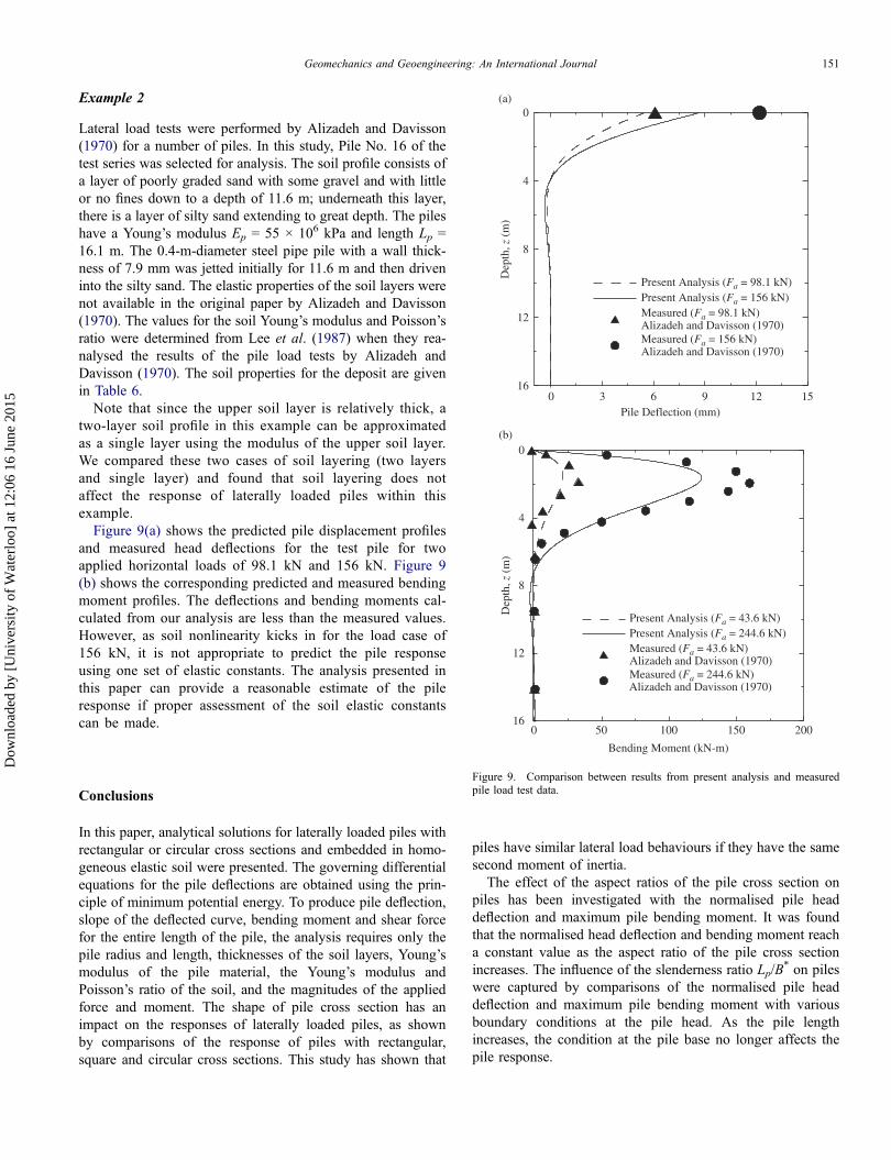
Example 2
Lateral load tests were performed by Alizadeh and Davisson(1970) for a number of piles. In this study, Pile No. 16 of thetest series was selected for analysis. The soil profile consists ofa layer of poorly graded sand with some gravel and with littleor no fines down to a depth of 11.6 m; underneath this layer,there is a layer of silty sand extending to great depth. The pileshave a Young’s modulus Ep = 55 × 106 kPa and length Lp =16.1 m. The 0.4-m-diameter steel pipe pile with a wall thick-ness of 7.9 mm was jetted initially for 11.6 m and then driveninto the silty sand. The elastic properties of the soil layers werenot available in the original paper by Alizadeh and Davisson(1970). The values for the soil Young’s modulus and Poisson’sratio were determined from Lee et al. (1987) when they rea-nalysed the results of the pile load tests by Alizadeh andDavisson (1970). The soil properties for the deposit are givenin Table 6.
Note that since the upper soil layer is relatively thick, atwo-layer soil profile in this example can be approximatedas a single layer using the modulus of the upper soil layer.We compared these two cases of soil layering (two layersand single layer) and found that soil layering does notaffect the response of laterally loaded piles within thisexample.
Figure 9(a) shows the predicted pile displacement profilesand measured head deflections for the test pile for twoapplied horizontal loads of 98.1 kN and 156 kN. Figure 9(b) shows the corresponding predicted and measured bendingmoment profiles. The deflections and bending moments cal-culated from our analysis are less than the measured values.However, as soil nonlinearity kicks in for the load case of156 kN, it is not appropriate to predict the pile responseusing one set of elastic constants. The analysis presented inthis paper can provide a reasonable estimate of the pileresponse if proper assessment of the soil elastic constantscan be made.
Conclusions
In this paper, analytical solutions for laterally loaded piles withrectangular or circular cross sections and embedded in homo-geneous elastic soil were presented. The governing differentialequations for the pile deflections are obtained using the prin-ciple of minimum potential energy. To produce pile deflection,slope of the deflected curve, bending moment and shear forcefor the entire length of the pile, the analysis requires only thepile radius and length, thicknesses of the soil layers, Young’smodulus of the pile material, the Young’s modulus andPoisson’s ratio of the soil, and the magnitudes of the appliedforce and moment. The shape of pile cross section has animpact on the responses of laterally loaded piles, as shownby comparisons of the response of piles with rectangular,square and circular cross sections. This study has shown that
piles have similar lateral load behaviours if they have the samesecond moment of inertia.The effect of the aspect ratios of the pile cross section on
piles has been investigated with the normalised pile headdeflection and maximum pile bending moment. It was foundthat the normalised head deflection and bending moment reacha constant value as the aspect ratio of the pile cross sectionincreases. The influence of the slenderness ratio Lp/B
* on pileswere captured by comparisons of the normalised pile headdeflection and maximum pile bending moment with variousboundary conditions at the pile head. As the pile lengthincreases, the condition at the pile base no longer affects thepile response.
(a)
(b)
0 3 6 9 12 15Pile Deflection (mm)
16
12
8
4
0
Dep
th, z
(m
)
Present Analysis (Fa = 98.1 kN)Present Analysis (Fa = 156 kN)Measured (Fa = 98.1 kN)Alizadeh and Davisson (1970)Measured (Fa = 156 kN)Alizadeh and Davisson (1970)
0 50 100 150 200
Bending Moment (kN-m)
16
12
8
4
0
Dep
th, z
(m
)
Present Analysis (Fa = 43.6 kN)Present Analysis (Fa = 244.6 kN)Measured (Fa = 43.6 kN)Alizadeh and Davisson (1970)Measured (Fa = 244.6 kN)Alizadeh and Davisson (1970)
Figure 9. Comparison between results from present analysis and measuredpile load test data.
Geomechanics and Geoengineering: An International Journal 151
Dow
nloa
ded
by [
Uni
vers
ity o
f W
ater
loo]
at 1
2:06
16
June
201
5

Simple equations predicting the pile head deflection andbending moment were developed and the response of laterallyloaded pile can be easily estimated with these equations givingconsistent values. Design examples are provided that illustratethe use of the analysis. A user-friendly spreadsheet program,LATPAXL, was developed to apply our analysis to practicalproblems readily.
Acknowledgement
This material is based upon work supported by the National ScienceFoundation [grant number 0556347]. The authors are grateful for the supportreceived from the program director, Dr. Richard Fragaszy.
Any opinions, findings, and conclusions or recommendations expressed inthis material are those of the author(s) and do not necessarily reflect the viewsof the National Science Foundation.
References
Alizadeh, M. and Davisson, M.T., 1970. Lateral load test piles,Arkansas River project. Journal of the Soil Mechanics andFoundations Division, 96 (5), 1583–1604.
Banerjee P.K. and Davies T.G., 1978. The behaviour of axially andlaterally loaded single piles embedded in nonhomogeneous soils.Geotechnique, 28 (3), 309–326.
Basu, D., and Salgado, R., 2007. Elastic analysis of laterally-loadedpile in multilayered soil. Geomechanics and Geoengineering: AnInternational Journal, 2 (3), 183–196
Basu, D. and Salgado, R., 2008. Analysis of laterally loaded pileswith rectangular cross sections embedded in layered soil media.International Journal of Numerical and Analytical Methods inGeomechanics, 32 (7), 721–744.
Bransby, M.F., 1999. Selection of p-y curves for the design of singlelaterally loaded piles. International Journal of Numerical andAnalytical Methods in Geomechanics, 23, 1909–1926.
Einav, I., 2005. Energy and variational principles for piles in dissipa-tive soil. Geotechnique, 55 (7), 515–525.
Guo, W.D. and Lee, F.H., 2001. Load transfer approach for laterallyloaded piles. International Journal of Numerical and AnalyticalMethods in Geomechanics, 25 (11), 1101–1129.
Lee, S.L., Kog, Y.C. and Karunaratne, G.P., 1987. Laterally loadedpiles in layered soil. Journal of Soil Mechanics, FoundationsDivision, 27 (4), 1–10.
Matlock, H., 1970. Correlations for design of laterally loaded piles insoft clay. Proceedings of the 2nd Offshore Technical Conference,Houston, Texas, 1, 577–594.
McLachlan, N.W., 1955. Bessel functions for engineers. Oxford:Oxford University Press.
Poulos, H.G. and Davis, E.H., 1980. Pile foundation analysis anddesign. New York: John Wiley & Sons.
Randolph, M.F., 1981. The response of flexible piles to lateral load-ing. Geotechnique, 31 (2), 247–259.
Reese, L.C., Cox, W.R. and Koop, F.D., 1974. Analysis of laterallyloaded piles in sand. Proceedings of the 6th Offshore TechnicalConference, Houston, Texas, 2, 473–483.
Reese, L.C. and Welch, R.C., 1975. Lateral loading of deep founda-tions in stiff clay. Journal of Geotechnical andGeoenvironmental Engineering, 101 (GT7), 633–649.
Sun, K., 1994. Laterally loaded piles in elastic media. Journal ofGeotechnical and Geoenvironmental Engineering, 120 (8),1324–1344.
Trochanis, A.M., Bielak, J. and Christiano, P., 1991. Three-dimen-sional nonlinear study of piles. Journal of Geotechnical andGeoenvironmental Engineering, 117 (3), 429–447.
Veruijt, A. and Kooijman, A.P., 1989. Laterally loaded piles in alayered elastic medium. Geotechnique, 39 (1), 39–46.
152 Y.S. Choi et al.
Dow
nloa
ded
by [
Uni
vers
ity o
f W
ater
loo]
at 1
2:06
16
June
201
5
Copyright © 2022 FDOKUMEN