Behavior of Laterally Top-Loaded Deep Foundations in Highly ...
9
Behavior of Laterally Top-Loaded Deep Foundations in Highly Porous and Collapsible Soil Paulo José Rocha de Albuquerque, D.Sc. 1 ; David de Carvalho, D.Sc. 2 ; Roberto Kassouf 3 ; and Nelson L. Fonte Jr. 4 Abstract: Problems associated with horizontal loading in foundation structures often occur when the surface soil has particular character- istics like the unsaturated, porous, and collapsible soils that are very common in Brazil. In the state of São Paulo, more precisely in the region of Campinas, the occurrence of such soils is detected in several places. For this reason, this work was conceived for the purpose of assessing the performance of four types of deep foundations subjected to horizontal loading via analysis of the load versus horizontal displacement curve and determination of the horizontal reaction coefficient of the soil (n h ). To accomplish this, load tests were carried out with bored piles, continuous flight auger piles (CFA), steel piles, and belled caissons at the Experimental Site of Foundations at the State University of Campinas—Unicamp, Campinas, São Paulo, Brazil. The tests were performed under soil conditions of natural moisture and after 48 h of flooding. The results showed a large drop in parameters of soil resistance due to flooding—an approximately 50% drop on average for the ultimate load and 70% for the horizontal reaction coefficient of the soil. DOI: 10.1061/(ASCE)MT.1943-5533.0002582. © 2018 American Society of Civil Engineers. Author keywords: Lateral load tests; Foundations; Highly porous soil; Collapsible soil. Introduction The soil and the foundation elements are critical parts to consider when analyzing the behavior of a structure. In some cases, deep foundations are used because of the need to transmit loads in deep and resistant soil horizons. In general, this type of foundation can be submitted to different simultaneous loads (vertical, horizontal, and bending moments) and to different types of loading (static, cyclic, or dynamic). Although these situations occur frequently, few cases are reviewed, particularly in porous, collapsible soils. In many cases, parameters used in other studies are adopted, ignoring the hetero- geneity and particular behavior of these types of soils. The calcu- lation of horizontally loaded piles is carried out with the use of simplified mathematical models that reduce the complexity of the real problem. In the literature, one can review the classical models presented by Miche (1930), Matlock and Reese (1961), Broms (1964), Poulos (1971), and Poulos and David (1980). The most commonly used concept is the theory of horizontal reaction of the soil (Terzaghi 1955; Palmer and Thompson 1948; Davisson and Gill 1963; Matlock and Reese 1960, 1961; Davisson 1970). This theory enables estimation of the proportionality be- tween the reaction and soil displacement by means of a factor known as the coefficient of horizontal reaction (n h ). This parameter is difficult to determine mathematically, but it can be calculated via load tests. In the case of horizontal loading, the load is assessed according to a prefixed or limit displacement, because it is not easy to identify the geotechnical rupture load as observed in compression and traction loadings. In this way, when sizing piled foundations under horizontal loading, the criterion for the project is not the ultimate horizontal load capacity; the criterion is the maximum dis- placement or, in some cases, the prefixed displacement that the load can attain (Poulos and David 1980). The critical parameter to be determined in a horizontal loading test is the coefficient of horizontal reaction (n h ), which is defined as the horizontal reaction of the soil along the pile shaft divided by its deflection in a determined position. In general, simplified hypoth- eses are used in foundation projects that involve horizontal loading, adopting proportionality between the soil reaction and the displace- ment of the deep foundation. It must be pointed out that this parameter is not an intrinsic prop- erty of the soil, because it depends on the characteristics and dimensions of the piles and on the displacement to be imposed. Considering the difficulty of estimating its value theoretically, it is common to use the resource of load tests as a means to determine this parameter more appropriately, because it is performed in the place where the construction will occur. In Brazil, the incidence of porous, collapsible soils in surface layers is high; such soils may represent more than half of the cover- age area in a determined region. Several studies have been performed in Brazil to analyze the behavior of deep foundations, particularly by means of piles in this type of soil (Cintra 1981; Cintra and Aoki 2009; Del Pino 2003; Miguel and Cintra 1996; Miguel 1996). These studies demonstrated the influence of these soils under the effect of horizontal loading, particularly when the moisture content varies, leading to excess decrease of horizontal reaction. In the study of transversally loaded piles, a key aspect is the reaction of the soil, that is, how the soil reacts when it receives pile loads. Hence, the problem of laterally loaded piles is a problem of soil–structure interaction, which involves key characteristics such as the type of soil, the physical and mechanical properties of the 1 Associate Professor, School of Civil Engineering, Architecture and Urban Design, Univ. of Campinas, Campinas 13083-889, Brazil. Email: [email protected] 2 Associate Professor, College of Agricultural Engineering, Univ. of Campinas, Campinas 13083-875, Brazil. Email: [email protected] 3 Professor, Dept. of Civil Engineering, DeVry Metrocamp, Campinas 13035-500, Brazil (corresponding author). Email: kassouf.engenharia@ kassouf.com.br 4 Director, Geoponto Engineering, Mogi das Cruzes 08773-530, Brazil. Email: [email protected] Note. This manuscript was submitted on August 14, 2017; approved on July 25, 2018; published online on November 26, 2018. Discussion period open until April 26, 2019; separate discussions must be submitted for individual papers. This paper is part of the Journal of Materials in Civil Engineering, © ASCE, ISSN 0899-1561. © ASCE 04018373-1 J. Mater. Civ. Eng. J. Mater. Civ. Eng., 2019, 31(2): 04018373 Downloaded from ascelibrary.org by UNICAMP - Universidade Estadual De Campinas on 12/01/18. Copyright ASCE. For personal use only; all rights reserved.
-
Upload
khangminh22 -
Category
Documents
-
view
4 -
download
0
Transcript of Behavior of Laterally Top-Loaded Deep Foundations in Highly ...

Behavior of Laterally Top-Loaded Deep Foundations inHighly Porous and Collapsible Soil
Paulo José Rocha de Albuquerque, D.Sc.1; David de Carvalho, D.Sc.2;Roberto Kassouf3; and Nelson L. Fonte Jr.4
Abstract: Problems associated with horizontal loading in foundation structures often occur when the surface soil has particular character-istics like the unsaturated, porous, and collapsible soils that are very common in Brazil. In the state of São Paulo, more precisely in the regionof Campinas, the occurrence of such soils is detected in several places. For this reason, this work was conceived for the purpose of assessing theperformance of four types of deep foundations subjected to horizontal loading via analysis of the load versus horizontal displacement curve anddetermination of the horizontal reaction coefficient of the soil (nh). To accomplish this, load tests were carried out with bored piles, continuousflight auger piles (CFA), steel piles, and belled caissons at the Experimental Site of Foundations at the StateUniversity of Campinas—Unicamp,Campinas, São Paulo, Brazil. The tests were performed under soil conditions of naturalmoisture and after 48 h of flooding. The results showed alarge drop in parameters of soil resistance due to flooding—an approximately 50% drop on average for the ultimate load and 70% for thehorizontal reaction coefficient of the soil. DOI: 10.1061/(ASCE)MT.1943-5533.0002582. © 2018 American Society of Civil Engineers.
Author keywords: Lateral load tests; Foundations; Highly porous soil; Collapsible soil.
Introduction
The soil and the foundation elements are critical parts to considerwhen analyzing the behavior of a structure. In some cases, deepfoundations are used because of the need to transmit loads in deepand resistant soil horizons. In general, this type of foundation can besubmitted to different simultaneous loads (vertical, horizontal, andbending moments) and to different types of loading (static, cyclic, ordynamic). Although these situations occur frequently, few cases arereviewed, particularly in porous, collapsible soils. In many cases,parameters used in other studies are adopted, ignoring the hetero-geneity and particular behavior of these types of soils. The calcu-lation of horizontally loaded piles is carried out with the use ofsimplified mathematical models that reduce the complexity of thereal problem. In the literature, one can review the classical modelspresented by Miche (1930), Matlock and Reese (1961), Broms(1964), Poulos (1971), and Poulos and David (1980).
The most commonly used concept is the theory of horizontalreaction of the soil (Terzaghi 1955; Palmer and Thompson 1948;Davisson and Gill 1963; Matlock and Reese 1960, 1961; Davisson1970). This theory enables estimation of the proportionality be-tween the reaction and soil displacement by means of a factorknown as the coefficient of horizontal reaction (nh). This parameter
is difficult to determine mathematically, but it can be calculated viaload tests. In the case of horizontal loading, the load is assessedaccording to a prefixed or limit displacement, because it is not easyto identify the geotechnical rupture load as observed in compressionand traction loadings. In this way, when sizing piled foundationsunder horizontal loading, the criterion for the project is not theultimate horizontal load capacity; the criterion is the maximum dis-placement or, in some cases, the prefixed displacement that the loadcan attain (Poulos and David 1980).
The critical parameter to be determined in a horizontal loadingtest is the coefficient of horizontal reaction (nh), which is defined asthe horizontal reaction of the soil along the pile shaft divided by itsdeflection in a determined position. In general, simplified hypoth-eses are used in foundation projects that involve horizontal loading,adopting proportionality between the soil reaction and the displace-ment of the deep foundation.
It must be pointed out that this parameter is not an intrinsic prop-erty of the soil, because it depends on the characteristics anddimensions of the piles and on the displacement to be imposed.Considering the difficulty of estimating its value theoretically, it iscommon to use the resource of load tests as a means to determinethis parameter more appropriately, because it is performed in theplace where the construction will occur.
In Brazil, the incidence of porous, collapsible soils in surfacelayers is high; such soils may represent more than half of the cover-age area in a determined region. Several studies have been performedin Brazil to analyze the behavior of deep foundations, particularly bymeans of piles in this type of soil (Cintra 1981; Cintra and Aoki2009; Del Pino 2003; Miguel and Cintra 1996; Miguel 1996). Thesestudies demonstrated the influence of these soils under the effect ofhorizontal loading, particularly when the moisture content varies,leading to excess decrease of horizontal reaction.
In the study of transversally loaded piles, a key aspect is thereaction of the soil, that is, how the soil reacts when it receives pileloads. Hence, the problem of laterally loaded piles is a problem ofsoil–structure interaction, which involves key characteristics suchas the type of soil, the physical and mechanical properties of the
1Associate Professor, School of Civil Engineering, Architecture andUrban Design, Univ. of Campinas, Campinas 13083-889, Brazil. Email:[email protected]
2Associate Professor, College of Agricultural Engineering, Univ. ofCampinas, Campinas 13083-875, Brazil. Email: [email protected]
3Professor, Dept. of Civil Engineering, DeVry Metrocamp, Campinas13035-500, Brazil (corresponding author). Email: [email protected]
4Director, Geoponto Engineering, Mogi das Cruzes 08773-530, Brazil.Email: [email protected]
Note. This manuscript was submitted on August 14, 2017; approvedon July 25, 2018; published online on November 26, 2018. Discussionperiod open until April 26, 2019; separate discussions must be submittedfor individual papers. This paper is part of the Journal of Materials inCivil Engineering, © ASCE, ISSN 0899-1561.
© ASCE 04018373-1 J. Mater. Civ. Eng.
J. Mater. Civ. Eng., 2019, 31(2): 04018373
Dow
nloa
ded
from
asc
elib
rary
.org
by
UN
ICA
MP
- U
nive
rsid
ade
Est
adua
l De
Cam
pina
s on
12/
01/1
8. C
opyr
ight
ASC
E. F
or p
erso
nal u
se o
nly;
all
righ
ts r
eser
ved.

soil, pile stiffness and geometry, and the type of loading (static,dynamic, cyclic).
In the study of piles subjected to horizontal loading, it is neces-sary to determine the variation of the modulus of the horizontalreaction of the soil with depth. The simplest hypotheses are thosethat take the modulus of horizontal reaction as constant or as grow-ing linearly with depth, a variation linked to the characteristicsof soil deformation.
The theory of soil horizontal reaction (Winkler’s hypothesis),which enables simulation of the behavior of soil submitted to hori-zontal stresses with a set of independent springs, it is possible toconsider the proportionality between the soil reaction and the dis-placement of the spot under analysis. This is how Terzaghi (1955),through Winkler’s hypothesis, defined the relationship betweenhorizontal stress and displacement with the concept of the coeffi-cient of horizontal reaction of the soil (K), which can be seen inEq. (1). This reaction is defined as the relationship between the soilreaction (in units of force applied along the pile length) and thecorresponding displacement [Eq. (1)] (Reese and Van Impe 2011):
K ¼ py
ð1Þ
whereK = modulus of horizontal reaction (FL−2); p = applied force(FL−1); and y = horizontal displacement (L).
This notation presents the advantage of being independent of thediameter of the foundation. Therefore, Eq. (1) can be rewritten as
K ¼ kh · D ð2Þwhere kh = horizontal reaction coefficient (FL−3); and D = diameterof the foundation (L).
For pure sand, the Young’s modulus increases (approximately)linearly with depth. Therefore, the soil reaction to the load appliedto the pile is assumed to increase linearly with depth [Eq. (3)]:
K ¼ py¼ nh · z ð3Þ
where nh = modulus of the horizontal reaction of the soil (FL−3);and z = depth (L).
Although the supposed behavior of the variation of the modulusof horizontal reaction is not precisely similar to the actual behavior,the approximations are considered effective because, according toTerzaghi (1955), refinements and sophistications in the reactionmodulus function are not justifiable due to the depth, because errorsin the results of the calculations are very small when compared tothose involved in the estimation of numerical values of soil reactionmoduli. Therefore, for most cases, fully satisfactory results can bederived by using laws of simple variation of the reaction moduluswith the depth. Matlock and Reese (1960) supplemented this affir-mation by stating that the use of results from practical cases, bymeans of load tests, is a common tool for such cases and a simpleway to get the modulus of horizontal reaction. The first studies onthe results of load tests in sandy soils were those produced byAlizadeh and Davisson (1970), showing a graph of the variationof the coefficient of horizontal reaction (nh) in the y-axis and hori-zontal displacement (yo) in the x-axis using equation Eq. (4) asproposed by Matlock and Reese (1961):
yo ¼�HT3
EI
�Δy ð4Þ
where T = relative stiffness between the pile and the soil; H =lateral load; E = Young’s modulus of the pile; I = inertia moment;and Δy = correction of the vertical displacement.
The relative stiffness (T) is defined by Eq. (5):
T ¼ffiffiffiffiffiffiEInh
5
sð5Þ
The modulus of the horizontal reaction (nh) is defined byEq. (6):
nh ¼4.42H5=3
y5=3o ðEIÞ2=3ð6Þ
This work was developed based on the results of horizontal load-ing tests in foundations executed locally. With the results, it waspossible to draw the load versus horizontal displacement curves foreach soil condition (natural and preflooded) as well as graphs of thecoefficient of horizontal reaction versus horizontal displacement.The displacements were measured at the tip of the pile at the samelevel as the application of the load. The nh values were obtained perthe proposal of Alizadeh and Davisson (1970).
Materials and Methods
This section presents the main geological and geotechnical charac-teristics of the experimental site and the characteristics of the pilesand belled caisson studied.
Geological and Geotechnical Characteristics
Diabase soils in the northwest region of Campinas surface as dark,reddish-brown porous soil. The subsoil of the experimental site iscomposed of a layer of diabase soil mostly composed of a sandy-silty clay surface layer with high porosity down to a depth of 6 m,followed by a sandy-clayey silt layer down to a depth of 19 m. Thewater table is found at a depth of 18 m (Cavalcante et al. 2007). Inorder to determine the geotechnical properties of the local subsoil,undisturbed samples were extracted down to 15 m deep in order tocarry out tests of characterization, resistance, and compressibility.Standard penetration tests with torque measurements (SPT-T) andcone penetration tests (CPT) were also performed (Fig. 1).
In order to assess the collapsible characteristics of the soil,oedometric tests were conducted at determined depths (0.75 m,5.00 m, and 8.00 m) Monacci (1995) (Table 1). From the resultsobtained, the proposal of Vargas (1978) was used, which considerspotentially collapsible soils as soils with a degree of structuralcollapse above 2% [Eq. (7)]:
i ¼ Δec1þ ei
ð7Þ
where Δec = variation in the void ratio due to collapse of the soilstructure; and ei is the index of voids before flooding.
In addition to the study carried out by Monacci (1995), anotherresearch study regarding collapsibility was conducted by Gon(2011), who performed oedometric tests with flooding at stressesof 100, 200, and 400 kPa. Table 2 shows the results of the collaps-ibility index (Vargas 1978). The results indicate that at prefloodingstress values of 200 kPa and 400 kPa, the soil indicates a potentialfor collapse at almost all depths. For a stress of 100 kPa, only thesamples at 1 m, 4 m, and 8 m indicate the potential for collapse(Table 2).
© ASCE 04018373-2 J. Mater. Civ. Eng.
J. Mater. Civ. Eng., 2019, 31(2): 04018373
Dow
nloa
ded
from
asc
elib
rary
.org
by
UN
ICA
MP
- U
nive
rsid
ade
Est
adua
l De
Cam
pina
s on
12/
01/1
8. C
opyr
ight
ASC
E. F
or p
erso
nal u
se o
nly;
all
righ
ts r
eser
ved.

Load Tests
The preparation of the tests followed the recommendations of theUS standard D3966 (ASTM 2013), which provides standard testmethods for deep foundations under lateral loads. The minimumtime of application for each load was 30 min, following the require-ments of the Brazilian standard NBR 12131 (ABNT 2006) forslowly maintained load tests (SMLT). The location tests are shownin Fig. 2.
Two load tests were performed for each type of foundation, thefirst with soil in a natural condition and the second with a soil in apreflooding condition. The tests followed the Brazilian standard
Typical profile based on SPT
Dep
th (
m)
0
2
4
6
8
10
12
14
16
18
20
22
Red poroussilty clay
(Colluvium Soil)
Concretion
Redclayey Silt
(ResidualDiabasic)
CL LG'
ML NG'
Siltyfine sand
(DecomposedDiabasic Rock)
GWL
Grain SizeDistribution (%)
0 25 50 75 100
Med
ium
san
d
Cla
y
Fine
san
d
Silt
qc (MPa)
0 1 2 3 4 5 6
Rf (%)
0 2 4 6 8 10
fs (MPa)
0.0 0.1 0.2 0.3
Nspt 60(blows/30 cm)
0 10 20 30 40
T/Nspt 60(N.m/blows/30 cm)
0 10 20 30 40
Fig. 1. Electrical and mechanical CPT and SPT-T test results. (Adapted from Giacheti et al. 2004.)
Table 1. Collapse coefficients according to the applied pressure and thedepth
Depth (m) σ (kPa) i (%)
0.75 5.0 5.09.8 11.119.4 7.4
5.00 9.8 2.419.4 3.8
8.00 38.7 3.177.3 5.3
Source: Data from Monacci (1995).
Table 2. Collapsibility index
Depth (m)
PC (%)
100 kPa 200 kPa 400 kPa
1 7.80a 27.0a 6.00a
2 1.30 0.65 23.0a
3 0.45 0.04 19.8a
4 9.90a 7.50a 26.8a
5 0.28 7.03a 7.24a
6 1.10 3.40a 9.20a
7 1.40 5.60a 10.7a
8 5.20a 6.60a 0.09
Source: Data from Vargas (1978).Note: PC = potential collapsibility.aPC > 2%.
Fig. 2. Pile test locations.
© ASCE 04018373-3 J. Mater. Civ. Eng.
J. Mater. Civ. Eng., 2019, 31(2): 04018373
Dow
nloa
ded
from
asc
elib
rary
.org
by
UN
ICA
MP
- U
nive
rsid
ade
Est
adua
l De
Cam
pina
s on
12/
01/1
8. C
opyr
ight
ASC
E. F
or p
erso
nal u
se o
nly;
all
righ
ts r
eser
ved.

NBR 12131 for slowly maintained loading tests; that is, the read-ings were acquired at times of 1, 2, 4, 8, 15, 30 min, and so forth.The minimum time before changing the load stage was 30 min.The load stages used were on the order of 10% of the maximumestimated load with a limit displacement of 25 mm for finalizing theloading.
Prior to the beginning of the preflooding process, a preexcava-tion with a depth of approximately 0.3 m and dimensions of 0.5 ×0.5 mwas constructed. From this well, it was possible to maintain aconstant water depth. The preflooding was maintained until the be-ginning of loading. Flooding was maintained for 48 h, and the flowrate was measured through a hydrometer; the flow averaged a watervolume of 52 m3, that is, 1.08 m3=h. Although the soil has a clayeytexture, its behavior is similar to sandy silt with a porous structure(63% average porosity and 1.8 × 10⁻⁵ m=s permeability coeffi-cient), which justifies the percolated volume.
The load tests were performed using a hydraulic jack witha 500 kN capacity and a pump and load cell with the samecapacity. For the belled caisson tested, there were two other cais-sons reacting against each other on the other side, as seen in themodels in Figs. 3 and 4.
After the tests, samples of the subsoil were obtained to verify theinfluence of flooding on the subsoil. The samples showed thatflooding changed the soil moisture to a depth of 3 m.
Tested Piles
The load tests were performed on four types of deep foundations.Table 3 shows the characteristics of the elements used.
Results and Analysis
Load versus Displacement
From the results of the load tests, it was possible to obtain theload versus displacement curves and their maximum values.Table 4 summarizes the values of the maximum load and maximumdisplacement, and Figs. 5–8 show the load versus displacementbehavior.
The loading end criterion was based on a minimum displacementof 12 mm, so that nh could be calculated for the predetermined in-terval (6–12 mm) or for a load that would guarantee the structuralintegrity of the pile, as was the case with the bored pile. In view of itsreinforcement rate, it was found that it would not be possible to addmore load to the structural element.
Table 4 shows that, in the case of the caisson, the maximumload was higher for flooded conditions than for the natural soil.However, it should be noted that the maximum displacement was9.5 times higher than that obtained in natural conditions. In theother foundation types, the loads obtained in flooded conditionswere lower, that is, less than half the values in natural conditions,showing the collapsible behavior of the subsoil. It is possible toverify the differences in the behavior of the load versus displace-ment curves for the analyzed conditions in Figs. 5–8.
Preflooding the topsoil caused a drastic reduction in soil resis-tance to horizontal loading. Taking a 5-mm displacement as a refer-ence for the steel pile in natural soil conditions, the supported load
Fig. 3. Belled caisson system setup.
Fig. 4. Assembly details of the belled caisson load test.
Table 3. Pile characteristics
Characteristic
Foundation type
Steel pile CFA pile Bored pile Belled caisson
Length (m) 12 12 12 9Section W ¼ 250 mm × 32.7 kg=m; S ¼ 42.1 cm2;
Iyy ¼ 473 cm4; Ixx ¼ 4,937 cm4
0.40 m 0.40 m Shaft = 0.8 m;base = 1.6 m
Reinforcement (mm) — 4ϕ16 4ϕ16 15ϕ25Young’s modulus (GPa) 205 21 20 20
Note: W = designation; S = area; Iyy = inertia moment (y − y); and Ixx = inertia moment (x − x).
© ASCE 04018373-4 J. Mater. Civ. Eng.
J. Mater. Civ. Eng., 2019, 31(2): 04018373
Dow
nloa
ded
from
asc
elib
rary
.org
by
UN
ICA
MP
- U
nive
rsid
ade
Est
adua
l De
Cam
pina
s on
12/
01/1
8. C
opyr
ight
ASC
E. F
or p
erso
nal u
se o
nly;
all
righ
ts r
eser
ved.

is approximately 50 kN, whereas in the preflooded soil at the samedisplacement the supported load is approximately 3 kN. For boredpiles in natural soil conditions and a 5-mm displacement, the sup-ported load is approximately 48 kN, while for preflooded soil at thesame displacement the supported load is approximately 8 kN. Forcontinuous flight auger (CFA) piles, the supported load is approx-imately 45 kN in natural soil conditions, whereas for prefloodedsoil with a 5-mm displacement the supported load is approximately
2 kN. For the belled caisson, the loss of strength was more evident.In natural soil conditions at a displacement of 5 mm, the load wason the order of 125 kN. However, the same load in floodedconditions represented a displacement of approximately 50 mm—10 times higher.
Horizontal Reaction Coefficient (nh) versusDisplacement
From the values obtained from the tests and by the Matlock andReese (1960, 1961) equation, the nh values were obtained for arange of 6–12 mm (Table 5).
The values of nh obtained for the bored piles, CFA piles, and thebelled caissons were on the same order, that is, with average valuesof 10.8 MN=m3 and coefficients of variation on the order of 15%.However, for the steel pile, the value of nh was 2.5 times higher,which may due to the high stiffness of the material (steel) due to itsYoung’s modulus being approximately 10 times greater than thoseof the concrete foundations analyzed.
For the values obtained in the flooded situation, a drastic reduc-tion was observed for both the bored and CFA piles. A repre-sentative result of only 3.5% of the value obtained in natural soilconditions was obtained. For the belled caissons, it was observedthat the reduction in the nh values, which was on the order of 27%,was not as evident as in the bored and CFA piles; in the steel pilesthe reduction was 70%. Fig. 9 shows the variation in the horizontal
Table 4. Values of horizontal maximum loads and maximumdisplacements
Foundationtype
Soilmoisturecontent
conditionsMaximumload (kN)
Maximumdisplacement
(mm) Qnat∶Qflooded
Steel pile Natural 70 12.74 0.44Flooded 30 34.79
Bored pile Natural 41 7.91 0.31Flooded 13 13.66
CFA pile Natural 41 12.02 0.31Flooded 13 13.69
Belled Caisson Natural 180 18.17 0.86Flooded 210 171.09
0
10
20
30
40
50
60
70
80
0 5 10 15 20 25 30 35
Lat
eral
load
(kN
)
Displacement (mm)
Natural ( SMLT)
Flooded (QLMT)
Fig. 5. Load versus horizontal displacement curves for steel piles.
0
10
20
30
40
50
60
0 2 4 6 8 10 12 14 16 18 20 22 24 26 28
Lat
eral
Loa
d (k
N)
Displacement (mm)
NaturalFlooded
Fig. 6. Load versus horizontal displacement curves for bored piles.
0
10
20
30
40
50
60
0 5 10 15 20 25 30 35 40 45 50 55
Lat
eral
load
(kN
)
Displacement (mm)
Natural
Flooded
Fig. 7. Load versus horizontal displacement curves for CFA piles.
0
50
100
150
200
250
0 20 40 60 80 100 120 140 160 180
Lat
eral
Loa
d (k
N)
Displacement (mm)
Natural
Flooded
Fig. 8. Load versus horizontal displacement curves for belled caissons.
© ASCE 04018373-5 J. Mater. Civ. Eng.
J. Mater. Civ. Eng., 2019, 31(2): 04018373
Dow
nloa
ded
from
asc
elib
rary
.org
by
UN
ICA
MP
- U
nive
rsid
ade
Est
adua
l De
Cam
pina
s on
12/
01/1
8. C
opyr
ight
ASC
E. F
or p
erso
nal u
se o
nly;
all
righ
ts r
eser
ved.

reaction coefficient for natural soil conditions for all foundationstested.
Fig. 9 shows that the horizontal reactions of the concrete foun-dations were close, as previously observed by means of the valuesof nh. A higher stiffness of the steel pile is observed, which is re-lated to the material (steel) and its geometry. Note that the loadingwas done in the direction of greater inertia. Fig. 10 shows the varia-tion in the horizontal reaction coefficient for flooded conditions forall of the foundations tested.
In Fig. 10, the bored and CFA piles show similar behaviors, inthe same way as seen with the natural soil conditions; however, thisobservation does not hold true for the belled caissons. The belledcaissons were less influenced by the effects of the flood. In contrast,the steel piles presented anomalous behavior, with an increase inthe reaction up to a displacement of 10 mm and a decrease there-after. This behavior was associated with the noncontact area be-tween the soil and the pile originated by the first loading, whichwas on the same order of magnitude.
Displacement along the Depth: Belled Caissons
In the belled caisson load tests (natural soil conditions) it waspossible to use the inclinometer, which allowed the collection of dis-placement readings along the depth after each increment of load. Thereadings were taken every 0.5 m in depth using a torpedo sensor(Fig. 11). An inclinometer was utilized (OTR-OG310S, OTR-GEO,
Italy; scale� 30°; resolution 25,000; sinα; nonlinearity < �0.057°in full scale; misalignment between the two axes < 1.5°).
In Fig. 12, it is possible to check the displacements along thedepth for each load increment.
Based on Fig. 12, it can be observed that the belled caissonsshowed displacements up to a depth of 5.5 m, which demonstratesthe importance of assembling the reinforcement in this region inwhich there is greater influence of the load. Note that below thisdepth a small deflection in the direction opposite to that of the
0
10
20
30
40
50
60
70
80
0 5 10 15 20 25 30
n h(M
N/m
3 )
Displacement (mm)
Bored
CFA
Caisson
Steel
Fig. 9. Curves for nh versus horizontal displacement—natural soilconditions.
0
2
4
6
8
10
12
14
16
18
20
0 5 10 15 20 25 30
n h(M
N/m
3 )
Displacement (mm)
Bored
CFA
Caisson
Steel
Fig. 10. Curves for nh versus horizontal displacement—floodedconditions.
Table 5. Values of the horizontal reaction coefficients
Foundation typeSoil moisture
content conditions nh (MN=m3)a
Steel pile Natural 25.4Flooded 7.4b
Bored pile Natural 11.6Flooded 0.6
CFA pile Natural 11.9Flooded 0.2
Belled Caisson Natural 9.0Flooded 6.5
aAverage values from 6–12 mm displacements.bRange from 10–12 mm.
Fig. 11. Insertion of the equipment.
© ASCE 04018373-6 J. Mater. Civ. Eng.
J. Mater. Civ. Eng., 2019, 31(2): 04018373
Dow
nloa
ded
from
asc
elib
rary
.org
by
UN
ICA
MP
- U
nive
rsid
ade
Est
adua
l De
Cam
pina
s on
12/
01/1
8. C
opyr
ight
ASC
E. F
or p
erso
nal u
se o
nly;
all
righ
ts r
eser
ved.
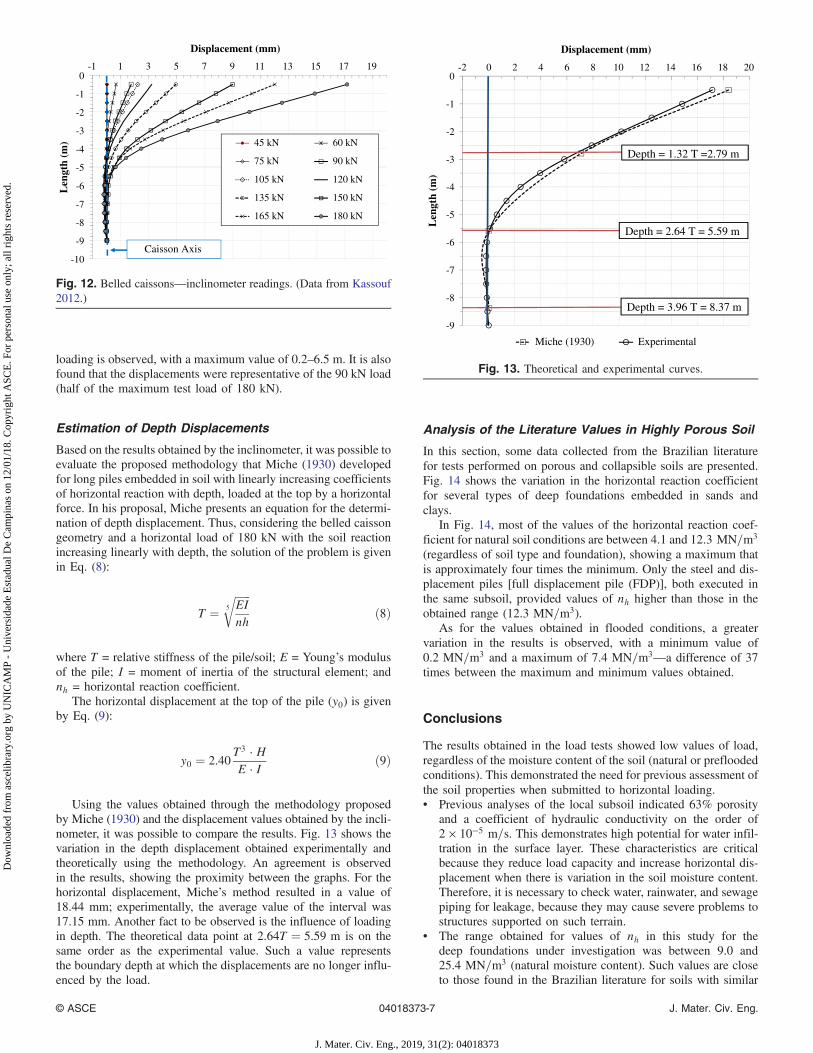
loading is observed, with a maximum value of 0.2–6.5 m. It is alsofound that the displacements were representative of the 90 kN load(half of the maximum test load of 180 kN).
Estimation of Depth Displacements
Based on the results obtained by the inclinometer, it was possible toevaluate the proposed methodology that Miche (1930) developedfor long piles embedded in soil with linearly increasing coefficientsof horizontal reaction with depth, loaded at the top by a horizontalforce. In his proposal, Miche presents an equation for the determi-nation of depth displacement. Thus, considering the belled caissongeometry and a horizontal load of 180 kN with the soil reactionincreasing linearly with depth, the solution of the problem is givenin Eq. (8):
T ¼ffiffiffiffiffiffiEInh
5
rð8Þ
where T = relative stiffness of the pile/soil; E = Young’s modulusof the pile; I = moment of inertia of the structural element; andnh = horizontal reaction coefficient.
The horizontal displacement at the top of the pile (y0) is givenby Eq. (9):
y0 ¼ 2.40T3 · HE · I
ð9Þ
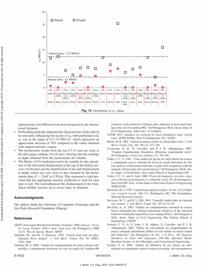
Using the values obtained through the methodology proposedby Miche (1930) and the displacement values obtained by the incli-nometer, it was possible to compare the results. Fig. 13 shows thevariation in the depth displacement obtained experimentally andtheoretically using the methodology. An agreement is observedin the results, showing the proximity between the graphs. For thehorizontal displacement, Miche’s method resulted in a value of18.44 mm; experimentally, the average value of the interval was17.15 mm. Another fact to be observed is the influence of loadingin depth. The theoretical data point at 2.64T ¼ 5.59 m is on thesame order as the experimental value. Such a value representsthe boundary depth at which the displacements are no longer influ-enced by the load.
Analysis of the Literature Values in Highly Porous Soil
In this section, some data collected from the Brazilian literaturefor tests performed on porous and collapsible soils are presented.Fig. 14 shows the variation in the horizontal reaction coefficientfor several types of deep foundations embedded in sands andclays.
In Fig. 14, most of the values of the horizontal reaction coef-ficient for natural soil conditions are between 4.1 and 12.3 MN=m3
(regardless of soil type and foundation), showing a maximum thatis approximately four times the minimum. Only the steel and dis-placement piles [full displacement pile (FDP)], both executed inthe same subsoil, provided values of nh higher than those in theobtained range (12.3 MN=m3).
As for the values obtained in flooded conditions, a greatervariation in the results is observed, with a minimum value of0.2 MN=m3 and a maximum of 7.4 MN=m3—a difference of 37times between the maximum and minimum values obtained.
Conclusions
The results obtained in the load tests showed low values of load,regardless of the moisture content of the soil (natural or prefloodedconditions). This demonstrated the need for previous assessment ofthe soil properties when submitted to horizontal loading.• Previous analyses of the local subsoil indicated 63% porosity
and a coefficient of hydraulic conductivity on the order of2 × 10−5 m=s. This demonstrates high potential for water infil-tration in the surface layer. These characteristics are criticalbecause they reduce load capacity and increase horizontal dis-placement when there is variation in the soil moisture content.Therefore, it is necessary to check water, rainwater, and sewagepiping for leakage, because they may cause severe problems tostructures supported on such terrain.
• The range obtained for values of nh in this study for thedeep foundations under investigation was between 9.0 and25.4 MN=m3 (natural moisture content). Such values are closeto those found in the Brazilian literature for soils with similar
-10
-9
-8
-7
-6
-5
-4
-3
-2
-1
0-1 1 3 5 7 9 11 13 15 17 19
Len
gth
(m)
Displacement (mm)
45 kN 60 kN
75 kN 90 kN
105 kN 120 kN
135 kN 150 kN
165 kN 180 kN
Caisson Axis
Fig. 12. Belled caissons—inclinometer readings. (Data from Kassouf2012.)
-9
-8
-7
-6
-5
-4
-3
-2
-1
0-2 0 2 4 6 8 10 12 14 16 18 20
Len
gth
(m)
Displacement (mm)
Miche (1930) Experimental
Depth = 3.96 T = 8.37 m
Depth = 2.64 T = 5.59 m
Depth = 1.32 T =2.79 m
Fig. 13. Theoretical and experimental curves.
© ASCE 04018373-7 J. Mater. Civ. Eng.
J. Mater. Civ. Eng., 2019, 31(2): 04018373
Dow
nloa
ded
from
asc
elib
rary
.org
by
UN
ICA
MP
- U
nive
rsid
ade
Est
adua
l De
Cam
pina
s on
12/
01/1
8. C
opyr
ight
ASC
E. F
or p
erso
nal u
se o
nly;
all
righ
ts r
eser
ved.
characteristics but different from those proposed by the interna-tional literature.
• Preflooding markedly impacted the characteristics of the subsoilby relevantly influencing the results of nh; with preflooded soil,nh was in the range of 0.2–7.4 MN=m3, which represents anapproximate decrease of 70% compared to the values obtainedwith natural moisture content.
• The inclinometer results from the top (17.15 mm) are close tothe dial gauge readings (18.18 mm), showing that the readingsin depth obtained from the inclinometer are reliable.
• The Miche (1930) method proved to be suitable for the calcula-tion of the horizontal displacement at the top of the belled cais-sons (18.40 mm) and the identification of the null displacementat depth, which was very close to that obtained by the inclin-ometer data (Z ¼ 2.64T or 5.59 m). This statement is valid pro-vided that the appropriate reaction coefficient is used for eachtype of soil. The load influenced the displacement of the foun-dation (belled caisson) up to seven times its diameter.
Acknowledgments
The authors thank the University of Campinas (Unicamp) and theSão Paulo Research Foundation (Fapesp).
References
ABNT (Associação Brasileira de Normas Técnicas). 2006. Estacas—Provade Carga Estática [Piles—static load test]. [In Portuguese.] NBR12131. Rio de Janeiro, Brazil: ABNT.
Alizadeh, M., and M. T. Davisson. 1970. “Lateral load tests on piles:Arkansas River project.” J. Soil Mech. Found. Div. 96 (SM5):1583–1604.
Almeida, M. A. 2008. “Análise do comportamento de estacas Strauss sub-metidas a carregamento horizontal no solo da região de Londrina-PR
[Analysis of the behavior of Strauss piles subjected to horizontal load-ing in the soil of Londrina-PR].” [In Portuguese.] M.Sc. thesis, Dept. ofCivil Engineering, State Univ. of Londrina.
ASTM. 2013. Standard test methods for deep foundations under lateralload. ASTM D3966. West Conshohocken, PA: ASTM.
Broms, B. B. 1964. “Lateral resistance of piles in cohesionless soils.” J. SoilMech. Found. Eng. Div. 90 (3): 123–158.
Cavalcante, E. H., D. Carvalho, and P. J. R. Albuquerque. 2007.“Campos Experimentais Brasileiros [Brazilian experimental sites].”[In Portuguese.] Geotecnia (Lisboa) 111: 99–205.
Cintra, J. C. A. 1981. “Uma análise de provas de carga lateral em estacase comparação com os métodos da teoria de reação horizontal do solo[An analysis of horizontal load tests on piles and comparison with themethods of horizontal soil reaction theory].” [In Portuguese.] M.Sc. the-sis, Dept. of Geotechnics, Sao Carlos School of Engineering–USP.
Cintra, J. C. A., and N. Aoki. 2009. Projeto de fundações em solos colap-síveis [Design of foundations in collapsible soils], 99. [In Portuguese.]São Carlos/SP: Univ. of São Paulo at São Carlos School of Engineering(EESC/USP).
Davisson, M. T. 1970. “Lateral load capacity of piles.” In Vol. 333 of High-way research record, 104–112. Washington, DC: Pile Foundations,National Research Council.
Davisson, M. T., and H. L. Gill. 1963. “Laterally loaded piles in a layeredsoil system.” J. Soil Mech. Found. Div. 89 (3): 63–94.
Del Pino, A., Jr. 2003. “Análise do comportamento estrutural de estacasbrocas solicitadas por esforços transversais [Analysis of the structuralbehavior of drill piles required by cross-cutting efforts].” [In Portuguese.]M.Sc. thesis, Dept. of Civil Engineering, Ilha Solteira School ofEngineering, UNESP.
Ferreira, C. V., A. S. Lobo, J. H. Albiero, D. Carvalho, and P. J. R.Albuquerque. 2007. “Efeito do solo-cimento no comportamento deestaca carregada lateralmente [Effect of soil-cement on lateral loadedpile behavior].” [In Portuguese.] In Vol. 1 of Proc., 6th SimposioBrasileiro de Solos Não Saturados, 299–306. Salvador, Brazil:Brazilian Society of Soil Mechanics and Geotechnical Engineering.
Fioratti, N. A. 2008. “Análise da influência de um reforço de solo-cimento na extremidade superior estacas escavadas, sob carregamentos
0
5
10
15
20
25
30
Clay Clay Clay Clay Sand Sand Sand Clay Clay Clay Clay Clay Sand Clay Sand Clay
authors Fioratti(2008)
Miguelet al
(2001)
Almeida(2008)
Ferreiraet al2007
Del PinoJr
(2003)
Miguel(1996)
authors authors authors Miguelet al
(2008)
MirandaJr
(2006)
Miguel(1996)
MirandaJr
(2006)
Menezeset al
(2005)
MirandaJr
(2006)
Bored Bored Bored Bored Bored Bored Bored CFA Caisson Steel Steel -Rail
Root Root Precast Precast FDP
n h(M
N/m
3 )
Natural Flooded
Natural (max) - 12.3 MN/m3
Natural (min) - 4.1 MN/m3
Fig. 14. Distribution of nh values.
© ASCE 04018373-8 J. Mater. Civ. Eng.
J. Mater. Civ. Eng., 2019, 31(2): 04018373
Dow
nloa
ded
from
asc
elib
rary
.org
by
UN
ICA
MP
- U
nive
rsid
ade
Est
adua
l De
Cam
pina
s on
12/
01/1
8. C
opyr
ight
ASC
E. F
or p
erso
nal u
se o
nly;
all
righ
ts r
eser
ved.

horizontais [Analysis of the influence of a soil-cement reinforcementon upper end bored piles under horizontal loads].” [In Portuguese.]M.Sc. thesis, Dept. of Civil Engineering, Ilha Solteira School ofEngineering.
Giacheti, H. L., A. S. P. Peixoto, and G. Mondelli. 2004. “Comparação dosresultados obtidos entre CPT elétrico e mecânico em solos tropicais[Comparison of results obtained between electrical and mechanicalCPT in tropical soils].” [In Portuguese.] Revista Solos e Rochas.27 (2): 191–200.
Gon, F. S. 2011. “Caracterização geotécnica através de ensaios de labo-ratorio de um solo de diabásio da região de Campinas/SP [Geotech-nical characterization through laboratory tests of a diabase soil fromCampinas/SP].” [In Portuguese.] M.Sc. thesis, School of Civil Engi-neering, Architecture and Urban Design, Univ. of Campinas.
Kassouf, R. 2012. “Análise de prova de carga em tubulão a céu aberto sub-metido a esforço horizontal em solo não saturado de diabásio da regiãode Campinas [Analysis of load test on caisson submitted to horizontalloading in unsaturated soil of diabase of the region of Campinas].” [InPortuguese.] M.Sc. thesis, School of Civil Engineering, Architectureand Urban Design, Univ. of Campinas.
Matlock, H., and L. C. Reese. 1960. “Generalized solutions for laterallyloaded piles.” J. Soil Mech. Found. Eng. Div. 86 (5): 63–94.
Matlock, H., and L. C. Reese. 1961. “Foundation analysis of offshore pilesupported structures.” In Vol. 2 of Proc., Int. Conf. on Soil Mechanicsand Geotechnical Engineering, 91–97. Paris: International Society onSoil Mechanics and Geotechnical Engineering.
Menezes, S. M., D. Carvalho, and P. J. R. Albuquerque. 2005. “Provas decarga horizontais em estacas pré-moldadas de concreto cravadas emsolo de alta porosidade [Horizontal load tests on precast concrete pilesembedded in high porosity soil].” [In Portuguese.] Jornal Ciência eEngenharia 5 (2): 77–82.
Miche, R. J. 1930. “Investigation of piles subjected to horizontal forcer.Application to quay walls.” J. School Eng. 4,.in press.
Miguel, M. G. 1996. “Execução e análise de provas de carga horizontal emestacas em solo colapsível [Execution and analysis of horizontal loadingtests on piles in collapsible soil].” [In Portuguese.] M.Sc. thesis, Dept. ofGeotechnics, Univ. of São Paulo.
Miguel, M. G., A. Belincanta, R. S. Teixeira, and C. J. M. Costa Branco.2001. “Provas de carga horizontal em estacas escavadas a trado
mecânico em solo colapsível da região de Londrina/PR [Horizontalload tests on bored piles in collapsible soil of Londrina/PR].”[In Portuguese.] Acta Scientiarum, Maringá/PR 23 (6): 1579–1587.
Miguel, M. G., and J. C. Cintra. 1996. “Provas de carga horizontal em es-tacas do tipo raiz em solo colapsível [Horizontal loading tests on roottype pile on collapsible soil].” [In Portuguese.] Solos e Rochas 19 (3):217–229.
Miguel, M. G., T. Y. Liang, and D. Carvalho. 2008. “Provas de carga hori-zontal em estacas metálicas tipo trilho em solo laterítico de Campinas/SP [Horizontal load tests on rail type steel piles in lateritic soil ofCampinas/SP].” [In Portuguese.] In Proc., VI Seminário de Engenhariade Fundações Especiais e Geotecnia, 10. São Paulo-SP, Brazil:Brazilian Association of Foundation Companies.
Miranda, G., Jr. 2006. “Estacas submetidas a esforços horizontais em soloscolapsíveis do interior de São Paulo nas condições natural, melhorada einundada [Piles submitted to horizontal efforts in collapsible soils in theSão Paulo state under natural, improved, and flooded conditions].”[In Portuguese.] Ph.D. thesis, School of Agricultural Engineering, Univ.of Campinas.
Monacci, M. G. 1995. “Estudo da colapsibilidade de um solo do campoexperimental da Faculdade de Engenharia Agrícolas—Unicamp [Studyof the collapsibility of a soil of the experimental site of the Faculty ofAgricultural Engineering—Unicamp].” [In Portuguese.] M.Sc. thesis,School of Agricultural Engineering , Univ. of Campinas.
Palmer, L. A., and J. B. Thompson. 1948. “The earth pressure and deflec-tion along the embedded lengths of piles subjected to lateral thrusts.”In Vol. 5 of Proc., 2nd Int. Conf. on Soil Mechanics and FoundationEngineering, 156–161. Rotterdam, Netherlands: International Societyon Soil Mechanics and Geotechnical Engineering.
Poulos, H. G. 1971. “Behavior of laterally loaded piles. Part I: Single piles.”J. Soil Mech. Found. Eng. Div. 97 (5): 711–731.
Poulos, H. G., and E. H. David. 1980. Pile foundation analysis and design,357. New York: Wiley.
Reese, L. C., andW. F. Van Impe. 2011. Single piles and piles groups underlateral loading. London: CRC Press.
Terzaghi, K. 1955. “Evaluation of coefficients of subgrade reaction.” Géo-technique 5 (4): 297–326. https://doi.org/10.1680/geot.1955.5.4.297.
Vargas, M. 1978. Introdução à Mecânica dos Solos [Soil mechanicsintroduction]. [In Portuguese.] São Paulo, Brazil: McGraw-Hill.
© ASCE 04018373-9 J. Mater. Civ. Eng.
J. Mater. Civ. Eng., 2019, 31(2): 04018373
Dow
nloa
ded
from
asc
elib
rary
.org
by
UN
ICA
MP
- U
nive
rsid
ade
Est
adua
l De
Cam
pina
s on
12/
01/1
8. C
opyr
ight
ASC
E. F
or p
erso
nal u
se o
nly;
all
righ
ts r
eser
ved.