Stinger Reference Release 9.2-167.1 - Doc Center
722
Stinger ® Reference Part Number: 7820-0713-004 For software version 9.2-167.1 March 2002
-
Upload
khangminh22 -
Category
Documents
-
view
1 -
download
0
Transcript of Stinger Reference Release 9.2-167.1 - Doc Center

Stinger®
Reference
Part Number: 7820-0713-004For software version 9.2-167.1
March 2002
Copyright © 2002 Lucent Technologies Inc. All rights reserved.
This material is protected by the copyright laws of the United States and other countries. It may not be reproduced, distributed, or altered in any fashion by any entity (either internal or external to Lucent Technologies), except in accordance with applicable agreements, contracts, or licensing, without the express written consent of Lucent Technologies. For permission to reproduce or distribute, please email your request to [email protected].
Notice
Every effort was made to ensure that the information in this document was complete and accurate at the time of printing, but information is subject to change.
European Community (EC) RTTE compliance
Hereby, Lucent Technologies, declares that the equipment documented in this publication is in compliance with the essential requirements and other relevant
provisions of the Radio and Telecommunications Technical Equipment (RTTE) Directive 1999/5/EC.
To view the official Declaration of Conformity certificate for this equipment, according to EN 45014, access the Lucent INS online documentation library at http://www.lucentdocs.com/ins.
Safety, compliance, and warranty Information
Before handling any Lucent Access Networks hardware product, read the Edge Access Safety and Compliance Guide included in your product package. See that guide also to determine how products comply with the electromagnetic interference (EMI) and network compatibility requirements of your country. See the warranty card included in your product package for the limited warranty that Lucent Technologies provides for its products.
Security statement
In rare instances, unauthorized individuals make connections to the telecommunications network through the use of access features.
Trademarks
Lucent, the Lucent logo, and all Lucent brand and product names are trademarks or registered trademarks of Lucent Technologies Inc. Other brand and product names are trademarks of their respective holders.
Ordering Information
You can order the most up-to-date product information and computer-based training online at http://www.lucentdocs.com/bookstore.
Feedback
Lucent Technologies appreciates customer comments about this manual. Please send them to [email protected].
Lucent Technologies
Customer Service
Customer ServiceProduct and service information, and software upgrades, are available 24 hours a day. Technical assistance options accommodate varying levels of urgency.
Finding information and software
To obtain software upgrades, release notes, and addenda for this product, log in to Lucent OnLine Customer Support at http://www.lucent.com/support.
Lucent OnLine Customer Support also provides technical information, product information, and descriptions of available services. The center is open 24 hours a day, seven days a week. Log in and select a service.
Obtaining technical assistance
Lucent OnLine Customer Support at http://www.lucent.com/support provides access to technical support. You can obtain technical assistance through email or the Internet, or by telephone. If you need assistance, make sure that you have the following information available:
■ Active service or maintenance contract number, entitlement ID, or site ID
■ Product name, model, and serial number
■ Software version
■ Software and hardware options If supplied by your carrier, service profile identifiers (SPIDs) associated with your line
■ Your local telephone company’s switch type and operating mode, such as AT&T 5ESS Custom or Northern Telecom National ISDN-1
■ Whether you are routing or bridging with your Lucent product
■ Type of computer you are using
■ Description of the problem
Obtaining assistance through email or the Internet
If your services agreement allows, you can communicate directly with a technical engineer through Email Technical Support or a Live Chat. Select one of these sites when you log in to http://www.lucent.com/support.
Calling the technical assistance center (TAC)
If you cannot find an answer through the tools and information of Lucent OnLine Customer Support or if you have a very urgent need, contact TAC. Access Lucent OnLine Customer Support at http://www.lucent.com/support and click Contact Us for a list of telephone numbers inside and outside the United States.
Alternatively, call 1-866-LUCENT8 (1-866-582-3688) from any location in North America for a menu of Lucent services. Or call +1 510-769-6001 for an operator. If you do not have an active services agreement or contract, you will be charged for time and materials.
Stinger® Reference iii

Contents
Customer Service ........................................................................................................iii
About This Reference ........................................................................vii
What is in this reference ............................................................................................viiWhat you should know..............................................................................................viiDocumentation conventions ......................................................................................viiStinger documentation set ........................................................................................viii
Chapter 1 Stinger Command Reference ...........................................................1-1
A............................................................................................................................... 1-3B ............................................................................................................................. 1-19C ............................................................................................................................. 1-20D............................................................................................................................. 1-26E ............................................................................................................................. 1-35F ............................................................................................................................. 1-36G............................................................................................................................. 1-39H............................................................................................................................. 1-44I .............................................................................................................................. 1-47L ............................................................................................................................. 1-53M ............................................................................................................................ 1-65N............................................................................................................................. 1-66O............................................................................................................................. 1-77P ............................................................................................................................. 1-81Q........................................................................................................................... 1-103R ........................................................................................................................... 1-103S ........................................................................................................................... 1-108T ........................................................................................................................... 1-123U........................................................................................................................... 1-127V ........................................................................................................................... 1-130W.......................................................................................................................... 1-131
Chapter 2 Stinger Profile Reference..................................................................2-1
A............................................................................................................................... 2-2B ............................................................................................................................. 2-17C ............................................................................................................................. 2-20D............................................................................................................................. 2-28E ............................................................................................................................. 2-33F ............................................................................................................................. 2-36H............................................................................................................................. 2-39
Stinger® Reference v
I .............................................................................................................................. 2-40L ............................................................................................................................. 2-51M ............................................................................................................................ 2-59N............................................................................................................................. 2-62O............................................................................................................................. 2-64P ............................................................................................................................. 2-66Q............................................................................................................................. 2-75R ............................................................................................................................. 2-76S ............................................................................................................................. 2-79T ............................................................................................................................. 2-88U............................................................................................................................. 2-97V ............................................................................................................................. 2-98W.......................................................................................................................... 2-100X ........................................................................................................................... 2-101
Chapter 3 Stinger Parameter Reference ...........................................................3-1
Numeric.................................................................................................................... 3-2A............................................................................................................................... 3-2B ............................................................................................................................. 3-60C ............................................................................................................................. 3-72D........................................................................................................................... 3-109E ........................................................................................................................... 3-134F ........................................................................................................................... 3-145G........................................................................................................................... 3-166H........................................................................................................................... 3-171I ............................................................................................................................ 3-180L ........................................................................................................................... 3-205M .......................................................................................................................... 3-231N........................................................................................................................... 3-265O........................................................................................................................... 3-287P ........................................................................................................................... 3-293Q........................................................................................................................... 3-324R ........................................................................................................................... 3-327S ........................................................................................................................... 3-355T ........................................................................................................................... 3-408U........................................................................................................................... 3-444V ........................................................................................................................... 3-454W.......................................................................................................................... 3-463Y ........................................................................................................................... 3-467
Chapter 4 Progress and Disconnect Codes .......................................................4-1
Progress codes .......................................................................................................... 4-1Disconnect codes ...................................................................................................... 4-3
vi Stinger® Reference
About This Reference
What is in this referenceThis manual provides an alphabetic reference to all the Stinger profiles, parameters, and commands and details the settings and options you can specify.
Note This manual describes the full set of features for Stinger units running the current True AccessTM Operating System (TAOS) software version. Some features might not be available with earlier versions or specialty loads of the software.
Warning Before installing your Stinger unit, be sure to read the safety instructions in the Edge Access Safety and Compliance Guide. For information specific to your unit, see the “Safety-Related Physical, Environmental, and Electrical Information” appendix in the Getting Started Guide for your Stinger unit.
What you should knowThis reference is intended for the person who configures and maintains the Stinger. To use it effectively, you must have a basic understanding of Stinger security and configuration and be familiar with authentication servers and networking concepts.
Documentation conventionsFollowing are the special characters and typographical conventions that might be used in this manual:
Convention Meaning
Monospace text
Represents text that appears on your computer’s screen, or that might appear on your computer’s screen.
Boldface monospace text
Represents characters that you enter exactly as shown (unless the characters are also in italics—see Italics, below). If you could enter the characters but are not specifically instructed to, they do not appear in boldface.
Italics Represent variable information. Do not enter the words them-selves in the command. Enter the information they represent. In ordinary text, italics are used for titles of publications, for some terms that would otherwise be in quotation marks, and to show emphasis.
[ ] Indicate an optional argument you might add to a command. To include such an argument, type only the information inside the brackets. Do not type the brackets unless they appear in boldface.
Stinger® Reference vii
About This ReferenceStinger documentation set
Stinger documentation setThe Stinger documentation set consists of the following manuals, which can be found at http://www.lucentdocs.com/ins:
■ Read me first:
– Edge Access Safety and Compliance Guide. Contains important safety instructions and country-specific information that you must read before installing a Stinger unit.
– TAOS Command-Line Interface Guide. Introduces the TAOS command-line environment and shows you how to use the command-line interface effectively. This guide describes keyboard shortcuts and introduces commands, security levels, profile structure, and parameter types.
■ Installation and basic configuration:
– Getting Started Guide for your unit. Shows how to install your Stinger chassis and hardware. This guide also shows you how to use the command-line interface to configure and verify IP access and basic access security on the unit, and how to configure Stinger control module redundancy.
– Module guides. For each Stinger line interface module (LIM) and trunk module, or other type of module, an individual guide describes the module's features and provides instructions for configuring the module and verifying its status.
| Separates command choices that are mutually exclusive.
> Points to the next level in the path to a parameter or menu item. The item that follows the angle bracket is one of the options that appear when you select the item that precedes the angle bracket.
Key1-Key2 Represents a combination keystroke. To enter a combination key-stroke, press the first key and hold it down while you press one or more other keys. Release all the keys at the same time. (For example, Ctrl-H means hold down the Control key and press the H key.)
Press Enter Means press the Enter, or Return, key or its equivalent on your computer.
Note Introduces important additional information.
!Caution:
Warns that a failure to follow the recommended procedure might result in loss of data or damage to equipment.
!Warning:
Warns that a failure to take appropriate safety precautions might result in physical injury.
Warning:
Warns of danger of electric shock.
Convention Meaning
viii Stinger® Reference
About This ReferenceStinger documentation set
■ Configuration:
– Stinger ATM Configuration Guide. Describes how to use the command-line interface to configure Asynchronous Transfer Mode (ATM) operations on a Stinger unit. The guide explains how to configure permanent virtual circuits (PVCs), and shows how to use standard ATM features such as quality of service (QoS), connection admission control (CAC), and subtending.
– Stinger Private Network-to-Network Interface (PNNI) Supplement. Provides quick-start instructions for configuring PNNI and soft PVCs (SPVCs), and describes the related profiles and commands in the Stinger command-line interface.
– Stinger SNMP Management of the ATM Stack Supplement. Describes SNMP management of ATM ports, interfaces, and connections on a Stinger unit to provide guidelines for configuring and managing ATM circuits through any SNMP management utility.
– Stinger T1000 Module Routing and Tunneling Supplement. Describes how to configure the Layer 3 routing and virtual private network (VPN) capabilities supported by a Stinger T1000 module.
– TAOS RADIUS Guide and Reference. Describes how to set up a TAOS unit to use the Remote Authentication Dial-In User Service (RADIUS) server and contains a complete reference to RADIUS attributes.
■ Administration and troubleshooting:
– Stinger Administration Guide. Describes how to administer the Stinger unit and manage its operations. Each chapter focuses on a particular aspect of Stinger administration and operations. The chapters describe tools for system management, network management, and Simple Network Management Protocol (SNMP) management.
■ Reference:
– Stinger Reference (this manual). An alphabetic reference to Stinger profiles, parameters, and commands.
– TAOS Glossary. Defines terms used in documentation for Stinger units.
Stinger® Reference ix

1Stinger Command Reference
A . . . . . . . . . . . . . . . . . . . . . . . . . . . . . . . . . . . . . . . . . . . . . . . . . . . . . . . . . . . . . 1-3
B. . . . . . . . . . . . . . . . . . . . . . . . . . . . . . . . . . . . . . . . . . . . . . . . . . . . . . . . . . . . . 1-19
C. . . . . . . . . . . . . . . . . . . . . . . . . . . . . . . . . . . . . . . . . . . . . . . . . . . . . . . . . . . . . 1-20
D . . . . . . . . . . . . . . . . . . . . . . . . . . . . . . . . . . . . . . . . . . . . . . . . . . . . . . . . . . . . 1-26
E. . . . . . . . . . . . . . . . . . . . . . . . . . . . . . . . . . . . . . . . . . . . . . . . . . . . . . . . . . . . . 1-35
F . . . . . . . . . . . . . . . . . . . . . . . . . . . . . . . . . . . . . . . . . . . . . . . . . . . . . . . . . . . . . 1-36
G . . . . . . . . . . . . . . . . . . . . . . . . . . . . . . . . . . . . . . . . . . . . . . . . . . . . . . . . . . . . 1-39
H . . . . . . . . . . . . . . . . . . . . . . . . . . . . . . . . . . . . . . . . . . . . . . . . . . . . . . . . . . . . 1-44
I . . . . . . . . . . . . . . . . . . . . . . . . . . . . . . . . . . . . . . . . . . . . . . . . . . . . . . . . . . . . . 1-47
L . . . . . . . . . . . . . . . . . . . . . . . . . . . . . . . . . . . . . . . . . . . . . . . . . . . . . . . . . . . . . 1-53
M . . . . . . . . . . . . . . . . . . . . . . . . . . . . . . . . . . . . . . . . . . . . . . . . . . . . . . . . . . . . 1-65
N . . . . . . . . . . . . . . . . . . . . . . . . . . . . . . . . . . . . . . . . . . . . . . . . . . . . . . . . . . . . 1-66
O . . . . . . . . . . . . . . . . . . . . . . . . . . . . . . . . . . . . . . . . . . . . . . . . . . . . . . . . . . . . 1-77
P . . . . . . . . . . . . . . . . . . . . . . . . . . . . . . . . . . . . . . . . . . . . . . . . . . . . . . . . . . . . . 1-81
Q . . . . . . . . . . . . . . . . . . . . . . . . . . . . . . . . . . . . . . . . . . . . . . . . . . . . . . . . . . . 1-103
R. . . . . . . . . . . . . . . . . . . . . . . . . . . . . . . . . . . . . . . . . . . . . . . . . . . . . . . . . . . . 1-103
S . . . . . . . . . . . . . . . . . . . . . . . . . . . . . . . . . . . . . . . . . . . . . . . . . . . . . . . . . . . . 1-108
T . . . . . . . . . . . . . . . . . . . . . . . . . . . . . . . . . . . . . . . . . . . . . . . . . . . . . . . . . . . . 1-123
U . . . . . . . . . . . . . . . . . . . . . . . . . . . . . . . . . . . . . . . . . . . . . . . . . . . . . . . . . . . 1-127
V. . . . . . . . . . . . . . . . . . . . . . . . . . . . . . . . . . . . . . . . . . . . . . . . . . . . . . . . . . . . 1-130
W . . . . . . . . . . . . . . . . . . . . . . . . . . . . . . . . . . . . . . . . . . . . . . . . . . . . . . . . . . . 1-131
Stinger® Reference 1-1
Stinger Command Reference?
The information contained here is designed for quick reference, and does not include tutorials. All commands are listed alphabetically. For an overall alphabetic listing, see the general table of contents, or click on the Stinger Command Reference hyperlink in the left frame of the pdf.
?
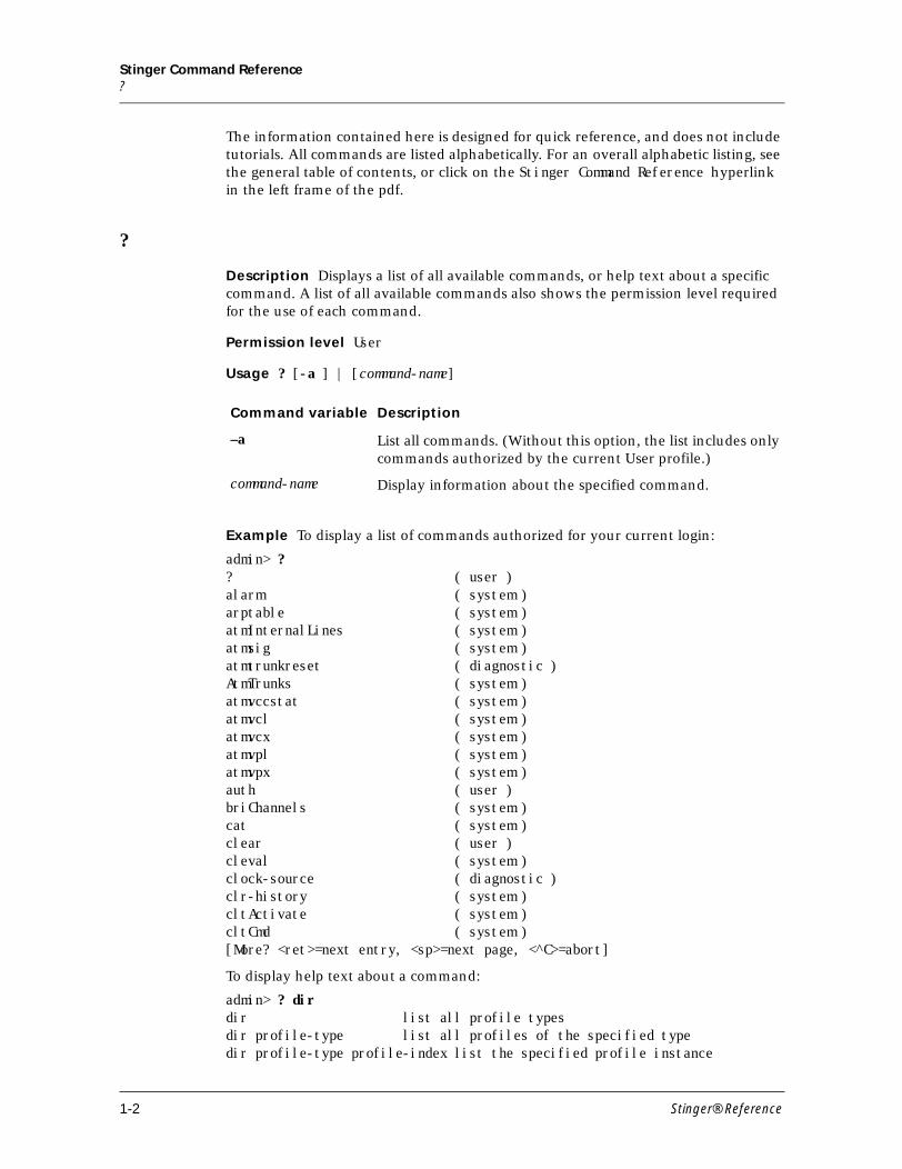
Description Displays a list of all available commands, or help text about a specific command. A list of all available commands also shows the permission level required for the use of each command.
Permission level User
Usage ? [-a ] | [command-name]
Example To display a list of commands authorized for your current login:
admin> ? ? ( user )alarm ( system )arptable ( system )atmInternalLines ( system )atmsig ( system )atmtrunkreset ( diagnostic )AtmTrunks ( system )atmvccstat ( system )atmvcl ( system )atmvcx ( system )atmvpl ( system )atmvpx ( system )auth ( user )briChannels ( system )cat ( system )clear ( user )cleval ( system )clock-source ( diagnostic )clr-history ( system )cltActivate ( system )cltCmd ( system )[More? <ret>=next entry, <sp>=next page, <^C>=abort]
To display help text about a command:
admin> ? dirdir list all profile typesdir profile-type list all profiles of the specified typedir profile-type profile-index list the specified profile instance
Command variable Description
–a List all commands. (Without this option, the list includes only commands authorized by the current User profile.)
command-name Display information about the specified command.
1-2 Stinger® Reference
Stinger Command ReferenceA
Dependencies The current security level is set by the current user profile and determines which commands are displayed in response to the ? command. If the current User profile does not have sufficient privileges to execute a command, that command is not displayed unless you include the -a option. By default, commands that go with the current User security level are always displayed. For details, see “Auth” on page 1-18.
See Also help, auth
A
alarm
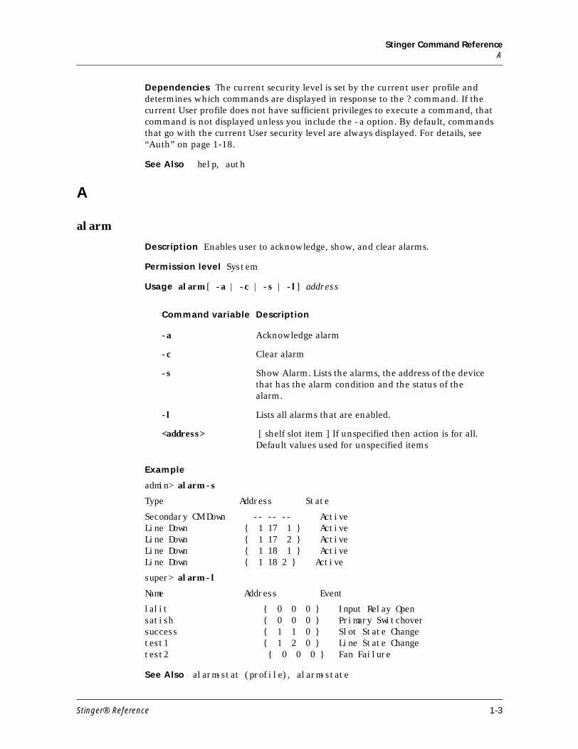
Description Enables user to acknowledge, show, and clear alarms.
Permission level System
Usage alarm [ -a | -c | -s | -l] address
Example
admin> alarm -s
Type Address State
Secondary CM Down -- -- -- Active Line Down { 1 17 1 } Active Line Down { 1 17 2 } Active Line Down { 1 18 1 } Active Line Down { 1 18 2 } Active
super> alarm -l
Name Address Event
lalit { 0 0 0 } Input Relay Opensatish { 0 0 0 } Primary Switchoversuccess { 1 1 0 } Slot State Changetest1 { 1 2 0 } Line State Changetest2 { 0 0 0 } Fan Failure
See Also alarm-stat (profile), alarm-state
Command variable Description
-a Acknowledge alarm
-c Clear alarm
-s Show Alarm. Lists the alarms, the address of the device that has the alarm condition and the status of the alarm.
-l Lists all alarms that are enabled.
<address> [ shelf slot item ] If unspecified then action is for all. Default values used for unspecified items
Stinger® Reference 1-3
Stinger Command Referenceapsmgr
apsmgr
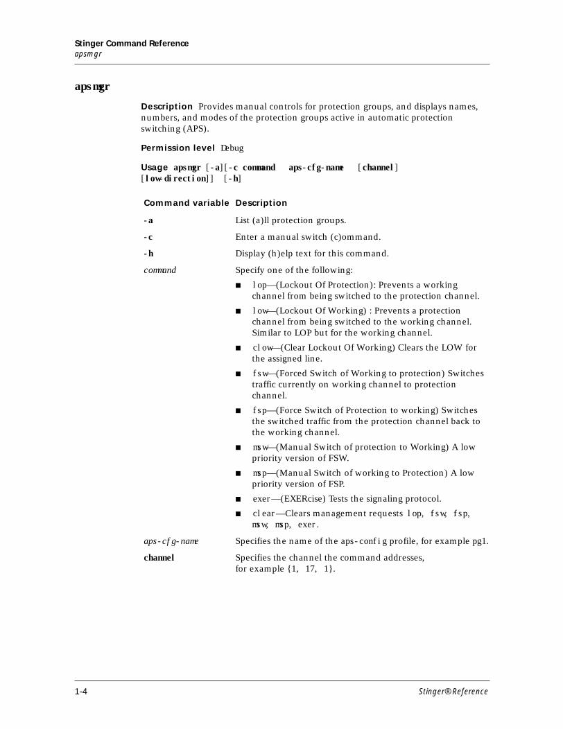
Description Provides manual controls for protection groups, and displays names, numbers, and modes of the protection groups active in automatic protection switching (APS).
Permission level Debug
Usage apsmgr [-a][-c command aps-cfg-name [channel] [low-direction]] [-h]
Command variable Description
-a List (a)ll protection groups.
-c Enter a manual switch (c)ommand.
-h Display (h)elp text for this command.
command Specify one of the following:
■ lop—(Lockout Of Protection): Prevents a working channel from being switched to the protection channel.
■ low—(Lockout Of Working) : Prevents a protection channel from being switched to the working channel. Similar to LOP but for the working channel.
■ clow—(Clear Lockout Of Working) Clears the LOW for the assigned line.
■ fsw—(Forced Switch of Working to protection) Switches traffic currently on working channel to protection channel.
■ fsp—(Force Switch of Protection to working) Switches the switched traffic from the protection channel back to the working channel.
■ msw—(Manual Switch of protection to Working) A low priority version of FSW.
■ msp—(Manual Switch of working to Protection) A low priority version of FSP.
■ exer—(EXERcise) Tests the signaling protocol.
■ clear—Clears management requests lop, fsw, fsp, msw, msp, exer.
aps-cfg-name Specifies the name of the aps-config profile, for example pg1.
channel Specifies the channel the command addresses, for example {1, 17, 1}.
1-4 Stinger® Reference
Stinger Command Referencearptable
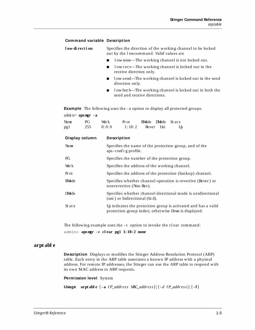
Example The following uses the -a option to display all protected groups.
admin> apsmgr -a
Name PG Work Prot RMode DMode Statepg1 255 0:0:0 1:18:2 Rever Uni Up
The following example uses the -c option to invoke the clear command:
admin> apsmgr -c clear pg1 1:18:2 none
arptable
Description Displays or modifies the Stinger Address Resolution Protocol (ARP) table. Each entry in the ARP table associates a known IP address with a physical address. For remote IP addresses, the Stinger can use the ARP table to respond with its own MAC address to ARP requests.
Permission level System
Usage arptable [-a IP_address MAC_address]|[-d IP_address]|[-f]
low-direction Specifies the direction of the working channel to be locked out by the low command. Valid values are
■ low-none—The working channel is not locked out.
■ low-recv—The working channel is locked out in the receive direction only.
■ low-send—The working channel is locked out in the send direction only.
■ low-both—The working channel is locked out in both the send and receive directions.
Display column Description
Name Specifies the name of the protection group, and of the aps-config profile.
PG Specifies the number of the protection group.
Work Specifies the address of the working channel.
Prot Specifies the address of the protection (backup) channel.
RMode Specifies whether channel operation is revertive (Rever) or nonrevertive (Non-Rev).
DMode Specifies whether channel directional mode is unidirectional (uni) or bidirectional (bid).
State Up indicates the protection group is activated and has a valid protection group index; otherwise Down is displayed.
Command variable Description
Stinger® Reference 1-5
Stinger Command Referencearptable
Example
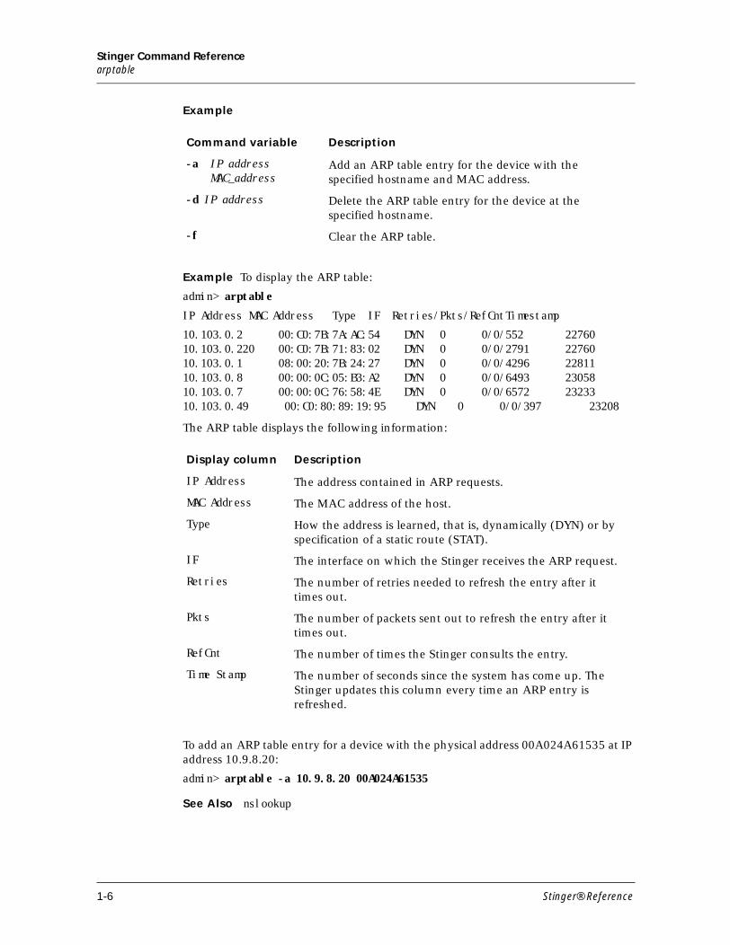
Example To display the ARP table:
admin> arptable
IP Address MAC Address Type IF Retries/Pkts/RefCntTimestamp
10.103.0.2 00:C0:7B:7A:AC:54 DYN 0 0/0/552 2276010.103.0.220 00:C0:7B:71:83:02 DYN 0 0/0/2791 2276010.103.0.1 08:00:20:7B:24:27 DYN 0 0/0/4296 2281110.103.0.8 00:00:0C:05:B3:A2 DYN 0 0/0/6493 2305810.103.0.7 00:00:0C:76:58:4E DYN 0 0/0/6572 2323310.103.0.49 00:C0:80:89:19:95 DYN 0 0/0/397 23208
The ARP table displays the following information:
To add an ARP table entry for a device with the physical address 00A024A61535 at IP address 10.9.8.20:
admin> arptable -a 10.9.8.20 00A024A61535
See Also nslookup
Command variable Description
-a IP addressMAC_address
Add an ARP table entry for the device with the specified hostname and MAC address.
-d IP address Delete the ARP table entry for the device at the specified hostname.
-f Clear the ARP table.
Display column Description
IP Address The address contained in ARP requests.
MAC Address The MAC address of the host.
Type How the address is learned, that is, dynamically (DYN) or by specification of a static route (STAT).
IF The interface on which the Stinger receives the ARP request.
Retries The number of retries needed to refresh the entry after it times out.
Pkts The number of packets sent out to refresh the entry after it times out.
RefCnt The number of times the Stinger consults the entry.
Time Stamp The number of seconds since the system has come up. The Stinger updates this column every time an ARP entry is refreshed.
1-6 Stinger® Reference
Stinger Command Referenceatmcacstat
atmcacstat
Description Displays statistics about CAC bandwidth allocation.
Permission level System
Usage atmcacstat - s| b |p | a | r |c service
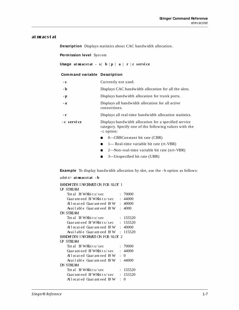
Example To display bandwidth allocation by slot, use the -b option as follows:
admin> atmcacstat -b
BANDWIDTH INFORMATION FOR SLOT 1UP STREAM
Total B/W Kbits/sec : 70000Guaranteed B/W Kbits/sec : 44000Allocated Guaranteed B/W : 40000Available Guaranteed B/W : 4000
DN STREAMTotal B/W Kbits/sec : 155520Guaranteed B/W Kbits/sec : 155520Allocated Guaranteed B/W : 40000Available Guaranteed B/W : 115520
BANDWIDTH INFORMATION FOR SLOT 2UP STREAM
Total B/W Kbits/sec : 70000Guaranteed B/W Kbits/sec : 44000Allocated Guaranteed B/W : 0Available Guaranteed B/W : 44000
DN STREAMTotal B/W Kbits/sec : 155520Guaranteed B/W Kbits/sec : 155520Allocated Guaranteed B/W : 0
Command variable Description
-s Currently not used.
-b Displays CAC bandwidth allocation for all the slots.
-p Displays bandwidth allocation for trunk ports.
-a Displays all bandwidth allocation for all active connections.
-r Displays all real-time bandwidth allocation statistics.
-c service Displays bandwidth allocation for a specified service category. Specify one of the following values with the -c option:
■ 0—CBRConstant bit rate (CBR)
■ 1— Real-time variable bit rate (rt-VBR)
■ 2—Non-real-time variable bit rate (nrt-VBR)
■ 3—Unspecified bit rate (UBR)
Stinger® Reference 1-7
Stinger Command Referenceatmcacstat
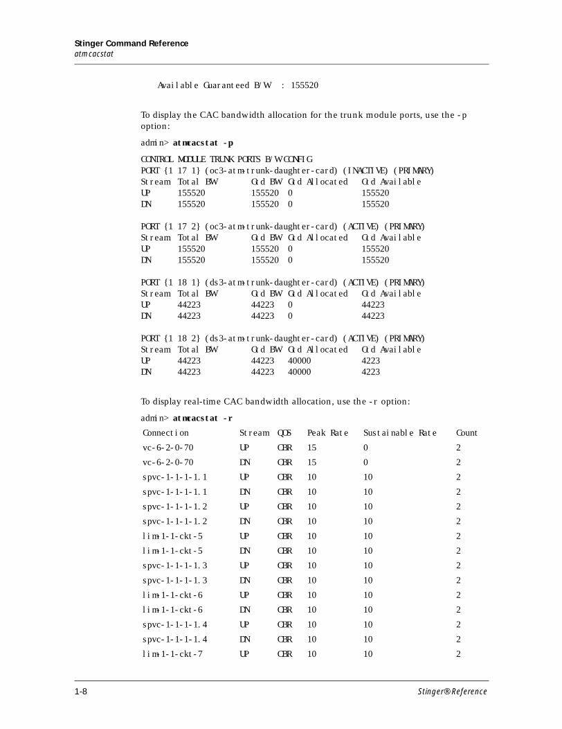
Available Guaranteed B/W : 155520
To display the CAC bandwidth allocation for the trunk module ports, use the -p option:
admin> atmcacstat -p
CONTROL MODULE TRUNK PORTS B/W CONFIGPORT {1 17 1} (oc3-atm-trunk-daughter-card) (INACTIVE) (PRIMARY)Stream Total BW Gtd BW Gtd Allocated Gtd AvailableUP 155520 155520 0 155520DN 155520 155520 0 155520
PORT {1 17 2} (oc3-atm-trunk-daughter-card) (ACTIVE) (PRIMARY)Stream Total BW Gtd BW Gtd Allocated Gtd AvailableUP 155520 155520 0 155520DN 155520 155520 0 155520
PORT {1 18 1} (ds3-atm-trunk-daughter-card) (ACTIVE) (PRIMARY)Stream Total BW Gtd BW Gtd Allocated Gtd AvailableUP 44223 44223 0 44223DN 44223 44223 0 44223
PORT {1 18 2} (ds3-atm-trunk-daughter-card) (ACTIVE) (PRIMARY)Stream Total BW Gtd BW Gtd Allocated Gtd AvailableUP 44223 44223 40000 4223DN 44223 44223 40000 4223
To display real-time CAC bandwidth allocation, use the -r option:
admin> atmcacstat -r
Connection Stream QOS Peak Rate Sustainable Rate Count
vc-6-2-0-70 UP CBR 15 0 2
vc-6-2-0-70 DN CBR 15 0 2
spvc-1-1-1-1.1 UP CBR 10 10 2
spvc-1-1-1-1.1 DN CBR 10 10 2
spvc-1-1-1-1.2 UP CBR 10 10 2
spvc-1-1-1-1.2 DN CBR 10 10 2
lim-1-1-ckt-5 UP CBR 10 10 2
lim-1-1-ckt-5 DN CBR 10 10 2
spvc-1-1-1-1.3 UP CBR 10 10 2
spvc-1-1-1-1.3 DN CBR 10 10 2
lim-1-1-ckt-6 UP CBR 10 10 2
lim-1-1-ckt-6 DN CBR 10 10 2
spvc-1-1-1-1.4 UP CBR 10 10 2
spvc-1-1-1-1.4 DN CBR 10 10 2
lim-1-1-ckt-7 UP CBR 10 10 2
1-8 Stinger® Reference
Stinger Command Referenceatminternallines
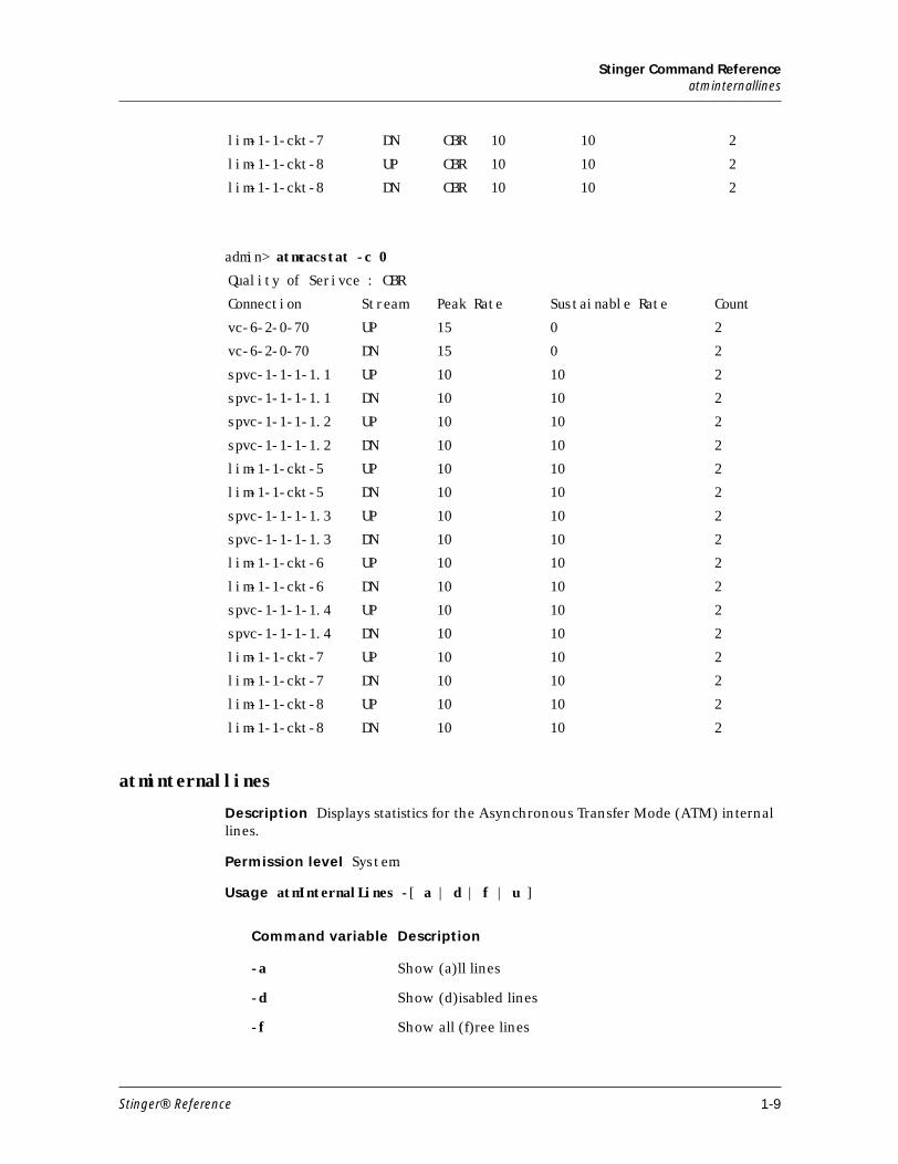
admin> atmcacstat -c 0
atminternallines
Description Displays statistics for the Asynchronous Transfer Mode (ATM) internal lines.
Permission level System
Usage atmInternalLines -[ a | d | f | u ]
lim-1-1-ckt-7 DN CBR 10 10 2
lim-1-1-ckt-8 UP CBR 10 10 2
lim-1-1-ckt-8 DN CBR 10 10 2
Quality of Serivce : CBR
Connection Stream Peak Rate Sustainable Rate Count
vc-6-2-0-70 UP 15 0 2
vc-6-2-0-70 DN 15 0 2
spvc-1-1-1-1.1 UP 10 10 2
spvc-1-1-1-1.1 DN 10 10 2
spvc-1-1-1-1.2 UP 10 10 2
spvc-1-1-1-1.2 DN 10 10 2
lim-1-1-ckt-5 UP 10 10 2
lim-1-1-ckt-5 DN 10 10 2
spvc-1-1-1-1.3 UP 10 10 2
spvc-1-1-1-1.3 DN 10 10 2
lim-1-1-ckt-6 UP 10 10 2
lim-1-1-ckt-6 DN 10 10 2
spvc-1-1-1-1.4 UP 10 10 2
spvc-1-1-1-1.4 DN 10 10 2
lim-1-1-ckt-7 UP 10 10 2
lim-1-1-ckt-7 DN 10 10 2
lim-1-1-ckt-8 UP 10 10 2
lim-1-1-ckt-8 DN 10 10 2
Command variable Description
-a Show (a)ll lines
-d Show (d)isabled lines
-f Show all (f)ree lines
Stinger® Reference 1-9
Stinger Command Referenceatmqos
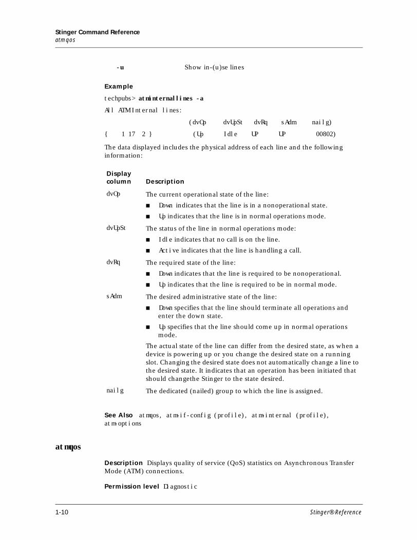
Example
techpubs> atminternallines -a
All ATM Internal lines:
(dvOp dvUpSt dvRq sAdm nailg)
{ 1 17 2 } (Up Idle UP UP 00802)
The data displayed includes the physical address of each line and the following information:
See Also atmqos, atm-if-config (profile), atm-internal (profile), atm-options
atmqos
Description Displays quality of service (QoS) statistics on Asynchronous Transfer Mode (ATM) connections.
Permission level Diagnostic
-u Show in-(u)se lines
Display column Description
dvOp The current operational state of the line:
■ Down indicates that the line is in a nonoperational state.
■ Up indicates that the line is in normal operations mode.
dvUpSt The status of the line in normal operations mode:
■ Idle indicates that no call is on the line.
■ Active indicates that the line is handling a call.
dvRq The required state of the line:
■ Down indicates that the line is required to be nonoperational.
■ Up indicates that the line is required to be in normal mode.
sAdm The desired administrative state of the line:
■ Down specifies that the line should terminate all operations and enter the down state.
■ Up specifies that the line should come up in normal operations mode.
The actual state of the line can differ from the desired state, as when a device is powering up or you change the desired state on a running slot. Changing the desired state does not automatically change a line to the desired state. It indicates that an operation has been initiated that should changethe Stinger to the state desired.
nailg The dedicated (nailed) group to which the line is assigned.
1-10 Stinger® Reference

Stinger Command Referenceatmqos
Usage atmqos -[a|c|d] qos name
Example
admin> atmqos -a
Examples using the -c and -d options follow:
admin>atmqos -c atmqos416vc-11-1-0-35 Total Number Of Connections : 1
admin>atmqos -d atmqos416Traffic Descriptor : 416Traffic Type : NO_CLP_SCRPCR(Cells Per Second) : 1000 SCR : 1000 MBS : 5 QOS Class : 0 ATM Service Category : RT_VBR
Syntax Element Description
-a Show QoS statistics on all ATM connections.
-c qos name Show all Connections that use the specified QoS Name.
-d qos name Display QOS statistics for the specified QoS Name only.
Td Index QoS Name Category PCR (CellsPer Second)
SCR (Cells Per Second)
1 default UBR 0 -
2 default-ctl NRT_VBR 37 37
3 default-rcc NRT_VBR 905 452
392 ATMQOS392 UBR 96000 -
416 ATMQOS416 RT_VBR 1000 1000
Label Description
Td Index Traffic descriptor index.
QoS Name The name assigned to the atm-qos profile.
Category Quality of service.
PCR Peak cell rate in number of cells per second.
SCR Sustainable cell rate in number of cells per second.
Stinger® Reference 1-11
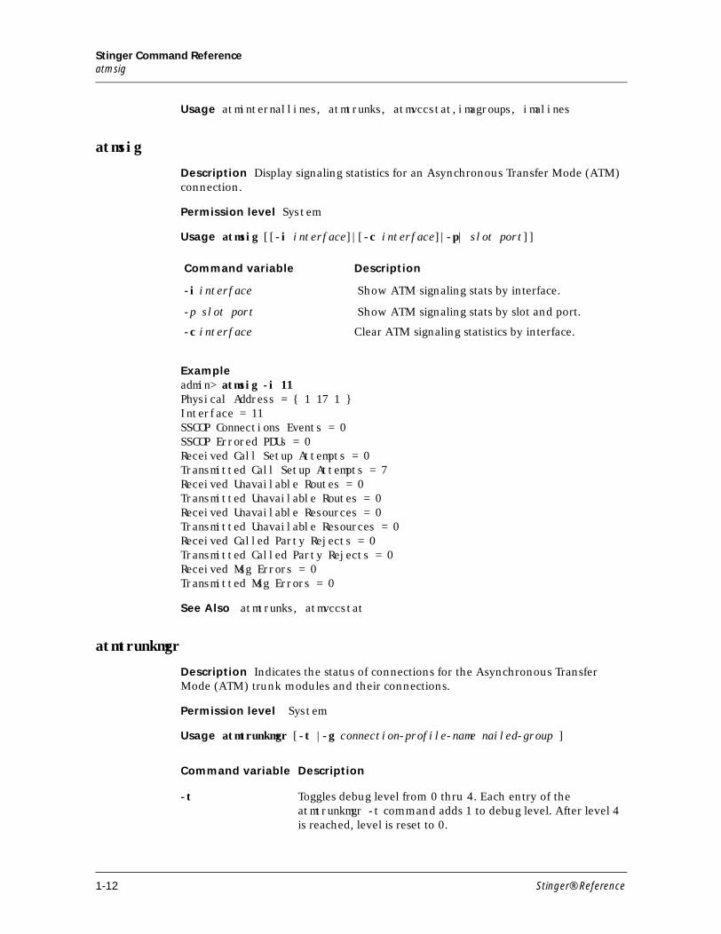
Stinger Command Referenceatmsig
Usage atminternallines, atmtrunks, atmvccstat,imagroups, imalines
atmsig
Description Display signaling statistics for an Asynchronous Transfer Mode (ATM) connection.
Permission level System
Usage atmsig [[-i interface]|[-c interface]|-p| slot port]]
Exampleadmin> atmsig -i 11Physical Address = { 1 17 1 }Interface = 11SSCOP Connections Events = 0SSCOP Errored PDUs = 0Received Call Setup Attempts = 0Transmitted Call Setup Attempts = 7Received Unavailable Routes = 0Transmitted Unavailable Routes = 0Received Unavailable Resources = 0Transmitted Unavailable Resources = 0Received Called Party Rejects = 0Transmitted Called Party Rejects = 0Received Msg Errors = 0Transmitted Msg Errors = 0
See Also atmtrunks, atmvccstat
atmtrunkmgr
Description Indicates the status of connections for the Asynchronous Transfer Mode (ATM) trunk modules and their connections.
Permission level System
Usage atmtrunkmgr [-t |-g connection-profile-name nailed-group ]
Command variable Description
-i interface Show ATM signaling stats by interface.
-p slot port Show ATM signaling stats by slot and port.
-c interface Clear ATM signaling statistics by interface.
Command variable Description
-t Toggles debug level from 0 thru 4. Each entry of the atmtrunkmgr -t command adds 1 to debug level. After level 4 is reached, level is reset to 0.
1-12 Stinger® Reference
Stinger Command Referenceatmtrunkreset
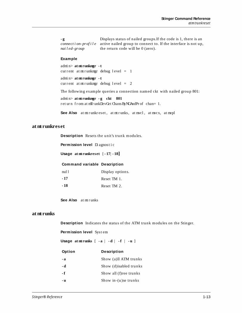
Example
admin> atmtrunkmgr -tcurrent atmtrunkmgr debug level = 1
admin> atmtrunkmgr -tcurrent atmtrunkmgr debug level = 2
The following example queries a connection named ckt with nailed group 801:
admin> atmtrunkmgr -g ckt 801return from atmTrunkDevGetChansByNGAndProf chan= 1.
See Also atmtrunkreset, atmtrunks, atmvcl, atmvcx, atmvpl
atmtrunkreset
Description Resets the unit’s trunk modules.
Permission level Diagnostic
Usage atmtrunkreset [-17|-18]
See Also atmtrunks
atmtrunks
Description Indicates the status of the ATM trunk modules on the Stinger.
Permission level System
Usage atmtrunks [ -a | -d | -f | -u ]
-g connection-profile nailed-group
Displays status of nailed groups.If the code is 1, there is an active nailed group to connect to. If the interface is not up, the return code will be 0 (zero).
Command variable Description
null Display options.
-17 Reset TM 1.
-18 Reset TM 2.
Option Description
-a Show (a)ll ATM trunks
-d Show (d)isabled trunks
-f Show all (f)ree trunks
-u Show in-(u)se trunks
Stinger® Reference 1-13
Stinger Command Referenceatmvccstat
Example
testbox> atmtrunks -a
All OC3 ATM trunks:
OC3 Lines m(dvOp dvUpSt dvRq sAdm nailg)
Line { 1 17 1 }(Down Idle UP UP 00801)
Line { 1 17 2 }(Up Idle UP UP 00802)
All DS3 ATM trunks:
DS3 Lines( dvOp dvUpSt dvRq sAdm nailg)
Line { 1 18 1 }(Up Idle UP UP 00851)
Line { 1 18 2 }(Down Idle UP UP 00852)
All E3 ATM trunks:
E3 Lines (dvOp dvUpSt dvRq sAdm nailg)
See Also atmtrunkmgr, atmvccstat
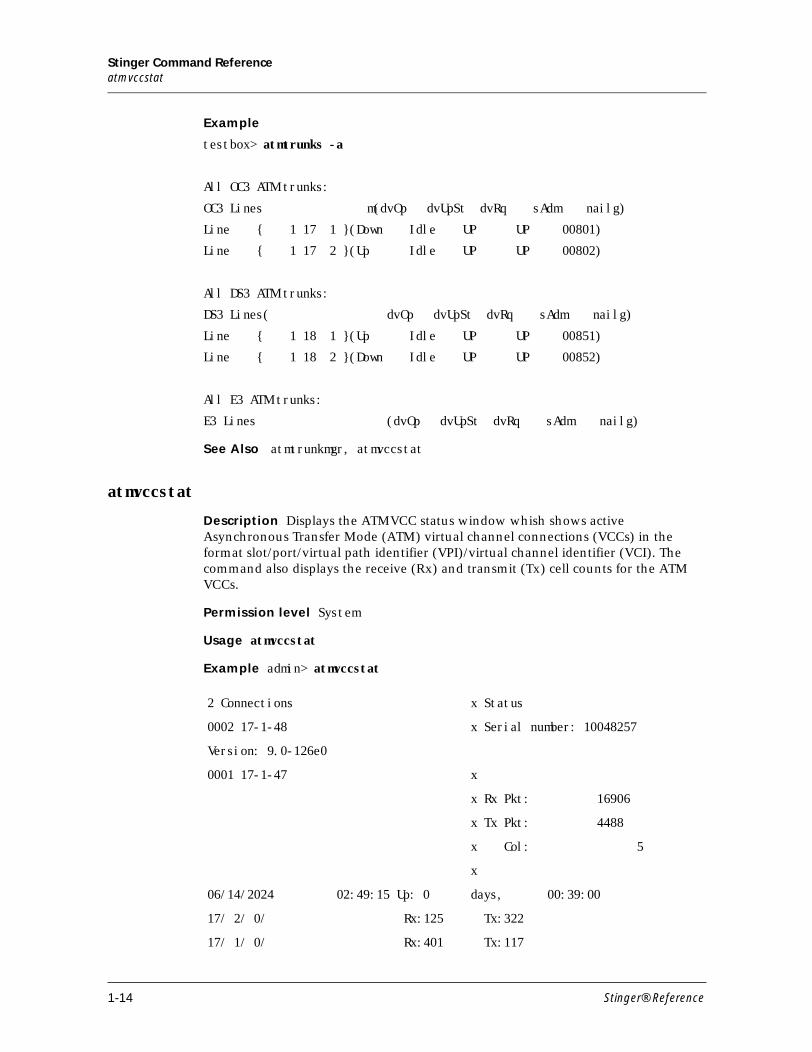
atmvccstat
Description Displays the ATMVCC status window whish shows active Asynchronous Transfer Mode (ATM) virtual channel connections (VCCs) in the format slot/port/virtual path identifier (VPI)/virtual channel identifier (VCI). The command also displays the receive (Rx) and transmit (Tx) cell counts for the ATM VCCs.
Permission level System
Usage atmvccstat
Example admin> atmvccstat
2 Connections x Status
0002 17-1-48 x Serial number: 10048257
Version: 9.0-126e0
0001 17-1-47 x
x Rx Pkt: 16906
x Tx Pkt: 4488
x Col: 5
x
06/14/2024 02:49:15 Up: 0 days, 00:39:00
17/ 2/ 0/ Rx:125 Tx:322
17/ 1/ 0/ Rx:401 Tx:117
1-14 Stinger® Reference
Stinger Command Referenceatmvcl
See Also atmtrunks, atmvcx
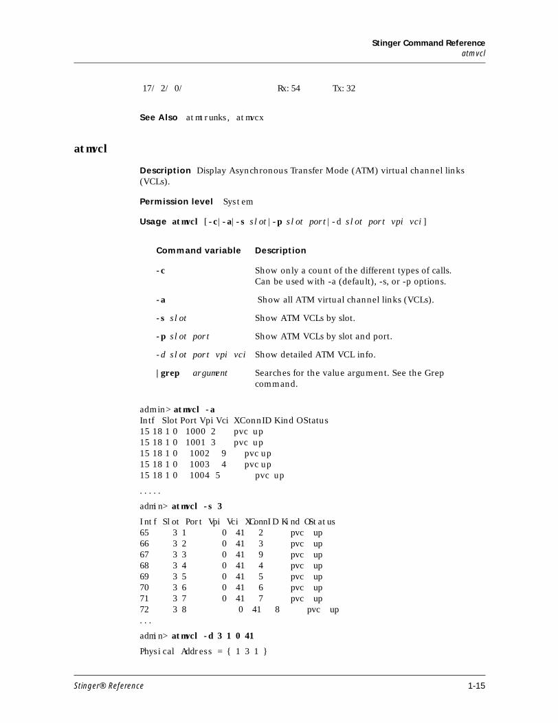
atmvcl
Description Display Asynchronous Transfer Mode (ATM) virtual channel links (VCLs).
Permission level System
Usage atmvcl [-c|-a|-s slot|-p slot port|-d slot port vpi vci]
admin> atmvcl -aIntf Slot Port Vpi Vci XConnID Kind OStatus15 18 1 0 1000 2 pvc up15 18 1 0 1001 3 pvc up15 18 1 0 1002 9 pvc up15 18 1 0 1003 4 pvc up15 18 1 0 1004 5 pvc up
.....
admin> atmvcl -s 3
Intf Slot Port Vpi Vci XConnID Kind OStatus65 3 1 0 41 2 pvc up66 3 2 0 41 3 pvc up67 3 3 0 41 9 pvc up68 3 4 0 41 4 pvc up69 3 5 0 41 5 pvc up70 3 6 0 41 6 pvc up71 3 7 0 41 7 pvc up72 3 8 0 41 8 pvc up...
admin> atmvcl -d 3 1 0 41
Physical Address = { 1 3 1 }
17/ 2/ 0/ Rx:54 Tx:32
Command variable Description
-c Show only a count of the different types of calls. Can be used with -a (default), -s, or -p options.
-a Show all ATM virtual channel links (VCLs).
-s slot Show ATM VCLs by slot.
-p slot port Show ATM VCLs by slot and port.
-d slot port vpi vci Show detailed ATM VCL info.
|grep argument Searches for the value argument. See the Grep command.
Stinger® Reference 1-15
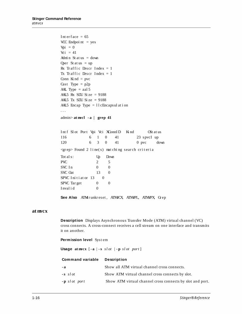
Stinger Command Referenceatmvcx
Interface = 65VCC Endpoint = yesVpi = 0Vci = 41Admin Status = downOper Status = upRx Traffic Descr Index = 1Tx Traffic Descr Index = 1Conn Kind = pvcCast Type = p2pAAL Type = aal5AAL5 Rx SDU Size = 9188AAL5 Tx SDU Size = 9188AAL5 Encap Type = llcEncapsulation...
admin> atmvcl -a | grep 41
Intf Slot Port Vpi Vci XConnID Kind OStatus116 6 1 0 41 23 spvcI up120 6 3 0 41 0 pvc down
<grep> Found 2 line(s) matching search criteria
Totals: Up DownPVC 2 5SVC In 0 0SVC Out 13 0SPVC Initiator 13 0SPVC Target 0 0Invalid 0
See Also ATMtrunkreset, ATMVCX, ATMVPL, ATMVPX, Grep
atmvcx
Description Displays Asynchronous Transfer Mode (ATM) virtual channel (VC) cross connects. A cross-connect receives a cell stream on one interface and transmits it on another.
Permission level System
Usage atmvcx [-a |-s slot |-p slot port]
Command variable Description
-a Show all ATM virtual channel cross connects.
-s slot Show ATM virtual channel cross connects by slot.
-p slot port Show ATM virtual channel cross connects by slot and port.
1-16 Stinger® Reference
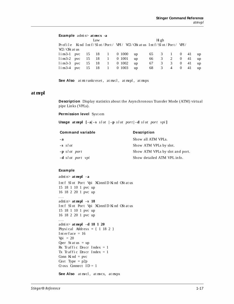
Stinger Command Referenceatmvpl
Example admin> atmvcx -a Low HighProfile Kind Intf/Slot/Port/ VPI/ VCI/OStatus Intf/Slot/Port/ VPI/ VCI/OStatus lim-3-1 pvc 15 18 1 0 1000 up 65 3 1 0 41 uplim-3-2 pvc 15 18 1 0 1001 up 66 3 2 0 41 uplim-3-3 pvc 15 18 1 0 1002 up 67 3 3 0 41 uplim-3-4 pvc 15 18 1 0 1003 up 68 3 4 0 41 up
See Also atmtrunkreset, atmvcl, atmvpl, atmvpx
atmvpl
Description Display statistics about the Asynchronous Transfer Mode (ATM) virtual pipe Links (VPLs).
Permission level System
Usage atmvpl [-a|-s slot |-p slot port|-d slot port vpi]
Example
admin> atmvpl -a
Intf Slot Port Vpi XConnID Kind OStatus15 18 1 10 1 pvc up16 18 2 20 1 pvc up...admin> atmvpl -s 18Intf Slot Port Vpi XConnID Kind OStatus15 18 1 10 1 pvc up16 18 2 20 1 pvc up...admin> atmvpl -d 18 1 20Physical Address = { 1 18 2 }Interface = 16Vpi = 20Oper Status = upRx Traffic Descr Index = 1Tx Traffic Descr Index = 1Conn Kind = pvcCast Type = p2pCross Connect ID = 1
See Also atmvcl, atmvcx, atmvpx
Command variable Description
-a Show all ATM VPLs.
-s slot Show ATM VPLs by slot.
-p slot port Show ATM VPLs by slot and port.
-d slot port vpi Show detailed ATM VPL info.
Stinger® Reference 1-17
Stinger Command Referenceatmvpx
atmvpx
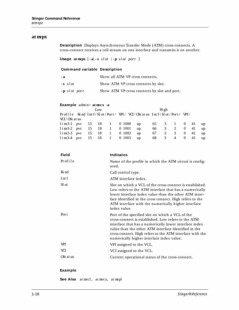
Description Displays Asynchronous Transfer Mode (ATM) cross-connects. A cross-connect receives a cell stream on one interface and transmits it on another.
Usage atmvpx [-a|-s slot |-p slot port ]
Example admin> atmvcx -a Low HighProfile Kind Intf/Slot/Port/ VPI/ VCI/OStatus Intf/Slot/Port/ VPI/ VCI/OStatus lim-3-1 pvc 15 18 1 0 1000 up 65 3 1 0 41 uplim-3-2 pvc 15 18 1 0 1001 up 66 3 2 0 41 uplim-3-3 pvc 15 18 1 0 1002 up 67 3 3 0 41 uplim-3-4 pvc 15 18 1 0 1003 up 68 3 4 0 41 up
Example
See Also atmvcl, atmvcx, atmvpl
Command variable Description
-a Show all ATM VP cross connects.
-s slot Show ATM VP cross connects by slot.
-p slot port Show ATM VP cross connects by slot and port.
Field Indicates
Profile Name of the profile in which the ATM circuit is config-ured.
Kind Call control type.
Intf ATM interface index.
Slot Slot on which a VCL of the cross-connect is established. Low refers to the ATM interface that has a numerically lower interface index value than the other ATM inter-face identified in the cross connect. High refers to the ATM interface with the numerically higher interface index value.
Port Port of the specified slot on which a VCL of the cross-connect is established. Low refers to the ATM interface that has a numerically lower interface index value than the other ATM interface identified in the cross connect. High refers to the ATM interface with the numerically higher interface index value.
VPI VPI assigned to the VCL.
VCI VCI assigned to the VCL.
OStatus Current operational status of the cross-connect.
1-18 Stinger® Reference
Stinger Command Referenceauth
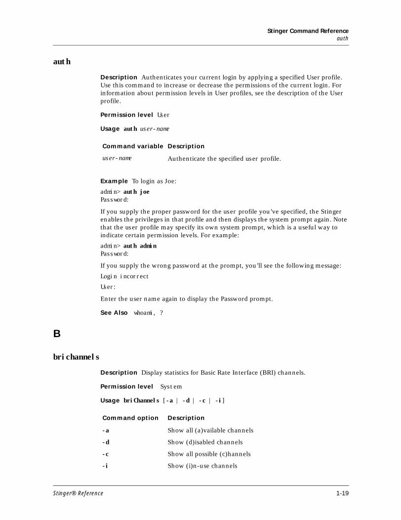
auth
Description Authenticates your current login by applying a specified User profile. Use this command to increase or decrease the permissions of the current login. For information about permission levels in User profiles, see the description of the User profile.
Permission level User
Usage auth user-name
Example To login as Joe:
admin> auth joePassword:
If you supply the proper password for the user profile you’ve specified, the Stinger enables the privileges in that profile and then displays the system prompt again. Note that the user profile may specify its own system prompt, which is a useful way to indicate certain permission levels. For example:
admin> auth adminPassword:
If you supply the wrong password at the prompt, you’ll see the following message:
Login incorrect
User:
Enter the user name again to display the Password prompt.
See Also whoami, ?
B
brichannels
Description Display statistics for Basic Rate Interface (BRI) channels.
Permission level System
Usage briChannels [-a | -d | -c | -i]
Command variable Description
user-name Authenticate the specified user profile.
Command option Description
-a Show all (a)vailable channels
-d Show (d)isabled channels
-c Show all possible (c)hannels
-i Show (i)n-use channels
Stinger® Reference 1-19
Stinger Command ReferenceC
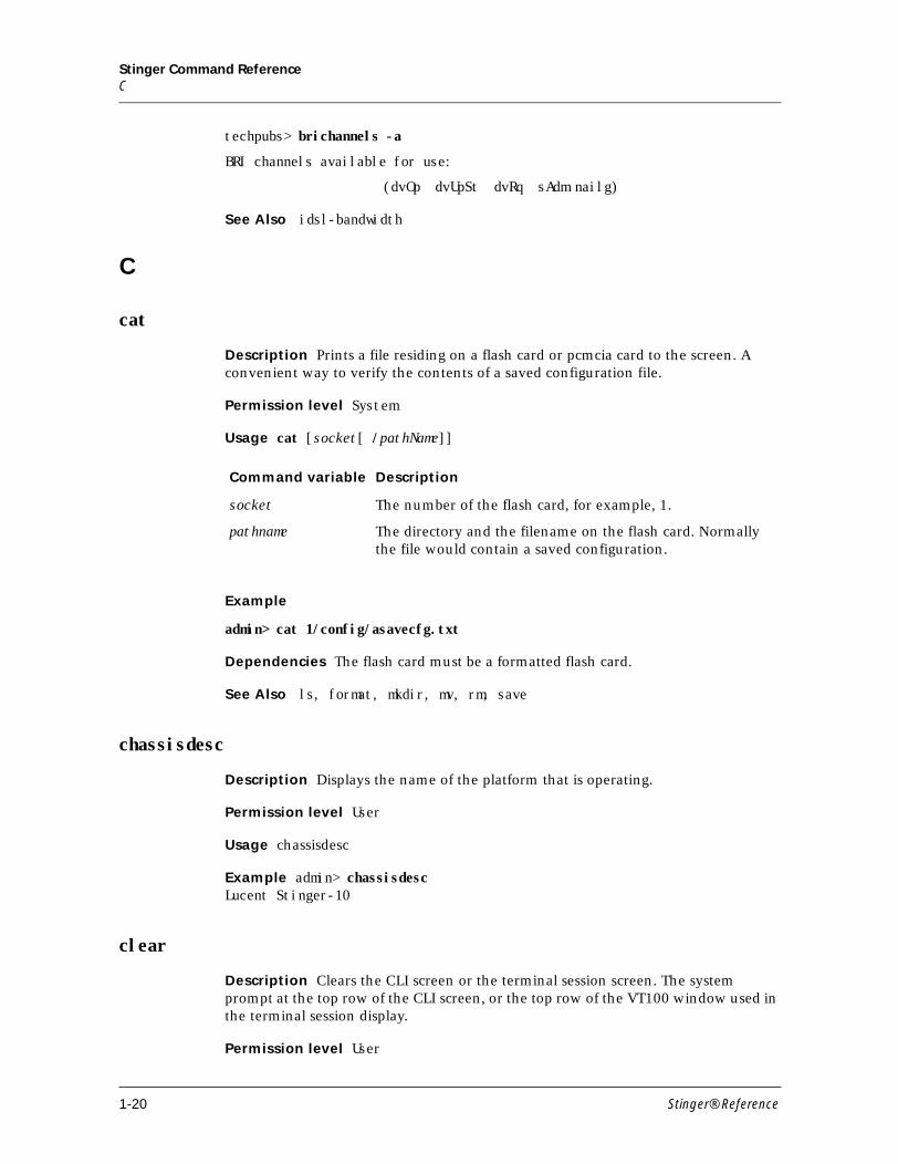
techpubs> brichannels -a
BRI channels available for use:
(dvOp dvUpSt dvRq sAdm nailg)
See Also idsl-bandwidth
C
cat
Description Prints a file residing on a flash card or pcmcia card to the screen. A convenient way to verify the contents of a saved configuration file.
Permission level System
Usage cat [socket[ /pathName]]
Example
admin> cat 1/config/asavecfg.txt
Dependencies The flash card must be a formatted flash card.
See Also ls, format, mkdir, mv, rm, save
chassisdesc
Description Displays the name of the platform that is operating.
Permission level User
Usage chassisdesc
Example admin> chassisdesc Lucent Stinger-10
clear
Description Clears the CLI screen or the terminal session screen. The system prompt at the top row of the CLI screen, or the top row of the VT100 window used in the terminal session display.
Permission level User
Command variable Description
socket The number of the flash card, for example, 1.
pathname The directory and the filename on the flash card. Normally the file would contain a saved configuration.
1-20 Stinger® Reference
Stinger Command Referencecleval
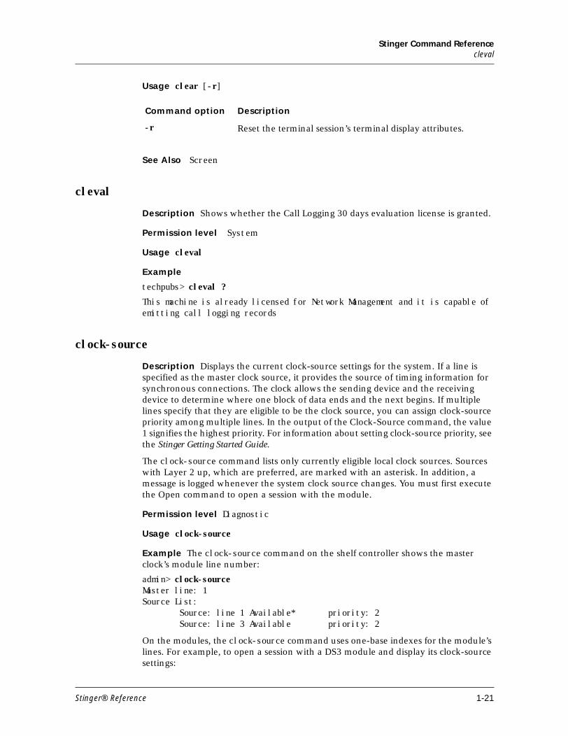
Usage clear [-r]
See Also Screen
cleval
Description Shows whether the Call Logging 30 days evaluation license is granted.
Permission level System
Usage cleval
Example
techpubs> cleval ?
This machine is already licensed for Network Management and it is capable of emitting call logging records
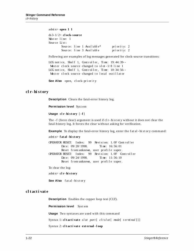
clock-source
Description Displays the current clock-source settings for the system. If a line is specified as the master clock source, it provides the source of timing information for synchronous connections. The clock allows the sending device and the receiving device to determine where one block of data ends and the next begins. If multiple lines specify that they are eligible to be the clock source, you can assign clock-source priority among multiple lines. In the output of the Clock-Source command, the value 1 signifies the highest priority. For information about setting clock-source priority, see the Stinger Getting Started Guide.
The clock-source command lists only currently eligible local clock sources. Sources with Layer 2 up, which are preferred, are marked with an asterisk. In addition, a message is logged whenever the system clock source changes. You must first execute the Open command to open a session with the module.
Permission level Diagnostic
Usage clock-source
Example The clock-source command on the shelf controller shows the master clock’s module line number:
admin> clock-sourceMaster line: 1Source List:
Source: line 1 Available* priority: 2Source: line 3 Available priority: 2
On the modules, the clock-source command uses one-base indexes for the module’s lines. For example, to open a session with a DS3 module and display its clock-source settings:
Command option Description
-r Reset the terminal session’s terminal display attributes.
Stinger® Reference 1-21
Stinger Command Referenceclr-history
admin> open 1 1
ds3-1/2> clock-sourceMaster line: 1Source List: Source: line 1 Available* priority: 2 Source: line 3 Available priority: 2
Following are examples of log messages generated for clock-source transitions:
LOG notice, Shelf 1, Controller, Time: 19:44:39-- Master clock source changed to slot-1/8 line 1LOG notice, Shelf 1, Controller, Time: 10:34:56-- Master clock source changed to local oscillator
See Also open, clock-priority
clr-history
Description Clears the fatal-error history log.
Permission level System
Usage clr-history [-f]
The -f (force clear) argument is used if clr-history without it does not clear the fatal-history log. It forces the clear without asking for verification.
Example To display the fatal-error history log, enter the fatal-history command:
admin> fatal-history
OPERATOR RESET: Index: 99 Revision: 1.0F Controller Date: 09/20/1998. Time: 16:56:01 Reset from unknown, user profile super.OPERATOR RESET: Index: 99 Revision: 1.0F Controller Date: 09/24/1998. Time: 11:56:10 Reset from unknown, user profile super.
To clear the log:
admin> clr-history
See Also fatal-history
cltactivate
Description Enables the copper loop test (CLT).
Permission level System
Usage Two syntaxes are used with this command
Syntax 1: cltactivate slot port[ cltslot[ mode[ terminal]]]
Syntax 2: cltactivate external-loop
1-22 Stinger® Reference
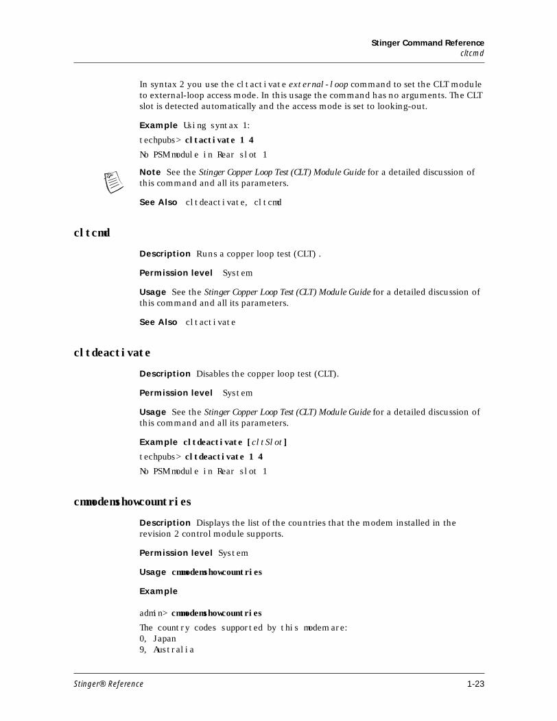
Stinger Command Referencecltcmd
In syntax 2 you use the cltactivate external-loop command to set the CLT module to external-loop access mode. In this usage the command has no arguments. The CLT slot is detected automatically and the access mode is set to looking-out.
Example Using syntax 1:
techpubs> cltactivate 1 4
No PSM module in Rear slot 1
Note See the Stinger Copper Loop Test (CLT) Module Guide for a detailed discussion of this command and all its parameters.
See Also cltdeactivate, cltcmd
cltcmd
Description Runs a copper loop test (CLT) .
Permission level System
Usage See the Stinger Copper Loop Test (CLT) Module Guide for a detailed discussion of this command and all its parameters.
See Also cltactivate
cltdeactivate
Description Disables the copper loop test (CLT).
Permission level System
Usage See the Stinger Copper Loop Test (CLT) Module Guide for a detailed discussion of this command and all its parameters.
Example cltdeactivate [cltSlot]
techpubs> cltdeactivate 1 4
No PSM module in Rear slot 1
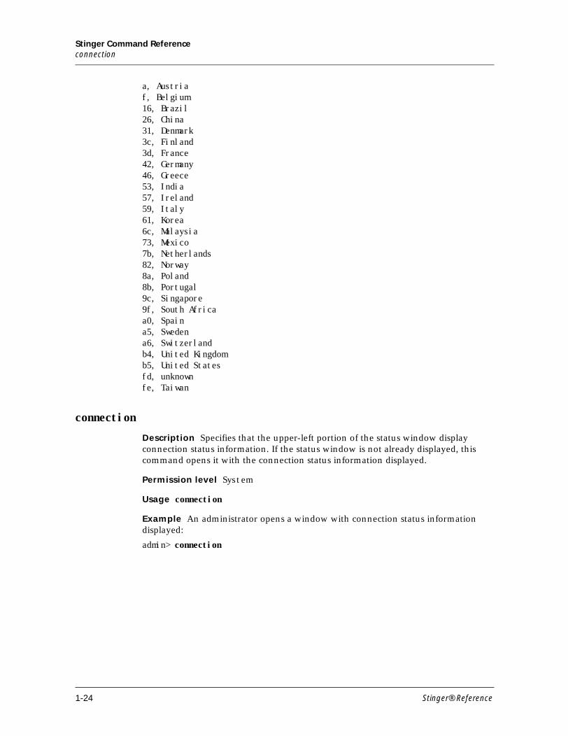
cmmodemshowcountries
Description Displays the list of the countries that the modem installed in the revision 2 control module supports.
Permission level System
Usage cmmodemshowcountries
Example
admin> cmmodemshowcountries
The country codes supported by this modem are:0, Japan 9, Australia
Stinger® Reference 1-23
Stinger Command Referenceconnection
a, Austria f, Belgium 16, Brazil 26, China 31, Denmark 3c, Finland 3d, France 42, Germany 46, Greece 53, India 57, Ireland 59, Italy 61, Korea 6c, Malaysia 73, Mexico 7b, Netherlands 82, Norway 8a, Poland 8b, Portugal 9c, Singapore 9f, South Africa a0, Spain a5, Sweden a6, Switzerland b4, United Kingdom b5, United States fd, unknown fe, Taiwan
connection
Description Specifies that the upper-left portion of the status window display connection status information. If the status window is not already displayed, this command opens it with the connection status information displayed.
Permission level System
Usage connection
Example An administrator opens a window with connection status information displayed:
admin> connection
1-24 Stinger® Reference
Stinger Command Referencecmmodemshowcountries
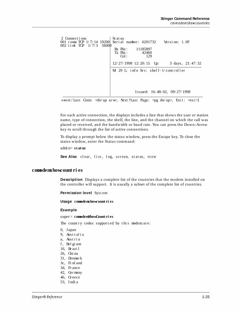
For each active connection, the displays includes a line that shows the user or station name, type of connection, the shelf, the line, and the channel on which the call was placed or received, and the bandwidth or baud rate. You can press the Down-Arrow key to scroll through the list of active connections.
To display a prompt below the status window, press the Escape key. To close the status window, enter the Status command:
admin> status
See Also clear, list, log, screen, status, view
cmmodemshowcountries
Description Displays a complete list of the countries that the modem installed on the controller will support. It is usually a subset of the complete list of countries.
Permission level System
Usage cmmodemshowcountries
Example
super> cmmodemShowCountries
The country codes supported by this modem are:
0, Japan 9, Australia a, Austria f, Belgium 16, Brazil 26, China 31, Denmark 3c, Finland 3d, France 42, Germany 46, Greece 53, India
2 Connections StatusSerial number: 6201732 Version: 1.0F
Rx Pkt: 11185897 Tx Pkt: 42460 Col: 129
12/27/1998 12:20:15 Up: 3 days, 21:47:32
M: 29 L: info Src: shelf-1/controller
Issued: 16:48:02, 09/27/1998
✻✮ ext/Last Conn: <dn/up arw>, Next?Last Page: <pg dn/up>, Exit: <esc>]
001 tomw TCP 1/7/14 19200002 timl TCP 1/7/3 56000
Stinger® Reference 1-25
Stinger Command Referencecmmodemshowcurrentcountry
57, Ireland 59, Italy 61, Korea 6c, Malaysia 73, Mexico 7b, Netherlands 82, Norway 8a, Poland 8b, Portugal 9c, Singapore 9f, South Africa a0, Spain a5, Sweden a6, Switzerland b4, United Kingdom b5, United States fd, unknown fe, Taiwan
cmmodemshowcurrentcountry
Description Displays the country code that is currently configured for the modem.
Permission level Debug
Usage cmmodemshowcurrentcountry
Example admin> cmmodemshowcurrentcountryThe country code programmed is b5, United States
D
date
Description Displays or sets the Stinger system date and time. The date and time are stored in the timedate profile.
Permission level Update
Usage date
Example
admin> date
Wed Mar 7 16:17:41 2001
Note You can set the Stinger system date and time in the timedate profile.
See Also time-stamp
debug
Description Enables or disables diagnostic output.
1-26 Stinger® Reference
Stinger Command Referencedegen-tone
Permission level Diagnostic
Usage debug on | off
Example To enable diagnostic output:
admin> debug onDiagnostic output enabledadmin> FRMAIN: Setting timer DCEFRMAIN: time 88121200, mkstatus type 1, seq (026,025)
See Also auth
degen-tone
Description Stops multiport tone testing for the designated shelf and slot.
Permission level System
Usage degen-tone shelf slot
Example degen-tone 1 5
See Also gen-tone
deisolate
Description Stops galvanic isolation testing for the designated shelf and slot.
Permission level System
Usage deisolate shelf slot
Example deisolate 1 5
See Also isolate
delete
Description Permanently deletes a profile from local storage. Any flash space that was used by the profile becomes available to the system.
Permission level Update
Command variable Description
on Enables diagnostic output.
off Disables diagnostic output.
Stinger® Reference 1-27
Stinger Command Referencedevice
Usage delete [-f] profile-type [profile-index]
Example To delete the connection profile previously created for Tom Lynch:
admin> delete conn tlynchDelete profile CONNECTION /tlynch? [y/n] yCONNECTION /tlynch deleted
See Also get, new, read
device
Description Initiates a state change in a specified device. The device is specified by its interface address. This command is typically used to administratively up or down a device. For a list of devices supported by the Stinger, see the description of Device-Address.
Permission level Diagnostic
Usage device -d|-t|-u|-? interface_address
Example To administratively disconnect device #24 in slot #3 on shelf #1:
admin> device -d {{1 3 24} 0}
See Also show, slot
dir
Description Lists profiles. With no options, the dir command lists all profile types
supported by the Stinger. It can also be used to list all profiles of a certain type, or to
list file-system information about a specific profile.
Permission level System
Command variable Description
-f Delete without prompting for confirmation.
profile-type A type of profile, as listed by the Dir command.
profile-index The index of the specified profile type. Not all profile types require an index.
Command variable Description
-d Bring the specified device down.
-u Bring the specified device up.
interface_address The interface address of the device, specified as shelf, slot, item number, and logical item number.
1-28 Stinger® Reference
Stinger Command Referencedir
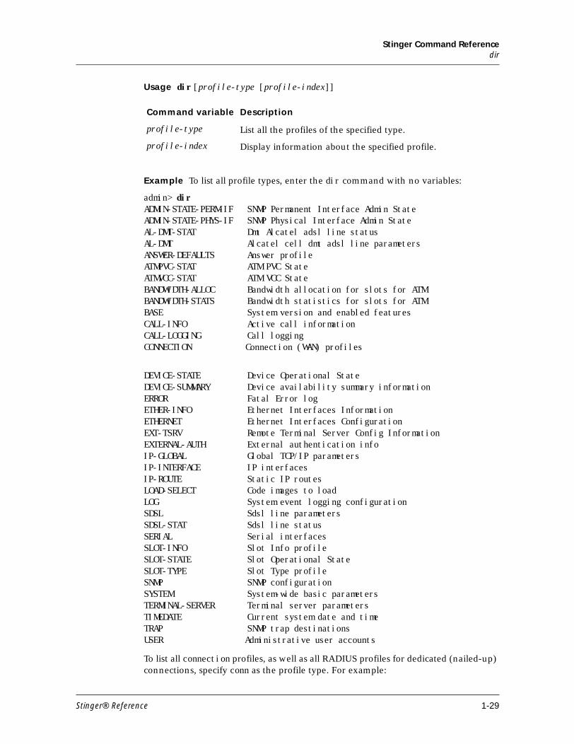
Usage dir [profile-type [profile-index]]
Example To list all profile types, enter the dir command with no variables:
admin> dirADMIN-STATE-PERM-IF SNMP Permanent Interface Admin StateADMIN-STATE-PHYS-IF SNMP Physical Interface Admin StateAL-DMT-STAT Dmt Alcatel adsl line statusAL-DMT Alcatel cell dmt adsl line parametersANSWER-DEFAULTS Answer profileATMPVC-STAT ATM PVC StateATMVCC-STAT ATM VCC StateBANDWIDTH-ALLOC Bandwidth allocation for slots for ATMBANDWIDTH-STATS Bandwidth statistics for slots for ATMBASE System version and enabled featuresCALL-INFO Active call informationCALL-LOGGING Call loggingCONNECTION Connection (WAN) profiles
DEVICE-STATE Device Operational StateDEVICE-SUMMARY Device availability summary informationERROR Fatal Error logETHER-INFO Ethernet Interfaces InformationETHERNET Ethernet Interfaces ConfigurationEXT-TSRV Remote Terminal Server Config InformationEXTERNAL-AUTH External authentication infoIP-GLOBAL Global TCP/IP parametersIP-INTERFACE IP interfacesIP-ROUTE Static IP routesLOAD-SELECT Code images to loadLOG System event logging configurationSDSL Sdsl line parametersSDSL-STAT Sdsl line statusSERIAL Serial interfacesSLOT-INFO Slot Info profileSLOT-STATE Slot Operational StateSLOT-TYPE Slot Type profileSNMP SNMP configurationSYSTEM System-wide basic parametersTERMINAL-SERVER Terminal server parametersTIMEDATE Current system date and timeTRAP SNMP trap destinationsUSER Administrative user accounts
To list all connection profiles, as well as all RADIUS profiles for dedicated (nailed-up) connections, specify conn as the profile type. For example:
Command variable Description
profile-type List all the profiles of the specified type.
profile-index Display information about the specified profile.
Stinger® Reference 1-29
Stinger Command Referencedircode
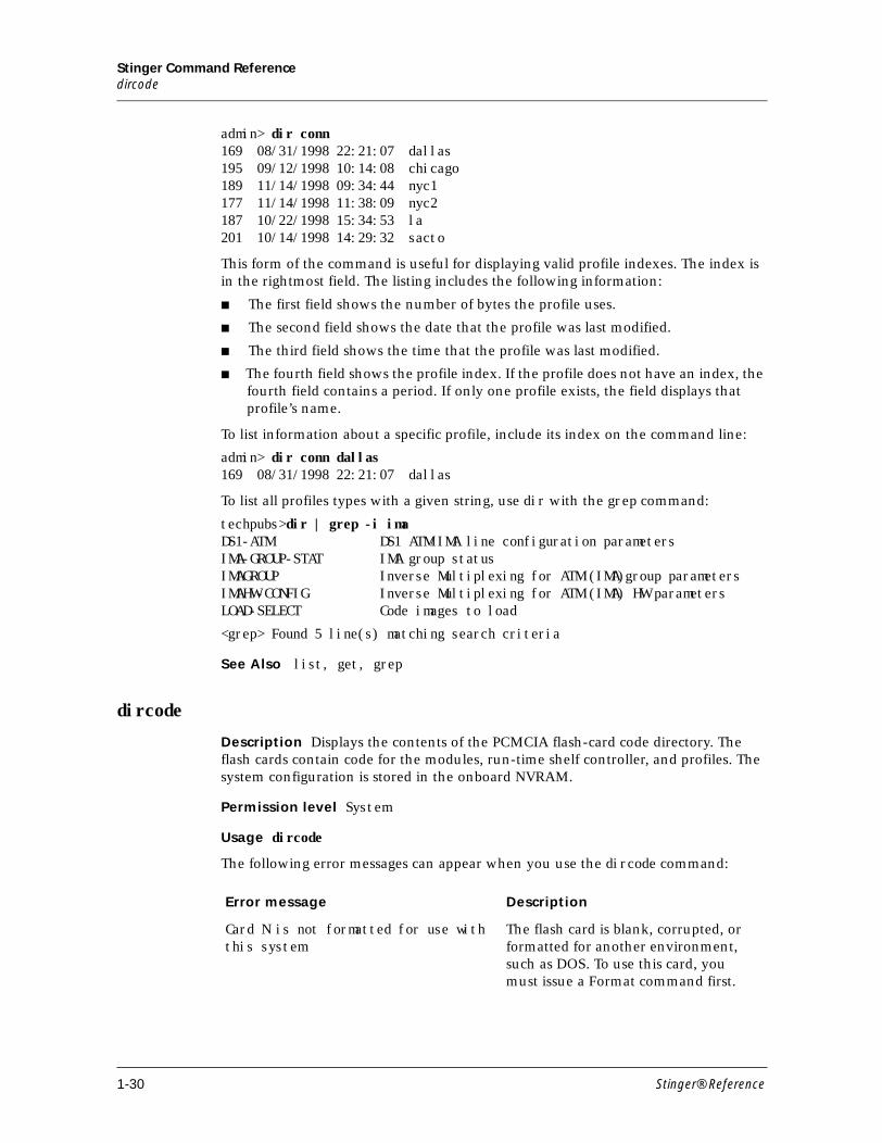
admin> dir conn169 08/31/1998 22:21:07 dallas195 09/12/1998 10:14:08 chicago189 11/14/1998 09:34:44 nyc1177 11/14/1998 11:38:09 nyc2187 10/22/1998 15:34:53 la201 10/14/1998 14:29:32 sacto
This form of the command is useful for displaying valid profile indexes. The index is in the rightmost field. The listing includes the following information:
■ The first field shows the number of bytes the profile uses.
■ The second field shows the date that the profile was last modified.
■ The third field shows the time that the profile was last modified.
■ The fourth field shows the profile index. If the profile does not have an index, the fourth field contains a period. If only one profile exists, the field displays that profile’s name.
To list information about a specific profile, include its index on the command line:
admin> dir conn dallas169 08/31/1998 22:21:07 dallas
To list all profiles types with a given string, use dir with the grep command:
techpubs>dir | grep -i imaDS1-ATM DS1 ATM/IMA line configuration parametersIMA-GROUP-STAT IMA group statusIMAGROUP Inverse Multiplexing for ATM (IMA)group parametersIMAHW-CONFIG Inverse Multiplexing for ATM (IMA) HW parametersLOAD-SELECT Code images to load
<grep> Found 5 line(s) matching search criteria
See Also list, get, grep
dircode
Description Displays the contents of the PCMCIA flash-card code directory. The flash cards contain code for the modules, run-time shelf controller, and profiles. The system configuration is stored in the onboard NVRAM.
Permission level System
Usage dircode
The following error messages can appear when you use the dircode command:
Error message Description
Card N is not formatted for use with this system
The flash card is blank, corrupted, or formatted for another environment, such as DOS. To use this card, you must issue a Format command first.
1-30 Stinger® Reference
Stinger Command Referencedmtaldsllines
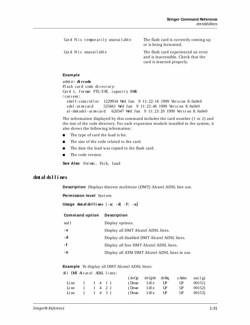
Example
admin> dircodeFlash card code directory:Card 1, format FTL/FAT, capacity 8MB/current: shelf-controller 1229934 Wed Jun 9 11:22:16 1999 Version 8.0a0e0 sdsl-atm-card 525661 Wed Jun 9 11:22:46 1999 Version 8.0a0e0 al-dmtadsl-atm-card 620347 Wed Jun 9 11:23:20 1999 Version 8.0a0e0
The information displayed by this command includes the card number (1 or 2) and the size of the code directory. For each expansion module installed in the system, it also shows the following information:
■ The type of card the load is for.
■ The size of the code related to the card.
■ The date the load was copied to the flash card.
■ The code version.
See Also Format, Fsck, Load
dmtaldsllines
Description Displays discrete multitone (DMT) Alcatel ADSL line use.
Permission level System
Usage dmtaldsllines [-a| -d| -f| -u]
Example To display all DMT Alcatel ADSL lines:
All DMT Alcatel ADSL lines: (dvOp dvUpSt dvRq sAdm nailg) Line { 1 4 1 } (Down Idle UP UP 00151) Line { 1 4 2 } (Down Idle UP UP 00152) Line { 1 4 3 } (Down Idle UP UP 00153)
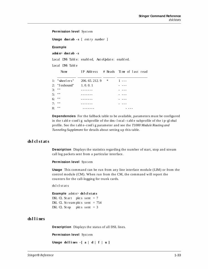
Card N is temporarily unavailable The flash card is currently coming up or is being formatted.
Card N is unavailable The flash card experienced an error and is inaccessible. Check that the card is inserted properly.
Command option Description
null Display options.
-a Display all DMT Alcatel ADSL lines.
-d Display all disabled DMT Alcatel ADSL lines.
-f Display all free DMT Alcatel ADSL lines.
-u Display all ATM DMT Alcatel ADSL lines in use.
Stinger® Reference 1-31
Stinger Command Referencednstab
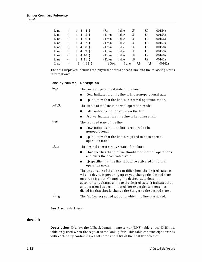
Line { 1 4 4 } (Up Idle UP UP 00154) Line { 1 4 5 } (Down Idle UP UP 00155) Line { 1 4 6 } (Down Idle UP UP 00156) Line { 1 4 7 } (Down Idle UP UP 00157) Line { 1 4 8 } (Down Idle UP UP 00158) Line { 1 4 9 } (Down Idle UP UP 00159) Line { 1 4 10 } (Down Idle UP UP 00160) Line { 1 4 11 } (Down Idle UP UP 00161) Line { 1 4 12 } (Down Idle UP UP 00162)
The data displayed includes the physical address of each line and the following status information::
See Also sdsllines
dnstab
Description Displays the fallback domain name server (DNS) table, a local DNS host table only used when the regular name lookup fails. This table contains eight entries with each entry containing a host name and a list of the host IP addresses.
Display column Description
dvOp The current operational state of the line:
■ Down indicates that the line is in a nonoperational state.
■ Up indicates that the line is in normal operation mode.
dvUpSt The status of the line in normal operation mode:
■ Idle indicates that no call is on the line.
■ Active indicates that the line is handling a call.
dvRq The required state of the line:
■ Down indicates that the line is required to be nonoperational.
■ Up indicates that the line is required to be in normal operation mode.
sAdm The desired administrative state of the line:
■ Down specifies that the line should terminate all operations and enter the deactivated state.
■ Up specifies that the line should be activated in normal operation mode.
The actual state of the line can differ from the desired state, as when a device is powering up or you change the desired state on a running slot. Changing the desired state does not automatically change a line to the desired state. It indicates that an operation has been initiated (for example, someone has dialed in) that should change the Stinger to the desired state .
nailg The (dedicated) nailed group to which the line is assigned.
1-32 Stinger® Reference
Stinger Command Referencedslclstats
Permission level System
Usage dnstab -s [ entry number ]
Example
admin> dnstab -s
Local DNS Table: enabled, AutoUpdate: enabled.
Local DNS Table
Name IP Address # Reads Time of last read ___________ ______________ _______ __________________1: "wheelers" 206.65.212.9 * 1 ---2: "foxhound" 1.0.0.1 - ---3: "" ------- - ---5: "" ------- - ---6: "" ------- - ---7: "" ------- - ---8: "" ------- - ---
Dependencies For the fallback table to be available, parameters must be configured in the table-config subprofile of the dns-local-table subprofile of the ip-global profile. See the table-config parameter and see the T1000 Module Routing and
Tunneling Supplement for details about setting up this table.
dslclstats
Description Displays the statistics regarding the number of start, stop and stream call log packets sent from a particular interface.
Permission level System
Usage This command can be run from any line interface module (LIM) or from the control module (CM). When run from the CM, the command will report the counters for the call-logging for trunk cards.
dslclstats
Example admin> dslclstats DSL CL Start pkts sent = 7 DSL CL Stream pkts sent = 754 DSL CL Stop pkts sent = 3
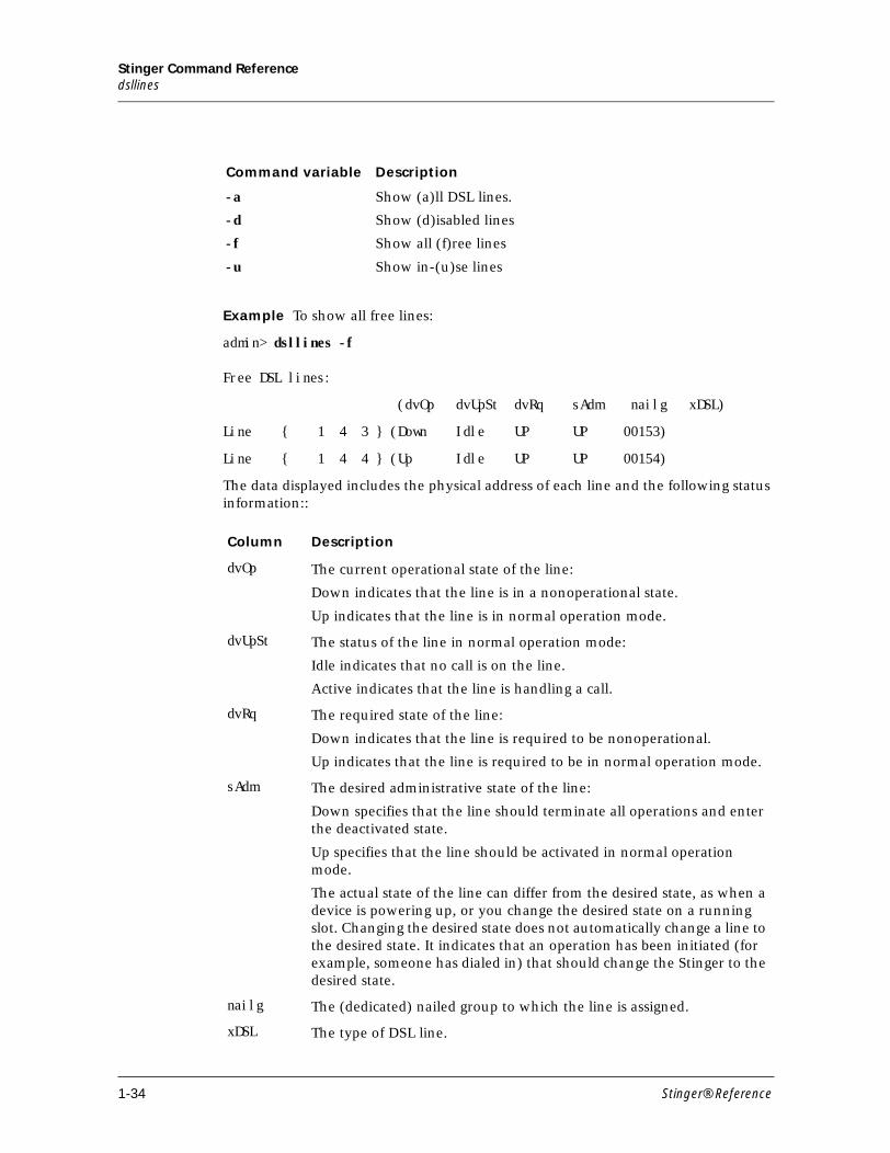
dsllines
Description Displays the status of all DSL lines.
Permission level System
Usage dsllines -[ a | d | f | u ]
Stinger® Reference 1-33
Stinger Command Referencedsllines
Example To show all free lines:
admin> dsllines -f
Free DSL lines:
(dvOp dvUpSt dvRq sAdm nailg xDSL)
Line { 1 4 3 } (Down Idle UP UP 00153)
Line { 1 4 4 } (Up Idle UP UP 00154)
The data displayed includes the physical address of each line and the following status information::
Command variable Description
-a Show (a)ll DSL lines.
-d Show (d)isabled lines
-f Show all (f)ree lines
-u Show in-(u)se lines
Column Description
dvOp The current operational state of the line:
Down indicates that the line is in a nonoperational state.
Up indicates that the line is in normal operation mode.
dvUpSt The status of the line in normal operation mode:
Idle indicates that no call is on the line.
Active indicates that the line is handling a call.
dvRq The required state of the line:
Down indicates that the line is required to be nonoperational.
Up indicates that the line is required to be in normal operation mode.
sAdm The desired administrative state of the line:
Down specifies that the line should terminate all operations and enter the deactivated state.
Up specifies that the line should be activated in normal operation mode.
The actual state of the line can differ from the desired state, as when a device is powering up, or you change the desired state on a running slot. Changing the desired state does not automatically change a line to the desired state. It indicates that an operation has been initiated (for example, someone has dialed in) that should change the Stinger to the desired state.
nailg The (dedicated) nailed group to which the line is assigned.
xDSL The type of DSL line.
1-34 Stinger® Reference
Stinger Command Referencedumpcachestat
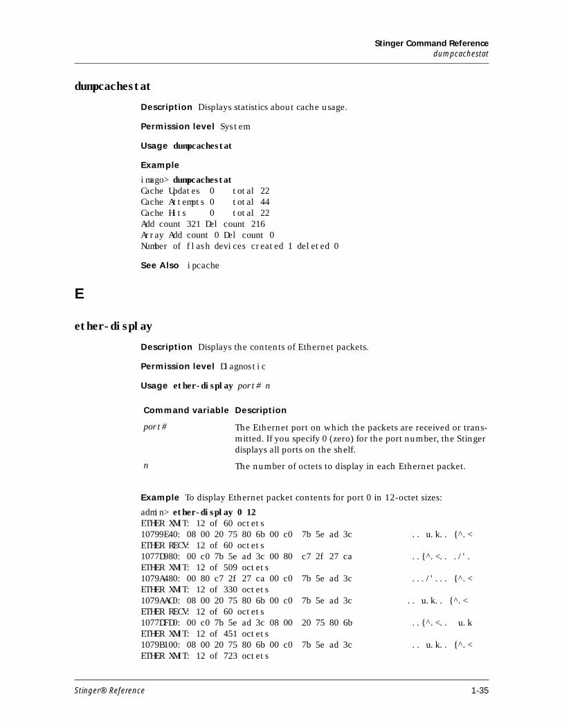
dumpcachestat
Description Displays statistics about cache usage.
Permission level System
Usage dumpcachestat
Example
imago> dumpcachestatCache Updates 0 total 22Cache Attempts 0 total 44Cache Hits 0 total 22Add count 321 Del count 216Array Add count 0 Del count 0Number of flash devices created 1 deleted 0
See Also ipcache
E
ether-display
Description Displays the contents of Ethernet packets.
Permission level Diagnostic
Usage ether-display port# n
Example To display Ethernet packet contents for port 0 in 12-octet sizes:
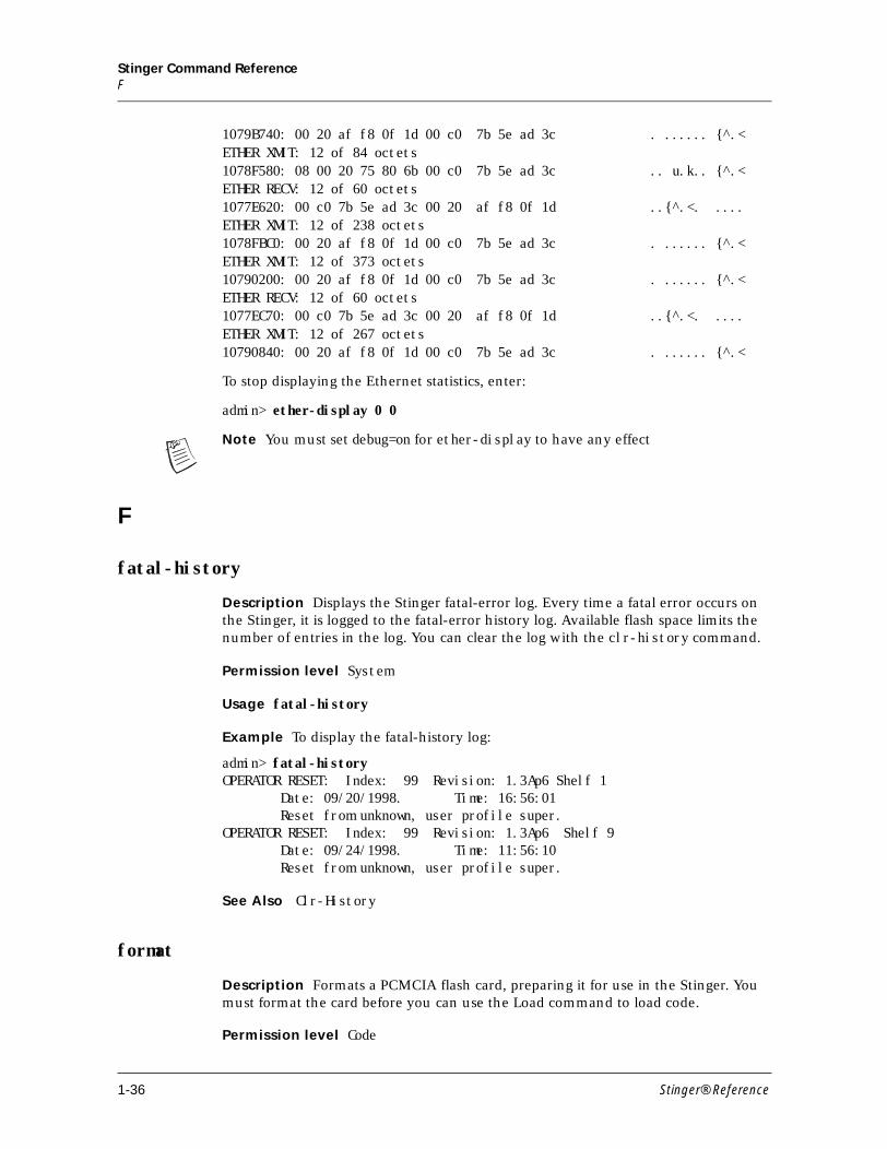
admin> ether-display 0 12ETHER XMIT: 12 of 60 octets10799E40: 08 00 20 75 80 6b 00 c0 7b 5e ad 3c .. u.k.. {^.<ETHER RECV: 12 of 60 octets1077D980: 00 c0 7b 5e ad 3c 00 80 c7 2f 27 ca ..{^.<.. ./'.ETHER XMIT: 12 of 509 octets1079A480: 00 80 c7 2f 27 ca 00 c0 7b 5e ad 3c .../'... {^.<ETHER XMIT: 12 of 330 octets1079AAC0: 08 00 20 75 80 6b 00 c0 7b 5e ad 3c .. u.k.. {^.<ETHER RECV: 12 of 60 octets1077DFD0: 00 c0 7b 5e ad 3c 08 00 20 75 80 6b ..{^.<.. u.kETHER XMIT: 12 of 451 octets1079B100: 08 00 20 75 80 6b 00 c0 7b 5e ad 3c .. u.k.. {^.<ETHER XMIT: 12 of 723 octets
Command variable Description
port# The Ethernet port on which the packets are received or trans-mitted. If you specify 0 (zero) for the port number, the Stinger displays all ports on the shelf.
n The number of octets to display in each Ethernet packet.
Stinger® Reference 1-35
Stinger Command ReferenceF
1079B740: 00 20 af f8 0f 1d 00 c0 7b 5e ad 3c . ...... {^.<ETHER XMIT: 12 of 84 octets1078F580: 08 00 20 75 80 6b 00 c0 7b 5e ad 3c .. u.k.. {^.<ETHER RECV: 12 of 60 octets1077E620: 00 c0 7b 5e ad 3c 00 20 af f8 0f 1d ..{^.<. ....ETHER XMIT: 12 of 238 octets1078FBC0: 00 20 af f8 0f 1d 00 c0 7b 5e ad 3c . ...... {^.<ETHER XMIT: 12 of 373 octets10790200: 00 20 af f8 0f 1d 00 c0 7b 5e ad 3c . ...... {^.<ETHER RECV: 12 of 60 octets1077EC70: 00 c0 7b 5e ad 3c 00 20 af f8 0f 1d ..{^.<. ....ETHER XMIT: 12 of 267 octets10790840: 00 20 af f8 0f 1d 00 c0 7b 5e ad 3c . ...... {^.<
To stop displaying the Ethernet statistics, enter:
admin> ether-display 0 0
Note You must set debug=on for ether-display to have any effect
F
fatal-history
Description Displays the Stinger fatal-error log. Every time a fatal error occurs on the Stinger, it is logged to the fatal-error history log. Available flash space limits the number of entries in the log. You can clear the log with the clr-history command.
Permission level System
Usage fatal-history
Example To display the fatal-history log:
admin> fatal-historyOPERATOR RESET: Index: 99 Revision: 1.3Ap6 Shelf 1 Date: 09/20/1998. Time: 16:56:01 Reset from unknown, user profile super.OPERATOR RESET: Index: 99 Revision: 1.3Ap6 Shelf 9 Date: 09/24/1998. Time: 11:56:10 Reset from unknown, user profile super.
See Also Clr-History
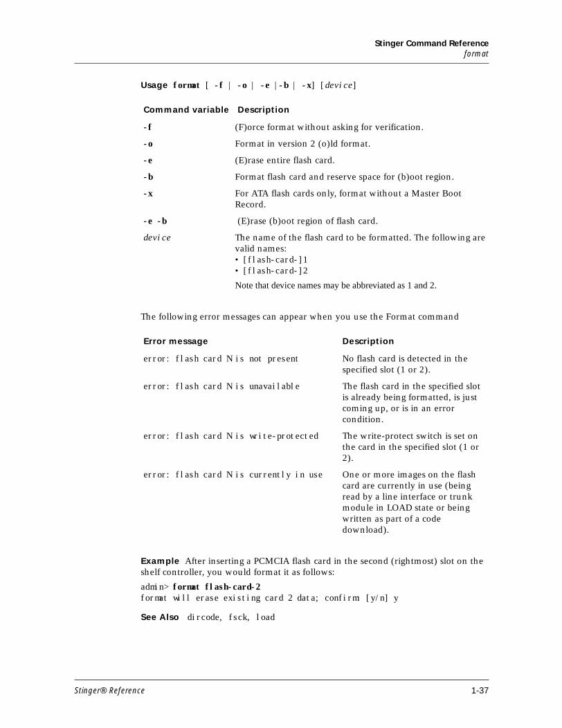
format
Description Formats a PCMCIA flash card, preparing it for use in the Stinger. You must format the card before you can use the Load command to load code.
Permission level Code
1-36 Stinger® Reference
Stinger Command Referenceformat
Usage format [ -f | -o | -e |-b | -x] [device]
The following error messages can appear when you use the Format command
Example After inserting a PCMCIA flash card in the second (rightmost) slot on the shelf controller, you would format it as follows:
admin> format flash-card-2format will erase existing card 2 data; confirm: [y/n] y
See Also dircode, fsck, load
Command variable Description
-f (F)orce format without asking for verification.
-o Format in version 2 (o)ld format.
-e (E)rase entire flash card.
-b Format flash card and reserve space for (b)oot region.
-x For ATA flash cards only, format without a Master Boot Record.
-e -b (E)rase (b)oot region of flash card.
device The name of the flash card to be formatted. The following are valid names:• [flash-card-]1• [flash-card-]2
Note that device names may be abbreviated as 1 and 2.
Error message Description
error: flash card N is not present No flash card is detected in the specified slot (1 or 2).
error: flash card N is unavailable The flash card in the specified slot is already being formatted, is just coming up, or is in an error condition.
error: flash card N is write-protected The write-protect switch is set on the card in the specified slot (1 or 2).
error: flash card N is currently in use One or more images on the flash card are currently in use (being read by a line interface or trunk module in LOAD state or being written as part of a code download).
Stinger® Reference 1-37
Stinger Command Referencefsck
fsck
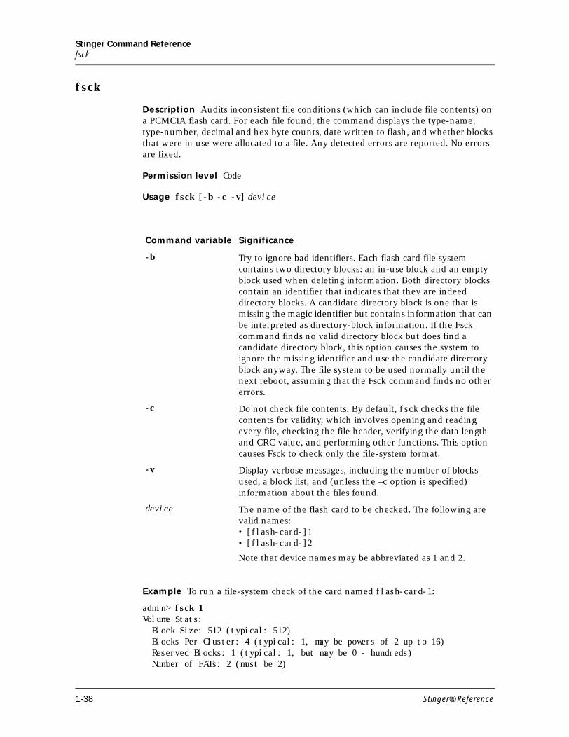
Description Audits inconsistent file conditions (which can include file contents) on a PCMCIA flash card. For each file found, the command displays the type-name, type-number, decimal and hex byte counts, date written to flash, and whether blocks that were in use were allocated to a file. Any detected errors are reported. No errors are fixed.
Permission level Code
Usage fsck [-b -c -v] device
Example To run a file-system check of the card named flash-card-1:
admin> fsck 1Volume Stats: Block Size: 512 (typical: 512) Blocks Per Cluster: 4 (typical: 1, may be powers of 2 up to 16) Reserved Blocks: 1 (typical: 1, but may be 0 - hundreds) Number of FATs: 2 (must be 2)
Command variable Significance
-b Try to ignore bad identifiers. Each flash card file system contains two directory blocks: an in-use block and an empty block used when deleting information. Both directory blocks contain an identifier that indicates that they are indeed directory blocks. A candidate directory block is one that is missing the magic identifier but contains information that can be interpreted as directory-block information. If the Fsck command finds no valid directory block but does find a candidate directory block, this option causes the system to ignore the missing identifier and use the candidate directory block anyway. The file system to be used normally until the next reboot, assuming that the Fsck command finds no other errors.
-c Do not check file contents. By default, fsck checks the file contents for validity, which involves opening and reading every file, checking the file header, verifying the data length and CRC value, and performing other functions. This option causes Fsck to check only the file-system format.
-v Display verbose messages, including the number of blocks used, a block list, and (unless the –c option is specified) information about the files found.
device The name of the flash card to be checked. The following are valid names:• [flash-card-]1• [flash-card-]2
Note that device names may be abbreviated as 1 and 2.
1-38 Stinger® Reference
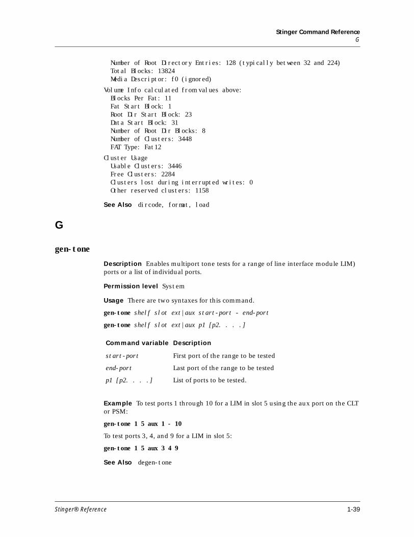
Stinger Command ReferenceG
Number of Root Directory Entries: 128 (typically between 32 and 224) Total Blocks: 13824 Media Descriptor: f0 (ignored)
Volume Info calculated from values above: Blocks Per Fat: 11 Fat Start Block: 1 Root Dir Start Block: 23 Data Start Block: 31 Number of Root Dir Blocks: 8 Number of Clusters: 3448 FAT Type: Fat12
Cluster Usage Usable Clusters: 3446 Free Clusters: 2284 Clusters lost during interrupted writes: 0 Other reserved clusters: 1158
See Also dircode, format, load
G
gen-tone
Description Enables multiport tone tests for a range of line interface module LIM) ports or a list of individual ports.
Permission level System
Usage There are two syntaxes for this command.
gen-tone shelf slot ext|aux start-port - end-port
gen-tone shelf slot ext|aux p1 [p2. . . .]
Example To test ports 1 through 10 for a LIM in slot 5 using the aux port on the CLT or PSM:
gen-tone 1 5 aux 1 - 10
To test ports 3, 4, and 9 for a LIM in slot 5:
gen-tone 1 5 aux 3 4 9
See Also degen-tone
Command variable Description
start-port First port of the range to be tested
end-port Last port of the range to be tested
p1 [p2. . . .] List of ports to be tested.
Stinger® Reference 1-39
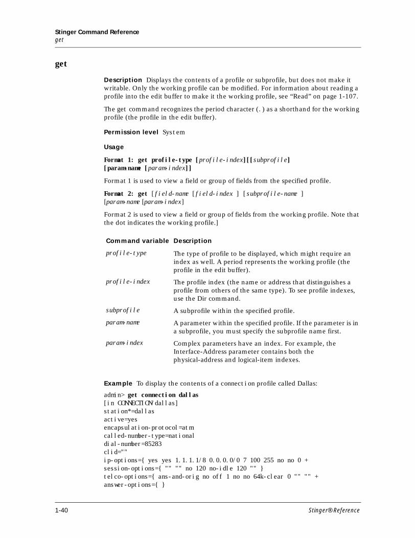
Stinger Command Referenceget
get
Description Displays the contents of a profile or subprofile, but does not make it writable. Only the working profile can be modified. For information about reading a profile into the edit buffer to make it the working profile, see “Read” on page 1-107.
The get command recognizes the period character (.) as a shorthand for the working profile (the profile in the edit buffer).
Permission level System
Usage
Format 1: get profile-type [profile-index][[subprofile][param-name [param-index]]
Format 1 is used to view a field or group of fields from the specified profile.
Format 2: get [field-name [field-index ] [subprofile-name ][param-name [param-index]
Format 2 is used to view a field or group of fields from the working profile. Note that the dot indicates the working profile.]
Example To display the contents of a connection profile called Dallas:
admin> get connection dallas[in CONNECTION/dallas]station*=dallasactive=yesencapsulation-protocol=atmcalled-number-type=nationaldial-number=85283clid=""ip-options={ yes yes 1.1.1.1/8 0.0.0.0/0 7 100 255 no no 0 +session-options={ "" "" no 120 no-idle 120 "" }telco-options={ ans-and-orig no off 1 no no 64k-clear 0 "" "" +answer-options={ }
Command variable Description
profile-type The type of profile to be displayed, which might require an index as well. A period represents the working profile (the profile in the edit buffer).
profile-index The profile index (the name or address that distinguishes a profile from others of the same type). To see profile indexes, use the Dir command.
subprofile A subprofile within the specified profile.
param-name A parameter within the specified profile. If the parameter is in a subprofile, you must specify the subprofile name first.
param-index Complex parameters have an index. For example, the Interface-Address parameter contains both the physical-address and logical-item indexes.
1-40 Stinger® Reference
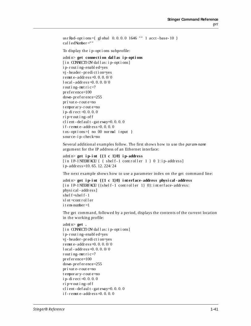
Stinger Command Referenceget
usrRad-options={ global 0.0.0.0 1646 "" 1 acct-base-10 }calledNumber=""
To display the ip-options subprofile:
admin> get connection dallas ip-options[in CONNECTION/dallas:ip-options]ip-routing-enabled=yesvj-header-prediction=yesremote-address=0.0.0.0/0local-address=0.0.0.0/0routing-metric=7preference=100down-preference=255private-route=notemporary-route=noip-direct=0.0.0.0rip=routing-offclient-default-gateway=0.0.0.0if-remote-address=0.0.0.0tos-options={ no 00 normal input }source-ip-check=no
Several additional examples follow. The first shows how to use the param-name argument for the IP address of an Ethernet interface:
admin> get ip-int {{1 c 1}0} ip-address[in IP-INTERFACE/{ { shelf-1 controller 1 } 0 }:ip-address] ip-address=10.65.12.224/24
The next example shows how to use a parameter index on the get command line:
admin> get ip-int {{1 c 1}0} interface-address physical-address[in IP-INTERFACE/{{shelf-1 controller 1} 0}:interface-address:physical-address]shelf=shelf-1slot=controlleritem-number=1
The get command, followed by a period, displays the contents of the current location in the working profile:
admin> get .[in CONNECTION/dallas:ip-options]ip-routing-enabled=yesvj-header-prediction=yesremote-address=0.0.0.0/0local-address=0.0.0.0/0routing-metric=7preference=100down-preference=255private-route=notemporary-route=noip-direct=0.0.0.0rip=routing-offclient-default-gateway=0.0.0.0if-remote-address=0.0.0.0
Stinger® Reference 1-41
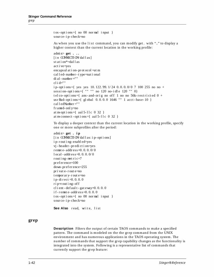
Stinger Command Referencegrep
tos-options={ no 00 normal input }source-ip-check=no
As when you use the list command, you can modify get. with “..” to display a higher context than the current location in the working profile:
admin> get . ..[in CONNECTION/dallas]station*=dallasactive=yesencapsulation-protocol=atmcalled-number-type=nationaldial-number=""clid=""ip-options={ yes yes 10.122.99.1/24 0.0.0.0/0 7 100 255 no no +session-options={ "" "" no 120 no-idle 120 "" 0}telco-options={ ans-and-orig no off 1 no no 56k-restricted 0 +usrRad-options={ global 0.0.0.0 1646 "" 1 acct-base-10 }calledNumber=""framed-only=noatm-options={ aal5-llc 0 32 }atm-connect-options={ aal5-llc 0 32 }
To display a deeper context than the current location in the working profile, specify one or more subprofiles after the period:
admin> get . ip[in CONNECTION/dallas:ip-options]ip-routing-enabled=yesvj-header-prediction=yesremote-address=0.0.0.0/0local-address=0.0.0.0/0routing-metric=7preference=100down-preference=255private-route=notemporary-route=noip-direct=0.0.0.0rip=routing-offclient-default-gateway=0.0.0.0if-remote-address=0.0.0.0tos-options={ no 00 normal input }source-ip-check=no
See Also read, write, list
grep
Description Filters the output of certain TAOS commands to make a specified pattern. The command is modeled on the the grep command from the UNIX environment and has numerous applications in the TAOS operating system. The number of commands that support the grep capability changes as the functionality is integrated into the system. Following is a representative list of commands that currently support the grep feature:
1-42 Stinger® Reference
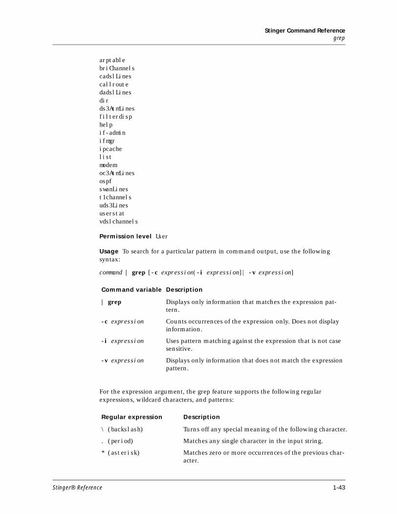
Stinger Command Referencegrep
arptablebriChannelscadslLinescallroutedadslLinesdirds3AtmLinesfilterdisphelpif-adminifmgripcachelistmodemoc3AtmLinesospfswanLinest1channelsuds3Linesuserstatvdslchannels
Permission level User
Usage To search for a particular pattern in command output, use the following syntax:
command | grep [-c expression|-i expression]| -v expression]
For the expression argument, the grep feature supports the following regular expressions, wildcard characters, and patterns:
Command variable Description
| grep Displays only information that matches the expression pat-tern.
-c expression Counts occurrences of the expression only. Does not display information.
-i expression Uses pattern matching against the expression that is not case sensitive.
-v expression Displays only information that does not match the expression pattern.
Regular expression Description
\ (backslash) Turns off any special meaning of the following character.
. (period) Matches any single character in the input string.
* (asterisk) Matches zero or more occurrences of the previous char-acter.
Stinger® Reference 1-43
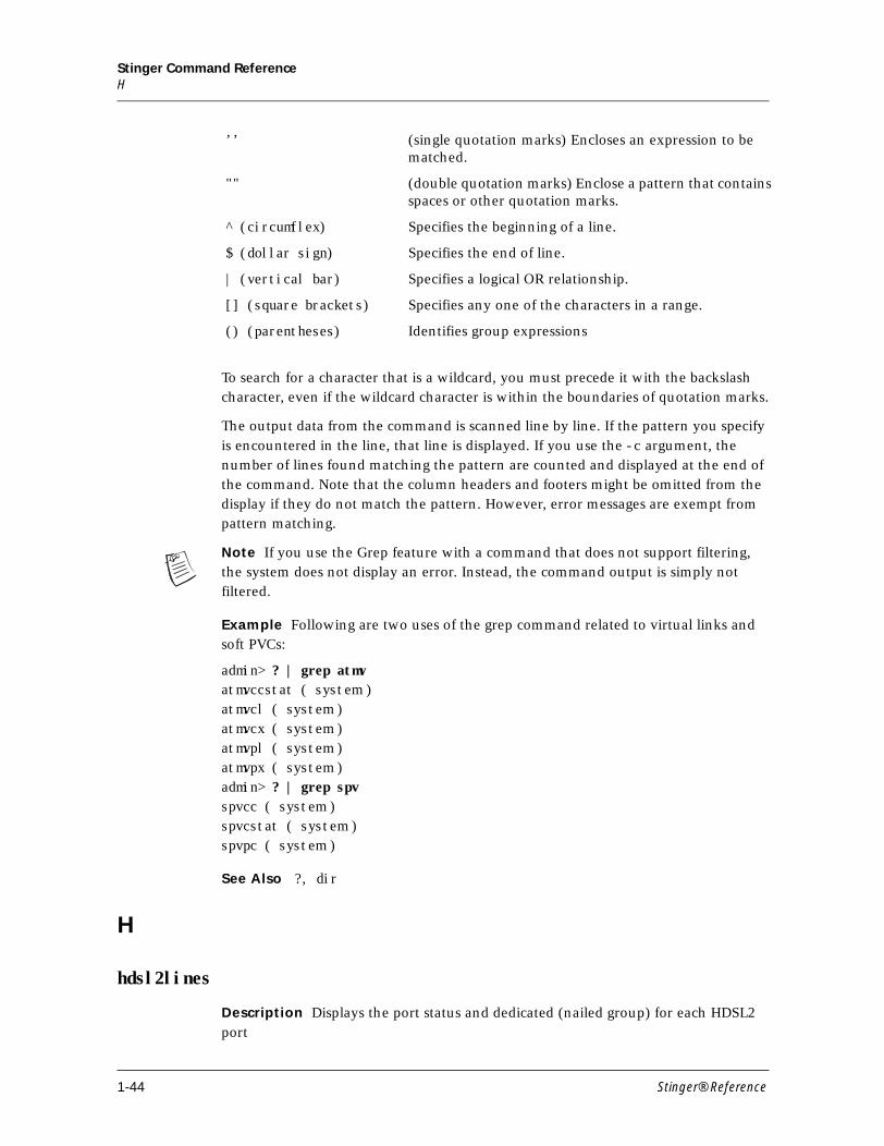
Stinger Command ReferenceH
To search for a character that is a wildcard, you must precede it with the backslash character, even if the wildcard character is within the boundaries of quotation marks.
The output data from the command is scanned line by line. If the pattern you specify
is encountered in the line, that line is displayed. If you use the -c argument, the number of lines found matching the pattern are counted and displayed at the end of the command. Note that the column headers and footers might be omitted from the display if they do not match the pattern. However, error messages are exempt from pattern matching.
Note If you use the Grep feature with a command that does not support filtering, the system does not display an error. Instead, the command output is simply not filtered.
Example Following are two uses of the grep command related to virtual links and soft PVCs:
admin> ? | grep atmvatmvccstat ( system )atmvcl ( system )atmvcx ( system )atmvpl ( system )atmvpx ( system )admin> ? | grep spvspvcc ( system )spvcstat ( system )spvpc ( system )
See Also ?, dir
H
hdsl2lines
Description Displays the port status and dedicated (nailed group) for each HDSL2
port
’’ (single quotation marks) Encloses an expression to be matched.
"" (double quotation marks) Enclose a pattern that contains spaces or other quotation marks.
^ (circumflex) Specifies the beginning of a line.
$ (dollar sign) Specifies the end of line.
| (vertical bar) Specifies a logical OR relationship.
[] (square brackets) Specifies any one of the characters in a range.
() (parentheses) Identifies group expressions
1-44 Stinger® Reference
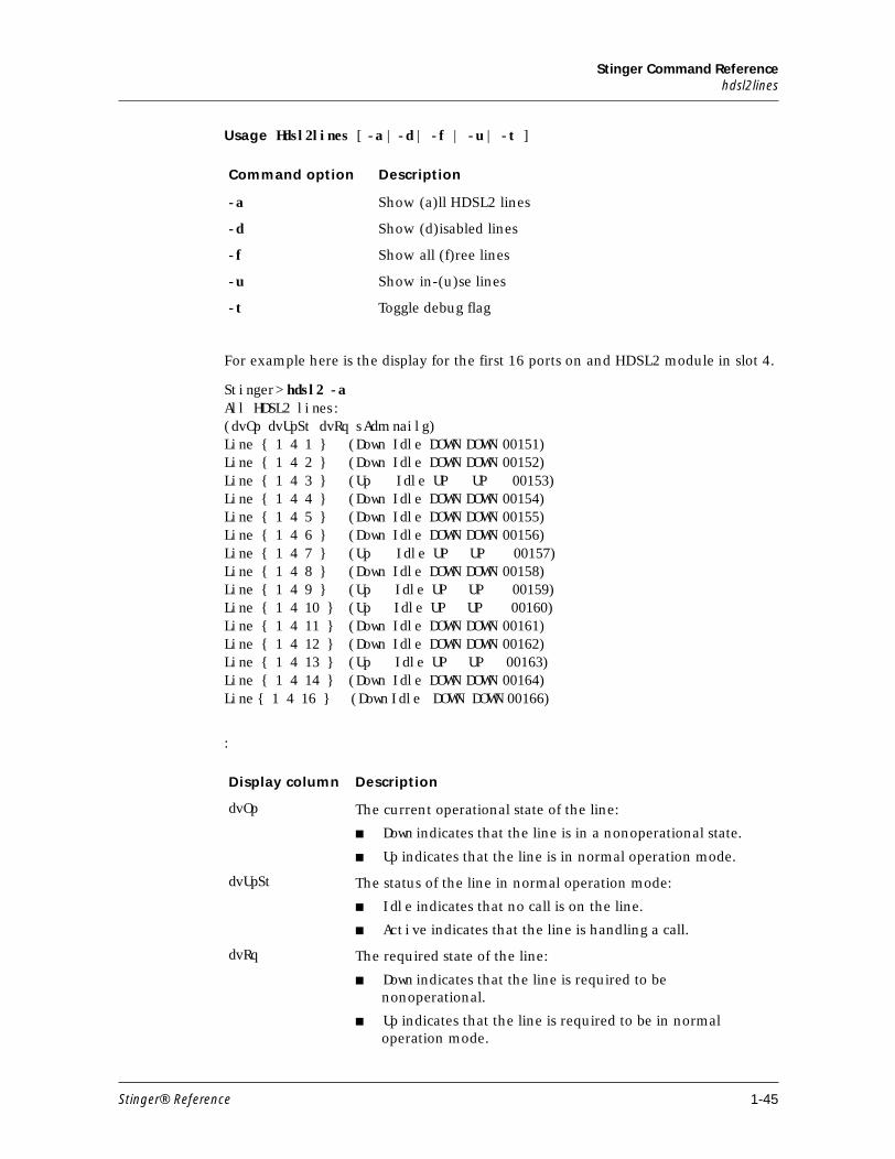
Stinger Command Referencehdsl2lines
Usage Hdsl2lines [ -a | -d | -f | -u | -t ]
For example here is the display for the first 16 ports on and HDSL2 module in slot 4.
Stinger> hdsl2 -aAll HDSL2 lines:(dvOp dvUpSt dvRq sAdm nailg)Line { 1 4 1 } (Down Idle DOWN DOWN 00151)Line { 1 4 2 } (Down Idle DOWN DOWN 00152)Line { 1 4 3 } (Up Idle UP UP 00153)Line { 1 4 4 } (Down Idle DOWN DOWN 00154)Line { 1 4 5 } (Down Idle DOWN DOWN 00155)Line { 1 4 6 } (Down Idle DOWN DOWN 00156)Line { 1 4 7 } (Up Idle UP UP 00157)Line { 1 4 8 } (Down Idle DOWN DOWN 00158)Line { 1 4 9 } (Up Idle UP UP 00159)Line { 1 4 10 } (Up Idle UP UP 00160)Line { 1 4 11 } (Down Idle DOWN DOWN 00161)Line { 1 4 12 } (Down Idle DOWN DOWN 00162)Line { 1 4 13 } (Up Idle UP UP 00163)Line { 1 4 14 } (Down Idle DOWN DOWN 00164)Line { 1 4 16 } (Down Idle DOWN DOWN 00166)
:
Command option Description
-a Show (a)ll HDSL2 lines
-d Show (d)isabled lines
-f Show all (f)ree lines
-u Show in-(u)se lines
-t Toggle debug flag
Display column Description
dvOp The current operational state of the line:
■ Down indicates that the line is in a nonoperational state.
■ Up indicates that the line is in normal operation mode.
dvUpSt The status of the line in normal operation mode:
■ Idle indicates that no call is on the line.
■ Active indicates that the line is handling a call.
dvRq The required state of the line:
■ Down indicates that the line is required to be nonoperational.
■ Up indicates that the line is required to be in normal operation mode.
Stinger® Reference 1-45
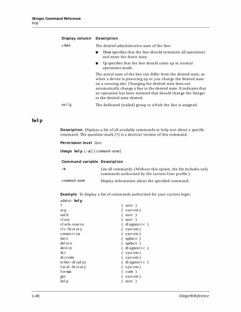
Stinger Command Referencehelp
help
Description Displays a list of all available commands or help text about a specific command. The question-mark (?) is a shortcut version of this command.
Permission level User
Usage help [-a]|[command-name]
Example To display a list of commands authorized for your current login:
admin> help? ( user )arp ( system )auth ( user )clear ( user )clock-source ( diagnostic )clr-history ( system )connection ( system )date ( update )delete ( update )device ( diagnostic )dir ( system )dircode ( system )ether-display ( diagnostic )fatal-history ( system )format ( code )get ( system )help ( user )
sAdm The desired administrative state of the line:
■ Down specifies that the line should terminate all operations and enter the down state.
■ Up specifies that the line should come up in normal operations mode.
The actual state of the line can differ from the desired state, as when a device is powering up or you change the desired state on a running slot. Changing the desired state does not automatically change a line to the desired state. It indicates that an operation has been initiated that should change the Stinger to the desired state desired.
nailg The dedicated (nailed) group to which the line is assigned.
Display column Description
Command variable Description
–a List all commands. (Without this option, the list includes only commands authorized by the current User profile.)
command-name Display information about the specified command.
1-46 Stinger® Reference
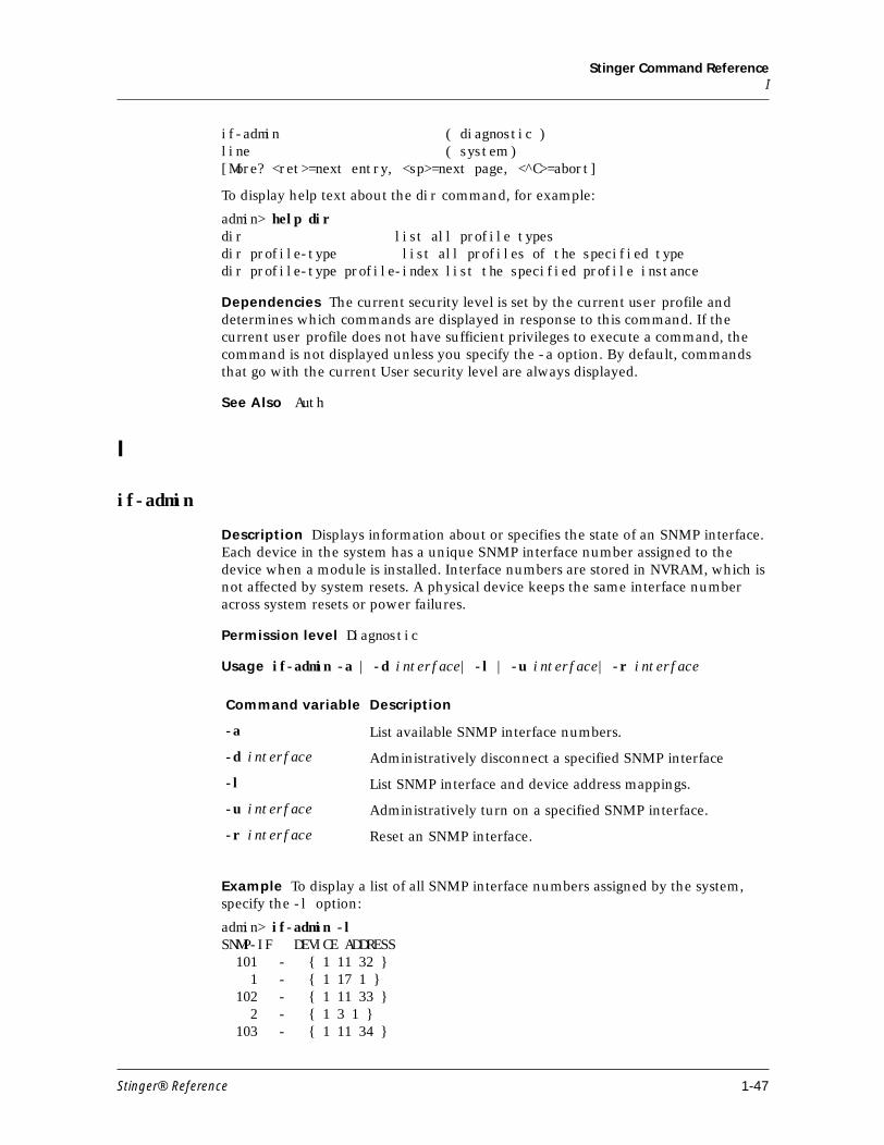
Stinger Command ReferenceI
if-admin ( diagnostic )line ( system )[More? <ret>=next entry, <sp>=next page, <^C>=abort]
To display help text about the dir command, for example:
admin> help dirdir list all profile typesdir profile-type list all profiles of the specified typedir profile-type profile-index list the specified profile instance
Dependencies The current security level is set by the current user profile and determines which commands are displayed in response to this command. If the current user profile does not have sufficient privileges to execute a command, the command is not displayed unless you specify the -a option. By default, commands that go with the current User security level are always displayed.
See Also Auth
I
if-admin
Description Displays information about or specifies the state of an SNMP interface. Each device in the system has a unique SNMP interface number assigned to the device when a module is installed. Interface numbers are stored in NVRAM, which is not affected by system resets. A physical device keeps the same interface number across system resets or power failures.
Permission level Diagnostic
Usage if-admin -a | -d interface| -l | -u interface| -r interface
Example To display a list of all SNMP interface numbers assigned by the system, specify the -l option:
admin> if-admin -lSNMP-IF DEVICE ADDRESS 101 - { 1 11 32 } 1 - { 1 17 1 } 102 - { 1 11 33 } 2 - { 1 3 1 } 103 - { 1 11 34 }
Command variable Description
-a List available SNMP interface numbers.
-d interface Administratively disconnect a specified SNMP interface
-l List SNMP interface and device address mappings.
-u interface Administratively turn on a specified SNMP interface.
-r interface Reset an SNMP interface.
Stinger® Reference 1-47
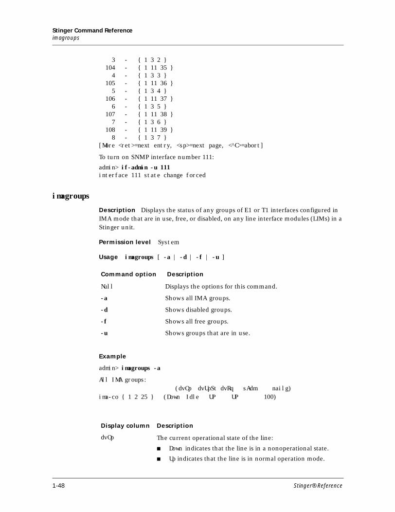
Stinger Command Referenceimagroups
3 - { 1 3 2 } 104 - { 1 11 35 } 4 - { 1 3 3 } 105 - { 1 11 36 } 5 - { 1 3 4 } 106 - { 1 11 37 } 6 - { 1 3 5 } 107 - { 1 11 38 } 7 - { 1 3 6 } 108 - { 1 11 39 } 8 - { 1 3 7 }[More <ret>=next entry, <sp>=next page, <^C>=abort]
To turn on SNMP interface number 111:
admin> if-admin -u 111interface 111 state change forced
imagroups
Description Displays the status of any groups of E1 or T1 interfaces configured in IMA mode that are in use, free, or disabled, on any line interface modules (LIMs) in a Stinger unit.
Permission level System
Usage imagroups [ -a | -d | -f | -u ]
Example
admin> imagroups -a
All IMA groups: (dvOp dvUpSt dvRq sAdm nailg)
ima-co { 1 2 25 } (Down Idle UP UP 100)
Command option Description
Null Displays the options for this command.
-a Shows all IMA groups.
-d Shows disabled groups.
-f Shows all free groups.
-u Shows groups that are in use.
Display column Description
dvOp The current operational state of the line:
■ Down indicates that the line is in a nonoperational state.
■ Up indicates that the line is in normal operation mode.
1-48 Stinger® Reference
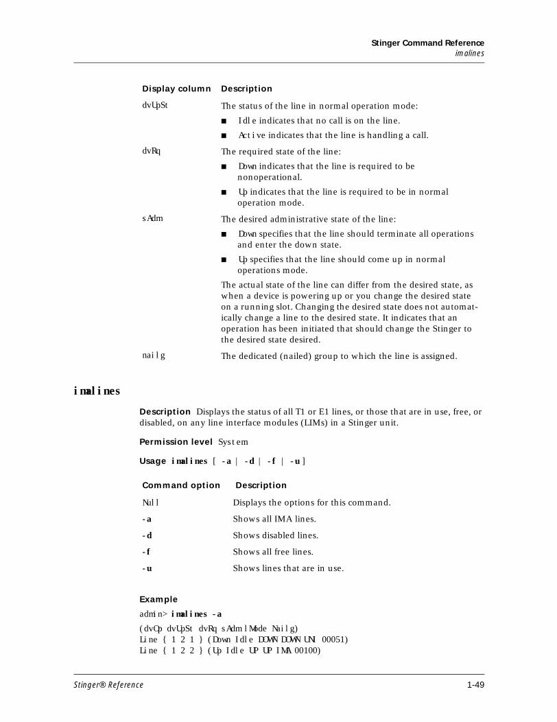
Stinger Command Referenceimalines
imalines
Description Displays the status of all T1 or E1 lines, or those that are in use, free, or disabled, on any line interface modules (LIMs) in a Stinger unit.
Permission level System
Usage imalines [ -a | -d | -f | -u ]
Example
admin> imalines -a
(dvOp dvUpSt dvRq sAdm lMode Nailg)Line { 1 2 1 } (Down Idle DOWN DOWN UNI 00051)Line { 1 2 2 } (Up Idle UP UP IMA 00100)
dvUpSt The status of the line in normal operation mode:
■ Idle indicates that no call is on the line.
■ Active indicates that the line is handling a call.
dvRq The required state of the line:
■ Down indicates that the line is required to be nonoperational.
■ Up indicates that the line is required to be in normal operation mode.
sAdm The desired administrative state of the line:
■ Down specifies that the line should terminate all operations and enter the down state.
■ Up specifies that the line should come up in normal operations mode.
The actual state of the line can differ from the desired state, as when a device is powering up or you change the desired state on a running slot. Changing the desired state does not automat-ically change a line to the desired state. It indicates that an operation has been initiated that should change the Stinger to the desired state desired.
nailg The dedicated (nailed) group to which the line is assigned.
Display column Description
Command option Description
Null Displays the options for this command.
-a Shows all IMA lines.
-d Shows disabled lines.
-f Shows all free lines.
-u Shows lines that are in use.
Stinger® Reference 1-49
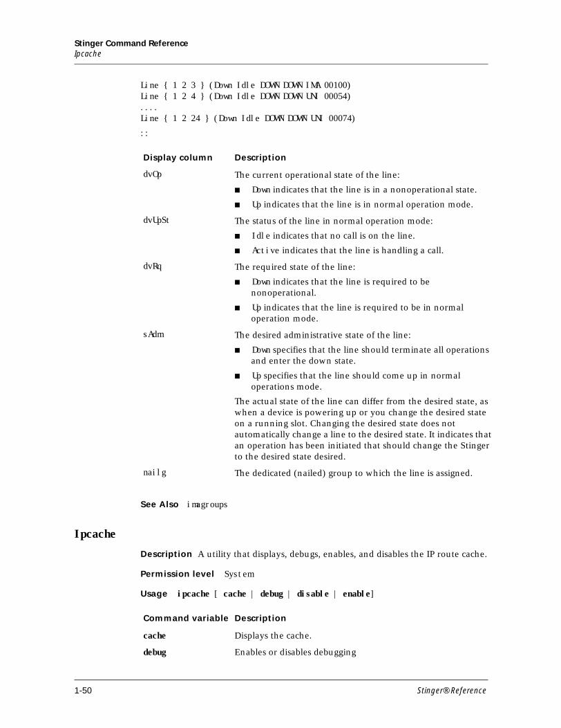
Stinger Command ReferenceIpcache
Line { 1 2 3 } (Down Idle DOWN DOWN IMA 00100)Line { 1 2 4 } (Down Idle DOWN DOWN UNI 00054)....Line { 1 2 24 } (Down Idle DOWN DOWN UNI 00074)
::
See Also imagroups
Ipcache
Description A utility that displays, debugs, enables, and disables the IP route cache.
Permission level System
Usage ipcache [ cache | debug | disable | enable]
Display column Description
dvOp The current operational state of the line:
■ Down indicates that the line is in a nonoperational state.
■ Up indicates that the line is in normal operation mode.
dvUpSt The status of the line in normal operation mode:
■ Idle indicates that no call is on the line.
■ Active indicates that the line is handling a call.
dvRq The required state of the line:
■ Down indicates that the line is required to be nonoperational.
■ Up indicates that the line is required to be in normal operation mode.
sAdm The desired administrative state of the line:
■ Down specifies that the line should terminate all operations and enter the down state.
■ Up specifies that the line should come up in normal operations mode.
The actual state of the line can differ from the desired state, as when a device is powering up or you change the desired state on a running slot. Changing the desired state does not automatically change a line to the desired state. It indicates that an operation has been initiated that should change the Stinger to the desired state desired.
nailg The dedicated (nailed) group to which the line is assigned.
Command variable Description
cache Displays the cache.
debug Enables or disables debugging
1-50 Stinger® Reference
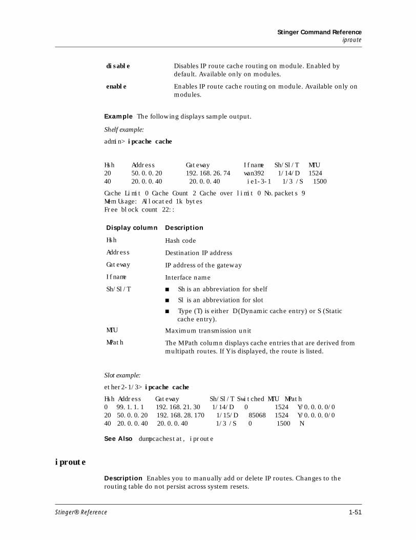
Stinger Command Referenceiproute
Example The following displays sample output.
Shelf example:
admin> ipcache cache
Hsh Address Gateway Ifname Sh/Sl/T MTU20 50.0.0.20 192.168.26.74 wan392 1/14/D 1524 40 20.0.0.40 20.0.0.40 ie1-3-1 1/3 /S 1500
Cache Limit 0 Cache Count 2 Cache over limit 0 No.packets 9 Mem Usage: Allocated 1k bytesFree block count 22::
Slot example:
ether2-1/3> ipcache cache
Hsh Address Gateway Sh/Sl/T Switched MTU MPath0 99.1.1.1 192.168.21.30 1/14/D 0 1524 Y/0.0.0.0/0 20 50.0.0.20 192.168.28.170 1/15/D 85068 1524 Y/0.0.0.0/0 40 20.0.0.40 20.0.0.40 1/3 /S 0 1500 N
See Also dumpcachestat, iproute
iproute
Description Enables you to manually add or delete IP routes. Changes to the routing table do not persist across system resets.
disable Disables IP route cache routing on module. Enabled by default. Available only on modules.
enable Enables IP route cache routing on module. Available only on modules.
Display column Description
Hsh Hash code
Address Destination IP address
Gateway IP address of the gateway
Ifname Interface name
Sh/Sl/T ■ Sh is an abbreviation for shelf
■ Sl is an abbreviation for slot
■ Type (T) is either D (Dynamic cache entry) or S (Static cache entry).
MTU Maximum transmission unit
MPath The MPath column displays cache entries that are derived from multipath routes. If Y is displayed, the route is listed.
Stinger® Reference 1-51
Stinger Command ReferenceIsolate
Permission level System
Usageiproute [add dest_IPaddr [/subnet_mask] gateway_IPaddr [/subnet_mask] [pref] [metric] |delete dest_IPaddr/subnet_mask [gateway_IPaddr[/subnet_mask]]]
To add a static IP route to the unit’s routing table, use the iproute add command.
iproute [add dest_IPaddr [/subnet_mask] gateway_IPaddr [/subnet_mask] [pref] [metric]
For example, the following command adds a route to the 10.1.2.0 network, through the IP router located at 10.0.0.3/24. The metric to the route is 1 (one hop away).
admin> iproute add 10.1.2.0/24 10.0.0.3/24 1
If you try to add a route to a destination that is already in the routing table, the Stinger replaces the existing route only if it has a higher metric than the route you are attempting to add. If you get the message Warning: a better route appears to exist, the Stinger has rejected your attempt to add a route. Note that RIP updates can change the metric for the route.Note Any routes you add with the add option are lost when you reset the Stinger.
To remove a static IP route from the unit’s routing table, enter the IProute delete option.
iproute delete dest_IPaddr/subnet_mask [gateway_IPaddr[/subnet_mask]]
For example, the following command removes the route to the 10.1.2.0 network:
admin> iproute delete 10.1.2.0/24 10.0.0.3/24Note RIP updates can add back any route you remove with delete option. Also, the Stinger restores all routes listed in the IP-Route profile after a system reset.
See Also ipcache
Isolate
Description Enables galvanic isolation tests for a range of line interface module (LIM) ports or a list of individual ports.
Command variable Description
add Add an IP route to the routing table.
delete Delete an IP route from the routing table.
dest_IPaddr/subnet_mask Destination network address and subnet mask (in bits). The default is 0.0.0.0/0.
gateway_IPaddr/subnet_mask IP address of the router that can forward packets to the destination network, and subnet mask (in bits). The default is 0.0.0.0.
pref Route preference. The default is 100.
metric Virtual hop count of the route. You can enter a value between 1 and 15. The default is 1.
1-52 Stinger® Reference
Stinger Command ReferenceL
Permission level System
Usage There are two syntaxes for this command.
isolate shelf slot start-port - end-port
and
isolate shelf slot p1 [p2. . . .]
Example To test ports 1 through 10 for a LIM in slot 5:
isolate 1 5 1 - 10
To test ports 3, 4, and 9 for a LIM in slot 5:
isolate 1 5 3 4 9
See Also deisolate
L
line
Description Specifies that the upper-right or lower-right portion of the status window (or both) should display line and channel status information. If the status window is not already displayed, this command opens it with the connection status information displayed.
Permission level System
Usage line all|enabled | top|bottom
Example To display line status information in the upper part of the status window use the command as follows:
Command variable Description
start-port First port of the range to be tested
end-port Last port of the range to be tested
p1 [p2. . . .] List of ports to be tested.
Command option Description
all Display status information about all lines.
enabled Display status information only about enabled lines.
top Display line status in the upper portion of the status window.
bottom Display line status in the lower portion of the status window (the default).
Stinger® Reference 1-53
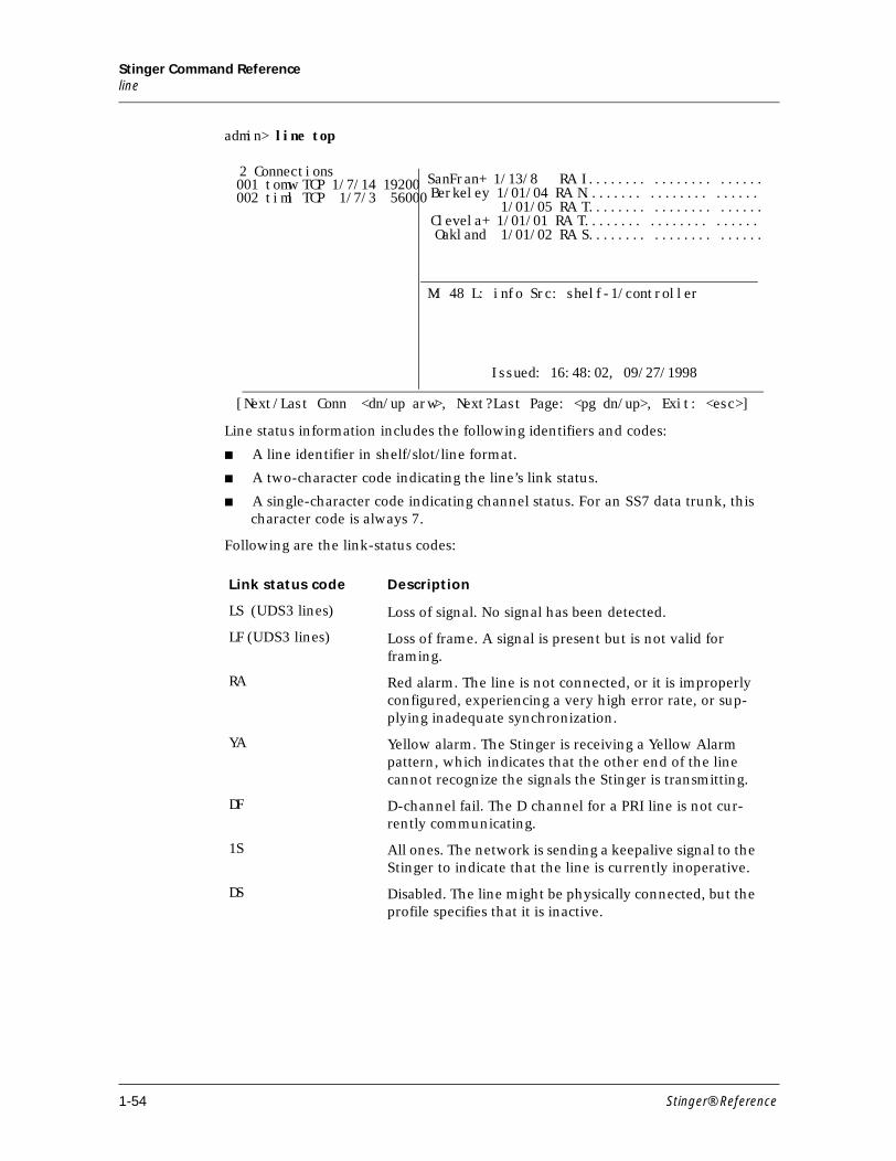
Stinger Command Referenceline
admin> line top
Line status information includes the following identifiers and codes:
■ A line identifier in shelf/slot/line format.
■ A two-character code indicating the line’s link status.
■ A single-character code indicating channel status. For an SS7 data trunk, this character code is always 7.
Following are the link-status codes:
Link status code Description
LS (UDS3 lines) Loss of signal. No signal has been detected.
LF (UDS3 lines) Loss of frame. A signal is present but is not valid for framing.
RA Red alarm. The line is not connected, or it is improperly configured, experiencing a very high error rate, or sup-plying inadequate synchronization.
YA Yellow alarm. The Stinger is receiving a Yellow Alarm pattern, which indicates that the other end of the line cannot recognize the signals the Stinger is transmitting.
DF D-channel fail. The D channel for a PRI line is not cur-rently communicating.
1S All ones. The network is sending a keepalive signal to the Stinger to indicate that the line is currently inoperative.
DS Disabled. The line might be physically connected, but the profile specifies that it is inactive.
SanFran+ 1/13/8 RA I........ ........ ......
M: 48 L: info Src: shelf-1/controller
Issued: 16:48:02, 09/27/1998
[Next/Last Conn <dn/up arw>, Next?Last Page: <pg dn/up>, Exit: <esc>]
2 Connections001 tomw TCP 1/7/14 19200002 timl TCP 1/7/3 56000 Berkeley 1/01/04 RA N........ ........ ......
1/01/05 RA T........ ........ ...... Clevela+ 1/01/01 RA T........ ........ ...... Oakland 1/01/02 RA S........ ........ ......
1-54 Stinger® Reference
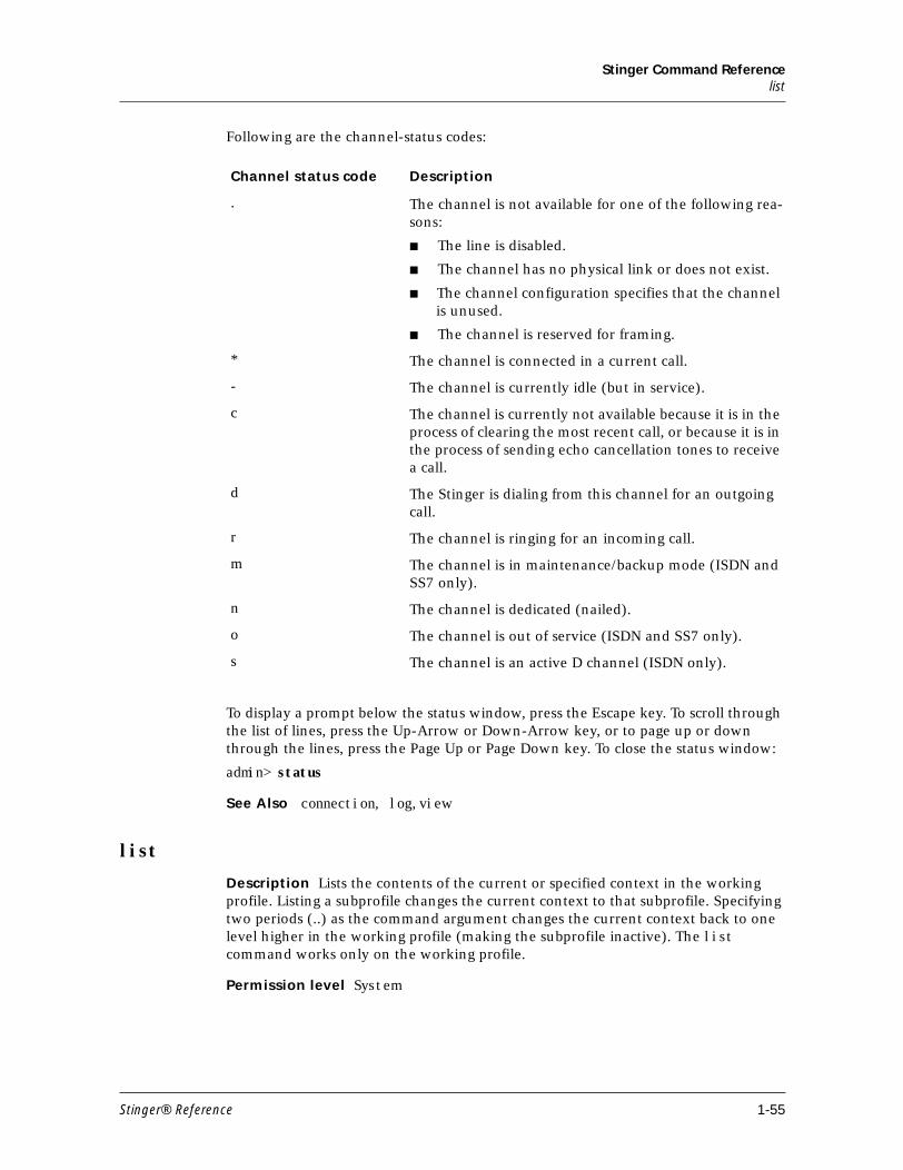
Stinger Command Referencelist
Following are the channel-status codes:
To display a prompt below the status window, press the Escape key. To scroll through the list of lines, press the Up-Arrow or Down-Arrow key, or to page up or down through the lines, press the Page Up or Page Down key. To close the status window:
admin> status
See Also connection, log,view
list
Description Lists the contents of the current or specified context in the working profile. Listing a subprofile changes the current context to that subprofile. Specifying two periods (..) as the command argument changes the current context back to one level higher in the working profile (making the subprofile inactive). The list command works only on the working profile.
Permission level System
Channel status code Description
. The channel is not available for one of the following rea-sons:
■ The line is disabled.
■ The channel has no physical link or does not exist.
■ The channel configuration specifies that the channel is unused.
■ The channel is reserved for framing.
* The channel is connected in a current call.
- The channel is currently idle (but in service).
c The channel is currently not available because it is in the process of clearing the most recent call, or because it is in the process of sending echo cancellation tones to receive a call.
d The Stinger is dialing from this channel for an outgoing call.
r The channel is ringing for an incoming call.
m The channel is in maintenance/backup mode (ISDN and SS7 only).
n The channel is dedicated (nailed).
o The channel is out of service (ISDN and SS7 only).
s The channel is an active D channel (ISDN only).
Stinger® Reference 1-55
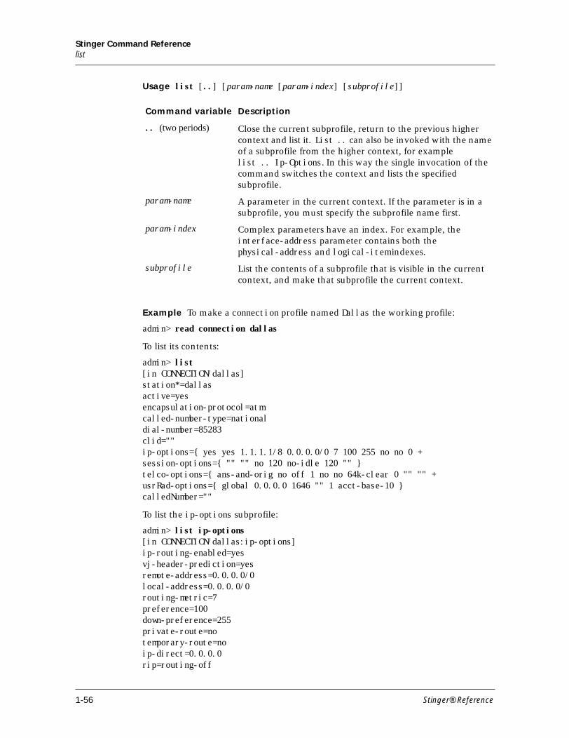
Stinger Command Referencelist
Usage list [..] [param-name [param-index] [subprofile]]
Example To make a connection profile named Dallas the working profile:
admin> read connection dallas
To list its contents:
admin> list[in CONNECTION/dallas]station*=dallasactive=yesencapsulation-protocol=atmcalled-number-type=nationaldial-number=85283clid=""ip-options={ yes yes 1.1.1.1/8 0.0.0.0/0 7 100 255 no no 0 +session-options={ "" "" no 120 no-idle 120 "" }telco-options={ ans-and-orig no off 1 no no 64k-clear 0 "" "" +usrRad-options={ global 0.0.0.0 1646 "" 1 acct-base-10 }calledNumber=""
To list the ip-options subprofile:
admin> list ip-options[in CONNECTION/dallas:ip-options]ip-routing-enabled=yesvj-header-prediction=yesremote-address=0.0.0.0/0local-address=0.0.0.0/0routing-metric=7preference=100down-preference=255private-route=notemporary-route=noip-direct=0.0.0.0rip=routing-off
Command variable Description
.. (two periods) Close the current subprofile, return to the previous higher context and list it. List .. can also be invoked with the name of a subprofile from the higher context, for examplelist .. Ip-Options.In this way the single invocation of the command switches the context and lists the specified subprofile.
param-name A parameter in the current context. If the parameter is in a subprofile, you must specify the subprofile name first.
param-index Complex parameters have an index. For example, the interface-address parameter contains both the physical-address and logical-item indexes.
subprofile List the contents of a subprofile that is visible in the current context, and make that subprofile the current context.
1-56 Stinger® Reference
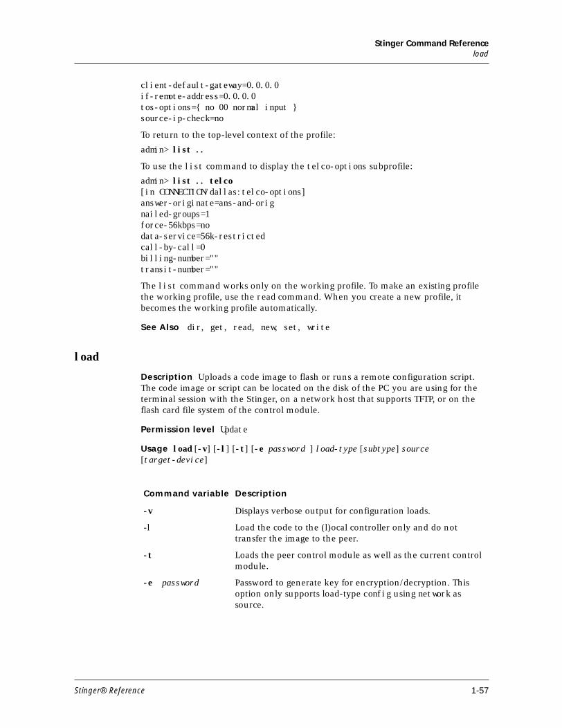
Stinger Command Referenceload
client-default-gateway=0.0.0.0if-remote-address=0.0.0.0tos-options={ no 00 normal input }source-ip-check=no
To return to the top-level context of the profile:
admin> list ..
To use the list command to display the telco-options subprofile:
admin> list .. telco[in CONNECTION/dallas:telco-options]answer-originate=ans-and-orignailed-groups=1force-56kbps=nodata-service=56k-restrictedcall-by-call=0billing-number=""transit-number=""
The list command works only on the working profile. To make an existing profile the working profile, use the read command. When you create a new profile, it becomes the working profile automatically.
See Also dir, get, read, new, set, write
load
Description Uploads a code image to flash or runs a remote configuration script. The code image or script can be located on the disk of the PC you are using for the terminal session with the Stinger, on a network host that supports TFTP, or on the flash card file system of the control module.
Permission level Update
Usage load [-v] [-l] [-t] [-e password ] load-type [subtype] source [target-device]
Command variable Description
-v Displays verbose output for configuration loads.
-l Load the code to the (l)ocal controller only and do not transfer the image to the peer.
-t Loads the peer control module as well as the current control module.
-e password Password to generate key for encryption/decryption. This option only supports load-type config using network as source.
Stinger® Reference 1-57
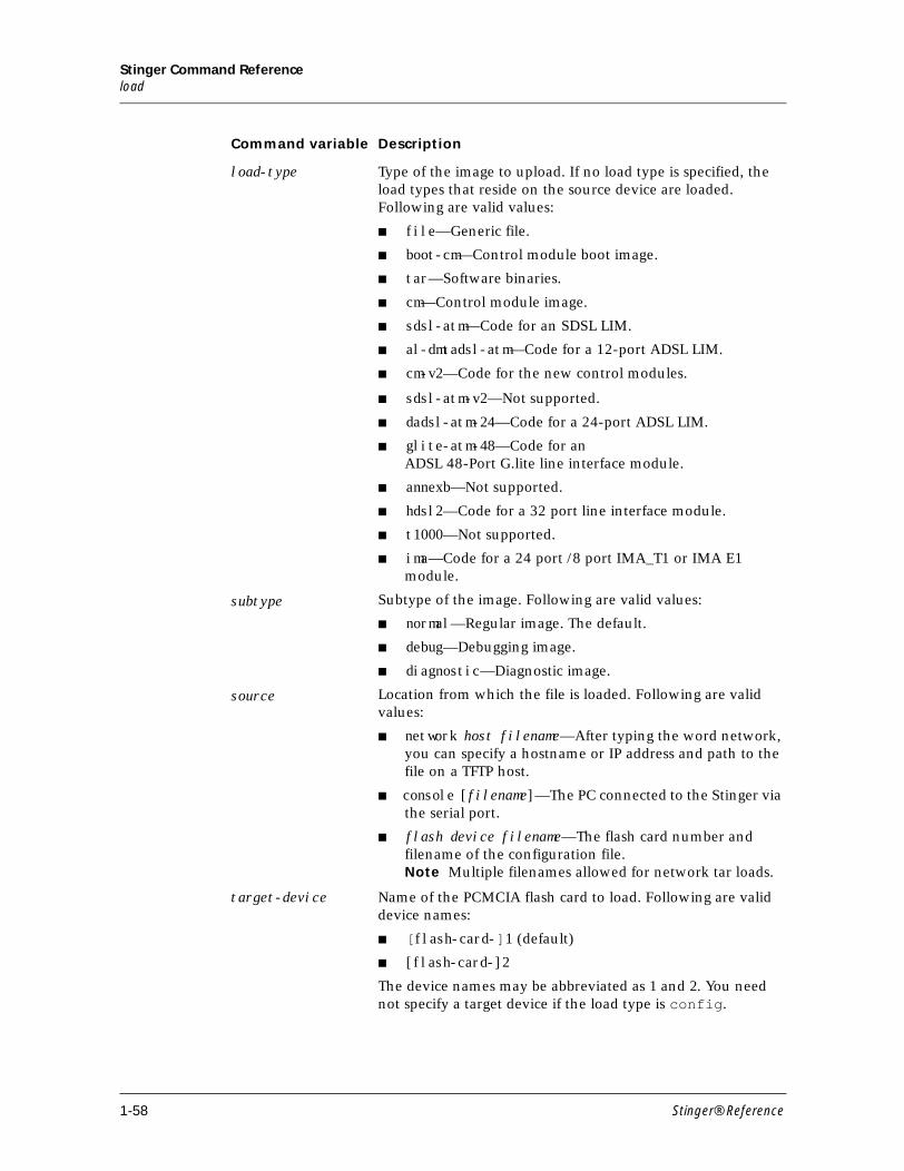
Stinger Command Referenceload
load-type Type of the image to upload. If no load type is specified, the load types that reside on the source device are loaded. Following are valid values:
■ file—Generic file.
■ boot-cm—Control module boot image.
■ tar—Software binaries.
■ cm—Control module image.
■ sdsl-atm—Code for an SDSL LIM.
■ al-dmtadsl-atm—Code for a 12-port ADSL LIM.
■ cm-v2—Code for the new control modules.
■ sdsl-atm-v2—Not supported.
■ dadsl-atm-24—Code for a 24-port ADSL LIM.
■ glite-atm-48—Code for anADSL 48-Port G.lite line interface module.
■ annexb—Not supported.
■ hdsl2—Code for a 32 port line interface module.
■ t1000—Not supported.
■ ima—Code for a 24 port /8 port IMA_T1 or IMA E1 module.
subtype Subtype of the image. Following are valid values:
■ normal—Regular image. The default.
■ debug—Debugging image.
■ diagnostic—Diagnostic image.
source Location from which the file is loaded. Following are valid values:
■ network host filename—After typing the word network, you can specify a hostname or IP address and path to the file on a TFTP host.
■ console [filename]—The PC connected to the Stinger via the serial port.
■ flash device filename—The flash card number and filename of the configuration file.Note Multiple filenames allowed for network tar loads.
target-device Name of the PCMCIA flash card to load. Following are valid device names:
■ [flash-card-]1 (default)
■ [flash-card-]2
The device names may be abbreviated as 1 and 2. You need not specify a target device if the load type is config.
Command variable Description
1-58 Stinger® Reference
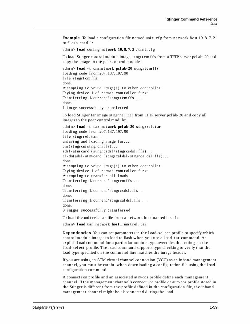
Stinger Command Referenceload
Example To load a configuration file named unit.cfg from network host 10.8.7.2 to flash card 1:
admin> load config network 10.8.7.2 /unit.cfg
To load Stinger control module image stngrtcm.ffs from a TFTP server pclab-20 and copy the image to the peer control module:
admin> load -t cm network pclab-20 stngrtcm.ffsloading code from 207.137.197.90file stngrtcm.ffs...done.Attempting to write image(s) to other controllerTrying device 1 of remote controller firstTransferring 1/current/stngrtcm.ffs ...done.1 image successfully transferred
To load Stinger tar image stngrrel.tar from TFTP server pclab-20 and copy all images to the peer control module:
admin> load -t tar network pclab-20 stngrrel.tarloading code from 207.137.197.90file stngrrel.tar...untaring and loading image for...cm (stngrcm/stngrcm.ffs)...sdsl-atm-card (stngrcsdsl/stngrcsdsl.ffs)...al-dmtadsl-atm-card (stngrcaldsl/stngrcaldsl.ffs)...done.Attempting to write image(s) to other controllerTrying device 1 of remote controller firstAttempting to transfer all loadsTransferring 1/current/stngrcm.ffs ...done.Transferring 1/current/stngrcsdsl.ffs ...done.Transferring 1/current/stngrcaldsl.ffs ...done.3 images successfully transferred
To load the unitrel.tar file from a network host named host1:
admin> load tar network host1 unitrel.tar
Dependencies You can set parameters in the load-select profile to specify which control module images to load to flash when you use a load tar command. An explicit load command for a particular module type overrides the settings in the load-select profile. The load command supports type checking to verify that the load type specified on the command line matches the image header.
If you are using an ATM virtual channel connection (VCC) as an inband management channel, you must be careful when downloading a configuration file using the load configuration command.
A connection profile and an associated atm-qos profile define each management channel. If the management channel’s connection profile or atm-qos profile stored in the Stinger is different from the profile defined in the configuration file, the inband management channel might be disconnected during the load.
Stinger® Reference 1-59
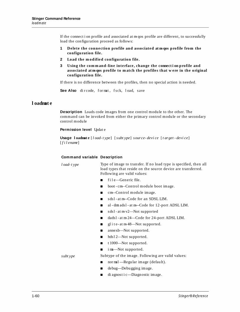
Stinger Command Referenceloadmate
If the connection profile and associated atm-qos profile are different, to successfully load the configuration proceed as follows:
1 Delete the connection profile and associated atm-qos profile from the configuration file.
2 Load the modified configuration file.
3 Using the command-line interface, change the connection profile and associated atm-qos profile to match the profiles that were in the original configuration file.
If there is no difference between the profiles, then no special action is needed.
See Also dircode, format, fsck, load, save
loadmate
Description Loads code images from one control module to the other. The command can be invoked from either the primary control module or the secondary control module
Permission level Update
Usage loadmate [load-type] [subtype] source-device [target-device] [filename]
Command variable Description
load-type Type of image to transfer. If no load type is specified, then all load types that reside on the source device are transferred. Following are valid values:
■ file—Generic file.
■ boot-cm—Control module boot image.
■ cm—Control module image.
■ sdsl-atm—Code for an SDSL LIM.
■ al-dmtadsl-atm—Code for 12-port ADSL LIM.
■ sdsl-atm-v2—Not supported
■ dadsl-atm-24—Code for 24-port ADSL LIM.
■ glite-atm-48—Not supported.
■ annexb—Not supported.
■ hdsl2—Not supported.
■ t1000—Not supported.
■ ima—Not supported.
subtype Subtype of the image. Following are valid values:
■ normal—Regular image (default).
■ debug—Debugging image.
■ diagnostic—Diagnostic image.
1-60 Stinger® Reference
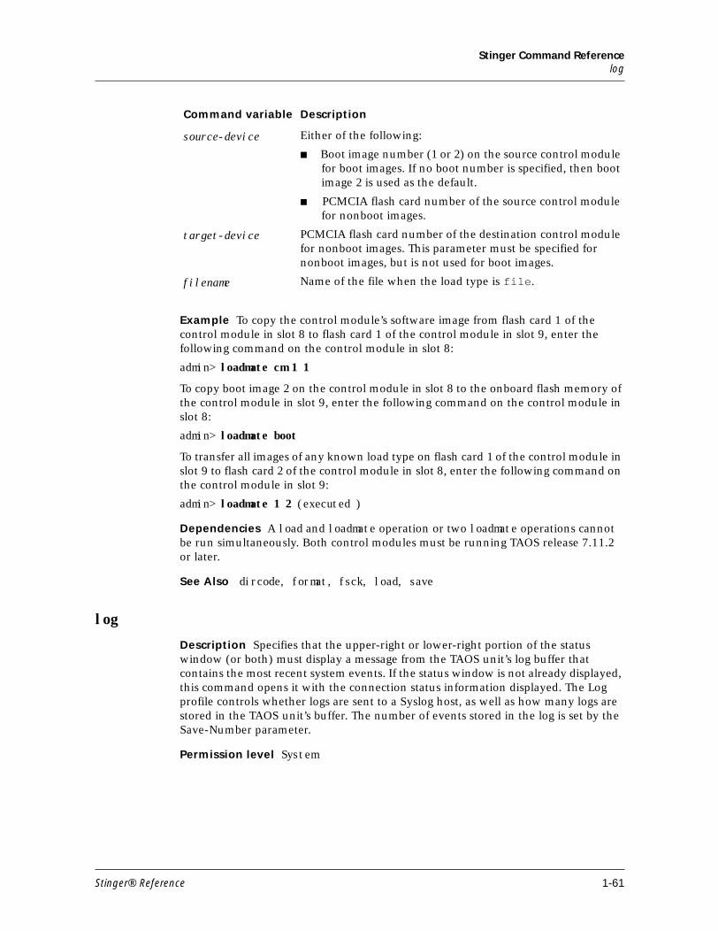
Stinger Command Referencelog
Example To copy the control module’s software image from flash card 1 of the control module in slot 8 to flash card 1 of the control module in slot 9, enter the following command on the control module in slot 8:
admin> loadmate cm 1 1
To copy boot image 2 on the control module in slot 8 to the onboard flash memory of the control module in slot 9, enter the following command on the control module in slot 8:
admin> loadmate boot
To transfer all images of any known load type on flash card 1 of the control module in slot 9 to flash card 2 of the control module in slot 8, enter the following command on the control module in slot 9:
admin> loadmate 1 2 (executed )
Dependencies A load and loadmate operation or two loadmate operations cannot be run simultaneously. Both control modules must be running TAOS release 7.11.2 or later.
See Also dircode, format, fsck, load, save
log
Description Specifies that the upper-right or lower-right portion of the status window (or both) must display a message from the TAOS unit’s log buffer that contains the most recent system events. If the status window is not already displayed, this command opens it with the connection status information displayed. The Log profile controls whether logs are sent to a Syslog host, as well as how many logs are stored in the TAOS unit’s buffer. The number of events stored in the log is set by the Save-Number parameter.
Permission level System
source-device Either of the following:
■ Boot image number (1 or 2) on the source control module for boot images. If no boot number is specified, then boot image 2 is used as the default.
■ PCMCIA flash card number of the source control module for nonboot images.
target-device PCMCIA flash card number of the destination control module for nonboot images. This parameter must be specified for nonboot images, but is not used for boot images.
filename Name of the file when the load type is file.
Command variable Description
Stinger® Reference 1-61
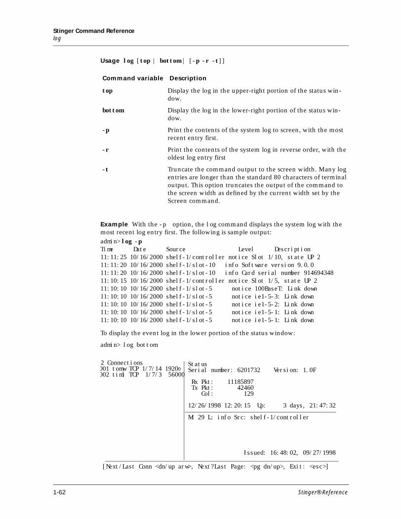
Stinger Command Referencelog
Usage log [top | bottom | [-p -r -t]]
Example With the -p option, the log command displays the system log with the most recent log entry first. The following is sample output:
admin> log -pTime Date Source Level Description11:11:25 10/16/2000 shelf-1/controller notice Slot 1/10, state UP 211:11:20 10/16/2000 shelf-1/slot-10 info Software version 9.0.011:11:20 10/16/2000 shelf-1/slot-10 info Card serial number 91469434811:10:15 10/16/2000 shelf-1/controller notice Slot 1/5, state UP 211:10:10 10/16/2000 shelf-1/slot-5 notice 100BaseT: Link down11:10:10 10/16/2000 shelf-1/slot-5 notice ie1-5-3: Link down11:10:10 10/16/2000 shelf-1/slot-5 notice ie1-5-2: Link down11:10:10 10/16/2000 shelf-1/slot-5 notice ie1-5-1: Link down11:10:10 10/16/2000 shelf-1/slot-5 notice ie1-5-1: Link down
To display the event log in the lower portion of the status window:
admin> log bottom
Command variable Description
top Display the log in the upper-right portion of the status win-dow.
bottom Display the log in the lower-right portion of the status win-dow.
-p Print the contents of the system log to screen, with the most recent entry first.
-r Print the contents of the system log in reverse order, with the oldest log entry first
-t Truncate the command output to the screen width. Many log entries are longer than the standard 80 characters of terminal output. This option truncates the output of the command to the screen width as defined by the current width set by the Screen command.
StatusSerial number: 6201732 Version: 1.0F
Rx Pkt: 11185897 Tx Pkt: 42460 Col: 129
12/26/1998 12:20:15 Up: 3 days, 21:47:32
M: 29 L: info Src: shelf-1/controller
Issued: 16:48:02, 09/27/1998
[Next/Last Conn <dn/up arw>, Next?Last Page: <pg dn/up>, Exit: <esc>]
2 Connections001 tomw TCP 1/7/14 19200002 timl TCP 1/7/3 56000
1-62 Stinger® Reference
Stinger Command Referencelog
The first line of the event-log window shows the log entry number (M:00 through M:N, where N is set in the save-number parameter of the log profile), the level of message, and the device on which the event occurred. The last line shows the date and time when the event occurred.
The message levels are as follows:
The text of the most recent message is displayed in the middle of the window. You can press the Up-Arrow key to see previous messages, and return to more recent messages by pressing the Down-Arrow key.
Following are some sample informational messages:
Message level Description
emergency A failure or major error has occurred, and normal operation is doubtful.
alert A failure or major error has occurred, but normal operation can probably continue.
critical An interface has gone down, or there has been a security error.
error Something that should not occur has occurred.
warning Something out of the ordinary, such as a login failure due to an invalid user name or password, has happened in otherwise normal operations.
notice Something of interest, such as a link going up or down, has hap-pened during normal operation.
info A change in state or status was noticed. Such messages are not of general interest.
debug The message is of interest only if you are debugging a configuration.
Information message Description
48 out of 48 modems passed POST
All of the modems on a card passed the power-on self test.
Incoming call A call has been received but not yet routed.
Outgoing call The TAOS unit has dialed a call.
Added Bandwidth The TAOS unit has added bandwidth to an active call.
Ethernet up The Ethernet interface has been initialized and is running.
LAN session up A PPP session has been established.
LAN session down A PPP session has been terminated.
Assigned to port The TAOS unit has determined the assignment of an incoming call to a digital modem or High-Level Data Link Control (HDLC) channel.
Stinger® Reference 1-63
Stinger Command Referencels
Following are some sample warning messages:
Press the Escape key to display a prompt below the status window. Then, to close the status window, enter the status command:
admin> status
See Also connection, log (profile), view
ls
Description This command of the flash file system shows the contents of any PCMCIA flash card directory. Lists file name, subtype, status, size, and creation date.
Permission level System
Usage ls [socket[/path]]
Example
esprit> ls
Call Terminated An active call was disconnected normally, although not necessarily by operator command.
Removed Bandwidth The TAOS unit has removed bandwidth from an active call.
RADIUS config error The TAOS unit has detected an error in the configuration of a RADIUS user profile.
Requested Service Not Authorized
This message appears in the terminal server interface if the user requests a service not authorized by the RADIUS server.
Warning message Description
Network problem The call setup was faulty because of problems in the WAN or in the line profile configuration. The D channel might be getting an error message from the switch, or the telco might be experiencing a problem.
Call disconnected The call has ended unexpectedly.
Far end hung up The remote end terminated the call normally.
Information message Description
Command variable Description
socket Specify the flash card number.
/path Specify a subdirectory on the flash card.
1-64 Stinger® Reference
Stinger Command ReferenceM
ls 1/currentls Flash card 1:current/ 0 Wed Nov 15 12:24:08 2000
/current:stngrcm.ffs 3154652 Wed Nov 15 12:25:14 2000 Version 9.0-126.0e0stngrcsdsl.ffs 738960 Wed Nov 15 12:25:30 2000 Version 9.0-126.0e0stngrcaldsl.ffs 958456 Wed Nov 15 12:25:50 2000 Version 9.0-126.0e0stngrral24dsl.ffs 742266 Wed Nov 15 12:26:08 2000 Version 9.0-126.0e0stngrgltdsl.ffs 691168 Wed Nov 15 12:26:28 2000 Version 9.0-126.0e0stngrrsdsl.ffs 736002 Wed Nov 15 12:26:46 2000 Version 9.0-126.0e0
See Also cat, mkdir, mv, rm
M
mkdir
Description This command of the flash file system creates a new directory on a flash card.
Permission level System
Usage mkdir socket/path
Example To create the directory test on flash card 1, you enter the following:
admin> mkdir 1/test
See Also cat, ls, mv, rm
mv
Description This command of the flash file system moves a file or directory from one file or directory to another on a flash card.
Permission level System
Command variable Description
socket Specify the flash card number.
/path Specify a subdirectory on the flash card.
Stinger® Reference 1-65
Stinger Command ReferenceN
Usage mv socket1/path1 socket2/path2
Note You cannot move something from one flash card to another with the mv command.
Example To replace the /test1 directory on flash card 1 with the /test2 directory, you enter the following:
admin> mv 1/test1 1/test2
See Also cat, ls, mkdir, rm
N
netstat
Description Displays the Stinger interface and routing tables, protocol statistics, and active sockets.
Permission level System
Usage netstat [-i] [-r[host]] [?] [-n | -d][-s identifiers][-z]
Command variable Description
socket1 Specify the number of the flash card on which path1 is found.
socket2 Specify the number of the flash card on which path2 is found.
path1 Specify the file and/or directory to be moved.
path2 Specify the file and/or directory that replaces path1.
Command variable Description
null Display UDP and TCP statistics.
-i Display the IP interface table.
-r host Display the IP routing table. You can specify a hostname after the –r option to display the routing table entry for that host.
-? Display a usage summary.
-n Display numeric addresses rather than symbolic names (the default).
-d Display symbolic names rather than numeric addresses.
1-66 Stinger® Reference
Stinger Command Referencenetstat
Example
To display both UDP and TCP statistics, do not specify any options.
admin> netstat
udp:-Socket- Local Port InQLen InQMax InQDrops Total Rx1/c 0 1023 0 1 0 01/c 1 route 0 0 0 251/c 2 echo 0 32 0 01/c 3 ntp 0 32 0 11/c 4 1022 0 128 0 01/c 5 snmp 0 128 0 01/1 0 1 0 256 0 01/1 1 1018 0 128 0 01/3 0 3 0 256 0 01/3 1 1021 0 128 0 01/5 0 5 0 256 0 01/5 1 1020 0 128 0 0tcp:Socket Local Remote State1/c 0 *.23 *.* LISTEN1/c 1 10.2.3.114.23 15.5.248.121.44581 ESTABLISHED
The display fields contain the following information:
-s identifiers Display protocol statistics. If no identifiers follow the –s option, all protocol statistics are printed. If you specify one or more identifiers, they determine the type of protocol statistics to display. The valid protocol identifiers are:• udp• tcp• icmp• ip• igmp• mcast
-z Display Zombie routes created for RIP. Zombie routes are those that have been deleted from the main routing table and are advertised with an infinite metric (16) for a period of 2 minutes to cause neighboring router to flush this route from their tables.
Display column Description
Socket The shelf, slot, and socket corresponding to a local UDP or TCP port.
Local Port The port on which the Stinger is listening for UDP packets.
InQLen The number of packets in the input queue for the socket. The packets are waiting to be processed.
Command variable Description
Stinger® Reference 1-67
Stinger Command Referencenetstat
InQMax The maximum number of packets that can reside in the input queue for the socket. A value of 0 (zero) means no limit. The Stinger drops excess packets.
InQDrops The number of packets dropped from the input queue because the value of InQMax was reached.
Total Rx The total number of packets received on the socket, including dropped packets.
Local The local IP address and port for a TCP session. For example, in the value 10.2.3.114.23, 10.2.3.114 specifies the IP address and 23 specifies the port for a TCP session. If the address por-tion contains only an asterisk (*), the Stinger is listening for the start of a TCP session.
Remote The remote IP address and port for a TCP session. For example, in the value 15.5.248.121.44581, 15.5.248.121 specifies the IP address and 44581 specifies the port for a TCP session. If the specification contains only asterisks (*.*), the Stinger is listening for the start of a TCP session.
State The state of the session. The possible state values are:
■ CLOSED—The socket is not in use.
■ LISTEN—The socket is listening for incoming connections. Note that no session is associated with the LISTEN state, because this state precedes the establishment of a TCP session.
■ SYN_SENT—The socket is trying to establish a connection.
■ SYN_RECEIVED—The connection is being synchronized.
■ ESTABLISHED—The connection is established.
■ CLOSE_WAIT—The remote side has shut down the connection, and the Stinger is waiting for the socket to close.
■ FIN_WAIT_1—The socket is closed, and the Stinger is shutting down the connection.
■ CLOSING—The socket is closed. The Stinger is waiting for acknowledgment that the remote end has shut down.
■ LAST_ACK—The remote end has shut down and closed the socket, and it is waiting for an acknowledgment from the Stinger.
■ FIN_WAIT_2—The socket is closed, and the Stinger is waiting for the remote end to shut down the connection.
■ TIME_WAIT—The socket is closed, and the Stinger is waiting for a remote-shutdown retransmission.
Display column Description
1-68 Stinger® Reference
Stinger Command Referencenetstat
For UDP, Netstat reports the following services:
For TCP, Netstat reports the following services:
The Stinger interface table shows the address of each interface. To display the Stinger interface table, specify the -i option:
admin> netstat -i
The entries in the interface table associated with the Stinger Ethernet interfaces use the following naming convention, where ie stands for interface ethernet:
ie[shelf]-[slot]-[item]
For example, the following output shows a four-port Ethernet module in slot 13:
Name MTU Net/Dest Address Ipkts Ierr Opkts Oerrie0 1500 12.65.212.0/24 12.65.212.227 107219 0 54351 0lo0 1500 127.0.0.1/32 127.0.0.1 4867 0 4867 0rj0 1500 127.0.0.2/32 127.0.0.2 0 0 0 0bh0 1500 127.0.0.3/32 127.0.0.3 0 0 0 0wan4 1500 10.122.99.1 - 0 0 0 0ie1-12-1 1500 11.168.6.0/24 11.168.6.227 430276 651 0 0ie1-12-2 1500 10.122.72.0/24 10.122.72.1 0 0 0 3144ie1-12-3 1500 10.122.73.0/24 10.122.73.1 0 0 3142 0ie1-12-4 1500 10.122.74.0/24 10.122.74.1 0 0 3141 0
Service UDP port number
Route 520
Echo 7
NTP 123
SNMP 161
SNMPTrap 162
Service TCP port number
Telnet 23
Stinger® Reference 1-69
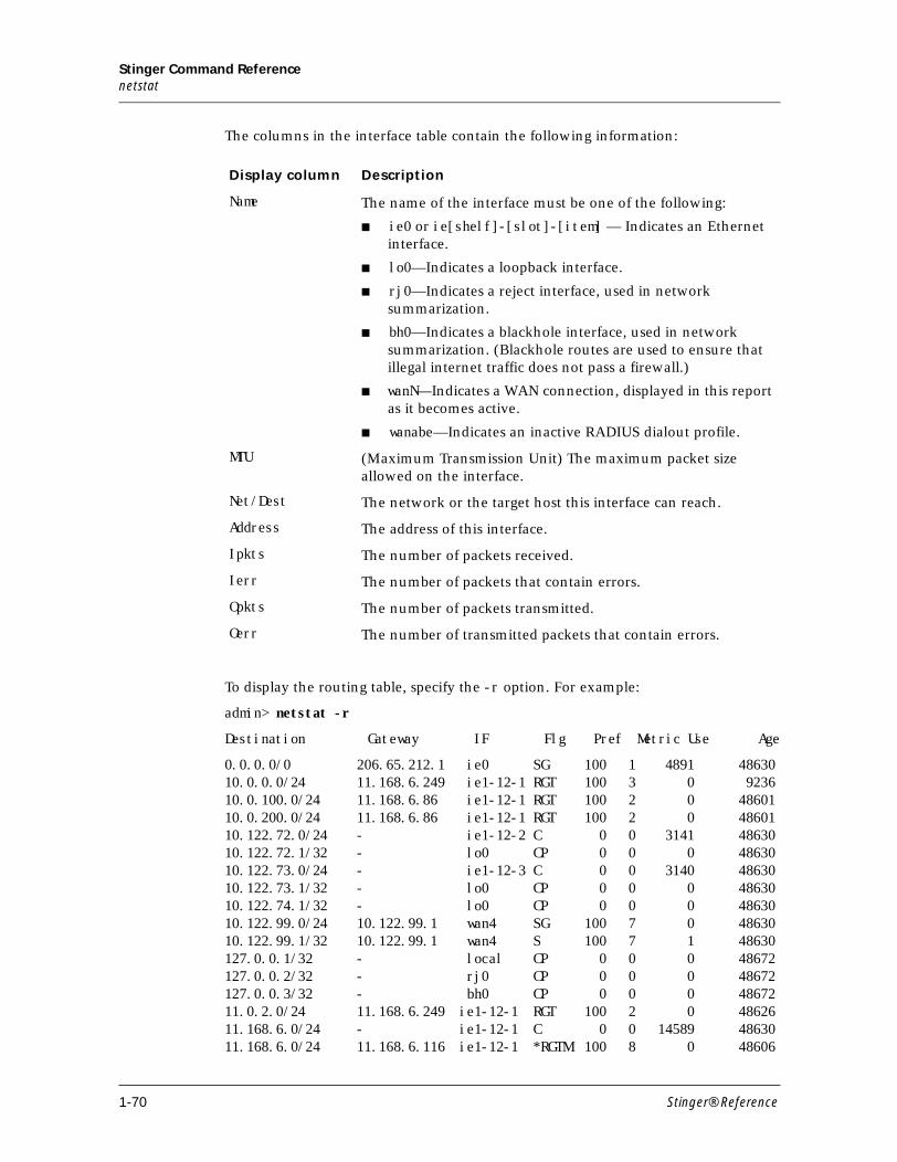
Stinger Command Referencenetstat
The columns in the interface table contain the following information:
To display the routing table, specify the -r option. For example:
admin> netstat -r
Destination Gateway IF Flg Pref Metric Use Age
0.0.0.0/0 206.65.212.1 ie0 SG 100 1 4891 4863010.0.0.0/24 11.168.6.249 ie1-12-1 RGT 100 3 0 923610.0.100.0/24 11.168.6.86 ie1-12-1 RGT 100 2 0 4860110.0.200.0/24 11.168.6.86 ie1-12-1 RGT 100 2 0 4860110.122.72.0/24 - ie1-12-2 C 0 0 3141 4863010.122.72.1/32 - lo0 CP 0 0 0 4863010.122.73.0/24 - ie1-12-3 C 0 0 3140 4863010.122.73.1/32 - lo0 CP 0 0 0 4863010.122.74.1/32 - lo0 CP 0 0 0 4863010.122.99.0/24 10.122.99.1 wan4 SG 100 7 0 4863010.122.99.1/32 10.122.99.1 wan4 S 100 7 1 48630127.0.0.1/32 - local CP 0 0 0 48672127.0.0.2/32 - rj0 CP 0 0 0 48672127.0.0.3/32 - bh0 CP 0 0 0 4867211.0.2.0/24 11.168.6.249 ie1-12-1 RGT 100 2 0 4862611.168.6.0/24 - ie1-12-1 C 0 0 14589 4863011.168.6.0/24 11.168.6.116 ie1-12-1 *RGTM 100 8 0 48606
Display column Description
Name The name of the interface must be one of the following:
■ ie0 or ie[shelf]-[slot]-[item] — Indicates an Ethernet interface.
■ lo0—Indicates a loopback interface.
■ rj0—Indicates a reject interface, used in network summarization.
■ bh0—Indicates a blackhole interface, used in network summarization. (Blackhole routes are used to ensure that illegal internet traffic does not pass a firewall.)
■ wanN—Indicates a WAN connection, displayed in this report as it becomes active.
■ wanabe—Indicates an inactive RADIUS dialout profile.
MTU (Maximum Transmission Unit) The maximum packet size allowed on the interface.
Net/Dest The network or the target host this interface can reach.
Address The address of this interface.
Ipkts The number of packets received.
Ierr The number of packets that contain errors.
Opkts The number of packets transmitted.
Oerr The number of transmitted packets that contain errors.
1-70 Stinger® Reference
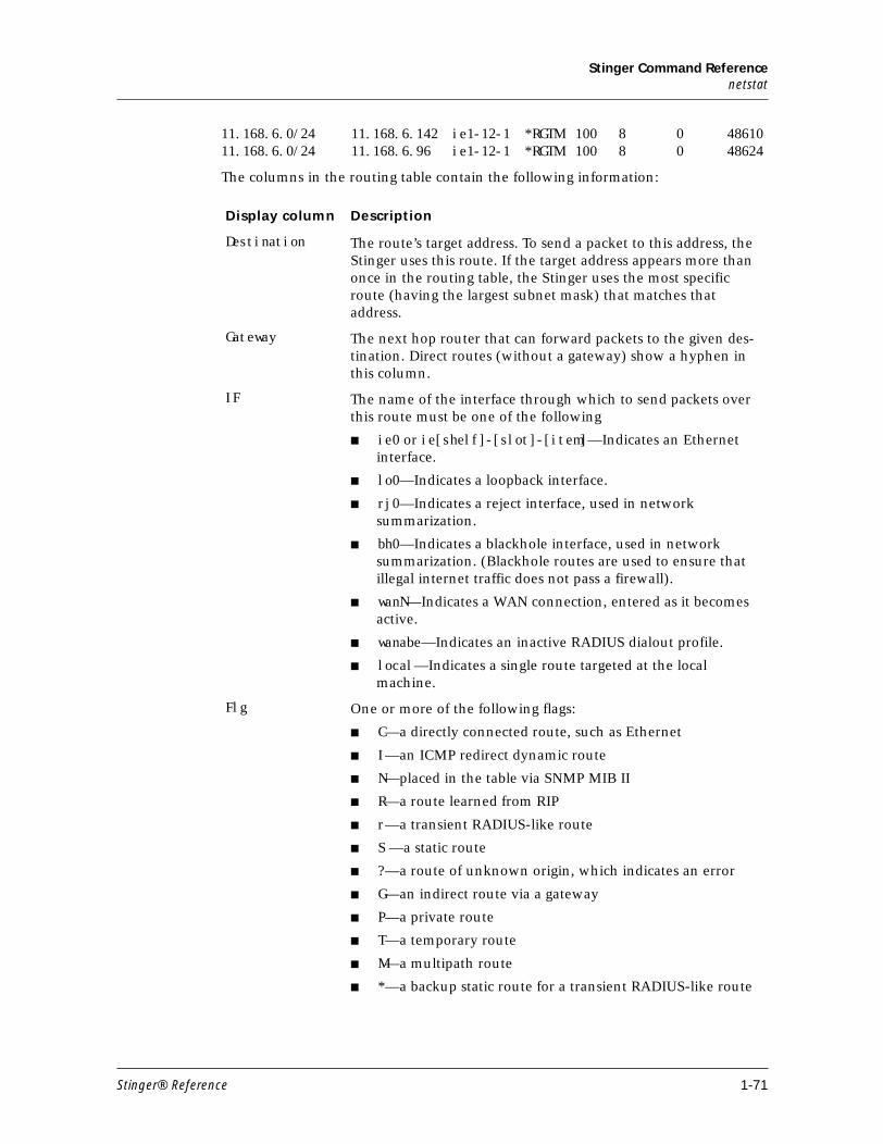
Stinger Command Referencenetstat
11.168.6.0/24 11.168.6.142 ie1-12-1 *RGTM 100 8 0 4861011.168.6.0/24 11.168.6.96 ie1-12-1 *RGTM 100 8 0 48624
The columns in the routing table contain the following information:
Display column Description
Destination The route’s target address. To send a packet to this address, the Stinger uses this route. If the target address appears more than once in the routing table, the Stinger uses the most specific route (having the largest subnet mask) that matches that address.
Gateway The next hop router that can forward packets to the given des-tination. Direct routes (without a gateway) show a hyphen in this column.
IF The name of the interface through which to send packets over this route must be one of the following
■ ie0 or ie[shelf]-[slot]-[item]—Indicates an Ethernet interface.
■ lo0—Indicates a loopback interface.
■ rj0—Indicates a reject interface, used in network summarization.
■ bh0—Indicates a blackhole interface, used in network summarization. (Blackhole routes are used to ensure that illegal internet traffic does not pass a firewall).
■ wanN—Indicates a WAN connection, entered as it becomes active.
■ wanabe—Indicates an inactive RADIUS dialout profile.
■ local—Indicates a single route targeted at the local machine.
Flg One or more of the following flags:
■ C—a directly connected route, such as Ethernet
■ I—an ICMP redirect dynamic route
■ N—placed in the table via SNMP MIB II
■ R—a route learned from RIP
■ r—a transient RADIUS-like route
■ S —a static route
■ ?—a route of unknown origin, which indicates an error
■ G—an indirect route via a gateway
■ P—a private route
■ T—a temporary route
■ M—a multipath route
■ *—a backup static route for a transient RADIUS-like route
Stinger® Reference 1-71
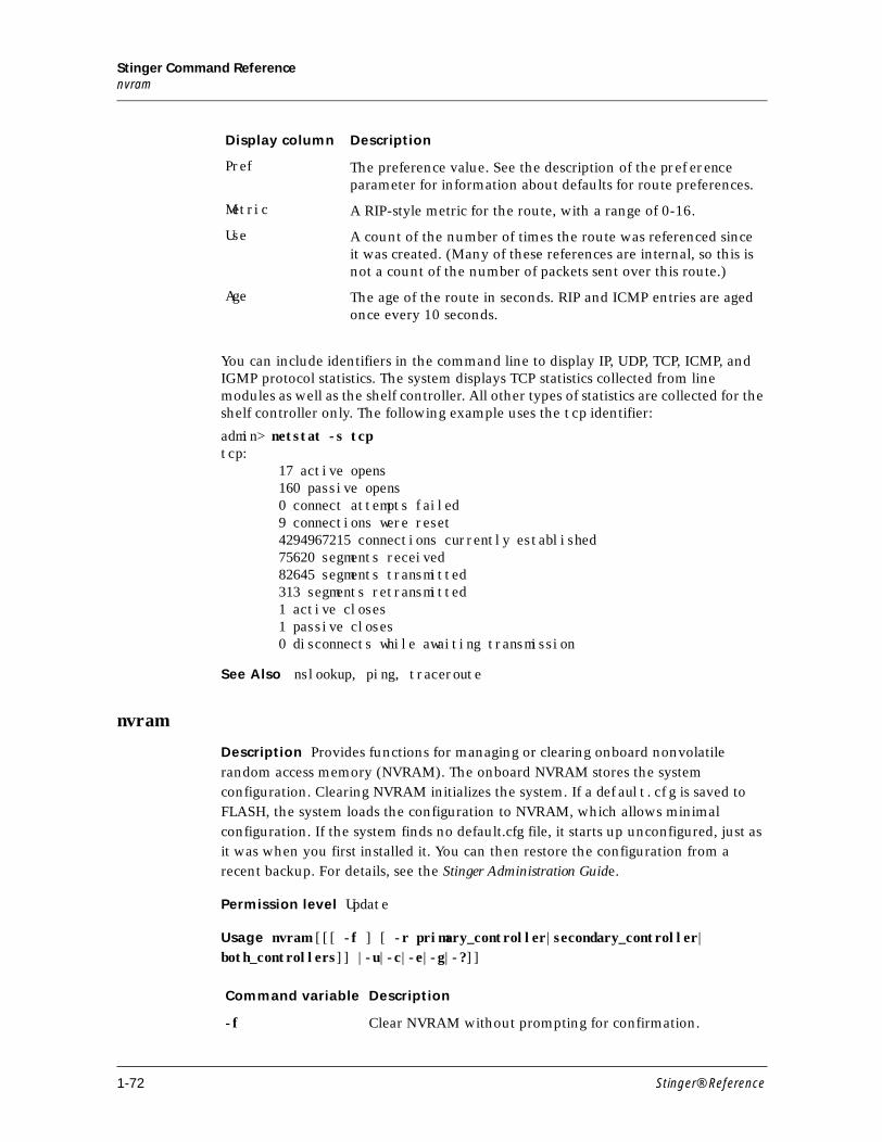
Stinger Command Referencenvram
You can include identifiers in the command line to display IP, UDP, TCP, ICMP, and IGMP protocol statistics. The system displays TCP statistics collected from line modules as well as the shelf controller. All other types of statistics are collected for the shelf controller only. The following example uses the tcp identifier:
admin> netstat -s tcp tcp: 17 active opens 160 passive opens 0 connect attempts failed 9 connections were reset 4294967215 connections currently established 75620 segments received 82645 segments transmitted 313 segments retransmitted 1 active closes 1 passive closes 0 disconnects while awaiting transmission
See Also nslookup, ping, traceroute
nvram
Description Provides functions for managing or clearing onboard nonvolatile
random access memory (NVRAM). The onboard NVRAM stores the system
configuration. Clearing NVRAM initializes the system. If a default.cfg is saved to
FLASH, the system loads the configuration to NVRAM, which allows minimal
configuration. If the system finds no default.cfg file, it starts up unconfigured, just as
it was when you first installed it. You can then restore the configuration from a
recent backup. For details, see the Stinger Administration Guide.
Permission level Update
Usage nvram [[[ -f ] [ -r primary_controller|secondary_controller| both_controllers]] |-u|-c|-e|-g|-?]]
Pref The preference value. See the description of the preference parameter for information about defaults for route preferences.
Metric A RIP-style metric for the route, with a range of 0-16.
Use A count of the number of times the route was referenced since it was created. (Many of these references are internal, so this is not a count of the number of packets sent over this route.)
Age The age of the route in seconds. RIP and ICMP entries are aged once every 10 seconds.
Display column Description
Command variable Description
-f Clear NVRAM without prompting for confirmation.
1-72 Stinger® Reference
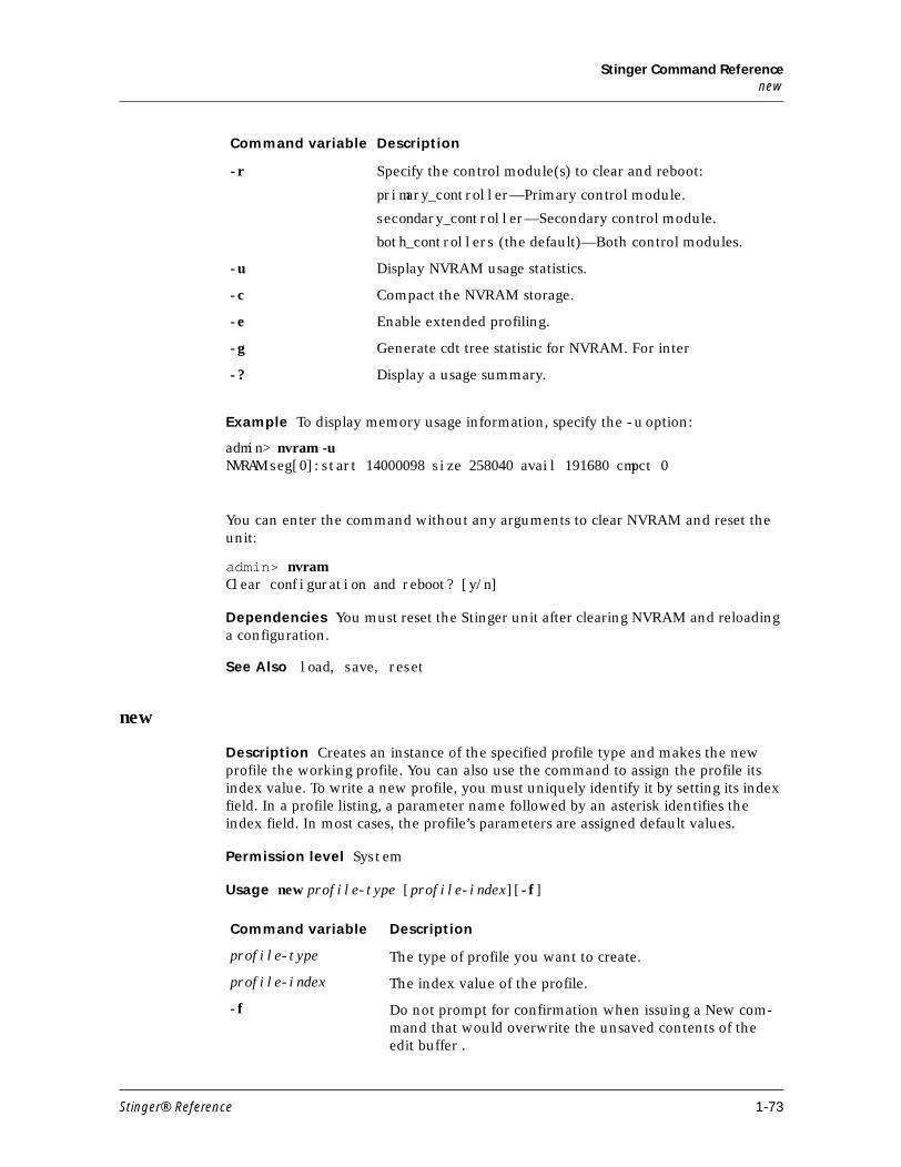
Stinger Command Referencenew
Example To display memory usage information, specify the -u option:
admin> nvram -uNVRAM seg[0]:start 14000098 size 258040 avail 191680 cmpct 0
You can enter the command without any arguments to clear NVRAM and reset the unit:
admin> nvramClear configuration and reboot? [y/n]
Dependencies You must reset the Stinger unit after clearing NVRAM and reloading a configuration.
See Also load, save, reset
new
Description Creates an instance of the specified profile type and makes the new profile the working profile. You can also use the command to assign the profile its index value. To write a new profile, you must uniquely identify it by setting its index field. In a profile listing, a parameter name followed by an asterisk identifies the index field. In most cases, the profile’s parameters are assigned default values.
Permission level System
Usage new profile-type [profile-index][-f]
-r Specify the control module(s) to clear and reboot:
primary_controller—Primary control module.
secondary_controller—Secondary control module.
both_controllers (the default)—Both control modules.
-u Display NVRAM usage statistics.
-c Compact the NVRAM storage.
-e Enable extended profiling.
-g Generate cdt tree statistic for NVRAM. For inter
-? Display a usage summary.
Command variable Description
Command variable Description
profile-type The type of profile you want to create.
profile-index The index value of the profile.
-f Do not prompt for confirmation when issuing a New com-mand that would overwrite the unsaved contents of the edit buffer .
Stinger® Reference 1-73
Stinger Command Referencenew
If you create a new indexed profile without using the profile-index argument, a default index (usually null or zero) is used. For example
If you specify the profile-index on the command line, it is validated before use. For example:
admin> new sdsl {12 2 3}error: bad index: unknown value "12"
admin> new system fooerror: profile has no index
If you specify a valid index, it is applied to the new profile, which is read into the edit buffer. For example:
admin> new sdsl {1 2 3} SDSL/{ shelf-1 slot-2 3 } read
admin> list[in SDSL/{ shelf-1 slot-2 3 } (new)]name=""physical-address*={ shelf-1 slot-2 3 }enabled=noline-config={ 0 0 static { any-shelf any-slot 0 } }
Example To create a new connection profile called Tim:
admin> new conn timCONNECTION/tim read
admin> list[in CONNECTION/tim (new)]station*=timactive=noencapsulation-protocol=atmcalled-number-type=nationaldial-number=""clid=""ip-options={ yes yes 0.0.0.0/0 0.0.0.0/0 7 100 255 no no 0 +session-options={ "" "" no 120 no-idle 120 "" }telco-options={ ans-and-orig no off 1 no no 56k-restricted 0 +usrRad-options={ global 0.0.0.0 1646 "" 1 acct-base-10 }calledNumber=""
admin> writeCONNECTION/tim written
Profile type Default index
User ""
Serial { any-shelf any-slot 0 }
Ethernet { any-shelf any-slot 0 }
IP-Interface { { any-shelf any-slot 0 } 0 }
1-74 Stinger® Reference
Stinger Command Referencenew
Dependencies The index you choose might affect the factory default values set in the profile. For example, if you specify the profile-index default for a user profile, the factory default permission settings are as follows:
admin> new user defaultUSER/default read
admin> list[in USER/default (new)]name*=defaultpassword=""active-enabled=yesallow-termserv=noallow-system=noallow-diagnostic=noallow-update=noallow-password=noallow-code=noallow-debug=noidle-logout=0prompt=*default-status=notop-status=general-infobottom-status=log-windowleft-status=connection-listuse-scroll-regions=nolog-display-level=none
If you specify admin instead, the factory-default permissions are set as follows:
admin> new user adminUSER/admin read
admin> list[in USER/admin (new)]name*=adminpassword=MyPWactive-enabled=yesallow-termserv=yesallow-system=yesallow-diagnostic=yesallow-update=yesallow-password=noallow-code=yesallow-debug=noidle-logout=0prompt=*default-status=notop-status=general-infobottom-status=log-windowleft-status=connection-listuse-scroll-regions=nolog-display-level=error
See Also delete, list, read, set, write
Stinger® Reference 1-75
Stinger Command Referencenslookup
nslookup
Description Resolves the IP address of a specified hostname by performing a DNS lookup. The IP-Global profile must be configured with the address of at least one DNS server. For information about configuring DNS, see the Stinger Administration Guide.
Permission level Diagnostic
Usage nslookup hostname
Example To look up a host’s IP address in DNS:
admin> nslookup host-231Resolving host host-231.IP address for host host-231 is 10.65.12.231.
See Also aliastbl, netstat
nvram
Description Provides functions for managing or clearing onboard nonvolatile random access memory (NVRAM). The onboard NVRAM stores the system configuration. Clearing NVRAM initializes the system. It starts up unconfigured, just as it was when you first installed it. You can then restore the configuration from a recent backup. For details, see the Stinger Administration Guide.
Permission level Update
Usage nvram -f|-t|-u|-c|-?
Example To display memory usage information, specify the -u option:
admin> nvram -uNVRAM seg[0]:start 14000098 size 258040 avail 191680 cmpct 0
You can enter the command without any arguments to clear NVRAM and reset the unit:
Command variable Description
hostname The hostname for which you want to obtain an IP address.
Command option Description
-f Clear NVRAM without prompting for confirmation.
-t Toggle module debug level.
-u Display NVRAM usage statistics.
-c Compact the NVRAM storage.
-? Display a usage summary.
1-76 Stinger® Reference
Stinger Command ReferenceO
admin> nvramClear configuration and reboot? [y/n]
Note You must reset the Stinger after clearing NVRAM and reloading a configuration.
See Also load, save, reset
O
oam
Description Enables you to send F4 and F5 operations, administration and maintenance (OAM) connectivity and loopback testing cells from a port on a Stinger trunk module or line interface module (LIM) to a remote DSL port—for example, to a customer premises equipment (CPE) device.
Permission level Diagnostic
Usage Format 1 is used when running the command from a trunk module. Format 2 is used when running the command from a line interface module (LIM).
1) oam -e|-c|-l|-p|-L|-C [slot] [port] [vpi] [vci]
2) oam [-L port vpi s n ]
When you run the oam command from the control module (CM) for the virtual channel on the trunk port, you need to use syntax 1 and specify slot and port number to identify the trunk, for example 17 1.
Command variable Description
-e Displays the OAM entry list
-c Runs an OAM F5 connectivity test
-l Runs an OAM F5 loopback test
-p Turns on/off OAM internal debug
-c Runs an OAM F4 connectivity test
-L Runs an OAM F4 loopback test
slot Slot number. Not used when running the command from the LIM.
port Port number on a CPE device
vpi Virtual path identifier (VPI) number. Not used when running the command from the LIM.
vci Specifies the virtual channel identifier (VCI) number
-s Runs a segment test, and must be followed by a value for the n variable.
n Number of consecutive segments in the segment test.
Stinger® Reference 1-77
Stinger Command Referenceoamloop
When you run oam command from stinger line interface module (LIM) for the virtual channel on the LIM DSL port, you use syntax 2. You only need to specify the port number to identify the DSL port, for example, 1 or 24. You can verify this with the help for the oam command: run the OAM help command from the LIM, and you see that it does not display the word [slot] as a variable.
Note F4 OAM segment and end-to-end loopback testing is supported on the following Stinger modules only:
■ All Stinger trunk modules
■ 12-port ADSL LIMs (STGR-LIM-AD-12 only)
■ 12-port ADSL LIMs with Annex B support (STGR-LIM-AN-12 only)
■ 48-port SDSL LIMs (STGR-LIM-SH-48 only)
Example To send 64 consecutive segment loopback cells to VPI 15 on DSL port 2, issue the oam command using syntax 2:
admin> oam -L 2 15 s 64
The following command displays additional information about the outgoing and incoming segment test cells:
admin> oam -p
See Also oamloop
oamloop
Description Sends ATM operation-and-maintenance (OAM) loopback cells on an Asynchronous Transfer Mode (ATM) interface:
Permission level Diagnostic
Usage oamloop -e|-s [-c count][-i sec] shelf slot vpi vci
Command variable Description
-e (End-to-end). Transmit an end-to-end OAM loop cell, to be looped by the user connection point.
-s (Segment). Transmit a segment OAM loop cell, to be looped by the first network connection point.
-c count Transmit the specified number of cells. If this argument is not specified, the count defaults to 0 (zero), which means that the cells are transmitted continuously until the administrator sends an interrupt by pressing Ctrl-C.
-i sec Transmit the cells at the specified interval in seconds. If this argument is not specified, the interval defaults to one second.
shelf Specifies the shelf in which the OC3 ATM trunk module is located.
1-78 Stinger® Reference
Stinger Command Referenceopen
Example Following is an example oamloop command line and output:
admin> oamloop -c 10 -e 1 2 1 32Received our End2End OAM loopback cell, Id=9Received our End2End OAM loopback cell, Id=10Received our End2End OAM loopback cell, Id=11Received our End2End OAM loopback cell, Id=12Received our End2End OAM loopback cell, Id=13Received our End2End OAM loopback cell, Id=14Received our End2End OAM loopback cell, Id=15Received our End2End OAM loopback cell, Id=16Received our End2End OAM loopback cell, Id=17Received our End2End OAM loopback cell, Id=18--- OAM loop statistics ---10 cells transmitted, 10 cells received, 0% cell loss
See Also oam
open
Description Each trunk module and line interface module (LIM) has its own processor, memory, operating system, and set of debug commands. The open command sets up a Telnet-like session across the control bus to one of the modules. Then you can execute commands on that module.
Permission level Diagnostic
Usage open 1..9 [1..16]
Example To open a session with a DS3-ATM trunk module installed in shelf 1, slot 1:
admin> open 1 1
The prompt changes to show your location, and you can list the available commands:
ds3-1/2> ?
slot Specifies the slot in which the OC3 ATM trunk module is located.
vpi Specifies the virtual path identifier (VPI) on which to transmit the looped-back cells.
vci Specifies the virtual channel identifier (VCI) on which to send the looped-back cells.
Command variable Description
Command variable Description
1..9 The shelf number.
1..16 The number of the expansion slot you want to diagnose.
Stinger® Reference 1-79
Stinger Command Referenceopen
? ( user )auth ( user )cbcardif ( debug )checkd ( debug )clear ( user )clock-source ( diagnostic )debug ( diagnostic )debugd ( debug )display ( debug )dp-ram-display ( debug )dpram-test ( debug )dspBypassClients ( debug )dspDial ( debug )dspSetDddTimeslot ( debug )fill ( debug )frreset ( debug )gdb ( debug )help ( user )lifDebug ( debug )logdebug ( debug )logtest ( debug )mibcbagt ( debug )mibcbreq ( debug )mibmgr ( debug )modify ( debug )nailedState ( debug )nlcb ( debug )open ( diagnostic )quit ( user )revision ( debug )slots ( debug )stackLimit ( debug )stackUsage ( debug )tdm ( debug )timedMsgTest ( debug )tprofmgr ( debug )tss ( debug )update ( debug )version ( system )whoami ( user )
To return to the shelf controller:
ds3-1/2> quit
See Also show, slot
1-80 Stinger® Reference
Stinger Command ReferenceP
P
ping
Description Sends ICMP Echo Request packets to the specified host as a way to verify that the host is established and the transmission path to the host is open. The host returns ICMP Echo Response packets, and the command generates statistics about the exchange.
Permission level Diagnostic
Usage ping [-q|-f host|-v][-c count][-i delay][-s packetsize] hostname
Example To ping a host named Host-231 on a local network do the following:
admin> ping host-231PING host-231 (10.65.12.231): 56 data bytes64 bytes from 10.65.12.231: icmp_seq=0 ttl=255 time=0 ms64 bytes from 10.65.12.231: icmp_seq=1 ttl=255 time=0 ms64 bytes from 10.65.12.231: icmp_seq=2 ttl=255 time=0 ms64 bytes from 10.65.12.231: icmp_seq=3 ttl=255 time=0 ms64 bytes from 10.65.12.231: icmp_seq=4 ttl=255 time=0 ms^C--- host-231 ping statistics ---5 packets transmitted, 5 packets received, 0% packet lossround-trip min/avg/max=0/0/0 ms
Command variable Description
-q Quiet. Do not display informational messages. Just display the summary lines at the beginning and end of the command.
-f host Set the Don't Fragment (DF) bit in the IP header of Ping packets. Setting the DF bit enables the Stinger unit to identify the permissible datagram size, also called the path maximum transmission unit (PMTU), of the path from the remote host. If any datagram is too large to be forwarded without fragmentation by some router along the path, the router discards it and returns an ICMP Destination Unreachable message with a code that indicates fragmentation is needed and that DF is set.
-v Verbose. List every ICMP packet received, except Echo Response packets.
-c count Send only the specified number of packets.
-i delay Wait the specified number of seconds before sending the next packet. The default delay period is one second.
-s packetsize Send the specified number of data bytes. The default size is 64 bytes, not including the 8-byte ICMP header. The minimum is 16.
hostname The station’s IP address or DNS hostname.
Stinger® Reference 1-81
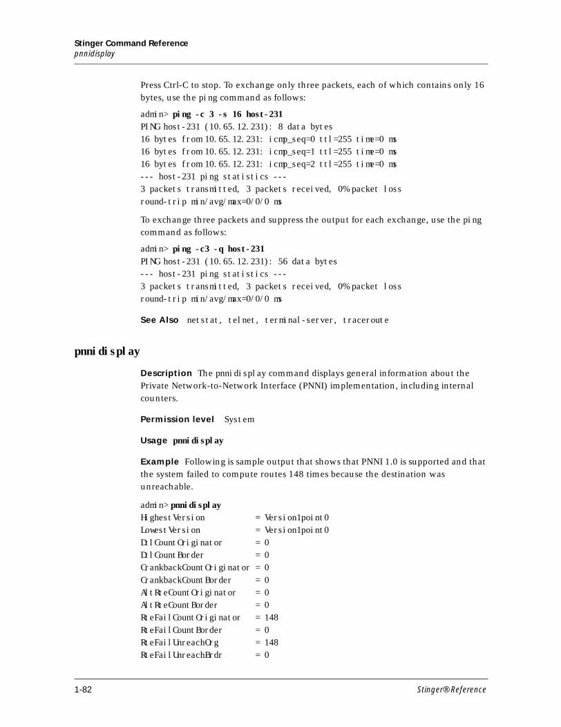
Stinger Command Referencepnnidisplay
Press Ctrl-C to stop. To exchange only three packets, each of which contains only 16
bytes, use the ping command as follows:
admin> ping -c 3 -s 16 host-231PING host-231 (10.65.12.231): 8 data bytes16 bytes from 10.65.12.231: icmp_seq=0 ttl=255 time=0 ms16 bytes from 10.65.12.231: icmp_seq=1 ttl=255 time=0 ms16 bytes from 10.65.12.231: icmp_seq=2 ttl=255 time=0 ms--- host-231 ping statistics ---3 packets transmitted, 3 packets received, 0% packet lossround-trip min/avg/max=0/0/0 ms
To exchange three packets and suppress the output for each exchange, use the ping
command as follows:
admin> ping -c3 -q host-231PING host-231 (10.65.12.231): 56 data bytes--- host-231 ping statistics ---3 packets transmitted, 3 packets received, 0% packet lossround-trip min/avg/max=0/0/0 ms
See Also netstat, telnet, terminal-server, traceroute
pnnidisplay
Description The pnnidisplay command displays general information about the
Private Network-to-Network Interface (PNNI) implementation, including internal
counters.
Permission level System
Usage pnnidisplay
Example Following is sample output that shows that PNNI 1.0 is supported and that
the system failed to compute routes 148 times because the destination was
unreachable.
admin> pnnidisplayHighestVersion = Version1point0LowestVersion = Version1point0DtlCountOriginator = 0DtlCountBorder = 0CrankbackCountOriginator = 0CrankbackCountBorder = 0AltRteCountOriginator = 0AltRteCountBorder = 0RteFailCountOriginator = 148RteFailCountBorder = 0RteFailUnreachOrg = 148RteFailUnreachBrdr = 0
1-82 Stinger® Reference
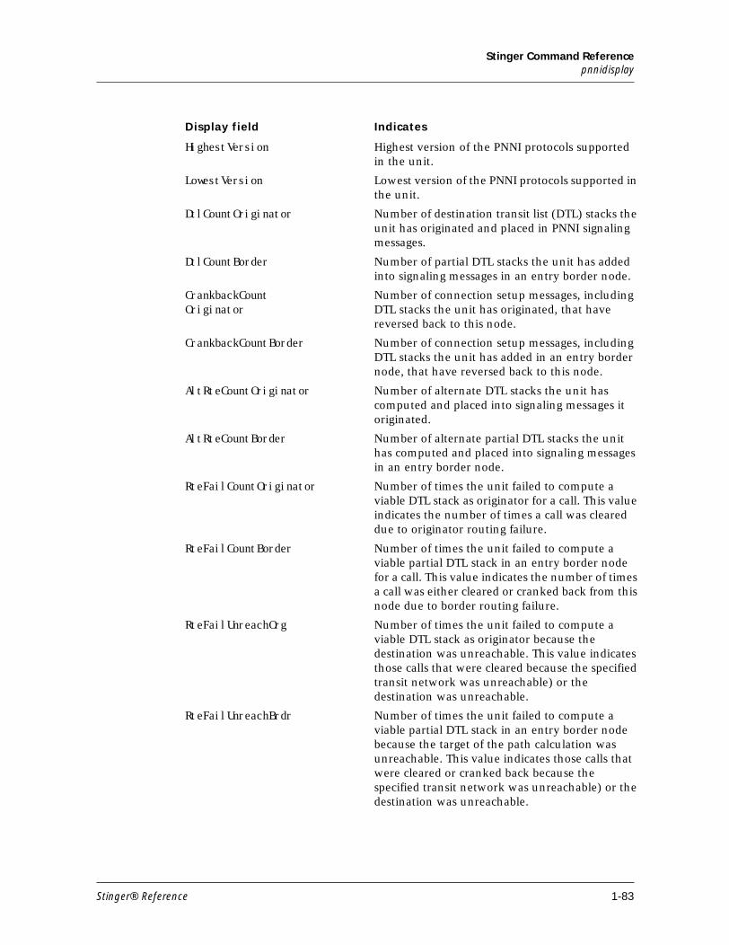
Stinger Command Referencepnnidisplay
Display field Indicates
HighestVersion Highest version of the PNNI protocols supported in the unit.
LowestVersion Lowest version of the PNNI protocols supported in the unit.
DtlCountOriginator Number of destination transit list (DTL) stacks the unit has originated and placed in PNNI signaling messages.
DtlCountBorder Number of partial DTL stacks the unit has added into signaling messages in an entry border node.
CrankbackCountOriginator
Number of connection setup messages, including DTL stacks the unit has originated, that have reversed back to this node.
CrankbackCountBorder Number of connection setup messages, including DTL stacks the unit has added in an entry border node, that have reversed back to this node.
AltRteCountOriginator Number of alternate DTL stacks the unit has computed and placed into signaling messages it originated.
AltRteCountBorder Number of alternate partial DTL stacks the unit has computed and placed into signaling messages in an entry border node.
RteFailCountOriginator Number of times the unit failed to compute a viable DTL stack as originator for a call. This value indicates the number of times a call was cleared due to originator routing failure.
RteFailCountBorder Number of times the unit failed to compute a viable partial DTL stack in an entry border node for a call. This value indicates the number of times a call was either cleared or cranked back from this node due to border routing failure.
RteFailUnreachOrg Number of times the unit failed to compute a viable DTL stack as originator because the destination was unreachable. This value indicates those calls that were cleared because the specified transit network was unreachable) or the destination was unreachable.
RteFailUnreachBrdr Number of times the unit failed to compute a viable partial DTL stack in an entry border node because the target of the path calculation was unreachable. This value indicates those calls that were cleared or cranked back because the specified transit network was unreachable) or the destination was unreachable.
Stinger® Reference 1-83
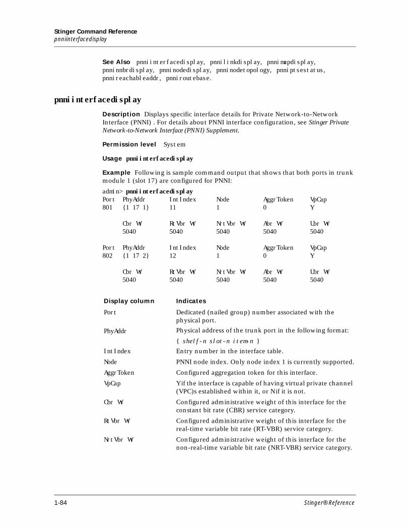
Stinger Command Referencepnniinterfacedisplay
See Also pnniinterfacedisplay, pnnilinkdisplay, pnnimapdisplay, pnninnbrdisplay, pnninodedisplay, pnninodetopology, pnniptsestatus, pnnireachableaddr, pnniroutebase.
pnniinterfacedisplay
Description Displays specific interface details for Private Network-to-Network Interface (PNNI) . For details about PNNI interface configuration, see Stinger Private Network-to-Network Interface (PNNI) Supplement.
Permission level System
Usage pnniinterfacedisplay
Example Following is sample command output that shows that both ports in trunk module 1 (slot 17) are configured for PNNI:
admin> pnniinterfacedisplayPort PhyAddr IntIndex Node AggrToken VpCap801 {1 17 1} 11 1 0 Y Cbr Wt RtVbr Wt NrtVbr Wt Abr Wt Ubr Wt 5040 5040 5040 5040 5040 Port PhyAddr IntIndex Node AggrToken VpCap802 {1 17 2} 12 1 0 Y Cbr Wt RtVbr Wt NrtVbr Wt Abr Wt Ubr Wt 5040 5040 5040 5040 5040
Display column Indicates
Port Dedicated (nailed group) number associated with the physical port.
PhyAddr Physical address of the trunk port in the following format:
{ shelf-n slot-n item-n }
IntIndex Entry number in the interface table.
Node PNNI node index. Only node index 1 is currently supported.
AggrToken Configured aggregation token for this interface.
VpCap Y if the interface is capable of having virtual private channel (VPC)s established within it, or N if it is not.
Cbr Wt Configured administrative weight of this interface for the constant bit rate (CBR) service category.
RtVbr Wt Configured administrative weight of this interface for the real-time variable bit rate (RT-VBR) service category.
NrtVbr Wt Configured administrative weight of this interface for the non-real-time variable bit rate (NRT-VBR) service category.
1-84 Stinger® Reference
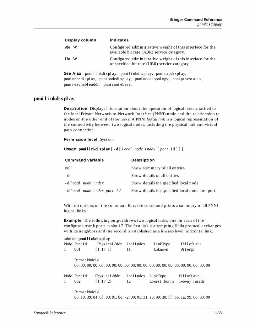
Stinger Command Referencepnnilinkdisplay
See Also pnnilinkdisplay, pnnilinkdisplay, pnnimapdisplay, pnninnbrdisplay, pnninodedisplay, pnninodetopology, pnniptsestatus, pnnireachableaddr, pnniroutebase.
pnnilinkdisplay
Description Displays information about the operation of logical links attached to the local Private Network-to-Network Interface (PNNI) node and the relationship to nodes on the other end of the links. A PNNI logical link is a logical representation of the connectivity between two logical nodes, including the physical link and virtual path connection.
Permission level System
Usage pnnilinkdisplay [ -d [ local node index [ port Id ] ] ]
With no options on the command line, the command prints a summary of all PNNI logical links.
Example The following output shows two logical links, one on each of the configured trunk ports in slot 17. The first link is attempting Hello protocol exchanges with its neighbors and the second is established as a lowest-level horizontal link.
admin> pnnilinkdisplayNode PortId PhysicalAddr IntfIndex LinkType HelloState1 801 {1 17 1} 11 Unknown Attempt
RemoteNodeId 00:00:00:00:00:00:00:00:00:00:00:00:00:00:00:00:00:00:00:00:00:00
Node PortId PhysicalAddr IntfIndex LinkType HelloState1 802 {1 17 2} 12 Lowest horiz Twoway inside
RemoteNodeId 60:a0:39:84:0f:80:01:bc:72:00:01:31:a3:99:38:ff:b6:ca:99:00:00:00
Abr Wt Configured administrative weight of this interface for the available bit rate (ABR) service category.
Ubr Wt Configured administrative weight of this interface for the unspecified bit rate (UBR) service category.
Display column Indicates
Command variable Description
null Show summary of all entries
-d Show details of all entries
-d local node index Show details for specified local node
-d local node index port Id Show details for specified local node and port
Stinger® Reference 1-85
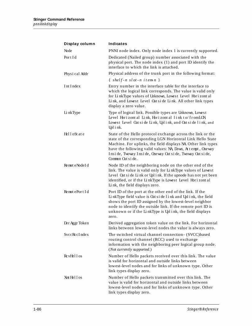
Stinger Command Referencepnnilinkdisplay
Display column Indicates
Node PNNI node index. Only node index 1 is currently supported.
PortId Dedicated (Nailed group) number associated with the physical port. The node index (1) and port ID identify the interface to which the link is attached.
PhysicalAddr Physical address of the trunk port in the following format:
{ shelf-n slot-n item-n }
IntIndex Entry number in the interface table for the interface to which the logical link corresponds. The value is valid only for LinkType values of Unknown, Lowest Level Horizontal Link, and Lowest Level Outside Link. All other link types display a zero value.
LinkType Type of logical link. Possible types are Unknown, Lowest Level Horizontal Link, Horizontal link to/from LGN, Lowest Level Outside Link, Uplink, and Outside link, and Uplink.
HelloState State of the Hello protocol exchange across the link or the state of the corresponding LGN Horizontal Link Hello State Machine. For uplinks, the field displays NA. Other link types have the following valid values: NA, Down, Attempt, Oneway Inside, Twoway Inside, Oneway Outside, Twoway Outside, Common Outside.
RemoteNodeId Node ID of the neighboring node on the other end of the link. The value is valid only for LinkType values of Lowest Level Outside Link or Uplink. If the upnode has not yet been identified, or if the LinkType is Lowest Level Horizontal Link, the field displays zero.
RemotePortId Port ID of the port at the other end of the link. If the LinkType field value is Outside link and Uplink, the field shows the port ID assigned by the lowest-level neighbor node to identify the outside link. If the remote port ID is unknown or if the LinkType is Uplink, the field displays zero.
DerAggrToken Derived aggregation token value on the link. For horizontal links between lowest-level nodes the value is always zero.
SvccRccIndex The switched virtual channel connection- (SVCC)based routing control channel (RCC) used to exchange information with the neighboring peer logical group node. (Not currently supported.)
RcvHellos Number of Hello packets received over this link. The value is valid for horizontal and outside links between lowest-level nodes and for links of unknown type. Other link types display zero.
XmtHellos Number of Hello packets transmitted over this link. The value is valid for horizontal and outside links between lowest-level nodes and for links of unknown type. Other link types display zero.
1-86 Stinger® Reference
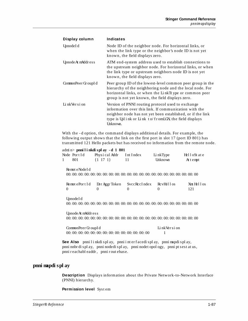
Stinger Command Referencepnnimapdisplay
With the -d option, the command displays additional details. For example, the following output shows that the link on the first port in slot 17 (port ID 801) has transmitted 121 Hello packets but has received no information from the remote node.
admin> pnnilinkdisplay -d 1 801Node PortId PhysicalAddr IntIndex LinkType HelloState1 801 {1 17 1} 11 Unknown Attempt RemoteNodeId 00:00:00:00:00:00:00:00:00:00:00:00:00:00:00:00:00:00:00:00:00:00 RemotePortId DerAggrToken SvccRccIndex RcvHellos XmtHellos 0 0 0 0 121 UpnodeId 00:00:00:00:00:00:00:00:00:00:00:00:00:00:00:00:00:00:00:00:00:00 UpnodeAtmAddress 00:00:00:00:00:00:00:00:00:00:00:00:00:00:00:00:00:00:00:00:00:00 CommonPeerGroupId LinkVersion 00:00:00:00:00:00:00:00:00:00:00:00:00:00 1
See Also pnnilinkdisplay, pnniinterfacedisplay, pnnimapdisplay, pnninnbrdisplay, pnninodedisplay, pnninodetopology, pnniptsestatus, pnnireachableaddr, pnniroutebase.
pnnimapdisplay
Description Displays information about the Private Network-to-Network Interface (PNNI) hierarchy.
Permission level System
UpnodeId Node ID of the neighbor node. For horizontal links, or when the link type or the neighbor’s node ID is not yet known, the field displays zero.
UpnodeAtmAddress ATM end-system address used to establish connections to the upstream neighbor node. For horizontal links, or when the link type or upstream neighbors node ID is not yet known, the field displays zero.
CommonPeerGroupId Peer group ID of the lowest-level common peer group in the hierarchy of the neighboring node and the local node. For horizontal links, or when the LinkTtype or common peer group is not yet known, the field displays zero.
LinkVersion Version of PNNI routing protocol used to exchange information over this link. If communication with the neighbor node has not yet been established, or if the link type is Uplink or Link to/from LGN, the field displays Unknown.
Display column Indicates
Stinger® Reference 1-87
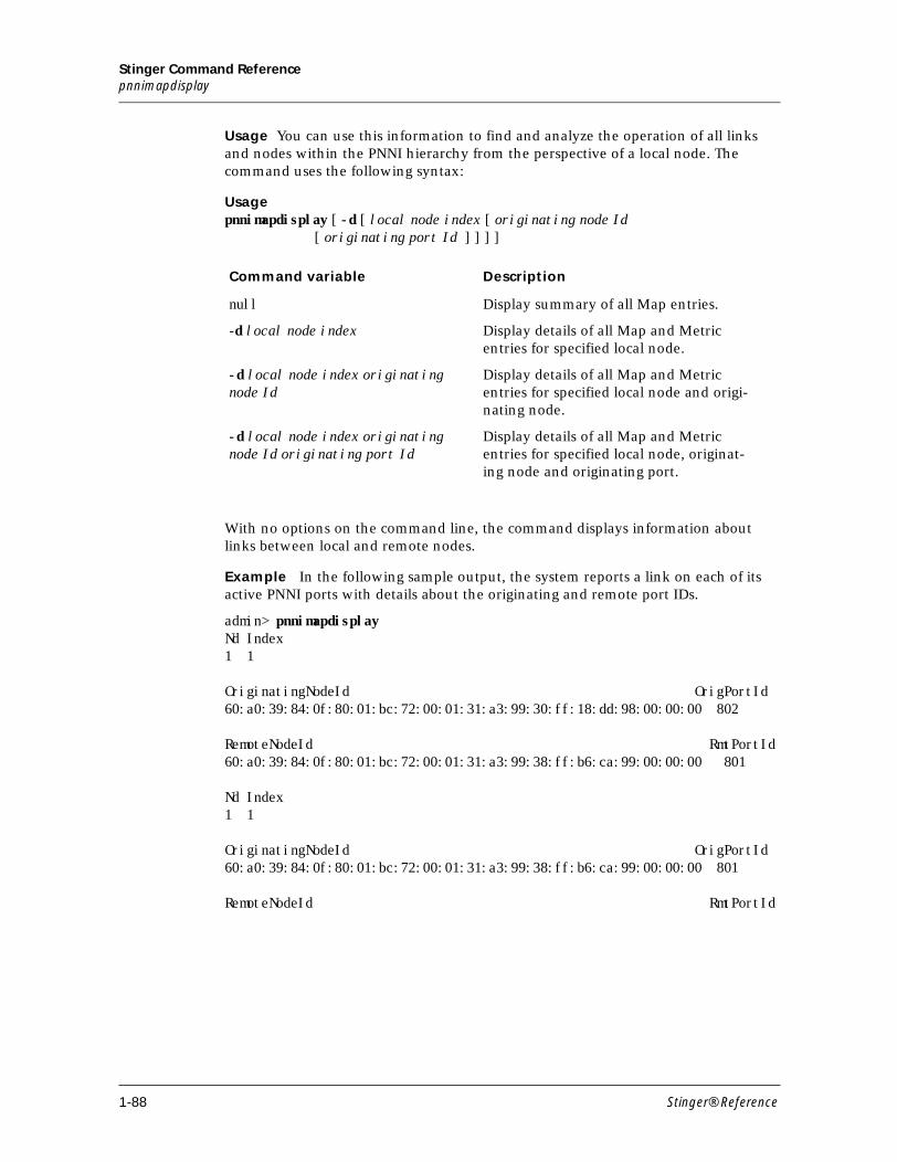
Stinger Command Referencepnnimapdisplay
Usage You can use this information to find and analyze the operation of all links and nodes within the PNNI hierarchy from the perspective of a local node. The command uses the following syntax:
Usagepnnimapdisplay [ -d [ local node index [ originating node Id [ originating port Id ] ] ] ]
With no options on the command line, the command displays information about links between local and remote nodes.
Example In the following sample output, the system reports a link on each of its active PNNI ports with details about the originating and remote port IDs.
admin> pnnimapdisplayNd Index1 1
OriginatingNodeId OrigPortId60:a0:39:84:0f:80:01:bc:72:00:01:31:a3:99:30:ff:18:dd:98:00:00:00 802
RemoteNodeId RmtPortId60:a0:39:84:0f:80:01:bc:72:00:01:31:a3:99:38:ff:b6:ca:99:00:00:00 801
Nd Index1 1 OriginatingNodeId OrigPortId60:a0:39:84:0f:80:01:bc:72:00:01:31:a3:99:38:ff:b6:ca:99:00:00:00 801 RemoteNodeId RmtPortId
Command variable Description
null Display summary of all Map entries.
-d local node index Display details of all Map and Metric entries for specified local node.
-d local node index originating node Id
Display details of all Map and Metric entries for specified local node and origi-nating node.
-d local node index originating node Id originating port Id
Display details of all Map and Metric entries for specified local node, originat-ing node and originating port.
1-88 Stinger® Reference
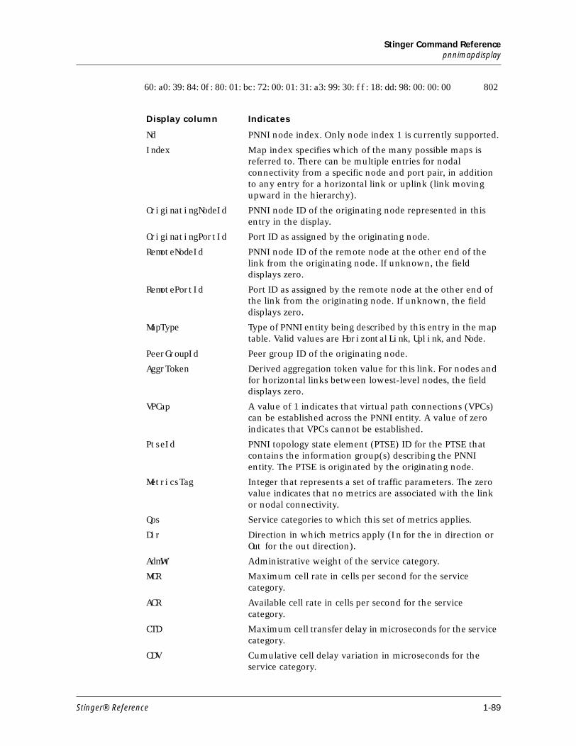
Stinger Command Referencepnnimapdisplay
60:a0:39:84:0f:80:01:bc:72:00:01:31:a3:99:30:ff:18:dd:98:00:00:00 802
Display column Indicates
Nd PNNI node index. Only node index 1 is currently supported.
Index Map index specifies which of the many possible maps is referred to. There can be multiple entries for nodal connectivity from a specific node and port pair, in addition to any entry for a horizontal link or uplink (link moving upward in the hierarchy).
OriginatingNodeId PNNI node ID of the originating node represented in this entry in the display.
OriginatingPortId Port ID as assigned by the originating node.
RemoteNodeId PNNI node ID of the remote node at the other end of the link from the originating node. If unknown, the field displays zero.
RemotePortId Port ID as assigned by the remote node at the other end of the link from the originating node. If unknown, the field displays zero.
MapType Type of PNNI entity being described by this entry in the map table. Valid values are HorizontalLink, Uplink, and Node.
PeerGroupId Peer group ID of the originating node.
AggrToken Derived aggregation token value for this link. For nodes and for horizontal links between lowest-level nodes, the field displays zero.
VPCap A value of 1 indicates that virtual path connections (VPCs) can be established across the PNNI entity. A value of zero indicates that VPCs cannot be established.
PtseId PNNI topology state element (PTSE) ID for the PTSE that contains the information group(s) describing the PNNI entity. The PTSE is originated by the originating node.
MetricsTag Integer that represents a set of traffic parameters. The zero value indicates that no metrics are associated with the link or nodal connectivity.
Qos Service categories to which this set of metrics applies.
Dir Direction in which metrics apply (In for the in direction or Out for the out direction).
AdmWt Administrative weight of the service category.
MCR Maximum cell rate in cells per second for the service category.
ACR Available cell rate in cells per second for the service category.
CTD Maximum cell transfer delay in microseconds for the service category.
CDV Cumulative cell delay variation in microseconds for the service category.
Stinger® Reference 1-89
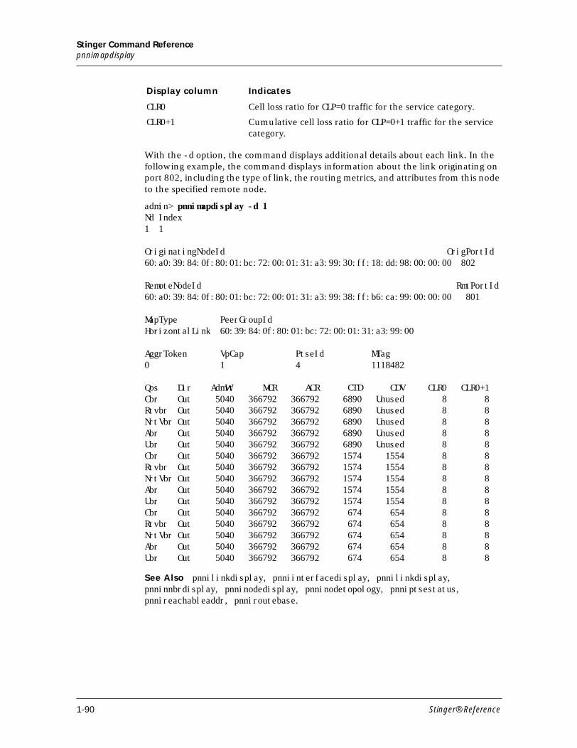
Stinger Command Referencepnnimapdisplay
With the -d option, the command displays additional details about each link. In the following example, the command displays information about the link originating on port 802, including the type of link, the routing metrics, and attributes from this node to the specified remote node.
admin> pnnimapdisplay -d 1Nd Index1 1
OriginatingNodeId OrigPortId60:a0:39:84:0f:80:01:bc:72:00:01:31:a3:99:30:ff:18:dd:98:00:00:00 802
RemoteNodeId RmtPortId60:a0:39:84:0f:80:01:bc:72:00:01:31:a3:99:38:ff:b6:ca:99:00:00:00 801
MapType PeerGroupIdHorizontalLink 60:39:84:0f:80:01:bc:72:00:01:31:a3:99:00
AggrToken VpCap PtseId MTag0 1 4 1118482
Qos Dir AdmWt MCR ACR CTD CDV CLR0 CLR0+1Cbr Out 5040 366792 366792 6890 Unused 8 8Rtvbr Out 5040 366792 366792 6890 Unused 8 8NrtVbr Out 5040 366792 366792 6890 Unused 8 8Abr Out 5040 366792 366792 6890 Unused 8 8Ubr Out 5040 366792 366792 6890 Unused 8 8Cbr Out 5040 366792 366792 1574 1554 8 8Rtvbr Out 5040 366792 366792 1574 1554 8 8NrtVbr Out 5040 366792 366792 1574 1554 8 8Abr Out 5040 366792 366792 1574 1554 8 8Ubr Out 5040 366792 366792 1574 1554 8 8Cbr Out 5040 366792 366792 674 654 8 8Rtvbr Out 5040 366792 366792 674 654 8 8NrtVbr Out 5040 366792 366792 674 654 8 8Abr Out 5040 366792 366792 674 654 8 8Ubr Out 5040 366792 366792 674 654 8 8
See Also pnnilinkdisplay, pnniinterfacedisplay, pnnilinkdisplay, pnninnbrdisplay, pnninodedisplay, pnninodetopology, pnniptsestatus, pnnireachableaddr, pnniroutebase.
CLR0 Cell loss ratio for CLP=0 traffic for the service category.
CLR0+1 Cumulative cell loss ratio for CLP=0+1 traffic for the service category.
Display column Indicates
1-90 Stinger® Reference
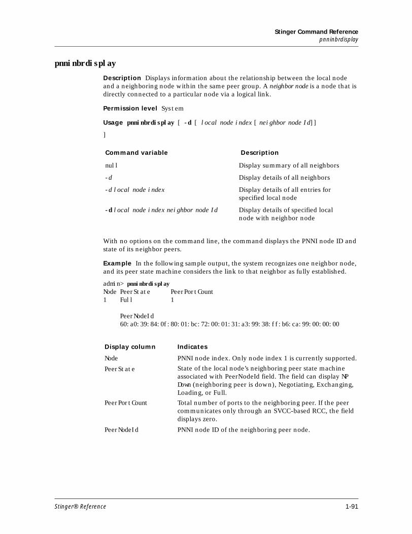
Stinger Command Referencepnninbrdisplay
pnninbrdisplay
Description Displays information about the relationship between the local node and a neighboring node within the same peer group. A neighbor node is a node that is directly connected to a particular node via a logical link.
Permission level System
Usage pnninbrdisplay [ -d [ local node index [ neighbor node Id]]
]
With no options on the command line, the command displays the PNNI node ID and state of its neighbor peers.
Example In the following sample output, the system recognizes one neighbor node, and its peer state machine considers the link to that neighbor as fully established.
admin> pnninbrdisplayNode PeerState PeerPortCount1 Full 1 PeerNodeId 60:a0:39:84:0f:80:01:bc:72:00:01:31:a3:99:38:ff:b6:ca:99:00:00:00
Command variable Description
null Display summary of all neighbors
-d Display details of all neighbors
-d local node index Display details of all entries for specified local node
-d local node index neighbor node Id Display details of specified local node with neighbor node
Display column Indicates
Node PNNI node index. Only node index 1 is currently supported.
PeerState State of the local node’s neighboring peer state machine associated with PeerNodeId field. The field can display NP Down (neighboring peer is down), Negotiating, Exchanging, Loading, or Full.
PeerPortCount Total number of ports to the neighboring peer. If the peer communicates only through an SVCC-based RCC, the field displays zero.
PeerNodeId PNNI node ID of the neighboring peer node.
Stinger® Reference 1-91
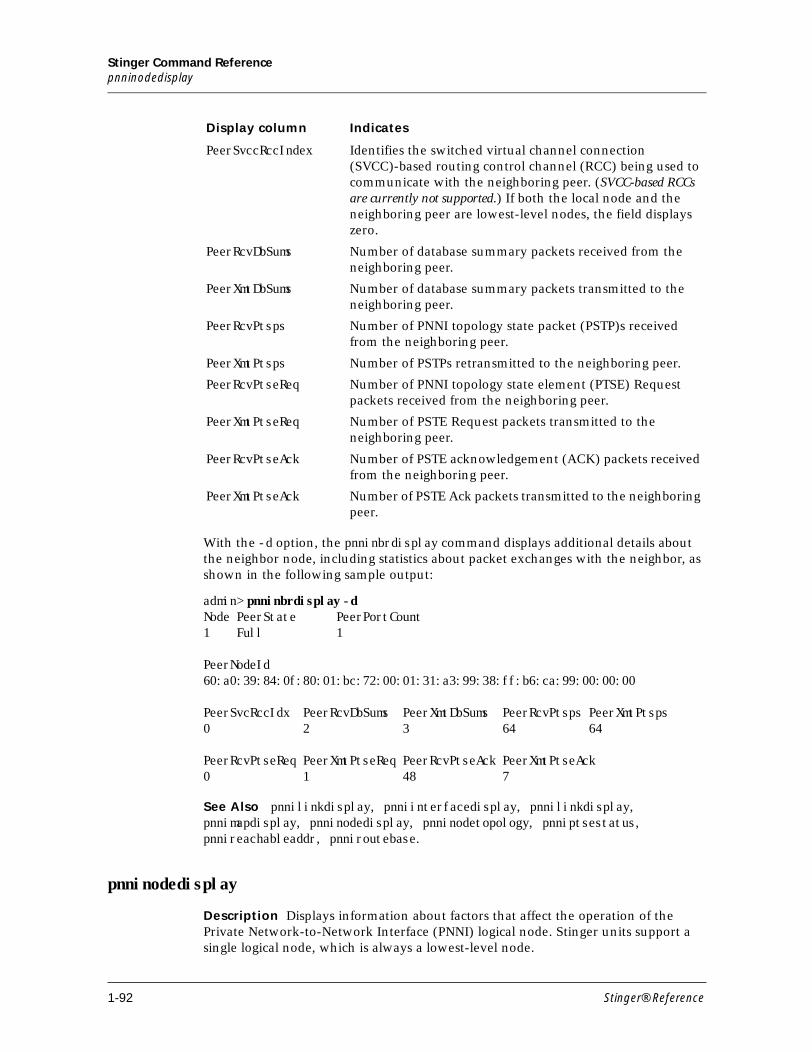
Stinger Command Referencepnninodedisplay
With the -d option, the pnninbrdisplay command displays additional details about the neighbor node, including statistics about packet exchanges with the neighbor, as shown in the following sample output:
admin> pnninbrdisplay -dNode PeerState PeerPortCount1 Full 1 PeerNodeId60:a0:39:84:0f:80:01:bc:72:00:01:31:a3:99:38:ff:b6:ca:99:00:00:00 PeerSvcRccIdx PeerRcvDbSums PeerXmtDbSums PeerRcvPtsps PeerXmtPtsps0 2 3 64 64 PeerRcvPtseReq PeerXmtPtseReq PeerRcvPtseAck PeerXmtPtseAck0 1 48 7
See Also pnnilinkdisplay, pnniinterfacedisplay, pnnilinkdisplay, pnnimapdisplay, pnninodedisplay, pnninodetopology, pnniptsestatus, pnnireachableaddr, pnniroutebase.
pnninodedisplay
Description Displays information about factors that affect the operation of the Private Network-to-Network Interface (PNNI) logical node. Stinger units support a single logical node, which is always a lowest-level node.
PeerSvccRccIndex Identifies the switched virtual channel connection (SVCC)-based routing control channel (RCC) being used to communicate with the neighboring peer. (SVCC-based RCCs are currently not supported.) If both the local node and the neighboring peer are lowest-level nodes, the field displays zero.
PeerRcvDbSums Number of database summary packets received from the neighboring peer.
PeerXmtDbSums Number of database summary packets transmitted to the neighboring peer.
PeerRcvPtsps Number of PNNI topology state packet (PSTP)s received from the neighboring peer.
PeerXmtPtsps Number of PSTPs retransmitted to the neighboring peer.
PeerRcvPtseReq Number of PNNI topology state element (PTSE) Request packets received from the neighboring peer.
PeerXmtPtseReq Number of PSTE Request packets transmitted to the neighboring peer.
PeerRcvPtseAck Number of PSTE acknowledgement (ACK) packets received from the neighboring peer.
PeerXmtPtseAck Number of PSTE Ack packets transmitted to the neighboring peer.
Display column Indicates
1-92 Stinger® Reference
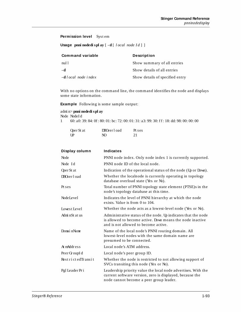
Stinger Command Referencepnninodedisplay
Permission level System
Usage pnninodedisplay [ -d [ local node Id ] ]
With no options on the command line, the command identifies the node and displays some state information.
Example Following is some sample output:
admin> pnninodedisplayNode NodeId1 60:a0:39:84:0f:80:01:bc:72:00:01:31:a3:99:30:ff:18:dd:98:00:00:00 OperStat DBOverload Ptses UP NO 21
Command variable Description
null Show summary of all entries
-d Show details of all entries
-d local node index Show details of specified entry
Display column Indicates
Node PNNI node index. Only node index 1 is currently supported.
Node Id PNNI node ID of the local node.
OperStat Indication of the operational status of the node (Up or Down).
DBOverload Whether the localnode is currently operating in topology database overload state (Yes or No).
Ptses Total number of PNNI topology state element (PTSE)s in the node’s topology database at this time.
NodeLevel Indicates the level of PNNI hierarchy at which the node exists. Value is from 0 to 104.
LowestLevel Whether the node acts as a lowest-level node (Yes or No).
AdminStatus Administrative status of the node. Up indicates that the node is allowed to become active. Down means the node inactive and is not allowed to become active.
DomainName Name of the local node’s PNNI routing domain. All lowest-level nodes with the same domain name are presumed to be connected.
AtmAddress Local node’s ATM address.
PeerGroupId Local node’s peer group ID.
RestrictedTransit Whether the node is restricted to not allowing support of SVCs transiting this node (Yes or No).
PglLeaderPri Leadership priority value the local node advertises. With the current software version, zero is displayed, because the node cannot become a peer group leader.
Stinger® Reference 1-93
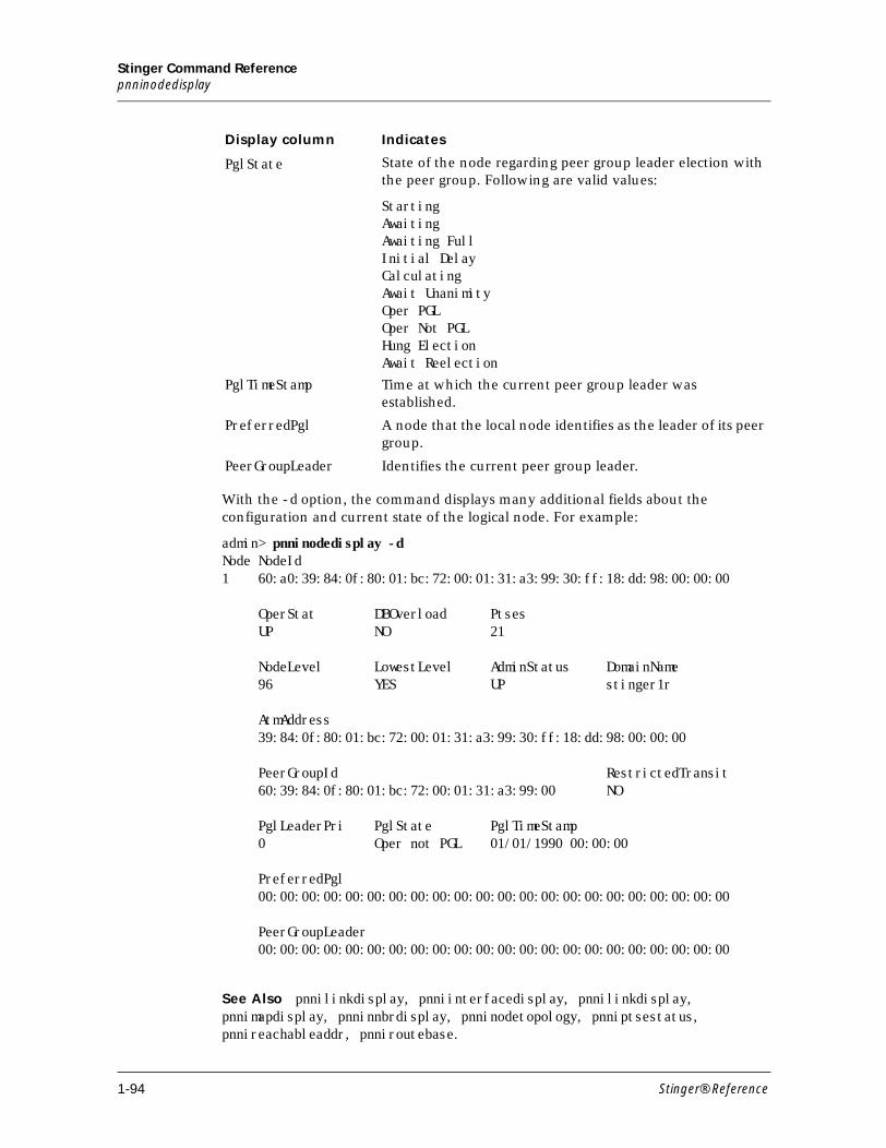
Stinger Command Referencepnninodedisplay
With the -d option, the command displays many additional fields about the configuration and current state of the logical node. For example:
admin> pnninodedisplay -dNode NodeId1 60:a0:39:84:0f:80:01:bc:72:00:01:31:a3:99:30:ff:18:dd:98:00:00:00 OperStat DBOverload Ptses UP NO 21 NodeLevel LowestLevel AdminStatus DomainName 96 YES UP stinger1r AtmAddress 39:84:0f:80:01:bc:72:00:01:31:a3:99:30:ff:18:dd:98:00:00:00 PeerGroupId RestrictedTransit 60:39:84:0f:80:01:bc:72:00:01:31:a3:99:00 NO PglLeaderPri PglState PglTimeStamp 0 Oper not PGL 01/01/1990 00:00:00 PreferredPgl 00:00:00:00:00:00:00:00:00:00:00:00:00:00:00:00:00:00:00:00:00:00 PeerGroupLeader 00:00:00:00:00:00:00:00:00:00:00:00:00:00:00:00:00:00:00:00:00:00
See Also pnnilinkdisplay, pnniinterfacedisplay, pnnilinkdisplay, pnnimapdisplay, pnninnbrdisplay, pnninodetopology, pnniptsestatus, pnnireachableaddr, pnniroutebase.
PglState State of the node regarding peer group leader election with the peer group. Following are valid values:
StartingAwaitingAwaiting FullInitial DelayCalculatingAwait UnanimityOper PGLOper Not PGLHung Election Await Reelection
PglTimeStamp Time at which the current peer group leader was established.
PreferredPgl A node that the local node identifies as the leader of its peer group.
PeerGroupLeader Identifies the current peer group leader.
Display column Indicates
1-94 Stinger® Reference
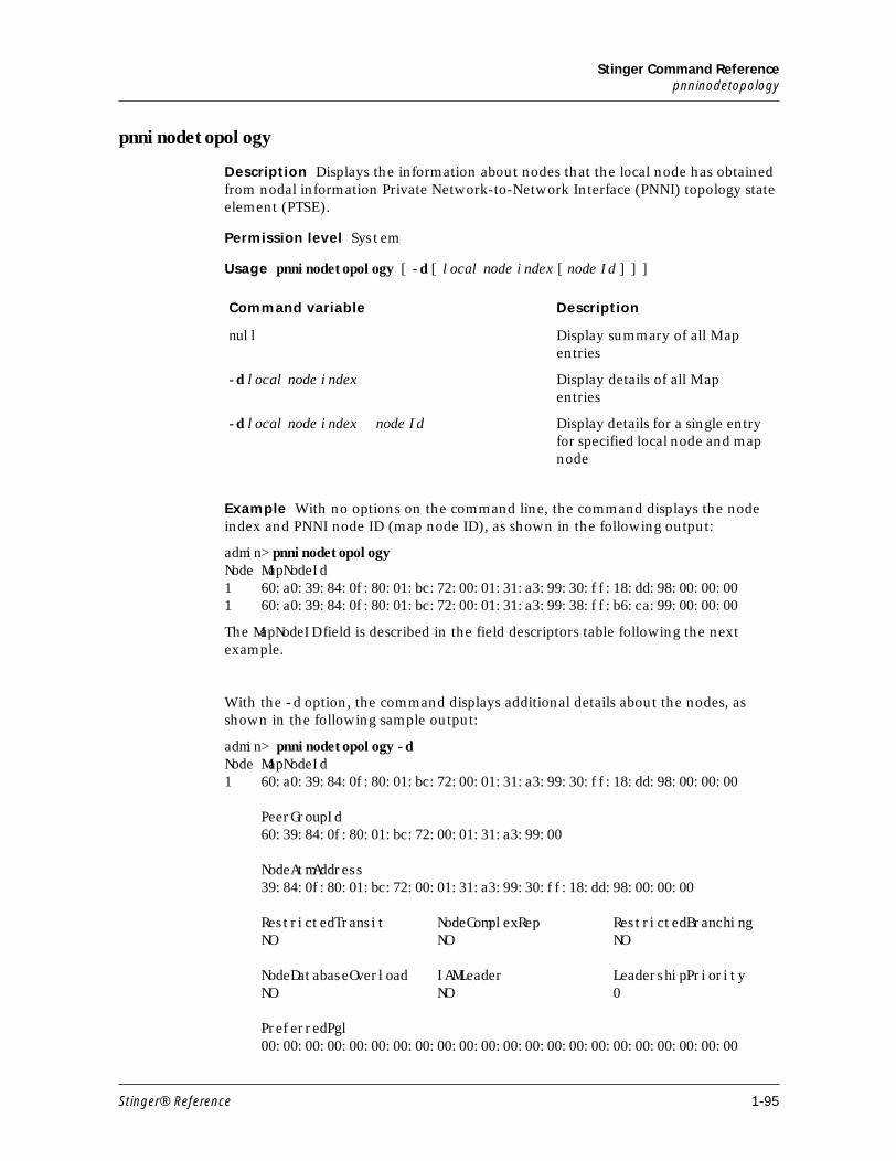
Stinger Command Referencepnninodetopology
pnninodetopology
Description Displays the information about nodes that the local node has obtained from nodal information Private Network-to-Network Interface (PNNI) topology state element (PTSE).
Permission level System
Usage pnninodetopology [ -d [ local node index [ node Id ] ] ]
Example With no options on the command line, the command displays the node index and PNNI node ID (map node ID), as shown in the following output:
admin> pnninodetopologyNode MapNodeId1 60:a0:39:84:0f:80:01:bc:72:00:01:31:a3:99:30:ff:18:dd:98:00:00:001 60:a0:39:84:0f:80:01:bc:72:00:01:31:a3:99:38:ff:b6:ca:99:00:00:00
The MapNodeID field is described in the field descriptors table following the next example.
With the -d option, the command displays additional details about the nodes, as shown in the following sample output:
admin> pnninodetopology -dNode MapNodeId1 60:a0:39:84:0f:80:01:bc:72:00:01:31:a3:99:30:ff:18:dd:98:00:00:00 PeerGroupId 60:39:84:0f:80:01:bc:72:00:01:31:a3:99:00 NodeAtmAddress 39:84:0f:80:01:bc:72:00:01:31:a3:99:30:ff:18:dd:98:00:00:00 RestrictedTransit NodeComplexRep RestrictedBranching NO NO NO NodeDatabaseOverload IAMLeader LeadershipPriority NO NO 0 PreferredPgl 00:00:00:00:00:00:00:00:00:00:00:00:00:00:00:00:00:00:00:00:00:00
Command variable Description
null Display summary of all Map entries
-d local node index Display details of all Map entries
-d local node index node Id Display details for a single entry for specified local node and map node
Stinger® Reference 1-95
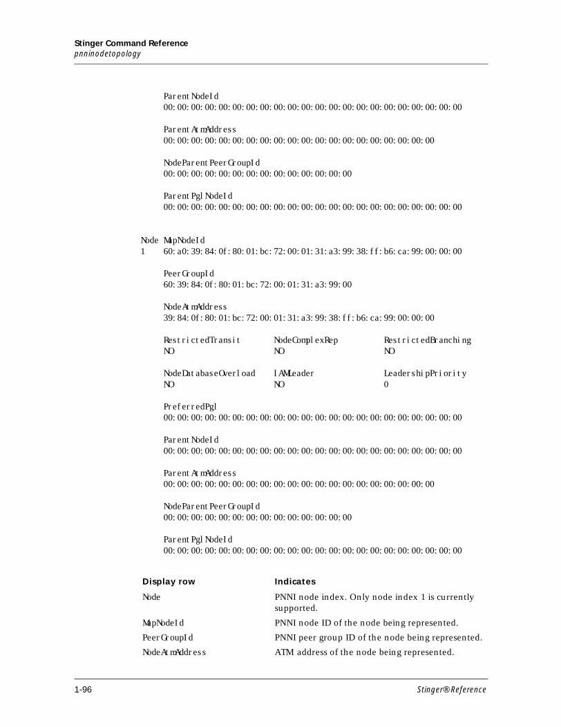
Stinger Command Referencepnninodetopology
ParentNodeId 00:00:00:00:00:00:00:00:00:00:00:00:00:00:00:00:00:00:00:00:00:00 ParentAtmAddress 00:00:00:00:00:00:00:00:00:00:00:00:00:00:00:00:00:00:00:00 NodeParentPeerGroupId 00:00:00:00:00:00:00:00:00:00:00:00:00:00 ParentPglNodeId 00:00:00:00:00:00:00:00:00:00:00:00:00:00:00:00:00:00:00:00:00:00 Node MapNodeId1 60:a0:39:84:0f:80:01:bc:72:00:01:31:a3:99:38:ff:b6:ca:99:00:00:00 PeerGroupId 60:39:84:0f:80:01:bc:72:00:01:31:a3:99:00
NodeAtmAddress 39:84:0f:80:01:bc:72:00:01:31:a3:99:38:ff:b6:ca:99:00:00:00 RestrictedTransit NodeComplexRep RestrictedBranching NO NO NO NodeDatabaseOverload IAMLeader LeadershipPriority NO NO 0 PreferredPgl 00:00:00:00:00:00:00:00:00:00:00:00:00:00:00:00:00:00:00:00:00:00 ParentNodeId 00:00:00:00:00:00:00:00:00:00:00:00:00:00:00:00:00:00:00:00:00:00 ParentAtmAddress 00:00:00:00:00:00:00:00:00:00:00:00:00:00:00:00:00:00:00:00 NodeParentPeerGroupId 00:00:00:00:00:00:00:00:00:00:00:00:00:00 ParentPglNodeId 00:00:00:00:00:00:00:00:00:00:00:00:00:00:00:00:00:00:00:00:00:00
Display row Indicates
Node PNNI node index. Only node index 1 is currently supported.
MapNodeId PNNI node ID of the node being represented.
PeerGroupId PNNI peer group ID of the node being represented.
NodeAtmAddress ATM address of the node being represented.
1-96 Stinger® Reference
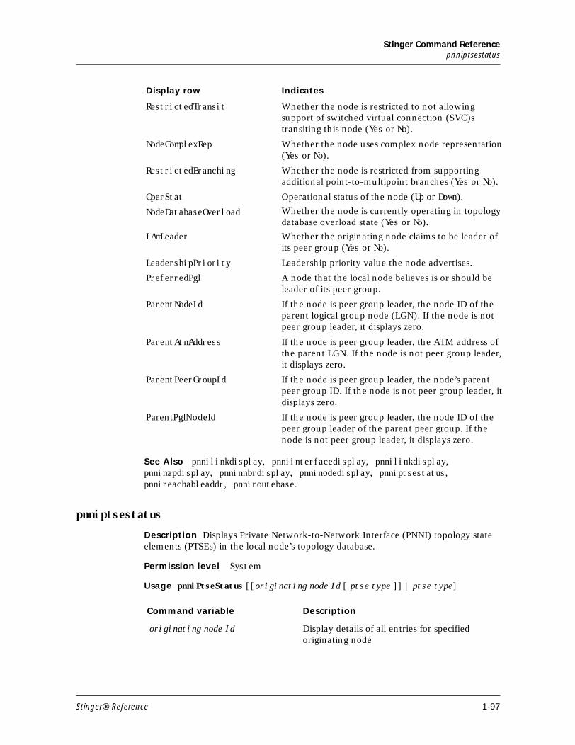
Stinger Command Referencepnniptsestatus
See Also pnnilinkdisplay, pnniinterfacedisplay, pnnilinkdisplay, pnnimapdisplay, pnninnbrdisplay, pnninodedisplay, pnniptsestatus, pnnireachableaddr, pnniroutebase.
pnniptsestatus
Description Displays Private Network-to-Network Interface (PNNI) topology state elements (PTSEs) in the local node’s topology database.
Permission level System
Usage pnniPtseStatus [[originating node Id [ ptse type ]] | ptse type]
RestrictedTransit Whether the node is restricted to not allowing support of switched virtual connection (SVC)s transiting this node (Yes or No).
NodeComplexRep Whether the node uses complex node representation (Yes or No).
RestrictedBranching Whether the node is restricted from supporting additional point-to-multipoint branches (Yes or No).
OperStat Operational status of the node (Up or Down).
NodeDatabaseOverload Whether the node is currently operating in topology database overload state (Yes or No).
IAmLeader Whether the originating node claims to be leader of its peer group (Yes or No).
LeadershipPriority Leadership priority value the node advertises.
PreferredPgl A node that the local node believes is or should be leader of its peer group.
ParentNodeId If the node is peer group leader, the node ID of the parent logical group node (LGN). If the node is not peer group leader, it displays zero.
ParentAtmAddress If the node is peer group leader, the ATM address of the parent LGN. If the node is not peer group leader, it displays zero.
ParentPeerGroupId If the node is peer group leader, the node’s parent peer group ID. If the node is not peer group leader, it displays zero.
ParentPglNodeId If the node is peer group leader, the node ID of the peer group leader of the parent peer group. If the node is not peer group leader, it displays zero.
Display row Indicates
Command variable Description
originating node Id Display details of all entries for specified originating node
Stinger® Reference 1-97
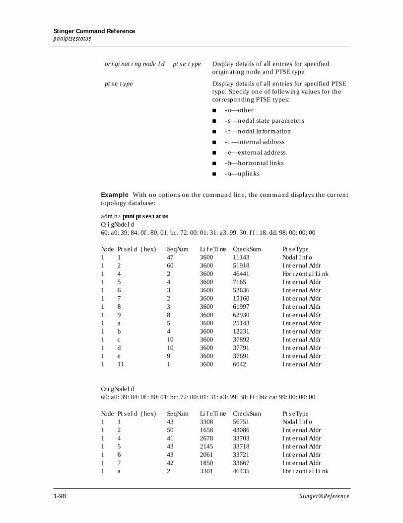
Stinger Command Referencepnniptsestatus
Example With no options on the command line, the command displays the current topology database:
admin> pnniptsestatusOrigNodeId60:a0:39:84:0f:80:01:bc:72:00:01:31:a3:99:30:ff:18:dd:98:00:00:00 Node PtseId (hex) SeqNum LifeTime CheckSum PtseType1 1 47 3600 11143 NodalInfo1 2 60 3600 51918 InternalAddr1 4 2 3600 46441 HorizontalLink1 5 4 3600 7165 InternalAddr1 6 3 3600 52636 InternalAddr1 7 2 3600 15160 InternalAddr1 8 3 3600 61997 InternalAddr1 9 8 3600 62930 InternalAddr1 a 5 3600 25143 InternalAddr1 b 4 3600 12231 InternalAddr1 c 10 3600 37892 InternalAddr1 d 10 3600 37791 InternalAddr1 e 9 3600 37691 InternalAddr1 11 1 3600 6042 InternalAddr OrigNodeId60:a0:39:84:0f:80:01:bc:72:00:01:31:a3:99:38:ff:b6:ca:99:00:00:00 Node PtseId (hex) SeqNum LifeTime CheckSum PtseType1 1 43 3308 56751 NodalInfo1 2 50 1658 43086 InternalAddr1 4 41 2678 33703 InternalAddr1 5 43 2145 33718 InternalAddr1 6 43 2061 33721 InternalAddr1 7 42 1850 33667 InternalAddr1 a 2 3301 46435 HorizontalLink
originating node Id ptse type Display details of all entries for specified originating node and PTSE type
ptse type Display details of all entries for specified PTSE type. Specify one of following values for the corresponding PTSE types:
■ -o—other
■ -s—nodal state parameters
■ -f—nodal information
■ -i—internal address
■ -e—external address
■ -h—horizontal links
■ -u—uplinks
1-98 Stinger® Reference
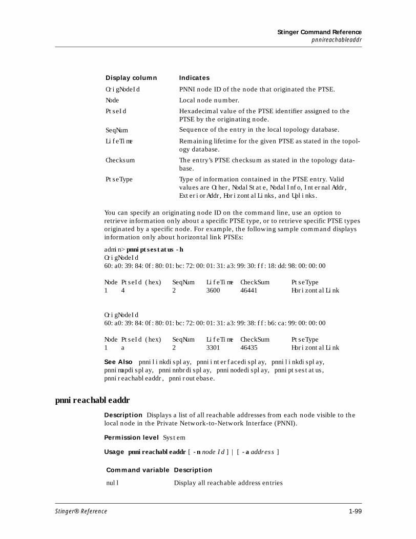
Stinger Command Referencepnnireachableaddr
You can specify an originating node ID on the command line, use an option to retrieve information only about a specific PTSE type, or to retrieve specific PTSE types originated by a specific node. For example, the following sample command displays information only about horizontal link PTSEs:
admin> pnniptsestatus -hOrigNodeId60:a0:39:84:0f:80:01:bc:72:00:01:31:a3:99:30:ff:18:dd:98:00:00:00 Node PtseId (hex) SeqNum LifeTime CheckSum PtseType1 4 2 3600 46441 HorizontalLink OrigNodeId60:a0:39:84:0f:80:01:bc:72:00:01:31:a3:99:38:ff:b6:ca:99:00:00:00 Node PtseId (hex) SeqNum LifeTime CheckSum PtseType1 a 2 3301 46435 HorizontalLink
See Also pnnilinkdisplay, pnniinterfacedisplay, pnnilinkdisplay, pnnimapdisplay, pnninnbrdisplay, pnninodedisplay, pnniptsestatus, pnnireachableaddr, pnniroutebase.
pnnireachableaddr
Description Displays a list of all reachable addresses from each node visible to the local node in the Private Network-to-Network Interface (PNNI).
Permission level System
Usage pnnireachableaddr [ -n node Id ] | [ -a address ]
Display column Indicates
OrigNodeId PNNI node ID of the node that originated the PTSE.
Node Local node number.
PtseId Hexadecimal value of the PTSE identifier assigned to the PTSE by the originating node.
SeqNum Sequence of the entry in the local topology database.
LifeTime Remaining lifetime for the given PTSE as stated in the topol-ogy database.
Checksum The entry’s PTSE checksum as stated in the topology data-base.
PtseType Type of information contained in the PTSE entry. Valid values are Other, NodalState, NodalInfo, InternalAddr, ExteriorAddr, HorizontalLinks, and Uplinks.
Command variable Description
null Display all reachable address entries
Stinger® Reference 1-99
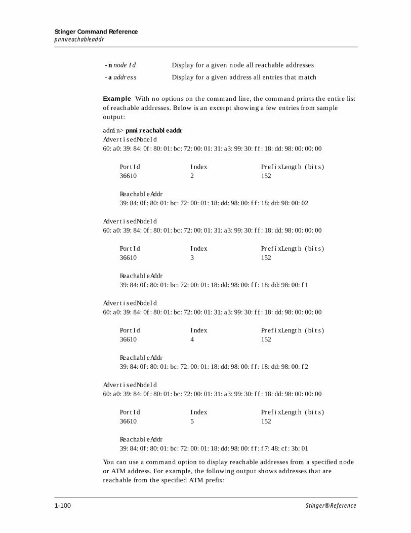
Stinger Command Referencepnnireachableaddr
Example With no options on the command line, the command prints the entire list
of reachable addresses. Below is an excerpt showing a few entries from sample output:
admin> pnnireachableaddrAdvertisedNodeId60:a0:39:84:0f:80:01:bc:72:00:01:31:a3:99:30:ff:18:dd:98:00:00:00 PortId Index PrefixLength (bits) 36610 2 152 ReachableAddr 39:84:0f:80:01:bc:72:00:01:18:dd:98:00:ff:18:dd:98:00:02 AdvertisedNodeId60:a0:39:84:0f:80:01:bc:72:00:01:31:a3:99:30:ff:18:dd:98:00:00:00 PortId Index PrefixLength (bits) 36610 3 152 ReachableAddr 39:84:0f:80:01:bc:72:00:01:18:dd:98:00:ff:18:dd:98:00:f1 AdvertisedNodeId60:a0:39:84:0f:80:01:bc:72:00:01:31:a3:99:30:ff:18:dd:98:00:00:00 PortId Index PrefixLength (bits) 36610 4 152 ReachableAddr 39:84:0f:80:01:bc:72:00:01:18:dd:98:00:ff:18:dd:98:00:f2 AdvertisedNodeId60:a0:39:84:0f:80:01:bc:72:00:01:31:a3:99:30:ff:18:dd:98:00:00:00 PortId Index PrefixLength (bits) 36610 5 152 ReachableAddr 39:84:0f:80:01:bc:72:00:01:18:dd:98:00:ff:f7:48:cf:3b:01
You can use a command option to display reachable addresses from a specified node or ATM address. For example, the following output shows addresses that are reachable from the specified ATM prefix:
-n node Id Display for a given node all reachable addresses
-a address Display for a given address all entries that match
1-100 Stinger® Reference
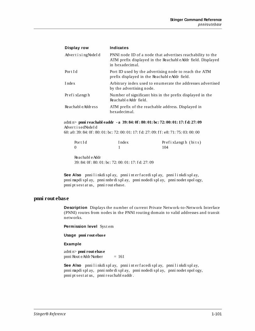
Stinger Command Referencepnniroutebase
admin> pnnireachableaddr -a 39:84:0f:80:01:bc:72:00:01:17:fd:27:09AdvertisedNodeId60:a0:39:84:0f:80:01:bc:72:00:01:17:fd:27:09:ff:e8:71:75:03:00:00
PortId Index PrefixLength (bits) 0 1 104
ReachableAddr 39:84:0f:80:01:bc:72:00:01:17:fd:27:09
See Also pnnilinkdisplay, pnniinterfacedisplay, pnnilinkdisplay, pnnimapdisplay, pnninnbrdisplay, pnninodedisplay, pnninodetopology, pnniptsestatus, pnniroutebase.
pnniroutebase
Description Displays the number of current Private Network-to-Network Interface (PNNI) routes from nodes in the PNNI routing domain to valid addresses and transit networks.
Permission level System
Usage pnniroutebase
Example
admin> pnniroutebasepnniRouteAddrNumber = 161
See Also pnnilinkdisplay, pnniinterfacedisplay, pnnilinkdisplay, pnnimapdisplay, pnninnbrdisplay, pnninodedisplay, pnninodetopology, pnniptsestatus, pnnireachableaddr.
Display row Indicates
AdvertisingNodeId PNNI node ID of a node that advertises reachability to the ATM prefix displayed in the ReachableAddr field. Displayed in hexadecimal.
PortId Port ID used by the advertising node to reach the ATM prefix displayed in the ReachableAddr field.
Index Arbitrary index used to enumerate the addresses advertised by the advertising node.
PrefixLength Number of significant bits in the prefix displayed in the ReachableAddr field.
ReachableAddress ATM prefix of the reachable address. Displayed in hexadecimal.
Stinger® Reference 1-101
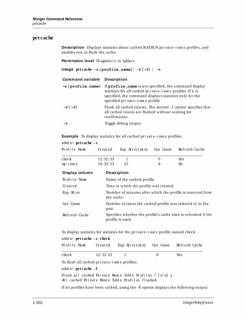
Stinger Command Referenceprtcache
prtcache
Description Displays statistics about cached RADIUS private-route profiles, and enables you to flush the cache.
Permission level Diagnostic or Update
Usage prtcache -s [profile_name]| -f [-f] | -t
Example To display statistics for all cached private-route profiles:
admin> prtcache -s
Profile Name Created Exp After(min) Use Count Refresh Cache______________________________________________________________________check 12:32:53 1 0 Yesmy-route 10:32:53 23 8 No
To display statistics for statistics for the private-route profile named check:
admin> prtcache -s check
Profile Name Created Exp After(min) Use Count Refresh Cache______________________________________________________________________check 12:32:53 1 0 Yes
To flush all cached private-route profiles:
admin> prtcache -f
Flush all cached Private Route Table Profiles ? [y/n] yAll cached Private Route Table Profiles flushed.
If no profiles have been cached, using the -f option displays the following output:
Command variable Description
-s [profile_name] If profile_name is not specified, the command display statistics for all cached private-route profiles. If it is specified, the command displays statistics only for the specified private-route profile
-f [-f] Flush all cached entries. The second -f option specifies that all cached routes are flushed without waiting for confirmation.
-t Toggle debug output.
Display column Description
Profile Name Name of the cached profile.
Created Time at which the profile was created.
Exp After Number of minutes after which the profile is removed from the cache.
Use Count Number of times the cached profile was referred to in the past.
Refresh Cache Specifies whether the profile’s cache time is refreshed if the profile is used.
1-102 Stinger® Reference
Stinger Command ReferenceQ
admin> prtcache -f
Flush all cached Private Route Table Profiles ? [y/n] yNo cached Profiles to flush.
If the user does not have the required permission:
admin> prtcache -f
error: Command requires 'diagnose' or 'update' privileges
Note All cached RADIUS private-route profiles are read only. You can delete a single cached profile by using the delete command. To delete all cached profiles, use the prtcache command.
Q
quit
Description Terminates the current Telnet session.
Permission level User
Usage quit
Example To terminate the current Telnet session:
admin> quitConnection closed by foreign host.my-station%
R
read
Description Reads a copy of the specified profile into the edit buffer, making it the working profile. If the profile is one of a kind, such as the IP-Global profile, it has no index field. If an index field exists for a profile, it must be specified on the command line.
Only the working profile can be modified. The set and list commands apply only to the working profile.
Note The working profile remains in the edit buffer until you overwrite the buffer with another read command or the new command. To save changes made in the buffer, you must use the write command.
Permission level System
Usage read profile-type [profile-index][-f]
Command variable Description
profile-type The type of profile to be read (or the profile itself if it does not require an index specification).
Stinger® Reference 1-103
Stinger Command Referenceread
By default, when you issue a read command that would overwrite the contents of the edit buffer when the buffer contains unsaved changes, the system displays a message prompting for confirmation. For example:
admin> read connection davidReading will overwrite the changes you've made.Read anyway? [y/n] yCONNECTION/david read
You can avoid this prompt by using the –f option on the read command line.
Example To find the right index for an ip-interface profile, read that profile, and list its contents:
admin> dir ip-interface66 12/20/1998 14:02:02 { { shelf-1 slot-12 1 } 0 }66 12/27/1998 16:34:40 { { shelf-1 slot-12 2 } 0 }66 12/27/1998 16:34:47 { { shelf-1 slot-12 3 } 0 }66 12/27/1998 16:34:54 { { shelf-1 slot-12 4 } 0 }66 12/28/1998 00:21:06 { { shelf-1 controller 1 } 0 }
admin> read ip-int {{1 c 1} 0}IP-INTERFACE/{ { shelf-1 controller 1 } 0 } read
admin> list[in IP-INTERFACE/{ { Shelf-1 controller 1} 0 }]interface-address*={ { shelf-1 controller 1 } 0 }ip-address=10.6.212.227/24rip-mode=routing-send-and-recv
The profile remains in the edit buffer until another read command or a new command overwrites the buffer. The set command modifies the profile. The write command saves changes without clearing the buffer.
admin> set ip-address=10.6.212.228/24
admin> writeIP-INTERFACE/{ { shelf-1 controller 1 } 0 } written
The working profile is represented by a period (.) character. Even after you have used the get command to display other profiles, or have executed other commands, you can still use the get command to display the working profile:
admin> get .[in IP-INTERFACE/{ { Shelf-1 controller 1} 0 }]interface-address*={ { shelf-1 controller 1 } 0 }ip-address=10.6.212.228/24rip-mode=routing-send-and-recv
See Also get, list, new, set, write
profile-index The name or address that distinguishes a profile from others of the same type. To see profile indexes, enter the dir command (dir profile-type).
-f Do not prompt for confirmation when overwriting the unsaved contents of the edit buffer.
Command variable Description
1-104 Stinger® Reference
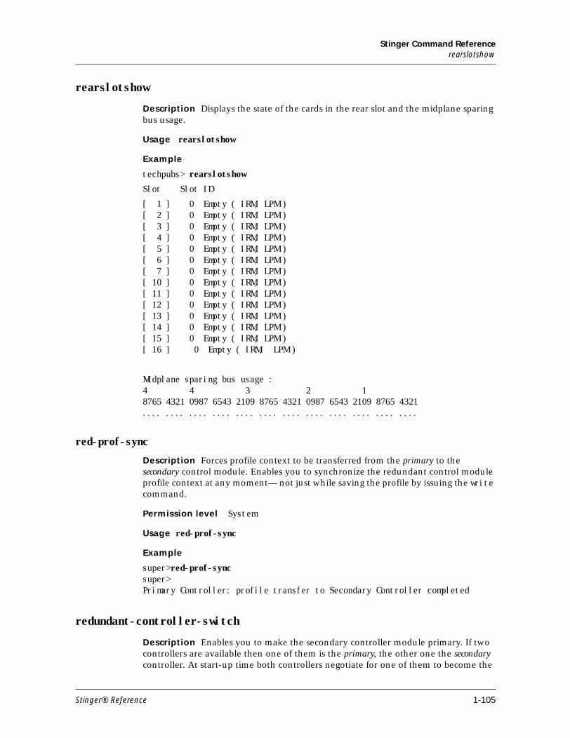
Stinger Command Referencerearslotshow
rearslotshow
Description Displays the state of the cards in the rear slot and the midplane sparing bus usage.
Usage rearslotshow
Example
techpubs> rearslotshow
Slot Slot ID
[ 1 ] 0 Empty ( IRM, LPM ) [ 2 ] 0 Empty ( IRM, LPM ) [ 3 ] 0 Empty ( IRM, LPM ) [ 4 ] 0 Empty ( IRM, LPM ) [ 5 ] 0 Empty ( IRM, LPM ) [ 6 ] 0 Empty ( IRM, LPM ) [ 7 ] 0 Empty ( IRM, LPM ) [ 10 ] 0 Empty ( IRM, LPM ) [ 11 ] 0 Empty ( IRM, LPM ) [ 12 ] 0 Empty ( IRM, LPM ) [ 13 ] 0 Empty ( IRM, LPM ) [ 14 ] 0 Empty ( IRM, LPM ) [ 15 ] 0 Empty ( IRM, LPM ) [ 16 ] 0 Empty ( IRM, LPM )
Midplane sparing bus usage :4 4 3 2 1 8765 4321 0987 6543 2109 8765 4321 0987 6543 2109 8765 4321.... .... .... .... .... .... .... .... .... .... .... ....
red-prof-sync
Description Forces profile context to be transferred from the primary to the secondary control module. Enables you to synchronize the redundant control module profile context at any moment— not just while saving the profile by issuing the write command.
Permission level System
Usage red-prof-sync
Example
super>red-prof-syncsuper> Primary Controller: profile transfer to Secondary Controller completed
redundant-controller-switch
Description Enables you to make the secondary controller module primary. If two controllers are available then one of them is the primary, the other one the secondary controller. At start-up time both controllers negotiate for one of them to become the
Stinger® Reference 1-105
Stinger Command Referencerefresh
primary. The user can influence this process by setting the primary preference flag in the redundancy profile to the slot number of the controller that will become primary in the case when two controllers are present. If the primary fails then the secondary automatically takes over control of the system. When the original primary fails, the new primary deactivates all slot modules and reactivates the system.
Permission level System
Usage redundant-controller-switch [-f]
The -f option forces a switchover.
Following are examples of issuing this command from controllers in various conditons.
Command executed on secondary controller:
admin> redundant-controller-switchThis controller is not the PRIMARY, it does not own the bus !
Command on primary when secondary is not asking to be primary
admin> redundant-controller-switch The remote controller is not requesting the bus,
it cannot become PRIMARY !
Command executed on primary when there is only one controller:
admin> redundant-controller-switch There is no remote controller !
See Also refresh
refresh
Description Opens a connection to a RADIUS server and retrieves the latest configuration information.
Permission level System
Usage refresh -a |-n |-p |-r | -t
See Also rad-auth-client
Command option Description
-a Refresh all types of configuration.
-n Refresh nailed profiles configuration.
-p Refresh address (p)ools configuration.
-r Refresh static routes configuration.
-t Refresh terminal server configuration.
-s Clears the current Source Auth information (purging all existing Source Auth entries from the cache) and reloads it from RADIUS.
1-106 Stinger® Reference
Stinger Command Referencerelayoff
relayoff
Description Turns off alarm relay.
Permission level Diagnostic
Usage relayoff [major | minor ]
Example To turn off the major relay:
admin> relayoff major
reset
Description Resets the Stinger. When you reset the unit, it restarts, and all active connections are terminated. All users are logged out and the default security level is reactivated. In addition, a system reset can cause a WAN line to temporarily be shut down due to momentary loss of signaling or framing information. After a reset, the Stinger runs POST (power-on self tests).
Permission level Update
Usage reset [ -f ] [ -r primary_controller | secondary_controller | both_controllers ]
See Also nvram
rm
Description This command of the flash file system deletes a file or directory on a flash card.
Permission level System
Command variable Description
major Turn of major relay.
minor Turn of minor relay.
Command variable Description
-f Perform the reset without prompting for confirmation.
-r primary_controller Reset primary controller only.
-r secondary_controller Reset secondary controller only.
-r both_controllers Reset both controllers. This is the default.
Stinger® Reference 1-107
Stinger Command ReferenceS
Usage rm socket/path
Example To remove the /test1 directory on flash card 1, enter the following:
admin> rm 1/test1
See Also cat, ls, mkdir, mv
S
Save
Description Saves configuration information to a file. The file can reside either on the hard disk of the PC you are using to issue commands to the Stinger or on a networked host. The file is saved in a format that can be loaded into the Stinger to restore a configuration. The Save command uses TFTP to transfer the configuration across the network. To save the Stinger configuration on a remote host, you must have the necessary permissions in the directory.
Permission level Update
Usage save [-a][-m][-e encryption_type password][target [profile-type [profile-index]] | network host filename [ -p profile1, profile2... | -x profile1, profile2...]
Command variable Description
socket Specify the flash card number.
path Specify the subdirectory to be deleted.
Command variable Description
-a Explicitly save all fields, even those with default values. If you do not specify this option, the file stores only those fields whose values have been changed from the default.
-m Use MIB tags instead of field and value names, and use pro-file-type numbers rather than profile-type text names.
-e
encryption_type
password
Use encryption. The encryption_type argument specifies the method to be used for encryption and decruption. You can specify DES or MD5. The password argument specifies the pass-word used to generate the key for encryption and decryption. The -e option supports only a network target.
target The destination of the file to be saved. Valid specifications are:
■ network host filename—A network hostname of IP address and the name of the file on that host.
■ console—The PC you are using in a terminal session.
■ flash device/filename—the PCMCIA flash card.
1-108 Stinger® Reference
Stinger Command ReferenceSave
Note
Note Most Telnet utilities have a capture function, for example Telnet.cfg, has a capture function under the file menu. Start the capture before issuing the save command, and end the capture after the terminal display has ended. The capture function will usually tell you the target filename into which the display has been saved.
Example Saving all connection profiles to a file on a PC’s hard disk (after starting the capture utility in the terminal emulation software):
admin> save console connection; saving profiles of type CONNECTION; profile saved Thu Jan 2 13:02:54 1999new CONNECTION dallasset active=yesset ip-options remote-address=10.122.99.1/24write -f;
; profile saved Thu Jan 2 13:02:54 1999new CONNECTION chicagoset active=yesset dial-number=999set ip-options remote-address=10.168.6.57/24set ip-options routing-metric=2write -f;
To save the file, stop the capture in the terminal emulation software. To save the entire configuration to hard disk, start the capture utility and specify the console option:
admin> save console; saving all profiles...
profile-type The type of profile to be read, or the profile itself if it does not require an index specification.
profile-index The name or address that distinguishes a profile from others of the same type. To see profile indexes, enter the Dir com-mand (dir profile-type).
network hostfilename
The hostname or IP address of the source network and the name of the file on that host.
-p profile1, profile2...
Save the specified list of profiles. Only used with the network option.
-x profile1, profile2...
Save all profiles, except those in the specified list. Only used with the network option.
Command variable Description
Stinger® Reference 1-109
Stinger Command Referencescreen
All configured profiles and parameters scroll to the capture buffer. When the entire configuration has been displayed, the following output appears:
;;; all profiles saved
To save the file, stop the capture. The following example shows how to save a specific profile to a file on a network host:
admin> save network host-231 /users/marcel/ipglobal ip-globalconfiguration being saved to 10.65.12.231file /users/marcel/ipglobal...saveadmin>
The following example shows how the save command specifies a profile type by its internal number when saving, using the -m option:
admin> save -m console system; saving profiles of type SYSTEM; profile saved Sat Mar 29 13:29:42 1998new 3set 1=1set 2=eng-lab-43write -f
Note If the first item following a new, read, or dir command is numeric, it is assumed to be a profile-type number.
See Also load, nvram
screen
Description Changes window display sizes for the current session only.
Permission level Update
Usage screen [screen-length] [status-length] [-w width]
If the status window is open when you execute the screen command, the window is resized dynamically. If it is not open, the status window is resized when you next open it.
Command variable Description
screen-length The number of lines displayed in the command-line window. The default is 24 lines, which is the minimum size. The maximum size is 999 lines
status-length The number of lines displayed in the Status window, including dividing lines. The default is 18 lines, which is the minimum size. The maximum size is 993 lines. The status-length value must be less than the screen-length by at least six lines
-w width A value from 80 to 256; the default is 80.
1-110 Stinger® Reference
Stinger Command Referencesdsllines
Example admin> screen 55 22
If only the screen-length argument is specified, and the stored status-length is not less than the specified value by six lines, the status-length is automatically adjusted. This scenario is demonstrated in the following example:
admin> screen 55 22new screen-length 55new status-length 22
admin> screen 24error: screen-length conflict, adjusting status-length from 22 to 18new screen-length 24new status-length 18
The screen command enables you to specify the width of the screen. For example, the following command sets the screen width to 256 characters:
admin> screen -w 256
The specified screen width is the number of characters that are visible without scrolling, including the system prompt and spaces following it.
For example, if the screen width is 80 characters and the prompt is admin> (a 6-character prompt followed by a space), the maximum number of visible characters in a command is 72. If you enter a long command (for example, one that has 100 characters), 28 of the characters are not visible at any one time. You can scroll to the characters not currently visible by moving the cursor left or right. The Ctrl-L, Ctrl-R control sequence allows you to redraw the current line.
For details, see the Taos Command-Line Interface Guide.
See Also screen-length, screen-width
sdsllines
Description Displays SDSL channel information.
Permission level System
Usage sdsllines -a | -d | -f | - u
Example To display all SDSL channels available, use the -a option:
admin> sdsllines -a
All SDSL lines: (dvOp dvUpSt dvRq sAdm nailg) Line { 1 3 1 } (Up Idle UP UP 00001)
Command option Description
-a Display all available channels.
-d Display all disabled channels.
-f Display all possible channels.
-u Display all in-use channels.
Stinger® Reference 1-111
Stinger Command Referencesdsllines
Line { 1 3 2 } (Up Assigned UP UP 00002) Line { 1 3 3 } (Up Assigned UP UP 00003) Line { 1 3 4 } (Up Idle UP UP 00004) Line { 1 3 5 } (Up Idle UP UP 00005) Line { 1 3 6 } (Up Assigned UP UP 00006) Line { 1 3 7 } (Up Idle UP UP 00007) Line { 1 3 8 } (Up Assigned UP UP 00008) Line { 1 3 9 } (Up Assigned UP UP 00009) Line { 1 3 10 } (Up Assigned UP UP 00010) Line { 1 3 11 } (Up Assigned UP UP 00011) Line { 1 3 12 } (Up Assigned UP UP 00012) Line { 1 3 13 } (Up Assigned UP UP 00013) Line { 1 3 14 } (Up Assigned UP UP 00014) Line { 1 3 15 } (Up Assigned UP UP 00015) Line { 1 3 16 } (Up Idle UP UP 00016)
The data displayed includes the physical address and channel number, and the following status information about each channel:
Display column Description
dvOp The current operational state of the channel (also specified by the device-state parameter):
■ Down—Indicates that the channel is in a nonoperational state.
■ Up—Indicates that the channel is in normal operation mode.
dvUpSt The status of the channel in normal operation mode:
■ Idle—Indicates that no call is on the line.
■ Active—Indicates that the channel is handling a call.
dvRq The required state of the channel as specified by the reqd-state setting:
■ Down—Indicates that the channel is required to be nonoperational.
■ Up—Indicates that the channel is required to be in normal operation mode.
sAdm The desired administrative state of the line:
■ Down—Indicates that the line should terminate all operations and enter the down state.
■ Up—Indicates that the line should come up in normal operations mode.
The actual state of the line can differ from the desired state, as when a device is powering up or you change the desired state on a running slot. Changing the desired state does not automatically change a line to the desired state. It indicates that an operation has been initiated that should change the Stinger to the state desired.
nailg The dedicated (nailed) group to which the line is assigned.
1-112 Stinger® Reference
Stinger Command Referenceset
See Also device-type, device-state
set
Description Sets a parameter’s value or displays help text for a parameter in the current or specified context of the working profile. To save the new setting, you must write the profile.
Permission level System
Usage set param-name [param-index] [subprofile] = value |?
Example set enabled = yes
See Also list, new,physical-address, read, write
shdsllines
Description Displays the status of all SHDSL lines.
Permission level System
Usage shdsllines -[ a | d | f | u| t]
Command variable Description
param-name Name of the parameter in the current or specified context of the working profile.
param-index Parameter index, which might be required for some complex or array parameters. (See the Physical-Address parameter example.)
subprofile Subprofile name within the working profile. By specifying its name on the command line, you can set a parameter in a subprofile without opening the subprofile.
= Equal sign is part of the required syntax unless using the question mark (?) for help.
value Legal parameter value.
? Display help text about the specified parameter. Omit the equals (=) sign. To display help about the address parameter, for example, enter set address ? from within the profile and subprofile that contains the address parameter.
Command variable Description
-a Show (a)ll DSL lines.
-d Show (d)isabled lines
-f Show all (f)ree lines
Stinger® Reference 1-113

Stinger Command Referenceshow
Example To show all free lines:
admin> shdsllines -f
Free SHDSL lines:
(dvOp dvUpSt dvRq sAdm nailg )
Line { 1 4 3 } (Down Idle UP UP 00153)
Line { 1 4 4 } (Up Idle UP UP 00154)
The data displayed includes the physical address of each line and the following status information::
show
Description Displays information about installed modules and their status.
Permission level System
-u Show in-(u)se lines
-t Toggle debug flag.
Column Description
dvOp The current operational state of the line:
Down indicates that the line is in a nonoperational state.
Up indicates that the line is in normal operation mode.
dvUpSt The status of the line in normal operation mode:
Idle indicates that no call is on the line.
Active indicates that the line is handling a call.
dvRq The required state of the line:
Down indicates that the line is required to be nonoperational.
Up indicates that the line is required to be in normal operation mode.
sAdm The desired administrative state of the line:
Down specifies that the line should terminate all operations and enter the deactivated state.
Up specifies that the line should be activated in normal operation mode.
The actual state of the line can differ from the desired state, as when a device is powering up, or you change the desired state on a running slot. Changing the desired state does not automatically change a line to the desired state. It indicates that an operation has been initiated (for example, someone has dialed in) that should change the Stinger to the desired state.
nailg The (dedicated) nailed group to which the line is assigned.
Command variable Description
1-114 Stinger® Reference
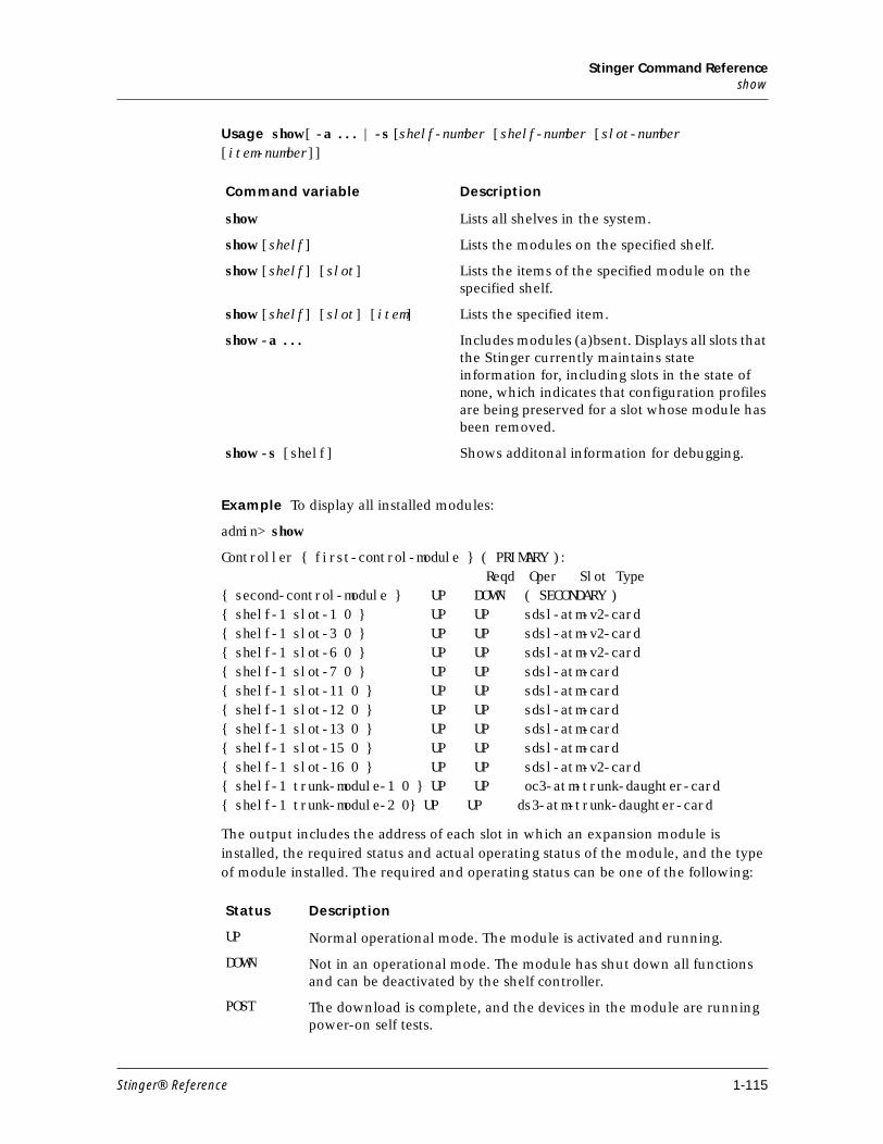
Stinger Command Referenceshow
Usage show [ -a ... | -s [shelf-number [shelf-number [slot-number [item-number]]
Example To display all installed modules:
admin> show
Controller { first-control-module } ( PRIMARY ):Reqd Oper Slot Type
{ second-control-module } UP DOWN ( SECONDARY ){ shelf-1 slot-1 0 } UP UP sdsl-atm-v2-card{ shelf-1 slot-3 0 } UP UP sdsl-atm-v2-card{ shelf-1 slot-6 0 } UP UP sdsl-atm-v2-card{ shelf-1 slot-7 0 } UP UP sdsl-atm-card{ shelf-1 slot-11 0 } UP UP sdsl-atm-card{ shelf-1 slot-12 0 } UP UP sdsl-atm-card{ shelf-1 slot-13 0 } UP UP sdsl-atm-card{ shelf-1 slot-15 0 } UP UP sdsl-atm-card{ shelf-1 slot-16 0 } UP UP sdsl-atm-v2-card{ shelf-1 trunk-module-1 0 } UP UP oc3-atm-trunk-daughter-card{ shelf-1 trunk-module-2 0} UP UP ds3-atm-trunk-daughter-card
The output includes the address of each slot in which an expansion module is installed, the required status and actual operating status of the module, and the type of module installed. The required and operating status can be one of the following:
Command variable Description
show Lists all shelves in the system.
show [shelf] Lists the modules on the specified shelf.
show [shelf] [slot] Lists the items of the specified module on the specified shelf.
show [shelf] [slot] [item] Lists the specified item.
show -a ... Includes modules (a)bsent. Displays all slots that the Stinger currently maintains state information for, including slots in the state of none, which indicates that configuration profiles are being preserved for a slot whose module has been removed.
show -s [shelf] Shows additonal information for debugging.
Status Description
UP Normal operational mode. The module is activated and running.
DOWN Not in an operational mode. The module has shut down all functions and can be deactivated by the shelf controller.
POST The download is complete, and the devices in the module are running power-on self tests.
Stinger® Reference 1-115
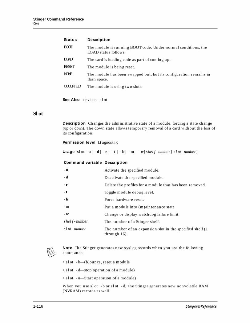
Stinger Command ReferenceSlot
See Also device, slot
Slot
Description Changes the administrative state of a module, forcing a state change (up or down). The down state allows temporary removal of a card without the loss of its configuration.
Permission level Diagnostic
Usage slot -u | -d | -r | -t | -b | -m | -w [shelf-number] slot-number]
Note The Stinger generates new syslog records when you use the following commands:
• slot -b—(b)ounce, reset a module
• slot -d—stop operation of a module)
• slot -u—Start operation of a module)
When you use slot -b or slot -d, the Stinger generates new nonvolatile RAM (NVRAM) records as well.
BOOT The module is running BOOT code. Under normal conditions, the LOAD status follows.
LOAD The card is loading code as part of coming up.
RESET The module is being reset.
NONE The module has been swapped out, but its configuration remains in flash space.
OCCUPIED The module is using two slots.
Status Description
Command variable Description
-u Activate the specified module.
-d Deactivate the specified module.
-r Delete the profiles for a module that has been removed.
-t Toggle module debug level.
-b Force hardware reset.
-m Put a module into (m)aintenance state
-w Change or display watchdog failure limit.
shelf-number The number of a Stinger shelf.
slot-number The number of an expansion slot in the specified shelf (1 through 16).
1-116 Stinger® Reference
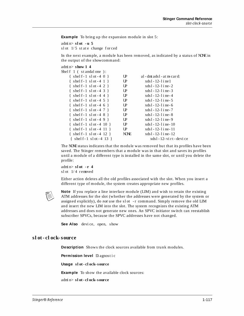
Stinger Command Referenceslot-clock-source
Example To bring up the expansion module in slot 5:
admin> slot -u 5slot 1/5 state change forced
In the next example, a module has been removed, as indicated by a status of NONE in the output of the show command:
admin> show 1 4Shelf 1 ( standalone ): { shelf-1 slot-4 0 } UP al-dmtadsl-atm-card: { shelf-1 slot-4 1 } UP xdsl-12-line1 { shelf-1 slot-4 2 } UP xdsl-12-line-2 { shelf-1 slot-4 3 } UP xdsl-12-line-3 { shelf-1 slot-4 4 } UP xdsl-12-line-4 { shelf-1 slot-4 5 } UP xdsl-12-line-5 { shelf-1 slot-4 6 } UP xdsl-12-line-6 { shelf-1 slot-4 7 } UP xdsl-12-line-7 { shelf-1 slot-4 8 } UP xdsl-12-line-8 { shelf-1 slot-4 9 } UP xdsl-12-line-9 { shelf-1 slot-4 10 } UP xdsl-12-line-10 { shelf-1 slot-4 11 } UP xdsl-12-line-11 { shelf-1 slot-4 12 } NONE xdsl-12-line-12
{ shelf-1 slot-4 13 } xdsl-12-virt-device
The NONE status indicates that the module was removed but that its profiles have been saved. The Stinger remembers that a module was in that slot and saves its profiles until a module of a different type is installed in the same slot, or until you delete the profile:
admin> slot -r 4slot 1/4 removed
Either action deletes all the old profiles associated with the slot. When you insert a different type of module, the system creates appropriate new profiles.
Note If you replace a line interface module (LIM) and wish to retain the existing ATM addresses for the slot (whether the addresses were generated by the system or assigned explicitly), do not use the slot -r command. Simply remove the old LIM and insert the new LIM into the slot. The system recognizes the existing ATM addresses and does not generate new ones. An SPVC initiator switch can reestablish subscriber SPVCs, because the SPVC addresses have not changed.
See Also device, open, show
slot-clock-source
Description Shows the clock sources available from trunk modules.
Permission level Diagnostic
Usage slot-clock-source
Example To show the available clock sources:
admin> slot-clock-source
Stinger® Reference 1-117
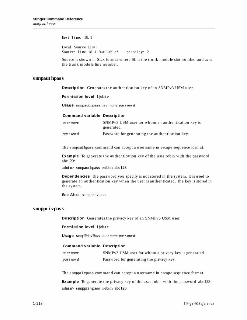
Stinger Command Referencesnmpauthpass
Best line: 18.1
Local Source List: Source: line 18.1 Available* priority: 2
Source is shown in SL.x format where SL is the trunk module slot number and .x is the trunk module line number.
snmpauthpass
Description Generates the authentication key of an SNMPv3 USM user.
Permission level Update
Usage snmpauthpass username password
The snmpauthpass command can accept a username in escape sequence format.
Example To generate the authentication key of the user robin with the password abc123:
admin> snmpauthpass robin abc123
Dependencies The password you specify is not stored in the system. It is used to generate an authentication key when the user is authenticated. The key is stored in the system.
See Also snmpprivpass
snmpprivpass
Description Generates the privacy key of an SNMPv3 USM user.
Permission level Update
Usage snmpPrivPass username password
The snmpprivpass command can accept a username in escape sequence format.
Example To generate the privacy key of the user robin with the password abc123:
admin> snmpprivpass robin abc123
Command variable Description
username SNMPv3 USM user for whom an authentication key is generated.
password Password for generating the authentication key.
Command variable Description
username SNMPv3 USM user for whom a privacy key is generated.
password Password for generating the privacy key.
1-118 Stinger® Reference
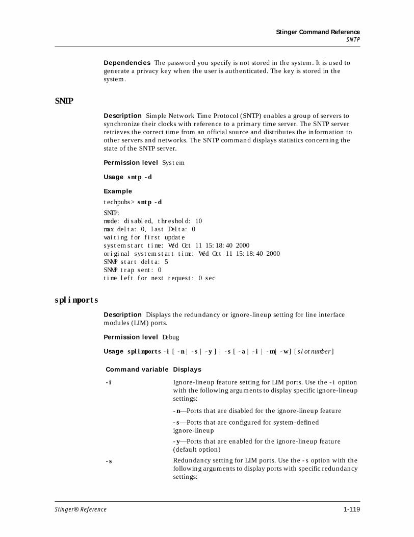
Stinger Command ReferenceSNTP
Dependencies The password you specify is not stored in the system. It is used to generate a privacy key when the user is authenticated. The key is stored in the system.
SNTP
Description Simple Network Time Protocol (SNTP) enables a group of servers to synchronize their clocks with reference to a primary time server. The SNTP server retrieves the correct time from an official source and distributes the information to other servers and networks. The SNTP command displays statistics concerning the state of the SNTP server.
Permission level System
Usage sntp -d
Example
techpubs> sntp -d
SNTP:mode: disabled, threshold: 10max delta: 0, last Delta: 0waiting for first update system start time: Wed Oct 11 15:18:40 2000original system start time: Wed Oct 11 15:18:40 2000SNMP start delta: 5SNMP trap sent: 0time left for next request: 0 sec
splimports
Description Displays the redundancy or ignore-lineup setting for line interface modules (LIM) ports.
Permission level Debug
Usage splimports -i [ -n | -s | -y ] | -s [ -a | -i | -m | -w ] [slotnumber]
Command variable Displays
-i Ignore-lineup feature setting for LIM ports. Use the -i option with the following arguments to display specific ignore-lineup settings:
-n—Ports that are disabled for the ignore-lineup feature
-s—Ports that are configured for system-defined ignore-lineup
-y—Ports that are enabled for the ignore-lineup feature (default option)
-s Redundancy setting for LIM ports. Use the -s option with the following arguments to display ports with specific redundancy settings:
Stinger® Reference 1-119
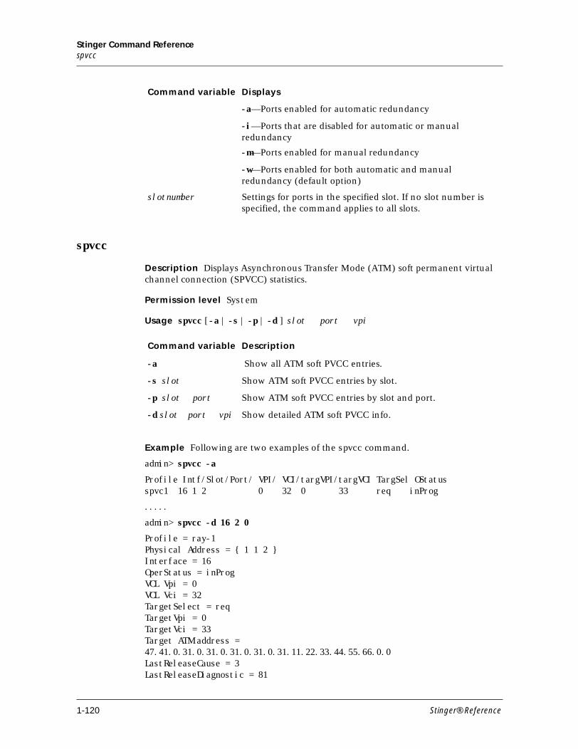
Stinger Command Referencespvcc
spvcc
Description Displays Asynchronous Transfer Mode (ATM) soft permanent virtual channel connection (SPVCC) statistics.
Permission level System
Usage spvcc [-a | -s | -p | -d ] slot port vpi
Example Following are two examples of the spvcc command.
admin> spvcc -a
Profile Intf/Slot/Port/ VPI/ VCI/targVPI/targVCI TargSel OStatusspvc1 16 1 2 0 32 0 33 req inProg
.....
admin> spvcc -d 16 2 0
Profile = ray-1Physical Address = { 1 1 2 }Interface = 16OperStatus = inProgVCL Vpi = 0VCL Vci = 32TargetSelect = reqTargetVpi = 0TargetVci = 33Target ATM address =47.41.0.31.0.31.0.31.0.31.0.31.11.22.33.44.55.66.0.0LastReleaseCause = 3LastReleaseDiagnostic = 81
-a—Ports enabled for automatic redundancy
-i—Ports that are disabled for automatic or manual redundancy
-m—Ports enabled for manual redundancy
-w—Ports enabled for both automatic and manual redundancy (default option)
slotnumber Settings for ports in the specified slot. If no slot number is specified, the command applies to all slots.
Command variable Displays
Command variable Description
-a Show all ATM soft PVCC entries.
-s slot Show ATM soft PVCC entries by slot.
-p slot port Show ATM soft PVCC entries by slot and port.
-d slot port vpi Show detailed ATM soft PVCC info.
1-120 Stinger® Reference
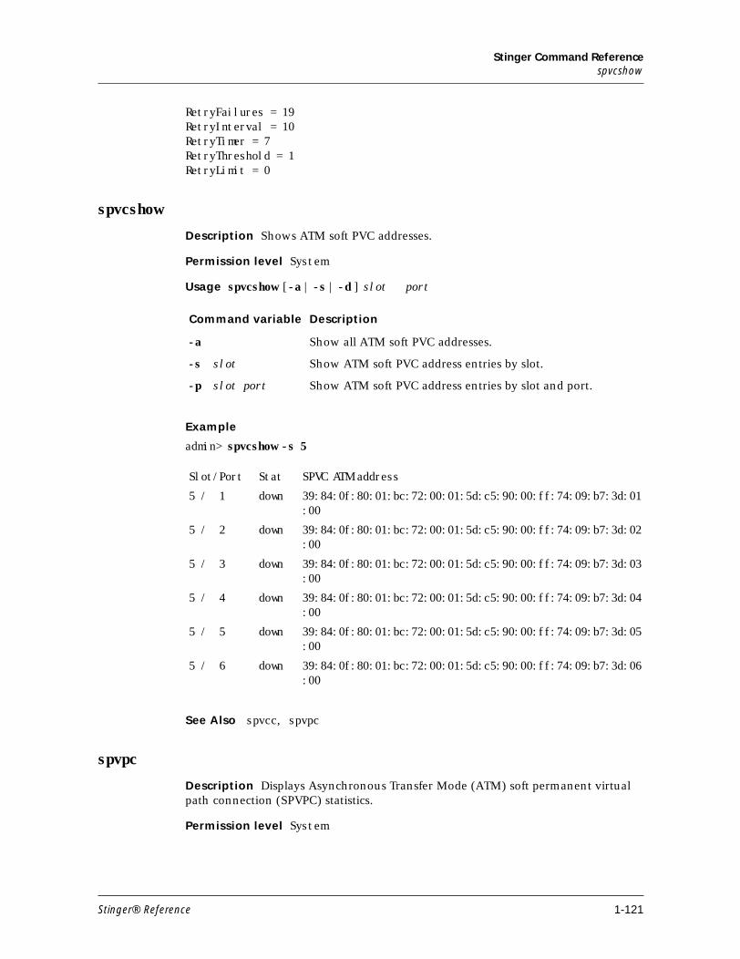
Stinger Command Referencespvcshow
RetryFailures = 19RetryInterval = 10RetryTimer = 7RetryThreshold = 1RetryLimit = 0
spvcshow
Description Shows ATM soft PVC addresses.
Permission level System
Usage spvcshow [-a | -s | -d ] slot port
Example
admin> spvcshow -s 5
See Also spvcc, spvpc
spvpc
Description Displays Asynchronous Transfer Mode (ATM) soft permanent virtual path connection (SPVPC) statistics.
Permission level System
Command variable Description
-a Show all ATM soft PVC addresses.
-s slot Show ATM soft PVC address entries by slot.
-p slot port Show ATM soft PVC address entries by slot and port.
Slot/Port Stat SPVC ATM address
5 / 1 down 39:84:0f:80:01:bc:72:00:01:5d:c5:90:00:ff:74:09:b7:3d:01:00
5 / 2 down 39:84:0f:80:01:bc:72:00:01:5d:c5:90:00:ff:74:09:b7:3d:02:00
5 / 3 down 39:84:0f:80:01:bc:72:00:01:5d:c5:90:00:ff:74:09:b7:3d:03:00
5 / 4 down 39:84:0f:80:01:bc:72:00:01:5d:c5:90:00:ff:74:09:b7:3d:04:00
5 / 5 down 39:84:0f:80:01:bc:72:00:01:5d:c5:90:00:ff:74:09:b7:3d:05:00
5 / 6 down 39:84:0f:80:01:bc:72:00:01:5d:c5:90:00:ff:74:09:b7:3d:06:00
Stinger® Reference 1-121
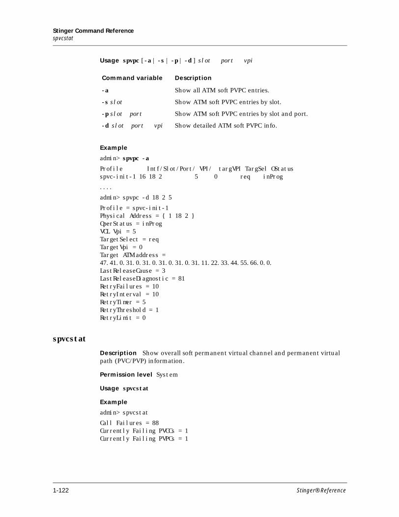
Stinger Command Referencespvcstat
Usage spvpc [-a | -s | -p | -d ] slot port vpi
Example
admin> spvpc -a
Profile Intf/Slot/Port/ VPI/ targVPI TargSel OStatusspvc-init-1 16 18 2 5 0 req inProg
....
admin> spvpc -d 18 2 5
Profile = spvc-init-1Physical Address = { 1 18 2 }OperStatus = inProgVCL Vpi = 5TargetSelect = reqTargetVpi = 0Target ATM address =47.41.0.31.0.31.0.31.0.31.0.31.11.22.33.44.55.66.0.0.LastReleaseCause = 3LastReleaseDiagnostic = 81RetryFailures = 10RetryInterval = 10RetryTimer = 5RetryThreshold = 1RetryLimit = 0
spvcstat
Description Show overall soft permanent virtual channel and permanent virtual path (PVC/PVP) information.
Permission level System
Usage spvcstat
Example
admin> spvcstat
Call Failures = 88Currently Failing PVCCs = 1Currently Failing PVPCs = 1
Command variable Description
-a Show all ATM soft PVPC entries.
-s slot Show ATM soft PVPC entries by slot.
-p slot port Show ATM soft PVPC entries by slot and port.
-d slot port vpi Show detailed ATM soft PVPC info.
1-122 Stinger® Reference
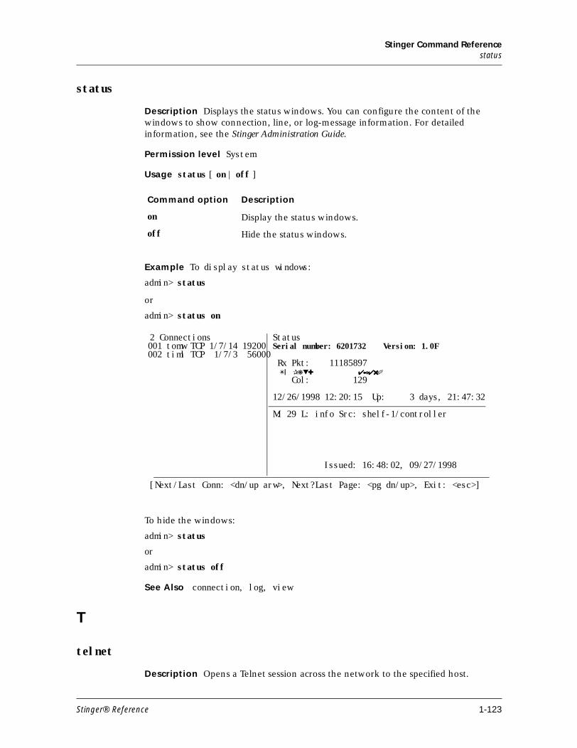
Stinger Command Referencestatus
status
Description Displays the status windows. You can configure the content of the windows to show connection, line, or log-message information. For detailed information, see the Stinger Administration Guide.
Permission level System
Usage status [ on | off ]
Example To display status windows:
admin> status
or
admin> status on
To hide the windows:
admin> status
or
admin> status off
See Also connection, log, view
T
telnet
Description Opens a Telnet session across the network to the specified host.
Command option Description
on Display the status windows.
off Hide the status windows.
2 Connections StatusSerial number: 6201732 Version: 1.0F
Rx Pkt: 11185897 ✴❘ ✰❋▼✚ ✔✒✔✖✐
Col: 129
12/26/1998 12:20:15 Up: 3 days, 21:47:32
M: 29 L: info Src: shelf-1/controller
Issued: 16:48:02, 09/27/1998
[Next/Last Conn: <dn/up arw>, Next?Last Page: <pg dn/up>, Exit: <esc>]
001 tomw TCP 1/7/14 19200002 timl TCP 1/7/3 56000
Stinger® Reference 1-123
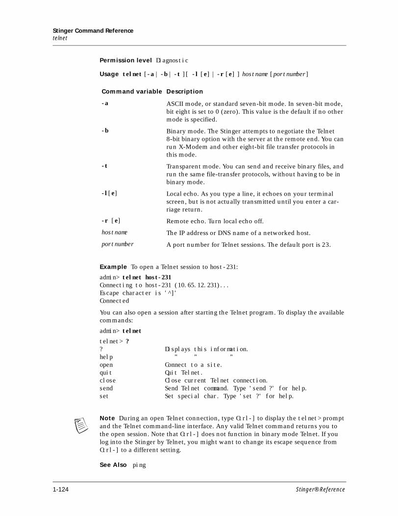
Stinger Command Referencetelnet
Permission level Diagnostic
Usage telnet [-a | -b | -t ][ -l [e] | -r [e] ] hostname [portnumber]
Example To open a Telnet session to host-231:
admin> telnet host-231Connecting to host-231 (10.65.12.231)...Escape character is '^]'Connected
You can also open a session after starting the Telnet program. To display the available commands:
admin> telnet
telnet> ?? Displays this information.help " " "open Connect to a site.quit Quit Telnet.close Close current Telnet connection.send Send Telnet command. Type 'send ?' for help.set Set special char. Type 'set ?' for help.
Note During an open Telnet connection, type Ctrl-] to display the telnet> prompt and the Telnet command-line interface. Any valid Telnet command returns you to the open session. Note that Ctrl-] does not function in binary mode Telnet. If you log into the Stinger by Telnet, you might want to change its escape sequence from Ctrl-] to a different setting.
See Also ping
Command variable Description
-a ASCII mode, or standard seven-bit mode. In seven-bit mode, bit eight is set to 0 (zero). This value is the default if no other mode is specified.
-b Binary mode. The Stinger attempts to negotiate the Telnet 8-bit binary option with the server at the remote end. You can run X-Modem and other eight-bit file transfer protocols in this mode.
-t Transparent mode. You can send and receive binary files, and run the same file-transfer protocols, without having to be in binary mode.
-l[e] Local echo. As you type a line, it echoes on your terminal screen, but is not actually transmitted until you enter a car-riage return.
-r [e] Remote echo. Turn local echo off.
hostname The IP address or DNS name of a networked host.
portnumber A port number for Telnet sessions. The default port is 23.
1-124 Stinger® Reference

Stinger Command Referenceterminal-server
terminal-server
Description Starts terminal-server mode, which has its own command interface.
Permission level Termserv
Usage terminal-server
Example To enter terminal-server mode and display the list of available commands:
admin> terminal-serveradmin% ?? Display help informationhelp " " "quit Closes terminal server sessionhangup " " " "local Go to local moderemote remote <station>set Set various items. Type 'set ?' for helpshow Show various tables. Type 'show ?' for helpiproute Manage IP routes. Type 'iproute ?' for helptelnet telnet [-a|-b|-t] <host-name> [<port-number>]tcp tcp <host-name> <port-number>ping ping <host-name>traceroute Trace route to host. Type 'traceroute -?' for helprlogin rlogin [-l user -ec] <host-name>
To exit terminal server mode:
admin% quit
admin>
See Also ping, telnet
traceroute
Description Traces the route an IP packet follows by launching UDP probe packets with a low time-to-live (TTL) value and then listening for an ICMP time exceeded reply from a router. Probes start with a TTL of one and increase by one until either a probe packet reaches the destination host or the TTL reaches the maximum.
Three probes are sent at each TTL setting. The second line of command output shows the address of the router and round-trip time of each probe. If the probe answers come from different gateways, the address of each responding system is printed. If there is no response within a 3-second timeout interval, the command output is an asterisk.
The destination host is not supposed to process the UDP probe packets, so the destination port is set to an unlikely value, such as 33434. When the packets reach the destination host, it sends back an ICMP port unreachable message.
Permission level Diagnostic
Stinger® Reference 1-125
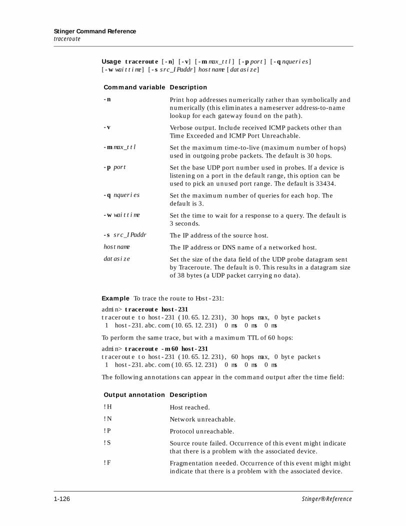
Stinger Command Referencetraceroute
Usage traceroute [-n] [-v] [-m max_ttl] [-p port] [-q nqueries] [-w waittime] [-s src_IPaddr] hostname [datasize]
Example To trace the route to Host-231:
admin> traceroute host-231traceroute to host-231 (10.65.12.231), 30 hops max, 0 byte packets 1 host-231.abc.com (10.65.12.231) 0 ms 0 ms 0 ms
To perform the same trace, but with a maximum TTL of 60 hops:
admin> traceroute -m 60 host-231traceroute to host-231 (10.65.12.231), 60 hops max, 0 byte packets 1 host-231.abc.com (10.65.12.231) 0 ms 0 ms 0 ms
The following annotations can appear in the command output after the time field:
Command variable Description
-n Print hop addresses numerically rather than symbolically and numerically (this eliminates a nameserver address-to-name lookup for each gateway found on the path).
-v Verbose output. Include received ICMP packets other than Time Exceeded and ICMP Port Unreachable.
-m max_ttl Set the maximum time-to-live (maximum number of hops) used in outgoing probe packets. The default is 30 hops.
-p port Set the base UDP port number used in probes. If a device is listening on a port in the default range, this option can be used to pick an unused port range. The default is 33434.
-q nqueries Set the maximum number of queries for each hop. The default is 3.
-w waittime Set the time to wait for a response to a query. The default is3 seconds.
-s src_IPaddr The IP address of the source host.
hostname The IP address or DNS name of a networked host.
datasize Set the size of the data field of the UDP probe datagram sent by Traceroute. The default is 0. This results in a datagram size of 38 bytes (a UDP packet carrying no data).
Output annotation Description
!H Host reached.
!N Network unreachable.
!P Protocol unreachable.
!S Source route failed. Occurrence of this event might indicate that there is a problem with the associated device.
!F Fragmentation needed. Occurrence of this event might might indicate that there is a problem with the associated device.
1-126 Stinger® Reference
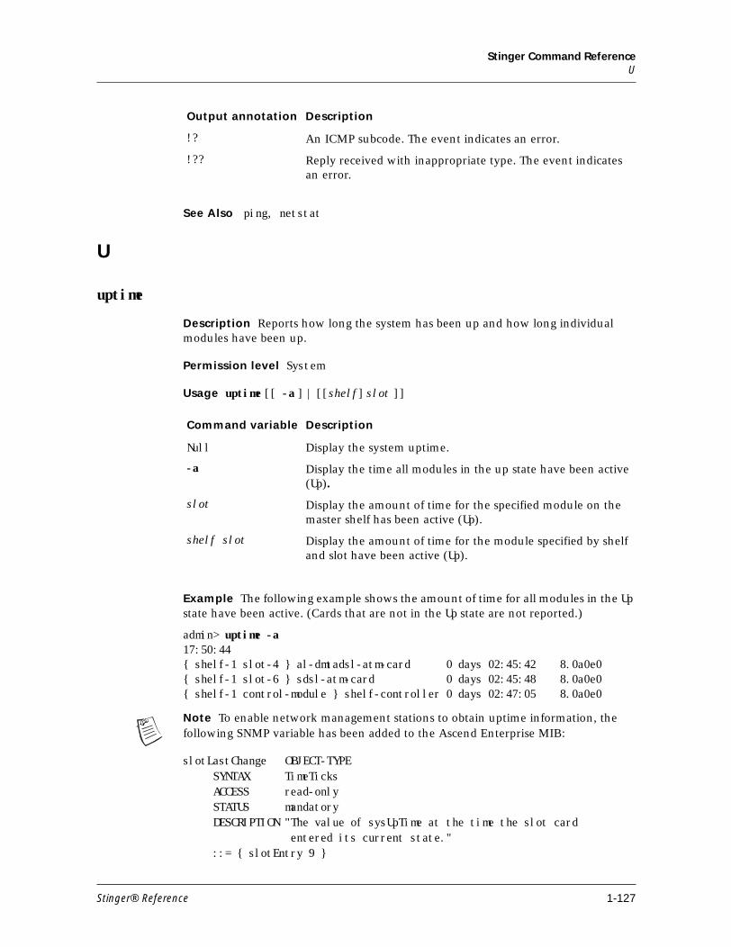
Stinger Command ReferenceU
See Also ping, netstat
U
uptime
Description Reports how long the system has been up and how long individual modules have been up.
Permission level System
Usage uptime [[ -a ] | [[shelf] slot ]]
Example The following example shows the amount of time for all modules in the Up state have been active. (Cards that are not in the Up state are not reported.)
admin> uptime -a17:50:44{ shelf-1 slot-4 } al-dmtadsl-atm-card 0 days 02:45:42 8.0a0e0{ shelf-1 slot-6 } sdsl-atm-card 0 days 02:45:48 8.0a0e0{ shelf-1 control-module } shelf-controller 0 days 02:47:05 8.0a0e0
Note To enable network management stations to obtain uptime information, the following SNMP variable has been added to the Ascend Enterprise MIB:
slotLastChange OBJECT-TYPE SYNTAX TimeTicks ACCESS read-only STATUS mandatory DESCRIPTION "The value of sysUpTime at the time the slot card entered its current state." ::= { slotEntry 9 }
!? An ICMP subcode. The event indicates an error.
!?? Reply received with inappropriate type. The event indicates an error.
Output annotation Description
Command variable Description
Null Display the system uptime.
-a Display the time all modules in the up state have been active (Up).
slot Display the amount of time for the specified module on the master shelf has been active (Up).
shelf slot Display the amount of time for the module specified by shelf and slot have been active (Up).
Stinger® Reference 1-127
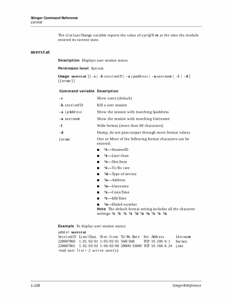
Stinger Command Referenceuserstat
The slotLastChange variable reports the value of sysUpTime at the time the module entered its current state.
userstat
Description Displays user session status.
Permission level System
Usage userstat [[ -s | -k sessionID | -a ipaddress | -u username | -l | -d ] [format]]
Example To display user session status:
admin> userstat SessionID Line/Chan Slot:Item Tx/Rx Rate Svc Address Username228687860 1.01.02/01 1:03:01/01 56K/56K TCP 10.100.0.1 barney228687861 1.02.03/02 1:04:02/00 28800/33600 TCP 10.168.6.24 jake<end user list> 2 active user(s)
Command variable Description
-s Show users (default)
-k sessionID Kill a user session
-a ipAddress Show the session with matching Ipaddress
-u username Show the session with matching Username
-l Wide format (more than 80 characters)
-d Dump, do not pass output through more format values
format One or More of the following format characters can be entered:
■ %i—SessionID
■ %l—Line/chan
■ %s—Slot:Item
■ %r—Tx/Rx rate
■ %d—Type of service
■ %a—Address
■ %u—Username
■ %c—ConnTime
■ %t—IdleTime
■ %n—Dialed numberNote The default format setting includes all the character settings: %i %l %s %r %d %a %u %c %t %n
1-128 Stinger® Reference
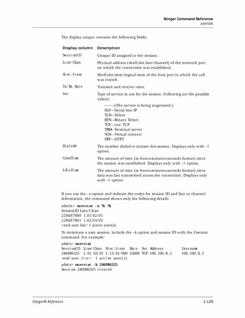
Stinger Command Referenceuserstat
The display output contains the following fields:
If you use the -o option and indicate the codes for session ID and line or channel information, the command shows only the following details:
admin> userstat -o %i %lSessionID Line/Chan228687860 1.01.02/01228687861 1.02.03/02<end user list> 1 active user(s)
To terminate a user session, include the -k option and session ID with the Userstat command. For example:
admin> userstatSessionID Line/Chan Slot:Item Rate Svc Address Username246986325 1.01.02/01 1:13:01/000 33600 TCP 100.100.8.2 100.100.8.2 <end user list> 1 active user(s)
admin> userstat -k 246986325Session 246986325 cleared
Display column Description
SessionID Unique ID assigned to the session.
Line/Chan Physical address (shelf.slot.line/channel) of the network port on which the connection was established.
Slot:Item Shelf:slot:item/logical-item of the host port to which the call was routed.
Tx/Rx Rate Transmit and receive rates.
Svc Type of service in use for the session. Following are the possible values:
---—(The service is being negotiated.)SLP—Serial line IPTLN—TelnetBTN—Binary TelnetTCP—raw TCPTRM—Terminal serverVCN—Virtual connectDTP—DTPT
Dialed# The number dialed to initiate this session. Displays only with -l option.
ConnTime The amount of time (in hours:minutes:seconds format) since the session was established. Displays only with -l option.
IdleTime The amount of time (in hours:minutes:seconds format) since data was last transmitted across the connection. Displays only with -l option.
Stinger® Reference 1-129
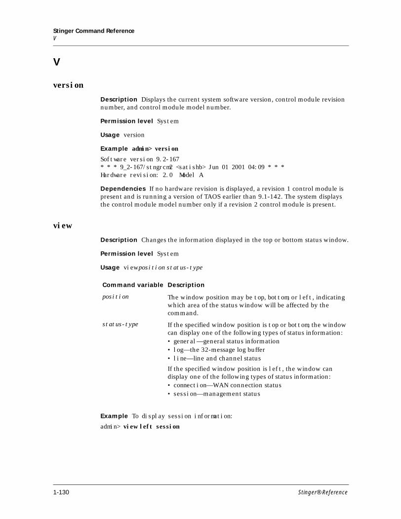
Stinger Command ReferenceV
V
version
Description Displays the current system software version, control module revision number, and control module model number.
Permission level System
Usage version
Example admin> version
Software version 9.2-167* * * 9_2-167/stngrcm2 <satishb> Jun 01 2001 04:09 * * *Hardware revision: 2.0 Model A
Dependencies If no hardware revision is displayed, a revision 1 control module is present and is running a version of TAOS earlier than 9.1-142. The system displays the control module model number only if a revision 2 control module is present.
view
Description Changes the information displayed in the top or bottom status window.
Permission level System
Usage view position status-type
Example To display session information:
admin> view left session
Command variable Description
position The window position may be top, bottom, or left, indicating which area of the status window will be affected by the command.
status-type If the specified window position is top or bottom, the window can display one of the following types of status information:• general—general status information• log—the 32-message log buffer• line—line and channel status
If the specified window position is left, the window can display one of the following types of status information:• connection—WAN connection status• session—management status
1-130 Stinger® Reference
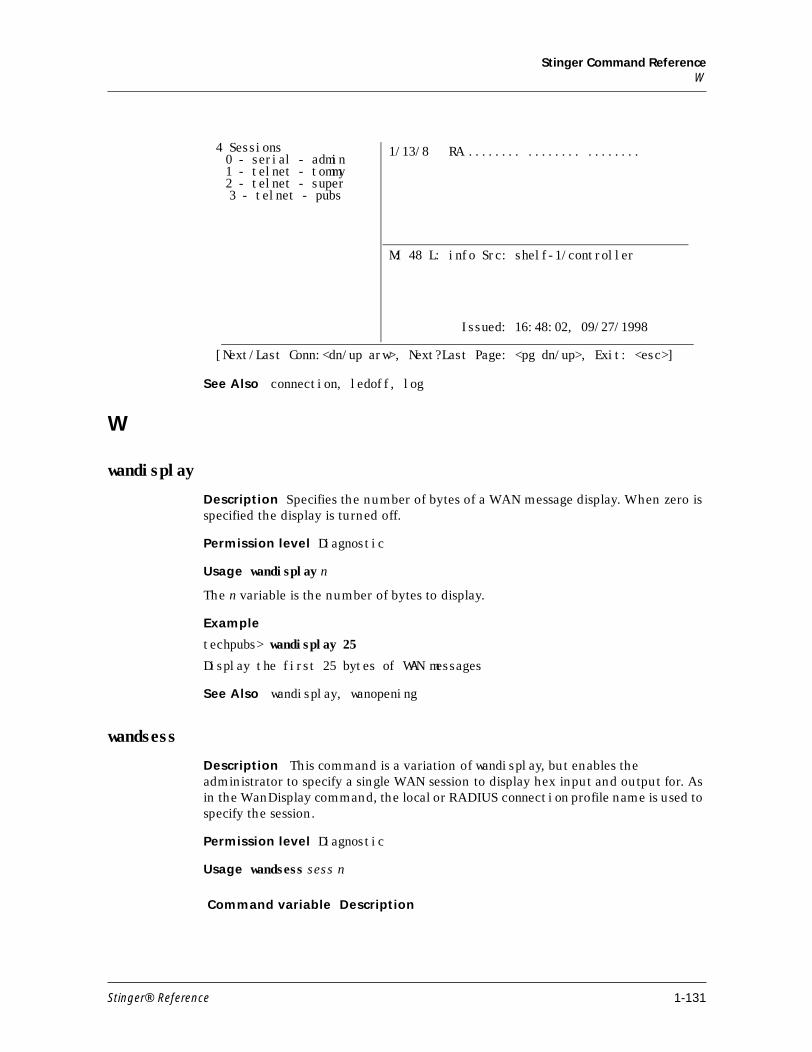
Stinger Command ReferenceW
See Also connection, ledoff, log
W
wandisplay
Description Specifies the number of bytes of a WAN message display. When zero is specified the display is turned off.
Permission level Diagnostic
Usage wandisplay n
The n variable is the number of bytes to display.
Example
techpubs> wandisplay 25
Display the first 25 bytes of WAN messages
See Also wandisplay, wanopening
wandsess
Description This command is a variation of wandisplay, but enables the administrator to specify a single WAN session to display hex input and output for. As in the WanDisplay command, the local or RADIUS connection profile name is used to specify the session.
Permission level Diagnostic
Usage wandsess sess n
4 Sessions 1/13/8 RA ........ ........ ........
M: 48 L: info Src: shelf-1/controller
Issued: 16:48:02, 09/27/1998
[Next/Last Conn:<dn/up arw>, Next?Last Page: <pg dn/up>, Exit: <esc>]
0 - serial - admin 1 - telnet - tommy 2 - telnet - super 3 - telnet - pubs
Command variable Description
Stinger® Reference 1-131
Stinger Command Referencewannext
Example
hdlc-1/16> wandsess tim 120
hdlc-1/16> wandsess bob 160
hdlc-1/16> wandsess
120 tim
160 bob
See Also wandisplay, wannext, wanopening
wannext
Description Specifies the number of bytes of a WAN message to display for the next call only. When zero is specified the display is turned off.
Permission level Diagnostic
Usage wannext n
The n variable is the number of bytes to display.
Example
techpubs> wannext 25
Display the first 25 bytes of WAN messages for the NEXT call
See Also Wandisplay, wandsess, wanOpening
wanopening
Description Specifies the number of bytes of a WAN opening message to display. Zero disables the display.
Permission level Diagnostic
Usage wanopening n
The n variable is the number of bytes to display
Example
techpubs> wanopening 50
Display the first 50 bytes of WAN messages during OPENING only
See Also Wandisplay, wandsess
sess The local or RADIUS connection profile name is used to specify the session.
n Number of bytes to display.
1-132 Stinger® Reference
Stinger Command Referencewhich
which
Description Enables you to look up the nailed group associated with the port used for an Asynchronous Transfer Mode (ATM) connection.
Permission level System
Usage which [ -p group | -n port ] [ -c ]
Example
admin> which -p 21The port corresponding to nailed group 21 is:{ shelf-1 slot-1 21 }
Example Add the -c option to include a display of the connections associated with this nailed group.
admin>which -p -c 21The port corresponding to nailed group 21 is:{ shelf-1 slot-1 21 } The connection(s) associated with this nailed group are:lim-1-21-ckt-1lim-1-21-ckt-8lim-1-21-ckt-7lim-1-21-ckt-6lim-1-21-ckt-5lim-1-21-ckt-4lim-1-21-ckt-3lim-1-21-ckt-2
Or, in the case of the nailed group corresponding to the port of an IDSL card:
admin> which -n {1 13 1}Nailed group corresponding to port { shelf-1 slot-13 idsl-1 channel 1 } is 601Nailed group corresponding to port { shelf-1 slot-13 idsl-1 channel 2 } is 601Nailed group corresponding to port { shelf-1 slot-13 atm-internal-1} is 633
Note For the IDSL line interface module (LIM), the dedicated (nailed) groups assigned to both BRI channels and the dedicated (nailed) group assigned to the ATM interface are displayed. The ATM Internal interface has the same physical address as the 1st BRI channel. The IDSL line is identified by idsl- before the line number. The ATM Internal interface is identified by atm-internal- before the line number.
Command variable Description
-p group Specifies the port (and channel, for the IDSL line interface module) associated with the dedicated (nailed) group indicated by group.
-n port Specifies the dedicated (nailed-up) group or groups associated with the port indicated by port.
-c Lists the connections associated with the nailed group or port
Stinger® Reference 1-133
Stinger Command Referencewhoami
You can use the which command to determine which port is in use when you have the dedicated (nailed) -group assignment of a connection profile. For example, if the circuit uses nailed-group 296:
admin> which -p 296The port corresponding to nailed group 296 is: { shelf-1 slot-6 46 }
Or, in the case of the port of an IDSL card, if the circuit uses nailed-group 601, and nailed-group 633 its ATM internal interface:
admin> which -p 601The port corresponding to nailed group 601 is: { shelf-1 slot-13 idsl-1 chan-1 }{ shelf-1 slot-13 idsl-1 chan-22 }
admin> which -p 633The port corresponding to nailed group 633 is: { shelf-1 slot-13 atm-internal-1}
If the argument specifies a slot that is not populated, or a dedicated (nailed)-group that is not assigned, the command returns a message that the number was not found. For example:
admin> which -p 43The port corresponding to nailed group 43 is:NONE!
If more than one port has the same dedicated (nailed) group associated with it (which is illegal), the which command returns all the ports that have this dedicated (nailed) group. Using the which command can be a convenient way to find duplicate dedicated (nailed) groups. For example:
admin> read sdsl {1 6 46}SDSL/{ shelf-1 slot-6 46 } read
admin> set line-config nailed-group=801
admin> writeSDSL/{ shelf-1 slot-6 46 } written
admin> which -p 801The port corresponding to nailed group 801 is:{ shelf-1 slot-6 46 } { shelf-1 trunk-module-1 1 }
Duplicate dedicated- (nailed) group assignments can occur only when the administrator changes default nailed-group numbers. To fix the problem, change the dedicated- (nailed) group assignments in one or more profiles, and then verify by using the which command again.
whoami
Description Displays the name of the user profile associated with the current session.
Permission level User
Usage whoami
Example To display the name of your user profile:
1-134 Stinger® Reference
Stinger Command Referencewrite
admin> whoami
tommy
See Also auth
write
Description Validates the settings of the working profile and then writes it from the edit buffer to NVRAM.
Note If the working profile has an index field (a parameter followed by an asterisk), that parameter must have a value or the write is not allowed. If you modify a profile and do not use the write command before reading another profile, the changes are lost.
Permission level Update
Usage write [ -f]
The -f option forces the write without prompting for confirmation, overwriting an existing profile if one exists with the same index
Example If you issue a write command when the current profile has not been modified from the saved version, the write does not occur and the following message is displayed:
admin> writeNothing new to write; nothing written.
You can force the write to occur by using the –f option on the write command line.
Note The write always occurs if the profile has not been written previously.
To create a new connection profile, modify it, and write it to NVRAM:
admin> new conn newyork CONNECTION/newyork read
admin> list[in CONNECTION/newyork (new)]station*=newyorkactive=noencapsulation-protocol=atmcalled-number-type=nationaldial-number=""clid=""ip-options={ yes yes 0.0.0.0/0 0.0.0.0/0 7 100 255 no no 0 +session-options={ "" "" no 120 no-idle 120 "" }telco-options={ ans-and-orig no off 1 no no 56k-restricted 0 +usrRad-options={ global 0.0.0.0 1646 "" 1 acct-base-10 }calledNumber=""
admin> writeCONNECTION/newyork written
PreferredPgl 00:00:00:00:00:00:00:00:00:00:00:00:00:00:00:00:00:00:00:00:00:00
Stinger® Reference 1-135
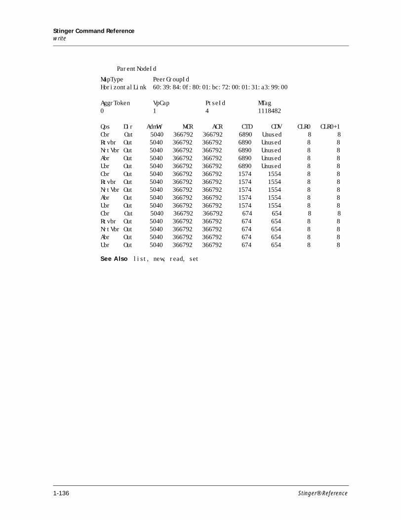
Stinger Command Referencewrite
ParentNodeId
MapType PeerGroupIdHorizontalLink 60:39:84:0f:80:01:bc:72:00:01:31:a3:99:00
AggrToken VpCap PtseId MTag0 1 4 1118482
Qos Dir AdmWt MCR ACR CTD CDV CLR0 CLR0+1Cbr Out 5040 366792 366792 6890 Unused 8 8Rtvbr Out 5040 366792 366792 6890 Unused 8 8NrtVbr Out 5040 366792 366792 6890 Unused 8 8Abr Out 5040 366792 366792 6890 Unused 8 8Ubr Out 5040 366792 366792 6890 Unused 8 8Cbr Out 5040 366792 366792 1574 1554 8 8Rtvbr Out 5040 366792 366792 1574 1554 8 8NrtVbr Out 5040 366792 366792 1574 1554 8 8Abr Out 5040 366792 366792 1574 1554 8 8Ubr Out 5040 366792 366792 1574 1554 8 8Cbr Out 5040 366792 366792 674 654 8 8Rtvbr Out 5040 366792 366792 674 654 8 8NrtVbr Out 5040 366792 366792 674 654 8 8Abr Out 5040 366792 366792 674 654 8 8Ubr Out 5040 366792 366792 674 654 8 8
See Also list, new, read, set
1-136 Stinger® Reference
2Stinger Profile Reference
A . . . . . . . . . . . . . . . . . . . . . . . . . . . . . . . . . . . . . . . . . . . . . . . . . . . . . . . . . . . . . 2-2
B. . . . . . . . . . . . . . . . . . . . . . . . . . . . . . . . . . . . . . . . . . . . . . . . . . . . . . . . . . . . . 2-24
C. . . . . . . . . . . . . . . . . . . . . . . . . . . . . . . . . . . . . . . . . . . . . . . . . . . . . . . . . . . . . 2-27
D . . . . . . . . . . . . . . . . . . . . . . . . . . . . . . . . . . . . . . . . . . . . . . . . . . . . . . . . . . . . 2-34
F . . . . . . . . . . . . . . . . . . . . . . . . . . . . . . . . . . . . . . . . . . . . . . . . . . . . . . . . . . . . . 2-42
H . . . . . . . . . . . . . . . . . . . . . . . . . . . . . . . . . . . . . . . . . . . . . . . . . . . . . . . . . . . . 2-46
I . . . . . . . . . . . . . . . . . . . . . . . . . . . . . . . . . . . . . . . . . . . . . . . . . . . . . . . . . . . . . 2-48
L . . . . . . . . . . . . . . . . . . . . . . . . . . . . . . . . . . . . . . . . . . . . . . . . . . . . . . . . . . . . . 2-61
M . . . . . . . . . . . . . . . . . . . . . . . . . . . . . . . . . . . . . . . . . . . . . . . . . . . . . . . . . . . . 2-68
O . . . . . . . . . . . . . . . . . . . . . . . . . . . . . . . . . . . . . . . . . . . . . . . . . . . . . . . . . . . . 2-73
P . . . . . . . . . . . . . . . . . . . . . . . . . . . . . . . . . . . . . . . . . . . . . . . . . . . . . . . . . . . . . 2-75
Q . . . . . . . . . . . . . . . . . . . . . . . . . . . . . . . . . . . . . . . . . . . . . . . . . . . . . . . . . . . . 2-75
R. . . . . . . . . . . . . . . . . . . . . . . . . . . . . . . . . . . . . . . . . . . . . . . . . . . . . . . . . . . . . 2-84
S . . . . . . . . . . . . . . . . . . . . . . . . . . . . . . . . . . . . . . . . . . . . . . . . . . . . . . . . . . . . . 2-87
T . . . . . . . . . . . . . . . . . . . . . . . . . . . . . . . . . . . . . . . . . . . . . . . . . . . . . . . . . . . . . 2-97
U . . . . . . . . . . . . . . . . . . . . . . . . . . . . . . . . . . . . . . . . . . . . . . . . . . . . . . . . . . . 2-107
V. . . . . . . . . . . . . . . . . . . . . . . . . . . . . . . . . . . . . . . . . . . . . . . . . . . . . . . . . . . . 2-109
X. . . . . . . . . . . . . . . . . . . . . . . . . . . . . . . . . . . . . . . . . . . . . . . . . . . . . . . . . . . . 2-112
Stinger® Reference 2-1
Stinger Profile ReferenceA
A
access-properties
Description A subprofile that configures settings for the vacm-access profile.
Usage Following is a listing of the access-properties subprofile with default settings:
[in VACM-ACCESS/{ "" "" v1 no+ }:access-properties (new)]group-name = ""context-prefix = ""security-model = v1security-level = none
Location VACM-ACCESS/””
action
Description A subprofile that specifies the action performed by the Stinger when it detects the event specified by the event parameter setting.
Usage Following is a listing of the action subprofile with default settings:
[in ALARM/robin:action]alarm-led-minor=offalarm-led-major=offalarm-relay-minor=offalarm-relay-minor-duration=0alarm-relay-major=offalarm-relay-major-duration=0
Location ALARM/””
addr-index
Description A subprofile that defines the index to the summary address. See the Stinger Private Network-to-Network Interface (PNNI) Supplement.
Usage Following is a listing of the addr-index subprofile with its default settings:
Location [in PNNI-SUMMARY-ADDR/"":addr-index (new)] node-index = 0 type = internal-summary address = 00:00:00:00:00:00:00:00:00:00:00:00:00:00:00:00:00:00:00:00 prefix-len = 0
See Also PNNI-SUMMARY-ADDR
2-2 Stinger® Reference
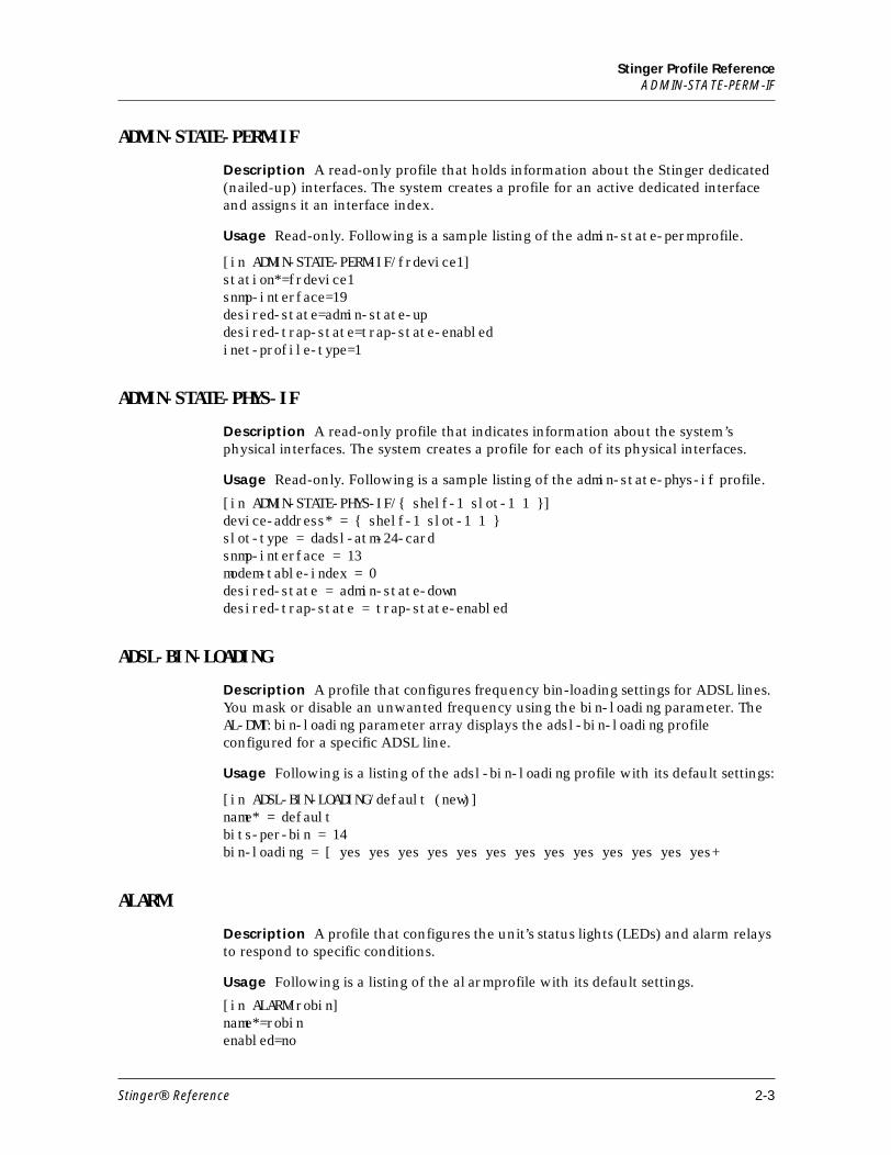
Stinger Profile ReferenceADMIN-STATE-PERM-IF
ADMIN-STATE-PERM-IF
Description A read-only profile that holds information about the Stinger dedicated (nailed-up) interfaces. The system creates a profile for an active dedicated interface and assigns it an interface index.
Usage Read-only. Following is a sample listing of the admin-state-perm profile.
[in ADMIN-STATE-PERM-IF/frdevice1]station*=frdevice1snmp-interface=19desired-state=admin-state-updesired-trap-state=trap-state-enabledinet-profile-type=1
ADMIN-STATE-PHYS-IF
Description A read-only profile that indicates information about the system’s physical interfaces. The system creates a profile for each of its physical interfaces.
Usage Read-only. Following is a sample listing of the admin-state-phys-if profile.
[in ADMIN-STATE-PHYS-IF/{ shelf-1 slot-1 1 }]device-address* = { shelf-1 slot-1 1 }slot-type = dadsl-atm-24-cardsnmp-interface = 13modem-table-index = 0desired-state = admin-state-downdesired-trap-state = trap-state-enabled
ADSL-BIN-LOADING
Description A profile that configures frequency bin-loading settings for ADSL lines. You mask or disable an unwanted frequency using the bin-loading parameter. The AL-DMT:bin-loading parameter array displays the adsl-bin-loading profile configured for a specific ADSL line.
Usage Following is a listing of the adsl-bin-loading profile with its default settings:
[in ADSL-BIN-LOADING/default (new)]name* = defaultbits-per-bin = 14bin-loading = [ yes yes yes yes yes yes yes yes yes yes yes yes yes+
ALARM
Description A profile that configures the unit’s status lights (LEDs) and alarm relays to respond to specific conditions.
Usage Following is a listing of the alarm profile with its default settings.
[in ALARM/robin]name*=robinenabled=no
Stinger® Reference 2-3
Stinger Profile Referencealarm-id
event=line-state-changephysical-address={ any-shelf any-slot 0 }action={ off off off 0 off 0 }
Note You can configure default ALARM profiles that apply to the entire Stinger unit by setting the physical-address parameter to 0 0 0 (any shelf, any slot, any item).
See Also action
alarm-id
Description A subprofile that identifies an alarm by indicating the shelf and module.
Usage Following is a listing of the alarm-id subprofile with default settings.
[in ALARM-STAT/{ { shelf-1 trunk-module-1 1 }line-state-change+]alarm-id* = { { shelf-1 trunk-module-1 1 } line-state-change }alarm-state = alarm-active
Location ALARM-STAT
See Also alarm (command), ALARM-STAT
ALARM-STAT
Description A read-only profile that indicates the status of alarms. When there are alarms, alarm-stat parameters are created.The profile lists an alarm-id subprofile for each of the alarms that have occurred. The alarm-id subprofile consists of the physical address of the device that has the alarm condition and the alarm event.
Usage Read-only. Following is a sample listing of the alarm-stat profile:
[in ALARM-STAT/{ { shelf-1 trunk-module-1 1 } line-state-change+]alarm-id* = { { shelf-1 trunk-module-1 1 } line-state-change }alarm-state = alarm-active
See Also alarm-id
AL-DMT
Description A profile that configures each of the 12 asymmetric digital subscriber-line ports on each installed ATM ADSL line interface module (LIM).
Usage Following is a listing of the al-dmt profile for the device on shelf 1, slot 4 with default settings:
[in AL-DMT/{ shelf-1 slot-4 1 }]name=1:4:1physical-address*={ shelf-1 slot-4 1 }enabled=yessparing-mode = inactiveignore-lineup = system-defined
2-4 Stinger® Reference
Stinger Profile ReferenceAL-DMT-STAT
line-config={ 0 301 static { any-shelf any-slot 0 } +fast-path-config={ 10 50 1000 8000 200 1000 }interleave-path-config={ 0 0 0 0 0 0 16 16 }margin-config={ 6 6 0 0 31 31 0 0 0 0 0 0 0 0 }thresh-profile = defaultbin-loading-profile = default
AL-DMT-STAT
Description A read-only profile that provides statistics and connection status for each rate adaptive digital subscriber lines (RADSL) interface.
Usage Read-only. Following is a sample listing of the al-dmt-stat profile:
[in AL-DMT-STAT/{ shelf-1 slot-4 1 }] physical-address* = { shelf-1 slot-4 1 } line-state = active spare-physical-address = { any-shelf any-slot 0 } sparing-state = sparing-none sparing-change-reason = unknown sparing-change-time = 0 sparing-change-counter = 0 vpi-vci-range = vpi-0-7-vci-32-255 vp-switching-vpi = 7 physical-status = { 155 coe port-up 0 0 512000 2336000 interleave +physical-statistic = { { 4 1 43 } yes 2 passed 4 7 3 6 0 11 40142 231 65 +
See Also physical-address, physical-status, physical-statistic
ANSWER-DEFAULTS
Description A profile that configures system defaults for incoming session requests. The system uses the values in this profile before it answers an incoming call. The values you set override factory defaults.
Usage Following is a list of the profile with default settings:
[in ANSWER-DEFAULTS]use-answer-for-all-defaults = yesforce-56kbps = noprofiles-required = yesclid-auth-mode = ignoreclid-selection = firstppp-answer = { yes no-ppp-auth none "" yes 0 none 1524 no 600 600 1524+mp-answer = { yes 1 2 }mpp-answer = { yes quadratic transmit 1 1 15 5 10 70 }fr-answer = { yes }tcp-clear-answer = { yes }ip-answer = { yes yes no 1 no }session-info = { "" "" no 120 no-idle 120 0 }atm-answer = { }
Stinger® Reference 2-5
Stinger Profile Referenceanswer-options
Dependencies Consider the following:
■ Similar settings in a client’s profile, which are applied after a call has been authenticated, always override the default settings in this profile
■ The following answer-defaults entries do not apply to Stinger units:
force-56kbps = noclid-auth-mode = ignoreclid-selection = firstmp-answer = { yes 1 2 }mpp-answer = { yes quadratic transmit 1 1 15 5 10 70 }tcp-clear-answer = { yes }
answer-options
Description A subprofile that configures answering procedures within a connection profile.
Usage Following is a listing of the answer-options subprofile with default settings:.
[in CONNECTION/"":answer-options (new)]profile-required = noans-default = noprofile-flags = noclid-auth-mode = ignoreclid-selection = first
Location CONNECTION/""
APS-CONFIG
Description A profile that configures the protection group in a channel using automatic protection switching (APS). The protection group is created for each OC3-ATM trunk port on the trunk aggregation module when the aps-config profile is configured and activated, and is referred to from an oc3-atm profile by its aps-config-name parameter.
Usage Following is a listing of a aps-config profile named pg1 with its default settings:
[in APS-CONFIG/pg1 (new)]name = pg1active = nolinear-protection-channel = { 1 trunk-module-1 2 }protection-mode = 1+1direction-mode = bidirectionalrevertive-mode = revertivewtr-timer-duration = 30000psbf-failure-timer-duration = 250psbf-clear-timer-duration = 1000mode-mismatch-failure-timer-duration = 250mode-mismatch-clear-timer-duration = 1000channel-mismatch-failure-timer-duration = 250
2-6 Stinger® Reference
Stinger Profile ReferenceAPS-STAT
channel-mismatch-clear-timer-duration = 1000fepl-mismatch-failure-timer-duration = 250fepl-mismatch-clear-timer-duration = 1000protection-channel-signal-degrade-exponent = 6protection-channel-signal-failure-exponent = 3working-channel-signal-degrade-exponent = 6working-channel-signal-failure-exponent = 3
APS-STAT
Description A read-only profile that is created whenever a protection group is activated and is indexed by the protection group's name.
Usage Read-only. Following is a sample listing of a aps-stat profile called pg1:
[in APS-STAT/pg1]name = pg1protection-channel = { shelf-1 trunk-module-1 2 }working-channel = { shelf-1 trunk-module-1 1 }aps-state = on-workingbridge-status = Truelast-switch-time = 0switch-count = 0aps-cfg-creation-time = 356537747number-of-channels = 2psbf-failure = Falsechannel-mismatch-failure = Falsemode-mismatch-failure = Falsefepl-failure = Falserecv-psbf-count = 0recv-mode-mismatch-count = 0recv-channel-mismatch-count = 0recv-fepl-count = 0extra-traffic-flag = Falseprotection-mode = 1+1direction-mode = bidirectionalrevertive-mode = revertiverx-k1-byte-value = 00rx-k2-byte-value = 05tx-k1-byte-value = 00tx-k2-byte-value = 00
Note The fields in this profile have no factory defaults. The Stinger system retrieves the value of each field from its automatic protection switching (APS) system information before it creates the profile and refreshes the profile periodically. The system creates a completely new profile whenever a protection group is activated and deletes it when the corresponding protection group is deactivated.
atm-aal-options
Description A subprofile of the connection profile that allows you to specify the ATM adaptation layer (AAL) type.
Stinger® Reference 2-7
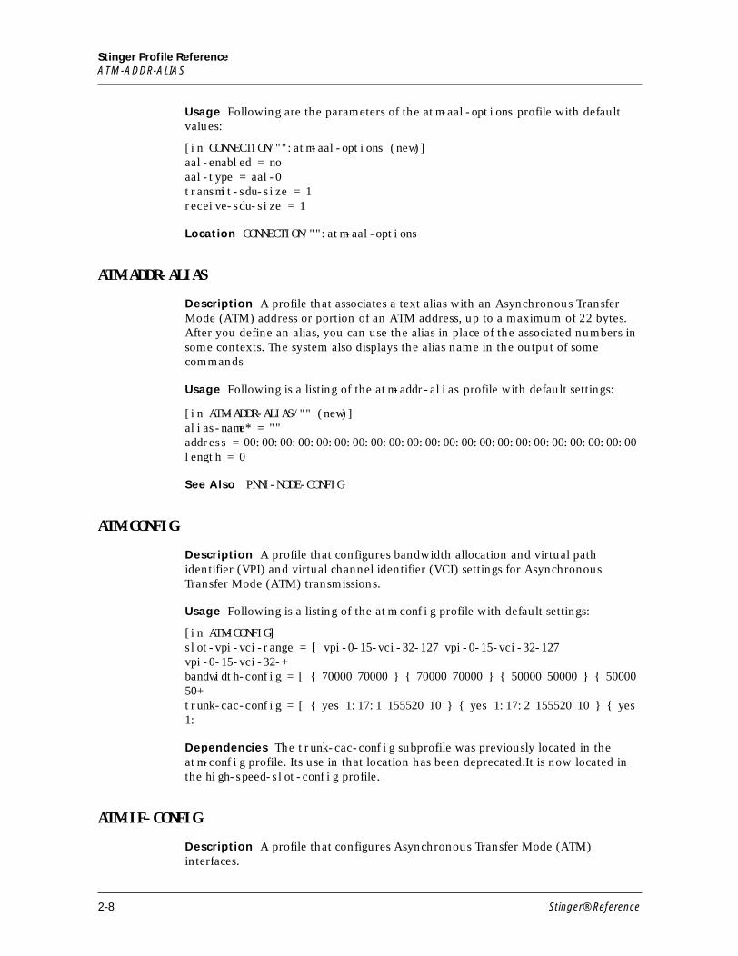
Stinger Profile ReferenceATM-ADDR-ALIAS
Usage Following are the parameters of the atm-aal-options profile with default values:
[in CONNECTION/"":atm-aal-options (new)] aal-enabled = no aal-type = aal-0 transmit-sdu-size = 1 receive-sdu-size = 1
Location CONNECTION/"":atm-aal-options
ATM-ADDR-ALIAS
Description A profile that associates a text alias with an Asynchronous Transfer Mode (ATM) address or portion of an ATM address, up to a maximum of 22 bytes. After you define an alias, you can use the alias in place of the associated numbers in some contexts. The system also displays the alias name in the output of some commands
Usage Following is a listing of the atm-addr-alias profile with default settings:
[in ATM-ADDR-ALIAS/"" (new)] alias-name* = "" address = 00:00:00:00:00:00:00:00:00:00:00:00:00:00:00:00:00:00:00:00:00:00 length = 0
See Also PNNI-NODE-CONFIG
ATM-CONFIG
Description A profile that configures bandwidth allocation and virtual path identifier (VPI) and virtual channel identifier (VCI) settings for Asynchronous Transfer Mode (ATM) transmissions.
Usage Following is a listing of the atm-config profile with default settings:
[in ATM-CONFIG]slot-vpi-vci-range = [ vpi-0-15-vci-32-127 vpi-0-15-vci-32-127 vpi-0-15-vci-32-+bandwidth-config = [ { 70000 70000 } { 70000 70000 } { 50000 50000 } { 50000 50+trunk-cac-config = [ { yes 1:17:1 155520 10 } { yes 1:17:2 155520 10 } { yes 1:
Dependencies The trunk-cac-config subprofile was previously located in the atm-config profile. Its use in that location has been deprecated.It is now located in the high-speed-slot-config profile.
ATM-IF-CONFIG
Description A profile that configures Asynchronous Transfer Mode (ATM) interfaces.
2-8 Stinger® Reference
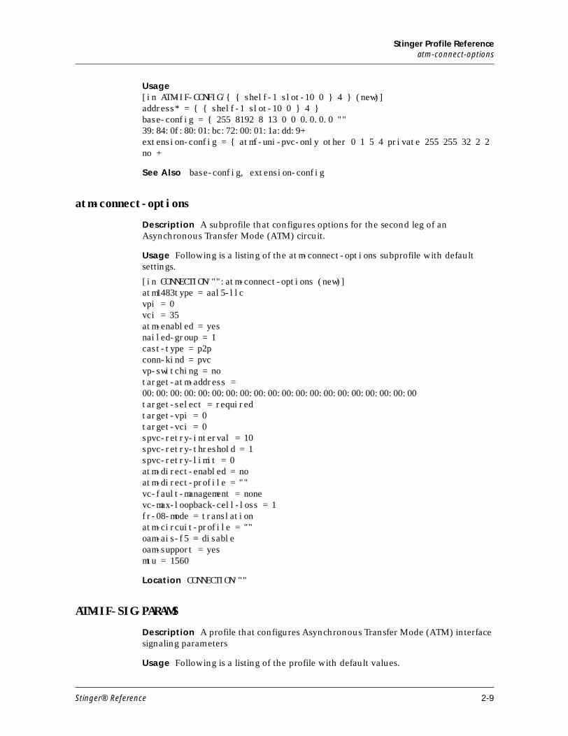
Stinger Profile Referenceatm-connect-options
Usage[in ATM-IF-CONFIG/{ { shelf-1 slot-10 0 } 4 } (new)]address* = { { shelf-1 slot-10 0 } 4 }base-config = { 255 8192 8 13 0 0 0.0.0.0 "" 39:84:0f:80:01:bc:72:00:01:1a:dd:9+extension-config = { atmf-uni-pvc-only other 0 1 5 4 private 255 255 32 2 2 no +
See Also base-config, extension-config
atm-connect-options
Description A subprofile that configures options for the second leg of an Asynchronous Transfer Mode (ATM) circuit.
Usage Following is a listing of the atm-connect-options subprofile with default settings.
[in CONNECTION/"":atm-connect-options (new)] atm1483type = aal5-llc vpi = 0 vci = 35 atm-enabled = yes nailed-group = 1 cast-type = p2p conn-kind = pvc vp-switching = no target-atm-address = 00:00:00:00:00:00:00:00:00:00:00:00:00:00:00:00:00:00:00:00target-select = required target-vpi = 0 target-vci = 0 spvc-retry-interval = 10 spvc-retry-threshold = 1 spvc-retry-limit = 0 atm-direct-enabled = no atm-direct-profile = "" vc-fault-management = none vc-max-loopback-cell-loss = 1 fr-08-mode = translation atm-circuit-profile = "" oam-ais-f5 = disable oam-support = yes mtu = 1560
Location CONNECTION/""
ATM-IF-SIG-PARAMS
Description A profile that configures Asynchronous Transfer Mode (ATM) interface signaling parameters
Usage Following is a listing of the profile with default values.
Stinger® Reference 2-9
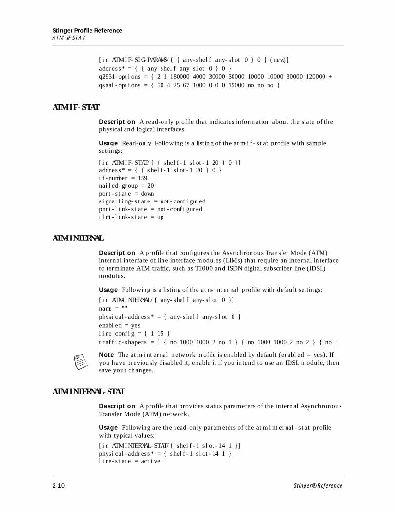
Stinger Profile ReferenceATM-IF-STAT
[in ATM-IF-SIG-PARAMS/{ { any-shelf any-slot 0 } 0 } (new)]address* = { { any-shelf any-slot 0 } 0 }q2931-options = { 2 1 180000 4000 30000 30000 10000 10000 30000 120000 +qsaal-options = { 50 4 25 67 1000 0 0 0 15000 no no no }
ATM-IF-STAT
Description A read-only profile that indicates information about the state of the physical and logical interfaces.
Usage Read-only. Following is a listing of the atm-if-stat profile with sample settings:
[in ATM-IF-STAT/{ { shelf-1 slot-1 20 } 0 }]address* = { { shelf-1 slot-1 20 } 0 }if-number = 159nailed-group = 20port-state = downsignalling-state = not-configuredpnni-link-state = not-configuredilmi-link-state = up
ATM-INTERNAL
Description A profile that configures the Asynchronous Transfer Mode (ATM) internal interface of line interface modules (LIMs) that require an internal interface to terminate ATM traffic, such as T1000 and ISDN digital subscriber line (IDSL) modules.
Usage Following is a listing of the atm-internal profile with default settings:
[in ATM-INTERNAL/{ any-shelf any-slot 0 }]name = ""physical-address* = { any-shelf any-slot 0 }enabled = yesline-config = { 1 15 }traffic-shapers = [ { no 1000 1000 2 no 1 } { no 1000 1000 2 no 2 } { no +
Note The atm-internal network profile is enabled by default (enabled = yes). If you have previously disabled it, enable it if you intend to use an IDSL module, then save your changes.
ATM-INTERNAL-STAT
Description A profile that provides status parameters of the internal Asynchronous Transfer Mode (ATM) network.
Usage Following are the read-only parameters of the atm-internal-stat profile with typical values:
[in ATM-INTERNAL-STAT/{ shelf-1 slot-14 1 }]physical-address* = { shelf-1 slot-14 1 } line-state = active
2-10 Stinger® Reference
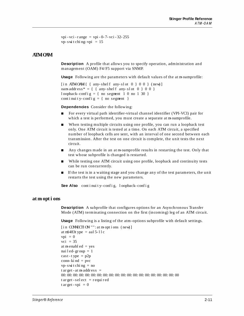
Stinger Profile ReferenceATM-OAM
vpi-vci-range = vpi-0-7-vci-32-255 vp-switching-vpi = 15
ATM-OAM
Description A profile that allows you to specify operation, administration and management (OAM) F4/F5 support via SNMP.
Usage Following are the parameters with default values of the atm-oam profile:
[in ATM-OAM/{ { any-shelf any-slot 0 } 0 0 } (new)]oam-address* = { { any-shelf any-slot 0 } 0 0 } loopback-config = { no segment 1 0 no 1 30 } continuity-config = { no segment }
Dependencies Consider the following:
■ For every virtual path identifier-virtual channel identifier (VPI-VCI) pair for which a test is performed, you must create a separate atm-oam profile.
■ When testing multiple circuits using one profile, you can run a loopback test only. One ATM circuit is tested at a time. On each ATM circuit, a specified number of loopback cells are sent, with an interval of one second between each transmission. After the test on one circuit is complete, the unit tests the next circuit.
■ Any changes made in an atm-oam profile results in restarting the test. Only that test whose subprofile is changed is restarted.
■ While testing one ATM circuit using one profile, loopback and continuity tests can be run concurrently.
■ If the test is in a waiting stage and you change any of the test parameters, the unit restarts the test using the new parameters.
See Also continuity-config, loopback-config
atm-options
Description A subprofile that configures options for an Asynchronous Transfer Mode (ATM) terminating connection on the first (incoming) leg of an ATM circuit.
Usage Following is a listing of the atm-options subprofile with default settings.
[in CONNECTION/"":atm-options (new)] atm1483type = aal5-llc vpi = 0 vci = 35 atm-enabled = yes nailed-group = 1 cast-type = p2p conn-kind = pvc vp-switching = no target-atm-address = 00:00:00:00:00:00:00:00:00:00:00:00:00:00:00:00:00:00:00:00target-select = required target-vpi = 0
Stinger® Reference 2-11
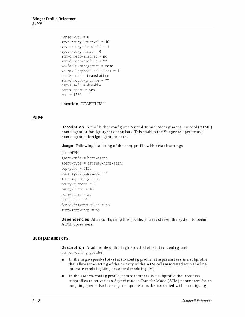
Stinger Profile ReferenceATMP
target-vci = 0 spvc-retry-interval = 10 spvc-retry-threshold = 1 spvc-retry-limit = 0 atm-direct-enabled = no atm-direct-profile = "" vc-fault-management = none vc-max-loopback-cell-loss = 1 fr-08-mode = translation atm-circuit-profile = "" oam-ais-f5 = disable oam-support = yes mtu = 1560
Location CONNECTION/""
ATMP
Description A profile that configures Ascend Tunnel Management Protocol (ATMP) home agent or foreign agent operations. This enables the Stinger to operate as a home agent, a foreign agent, or both.
Usage Following is a listing of the atmp profile with default settings:
[in ATMP]agent-mode = home-agentagent-type = gateway-home-agentudp-port = 5150home-agent-password =””atmp-sap-reply = noretry-timeout = 3retry-limit = 10idle-timer = 30mtu-limit = 0force-fragmentation = noatmp-snmp-trap = no
Dependencies After configuring this profile, you must reset the system to begin ATMP operations.
atm-parameters
Description A subprofile of the high-speed-slot-static-config and switch-config profiles.
■ In the high-speed-slot-static-config profile, atm-parameters is a subprofile that allows the setting of the priority of the ATM cells associated with the line interface module (LIM) or control module (CM).
■ In the switch-config profile, atm-parameters is a subprofile that contains subprofiles to set various Asynchronous Transfer Mode (ATM) parameters for an outgoing queue. Each configured queue must be associated with an outgoing
2-12 Stinger® Reference
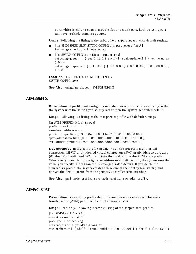
Stinger Profile ReferenceATM-PREFIX
port, which is either a control module slot or a trunk port. Each outgoing port can have multiple outgoing queues.
Usage Following is a listing of the subprofile atm-parameters with default settings:
■ [in HIGH-SPEED-SLOT-STATIC-CONFIG:atm-parameters (new)]incoming-priority = low-priority
■ [in SWITCH-CONFIG/tram-18:atm-parameters]outgoing-queue = [ { yes 1:18:1 { shelf-1 trunk-module-2 1 } yes no no no 5 0 {+outgoing-shaper = [ { 0 1 8000 } { 0 1 8000 } { 0 1 8000 } { 0 1 8000 } { 0 1 8+
Location HIGH-SPEED-SLOT-STATIC-CONFIGSWITCH-CONFIG name
See Also outgoing-shaper, SWITCH-CONFIG
ATM-PREFIX
Description A profile that configures an address or a prefix setting explicitly so that the system uses the setting you specify rather than the system-generated default.
Usage Following is a listing of the atm-prefix profile with default settings:
[in ATM-PREFIX/default (new)] prefix-name* = default use-short-address = no pnni-node-prefix = { 13 39:84:0f:80:01:bc:72:00:01:00:00:00:00 } spvc-address-prefix = { 0 00:00:00:00:00:00:00:00:00:00:00:00:00 } svc-address-prefix = { 0 00:00:00:00:00:00:00:00:00:00:00:00:00 }
Dependencies In the atm-prefix profile, when the soft permanent virtual connection (SPVC) and switched virtual connection (SVC) prefix addresses are zero (0), the SPVC prefix and SVC prefix take their value from the PNNI node prefix. Whenever you explicitly configure an address or a prefix setting, the system uses the value you specify rather than the system-generated default. If you delete the atm-prefix profile, the system creates a new one at the next system startup and derives the default prefix from the primary controller serial number.
See Also pnni-node-prefix, spvc-addr-prefix, svc-addr-prefix.
ATMPVC-STAT
Description A read-only profile that monitors the status of an asynchronous transfer mode (ATM) permanent virtual channel (PVC).
Usage Read-only. Following is sample listing of the atmpvc-stat profile:
[in ATMPVC-STAT/unit1]circuit-name* = unit1pvc-type = connectingcurrent-state = pvc-data-transfervcc-members = [ { shelf-1 trunk-module-1 1 0 120 801 } { shelf-1 slot-13 1 0
Stinger® Reference 2-13
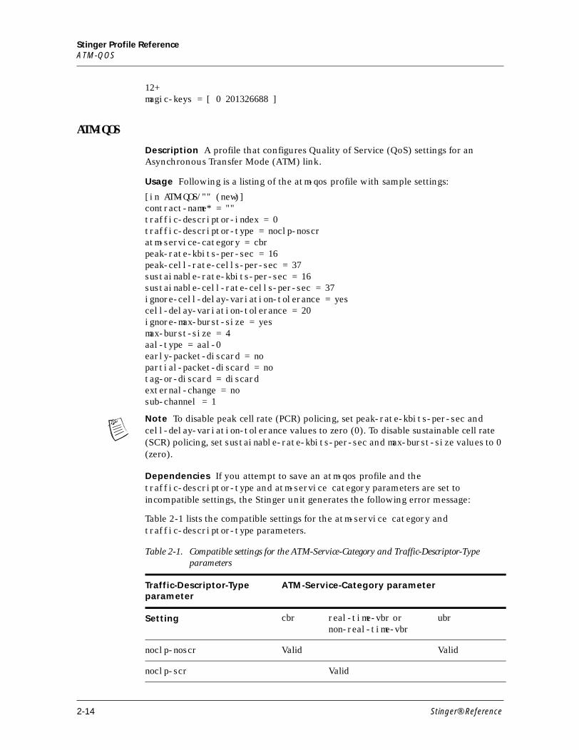
Stinger Profile ReferenceATM-QOS
12+magic-keys = [ 0 201326688 ]
ATM-QOS
Description A profile that configures Quality of Service (QoS) settings for an Asynchronous Transfer Mode (ATM) link.
Usage Following is a listing of the atm-qos profile with sample settings:
[in ATM-QOS/"" (new)] contract-name* = "" traffic-descriptor-index = 0 traffic-descriptor-type = noclp-noscr atm-service-category = cbr peak-rate-kbits-per-sec = 16 peak-cell-rate-cells-per-sec = 37 sustainable-rate-kbits-per-sec = 16 sustainable-cell-rate-cells-per-sec = 37 ignore-cell-delay-variation-tolerance = yescell-delay-variation-tolerance = 20 ignore-max-burst-size = yes max-burst-size = 4 aal-type = aal-0 early-packet-discard = no partial-packet-discard = no tag-or-discard = discard external-change = no sub-channel = 1
Note To disable peak cell rate (PCR) policing, set peak-rate-kbits-per-sec and cell-delay-variation-tolerance values to zero (0). To disable sustainable cell rate (SCR) policing, set sustainable-rate-kbits-per-sec and max-burst-size values to 0 (zero).
Dependencies If you attempt to save an atm-qos profile and the traffic-descriptor-type and atm-service category parameters are set to incompatible settings, the Stinger unit generates the following error message:
Table 2-1 lists the compatible settings for the atm-service category and traffic-descriptor-type parameters.
Table 2-1. Compatible settings for the ATM-Service-Category and Traffic-Descriptor-Type parameters
Traffic-Descriptor-Type parameter
ATM-Service-Category parameter
Setting cbr real-time-vbr or non-real-time-vbr
ubr
noclp-noscr Valid Valid
noclp-scr Valid
2-14 Stinger® Reference
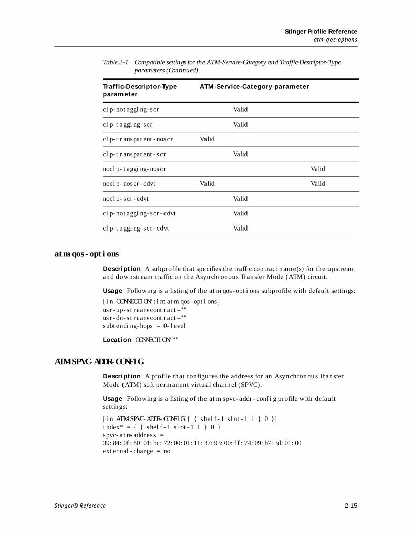
Stinger Profile Referenceatm-qos-options
atm-qos-options
Description A subprofile that specifies the traffic contract name(s) for the upstream and downstream traffic on the Asynchronous Transfer Mode (ATM) circuit.
Usage Following is a listing of the atm-qos-options subprofile with default settings:
[in CONNECTION/tim:atm-qos-options]usr-up-stream-contract=""usr-dn-stream-contract=""subtending-hops = 0-level
Location CONNECTION/""
ATM-SPVC-ADDR-CONFIG
Description A profile that configures the address for an Asynchronous Transfer Mode (ATM) soft permanent virtual channel (SPVC).
Usage Following is a listing of the atm-spvc-addr-config profile with default settings:
[in ATM-SPVC-ADDR-CONFIG/{ { shelf-1 slot-1 1 } 0 }]index* = { { shelf-1 slot-1 1 } 0 }spvc-atm-address = 39:84:0f:80:01:bc:72:00:01:11:37:93:00:ff:74:09:b7:3d:01:00external-change = no
clp-notagging-scr Valid
clp-tagging-scr Valid
clp-transparent-noscr Valid
clp-transparent-scr Valid
noclp-tagging-noscr Valid
noclp-noscr-cdvt Valid Valid
noclp-scr-cdvt Valid
clp-notagging-scr-cdvt Valid
clp-tagging-scr-cdvt Valid
Table 2-1. Compatible settings for the ATM-Service-Category and Traffic-Descriptor-Type parameters (Continued)
Traffic-Descriptor-Type parameter
ATM-Service-Category parameter
Stinger® Reference 2-15
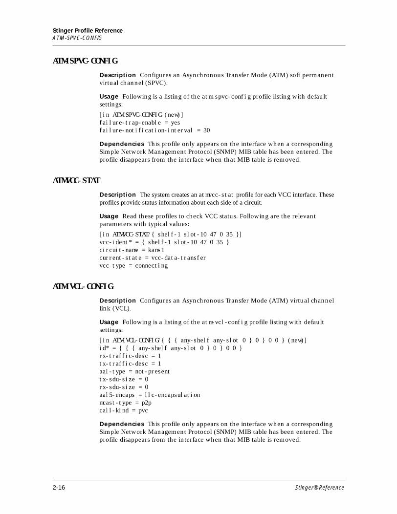
Stinger Profile ReferenceATM-SPVC-CONFIG
ATM-SPVC-CONFIG
Description Configures an Asynchronous Transfer Mode (ATM) soft permanent virtual channel (SPVC).
Usage Following is a listing of the atm-spvc-config profile listing with default settings:
[in ATM-SPVC-CONFIG (new)]failure-trap-enable = yesfailure-notification-interval = 30
Dependencies This profile only appears on the interface when a corresponding Simple Network Management Protocol (SNMP) MIB table has been entered. The profile disappears from the interface when that MIB table is removed.
ATMVCC-STAT
Description The system creates an atmvcc-stat profile for each VCC interface. These profiles provide status information about each side of a circuit.
Usage Read these profiles to check VCC status. Following are the relevant parameters with typical values:
[in ATMVCC-STAT/{ shelf-1 slot-10 47 0 35 }]vcc-ident* = { shelf-1 slot-10 47 0 35 }circuit-name = kam-1current-state = vcc-data-transfervcc-type = connecting
ATM-VCL-CONFIG
Description Configures an Asynchronous Transfer Mode (ATM) virtual channel link (VCL).
Usage Following is a listing of the atm-vcl-config profile listing with default settings:
[in ATM-VCL-CONFIG/{ { { any-shelf any-slot 0 } 0 } 0 0 } (new)]id* = { { { any-shelf any-slot 0 } 0 } 0 0 }rx-traffic-desc = 1tx-traffic-desc = 1aal-type = not-presenttx-sdu-size = 0rx-sdu-size = 0aal5-encaps = llc-encapsulationmcast-type = p2pcall-kind = pvc
Dependencies This profile only appears on the interface when a corresponding Simple Network Management Protocol (SNMP) MIB table has been entered. The profile disappears from the interface when that MIB table is removed.
2-16 Stinger® Reference
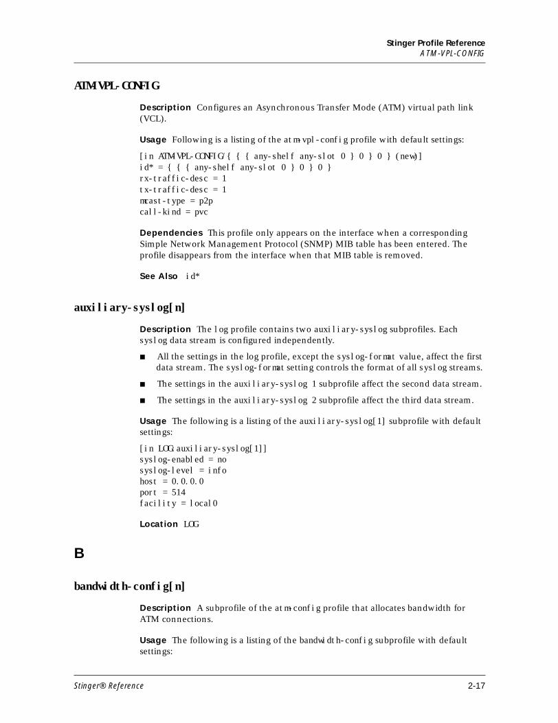
Stinger Profile ReferenceATM-VPL-CONFIG
ATM-VPL-CONFIG
Description Configures an Asynchronous Transfer Mode (ATM) virtual path link (VCL).
Usage Following is a listing of the atm-vpl-config profile with default settings:
[in ATM-VPL-CONFIG/{ { { any-shelf any-slot 0 } 0 } 0 } (new)]id* = { { { any-shelf any-slot 0 } 0 } 0 }rx-traffic-desc = 1tx-traffic-desc = 1mcast-type = p2pcall-kind = pvc
Dependencies This profile only appears on the interface when a corresponding Simple Network Management Protocol (SNMP) MIB table has been entered. The profile disappears from the interface when that MIB table is removed.
See Also id*
auxiliary-syslog[n]
Description The log profile contains two auxiliary-syslog subprofiles. Each syslog data stream is configured independently.
■ All the settings in the log profile, except the syslog-format value, affect the first data stream. The syslog-format setting controls the format of all syslog streams.
■ The settings in the auxiliary-syslog 1 subprofile affect the second data stream.
■ The settings in the auxiliary-syslog 2 subprofile affect the third data stream.
Usage The following is a listing of the auxiliary-syslog[1] subprofile with default settings:
[in LOG:auxiliary-syslog[1]]syslog-enabled = nosyslog-level = infohost = 0.0.0.0port = 514facility = local0
Location LOG
B
bandwidth-config[n]
Description A subprofile of the atm-config profile that allocates bandwidth for ATM connections.
Usage The following is a listing of the bandwidth-config subprofile with default settings:
Stinger® Reference 2-17
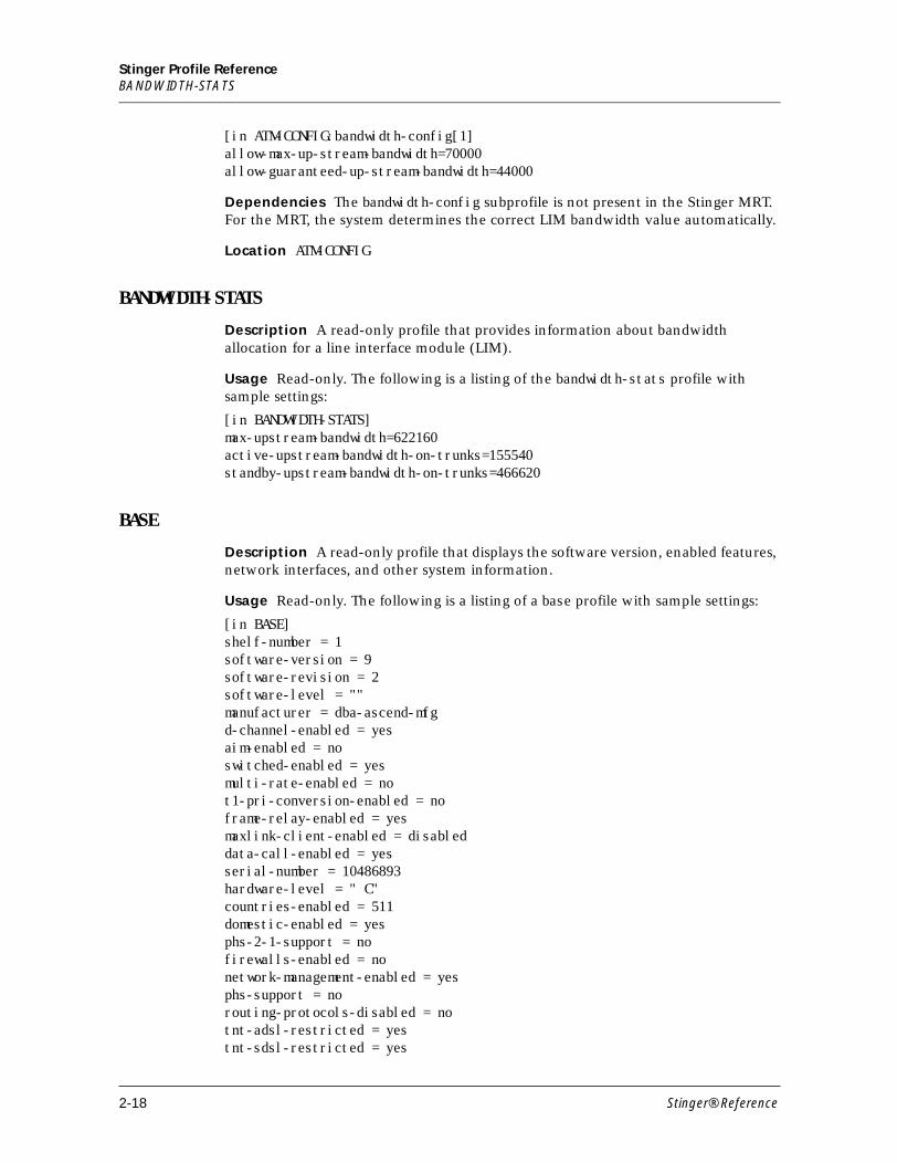
Stinger Profile ReferenceBANDWIDTH-STATS
[in ATM-CONFIG:bandwidth-config[1] allow-max-up-stream-bandwidth=70000allow-guaranteed-up-stream-bandwidth=44000
Dependencies The bandwidth-config subprofile is not present in the Stinger MRT. For the MRT, the system determines the correct LIM bandwidth value automatically.
Location ATM-CONFIG
BANDWIDTH-STATS
Description A read-only profile that provides information about bandwidth allocation for a line interface module (LIM).
Usage Read-only. The following is a listing of the bandwidth-stats profile with sample settings:
[in BANDWIDTH-STATS]max-upstream-bandwidth=622160active-upstream-bandwidth-on-trunks=155540standby-upstream-bandwidth-on-trunks=466620
BASE
Description A read-only profile that displays the software version, enabled features, network interfaces, and other system information.
Usage Read-only. The following is a listing of a base profile with sample settings:
[in BASE] shelf-number = 1 software-version = 9 software-revision = 2 software-level = "" manufacturer = dba-ascend-mfg d-channel-enabled = yes aim-enabled = no switched-enabled = yes multi-rate-enabled = no t1-pri-conversion-enabled = no frame-relay-enabled = yes maxlink-client-enabled = disabled data-call-enabled = yes serial-number = 10486893 hardware-level = " C" countries-enabled = 511 domestic-enabled = yes phs-2-1-support = no firewalls-enabled = no network-management-enabled = yes phs-support = no routing-protocols-disabled = no tnt-adsl-restricted = yes tnt-sdsl-restricted = yes
2-18 Stinger® Reference
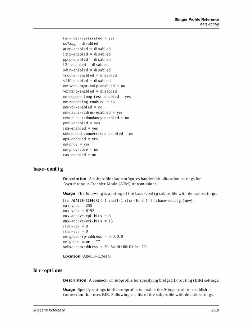
Stinger Profile Referencebase-config
tnt-idsl-restricted = yes ss7asg = disabled atmp-enabled = disabled l2tp-enabled = disabled pptp-enabled = disabled l2f-enabled = disabled sdtn-enabled = disabled vrouter-enabled = disabled v110-enabled = disabled network-mgmt-voip-enabled = no wormarq-enabled = disabled nm-copper-loop-test-enabled = yes nm-reporting-enabled = no nm-vpn-enabled = no nm-navis-radius-enabled = yes restrict-redundancy-enabled = no pnni-enabled = yes ima-enabled = yes subtended-connections-enabled = no aps-enabled = yes nm-prov = yes nm-prov-core = no ras-enabled = no
base-config
Description A subprofile that configures bandwidth allocation settings for Asynchronous Transfer Mode (ATM) transmissions
Usage The following is a listing of the base-config subprofile with default settings:
[in ATM-IF-CONFIG/{ { shelf-1 slot-10 0 } 4 }:base-config (new)]max-vpcs = 255max-vccs = 8192max-active-vpi-bits = 8max-active-vci-bits = 13ilmi-vpi = 0ilmi-vci = 0neighbor-ip-address = 0.0.0.0neighbor-name = ""subsc-atm-address = 39:84:0f:80:01:bc:72:
Location ATM-IF-CONFIG
bir-options
Description A connection subprofile for specifying bridged IP routing (BIR) settings.
Usage Specify settings in this subprofile to enable the Stinger unit to establish a connection that uses BIR. Following is a list of the subprofile with default settings:
Stinger® Reference 2-19
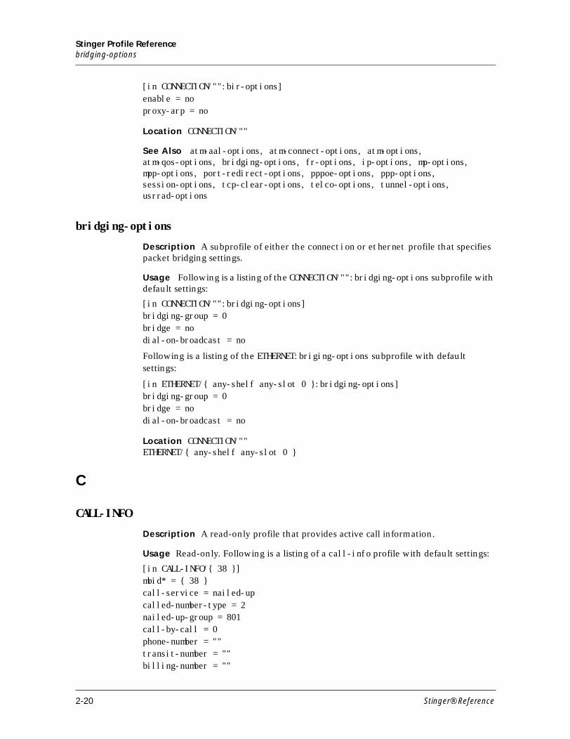
Stinger Profile Referencebridging-options
[in CONNECTION/"":bir-options]enable = noproxy-arp = no
Location CONNECTION/""
See Also atm-aal-options, atm-connect-options, atm-options, atm-qos-options, bridging-options, fr-options, ip-options, mp-options, mpp-options, port-redirect-options, pppoe-options, ppp-options, session-options, tcp-clear-options, telco-options, tunnel-options, usrrad-options
bridging-options
Description A subprofile of either the connection or ethernet profile that specifies packet bridging settings.
Usage Following is a listing of the CONNECTION/"":bridging-options subprofile with default settings:
[in CONNECTION/"":bridging-options]bridging-group = 0bridge = nodial-on-broadcast = no
Following is a listing of the ETHERNET:briging-options subprofile with default settings:
[in ETHERNET/{ any-shelf any-slot 0 }:bridging-options]bridging-group = 0bridge = nodial-on-broadcast = no
Location CONNECTION/""ETHERNET/{ any-shelf any-slot 0 }
C
CALL-INFO
Description A read-only profile that provides active call information.
Usage Read-only. Following is a listing of a call-info profile with default settings:
[in CALL-INFO/{ 38 }]mbid* = { 38 }call-service = nailed-upcalled-number-type = 2nailed-up-group = 801call-by-call = 0phone-number = ""transit-number = ""billing-number = ""
2-20 Stinger® Reference
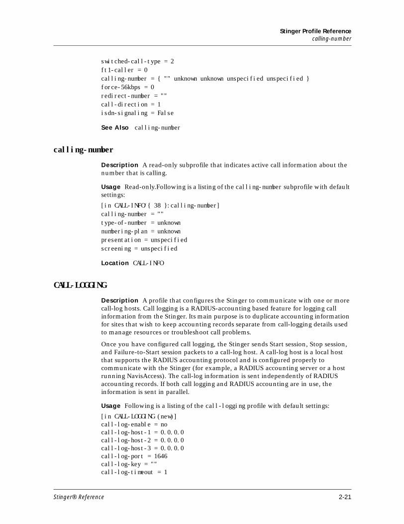
Stinger Profile Referencecalling-number
switched-call-type = 2ft1-caller = 0calling-number = { "" unknown unknown unspecified unspecified }force-56kbps = 0redirect-number = ""call-direction = 1isdn-signaling = False
See Also calling-number
calling-number
Description A read-only subprofile that indicates active call information about the number that is calling.
Usage Read-only.Following is a listing of the calling-number subprofile with default settings:
[in CALL-INFO/{ 38 }:calling-number]calling-number = ""type-of-number = unknownnumbering-plan = unknownpresentation = unspecifiedscreening = unspecified
Location CALL-INFO
CALL-LOGGING
Description A profile that configures the Stinger to communicate with one or more call-log hosts. Call logging is a RADIUS-accounting based feature for logging call information from the Stinger. Its main purpose is to duplicate accounting information for sites that wish to keep accounting records separate from call-logging details used to manage resources or troubleshoot call problems.
Once you have configured call logging, the Stinger sends Start session, Stop session, and Failure-to-Start session packets to a call-log host. A call-log host is a local host that supports the RADIUS accounting protocol and is configured properly to communicate with the Stinger (for example, a RADIUS accounting server or a host running NavisAccess). The call-log information is sent independently of RADIUS accounting records. If both call logging and RADIUS accounting are in use, the information is sent in parallel.
Usage Following is a listing of the call-logging profile with default settings:
[in CALL-LOGGING (new)] call-log-enable = no call-log-host-1 = 0.0.0.0 call-log-host-2 = 0.0.0.0 call-log-host-3 = 0.0.0.0 call-log-port = 1646 call-log-key = "" call-log-timeout = 1
Stinger® Reference 2-21
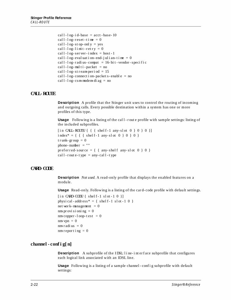
Stinger Profile ReferenceCALL-ROUTE
call-log-id-base = acct-base-10 call-log-reset-time = 0 call-log-stop-only = yes call-log-limit-retry = 0 call-log-server-index = host-1 call-log-evaluation-end-julian-time = 0 call-log-radius-compat = 16-bit-vendor-specific call-log-multi-packet = no call-log-stream-period = 15 call-log-connection-packets-enable = no call-log-csm-modem-diag = no
CALL-ROUTE
Description A profile that the Stinger unit uses to control the routing of incoming and outgoing calls. Every possible destination within a system has one or more profiles of this type.
Usage Following is a listing of the call-route profile with sample settings: listing of the included subprofiles.
[in CALL-ROUTE/{ { { shelf-1 any-slot 0 } 0 } 0 }]index* = { { { shelf-1 any-slot 0 } 0 } 0 }trunk-group = 0phone-number = ""preferred-source = { { any-shelf any-slot 0 } 0 }call-route-type = any-call-type
CARD-CODE
Description Not used. A read-only profile that displays the enabled features on a module.
Usage Read-only. Following is a listing of the card-code profile with default settings.
[in CARD-CODE/{ shelf-1 slot-1 0 }]physical-address* = { shelf-1 slot-1 0 }network-management = 0nm-provisioning = 0nm-copper-loop-test = 0nm-vpn = 0nm-radius = 0nm-reporting = 0
channel-config[n]
Description A subprofile of the IDSL:line-interface subprofile that configures each logical link associated with an IDSL line.
Usage Following is a listing of a sample channel-config subprofile with default settings:
2-22 Stinger® Reference
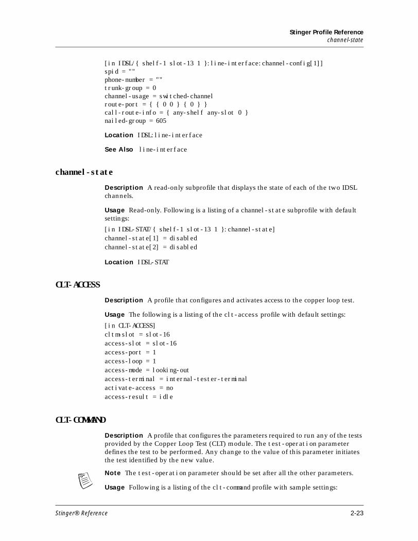
Stinger Profile Referencechannel-state
[in IDSL/{ shelf-1 slot-13 1 }:line-interface:channel-config[1]]spid = ""phone-number = ""trunk-group = 0channel-usage = switched-channelroute-port = { { 0 0 } { 0 } }call-route-info = { any-shelf any-slot 0 }nailed-group = 605
Location IDSL:line-interface
See Also line-interface
channel-state
Description A read-only subprofile that displays the state of each of the two IDSL channels.
Usage Read-only. Following is a listing of a channel-state subprofile with default settings:
[in IDSL-STAT/{ shelf-1 slot-13 1 }:channel-state]channel-state[1] = disabledchannel-state[2] = disabled
Location IDSL-STAT
CLT-ACCESS
Description A profile that configures and activates access to the copper loop test.
Usage The following is a listing of the clt-access profile with default settings:
[in CLT-ACCESS]cltm-slot = slot-16access-slot = slot-16access-port = 1access-loop = 1access-mode = looking-outaccess-terminal = internal-tester-terminalactivate-access = noaccess-result = idle
CLT-COMMAND
Description A profile that configures the parameters required to run any of the tests provided by the Copper Loop Test (CLT) module. The test-operation parameter defines the test to be performed. Any change to the value of this parameter initiates the test identified by the new value.
Note The test-operation parameter should be set after all the other parameters.
Usage Following is a listing of the clt-command profile with sample settings:
Stinger® Reference 2-23
Stinger Profile ReferenceCLT-COMMAND
[in CLT-COMMAND (new)] cltm-slot = slot-16 test-time-stamp = 0 test-sequence = 0 test-operation = none dmm-type = resistance dmm-lead = tip-ring background-noise-filter = psd background-noise-termination = term100 loop-resistance-unit = metric loop-resistance-temp = 0 impulse-noise-start-thresh = 50 impulse-noise-start-delta = 2 impulse-noise-start-max-count = 1 impulse-noise-start-dead-time = 1 impulse-noise-start-timer = 1 calibration-type = insertion-loss tone-send-freq = 10 tone-send-level = 0 tone-send-period = 0 tdr-unit = metric tdr-gauge = 0 tdr-vp = 0 tdr-avg = 1 tdr-get-type = automatic tdr-start-distance = 0 tdr-measurement-length = 0 dmmdcd-period = 0 dmmdcd-voltage = 0 dmmdcd-impedance = 10 dmmcap-period = 0 dmmall-type = resistance dmmall-period = 0 dmmall-input-imp = 0 ctone-type = adsl ctone-tone = quiet ttone-lead = tip-ring ttone-level = 0 ttone-period = 0 btap-start-length = 0 btap-measure-length = 0 fclloc-unit = metric fclloc-gauge = 0 shortloc-unit = metric shortloc-gauge = 0 shortloc-type = detect setresp-mode = on setresp-mode-period = 0
2-24 Stinger® Reference
Stinger Profile ReferenceCLT-RESULT
CLT-RESULT
Description A profile that indicates the test result of all the tests the tester module has executed. The test-result-status parameter is set to not-valid at the start of each test and is updated to valid, or out-of-range at the end of each test. All of the clt-result profile is cleared at the start of each test, and, depending on the test, the corresponding result parameters are updated at the end of the test.
Usage Following is a clt-result profile with sample settings.
[in CLT-RESULT (new)] cltm-slot = slot-16 test-result-time-stamp = 0 test-result-sequence = 0 test-result-status = not-ready dmm-result = 0 loop-resistance = 0 loop-resistance-length-1 = 0 loop-resistance-length-2 = 0 loop-resistance-length-3 = 0 coil-detection-coil-count = 0 impulse-noise-read-low-threshold = 0 impulse-noise-read-mid-threshold = 0 impulse-noise-read-high-threshold = 0 rcv-tone-frequency = 0 rcv-tone-level = 0 tdr-manual-sample-count = 0 tdr-automatic-fault-distance = 0 hardware-revision = 0 sofware-revision = 0 psd-frequency-level = [ { 0 0 } { 0 0 } { 0 0 } { 0 0 } { 0 0 } { 0 0 } { 0 0 }+tdr-distance-level = [ { 0 0 } { 0 0 } { 0 0 } { 0 0 } { 0 0 } { 0 0 } { 0 0 } +dc-delta-resistance-t-r = 0 dc-delta-resistance-t-s = 0 dc-delta-resistance-r-s = 0 dc-delta-voltage-t-s = 0 dc-delta-voltage-r-s = 0 cap-equivalent-t-r = 0 cap-equivalent-t-s = 0 cap-equivalent-r-s = 0 dmm-all-t-r = 0 dmm-all-t-s = 0 dmm-all-r-s = 0 ringer = 0 atu-r = 0 bridge-tap-number = 0 bridge-tap-length = 0 bridge-tap-table = [ { 0 0 0 } { 0 0 0 } { 0 0 0 } { 0 0 0 } { 0 0 0 } { 0 0 0 +voice-detection = 0 first-coil-location = 0
Stinger® Reference 2-25
Stinger Profile ReferenceCONNECTION
short-location = 0 splitter-det-result = 0
CONNECTION
Description A profile that configures connection-specific information, including user-password authentication settings, compression values, filter specifications, and Asynchronous Transfer Mode (ATM) options.
Usage Following is a listing of the connection profile with default settings:
[in CONNECTION/""]station* = ""active = noencapsulation-protocol = atm-circuitcalled-number-type = nationaldial-number = ""clid = ""auto-profiles = yesip-options = { yes yes 0.0.0.0/0 0.0.0.0/0 1 60 120 no 0 0.0.0.0 +bridging-options = { 0 no no }session-options = { "" "" no 120 no-idle 120 "" 0 disabled autobaud+telco-options = { ans-and-orig no ft1 1 no no 56k-clear 0 "" "" no +ppp-options = { no-ppp-auth none "" none "" "" "" "" stac 1524 no 6+mp-options = { 1 1 2 }mpp-options = { "" quadratic transmit 1 1 15 5 10 70 }fr-options = { "" 16 "" transparent-link no "" 16 "" }tcp-clear-options = { "" 0 "" 0 "" 0 "" 0 no "" 256 20 }usrRad-options = { global 0.0.0.0 1646 "" 1 acct-base-10 }calledNumber = ""shared-prof = nomax-shared-users = 0tunnel-options = { disabled atmp-protocol 0 rip-off "" "" 5150 "" "+vrouter = ""cross-connect-index = 0atm-options = { aal5-llc 0 35 1 p2p pvc no 00:00:00:00:00:00:00:00:+atm-connect-options = { aal5-llc 0 35 1 p2p pvc no 00:00:00:00:00:0+port-redirect-options = { none 0 0.0.0.0 }pppoe-options = { no no }atm-qos-options = { default default 0-level }bir-options = { no no }atm-aal-options = { no aal-0 1 1 }conn-user = default
Dependencies The following connection entries do not apply to Stinger units:
called-number-type = nationaldial-number = ""clid = ""expect-callback = nomp-options = { 1 1 2 }
2-26 Stinger® Reference
Stinger Profile Referencecontext[n]
mpp-options = { "" quadratic transmit 1 1 15 5 10 70 }tcp-clear-options = { "" 0 "" 0 "" 0 "" 0 no "" 256 20 }calledNumber = ""
context[n]
Description A subprofile of the REDUNDANCY:context subprofile that configures options for an individual controller. The index for each subprofile is a controller number.
Usage The following is a listing of the context [n] subprofile with default settings:
[in REDUNDANCY:context[1]]must-agree=no
Location REDUNDANCY:context[n]
context-stats[n]
Description This subprofile of the redundancy-stats profile contains the
redundancy statistics for a particular control module (CM). There is one
context-stats subprofile for each CM.
Usage Following are the read-only parameters for the context-stats subprofile:
[in REDUNDANCY-STATS:context-stats[1]] state = monitoring function = secondary select-reason = defer-to-running-primary prior-function = secondary last-reboot = crash local = { 9487770 } pair = { 10486893 } chassis-serial-number = 0 initialization-time = 382400025 post-start = 382400029 post-end = 382400031 selection-start = 382400029 selection-end = 382400031 load-start = 382400031 load-end = 382400074 inauguration-time = 382400074 last-sent = 382400074 last-received = 382400074 last-profile-sync = 0 last-code-sync = 0 last-log-recv = 0 update-time = 382400074
Location REDUNDANCY-STATS
Stinger® Reference 2-27
Stinger Profile Referencecontinuity-config
continuity-config
Description A subprofile of the atm-oam profile that you use to configure continuity check parameters.
Usage Set values in this profile to specify the continuity check parameters. Following is a list of the subprofile’s contents, shown with default values:
[in ATM-OAM/{ { any-shelf any-slot 0 } 0 0 }:continuity-config (new)]enabled = no continuity-level = segment
Location ATM-OAM
controller-static-config
Description A profile that configures the Asynchronous Transfer Mode (ATM)) cell processor. This profile has been renamed switch-config. See the entry for the switch-config profile.
D
date
Description A subprofile that configures the day of the week and the current system date.
Usage Following is a listing of the date subprofile with sample settings:
admin> list date[in TIMEDATE:date]weekday=Fridaymonth=Octoberday=18year=1996
Note You can also use the date command to set the day of the week and the system date.
Location TIMEDATE
DEBUG
Description A profile that allows you to configure Stinger debug options.
Usage Following is a list of the profile contents, shown with the default values:
[in DEBUG/{ any-shelf any-slot 0 }]physical-Address* = { any-shelf any-slot 0 }active = yesenable-core-dump = nocore-dump-server = ""enable-gdb = nogdb-host = ""
2-28 Stinger® Reference
Stinger Profile Referencedevice-address
generic-field = 2147483647min-warning-core-dump = 0max-warning-core-dump = 0core-dump-rip-update = update-high-freq
device-address
Description A subprofile of the CALL-ROUTE/{ { { shelf-1 any-slot 0 } 0 } 0 }:index subprofile that configures the address for the device carrying the call?
Usage The following is a listing for the subprofile with default settings:
[in CALL-ROUTE/{ { { shelf-1 any-slot 0 } 0 } 0 }:index:device-address]physical-address = { shelf-1 any-slot 0 }logical-item = 0
Location CALL-ROUTE/{ { { shelf-1 any-slot 0 } 0 } 0 }:index
See Also index, preferred-source
DEVICE-STATE
Description A read-only profile that indicates the current state of a device. The Stinger does not store the device-state profile in NVRAM, so the profile’s settings do not persist across system resets or power cycles. The device-state parameter setting might differ from the reqd-state parameter setting during state changes, such as when a device is being disconnected. State changes are complete when the device-state and the reqd-state values match.
Usage Read-only. The following is a listing of the device-state profile with sample settings:
[in DEVICE-STATE/{ { shelf-1 slot-13 19 } 0 }] device-address* = { { shelf-1 slot-13 19 } 0 } device-state = down-dev-state up-status = idle-up-status reqd-state = down-reqd-state route-id = { 0 } used-count = 0 bad-count = 0 last-32 = 0
Dependencies An SNMP manager can read the device-state profile.
dialout-configuration
Description Not used.
Location TERMINAL-SERVER
Stinger® Reference 2-29
Stinger Profile Referencedialout-options
dialout-options
Description Not supported. A tunnel-server subprofile that specifies dial-out options for a specific Layer 2 Tunneling Protocol (L2TP) network server (LNS). The parameters in this subprofile do not apply to Stinger units operating as a L2TP access concentrators (LACs).
Location TUNNEL-SERVER/""
dlci-ident
Description A read-only subprofile that indicates data link connection identifier (DLCI) information.
Usage Read only. Following is a listing of a dlci-ident subprofile with sample settings:
[in FRDLCI-STAT/{ 16 3 fr13_20_1 transparent-link }:dlci-ident]dlci = 16dlci-route-id = 3fr-profile = fr13_20_1fr-link-type = transparent-link
Location FRDLCI-STAT
dlci-members n
Description A read-only subprofile that indicates the data link connection identifier (DLCI) information for each of the dlci members.
Permission level
Usage Read-only. The following is a sample listing of the dlci-members subprofile:
[in FRPVC-STAT/801_0_120:dlci-members[1]]dlci = 16dlci-route-id = 3fr-profile = fr13_20_1fr-link-type = transparent-link
Location FRPVC-STAT
dns-local-table
Description A subprofile that configures a Domain Name System (DNS) table of up to eight hostnames and their IP addresses. The system consults the table in RAM for address resolution only if requests to the DNS server fail. The local table acts as a safeguard to ensure that the system can resolve certain DNS names, even if all DNS servers are inaccessible.
The local DNS table is propagated to RAM from the settings in this subprofile. At startup, the system copies values in the profile to the table in RAM. If you subsequently modify the dns-local-table subprofile, the changes are propagated to the table in RAM when the profile is written.
2-30 Stinger® Reference
Stinger Profile ReferenceDS1-ATM
Usage Following is a listing of the dns-local-table subprofile with default settings:
[in IP-GLOBAL:dns-local-table]enabled = noauto-update = notable-config = [ { "" 0.0.0.0 } { "" 0.0.0.0 } { "" 0.0.0.0 } { "" 0.+
Location IP-GLOBAL
See Also table-config
DS1-ATM
Description A profile that configures hardware-specific parameters that are common to the IMA chip. For example, because 24-port IMA line interface modules (LIMs) contain three chips, three profiles are created. However, because eight-port IMA LIMs contain a single chip, only one profile is created.
Usage The following is a listing of the DS1-ATM profile with default settings:
[in DS1-ATM/{ any-shelf any-slot 0 } (new)] name = 0:0:0 physical-address* = { any-shelf any-slot 0 } enabled = no spare-physical-address = { any-shelf any-slot 0 } sparing-mode = inactive ignore-lineup = system-defined line-config = { esf b8zs 4294967246 no-loopback not-eligible high-priority none+
See Also line-config
DS1-ATM-STAT
Description A read-only profile that indicates the statistics for DS1-ATM modules.
Usage Read-only. Following is a sample listing of a ds1-atm-stat profile:
[in DS1-ATM-STAT/{ shelf-1 slot-2 1 }]physical-address* = { shelf-1 slot-2 1 }line-mode = uniline-state = disabledloss-of-carrier = Trueloss-of-sync = Falseais-receive = Trueyellow-receive = Falseber-receive = Falsecarrier-established = Falsecell-delineation = Falsenetwork-loopback = Falsespare-physical-address = { any-shelf any-slot 0 }sparing-state = sparing-nonesparing-change-reason = unknown
Stinger® Reference 2-31
Stinger Profile ReferenceDS3-ATM
sparing-change-time = 0sparing-change-counter = 0vpi-vci-range = vpi-0-15-vci-32-127vp-switching-vpi = 15ima-link-status = { not-in-group not-in-group not-in-group not-in-groupno-fail+ima-link-statistic = { 0 0 0 0 0 0 0 0 0 0 0 0 0 0 0 0 0 }utopia-address = 4294967295send-code-status = disabledpattern-test-status = none
See Also ima-link-status
DS3-ATM
Description Configures a DS3-ATM module.
Usage Following is a listing of the ds3-atm profile with default settings:
[in DS3-ATM/{ shelf-1 slot-1 0 }]name=""physical-address*={ shelf-1 slot-1 0 }enabled=nospare-physical-address={ any-shelf any-slot 0 }sparing-mode=inactiveignore-lineup = system-definedline-config={ 9 0 static { shelf-1 slot-1 0 } no-loopback no +
See Also line-config
DS3-ATM-STAT
Description A read-only profile that indicates the status of a DS3-ATM trunk module.
Usage Read-only. The following is a sample listing of the ds3-atm-stat profile:
[in DS3-ATM-STAT/{ shelf-1 trunk-module-2 1 }]physical-address* = { shelf-1 trunk-module-2 1 }line-state = activespare-physical-address = { any-shelf any-slot 0 }sparing-state = sparing-nonesparing-change-reason = manualsparing-change-time = 0sparing-change-counter = 0vpi-vci-range = vpi-0-255-vci-32-4095vc-switching-vpi = ""vcc-vpi = [ 0 0 0 0 0 0 0 ]f-bit-error-count = 227p-bit-error-count = 9cp-bit-error-count = 5
2-32 Stinger® Reference
Stinger Profile ReferenceDSL-THRESHOLD
feb-error-count = 24bpv-error-count = 5303loss-of-signal = Falseloss-of-frame = Falseyellow-receive = Falseais-receive = False
DSL-THRESHOLD
Description A profile that configures threshold settings for Digital Subscriber Line (DSL) services.
Usage Following is a listing of the dsl-threshold profile with default settings:
[in DSL-THRESHOLD/default]name* = defaultenabled = noatuc-15min-lofs = 0atuc-15min-loss = 0atuc-15min-lols = 0atuc-15min-lprs = 0atuc-15min-ess = 0atuc-fast-rate-up = 0atuc-interleave-rate-up = 0atuc-fast-rate-down = 0atuc-interleave-rate-down = 0atuc-init-failure-trap = disable
E
E3-ATM
Description This profile allows you to configure the parameters for an E3 trunk module.
Usage Following is a list of the profiles contents, shown with the default values:
[in E3-ATM/{ any-shelf any-slot 0 } (new)]name = ""physical-address* = { any-shelf any-slot 0 }enabled = noignore-lineup = system-definedline-config = { 9 1 no-loopback no g832-adm vpi-0-255-vci-32-8191 [ 0 0 0 0 0 0+spare-physical-address = { any-shelf any-slot 0 }sparing-mode = inactive
E3-ATM-STAT
Description A read-only profile that indicates the status of a E3-ATM trunk module.
Usage Read-only. The following is a sample listing of the e3-atm-stat profile:
Stinger® Reference 2-33
Stinger Profile ReferenceERROR
[in E3-ATM-STAT/{ shelf-1 trunk-module-1 1 }]physical-address* = { shelf-1 trunk-module-1 1 }line-state = activespare-physical-address = { any-shelf any-slot 0 }sparing-state = sparing-nonesparing-change-reason = manualsparing-change-time = 0sparing-change-counter = 0vpi-vci-range = vpi-0-255-vci-32-8191vc-switching-vpi = ""vcc-vpi = [ 0 0 0 0 0 0 0 ]f-bit-error-count = 0p-bit-error-count = 0cp-bit-error-count = 0feb-error-count = 0bpv-error-count = 0loss-of-signal = Falseloss-of-frame = Falseyellow-receive = Falseais-receive = False
ERROR
Description A read-only profile that provides information about any errors that occur when the Stinger is running.
Usage Read-only. The following is a sample listing of the error profile:
[in ERROR/562] is-post = no type = 99 abstime = 380755993 slot = 9 version = 9.0-169a0e0 user-profile = admin stack-trace = [ 0 0 0 0 0 0 ] loadname = stngrcm index* = 562 shelf = 1 login-source = 192.168.120.10
ETHER-INFO
Description A read-only profile that indicates the MAC address and link state of an Ethernet interface. The ether-info profile is created when the Ethernet module enters an active state and deleted when the slot is deactivated. The contents of the profile are not written to NVRAM.
Usage Read-only. Following is a listing of the ether-info profile with sample settings:
[in ETHER-INFO/{ shelf-1 slot-2 1 }]interface-address*={ shelf-1 slot-2 1 }
2-34 Stinger® Reference
Stinger Profile ReferenceETHERNET
mac-address=00:c0:7b:68:ef:98link-state=upmedia-speed-mbit = 100
ETHERNET
Description A profile that configures the physical characteristics of an Ethernet interface. With the optional line element module (LEM) of a T1000 module, two additional Ethernet interfaces are supported by the Stinger unit.
Usage Following is a listing of the ethernet profile with default settings:
[in ETHERNET/{ any-shelf any-slot 0 }]interface-address* = { any-shelf any-slot 0 }link-state-enabled = noenabled = yesether-if-type = utpbridging-enabled = nofilter-name = ""duplex-mode = full-duplexpppoe-options = { no no }bridging-options = { 0 no }media-speed-mbit = 100mbauto-negotiate = no
See Also bridging-options, pppoe-options
extension-config
Description An atm-if-config subprofile containing supplemental parameters for configuring the ATM cell layer.
Usage Set values in this profile to specify the supplemental parameters. Following is a list of the subprofile’s contents, shown with default values:
[in ATM-IF-CONFIG/{ { any-shelf any-slot 0 } 0 }:extension-config (new)] config-type = atmf-uni-pvc-only config-side = other ilmi-admin-status = no ilmi-connectivity = no conn-estab-interval = 1 loss-detect-interval = 5 poll-inact-factor = 4 device-type = private max-switched-vpc-vpi = 255 max-switched-vcc-vpi = 255 min-switched-vcc-vci = 32 sig-vcc-rx-qos-name = default-ctl sig-vcc-tx-qos-name = default-ctl pvc-failure-trap-enabled = no pvc-failure-intvl = 30
Location ATM-IF-CONFIG/""
Stinger® Reference 2-35
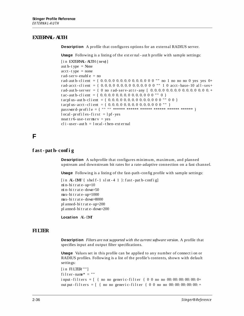
Stinger Profile ReferenceEXTERNAL-AUTH
EXTERNAL-AUTH
Description A profile that configures options for an external RADIUS server.
Usage Following is a listing of the external-auth profile with sample settings:
[in EXTERNAL-AUTH (new)] auth-type = None acct-type = none rad-serv-enable = no rad-auth-client = { 0.0.0.0 0.0.0.0 0.0.0.0 0 0 "" no 1 no no no 0 yes yes 0+rad-acct-client = { 0.0.0.0 0.0.0.0 0.0.0.0 0 0 "" 1 0 acct-base-10 all-ses+rad-auth-server = { 0 no rad-serv-attr-any [ 0.0.0.0 0.0.0.0 0.0.0.0 0.0 0.+tac-auth-client = { 0.0.0.0 0.0.0.0 0.0.0.0 0 0 "" 0 } tacplus-auth-client = { 0.0.0.0 0.0.0.0 0.0.0.0 0 0 "" 0 0 } tacplus-acct-client = { 0.0.0.0 0.0.0.0 0.0.0.0 0 0 "" } password-profile = { "" "" ****** ****** ****** ****** ****** ****** } local-profiles-first = lpf-yes noattr6-use-termsrv = yes cli-user-auth = local-then-external
F
fast-path-config
Description A subprofile that configures minimum, maximum, and planned upstream and downstream bit rates for a rate-adaptive connection on a fast channel.
Usage Following is a listing of the fast-path-config profile with sample settings:
[in AL-DMT/{ shelf-1 slot-4 1 }:fast-path-config]min-bitrate-up=10min-bitrate-down=50max-bitrate-up=1000max-bitrate-down=8000planned-bitrate-up=200planned-bitrate-down=200
Location AL-DMT
FILTER
Description Filters are not supported with the current software version. A profile that specifies input and output filter specifications.
Usage Values set in this profile can be applied to any number of connection or RADIUS profiles. Following is a list of the profile’s contents, shown with default settings:
[in FILTER/""]filter-name* = ""input-filters = [ { no no generic-filter { 0 0 no no 00:00:00:00:00:0+output-filters = [ { no no generic-filter { 0 0 no no 00:00:00:00:00:+
2-36 Stinger® Reference
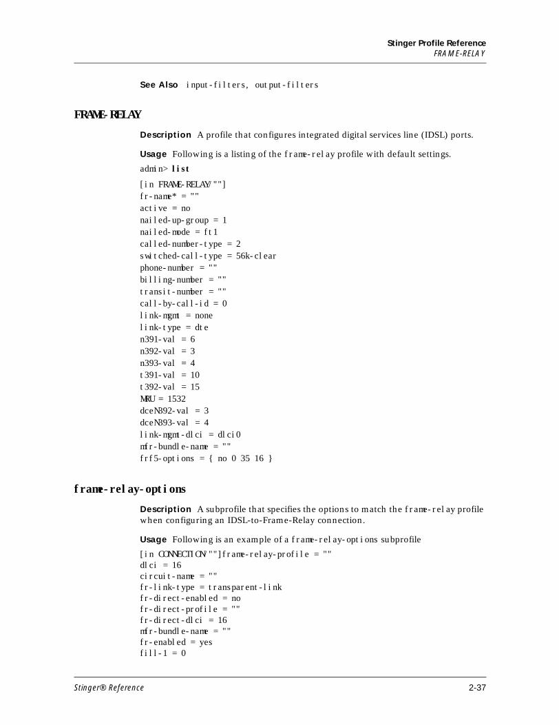
Stinger Profile ReferenceFRAME-RELAY
See Also input-filters, output-filters
FRAME-RELAY
Description A profile that configures integrated digital services line (IDSL) ports.
Usage Following is a listing of the frame-relay profile with default settings.
admin> list
[in FRAME-RELAY/""]fr-name* = ""active = nonailed-up-group = 1nailed-mode = ft1called-number-type = 2switched-call-type = 56k-clearphone-number = ""billing-number = ""transit-number = ""call-by-call-id = 0link-mgmt = nonelink-type = dten391-val = 6n392-val = 3n393-val = 4t391-val = 10t392-val = 15MRU = 1532dceN392-val = 3dceN393-val = 4link-mgmt-dlci = dlci0mfr-bundle-name = ""frf5-options = { no 0 35 16 }
frame-relay-options
Description A subprofile that specifies the options to match the frame-relay profile when configuring an IDSL-to-Frame-Relay connection.
Usage Following is an example of a frame-relay-options subprofile
[in CONNECTION/""]frame-relay-profile = ""dlci = 16circuit-name = ""fr-link-type = transparent-linkfr-direct-enabled = nofr-direct-profile = ""fr-direct-dlci = 16mfr-bundle-name = ""fr-enabled = yesfill-1 = 0
Stinger® Reference 2-37
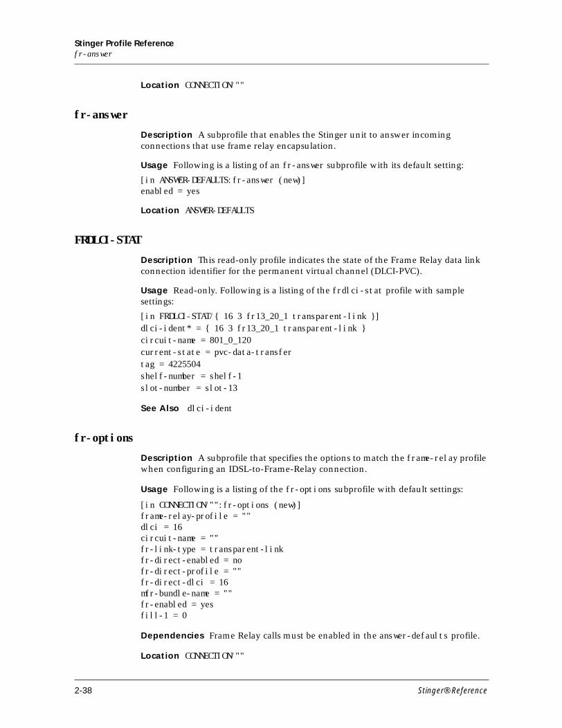
Stinger Profile Referencefr-answer
Location CONNECTION/""
fr-answer
Description A subprofile that enables the Stinger unit to answer incoming connections that use frame relay encapsulation.
Usage Following is a listing of an fr-answer subprofile with its default setting:
[in ANSWER-DEFAULTS:fr-answer (new)]enabled = yes
Location ANSWER-DEFAULTS
FRDLCI-STAT
Description This read-only profile indicates the state of the Frame Relay data link connection identifier for the permanent virtual channel (DLCI-PVC).
Usage Read-only. Following is a listing of the frdlci-stat profile with sample settings:
[in FRDLCI-STAT/{ 16 3 fr13_20_1 transparent-link }]dlci-ident* = { 16 3 fr13_20_1 transparent-link }circuit-name = 801_0_120current-state = pvc-data-transfertag = 4225504shelf-number = shelf-1slot-number = slot-13
See Also dlci-ident
fr-options
Description A subprofile that specifies the options to match the frame-relay profile when configuring an IDSL-to-Frame-Relay connection.
Usage Following is a listing of the fr-options subprofile with default settings:
[in CONNECTION/"":fr-options (new)] frame-relay-profile = "" dlci = 16 circuit-name = "" fr-link-type = transparent-link fr-direct-enabled = no fr-direct-profile = "" fr-direct-dlci = 16 mfr-bundle-name = "" fr-enabled = yes fill-1 = 0
Dependencies Frame Relay calls must be enabled in the answer-defaults profile.
Location CONNECTION/""
2-38 Stinger® Reference
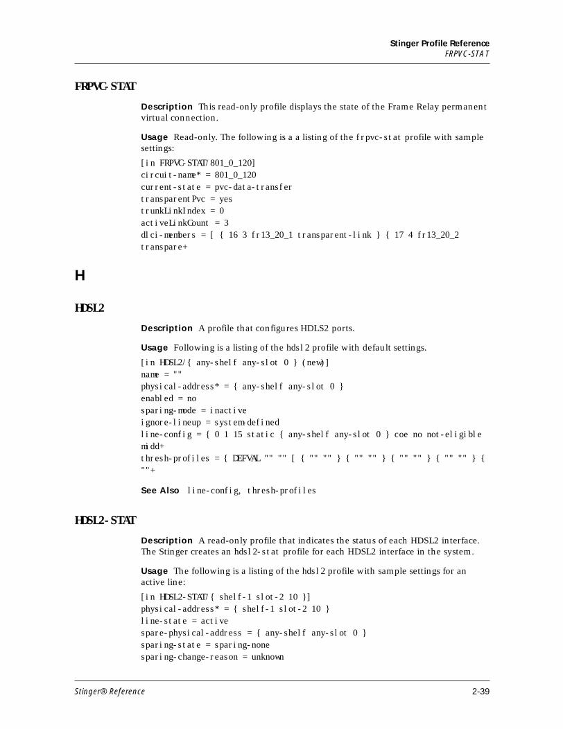
Stinger Profile ReferenceFRPVC-STAT
FRPVC-STAT
Description This read-only profile displays the state of the Frame Relay permanent virtual connection.
Usage Read-only. The following is a a listing of the frpvc-stat profile with sample settings:
[in FRPVC-STAT/801_0_120]circuit-name* = 801_0_120current-state = pvc-data-transfertransparentPvc = yestrunkLinkIndex = 0activeLinkCount = 3dlci-members = [ { 16 3 fr13_20_1 transparent-link } { 17 4 fr13_20_2 transpare+
H
HDSL2
Description A profile that configures HDLS2 ports.
Usage Following is a listing of the hdsl2 profile with default settings.
[in HDSL2/{ any-shelf any-slot 0 } (new)]name = ""physical-address* = { any-shelf any-slot 0 }enabled = nosparing-mode = inactiveignore-lineup = system-definedline-config = { 0 1 15 static { any-shelf any-slot 0 } coe no not-eligible midd+thresh-profiles = { DEFVAL "" "" [ { "" "" } { "" "" } { "" "" } { "" "" } { ""+
See Also line-config, thresh-profiles
HDSL2-STAT
Description A read-only profile that indicates the status of each HDSL2 interface. The Stinger creates an hdsl2-stat profile for each HDSL2 interface in the system.
Usage The following is a listing of the hdsl2 profile with sample settings for an active line:
[in HDSL2-STAT/{ shelf-1 slot-2 10 }]physical-address* = { shelf-1 slot-2 10 }line-state = activespare-physical-address = { any-shelf any-slot 0 }sparing-state = sparing-nonesparing-change-reason = unknown
Stinger® Reference 2-39
Stinger Profile ReferenceHIGH-SPEED-SLOT-STATIC-CONFIG
sparing-change-time = 0sparing-change-counter = 0vpi-vci-range = vpi-0-15-vci-32-127vp-switching-vpi = 15physical-status = { 0 cpe port-up 1544000 A100 1 }physical-statistic = { { 0 0 3 } yes 36 3 passed 10 0 in-sync 0 0 0 0 0 0 0 no+
See Also physical-statistic
HIGH-SPEED-SLOT-STATIC-CONFIG
Description A profile that configures auxiliary ATM parameters for each trunk or TRAM module.
Usage Following is a listing of the high-speed-slot-static-config profile with default settings:
[in HIGH-SPEED-SLOT-STATIC-CONFIG/{ shelf-1 trunk-module-1 1 }]name = ""physical-address* = { shelf-1 trunk-module-1 1 }atm-parameters = { low-priority }trunk-cac-config = { yes "" 155520 10 }
Dependencies The trunk-cac-config profile was previously located in the atm-config profile. Its use in that location has been deprecated.
If a user has already set this profile under a previous release in the atm-config profile the parameters are copied into the corresponding high-speed-slot-static-config profile. The parameters are now invisible in the atm-config profile unless allow-debug is set to yes.
I
id*
Description A subprofile of the atm-vcl-config profile that identifies the virtual channel link (VCL)
Usage Following is a listing of the id subprofile with default settings:
[in ATM-VCL-CONFIG/{ { { any-shelf any-slot 0 } 0 } 0 0 }:id (new)] address = { { any-shelf any-slot 0 } 0 } vpi = 0 vci = 0
Location ATM-VCL-CONFIG
IDSL
Description A profile that configures IDSL ports.
2-40 Stinger® Reference
Stinger Profile ReferenceIDSL-STAT
Usage Following is an example of the idsl profile with default settings:
[in IDSL/{ shelf-1 slot-13 5 }]name = 1:13:5line-interface = { no [ {switched-channel 605 } { switched-channel 605 } ] +physical-address* = { shelf-1 slot-13 5 }sparing-mode = inactive
See Also channel-config, line-interface
IDSL-STAT
Description A read-only profile indicates the state of the IDSL channels.
Usage Read-only. The following is a sample listing of an idsl-stat profile.
[in IDSL-STAT/{ shelf-1 slot-13 1 }]physical-address* = { shelf-1 slot-13 1 }line-state = disabledchannel-state = [ disabled disabled ]error-count = [ 0 0 ]
See Also channel-state
IF-SPARING-CONFIG
Description This profile configures spare line interface module (LIM)s, using automatic sparing.
Usage Following is a listing of the if-sparing-config profile with default settings:
[in IF-SPARING-CONFIG (new)] if-spared-slot = [ any-slot any-slot any-slot any-slot any-slot any-sl+if-spare-slot = [ any-slot any-slot any-slot any-slot any-slot any-slo+if-auto-spare-info = [ 0 0 0 0 0 0 0 0 0 0 0 0 0 0 0 0 0 0 0 0 0 00 0 +lim-auto-spare-info = [ any-slot any-slot any-slot any-slot ot any-+
if-sparing-config
Description A read-only subprofile of lim-sparing-config that contains the slot number of the redundant LIM for each LIM port.
Usage This is a read-only profile contains up to 72 port entries.
[in LIM-SPARING-CONFIG/{ any-shelf any-slot 0 }:if-sparing-config (new)]if-sparing-config[n] = any-slot
Location LIM-SPARING-CONFIG/""
IMAGROUP
Description A profile that configures an inverse multiplexing ATM IMA port. When you enter the command new imagroup a new profile is created to establish all group-related IMA parameters.
Stinger® Reference 2-41
Stinger Profile ReferenceIMA-GROUP-STAT
Usage Following is a sample listing of an imagroup profile:
[in IMAGROUP/"" (new)] name* = "" active = no nailed-group = 0 group-symmetry-mode = symmetric-operation version = v1-1 do-version-fallback = no ignore-lineup = system-defined lasr = yes ne-tx-clk-mode = ctc tx-min-num-links = 1 rx-min-num-links = 1 ima-id = 0 frame-length = 128 diff-delay-max = 25 check-far-end-ima-id = no expected-far-end-ima-id = 0 far-end-check-frame-length = no expected-far-end-frame-length = 128 atm-if-delay = 0 tpp-test-link = 0 tpp-test-pattern = -1 tpp-state = disabled
IMA-GROUP-STAT
Description A profile that indicates the performance of an IMA group. The profile is automatically created by the system once the imagroup profile is properly configured and associated with a ds1-atm profile.
Usage The following is a sample listing of the IMA-GROUP-STAT profile:
[in IMA-GROUP-STAT/ima3_1]name* = ima3_1physical-address = { shelf-1 slot-3 25 }near-end-ima-group-state = operationalfailure-status = no-failurefar-end-txclock-mode = ctctx-timing-ref-link = 0rx-timing-ref-link = 0rx-ima-id = 0rx-frame-length = 128least-delay-link = 0diff-delay-max-obs = 0running-secs = 1435tx-avail-cellrate = 2147488176rx-avail-cellrate = 4493tx-num-config-links = 2rx-num-config-links = 2
2-42 Stinger® Reference
Stinger Profile Referenceima-group-statistic
tx-num-active-links = 1rx-num-active-links = 1tx-oam-label-value = 3rx-oam-label-value = 3last-change-time = 52tpp-test-link = 1 tpp-test-pattern = 100 tpp-test-status = link-fail valid-intervals = 0invalid-intervals = 96vpi-vci-range = vpi-0-15-vci-32-127vp-switching-vpi = 0ima-group-statistic = { 40 0 6571424 }nailed-group = 310
See Also IMAGROUP, imagroup-statistic, DS1-ATM
ima-group-statistic
Description A read-only subprofile of the IMA-GROUP-STAT:ima-rt subprofile that indicates the status of the IMA group.
Usage Read-only. Following is a sample listing of the ima-group-statistic subprofile
[in IMA-GROUP-STAT:ima-group-statistic]unavailable-secs = 56near-end-num-failures = 3far-end-num-failures = 6
Location IMA-GROUP-STAT
See Also ima-rt
IMAHW-CONFIG
Description A profile that configures hardware-specific parameters that are common to the inverse multiplexing ATM (IMA) chip. For example, because the 24-port IMA line interface modules (LIMs) contain three chips, three profiles are created. However, the 8-port IMA LIMs contain a single chip so only one profile is created for it.
Usage Following is an listing of the imahw-config profile with sample settings:
[in IMAHW-CONFIG/{ any-shelf any-slot 0 } (new)]name = ""physical-address* = { any-shelf any-slot 0 }alpha-ima-value = 2beta-ima-value = 2gamma-ima-value = 1alpha-cell-delin-value = 7delta-cell-delin-value = 6
Stinger® Reference 2-43
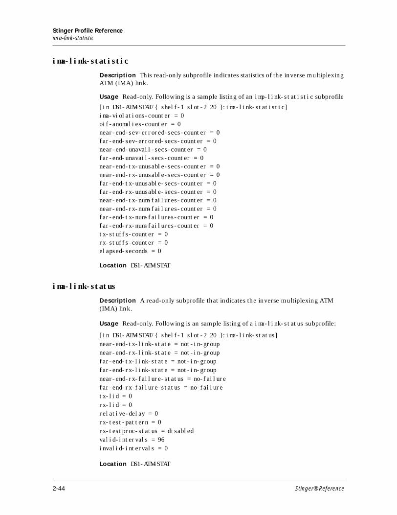
Stinger Profile Referenceima-link-statistic
ima-link-statistic
Description This read-only subprofile indicates statistics of the inverse multiplexing ATM (IMA) link.
Usage Read-only. Following is a sample listing of an imp-link-statistic subprofile
[in DS1-ATM-STAT/{ shelf-1 slot-2 20 }:ima-link-statistic]ima-violations-counter = 0oif-anomalies-counter = 0near-end-sev-errored-secs-counter = 0far-end-sev-errored-secs-counter = 0near-end-unavail-secs-counter = 0far-end-unavail-secs-counter = 0near-end-tx-unusable-secs-counter = 0near-end-rx-unusable-secs-counter = 0far-end-tx-unusable-secs-counter = 0far-end-rx-unusable-secs-counter = 0near-end-tx-num-failures-counter = 0near-end-rx-num-failures-counter = 0far-end-tx-num-failures-counter = 0far-end-rx-num-failures-counter = 0tx-stuffs-counter = 0rx-stuffs-counter = 0elapsed-seconds = 0
Location DS1-ATM-STAT
ima-link-status
Description A read-only subprofile that indicates the inverse multiplexing ATM (IMA) link.
Usage Read-only. Following is an sample listing of a ima-link-status subprofile:
[in DS1-ATM-STAT/{ shelf-1 slot-2 20 }:ima-link-status]near-end-tx-link-state = not-in-groupnear-end-rx-link-state = not-in-groupfar-end-tx-link-state = not-in-groupfar-end-rx-link-state = not-in-groupnear-end-rx-failure-status = no-failurefar-end-rx-failure-status = no-failuretx-lid = 0rx-lid = 0relative-delay = 0rx-test-pattern = 0rx-testproc-status = disabledvalid-intervals = 96invalid-intervals = 0
Location DS1-ATM-STAT
2-44 Stinger® Reference
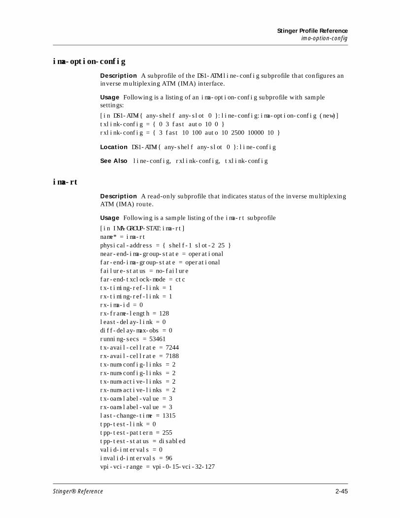
Stinger Profile Referenceima-option-config
ima-option-config
Description A subprofile of the DS1-ATM:line-config subprofile that configures an inverse multiplexing ATM (IMA) interface.
Usage Following is a listing of an ima-option-config subprofile with sample settings:
[in DS1-ATM/{ any-shelf any-slot 0 }:line-config:ima-option-config (new)]txlink-config = { 0 3 fast auto 10 0 }rxlink-config = { 3 fast 10 100 auto 10 2500 10000 10 }
Location DS1-ATM/{ any-shelf any-slot 0 }:line-config
See Also line-config, rxlink-config, txlink-config
ima-rt
Description A read-only subprofile that indicates status of the inverse multiplexing ATM (IMA) route.
Usage Following is a sample listing of the ima-rt subprofile
[in IMA-GROUP-STAT:ima-rt]name* = ima-rtphysical-address = { shelf-1 slot-2 25 }near-end-ima-group-state = operationalfar-end-ima-group-state = operationalfailure-status = no-failurefar-end-txclock-mode = ctctx-timing-ref-link = 1rx-timing-ref-link = 1rx-ima-id = 0rx-frame-length = 128least-delay-link = 0diff-delay-max-obs = 0running-secs = 53461tx-avail-cellrate = 7244rx-avail-cellrate = 7188tx-num-config-links = 2rx-num-config-links = 2tx-num-active-links = 2rx-num-active-links = 2tx-oam-label-value = 3rx-oam-label-value = 3last-change-time = 1315tpp-test-link = 0tpp-test-pattern = 255tpp-test-status = disabledvalid-intervals = 0invalid-intervals = 96vpi-vci-range = vpi-0-15-vci-32-127
Stinger® Reference 2-45
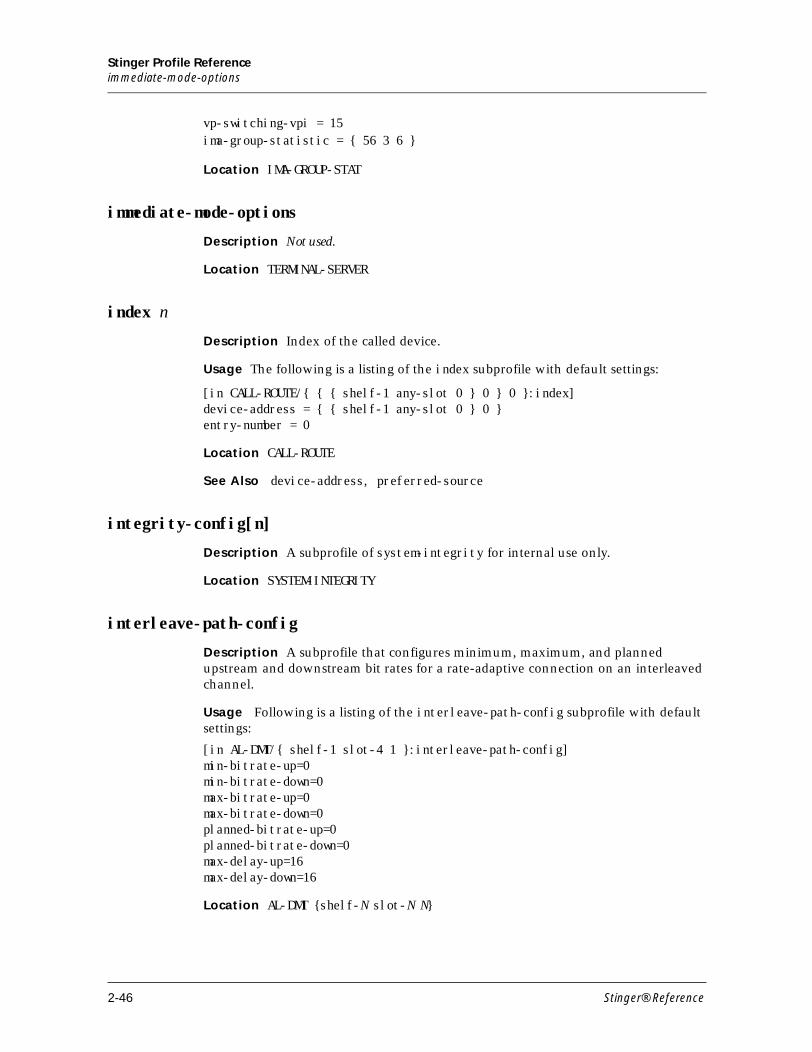
Stinger Profile Referenceimmediate-mode-options
vp-switching-vpi = 15ima-group-statistic = { 56 3 6 }
Location IMA-GROUP-STAT
immediate-mode-options
Description Not used.
Location TERMINAL-SERVER
index n
Description Index of the called device.
Usage The following is a listing of the index subprofile with default settings:
[in CALL-ROUTE/{ { { shelf-1 any-slot 0 } 0 } 0 }:index]device-address = { { shelf-1 any-slot 0 } 0 }entry-number = 0
Location CALL-ROUTE
See Also device-address, preferred-source
integrity-config[n]
Description A subprofile of system-integrity for internal use only.
Location SYSTEM-INTEGRITY
interleave-path-config
Description A subprofile that configures minimum, maximum, and planned upstream and downstream bit rates for a rate-adaptive connection on an interleaved channel.
Usage Following is a listing of the interleave-path-config subprofile with default settings:
[in AL-DMT/{ shelf-1 slot-4 1 }:interleave-path-config]min-bitrate-up=0min-bitrate-down=0max-bitrate-up=0max-bitrate-down=0planned-bitrate-up=0planned-bitrate-down=0max-delay-up=16max-delay-down=16
Location AL-DMT {shelf-N slot-N N}
2-46 Stinger® Reference
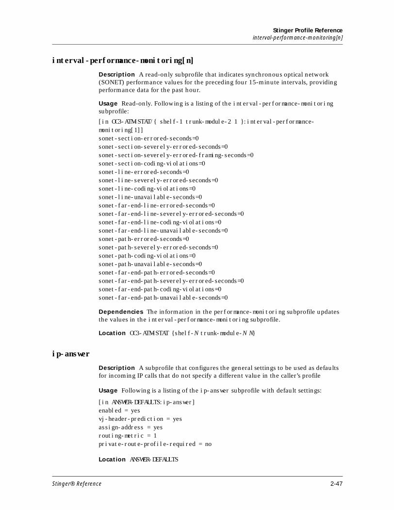
Stinger Profile Referenceinterval-performance-monitoring[n]
interval-performance-monitoring[n]
Description A read-only subprofile that indicates synchronous optical network (SONET) performance values for the preceding four 15-minute intervals, providing performance data for the past hour.
Usage Read-only. Following is a listing of the interval-performance-monitoring subprofile:
[in OC3-ATM-STAT/{ shelf-1 trunk-module-2 1 }:interval-performance-monitoring[1]]sonet-section-errored-seconds=0sonet-section-severely-errored-seconds=0sonet-section-severely-errored-framing-seconds=0sonet-section-coding-violations=0sonet-line-errored-seconds=0sonet-line-severely-errored-seconds=0sonet-line-coding-violations=0sonet-line-unavailable-seconds=0sonet-far-end-line-errored-seconds=0sonet-far-end-line-severely-errored-seconds=0sonet-far-end-line-coding-violations=0sonet-far-end-line-unavailable-seconds=0sonet-path-errored-seconds=0sonet-path-severely-errored-seconds=0sonet-path-coding-violations=0sonet-path-unavailable-seconds=0sonet-far-end-path-errored-seconds=0sonet-far-end-path-severely-errored-seconds=0sonet-far-end-path-coding-violations=0sonet-far-end-path-unavailable-seconds=0
Dependencies The information in the performance-monitoring subprofile updates the values in the interval-performance-monitoring subprofile.
Location OC3-ATM-STAT {shelf-N trunk-module-N N}
ip-answer
Description A subprofile that configures the general settings to be used as defaults for incoming IP calls that do not specify a different value in the caller’s profile
Usage Following is a listing of the ip-answer subprofile with default settings:
[in ANSWER-DEFAULTS:ip-answer]enabled = yesvj-header-prediction = yesassign-address = yesrouting-metric = 1private-route-profile-required = no
Location ANSWER-DEFAULTS
Stinger® Reference 2-47
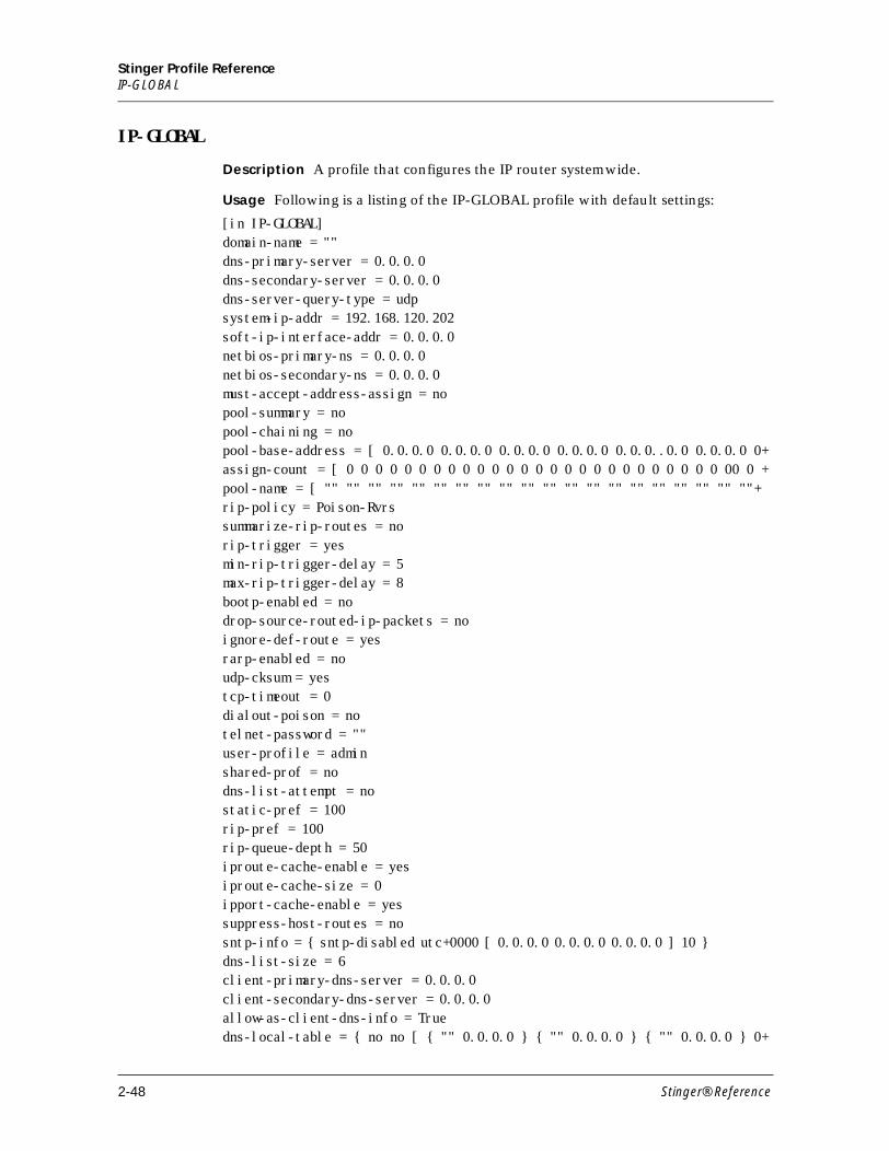
Stinger Profile ReferenceIP-GLOBAL
IP-GLOBAL
Description A profile that configures the IP router systemwide.
Usage Following is a listing of the IP-GLOBAL profile with default settings:
[in IP-GLOBAL] domain-name = "" dns-primary-server = 0.0.0.0 dns-secondary-server = 0.0.0.0 dns-server-query-type = udp system-ip-addr = 192.168.120.202 soft-ip-interface-addr = 0.0.0.0 netbios-primary-ns = 0.0.0.0 netbios-secondary-ns = 0.0.0.0 must-accept-address-assign = no pool-summary = no pool-chaining = no pool-base-address = [ 0.0.0.0 0.0.0.0 0.0.0.0 0.0.0.0 0.0.0..0.0 0.0.0.0 0+assign-count = [ 0 0 0 0 0 0 0 0 0 0 0 0 0 0 0 0 0 0 0 0 0 0 0 0 0 0 00 0 +pool-name = [ "" "" "" "" "" "" "" "" "" "" "" "" "" "" "" "" "" "" "" ""+rip-policy = Poison-Rvrs summarize-rip-routes = no rip-trigger = yes min-rip-trigger-delay = 5 max-rip-trigger-delay = 8 bootp-enabled = no drop-source-routed-ip-packets = no ignore-def-route = yes rarp-enabled = no udp-cksum = yes tcp-timeout = 0 dialout-poison = no telnet-password = "" user-profile = admin shared-prof = no dns-list-attempt = no static-pref = 100 rip-pref = 100 rip-queue-depth = 50 iproute-cache-enable = yes iproute-cache-size = 0 ipport-cache-enable = yes suppress-host-routes = no sntp-info = { sntp-disabled utc+0000 [ 0.0.0.0 0.0.0.0 0.0.0.0 ] 10 } dns-list-size = 6 client-primary-dns-server = 0.0.0.0 client-secondary-dns-server = 0.0.0.0 allow-as-client-dns-info = True dns-local-table = { no no [ { "" 0.0.0.0 } { "" 0.0.0.0 } { "" 0.0.0.0 } 0+
2-48 Stinger® Reference
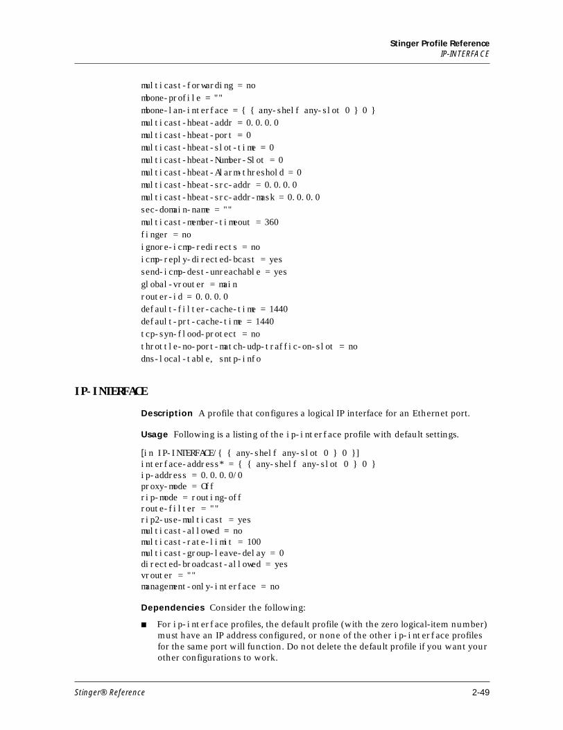
Stinger Profile ReferenceIP-INTERFACE
multicast-forwarding = no mbone-profile = "" mbone-lan-interface = { { any-shelf any-slot 0 } 0 } multicast-hbeat-addr = 0.0.0.0 multicast-hbeat-port = 0 multicast-hbeat-slot-time = 0 multicast-hbeat-Number-Slot = 0 multicast-hbeat-Alarm-threshold = 0 multicast-hbeat-src-addr = 0.0.0.0 multicast-hbeat-src-addr-mask = 0.0.0.0 sec-domain-name = "" multicast-member-timeout = 360 finger = no ignore-icmp-redirects = no icmp-reply-directed-bcast = yes send-icmp-dest-unreachable = yes global-vrouter = main router-id = 0.0.0.0 default-filter-cache-time = 1440 default-prt-cache-time = 1440 tcp-syn-flood-protect = no throttle-no-port-match-udp-traffic-on-slot = no dns-local-table, sntp-info
IP-INTERFACE
Description A profile that configures a logical IP interface for an Ethernet port.
Usage Following is a listing of the ip-interface profile with default settings.
[in IP-INTERFACE/{ { any-shelf any-slot 0 } 0 }]interface-address* = { { any-shelf any-slot 0 } 0 }ip-address = 0.0.0.0/0proxy-mode = Offrip-mode = routing-offroute-filter = ""rip2-use-multicast = yesmulticast-allowed = nomulticast-rate-limit = 100multicast-group-leave-delay = 0directed-broadcast-allowed = yesvrouter = ""management-only-interface = no
Dependencies Consider the following:
■ For ip-interface profiles, the default profile (with the zero logical-item number) must have an IP address configured, or none of the other ip-interface profiles for the same port will function. Do not delete the default profile if you want your other configurations to work.
Stinger® Reference 2-49
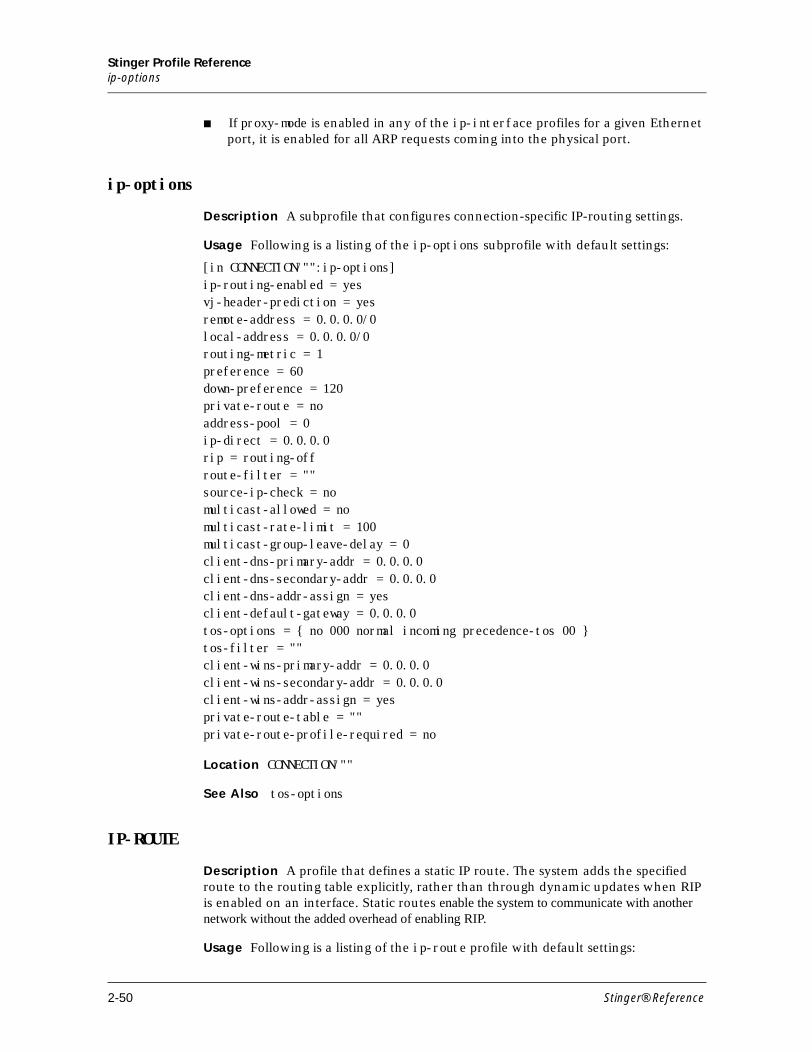
Stinger Profile Referenceip-options
■ If proxy-mode is enabled in any of the ip-interface profiles for a given Ethernet port, it is enabled for all ARP requests coming into the physical port.
ip-options
Description A subprofile that configures connection-specific IP-routing settings.
Usage Following is a listing of the ip-options subprofile with default settings:
[in CONNECTION/"":ip-options]ip-routing-enabled = yesvj-header-prediction = yesremote-address = 0.0.0.0/0local-address = 0.0.0.0/0routing-metric = 1preference = 60down-preference = 120private-route = noaddress-pool = 0ip-direct = 0.0.0.0rip = routing-offroute-filter = ""source-ip-check = nomulticast-allowed = nomulticast-rate-limit = 100multicast-group-leave-delay = 0client-dns-primary-addr = 0.0.0.0client-dns-secondary-addr = 0.0.0.0client-dns-addr-assign = yesclient-default-gateway = 0.0.0.0tos-options = { no 000 normal incoming precedence-tos 00 }tos-filter = ""client-wins-primary-addr = 0.0.0.0client-wins-secondary-addr = 0.0.0.0client-wins-addr-assign = yesprivate-route-table = ""private-route-profile-required = no
Location CONNECTION/""
See Also tos-options
IP-ROUTE
Description A profile that defines a static IP route. The system adds the specified route to the routing table explicitly, rather than through dynamic updates when RIP is enabled on an interface. Static routes enable the system to communicate with another network without the added overhead of enabling RIP.
Usage Following is a listing of the ip-route profile with default settings:
2-50 Stinger® Reference
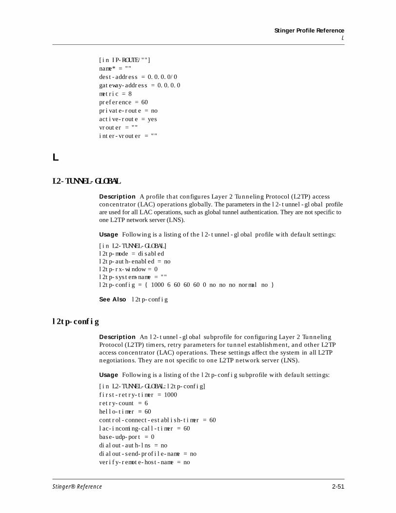
Stinger Profile ReferenceL
[in IP-ROUTE/""]name* = ""dest-address = 0.0.0.0/0gateway-address = 0.0.0.0metric = 8preference = 60private-route = noactive-route = yesvrouter = ""inter-vrouter = ""
L
L2-TUNNEL-GLOBAL
Description A profile that configures Layer 2 Tunneling Protocol (L2TP) access concentrator (LAC) operations globally. The parameters in the l2-tunnel-global profile are used for all LAC operations, such as global tunnel authentication. They are not specific to one L2TP network server (LNS).
Usage Following is a listing of the l2-tunnel-global profile with default settings:
[in L2-TUNNEL-GLOBAL]l2tp-mode = disabledl2tp-auth-enabled = nol2tp-rx-window = 0l2tp-system-name = ""l2tp-config = { 1000 6 60 60 60 0 no no no normal no }
See Also l2tp-config
l2tp-config
Description An l2-tunnel-global subprofile for configuring Layer 2 Tunneling Protocol (L2TP) timers, retry parameters for tunnel establishment, and other L2TP access concentrator (LAC) operations. These settings affect the system in all L2TP negotiations. They are not specific to one L2TP network server (LNS).
Usage Following is a listing of the l2tp-config subprofile with default settings:
[in L2-TUNNEL-GLOBAL:l2tp-config]first-retry-timer = 1000retry-count = 6hello-timer = 60control-connect-establish-timer = 60lac-incoming-call-timer = 60base-udp-port = 0dialout-auth-lns = nodialout-send-profile-name = noverify-remote-host-name = no
Stinger® Reference 2-51
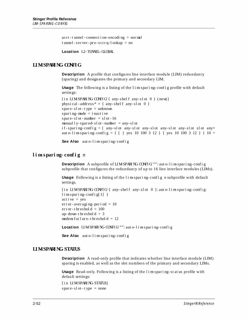
Stinger Profile ReferenceLIM-SPARING-CONFIG
acct-tunnel-connection-encoding = normaltunnel-server-pre-sccrq-lookup = no
Location L2-TUNNEL-GLOBAL
LIM-SPARING-CONFIG
Description A profile that configures line interface module (LIM) redundancy (sparing) and designates the primary and secondary LIM.
Usage The following is a listing of the lim-sparing-config profile with default settings:
[in LIM-SPARING-CONFIG/{ any-shelf any-slot 0 } (new)] physical-address* = { any-shelf any-slot 0 } spare-slot-type = unknown sparing-mode = inactive spare-slot-number = slot-16 manually-spared-slot-number = any-slot if-sparing-config = [ any-slot any-slot any-slot any-slot any-slot slot any+auto-lim-sparing-config = { [ { yes 10 100 3 12 } { yes 10 100 3 12 } { 10 +
See Also auto-lim-sparing-config
lim-sparing-config n
Description A subprofile of LIM-SPARING-CONFIG/””:auto-lim-sparing-config subprofile that configures the redundancy of up to 16 line interface modules (LIMs).
Usage Following is a listing of the lim-sparing-config n subprofile with default settings.
[in LIM-SPARING-CONFIG/{ any-shelf any-slot 0 }:auto-lim-sparing-config:lim-sparing-config[1] }active = yeserror-averaging-period = 10error-threshold = 100up-down-threshold = 3modem-failure-threshold = 12
Location LIM-SPARING-CONFIG/””:auto-lim-sparing-config
See Also auto-lim-sparing-config
LIM-SPARING-STATUS
Description A read-only profile that indicates whether line interface module (LIM) sparing is enabled, as well as the slot numbers of the primary and secondary LIMs.
Usage Read-only. Following is a listing of the lim-sparing-status profile with default settings:
[in LIM-SPARING-STATUS]spare-slot-type = none
2-52 Stinger® Reference
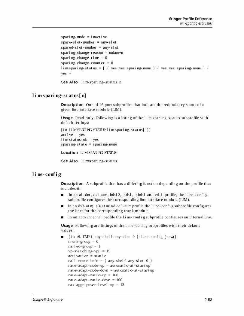
Stinger Profile Referencelim-sparing-status[n]
sparing-mode = inactivespare-slot-number = any-slotspared-slot-number = any-slotsparing-change-reason = unknownsparing-change-time = 0sparing-change-counter = 0lim-sparing-status = [ { yes yes sparing-none } { yes yes sparing-none } { yes +
See Also lim-sparing-status n
lim-sparing-status[n]
Description One of 16 port subprofiles that indicate the redundancy status of a given line interface module (LIM).
Usage Read-only. Following is a listing of the lim-sparing-status subprofile with default settings:
[in LIM-SPARING-STATUS:lim-sparing-status[1]]active = yeslim-status-ok = yessparing-state = sparing-none
Location LIM-SPARING-STATUS
See Also lim=sparing-status
line-config
Description A subprofile that has a differing function depending on the profile that includes it.
■ In an al-dmt, ds1-atm, hdsl2, sdsl, shdsl and vdsl profile, the line-config subprofile configures the corresponding line interface module (LIM).
■ In an ds3-atm, e3-atm and oc3-atm profile the line-config subprofile configures the lines for the corresponding trunk module.
■ In an atm-internal profile the line-config subprofile configures an internal line.
Usage Following are listings of the line-config subprofiles with their default values:
■ [in AL-DMT/{ any-shelf any-slot 0 }:line-config (new)]trunk-group = 0 nailed-group = 1 vp-switching-vpi = 15 activation = static call-route-info = { any-shelf any-slot 0 } rate-adapt-mode-up = automatic-at-startup rate-adapt-mode-down = automatic-at-startup rate-adapt-ratio-up = 100 rate-adapt-ratio-down = 100 max-aggr-power-level-up = 13
Stinger® Reference 2-53
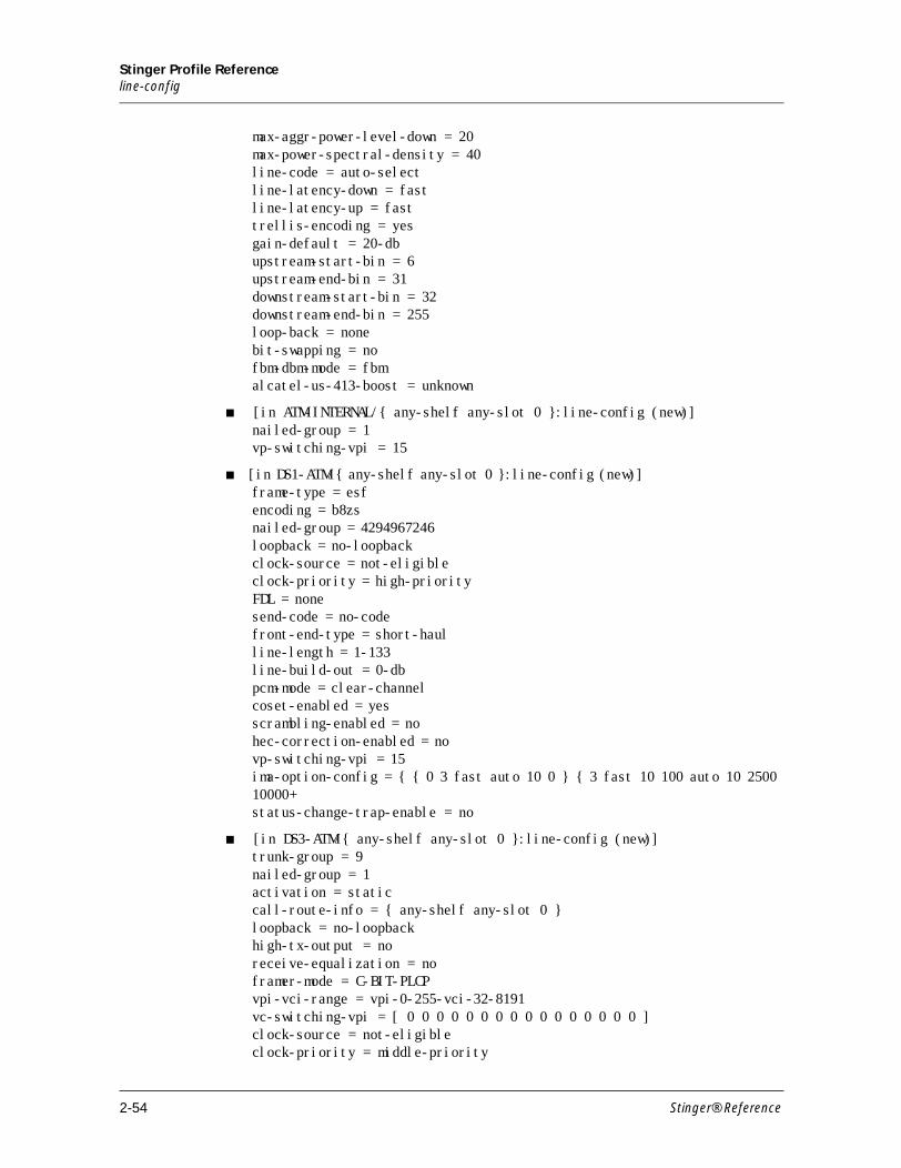
Stinger Profile Referenceline-config
max-aggr-power-level-down = 20 max-power-spectral-density = 40 line-code = auto-select line-latency-down = fast line-latency-up = fast trellis-encoding = yes gain-default = 20-db upstream-start-bin = 6 upstream-end-bin = 31 downstream-start-bin = 32 downstream-end-bin = 255 loop-back = none bit-swapping = no fbm-dbm-mode = fbm alcatel-us-413-boost = unknown
■ [in ATM-INTERNAL/{ any-shelf any-slot 0 }:line-config (new)] nailed-group = 1 vp-switching-vpi = 15
■ [in DS1-ATM/{ any-shelf any-slot 0 }:line-config (new)] frame-type = esf encoding = b8zs nailed-group = 4294967246 loopback = no-loopback clock-source = not-eligible clock-priority = high-priority FDL = none send-code = no-code front-end-type = short-haul line-length = 1-133 line-build-out = 0-db pcm-mode = clear-channel coset-enabled = yes scrambling-enabled = no hec-correction-enabled = no vp-switching-vpi = 15 ima-option-config = { { 0 3 fast auto 10 0 } { 3 fast 10 100 auto 10 2500 10000+status-change-trap-enable = no
■ [in DS3-ATM/{ any-shelf any-slot 0 }:line-config (new)]trunk-group = 9 nailed-group = 1 activation = static call-route-info = { any-shelf any-slot 0 } loopback = no-loopback high-tx-output = no receive-equalization = no framer-mode = C-BIT-PLCP vpi-vci-range = vpi-0-255-vci-32-8191 vc-switching-vpi = [ 0 0 0 0 0 0 0 0 0 0 0 0 0 0 0 0 ] clock-source = not-eligible clock-priority = middle-priority
2-54 Stinger® Reference
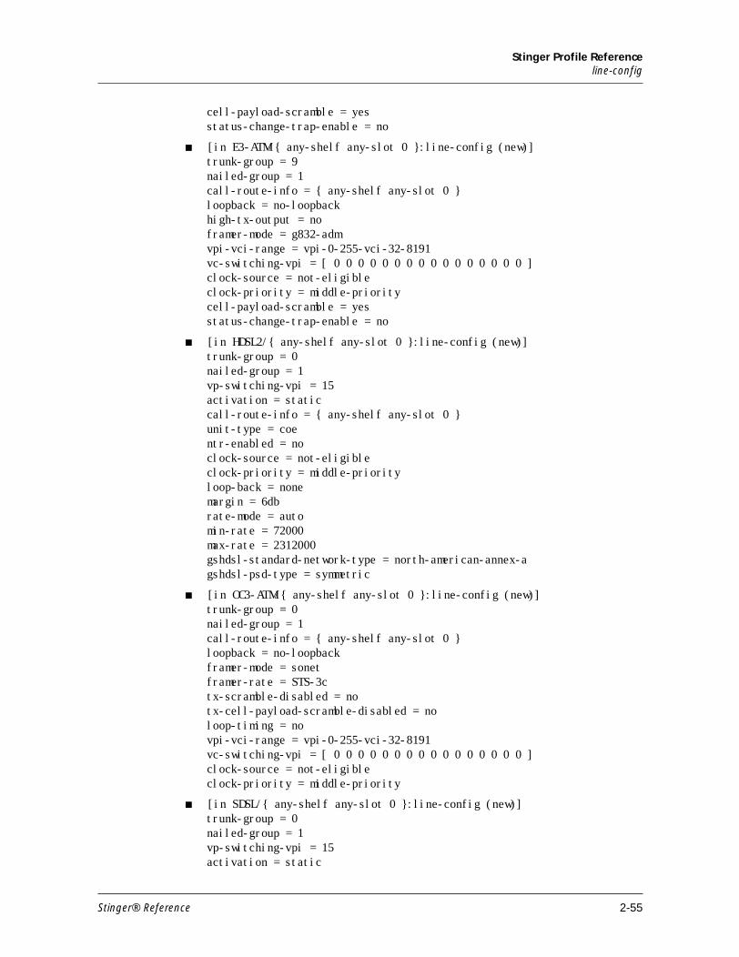
Stinger Profile Referenceline-config
cell-payload-scramble = yes status-change-trap-enable = no
■ [in E3-ATM/{ any-shelf any-slot 0 }:line-config (new)] trunk-group = 9 nailed-group = 1 call-route-info = { any-shelf any-slot 0 } loopback = no-loopback high-tx-output = no framer-mode = g832-adm vpi-vci-range = vpi-0-255-vci-32-8191 vc-switching-vpi = [ 0 0 0 0 0 0 0 0 0 0 0 0 0 0 0 0 ] clock-source = not-eligible clock-priority = middle-priority cell-payload-scramble = yes status-change-trap-enable = no
■ [in HDSL2/{ any-shelf any-slot 0 }:line-config (new)] trunk-group = 0 nailed-group = 1 vp-switching-vpi = 15 activation = static call-route-info = { any-shelf any-slot 0 } unit-type = coe ntr-enabled = no clock-source = not-eligible clock-priority = middle-priority loop-back = none margin = 6db rate-mode = auto min-rate = 72000 max-rate = 2312000 gshdsl-standard-network-type = north-american-annex-a gshdsl-psd-type = symmetric
■ [in OC3-ATM/{ any-shelf any-slot 0 }:line-config (new)] trunk-group = 0 nailed-group = 1 call-route-info = { any-shelf any-slot 0 } loopback = no-loopback framer-mode = sonet framer-rate = STS-3c tx-scramble-disabled = no tx-cell-payload-scramble-disabled = no loop-timing = no vpi-vci-range = vpi-0-255-vci-32-8191 vc-switching-vpi = [ 0 0 0 0 0 0 0 0 0 0 0 0 0 0 0 0 ] clock-source = not-eligible clock-priority = middle-priority
■ [in SDSL/{ any-shelf any-slot 0 }:line-config (new)] trunk-group = 0 nailed-group = 1 vp-switching-vpi = 15 activation = static
Stinger® Reference 2-55
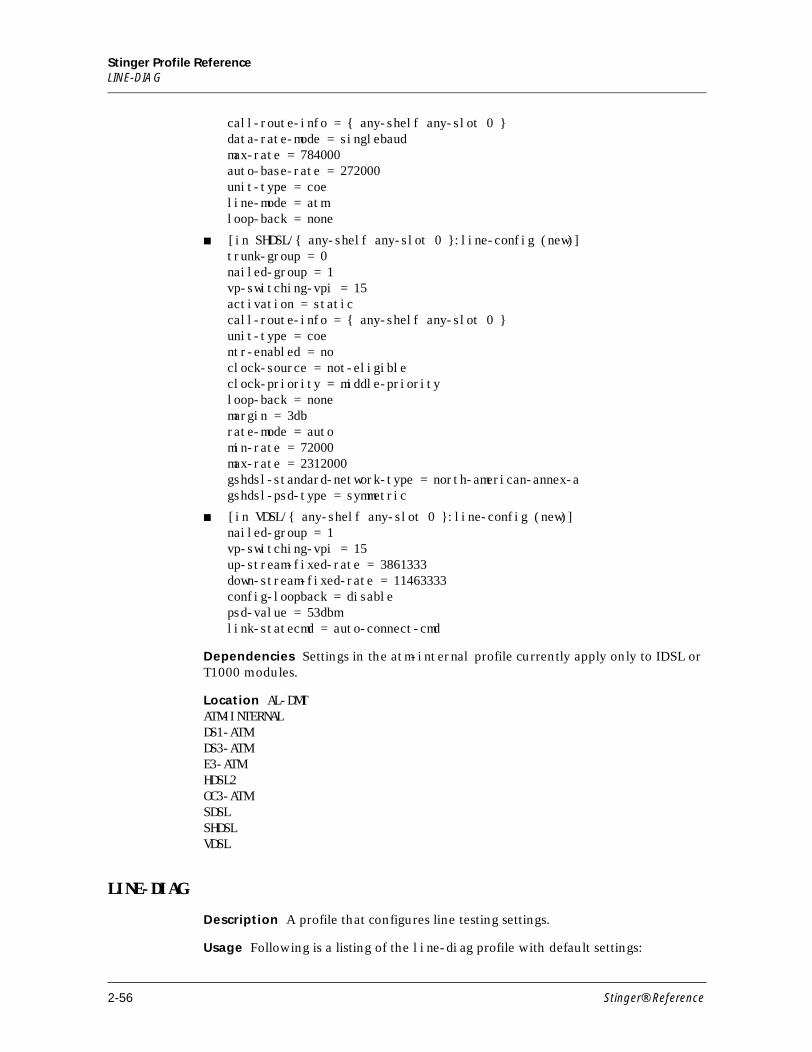
Stinger Profile ReferenceLINE-DIAG
call-route-info = { any-shelf any-slot 0 } data-rate-mode = singlebaud max-rate = 784000 auto-base-rate = 272000 unit-type = coe line-mode = atm loop-back = none
■ [in SHDSL/{ any-shelf any-slot 0 }:line-config (new)] trunk-group = 0 nailed-group = 1 vp-switching-vpi = 15 activation = static call-route-info = { any-shelf any-slot 0 } unit-type = coe ntr-enabled = no clock-source = not-eligible clock-priority = middle-priority loop-back = none margin = 3db rate-mode = auto min-rate = 72000 max-rate = 2312000 gshdsl-standard-network-type = north-american-annex-a gshdsl-psd-type = symmetric
■ [in VDSL/{ any-shelf any-slot 0 }:line-config (new)] nailed-group = 1 vp-switching-vpi = 15 up-stream-fixed-rate = 3861333 down-stream-fixed-rate = 11463333 config-loopback = disable psd-value = 53dbm link-statecmd = auto-connect-cmd
Dependencies Settings in the atm-internal profile currently apply only to IDSL or T1000 modules.
Location AL-DMTATM-INTERNALDS1-ATMDS3-ATME3-ATMHDSL2OC3-ATMSDSLSHDSLVDSL
LINE-DIAG
Description A profile that configures line testing settings.
Usage Following is a listing of the line-diag profile with default settings:
2-56 Stinger® Reference
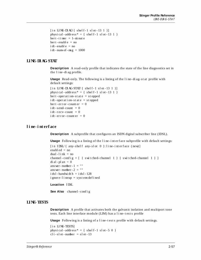
Stinger Profile ReferenceLINE-DIAG-STAT
[in LINE-DIAG/{ shelf-1 slot-13 1 }]physical-address* = { shelf-1 slot-13 1 }bert-timer = 1-minutebert-enable = noidt-enable = noidt-num-of-msg = 1000
LINE-DIAG-STAT
Description A read-only profile that indicates the state of the line diagnostics set in the line-diag profile.
Usage Read-only. The following is a listing of the line-diag-stat profile with default settings:
[in LINE-DIAG-STAT/{ shelf-1 slot-13 1 }]physical-address* = { shelf-1 slot-13 1 }bert-operation-state = stoppedidt-operation-state = stoppedbert-error-counter = 0idt-send-count = 0idt-recv-count = 0idt-error-counter = 0
line-interface
Description A subprofile that configures an ISDN digital subscriber line (IDSL).
Usage Following is a listing of the line-interface subprofile with default settings:
[in IDSL/{ any-shelf any-slot 0 }:line-interface (new)] enabled = no dual-link = no channel-config = [ { switched-channel 1 } { switched-channel 1 } ] dial-plan = 0 answer-number-1 = "" answer-number-2 = "" idsl-bandwidth = idsl-128 ignore-lineup = system-defined
Location IDSL
See Also channel-config
LINE-TESTS
Description A profile that activates both the galvanic isolation and multiport tone tests. Each line interface module (LIM) has a line-tests profile
Usage Following is a listing of a line-tests profile with default settings.
[in LINE-TESTS]physical-address* = { shelf-1 slot-5 0 }clt-slot-number = slot-13
Stinger® Reference 2-57
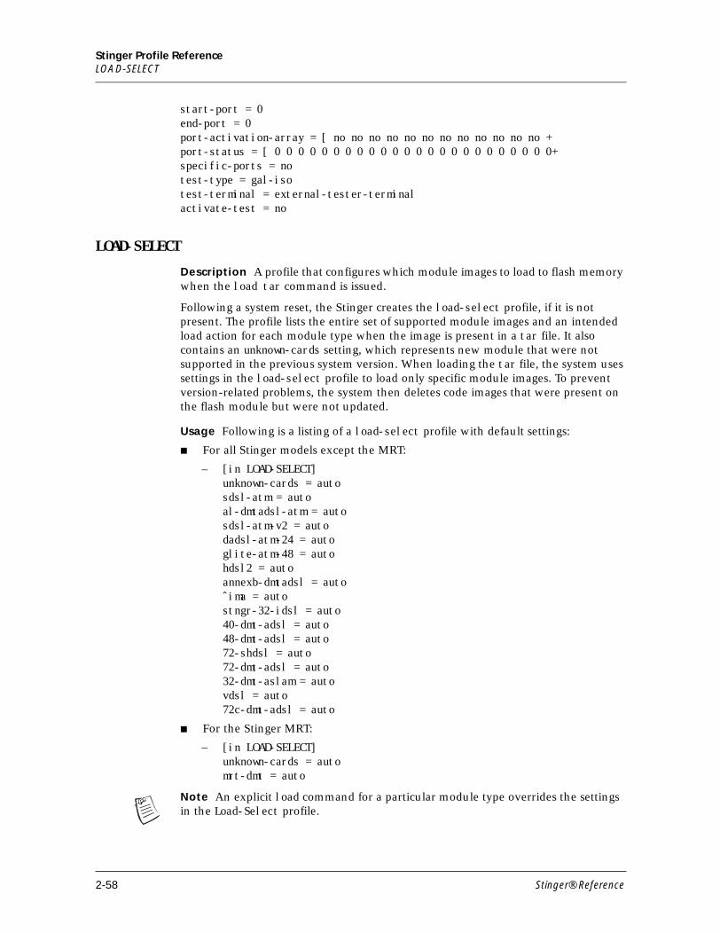
Stinger Profile ReferenceLOAD-SELECT
start-port = 0end-port = 0port-activation-array = [ no no no no no no no no no no no no +port-status = [ 0 0 0 0 0 0 0 0 0 0 0 0 0 0 0 0 0 0 0 0 0 0 0 0+specific-ports = notest-type = gal-isotest-terminal = external-tester-terminalactivate-test = no
LOAD-SELECT
Description A profile that configures which module images to load to flash memory when the load tar command is issued.
Following a system reset, the Stinger creates the load-select profile, if it is not present. The profile lists the entire set of supported module images and an intended load action for each module type when the image is present in a tar file. It also contains an unknown-cards setting, which represents new module that were not supported in the previous system version. When loading the tar file, the system uses settings in the load-select profile to load only specific module images. To prevent version-related problems, the system then deletes code images that were present on the flash module but were not updated.
Usage Following is a listing of a load-select profile with default settings:
■ For all Stinger models except the MRT:
– [in LOAD-SELECT] unknown-cards = auto sdsl-atm = auto al-dmtadsl-atm = auto sdsl-atm-v2 = auto dadsl-atm-24 = auto glite-atm-48 = auto hdsl2 = auto annexb-dmtadsl = auto ˆima = auto stngr-32-idsl = auto 40-dmt-adsl = auto 48-dmt-adsl = auto 72-shdsl = auto 72-dmt-adsl = auto 32-dmt-aslam = auto vdsl = auto 72c-dmt-adsl = auto
■ For the Stinger MRT:
– [in LOAD-SELECT] unknown-cards = auto mrt-dmt = auto
Note An explicit load command for a particular module type overrides the settings in the Load-Select profile.
2-58 Stinger® Reference
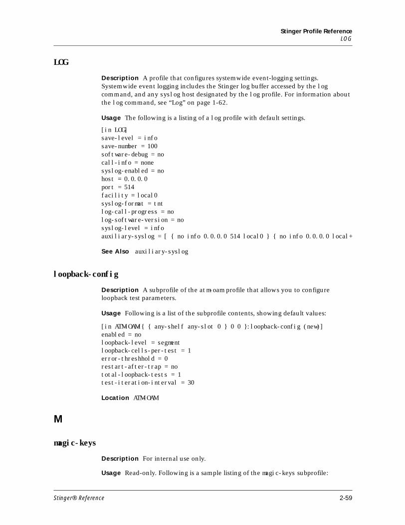
Stinger Profile ReferenceLOG
LOG
Description A profile that configures systemwide event-logging settings. Systemwide event logging includes the Stinger log buffer accessed by the log command, and any syslog host designated by the log profile. For information about the log command, see “Log” on page 1-62.
Usage The following is a listing of a log profile with default settings.
[in LOG] save-level = info save-number = 100 software-debug = no call-info = none syslog-enabled = no host = 0.0.0.0 port = 514 facility = local0 syslog-format = tnt log-call-progress = no log-software-version = no syslog-level = info auxiliary-syslog = [ { no info 0.0.0.0 514 local0 } { no info 0.0.0.0 local+
See Also auxiliary-syslog
loopback-config
Description A subprofile of the atm-oam profile that allows you to configure loopback test parameters.
Usage Following is a list of the subprofile contents, showing default values:
[in ATM-OAM/{ { any-shelf any-slot 0 } 0 0 }:loopback-config (new)] enabled = no loopback-level = segment loopback-cells-per-test = 1 error-threshhold = 0 restart-after-trap = no total-loopback-tests = 1 test-iteration-interval = 30
Location ATM-OAM
M
magic-keys
Description For internal use only.
Usage Read-only. Following is a sample listing of the magic-keys subprofile:
Stinger® Reference 2-59
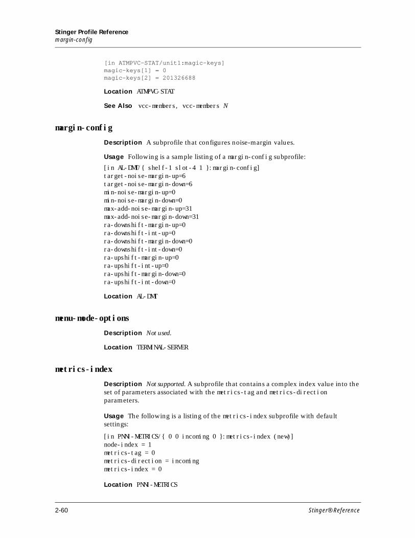
Stinger Profile Referencemargin-config
[in ATMPVC-STAT/unit1:magic-keys]magic-keys[1] = 0magic-keys[2] = 201326688
Location ATMPVC-STAT
See Also vcc-members, vcc-members N
margin-config
Description A subprofile that configures noise-margin values.
Usage Following is a sample listing of a margin-config subprofile:
[in AL-DMT/{ shelf-1 slot-4 1 }:margin-config]target-noise-margin-up=6target-noise-margin-down=6min-noise-margin-up=0min-noise-margin-down=0max-add-noise-margin-up=31max-add-noise-margin-down=31ra-downshift-margin-up=0ra-downshift-int-up=0ra-downshift-margin-down=0ra-downshift-int-down=0ra-upshift-margin-up=0ra-upshift-int-up=0ra-upshift-margin-down=0ra-upshift-int-down=0
Location AL-DMT
menu-mode-options
Description Not used.
Location TERMINAL-SERVER
metrics-index
Description Not supported. A subprofile that contains a complex index value into the set of parameters associated with the metrics-tag and metrics-direction parameters.
Usage The following is a listing of the metrics-index subprofile with default settings:
[in PNNI-METRICS/{ 0 0 incoming 0 }:metrics-index (new)]node-index = 1metrics-tag = 0metrics-direction = incomingmetrics-index = 0
Location PNNI-METRICS
2-60 Stinger® Reference
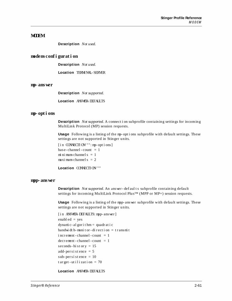
Stinger Profile ReferenceMODEM
MODEM
Description Not used.
modem-configuration
Description Not used.
Location TERMINAL-SERVER
mp-answer
Description Not supported.
Location ANSWER-DEFAULTS
mp-options
Description Not supported. A connection subprofile containing settings for incoming MultiLink Protocol (MP) session requests.
Usage Following is a listing of the mp-options subprofile with default settings. These settings are not supported in Stinger units.
[in CONNECTION/"":mp-options]base-channel-count = 1minimum-channels = 1maximum-channels = 2
Location CONNECTION/""
mpp-answer
Description Not supported. An answer-defaults subprofile containing default settings for incoming MultiLink Protocol Plus™ (MPP or MP+) session requests.
Usage Following is a listing of the mpp-answer subprofile with default settings. These settings are not supported in Stinger units.
[in ANSWER-DEFAULTS:mpp-answer]enabled = yesdynamic-algorithm = quadraticbandwidth-monitor-direction = transmitincrement-channel-count = 1decrement-channel-count = 1seconds-history = 15add-persistence = 5sub-persistence = 10target-utilization = 70
Location ANSWER-DEFAULTS
Stinger® Reference 2-61
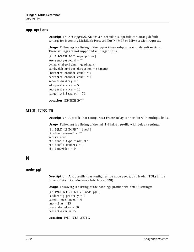
Stinger Profile Referencempp-options
mpp-options
Description Not supported. An answer-defaults subprofile containing default settings for incoming MultiLink Protocol Plus™ (MPP or MP+) session requests.
Usage Following is a listing of the mpp-options subprofile with default settings. These settings are not supported in Stinger units.
[in CONNECTION/"":mpp-options]aux-send-password = ""dynamic-algorithm = quadraticbandwidth-monitor-direction = transmitincrement-channel-count = 1decrement-channel-count = 1seconds-history = 15add-persistence = 5sub-persistence = 10target-utilization = 70
Location CONNECTION/""
MULTI-LINK-FR
Description A profile that configures a Frame Relay connection with multiple links.
Usage Following is a listing of the multi-link-fr profile with default settings:
[in MULTI-LINK-FR/"" (new)]mfr-bundle-name* = ""active = nomfr-bundle-type = mfr-dtemax-bundle-members = 1min-bandwidth = 0
N
node-pgl
Description A subprofile that configures the node peer group leader (PGL) in the Private Network-to-Network Interface (PNNI).
Usage Following is a listing of the node-pgl profile with default settings:
[in PNNI-NODE-CONFIG/1:node-pgl ]leadership-priority = 0parent-node-index = 0init-time = 15override-delay = 30reelect-time = 15
Location PNNI-NODE-CONFIG
2-62 Stinger® Reference
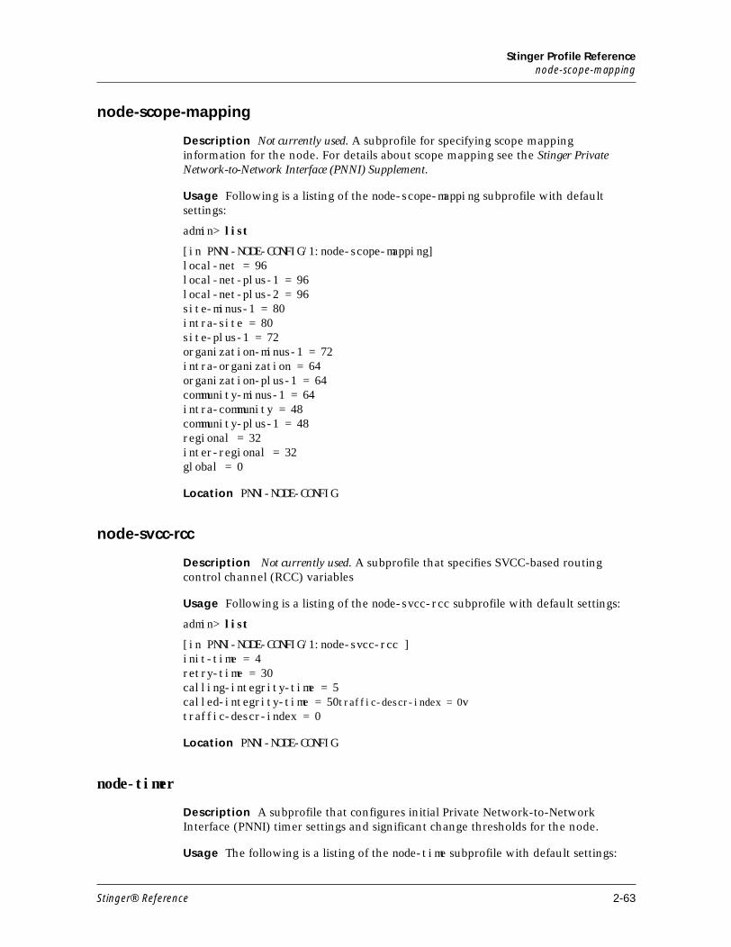
Stinger Profile Referencenode-scope-mapping
node-scope-mapping
Description Not currently used. A subprofile for specifying scope mapping information for the node. For details about scope mapping see the Stinger Private Network-to-Network Interface (PNNI) Supplement.
Usage Following is a listing of the node-scope-mapping subprofile with default settings:
admin> list
[in PNNI-NODE-CONFIG/1:node-scope-mapping] local-net = 96 local-net-plus-1 = 96 local-net-plus-2 = 96 site-minus-1 = 80 intra-site = 80 site-plus-1 = 72 organization-minus-1 = 72 intra-organization = 64 organization-plus-1 = 64 community-minus-1 = 64 intra-community = 48 community-plus-1 = 48 regional = 32 inter-regional = 32 global = 0
Location PNNI-NODE-CONFIG
node-svcc-rcc
Description Not currently used. A subprofile that specifies SVCC-based routing control channel (RCC) variables
Usage Following is a listing of the node-svcc-rcc subprofile with default settings:
admin> list
[in PNNI-NODE-CONFIG/1:node-svcc-rcc ]init-time = 4retry-time = 30calling-integrity-time = 5called-integrity-time = 50traffic-descr-index = 0vtraffic-descr-index = 0
Location PNNI-NODE-CONFIG
node-timer
Description A subprofile that configures initial Private Network-to-Network Interface (PNNI) timer settings and significant change thresholds for the node.
Usage The following is a listing of the node-time subprofile with default settings:
Stinger® Reference 2-63
Stinger Profile ReferenceO
[in PNNI-NODE-CONFIG/1:node-timer ]ptse-holddown = 10hello-holddown = 10hello-interval = 15hello-inactivity-factor = 5hlink-inact = 120ptse-refresh-interval = 1800ptse-lifetime-factor = 200rxmt-interval = 5peer-delayed-ack-interval = 10avcr-pm = 50avcr-mt = 3cdv-pm = 25ctd-pm = 50ctd-pm = 50
Location PNNI-NODE-CONFIG N
O
OC3-ATM
Description A profile that configures settings for the OC3-ATM interface.
Usage Following is a listing of the oc2-atm profile with default settings.
[in OC3-ATM/{ shelf-1 trunk-module-1 1 }]name = 1:17:1physical-address* = { shelf-1 trunk-module-1 1 }enabled = nospare-physical-address = { any-shelf any-slot 0 }sparing-mode = inactiveignore-lineup = system-definedaps-config-name = pg1
OC3-ATM-STAT
Description A read-only profile that indicates ATM framer status and error counters for an OC3-ATM interface. (Note to Michael: Add time-elapsed parameter to this profile)
Usage Read-only. Following is a sample listing of an oc3-atm-stat profile:
[in OC3-ATM-STAT/{ shelf-1 trunk-module-1 1 }] physical-address* = { shelf-1 trunk-module-1 1 } line-state = active spare-physical-address = { any-shelf any-slot 0 } sparing-state = sparing-none sparing-change-reason = unknown sparing-change-time = 0 sparing-change-counter = 0 vpi-vci-range = vpi-0-255-vci-32-1023 vc-switching-vpi = "0 1 2 3 4 5 6"
2-64 Stinger® Reference
Stinger Profile Referenceoutgoing-queue[n]
vcc-vpi = [ 0 1 2 3 4 5 6 0 0 0 0 0 0 0 0 0 ] aps-config-name = "" aps-channel-status = unknown aps-channel-sd-condition = False aps-channel-sf-condition = False aps-channel-low-direction = low-none aps-channel-recv-sd-count = 0 aps-channel-recv-sf-count = 0 aps-channel-recv-ais-count = 0 aps-channel-recv-rdi-count = 0 loss-of-signal = False loss-of-frame = False out-of-frame = False section-state = sonet-section-active-no-defect path-state = sonet-path-active-no-defect ais-receive = False yellow-receive = False out-of-cell-delineation = False loss-of-cell-delineation = False aps-receive = False rsop-bip-error-count = 0 rlop-bip-error-count = 0 rlop-febe-error-count = 0 rpop-bip-error-count = 0 rpop-febe-error-count = 0 racp-chcs-error-count = 0 racp-uchcs-error-count = 0 racp-rx-cell-count = 0 tacp-tx-cell-count = 0 frequency-justification-count = 3 HEC-cell-drop-counter = 0 FIFO-overflow-counter = 0 idle-cell-counter = 3778231663 valid-cell-counter = 280935 time-elapsed = 191 performance-monitoring = { 0 0 0 0 0 0 0 0 0 0 0 0 0 0 0 0 0 0 0 0 } interval-performance-monitoring = [ { 0 0 0 0 0 0 0 0 0 0 0 0 0 0 0 0 0 0 0 0
outgoing-queue[n]
Description A subprofile that is one of an array of 62 subprofiles of the SWITCH-CONFIG:atm-parameters subprofile that configures Asynchronous Transfer Mode (ATM) for an outgoing queue. Each configured queue must be associated with an outgoing port that is either a control module slot or a trunk port. Each outgoing port can have multiple outgoing queues.
Usage Following is a listing of the outgoting-queue subprofile with default settings.
[in SWITCH-CONFIG/tram-18:atm-parameters:outgoing-queue[1]]active = yes
Stinger® Reference 2-65
Stinger Profile Referenceoutgoing-shaper[n]
name = 1:18:1physical-address = { shelf-1 trunk-module-2 1 }cbr = yesreal-time-vbr = nonon-real-time-vbr = noubr = nohigh-priority-weight = 5low-priority-weight = 0source-port = { shelf-1 trunk-module-2 2 }hop-level = any-level
Location SWITCH-CONFIG/””:atm-parameters
outgoing-shaper[n]
Description A subprofile that is one of an array of ten subprofiles of a SWITCH-CONFIG:atm-parameters subprofile that configure the shapers available for the entire system. A trunk port might use zero, one, or more shaper(s) to shape outgoing ATM traffic with certain virtual path identifiers (VPIs).
Usage Following is a listing of the outgoing-shaper subprofile with default settings:
[in SWITCH-CONFIG:atm-parameters:outgoing-shaper[1] (new)]queue-index = 0vpi = 1bandwidth = 8000
Location SWITCH-CONFIG/””:atm-parameters
P
password-profile
Description A subprofile of external-auth containing settings for calling line ID
(CLID) and Dialed Number Information Service (DNIS) passwords set in a RADIUS
profile.
Usage Following is a listing of a password-profile subprofile with its default
settings:
[in EXTERNAL-AUTH:password-profile] clid = "" dnis = "" banner = ****** init-banner = ****** pool = ****** frdl = ****** dialout = ****** dialout-routes = ******
Location EXTERNAL-AUTH
2-66 Stinger® Reference
Stinger Profile Referenceperformance-monitoring
performance-monitoring
Description A read-only subprofile that indicates cumulative synchronous optical network (SONET) performance counters, which are reset at the end of every 15-minute interval.
Usage Read-only. The following is a listing of the performance-monitoring subprofile with default settings:
[in OC3-ATM-STAT/{ shelf-1 trunk-module-2 1 }:performance-monitoring]sonet-section-errored-seconds=0sonet-section-severely-errored-seconds=0sonet-section-severely-errored-framing-seconds=0sonet-section-coding-violations=0sonet-line-errored-seconds=0sonet-line-severely-errored-seconds=0sonet-line-coding-violations=0sonet-line-unavailable-seconds=0sonet-far-end-line-errored-seconds=0sonet-far-end-line-severely-errored-seconds=0sonet-far-end-line-coding-violations=0sonet-far-end-line-unavailable-seconds=0sonet-path-errored-seconds=0sonet-path-severely-errored-seconds=0sonet-path-coding-violations=0sonet-path-unavailable-seconds=0sonet-far-end-path-errored-seconds=0sonet-far-end-path-severely-errored-seconds=0sonet-far-end-path-coding-violations=0sonet-far-end-path-unavailable-seconds=0
Location OC3-ATM-STAT {shelf-N trunk-module-N N}
physical-statistic
Description A read-only subprofile of the al-dmt-stat, hdsl2-stat,and sdsl-stat profiles that reports statistics about xDSL performance.
Usage A read-only profile. The following is a sample listing of the each of the different physical-statistics subprofiles for the ADSL, HDSL2 and SDSL line interface modules (LIMs):
■ [in AL-DMT-STAT/{ shelf-1 slot-11 21 }:physical-statistic] line-up-timer = { 0 1 4 } rx-signal-present = yes up-dwn-cntr = 1 self-test = passed noise-margin-down = 112 attenuation-down = 1 output-power-down = 7 noise-margin-up = 9 attenuation-up = 1
Stinger® Reference 2-67
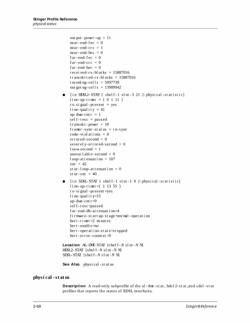
Stinger Profile Referencephysical-status
output-power-up = 11 near-end-fec = 0 near-end-crc = 1 near-end-hec = 0 far-end-fec = 0 far-end-crc = 0 far-end-hec = 0 received-rs-blocks = 15887016 transmitted-rs-blocks = 15887016 incoming-cells = 5097739 outgoing-cells = 13989942
■ [in HDSL2-STAT/{ shelf-1 slot-3 21 }:physical-statistic] line-up-timer = { 0 1 11 } rx-signal-present = yes line-quality = 41 up-dwn-cntr = 1 self-test = passed transmit-power = 10 framer-sync-status = in-sync code-violations = 0 errored-second = 0 severely-errored-second = 0 losw-second = 1 unavailable-second = 0 loop-attenuation = 107 snr = 42 stur-loop-attenuation = 0 stur-snr = 40
■ [in SDSL-STAT { shelf-1 slot-1 0 }:physical-statistic]line-up-timer={ 1 13 55 }rx-signal-present=yesline-quality=15up-dwn-cntr=0self-test=passedfar-end-db-attenuation=4firmware-startup-stage=normal-operationbert-timer=2 minutesbert-enable=nobert-operation-state=stoppedbert-error-counter=0
Location AL-DMT-STAT {shelf-N slot-N N}HDSL2-STAT {shelf-N slot-N N}SDSL-STAT {shelf-N slot-N N}
See Also physical-status
physical-status
Description A read-only subprofile of the al-dmt-stat, hdsl2-stat,and sdsl-stat profiles that reports the status of XDSL interfaces.
2-68 Stinger® Reference
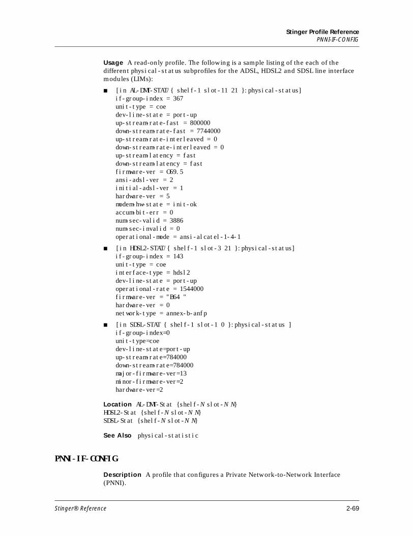
Stinger Profile ReferencePNNI-IF-CONFIG
Usage A read-only profile. The following is a sample listing of the each of the different physical-status subprofiles for the ADSL, HDSL2 and SDSL line interface modules (LIMs):
■ [in AL-DMT-STAT/{ shelf-1 slot-11 21 }:physical-status] if-group-index = 367 unit-type = coe dev-line-state = port-up up-stream-rate-fast = 800000 down-stream-rate-fast = 7744000 up-stream-rate-interleaved = 0 down-stream-rate-interleaved = 0 up-stream-latency = fast down-stream-latency = fast firmware-ver = O69.5 ansi-adsl-ver = 2 initial-adsl-ver = 1 hardware-ver = 5 modem-hw-state = init-ok accum-bit-err = 0 num-sec-valid = 3886 num-sec-invalid = 0 operational-mode = ansi-alcatel-1-4-1
■ [in HDSL2-STAT/{ shelf-1 slot-3 21 }:physical-status] if-group-index = 143 unit-type = coe interface-type = hdsl2 dev-line-state = port-up operational-rate = 1544000 firmware-ver = "B64 " hardware-ver = 0 network-type = annex-b-anfp
■ [in SDSL-STAT { shelf-1 slot-1 0 }:physical-status ]if-group-index=0unit-type=coedev-line-state=port-upup-stream-rate=784000down-stream-rate=784000major-firmware-ver=13minor-firmware-ver=2hardware-ver=2
Location AL-DMT-Stat {shelf-N slot-N N}HDSL2-Stat {shelf-N slot-N N}SDSL-Stat {shelf-N slot-N N}
See Also physical-statistic
PNNI-IF-CONFIG
Description A profile that configures a Private Network-to-Network Interface (PNNI).
Stinger® Reference 2-69
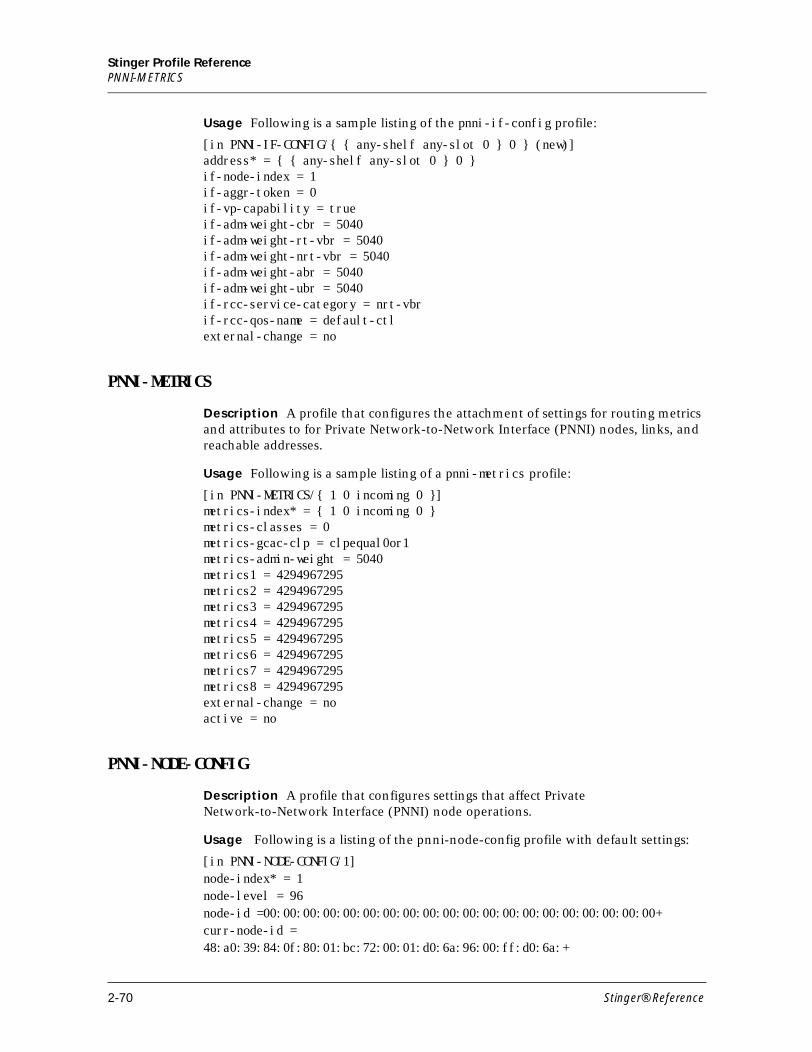
Stinger Profile ReferencePNNI-METRICS
Usage Following is a sample listing of the pnni-if-config profile:
[in PNNI-IF-CONFIG/{ { any-shelf any-slot 0 } 0 } (new)]address* = { { any-shelf any-slot 0 } 0 }if-node-index = 1if-aggr-token = 0if-vp-capability = trueif-adm-weight-cbr = 5040if-adm-weight-rt-vbr = 5040if-adm-weight-nrt-vbr = 5040if-adm-weight-abr = 5040if-adm-weight-ubr = 5040if-rcc-service-category = nrt-vbrif-rcc-qos-name = default-ctlexternal-change = no
PNNI-METRICS
Description A profile that configures the attachment of settings for routing metrics and attributes to for Private Network-to-Network Interface (PNNI) nodes, links, and reachable addresses.
Usage Following is a sample listing of a pnni-metrics profile:
[in PNNI-METRICS/{ 1 0 incoming 0 }]metrics-index* = { 1 0 incoming 0 }metrics-classes = 0metrics-gcac-clp = clpequal0or1metrics-admin-weight = 5040metrics1 = 4294967295metrics2 = 4294967295metrics3 = 4294967295metrics4 = 4294967295metrics5 = 4294967295metrics6 = 4294967295metrics7 = 4294967295metrics8 = 4294967295external-change = no active = no
PNNI-NODE-CONFIG
Description A profile that configures settings that affect Private Network-to-Network Interface (PNNI) node operations.
Usage Following is a listing of the pnni-node-config profile with default settings:
[in PNNI-NODE-CONFIG/1]node-index* = 1node-level = 96node-id =00:00:00:00:00:00:00:00:00:00:00:00:00:00:00:00:00:00:00:00+curr-node-id =48:a0:39:84:0f:80:01:bc:72:00:01:d0:6a:96:00:ff:d0:6a:+
2-70 Stinger® Reference
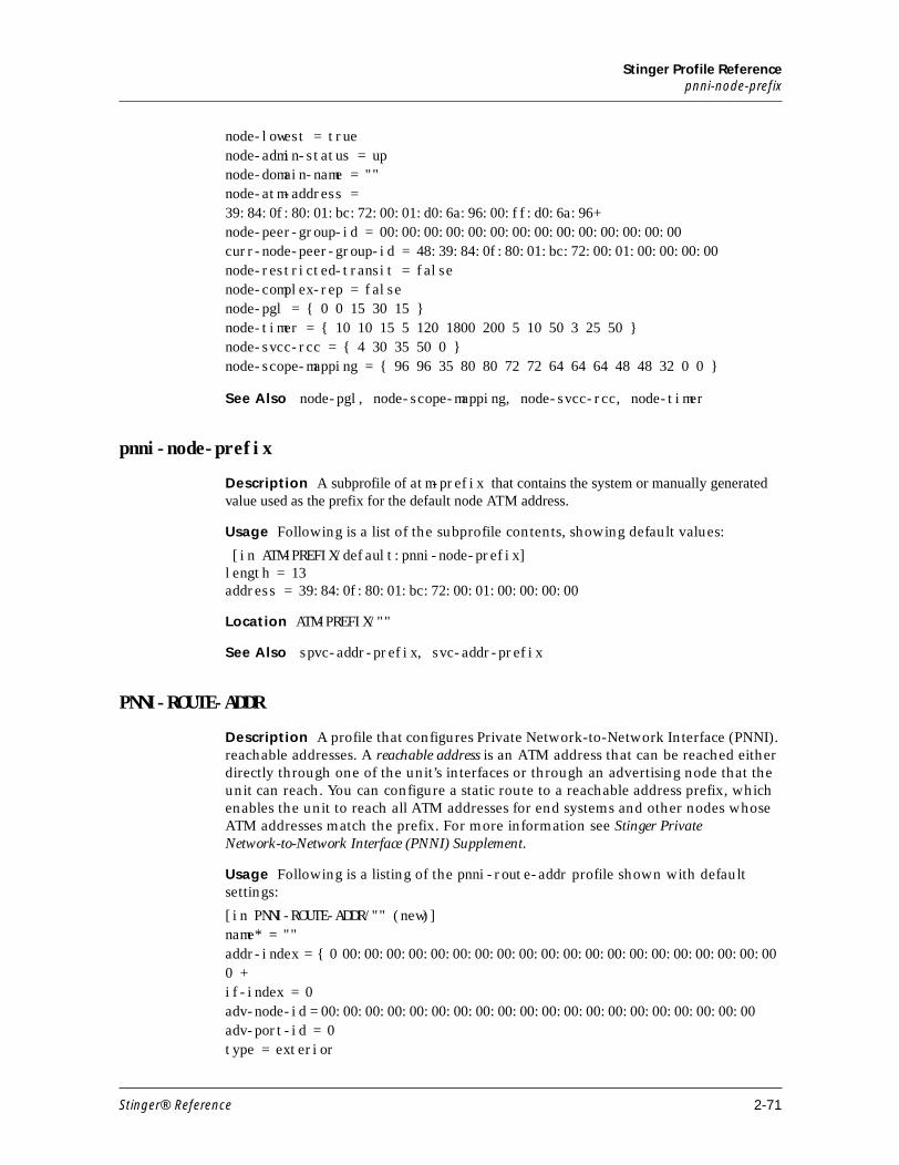
Stinger Profile Referencepnni-node-prefix
node-lowest = truenode-admin-status = upnode-domain-name = ""node-atm-address =39:84:0f:80:01:bc:72:00:01:d0:6a:96:00:ff:d0:6a:96+node-peer-group-id = 00:00:00:00:00:00:00:00:00:00:00:00:00:00curr-node-peer-group-id = 48:39:84:0f:80:01:bc:72:00:01:00:00:00:00node-restricted-transit = falsenode-complex-rep = falsenode-pgl = { 0 0 15 30 15 }node-timer = { 10 10 15 5 120 1800 200 5 10 50 3 25 50 }node-svcc-rcc = { 4 30 35 50 0 }node-scope-mapping = { 96 96 35 80 80 72 72 64 64 64 48 48 32 0 0 }
See Also node-pgl, node-scope-mapping, node-svcc-rcc, node-timer
pnni-node-prefix
Description A subprofile of atm-prefix that contains the system or manually generated value used as the prefix for the default node ATM address.
Usage Following is a list of the subprofile contents, showing default values:
[in ATM-PREFIX/default:pnni-node-prefix] length = 13 address = 39:84:0f:80:01:bc:72:00:01:00:00:00:00
Location ATM-PREFIX/""
See Also spvc-addr-prefix, svc-addr-prefix
PNNI-ROUTE-ADDR
Description A profile that configures Private Network-to-Network Interface (PNNI). reachable addresses. A reachable address is an ATM address that can be reached either directly through one of the unit’s interfaces or through an advertising node that the unit can reach. You can configure a static route to a reachable address prefix, which enables the unit to reach all ATM addresses for end systems and other nodes whose ATM addresses match the prefix. For more information see Stinger Private Network-to-Network Interface (PNNI) Supplement.
Usage Following is a listing of the pnni-route-addr profile shown with default settings:
[in PNNI-ROUTE-ADDR/"" (new)] name* = "" addr-index = { 0 00:00:00:00:00:00:00:00:00:00:00:00:00:00:00:00:00:00:00:00 0 +if-index = 0 adv-node-id = 00:00:00:00:00:00:00:00:00:00:00:00:00:00:00:00:00:00:00:00 adv-port-id = 0 type = exterior
Stinger® Reference 2-71
Stinger Profile ReferencePNNI-ROUTE-TNS
proto = other pnni-scope = 0 vp-capability = false metrics-tag = 0 ptse-id-ptse-id = 0 originate-advert = true info = "" oper-status = inactive time-stamp = 0 external-change = no active = no
See Also addr-index
PNNI-ROUTE-TNS
Description A profile that configures a static route to a Private Network-to-Network Interface (PNNI) transit network. A transit network lies between the networks of the two end points of a connection. A connection’s data transits the network, but does not originate or stop there. For more information see Stinger Private Network-to-Network Interface (PNNI) Supplement.
Usage Following is a listing of the pnni-route-tns profile which includes a listing of its associated subprofile.
[in PNNI-ROUTE-TNS/{ 0 other other 00:00:00:00 0 } ]tns-index* = { 0 other other 00:00:00:00 0 }tns-if-index = 0tns-advertising-node-id = 00:00:00:00:00:00:00:00:00:00:00:00:00:00:0+tns-advertised-port-id = 0tns-route-type = exteriortns-pnni-scope = 0tns-vp-capability = notns-metrics-tag = 0tns-originate-advertisement = yesactive = no
PNNI-SUMMARY-ADDR
Description A profile that explicitly configures summary addresses.
Usage Following is a listing of the pnni-summary-addr profile with default settings:
[in PNNI-SUMMARY-ADDR/""]index-name* = ""addr-index = { 1 internal-summary 00:00:00:00:00:00:00:00:00:00:00:00+suppress = falsestate = inactiveactive = no
See Also addr-index
2-72 Stinger® Reference
Stinger Profile Referenceport-redirect-options
port-redirect-options
Description A subprofile that enables you to redirect certain packet types to a specified server. For example, you can redirect Hypertext Transfer Protocol (HTTP) traffic to a Web cache server on a local network. You can use the port redirection capability to redirect any TCP or UDP packet on the basis of its protocol and port information.
Usage Following is a listing of the port-redirect-options subprofile with default settings:
[in CONNECTION/"":port-redirect-options]protocol = noneport-number = 0redirect-address = 0.0.0.0
Location CONNECTION/""
ppp-answer
Description A subprofile that configures default settings for incoming PPP session requests. You set values in this subprofile to specify general values to be used as defaults for incoming PPP session requests that do not specify a different value in the caller’s profile.
Usage Following is a listing of the ppp-answer subprofile with default settings:
[in ANSWER-DEFAULTS:ppp-answer]enabled = yesreceive-auth-mode = no-ppp-authbi-directional-auth = nonesubstitute-send-name = ""disconnect-on-auth-timeout = yesbridging-group = 0link-compression = nonemru = 1524lqm = nolqm-minimum-period = 600lqm-maximum-period = 600mtu = 1524max-pap-auth-retry = 0
Location ANSWER-DEFAULTS
pppoe-options
Description A subprofile of the connection and the ethernet profiles that enables the T1000 module to process PPP over Ethernet (PPPoE) packets, as defined in RFC 2516
Usage Following are listings of both versions of the subprofile:
Stinger® Reference 2-73
Stinger Profile Referenceppp-options
■ Following is a listing of the CONNECTION/"":pppoe-options subprofile in the with default settings:
– [in CONNECTION/"":pppoe-options]pppoe = nobridge-non-pppoe = no
■ Following is a listing of the ETHERNET/{ any-shelf any-slot 0 }:pppoe-options subprofile with default settings:
– [in ETHERNET/{ any-shelf any-slot 0 }:pppoe-options]pppoe = nobridge-non-pppoe = no
Location CONNECTION/""ETHERNET/{ any-shelf any-slot 0 }
ppp-options
Description A subprofile that configures the Stinger unit to establish a connection that uses Point-to-Point Protocol (PPP) authentication.
Usage Following is a listing of the ppp-options subprofile with default settings:
[in CONNECTION/"":ppp-options]send-auth-mode = no-ppp-authppp-circuit = noneppp-circuit-name = ""bi-directional-auth = nonesend-password = ""substitute-send-name = ""recv-password = ""substitute-recv-name = ""link-compression = stacmru = 1524lqm = nolqm-minimum-period = 600lqm-maximum-period = 600split-code-dot-user-enabled = nomtu = 1524
Location CONNECTION/""
See Also answer-options, ip-options, session-options, telco-options, fr-options, tos-options, usrrad-options
preferred-source
Description A subprofile of the CALL-ROUTE profile that configures the address of a device within the system. Calls that originate at the preferred source may be routed to the indexed destination.
Usage Following is a listing of the preferred-source subprofile with default settings:
2-74 Stinger® Reference
Stinger Profile ReferencePRIVATE-ROUTE-TABLE
[in CALL-ROUTE/{ { { shelf-1 any-slot 0 } 0 } 0 }:preferred-source]physical-address = { any-shelf any-slot 0 }logical-item = 0
Location CALL-ROUTE
See Also device-address, index
PRIVATE-ROUTE-TABLE
Description A profile that configures a private routing table. Specific connection or radius profiles can refer to a private routing table by name to have access to its routes.
Usage Following is a listing of the private-route-table profile with default setting:
[in PRIVATE-ROUTE-TABLE/""]name* = ""route-description-list = [ { no 0.0.0.0/0 0.0.0.0 0.0.0.0 0 } { no 0.+
psd-frequency-level
Description A subprofile of the clt-result profile that contains the results of the SD) test for the copper loop test (CLT) module.
Usage Following is a sample listing of the subprofile:
[in CLT-RESULT:psd-frequency-level[1] (new)]frequency = 0level = 0
Location CLT-RESULT
Q
q2931-options
Description A subprofile of atm-if-sig-parms containing Q.2931 parameters specifying the timers and retry values associated with the functionality of the Q.2931 signaling layer.
Usage Following is a list of the subprofile contents, showing default values:
[in ATM-IF-SIG-PARAMS/{ { any-shelf any-slot 0 } 0 }:q2931-options (new)]ax-restart = 2ax-statenq = 1301-ms = 180000303-ms = 4000306-ms = 30000308-ms = 30000309-ms = 10000310-ms = 10000313-ms = 30000
Stinger® Reference 2-75
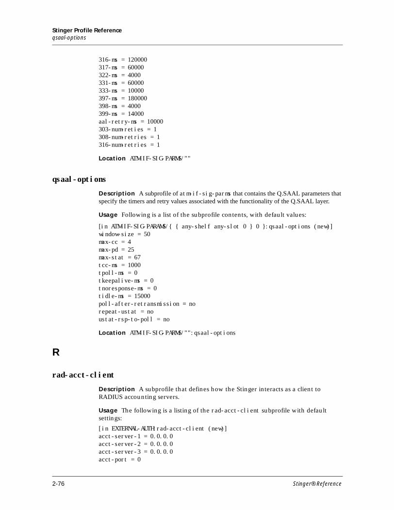
Stinger Profile Referenceqsaal-options
316-ms = 120000317-ms = 60000322-ms = 4000331-ms = 60000333-ms = 10000397-ms = 180000398-ms = 4000399-ms = 14000aal-retry-ms = 10000303-num-reties = 1308-num-retries = 1316-num-retries = 1
Location ATM-IF-SIG-PARMS/""
qsaal-options
Description A subprofile of atm-if-sig-parms that contains the Q.SAAL parameters that specify the timers and retry values associated with the functionality of the Q.SAAL layer.
Usage Following is a list of the subprofile contents, with default values:
[in ATM-IF-SIG-PARAMS/{ { any-shelf any-slot 0 } 0 }:qsaal-options (new)]window-size = 50 max-cc = 4 max-pd = 25 max-stat = 67 tcc-ms = 1000 tpoll-ms = 0 tkeepalive-ms = 0 tnoresponse-ms = 0 tidle-ms = 15000 poll-after-retransmission = no repeat-ustat = no ustat-rsp-to-poll = no
Location ATM-IF-SIG-PARMS/"":qsaal-options
R
rad-acct-client
Description A subprofile that defines how the Stinger interacts as a client to RADIUS accounting servers.
Usage The following is a listing of the rad-acct-client subprofile with default settings:
[in EXTERNAL-AUTH:rad-acct-client (new)] acct-server-1 = 0.0.0.0 acct-server-2 = 0.0.0.0 acct-server-3 = 0.0.0.0 acct-port = 0
2-76 Stinger® Reference
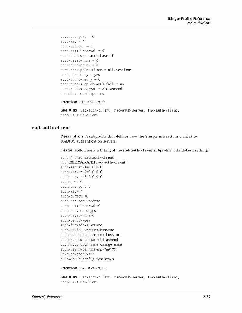
Stinger Profile Referencerad-auth-client
acct-src-port = 0 acct-key = "" acct-timeout = 1 acct-sess-interval = 0 acct-id-base = acct-base-10 acct-reset-time = 0 acct-checkpoint = 0 acct-checkpoint-timer = all-sessions acct-stop-only = yes acct-limit-retry = 0 acct-drop-stop-on-auth-fail = no acct-radius-compat = old-ascend tunnel-accounting = no
Location External-Auth
See Also rad-auth-client, rad-auth-server, tac-auth-client, tacplus-auth-client
rad-auth-client
Description A subprofile that defines how the Stinger interacts as a client to RADIUS authentication servers.
Usage Following is a listing of the rad-auth-client subprofile with default settings:
admin> list rad-auth-client[in EXTERNAL-AUTH:rad-auth-client]auth-server-1=0.0.0.0auth-server-2=0.0.0.0auth-server-3=0.0.0.0auth-port=0auth-src-port=0auth-key=""auth-timeout=0auth-rsp-required=noauth-sess-interval=0auth-ts-secure=yesauth-reset-time=0auth-Send67=yesauth-frm-adr-start=noauth-id-fail-return-busy=noauth-id-timeout-return-busy=noauth-radius-compat=old-ascendauth-keep-user-name=change-nameauth-realm-delimiters="@/\%"id-auth-prefix=""allow-auth-config-rqsts=yes
Location EXTERNAL-AUTH
See Also rad-acct-client, rad-auth-server, tac-auth-client, tacplus-auth-client
Stinger® Reference 2-77
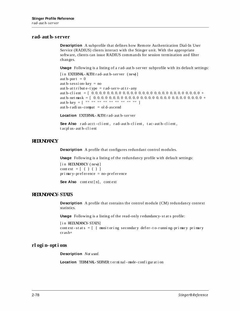
Stinger Profile Referencerad-auth-server
rad-auth-server
Description A subprofile that defines how Remote Authentication Dial-In User Service (RADIUS) clients interact with the Stinger unit. With the appropriate software, clients can issue RADIUS commands for session termination and filter changes.
Usage Following is a listing of a rad-auth-server subprofile with its default settings:
[in EXTERNAL-AUTH:rad-auth-server (new)]auth-port = 0auth-session-key = noauth-attribute-type = rad-serv-attr-anyauth-client = [ 0.0.0.0 0.0.0.0 0.0.0.0 0.0.0.0 0.0.0.0 0.0.0.0 0.0.0.0 +auth-netmask = [ 0.0.0.0 0.0.0.0 0.0.0.0 0.0.0.0 0.0.0.0 0.0.0.0 0.0.0.0 +auth-key = [ "" "" "" "" "" "" "" "" "" ]auth-radius-compat = old-ascend
Location EXTERNAL-AUTH:rad-auth-server
See Also rad-acct-client, rad-auth-client, tac-auth-client, tacplus-auth-client
REDUNDANCY
Description A profile that configures redundant control modules.
Usage Following is a listing of the redundancy profile with default settings:
[in REDUNDANCY (new)] context = [ { } { } ] primary-preference = no-preference
See Also context[n], context
REDUNDANCY-STATS
Description A profile that contains the control module (CM) redundancy context statistics.
Usage Following is a listing of the read-only redundancy-stats profile:
[in REDUNDANCY-STATS] context-stats = [ { monitoring secondary defer-to-running-primary primary crash+
rlogin-options
Description Not used.
Location TERMINAL-SERVER:terminal-mode-configuration
2-78 Stinger® Reference
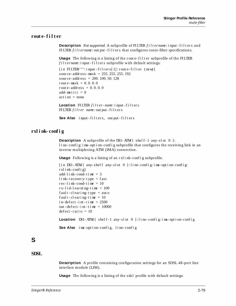
Stinger Profile Referenceroute-filter
route-filter
Description Not supported. A subprofile of FILTER filtername:input-filters and FILTER filtername:output-filters that configures route-filter specifications.
Usage The following is a listing of the route-filter subprofile of the FILTER filtername:input-filters subprofile with default settings:
[in FILTER/"":input-filters[1]:route-filter (new)]source-address-mask = 255.255.255.192source-address = 200.100.50.128route-mask = 0.0.0.0route-address = 0.0.0.0add-metric = 0action = none
Location FILTER filter-name:input-filtersFILTER filter name:output-filters
See Also input-filters, output-filters
rxlink-config
Description A subprofile of the DS1-ATM/{ shelf-1 any-slot 0 }: line-config:ima-option-config subprofile that configures the receiving link in an inverse multiplexing ATM (IMA) connection.
Usage Following is a listing of an rxlink-config subprofile.
[in DS1-ATM/{ any-shelf any-slot 0 }:line-config:ima-option-config: rxlink-config]add-link-cond-time = 3link-recovery-type = fastrec-link-cond-time = 10rx-lid-learning-time = 100fault-clearing-type = autofault-clearing-time = 10in-defect-int-time = 2500out-defect-int-time = 10000defect-ratio = 10
Location DS1-ATM/{ shelf-1 any-slot 0 }:line-config:ima-option-config
See Also ima-option-config, line-config
S
SDSL
Description A profile containing configuration settings for an SDSL 48-port line interface module (LIM).
Usage The following is a listing of the sdsl profile with default settings:
Stinger® Reference 2-79
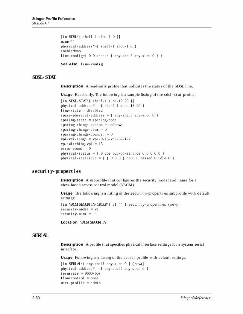
Stinger Profile ReferenceSDSL-STAT
[in SDSL/{ shelf-1 slot-1 0 }]name=""physical-address*={ shelf-1 slot-1 0 }enabled=noline-config={ 0 0 static { any-shelf any-slot 0 } }
See Also line-config
SDSL-STAT
Description A read-only profile that indicates the status of the SDSL line.
Usage Read-only. The following is a sample listing of the sdsl-stat profile:
[in SDSL-STAT/{ shelf-1 slot-13 20 }] physical-address* = { shelf-1 slot-13 20 } line-state = disabled spare-physical-address = { any-shelf any-slot 0 } sparing-state = sparing-none sparing-change-reason = unknown sparing-change-time = 0 sparing-change-counter = 0 vpi-vci-range = vpi-0-15-vci-32-127 vp-switching-vpi = 15 error-count = 0 physical-status = { 0 coe out-of-service 0 0 0 0 0 } physical-statistic = { { 0 0 0 } no 0 0 passed 0 idle 0 }
security-properties
Description A subprofile that configures the security model and name for a view-based access control model (VACM).
Usage The following is a listing of the security-properties subprofile with default settings:
[in VACM-SECURITY-GROUP/{ v1 "" }:security-properties (new)]security-model = v1security-name = ""
Location VACM-SECURITY
SERIAL
Description A profile that specifies physical interface settings for a system serial interface.
Usage Following is a listing of the serial profile with default settings:
[in SERIAL/{ any-shelf any-slot 0 } (new)]physical-address* = { any-shelf any-slot 0 }term-rate = 9600-bpsflow-control = noneuser-profile = admin
2-80 Stinger® Reference
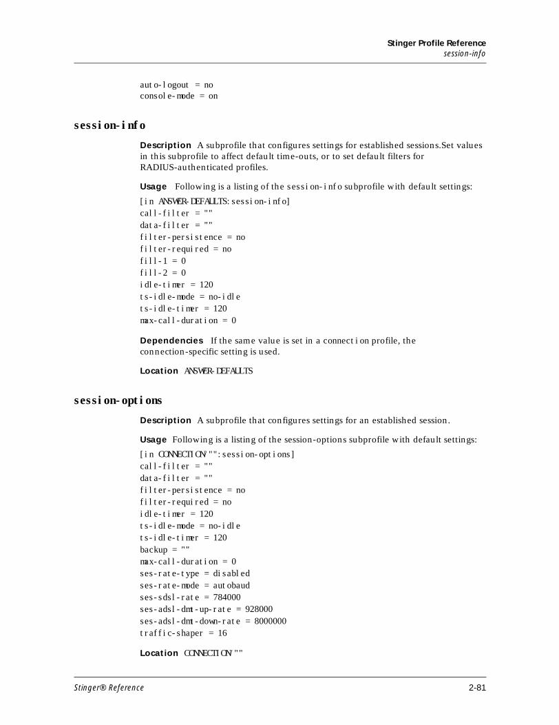
Stinger Profile Referencesession-info
auto-logout = noconsole-mode = on
session-info
Description A subprofile that configures settings for established sessions.Set values in this subprofile to affect default time-outs, or to set default filters for RADIUS-authenticated profiles.
Usage Following is a listing of the session-info subprofile with default settings:
[in ANSWER-DEFAULTS:session-info] call-filter = "" data-filter = "" filter-persistence = no filter-required = no fill-1 = 0 fill-2 = 0 idle-timer = 120 ts-idle-mode = no-idle ts-idle-timer = 120 max-call-duration = 0
Dependencies If the same value is set in a connection profile, the connection-specific setting is used.
Location ANSWER-DEFAULTS
session-options
Description A subprofile that configures settings for an established session.
Usage Following is a listing of the session-options subprofile with default settings:
[in CONNECTION/"":session-options]call-filter = ""data-filter = ""filter-persistence = nofilter-required = noidle-timer = 120ts-idle-mode = no-idlets-idle-timer = 120backup = ""max-call-duration = 0ses-rate-type = disabledses-rate-mode = autobaudses-sdsl-rate = 784000ses-adsl-dmt-up-rate = 928000ses-adsl-dmt-down-rate = 8000000traffic-shaper = 16
Location CONNECTION/""
Stinger® Reference 2-81
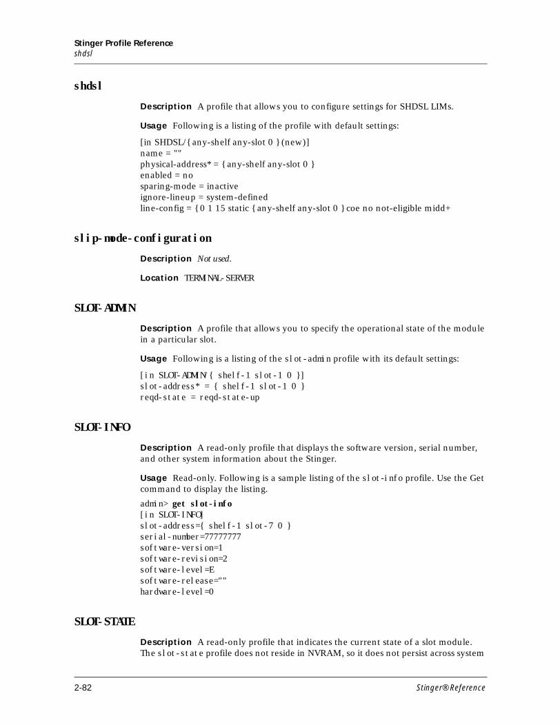
Stinger Profile Referenceshdsl
shdsl
Description A profile that allows you to configure settings for SHDSL LIMs.
Usage Following is a listing of the profile with default settings:
[in SHDSL/{ any-shelf any-slot 0 } (new)] name = "" physical-address* = { any-shelf any-slot 0 } enabled = no sparing-mode = inactive ignore-lineup = system-defined line-config = { 0 1 15 static { any-shelf any-slot 0 } coe no not-eligible midd+
slip-mode-configuration
Description Not used.
Location TERMINAL-SERVER
SLOT-ADMIN
Description A profile that allows you to specify the operational state of the module in a particular slot.
Usage Following is a listing of the slot-admin profile with its default settings:
[in SLOT-ADMIN/{ shelf-1 slot-1 0 }] slot-address* = { shelf-1 slot-1 0 } reqd-state = reqd-state-up
SLOT-INFO
Description A read-only profile that displays the software version, serial number, and other system information about the Stinger.
Usage Read-only. Following is a sample listing of the slot-info profile. Use the Get command to display the listing.
admin> get slot-info[in SLOT-INFO]slot-address={ shelf-1 slot-7 0 }serial-number=77777777software-version=1software-revision=2software-level=Esoftware-release=""hardware-level=0
SLOT-STATE
Description A read-only profile that indicates the current state of a slot module. The slot-state profile does not reside in NVRAM, so it does not persist across system
2-82 Stinger® Reference
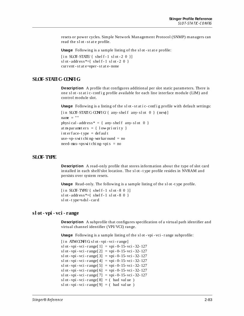
Stinger Profile ReferenceSLOT-STATIC-CONFIG
resets or power cycles. Simple Network Management Protocol (SNMP) managers can read the slot-state profile.
Usage Following is a sample listing of the slot-state profile:
[in SLOT-STATE/{ shelf-1 slot-2 0 }]slot-address*={ shelf-1 slot-2 0 }current-state=oper-state-none
SLOT-STATIC-CONFIG
Description A profile that configures additional per slot static parameters. There is one slot-static-config profile available for each line interface module (LIM) and control module slot.
Usage Following is a listing of the slot-static-config profile with default settings:
[in SLOT-STATIC-CONFIG/{ any-shelf any-slot 0 } (new)]name = ""physical-address* = { any-shelf any-slot 0 }atm-parameters = { low-priority }interface-type = defaultuse-vp-switching-workaround = noneed-max-vpswitching-vpis = no
SLOT-TYPE
Description A read-only profile that stores information about the type of slot card installed in each shelf/slot location. The slot-type profile resides in NVRAM and persists over system resets.
Usage Read-only. The following is a sample listing of the slot-type profile.
[in SLOT-TYPE/{ shelf-1 slot-8 0 }]slot-address*={ shelf-1 slot-8 0 }slot-type=sdsl-card
slot-vpi-vci-range
Description A subprofile that configures specification of a virtual path identifier and virtual channel identifier (VPI/VCI) range.
Usage Following is a sample listing of the slot-vpi-vci-range subprofile:
[in ATM-CONFIG:slot-vpi-vci-range]slot-vpi-vci-range[1] = vpi-0-15-vci-32-127slot-vpi-vci-range[2] = vpi-0-15-vci-32-127slot-vpi-vci-range[3] = vpi-0-15-vci-32-127slot-vpi-vci-range[4] = vpi-0-15-vci-32-127slot-vpi-vci-range[5] = vpi-0-15-vci-32-127slot-vpi-vci-range[6] = vpi-0-15-vci-32-127slot-vpi-vci-range[7] = vpi-0-15-vci-32-127slot-vpi-vci-range[8] = ( bad value )slot-vpi-vci-range[9] = ( bad value )
Stinger® Reference 2-83
Stinger Profile ReferenceSNMP
slot-vpi-vci-range[10] = vpi-0-15-vci-32-127slot-vpi-vci-range[11] = vpi-0-15-vci-32-127slot-vpi-vci-range[12] = vpi-0-15-vci-32-127slot-vpi-vci-range[13] = vpi-0-15-vci-32-127slot-vpi-vci-range[14] = vpi-0-15-vci-32-127slot-vpi-vci-range[15] = vpi-0-15-vci-32-127slot-vpi-vci-range[16] = vpi-0-15-vci-32-127
Note This is an array, and cannot be set directly.
Location ATM-CONFIG
SNMP
Description A profile configures settings that determine SNMP security, specify a contact and location, and control which hosts can access the Stinger by means of the SNMP manager utilities.
Usage Following is a listing of the snmp profile with default settings:
[in SNMP (new)]enabled = yesread-community = *******read-write-enabled = yesread-write-community = ********enforce-address-security = noread-access-hosts = [ 0.0.0.0 0.0.0.0 0.0.0.0 0.0.0.0 0.0.0.0 0.0.0.0 0.0.0.0 0+write-access-hosts = [ 0.0.0.0 0.0.0.0 0.0.0.0 0.0.0.0 0.0.0.00.0.0.0 0.0.0.0 +contact = ""location = ""queue-depth = 0csm-modem-diag = noengine-id = 00:00:00:00:00:00:00:00:00:00:00:00engine-boots = 0snmp-message-type = v1-and-v3security-level = noneenable-vacm = nonotification-log-age-out = 1440 bit-strings-allowed = yes
SNMP-MANAGER
Description A profile that configures the security hosts of the Simple Network Management Protocol (SNMP) manager.
Usage Following is a listing of the snmp-manager profile with default settings:
[in SNMP-MANAGER/"" (new)]name* = ""active = nowrite-access = nosnmp-message-type = v1-and-v3
2-84 Stinger® Reference
Stinger Profile ReferenceSNMPV3-NOTIFICATION
SNMPV3-NOTIFICATION
Description A profile that, in conjunction with the snmpv3-target-params profile, configures the Stinger to perform the following tasks:
■ Send SNMPv1 traps (Trap PDUs) or SNMPv2 Traps (Trap2 PDUs).
■ Send traps to a specified IP address and port.
■ Send Trap2 PDUs with different levels of security.
■ Send Trap2 PDUs with different user names.
Usage The following is a listing of the snmpv3-notification profile with default settings:
[in SNMPV3-NOTIFICATION/default]name* = defaultactive-enabled = yestag = defaulttype = trap
See Also SNMPV3-TARGET-PARAM
SNMPV3-TARGET-PARAM
Description A profile that, in conjunction with the snmpv3-notification profile, configures the Stinger to perform the following tasks:
■ Send SNMPv1 traps (Trap PDUs) or SNMPv2 Traps (Trap2 PDUs).
■ Send traps to a specified IP address and port.
■ Send Trap2 PDUs with different levels of security.
■ Send Trap2 PDUs with different usernames.
The SNMPv3 notification feature follows the specifications in RFC 2573.
Usage Following is a listing of the snmpv3-target-params profile with default settings:
[in SNMPV3-TARGET-PARAM/default]name* = defaultactive-enabled = yesmsg-proc-model = v1security-model = v1security-name = security-level = none
See Also SNMPV3-NOTIFICATION
SNMPV3-USM-USER
Description A profile that permits you to create and edit user profiles for support of SNMPv3 USM privacy.
Usage Following is a listing of the snmpv3-usm-user profile with default settings:
Stinger® Reference 2-85
Stinger Profile Referencesntp-info
[in SNMPV3-USM-USER/groupz]name* =groupzactive-enabled = noread-write-access = noauth-protocol = md5-authpriv-protocol = no-privauth-key =priv-key =public-str = ""
sntp-info
Description A subprofile that configures the use of the Simple Network Time Protocol (SNTP), which is described in RFC 1305.
Usage Following is a list of the sntp-info subprofile with default settings:
[in IP-GLOBAL:sntp-info]enabled = sntp-disabledGMT-offset = utc+0000host = [ 0.0.0.0 0.0.0.0 0.0.0.0 ]update-threshold = 10
Location IP-GLOBAL
spvc-address-prefix
Description A subprofile of the atm-prefix profile that contains the prefix portion of the SPVC target address.
Usage Following is a list of the subprofile contents, showing default values:
[in ATM-PREFIX/default:spvc-address-prefix] length = 0 address = 00:00:00:00:00:00:00:00:00:00:00:00:00
Location ATM-PREFIX/""
svc-addr-prefix
Description A subprofile of the atm-prefix profile that contains the prefix portion of the SVC target address
Following is a listing of the pnni-node-prefix with default settings:[in ATM-PREFIX/default:svc-addr-prefix]length = 0address = 00:00:00:00:00:00:00:00:00:00:00:00:00
Location ATM-PREFIX
See Also pnni-node-prefix, spvc-addr-prefix
2-86 Stinger® Reference
Stinger Profile ReferenceSWITCH-CONFIG
SWITCH-CONFIG
Description A profile that configures an ATM application-specific integrated circuit (ASIC). This profile is indexed by the module on which the ASIC is located (for example, controller, tram-17, or tram-18). The system creates a profile for the controller ASIC. If a trunk aggregation module (TRAM) is installed, it also creates a switch-config profile for those processors.
Usage Following is a listing of the switch-config profile with default settings:
[in SWITCH-CONFIG/controller]switch-name* = controlleratm-parameters = { [ { yes 1:17:1 { shelf-1 trunk-module-1 1 } yes no +
See Also atm-parameters
SYSTEM
Description A profile that configures systemwide settings for call management.
Usage Following is a listing of the system profile with default settings:
[in SYSTEM] installation-complete = yes name = idslstg system-rmt-mgmt = yes use-trunk-groups = no num-digits-trunk-groups = 1 idle-logout = 0 max-dialout-time = 20 parallel-dialing = 12 single-file-incoming = yes exclusive-port-routing = no high-ber-alarm-threshold = 10-**-3 high-ber-alarm = no no-trunk-alarm = no sessionid-base = 0 call-routing-sort-method = item-first digital-call-routing-sort-method = slot-first exact-match-call-routing = no shelf-controller-type = standalone master-shelf-controller = 1 new-nas-port-id-format = yes perm-conn-upd-mode = all userstat-format = "%i %l %s %r %d %a %u %c %t %n" control-bus-type = dpram boot-cm-version = 9.2-167.1 system-8k-clock = controller ignore-lineup = no nvram-was-rebuilt = no connection-profile-auto-naming-convention = lower-interface-number-first
Stinger® Reference 2-87
Stinger Profile ReferenceSYSTEM-INTEGRITY
SYSTEM-INTEGRITY
Description A profile for internal use only.
T
T1-STAT
Description A read-only profile that displays information about the state of a T1 line and its channels.
Usage Read-only. Following is a sample listing of a t1-stat profile:
[in T1-STAT/{ shelf-1 slot-1 1 }]physical-address* = { shelf-1 slot-1 1 }line-state = disabledchannel-state = [ disabled disabled disabled disabled disabled disabled disable+error-count = [ 0 0 0 0 0 0 0 0 0 0 0 0 0 0 0 0 0 0 0 0 0 0 0 0 ]loss-of-carrier = Falseloss-of-sync = Falseais-receive = Falseyellow-receive = Falseber-receive = Falsecarrier-established = Falsenetwork-loopback = False
table-config
Description A subprofile of the IP-GLOBAL:dns-local-table subprofile that configures the dns local table, storing up to eight host names and initial IP addresses.
Usage Following is a sample listing of the table-config subprofile:
[in IP-GLOBAL:dns-local-table:table-config[1]]host-name = ""ip-address = 0.0.0.0
Location IP-GLOBAL:dns-local-table
tac-auth-client
Description A subprofile that configures the way in which a Stinger interacts as a client of Terminal Access Controller Access Control System (TACACS) protocol authentication servers.
Usage Following is a listing of the tac-auth-client subprofile with default settings:
Example To list the Tac-Auth-Client subprofile:
[in EXTERNAL-AUTH:tac-auth-client]auth-server-1 = 0.0.0.0auth-server-2 = 0.0.0.0
2-88 Stinger® Reference
Stinger Profile Referencetacplus-acct-client
auth-server-3 = 0.0.0.0auth-port = 0auth-src-port = 0auth-key = ""auth-timeout = 0
Location EXTERNAL-AUTH
tacplus-acct-client
Description A subprofile that defines how the Stinger unit interacts as a client of TACACS+ accounting servers.
Usage Following is a listing of a tacplus-acct-client subprofile with its default settings:
[in EXTERNAL-AUTH:tacplus-acct-client (new)]acct-server-1 = 0.0.0.0acct-server-2 = 0.0.0.0acct-server-3 = 0.0.0.0acct-port = 0acct-src-port = 0acct-key = ""
Location EXTERNAL-AUTH
tacplus-auth-client
Description A subprofile that defines how the Stinger unit interacts as a client of TACACS+ authentication servers.
Usage Following is a listing of a tacplus-auth-client subprofile with its default settings:
[in EXTERNAL-AUTH:tacplus-auth-client (new)]auth-server-1 = 0.0.0.0auth-server-2 = 0.0.0.0auth-server-3 = 0.0.0.0auth-port = 0auth-src-port = 0auth-key = ""auth-timeout-time = 0auth-retries = 0
Location EXTERNAL-AUTH
tcp-clear-answer
Description Not supported. A subprofile that enables TCP-Clear sessions.
Usage Following is a listing of the tcp-clear-answer subprofile, which is not supported in Stinger units.
Stinger® Reference 2-89
Stinger Profile Referencetcp-clear-options
[in ANSWER-DEFAULTS:tcp-clear-answer]enabled = yes
Location ANSWER-DEFAULTS
tcp-clear-options
Description Not supported. A subprofile that configures default settings for a TCP-Clear session.
Usage Following is a listing of the tcp-clear-options subprofile, which is not supported in Stinger units.
[in CONNECTION/"":tcp-clear-options (new)]host = ""port = 0host2 = ""port2 = 0host3 = ""port3 = 0host4 = ""port4 = 0detect-end-of-packet = noend-of-packet-pattern = ""flush-length = 256flush-time = 20
Location CONNECTION/""
tdr-distance-level
Description A subprofile that contains distance and level data pairs for the tdr test of the copper loop test (CLT) module.
Usage Following is a listing of the subprofile with its defaults.
[in CLT-RESULT:tdr-distance-level[1]] distance = 0 level = 0
Location CLT-RESULT
telco-options
Description A subprofile that configures options negotiated with the telephone company carrier.
Usage Following is a listing of the telco-options subprofile with default settings:
[in CONNECTION/"":telco-options (new)] answer-originate = ans-and-orig callback = no fill-1 = ""
2-90 Stinger® Reference
Stinger Profile Referencetelnet-options
call-type = ft1 nailed-groups = 1 nailed-up-group = 1 ft1-caller = no force-56kbps = no data-service = 56k-clear call-by-call = 0 billing-number = "" transit-number = "" expect-callback = no delay-callback = 0 nas-port-type = any
Location CONNECTION/""
telnet-options
Description Not used.
Location TERMINAL-SERVER:terminal-mode-configuration
terminal-mode-configuration
Description Not used.
Location TERMINAL-SERVER
TERMINAL-SERVER
Description Not used.
Location TERMINAL-SERVER
THERMAL
Description A profile that allows the specification of temperature thresholds for the builtin temperature sensors in the Stinger control module (CM).
Usage The following is a listing of the thermal profile with default settings:
bottom-low-temperature-threshold = 0 bottom-high-temperature-threshold = 60 top-low-temperature-threshold = 0 top-high-temperature-threshold = 60
Dependencies Temperture sensors are available only in version 3 and higher of the CM.
THRESH-HDSL2-SHDSL
Description Not supported.
Stinger® Reference 2-91
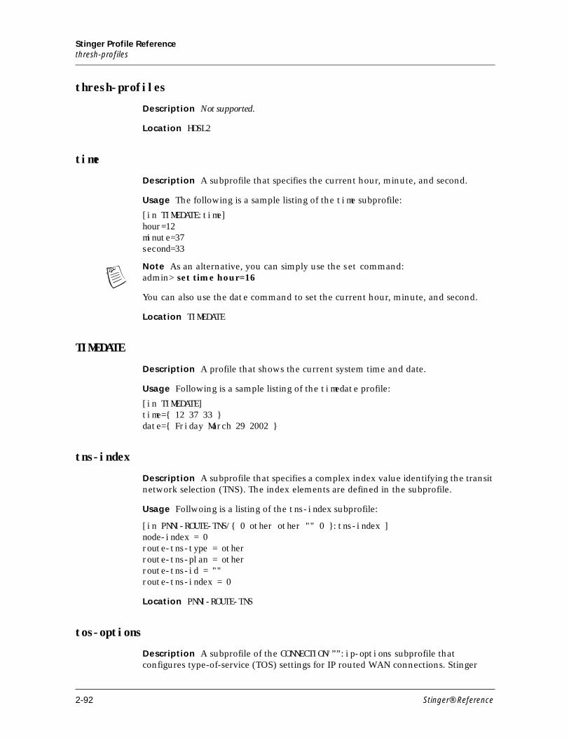
Stinger Profile Referencethresh-profiles
thresh-profiles
Description Not supported.
Location HDSL2
time
Description A subprofile that specifies the current hour, minute, and second.
Usage The following is a sample listing of the time subprofile:
[in TIMEDATE:time] hour=12minute=37second=33
Note As an alternative, you can simply use the set command:admin> set time hour=16
You can also use the date command to set the current hour, minute, and second.
Location TIMEDATE
TIMEDATE
Description A profile that shows the current system time and date.
Usage Following is a sample listing of the timedate profile:
[in TIMEDATE]time={ 12 37 33 }date={ Friday March 29 2002 }
tns-index
Description A subprofile that specifies a complex index value identifying the transit network selection (TNS). The index elements are defined in the subprofile.
Usage Follwoing is a listing of the tns-index subprofile:
[in PNNI-ROUTE-TNS/{ 0 other other "" 0 }:tns-index ]node-index = 0route-tns-type = otherroute-tns-plan = otherroute-tns-id = ""route-tns-index = 0
Location PNNI-ROUTE-TNS
tos-options
Description A subprofile of the CONNECTION/””:ip-options subprofile that configures type-of-service (TOS) settings for IP routed WAN connections. Stinger
2-92 Stinger® Reference
Stinger Profile Referencetraffic-shapers
units do not implement priority queuing, but they do set information that can be used by other routers to prioritize and select links for particular data streams. You set values in this subprofile to configure the Stinger unit to set quality of service (QoS) priority bits and TOS classes of service on behalf of customer applications.
Usage Following is a listing of the tos-options subprofile contents with default settings:
[in CONNECTION/"":ip-options:tos-options]active = noprecedence = 000type-of-service = normalapply-to = incomingmarking-type = precedence-tosdscp = 00
Location CONNECTION/"":ip-options
See Also ip-options
traffic-shapers
Description A subprofile that configures bandwidth of virtual circuits.
Usage Following is a listing of a traffic-shapers subprofile with default settings:.
[in ATM-CONFIG:traffic-shapers[1]]enabled = nobit-rate = 1000peak-rate = 1000max-burst-size = 2aggregate = nopriority-number = 1
Location ATM-CONFIG
TRAP
Description A profile configures the way in which the Stinger traps events. A trap is a mechanism in SNMP for reporting system change in real time. To report system change, the Stinger sends a traps-PDU (Protocol Data Unit) to the SNMP manager. (For the most up-to-date information about events, see the Ascend Enterprise MIB.)
Usage The following is a listing of the trap profile with default settings:
admin> new trap TRAP/””
[in TRAP/"" (new)] host-name* = "" active-enabled = yes community-name = "" host-address = 0.0.0.0 host-port = 162
Stinger® Reference 2-93
Stinger Profile ReferenceTRAP
inform-time-out = 1500 inform-retry-count = 4 notify-tag-list = default target-params-name = default notification-log-enable = no notification-log-limit = 50 alarm-enabled = yes security-enabled = no port-enabled = no slot-enabled = no coldstart-enabled = yes warmstart-enabled = yes linkdown-enabled = yes linkup-enabled = yes ascend-enabled = yes console-enabled = yes use-exceeded-enabled = yes password-enabled = yes fr-linkup-enabled = yes fr-linkdown-enabled = yes event-overwrite-enabled = yes radius-change-enabled = yes mcast-monitor-enabled = yes lan-modem-enabled = yes slot-profile-change-enabled = yes power-supply-enabled = yes authentication-enabled = yes config-change-enabled = yes sys-clock-drift-enabled = yes suspect-access-resource-enabled = yes watchdog-warning-enabled = yes controller-switchover-enabled = no call-log-serv-change-enabled = yes wan-line-state-change-enabled = yes call-log-dropped-pkt-enabled = yes lim-sparing-enabled = no interface-sparing-enabled = no secondary-controller-state-change-enabled = nopctfi-trunk-status-change-enabled = yes no-resource-available-enabled = yes dsl-thresh-trap-enabled = no atm-pvc-failure-trap-enabled = no atm-ima-alarm-trap-enabled = no ascend-link-down-trap-enabled = no ascend-link-up-trap-enabled = no snmp-illegal-access-attempt = no hdsl2-shdsl-threshold-traps-enabled = yes clock-change-trap-enabled = no oam-timeout-trap-enabled = no ascend-adsl-trap-enabled = no
2-94 Stinger® Reference
Stinger Profile Referencetree-properties
tree-properties
Description A subprofile that configures the identifiers of a view in a view-based access control model (VACM).
Usage The following is a listing of the tree-view-properties subprofile with default settings.
[in VACM-VIEW-TREE/{ "" "" }:tree-properties (new)]view-name = ""view-tree-oid = ""
Location VACM-VIEW-TREE
See Also trunk-cac-config[n]
trunk-cac-config
Description A subprofile of the high-speed-slot profile that the system creates for each trunk port.
Usage Following is a listing of a trunk-cac subprofile with default settings:
[in HIGH-SPEED-SLOT-STATIC-CONFIG/{ shelf-1 trunk-module-1 1 }:trunk-cac-config]enable = yes port-num = 1:17:1 line-rate = 155520 over-subscription = 10
Dependencies This parameter was previously located in the atm-config profile. Its use in that location has been deprecated.
If a user has already set these parameters under a previous release in the atm-config profile the paraeters are copied into the corresponding high-speed-slot-static-config profile. The parameters are now invisible in the atm-config profile unless allow-debug is set to yes.
Location HIGH-SPEED-SLOT-STATIC-CONFIG
trunk-cac-config[n]
Description Depricated and not used.
Location ATM-CONFIG:trunk-cac-config
See Also HIGH-SPEED-SLOT-STATIC-CONFIG
TRUNK-DAUGHTER-DEV
Description A profile that configures a trunk daughter device.
Usage Following is a listing of the trunk-daughter-dev profile:
Stinger® Reference 2-95
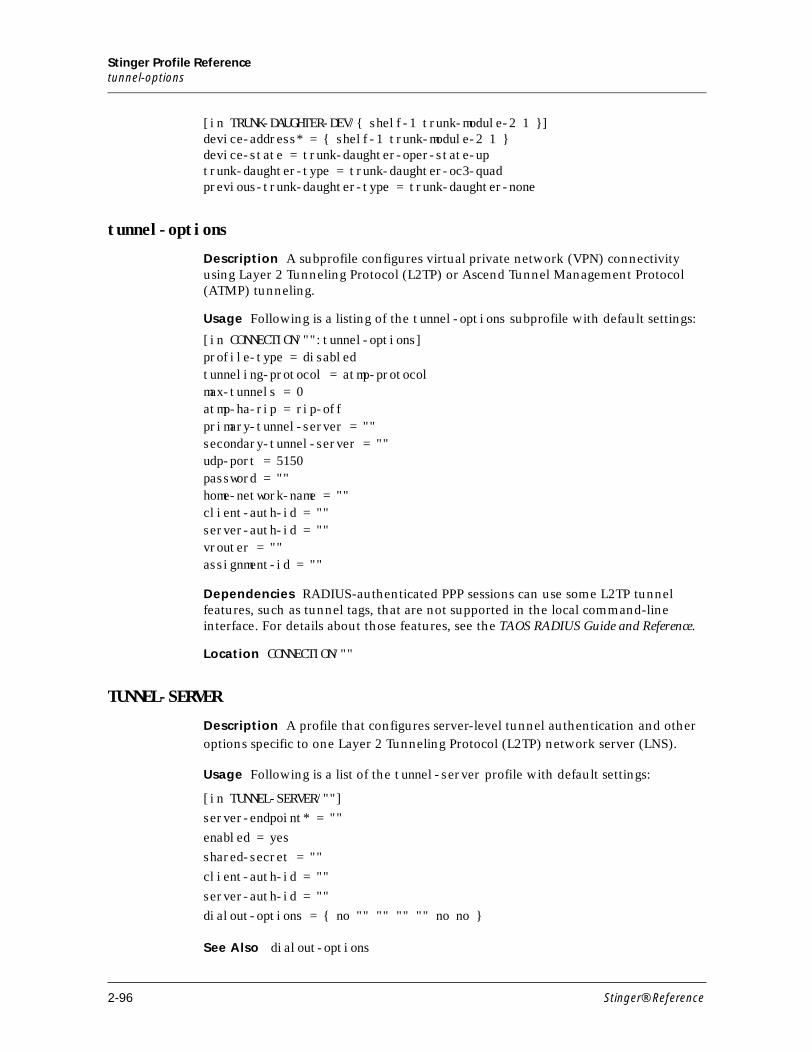
Stinger Profile Referencetunnel-options
[in TRUNK-DAUGHTER-DEV/{ shelf-1 trunk-module-2 1 }]device-address* = { shelf-1 trunk-module-2 1 }device-state = trunk-daughter-oper-state-uptrunk-daughter-type = trunk-daughter-oc3-quadprevious-trunk-daughter-type = trunk-daughter-none
tunnel-options
Description A subprofile configures virtual private network (VPN) connectivity using Layer 2 Tunneling Protocol (L2TP) or Ascend Tunnel Management Protocol (ATMP) tunneling.
Usage Following is a listing of the tunnel-options subprofile with default settings:
[in CONNECTION/"":tunnel-options]profile-type = disabledtunneling-protocol = atmp-protocolmax-tunnels = 0atmp-ha-rip = rip-offprimary-tunnel-server = ""secondary-tunnel-server = ""udp-port = 5150password = ""home-network-name = ""client-auth-id = ""server-auth-id = ""vrouter = ""assignment-id = ""
Dependencies RADIUS-authenticated PPP sessions can use some L2TP tunnel features, such as tunnel tags, that are not supported in the local command-line interface. For details about those features, see the TAOS RADIUS Guide and Reference.
Location CONNECTION/""
TUNNEL-SERVER
Description A profile that configures server-level tunnel authentication and other
options specific to one Layer 2 Tunneling Protocol (L2TP) network server (LNS).
Usage Following is a list of the tunnel-server profile with default settings:
[in TUNNEL-SERVER/""]server-endpoint* = ""
enabled = yesshared-secret = ""
client-auth-id = ""
server-auth-id = ""dialout-options = { no "" "" "" "" no no }
See Also dialout-options
2-96 Stinger® Reference
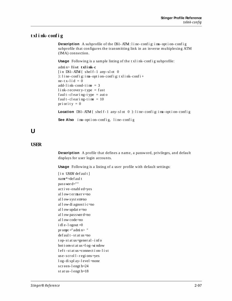
Stinger Profile Referencetxlink-config
txlink-config
Description A subprofile of the DS1-ATM/:line-config:ima-option-config subprofile that configures the transmitting link in an inverse multiplexing ATM (IMA) connection.
Usage Following is a sample listing of the txlink-config subprofile:
admin> list txlink-c[in DS1-ATM/{ shelf-1 any-slot 0 }:line-config:ima-option-config:txlink-confi+ne-tx-lid = 0add-link-cond-time = 3link-recovery-type = fastfault-clearing-type = autofault-clearing-time = 10priority = 0
Location DS1-ATM/{ shelf-1 any-slot 0 }:line-config:ima-option-config
See Also ima-option-config, line-config
U
USER
Description A profile that defines a name, a password, privileges, and default displays for user login accounts.
Usage Following is a listing of a user profile with default settings:
[in USER/default]name*=defaultpassword=""active-enabled=yesallow-termserv=noallow-system=noallow-diagnostic=noallow-update=noallow-password=noallow-code=noidle-logout=0prompt="admin> "default-status=notop-status=general-infobottom-status=log-windowleft-status=connection-listuse-scroll-regions=yeslog-display-level=nonescreen-length=24status-length=18
Stinger® Reference 2-97
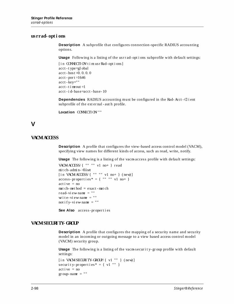
Stinger Profile Referenceusrrad-options
usrrad-options
Description A subprofile that configures connection-specific RADIUS accounting options.
Usage Following is a listing of the usrrad-options subprofile with default settings:
[in CONNECTION/tim:usrRad-options]acct-type=globalacct-host=0.0.0.0acct-port=1646acct-key=""acct-timeout=1acct-id-base=acct-base-10
Dependencies RADIUS accounting must be configured in the Rad-Acct-Client subprofile of the external-auth profile.
Location CONNECTION/""
V
VACM-ACCESS
Description A profile that configures the view-based access control model (VACM), specifying view names for different kinds of access, such as read, write, notify.
Usage The following is a listing of the vacm-access profile with default settings:
VACM-ACCESS/{ "" "" v1 no+ } readmitch-admin->list[in VACM-ACCESS/{ "" "" v1 no+ } (new)]access-properties* = { "" "" v1 no+ }active = nomatch-method = exact-matchread-view-name = ""write-view-name = ""notify-view-name = ""
See Also access-properties
VACM-SECURITY-GROUP
Description A profile that configures the mapping of a security name and security model in an incoming or outgoing message to a view based access control model (VACM) security group.
Usage The following is a listing of the vacm-security-group profile with default settings:
[in VACM-SECURITY-GROUP/{ v1 "" } (new)]security-properties* = { v1 "" }active = nogroup-name = ""
2-98 Stinger® Reference
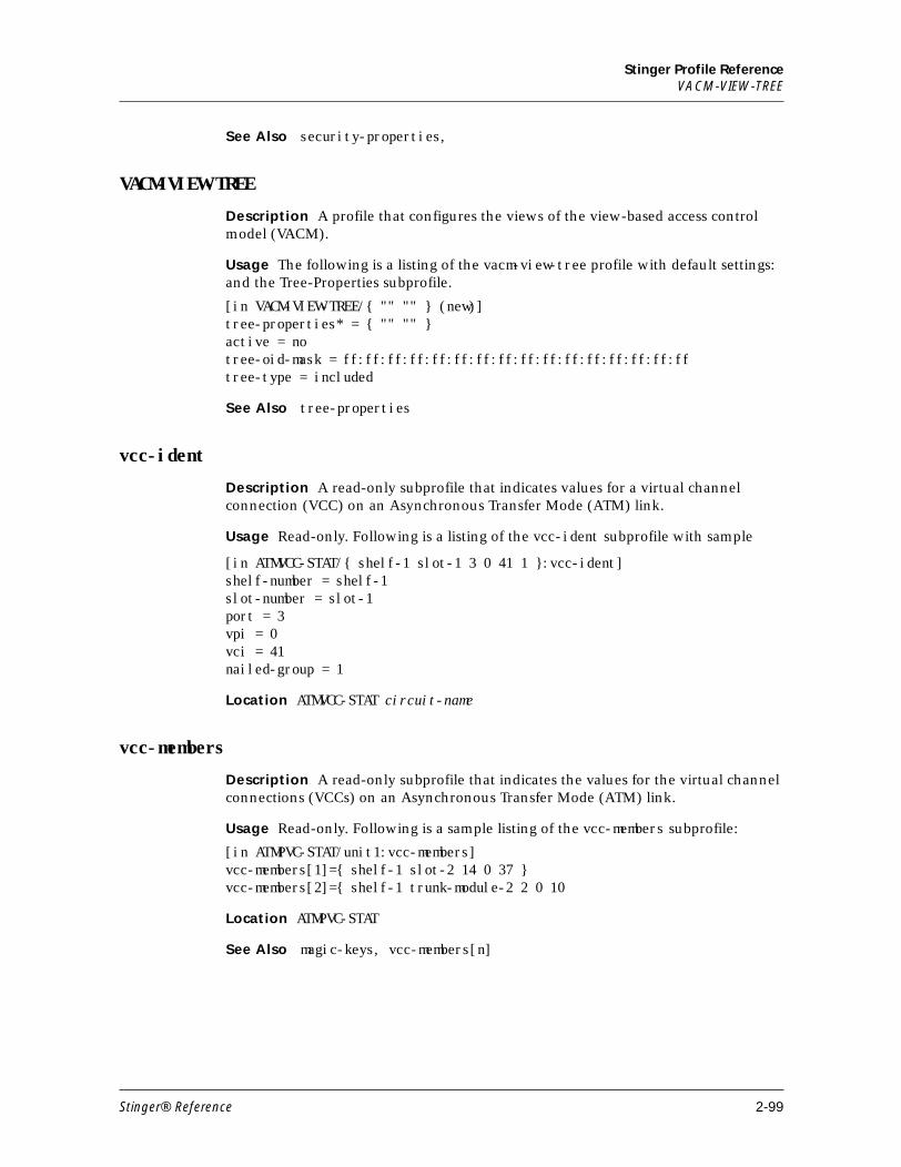
Stinger Profile ReferenceVACM-VIEW-TREE
See Also security-properties,
VACM-VIEW-TREE
Description A profile that configures the views of the view-based access control model (VACM).
Usage The following is a listing of the vacm-view-tree profile with default settings: and the Tree-Properties subprofile.
[in VACM-VIEW-TREE/{ "" "" } (new)]tree-properties* = { "" "" }active = notree-oid-mask = ff:ff:ff:ff:ff:ff:ff:ff:ff:ff:ff:ff:ff:ff:ff:fftree-type = included
See Also tree-properties
vcc-ident
Description A read-only subprofile that indicates values for a virtual channel connection (VCC) on an Asynchronous Transfer Mode (ATM) link.
Usage Read-only. Following is a listing of the vcc-ident subprofile with sample
[in ATMVCC-STAT/{ shelf-1 slot-1 3 0 41 1 }:vcc-ident] shelf-number = shelf-1 slot-number = slot-1 port = 3 vpi = 0 vci = 41 nailed-group = 1
Location ATMVCC-STAT circuit-name
vcc-members
Description A read-only subprofile that indicates the values for the virtual channel connections (VCCs) on an Asynchronous Transfer Mode (ATM) link.
Usage Read-only. Following is a sample listing of the vcc-members subprofile:
[in ATMPVC-STAT/unit1:vcc-members]vcc-members[1]={ shelf-1 slot-2 14 0 37 }vcc-members[2]={ shelf-1 trunk-module-2 2 0 10
Location ATMPVC-STAT
See Also magic-keys, vcc-members[n]
Stinger® Reference 2-99
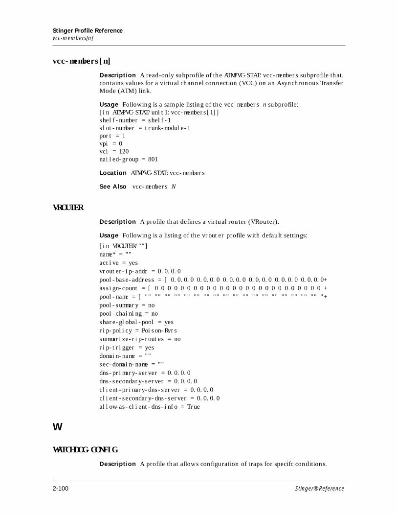
Stinger Profile Referencevcc-members[n]
vcc-members[n]
Description A read-only subprofile of the ATMPVC-STAT:vcc-members subprofile that. contains values for a virtual channel connection (VCC) on an Asynchronous Transfer Mode (ATM) link.
Usage Following is a sample listing of the vcc-members n subprofile:[in ATMPVC-STAT/unit1:vcc-members[1]]shelf-number = shelf-1slot-number = trunk-module-1port = 1vpi = 0vci = 120nailed-group = 801
Location ATMPVC-STAT:vcc-members
See Also vcc-members N
VROUTER
Description A profile that defines a virtual router (VRouter).
Usage Following is a listing of the vrouter profile with default settings:
[in VROUTER/""]name* = ""active = yesvrouter-ip-addr = 0.0.0.0pool-base-address = [ 0.0.0.0 0.0.0.0 0.0.0.0 0.0.0.0 0.0.0.0 0.0.0.0+assign-count = [ 0 0 0 0 0 0 0 0 0 0 0 0 0 0 0 0 0 0 0 0 0 0 0 0 0 0 +pool-name = [ "" "" "" "" "" "" "" "" "" "" "" "" "" "" "" "" "" "" "+pool-summary = nopool-chaining = noshare-global-pool = yesrip-policy = Poison-Rvrssummarize-rip-routes = norip-trigger = yesdomain-name = ""sec-domain-name = ""dns-primary-server = 0.0.0.0dns-secondary-server = 0.0.0.0client-primary-dns-server = 0.0.0.0client-secondary-dns-server = 0.0.0.0allow-as-client-dns-info = True
W
WATCHDOG-CONFIG
Description A profile that allows configuration of traps for specifc conditions.
2-100 Stinger® Reference
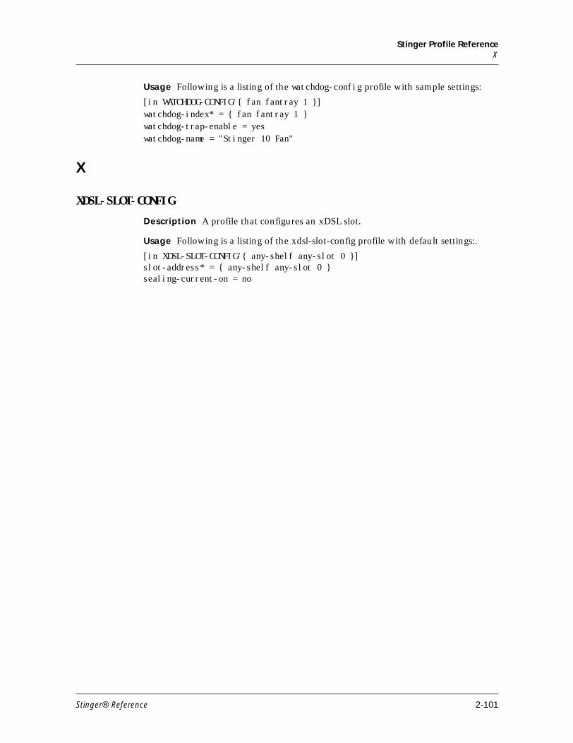
Stinger Profile ReferenceX
Usage Following is a listing of the watchdog-config profile with sample settings:
[in WATCHDOG-CONFIG/{ fan fantray 1 }]watchdog-index* = { fan fantray 1 }watchdog-trap-enable = yeswatchdog-name = "Stinger 10 Fan"
X
XDSL-SLOT-CONFIG
Description A profile that configures an xDSL slot.
Usage Following is a listing of the xdsl-slot-config profile with default settings:.
[in XDSL-SLOT-CONFIG/{ any-shelf any-slot 0 }]slot-address* = { any-shelf any-slot 0 }sealing-current-on = no
Stinger® Reference 2-101


3Stinger Parameter Reference
Numeric . . . . . . . . . . . . . . . . . . . . . . . . . . . . . . . . . . . . . . . . . . . . . . . . . . . . . . . . 3-2
A . . . . . . . . . . . . . . . . . . . . . . . . . . . . . . . . . . . . . . . . . . . . . . . . . . . . . . . . . . . . . 3-2
B. . . . . . . . . . . . . . . . . . . . . . . . . . . . . . . . . . . . . . . . . . . . . . . . . . . . . . . . . . . . . 3-60
C. . . . . . . . . . . . . . . . . . . . . . . . . . . . . . . . . . . . . . . . . . . . . . . . . . . . . . . . . . . . . 3-73
D . . . . . . . . . . . . . . . . . . . . . . . . . . . . . . . . . . . . . . . . . . . . . . . . . . . . . . . . . . . 3-111
E. . . . . . . . . . . . . . . . . . . . . . . . . . . . . . . . . . . . . . . . . . . . . . . . . . . . . . . . . . . . 3-136
F . . . . . . . . . . . . . . . . . . . . . . . . . . . . . . . . . . . . . . . . . . . . . . . . . . . . . . . . . . . . 3-147
G . . . . . . . . . . . . . . . . . . . . . . . . . . . . . . . . . . . . . . . . . . . . . . . . . . . . . . . . . . . 3-168
H . . . . . . . . . . . . . . . . . . . . . . . . . . . . . . . . . . . . . . . . . . . . . . . . . . . . . . . . . . . 3-173
I . . . . . . . . . . . . . . . . . . . . . . . . . . . . . . . . . . . . . . . . . . . . . . . . . . . . . . . . . . . . 3-182
L . . . . . . . . . . . . . . . . . . . . . . . . . . . . . . . . . . . . . . . . . . . . . . . . . . . . . . . . . . . . 3-217
M . . . . . . . . . . . . . . . . . . . . . . . . . . . . . . . . . . . . . . . . . . . . . . . . . . . . . . . . . . . 3-243
N . . . . . . . . . . . . . . . . . . . . . . . . . . . . . . . . . . . . . . . . . . . . . . . . . . . . . . . . . . . 3-277
O . . . . . . . . . . . . . . . . . . . . . . . . . . . . . . . . . . . . . . . . . . . . . . . . . . . . . . . . . . . 3-299
P . . . . . . . . . . . . . . . . . . . . . . . . . . . . . . . . . . . . . . . . . . . . . . . . . . . . . . . . . . . . 3-305
Q . . . . . . . . . . . . . . . . . . . . . . . . . . . . . . . . . . . . . . . . . . . . . . . . . . . . . . . . . . . 3-336
R. . . . . . . . . . . . . . . . . . . . . . . . . . . . . . . . . . . . . . . . . . . . . . . . . . . . . . . . . . . . 3-341
S . . . . . . . . . . . . . . . . . . . . . . . . . . . . . . . . . . . . . . . . . . . . . . . . . . . . . . . . . . . . 3-374
T . . . . . . . . . . . . . . . . . . . . . . . . . . . . . . . . . . . . . . . . . . . . . . . . . . . . . . . . . . . . 3-433
U . . . . . . . . . . . . . . . . . . . . . . . . . . . . . . . . . . . . . . . . . . . . . . . . . . . . . . . . . . . 3-475
V. . . . . . . . . . . . . . . . . . . . . . . . . . . . . . . . . . . . . . . . . . . . . . . . . . . . . . . . . . . . 3-487
W . . . . . . . . . . . . . . . . . . . . . . . . . . . . . . . . . . . . . . . . . . . . . . . . . . . . . . . . . . . 3-498
Y. . . . . . . . . . . . . . . . . . . . . . . . . . . . . . . . . . . . . . . . . . . . . . . . . . . . . . . . . . . . 3-502
Stinger® Reference 3-1
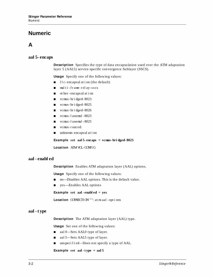
Stinger Parameter ReferenceNumeric
Numeric
A
aal5-encaps
Description Specifies the type of data encapsulation used over the ATM adaptation layer 5 (AAL5) service-specific convergence Sublayer (SSCS).
Usage Specify one of the following values:
■ llc-encapsulation (the default)
■ multi-frame-relay-sscs
■ other-encapsulation
■ vcmux-bridged-8023
■ vcmux-bridged-8025
■ vcmux-bridged-8026
■ vcmux-lanemul-8023
■ vcmux-lanemul-8025
■ vcmux-routed:
■ unknown-encapsulation
Example set aal5-encaps = vcmux-bridged-8023
Location ATM-VCL-CONFIG
aal-enabled
Description Enables ATM adaptation layer (AAL) options.
Usage Specify one of the following values:
■ no—Disables AAL options. This is the default value.
■ yes—Enables AAL options
Example set aal-enabled = yes
Location CONNECTION/"":atm-aal-options
aal-type
Description The ATM adaptation layer (AAL) type.
Usage Set one of the following values:
■ aal0—Sets AAL0 type of layer.
■ aal5—Sets AAL5 type of layer.
■ unspecified—Does not specify a type of AAL.
Example set aal-type = aal5
3-2 Stinger® Reference
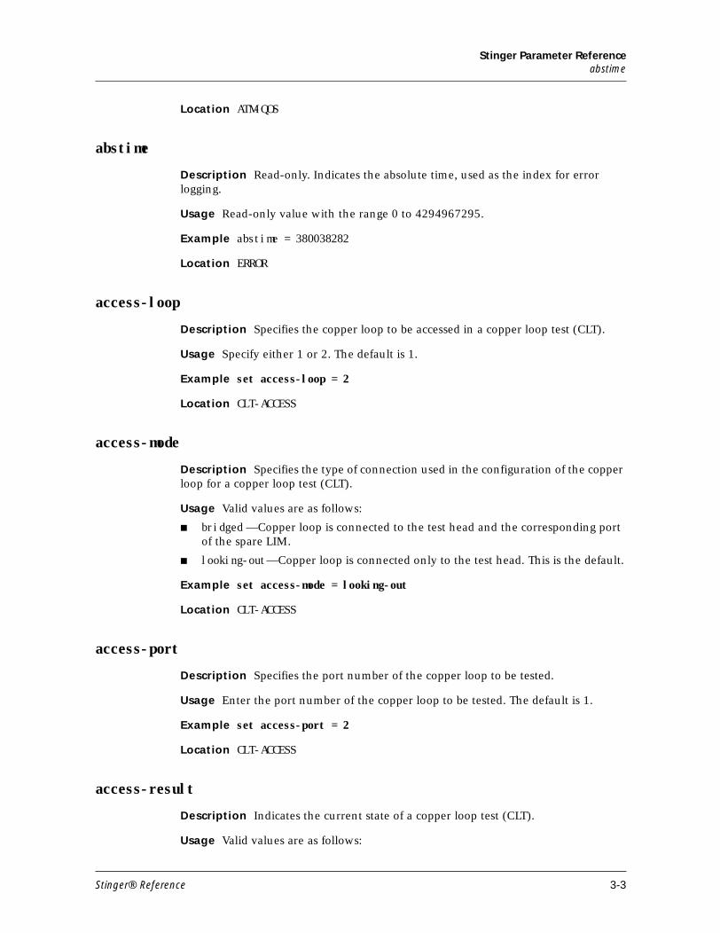
Stinger Parameter Referenceabstime
Location ATM-QOS
abstime
Description Read-only. Indicates the absolute time, used as the index for error logging.
Usage Read-only value with the range 0 to 4294967295.
Example abstime = 380038282
Location ERROR
access-loop
Description Specifies the copper loop to be accessed in a copper loop test (CLT).
Usage Specify either 1 or 2. The default is 1.
Example set access-loop = 2
Location CLT-ACCESS
access-mode
Description Specifies the type of connection used in the configuration of the copper loop for a copper loop test (CLT).
Usage Valid values are as follows:
■ bridged —Copper loop is connected to the test head and the corresponding port of the spare LIM.
■ looking-out—Copper loop is connected only to the test head. This is the default.
Example set access-mode = looking-out
Location CLT-ACCESS
access-port
Description Specifies the port number of the copper loop to be tested.
Usage Enter the port number of the copper loop to be tested. The default is 1.
Example set access-port = 2
Location CLT-ACCESS
access-result
Description Indicates the current state of a copper loop test (CLT).
Usage Valid values are as follows:
Stinger® Reference 3-3
Stinger Parameter Referenceaccess-slot
■ idle —Test head is inactive, and no copper loops are connected. This is the default
■ access-activated—Test head is active, and a copper loop is connected as specified.
Example set access-result = idle
Location CLT-ACCESS
access-slot
Description Specifies the slot number of the line interface module (LIM) containing the copper loop to be tested.
Usage Enter the slot number, preceded by slot-, of the LIM. The default is slot-16.
Specify one of the following:
■ any-slot—Special value used to specify any slot.
■ slot-1—Slot 1.
■ slot-2—Slot 2.
■ slot-3—Slot 3.
■ slot-4—Slot 4.
■ slot-5—Slot 5.
■ slot-6—Slot 6.
■ slot-7—Slot 7.
■ slot-10—Slot 10.
■ slot-11—Slot 11.
■ slot-12—Slot 12.
■ slot-13—Slot 14.
■ slot-14—Slot 14.
■ slot-15—Slot 15.
■ slot-16—Slot 16.
Example set access-slot = slot-2
Location CLT-ACCESS
access-terminal
Description Specifies the connection point of the copper loop used in the configuration of the copper loop for a copper loop test (CLT).
Usage Valid values are as follows:
■ internal-tester-terminal—Copper loop is connected to the internal test head of the CLT module. This is the default.
■ external-tester-terminal—Copper loop is connected to the external test terminals of the CLT module or path selector module (PSM).
3-4 Stinger® Reference
Stinger Parameter Referenceacct-checkpoint
■ auxiliary-tester-terminal—Copper loop is connected to the auxiliary test terminals of the CLT module or PSM.
■ external-loop—Internal test head of the CLT module is connected to external terminals.
Example set access-terminal = external-tester-terminal
Location CLT-ACCESS
acct-checkpoint
Description Specifies the interval (in seconds) at which to send checkpoint packets to the RADIUS daemon.
Usage Specify an integer from 0 to 60. The default is 0 (zero).
Example set acct-checkpoint = 30
Location EXTERNAL-AUTH:rad-acct-client
acct-checkpoint-timer
Description Specifies whether to send RADIUS checkpoint accounting packets on a per-session basis.
Usage Specify one of the following settings:
■ per-session—Specifies that checkpoint packets are sent on a per-session basis at the interval specified by the acct-checkpoint parameter.
■ all-sessions (the default)—Specifies that checkpoint packets are all sent at the same time.
Example set acct-checkpoint-timer = per-session
Dependencies For acct-checkpoint-timer to apply, you must set acct-type to radius.
Location EXTERNAL-AUTH:rad-acct-client
acct-drop-stop-on-auth-fail
Description Specifies whether RADIUS accounting stop packets are dropped for connections that fail authentication.
Usage Valid values are as follows:
■ yes—Specifies that RADIUS Accounting Stop packets are dropped for connections that fail authentication.
■ no—Specifies that RADIUS Accounting Stop packets are sent for connections that fail authentication. This is the default.
Example set acct-drop-stop-on-auth-fail = yes
Location EXTERNAL-AUTH:rad-acct-client
Stinger® Reference 3-5
Stinger Parameter Referenceacct-host
acct-host
Description Specifies a RADIUS accounting server for the Stinger to use for the connection.
Usage Enter the IP address of a RADIUS accounting server. The default is 0.0.0.0, which causes the Stinger to look for an accounting server at the address specified by the external-auth profile.
Example set acct-host = 10.9.8.2/24
Location CONNECTION:usrrad-options
acct-id-base
Description Specifies whether the numeric base of the RADIUS Acct-Session-ID attribute is 10 or 16. You can set acct-id-base globally and for each connection.
Usage Valid values are as follows:
■ acct-base-10—Specifies a decimal base. This is the default.
■ acct-base-16—Specifies a hexadecimal base.
The value you specify controls how the Stinger system presents the Acct-Session-ID attribute to the RADIUS accounting server.
Note The Acct-Session-ID attribute is defined in section 5.5 of the RADIUS accounting specification.
Example set acct-id-base = acct-base-16
Dependencies Consider the following:
■ If acct-type does not specify radius, the acct-id-base value does not apply.
■ Changing the value of acct-id-base while accounting sessions are active results in inconsistent reporting between the Start and Stop records.
Location CONNECTION:usrrad-optionsEXTERNAL-AUTH:rad-acct-client
acct-key
Description Specifies a RADIUS shared secret. A shared secret acts as a password between the Stinger unit and the accounting server.
Usage Specify the text of the shared secret. The value you specify must match the value in the RADIUS clients file. If you specify a null value, the system logs the following warning:
warning: acct-key is empty (bad for security)
Example set acct-key = mypw
Dependencies If the acct-type parameter value does not specify radius, acct-key does not apply.
3-6 Stinger® Reference
Stinger Parameter Referenceacct-limit-retry
Location CONNECTION:usrrad-optionsEXTERNAL-AUTH:rad-acct-client
acct-limit-retry
Description Specifies the maximum number of times the Stinger system tries to send accounting packets.
When the Stinger is configured for RADIUS accounting, it sends accounting Start and Stop packets to the RADIUS server to record connections. If the server does not acknowledge a packet within the number of seconds you specify for acct-timeout, the Stinger tries again, resending the packet until the server responds, or dropping the packet if the queue of packets to be resent is full. You can limit the number of retries by setting a maximum.
Usage To set the maximum number of retries for accounting packets, set acct-limit-retry to a value greater than 0 (zero). A value of 0 (the default) indicates an unlimited number of retries.
Note The Stinger always makes at least one attempt. For example, if you set the number of retries to 10, the Stinger makes 11 attempts—the original attempt plus 10 retries.
Example set acct-limit-retry = 10
Location EXTERNAL-AUTH:rad-acct-client
acct-port
Description Specifies the UDP destination port to use for external accounting requests. When using RADIUS accounting, you can set acct-port globally and for each connection.
Usage Specify a UDP port number from 1 to 32767. The value must match the port number the accounting daemon uses. Following are the defaults for RADIUS:
■ The default in a connection profile is 1646.
■ The default in the external-auth profile is 0 (zero).
Example set acct-port = 1500
Dependencies If the acct-type parameter value does not specify radius, acct-port does not apply.
Location CONNECTION:usrrad-optionsEXTERNAL-AUTH:rad-acct-client
acct-radius-compat
Description Enables or disables vendor-specific attribute (VSA) compatibility mode when the Stinger is using RADIUS for accounting purposes.
Usage Valid values are as follows:
Stinger® Reference 3-7
Stinger Parameter Referenceacct-reset-time
■ old-ascend—Specifies that the Stinger does not send the vendor-specific attribute to the RADIUS server and does not recognize the vendor-specific attribute if the server sends it. This is the default.
■ vendor-specific—Specifies that the Stinger uses the vendor-specific attribute to encapsulate Lucent vendor attributes, and uses the RFC-defined User-Password encryption algorithm as well.
Example set acct-radius-compat = vendor-specific
Location EXTERNAL-AUTH:rad-acct-client
acct-reset-time
Description Specifies the number of seconds that must elapse before the Stinger returns to using the primary RADIUS accounting server.
Usage Specify the number of seconds. The default is 0 (zero), which specifies that the Stinger does not return to using the primary RADIUS accounting server.
Example set acct-reset-time = 60
Dependencies For acct-reset-time to apply, you must specify at least one value for the Acct-Server-N parameter.
Location EXTERNAL-AUTH:rad-acct-client
acct-server-n
Description Specifies the IP addresses of up to three external accounting servers. The Stinger first tries to connect to server 1. If it receives no response, it tries to connect to server 2. If it still receives no response, it tries to connect to server 3.
Usage Specify an IP address in dotted decimal notation. The default is 0.0.0.0, which indicates that no accounting server exists.
Example set acct-server-1 = 10.2.3.4/24
Dependencies Consider the following:
■ If the acct-type parameter value does not specify radius, acct-server-n does not apply.
■ If the Stinger connects to a server other than server 1, and acct-reset-time is set to 0, the Stinger continues to use that server until it fails to service requests, even if server 1 comes back online. If the acct-reset-time parameter is set to a value other than 0 (zero), the Stinger returns to using the primary accounting server after the number of seconds specified by acct-reset-time has elapsed.
Location EXTERNAL-AUTH:rad-acct-client
acct-sess-interval
Description Specifies the number of seconds between RADIUS accounting reports that record the number of open sessions.
3-8 Stinger® Reference
Stinger Parameter Referenceacct-src-port
Usage Specify a number of seconds from 0 to 65535. The default is 0 (zero), which turns off regular RADIUS open-session reports.
Example set acct-sess-interval = 15
Dependencies If the acct-type parameter value does not specify RADIUS, acct-sess-interval does not apply. Acct-Sess-Interval has no effect unless the Lucent RADIUS daemon is running.
Location EXTERNAL-AUTH:rad-acct-client
acct-src-port
Description Specifies the UDP source port to use for RADIUS accounting.
Usage Specify a value from 0 to 65535. The default is 0 (zero), which specifies that the Stinger selects the source port from the nonprivileged port range, 1024 through 2000.
Example set acct-src-port = 3278
Dependencies The Stinger uses the source port number to demultiplex the RADIUS reply packets to the appropriate line or trunk module. The system uses a separate source port for each module and shelf controller. On the Stinger, the actual source port is the value of acct-src-port plus the slot number. The slot number is 0 (zero) for the control module. So, if you set acct-src-port to 1000, packets originating from the control module have a source port value of 1000, while packets originating from slot 6 have a source port value of 1006.
Location EXTERNAL-AUTH:rad-acct-client
acct-stop-only
Description Specifies whether the Stinger can send an Accounting Stop packet that does not contain a username. (At times, the Stinger can send an Accounting Stop packet to the RADIUS server without having sent an Accounting Start packet. These Stop packets have no username.)
Usage Valid values are as follows:
■ yes—Specifies that the Stinger can send an Accounting Stop packet even if it does not contain a username. This is the default.
■ no—Specifies that the Stinger cannot send an Accounting Sop packet if it does not contain a username.
Example set acct-stop-only = no
Location EXTERNAL-AUTH:rad-acct-client
acct-timeout
Description Specifies the amount of time (in seconds) that the Stinger waits for a response to a RADIUS accounting request. You can set acct-timeout globally and for each connection.
Stinger® Reference 3-9
Stinger Parameter Referenceacct-tunnel-connection-encoding
If it does not receive a response within the specified time, the Stinger sends the accounting request to the next server specified by acct-server-n. If all RADIUS accounting servers are busy, the Stinger stores the accounting request and tries again at a later time. It can queue up to 154 requests.
Usage Specify an integer from 1 to 10. Following are the defaults:
■ The default for a connection profile is 1.
■ The default for the external-auth profile is 1.
Example set acct-timeout = 5
Dependencies If the acct-type parameter does not specify radius, acct-timeout does not apply.
Location CONNECTION:usrrad-optionsEXTERNAL-AUTH:rad-acct-client
acct-tunnel-connection-encoding
Description Specifies an encoding method for the value of the RADIUS Acct-Tunnel-Connection attribute. NavisRadius™ software uses the value generated by the default setting of this parameter.
Usage Specify one of the following values:
■ normal—Generates the Acct-Tunnel-Connection attribute value from the source and destination IP addresses, tunnel ID, and connection ID. This is the default.
■ decimal-call-serial-number—Generates the Acct-Tunnel-Connection attribute value from the 32-bit Layer 2 Tunneling Protocol (L2TP) call serial number (CSN) encoded as a decimal string.
■ hexadecimal-call-serial-number—Generates the Acct-Tunnel-Connection attribute value from the L2TP CSN encoded as a hexadecimal string.
Example set acct-tunnel-connection = decimal-call-serial-number
Location L2-TUNNEL-GLOBAL:l2tp-config
acct-type
Description Specifies whether to use RADIUS accounting or no accounting at all. You can specify accounting globally and for each connection.
Usage To enable or disable accounting in the external-auth profile, specify one of the following values:
■ none—Disables accounting. This is the default.
■ radius—Enables RADIUS accounting.
To set accounting policy for a particular connection, specify one of the following values in the connection profile:
■ global—Specifies that the Stinger sends accounting information to one of the accounting servers specified by the external-auth profile. This is the default.
3-10 Stinger® Reference
Stinger Parameter Referenceaccum-bit-err
■ local—Specifies that the Stinger sends accounting information to the accounting server specified by acct-host in the connection profile.
■ both—Specifies that the Stinger sends accounting information to both the global and local servers.
Example set acct-type = radius
Dependencies Consider the following:
■ If you set auth-type to radius/logout, the Stinger disables RADIUS accounting. For acct-type to have any effect in a connection profile, you must set auth-type to radius.
■ If you set acct-type to radius, you must set the acct-server parameter to specify at least one accounting server, and that server must be running a version of the daemon that specifically supports accounting.
Location CONNECTION:usrrad-optionsEXTERNAL-AUTH
accum-bit-err
Description Read-only. Indicates the read-only number of actual bit errors detected during a continuous bit-error-rate test (BERT).
Usage The accum-bit-err value is read-only.
Example accum-bit-err = 0
Location AL-DMT-STAT {shelf-N slot-N N }:physical-status
acf-comp-enabled
Description Not currently used. Specifies whether the PPP address and control field compression are enabled or disabled.
Usage Valid values are as follows:
■ yes—Compression is enabled.
■ no—Compression is disabled. This is the default.
Location CONNECTION :ppp-options
activate-access
Description Read-only. Indicates whether the copper loop is connected for a copper loop test (CLT).
Usage Valid values for this read-only parameter are as follows:
■ yes—Copper loop is connected as specified.
■ no—Copper loop is disconnected from the test head or test terminals. This is the default.
Example activate-access = no
Stinger® Reference 3-11
Stinger Parameter Referenceactivate-test
Location CLT-ACCESS
activate-test
Description Activates or deactivates a test.
Usage Valid values are as follows:
■ yes—Disconnects any existing calls on tested ports and begins the test.
■ no—Reconnects any disconnected calls and stops the test. This is the default.
Example set activate-test = yes
Location LINE-TESTS
activation
Description Not currently used.
Usage Leave the default value: static.
Example activation = static
Location AL-DMT:line-configDS3-ATM:line-configHDSL2:line-configSHDSL:line-config
active
Description Specifies the activation of an interface or feature. An active interface is available for use.
Usage Valid values are as follows:
■ yes—Activates the interface or feature. This is the default in the debug, lim-sparing-status, switch-config, and vrouter profiles only.
■ no—Makes the interface or feature unavailable for use. This is the default in all other profiles.
Example set active = yes
Location APS-CONFIGCONNECTIONCONNECTION:ip-options:tos-optionsDEBUGFRAME-RELAYIMA-GROUPLIM-SPARING-STATUS:lim-sparing-status[n]MULTI-LINK-FRPNNI-METRICSPNNI-ROUTE-ADDRPNNI-ROUTE-TNSPNNI-SUMMARY-ADDR
3-12 Stinger® Reference
Stinger Parameter Referenceactive-enabled
SWITCH-CONFIG:atm-parameters:outgoing-queue:outgoing-queue[n]VACM-ACCESSVACM-SECURITY-GROUPVACM-VIEW-TREEVROUTER
active-enabled
Description Specifies whether one of the following profiles is enabled or disabled:
■ user profile—Specifies whether the profile is enabled or disabled. A disabled profile is not available for use. A dash appears before each inactive profile.
■ snmpv3-notifications or snmpv3-target-param profile—Specifies whether the profile is used to generate notifications.
■ trap profile—Specifies whether traps are sent to the host specified by the profile.
Usage Valid values are as follows:
In a user profile
■ yes—Enables the user profile. This is the default.
■ no—Disables the user profile.
In an snmpv3-notifications or snmpv3-target-param profile
■ yes—Specifies that the profile is used to generate notifications.
■ no—Specifies that the profile is not used to generate notifications. This is the default.
In a trap profile
■ yes—Specifies traps are sent. This is the default.
■ no—Specifies that traps are not sent.
Example set active-enabled = yes
Location USERSNMPV3-NOTIFICATIONSSNMPV3-TARGET-PARAMTRAP
activelinkcount
Description Read-only. Indicates the number of active data link connection identifiers (DLCI) in the permanent virtual circuit (PVC).
Usage Read-only numeric parameter with a range of 0 to 65535.
Example activelinkcount = 10
Location FRPVC-STAT/""
Stinger® Reference 3-13
Stinger Parameter Referenceactive-route
active-route
Description Enables or disables the entry of a route in the routing table. (Setting the parameter to no is a useful way to make a route temporarily inactive, so you can reinstate the route later.)
Usage Specify yes or no. The default is yes, except for the ip-route profile called default. For the default ip-route profile, the default is no.
■ yes—Activates the static route and add it to the routing table.
■ no—Deactivates the route. An inactive route does not affect packet routing.
Example set active-route = yes
Dependencies The default route is an ip-route profile with the name default and a destination address of 0.0.0.0/0. To activate the default route, you must set gateway-address to the IP address of the default router, and set active-route to yes.
Location IP-ROUTE/""
active-upstream-bandwidth-on-trunks
Description Read-only. Indicates the active trunk-side bandwidth, based on the number of trunk ports and their status.
Usage The active-upstream-bandwidth-on-trunks value is read-only.
Example active-upstream-bandwidth-on-trunks = 155540
Location BANDWIDTH-STATS
add-link-cond-time
Description Not currently used. Specifies the link conditioning time-out, in seconds, during link addition or insertion.
Usage Leave the default value.
Example add-link-cond-time = 0
Location DS1-ATM/{ shelf-N slot-N N }:line-config:ima-option-config:txlink-configDS1-ATM/{ shelf-N slot-N N }:line-config:ima-option-config:rxlink-config
add-persistence
Description Specifies the number of seconds that average line utilization (ALU) must persist beyond the target-utilization threshold before the Stinger unit adds bandwidth from available channels.
Usage Specify an integer from 1 to 300. The default is 5.
Example set add-persistence = 15
3-14 Stinger® Reference

Stinger Parameter Referenceaddress
Dependencies Consider the following:
■ When adding bandwidth, the unit adds the number of channels specified by increment-channel-count parameter in the mpp-options subprofile.
■ When the seconds-history parameter value is high, add-persistence has little effect.
Location ANSWER-DEFAULTS:mpp-answerCONNECTION:mpp-options
address
Description Specifies an address or a prefix to an address in one of several profiles. Depending on which profile the parameter is in, the address setting can be configurable or read-only.
Usage Address parameters have different uses in different profiles. The specific use of the address determines the number of bytes the address needs.
■ In the atm-addr-alias profile, the address parameter specifies the Private Network-to-Network Interface (PNNI) node, the ATM end-system address, or a part of the end-system address. The number of bytes is specified in the length parameter setting in the same profile.
■ In the addr-index subprofile of the pnni-route-addr profile, the address parameter specifies the prefix of a reachable ATM address.
■ In the pnni-summary-addr profile, the address parameter specifies the prefix of a reachable ATM address.
Example set address = 47410017001700170017001700
Location ATM-ADDR-ALIASATM-IF-CONFIGATM-IF-SIG-PARAMSATM-IF-STATPNNI-IF-CONFIGPNNI-SUMMARY-ADDR:addr-index
See Also address (ATM-PREFIX:pnni-node-prefix), address (ATM-PREFIX:spvc-address-prefix), address (ATM-PREFIX:svc-address-prefix)
address (ATM-PREFIX:pnni-node-prefix)
Description Specifies the address prefix for Private Network-to-Network Interface (PNNI) node ATM addresses.
Usage Enter an address prefix value from 1 to 13 bytes long. The default value is a prefix value generated from the primary controller serial number.
Example set address = 39:84:0f:80:01:bc:72:00:01:bc:e7:6c:02
Dependencies Whenever you explicitly configure an address or a prefix setting, the system uses the value you specify rather than the system-generated default. If you delete the atm-prefix profile, the system creates a new one at the next system startup.
Stinger® Reference 3-15
Stinger Parameter Referenceaddress (ATM-PREFIX:spvc-address-prefix)
Location ATM-PREFIX/"":pnni-node-prefix
See Also address, address (ATM-PREFIX:spvc-address-prefix), address (ATM-PREFIX:svc-address-prefix)
address (ATM-PREFIX:spvc-address-prefix)
Description Specifies a prefix value used to generate the address in the default set of atm-spvc-addr-config profiles.
Usage Enter an address prefix value from 1 to 13 bytes long. The default value is 0.
Example set address = 39:84:0f:80:01:bc:72:00:01:bc:e7:6c:02
Dependencies With the default setting of 0, the value is taken from the address parameter in the pnni-node-prefix subprofile.
Location ATM-PREFIX/"":spvc-address-prefix
See Also address (ATM-PREFIX:pnni-node-prefix), address, address (ATM-PREFIX:svc-address-prefix)
address (ATM-PREFIX:svc-address-prefix)
Description A prefix value used to generate the address in the default set of atm-svc-addr-config profiles.
Usage Enter an address prefix value from 1 to 13 bytes long. The default value is 0.
Example set address = 39:84:0f:80:01:bc:72:00:01:bc:e7:6c:02
Dependencies With the default setting of 0, the value is taken from the address parameter in the pnni-node-prefix subprofile.
Location ATM-PREFIX/"":svc-address-prefix
See Also address (ATM-PREFIX:pnni-node-prefix), address (ATM-PREFIX:spvc-address-prefix), address
address-pool
Description Specifies a number of an address pool from which to acquire an address. When pool chaining is enabled, a pool number within a chain includes addresses defined in all other pools within the chain. For example, if pools 1, 2, and 3 are in a pool chain, setting this parameter to 1 has the same effect as setting it to 2 or 3.
Usage Specify a number from 0 to 128. The default is 0 (zero).
Example set address-pool = 5
Dependencies If address-pool is set to 0 (zero) and assign-address is set to yes, the Stinger unit gets IP addresses from the first defined address pool.
3-16 Stinger® Reference
Stinger Parameter Referenceadv-node-id
Location CONNECTION/"":ip-options
adv-node-id
Description Specifies the ID of a Private Network-to-Network Interface (PNNI) node that advertises reachability to the address prefix.
Usage You can enter the full 22-byte ID or an alias. For details about using an alias to assign an address, see the Stinger Private Network-to-Network Interface (PNNI) Supplement.
Example set adv-node-id = 00:00:00:00:00:00:00:00:00:00:00:00:00:00:00:00:00:00:0+
Location PNNI-ROUTE-ADDR
adv-port-id
Description Specifies the identifier on the advertising node of the interface used to reach the address prefix.
Usage Specify a number from zero (0) to 2147483647. The default is 0.
Example set adv-port-id = 0
Location PNNI-ROUTE-ADDR
agent-mode
Description Specifies whether the Stinger unit operates as an Ascend Tunnel Management Protocol (ATMP) Foreign Agent or Home Agent, or selects which of those two modes to use for different traffic streams.
Usage Specify one of the following values:
■ tunnel-disabled (the default)—Disables ATMP.
■ home-agent—Operates as a Home Agent.
■ foreign-agent—Operates as a Foreign Agent.
■ home-and-foreign-agent—Operates as both a Home Agent and a Foreign Agent.
Example set agent-mode = foreign-agent
Dependencies If you change the agent-mode setting from its default, the new value does not take effect until you reset the system.
Location ATMP
agent-type
Description In an Ascend Tunnel Management Protocol (ATMP) Home Agent configuration, this parameter specifies gateway-home-agent (the default) or router-home-agent, depending on how the Home Agent accesses the home network.
Stinger® Reference 3-17
Stinger Parameter Referenceaggregate
Usage Specify one of the following values:
■ gateway-home-agent (the default)—Delivers tunneled data to the home network without routing. The connection between the Home Agent and the home network must be a leased connection.
■ router-home-agent—Routes tunneled data to the home network.
Example set agent-type = router-home-agent
Dependencies This setting applies only when the agent-mode parameter is set to home-agent.
Location ATMP
aggregate
Description Specifies whether virtual circuits using this traffic shaper are to be aggregated or not.
Usage Valid values are as follows:
■ yes—Virtual circuits are aggregated. If the parameter set to yes and the traffic shaper is applied to more than one virtual circuit, the combined virtual circuits share the full bandwidth defined in the shaper.
■ no (the default)—Virtual circuits are not aggregated.
Example set aggregate = yes
Location ATM-CONFIG:traffic-shapers n
aim-enabled
Description Read-only. Indicates whether the unit enables Ascend Inverse Multiplexing (AIM).
Usage The aim-enabled setting is read-only. Values are as follows:
■ yes—Indicates that AIM is enabled.
■ no—Indicates that AIM is not enabled. This is the default.
Example aim-enabled = yes
Location BASE
ais-receive
Description Read-only. Indicates whether the remote end is sending an Alarm Indication signal (AIS) on the line. The remote end sends an AIS (instead of normal data) to take the line out of service.
Usage The ais-receive setting is read-only. Values are as follows:
■ true—Indicates that the remote end is sending an AIS.
■ false—Indicates that the remote end is not sending an AIS.
3-18 Stinger® Reference
Stinger Parameter Referencealarm-enabled
Example ais-receive = true
Location DS1-ATM-STATDS3-ATM-STAT {shelf-N slot-N N}E3-ATM-STATOC3-ATM-STAT {shelf-N trunk-module-N N}
alarm-enabled
Description Specifies whether the Stinger traps alarm events and sends a trap protocol data unit (PDU) to the SNMP manager. The Ascend Enterprise MIB defines the following alarm events. For a complete list, see the Stinger Administration Guide or the Ascend Enterprise MIB.
Usage Valid values are as follows:
■ yes (the default)—Specifies that the Stinger sends alarm-event traps to the host specified in the host-address parameter setting in the TRAP profile.
■ no—Specifies that the Stinger does not send alarm-event traps.
Example set alarm-enabled = no
Location TRAP
Alarm event Indicates that the unit
coldStart (RFC-1215 trap-type 0)
Is reinitializing itself in such a way that it might alter the configuration of either the SNMP man-ager or the unit.
warmStart (RFC-1215 trap-type 1)
Is reinitializing itself so that neither the configura-tion of the SNMP manager nor that of the unit will change.
linkDown (RFC-1215 trap-type 2)
Recognizes a failure in one of the communication links represented in the SNMP manager’s config-uration.
linkUp (RFC-1215 trap-type 3)
Recognizes that one of the communication links represented in the SNMP manager's configura-tion has come up.
frDLCIStatusChange (RFC-1315 trap-type 1)
Recognizes that one of the virtual circuits has changed states. The link has been created, invali-dated, or toggled between the active and inactive states.
eventTableOverwrite (Lucent trap-type 16)
Detected that a new event has overwritten an unread event. Once sent, additional overwrites will not cause another trap to be sent until at least one table’s worth of new events has occurred.
Stinger® Reference 3-19
Stinger Parameter Referencealarm-led-major
alarm-led-major
Description Specifies the behavior of the MAJOR alarm status light when the system detects a major alarm.
Usage Valid values are as follows:
■ on—The MAJOR alarm status light illuminates when the system detects the event specified by event in the alarm profile.
■ off (the default)—The MAJOR alarm status light remains off when the system detects an event.
Example set alarm-led-major = on
Location ALARM:action
alarm-led-minor
Description Specifies the behavior of the MINOR alarm status light when the system detects a minor alarm.
Usage Valid values are as follows:
■ on—The MINOR alarm status light illuminates when the system detects the event specified by event in the alarm profile.
■ off (the default)—The MINOR alarm status light remains off when the system detects an event.
Example set alarm-led-minor = on
Location ALARM:action
alarm-relay-major
Description Specifies the behavior of the MAJOR alarm relay.
Usage Valid values are as follows:
■ on—Sets the relay for the MAJOR alarm circuit to close when the system detects the condition specified by event.
■ off (the default)—Sets the relay for the MAJOR alarm circuit to ignore the condition specified by event.
Example set alarm-relay-major = on
Location ALARM:action
alarm-relay-major-duration
Description Specifies the number of seconds that the Stinger leaves alarm-relay-major in the position specified in the alarm-relay-major parameter.
Usage Specify an integer. The default is 0 (zero), which directs the Stinger to leave the alarm set indefinitely.
3-20 Stinger® Reference
Stinger Parameter Referencealarm-relay-minor
Example set alarm-relay-major-duration = 30
Location ALARM:action
alarm-relay-minor
Description Specifies the behavior of the MINOR alarm relay.
Usage Valid values are as follows:
■ on—Sets the relay for the MINOR alarm circuit to close when the system detects the condition specified by event.
■ off (the default)—Sets the relay for the MINOR alarm circuit to ignore the condition specified by event.
Example set alarm-relay-minor = on
Location ALARM:action
alarm-relay-minor-duration
Description Specifies the number of seconds that the Stinger leaves alarm-relay-minor in the position specified in the alarm-relay-minor parameter.
Usage Specify a number. The default is 0 (zero), which directs the Stinger to leave the alarm set indefinitely.
Example set alarm-relay-minor-duration = 30
Location ALARM:action
alarm-state
Description Read-only. Indicates the status of the alarm specified by alarm-id.
Usage Valid values are as follows:
■ alarm-active—Indicates that the alarm is active and appropriate action has been taken (setting status lights or closing relays).
■ alarm-acknowledged—Indicates that the alarm has been acknowledged by the user.
Example set alarm-state = alarm-active
Note You can acknowledge the alarm by setting the alarm-state parameter to alarm-acknowledged or using the alarm -a command.
Location ALARM-STAT
alcatel-us-413-boost
Description Provides an increase in upstream rate in T1.413 mode for 24 or 48-port Annex A line interface modules (LIMs) based on the Globespan chip set when connected to Alcatel customer premises equipment (CPE).
Stinger® Reference 3-21
Stinger Parameter Referenceal-dmtadsl-atm
Caution This parameter is irrelevant for any other situation. Use with extreme caution.
Usage Specify one of the following values:
■ new—Use with firmware releases 3.6.7.0 or later.
■ old—Use with firmware release earlier than 3.6.7.0.
■ unknown—Lucent Technologies recommends that this value be used for all firmware releases. This is the default value.
Example set alcatel-us-413-boost = old
Location AL-DMT:line-config
al-dmtadsl-atm
Description Not currently used. Controls whether code images for ADSL line interface modules (LIMs) are to be stored in flash memory.
Usage Valid values are as follows:
■ auto—Loads the code image if there is a module installed of that type. This is the default.
■ load—Loads the image when one is present in the tar file
■ skip—Skips the code image when one is present in the tar file
Example set al-dmtadsl-atm = auto
Location LOAD-SELECT
alias-name
Description Specifies a name to represent the address identified the atm-addr-alias profile. This parameter provides a more convenient way of accessing the ATM address.
Usage Specify a string of up to 20 characters. The default is null.
Example set alias-name = node1alias
Location ATM-ADDR-ALIAS
allow-as-client-dns-info
Description Enables or disables an exit mechanism to local servers if the client Domain Name System (DNS) servers are not found. To isolate local network information, set this parameter to false.
When specified in a vrouter profile, this DNS setting is exclusive to the virtual router. If DNS settings are not specified in a vrouter profile, the virtual router uses the DNS settings defined in the ip-global profile
Usage Valid values are as follows:
3-22 Stinger® Reference
Stinger Parameter Referenceallow-auth-config-rqsts
■ true (the default)—Makes the local DNS servers accessible to PPP connections if the client DNS servers are unavailable.
■ false—Does not make local DNS servers accessible to PPP connections if the client DNS servers are unavailable.
Example set allow-as-client-dns-info = false
Location IP-GLOBALVROUTER/""
allow-auth-config-rqsts
Description Specifies whether the unit allows external configuration requests in authentication processing.
Usage Valid values are as follows:
■ yes (the default)—Specifies that the unit allows external configuration requests in authentication processing.
■ no—Specifies that the unit does not allow external configuration requests in authentication processing.
Example set allow-auth-config-rqsts = no
Location EXTERNAL-AUTH:rad-auth-client
allow-code
Description Specifies whether permission to upload code to the Stinger and use the following code-level commands is enabled or disabled:
■ format—Prepares a flash card for use.
■ fsck—Checks the file system on a flash card.
Usage Valid values are as follows:
■ yes—Grants permission to upload code to the Stinger.
■ no (the default)—Denies permission to upload code to the Stinger.
Example set allow-code = yes
Location USER
allow-debug
Description Enables or disables user access to debug commands.
Usage Specify one of the following values:
■ no—User cannot use debug commands. This is the default value.
■ yes—User can use debug commands.
Example set allow-debug = yes
Stinger® Reference 3-23
Stinger Parameter Referenceallow-diagnostic
Location USER/""
allow-diagnostic
Description Specifies permission to all commands with a permission level of diagnostic, including the following:
Usage Valid values are as follows:
■ yes—Grants permission to use diagnostic commands.
■ no (the default)—Denies permission to use diagnostic commands.
Example set allow-diagnostic = yes
Location USER
allow-guaranteed-up-stream-bandwidth
Description Specifies the guaranteed upstream bandwidth for a slot.
Usage Specify an integer in kilobits per second. The default is 44000Kbps for each line interface module (LIM), which distributes the sum of 622Mbps across the 14 LIM slots. Typically, slots with a high requirement for real-time traffic need high guaranteed bandwidth.
Example set allow-guaranteed-up-stream-bandwidth = 80000
Dependencies Even when the system is heavily loaded or the network is congested, the slot should be able to send upstream traffic at the rate of the specified allow-guaranteed-up-stream-bandwidth value. The total of all guaranteed upstream bandwidth for all slots cannot exceed the maximum upstream capacity of the system.
Location ATM-CONFIG:bandwidth-config:bandwidth-config n
Command Description
clock-source Display clock-source statistics.
debug Enable or disable diagnostic output.
device Start or halt a device.
ether-display Display the contents of received Ethernet packets.
if-admin Administer an interface.
open Start a session with a line interface or trunk module.
ping Ping the specified host.
slot Administer a line interface or trunk module.
telnet Open a Telnet session.
traceroute Display route statistics.
uptime Report how long the system has been operational and how long individual modules have been operational.
3-24 Stinger® Reference
Stinger Parameter Referenceallow-max-up-stream-bandwidth
allow-max-up-stream-bandwidth
Description Specifies the maximum upstream bandwidth for the slot.
Usage Specify a value in kilobits per second (Kbps) from 0 to 155000 (OC3 speed). The default is 70,000Kbps for each line interface module (LIM), and 1000Kbps for each control module.
Example set allow-max-up-stream-bandwidth = 80000
Dependencies For some LIMs, the default allow-max-up-stream-bandwidth setting of 70Mbps is too low, which can cause a fully loaded LIM to drop upstream data cells.
For example, the 48-port SDSL LIM (STGR-LIM-SQ-48), which provides high-speed symmetric data transfer up to 2.3Mbps per interface, requires a maximum upstream bandwidth setting of 112Mbps to accommodate all its ports (48 * 2.32 = 112). For this LIM and any other LIM that supports upstream bandwidth greater than 70Mbps, you must modify the default setting for the allow-max-up-stream-bandwidth parameter to prevent the module from dropping data cells when it is fully loaded.
Note A 155Mb throughput on a LIM is not guaranteed traffic. If a LIM allows traffic up to that limit, the system makes a best-effort attempt to deliver it.
Location ATM-CONFIG:bandwidth-config:bandwidth-config n
allow-password
Description Specifies permission to view passwords.
Usage Valid values are as follows:
■ yes—Grants permission to view passwords.
■ no (the default)—Denies permission to view passwords.
Example set allow-password = yes
Location USER
allow-system
Description Enables or disables permission to use all commands with a permission level of system, including the following:
Command Description
arptable Display or modify the Stinger address resolution protocol (ARP) table.
clr-history Clear the fatal-error history log.
connection Display the connection-status window.
dir List profiles and profile types.
dircode Show the contents of the PCMCIA module code.
fatal-history List the fatal-error history log.
get Display settings in a profile.
Stinger® Reference 3-25
Stinger Parameter Referenceallow-termserv
Usage Valid values are as follows:
■ yes—Grants permission to use system commands.
■ no—Denies permission to use system commands. This is the default.
Example set allow-system = yes
Location USER
allow-termserv
Description Enables or disables permission to use the terminal server and its commands.
Usage Valid values are as follows:
■ yes—Grants permission to use the terminal server and its commands.
■ no—Denies permission to use the terminal server and its commands. This is the default.
Example set allow-termserv = yes
Location USER
allow-unencrypted-tunnel-password
Description Enables or disables acceptance of unencrypted tunnel passwords from RADIUS.
Usage Specify one of the following values:
■ no (the default)—Only encrypted tunnel passwords from RADIUS are accepted.
iproute Add or delete IP routes.
line Display the line-status window.
list List settings in the working profile.
log Display and control the event-log window.
netstat Display the routing or interface tables.
new Create a new profile.
read Make the specified profile the working profile.
refresh Refresh the remote configuration.
set Specify a value.
show Show shelves, slots, ports, or items.
status Display the system status or hide the status window.
userstat Display user session status.
version Display software-version information.
view Change the contents of a status window.
Command Description
3-26 Stinger® Reference
Stinger Parameter Referenceallow-update
■ yes—Unencrypted or encrypted tunnel-passwords are accepted from RADIUS.
Example set allow-unencrypted-tunnel-password = yes
Dependencies When this parameter is set to yes, RADIUS must encrypt the tunnel password before sending out to the tunnel server.
Location EXTERNAL-AUTH:rad-auth-client
allow-update
Description Specifies permission to use all commands with a permission level of update, including the following:
Usage Valid values are as follows:
■ yes—Grants permission to use update commands.
■ no—Denies permission to use update commands. This is the default.
Example set allow-update = yes
Location USER
alpha-cell-delin-value
Description Specifies the number of consecutive cells with incorrect header error control (HEC) that must be reached before the Stinger leaves the SYNC state (where the Stinger has correctly recognized cell boundaries) to go to the HUNT state (where the Stinger is still searching for the cell boundary) in an ATM connection.
Usage Specify a number from one to 16. The default is 7.
Example alpha-cell-delin-value = 7
Location IMAHW-CONFIG { shelf-n slot-n n}
alpha-ima-value
Description Specifies the number of consecutive invalid IMA Control Protocol (ICP) cells that the Stinger must detect before changing to inverse multiplexing ATM (IMA) HUNT state (cell-by-cell validation) from the SYNC state (frame-by-frame validation).
Command Description
date Set the system date.
delete Delete the specified profile.
load Load code or saved configuration to flash.
nvram Clear the configuration and reboot the system.
reset Reboot the system.
save Save a profile for a future restore.
write Store the working profile and save changes.
Stinger® Reference 3-27
Stinger Parameter Referenceannexb-dmtadsl
Usage Specify the number 1 (one) or the number 2. The default is 2.
Example set alpha-ima-value = 1
Location IMAHW-CONFIG { shelf-n slot-n n}
annexb-dmtadsl
Description Not currently used. Specifies whether code images for 12-port Annex B ADSL line interface modules (LIMs) are to be stored in flash memory.
Usage Valid values are as follows:
■ auto—Load the code image if there is a module installed of that type. This is the default.
■ load—Load the code image when one is present in the tar file.
■ skip—Skip the code image when one is present in the tar file.
Example set annexb-dmtadsl = auto
Location LOAD-SELECT
ansi-adsl-ver
Description Read-only. Indicates the supported issue of the ANSI T1.413 standard (issue 2).
Usage The ansi-adsl-ver value is read-only.
Example ansi-adsl-ver = 2
Location AL-DMT-STAT {shelf-n slot-n n}:physical-status
answer-number-1
Description Specifies the first telephone number to be used for the analog device attached to the Stinger. The Stinger uses this number, or the value in answer-number-2, to route all calls it receives with this number to the device.
Usage Enter a telephone number of up to 24 characters.
Example set answer-number-1 = 747-5775
Location IDSL { n n n }:line-interface
answer-number-2
Description Specifies a second telephone number to be used for the analog device attached to the Stinger. The Stinger uses this number, or the value in answer-number-1, to route all calls it receives with this number to the device.
Usage Enter a telephone number of up to 24 characters.
3-28 Stinger® Reference
Stinger Parameter Referenceanswer-originate
Example set answer-number-2 = 747-5776
Location IDSL { n n n }:line-interface
answer-originate
Description Not supported. Specifies whether the connection profile allows dial-out capability.
Location CONNECTION/"":telco-options
apply-to
Description Specifies the direction in which type-of-service (TOS) settings are enabled.
Usage Specify one of the following values:
■ input (the default)—Set bits in packets received on the interface.
■ output—Set bits in packets transmitted on the interface.
■ both—Set bits in packets sent and received on the interface.
Example set apply-to = both
Dependencies For this setting to apply, TOS and IP routing must be enabled in the connection profile.
Location CONNECTION/"":ip-options:tos-options
aps-cfg-creation-time
Description Read-only. A timestamp that indicates the amount of time that has elapsed since the creation of the aps-config profile in automatic protection switching (APS). The TAOS timestamp shows the number of ticks since December 1, 1990.
Usage The valid range for this read-only parameter is from 0 through 2147483647.
Example aps-cfg-creation-time = 356537747
Location APS-STAT
aps-channel-low-direction
Description Read-only. Indicates the state of lockout of the working (LOW) direction in the automatic protection (APS) system.
Usage Valid values for this read-only parameter are as follows
■ low-none (the default)—No lock out of the working channel in either direction currently exists.
■ low-recv—There is a lock out of the working channel in the receive direction.
■ low-send—There is a lock out of the working channel in the send direction.
Stinger® Reference 3-29
Stinger Parameter Referenceaps-channel-recv-ais-count
■ low-both—There is a lock out of the working channel in the both directions.
Example aps-channel-low-direction = none
Location OC3-ATM-STAT
aps-channel-recv-ais-count
Description Read-only. Indicates the count of Alarm Indication signal (AIS)-L errors received on the channel.
Usage The valid range for this read-only parameter is from 0 through 2147483647. The default is 0.
Example aps-channel-recv-ais-count = 0
Location OC3-ATM-STAT/{ shelf-any trunk-module-any any }
aps-channel-recv-rdi-count
Description Read-only. Indicates the count of restricted digital information (RDI)-L received on the protection channel.
Usage The valid range for this read-only parameter is from 0 through 2147483647. The default is 0.
Example aps-channel-recv-rdi-count = 2
Location OC3-ATM-STAT/{ shelf-any trunk-module-any any }
aps-channel-recv-sf-condition
Description Read-only. Indicates the number of signal degrade conditions (line bit-error rates beyond the configured threshold) received over the K1K2 APS channel from the far-end.
Usage The valid range for this read-only parameter is from 0 through 2147483647. The default is 0.
Example aps-channel-rec-sf-condition = 0
Location OC3-ATM-STAT
aps-channel-recv-sd-count
Description Read-only. Indicates the number of signal degrade conditions (line bit-error rates beyond the configured threshold) received over the K1K2 APS channel from the far-end.
Usage The valid range for this read-only parameter is from 0 through 2147483647. The default is 0.
Example aps-channel-rec-sf-condition = 0
3-30 Stinger® Reference
Stinger Parameter Referenceaps-channel-recv-sf-count
Location OC3-ATM-STAT/{ shelf-any trunk-module-any any }
aps-channel-recv-sf-count
Description Read-only. Indicates the count of signal failure condition—loss of signal, loss of frame, Alarm Indication signal (AIS)-L or bit-error rate (BER) exceeding the configured threshold— received on the channel.
Usage The valid range for this read-only parameter is from 0 through 2147483647. The default is 0.
Example aps-channel-rec-sf-condition = 0
Location OC3-ATM-STAT/{ shelf-any trunk-module-any any }
aps-channel-sd-condition
Description Read-only. Indicates whether there is currently a signal degrade condition—line bit-error rates beyond the configured threshold—received over the K1K2 APS channel from the far end.
Usage Values for this read-only parameter are true and false.
Example aps-channel-sd-condition = false
Location OC3-ATM-STAT/{ shelf-any trunk-module-any any }
aps-channel-sf-condition
Description Read-only. Indicates whether there is currently a signal-failure condition—loss of signal, loss of frame, Alarm Indication signal (AIS)-L or bit-error rate (BER)— exceeding the configured threshold.
Usage The values for this read-only parameter are true and false.
Example aps-channel-sf-condition = false
Location OC3-ATM-STAT/{ shelf-any trunk-module-any any }
aps-channel-status
Description Read-only. Indicates the current status of the channel (port).
Usage Valid values for this read-only parameter are as follows:
■ on-protection—The channel is currently switched to the protection channel.
■ on-working—The channel is currently switched to the working channel.
Example aps-channel-status = on-working
Location OC3-ATM-STAT/{ shelf-any trunk-module-any any }
Stinger® Reference 3-31
Stinger Parameter Referenceaps-config-name
aps-config-name
Description Does one of the following:
■ In the OC3-ATM profile, configures the protection group in a channel using automatic protection switching (APS).
The protection group is created for each OC3-ATM trunk port on the trunk aggregation module (TRAM) when the aps-config profile is configured and activated, and is referred to from one of the OC3-ATM profiles.
■ In the OC3-ATM-STAT profile, indicates the name of the APS group.
Usage Specify the name of the aps-config profile.
Example set aps-config-name = pg1
Location OC3-ATM/{ any-shelf any-slot 0 }OC3-ATM-STAT
aps-enabled
Description Read-only. Indicates the license status of the automatic protection switching (APS) feature.
Usage Read-only parameter with the following values:
■ no—APS feature is not enabled.
■ yes—APS feature is enabled.
Example aps-enabled = yes
Location BASE
aps-state
Description Indicates the current state of the protection group.
Usage Values for this read-only parameter are as follows:
■ unknown— The state of protection group is unknown. Occurs when, for example, protection group is not started.
■ on-protection— The active channel is currently the protection channel.
■ on-working— The active channel is currently the working channel.
Example aps-state = on-working
Location APS-STAT/””
ascend-adsl-trap-enabled
Description Enables or disables sending of the ADSL remote power-down trap (notification) and Ascend-specific ADSL link-down trap to the identified host.
Usage Select one of the following values:
3-32 Stinger® Reference
Stinger Parameter Referenceascend-enabled
■ yes—Enables sending of the trap.
■ no—Disables sending of the trap. This is the default value.
Example set ascend-adsl-trap-enabled = yes
Location TRAP
ascend-enabled
Description Specifies whether the Stinger SNMP agent generates a trap (notification) to indicate a change of state in a host interface. All port connections are monitored by the system and reported by means of this trap.
Usage Valid values are as follows:
■ yes—Specifies that a trap is generated to indicate a change of state in a host interface. This is the default.
■ no—Specifies that a trap is not generated to indicate a change of state in a host interface.
Example set ascend-enabled = no
Dependencies If you set ascend-enabled to yes, you must also set port-enabled in the trap profile to yes.
Location TRAP
ascend-link-down-trap-enabled
Description Specifies whether the system sends the Ascend link-down trap (notification) to the identified host when a failure occurs in a communication link between the unit and the SNMP manager.
Usage Specify one of the following values:
■ yes—The system sends the Ascend link-down trap to the host.
■ no (the default)—The system does not send the Ascend link-down trap to the host.
Example set ascend-link-down-trap-enabled = yes
Dependencies The linkdown-enabled parameter must be set to yes for this trap to be enabled.
Location TRAP
ascend-link-up-trap-enabled
Description Specifies whether the system sends the Ascend link-up trap (notification) to the identified host when the communication link between the unit and the SNMP manager is reestablished.
Usage Specify one of the following values:
Stinger® Reference 3-33
Stinger Parameter Referenceassign-address
■ yes—The system sends the Ascend link-up trap to the host.
■ no (the default)—The system does not send the Ascend link-up trap to the host.
Example set ascend-link-uptrap-enabled = yes
Dependencies The linkup-enabled parameter must be set to yes for this trap to be enabled.
Location TRAP
assign-address
Description Enables or disables dynamic IP address assignment for incoming calls.
Usage Valid values are as follows:
■ yes—Assigns dynamic IP addresses to incoming calls as required.
■ no (the default)—Disables dynamic IP address assignment.
Example set assign-address = yes
Dependencies The unit must have at least one configured pool of IP addresses. You can configure the pool locally or in RADIUS.
Location ANSWER-DEFAULTS:ip-answer
assign-count[n]
Description An array of 128 elements, each of which can specify the number of host addresses contained in one IP address pool. For each pool, a contiguous block of addresses must be available, starting with the address you specify by using the pool-base-address parameter. The addresses in a pool are available for dynamic assignment to callers.
When specified in a vrouter profile, address pools are exclusive to that virtual router. If address pools are not specified in a vrouter profile, the virtual router(s) can share the address pools defined in the ip-global profile.
Usage For each pool, specify a number from 0 through 65535. The default is 0 (zero).
Example set assign-count 1 = 25set pool-base-address = 1.1.1.125
Location IP-GLOBALVROUTER/""
assignment-id
Description In a Layer 2 Tunneling Protocol (L2TP) mobile-client profile, this parameter specifies an identification (name) assigned to tunnels to allow grouping sessions. The value has local significance only. It is not transmitted to the remote tunnel end point.
3-34 Stinger® Reference
Stinger Parameter Referenceassign-vpi-vci
Usage Specify a name of up to 31 characters. The default is null.
Example set assignment-id = xyzserver
Dependencies This setting applies only when tunneling-protocol is set to l2tp-protocol and profile-type is set to mobile-client.
Location CONNECTION/"":tunnel-options
assign-vpi-vci
Description Specifies whether the virtual path identifier and virtual channel identifier (VPI-VCI) of the signaling virtual channel connection (VCC) is assigned locally or by the remote peer.
Usage Valid values are as follows:
■ yes—Specifies that the local stack assigns the VPI-VCI. This is the default.
■ no—Specifies that the remote peer assigns the VPI-VCI
Example set assign-vpi-vci = yes
Location ATM-IF-SIG-PARAMS N:q2931-options
async-analog-profile
Description Specifies the connection profile name for asynchronous framing and analog bearer dial-out request.
Usage Specify an alphanumeric text string of up to 31 characters. The default value is blank.
Example set async-analog-profile = analog_name
Location TUNNEL-SERVER/"":dialout-options
async-control-char-map
Description Read-only. A 4-byte (32-bit) field that indicates which of the 32 control codes are not to be sent in the clear.
Usage Read-only parameter consisting of four pairs of hexadecimal digits.
Example async-control-char-map = 12:34:56:78
Location CONNECTION/"":ppp-options
async-digital-profile
Description Specifies the connection profile name for asynchronous framing and digital bearer dial-out request.
Usage Specify an alphanumeric text string of up to 31 characters. The default value is blank.
Stinger® Reference 3-35
Stinger Parameter Referenceat-answer-string
Example set async-analog-profile = analog_name
Location TUNNEL-SERVER/"":dialout-options
at-answer-string
Description Not used.
atm1483type
Description Specifies the multiplexing method for carrying multiple protocols over Asynchronous Transfer Mode (ATM) circuits by means of the ATM adaptation layer 5 (AAL5). When a system transfers user data, the RFC 1483 specification is used to encapsulate the packets over AAL5. RFC 1483 outlines vendor-independent ways of transferring multiprotocol encapsulated packets on the ATM network.
Usage Valid values are as follows:
■ aal5-llc—Specifies that system identifies the protocols by prefixing the protocol data unit (PDU) with an IEEE 802.2 Logical Link Control (LLC) header. This is the default.
■ aal5-vc—Specifies that the system performs higher-layer protocol multiplexing by creating separate ATM virtual circuits (virtual circuit multiplexing).
Example set atm1483type = aal5-vc
Location CONNECTION:atm-optionsCONNECTION:atm-connect-options
atm-circuit-profile
Description Specifies the name of a connection profile that defines an Asynchronous Transfer Mode (ATM) circuit between a WAN interface and an ATM internal interface. These ATM circuits are used to switch incoming traffic directly from a WAN interface to a module that can process the data stream, such as a T1000 module to route an IP data stream.
Usage Specify the name of a connection profile. The default value is an empty string.
Caution Currently, only ISDN digital subscriber line (IDSL) and T1000 modules support ATM internal interfaces. This parameter has meaning in the atm-options subprofile only. Although it also appears in the atm-connect-options subprofile, the parameter is not used and must be left at the default null value.
Example set atm-circuit-profile = ckt-7
Location CONNECTION/"":atm-optionsCONNECTION/"":atm-connect-options
atm-direct-enabled
Description Specifies whether the ATM direct feature is enabled.
3-36 Stinger® Reference
Stinger Parameter Referenceatm-direct-profile
Usage Specify one of the following settings:
■ yes—Specifies that ATM direct is enabled.
■ no—Specifies that ATM direct is disabled. This is the default value.
Example set atm-direct-enabled = yes
Location CONNECTION/"":atm-options
atm-direct-profile
Description Specifies the name of the ATM connection profile to be used for the Asynchronous Transfer Mode (ATM) direct connection.
Usage Specify a name of up to 31 characters
Example set atm-direct-profile = atmdirect
Location CONNECTION:atm-optionsCONNECTION:atm-connect-options
atm-enabled
Description Specifies whether Asynchronous Transfer Mode (ATM) is enabled for the connection.
Usage Valid values are as follows:
■ yes—Specifies that ATM is enabled for the connection. This is the default.
■ no—Specifies that ATM is not enabled for the connection.
Example set atm-enabled = no
Dependencies If the encapsulation-protocol parameter in the connection profile is not set to atm or atm-circuit, the value specified by atm-enabled does not apply.
Location CONNECTION:atm-optionsCONNECTION:atm-connect-options
atm-if-delay
Description Specifies the minimum time in seconds for IMA data cell rate (IDCR) changes between the subsequent ATM layer. This parameter pertains to inverse multiplexing ATM (IMA).
Usage The valid range is from 0 (zero) through 2147483647. The default is 0.
Example set atm-if-delay = 0
Location IMAGROUP
Stinger® Reference 3-37
Stinger Parameter Referenceatm-ima-alarm-trap-enabled
atm-ima-alarm-trap-enabled
Description Specifies whether the system sends the inverse multiplexing ATM (IMA) alarm trap (notification) to the identified host.
Usage Specify one of the following values:
■ yes—The system sends the IMA alarm trap to the host.
■ no (the default)—The system does not send IMA alarm trap to the host.
Example set atm-ima-alarm-trap-enabled = yes
Location TRAP
atmp-enabled
Description Indicates the license status for Ascend Tunneling Management Protocol (ATMP) tunnel protocol.
Usage Read-only parameter with possible values as follows:
■ yes—ATMP tunnel protocol is enabled.
■ no—ATMP tunnel protocol is not enabled.
Example atmp-enabled = yes
Location BASE
atmp-ha-rip
Description In an Ascend Tunnel Management Protocol (ATMP) Home Agent gateway profile, this parameter enables or disables construction of mobile-client routes in RIP-v2 responses to the home router. When this feature is enabled, the Home Agent informs the home router about routes to its mobile clients and saves the home router from maintaining a static route for each ATMP mobile client.
This feature also provides the basis for a resilient configuration, in which a secondary Home Agent can take over for a primary Home Agent if the primary agent becomes unavailable.
Usage Valid values are as follows:
■ rip-off (the default)—Does not construct routes to mobile clients by using RIP.
■ rip-send-v2—Sends the home router RIP-v2 response packets specifying mobile-client routes. The routes specify a mobile-client IP address and subnet mask, with the next hop set to 0.0.0.0 and the metric set to 1.
Example set atmp-ha-rip = rip-send-v2
Dependencies Consider the following:
■ This parameter does not apply unless profile-type is set to gateway-profile.
■ The ip-options rip parameter must be set to routing-off so that the home router does not send RIP updates to the Home Agent, which does not inspect them. Otherwise, RIP updates are forwarded, incorrectly, to the mobile clients.
3-38 Stinger® Reference
Stinger Parameter Referenceatmp-sap-reply
Location CONNECTION/"":tunnel-options
atmp-sap-reply
Description Not supported. Enables or disables a Home Agent’s ability to reply to an IPX Nearest Server query.
Location ATMP
atmp-snmp-trap
Description Enables or disables the following SNMP traps for the Ascend Tunnel Management Protocol (ATMP):
■ atmpMaxTunnelExceeded (27)—Generated when the number of tunnels to a home network exceeds the maximum value.
■ atmpAgentErrorSen (28)—Generated when errors have occurred at the agent level or with tunnel creation and are sent to the peer agent.
■ atmpAgentErrorRecvTrap (29)—Generated when errors are received from the peer agent.
Usage Specify yes or no. The default value is no.
■ yes— Enables ATMP SNMP traps.
■ no—Does not enable ATMP SNMP traps.
Example set atmp-snmp-trap = yes
Location ATMP
atm-pvc-failure-trap-enabled
Description Specifies whether the system sends the permanent virtual circuit (PVC) or soft PVC (SPVC) failure trap (notification) to the identified host.
Usage Specify one of the following values:
■ yes—The system sends the PVC or soft PVC failure trap to the host.
■ no (the default)—The system does not send the PVC or soft PVC failure trap to the host.
Example set atm-pvc-failure-trap-enabled = yes
Location TRAP
atm-service-category
Description Specifies the Asynchronous Transfer Mode (ATM) service class for the quality of service (QoS) contract. Also referred to as ATM service category.
Usage Valid values are as follows:
■ cbr—Specifies constant bit rate, a service class for connections that depend on precise clocking to ensure undistorted delivery of bits. This is the default.
Stinger® Reference 3-39
Stinger Parameter Referenceattenuation-down
■ vbr-rt—Specifies variable bit rate-real time a service class that handles the packaging of special delay-sensitive applications (such as packet video) that require low cell-delay variation between endpoints.
■ vbr-nrt—Specifies a service class that handles packaging for the transfer of long, bursty data streams over a pre-established ATM connection.
■ ubr—Specifies unspecified bit rate, a service class that handles bursty LAN traffic, as well as data that accepts delays and cell loss. It is a best-effort service that does not specify bit rates or traffic values, and offers no QoS guarantees.
Example set atm-service-category = ubr
Dependencies If encapsulation-protocol is not set to ATM or ATM-Circuit, atm-service-category does not apply.
Location ATM-QOS
attenuation-down
Description Read-only. Indicates the current downstream attenuation in decibels. Use this parameter to check the decrease in power of the signal in the downstream communication.
Usage The attenuation-down value is read-only.
Example attenuation-down = 6
Location AL-DMT-STAT { shelf-n slot-n n }:physical-statistic
attenuation-up
Description Read-only. Indicates the current upstream attenuation in decibels. Use this parameter to check the decrease in power of the signal in the upstream communication.
Usage The attenuation-up value is read-only.
Example attenuation-up = 41
Location AL-DMT-STAT { shelf-n slot-n n }:physical-statistic
atuc-15min-ess
Description Specifies the number of errored seconds encountered by a DSL interface within any given 15-minute data collection period before a Simple Network Management Protocol (SNMP) notification (trap) is sent
Usage One notification is sent per interval per interface. A value of zero (0) disables the notification. Enter a value from 0 through 900.
Example set atuc-15min-ess = 10
Location DSL-THRESHOLD
3-40 Stinger® Reference
Stinger Parameter Referenceatuc-15min-lofs
atuc-15min-lofs
Description Specifies the number of loss-of-frame seconds encountered by a DSL interface within any given 15-minute data collection period before a Simple Network Management Protocol (SNMP) notification (trap) is sent.
Usage One notification is sent per 15 minute interval per interface. A value of 0 disables the trap. Enter a value from 0 through 900.
Example set atuc-15min-lofs = 10
Location DSL-THRESHOLD
atuc-15min-lols
Description Specifies the number of loss-of-link seconds encountered by a DSL interface within any given 15-minute data collection period before a Simple Network Management Protocol (SNMP) notification (trap) is sent.
Usage One notification is sent per interval per interface. A value of 0 disables the notification. Enter a value from 0 through 900.
Example set atuc-15min-lols = 20
Location DSL-THRESHOLD
atuc-15min-loss
Description Specifies the number of loss-of-signal-seconds encountered by a DSL interface within any given 15-minute data collection period before a Simple Network Management Protocol (SNMP) notification (trap) is sent.
Usage One notification is sent per 15-minute interval per interface. A value of 0 disables the trap. Enter a value from 0 through 900.
Example set atuc-15min-loss = 28
Location DSL-THRESHOLD
atuc-15min-lprs
Description Specifies the number of loss-of-power seconds encountered by a DSL interface within any given 15-minute data collection period before a Simple Network Management Protocol (SNMP) notification (trap) is sent
Usage One notification is sent per interval per interface. A value of 0 disables the notification. Enter a value from 0 through 900.
Example set atuc-15min-lprs = 10
Location DSL-THRESHOLD
Stinger® Reference 3-41

Stinger Parameter Referenceatuc-fast-rate-down
atuc-fast-rate-down
Description Specifies the amount of change in rate of a fast channel that must occur to cause a notification (trap) to be sent. A notification is produced when the value of atuc-fast-rate-down exceeds the value of an internal parameter based on the channel rate down.
Usage Enter a value from zero (0) through 2147483647. A value of 0 disables the trap.
Example set atuc-fast-rate-down = 0
Location DSL-THRESHOLD
atuc-fast-rate-up
Description Specifies the amount of change in rate of a fast channel that must occur to cause a notification (trap) to be sent. A notification is produced when the value of atuc-fast-rate-up exceeds the value of an internal parameter based on the channel rate up.
Usage Enter a value from 0 through 2147483647. A value of 0 disables the trap.
Example set atuc-fast-rate-up = 0
Location DSL-THRESHOLD
atuc-interleave-rate-up
Description Specifies the amount of change in rate of an interleaved channel that must occur to cause a notification (trap) to be sent. A notification is produced when the value of atuc-interleave-rate-up exceeds the value of an internal parameter based on the channel rate up.
Usage Enter a value from zero (0) through 2147483647. A value of 0 disables the trap.
Example set atuc-interleave-rate-up = 0
Location DSL-THRESHOLD
atuc-interleave-rate-down
Description Specifies the amount of change in rate of an interleaved channel that must occur to cause a notification (trap) to be sent. A notification is produced when the value of atuc-interleave-rate-down exceeds the value of an internal parameter based on the channel rate down.
Usage Enter a value from zero (0) through 2147483647. A value of 0 disables the trap.
Example set atuc-interleave-rate-down = 0
Location DSL-THRESHOLD
3-42 Stinger® Reference
Stinger Parameter Referenceatuc-init-failure-trap
atuc-init-failure-trap
Description Enables/disables InitFailureTrap.
Usage Specify enable or disable.
Example set atuc-init-failure-trap = disable
Location DSL-THRESHOLD
atu-r
Description Read-only. Indicates the results of the ADSL transceiver unit-remote (ATU-R) test.
Usage Read-only parameter with the following values:
■ no—ATU-R is not present.
■ yes—ATU-R is present.
Example atu-r = yes
Dependencies This test is valid only for ADSL line interface modules (LIMs).
Location CLT-RESULT
atur-15min-lofs
Description Specifies the number of loss-of-frame seconds encountered by a remote ADSL interface within any given 15-minute data collection period before a Simple Network Management Protocol (SNMP) notification is sent.
Usage One notification is sent per 15-minute interval per interface. A value of 0 disables the trap. Enter a value from 0 through 900.
Example set atur-15min-lofs = 10
Location DSL-THRESHOLD
atur-15min-loss
Description Specifies the number of loss-of-signal-seconds encountered by a remote ADSL interface within any given 15-minute data collection period before a Simple Network Management Protocol (SNMP) notification is sent.
Usage One notification is sent per 15-minute interval per interface. A value of 0 disables the trap. Enter a value from 0 through 900.
Example set atur-15min-loss = 28
Location DSL-THRESHOLD
Stinger® Reference 3-43
Stinger Parameter Referenceatur-15min-lprs
atur-15min-lprs
Description Specifies the number of loss-of-power seconds encountered by a remote ADSL interface within any given 15-minute data collection period before a Simple Network Management Protocol (SNMP) notification is sent
Usage One notification is sent per interval per interface. A value of 0 disables the notification. Enter a value from 0 through 900.
Example set atur-15min-lprs = 10
Location DSL-THRESHOLD
atur-15min-ess
Description Specifies the number of errored seconds encountered by a remote ADSL interface within any given 15-minute data collection period before a Simple Network Management Protocol (SNMP) notification is sent.
Usage One notification is sent per interval per interface. A value of zero (0) disables the notification. Enter a value from 0 through 900.
Example set atur-15min-ess = 10
Location DSL-THRESHOLD
atur-fast-rate-up
Description Specifies the increase in rate of a fast channel that will cause a trap to be sent.
Usage Specify a value from 0 to 4294967295. A value of 0 disables the trap.
Example set atuc-fast-rate-up = 0
Dependencies This threshold applies to fast channels only.
Location DSL-THRESHOLD
atur-interleave-rate-up
Description Specifies the increase in rate of an interleaved channel that will cause a trap to be sent.
Usage Specify a value from 0 to 4294967295. A value of 0 disables the trap.
Example set atur-interleave-rate-up = 0
Dependencies This parameter applies to interleaved channels only.
Location DSL-THRESHOLD
3-44 Stinger® Reference
Stinger Parameter Referenceatur-fast-rate-down
atur-fast-rate-down
Description Specifies the decrease in rate of a fast channel that will cause a trap to be sent.
Usage Specify a value from 0 to 4294967295. A value of 0 disables the trap.
Example set atuc-fast-rate-down = 0
Dependencies This parameter applies to fast channels only.
Location DSL-THRESHOLD
atur-interleave-rate-down
Description Specifies the decrease in rate of an interleaved channel that will cause a trap to be sent.
Usage Specify a value from 0 to 4294967295. A value of 0 disables the trap.
Example set atur-interleave-rate-down = 0
Dependencies This parameter applies to interleaved channels only.
Location DSL-THRESHOLD
auth-attribute-type
Description Specifies the attribute(s) used for session matching.
Usage Valid values are as follows
■ rad-serv-attr-any—Specifies that the first Remote Authentication Dial-In User Service (RADIUS) attribute is used for session matching. This is the default.
■ rad-serv-attr-key—Specifies that the session key is used for session matching.
■ rad-serv-attr-all—Specifies that all attributes must match for session matching.
Example set auth-attribute-type = rad-serv-attr-any
Dependencies If the rad-serv-enable parameter in the external-auth profile is set to no, auth-attribute-type does not apply.
Location EXTERNAL-AUTH:rad-auth-server
auth-boot-host
Description Specifies the IP address of the authentication boot host.
Usage Specify the IP address in dotted decimal notation.
Example set auth-boot-host = 10.2.3.4
Location EXTERNAL-AUTH:rad-auth-client
Stinger® Reference 3-45
Stinger Parameter Referenceauth-boot-host-2
auth-boot-host-2
Note This setting is for a customer-specific application outside of the United States. It is not intended for general use.
Description Specifies the IP address of the secondary RADIUS server to which ZGR answer-number requests, subaddress requests, and external-configuration requests are sent. External-configuration requests include requests for banner configurations, IP address pools, frame relay link configurations, dial-out profiles, answer numbers, ZGR answer numbers, and dial-out routes.
Usage Specify an IP address in dotted decimal notation. The default is 0.0.0.0.
Example set auth-boot-host-2 = 200.54.6.79
Dependencies For auth-boot-host-2 to apply, you must set auth-type to radius.
Location EXTERNAL-AUTH:rad-auth-client
auth-boot-port
Description Specifies the user datagram protocol (UDP) port to use for RADIUS authentication.
Usage Specify a number between zero (0) and 65535.
Example set auth-boot-port = 1111
Location EXTERNAL-AUTH:rad-auth-client
auth-client n
Description Specifies up to nine IP addresses of Remote Authentication Dial-In User Service (RADIUS) clients permitted to issue RADIUS commands for session termination and filter changes.
Usage Specify an IP address in dotted decimal notation. The address 255.255.255.255 indicates that any client can issue RADIUS commands. (Currently, a maximum of nine clients is supported.) The default is 0.0.0.0, which indicates that no client can issue RADIUS commands.
Example set auth-client 1 = 10.2.3.4
Dependencies If the rad-serv-enable parameter in the external-auth profile is set to no, auth-client n does not apply. In addition, if you do not use auth-netmask n to supply a subnet mask, the system supplies a default subnet mask based on the address class.
Location EXTERNAL-AUTH:rad-auth-server
authentication-enabled
Description Specifies whether the system generates a notification (trap) when an authentication failure occurs.
3-46 Stinger® Reference
Stinger Parameter Referenceauth-frm-adr-start
Usage Valid values are as follows:
■ yes—Specifies that the system generates a trap when an authentication failure occurs. This is the default.
■ no—Specifies that the system does not generate a trap when an authentication failure occurs.
Example set authentication-enabled = no
Location TRAP
auth-frm-adr-start
Description Specifies whether to send a second RADIUS Accounting Start record when the RADIUS Framed-Address value is assigned.
Usage Valid values are as follows:
■ Yes—Enables the Stinger to send a second RADIUS Accounting Start record when the RADIUS Framed-Address value is assigned.
■ No (the default)—Prevents the Stinger from sending a second RADIUS Accounting Start record.
Example set auth-frm-adr-start = yes
Location EXTERNAL-AUTH:rad-auth-client
auth-id-fail-return-busy
Description Specifies whether the Stinger unit returns user busy (decimal 17) or normal call clearing (decimal 16) as the cause element in ISDN Disconnect packets when calling line ID (CLID) or called-number authentication fails.
Usage Specify one of the following settings:
■ yes specifies that the Stinger unit returns user busy (decimal 17) when CLID or called-number authentication fails.
■ no (the default) specifies that the Stinger unit returns normal call clearing (decimal 16) when CLID or called-number authentication fails.
Example set auth-id-fail-return-busy = yes
Dependencies For auth-id-fail-return-busy to apply, you must set auth-type to radius.
Location EXTERNAL-AUTH:rad-auth-client
auth-id-max-retry-time
Description Specifies the maximum time limit for retrying RADIUS servers during the process of ID authentication.
Usage Specify a number between zero (0) and 10. A value of 0 sets the limit to the internal default value.
Stinger® Reference 3-47
Stinger Parameter Referenceauth-id-timeout-return-busy
Example set auth-id-max-retry-time = 0
Location EXTERNAL-AUTH:rad-auth-client
auth-id-timeout-return-busy
Description Specifies whether the Stinger returns User Busy (decimal 17) or Normal Call Clearing (decimal 16) as the Cause Element in ISDN Disconnect packets when called line ID (CLID) or dialed number identification service (DNIS) times out.
Usage Valid values are as follows:
■ yes—Specifies that the Stinger returns User Busy (decimal 17) when CLID or called-number authentication times out.
■ no—Specifies that the Stinger returns Normal Call Clearing (decimal 16) when CLID or called-number authentication times out. This is the default.
Example set auth-id-timeout-return-busy = yes
Location EXTERNAL-AUTH:rad-auth-client
auth-keep-user-name
Description Specifies how to handle the RADIUS User-Name attribute.
Usage Valid values are as follows:
■ change-name—Specifies that the name provided by the server is used for the status display and for RADIUS accounting purposes. This is the default.
■ keep-name—Specifies that the Stinger does not use the username returned by the server. If a name has been specified—that is, if called line ID (CLID) or dialed number identification service (DNIS) authentication is not used—the system uses that name. Otherwise, the system uses the name sent to the server for authentication.
■ keep-realm-name—Specifies that if the username sent to the server for authentication is in a realm, the system behaves as if auth-keep-user-name is set to keep-name. (For example, if the username contains one of the characters @,\,/, or %, the username is in a realm.) Otherwise, the system behaves as if change-name is specified.
Note A user authenticated by called line ID (CLID) or dialed number identification service (DNIS) will appear to have the CLID or DNIS number as his or her username. If this condition is a problem, set auth-keep-user-name to keep-realm-name.
Example set auth-keep-user-name = keep-name
Location EXTERNAL-AUTH:rad-auth-client
auth-key
Description Specifies an authentication key in one of two profiles. You configure the parameter setting either directly or indirectly depending on which profile the parameter is in.
3-48 Stinger® Reference
Stinger Parameter Referenceauth-key
Usage The auth-key parameter appears in the rad-auth-client, rad-auth-server, tac-auth-client, and tacplus-auth-server subprofiles of the external-auth profile, and in the snmpv3-usm-user profile.
■ In the rad-auth-client subprofile, the auth-key parameter specifies an authentication key that appears in external authentication configurations. Specify a string of up to 22 characters. The default is null.
Note For security, the specified string is hidden when the auth-key parameter is displayed. If you specify a null value, the system returns the following warning:
warning: auth-key is empty (bad for security)
■ In the snmpv3-usm-user profile, you do not set this string directly in most cases. You use the snmpauthpass command to generate the value. If you have permission to view passwords, the authentication key appears as a string with escape sequences for save and restore purposes. Otherwise, the authentication key appears as a row of asterisks. The default is null.
If you change the value of auth-key directly, keep in mind that the length of the escape sequence must be either of the following values:
– 10 (16d in hexadecimal) if message-digest algorithm 5 (MD5) is in use
– 14 (20d in hexadecimal) if the secure hash algorithm (SHA) is in use.
If you specify an invalid value, the unit uses the previous key, if any, to communicate with the SNMP manager. If no previous key exists, this USM user cannot communicate with the network until a valid key is set by means of the snmpauthpass command.
Example
■ For the auth-key parameter in the rad-auth-client profile:
set auth-key = 8&4(675IOl0)
■ In the snmpv3-usm-user profile. Suppose you use the snmpauthpass command to generate the following 16-byte string:
27 0a dc 75 f8 98 e5 7c 4c 03 22 7d dd ac 0d ef
The system displays it as the following auth-key value:
'\x0a\xdcu\xf8\x98\xe5|L\x03"}\xdd\xac\x0d\xef
Dependencies When the auth-key parameter is in the snmpv3-usm-user profile, consider the following:
■ You must generate the authentication key by means of the snmpauthpass command before the snmpv3-usm-user profile can be used for communication with the SNMP manager.
■ If you change the authentication protocol from MD5 to SHA (or vice versa), you must change the authentication key by means of the snmpauthpass command. The previous protocol-and-key combination is used until you specify a new one.
■ If auth-protocol is no-auth, auth-key does not apply.
Location EXTERNAL-AUTH:rad-auth-clientEXTERNAL-AUTH:rad-auth-serverEXTERNAL-AUTH:tac-auth-client
Stinger® Reference 3-49
Stinger Parameter Referenceauth-netmask n
EXTERNAL-AUTH:tacplus-auth-clientSNMPV3-USM-USER
auth-netmask n
Description Specifies up to nine subnet masks. The Stinger unit matches each mask to the IP addresses of a Remote Authentication Dial-In User Service (RADIUS) client permitted to issue RADIUS commands for session termination and filter changes.
Usage Specify a subnet mask in dotted decimal notation. The default is 0.0.0.0.
Example set auth-netmask 1 = 255.255.255.248
Dependencies If the rad-serv-enable parameter is set to no, or if no auth-client n setting specifies an IP address, auth-netmask n does not apply.
Location EXTERNAL-AUTH:rad-auth-server
auth-pool-add
Description Internal field, not settable from user interface.
Usage Read-only IP address or netmask field.
Example auth-pool-add = 192.207.23.13
Location CONNECTION/"":ip-options
auth-port
Description Specifies the UDP port to use for communication with the external authentication server. The value you specify must match the port specified for use in the server’s configuration.
Usage Specify the UDP destination port to use for authentication. The default UDP port used by the RADIUS daemon is specified in the /etc/services file (UNIX).
Example set auth-port = 1565
Location EXTERNAL-AUTH:rad-auth-clientEXTERNAL-AUTH:rad-auth-serverEXTERNAL-AUTH:tac-auth-clientEXTERNAL-AUTH:tacplus-auth-client
auth-protocol
Description Specifies authentication of messages sent on behalf of this user to or from the Simple Network Management Protocol (SNMP) engine and, if enabled, the type of authentication protocol to be used.
Usage Valid values are as follows:
■ no-auth—Disables authentication for this user.
3-50 Stinger® Reference
Stinger Parameter Referenceauth-radius-compat
■ md5-auth—Enables authentication and specifies that the message-digest algorithm 5 (MD5) must be used. This is the default.
■ sha-auth—Enables authentication and specifies that the secure hash algorithm (SHA) must be used.
Example auth-protocol = md5-auth
Dependencies If this parameter is set to a value other than no-auth, the password parameter must specify the password to be used.
Location SNMPV3-USM-USER
auth-radius-compat
Description Enables or disables vendor-specific attribute (VSA) compatibility mode when the Stinger is using RADIUS for authentication and authorization purposes.
Usage Valid values are as follows:
■ old-ascend—The Stinger does not send the vendor-specific attribute to the RADIUS server and does not recognize the vendor-specific attribute if the server sends it. This is the default.
■ vendor-specific—The Stinger uses the vendor-specific attribute to encapsulate Lucent vendor attributes, and uses the RFC-defined User-Password encryption algorithm as well.
Example set auth-radius-compat = vendor-specific
Location EXTERNAL-AUTH:rad-auth-clientEXTERNAL-AUTH:rad-auth-server
auth-realm-delimiters
Description Specifies the characters that delimit a realm from the username.
Usage Specify up to seven characters in any order. The default is @\/%. If you do not specify any characters, the system behaves as though auth-keep-user-name is set to change-name.
Example set auth-realm-delimiters = "%"
Dependencies The auth-realm-delimiters setting does not apply unless auth-keep-user-name is set to keep-realm-name.
Location EXTERNAL-AUTH:rad-auth-client
auth-req-delim-count
Description Specifies the number of delimiters to strip from a username in a RADIUS authentication request.
Usage Specify a number between zero (0) and 65535. The default is 0.
Example set auth-req-delim-count = 2
Stinger® Reference 3-51
Stinger Parameter Referenceauth-req-strip-side
Dependencies You must be sure that the delimiters to strip are specified in the auth-realm-delimiters parameter.
Location EXTERNAL-AUTH:rad-auth-client
auth-req-strip-side
Description Specifies the side from which to strip characters in a username of a RADIUS authentication request.
Usage Valid values are as follows:
■ none (the default)—Does not strip characters from a username.
■ left—Strips characters from the left side of the username.
■ right—Strips characters from the right side of the username.
Example set auth-req-strip-side = left-req-strip-side = left
Dependencies The auth-req-delim-count value must be greater than zero (0) for this parameter to take effect.
Location EXTERNAL-AUTH:rad-auth-client
auth-retries
Description Specifies the number of times the Stinger unit attempts to connect to a backup TACACS+ server.
Usage Specify a number. The 0 (zero) default specifies that the Stinger unit does not attempt to connect to a backup TACACS+ server.
Example set auth-retries = 2
Dependencies For auth-retries to apply, you must set auth-type to tacacsplus.
Location EXTERNAL-AUTH:tacplus-auth-client
auth-reset-time
Description Specifies the authentication-timeout period, in seconds, after which the Stinger returns to the primary RADIUS authentication server. (The auth-server-n setting specifies the primary RADIUS authentication server.)
Usage Specify the number of seconds. The default is 0 (zero), which specifies that the Stinger does not return to using the primary RADIUS authentication server.
Example set auth-reset-time = 60
Dependencies For auth-reset-time to apply, you must specify at least one value for auth-server-n.
Location EXTERNAL-AUTH:rad-auth-client
3-52 Stinger® Reference
Stinger Parameter Referenceauth-rsp-required
auth-rsp-required
Description Specifies how the Stinger unit responds if an authentication request times out after a call has passed calling line ID (CLID) authentication.
Usage Specify one of the following settings:
■ yes (the default)—Specifies that the Stinger unit drops calls that have passed CLID authentication.
■ no—Specifies that the Stinger unit allows CLID-authenticated connections even if there is no response form the external server.
Example set auth-rsp-required = yes
Dependencies For auth-rsp-required to apply, CLID authentication must be in use, clid-auth-mode must be set to required, and auth-type must be set to radius.
Location EXTERNAL-AUTH:rad-auth-client
auth-send67
Description Specifies whether the Stinger unit requires Remote Authentication Dial-In User Service (RADIUS) attributes 6 (User-Service) and 7 (Framed-Protocol) in a RADIUS user profile when a user wants to initiate PPP.
Usage Valid values are as follows:
■ yes—Specifies that if a user wants to initiate PPP, his or her RADIUS profile must include attributes 6 and 7.
■ no—Specifies that attributes 6 and 7 need not be present in a RADIUS user profile for a user to initiate PPP. This is the default.
Example set auth-send67 = yes
Location EXTERNAL-AUTH:rad-auth-client
auth-server-n
Description Specifies the IP addresses of up to three external authentication servers.
The Stinger first tries to connect to server 1. If it receives no response, it tries to connect to server 2. If the Stinger still receives no response, it tries server 3. A Stinger that connects to a server other than server 1 continues to use that server until it fails to service requests, even if server 1 has come back online.
Usage Specify an IP address in dotted decimal notation, separating the optional subnet mask value from the address with a forward slash (\). The addresses must all point to servers of the same type, as specified by the auth-type setting. The default is 0.0.0.0, which indicates that no authentication server exists.
Example set auth-server-1 = 10.2.3.4/24
Stinger® Reference 3-53
Stinger Parameter Referenceauth-sess-interval
Location EXTERNAL-AUTH:rad-auth-clientEXTERNAL-AUTH:tac-auth-clientEXTERNAL-AUTH:tacplus-auth-client
auth-sess-interval
Description Specifies the number of seconds between RADIUS authentication reports concerning the number of open sessions.
Usage Specify a number of seconds from 0 through 65535. The 0 (zero) default turns off regular RADIUS open-session reports.
Example set auth-sess-interval = 15
Dependencies For auth-sess-interval to apply, you must set auth-type to radius.
Location EXTERNAL-AUTH:rad-auth-client
auth-session-key
Description Specifies whether session-key assignments are enabled.
Usage Valid values are as follows:
■ yes—Specifies that session-key assignments are enabled.
■ no—Specifies that session-key assignments are disabled. This is the default.
Example set auth-session-key = no
Dependencies If rad-serv-enable is set to no, auth-session-key does not apply.
Location EXTERNAL-AUTH:rad-auth-server
auth-src-port
Description Specifies the UDP source port to use for external authentication.
The Stinger uses the source port number to demultiplex the RADIUS reply packets to the appropriate modules. A separate source port is used for each module. On the Stinger, the actual source port is the value of auth-src-port plus the slot number, where the control module has a slot number of 0 (zero). So, if auth-src-port is set to 1000, packets originating from the control module have a source port value of 1000, while packets originating from slot 6 have a source port value of 1006.
Usage Specify a value from 0 to 65535. The default is 0 (zero), which specifies that the source port is selected from the nonprivileged port range (1024 through 2000).
Example set auth-src-port = 9000
Location EXTERNAL-AUTH:rad-auth-clientEXTERNAL-AUTH:tac-auth-clientEXTERNAL-AUTH:tacplus-auth-client
3-54 Stinger® Reference
Stinger Parameter Referenceauth-timeout
auth-timeout
Description Specifies the number of seconds between attempts to reach an external authentication server.
The Stinger waits the specified number of seconds for a response to a RADIUS authentication request. If the Stinger does not receive a response within that time, it times out and sends the authentication request to the next authentication server (for example, auth-server-2).
Usage Specify an integer from 1 to 10. The default is 1 for a RADIUS request.
Example set auth-timeout = 5
Dependencies If auth-type is set to none, the auth-timeout parameter value does not apply.
Location EXTERNAL-AUTH:rad-auth-clientEXTERNAL-AUTH:tac-auth-client
auth-timeout-time
Description Specifies the number of seconds that must elapse before the Stinger unit attempts to connect to a backup TACACS+ server.
Usage Specify the number of seconds. The 0 (zero) default specifies that the Stinger unit does not attempt to use a backup TACACS+ server.
Example set auth-timeout-time = 60
Dependencies For auth-timeout-time to apply, you must set auth-type to tacacsplus.
Location EXTERNAL-AUTH:tacplus-auth-client
auth-ts-secure
Description Specifies security access to the terminal-server interface when the RADIUS Login-IP-Host (14) value is not specified.
Usage Valid values are as follows:
■ yes—Specifies that the terminal-server must be secure. If the Login-IP-Host is not specified, the Stinger drops the call. This is the default.
■ no—Specifies that if the Login-IP-Host is not specified, the Stinger allows the dial-in connection to access the terminal-server interface.
Example set auth-ts-secure = yes
Location EXTERNAL-AUTH:rad-auth-client
Stinger® Reference 3-55
Stinger Parameter Referenceauth-type
auth-type
Description Specifies the type of external authentication server to access for incoming connections.
Usage Valid values are as follows:
■ none—Disables the use of an authentication server. This is the default.
■ radius—Specifies that the Stinger accesses a RADIUS server. In a RADIUS query, the Stinger provides a user ID and password to the server. If the validation succeeds, the server sends back a complete profile. The profile specifies routing, destination-specific static routes, and usage restrictions for the user. RADIUS supports Password Authentication Protocol (PAP) and Challenge Handshake Authentication Protocol (CHAP), and terminal-server validation.
■ radius/logout—Identical to radius, except that when you select radius/logout, the Stinger sends a request to the RADIUS server to initiate logout when the session ends.
Example set auth-type = radius
Dependencies If auth-type is set to a value other than none, you must specify at least one authentication server address.
Location EXTERNAL-AUTH
auth-cli-user-dnis
Description Specifies a pseudo-dialed number identification service (DNIS) number for Telnet command-line interface users that need to be authenticated by the RADIUS server.
Specifying a value for this parameter enables a unit to use the DNIS number as a proxy to send access requests to a RADIUS server that holds the Telnet user accounts.
Usage Specify an integer of up to 40 characters.
■ If the value is not null, the number is sent to RADIUS in Access Request packets as the DNIS attribute Called-Station-Id.
■ If the value of auth-cli-user-dnis is null, Called-Station-Id is not sent.
Example set auth-cli-user-dnis = 5051
Dependencies The auth-cli-user-dnis value applies only when the cli-user-auth parameter is not set to local-only.
Location EXTERNAL-AUTH:rad-auth-client
auto-base-rate
Description Specifies the initial rate at which the SDSL LIMs train, in kilobytes per second.
Usage Specify one of the following rates:
3-56 Stinger® Reference
Stinger Parameter Referenceauto-correction-enable
144000272000 (the default)400000528000 784000116800015520002320000
Example set auto-base-rate = 272000
Dependencies This parameter is ignored if data-rate-mode is set to fastautobaud.
Location SDSL { shelf-n slot-n n }:line-config
auto-correction-enable
Description Specifies whether autocorrections for this line interface module (LIM) are enabled or disabled.
Usage Valid values are as follows:
■ no—Specifies that the LIM attempts to correct problems every few hours automatically.
■ yes (the default)—Specifies that the LIM uses the interval-auto-correction parameter to determine how often to correct itself.
Example set auto correction-enable = yes
Location SYSTEM-INTEGRITY:integrity-config
auto-logout
Description Specifies whether to log off the current user profile and go back to default privileges upon loss of a Data Transmit Ready (DTR) signal from the serial port.
Usage Valid values are as follows:
■ yes—Specifies that the Stinger automatically logs off the current user profile if DTR is lost on the serial port.
■ no (the default)—Specifies that the current user profile remains logged in.
Example set auto-logout = yes
Location SERIAL
auto-negotiate
Description Enables or disables negotiation by the LAN interface of its own operating speed and duplex mode.
Usage Valid values are as follows:
Stinger® Reference 3-57
Stinger Parameter Referenceauto-profile
■ yes—The interface determines the appropriate operating speed and duplex mode by using the autonegotiation protocol.
■ no (the default)—The duplex-mode and media-speed-mbit settings determine operating speed and mode of the interface.
Example set auto-negotiate = yes
Location ETHERNET/{ any-shelf any-slot 0 }
auto-profile
Description Specifies whether the automatic creation of an accessory profile for ATM termination and the ATM circuit is enabled or disabled when the LAN session is established on an IDSL line interface module (LIM).
When PPP transparent circuit or frame relay circuit encapsulation is configured for connection profiles assigned to the Stinger IDSL LIM, the accessory profiles for ATM termination and the ATM circuit are automatically created by the system when the LAN session is established on the interface.
The accessory profiles are automatically created with the station name set to the station name of the parent PPP transparent circuit or frame relay circuit connection profile. The suffix _SYXA is added to the name of the accessory ATM termination profile, and the suffix _SYXC is added to the name of the ATM circuit profile.
Usage Valid values are as follows:
■ yes—Specifies that automatic profile creation is enabled. This is the default.
■ no—Specifies that automatic profile creation is disabled.
Example set auto-profile = no
Dependencies The ATM termination profile can be either ATM encapsulation or ATM frame relay circuit encapsulation. For automatic profiles, if the parent profile (which is the profile configured for PPP transparent circuit or frame relay circuit encapsulation), is modified or deleted, then the accessory profiles are deleted, if they exist.
Note A convenient way to delete the accessory profiles without deleting the parent profile is to set auto-profile to no while the parent profile is active.
Location CONNECTION
auto-telnet
Description Not used.
auto-update
Description Specifies whether regular successful Domain Name System (DNS) queries update the local DNS table. You can use this feature to build a DNS table stored in local RAM, to be used if DNS servers become unavailable.
3-58 Stinger® Reference
Stinger Parameter Referenceaux-send-password
When this feature is enabled and a DNS query succeeds, the system performs a lookup on that hostname in the local table. If no entry exists for the hostname, the entry's IP address (or multiple addresses) is replaced by the query response. The number of addresses added to the table depends on the dns-list-attempt and dns-list-size settings.
Usage Valid values are as follows:
■ yes—Enables the auto-update feature for the DNS local table.
■ no (the default)—Disables auto-update. The contents of the local DNS table are not affected by successful DNS queries.
Example set auto-update = yes
Dependencies The dns-list-attempt and dns-list-size settings affect how the table is updated when auto-update is set to yes.
If dns-list-attempt is set to yes, a successful DNS query returns the number of addresses it finds for the host, up to the value of dns-list-size. In the DNS table in RAM, those addresses are stored, overwriting the configured address or the addresses retrieved from earlier DNS queries. If the table in RAM contains more addresses than dns-list-size specifies, the excess addresses are cleared at each update to prevent the accumulation of stale addresses.
Location IP-GLOBAL:dns-local-table
aux-send-password
Description Specifies the password the Stinger unit sends when it adds channels to a Multilink Protocol Plus™ (MP+) call that uses PAP-Token-CHAP authentication. The unit obtains authentication of the first channel of the MP+ call from the user’s hand-held security card.
Usage Enter the same password specified by Ascend-Receive-Secret in the RADIUS user profile for the Stinger unit.
Example set aux-send-password = unit0
Dependencies For aux-send-password to apply, the call must use MP+.
Location CONNECTION/"":mpp-options
avcr-mt
Description Specifies the minimum threshold, expressed as a percentage, used in the algorithms that determine significant change for available cell rate (AvCR) parameters.
Usage Specify a percentage. The default is 3.
Example set avcr-mt = 3
Location PNNI-NODE-CONFIG:node-timer
Stinger® Reference 3-59
Stinger Parameter Referenceavcr-pm
avcr-pm
Description Specifies the proportional multiplier, expressed as a percentage, used in the algorithms that determine significant change for available cell rate (AvCR) parameters—for example, increase by 50 percent, or decrease by 50 percent.
Available cell rate specifications use a proportional multiplier.
Usage Specify a percentage. The default is 50.
Example set avcr-pm = 50
Location PNNI-Node-Config N > Node-timer
B
background-noise-filter
Description Specifies the type of filter to use for background noise tests performed with the copper loop test (CLT) module.
Usage Valid values are as follows:
■ psd—Power spectral density measurement for a 22KHz-to-1.6Mhz range.
■ e—Reports one noise value at 135-ohm impedance for a 1KHz-to-50kHz range. Used for ISDN qualification.
■ f—Reports one value for a 5KHz-to-245KHz range. Used for HDSL qualification.
■ g—Reports one noise value at 100-ohm impedance for a 20KHz-to 1.1-MHz range. Used for ADSL qualification.
Example set background-noise-filter = psd
Location CLT-COMMAND
background-noise-termination
Description Sets the receiver termination for a background noise test performed with the copper loop test (CLT) module.
Usage Valid values are as follows:
■ term100—Places a 100-ohm termination on the received signal.
■ term135—Places a 135-ohm termination on the received signal.
■ bridge100—Puts the receiver in high-impedance mode, and calculates a noise signal based on 100-ohm impedance.
■ bridge135—Puts the receiver in high-impedance mode, and calculates a noise signal based on 135-ohm impedance.
Example set background-noise-termination = bridge135
Location CLT-COMMAND
3-60 Stinger® Reference
Stinger Parameter Referencebackup
backup
Description Specifies the name of a backup connection profile for a dedicated (nailed) connection. The profile serves as a backup if the remote device goes out of service. It is not intended to provide alternative lines for getting to a single destination.
When the system detects that the primary interface is unavailable, it puts the primary interface in a Backup Active state. It does not remove the routes to the primary interface. It then diverts traffic from the primary to the backup interface. When the system detects that the primary interface is available again, it diverts traffic back to the primary interface. If the backup interface is a switched connection, the Stinger then breaks the connection.
Usage Specify the name of a connection profile. You can enter up to 32 characters. The default is null.
Example set backup = newyork
Dependencies Consider the following:
■ One of the side effects of the data-link-layer backup interface is that, when a dedicated (nailed) interface specifies a backup interface, the routes to the dedicated interface never go down.
■ Nested backups are not supported. (The profile for a backup interface cannot specify another backup interface.)
■ The profile for a backup interface does not inherit attributes from the profile for the primary dedicated connection.
Location CONNECTION:session-options
backup-enabled
Description Read-only. Internal field used with backup profiles.
Usage Read-only parameter with the following values:
■ no—Backup is disabled.
■ yes—Backup is enabled.
Example backup-enabled = yes
Location CONNECTION/"":session-options
bad-count
Description Read-only. Indicates the number of times this device has failed.
Usage Read-only numeric value with range 0 to 4294967295.
Example bad-count = 96
Location DEVICE-STATE
Stinger® Reference 3-61
Stinger Parameter Referencebandwidth
bandwidth
Description Specifies the shaped bandwidth in kilobits per second.
Usage Valid values range from 8000Kbps through 155520Kbps. The default is 8000.
Example set bandwidth = 9000
Location SWITCHCONFIG:atm-parameters:outgoing-shaper:outgoing-shaper[n]
bandwidth-monitor-direction
Description Specifies the direction for monitoring link utilization.
Usage Valid values are as follows:
■ transmit—Monitors the transmit direction only.
■ transmit-recv—Monitors both the transmit and receive directions.
■ none—Turns off link utilization monitoring.
Example set bandwidth-monitor-direction = transmit
Location ANSWER-DEFAULTS:mp-answerCONNECTION:mpp-options
banner
Description Not used.
banner n
Description Not used.
base-channel-count
Description Specifies the number of channels to be used for a call when the session is initially set up, provided that it is a fixed session.
Usage Specify a number between 0 (zero) and 65535. The default is 1 (one).
Example set base channel count = 25
Location CONNECTION:mp-options
base-udp-port
Description Specifies a UDP port number. The default zero value causes the system to dynamically assign a nonprivate port for exchanging control information while establishing a tunnel. Having a nonprivate port avoids the possibility of requesting a UDP port that is already in use.
3-62 Stinger® Reference

Stinger Parameter Referenceber-receive
Usage You can configure nonzero values from 10,000 to 60,000 to use a known port, which is sometimes a firewall requirement. The system uses the configured value in the following formula to assign a port number:
base-udp-port + (shelf-number × 100) + slot-number
Example set base-udp-port = 55555
Location L2-TUNNEL-GLOBAL:l2tp-config
ber-receive
Description Read-only. Indicates whether the bit-error-rate threshold has been reached or not.
Usage Valid values for this read-only parameter are as follows:
■ true—Indicates that the bit-error-rate threshold has been reached.
■ false—Indicates that the bit-error-rate has not been reached.
Example ber-receive = false
Location DS1-ATM-STAT { shelf-n slot-n n }
bert-enable
Description Specifies whether the bit-error-rate test (BERT) is enabled or disabled.
To check the data integrity of the connection, the BERT counts data errors that occur on each channel. If the two ends of the connection are physically connected, the BERT is run between the two units. If the two ends are not connected, the BERT is run within the module itself. Both ends of the connection must enable the BERT.
Note During a BERT, normal data transmission is interrupted.
Usage Valid values are as follows:
■ yes—Enables the BERT.
■ no—Disables the BERT. This is the default
Example set bert-enable = yes
Dependencies Consider the following:
■ The bert-enable setting is not saved to the unit’s permanent memory. If you reset the module or the unit, the setting reverts to its default.
■ The bert-timer setting determines the duration of the BERT.
Location LINE-DIAG {shelf-n slot-n n}
bert-error-counter
Description Read-only. Indicates the number of errors received during the bit-error-rate test (BERT).
Usage The bert-error-counter parameter is read-only.
Stinger® Reference 3-63
Stinger Parameter Referencebert-operation-state
Dependencies You must set bert-enable to yes for bert-error-counter to apply.
Example bert-error-counter = 0
Location LINE-DIAG-STAT {shelf-N slot-N N}
bert-operation-state
Description Read-only. Indicates the state of the bit-error-rate test (BERT).
Usage The bert-operation-state setting is read-only. Valid values are as follows:
■ waiting-for-511-sync—The Stinger is waiting for customer premises equipment (CPE) before starting the BERT.
■ local-loop-active—The interface is in local analog loopback and is running the test. No remote device is involved.
■ active—BERT is running with customer premises equipment (CPE).
■ stopped—BERT was disabled.
■ loop-back-setup—The interface is being placed into analog loopback.
■ start-up—BERT is starting up.
Example bert-operation-state = stopped
Dependencies If the two ends of the connection are not connected, the bert-operation-state setting does not apply. In this case, you must set bert-enabled to no to end the BERT.
Location LINE-DIAG-STAT {shelf-N slot-N N}
bert-timer
Description Specifies the duration of a bit-error-rate test (BERT).
Usage Specify one of the following values:
■ 1 minute (the default)
■ 2 minutes
■ 3 minutes
■ 4 minutes
■ 5 minutes
■ 10 minutes
■ 15 minutes
■ 20 minutes
■ 30 minutes
Example set bert-timer = 1 minute
Dependencies Consider the following:
■ If the two ends of the connection are not connected, bert-timer does not apply. In this case, you must set bert-enabled to no to end the BERT.
3-64 Stinger® Reference
Stinger Parameter Referencebeta-ima-value
■ The bert-timer setting is not saved to the unit’s permanent memory. If you reset the module or the unit, the setting reverts to its default.
Location LINE-DIAG {shelf-n slot-n n}
beta-ima-value
Description Specifies the beta value used to specify the number of consecutive invalid IMA Control Protocol (ICP) cells to be detected before moving to inverse multiplexing over ATM (IMA) HUNT state from the SYNC state.
Usage Valid numbers range from 1 to 5. The default is 2.
Example set beta-ima-value = 2
Location IMAHW-CONFIG { shelf-n slot-n-n }
bi-directional-auth
Description Specifies whether Challenge Handshake Authentication Protocol (CHAP) authentication must be bidirectional. If bidirectional CHAP is allowed or required, and the second authentication is attempted, it must be successful. Otherwise, the Stinger unit rejects the call.
Usage Specify one of the following values:
■ none (the default)—CHAP authentication is unidirectional. The system identifies the calling device.
■ allowed—Authentication can be bidirectional. The system identifies the calling device, and also allows the calling device to authenticate the Stinger unit. The system tries to negotiate authentication in the opposite direction as well, but the call is established even if the called device refuses to perform the second authentication option.
■ required—Authentication must be bidirectional. The system requires that both the calling and called devices authenticate each other. If authentication is not performed in both directions, the Stinger unit rejects the call.
Example set bi-directional-auth = allowed
Dependencies Bidirectional authentication is applicable only if the authentication mode is CHAP, MS-CHAP, or cache-token-ppp-auth. If receive-auth-mode is set to any-ppp-auth and the system negotiates Password Authentication Protocol (PAP) authentication with the caller, bidirectional authentication is automatically disabled, even if bi-directional-auth is set to required.
Location ANSWER-DEFAULTS:ppp-answerCONNECTION/"":ppp-options
See Also ppp-answer, ppp-options
Stinger® Reference 3-65
Stinger Parameter Referencebilling-number
billing-number
Description Not supported. Specifies a telephone number provided by the carrier to be used for billing purposes.
Location CALL-INFOCONNECTION/"":telco-optionsFRAME-RELAY
bin-loading
Description An array that enables or disables up to 256 bins (intervals) that correspond to particular frequencies.
Usage For each element in the array, specify one of the following values:
■ yes (the default)—Enables a bin to allow a frequency.
■ no—Disables a bin to mask a frequency.
To determine the bin number in the array, divide the frequency in question by 4.3125 and add 1.
Example The following command masks the frequency 640kHz by disabling bin 149 (640/4.3125 + 1 = 149):
set bin-loading 149 = no
Location ADSL-BIN-LOADING
bin-loading-profile
Description Specifies the name of the adsl-bin-loading profile that applies to this ADSL line.
Usage Specify the name of a bin-loading profile. By default, the bin-loading-profile parameter takes the settings of the adsl-bin-loading profile, default.
Example set bin-loading-profile = default
Location AL-DMT
bit-rate
Description Specifies the maximum sustainable effective bit rate in kilobits per second.
Usage The valid range is 1 through 135631. The default is 1000 (1Mbps). The Stinger unit verifies that the bit-rate value of a shaper does not exceed the effective line rate.
Example set bit-rate = 10000
Location ATM:traffic-shaper
3-66 Stinger® Reference
Stinger Parameter Referencebits-per-bin
bits-per-bin
Description Specifies the maximum number of bits per frequency bin (interval).
Usage Although you can specify a number from 0 through 15, leave this parameter at its default setting of 14, unless you encounter the following situations:
■ You need to restrict the line rate, but at the same time retain a uniform distribution of bits per bin across all the bins.
■ You need to lower the bits per bin to enable the Stinger unit to interoperate with customer premises equipment (CPE) devices that do not allow 14 bits per bin.
Example set bits-per-bin = 10
Location ADSL-BIN-LOADING
bit-strings-allowed
Description Specifies whether the SNMP agent in a Stinger unit responds to the BITS data type in bit string format or numeric format.
Usage Valid values are as follows:
■ yes (the default)—Specifies that the SNMP agent responds to BITS data in bit string format.
■ no—Specifies that the SNMP agent responds to BITS data in numeric format.
Example set bit-strings-allowed = no
Location SNMP
bit-swapping
Description Enables or disables bit swapping for an ADSL line interface module (LIM).
Note On the 12-port ADSL LIM and the 48-port ADSL G.lite LIM, bit swapping has no effect.
Usage Valid values are as follows:
■ yes—Specifies that bit swapping is enabled
■ no—Specifies that bit swapping is disabled. This is the default.
Example set bit-swapping = yes
Location AL-DMT:line-config
bootp-enabled
Description Enables or disables querying a BOOTP server for settings or to check for a new software load.
Usage Specify yes or no. The default is no.
Stinger® Reference 3-67
Stinger Parameter Referenceboot-cm-version
■ yes—Enables the system to use BOOTP.
■ no—Disables the use of BOOTP.
Example set bootp-enabled = yes
Location IP-GLOBAL
boot-cm-version
Description Read-only. Indicates the version of the control module (CM) boot loader currently present on the control module.
Usage Read-only, 20-character, alphanumeric field.
Example boot-cm-version = 9.2-167.0
Location SYSTEM
bottom-high-temperature-threshold
Description Specifies the bottom control module (CM) thermal sensor high temperature trigger level (in degrees Celsius). When the temperature exceeds this value, an alarm or watchdog state can be generated.
Usage Specify a numeric value between -20 degrees C and 75 degrees C (-4 degrees F and 167 degrees F). A value of 60 degrees C (140 degrees F) is the default.
Example set bottom-high-temperature-threshold = 65
Dependencies This threshold can be used for setting an alarm profile and watchdog-config profile trap. Temperture sensors are available only in version 3 and higher of the CM.
Location THERMAL
bottom-low-temperature-threshold
Description Specifies the bottom control module (CM) thermal sensor low temperature trigger level (in degrees Celsius). When the temperature falls below this value, an alarm or watchdog state can be generated.
Usage Specify a numeric value between -20 degrees C and 75 degrees C (-4 degrees F and 167 degrees F). A value of 0 degrees C (32 degrees F) is the default.
Example set bottom-low-temperature-threshold = 15
Dependencies This threshold can be used for setting an alarm profile and watchdog-config profile trap. Temperture sensors are available only in version 3 and higher of the CM.
Location THERMAL
3-68 Stinger® Reference
Stinger Parameter Referencebottom-status
bottom-status
Description Specifies the default contents of the bottom-right portion of the status window.
Usage Valid values are as follows:
■ general-info—Displays general information and statistics for the system.
■ log-window—Displays saved system-event log entries. This is the default.
■ line-status—Displays the status of the system telephony interfaces.
Example set bottom-status = general-info
Location USER
bpv-error-count
Description Read-only. Indicates the number of bipolar violation (BPV) errors received since the last time the unit was reset. BPV errors might indicate that the line sent consecutive 1 (one) bits with the same polarity, that three or more consecutive zeroes were sent, or that an incorrect polarity was present.
Usage The bpv-error-count value is read-only.
Example bpv-error-count = 0
Location DS3-ATM-STAT {shelf-n slot-n n}E3-ATM-STAT {shelf-n slot-n n}
bridge
Description Enables or disables WAN packet bridging on the interface. With WAN bridging, the Stinger unit can provide a connection between segments that might be connected by a telecommunications link.
Usage Specify yes or no. The default value is no.
■ yes—Enable WAN bridging.
■ no—Do not enable WAN bridging.
Example set bridge = yes
Location CONNECTION/"":bridging-optionsETHERNET:bridging-options
bridge-non-pppoe
Description Enables or disables bridging of packets other than PPP over Ethernet (PPPoE) packets on the interface.
Usage Valid values are as follows:
■ yes—Bridges all types of bridged packets.
Stinger® Reference 3-69
Stinger Parameter Referencebridge-status
■ no (the default)—Bridges only PPPoE packets and discards other types of bridged packets.
Example set bridge-non-pppoe = yes
Dependencies Setting bridge-non-pppoe = yes will have no effect unless the parameter bridging-enabled in the corresponding ethernet profile is set to yes.
Location CONNECTION/"":pppoe-optionsETHERNET/{ any-shelf any-slot 0 }:pppoe-options
bridge-status
Description Read-only. Indicates the status of the bridge in the automatic protection switching (APS) system.
Usage Valid values for this read-only parameter are as follows:
■ true—Bridging is enabled. Bridging is always enabled when the APS system is enabled in 1+1 protection mode.
■ false—Bridging is disabled.
Example bridge-status = true
Location APS-STAT/””
bridge-tap-length
Description Read-only. Indicates the loop length to the first bridge tap detected by the copper loop test (CLT) module.
Usage Read-only numeric field 0 to 4294967295.
Example bridge-tap-length = 3500
Dependencies This value is reported in feet if TDR units is set to english, or in meters if TDR units is set to metric.
Location CLT-RESULT
bridge-tap-number
Description Read-only. Indicates the number of bridge taps detected by the copper loop test (CLT) module.
Usage Read-only numeric field 0 to 4294967295.
Example bridge-tap-number = 3
Location CLT-RESULT
3-70 Stinger® Reference
Stinger Parameter Referencebridge-tap-table
bridge-tap-table
Description Read-only. Indicates the sets of three values of bridge tap data. One set of values is reported for each bridge tap detected.
Usage Read-only parameters. Each set of data contains the following values:
■ Bridge-tap distance in feet or meters.
■ Bridge-tap length in feet or meters.
■ Confidence level in percentage. Valid values are 33 or 50%.
Dependencies The current copper loop test (CLT) module hardware supports only a single set of bridge-tap data.
Location CLT-RESULT
bridging-enabled
Description Enables or disables LAN packet bridging on the Ethernet interface. With LAN bridging, the Stinger unit provides a direct connection between the LAN segments connected to each interface.
Usage Valid values are as follows:
■ yes— Enables LAN bridging.
■ no (the default)—Disables LAN bridging.
Example set bridging-enabled = yes
Location ETHERNET/{ any-shelf any-slot 0 }
bridging-group
Description Specifies a number used to group bridged interfaces. When multiple bridged interfaces use the same group number, the Stinger unit consults the bridge logic for a destination interface only within that group. Bridged interfaces that use a different group number are not considered. The effect is to isolate traffic within a bridging group.
In the answer-defaults profile, this parameter specifies a default bridging group to use for PPP session requests that do not specify a group number in the connection or radius profile.
Note For performance reasons, specifying a unique nonzero bridging-group value on a PPPoE interface is recommended. A unique group guarantees that packets do not flow between two bridged interfaces.
Usage Specify a group number from 1 to 65535. The default value is 0 (zero).
Example set bridging-group = 1
Location ANSWER-DEFAULTS:ppp-answerCONNECTION/"":bridging-optionsETHERNET/{ any-shelf any-slot 0 }:bridging-options
Stinger® Reference 3-71
Stinger Parameter Referencebtap-measure-length
btap-measure-length
Description Specifies the loop length—100 to 20000 feet (32 to 6097 meters)—for a bridge-tap search by the copper loop test (CLT) module.
Usage Specify a number between zero (0) and 65535. The default is zero.
Example set btap-measure-length = 100
Location CLT-COMMAND
btap-start-length
Description Specifies the starting location—15 to 20000 feet (5 to 6097 meters)—for a bridge-tap search by the copper loop test (CLT) module.
Usage Specify a number between zero (0) and 65535. The default is zero.
Example set btap-start-length = 50
Location CLT-COMMAND
buffer-chars
Description Not used.
C
cac-preference
Description Specifies whether the system reserves bandwidth for a connection at connection setup time or when the connection is provisioned.
Usage Valid values are as follows:
■ connection-time (the default)—The system attempts to reserve bandwidth for a
connection when it is establishing the connection.
■ provisioning-time—The system attempts to reserve bandwidth for a connection when it is provisioning the connection. You can configure a new connection or
modify an existing one only if there is sufficient available bandwidth.
Example set cac-preference = provisioning-time
Dependencies Consider the following:
■ A change in the cac-preference value takes effect only after a system reset.
■ When you modify the quality-of-service (QoS) definitions in an atm-qos profile,
all connection profiles (both active and inactive) that specify the use of that profile are affected. The system deallocates the bandwidth assigned to those
3-72 Stinger® Reference
Stinger Parameter Referencecalibration-type
connections and then reallocates it according to the new definitions in the atm-qos profile.
Note If it does not have sufficient bandwidth for all connections, the system allocates the guaranteed bandwidth for as many connections as possible. The remaining connections (if any) that use the modified atm-qos profile are allocated no bandwidth and are therefore not established.
■ With provisioning-time in effect, if CAC bandwidth allocation fails while the system is provisioning a new connection or modifying the nailed-group or atm-qos profile assignment of an existing connection profile, the system displays an error message and does not write the profile. When the system fails to modify an existing configuration due to lack of sufficient available bandwidth, the existing CAC bandwidth is maintained for the connection.
Location ATM-CONFIG
calibration-type
Description Specifies the type of calibration needed for certain copper loop test (CLT) module tests.
Usage Specify one of the following values:
■ insertion-loss (the default)—Calibration type for an insertion loss test.
■ background-noise—Calibration type for a background noise test.
Example set calibration-type = insertion-loss
Location CLT-COMMAND
callback
Description Not supported. Enables or disables callback security, which requires dial-out capability.
Usage Valid values are as follows:
■ yes
■ no (the default)
Location CONNECTION/"":telco-options
call-by-call
Description Not used.
call-by-call-id
Description Not used.
Location FRAME-RELAY
Stinger® Reference 3-73
Stinger Parameter Referencecallednumber
callednumber
Description Not supported. Specifies the number called to establish the connection used for dialed number identification service (DNIS) authentication.
Location CONNECTION/""
called-number-type
Description Not supported. Specifies the type of telephone number used to dial a call.
Location CALL-INFOCONNECTIONFRAME-RELAY
call-filter
Description Specifies the name of a filter to apply to the interface. The filter name can be from a local filter profile or RADIUS pseudo-user profile.
The setting in the answer-defaults profile is used only for RADIUS-authenticated connections that do not specify a call filter.
If the system applies both a call filter and a data filter to a connection, it applies the data filter first. Only those packets that the data filter forwards reach the call filter.
Usage Specify the filter name. The default is null, which indicates no filter.
Example set call-filter = test
Dependencies If a local connection profile does not use authentication, it cannot specify a RADIUS filter profile. Filters are not supported with the current software version.
Location ANSWER-DEFAULTS:session-infoCONNECTION:session-option
call-info
Description Specifies whether, at the time an authenticated call ends, the Stinger reports to syslog the following information about the call:
■ Station name
■ Calling telephone number
■ Called telephone number
■ Encapsulation protocol
■ Data rate (in bits per second)
■ Progress code or disconnect reason
■ Number of seconds before authentication
■ Number of bytes or packets received during authentication
■ Number of bytes or packets sent during authentication
■ Length of session (in seconds)
3-74 Stinger® Reference
Stinger Parameter Referencecalling-integrity-time
■ Number of bytes or packets received during the session
■ Number of bytes or packets sent during the session
A one-line syslog message contains information about the terminated call. The information also appears in the connection status window and is logged as a message at level INFO. For example:
"Conn=("cjones-p50" 5106785291->? MP 56000 60/185) \Auth=(3 347/12 332/13) \Sess=(1 643/18 644/19), Terminated"
If some of the information is not available, that field is displayed as either a question mark (?) for strings or a zero (0) for numerals.
Note Use call-info only for diagnosing session problems. Because the reports to syslog rely on the UDP protocol, which does not guarantee delivery, do use call-info for billing purposes.
Usage Valid values are as follows:
■ end-of-call—Specifies that the Stinger reports the information to syslog.
■ none (the default)—Specifies that the Stinger does not report the information.
Example set call-info = end-of-call
Location LOG
calling-integrity-time
Description Not currently used. Specifies the number of seconds a node waits for an switched virtual channel connection (SVCC) it has initiated to become fully established before giving up and tearing it down.
Location PNNI-NODE-CONFIG:node-svcc-rcc
call-kind
Description Specifies the type of call control for an ATM virtual path link (VPL) or virtual channel link (VCL) configuration.
Usage Specify one of the following call control types:
■ pvc—Virtual link of a permanant virtual cirtuit (PVC) or permanent virtual path (PVP). This is the default value.
■ svc-incoming—Virtual link established after reception of a signaling request to set up a switched virtual circuit (SVC). An svc-incoming type call is built dynamically.
■ svc-outgoing—Virtual link established after the forwarding or transmission of a signaling request to set up an SVC. An svc-outgoing type call is built dynamically.
■ spvc-initiator—Virtual link at the PVC side of an SVC or PVC cross-connect, where the switch is the initiator of the soft PVC (SPVC) setup.
Stinger® Reference 3-75
Stinger Parameter Referencecall-log-connection-packets-enable
■ spvc-target—Virtual link at the PVC side of an SVC or PVC cross-connect, where the switch is the target of the soft PVC setup. An spvc-target type call is built dynamically.
Location ATM-VCL-CONFIGATM-VPL-CONFIG
call-log-connection-packets-enable
Description Specifies that call-logging Start and Stop packets are sent when a connection is established or ended, in contrast to line statistics call logging, which is always enabled.
Usage Valid values are as follows:
■ yes—Specifies that call-logging Start and Stop packets are sent when a connection is established or ended.
■ no (the default)—Specifies that call-logging Start and Stop packets are not sent. To optimize operations use the default.
Example set call-log-connection-packets-enable = yes
Location CALL-LOGGING
call-log-dropped-pkt-enabled
Description Enables or disables the transmission of an SNMP notification (trap) when the system detects a change in the status of call-logging packets.
If this parameter is enabled, the system generates a trap when the value of callLoggingDroppedPacketCount in the call-logging MIB changes. A change from 0 to 1 indicates that packets are being dropped. A change from 1 to 0 indicates that packets are no longer being dropped.
Usage Valid values are as follows:
■ yes (the default)—Enables transmission of a notification when the system detects a change in the status of call-logging packets.
■ no—Disables transmission of a notification when the system detects a change in the status of call-logging packets.
Example set call-log-dropped-pkt-enable = no
Location TRAP
call-log-enable
Description Enables or disables call logging.
Usage Valid values are as follows:
■ yes—Enables call logging.
■ no—Disables call logging. This is the default.
3-76 Stinger® Reference
Stinger Parameter Referencecall-log-evaluation-end-julian-time
Example set call-log-enable = yes
Dependencies If you set call-log-enable to yes, you must specify the IP address of at least one call-log host for the call-log-host-n setting.
Location CALL-LOGGING
call-log-evaluation-end-julian-time
Description Internal use only.
call-log-host-1call-log-host-2call-log-host-3
Description Specifies the IP address of a call-log host.
The Stinger unit first tries to connect to host 1. If it receives no response, it tries to connect to host 2. If it still receives no response, it tries host 3. If the Stinger unit connects to a host other than host 1, it continues to use that host until it fails to service requests, even if the first host has come back online.
Usage Specify an IP address in dotted decimal notation. The default is 0.0.0.0.
Example set call-log-host-1 = 10.1.2.3
Dependencies Consider the following:
■ For call-log-host-1, call-log-host-2, or call-log-host-3 to apply, you must set call-log-enable to yes.
■ Call logging is available with NavisRadius™ only. For information, see the NavisRadius™ documentation.
Location CALL-LOGGING
call-log-id-base
Description Specifies whether the Stinger presents a session ID to the call-log host in base 10 or base 16.
Usage Valid values are as follows:
■ acct-base-10—Specifies a decimal base. This is the default.
■ acct-base-16—Specifies a hexadecimal base.
Example set call-log-id-base = acct-base-16
Dependencies Consider the following:
■ If call-log-enable is set to no, call-log-id-base does not apply.
■ Changing the value of call-log-id-base while call-logging sessions are active results in inconsistent reporting between the Start and Stop records.
Location CALL-LOGGING
Stinger® Reference 3-77
Stinger Parameter Referencecall-log-key
call-log-key
Description Specifies a shared secret that enables the call-logging host to recognize data from the Stinger. A shared secret acts as a password between the Stinger and the call-logging host.
Usage Specify the text of the shared secret. The value you specify must match the value configured on the call-logging host. The default is null.
Example set call-log-key = mypw
Dependencies If call-log-enable is set to no, call-log-key does not apply.
Location CALL-LOGGING
call-log-limit-retry
Description Specifies the maximum number of retries for call-logging packets.
When the Stinger is configured for call logging, it sends Start and Stop packets to the call-log host to record connections. If the host does not acknowledge a packet within the number of seconds you specify for call-log-timeout, the Stinger tries again, resending the packet until the host responds, or dropping the packet if the queue of packets to be resent is full. You can limit the number of retries by setting a maximum.
The Stinger always makes at least one attempt before this parameter setting goes into effect. For example, if you set the number of retries to 10, the Stinger makes 11 attempts: the original attempt plus 10 retries.
Usage To set the maximum number of retries for Start and Stop packets, set call-log-limit-retry to a value greater than 0 (zero). A value of 0 (the default) indicates an unlimited number of retries.
Example set call-log-limit-retry = 10
Location CALL-LOGGING
call-log-multi-packet
Description Enables or disables delivery by the Stinger unit of multiple requests in a single call-logging packet to a call-logging host that supports the Lucent 16-bit vendor-specific attributes (VSAs). Enabling this feature optimizes the transfer of call-logging data to the network management station.
Usage Valid values are as follows:
■ yes—Specifies that multiple all-logging requests are sent in a single packet.
■ no (the default)—Specifies that multiple all-logging requests are not sent in a single packet.
Dependencies This parameter can be enabled only if the call-log-radius-compat parameter is set to the value 16-bit-vendor-specific.
Example set call-log-multi-packet = no
3-78 Stinger® Reference

Stinger Parameter Referencecall-log-port
Location CALL-LOGGING
call-log-port
Description Specifies the UDP destination port to use for call-logging requests.
Usage Specify a UDP port number from 1 to 32767. The value must match the port number configured on the call-logging host. The default is 1646.
Example set call-log-port = 1500
Dependencies If call-log-enable is set to no in the call-logging profile, call-log-port does not apply.
Location CALL-LOGGING
call-log-radius-compat
Description Enables or disables vendor-specific attribute (VSA) compatibility mode when the unit is using RADIUS for call logging to the NavisAccess™ manager.
Usage Valid values are as follows:
■ vendor-specific—Specifies 8-bit VSA support. All standard attributes are sent in standard RFC format, and all VSAs are sent in 8-bit VSA format. The unit ignores all VSAs in received packets that do not have vendor-id set to ascend-vendor-id.
■ 16-bit-vendor-specific—Specifies 16-bit VSA support. All standard attributes are sent in standard RFC format, and all VSAs are sent in the 16-bit VSA format as Lucent VSAs. The system ignores all VSAs in received packets that do not have vendor-id set to lucent-vendor-id. In this format, the first 256 Lucent VSAs are mapped to the 256 Ascend VSAs.
Note The old-ascend setting is no longer available for call-log-radius-compat.
Example set call-log-radius-compat = vendor-specific
Dependencies Consider the following:
■ For call-log-radius-compat to apply, you must set call-log-enable to yes.
■ Call logging is available with NavisRadius™ only. For information, see the NavisRadius™ documentation.
■ At this time, only NavisRadius™ supports 16-bit VSAs.
Location CALL-LOGGING
call-log-reset-time
Description Specifies the number of seconds that must elapse before the Stinger returns to using the primary call-log host (call-log-host-1).
Usage Specify the number of seconds. The default is 0 (zero), which specifies that the Stinger does not return to using the primary call-log host.
Example set call-log-reset-time = 60
Stinger® Reference 3-79
Stinger Parameter Referencecall-log-serv-change-enabled
Dependencies For call-log-reset-time to apply, you must set call-log-enable to yes in the call-logging profile and specify at least one value for call-log-host-n in the same profile.
Location CALL-LOGGING
call-log-serv-change-enabled
Description Enables or disables trap (notification) generation when the call-logging server changes (Ascend trap 38).
If the call-logging server index is changed, or if the IP address of the active call-logging server is changed, this trap sends the following information to the Simple Network Management Protocol (SNMP) manager:
■ The new call logging server index (callLoggingServerIndex)
■ The IP address of new call logging server (callLoggingServerIPAddress)
■ The absolute time to show when the server change occurred (sysAbsoluteCurrentTime)
Usage Specify one of the following settings:
■ yes—Specifies that the unit generates a trap when the call-logging server changes.
■ no (the default)—Specifies that the unit does not generate a trap when the call-logging server changes.
Example set call-log-serv-change-enabled = yes
Dependencies Call logging is available with NavisRadius™ only. For information, see the NavisRadius™ documentation.
Location TRAP/""
call-log-server-index
Description Specifies which of the configured call-log-host-n parameter settings are used as the active call-logging server.
Usage Valid values are as follows:
■ host-1 (the default)
■ host-2
■ host-3
If the Stinger cannot authenticate the specified server, it attempts to use the next configured server.
Example set call-log-server-index = host-1
Location CALL-LOGGING
3-80 Stinger® Reference
Stinger Parameter Referencecall-service
call-service
Description Read-only. Indicates the type of call service.
Usage Read-only parameter with one of the following values:
■ nailed-up—This channel is not switched, but is permanent. No setup procedures are required.
■ switched—The call is switched, using the service type specified above.
■ serial-wan—The call is served by a serial WAN port or an xDSL port that acts like a serial WAN port.
■ atm-wan—The call is connected to an E3-ATM, DS3-ATM, or OC3-ATM port.
Example call-service = nailed-up
Location CALL-INFO
call-log-stop-only
Description Specifies whether the Stinger sends a Stop packet that does not contain a username. (At times, the Stinger can send a Stop packet to the call-logging host without having sent a Start packet. Such a Stop packet has no username.)
Usage Valid values are as follows:
■ yes (the default)—Specifies that the Stinger sends a Stop packet even if it does not contain a username. This is the default.
■ no—Specifies that the Stinger does not send a Stop packet that does not contain a username.
Example set call-log-stop-only = no
Location CALL-LOGGING
call-log-stream-period
Description Specifies the number of minutes between snapshots for stream packets.
Usage Leave the setting for this parameter at its default value of 15.
Example set call-log-stream-period = 15
Location CALL-LOGGING
call-log-timeout
Description Specifies the amount of time (in seconds) that the Stinger waits for a response to a call-logging request. If it does not receive a response within the specified time, the Stinger sends the request to the next host specified by Call-Log-Host-N. If all call-logging hosts are busy, the Stinger stores the request and tries again at a later time. It can queue up to 154 requests.
Usage Specify an integer from 1 to 10. The default is 1.
Stinger® Reference 3-81
Stinger Parameter Referencecall-route-info
Example set call-log-timeout = 5
Dependencies If call-log-enable is set to no, call-log-timeout does not apply.
Location CALL-LOGGING
call-route-info
Description Not used. The current default setting indicates the preferred-source setting in a call-route profile. Any call received on the specified T1 channel is routed to the index address.
The preferred method of call routing is to use the call-route profile. However, although call-route-info is deprecated, any nondefault setting you specify for it takes precedence over a preferred-source specification in a call-route profile.
Usage Specify a device address within the Stinger. Set call-route-info in any profile or subprofile listed in the location information below. The default indicates any device and passes the responsibility for call routing to call-route profiles. Lucent Technologies recommends that you accept the default.
Example set call-route-info = { 1 6 48 }
Location AL-DMT:line-configDS3-ATM:line-configE3-ATM:line-configHDSL2:line-configOC3-ATM:line-configSDSL:line-configSHDSL:line-config
call-route-type
Description Specifies the type of call that the Stinger unit can route to a host device.
Usage Valid values are as follows:
■ any-call-type (the default)—Specifies that the Stinger unit can route any type of call to a host device.
■ voice-call-type—Specifies that the Stinger unit can route voice bearer calls, excluding 3.1kHz audio, to a host device.
■ digital-call-type—Specifies that the Stinger unit can route general digital calls, including 3.1kHz audio bearer channel calls, to a host device. As far as the Stinger unit is concerned, 3.1kHz audio calls are voice-bearing. The Stinger unit routes them to a modem, not a High-Level Data Link Control (HDLC) controller.
■ trunk-call-type—Specifies that the Stinger unit routes calls to a trunk device. This value applies to trunk calls.
■ voip-call-type—Specifies that the Stinger unit treats incoming calls as voice calls coming from the Public Switched Telephone Network (PSTN) for routing across a packet network bridge to another PSTN.
■ phs-call-type—Specifies Personal Handyphone System (PHS) calls.
3-82 Stinger® Reference
Stinger Parameter Referencecall-routing-sort-method
■ v110-call-type—Specifies digital calls recognized as containing V.110 rate-adapted bearer channels.
Example set call-route-type = trunk-call-type
Dependencies Consider the following:
■ The voip-call-type setting is supported only when voip-enabled is set to yes.
■ When a Voice over IP (VoIP) software license has been enabled, the system creates a new call-route profile for each installed MultiDSP module that supports VoIP. The new call-route profile sets the call-route-type value to voip-call-type., which enables the system to route VoIP calls to the MultiDSP module.
When the unit receives a VoIP call on a network line, it routes the traffic internally on its time-division multiplexing (TDM) bus to the MultiDSP module, which handles VoIP-related functions such as audio coder/decoder (codec) processing, Real-Time Transport Protocol (RTP) processing, and UDP processing.
Location CALL-ROUTE {{{shelf-n slot-n n} n} n}
call-routing-sort-method
Description Specifies whether to use the slot-first call-routing sort method or the item-first sort method for analog calls.
When the system resets, the Stinger unit creates the call-routing database by sorting the list of all installed devices. During active use, the Stinger unit resorts the list on the basis of system activity, but the initial sort order determines the initial order in which the unit uses host modules.
Usage Valid values are as follows:
■ item-first (the default)—Specifies that the Stinger unit sorts by item number, then shelf, and then slot number. This setting tends to distribute incoming calls evenly across multiple host modules, resulting in load balancing across all modules, even after a system reset..
■ slot-first—Specifies that the Stinger unit sorts by shelf and slot number, and then by item number. This setting tends to concentrate incoming calls on one host module at a time.
Example set call-routing-sort-method = slot-first
Location SYSTEM
call-type
Description Specifies whether a session must remain established, even if inactive.
Usage Specify one of the following values:
■ off—Enables the system to end inactive PPP over Ethernet (PPPoE) sessions.
■ ft1 (the default)—Keeps PPPoE sessions established indefinitely.
■ ft1-mpp—Not supported.
Stinger® Reference 3-83
Stinger Parameter Referencecap-equivalent-r-s
■ ft1-bo—Not supported.
Example set call-type = off
Dependencies This setting applies only to Stinger units that support PPPoE sessions to a T1000 module.
Location CONNECTION/"":telco-options
cap-equivalent-r-s
Description Read-only. Indicates the ring-to-shield equivalent capacitance in picofarads for copper loop test (CLT) module capacitance test.
Usage Read-only numeric value with a range of 0 to 4294967295.
Example cap-equivalent-r-s = 1200
Location CLT-RESULT
cap-equivalent-t-r
Description Read-only. Indicates the tip-to-ring equivalent capacitance in picofarads for copper loop test (CLT) module capacitance test.
Usage Read-only numeric value with a range of 0 to 4294967295.
Example cap-equivalent-t-r = 1200
Location CLT-RESULT
cap-equivalent-t-s
Description Read-only. Indicates the tip-to-shield equivalent capacitance in picofarads for copper loop test (CLT) module capacitance test.
Usage Read-only numeric value with a range of 0 to 4294967295.
Example cap-equivalent-t-s = 1200
Location CLT-RESULT
carrier-established
Description Read-only. Indicates whether error conditions exist on the physical line connection.
Usage Valid values for this read-only parameter are as follows:
■ true—Indicates there are no error conditions.
■ false—Indicates there are error conditions.
Example carrier-established = false
3-84 Stinger® Reference
Stinger Parameter Referencecast-type
Location DS1-ATM-STAT { shelf-n slot-n n }
cast-type
Description Specifies the connection profile topology type.
Usage With the current software version, only the default value 2p2 (point-to-point) is valid.
Example set cast-type = p2p
Location CONNECTION:atm-optionsCONNECTION:atm-connect-options
cbr
Description Specifies whether constant bit rate (CBR) traffic is enabled or disabled in this queue.
Usage Valid values are as follows:
■ yes—Indicates the queue supports CBR traffic. This is the default.
■ no—Indicates the queue does not support CBR traffic.
For each queue, one or more Asynchronous Transfer Mode (ATM) services categories can be set to yes. CBR must be set to yes for at least one and no more than two of the active queues assigned to a line interface module (LIM), control module, or trunk.
Example set cbr = no
Location SWITCH-CONFIG:atm-parameters:outgoing-queue
cdv-pm
Description Specifies a proportional multiplier (a percentage) used to determine significant change for the cell delay variation (CDV) metrics. CDV is a component of cell transfer delay (see ctd-pm), induced by buffering and cell scheduling and is associated with constant bit rate (CBR) and variable bit rate (VBR) quality of service (QoS).
Usage Specify a percentage. The default value is 25.
Example set cdv-pm = 25
Location PNNI-NODE-CONFIG N:node-timer
See Also ctd-pm
cell-delay-variation-tolerance
Description Specifies the cell delay variation tolerance (CDVT) in microseconds.
Stinger® Reference 3-85
Stinger Parameter Referencecell-delineation
Usage Specify a value in the range 0 (zero) to 1500 microseconds. The default value is 20. This setting is related to the jitter tolerance of the application. Use these guidelines to help you determine a setting:
■ The ideal delay variation is 0 for an application such as voice.
■ The default of 20 microseconds is a reasonable jitter threshold for most applications with a low tolerance for delay—for example, constant bit rate (CBR) and real-time variable bit rate (VBR) traffic applications.
■ A higher value can be used for nonreal-time VBR and other applications that are not delay sensitive.
Example set cell-delay-variation-tolerance = 50
Location ATM-QOS
cell-delineation
Description Read-only. Indicates that ATM cell delineation, which is cell transfer below the specified header error control (HEC) level, has been reached.
Usage Valid values for this read-only parameter are as follows:
■ true—Indicates cell delineation has been reached.
■ false (the default)—Indicates cell delineation has not been reached.
Example cell-delineation = false
Location DS1-ATM-STAT { shelf-N slot-N N }
cell-level
Description Not used.
cell-mode-first
Description Not used.
cell-payload-scramble
Description Specifies whether cell payload scrambling in Asynchronous Transfer Mode (ATM) cells is enabled.
Usage Valid values are as follows:
■ yes—Enables cell payload scrambling. This is the default.
■ no—Disables cell payload scrambling
Example set cell-payload-scramble = no
Location DS3-ATM:line-configE3-ATM:line-config
3-86 Stinger® Reference
Stinger Parameter Referencechannel-mismatch-clear-timer-duration
channel-mismatch-clear-timer-duration
Description Specifies the amount of time in tens of milliseconds allowed for clearing the timer in a channel mismatch in automatic protection switching (APS).
Usage Specify a number from 0 through 4,294,967,295. The default is 1000.
Example set channel-mismatch-clear-timer-duration = 500
Location APS-CONFIG/””
channel-mismatch-failure
Description Read-only. Indicates whether one channel has been mistakenly matched with another.
Usage Valid values for this read-only parameter are as follows:
■ true—A channel-mismatch failure has occurred.
■ false—A channel-mismatch failure has not occurred.
Example channel-mismatch-failure = false
Location APS-STAT/””
channel-mismatch-failure-timer-duration
Description Specifies the channel-mismatch failure timer duration in tens of milliseconds in automatic protection switching (APS).
Usage Specify a number from 0 through 4,294,967,295. The default is 250.
Example set channel-mismatch-failure-timer-duration = 290
Location APS-CONFIG/””
channel-state
Description Read-only. Indicates the status of the physical connection on the line.
Usage Valid values for this read-only parameter are as follows:
■ disabled—Indicates that line is configured as disabled.
■ unavailable—Indicates that the line is enabled, but no customer premises equipment (CPE) device is connected to the IDSL port.
■ nailed-up—Indicates that physical connection has been made.
Example channel-state = [ disabled disabled ]
Location IDSL-Stat { N N N }
channel-usage
Description Not used.
Stinger® Reference 3-87
Stinger Parameter Referencechassis-serial-number
chassis-serial-number
Description Read-only. Indicates the identity of the Stinger chassis.
Usage Read-only parameter with a range of 0 to 4294967295.
Location REDUNDANCY-STATS:context-stats:context-stats[N]
check-far-end-ima-id
Description Enables or disables the verification of the far-end IMA ID during inverse multiplexing over ATM (IMA) group startup.
Usage Valid values are as follows:
■ yes—Specifies that this check is enabled.
■ no—Specifies that this check is not enabled. This is the default.
Example check-far-end-ima-id = no
Location IMAGROUP
circuit-name
Description Indicates or specifies, according to the profile that includes it, the name of a circuit.
Usage Valid values for this parameter are as follows:
■ In an atmpvc-stat profile, circuit-name is a read-only value for the name of the permanent virtual circuit (PVC).
■ In an atmvcc-stat profile, circuit-name is a read-only value for the name of the virtual channel connection (VCC).
■ In the fr-options subprofile of a connection profile, you can specify a name for the peer frame relay data link for a frame relay circuit, using up to 14 characters.
Note If you are configuring IDSL, and you do not specify circuit-name in the fr-options subprofile of the connection profile, the Stinger unit automatically creates a circuit name based on the vpi, vci, and nailed-group parameters set in the atm-connect-options subprofile.
■ In frdlci-stat and frpvc-stat profiles, the circuit name is a read-only parameter containing the name of the peer frame relay data link.
Example set circuit-name = ozone1
Location ATMPVC-STATATMVCC-STATCONNECTION:fr-optionsFRDLCI-STATFRPVC-STAT
3-88 Stinger® Reference
Stinger Parameter Referenceclear-call
clear-call
Description Specifies whether the Stinger clears a dial-in connection when an interactive Telnet, rlogin, or TCP session terminates.
Usage Valid values are as follows:
■ yes—Specifies that the Stinger clears a dial-in connection when an interactive Telnet, rlogin, or TCP session terminates.
■ no—Specifies that the Stinger does not clear a dial-in connection when an interactive session terminates. Instead, the Stinger returns the user to the terminal-server menu. This is the default.
Example set clear-call = yes
Dependencies If terminal services are disabled, clear-call does not apply.
Location TERMINAL-SERVER:terminal-mode-configuration
clear-screen
Description Specifies whether the Stinger clears the screen when a terminal-server session begins.
Usage Valid values are as follows:
■ yes—Specifies that the Stinger clears the screen of all status messages and echoed scripts when it establishes a terminal-server session. This is the default.
■ no—Specifies that the Stinger establishes the terminal-server session without clearing the screen.
Example set clear-screen = no
Dependencies If terminal services are disabled, clear-screen does not apply.
Location TERMINAL-SERVER:terminal-mode-configuration
clid
Description Specifies the calling line number for authentication.
Usage Specify an alphanumeric value of up to 24 characters. The default value is blank.
Example set clid = 510-555-1212
Location CONNECTION
clid-auth-mode
Description Not supported. Specifies an authentication mode to occur before the system retrieves a caller’s profile by using the caller ID or called number.
Stinger® Reference 3-89
Stinger Parameter Referenceclid-selection
Location ANSWER-DEFAULTSCONNECTION:answer-options
clid-selection
Description Not supported. Specifies whether to use a Public Switched Telephone Network (PSTN) caller ID or one supplied by the device requesting a session.
Location ANSWER-DEFAULTSCONNECTION:tunnel-options
client-auth-id
Description Specifies the Layer 2 Tunneling Protocol (L2TP) access concentrator (LAC) system name used for tunnel authentication. The name is sent to the L2TP network server (LNS) in Start Control Connection Request (SCCRQ) packets.
Tunnel authentication can be configured on a tunnel server end point level or on a connection basis. It occurs during tunnel establishment. For details about L2TP-specific names used in tunnel authentication, see the Stinger Network Configuration Guide.
Usage Specify the LAC name, up to 31 characters. The default is null.
Example set client-auth-id = nyserver
Location CONNECTION/"":tunnel-optionsTUNNEL-SERVER/""
client-default-gateway
Description Specifies a default gateway for traffic from this connection if no specific route appears in the IP routing table.
Usage Specify an IP address. The default is 0.0.0.0, which causes the system to use the default route.
Example set client-default-gateway = 2.2.2.2
Location CONNECTION/"":ip-options
client-dns-addr-assign
Description Enables or disables client Domain Name System (DNS) for the connection. When client DNS is enabled, the system presents client DNS server addresses while negotiating the connection. The addresses it presents can be specified in the connection profile or ip-global profile.
For details about using client DNS, see the Stinger T1000 Module Routing and Tunneling Supplement.
Usage Valid values are as follows:
3-90 Stinger® Reference
Stinger Parameter Referenceclient-dns-primary-addr
■ yes(the default)—Makes the client DNS server addresses available to the connection.
■ no —Does not make the client DNS server addresses available.
Example set client-dns-addr-assign = no
Location CONNECTION/"":ip-options
client-dns-primary-addr
Description Specifies the IP address of a client Domain Name System (DNS) server for the connection. Client DNS servers provide a way to protect your local DNS information from WAN users. Client DNS has two levels: a global configuration, and a connection-specific configuration. This setting applies to the connection-specific level.
Usage Specify the IP address of the primary DNS server for the connection. The default is 0.0.0.0/0, which specifies that no primary DNS server is available for the connection.
Example set client-dns-primary-addr = 3.3.3.3/28
Dependencies
■ If client-dns-addr-assign is set to no, this setting does not apply.
■ If this setting is null, and client DNS has been configured system-wide in the ip-global profile, the system uses the global client DNS server address.
Location CONNECTION/"":ip-options
client-dns-secondary-addr
Description Specifies the IP address of a secondary client Domain Name System (DNS) server for the connection. The unit presents this server address during IP Control Protocol (IPCP) negotiation only if the server specified by client-dns-primary-addr is inaccessible.
Usage Specify the IP address of the secondary DNS server for the connection. The default is 0.0.0.0/0, which specifies that no secondary DNS server is available for the connection.
Example set client-dns-secondary-addr = 4.4.4.4/28
Dependencies If client-dns-addr-assign is set to no, this setting does not apply.
Location CONNECTION/"":ip-options
client-primary-dns-server
Description Specifies the IP address of the primary client Domain Name System (DNS) server for remote customer premises equipment (CPE) devices that do not have a client DNS server defined in the client’s profile. The address is presented to WAN connections during IP Control Protocol (IPCP) negotiation.
Stinger® Reference 3-91
Stinger Parameter Referenceclient-secondary-dns-server
Client DNS can be specified system-wide to allow all CPE to access one or two DNS servers. Or it can be configured on a connection basis, to allow each appropriately configured connection to access one or two specific servers. At the system level, client DNS also allows an exit mechanism to the local servers if the client servers are inaccessible.
When specified in a vrouter profile, the effect of this DNS setting is similar to that in the ip-global profile, but is exclusive to the virtual router. If DNS settings are not specified in a vrouter profile, the virtual router uses the DNS settings defined in the ip-global profile
Usage Specify the IP address of a DNS server for CPE devices that do not require a connection-specific client DNS configuration. The default is 0.0.0.0/0, which specifies that no client DNS server is available on a global level.
Example set client-primary-dns-server = 1.1.1.1/28
Location IP-GLOBALVROUTER/""
client-secondary-dns-server
Description Specifies the IP address of a secondary client Domain Name System (DNS) server for remote customer premises equipment (CPE) devices that do not have a client DNS server defined in the client’s profile. The address is presented to WAN connections during IP Control Protocol (IPCP) negotiation.
Client DNS can be specified system-wide to allow all CPE to access one or two DNS servers. Or it can be configured on a connection basis, to allow each appropriately configured connection to access one or two specific servers. At the system level, client DNS also allows an exit mechanism to the local servers if the client servers are inaccessible.
When specified in a vrouter profile, the effect of this DNS setting is similar to that in the ip-global profile, but is exclusive to the virtual router. If DNS settings are not specified in a vrouter profile, the virtual router uses the DNS settings defined in the ip-global profile
Usage Specify the IP address of a DNS server for CPE devices that do not require a connection-specific client DNS configuration. The default is 0.0.0.0/0, which specifies that no client DNS server is available on a global level.
Example set client-secondary-dns-server = 2.2.2.2/28
Location IP-GLOBALVROUTER/""
client-wins-addr-assign
Description Enables or disables client Windows Internet Name Service (WINS) for the connection. When client WINS is enabled, the system presents client WINS server addresses while negotiating the connection. The addresses it presents can be specified in the connection profile or ip-global profile.
3-92 Stinger® Reference
Stinger Parameter Referenceclient-wins-primary-addr
For details about using client WINS, see the Stinger T1000 Module Routing and Tunneling Supplement.
Usage Valid values are as follows:
■ yes (the default)—Makes the client WINS server addresses available to the connection.
■ no—Does not make the client WINS server addresses available.
Example set client-wins-addr-assign = no
Location CONNECTION/"":ip-options
client-wins-primary-addr
Description Specifies the IP address of a client Windows Internet Name Service (WINS) server for the connection.
Client WINS servers provide a way to protect your local WINS information from WAN users. Client WINS has two levels: a global configuration that applies to all PPP connections, and a connection-specific configuration. This setting applies to the connection-specific level.
The system uses the global client addresses only if the connection profile specifies no WINS server addresses. You can also choose to present your local WINS servers to clients if no other servers are defined or available.
Usage Specify the IP address of the primary WINS server for the connection. The default is 0.0.0.0/0, which specifies that no primary WINS server is available for the connection.
Example set client-wins-primary-addr = 3.3.3.3/28
Dependencies If client-wins-addr-assign is set to no, this setting does not apply.
Location CONNECTION/"":ip-options
client-wins-secondary-addr
Description Specifies the IP address of a secondary client Windows Internet Name Service (WINS) server for the connection. The unit presents this server address during IP Control Protocol (IPCP) negotiation only if the server specified by client-wins-primary-addr is inaccessible.
Usage Specify the IP address of the secondary WINS server for the connection. The default is 0.0.0.0/0, which specifies that no secondary WINS server is available for the connection.
Example set client-wins-secondary-addr = 4.4.4.4/28
Dependencies If client-wins-addr-assign is set to no, this setting does not apply.
Location CONNECTION/"":ip-options
Stinger® Reference 3-93
Stinger Parameter Referencecli-user-auth
cli-user-auth
Description Specifies whether the Stinger unit authenticates a command-line-interface user by means of local profiles or an external authentication server, and if the authentication is to be in any specific order.
Usage Specify one of the following settings:
■ local-then-external (default)—Specifies that the Stinger unit uses local user profiles for the first authentication attempt. If that attempt fails, the unit attempts authentication through an external server, if an external authentication server exists.
■ local-only—Specifies that the Stinger unit uses only local user profiles.
■ external-only—Specifies that the Stinger unit uses only an external authentication server and ignores local user profiles.
■ external-then-local—Specifies that the Stinger unit authenticates by means of an external authentication server. If authentication fails or times out, the unit uses local user profiles to make another attempt.
■ external-then-local-if-timeout—Specifies that the Stinger unit authenticates by means of an external authentication server. If authentication times out, the unit uses local user profiles to make another attempt.
Example set cli-user-auth = local-only
Location EXTERNAL-AUTH
clock-change-trap-enabled
Description Enables or disables the system generation of a trap (notification) on a clock change.
Usage Select one of the following values:
■ yes—Clock change generates a trap.
■ no (the default)—Clock change does not generate a trap.
Example set clock-change-trap-enabled = yes
Location TRAP
clock-priority
Description Assigns a clock source priority to an interface.
When multiple interfaces are eligible to be the clock source for synchronous transmissions, the Stinger uses the value you specify to select an interface as the master clock source.
Usage Valid values are as follows. The default is middle-priority in all profiles except ds1-atm, in which the default is high-priority.
■ high-priority—Specifies the highest priority. The Stinger chooses an interface with this priority setting as the clock source over other interfaces with a lower
3-94 Stinger® Reference
Stinger Parameter Referenceclock-source
priority. If more than one interface has the highest priority, the first available interface becomes the clock source.
■ middle-priority—Specifies the second priority. The Stinger chooses an interface with this priority setting if every interface with a high-priority setting is unavailable. If more than one interface has a middle-priority setting, the first available middle-priority interface becomes the clock source.
■ low-priority—Specifies the lowest priority. The Stinger chooses an interface with this priority only if every interface with a higher priority setting is unavailable. If more than one interface has a low-priority setting, the first available low-priority interface becomes the clock source.
Once the Stinger chooses an interface as the clock source, it uses that interface until it becomes unavailable, or a until a higher-priority source becomes available.
Example set clock-priority = middle-priority
Dependencies Consider the following:
■ If clock-source is set to not-eligible, this setting does not apply.
■ If multiple interfaces are eligible to be the clock source and each interface has an equal clock-priority value, the Stinger chooses a clock source at random.
Location DS1-ATM:line-configDS3-ATM {shelf-N trunk-module-N N}:line-config E3-ATM:line-configOC3-ATM {shelf-N trunk-module-N N}:line-configHDLS2 {shelf-N slot-N N}:line-configSHDSL:line-config
clock-source
Description Specifies whether a Stinger unit can use an interface as the master clock source for its timing subsystem.
Usage Valid values are as follows:
■ eligible—The system can obtain its clock signal from the port.
■ not-eligible (the default)—The system cannot use the port for a clock source.
Example set clock-source = eligible
Location DS1-ATM:line-configDS3-ATM {shelf-N trunk-module-N N}:line-config E3-ATM:line-configOC3-ATM {shelf-N trunk-module-N N}:line-configHDLS2 {shelf-N slot-N N}:line-configSHDSL:line-config
cltm-slot
Description Specifies the number of the slot in which a copper loop test (CLT) module or path selector module (PSM) is installed.
Stinger® Reference 3-95
Stinger Parameter Referenceclt-slot-number
Usage Enter the slot number, preceded by slot-.
Example set cltm-slot = slot-15
Location CLT-ACCESSCLT-COMMANDCLT-RESULT
clt-slot-number
Description Read-only. Indicates the number of the slot in which a copper loop test (CLT) module or path selector module (PSM) is installed.
Usage The clt-slot-number value is read-only.
Example clt-slot-number = any-slot
Location LINE-TESTS
code-violations
Description Read-only. Indicates the number of HDSL2 cyclic redundancy check (CRC) anomalies occurring during the accumulation period. Use this parameter to check interface operations.
Usage The code-violations value is read-only.
Example code-violations = 17
Location HDSL2-STAT { shelf-N slot-N N }:physical-statistics
coil-detection-coil-count
Description Read-only. Indicates the number of load coils detected during a copper loop test (CLT).
Usage The coil-detection-coil-count value is read-only.
Example coil-detection-coil-count = 2
Location CLT-RESULT
coldstart-enabled
Description Specifies whether the system generates a notification (trap) when the Stinger reinitializes itself so that the configuration of the SNMP manager or the system itself might be altered.
Usage Valid values are as follows:
■ yes—Specifies that the system generates a trap when the Stinger reinitializes itself so that the configuration of the SNMP manager or the system itself might be altered. This is the default.
3-96 Stinger® Reference
Stinger Parameter Referencecommunity-minus-1
■ no—Specifies that the system does not generates a notification (trap) when the Stinger reinitializes itself so that the configuration of the SNMP manager or the system itself might be altered.
Example set coldstart-enabled = no
Location TRAP
community-minus-1
Description Not currently used. Specifies a number representing the highest level of the Private Network-to-Network Interface (PNNI) hierarchy that lies within the community minus one scope.
Usage Specify a number from 1 (one) to 104. The default is 64.
Example set community-minus-1 = 64
Location PNNI-NODE-CONFIG:node-scope-mapping
community-name
Description Specifies the SNMP community name associated with SNMP protocol data units (PDUs). The string you specify becomes a password that the Stinger sends to the SNMP manager when an SNMP notification (trap) event occurs. The password authenticates the sender identified by host-address.
Usage Specify a community name of up to 31 characters. The default is public.
Example set community-name = mycomm
Location TRAP
community-plus-1
Description Not currently used. Specifies a number representing the highest level of the Private Network-to-Network Interface (PNNI) hierarchy that lies within the community plus one scope.
Usage Specify a number from 1 (one) to 104. The default is 48.
Example set community-plus-1 = 48
Location PNNI-Node-Config N > Node-Scope-Mapping
config-change-enabled
Description Specifies whether the Stinger unit generates a Simple Network Management Protocol (SNMP) Config-Change notification (trap 30) whenever the system configuration is modified or a new software version is loaded.
Usage Valid values are as follows:
■ yes (the default)—Specifies that the trap is enabled.
Stinger® Reference 3-97
Stinger Parameter Referenceconfig-side
■ no—Specifies that the trap is not enabled.
Example set config-change-enabled = no
Location TRAP
config-side
Description Specifies the role of the managed entity as one side of the Asynchronous Transfer Mode (ATM) interface.
Usage Valid values are as follows:
■ user—The managed entity has the role of user.
■ network—The managed entity has the role of network.
■ other—This is the default.
Example set config-side = other
Dependencies This value does not apply when config-type is set to atmf-pnni1dot0.
Location ATM-IF-CONFIG { { any-shelf any-slot N }N }:extension-config
config-side
Description Specifies the configured role of the managed entity as one side of the ATM interface.
Usage Specify one of the following values:
■ other
■ user
■ network
Example set config-side = network
Dependencies This value does not apply when the config-type parameter is set to atmf-pnni1dot0.
Location ATM-IF-CONFIG:extension-config
config-type
Description Specifies the type of connection setup procedures configured for the ATM interface.
Usage Specify one of the following values:
■ atmf-uni-pvc-only (the default)
■ atmf-pnni1dot—For trunk port interfaces, this value enables a Private Network-to-Network Interface (PNNI) setup.
■ atmf-auto-config—Sets the configuration type automatically.
3-98 Stinger® Reference
Stinger Parameter Referenceconnection-profile-auto-naming-convention
Example set config-type = atmf-pnni1dot
Location ATM-IF-CONFIG:extension-config
connection-profile-auto-naming-convention
Description Specifies the naming convention for connection profiles generated by the system when a cross-connect entry has been created via SNMP.
Usage Valid values are as follows:
■ lower-interface-number-first (the default)—Creates a connection profile and assign the profile a name that specifies the slot and port with the low ifIndex value first, followed by the slot and port with the higher ifIndex value. For example:
admin> dir connection147 11/25/2001 18:28:05 17:1-0-50x1:1-0-50146 11/25/2001 18:36:25 17:1-15x1:1-15
■ atm-options-entry-first—Creates a connection profile and assign the profile a name that specifies the slot and port of the first side of the ATM circuit (the interface specified in the connection atm-options subprofile) , followed by the slot and port of the second side of the ATM circuit (the interface specified in the atm-connect-options subprofile).
admin> dir connection147 11/25/2001 18:28:05 1:1-0-50x17:1-0-50146 11/25/2001 18:36:25 1:1-15x17:1-15
Example set connection-profile-auto-naming-convention = atm-options-entry-first
Location SYSTEM
conn-estab-interval
Description Specifies the number of seconds between successive transmissions of interim link management interface (ILMI) messages on this interface for the purpose of detecting establishment of ILMI connectivity. ILMI is not supported with the current software version.
Usage Set a value from 1 to 65535 seconds. The default value is 1 (one).
Example set conn-estab-interval = 15
Location ATM-IF-CONFIG:extension-config
conn-kind
Description Specifies the kind of soft permanent virtual circuit (SPVC).
Usage With the current software version, valid values are as follows:
■ pvc—Specifies a virtual link of a permanent virtual circuit (PVC)/permanent virtual path (PVP). This is the default.
Stinger® Reference 3-99
Stinger Parameter Referenceconn-user
■ spvc-initiator—Specifies a virtual link at the permanent virtual channel (PVC) side of an SPVC—the line interface module (LIM)-side connection to customer premises equipment (CPE).
■ spvc-target—Specifies a virtual link at the PVC side of an SPVC where the switch is the target of the SPVC setup
■ svc-incoming—Not currently used. Specifies a virtual link established after reception of a signaling request to set up a switched virtual connection (SVC).
■ svc-outgoing—Not currently used. Specifies a virtual link established after forwarding or transmission of a signaling request to set up an SVC.
Note With the current software version, the settings specified by svc-incoming and svc-outgoing are build dynamically by the system and are unavailable in the TAOS command-line interface.
Example set conn-kind = spvc-target
Location CONNECTION:atm-connect-optionsCONNECTION:atm-options
conn-user
Description Read-only. Indicates whether a soft permanent virtual circuit (SPVC) connection is for a user or for a signaling channel.
Usage Valid values for this read-only parameter are as follows:
■ default—Represents any normal user connection.
■ cpcs (common part convergence sublayer)—Indicates that the profile was created automatically for use by the ATM signaling control channel.
Example conn-user = default
Location CONNECTION
console-enabled
Description Specifies whether the system generates an SNMP notification (trap) when the console has changed state.
Usage Valid values are as follows:
■ yes—Specifies that the system generates a trap when the console has changed state. This is the default.
■ no—Specifies that the system does not generate a trap when the console has changed state.
Example set console-enabled = no
Location TRAP
console-mode
Description Specifies the console mode used on the serial console (diagnostic) port.
3-100 Stinger® Reference
Stinger Parameter Referencecontact
Usage Valid values are as follows:
■ on (the default)—Specifies that the console port is activated for the specified control module.
■ off—Specifies that the console port is not activated for the specified control module.
■ y-cable—Specifies that the console port on a unit with redundant control modules uses automatic mode. In this mode, when control of the system switches to the secondary control module so that the secondary became primary, that control module’s console also switches over and becomes active. This is a kind of console redunduncy.
Example set console-mode = y-cable
Dependencies For the y-cable setting to apply, the serial ports of both redundant control modules must be connected through a Y-cable to an administrative terminal. For more information, see the Getting Started Guide for your Stinger unit.
Location SERIAL
contact
Description Specifies the person or department to contact for reporting error conditions. The contact value is SNMP readable and settable.
Usage Specify the name of a contact person or department. You can enter up to 80 characters. The default is null.
Example set contact = rchu
Location SNMP
context-prefix
Description Specifies a name to be compared with the name present in the incoming or outgoing protocol data unit (PDU), either as a prefix or as a complete match. This parameter must be configured as part of the view based access control model (VACM).
Usage Specify a name in plain text of up to 32 characters.
Example set context-name = electra
Dependencies The value of match-method determines how the value of context-prefix is matched in the incoming or outgoing PDU:
■ If match-method is set to exact-match, the name in the PDU must match exactly.
■ If match-method is set to prefix-match, only the prefix of the name in the PDU must match.
Location VACM-ACCESS:access-properties
Stinger® Reference 3-101
Stinger Parameter Referencecontinuity-level
continuity-level
Description Specifies the type of continuity test.
Usage Specify one of the following values:
■ end-to-end—Specifies testing at the end-to-end level.
■ segment (the default)—Specifies testing at the segment level.
Example set continuity-level = end-to-end
Location ATM-OAM:continuity-config
contract-name
Description Specifies a name in one of two profiles:
■ In an atm-qos profile, contract-name specifies the unique name of the quality-of-service (QoS) contract used with one or more Asynchronous Transfer Mode (ATM) connections.
■ In an atm-prefix profile, contract-name specifies the name of the profile.
Usage Valid values are as follows:
■ In an atm-qos profile, specify a text string of up to 16 characters. The default is null.
■ In an atm-prefix profile, specify a name of up to 20 characters. The name specifies the profile with the default index containing the system-generated ATM prefix.
Dependencies In the atm-qos profile only, if encapsulation-protocol is not set to atm or atm-circuit, contract-name does not apply.
Example
■ For an atm-qos profile:
set contract-name = contract002
■ For an atm-prefix profile:
set contract-name = target-2
Location ATM-PREFIXATM-QOS
control-bus-type
Description Specifies how to send control bus messages.
Usage Valid values are as follows:
■ dpram (dual port RAM; the default)—Specifies a single shared bus between the control module and each line interface module (LIM). It is an extension of the control module processor.
■ pbus (packet bus)—Specifies an ATM start connection between the control module and each LIM.
3-102 Stinger® Reference
Stinger Parameter Referencecontrol-connect-establish-timer
Example set control-bus-type = pbus
Location SYSTEM
control-connect-establish-timer
Description Specifies the number of seconds during which the system can establish a Layer 2 Tunneling Protocol (L2TP) tunnel with another host. Any change you make to this value takes effect when the previous timer expires.
Usage Specify a number from 0 to 600. The default is 60.
Example set control-connect-establish-timer = 120
Location L2-TUNNEL-GLOBAL:l2tp-config
controller-switchover-enabled
Description Enables or disables system generation of a trap (notification) on a control module switchover in a redundant system.
Usage Select one of the following values:
■ yes—Control module change generates a trap.
■ no—Control module change does not generate a trap.
Example set controller-switchover-enabled = yes
Location TRAP
core-dump-rip-update
Description Specifies the RIP update rate during a core dump.
Usage Specify one of the following values:
■ update-higher-freq—RIP updates are sent in higher frequency during core dumps.
■ update-high-freq (the default)—RIP updates are sent in high frequency during core dumps.
■ update-med-freq—RIP updates are sent in medium frequency during core dumps.
■ update-low-freq—RIP updates are sent in low frequency during core dumps.
■ update-lower-freq—RIP updates are sent in lower frequency during core dumps.
■ update-off—RIP updates are not sent during core dumps.
Example set core-dump-rip-update = update-off
Location DEBUG
Stinger® Reference 3-103
Stinger Parameter Referencecorrection-factor
correction-factor
Description Specifies the number of failures that must be detected by control module self-tests before a correction is made. The system is configured by default to perform background integrity tests of the control module application-specific integrated circuit (ASIC) at a specified interval (10 milliseconds by default).
Usage Valid values range from 1 (one) through 20. The default is 5.
The system keeps a history of the past 20 tests. If the correction factor is 1, 1 failure out of the past 20 tests results in a correction. If the correction factor is 5, 5 failures out of 20 result in a correction.
Example set correction-factor = 6
Location SYSTEM-INTEGRITY:integrity-config
coset-enabled
Description Not currently used. Specifies whether the ATM Forum polynomial (coset polynomial) is added to the header error control (HEC) field, in the transmit direction, before the HEC verification of a received cell.
Usage Specify one of the following values:
■ yes (the default)—Specifies that the ATM Forum coset polynomial value is added to HEC before the HEC verification of a received cell.
■ no—Specifies that the ATM Forum polynomial (coset polynomial) is not added to HEC before the HEC verification of a received cell.
Example set coset-enabled = no
Location DS1-ATM { shelf-N slot-N N }:line-config
countries-enabled
Description Read-only. Indicates the bit set identifying the countries enabled in the Stinger unit.
Usage The countries-enabled setting is read-only.
Example countries-enabled = 511
Location BASE
country-code
Description Specifies the country location regarding modem settings, to program the modem for any operational parameters that need to be adjusted for national regulations or telephone networks.
Usage Valid values are as follows. The default value is unitedstates.
australia austria belgium brazil
3-104 Stinger® Reference
Stinger Parameter Referencecp-bit-error-count
Example set country-code = malaysia
Dependencies When the modem profile is updated and written, a check is made to see if the modem supports the selected value for country-code. If the modem supports the value, it is programmed with the new country code. If the modem does not support the selected country code then country-code is not updated with the new value and an error message is logged.
Location MODEM
cp-bit-error-count
Description Read-only. Indicates the number of parity errors on C-bit-parity lines since the last time the unit was reset.
Usage The cp-bit-error-count value is read-only.
Example cp-bit-error-count = 0
Location DS3-ATM-STAT { shelf-N slot-N N }E3-ATM-STAT
cross-connect-index
Description Read-only. Indicates the cross-connect index in the AToM MIB. A cross-connect receives a cell stream on one interface and transmits it on another. For related information, see the Stinger Private Network-to-Network Interface (PNNI) Supplement.
Usage The cross-connect-index value is read-only.
Example cross-connect-index = 0
Location CONNECTION
cslip-auto-detect
Description Not used.
bulgaria canada china czechslovak
denmark finland france germany
greece hongkong hungary india
ireland israel italy japan
korea luxembourg malaysia mexico
netherlands newzealand norway philippines
poland portugal russia singapore
southafrica spain sweden switzerland
taiwan unitedkingdom unitedstates
Stinger® Reference 3-105
Stinger Parameter Referencectd-pm
ctd-pm
Description Specifies the proportional multiplier (a percentage) used to determine significant change for the cell transfer delay (CTD) metrics. Cell transfer delay is the elapsed time between a cell exit event at one interface for a connection, such as the source User-Network Interface (UNI), and the corresponding cell entry event at another interface, such as the destination UNI. The cell transfer delay between two measurement points is the sum of the total inter-ATM node transmission delay.
Usage Specify a percentage from 1 to 99. The default is 50.
Example set ctd-pm = 60
Location PNNI-NODE-CONFIG N:node-timer
ctone-tone
Description Specifies the type of control tone to be used in a copper loop test (CLT).
Usage Valid values are as follows:
■ quiet—Specifies the quiet type of tone. This is the default.
■ restore—Specifies that a normal tone type is restored.
Example set ctone-tone = restore
Location CLT-COMMAND
ctone-type
Description Specifies the type of DSL service to use for the control tone in a copper loop test (CLT).
Usage Valid values are as follows:
■ adsl—Specifies that ADSL is used for the control tone. This is the default.
■ glite—Specifies that G.lite is used for the control tone.
Example set ctone-typt = glite
Location CLT-COMMAND
current-state
Description Read-only. Indicates the state of a slot, a permanent virtual circuit (PVC), or an ATM virtual channel connection (VCC), depending on the profile.
Usage Valid values for this read-only parameter are as follows:
■ In a slot-state profile, current-state indicates the current operational state of the slot and can have one of the following values:
– oper-state-down—The slot is in a nonoperational state.
– oper-state-up—The slot is in normal operations mode.
– oper-state-diag—The slot is in diagnostics mode.
3-106 Stinger® Reference
Stinger Parameter Referencecurr-node-id
– oper-state-dump—The slot is dumping its memory.
– oper-state-pend—The slot is no longer down, but is not yet ready for normal operation. This value denotes a transitional state in which additional shelf-to-slot communications are required to make the slot fully operational.
– oper-state-post—The slot is running a self-test.
– oper-state-maint—This state indicates the operator explicitly took the card out of operation.
– oper-state-none—The slot is empty.
■ In an atmpvc-stat profile, current-state indicates the current state of the ATM permanent virtual circuit (PVC) and can have one of the following values:
– pvc-inactive—The PVC is inactive.
– pvc-closed—The PVC exists, but it is closed.
– pvc-data-transfer—The PVC is active, and data can be transferred.
■ In an atmvcc-stat profile, current-state indicates the current state of the ATM virtual channel connection (VCC) and can have one of the following values:
– vcc-inactive—The VCC is inactive.
– vcc-closed—The VCC exists, but it is closed.
– vcc-data-transfer—The VCC is active, and data can be transferred.
Example current-state = pvc-inactive
Location ATMPVC-STATATMVCC-STAT FRDLC-STATEFRPVC-STATSLOT-STATE { shelf-N slot-N N }
curr-node-id
Description Specifies the value that the unit is currently using to represent itself as this Private Network-to-Network Interface (PNNI) node.
Usage Specify either the PNNI node ID generated by the system or the ID manually entered for node-id.
Example set curr-node-id = 48:a0:39:84:0f:80:01:bc:72:00:01:d0:6a:96:00:ff:d0:6a:+
Location PNNI-NODE-CONFIG
curr-node-peer-group-id
Description Specifies the value the unit is currently using as its peer group ID.
Usage Specify either the Private Network-to-Network Interface (PNNI) peer group ID generated by the system, or the ID manually entered in node-peer-group-id.
Stinger® Reference 3-107

Stinger Parameter Referencecurr-node-peer-group-id
Example set curr-node-peer-group-id = 48:39:84:0f:80:01:bc:72:00:01:00:00:00:00
Location PNNI-NODE-CONFIG
3-108 Stinger® Reference
Stinger Parameter ReferenceD
D
dadsl-atm-24
Description Specifies whether code images for ADSL 24-port line interface modules (LIMs) are to be stored in flash memory.
Usage Valid values are as follows:
■ auto—Specifies that the system loads the code image if an ADSL 24-port LIM is installed. This is the default.
■ load—Specifies that the system loads the code image when one is present in the tar file.
■ skip—Specifies that the system skips the code image when one is present in the tar file.
Note A module is considered present in the system if a slot-type profile exists for that module type. The system creates a slot-type profile when it first detects the presence of a module, and does not delete the profile unless you use the slot –r command to permanently remove a module that is no longer installed in the system, or clear nonvolatile RAM (NVRAM). To ensure that the system does not load unnecessary images, use slot –r to remove slot-type profiles for modules that are no longer installed in the system.
Example set dadsl-atm-24 = auto
Location LOAD-SELECT
data-call-enabled
Description Read-only. Indicates whether the Stinger supports data calls over integrated services digital network (ISDN) lines.
Usage The data-call-enabled parameter setting is read-only. Valid values are as follows:
■ yes—Indicates that the Stinger supports data calls over ISDN lines.
■ no (the default)—Indicates that the Stinger does not support data calls over ISDN lines.
Example data-call-enabled = yes
Location BASE
data-filter
Description Not currently used. Specifies the name of a filter to apply to the interface. The filter name can be from a local filter profile or RADIUS pseudo-user profile.
The setting in the answer-defaults profile is used only for RADIUS-authenticated connections that do not specify a data filter.
If the system applies both a call filter and a data filter to a connection, it applies the data filter first. Only those packets that the data filter forwards reach the call filter.
Stinger® Reference 3-109
Stinger Parameter Referencedata-ip-address
Usage Specify the filter name. The default is null, which indicates no filter.
Example set data-filter = ip-spoof
Dependencies If a local connection profile does not use authentication, it cannot specify a RADIUS filter profile. Filters are not supported with the current software version.
Location ANSWER-DEFAULTS:session-infoCONNECTION:session-options
data-ip-address
Description Specifies the IP address of the Ethernet port to be used for stacking data traffic. The system advertises the address to other members of the stack in stacking control packets, and those systems, in turn, send stacking data packets to the address you specify.
Usage Specify an IP address in dotted decimal notation. The default is 0.0.0.0, which specifies that the system-ip-addr value is advertised instead of the data-ip-address value.
Example set data-ip-address = 1.1.1.1
Dependencies The Stinger unit supports a soft IP interface, which is an internal interface that is always operational. Routing protocols always advertise the soft interface address as reachable on all interfaces that are operational and running a routing protocol. Like the system-ip-addr, the data-ip-address is an area of memory that contains the address of one of the Ethernet interfaces of the Stinger unit.
If the specified interface becomes unavailable, all stacking data packets destined for the interface are lost. Some applications use the soft interface for the data-ip-address value to keep from being bound to a particular interface. To use the soft interface as the destination for stacking data packets, enter the soft IP interface address for data-ip-address.
Location STACKING
data-rate-mode
Description Specifies the per-session DSL data-rate mode.
Usage Valid values are as follows:
■ autobaud—Specifies that a DSL modem must train up to a set data rate. If a DSL modem cannot train to this data rate, it connects at the closest rate to which it can train (the modem’s ceiling rate).
■ singlebaud (the default)—Specifies that the device trains to a single data rate, even if the DSL modem can train at a higher or lower data rate.
Note Currently, only the singlebaud setting is supported on the SDSL module.
Example set data-rate-mode = singlebaud
Location SDSL { shelf-N slot-N N }:line-config
3-110 Stinger® Reference
Stinger Parameter Referencedata-service
data-service
Description Not supported. Specifies the type of service requested of a telephone company central office (CO) switch.
Location CONNECTION/"":telco-options
dc-delta-resistance-r-s
Description Read-only. Indicates the ring-to-shield resistance in ohms for a copper loop test (CLT) module dc-delta resistance test.
Usage Read-only numeric field with a range of 0 to 4294967295. The value 99999999 indicates that the measurement is over range.
Example dc-delta-resistance-r-s = 1200
Location CLT-RESULT
dc-delta-resistance-t-r
Description Read-only. Indicates the tip-to-ring delta resistance in ohms.for a copper loop test (CLT) module dc-delta resistance test.
Usage Read-only numeric field with a range of 0 to 4294967295. The value 99999999 indicates that the measurement is over range.
Example dc-delta-resistance-t-r = 1200
Location CLT-RESULT
dc-delta-resistance-t-s
Description Read-only. Indicates the tip-to-shield delta resistance in ohms for a copper loop test (CLT) module dc-delta resistance test.
Usage Read-only numeric field with a range of 0 to 4294967295. The value 99999999 indicates that the measurement is over range.
Example dc-delta-resistance-t-s = 1200
Location CLT-RESULT
dc-delta-voltage-r-s
Description Read-only. Indicates the ring-to-shield voltage in millivolts for a copper loop test (CLT) module dc-delta voltage test.
Usage Read-only numeric field with a range of 0 to 4294967295.
Example dc-delta-voltage-r-s = 200
Location CLT-RESULT
Stinger® Reference 3-111
Stinger Parameter Referencedc-delta-voltage-t-s
dc-delta-voltage-t-s
Description Read-only. Indicates the tip-to-shield voltage in millivolts for a copper loop test (CLT) module dc-delta voltage test.
Usage Read-only numeric field with a range of 0 to 4294967295.
Example dc-delta-voltage-t-s = 200
Location CLT-RESULT
dcen392-val
Description Specifies the total number of errors that must occur during data circuit-terminating equipment (DCE)-N392-monitored events to cause the network side to declare the user side’s procedures inactive.
Usage Specify a value from 1 to 10. The value you specify must be less than the dcen393-val value. The default is 3.
Example set dcen392-val = 7
Dependencies If link-type is set to dte, dcen392-val does not apply.
Location FRAME-RELAY
dcen393-val
Description Specifies the data circuit-terminating equipment (DCE)-monitored event count.
Usage Specify a value from 1 to 10. The value you specify must be greater than the value of dcen392-val. The default is 4.
Example set dcen393-val = 8
Dependencies If link-type is set to dte, dcen393-val does not apply.
Location FRAME-RELAY
d-channel-enabled
Description Read-only. Indicates whether the unit enables D-channel (ISDN) signaling.
Usage The d-channel-enabled setting is read-only. Valid values are as follows:
■ yes—Indicates that the unit supports D-channel signaling.
■ no—Indicates that the unit does not support D-channel signaling.
Example d-channel-enabled = yes
Location BASE
3-112 Stinger® Reference
Stinger Parameter Referencedecrement-channel-count
decrement-channel-count
Description Specifies the number of channels the Stinger unit removes as a bundle when bandwidth changes, either manually or automatically, during a call.
Note You cannot clear a call by decrementing channels.
Usage Specify an integer from 1 to 32. The default is 1.
Example set decrement-channel-count = 2
Location ANSWER-DEFAULTS:mpp-answerCONNECTION:mpp-options
default-filter-cache-time
Description Not currently used. Specifies the number of minutes to cache RADIUS filter profiles that do not include a value for Ascend-Cache-Time (57).
Once the cache timer expires, cached profiles are deleted from system memory. The next time a remote filter is needed, the system retrieves the profile from RADIUS and stores it in cache again. Keeping a profile in cache increases performance when establishing sessions that use the filter, at the cost of some system memory.
Usage Specify a number of minutes. The default is 1440 (24 hours). If this parameter is set to 0 (zero), the default timer is disabled so that only RADIUS profiles specifying a cache time are cached.
Example set default-filter-cache-time = 600
Dependencies The system uses this setting only if no cache time is specified in the RADIUS filter profile. Filters are not supported with the current software version.
Location IP-GLOBAL
default-prt-cache-time
Description Specifies the number of minutes to cache RADIUS private-route profiles that do not include a value for Ascend-Cache-Time (57).
Keeping a profile in cache increases the performance of route lookups, at the cost of some system memory. Once the cache timer expires, cached profiles are deleted from system memory. The next time a private route is needed, the system retrieves the profile from RADIUS and stores it in cache again.
Usage Specify a number of minutes. The default is 1440 (24 hours). If this parameter is set to 0 (zero), the default timer is disabled so that only RADIUS profiles specifying a cache time are cached.
Example set default-prt-cache-time = 600
Dependencies The system uses this setting only if no cache time is specified in the RADIUS private-route profile.
Location IP-GLOBAL
Stinger® Reference 3-113
Stinger Parameter Referencedefault-status
default-status
Description Specifies whether the Stinger displays the status screen by default when the user logs in.
Usage Valid values are as follows:
■ yes—Specifies that the Stinger displays the status screen when it authenticates the profile.
■ no—Specifies that the Stinger does not display the status screen when it authenticates the profile. This is the default.
Example set default-status = yes
Dependencies The default-status setting applies to Telnet and console logins. It does not apply to use of the auth command.
Location USER
defect-ratio
Description Not currently used. Specifies the ratio of “no-defect-to-defect” time on a link. This parameter determines the relationship between the following:
■ The amount of time the Stinger system waits to declare no defect
■ The amount of time it waits before declaring a defect
The higher the value, the greater the integration time needed before the link can be used after it is out of alarms.
Usage Enter a number between 0 (zero) and 2147483647. The default is 10.
Example The following example specifies that five times as much time must elapse before the unit declares no defect and can use the link again.
set defect-ratio = 5
Location DS1-ATM { shelf-N slot-N N }:line-config:ima-option-config:rxlink-config
delay
Description Not used.
delay-callback
Description Not supported. Specifies a delay (in seconds) before the system initiates callback.
Location CONNECTION/"":telco-options
3-114 Stinger® Reference
Stinger Parameter Referencedelta-cell-delin-value
delta-cell-delin-value
Description Specifies the number of consecutive cells with a correct header error count (HEC) required for the Stinger unit to move from the PRESYNC state to the SYNC state.
Usage Specify a number between 1 (one) and 16. The default is 6.
Example set delta-cell-delin-value = 16
Location IMAHW-CONFIG { shelf-N slot-N N }
desired-state
Description Specifies the desired administrative state of a device.
The actual state of the device can differ from the desired state, as when a device is starting (powering up), or if you change the desired state on a running slot. Changing the desired state does not force a device to the new state. It directs the Stinger to change the device state in a graceful manner.
Usage Valid values are as follows:
■ admin-state-down—Specifies that the addressed device should terminate all operations and enter the DOWN state.
■ admin-state-up (the default)—Specifies that the addressed device should come up in normal operations mode.
Dependencies You can change the administrative state of a device by using the SNMP Set commands or the Stinger slot-d and slot-u commands.
Example set desired-state = admin-state-down
Location ADMIN-STATE-PERM-IFADMIN-STATE-PHYS-IF {shelf-N slot-N N}
desired-trap-state
Description Read-only. Indicates whether linkUp and linkDown notifications (traps) have been enabled.
Usage The desired-trap-state setting is read-only. Valid values are as follows:
■ trap-state-enabled—Indicates that linkUp and linkDown traps are generated for the interface.
■ trap-state-disabled—Indicates that linkUp and linkDown traps are not generated for the interface.
Example desired-trap-state = trap-state-enabled
Location ADMIN-STATE-PERM-IFADMIN-STATE-PHYS-IF {shelf-N slot-N N}
Stinger® Reference 3-115
Stinger Parameter Referencedest-address
dest-address
Description Specifies a destination IP address in the following profiles:
■ In an ip-route profile or the route description in a private-route-table profile, the default null address (0.0.0.0) represents the default route. The system forwards packets whose destinations do not match an entry in the routing table to the default route.
■ Not currently used. In a filter profile, the combined value of dest-address and dest-address-mask represents a destination address to be filtered. The default null address (0.0.0.0) matches all packets.
Usage Specify an IP address in dotted decimal notation.
Example set dest-address = 1.1.1.1
Dependencies In a filter profile, this setting applies only if type is set to ip-filter or tos-filter. Filters are not supported with the current software version.
Location FILTER/"":input-filters[n]:ip-filterFILTER/"":output-filters[n]:ip-filterFILTER/"":input-filters[n]:tos-filterFILTER/"":output-filters[n]:tos-filterIP-ROUTE/""PRIVATE-ROUTE-TABLE/""
detect-end-of-packet
Description Enables or disables detection of the end of a packet.
Usage Valid values are as follows:
■ yes—Specifies that end-of-packet detection is enabled.
■ no—Specifies that end-of-packet detection is not enabled. This is the default.
Example set detect-end-of-packet = yes
Location CONNECTION:tcp-clear-options
detection-interval
Description Specifies the detection interval in milliseconds for continuous detection. The system attempts to detect any abnormality at the defined milliseconds interval.
Usage The recommended value is 100ms (the default) for control modules. Valid values range from 0 (zero) to 65535.
Example set detection-interval = 100
Location SYSTEM INTEGRITY:integrity-config
3-116 Stinger® Reference
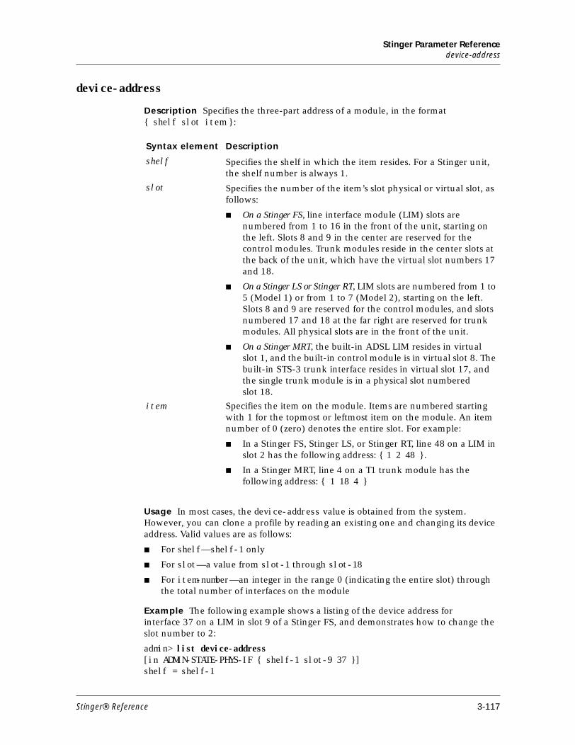
Stinger Parameter Referencedevice-address
device-address
Description Specifies the three-part address of a module, in the format { shelf slot item }:
Usage In most cases, the device-address value is obtained from the system. However, you can clone a profile by reading an existing one and changing its device address. Valid values are as follows:
■ For shelf—shelf-1 only
■ For slot—a value from slot-1 through slot-18
■ For item-number—an integer in the range 0 (indicating the entire slot) through the total number of interfaces on the module
Example The following example shows a listing of the device address for interface 37 on a LIM in slot 9 of a Stinger FS, and demonstrates how to change the slot number to 2:
admin> list device-address[in ADMIN-STATE-PHYS-IF { shelf-1 slot-9 37 }]shelf = shelf-1
Syntax element Description
shelf Specifies the shelf in which the item resides. For a Stinger unit, the shelf number is always 1.
slot Specifies the number of the item’s slot physical or virtual slot, as follows:
■ On a Stinger FS, line interface module (LIM) slots are numbered from 1 to 16 in the front of the unit, starting on the left. Slots 8 and 9 in the center are reserved for the control modules. Trunk modules reside in the center slots at the back of the unit, which have the virtual slot numbers 17 and 18.
■ On a Stinger LS or Stinger RT, LIM slots are numbered from 1 to 5 (Model 1) or from 1 to 7 (Model 2), starting on the left. Slots 8 and 9 are reserved for the control modules, and slots numbered 17 and 18 at the far right are reserved for trunk modules. All physical slots are in the front of the unit.
■ On a Stinger MRT, the built-in ADSL LIM resides in virtual slot 1, and the built-in control module is in virtual slot 8. The built-in STS-3 trunk interface resides in virtual slot 17, and the single trunk module is in a physical slot numbered slot 18.
item Specifies the item on the module. Items are numbered starting with 1 for the topmost or leftmost item on the module. An item number of 0 (zero) denotes the entire slot. For example:
■ In a Stinger FS, Stinger LS, or Stinger RT, line 48 on a LIM in slot 2 has the following address: { 1 2 48 }.
■ In a Stinger MRT, line 4 on a T1 trunk module has the following address: { 1 18 4 }
Stinger® Reference 3-117
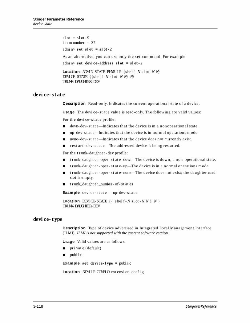
Stinger Parameter Referencedevice-state
slot = slot-9item-number = 37
admin> set slot = slot-2
As an alternative, you can use only the set command. For example:
admin> set device-address slot = slot-2
Location ADMIN-STATE-PHYS-IF {shelf-N slot-N N}DEVICE-STATE {{shelf-N slot-N N} N}TRUNK-DAUGHTER-DEV
device-state
Description Read-only. Indicates the current operational state of a device.
Usage The device-state value is read-only. The following are valid values:
For the device-state profile:
■ down-dev-state—Indicates that the device is in a nonoperational state.
■ up-dev-state—Indicates that the device is in normal operations mode.
■ none-dev-state—Indicates that the device does not currently exist.
■ restart-dev-state—The addressed device is being restarted.
For the trunk-daughter-dev profile:
■ trunk-daughter-oper-state-down—The device is down, a non-operational state.
■ trunk-daughter-oper-state-up—The device is in a normal operations mode.
■ trunk-daughter-oper-state-none—The device does not exist; the daughter card slot is empty.
■ trunk_daughter_number-of-states
Example device-state = up-dev-state
Location DEVICE-STATE {{ shelf-N slot-N N } N }TRUNK-DAUGHTER-DEV
device-type
Description Type of device advertised in Integrated Local Management Interface (ILMI). ILMI is not supported with the current software version.
Usage Valid values are as follows:
■ private (default)
■ public
Example set device-type = public
Location ATM-IF-CONFIG:extension-config
3-118 Stinger® Reference
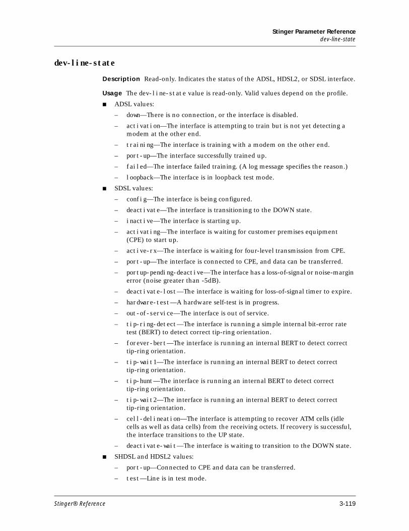
Stinger Parameter Referencedev-line-state
dev-line-state
Description Read-only. Indicates the status of the ADSL, HDSL2, or SDSL interface.
Usage The dev-line-state value is read-only. Valid values depend on the profile.
■ ADSL values:
– down—There is no connection, or the interface is disabled.
– activation—The interface is attempting to train but is not yet detecting a modem at the other end.
– training—The interface is training with a modem on the other end.
– port-up—The interface successfully trained up.
– failed—The interface failed training. (A log message specifies the reason.)
– loopback—The interface is in loopback test mode.
■ SDSL values:
– config—The interface is being configured.
– deactivate—The interface is transitioning to the DOWN state.
– inactive—The interface is starting up.
– activating—The interface is waiting for customer premises equipment (CPE) to start up.
– active-rx—The interface is waiting for four-level transmission from CPE.
– port-up—The interface is connected to CPE, and data can be transferred.
– portup-pending-deactive—The interface has a loss-of-signal or noise-margin error (noise greater than -5dB).
– deactivate-lost—The interface is waiting for loss-of-signal timer to expire.
– hardware-test—A hardware self-test is in progress.
– out-of-service—The interface is out of service.
– tip-ring-detect—The interface is running a simple internal bit-error rate test (BERT) to detect correct tip-ring orientation.
– forever-bert—The interface is running an internal BERT to detect correct tip-ring orientation.
– tip-wait1—The interface is running an internal BERT to detect correct tip-ring orientation.
– tip-hunt—The interface is running an internal BERT to detect correct tip-ring orientation.
– tip-wait2—The interface is running an internal BERT to detect correct tip-ring orientation.
– cell-delineation—The interface is attempting to recover ATM cells (idle cells as well as data cells) from the receiving octets. If recovery is successful, the interface transitions to the UP state.
– deactivate-wait—The interface is waiting to transition to the DOWN state.
■ SHDSL and HDSL2 values:
– port-up—Connected to CPE and data can be transferred.
– test—Line is in test mode.
Stinger® Reference 3-119
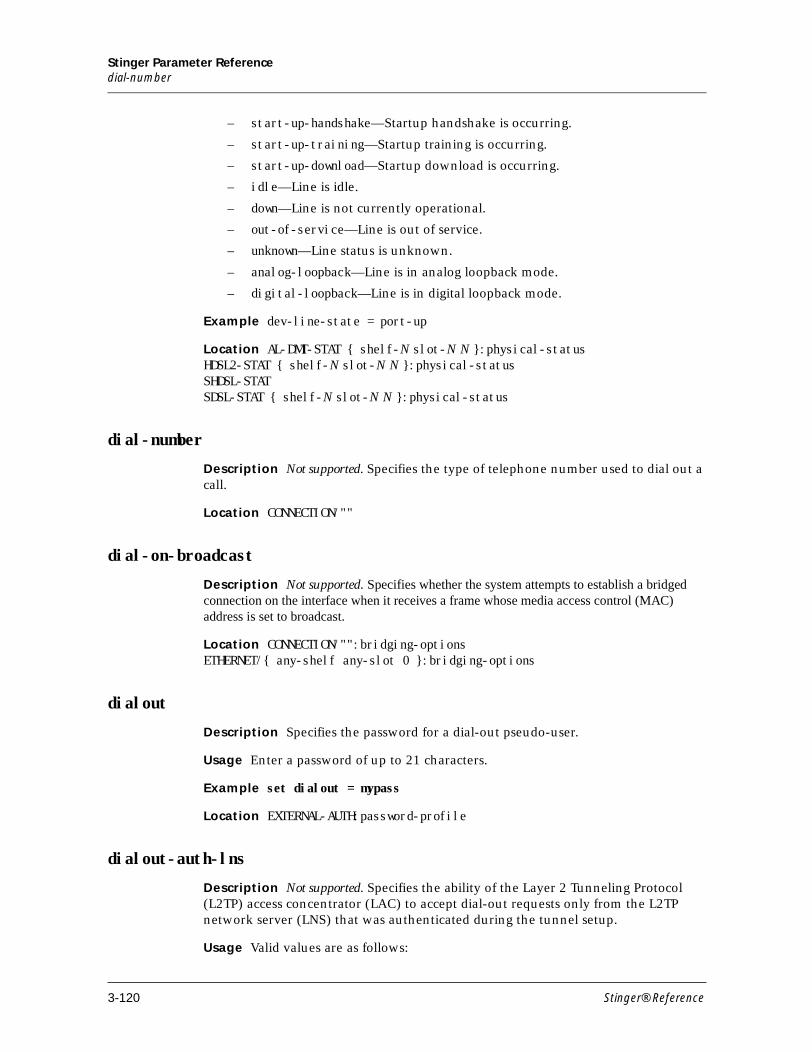
Stinger Parameter Referencedial-number
– start-up-handshake—Startup handshake is occurring.
– start-up-training—Startup training is occurring.
– start-up-download—Startup download is occurring.
– idle—Line is idle.
– down—Line is not currently operational.
– out-of-service—Line is out of service.
– unknown—Line status is unknown.
– analog-loopback—Line is in analog loopback mode.
– digital-loopback—Line is in digital loopback mode.
Example dev-line-state = port-up
Location AL-DMT-STAT { shelf-N slot-N N }:physical-statusHDSL2-STAT { shelf-N slot-N N }:physical-statusSHDSL-STATSDSL-STAT { shelf-N slot-N N }:physical-status
dial-number
Description Not supported. Specifies the type of telephone number used to dial out a call.
Location CONNECTION/""
dial-on-broadcast
Description Not supported. Specifies whether the system attempts to establish a bridged connection on the interface when it receives a frame whose media access control (MAC) address is set to broadcast.
Location CONNECTION/"":bridging-optionsETHERNET/{ any-shelf any-slot 0 }:bridging-options
dialout
Description Specifies the password for a dial-out pseudo-user.
Usage Enter a password of up to 21 characters.
Example set dialout = mypass
Location EXTERNAL-AUTH:password-profile
dialout-auth-lns
Description Not supported. Specifies the ability of the Layer 2 Tunneling Protocol (L2TP) access concentrator (LAC) to accept dial-out requests only from the L2TP network server (LNS) that was authenticated during the tunnel setup.
Usage Valid values are as follows:
3-120 Stinger® Reference
Stinger Parameter Referencedialout-number-auth
■ yes—Restricts the LAC to accept dial-out requests from only the LNS that was authenticated during tunnel setup.
■ no—Allows the LAC to accept dial-out requests from an LNS other than the one that was authenticated during tunnel setup.
Location L2-TUNNEL-GLOBAL:l2tp-config
dialout-number-auth
Description Enables or disables calling line ID (CLID) authorization for the dial-out number passed by the Layer 2 Tunneling Protocol (L2TP) network server (LNS).
Usage Valid values are as follows:
■ no—Disables CLID authorization.
■ yes—Enables CLID authorization.
Example set dialout-numer-auth = yes
Location TUNNEL-SERVER:dialout-options
dialout-poison
Description Enables or disables advertisement of dial-out routes when no trunks are available. Disabling advertisement (the yes setting) allows a redundant unit to take over.
Usage Specify yes or no. The default is no.
■ yes—Stop advertising the system’s IP dial-out routes if no trunks are available.
■ no—Continue to advertise the unit’s dial-out routes, even if no trunks are currently available. This is the appropriate setting for Stinger units, which do not use dial-out routes.
Example set dialout-poison = no
Location IP-GLOBAL
dialout-routes
Description Specifies the password for the dial-out route’s pseudo-user.
Usage Enter a password of up to 21 characters.
Example set dialout-routes = mypass
Location EXTERNAL-AUTH:password-profile
dialout-send-profile-name
Description Not supported. Specifies whether the Layer 2 Tunneling Protocol (L2TP) network server (LNS) can send the connection profile name vendor-specific attribute along with the dial-out request.
Stinger® Reference 3-121
Stinger Parameter Referencediff-delay-max
Location L2-TUNNEL-GLOBAL:l2tp-config
diff-delay-max
Description Specifies the maximum differential delay of an inverse multiplexing over ATM (IMA) group in milliseconds.
Usage Specify a number between from 0 (zero) to 281. The default is 25. To determine the maximum differential delay among the lines in a group, subtract the smallest delay from the largest.
Example The following command sets the maximum differential delay for an IMA group in which line 1 has a delay of 10ms, line 2 has a delay of 25ms and line 3 has a delay of 5ms. The maximum differential delay among the three lines is 25 minus 5, or 20ms.
set diff-delay-max = 20
Location IMAGROUP
diff-delay-max-obs
Description Read-only, Indicates the latest maximum differential delay observed (in milliseconds) between the links having the least and most link propagation delay, among the receive links that are currently configured in the inverse multiplexing over ATM (IMA) group.
Usage The diff-delay-max-obs value is read-only. Valid values range from 0 (zero) to 2147483647.
Example diff-delay-max-obs = 0
Location IMA-GROUP-STAT
direct
Description Not used.
direct-access
Description Not used.
directed-broadcast-allowed
Description Enables or disables forwarding of directed broadcast traffic onto the interface and its network.
Denial-of-service attacks known as “smurf” attacks typically use Internet Control Message Protocol (ICMP) Echo Request packets with a spoofed source address and packets directed to IP broadcast addresses. These attacks are intended to degrade network performance, possibly to the point that the network becomes unusable. This
3-122 Stinger® Reference
Stinger Parameter Referencedirection-mode
setting can prevent the IP router from being used as an intermediary in this type of denial-of-service attack launched from another network
Usage Valid values are as follows:
■ yes (the default)—Allows the system to forward directed broadcasts received from another network.
■ no—Prevents the router from forwarding directed broadcasts it receives from another network.
Note To protect against the router being used in a denial-of-service attack, you must prevent the router from forwarding directed broadcasts it receives from another network on all IP interfaces in the system. For example, you must disable directed broadcasts on both control-module interfaces (so the broadcasts are still disabled if controller switchover occurs), as well as the IP interfaces of a T1000 module.
Example set directed-broadcast-allowed = no
Location IP-INTERFACE/{ { any-shelf any-slot 0 } 0 }
direction-mode
Description Specifies (in the aps-config profile) and indicates (in the aps-stat profile) whether the protection group’s mode of direction is unidirectional or bidirectional in automatic protection switching (APS).
Usage Valid values are as follows:
■ unidirectional—The end having the failure switches to the protection channel without communicating to the other end first. The decision to switch is unilateral. This is the default and is recommended for APS 1+1.
■ bidirectional—When a failure occurs, it is communicated to the opposite end and both ends determine whether to switch to the protection channel.
Example set direction-mode = unidirectional
Location APS-CONFIGAPS-STAT
disabled-count
Description Not used.
disconnect-on-auth-timeout
Description Specifies how the Stinger unit disconnects a PPP connection if it times out while waiting for RADIUS authentication.
Usage Valid values are as follows:
■ yes (the default)—Instructs the unit to hang up a PPP connection if RADIUS authentication times out.
■ no—Instructs the unit to disconnect cleanly after a RADIUS time-out.
Stinger® Reference 3-123
Stinger Parameter Referencedlci
Example set disconnect-on-auth-timeout = yes
Location ANSWER-DEFAULTS:ppp-answerCONNECTION:ppp-options
dlci
Description Specifies a data link connection identifier (DLCI) number for a frame relay connection.
A DLCI is not an address, but a local label that identifies a logical link between a device and the frame relay switch. The switch uses the DLCI to route frames through the network, and the DLCI can change as frames are passed through multiple switches.
Usage Specify an integer from 16 through 991. The default is 16. Ask your frame relay network administrator for the value you must enter.
Example set dlci = 17
Dependencies Consider the following:
■ For dlci to apply, fr-direct-enabled must be set to no.
■ The dlci setting is ignored for a connection profile that has circuit-type set to svc. For a switched virtual circuit (SVC), the DLCI value is assigned to the circuit by the network. The range of DLCI values for circuits is shared between permanent virtual circuits (PVCs) and SVCs, and is managed between the network and user entities.
Location CONNECTION/"":fr-optionsFRPVC-STAT:dlci-members:dlci-member:[N]
dmmall-input-imp
Description Specifies the input impedance, in kilohms, for a digital multimeter (DMM) copper loop test (CLT).
Usage Specify either 100 or 1000.
Example set dmmall-input-imp = 100
Location CLT-COMMAND
dmmall-period
Description Specifies the amount of time, in tenths of a second, during which
measurement is made in a digital multimeter (DMM) copper loop test (CLT).
Usage Specify a number between 0 (zero) and 5. The default value, 0, sets the
maximum time period. Values between 1 and 5 set times between 100ms and 500ms.
Example set dmmall-period = 1
Location CLT-COMMAND
3-124 Stinger® Reference
Stinger Parameter Referencedmm-all-r-s
dmm-all-r-s
Description Read-only. Indicates the ring-to-shield measurement data for a copper loop test (CLT) module digital multimeter test.
Usage Read-only numeric value with a range of 0 to 4294967295. Volts dc and volts ac are in millivolts. Resistance is in ohms. Capacitance is in picofarads.
Example dmm-all-r-s = 1220
Location CLT-RESULTS
dmm-all-t-r
Description Read-only. Indicates the tip-to-ring measurement data for a copper loop test (CLT) module digital multimeter test.
Usage Read-only numeric value with a range of 0 to 4294967295. Volts dc and volts ac are in millivolts. Resistance is in ohms. Capacitance is in picofarads.
Example dmm-all-t-r = 1220
Location CLT-RESULTS
dmm-all-t-s
Description Read-only. Indicates the tip-to-shield measurement data for a copper loop test (CLT) module digital multimeter test.
Usage Read-only numeric value with a range of 0 to 4294967295. Volts dc and volts ac are in millivolts. Resistance is in ohms. Capacitance is in picofarads.
Example dmm-all-t-s = 1220
Location CLT-RESULTS
dmmall-type
Description Specifies the type of digital multimeter (DMM) cooper loop test (CLT) to run for all measurements: tip to ring, tip to ground, and ring to ground.
Usage Valid values are as follows:
■ resistance—Measures dc resistance to detect shorts and leakage between tip and ring, tip and ground, and ring and ground.
■ dc-voltage—Measures dc voltage to detect unwanted foreign voltage.
■ ac-voltage—Measures ac voltage to detect unwanted foreign voltage.
■ capacitance—Measures actual capacitance and estimated length for loop-length estimation.
Example set dmmall-type = resistance
Location CLT-COMMAND
Stinger® Reference 3-125
Stinger Parameter Referencedmmcap-period
dmmcap-period
Description Specifies the amount of time, in tenths of a second, during which measurement is made in a digital multimeter (DMM) copper loop test (CLT) that measures capacitance.
Usage Specify a number between 0 (zero) and 5. The default value, 0, sets the maximum time period. Values between 1 and 5 set times between 100ms and 500ms.
Example set dmmcap-period = 2
Location CLT-COMMAND
dmmdcd-impedance
Description Specifies the output impedance, in kilohms, to be used in a digital multimeter (DMM) copper loop test (CLT) that measures loop resistance based on a dc Thevenin circuit.
Usage Specify a number between 10 and 1000. The default is 10.
Example set dmmdcd-impedance = 1000
Location CLT-COMMAND
dmmdcd-period
Description Specifies the amount of time, in tenths of a second, during which measurement is made in a digital multimeter (DMM) copper loop test (CLT) that measures loop resistance based on a dc Thevenin circuit.
Usage Specify a number between 1 (one) and 5. Each unit represents 100 milliseconds. Enter the default 0 (zero) value for the maximum time.
Example set dmmdcd-period = 1
Location CLT-COMMAND
dmmdcd-voltage
Description Specifies the test voltage to be used in a digital multimeter (DMM) copper loop test (CLT) that measures loop resistance based on a dc Thevenin circuit.
Usage Specify a number between -230 and 230. The default is 0 (zero).
Example set dmmdcd-voltage = 230
Location CLT-COMMAND
dmm-lead
Description Specifies the digital multimeter (DMM) measurement leads to be used in a copper loop test (CLT).
3-126 Stinger® Reference
Stinger Parameter Referencedmm-result
Usage Valid values are as follows:
■ tip-ring—Measures between tip and ring (lead T-R.) This is the default.
■ tip-sleeve—Measures between tip and ground (lead T-S).
■ ring-sleeve—Measures between ring ground (lead R-S).
Example set dmm-lead = tip-sleeve
Location CLT-COMMAND
dmm-result
Description Read-only. Indicates the results of a digital multimeter (DMM) copper loop test (CLT).
Usage The dmm-result value is read-only. V
■ Voltage ac and dc are reported in millivolts.
■ Resistance is reported in ohms.
■ Capacitance is reported in nanofarads.
Example dmm-result = 0
Location CLT-RESULT
dmm-type
Description Specifies the type of digital multimeter (DMM) copper loop test (CLT) to run.
Usage Valid values are as follows:
■ resistance (the default)—Measures dc resistance to detect shorts and leakage between tip and ring, tip and ground, and ring and ground.
■ dc-voltage—Measures dc voltage to detect unwanted foreign voltage.
■ ac-voltage—Measures ac voltage to detect unwanted foreign voltage.
■ capacitance—Measures actual capacitance and estimated length for loop-length estimation.
Example set dmm-type = capacitance
Location CLT-COMMAND
dns-list-attempt
Description Enables or disables the Domain Name System (DNS) list feature.
DNS lists allow the system to return multiple IP addresses to Telnet clients at sites where DNS responds with more than one address. The system stores the hostname/address associations in the local DNS table in RAM, overwriting configured addresses in that table or addresses received from earlier DNS queries. To prevent stale entries in the table in RAM, the system clears the number of addresses exceeding the amount specified by dns-list-size.
Stinger® Reference 3-127
Stinger Parameter Referencedns-list-size
If the DNS list feature is disabled, the system stores a single returned address in the local DNS table in RAM, clearing the remaining 34 hostname/address fields. For details about DNS lists, see the Stinger Network Configuration Guide.
Usage Valid values are as follows:
■ yes—Returns multiple addresses if available, up to the limit specified by dns-list-size.
■ no (the default)—Returns only one address from any successful DNS query.
Example set dns-list-attempt = yes
Location IP-GLOBAL
dns-list-size
Description Specifies the maximum number of hosts in a Domain Name System (DNS) list, up to 35.
If the DNS list feature is enabled and DNS returns multiple addresses, this setting determines the number of addresses displayed for a Telnet client. For details about DNS lists, see the Stinger Network Configuration Guide.
Usage Enter a number from 0 to 35. The default is 6.
Example set dns-list-size = 10
Dependencies If dns-list-attempt is set to no, dns-list-size has no effect.
Location IP-GLOBAL
dns-primary-server
Description Specifies the IP address of the primary local Domain Name System (DNS) server to use for lookups.
Usage Specify an IP address in dotted decimal notation.
Example set dns-primary-server = 2.2.2.2/28
Dependencies When specified in a vrouter profile, this DNS setting is exclusive to the virtual router. If DNS settings are not specified in a vrouter profile, the virtual router uses the DNS settings defined in the ip-global profile.
Location IP-GLOBALVROUTER/""
dns-secondary-server
Description Specifies the IP address of the secondary local Domain Name System (DNS) server to use for lookups. This DNS setting is used only if the primary server is not found.
Usage Specify an IP address in dotted decimal notation.
3-128 Stinger® Reference
Stinger Parameter Referencedns-server-query-type
Example set dns-secondary-server = 2.2.2.4/28
Dependencies When specified in a vrouter profile, this DNS setting is exclusive to the virtual router. If DNS settings are not specified in a vrouter profile, the virtual router use the DNS settings defined in the ip-global profile.
Location IP-GLOBALVROUTER/""
dns-server-query-type
Description Specifies how to query a Domain Name System (DNS) server.
Usage Valid values are as follows:
■ udp (the default)—Queries the DNS server first by means of UDP, and then, if the TC-bit is set and a retry is necessary, by means of TCP.
■ udp-ignore-tc-bit—Queries the DNS server only by means of UDP.
■ tcp—Queries the DNS server only by means of TCP.
■ tcp-keep-open—Queries the DNS server by means of TCP only and then attempts to keep the TCP session established, rather than opening a new TCP session for each additional query.
Example set dns-server-query-type = tcp
Location IP-GLOBAL
domain-name
Description Specifies the primary domain name to use for Domain Name System (DNS) lookups. The system appends this domain name to hostnames when performing lookups.
Usage Specify a domain name.
Example set domain-name = abc.com
Dependencies When specified in a vrouter profile, this DNS setting is exclusive to the virtual router. If DNS settings are not specified in a vrouter profile, the virtual router use the DNS settings defined in the ip-global profile.
Location IP-GLOBALVROUTER/""
domestic-enabled
Description Read-only. Indicates whether a Stinger unit can operate domestically.
Usage Read-only parameter with the following possible values:
■ no—Unit cannnot operate domestically.
■ yes—Unit can operate domestically.
Stinger® Reference 3-129
Stinger Parameter Referencedo-version-fallback
Example domestic-enabled = no
Location BASE
do-version-fallback
Description Specifies whether the Stinger unit automatically falls back to the earlier version of inverse multiplexing ATM (IMA) if the far-end Stinger is detected to be running the earlier version.
Usage Valid values are as follows:
■ yes—Specifies that the unit falls back from version 1.1 to version 1.0.
■ no—Specifies that the unit does not fall back, but moves to the configAborted state. This is the default.
Example set do-version-fallback = yes
Location IMAGROUP
down-metric
Description Specifies the routing metric, typically measured in number of hops, to be used in the routing table entry created for this connection when the connection is inactive.
Usage Numeric parameter with a range of 1 to 15 hops. Default value is 7.
Example set down-metric = 12
Location CONNECTION/"":ip-options
down-preference
Description Specifies a preference value for a route when the interface is unavailable. The system uses this value to determine when to bring a route online.
Usage Specify a number from 0 to 214748364. The lower the preference, the more likely the system is to bring the route online when interface is unavailable. The default is 120.
Example set down-preference = 255
Location CONNECTION/"":ip-options
downstream-end-bin
Description Specifies the ending frequency bin (interval) for downstream transmission.
The upstream and downstream start and end bins define the frequency ranges for upstream and downstream data. The frequency for a particular bin is defined as follows:
3-130 Stinger® Reference
Stinger Parameter Referencedown-stream-latency
frequency = bin number x 4.3125kHz
You can use these parameters to adjust the frequency content of the ADSL signals. For example, splitterless ANSI discrete multitone (DMT) can be supported by appropriate adjustment of the frequency range.
Usage Valid values are as follows:
■ For 12-port and 24-port line interface modules (LIMS), specify a number from 32 to 255. The default is 255.
■ For 48-port LIM, specify a number from 37 to 127. The default is 127.
Example set downstream-end-bin = 50
Dependencies You must adjust the maximum and minimum bit rate parameters to match the frequency range defined by the start and end bin numbers.
Location AL-DMT { any-shelf any-slot N }:line-config
down-stream-latency
Description Read-only. Indicates the operational downstream latency setting.
Usage The down-stream-latency value is read-only. Valid values are as follows:
■ none—Indicates that the line is not operational.
■ fast—Indicates that the setting for least downstream delay is in effect.
■ interleave—Indicates that interleave latency (greater than fast) in is effect
Example down-stream-latency = interleave
Location AL-DMT-STAT {shelf-N slot-N N }:physical-status
down-stream-rate
Description Read-only. Indicates the downstream rate, in bits per second, for an SDSL line interface module (LIM) and port reported on.
Usage Read-only parameter with a numeric value of 0 to 4294967295bps.
Example down-stream-rate = 18282
Location SDSL-STAT/{ shelf-1 slot-13 1 }:physical-status
down-stream-rate-fast
Description Read-only. Indicates the downstream data rate in bits per second when latency is fast.
Usage The down-stream-rate-fast value is read-only. Zero (0) means that latency is set to interleave or that the data rate is unknown.
Example down-stream-rate-fast = 0
Location AL-DMT-STAT { any-shelf any-slot N }:physical-status
Stinger® Reference 3-131
Stinger Parameter Referencedown-stream-rate-interleaved
down-stream-rate-interleaved
Description Read-only. Indicates the downstream data rate in bits per second when latency is interleave.
Usage The down-stream-rate-interleaved value is read-only. Zero (0) means that latency is set to fast or the data rate is unknown.
Example down-stream-rate-interleaved = 2944000
Location AL-DMT-STAT { shelf-N slot-N N }:physical-status
downstream-start-bin
Description Specifies the starting downstream frequency bin (interval).
Usage Specify a number from 32 to 255. The default is 32.
Example set downstream-start-bin = 35
Location AL-DMT:line-config
drop-source-routed-ip-packets
Description Enables or disables forwarding of IP packets that have the source route option set.
Usage Valid values are the following.
■ yes—Drop all packets that have a Loose or a Strict source route among their IP options.
■ no (the default)—Forward all source-routed packets, as described in RFC 1812.
Example set drop-source-routed-ip-packets = no
Location IP-GLOBAL
dscp
Description Specifies the differentiated services code point (DSCP) value.
Usage Specify a value from 00 (the default) to 3F (hexadecimal). DSCP marking, as defined in RFC 2474, uses the first 6 bits in the second octet in the IP datagram to create values (from 00 through 3F) specifying different classes of service:
Bit positions
TOS-precedence (RFC 791) DSCP (RFC 2474)
0 to 2 Precedence (eight levels of prior-ity)
DSCP value
3 Delay (normal or low) DSCP value (continued)
4 Throughput (normal or high) DSCP value (continued)
5 Reliability (normal or high) DSCP value (continued)
3-132 Stinger® Reference
Stinger Parameter Referencedsl-thresh-trap-enabled
Example set dscp = 3f
Dependencies For this setting to apply, you must set the marking-type parameter to dscp. In addition, type-of-service (TOS) and IP routing must be enabled in the connection profile, or TOS must be specified as the filter type in the filter profile. Filters are not supported with the current software version.
Location CONNECTION/"":ip-options:tos-optionsFILTER/"":input-filters:tos-filterFILTER/"":output-filters:tos-filter
dsl-thresh-trap-enabled
Description Enables or disables sending of DSL traps (notifications) to the identified host.
Usage Specify one of the following values:
■ yes—The system sends DSL traps to the identified host.
■ no—The system does not send DSL traps to the identified host.
Example set dsl-thresh-trap-enabled = yes
Location TRAP
dual-link
Description Not currently used.
dual-slot-t1-enabled
Description Indicates whether all 8 T1 ports on the MRT trunk module are enabled.
Usage The following read only values are valid:
■ yes—All T1 ports are enabled.
■ no—All T1 ports are not enable.
Dependencies This parameter is only visible on a Stinger MRT.
Location BASE
duplex-mode
Description Specifies the operating mode of the Stinger Ethernet LAN interface.
Usage Valid values are the following:
■ full-duplex (the default)—Provides higher throughput.
6 to 7 Reserved Reserved
Bit positions
TOS-precedence (RFC 791) DSCP (RFC 2474)
Stinger® Reference 3-133
Stinger Parameter Referencedynamic-algorithm
■ half-duplex—Enables the unit to operate with older equipment that does not support full duplex.
Example set duplex-mode = half-duplex
Dependencies The system can determine the proper setting for this parameter when auto-negotiate is set to yes.
Location ETHERNET/{ any-shelf any-slot 0 }
dynamic-algorithm
Description Specifies the algorithm to use to calculate the average link utilization (ALU) over a specified number of seconds (seconds-history). After calculating the average, the Stinger unit compares it to the target-utilization value. If the average exceeds or falls below the target for a specified number of seconds, the unit adjusts the bandwidth of the connection.
Usage Valid values are as follows:
■ quadratic (the default)—Specifies that more weight is given to recent samples of bandwidth usage than to older samples. The weighting grows at a quadratic rate.
■ linear—Specifies that more weight is given to recent samples of bandwidth usage than to older samples. The weighting grows at a linear rate.
■ constant—Specifies that equal weight is given to all samples.
Example set dynamic-algorithm = linear
Location ANSWER-DEFAULTS:mpp-answerCONNECTION:mpp-options
E
early-packet-discard
Description Specifies whether all cells in an asynchronous transfer mode (ATM)
packet are discarded if the first cell cannot be queued.
Usage Valid values are as follows:
■ yes—Specifies that the cell and all remaining cells are discarded. This is the
default.
■ no—Specifies that the cell and all remaining cells are not discarded. However,
when the end of the current packet is detected, all the cells in the next packet are
discarded. This is the default.
Example set early packet-discard = no
Dependencies If encapsulation-protocol is not set to atm or atm-circuit, the
early-packet-discard setting does not apply.
Location ATM-QOS
3-134 Stinger® Reference
Stinger Parameter Referenceelapsed-seconds
elapsed-seconds
Description Read-only. Indicates the number of seconds that have elapsed in the current measurement interval of 15 minutes.
Usage The elapsed-seconds value is read-only. Valid values range from 0 (zero) to 2147483647.
Example elapsed-seconds = 0
Location DS1-ATM-STAT { shelf-N slot-N N }:ima-link-statistic
enable
Description Enables or disables a feature:
■ In a trunk-cac-config subprofile, specifies whether connection admission control (CAC) is enabled on the port specified in port-num in this subprofile.
■ In a bir-options subprofile, specifies whether bridged IP routing (BIR) is enabled on an interface.
Usage Valid values are as follows:
■ yes—Enables the feature. This is the default in trunk-cac-config subprofile.
■ no—Disables the feature. This is the default in a bir-options subprofile.
Example set enable = no
Dependencies When the OC3 interface is disabled, it transmits the OC3 Idle signal to the remote end.
Location CONNECTION:bir-optionsHIGH-SPEED-SLOT-STATIC-CONFIG:trunk-cac-config
Note This parameter was previously located in the trunk-cac-config subprofile of the atm-config profile. Its use in that location has been deprecated.
enable-centralized-detection
Description Specifies whether central integrity checking is enabled by the primary control module for the entire system.
Usage Valid values are as follows:
■ yes—Enables central integrity checking.
■ no (the default)—Disables central integrity checking. By default, line interface modules (LIMs) perform error correction, which is usually sufficient for most applications. .
Example set enable-centralized-detection = yes
Location SYSTEM-INTEGRITY
Stinger® Reference 3-135
Stinger Parameter Referenceenable-continuous-detection
enable-continuous-detection
Description Specifies whether continuous switching fabric testing, detection, and correction are enabled.
Usage Valid values are as follows. The recommended setting is yes for control modules and no for line interface modules (LIMs).
■ yes—Enables continuous switching fabric testing, detection, and correction.
■ no (the default)—Disables continuous switching fabric testing, detection, and correction.
Example set enable-continuous-detection = no
Location SYSTEM-INTEGRITY:integrity-config
enable-core-dump
Description Enables or disables a core dump on system failure.
Usage Specify one of the following values:
■ yes—Enables a core dump on system failure.
■ no—Disables a core dump on system failure. This is the default value.
Example set enable-core-dump = yes
Location DEBUG
enabled
Description Specifies whether a feature, interface, line, or test is enabled or disabled.
Following are the results of enabled settings in particular profiles:
■ If enabled is set to no in the ethernet profile, packets routed to and received by the interface are discarded.
■ When an OC3 interface is disabled, it transmits the OC3 idle signal to the remote end.
■ In the dns-local-table subprofile of the ip-global profile, the enabled setting specifies whether the local Domain Name System (DNS) table in RAM is available when a DNS query fails:
– If enabled is set to no (the default) and a DNS query times out, the request fails.
– If enabled is set to yes, the Stinger unit attempts to resolve the query by using the host-to-address mapping in the DNS table in RAM. If the query has an entry in the table in RAM, the system returns the associated IP address(es) to the requester.
■ If enabled is set to yes in the continuity-config or loopback-config subprofile of the atm-oam profile, the system resets the parameter to its no default when the continuity or loopback tests are complete,.
3-136 Stinger® Reference
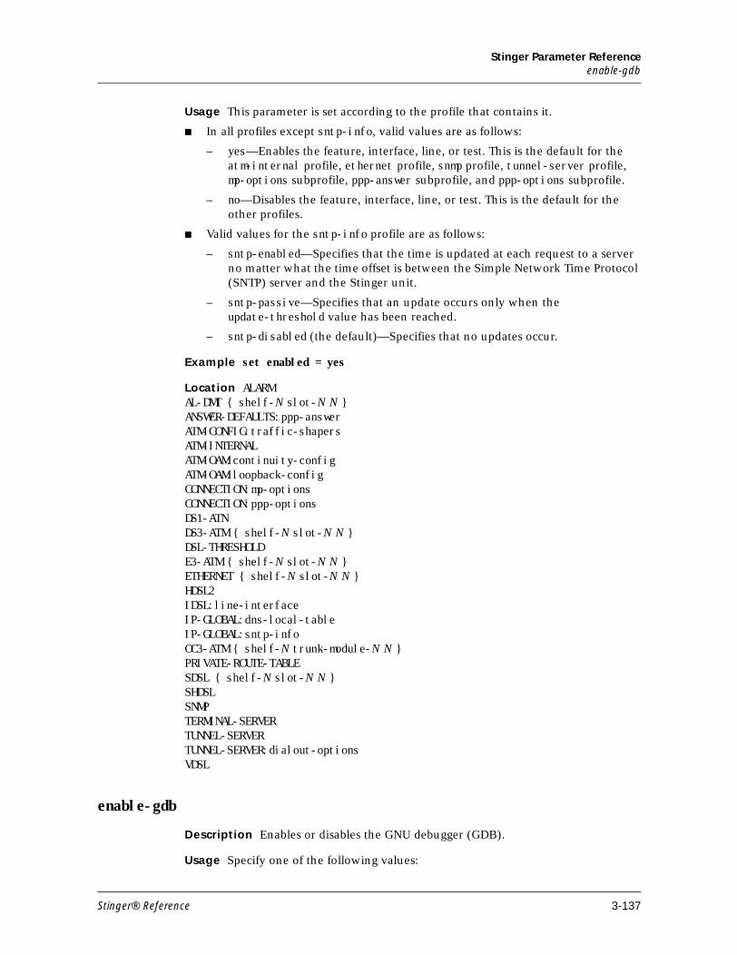
Stinger Parameter Referenceenable-gdb
Usage This parameter is set according to the profile that contains it.
■ In all profiles except sntp-info, valid values are as follows:
– yes—Enables the feature, interface, line, or test. This is the default for the atm-internal profile, ethernet profile, snmp profile, tunnel-server profile, mp-options subprofile, ppp-answer subprofile, and ppp-options subprofile.
– no—Disables the feature, interface, line, or test. This is the default for the other profiles.
■ Valid values for the sntp-info profile are as follows:
– sntp-enabled—Specifies that the time is updated at each request to a server no matter what the time offset is between the Simple Network Time Protocol (SNTP) server and the Stinger unit.
– sntp-passive—Specifies that an update occurs only when the update-threshold value has been reached.
– sntp-disabled (the default)—Specifies that no updates occur.
Example set enabled = yes
Location ALARMAL-DMT { shelf-N slot-N N }ANSWER-DEFAULTS:ppp-answerATM-CONFIG:traffic-shapersATM-INTERNALATM-OAM:continuity-configATM-OAM:loopback-configCONNECTION:mp-optionsCONNECTION:ppp-optionsDS1-ATNDS3-ATM { shelf-N slot-N N }DSL-THRESHOLDE3-ATM { shelf-N slot-N N }ETHERNET { shelf-N slot-N N } HDSL2IDSL:line-interfaceIP-GLOBAL:dns-local-tableIP-GLOBAL:sntp-infoOC3-ATM { shelf-N trunk-module-N N } PRIVATE-ROUTE-TABLESDSL { shelf-N slot-N N }SHDSLSNMPTERMINAL-SERVERTUNNEL-SERVERTUNNEL-SERVER:dialout-optionsVDSL
enable-gdb
Description Enables or disables the GNU debugger (GDB).
Usage Specify one of the following values:
Stinger® Reference 3-137
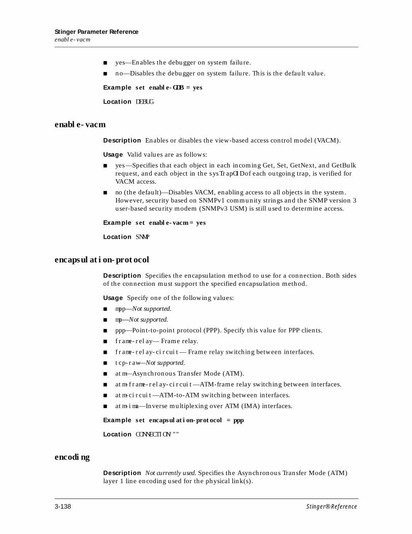
Stinger Parameter Referenceenable-vacm
■ yes—Enables the debugger on system failure.
■ no—Disables the debugger on system failure. This is the default value.
Example set enable-GDB = yes
Location DEBUG
enable-vacm
Description Enables or disables the view-based access control model (VACM).
Usage Valid values are as follows:
■ yes—Specifies that each object in each incoming Get, Set, GetNext, and GetBulk request, and each object in the sysTrapOID of each outgoing trap, is verified for VACM access.
■ no (the default)—Disables VACM, enabling access to all objects in the system. However, security based on SNMPv1 community strings and the SNMP version 3 user-based security modem (SNMPv3 USM) is still used to determine access.
Example set enable-vacm = yes
Location SNMP
encapsulation-protocol
Description Specifies the encapsulation method to use for a connection. Both sides of the connection must support the specified encapsulation method.
Usage Specify one of the following values:
■ mpp—Not supported.
■ mp—Not supported.
■ ppp—Point-to-point protocol (PPP). Specify this value for PPP clients.
■ frame-relay— Frame relay.
■ frame-relay-circuit— Frame relay switching between interfaces.
■ tcp-raw—Not supported.
■ atm—Asynchronous Transfer Mode (ATM).
■ atm-frame-relay-circuit—ATM-frame relay switching between interfaces.
■ atm-circuit—ATM-to-ATM switching between interfaces.
■ atm-ima—Inverse multiplexing over ATM (IMA) interfaces.
Example set encapsulation-protocol = ppp
Location CONNECTION/""
encoding
Description Not currently used. Specifies the Asynchronous Transfer Mode (ATM) layer 1 line encoding used for the physical link(s).
3-138 Stinger® Reference
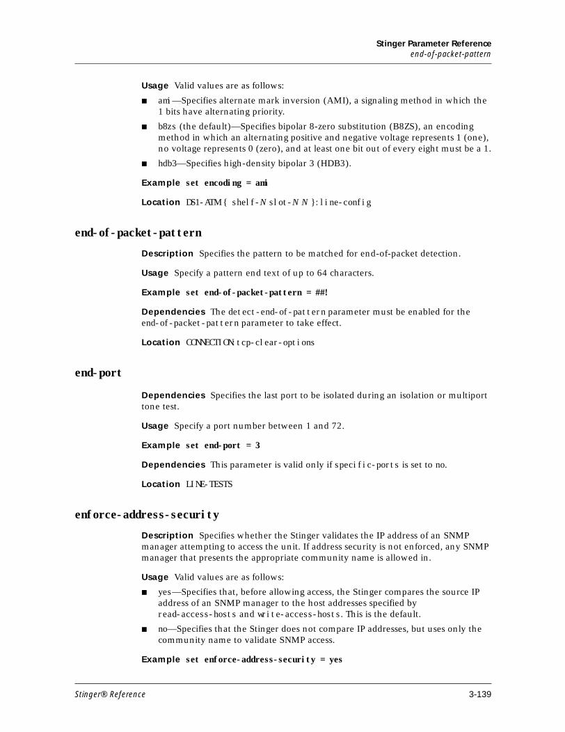
Stinger Parameter Referenceend-of-packet-pattern
Usage Valid values are as follows:
■ ami—Specifies alternate mark inversion (AMI), a signaling method in which the 1 bits have alternating priority.
■ b8zs (the default)—Specifies bipolar 8-zero substitution (B8ZS), an encoding method in which an alternating positive and negative voltage represents 1 (one), no voltage represents 0 (zero), and at least one bit out of every eight must be a 1.
■ hdb3—Specifies high-density bipolar 3 (HDB3).
Example set encoding = ami
Location DS1-ATM { shelf-N slot-N N }:line-config
end-of-packet-pattern
Description Specifies the pattern to be matched for end-of-packet detection.
Usage Specify a pattern end text of up to 64 characters.
Example set end-of-packet-pattern = ##!
Dependencies The detect-end-of-pattern parameter must be enabled for the end-of-packet-pattern parameter to take effect.
Location CONNECTION:tcp-clear-options
end-port
Dependencies Specifies the last port to be isolated during an isolation or multiport tone test.
Usage Specify a port number between 1 and 72.
Example set end-port = 3
Dependencies This parameter is valid only if specific-ports is set to no.
Location LINE-TESTS
enforce-address-security
Description Specifies whether the Stinger validates the IP address of an SNMP manager attempting to access the unit. If address security is not enforced, any SNMP manager that presents the appropriate community name is allowed in.
Usage Valid values are as follows:
■ yes—Specifies that, before allowing access, the Stinger compares the source IP address of an SNMP manager to the host addresses specified by read-access-hosts and write-access-hosts. This is the default.
■ no—Specifies that the Stinger does not compare IP addresses, but uses only the community name to validate SNMP access.
Example set enforce-address-security = yes
Stinger® Reference 3-139
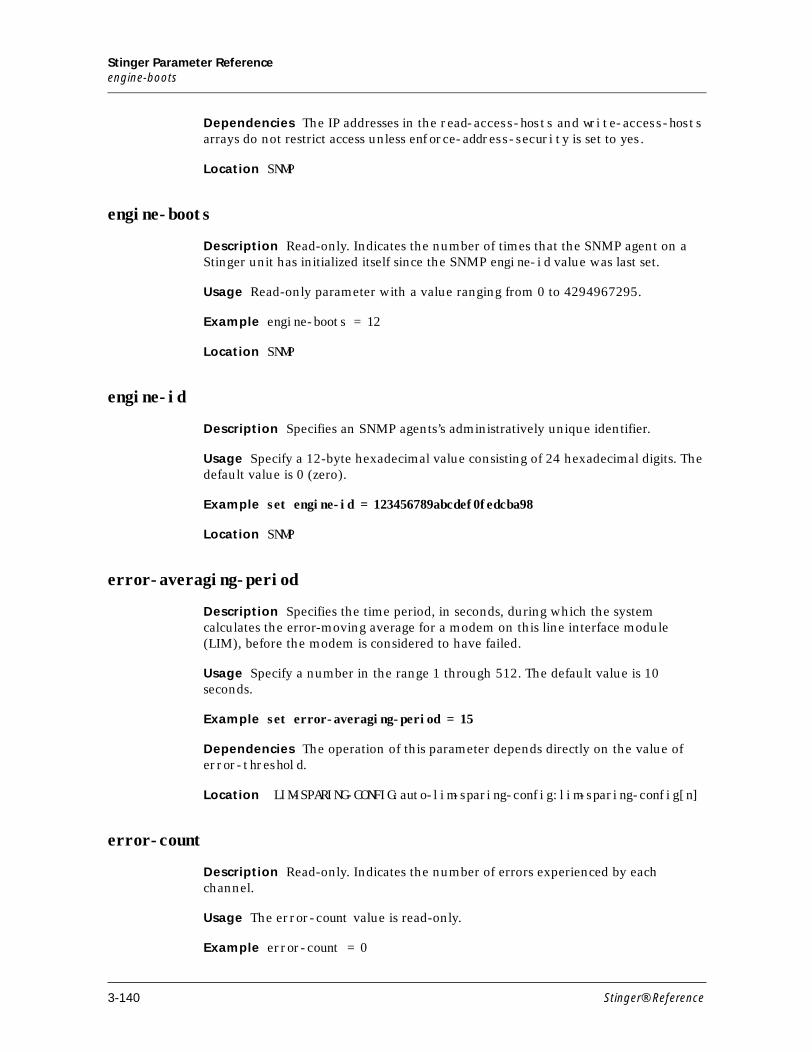
Stinger Parameter Referenceengine-boots
Dependencies The IP addresses in the read-access-hosts and write-access-hosts arrays do not restrict access unless enforce-address-security is set to yes.
Location SNMP
engine-boots
Description Read-only. Indicates the number of times that the SNMP agent on a Stinger unit has initialized itself since the SNMP engine-id value was last set.
Usage Read-only parameter with a value ranging from 0 to 4294967295.
Example engine-boots = 12
Location SNMP
engine-id
Description Specifies an SNMP agents’s administratively unique identifier.
Usage Specify a 12-byte hexadecimal value consisting of 24 hexadecimal digits. The default value is 0 (zero).
Example set engine-id = 123456789abcdef0fedcba98
Location SNMP
error-averaging-period
Description Specifies the time period, in seconds, during which the system calculates the error-moving average for a modem on this line interface module (LIM), before the modem is considered to have failed.
Usage Specify a number in the range 1 through 512. The default value is 10 seconds.
Example set error-averaging-period = 15
Dependencies The operation of this parameter depends directly on the value of error-threshold.
Location LIM-SPARING-CONFIG:auto-lim-sparing-config:lim-sparing-config[n]
error-count
Description Read-only. Indicates the number of errors experienced by each channel.
Usage The error-count value is read-only.
Example error-count = 0
3-140 Stinger® Reference
Stinger Parameter Referenceerrored-second
Location ADSL-STAT { shelf-N slot-N N }IDSL-STATSDSL-STAT
errored-second
Description Indicates the number of 1-second intervals (out of a 15-minute sampling period) during which one or more cyclic redundancy check (CRC) anomalies are declared and/or one or more loss of synchronous word (LOSW) defects are declared.
Usage The errored-second value is read-only and helps you monitor interface operations.
Example errored-second = 3
Location HDSL2-STAT { shelf-N slot-N N }:physical-statistic
error-threshold
Description Specifies a threshold for errors in the following profiles:
■ In the loopback-config subprofile of the atm-oam profile, error-threshold specifies the threshold for the number of loopback cells that can be lost. If the number of cells lost become equal to or greater than the value you specify, a trap is generated.
■ In the lim-sparing-config[n] subprofile of the lim-sparing-config:auto-lim-sparing-config profile, error-threshold specifies the number of errors that must occur during the error-averaging period before a modem on this line interface module (LIM) is considered inoperable.
Usage Valid values are as follows:
■ In loopback-config, specify a number from 0 through 10. The default is 0 (zero), which means that no trap is sent.
■ In auto-lim-sparing-config, specify a number. The default value is 100.
Example set error-threshold = 5 set error-threshold = 90
Dependencies In the auto-lim-sparing-config subprofile, an error-averaging-period value must be specified appropriately to make error-threshold usable.
Location ATM-OAM:loopback-configLIM-SPARING-CONFIG:auto-lim-sparing-config:lim-sparing-config[n]
ether-if-type
Description Read-only. Indicates the type of physical Ethernet interface in use.
Usage The ether-if-type value is read-only. Valid values are as follows:
Stinger® Reference 3-141
Stinger Parameter Referenceevent
■ utp—Indicates unshielded twisted pair (UTP), as specified in IEEE 802 (10BaseT) Ethernet.
■ aui—Indicates an auxiliary unit interface (AUI) transceiver (thick Ethernet), as specified in IEEE 802.3 (10Base5) Ethernet.
■ coax—Coaxial cable.
Example ether-if-type = utp
Location ETHERNET/{ any-shelf any-slot 0 }
event
Description Specifies an alarm event that triggers the actions indicated by the action subprofile.
Usage Valid values are as follows:
■ power-failure—Specifies that the event is a redundant power supply failure.
■ fan-failure—Specifies that the event is a redundant fan failure.
■ line-state-change (the default)—Specifies that the event is a state change in a line.
■ slot-state-change—Specifies that the event is a state change in a slot.
■ primary-switch-over—Specifies that the event is a switchover of the primary control module functions to the secondary control module.
■ secondary-controller-state-change—Specifies that the event is a state change in the secondary control module.
■ input-relay-closed—Specifies that the event is the closure of an input relay-monitoring circuit.
■ input-relay-open—Specifies that the event is the opening of an input relay-monitoring circuit.
■ low-temperature-trigger—Specifies that the event is the crossing of a low-temperature threshold in the thermal profile.
■ high-temperature-trigger—Specifies that that the event is the crossing of a high-temperature threshold in the thermal profile.
Example set event = fan-failure
Location ALARM
event-overwrite-enabled
Description Specifies whether the system generates a trap when a new event has overwritten an unread event. Once sent, additional overwrites do not cause another trap to be sent until at least one table's worth of new events have occurred.
Usage Valid values are as follows:
■ yes—Specifies that the system generates a trap when a new event has overwritten an unread event. This is the default.
3-142 Stinger® Reference
Stinger Parameter Referenceexact-match-call-routing
■ no—Specifies that the system does not generate a trap when a new event has overwritten an unread event.
Example set event-overwrite-enabled = no
Location TRAP
exact-match-call-routing
Description Enables or disables the system’s use of an exact match for call-route profile parameters when it selects devices.
Usage Valid values are as follows:
■ yes—Specifies that the system searches for an exact match of call-route profile parameters when selecting devices.
■ no (the default)—Specifies that the system does not search for an exact match of call-route profile parameters when selecting devices.
Example set exact-match-call-routing = no
Location SYSTEM
expect-callback
Description Not supported. Specifies whether callback security is expected.
Location CONNECTION/"":telco-options
expected-far-end-frame-length
Description Specifies the value of the far-end frame length expected during inverse multiplexing over ATM (IMA) group startup. If the actual frame length is not equal to expected-far-end-frame-length, IMA group startup is terminated.
Usage Valid values are as follows:
■ 32—IMA frame is 32 cells long.
■ 64—IMA frame is 64 cells long.
■ 128—IMA frame is 128 cells long. This is the default.
■ 256—IMA frame is 256 cells long.
Example set expected-far-end-frame-length = 256
Dependencies The parameter far-end-check-frame-length must be set to yes to enable the frame length check.
Location IMAGROUP
expected-far-end-ima-id
Description Specifies a number to check against the inverse multiplexing over ATM (IMA) ID at the far end.
Stinger® Reference 3-143
Stinger Parameter Referenceexternal-change
The far-end IMA ID is compared against this value during group startup. If the IDs do not match, the unit moves to the ConfigAborted state.
Usage Specify a number from 0 (zero) to 255.
Example set expected-far-end-ima-id = 33
Dependencies For this parameter to apply, check-far-end-ima-id must be set to yes.
Location IMAGROUP
external-change
Description Read-only. Tracks the source of the most recent change to a profile.
Usage Read-only parameter with one of the following values:
■ yes—Most recent read, create, or modify action on this profile was not performed using the command-line-interface.
■ no—Most recent read, create, or modify action on this profile was performed using the command-line-interface.
Example external-change = yes
Location ATM-QOSPNNI-METRICSPNNI-ROUTE-TNSPNNI-SUMMARY-ADDRATM-SPVC-ADDR-CONFIGPNNI-IF-CONFIGPNNI-NODE-CONFIGPNNI-ROUTE-ADDR
extra-traffic-flag
Description Read-only. Indicates whether extra traffic is being carried on the protection channel in automatic protection switching (APS).
Usage The extra-traffic-flag value is read-only. Valid values are as follows:
■ true—Indicates that the protection channel is carrying extra traffic.
■ fals—Indicates that the protection channel is not carrying extra traffic..
Example extra-traffic-flag = false
Location APS-STAT/””
3-144 Stinger® Reference
Stinger Parameter ReferenceF
F
facility
Description Specifies the syslog daemon facility code for messages logged from the Stinger. For detailed information, see the syslog.conf manual page entry on the UNIX Syslog server.
The facility value in the log profile affects all data streams. The facility value in each auxiliary-syslog subprofile affects the individual data stream directed to the device specified by the host value, and overrides the value in the log profile.
Usage Valid values are as follows:
■ local0 (the default)
■ local1
■ local2
■ local3
■ local4
■ local5
■ local6
■ local7
Example set facility = local4
Location LOGLOG:auxiliary-syslog:auxiliary-syslog N
failure-notification-interval
Description Specifies the minimum interval between the sending of atmSoftPvcCallFailuresTrap notifications.
Usage Specify a value in the range from 0 to 3600 seconds. The default value is 30.
Example set failure-notification-interval = 120
Location ATM-SPVC-CONFIG
failure-status
Description Read-only. Indicates the current failure status of the inverse multiplexing ATM (IMA) group, providing the reason why group traffic is in the DOWN state.
Usage The failure-status value is read-only. Valid values are as follows:
■ no-failure—No failure of the IMA group. The unit is operational.
■ start-up-ne—IMA group startup failure occurred at the near end.
■ start-up-fe—IMA group startup failure occurred at the far end.
Stinger® Reference 3-145
Stinger Parameter Referencefailure-trap-enable
■ failed-asymmetric-ne—IMA group startup failed due to asymmetry at the near end.
■ failed-asymmetric-fe—IMA group startup failed due to asymmetry at the far end.
■ insufficient-links-ne—IMA group startup failed due to insufficient links at the near end.
■ insufficient-links-fe—IMA group startup failed due to insufficient links at the far end.
■ blocked-ne—IMA group startup was blocked at the near end.
■ blocked-fe—IMA group startup was blocked at the far end.
■ other-failure—IMA group startup has some other failure.
■ invalid-ima-version-ne—Near end reported an invalid IMA version.
■ invalid-ima-version-fe—Far end reported an invalid IMA version.
Example failure-status = no-failure
Location IMA-GROUP-STAT
failure-trap-enable
Description Enables or disables the generation of traps (notifications) in response to call failures.
Usage Specify one of the following values:
■ yes—The system generates traps in response to call failures. This is the default value.
■ no—The system does not generate traps in response to call failures.
Example set failure-trap-enable = no
Location ATM-SPVC-CONFIG
far-end-check-frame-length
Description Enables or disables comparison of the actual far-end frame length with the expected-far-end-frame-length parameter during inverse multiplexing over ATM (IMA) group startup.
Usage Specify one of the following values:
■ yes—Enables far-end frame length checking during IMA group startup.
■ no—Disables far-end frame length checking during IMA group startup.
Example set far-end-check-frame-length = yes
Location IMAGROUP
3-146 Stinger® Reference
Stinger Parameter Referencefar-end-crc
far-end-crc
Description Read-only. Indicates the number of cyclic redundancy check (CRC) errors detected by the ADSL transceiver unit (ATU) of the customer premises equipment (CPE).
Usage The far-end-crc value is read-only.
Example far-end-crc = 0
Location AL-DMT-STAT { shelf-N slot-N N }:physical-statistic
far-end-db-attenuation
Description Read-only. Indicates the attenuation of the signal in decibels received from the customer premises equipment (CPE).
Usage The far-end-db-attenuation setting is read-only.
Example far-end-db-attenuation = 0
Location SDSL-STAT { shelf-N slot-N N }:physical-statistic
far-end-fec
Description Read-only. Indicates the number of forward error correction (FEC) errors detected by the ADSL transceiver unit (ATU) on the customer premises equipment (CPE).
Usage The far-end-fec value is read-only.
Example far-end-fec = 0
Location AL-DMT-STAT { shelf-N slot-N N }:physical-statistic
far-end-hec
Description Read-only. Indicates the number of header error control (HEC) errors detected by the ADSL transceiver unit (ATU) on the customer premises equipment (CPE).
Usage The far-end-hec value is read-only.
Example far-end-hec = 0
Location AL-DMT-STAT { shelf-N slot-N N }:physical-statistic
far-end-ima-group-state
Description Read-only. Indicates the current operational state of the far-end inverse multiplexing over ATM (IMA) group.
Usage The far-end-ima-group-state value is read-only. Valid values are as follows:
Stinger® Reference 3-147
Stinger Parameter Referencefar-end-num-failures
■ not-configured—IMA group is not configured.
■ start-up—IMA group is in the startup state.
■ start-up-ack—IMA group is in a transitional state and has transitioned out of IMA startup state.
■ aborted-unsupported-framelength—IMA group connection failed because the Frame length (M) received from the remote end was not acceptable to the local end.
■ aborted-incompatible-symmetry—IMA group connection failed because the remote end and local end have incompatible group symmetry modes.
■ aborted-other—IMA group connection failed for some other reasons.
■ insufficient-links—IMA group connection is currently in the insufficient links state.
■ blocked—IMA group connection is in the blocked state.
■ operational—IMA group connection is in the operational state.
■ aborted-unsupported-version—Stinger moved to the configAborted state because of an IMA version mismatch between the local and remote ends.
Example far-end-ima-group-state = operational
Location IMA-GROUP-STAT
far-end-num-failures
Description Read-only. Indicates the number of times a far-end group failure (for example, configAborted or insufficient links) has been reported in the current 15-minutes interval.
Usage The far-end-num-failures value is read-only. Valid values range from 0 ((zero) to 2147483647.
Example far-end-num-failures = 6
Location IMA-GROUP-STAT:ima-group-statistic
far-end-rx-failure-status
Description Read-only. Indicates the far end receive (RX) failure status of the IMA link.
Usage Valid values for this read-only parameter are as follows:
■ no-failure—IMA link does not have any failure.
■ ima-link-failure—IMA link experienced a failure at the IMA layer.
■ lif-failure—IMA link experienced a loss of IMA frame (LIF) failure.
■ lods-failure—IMA link experienced a loss of delay synchronization (LODS) failure.
■ misconnected—IMA link is misconnected to the far-end.
■ blocked—IMA link is in blocked state.
3-148 Stinger® Reference

Stinger Parameter Referencefar-end-rx-link-state
■ fault—IMA link is in fault state.
■ far-end-tx-link-unusable—Far end transmit of the IMA link is in an unusable state.
■ far-end-rx-link-unusable—Far end receive of the IMA link is in an unusable state.
Example far-end-rx-failure-status = no-failure
Location DS1-ATM-STAT { shelf-N slot-N N }:ima-link-status
far-end-rx-link-state
Description Read-only. Indicates the far-end receive (RX) state of the DS1-ATM link.
Usage Valid values for this read-only parameter are as follows:
■ unusable-no-given-reason—IMA link is not usable but the reason is not known.
■ unusable-fault—IMA link is not usable because of a fault.
■ unusable-misconnected—IMA link is not usable because it is misconnected with the far end.
■ unusable-inhibited—IMA link is not usable because it is in an inhibited state.
■ unusable-failed—IMA link is not usable because it is in failed state.
■ usable— IMA link is usable.
■ active—IMA link is active, part of an IMA group, and carrying traffic from the ATM layer.
Example far-end-rx-link-state = not-in-group
Location DS1-ATM-STAT { shelf-N slot-N N }:ima-link-status
far-end-rx-num-failures-counter
Description Read-only. Indicates the number of times a far-end (FE) receive failure alarm condition has been entered on the Rx-Unusable-FE link. This is an optional attribute.
Usage Valid for this read-only parameter range from 0 (zero) to 2147483647.
Example far-end-rx-num-failures-counter = 0
Location DS1-ATM-STAT { shelf-N slot-N N }:ima-link-statistic
far-end-rx-unusable-secs-counter
Description Read-only. Indicates the count of seconds with receive (RX) unusable indications at the far-end link.
Usage The valid range for this read-only parameter is from 0 (zero) to 2147483647.
Example far-end-rx-unusable-secs-counter = 134
Stinger® Reference 3-149
Stinger Parameter Referencefar-end-sev-errored-secs-counter
Location DS1-ATM-STAT { shelf-N slot-N N }:ima-link-statistic
far-end-sev-errored-secs-counter
Description Read-only. Indicates the count of one second intervals containing one or more remote defect indicator (RDI) defects in inverse multiplexing over ATM (IMA), except during the unavailable seconds for IMA far end (UAS-IMA-FE) condition.
Usage The valid range for this read-only parameter is from 0 (zero) to 2147483647.
Example far-end-sev-errored-secs-counter = 0
Location DS1-ATM-STAT { shelf-N slot-N N }:ima-link-statistic
far-end-txclock-mode
Description Read-only. Indicates the transmit clocking mode used by the far-end inverse multiplexing over ATM (IMA) group.
Usage Valid values for this read-only parameter are as follows
■ ctc—Common transmit clock. The transmit clocks of the links within the IMA group are derived from the same clock source.
■ itc—Independent transmit clock. The transmit clocks of the links within the IMA group are derived from their respective receive clocks.
Example far-end-txclock-mode = ctc
Location IMA-GROUP-STAT
far-end-tx-link-state
Description Read-only. Indicates the transmit state of the link.
Usage Valid values for this read-only parameter are as follows
■ not-in-group—IMA link is not part of an IMA group.
■ unusable-no-given-reason—IMA link is not usable, but the reason is not known.
■ unusable-fault—IMA link is not usable because of a fault.
■ unusable-misconnected—IMA link is not usable because it is misconnected with the far end.
■ unusable-inhibited—IMA link is not usable because it is in an inhibited state.
■ unusable-failed—IMA link is not usable because it is in failed state.
■ usable—IMA link is usable.
■ active—IMA link is active, part of an IMA group, and carrying traffic from the ATM layer.
Example far-end-tx-link-state = not-in-group
Location DS1-ATM-STAT { shelf-N slot-N N }:ima-link-status
3-150 Stinger® Reference
Stinger Parameter Referencefar-end-tx-num-failures-counter
far-end-tx-num-failures-counter
Description Read-only. Indicates the number of times a far-end (FE) transmit (TX) failure alarm condition has been entered on the Tx-Unusable-FE link. This is an optional attribute.
Usage The valid range for this read-only parameter is from 0 (zero) to 2147483647.
Example far-end-tx-num-failures-counter = 12
Location DS1-ATM-STAT { shelf-N slot-N N }:ima-link-statistic
far-end-tx-unusable-secs-counter
Description Read-only. Indicates the count of seconds with Tx Unusable indications from the far-end transmit (TX) link.
Usage The valid range for this read-only parameter is from 0 (zero) to 2147483647.
Example far-end-tx-unusable-secs-counter = 0
Location DS1-ATM-STAT { shelf-N slot-N N }:ima-link-statistic
far-end-unavail-secs-counter
Description Read-only. Indicates the count of unavailable seconds at the far end.
Unavailability begins at the onset of 10 contiguous severely errored seconds for inverse multiplexing over ATM (SES-IMA-FE) and ends at the onset of 10 contiguous seconds with no SES-IMA-FE.
Usage Valid range for this read-only parameter is from 0 (zero) to 2147483647.
Example far-end-unavail-secs-counter = 0
Location DS1-ATM-STAT { shelf-N slot-N N }:ima-link-statistic
fault-clearing-time
Description Not currently used. Specifies the amount of time, in seconds, after which a fault on an inverse multiplexing over ATM (IMA) link is cleared.
Usage Valid range is 0 (zero) to 2147483647.
Example set fault-clearing-time = 10
Dependencies For fault-clearing-time to apply, fault-clearing-type must be set to auto.
Location DS1-ATM { shelf-N slot-N N }:line-config:ima-option-config:rx-link-configDS1-ATM { shelf-N slot-N N }:line-config:ima-option-config:tx-link-config
Stinger® Reference 3-151
Stinger Parameter Referencefault-clearing-type
fault-clearing-type
Description Not currently used. Specifies whether fault clearing on an inverse multiplexing over ATM (IMA) link is automatic or manual.
Usage Valid values are as follows:
■ manual—Link fault clearing is manual.Any fault is permanent until cleared by the user.
■ auto—Link fault clearing is automatic. A fault is automatically cleared after the user-defined time. This is the default.
Example set fault-clearing-type = auto
Location DS1-ATM { shelf-N slot-N N }:line-config:ima-option-config:rx-link-configDS1-ATM { shelf-N slot-N N }:line-config:ima-option-config:tx-link-config
f-bit-error-count
Description Read-only. Indicates the number of framing bit errors received since the last time the unit was reset.
Usage This read-only display is used for monitoring line communications as follows:
■ For the ds3-atm-stat profile—If three or more errors occur in up to 16 consecutive framing bits in a DS3 M-frame, a DS3 out-of-frame defect is detected. If an out-of-frame defect is consistent for up to 10 seconds, a DS3 loss-of-frame defect is detected.
■ For the e3-atm-stat profile—Number of F-bit errors. If three or more errors occur in up to 16 consecutive F-bits in an E3 M-frame, an E3 out-of-frame defect is detected. If an out-of-frame defect is consistent for up to 10 seconds, an E3 loss-of-frame is detected.
Example f-bit-error-count = 0
Location DS3-ATM-STAT { shelf-N slot-N N }E3-ATM-STAT
fbm-dbm-mode
Description For Annex C line interface modules (LIMs) only, specifies the bit-map mode for a line.
Usage Valid values are as follows:
■ fbm (the default)—Specifies fixed bit-map mode.
■ dbm—Specifies dual bit-map mode.
Example set fbm-dbm-mode = dbm
Location AL-DMT:line-config
3-152 Stinger® Reference
Stinger Parameter Referencefclloc-gauge
fclloc-gauge
Description Specifies the gauge of the cable in the loop of a copper loop test (CLT).
Usage Valid values are as follows:
■ If you have selected English units, enter one of the following American wire gauge (AWG) values:
– 22
– 24
– 26
■ If you have selected metric units, enter one of the following values to specify a gauge in tenths of a millimeter:
– 4
– 5
– 6
Example When metric units have been selected, the following example specifies a cable loop of 0.4mm:
set fclloc-gauge = 4
Dependencies For fclloc-gauge to apply, you must specify the appropriate unit of measurement in fclloc-unit.
Location CLT-COMMAND
fclloc-unit
Description Specifies the units of measurement used for a first coil location test in a copper loop test (CLT).
Usage Valid values are as follows:
■ english—Specifies that English units are used for the measurement.
■ metric (the default)—Specifies that metric units are used for the measurement.
Example set fclloc-unit = metric
Location CLT-COMMAND
fdl
Description Specifies the Facilities Data Link (FDL) protocol that the telephone company uses to monitor the quality and performance of a T1 line. The protocol provides information at regular intervals to your carrier’s maintenance requirements.
Usage Specify one of the following values:
■ none—Disables FDL signaling. This is the default.
■ AT&T—Specifies AT&T FDL signaling
■ ANSI—Specifies ANSI FDL signaling
Stinger® Reference 3-153
Stinger Parameter Referencefeb-error-count
■ sprint—Specifies Sprint FDL signaling
Note Currently the Sprint setting conforms to the same functionality as the at&t setting.
Example set fdl = at&t
Dependencies FDL does not apply to D4 framed lines.However, even if you do not choose the FDL protocol, the Stinger unit accumulates D4 and ESF performance statistics in the FDL Statistics windows.
Location DS1-ATM { shelf-N slot-N N }:line-config
feb-error-count
Description Read-only. Indicates the number of far-end block errors (C-bit coding violations) received since the last time the unit was reset.
Usage The feb-error-count value is read-only.
Example feb-error-count = 0
Location DS3-ATM-STAT { shelf-N slot-N N }E3-ATM-STAT
fepl-failure
Description Read-only. Indicates whether a far-end protection line (FEPL) failure has occurred.
Usage Valid values are for this read-only parameter are as follows:
■ true—Indicates a FEPL failure.
■ false—Indicates no FEPL failure has occurred.
Example fepl failure = false
Location APS-STAT/””
fepl-mismatch-clear-timer-duration
Description Specifies the duration of the clear timer for a far-end protection line (FEPL) mismatch, in tenths of milliseconds. This setting is part of the automatic protection switching (APS) system.
Usage Specify a number from 0 through 4,294,967,295. The default is 1000.
Example set fepl-mismatch-clear-timer-duration = 2000
Location APS-CONFIG/””
3-154 Stinger® Reference
Stinger Parameter Referencefepl-mismatch-failure-timer-duration
fepl-mismatch-failure-timer-duration
Description Specifies the time duration allowed for a far-end protection line (FEPL) failure mismatch, in tens of milliseconds.
Usage Specify a number from 0 through 4,294,967,295. The default is 250.
Example set fepl-mismatch-failure-timer-duration = 300
Location APS-CONFIG/””
fifo-overflow-counter
Description Read-only. Indicates the number of cells dropped due to first-in-first-out (FIFO) overflow.
Usage The fifo-overflow-counter value is read-only.
Example fifo-overflow-counter = 0
Location OC3-ATM-STAT { shelf-N trunk-module-N N }
fill-1
Description Specifies the amount of 32-bit boundary filler.
Usage Specify a numeric value in a range of 0 to 255. The default value is 0.
Example set fill-1 = 56
Location CONNECTION:telco-options CONNECTION:mpp-options CONNECTION:mp-options CONNECTION:session-options CONNECTION:fr-options CONNECTION:ip-options CONNECTION:ppp-optionsETHERNET
fill-2
Description Specifies the amount of filler.
Usage Specify a numeric value in a range of 0 to 65535. The default value is 0.
Example set fill-2 = 2556
Location ETHERNET
filter-name
Description Specifies the name of a filter.
Stinger® Reference 3-155
Stinger Parameter Referencefilter-persistence
■ In a filter profile, the name you assign becomes the filter profile’s index, which is used to apply the filter to interfaces.
■ In an ethernet profile, the name specifies a data filter to apply to the Ethernet interface.
Usage Specify a filter name of up to 36 characters. The default is null.
Example set filter-name = ip-spoof
Dependencies Filters are not supported with the current software version.
Location ETHERNET/{ any-shelf any-slot 0 }FILTER/""
filter-persistence
Description Enables or disables filter persistence across connection state changes.
A state change occurs when a connection temporarily stops operating because of inactivity on the line.
Usage Valid values are as follows:
■ yes—Filters persist across state changes.
■ no (the default)—Filters do not persist across state changes.
Example set filter-persistence = yes
Dependencies Filters are not supported with the current software version.
Location ANSWER-DEFAULTS:session-infoCONNECTION:session-options
filter-required
Description Specifies whether access to the filter is required to establish the session.
In the answer-defaults profile, this parameter is used for RADIUS user profiles that apply a filter and do not specify a value for Ascend-Filter-Required (50).
Usage Valid values are as follows:
■ yes—Disconnects the call with cause code 425 if the filter is not found locally or in RADIUS.
■ no (the default)—Establishes the session even if the specified filter is not found, and logs a notice-level message.
Example set filter-required = yes
Dependencies This setting does not apply if the profile does not specify a filter by name. Filters are not supported with the current software version.
Location ANSWER-DEFAULTS:session-infoCONNECTION:session-options
3-156 Stinger® Reference
Stinger Parameter Referencefinger
finger
Description Enables or disables response to remote finger queries.
The finger facility is described in RFC 1288. The finger forwarding service, which uses the hostname format @host1@host2, is not supported. If the remote client uses the forwarding request format, the system sends a message that the service is denied.
Usage Valid values are as follows:
■ yes—Accepts finger queries and returns the requested active session details to a remote client. The client can ask for short or wide format of session information, and can request the details of all sessions, or of a single session.
■ no (the default)—Rejects queries from finger clients and sends a message that the finger online user list is denied.
Example set finger = yes
Location IP-GLOBAL
firmware-startup-stage
Description Read-only. Indicates the current firmware state.
Usage The firmware-startup-stage value is read-only.
Example firmware-startup-stage = idle
Location SDSL-STAT { shelf-N slot-N N }:physical-statistic
firmware-ver
Description Read-only. Indicates the version number of the line interface module (LIM) firmware.
Usage The firmware-ver value is read-only.
Example firmware-ver = 1.4.1
Location AL-DMT-STAT { shelf-N slot-N N }:physical-statusHDSL2-STAT:physical-status
first-coil-location
Description Specifies the distance to the first load coil detected in a copper loop test (CLT).
Usage Distance is reported in centimeters if fclloc-unit is set to metric. Distance is reported in hundredths of feet if fclloc-unit is set to English. A value of 0 indicates no load coil was detected.
Example first-coil-location = 74
Location CLT-RESULT
Stinger® Reference 3-157
Stinger Parameter Referencefirst-retry-timer
first-retry-timer
Description Specifies the initial interval, in milliseconds, that the system waits before retransmitting control packets in the attempt to establish a Layer 2 Tunneling Protocol (L2TP) tunnel with an L2TP network server (LNS) system.
Usage Enter a number from 100 to 5000. The default is 1000.
Example set first-retry-timer = 1000
Dependencies This timer works with the retry-count parameter in establishing and maintaining tunnel sessions.
Location L2-TUNNEL-GLOBAL:l2tp-config
flow-control
Description Specifies the flow control method used on the serial port.
Usage Valid values are as follows:
■ none (the default)—Specifies no flow control.
■ xon-xoff—Specifies software flow control.
■ hardware-handshake—Specifies hardware flow control.
Example set flow-control = xon-xoff
Location SERIAL { shelf-N slot-N N }
force-56kbps
Description Not supported. Specifies whether to use only the 56Kbps portion of a channel, even when all 64Kbps appear to be available.
Location ANSWER-DEFAULTSCALL-INFOCONNECTION/"":telco-options
force-fragmentation
Description Enables or disables the fragmentation of packets with the DF (Don’t Fragment) bit set, sent by client software.
If outdated client software sends large packets with the DF bit set, you can set this parameter to force the system to fragment the packets anyway. For details, see the Stinger Network Configuration Guide.
Usage Valid values are as follows:
■ yes—Forces prefragmentation of large IP frames before they are sent to the remote agent, even if the frame has the DF bit set. This behavior is not standard and prevents maximum transmission unit (MTU) discovery mechanisms.
■ no (the default)—Sends an Internet Control Message Protocol (ICMP) message if a frame needs fragmentation and the DF bit is set. This is the standard behavior.
3-158 Stinger® Reference
Stinger Parameter Referencefr-08-mode
Example set force-fragmentation = no
Location ATMP
fr-08-mode
Description Specifies how frame relay packet headers are processed when they flow between the frame relay interface and the Asynchronous Transfer Mode (ATM) interface.
Note This parameter is not currently used in the atm-connect-options subprofile.
Usage Valid values are as follows:
■ translation— RFC 1490 headers are converted to RFC 1483 header format. This is the default.
■ transparent—RFC 1490 headers are not converted to RFC 1483 header format.
Example set fr-08-mode = transparent
Location CONNECTION:atm-connect-optionsCONNECTION:atm-options
framed-only
Description Specifies whether an incoming call must use a framed protocol or not.
Usage Valid values are as follows:
■ yes—Specifies that an incoming call must use a framed protocol.
■ no—Specifies that an incoming call need not use a framed protocol. This is the default.
Example set framed-only = yes
Location CONNECTION
frame-length
Description Specifies the frame length for an inverse multiplexing ATM (IMA) group.
Usage Valid values are as follows:
■ 32—IMA frame is 32 cells long.
■ 64—IMA frame is 64 cells long.
■ 128—IMA frame is 128 cells long. This is the default.
■ 256—IMA frame is 256 cells long.
Example set frame-length = 64
Location IMAGROUP
Stinger® Reference 3-159
Stinger Parameter Referenceframer-mode
framer-mode
Description Specifies the Asynchronous Transfer Mode (ATM) framer mode for DS3 and E3 interfaces. Specifies the SONET mode for OC3 interfaces.
Usage Valid values are as follows:
■ For DS3-ATM interfaces:
– c-bit-adm—Free-running and fixed-stuffing C-bit ATM direct-mapping (ADM) mode.
– c-bit-plcp—Free-running and fixed-stuffing C-bit Physical Layer Convergence Protocol (PLCP) mode. This is the default.
– c-bit-adm-loop-timed—Loop-timed C-bit ADM mode.
– c-bit-plcp-loop-timed—Loop-timed C-bit PLCP mode.
– c-bit-adm-frame-locked—Frame-locked C-bit ADM mode.
– c-bit-plcp-frame-locked—Frame-locked C-bit PLCP mode.
■ For E3-ATM interfaces:
– g832-adm—G.832 framing, ADM, fixed-stuffing mode.
– g832-adm-frame-locked—Frame-locked E3-ATM G.832 ADM mode.
– g832-adm-loop-timed—Loop-timed E3-ATM G.832 ADM mode.
■ For OC3-ATM interfaces:
– sonet—Synchronous Optical Network mode.
– sdh—Synchronous digital hierarchy mode.
Example set framer-mode = c-bit-plcp-frame-locked
Location DS3-ATM { shelf-N shelf-N N }:line-configE3-ATM { shelf-N shelf-N N }:line-configOC3-ATM { shelf-N shelf-N N }:line-config
framer-rate
Description Specifies the framing to use on the line.
Usage Currently, the only supported value is sts-3c, which is used for a 155.52Mbps interface in the U.S. as well as the equivalent European 155Mbps interface (STM-1).
Example set framer-rate = sts-3c
Location OC3-ATM { shelf-N trunk-module-N N }:line-config
frame-relay-enabled
Description Read-only. Indicates whether frame relay is enabled on the Stinger unit.
Usage The frame-relay-enabled value is read-only and can have one of the following settings:
3-160 Stinger® Reference
Stinger Parameter Referenceframe-relay-profile
■ yes—Indicates that frame relay is enabled.
■ no—Indicates that frame relay is not enabled.
Example frame-relay-enabled = no
Location BASE
frame-relay-profile
Description Specifies the name of the frame-relay profile to use.
Usage Specify the name of a frame-relay profile, exactly as specified by the fr-name value, including case changes.
Example set frame-relay-profile = att-dce
Dependencies For frame-relay-profile to apply, you must set fr-direct-enabled to no.
Location CONNECTION/"":fr-options
framer-sync-status
Description Read-only. Indicates the state of the HDSL2 framer. Provides troubleshooting information and can assist in determining the reason for a loss-of-signal (LOS) condition.
Usage Valid values for this read-only parameter are as follows:
■ in-sync—Framer is in synchronization. The HDSL2 framers are successfully passing HDSL2 frames.
■ resync-state 1 through resync-state 5—HDSL2 framer is trying to regain synchronization.
■ out-of-sync—HDSL2 framer is out of synchronization and is not trying to regain synchronization.
■ out-of-sync-pre-sync—HDSL2 framer is out of synchronization and is not trying to gain synchronization.
Example framer-sync-status = in-sync
Location HDSL2-STAT { shelf-N slot-N N }:physical-statistic
frame-type
Description Not currently used. Specifies the super-framing mode used for the physical link(s).
Usage Valid values are as follows:
■ d4—Fourth-generation channel bank
■ esf—Extended Super Frame format, a T1 format that uses the framing bit for nonintrusive signaling and control. This is the default.
■ 703
Stinger® Reference 3-161
Stinger Parameter Referencefr-answer
Example set frame-type = esf
Location DS1-ATM { shelf-N slot-N N }:line-config
fr-answer
Description Specifies whether the Stinger answers incoming connections that use frame relay encapsulation.
Usage Valid values are as follows:
■ yes—Specifies that the Stinger unit answers incoming connections that use frame relay encapsulation. This is the default.
■ no—Specifies that this function is disabled.
Example fr-answer = yes
Location ANSWER-DEFAULTS
fr-direct-dlci
Description Not currently used. Specifies the data link connection identifier (DLCI) of the frame relay direct connection.
Usage Specify a number from 16 through 91.
Example set fr-dlci = 16
Location CONNECTION:fr-options
fr-direct-enabled
Description Not currently used. Specifies that the Stinger uses the connection for Frame Relay Direct.
Usage Valid values are as follows:
■ yes—Specifies that the Stinger uses the connection for frame relay direct.
■ no—Specifies that the Stinger does not use the connection for frame relay direct. This is the default
Example set fr-direct-enabled = yes
Dependencies If encapsulation-protocol is set to frame-relay or frame-relay-circuit, fr-direct-enabled does not apply.
Location CONNECTION:fr-options
fr-direct-profile
Description Not currently used. Specifies the name of the frame relay profile to be used for frame relay direct routing
Usage Specify a name of up to 16 characters.
3-162 Stinger® Reference
Stinger Parameter Referencefrdl
Example set fr-direct-profile = cingula
Location CONNECTION:fr-options
frdl
Description Specifies the password for the frame relay pseudo user.
Usage Specify a password of up to 21 characters.
Example set frdl = yourpass
Location EXTERNAL-AUTH:password-profile
fr-dlci
Description Specifies a frame relay data link connection identifier (DLCI) number to use for frame relay direct connections.
Usage Specify the DLCI obtained from the frame relay administrator for frame relay direct links. The default is null. More than one direct PPP connection can share an fr-dlci number.
Example set fr-dlci = 72
Dependencies If fr-direct-enabled is set to no, fr-dlci does not apply. The fr-dlci parameter does not apply to gateway or circuit connections.
Location CONNECTION:fr-options
frequency-justification-count
Description Read-only. Indicates the count of frequency justification instances that have taken place.
These operations monitor and reinforce synchronicity in the sending of packets.
Usage The frequency-justification-count value is read-only.
Example frequency-justification-count = 0
Location OC3-ATM-STAT { shelf-N trunk-module-N N }
fr-linkdown-enabled
Description Specifies whether a trap (notification) is sent whenever a data link connection identifier (DLCI) is brought down.
Usage Valid values are as follows:
■ yes—Specifies that a trap is sent whenever a DLCI is brought down. This is the default.
■ yes—Specifies that a trap is not sent whenever a DLCI is brought down.
Stinger® Reference 3-163
Stinger Parameter Referencefr-link-type
Example set fr-linkdown-enabled = no
Dependencies If you set fr-linkdown-enabled to yes, you must also set alarm-enabled to yes for a trap to be sent whenever a DLCI is brought down.
Location TRAP
fr-link-type
Description Not currently used. Specifies the type of link for the circuit end point.
Usage Valid values are as follows:
■ transparent-link—Specifies a 1:1 circuit. It requires two end points that specify the same circuit name and the transparent-link type. If only one end point is specified, data received on the specified DLCI is dropped. If more than two transparent-link end points are specified with the same circuit name, only two of the profiles will be used to form a circuit. This is the default.
■ host-link—Specifies virtual channel trunking with multiple end points on the host side.
■ trunk-link—Specifies virtual channel trunking with a single end point on the trunk side.
Example set fr-link-type = transparent-link
Location CONNECTION:fr-options
fr-linkup-enabled
Description Specifies whether a trap (notification) is sent whenever a data link connection identifier (DLCI) is brought up.
Usage Valid values are as follows:
■ Yes—Specifies that a trap is sent whenever a DLCI is brought up. This is the default.
■ No—Specifies that a trap is not sent whenever a DLCI is brought up.
Example set fr-linkup-enabled = no
Dependencies If you set fr-linkup-enabled to yes, you must also set alarm-enabled to yes for a trap to be sent whenever a DLCI is brought up.
Location Trap host-name
fr-name
Description Specifies the name of a frame-relay profile.
Usage Specify a unique of no more than 15 characters. The default is null.
Example set fr-name = att-dce
Location FRAME-RELAY
3-164 Stinger® Reference
Stinger Parameter Referencefront-end-type
front-end-type
Description Specifies the front-end type of the transceiver: a long-haul or short-haul line interface unit.
Usage Valid values are as follows:
■ short-haul—Sets the port for short-haul mode, which sets the receive sensitivity to -12dB in E1 mode and -30dB in T1 mode. A cross-connect receives a cell stream on one interface and transmits it on another. This is the default.
■ long-haul—Sets the port to the long-haul mode, which sets the receive sensitivity on the interface to -43dB in E1 mode and -36dB in T1 mode.
Example set front-end-type = short-haul
Dependencies Consider the following:
■ For the short-haul setting to apply, you must also set the line-length parameter to the length of the cable that connects to the digital cross-connect.
■ For the long-haul setting to apply, you must also specify the correct value for the line-build-out parameter.
■ The long-haul setting requires 120-ohm termination.
Location DS1-ATM { shelf-N slot-N N }:line-config
fr-profile
Description Specifies the name of the frame-relay profile to use for a frame relay direct connection.
Usage Specify the name of a configured frame-relay profile, exactly as specified by the fr-name setting, including case changes.
Example set fr-profile = att-dce
Dependencies For fr-profile to apply, you must set fr-direct-enabled to yes. The fr-profile parameter does not apply to gateway or circuit connections.
Location CONNECTION:fr-options
ft1-caller
Description Not supported. Specifies whether the system allows fractional T1 dial-out.
Location CALL-INFOCONNECTION/"":telco-options
function
Description Read-only. Indicates the current function of the controller in this context.
Usage Read-only parameter with the following possible values:
Stinger® Reference 3-165
Stinger Parameter ReferenceG
■ no-function
■ primary
■ secondary
Example function = secondary
Location REDUNDANCY-STATS:context-stats
G
gain-default
Description Specifies the default gain value in decibels (dB) for automatic gain control (AGC).
Usage Valid values are as follows:
■ 16—Specifies 16dB, the optimum for upstream transmission.
■ 20—Specifies 20dB, the optimum value for downstream transmission.
Example set gain-default = 20
Location AL-DMT { any-shelf any-slot N }:fast-path-config
gamma-ima-value
Description Specifies the number of consecutive valid inverse multiplexing over ATM (IMA) Control Protocol (ICP) cells that must be detected before the system moves to IMA SYNC state from the PRESYNC state.
Usage Specify a number from 1 to 5.
Example set gamma-ima-value = 1
Location IMAHW-CONFIG { shelf-N slot-N N }
gateway-address
Description Specifies the IP address of a next-hop router used to reach the destination address specified by a static or private route.
A next-hop router is directly connected to the same Ethernet segment as the Stinger unit, or is one hop away on a WAN link. For details about routing and private route tables, see the Stinger Network Configuration Guide.
Usage Specify an IP address. The default is 0.0.0.0.
Example set gateway-address = 2.2.2.2
Location IP-ROUTE/""PRIVATE-ROUTE-TABLE/"":route-description-list[n]
3-166 Stinger® Reference
Stinger Parameter Referencegdb-host
gdb-host
Description Specifies the name or IP address of the host running GNU debugger (GDB).
Usage Specify an alphanumeric value up to 31 characters long. The default is blank.
Example set gdb-host = GNUs new
Location DEBUG
generic-field
Description Specifies a field used as a generic bit mask stored in nonvolatile memory and preserved over resets and power downs.
Usage Specify a numeric value ranging from 0 to 4294967295.
Example set generic-field = 123456
Location DEBUG
glite-atm-48
Description Specifies whether code images for ADSL 48-port G.lite line interface modules (LIMs) are to be stored in flash memory.
Usage Valid values are as follows:
■ auto—Causes the system to load images for ADSL 48-port G.lite LIMs that are installed in the Stinger, and to skip images for modules that are not installed. This is the default.
■ load—Causes the system to load the image, even if no ADSL 48-Port G.lite LIMs are installed.
■ skip—Causes the system to skip the image, even if an ADSL 48-Port G.lite LIM is installed.
Note A module is considered present in the system if a slot-type profile exists for that module type. The system creates a slot-type profile when it first detects the presence of a module, and does not delete the profile unless you use the slot –r command to permanently remove a module that is no longer installed in the system, or clear nonvolatile RAM (NVRAM). To ensure that the system does not load unnecessary images, use slot –r to remove slot-type profiles for modules that are no longer installed in the system.
Example set glite-atm-48 = auto
Location LOAD-SELECT
global
Description Not currently used. Specifies the highest level of the Private Network-to-Network Interface (PNNI) hierarchy that lies within the global scope.
Stinger® Reference 3-167

Stinger Parameter Referenceglobal-vrouter
Usage Specify a number from 0 to 104. The default value is 0.
Location PNNI-NODE-CONFIG:node-scope-mapping
global-vrouter
Description Specifies the name of the global virtual router (the main router).
For details about virtual routers (VRouters), see the Stinger Network Configuration Guide.
Usage Specify up to 23 characters. The default is main.
Example set global-vrouter = test
Location IP-GLOBAL
gmt-offset
Description Specifies the local time zone as an offset from the Coordinated Universal Time (UTC).
When Simple Network Time Protocol (SNTP) has been enabled, specifying the time zone allows the system to query the server to maintain its system time.
Usage Because UTC is in the same time zone as Greenwich Mean Time (GMT), specify the offset in hours, using a 24-hour clock. Because some time zones, such as Newfoundland, cannot use an even-hour boundary, the offset includes 4 digits and is specified in half-hour increments. Valid values are as follows:
utc-1130utc-1100utc-1030utc-1000utc-0930utc-0900utc-0830utc-0800utc-0730utc-0700utc-0630utc-0600utc-0530utc-0500utc-0430utc-0400utc-0330utc-0300utc-0230utc-0200utc-0130utc-0100utc-0030utc+0000 (the default)
3-168 Stinger® Reference
Stinger Parameter Referencegroup-name
utc+0030utc+0100utc+0130utc+0200utc+0230utc+0300utc+0330utc+0400utc+0430utc+0500utc+0530utc+0600utc+0630utc+0700utc+0730utc+0800utc+0830utc+0900utc+0930utc+1000utc+1030utc+1100utc+1130utc+1200
Example Use the following examples to help you set gmt-offset:
■ To set the offset for Newfoundland, which is 1.5 hours ahead of UTC:
set gmt-offset = utc+0130
■ To set the offset for San Francisco, which is 8 hours ahead of UTC:
set gmt-offset = utc+0800
■ To set the offset for Frankfurt, which is 1 hour behind UTC:
set gmt-offset = utc-0100
Location IP-GLOBAL:sntp-info
group-name
Description Specifies the name of the view based access control model (VACM) group to which the combination of security-model plus security-name in the security-properties subprofile belongs.
Usage Specify a name of up to 23 characters.
Example set group-name = pluto
Location VACM-ACCESS:access-propertiesVACM-SECURITY-GROUP
Stinger® Reference 3-169
Stinger Parameter Referencegroup-symmetry-mode
group-symmetry-mode
Description Specifies the symmetry mode of the inverse multiplexing over ATM (IMA) group to which this link belongs.
Usage Currently symmetric-operation is the only value for this parameter supported.
Symmetric operation entails symmetrical configuration and operation. An IMA link must be configured for each direction of all the physical links to be used, and the IMA unit is only allowed to transmit and receive ATM layer cells over the physical links on which IMA links running in both directions are active.
Example set group-symmetry-mode = symmetric-operation
Location IMAGROUP
gshdsl-psd-type
Description Specifies the rate or rates at which a modem outputs a symmetric power spectral density (PSD), based on the G.shdsl standard G.991.2.
Usage Valid values are as follows:
■ symmetric (the default)—The modem outputs a symmetric power spectral density for all rates.
■ asymmetric-776k-psd-annex-a—The modem outputs an asymmetric power spectral density at 776Kbps only. This parameter is valid only on annex A networks.
■ asymmetric-1544k-psd-annex-a—The modem outputs an asymmetric power spectral density at 1544Kbps only. This parameter is valid only on annex A networks.
■ asymmetric-2056k-psd-annex-b—The modem outputs an asymmetric power spectral density at 2056Kbps only. This parameter is valid only on annex B networks.
■ asymmetric-2312k-psd-annex-b—The modem outputs an asymmetric power spectral density at 2312Kbps only. This parameter is valid only on annex B networks.
Example set gshdsl-psd-type = symmetric
Location HDSL2 { N N N }:line-configSHDSL:line-config
gshdsl-standard-network-type
Description Specifies the G.991.2 standard network type for the network that is connected to the single-pair high-rate digital subscriber line (SHDSL) port.
This setting configures a modem to output different characteristics that have been classified for North American and European networks.
Usage Valid values are as follows:
3-170 Stinger® Reference
Stinger Parameter ReferenceH
■ north-american-annex-a—North American Annex A network.
■ european-annex-b—European Annex B network.
Example set gshdsl-standard-network-type = north-american-annex-a
Dependencies This parameter applies only if the interface-type parameter is set to g-shdsl.
Location HDSL2 { N N N }:line-configSHDSL:line-config
H
h248
Description Read-only. Indicates whether H.248 protocol support is enabled or disabled on a Stinger unit.
Usage Read-only parameter with one of the following values:
■ yes—H.248 protocol support is enabled.
■ no—H.248 protocol support is disabled.
Example h248 = yes
Location BASE
hardware-level
Description Read-only. Indicates a one-character or two-character string representing the hardware revision level of the module.
Usage The hardware-level setting is read-only. A value of 0 (zero) means that the revision level is unknown.
Example hardware-level = 0
Location BASESLOT-INFO {shelf-N slot-N N}
hardware-revision
Description Read-only. Indicates the level of revision for test head hardware in the copper loop test (CLT).
Usage The hardware-revision value is read-only.
Example hardware-revision = 0
Location CLT-RESULT
Stinger® Reference 3-171
Stinger Parameter Referencehardware-rework-count
hardware-rework-count
Description Read-only. Indicates the number of times the module has been reworked.
Usage The hardware-rework-count setting is read-only.
Location SLOT-INFO { shelf-N slot-N N }
hardware-ver
Description Read-only. Indicates the hardware version of the line interface module (LIM) or of the ADSL modem.
Usage The hardware-ver setting is read-only.
Example hardware-ver = 1
Location AL-DMT-STAT { shelf-N slot-N N }:physical-status SDSL-STAT { shelf-N slot-N N }:physical-status
hdlc-rx-crc-error-cnt
Description Read-only. Indicates the number of high-level data link control (HDLC) cyclic redundancy check (CRC) errors associated with this channel.
Usage Read-only numeric value with a range of 0 to 4294967295.
Example hdlc-rx-crc-error-cnt = 28
Location SDSL-STAT:physical-statistic
hdsl2
Description Specifies whether code images for HDSL2 32-port line interface modules (LIMs) are to be stored in flash memory.
Usage Valid values are as follows:
■ auto—Specifies that the system loads the code image if an HDSL2 32-port LIM is installed. This is the default.
■ load—Specifies that the system loads the code image when one is present in the tar file.
■ skip—Specifies that the system skips the code image when one is present in the tar file.
Note A module is considered present in the system if a slot-type profile exists for that module type. The system creates a slot-type profile when it first detects the presence of a module, and does not delete the profile unless you use the slot –r command to permanently remove a module that is no longer installed in the system, or clear nonvolatile RAM (NVRAM). To ensure that the system does not load unnecessary images, use slot –r to remove slot-type profiles for modules that are no longer installed in the system.
3-172 Stinger® Reference
Stinger Parameter Referencehdsl2-shdsl-threshold-traps-enabled
Example set hdsl2 = auto
Location LOAD-SELECT
hdsl2-shdsl-threshold-traps-enabled
Description Enables or disables HDSL2/SHDSL threshold traps (notifications).
Usage Specify one of the following values:
■ yes—Enables HDSL2/SHDSL threshold traps. This is the default.
■ no—Disables HDSL2/SHDSL threshold traps.
Example set hdsl2-shdsl-threshold-traps-enabled = no
Location TRAPS
hec-cell-drop-counter
Description Read-only. Indicates the number of cells dropped by header error control (HEC) processing.
Usage The hec-cell-drop-counter value is read-only.
Example hec-cell-drop-counter = 0
Location OC3-ATM-stat { shelf-N trunk-module-N N }
hec-correction-enabled
Description Not currently used. Specifies whether correction of cells received with a single-bit error in the header error control (HEC) is enabled.
Usage Valid values are as follows:
■ yes—Specifies that correction of cells received with a single-bit error in the HEC is enabled.
■ no—Specifies that correction of cells received with a single-bit error in the HEC is disabled. This is the default.
Example set hec-correction-enabled = no
Location DS1-ATM { shelf-N slot-N N }:line-config
hello-holddown
Description Specifies the initial value, in 100ms units, for the Hello hold-down timer used by a Private Network-to-Network Interface (PNNI) node to limit the rate at which it sends Hello packets.
Usage Specify a positive nonzero number.
Example set hello-holdown = 10
Stinger® Reference 3-173
Stinger Parameter Referencehello-inactivity-factor
Location PNNI-NODE-CONFIG N:node-timer
hello-inactivity-factor
Description Specifies the inactivity factor a Private Network-to-Network Interface (PNNI) node uses to determine when a neighbor has stopped operating.
Usage Specify a number to designate neighbor inactivity. The default is 10.
Example set hello-inactivity-factor = 5
Location PNNI-NODE-CONFIG N:node-timer
hello-interval
Description Initial value, in seconds, for the Hello timer. In the absence of triggered Hellos, a Private Network-to-Network Interface (PNNI) node sends one Hello packet on each of its ports on this interval.
Usage Specify a positive nonzero number. The default is 15.
Example set hello-interval = 10
Location PNNI-NODE-CONFIG N:node-timer
hello-timer
Description Specifies the interval, in seconds, between Hello messages sent to the Layer 2 Tunneling Protocol (L2TP) network server (LNS).
Usage Specify a number from 0 to 600. The default is 60. The 0 setting specifies that no Hello messages are sent.
Example set hello-timer = 60
Location L2-TUNNEL-GLOBAL:l2tp-config
high-ber-alarm
Description Enables or disables the setting of a relay alarm when the bit-error rate (BER) exceeds the high-ber-alarm-threshold value.
Usage Select one of the following values:
■ yes—Enables setting a relay alarm when the bit-error rate (BER) exceeds high-ber-alarm-threshold.
■ no—Disables setting a relay alarm when the bit-error rate (BER) exceeds high-ber-alarm-threshold. This is the default.
Example set high-ber-alarm = yes
Location SYSTEM
3-174 Stinger® Reference
Stinger Parameter Referencehigh-ber-alarm-threshold
high-ber-alarm-threshold
Description Specifies the high bit-error rate (BER). When the bit-error rate exceeds the threshold, a relay alarm is set.
Usage Select one of the following values:
■ 10-**-3—One error in 103 bits .
■ 10-**-4—One error in 104 bits .
■ 10-**-5—One error in 105 bits .
Example set high-ber-alarm-threshold = 10-**-5
Dependencies For high-ber-alarm-threshold to apply, high-ber-alarm must be set to yes.
Location SYSTEM
high-priority-weight
Description Specifies the weight of a queue on the high-priority scheduler.
The relative weight determines how much of the scheduler's work cycle this queue can receive relative to other queues on the same scheduler.
Usage Specify a value in the range
Example 0 to 15. The total weight per scheduler must be less than or equal to 128. The high-priority weight or low-priority weight must be nonzero if the queue is active.
Example set high-priority-weight = 12
Location SWITCH-CONFIG:atm-parameters:outgoing-queue
high-tx-output
Description Enables or disables high transmit output. This parameter specifies whether the DS3 cable length is more than 255 feet (77.7m).
Usage Valid values are as follows:
■ For DS3-ATM profiles:
– yes—Specifies that the DS3 cable length is more than 255 feet (77.7m).
– no—Specifies that the DS3 cable length is less than 255 feet. This is the default.
For DS3 cables longer than 255 feet, set this parameter to yes.
■ For E3-ATM profiles:
– yes—Specifies that the E3 cable length is more than 300 feet (92m).
– no—Specifies that the E3 cable length is less than 300 feet. This is the default.
For E3 cables longer than 300 feet, set this parameter to yes.
Stinger® Reference 3-175
Stinger Parameter Referencehlink-inact
Example set high-tx-output = yes
Location DS3-ATM { shelf-N slot-N N }:line-configE3-ATM { shelf-N slot-N N }:line-config
hlink-inact
Description Specifies the number of seconds the Private Network-to-Network Interface (PNNI) node continues to advertise a horizontal link for which it has not received and processed a logical group node (LGN) horizontal link group.
Usage Specify the number of seconds.The default is 120.
Example set hlink-inact = 100
Location PNNI-NODE-CONFIG N:node-timer
home-agent-password
Description Specifies the password required for Ascend Tunnel Management Protocol (ATMP) tunnel authentication.
Mobile client profiles must supply the password to initiate a tunnel. If the Foreign Agent supplies the proper password when requesting a tunnel, the Home Agent returns a RegisterReply message with a number that identifies the tunnel, and the mobile client’s tunnel is established. If the password does not match, the Home Agent rejects the tunnel, and the Foreign Agent logs a message and disconnects the mobile client.
Usage Specify a text string of up to 20 characters.
Example set home-agent-password = tunnel-password
Location ATMP
home-network-name
Description In an Ascend Tunnel Management Protocol (ATMP) mobile client profile, specifies the name of the gateway profile that defines the connection to the home network when the ATMP Home Agent is operating in gateway mode.
Usage If profile-type is set to mobile-client and agent-type is set to gateway-home-agent, enter the setting specified for station in the connection profile on the Home Agent. Otherwise, leave the default of null.
Example set home-network-name = myhome
Dependencies This setting applies only when tunneling-protocol is set to atmp-protocol and profile-type is set to gateway-profile.
Location CONNECTION/"":tunnel-options
3-176 Stinger® Reference
Stinger Parameter Referencehop-level
hop-level
Description Number of hops (ATM switches) between the Stinger unit and a virtual circuit end point that is permitted to use the queue.
This parameter is used to restrict a configured queue for use by virtual circuits originating a certain distance away.
Usage Valid values are as follows:
■ any-level (the default)—Specifies that virtual circuits originating from a node that is any number of hops away from the Stinger unit are permitted into this queue.
■ 0-level—Specifies that virtual circuits originating from a node that is zero hops away are permitted into this queue.
■ 1-level—Specifies that virtual circuits originating from a node that is one hop away are permitted into this queue.
■ 2-level—Specifies that virtual circuits originating from a node that is two hops away are permitted into this queue.
■ 3-level—Specifies that virtual circuits originating from a node that is three hops away are permitted into this queue.
Example set hop-level = 1-level
Location SWITCH-CONFIG:atm-parameters:outgoing-queue[N]
host
Description Specifies the Domain Name System (DNS) hostname or address of a host on the network, as follows:
■ In a connection profile, the host value specifies the first host that the Stinger unit attempts to use for a TCP-clear connection.
■ In the ip-global profile, the host value is an array of IP addresses for up to three Simple Network Time Protocol (SNTP) servers. The Stinger unit always queries the first address unless it is inaccessible. In that case, the unit attempts to communicate with the second address, trying the third address only if the other two are inaccessible.
■ In the log profile and the auxiliary-syslog[1] and auxiliary-syslog[2] subprofiles of the log profile, the host value specifies the host to which the Stinger unit sends syslog messages for the first, second, and third data stream, respectively.
■ In the terminal-server profile, the host value specifies the name, IP address, or X.121 address of the host to use for immediate service. When the Stinger authenticates a connection, it immediately directs the data stream to the specified host.
Usage Valid values are as follows:
■ For an auxiliary-syslog subprofile, specify the host to which the unit sends syslog messages.
Stinger® Reference 3-177
Stinger Parameter Referencehost2 host3 host4
■ For a connection profile, specify the name of one or more login hosts to use for TCP-clear connections. You can enter a name of up to 32 characters for each host. The default is null.
■ For the ip-global profile, specify up to three IP addresses of SNTP servers, in dotted decimal notation. The default is 0.0.0.0.
■ For the log profile, specify the IP address of a UNIX syslog server, in dotted decimal notation. The default is 0.0.0.0.
Example Use the following examples to help you set the host value:
■ The following example sets addresses for the first, second, and third SNTP servers in an ip-global profile:
set host 1 = 1.1.1.1set host 2 = 1.1.1.2set host 3 = 1.1.1.3
■ The following example sets the first login TCP-clear login host in a connection profile:
set tcp-clear-options host = mars
Dependencies Consider the following:
■ In the log profile, the host value affects all data streams. However, the host value in each auxiliary-syslog subprofile affects the individual data stream directed to the specified device, and overrides the value in the log profile.
■ In a connection profile, the host, host2, host3, and host4 values specify the names of up to four login hosts to use for TCP-clear connections. If the TCP connection to the first specified host fails, the system attempts to connect to the next specified host, and so on, up to host4. If all connection attempts fail, the session terminates and the Stinger unit returns a TCP connection error to the dial-in client.
Location CONNECTION:tcp-clear-optionsIP-GLOBAL:sntp-infoLOGLOG:auxiliary-syslog
host2host3host4
Description Specifies the name of a login host that the Stinger unit attempts to use for TCP-clear connections.
Usage Specify a name of up to 32 characters. The default is null.
Example The following examples set addresses for the second, third, and fourth TCP-clear login hosts:
set host2 = mercuryset host3 = jupiterset host4 = saturn
3-178 Stinger® Reference
Stinger Parameter Referencehost-address
Dependencies The host, host2, host3, and host4 values specify the names of up to four login hosts to use for TCP-clear connections. If the TCP connection to the first specified host fails, the system attempts to connect to the next specified host, and so on, up to host4. If all connection attempts fail, the session terminates and the Stinger unit returns a TCP connection error to the dial-in client.
Location CONNECTION:tcp-clear-options
host-address
Description Specifies the address to which the Stinger sends trap (notification) protocol data units (PDUs).
Usage Specify an IP address in dotted decimal notation. The default is 0.0.0.0.
Example set host-address = 10.2.3.4/24
Dependencies Consider the following:
■ If host-address is set to 0.0.0.0 and the Domain Name System (DNS) or Yellow Pages/Network Information System (YP/NIS) is supported, the Stinger looks up the host address and sends trap PDUs.
■ If host-address is set to 0.0.0.0 and community-name is null, traps are disabled.
Location TRAP
host-name
Description Specifies a hostname or a fully qualified domain name for a hostname-address entry in the local Domain Name System (DNS) table.
Usage Specify a hostname or fully qualified domain name. A hostname must be unique within the local DNS table, must start with an alphabetic character, and must have fewer than 256 characters. Trailing periods are ignored in the comparison.
Example set host-name = mercury.abc.com
Dependencies Consider the following:
■ If the name does not include a domain name, and you have specified one or more domain-name settings, the system appends the specified domain name when looking up the hostname.
■ If auto-update is enabled and the corresponding ip-address value for a host-name setting specifies the default zero address, successful DNS queries will gradually build the local table.
Location IP-GLOBAL:dns-local-table:table-config[n]TRAP
host-port
Description Specifies the port to which traps are sent.
Usage Specify a number from 1 to 65535. The default is 162.
Stinger® Reference 3-179
Stinger Parameter Referencehosts-info n
Example set host-port = 20
Location TRAP
hosts-info n
Description Read-only. Indicates up to 10 IP addresses and hostnames for the menu displayed in Terminal-Server menu mode.
Usage The hosts-info setting is read-only.
Example hosts-info [1] = { 200.50.40.5 }
Location EXT-TSRV
I
icmp-reply-directed-bcast
Description Enables or disables responding as a host to directed-broadcast Internet Control Message Protocol (ICMP) echo requests.
If an attacker compromises another router on the same Ethernet network as the Stinger unit, ICMP echo requests to the broadcast address might involve the T1000 router in denial-of-service attacks. Change this parameter’s default setting to prevent the Stinger unit from responding to directed-broadcast ICMP Echo Request packets sent to the IP broadcast address.
Usage Specify yes or no. The default is yes.
■ yes—Responds to directed-broadcast ICMP echo requests.
■ no—Does not respond to directed-broadcast ICMP echo requests.
Example set icmp-reply-directed-bcast = no
Location IP-GLOBAL
id-auth-prefix
Description Specifies the string inserted as a prefix to the telephone number presented to the RADIUS server in caller-ID (CLID) or Dialed Number Information Service (DNIS) authentication requests.
Usage Specify a string of up to 16 characters. The default is null.
Example set id-auth-prefix = test
Location EXTERNAL-AUTH:rad-auth-client
idle-cell-counter
Description Read-only. Indicates the total number of idle cells received by the Stinger unit.
3-180 Stinger® Reference
Stinger Parameter Referenceidle-logout
Usage The idle-cell-counter value is read-only.
Example idle-cell-counter = 0
Location OC3-ATM-STAT { shelf-N trunk-module-N N }
idle-logout
Description Specifies the number of seconds a Telnet session can remain logged in with no keyboard activity.
Usage Specify a number of seconds. The default is 0 (zero), which specifies that the station can remain logged in indefinitely.
Example set idle-logout = 60
Location SYSTEMUSER
idle-timer
Description Specifies a time limit as follows:
■ In the answer-defaults and connection profiles, specifies the number of seconds the system waits before clearing a call when a session is inactive (when no packets are being transmitted through the router to the WAN connection).
■ In the atmp profile, specifies the number of minutes that the Home Agent maintains an idle tunnel before disconnecting it.
Usage Specify a number from 0 to 65535. A setting a value of 0 (zero) disables the idle timer, so that an idle call or tunnel is maintained indefinitely.
■ In the answer-defaults and connection profiles, the default setting is 120 seconds.
■ In the atmp profile, the default is 0 (zero) minutes.
Example set idle-timer = 30
Location ANSWER-DEFAULTS:session-infoATMPCONNECTION/"":session-options
idsl-bandwidth
Description Specifies the IDSL subscriber bandwith setting.
Usage Valid values are as follows:
■ idsl-128—IDSL line has 128Kbps available for subscriber data.
■ idsl-144—IDSL line has 144Kbps available for subscriber data.
Example idsl-bandwidth = idsl-128
Location IDSL { N N N }:line-interface
Stinger® Reference 3-181
Stinger Parameter Referenceidt-enable
idt-enable
Description Specifies whether the internal diagnostic test (IDT) feature is enabled on a line.
Usage Valid values are as follows:
■ yes—Specifies that loopback testing is enabled on the line.
■ no—Specifies that loopback testing is not enabled on the line. This is the default.
Example set idt-enable = yes
Location LINE-DIAG
idt-error-counter
Description Read-only. Indicates the number of error messages received in an internal diagnostic test (IDT).
Usage The valid range for this read-only parameter is from 0 to 2147483647.
Example idt-error-counter = 300
Location LINE-DIAG-STAT
idt-num-of-msg
Description Specifies the number of messages that the control module sends to the line in an internal diagnostic test (IDT).
Usage Enter a number from 0 to 214784647. The default is 1000.
Example set idt-num-of-msg = 2000
Location LINE-DIAG
idt-operation-state
Description Specifies whether the internal diagnostic test (IDT) is active on the line.
Usage Valid values are as follows:
■ stopped—Specifies that the test is not active. This is the default.
■ active—Specifies that the line is undergoing the internal diagnostic test.
Example set idt-operation-state = active
Location LINE-DIAG-STAT
idt-recv-count
Description Read-only. Indicates the number of messages received by the control module in an internal diagnostic test (IDT).
3-182 Stinger® Reference
Stinger Parameter Referenceidt-send-count
Usage Valid range for this read-only parameter is from 0 to 2147483647.
Example idt-recv-count = 100
Location LINE-DIAG-STAT
idt-send-count
Description Read-only. Indicates the number of messages sent by the control module in an internal diagnostic test (IDT)
Usage Valid range for this read-only parameter is from 0 to 2147483647.
Example idt-send-count = 100
Location LINE-DIAG-STAT
if-adm-weight-abr
Description Specifies the administrative weight of a Private Network-to-Network Interface (PNNI) for the available bit rate (ABR) service category.
Usage Administrative weight is a value used to specify preferential use of a link or node for a specific service category—in this case, for the PNNI ABR category. It is one of the elements of topology-state information exchanged among the nodes, along with a dynamic assessment of available bandwidth, assigned metrics, and other possible attribute values, all of which affect how the most efficient link is chosen at a given time.
Enter a numeric value from 0 to 4294967295. The default value is 5040.
Example set if-adm-weight-abr = 5040
Location PNNI-IF-CONFIG { { N N N } N }
if-adm-weight-cbr
Description Specifies the administrative weight of a Private Network-to-Network Interface (PNNI) for the constant bit rate (CBR) service category.
Usage Administrative weight is a value used to specify preferential use of a link or node for a specific service category—in this case, for the PNNI CBR category. It is one of the elements of topology state information exchanged among the nodes, along with a dynamic assessment of available bandwidth, assigned metrics, and other possible attribute values, all of which affect how the most efficient link is chosen at a given time.
Enter a numeric value from 0 to 4294967295. The default value is 5040.
Example set if-adm-weight-cbr = 5040
Location PNNI-IF-CONFIG { { N N N } N }
Stinger® Reference 3-183
Stinger Parameter Referenceif-adm-weight-nrt-vbr
if-adm-weight-nrt-vbr
Description Specifies the administrative weight of a Private Network-to-Network Interface (PNNI) for the non-real-time variable bit rate (NRT-VBR) service category.
Usage Administrative weight is a value used to specify preferential use of a link or node for a specific service category—in this case, for the PNNI VBR category. It is one of the elements of topology state information exchanged among the nodes, along with a dynamic assessment of available bandwidth, assigned metrics, and other possible attribute values, all of which affect how the most efficient link is chosen at a given time.
Enter a numeric value from 0 to 4294967295. The default value is 5040.
Example set if-adm-weight-nrt-vbr = 5040
Location PNNI-IF-CONFIG { { N N N } N }
if-adm-weight-rt-vbr
Description Pertains to the characterization of nodes in the Private Network-to-Network Interface (PNNI). Specifies the administrative weight of this interface for the real-time-variable bit rate (RT-VBR) service category.
Usage Administrative weight is a value used to specify preferential use of a link or node for a specific service category. It is one of the elements of topology state information exchanged among the nodes, along with a dynamic assessment of available bandwidth, assigned metrics, and other possible attribute values, all of which affect how the most efficient link is chosen at a given time.
Enter a numeric value from 0 to 4294967295. The default value is 5040.
Example set if-adm-weight-rt-vbr = 5040
Location PNNI-IF-CONFIG { { N N N } N }
if-adm-weight-ubr
Description Specifies the administrative weight of this interface for the unspecified bit rate (UBR) service category.
Usage Administrative weight is a value used to specify preferential use of a link or node for a specific service category, in this case for a Private Network-to-Network Interface (PNNI). It is one of the elements of topology state information exchanged among the nodes, along with a dynamic assessment of available bandwidth, assigned metrics, and other possible attribute values, all of which affect how the most efficient link is chosen at a given time.
Enter a numeric value from 0 to 4294967295. The default value is 5040.
Example set if-adm-weight-ubr = 5040
Location PNNI-IF-CONFIG { { any-shelf any-slot N } N }
3-184 Stinger® Reference
Stinger Parameter Referenceif-aggr-token
if-aggr-token
Description Specifies the configured aggregation token for the associated Asynchronous Transfer Mode (ATM) interface.
An aggregation token is used to determine which links to a given neighbor node are to be aggregated and used as a single logical link.
Usage Enter a numeric value from 0 to 4294967295. The default value is 0.
Example set if-aggr-token = 0
Location PNNI-IF-CONFIG { { any-shelf any-slot N } N }
if-auto-spare-info[n]
Description Read-only. Indicates the slot number of port n being monitored for automatic port redundancy.
Usage A read-only array parameter having one entry for each port on the sparing bus. The individual entry is a numeric value with a range of 0 to 4294967295. The default value is 0, which indicates that the port is not monitored.
Example if-auto-spare-info[2] = 23
Location IF-SPARING-CONFIG
if-group-index
Description Read-only. Indicates the Simple Network Management Protocol (SNMP) interface group index assigned to the line.
Usage The if-group-index setting is read-only.
Example if-group-index = 0
Location AL-DMT-STAT { shelf-N slot-N N }:physical-statusHDSL2-STAT { shelf-N slot-N N }:physical-statusSDSL-STAT { shelf-N slot-N N }:physical-status
if-rcc-qos-name
Description Specifies the quality-of-service (QoS) contract name for the Private Network-to-Network Interface (PNNI) routing control channel.
Usage Specify a contract name with up to 31 alphanumeric characters.
Example set if-rcc-qos-name = pnni-qos-1
Location PNNI-IF-CONFIG
Stinger® Reference 3-185
Stinger Parameter Referenceif-index
if-index
Description Specifies the local interface over which the reachable address can be reached.
Usage Specify a value. The default, 0 (zero), indicates an unknown interface or reachability through a remote node.
Example set if-index = 0
Location PNNI-ROUTE-ADDR
if-node-index
Description Specifies the Private Network-to-Network Interface (PNNI) node within the switching system that the interface is directly attached to.
Usage Specify a number from 1 to 65535. The value 0 (zero) is not a valid value.
Example set if-node-index = 1
Location PNNI-IF-CONFIG { { N N N } N }
if-number
Description Read-only. Indicates the interface number.
Usage The if-number value is read-only.
Example if-number = 159
Location ATM-If-STAT { { N N } N }
if-port-id
Description Read-only. Indicates the nailed-group number associated with the trunk port.
Usage The system assigns each interface a unique default number. This value is read-only.
Example if-port-id = 0
Location PNNI-IF-CONFIG { { N N N } N }
if-rcc-service-category
Description Specifies the service category used for the Private Network-to-Network Interface (PNNI) routing control channel (RCC) on the interface assigned in this profile.
Usage Valid values are as follows:
3-186 Stinger® Reference
Stinger Parameter Referenceif-rcc-traffic-descr-index
■ cbr—Constant bit rate. A service class for connections that depend on precise clocking to ensure undistorted delivery of bits.
■ vbr-rt—Variable bit rate real-time. A service class that handles the packaging of special delay-sensitive applications (such as packet video) that require low cell-delay variation between end points.
■ vbr-nrt—Variable bit rate non-real-time. A service class that handles packaging for the transfer of long, bursty data streams over a preestablished ATM connection.
■ ubr—Unspecified bit rate. A service class that handles bursty LAN traffic, as well as data that accepts delays and cell loss. It is a best-effort service that does not specify bit rates or traffic values, and offers no quality of service (QoS) guarantees.
Example set if-rcc-service-category = nrt-vbr
Location PNNI-IF-CONFIG { { N N N } N }
if-rcc-traffic-descr-index
Description Specifies the traffic descriptor index used for traffic allocation for the Private Network-to-Network Interface (PNNI) routing control channel (VCI = 18) on this interface.
Usage The default 2 specifies the default-control service contract used by default for PNNI signaling and routing control.
Example set if-rcc-traffic-descr-index = 2
Location PNNI-IF-CONFIG { { N N N } N }
if-remote-address
Description Specifies the IP address of the numbered interface at the remote end of a link.
Usage Specify the IP address of the numbered interface in dotted decimal notation. The default is 0.0.0.0.
Example set if-remote-address = 10.1.2.3
Dependencies For if-remote-address to apply, you must enable IP for the connection profile.
Location CONNECTION:ip-options
if-spared-slot[n]
Description Read-only. Indicates the slot number of the line interface module (LIM) port n being replaced by the redundant (spare) LIM port n.
Stinger® Reference 3-187
Stinger Parameter Referenceif-spare-slot[n]
Usage A read-only array parameter having one entry for each port on the sparing bus. If the slot number is 0, then the port is not being replaced by the redundant (spare) LIM port. This is the default value.
Example if-spared-slot[5] = 10
Location IF-SPARING-CONFIG
if-spare-slot[n]
Description Read-only. Indicates the slot number of the redundant (spare) line interface module (LIM) port n backing up LIM port n.
Usage A read-only array parameter having one entry for each port on the sparing bus. If the slot number is 0, then the redundant (spare) LIM port is not being used. This is the default value.
Example if-spared-slot[10] = 5
Location IF-SPARING-CONFIG
if-sparing-config[n]
Description Read-only. Indicates the slot number of the line interface module (LIM) port n being replaced by the redundant (spare) LIM port n.
Usage A read-only array parameter having one entry for each port on the sparing bus. If the slot number is 0, then the port is not being replaced by the redundant (spare) LIM port. This is the default value.
Example if-sparing-config[5] = 10
Location LIM-SPARING-CONFIG
if-vp-capability
Description Enables or disables the ability to establish a virtual private channel (VPC) on the interface.
Usage Valid values are as follows:
■ true—A VPC can be established on this interface.
■ false—A VPC cannot be established on this interface.
Example set if-vp-capability = false
Dependencies Only physical ATM interfaces can set this parameter to true. If it is set to true on any other type of interface, the setting is ignored.
Location PNNI-IF-CONFIG { { N N N } N }
3-188 Stinger® Reference
Stinger Parameter Referenceignore-cell-delay-variation-tolerance
ignore-cell-delay-variation-tolerance
Description Enables or disables the system’s use of cell delay variation tolerance (CDVT).
Usage Valid values are as follows:
■ yes (the default)—The cell-delay-variation-tolerance parameter is ignored. An internal parameter is used to tolerate bursty customer premises equipment (CPE) that has inadequate or no traffic shaping capability.
■ no—The cell-delay-variation-tolerance parameter is not ignored.
Example set ignore-cell-delay-variation-tolerance = no
Dependencies When this parameter is set to no, the ignore-max-burst-size parameter is applied.
Location ATM-QOS
ignore-def-route
Description Enables or disables exclusion of advertised default routes from updates to the routing table.
Enabling this feature protects the system’s local default route from being modified by RIP updates.
Usage Valid values are as follows:
■ yes (the default)—The system does not add advertised default routes to the local routing table. This setting (which is recommended) prevents updates from modifying the default route in the routing table.
■ no—The system includes advertised default routes in routing table updates.
Example set ignore-def-route = no
Location IP-GLOBAL
ignore-icmp-redirects
Description Enables or disables processing of Internet Control Message Protocol (ICMP) Redirect packets.
ICMP Redirect packets can be counterfeited and used to change the way a device routes packets. For security purposes, many sites choose to ignore ICMP redirects.
Usage Valid values are as follows:
■ yes—The system ignores ICMP Redirect packets.
■ no (the default)—The system processes ICMP Redirect packets normally.
Example set ignore-icmp-redirects = yes
Location IP-GLOBAL
Stinger® Reference 3-189
Stinger Parameter Referenceignore-lineup
ignore-lineup
Description This parameter is used differently in the system profile and in a line profile. A line profile is a profile for a particular line type (al-dmt, ds1-atm, e3-atm, and so on).
■ In a line profile, ignore-linup specifies whether the line status of a slot determines the Stinger call-control mechanism on a specified port.
■ In the system profile, ignore-linup specifies whether the Stinger ignores line status when determining whether calls are established.
Usage Valid values are as follows:
■ In a line profile, specify one of the following values for this parameter:
– system-defined—Sets the Stinger to inherit the ignore-lineup value from the system profile. This is the default.
– no—Sets the Stinger call-control mechanism to ignore the system-wide ignore-lineup setting and allows calls to be established when the line state is UP and disallow calls on the port when the line state is DOWN.
– yes—Sets the Stinger call-control mechanism to ignore both the line state and the system-wide setting and allows calls to be established on the specified port as long as the specified slot is operational and the specified port is enabled.
■ In the system profile, specify one of the following values for this parameter:
– no—The Stinger call-control mechanism allows calls to be established when the line state is UP and disallow calls when the line state is DOWN. This is the default.
– yes—The Stinger call-control mechanism ignores the line state and allows calls to be established on a port as long as the specified slot is operational and the specified port is enabled.
Example set ignore-lineup = yes
Location AL-DMTDS1-ATMDS3-ATME3-ATMHDSL2IDSL:line-interfaceIMAGROUPOC3-ATMSHDSLSDSLSYSTEMVDSL
ignore-max-burst-size
Description Enables or disables the system’s use of the max-burst-size parameter setting.
Usage Valid values are as follows:
3-190 Stinger® Reference
Stinger Parameter Referenceilmi-admin-status
■ yes—Specifies the max-burst-size parameter is ignored. Instead an internal parameter is used to tolerate bursty customer premises equipment (CPE) that does not have or has inadequate traffic shaping capability. This is the default.
■ no—Specifies that the max-burst-size parameter is applied.
Example set ignore-max-burst-size = no
Location ATM-QOS
ilmi-admin-status
Description Enables or disables Integrated Local Management Interface (ILMI) connectivity procedures. ILMI is not supported with the current software version.
Usage This parameter must be set to yes to enable ILMI connectivity procedures. Specify one of the following values:
■ yes—Enables ILMI connectivity.
■ no (the default)—Disables ILMI connectivity.
Example set ilmi-admin-status = yes
Dependencies ILMI connectivity is enabled only when both ilmi-admin-status and ilmi-connectivity are set to yes. ILMI connectivity is disabled if ilmi-admin-status or ilmi-connectivity is set to no.
Location ATM-IF-CONFIG:extension-config
ilmi-connectivity
Description Enables or disables Integrated Local Management Interface (ILMI) connectivity procedures. ILMI is not supported with the current software version.
Usage Specify one of the following values:
■ yes—Enables ILMI connectivity.
■ no (the default)—Disables ILMI connectivity.
Example set ilmi-connectivity = yes
Dependencies ILMI connectivity is enabled only when both ilmi-admin-status and ilmi-connectivity are set to yes. ILMI connectivity is disabled if ilmi-admin-status or ilmi-connectivity is set to no.
Location ATM-IF-CONFIG:extension-config
ilmi-link-state
Description Read-only. Specifies the Integrated Local Management Interface (ILMI) link state of the port. ILMI is not supported with the current software version.
Usage Read-only parameter with one of the following values:
■ not-configured—The component is not configured. This is the default.
Stinger® Reference 3-191
Stinger Parameter Referenceilmi-vci
■ up—The component is in UP state.
■ down—The component is in DOWN state.
Example ilmi-link-state = up
Location ATM-IF-STAT
ilmi-vci
Description Integrated Local Management Interface (ILMI) is not supported with the current software version. Specifies the virtual channel identifier (VCI) value for the virtual channel connection (VCC) supporting the ILMI at this ATM interface
Dependencies If this value and the value of the ilmi-vpi parameter are both equal to zero then the ILMI is not supported at this ATM interface.
Example set ilmi-vci = 0
Location ATM-IF-CONFIG { { any-shelf any-slot 0 } 0 }:base-config
ilmi-vpi
Description Integrated Local Management Interface (ILMI) is not supported with the current software version. Specifies the virtual channel identifier (VCI) value for the virtual channel connection (VCC) supporting the ILMI at this ATM interface.
Dependencies If this value and the value of the ilmi-vci parameter are both equal to 0 (zero) then the ILMI is not supported at this ATM interface.
Example set ilmi-vpi = 0
Location ATM-IF-CONFIG { { any-shelf any-slot 0 } 0 }:base-config
ima
Description Specifies whether code images for T1 and E1 modules are to be stored in flash memory.
Usage Valid values are as follows:
■ auto—Specifies that the system loads the code image if a T1 or E1 module is installed. This is the default.
■ load—Specifies that the system loads the code image when one is present in the tar file.
■ skip—Specifies that the system skips the code image when one is present in the tar file.
Note A module is considered present in the system if a slot-type profile exists for that module type. The system creates a slot-type profile when it first detects the presence of a module, and does not delete the profile unless you use the slot –r command to permanently remove a module that is no longer installed in the system, or clear nonvolatile RAM (NVRAM). To ensure that the system does not load
3-192 Stinger® Reference
Stinger Parameter Referenceima-enabled
unnecessary images, use slot –r to remove slot-type profiles for modules that are no longer installed in the system.
Example set ima = auto
Location LOAD-SELECT
ima-enabled
Description Read-only. Indicates the status of the inverse multiplexing over ATM (IMA) feature.
Usage Read-only parameter with one of the following values.
■ yes—IMA feature is enabled.
■ no—IMA feature is not enabled.
Example ima-enabled = yes
Location BASE
ima-id
Description Specifies the inverse multiplexing over ATM (IMA) identifier of the IMA group.
Usage Specify a number from 0 (zero) to 255.
Example set ima-id = 7
Location IMA-GROUP
ima-violations-counter
Description Read-only. Indicates the number of inverse multiplexing over ATM (IMA) Control Protocol (ICP) violations.
ICP violations are errored, invalid, or missing ICP cells in a 15-minute interval. This value does indicate severely errored seconds-IMA (SES-IMA) or unavailable-seconds-IMA (UAS-IMA) conditions.
Usage The valid range is from 0 (zero) to 2147483647.
Example ima-violations-counter = 0
Location DS1-ATM-STAT { shelf-N slot-N N }:ima-link-statistic
impulse-noise-read-high-threshold
Description Read-only. Indicates the number of impulse events with levels exceeding the threshold value plus 2delta in a copper loop test (CLT).
Usage The value is read-only.
Stinger® Reference 3-193
Stinger Parameter Referenceimpulse-noise-read-low-threshold
Example impulse-noise-read-high-threshold = 0
Location CLT-RESULT
impulse-noise-read-low-threshold
Description Read-only. Indicates the number of impulse noise events with levels between the threshold and the threshold plus delta in a copper loop test (CLT).
Usage The value is read-only.
Example impulse-noise-read-low-threshold = 0
Location CLT-RESULT
impulse-noise-read-mid-threshold
Description Read-only. Indicates the number of impulse events with levels between threshold plus delta and threshold plus 2delta in a copper loop test (CLT).
Usage The value is read-only.
Example impulse-noise-read-mid-threshold = 0
Location CLT-RESULT
impulse-noise-start-dead-time
Description Specifies the measurement delay, in tenths (0.1) of a millisecond, after the Stinger detects the initial impulse in a copper loop test (CLT).
Usage Specify a number from 10 to 2550.
Example set impulse-noise-start-dead-time = 11
Location CLT-COMMAND
impulse-noise-start-delta
Description Specifies the amount above threshold, in decibels below 1 milliwatt (dBm), for noise spike detection in a copper loop test (CLT).
Usage Specify a number from 2 to 6.
Example set impulse-noise-start-delta = 4
Location CLT-COMMAND
impulse-noise-start-max-count
Description Specifies the maximum number of impulse events to be counted during a single measurement in a copper loop test (CLT).
3-194 Stinger® Reference
Stinger Parameter Referenceimpulse-noise-start-thresh
Usage Specify a number from 1 to 9999.
Example set impulse-noise-start-max-count = 200
Location CLT-COMMAND
impulse-noise-start-thresh
Description Specifies the threshold value, in decibels below 1 milliwatt (dBm), of the smallest noise spike detected in a copper loop test (CLT).
Usage Specify a number from 50 to 100.
Example set impulse-noise-start-thresh = 60
Location CLT-COMMAND
impulse-noise-start-timer
Description Specifies the duration, in minutes, of impulse noise measurement in a copper loop test (CLT).
Usage Specify a number from 1 to 9999.
Example set impulse-noise-start-timer = 30
Location CLT-COMMAND
incoming-cells
Description Read-only. Indicates the number of cells coming in on the interface.
Usage This read-only statistic helps you verify the operation of the physical interface.
Example incoming-cells = 92
Location AL-DMT-STAT { shelf-N slot-N N }:physical-statistic
incoming-priority
Description Specifies the relative priority of Asynchronous Transfer Mode (ATM) cells incoming from this line interface module (LIM) or control module slot.
Usage Valid values are as follows:
■ high-priority—ATM cells incoming from this LIM or control module slot have a higher priority than others.
■ low-priority—ATM cells incoming from this LIM or control module slot have a lower priority than others. This is the default.
Example set incoming-priority = high-priority
Location HIGH-SPEED-SLOT-STATIC-CONFIG { shelf-N slot-N N }:atm-parameters
Stinger® Reference 3-195
Stinger Parameter Referenceincrement-channel-count
increment-channel-count
Description Specifies the number of channels the Stinger unit adds for a manual or automatic bandwidth change during a call.
Usage Specify an number from 1 to 32. The default is 1.
Example set increment-channel-count = 3
Location ANSWER-DEFAULTS:mpp-answerCONNECTION:mpp-options
in-defect-int-time
Description Not currently used. Specifies the maximum amount of time, in milliseconds, allowed for the system to learn the receiving link ID (RX LID) in intelligent call processing (ICP) cells.
If the defect is persistent for this time, the link enters the FAILED state.
Usage The valid range is from 0 (zero) to 2147483647.
Example set in-defect-int-time = 2500
Location DS1-ATM { shelf-N slot-N N }:line-config:ima-option-config:rxlink-config
index
Description Indicates an internal index, or distinguishes between multiple listings.
Usage Valid values are as follows:
■ In the index subprofile of the error profile, the value of the index parameter indicates the internal index of the entry. The index setting is read-only.
■ In the index subprofile of the atm-spvc-addr-configr profile, you specify the value of the index parameter to distinguish between multiple listings of connectivity to a given address prefix from the local node.
■ In the index subprofile of the call-route profile, you specify the index of this call routing profile entry. The index contains the physical address of the device to which a call can be routed and an entry number allowing multiple entries for a device.
Example index = mithra0
Location ATM-SPVC-ADDR-CONFIGCALL-ROUTEERROR
index-name
Description Specifies the name of the pnni-summary-addr profile corresponding to the values of the addr-index subprofile.
3-196 Stinger® Reference
Stinger Parameter Referenceinet-profile-type
Usage Specify an index name up to 50 alphanumeric characters in length.
Example set index name = summary_addr_one
Location PNNI-SUMMARY-ADDR
inet-profile-type
Description Read-only. Indicates whether the dedicated (nailed-up) profile associated with the hostname in the admin-state-perm-if profile is a local profile or a profile from the RADIUS server.
Usage The inet-profile-type setting is read-only. The number 0 (zero) indicates a local profile. The number 1 (one) indicates a RADIUS profile.
Example inet-profile-type = 1
Location ADMIN-STATE-PERM-IF
info
Description Not currently used. Specifies a reference to management information base (MIB) definitions specific to the routing protocol set in the proto parameter.
Usage This parameter is currently set to the null string.
Example set info = ""
Location PNNI-ROUTE-ADDR
inform-retry-count
Description Read-only. Indicates the number of retries attempted when acknowledgement is not received for an Inform protocol data unit (PDU).
Usage This parameter is read-only. The valid range is from 0 to 2147483637. The default is 4.
Example inform-retry-count = 10
Location TRAPS
inform-time-out
Description Not currently used. Read-only. Indicates the timeout interval in units of 0.01 seconds after which the Inform protocol data unit (PDU) is retransmitted on receiving no acknowledgement.
Usage This parameter is read-only. The valid range is from 0 to 2147483637. The default is 1500.
Example inform-time-out = 1000
Location TRAPS
Stinger® Reference 3-197
Stinger Parameter Referenceinit-banner n
init-banner n
Description Read-only. Indicates the initial banners for terminal-server logins, downloaded from RADIUS.
Usage The init-banner setting is read-only.
Example init-banner [1] = "Welcome"
Location EXT-TSRV
initial-adsl-ver
Description Read-only. Indicates the number of changes made to the Alcatel Proprietary Exchange phase in this version of the software.
Usage The initial-adsl-ver value is read-only. The current value is 1.
Note This parameter is valid only for the ADSL 12-port LIM, which is based on the Alcatel chipset.
Example initial-adsl-ver = 1
Dependencies Both ends of the connection must agree on the value of initial-adsl-ver parameter for the chip sets to take advantage of the advanced functionality supported by Alcatel equipment.
Location AL-DMT-STAT { shelf-N slot-N N }:physical-status
initialization-time
Description Read-only. Indicates the time at which the controller in this context sets its function.
Usage Read-only parameter with a numeric range of 0 to 4294967295.
Location REDUNDANCY-STATS:context-stats
init-time
Description Specifies the number of seconds the Private Network-to-Network Interface (PNNI) node delays advertising its choice of the preferred peer group leader (PGL), after having initialized operation and reached the full state with a least one neighbor in the peer group.
Note This parameter is not currently supported in the node-svcc-rcc subprofile.
Usage Specify the number of seconds.
Example set init-time = 15
Location PNNI-NODE-CONFIG N:node-pglPNNI-NODE-CONFIG N:node-svcc-rcc
3-198 Stinger® Reference
Stinger Parameter Referenceinstallation-complete
installation-complete
Description Read-only. Indicates whether the first-time installation menu has been run and NVRAM first initialized.
Usage Read-only parameter with the following possible values:
■ yes—NVRAM has not been first initialized.
■ no—NVRAM has been first initialized.
Example installation-complete = no
Location SYSTEM
interface-address
Description Specifies the physical address of the Ethernet interface in the Stinger unit, or, if the item number is not zero, the IP virtual interface address.
For details about virtual LAN interfaces, see the Stinger Network Configuration Guide.
Usage In most cases, the interface-address value is obtained from the system. However, you can modify it in an ip-interface profile to create a new virtual interface profile from an existing profile.
Example set interface-address logical-item = 1
Location ETHERNET/ { any-shelf any-slot 0 }ETHERNET-INFOIP-INTERFACE/{ { any-shelf any-slot 0 } 0 }
interface-sparing-enabled
Description Specifies whether the interface (port) redundancy trap (notification) is to be sent to the identified host.
Usage Valid values are as follows:
■ yes—Specifies that the interface (port) redundancy trap is sent to the identified host. This is the default.
■ no—Specifies that the interface (port) redundancy trap is not sent to the identified host.
Example set interface-sparing-enabled = yes
Dependencies Only when this parameters is set to no can the SNMP agent in a Stinger unit report traps to an SNMP manager.
Location TRAP
Stinger® Reference 3-199
Stinger Parameter Referenceinterface-type
interface-type
Description Specifies or indicates the mode of operation for an single-pair high-rate digital subscriber line (SHDSL)/high-rate digital subscriber line 2 (HDSL2) 32-port line interface module (LIM).
Usage Following are valid values:
■ For the slot-static-config profile, specify one of the following values:
– g-shdsl (default)—The LIM operates in SHDSL mode and supports symmetric data rates from 72Kbps to 2312Kbps.
– hdsl2—The LIM operates in HDSL2 mode and supports symmetric data transfer at 1.544Mbps over a single twisted pair.
– default—The default mode of operation of the LIM that is inserted into the slot. For the SHDSL/HDSL2 32-port LIM, the default is g-shdsl.
■ For the hdsl2-stat profile, this parameter has the following read-only values:
– g-shdsl—The LIM is operating in SHDSL mode.
– hdsl2—The LIM is operating in HDSL2 mode.
– default—The LIM is not a HDSL2/SHDSL LIM.
Example set interface-type = hdsl2
Dependencies If this parameter is set to hdsl2, the rate-mode, min-rate, and max-rate parameters do not apply in the line-config subprofile of the hdsl2 profile.
Location HDSL2-STAT:physical-statusSLOT-STATIC-CONFIG { N N N }
interval-auto-correction
Description Specifies the interval, in milliseconds, during which a line interface module (LIM) attempts autocorrection.
Some LIMs are capable of performing detection before correction. These LIMs attempt to detect the problem and then correct it.
Usage Specify a value from 0 to 2147483647. The default is 12000ms.
Example set interval-auto-correction = 500000
Location SYSTEM-INTEGRITY:integrity-config
inter-vrouter
Description Specifies the name of a virtual router (VRouter) to use as the route’s next hop. All packets to the static route’s destination network are sent to the specified virtual router for a routing decision.
Usage Specify the name of a defined virtual router. The default is null, which represents the global virtual router (the main IP router).
Example set inter-vrouter = vrouter-1
3-200 Stinger® Reference
Stinger Parameter Referenceintra-community
Dependencies The gateway-address parameter must be set to the zero address for this parameter to apply.
Location IP-ROUTE/""
intra-community
Description Not currently used. Specifies the highest level of the Private Network-to-Network Interface (PNNI) hierarchy that lies within the intracommunity scope.
Usage Specify a number from 0 to 104. The default value is 48.
Example set intra-community = 50
Location PNNI-NODE-CONFIG N:node-scope-mapping
intra-organization
Description Not currently used. Specifies the highest level of the Private Network-to-Network Interface (PNNI) hierarchy that lies within the intraorganization scope.
Usage Specify a number from 0 to 104. The default value is 64.
Example set intra-organization = 75
Location PNNI-NODE-CONFIG N:node-scope-mapping
intra-regional
Description Not currently used. Specifies the highest level of the Private Network-to-Network Interface (PNNI) hierarchy that lies within the interregional scope.
Usage Specify a number from 0 to 104. The default value is 32.
Example set intra-regional = 35
Location PNNI-NODE-CONFIG N:node-scope-mapping
intra-site
Description Not currently used. Specifies the highest level of the Private Network-to-Network Interface (PNNI) hierarchy that lies within the intrasite scope.
Usage Specify a number from 0 to 104. The default value is 80.
Example set intra-site = 86
Location PNNI-NODE-CONFIG N:node-scope-mapping
Stinger® Reference 3-201
Stinger Parameter Referenceinauguration-time
inauguration-time
Description Read-only. Indicates the time at which the controller in this context started waiting for the other controller to load the operational code.
Usage Read-only parameter with a numeric range of 0 to 4294967295.
Example inauguration-time = 12324
Location REDUNDANCY-STATS:context-stats
invalid-intervals
Description Read-only. Indicates the number of 15-minute intervals for which no valid data is available.
Usage The valid range for this read-only parameter is from 0 (zero) to 96.
Example invalid-intervals = 0
Location DS1-ATM-STAT { shelf-N slot-N N }:ima-link-statusIMA-GROUP-STAT
ip-address
Description Specifies or indicates an IP address, as follows:.
■ In an ip-interface profile, the value is the IP address of an Ethernet interface.
■ In the Domain Name System (DNS) local table definition in the ip-global profile, the value is a valid IP address for the host-name setting, or the zero address.
If auto-update is enabled and ip-address specifies the default zero address, successful DNS queries will gradually build the local table.
■ In an error profile, the ip-address parameter is read-only and indicates the address or subnet from which an operator reset was requested.
Usage Specify an IP address in dotted decimal notation. The default is the null address (0.0.0.0/0).
In an error profile, the default is 0.0.0.0.
Example set ip-address = 1.1.1.1/32
Location ERRORIP-GLOBAL:dns-local-table:table-config[n]IP-INTERFACE/{ { any-shelf any-slot 0 } 0 }
ip-direct
Description Specifies the IP address of a host to which the system directs all IP packets received across the link, without consulting the IP routing table.
For details about using IP direct, see the Stinger Network Configuration Guide.
3-202 Stinger® Reference
Stinger Parameter Referenceipport-cache-enable
Usage Specify an IP address in dotted decimal notation. The default is the null address (0.0.0.0/0).
Example set ip-direct = 1.1.1.10/28
Location CONNECTION/"":ip-options
ipport-cache-enable
Description Not supported. Enables or disables module-to-module IP packet forwarding based on the packet destination IP address and port. This setting is not used by the T1000 module, which supports its own router subsystem.
Location IP-GLOBAL
iproute-cache-enable
Description Not supported. Enables or disables the route cache. This setting is not used by the T1000 module, which supports its own router subsystem.
Location IP-GLOBAL
iproute-cache-size
Description Not supported. Specifies the size of the internal route cache. This setting is not used by the T1000 module, which supports its own router subsystem.
Location IP-GLOBAL
ip-routing-enabled
Description Enables or disables IP routing for the interface.
IP routing is typically disabled in Asynchronous Transfer Mode (ATM) circuit configurations, and enabled in terminating connections or those that are switched internally for routing to the T1000 module.
Usage Valid values are as follows:
■ yes (the default)—Enables IP routing on the WAN interface.
■ no—Disables IP routing on the interface.
Example set ip-routing-enabled = no
Location CONNECTION/"":ip-options
is-post
Description Read-only. Indicates whether the error specified in the error profile occurred during a power-on self test (POST).
Usage The is-post setting is read-only. Valid values are as follows:
Stinger® Reference 3-203
Stinger Parameter Referenceitem-number
■ yes—Indicates that the error occurred during a POST.
■ no—Indicates that the error did not occur during a POST.
Example is-post = no
Location ERROR
item-number
Description Specifies an item on a line interface module (LIM) or trunk module. I
Items are numbered starting with 1 for the topmost or leftmost item on the module. For example:
■ In a Stinger FS, Stinger LS, or Stinger RT, line 48 on a LIM in slot 2 has the following address: { 1 2 48 }.
■ In a Stinger MRT, line 4 on a T1 trunk module has the following address: { 1 18 4 }
Usage Specify a number from 0 to 65535. The default is 0 (zero), which denotes the entire slot.
Example set item-number = 24
Location DEVICE-ADDRESSPHYSICAL-ADDRESS
3-204 Stinger® Reference
Stinger Parameter ReferenceL
L
l2tp-auth-enabled
Description Enables or disables Layer 2 Tunneling Protocol (L2TP) tunnel authentication. With the yes setting, you can configure a variety of authentication methods as described in the Stinger T1000 Module Routing and Tunneling Supplement.
Usage Values are as follows:
■ yes—Authenticates the L2TP network server (LNS) before passing calls to the system.
■ no (the default)—Does not authenticate the LNS.
Example set l2tp-auth-enabled = yes
Dependencies If you are using RADIUS with L2TP, the RADIUS server must be able to encrypt the tunnel-password attribute.
Location L2-TUNNEL-GLOBAL
l2tp-enabled
Description Read-only. Indicates the status of the Layer 2 Tunneling Protocol (L2TP) feature.
Usage Read-only parameter with one of the following values:
■ no—L2TP feature is not enabled.
■ yes—L2TP feature is enabled.
Example l2tp-enabled = yes
Location BASE
l2tp-mode
Description Enables or disables Layer 2 Tunneling Protocol (L2TP) operations.
Usage Values are as follows:
■ lac—Enables L2TP access concentrator (LAC) operations.
■ lns—Not supported.
■ both—Not supported.
■ disabled (the default)—Disables L2TP functionality.
Example set l2tp-mode = lac
Location L2-TUNNEL-GLOBAL
Stinger® Reference 3-205
Stinger Parameter Referencel2tp-rx-window
l2tp-rx-window
Description Specifies the Layer 2 Tunneling Protocol (L2TP) receive window size to advertise for data channels.
Usage The valid range is from 0 to 63. The 0 (zero) default specifies that the L2TP access concentrator (LAC) requests no flow control for inbound L2TP payloads. A nonzero value enables behavior that predates RFC 2661.
Note Not all L2TP implementations support a nonzero value. Be careful to ensure that the L2TP network server (LNS) supports a nonzero value for this parameter before changing the default.
Example set l2tp-rx-window = 63
Location L2-TUNNEL-GLOBAL
l2tp-system-name
Description Specifies a name that can be sent to the Layer 2 Tunneling Protocol (L2TP) network server (LNS) during tunnel authentication.
For details about L2TP-specific names used in tunnel authentication, see the Stinger T1000 Module Routing and Tunneling Supplement.
Usage Enter a string of up to 31 characters. The default is null.
Example set l2tp-system-name = lac-1
Dependencies If you specify a value of more than 31 alphanumeric characters, the hostname passed to the L2TP end point is truncated and the plus (+) sign is appended to it.
Location L2-TUNNEL-GLOBAL
lac-incoming-call-timer
Description Specifies the number of seconds the system waits for an incoming session request to complete.
Usage Specify a number from 1 to 600. The default is 60.
Example set lac-incoming-call-timer = 120
Location L2-TUNNEL-GLOBAL:l2tp-config
lasr
Description Specifies whether link addition and slow recovery (LASR) procedures are enabled or disabled.
Usage Valid values are as follows:
■ yes—Specifies that LASR is enabled. This is the default.
■ no—Specifies that LASR is disabled.
3-206 Stinger® Reference
Stinger Parameter Referencelast-32
Example set lasr = no
Location IMAGROUP
last-32
Description Read-only. Indicates a 32-bit mask to track the last 32 times this device is tried.
Usage The last-32 value is read-only. A 0 (zero) in the bit position indicates failure, while a 1 (one) indicates success. Numeric values range from 0 through 4294967295. The value 0 is the default.
Example last-32 = 1028
Location DEVICE-STATE
last-change-time
Description Read-only. The number of seconds or milliseconds that have lapsed since the inverse multiplexing over ATM (IMA) group last changed state.
Usage The fast-change-time value is read-only. Valid values range from zero to 2147483647.
Example last-change-time = 1320
Location IMA-GROUP-STAT
last-code-sync
Description Read-only. Indicates the time at which the controller in this context last synchronized its code repository with its partner.
Usage Read-only parameter with a numeric range of 0 to 4294967295.
Example last-code-sync = 123
Location REDUNDANCY-STATS:context-stats
last-log-recv
Description Read-only. Indicates the time at which the controller in this context last received a fatal log entry from its partner.
Usage Read-only parameter with a numeric range of 0 to 4294967295.
Example last-log-recv = 123
Location REDUNDANCY-STATS:context-stats
Stinger® Reference 3-207
Stinger Parameter Referencelast-profile-sync
last-profile-sync
Description Read-only. Indicates the time at which the controller in this context last synchronized its profile repository with its partner.
Usage Read-only parameter with a numeric range of 0 to 4294967295.
Example last-profile-sync = 123
Location REDUNDANCY-STATS:context-stats
last-reboot
Description Read-only. Indicates the reason the controller in this context was last rebooted.
Usage Read-only parameter with the following possible values:
■ crash
■ local-report-local-error
■ remote-report-local-error
■ local-report-remote-error
■ remote-report-remote-error
■ local-manual-reboot
■ remote-manual-reboot
■ redundant-controller-switch-cmd
■ number-of-reboot-types
■ primary-operational-reboot
■ secondary-operational-reboot
Example last-reboot = crash
Location REDUNDANCY-STATS:context-stats
last-received
Description Read-only. Indicates the time at which the controller in this context last received a redundancy message.
Usage Read-only parameter with a numeric range of 0 to 4294967295.
Example last-received = 123
Location REDUNDANCY-STATS:context-stats
last-sent
Description Read-only. Indicates the time at which the controller in this context last got an acknowledgement (ACK) for a sent redundancy message.
Usage Read-only parameter with a numeric range of 0 to 4294967295.
3-208 Stinger® Reference
Stinger Parameter Referencelast-switch-time
Example last-sent = 123
Location REDUNDANCY-STATS:context-stats
last-switch-time
Description Read-only. A time stamp that indicates the time since the last switchover to the other channel in automatic protection switching (APS). The TAOS timestamp shows the number of ticks since December 1, 1990.
Usage Valid values for this read-only parameter range from 0 through 2147483647.
Example last-switch-time = 3487821
Location APS-STAT/””
leadership-priority
Description Specifies a number representing the leadership priority value that the node advertises to the peer group in a Private Network-to-Network Interface (PNNI).
Usage The default 0 (zero) value is required for nodes that are not peer group leader/logical group node (PGL/LGN) capable.
Example set leadership-priority = 0
Location PNNI-NODE-CONFIG N:node-pgl
least-delay-link
Description Read-only. Indicates the index of the link configured in the inverse multiplexing over ATM (IMA) group which has the smallest link propagation delay.
Usage Valid range is from 0 (zero) to 24. The distinguished value of zero is used if no link has been configured in the IMA group, or if the link with the smallest link propagation delay has not yet been determined.
Example least-delay-link = 0
Location IMA-GROUP-STAT
left-status
Description Specifies the default content of the left side of the status window.
Usage Valid values are as follows:
■ session-list—Specifies that the Stinger displays current system administration sessions on the left side of the status window.
■ connection-list—Specifies that the Stinger displays current system WAN sessions on the left side of the status window. This is the default.
Example set left-status = session-list
Stinger® Reference 3-209
Stinger Parameter Referencelength
Location USER
length
Description Specifies the number of bytes in a specified address. Length is used in a specific way in each profile or subprofile
Usage Valid values areas follows:
■ In the atm-addr-alias profile—Number of bytes in the aliased address (from 0 to 22 bytes).
■ In the pnni-node-prefix subprofile of the atm-prefix profile—Length in number of bytes of the prefix portion of the Private Network-to-Network Interface (PNNI) node address. By default, the prefix is 13 bytes, which is consistent with the DCC-AESA format. The valid range is from 1 to 13.
■ In the spvc-addr-prefix subprofile of the atm-prefix profile—Length in number of bytes of the prefix portion of the soft permanent virtual circuit (SPVC) target address. With the default (0) zero setting, the value is taken from the pnni-node-prefix profile’s length setting. The valid range is from 0 to 13.
■ In the svc-addr-prefix subprofile of the atm-prefix profile—Length in number of bytes of the prefix portion of the switched virtual circuit (SVC) interface address. With the default zero setting, the value is taken from the pnni-node-prefix profile’s length setting. The valid range is from 0 to 13.
Example The following command sets the aliased address length in the atm-addr-alias profile:
set length = 22
Location ATM-ADDR-ALIASATM-PREFIX:pnni-node-prefixATM-PREFIX:spvc-addr-prefixATM-PREFIX:svc-addr-prefix
lim-sparing-enabled
Description Specifies whether the line interface module (LIM) redundancy trap (notification) is sent to the identified host.
Usage Valid values are as follows:
■ yes—Specifies that LIM redundancy trap is sent to the identified host.
■ no—Specifies that LIM redundancy trap is not sent to the identified host. This is the default.
Example set lim-sparing-enabled = yes
Dependencies Only when this parameters is set to no can the Stinger unit report traps to an SNMP agent.
Location TRAP
3-210 Stinger® Reference

Stinger Parameter Referencelim-status-ok
lim-status-ok
Description Read-only. Indicates the status of line interface module (LIM) redundancy for a given LIM.
Usage Valid values are as follows:
■ yes—Indicates that the LIM redundancy for this port is properly working. This is the default.
■ no—Indicates that LIM redundancy for this port is not properly working.
Example set LIM-status-ok = no
Location LIM-SPARING-STATUS
linear-protection-channel
Description Specifies the physical address of a protection channel in automatic protection switching (APS).
Usage Specify a valid physical address for a trunk port in terms of shelf, slot, and port. The value { any-shelf any-slot 0 } is invalid.
Example set linear-protection-channel = { 1 trunk-module-1 2 }
Location APS-CONFIG/””
line-build-out
Description Specifies the line buildout value, in decibels, for connecting to channel service unit (CSU) devices.
Usage Valid values are as follows:
■ 0-db—This is the default.
■ 7.5-db
■ 15-db
■ 22.55-db
Dependencies For this setting to apply, you must set the Front-End-Type parameter to long-haul.
Example set line-build-out = 15-db
Location DS1-ATM { shelf-N slot-N N }:line-config
line-code
Description Specifies the discrete multitone (DMT) line code to be used for training.
Usage Valid values are as follows:
Stinger® Reference 3-211
Stinger Parameter Referenceline-latency-down
■ auto-select—Enables automatic detection of the ADSL line coding. This is the default value for any line interface module (LIM) except the ADSL 48-port G.lite LIM.
■ ansi-dmt—Sets the line code to the ANSI DMT standard. Use this value for optimum performance when configuring a 12-port LIM to ANSI DMT.
■ g.lite—Sets the line code to the G.lite standard. The line code is automatically set to this value for the ADSL 48-port G.lite LIM.
■ g.dmt—Sets the line code to the G.dmt standard.
■ legacy-mode—For 24-port ADSL LIMs only. Allows training to legacy Alcatel devices such as the CopperCom MXR integrated access device (IAD) modem.
■ etsi-annex-b—For annex B ADSL LIMs only. Sets European Telecommunications Standards Institute (ETSI) mode. ETSI mode uses a single tone to initiate the startup sequence and fixes the location of bins for upstream and downstream rates.
Example set line-code = auto-select
Location AL-DMT { shelf-N slot-N N }:line-config
line-latency-down
Description Specifies the latency path for downstream data transport.
Usage Valid values are as follows. The default value is interleave for G.lite and fast for all other line codings.
■ fast—Specifies noninterleaved channels.
■ interleave—Specifies interleaved channels.
Example set line-latency-down = fast
Dependencies The fast-path-config subprofile values are not relevant to the 48-port line interface module (LIM) configuration because fast latency is not available for that configuration.
Location AL-DMT { shelf-N slot-N N }:line-config
line-latency-up
Description Specifies the latency path for upstream data transport.
Usage Valid values are as follows. The default value is interleave for G.lite and fast for all other line codings.
■ fast—Specifies noninterleaved channels.
■ interleave—Specifies interleaved channels.
Example set line-latency-up = fast
Dependencies The fast-path-config subprofile values are not relevant to the 48-port line interface module (LIM) configuration because fast latency is not available for that configuration.
3-212 Stinger® Reference
Stinger Parameter Referenceline-length
Location AL-DMT { shelf-N slot-N N }:line-config
line-length
Description Specifies the length of the physical line in feet for connecting to short-haul digital cross-connect (DSX) devices.
Usage Valid values are as follows:
■ 1-133—Equivalent to 0.3m to 40.5m. This is the default.
■ 134-266—Equivalent to 40.8m to 81.1m.
■ 267-399—Equivalent to 81.4m to 121.6m.
■ 400-533—Equivalent to 121.9m to 162.5m.
■ 534-655—Equivalent to 162.8m to 199.6m.
Dependencies This parameter replaces the max-cable-loss parameter in the ds1-atm profile. While the line-length and max-cable-loss parameters have the same valid values, you must reapply the value set in the max-cable-loss parameter to the line-length parameter for the setting to apply.
Note This parameter does not apply if the front-end-type parameter is set to long-haul.
Example set line-length = 1-133
Location DS1-ATM { shelf-N slot-N N }:line-config
line-mode
Description Depending on the profile, indicates or specifies the mode in which this line is operating.
Usage Valid values are as follows:
■ In the ds1-atm-stat profile, the following values are read-only:
– uni—Indicates that the link operates in User-to-Network-Interface (UNI) mode.
– ima—Indicates that the link operates in inverse multiplexing over ATM (IMA) mode.
■ In the line-config subprofile of the sdsl profile, specify one of the following values:
– atm—Specifies that the line operates in Asynchronous Transfer Mode (ATM).
– hdlc—Specifies that the line operates in High-Level Data Link Control (HDLC) serial mode.
Example Use the following examples to help you read or set line-mode:
■ In the following example, the DS1 line mode is in UNI mode:
line-mode = uni
■ The following command sets an SDSL line to run in HDLC serial mode:
set line-mode = hdlc
Stinger® Reference 3-213
Stinger Parameter Referenceline-quality
Location DS1-ATM-STAT { shelf-N slot-N N }SDSL:line-config
line-quality
Description Read-only. Indicates the line quality (in decibels). For an SDSL interface, a reading of -5dB or better is required for reliable data transfer.
Usage The line-quality setting is read-only.
Example line-quality = 15
Location HDSL2-STAT { shelf-N slot-N N }:physical-statisticSDSL-STAT { shelf-N slot-N N }:physical-statistic
line-rate
Description Read-only. Indicates the maximum data rate for this port.
Usage The line-rate setting is read-only.
Example line-rate = 155520
Location HIGH-SPEED-SLOT-STATIC-CONFIG:trunk-cac-config
Note This parameter was previously located in the atm-config profile. Its use in that location has been deprecated.
line-state
Description Read-only. Indicates the overall state of a line.
Usage The line-state setting is read-only. You cannot set line-state directly. For a RADSL or an ADSL line, line-state can have one of the following values:
For an SDSL or an HDSL line, line-state can have one of the following values:
Value Indicates
disabled Line is disabled.
active Line is enabled and operating normally.
Value Indicates
does-not-exist Line is not installed.
disabled Line is disabled.
active Line is enabled and operating normally. Multipoint connection is established (for HDSL).
3-214 Stinger® Reference
Stinger Parameter Referenceline-up-timer
For an IDSL line, line-state can have one of the following values:
For a DS3-ATM or an OC3-ATM line, line-state can have one of the following values:
Example line-state = active
Location AL-DMT-STAT { shelf-N slot-N N }ATM-INTERNAL-STAT { N N N }DS1-ATM-STAT { shelf-N slot-N N }DS3-ATM-STAT { shelf-N trunk-module-N N }E3-ATM-STAT { shelf-N trunk-module-N N }HDSL2-STAT { shelf-N slot-N N }IDSL-STATOC3-ATM-STAT { shelf-N trunk-module-N N }SDSL-STAT { shelf-N slot-N N }
line-up-timer
Description Read-only. Indicates the length of time the line has been in the UP state.
Usage The line-up-timer value is read-only. It has the following format:
{hh mm ss}
■ hh—Indicates the number of hours.
■ mm—Indicates the number of minutes.
■ ss—Indicates the number of seconds.
Value Indicates
disabled Line is disabled.
no-physical No physical link exists.
point-to-point Point-to-point link is established.
Value Indicates
does-not-exist No link is established.
disabled Line is disabled.
loss-of-signal Red Alarm state has occurred, which indicates a near-end loss of signal.
loss-of-frame Framing error has occurred on the near end.
yellow-alarm Device on the line is detecting framing errors in the signal, which indicates a far-end loss of frame.
ais-receive Line is receiving a keepalive signal.
active Line is enabled.
Stinger® Reference 3-215
Stinger Parameter Referencelink-compression
Location AL-DMT-STAT { shelf-N slot-N N }:physical-statisticHDSL2-STAT { shelf-N slot-N N }:physical-statisticSDSL-STAT { shelf-N slot-N N }:physical-statistic
link-compression
Description Specifies the link-compression method for Point-to-Point Protocol (PPP)-encapsulated packets transmitted and received on the connection.
Usage Valid values are the following:
■ none—Does not use link compression. This value is the default in the answer-defaults profile.
■ stac—Uses a modified version of draft 0 of the Compression Control Protocol (CCP), which predates RFC 1974. This modified version is supported by older equipment. This value is the default in connection profiles.
■ stac-9 —Uses draft 9 of the Stac LZS compression protocol, which is described in RFC 1974. Most devices use this compression method.
■ ms-stac—Uses Microsoft/Stac compression (the method used by Windows 95). If the caller does not acknowledge Microsoft/Stac compression, the Stinger unit attempts to use standard stac compression. If the caller does not acknowledge stac compression, the link uses no compression.
■ mppc—Uses Microsoft Point-to-Point Compression (MPPC).
Example set link-compression = stac-9
Dependencies Both sides of the connection must support the same type of link compression. Otherwise, this setting has no effect.
Location ANSWER-DEFAULTS:ppp-answerCONNECTION/"":ppp-options
linkdown-enabled
Description Specifies whether the system generates a trap when a failure occurs in a communication link between the unit and the SNMP manager.
Usage Valid values are as follows:
■ yes—Specifies that the system generates a trap when a failure occurs in a communication link between the unit and the SNMP manager. This is the default.
■ no—Specifies that the system does not generate a trap when a failure occurs in a communication link between the unit and the SNMP manager.
Example set linkdown-enabled = no
Location TRAP
3-216 Stinger® Reference
Stinger Parameter Referencelink-mgmt
link-mgmt
Description Specifies the link management protocol between the Stinger and the frame relay switch. The frame relay administrator or service provider can tell you which value to use.
Note To ensure interoperability with equipment from different vendors, the same version of management protocol must be used at each end of the frame relay link.
Usage Valid values are as follows:
■ none—Specifies no link management. The Stinger assumes that the physical link is enabled and that all Data Link Connection Indicators (DLCIs) are active on the physical link. This is the default.
■ ANSI-T1.617d—Specifies the link management protocol defined in ANSI T1.617 Annex D.
■ CCITT-Q.933a—Specifies the link management protocol defined Q.933 Annex A.
Example set link-mgmt = ansi-t1.617d
Location FRAME-RELAY
link-mgmt-dlci
Description Specifies the data link connection identifier (DLCI) to use for link management on the frame relay data link.
Usage Specify one of the following settings:
■ dlci0 (the default) specifies DLCI 0.
■ dlci1023 specifies DLCI 1023.
Example set link-mgmt-dlci = dlci1023
Dependencies When switched virtual circuit (SVC) signaling is enabled, link-mgmt-dlci must be set to its default value of dlci0.
Location FRAME-RELAY/""
link-recovery-type
Description Specifies the type of link recovery.
Usage Valid values are as follows:
■ manual—Link recovery type is manual.
■ slow—Link recovery type is slow.
■ fast (the default)—Link recovery type is fast.
Example set link-recovery-type = slow
Location DS1-ATM { shelf-N slot-N }:line-config:ima-option-config:rxlink-configDS1-ATM { shelf-N slot-N }:line-config:ima-option-config:txlink-config
Stinger® Reference 3-217
Stinger Parameter Referencelink-state
link-state
Description Read-only. Indicates the physical state of the LAN interface.
Usage The link-state setting is read-only. The value can be set by the Ethernet driver only.
■ up—Indicates that the LAN interface can transmit and receive network traffic.
■ down—Indicates that the LAN interface cannot transmit and receive network traffic (for example, if the Ethernet cable is unplugged or the Ethernet hub on the interface is not operating).
■ unknown—Indicates an Ethernet interface on the control module.
Example link-state = up
Location ETHER-INFO { shelf-N slot-N N }
link-state-enabled
Description Specifies whether the link state of the Ethernet interface affects the system’s IP routing tables.
Usage Valid values are as follows:
■ yes—Specifies that the Stinger deletes routes to an interface when the interface is unavailable, and then restore the routes when the interface becomes available again.
■ no (the default)—Specifies that the Stinger does not choose an alternate route if the interface is unavailable. (Packets are discarded.)
Example set link-state-enabled = yes
Location ETHERNET { shelf-N slot-N N }
link-type
Description Specifies the kind of logical interface between the Stinger and the frame relay network on the data link:
■ Data circuit-terminating equipment (DCE) is a device that connects the data terminal equipment (DTE) to a communications channel, such as a telephone line.
■ Data terminal equipment (DTE) is a device that an operator uses, such as a computer or a terminal.
■ Network-to-Network Interface (NNI) operation allows the Stinger to act as a frame relay switch communicating with another frame relay switch.
Usage Valid values are as follows:
■ dce—Specifies a UNI-DCE connection. The Stinger operates as the network side, communicating with the user side (UNI-DTE) of a frame relay terminating unit.
■ dte—Specifies a UNI-DTE connection. The Stinger operates as the user side, communicating with the network-side DCE switch. This is the default.
3-218 Stinger® Reference
Stinger Parameter Referencelinkup-enabled
■ nni—Specifies an NNI connection. The Stinger performs both DTE and DCE link management.
Example set link-type = dce
Location FRAME-RELAY
linkup-enabled
Description Specifies whether the system generates a trap (notification) when the communication link between the unit and the SNMP manager is reestablished.
Usage Valid values are as follows:
■ yes—Specifies that the system generates a trap when the communication link between the unit and the SNMP manager is reestablished. This is the default.
■ no—Specifies that the system does not generate a trap when the communication link between the unit and the SNMP manager is reestablished.
Example set linkup-enabled = no
Location TRAP
load-end
Description Read-only. Indicates the time at which the controller in this context detected that the other controller completed loading the operational code.
Usage Read-only parameter with a numeric range of 0 to 4294967295.
Example load-end = 123
Location REDUNDANCY-STATS:context-stats
loadname
Description Read-only. Indicates the name of the software load that was running on a slot that failed.
Usage The loadname setting is read-only.
Example loadname = load1
Location ERROR
load-start
Description Read-only. Indicates the time at which the controller in this context started waiting for the other controller to load the operational code.
Usage Read-only parameter with a numeric range of 0 to 4294967295.
Location REDUNDANCY-STATS:context-stats
Stinger® Reference 3-219
Stinger Parameter Referencelocal
local
Description Read-only. Indicates the identity and reboot statistics for the controller in this context.
Usage Read-only, complex field.
Example local = { 10486893 }
Location REDUNDANCY-STATS:context-stats
local-address
Description Specifies an IP address assigned to the local side of a numbered-interface connection. The Stinger unit uses this value to match the address presented by an incoming IP connection.
Bridged IP routing (BIR) configurations require numbered interfaces, for which the remote and local side of the connection are each assigned a unique IP address. Typically, the local address for the Stinger unit is a unique address on the remote subnet. For details about numbered interfaces, see the Stinger T1000 Module Routing and Tunneling Supplement.
Usage Specify an IP address. The default is the null address (0.0.0.0/0).
Example set local-address = 1.2.3.4/32
Location CONNECTION/"":ip-options
local-echo
Description Specifies the local-echo mode for a terminal-server session.
Local-echo mode is a line-by-line mode. The line appears as the user types it, but is not transmitted until the user enters a carriage return. If local echo is enabled, the line transmitted is echoed on the local Stinger terminal screen. Local echo allows Stinger terminal-server users to connect to nonstandard Telnet ports and programs. If the remote server turns local echo on or off in its option negotiation for a Telnet session, the negotiated setting overrides the value of local-echo.
Usage Valid values are as follows:
■ yes—Turns on local echo.
■ no—Disables local echo. This is the default.
Example set local-echo = yes
Dependencies If terminal services are disabled, local-echo does not apply. A terminal-server user can override the local-echo setting from the command line by using the -e option of the Telnet command.
Location TERMINAL-SERVER:terminal-mode-configuration:telnet-options
3-220 Stinger® Reference
Stinger Parameter Referencelocal-net
local-net
Description Not currently used. Read-only. Indicates the local-net number representing the highest level of the Private Network-to-Network Interface (PNNI) hierarchy that lies within the local network scope.
Usage The local-net value is read-only. Valid values range from 0 to 104. The default value is 96.
Example local-net = 96
Location PNNNI-NODE-CONFIG N:node-scope-mapping
local-net-plus-1
Description Not currently used. Indicates the local-net number representing the highest level of the Private Network-to-Network Interface (PNNI) hierarchy that lies within the local network plus 1 scope.
Usage The local-net-plus-1 value is read-only. Valid values range from 0 to 104. The default value is 96.
Example local-net-plus-1 = 96
Usage PNNNI-NODE-CONFIG N:node-scope-mapping
local-net-plus-2
Description Not currently used. Indicates the local-net number representing the highest level of the Private Network-to-Network Interface (PNNI) hierarchy that lies within the local network plus 2 scope.
Usage The local-net-plus-2 value is read-only. Valid values range from 0 to 104. The default value is 96.
Example local-net-plus-2 = 96
Location PNNNI-NODE-CONFIG N:node-scope-mapping
local-profiles-first
Description Specifies whether the Stinger attempts local authentication before remote external authentication.
Usage Valid values are as follows:
Usage Specify one of the following settings:
■ lpf-yes (the default)—Specifies that the Stinger first attempts to authenticate the connection with a local profile. If the profile exists and the password matches, the Stinger allows the connection. If no local profile exists or if a local profile exists but the password fails, the Stinger tries to authenticate the connection through an external authentication server.
Stinger® Reference 3-221
Stinger Parameter Referencelocation
■ lpf-no—Specifies that the Stinger first tries to authenticate the connection through a remote authentication server. If the server acknowledges the request, it allows the connection. If the server does not acknowledge (NAKs) the request and remote authentication fails (because no remote profile exists, or a remote profile exists but the password fails), or if the remote authentication server cannot be reached, the Stinger attempts to authenticate the connection with a local profile.
■ lpf-rno—Specifies that the Stinger first tries to authenticate the connection through a remote authentication server. If the profile exists and the password matches, the Stinger allows the connection. If the server does not respond, the Stinger checks for a matching local profile. If the server does not acknowledge (NAKs) the request and remote authentication fails, the Stinger terminates the connection.
Example set local-profiles-first = lpf-no
Dependencies Consider the following:
■ If auth-type is set to none, local-profiles-first does not apply.
■ PAP-Token authentication does not produce a challenge with a local profile. Using a local profile defeats the security of using PAP-Token.
■ When you use a local profile, PAP-Token-CHAP brings up one channel, but all other channels fail.
■ If the remote end of the connection has ever been authenticated with a challenge, Cache-Token does not work with a local profile. If the remote end has never been authenticated, no problem occurs when using a local profile.
■ When you set local-profiles-first to lpf-no, the Stinger waits for the remote authentication to time out before attempting to authenticate locally. This time-out might take longer than the time-out specified for the connection and could cause all connection attempts to fail. Therefore, set the authentication time-out value low enough to guard against the line becoming unavailable, but high enough to permit the unit to respond if it can. The recommended time is 3 seconds.
Location EXTERNAL-AUTH
location
Description Specifies the physical location of the Stinger. An SNMP manager can both read and set the location value.
Usage Specify text describing where the Stinger is located. You can enter up to 80 characters. The default is null.
Example set location = building-64
Location SNMP
log-call-progress
Description Specifies whether the unit logs incoming call-progress messages.
3-222 Stinger® Reference
Stinger Parameter Referencelog-display-level
Usage Valid values are as follows:
■ yes—Specifies that the unit logs incoming call-progress messages. This is the default.
■ no—Specifies that the unit discards incoming call-progress messages.
Example set log-call-progress = no
Location LOG
log-display-level
Description Specifies the lowest level of the log messages that the Stinger displays to a logged-in user.
Note Do not confuse log-display-level with save-level in the log profile. The save-level parameter determines which messages are displayed in the event-log status window.
Usage The following levels are arranged from the highest—starting with emergency—to the lowest, debug. Specify a level as the lowest level setting. The level you specify and all levels above that setting are displayed. For example, if critical is the lowest setting, only critical, alert, and emergency level log messages are displayed.
■ none (the default)—The Stinger does not display log messages.
■ emergency—The unit has an error condition and is unlikely to be operating normally.
■ alert—The unit has an error condition but is still operating normally.
■ critical—An interface has failed, or a security error has occurred.
■ error—An error event has occurred.
■ warning—An unusual event has occurred, but the unit is otherwise operating normally. For example, this type of message appears when a login attempt has failed because the user entered an incorrect username or password.
■ notice—Events of interest in normal operation have occurred (a link becoming enabled or disabled, for example).
■ info—State and status changes that are commonly not of general interest have occurred.
■ debug—Helpful debugging information.
Example set log-display-level = debug
Location USER
logical-item
Description Specifies a number that assigns an addressable logical entity within the context of a physical address.
Usage Specify a number from 0 (zero) to 2147483647.
Example set logical-item = 0
Stinger® Reference 3-223
Stinger Parameter Referencelogin-prompt
Location CALL-ROUTE { { { shelf-N any-slot N } N } N }:preferred-source
login-prompt
Description Not used.
login-source
Description Read-only. Indicates the location from which an operator reset was requested.
Usage Read-only alphanumeric value of up to 23 characters. The default is blank.
Example login-source = oploc
Location ERROR
login-timeout
Description Specifies the number of seconds a user can wait to log into the terminal server.
When a user attempts to log into the terminal server in terminal mode, a login prompt appears. If the user does not proceed any further than the login prompt within the number of seconds you specify, the login times out.
Usage Specify a number of seconds from 0 to 300. The default is 300. If you set login-timeout to 0 (zero), the login never times out.
Example set login-timeout = 60
Location TERMINAL-SERVER:terminal-mode-configuration
log-software-version
Description Specifies whether the Stinger logs the system version number.
Usage Valid values are as follows:
■ yes(the default)—The system version number is logged.
■ no —The system number is not logged.
Example set log-software-version = yes
Location LOG
loop-attenuation
Description Read-only. Indicates current diminution (attenuation) in the loop, in decibels (dB).
Usage This value is read-only.
3-224 Stinger® Reference
Stinger Parameter Referenceloopback
Example loop-attenuation = 10
Location HDSL2-STAT { shelf-N slot-N N }:physical-statistic
loopback
Description Specifies whether to run a loopback test on the interface. While the interface is looped back, normal data traffic is interrupted.
Usage Valid values are as follows:
■ no-loopback (the default)—Specifies that no loopback test is run.
■ facility-loopback—Specifies that during a facility loopback, the interface returns the signal it receives on the line.
■ local-loopback—Specifies that during a local loopback, the interface’s receive path is connected to the interface’s transmit path. The transmitted signal is still sent to the network as well.
■ atm-layer-loopback—Specifies that during an ATM layer loopback test, cells are looped from the input of the ATM framer to its output.
Example set loopback = local-loopback
Location DS1-ATM { shelf-N slot-N N }:line-configDS3-ATM { shelf-N trunk-module-N N }:line-configE3-ATM { shelf-N trunk-module-N N }:line-confiOC3-ATM { shelf-N trunk-module-N N }:line-config
loop-back
Description Specifies whether the line passes normal data or is in loopback mode.
Usage Valid values are as follows:
■ none (the default)—Specifies that no loopback test is run.
■ analog—Specifies that the line is enabled for analog loopback tests. Terminating the DSL line with a 100-ohm resistor might be required.
■ digital—Specifies that the line is enabled for digital loopback tests.
Example set loop-back = digital
Location AL-DMT { shelf-N slot-N N }:line-configHDSL2 { shelf-N slot-N N }:line-configSDSL { shelf-N slot-N N }:line-configSHDSL { shelf-N slot-N N }:line-config
loopback-cells-per-test
Description Specifies the number of loopback-per-test cells to be sent on each ATM circuit to be tested.
Usage Specify a number from 1 through 10. The default is 1. The time interval between transmission of each loopback cell is 1 second.
Stinger® Reference 3-225
Stinger Parameter Referenceloopback-level
Example set loopback-cells-per-test = 5
Location ATM-OAM:loopback-config
loopback-level
Description Specifies the type of loopback test.
Usage Specify one of the following values:
■ end-to-end—Specifies testing at the end-to-end level.
■ segment (the default)—Specifies testing at the segment level.
Example set loopback-level = end-to-end
Location ATM-OAM:loopback-config
loop-resistance
Description Read-only. Indicates the resistance, in ohms, registered in the loop during a copper loop test (CLT).
Usage The loop-resistance value is read-only.
Example loop-resistance = 0
Location CLT-RESULT
loop-resistance-length-1
Description Read-only. Indicates the estimated length of resistance for 22 American wire gauge (AWG) or 0.644mm cable size.
Usage The loop-resistance-length-1 value is read-only. Valid values are as follows:
■ If units are set to english, length-1 is the estimated length in hundreths of a foot (0.01) based on 22 AWG cable size.
■ If units are set to metric, length-1 is the estimated length in centimeters based on a 0.644mm cable size.
Example loop-resistance-length-1 = 0
Location CLT-RESULT
loop-resistance-length-2
Description Read-only. Indicates the estimated length of resistance for 24 American wire gauge (AWG) or 0.511mm cable size.
Usage The loop-resistance-length-2 value is read-only. Valid values are as follows:
3-226 Stinger® Reference

Stinger Parameter Referenceloop-resistance-length-3
■ If units are set to english, length-2 is the estimated length in hundreths of a foot (0.01) based on 24 AWG cable.
■ If units are set to metric, length-2 is the estimated length in centimeters based on 0.511mm cable size.
Example loop-resistance-length-2 = 0
Location CLT-RESULT
loop-resistance-length-3
Description Read-only. Indicates the estimated length of resistance for 26 American wire gauge (AWG) or 0.405mm cable size.
Usage The loop-resistance-length-3 value is read-only. Valid values are as follows:
■ If units are set to english, length-3 is the estimated length in hundreths of a foot (0.01) based on 26 AWG cable size.
■ If units are set to metric, length-3 is the estimated length in centimeters based on 0.405mm cable size.
Example loop-resistance-length-3 = 0
Location CLT-RESULT
loop-resistance-temp
Description Specifies the temperature of loop in a copper loop test (CLT).
Usage Specify a number according to the loop-resistance-unit value specified. Valid values are as follows:
■ If loop-resistance-unit is english, specify a value in the range 0 to 100 degrees F.
■ If loop-resistance-unit is metric, specify a value in the range -178 to 93.3 degrees C in tenths (0.1) of a degree.
Example set loop-resistance-temp = 80
Dependencies The loop-resistance-unit parameter must specify the type of units of measurement.
Location CLT-COMMAND
loop-resistance-unit
Description Specifies the unit of measurement for the for loop resistance test in a copper loop test (CLT).
Usage Valid values are as follows:
■ english—Uses English units for test parameters.
■ metric (the default)—Uses metric units for test parameters.
Stinger® Reference 3-227
Stinger Parameter Referenceloop-timing
Example set loop-resistance-unit = metric
Dependencies The loop-resistance-temp parameter must specify the temperature.
Location CLT-COMMAND
loop-timing
Description Sets the source for transmission (TX) timing.
Usage Valid values are as follows:
■ yes—Specifies that the TX timing for all the trunk ports, including this port, are derived from the receiver inputs of the port.
■ no—Specifies that the TX timing is derived from the reference clock. This is the default.
Example set loop-timing = yes
Location OC3-ATM { shelf-N trunk-module-N N }:line-config
loss-detect-interval
Description Specifies the number of seconds between successive transmissions of Integrated Local Management Interface (ILMI) messages on this interface for the purpose of detecting loss of ILMI connectivity. ILMI is not supported with the current software version.
Usage Specify a value of from 0 to 65536 seconds. The default value is 5.
Example set loss-detect-interval = 25
Dependencies If this parameter is set to 0, ILMI connectivity procedures are disabled on the interface.
Location ATM-IF-CONFIG:extension-config
loss-of-carrier
Description Read-only. Indicates a loss of carrier on the DS1 ATM line.
Usage Valid values are as follows:
■ false—Indicates no loss of carrier.
■ true—Indicates a loss of carrier.
Example loss-of-carrier = false
Location DS1-ATM-STAT { shelf-N slot-N N }
loss-of-cell-delineation
Description Read-only. Indicates whether a header error control (HEC) check failed on the line.
3-228 Stinger® Reference
Stinger Parameter Referenceloss-of-frame
Usage The loss-of-cell-delineation setting is read-only. Valid values are as follows:
■ true—Indicates that an HEC check failed.
■ false—Indicates that the line passed an HEC check.
Example loss-of-cell-delineation = false
Location OC3-ATM-STAT {shelf-N trunk-module-N N}
loss-of-frame
Description Read-only. Indicates whether a framing error has occurred on the line (also known as a red alarm).
Usage The Loss-Of-Frame value is read-only. Valid values are as follows:
■ true—Indicates that a framing error has occurred on the line.
■ false—Indicates that the line is operational and in frame.
Example loss-of-frame = false
Location DS3-ATM-STAT { shelf-N slot-N N }E3-ATM-STAT { shelf-N trunk-module-N N }OC3-ATM-STAT { shelf-N trunk-module-N N }
loss-of-signal
Description Read-only. Indicates whether the carrier is maintaining a connection or not.
Usage The loss-of-signal value is read-only. Valid values are as follows:
■ true—Indicates that the carrier is not maintaining a connection.
■ false—Indicates that the carrier is maintaining a connection.
Example loss-of-signal = false
Location DS3-ATM-STAT { shelf-N slot-N N }E3-ATM-STAT { shelf-N trunk-module-N N }OC3-ATM-STAT { shelf-N trunk-module-N N }
loss-of-sync
Description Read-only. Indicates a loss of synchronization on the DS1 ATM line.
Usage Valid values for this read-only parameter are as follows:
■ true—Indicates a loss of synchronization.
■ false—Indicates no loss is indicated.
Example loss-of-sync = false
Location DS1-ATM-STAT { shelf-N slot-N N }
Stinger® Reference 3-229
Stinger Parameter Referencelosw-second
losw-second
Description Read-only. Indicates the number of 1-second intervals during which one or more HDSL2 loss-of-synchronous-word (LOSW) defects are declared.
Usage The losw-second value is read-only.
Example losw-second = 1
Location HDSL2-STAT { shelf-N slot-N N }: physical-statistic
low-priority-weight
Description Sets the weight of this queue on the low-priority scheduler.
The relative weight determines how much of the scheduler's work cycle this queue can receive relative to other queues on the same scheduler.
Usage Specify a value in the range 0 to 15. The total weight per scheduler must be less than or equal to 128. The high-priority weight or low-priority weight must be nonzero if the queue is active.
Example set low-priority-weight = 0
Location SWITCH-CONFIG:atm-parameters:outgoing-queue
lqm
Description Specifies whether the Stinger unit requests link-quality monitoring (LQM) when answering a PPP session request.
Link-quality monitoring counts the number of packets sent across the link and periodically queries the remote end about how many packets it has received. Discrepancies are evidence of packet loss and indicate link-quality problems. Link-quality monitoring also generates periodic link-quality reports, and the two ends of the link exchange the reports.
Usage Specify yes or no. The default is no.
■ yes—Requests link-quality monitoring.
■ no—Does not request link-quality monitoring.
Example set lqm = yes
Location ANSWER-DEFAULTS:ppp-answerCONNECTION/"":ppp-options
lqm-maximum-period
Description Specifies the maximum period, in hundredths of a second, during which the Stinger unit can accept and send link-quality monitoring (LQM) packets when answering a PPP session request.
Usage Specify a number from 0 to 600. The default is 600.
3-230 Stinger® Reference
Stinger Parameter Referencelqm-minimum-period
Example set lqm-maximum-period = 300
Dependencies This setting does not apply if lqm is set to no.
Location ANSWER-DEFAULTS:ppp-answerCONNECTION/"":ppp-options
lqm-minimum-period
Description Specifies the minimum period, in hundredths of a second, during which the Stinger unit can accept link-quality monitoring (LQM) packets when answering a PPP session request.
Usage Specify a number from 0 to 600. The default is 600.
Example set lqm-minimum-period = 200
Dependencies This setting does not apply if lqm is set to no.
Location ANSWER-DEFAULTS:ppp-answerCONNECTION/"":ppp-options
M
mac-address
Description Specifies the media access control (MAC) address of an Ethernet interface.
An Ethernet MAC address is a 12-digit hexadecimal number denoting the physical address encoded in the controller.
Usage In most cases, the mac-address value is obtained from the system. However, you can clone a profile by reading an existing one and changing its physical address.
Example set mac-address = 00:c0:6c:4e:ac:5a
Location ETHER-INFO { shelf-N slot-N N }
magic-key
Description Read-only. Indicates the magic key for the virtual channel connection (VCC).
Usage The magic-key value is read-only.
Example set magic-key = 358
Location ATMVCC-STAT
Stinger® Reference 3-231
Stinger Parameter Referencemagic-keys
magic-keys
Description Read-only. An array that contains read-only values for the Asynchronous Transfer Mode (ATM) magic keys.
Usage The magic-key array values are read-only.
Example magic-keys[1] = 16777313magic-keys[2] = 16777313
Location ATMPVC-STAT
major-firmware-ver
Description Read-only. Indicates the major firmware version of the SDSL line interface module (LIM).
Usage The major-firmware-ver value is read-only.
Location SDSL-STAT { shelf-N slot-N N }:physical-status
management-only-interface
Description Enables or disables management-only on the IP interface.
On a management-only interface, incoming traffic on the interface terminates in the system itself, and is not forwarded on any other interface. In addition, only traffic generated by the system is forwarded on the management-only interface. Traffic generated externally is dropped on the interface.
Usage Valid values are as follows:
■ yes—Terminates all incoming traffic received on the interface in the system itself, and transmit only traffic generated by the system itself.
■ no (the default)—Processes inbound and outbound traffic normally on the interface.
Example set management-only-interface = yes
Location IP-INTERFACE/{ { any-shelf any-slot 0 } 0 }
manually-spared-slot-number
Description Specifies the slot number of the primary line interface module (LIM) associated with the spare LIM specified by the spare-slot-number parameter.
Usage Specify an integer. The default is any-slot.
Example set manually-spared-slot-number = 2
Dependencies The manually-spared-slot-number setting does not apply if sparing-mode is set to inactive.
Location LIM-SPARING-CONFIG
3-232 Stinger® Reference
Stinger Parameter Referencemargin
margin
Description Specifies the noise margin value (in decibels) in the configuration of an HDSL2 line.
Usage Specify a value from 0dB to 15dB, considering the following:
■ Specifying a value less than 6dB causes modems to train at higher rates, but on noisy loops, modems might become unstable and retrain.
■ Specifying a value greater than 6dB causes the modems to train at lower rates, but the modems are more stable and are less likely to retrain on noisy loops.
Example set margin = 10db
Dependencies This parameter applies only if the interface-type parameter is set to g-shdsl.
Location HDSL2 { shelf-N slot-N N }:line-configSHDSL { shelf-N slot-N N }:line-config
marking-type
Description Enables or disables marking of packets to provide information for other network elements in a network domain using differentiated services code points (DSCPs).
Changing the value of this setting in a connection profile takes effect for new connections when the profile is written.
Usage Valid values are as follows:
■ precedence-tos (the default)—Marks packets in a manner consistent with RFC 791, in which the first 6 bits in the second octet indicate the precedence and type of service (TOS) of the packet, as specified in the precedence and type-of-service settings.
■ dscp—Marks packets as specified in RFC 2474, making use of the DSCP value specified in the dscp parameter.
Example set marking-type = dscp
Dependencies For this setting to apply, TOS and IP routing must be enabled in the connection profile, or TOS must be specified as the filter type in the filter profile. Filters are not supported with the current software version.
Location CONNECTION/"":ip-options:tos-optionsFILTER/"":input-filters:tos-filterFILTER/"":output-filters:tos-filter
match-method
Description Specifies how the context name specified in the incoming or outgoing protocol data unit (PDU) is to be matched to the value specified in the context-prefix parameter in the access-properties subprofile.
Usage Valid values are as follows:
Stinger® Reference 3-233
Stinger Parameter Referencemax-active-vci-bits
■ exact-match (the default)—Specifies that the entire context name specified in the incoming or outgoing PDU is to be matched to the value specified in the context-prefix parameter.
■ prefix-match—Specifies that only the prefix of the context name specified in the incoming or outgoing PDU is to be matched.
Example set match-method = prefix-match
Location VACM-ACCESS
max-active-vci-bits
Description Read-only. Indicates the maximum number of active virtual channel identifier (VCI) bits configured for use at this Asynchronous Transfer Mode (ATM) interface.
Usage This parameter is read-only. For details about virtual path identifier-virtual channel identifier (VPI-VCI) allocation in the Stinger unit, see the Stinger ATM Configuration Guide.
Example max-active-vci-bits = 13
Location ATM-IF-CONFIG { { any-shelf any-slot N } N }:base-config
max-active-vpi-bits
Description Read-only. Indicates the maximum number of virtual path identifier (VPI) bits in virtual path identifier-virtual channel identifier (VPI-VCI) pairs on the asynchronous transfer mode ATM interface.
Usage This parameter is read-only. For details about VPI-VCI allocation in the Stinger unit, see the Stinger ATM Configuration Guide.
Example max-active-vpi-bits = 8
Location ATM-IF-CONFIG { { any-shelf any-slot N } N }:base-config
max-add-noise-margin-down
Description Specifies the maximum downstream noise margin, in decibels beyond the target-noise-margin-down value, that the line tolerates relative to 0dB before attempting to reduce power output.
Usage Specify an integer from 0dB to 31dB. The default is 31dB for 12-port line interface modules (LIMs) and 30dB for 48-port LIMs.
For a system with typical noise patterns, set the max-add-noise-margin-down parameter to a value close to 8. For a system with greater noise patterns, you can set a higher value.
Example set max-add-noise-margin-down = 15
Dependencies Consider the following:
3-234 Stinger® Reference
Stinger Parameter Referencemax-add-noise-margin-up
■ You cannot set the max-add-noise-margin-down parameter to a value that is less than that of the target-noise-margin-down parameter.
■ The modem software limits the maximum noise margin to 15dB. If you specify a setting greater than 15, the modem software uses 15dB.
■ This parameter is not used for and has no effect on 24-port LIMS.
Location AL-DMT { shelf-N slot-N N }:margin-config
max-add-noise-margin-up
Description Specifies the maximum upstream noise margin, in decibels beyond the target-noise-margin-up value, that the line tolerates relative to 0dB before attempting to reduce power output.
Usage Specify an integer from 0 to 31dB. The default is 31dB for 12-port line interface modules (LIMs) and 30dB for 48-port LIMs.
Example set max-add-noise-margin-up = 15
Dependencies Consider the following:
■ You cannot set the max-add-noise-margin-up parameter to a value that is less than that of target-noise-margin-up.
■ The modem software limits the maximum noise margin to 15dB. If you specify a setting greater than 15, the modem software uses 15dB.
■ This parameter is not used for and has no effect on 24-port LIMS.
Location AL-DMT { shelf-N slot-N N }:margin-config
max-aggr-power-level-down
Description Specifies the maximum aggregate power level on the downstream channel on the designated line in this line-config profile.
Usage Specify an integer from 0 to 20dBm.The default is 20
Example set max-aggr-power-level-down = 13
Location AL-DMT { shelf-N slot-N N }:line-config
max-aggr-power-level-up
Description Specifies the maximum aggregate power level on the upstream channel on the designated line in this line-config profile.
Usage Specify an integer from 0 to 13dBm. The default is 13.
Example set max-aggr-power-level-up = 10
Location AL-DMT { shelf-N slot-N N }:line-config
Stinger® Reference 3-235
Stinger Parameter Referencemax-baud-rate
max-baud-rate
Description Specifies the highest baud rate that digital modems can attempt to negotiate.
Typically, the digital modems start with the highest possible baud rate (33600) and negotiate down to the rate accepted by the remote modem. You can adjust the maximum rate to bypass some of the negotiation cycles, provided that no incoming calls use a baud rate higher than the value you specify for max-baud-rate.
Usage Valid values are as follows:
33600-max-baud (the default)31200-max-baud28800-max-baud26400-max-baud2400-max-baud21600-max-baud19200-max-baud16800-max-baud14400-max-baud12000-max-baud9600-max-baud7200-max-baud4800-max-baud2400-max-baud
Example set max-baud-rate = 31200-max-baud
Dependencies If terminal services are disabled, max-baud-rate does not apply.
Location TERMINAL-SERVER:modem-configuration
max-bitrate-down
Description Specifies the maximum requested bit rate for downstream traffic.
Usage Specify an integer from 0Kbps to 15000Kbps. The default value is 8000Kbps for 12-port and 24-port line interface modules (LIMs), and 2272Kbps for 48-port LIMs.
Example set max-bitrate-down = 10000
Dependencies Consider the following:
■ max-bitrate-down does not apply to operator-controlled rate-adaptation.
■ If you set max-bitrate-down to a nonzero value in one of the subprofiles it appears in (either fast-path-config or interleave-path-config), set max-bitrate-down to 0 (zero) in the other subprofile.
Location AL-DMT { shelf-N slot-N N }:fast-path-configAL-DMT { shelf-N slot-N N }:interleave-path-config
3-236 Stinger® Reference
Stinger Parameter Referencemax-bitrate-up
max-bitrate-up
Description Specifies the maximum requested bit rate for upstream traffic when operator-controlled rate-adaptive mode is in use.
Usage Specify an integer from 0Kpbs to 2000Kbps.The default value is 512Kbps for a 12- or 24-port line interface module (LIM) and 544Kbps for 48-port LIMs.
Example set max-bitrate-up = 1200
Dependencies Consider the following:
■ max-bitrate-up does not apply to operator-controlled rate-adaptation.
■ If you set max-bitrate-up to a nonzero value in one of the subprofiles it appears in (either fast-path-config or interleave-path-config), set max-bitrate-up to 0 (zero) in the other subprofile.
Location AL-DMT { shelf-N slot-N N }:fast-path-configAL-DMT { shelf-N slot-N N }:interleave-path-config
max-bundle-members
Description Specifies the maximum number of data links allowed to join the multilink frame relay (MFR) bundle.
Usage Specify an integer. The default value is 1 (one). If you specify a number higher than 1, you can add bandwidth to the bundle up to the specified number of data links.
Example set max-bundle-members = 4
If max-bundle-members is set to 4 and the bundle has two data links, you can add bandwidth dynamically by configuring another data link profile with the bundle name.
Dependencies Consider the following:
■ Because all member data links must reside on the same module, the module’s capacity imposes a practical limitation on the maximum number of bundle members.
■ The system checks first for a bundle specified by mfr-bundle-name in a connection profile. If it does not find a bundle name, it checks for one in the frame-relay profile.
Location MULTI-LINK-FR/""
max-burst-size
Description Specifies the maximum number of Asynchronous Transfer Mode (ATM) cells that can be transmitted at peak cell rate (PCR) before the Stinger determines that the connection exceeds the traffic contract.
Once the maximum burst size (MBS) value is reached, the Stinger unit begins discarding or tagging cells.
Stinger® Reference 3-237
Stinger Parameter Referencemax-call-duration
Usage Specify a cell rate relative to the PCR, not a rate in kilobits per second. The range is 0 to 50. Default values are as follows:
■ For the atm-config profile, the default is 2.
■ For the atm-qos profile, the default is 4.
Example set max-burst-size = 10
Dependencies The max-burst-size value applies only to variable bit rate (VBR) real-time traffic.
Location ATM-CONFIG:traffic-shapersATM-QOS
max-call-duration
Description Maximum number of minutes a session can stay connected.
Usage Specify a number from 0 through 1440. The default value of 0 (zero) sets no maximum limit on the duration of the session.
Example set max-call-duration = 60
Location ANSWER-DEFAULTS:session-infoCONNECTION/"":session-options
max-cc
Description Specifies the maximum number of control protocol data unit (PDU) retransmissions of the types BGN, END, and RESYNC that are allowed.
Usage Valid values are from 0 (zero) to 64. The default value is 4 retransmissions allowed.
Example set max-cc = 4
Location ATM-IF-SIG-PARAMS:qsaal-options
max-delay-down
Description Specifies the maximum allowed downstream delay (in microseconds) that is induced by interleaving data.
Usage Specify a value from 0 to 64 microseconds. The default is 16.
Example set max-delay-down = 10
Location AL-DMT { shelf-N slot-N N }:interleave-path-config
max-delay-up
Description Specifies the maximum allowed upstream delay (in microseconds) that is induced by interleaving data.
3-238 Stinger® Reference
Stinger Parameter Referencemax-dialout-time
Usage Specify a value from 0 to 64 microseconds. The default is 16.
Example set max-delay-up = 10
Location AL-DMT { shelf-N slot-N N }:interleave-path-config
max-dialout-time
Description Not used. Specifies the maximum number of seconds the system waits for a Call Setup Complete message from the remote side when dialing out.
Usage Specify an integer from 0 to 255. The default is 20 seconds. If max-dialout-time is set to 0 (zero), the Stinger unit uses its internal default of 20 seconds.
Example set max-dialout-time = 60
Dependencies Consider the following:
■ The max-dialout-time setting does not influence the modem timeout to detect carrier. Modems have an internal timer that counts down from dial-out to establishing carrier with the remote modem (including training), which for Rockwell modems has a default of 45 seconds.
■ For Voice over IP (VoIP) processing, a setting of 60 or greater is recommended to allow sufficient time for the unit to establish the connection with the called destination. In addition, a setting of 60 makes this timer consistent with other internal H.323 timers, which are hardcoded to time out after 60 seconds. The unit can clear abandoned or failed outgoing calls more quickly and efficiently.
Location SYSTEM
maximum-channels
Description Specifies the default value for the maximum number of channels in a multichannel call.
Usage Specify a number from 1 to 32. The default is 2.
Example set maximum-channels = 10
Location CONNECTION:mp-options
maxlink-client-enabled
Description Read-only. Indicates whether the MAXLink client software is enabled.
Usage Valid values for this read-only parameter are as follows:
■ enabled— indicates that the MAXLink client software is enabled for the Stinger unit.
■ disabled—indicates that the MAXLink client software is not enabled.
Example maxlink-client-enabled = enabled
Stinger® Reference 3-239
Stinger Parameter Referencemax-margin-enabled
Location BASE
max-margin-enabled
Description Enables or disables the ability of the Stinger unit to reduce the amount of transmit power according to the existing line conditions.
Usage Valid values are as follows:
■ yes—Enables maximum power management.
■ no (the default)—Disables maximum power management.
Example set max-margin-enabled = yes
Dependencies The system uses this parameter with the max-add-noise-margin-down and max-add-noise-margin-down parameters.
Location AL-DMT/{ any-shelf any-slot 0 }:margin-config
max-pap-auth-retry
Description Specifies the maximum number of retries for failed Password Authentication Protocol (PAP) authentication attempts.
Usage Specify a number from 0 to 5. The default is 0 (zero).
Example set max-pap-auth-retry = 3
Location ANSWER-DEFAULTS:ppp-answerCONNECTION:ppp-options
max-pd
Description Specifies the maximum number of sequenced data protocol data units (PDUs) allowed between poll intervals.
Usage Valid values are from 1 to 64. The default value is 25.
Example set max-pd = 28
Location ATM-IF-SIG-PARAMS:qsaal-options
max-power-spectral-density
Description Specifies the maximum power spectral density (PSD) in both directions.
Usage Specify a number from 34 to 52 in even-numbered increments. The default is 40. If you specify an odd number, the system uses the even-numbered setting below it. The actual value used is the negative value of the number you specify.
Example set max-power-spectral-density = 34
Location AL-DMT { shelf-N slot-N N }:line-config
3-240 Stinger® Reference
Stinger Parameter Referencemax-rate
max-rate
Description Specifies the maximum rate that the modem trains when rate-mode is set to auto in a configured HDSL2, SDSL or SHDSL line.
When rate-mode is set to fixed, the modem attempts to train only to the rate specified by this parameter. You need only to configure the central office equipment (COE) for the maximum rate value. The modem uses G.hs handshake protocol to communicate the maximum rate value to the customer premises equipment (CPE).
Usage The loop can be set to support up to 2.32Mbps. Specify one of the following values in kilobits per seconds (Kbps):
144000160000192000208000272000384000400000416000528000768000784000 (the default for SDSL lines)1040000115200011680001536000155200015680002312000 (the default for HDSL2 and SHDSL lines)2320000
Example set max-rate = 1536000
Dependencies This parameter applies only if the interface-type parameter is set to g-shdsl.
Location HDSL2 { shelf-N slot-N N }:line-configSDSL { shelf-N slot-N N }:line-configSHDSL { shelf-N slot-N N }:line-config
max-restart
Description Specifies the maximum number of unacknowledged transmit Restart messages allowed.
Usage Specify a number from zero (0) to 32. The default is 2.
Example set max-restart = 4
Location ATM-IF-SIG-PARAMS:q2931-options
Stinger® Reference 3-241
Stinger Parameter Referencemax-rip-trigger-delay
max-rip-trigger-delay
Description Specifies the maximum delay for triggered Routing Information Protocol (RIP) updates.
Usage Specify a value in seconds in a range from 1 to 30 seconds. The default is 8 seconds.
Example set max-rip-trigger-delay = 20
Location IP-GLOBAL
max-shared-users
Description Specifies the maximum number of users that can be simultaneously connected through a shared profile.
Usage Enter a number from 0 (zero) to the maximum number of calls the system can handle. The default zero value indicates no limit on the number of users sharing a profile at the same time.
Example set max-shared-users = 3
Location CONNECTION/""
max-source-port
Description Specifies the highest rlogin source port value.
Usage Specify an integer from 128 to 1023. The default is 1023.
Example set max-source-port = 250
Dependencies Consider the following:
■ The max-source-port value must be greater than or equal to the setting of min-source-port.
■ rlogin must be enabled for max-source-port to have any effect.
Location TERMINAL-SERVER:terminal-mode-configuration:rlogin-options
max-stat
Description Specifies the maximum length of the STAT protocol data unit (PDU).
Usage Valid values are from 32 to 128. The default value is 67.
Example set max-stat = 64
Location ATM-IF-SIG-PARAMS:qsaal-options
3-242 Stinger® Reference
Stinger Parameter Referencemax-statenq
max-statenq
Description Specifies the maximum number of unacknowledged transmit STATUS ENQ messages allowed.
Usage The default value is 1. Up to 32 are allowed.
Example set max-statenq = 2
Location ATM-IF-SIG-PARAMS:q2931-options
max-switched-vcc-vpi
Description Maximum number of virtual path identifiers (VPIs) supported by the signaling stack on the interface for allocation to switched virtual channel connections (SVCCs).
Usage The default value for Stinger units is 255. On a Private Network-to-Network Interface (PNNI)-enabled trunk interface, you can specify a lower number to restrict SVCCs to a lower range of VPIs on the interface.
Example set max-switched-vcc-vpi = 128
Dependencies This parameter can be modified only for trunk interfaces. If you change its value on a line interface module (LIM) interface, the system displays an error message and reverts to the default setting.
Location ATM-IF-CONFIG/{ { any-shelf any-slot 0 } 0 }:extension-config
max-switched-vpc-vpi
Description Maximum number of virtual path identifiers (VPIs) supported by the signaling stack on the interface for allocation to switched virtual path connections (SVPCs).
Usage The default value for Stinger units is 255. On a PNNI-enabled trunk interface, you can specify a lower number to restrict SVCCs to a lower range of VPIs on the interface.
Example set max-switched-vpc-vpi = 255
Dependencies This parameter can be modified only for trunk interfaces. If you change its value on a line interface module (LIM) interface, the system displays an error message and reverts to the default setting.
Location ATM-IF-CONFIG/{ { any-shelf any-slot 0 } 0 }:extension-config
max-tunnels
Description In an Ascend Tunnel Management Protocol (ATMP) Home Agent gateway profile, specifies the maximum number of mobile clients that can use the connection, all at the same time, to tunnel into the home network.
Stinger® Reference 3-243
Stinger Parameter Referencemax-upstream-bandwidth
Usage Specify an number from 0 through 65535. The default value of 0 (zero) sets no limit.
Example set max-tunnels = 256
Dependencies This setting applies only when profile-type specifies gateway-profile.
Location CONNECTION/"":tunnel-options
max-upstream-bandwidth
Description Read-only. Indicates the maximum upstream bandwidth of all line interface modules (LIMs).
Usage The max-upstream-bandwidth value is read-only.
Example max-upstream-bandwidth = 622160
Location BANDWIDTH-STATS
max-vccs
Description Read-only. Indicates the maximum number of virtual channel connections (VCCs) supported on the interface.
Usage This parameter is read-only. For details about virtual path identifier-virtual channel identifier (VPI-VCI) allocation in the Stinger unit, see the Stinger ATM Configuration Guide.
Example max-vccs = 8192
Location ATM-IF-CONFIG { { any-shelf any-slot N } N }:base-config
max-vpcs
Description Read-only. Indicates the maximum number of virtual path connections (VPCs) supported on the interface.
Usage This parameter is read-only. For details about virtual path identifier-virtual channel identifier (VPI-VCI) allocation in the Stinger unit, see the Stinger ATM Configuration Guide.
Example max-vpcs = 255
Location ATM-IF-CONFIG { { any-shelf any-slot N } N }:base-config
max-warning-core-dump
Description Specifies the maximum value for a range of warning numbers that will generate a core dump.
Usage Specify a numeric value with range of to 9999. The default value is 0 (zero).
3-244 Stinger® Reference
Stinger Parameter Referencembone-lan-interface
Example set max-warning-core-dump = 200
Dependencies Consider the following:
■ enable-core-dump must equal yes for this parameter to be active.
■ If min-warning-core-dump and max-warning-core-dump both equal 0 then only warnings from 101 to 121 will cause a core dump.
Location DEBUG
mbone-lan-interface
Description Specifies the physical address (shelf, slot, and port) of a LAN interface used to reach a multicast backbone (MBONE) router.
Usage Specify the physical interface address of an Ethernet interface on which the MBONE router resides.
Example set mbone-lan-interface physical-address = { 1 3 0 }
Dependencies This parameter and the mbone-profile parameter are mutually exclusive.
Location IP-GLOBAL
mbone-profile
Description Specifies the name of a local connection profile for a multicast backbone (MBONE) router on a WAN interface.
Usage Specify the station name of a connection profile to the MBONE router.
Example set mbone-profile = wan3-mbone
Dependencies This parameter and the mbone-lan-interface parameter are mutually exclusive.
Location IP-GLOBAL
mcast-monitor-enabled
Description Enables or disables the multicast monitor trap.
Usage Select one of the following values:
■ no—Disable the multicast monitor trap.
■ yes—Enable the multicast monitor trap. This is the default.
Example set mcast-monitor-enabled = no
Location TRAP
Stinger® Reference 3-245
Stinger Parameter Referencemcast-type
mcast-type
Description Specifies the connection topology type.
Usage Specify one of the following values:
■ p2p—The connection is a point-to-point connection. This is the default.
■ p2mproot—The host is the root of point-to-multipoint connection.
■ p2mpleaf—The host is a leaf of point-to-multipoint connection.
Example set mcast-type = p2mproot
Location ATM-VCL-CONFIGATM-VPL-CONFI
media-speed-mbit
Description Specifies the operating speed of the Ethernet interface.
Usage Valid values are as follows:
■ 100mb (the default)—Sets the interface speed to 100Mbps.
■ 10mb—Sets the interface speed to 10Mbps.
Example set media-speed-mbit = 10mb
Dependencies The system can determine the proper setting for this parameter when auto-negotiate is set to yes.
Location ETHERNET/{ any-shelf any-slot 0 }
menu-selection-string
Description Specifies the selection string for the menu mode.
Usage Enter up to 60 characters.
Example set menu-selection-string = Select from these options
Location TERMINAL-SERVER:menu-mode
metric
Description Specifies a RIP-style metric for the route.
RIP is a distance-vector protocol that uses hop count as its metric. Among routes with the same destination address, a higher metric means that the system is less likely to choose the route.
Usage Specify a number from 0 to 15. In an ip-route profile, the default is 8. In a private-route-table profile, the default is 0.
Example set metric = 3
3-246 Stinger® Reference
Stinger Parameter Referencemetrics1
Location IP-ROUTE/""PRIVATE-ROUTE-TABLE/"":route-description-list[n]
metrics1
Description Not currently used. Specifies the maximum cell rate in cells per second for the service categories represented in the metrics-classes value.
For more information, see the Stinger Private Network-to-Network Interface (PNNI) Supplement.
Usage The default value is 4294967295 (0xFFFFFFFF).
Example set metrics1 = 4294967295
Location PNNI-METRICS { N N incoming N }
metrics2
Description Not currently used. Specifies the available cell rate in cells per second for the service categories represented in the metrics-classes value.
For more information, see the Stinger Private Network-to-Network Interface (PNNI) Supplement.
Usage The default value is 4294967295 (0xFFFFFFFF).
Example set metrics2 = 4294967295
Location PNNI-METRICS { N N incoming N }
metrics3
Description Not currently used. Specifies the cumulative maximum cell transfer delay in microseconds for the service categories represented in the metrics-classes value.
For more information, see the Stinger Private Network-to-Network Interface (PNNI) Supplement.
Usage The default value is 4294967295 (0xFFFFFFFF).
Example set metrics3 = 4294967295
Location PNNI-METRICS { N N incoming N }
metrics4
Description Not currently used. Specifies the cumulative cell delay variation in microseconds for the service categories represented in the metrics-classes value.
For more information, see the Stinger Private Network-to-Network Interface (PNNI) Supplement.
Usage The default value is 4294967295 (0xFFFFFFFF).
Stinger® Reference 3-247
Stinger Parameter Referencemetrics5
Example set metrics4 = 4294967295
Location PNNI-METRICS { N N incoming N }
metrics5
Description Not currently used. Specifies the cumulative cell loss ratio for traffic having a cell loss priority (CLP) of 0 (zero), for the specified service categories.
For more information, see the Stinger Private Network-to-Network Interface (PNNI) Supplement.
Usage The Stinger computes the cell-loss ratio value as 10**(-n) where n is the value returned in this variable. The default value is 4294967295 (0xFFFFFFFF).
Example set metrics5 = 4294967295
Location PNNI-METRICS { N N incoming N }
metrics6
Description Not currently used. Specifies the cumulative cell loss ratio for traffic having a cell loss priority (CLP) of 0+1, for the specified service categories.
For more information, see the Stinger Private Network-to-Network Interface (PNNI) Supplement.
Usage The Stinger computes the cell loss ratio value as 10**(-n) where n is the value returned in this variable. The default value is 4294967295 (0xFFFFFFFF).
Example metrics6 = 4294967295
Location PNNI-METRICS { N N incoming N }
metrics7
Description Not currently used. Specifies the cell rate margin in cells per second for the service categories represented in the metrics-classes value.
For more information, see the Stinger Private Network-to-Network Interface (PNNI) Supplement.
Usage The default value is 4294967295 (0xFFFFFFFF).
Example metrics7 = 4294967295
Location PNNI-METRICS { N N incoming N }
metrics8
Description Not currently used. Specifies the variance factor in units of 2**(-8) for the service categories represented in the metrics-classes value.
For more information, see the Stinger Private Network-to-Network Interface (PNNI) Supplement.
3-248 Stinger® Reference
Stinger Parameter Referencemetrics-admin-weight
Usage The default value is 4294967295 (0xFFFFFFFF).
Example metrics8 = 4294967295
Location PNNI-METRICS { N N incoming N }
metrics-admin-weight
Description Specifies the relative weight of the service categories assigned in the pnni-metrics profile, from the advertising node to the remote end of a Private Network-to-Network Interface (PNNI) link.
The lower the weight, the higher the preference for using the link. Weight can be assigned for any reason significant to the network administrator, but it is not intended to express information such as bandwidth capacity, which is provided by other values.
For more information, see the Stinger Private Network-to-Network Interface (PNNI) Supplement.
Usage Specify a number between 1 and 2,147,483,647, assigning the relative weight. The default value is 5040.
Example set metrics-admin-weight = 5040
Location PNNI-METRICS { N N incoming N }
metrics-classes
Description Specifies a number that translates to a 5-bit binary bit mask representing the service category or categories to which this set of metrics applies.
Each bit that is set represents a single service category for which the resources indicated are available:
■ Bit 5 represents constant bit rate (CBR).
■ Bit 4 represents real-time variable bit rate (VBR).
■ Bit 3 represents nonreal-time VBR.
■ Bit 2 represents available bit rate (ABR).
■ Bit 1 represents unspecified bit rate (UBR).
For more information, see the Stinger Private Network-to-Network Interface (PNNI) Supplement.
Usage Specify a decimal integer that translates to a binary bit mask representing a service category. The 0 (zero) default indicates that the metrics to not apply to the associated service categories.
A 1 (one) value indicates that the metrics do apply.
Example Use the following examples to help you:
■ The following example sets a value that translates to the binary number 11111, which indicates that the specified metrics apply to all service categories:
set metrics-classes = 31
Stinger® Reference 3-249
Stinger Parameter Referencemetrics-direction
■ The following example sets a value that translates to binary 10000, which indicates that the metrics apply to CBR traffic only:
set metrics-classes = 16
Location PNNI-METRICS { N N incoming N }
metrics-direction
Description Specifies the direction in which the parameters in this profile apply, relative to the advertising node.
For more information, see the Stinger Private Network-to-Network Interface (PNNI) Supplement.
Usage Valid values are as follows:
■ incoming (the default)—Metrics apply to traffic coming into the advertising node.
■ outgoing—Metrics apply to traffic leaving the advertising node.
Example set metrics-direction = outgoing
Location PNNI-METRICS { N N incoming N }:metrics-index
metrics-gcac-clp
Description Specifies the cell loss priority (CLP) level at which the advertised generic connection admission control (GCAC) parameters apply.
For more information, see the Stinger Private Network-to-Network Interface (PNNI) Supplement.
Usage Valid values are as follows:
■ clpequal0or1—Specifies that GCAC parameters apply to cells with a cell loss priority of 1 (low-priority cells). Thus cells with a low priority can be discarded during periods of congestion. This is the default.
■ clpequal0—Specifies that GCAC parameters apply to cells with a cell loss priority of 0 (normal cells). Thus normal priority cells can be discarded during periods of congestion.
Example set metrics-gcac-clp = clpequal0
Location PNNI-METRICS { N N incoming N }
metrics-index
Description Specifies an integer used as an index into the set of parameters associated with metrics-tag and metrics-direction.
For more information, see the Stinger Private Network-to-Network Interface (PNNI) Supplement.
Usage Specify a number as the index. The default is 0 (zero).
Example set metrics-index = 29
3-250 Stinger® Reference
Stinger Parameter Referencemetrics-tag
Location PNNI-METRICS { N N incoming N }:metrics-index
metrics-tag
Description Specifies an integer used to associate a set of traffic parameters that are always advertised together.
This tag represents the group of metric settings that apply to the connectivity from the advertising node to the reachable address prefix.
For more information, see the Stinger Private Network-to-Network Interface (PNNI) Supplement.
Usage The tag must be defined in one or more pnni-metrics profiles. If no traffic parameters apply, use the default value 0 (zero).
Example set metrics-tag = 12
Location PNNI-METRICS { N N incoming N }:metrics-indexPNNI-ROUTE-ADDR
mfr-bundle-name
Description Specifies the name of the multilink frame relay (MFR) bundle to which this data link belongs.
Usage Specify a string of up to 15 characters. This name is used differently according to the profile in which it occurs:
■ In a multi-link-fr profile, mfr-bundle-name defines a name for the bundle and for the Multi-Link-FR profile.
■ In a frame-relay profile—mfr-bundle-name adds the data link and all data link connection identifiers (DLCIs) that use it to the MFR bundle. All member data links must specify the same bundle name in the frame-relay profile.
■ In a connection profile—mfr-bundle-name adds the DLCI.
Example set mfr-bundle-name = mfrb1
Location CONNECTION:fr-optionsFRAME-RELAYMULTI-LINK-FR
mfr-bundle-type
Description Specifies the type of multilink frame relay (MFR) configuration.
Usage Only the mfr-dte type is supported.
Example set mfr-bundle-type = mfr-dte
Location MULTI-LINK-FR/""
Stinger® Reference 3-251
Stinger Parameter Referencemin-bandwidth
min-bandwidth
Description Specifies the minimum aggregated bandwidth before a multilink frame relay (MFR) bundle is considered inactive.
Usage Accept the default of 0 (zero). Because of an unresolved problem in frame relay, if min-bandwidth is set to any other value, data is not sent on the bundle.
Example set min-bandwidth = 0
Location MULTI-LINK-FR/""
min-bitrate-down
Description Specifies the minimum bit rate for downstream traffic.
Usage Specify an integer from 0 to 8192Kbps. The default value is 128Kbps for 12-port and 24-port line interface modules (LIMs) and 32Kbps for 48-port LIMs.
Example set min-bitrate-down = 100
Dependencies Consider the following:
■ When automatic rate-adaptive mode is in effect, the line initializes at the downstream rate of min-bitrate-down, or it does not initialize at all.
■ min-bitrate-down does not apply to operator-controlled rate-adaptation.
■ If you set min-bitrate-down to a nonzero value in one subprofile, min-bitrate-down must be set to 0 (zero) in the other subprofile.
Location AL-DMT { shelf-N slot-N N }:fast-path-configAL-DMT { shelf-N slot-N N }:interleave-path-config
min-bitrate-up
Description Specifies the minimum bit rate for upstream traffic.
Usage Specify an integer from 0 to 1024Kbps. The default value is 128Kbps for 12-port and 24-port line interface modules (LIMs) and 32Kbps for 48-port LIMs.
Example set min-bitrate-up = 20
Dependencies Consider the following:
■ When automatic rate-adaptive mode is in effect, the line initializes at the upstream rate of min-bitrate-up, or it does not initialize at all.
■ min-bitrate-up does not apply to operator-controlled rate-adaptation.
■ If you set min-bitrate-up to a nonzero value in one subprofile, set min-bitrate-up to 0 (zero) in the other subprofile.
Location AL-DMT { shelf-N slot-N N }:fast-path-configAL-DMT { shelf-N slot-N N }:interleave-path-config
3-252 Stinger® Reference
Stinger Parameter Referenceminimum-channels
minimum-channels
Description Specifies the minimum number of channels in a multichannel call.
Usage Specify an integer from 1 to 32. The default is 1.
Example set minimum-channels = 2
Location ANSWER-DEFAULTS:mp-answerCONNECTION:mp-options
min-noise-margin-down
Description Specifies the minimum downstream noise margin that the line tolerates relative to 0dB before attempting to increase power output.
Usage Specify an integer from 1dB to 31dB. The default is 6dB for 12-port line interface modules (LIMs) and 0dB for 48-port LIMs.
Example set min-noise-margin-down = 15
Dependencies Consider the following:
■ The modem software limits the maximum noise margin to 15dB. If you specify a setting greater than 15, the modem software uses 15dB.
■ This parameter is not used for and has no effect on 24-port LIMS.
Location AL-DMT { shelf-N slot-N N }:margin-config
min-noise-margin-up
Description Specifies the minimum upstream noise margin that the line tolerates relative to 0dB before attempting to increase power output.
Usage Specify an integer from 1 to 31dB. The default is 6dB for 12-port LIMs and 0dB for 48-port LIMs.
Example set min-noise-margin-up = 15
Dependencies Consider the following:
■ The modem software limits the maximum noise margin to 15dB. If you specify a setting greater than 15, the modem software uses 15dB.
■ This parameter is not used for and has no effect on 24-port LIMS.
Location AL-DMT { shelf-N slot-N N }:margin-config
minor-firmware-ver
Description Read-only. Indicates the minor firmware version of the synchronous digital subscriber line (SDSL) line interface module (LIM).
Usage The minor-firmware-ver setting is read-only.
Example minor-firmware-ver = 0
Stinger® Reference 3-253
Stinger Parameter Referencemin-rate
Location SDSL-STAT { shelf-N slot-N N }:physical-status
min-rate
Description Specifies the minimum rate in kilobits per second at which a modem trains when the rate-mode parameter is set to auto.
Usage Valid values are as follows:
■ 72000 (the default)
■ 136000
■ 200000
■ 264000
■ 328000
■ 392000
■ 520000
■ 776000
■ 1032000
■ 1160000
■ 1288000
■ 1544000
■ 2056000
■ 2312000
Example set min-rate = 136000
Dependencies This parameter applies to only if the interface-type parameter is set to g-shdsl.
Location HDSL2 { N N N }:line-configSHDSL { N N N }:line-config
min-rip-trigger-delay
Description Specifies the minimum delay, in seconds, for triggered Routing Information Protocol (RIP) updates.
Usage Specify a value in the range from 1 to 30 seconds. The default is 5 seconds.
Example set min-rip-trigger-delay = 20
Location IP-GLOBAL
min-source-port
Description Specifies the lowest rlogin source port value.
Usage Specify an integer from 128 to 1023. The default is 1023.
3-254 Stinger® Reference
Stinger Parameter Referencemin-switched-vcc-vci
Example set min-source-port = 250
Dependencies Consider the following:
■ The value of min-source-port must be less than or equal to the setting of max-source-port.
■ rlogin must be enabled in the same subprofile for min-source-port to have any effect.
Location TERMINAL-SERVER:terminal-mode-configuration:rlogin-options
min-switched-vcc-vci
Description Specifies the minimum virtual channel identifier (VCI) supported by the signaling stack on the interface for allocation to switched virtual channel connections (SVCCs).
Usage The default value for Stinger units is 32. On a Private Network-to-Network Interface (PNNI)-enabled trunk interface, you can specify a higher number to restrict SVCCs to a smaller range of VCIs on the interface.
Example set min-switched-vcc-vci = 128
Dependencies This parameter can be modified only for trunk interfaces. If you change its value on a line interface module (LIM) interface, the system displays an error message and reverts to the default setting.
Location ATM-IF-CONFIG/{ { any-shelf any-slot 0 } 0 }:extension-config
min-warning-core-dump
Description Specifies the minimum value for a range of warning numbers that will generate a core dump.
Usage Specify a numeric value with range of to 9999. The default value is 0.
Example set min-warning-core-dump = 200
Dependencies Consider the following:
■ enable-core-dump must equal yes for this parameter to be active.
■ If min-warning-core-dump and max-warning-core-dump both equal 0, then only warnings from 101 to 121 will cause a core dump.
Location DEBUG
modem-failure-threshold
Description Specifies the number of modems on this line interface module (LIM) that must be regarded as nonfunctional before this LIM is considered nonfunctional.
Usage Specify a number between 1 and 12. The default value is 12 modems.
Example set modem-failure-threshold = 10
Stinger® Reference 3-255
Stinger Parameter Referencemodem-hw-state
Location LIM-SPARING-CONFIG:auto-lim-sparing-config
modem-hw-state
Description Read-only. Indicates the state of the interface after initialization.
Usage The Modem-Hw-State value is read-only. Valid values are
■ init-ok (the default)—Indicates that the interface is functioning normally.
■ bad-sdram—Indicates memory problems, probably associated with a self-test failure.
■ bad-cache—Indicates memory problems, probably associated with a self-test failure.
■ bad-cache-sdram—Indicates memory problems, probably associated with a self-test failure.
Example modem-hw-state = init-ok
Location AL-DMT-STAT { shelf-N slot-N N }:physical-status
mode-mismatch-clear-timer-duration
Description Specifies the mode mismatch clear timer duration in tens of milliseconds in automatic protection switching (APS).
Usage Specify a number from 0 through 4,294,967,295. The default is 1000.
Example set mode-mismatch-clear-timer-duration = 2000
Location APS-CONFIG/””
mode-mismatch-failure
Description Read-only. Indicates whether a mode mismatch has occurred.
Usage Valid values for this read-only parameter are as follows:
■ true—A revertive or nonrevertive mode mismatch occurred.
■ false—No mode mismatch occurred.
Example mode-mismatch-failure = false
Location APS-STAT/””
mode-mismatch-failure-timer-duration
Description Specifies the mode mismatch failure timer duration in tens of milliseconds in automatic protection switching (APS).
Usage Specify a number from 0 through 4,294,967,295. The default is 250.
Example set mode-mismatch-failure-timer-duration = 300
3-256 Stinger® Reference
Stinger Parameter Referencemodem-mod
Location APS-CONFIG/””
modem-mod
Description Configures the modem modulation for answering calls on a 56Kbps modem.
Usage Valid values are as follows:
■ k56-modulation—Specifies that the module can operate at a normal rate.
■ v34-modulation—Specifies that the module never exceeds V.34 speeds (33.6Kbps) and does not send the V.8bis tone.
■ v90-modulation—Specifies that the module operates at V.90 modulation. This is the default.
Example set modem-mod = v34-modulation
Location TERMINAL-SERVER:modem configuration
modem-table-index
Description Read-only. Indicates the Simple Network Management Protocol (SNMP) modem table index number of the device whose state is described by the admin-state or admin-state-phys-if profile.
Usage The modem-table-index setting is read-only.
Example modem-table-index = 0
Location ADMIN-STATE { shelf-N slot-N N }ADMIN-STATE-PHYS-IF { shelf-N slot-N N }
modem-transmit-level
Description Specifies the transmit attenuation level for a digital modem.
When a modem calls, the Stinger unit attempts to connect at the transmit level you specify.
Usage Generally, you do not need to change the transmit level. However, when the carrier is aware of line problems or irregularities, you might need to alter the modem’s transmit level by specifying one of the following values:
■ -13-db-mdm-trn-level—Sets the modem transmit level to-13dB. This is the default.
■ -14-db-mdm-trn-level—Sets the modem transmit level to -14dB.
■ -15-db-mdm-trn-level—Sets the modem transmit level to -15dB.
■ -16-db-mdm-trn-level—Sets the modem transmit level to -16dB.
■ -17-db-mdm-trn-level—Sets the modem transmit level to -17dB.
■ -18-db-mdm-trn-level—Sets the modem transmit level to -17dB.
Example set modem-transmit-level = -17-db-mdm-trn-level
Stinger® Reference 3-257
Stinger Parameter Referencemru
Dependencies If terminal services are disabled, modem-transmit-level does not apply. For 56Kbps modem, accept the default of -10-db-mdm-trn-level.
Location TERMINAL-SERVER:modem-configuration
mru
Description Specifies the maximum number of bytes the Stinger unit can receive in a single packet.
Usage In most cases, you can accept the default setting for the connection. If you must change the default, specify a value less than the default value.
■ For PPP, the default is 1524. Accept the default unless the device at the remote end of the link cannot support it.
■ For frame relay, the default is 1532.
Example set mru = 1524
Location ANSWER-DEFAULTS:ppp-answerCONNECTION/"":ppp-optionsFRAME-RELAY
msg-proc-model
Description Specifies the message-processing model to use when generating SNMP messages.
Usage Specify one of the following values:
■ v1 (the default)—Specifies SNMP version 1.
■ v3—Specifies SNMP version 3. For SNMPv3 notifications support, specify v3.
Example set msg-proc-model = v3
Location SNMPV3-TARGET-PARAM
mtu
Description Specifies the maximum transmission unit (MTU) size—the maximum number of bytes that the Stinger unit can send in a single packet.
Usage Specify a number from 128 to 1524 bytes. Defaults are as follows:
■ For Point-to-Point Protocol (PPP) connections, the default is 1524.
■ For Asynchronous Transfer Mode (ATM) connections, the default is 1560.
Example set mtu = 1500
Location ANSWER-DEFAULTS:ppp-answerCONNECTION/””:atm-connect-optionsCONNECTION/””:atm-optionsCONNECTION/"":ppp-options
3-258 Stinger® Reference
Stinger Parameter Referencemtu-limit
mtu-limit
Description Specifies the maximum IP packet size, in bytes, that the system can transmit to a remote agent without performing prefragmentation.
For details about prefragmentation, see the Stinger T1000 Module Routing and Tunneling Supplement.
Usage Specify a number from 0 through 65535. The default value of 0 (zero) disables this feature. If you specify a nonzero value, the smallest IP packet size the system uses is 68, even if a smaller size is specified. This value complies with the minimum IP packet size requirement in RFC 791.
Example set mtu-limit = 1472
Location ATMP
multicast-address
Description Specifies the multicast destination address for multicast stacking control packets. The packets are sent to the specified multicast address and to the UDP port number specified by udp-port.
Usage Specify an IP address in dotted decimal notation. The default setting is 239.192.74.72, which is within the organization local scope defined in RFC 2365 as the address space from which an organization must allocate subranges when defining scopes for private use.
The specified address must be a valid multicast (class D) address.
Example set multicast-address = 239.192.74.75
Location STACKING
multicast-allowed
Description Enables or disables handling of Internet Group Management Protocol (IGMP) requests and responses on the LAN or WAN interface.
Usage Valid values are as follows:
■ yes—Responds to IGMP client requests and responses.
■ no (the default)—Does not respond to multicast clients on the interface.
Example set multicast-allowed = yes
Dependencies If you set multicast-allowed to yes and multicast-rate-limit remains at the default of 100, the Stinger unit handles IGMP responses and requests on the interface but does not forward multicast traffic. You must set multicast-rate-limit to a nondefault value before the Stinger unit can forward multicast traffic.
Location CONNECTION/"":ip-optionsIP-INTERFACE/{ { any-shelf any-slot 0 } 0 }
Stinger® Reference 3-259
Stinger Parameter Referencemulticast-forwarding
multicast-forwarding
Description Enables or disables multicast forwarding in the Stinger unit.
When you change the value to yes and write the profile, the multicast subsystem reads the values in the ip-global profile and initiates the forwarding function on the interface on which the multicast backbone (MBONE) router resides.
Usage Specify yes or no. The default is no.
■ yes—Enables multicast forwarding.
■ no (the default)—Disables multicast forwarding.
Example set multicast-forwarding = yes
Dependencies You must specify the interface on which the MBONE router resides by setting the mbone-lan-interface or mbone-profile parameters. If you modify a multicast value in the ip-global profile, you must toggle this setting to force a read of the new values.
Location IP-GLOBAL
multicast-group-leave-delay
Description Specifies the number of seconds the Stinger unit waits before forwarding an Internet Group Management Protocol (IGMP)-v2 Leave Group message from a multicast client to the multicast backbone (MBONE) router.
Usage Specify a number of seconds from 0 to 120. The default is 0 (zero).
■ If you accept the default, the Stinger unit forwards a Leave Group message immediately.
■ If you specify a value other than the default, and the Stinger unit receives a Leave Group message, the unit sends an IGMP query to the WAN interface or client from which it received the Leave Group message. If the Stinger unit does not receive a response from an active multicast client that belongs to the client group, it sends a Leave Group message when the time you specify expires.
If users might establish multiple multicast sessions for identical groups, specify a value of 10 to 20 seconds.
Example set multicast-group-leave-delay = 15
Dependencies This setting applies only when multicast-forwarding and multicast-allowed are set to yes.
Location CONNECTION/"":ip-optionsIP-INTERFACE/{ { any-shelf any-slot 0 } 0 }
multicast-hbeat-addr
Description Specifies the multicast address to be monitored for determining a minimal level of traffic (heartbeat).
3-260 Stinger® Reference
Stinger Parameter Referencemulticast-hbeat-alarm-threshold
The heartbeat monitoring function causes the unit to poll for multicast traffic and, if desired, send an SNMP alarm if traffic falls below a certain threshold.
Usage Specify a multicast address in dotted decimal notation. The default is 0.0.0.0.
Example set multicast-hbeat-addr = 224.1.1.4
Dependencies All the multicast-hbeat values interact to enable the optional heartbeat monitoring feature and fine-tune multicast heartbeat monitoring.
Location IP-GLOBAL
multicast-hbeat-alarm-threshold
Description Specifies the number of packets within the monitoring interval that represents normal multicast traffic. If the number of monitored packets falls below this number, the SNMP alarm trap is sent.
Usage Specify a number of packets that represents a minimal level of normal multicast traffic. The default value of 0 (zero) disables heartbeat monitoring.
Example set multicast-hbeat-alarm-threshold = 100
Dependencies All the multicast-hbeat values interact to enable the optional heartbeat monitoring feature and fine-tune multicast heartbeat monitoring.
For example, if you set multicast-hbeat-number-slot to 5, and multicast-hbeat-slot-time to 3 seconds, the Stinger unit polls five times at 3-second intervals. After 60 seconds of elapsed time, it compares the number of multicast packets received to the value of this parameter.
Location IP-GLOBAL
multicast-hbeat-number-slot
Description Specifies the number of times to poll for the specified interval before comparing the number of heartbeat packets received to the alarm threshold.
Usage Specify the number of times the Stinger unit polls for packets before comparing to the threshold. The default is 0 (zero).
Example set multicast-hbeat-number-slot = 5
Dependencies All the multicast-hbeat values interact to enable the optional heartbeat monitoring feature and fine-tune multicast heartbeat monitoring.
For example, if you set multicast-hbeat-number-slot to 5, and multicast-hbeat-slot-time to 3 seconds, the Stinger unit polls five times at 3-second intervals. After 60 seconds of elapsed time, it compares the number of multicast packets received to the value of multicast-hbeat-alarm-threshold.
Location IP-GLOBAL
Stinger® Reference 3-261
Stinger Parameter Referencemulticast-hbeat-port
multicast-hbeat-port
Description Specifies a UDP port number to be monitored for determining a minimal level of traffic (heartbeat). The Stinger unit counts only packets received on this port.
Usage Specify a UDP port number. The default is 0 (zero).
Example set multicast-hbeat-port = 16834
Dependencies All the multicast-hbeat values interact to enable the optional heartbeat monitoring feature and fine-tune multicast heartbeat monitoring.
Location IP-GLOBAL
multicast-hbeat-slot-time
Description Specifies a polling interval (in seconds) during which the Stinger unit polls for multicast traffic.
Usage Specify the number of seconds between polling cycles. The default is 0 (zero).
Example set multicast-hbeat-slot-time = 6
Dependencies All the multicast-hbeat values interact to enable the optional heartbeat monitoring feature and fine-tune how multicast heartbeat monitoring operates.
For example, if you set multicast-hbeat-number-slot to 5, and multicast-hbeat-slot-time to 3 seconds, the Stinger unit polls five times at 3-second intervals. After 60 seconds of elapsed time, it compares the number of multicast packets received to the value of this parameter.
Location IP-GLOBAL
multicast-hbeat-src-addr
Description Specifies a source IP address to be ignored. Packets received from that address are ignored for heartbeat monitoring purposes.
Usage Specify an IP address in dotted decimal notation. The default is 0.0.0.0.
Example set multicast-hbeat-src-addr = 2.2.2.2
Dependencies All the multicast-hbeat values interact to enable the optional heartbeat monitoring feature and fine-tune multicast heartbeat monitoring.
Location IP-GLOBAL
multicast-hbeat-src-addr-mask
Description Specifies a subnet mask that the system applies to the multicast-hbeat-src-addr value before comparing it to the source address in a packet.
3-262 Stinger® Reference
Stinger Parameter Referencemulticast-interface-ip-address
Usage Specify a subnet mask. The default is 0.0.0.0.
Example set multicast-hbeat-src-addr-mask = 255.255.255.248
Dependencies All the multicast-hbeat values interact to enable the optional heartbeat monitoring feature and fine-tune multicast heartbeat monitoring.
Location IP-GLOBAL
multicast-interface-ip-address
Description Specifies the IP address of the Ethernet port to be used for stacking IP multicast control traffic.
Usage Specify an IP address in dotted decimal notation. The default is 0.0.0.0, which specifies that the unit uses the system’s shelf-controller Ethernet interface.
Example set multicast-interface-ip-address = 10.10.10.1
Location STACKING
multicast-member-timeout
Description Specifies a time-out (in seconds) for client responses to multicast polling messages.
When the system is operating as a multicast forwarder, it forwards polling messages generated by the multicast router, and keeps track of active memberships from its client interfaces. If it does not receive responses on a client interface in the specified number of seconds, the system stops forwarding multicast traffic on the interface.
Usage Specify a number from 60 to 65535. The default is 360.
Example set multicast-member-timeout = 60
Location IP-GLOBAL
multicast-rate-limit
Description Specifies the rate at which the Stinger unit accepts multicast packets from clients on the LAN or WAN interface.
Usage Valid values are as follows:
■ To begin forwarding multicast traffic on the interface, specify an integer lower than 100.
■ To disable the forwarding of multicast traffic on the interface, specify the default (100). This setting can help the multicast forwarder to prevent multicast clients from creating response storms to multicast transmissions. It does not affect the multicast backbone (MBONE) interface.
Example Setting this parameter as in the following example enables the Stinger unit to accept a packet from multicast clients on the interface every 5 seconds. The unit discards any subsequent packets received in that 5-second window.
Stinger® Reference 3-263
Stinger Parameter Referencemulti-rate-enabled
set multicast-rate-limit = 5
Dependencies If you set multicast-allowed to yes and multicast-rate-limit remains at the default of 100, the Stinger unit handles Internet Group Management Protocol (IGMP) responses and requests on the interface but does not forward multicast traffic. You must set multicast-rate-limit to a nondefault value before the Stinger unit can forward multicast traffic.
Location CONNECTION/"":ip-optionsIP-INTERFACE/{ { any-shelf any-slot 0 } 0 }
multi-rate-enabled
Description Read-only. Indicates whether the unit can make dialable wideband service (DWS) calls.
Usage The value is read-only. Valid values are as follows.
■ yes—Indicates that the unit can make DWS calls.
■ no—Indicates that the unit cannot make DWS calls.
Example multi-rate-enabled = yes
Location BASE
must-accept-address-assign
Description Enables or disables the ability of an incoming caller to reject an assigned IP address during PPP negotiation.
Usage Valid values are as follows:
■ yes—Callers must accept assigned addresses. If a caller rejects dynamic IP address assignment, the Stinger unit hangs up.
■ no (the default)—An address received from the far end can override a dynamically assigned address.
Example set must-accept-address-assign = yes
Location IP-GLOBAL
must-agree
Description Specifies whether the controllers must agree on the choice of a primary control module.
Usage Valid values are as follows:
■ no (the default)—Specifies that the primary controllers need not agree on the choice of a primary control module. This setting enables a control module to become primary without the agreement of the other control module. This setting is recommended.
■ yes—Specifies that the primary controllers must agree.
3-264 Stinger® Reference
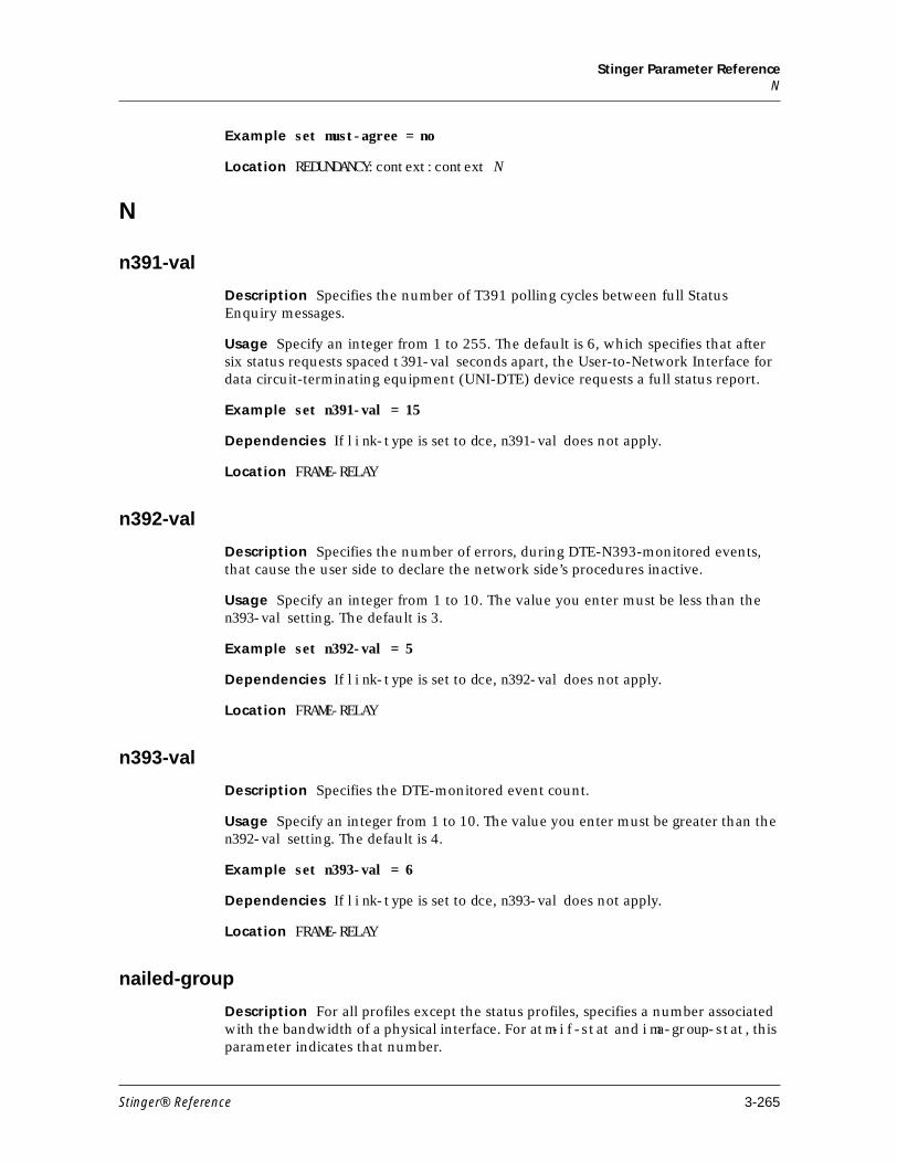
Stinger Parameter ReferenceN
Example set must-agree = no
Location REDUNDANCY:context:context N
N
n391-val
Description Specifies the number of T391 polling cycles between full Status Enquiry messages.
Usage Specify an integer from 1 to 255. The default is 6, which specifies that after six status requests spaced t391-val seconds apart, the User-to-Network Interface for data circuit-terminating equipment (UNI-DTE) device requests a full status report.
Example set n391-val = 15
Dependencies If link-type is set to dce, n391-val does not apply.
Location FRAME-RELAY
n392-val
Description Specifies the number of errors, during DTE-N393-monitored events, that cause the user side to declare the network side’s procedures inactive.
Usage Specify an integer from 1 to 10. The value you enter must be less than the n393-val setting. The default is 3.
Example set n392-val = 5
Dependencies If link-type is set to dce, n392-val does not apply.
Location FRAME-RELAY
n393-val
Description Specifies the DTE-monitored event count.
Usage Specify an integer from 1 to 10. The value you enter must be greater than the n392-val setting. The default is 4.
Example set n393-val = 6
Dependencies If link-type is set to dce, n393-val does not apply.
Location FRAME-RELAY
nailed-group
Description For all profiles except the status profiles, specifies a number associated with the bandwidth of a physical interface. For atm-if-stat and ima-group-stat, this parameter indicates that number.
Stinger® Reference 3-265
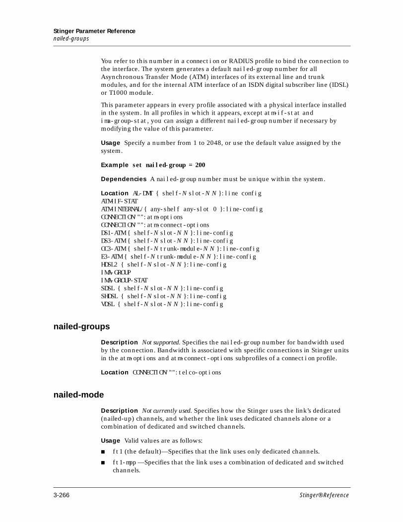
Stinger Parameter Referencenailed-groups
You refer to this number in a connection or RADIUS profile to bind the connection to the interface. The system generates a default nailed-group number for all Asynchronous Transfer Mode (ATM) interfaces of its external line and trunk modules, and for the internal ATM interface of an ISDN digital subscriber line (IDSL) or T1000 module.
This parameter appears in every profile associated with a physical interface installed in the system. In all profiles in which it appears, except atm-if-stat and ima-group-stat, you can assign a different nailed-group number if necessary by modifying the value of this parameter.
Usage Specify a number from 1 to 2048, or use the default value assigned by the system.
Example set nailed-group = 200
Dependencies A nailed-group number must be unique within the system.
Location AL-DMT { shelf-N slot-N N }:line configATM-IF-STATATM-INTERNAL/{ any-shelf any-slot 0 }:line-configCONNECTION/"":atm-optionsCONNECTION/"":atm-connect-optionsDS1-ATM { shelf-N slot-N N }:line-configDS3-ATM { shelf-N slot-N N }:line-configOC3-ATM { shelf-N trunk-module-N N }:line-configE3-ATM { shelf-N trunk-module-N N }:line-configHDSL2 { shelf-N slot-N N }:line-configIMA-GROUPIMA-GROUP-STATSDSL { shelf-N slot-N N }:line-configSHDSL { shelf-N slot-N N }:line-configVDSL { shelf-N slot-N N }:line-config
nailed-groups
Description Not supported. Specifies the nailed-group number for bandwidth used by the connection. Bandwidth is associated with specific connections in Stinger units in the atm-options and atm-connect-options subprofiles of a connection profile.
Location CONNECTION/"":telco-options
nailed-mode
Description Not currently used. Specifies how the Stinger uses the link’s dedicated (nailed-up) channels, and whether the link uses dedicated channels alone or a combination of dedicated and switched channels.
Usage Valid values are as follows:
■ ft1 (the default)—Specifies that the link uses only dedicated channels.
■ ft1-mpp —Specifies that the link uses a combination of dedicated and switched channels.
3-266 Stinger® Reference
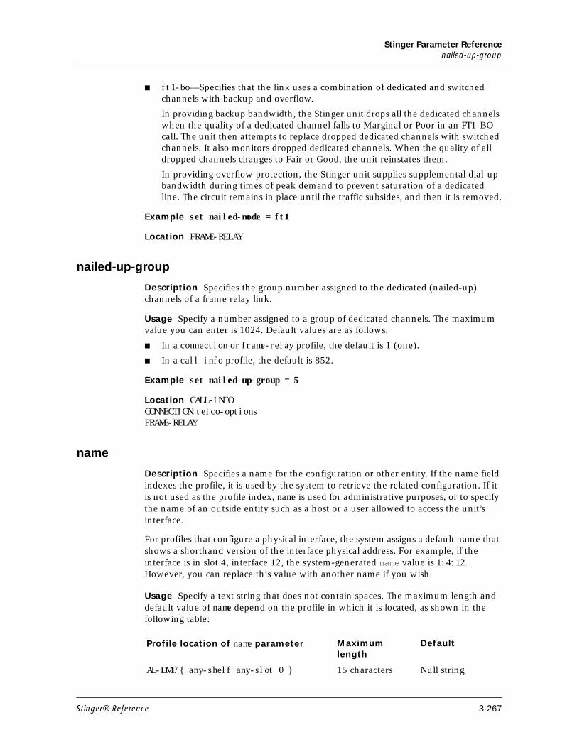
Stinger Parameter Referencenailed-up-group
■ ft1-bo—Specifies that the link uses a combination of dedicated and switched channels with backup and overflow.
In providing backup bandwidth, the Stinger unit drops all the dedicated channels when the quality of a dedicated channel falls to Marginal or Poor in an FT1-BO call. The unit then attempts to replace dropped dedicated channels with switched channels. It also monitors dropped dedicated channels. When the quality of all dropped channels changes to Fair or Good, the unit reinstates them.
In providing overflow protection, the Stinger unit supplies supplemental dial-up bandwidth during times of peak demand to prevent saturation of a dedicated line. The circuit remains in place until the traffic subsides, and then it is removed.
Example set nailed-mode = ft1
Location FRAME-RELAY
nailed-up-group
Description Specifies the group number assigned to the dedicated (nailed-up) channels of a frame relay link.
Usage Specify a number assigned to a group of dedicated channels. The maximum value you can enter is 1024. Default values are as follows:
■ In a connection or frame-relay profile, the default is 1 (one).
■ In a call-info profile, the default is 852.
Example set nailed-up-group = 5
Location CALL-INFOCONNECTION:telco-optionsFRAME-RELAY
name
Description Specifies a name for the configuration or other entity. If the name field indexes the profile, it is used by the system to retrieve the related configuration. If it is not used as the profile index, name is used for administrative purposes, or to specify the name of an outside entity such as a host or a user allowed to access the unit’s interface.
For profiles that configure a physical interface, the system assigns a default name that shows a shorthand version of the interface physical address. For example, if the interface is in slot 4, interface 12, the system-generated name value is 1:4:12. However, you can replace this value with another name if you wish.
Usage Specify a text string that does not contain spaces. The maximum length and default value of name depend on the profile in which it is located, as shown in the following table:
Profile location of name parameter Maximum length
Default
AL-DMT/{ any-shelf any-slot 0 } 15 characters Null string
Stinger® Reference 3-267
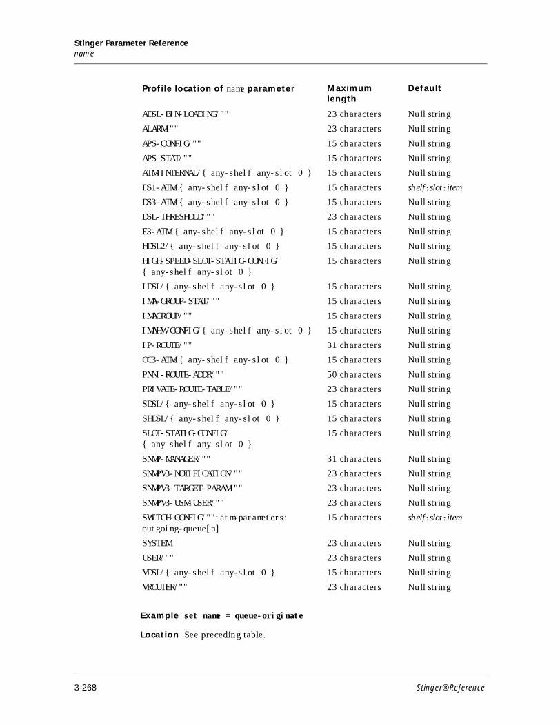
Stinger Parameter Referencename
Example set name = queue-originate
Location See preceding table.
ADSL-BIN-LOADING/"" 23 characters Null string
ALARM/"" 23 characters Null string
APS-CONFIG/"" 15 characters Null string
APS-STAT/"" 15 characters Null string
ATM-INTERNAL/{ any-shelf any-slot 0 } 15 characters Null string
DS1-ATM/{ any-shelf any-slot 0 } 15 characters shelf:slot:item
DS3-ATM/{ any-shelf any-slot 0 } 15 characters Null string
DSL-THRESHOLD/"" 23 characters Null string
E3-ATM/{ any-shelf any-slot 0 } 15 characters Null string
HDSL2/{ any-shelf any-slot 0 } 15 characters Null string
HIGH-SPEED-SLOT-STATIC-CONFIG/{ any-shelf any-slot 0 }
15 characters Null string
IDSL/{ any-shelf any-slot 0 } 15 characters Null string
IMA-GROUP-STAT/"" 15 characters Null string
IMAGROUP/"" 15 characters Null string
IMAHW-CONFIG/{ any-shelf any-slot 0 } 15 characters Null string
IP-ROUTE/"" 31 characters Null string
OC3-ATM/{ any-shelf any-slot 0 } 15 characters Null string
PNNI-ROUTE-ADDR/"" 50 characters Null string
PRIVATE-ROUTE-TABLE/"" 23 characters Null string
SDSL/{ any-shelf any-slot 0 } 15 characters Null string
SHDSL/{ any-shelf any-slot 0 } 15 characters Null string
SLOT-STATIC-CONFIG/{ any-shelf any-slot 0 }
15 characters Null string
SNMP-MANAGER/"" 31 characters Null string
SNMPV3-NOTIFICATION/"" 23 characters Null string
SNMPV3-TARGET-PARAM/"" 23 characters Null string
SNMPV3-USM-USER/"" 23 characters Null string
SWITCH-CONFIG/"":atm-parameters:outgoing-queue[n]
15 characters shelf:slot:item
SYSTEM 23 characters Null string
USER/"" 23 characters Null string
VDSL/{ any-shelf any-slot 0 } 15 characters Null string
VROUTER/"" 23 characters Null string
Profile location of name parameter Maximum length
Default
3-268 Stinger® Reference
Stinger Parameter Referencenas-port-type
nas-port-type
Description Not supported. Specifies a type of service for the session.
Location CONNECTION/"":telco-options
near-end-crc
Description Read-only. Indicates the number of cyclic redundancy check (CRC) errors detected by an ADSL transceiver unit (ATU) in the central office equipment (COE).
Usage The near-end-crc value is read-only.
Example near-end-crc = 0
Location AL-DMT-STAT { shelf-N slot-N N }:physical-statistic
near-end-fec
Description Read-only. Indicates the number of forward error correction (FEC) errors detected by an ADSL transceiver unit (ATU) in the central office equipment (COE).
Usage The near-end-fec value is read-only.
Example near-end-fec = 0
Location AL-DMT-STAT { shelf-N slot-N N }:physical-statistic
near-end-hec
Description Read-only. Indicates the number of header error checksum (HEC) errors detected by an ADSL transceiver unit (ATU) in the central office equipment (COE).
Usage The near-end-hec value is read-only.
Example near-end-hec = 0
Location AL-DMT-STAT { shelf-N slot-N N }:physical-statistic
near-end-ima-group-state
Description Read-only. Indicates the current operational state of the near-end inverse multiplexing over ATM (IMA) group.
Usage Values are as follows:
Value Description
not-configured IMA group is not configured.
Stinger® Reference 3-269
Stinger Parameter Referencenear-end-num-failures
Example near-end-ima-group-state = operational
Location IMA-GROUP-STAT
near-end-num-failures
Description Read-only. Indicates the number of times a near-end group failure (for example, Config-Aborted or Insufficient-Links) has been reported in the current 15-minute interval.
Usage The valid range for this read-only value is from 0 (zero) to 2147483647.
Example near-end-num-failures = 3
Location IMA-GROUP-STAT:ima-group-statistic
near-end-rx-failure-status
Description Read-only. Indicates the near-end receive (Rx) failure status of the link.
start-up IMA group is in the startup state.
start-up-ack IMA group is in a transitional state and has transitioned out of IMA startup state.
aborted-unsupported-framelength IMA group establishment failed because the frame length (M) received from the remote end was not acceptable to the local end.
aborted-incompatible-symmetry IMA group establishment failed because the remote end and local end have incompatible group symmetry modes.
aborted-other IMA group establishment failed for unspecified reasons.
insufficient-links IMA group is currently in the insufficient links state.
blocked IMA group is in the blocked state.
operational IMA group is in the operational state.
aborted-unsupported-version IMA group failed because of an IMA version mismatch between the local and remote ends.
Value Description
3-270 Stinger® Reference

Stinger Parameter Referencenear-end-rx-link-state
Usage Valid values for this read-only parameter are as follows:
Example near-end-rx-failure-status = no-failure
Location DS1-ATM-STAT { shelf-N slot-N N }:ima-link-status
near-end-rx-link-state
Description Indicates the near end receive (Rx) state of the link.
Usage Valid values for this read-only parameter are as follows:
Example far-end-rx-link-state = not-in-group
Value Description
no-failure Link does not have any failure.
ima-link-failure Link experienced a failure at the inverse multiplexing over ATM (IMA) layer.
lif-failure Link experienced a loss of IMA frame (LIF) failure.
lods-failure Link experienced a loss of delay synchronization (LODS) failure.
misconnected Link is misconnected to the far-end.
blocked Link is in blocked state.
fault Link is in fault state.
far-end-tx-link-unusable Far end Tx of the link is in an unusable state.
far-end-rx-link-unusable Far end Rx of the link is in an unusable state.
Value Description
not-in-group Link is not part of an IMA group.
unusable-no-given-reason Link is not usable but the reason is not known.
unusable-fault Link is not usable because of a fault.
unusable-misconnected Link is not usable because it is misconnected with the far end.
unusable-inhibited Link is not usable because it is in an inhibited state.
unusable-failed Link is not usable because it is in failed state.
usable Link is usable.
active Link is active, part of an IMA group, and carrying traffic from the ATM layer.
Stinger® Reference 3-271
Stinger Parameter Referencenear-end-rx-num-failures-counter
Location DS1-ATM-STAT { shelf-N slot-N N }:ima-link-status
near-end-rx-num-failures-counter
Description Read-only. Indicates the number of times a near-end receive failure alarm condition has been entered on this link.
Such conditions include loss of IMA frame (LIF), loss of delay synchronization (LODS), remote failure indication (RFI)-IMA, misconnection, and various forms of implementation-specific receive faults.
Usage The valid range for this read-only value is from (0) zero to 2147483647.
Example near-end-rx-num-failures-counter = 0
Location DS1-ATM-STAT { shelf-N slot-N N }:ima-link-statistic
near-end-rx-unusable-secs-counter
Description Read-only. Indicates the number of received unusable seconds at the near-end receive (Rx) link.
Usage The valid range for this read-only value is from 0 to 4294967295 counts.
Example near-end-rx-unusable-secs-counter = 100
Location DS1-ATM-STAT/:ima-link-statistic
near-end-sev-errored-secs-counter
Description Read-only. Indicates the count of 1-second intervals during which 30 percent or more of the inverse multiplexing over ATM (IMA) Control Protocol (ICP) cells were counted as IV-IMA conditions or had one or more defects, except during unavailable seconds IMA (UAS-IMA) conditions. The count is for the current 15-minute interval.
Defects include link defects such as loss of synchronization (LOS), out of frame (OOF) or loss of frame (LOF) errors, Alarm Indication signals (AISs), or loss of cell delineation (LCD); loss of IMA frame (LIM) defects; or loss of delay synchronization (LODS) defects.
Usage The valid range for this read-only value is from 0 (zero) through 2147483647.
Example near-end-sev-errored-secs-counter = 0
Location DS1-ATM -STAT { shelf-N slot-N N }:ima-link-statistic
near-end-tx-link-state
Description Read-only. Indicates the near end transmission state of the link.
3-272 Stinger® Reference
Stinger Parameter Referencenear-end-tx-num-failures-counter
Usage Valid values for this read-only parameter are as follows:
Example near-end-tx-link-state = not-in-group
Location DS1-ATM-STAT { shelf-N slot-N N }:ima-link-status
near-end-tx-num-failures-counter
Description Read-only. Indicates the number of times a near-end transmit failure alarm condition (some form of implementation-specific transmit fault) has been entered on this link.
Usage The valid range for this read-only value is from zero to 2147483647.
Example near-end-tx-num-failures-counter = 0
Location DS1-ATM-STAT { shelf-N slot-N N }:ima-link-statistic
near-end-unavail-secs-counter
Description Read-only. Indicates the count of unavailable seconds at the near-end.
Unavailability begins at the onset of 10 contiguous severely-errored-seconds inverse multiplexing over ATM (IMA) (SES-IMA) conditions and ends at the onset of 10 contiguous seconds with no severely errored IMA seconds.
Usage The valid range for this read-only value is from zero (0) to 2147483647.
Example near-end-unavail-secs-counter = 0
Location DS1-ATM-STAT { shelf-N slot-N N }:ima-link-statistic
Value Description
not-in-group Link is not part of an IMA group.
unusable-no-given-reason Link is not usable but the reason is not known.
unusable-fault Link is not usable because of a fault.
unusable-misconnected Link is not usable because it is misconnected with the far end.
unusable-inhibited Link is not usable because it is in an inhibited state.
unusable-failed Link is not usable because it is in failed state.
usable Link is usable.
active Link is active, part of an IMA group, and carrying traffic from the ATM layer.
Stinger® Reference 3-273
Stinger Parameter Referencenear-end-tx-unusable-secs-counter
near-end-tx-unusable-secs-counter
Description Read-only. Indicates the number of transmitted unusable seconds at the near-end transmit (Tx) link.
Usage The valid range for this read-only value is from 0 to 4294967295 counts.
Example near-end-tx-unusable-secs-counter = 100
Location DS1-ATM-STAT/:ima-link-statistic
need-max-vpswitching-vpis
Description Specifies whether the maximum number of line interface module (LIM)-to-trunk virtual path (VP)-switching virtual path identifiers (VPIs) to be configured on a slot is 6 or 12.
Usage Valid values are as follows:
■ yes—Up to 12 error-free LIM-to-trunk virtual path connections can be configured for connections originating from this slot. Enabling this parameter disables operations, administration, and maintenance (OAM) functionality for ATM-circuit connections. OAM functionality for ATM (terminating) connections is still supported.
■ no (the default)—Up to 6 LIM-to-trunk virtual path connections can be configured for connections originating from this slot.
Example set need-max-vp-switching-vpis = yes
Dependencies You must enable the use-vp-switching-workaround parameter for the settings to apply.
Changing the setting for this parameter causes all connections on that slot to be broken and then reestablished. This process ensures that the system allocates the correct resources on the backplane. Be aware of the following expected results when using use-vp-switching-workaround with the need-max-vpswitching-vpis parameter:
Value of use-vp-switching-workaround
Value of need-max-vpswitching-vpis
Expected results
yes yes ■ Guarantees that up to 12 LIM-to-trunk VP-switching VPIs are free from any packet errors on the slot.
■ Disables OAM functionality for ATM-circuit connections.
■ Disables LIM-to-LIM functionality for that slot.
3-274 Stinger® Reference
Stinger Parameter Referenceneighbor-ip-address
Location SLOT-STATIC-CONFIGS
neighbor-ip-address
Description Specifies the address of a Private Network-to-Network Interface (PNNI) neighbor reachable across this interface, to which a network management station can communicate.
Usage Specify an address in dotted decimal notation. The default is the null address 0.0.0.0.
Example set neighbor-ip-address = 0.0.0.0
Location ATM-IF-CONFIG { { any-shelf any-slot N } N }:base-config
neighbor-name
Description Specifies the textual name of the interface on the neighbor system.
Usage Specify a plain text string to designate the name. If the neighbor’s interface does not have a name, this setting must be null (the default).
Example set neighbor-name = r2d2
yes no ■ Enables you to configure up to 6 VP-switching VPIs if the LIM is placed in slots 1 through 7 or up to 5 VP-switching VPIs if the LIM is placed in slots 10 through 16.
■ Disables LIM-to-LIM functionality for that slot.
■ LIM-to-LIM virtual channel connections will not work on a slot if the internal VPI allocated on the backplane conflicts with the slot number in which the T1 or E1 module is installed.
If you must host both LIM-to-trunk virtual path connections and LIM-to-LIM virtual channel connections on the same slot, Lucent recommends that you install the T1 or E1 module in slots 1 through 7 of the Stinger chassis. If you will not configure LIM-to-LIM virtual channel connections on that module, then you can install the T1 or E1 module in any slot
no no Disables VP-switching without packet errors.
no yes Invalid combination.
Value of use-vp-switching-workaround
Value of need-max-vpswitching-vpis
Expected results
Stinger® Reference 3-275
Stinger Parameter Referencenetbios-primary-ns
Location ATM-IF-CONFIG { { any-shelf any-slot N } N }:base-config
netbios-primary-ns
Description Specifies the IP address of a primary NetBIOS server.
Usage Specify an IP address in dotted decimal notation.
Example set netbios-primary-ns = 2.2.2.2/28
Location IP-GLOBAL
netbios-secondary-ns
Description Specifies the IP address of a secondary NetBIOS server. The Stinger unit accesses the secondary server if the primary NetBIOS server is unavailable.
Usage Specify an IP address in dotted decimal notation.
Example set netbios-secondary-ns = 2.2.2.2/28
Location IP-GLOBAL
netmask
Description Specifies a subnet mask for the destination IP address of a private route. The value of netmask is set automatically when you specify a prefix length as part of the IP address.
Usage Specify a subnet mask in dotted decimal notation. The default is 0.0.0.0.
Example set netmask = 255.255.255.255
Location IP-INTERFACEIP-ROUTEPRIVATE-ROUTE-TABLE/""
netmask-local
Description Specifies the netmask of the local interface address.
Usage Specify a netmask in IP address format. The default is 0.0.0.0.
Example set netmask-local = 255.255.255.0
Location CONNECTION/"":ip-options
netmask-remote
Description Specifies the netmask of the remote address.
Usage Specify a netmask in IP address format. The default is 0.0.0.0.
3-276 Stinger® Reference
Stinger Parameter Referencenetwork-loopback
Example set netmask-remote = 255.255.255.0
Location CONNECTION/"":ip-options
network-loopback
Description Read-only. Indicates whether there is a line looped back out to the network.
Usage For this read-only parameter valid values are as follows:
■ true—Indicates that a line is looped back to the network.
■ false—Indicates that no line is looped back to the network.
Example network-loopback = false
Location DS1-ATM-STAT { shelf-N slot-N N }
network-management-enabled
Description Read-only. Indicates whether the network-management option is enabled.
Usage The network-management-enabled parameter is read-only. Valid values are as follows:
■ yes—Indicates that the network-management option is enabled.
■ no—Indicates that the network-management option is disabled.
Example network-management-enabled = yes
Location BASE
network-mgmt-voip-enabled
Description Read-only. Indicates the status of network management for the Voice over IP (VoIP) feature.
Usage Read-only parameter with the following possible values:
■ no—Network management VoIP feature is not enabled.
■ yes—Network management VoIP feature is enabled.
Example network-mgmt-voip-enabled = yes
Location BASE
ne-tx-clk-mode
Description Specifies the mode of the inverse multiplexing over ATM (IMA) group clocking.
Usage Valid values are as follows:
Stinger® Reference 3-277
Stinger Parameter Referencene-tx-lid
■ ctc (the default)—Common transmit clock. Transmits clocks of the links within the IMA group are derived from the same clock source.
■ itc—Independent transmit clock. Transmits clock of the links within the IMA group are derived from their respective receive clocks, as, for example, when group-symmetry-mode is set to symmetric-operation.
Example set ne-tx-clk-mode = ctc
Location IMAGROUP
ne-tx-lid
Description Not currently used. Specifies the transmit LID for the link.
Usage Specify a number from (0) zero to 31.
Location DS1-ATM:line-config:ima-option-config:txlink-config
new-nas-port-id-format
Description Specifies whether to use the new network access server (NAS) port ID format.
Usage Valid values are as follows:
■ yes—Specifies that the new NAS port ID format is used. This is the default.
■ no—Specifies that the old NAS port ID is used.
Example set new-nas-port-id-format = yes
Location SYSTEM
nm-copper-loop-test-enabled
Description Read-only. Indicates the status of the copper loop test feature.
Usage Read-only parameter with the following possible values:
■ yes—Copper loop test feature is enabled.
■ no (the default)—Copper loop test feature is not enabled.
Example nm-copper-loop-test-enabled= yes
Location BASE
nm-navis-radius-enabled
Description Read-only. Indicates the status of the NavisRadius™ feature.
Usage Read-only parameter with the following possible values:
■ yes—NavisRadius™ feature is enabled.
■ no (the default)—NavisRadius™ feature is not enabled.
3-278 Stinger® Reference
Stinger Parameter Referencenm-prov
Example nm-navis-radius-enabled = yes
Location BASE
nm-prov
Description Read-only. Indicates the status of the Navis™ Provisioning Server for edge devices support feature.
Usage Read-only parameter with the following possible values:
■ yes—Navis™ Provisioning Server for edge devices support feature is enabled.
■ no (the default)—Navis™ Provisioning Server for edge devices support feature is not enabled.
Example nm-prov = yes
Location BASE
nm-prov-core
Description Read-only. Indicates the status of Navis™ Provisioning Server support for edge and core devices feature.
Usage Read-only parameter with the following possible values:
■ yes—Navis™ Provisioning Server support for edge and core devices feature is enabled.
■ no (the default)—Navis™ Provisioning Server support for edge and core devices feature is not enabled.
Example nm-prov-core = yes
Location BASE
nm-reporting-enabled
Description Read-only. Indicates the status of the reporting feature.
Usage Read-only parameter with the following possible values:
■ yes—Reporting feature is enabled.
■ no (the default)—Reporting feature is not enabled.
Example nm-reporting-enabled = yes
Location BASE
nm-vpn-enabled
Description Read-only. Indicates the status of the virtual private network (VPN) feature.
Usage Read-only parameter with the following possible values:
Stinger® Reference 3-279
Stinger Parameter Referencenoattr6-use-termsrv
■ yes—VPN feature is enabled.
■ no (the default)—VPN feature is not enabled.
Example nm-vpn-enabled = yes
Location BASE
noattr6-use-termsrv
Description Specifies whether the unit initiates a terminal-server login if it does not receive a RADIUS Service-Type (6) attribute.
Usage Valid values are as follows:
■ yes—Specifies that the Stinger initiates a terminal-server login if Service-Type is not received, regardless of whether Framed-Protocol (7) is received or not. This is the default.
■ no—Specifies the following:
– If Service-Type is not received, but Framed-Protocol is received, a framed-protocol login is initiated.
– If neither Service-Type nor Framed-Protocol is received, a terminal-server login is initiated.
Example set noattr6-use-termsrv = no
Location EXTERNAL-AUTH
node-admin-status
Description Specifies the administrative status of a Private Network-to-Network Interface (PNNI) node.
Usage Valid values are as follows:
■ up (the default)—Specifies that the node is allowed to become active.
■ down—Specifies that the node is forced to become inactive.
Example set node-admin-status = up
Location PNNI-NODE-CONFIG
node-atm-address
Description Specifies the network service access point (NSAP) ATM address that identifies the Stinger unit as a node within a Private Network-to-Network Interface (PNNI) network.
Usage Remote systems that exchange PNNI protocol packets with the node direct packets or calls to this address.
Example set node-atm-address = 39:84:0f:80:01:bc:72:00:01:d0:6a:96:00:ff:d0:6a:96+
3-280 Stinger® Reference
Stinger Parameter Referencenode-complex-rep
Location PNNI-NODE-CONFIG
node-complex-rep
Description Enables or disables complex node representation in Private Network-to-Network Interface (PNNI) network. Complex representation provides information omitted in simple representation, but slows transmission.
Usage Valid values are as follows:
■ true—Complex node representation is used.
■ false (the default)—Simple node representation is used.
Example set node-complex-rep = true
Location PNNI-NODE-CONFIG
node-domain-name
Description Specifies the name of the Private Network-to-Network Interface (PNNI) routing domain.
Usage All lowest-level PNNI nodes with the same domain name are presumed to be connected.
Example set node-domain-name = segundo
Location PNNI-NODE-CONFIG
node-id
Description Specifies a number that identifies a Private Network-to-Network Interface (PNNI) node within a peer group.
Usage If both this parameter and the node-peer-group-id parameter have the default value of zero, the system derives the PNNI node ID from the node ATM address and other values.
Or you can manually specify a 22-byte, 44-digit hexadecimal number as a node ID.
For more information about node IDs and using aliases to specify them, see the Stinger ATM Configuration Guide.
Example set node-id = 00:00:00:00:00:00:00:00:00:00:00:00:00:00:00:00:00:00:00:00+
Location PNNI-NODE-CONFIG
node-index
Description Specifies the Private Network-to-Network Interface (PNNI) node index.
Usage Only node index 1 is currently supported.
Stinger® Reference 3-281
Stinger Parameter Referencenode-level
Example set node-index = 1
Location PNNI-METRICS { N N incoming N }:metrics-indexPNNI-NODE-CONFIGPNNI-ROUTE-TNS { 0 other other 00:00:00:00 0 }PNNI-SUMMARY-ADDR:addr-index
node-level
Description Specifies the Private Network-to-Network Interface (PNNI) routing-level indicator.
Usage Specify a number from 0 to 104, representing the level of the PNNI hierarchy at which this node exists.
Example set node-level = 96
Location PNNI-NODE-CONFIG
node-lowest
Description Enables or disables lowest-level node status for a Private Network-to-Network Interface (PNNI) node.
Usage Valid values are as follows:
■ true (the default)—Specifies that the node is a lowest-level node.
■ false—The false setting is not currently supported.
Example set node-lowest = true
Location PNNI-NODE-CONFIG
node-peer-group-id
Description Specifies a number used to group nodes into a Private Network-to-Network Interface (PNNI) peer group.
Usage All members of the same PNNI peer group have the same peer group ID. If both this parameter and the node-id parameter have the default value of zero, the system derives the PNNI peer group ID from the Asynchronous Transfer Mode (ATM) node address and other values.
Or you can manually specify a 14-byte, 28-digit hexadecimal number as a peer group ID.
For more information about peer group IDs and using aliases to specify them, see Stinger Private Network-to-Network Interface (PNNI) Supplement.
Example set node-peer-group-id = 00:00:00:00:00:00:00:00:00:00:00:00:00:00
Location PNNI-NODE-CONFIG
3-282 Stinger® Reference
Stinger Parameter Referencenode-restricted-transit
node-restricted-transit
Description Specifies whether to enable or disable support of switched virtual channels (SVCs) transiting the node.
Usage Valid values are as follows:
■ true—The node prevents the transit of SVCs.
■ false (the default)—The node allows transit of SVCs.
Example set node-restricted-transit = false
Location PNNI-NODE-CONFIG
noise-margin-down
Description Read-only. Indicates the current downstream noise margin of the asymmetric digital subscriber line (ADSL) in decibels (dB).
Usage The noise-margin-down value is read-only.
Example noise-margin-down = 6
Location AL-DMT-STAT { shelf-N slot-N N }:physical-statistic
noise-margin-up
Description Read-only. Indicates the current upstream noise margin of the asymmetric digital subscriber line (ADSL) in decibels (dB).
Usage The noise-margin-up value is read-only.
Example noise-margin-up = 6
Location AL-DMT-STAT { shelf-N slot-N N }:physical-statistic
non-real-time-vbr
Description Enables and disables variable bit rate (VBR)-nonreal time traffic in the queue containing this parameter.
Usage Valid values are as follows:
■ yes—This queue supports ATM VBR-nonreal time traffic.
■ no—The queue does not support VBR-nonreal time traffic. This is the default.
Example set non-real-time-vbr = no
Dependencies For each queue, one or more ATM services categories can be set to yes. The non-real-time-vbr parameter must be set to yes for at least one and no more than two of the active queues assigned to a line interface module (LIM), control module, or trunk module.
Location SWITCH-CONFIG:atm-parameters:outgoing-queue
Stinger® Reference 3-283
Stinger Parameter Referencenotification-log-age-out
notification-log-age-out
Description Specifies the number of minutes that an SNMP trap (notification) is kept in a log before it is automatically removed.
Usage Specify a number from 0 to 2147483647. The default is 1440 (24 hours). If you specify 0 (zero), a notification is kept in a log indefinitely.
Example set notification-log-age-out = 2880
Location SNMP
notification-log-enable
Description Specifies whether SNMP traps (notifications) for this profile are to be logged.
Usage Valid values are as follows:
■ yes—Enables logging.
■ no (the default)—Disables logging.
Example set notification-log-enable = yes
Location TRAP
notification-log-limit
Description Specifies the maximum number of trap (notification) entries that can be held in the SNMP notification log.
Usage Specify a number from 1 to 500. The default is 50.
Example set notification-log-limit = 100
Location TRAP
notify-tag-list
Description Specifies the tag list that is specified by the tag parameter value in each occurrence of the snmpv3-notification profile.
Usage Specify the tag value(s) you specified in one or more snmpv3-notification profiles.
Example set notify-tag-list = default1
Location TRAP
notify-view-name
Description Specifies the name of a view for notify access in a view-based access control model (VACM).
3-284 Stinger® Reference
Stinger Parameter Referenceno-trunk-alarm
Usage Specify a name of up to 32 characters. If a request that matches the access properties specified in this profile uses this name, read access is granted.
Example set notify-view-name = notify1
Location VACM-ACCESS
no-trunk-alarm
Description Enables or disables setting an alarm relay when no trunk is available.
Usage Valid values are as follows:
■ no (the default)—Does not set an alarm relay when no trunk is available.
■ yes—Sets an alarm relay when no trunk is available.
Example set no-trunk-alarm = yes
Location SYSTEM
ntr-enabled
Description Enables or disables network time reference (NTR) functionality.
Usage Valid values are as follows:
■ no—Disables NTR functionality. This is the default.
■ yes—Enables NTR functionality.
Example set ntr-enabled = yes
Dependencies If unit-type is coe (central office equipment), the system clock signal is used as the input and the customer premises equipment (CPE), if equipped to do so, can recover the clock.
If unit-type is cpe, the port outputs the recovered clock signal as the system clock if clock-source is set to eligible and clock-priority is set so that the clock can be selected.
Location HDSL2 { shelf-N slot-N N }:line-configSHDSL { shelf-N slot-N N }:line-config
number-of-channels
Description Read-only. Indicates the number of channels in this protection group.
Usage The valid range for this read-only parameter is from 0 through 255.
Example number-of-channels = 2
Location APS-STAT/””
Stinger® Reference 3-285
Stinger Parameter Referencenum-digits-trunk-groups
num-digits-trunk-groups
Description Specifies the number of digits to allow for trunk groups.
Usage Specify a number from 1 to 4:
■ When you accept the default of 1, trunk-group numbers range from 2 to 9, and the dial-out telephone number is preceded by a single-digit number.
■ If num-digits-trunk-groups is set to 2, 3, or 4, the range of trunk-group numbers can include the specified number of digits (up to 9999), and the dial-out telephone number is always preceded by that number of digits.
For example, if you set num-digits-trunk-groups to 2, and you want the device to dial the number 555-1212 on trunk 7, the dial-out telephone string is 075551212.
Example set num-digits-trunk-groups = 2
Dependencies Consider the following:
■ When the Stinger unit is configured to interoperate with an external application for dial-out, the external system and the Stinger unit must agree about the number of digits in a trunk-group number. Otherwise, telephone numbers are not parsed correctly and calls fail.
■ use-trunk-groups must be set to yes for num-digits-trunk-groups to have an effect.
Location SYSTEM
num-sec-invalid
Description Read-only. Indicates how many error seconds were detected during the continuous bit error-rate test (BERT).
Usage The num-sec-invalid value is read-only.
Location AL-DMT-STAT { shelf-N slot-N N }:physical-status
num-sec-valid
Description Read-only. Indicates how many seconds were error-free during the continuous bit error-rate test (BERT).
Usage The num-sec-valid value is read-only.
Location AL-DMT-STAT { shelf-N slot-N N }:physical-status
nvram-was-rebuilt
Description Read-only. Indicate nonvolatile RAM (NVRAM) rebuild status.
Usage Read-only parameter with one of the following values:
■ no—NVRAM was not rebuilt.
■ yes—NVRAM was rebuilt.
3-286 Stinger® Reference
Stinger Parameter ReferenceO
Example nvram-was-rebuilt = yes
Location SYSTEM
O
oam-address
Description Specifies information about the ATM interface on which a test is carried out.
Usage Specify shelf, slot, port, vpi, and vci values. The shelf number is always 1 (one).
■ When you specify 0 (zero) for the port value, the tests are performed on all ports on the specified slot.
■ When you specify 32768 for the vpi value, the tests are performed for all virtual path identifiers (VPIs) on the specified slot and port.
■ When you specify 32768 for the vci value, the tests are performed for all virtual channel identifiers (VCIs) on the specified slot and port.
■ When you specify 32769 for the vci value, an F4 test is performed. For F5 testing, you must specify a vci value greater than 31.
Example The following example specifies that a test is to be performed on the ATM interface port 5 in slot 3, with VPI 4, and VCI 5:
admin> set oam-address = {{1 3 5}4 2}
admin> list oam-address
[in ATM-OAM/{ { shelf-1 slot-3 5 } 4 2 }:oam-address (new) (changed)] physical-address = { shelf-1 slot-3 5 } vpi = 4 vci = 2
Location OAM-ADDRESS*
oam-ais-f5
Description Enables or disables sending operations, administration, and maintenance (OAM) Alarm Indication signal (AIS) F5 cells when a permanent virtual circuit (PVC) fails.
Usage Valid values are as follows:
■ disable—Does not send any OAM AIS F5 cells. This is the default.
■ segment—Sends OAM AIS F5 cells indicating segment failure.
■ end-to-end—Sends OAM AIS F5 cells indicating end-to-end failure.
Example set oam-ais-f5 = segment
Location CONNECTION:atm-options CONNECTION:atm-connect-options
Stinger® Reference 3-287
Stinger Parameter Referenceoam-support
oam-support
Description Enables or disables F4 operations, administration, and maintenance (OAM) support on a virtual path connection (VPC).
Usage Valid values are as follows:
■ yes (the default)—Enables OAM support on a VPC.
■ no—Disables OAM support on a VPC.
Example set oam-support = yes
Dependencies You must also set the vp-switching parameter to yes to enable F4 OAM support on the VPC.
Location CONNECTION:atm-connect-optionsCONNECTION:atm-options
oam-timeout-trap-enabled
Description Enables or disables an operations, administration, and maintenance (OAM) trap.
Usage Valid values are as follows:
■ yes—Enables the OAM trap.
■ no (the default)—Disables the OAM trap.
Example set oam-timeout-trap-enabled = yes
Location TRAP/""
oif-anomalies-counter
Description Indicates the number of out-of-IMA-frame (OIF) anomalies in inverse multiplexing over ATM (IMA), except during severely-errored-seconds IMA (SES-IMA) or unavailable seconds IMA (UAS-IMA) conditions, in the current 15-minute interval.
Usage The valid range for this read-only value is from 0 (zero) to 2147483647.
Example oif-anomalies-counter = 213
Location DS1-ATM-STAT { shelf-N slot-N N }:ima-link-statistic
old-call-filter
Description Specifies the number of the filter used to determine if a packet should cause the idle timer to be reset. Filters are not supported with the current software version.
Usage Specify a numeric value in a range of 0 (zero) to 32. The default is 0.
Example set old-call-filter = 4
Location CONNECTION/"":session-options
3-288 Stinger® Reference
Stinger Parameter Referenceold-data-filter
old-data-filter
Description Specifies the number of the filter used to determine if packets should be forwarded or dropped. Filters are not supported with the current software version.
Usage Specify a numeric value in a range of 0 (zero) to 32. The default is 0.
Example set old-data-filter = 4
Location CONNECTION/"":session-options
only-one-correction
Description Enables or disables use of only one instead of many switching fabric corrections.
Usage Valid values are as follows:
■ yes (the default)—Switching fabric corrections can occur only once. One correction is recommended.
■ no—Switching fabric corrections can occur many times.
Example set only-one-correction = no
Location SYSTEM-INTEGRITY:integrity-config
operational-count
Description Read-only. Indicates the number of devices that are in the UP state.
Usage The operational-count setting is read-only.
Example operational-count = 10
Location DEVICE-SUMMARY
operational-mode
Description Read-only. Indicates the mode in which the modem operates as automatically detected or as set by user.
Usage Valid values for this read-only parameter are as follows:
■ ansi-dmt
■ g.lite
■ g.dmt
■ unknown
Example operational-mode = g.lite
Location AL-DMT-STAT { shelf-N slot-N N }:physical-status
Stinger® Reference 3-289
Stinger Parameter Referenceoperational-rate
operational-rate
Description Read-only. Indicates the data rate for the symmetrical interface to which this parameter applies.
Usage The data rate is currently fixed at 1.544Mbps.
Example operational-rate = 1544000
Location HDSL2-STAT { shelf-N slot-N N }:physical-status
oper-status
Description Read-only. Indicates the operational status of the reachable address and whether it is being advertised by this Private Network-to-Network Interface (PNNI) node.
Usage Valid values for this read-only parameter are as follows:
■ inactive—The prefix is not reachable.
■ active—The prefix is reachable and is not being advertised in PNNI.
■ advertised—The prefix is reachable and is being advertised in PNNI.
Example oper-status = inactive
Location PNNI-ROUTE-ADDR
organization-minus-1
Description Not currently used. Specifies a number representing the highest level of the Private Network-to-Network Interface (PNNI) hierarchy that lies within the organization-minus-one scope.
Usage Specify a number from 0 to 104. The default value is 72.
Location PNNI-NODE-CONFIG:node-scope-mapping
organization-plus-1
Description Not currently used. Specifies the highest level of the Private Network-to-Network Interface (PNNI) hierarchy that lies within the organization-plus-one scope.
Usage Specify a number from 0 to 104. The default value is 64.
Location PNNI-NODE-CONFIG:node-scope-mapping
originate-advert
Description Specifies whether or not the reachable address is to be advertised by the local node into its Private Network-to-Network Interface (PNNI) routing domain.
Usage Valid values are as follows:
3-290 Stinger® Reference
Stinger Parameter Referenceout-defect-int-time
■ true (the default)—The local node advertises reachability of the address into the routing domain.
■ false—The local node does not advertise the reachable address.
Example set originate-advert = true
Location PNNI-ROUTE-ADDR
out-defect-int-time
Description Specifies the time, in milliseconds, that must elapse before the FAILED state condition can be turned off for the receiving link of an inverse multiplexing over ATM (IMA) connection.
If the NO DEFECT condition persists for this time, the link leaves the FAILED state.
Usage Valid values are from 0 (zero) to 2147483647. The default is 10000.
Example set out-defect-int-time = 10000
Location DS1-ATM { shelf-N slot-N N }:line-config:ima-option-config:rxlink-config
outgoing-cells
Description Read-only. Indicates the number of outgoing cells in an asymmetric digital subscriber (ADSL) line.
Usage The outgoing-cells value is read-only.
Example outgoing-cells = 100
Location AL-DMT-STAT { shelf-N slot-N N }:physical-statistic
out-of-cell-delineation
Description Read-only. Indicates whether the device is receiving a far-end loss-of-frame signal, also known as a Yellow Alarm.
Usage The out-of-cell-delineation value is read-only. Valid values are as follows:
■ true—Indicates that the device is receiving a far-end loss-of-frame signal.
■ false—Indicates that the device is not receiving a far-end loss-of-frame signal.
Example out-of-cell-delineation = false
Location OC3-ATM-STAT { shelf-N trunk-module-N N }
out-of-frame
Description Read-only. Indicates whether the local line is connected and in frame.
Usage Valid values are as follows:
Stinger® Reference 3-291
Stinger Parameter Referenceoutput-power-down
■ true —Indicates that near end is out of frame.
■ false —Indicates that the line is connected and in frame.
Example out-of-frame = false
Location OC3-ATM-STAT { shelf-N trunk-module-N N }
output-power-down
Description Read-only. Indicates the current downstream aggregate power level in decibels (dB).
Usage The output-power-down value is read-only.
Example output-power-down = 19
Location AL-DMT-STAT { shelf-N slot-N N }:physical-statistic
output-power-up
Description Read-only. Indicates the current upstream aggregate power level in decibels (dB).
Usage The output-power-up value is read-only.
Example output-power-up = 19
Location AL-DMT-STAT { shelf-N slot-N N }:physical-statistic
override-delay
Description Specifies the number of seconds a Private Network-to-Network Interface (PNNI) node waits for itself to be declared the preferred peer group leader (PGL) by unanimous agreement among its peers.
When unanimous agreement is not reached, override-delay specifies the number of seconds that must pass before the node considers a two-thirds majority as sufficient agreement to declare itself peer group leader, abandoning the attempt to get unanimous agreement.
Usage Specify the number of seconds. The default is 30.
Example set override-delay = 50
Location PNNI-NODE-CONFIG:node-pgl
over-subscription
Description Specifies the allowed oversubscription to the line rate for connection admission control (CAC).
Oversubscription modifies the allowed bandwith on a port. The allowed bandwidth on a trunk port is equal to line-rate multiplied by over-subscription divided by 10 (line-rate * over-subscription/ 10).
3-292 Stinger® Reference
Stinger Parameter ReferenceP
Usage Valid values range from 0 (zero) to 10240. The default value is 10. Consider the following:
■ The default value (10) limits the port to accept only connections that do not exceed line-rate.
■ Values between 1 and 9 limit the allowed bandwidth to a value less than line-rate.
■ A value of 0 (zero) disables the port from taking part in any CAC. The bandwidth is advertised as 0.
Example set over-subscription = 50
Location HIGH-SPEED-SLOT-STATIC-CONFIG:trunk-cac-config
Note This parameter was previously located in the atm-config profile. Its use in that location has been deprecated.
P
pair
Description Read-only. Indicates identity and reboot statistics for the other controller in this context.
Usage Read-only, complex field.
Example pair = { 9487770 }
Location REDUNDANCY-STATS:context-stats
parallel-dialing
Description Specifies the number of Call-Setup requests the system sends to the network side at any given time.
If the system is processing the maximum number of calls when it receives a new call request, it queues the request and processes it after the network side sends a call-proceeding message for a previous request.
Usage Specify an integer from 1 to 64. The default is 12. Consider the following:
■ If the Stinger has trouble establishing an initial connection at the full bandwidth for calls from the U.S. to another country, reduce parallel-dialing to a value of 1.
■ For ADSL or SDSL operation, you must set parallel-dialing to the number of ADSL or SDSL interfaces.
Example set parallel-dialing = 12
Location SYSTEM
Stinger® Reference 3-293
Stinger Parameter Referenceparent-node-index
parent-node-index
Description Specifies the number identifying the node that will represent this peer group at the next higher routing level, if this node becomes peer group leader (PGL).
Usage The default 0 (zero) value indicates that no parent node exists.
Example set parent-node-index = 0
Location PNNI-NODE-CONFIG:node-pgl
partial-packet-discard
Description Specifies whether the remaining cells in a packet (except the last cell) are to be discarded if buffers become congested after some cells of a packet have been queued.
Usage Valid values are as follows:
■ yes—Specifies that the remaining cells in a packet (except the last cell) are discarded if buffers become congested after some cells of a packet have been queued. In addition, if congestion occurs when the unit is receiving the last cell of a packet, it discards the entire next packet. Partial packet discard (PPD) relies on a higher layer to reject the partial packet when it is received.
■ no (the default)—Specifies that none of the remaining cells in a packet are discarded if buffers become congested after some cells of a packet have been queued.
Dependencies This parameters applies only to ATM adaptation layer 5 (AAL5) circuits.
Location ATM-QOS
password
Description Specifies a password.
■ In a user profile, the password setting specifies a password that the user must enter to log in.
■ In a tunnel-options subprofile configured for Ascend Tunnel Management Protocol (ATMP), the password setting specifies the password that a Foreign Agent must supply to establish a tunnel with the Stinger T1000 module.
■ In an snmpv3-usm-user profile, the password setting specifies the user’s password, which maps to a 16-octet or 20-octet key, in compliance with RFC 2574.
Usage Specify a text string of up to 20 characters. The default is null. The value you enter is case sensitive.
Note In an snmpv3-usm-user profile, you can include special characters by using the \xNN format with the ASCII code for the character. For example, the value test\x20\x21 represents the following string:
test !
3-294 Stinger® Reference
Stinger Parameter Referencepassword-enabled
Example set password = unit
Dependencies Consider the following:
■ You must set agent-mode to home-agent for the password setting to apply in a tunnel-options subprofile.
■ In an snmpv3-usm-user profile, you must specify a password if the auth-protocol setting is a value other than no-auth.
Location ATMPCONNECTION:tunnel-optionsSNMPV3-USM-USERUSER
password-enabled
Description Specifies whether all failed Telnet login attempts generate a trap (notification).
Usage Valid values are as follows:
■ yes—Specifies that all failed Telnet login attempts generate a trap. This is the default.
■ no—Specifies that failed Telnet login attempts do not generate a trap.
Example set password-enabled = no
Dependencies When password-enabled is set to yes, you must also set security-enabled to yes for all failed Telnet login attempts to generate a trap.
Location TRAP
password-for-direct-access
Description Specifies the password that the user must enter when security-for-direct-access is set to global.
Usage Specify a password of up to 64 characters. The default is null.
Example set password-for-direct-access = mypassword
Dependencies Consider the following:
■ If security-for-direct-access is not set to global, the password-for-direct-access setting is ignored.
■ If direct-access is set to no, password-for-direct-access does not apply.
Location TERMINAL-SERVER:dialout-configuration
password-prompt
Description Specifies the string the terminal server uses to prompt for the system-password value when authentication is in use and an interactive user initiates a connection.
Stinger® Reference 3-295
Stinger Parameter Referencepath-state
Usage Specify up to 15 characters. Password: is the default.
Example set password-prompt = Your Password:
Dependencies If terminal services are disabled, password-prompt does not apply.
Location TERMINAL-SERVER:terminal-mode-configuration
path-state
Description Read-only. Indicates the state of the synchronous optical network (SONET) path.
Usage The path-state value is read-only.
Example path-state = sonet-path-active-no-defect
Location OC3-ATM-STAT { shelf-N trunk-module-N N }
pattern-test-status
Description Read-only. Indicates the result of the pattern test.
Usage The pattern-test-status value is read-only. Valid values are as follows:
■ none—Indicates that no pattern test has been run on this link.
■ in-sync—The pattern test indicates that the line is synchronized.
■ lost-sync—The pattern test indicates that the line has lost synchronization.
Location DS1-ATM-STAT { shelfN slotN N }
p-bit-error-count
Description Read-only. Indicates the number of P-bit parity errors received in Asynchronous Transfer Mode (ATM) error-checking since the last time the unit was reset.
P-bit errors indicate that the unit received a P-bit code on the DS3 M-frame that differs from the locally calculated code.
Usage The p-bit-error-count value is read-only.
Example p-bit-error-count = 0
Location DS3-ATM-STAT { shelf-N slot-N N }E3-ATM-STAT { shelf-N slot-N N }
pcm-mode
Description Not currently used. Specifies the number of active channels in a pulse code modulation (PCM) highway.
Usage Valid values are the following:
3-296 Stinger® Reference
Stinger Parameter Referencepeak-cell-rate-cells-per-sec
■ isdn—Use 23 channels to carry the cells.
■ clear-channel (the default)—Use 24 channels to carry the cells.
Example set pcm-mode = isdn
Location DS1-ATM { shelf N slot N N }:line-config
peak-cell-rate-cells-per-sec
Description Read-only. Indicates peak cell rate (PCR), which is the maximum number of cells allowed per second.
Usage The value is read-only. The PCR is calculated from the peak-rate-kbits-per-sec setting and used in the internal Asynchronous Transfer Mode (ATM) configuration.
Example peak-cell-rate-cells-per-sec = 37
Location ATM-QOS
peak-rate
Description Specifies the maximum effective bit rate allowed, in kilobits per second.
The Stinger verifies that the peak-rate value of a shaper does not exceed the effective line rate.
Usage The valid range is 1 through 135631. The default is 1000 (1Mbps).
Example set peak-rate = 15000
Location ATM-CONFIG:traffic-shapers
peak-rate-kbits-per-sec
Description Specifies the peak bit rate per second in kilobits per second.
Usage Specify a value within the range from 0 to 155520Kbps. The default value is 16Kbps. Use a value that is appropriate for the type of traffic, as follows:
■ For constant bit rate (CBR) traffic, specify the static bit rate.
■ For available bit rate (ABR), specify the maximum explicit rate.
■ For variable bit rate (VBR), specify the upper boundary of the variable bit rate.
Example set peak-rate-kbits-per-sec = 20
Location ATM-QOS
Stinger® Reference 3-297

Stinger Parameter Referencepeer-delayed-ack-interval
peer-delayed-ack-interval
Description In Private Network-to-Network Interface (PNNI), specifies the minimum amount of time between transmissions of delayed PNNI topology state element (PTSE) acknowledgement packets.
Usage Specify an integer in 100ms units. The default is 10.
Example set peer-delayed-ack-interval = 10
Location PNNI-NODE-CONFIG:node-timer
perm-conn-upd-mode
Description Specifies under what circumstances the Stinger performs nonintrusive remote updates of the configurations of permanent connections.
Usage Valid values are as follows:
■ all (the default)—Specifies that, if they are fetched from the RADIUS server, all existing permanent connections are torn down and reestablished following the update. This setting causes a service interruption every time any dedicated (nailed profile is updated or added.
■ changed—Specifies that only changed permanent connections are torn down and reestablished.
Example set perm-conn-upd-mode = changed
Location SYSTEM
pf-comp-enabled
Description Not currently used. Enables or disables protocol field compression. Asynchronous only.
Location CONNECTION:ppp-options
phone-number
Description Not currently used. Specifies the number the Stinger dials to reach the
switch.
Usage Specify a telephone number of up to 24 characters, limited to the following
choice of characters: 1234567890()[]!z-*|. The default is null.
Example set phone-number = 555-1234
Dependencies For frame relay, if a dedicated (nailed-up) data link connection is in
use, phone-number does not apply.
Location CALL-INFOCALL-ROUTEFRAME-RELAY
3-298 Stinger® Reference
Stinger Parameter Referencephs-support
phs-support
Description Read-only. Indicates whether support for the Personal Handyphone System (PHS) is enabled.
Usage The phs-support setting is read-only. Valid values are as follows:
■ yes—Indicates that PHS support is enabled.
■ no—Indicates that PHS support is disabled.
Example phs-support = yes
Location BASE
physical-address
Description Identifies the location of a physical interface or module within the Stinger unit.
This value is used by the system to retrieve the configuration of an item. The system also addresses the Asynchronous Transfer Mode (ATM) internal interface of an ISDN digital subscriber line (IDSL) or T1000 module by a physical-address value. The address has the format {shelf slot item}. The elements of the address are identified as follows:
■ shelf—Currently, in Stinger units, the shelf number is always 1.
■ slot—Number of the slot in which the module resides.
■ item—Number of the interface on the module. Interfaces are numbered starting with 1 for the topmost or leftmost interface on the module. An item number of 0 (zero) denotes the entire slot.
Usage The physical-address setting is a complex field consisting of shelf, slot, and item-number component settings. This value is set by the system when it creates the profile for an interface. After you configure an interface and write the profile, you can clone the configuration by modifying this value, as shown in the following example.
Example set physical-address slot = 4
This example modifies the slot value to copy the configured profile for a module in another slot.
Location This parameter appears in every profile associated with one of the system’s physical interfaces:
ALARMAL-DMT { shelf-N slot-N N }AL-DMT-STAT { shelf-N slot-N N }ATM-INTERNAL/{ any-shelf any-slot 0 }ATM-INTERNAL-STAT { any-shelf any-slot 0 }CARD-CODEDEBUGDS1-ATM { shelf-N slot-N N }DS1-ATM-STAT { shelf-N slot-N N }DS3-ATM { shelf-N slot-N N }
Stinger® Reference 3-299
Stinger Parameter Referenceping
DS3-ATM-STAT { shelf-N slot-N N }E3-ATM { shelf-N slot-N N }E3-ATM-STAT { shelf-N slot-N N }HDSL2 { shelf-N slot-N N }HDSL2-STAT { shelf-N slot-N N }HIGH-SPEED-SLOT-STATIC-CONFIG { shelf-N slot-N N }IDSL { shelf-N slot-N N }IMA-GROUP-STATIMAHW-CONFIGLIM-SPARING-CONFIGLINE-DIAGLINE-DIAG-STATLINE-TESTSMODEMOC3-ATM { shelf-N slot-N N }OC3-ATM-STAT { shelf-N slot-N N }SDSL { shelf-N slot-N N }SDSL-STAT { shelf-N slot-N N }SERIALSHDSL { shelf-N slot-N N }SLOT-STATIC-CONFIGSWITCH-CONFIG:atm-parameters:outgoing-queueVDSL
ping
Description Enables and disables the terminal-server ping command.
Usage Valid values are as follows:
■ yes—Specifies terminal-server users to use the ping command.
■ no—Specifies the ping command in the terminal-server interface. This is the default.
Example set ping = yes
Location TERMINAL-SERVER:terminal-mode-configuration
planned-bitrate-down
Description Specifies the constant bit rate for downstream traffic when operator-controlled rate-adaptive mode is in effect.
Usage Specify an integer from 0 to 1500Kbps. The default value is 8000Kbps for 12-port and 24-port line interface modules (LIMs) and 2272Kbps for 48-port LIMs.
Example set planned-bitrate-down = 100
Dependencies Consider the following:
■ planned-bitrate-down does not apply when automatic-at-startup rate adaptation is in use on the line.
3-300 Stinger® Reference
Stinger Parameter Referenceplanned-bitrate-up
■ If you set planned-bitrate-down to a nonzero value in one subprofile, set planned-bitrate-down to 0 (zero) in the other subprofile.
Location AL-DMT { shelf-N slot-N N }:fast-path-configAL-DMT { shelf-N slot-N N }:interleave-path-config
planned-bitrate-up
Description Specifies the constant bit rate for upstream traffic when operator-controlled rate-adaptive mode is in effect.
Usage Specify an integer from 0 to 2000Kbps. The default value is 512Kbps for 12-port and 24-port line interface modules (LIMs) and 544Kbps for 48-port LIMs.
Example set planned-bitrate-up = 100
Dependencies Consider the following:
■ planned-bitrate-up does not apply when automatic-at-startup rate adaptation is in use on the line.
■ If you set planned-bitrate-up to a nonzero value in one subprofile, set planned-bitrate-up to 0 (zero) in the other subprofile.
Location AL-DMT { shelf-N slot-N N }:fast-path-configAL-DMT { shelf-N slot-N N }:interleave-path-config
pnni-enabled
Description Read-only. Indicates the status of the Private Network-to-Network Interface (PNNI) protocol feature.
Usage Read-only parameter with the following possible values:
■ yes (the default)—PNNI feature is enabled.
■ no—PNNI feature is not enabled.
Example pnni-enabled = yes
Location BASE
pnni-link-state
Description Read-only. Indicates the Private Network-to-Network Interface (PNNI) link state of the port.
Usage This parameter is read-only. Valid values are as follows:
■ not-configured—No link state has been configured for the port.
■ up—Link state for the port is up.
■ down—Link state for the port is down.
Example pnni-link-state = up
Location ATM-IF-STAT { { N N } N }
Stinger® Reference 3-301
Stinger Parameter Referencepnni-scope
pnni-scope
Description Specifies the extent of the advertisement of reachability from the advertising Private Network-to-Network Interface (PNNI) node to the address prefix.
Usage The default value is 0. For information about scope, see the Stinger Private Network-to-Network Interface (PNNI) Supplement.
Example set pnni-scope = 0
Location PNNI-ROUTE-ADDR
poll-after-retransmission
Description Specifies whether the Stinger unit sends a poll after retransmitting protocol data units (PDUs) before sending any further PDUs.
Usage Valid values are as follows:
■ yes—Enables the poll.
■ no (the default)—Disables the poll.
Example poll-after-retransmission = yes
Location ATM-IF-SIG-PARAMS:qsaal-options
poll-inact-factor
Description Number of consecutive polls on the interface for which no Integrated Local Management Interface (ILMI) response message is received before ILMI connectivity is considered lost. ILMI is not supported with the current software version.
Usage Specify a value from 1 to 65536. The default value is 4.
Example set poll-inact-factor = 12
Location ATM-IF-CONFIG:extension-config
pool-base-address
Description Specifies the base addresses of up to 128 IP address pools. A contiguous block of addresses must be available, starting with the address you specify.
Usage For each pool, specify the base IP address of a block of contiguous addresses. The default is 0.0.0.0.
!Caution For Point-to-Point Protocol (PPP) interfaces, the Windows operating system uses a default subnet mask of /24. Therefore, if NetBIOS over IP is enabled, connected Windows users will broadcast to .255, causing a performance problem for anyone connected at that address.
Example set pool-base-address[3] = 10.207.23.1
Dependencies Consider the following:
3-302 Stinger® Reference
Stinger Parameter Referencepool-chaining
■ An address in a pool does not accept a subnet mask modifier, because pool addresses are advertised as host routes. If you allocate IP addresses on a separate IP network or subnet, make sure you inform other IP routers about the route to that network or subnet.
■ The number of addresses in the pool must be specified by assign-count.
■ If you are using network summarization (by means of the pool-summary setting), the address you specify must be network aligned.
■ In a vrouter profile, the address pool is exclusive to one virtual router (VRouter). If you do not specify an address pool in a vrouter profile, virtual routers can share the address pools defined in the ip-global profile.
■ If you change the value of pool-base-address to a lower number, you must reset the unit for the change to take effect.
Location IP-GLOBALVROUTER/""
pool-chaining
Description Enables or disables IP pool chaining.
Usage Valid values are as follows:
■ yes—Enables pool chaining. The system treats contiguous IP address pools as a single extended pool space when searching for an available address to assign to a caller.
■ no (the default)—Disables pool chaining.
Example set pool-chaining = yes
Dependencies Consider the following:
■ Address pools must be defined either locally or in RADIUS pseudo-user profiles.
■ When specified in a vrouter profile, address pools are exclusive to that virtual router. If address pools are not specified in a vrouter profile, the virtual router(s) can share the address pools defined in the ip-global profile.
Location IP-GLOBALVROUTER/""
pool-name[n]
Description Assigns a name to an IP address pool for TACACS+ authentication or virtual router (VRouter) operation.
Usage Specify a name of up to 11 characters. The default is null.
Example set pool-name 1 = newyork
Dependencies Consider the following:
■ Each pool configuration consists of a base address (specified by pool-base-address), address count (specified by assign-count), and name (specified by pool-name).
Stinger® Reference 3-303
Stinger Parameter Referencepool-summary
■ If TACACS+ authentication is not in use, the Stinger unit treats a pool name specification as a comment.
■ In a vrouter profile, the address pool is exclusive to one virtual router. If you do not specify an address pool in a vrouter profile, virtual routers can share the address pools defined in the ip-global profile.
Location IP-GLOBALVROUTER/""
pool-summary
Description Sets or clears the pool summary flag. The use of pool summarization can significantly reduce the size of routing table advertisements.
When the flag is set, the Stinger unit adds IP addresses from an address pool to the routing table as individual host routes, and summarizes the series of host routes into a network route advertisement. It advertises the entire pool as a route, and only privately keeps track of the IP addresses in the pool. If a remote network sends a packet to an inactive IP address, the Stinger unit either bounces the packet back to the remote network or silently discards it.
When specified in a vrouter profile, address pools are exclusive to that virtual router. If address pools are not specified in a vrouter profile, the virtual router(s) can share the address pools defined in the ip-global profile.
Usage Valid values are as follows:
■ yes—Enables pool summarization.
■ no (the default)—Disables pool summarization.
Example set pool-summary = yesset pool-base-address[3] = 10.12.253.1set assign-count = 62
Dependencies When pool-summary is set to yes, the pool-base-address you specify must be network aligned. For details on configuring network-aligned pools, see the Stinger T1000 Module Routing and Tunneling Supplement.
Location IP-GLOBALVROUTER/""
port
Description Specifies or indicates the port number, as follows:
■ In the tcp-clear-options subprofile of a connection profile, port specifies the first port to which a TCP-Clear session attempts to connect. You can specify a port on up to three more login hosts with the parameters port2, port3, and port4.
If the TCP connection to the first specified host-port combination fails, the system attempts to connect to the next specified host and port. If the connection to the next host-port combination fails, the system attempts to connect to the third host and port, and so forth. If all connection attempts fail, the session terminates and the Stinger unit returns a TCP connection error to the dial-in client.
3-304 Stinger® Reference
Stinger Parameter Referenceport2 port3 port4
■ In the terminal-server profile, port specifies the port on the login host to which the user connects in immediate mode.
■ In a log profile and auxiliary-syslog subprofile, port specifies the destination port of the syslog host.
■ In a vcc-members or vcc-ident subprofile, port indicates the port number of the module that owns the virtual channel connection (VCC) on an Asynchronous Transfer Mode (ATM) link.
Usage Specify a port number. Defaults are as follows:
■ For a tcp-clear-options subprofile of a connection profile, the default is 0 (zero).
■ For a terminal-server profile, the default is 0 (zero).
■ For the log profile, the default is 514.
For a vcc-members or vcc-ident subprofile, the port setting is read-only.
Dependencies Consider the following:
■ The port value in the log profile affects all data streams.
■ The port value in each auxiliary-syslog subprofile affects the individual data stream directed to the device specified by the host value, and overrides the value in the log profile.
Location ATMPVC-STAT:vcc-members:vcc-members n,ATMVCC-STAT:vcc-identCONNECTION:tcp-clear-optionsLOG LOG:auxiliary-syslog:auxiliary-syslog nTERMINAL-SERVER:immediate-mode-options
port2port3port4
Description Specifies a port on up to three login hosts, in addition to the first specified by port, to which a TCP-Clear session attempts to connect.
You can specify one port for each of four login hosts. If the TCP connection to the first specified host-port combination fails, the system attempts to connect to the next specified host and port. If the connection to the next host-port combination fails, the system attempts to connect to the third host and port, and so forth. If all connection attempts fail, the session terminates and the Stinger unit returns a TCP connection error to the dial-in client.
Usage Specify a port number. The default is 0 (zero).
Example The following example specifies two login host-port combinations:
admin> read connection fredCONNECTION/fred readadmin> set tcp-clear-options host = mercuryadmin> set tcp-clear-options host2 = venus
Stinger® Reference 3-305
Stinger Parameter Referenceport-activation-array
admin> set tcp-clear-options port = 155admin> set tcp-clear-options port2 = 256
admin> writeCONNECTION/fred written
Location CONNECTION:tcp-clear-options
port-activation-array
Description An array selecting a specific port or ports on a line interface module (LIM) to be isolated for galvanic isolation tests, or connected to a tone generator for multiport tone tests.
Usage Valid values are as follows:
■ yes—Isolates the port or connects it to a tone generator.
■ no (the default)—Does not isolate or connect the port.
Example The following commands select ports 3 and 9 for testing:
set port-activation 3 = yes
set port-activation 9 = yes
Dependencies This parameter is valid only if specific-ports is set to yes.
Location LINE-TESTS
port-enabled
Description Specifies whether the Stinger unit traps changes in the state of a host interface and sends trap (notification) protocol data units (PDUs) to the Simple Network Management Protocol (SNMP) manager.
All port connections are monitored in a state machine and reported by means of this trap.
Usage Valid values are as follows:
■ yes—Specifies that the Stinger sends trap PDUs to the host specified by host-address.
■ no—Specifies that the Stinger does not send trap PDUs. This is the default.
Example set port-enabled = yes
Location TRAP
port-for-direct-access
Description Specifies a Telnet port number to use for direct-access dial-out service. To dial out, a local operator uses Telnet to connect to the specified port. When the connection to the modem is established, the user can issue AT commands to the modem as if connected locally to its asynchronous port.
Usage Specify a port number from 5000 to 32767. The default is 5000.
3-306 Stinger® Reference
Stinger Parameter Referenceport-num
Example set port-for-direct-access = 5001
Dependencies If terminal services are disabled or direct-access is set to no, port-for-direct-access does not apply.
Location TERMINAL-SERVER:dialout-configuration
port-num
Description Read-only. Identifies a trunk port within the system.
Usage The port-num value is read-only and has a maximum of 15 characters.
Example port-num = 1:17:1
Location HIGH-SPEED-SLOT-STATIC-CONFIG:trunk-cac-config
Note This parameter was previously located in the atm-config profile. Its use in that location has been deprecated.
port-number
Description Specifies the port number to be redirected.
Usage Specify a numeric value in a range of 0 to 65535. The default value is 0.
Example set port-number = 23
Location CONNECTION/"":port-redirect-options
port-state
Description Read-only. Indicates the state of the physical port.
Usage Valid values for this read-only parameter are as follows:
■ not-configured—The port is not configured.
■ up—The port is in an up state.
■ down—The port is in a down state.
Example port-state = up
Location ATM-IF-STAT { {N N } N }
port-status
Description Read-only. An array showing the line-test status of each port on a line interface module (LIM).
Usage This array is a read-only field. A value equal to the slot number of the LIM indicates that a port is isolated or connected to a tone generator. A value of 0 indicates that a port is not isolated or connected to a tone generator.
Stinger® Reference 3-307
Stinger Parameter Referencepost-end
Location LINE-TESTS
post-end
Description Read-only, Indicates the time at which this controller detected the end of a remote power-on self test (POST).
Usage This read-only parameter has a numeric range of 0 to 4294967295.
Example post-end = 123
Location REDUNDANCY-STATS:context-stats
post-start
Description Read-only, Indicates the time at which this controller started local power-on self test (POST).
Usage This read-only parameter has a numeric range of 0 to 4294967295.
Example post-start = 123
Location REDUNDANCY-STATS:context-stats
power-supply-enabled
Description Specifies whether the system generates a trap (notification) when a power supply module is added or removed.
Usage Valid values are as follows:
■ yes—Specifies that the system generates a trap when a power supply module is added or removed. This is the default.
■ no—Specifies that the system does not generate a trap when a power supply module is added or removed.
Example set power-supply-enabled = no
Location TRAP
ppp-circuit
Description Specifies whether transparent Point-to-Point Protocol (PPP) switching is enabled on the Stinger.
Usage Valid values are as follows:
■ none—Transparent PPP switching disabled. This is the default.
■ transparent—Transparent PPP switching is enabled.
Example set ppp-circuit = none
Location CONNECTION:ppp-options
3-308 Stinger® Reference
Stinger Parameter Referenceppp-circuit-name
ppp-circuit-name
Description Specifies the name of a Point-to-Point Protocol (PPP) circuit.
A PPP transparent circuit consists of two linked connections. You configure the connections by setting ppp-circuit to transparent, which enables the interface to be part of the PPP circuit.
Usage Specify an ASCII string with a maximum length of 15 characters. The default is a null string. Characters are limited to the character set that is used for the frame relay circuit name. Note that encapsulation must be ppp. You link the connections together by specifying the same ppp-circuit-name value for the two connections that form the PPP circuit.
Example set ppp-circuit-name = firstpppcircuit
Dependencies Consider the following:
■ This parameter is ineffective unless ppp-circuit parameter is set to transparent.
■ For IDSL, if you do not specify a circuit name the Stinger unit creates a circuit name based on the values of the VPI, Vci, and Nailed-Group parameters set in the ATM-Connect-Options subprofile. If you specify a circuit name, it overrides the default name created by the Stinger unit.
Location CONNECTION:ppp-options
pppoe-options
Description Enables or disables processing of PPP over Ethernet (PPPoE) packets on a Stinger interface.
■ When PPPoE is enabled on an interface, PPPPoE requests received on the interface are handled by the onboard PPPoE server in the T1000 module.
■ If PPPoE is not enabled on an interface and bridging is enabled, the T1000 module bridges the PPPoE requests to an external PPPoE server.
Usage Specify yes or no. The default value is no.
■ no—Enable PPPoE packet processing on the interface.
■ yes—Disable PPPoE packet processing on the interface.
Example set pppoe = yes
Dependencies If both PPPoE and packet bridging are disabled on the Ethernet interface, PPPoE packets will be discarded. Under those conditions, only IP packets will be accepted on the interface.
Location CONNECTION/"":pppoe-optionsETHERNET/{ any-shelf any-slot 0 }:pppoe-options
precedence
Description Specifies the priority level of the data stream. The three most significant bits of the type-of-service (TOS) byte are priority bits used to set precedence for priority queuing.
Stinger® Reference 3-309
Stinger Parameter Referencepreempt
When TOS is enabled in a connection profile, you can set the priority bits to one of the following values to set proxy-quality-of-service (QoS) precedence for the traffic on a particular WAN connection. In a filter profile, specifying a precedence value causes the system to enable proxy-QoS for packets that match the filter.
Usage Specify one of the following values (most significant bit first):
■ 000 (the default)—Normal priority
■ 001—Priority level 1
■ 010—Priority level 2
■ 011—Priority level 3
■ 100—Priority level 4
■ 101—Priority level 5
■ 110—Priority level 6
■ 111—Priority level 7 (the highest priority)
Example set precedence = 001
Dependencies For this setting to apply, TOS and IP routing must be enabled in the connection profile, or TOS must be specified as the filter type in the filter profile. Filters are not supported with the current software version.
Location CONNECTION/"":ip-options:tos-optionsFILTER/"":input-filters:tos-filterFILTER/"":output-filters:tos-filter
preempt
Description Specifies the number of seconds of idle time that a session can have before being preempted.
Usage Specify a numeric value in seconds in a range of 0 to 65535. The default value is 60 (1 minute). The value 0 (zero) prevents preemption.
Example set preempt = 100
Dependencies The idle-timer parameter must be greater in value than preempt.
Location CONNECTION:session-options
preference
Description Specifies a preference value for the route. When choosing a route, the router first compares their preference values, preferring the lowest number. If the preference values are equal, the router compares the metric values, and selects the route with the lowest metric.
Usage Specify a number from 0 to 255. A value of 255 prevents the use of the route, and is valid only for a WAN route specified by a connection profile. Following are the default preferences for different types of routes:
■ 0 (zero)—Connected routes
3-310 Stinger® Reference
Stinger Parameter Referenceprefix-len
■ 10—Open Shortest Path First (OSPF) routes
■ 30—Routes learned from Internet Control Message Protocol (ICMP) redirects
■ 100—Routes learned from RIP
■ 100—Static routes
■ 100—Ascend Tunnel Management Protocol (ATMP) routes
Example set preference = 100
Location CONNECTION/"":ip-optionsIP-ROUTE/""
prefix-len
Description Specifies the length of the reachable Asynchronous Transfer Mode (ATM) address prefix.
Usage Specify a number from 0 to 152.
Example set prefix-len = 50
Location PNNI-ROUTE-ADDRPNNI-SUMMARY-ADDR:addr-index
prefix-name
Description Name of the atm-prefix profile. The profile with the default index contains the system-generated prefix and can be used to generate defaults for all three types of system addresses.
Usage Enter up to 20 alphanumeric characters to specify the name of the profile. The default value is default.
Example set prefix-name = atm-pre-1
Location ATM-PREFIX/""
previous-trunk-daughter-type
Description Specifies the previous type of trunk daughter module in this device, if there was one.
Usage Valid values are as follows:
■ trunk-daughter-none
■ trunk-daughter-oc3-quad
■ trunk-daughter-ds3
■ trunk-daughter-oc3-ds3-combo
■ trunk-daughter-oc3-single
■ trunk-daughter-ds3-single
■ trunk-daughter-e3
Stinger® Reference 3-311
Stinger Parameter Referenceprimary-preference
■ trunk-daughter-e3-single
Example set previous-trunk-daughter-type = trunk-daughter-e3
Location TRUNK-DAUGHTER-DEV
primary-preference
Description In a redundant system, specifies the preference level for electing this control module as primary at the next system reset.
Usage Valid values are as follows:
■ no-preference (the default)—Specifies that the system chooses the primary control module. The system chooses the one that was primary most recently.
■ first-controller-preferred—Specifies that the system gives preference to the control module in the first control module slot (slot 8). If this control module is not available, the system designates the one in slot 9 as primary.
■ second-controller-preferred—Specifies that the system gives preference to the control module in the second control module slot (slot 9). If this control module is not available, the system designates the one in slot 8 as primary.
Example set primary-preference = first-controller-preferred
Location REDUNDANCY
primary-tunnel-server
Description Specifies an IP address or hostname of the primary tunnel end point. If the primary server is unavailable, the system attempts to establish a tunnel to the secondary server.
If you specify a hostname and a Domain Name System (DNS) lookup returns several IP addresses, the system attempts to establish a tunnel to each address in turn.
Usage Specify an address or name as follows, depending on the tunneling protocol used:
■ For Layer 2 Tunneling Protocol (L2TP) tunneling, specify the address or name of the primary L2TP network server (LNS).
■ For Ascend Tunnel Management Protocol (ATMP) tunneling, specify the address or name of the primary Home Agent. In an ATMP mobile-client profile, you can specify a port value by appending a colon character (:) and the port number to the IP address. The port number must match the UDP port specified in the Home Agent atmp profile.
Example Use these examples to help you:
■ The following command sets the primary tunnel server address to 2.2.2.2:
set primary-tunnel-server = 2.2.2.2
■ The following command sets the address of the primary ATMP Home Agent to 2.2.2.2 and the UPD port to 8877:
set primary-tunnel-server = 2.2.2.2:8877
3-312 Stinger® Reference
Stinger Parameter Referenceprimary-sdtn-empty-enabled
Dependencies If the primary-tunnel-server address is ATMP Home Agent address that includes a UDP port number, the port number must match the value of udp-port.
Location CONNECTION/"":tunnel-options
primary-sdtn-empty-enabled
Description Specifies whether the short-duration transaction network (SDTN) primary list empty trap (notification) is enabled.
Usage Valid values are as follows:
■ yes—Specifies that the SDTN primary list empty trap is enabled. This is the default.
■ no—Specifies that the SDTN primary list empty trap is not enabled.
Example set primary-sdtn-empty-enabled = no
Location TRAP
primary-tunnel-server
Description Specifies the IP address or hostname of the Ascend Tunnel Management Protocol (ATMP) primary Home Agent, L2TP Network Server (LNS) end point, or intermediate destination that decapsulates IP packets using IP-within-IP (IPIP) tunneling.
Usage Specify an IP address in dotted decimal notation, or a symbolic hostname containing up to 31 characters. The IP address must be the system address, not the IP address of the interface on which the unit receives tunneled data. The default is 0.0.0.0.
If you specify a hostname, the Stinger T1000 module unit uses the Domain Name System (DNS) to look up the host IP address. If the unit requires a UDP port number different from the value specified by udp-port, you can specify a port value by appending a colon character (:) and the port number to the IP address or hostname.
Example The following setting specifies an IP address and UPD port number:
admin> set primary-tunnel-server = 10.11.22.33:8877
The following setting specifies a hostname and UPD port number:
admin> set primary-tunnel-server = server.company.com:6969
Dependencies You must set profile-type to mobile-client for the primary-tunnel-server setting to apply.
Location CONNECTION:tunnel-options
prior-function
Description Read-only. Indicates the prior function of the controller in this context.
Usage Read-only parameter with the following possible values:
Stinger® Reference 3-313
Stinger Parameter Referencepriority
■ no-function
■ primary
■ secondary
Example prior-function = primary
Location REDUNDANCY-STATS:context-stats
priority
Description Specifies the priority assigned for the timing reference link (TRL). The TRL is used to derive the inverse multiplexing over ATM (IMA) data cell rate (IDCR).
Usage Specify a numeric value between 0 and 7.
Example set priority = 4
Location DS1-ATM:line-config:ima-option-config:txlink-config
priority-number
Description Read-only. Indicates the number of the traffic shaper.
Usage Read-only numeric value, set to the number of the traffic shaper.
Example priority-number = 16
Location ATM-CONFIG:traffic-shapers
private-route
Description Enables or disables advertisement of the route in RIP update packets sent out by the system.
Usage Valid values are as follows:
■ yes—Excludes the route from update packets.
■ no (the default)—Includes the route in RIP updates.
Example set private-route = yes
Location CONNECTION/"":ip-optionsIP-ROUTE/""
private-route-profile-required
Description Specifies whether the system must have access to a private routing table to establish a call.
■ In a connection profile, this parameter specifies whether access to the private routing table is required for the session. This parameter does not apply if the profile does not refer to a private routing table by name.
3-314 Stinger® Reference
Stinger Parameter Referenceprivate-route-table
■ In the answer-defaults profile, this parameter is used for RADIUS user profiles that refer to a private routing table and do not specify a value for Ascend-Private-Route-Required (55).
Usage Valid values are as follows:
■ yes—Drops the call if the system cannot locate the private routing table.
■ no (the default)—Establishes the link even if the system cannot locate the private routing table.
Example set private-route-profile-required = yes
Dependencies The system uses the private-route-profile-required value in the answer-defaults profile only if the Ascend-Private-Route-Required (55) attribute is not set in a RADIUS private-route profile.
Location ANSWER-DEFAULTS:ip-answerCONNECTION/"":ip-options
private-route-table
Description Specifies the name of a private-route-table profile associated with the connection. The name can be that of a local profile or of a private-route pseudo-user profile in RADIUS.
Usage Specify the name of a private-route-table profile. The default is null.
Example set private-route-table = private-rt-1
Dependencies A local connection profile must use authentication, or it cannot point to a RADIUS private-route profile.
Location CONNECTION/"":ip-options
priv-key
Description Specifies a privacy key for SNMPv3 user-based security model (USM) users.
Usage In most cases, you do not set this string directly. Instead, use the snmpprivpass command to generate the value. If you have permission to view passwords, the privacy key appears as a string with escape sequences for save and restore purposes. Otherwise, the privacy key appears as a row of asterisks. The default is null.
If you change the value of priv-key directly, keep in mind that the length of the escape sequence must be either of the following values:
■ 10 (16d in hexadecimal) if message-digest algorithm 5 (MD5) is in use
■ 14 (20d in hexadecimal) if the secure hash algorithm (SHA) is in use
If you specify an invalid value, the unit uses the previous key, if any, to communicate with the SNMP manager. If no previous key exists, this USM user cannot communicate with the network until a valid key is generated by means of the snmpprivpass command.
Stinger® Reference 3-315
Stinger Parameter Referencepriv-password
Example Suppose you use the snmpprivpass command to generate the following 16-byte string:
27 0a dc 75 f8 98 e5 7c 4c 03 22 7d dd ac 0d ef
The system displays it as the following priv-key value:
'\x0a\xdcu\xf8\x98\xe5|L\x03"}\xdd\xac\x0d\xef
Dependencies Consider the following:
■ You must generate the privacy key by means of the snmpprivpass command before the snmpv3-usm-user profile can be used for communication with the SNMP manager.
■ If you change the authentication protocol from MD5 to SHA (or vice versa), you must change the privacy key by means of the snmpprivpass command. The previous protocol-and-key combination is used until you specify a new one.
Location SNMPV3-USM-USER
priv-password
Description Specifies the privacy password for generating the private key for Data Encryption Standard (DES) encryption.
Usage Specify a text string. The default is null.
Example set priv-password = homer
Dependencies The priv-password parameter applies only if priv-protocol is set to des-priv.
Location SNMPV3-USM-USER
priv-protocol
Description Specifies whether messages sent on behalf of the user to and from the Simple Network Management Protocol (SNMP) agent in the Stinger unit can be protected by encryption and, if so, the type of privacy protocol to be used.
Usage Valid values are as follows::
■ no-priv—Specifies that no encryption is required and that privacy is disabled. This is the default.
■ des-priv—Specifies that Data Encryption Standard (DES)-based privacy is required. Incoming messages that are DES-encrypted are interpreted. The Stinger system uses DES to encrypt outgoing responses. Note that outgoing reports are not encrypted.
Example set priv-protocol = des-priv
Location SNMPV3-USM-USER
3-316 Stinger® Reference
Stinger Parameter Referenceprofile-required
profile-required
Description Specifies whether a dedicated profile is required to connect the user availing himself of this connection profile.
Usage Valid values are as follows:
■ yes
■ no (the default)
Example set profile-required = yes
Location CONNECTION:answer-options
profiles-required
Description Specifies whether the Stinger rejects incoming calls for which it could find neither a connection profile nor an entry on a remote authentication server.
If you do not require a configured profile for all callers, the Stinger builds a temporary profile for unknown callers. Many sites consider the use of a temporary profile a security breach, and require that all callers have a configured profile.
Usage Valid values are as follows:
■ yes—Specifies that the Stinger requires a configured profile for all callers. The unit rejects calls for which it cannot find a configured profile. This is the default.
■ no—Specifies that if the Stinger cannot find a configured profile, it creates a temporary profile for the caller.
Example set profiles-required = no
Dependencies You cannot set profiles-required for terminal-server calls.
Location ANSWER-DEFAULTS
profile-type
Description Specifies the type of tunneling profile.
Usage Specify one of the following values:
■ disabled—The connection is not used for tunneling. This is the default.
■ mobile-client—The profile is used to authenticate a mobile client. Use this setting for PPP clients using Layer 2 Tunneling Protocol (L2TP) or Ascend Tunnel Management Protocol (ATMP) tunneling.
■ gateway-profile—The profile sets up a gateway connection to an ATMP home network. Use this setting in an ATMP Home Agent gateway profile.
■ dialout-profile—Not supported.
Example set profile-type = mobile-client
Location CONNECTION/"":tunnel-options
Stinger® Reference 3-317
Stinger Parameter Referenceprompt
prompt
Description Specifies a string that the Stinger uses as a command-line prompt.
Usage Specify a string of up to 15 characters. In a user profile, the default is an asterisk, which causes the Stinger to substitute the value of the profile’s name upon successful login.
Example set prompt = virginia>
Location TERMINAL-SERVER:terminal-mode-configurationUSER
prompt-format
Description Specifies whether the Stinger interprets carriage-return/linefeed and tab characters in the string specified by login-prompt.
Usage Valid values are as follows:
■ yes—Specifies that the Stinger interprets carriage-return/linefeed and tab characters in the string specified by login-prompt.
■ no—Specifies that the Stinger ignores carriage-return/linefeed or tab characters in the string specified by login-prompt.
Example set prompt-format = no
Dependencies If terminal services are disabled, prompt-format does not apply.
Location TERMINAL-SERVER:terminal-mode-configuration
protection-channel
Description Read-only. Indicates the physical address of the protection channel.
Usage This read-only parameter shows the address in { shelf slot port} format.
Example protection-channel = { shelf-1 trunk-module-2 2 }
Location APS-STAT
protection-channel-signal-degrade-exponent
Description Specifies the signal degrade exponent for the protection channel in automatic protection switching (APS).
Usage Specify a number from 5 through 9. The default is 6.
Example set protection-channel-signal-degrade-exponent = 7
Location APS-CONFIG/””
3-318 Stinger® Reference
Stinger Parameter Referenceprotection-channel-signal-failure-exponent
protection-channel-signal-failure-exponent
Description Specifies the signal failure exponent for the protection channel in automatic protection switching (APS).
Usage Specify a number from 3 through 5. The default is 3.
Example set protection-channel-signal-failure-exponent = 4
Location APS-CONFIG/””
protection-mode
Description Specifies or indicates the mode of linear automatic protection switching (APS), depending on the profile it appears in.
Usage Currently only linear APS 1+1 is supported. The value 1+1 is the default.
Example set protection-mode = 1+1
Location APS-CONFIG/””APS-STAT
proto
Description Specifies the mechanism by which the advertising node learns of reachability to the address prefix.
Usage Valid values are as follows:
■ other—The protocol is unspecified. This is the default.
■ local—Specifies a local routing protocol such as Integrated Local Management Interface (ILMI). ILMI is not supported with the current software version.
■ mgmt—Specifies a management protocol such as Simple Network Management Protocol (SNMP).
■ pnni—Specifies ATM Forum Private Network-to-Network Interface (PNNI) dynamic routing protocol.
Example set proto = other
Location PNNI-ROUTE-ADDR
protocol
Description Specifies the protocol type of packets to be filtered or redirected, as follows:
■ When specified in the port-redirect-options subprofile of a connection profile, the specified setting is used for port redirection. Port redirection enables you to redirect any TCP or UDP packet to a specified server on the basis of its protocol and port information.
■ When specified in a filter profile, the system compares the protocol number you specify to the protocol number field in packets. A number of 0 (zero)
Stinger® Reference 3-319
Stinger Parameter Referenceproxy-arp
matches all protocols. If you specify a nonzero number, the system compares it to the protocol field in each packet. Filters are not supported with the current software version.
Usage Valid values are as follows.
■ In a connection profile, specify one of the following values:
– none (the default)—Disables port redirection.
– udp—Redirects UDP packets received on the port specified in the port-number parameter to the address specified in the redirect-address parameter.
– tcp—Redirects TCP packets received on the port specified in the port-number parameter to the address specified in the redirect-address parameter.
■ In a filter profile, specify a nonzero protocol number to identify the type of protocol to be filtered. For a list of assigned protocol numbers, see RFC 1700, Assigned Numbers, by Reynolds, J. and Postel, J., October 1994.
Example Use these examples to help you:
■ For FTP traffic, set protocol and port-number in port-redirect-options as follows:
set protocol = tcpset port-number = 21
■ For Telnet traffic, set protocol and port-number in port-redirect-options as follows:
set protocol = tcpset port-number = 23
■ For HTTP traffic, set protocol and port-number in port-redirect-options as follows:
set protocol = tcpset port-number = 80
■ In a filter profile, the following command sets the protocol to be filtered to TCP:
set protocol = 6
Dependencies Consider the following:
■ For port redirection, both the protocol and port-number settings are required to define a type of packet to be redirected.
■ In a filter, this setting applies only if type is set to ip-filter or tos-filter.
Location CONNECTION/"":port-redirect-optionsFILTER/"":input-filters:ip-filterFILTER/"":output-filters:ip-filterFILTER/"":input-filters:tos-filterFILTER/"":output-filters:tos-filter
proxy-arp
Description Enables or disables Proxy Address Resolution Protocol (ARP), which causes the T1000 module to respond as a proxy for remote hosts on the far end of the bridged IP routing (BIR) link when a local host issues an ARP request.
3-320 Stinger® Reference
Stinger Parameter Referenceproxy-mode
Usage Valid values are as follows:
■ yes—Enables Proxy ARP.
■ no (the default)—Does not enable Proxy ARP.
Example set proxy-arp = yes
Location CONNECTION/"":bir-options
proxy-mode
Description Enables or disables Proxy Address Resolution Protocol (ARP) responses for remote devices that are assigned local addresses.
Usage Valid values are as follows:
■ off—Specifies that the system does not proxy any addresses. This is the default.
■ active—Specifies that the system responds to an ARP request with its own media access control (MAC) address if the request matches an active connection profile over which the Stinger unit routes IP.
■ inactive—Specifies that the system responds to an ARP request if the request matches the IP address of any inactive connection profile over which the unit routes IP.
■ always—Specifies that the system responds to an ARP request with its own MAC address if the request matches any IP address to which the unit has a route.
Example set proxy-mode = inactive
Location IP-INTERFACE/{ { any-shelf any-slot 0 } 0 }
psbf-clear-timer-duration
Description Specifies the protection switching byte failure (PSBF) clear timer duration in tenths of milliseconds in automatic protection switching (APS).
Usage Specify a number from 0 through 4,294,967,295. The default is 1000.
Example set psbf-clear-timer-duration = 20
Location APS-CONFIG/””
psbf-failure
Description Read-only. Indicates whether a protection switching byte failure (PSBF) occurred in the automatic protection switching (APS) system.
Usage Valid values are for this read-only parameter are as follows:
■ true—A protection switching byte failure (PSBF) occurred.
■ false—No PDSPF occurred.
Example psbf-failure = false
Location APS-STAT/””
Stinger® Reference 3-321
Stinger Parameter Referencepsbf-failure-timer-duration
psbf-failure-timer-duration
Description Specifies the protection switching byte failure (PSBF) timer duration in tens of milliseconds in automatic protection switching (APS).
Usage Specify a number from 0 through 4,294,967,295. The default is 250.
Example set psbf-failure-timer-duration = 200
Location APS-CONFIG/””
psd-frequency-level
Description Read-only. Reports test results concerning noise in a copper loop test (CLT).
Usage Valid values for this read-only parameter are as follows:
Example psd-frequency-level = [ { 4 -7892 } { 9 -3849 } { 13 -3849 } { 17 -3422 } { 22 +
Location CLT-RESULT
ptse-holddown
Description Specifies the initial value in 100-millisecond units for the Private Network-to-Network Interface (PNNI) topology state element (PTSE) hold-down timer.
The node uses this timer value to limit the rate at which it can send PTSEs.
Usage Specify a positive nonzero number. The default is 10.
Example set ptse-holdown = 8
Noise test type Data reported
Background noise test in power spectral density (PSD) mode
Data consists of 371 pairs of PSD test data. The first number in each pair is the test frequency in kilohertz. The second number in each pair is the noise level in decibels referred to 1 milliwatt per hertz (dBm/Hz).
Background noise test, E, F, or G mode
A single value representing aggregated noise in hundreths (0.01) of a dBm.
Insertion loss test Data consists of 371 pairs of test data. The first number in each pair is the test frequency in kHz. the second number in each pair is the loss in hundreths (0.01) of a decibel.
Signal-to noise-test Data consists of 371 pairs of test data. The first number in each pair is the test frequency in kilohertz. The second number in each pair is the S/N ratio in hundreths (0.01) of a decibel.
3-322 Stinger® Reference
Stinger Parameter Referenceptse-lifetime-factor
Location PNNI-NODE-CONFIG:node-timer
ptse-lifetime-factor
Description Specifies the multiplier, expressed as a percentage, by which the system multiplies the ptse-refresh-interval value to obtain the initial lifetime to place into self-originated Private Network-to-Network Interface (PNNI) topology state elements (PTSEs).
Usage Specify a percentage by which the ptse-refresh-interval is multiplied. The product is assigned to self-originated PTSEs. The default is 200
Example set ptse-lifetime-factor = 150
Location PNNI-NODE-CONFIG:node-timer
ptse-id-ptse-id
Description Specifies the PNNI topology state element (PTSE) identifier (ID) of the PNNI topology state element (PTSE). This id is originated by the node that contains the information group(s) describing the reachable address.
Usage For reachable addresses learned by means other than PNNI, the default zero value is required.
Example ptse-id-ptse-id = 0
Location PNNI-Route-Addr
ptse-refresh-interval
Description Specifies the value, in seconds, for the Refresh timer. This value is used to determine how often to originate Private Network-to-Network Interface (PNNI) topology state elements (PTSEs) in the absence of triggered updates.
Usage Specify the number of seconds. The default is 1800.
Example set ptse-refresh-interval = 1700
Location PNNI-NODE-CONFIG:node-timer
pvc-failure-intvl
Description Minimum number of seconds between the sending of PVC failure trap notifications.
Usage Set a value from 0 to 3600 seconds. The default value is 30.
Example set pvc-failure-intvl = 60
Location ATM-IF-CONFIG:extension-config
Stinger® Reference 3-323
Stinger Parameter Referencepvc-failure-trap-enabled
pvc-failure-trap-enabled
Description Enables or disables generation of traps (notifications) in response to permanent virtual circuit (PVC) failures on this interface.
Usage The following values are valid:
■ no (default)—Disables traps in response to PVC failures.
■ yes—Enables traps in response to PVC failures.
Example set pvc-failure-trap-enabled = yes
Location ATM-IF-CONFIG:extension-config
pvc-type
Description Read-only. Indicates the type of permanent virtual circuit (PVC) in use on an Asynchronous Transfer Mode (ATM) connection.
Usage The PVC-Type value is read-only. Valid values are as follows:
■ connecting—Indicates that the PVC is a point-to-point connection.
■ terminating—Indicates that the PVC terminates on this platform.
Location ATMPVC-STAT
Q
qos-class
Description Specifies the Asynchronous Transfer Mode (ATM) service class for the quality-of-service (QoS) contract. Also referred to as ATM service category.
Usage Valid values are as follows:
■ cbr (the default)—Specifies constant bit rate, a service class for connections that depend on precise clocking to ensure undistorted delivery of bits.
■ vbr-rt—Specifies variable bit rate (VBR)-real time, a service class that handles the packaging of special delay-sensitive applications (such as packet video) that require low cell-delay variation between end points.
■ vbr-nrt—Specifies VBR-nonreal time, a service class that handles packaging for the transfer of long, bursty data streams over a preestablished ATM connection.
■ ubr—Specifies unspecified bit rate, a service class that handles bursty LAN traffic, as well as data that accepts delays and cell loss. It is a best-effort service that does not specify bit rates or traffic values, and offers no QoS guarantees.
Example set qos-class = ubr
Dependencies If encapsulation-protocol is not set to atm or atm-circuit, qos-class does not apply.
Location ATM-QOS
3-324 Stinger® Reference
Stinger Parameter Referenceqos-contract
qos-contract
Description Specifies the Asynchronous Transfer Mode (ATM) quality-of-service (QoS) contract for the connection.
Usage Valid values are as follows:
■ cbr (the default)—Constant bit rate, for connections that depend on precise clocking to ensure undistorted delivery of bits.
■ real-time-vbr—Variable bit rate(VBR)-real time, which handles the packaging of special delay-sensitive applications (such as packet video) that require low cell-delay variation between end points.
■ non-real-time-vbr—VBR-nonreal time, which handles packaging for the transfer of long, bursty data streams over a preestablished ATM connection.
■ abr—Available bit rate.
■ ubr—Unspecified bit rate, which handles bursty LAN traffic, as well as data that accepts delays and cell loss. It is a best-effort service that does not specify bit rates or traffic values, and offers no QoS guarantees.
Example set qos-contract = cbr
Dependencies If encapsulation-protocol is not set to atm or atm-circuit, qos-contract does not apply.
Location CONNECTION:atm-optionsCONNECTION:atm-connect-options
queue-depth
Caution Specifies the number of packets that can be held for transmission for Simple Network Management Protocol (SNMP) requests. Packets in excess of this number are dropped.
Usage Specify a number from 0 to 65535. The default is 0, which specifies that the Stinger does not drop packets, no matter how far behind the SNMP subsystem gets. If the queue grows too large in a heavily loaded environment, the system can run out of memory.
Example set queue-depth = 25
Dependencies When setting this value, you are trading memory resources for SNMP retries in the event that the Stinger unit is busy and falls behind in transmitting the SNMP packets.
Location SNMP
queue-index
Description Specifies the queue of the outgoing trunk port that is associated with the virtual path identifier (VPI) of the path whose traffic is shaped.
Usage Specify a number from 0 to 62. A value of zero inactivates the shaper.
Stinger® Reference 3-325

Stinger Parameter Referencequeue-index
Example set queue-index = 5
Dependencies You must specify an additional, separate queue in the outgoing-queue N subprofile before this parameter is set.
Location SWITCH-CONFIG:atm-parameters:outgoing-shaper
3-326 Stinger® Reference
Stinger Parameter ReferenceR
R
racp-chcs-error-count
Description Read-only. Indicates the number of receive ATM cell processor (RACP) correctable header check sequence (CHCS) errors. The RACP delineates ATM cells and filters cells on the basis of their idle status, unassigned status, or HCS errors. It also descrambles the cell payload.
Usage The racp-chcs-error-count value is read-only.
Example racp-chcs-error-count = 0
Location OC3-ATM-STAT {shelf-N trunk-module-N N}
racp-rx-cell-count
Description Read-only. Indicates the receive ATM cell processor (RACP) receive cell count.
Usage The racp-rx-cell-count value is read-only.
Example racp-rx-cell-count = 0
Location OC3-ATM-STAT {shelf-N trunk-module-N N}
See Also tacp-tx-cell-count
racp-uchcs-error-count
Description Read-only. Indicates the number of receive ATM cell processor (RACP) uncorrectable header check sequence (UCHCS) errors. The RACP delineates ATM cells and filters cells on the basis of their idle status, unassigned status, or HCS errors. It also descrambles the cell payload.
Usage The racp-uchcs-error-count value is read-only.
Example racp-uchcs-error-count = 0
Location OC3-ATM-STAT {shelf-N trunk-module-N N}
See Also racp-chcs-error-count
rad-id-source-unique
Description Not used. Specifies whether each RADIUS accounting request should be identified by the user datagram protocol (UDP) source port value, as well as by RADIUS ID, in order to extend the available number of unique IDs for accounting requests.
RADIUS uses ID values in Request-Response matching. For each unique accounting request (including retries, if a response is not received within the configured timeout period), RADIUS assigns an 8-bit ID value. The assigned value is freed when the
Stinger® Reference 3-327
Stinger Parameter Referencerad-id-space
request is no longer pending—that is, when RADIUS matches a request with a response, or the request times out.
When the Stinger runs at high capacity, RADIUS can run out of unique IDs. By default, when the server reaches its limit of 256 outstanding requests, no unique values are available for the next accounting request. To overcome this limitation, you can specify that each request be identified by the UDP source port as well as by the RADIUS ID value.
rad-id-space
Description Not used. Specifies whether the Stinger uses a single sequence space for the RADIUS ID number. RADIUS uses an ID value to aid in Request-Response matching. By default, the Stinger uses a single sequence space for the RADIUS ID number in all RADIUS messages, which limits the number of IDs available for assignment to 256. A combined total of 256 authentication and accounting packets are sent before the ID sequence rolls over. However, by setting Rad-ID-Space to Distinct, you can configure distinct ID sequence spaces for RADIUS accounting and authentication packets.
radius-change-enabled
Description Specifies whether the system generates a trap (notification) when a new RADIUS server is being accessed. This trap returns the objectID and IP address of the new server.
Usage Valid values are as follows:
■ yes—Specifies that the system generates a trap when a new RADIUS server is being accessed. This is the default.
■ no—Specifies that the system does not generate a trap when a new RADIUS server is being accessed.
Example set radius-change-enabled = no
Location TRAP host-name
See Also event-overwrite-enabled
ra-downshift-int-down
Description Not currently used. Specifies the number of seconds that the downshift noise margin can be maintained before the line reduces its downstream bit rate.
Usage When this parameter becomes available you will be able to specify a value from 1 to 255.
Example set ra-downshift-int-down=15
Location AL-DMT {shelf-N slot-N N}:margin-config
See Also ra-downshift-int-up
3-328 Stinger® Reference
Stinger Parameter Referencera-downshift-int-up
ra-downshift-int-up
Description Not currently used. Specifies the number of seconds that the downshift noise margin can be maintained before the line reduces its upstream bit rate.
Usage When this parameter becomes available you will be able to specify a value from 1 to 255.
Example set ra-downshift-int-up = 15
Location AL-DMT {shelf-N slot-N N}:margin-config
See Also rarp-enabled
ra-downshift-margin-down
Description Not currently used. Specifies the downstream noise margin relative to zero decibels (dB). If the noise level remains at this level for more than the specified time interval, the line reduces its downstream bit rate.
Usage When this parameter becomes available you will be able to specify a value from 1 to 31 dB.
Example set ra-downshift-margin-down = 15
Location AL-DMT {shelf-N slot-N N}:margin-config
See Also ra-downshift-margin-up
ra-downshift-margin-up
Description Not currently used. Specifies the upstream noise margin relative to 0 dB. If the noise level remains at this level for more than the specified time interval, the line reduces its upstream bit rate.
Usage When this parameter becomes available you will be able to specify a value from 1 to 31 dB.
Example ra-downshift-margin-up = 15
Location AL-DMT {shelf-N slot-N N}:margin-config
See Also ra-downshift-margin-down
rad-serv-enable
Description Specifies whether or not the on-board RADIUS server is enabled.
Usage Valid values are as follows:
■ yes—Specifies that the RADIUS server is enabled.
■ no—Specifies that the RADIUS server is not enabled. This is the default.
Example set rad-serv-enable = yes
Stinger® Reference 3-329
Stinger Parameter Referencerarp-enabled
Location EXTERNAL-AUTH
rarp-enabled
Description Enables or disables obtaining the system’s IP addresses from a Reverse Address Resolution Protocol (RARP) server.
Usage Specify yes or no. The default is no.
■ yes—Enable the Stinger unit to use RARP to obtain its IP address from a RARP server.
■ no—Disable the Stinger unit’s ability to use RARP.
Example set rarp-enabled = yes
Location IP-GLOBAL
rate-adapt-mode-down
Description Specifies the rate-adaptive mode for downstream training.
Usage Specify one of the following values:
■ automatic-at-startup—specifies that the downstream rate is selected at startup. If you accept the Automatic-At-Startup default, the Customer Premises Equipment (CPE) initializes at a minimum specified bit rate and target noise margin.
If the CPE fails to achieve the minimum bit rate in either direction, it cannot initialize, and it sends a message that the requested bit rate was too high. If the CPE can support a higher bit rate than the specified minimum, it can train up to a higher rate within the acceptable noise margin. Each direction can specify a different minimum and maximum bit rate for using the fast or interleaved ADSL channel. This is the default.
■ operator-controlled—specifies that the line trains downstream using a constant planned bit rate. The Customer Premises Equipment (CPE) must initialize at and maintain a specific bit rate with an acceptable target noise margin.
If the CPE fails to achieve the planned bit rate in either direction, it fails to initialize. The CPE does not use a higher bit rate, even if it can support one.
■ The dynamic setting is not currently used.
Location AL-DMT {shelf-N slot-N N}:line-config
See Also Rate-Adapt-Mode-Up
rate-adapt-mode-up
Description Specifies the rate-adaptive mode for upstream training.
Usage Specify one of the following values:
■ automatic-at-startup—Specifies that the upstream rate is selected at startup. If you accept the Automatic-At-Startup default, the Customer Premises Equipment (CPE) initializes at a minimum specified bit rate and target noise margin.
3-330 Stinger® Reference
Stinger Parameter Referencerate-adapt-ratio-down
If the CPE fails to achieve the minimum bit rate in either direction, it cannot initialize, and sends a message that the requested bit rate was too high. If the CPE can support a higher bit rate than the specified minimum, it can train up to a higher rate within the acceptable noise margin. Each direction can specify a different minimum and maximum bit rate for using the fast or interleaved ADSL channel. This is the default.
■ operator-controlled—Specifies that the line trains upstream using a constant planned bit rate. The Customer Premises Equipment (CPE) must initialize at and maintain a specific bit rate with an acceptable target noise margin.
If the CPE fails to achieve the planned bit rate in either direction, it fails to initialize. The CPE does not use a higher bit rate, even if it can support one.
■ The dynamic setting is not currently used.
Dependencies By default, the rate-adapt-mode-up and rate-adapt-mode-down parameters in the al-dmt:line-config subprofile are set to automatic-at-startup. To change the setting to operator for both the rate-adapt-mode-up and rate-adapt-mode-down parameters, you need only configure the rate-adapt-mode-up parameter. For example:
[in AL-DMT/{ any-shelf any-slot 0 }:line-config (new)]
admin> set rate-adapt-mode-up = operatoradmin> write
Location AL-DMT {shelf-N slot-N N}:line-config
See Also rate-adapt-mode-down
rate-adapt-ratio-down
Description Not currently used. Specifies the ratio for distributing excess downstream bit rate among the fast and interleaved channels when dual latency is supported.
Usage Specify a percentage from 0 to 100 percent. 100 percent is the default.
Example rate-adapt-ratio-down = 100
Dependencies Valid only when rate-adapt-mode is set to automatic_at_startup or dynamic.
Location AL-DMT {shelf-N slot-N N}:line-config
rate-adapt-ratio-up
Description Not currently used. Specifies the ratio for distributing excess upstream bit rate among the fast and interleaved channels when dual latency is supported.
Usage Specify a percentage from 0 to 100 percent. 100 percent is the default.
Example rate-adapt-ratio-up = 100
Dependencies Valid only when rate-adapt-mode is set to automatic_at_startup or dynamic.
Stinger® Reference 3-331
Stinger Parameter Referencerate-mode
Location AL-DMT {shelf-N slot-N N}:line-config
rate-mode
Description Specifies whether the HDSL2 line rate is fixed or adaptive (also called automatic).
Usage This parameter applies only if the hdsl2:line-config:interface-type parameter is set to g-shdsl. Specify one of the following values:
■ fixed—A modem attempts to train only at the rate specified by the max-rate parameter.
■ auto —A modem attempts to train at a rate within the range specified by the min-rate and max-rate parameters. This is the default.
Example set rate-mode = fixed
Location HDSL2:line-config
ratio-centralized-detection
Description For internal use only.
ra-upshift-int-down
Description Not currently used. Specifies the number of seconds that the upshift noise margin can be maintained before the line increases its downstream bit rate.
Usage When this parameter becomes available, you will be able to specify a value from 1 to 255.
Example set ra-upshift-int-down = 15
Location AL-DMT:margin-config
See Also ra-upshift-int-up
ra-upshift-int-up
Description Not currently used. Specifies the number of seconds that the upshift noise margin can be maintained before the line increases its upstream bit rate.
Usage When this parameter becomes available, you will be able to specify a value from 1 to 255.
Example set ra-upshift-int-up = 15
Location AL-DMT:margin-config
See Also ra-upshift-int-down
3-332 Stinger® Reference
Stinger Parameter Referencera-upshift-margin-down
ra-upshift-margin-down
Description Not currently used. Specifies the downstream noise margin relative to zero decibels (dB). If the noise level remains at this level for more than the specified time interval, the line increases its downstream bit rate.
Usage When this parameter becomes available, you will be able to specify a value from 1dB to 31dB.
Example set ra-upshift-margin-down = 15
Location AL-DMT:margin-config
See Also ra-upshift-margin-up
ra-upshift-margin-up
Description Not currently used. Specifies the upstream noise margin relative to 0 dB. If the noise level remains at this level for more than the specified time interval, the line increases its upstream bit rate.
Usage When this parameter becomes available, you will be able to specify a values from 1dB to 31dB.
Example set ra-upshift-margin-up = 15
Location AL-DMT:margin-config
See Also ra-upshift-margin-down
rcv-tone-frequency
Description Read-only. Reports the receive tone frequency in Herz during a copper loop test (CLT) module test.
Usage This is a read-only value.
Example rcv-tone-frequency = 0
Location CLT-RESULT
See Also rcv-tone-level
rcv-tone-level
Description Read-only. Reports the receive tone level in hundredths (.01) dBm during a copper loop test (CLT) module test.
Usage This is a read-only value.
Example rcv-tone-level = 0
Location CLT-RESULT
See Also rcv-tone-frequency
Stinger® Reference 3-333
Stinger Parameter Referenceread-access-hosts
read-access-hosts
Description Specifies an array containing up to five IP addresses of Simple Network Management Protocol (SNMP) managers that have read permission. If enforce-address-security=yes, the Stinger responds to SNMP Get and Get-Next commands from only the SNMP managers you specify in the array.
Usage Each element in the array can specify an IP address. For example:
admin> list read-access-hosts[in SNMP:read-access-hosts]read-access-hosts[1]=0.0.0.0read-access-hosts[2]=0.0.0.0read-access-hosts[3]=0.0.0.0read-access-hosts[4]=0.0.0.0read-access-hosts[5]=0.0.0.0
You can then set a value for read-access-hosts by specifying the numeric index of one of the array elements and the value for that element. For example:
admin> set 1 10.2.3.4/24
Or, you can set an array element without listing the array. For example:
admin> set read-access-hosts 1 10.2.3.4/24
Dependencies You must set enforce-address-security to yes for . to have any effect.
Location SNMP
read-community
Description Specifies a Simple Network Management Protocol (SNMP) community name. An SNMP manager must send the correct community name to access the SNMP Get and Get-Next commands.
Usage Specify the community name. You can enter up to 32 characters. The default is public. Asterisks will be displayed in place of the name.
Example set read-community = mycomm
Location SNMP
read-view-name
Description Specifies the name of a view for read access in a view based access control model (VACM).
Usage Specify a name of up to 32 characters. If a request that matches the access-properties specified in this profile uses this name, read access is granted. The default name is a null string.
Example set read-view-name = elsinore
Location VACM-ACCESS
3-334 Stinger® Reference
Stinger Parameter Referenceread-write-access
See Also access-properties
read-write-access
Description Enables or disables read-write access to the unit’s MIBs for this user.
Usage With the default value no, the user has read access only, which enables viewing but not modification of the MIBs. Specify yes or no
■ yes—Enables read/write access.
■ no—Enables read access only. This is the default.
Example read-write-access = no
Location SNMPv3-USM-USER
read-write-community
Description Specifies a read/write Simple Network Management Protocol (SNMP) community name. An SNMP manager must send the correct community name to access the SNMP Get, Get-Next, and Set commands.
Usage Specify the community name. You can enter up to 32 characters. The default is write.
Example set read-write-community = secret
Location SNMP
read-write-enabled
Description Specifies whether the read/write community can be accessed by means of SNMP.
Usage Valid values are as follows:
■ yes—Specifies that the read/write community can be accessed by means of SNMP. This is the default.
■ no—Specifies the read/write community cannot be accessed by means of SNMP.
Example set read-write-enabled = yes
Location SNMP
See Also read-write-access
real-time-vbr
Description Enables or disables variable bit rate real-time (VBR-RT) traffic in this queue.
Usage Valid values are as follows:
■ yes—This queue supports ATM real-time variable bit rate (VBR-RT) traffic.
Stinger® Reference 3-335
Stinger Parameter Referencereceive-auth-mode
■ no—The queue does not support variable bit rate real time traffic.This is the default.
For each queue, one or more ATM services categories can be set to yes. The Real-Time-Vbr parameter must be set to yes for at least one and no more than two of the active queues assigned to a LIM, control module, or trunk.
Location SWITCH-CONFIG:atm-parameters:outgoing-queue
receive-auth-mode
Description Specifies the authentication protocol to use for incoming PPP session requests. RADIUS is required for dynamic password using token cards. For details, see the TAOS RADIUS Guide and Reference.
Usage Specify one of the following values:
■ no-ppp-auth (the default)—no authentication is required.
■ pap-ppp-auth—The connection must use Password Authentication Protocol (PAP). The remote end sends its password in the clear. The password is not encrypted.
■ chap-ppp-auth—The connection must use Challenge Handshake Authentication Protocol (CHAP). The remote end does not send its password in the clear. An MD5 digest calculated from the password and a random challenge are sent instead.
■ any-ppp-auth—The connection must use PAP or CHAP or MS-CHAP (Microsoft’s extension of CHAP).
■ des-pap-ppp-auth—The connection must use PAP with dynamic passwords.
■ token-pap-ppp-auth—The connection must use PAP with dynamic passwords. The system uses one-time Data Encryption Standard (DES) password encryption and sends a challenge in the token.
■ token-chap-ppp-auth—The connection must use pap-token for the first call of a multichannel session, and CHAP for additional channels.
■ cache-token-ppp-auth—The connection must use CHAP with dynamic passwords. The system uses CHAP with challenges, but caches token responses and uses them for authenticating additional channels.
■ ms-chap-ppp-auth—The connection must use MS-CHAP, designed mostly for Windows NT or LAN Manager platforms.
■ pap-preferred—The connection must use PAP or CHAP or MS-CHAP, but PAP is attempted first. If PAP is rejected by the client, then either CHAP or MS-CHAP is used.
Example set receive-auth-mode = any-ppp-auth
Dependencies When receive-auth-mode is set to any value other than no-ppp-auth, all connection or RADIUS profiles that specify PPP encapsulation must also specify a password. RADIUS is required for dynamic passwords using token cards. For details, see the TAOS RADIUS Guide and Reference.
Location ANSWER-DEFAULTS:ppp-answer
3-336 Stinger® Reference
Stinger Parameter Referencereceived-rs-blocks
See Also ppp-answer
received-rs-blocks
Description Read-only. Indicates the number of received Reed-Solomon blocks. Enabled on 24-port and 48-port LIMs only.
Usage The Received-Rs-Blocks parameter is a read-only display for checking operations.
Example received-rs-blcks = 104073
Location AL-DMT-STAT {shelf-N slot-N N}:physical-statistic
See Also incoming-cells, transmitted-rs-blocks
receive-equalization
Description Enables or disables receive equalization.
Usage Select one of the following values:
■ no—Receive equalization is not enabled. This is the default value.
■ yes—Receive equalization is enabled.
Example set receive-equalization = yes
Dependencies Receive equalization is needed if the cable length is more than 450 feet (157m).
Location DS3-ATM:line-config
receive-sdu-size
Description Size of the receive service data unit (SDU) in octets.
Usage Specify a value between 1 and 2000 octets. One octet is the default value.
Example set receive-sdu-size = 128
Location CONNECTION/"":atm-aal-options
rec-link-cond-time
Description not currently used. Specifies amount of time before Link conditioning timeout during link recovery,
Usage When this parameter becomes available, you will be able to specify a number from 0 through 2147483647.
Example set rec-link-cond-time = 10
Location DS1-ATM { shelf-N slot-N N}:line-config:ima-option-config:rxlink-config
Stinger® Reference 3-337
Stinger Parameter Referencerecv-channel-mismatch-count
recv-channel-mismatch-count
Description Read-only. Indicates the number of channel-mismatch events received in the automatic protection switching (APS) system.
Usage Valid range for this read-only parameter is from 0 through 2147483647. Zero is the default value.
Example recv-channel-mismatch-count = 49
Location APS-STAT/””
recv-fepl-count
Description Read-only. Indicates the number of far end protection line (FEPL) events received in the automatic protection switching (APS) system.
Usage Valid range for this read-only parameter is from 0 through 2147483647. The default vale is 0.
Example recv-fepl-count = 15
Location APS-STAT/””
recv-mode-mismatch-count
Description Read-only. Indicates the number of mode-mismatch events received in the automatic protection switching (APS) system.
Usage Valid range for this read-only parameter is from 0 through 2147483647. The default vale is 0.,
Example recv-mode-mismatch-count = 0
Location APS-STAT/””
recv-password
Description Specifies the password that the Stinger unit must receive from the device initiating the PPP session request.
Usage Specify a text string of up to 20 characters. The password is case sensitive. If the Stinger unit does not require a password from the remote end, accept the default of null.
Example set recv-password = remote
Dependencies This setting does not apply if receive-auth-mode is set to no-ppp-auth. If receive-auth-mode is set to any other value, you must specify a password or the incoming request will fail authentication.
Location CONNECTION/"":ppp-options
3-338 Stinger® Reference
Stinger Parameter Referencerecv-psbf-count
recv-psbf-count
Description Read-only. Indicates the number of protection switching byte failure (PSBF) events received in the automatic protection switching (APS) system.
Usage Valid range for this read-only parameter is from 0 through 2147483647. The default vale is 0.
Example revc-psbf-count = 42
Location APS-STAT/””
redirect-address
Description Specifies an IP address to which matching packets are redirected. Port redirection enables you to redirect any TCP or UDP packet to a specified server on the basis of its protocol and port information. For example, you can redirect HTTP traffic to a Web cache server on a local network.
Usage Specify an IP address. Packets that match the protocol setting received on the port specified in the port-number parameter are redirected to the specified address.
Example set redirect-address = 3.3.3.3/28
Location CONNECTION/"":port-redirect-options
See Also port-redirect-options
reelect-time
Description Specifies the number of seconds that the node waits after losing connectivity to the current peer group leader before restarting the process of electing a new peer group leader.
Usage Specify the number of seconds to wait. The default vale is 15 seconds.
Example set reelect-time = 15
Location PNNI-NODE-CONFIG N:node-pgl
regional
Description Not currently used. Specifies a regional number from 0 to 104 representing the highest level of the PNNI hierarchy that lies within the regional scope. The default value is 32.
relative-delay
Description Read-only. Indicates the latest measured delay on this link relative to the link, in the same inverse multiplexing ATM (IMA) group, with the least delay.
Usage Valid range for this read-only value is from 0 through 2147483647.
Stinger® Reference 3-339
Stinger Parameter Referenceremote-address
Example relative-delay = 0
Location DS1-ATM-STAT:{ shelf-N slot-N N }:ima-link-status
remote-address
Description Specifies an IP address of the remote device, which can include a subnet specification. If the address does not include a subnet mask, the router assumes the default subnet mask based on address class.
Usage Specify an IP address. The default is the null address (0.0.0.0/0).
Example set remote-address = 1.2.3.4/32
Dependencies The system uses this value to match the address presented by an incoming IP connection.
Location CONNECTION/"":ip-options
remote-configuration
Description Not used.
repeat-ustat
Description Enables or disables sending two USTAT messages each time a USTAT message is required.
Usage This parameter is disabled by default.
Example repeat-ustat = no
Location ATM-IF-SIG-PARAMS:qsaal-options
reqd-state
Description The required operational state of the module in the slot. Changing this value initiates a change to the required state.
Usage Specify one of the following values:
■ reqd-state-up—The module is required to be in a normal operating state.
■ reqd-state-down—The module is required to be in the down state.
■ reqd-state-maint—The module is required to be in the maintenance state.
Example set reqd-state = reqd-state-down
Location SLOT-ADMIN
3-340 Stinger® Reference
Stinger Parameter Referencerestart-after-trap
restart-after-trap
Description Specifies whether user wants to continue testing after a trap (notification) is generated.
Usage Specify one of the following settings:
■ yes—Specifies that testing continues after a trap is generated.
■ no (the default)—Specifies that testing does not continue after a trap is generated.
Example set restart-after-trap = yes
Dependencies This parameter has no effect in the case of profiles created for multiple testing. In that case, the test is always restarted.
Location ATM-OAM:loopback-config
restrict-redundancy-enabled
Description Not used.
Location BASE
retry-count
Description Specifies the number of times the system retransmits control packets in the attempt to establish or reestablish a tunnel. Any change you make to this value takes effect when the previous timer expires.
Usage Specify a number from 1 to 10. The default is 6.
Example set retry-count = 10
Dependencies This counter works with the first-retry-timer parameter in establishing and maintaining tunnel sessions.
Location L2-TUNNEL-GLOBAL:l2tp-config
retry-limit
Description Specifies the maximum number of failed attempts to establish an Ascend Tunnel Management Protocol (ATMP) tunnel to the primary Home Agent before switching to the secondary Home Agent.
Together with the retry-timeout setting, this parameter specifies how many tunnel RegisterRequest and DeregisterRequest messages are sent and the number of seconds between each message. Both parameters have default settings that are appropriate for most sites.
Usage Specify a number, from 1 through 100. The default is 10.
Example set retry-limit = 25
Location ATMP
Stinger® Reference 3-341
Stinger Parameter Referenceretry-time
retry-time
Description Not currently used. Specifies the number of seconds the node waits before attempting to reestablish a switched virtual channel connection (SVCC) where that RCC appears to be still necessary and viable but that has unexpectedly terminated.
Location PNNI-NODE-CONFIG:node-svcc-rcc
retry-timeout
Description Specifies the number of seconds between retries to establish an Ascend Tunnel Management Protocol (ATMP) tunnel.
Together with the retry-limit setting, this parameter specifies how many tunnel RegisterRequest and DeregisterRequest messages are sent and the number of seconds between each message. Both parameters have default settings that are appropriate for most sites.
Usage Specify a number of seconds, from 1 through 120. The default is 3.
Example set retry-timeout = 5
Location ATMP
revertive-mode (in aps-config)
Description Specifies whether the connection returns to the working line from the protection line once the working line has recovered in an automatic protection switching (APS) system.
Usage Specify revertive or non-revertive.
■ revertive— the connection reverts to the working line once it is restored and the waiting time to revert has elapsed.
■ non-revertive—the connection does not revert to the working line once it is restored. The default is non-revertive.
Example set revertive-mode = non-revertive
Location APS-CONFIG/””
revertive-mode (in aps-stat)
Description Shows whether the connection returns to the working line from the protection line once the working line has recovered in an automatic protection switching (APS) system.
Usage Shows revertive or non-revertive.
■ revertive— the connection reverts to the working line once it is restored and the waiting time to revert has elapsed. The default is revertive.
■ non-revertive—the connection does not revert to the working line once it is restored.
3-342 Stinger® Reference
Stinger Parameter Referenceringer
Location APS-STAT/””
ringer
Description Results of the copper loop test (CLT) module ringer detection test.
Usage Read-only value with one of the following values:
■ no—Ringer is not detected.
■ yes—Ringer is detected.
Example ringer = yes
Location CLT-RESULT
rip
Description Enables or disables Routing Information Protocol (RIP) updates on the interface.
Usage Specify one of the following values:
■ routing-off—Do not send routing updates, and ignore any routing updates received for the connection. This is the default.
■ routing-send-only—Send RIP-v1 routing updates, but ignore any received for the connection.
■ routing-recv-only—Do not send RIP-v1 routing updates, but accept any routing updates received for the connection.
■ routing-send-and-recv—Send RIP-v1 routing updates and accept any received for the connection.
■ routing-send-only-v2—Send RIP-v2 routing updates, but ignore any received for the connection.
■ routing-recv-only-v2—Do not send RIP-v2 routing updates, but accept any routing updates received for the connection.
■ routing-send-and-recv-v2—Send RIP-v2 routing updates and accept any received for the connection.
Example set rip = routing-send-only-v2
Location CONNECTION/"":ip-optionsIP-INTERFACE/{ { any-shelf any-slot 0 } 0 }
See Also ip-interface, ip-options
rip2-use-multicast
Description Enables or disables use of the multicast address (224.0.0.9) rather than the broadcast address for RIP updates. By default, RIP updates use the multicast address.
Usage Specify yes or no. The default is yes.
Stinger® Reference 3-343
Stinger Parameter Referencerip-mode
■ yes—Enables RIP-v2 to use the multicast address (224.0.0.9) instead of the broadcast address for its updates.
■ no—Disables the use of the multicast address for RIP updates. Use this setting if you must use the broadcast address for backward compatibility with other systems.
Example set rip2-use-multicast = yes
Dependencies This setting does not apply when rip-mode specifies RIP version 1.
Location IP-INTERFACE/{ { any-shelf any-slot 0 } 0 }
rip-mode
Description Specifies whether the interface should run Routing Information Protocol (RIP) version 1 or RIP version 2, and whether it should send updates, receive them, or both.
The Internet Engineering Task Force (IETF) has voted to move RIP-v1 into the historic category, and its use is no longer recommended. You should upgrade all routers and hosts to RIP-v2. If you must maintain RIP-v1, Lucent Technologies recommends that you create a separate subnet, and place all RIP-v1 routers and hosts on that subnet.
Usage Specify one of the following values:
Example set rip-mode = routing-send-only-v2
Location IP-INTERFACE {{shelf-N slot-N N} N}
rip-policy
Description Specifies the policy for sending update packets that include routes received on the same interface when the system supports RIP-v1.
Value Specifies that the Stinger unit
routing-off (the default) Does not send routing updates, and ignores any routing updates it receives for the connection.
routing-send-only Sends RIP-v1 routing updates, but ignores any it receivesfor the connection.
routing-recv-only Does not send RIP-v1 routing updates, but accepts any routing updates it receives for the connection.
routing-send-and-recv Sends RIP-v1 routing updates and accepts any it receivesfor the connection.
routing-send-only-v2 Sends RIP-v2 routing updates, but ignores any it receivesfor the connection.
routing-recv-only-v2 Does not send RIP-v2 routing updates, but accepts any routing updates it receives for the connection.
routing-send-and-recv-v2 Sends RIP-v2 routing updates and accepts any it receivesfor the connection.
3-344 Stinger® Reference
Stinger Parameter Referencerip-pref
Usage Specify one of the following values:
■ Poison-Rvrs (the default)—Propagate routes back to the subnet from which they were received, but with a metric of 16 (infinite metric).
■ Split-Horzn—Do not propagate routes back to the subnet from which they were received.
Example set rip-policy = split-horzn
Dependencies This setting applies only when the system supports RIP-v1. In a vrouter profile, default settings related to RIP are recommended for most sites.
Location IP-GLOBALVROUTER/""
See Also ip-global, vrouter
rip-pref
Description Specifies the default preference for routes that the system learns from RIP. When choosing the routes to put in the routing table, the router first compares their preference values, preferring the lowest number. If the preference values are equal, the router compares the metric values, using the route with the lowest metric.
Usage Specify a number from 0 to 255. A value of 255 prevents the use of the route. Following are the default preferences for different types of routes:
■ 0 (zero)—Connected routes
■ 10—OSPF routes
■ 30—Routes learned from ICMP redirects
■ 100—Routes learned from RIP
■ 100—Static routes
■ 100—ATMP routes
Example set rip-pref = 50
Location IP-GLOBAL
rip-queue-depth
Description Specifies the maximum number of RIP packets to be held for processing. To prevent delays in routing, UDP processing runs at a lower priority than the processing of routed packets. On a system busily routing packets, this behavior can cause a backlog of UDP packets to build up. This parameter specifies how many RIP update packets to queue before the system begins dropping RIP packets.
Usage Specify the maximum number of RIP update packets to queue. Valid values are from 0 through 1024. The default value is 50.
■ The value of 0 means that the queue is unlimited.
■ If you specify a nonzero queue depth, the Stinger unit is more likely to drop UDP packets when it is busy routing packets, but time-sensitive routed packets are less likely to be delayed and system memory is used more efficiently.
Stinger® Reference 3-345
Stinger Parameter Referencerip-tag
Example set rip-queue-depth = 128
rip-tag
Description Specifies a tag to associate with RIP routes. A tag is a 32-bit hexadecimal number.
Usage Specify a 32-bit hexadecimal number. The default is c8:00:00:00.
Example rip-tag = cf000000
Location IP-GLOBAL
rip-trigger
Description Enables or disables RIP triggering. RIP triggering enables the router or virtual router to tag routes that have been updated in the routing table and send updates that include only the changed routes.
Changes occur when a call arrives or disconnects, RIP learns a route from another router, or the administrator modifies a route-related profile. The router broadcasts updates 5 to 8 seconds after the first change in the routing table is detected. The delay helps to prevent constant updates during peak traffic conditions. The result is reduced processing overhead for both the router and its neighbors.
Usage Specify yes or no. The default is yes.
■ yes—Tag changes to the routing table and include only the tagged routes in the next RIP update, 5 to 8 seconds after the first change in the table is detected.
■ no—Send full table updates every 20 to 40 seconds. To prevent RIP routers on a network from synchronizing and sending large updates in unison, the full table update is no longer broadcast at fixed 30-second intervals.
Example set rip-trigger = yes
Dependencies In a vrouter profile, default settings related to RIP are recommended for most sites.
Location IP-GLOBALVROUTER/""
rlogin
Description Not used.
rlop-bid-error-count
Description Read-only. Indicates the number of Receive Line Overhead Processor (RLOP) Bit Interleaved Parity (BIP-8) errors. The RLOP is responsible for line-level alarms and performance monitoring.
Usage The RLOP-BIP-Error-Count value is read-only.
3-346 Stinger® Reference
Stinger Parameter Referencerlop-fee-error-count
Example rlop-bip-error-count = 0
Location OC3-ATM-STAT {shelf-N trunk-module-N N}
rlop-fee-error-count
Description Read-only. Indicates the number of Receive Line Overhead Processor (RLOP) far-end block errors (FEBEs).
Usage The rlop-febe-error-count value is read-only.
Example rlop-febe-error-count = 0
Location OC3-ATM-STAT {shelf-N trunk-module-N N}
route-description-listen]
Description An array of 24 elements, each of which defines a route to be included in the private routing table. Specific connection or RADIUS profiles can refer to a private routing table by name to have access to its routes.
Usage To define an entry in the private routing table, list the contents of an array element as follows.
Example list route-description-list 1[in PRIVATE-ROUTE-TABLE/"":route-description-list[1]]enabled = nodest-address = 0.0.0.0/0netmask = 0.0.0.0gateway-address = 0.0.0.0metric = 0
Location PRIVATE-ROUTE-TABLE/""
route-filter
Description Specifies the name of a filter profile that defines a route filter. The specified route filter will be applied to the interface.
Usage Specify the filter name. The default is null, which indicates no filter.
Example set route-filter = route-test
Dependencies Filters are not supported with the current software version.
Location CONNECTION/"":ip-optionsIP-INTERFACE/{ { any-shelf any-slot 0 } 0 }
route-id
Description Current route ID of this device.
Usage Complex field not set directly. Use this subprofile to set:
Stinger® Reference 3-347
Stinger Parameter Referenceroute-port
[in DEVICE-STATE:route-id] id = 1855
Example set id = 140
Location DEVICE-STATE:route-id
route-port
Description Not used.
router-id
Description Specifies the router IP address.
Usage Specify the IP address including the netmask field if applicable.
Example set router-id = 192.207.23.13
Location IP-GLOBAL
See Also ignore-icmp-redirects
route-tns-id
Description Specifies the value of the transit network identifier.
Usage Specify a string to identify the transit network.
Example set route-tns-id = mixxx0
Location PNNI-ROUTE-TNS { N other other "" N }:tns-index
route-tns-index
Description Specifies an index that distinguishes between multiple listings of connectivity to a given transit network from the local node.
Usage Only the number 1 is currently supported.
Example set route-tns-index = 1
Location PNNI-ROUTE-TNS { N other other "" N }:tns-index
route-tns-plan
Description Specifies a network identification plan according to which network identification has been assigned.
Usage Valid values are as follows:
■ carrier-ident-code
■ other—This is the default.
3-348 Stinger® Reference
Stinger Parameter Referenceroute-tns-type
Example route-tns-plan = other
Location PNNI-ROUTE-TNS { N other other "" N }:tns-index
route-tns-type
Description Specifies the type of network identification used for this transit network.
Usage Valid values are
■ other —Unspecified. This is the default.
■ reject —A route that discards traffic
■ internal—Directly attached to the logical node advertising the address
■ exterior —Reachable through the PNNI routing domain, but not located in the PNNI routing domain. set route-tns-type = other
Location PNNI-ROUTE-TNS { N other other "" N }:tns-index
routing-metric
Description Specifies a RIP-style metric for the route. RIP is a distance-vector protocol that uses hop count as its metric. Among routes with the same destination address and equal preference values, a higher metric means that the system is less likely to choose the route.
Usage Specify a number from 1 to 15. The default value is 1.
Example set routing-metric = 5
Location ANSWER-DEFAULTS:ip-answerCONNECTION/"":ip-options
routing-protocols-disabled
Description Not used.
Location BASE
rpop-bip-error-count
Description Read-only. Indicates the number of Receive Path Overhead Processor (RPOP) Bit Interleaved Parity 8 (BIP-8) errors. The RPOP interprets pointers and extracts path overhead and the synchronous payload envelope. It is also responsible for path-level alarms and for monitoring performance.
Usage The rpop-bip-error-count value is read-only.
Example rpop-bip-error-count = 0
Location OC3-ATM-STAT {shelf-N trunk-module-N N}
See Also rlop-bip-error-count, rsop-bip-error-count
Stinger® Reference 3-349
Stinger Parameter Referencerpop-febe-error-count
rpop-febe-error-count
Description Read-only. Indicates the number of Receive Path Overhead Processor (RPOP) Far End Block Errors (FEBEs).
Usage The rpop-febe-error-count value is read-only.
Example rpop-febe-error-count = 0
Location OC3-ATM-STAT {shelf-N trunk-module-N N}
See Also rlop-febe-error-count
rsop-bip-error-count
Description Read-only. Indicates the number of Receive Section Overhead Processor (RSOP) Bit Interleaved Parity 8 (BIP-8) errors. The RSOP synchronizes and descrambles frames, and provides section-level alarms and performance monitoring.
Usage The rsop-bip-error-count value is read-only.
Example rsop-bip-error-count = 0
Location OC3-ATM-STAT
See Also rlop-bip-error-count, rpop-bip-error-count
running-secs
Description Read-only. Indicates the number of seconds since this inverse multiplexing ATM (IMA) group has been in the operational state.
Usage Valid range for this read-only parameter is from 0 through 2147483647.
Example running-secs = 53461
Location IMA-GROUP-STAT name
rx-avail-cellrate
Description Read-only. Indicates the current cell rate (truncated value in cells per second) provided by this inverse multiplexing ATM (IMA) group in the receive direction, considering all the receive links in the Active state.
Usage Valid range for this read-only parameter is from 0 through 2147483647.
Example rx-avail-cellrate = 0
Location IMA-GROUP-STAT name
3-350 Stinger® Reference
Stinger Parameter Referencerx-frame-length
rx-frame-length
Description Read-only. Indicates the value of inverse multiplexing ATM (IMA) frame length as received from remote IMA function.
Usage Valid values for this read-only parameter are as follows:
Example rx-frame-length = 128
Location IMA-GROUP-STAT name
rx-ima-id
Description Read-only. Indicates the inverse multiplexing ATM (IMA) ID currently in use by the near-end IMA function.
Usage Valid range for this read-only parameter is from 0 through 255.
Example rx-ima-id = 0
Location IMA-GROUP-STAT name
rx-k1-byte-value
Description Read-only. Indicates the current value of the K1 byte received on the protection channel in the automatic protection switching (APS) system.
Usage Valid range for this read-only parameter is from 0 through 255.
Location APS-STAT/””
rx-k2-byte-value
Description Read-only. Indicates the current value of the K2 byte received on the protection channel in the automatic protection switching (APS) system.
Usage Valid range for this read-only parameter is from 0 through 255.
Location APS-STAT/””
rx-lid
Description Read-only. Indicates the receiving link identifier (Rx-Lid) of the link.
Option Description
32 IMA frame is 32 cells long.
64 IMA frame is 64 cells long.
128 IMA frame is 128 cells long.
256 IMA frame is 256 cells long.
Stinger® Reference 3-351
Stinger Parameter Referencerx-lid-learning-time
Usage Valid range for this read-only parameter is from 0 through 31.
Example rx-lid = 0
Location DS1-ATM-STAT {shelf-N slot-N N}:ima-link-status
rx-lid-learning-time
Description Not currently used. Specifies the maximum amount of time in milliseconds allowed for learning the receiving link ID (the Rx Lid value) in IMA Control Protocol (ICP) cells.
Usage Valid range is from 0 through 2147483647.The default value is 100.
Example set rx-lid-learning-time = 100
rx-min-num-links
Description Specifies the minimum number of receiving links to be active in order for the inverse multiplexing ATM (IMA) group to remain in the operational state.
Usage Specify a number from 1 and 8. The default value is 1.
Example set rx-min-num-links = 1
Location IMAGROUP name
rxmt-interval
Description Pertains to Private Network-to-Network Interface (PNNI). Specifies the number of seconds between retransmissions of unacknowledged Database summary packets, PPNI Topology State Element (PTSE) Request packets, and PPNI Topology State Packets (PTSPs).
Usage Specify the number of seconds. The default value is 5.
Example set rxmt-interval = 5
Location PNNI-NODE-CONFIG N:node-timer
See Also peer-delayed-ack-interval, ptse-holddown,ptse-lifetime-factor, ptse-refresh-interval
rx-num-active-links
Description Read-only. Indicates the number of links that are configured to receive and are currently active in this inverse multiplexing ATM (IMA) group.
Usage Valid range for this read-only parameter is from 0 through 24.
Example rx-num-active-links = 4
Location IMA-GROUP-STAT name
3-352 Stinger® Reference
Stinger Parameter Referencerx-num-config-links
rx-num-config-links
Description Read-only. Indicates the number of links that are configured to receive in this inverse multiplexing ATM (IMA) group.
Usage Valid range for this read-only parameter is from 0 through 24.
Example rx-num-config-links = 2
Dependencies The value of this parameter is overwritten by the value of the Tx-Num-Active-Links parameter in the ima-group-stat profile when the IMA group is configured in the SymmetricalConfiguration group symmetry mode.
Location IMA-GROUP-STAT name
rx-oam-label-value
Description Read-only. Indicates the inverse multiplexing ATM (IMA) OAM Label value transmitted by the far end (FE) IMA unit. A value of 0 likely means that the IMA unit has not received an Administration, Operations, and Maintenance (OAM) label from the FE IMA unit at this time.
Usage Valid range for this read-only parameter is from 0 through 255.
Example rx-oam-label-value = 3
Location IMA-GROUP-STAT name
rx-sdu-size
Description Specifies the maximum ATM adaptation layer 5 (AAL5), common part convergence layer (CPCS), service data unit (SDU) size that is supported in the receive direction of this virtual channel connection (VCC).
Usage Specify the number of octets in a range for 0 to 65535. The default value is 0.
Example set rx-sdu-size = 32
Location ATM-VCL-CONFIG
rx-signal-present
Description Read-only. Indicates whether the line is receiving signal from the remote end or not.
Usage Valid values for this read-only parameter are as follows:
■ yes—Indicates that the local node is receiving a signal from the remote customer premises equipment (CPE).
■ no—Indicates that the local node is not receiving a signal from the remote.
Example rx-signal-present = yes
Stinger® Reference 3-353
Stinger Parameter ReferenceRx-Stuffs-Counter
Location AL-DMT-STAT {shelf-N slot-N N}:physical-statisticHDSL2-STAT { shelf-N slot-N N }:physical-statistic
rx-stuffs-counter
Description Read-only. Indicates the count of stuff events detected in the receive direction.
Usage Valid range for this read-only parameter is from 0 through 2147483647.
Example rx-stuffs-counter = 0
Location DS1-ATM-STAT { shelf-N slot-N N }:ima-link-statistic
See Also Elapsed-Seconds, Tx-Stuffs-Counter
rx-test-pattern
Description Read-only. Indicates the test pattern received in the IMA control protocol (ICP) cell (octet 17) on the link during the inverse multiplexing ATM (IMA) test pattern procedure.
Usage Valid range for this read-only parameter is from 0 through 255.
Example rx-test-pattern = 0
Location DS1-ATM-STAT { shelf-N slot-N N }:ima-link-status
rx-testproc-status
Description Read-only. Indicates the current state of the test pattern procedure.
Usage Valid values for this read-only parameter are as follows:
■ disabled—Test pattern procedure is currently disabled on this link.
■ operating—Test pattern procedure is currently operating on this link.
■ link-fail—Test pattern procedure has failed on this link.
Example rx-testproc-status = disabled
Location DS1-ATM-STAT { shelf-N slot-N N }:ima-link-status
rx-timing-ref-link
Description Read-only. Indicates the index of the receive timing reference link.
This index is used by the near end for inverse multiplexing ATM (IMA) data cell clock recovery. The Rx-Timing-Ref-Link is used to recover the clock from the physical layer and uses that recovered clock as a reference when it delivers cells to the higher layer, which is the ATM layer.
3-354 Stinger® Reference
Stinger Parameter Referencerx-traffic-desc
Usage Specify a number from 0 through 24. The distinguished value of zero may be used if no link has been configured in the IMA group, or if the receive timing reference link has not yet been detected.
Example rx-timing-ref-link = 1
Location IMA-GROUP-STAT name
rx-traffic-desc
Description The ATM traffic descriptor index applied to the receive direction of the virtual channel link (VCL).
Usage Specify a numeric value in the range 0 to 4294967295. The default value is 1.
Example set rx-traffic-desc = 100
Location ATM-VCL-CONFIGATM-VPL-CONFIG
S
saal-retry-ms
Description In Asynchronous Transfer Mode (ATM), specifies the number of milliseconds allowed to lapse before retrying ATM adaptation layer (AAL) establish messages.
Usage Valid values are from 1000 to 5000.
Example set saal-retry-ms = 10000
Location ATM-IF-SIG-PARAMS N:q2931-options]
save-level
Description Specifies the lowest level of log messages the Stinger displays in the log status window. The unit logs all messages that are at the specified level or higher. For example, if alert is specified, all messages at Alert, and Emergency level are logged.
Usage Specify one of the following values:
Value Lowest-level message indicates
none The Stinger does not display log messages.
emergency The unit has an error condition and is unlikely to be operating normally.
alert The unit has an error condition but is still operating normally.
critical An interface has gone down or a security error has occurred.
error An error event has occurred.
Stinger® Reference 3-355
Stinger Parameter Referencesave-number
Example set save-level = error
Dependencies Log levels are also configurable on a per-user basis in user profiles.
Location LOG
save-number
Description Specifies the maximum number of log messages that the Stinger Unit saves for display in the status windows.
Usage Specify an integer. The default is 100.
Example set save-number = 150
Location LOG
scrambling-enabled
Description Not currently used. Specifies whether the payload of transmitted cells is scrambled or not.
Usage When this parameter becomes available valid values will be:
■ yes—Enables the descrambling of received cells on the link. The payload of transmitted cells is scrambled.
■ no— Disables the descrambling of received cells on the link. The payload of transmitted cells is not scrambled. This is the default.
Example set scrambling-enabled = yes
Location DS1-ATM {shelf N slot N N):line-config
See Also frame-type
screen-length
Description Specifies the number of lines displayed in the command-line window. (For the values to take effect, the user must log in again.)
warning An unusual event has occurred, but the unit is otherwise operating normally. For example, this type of message appears when a login attempt has failed because the user entered an incorrect user name or password.
notice Events of interest in normal operation have occurred (a link going up or down, for example).
info (the default) State and status changes that are commonly not of general interest have occurred.
debug Helpful debugging information.
Value Lowest-level message indicates
3-356 Stinger® Reference
Stinger Parameter Referencescreen-width
Usage Specify a number from 24 to 999. The default is 24 lines.
Example set screen-length = 68
Location USER
See Also status-length
screen-width
Description Specifies the screen width for all command line interface sessions subsequent to the current session.
Usage Specify a number from 80 (the default) to 255.
Example set screen-width = 255
Location USER name
See Also screen
sdsl
Description Specifies the action to take when the code image for an SDSL 48-Port Line Interface Module is present in a tar file.
Usage Valid values are as follows:
■ auto —Causes the system to load images for cards that are installed in the Stinger, and to skip images for cards that are not installed. This is the default.
■ load—Causes the system to load the image, even if there is no card of that type installed.
■ skip—Causes the system to skip the image, even if there is a card of that type installed.
Example sdsl = auto
Dependencies A module is considered present in the system if a Slot-Type profile exists for that module type. The system creates a Slot-Type profile when it first detects the presence of a module, and does not delete the profile unless the administrator uses the Slot –r command to permanently remove a module that is no longer installed in the system, or clears NVRAM. To ensure that the system does not load unnecessary images, use Slot –r to remove Slot-Type profiles for modules that are no longer installed in the system.
Location LOAD-SELECT
sdsl-atm
Description Specifies whether code images for SDSL-48-Port Line Interface Modules (LIMs) should be stored in Flash memory.
Usage Valid values are as follows:
Stinger® Reference 3-357
Stinger Parameter Referencesdsl-atm-v2
■ auto —Causes the system to load images for cards that are installed in the Stinger, and to skip images for cards that are not installed. This is the default.
■ load—Causes the system to load the image, even if there is no card of that type installed.
■ skip—Causes the system to skip the image, even if there is a card of that type installed.
Example set sdsl-atm = auto
Location LOAD-SELECT
sdsl-atm-v2
Description Specifies whether code images for SDSL-ATM-v2 cards should be stored in Flash memory.
Usage Valid values are as follows:
■ Auto —Causes the system to load images for cards that are installed in the Stinger, and to skip images for cards that are not installed. This is the default.
■ Load—Causes the system to load the image, even if there is no card of that type installed.
■ Skip—Causes the system to skip the image, even if there is a card of that type installed.
Example set sdsl-atm-v2 = auto
Location LOAD-SELECT
sdtn
Description Not used.
Location BASE
sealing-current-on
Description Enables or disables the sealing current function for testing purposes for all xDSL ports of the slot.
Valid values are as follows:
Usage
■ yes—Sets sealing current on.
■ no—Sets sealing current off.
Example set sealing-current-on = no
Dependencies Currently only the SDSL and HDSL2 LIMs have the hardware to support sealing current for testing purposes.
The xdsl-slot-config profile is used to configure parameters at slot level that are common to all xDSL LIMs. By default, an xdsl-slot-config profile is created with an
3-358 Stinger® Reference
Stinger Parameter Referencesec-domain-name
index of [any-shelf any-slot 0]. You can then create a profile for a particular slot with shelf 1 slot 0 as the index. The item number of the index must be 0.
Location XDSL-SLOT-CONFIG { any-shelf any-slot N }
See Also SLOT-INFO (profile)
sec-domain-name
Description Specifies a secondary domain name to use for Domain Name System (DNS) lookups if the hostname is not found in the primary domain.
When specified in a vrouter profile, this DNS setting is exclusive to the virtual router. If DNS settings are not specified in a vrouter profile, the virtual router uses the DNS settings defined in the ip-global profile
Usage Specify a domain name.
Example set sec-domain-name = eng.abc.com
Location IP-GLOBALVROUTER/""
secondary-controller-state-change-enabled
Description Enable or disables a trap (notification) when the secondary controller changes state.
Usage Select one of the following values:
■ no—Disables a trap when the secondary controller changes state. This is the default value.
■ yes—Enables a trap when the secondary controller changes state.
Example set secondary-controller-state-change-enabled = yes
Location TRAP
secondary-tunnel-server
Description Specifies the IP address or hostname of a secondary tunnel end point. If the primary server is unavailable, the system attempts to establish a tunnel to the secondary server.
Usage Specify the following, according to the tunneling protocol:
■ For Layer 2 Tunneling Protocol (L2TP) tunneling, optionally specify the address or name of a secondary L2TP network server (LNS).
■ For Ascend Tunnel Management Protocol (ATMP) tunneling, optionally specify the address or name of a secondary Home Agent.
Example set secondary-tunnel-server = 3.3.3.3/24
In an ATMP mobile-client profile, the value can include a UDP port number, which must match the UDP port specified in the Home Agent atmp profile. For example,
Stinger® Reference 3-359
Stinger Parameter Referenceseconds-history
set secondary-tunnel-server = 3.3.3.3:1155
Dependencies If you specify a hostname and a DNS lookup returns several IP addresses, the system attempts to establish a tunnel to each address in turn.
Location CONNECTION/"":tunnel-options
seconds-history
Description Specifies the number of seconds to use as the basis for calculating average line utilization (ALU). When the ALU exceeds or falls below the Target-Utilization percentage for a specified number of seconds, the Stinger adds or subtracts bandwidth.
Usage Usage: Specify an integer from 1 to 300. The default is 15 seconds.
Example seconds-history = 60
The number of seconds you specify must be related to traffic patterns. For example, if you want to average spikes with normal traffic flow, you might want the Stinger to base ALU on a longer time period. If, on the other hand, traffic patterns consist of many spikes that are short in duration, you might want to specify a shorter period of time to give less weight to the short spikes.
Location ANSWER-DEFAULTS:mpp-answerCONNECTION STATION:mpp-options
section-state
Description Read-only. Indicates the state of the SONET section. A SONET section is a single run of cable. Section-terminating equipment is any adjacent pair of switches.
Usage The section-state value is read-only. Valid values are as follows:
■ sonet-disabled—Sonet disabled.
■ sonet-section-active-no-defect—Sonet section active no defect.
■ sonet-section-loss-of-signal—Sonet section in loss-of-signal state.
■ sonet-section-loss-of-frame—Sonet section in loss-of-frame state.
Example section-state = sonet-section-active-no-defect
Location OC3-ATM-STAT {shelf-N trunk-module-N N}
security-enabled
Description Specifies whether the Stinger traps security events and sends a trap (notification) protocol data unit (PDU) to the Simple Network Management Protocol (SNMP) manager. Security events notify users of security problems and track access to the unit.
3-360 Stinger® Reference
Stinger Parameter ReferenceSecurity-Level
The Stinger unit can trap the following security events. For the most up-to-date information about security events, see the Stinger Administration Guide or the Ascend Enterprise MIB.
Usage Valid values are as follows:
■ yes—Specifies that the Stinger sends security-event traps to the host specified by host-address.
■ no—Specifies that the Stinger does not send security-event traps. This is the default.
Example set security-enabled = yes
Location TRAP
security-level
Description Specifies the level of security to use when generating messages.
Usage Valid values are as follows:
■ none—Specifies no authentication and no privacy. This is the default.
■ auth-nopriv—Specifies authentication and no privacy.
■ auth-priv—Specifies authentication and privacy.
Example set security-level = auth-priv
Dependencies For Auth-Priv to apply, you must set the Priv-Protocol and Priv-Password parameters in the SNMPv3-USM-User profile.
When you specify the auth-priv setting, all user transmissions with a security level of none or auth-nopriv are rejected with the error message Unsupported Security Level.
Location SNMPSNMPV3-TARGET-PARAM name
security-mode
Description Not used.
Event Indication
authentication An authentication failure occurred.
console Console associated with the passed console index has changed state. To read the console’s state, get ConsoleEntry from the Ascend Enterprise MIB.
useexceeded Specific port has exceeded the number of DS0 minutes allocated to it.
Stinger® Reference 3-361
Stinger Parameter Referencesecurity-model
security-model
Description Specifies the security model to use when generating SNMP messages.
Usage Valid values are as follows:
■ v1—Specifies the SNMP version 1 security model. This is the default.
■ v3-usm—Specifies the SNMP version 3 User-Based Security Model (USM). For SNMPv3 Notifications support, specify v3-usm. Specify this value for view based access control model (VACM) support
Example set security-model = v3-usm
Dependencies Consider the following:
■ You can specify V1 only when you have also set Msg-Proc-Model to V1.
■ You can specify V3-USM only when you set Msg-Proc-Model to V3.
■ When Security-Model is set to V3-USM, you must configure an snmpv3-usm-user profile, with the name specified for the Security-Name parameter, in order for the snmpv3-target-param profile to have any effect.
Location SNMPV3-TARGET-PARAM nameVACM-SECURITY:security-properties
security-name
Description Specifies a name used inSimple Network Management Protocol (SNMP) version 3 USM. The security name identifies the user on whose behalf SNMPv3 USM messages are generated.
Usage Specify up to 22 characters. The default is null.
Example set security-name = newuser
Dependencies Security-Name applies only if Security-Model is set to V3-USM.
Location SNMPV3-TARGET-PARAM nameVACM-SECURITY:security-properties
selection-end
Description Time at which the controller in this context detected the end of remote selection.
Usage Read-only parameter with a numeric range of 0 to 4294967295.
Example selection-end = 123
Location REDUNDANCY-STATS:context-stats
selection-start
Description Time at which the controller in this context selected a function.
3-362 Stinger® Reference
Stinger Parameter Referenceselect-reason
Usage Read-only parameter with a numeric range of 0 to 4294967295.
Example selection-start = 123
Location REDUNDANCY-STATS:context-stats
select-reason
Description Basis on which the controller in this context was assigned the current function.
Usage Read-only parameter with the following possible values:
■ defer-to-running-primary
■ no-running-primary
■ single-controller-operation
■ local-primary-preference
■ remote-primary-preference
■ local-crash
■ remote-crash
■ local-local-local-error
■ remote-local-local-error
■ local-remote-local-error
■ remote-remote-local-error
■ local-matches-chassis
■ remote-matches-chassis
■ prior-pair-function
■ local-primary-resources
■ remote-primary-resources
■ local-secondary-resources
■ remote-secondary-resources
■ prior-local-primary
■ prior-remote-primary
■ local-crash-history
■ remote-crash-history
■ local-local-local-error-history
■ remote-local-local-error-history
■ local-remote-local-error-history
■ remote-remote-local-error-history
■ local-slot-number
■ remote-slot-number
■ contention-resolution
■ unable-to-acquire-buses
Stinger® Reference 3-363
Stinger Parameter ReferenceSelf-Test
■ communication-loss
Location REDUNDANCY-STATS:context-stats
self-test
Description Read-only. Indicates whether the module has passed the Power-On Self Test (POST).
Usage Valid values for this read-only parameter are:
■ passed—Indicates that the module passed the POST.
■ failed—Indicates that the module failed the POST.
Example self-test = passed
Location AL-DMT-STAT {shelf-N slot-N N}:physical-statistic HDSL2-STAT {shelf-N slot-N N}:physical-statisticSDSL-STAT {shelf-N slot-N N}:physical-statistic
send-auth-mode
Description Specifies the authentication protocol the system uses to send a password to the calling device during bidirectional Challenge Handshake Authentication Protocol (CHAP) authentication.
Usage Specify one of the following values:
■ no-ppp-auth (the default)—Do not use bidirectional authentication.
■ pap-ppp-auth—Not supported for bidirectional CHAP.
■ chap-ppp-auth—Use CHAP to send a password to the calling device.
■ ms-chap-ppp-auth—Use Microsoft's extension of CHAP, designed mostly for Windows NT and LAN Manager platforms.
Example set send-auth-mode = chap-ppp-auth
Dependencies Bidirectional authentication is applicable only if the send authentication mode is CHAP or MS-CHAP. These settings are used only when bi-directional-auth is enabled.
Location CONNECTION/"":ppp-options
send-code
Description Specifies the type of code pattern to send to the DS1-ATM interface.
Usage Following are the valid values:
■ no-code (the default)—Sends looped or normal data.
■ line-code—Sends a request for a line loopback.
■ payload-code—Sends a request for a payload loopback.
■ reset-code—Sends a loopback termination request.
3-364 Stinger® Reference
Stinger Parameter ReferenceSend-Code-Status
■ qrs-code—Sends a quasi-random signal (QRS) test pattern.
■ 511-pattern—Sends a 511-bit fixed-test pattern.
■ 3-in-24-pattern—Sends a fixed test pattern of 3 bits set in 24.
■ 1-in-16-pattern—Sends a fixed test pattern of 1 bit set in 16.
■ all-ones-pattern—Sends a fixed test pattern of all ones.
■ all-zeros-pattern—Sends a fixed test pattern of all zeros.
■ alt-ones-zeros-pattern—Sends a fixed test pattern of alternating ones and zeros.
■ dbl-alt-ones-zeros-pattern—Sends a fixed test pattern of double alternating ones and zeros.
■ 2-pow-20-pattern—Sends the pseudorandom pattern type (2**20 - 1) (ITU-T recommendation O.151).
Example set send-code = Send 1 in 16 Pattern
Location DS1-ATM:line-config
See Also frame-type, line-interface, fdl
send-code-status
Description Specifies the current state of the Send-Code sent over a DS1 line.
Usage The following are valid values:
■ disabled—Specifies that the SendCode procedure is currently disabled on this link.
■ line-loopback—Specifies that line loopback has been requested to the remote end
■ payload-loopback—Specifies that payload loopback has been requested to the remote end
Example set send-code-status = line-loopback
Location DS1-ATM-STAT {shelfN slotN N}
See Also fdl, pattern-test-status
send-icmp-dest-unreachable
Description Not supported. Specifies whether the unit sends Internet Control Message Protocol (ICMP) destination-unreachable packets. Setting this parameter to no can break required behavior for IPv4 routers, such as path MTU discovery. It is intended for use only in voice over IP applications.
Location IP-GLOBAL
Stinger® Reference 3-365
Stinger Parameter Referencesend-password
send-password
Description Specifies the password the system sends to the calling device during bidirectional Challenge Handshake Authentication Protocol (CHAP) authentication.
Usage Specify up to 20 characters. The password is case sensitive.
Example set send-password = unit0
Dependencies Bidirectional authentication is applicable only if the send authentication mode is CHAP or MS-CHAP. These settings are used only when bi-directional-auth is enabled.
Location CONNECTION/"":ppp-options
serial-number
Description Displays the unit’s serial number.
Usage The Serial-Number setting is read-only.
Example serial-number = 6201732
Location BASESLOT-INFO {shelf-N slot-N N}
See Also software-level, software-revision, software-version
server-auth-id
Description Specifies the Layer 2 Tunneling Protocol (L2TP) network server (LNS) system name used for tunnel authentication. This name is sent to the L2TP access concentrator (LAC) in Start-Control-Connection-Reply (SCCRP) packets.
Usage Specify up to 31 characters. The default is null.
Example set server-auth-id = caserver
Dependencies This setting is currently ignored if specified in a connection profile.
Location CONNECTION/"":tunnel-optionsTUNNEL-SERVER/""
server-endpoint
Description Specifies the IP address or hostname of the Layer 2 Tunneling Protocol (L2TP) network server (LNS). Usually, this is the same value as the Tunnel-Server-Endpoint RADIUS attribute, but it can differ.
Usage Specify a hostname or IP address. The default is the null address. If you specify a hostname, the system performs a Domain Name System (DNS) lookup for the IP address. The default is null.
Example set server-endpoint = 1.1.1.1
3-366 Stinger® Reference
Stinger Parameter ReferenceService
Location TUNNEL-SERVER/""
service
Description Not used.
Location TERMINAL-SERVER
ses-adsl-dmt-down-rate
Description The per-session ADSL DMT down stream data rate.
Usage Specify one of the following. Values are in bits per second.
■ 128000
■ 256000
■ 384000
■ 512000
■ 640000
■ 768000
■ 960000
■ 1280000
■ 1600000
■ 1920000
■ 2240000
■ 2560000
■ 2688000
■ 3200000
■ 4480000
■ 5120000
■ 6272000
■ 7168000
■ 8000000—Default value.
■ 25600
■ 8960000
■ 9504000
■ auto
Example set ses-adsl-dmt-down-rate = 9504000
Location CONNECTION/"":session-options
ses-adsl-dmt-up-rate
Description The per-session ADSL DMT down stream data rate.
Stinger® Reference 3-367
Stinger Parameter ReferenceSes-Rate-Mode
Usage Specify one of the following. Values are in bits per second.
■ 128000
■ 256000
■ 384000
■ 512000
■ 640000
■ 768000
■ 800000
■ 896000
■ 928000—Default value.
■ 1088000
■ auto
Example set ses-adsl-dmt-up-rate = 800000
Location CONNECTION/"":session-options
ses-rate-mode
Description Specifies the DSL data rate mode for the connection.
Usage Select one of the following values:
■ autobaud—Specifies that a DSL modem should train up to a set data rate. If a DSL modem cannot train to this data rate, it connects to the closest rate to which it can train (the modem’s ceiling rate). This is the default value.
■ singlebaud—Causes the system to train to a single data rate, even if the DSL modem can train at a higher or lower data rate. If the DSL modem cannot train to the specified single rate, the connection fails.
Example set ses-rate-mode = singlebaud
Location CONNECTION:session-options
ses-rate-type
Description Specifies the per-session modem type for rate control.
Usage Valid values are as follows:
■ disabled—Specifies that modem rate control is not active for the connection. This is the default.
■ SDSL—Specifies SDSL modem rate control.
Example set ses-rate-type = sdsl
Location CONNECTION:session-options
3-368 Stinger® Reference
Stinger Parameter ReferenceSes-SDSL-Rate
ses-sdsl-rate
Description Specifies the symmetrical data rate. This setting applies to connections on the 24-port SDSL data or voice card.
Usage Specify one of the following values:
14400027200040000052800078400011680001552000
Example set ses-sdsl-rate = 1552000
Location CONNECTION:session-options
See Also Ses-Rate-Type
sessionid-base
Description Specifies the base number the Stinger uses for generating a unique ID for each session.
The Stinger can pass a session ID to SNMP, RADIUS, or other external entities. If the value of SessionID-Base is nonzero, the Stinger uses it as the initial base for calculating session IDs after a system reset. The ID for each subsequent session is incremented by 1. If SessionID-Base is zero, the Stinger sets the initial base for session IDs to the absolute clock. For example, if the clock is 0x11cf4959, the subsequent session IDs use 0x11cf4959 as a base. However, if the clock is changed and the system reboots or clears NVRAM, session IDs might be duplicated.
Usage Specify an integer from 1 to 2147483647. The default is 0 (zero), which causes the Stinger to use the absolute clock to generate a session ID base.
Example set sessionid-base = 0
Dependencies You can also set a session ID base by using the Set SessID command in the terminal-server interface. The terminal server provides a Show SessID command to display the next session ID the unit will use.
Location SYSTEM
severely-errored-second
Description Read-only. Indicates the number of 1-second intervals during which at least 50 cyclic redundancy check (CRC) anomalies are declared or one or more loss of synchronous word (LOSW) defects are declared.
Usage severely-errored-second is a read-only display for checking operations.
Example severely-errored-second = 1
Stinger® Reference 3-369
Stinger Parameter Referenceshared-prof
Location HDSL2-STAT { shelf-N slot-N N }:physical-statistic
See Also errored-second, losw-second, unavailable-second
shared-prof
Description Enables or disables multiple callers sharing a single connection profile. Sharing profiles is recommended only for low-security networks.
Sharing profiles can be enabled on two levels: globally in the ip-global profile, or connection-specific in a connection profile. Once you enable shared profiles globally, you cannot disable it for an individual connection. However, if you disable shared profiles globally, you can enable it for specific connections only. This functionality is also available in RADIUS profiles via the ascend-shared-profile-enable attribute.
Usage Specify yes or no. The default is no.
■ yes—Allow more than one caller to share the same profile and password, provided that no IP address conflicts result.
■ no—Do not allow shared profiles.
Example set shared-prof = no
Dependencies Profiles with a hard-coded remote IP address cannot be shared.
Location CONNECTION/""IP-GLOBAL
shared-secret
Description Specifies a value (up to 21 characters) used by both the Layer 2 Tunneling Protocol (L2TP) access concentrator (LAC) and the L2TP network server (LNS) ends of an L2TP tunnel to authenticate tunnel requests initiated by local connection profiles. RADIUS user profiles, provide some additional flexibility in this type of tunnel authentication. For details, see the TAOS RADIUS Guide and Reference or the Stinger Network Configuration Guide.
Usage Specify the text of the shared secret. The default is null.
Example set shared-secret = 3f4tr
Location TUNNEL-SERVER/""
share-global-pool
Description Enables or disables the virtual router to share the address pools configured in the ip-global profile. When this feature is enabled, a virtual router can use its own address pools, which are configured in its vrouter profile, but cannot assign addresses from the pools defined in the ip-global profile.
Usage Specify yes or no. The default is yes.
3-370 Stinger® Reference
Stinger Parameter ReferenceShelf
■ yes—If no address pools are configured for the virtual router, or if its pools have no free addresses, a connection profile in the virtual router’s domain can be assigned an IP address from the pool defined in the ip-global profile.
■ no—If no address pools are configured for the virtual router, or if its pools have no free addresses, connection profile in the virtual router’s domain that requires dynamic address assignment are unable to establish a connection.
Example set share-global-pool = no
Location VROUTER/""
shelf
Description Specifies the shelf in which an item resides. If you are using a single-shelf system, the shelf number is always 1.
Usage For a Device-Address or Physical-Address setting, specify the integer 1. In an Error profile, the Shelf setting is read-only.
Example set shelf = 1
Location DEVICE-ADDRESSERRORPHYSICAL-ADDRESS
shelf-number
Description The shelf number of the Stinger unit.
Usage The shelf-number is always 1 for Stinger units.
Example shelf-number = 1
Location BASEFRDLCI-STAT
short-flag
Description Enables or disables use of a shorter address format for system-generated Asynchronous Transfer Mode (ATM) addresses.
Usage Specify one of the of the following values:
■ no—Specifies the use of the 20 byte address. This is the default value.
■ yes—Specifes the use of ATM addresses less that 20 bytes withing your PNNI network.
Example set Short-Flag = true
Dependencies In the atm-prefix profile, when the SPVC and SVC prefix addresses are zero, the switched permanent virtual channel (SPVC) prefix and switched virtual channel (SVC) prefix take their value from the Private Network-to-Network Interface (PNNI) node prefix. If you explicitly configure an address or a prefix setting, the
Stinger® Reference 3-371
Stinger Parameter ReferenceShort-Location
system uses the value you specify rather than the system-generated default. If you delete the atm-prefix profile, the system creates a new one at the next system startup and derives the default prefix from the primary controller serial number.
Location ATM-PREFIX
short-location
Description Specifies the distance detected to the short circuit in a copper loop test (CLT).
Usage Specify the number of units. Distance is reported in centimeters if units are set to metric. Distance is reported in hundredths of feet if units are set to English. The default value of 0 (zero) specifies that no short circuit is to be detected.
Example set short-location = 52
Dependencies The shortloc-unit parameter must be set to the appropriate unit to make short-location effective.
Location CLT-RESULT
shortloc-gauge
Description Specifies the gauge of the cable in the loop of a copper loop test (CLT).
Usage Valid values are as follows:
■ In English units, the value is 22, 24 or 26 AWG.
■ In metric units, the value is 4, 5, or 6 tenths of a millimeter.
Example shortloc-gauge = 4
Dependencies The shortloc-unit parameter must be specified correctly to make the shortloc-gauge parameter effective.
Location CLT-COMMAND
shortloc-type
Description Specifies the type of short circuit test in a copper loop test (CLT).
Usage Valid values are as follows:
■ detect—Short circuit detection occurs prior to the measure of the short circuit location. This is the default value.
■ nodet—Short circuit detection does not occur prior to the measure of the short circuit location.
Example set shortloc-type = detect
Location CLT-COMMAND
3-372 Stinger® Reference
Stinger Parameter ReferenceShortloc-Unit
shortloc-unit
Description Units of measurement for short circuit location test in a copper loop test (CLT).
Usage Valid values are
■ english—English units are used for the measurement.
■ metric—Metric units are used for the measurement. This is the default value.
Example set shortloc-unit = metric
Dependencies The Shortloc-Gauge parameter must be specified correctly to make the Shortloc-Unit parameter effective.
Location CLT-COMMAND
signalling-state
Description Read-only. Indicates the signaling state of the port.
Usage Valid values are as follows:
■ not-configured—The component is not configured.
■ up—The component is in up state.
■ down—The component is in down state.
Example signalling-state = up
Location ATM-IF-STAT { { N N } N }
See Also pnni-link-state, port-state
sig-vcc-rx-qos-name
Description Name of the QoS contract (atm-qos profile) used during ILMI autoconfiguration to specify the advertised signaling VCC traffic parameters for the receive direction. ILMI is not supported with the current software version.
Usage Enter up to 31 alphanumeric characters. You can specify the name of any configured atm-qos profile. Default value is default-ctl.
Example set sig-vcc-rx-qos-name = rx-ctl
Location ATM-IF-CONFIG:extension-config
sig-vcc-rx-tdesc-index
Description ILMI is not currently used. Specifies the traffic descriptor index which is used during the interim link management interface (ILMI) autoconfiguration to specify the advertised signaling virtual channel connection (VCC) traffic parameters for the receive direction.
Stinger® Reference 3-373
Stinger Parameter Referencesig-vcc-tx-qos-name
Usage When this parameter becomes available, the default value of 2 specifies the default-ctl traffic descriptor used for PNNI signalling and routing control.
Example sig-vcc-tx-tdesc-index = 2
Location ATM-IF-CONFIG { { any-shelf any-slot N } N}:extension-config
sig-vcc-tx-qos-name
Description Name of the QoS contract (atm-qos profile) used during ILMI autoconfiguration to specify the advertised signaling VCC traffic parameters for the transmit direction. ILMI is not supported with the current software version.
Usage Enter up to 31 alphanumeric characters. You can specify the name of any configured atm-qos profile. Default value is default-ctl.
Example set sig-vcc-tx-qos-name = tx-ctl
Location ATM-IF-CONFIG:extension-config
sig-vcc-tx-tdesc-index
Description ILMI is not currently used. Traffic descriptor index used during interim link management interface (ILMI) autoconfiguration to specify the advertised signaling virtual channel connection (VCC) traffic parameters for the transmit direction.
Usage When this parameter becomes available, the default value of 2 specifies the default-ctl traffic descriptor used for Private Network-to-Network Interface (PNNI) signaling and routing control.
Example set sig-vcc-rx-tdesc-index = 2
Location ATM-IF-CONFIG { { any-shelf any-slot N } N}:extension-config
silent-mode
Description Not used.
Location TERMINAL-SERVER:terminal-mode-configuration
single-file-incoming
Description Specifies whether the Stinger treats incoming calls as a single-file list, or handles them in parallel.
Usage Valid values are as follows:
Example
■ yes—Specifies that the Stinger answers and routes one call before answering and routing the next call. This is the default.
■ no—Specifies that the Stinger answers and routes an incoming call immediately.
3-374 Stinger® Reference
Stinger Parameter ReferenceSite-Minus-1
Example set single-file-incoming = yes
Location SYSTEM
See Also parallel-dialing
site-minus-1
Description Not currently used. Specifies the number representing the highest level of the Private Network-to-Network Interface (PNNI) hierarchy that lies within the site, minus one scope.
Usage When this parameter becomes available, you will be able to specify a number from 0 to 104. The default value is 80. Specify a number from 0 to 104. The default value is 80.
Example site-minus-1 = 80
Location PNNI-NODE-CONFIG N:node-scope-mapping
site-plus-1
Description Not currently used. Specifies the number representing the highest level of the Private Network-to-Network Interface (PNNI) hierarchy that lies within the site, plus one scope. The default value is 72.
Usage When this parameter becomes available, you will be able to specify a number from 0 to 104. The default value is 72.
Example set site-plus-1 = 72
Location PNNI-NODE-CONFIG N:node-scope-mapping
See Also intra-site ,local-net, local-net-plus-1
slip
Description Not used.
Location TERMINAL-SERVER:slip-mode-configuration
slip-bootp
Description Not used.
Location TERMINAL-SERVER:slip-mode-configuration
slot
Description Specifies the number of the item’s expansion slot.
Stinger® Reference 3-375
Stinger Parameter ReferenceSlot-Address
For Stinger FS, the line interface module (LIM) slots are numbered from 1 to 16 with slots 8 and 9 being reserved for the control module (CM). Slots 17 and 18 are reserved for the trunk modules.
For the Stinger LS/RT, the LIM slots are numbered from 1 to 5 for the model 1 chassis and 1 to 7 for the model 2 chassis. Slots 8 and 9 are reserved for the CM. Slots 17 and 18 are reserved for the trunk modules.
For the Stinger MRT, the built in LIM operates from virtual slot 1. The built in controller operates from virtual slot 8. The built in trunk module operates from slot 17 while the plug in trunk module operates from slot 18.
Usage For a Device-Address or Physical-Address setting, specify an integer from 1 to 18. In an Error profile, the Slot setting is read-only.
Example set slot = 10
Location DEVICE-ADDRESSERRORPHYSICAL-ADDRESS
slot-address
Description Indicates or specifies the physical address of the slot.
Usage For any Stinger unit, the shelf number is always 1.
For a Stinger FS, the line interface module (LIM) slots are numbered from 1 to 16 with slots 8 and 9 being reserved for the control modules (CM). Slots 17 and 18 are reserved for the trunk modules.
For a Stinger LS or Stinger RT, the LIM slots are numbered from 1 to 5 for the model 1 chassis and 1 to 7 for the model 2 chassis. Slots 8 and 9 are reserved for the control modules. Slots 17 and 18 are reserved for the trunk modules.
For the Stinger MRT, the built-in LIM operates from virtual slot 1. The built-in control module operates from virtual slot 8. The built-in trunk module operates from slot 17, while the plug-in trunk module operates from slot 18.
In most cases, the value of slot-address is obtained from the system. However, you can clone a profile by reading an existing one and changing its physical address.
Example Use the following examples to help you:
■ To modify the value after reading a slot-info, slot-state, or slot-type profile, use the list and set commands. For example:
admin> list slot-address[in SLOT-INFO/{ shelf-1 slot-9 37 }:slot-address]shelf=shelf-1slot=slot-9item-number=37
admin> set shelf = shelf-2
■ As an alternative, you can simply use the set command:
admin> set slot-address shelf = shelf-2
3-376 Stinger® Reference

Stinger Parameter Referenceslot-enabled
Location SLOT-INFO {shelf-N slot-N N}SLOT-STATE {shelf-N slot-N N} SLOT-TYPE {shelf-N slot-N N}
See Also physical-address
slot-enabled
Description Specifies whether the Stinger unit traps changes of state in a host interface and sends a trap (notification) protocol data unit (PDU) to the Simple Network Management Protocol (SNMP) manager.
Usage Valid values are as follows:
■ yes—Specifies that the Stinger unit sends a trap PDU to the host specified by host-address.
■ no—Specifies that the host does not receive a trap. This is the default.
Example set slot-enabled = yes
Location TRAP
slot-number
Description Read-only. Indicates the slot number of the line interface module (LIM) or trunk module on a Stinger unit owning the virtual channel connection (VCC) on an Asynchronous Transfer Mode (ATM) link.
Usage The slot-number value is read-only, and can be one of the following:
Any-SlotSlot-1Slot-2Slot-3Slot-4Slot-5Slot-6Slot-7Control-Module—Primary control module (CM) pseudo-slotControl-Module-2—Secondary control module (CM) pseudo-slotSlot-10Slot-11Slot-12Slot-13Slot-14Slot-15Slot-16Trunk-Module-1—Trunk Module 1 pseudo-slotTrunk-Module-2—Trunk Module 2 pseudo slotSlot-Forward—Shelf-controller forward pseudo-slot
Example set slot-number = slot-10
Stinger® Reference 3-377
Stinger Parameter ReferenceSlot-Profile-Change-Enabled
Location ATMPVC-STAT circuit-name:vcc-members:vcc members NATMVCC-STAT circuit-name:vcc-ident
slot-profile-change-enabled
Description Specifies whether the system generates a trap (notification) when a slot-state profile changes.
A trap indicates that a slot-state profile has been created as a result of slot insertion, or that a slot state has transitioned to oper-state-down, oper-state-up, oper-state-dump, or oper-state-none.
Usage Valid values are as follows:
■ yes—Specifies that the system generates a trap. This is the default.
■ no—Specifies that the system does not generate a trap.
Example set slot-profile-change-enabled = no
Location TRAP host-name
See Also current-state, slot-type
slot-type
Description Read-only. Indicates the type of device in the slot. If the actual type of
device identified by the system at startup differs from the type indicated by
slot-type, the Stinger determines that you have changed slot cards. It then deletes
the old Simple Network Management Protocol (SNMP) interface numbers.
Usage Valid values are as follows:
Value Indicates
al-dmtadsl-atm-card 12-port DMT ADSL ATM LIM.
annexb-dadsl-atm-card 12 port ANNEX B DMT ADSL ATM LIM.
cm Control module in slot 8 and 9.
dadsl-atm-24-card 24-port DMT ADSL ATM LIM.
ds3-atm2-card DS3-ATM trunk module.
ds3-atm-card DS3-ATM module.
ds3-atm-trunk-daughter-card DS3-ATM trunk daughter module.
e3-atm-card E3-ATM trunk module
e3-atm-trunk-daughter-card E3-ATM trunk daughter module.
glite-atm-48-card 48-port G-lite ADSL LIM.
hdsl2-card 32-port SHDSL/HDSL2 LIM.
ima-24-e1-card 24-port E1 module.
ima-24t1-card 24-port T1 module.
3-378 Stinger® Reference
Stinger Parameter ReferenceSlot-VPI-VCI-Range[N]
Example slot-type = dadsl-atm-24-card
Dependencies You can also display the slot type for a particular device by using the terminal-server Show command.
Location ADMIN-STATE-PHYS-IF {shelf-N slot-N N}SLOT-TYPE {shelf-N slot-N N}
See Also slot, slot-address, SLOT-INFO (profile), slot-type
slot-vpi-vci-range[n]
Description Specifies the valid Virtual Path Identifier/Virtual Channel Identifier (VPI/VCI) range for the link interface modules (LIMs).
Usage You use the slot-vpi-vci-range value to select the best combination of VPI and VCI bit to fit the list of supported VPI/VCI pairs obtained from the network provider. The new values take effect as soon as you write the profile. Following are the possible settings and the corresponding number of VPI/VCI bits:
ima-8-e1-card 8-port E1 module.
ima-8-t1-card 8-port T1 module
mrt-36-adsl-card Stinger MRT ADSL ports
none No module present in the addressed slot.
oc3-atm-card OC3-ATM trunk module.
oc3-atm-trunk-daughter-card OC3-ATM trunk daughter module.
router-card T1000 module.
sdsl-atm-card 48-port SDSL v1 LIM.
sdsl-atm-v2-card 48-port SDSL v2 LIM.
stngr-32-idsl-card 32-port IDSL LIM
stngr-40a-adsl-card 40-port ADSL CT Annex A LIM.
stngr-48a-adsl-card 48-port ADSL GS Annex A LIM.
stngr-48b-adsl-card 48-port ADSL GS Annex B LIM.
stngr-48c-adsl-card 48-port ADSL GS Annex C LIM.
Value Indicates
Option # of VPI bits # of VCI bits
VPI-0-3-VCI-32-511 2 9
VPI-0-7-VCI-32-255 3 8
VPI-0-15-VCI-32-127 4 7
VPI-0-31-VCI-32-63 5 6
Stinger® Reference 3-379
Stinger Parameter Referencesnmp-illegal-access-attempt
Example set slot-vpi-vci-range = vpi-0-31-vci-32-63
Dependencies The range you specify is shared by all ports of the LIM. Be very careful when changing this value. In order to make the new range effective, the system drops all connections involving any of the ports of the LIM.
Location ATM-CONFIG:slot-vpi-vci-range
snmp-illegal-access-attempt
Description Enables or disables the Ascend security alert trap (notification).
Usage Select one of the following values.
■ no—Disables the Ascend security alert trap. This is the default value.
■ yes—Enables the Ascend security alert trap.
Example set snmp-illegal-access-attempt = yes
Location TRAP
snmp-interface
Description Read-only. Indicates the Simple Network Management Protocol (SNMP) interface number assigned to the device by the system.
Usage The SNMP-Interface setting is read-only.
Example snmp-interface = 65
Dependencies At system startup, the Stinger reads the admin-state-perm-if and admin-state-phys-if profiles. If the addressed device is not present in the system and has been replaced by a device of another type, the unit deletes the profile associated with the device. The next time the unit is reset or power cycled, the old device’s SNMP interface number is made available for reassignment. Removing a module and leaving the slot empty, however, does not free up interface numbers. If you reinstall the module, the unit reassigns the same interface number. In addition, removing a slot card and replacing it with a slot card of another type does not immediately free up the old interface numbers. New numbers are assigned to the new module, and the old numbers become available at the next power cycle or system reset.
Location ADMIN-STATE-PERM-IF stationADMIN-STATE-PHYS-IF {shelf-N slot-N N}
See Also SNMP (profile)
snmp-message-type
Description Specifies the version of Simple Network Management Protocol (SNMP) used by the SNMP agent in the unit.
Usage Valid values are as follows:
3-380 Stinger® Reference
Stinger Parameter Referencesoft-ip-interface-addr
■ V1-and-V3—Causes the SNMP agent to use both SNMPv1 and SNMPv3 protocols. This is the default.
■ V1-only—Causes the SNMP agent to use only the SNMPv1 protocol and discard any other types of messages.
■ V3-only—Causes the SNMP agent to use only the SNMPv3 protocol and discard other types of messages.
Example set snmp-message-type = v3-only
Location SNMP-MANAGER
See Also Security-Level
soft-ip-interface-addr
Description This parameter is no longer used. Use the IP-INTERFACE profile to specify the soft IP address.
software-debug
Description Enables or disables software debug message logging.
Usage Select one of the following values:
■ no—Software debug messages are discarded. This is the default value.
■ yes—Sofware debug messages are included with log level debug messages.
Example set software-debug = yes
Location LOG
software-level
Description Read-only. Indicates the software-version level of the control module code.
Usage The software-level setting is read-only.
Example software-level = H
Location BASESLOT-INFO {shelf-N slot-N N}
See Also hardware-level, software-release, software-revision, software-version
software-release
Description Displays the engineering or candidate release number of the code image.
Usage The Software-Release setting is read-only.
Stinger® Reference 3-381
Stinger Parameter ReferenceSoftware-Revision
Example software-release = 9.2-167
Location SLOT-INFO {shelf-N slot-N N}
See Also hardware-level, software-revision, software-version
software-revision
Description Read-only. Indicates the software revision number of the unit.
Usage The software-revision setting is read-only.
Example software-revision = 1
Location BASESLOT-INFO {shelf-N slot-N N}
See Also hardware-level, software-release, software-version
software-version
Description Read-only. Indicates the software version of the unit.
Usage The software-version setting is read-only.
Example software-version = 1.0
Dependencies You can also use the version command to view the current system software version.
Location BASESLOT-INFO {shelf-N slot-N N}
See Also hardware-level, software-release, software-revision
sonet-far-end-line-coding-violations
Description Read-only. Indicates the number of bit-interleaved parity errors at the far-end device’s Line layer. A Synchronous Optical Network (SONET) line consists of one or more sections.
Usage The sonet-far-end-line-coding-violations value is read-only.
Example sonet-far-end-line-coding-violations = 0
Location OC3-ATM-STAT {shelf-N trunk-module-N N}:performance-monitoringOC3-ATM-STAT {shelf-N trunk-module-N N}:interval-performance-monitoring
sonet-far-end-line-errored-seconds
Description Read-only. Indicates the number of errored seconds at the far-end device’s Line layer. A Synchronous Optical Network (SONET) line consists of one or more sections.
3-382 Stinger® Reference
Stinger Parameter ReferenceSONET-Far-End-Line-Severely-Errored-Seconds
Usage The sonet-far-end-line-errored-seconds value is read-only.
Example sonet-far-end-line-errored-seconds = 0
Location OC3-ATM-STAT {shelf-N trunk-module-N N}:performance-monitoringOC3-ATM-STAT {shelf-N trunk-module-N N}:interval-performance-monitoring
sonet-far-end-line-severely-errored-seconds
Description Read-only. Indicates the number of severely errored seconds at the far-end device’s Line layer. A Synchronous Optical Network (SONET) line consists of one or more sections.
Usage The sonet-far-end-line-severely-errored-seconds value is read-only.
Example sonet-far-end-line-severely-errored-seconds = 0
Location OC3-ATM-STAT {shelf-N trunk-module-N N}:performance-monitoringOC3-ATM-STAT {shelf-N trunk-module-N N}:interval-performance-monitoring
sonet-far-end-line-unavailable-seconds
Description Read-only. Indicates the number of unavailable seconds at the far-end device’s line layer. A Synchronous Optical Network (SONET) line consists of one or more sections.
Usage The sonet-far-end-line-unavailable-seconds value is read-only.
Example sonet-far-end-line-unavailable-seconds = 0
Location OC3-ATM-STAT {shelf-N trunk-module-N N}:performance-monitoringOC3-ATM-STAT {shelf-N trunk-module-N N}:interval-performance-monitoring
sonet-far-end-path-coding-violations
Description Read-only. Pertains to Synchronous Optical Network (SONET). Indicates the number of bit-interleaved parity errors at the far-end device’s Path layer. A path is an end-to-end circuit.
Usage The sonet-far-end-path-coding-violations value is read-only.
Example sonet-far-end-path-coding-violations = 0
Location OC3-ATM-STAT {shelf-N trunk-module-N N}:performance-monitoringOC3-ATM-STAT {shelf-N trunk-module-N N}:interval-performance-monitoring
sonet-far-end-path-errored-seconds
Description Read-only. Pertains to Synchronous Optical Network (SONET). Indicates the number of errored seconds at the far-end device’s Path layer. A path is an end-to-end circuit.
Usage The sonet-far-end-path-errored-seconds value is read-only.
Stinger® Reference 3-383
Stinger Parameter ReferenceSONET-Far-End-Path-Severely-Errored-Seconds
Example sonet-far-end-path-errored-seconds = 0
Location OC3-ATM-STAT {shelf-N trunk-module-N N}:performance-monitoringOC3-ATM-STAT {shelf-N trunk-module-N N}:interval-performance-monitoring
sonet-far-end-path-severely-errored-seconds
Description Read-only. Pertains to Synchronous Optical Network (SONET). Indicates the number of severely errored seconds at the far-end device’s path layer. A path is an end-to-end circuit.
Usage The sonet-far-end-path-severely-errored-seconds value is read-only.
Example sonet-far-end-path-severely-errored-seconds = 0
Location OC3-ATM-STAT {shelf-N trunk-module-N N}:performance-monitoringOC3-ATM-STAT {shelf-N trunk-module-N N}:interval-performance-monitoring
sonet-far-end-path-unavailable-seconds
Description Read-only. Pertains to Synchronous Optical Network (SONET). Indicates the number of unavailable seconds at the far-end device’s Path layer. A path is an end-to-end circuit.
Usage The sonet-far-end-path-unavailable-seconds value is read-only.
Example sonet-far-end-path-unavailable-seconds = 0
Location OC3-ATM-STAT {shelf-N trunk-module-N N}:performance-monitoringOC3-ATM-STAT {shelf-N trunk-module-N N}:interval-performance-monitoring
sonet-line-coding-violations
Description Read-only. Indicates the number of bit-interleaved parity errors at the unit’s line layer. A Synchronous Optical Network (SONET) line consists of one or more sections.
Usage The sonet-line-coding-violations value is read-only.
Example sonet-line-coding-violations = 0
Location OC3-ATM-STAT {shelf-N trunk-module-N N}:performance-monitoringOC3-ATM-STAT {shelf-N trunk-module-N N}:interval-performance-monitoring
sonet-line-errored-seconds
Description Read-only. Indicates the number of errored seconds at the unit’s line layer. A SONET line consists of one or more sections.
Usage The sonet-line-errored-seconds value is read-only.
Example sonet-line-errored-seconds = 0
3-384 Stinger® Reference
Stinger Parameter ReferenceSONET-Line-Severely-Errored-Seconds
Location OC3-ATM-STAT {shelf-N trunk-module-N N}:performance-monitoringOC3-ATM-STAT {shelf-N trunk-module-N N}:interval-performance-monitoring
sonet-line-severely-errored-seconds
Description Read-only. Indicates the number of severely errored seconds at the unit’s line layer. A Synchronous Optical Network (SONET) line consists of one or more sections.
Usage The sonet-line-severely-errored-seconds value is read-only.
Example sonet-line-severely-errored-seconds = 0
Location OC3-ATM-STAT {shelf-N trunk-module-N N}:performance-monitoringOC3-ATM-STAT {shelf-N trunk-module-N N}:interval-performance-monitoring
sonet-line-unavailable-seconds
Description Read-only. Indicates the number of unavailable seconds at the unit’s line layer. A Synchronous Optical Network (SONET) line consists of one or more sections.
Usage The sonet-line-unavailable-seconds value is read-only.
Example sonet-line-unavailable-seconds = 0
Location OC3-ATM-STAT {shelf-N trunk-module-N N}:performance-monitoringOC3-ATM-STAT {shelf-N trunk-module-N N}:interval-performance-monitoring
sonet-path-coding-violations
Description Read-only. Pertains to Synchronous Optical Network (SONET). Indicates the number of bit-interleaved parity errors at the unit’s path layer. A path is an end-to-end circuit.
Usage The sonet-path-coding-violations value is read-only.
Example sonet-path-coding-violations = 0
Location OC3-ATM-STAT {shelf-N trunk-module-N N}:performance-monitoringOC3-ATM-STAT {shelf-N trunk-module-N N}:interval-performance-monitoring
sonet-path-errored-seconds
Description Read-only. Pertains to Synchronous Optical Network (SONET). Indicates the number of errored seconds at the unit’s path layer. A path is an end-to-end circuit.
Usage The sonet-path-errored-seconds value is read-only.
Example sonet-path-errored-seconds = 0
Stinger® Reference 3-385
Stinger Parameter ReferenceSONET-Path-Severely-Errored-Seconds
Location OC3-ATM-STAT {shelf-N trunk-module-N N}:performance-monitoringOC3-ATM-STAT {shelf-N trunk-module-N N}:interval-performance-monitoring
sonet-path-severely-errored-seconds
Description Read-only. Pertains to Synchronous Optical Network (SONET). Indicates the number of severely errored seconds at the unit’s path layer. A path is an end-to-end circuit.
Usage The sonet-path-severely-errored-seconds value is read-only.
Example sonet-path-severely-errored-seconds = 0
Location OC3-ATM-STAT {shelf-N trunk-module-N N}:performance-monitoringOC3-ATM-STAT {shelf-N trunk-module-N N}:interval-performance-monitoring
sonet-path-unavailable-seconds
Description Read-only. Pertains to Synchronous Optical Network (SONET). Indicates the number of unavailable seconds at the unit’s path layer. A path is an end-to-end circuit.
Usage The sonet-path-unavailable-seconds value is read-only.
Example sonet-path-unavailable-seconds = 0
Location OC3-ATM-STAT {shelf-N trunk-module-N N}:performance-monitoringOC3-ATM-STAT {shelf-N trunk-module-N N}:interval-performance-monitoring
sonet-section-coding-violations
Description Read-only. Indicates the number of bit-interleaved parity errors at the unit’s section layer. A Synchronous Optical Network (SONET) section is a single run of cable. Section-terminating equipment is any adjacent pair of switches.
Usage The sonet-section-coding-violations value is read-only.
Example sonet-section-coding-violations = 0
Location OC3-ATM-STAT {shelf-N trunk-module-N N}:performance-monitoringOC3-ATM-STAT {shelf-N trunk-module-N N}:interval-performance-monitoring
sonet-section-errored-seconds
Description Read-only. Indicates the number of errored seconds at the unit’s section layer. A Synchronous Optical Network (SONET) section is a single run of cable. Section-terminating equipment is any adjacent pair of switches.
Usage The sonet-section-errored-seconds value is read-only.
Example sonet-section-errored-seconds = 0
3-386 Stinger® Reference
Stinger Parameter ReferenceSONET-Section-Severely-Errored-Framing-Seconds
Location OC3-ATM-STAT {shelf-N trunk-module-N N}:performance-monitoringOC3-ATM-STAT {shelf-N trunk-module-N N}:interval-performance-monitoring
sonet-section-severely-errored-framing-seconds
Description Read-only. Pertains to Synchronous Optical Network (SONET). Indicates the number of severely errored framing seconds at the unit’s section layer. A SONET section is a single run of cable. Section-terminating equipment is any adjacent pair of switches.
Usage The sonet-section-severely-errored-framing-seconds value is read-only.
Example sonet-section-severely-errored-framing-seconds = 0
Location OC3-ATM-STAT {shelf-N trunk-module-N N}:performance-monitoringOC3-ATM-STAT {shelf-N trunk-module-N N}:interval-performance-monitoring
sonet-section-severely-errored-seconds
Description Read-only. Indicates the number of severely errored seconds at the unit’s section layer. A Synchronous Optical Network (SONET) section is a single run of cable. Section-terminating equipment is any adjacent pair of switches.
Usage The sonet-section-severely-errored-seconds value is read-only.
Example sonet-section-severely-errored-seconds = 0
Location OC3-ATM-STAT {shelf-N trunk-module-N N}:performance-monitoringOC3-ATM-STAT {shelf-N trunk-module-N N}:interval-performance-monitoring
source-ip-check
Description Enables or disables antispoofing for the session.
Usage Valid values are as follows:
■ yes—Specifies that the system checks all packets received on the interface to ensure that their source IP address matches the combination of address and subnet mask specified by the remote-address value, or the address agreed upon in IPCP negotiation. If remote-address specifies a subnet, packets that originate on that subnet are accepted. If remote-address specifies a 32-bit mask, only packets from that host are accepted. Packets sent from an address that does not match are discarded.
■ no—Specifies that antispoofing for the session is disabled. This is the default.
Example set source-ip-check = yes
Location CONNECTION station:ip-options
See Also ip-address
Stinger® Reference 3-387
Stinger Parameter ReferenceSource-Port
source-port
Description Specifies the physical address of the LIM slot or the trunk port from which data is permitted into the specified queue.
Usage Specify the physical address using shelf, slot, and port. The wild-card address {any-shelf any-slot 0} indicates that data from any port and LIM slot is permitted into this queue.
Example set source-port = { shelf-1 trunk-module-2 2 }
Location SWITCH-CONFIG:atm-parameters:outgoing-queue
See Also hop-level
spared-slot-number
Description Specifies the primary line interface module (LIM) associated with the spare LIM specified by spare-slot-number parameter.
Usage The spared-slot-number value is read-only.
Example spared-slot-number = 2
Location LIM-SPARING-STATUS
See Also manually-spared-slot-number, sparing-mode
spare-physical-address
Description Specifies the redundancy peer of this trunk port. If the current port is the primary trunk port, the value identifies its spare (secondary) trunk port. If the current port is the secondary trunk, the value identifies the primary trunk port.
Usage In the ds3-atm or oc3-atm profile, specify a complex value that includes the shelf number, slot number and item (port) number of the spare trunk port. To specify the values, include both spare-physical-address and the relevant subfield in each set command. For example:
Example
admin> read oc3-atm {1 trunk-module-1 1}OC3-ATM/{ shelf-1 trunk-module-1 1 } read
admin> set spare-physical-address shelf=1
admin> set spare-physical-address slot=18
admin> set spare-physical-address item-number=1
Or, you can list spare-physical-address and then set its values directly. For example:
admin> read oc3-atm {1 trunk-module-1 1}OC3-ATM/{ shelf-1 trunk-module-1 1 } read
admin> list spare-physical-address[in OC3-ATM/{shelf-1 trunk-module-2 1}:spare-physical-address]
3-388 Stinger® Reference
Stinger Parameter ReferenceSpare-Slot-Number
shelf=any-shelfslot=any-slotitem-number=0
admin> set shelf=1
admin> set slot=18
admin> set item-number=1
In the al-dmt-stat, oc3-atm-stat and the sdsl-stat profiles, the spare-physical-address value is read-only.
Dependencies sparing-state must be set to yes for spare-physical-address to apply.
Location AL-DMT-STAT { shelf-N slot-N N }DS3-ATM {shelf-N slot-N N}:line-config OC3-ATM {shelf-N trunk-module-N N}SDSL-STAT { shelf-N slot-N N }
See Also sparing-state
spare-slot-number
Description Specifies or indicates the slot number containing the spare link interface module (LIM) and path selector module (PSM) or copper loop test (CLT) module.
Usage Valid values are as follows:
■ In the lim-sparing-config profile, specify an integer. The default is any-slot. The slot you specify must have a special backup LIM.
■ In the lim-sparing-status profile, the spare-slot-number value is read-only. This value is automatically set by the software when the Stinger powers up.
Example set spare-slot-number = 1
Dependencies spare-slot-number does not apply if sparing-mode is set to inactive.
Location LIM-SPARING-CONFIGLIM-SPARING-STATUS
See Also manually-spared-slot-number, spare-physical-address
spare-slot-type
Description Type of spare line interface module (LIM) installed in the slot. For example, suppose a Stinger is configured with an asymmetric digital subscriber line (ADSL) LIM in slot 1 and a symmetric digital subscriber line (SDSL) LIM in slot 4. Slot 14 contains a spare SDSL LIM with a path selector module (PSM), and slot 16 contains a spare ADSL LIM also with a PSM.
Usage Default is none. This value is automatically detected and set by the software when the Stinger powers up.
Stinger® Reference 3-389
Stinger Parameter ReferenceSparing-Change-Counter
Example spare-slot-type = none
Location LIM-SPARING-CONFIG { shelf-N, Slot-N N }
See Also manually-spared-slot-number, spare-physical-address
sparing-change-counter
Description Read-only. Displays a count of each redundancy change, including primary to secondary, secondary to primary, and so on.
Usage The counter is reset on power-up of the Stinger.
Example sparing-change-counter = 3
Location DS1-ATM-STATDS3-ATM-STATE3-ATM-STATOC3-ATM-STATLIM-SPARING-STATUSAL-DMT-STATHDSL2-STATSDSL-STAT
See Also spare-slot-number, sparing-change-reason, sparing-change-time
sparing-change-reason
Description Read-only. Indicates how the redundancy setup has been activated.
Usage Valid read only values are as follows:
■ inactive—Redundancy is not currently activated on this LIM.
■ manual—The redundancy setup has been manually activated.
■ automatic—The redundancy setup has been automatically configured.
Example sparing-change-reason = manual
Location DS1-ATM-STATDS3-ATM-STATE3-ATM-STATOC3-ATM-STATLIM-SPARING-STATUSAL-DMT-STATHDSL2-STATSDSL-STAT
See Also spare-slot-number, sparing-change-counter, sparing-change-time
sparing-change-time
Description Read-only. Indicates the time that the last change in the redundancy state occurred.
3-390 Stinger® Reference
Stinger Parameter ReferenceSparing-Mode
Usage The sparing-change-time value is a read-only display set by the system.
Example sparing-change-time = 0
Location DS1-ATM-STATDS3-ATM-STATE3-ATM-STATOC3-ATM-STATLIM-SPARING-STATUSAL-DMT-STATHDSL2-STATSDSL-STAT
See Also spare-slot-number, sparing-change-counter, sparing-change-time
sparing-mode
Description Enables or disables redundancy, and specifies the redundancy mode to use.
Usage Specify one of the following values:
■ manual—Enables redundancy.
■ inactive—Disables LIM port redundancy. This is the default.
■ automatic —Activates automatic redundancy for the port. The values of the error threshold parameters in the auto-lim-sparing-config:lim-sparing-config profile are used.
Example set sparing-mode = manual
Location DS1-ATM-STATDS3-ATM-STATE3-ATM-STATOC3-ATM-STATLIM-SPARING-STATUSAL-DMT-STATHDSL2-STATSDSL-STAT
See Also manually-spared-slot-number, spare-physical-address, spare-slot-number
sparing-state
Description State of the redundancy function. Specifies or indicates, depending upon the profile in which it occurs, whether the redundancy function for the port is enabled or disabled.
Usage Valid values are as follows:
■ sparing-none—Redundancy is not enabled. This is the default.
■ primary-active—Redundancy is enabled and the line interface module (LIM) slot is the primary (spare) LIM.
Stinger® Reference 3-391
Stinger Parameter ReferenceSpecific-Ports
■ primary-inactive—Redundancy is not enabled and the LIM slot is the primary (spare) LIM.
■ secondary-active—Redundancy is enabled and the LIM slot is the secondary (spare) LIM, and the spare is inactive.
■ secondary-inactive—Redundancy is enabled and the LIM slot is the secondary (spare) LIM, and the spare is active
■ not-applicable—Indicates that LIM redundancy is not applicable to this module.
Note In the ds3-atm-stat and oc3-atm-stat profiles, the sparing-state value is read-only.
Example sparing-state = sparing-none
Location DS1-ATM-STATDS3-ATM-STATE3-ATM-STATOC3-ATM-STATLIM-SPARING-STATUSAL-DMT-STATHDSL2-STATSDSL-STAT
See Also spare-physical-address
specific-ports
Description Enables port activation through the port-activation-array.
Usage Select one of the following values:
■ no—Disable port activation through the port-activation-array.
■ yes—Enable port activation through the port-activation-array.
Example set specific-ports = yes
Dependencies The start-port and end-port parameters are not valid when specific-ports is set to yes.
Location LINE-TESTS
spid
Description Not currently used. Assigns a channel to a trunk group.
Usage When this parameter becomes available, you will be able to specify a number from 2 to 9.
split-code-dot-user-enabled
Description Specifies whether the system can split usernames longer than five characters under cache-token authentication. This feature permits the use of usernames longer than five characters with a typical 4-digit pin and 6-digit ACE token code.
3-392 Stinger® Reference
Stinger Parameter ReferenceSPVC-ATM-Address
Usage Specify yes or no. The default is no.
■ yes—Allow local splitting of usernames.
■ no—Do not allow local splitting of usernames.
Example set split-code-dot-user-enabled = yes
Location CONNECTION/"":ppp-options
See Also ppp-options
spvc-atm-address
Description Specifies the unique Asynchronous Transfer Mode (ATM) target address for each ATM interface in the system (each trunk port and LIM port).
Usage The system assigns defaults, but you can override a default by configuring a parameters explicitly.
Example spvc-atm-address = 00:00:00:00:00:00:00:00:00:00:00:00:00:00:00:00:00+
Location ATM-SPVC-ADDR-CONFIG { { N NN 0 } 0 }
spvc-retry-interval
Description Specifies the number of seconds to wait before reattempting to establish the switched permanent virtual channel (SPVC) after a failed call attempt.
Usage The valid range is from 0 (zero) to 3600, with a default of 10 seconds. A 0 value indicates no retries.
Example set spvc-retry-interval = 10
Location CONNECTION:atm-optionsCONNECTION:atm-connect-options
SPVC-Retry-Limit
Description Specifies the maximum number of consecutive failed call-setup attempts allowed.
Usage The default 0 (zero) value indicates no limit (the attempts will continue until the setup is successful). If you specify a nonzero value and the limit is reached, a management action (such as a switched permanent virtual channel (SPVC) restart via Simple Network Management Protocol (SNMP)) is required to reinitiate call setup attempts.
Example set spvc-retry-limit = 0
Location CONNECTION:atm-optionsCONNECTION:atm-connect-options
Stinger® Reference 3-393
Stinger Parameter ReferenceSPVC-Retry-Threshold
spvc-retry-threshold
Description Specifies the number of consecutive failed call-setup attempts allowed before the system increments its count of switched permanent virtual channel (SPVC) call failures, which can cause an alarm.
Usage The valid range is from 0 to 65535, with a default of 1 failed call. A zero value specifies an infinite number of call attempts, which disables alarms for the SPVC.
Example set spvc-retry-threshold = 1
Location CONNECTION:atm-optionsCONNECTION:atm-connect-options
stack-trace[n]
Description Read-only. Indicates the stack trace record created when an error occurred.
Usage The stack-trace setting is read-only. It consists of an array of six elements.
Example stack-trace = [ 000000 ]
Location ERROR
standby-upstream-bandwidth-on-trunks
Description Not currently used. Read-only. Indicates the total bandwidth of all standby trunks.
Usage The standby-upstream-bandwidth-on-trunks value is read-only.
Example standby-upstream-bandwidth-on-trunks = 466620
Location BANDWIDTH-STATS
See Also Active-Upstream-Bandwidth-On-Trunks, max-upstream-bandwidth
start-port
Description First port to be isolated during an isolation or multiport tone test.
Usage Specify a port number between 1 and 72.
Example set start-port = 3
Dependencies This parameter is valid only if specific-port = no.
Location LINE-TESTS
start-with-menus
Description Not used.
3-394 Stinger® Reference
Stinger Parameter ReferenceState (in PNNI-summary-addr)
Location TERMINAL-SERVER:menu-mode-options
state (in pnni-summary-addr)
Description Pertains to Private Network-to-Network Interface (PNNI). Specifies the current state of advertising the summary address into the peer group.
Usage Valid values are as follows:
■ advertising—The summary address is being advertised into the peer group.
■ suppressing—The advertisement is currently suppressed.
■ inactive—This summary entry is inactive. This is the default.
Example state = inactive
Location PNNI-SUMMARY-ADDR name
state (in redundancy-stats:context-stats)
Description Current state of the controller in this context.
Usage Read-only parameter with the following possible values:
■ initial
■ load-context
■ start-post
■ local-post
■ remote-post
■ selecting
■ selection-complete
■ inauguration
■ primary-to-operational
■ loading
■ secondary-to-operational
■ monitoring
■ dead
Example state = selecting
Location REDUNDANCY-STATS:context-stats
static-pref
Description Specifies the default preference given to static IP routes.
Usage Specify a number from 0 to 255. A value of 255 prevents the use of the route. Following are the default preferences for different types of routes:
■ 0 (zero)—Connected routes
Stinger® Reference 3-395
Stinger Parameter ReferenceStation
■ 10—Open Shortest Path First (OSPF) routes
■ 30—Routes learned from Internet Control Message Protocol (ICMP) redirects
■ 100—Routes learned from RIP
■ 100—Static routes
■ 100—Ascend Tunnel Management Protocol (ATMP) routes
Example set static-pref = 50
Location IP-GLOBAL
station
Description Specifies or indicates, according to the profile, the following name:
■ In a connection profile, station specifies the name of the customer premises equipment (CPE) or remote device on the inbound side of the circuit.
■ In a soft permanent virtual circuit (SPVC) connection profile, station specifies the name of the CPE device followed by a number such as ray-dsl-1.
■ In the admin-state-perm-if profile, station indicates the name of a dedicated (nailed-up) or frame relay connection indicated by a connection profile or RADIUS user profile.
Usage Valid values are as follows:
■ In a connection profile, specify the name of the remote station. You can enter up to 31 characters. The value you specify is case sensitive, and must exactly match the name of the remote device. If you are not sure about the exact name, contact the administrator of the remote network. The default is null.
■ In the admin-state-perm-if profile, the station setting is read-only.
Example set station = robin-gw
Dependencies The name you specify for station is not necessarily a Domain Name System (DNS) hostname. The Stinger does not use the station name to obtain an IP address.
Location ADMIN-STATE-PERM-IFCONNECTION
status-change-trap-enable
Description Specifies whether the Stinger unit generates an SNMP trap (notification) when a T1 line changes state.
Usage Specify yes or no. The yes value specifies that the unit generates the trap. The no value (the default) specifies that the unit does not generate the trap.
■ no—A trap is not generated when a T1 line changes state.
■ yes—A trap is generated when a T1 line changes state.
Example set status-change-trap-enable = no
3-396 Stinger® Reference
Stinger Parameter ReferenceStatus-Length
Location T1:line-interfaceDS1-ATM:line-interface
status-length
Description Specifies the number of lines displayed in the status window, including dividing lines. (For a new value to take effect, the user must log in again.)
Usage Specify a number from 18 to 993. The default is 18 lines.
Example set status-length = 60
Dependencies The status-length parameter must be less than screen-length parameter by at least six lines.
Location USER
See Also left-status, screen-length, top-status
stngr-32-idsl
Description Specifies whether code images for 32 Port IDSL modules should be stored in Flash memory.
Usage Valid values are as follows:
■ Auto—Load code image if there is a card installed of that type. Otherwise, skip it. This is the default.
■ Load—Load code image when present in tar file.
■ Skip—Skip code image when present in tar file.
Example set stngr-32-idsl = auto
Location LOAD-SELECT
sub-channel
Description Specifies which subchannel to associate with this QOS type. This parameter is effective only with ADSL LIMs that support dual-latency.
Usage Specify one of the following values:
■ 1—When an ADSL LIM is set to dual-latency, the channel will be the fast channel. When dual latency is not used, this value is always used.
■ 2—When an ADSL LIM is set to dual-latency, the channel will be the interleave channel.
Example set sub-channel = 2
Dependencies The line-latency-down and/or line-latency-up parameter in the al-dmt:line-config subprofile must be set to both for both subchannel values to be effective.
Location ATM-QOS
Stinger® Reference 3-397
Stinger Parameter ReferenceSub-Persistence
sub-persistence
Description Specifies the number of seconds that Average Line Utilization (ALU) must persist below the target-utilization threshold before the Stinger subtracts bandwidth from the connection. When subtracting bandwidth, the unit removes the number of channels specified by decrement-channel-count. However, it does not clear the base channel of the call, nor does it cause the number of channels to fall below the minimum-channels value.
Usage Specify an integer from 1 to 300. The default is 10.
Example set sub-persistence = 15
Dependencies The sub-persistence parameter has little effect when the seconds-history value is high.
Location ANSWER-DEFAULT:mpp-answerCONNECTION STATION:mpp-options
subsc-atm-address
Description Not currently used. The SVC prefix is used on the user-network interface (not currently supported) to specify the ATM address prefix to the end system across the interface.
Location ATM-IF-CONFIG { { N NN N } N }:base-config
substitute-recv-name
Description Specifies the name expected from the far end during bidirectional Challenge Handshake Authentication Protocol (CHAP) authentication, if different from the station name or username of a RADIUS profile.
Usage Specify a name of up to 23 characters. The default is null. Bidirectional authentication requires that the name of the device be checked against a locally defined name. With the default value, the profile name is used.
Example set substitute-recv-name = cpe-test
Dependencies The system does not dial out calls, so this name is used only when a session is using bidirectional CHAP authentication.
Location CONNECTION/"":ppp-options
See Also ppp-options
substitute-send-name
Description Specifies the name sent to the calling device during bidirectional Challenge Handshake Authentication Protocol (CHAP) authentication, if different from the name specified in the system profile. You can specify this name in the answer-defaults profile, to affect all bidirectional CHAP authentications, or in a connection profile, to supply a name specific to a connection.
3-398 Stinger® Reference
Stinger Parameter Referencesubtended-connections-enabled
Usage Specify a name of up to 23 characters. The default is null. Bidirectional authentication requires that the far end checks the name of the called device. With the default value, the system name is used.
Example set substitute-send-name = stinger-auth-name
Dependencies The system does not dial out calls, so this name is used only when a session is using bidirectional CHAP authentication.
Location ANSWER-DEFAULTS:ppp-answerCONNECTION/"":ppp-options
See Also ppp-answer, ppp-options
subtended-connections-enabled
Description Indicates whether the subtended connections feature is licensed. This feature allows trunk to trunk VP switching on the TRAM.
Usage The following values are possible.
yes—Subtended connections feature is licensed.
no—Subtended connections feature is not licensed.
Example subtended-connections-enabled = yes
Location BASE
subtending-hops
Description Number of hops (ATM switches) between the subtending Stinger unit and the virtual circuit endpoint. This value is currently supported only for permanent virtual circuits (PVCs or PVPs).
Usage Currently, this parameter is supported only for permanent virtual circuits (PVCs) and permanent virtual paths (PVPs). For PVCs and PVPs, this parameter is specified by the user. This value is the number of hops a subtended virtual circuit coming into this queue must have. Possible values for subtending-hops are
■ any-level—A virtual circuit originating any number of hops away is permitted.
■ 0-level—Only a virtual circuit originating less than one hop away is permitted. This is the default.
■ 1-level—Only a virtual circuit originating one hop away is permitted.
■ 2-level—Only a virtual circuit originating two hops away is permitted.
■ 3-level—Only a virtual circuit originating three hops away is permitted.
For permanent virtual circuits, this value is specified by the user. For soft permanent virtual circuits, the value is initialized to 1-level.
Example set subtending-hops = 0-level
Location CONNECTION/station:atm-qos-options
See Also atm-qos-options
Stinger® Reference 3-399
Stinger Parameter Referencesummarize-rip-routes
summarize-rip-routes
Description Specifies whether to summarize subnet information in RIP-v1 advertisements. If the router summarizes subnet information, it advertises a route to all the subnets in a network of the same class. For example, the route to 200.5.8.13/28 (a class C address) is advertised as a route to 200.5.8.0.
When the virtual router does not summarize information, it advertises each route in its routing table as is.
Usage Specify yes or no. The default is no.
■ yes—Summarize RIP-v1 subnet information.
■ no—Advertise each route as it appears in the routing table.
Example set summarize-rip-routes = yes
Dependencies This setting applies only if the rip parameter specifies RIP-v1. In a vrouter profile, default settings related to RIP are recommended for most sites.
Location IP-GLOBALVROUTER/""
See Also ip-global, vrouter
suppress
Description Specifies whether the summary address will be advertised (propagated into the peer group) or suppressed.
Usage The default value of false specifies that the summary address is propagated. If you set the parameter to true, the unit suppresses the advertisement of addresses that match the prefix.
Example suppress = false
Location PNNI-SUMMARY-ADDR
See Also addr-index, state (in pnni-summary-addr)
suppress-host-routes
Description Enables or disables suppression of host routes for interfaces with a subnet mask of less than 32 bits. Suppression of host routes occurs as follows:
■ If a connection profile includes a subnet mask of less than 32 bits in the remote-address setting, host routes for the interface are suppressed while the session is being negotiated. After the session is established, only network routes are advertised for the interface.
■ If a connection profile includes a subnet mask of /32 in the remote-address setting, host routes for the interface are not suppressed. (Pool addresses also have a 32-bit mask, so they are not suppressed.)
Usage Specify yes or no. The default is no.
■ yes—Suppress host routes.
3-400 Stinger® Reference
Stinger Parameter ReferenceSuspect-Access-Resource-Enabled
■ no—Advertise host routes.
Example set suppress-host-routes = yes
Location IP-GLOBAL
suspect-access-resource-enabled
Description Specifies whether the suspect-access-resource trap (notification) is enabled.
Usage Valid values are as follows:
■ yes—Specifies that the suspect-access-resource trap is enabled. This is the default.
■ no—Specifies that the suspect-access-resource trap is disabled.
Example set suspect-access-resource-enabled = no
Location TRAP name
See Also sys-clock-drift-enabled
sustainable-cell-rate-cells-per-sec
Description Read-only. Indicates the sustainable cell rate (SCR), which is the average cell transmission rate allowed over a given period of time on a given circuit.
Usage The value is read-only. It is calculated from the sustainable-rate-kbits-per-sec setting and used in the internal ATM configuration. Valid range is from zero (0) to 2147483647.
Example sustainable-cell-rate-cells-per-sec = 37
Location ATM-QOS
sustainable-rate-kbits-per-sec
Description Read-only. Indicates the sustainable bit rate in kilobits per second.
Usage This setting applies only to variable bit rate (VBR) traffic, for which the bit rate is variable within the values specified for peak cell rate (PCR), sustainable cell rate (SCR), and maximum burst size (MBS).The default value is 16Kbps. The range is from 0 to 155520Kbps
Example sustainable-rate-kbits-per-sec = 16
Location ATM-QOS
switched-call-type
Description Specifies the type of bearer-channel capability the Stinger sets up for each switched call in a session.
Stinger® Reference 3-401
Stinger Parameter ReferenceSwitched-Call-Type
Usage Valid values are as follows:
Values Specifies
voice The Stinger sets up a voice call, even though the it will transmit data over the channel. The Voice setting assumes that only 56Kbps is available.
56k-restricted (the default) The Stinger sets up a data call with an explicit request for 56Kbps restricted data transfer. Data is transmitted to meet the density requirements for AMI-encoded T1 lines. These requirements dictate that you cannot transmit 16 consecutive zeroes. Use this setting only for a connection that uses robbed-bit signaling.
56k-clear The Stinger sets up a data call that uses 56Kbps of the data channel. 56K-Clear is a common setting for T1 PRI lines.
64k-restricted The Stinger sets up a data call with an explicit request for 64Kbps restricted data transfer. The call should be set up as a data call at a rate of 64 Kbps on an AMI-encoded line. With each transmission, a binary 1 is inserted in the least significant bit position.
64k-clear The Stinger sets up a data call that uses the full 64Kbps bandwidth of the data channel.
144k-clear The Stinger sets up a data call that utilizes the full 144Kbps of combined 2B+D data channels.
384k-restricted The Stinger sets up a data call that connects to Multi-Rate or GlobanD data services at 384Kbps.
384k-clear The Stinger sets up a data call that connects to the Switched-384 data service. This AT&T data service does not require Multi-Rate or GlobanD.
dws-384-clear A 384Kbps call coded as Multi-Rate, not H0.
1536k-clear The Stinger sets up a data call that connects to the Switched-1536 data service at 1536Kbps. NFAS signaling is required for the Switched-1536 data service. (Because all 24 channels of the T1 PRI line carry user data, the D channel must be on another line.)
1536k-restricted The same service as 1536K-Clear, but with a request for restricted data transfer. With each transmission, a binary 1 is inserted in the least significant bit position.
128k-clear to 1472k-clear (in multiples of 64)
Multi-Rate bit rates.
3-402 Stinger® Reference
Stinger Parameter ReferenceSwitch-Count
You must set this parameter for the userstat command to display the correct speed setting.
Example set switched-call-type = 56k-clear
Dependencies To ensure data integrity:
■ Use only digital end-to-end connectivity. No analog signals should be present anywhere in the link.
■ Make sure that the phone company is not using any intervening loss plans to economize on voice calls.
■ Do not use echo cancellation. The technology designed to remove echoes from analog lines can scramble data in the link.
■ Do not make any modifications that can change the data in the link.
If a dedicated (nailed-up) connection is in use, Switched-Call-Type does not apply.
Location FRAME-RELAY fr-name
See Also data-service
switch-count
Description Read-only. Indicates the number of times switchover to the protection channel has occurred in an automatic protection switching (APS) system.
Usage The valid range for this read-only parameter is from 0 through 255.
Example switch-count = 32
Location APS-STAT/””
switch-name
Description Name set by the system to identify which ATM application-specific integrated circuit (ASIC) can be configured in the switch-config profile.
By default, the system always creates a switch-config profile with switch-name set to controller. If one or more trunk aggregation modules (TRAMs) are installed, the system also creates profiles for those modules with switch-name set to tram-17 (a TRAM installed in slot 17) or tram-18 (a TRAM installed in slot 18).
Usage Do not modify the profile index names (controller, tram-17, or tram-18) assigned by the system.
Example dir switch-config603 08/02/2001 15:04:14 controller
modem The Stinger sets up the call as a voice call. When the call is up, the Stinger routes it to a digital modem.
Values Specifies
Stinger® Reference 3-403
Stinger Parameter ReferenceSwitched-Enabled
1964 08/02/2001 15:08:22 tram-171770 08/02/2001 15:05:37 tram-18
Dependencies If no TRAMs are installed, only the controller name is valid.
Location SWITCH-CONFIG/switch-name
switched-enabled
Description Not used. Read-only. Indicates whether the unit can make switched calls.
Usage The Switched-Enabled setting is read-only. yes indicates that the unit can make switched calls. No indicates that the unit can use only dedicated (nailed-up) links.
Example switched-enabled = yes
Location BASE
See Also Data-Call-Enabled, D-Channel-Enabled, multi-rate-enabled, R2-Signaling-Enabled
sys-clock-drift-enabled
Description Specifies whether the SNMP clock-drifted trap (notification) is enabled.
Usage Valid values are as follows:
■ yes—Specifies that the SNMP clock-drifted trap is enabled. This is the default.
■ no—Specifies that the SNMP clock-drifted trap is disabled.
Example set sys-clock-drift-enabled = no
Location TRAP name
See Also config-change-enabled
syslog-enabled
Description Enables or disables forwarding of log messages to the UNIX Syslog server.
Usage Valid values are as follows:
■ yes—Specifies forwarding of log messages to the UNIX Syslog server is enabled.
■ no—Specifies forwarding of log messages to the UNIX Syslog server is disabled. This is the default.
Example set syslog-enabled = yes
Dependencies Syslog is not a Stinger status display, but a facility that sends system status messages to a host computer, known as the Syslog host. (For information about the syslog daemon, see the UNIX man pages for logger(1), syslog(3), syslog.conf(5), and syslogd(8).) The Syslog function requires UDP port 514.
3-404 Stinger® Reference
Stinger Parameter Referencesyslog-format
Location LOG
See Also facility, host
syslog-format
Description Specifies the system log message format to use.
Usage Specify one of the following values:
■ tnt—Syslog message format is TNT style. This is the default value.
■ max—Syslog message format is MAX style.
Example set syslog-format = max
Location LOG
syslog-level
Description Specifies the lowest level of log messages Stinger sends to the Syslog
server.
Usage All levels above the level you indicate will be included in your syslog
messages. For example, if Alert is specified, messages at Emergency level and
messages at Alert level will be included. Specify one of the following values:
Value Lowest-level message indicates
none The unit does not display log messages.
emergency The unit has an error condition and is unlikely to be operating normally.
alert The unit has an error condition but is still operating normally.
critical An interface has gone down or a security error has occurred.
error (the default in log) An error event has occurred.
warning An unusual event has occurred, but the unit is otherwise operating normally. For example, this type of message appears when a login attempt has failed because the user entered an incorrect username or password.
notice Events of interest in normal operation have occurred (a link going up or down, for example).
info (the default in LOG:auxiliary-syslog:auxiliary-syslog n)
State and status changes that are commonly not of general interest have occurred.
debug Helpful debugging information.
Stinger® Reference 3-405

Stinger Parameter Referencesync-analog-profile
By default, Syslog records with a level of Debug are filtered out, and records with a level of Info or above are transmitted to the Syslog server.
Example set syslog-level = notice
Dependencies The Syslog-Level value in the Log profile affects all data streams. The Syslog-Level value in each Auxiliary-Syslog subprofile affects the individual data stream directed to the device specified by the Host value, and overrides the value in the Log profile.
Location LOGLOG:auxiliary-syslog:auxiliary-syslog n
See Also syslog-enabled
sync-analog-profile
Description The connection profile for sync framing and analog bearer dialout request.
Usage Specify an alphanumeric text string of up to 31 characters. Default value is blank.
Example set sync-analog-profile = analog_name
Location TUNNEL-SERVER/"":dialout-options
sync-digital-profile
Description The connection profile for sync framing and digital bearer dialout request.
Usage Specify an alphanumeric text string of up to 31 characters. Default value is blank.
Example set sync-analog-profile = analog_name
Location TUNNEL-SERVER/"":dialout-options
system-8k-clock
Description Specifies the 8 kilohertz (kHz) clock source for the unit.
Usage Valid values are as follows:
■ Controller—Specifies that the clock source is the control module (CM). This is the default..
■ Trunk-Module—Specifies that the clock source is the Trunk Module (TM) framer.
■ bits (Building Interoffice Timing Source)—Specifies that the clock source is the T1 framer.
■ ami-8k—Specifies that the clock source operates in the Annex-C system clock for Japan.
3-406 Stinger® Reference
Stinger Parameter Referencesystem-ip-addr
Example set system-8k-clock = trunk-module
Location SYSTEM
system-ip-addr
Description Specifies the source address for IP traffic originating from the Stinger unit or from the global virtual router. To enable the system to fail over smoothly to a redundant control module, you must set the system-ip-addr value to the address of the soft IP interface address. This allows the system IP address to be a single, unchanging address that always maps to the current primary control module. The soft IP interface address is always associated with the current primary control module.
The following algorithm determines the source address of packets from the Stinger unit:
1 The source address of IP-routing protocol packets is always the local address of the transmitting interface.
2 The source address of transmitted Telnet packets in telnet sessions to the unit is the destination address of the originating TCP SYN packet.
3 The source address of all other transmitted packets is the system IP address, if the system-ip-addr parameter specifies an IP address, or the local address of the transmitting interface, if system-ip-addr specifies the null address.
Protocols that follow this algorithm include the following:
■ TCP: Defender, Rlogin, TACACS+, Telnet
■ UDP: ATMP, DNS, RADIUS accounting, RADIUS authentication, SECURID, SNMP, Syslog, TFTP, Traceroute, VTP
If the system-ip-addr address becomes unreachable because of a topology change in the network, you can still initiate a telnet session to any of the unit’s IP interface addresses (subject to packet filtering throughout the network).
Usage Specify an IP address. The default is 0.0.0.0. For redundant control modules, specifying the soft interface address is recommended.
Example set system-ip-addr = 10.2.3.4
Location IP-GLOBAL
system-password
Description Not used.
Location TERMINAL-SERVER:terminal-mode-configuration
system-rmt-mgmt
Description Enables or disables remote management of the Stinger across multichannel calls.
Usage Valid values are as follows:
Stinger® Reference 3-407
Stinger Parameter ReferenceT
■ yes—Specifies that remote management of the Stinger across multichannel calls is eanbled This is the default.
■ no—Specifies that remote management of the Stinger across multichannel calls is disabled.
Example set system-rmt-mgmt = no
Location SYSTEM
See Also remote-configuration
T
t1000
Description Specifies whether code images for STNGR_T1000 cards should be stored in Flash memory.
Usage Valid values are as follows:
■ auto—Load code image if there is a card installed of that type. Otherwise, skip it. This is the default.
■ load—Load code image when present in tar file
■ skip—Skip code image when present in tar file
Example set t1000 = auto
Location LOAD-SELECT
t301-ms
Description Specifies the maximum amount of time (in milliseconds) that the Stinger waits for a response after an alert message is sent. The timer is stopped if a Release Complete or Release message is received before a Connect message, and the call is cleared.
Usage Specify a value from1 to 180000. The default value is 180000 (three minutes).
Example set t301-ms = 170000
Location ATM-IF-SIG-PARAMS N:q2931-options
t303-ms
Description Specifies the maximum amount of time (in milliseconds) that the Stinger waits for a response after an alert message is sent. The timer is stopped when a Connect, Call Proceeding, or Release Complete message is received.
Usage Specify a value from 500 to 5000. The default value is 4000.
Example set t303-ms = 5000
3-408 Stinger® Reference
Stinger Parameter ReferenceT303-Num-Retries
Location ATM-IF-SIG-PARAMS N:q2931-options
t303-num-retries
Description Specifies the number of retries for the timer set by the T303-Ms parameter. For each retry, the timer resets and waits for a response until the combined specifications of interval and retries expire or the response is received, whichever comes first.
Usage Specify a number from 1 to 4. The default value is 1.
Example T303-Num-Retries = 3
Location ATM-IF-SIG-PARAMS N:q2931-options
t306-ms
Description Specifies the maximum amount of time (in milliseconds) that the Stinger waits for a response after a Release message is sent with progress indicator No. 8 for inband information. The timer is stopped when a Release Complete message is received.
Usage The default value is 30000.
Example t306-ms = 30000
Location ATM-IF-SIG-PARAMS N:q2931-options
t308-ms
Description Specifies the maximum amount of time (in milliseconds) that the Stinger waits for a response after a Release message is sent. This timer is also called the release indication timer. The timer is started when the Release message is sent and normally is stopped when the Release or Release Complete message is received.
Usage Specify a value from 5000 to 50000. The default value is 30000.
Example t308-ms = 30000
Location ATM-IF-SIG-PARAMS N:q2931-options
t308-num-retries
Description Specifies the number of retries for the timer set by the T308-Ms parameter. For each retry, the timer resets and waits for a response until the combined specifications of interval and retries expire or the response is received, whichever comes first
Usage Specify a number from 1 to 4. The default is 1.
Example T308-num replies = 3
Location ATM-IF-SIG-PARAMS N:q2931-options
Stinger® Reference 3-409
Stinger Parameter ReferenceT309-Ms
t309-ms
Description Specifies the maximum amount of time (in milliseconds) that the Stinger waits to reconnect Q.SAAL. Signaling ATM adaptation layer (SAAL) resides between the atm layer and the Q.2931 function, providing reliable transport of Q.2931 messages. After the specified time has elapsed, calls are dropped.
Usage When this parameter is set to 0 (the default), a default value based an ATM signaling protocol is used. Specify a value from 0 to 200000.
Example set t309-ms = 10000
Location ATM-IF-SIG-PARAMS N:q2931-options
t310-ms
Description Specifies the maximum amount of time (in milliseconds) that the Stinger waits for a response after a Setup message is received. This timer is also called the call proceeding timer.
Usage Specify a value from 5000 to 50000. The default value is 10000.
Example set t310-ms = 20000
Location ATM-IF-SIG-PARAMS N:q2931-options
t313-ms
Description Specifies the maximum amount of time (in milliseconds) that the Stinger waits for a response after a Connect message is sent. This timer is also called the connect request timer. The timer is started when the Connect message is sent and is stopped when the Connect Acknowledge message is received.
Usage Valid values range from 1000 to 10000. The default value is 30000.
Example set t313-ms = 10000
Location ATM-IF-SIG-PARAMS N:q2931-options
t316-ms
Description Specifies the maximum amount of time (in milliseconds) that the Stinger waits for a response after a Restart message is sent. This timer is also called the restart request timer. The timer is started when the Restart message is sent and is stopped when the Restart Acknowledge message is received.
Usage Specify a value from 10000 to 300000. The default value is 120000.
Example set t316-ms = 110000
Location ATM-IF-SIG-PARAMS N:q2931-options
3-410 Stinger® Reference
Stinger Parameter ReferenceT316-Num-Retries
t316-num-retries
Description Specifies the number of retries for the timer set by the T316-Ms parameter. For each retry, the timer resets and waits for a response until the combined specifications of interval and retries expire or the response is received, whichever comes first.
Usage Specify a number from 1 to 4. The default is 1.
Example T316-Num-Retries = 3
Location ATM-IF-SIG-PARAMS N:q2931-options
t317-ms
Description Specifies the maximum amount of time (in milliseconds) that the Stinger waits before completing the internal clearing following receipt of a Restart message.The timer is stopped when a Restart Acknowledge message is transmitted to the originator.
Usage Specify a value from 10000 to 100000. The default value is 60000.
Example t317-ms = 60000
Location ATM-IF-SIG-PARAMS N:q2931-options
t322-ms
Description Specifies the maximum amount of time (in milliseconds) that the Stinger waits for a response after a Status Enq message is sent.
Usage Specify a value from 1000 to 10000. The default value is 4000.
Example t322-ms = 6600
Location ATM-IF-SIG-PARAMS N:q2931-options
t322-num-retries
Description Specifies the number of retries for the timer set by the T322-Ms parameter. For each retry, the timer resets and waits for a response until the combined specifications of interval and retries expire or the response is received, whichever comes first.
Usage Specify a number from 1 to 4.
Example set T322-Num-Retries= 3
Location ATM-IF-SIG-PARAMS N:q2931-options
Stinger® Reference 3-411
Stinger Parameter ReferenceT331-Ms
t331-ms
Description Specifies the maximum amount of time (in milliseconds) that the Stinger waits before internally clearing call references.
Usage Valid values range from 1000 to 10000. The default is 60000.
Example set t331-ms = 40000
Location ATM-IF-SIG-PARAMS N:q2931-options
t331-num-retries
Description Specifies the number of retries for the timer set by the T331-Ms parameter. For each retry, the timer resets and waits for a response until the combined specifications of interval and retries expire or the response is received, whichever comes first.
Usage Specify a number from 1 to 4. The default is 1.
Example set T331-Num-Retries = 3
Location ATM-IF-SIG-PARAMS N:q2931-options
t333-ms
Description Specifies the maximum amount of time (in milliseconds) that the Stinger waits before internally clearing call references.
Usage Specify a value from 1000 to 10000. The default is 10000.
Example set t333-ms = 2000
Location ATM-IF-SIG-PARAMS N:q2931-options
t391-val
Description Specifies the setting for the link Integrity Verification polling timer in frame relay.
Usage The value should be less than that of t392-val. The default is 10, which specifies that status requests are spaced 10 seconds apart. You can multiply the value by the number of polling cycles specified by n391-val to calculate the interval at which the user network interface data terminal equipment (UNI-DTE) device requests a full status report.
Example set t391-val = 2
Dependencies If link-type is set to dce, this parameter does not apply.
Location FRAME-RELAY:Name
3-412 Stinger® Reference
Stinger Parameter ReferenceT392-Val
t392-val
Description Specifies the T392-Val interval (in seconds) at which Status Enquiry messages should be received. If the network does not receive a Status Enquiry message within the specified number of seconds, the network records an error.
Usage The default value is 15.
Example n392-val = 3
Dependencies If link-type is set to dte, this parameter does not apply.
Location FRAME-RELAY:Name
t397-ms
Description Specifies the maximum amount of time (in milliseconds) that the Stinger waits before internally clearing call references.
Usage Specify a value from 60000 to 240000. The default is 180000
Example set t397-ms = 80000
Location ATM-IF-SIG-PARAMS N:q2931-options
t398-ms
Description Specifies the maximum amount of time (in milliseconds) that the Stinger waits for a response to a Drop Party message that was sent.
Usage Specify a value from 1000 to10000. The default value is 4000.
Example t398-ms = 6000
Location ATM-IF-SIG-PARAMS N:q2931-options
t399-ms
Description Specifies the maximum amount of time (in milliseconds) that the Stinger waits for a response to an Add Party message that was sent.
Usage Specify a value from 10000 to 20000. The default is 14000.
Example t399-ms = 16000
Location ATM-IF-SIG-PARAMS N:q2931-options
table-config[n]
Description An array of eight elements, each of which defines a hostname-address pair as an entry in the local Domain Name System (DNS) table. If the auto-update parameter is set to yes, the system creates table entries from successful DNS queries.
Stinger® Reference 3-413
Stinger Parameter ReferenceTACP-TX-Cell-Count
Usage To define an entry in the local DNS table, list the contents of an array element as follows.
Example list table-config 1[in IP-GLOBAL:dns-local-table:table-config[1]]host-name = ""ip-address = 0.0.0.0
Location IP-GLOBAL:dns-local-table
tacp-tx-cell-count
Description Read-only. Pertains to Asynchronous Transfer Mode (ATM). Indicates the Transmit ATM Cell Processor (TACP) transmit cell count.
Usage The tacp-tx-cell-count value is read-only.
Example tacp-tx-cell-count = 0
Location OC3-ATM-STAT {shelf-N trunk-module-N N}
tag
Description Pertains to Simple Network Management Protocol (SNMP). Specifies a value that links the snmpv3-notification profile with the trap profile specifying the host address to which notification messages are sent.
Usage Specify up to 255 characters. The default is null.
Example set tag = newtag
Location SNMPV3-NOTIFICATION name
tag-or-discard
Description Enables or disables tagging of cells that do not conform to the sustainable cell rate (SCR) part of the traffic contract. Tagging means changing the cell loss priority (CLP) bit to 1. Cells not conforming to program clock reference (PCR) are discarded.
Usage Valid values are as follows:
■ tag—enable tagging
■ discard—Disable tagging. This is the default.
Dependencies If you set the traffic-descriptor-type to clp-tagging-scr, noclp-tagging-noscr, or clp-tagging-scr, this parameter is set to tag. If you set the traffic descriptor type to any other value, the tag-or-discard parameter is set to discard (the default)
Example set tag-or-discard = tag
Location ATM-QOS
3-414 Stinger® Reference
Stinger Parameter ReferenceTarget-ATM-Address
target-atm-address
Description Specifies the ATM address of the destination port on which the target switch establishes the target PVC to the destination end system.
Example The value can be a 40-digit hexadecimal number or an alias that has been defined to represent the number. For details about aliases, see the Stinger ATM Configuration Guide.
Example target-atm-address = 00:00:00:00:00:00:00:00:00:00:00:00:00:00:00:00+
Dependencies The target-atm-address parameter does not apply if the conn-kind value is set to pvc.
Location CONNECTION name:atm-connect-options
target-noise-margin-down
Description Specifies the downstream noise margin the line must achieve relative to 0 dB to initialize successfully and to rate adapt during normal operations.
Usage Specify an integer from 1 to 31 representing decibels. The default is 6 dB for 12- and 24-port LIMs and 4 dB for 48-port LIMs. The LIM limits the maximum noise margin to 15 dB. If you specify a setting greater than 15, the LIM uses 15 dB.
Example set target-noise-margin-down = 10
Location AL-DMT {shelf-N slot-N N}:margin-config
See Also target-noise-margin-up
target-noise-margin-up
Description Specifies the upstream noise margin the line must achieve relative to 0 dB to initialize successfully and to rate adapt during normal operations.
Usage Specify an integer from 1 to 31 representing decibels. The default is 6 db for 12- and 24-port LIMs and 4 db for 48-port LIMs. The LIM limits the maximum noise margin to 15 dB. If you specify a setting greater than 15, the LIM uses 15 dB.
Example set target-noise-margin-up = 15
Location AL-DMT {shelf-N slot-N N}:margin-config
See Also target-noise-margin-down
target-params-name
Description Specifies the value indicated by the name setting in the snmpv3-target-param profile.
Usage Specify up to 22 characters.
Stinger® Reference 3-415
Stinger Parameter ReferenceTarget-Select
Example set target-params-name = profile1
Location TRAP name
target-select
Description Specifies the method of assigning the virtual path identifier-virtual channel identifier (VPI-VCI) pair for the target permanent virtual channel (PVC).
Usage Valid values are as follows:
■ required—Specifies that the target switch builds a read-only Connection profile using the VPI-VCI pair specified by the Target-VPI and Target-VCI settings, which are provided by the initiator switch during the signaling setup. This is the default.
■ any—Specifies that the target switch provides the VPI-VCI pair to the SPVC, and the Target-VPI and Target-VCI settings on the SPVC initiator do not apply.
Example set target-select = required
Location CONNECTION name
target-utilization
Description Specifies a number representing the percentage of line utilization to use as a threshold for determining when to add or subtract bandwidth. The Stingeradds bandwidth when average line utilization (ALU) exceeds the target-utilization value, and subtracts bandwidth when it falls below that value for a specified amount of time.
Usage Specify a number from 0 to 100. The default is 70.
Example target-utilization = 70
Location ANSWER-DEFAULTS:mpp-answerCONNECTION station:mp-options
target-vci
Description Specifies the virtual channel identifier (VCI) for the target permanent virtual channel (PVC), when Target-Select is set to required.
Usage Specify a number to be assigned to the target PVC. The default value is 0 (zero)
Example target-vci = 0
Location CONNECTION name
See Also target-select, target-vpi
3-416 Stinger® Reference
Stinger Parameter ReferenceTarget-VPI
target-vpi
Description Specifies the virtual path indicator (VPI) for the target permanent virtual channel (PVC), when target-select is set to required.
Usage Specify a number to be assigned to the target PVC. The default value is 0 (zero)
Example target-vpi = 0
Location CONNECTION name
See Also target-select, target-vci
tcc-ms
Description Specifies the time (in milliseconds) for control protocol data units (PDUs) (BGN, END, RESYNC).
Usage Valid values range from zero (0) to 3000. The default value is 1000.
Example tcc-ms = 1000
Location ATM-IF-SIG-PARAMs N:qsaal-options
See Also tidle-ms
tcp
Description Not used.
Location TERMINAL-SERVER:terminal-mode-configuration
tcp-syn-flood-protect
Description Enables or disables a flush of old Transmission Control Protocol (TCP) sockets that are in a Tcps_synrcvd state, when a heavy Tcp-syn flooding occurs.
Usage Valid values are as follows:
■ yes—Enables a flush of these sockets.
■ no—Disables any flush of these sockets.
Example set tcp-syn-flood-protect = yes
Location IP-GLOBAL
tcp-timeout
Description Specifies an interval for TCP retry attempts. After the specified number of seconds elapses, the retries stop and the connection is considered lost.
Usage Specify a number of seconds for a TCP time-out. Valid values range from 0 seconds (the default) to 200 seconds.
Stinger® Reference 3-417
Stinger Parameter Referencetdr-automatic-fault-distance
■ With the default value of 0 (zero), the system attempts a fixed number of retries at escalating intervals, adding up to about 170 seconds total.
■ If you set tcp-timeout to a nonzero value, the value is the number of seconds TCP retries persist. (Other limits in the system terminate TCP retries after about 170 seconds, even if the value is set to a higher number.)
Example set tcp-timeout = 30
Location IP-GLOBAL
tdr-automatic-fault-distance
Description Read-only. Indicates the distance to the first detected fault in a copper loop test (CLT). This value is only generated for time domain reflectometry (TDR) tests in automatic mode.
Usage Read-only value reported in hundredths (.01) of a foot for English units or centimeters for metric units.
Example tdr-automatic-fault-distance = 100000
Location CLT-RESULT
tdr-automatic-result
Description Read-only. Indicates the distance to the first detected fault in a copper loop test (CLT). Reported in hundredths (.01) feet for English units or centimeters for metric units. This value is only generated for time domain reflectometry (TDR) tests in automatic mode.
Usage The TDR-Automatic-Result value is read-only.
Example tdr-automatic-result = 0
Location CLT-RESULT
See Also tdr-automatic-result
tdr-avg
Description Specifies the number of times the time domain reflectometry (TDR) pulse is sent in a copper loop test (CLT).
Usage Range is from 1 to 5 pulses. Results are averaged if more than one pulse is used.
Example set tdr-avg = 2
Location CLT-COMMAND
See Also TDR-VP
3-418 Stinger® Reference
Stinger Parameter ReferenceTDR-Distance-Level
tdr-distance-level
Description Read-only. Indicates TDR-Sample-Count pairs of time domain reflectometry (TDR) test data. The first number in each pair is the distance in hundredths (.01) feet for English units or in centimeters for metric units. The second number in each pair is the level-axis raw data.
Usage The tdr-distance-level is a read-only value.
Example tdr-distance-level = [ { 0 0 } { 0 0 } { 0 0 } { 0 0 } { 0 0 } { 0 0 } { 0 0 } +
Location CLT-RESULT
See Also TDR-VP
tdr-gauge
Description Specifies the gauge of the cable in the loop in a copper loop test (CLT).
Usage Valid values are as follows:
■ 22, 24, or 26 AWG if english units are used.
■ 4, 5, or 6 tenths of a millimeter if metric units are used.
Example set tdr-gauge = 4
See Also TDR-VP
tdr-get-type
Description Specifies the type of time domain reflectometry (TDR) test in a copper loop test (CLT).
Usage Valid values are as follows:
■ Auto—First fault is automatically detected.
■ Manual—User specifies measurement range.
Example set tdr-get-type = manual
Location CLT-COMMAND
See Also TDR-VP
tdr-measurement-length
Description Specifies the total length of measurement in manual mode starting from start-distance in a copper loop test (CLT).
Stinger® Reference 3-419
Stinger Parameter Referencetdr-manual-sample-count
Usage Specify a number according to the units used.
Example set tdr-measurement-length = 10000
Location CLT-COMMAND
See Also TDR-VP
tdr-manual-sample-count
Description Read-only. Indicates the number of distance or level data points returned for a time domain reflectometry (TDR) test in a copper loop test (CLT).
Usage Read-only numeric value. If the TDR test is performed in auto mode and no faults are found, tdr-manual-sample-count is set to 0.
Example tdr-manual-sample-count = 0
Location CLT-RESULT
tdr-sample-count
Description Read-only. Indicates the number of distance or level data points returned for a time domain reflectometry (TDR) test in a copper loop test (CLT).
Usage If the TDR test is performed in auto mode and no faults are found, Sample-Count will be set to 0.
Example tdr-sample-count = 0
Location CLT-RESULT
See Also tdr-automatic-result
tdr-start-distance
Description Specifies the distance at which to start time domain reflectometry (TDR) measurement in manual mode in a copper loop test (CLT).
Usage Specify a number according to the units used. The default is 0.
If units used are: Specify:
english A number from 100 to 20,000 to designate feet. Start-distance plus measurement length must not exceed 20,000 feet.
metric A number from 32 to 6097 to designate meters. Start-distance plus measurement length must not exceed 6097 meters.
If units used are: Specify:
english A number from 15-20,000 to designate feet.
metric A number from 5-6097 to designate meters.
3-420 Stinger® Reference
Stinger Parameter ReferenceTDR-Unit
Example set tdr-start-distance = 6000
Location CLT-COMMAND
See Also TDR-VP
tdr-unit
Description Specifies the units of measurement for time domain reflectometry (TDR) testing.
Usage Valid values are as follows:
■ english—English units are used for the measurement.
■ metric—Metric units are used for the measurement. This is the default.
Example set tdr-unit = metric
Location CLT-COMMAND
See Also tdr-gauge
tdr-vp
Description Specifies the velocity of propagation for the cable under test in a copper loop test (CLT).
Usage Valid range is from 40 to 99 percent of the speed of light. The default value is 0.
Example set tdr-vp = 90
Location CLT-COMMAND
See Also tdr-gauge
telnet
Description Not used.
Location TERMINAL-SERVER:terminal-mode-configuration:telnet-options
telnet-host-auth
Description Not used.
Location TERMINAL-SERVER:immediate-mode-options
telnet-mode
Description Not used.
Location TERMINAL-SERVER:terminal-mode-configuration:telnet-options
Stinger® Reference 3-421
Stinger Parameter Referencetelnet-password
telnet-password
Description Not used.
Location IP-GLOBAL
temporary-route
Description Specifies that the Stinger adds the route to the routing table only when the link is up. Temporary-Route is especially useful for dedicated (nailed-up) IP-routing connections.
Usage Valid values are as follows:
■ yes—Specifies that a route from the routing table is excluded when its connection is down.
■ no—Specifies that a route from the routing table is included even if its connection is down. This is the default.
Example set temporary-route = no
Location CONNECTION station:ip-options
terminal-type
Description Not used.
Location TERMINAL-SERVER:terminal-mode-configuration
term-rate
Description Specifies the bit rate of a Stinger serial port. When you modify the bit rate of a serial port, you might also need to change the data-rate setting of the terminal accessing that port.
Usage Specify one of the following values:
5760038400192009600 (the default)48002400
Example set term-rate = 19200
Location SERIAL {shelf-N slot-N N}
test-iteration-interval
Description Specifies the time period in minutes between two tests.
Usage Specify a value from 0 through 10000. The default is 30.
3-422 Stinger® Reference
Stinger Parameter ReferenceTest-Operation
Example set test-iteration-interval = 60
Location ATM-OAM:loopback-config
test-operation
Description Specifies the type of copper loop test (CLT).
Usage Select one of the following values.
Example set test-operation = line-bgns-test
Location CLT-COMMAND
See Also test-result-status
test-result-sequence
Description Sequence of the last test result.
Usage Read-only number value with a range of 0 to 4294967295.
Example test-result-sequence = 9
Location CLT-RESULT
Value Specifies
line-dmm-test Digital multimeter tests.
line-inls-test Insertion loss test.
line-bgns-test Background noise test.
line-signs-test Signal to noise test.
line-lpres-test Loop resistance test.
line-cldet-test Load coil detection test.
line-impstart-test Start impulse noise test.
line-impread-test Read current result of impulse noise test.
line-impstop-test Stop impulse noise test.
line-calib-test Calibrate internal test head.
line-tonesnd-test Send tone down loop.
line-tonercv-test Measure amplitude and frequency of tone.
line-tdrset-test Set TDR parameters.
line-tdr-test Execute TDR test.
line-reset-test Reset test head electronics.
line-vers-test Report version numbers of hardware and software
Stinger® Reference 3-423
Stinger Parameter ReferenceTest-Result-Status
test-result-status
Description Read-only. Indicates the status of the copper loop test.
Usage Valid values are as follows:
■ not-valid—Test has not been performed or is in progress.
■ valid —Test is complete and the results are viable in the profile.
■ out-of-range—Test failed because of measurements or parameters that were out of range.
Example test-result-status = valid
Location CLT-RESULT
test-result-time-stamp
Description Value of system up time when the test result was obtained.
Usage Read-only value with a range of 0 to 4294967295.
Example test-result-time-stamp = 12324
Location CLT-RESULT
test-sequence
Description Sequence of the last issued test command.
Usage Read-only number value with a range of 0 to 4294967295.
Example test-sequence = 9
Location CLT-COMMAND
test-terminal
Description Specifies which CLT or PSM terminal to connect the test tone to.
Usage Values are external-tester-terminal (the default) and aux-tester-terminal.
Example set test-terminal = aux-tester-terminal
Dependencies This parameter is only relevant to the tone-gen test.
Location LINE-TESTS
test-time-stamp
Description Value of system up time when the last test command was issued.
Usage Read-only value with a range of 0 to 4294967295.
3-424 Stinger® Reference
Stinger Parameter ReferenceTest-Type
Example test-time-stamp = 12324
Location CLT-COMMAND
test-type
Description Defines the type of line test to be performed.
Usage The galvanic isolation test is specified by gal-iso. The multiport tone test is specified by tone-gen.
■ gal-iso—Specifies the galvanic isolation test. This is the default.
■ tone-gen—Specifies the multiport tone generation test.
Example set test-type = tone-gen
Location LINE-TESTS
text-n (n=1–4)
Description Not used.
Location TERMINAL-SERVER:menu-mode-options
time-elapsed
Description Reports the number of seconds since the start of the current performance measurement interval of the SNMP sonetMediumTimeElapsed field.
Permission level Read-only
Usage Read the oc3-atm-stat profile to display the current value for the field.
Example time-elapsed=8
Location OC3-ATM-STAT
third-login-prompt
Description Not used.
Location TERMINAL-SERVER:terminal-mode-configuration
third-prompt-sequence
Description Not used.
Location TERMINAL-SERVER:terminal-mode-configuration
thresh-profile
Description Not used. Specifies the name of a DSL-threshold profile.
Stinger® Reference 3-425
Stinger Parameter Referencethrottle-no-port-match-udp-traffic-on-slot
Usage Specify a name of up to 22 characters. A DSL-Threshold profile is not tied to a particular line, but is linked instead by the thresh-profile parameter of an AL-DMT profile for that line. During startup, the system creates a default DSL-Threshold profile named default and also sets the thresh-profile parameter in each AL-DMT profile to default, creating the link between the two profiles.
Example set thresh-profile = dsl-thrprof1
Location AL-DMTHDSL2
throttle-no-port-match-udp-traffic-on-slot
Description Enables or disables reception of UDP packets for UDP ports currently unknown to the Stinger unit. The system discards UDP packets until it receives packets for which the UDP port is known.
Usage Specify yes or no. The default is no.
■ yes—Disable reception of UDP packets for UDP ports unknown to the Stinger unit.
■ no—Enables reception of UDP packets for UDP ports unknown to the Stinger unit. This is the default.
Example set throttle-no-port-match-udp-traffic-on-slot = no
Location IP-GLOBAL
tidle-ms
Description Specifies the interval (in milliseconds) during which the Q.SAAL layer is idle, for UNI 3.1 only.
Usage Valid values range from 1000 to 20000. The default value is 15000.
Example tidle-ms = 15000
Location ATM-IF-SIG-PARAMS N:qsaal-options
See Also tcc-ms
time-stamp
Description Read-only. Indicates the time at which the local node recognized connectivity from the advertising node to the reachable address prefix.
Usage The time-stamp setting is read-only.
Example time-stamp = 0
Location PNNI-ROUTE-ADDR
3-426 Stinger® Reference
Stinger Parameter ReferenceTkeepalive-Ms
tkeepalive-ms
Description Pertains to the signaling ATM adaptation layer (SAAL) of Asynchronous Transfer Mode (ATM). Specifies the poll interval (in milliseconds) when the Q.SAAL layer is active in a transient state.
Usage When the tkeepalive-ms parameter is set to 0 (the default), a default value based on an ATM signaling protocol is used. Valid values range from 0 to 3000. The default is 0.
Example set tkeepalive-ms = 0
Location ATM-IF-SIG-PARAMS N:qsaal-options
See Also tpoll-ms
tnoresponse-ms
Description Specifies the maximum interval (in milliseconds) between receipt of STAT protocol data units (PDUs).
Usage When the tnoresponse-ms parameter is set to 0 (the default), a default value based an Asynchronous Transfer Mode (ATM) signaling protocol is used. Valid values range from 0 to 20000.
Example tnoresponse-ms = 0
Location ATM-IF-SIG-PARAMS N:qsaal-options
See Also tpoll-ms
tns-advertised-port-id
Description Specifies the port ID on the advertising node of the interface used to reach the transit network.
Usage Specify a number to assign to the transit network selection (TNS) port ID. The default value is 0.
Example tns-advertised-port-id = 3
Location PNNI-ROUTE-TNS { N other other NN:NN:NN:NN N }
tns-advertising-node-id
Description Specifies the Private Network-to-Network Interface (PNNI) node ID of a node that advertises this route.
Usage You can enter the full 22-byte ID or an alias, as described in the Stinger ATM Configuration Guide.
Example tns-advertising-node-id = 00:00:00:00:00:00:00:00:00:00:00:00:00:00:0+
Stinger® Reference 3-427
Stinger Parameter ReferenceTns-If-Index
Location PNNI-ROUTE-TNS { N other other NN:NN:NN:NN N }
tns-if-index
Description Specifies the local interface over which the transit network can be reached.
Usage Specify a number to assign to the index. The zero value specifies an unknown interface or reachability through a remote node. This is the default value.
Example tns-if-index = 0
Dependencies A nonzero value is allowed only if the value of the Tns-Proto parameter is not PNNI, and the node identified by Tns-Advertising-Node-Id is instantiated within this non-PNNI switching system
Location PNNI-ROUTE-TNS { N other other NN:NN:NN:NN N }
tns-metrics-tag
Description Specifies a tag representing a group of metric settings that apply to the connectivity from the advertising node to the reachable transit network.
Usage The tag must be defined in one or more PNNI-Metrics profiles. If no traffic parameters apply, the zero value is used. This is the default value. For details of defining a tag, see the Stinger Private Network-to-Network Interface (PNNI) Supplement.
Example tns-metrics-tag = 0
Location PNNI-ROUTE-TNS { N other other NN:NN:NN:NN N }
tns-originate-advertisement
Description Specifies whether or not the transit network should be advertised by the local node into its Private Network-to-Network Interface (PNNI) routing domain.
Usage With the default true setting, the local node advertises reachability of the address. Select one of the following values:
■ false—Do not adverstise the transit network.
■ true—Advertse the transit network. This is the default.
Example tns-originate-advertisement = false
Location PNNI-ROUTE-TNS { N other other NN:NN:NN:NN N }
tns-pnni-scope
Description Specifies the extent of the advertisement of reachability from the advertising node to the transit network. By scope is meant the routing range of a connection.
Usage Specify a value from 0 to 104. The default value is 0.
3-428 Stinger® Reference
Stinger Parameter ReferenceTns-Proto
Example tns-pnni-scope = 0
Location PNNI-ROUTE-TNS { N other other NN:NN:NN:NN N }
tns-proto
Description Not used. Specifies the mechanism by which the advertising node learned of reachability to the transit network.
Usage Valid values are as follows:
■ other— Unspecified
■ local—A local routing protocol such as interim link management interface (ILMI).
■ mgmt—A management protocol such as Simple Network Management Protocol (SNMP).
■ pnni—ATM Forum Private Network-to-Network Interface (PNNI) dynamic routing protocol.
Example set tns-proto = other
Location PNNI-ROUTE-TNS { N other other NN:NN:NN:NN N }
tns-route-type
Description Specifies the type of connectivity from the advertising node to the transit network.
Usage Valid values are as follows:
■ other —Unspecified
■ reject— A route that discards traffic
■ internal— Directly attached to the logical node advertising the address
■ exterior—Reachable through the PNNI routing domain, but which is not located in the PNNI routing domain). This is the default.
Example set tns-route-type = internal
Location PNNI-ROUTE-TNS { N other other NN:NN:NN:NN N }
tns-vp-capability
Description Read-only. Indicates whether virtual path connections (VPCs) can be established from the advertising node to the reachable transit network. Pertains to Private Network-to-Network Interface (PNNI).
Usage Select one of the following values:
■ true—VPCs can be established from the advertsing node.
■ false—VPCs can not be established from the advertsing node. This is the default value.
Example tns-vp-capability = no
Stinger® Reference 3-429
Stinger Parameter ReferenceToggle-Screen
Location PNNI-ROUTE-TNS { N other other NN:NN:NN:NN N }
toggle-screen
Description Not used.
Location TERMINAL-SERVER:menu-mode-options
tone-send-freq
Description Specifies the frequency of sent tone in a copper loop test.
Usage Valid range is from 10 kHz to 1600 kHz. The default is 0.
Example set tone-send-freq = 20
Location CLT-COMMAND
tone-send-level
Description Specifies the amplitude of a sent tone in a copper loop test.
Usage Valid range is from -10 dBm to 10dBm. The default is 0.
Example Set tone-send-level = 1
Location CLT-COMMAND
tone-send-period
Description Specifies the amount of time a tone is sent in a copper loop test.
Usage Valid range is from 0 to 20 minutes. The default is 0.
Example Set tone-send-period = 1
Location CLT-COMMAND
top-high-temperature-threshold
Description Top control module (CM) thermal sensor high temperature trigger level (in degrees Celsius). When temperature exceeds this value, an alarm or watchdog state can be generated.
Usage Specify a numeric value between -20 and 75 degrees Celsius. A value of 60 degrees is the default.
Example set top-high-temperature-threshold = 65
Dependencies This threshold can be used for setting an alarm profile and watchdog-config profile trap (notification). Temperture sensors are available only in version 3 and higher of the CM.
3-430 Stinger® Reference
Stinger Parameter Referencetop-low-temperature-threshold
Location THERMAL
top-low-temperature-threshold
Description Top control module (CM) thermal sensor low temperature trigger level (in degrees Celsius). When temperature falls below this value, an alarm or watchdog state can be generated.
Usage Specify a numeric value between -20 and 75 degrees Celsius. A value of 0 degrees is the default.
Example set top-low-temperature-threshold = 15
Dependencies This threshold can be used for setting an alarm profile and watchdog-config profile trap (notification). Temperture sensors are available only in version 3 and higher of the CM.
Location THERMAL
top-status
Description Specifies the default content of the upper-right portion of the status window.
Usage Valid values are as follows:
■ general-info —Specifies that the Stinger displays general information and statistics for the system. This is the default.
■ log-window—Specifies that the Stinger displays saved system-event log entries.
■ line-status—Specifies that the Stinger displays the status of system telephony interfaces.
Example top-status = general-info
Location USER name
tos-filter
Description Specifies the name of a filter profile defining a type-of-service (TOS) filter. TOS filters are used to enable proxy-quality-of-service (QoS) handling for packets that match the filter specification.
Usage Specify the filter name. The default is null, which indicates no filter.
Example set tos-filter = proxy-qos
Dependencies Filters are not supported with the current software version.
Location CONNECTION/"":ip-options
Stinger® Reference 3-431
Stinger Parameter ReferenceTotal-Count
total-count
Description Read-only. Indicates the total number of a particular class of devices present in the system.
Usage The total-count setting is read-only.
Example total-count = 10
Location DEVICE-SUMMARY
total-loopback-tests
Description Specifies the total number of tests to be performed on this interface.
Usage Specify a value from 0 through 10000. The default is 1. A value of 0 (zero) specifies continuous testing. If you specify 0, the statistics indicated by the testCompleted MIB variable are always 0.
Example set total-loopback-tests = 10
Location ATM-OAM:loopback-config
tpoll-ms
Description Specifies the poll interval (in milliseconds) when the Q.SAAL layer is active.
Usage When the tpoll parameter is set to 0 (the default), a default value based on an Asynchronous Transfer Mode (ATM) signaling protocol is used. Valid values range from 0 to 3000.
Example tpoll-ms = 0
Location ATM-IF-SIG-PARAMS N:qsaal-options
See Also tkeepalive-ms, tnoresponse-ms
tpp-state
Description Enables or disables the test pattern procedure.
Usage Valid values are as follows:
disabled— Test pattern procedure is currently disabled on this link. This is the default.
operating— Test pattern procedure is currently operating on this link
Example set tpp-state = disabled
Location IMAGROUP name
See Also tpp-test-link, tpp-test-pattern
3-432 Stinger® Reference
Stinger Parameter ReferenceTPP-Test-Link
tpp-test-link
Description Specifies a Simple Network Management Protocol (SNMP) interface as the test link for use in the test pattern procedure.
Usage Valid range is from -1 to 24. The default is zero.
Example set tpp-test-link = -1
Location IMAGROUP name:ima-rt
See Also tpp-state, tpp-test-pattern
tpp-test-pattern
Description Read-only. Indicates a number that specifies the test pattern transmitted in the IMA control protocol (ICP) cell (octet 17) on the link during the inverse multiplexing ATM (IMA) test pattern procedure.
Usage Valid range is from -1 to 255. The default is -1.
Example set tpp-test-pattern = -1
Location IMAGROUP name:ima-rt
See Also Tpp-state, tpp-test-link
tpp-test-status
Description Read-only. Indicates the current state of the test pattern procedure.
Usage This read-only parameter has the following possible values:
disabled—Test pattern procedure is currently disabled on this link
operating—Test pattern procedure is currently operating on this link
link-fail—Test pattern procedure has failed on this link
Example tpp-test-status = disabled
Location IMA-GROUP-STAT name
See Also tpp-state, tpp-test-link
traceroute
Description Not used.
Location TERMINAL-SERVER:terminal-mode-configuration
traffic-descriptor-index
Description Traffic descriptor index.
Stinger® Reference 3-433
Stinger Parameter Referencetraffic-descriptor-type
Usage Read-only parameter with a numeric range of 0 to 4294967295.
Example traffic-descriptor-index = 1234
Location ATM-QOS
traffic-descriptor-type
Description Specifies the ATM traffic descriptor type, as defined in RFC 2514, Definitions of Textual Conventions and OBJECT-IDENTITIES for ATM Management.
Usage Specify on of the following values:
■ unknown-traffic-descr—Currently not used.
■ noclp-noscr—With no CLP and no SCR.
■ noclp-scr—With no CLP, but with SCR.
■ clp-notagging-scr—With CLP, no tagging, and with SCR.
■ clp-tagging-scr—With CLP, tagging, and SCR.
■ clp-transparent-noscr—With CLP transparent and no SCR.
■ clp-transparent-scr—With CLP transparent and with SCR.
■ noclp-tagging-noscr—With no CLP, tagging and no SCR.
■ noclp-noscr-cdvt—With no CLP, no SCR, and with CDVT defined.
■ noclp-scr-cdvt—With No CLP, with SCR and CDVT defined.
■ clp-notagging-scr-cdvt—With CLP, with no tagging, with SCR and CDVT defined.
■ clp-tagging-scr-cdvt—With CLP and tagging and with SCR and CDVT defined.
Dependencies If you set this parameter to clp-tagging-scr, noclp-tagging-noscr, or clp-tagging-scr-cdvt, the SNMP tag-or-discard field is set to tag. Setting this parameter to all other traffic descriptor types sets the SNMP tag-or discard field to discard (the default).
Location ATM-QOS
See Also tag-or-discard
traffic-descr-index
Description Not currently used. Specifies an index to the atmTrafficDescrParamTable defined in RFC 1695. This traffic descriptor is used when establishing switched virtual channels for use as SVCC-based RCCs to or from PNNI logical group nodes.
Location ATM-QOS
transit-number
Description Not used. Specifies an Interexchange Carrier (IEC) for long-distance ISDN Primary Rate Interface (PRI) calls.
Location CONNECTION/"":telco-options
3-434 Stinger® Reference
Stinger Parameter ReferenceTransmit-Power
transmit-power
Description Read-only. Indicates the current transmission power the transceiver is using, reported in decibels under one milliwat (dBm).
Usage The transmit-power value is read-only.
Example transmit-power = 10
Location HDSL2-STAT { shelf-N slot-N N }:physical-statistic
transmit-sdu-size
Description Specifies the size of the transmit service data unit (SDU) in octets.
Usage Specify a value between 1 and 2000 octets. The default value is one.
Example set transmit-sdu-size = 128
Location CONNECTION/"":atm-aal-options
transmitted-rs-blocks
Description Read-only. Indicates the number of transmitted Reed-Solomon blocks. not enabled on 12-port ADSL LIMs.
Usage The transmitted-rs-blocks value is read-only.
Example transmitted-rs-blocks = 416772
Location AL-DMT-STAT { shelf-N slot-N N }:physical-statistic
See Also received-rs-blocks, incoming-cells
tree-oid-mask
Description Specifies a mask in hexadecimal format for comparing subidentifiers in the object identifier (OID).
Usage Specify a mask in hexadecimal of up to 16 bytes. Comparison of subidentifiers can be omitted by specifying 0 (zero). The default is ff:ff:ff:ff:ff:ff:ff:ff:ff:ff:ff:ff:ff:ff:ff:ff.
Example set tree-oid-mask = ff:ff:ff:ff:ff:ff:ff:ff:ff:ff:ff:ff:ff:ff:ff:ff
Location VACM-VIEW-TREE
See Also tree-type
tree-type
Description Specifies whether the object identifier (OID) is made accessible or not.
Stinger® Reference 3-435
Stinger Parameter ReferenceTrellis-Encoding
Usage Valid values are as follows:
■ included—Specifies that the OID is accessible. This is the default.
■ excluded—Specifies that the OID is not accessible.
Example set tree-type = excluded
Location VACM-VIEW-TREE
See Also tree-oid-mask, tree-view-properties
trellis-encoding
Description Enables or disables trellis encoding, which is a method of forward error correction.
Usage The use of trellis encoding is specified in the DMT standard. Disabling it can increase performance, at the cost of becoming noncompliant with the standard.
Example Valid values are as follows:
■ yes—Enables trellis encoding. This is the default.
■ no—Disables trellis encoding.
Example trellis-encoding = yes
Location AL-DMT { shelf-N slot-N }:line-config
trunk-daughter-type
Description Specifies the type of trunk daughter module present in a device.
Usage Valid values for the read-only parameter are as follows:
■ trunk-daughter-none
■ trunk-daughter-oc3-quad
■ trunk-daughter-ds3
■ trunk-daughter-oc3-ds3-combo
■ trunk-daughter-oc3-single
■ trunk-daughter-ds3-single
■ trunk-daughter-e3
■ trunk-daughter-e3-single
■ trunk-daughter-2oc3-4ds3
■ trunk-daughter-2stm1-4e3
■ trunk-daughter-oc3-ver2
■ trunk-daughter-ima-8t1
■ trunk-daughter-ima-8e1
■ trunk-daughter-16oc3
■ trunk_daughter_types
3-436 Stinger® Reference
Stinger Parameter ReferenceTrunk-Group
Example trunk-daughter-type = trunk-daughter-ds3
Location TRUNK-DAUGHTER-DEV {shelf N slot N N}
trunk-group
Description Not currently used. Specifies a trunk-group number.
ts-idle-mode
Description Not supported. Specifies the number of seconds a terminal-server session can remain idle before being terminated.
Location ANSWER-DEFAULTS:session-infoCONNECTION/"":session-options
See Also session-info, session-options
ts-idle-timer
Description Not supported. Specifies when to reset the terminal-server idle-session timer.
Location ANSWER-DEFAULTS:session-infoCONNECTION/"":session-options
See Also session-info, session-options
ttone-lead
Description Specify the measurement leads for the copper loop test (CLT) module trace tone test.
Usage Specify one of the following values:
■ tip-ring—Use tip and ring measurement leads. This is the default value.
■ tip-sleeve—Use tip and sleeve measurement leads.
■ ring-sleeve—Use ring and sleeve measurement leads.
Example set ttone-lead = ring-sleeve
Location CLT-COMMAND
ttone-level
Description Specify the trace tone send level for the copper loop test (CLT) module trace tone test.
Usage Specify the level in dBm in a range from -10 to 10 dBm. The default value is 0.
Example set ttone-level = 2
Stinger® Reference 3-437
Stinger Parameter Referencettone-period
Location CLT-COMMAND
ttone-period
Description Specify the trace tone period for the copper loop test (CLT) module trace tone test.
Usage Specify the period in minutes over a range of 1 to 120 minutes. The default is 60 minutes.
Example set ttone-period = 30
Location CLT-COMMAND
tunnel-accounting
Description Enable or disable RFC2867 RADIUS tunnel accounting.
Usage Specify one of the following values:
■ no—Disable RFC2867 RADIUS tunnel accounting. This is the default.
■ yes—Enable RFC2867 RADIUS tunnel accounting
Example set tunnel-accounting = yes
Location EXTERNAL-AUTH:rad-acct-client
tunneling-protocol
Description Specifies a protocol to establish a tunnel for this connection.
Usage Specify one of the following values:
■ disabled—Do not use tunneling for this connection.
■ l2tp-protocol— Use Layer 2 Tunneling Protocol (L2TP).
■ atmp-protocol (the default)— Use Ascend Tunnel Management Protocol (ATMP). This is the default.
Example set tunneling-protocol = l2tp-protocol
Location CONNECTION/"":tunnel-options
tunnel-server-pre-sccrq-lookup
Description Enables or disables a lookup for a tunnel-server profile when a password is not available for a tunnel request.
Usage Specify yes or no. The default is no.
■ yes—If the tunnel password is not available, the system looks for a matching tunnel-server profile before the Layer 2 Tunneling Protocol (L2TP) access concentrator (LAC) sends a Start Control Connection Request (SCCRQ) packet.
3-438 Stinger® Reference
Stinger Parameter ReferenceTx-Avail-Cellrate
■ no—The system looks for a matching tunnel-server profile after the system receives a L2TP Start-Control-Connection-Reply (SCCRP) packet from the L2TP network server (LNS).
Example set tunnel-server-pre-sccrq-lookup = yes
Location L2-TUNNEL-GLOBAL:l2tp-config
tx-avail-cellrate
Description Read-only. Indicates the current cell rate (truncated value in cells per second) provided by this inverse multiplexing ATM (IMA) group in the transmit direction, considering all the transmit links in the active state.
Usage Valid range for this read-only value is from 0 through 2147483647.
Example rx-avail-cellrate = 7188
Location IMA-GROUP-STAT name
tx-cell-payload-scramble-disabled
Description In transmitted cells, enables or disables scrambling of the 48-byte Asynchronous Transfer Mode (ATM) payload.
Usage Valid values are as follows:
■ yes—Disables scrambling of the 48-byte ATM payload in transmitted cells.
■ no—Enables scrambling of the 48-byte ATM payload in transmitted cells. This is the default.
Example set tx-cell-payload-scramble-disabled = yes
Dependencies Do not set tx-cell-payload-scramble-disabled to yes unless the receiving switch has disabled the corresponding descramble function.
Location OC3-ATM {shelf-N trunk-module-N N}:line-config
See Also rx-cell-payload-descramble-disabled, tx-scramble-disabled
tx-k1-byte-value
Description Read-only. Indicates the current value of the K1 byte transmitted on the protection channel in an automatic protection switching (APS) system.
Usage Valid range for this read-only parameter is from 0 through 255.
Example tx-k1-byte-value = 0
Location APS-STAT/””
Stinger® Reference 3-439
Stinger Parameter ReferenceTx-K2-Byte-Value
tx-k2-byte-value
Description Read-only. Indicates the current value of the K2 byte transmitted on the protection channel in an automatic protection switching (APS) system.
Usage Valid range for this read-only parameter is from 0 through 255.
Example tx-k2-byte-value = 0
Location APS-STAT/””
tx-lid
Description Specifies a number that identifies the transmit link.
Usage Valid range for this read-only value is from 0 through 31. The default is 0.
Example tx-lid = 0
Location DS1-ATM-STAT { shelf-N slot-N N}:ima-link-status
See Also near-end-tx-link-state, Rx-Lid, Valid-Intervals
tx-min-num-links
Description Specifies the minimum number of active transmission (Tx) links required for an inverse multiplexing ATM (IMA) group to remain in operational state.
Usage Specify a number from 1 to 8. The default is 1.
Example set tx-min-num-links = 1
Location IMAGROUP name
tx-num-active-links
Description Read-only. Indicates the number of links which are configured to transmit and are currently active in this inverse multiplexing ATM (IMA) group.
Usage Valid range for this read-only value is from zero (0) to 24.
Example tx-num-active-links = 2
Location IMA-GROUP-STAT name
tx-num-config-links
Description Read-only. Indicates the number of links that are configured to transmit in this inverse multiplexing ATM (IMA) group. This parameter overwrites the value of the imaGroupNumRxActLinks attribute when the IMA group is configured in the Symmetrical Configuration group symmetry mode.
Usage Valid range for this read-only parameter is from zero (0) to 24.
3-440 Stinger® Reference
Stinger Parameter ReferenceTx-OAM-Label-Value
Example tx-num-config-links = 2
Location IMA-GROUP-STAT Name
tx-oam-label-value
Description Read-only. Indicates the IMA operations and maintenance (OAM) label value transmitted by the near end (NE) inverse multiplexing ATM (IMA) unit.
Usage Valid values for this read-only parameter are from one (1) to 255.
Example tx-oam-label-value = 3
Location IMA-GROUP-STAT name
tx-scramble-disabled
Description Enables or disables scrambling of the entire Asynchronous Transfer Mode (ATM) transmit stream.
Usage Valid values are as follows:
■ yes—Specifies that scrambling of the entire ATM transmit stream is disabled.
■ no—Specifies that scrambling of the entire ATM transmit stream is enabled. This is the default.
Example set tx-scramble-disabled = yes
Dependencies Set tx-scramble-disabled to yes only if the receiving switch has disabled the corresponding descramble function.
Location OC3-ATM {shelf-N trunk-module-N N}:line-config
See Also Rx-Descramble-Disabled, Tx-Cell-Payload-Scramble-Disabled
tx-sdu-size
Description The maximum ATM adaptation layer 5 (AAL5), common part convergence layer (CPCS), service data unit (SDU) size that is supported in the transmit direction of this virtual channel connection (VCC).
Usage Specify the number of octets in a range for 0 to 65535. The default value is 0.
Example set tx-sdu-size = 32
Location ATM-VCL-CONFIG
tx-stuffs-counter
Description Read-only. Indicates the count of stuff events inserted in the transmit direction.
Usage Valid range for this read-only parameter is from 0 through 2147483647
Stinger® Reference 3-441
Stinger Parameter ReferenceTx-Timing-Ref-Link
Example tx-stuffs-counter = 0
Location DS1-ATM-STAT { shelf-N slot-N N}:ima-link-statistic
tx-timing-ref-link
Description Read-only. Indicates the index of the transmit timing reference link to be used by the near-end for inverse multiplexing ATM (IMA) data cell clock recovery from the Asynchronous Transfer Mode (ATM) layer.
Usage Valid values for this read-only parameter are from 0 through 24. The distinguished value of zero is used if no link has been configured in the IMA group, or if the transmit timing reference link has not yet been selected.
Example tx-timing-ref-link = 1
Location IMA-GROUP-STAT name
tx-traffic-desc
Description Specifies the ATM traffic descriptor index applied to the transmit direction of the virtual channel link (VCL).
Usage Specify a numeric value in the range 0 to 4294967295. The default value is 1.
Example set tx-traffic-desc = 100
Location ATM-VCL-CONFIGATM-VPL-CONFIG
type
Description Specifies or indicates, according to the profile, the following information:
■ In the error profile, type indicates the type of error that has occurred.
■ In the pnni-route-addr profile, type specifies the type of Private Network-to-Network Interface (PNNI) connectivity from the advertising node to the address prefix.
■ In the pnni-summary-addr:addr-index profile, type specifies the type of summary being described.
■ In the snmpv3-notification profile, type indicates the type of notification to be generated. This field is for future use. The agent does not generate INFORM protocol data units (PDUs).
Usage Valid values are as follows:
■ For the error profile, this read only parameter has a range of 0 to 4294967295.
■ For pnni-route-addr profile, specify one of the following PNNI connectivity type values:
– other
– internal—Directly attached to the logical node advertising the address.
3-442 Stinger® Reference
Stinger Parameter Referencetype-of-service
– exterior—Reachable through the PNNI routing domain, but not located in the PNNI routing domain. This is the default.
– reject—If the address prefix is matched, the unit discards the message as unreachable. This type of connectivity is used by some protocols to aggregate routes.
■ For the pnni-summary-addr:addr-index profile, specify one of the following values:
– internal-summary (the default).
– external-summary
■ For the snmpv3-notification profile this read-only parameter has the following values:
– trap—Unconfirmed notification
– inform—Confirmed notification
Example set type = exterior
Location ERRORPNNI-ROUTE-ADDRPNNI-SUMMARY-ADDR:Addr-IndexSNMPV3-NOTIFICATION
type-of-service
Description Specifies the type of service of the data stream. In the TOS byte of a packet, the 4 bits following the priority bits (specified in the precedence setting) are used to choose a link according to the type of service.
Usage According to the profile, as follows:
■ When TOS is enabled in a connection profile, you can set the type of service to one of the following values for the WAN connection.
■ In a filter profile, specifying a type-of-service value causes the system to use that value for packets that match the filter.
When TOS is enabled, specify one of the following values:
■ normal (the default)—Establish normal service.
■ cost—Minimize monetary cost.
■ reliability—Maximize reliability.
■ throughput—Maximize throughput.
■ latency—Minimize delay.
Example set type-of-service = cost
Dependencies For this setting to apply, TOS and IP routing must be enabled in the connection profile, or TOS must be specified as the filter type in the filter profile. Filters are not supported with the current software version.
Location CONNECTION/"":ip-options:tos-optionsFILTER/"":input-filters:tos-filterFILTER/"":output-filters:tos-filter
Stinger® Reference 3-443
Stinger Parameter ReferenceU
See Also tos-filter, tos-options
U
ubr
Description Enables or disables unspecified bit rate (UBR) traffic in this queue.
Usage Valid values are as follows:
■ yes—Specifies that the queue supports ATM unspecified-bit-rate (UBR) traffic.
■ no—Specifies that the queue does not support UBR traffic. This is the default.
For each queue, one or more ATM services categories can be set to yes. The ubr parameter must be set to yes for at least one and no more than two of the active queues assigned to a LIM, control module, or trunk.
Example set ubr = yes
Location SWITCH-CONFIG:atm-parameters:outgoing-queue
See Also cbr, real-time-vbr
udp-cksum
Description Enables or disables UDP checksums. You might want to enable checksums if data integrity is of the highest concern for your environment, and having redundant checks is important. This setting is also appropriate if your UDP-based servers are located on the remote side of a WAN link that is prone to errors.
Usage Specify yes or no. The default is yes.
■ yes—Enable UDP checksums. With this setting, the Stinger unit generates a checksum whenever it sends out a UDP packet.
■ no—Disable checksums.
Example set udp-cksum = yes
Location IP-GLOBAL
udp-port
Description Specifies a UDP port number to use for a tunnel. Both ends of the tunnel must agree on the number.
■ In an Ascend Tunnel Management Protocol (ATMP) Home Agent configuration, the setting identifies the port Foreign Agents must use to establish tunnels with the Home Agent.
■ In an ATMP mobile-client profile, the setting specifies the UDP port expected by one or both of the ATMP Home Agents. If the mobile-client profile specifies a Home Agent IP address that includes a port number, the value overrides this parameter.
3-444 Stinger® Reference
Stinger Parameter ReferenceUnavailable-Second
Usage Specify a UDP port number. The default is 5150.
Example set udp-port = 5100
Dependencies If you change the udp-port setting, the new value does not take effect until you reset the system.
Location ATMPCONNECTION/"":tunnel-options
unavailable-second
Description Read-only. Indicates the number of 1-second intervals for which the HDSL2 line is unavailable. The HDSL2 line becomes unavailable at the onset of 10 contiguous severely errored seconds (SESs). Once unavailable, the HDSL2 line becomes available at the onset of 10 contiguous seconds with no SESs.
Usage Valid range for this read-only value is from 0 to 4294967295.
Example unavailable-second = 0
Location HDSL2-STAT { shelf-N slot-N N }:physical-statistic
unavailable-secs
Description Read-only. Indicates the count of one second intervals where the inverse multiplexing ATM (IMA) group traffic state machine is down in the current 15 minutes interval.
Usage Valid range for this read-only parameter is from zero (0) to 2147483647.
Example unavailable-secs = 56
Location IMA-GROUP-STAT name:ima-group-statistic
unit-type
Description Specifies the operating mode of the symmetric digital subscriber line (SDSL) card.
Usage In the al-dmt-stat and sdsl-stat profile, the unit-type parameter is read-only. It can have one of the following values:
■ coe—Central office equipment.
■ cpe—Customer premises equipment.
In an SDSL profile, you must set the unit-type parameter to coe.
Example unit-type = cpe
Location AL-DMT-STAT {shelf-N slot-N N}:physical-status,SDSL {shelf-N slot-N N}:line-configSDSL-STAT {shelf-N slot-N N}:physical-status
Stinger® Reference 3-445
Stinger Parameter ReferenceUnknown-Cards
Unknown-Cards
Description Specifies the action to take when the code image for newly supported cards is present in a Tar file.
Usage Valid values are as follows:
■ auto—Load code image if there is a card installed of that type. Otherwise, skip it. This is the default.
■ load—Load code image when present in tar file
■ skip—Skip code image when present in tar file
Example unknown cards = auto
Dependencies A module is considered present in the system if a Slot-Type profile exists for that module type. The system creates a Slot-Type profile when it first detects the presence of a module, and does not delete the profile unless the administrator uses the Slot –r command to permanently remove a module that is no longer installed in the system, or clears NVRAM. To ensure that the system does not load unnecessary images, use Slot –r to remove Slot-Type profiles for modules that are no longer installed in the system.
Location LOAD-SELECT
update-threshold
Description Specifies the update threshold on the Simple Network Time Protocol (SNTP) server, in seconds.
Usage Specify the number of seconds from zero (0) to 2147483647.
Example update-threshold = 10
Dependencies This field is only applied if the enabled parameter in the sntp-info subprofile is set to passive.
Location IP-GLOBAL:sntp-info
See Also GMT-Offset, SNTP command
update-time
Description Absolute time at which this context was last updated.
Usage Read-only parameter with a numeric range of 0 to 4294967295.
Example update-time = 123
Location REDUNDANCY-STATS:context-stats
up-dwn-cntr
Description Read-only. Indicates the number of times the interface transitions from a DOWN state to an UP state.
3-446 Stinger® Reference
Stinger Parameter ReferenceUp-Down-Threshold
Usage Read-only parameter with a value ranging from 0 to 4294967295.
Example up-dwn-cntr = 4
Location AL-DMT-STAT:physical-statistic SDSL-STAT:physical-statistic HDSL2-STAT:physical-statistic
up-down-threshold
Description Specifies the number of times during the specified error-averaging-period that the line is brought up and down by the modem before the modem is considered nonfunctional.
Usage The default value is 3 counts.
Example up-down-threshold = 3
Location LIM-SPARING-CONFIG:auto-lim-sparing-config:lim-sparing-config
See Also error-averaging-period, error-threshold, modem-failure-threshold
up-status
Description Read-only. Indicates the status of a device.
Usage The up-status parameter is read-only. Valid values are as follows:
■ idle-up-status—Indicates that the device is not currently in use.
■ reserved-up-status—Indicates that the device is not currently in use and should not be used until all idle devices of the same type are in use.
■ assigned-up-status—Indicates that the device is in use.
Example up-status = idle-up-status
Location DEVICE-STATE {{shelf-N slot-N N} N}
See Also Device-Address, Device-State, Reqd-State
upstream-end-bin
Description Specifies the ending frequency bin for upstream transmission.
Usage Valid range is 0 to 31 for 12- and 24-port line interface modules (LIMs) and 6 to 31 for 48-port LIMs. The default value is 31.
Example upstream-end-bin = 31
Location AL-DMT { any-shelf any-slot N }
See Also Downstream-End-Bin, Downstream-Start-Bin, UpStream-Start-Bin
Stinger® Reference 3-447
Stinger Parameter ReferenceUp-Stream-Latency
up-stream-latency
Description Read-only. Indicates the operational upstream latency.
Usage The up-stream-latency parameter is read-only. Valid values are as follows:
■ none— Indicates that the line is not operational.
■ fast— Indicates that the setting for the least up stream latency is in effect.
■ interleave— Indicates that the interleave latency (greater than fast) is in effect.
Example up-stream-latency = fast
Location AL-DMT-STAT {shelf-N slot-N N}:physical-status
See Also down-stream-latency
up-stream-rate
Description Read-only. Indicates the upstream data rate for the symmetric digital subscriber line (SDSL) interface in bits per second.
Usage the up-stream-rate parameter is read-only. A value of 0 (zero) indicates that the data rate is unknown.
Example up-stream-rate = 0
Dependencies SDSL interfaces ensure maximum throughput for the particular condition of the line. The better the line quality, the higher the data rate.
Location AL-DMT-STAT {shelf-N slot-N N}:physical-statusSDSL-STAT {shelf-N slot-N N}:physical-status
See Also Down-Stream-Rate-Fast
up-stream-rate-fast
Description Read-only. Indicates the upstream data rate in bits per second when up stream latency has a value of fast.
Usage A value of zero means that latency is set to interleave or the data rate is unknown.
Example up-stream-rate-fast = 0
Location AL-DMT-STAT {shelf-N slot-N N}:physical-status
See Also down-stream-rate-interleave, down-stream-latency, up-stream-latency, up-stream-rate-interleave
up-stream-rate-interleave
Description Read-only. Indicates the upstream data rate in bits per second when up stream latency has a value of interleave.
3-448 Stinger® Reference
Stinger Parameter ReferenceUpStream-Start-Bin
Usage A value of zero means that latency is set to fast or the data rate is unknown.
Example up-stream-rate-interleave = 0
Location AL-DMT-STAT {shelf-N slot-N N}:physical-status
See Also down-stream-rate-interleave, down-stream-latency, up-stream-latency, up-stream-rate-interleave
upstream-start-bin
Description Specifies the starting frequency bin for upstream transmission.
Usage Valid range is 0 to 31 for 12- and 24-port LIMs and 6 -31 for 48-port link interface modules (LIMs). The default value is 6.
Example set upstream-Start-bin = 31
Location AL-DMT { any-shelf any-slot N}
See Also Downstream-End-Bin, Downstream-Start-Bin, GMT-Offset, SNTP command
use-answer-for-all-defaults
Usage Specifies whether values in the Answer-Defaults profile should override values in the default Internet profile when the Stinger uses RADIUS to validate an incoming call.
Usage Valid values are as follows:
■ yes—Specifies that the Stinger to use the Answer-Defaults profile for defaults. When you specify yes, the Stinger falls back to the values specified in the Answer-Defaults profile for options that are not specified in a given external authentication profile.This is the default.
■ no—Specifies that the Stinger uses the default Internet profile for defaults. When you specify no, the Stinger uses defaults for options not specified in a given external authentication profile.
Example set use-answer-for-all-defaults = no
Location ANSWER-DEFAULTS
See Also profiles-required
used-count
Description The number of times this device was used.
Usage Read-only numeric parameter with a range of 0 to 4294967295.
Example used-count = 10
Location DEVICE-STATE
Stinger® Reference 3-449
Stinger Parameter ReferenceUse-Exceeded-Enabled
use-exceeded-enabled
Description Specifies whether the system generates a trap (notification) when either a specific port has exceeded the number of DS0 minutes allocated to it or the system DS0 usage has been exceeded.
Usage Valid values are as follows:
■ yes—Specifies that the system generates a trap when a specific port has exceeded the number of DS0 minutes allocated to it, or the system DS0 usage has been exceeded. This is the default.
■ no—Specifies that the system does not generate a trap when a specific port has exceeded the number of DS0 minutes allocated to it, or the system DS0 usage has been exceeded.
Example set use-exceeded-enabled = no
Location TRAP host-name
See Also port-enabled
use-short-address
Description Enable or disable use of a shorter address format for system-generated ATM addresses.
Usage Specify yes or no. The default is no.
■ no—Use 20 byte addresses.
■ yes—Use addresses of fewer than 20 bytes.
Example set use-short-address = yes
Location ATM-PREFIX/""
use-vp-switching-workaround
Description Enables or disables VP-switching from the LIM in this slot to trunk.
Permission level n/a
Usage Specify one of the following values:
■ yes—LIM-to-trunk VP connections are configured for connections originating from this slot.
■ no—LIM-TRUNK VP connections will not be configured for connections originating from this slot
Example set use-vp-switching-workaround = no
Dependencies Used with the need-max-vpswitching-vpis parameter
Location SLOT-STATIC-CONFIG/{ any-shelf any-slot N }
See Also need-max-vpswitching-vpis
3-450 Stinger® Reference
Stinger Parameter ReferenceUser-Profile
user-profile
Description Specifies or indicates, according to the profile, a user profile name as follows:
■ In the ip-global profile, user-profile specifies the name of the default user profile associated with Telnet sessions.
■ In a serial profile, user-profile specifies the name of the default user profile associated with serial access to the Stinger command interface.
■ In an error profile, user-profile indicates the name of the user that reset the unit.
Usage
■ In the ip-global or serial profile, specify the name of a user profile. Defaults are as follows. In either profile, a null value specifies that the user must log in explicitly.
– For the ip-global profile, the default is null.
– For the serial profile, the default is admin.
■ In an error profile, the user-profile parameter is read-only.
Example set user-profile = default
Location ERRORIP-GLOBALSERIAL {shelf-N slot-N N}
userstat-format
Description Customizes the output of the Userstat command.
Usage Specify a series of conversion strings. You can enter up to 72 characters. The
maximum width of the output string depends on the width of the fields present in
the session listing output. If you enter a character without a percent sign, it is printed
as a literal character in the session-listing output. You can enter one or more of the
following strings:
String Field width Output text Meaning
%i 10 SessionID Unique ID assigned to the session
%l 10 Line/Chan Physical address (shelf.slot.line/chan)
%s 11 Slot:Item Shelf:slot:item/logical-item of the host port
%r 11 Tx/Rx Rate Transmit and receive rates
%d 3 Svc A three-letter code showing the type of service
%a 15 Address IP address
%u 14 Username Connection profile name
%c 10 ConnTime Amount of time connected, in hours:minutes:seconds
Stinger® Reference 3-451
Stinger Parameter ReferenceUse-Scroll-Regions
The default value of Userstat-Format causes the standard session-listing output format for the Userstat command.
Example An administrator customizes the session-listing output to include only the Username, Svc, and ConnTime information, and enters an at sign between the service and connection time for each session:
admin> read systemSYSTEM read
admin> set userstat-format = %u (%d) @ %c
admin> writeSYSTEM written
admin> userstat
Username Svc ConnTime
joeb (TCP) @ 1:22:34jimmyq (TCP) @ 3:44:19sallyg (TCP) @ 5:12:56
<end user list> 3 active user(s)
Location SYSTEM
See Also userstat command
use-scroll-regions
Description Specifies whether the VT100 scroll-region commands are used to reduce screen redraws when the status screen is displayed.
Usage Valid values are as follows:
■ yes—Specifies that the VT100 scroll-region commands are used to reduce screen redraws. This is the default.
■ no—Specifies that the VT100 scroll-region commands is disabled. If the status screen is not redrawing properly, try setting Use-Scroll-Regions to no. This is the default.
Example set use-scroll-regions = yes
Location USER name
See Also bottom-status, default-status
%t 10 IdleTime Amount of time idle, in hours:minutes:seconds
%n 24 Dialed# Number dialed if known
String Field width Output text Meaning
3-452 Stinger® Reference
Stinger Parameter ReferenceUse-Trunk-Groups
use-trunk-groups
Description Not used. Enables or disables the use of trunk groups for all network lines. When trunk groups are enabled, channels must be assigned trunk-group numbers.
Usage Valid values are as follows:
■ yes—Specifies that all channels must be assigned a trunk group number for outgoing calls.
■ yes—Specifies that trunk groups are not used for network lines. This is the default.
Example set use-trunk-groups = yes
Dependencies When use-trunk-groups is set to yes, the channel-configuration must be set to specify trunk-group assignments.
Location SYSTEM
usr-dn-stream-contract
Description Specifies the traffic contract name for the downstream traffic on an Asynchronous Transfer Mode (ATM) circuit.
Usage Specify a text string of up to 30 characters. The default is null.
Example set usr-dn-stream-contract = avalon1
Location CONNECTION:atm-qos-options
See Also usr-up-stream-contract
usr-up-stream-contract
Description Specifies the traffic contract name for the upstream traffic on the Asynchronous Transfer Mode (ATM) circuit.
Usage Specify a text string of up to 30 characters. The default is null.
Example set usr-up-stream-contract = avalon1
Location CONNECTION:atm-qos-options
See Also usr-dn-stream-contract
ustat-rsp-to-poll
Description Enables or disables sending of a USTAT message in response to a poll indicating an out of sequence protocol data unit (PDU).
Usage Select one of the following values:
■ yes—Enable USTAT message for an out of sequence PDU.
■ no—Disable USTAT message for an out of sequence PDU. This is the default.
Stinger® Reference 3-453
Stinger Parameter Referenceutopia-address
Location ATM-IF-SIG-PARAMS N:qsaal-options
utopia-address
Description For internal use only.
Location DS1-ATM-STAT
V
v42/mnp
Description Not used.
valid-cell-counter
Description Read-only. Indicates the total number of valid cells received by the unit.
Usage The Valid-Cell-Counter value is read-only.
Example valid-cell-counter = 0
Location OC3-ATM-STAT {shelf-N trunk-module-N N}
See Also idle-cell-counter
valid-intervals
Description Read-only. Indicates the number of previous 15 minute intervals for which valid data was collected.
Usage Valid range for this read-only parameter is from 0 through 96. The value is 96 unless the inverse multiplexing ATM (IMA) link was added to the IMA group within the last 24 hours, in which case the value is the number of complete 15 minute intervals since the link was added to an IMA group.
Example valid-intervals = 96
Location DS1-ATM-STAT { shelf-N slot-N N }:ima-link-status
vcc-ident
Description Unique VCC identifier, made up of the interface address (shelf, slot, and modem numbers), the VPI, and the VCI.
Usage Read-only value.
Example vcc-ident* = { shelf-1 slot-10 47 0 35 }
Location ATMVCC-STAT
3-454 Stinger® Reference
Stinger Parameter Referencevcc-members
vcc-members
admin> list 1[in ATMPVC-STAT/unit1:vcc-members[1]]slot-number=slot-2port=14vpi=0vci=37
To close the subprofile and return to a higher context in the working profile:
admin> list ..
Location ATMPVC-STAT circuit-name:vcc-members
vcc-type
Description Type of circuit.
Usage Read-only value with the following possible values:
■ connecting—Point to point connecting. Always valid for an ATM circuit.
■ terminating—Circuit is terminated.
Example vcc-type = connecting
Location ATMVCC-STAT
vcc-vci n
Description Array of 16 virtual circuit identifiers for virtual circuit connections in Asynchronous Transfer Mode (ATM).
Usage This is a read-only parameter.
Example vcc-vci[1] = greenham
Location OC3-ATM-STAT
vc-fault-management
Description Not currently used. Specifies the virtual circuit fault management type.
Usage When this parameter becomes available valid values will be as follows:
■ none— no fault management is performed on the virtual circuit. This is the default.
■ segment loopback— the system sends anOAM F5 segment loopback cell to the remote device every 5 seconds.
■ end-to-end-loopback— the system sends an OAM F5 end-to-end loopback cell to the remote device every 5 seconds.
Example vc-fault-management = none
Location CONNECTION station:atm-connect-options
Stinger® Reference 3-455
Stinger Parameter Referencevci
See Also oam-support, spvc-retry-limit, vc-max-loopback-cell-loss
vci
Description Specifies or indicates, according to the profile, the virtual channel identifier (VCI) for an Asynchronous Transfer Mode (ATM) link, as follows.
■ In the atm-options subprofile, vci specifies the first side of the circuit.
■ In the atm-connect-options subprofile, vci specifies the second side of the circuit.
■ In the atmpvc-stat and atmvcc-stat profiles, the vci value is read-only.
Usage
■ In an atm-options or atm-connect-options subprofile, specify a number from 1 to 32767.
■ In the atmpvc-stat and atmvcc-stat profiles, the vci value is read-only.
Dependencies For the 32-port IDSL LIM, consider the following:
■ If you set the vci parameter in connection:any-connection:atm-options to a nondefault value (the default is 0), the system uses the new value for the system-generated profiles any-connection_SYXA for the ATM terminating profile and any-connection_SYXC for the ATM circuit profile.
■ If the you leave the parameter at its default value, the Stinger unit uses the VCI values configured for the vpi and vci parameters in the connection:any-connection:atm-connect-options subprofile.
Location CONNECTION/"":atm-optionsCONNECTION/"":atm-connect-optionATMPVC-STAT/"":vcc-members NATMPVC-STAT circuit-name:vcc-members:vcc-membersATMVCC-STAT circuit-name:vcc-ident, connection:atm-options
See Also vpi
vc-max-loopback-cell-loss
Description Not currently used. Specifies the number of consecutive loopback cells that can be lost before the system clears the connection. When a PVC is cleared, the interface is in an inactive state until the system can reestablish the connection.
Usage The default is 1. When this parameter becomes available you will be able to specify a different value.
Example vc-max-loopback-cell-loss = 1
Location CONNECTION station:atm-connect-options
See Also oam-support, spvc-retry-limit, vcc-vci n
3-456 Stinger® Reference
Stinger Parameter ReferenceVC-Switching-VPI N
vc-switching-vpi n
Description Specifies the virtual path identifiers (VPIs), in addition to VPI 0, that the system uses for virtual channel (VC) switching. Up to 16 can be configured.
Usage Specify a VPI for each field in the array. The default is 0 (zero).
Example set vc-switching-vpi 1 = 50
Dependencies Consider the following:
■ All VC-switching VPIs have a valid range specified by VPI-VCI-Range. All other VPIs are used for virtual path (VP) switching.
■ Adding a VPI to a list of VC-switching VPIs causes the system to allocate more virtual channel connections (VCCs) for this port. You must make sure that the number of VCCs for other ports has been reduced to accommodate the increase in VCCs, because the system can support VCCs up to a limit of 32K on all trunk ports combined.
For example, if the VPI-VCI-Range is 4K, and VPI 0 is the only VPI allocated for VC switching for this port, then the port occupies 4K. If you add VPI 1 to the list of VPIs allocated for VC switching, a total of 8K is allocated for the port.
■ Any change you make to a list of VPIs is effective immediately. In order to make the change, the system drops and reestablishes all connections.
■ The total number of VPIs for VCCs cannot exceed 29 system wide.
■ The Stinger controller’s ATM ASIC supports up to 32,768 virtual connections across all trunk interfaces. So if you specify additional VPI numbers to be used for VCCs, you must decrease the valid range of VCIs that can be assigned in combination with those VPIs. The reasons for this requirement are both to efficiently allocate VCCs across trunk interfaces and to remain within the limits of the ASIC capacity. For details, see the Stinger ATM Configuration Guide.
Location DS3-ATM {shelf-N slot-N N}:line-configE3-ATM/{ any-shelf any-slot 0 }:line-configOC3-ATM {shelf-n trunk-module-n n}:line-config
verify-remote-host-name
Description Enables or disables verification of the hostname returned by the Layer 2 Tunneling Protocol (L2TP) network server (LNS). When enabled, the L2TP access concentrator (LAC) compares the hostname returned by the LNS in the Start-Control-Connection-Reply (SCCRP) packet to the server-auth-id value configured in the local tunnel-server profile or the Tunnel-Server-Auth-ID attribute in a RADIUS profile. If the values do not match, the LAC terminates the tunnel request.
Usage Specify yes or no. The default is no.
■ yes—Enable verification of the hostname returned by the LNS.
■ no—Do not perform hostname verification.
Example set verify-remote-host-name = yes
Location L2-TUNNEL-GLOBAL:l2tp-config
Stinger® Reference 3-457
Stinger Parameter Referenceversion (in ERROR)
version (in error)
Description The software version running when the error occurred.
Usage Alphanumeric read-only parameter with up to 24 characters.
Example version = 9.2-167.0
Location ERROR
version (in imagroup)
Description Inverse multiplexing over ATM (IMA) specification version.
Usage Specify one of the following values:
■ v1-0—ATM Forum IMA version 1.0
■ v1-1—ATM Forum IMA version 1.1 This is the default value.
Example set version = v1-0
Location IMAGROUP
view-name
Description Specifies the name of a view in a view based access control model (VACM) that acts as the link between vacm-view-tree profile and vacm-access profile.
Usage Specify a string of up to 32 characters.
Example set view-name = view1
Location VACM-VIEW-TREE:tree-properties
view-tree-oid
Description Specifies the MIB object id (OID) that represents the sub tree for allowing or disallowing access in a view based access control model (VACM).
Usage Specify up to 255 characters in dotted decimal format. The default is null.
Example set view-tree-oid = 10.10.10.10
Location VACM-VIEW-TREE:tree-properties
vj-header-prediction
Description Enables or disables Van Jacobson prediction for TCP packets on session requests using encapsulation protocols that support Van Jacobson compression.
Usage Specify yes or no. The default is yes.
■ yes —Enable VJ compression for TCP packets.
3-458 Stinger® Reference
Stinger Parameter ReferenceVoice-Detection
■ no —Disable VJ compression for TCP packets.
Example set vj-header-prediction = no
Location ANSWER-DEFAULTS:ip-answerCONNECTION/"":ip-options
See Also ip-answer, ip-options
voice-detection
Description Read-only. A numeric value indicating the result of a copper loop test (CLT).
Usage This read-only parameter has the following possible values:
■ 1—Voice signal not detected.
■ 2—Voice signal detected.
■ 3—Steady state indicates possible data traffic.
■ 4—Interrupted tone detected: 60 or 120 IPM.
Example voice-detection = 1
Location CLT-RESULT
vp-capability
Description Specifies whether a virtual private channel (VPC) can be established from the advertising node to the reachable address prefix.
Usage Select one of the following values:
■ true—VPCs can be established.
■ false—VPCs cannot be established. This is the default.
Example set vp-capability = true
Location PNNI-ROUTE-ADDR
vpi
Description Specifies or indicates, according to the profile, the virtual path identifier (VPI) for an Asynchronous Transfer Mode (ATM) link, as follows:
■ In the atm-options subprofile, vpi specifies the first side of the circuit.
■ In the atm-connect-options subprofile, vpi specifies the second side of the circuit.
■ In the outgoing-shaper subprofile, vpi specifies the VPI of the path whose traffic is shaped.
■ In the atmpvc-stat and atmvcc-stat profiles, the vpi value is read-only.
Usage Valid values are as follows:
■ In an atm-options subprofile specify a number from 1 to 32767.
Stinger® Reference 3-459
Stinger Parameter Referencevp-switching-vpi
■ In the atm-connect-options subprofile, specify a number from 0 to 255. The default is 0 (zero), which causes the unit to use virtual channel (VC) switching.
■ In the atmpvc-stat and atmvcc-stat profiles, the vpi value is read-only.
Dependencies For the 32-port IDSL LIM, consider the following:
■ If you set the vpi parameter in connection:any-connection:atm-options to a nondefault value (the default is 0), the system uses the new value for the system-generated profiles any-connection_SYXA for the ATM terminating profile and any-connection_SYXC for the ATM circuit profile.
■ If the you leave the parameter at it default value, the Stinger unit uses the VPI values configured for the vpi parameter in the connection:any-connection:atm-connect-options subprofile.
Location CONNECTION:atm-optionsCONNECTION:atm-connect-optionsATMPVC-STAT circuit-nameATMVCC-STAT circuit-nameSWITCH-CONFIG:atm-parameters:outgoing-shaper
See Also vci
vp-switching-vpi
Description Specifies the virtual path identifier (VPI) to be used for virtual path switching on the interface. If you change the VPI used for virtual path switching, the system must drop all active connections on the module before using the new value. The rest of the VPIs supported on the interface are used for virtual channel switching.
Usage Specify a VPI from 1 to 31. The default is 15.
Example set vp-switching-vpi = 15
Dependencies In the atm-internal profile, this setting applies only to ISDN digital subscriber line (IDSL) line interface modules (LIMs). It does not apply to the T1000 module.
On an ATM interface of an external module, the rest of the VPI values in the vpi-vci-range specification for the interface are used for virtual channel switching.
Location AL-DMT:line-configAL-DMT-STATATM-INTERNAL:line-config ATM-INTERNAL-STATDS1-ATM:line-config DS1-ATM-STATHDSL2:line-config HDSL2-STATIMAGROUPIMA-GROUP-STATSDSL:line-config SDSL-STATSHDSL:line-config VDSL:line-config
3-460 Stinger® Reference
Stinger Parameter ReferenceVPI-VCI-Range
See Also atm-internal
vpi-vci-range
Description Specifies a vrtual path identifier/virtual channel identifier (VPI/VCI) range.
Usage You can use the VPI-VCI-Range value to select the best combination of VPI and VCI bit sizes to fit the list of supported VPI/VCI pairs obtained from the network provider. The new values take effect as soon as you write the profile. Following are the possible values:
Dependencies Consider the following
■ Before setting the VPI-VCI-Range value, make sure that there is only one VC-switching VPI for the port, and that the rest of the trunk ports in the system use less than 16K for the VCC. The system can handle a maximum 32K VCC for all trunk ports combined.
■ The VCI range is valid only for VPIs assigned for VC switching by the VC-Switching-VPI setting. VPI 0 is always used for the VCC. There are no restrictions on the VCI range for VPIs that use VP switching.
■ Exercise caution when changing the value of VPI-VCI-Range. Any increase in the range requires the unit to reserve more VCCs for the port, and all VPIs assigned for VC switching reserve the range. Therefore, the VCC numbers for the port increase with the number of VPIs assigned for the VCC.
■ Be very careful when changing the value of VPI-VCI-Range. In order to make the new range effective, the system drops all connections on the system.
Location AL-DMT-STATATM-INTERNAL-STATDS1-ATM-STATDS3-ATM:line-config DS3-ATM-STATE3-ATM:line-config E3-ATM-STATHDSL2-STATIMA-GROUP-STATOC3-ATM:line-config
Value VPI range VCI range
VPI-0-255-VCI-32-255 0-255 32-255
VPI-0-255-VCI-32-511 0-255 32-511
VPI-0-255-VCI-32-1023 0-255 32-1023
VPI-0-255-VCI-32-2047 0-255 32-2047
VPI-0-255-VCI-32-4095 0-255 32-4095
VPI-0-255-VCI-32-8191 0-255 32-8191
VPI-0-255-VCI-32-16383 0-255 32-16383
Stinger® Reference 3-461
Stinger Parameter ReferenceVP-Switching
OC3-ATM-STATSDSL-STAT
See Also vci, vpi
vp-switching
Description Enables or disables VP switching for the first side of the circuit.
Usage The default value is no. If this parameter is set to yes, you must enable VP switching on both sides of the circuit and specify a valid VPI number for each side. For details about VP switching, see the Stinger ATM Configuration Guide and the Stinger Private Network-to-Network Interface (PNNI) Supplement.
Example set vp-switching = no
Location CONNECTION
See Also vp-switching-vpi, vpi
vrouter
Description Specifies the name of a defined virtual router (VRouter). The effect varies by profile as follows:
■ Specifying the VRouter name in a connection profile groups the WAN interfaces with the VRouter.
■ Specifying the VRouter name in an ip-interface profile groups the LAN interfaces with the VRouter.
■ Specifying the VRouter name in the tunnel-options subprofile defines the name of the VRouter to use for establishing a Layer 2 Tunneling Protocol (L2TP) tunnel.
■ Specifying the name in an ip-route profile defines the name of the VRouter that owns the static route. The route will be part of the VRouter’s routing table.
Usage Specify the name of a VRouter. The default is null, which specifies that the global VRouter is in use.
Example set vrouter = vrouter2
Dependencies Consider the following:
■ L2TP tunnels can be built on specific VRouters. L2TP packets (control channel and encapsulated data) are sent by the configured VRouter for that tunnel. Because each VRouter maintains its own routing table and knows about only those interfaces that explicitly specify the same VRouter, this feature enables the system to separate traffic for different LNS systems. Note that the Stinger T1000 module must dedicate one IP interface to each VRouter. In addition, the specified VRouter must reside on the L2TP Access Concentrator (LAC).
■ You can use multiple VRouters with ATMP configurations by defining a VRouter in each connection profile.
3-462 Stinger® Reference
Stinger Parameter Referencevrouter-enabled
Location CONNECTION stationCONNECTION station:tunnel-optionsIP-INTERFACE {shelf-N slot-N N}IP-ROUTE name
vrouter-enabled
Description Read-only. Indicates the license status for the virtual router feature.
Usage Following are the valid values for this parameter:
■ yes—Vrouter feature is enabled.
■ no—Vrouter feature is disabled.
Dependencies This feature is available only on Stinger units equiped with a T1000 module.
Location BASE
vrouter-ip-addr
Description Specifies the system IP address for the virtual router.
Usage Specify an IP address. The default is 0.0.0.0.
Example set vrouter-ip-addr = 200.40.60.5
Location VROUTER/""
W
wan-line-state-change-enabled
Description Enables or disables trap (notification) generation if the state of an E1 or T1 line changes (Ascend trap 40). This trap sends the following information to the Simple Network Management Protocol (SNMP) manager:
■ The T1 or E1 line interface index (wanLineIfIndex).
■ The line usage (wanLineUsage). This usage is reported as trunk, quiesced, or disabled.
■ The absolute time to show when the line state changed (sysAbsoluteCurrentTime).
Usage Specify one of the following settings:
■ yes enables trap generation if the state of an E1 or T1 line changes.
■ no (the default) disables trap generation if the state of an E1 or T1 line changes.
Example set wan-line-state-change-enabled = yes
Location TRAP/””
Stinger® Reference 3-463
Stinger Parameter ReferenceWarmstart-Enabled
warmstart-enabled
Description Specifies whether the Stinger generates a trap (notification) when the unit reinitializes itself in such a way that neither the configuration of the SNMP manager nor of the unit itself is altered.
Usage Valid values are as follows:
■ yes—Specifies that the system generates a trap when the Stinger reinitializes itself so that neither the configuration of the SNMP manager nor of the system itself is altered. This is the default.
■ no—Specifies that the system does not generates a trap when the Stinger reinitializes itself so that neither the configuration of the SNMP manager nor of the system itself is altered.
Location TRAP host-name
See Also coldstart-enabled
watchdog-name
Description Specifies an individual watchdog name.
Usage Specify up to 80 characters. The default is a system-defined standard name.
Example set watchdog-name = tempModule1
Location WATCHDOG-CONFIG
watchdog-trap-enable
Description Enables or disables the watchdog warning trap (notification) for the specified watchdog.
Usage Specify yes or no.
■ yes— (the default) enables the watchdog warning trap.
■ no— disables the watchdog warning trap.
Example set watchdog-trap-enable = no
Location WATCHDOG-CONFIG
watchdog-warning-enabled
Description Specifies whether the SNMP watchdog-warning trap (notification) is enabled.
Usage Valid values are as follows:
■ yes—Specifies that the SNMP watchdog-warning trap is enabled. This is the default.
■ no—Specifies that the SNMP watchdog-warning trap is disabled.
Example set watchdog-warning-enabled = no
3-464 Stinger® Reference
Stinger Parameter ReferenceWindow-Size
Location TRAP name
window-size
Description Specifies the size of the Q.SAAL window. (The signaling ATM adaptation layer (SAAL) provides reliable transport of q.2931 messages). Window size is typically related to an interval at which packets can be received or retransmitted. Standard algorithms are used to adjust window size according to network conditions.
Usage Valid values range from 16 to 128. The default value is 64.
Example set window-size = 50
Location ATM-IF-SIG-PARAMS:qsaal-options
working-channel
Description Read-only. Indicates the physical address of the working channel in an automatic protection switching (APS) system.
Usage If a switch has occurred, this read-only parameter is set to the address of the channel being switched. Otherwise it is set to the value { any-shelf any-slot 0 }.
Example working-channel = { shelf-1 trunk-module-1 1 }
Location APS-STAT/””
working-channel-signal-degrade-exponent
Description Specifies the signal degrade exponent for the working channel in automatic protection switching (APS).
Usage Specify a number from 5 through 9. The default is 6.
Example set working-channel-signal-degrade-exponent = 7
Location APS-CONFIG/””
working-channel-signal-failure-exponent
Description Specifies the signal failure exponent for the working channel in automatic protection switching (APS).
Usage Specify a number from 3 through 5. The default is 3.
Example set working-channel-signal-failure-exponent = 4
Location APS-CONFIG/””
Stinger® Reference 3-465
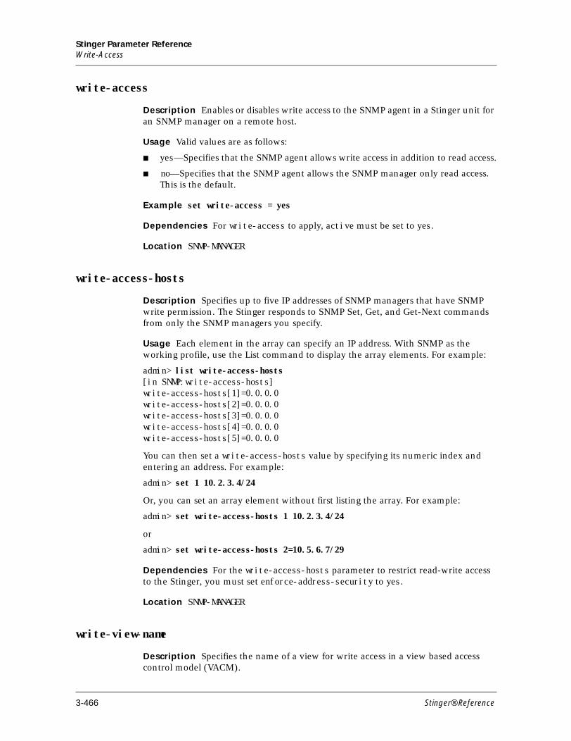
Stinger Parameter ReferenceWrite-Access
write-access
Description Enables or disables write access to the SNMP agent in a Stinger unit for an SNMP manager on a remote host.
Usage Valid values are as follows:
■ yes—Specifies that the SNMP agent allows write access in addition to read access.
■ no—Specifies that the SNMP agent allows the SNMP manager only read access. This is the default.
Example set write-access = yes
Dependencies For write-access to apply, active must be set to yes.
Location SNMP-MANAGER
write-access-hosts
Description Specifies up to five IP addresses of SNMP managers that have SNMP write permission. The Stinger responds to SNMP Set, Get, and Get-Next commands from only the SNMP managers you specify.
Usage Each element in the array can specify an IP address. With SNMP as the working profile, use the List command to display the array elements. For example:
admin> list write-access-hosts[in SNMP:write-access-hosts]write-access-hosts[1]=0.0.0.0write-access-hosts[2]=0.0.0.0write-access-hosts[3]=0.0.0.0write-access-hosts[4]=0.0.0.0write-access-hosts[5]=0.0.0.0
You can then set a write-access-hosts value by specifying its numeric index and entering an address. For example:
admin> set 1 10.2.3.4/24
Or, you can set an array element without first listing the array. For example:
admin> set write-access-hosts 1 10.2.3.4/24
or
admin> set write-access-hosts 2=10.5.6.7/29
Dependencies For the write-access-hosts parameter to restrict read-write access to the Stinger, you must set enforce-address-security to yes.
Location SNMP-MANAGER
write-view-name
Description Specifies the name of a view for write access in a view based access control model (VACM).
3-466 Stinger® Reference
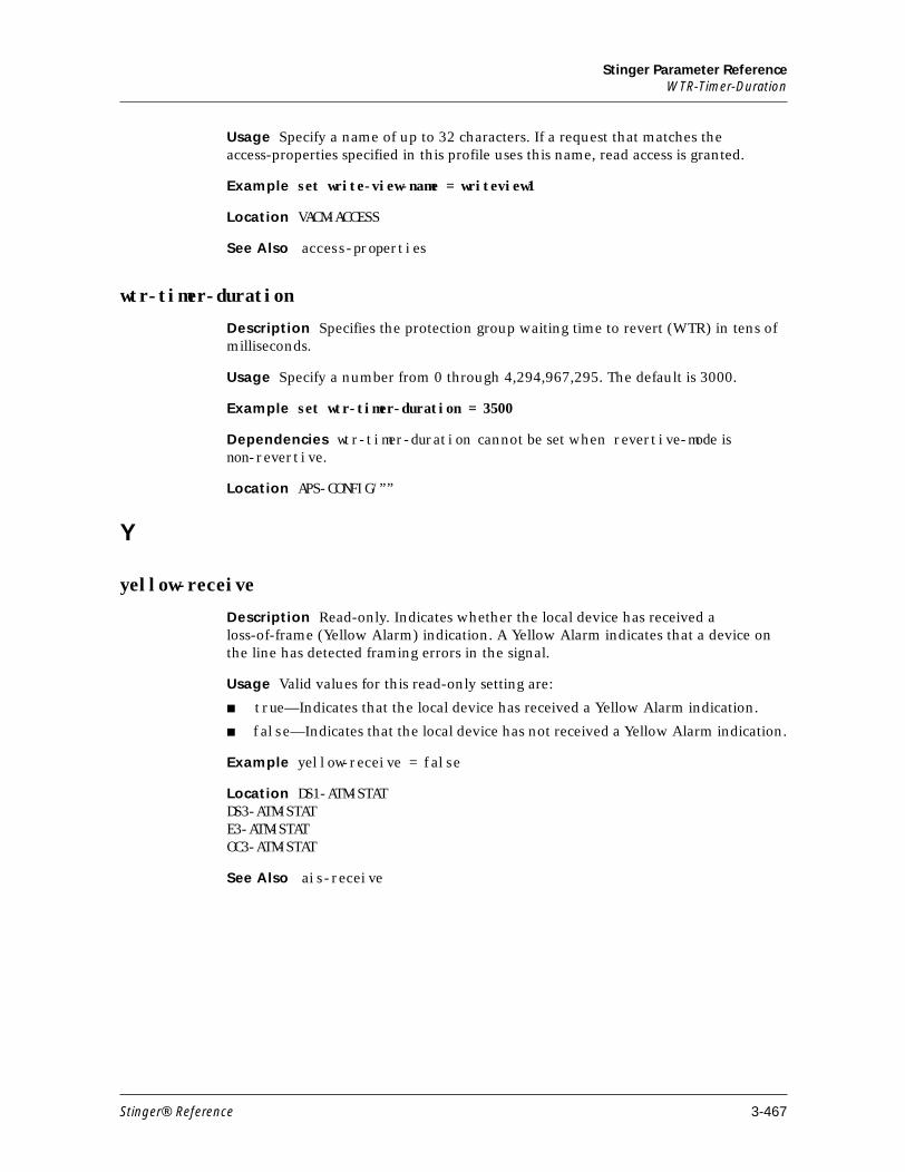
Stinger Parameter ReferenceWTR-Timer-Duration
Usage Specify a name of up to 32 characters. If a request that matches the access-properties specified in this profile uses this name, read access is granted.
Example set write-view-name = writeview1
Location VACM-ACCESS
See Also access-properties
wtr-timer-duration
Description Specifies the protection group waiting time to revert (WTR) in tens of milliseconds.
Usage Specify a number from 0 through 4,294,967,295. The default is 3000.
Example set wtr-timer-duration = 3500
Dependencies wtr-timer-duration cannot be set when revertive-mode is non-revertive.
Location APS-CONFIG/””
Y
yellow-receive
Description Read-only. Indicates whether the local device has received a loss-of-frame (Yellow Alarm) indication. A Yellow Alarm indicates that a device on the line has detected framing errors in the signal.
Usage Valid values for this read-only setting are:
■ true—Indicates that the local device has received a Yellow Alarm indication.
■ false—Indicates that the local device has not received a Yellow Alarm indication.
Example yellow-receive = false
Location DS1-ATM-STATDS3-ATM-STATE3-ATM-STATOC3-ATM-STAT
See Also ais-receive
Stinger® Reference 3-467

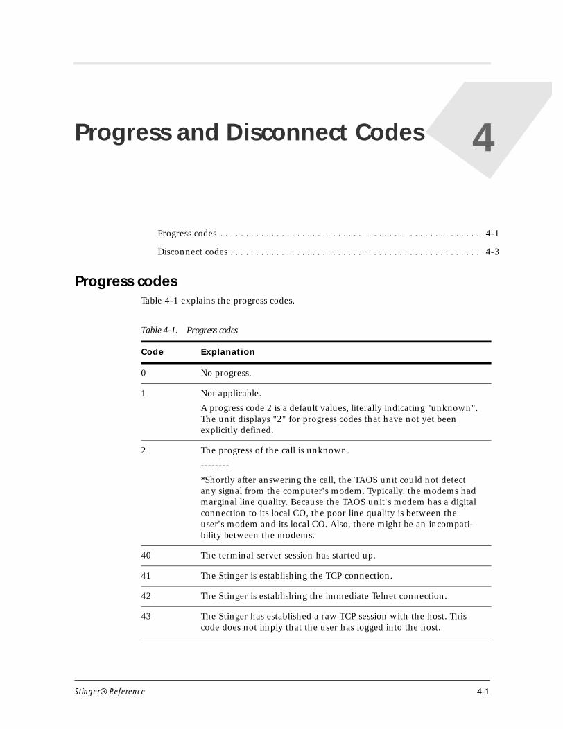
4Progress and Disconnect Codes
Progress codesTable 4-1 explains the progress codes.
Progress codes . . . . . . . . . . . . . . . . . . . . . . . . . . . . . . . . . . . . . . . . . . . . . . . . . . . 4-1
Disconnect codes . . . . . . . . . . . . . . . . . . . . . . . . . . . . . . . . . . . . . . . . . . . . . . . . . 4-3
Table 4-1. Progress codes
Code Explanation
0 No progress.
1 Not applicable.
A progress code 2 is a default values, literally indicating "unknown". The unit displays "2" for progress codes that have not yet been explicitly defined.
2 The progress of the call is unknown.
--------
*Shortly after answering the call, the TAOS unit could not detect any signal from the computer's modem. Typically, the modems had marginal line quality. Because the TAOS unit's modem has a digital connection to its local CO, the poor line quality is between the user's modem and its local CO. Also, there might be an incompati-bility between the modems.
40 The terminal-server session has started up.
41 The Stinger is establishing the TCP connection.
42 The Stinger is establishing the immediate Telnet connection.
43 The Stinger has established a raw TCP session with the host. This code does not imply that the user has logged into the host.
Stinger® Reference 4-1
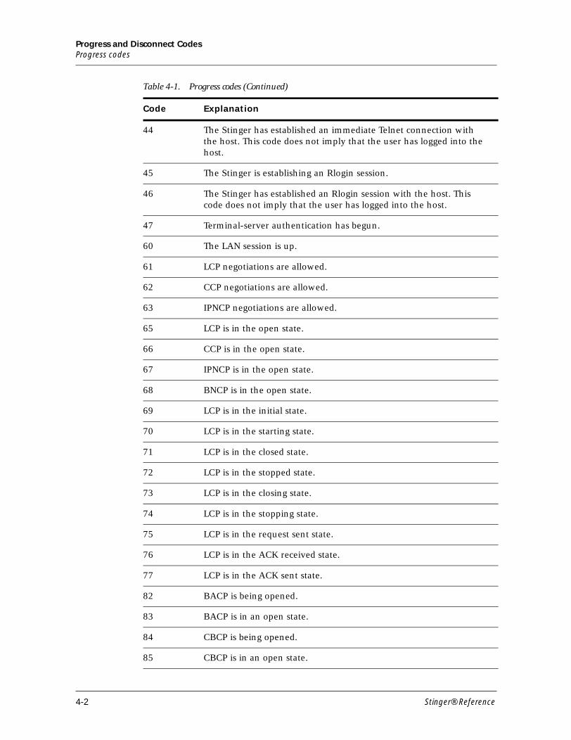
Progress and Disconnect CodesProgress codes
44 The Stinger has established an immediate Telnet connection with the host. This code does not imply that the user has logged into the host.
45 The Stinger is establishing an Rlogin session.
46 The Stinger has established an Rlogin session with the host. This code does not imply that the user has logged into the host.
47 Terminal-server authentication has begun.
60 The LAN session is up.
61 LCP negotiations are allowed.
62 CCP negotiations are allowed.
63 IPNCP negotiations are allowed.
65 LCP is in the open state.
66 CCP is in the open state.
67 IPNCP is in the open state.
68 BNCP is in the open state.
69 LCP is in the initial state.
70 LCP is in the starting state.
71 LCP is in the closed state.
72 LCP is in the stopped state.
73 LCP is in the closing state.
74 LCP is in the stopping state.
75 LCP is in the request sent state.
76 LCP is in the ACK received state.
77 LCP is in the ACK sent state.
82 BACP is being opened.
83 BACP is in an open state.
84 CBCP is being opened.
85 CBCP is in an open state.
Table 4-1. Progress codes (Continued)
Code Explanation
4-2 Stinger® Reference
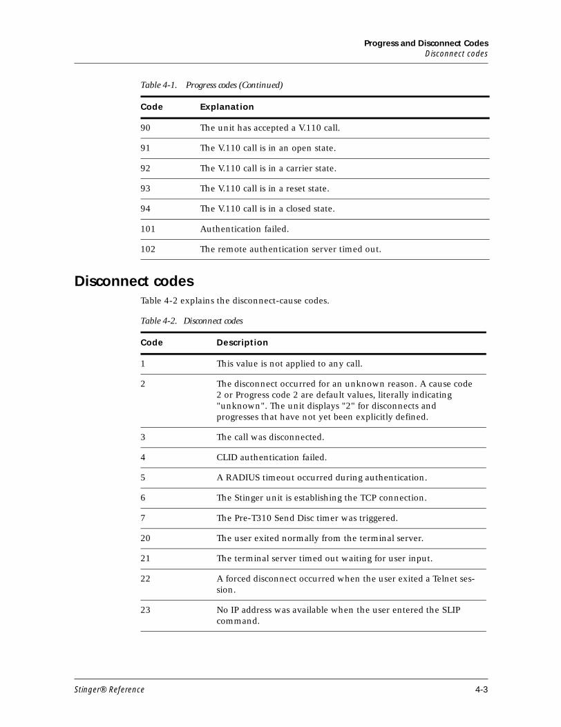
Progress and Disconnect CodesDisconnect codes
Disconnect codesTable 4-2 explains the disconnect-cause codes.
90 The unit has accepted a V.110 call.
91 The V.110 call is in an open state.
92 The V.110 call is in a carrier state.
93 The V.110 call is in a reset state.
94 The V.110 call is in a closed state.
101 Authentication failed.
102 The remote authentication server timed out.
Table 4-1. Progress codes (Continued)
Code Explanation
Table 4-2. Disconnect codes
Code Description
1 This value is not applied to any call.
2 The disconnect occurred for an unknown reason. A cause code 2 or Progress code 2 are default values, literally indicating "unknown". The unit displays "2" for disconnects and progresses that have not yet been explicitly defined.
3 The call was disconnected.
4 CLID authentication failed.
5 A RADIUS timeout occurred during authentication.
6 The Stinger unit is establishing the TCP connection.
7 The Pre-T310 Send Disc timer was triggered.
20 The user exited normally from the terminal server.
21 The terminal server timed out waiting for user input.
22 A forced disconnect occurred when the user exited a Telnet ses-sion.
23 No IP address was available when the user entered the SLIP command.
Stinger® Reference 4-3
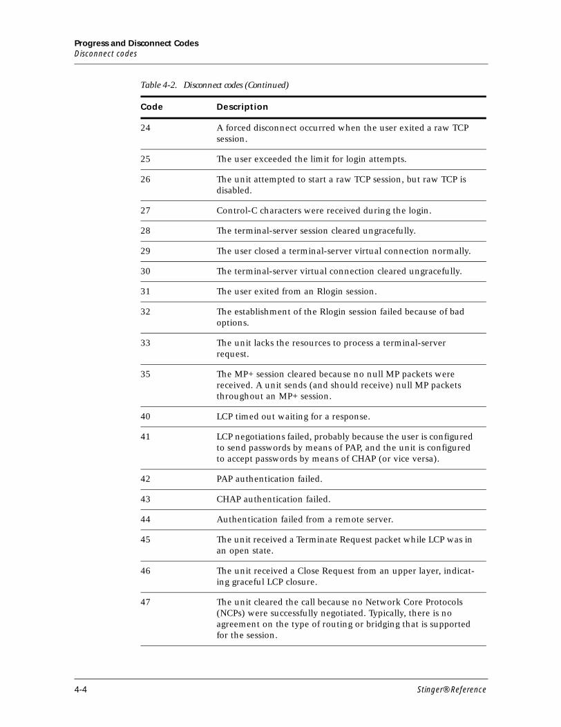
Progress and Disconnect CodesDisconnect codes
24 A forced disconnect occurred when the user exited a raw TCP session.
25 The user exceeded the limit for login attempts.
26 The unit attempted to start a raw TCP session, but raw TCP is disabled.
27 Control-C characters were received during the login.
28 The terminal-server session cleared ungracefully.
29 The user closed a terminal-server virtual connection normally.
30 The terminal-server virtual connection cleared ungracefully.
31 The user exited from an Rlogin session.
32 The establishment of the Rlogin session failed because of bad options.
33 The unit lacks the resources to process a terminal-server request.
35 The MP+ session cleared because no null MP packets were received. A unit sends (and should receive) null MP packets throughout an MP+ session.
40 LCP timed out waiting for a response.
41 LCP negotiations failed, probably because the user is configured to send passwords by means of PAP, and the unit is configured to accept passwords by means of CHAP (or vice versa).
42 PAP authentication failed.
43 CHAP authentication failed.
44 Authentication failed from a remote server.
45 The unit received a Terminate Request packet while LCP was in an open state.
46 The unit received a Close Request from an upper layer, indicat-ing graceful LCP closure.
47 The unit cleared the call because no Network Core Protocols (NCPs) were successfully negotiated. Typically, there is no agreement on the type of routing or bridging that is supported for the session.
Table 4-2. Disconnect codes (Continued)
Code Description
4-4 Stinger® Reference
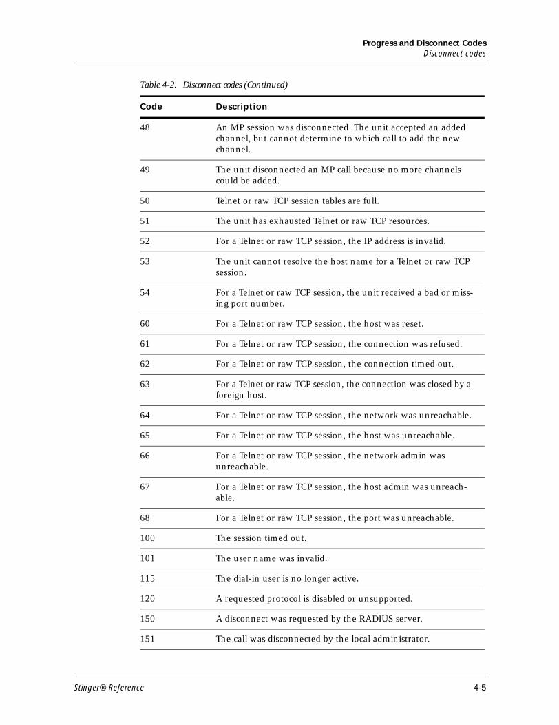
Progress and Disconnect CodesDisconnect codes
48 An MP session was disconnected. The unit accepted an added channel, but cannot determine to which call to add the new channel.
49 The unit disconnected an MP call because no more channels could be added.
50 Telnet or raw TCP session tables are full.
51 The unit has exhausted Telnet or raw TCP resources.
52 For a Telnet or raw TCP session, the IP address is invalid.
53 The unit cannot resolve the host name for a Telnet or raw TCP session.
54 For a Telnet or raw TCP session, the unit received a bad or miss-ing port number.
60 For a Telnet or raw TCP session, the host was reset.
61 For a Telnet or raw TCP session, the connection was refused.
62 For a Telnet or raw TCP session, the connection timed out.
63 For a Telnet or raw TCP session, the connection was closed by a foreign host.
64 For a Telnet or raw TCP session, the network was unreachable.
65 For a Telnet or raw TCP session, the host was unreachable.
66 For a Telnet or raw TCP session, the network admin was unreachable.
67 For a Telnet or raw TCP session, the host admin was unreach-able.
68 For a Telnet or raw TCP session, the port was unreachable.
100 The session timed out.
101 The user name was invalid.
115 The dial-in user is no longer active.
120 A requested protocol is disabled or unsupported.
150 A disconnect was requested by the RADIUS server.
151 The call was disconnected by the local administrator.
Table 4-2. Disconnect codes (Continued)
Code Description
Stinger® Reference 4-5
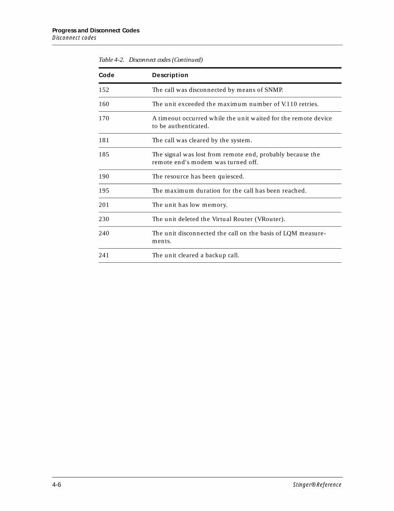
Progress and Disconnect CodesDisconnect codes
152 The call was disconnected by means of SNMP.
160 The unit exceeded the maximum number of V.110 retries.
170 A timeout occurred while the unit waited for the remote device to be authenticated.
181 The call was cleared by the system.
185 The signal was lost from remote end, probably because the remote end's modem was turned off.
190 The resource has been quiesced.
195 The maximum duration for the call has been reached.
201 The unit has low memory.
230 The unit deleted the Virtual Router (VRouter).
240 The unit disconnected the call on the basis of LQM measure-ments.
241 The unit cleared a backup call.
Table 4-2. Disconnect codes (Continued)
Code Description
4-6 Stinger® Reference