
NSE User Guide 9.2 - February 2022 - Nomadix
297
Software Version 9.2 www.nomadix.com ©2022 Nomadix Inc. All Rights Reserved. NSE USER GUIDE February 2022
-
Upload
khangminh22 -
Category
Documents
-
view
3 -
download
0
Transcript of NSE User Guide 9.2 - February 2022 - Nomadix

Software Version 9.2
www.nomadix.com ©2022 Nomadix Inc. All Rights Reserved.
NSE USER GUIDE
February 2022

Customer Confidence 2
Copyright
Copyright © 2022 Nomadix, Inc. All Rights Reserved.
This product also includes software developed by: The University of California, Berkeley and its contributors; Carnegie Mellon University, Copyright © 1998 by Carnegie Mellon University All Rights Reserved; Go Ahead Software, Inc., Copyright
© 1999 Go Ahead Software, Inc. All Rights Reserved; Livingston Enterprises, Inc., Copyright © 1992 Livingston Enterprises, Inc. All Rights Reserved; The Regents of the University of Michigan and Merit Network, Inc., Copyright 1992 – 1995 All Rights Reserved; and includes source code covered by the Mozilla Public License, Version 1.0 and OpenSSL.
Disclaimer The specifications and information regarding the products in this guide are subject to change without notice. All statements, information, and recommendations in this guide are believed to be accurate but are presented without warranty of any kind, express or implied.
Nomadix, Inc. makes no warranty, either express or implied, including but not limited to any implied warranties of merchantability and fitness for a particular purpose, regarding the product described herein. In no event shall Nomadix, Inc. be liable to anyone for special, collateral, incidental, or consequential damages in connection with or arising from the use of Nomadix, Inc. products.
This User Guide is protected by U.S. copyright laws. You may not transmit, copy, modify, or translate this manual, or reduce it or any part of it to any machine readable format, without the express permission of the copyright holder.
Nomadix, Inc. reserves the right to improve this document, its contents, and any products described herein at any time without prior notification. The information in this document has been reviewed for accuracy, clarity, and completeness. If you find any errors or have any comments, please forward them to:
Nomadix Inc. 21600 Oxnard St.
Suite 1900 Woodland Hills, CA 91367
USA https://nomadix.com
Trademarks
The symbol, and Nomadix Service Engine® are registered trademarks of Nomadix, Inc. All other trademarks and brand names are marks of their respective holders.
Product Information
Telephone: +1.818.597.1500
Fax: +1.818.597.1502

Customer Confidence 3
Repairs
Repairs to this equipment can only be made by Nomadix, Inc. To obtain repair service, contact:
Nomadix Inc. 21600 Oxnard St
Suite 1900 Woodland Hills, CA 91367
USA https://nomadix.com/support Toll Free +1888.666.2349
or report the problem using our web site at : http://www.nomadix.com/support
Support
This guide should be used in conjunction with the Quick Start Guide for reference material on getting started with the Nomadix Access Gateway, Fiber Module Installation Guide for detailed steps on installing the 10 Gb SFP+ Fiber Module and the XML Interface DTD for a list of all XML commands.

Customer Confidence 4
Warnings THIS EQUIPMENT MUST BE GROUNDED. THE POWER CORD FOR THIS PRODUCT MUST BE
CONNECTED TO A SOCKET-OUTLET WITH EARTHING CONNECTION.
WARNING
Risk of electric shock; do not open; no user-serviceable parts inside.
CAUTION Read the instruction manual prior to
operation.
AVERTISSEMENT Risque de choc electrique; ne pas ouvrir; ne
pas tenter de demontre l’appareil
ATTENTION
Lire le mode d’emploi avant utilisation.
WARNUNG Nicht öffnen; elektrische Bauteile.
ACHTUNG Lesen Sie das Handbuch bevor Sie das
Gerät in Betrieb nehmen.
AVISO Riesgo de shock eléctrico. No abrir. No hay
piezas configurables dentro.
PRECAUCIÓN
Leer el manual de instrucciones antes de poner en marcha el equipo.
Lithium Battery Caution
WARNING:
Ø The removable lithium [Li (CF) x] BATTERY on must be serviced by authorized personnel.
Ø Please conform to your local laws and regulations regarding safe disposal of lithium BATTERY.
Ø Risk of Explosion if BATTERY is replaced by an incorrect type.
Ø Disposal of BATTERY into fire or hot oven, or mechanically crushing or cutting of a BATTERY can result in an explosion.
Ø Leaving a BATTERY in an extremely high temperature surrounding environment ca result in a explosion or the leakage of flammable liquid or gas.
Ø A BATTERY subjected to extremely low air pressure may result in an Explosion or leakage of flammable liquid or gas.

Customer Confidence 5
Lithium Battery Caution (cont.)
MISE EN GARDE ::
Ø La batterie au lithium amovible [Li (CF) x] doit être réparée par du personnel autorisé.
Ø Veuillez vous conformer aux lois et réglementations locales concernant l'élimination sûre de la batterie au lithium.
Ø Explosionsgefahr, wenn BATTERIE durch einen falschen Typ ersetzt wird.
Ø Die Entsorgung der BATTERIE in ein Feuer oder einen heißen Ofen oder das mechanische Brechen oder Schneiden einer BATTERIE kann zu einer Explosion führen.
Ø Wenn Sie eine BATTERIE in einer Umgebung mit extrem hohen Temperaturen lassen, kann dies zu einer Explosion oder dem Austreten brennbarer Flüssigkeiten oder Gase führen.
Ø Eine BATTERIE, die einem extrem niedrigen Luftdruck ausgesetzt ist, kann zu einer Explosion oder einem Austritt brennbarer Flüssigkeiten oder Gase führen.
WARNUNG :
Ø Die abnehmbare Lithiumbatterie (Li (CF) x) muss von autorisiertem Personal gewartet werden.
Ø Bitte beachten Sie die lokalen Gesetze und Vorschriften zur sicheren Entsorgung von Lithiumbatterien.
Ø Explosionsgefahr, wenn BATTERIE durch einen falschen Typ ersetzt wird.
Ø Die Entsorgung der BATTERIE in ein Feuer oder einen heißen Ofen oder das mechanische Brechen oder Schneiden einer BATTERIE kann zu einer Explosion führen.
Ø Wenn Sie eine BATTERIE in einer Umgebung mit extrem hohen Temperaturen lassen, kann dies zu einer Explosion oder dem Austreten brennbarer Flüssigkeiten oder Gase führen.
Ø Eine BATTERIE, die einem extrem niedrigen Luftdruck ausgesetzt ist, kann zu einer Explosion oder einem Austritt brennbarer Flüssigkeiten oder Gase führen.

Customer Confidence 6
Lithium Battery Caution (cont.)
警告
Ø 可拆卸锂[Li(CF)x]电池必须由授权人员进行维修。
Ø 请遵守当地有关锂电池安全处理的法律法规。
Ø 如果 BATTERY由不正确的类型替换,则存在爆炸危险。
Ø 將電池放入火爐或烤箱中,或機械破碎或切割電池可能會導致爆炸。
Ø 将电池置于环境温度极高的环境中会导致爆炸或易燃液体或气体泄漏。
Ø 气压极低的电池可能会导致易燃液体或气体爆炸或泄漏。
EG 6000 Only
§ Suitable for installation in Information Technology Rooms in accordance with Article 645 of the National Electrical Code and NFPA 75.
§ Convient pour une installation dans des salles informatiques conformément à l'article 645 du Code national de l'électricité et à la norme NFPA 75.
21600 Oxnard St, Suite 1900, Woodland Hill, CA 91367 USA (head office)

ACCESS GATEWAY
i
Introduction ................................................................................................................................................................ 1 AboutthisGuide ................................................................................................................................................... 1 Organization ......................................................................................................................................................... 1
Nomadix Family of Gateways ..................................................................................................................................... 3 ProductConfigurationandLicensing ............................................................................................................... 3
Key Features and Benefits ........................................................................................................................................... 3 PlatformReliability ............................................................................................................................................. 4 LocalContentandServices ................................................................................................................................. 4 TransparentConnectivity ................................................................................................................................... 4 Billing Enablement ................................................................................................................................................ 5 Access Control and Authentication ..................................................................................................................... 5 Security .................................................................................................................................................................. 5 5-Step Service Branding ....................................................................................................................................... 5
NSE Core Functionality ............................................................................................................................................... 6 Access Control ....................................................................................................................................................... 7 Bandwidth Management ...................................................................................................................................... 7 Billing Records Mirroring .................................................................................................................................... 8 Bridge Mode .......................................................................................................................................................... 8 Class-Based Queueing ........................................................................................................................................... 8 Command Line Interface ................................................................................................................................... 11 Daylight Savings Time and IANA Time Zone Support ................................................................................... 12 Dynamic Address Translation™ ....................................................................................................................... 12 Dynamic Transparent Proxy .............................................................................................................................. 12 End User Licensee Count ................................................................................................................................... 12 External Web Server Mode ................................................................................................................................ 12 Facebook Authentication .................................................................................................................................... 12 Home Page Redirect ............................................................................................................................................ 13 iNAT™ ................................................................................................................................................................. 14 Information and Control Console ..................................................................................................................... 14 Initial NSE Configuration .................................................................................................................................. 15 Internal Web Server ........................................................................................................................................... 15 International Language Support ....................................................................................................................... 15 IP Upsell ............................................................................................................................................................... 16 IPv6 Device Management ................................................................................................................................... 16 IPv6 Support ........................................................................................................................................................ 16 Link Aggregation Control Protocol (LACP) .................................................................................................... 16 Logout Pop-Up Window ..................................................................................................................................... 16 MAC Filtering ..................................................................................................................................................... 17

ACCESS GATEWAY
ii
Multi-Level Administration Support ................................................................................................................ 17 Multi-WAN Interface Management .................................................................................................................. 17 NTP Support ........................................................................................................................................................ 17 PayPal ................................................................................................................................................................... 17 Portal Page Redirect ........................................................................................................................................... 17 RADIUS-driven Auto Configuration ................................................................................................................ 18 RADIUS Client .................................................................................................................................................... 18 RADIUS Proxy .................................................................................................................................................... 18 Realm-Based Routing ......................................................................................................................................... 18 Remember Me and RADIUS Re-Authentication ............................................................................................. 19 Secure Management ............................................................................................................................................ 19 Secure Socket Layer (SSL) ................................................................................................................................. 20 Secure XML API ................................................................................................................................................. 20 Session Rate Limiting (SRL) .............................................................................................................................. 20 Session Termination Redirect ............................................................................................................................ 21 Smart Client Support .......................................................................................................................................... 21 SNMP Nomadix Private MIB ............................................................................................................................ 21 Static Port Mapping ............................................................................................................................................ 21 Tri-Mode Authentication ................................................................................................................................... 21 URL Filtering ...................................................................................................................................................... 21 Walled Garden .................................................................................................................................................... 22 Web Management Interface ............................................................................................................................... 22 Weighted Fair Queueing .................................................................................................................................... 22
Optional NSE Modules .............................................................................................................................................. 22 Load Balancing .................................................................................................................................................... 22 Hospitality Module .............................................................................................................................................. 23 High Availability Module ................................................................................................................................... 23
Network Architecture (Sample) ................................................................................................................................ 23 Multiple Unit Clustering ............................................................................................................................................ 25
Standard Gateways Clustering .......................................................................................................................... 25 High Availability Clustering .............................................................................................................................. 26
Load Balancing and Link Failover ........................................................................................................................... 28 Definitions and Concepts .................................................................................................................................... 28 User-Based ISP Selection versus Random ISP Selection ................................................................................ 29 Traffic Balancing and Weighting ...................................................................................................................... 29 Load Balancing across Multiple Low Speed Links .......................................................................................... 30 Failover to Standby ISP Link ............................................................................................................................ 31 Separate Guest HSIA and Admin ISP Links, with Failover Between Each ISP Link ................................. 31 Guest HSIA Failover Only, to Admin Network ............................................................................................... 32

ACCESS GATEWAY
iii
Sharing Guest HSIA Network and Hotel Admin Network Among Multiple ISP Links .............................. 32 Load Balancing With Users Connected to a Preferred ISP Link ................................................................... 33
Online Help (Web Help) ............................................................................................................................................ 34 Notes, Cautions, and Warnings ................................................................................................................................. 34 Installing the Access Gateway ................................................................................................................................... 35 Installation Workflow ................................................................................................................................................ 36 Powering Up the System ............................................................................................................................................ 37 User Manual and Documentation ............................................................................................................................. 38 Configuration .............................................................................................................................................................. 38
Step 1a: Static WAN IP Configuration ............................................................................................................. 39 Step 1b: DHCP Client Configuration ................................................................................................................ 40 Step 1c: PPPoE Dynamic IP Client Configuration .......................................................................................... 41 Step 1d: PPPoE Static IP Client Configuration ............................................................................................... 43 Step 2: Entering Your Location Information ................................................................................................... 43 Step 3: Retrieving Your License Key ................................................................................................................ 43 Step 4: Configuring the System ......................................................................................................................... 44 Step 5: Configuring EG DHCP Server Settings ............................................................................................... 44
The Management Interfaces (CLI and Web) .......................................................................................................... 45 Making Menu Selections and Inputting Data with the CLI ............................................................................ 46 Menu Organization (Web Management Interface) ......................................................................................... 46 Inputting Data – Maximum Character Lengths .............................................................................................. 46 Online Documentation and Help ....................................................................................................................... 47
Establishing the Start Up Configuration ................................................................................................................. 48 Assigning Login User Names and Passwords ................................................................................................... 48 Setting the SNMP Parameters (optional) .......................................................................................................... 49 Configuring the WAN interface ......................................................................................................................... 50 Enabling the Logging Options (recommended) ............................................................................................... 51 Logging Out and Powering Down the System .................................................................................................. 53 Connecting the Access Gateway to the Customer’s Network ......................................................................... 53
Establishing the Basic Configuration for Subscribers ............................................................................................ 53 Setting the DHCP Options ................................................................................................................................. 54 DHCP Options from RFC 2132 ......................................................................................................................... 55 DHCP Dynamic Enable and Disable ................................................................................................................. 57 Setting the DNS Options ..................................................................................................................................... 57
Installing the Nomadix Private MIB ........................................................................................................................ 58 Obtaining the Management Information Base (MIB) file ............................................................................... 58 Configuring the Management Information Base ............................................................................................. 58
SystemAdministration ............................................................................................................................................ 60 Choosing a Remote Connection ................................................................................................................................ 60

ACCESS GATEWAY
iv
Using the Web Management Interface (WMI) ................................................................................................. 60 Using an SNMP Manager ................................................................................................................................... 61 Using a Telnet Client ........................................................................................................................................... 62
Logging In ................................................................................................................................................................... 62 About Your Product License ..................................................................................................................................... 62 Configuration Menu ................................................................................................................................................... 62
Defining the AAA Services {AAA} .................................................................................................................... 62 Establishing Secure Administration {Access Control} .................................................................................... 71 Defining Automatic Configuration Settings {Auto Configuration} ............................................................... 73 Setting Up Bandwidth Management {Bandwidth Management} ................................................................... 76 Group Bandwidth Limit Policy ......................................................................................................................... 77 Group Bandwidth Limit Policy – Operation .................................................................................................... 78 Group Bandwidth Limit Policy – Current Table ............................................................................................. 78 Establishing Billing Records “Mirroring” {Bill Record Mirroring} .............................................................. 79 Class-Based Queueing ......................................................................................................................................... 80 Clustering {Clustering} ....................................................................................................................................... 85 Configuring Destination HTTP Redirection {Destination HTTP Redirection} ............................................ 86 Managing the DHCP service options {DHCP} ................................................................................................. 88 Managing the DNS Options {DNS} ................................................................................................................... 91 Enabling DNSSEC Support ............................................................................................................................... 92 Managing the Dynamic DNS Options {Dynamic DNS} ................................................................................... 92 Ethernet Ports/WAN ........................................................................................................................................... 93 IPv6 Device Setup ................................................................................................................................................ 95 Link Aggregation ................................................................................................................................................ 97 Enabling Fast Forwarding ............................................................................................................................... 100 Setting the High Availability Clustering Options {High Availability Clustering} ...................................... 100 Setting the Home Page Redirection Options {Home Page Redirect} ........................................................... 103 Enabling Intelligent Address Translation (iNAT™) ..................................................................................... 103 Interface Monitoring ......................................................................................................................................... 105 Defining IPSec Tunnel Settings {IPSec} .......................................................................................................... 106 Managing IPSec Tunnel Peers ......................................................................................................................... 106 Managing IPSec Security Policies ................................................................................................................... 108
Load Balancing ......................................................................................................................................................... 110 Establishing Your Location {Location} .......................................................................................................... 111 ManagingtheLogOptions{Logging} ........................................................................................................... 112 Enabling MAC Authentication {MAC Authentication} ................................................................................ 116 Assigning Passthrough Addresses {Passthrough Addresses} ........................................................................ 117 Assigning a PMS Service {PMS} ...................................................................................................................... 118 Setting Up Port Locations {Port-Location} .................................................................................................... 123

ACCESS GATEWAY
v
Setting up Quality of Service {QoS} ................................................................................................................ 127 DefiningtheRADIUSClientSettings{RADIUSClient} .............................................................................. 129 Defining the RADIUS Proxy Settings {RADIUS Proxy} ............................................................................... 133 RadSec ............................................................................................................................................................... 136 DefiningtheRealm-BasedRoutingSettings{Realm-BasedRouting} ................................................... 136 Managing SMTP Redirection {SMTP} ........................................................................................................... 141 Managing the SNMP Communities {SNMP} ................................................................................................. 142 Enabling Dynamic Multiple Subnet Support (Subnets) ................................................................................ 145 Displaying Your Configuration Settings {Summary} .................................................................................... 145 Setting the System Date and Time {Time} ...................................................................................................... 146 Setting up Traffic Descriptors {Traffic Descriptors} ..................................................................................... 147 Setting Up URL Filtering {URL Filtering} ..................................................................................................... 149 Selecting User Agent Filtering Settings ........................................................................................................... 149 Zone Migration .................................................................................................................................................. 150
Network Info Menu .................................................................................................................................................. 152 Displaying ARP Table Entries {ARP} ............................................................................................................. 152 Displaying DAT Sessions {DAT} ..................................................................................................................... 152 Displaying the Host Table {Hosts} ................................................................................................................... 153 Displaying ICMP Statistics {ICMP} ................................................................................................................ 153 Displaying the Network Interfaces {Interfaces} ............................................................................................. 154 Displaying the IP Statistics {IP} ....................................................................................................................... 155 Viewing IPSec Tunnel Status {IPSec} ............................................................................................................. 156 Viewing IPv6 Prefix Delegation ....................................................................................................................... 156 Viewing NAT IP Address Usage {NAT IP Usage} ......................................................................................... 157 Displaying the Routing Tables {Routing} ....................................................................................................... 157 Displaying the Active IP Connections {Sockets} ............................................................................................ 158 Displaying the Static Port Mapping Table {Static Port-Mapping} .............................................................. 159 Displaying TCP Statistics {TCP} ..................................................................................................................... 160 Displaying UDP Statistics {UDP} ..................................................................................................................... 161
Port-Location Menu ................................................................................................................................................. 161 Adding and Updating Port-Location Assignments {Add} ............................................................................. 162 Exporting Port-Location Assignments {Export} ............................................................................................ 165 Finding Port-Location Assignments by Description {Find by Description} ................................................ 165 Finding Port-Location Assignments by Location {Find by Location} ......................................................... 166 Finding Port-Location Assignments by Port {Find by Port} ........................................................................ 166 Importing Port-Location Assignments {Import} ........................................................................................... 167 Displaying the Port-Location Mappings {List} .............................................................................................. 168 Deleting Port-Location Assignments ............................................................................................................... 169 Enabling Facebook Login for a Port Location ............................................................................................... 169

ACCESS GATEWAY
vi
Subscriber Intra-Port Communication ........................................................................................................... 170 Subscriber Administration Menu ........................................................................................................................... 171
Access Codes ...................................................................................................................................................... 171 Adding Subscriber Profiles {Add} ................................................................................................................... 173 Displaying Current Subscriber Connections {Current} ................................................................................ 178 Deleting Subscriber Profiles by MAC Address {Delete by MAC} ............................................................... 179 Deleting Subscriber Profiles by User Name {Delete by User} ...................................................................... 179 Displaying the Currently Allocated DHCP Leases {DHCP Leases} ............................................................ 180 Deleting All Expired Subscriber Profiles {Expired} ...................................................................................... 180 Finding Subscriber Profiles by MAC Address {Find by MAC} ................................................................... 181 Finding Subscriber Profiles by User Name {Find by User} .......................................................................... 181 Listing Subscriber Profiles {List Profiles} ...................................................................................................... 181 Viewing RADIUS Proxy Accounting Logs {RADIUS Session History} ....................................................... 182 Displaying Current Profiles and Connections {Statistics} ............................................................................ 183
Subscriber Interface Menu ...................................................................................................................................... 183 Defining the Billing Options {Billing Options} ............................................................................................... 183 Setting Up the Information and Control Console {ICC Setup} .................................................................... 188 Defining Languages {Language Support} ....................................................................................................... 192 Enable Serving of Local Web Pages {Local Web Server} ............................................................................. 194 Defining the Subscriber’s Login UI {Login UI} ............................................................................................. 196 Defining the Post Session User Interface (Post Session UI) .......................................................................... 199 Defining Subscriber UI Buttons {Subscriber Buttons} ................................................................................. 202 Defining Subscriber UI Labels {Subscriber Labels} ..................................................................................... 202 Defining Subscriber Error Messages {Subscriber Errors} ........................................................................... 203 Defining Subscriber Messages {Subscriber Messages} .................................................................................. 204
System Menu ............................................................................................................................................................. 205 Adding and Deleting ARP Table Entries ........................................................................................................ 205 Configurable Gateway ARP Refresh Interval ................................................................................................ 206 Enabling the Bridge Mode Option {Bridge Mode} ........................................................................................ 207 Exporting Configuration Settings to the Archive File {Export} ................................................................... 208 Importing the Factory Defaults {Factory} ...................................................................................................... 209 Defining the Fail Over Options {Fail Over} ................................................................................................... 209 Viewing the History Log {History} .................................................................................................................. 210 Establishing ICMP Blocking Parameters {ICMP} ........................................................................................ 211 Importing Configuration Settings from the Archive File {Import} ............................................................. 211 Establishing Login Access Levels {Login} ...................................................................................................... 212 Remote RADIUS Testing .................................................................................................................................. 214 Defining the MAC Filtering Options {MAC Filtering} ................................................................................. 215 Utilizing Packet Capturing {Packet Capture} ................................................................................................ 216

ACCESS GATEWAY
vii
Rebooting the System {Reboot} ....................................................................................................................... 217 Routing Tables {Routing} ................................................................................................................................. 217 Establishing Session Rate Limiting {Session Limit} ...................................................................................... 219 Adding/Deleting Static Ports {Static Port-Mapping} .................................................................................... 219 Updating the Access Gateway Firmware {Upgrade} ..................................................................................... 221
TheSubscriberInterface ...................................................................................................................................... 222 Authorization and Billing ........................................................................................................................................ 223
The AAA Structure ........................................................................................................................................... 223 Process Flow (AAA) .......................................................................................................................................... 225 Internal and External Web Servers ................................................................................................................ 226 Language Support ............................................................................................................................................. 226 Home Page Redirection .................................................................................................................................... 227
Subscriber Management .......................................................................................................................................... 227 Subscriber Management Models ..................................................................................................................... 227 Configuring the Subscriber Management Models ......................................................................................... 227
Information and Control Console (ICC) ................................................................................................................ 228 ICC Pop-Up Window ........................................................................................................................................ 229 Logout Console .................................................................................................................................................. 229
QuickReferenceGuide .......................................................................................................................................... 230 Web Management Interface (WMI) Menus .......................................................................................................... 231
Configuration Menu Items ............................................................................................................................... 231 Network Info Menu Items ................................................................................................................................ 233 Port-Location Menu Items ............................................................................................................................... 234 Subscriber Administration Menu Items ......................................................................................................... 235 Subscriber Interface Menu Items .................................................................................................................... 235 System Menu Items ........................................................................................................................................... 236
Alphabetical Listing of Menu Items (WMI) .......................................................................................................... 236 Default (Factory) Configuration Settings .............................................................................................................. 239 Sample AAA Log ...................................................................................................................................................... 244
Message Definitions (AAA Log) ....................................................................................................................... 245 Sample SYSLOG Report ......................................................................................................................................... 245 Sample History Log .................................................................................................................................................. 245 Keyboard Shortcuts ................................................................................................................................................. 246 HyperTerminal Settings .......................................................................................................................................... 246 RADIUS Attributes .................................................................................................................................................. 247
Authentication-Request .................................................................................................................................... 247 Authentication-Reply (Accept) ........................................................................................................................ 248 Accounting-Request .......................................................................................................................................... 248 Selected Detailed Descriptions ......................................................................................................................... 249

ACCESS GATEWAY
viii
Nomadix Vendor-Specific RADIUS Attributes .............................................................................................. 251 Setting Up the SSL Feature ..................................................................................................................................... 252
Prerequisites ...................................................................................................................................................... 252 Obtain a Private Key File (cakey.pem) ........................................................................................................... 252 Installing Cygwin and OpenSSL on a PC ....................................................................................................... 253 Private Key Generation .................................................................................................................................... 256 Create a Certificate Signing Request (CSR) File ........................................................................................... 257 Create a Public Key File (server.pem) ............................................................................................................ 258 Setting Up Access Gateway for SSL Secure Login ........................................................................................ 260 Changing Settings in the WMI ........................................................................................................................ 260
Mirroring Billing Records ....................................................................................................................................... 261 Sending Billing Records .................................................................................................................................... 261 XML Interface ................................................................................................................................................... 261
Troubleshooting ..................................................................................................................................................... 264 General Hints and Tips ..................................................................................................................................... 265 Management Interface Error Messages .......................................................................................................... 265 Common Problems ............................................................................................................................................ 266
Appendix A: Technical Support ............................................................................................................................. 267 Appendix B: Log Files Examples ............................................................................................................................ 268
System Log File (Example) ............................................................................................................................... 268 AAA Log (Example) .......................................................................................................................................... 268 RADIUS History Log (Example) ..................................................................................................................... 268 System Report Log (Example) ......................................................................................................................... 268 Subscriber Tracking Log (Example) ............................................................................................................... 268
Appendix C: Glossary of Terms ............................................................................................................................. 269
ACCESS GATEWAY 1
Introduction 1
IntroductionAboutthisGuideThis User Guide provides information and procedures that will enable system administrators to install, configure, manage, and use the Nomadix Edge and Access Gateway products successfully and efficiently. Use this guide to take full advantage of the Edge and Access Gateway’s functionality and features.
This User Guide is intended only for products supporting version 9.1 of the NSE (Nomadix Service Engine) software.
Product Version 9.1
EG 1000 ■
AG 3000 ■
AG 6000 ■
EG 2500 ■
EG 5900 ■
OrganizationThis User Guide is organized into the following sections:
Chapter 1: Introduction. The current chapter; an introduction to the features and benefits of the Nomadix Access Gateway.
Chapter 2: Installing the Access Gateway. Provides instructions for installing the Access Gateway and establishing the start-up configuration.
Chapter 3: System Administration. Provides all the instructions and procedures necessary to manage and administer the Access Gateway on the customer’s network, following a successful installation.
Chapter 4: The Subscriber Interface. Provides an overview and sample scenario for the Access Gateway’s subscriber interface. It also includes an outline of the authorization and billing processes utilized by the system, and the Nomadix Information and Control Console.
Chapter 5: Quick Reference Guide. Contains product reference information, organized by topic and functionality. It also contains a full listing of all product configuration elements, sorted alphabetically and by menu.
Chapter 6: Troubleshooting. Provides information to help you resolve common hardware and software problems. It also contains a list of error messages associated with the management interface.
Appendix A: Technical Support. Informs you how to obtain technical support. Refer to Troubleshooting before contacting Nomadix, Inc. directly.
Appendix B: Glossary of Terms. Provides an explanation of terms directly related to Nomadix product technology. Glossary entries are organized alphabetically.


ACCESS GATEWAY
Introduction 3
NomadixFamilyofGatewaysThe Access Gateway is a freestanding, fully featured network appliance that enables public access service providers to offer broadband Internet connectivity to their customers.
The Access Gateway handles transparent connectivity, advanced security, policy-based traffic shaping, and service placement supporting thousands of users simultaneously in a broadband environment. The Access Gateway also offers a unique set of security and connectivity features for deploying metro wireless 802.11 networks, including Mesh and WiMAX technologies.
A family of products that meets all price/performance requirements.
The Access Gateway yields a complete solution to a set of complex issues in the Enterprise, Public-LAN, and Residential segments.
ProductConfigurationandLicensingAll Nomadix Access Gateway products are powered by our patented and patent-pending suite of embedded software, called the Nomadix Service Engine™ (NSE). The Access Gateway employs our NSE core software package and comes pre-packaged with the option to purchase additional modules to expand the product’s functionality.
This User Guide covers all features and functionality provided with the NSE core package, as well as additional optional modules. Your product license must support the optional NSE modules if you want to take advantage of the expanded functionality. The following note will preface procedures that directly relate to optional modules.
See also:
• NSE Core Functionality
• Optional NSE Modules
KeyFeaturesandBenefitsThe Access Gateway is a 1U high, free-standing or rack-mountable device that provides Ethernet ports to interface with the router and the aggregation equipment within the network. It also provides an RS232 serial port for connecting to a Property Management System (PMS), while maintaining one billing relationship with their chosen provider.
The Access Gateway enables a wide variety of network deployment options for different venue types. For example:
• Allows for flexible WAN Connectivity (T1/E1, Cable, xDSL, and Fiber).
• Supports 802.11a/b/g/n/ac and hybrid networks utilizing wired Ethernet.
ACCESS GATEWAY
Introduction 4
• Supports key requirements needed to be compliant with the Wi-Fi ZONE™ program.
• Allows you to segment your existing network into public and private sections using VLANs, then leverage your existing network investment to create new revenue streams.
• Enables you to provide Wi-Fi access as a billable service or as an amenity to augment the main line of business for your venue.
• Contains an advanced XML interface for accepting and processing XML commands, allowing the implementation of a variety of service plans and offerings.
• Offers three user-friendly ways of remote management—through a Web interface, SNMP MIBs, and Telnet interfaces—allowing for scalable, large public access deployments.
• Provides capabilities for load balancing and fail-over management across multiple ISPs.
PlatformReliabilityThe Access Gateway is designed as a network appliance, providing maximum uptime and reliability unlike competitive offerings that use a server-based platform.
LocalContentandServicesThe Access Gateway’s Portal Page feature intercepts the user’s browser settings and directs them to a designated Web site to securely sign up for service or log in if they have a pre- existing account.
• Allows the provider to present their customers with local services or have the user sign up for service at zero expense.
• Offers both pre and post authentication redirects of the user’s browser, providing maximum flexibility in service branding.
TransparentConnectivityResolving configuration conflicts is difficult and time consuming for network users who are constantly on the move, and costly to the solution provider. In fact, most users are reluctant to make changes to their computer’s network settings and won’t even bother. This fact alone has prevented the widespread deployment of broadband network services.
Our patented Dynamic Address Translation™ (DAT) functionality offers a true “plug and play” solution by enabling a seamless and transparent experience and the tools to acquire new customers on-site.
DAT greatly reduces provisioning and technical support costs and enables providers to deliver an easy to use, customer-friendly service.

ACCESS GATEWAY
Introduction 5
BillingEnablementThe Access Gateway supports billing plans using PayPal, scratch cards, or monthly subscriptions, or direct billing to a hotel’s Property Management System (PMS) and can base the billable event on a number of different parameters such as time, volume, IP address type, or bandwidth.
AccessControlandAuthenticationThe Access Gateway ensures that all traffic to the Internet is blocked until authentication has been completed, creating an additional level of security in the network. Also, the Access Gateway allows service providers to create their own unique “walled garden,” enabling users to access only certain predetermined Web sites before they have been authenticated.
Nomadix simultaneously supports the secure browser-based Universal Access Method (UAM), IEEE 802.1x, and Smart Clients for companies such as Adjungo Networks, Boingo Wireless, GRIC and iPass. MAC-based authentication is also available.
SecurityThe patented iNAT™ (Intelligent Network Address Translation) feature creates an intelligent mapping of IP Addresses and their associated VPN tunnels—by far the most reliable multi- session VPN passthrough to be tested against diverse VPN termination servers from companies such as Cisco, Checkpoint, Nortel and Microsoft. Nomadix’ iNAT feature allows multiple tunnels to be established to the same VPN server, creating a seamless connection for all users on the network.
The Access Gateway provides fine-grain management of DoS (Denial of Service) attacks through its Session Rate Limiting (SRL) feature, and MAC filtering for improved network reliability.
5-StepServiceBrandingA network enabled with the Nomadix Access Gateway offers a 5-Step service branding methodology for service providers and their partners, comprising:

ACCESS GATEWAY
Introduction 6
1. Initial Flash Page branding.
2. Initial Portal Page Redirect (Pre-Authentication). Typically, this is used to redirect the user to a venue-specific Welcome and Login page.
3. Home Page Redirect (Post-Authentication). This redirect page can be tailored to the individual user (as part of the RADIUS Reply message, the URL is received by the NSE) or set to re-display itself at freely configurable intervals.
4. The Information and Control Console (ICC) contains multiple opportunities for an operator to display its branding or the branding of partners during the user’s session. As an alternative to the ICC, a simple pop-up window provides the opportunity to display a single logo.
5. The “Goodbye” page is a post-session page that can be defined either as a RADIUS VSA or be driven by the Internal Web Server (IWS) in the NSE. Using the IWS option means that this functionality is also available for other post-paid billing mechanisms (for example, post-paid PMS).
NSECoreFunctionalityPowering Nomadix’ family of Access Gateways, the Nomadix Service Engine (NSE) delivers a full range of features needed to successfully deploy public access networks. These “core” features solve issues of connectivity, security, billing, and roaming in a Wi-Fi public access network.
The NSE’s core package of features includes:
l Access Control l Bandwidth Management l Billing Records Mirroring l Bridge Mode l Class-Based Queueing l Command Line Interface l Dynamic Address Translation™ l Dynamic Transparent Proxy l End User Licensee Count l External Web Server Mode l Facebook Authentication l Home Page Redirect l iNAT™ l Information and Control Console l Internal Web Server l International Language Support l IP Upsell l IPv6 Device Management l Link Aggregation Control Protocol (LACP) l Logout Pop-Up Window l MAC Filtering

ACCESS GATEWAY
Introduction 7
l Multi-Level Administration Support l Multi-WAN Interface Management l NTP Support l PayPal
l Portal Page Redirect l RADIUS Client l RADIUS-driven Auto Configuration l RADIUS Proxy l Realm-Based Routing l Remember Me and RADIUS Re-Authentication l Secure Management l Secure Socket Layer (SSL) l Secure XML API l Session Rate Limiting (SRL) l Session Termination Redirect l Smart Client Support l SNMP Nomadix Private MIB l Static Port Mapping l Tri-Mode Authentication l URL Filtering l Walled Garden l Web Management Interface l Weighted Fair Queueing
AccessControlFor IP-based access control, the NSE incorporates a master access control list that checks the source (IP address) of administrator logins. A login is permitted only if a match is made with the master list contained within the NSE. If a match is not made, the login is denied, even if a correct login name and password are supplied.
The access control list supports up to 50 (fifty) entries in the form of a specific IP address or range of IP addresses.
The NSE also offers access control based on the interface being used. This feature allows administrators to block access from Telnet, Web Management, and FTP sources.
Administration can now be performed after unblocking the interfaces for the Subscriber side of the NSE. The Administrative ports are configurable as well. See Establishing Secure Administration {Access Control}, page 71.
BandwidthManagementThe NSE optimizes bandwidth by limiting bandwidth usage symmetrically or asymmetrically on a per device (MAC address / User) basis, and manages the WAN Link traffic to provide complete

ACCESS GATEWAY
Introduction 8
bandwidth management over the entire network. You can ensure that every user has a quality experience by placing a bandwidth ceiling on each device accessing the network, so every user gets a fair share of the available bandwidth.
With the Nomadix ICC feature enabled, subscribers can increase or decrease their own bandwidth and pricing plans for their service dynamically.
You can set default maximum up and down bandwidths for subscribers who do not have a specified bandwidth setting. See Setting Up Bandwidth Management {Bandwidth Management} on page 76.
Information and Control Console (ICC)
BillingRecordsMirroringNSE-powered devices can send copies of billing records to external servers that have been previously defined by system administrators. The NSE assumes control of billing transmissions and the saving of billing records. By effectively “mirroring” the billing data, the NSE can send copies of billing records to predefined “carbon copy” servers. Additionally, if the primary and secondary servers are not responding, the NSE can store up to 2,000 billing records. The NSE regularly attempts to connect with the primary and secondary severs. When a connection is re-established (with either server), the NSE sends the cached information to the server. Customers can be confident that their billing information is secure and that no transaction records are lost.
BridgeModeThis feature allows complete and unconditional access to devices. When Bridge Mode is enabled, your NSE-powered product is effectively transparent to the network in which it is located.
The NSE forwards any and all packets (except those addressed to the NSE network interface). The packets are unmodified and can be forwarded in both directions. The Bridge Mode function is a very useful feature when troubleshooting your entire network as it allows administrators to effectively “remove” your product from the network without physically disconnecting the unit.
Class-BasedQueueingThe Nomadix Class-Based Queueing feature provides the ability to define multiple groups (classes) of users. You can prioritize groups and guarantee minimum bandwidth on a per- group basis.
Users are added to classes, and rules are applied across the entire class. Each class has three configurable attributes:
l Priority
l Minimum Bandwidth
l Maximum Bandwidth

ACCESS GATEWAY
Introduction 9
Class-based queueing does not apply rules to individual users. You may use bandwidth limits to restrict individual users, if desired.
Class-based queueing does not provide application-level (layer 7) throttling or class of service.
Class-based queueing does not require AAA.
UseCase:Propertyhas100MbpsWANLink
In this scenario, a property wishes to provide guaranteed minimum bandwidth and prioritize traffic across three groups: Conference, Guest Room, and Public Areas. The property can configure class-based queuing according to the following table.
Class Priority Minimum Maximum User Bandwidth Limit**
Conference 1 30 Mbps 100 Mbps 5 Mbps
Guest Room 2 50 Mbps 100 Mbps 5 Mbps
Public 3 20 Mbps 100 Mbps 3 Mbps
User Bandwidth Limit is not an attribute of Class Based Queueing but can be applied (if desired) using existing Bandwidth Limit functionality.
The sum of minimums across all classes should not exceed the total available bandwidth.
It is generally recommended to set the Maximum to equal the total available bandwidth across all classes. This allows all classes to take advantage of the full bandwidth when there is no contention.
With the above configuration, each of the three classes may utilize the entire available bandwidth when there is no contention. But whenever contention occurs, bandwidth will be allocated according to priority and minimum guarantee.
For example, if there are no users in the Conference Class, then the Guest Room and Public Classes can use 100% of the bandwidth. If there is contention between the two, then the Guest Room class will be allocated up to 80Mbps (because it has a higher priority), with 20Mbps taken by the Public class (its minimum guarantee). If, however, there were no users in the Public class, then the Guest Room class could take 100% of the bandwidth (100Mbps).
If users are introduced into the Conference class (Priority 1), and this creates contention, then they will take bandwidth away from each of the other two classes until each reaches its minimum.
ExampleIllustrationofClass-BasedQueueing
The following diagram demonstrates the effect of Class Based Queueing with a saturated link of 200Mbps, and three classes defined with minimum guarantees of 100Mbps (Meeting Room), 60Mpbs (VIP Guests), and 40Mbps (Lobby).
Note the following over time:
l When only Lobby class subscribers are on the network, all available bandwidth is allocated to Lobby class subscribers.
l As VIP Guests join the network, bandwidth is allocated from Lobby class to VIP Guests, until the Lobby bandwidth drops to its minimum guarantee of 40Mbps.
l As Meeting Room subscribers join the network, the Lobby bandwidth is already at its minimum guarantee. Bandwidth is allocated from VIP Guests to Meeting Room subscribers, until bandwidth for VIP Guests reaches the minimum guarantee of 60Mbps and Meeting Room reaches its minimum guarantee of 100Mbps.
ACCESS GATEWAY
Introduction 10
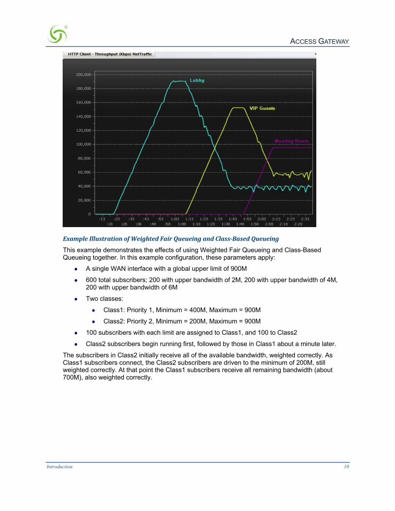
ExampleIllustrationofWeightedFairQueueingandClass-BasedQueueing
This example demonstrates the effects of using Weighted Fair Queueing and Class-Based Queueing together. In this example configuration, these parameters apply:
l A single WAN interface with a global upper limit of 900M
l 600 total subscribers; 200 with upper bandwidth of 2M, 200 with upper bandwidth of 4M, 200 with upper bandwidth of 6M
l Two classes:
l Class1: Priority 1, Minimum = 400M, Maximum = 900M
l Class2: Priority 2, Minimum = 200M, Maximum = 900M
l 100 subscribers with each limit are assigned to Class1, and 100 to Class2
l Class2 subscribers begin running first, followed by those in Class1 about a minute later.
The subscribers in Class2 initially receive all of the available bandwidth, weighted correctly. As Class1 subscribers connect, the Class2 subscribers are driven to the minimum of 200M, still weighted correctly. At that point the Class1 subscribers receive all remaining bandwidth (about 700M), also weighted correctly.

ACCESS GATEWAY
Introduction 11
NotesandCautions
Exercise caution in mixing subscribers with and without class membership. Subscribers with no class membership are automatically assigned a priority of eight the lowest priority and have no minimum bandwidth.
If higher priority classes are not assigned a maximum bandwidth cap, it is possible that unassigned subscribers will be completely starved for bandwidth.
In a mixed user environment, care should be taken to ensure top priority classes have sensible maximum thresholds. To take advantage of the class bandwidth queuing one should assign subscribers to a minimum bandwidth and specific class.
When running Class-Based Queueing concurrently with Weighted Fair Queueing, the NSE will maintain the weighting when multiple WAN interfaces with Load Balancing are configured. The upper bandwidth limit is constrained by the maximum bandwidth that the platform will support.
See also Class-Based Queueing on page 80.
CommandLineInterfaceThe Command Line Interface (CLI) is a character-based user interface that can be accessed remotely or via a direct cable connection. Until your Nomadix product is up and running on the network, the CLI is the Network Administrator’s window to the system. Software upgrades can only be performed from the CLI.
See also The Management Interfaces (CLI and Web) on page 45.

ACCESS GATEWAY
Introduction 12
DaylightSavingsTimeandIANATimeZoneSupportTime configuration includes support for configuration by region/city, automatic daylight savings time adjustment, and official IANA (iana.org) time zones.
DynamicAddressTranslation™Dynamic Address Translation (DAT) enables transparent broadband network connectivity, covering all types of IP configurations (static IP, DHCP, DNS), regardless of the platform or the operating system used—ensuring that everyone gets access to the network without the need for changes to their computer’s configuration settings or client-side software. The NSE supports both PPTP and IPSec VPNs in a manner that is transparent to the user and that provides a more secure standard connection. See also Transparent Connectivity on page 4.
DynamicTransparentProxyThe NSE directs all HTTP and HTTPS proxy requests through an internal proxy which is transparent to subscribers (no need for users to perform any reconfiguration tasks). Uniquely, the NSE also supports clients that dynamically change their browser status from non-proxy to proxy, or vice versa. In addition, the NSE supports proxy ports 80, 800-900, 911 and 990 as well as all unassigned ports (for example, ports above 1024), thus ensuring far fewer proxy related support calls than competitive products.
EndUserLicenseeCountThe NSE supports a range of simultaneous user counts depending on the Nomadix Access Gateway you choose. In addition, depending on your platform, various user count upgrades are available for each of our NSE-powered products that allow you to increase the simultaneous user count.
ExternalWebServerModeThe External Web Server (EWS) interface is for customers who want to develop and use their own content. It allows you to create a “richer” environment than is possible with your product’s embedded Internal Web Server.
The advantages of using an External Web Server are:
l Manage frequently changing content from one location.
l Serve different pages depending on site, sub-location (for example, VLAN), and user.
l Take advantage of the comprehensive Nomadix XML API to implement more complex billing plans.
l Recycle existing Web page content for the centrally hosted portal page.
If you choose to use the EWS interface, Nomadix Technical Support can provide you with sample scripts. See also Contact Information on page 267.
FacebookAuthenticationYou may provide Facebook authentication for facility guests. Login with Facebook is a 2-step process. A user must first click the New User button on the Nomadix splash screen:

ACCESS GATEWAY
Introduction 13
Then the user must click the “Log in with Facebook” button:
Several configuration steps are required to support Facebook authentication. See the following sections for specific instructions:
l Defining the AAA Services {AAA} on page 62
l Assigning Passthrough Addresses {Passthrough Addresses} on page 117
l Defining the Billing Options {Billing Options} on page 183
l Adding and Updating Port-Location Assignments {Add} on page 162
HomePageRedirectThe NSE supports a comprehensive HTTP redirect logic that allows network administrators to define multiple instances to intercept the browser’s request and replace it with freely configurable URLs.
Portal page redirect enables redirection to a portal page before the authentication process. This means that anyone will get redirected to a Web page to establish an account, select a service plan, and pay for access. Home Page redirect enables redirection to a page after the authentication process (for example, to welcome a specific user to the service—after the user has been identified by the authentication process. See also Portal Page Redirect on page 17.

ACCESS GATEWAY
Introduction 14
iNAT™Nomadix invented a new way of intelligently supporting multiple VPN connections to the same termination at the same time (iNAT™), thus solving a key problem of many public access networks.
Nomadix’ patented iNAT™ (intelligent Network Address Translation) feature contains an advanced, real-time translation engine that analyzes all data packets being communicated between the private address realm and the public address realm.
The NSE performs a defined mode of network address translation based on packet type and protocol (for example, ISAKMP, etc.). UDP packet fragmentation is supported to provide more seamless translation engine for certificate-based VPN connections.
If address translation is needed to ensure the success of a specific application (for example, multiple users trying to access the same VPN termination server at the same time), the packet engine selects an IP address from a freely definable pool of publicly routable IP addresses. The same public IP address can be used as a source IP to support concurrent tunnels to different termination devices—offering unmatched efficiency in the utilization of costly public IP addresses. If the protocol type can be supported without the use of a public IP (for example, HTTP, FTP), our proven Dynamic Address Translation™ functionality continues to be used.
Some of the benefits of iNAT™ include:
l Improves the success rate of VPN connectivity by misconfigured users, thus reducing customer support costs and boosting customer satisfaction.
l Maintains the security benefits of traditional address translation technologies while enabling secure VPN connections for mobile workers accessing corporate resources from a public access location.
l Dynamically adjusts the mode of address translation during the user's session, depending on the packet type.
l Supports users with static private IP addresses (for example, 192.168.x.x) or public (different subnet) IP addresses without any changes to the client IP settings.
l Dramatically heightens the reusability factor of costly public IP addresses.
InformationandControlConsoleThe Nomadix ICC is a HTML-based pop-up window that is presented to subscribers with their Web browser. The ICC allows subscribers to select their bandwidth and billing options quickly and efficiently from a simple pull-down menu. For PayPal accounts, the ICC displays a dynamic “time” field to inform subscribers of the time remaining on their account.
Information and Control Console (ICC)
Additionally, the ICC contains multiple opportunities for an operator to display its branding or the branding of partners during the user’s session, as well as display advertising banners and present a choice of redirection options to their subscribers. See also:

ACCESS GATEWAY
Introduction 15
l 5-Step Service Branding l Logout Pop-Up Window l Information and Control Console
InitialNSEConfigurationSee Installing the Access Gateway on page 35 for initial installation and configuration instructions.
InternalWebServerThe NSE offers an embedded Internal Web Server (IWS) to deliver Web pages stored in flash memory. These Web pages are configurable by the system administrator by selecting various parameters to be displayed on the internal pages. When providers or HotSpot owners do not want to develop their own content, the IWS is the answer. A banner at the top of each IWS page is configurable and contains the customer's company logo or any other image file they desire.
To support PDAs and other hand-held devices, the NSE automatically formats the IWS pages to a screen size that is optimal for the particular device being used.
See also:
l 5-Step Service Branding
l International Language Support
InternationalLanguageSupportThe NSE allows you to define the text displayed to your users by the IWS without any HTML or ASP knowledge. The language you select determines the language encoding that the IWS instructs the browser to use.
The available language options are: l English
l Chinese (Big 5)
l French
l German l Japanese (Shift_JIS)
l Spanish
For localizing the user-facing text into other languages, the following character sets are supported:
l Western ISO-8859-1
l Chinese (Big5, EUC-CN, EUC-TW, GB2312)
l Japanese (EUC-JP, ISO-2022-JP, Shift_JIS)
l Korean (EUC-KR, ISO-2022-KR, KS_C_5601) l UTF-8
See Defining Languages {Language Support} on page 192 for language configuration information.

ACCESS GATEWAY
Introduction 16
You also can change the language of the Web Management Interface text. See Selecting the language of the Web Management Interface, page 61. English and Chinese (simplified) interfaces are supported.
IPUpsellSystem administrators can set two different DHCP pools for the same physical LAN. When DHCP subscribers select a service plan with a public pool address, the NSE associates their MAC address with their public IP address for the duration of the service level agreement. The opposite is true if they select a plan with a private pool address. This feature enables a competitive solution and is an instant revenue generator for ISPs.
The IP Upsell feature solves a number of connectivity problems, especially with regard to certain video conferencing and online gaming applications.
You have additional flexibility for configuring up sell scenarios. Users can be assigned WAN’s of different bandwidth capabilities; for example, hotel guests with loyalty memberships can qualify for premium services.
IPv6DeviceManagementThere are many network management tools that have IPv6 support. They can communicate to the network devices and servers over IPv4 or IPv6 transport. They can also perform communications to those devices and servers utilizing the IPv6 interface for configuration, performance and status. The ability to manage infrastructure devices that are addressed with IPv6 addresses behind the Gateway is built in.
IPv6SupportThe NSE has IPv6 support for almost every WAN side feature. You can use an IPv6 address directly or a URL that resolves to an IPv6 address for those features that support URLs. This includes management of the NSE through an IPv6 address. That address can be obtained through statically configuring the IPv6 address, IPv6 DHCP, or SLAAC.
LinkAggregationControlProtocol(LACP)Link Aggregation Control Protocol is a useful feature for creating dynamic port groupings or Aggregate Groups. LACP allows for the combing (aggregation) of multiple network connections in parallel in order to increase throughput beyond what a single connection could sustain, and to provide redundancy in case one of the links should fail. A Link Aggregation Group (LAG) must be configured to combine a number of physical ports together to make a single logical interface. The network must be configured and support active LACP. Link Aggregation will not allow throughput beyond the device supported throughput.
LogoutPop-UpWindowAs an alternative to the ICC, the NSE delivers a HTML-based pop-up window with the following functions:
l Provides the opportunity to display a single logo.
l Displays the session’s elapsed/count-down time. l Presents an explicit Logout button.
See also Information and Control Console on page 14.

ACCESS GATEWAY
Introduction 17
MACFilteringMAC Filtering enhances Nomadix' access control technology by allowing system administrators to block malicious users based on their MAC address. Up to 50 MAC addresses can be blocked at any one time. See also Session Rate Limiting (SRL) on page 20.
Multi-LevelAdministrationSupportThe NSE allows you to define 2 concurrent access levels to differentiate between managers and operators, where managers are permitted read/write access and operators are restricted to read access only.
Once the logins have been assigned, managers have the ability to perform all write commands (Submit, Reset, Reboot, Add, Delete, etc.), but operators cannot change any system settings. When Administration Concurrency is enabled, one manager and three operators can access the Access Gateway platform at any one time.
Multi-WANInterfaceManagementThe NSE supports multiple independently configurable WAN interfaces, to optimize ISP resource allocation, and provide load balancing (optional), fail-over and upsell capabilities.
NTPSupportThe NSE supports Network Time Protocol (NTP), an Internet standard protocol that assures accurate synchronization (to the millisecond) of computer clock times in a network of computers. NTP synchronizes the client’s clock to the U.S. Naval Observatory master clocks. Running as a continuous background client program on a computer, NTP sends periodic time requests to servers, obtaining server time stamps and using them to adjust the client's clock.
PayPalPayPal support allows the internet access to be billed to either a PayPal account or directly to a credit card held by the end user.
PortalPageRedirectThe NSE contains a comprehensive HTTP page redirection logic that allows for a page redirect before (Portal Page Redirect) and/or after the authentication process (Home Page Redirect). As part of the Portal Page Redirect feature, the NSE can send a defined set of parameters to the portal page redirection logic that allows an External Web Server to perform a redirection based on:
l Access Gateway ID and IP Address
l Origin Server
l Port Location
l Subscriber MAC address l Externally hosted RADIUS login failure page
This means that the network administrator can now perform location-specific service branding (for example, an airport lounge) from a centralized Webserver. See also Adding and Updating Port-Location Assignments {Add} on page 162.

ACCESS GATEWAY
Introduction 18
RADIUS-drivenAutoConfigurationNomadix’ unique RADIUS-driven Auto Configuration functionality utilizes the existing infrastructure of a mobile operator to provide an effortless and rapid method for configuring devices for fast network roll-outs. Once configured, this methodology can also be effectively used to centrally manage configuration profiles for all Nomadix devices in the public access network. Two subsequent events drive the automatic configuration of Nomadix devices:
1. A flow of RADIUS Authentication Request and Reply messages between the Nomadix gateway and the centralized RADIUS server that specifies the location of the meta configuration file (containing a listing of the individual configuration files and their download frequency status) are downloaded from an FTP server into the flash of the Nomadix device.
2. Defines the automated login into the centralized FTP server and the actual download process into the flash.
Optionally, the RADIUS authentication process and FTP download can be secured by sending the traffic through a peer-to-peer IPSec tunnel established by the Nomadix gateway and terminated at the NOC (Network Operations Center). See also Secure Management on page 19.
RADIUSClientNomadix offers an integrated RADIUS (Remote Authentication Dial-In User Service) client with the NSE allowing service providers to track or bill users based on the number of connections, location of the connection, bytes sent and received, connect time, etc. The customer database can exist in a central RADIUS server, along with associated attributes for each user. When a customer connects into the network, the RADIUS client authenticates the customer with the RADIUS server, applies associated attributes stored in that customer's profile, and logs their activity (including bytes transferred, connect time, etc.). The NSE's RADIUS implementation also handles vendor specific attributes (VSAs), required by WISPs that want to enable more advanced services and billing schemes, such as a per device/per month connectivity fee.
RADIUSProxyThe RADIUS Proxy feature relays authentication and accounting packets between the parties performing the authentication process. Different realms can be set up to directly channel RADIUS messages to the various RADIUS servers. This functionality can be effectively deployed to:
l Support a wholesale WISP model directly from the edge without the need for any centralized AAA proxy infrastructure.
l Support EAP authenticators (for example, WLAN APs) on the subscriber-side of the NSE to transparently proxy all EAP types (TLS, SIM, etc.) and to allow for the distribution of per-session keys to EAP authenticators and supplicants.
Realm-BasedRoutingRealm-Based Routing provides advanced NAI (Network Access Identifier) routing capabilities, enabling multiple service providers to share a HotSpot location, further supporting a Wi-Fi wholesale model. This functionality allows users to interact only with their chosen provider in a seamless and transparent manner.
The Access Gateway can route RADIUS messages depending on the Network Access Identifier (NAI). Both prefix-based (for example, ISP/[email protected]) and suffix-based

ACCESS GATEWAY
Introduction 19
([email protected]) NAI routing mechanisms are supported. Together, the RADIUS Proxy and Realm-Based Routing further support the deployment of the Wholesale Wi-Fi™ model allowing multiple providers to service one location.
RememberMeandRADIUSRe-AuthenticationThe NSE’s Internal Web Server (IWS) stores encrypted login cookies in the browser to remember logins, using usernames and passwords. This “Remember Me” functionality creates a more efficient and better user experience in wireless networks.
RADIUS Re-Authentication allows the Access Gateway to store the RADIUS credentials of specific devices for a configurable period of time. This helps devices to seamlessly leave and then reconnect to the guest network and retain their RADIUS parameters without requiring another manual login. See also Defining the RADIUS Client Settings {RADIUS Client} on page 129.
SecureManagementThere are many different ways to configure, manage and monitor the performance and up-time of network devices. SNMP, Telnet, HTTP and ICMP are all common protocols to accomplish network management objectives. And within those objectives is the requirement to provide the highest level of security possible.
While several network protocols have evolved that offer some level of security and data encryption, the preferred method for attaining maximum security across all network devices is to establish an IPSec tunnel between the NOC (Network Operations Center) and the edge device (early VPN protocols such as PPTP have been widely discredited as a secure tunneling method).
As part of Nomadix’ commitment to provide outstanding carrier-class network management capabilities to its family of public access gateways, we offer secure management through the NSE’s standards-driven, peer-to-peer IPSec tunneling with strong data encryption. Establishing the IPSec tunnel not only allows for the secure management of the Nomadix gateway using any preferred management protocol, but also the secure management of third party devices (for example, WLAN Access Points and 802.3 switches) on private subnets on the subscriber side of the Nomadix gateway. See also

ACCESS GATEWAY
Introduction 20
Defining IPSec Tunnel Settings {IPSec} on page 106.
Two subsequent events drive the secure management function of the Nomadix gateway and the devices behind it:
1. Establishing an IPSec tunnel to a centralized IPSec termination server (for example, Nortel Contivity). As part of the session establishment process, key tunnel parameters are exchanged (for example, Hash Algorithm, Security Association Lifetimes, etc.).
2. The exchange of management traffic, originating either at the NOC or from the edge device through the IPSec tunnel. Alternatively, AAA data such as RADIUS Authentication and Accounting traffic can be sent through the IPSec tunnel. See also RADIUS Client on page 18.
The advantage of using IPSec is that all types of management traffic are supported, including the following typical examples:
l ICMP - PING from NOC to edge devices
l Telnet - Telnet from NOC to edge devices
l Web Management - HTTP access from NOC to edge devices
l SNMP
l SNMP GET from NOC to subscriber-side device (for example, AP)
l SNMP SET from NOC to subscriber-side device (for example, AP)
l SNMP Trap from subscriber-side device (for example, AP) to NOC
SecureSocketLayer(SSL)This feature allows for the creation of an end-to-end encrypted link between your NSE- powered product and wireless clients by enabling the Internal Web Server (IWS) to display pages under a secure link—important when transmitting AAA information in a wireless network when using RADIUS.
SSL requires service providers to obtain digital certificates to create HTTPS pages. Instructions for obtaining certificates are provided by Nomadix.
SecureXMLAPIXML (Extensible Markup Language) is used by the subscriber management module for user administration. The XML interface allows the NSE to accept and process XML commands from an external source. XML commands are sent over the network to your NSE-powered product which executes the commands, and returns data to the system that initiated the command request. XML enables solution providers to customize and enhance their product installations.
This feature allows the operator to use Nomadix' popular XML API using the built-in SSL certificate functionality in the NSE so that parameters passed between the Gateway and the centralized Web server are secured via SSL.
If you plan to implement XML for external billing, please contact technical support for the XML specification of your product. Refer to Contact Information on page 267.
SessionRateLimiting(SRL)Session Rate Limiting (SRL) significantly reduces the risk of “Denial of Service” attacks by allowing administrators to limit the number sessions any one user can take over a given time period and, if necessary, then block malicious users.

ACCESS GATEWAY
Introduction 21
SessionTerminationRedirectOnce connected to the public access network, the NSE will automatically redirect the customer to a Web site for local or personalized services if the customer logs out or the customer’s account expires while online and the goodbye page is enabled. In addition, the NSE also provides pre- and post-authentication redirects as well as one at session termination.
SmartClientSupportThe NSE supports authentication mechanisms used by Smart Clients by companies such as Adjungo Networks, Boingo Wireless, GRIC and iPass.
SNMPNomadixPrivateMIBNomadix’ Access Gateways can be easily managed over the Internet with an SNMP client manager (for example, HP OpenView or Castle Rock). See Using an SNMP Manager on page 61.
To take advantage of the functionality provided with Nomadix’ private MIB (Management Information Base), to view and manage SNMP objects on your product, see Installing the Nomadix Private MIB on page 58.
StaticPortMappingThis feature allows the network administrator to setup a port mapping scheme that forwards packets received on a specific port to a particular static IP (typically private and misconfigured) and port number on the subscriber side of the NSE. The advantage for the network administrator is that free private IP addresses can be used to manage devices (such as Access Points) on the subscriber side of the NSE without setting them up with Public IP addresses.
Tri-ModeAuthenticationThe NSE enables multiple authentication models providing the maximum amount of flexibility to the end user and to the operator by supporting any type of client entering their network and any type of business relationship on the back end. For example, in addition to supporting the secure browser-based Universal Access Method (UAM) via SSL, Nomadix is the only company to simultaneously support port-based authentication using IEEE 802.1x and authentication mechanisms used by Smart Clients. MAC-based authentication is also available.
See also:
l Access Control and Authentication l Smart Client Support
URLFilteringThe NSE can restrict access to specified Web sites based on URLs defined by the system administrator. URL filtering will block access to a list of sites and/or domains entered by the administrator using the following three methods:
l Host IP address (for example, 1.2.3.4).
l Host DNS name (for example, www.yahoo.com).
l DNS domain name (for example, *.yahoo.com, meaning all sites under the yahoo.com hierarchy, such as finance.yahoo.com, sports.yahoo.com, etc.).

ACCESS GATEWAY
Introduction 22
The system administrator can dynamically add or remove up to 300 specific IP addresses and domain names to be filtered for each property.
WalledGardenThe NSE provides up to 300 IP pass-through addresses (and/or DNS entries), allowing you to create a “Walled Garden” within the Internet where unauthenticated users can be granted or denied access to sites of your choosing.
WebManagementInterfaceNomadix’ Access Gateways can be managed remotely via the built-in Web Management Interface where various levels of administration can be established. See also Using the Web Management Interface (WMI) on page 60.
WeightedFairQueueingWeighted Fair Queueing allocates bandwidth to individual users or groups in proportion to their individual or group bandwidth limits. Weighted Fair Queueing provides a fallback in an over-subscribed scenario.
ExampleScenario
Your facility has a 150 Mbps internet connection. You have 100 subscribers with a basic plan with 1M up/down bandwidth limits, and 100 subscribers with a premium plan with 2M up/ down speeds
At full capacity, your 200 subscribers will consume 300 Mbps. However, the total available bandwidth is only 150 Mbps.
When WFQ is ON, the premium subscribers will get a total bandwidth of 100 MB. And regular subscribers will get a total bandwidth of 50MB only. The ratio of bandwidth utilization between the premium subscribers and regular subscribers remains 2:1.
OptionalNSEModules
LoadBalancing
Load Balancing requires an optional NSE product license.
With the Load Balancing Module, Internet traffic is balanced across multiple WAN/ISP connections to ensure that traffic is distributed based on the capability of each connection. For example, organizations may wish to balance traffic between a low-cost DSL WAN/ISP and one high-performance, high-capacity WAN/ISP. This is of value when multiple links are used to optimize cost for Internet service, such as balancing traffic between one low-cost DSL WAN/ ISP and one high-performance, high-capacity WAN/ISP. Hotels may also use this capability to provide tiered services reflecting the capacity of the WAN/ISP connection.
The Link Failover feature of the Load Balancing Module is designed to improve business continuity. In the event that one or more links fail, traffic is seamlessly rerouted to the remaining surviving links without lapse of service. When the failed links recover, the NSE routes new connections toward the now-working links until a normal, balanced configuration is reached.
Please note Load Balancing is not available for the EG 1000 (it only has a single WAN port). For details of the capabilities and sample use cases for the rest of the range, see

ACCESS GATEWAY
Introduction 23
Load Balancing and Link Failover on page 28.
HospitalityModuleThe optional Hospitality Module provides the widest range of Property Management System (PMS) interfaces to enable in-room guest billing for High Speed Internet Access (HSIA) service. This module also includes 2-Way PMS interface capability for in-room billing in a Wi- Fi enabled network. In addition, the Hospitality Module includes the Bill Mirror functionality for posting of billing records to multiple sources. With this module, the NSE also supports billing over a TCP/IP connection to select PMS interfaces.
By integrating with a hotel’s PMS, your NSE-powered product can post charges for Internet access directly to a guest’s hotel bill. In this case, the guest is billed only once. The NSE outputs a call accounting record to the PMS system whenever a subscriber purchases Internet service and decides to post the charges to their room. Nomadix’ Access Gateways are equipped with a serial PMS interface port to facilitate connectivity with a customer’s Property Management System.
Some Property Management Systems may require you to obtain a license before integrating the PMS with the Access Gateway. Check with the PMS vendor.
HighAvailabilityModule
Your product license may not support this feature.
The optional High Availability Module offers enhanced network uptime and service availability when delivering high-quality Wi-Fi service by providing Fail-Over functionality. This module allows a secondary Nomadix Access Gateway to be placed in the network that can take over if the primary device fails, ensuring Wi-Fi service remains uninterrupted.
From NSE R9.2, a new optional High-Availability Clustering Module is also available, allowing the combination of 2 or more units into a cluster to scale beyond the maximum capacity of a single unit in a fully redundant architecture providing instant recovery. This functionality is further explained in the multiple-unit clustering chapter of this document.
NetworkArchitecture(Sample)The Access Gateway can be deployed effectively in a variety of wireless and wired broadband environments where there are many users—usually mobile—who need high speed access to the Internet.
The following example shows a potential Hospitality application:

ACCESS GATEWAY
Introduction 24

ACCESS GATEWAY
Introduction 25
MultipleUnitClusteringIt is possible to combine several gateways into a cluster to scale beyond the maximum capacity of a single unit. Since NSE R9.2, it is also possible to achieve new levels of resilience thanks to the High-Availability Clustering Module.
StandardGatewaysClusteringWith standard clustering (available without the need for additional licenses), all subscribers can be on the same segment, as the subscribers are distributed across multiple gateways. A large number of subscribers can be distributed to as many as 256 gateways, thus providing a design capacity of two million subscribers.
One can scale the cluster up and down just by adding gateways or removing gateways. Remember that a subscriber and the subscriber’s MAC address are positioned in a specific gateway, so changing the number of gateways will require the gateways to reconfigure, and their current subscriber table updated. If a prepaid subscriber exists in a radius or authentication file, this prepayment will be lost. It is recommended that prepayment situations should be avoided.
The cluster will distribute the subscribers MAC addresses according to a modulus calculation based on the last three bytes of the MAC address of the subscriber. The result will determine which gateway will support that MAC address while the other gateways ignore the traffic for the MAC.
There is currently no failover in support of clustering. The following other NSE features are not compatible with clustering:
l Proxy ARP for device
l Routed subscribers
Identifying the Resident Gateway in a Cluster Environment To diagnose device connection problems in a cluster environment, you must identify the resident gateway. For a given MAC address, you can determine the gateway as follows. You will need the last three bytes of the device MAC address and the total number of gateways.
Convert the hex bytes to decimal:
1. Using the Windows Calculator in programmer mode
2. In hex mode, input the last three bytes of the MAC address
3. Convert to decimal by using that function on the calculator
The resident gateway is the (decimal bytes) modulus (the total number of gateways), plus 1.

ACCESS GATEWAY
Introduction 26
The following graphic illustrates a clustering scenario with 12,000 users and three gateways.
HighAvailabilityClusteringNSE R9.2 brings a major enhancement: High Availability Clustering. This licensed module offers improved resilience and scalability by enabling to share load and expand beyond the size limitations of a single gateway, in a fully redundant architecture.
The main benefits and differences between this optional licensed module and the standard gateways clustering functionality described in the earlier chapter are as follows:
l Active-active failover for gateway nodes within the cluster
l Instant recovery time (subject to network infrastructure LACP)
l Centralized user management
l Support full NSE feature set – no limitations
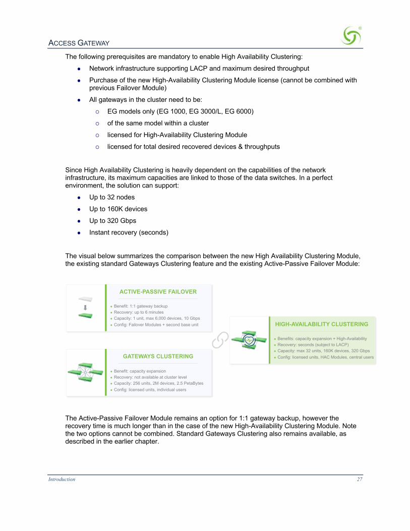
ACCESS GATEWAY
Introduction 27
The following prerequisites are mandatory to enable High Availability Clustering:
l Network infrastructure supporting LACP and maximum desired throughput
l Purchase of the new High-Availability Clustering Module license (cannot be combined with previous Failover Module)
l All gateways in the cluster need to be:
¡ EG models only (EG 1000, EG 3000/L, EG 6000)
¡ of the same model within a cluster
¡ licensed for High-Availability Clustering Module
¡ licensed for total desired recovered devices & throughputs
Since High Availability Clustering is heavily dependent on the capabilities of the network infrastructure, its maximum capacities are linked to those of the data switches. In a perfect environment, the solution can support:
l Up to 32 nodes
l Up to 160K devices
l Up to 320 Gbps
l Instant recovery (seconds)
The visual below summarizes the comparison between the new High Availability Clustering Module, the existing standard Gateways Clustering feature and the existing Active-Passive Failover Module:
The Active-Passive Failover Module remains an option for 1:1 gateway backup, however the recovery time is much longer than in the case of the new High-Availability Clustering Module. Note the two options cannot be combined. Standard Gateways Clustering also remains available, as described in the earlier chapter.
● Benefit: capacity expansion● Recovery: not available at cluster level● Capacity: 256 units, 2M devices, 2.5 PetaBytes● Config: licensed units, individual users
GATEWAYS CLUSTERING
● Benefit: 1:1 gateway backup● Recovery: up to 6 minutes● Capacity: 1 unit, max 6,000 devices, 10 Gbps● Config: Failover Modules + second base unit
ACTIVE-PASSIVE FAILOVER
● Benefits: capacity expansion + High-Availability● Recovery: seconds (subject to LACP)● Capacity: max 32 units, 160K devices, 320 Gbps● Config: licensed units, HAC Modules, central users
HIGH-AVAILABILITY CLUSTERING

ACCESS GATEWAY
Introduction 28
LoadBalancingandLinkFailoverThe NSE supports individual configuration of multiple WANs on an Access Gateway (supported on AG 5900, EG 3000 and EG 6000 hardware – not on EG 1000 since it only has a single WAN port). Hotels can use this capability in a number of ways, including load balancing, failure protection, and subscriber allocation.
This section provides use cases and scenarios to help you consider the full advantage of these capabilities.
DefinitionsandConcepts
LoadBalancing
Load balancing refers to the general process of balancing user traffic across multiple ISP connections. All load-balancing appliances, as well as the Nomadix NSE, support load balancing.
LinkAggregation
Link aggregation refers to the process of connecting multiple ISP connections to an appliance and having the sum of all of the ISP bandwidth available to be shared across all users.
However, one individual connection is limited to the speed of the ISP connection that is currently being used. For example, a hotel may aggregate 5 x 1.5Mbps DSL connections together. This means that a total of 7.5Mbps of bandwidth is available to be shared across all users, but a single user can receive a maximum of 1.5Mbps. All load-balancing appliances, as well as the Nomadix NSE, support link aggregation. In most cases, link aggregation and load balancing is effectively the same thing.
LinkFailover
Link failover (sometimes referred to ISP redundancy) is the process of providing a second (or occasionally a third or more) ISP link as a back up to the primary ISP link. In the event that the primary link fails, all traffic is re-routed to the backup link, until such time as the primary link becomes available.
CombinedLoadBalancingandLinkFailover
This is the process where both load balancing and link failover are combined together. It represents the best of both worlds. Where multiple ISP links are used in load balancing mode, in the event that one or more links fail, all traffic is automatically rerouted to the remaining surviving links. When the failed links recover, new connections are routed toward these until the normal balanced configuration is reached.
ISPlinkSelectionCriteria
In a load-balancing scenario, some criteria must be used to decide which ISP is selected for outgoing traffic. There a number of factors that influence this decision, including:
l Identity of the users: Is a random ISP section used or is it desirable to have certain users steered toward a particular ISP?
l For random ISP: Whether subscriber, destination address or session-based link selection is used?
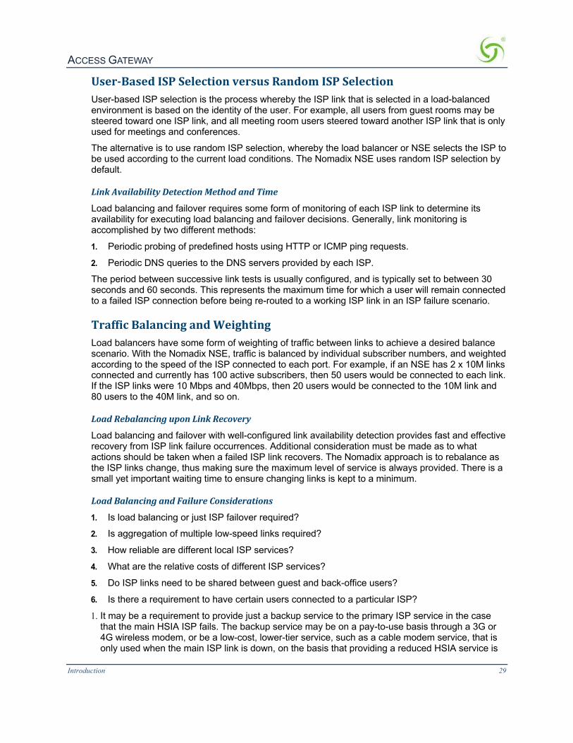
ACCESS GATEWAY
Introduction 29
User-BasedISPSelectionversusRandomISPSelectionUser-based ISP selection is the process whereby the ISP link that is selected in a load-balanced environment is based on the identity of the user. For example, all users from guest rooms may be steered toward one ISP link, and all meeting room users steered toward another ISP link that is only used for meetings and conferences.
The alternative is to use random ISP selection, whereby the load balancer or NSE selects the ISP to be used according to the current load conditions. The Nomadix NSE uses random ISP selection by default.
LinkAvailabilityDetectionMethodandTime
Load balancing and failover requires some form of monitoring of each ISP link to determine its availability for executing load balancing and failover decisions. Generally, link monitoring is accomplished by two different methods:
1. Periodic probing of predefined hosts using HTTP or ICMP ping requests.
2. Periodic DNS queries to the DNS servers provided by each ISP.
The period between successive link tests is usually configured, and is typically set to between 30 seconds and 60 seconds. This represents the maximum time for which a user will remain connected to a failed ISP connection before being re-routed to a working ISP link in an ISP failure scenario.
TrafficBalancingandWeightingLoad balancers have some form of weighting of traffic between links to achieve a desired balance scenario. With the Nomadix NSE, traffic is balanced by individual subscriber numbers, and weighted according to the speed of the ISP connected to each port. For example, if an NSE has 2 x 10M links connected and currently has 100 active subscribers, then 50 users would be connected to each link. If the ISP links were 10 Mbps and 40Mbps, then 20 users would be connected to the 10M link and 80 users to the 40M link, and so on.
LoadRebalancinguponLinkRecovery
Load balancing and failover with well-configured link availability detection provides fast and effective recovery from ISP link failure occurrences. Additional consideration must be made as to what actions should be taken when a failed ISP link recovers. The Nomadix approach is to rebalance as the ISP links change, thus making sure the maximum level of service is always provided. There is a small yet important waiting time to ensure changing links is kept to a minimum.
LoadBalancingandFailureConsiderations
1. Is load balancing or just ISP failover required?
2. Is aggregation of multiple low-speed links required?
3. How reliable are different local ISP services?
4. What are the relative costs of different ISP services?
5. Do ISP links need to be shared between guest and back-office users?
6. Is there a requirement to have certain users connected to a particular ISP?
1. It may be a requirement to provide just a backup service to the primary ISP service in the case that the main HSIA ISP fails. The backup service may be on a pay-to-use basis through a 3G or 4G wireless modem, or be a low-cost, lower-tier service, such as a cable modem service, that is only used when the main ISP link is down, on the basis that providing a reduced HSIA service is

ACCESS GATEWAY
Introduction 30
better than no service at all when the main ISP link is down. Alternatively, the organization may have multiple ISP links, and wants to be able to fully utilize all of them under normal conditions. The Nomadix NSE supports both failover only and combined load balancing with failover.
2. In some instances, suitable high-speed internet services required to meet the aggregate needs of the organization may not be available or are simply too expensive. In this case it may be desirable to aggregate multiple lower-cost, lower-speed lines together. The Nomadix AG 2500 and EG 3000 can aggregate services from up to three ISP links; the AG 5900 and EG 6000 can handle up to five links.
3. It is important to consider the relative quality of each ISP link. If a second link is much lower quality than the main ISP link, then it should only be used as a back-up link in failover mode, and not in a load-balanced environment. If the quality of the links is much the same, then load balancing with failover should be used.
4. It is important to consider the relative cost of links. If all links have a fixed monthly charge, then ideally they should be used in a load-balanced mode, so that costly links are not sitting unused most of the time. But if an ISP link has a relatively low monthly charge with high per- megabyte data usage charges, then it should only be used in failover mode as a backup to a main ISP link.
5. It may be requirement to share ISP bandwidth between Guest HSIA and Hotel Admin networks, or have each network available as a fallback network for the other. Both scenarios can be handled with the Nomadix NSE.
6. It may be desirable to have certain users connected to a particular ISP link, and other users connected to a different ISP link. The Nomadix NSE provides a “preferred WAN” radius attribute (VSA). For example, paying users may be connected to an expensive high-quality link, with free users connected to a lower-quality link, with link failover still available if the preferred link fails.
Some examples of typical common deployment scenarios are outlined below: These are just examples and other deployment scenarios can be handled, as well.
LoadBalancingacrossMultipleLowSpeedLinksIn this example, an establishment has access to only low-speed, DSL-based ISP circuits and wishes to aggregate five such links together. The Nomadix NSE is configured with load balancing between all links.

ACCESS GATEWAY
Introduction 31
FailovertoStandbyISPLinkIn this example, the organization has a high-quality 100M Ethernet service. But to guarantee continuous HSIA service, the organization has a back-up ISP service from a low-cost wireless provider, which charges on a data volume basis. The organization only wishes for this link to be used when the main ISP circuit is not available.
The Nomadix NSE is configured for failover only from the WAN to port Eth2 on the NSE.
SeparateGuestHSIAandAdminISPLinks,withFailoverBetweenEachISPLinkIn this scenario, the hotel has separate HSIA and Hotel Admin ISP circuits. Under normal circumstances, Guests will be connected to the Guest HSIA ISP, and Hotel Admin users will connect to the Admin ISP. If either link fails, then failover to the other link will occur. If the Guest HSIA link fails, the guests will be connected to the Admin ISP link until the Guest HSIA link is restored. If the Admin ISP link fails, the Admin users will be connected to the Guest HSIA link until the Admin ISP is restored
The Nomadix NSE is configured with load balancing and failover. All Guests use ISP 1 as the preferred WAN, the Admin network router uses ISP2 as the preferred WAN.

ACCESS GATEWAY
Introduction 32
GuestHSIAFailoverOnly,toAdminNetworkIn this scenario, the hotel has separate ISP circuits for the Guest HSIA network and Hotel Admin network. The hotel wants the Admin network to be available as a back-up link in case the Guest HSIA ISP link fails. There is no back-up for the Admin ISP network.
The Nomadix NSE is configured with link failover between the WAN port and port ETH2, which is connected to the hotel Admin network router.
SharingGuestHSIANetworkandHotelAdminNetworkAmongMultipleISPLinksIn this scenario, multiple ISP links are connected to the Nomadix NSE, in a similar method to the first scenario, but both the guest HSIA network and the Hotel Admin network are connected to the NSE and share the aggregate bandwidth of the combined ISP links.
The Nomadix NSE is configured for load balancing, and the back office router's MAC address is registered in as a device in the NSE with an appropriate bandwidth limit.

ACCESS GATEWAY
Introduction 33
LoadBalancingWithUsersConnectedtoaPreferredISPLinkIn this scenario, the hotel has purchased 2 x ISP links for guest HSIA. One is a high-quality, high-cost "business grade" ISP circuit, and the other is a low-cost, lower-grade domestic service provided by the local cable TV operator. The hotel has a number of bill plan options including free-to-use and pay-to-use premium plans. Under normal circumstances, the hotel wants guests who have selected a free plan to use the low-cost link, and guests who have selected a premium service to use the higher-cost, business-grade ISP connection. If either link fails, guest should fail over to the other links until the preferred link is restored.
ACCESS GATEWAY
Introduction 34
OnlineHelp(WebHelp)The Access Gateway incorporates an online Help system called “WebHelp” which is accessible through the Web Management Interface (when a remote Internet connection is established following a successful installation). WebHelp is HTML-based and can be viewed in a browser.
WebHelp is useful when you have an Internet connection to the Access Gateway and you want to access information quickly and efficiently. It contains all the information you will find in this User Guide.
For more information about WebHelp and other online documentation resources, go to Online Documentation and Help on page 47.
Notes,Cautions,andWarningsThe following formats are used throughout this User Guide:
General notes and additional information that may be useful are indicated with a Note.
Cautions and warnings are indicated with a Caution. Cautions and warnings provide important information to eliminate the risk of a system malfunction or possible damage.

ACCESS GATEWAY 2
Installing the Access Gateway 35
InstallingtheAccessGateway
This section provides installation instructions for the hardware and software components of the Access Gateway. It also includes an overview of the management interface, some helpful hints for system administrators, and procedures. A Quick Reference Guide chapter is also provided in this document.

ACCESS GATEWAY
36 Installing the Access Gateway
InstallationWorkflowThe following flowchart illustrates the steps that are required to install and configure your Access Gateway successfully. Review the installation workflow before attempting to install the Access Gateway on the customer’s network.
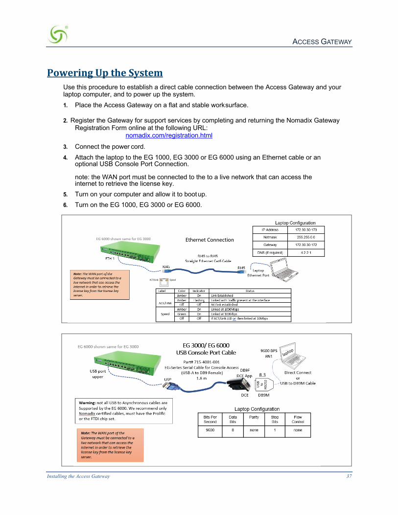
ACCESS GATEWAY
Installing the Access Gateway 37
PoweringUptheSystemUse this procedure to establish a direct cable connection between the Access Gateway and your laptop computer, and to power up the system. 1. Place the Access Gateway on a flat and stable work surface.
2. Register the Gateway for support services by completing and returning the Nomadix Gateway Registration Form online at the following URL: nomadix.com/registration.html
3. Connect the power cord. 4. Attach the laptop to the EG 1000, EG 3000 or EG 6000 using an Ethernet cable or an
optional USB Console Port Connection. note: the WAN port must be connected to the to a live network that can access the internet to retrieve the license key.
5. Turn on your computer and allow it to boot up. 6. Turn on the EG 1000, EG 3000 or EG 6000.

ACCESS GATEWAY
38 Installing the Access Gateway
UserManualandDocumentationPlease refer to the Quick Start Guide for additional information.
The Nomadix product user manuals, product documentation and support files including MIB, XML DTD and sample dictionary files are located at the following URL: http://www.nomadix.com/support
If you have any problems, please contact our technical support team at +1.818.575.2590, or email: [email protected].
The Quick Start Guide provides instructions and reference material for getting started with the Nomadix Access Gateway products, specifically the EG 1000, EG 3000 and EG 6000. https://nomadix.com/technical-support-documentation.html
ConfigurationNote: The WAN port of the EG must be connected to a live network that can access the Internet in order to retrieve the license key from the license key server.
Ethernet Connection On the PC/laptop open an SSH (Secure Shell) client connection using PuTTY, Hyperterm, Procomm (or equivalent) to the EG 1000, EG 3000 or EG 6000 using the Gateway’s default IP address 172.30.30.172. Go to Initial (startup) Configuration.
USB Console Port Connection On the PC/laptop start the asynchronous terminal emulation application, using PuTTY, Hyperterm, Procomm (or equivalent) application using the following configuration parameters for the comm port [Table 2].
Log in by typing admin then password: admin. Type (y)es when prompted to configure settings. The initial minimal WAN port configuration mode will be displayed as shown in Figure 1.
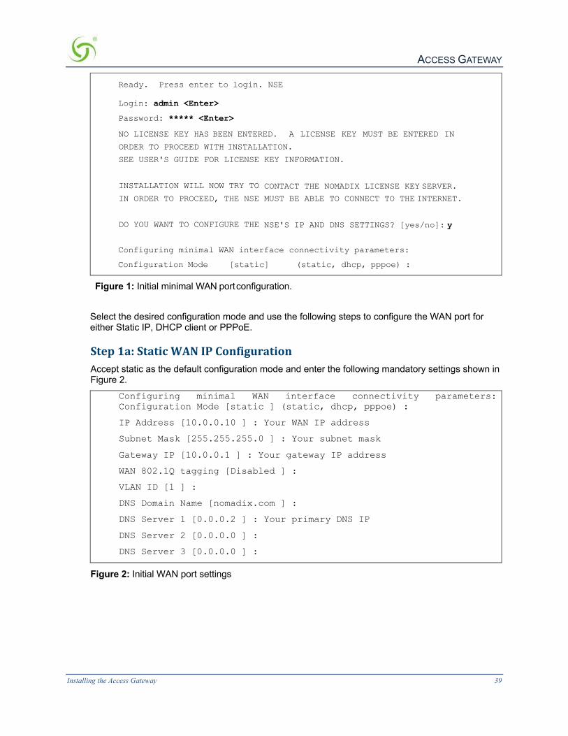
ACCESS GATEWAY
Installing the Access Gateway 39
Ready. Press enter to login. NSE
Login: admin <Enter>
Password: ***** <Enter>
NO LICENSE KEY HAS BEEN ENTERED. A LICENSE KEY MUST BE ENTERED IN
ORDER TO PROCEED WITH INSTALLATION.
SEE USER'S GUIDE FOR LICENSE KEY INFORMATION.
INSTALLATION WILL NOW TRY TO CONTACT THE NOMADIX LICENSE KEY SERVER.
IN ORDER TO PROCEED, THE NSE MUST BE ABLE TO CONNECT TO THE INTERNET.
DO YOU WANT TO CONFIGURE THE NSE'S IP AND DNS SETTINGS? [yes/no]: y
Configuring minimal WAN interface connectivity parameters:
Configuration Mode [static] (static, dhcp, pppoe) :
Figure 1: Initial minimal WAN port configuration.
Select the desired configuration mode and use the following steps to configure the WAN port for either Static IP, DHCP client or PPPoE.
Step1a:StaticWANIPConfigurationAccept static as the default configuration mode and enter the following mandatory settings shown in Figure 2.
Configuring minimal WAN interface connectivity parameters: Configuration Mode [static ] (static, dhcp, pppoe) :
IP Address [10.0.0.10 ] : Your WAN IP address
Subnet Mask [255.255.255.0 ] : Your subnet mask
Gateway IP [10.0.0.1 ] : Your gateway IP address
WAN 802.1Q tagging [Disabled ] :
VLAN ID [1 ] :
DNS Domain Name [nomadix.com ] :
DNS Server 1 [0.0.0.2 ] : Your primary DNS IP
DNS Server 2 [0.0.0.0 ] :
DNS Server 3 [0.0.0.0 ] :
Figure 2: Initial WAN port settings

ACCESS GATEWAY
40 Installing the Access Gateway
A WAN port summary page will then be displayed as shown in Figure 3.
Port Name : WAN
Port Role : wanIf
Configuration Mode : static
IP Address : Your IP address
Subnet Mask : Your subnet mask
Gateway IP : Your gateway IP address
WAN 802.1Q tagging : Disabled
VLAN ID : 1
DNS Domain Name : nomadix.com
DNS Server 1 : Your primary DNS IP address
DNS Server 2 :
DNS Server 3 : 0.0.0.0
Additional NAT IP addresses : Disabled
show all - Show all WAN Interface configuration
show interface <name> - Show a single WAN Interface configuration
modify interface <name> - Modify a single WAN Interface configuration
Type b to go back, <esc> to abort, ? for help.
Ethernet port/WAN interface configuration>
Figure 3: WAN port static IP configuration summary page.
If everything is correct in the summary, type (b)ack to return to the previous menu, and proceed to Step 2 to enter the location information.
Otherwise, select an option from the Ethernet port configuration menu to display or make changes to the WAN port settings. When finished with the settings, type b(ack) to return to the previous menu, and go to Step 2.
Step1b:DHCPClientConfigurationType (d)hcp for the configuration mode as shown in Figure 4.
Configuring minimal WAN interface connectivity parameters: Configuration Mode [static ] (static, dhcp, pppoe) : d
WAN 802.1Q tagging [Disabled ] :
VLAN ID [1 ] :
DNS Server 3 [0.0.0.0 ] :
Figure 4: Selecting DHCP Client for WAN configuration.

ACCESS GATEWAY
Installing the Access Gateway 41
A WAN port summary page will then be displayed as shown in Figure 5.
Port Name : WAN
Port Role : wanIf
Configuration Mode : dhcp
IP Address : Your IP address
Subnet Mask : Your subnet mask
Gateway IP : Your gateway IP address
WAN 802.1Q tagging : Disabled
VLAN ID : 1
DNS Domain Name : Your domain name
DNS Server 1 : Your primary DNS IP address
DNS Server 2 :
DNS Server 3 : 0.0.0.0
Additional NAT IP addresses : Disabled
show all - Show all WAN Interface configuration
show interface <name> - Show a single WAN Interface configuration
modify interface <name> - Modify a single WAN Interface configuration
Type b to go back, <esc> to abort, ? for help.
Ethernet port/WAN interface configuration>
Figure 5: WAN port DHCP client configuration summary page.
If everything is correct in the summary, type (b)ack to return to the previous menu, and proceed to step 2 to enter location information.
Otherwise, select an option from the Ethernet port configuration menu to display or make changes to the WAN port settings. When finished with settings, type b(ack) to return to the previous menu, and go to step 2.
Step1c:PPPoEDynamicIPClientConfigurationEnter (p)ppoe when prompted. Enter the following mandatory settings for a PPPoE connection with dynamic PPP IP configuration shown in Figure 6.
Configuring minimal WAN interface connectivity parameters:
Port Role [wanIf ] : (outOfService, subscriberIf, wanIf)
Configuration Mode [static ] (static, dhcp, pppoe) : p
PPPoE Service Name [ ] : ("none" to clear) : Your Service
LCP Echo-Request Interval [30 ] :
Maximum LCP Non-responses [6 ] :
PPP Authentication User Name [ ] : ("none" to clear) : Your User Name
PPP Authentication Password [ ] : ("none" to clear) : Your Password

ACCESS GATEWAY
42 Installing the Access Gateway
PPP IP Configuration Mode [dynamic ] (dynamic, static) :
PPP Static IP Address [0.0.0.0 ] :
PPP Maximum TCP MSS [1452 ] :
WAN 802.1Q tagging [Disabled ] :
VLAN ID [1] :
DNS Domain Name [nomadix.com ] :
DNS Server 3 [0.0.0.0 ] :
Figure 6: Selecting PPPoE with dynamic IP configuration.
A WAN port summary page will then be displayed as shown in Figure 7.
Port Name : WAN
Port Role : wanIf
Configuration Mode : pppoe
IP Address : Your IP address
Subnet Mask : Your subnet mask
Gateway IP : Your gateway
PPPoE Service Name : Your Service Name
LCP Echo-Request Interval : 30
Maximum LCP Non-responses : 6
PPP Authentication User Name : Your user name
PPP Authentication Password : Your password
PPP IP Configuration Mode : dynamic
PPP Static IP Address : 0.0.0.0
PPP Maximum TCP MSS : 1452
WAN 802.1Q tagging : Disabled
VLAN ID : 1
DNS Domain Name : Your domain name
DNS Server 1 : Your dns server IP address
DNS Server 2 : 0.0.0.0
DNS Server 3 : 0.0.0.0
Additional NAT IP addresses : Disabled
show all - Show all WAN Interface configuration
show interface <name> - Show a single WAN Interface configuration
modify interface <name>- Modify a single WAN Interface configuration
Type b to go back, <esc> to abort, ? for help. Ethernet port/WAN interface configuration>

ACCESS GATEWAY
Installing the Access Gateway 43
Figure 7: WAN port PPPoE client configuration summary page.
If everything is correct in the summary, type (b)ack to return to the previous menu, and proceed to step 2 to enter location information.
Otherwise, select an option from the Ethernet port configuration menu to display or make changes to the WAN port settings. When finished with settings, type b(ack) to return to the previous menu, and go to step 2.
Step1d:PPPoEStaticIPClientConfigurationUse the same steps for configuring dynamic PPPoE shown in Figure 6 above, but select static for PPP IP Configuration Mode, and enter your IP address for PPP Static IP Address. A summary page similar to Figure 7 above will be displayed.
If everything is correct in the summary, type (b)ack to return to the previous menu, and proceed to step 2 to enter location information.
Otherwise, select an option from the Ethernet port configuration menu to display or make changes to the WAN port settings. When finished with settings, type b(ack) to return to the previous menu, and go to step 2.
Step2:EnteringYourLocationInformationYou will be required to enter location information in order to obtain the license key. Enter the following mandatory location information details shown in Figure 8.
Ethernet port/WAN interface configuration>b
Please enter your Company Name [ ]: Your company name
Please enter your Site Name [ ]: Your site name
Please enter your Address (Line 1) [ ]:
(Line 2) [ ]:
(City) [ ]: Your site city
(State) [ ]: Your site state
(ZIP/Postal Code) [ ]:
(Country) [ ]: Your site country
Please enter your E-Mail Address [ ]: email address
Please select the venue type that most reflects your location
1. Apartment
...
25. Other
Please enter a number from the above list: Venue Type
Figure 8: Site location details.
Step3:RetrievingYourLicenseKeyThe system will now prompt you to accept or decline the End User License Agreement (EULA). You must accept the terms of the EULA before the AG can retrieve its license key. To retrieve the

ACCESS GATEWAY
44 Installing the Access Gateway
license key, enter (y)es as shown in Figure 9. The AG retrieves the license key from the Nomadix license key server, then reboots.
PLEASE READ THE NOMADIX END USER LICENSE AGREEMENT ('AGREEMENT') INCLUDED WITH THE NOMADIX PRODUCT.
BY USING THIS SOFTWARE, YOU INDICATE YOUR ACCEPTANCE OF THE AGREEMENT. I AGREE TO THE TERMS AND CONDITIONS OF THE NOMADIX END USER LICENSE AGREEMENT.
(Y)ES (N)O
y
The system will now try to contact the Nomadix License Key Server. Please wait...
Received key from License Key Server.
If the license key is successfully processed the unit will reboot...
Figure 9: License key retrieval
NOTE: The date and time Software License Subscription start date.
Step4:ConfiguringtheSystemYou have now established a basic configuration for the AG that enables internet connectivity.
Before you can log into the AG and use the graphical Web Management Interface (WMI), you must disable subscriber-side HTTP:
1. Log in to the AG
2. Navigate to Configuration -> Access Control -> Interface 3. Press Enter until you reach Subscriber-side HTTP 4. Enter disabled You can now use the graphical Web Management Interface (WMI) to configure the product’s features.
Step5:ConfiguringEGDHCPServerSettingsDHCP Server is enabled by default. To configure the DHCP Server, go to DHCP under the Configuration menu. You can either modify the default DHCP pool or delete/add another DHCP pool. The total lease pool size recommendation is 5 times more than the number of licensed subscribers
DHCP Parameter Your Settings Default Values
DHCP Services (Disable) no
DHCP Relay (Yes / No) If No, skip to DHCP Server
no
DHCP Relay Server IP Address blank

ACCESS GATEWAY
Installing the Access Gateway 45
DHCP Parameter Your Settings Default Values
DHCP Relay Agent IP Address blank
DHCP Server (Yes / No) Only if the DHCP Relay is disabled
yes
DHCP Server IP Address 10. 0. 0.4
DHCP Server Subnet Mask 255.255.255.0
DHCP Pool Start IP Address 10.0.0.12
DHCP Pool End IP Address 10.0.0.72
DHCP Lease Minutes 1440
An example of a basic network including an AG is shown below.
TheManagementInterfaces(CLIandWeb)
The Access Gateway supports various methods for managing the system remotely. These include, an embedded graphical Web Management Interface (WMI), an SNMP client, or Telnet. However, until the unit is installed and running, system management is performed from the Access Gateway’s embedded CLI via a direct serial cable connection. The CLI can also be accessed remotely.
Until the unit is installed on the customer’s network and a remote connection is established, the CLI is the administrator’s window to the system. This is where you establish all the Access Gateway start-up configuration parameters, depending on the customer’s network architecture.
The Access Gateway Menu is your starting point. From here, you access all the system administration items from the 5 (five) primary menus available:
• Configuration
• Network Info
• Port-location
• Subscribers

ACCESS GATEWAY
46 Installing the Access Gateway
• System
Although the basic functional elements are the same, the CLI and the WMI have some minor content and organizational differences. For example, in the WMI the “subscribers” menu is divided into “Subscriber Administration” and “Subscriber Interface.” See also “Menu Organization (Web Management Interface)” on page 57.
MakingMenuSelectionsandInputtingDatawiththeCLIThe CLI is character-based. It recognizes the fewest unique characters it needs to correctly identify an entry. For example, in the Access Gateway Menu you need only enter c to access the Configuration menu, but you must enter su to access the Subscribers menu and sy to access the System menu (because they both start with the letter “s”).
You may also do any of the following:
l Enter b (back) or press Esc (escape) to return to a previous menu. l Press Esc to abort an action at any time.
l Press Enter to redisplay the current menu. l Press ? at any time to access the CLI’s Help screen.
When using the CLI, if a procedure asks you to “enter sn,” this means you must type sn and press the Enter key. The system does not accept data or commands until you hit the Enter key.
MenuOrganization(WebManagementInterface)When you have successfully installed and configured the Access Gateway from the CLI, you can then access the Access Gateway from its embedded Web Management Interface (WMI). The WMI is easier to use (point and click) and includes some items not found in the CLI. You can use either interface, depending on your preference.
For a complete description of all features available in the WMI, see Using the Web Management Interface (WMI) on page 60.
InputtingData–MaximumCharacterLengthsThe following table details the maximum allowable character lengths when inputting data:
Data Field Max. Characters
All Messages (billing options) 72
All Messages (subscriber error messages) 72
All Messages (subscriber login UI) 72
All Messages (subscriber “other” messages) 72
Description of Service (billing options Plan) 140
Home Page URL 237
Host Name and Domain Name (DNS settings) 64
IP / DNS Name (pass-through addresses) 237
Label (billing options plan) 16

ACCESS GATEWAY
Installing the Access Gateway 47
Location settings (all fields) 99
Partner Image File Name 12
Password (adding subscriber profiles) 128
Port Description (finding ports by description) 63
Redirection Frequency (in minutes) 2,147,483,647 (recommend 3600)
Reservation Number 24
Username (adding subscriber profiles) 96
Valid SSL Certificate DNS Name 64
OnlineDocumentationandHelpThe Web Management Interface (WMI) incorporates an online help system that is accessible from the main window.
Other online documentation resources, available from our corporate Web site (www.nomadix.com/support), include a full PDF version of this User Guide (viewable with Acrobat™ Reader), How-To Guides, README files, white papers, technical notes, and business cases.

ACCESS GATEWAY
48 Installing the Access Gateway
EstablishingtheStartUpConfigurationThe CLI allows you to administer the Access Gateway’s start-up configuration settings.
When establishing the start-up configuration for a new installation, you are connected to the Access Gateway via a direct serial connection (you do not have remote access capability because the Access Gateway is not yet configured or connected to a network). Once the installation is complete (see Installation Workflow on page 36) and the system is successfully configured, you will have the additional options of managing the Access Gateway remotely from the system’s Web Management Interface, an SNMP client manager of your choice, or a simple Telnet interface.
The startup configuration must be established before connecting the Access Gateway to a customer’s network. The “startup” configuration settings include:
l Assigning Login User Names and Passwords – You must assign a unique login user name and password that enables you to administer and manage the Access Gateway securely.
User names and passwords are case-sensitive.
l Setting the SNMP Parameters (optional) – The SNMP (Simple Network Management Protocol) parameters must be established before you can use an SNMP client (for example, HP OpenView) to manage and monitor the Access Gateway remotely.
l Enabling the Logging Options (recommended) – Servers must be assigned and set up if you want to create system and AAA (billing) log files, and retrieve error messages generated by the Access Gateway.
l Assigning the Location Information and IP Addresses (Connecting the Access Gateway to the Customer’s Network):
l Assigning the Network Interface IP Address - This is the public IP address that allows administrators and subscribers to see the Access Gateway on the network. Use this address when you need to make a network connection with the Access Gateway.
l Assigning the Subnet Mask – The subnet mask defines the number of IP addresses that are available on the routed subnet where the Access Gateway is located.
l Assigning the Default Gateway IP Address – This is the IP address of the router that the Access Gateway uses to transmit data to the Internet.
AssigningLoginUserNamesandPasswordsWhen you initially powered up the Access Gateway and logged in to the Management Interface, the default login user name and password you used was “admin.” The Access Gateway allows you to define 2 concurrent access levels to differentiate between managers and operators, where managers are permitted read/write access and operators are restricted to read access only. Once the logins have been assigned, managers have the ability to perform all write commands (Submit, Reset, Reboot, Add, Delete, etc.), but operators cannot change any system settings. When Administration Concurrency is enabled, one manager and three operators can access the Access Gateway at any one time (the default setting for this feature is “disabled”).
1. Enter sy (system) at the Access Gateway Menu. The System menu appears.
2. Enter lo (login). The system prompts you for the current login. If this is the first time you are changing the login

ACCESS GATEWAY
Installing the Access Gateway 49
parameters since initializing the Access Gateway, the default login name and password is “admin.”
The system accepts up to 11 characters (any character type) for user names and passwords. All user names and passwords are case-sensitive.
3. When prompted, confirm the current login parameters and enter new ones.
Sample Screen Response: System>lo Enable/Disable Administration Concurrency [disabled]: e Current login: admin Current password: ***** Enter new manager login: newmgr Enter new password: ******* Retype new password: ******* The administrative login and password were changed Enter new operator login: newop Enter new operator password: ***** Retype new operator password: ***** The operator login and password were changed
Enter RADIUS remote test login: rad Enter new RADIUS remote test password: ***** Retype new RADIUS remote test password: ***** The RADIUS remote test login and password were changed
You must use the new login user name(s) and password(s) to access the system.
SettingtheSNMPParameters(optional)You can address the Access Gateway using an SNMP client manager (for example, HP OpenView). SNMP is the standard protocol that regulates network management over the Internet. To do this, you must set up the SNMP communities and identifiers. For more information about SNMP, see “Using an SNMP Manager” on page 61.
If you want to use SNMP, you must manually turn on SNMP.
1. Enter c (configuration) at the Access Gateway Menu. The Configuration menu appears.
2. Enter “snmpv2”.
3. Enable the SNMP daemon, as required. The system displays any existing SNMP contact information and prompts you to enter new information. If this is the first time you have initialized the SNMP command since removing the Access Gateway from its box, the system has no information to display (there are no defaults).
4. Enter the SNMP parameters (communities and identifiers). The SNMP parameters include your contact information, the get/set communities, and the IP address of the trap recipient. Your SNMP manager needs this information to enable network management over the Internet.
5. If you enabled the SNMP daemon, you must reboot the system for your changes to take effect. In this case, enter y (yes) to reboot your Access Gateway. Sample Screen Response: Configuration>snmpv2

ACCESS GATEWAY
50 Installing the Access Gateway
Enable the SNMP Daemon? [Yes]: Enter new system contact: [email protected] [Nomadix, Newbury Park, CA] Enter new system location: Office, Newbury Park, CA Enter read/get community [public]: Enter write/set community [private]: Enter IP of trap recipient [0.0.0.0]: 10.11.12.13 SNMP Daemon: Enabled
System contact: [email protected] System location: Office, Newbury Park, CA Get (read) community: public Set (write) community: private Trap recipient: 10.11.12.13 Reboot to enable new changes? [yes/no] y Rebooting...
You can now address the Access Gateway using an SNMP client manager.
ConfiguringtheWANinterfaceIf a license key is not present, you will still be directed to set up the WAN configuration as soon as you log into the CLI. However, the subsequent steps are new and network settings are no longer configured under Location.
The following are the steps needed to configure the main WAN interface:
1. Enter c (configuration) at the Access Gateway Menu. The Configuration menu appears.
2. Enter eth (ethernet).
3. After you have entered “yes” to the initial prompt, enter “mod int WAN” or “m i WAN” (“modify interface WAN”). Note that modes and interface names are case sensitive. The configuration then steps through the settings one by one.
4. Port role for the WAN port should be already set to WAN, just hit <enter>
5. Set the configuration mode to match your network settings.
6. Set the remaining network settings .
7. Default uplink and download speed is 15 Mbps. Enter different values if desired.
8. Bandwidth and DNS settings are configured separately for each WAN interface. You can configure them later in the WAN configuration dialog in the Web Management Interface.
9. If you do not wish to configure additional NAT IP addresses at this time, type “b”.
10. A summary of the WAN port settings is now displayed; if they are correct, type “b” again.
You will now see the Nomadix location configuration page. Enter contact data and agree to the Nomadix End User License Agreement. Your license will be retrieved when you enter “y”. The NSE will then reboot to activate your license settings.

ACCESS GATEWAY
Installing the Access Gateway 51
EnablingtheLoggingOptions(recommended)System logging creates log files and error messages generated at the system level. AAA logging creates activity log files for the AAA (Authentication, Authorization, and Accounting) functions. You can enable either of these options.
Although the AAA and billing logs can go to the same server, we recommend that they have their own unique server ID number assigned (between 0 and 7). When managing multiple properties, the properties are identified in the log files by their IP addresses.
When system logging is enabled, the standard SYSLOG protocol (UDP) is used to send all message logs generated by the Access Gateway to the specified server.
1. Enter log (logging) at the Configuration menu. The system displays the current logging status (enabled or disabled).
2. Enable or disable the system and/or AAA logging options, as required. If you enable either option, go to Step 3, otherwise logging is disabled and you can terminate this procedure.
3. Assign a valid ID number (0-7) to each server.
4. Enter the IP addresses to identify the location of the system and AAA SYSLOG servers on the network (the default for both is 0.0.0.0).
When logging is enabled, log files and error messages are sent to these servers for future retrieval. To see sample reports, go to Sample SYSLOG Report on page 245 and Sample AAA Log on page 244.
Sample Screen Response: Configuration>log Enable/disable System Log [disabled ]: enable Enter System Log Number (0-7) [0 ]: 2 Enter System Log Filter
0: Emergency 1: Alert 2: Critical 3: Error 4: Warning
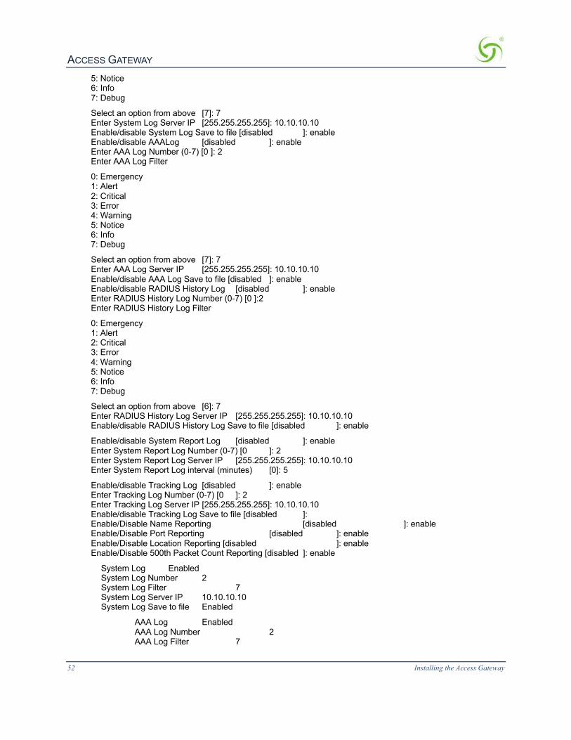
ACCESS GATEWAY
52 Installing the Access Gateway
5: Notice 6: Info 7: Debug
Select an option from above [7]: 7 Enter System Log Server IP [255.255.255.255]: 10.10.10.10 Enable/disable System Log Save to file [disabled ]: enable Enable/disable AAALog [disabled ]: enable Enter AAA Log Number (0-7) [0 ]: 2 Enter AAA Log Filter
0: Emergency 1: Alert 2: Critical 3: Error 4: Warning 5: Notice 6: Info 7: Debug
Select an option from above [7]: 7 Enter AAA Log Server IP [255.255.255.255]: 10.10.10.10 Enable/disable AAA Log Save to file [disabled ]: enable Enable/disable RADIUS History Log [disabled ]: enable Enter RADIUS History Log Number (0-7) [0 ]:2 Enter RADIUS History Log Filter
0: Emergency 1: Alert 2: Critical 3: Error 4: Warning 5: Notice 6: Info 7: Debug
Select an option from above [6]: 7 Enter RADIUS History Log Server IP [255.255.255.255]: 10.10.10.10 Enable/disable RADIUS History Log Save to file [disabled ]: enable
Enable/disable System Report Log [disabled ]: enable Enter System Report Log Number (0-7) [0 ]: 2 Enter System Report Log Server IP [255.255.255.255]: 10.10.10.10 Enter System Report Log interval (minutes) [0]: 5
Enable/disable Tracking Log [disabled ]: enable Enter Tracking Log Number (0-7) [0 ]: 2 Enter Tracking Log Server IP [255.255.255.255]: 10.10.10.10 Enable/disable Tracking Log Save to file [disabled ]: Enable/Disable Name Reporting [disabled ]: enable Enable/Disable Port Reporting [disabled ]: enable Enable/Disable Location Reporting [disabled ]: enable Enable/Disable 500th Packet Count Reporting [disabled ]: enable
System Log Enabled System Log Number 2 System Log Filter 7 System Log Server IP 10.10.10.10 System Log Save to file Enabled
AAA Log Enabled AAA Log Number 2 AAA Log Filter 7

ACCESS GATEWAY
Installing the Access Gateway 53
AAA Log Server IP 10.10.10.10 AAA Log Save to file Enabled
RADIUS History Log Enabled RADIUS History Log Number 2 RADIUS History Log Filter 7 RADIUS History Log Server IP 10.10.10.10 RADIUS History Log Save to file Enabled
System Report Log Enabled System Report Log Number 2 System Report Log Server IP 10.10.10.10 System Report Log Interval (in minutes) 5
Tracking Log Enabled Tracking Log Number 2 Tracking Log Server IP 10.10.10.10 Tracking Log Save to file Disabled Tracking Name Reporting Enabled Tracking Port Reporting Enabled Tracking Location Reporting Enabled Tracking Report every 500th packet Enabled
WARNING: Communication between the gateway and the syslog server may need to be secured to comply with local laws. Consider routing communication through an IPSec tunnel.
Configuration>
LoggingOutandPoweringDowntheSystemUse this procedure to log out and power down the Access Gateway.
1. Enter l (logout) at the Access Gateway Menu. Your serial session closes automatically.
2. Turn off the Access Gateway and disconnect the power cord.
3. Disconnect the cable between the Access Gateway and your computer.
ConnectingtheAccessGatewaytotheCustomer’sNetworkUse this procedure to connect the Access Gateway to the customer’s network (after the startup configuration parameters have been established).
1. Choose an appropriate physical location that allows a minimum clearance of 4cm either side of the unit (for adequate airflow).
2. Connect the Access Gateway to the router, then connect the Access Gateway to the customer’s subscriber port.
3. Connect the power cord and turn on the Access Gateway.
4. Go to Establishing the Basic Configuration for Subscribers on page 53.
EstablishingtheBasicConfigurationforSubscribersWhen you have successfully established the startup configuration and installed the unit onto the customer’s network, connect to the Access Gateway via Telnet. You must now set up the basic configuration parameters for subscribers, including:
l Setting the DHCP Options – DHCP (Dynamic Host Configuration Protocol) allows you to assign IP addresses automatically (to subscribers who are DHCP enabled). The Access Gateway can “relay” the service through an external DHCP server or it can be configured to act as its own DHCP server.

ACCESS GATEWAY
54 Installing the Access Gateway
l Setting the DNS Options – DNS (Domain Name System) allows subscribers to enter meaningful URLs into their browsers (instead of complicated numeric IP addresses). DNS converts the URLs into the correct IP addresses automatically.
SettingtheDHCPOptionsWhen a device connects to the network, the DHCP server assigns it a “dynamic” IP address for the duration of the session. Most users have DHCP capability on their computer. To enable this service on the Access Gateway, you can either enable the DHCP relay (routed to an external DHCP server IP address), or you can enable the Access Gateway to act as its own DHCP server. In both cases, DHCP functionality is necessary if you want to automatically assign IP addresses to subscribers.
The Access Gateway’s adaptive configuration technology provides Dynamic Address Translation (DAT) functionality. DAT is automatically configured to facilitate “plug-and-play” access to subscribers who are misconfigured with static (permanent) IP addresses, or subscribers that do not have DHCP capability on their computers. DAT allows all users to obtain network access, regardless of their computer’s network settings.
1. Enter c (configuration) at the Access Gateway Menu. The Configuration menu appears.
2. Enter dh (dhcp).
By default, the Access Gateway is configured to act as its own DHCP server and the relay feature is disabled. Please verify that your DHCP Server supports DHCP packets before enabling the relay. Not all devices containing DHCP servers (for example, routers) support DHCP Relay functionality.
When assigning a DHCP Relay Agent IP address for the DHCP Relay, ensure that the IP address you use does not conflict with devices on the network side of the Access Gateway.
Although you cannot enable the DHCP relay and the DHCP service at the same time, it is possible to “disable” both functions from the Command Line Interface. In this case, a warning message informs you that no DHCP services are available to subscribers.
3. Follow the on-screen instructions to set up your DHCP options. For example:
Sample Screen Response: Configuration>dh
Enable/Disable IP Upsell [disabled ]: Enable/Disable DHCP Relay [disabled ]: Enable/Disable DHCP Server [enabled ]: Enable/Disable Subnet-based DHCP Service [disabled ]: Enable/Disable Forwarded DHCP Clients [disabled ]:
IP Upsell Disabled DHCP Relay Disabled External DHCP Server IP 0.0.0.0 DHCP Relay Agent IP 0.0.0.0 DHCP Server Enabled DHCP Server Subnet-based Disabled Forwarded DHCP Clients Disabled
Server-IP Server-Netmask Start-IP End-IP Lease Type IPUp 208.11.0.4 255.255.0.0 208.11.0.5 208.11.0.7 20 PRIV NO
10.0.0.4 255.255.255.0 10.0.0.5 10.0.0.250 30 PRIV NO *
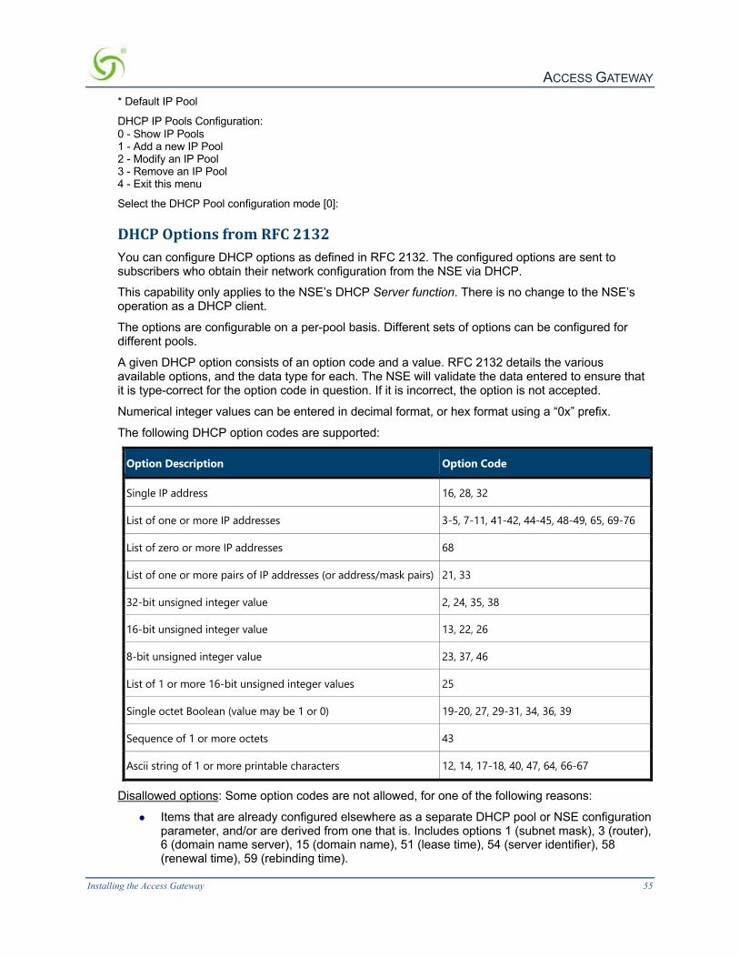
ACCESS GATEWAY
Installing the Access Gateway 55
* Default IP Pool
DHCP IP Pools Configuration: 0 - Show IP Pools 1 - Add a new IP Pool 2 - Modify an IP Pool 3 - Remove an IP Pool 4 - Exit this menu
Select the DHCP Pool configuration mode [0]:
DHCPOptionsfromRFC2132You can configure DHCP options as defined in RFC 2132. The configured options are sent to subscribers who obtain their network configuration from the NSE via DHCP.
This capability only applies to the NSE’s DHCP Server function. There is no change to the NSE’s operation as a DHCP client.
The options are configurable on a per-pool basis. Different sets of options can be configured for different pools.
A given DHCP option consists of an option code and a value. RFC 2132 details the various available options, and the data type for each. The NSE will validate the data entered to ensure that it is type-correct for the option code in question. If it is incorrect, the option is not accepted.
Numerical integer values can be entered in decimal format, or hex format using a “0x” prefix.
The following DHCP option codes are supported:
Option Description Option Code
Single IP address 16, 28, 32
List of one or more IP addresses 3-5, 7-11, 41-42, 44-45, 48-49, 65, 69-76
List of zero or more IP addresses 68
List of one or more pairs of IP addresses (or address/mask pairs) 21, 33
32-bit unsigned integer value 2, 24, 35, 38
16-bit unsigned integer value 13, 22, 26
8-bit unsigned integer value 23, 37, 46
List of 1 or more 16-bit unsigned integer values 25
Single octet Boolean (value may be 1 or 0) 19-20, 27, 29-31, 34, 36, 39
Sequence of 1 or more octets 43
Ascii string of 1 or more printable characters 12, 14, 17-18, 40, 47, 64, 66-67
Disallowed options: Some option codes are not allowed, for one of the following reasons:
l Items that are already configured elsewhere as a separate DHCP pool or NSE configuration parameter, and/or are derived from one that is. Includes options 1 (subnet mask), 3 (router), 6 (domain name server), 15 (domain name), 51 (lease time), 54 (server identifier), 58 (renewal time), 59 (rebinding time).

ACCESS GATEWAY
56 Installing the Access Gateway
l Items not valid in a DHCP offer or ACK message. Includes options 50 (requested IP address), 55 (parameter request list), 56 (error message), 57 (maximum message size), 60 (vendor class identifier), 61 (client identifier).
l Items generated automatically by the mechanism of DHCP message construction, which carry no application information. Includes options 0 (pad), 52 (option overload), 53 (DHCP message type), 255 (end).
Unrecognized options: Options 62-63, 77-254 are unrecognized. Some of these codes are legitimate and are defined in other RFCs, while others are not defined. These option codes are not explicitly disallowed on the NSE, but the NSE is “unaware” of them – that is, it will make no attempt to validate either the code or the data. It is the administrator’s responsibility to ensure that the option codes and data entered are legitimate.
The following screens illustrate adding additional DHCP options to a DHCP Pool.

ACCESS GATEWAY
Installing the Access Gateway 57
DHCPDynamicEnableandDisableClick Configuration->DHCP. Click the Server-IP and Enable this DHCP Pool. Note that DHCP enable/disable is dynamic, no reboot required.
SettingtheDNSOptionsDNS allows subscribers to enter meaningful URLs into their browsers (instead of numeric IP addresses) by automatically converting the URLs into the correct IP addresses.
After you have configured DNS global options in the command-line interface, you can assign a primary, secondary, or tertiary (third) DNS server for each WAN in the Web Management Interface (WMI). See Ethernet Ports/WAN on page 93 for WAN-specific DNS configuration.
To set the DNS global configuration options: 1. Enter c (configuration) at the Access Gateway Menu. The Configuration menu appears. 2. Enter dn (dnsglobal) at the Configuration menu. 3. Enter the host name (the DNS name of the Access Gateway). The host name must not
contain any spaces. 4. Specify the Redirection Port Mode. If floating, the DNS will use ephemeral ports for the source
port of DNS requests. If fixed (default), the manually configured ports are used. 5. Specify the UDP DNS Redirection Port. 6. Enable (default) or disable DNSSEC (Domain Name System Security Extensions).
Sample Screen Response: Configuration>dn Enter host name (no spaces) [AG5x00 ]:usg Redirection Port Mode (Fixed/Floating) [fixed ]:

ACCESS GATEWAY
58 Installing the Access Gateway
Enter UDP DNS Redirection Port [1029 ]: Enter Proxy UDP DNS Port [1028 ]: Enable/Disable DNSSEC [enabled ]: Host Name usg DNS Redirection Port Mode fixed UDP DNS Redirection Port 1029 Proxy UDP DNS Port 1028 DNSSEC Support enabled
InstallingtheNomadixPrivateMIBThe Nomadix Private Management Information Base (MIB) allows you to view and manage SNMP objects on your Access Gateway. To use the MIB, you must obtain the appropriate nomadix.mib file for your Access Gateway. This file is available in the Support area of the Nomadix web site.
ObtainingtheManagementInformationBase(MIB)file1. Visit www.nomadix.com/support. 2. Scroll to “Gateway Documentation”. 3. Click “Latest Documentation” 4. Scroll to the group for your Access Gateway model. 5. Click the link to download the MIB file for your Access Gateway.
ConfiguringtheManagementInformationBase1. Import the nomadix.mib file into your SNMP client manager.
2. Connect to the Access Gateway from a node on the network that is accessible via the Access Gateway’s network port (Internet, LAN, etc.). Be sure to enable the SNMP daemon on the Access Gateway (available on the Access Gateway’s CLI or Web Management Interface, under the Configuration menu – snmp).
3. All variables defined by Nomadix start with the following prefix: iso.org.dod.internet.private.enterprises.nomadix
4. You should now be able to define queries and set the SNMP values on
Click to download the MIB file.

ACCESS GATEWAY
Installing the Access Gateway 59
your Access Gateway. If necessary, consult this User Guide or your SNMP client manager’s documentation for further details.
We recommend that you change the predefined community strings in order to maintain a secure environment for your Access Gateway.

ACCESS GATEWAY
60
SystemAdministration
This section provides all the instructions and procedures necessary for system administrators to manage the Access Gateway on the customer’s network (after a successful installation). The system administration procedures in this section are organized as they are listed under their respective Web Management Interface (WMI) menus:
l Configuration Menu on page 62 l Network Info Menu on page 152 l Port-Location Menu on page 161 l Subscriber Administration Menu on page 171 l Subscriber Interface Menu on page 183 l System Menu on page 205
Now that the Access Gateway has been installed and configured successfully, this User Guide moves away from the Command Line Interface (CLI) and documents the Access Gateway from the Web Management Interface (WMI) viewpoint.
ChoosingaRemoteConnectionOnce installed and configured for the customer’s network, the Access Gateway can be managed and administered remotely with any of the following interface options:
l Using the Web Management Interface (WMI)―Provides a powerful and flexible Web interface for network administrators.
l Using an SNMP Manager ― Allows remote “Windows” management using an SNMP client manager (for example, HP OpenView). However, before you can use SNMP to access the Access Gateway, you must set up the appropriate SNMP communities. For more information, refer to Managing the SNMP Communities {SNMP} on page 142.
l Using a Telnet Client
To use any of the remote connections (Web, SNMP, or Telnet), the network interface IP address for the Access Gateway must be established (you did this during the installation process).
Choose an interface connection, based on your preference.
UsingtheWebManagementInterface(WMI)The Web Management Interface (WMI) is a “graphical” version of the Command Line Interface, comprised of HTML files. The HTML files are embedded in the Access Gateway and are dynamically linked to the system’s functional command sets. You can access the WMI from any Web browser.
Your browser preferences or Internet options should be set to compare loaded pages with cached pages.
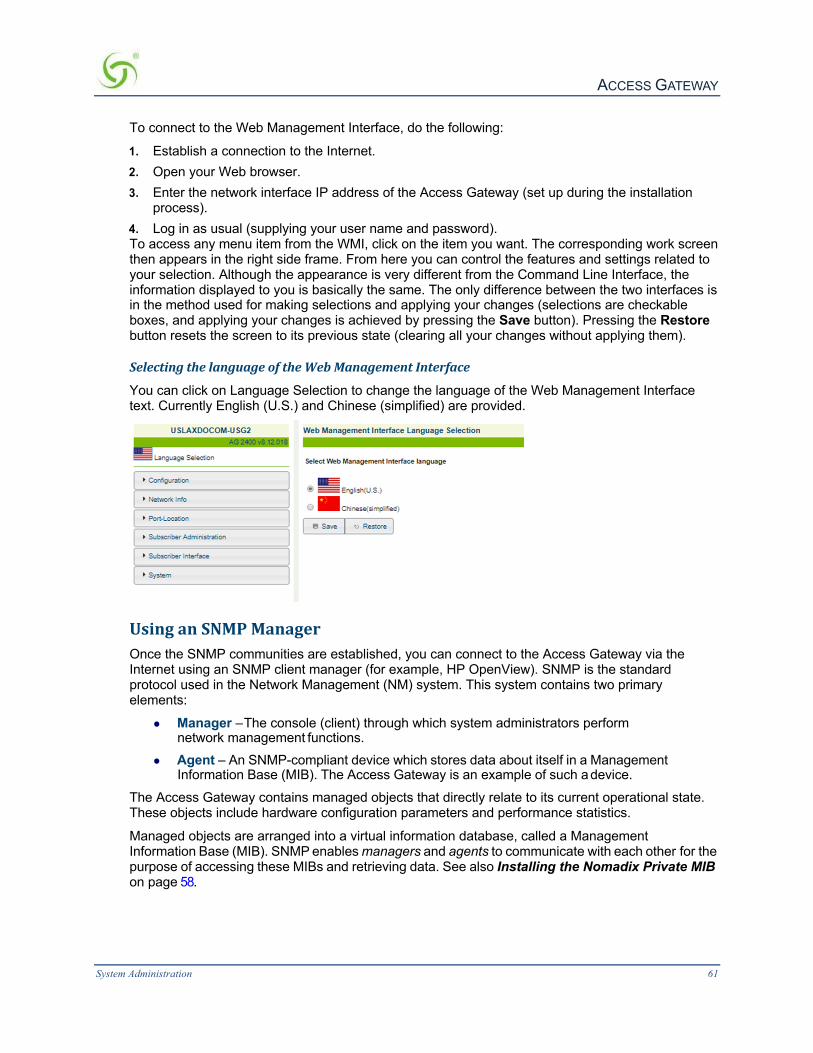
ACCESS GATEWAY
System Administration 61
To connect to the Web Management Interface, do the following:
1. Establish a connection to the Internet. 2. Open your Web browser. 3. Enter the network interface IP address of the Access Gateway (set up during the installation
process). 4. Log in as usual (supplying your user name and password). To access any menu item from the WMI, click on the item you want. The corresponding work screen then appears in the right side frame. From here you can control the features and settings related to your selection. Although the appearance is very different from the Command Line Interface, the information displayed to you is basically the same. The only difference between the two interfaces is in the method used for making selections and applying your changes (selections are checkable boxes, and applying your changes is achieved by pressing the Save button). Pressing the Restore button resets the screen to its previous state (clearing all your changes without applying them).
SelectingthelanguageoftheWebManagementInterface
You can click on Language Selection to change the language of the Web Management Interface text. Currently English (U.S.) and Chinese (simplified) are provided.
UsinganSNMPManagerOnce the SNMP communities are established, you can connect to the Access Gateway via the Internet using an SNMP client manager (for example, HP OpenView). SNMP is the standard protocol used in the Network Management (NM) system. This system contains two primary elements:
l Manager – The console (client) through which system administrators perform network management functions.
l Agent – An SNMP-compliant device which stores data about itself in a Management Information Base (MIB). The Access Gateway is an example of such a device.
The Access Gateway contains managed objects that directly relate to its current operational state. These objects include hardware configuration parameters and performance statistics.
Managed objects are arranged into a virtual information database, called a Management Information Base (MIB). SNMP enables managers and agents to communicate with each other for the purpose of accessing these MIBs and retrieving data. See also Installing the Nomadix Private MIB on page 58.

ACCESS GATEWAY
62 System Administration
The following example shows a (partial) SNMP screen response.
UsingaTelnetClientThere are many Telnet clients that you can use to connect with the Access Gateway. Using Telnet provides a simple terminal emulation that allows you to see and interact with the Access Gateway’s Command Line Interface (as if you were connected via the serial interface). As with any remote connection, the network interface IP address for the Access Gateway must be established (you did this during the installation process).
LoggingInTo access the Access Gateway’s Web Management Interface, use the Manager or Operator login user name and password you defined during the installation process (refer to Assigning Login User Names and Passwords).
User names and passwords are case-sensitive.
AboutYourProductLicenseSome features included in this section will not be available to you unless you have purchased the appropriate product license from Nomadix. In this case, the following statement will appear either immediately below the section heading or when the feature is mentioned in the body text:
Your product license may not support this feature. You can upgrade your product license at any time.
ConfigurationMenu
DefiningtheAAAServices{AAA}This procedure shows you how to set up the AAA (Authentication, Authorization, and Accounting) service options. AAA Services are used by the Access Gateway to authenticate, authorize, and subsequently bill subscribers for their use of the customer’s network. The Access Gateway currently supports several AAA models that are discussed in Subscriber Management on page 227.
1. From the Web Management Interface, click on Configuration, then AAA. The Authentication Authorization and Accounting Settings screen appears:

ACCESS GATEWAY
System Administration 63
2. Enable or disable AAA Services. If you enable AAA Services, go to Step 3; otherwise this feature is disabled and you can exit the procedure.
3. Select a Logout IP address from the drop-down list. The list contains IP address that can be used as the logout IP address. The default IP address is 198.51.100.10.
4. Click Configure to configure the XML Interface, as required.
XML is used by the Access Gateway’s subscriber management module for port location and user administration. Enabling the XML interface allows the Access Gateway to accept and process XML commands from an external source. XML commands are sent over the network to the Access Gateway. The Access Gateway parses the query string, executes the commands specified by the string, and returns data to the system that initiated the command request. You can authenticate XML commands via user credentials, as well as via IP addresses. You can choose either or both authentication mechanisms.
• If you select Enable Authentication via XML User Credentials, confirm that an XML user has been set up. Click on the User Credentials link, or select System > Login to set or confirm the XML Login ID and password. Below is an example XML command initiation that relies on XML User authentication:

ACCESS GATEWAY
64 System Administration
wget http://NSE_IP/usg/command.xml -O out.txt
--auth-no-challenge --user=xmlcommand
--password=xmlcommand --post-file="addUser.xml"
--header="Content-Type:text/xml"
• If you select Enable Authentication via IP Address, enter the valid XML server address(es). Up to four addresses are supported.
5. Enable or disable Print Billing Command, as required. This feature enables NSE to support Driverless Print servers. If this feature is enabled, you must enable the XML interface and enter the IP address for the XML interface (Step 3 and Step 4). With Print Billing enabled, print servers can bill subscribers’ rooms for printing their documents without them having to install printers.
The DNS name print.server.com will internally resolve to the Configured Print Server URL that is entered in the configuration. When subscribers are redirected to the Print Server the NSE adds Parameters to that request, so that the Server is able to charge the proper subscriber.
With these variables sent to the server it can now send the XML command to bill the users properly.
Print Server IP needs to be entered as one of the XML server IP for the command to successfully complete.
The XML command is: <USG COMMAND="BILL_PRINT" IP_ADDR="">
<ROOM_NUM></ROOM_NUM>
<DOC_NAME></DOC_NAME>
<NUM_COPIES></NUM_COPIES>
<NUM_PAGES></NUM_PAGES>
<COST></COST>
<TIME_SUBMITTED></TIME_SUBMITTED>
</USG> Subscribers could get to print.server.com by:
l ICC button link
l Printout in the hotel room
l Link from the hotel’s HPR Page
Your product license may not support this feature.
6. Enable or disable the AAA Passthrough Port feature, as required. System administrators can set the Access Gateway to pass-through HTTPS traffic, in addition to standard port 80 traffic, without being redirected. When access to a non-HTTPS address (for example, a Search Engine or News site) has been requested, the subscriber is then redirected as usual.
7. If AAA passthrough is enabled, enter the corresponding port number.
The port number must be different than 80, 2111, 1111, or 1112.
8. Enable or disable the 802.1x Authentication Support feature, as required.

ACCESS GATEWAY
System Administration 65
Both AAA and RADIUS Authentication must be enabled for 802.1x Authentication support.
9. Enable or disable the Origin Server (OS) parameter encoding for Portal Page and EWS feature, as required.
10. You can choose to Enable failover to Internal Web Server Authentication if Portal Page/External Web Server is not reachable by placing a check in that box.
11. Enable or disable Port Based Billing Policies. With Port Based Billing Policies enabled, you can individually configure the billing methods (RADIUS, PayPal, PMS) and the billing plans available on each port. This ability allows for having different billing methods and billing plans on different ports identified by VLANs or SNMP Port Query of the concentrator. A practical application of this feature is to have a normal hotel room with a plan A that is $9.99 for a day with PMS billing and have a meeting room with a plan of $14.99 an hour with PayPal billing. In order for the port-based policies to work, you must enable Port Based Billing Policies. See also Adding and Updating Port-Location Assignments {Add} on page 162.
12. Enable or disable HTTPS Redirection. The NSE responds to regular HTTP requests from pending subscribers with a redirection to the login screen. The NSE does not respond to HTTPS requests from pending subscribers (HTTP requests with a destination port = 443) with a redirect; this will result in a timeout or invalid certificate warning. Enabling HTTPS Redirection adds a security exception to the user’s browser to allow the certificate received from the NSE to be always “valid.”
13. Enable or disable Facebook Login. If you enable Facebook login, you must provide a Facebook App ID and Facebook App secret code. Instructions for creating these are available from Facebook.
14. Depending on which authorization mode you choose, go to the following sub-sections in this procedure:
l Enabling AAA Services with the Internal Web Server – The IWS is “flashed” into the system’s memory and the subscriber’s login page is served directly from the Access Gateway.
l Enabling AAA Services with an External Web Server – In the EWS mode, the Access Gateway redirects the subscriber’s login request to an external server (transparent to the subscriber). The login page served by the EWS reflects the “look and feel” of the solution provider’s network and presents more login options.
EnablingAAAServiceswiththeInternalWebServer
You are here because you want to enable the AAA Services with the Access Gateway’s Internal Web Server. The Access Gateway maintains an internal database of authorized subscribers, based on their MAC (hardware address) and user name (if enabled). By referring to its database record, also known as an authorization table, the Access Gateway instantly recognizes new subscribers on the network.
You can configure the Access Gateway to handle new subscribers in various ways (see the table on this page). With the IWS, you also have the option of enabling SSL support.

ACCESS GATEWAY
66 System Administration
After selecting the Internal Web Server authorization mode, you have the option of enabling or disabling the Usernames and New Subscribers features. These features work in conjunction with each other to determine how new subscribers are handled. Refer to the following table:
Usernames New Subscribers System Response
Disabled Enabled Allows new subscribers to enter the system without giving a user name and password.
Enabled (optional)
Enabled Allows new subscribers or authentication by their user name and password.
Enabled Disabled New subscribers are not allowed. Only existing subscribers are allowed after authenticating their user name and password.
Disabled Disabled You will not use this combination unless you want to lock out all subscribers.
1. Select the Internal Web Server tab.
2. Enable or disable the SSL Support feature, as required. If you enable SSL Support, you must
provide a valid Certificate DNS Name. For more information about setting up SSL, go to Setting Up the SSL Feature on page 252. SSL support allows for the creation of an end-to-end encrypted link between the Access Gateway and its clients by enabling the Internal Web Server (IWS) to display pages under a secure link—important when transmitting AAA information in a network. Adding SSL support to the Access Gateway requires service providers to obtain digital certificates from VeriSign™ to create HTTPS pages. Instructions for obtaining certificates are provided by Nomadix.

ACCESS GATEWAY
System Administration 67
To enable SSL Support, your Access Gateway’s flash must include the server.pem, cakey.pem, and cacert.pem certificate files (the “cacert.pem” file is provided with your Access Gateway). For assistance, contact Technical Support.
3. If you want to designate a portal page, you must enable the Portal Page feature; otherwise leave this feature disabled.
The Portal Page IP or DNS address are added to the IP passthrough list automatically.
4. If you enabled the Portal Page feature, provide the following supporting information:
l Portal Page URL
l Parameter Passing (enabled or disabled)
l Parameter Signing (including Method, Parameters, and Shared Secret)
See Redirection Parameter Signing on page 69 for more information about parameter signing.
l Portal XML POST URL, target for the NSE’s USER_STATUS XML commands. HTTP persistent connection, a single TCP connection to send and receive multiple HTTP requests and responses.
l Portal XML Post Port
l Support GIS Clients (enabled or disabled)
GIS stands for Generic Interface Specification, a document written by iPass. Enabling the Smart Client option in the Access Gateway automatically supports all GIS compliant clients using the Internal Web Server. Enabling “Support for GIS Clients” under the Portal Page feature means that the Access Gateway will defer the management of the GIS clients to the Portal Page server.
l Block IWS Login Page (enabled or disabled)
5. Enable or disable the Usernames feature, as required (refer to the table in Enabling AAA Services with the Internal Web Server on page 65). Some subscribers may want additional account flexibility and security for their services (for example, if they use more than one computer and their MAC address changes, or if they move between port-locations). In this case, a subscriber can define a unique user name and password which they can use from any machine or location (without being re- charged). Subscribers who choose this option are prompted for their user name and password whenever they try to access the Internet. Solution providers can charge a fee for this service.
6. Enable or disable the New Subscribers feature (refer to the table in Enabling AAA Services with the Internal Web Server on page 65).
New Subscribers must be enabled before enabling the PayPal and PMS options.
7. If you enabled New Subscribers, enable or disable the Relogin After Timeout option.
8. You can now enable or disable the PayPal feature. When this feature is enabled, subscribers are prompted to enter either their PayPal account information or their credit card information (for billing purposes). The Access Gateway is configured to use PayPal. You will need to open a business account with PayPal before this feature can be used.
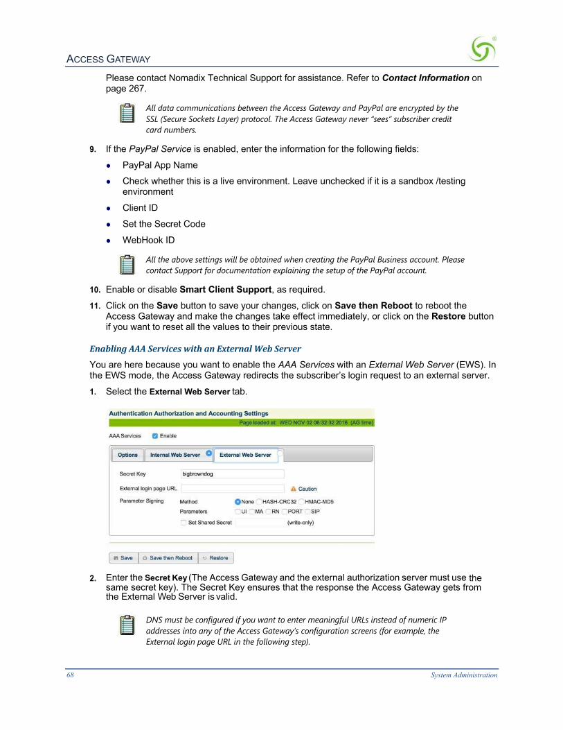
ACCESS GATEWAY
68 System Administration
Please contact Nomadix Technical Support for assistance. Refer to Contact Information on page 267.
All data communications between the Access Gateway and PayPal are encrypted by the SSL (Secure Sockets Layer) protocol. The Access Gateway never “sees” subscriber credit card numbers.
9. If the PayPal Service is enabled, enter the information for the following fields:
l PayPal App Name
l Check whether this is a live environment. Leave unchecked if it is a sandbox /testing environment
l Client ID
l Set the Secret Code
l WebHook ID
All the above settings will be obtained when creating the PayPal Business account. Please contact Support for documentation explaining the setup of the PayPal account.
10. Enable or disable Smart Client Support, as required.
11. Click on the Save button to save your changes, click on Save then Reboot to reboot the Access Gateway and make the changes take effect immediately, or click on the Restore button if you want to reset all the values to their previous state.
EnablingAAAServiceswithanExternalWebServer
You are here because you want to enable the AAA Services with an External Web Server (EWS). In the EWS mode, the Access Gateway redirects the subscriber’s login request to an external server.
1. Select the External Web Server tab.
2. Enter the Secret Key (The Access Gateway and the external authorization server must use the
same secret key). The Secret Key ensures that the response the Access Gateway gets from the External Web Server is valid.
DNS must be configured if you want to enter meaningful URLs instead of numeric IP addresses into any of the Access Gateway’s configuration screens (for example, the External login page URL in the following step).

ACCESS GATEWAY
System Administration 69
3. Enter a valid External login page URL. 4. Configure the Parameter Signing options.
See Redirection Parameter Signing for more information about parameter signing.
5. Click on the Save button to save your changes, click on Save then Reboot to reboot the Access Gateway and make the changes take effect immediately, or click on the Restore button if you want to reset all the values to their previous state (making changes to the EWS settings does not require a system reboot).
RedirectionParameterSigning
External Web Server (EWS) and Internal Web Server (IWS) Portal Page Parameters can be digitally signed, preventing malicious subscribers from intercepting, forging and replaying URL redirection strings used by the NSE and EWS or IWS Portal Page to validate subscriber access. This capability eliminates a vulnerability that was previously exploited to gain unauthorized Internet access at charge-for-use sites.
The signing feature can create a cryptographically strong signature that protects the sensitive portions of a URL redirection string (i.e., NSE ID, MAC address of the subscriber, etc.), while letting the EWS/Portal Page verify that the URL string has not been tampered or forged by the subscriber.

ACCESS GATEWAY
70 System Administration
The feature is configured by selecting a signing method, the parameters to be signed, and assigning a secret key.
Two signature methods are supported:
l HASH-CRC32
l HMAC-MD5
Not all parameters that are part of the URL redirection string need to be included in the signature calculation. The following parameters are considered sensitive and can be selected:
l UI (the ID of the NSE)
l MA (the subscriber’s MAC address)
l RN (the Room Number) l PORT (the port number the subscriber is connected to)
The desired secret key simply needs to be entered in the field. Once entered, it is not visible to the user.

ACCESS GATEWAY
System Administration 71
Information that indicates which parameters were signed, along with the resultant hash value, are then included in some additional parameters that are appended to the redirection string.
In order to utilize the parameter signing feature, the EWS or Portal Page Server used must be configured to correctly parse and verify the signing information. Documentation that includes guidelines for configuring a server to support signing can be obtained by contacting Nomadix Technical Support.
EstablishingSecureAdministration{AccessControl}The Access Gateway allows you to block administrator access to interfaces (Telnet, HTTP, HTTPS, FTP, SFTP and SSH) and incorporates a master access control list that checks the source (IP address) of administrator logins. A login is permitted only to the interfaces that have not been blocked, and only if a match is made with the master “Source IP” list contained on the Access Gateway. If a match is not made with the “Source IP list,” the login is denied, even if a correct login name and password are supplied. The access control list for source IPs supports up to 50 (fifty) entries in the form of a specific IP address or range of IP addresses.
This procedure allows you to enable the “Access Control” feature and block administrator access to specific interfaces, and add or remove administrator “Source IP” addresses.
The NSE supports secure https connections to the Web Management Interface (WMI). Correct certificates must be installed on the NSE flash memory for these connections to function properly. The same certificate set that is used to support SSL connections for subscribers is used for this purpose. For documentation about configuring the system to support secure connections, contact technical support. See Appendix A: Technical Support.
In addition, corresponding options to block https connections (independent of http) are included in the NSE's Access Control functionality, for both the network and subscriber sides.
If the required certificates are not resident on the flash, an attempted https connection will generate an error syslog.

ACCESS GATEWAY
72 System Administration
1. From the Web Management Interface, click on Configuration, then Access Control. The Access Control screen appears.
2. For Configurable Ports, enter a Telnet Port, HTTP, HTTPS and SSH/SFTP Port.
3. Enable or disable administrator access to any of the following interfaces: l Telnet Access l Web Management Access (HTTP)
l Web Management Access (HTTPS) l FTP Access l SFTP Access l SSH Shell Access
Blocking or unblocking interface access will terminate the current session.
Do not enable the blocking of all interfaces without setting up and enabling SNMP. Enabling the blocking of all interfaces and disabling SNMP will completely

ACCESS GATEWAY
System Administration 73
block access to the Access Gateway administration interface. For assistance, contact Nomadix Technical Support.
4. Enable or disable subscriber-side interface blocking for any of the following interfaces l Telnet Access: enables/disables blocking of Telnet access from the subscriber-side to the
NSE Telnet interface. Default setting is enabled. l Web Management Access (HTTP): enables/disables blocking of Web Management access
from the subscriber-side to the NSE WMI. Default setting is enabled. l Web Management Access (HTTPS): enables/disables blocking of secure Web
Management access from the subscriber-side to the NSE WMI. Default setting is enabled.
l FTP Access: enables/disables blocking of FTP access from the subscriber-side to the NSE. Default setting is enabled.
l SFTP Access: enables/disables blocking of SFTP access from the subscriber-side to the NSE. Default setting is enabled.
l SSH Shell Access: enables/disables blocking of SSH shell access from the subscriber-side to the NSE CLI. Default setting is disabled.
5. Click the check box for Access Control if you want to enable this feature, then click on the Save button to save your changes. If you enabled Access Control, administrator access is restricted only to the IP addresses shown under the “Currently Access is Permitted for IPs” listing. If you want to add to or remove IP addresses from the list, go to Step 7.
The Access Control list can contain up to 50 (fifty) valid administrator IP addresses or ranges of IP addresses.
6. Click the check box for IPv6 subscriber-side devices if you want to enable this feature.
7. To add an IP address (or range of IP addresses) to the list, enter the “starting” IP address in the Access Control Start IP field.
8. If you are adding a range of IP addresses to the access control list, you must now enter the “ending” IP address in the Access Control End IP field. If you are adding a single IP address, enter None in the Access Control End IP field.
9. Click on the Add button to add the IP address (or range of IP addresses) to the list.
10. To remove an IP address (or range of IP addresses) from the list, enter the “starting” IP address in the Access Control Start IP field. If you are removing a range of IP addresses from the access control list, you must now enter the “ending” IP address in the Access Control End IP field. If you are removing a single IP address, enter None in the Access Control End IP field.
11. Click on the Remove button to remove the IP address (or range of IP addresses) from the list.
If you enabled Access Control and have “locked yourself out,” of the system (for example, because you’ve forgotten your password), you must establish a local serial connection with the CLI to disable the Access Control feature, or change the range of allowed IP addresses to access the management interfaces.
DefiningAutomaticConfigurationSettings{AutoConfiguration}The Access Gateway allows you to define parameters to enable the automatic configuration of the system. See also RADIUS-driven Auto Configuration on page 18.

ACCESS GATEWAY
74 System Administration
1. From the Web Management Interface, click on Configuration, then Auto Configuration. The Autoconfiguration Settings screen appears:
2. Enable or disable Autoconfiguration, as required.
3. If you enabled Autoconfiguration, you must enter the following information into the corresponding fields:
l RADIUS Authentication Name l RADIUS Password
l Confirm Password
4. Click on the Save button to save your changes, click on Save then Reboot to reboot the Access Gateway and make the changes take effect immediately, or click or the Restore button to reset all data to its previous state.
EnablingAutoConfiguration
As shown in the diagram below, two subsequent events drive the automatic configuration of Nomadix devices:
1. A flow of RADIUS Authentication Request and Reply messages between the Nomadix gateway and the centralized RADIUS server that specifies the location of the meta configuration file (containing a listing of the individual configuration files and their download frequency status) are downloaded from an FTP server into the flash of the Nomadix device.
2. Defines the automated login into the centralized FTP server and the actual download process into the flash. Step 1: RADIUS Authentication Request/Response message to determine location of meta configuration file. Step 2: FTP download of configuration files (secure)
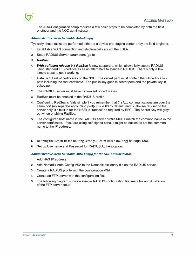
ACCESS GATEWAY
System Administration 75
The Auto-Configuration setup requires a few basic steps to be completed by both the field engineer and the NOC administrator.
AdministrativeStepstoEnableAuto-Config
Typically, these tasks are performed either at a device pre-staging center or by the field engineer.
1. Establish a WAN connection and electronically accept the EULA. 2. Setup RADIUS Server parameters (go to 3. RadSec 4. With software release 9.1 RadSec is now supported, which allows fully secure RADIUS
using standard TLS certificates as an alternative to standard RADIUS. There’s only a few simple steps to get it working:
1. Install a full set of certificates on the NSE. The cacert.pem must contain the full certification path including the root certificate. The public key goes in server.pem and the private key in cakey.pem.
2. The RADIUS server must have its own set of certificates.
3. RadSec must be enabled in the RADIUS profile.
4. Configuring RadSec is fairly simple if you remember that (1) ALL communications are over the same port (no separate accounting port)- it is 2083 by default; and (2) the secret (set on the server only, it's built in for the NSE) is "radsec" as required by RFC. The Secret Key will gray-out when enabling RadSec.
5. The configured host name in the RADIUS server profile MUST match the common name in the server certificates. If you are using self-signed certs, it might be easiest to set the common name to the IP address.
5. DefiningtheRealm-BasedRoutingSettings{Realm-BasedRouting} on page 136).
6. Set up Username and Password for RADIUS Authentication.
AdministrativeStepstoEnableAuto-ConfigfortheNOCAdministrator:
1. Add NAS IP address. 2. Add Nomadix Auto-Config VSA to the Nomadix dictionary file on the RADIUS server. 3. Create a RADIUS profile with the configuration VSA. 4. Create an FTP server with the configuration files. 5. The following diagram shows a sample RADIUS configuration file, meta file and illustration
of the FTP server setup.

ACCESS GATEWAY
76 System Administration
The Nomadix device will automatically initiate one reboot to enable the new settings. Configuration updates for network maintenance can be accomplished by simply enabling the Auto-Configuration option and rebooting the device (for example, using SNMP). See also Defining Automatic Configuration Settings {Auto Configuration}.
SettingUpBandwidthManagement{BandwidthManagement}The Access Gateway allows system administrators to manage the bandwidth for subscribers, defined in Kbps (Kilobits per seconds) for both upstream and downstream data transmissions. With the ICC feature enabled, subscribers can increase or decrease their own bandwidth dynamically, and adjust the pricing plan for their service.
You can enable or disable bandwidth policies for bandwidth management and group bandwidth management policies. You can specify settings for each individual WAN. The NSE supports setting default maximum up and downstream bandwidths for subscribers who do not have a specified bandwidth.
1. From the Web Management Interface, click on Configuration, then Bandwidth Management. The Bandwidth Management screen appears:

ACCESS GATEWAY
System Administration 77
2. If required, click the check box for Bandwidth Management Enabled. 3. If required, select Group Bandwidth Policies. Bandwidth Management must be enabled
before you can enable and specify Group Bandwidth Policies.
Note: The Bandwidth Management page only globally Enables and Disables Bandwidth Management and Group Bandwidth Policies. Bandwidth settings themselves are set for each WAN interface in Ethernet Ports/WAN.
4. If desired, click the check box to enable Weighted Fair Queuing. See Weighted Fair Queueing on page 22.
5. With Weighted Fair Queuing enabled, you have the option to Share Unused Bandwidth. If checked, unused bandwidth, if available, is distributed among users in proportion to the users’ bandwidth caps. If unchecked, users are held to their bandwidth cap limits.
6. If required, specify Default Valid Subscriber Bandwidth; Up and/or Down. These options specify the default maximum up and down bandwidths for any subscribers that do not have a specified bandwidth setting. A value of ‘0’ means that no limit will be applied.
7. Click on the Save button to save your changes, or click the Restore button to reset all the values to their previous state.
GroupBandwidthLimitPolicyThe Group Bandwidth Limit Policy allows the you to assign a common bandwidth rate limiting policy to a group of subscriber devices. All devices within the group share the total bandwidth allocated to the policy.
The Group Bandwidth Limit Policy feature defines the following vendor-specific attributes (VSAs):
Nomadix VSA #
Name Role/Value
19 GROUP_BW_POLICY_ID Defines the ID the for the group policy. Integer between 1 and 16777215, inclusive.
20 GROUP_BW_MAX_UP Defines the total upstream bandwidth allowed for the group in Kilobits per second. Integer value. 0 is interpreted as unlimited.
21 GROUP_BW_MAX_DOWN Defines the total downstream bandwidth allowed for the group in Kilobits per second. Integer value. 0 is interpreted as unlimited.

ACCESS GATEWAY
78 System Administration
GroupBandwidthLimitPolicy–OperationThe NSE maintains a collection of all installed group bandwidth policies. The collection is indexed by the bandwidth policy ID provided by the RADIUS server. The collection can store as many policy records as the number of licensed subscriber devices. All subscriber devices sharing the same group bandwidth policy ID belong to the same group. A subscriber device can participate in only one bandwidth-limiting group at a time.
When a login is performed to an account that returns a bandwidth policy ID that does not yet exist in the NSE, a new policy record is created and inserted into the aforementioned collection. The subscriber authorized by the Access-Accept is associated with the newly installed bandwidth policy ID, and the bandwidth limits returned are invoked.
When the Access-Accept for a subscriber contains a bandwidth policy ID already present on NSE, the subscriber is associated with the existing group policy. All subscribers that are now members of the group share the total bandwidth allocated to the policy.
If at some point a login is performed to an account that returns the policy ID for an existing policy, but also returns bandwidth values different than those currently allocated for that policy, the policy will be updated with the new values found in the Access-Accept. Thus, the latest Access-Accept determines the current rates for the entire group.
The lifetime of a group policy record in the collection is determined by the session time of the authorized (i.e. VALID) subscribers participating in the group. Group policy records are removed from the collection when the last subscriber device belonging to the group is logged out of the NSE regardless of the reason (e.g. session timeout, idle timeout, deletion of the subscriber by an administrator, etc.).
The NSE does not support the ability to enforce both per-subscriber and group bandwidth rates simultaneously for the same subscribers. The RADIUS server must specify either per- subscriber or group bandwidth attributes. However, in case a RADIUS Access-Accept contains both individual and group bandwidth attributes, the NSE will use the group attributes and ignore the per-subscriber attributes.
The NSE can concurrently support some subscribers as part of a group and some others with limits set on a per-subscriber basis. However, a single subscriber cannot be assigned group membership and individual limits at the same time.
GroupBandwidthLimitPolicy–CurrentTableWhen the feature is enabled, a group bandwidth policy ID column is displayed in the Current Subscribers table (Subscriber Administration > Current). Once policies are instantiated, policy information can also be viewed via XML.

ACCESS GATEWAY
System Administration 79
EstablishingBillingRecords“Mirroring”{BillRecordMirroring}The Access Gateway can send copies of PayPal transactions and PMS billing records to external servers that have been previously defined by system administrators. The Access Gateway assumes control of billing transmissions and saving billing records. By “mirroring” the billing data, the Access Gateway can also send copies of billing records to predefined “carbon copy” servers. Additionally, if the primary and secondary servers are down, the Access Gateway can store up to 2,000 credit card transaction records. When a connection is re- established (with either server), the Access Gateway sends the stored information to the server—no records are lost!
For more information about the bill record mirroring feature, go to Mirroring Billing Records on page 261.
1. From the Web Management Interface, click on Configuration, then Bill Record Mirroring. The Credit Card Mirroring Settings screen appears:
2. If you want to enable the billing records “mirroring” functionality for credit card
transactions, click on the check box for Enable Bill Record Mirroring. 3. Enter the property identification code in the Property ID field. 4. Enter the communication parameters for the primary server that is to be used for
mirroring, including: • Primary IP
• URL • Secret Key

ACCESS GATEWAY
80 System Administration
The Access Gateway and the “mirror” servers must use the same secret key.
5. Repeat Step 4 for the secondary server (if any) and all carbon copy servers. 6. Define the “fail-safe” provisions, including:
l Retransmit Method – Alternate, or do not alternate.
l Number of Retransmit Attempts – This tells the system how many times it should attempt to retransmit billing records before suspending the task.
l Retransmit Delay – This specifies the time delay between each retransmission. 7. Click on the Save button to save your changes, or click on the Restore button if you want to
reset all the values to their previous state.
Class-BasedQueueingNomadix Class-Based Queueing provides a flexible way to control the bandwidth provided to individual groups of users (classes). Classes have both maximum and minimum bandwidth specifications.
You can add users to classes and apply attributes across entire classes. Each class has 3 configurable attributes:
l Priority l Minimum Bandwidth l Maximum Bandwidth
For additional details, see Class-Based Queueing on page 8.
ToEnableandConfigureClass-BasedQueueing
1. Click Configuration > Class Based Queueing. The Class Based Queueing screen appears.

ACCESS GATEWAY
System Administration 81
2. Click Enable and then Save to enable Class-Based Queueing. 3. Click Add Class to add a class. Class names are case-sensitive. “Dot” notation (e.g.,
<top-level class>.<subclass>) is used to associate top-level classes and subclasses.
• Subscribers can only be assigned to sub-classes.
• Sub-classes cannot access bandwidth greater than their assigned WAN link.
• Top-level classes can be assigned a priority of 1 through 8. Sub-classes can be assigned a priority of 1, 2, or 3. One is the highest priority.
• Minimum bandwidths are respected regardless of priority. Minimums/maximum bandwidth is applied across all users in a class.
4. Click on a class name to change the class name or modify the attributes of a class.

ACCESS GATEWAY
82 System Administration
When selecting Share Unused Bandwidth. If checked, unused bandwidth, if available, is distributed among users in proportion to the users within the class. If unchecked, users are held to their bandwidth cap limits.
5. Click Throughput Estimator to evaluate traffic scenarios. Given different loads per class, the interface provides the estimated effective throughput. You can use this tool to preview how bandwidth will be assigned based on Class-Based Queueing structure and priority settings.
AssigningUserstoaClass
There are four ways to assign users to a particular class:
l Radius
l XML
l Subscriber Administration menu

ACCESS GATEWAY
System Administration 83
l Subscriber Interface menu
AssigningaUsertoClass-BasedQueueingUsingRadius
Subscribers can be assigned to a specific class/sub-class using Radius VSA. Subscribers with no class membership are assigned a priority of 8. ATTRIBUTE Nomadix-Bw-Class-Name 27 string
For example, when a subscriber logs in and this attribute is defined as follows, the subscriber gets assigned to the class priority1.Subclass.
Nomadix-Bw-Class-Name = "priority1.Sub-class"
AssigningausertoaclassusingXML
The CLASS_NAME element has been added to the USER_ADD and USER_PAYMENT XML commands. These are covered in the 8.4 XML DTD documentation, available from www.nomadix.com/support.
AssigningaUsertoaClassusingtheSubscriberAdministrationmenu
The procedures for Adding Subscriber Profiles (Subscriber Administration > Add) support adding a subscriber, device, or group account profile to a class. See Access Codes
This procedure illustrates how to create, edit and print/reprint Access Codes
1. Warning - before getting started it is important to allow pop-up for printing, if you plan on
printing Access Codes

ACCESS GATEWAY
84 System Administration
2. Create an Access Code Plan by a clicking on the Launch Plan Icon.
3. Enter the Fundamentals, Format and Session Parameters for the Access Codes
Access Codes Fundamentals
ü Enter the “Plan Name” (example The Oscars)
ü Enter the “Maximum Device” for the Access Code Plan (example 100)
ü DHCP type “Private” or “Public” (example Private)
ü DHCP Subnet
ü Configure the “Bandwidth Upstream” (example 1Mb)
ü Configure the “Bandwidth Downstream” (example 20Mb)
ü Select BW Class (example none)
ü Select “QoS Policy” (example none) Access Codes Format
ü Enter a Prefix (example 2019)
ü Pick a format (example nnnn-nn mixed digits and letters)
ü Enter as Suffix (example WOW) Access Codes Session Parameters
ü Configure the Session time: weeks , days, hours and minutes (example 3d, 0hr, and 0m)
ü Enter the Activate time/ Valid until date (example 2019-05-01 @ 06:00am)
Add the Plan
ü Depress the +Add
4. Simple and easy to create, edit, print or delete Access Code Plans.

ACCESS GATEWAY
System Administration 85
5. Printing Access Codes in a Batch of 1 to 100. Access Codes are added to Subscriber Administration >> List Profiles and are ready for use.
The following is an example of the Access Code just created ready for print!
Adding Subscriber Profiles {Add} on page 171.
AssigningaUsertoaClassUsingBillPlans(SubscriberInterfacemenu)
You can add a user to a class while setting up a billing plan. See Setting Up a “Normal” Billing Plan on page 186.
Clustering{Clustering}NSE Clustering provides the ability to cluster multiple gateways on one network segment. For more information about this feature, including description, limitations, and troubleshooting information, see

ACCESS GATEWAY
86 System Administration
Multiple Unit Clustering on page 25. Note for increased resilience R9.2 introduced the High-Availability Clustering Module, described further in this document.
To enable NSE Clustering:
1. Click Configuration > Clustering and click Enable.
2. Enter integers for the Total number of gateways and the Gateway number (must be from 2 to 256 with no gaps). For example, if clustering is being configured on three gateways, one gateway must be 1, one gateway must be 2 and one gateway must be 3.
Be aware of the following:
l All gateways in a cluster must have the same configuration l WAN and INAT IP addresses must not clash among clustered gateways l All gateways must have the same number of licensed subscribers
l No restrictions are placed on shared secrets, administrator credentials, RADIUS NAS identifier and NAS port.
ConfiguringDestinationHTTPRedirection{DestinationHTTPRedirection}Destination HTTP Redirect provides DNS-triggered redirection of HTTP requests to one or more portal page URLs configured on the NSE. Portal pages could include account status, maps, local information, etc.
The NSE will intercept and respond to DNS queries containing configurable strings. Subscribers requesting a website at that DNS will obtain a DNS response that contains a “magic” IP address (which is the same value obtained when the subscriber queries the DNS string “logout.nomadix.com”).
The NSE will process HTTP requests for that “magic” IP address (configurable on the AAA page), and will reply with an HTTP redirection (which may include a number of signed redirection parameters) to a configured URL. By following the HTTP redirection, the subscriber will reach the target URL, and he/she will then be served a page containing whatever information is relevant (account and/or other specific information).

ACCESS GATEWAY
System Administration 87
The figure above illustrates destination HTTP redirection, assuming a DNS query string for www.example.com, a magic IP address of 1.1.1.1, and a portal page URL of portal1.myhotel.com. Given this configuration, the following would apply:
• A DNS query for www.example.com is intercepted by the NSE, which responds with the magic IP address. Then, the subscriber’s browser sends an HTTP request to the magic IP and sets the Host header to www.example.com.
• The NSE will process the HTTP request and will analyze the Host header to find the redirection URL that corresponds to www.example.com, which is portal1.myhotel.com in this example. The NSE will then craft an HTTP redirection response that contains the portal page URL, followed by a query string. The string will include various redirection parameters, time-stamped and signed, if signing is enabled for that entry (which it is not in this example).
• The subscriber will follow the redirection string and will land on the portal page URL. The portal will verify and analyze the query string and then will return the relevant information (likely about the subscriber’s account status, depending on what the portal is configured to handle).
• After successful redirection occurs the list of signed parameters and signature methods are passed to the portal page. HTTP/1.0 302 RD http://portal1.myhotel.com/details?OS=<Original Server>&UI=<NSE’s ID>&MA=<subscriber’s MAC>&RN=<Room name>&PORT=<VLAN>&SIP=<subscriber’s IP>&TS=<timestamp>&NONCE=<16 chars>&SIGN=<signature>& SIGNED=<list of signed parameters>& METHOD=<signature method>
1. From the Web Management Interface, click on Configuration, then Destination HTTP Redirection. The Destination HTTP Redirection Settings screen appears:

ACCESS GATEWAY
88 System Administration
2. To enable Destination HTTP Redirection, click on the Enabled check box. The default
setting is disabled. You may create up to 20 portal pages.
3. In the Portal Pages section, enter the matching string that will be directed to the portal page in the Matching String field.
4. Enter the portal page’s URL in the URL field.
5. To enable parameter passing, click on the Parameter Passing Enable check box.
6. Select the Parameter Signing:
• Method: None, HASH-CRC32, or HMAC-MD5 (select one method). • Parameters: UI, MA, RN, and PORT (select all applicable parameters).
7. To enable Set Shared Secret, click on the Set Shared Secret check box. If you enable this feature, enter the shared secret text string in the Set Shared Secret field.
8. Click on the Save button to save the redirection settings, or click on the Restore button if you want to reset all the values to their previous state.
9. Portal page setting are saved to the table in Existing Portal Page entries section of the screen. From that table, you can edit or delete existing portal pages.
ManagingtheDHCPserviceoptions{DHCP}When a device connects to the network, the DHCP server assigns it a “dynamic” IP address for the duration of the session. Most users have DHCP capability on their computer. To enable this service on the Access Gateway, you can either enable the DHCP relay (routed to an external DHCP server IP address), or you can enable the Access Gateway to act as its own DHCP server. In both cases, DHCP functionality is necessary if you want to automatically assign IP addresses to subscribers.

ACCESS GATEWAY
System Administration 89
1. From the Web Management Interface, click on Configuration, then DHCP. The DHCP Settings screen appears:
Nomadix’ patented Dynamic Address Translation (DAT) functionality is automatically configured to facilitate “plug-and-play” access to subscribers who are misconfigured with static (permanent) IP addresses, or subscribers that do not have DHCP capability on their computers. DAT allows all users to obtain network access, regardless of their computer’s network settings.
2. DHCP Services is enabled by default. Do not disable it unless you want to lose all your DHCP services.
By default, the Access Gateway is configured to act as its own DHCP server and the relay feature is disabled. If you want the Access Gateway to act as its own DHCP server, do not enable the relay. Go directly to Step 8.
3. To route DHCP through an external server, enable the DHCP Relay.
4. If you enabled the DHCP Relay feature, you must assign a valid DHCP Server IP address (the default is 0.0.0.0) and a valid DHCP Relay Agent IP address. The DHCP Relay Agent allows the Access Gateway to request a specific range of IP addresses from different IP pools from the DHCP Server. Leaving these fields blank forces the system to use the IP pool that contains IP addresses that are on the same subnet as the Access Gateway.
You must disable the DHCP server before enabling the DHCP relay. Both features cannot be enabled concurrently.
If the DHCP Relay Agent IP address is set for an address that is already used or the IP address of the server, the other system will get an IP conflict and will not have Internet access.

ACCESS GATEWAY
90 System Administration
5. If desired, enable Relay Agent Information (option 82). The DHCP Relay Agent Information Option (option 82) allows the NSE to add information to a relayed DHCP request. This information identifies the origin of the request. You can set a Site prefix of up to 64 characters. The information also includes:
• Originating NSE physical subscriber port
• VLAN ID of the subscriber
• Nomadix IANA ID
• Port-specific description (view/set in the Port-Location Table).
You can view the Relay Agent Information, or change the Site prefix, by clicking the show/hide toggle button on the screen.
6. If you want the Access Gateway to act as its own DHCP Server (you did not enable the DHCP
Relay), enable it now.
7. If required, you can make the DHCP Server feature Subnet-based by checking the appropriate box.
8. If required, enable the IP Upsell feature. System administrators can set two different DHCP pools for the same physical LAN. When DHCP subscribers select a service plan with a public pool address, the Access Gateway associates their MAC address with their public IP address for the duration of the service level agreement. The opposite is true if they select a plan with a private pool address. This feature enables a competitive solution and is an instant revenue generator for ISPs. The IP Upsell functionality solves a number of connectivity problems, especially with regard to certain video conferencing and online gaming applications. The NSE provides additional flexibility for configuring upsell scenarios. Users can be assigned WAN’s of different bandwidth capabilities; for example, for hotel guests of stature or for premium payment.
9. If you want to add a new DHCP Pool, click on the Add button. The DHCP Settings screen displays fields for the new pool:

ACCESS GATEWAY
System Administration 91
10. Enter a valid DHCP Server IP address for the DHCP server.
11. Enter the DHCP Server Netmask. 12. Enter the starting and ending IP addresses for the DHCP address pool you want to use:
• DHCP Pool Start IP
• DHCP Pool Stop IP
13. Enter the DHCP Lease Minutes.
14. Select Public Pool or Private Pool, as required.
A “public” IP address will not be translated by DAT.
15. If required, make this an IP Upsell Pool and/or the Default Pool by checking the appropriate boxes.
Do not allow pools to overlap.
16. Optional, if the gateway router for the DHCP Pool is other than that of the DHCP Server IP, select Specify and enter the IP address of the gateway router of choice.
17. When finished establishing your DHCP Pools, click on the Back to Main DHCP Configuration Page to return to the previous page.
The existing lease pool and lease table are deleted and the Access Gateway reboots. The Access Gateway can issue IP addresses to any DHCP enabled subscriber who enters the network.
ManagingtheDNSOptions{DNS}DNS allows subscribers to enter meaningful URLs into their browsers (instead of complicated numeric IP addresses) by automatically converting the URLs into the correct IP addresses. You can assign a primary, secondary, or tertiary (third) DNS server. The Access Gateway utilizes whichever server is currently available.
Use the following procedure to set the DNS configuration options.
1. From the Web Management Interface, click on Configuration > DNS. The Domain Name System (DNS) Settings screen appears:

ACCESS GATEWAY
92 System Administration
2. Enter the Host Name (the DNS name of the Access Gateway).
The host name must not contain any spaces.
3. Enter a DNS Redirection Port and a Proxy DNS Port. 4. Click on the Save button to save your changes, or click on the Restore button if you want to
reset all the values to their previous state.
EnablingDNSSECSupportDNSSEC support adds authentication and integrity capability to DNS systems. The DNSSEC feature in the NSE allows DNSSEC queries and responses to traverse the NSE between subscribers and the NSE’s configured DNS servers. The NSE itself does not participate in DNSSEC trust relationships with subscribers.
Use the following procedure to set the DNS configuration options.
1. From the Web Management Interface, click on Configuration>DNS. The Domain Name System (DNS) Settings screen appears:
2. Check the Enable check box to enable DNSSEC Support functionality. The default setting is disabled.
3. Click on the Save button to save your changes (reboot is not required), or click the Restore button if you want to reset all the values to their previous state.
ManagingtheDynamicDNSOptions{DynamicDNS}Use the following procedure to set the Dynamic DNS options.
1. From the Web Management Interface, click Configuration, then Dynamic DNS. The Dynamic DNS Configuration screen appears:

ACCESS GATEWAY
System Administration 93
2. Check the Enable checkbox to enable Dynamic DNS (DDNS) functionality. The default setting is
disabled.
3. Enter the Provider Info: • Select the provider protocol from the Protocol menu. Currently, only dyndns.org and
dyndns.org (secure) are supported. The default setting is dyndns.org (secure).
• In the Server field, enter the server name to which the client sends updates to the DDNS server.
• Select the port number for the server from the Port menu.
4. Enter the Account Information: a. Enter the host name, which is the DDNS name that is mapped to the client IP
address, in the Hostname field. DDNS mapping is configured on the DynDNS.org account.
b. Enter the user name for the DDNS server account in the Username field. c. Enter the password name for the DDNS server account in the Password field.
5. In the Force Update field, click Save and Force Update to force an immediate update to the DDNS. Note that too many updates may be considered abuse by the DDNS vendor. Alternatively, click Save to save the settings or Restore to clear the changes and return the settings to the previous state.
EthernetPorts/WANThe NSE supports multiple, separately configurable WAN interfaces. You may assign each interface as a WAN, Subscriber Interface, assign it to an AGGregate port, or specify that it remain out of service. Each interface has its own IP, DNS, Bandwidth, VLAN, and NAT IP addresses, and can obtain its IP address by DHCP, PPPoE, or Static configuration.
The number of configurable WANs will vary with the Access Gateway hardware. See Error! Reference source not found. for these details.

ACCESS GATEWAY
94 System Administration
The NSE can now support up to five (AG5900 and EG 6000) WAN interfaces at once, using completely independent network settings for each. (The AG5900 with optional Fiber Module could have 7 and the EG 6000 could have 9 with the on-board fiber ports and the optional Fiber Module)
l Each WAN port has independent Mode, IP, DNS, iNAT, Monitoring, Additional NAT addresses, 802.1Q or 802.1ad tagging, and bandwidth settings.
l Roles for most ports (those marked either EthX or AuxX) are unrestricted; that is, each port can be set to
l WAN (Network Side Link) l SUB (Subscriber), l AGG (Link Aggregation) or l OOS (Out Of Service).
l Each configured and active WAN port can be used for NSE Management activity, and the WMI is available on that address.
l Multiple WAN interfaces may be configured and used for management activity (but not subscriber traffic), even without the Load Balancing license feature (or with the feature disabled).
l Out of the box, the NSE will boot with one WAN port and one LAN port enabled, and the remaining ports set to out-of-service.
l The AG 5900 and EG 6000 supports an optional plug-in module that provides two SFP+ 10 Gigabit fiber interface slots.
To view and configure WAN interfaces, select Configuration > Ethernet Ports/WAN. The Current Interfaces Settings screen appears, which summarizes all WAN connections.

ACCESS GATEWAY
System Administration 95
Click any individual interface name to view and set details of the individual WAN.
IPv6DeviceSetupThe NSE supports external access to subscriber-side IPv6 devices. This works on standard ports, fiber ports, and even Link Aggregation Groups. Basic functionality is equivalent to IPv4 static port mapping except as follows:
• The feature is provided by routing, not NAT. External computers will access the device’s IPv6 address directly.
• Access is given ONLY to the IPv6 addresses that have been entered in the Access Control List.
• Devices must be statically configured to an address in a specific IPv6 subnet.
Use the following steps to set up IPv6 device support:

ACCESS GATEWAY
96 System Administration
1. Enable IPv6 on the involved ports.
2. Set up prefix delegation on the WAN port.
3. Determine the delegated prefix and interface address for the subscriber port you will use.
(Network Info/Interfaces)
4. Based on that information, configure the device’s IPv6 settings.
Delegated prefixes are assigned in sequence starting at 0 for Eth0. TEI1 is port 8, the

ACCESS GATEWAY
System Administration 97
delegation is :80 /60, so if TEI1 is Sub it will get :87. Our subscriber could therefore be configured like this:
a. IPv6 Addr: 2001:428:4C05:87:2121:2222:2323:2424
b. Prefix Length: 64
c. Gateway: 2001:428:4c05:87::1 (the subscriber port address). This may need to be configured as a default route (ipv6 route ::/0 2001:428:4c05:87::1)
d. DNS: 2001:4860:4860::8888 (The exact address does not matter since the WAN port’s DNS setting will be used.)
5. Enable the feature under access control and set up allowed external access addresses.
6. Set up any required routing on the host network.
a. Unlike IPv4, under IPv6 we act as a router between the subscriber and network sides. At the present time the NSE does not support routing protocols, so it’s up to the host network to route subscriber IPv6 traffic back to the NSE’s WAN port.
b. In our example we have delegated 2001:428:4C05:80:: /60 to the NSE’s subscriber sides, and the NSE will use whichever it needs of those 16 addresses for the subscriber ports.
c. The ROUTE only needs to tell the network router that all traffic for 2001:428:4C05:80:: /60 should be sent to our WAN port IPv6 address. Depending on the network you might need to add a similar IPv6 route to a host computer on the WAN network for the same purpose.
LinkAggregationLink Aggregation provides improved throughput and link redundancy and does not require load balancing to do it. Aggregation combines two or more physical links into a single virtual link. However, since “conversations” must be transmitted on the same physical link, all the traffic from a subscriber will travel on the same link. Loss/restoration of a physical link is detected and traffic is rerouted.
• Two Link Aggregation Groups (LAGs) are available, and can be used for WAN or Sub connections as desired. Nomadix LAGs support LACP (Link Aggregation Control Protocol),

ACCESS GATEWAY
98 System Administration
so when configuring the connecting switch you would choose “active” mode. LAGs are listed in the Ethernet Ports / WAN listing like any other port.
• Individual ports are set to AGG (Aggregated) mode and assigned to one of the two LAGs.
• The LAG is then set to either WAN or SUB (or OOS).
• Once the LAG is populated all configuration is done to the LAG, not the individual ports. The LAGs look and behave and are configured exactly like individual WAN and Sub ports.
Use the following steps to set up a LAG:
1. Set the desired port to AGG mode.
2. Assign the aggregated port to a particular LAG.
A running and connected LAG port will show the ports aggregated to that LAG and their status:

ACCESS GATEWAY
System Administration 99

ACCESS GATEWAY
100 System Administration
EnablingFastForwardingNSE version 8.8 provides a Fast Forwarding mode. This mode enhances overall system throughput, and provides as much as double previously-achievable bandwidth.
To enable Fast Forwarding mode, choose Configuration > Fast Forwarding. Check Enabled.
If you enable Fast Forwarding, some counting statistics (e.g., bytes sent / received) are updated somewhat less frequently than when the feature is disabled. Normally such counts should update approximately every 5 seconds, but at high throughput levels, this can make the difference between successive values larger.
On higher-end NSE platforms, the maximum rate the system can achieve may be limited by the line rate of the interfaces used. In order to benefit from the Fast Forwarding feature on these platforms, you must use fiber interfaces or multiple 1G standard ethernet (both on the network and subscriber sides).
Fast Forwarding is enabled by default for all new systems. Fast Forwarding, if enabled, does not affect the following types of sessions:
• General Proxy Sessions
• Sessions that require an Application Level Gateway (ALG); e.g. FTP
• All sessions over WAN interfaces configured for PPPoE or GRE
• Subscriber IPSEC traffic NOT using NAT Traversal (i.e. usingiNAT)
• All traffic over IPSEC tunnels for which the NSE is an end point of the tunnel
SettingtheHighAvailabilityClusteringOptions{HighAvailabilityClustering}
Your product license may not support this feature.
This procedure shows you how to configure the High Availability Clustering feature to handle multiple Nomadix Gateway nodes in a single Cluster. Each Node will need to be configured and setup for the cluster.
Reminder: for this feature to operate, the network infrastructure needs to meet the prerequisites and the High Availability Clustering Module license needs to have been purchased.

ACCESS GATEWAY
System Administration 101
1. From the Web Management Interface, click on Configuration, then High Availability Clustering. The High Availability Clustering Settings screen appears:
2. Click on the check box for High Availability Clustering
3. Enter the ID of the Cluster that this Gateway will be a part of. If there is only one cluster on the network leave the default configuration
4. Enter the communication port desired for the Cluster nodes to communicate on. The default configured port will work unless there is network equipment that might block that communication.
5. Click on the Save button to save your configurations
6. Click on the Ethernet Ports/WAN Configuration page then on the Subscriber (LAN) port that is connected to the Switch fabric server the Guest network.
7. Change the port Role to AGG and select an Aggregator port to utilize for the Subscriber network connection.
8. Click on the Save button to save your changes, or click on the Cancel button if you want to
exit the configuration page without saving.
9. From the Ethernet Ports/WAN configuration page select the LAGG port that was configured for the Subscriber interface and set it to CLS

ACCESS GATEWAY
102 System Administration
10. Click on the Save button to save your changes, or click on the Cancel button if you want to
exit the configuration page without saving.
11. Configure the Switch to support LACP using the interfaces connected to the Nomadix Gateway Cluster nodes as aggregate ports.
Optionally you can configure the Subscriber Current table on any Node to display all the Devices on the Cluster. To do this follow these steps:
1. From the Web Management Interface, click on Subscriber Administration, then Current. The Current Subscriber Table screen appears:
2. Click on the checkbox next to Show cluster subscribers
3. Click on the Save button to save your changes, or click on the Restore button if you want to reset all the values to their previous state.

ACCESS GATEWAY
System Administration 103
SettingtheHomePageRedirectionOptions{HomePageRedirect}This procedure shows you how to redirect the subscriber’s browser to a specified home page. Subscribers may also be redirected to a page specified by the solution provider, without any interaction with the authentication process.
You must configure DNS if you want to enter meaningful URLs instead of numeric IP addresses into any of the Access Gateway’s configuration screens.
1. From the Web Management Interface, click on Configuration, then Home Page Redirect. The Home Page Redirection Settings screen appears:
2. Click on the check box for Home Page Redirection to enable this feature. If you enable home
page redirection, you must provide a URL for the redirected home page.
3. Enter the URL of the redirected home page in the Home Page URL field.
4. If required, click on the check box for Parameter Passing. Parameter passing allows the Access Gateway to track a subscriber’s initial Web request (usually their home page) and pass the information on to the solution provider. The solution provider uses this information to ensure that the subscriber can return to their home page easily.
5. In the Redirection Frequency field, specify the frequency (in minutes) for home page redirection. This is the interval at which the subscriber is redirected to the solution provider’s home page automatically.
6. Click on the Save button to save your changes, or click on the Restore button if you want to reset all the values to their previous state.
EnablingIntelligentAddressTranslation(iNAT™)The Nomadix patented iNAT™ feature contains an advanced, real-time translation engine that analyzes all data packets being communicated between the private and public address domains. The Nomadix iNAT™ engine performs a defined mode of network address translation based on packet type and protocol (for example, IKE etc.).
NSE provides the following iNAT enhancements:
l A separate iNAT interface page shows the settings for each port in either WAN or OOS modes. Ports in SUB mode are not shown.
l Each of the displayed ports has individual iNAT / Subscriber tunnel settings accessible by clicking on that port’s link.
l The interface allows easy deletion of any iNAT address range. iNAT settings are configured individually for each interface.
1. From the Web Management Interface, click on Configuration, then iNAT. A list of current iNAT settings appears. You can select a specific interface to change its iNAT configuration.

ACCESS GATEWAY
104 System Administration
The iNAT™ screen appears:
2. Enable or disable the iNAT feature, as required.
3. If you enabled iNAT, you have the option of enabling or disabling the following VPN protocols:
• PPTP
• PPTP CALL ID
• IPSEC
4. Click on the Save button to save your options. Use the iNAT Start and iNAT End fields to enter an IP address or range of IP addresses (up to 50), then click on the Add button to add the IP address(es), or click on the Remove button to delete the IP address(es) from the database.

ACCESS GATEWAY
System Administration 105
InterfaceMonitoringAs a complementary feature to Load Balancing, you can actively monitor each WAN connection to assure that full network functionality exists.
Interface Monitoring must be enabled; it is off by default. It is set separately for each configured WAN interface.
Three failures must occur before the system sets the port status to Unavailable and re-assigns subscribers.
Monitoring may be configured for both the Monitoring Interval (default is 60 seconds) and for three different methods as required by the network:
l The default method (Automatic) will generate a random DNS query to each configured DNS server. Receiving an ?Error? back from the server(s) verifies full network connectivity.
l Host Probing (Ping) — A Host or IP address can be pinged to verify connectivity via ICMP response.
l Host Probing (HTTP) will generate an HTTP GET to the configured Web address. The HTTP response will verify network connectivity.
To view configured WAN interfaces, select Configuration > Interface Monitoring in the Web Management Interface. The Interface Monitoring Settings screen appears:
Click on any interface name to configure individual interface settings:

ACCESS GATEWAY
106 System Administration
DefiningIPSecTunnelSettings{IPSec}1. From the Web Management Interface, click on Configuration, then IPSec. The IPSec Tunnel
Settings screen appears:
2. Check the Enable IPsec checkbox to enable IP Security.
3. Check Enable NAT Traversal to allow packets to traverse NAT/IPsec boundaries.
4. Click Save to save the setting. To add or modify IPsec tunnel peers, see Managing IPSec Tunnel Peers on page 106. To add or modify IPsec security policies, see Managing IPSec Security Policies on page 108.
ManagingIPSecTunnelPeersYou can add a new IPSec tunnel peer or modify the settings of an existing IPSec tunnel peer from the IPSec Tunnel Settings screen.
AddinganewIPSectunnelpeer
1. Click the Add button in the IPSec Tunnel Peers table. The IPSec Tunnel Peer Settings screen opens.

ACCESS GATEWAY
System Administration 107
2. Enter the IP address of the peer in the Tunnel Peer field. 3. Enter a Dead Peer Detection interval (integer value in seconds). 4. Select the Internet Key Exchange (IKE) Protocol Version. 5. In the Peer Authentication Method section, select one of the two peer authentication
methods: l Authenticate via pre-shared key – Enter the pre-shared key in the Shared Key field. l Authenticate via X.509 Certificate –
l Enter the filename of the private certificate in the Private Key Filename field. l Enter the filename of the public certificate in the Certificate Filename field. Note
that the files must exist on flash first. 6. In the IKE Channel Security Parameters section, select the following settings:
l Acceptable Encryption Algorithms – Check the DES, 3DES, and/or AES128CBC checkboxes (you must check at least one option).
l Acceptable Hash Algorithm – Check the MD5, SHA, and/or AES128 checkboxes (you must check at least one option).
l Key Strength – The options are 768-bit, 1024-bit, 1536-bit, and 2048-bit. The default setting is 768-bit.
l Lifetime – Enter the maximum key lifetime (in seconds). The default setting is 28800. 7. Click Add to add the IPSec tunnel peer to the IPSec Tunnel Peers table on the IPSec
Tunnel Settings screen.
8. Click the Back to Main IPSec Tunneling Settings page link to return to the IPSec Tunnel Settings screen.
ModifyinganExistingIPSecTunnelPeer
1. Click on the IPSec tunnel peer link that you wish to modify in the IPSec Tunnel Peers

ACCESS GATEWAY
108 System Administration
table. The IPSec Tunnel Peer Settings screen opens.
2. Modify the settings as desired. 3. Click:
l Modify to save the changes to the peer. l Remove to remove the peer from the IPSec Tunnel Peers table.
l Restore to undo any changes you made to the peer settings and return the peer to its original settings.
4. Click the Back to Main IPSec Tunneling Settings page link to return to the IPSec Tunnel Settings screen.
ManagingIPSecSecurityPoliciesYou can add a new IPSec security policy or modify the settings of an existing IPSec security policy from the IPSec Tunnel Settings screen.
AddingaNewIPSecSecurityPolicy
1. In the IPSec Security Policies table, click the Add button to add an entry. The IPsec Tunnel Security Policy Settings screen opens.
2. Select the tunnel peer IP address for which you would like to add a security policy from the
Tunnel peer IP address menu. You must select a peer if the policy is using ESP or AH; if the

ACCESS GATEWAY
System Administration 109
policy is a Discard or Bypass policy, select none. 3. In the Traffic Selectors section, define a specific protocol by one of the following
methods: • Select a specific protocol from the Protocol menu.
• Enter a specific protocol number in the Protocol field. Protocol numbers are available at www.iana.org/assignments/protocol-numbers.
Next you will define selectors of the Security Policy. All selectors must match for the policy to be applied.
4. Define the following selectors for the Remote End: l Remote IP/Subnet – Enter the IP address of the remote network secured by the IPSec
tunnel. The address can specify a host. l Subnet Mask – Enter the subnet mask of the remote network secured by the IPSec
tunnel. l Remote UDP/TCP Port – Enter the port number; 0 is for all ports (only if protocol is UDP or
TCP).
5. Security Policy can derive the settings for the Local End from the current Network IP settings of the unit. Select one of the following network options for the Local End: l Use current Network Interface IP Address – Select this option if you would like to use the
current network interface IP Address. Note that the network IP address is dynamic if DHCP or PPPoE client is enabled. This setting is the default setting.
l Use this static IP address/subnet – If you select this option you must also enter the Local IP/Subnet, the Subnet Mask, and the IP address of network interface for this policy.
l The Local IP/Subnet is the IP address of the local network secured by the IPSec tunnel. The address can specify a host.
l The Subnet Mask is the subnet mask of the local network secured by the IPSec tunnel. The address can specify a host.
l The IP address of network interface for this policy is the IP Address for the NSE inside an IPSec tunnel. The IP address must be within the Local LAN subnet or the same as the Local LAN IP address. IP address 0.0.0.0 disables the functionality. The default setting is 0.0.0.0.
6. Enter the port number in the Local UDP/TCP Port field; 0 is for all ports (only if protocol is UDP or TCP).
7. In the Security Parameters section, define the parameters of the security policy. The options are Discard, Bypass, ESP, and AH. ESP is the default setting. l Discard l Bypass – Select the direction of the discard/bypass; the options are: In only, Out only,
or In and Out. Out only is the default setting. l ESP – Select all the acceptable encryption algorithms by putting a check in the
checkbox of each option; the options are: DES, 3DES, and NULL. 3DES is the default setting. See Setting joint ESP and AH parameters on page 109 to set parameters that pertain to both ESP and AH polices.
l AH – See Setting joint ESP and AH parameters on page 109 to set parameters that pertain to both ESP and AH policies.
SettingjointESPandAHparameters
These parameters affect both ESP and AH policies. 1. Select all the Acceptable authentication algorithms by putting a check in the checkbox
of each option; the options are: MD5, SHA, and NULL. The default settings are MD5 and

ACCESS GATEWAY
110 System Administration
SHA. 2. Select the Perfect Forward Secrecy Strength to enable PFS. PFS makes the keying
material used in protecting the data independent of the keying material used for protecting the IKE exchanges. The options are None, 768-bit, 1024-bit, 1536-bit, and 2048-bit. The default setting is None.
3. Enter the maximum lifetime (in seconds) in the Maximum Lifetime field. The default settings 28800.
4. Enter the maximum life size (in kbytes) in the Maximum Lifesize field. 5. Enable the automatic renewal option by putting a check in the Automatic renewal
checkbox. The default setting is enabled. 6. Click Add to add the policy to the IPSec Security Policy table on the IPSec Tunnel
Settings screen. 7. Click the Back to Main IPSec Tunneling Settings page link to return to the IPSec Tunnel
Settings screen.
ModifyinganExistingIPSecSecurityPolicy
1. Click on the IPSec security policy link that you wish to modify in the IPSec Security Policies table. The IPsec Tunnel Security Policy Settings screen opens.
2. Modify the settings as desired. 3. Click:
l Modify to save the changes to the policy. l Remove to remove the security policy from the IPSec Security Policies table. l Restore to undo any changes you made to the policy settings and return the policy to
its original settings. 4. Click the Back to Main IPSec Tunneling Settings page link to return to the IPSec Tunnel
Settings screen.
LoadBalancingLoad Balancing is an optional licensed feature. For an overview of Nomadix load balancing and common use cases, see

ACCESS GATEWAY
System Administration 111
Load Balancing and Link Failover on page 28.
The NSE can balance subscriber assignment between all active WAN interfaces when Load Balancing mode is enabled. Note that subscribers are balanced, not traffic.
As subscribers go valid, they are assigned to a WAN interface, taking account of both the Uplink bandwidth settings of the interfaces and the number of subscribers currently using each interface. Higher bandwidth settings will mean more subscribers will be assigned to that interface. The subscriber will use the assigned interface for all traffic.
If a WAN interface goes down, the subscribers currently assigned to that interface will be reassigned to the remaining interfaces. Once that interface is restored, current subscribers will NOT be reassigned, but new subscribers can be assigned to that interface (in accordance with the load balancing algorithm).
An NSE reboot will rebalance all subscribers.
Subscribers will use the IP address of their WAN port (or assigned additional NAT address) for their DAT sessions.
To configure load balancing, choose Configuration>Load Balancing.
You can choose to trigger the Load Balancing / Failover feature either by the link status of the port(s) or by the active Interface Monitoring feature.
When either Interface Monitoring or link status is used, WAN ports will be characterized as either Available or Unavailable. If Load Balancing is configured to use Interface Monitoring but Monitoring itself is not configured, the status will be Unknown.
Using Link state will provide a faster response, but using Interface Monitoring will assure that there is internet access through that port before assigning subscribers to it.
Run Time Status gives a useful summary of all Load Balancing settings and subscriber distribution.
EstablishingYourLocation{Location}This command sets up your location. You must provide your full location information.
1. From the Web Management Interface, click on Configuration, then Location. The

ACCESS GATEWAY
112 System Administration
Location Settings screen appears:
2. Enter your location information in the following fields:
l Company Name
l Site Name
l Address (Line 1 and Line 2)
l City, State, Zip, and Country
l E-mail Address
l ISO Country Code
l Phone Country Code
l Calling Area Code
3. Select the area type that most resembles your location from the drop down list.
4. Enter a Network SSID/Zone.
5. Click Save to save your changes, or click Restore if you want to reset all the values to their previous state.
ManagingtheLogOptions{Logging}System logging creates log files and error messages generated at the system level. AAA logging creates activity log files for the AAA (Authorization, Authentication, and Accounting) functions. You can enable either of these options.
Although the AAA and billing logs can go to the same server, we recommend that they have their own unique server ID number assigned (between 0 and

ACCESS GATEWAY
System Administration 113
7). When managing multiple properties, the properties are identified in the log files by their IP addresses.
1. From the Web Management Interface, click on Configuration, then Logging. The Log Settings screen appears:
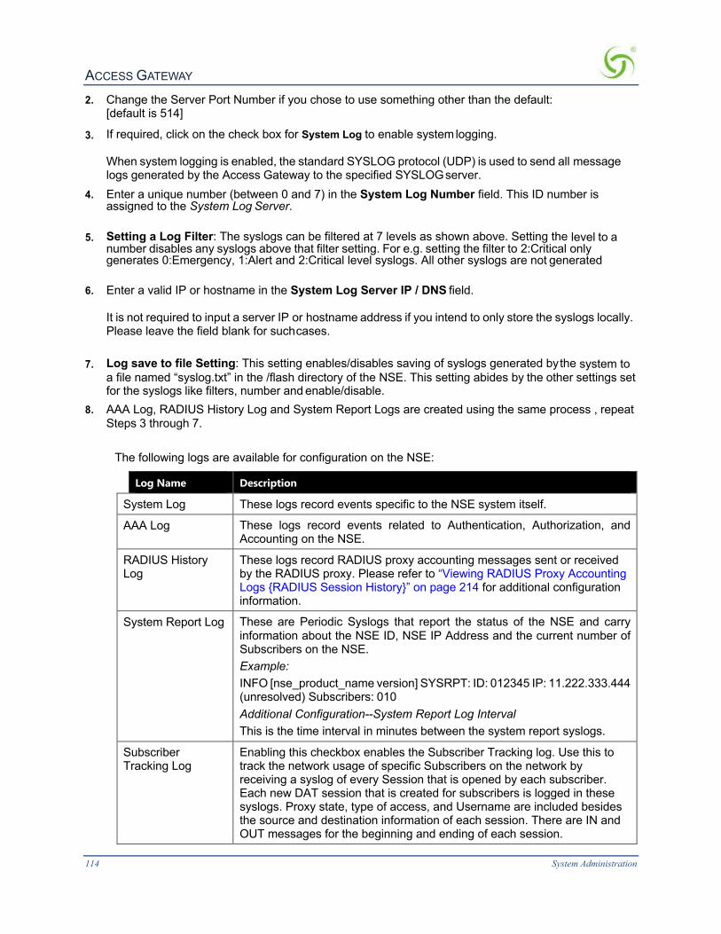
ACCESS GATEWAY
114 System Administration
2. Change the Server Port Number if you chose to use something other than the default: [default is 514]
3. If required, click on the check box for System Log to enable system logging. When system logging is enabled, the standard SYSLOG protocol (UDP) is used to send all message logs generated by the Access Gateway to the specified SYSLOG server.
4. Enter a unique number (between 0 and 7) in the System Log Number field. This ID number is assigned to the System Log Server.
5. Setting a Log Filter: The syslogs can be filtered at 7 levels as shown above. Setting the level to a number disables any syslogs above that filter setting. For e.g. setting the filter to 2:Critical only generates 0:Emergency, 1:Alert and 2:Critical level syslogs. All other syslogs are not generated
6. Enter a valid IP or hostname in the System Log Server IP / DNS field. It is not required to input a server IP or hostname address if you intend to only store the syslogs locally. Please leave the field blank for such cases.
7. Log save to file Setting: This setting enables/disables saving of syslogs generated by the system to a file named “syslog.txt” in the /flash directory of the NSE. This setting abides by the other settings set for the syslogs like filters, number and enable/disable.
8. AAA Log, RADIUS History Log and System Report Logs are created using the same process , repeat Steps 3 through 7.
The following logs are available for configuration on the NSE:
Log Name Description
System Log These logs record events specific to the NSE system itself.
AAA Log These logs record events related to Authentication, Authorization, and Accounting on the NSE.
RADIUS History Log
These logs record RADIUS proxy accounting messages sent or received by the RADIUS proxy. Please refer to “Viewing RADIUS Proxy Accounting Logs {RADIUS Session History}” on page 214 for additional configuration information.
System Report Log These are Periodic Syslogs that report the status of the NSE and carry information about the NSE ID, NSE IP Address and the current number of Subscribers on the NSE. Example: INFO [nse_product_name version] SYSRPT: ID: 012345 IP: 11.222.333.444 (unresolved) Subscribers: 010 Additional Configuration--System Report Log Interval This is the time interval in minutes between the system report syslogs.
Subscriber Tracking Log
Enabling this checkbox enables the Subscriber Tracking log. Use this to track the network usage of specific Subscribers on the network by receiving a syslog of every Session that is opened by each subscriber. Each new DAT session that is created for subscribers is logged in these syslogs. Proxy state, type of access, and Username are included besides the source and destination information of each session. There are IN and OUT messages for the beginning and ending of each session.

ACCESS GATEWAY
System Administration 115
Examples: INFO [Access Gateway v2.4.113] LI : IN-->: THU JUN 23 11:43:58 2007 | testlab | S(192.168.2.4/3444), D(66.163.175.128/80), X(67.130.149.4/5004), non-proxy , 00:90:27:78:81:00, RADIUS, IPASS/0U0000 INFO [Access Gateway v2.4.113] LI : OUT-->: THU JUN 23 11:44:01 2007 | testlab | S(192.168.2.4/3444), D(66.163.175.128/80), X(67.130.149.4/5004), non-proxy , 00:90:27:78:81:00, RADIUS, IPASS/0U0000 Field formats explained: LI : IN-->: Day Month Date Time Year | NSE_Site_Name | S(Source_IP/Port), D(Destination_IP/Port), X(NSE_Translated_IP/Port), proxy_type , Subscriber_MAC, Billing_Type, UserName(first 12 char). LI : IN-->: THU JUN 23 11:43:58 2007 | testlab | S(192.168.2.4/3444), D(66.163.175.128/80), (67.130.149.4/5004), non-proxy , 00:90:27:78:81:00, RADIUS, IPASS/0U0000
Do not configure the Server IP as the Network side IP of the gateway. Stored syslogs are viewable under System/Syslog menu. A total of 500 syslogs are stored locally.

ACCESS GATEWAY
116 System Administration
Page faults are stored in the file named “lograw.txt” in the /flash directory and is not viewable on the web management interface.
Enabling the Subscriber Tracking Log
1. Check the Subscriber Tracking Log option to enable or disable the Subscriber tracking log. Note: NTP must be enabled on the NSE for Subscriber tracking log to be enabled.
2. Enter the subscriber tracking log number in the Subscriber Tracking Log Number field. This is the syslog number to identify this syslog to your Server.
3. Enter the IP or hostname address of the Syslog server that is listening for the syslogs from your NSE in the Subscriber Tracking Log Server IP / DNS field.
4. Check the Subscriber Tracking Log save to file option to save the syslogs locally to the NSE flash. Note: Not Recommended to be used with guidance by authorized Nomadix Support.
5. Check the Include User Name Reporting option to include the first 25 characters of the username in the Syslog.
6. Check the Port Location: Include Port Reporting option and Port Location: Include Location option to include the port information from the port location table and the Port reported to the system by either VLAN or SNMP query. The Location information is limited to 25 characters.
7. Check Include every 500th Packet to follow the Danish law that requires the 500th packet for each subscriber to be logged. This will send the 500th packet for each subscriber to the syslog system.
8. Check Public subscriber tracking, Lawful interception of Subscriber information. 9. Click Save to save your changes, or click Restore if you want to reset all the values to their
previous state. When logging is enabled, log files and error messages are sent to these servers for future retrieval. To see sample reports, go to Sample SYSLOG Report on page 245 and Sample AAA Log on page 244.
EnablingMACAuthentication{MACAuthentication}1. From the Web Management Interface, click on Configuration, then MAC authentication. The
MAC Authentication Settings screen appears:
2. Check the MAC Authentication checkbox to enable the MAC-based authentication
functionality. The default setting is disabled.
3. Enter the retry frequency (in seconds) in the Retry Delay field. This setting is the wait time

ACCESS GATEWAY
System Administration 117
before reattempting MAC authentication following a failed attempt. The minimum (and default) value is 10 seconds.
4. Enter a Retry Limit. This setting is the maximum number of failed attempts before ceasing to retry authentication. Set this field to ‘0’ for unlimited attempts.
5. Select the MAC Address Format. This setting is the format in which the subscriber’s MAC address will be expressed in the RADIUS username and password attributes. The RADIUS server must use the same format. The options are: aa-bb-cc-dd-ee-ff, aa:bb:cc:dd:ee:ff, or aabbccddeeff. The default setting is aa-bb-cc-dd-ee-ff.
6. Select the Case of Hex-Alpha Characters. This setting specifies, in the MAC addresses in RADIUS username and password attributes, whether the hex-alpha characters A-F will be uppercase or lower case. The options are Lower or Upper. The default setting is Lower.
7. Select the RADIUS Service Profile to use from the RADIUS Service Profile to use menu. This setting specifies the RADIUS Service Profile (and therefore, which RADIUS servers) to use for MAC-based Authentication purposes.
8. Click Save to save the settings or Restore to return the settings to the previous state.
AssigningPassthroughAddresses{PassthroughAddresses}The Access Gateway allows up to 300 IP passthrough addresses and DNS names. This feature allows users to “pass through” the Access Gateway and access predetermined services (for example, the redirected home page) at the solution provider’s discretion, even though they may not have subscribed to the broadband Internet service. This is useful if solution providers want to openly promote selected services to all users, even if they are not currently subscribing (paying) for access. Allowing up to 300 passthroughs (IP and DNS) offers customers greater promotional flexibility.
1. From the Web Management Interface, click on Configuration, then Passthrough Addresses. The Passthrough Address Settings screen appears:
2. If required, enable Passthrough Addresses, then click on the Save button.
If you are supporting Facebook authentication, you must add Passthrough Addresses www.facebook.com:443 and fbstatic-a.akamaihd.net.

ACCESS GATEWAY
118 System Administration
3. In the IP/DNS Name field, enter the IP address or DNS name of the pass-through you want to add or remove from the system.
4. If adding this pass-through, click on the Add button, otherwise click on Remove to delete this pass-through from the list.
AssigningaPMSService{PMS}
If you are supporting Facebook authentication, you must add Passthrough Addresses www.facebook.com:443 and fbstatic-a.akamaihd.net.
The Access Gateway can be integrated with existing Property Management Systems. For example, by integrating with a hotel’s PMS, the Access Gateway can post charges for Internet access directly to a guest’s hotel bill. In this case, the guest is billed only once. The Access Gateway outputs a call accounting record to the PMS system whenever a subscriber purchases Internet service and decides to post the charges to their room. The Access Gateway offers “post-paid” PMS billing functionality for all supported PMS interfaces, providing hotel guests with the option to terminate their connection (via the ICC) and be billed only for the actual time he/she was online. The Access Gateway is equipped with a serial port to facilitate connectivity with a customer’s Property Management System.
Some PMS vendors may require you to obtain a license before integrating the PMS with the Access Gateway. Check with the PMS vendor.
Some Property Management Systems may use interfaces that are incompatible with the Access Gateway. If your Access Gateway is having trouble communicating with a solution provider’s PMS, please contact technical support. Refer to Contact Information on page 267.
Before you can change the PMS settings, a PMS must be connected to the Access Gateway via the serial port on the rear panel. See also Connecting the Access Gateway to the Customer’s Network on page 53.
The Access Gateway can query most popular Property Management Systems for confirmation of the “names” and “room numbers” of hotel guests—effectively becoming a “clone” of a popular Micros POS system. This functionality allows hotels to seamlessly deploy wireless networks (or alternatively use low-cost wired access concentration equipment) that either do not support port-ID or do so in a proprietary format that Nomadix does not currently support— and still be able to bill directly to the room.
Nomadix has certified interoperability with a variety of Property Management Systems:
l Encore
l FCS
l Galaxy (GEAC)
l GuestView
l Holodex (AutoClerk)
l Hilton 1
l Hilton 2
l Hotel Info Sys (HIS)
l Igets.net
l Innquest

ACCESS GATEWAY
System Administration 119
l LanMark l LIBICA l Logistics l Maestro l Marriott l Megasys Hospitality Systems
l Micros Fidelio FIAS (Serial, TCP/IP and Query/Post interface) l MSI l NH Hotels l Protocol Technologies l Ramesys ImagInn PMS
l OnQ (System 21)
l Xeta Virtual XL
For Micros Fidelio FIAS, Nomadix also supports a serial Redirector Service, which provides a means to send FIAS command messages through the NSE XML interface.
Nomadix offers the following standards-based interfaces, generally used to establish an interface to any of the PMS systems that are not proprietary:
l HOBIC-RSI
l HOBIC-TSPS
l HOBIC-1BT2
l HOBIC-TEST
l HOBIC-OSPS
1. From the Web Management Interface, click on Configuration, then PMS. The Property Management System Settings screen appears:

ACCESS GATEWAY
120 System Administration
2. You may disable PMS services by clicking on the PMS services disabled radio button, then
clicking on the Save button to save your choice. If you disable PMS services you can exit this procedure, otherwise proceed with the rest of the screen.
3. PMS Port Test Mode provides a utility to confirm that the PMS port is working. To run the utility, you must have the Nomadix-supplied db9-rj45 adapter plugged into same device that you used to check the command-line interface. Set up a terminal session, with the same terminal settings you previously used. The utility confirms both transmit and receive, and is the functional equivalent of an external loopback test. To test the PMS port, click PMS Port Test Mode, then click Save. If the PMS serial interface is working properly, characters typed into the Console program will be acknowledged as seen below:

ACCESS GATEWAY
System Administration 121
4. Select the Type of PMS (Pre-paid or Post-paid) you require from the available list, or choose
the ASCII Serial Printer option (when a serial printer is connected to the Access Gateway’s serial port)—you can choose only one of the listed options.
The pre-paid option requires hotel guests to “pre-pay” for services. The post-paid option allows hotel guests to terminate their connection (via the ICC) and be billed only for the actual time they are online. The NH proprietary PMS is offered on a “post-paid” basis only.
l If you choose HOBIC - RSI, you must select the Type of Access.
l For Marriott, you can either choose Marriott or you can choose a type of WFB interface (Post Only, Query and Post, or Name and Room).
l Click Disable Registration Number to suppress prompt for a registration number on guest login.
l If you choose Micros Fidelio (TCP/IP), you must provide the Target IP Address and the Target Port Number.
l If you choose Micros (1700/2000/3700/4700/8700 emulation) you must provide the following additional information:
l Communications System Unit Number (1 - 64)
l Communications System Name
l Store Revenue Center Number: Internet Access
l Store Revenue Center Number: Other
You also have the following check box options (see note):
• Match Last Name Only
• Skip First Char in Last Name
• OnQ Compliant (Enable this option if you want to use Nomadix Micros POS emulation to query & post to Hilton Corporation's OnQ PMS system).
5. In the Miscellaneous Settings group, you may enable phonetic name matching for WFB, FOSSE, MICROS, and MICROS Fidelio. This feature uses Metaphone3 to perform phonetic name matching between data supplied by the subscriber and the data provided by the PMS.

ACCESS GATEWAY
122 System Administration
6. Click Phonetic test to test the feature. Enter a string; the NSE will return a phonetic key.
7. Click Post to folio with CA or SC to enable cash and signed charge payments (Marriott).
8. Check the Suppress Posting of Zero Payment Amount if XML Charges of $0.00 should only do a lookup for the name and room to the Micros Fidelio and MICROS PMS types.
9. To view or modify PMS Redirector Service parameters, click the Configure link next to the PMS Redirector selector option. The PMS Redirector page appears:
10. Post-paid PMS only: If you selected a Post-paid PMS option, you can define an Idle Timeout
(in minutes) and an Idle Data Threshold (in bytes). These selections determine the thresholds when a “post-paid” hotel guest will be automatically disconnected from the service.
11. Property Management Systems generally operate at different baud rates. You must now select an appropriate baud rate for your chosen PMS. Select the Speed of PMS Interface and Serial Settings from the available list. If you are not sure which baud rate to choose, select Not Sure and the system will attempt to use the default.

ACCESS GATEWAY
System Administration 123
12. You must now select the Type of Service Post Mappings you require relative to the billing
plans you established in Defining the Billing Options {Billing Options} on page 183. Because some Property Management Systems do not allow you to enter characters, you must enter these service descriptions as a numeric value only (no characters or delimiters). The numbers must be entered in the form of a “telephone number” which the selected PMS will interpret.
If the “phone number” field required by the PMS is shorter than 15 characters, only the first required number of characters will be supplied.
13. If desired, enable Syslog PMS communications.
14. Click Save to save your changes and restart the serial interface, or click Restore if you want to
reset all the values to their previous state.
Based on the HOBIC interface standards, Nomadix, Inc. has also certified interoperability with a number of other PMS and call accounting solutions such as Ramesys’ ImagInn, Xeta Virtual XL, and Hilton’s proprietary standard OnQ. This development effort is on-going. For an up-to-date list of supported PMS systems, please contact our Technical Support team. Refer to Appendix A: Technical Support on page 267.
SettingUpPortLocations{Port-Location}Port-Location allows you to establish the mode of operation for devices.
1. From the Web Management Interface, click on Configuration, then Port-Location. The Port-Location Settings screen appears:

ACCESS GATEWAY
124 System Administration
2. System administrators can set the properties for each room from the subscriber side of the
Access Gateway. The system automatically detects which port number the administrator is using and allows them to enter the fields for the room corresponding to the port they are using. If required, click on the check box for In Room Port Mapping to enable this feature.
3. If you enabled In Room Port Mapping, you must assign a Username and Password. You will need these when you perform port mapping from the subscriber side of the Access Gateway. Go to In Room Port Mapping on page 125 to map rooms from the subscriber side of the Access Gateway.
For security reasons, this feature should be disabled when in room port mapping (from the subscriber side of the Access Gateway) is completed.
4. Select No Port Location Mapping if you are not using Port-based access. 5. If VLANs are used on the network, and if desired, select VLAN IDs: 802.1Q two-way. 6. If you are using an access concentration device that cannot handle VLAN IDs, select one of
the available Access Concentrator Query options:
The devices in the following list must be assigned an IP address on the same subnet as the Access Gateway. You must remove “old” concentrator types before entering new ones.
• Tut Systems Expresso
• Lucent DSL Terminator

ACCESS GATEWAY
System Administration 125
• Tut MDU Lite Systems
• RFC1493 Compliant Systems
• RiverDelta 1000B
• Elastic Networks
These options enable an SNMP query to “ask” the access concentration device which card, slot, or port the information is coming from. The information can then be “sent to” and “billed by” the PMS. You must enter the IP address (not name), SNMP community, and SNMP query duration (maximum time it takes to detect subscriber migration) of all access concentrators connected to the site. You can also opt to Relogin after migration by checking the “Relogin after migration” Enable box.
For “cascading” Tut and RFC1493 compliant systems, click on the associated Cascading button. The Cascading Support screen appears, allowing you to enter the IP address and SNMP community for the primary and all “cascading” devices connected to the site. For RFC1493 compliant systems, you have the additional option of defining the “Uplink port.”
From the Cascading Support screen, you can return to the main Port-Location Settings screen at any time by pressing the Back button.
7. Click Save to save your changes, or click Restore if you want to reset all the values to their previous state.
InRoomPortMapping
This section shows In Room Port Mapping from the subscriber side, when the In Room Port Mapping feature is enabled.
Access Gateway multiple VLAN tagged systems can use the same tags and be placed on different Subscriber ports. Although it is technically possible to place

ACCESS GATEWAY
126 System Administration
two different VLAN tagged switches (one on each Subscriber side) that have the same VLAN tags designated, this configuration can cause problems. To avoid conflicts, you must ensure that the VLAN tags are different on the different devices.
1. Enable In Room Port Mapping and assign a user name and password (see previous section, Steps 2 & 3).
2. Enter the following URL target format: http://(Access Gateway IP address):1111/usg/roommapping For example: http://219.57.108.103:1111/usg/roommapping The Enter Network Password prompt appears:
3. Enter your user name and password, then click OK. The In Room Port Mapping screen
appears:
4. Enter the room number and a description for this room.
5. Select the access mode you want to assign to this room:
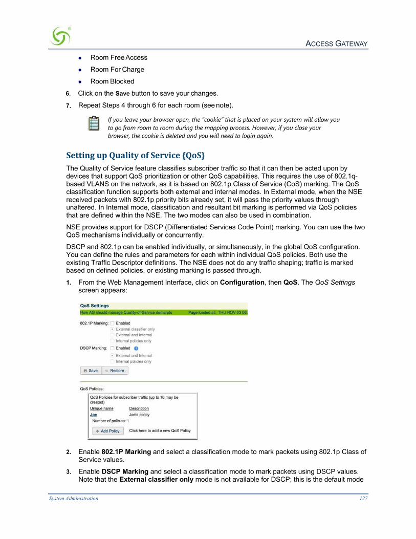
ACCESS GATEWAY
System Administration 127
l Room Free Access
l Room For Charge
l Room Blocked
6. Click on the Save button to save your changes.
7. Repeat Steps 4 through 6 for each room (see note).
If you leave your browser open, the “cookie” that is placed on your system will allow you to go from room to room during the mapping process. However, if you close your browser, the cookie is deleted and you will need to login again.
SettingupQualityofService{QoS}The Quality of Service feature classifies subscriber traffic so that it can then be acted upon by devices that support QoS prioritization or other QoS capabilities. This requires the use of 802.1q-based VLANS on the network, as it is based on 802.1p Class of Service (CoS) marking. The QoS classification function supports both external and internal modes. In External mode, when the NSE received packets with 802.1p priority bits already set, it will pass the priority values through unaltered. In Internal mode, classification and resultant bit marking is performed via QoS policies that are defined within the NSE. The two modes can also be used in combination.
NSE provides support for DSCP (Differentiated Services Code Point) marking. You can use the two QoS mechanisms individually or concurrently.
DSCP and 802.1p can be enabled individually, or simultaneously, in the global QoS configuration. You can define the rules and parameters for each within individual QoS policies. Both use the existing Traffic Descriptor definitions. The NSE does not do any traffic shaping; traffic is marked based on defined policies, or existing marking is passed through.
1. From the Web Management Interface, click on Configuration, then QoS. The QoS Settings screen appears:
2. Enable 802.1P Marking and select a classification mode to mark packets using 802.1p Class of
Service values.
3. Enable DSCP Marking and select a classification mode to mark packets using DSCP values. Note that the External classifier only mode is not available for DSCP; this is the default mode

ACCESS GATEWAY
128 System Administration
if DSCP is disabled. The following chart outlines the DSCP processing flow.
4. Select Add Policy to define a new QoS policy, or select a link to a policy that is already defined
in order to modify it. The Add QoS Policy for Subscribers screen appears:

ACCESS GATEWAY
System Administration 129
5. Enter a name for the policy in the QoS Policy field. 6. Enter a brief summary about the policy Description field. The rule list displays a list of the
rules that have been defined for this policy. 7. Click Save Policy to accept the parameters and rules defined and add the policy to the
policy list on the main page. 8. Provide default 802.1P CoS and/or DSCP values, as needed. 9. Select a traffic descriptor and a Class of Service for the rule, and then click Add Rule. Once
added, rules will be displayed in the list above. You must have one or more traffic descriptors previously defined. See Setting up Traffic Descriptors {Traffic Descriptors} on page 147.
DefiningtheRADIUSClientSettings{RADIUSClient}The Gateway supports Remote Authentication Dial-In User Service (RADIUS). RADIUS is an authentication and accounting system used by many Internet Service Providers.
The “Usernames” function must be enabled for a RADIUS login. See also Configuration Menu on page 62.
Nomadix offers an integrated RADIUS client, allowing service providers to track or bill users based on the number of connections, location of the connection, bytes sent and received, connect time, etc. The customer database can exist in a central RADIUS server, along with associated attributes for each user. When a customer connects into the network, the RADIUS client authenticates the

ACCESS GATEWAY
130 System Administration
customer with the RADIUS server, applies associated attributes stored in that customer's profile, and logs their activity (including bytes transferred, connect time, etc.). The Access Gateway's RADIUS implementation also handles VSAs (Vendor Specific Attributes), required by WISPs (Wireless Internet Service Providers) that want to enable more advanced services and billing schemes, such as a per device/per month connectivity fee.
All subscribers attempting to gain access to the network are validated by the RADIUS Server. For additional RADIUS information, see also:
l Defining the RADIUS Proxy Settings {RADIUS Proxy} on page 133 l l RadSec l With software release 9.1 RadSec is now supported, which allows fully secure
RADIUS using standard TLS certificates as an alternative to standard RADIUS. There’s only a few simple steps to get it working:
6. Install a full set of certificates on the NSE. The cacert.pem must contain the full certification path including the root certificate. The public key goes in server.pem and the private key in cakey.pem.
7. The RADIUS server must have its own set of certificates.
8. RadSec must be enabled in the RADIUS profile.
9. Configuring RadSec is fairly simple if you remember that (1) ALL communications are over the same port (no separate accounting port)- it is 2083 by default; and (2) the secret (set on the server only, it's built in for the NSE) is "radsec" as required by RFC. The Secret Key will gray-out when enabling RadSec.
10. The configured host name in the RADIUS server profile MUST match the common name in the server certificates. If you are using self-signed certs, it might be easiest to set the common name to the IP address.
l DefiningtheRealm-BasedRoutingSettings{Realm-BasedRouting} on page 136 l RADIUS Attributes on page 247
The following are “Guidelines” steps to assist in configuring RADIUS Client.
1. From the Web Management Interface, click on Configuration, then RADIUS Client. The RADIUS Client Settings screen appears:

ACCESS GATEWAY
System Administration 131
2. Under the Server Selection and Communication options, choose the Default RADIUS
Mode:
l Disabled (to disable RADIUS authentication)
l Realm-Based (for Realm routing)
l Fixed (for routing to predefined RADIUS servers)
3. Select the Default RADIUS Service Profile from the pull-down menu. If the “RADIUS Service Profile” does not appear it must be created by going to Configuration> Realm-Based Routing to add a RADIUS Service Profile.
4. Enter a Local Authentication Port and a Local Accounting Port i.e. the source port. Default = 0 the source port is dynamically selected.
5. Select whether Later Login Supersedes Previous. This will allow a secondary form of authentication to override the original authentication if necessary, and use the credentials of the last login to succeed.
MiscellaneousOptions
6. In the “Miscellaneous Options” category, Enter a value for the time (in seconds) in the Default User Idle Timeout field. This value determines how much “idle” time elapses before the subscriber’s session times out and they must login again.
7. The Access Gateway can reauthenticate “repeat” subscribers who return to the system within a specified amount of time. To enable this feature, click on the check box for Enable Automatic Subscriber Reauthentication, and provide a time-out value (in minutes) in the Automatic Subscriber Reauthentication Timeout field.
8. You can limit automatic reauthentication to the subscriber’s original zone. To do this, check Restrict Reauthentication to Originally Authenticated Zone.
9. If you want to enable the URL redirection feature, click on the check box for Enable URL

ACCESS GATEWAY
132 System Administration
Redirection.
10. For a Network Access Server (NAS), if you want to send a NAS identifier with your account access request, click on the check box for Send NAS identifier, then define the NAS identifier in the NAS identifier field.
11. To send the NAS IP address with your account request, click on the check box for Send NAS IP.
12. To send a NAS port type with your account request, click on the check box for Send NAS Port type, then define the NAS port in the NAS Port Type field.
13. To send the Framed IP address with your account request, click on the check box for Send Framed IP.
14. To enable RADIUS termination action enhancement, click on the check box for Enable Termination Action Radius Attribute, then select the percentage (100% - 75%) of the maximum data volume threshold for which term-action will be enforced (volume-based sessions only). This option provides support for Radius Termination-Action for time- and volume-based subscribers working in conjunction with an external Radius server. Enforcement of this attribute will result in either:
l logout of the subscriber
l re-authentication of the subscriber through issuance of a new Radius Access-Request that contains a new Acct-Session ID.
The Radius re-authentication that occurs due to term-action enforcement will be transparent to the subscriber. This is also true for time based sessions that expire. Radius accounting augmentation will take place as a result of a successful re-authentication.
The following VSAs are used for implementation of volume- and time-based Radius termination action:
VSA Name Value
Termination-Action 1

ACCESS GATEWAY
System Administration 133
Session-Timeout 60
Nomadix-MaxBytesDown 3000000
Nomadix-MaxBytesUp 3000000
15. If required, check the box for Enable Session-Terminate-End-Of-Day When Authorized (to allow business policies that want to terminate the session at midnight of every day).
16. If required, check the box for Enable Byte Count Reset On Account Start (to reset the transmitted and received byte count for a subscriber once an “accounting start” is sent). This function prevents counting Walled Garden traffic if the billing plan is using bytes sent/received as a charge criterion.
17. If required, check the box for Enable RADIUS Subnet Attribute (if you want to allocate a specific subnet to a user).
18. If required, check the box for Enable Goodbye URL (if you want the system to display a post session “goodbye” page). The “goodbye” page can be defined as a RADIUS VSA or be driven by the Access Gateway’s Internal Web Server (IWS).
19. If required, check the box Enable Forget your Password to create a link that users can go to (and is added to the passthrough list) so they can run a page at their ISP to get their password.
20. Enable or disable the User Session Time Adjustment and credit functionality when the NSE is down.
21. Enable charging for idle time to count idle time in the session time of Radius accounting packets.
22. Enable RADIUS QoS Policies to assign a QoS policy to a user in their Radius Profile.
23. Click Save to save your changes, or click Restore if you want to reset all the values to their previous state.
DefiningtheRADIUSProxySettings{RADIUSProxy}A RADIUS Proxy allows the NSE to relay authentication and accounting packets between the parties performing the authentication process. Different realms can be set up to directly channel RADIUS messages to the various RADIUS servers.
For additional RADIUS information, see also:
l Setting up Quality of Service {QoS} on page 127 l l RadSec l With software release 9.1 RadSec is now supported, which allows fully secure RADIUS
using standard TLS certificates as an alternative to standard RADIUS. There’s only a few simple steps to get it working:
11. Install a full set of certificates on the NSE. The cacert.pem must contain the full certification path including the root certificate. The public key goes in server.pem and the private key in cakey.pem.
12. The RADIUS server must have its own set of certificates.
13. RadSec must be enabled in the RADIUS profile.
14. Configuring RadSec is fairly simple if you remember that (1) ALL communications are over the same port (no separate accounting port)- it is 2083 by default; and (2) the secret (set on the

ACCESS GATEWAY
134 System Administration
server only, it's built in for the NSE) is "radsec" as required by RFC. The Secret Key will gray-out when enabling RadSec.
15. The configured host name in the RADIUS server profile MUST match the common name in the server certificates. If you are using self-signed certs, it might be easiest to set the common name to the IP address.
l DefiningtheRealm-BasedRoutingSettings{Realm-BasedRouting} on page 136 l RADIUS Attributes on page 247
The following are “Guidelines” steps to assist in configuring RADIUS Proxy. 1. From the Web Management Interface, click on Configuration, then RADIUS Proxy. The
RADIUS Proxy Settings screen appears:
2. Enable or disable RADIUS Proxy Services, as required, by clicking on the appropriate check
box.
3. If you enabled RADIUS Proxy Services, you must provide the Authentication Server Port and the Accounting Server Port references.
4. Enter a Local Port for Communicating with Home Server i.e. the source port. 5. Click on the Save button to save your changes, or click on the Restore button if you want to reset
all the values to their previous state.
See Adding an Upstream RADIUS NAS.
AddinganUpstreamRADIUSNAS
1. If you want to add a new Upstream RADIUS NAS (for example, an 802.11 Access Point on the subscriber side of the Access Gateway), click on the Add button. The Add Upstream RADIUS NAS screen appears:

ACCESS GATEWAY
System Administration 135
2. To make this entry the “active” NAS entry, click on the Entry Active check box.
3. Enter an IP Address for the Upstream NAS.
4. Enter a secret key in the Authentication Secret Key field. During the authentication process, the server and client exchange secret keys. The secret keys must match for communication between the server and the client to continue. The secret key is a valuable and necessary security measure.
5. Enter a secret key in the Accounting Secret Key field.
6. Select the Default RADIUS Service Profile from the pull-down menu (see note). If the “RADIUS Service Profile” does not appear it must be created by going to Configuration> Realm-Based Routing to add a RADIUS Service Profile.
7.
RADIUS requests originating from this Upstream NAS will be routed via the specified profile if it cannot be routed based on realm. Leave this field blank if default routing is not desired.
8. Click on the Add button to add this Upstream RADIUS NAS definition, then click on the Back to Main RADIUS Proxy Settings page link to return to the RADIUS Proxy Settings screen. The Upstream RADIUS NAS definition you just added appears in the list. You can add up to 10 definitions.

ACCESS GATEWAY
136 System Administration
9. Repeat steps 1 through 8 to add more Upstream RADIUS NAS definitions, as required.
RadSecWith software release 9.1 RadSec is now supported, which allows fully secure RADIUS using standard TLS certificates as an alternative to standard RADIUS. There’s only a few simple steps to get it working:
16. Install a full set of certificates on the NSE. The cacert.pem must contain the full certification path including the root certificate. The public key goes in server.pem and the private key in cakey.pem.
17. The RADIUS server must have its own set of certificates.
18. RadSec must be enabled in the RADIUS profile.
19. Configuring RadSec is fairly simple if you remember that (1) ALL communications are over the same port (no separate accounting port)- it is 2083 by default; and (2) the secret (set on the server only, it's built in for the NSE) is "radsec" as required by RFC. The Secret Key will gray-out when enabling RadSec.
20. The configured host name in the RADIUS server profile MUST match the common name in the server certificates. If you are using self-signed certs, it might be easiest to set the common name to the IP address.
DefiningtheRealm-BasedRoutingSettings{Realm-BasedRouting}Use this procedure when setting up RADIUS Service Profiles (up to 10) and Realm-based Routing Policies (up to 50).

ACCESS GATEWAY
System Administration 137
From the Web Management Interface, click on Configuration, then Realm-Based Routing. The Realm-Based Routing Settings screen appears:
DefineRADIUSServiceProfiles
RADIUS service profiles are used to direct username access requests for both plain RADIUS users and users who supply realm/domain in their username.
Create a RADIUS service profile to a RADIUS server that will handle Prefix-based users. This is to handle users that will login with a username in the format type of “ISP/username”. In this case the delimiter is “/” and what appears before it, “ISP”, is the realm name.
Create a RADIUS service profile for a RADIUS server that will handle Suffix-based users. This is to handle users that will login with a username in the format type of “[email protected]”. In this case the delimiter is “@” and what appears after it, “ISP.com”, is the realm name.
To add a RADIUS Service Profile, click on the appropriate Add button. The Add RADIUS Service Profile screen appears:

ACCESS GATEWAY
138 System Administration
Enter a name of your choice for this service profile in the Unique Name field.
Authentication
This category requires input for enabling RADIUS authentication and requires you to define IP addresses, ports, and secret keys for the primary and secondary RADIUS servers (the secondary server is optional).
21. Enable or disable the RADIUS Authentication Service, as required, by clicking on the Enable RADIUS Authentication Service check box.
22. If you enabled the RADIUS Authentication Service, enter the primary RADIUS authentication server IP address in the Primary IP field. This field can also be populated by a DNS name to allow for changing the DNS resolution, instead of having to change settings in the NSE when the IP of the Radius server changes.
23. Enter the authorization port in the Port field for the primary RADIUS authentication server. This is the port the system uses when authorizing subscribers.
24. Enter a secret key in the Secret Key field for the primary RADIUS authentication server. During the authentication process, the server and client exchange secret keys. The secret keys must match for communication between the server and the client to continue. The secret key is a valuable and necessary security measure.
The Access Gateway and the RADIUS servers must use the same secret key.
25. Repeat Steps 2 through 4 for the secondary RADIUS authentication server (if used).
If the Primary Authentication Server fails all RADIUS Authentication Requests will be sent to the Secondary Authentication RADIUS for 30 minutes. After 30 minutes the Primary will be retried.

ACCESS GATEWAY
System Administration 139
Accounting
This category requires input for enabling the RADIUS accounting service, and also requires the necessary IP addresses, ports and secret keys for the primary and secondary RADIUS accounting servers. The RADIUS accounting server is responsible for receiving accounting requests and returning a response to the client indicating that it has received the request.
1. To enable the accounting service for your RADIUS functionality, click on the check box for Enable RADIUS Accounting Service.
2. Enter the primary RADIUS accounting server IP address in the Primary IP field. This field can also be populated by a DNS name to allow for changing the DNS resolution, instead of having to change settings in the NSE when the IP of the Radius server changes.
2. Enter the accounting port in the Port field for the primary RADIUS accounting server. This is the port the system uses when communicating accounting records.
3. Enter a secret key in the Secret Key field for the primary RADIUS accounting server.
4. Repeat Steps 1 through 4 for the secondary RADIUS accounting server (if used).
RetransmissionOptions
This category requires you to define the data retransmission method (failover or round-robin), the retransmission frequency, and how many retransmissions the system should attempt.
1. Select the Retransmission Method (Failover or Round Robin).
2. Enter a value for the time (in seconds) in the Retransmission Delay field. This value determines how much time elapses between transmission attempts. [default is 3]
3. Enter a numeric value in the Retransmission Attempts (per server) field to define how many times the system attempts to transmit the data. [default is 2]
4. Click on the Add button to add this RADIUS Service Profile.
5. When you have completed the definition of your RADIUS Service Profile, you can return to the previous screen (Realm-Based Routing Settings) by clicking on the Back to Main Realm-Based Routing Settings page link. The RADIUS Service Profile you just created is added to the list.
DefineRealmRoutingPolicies
Realm routing policies are used to determine how supplied username/password input is used to authenticate users. Create a realm routing policy for each realm that will be handled. The realm routing policy will reference either a RADIUS service profile or a tunnel profile. Many different realm routing policies can reference the same RADIUS service or tunnel profile.
This policy references a RADIUS service profile so a realm match will result in an access request being sent to the RADIUS server(s) specified in the RADIUS service profile. In this case, the RADIUS service profile “RadiusPrefix” is referenced and so the RADIUS server(s) defined therein will receive RADIUS access requests.
From the Web Management Interface, click on Configuration, then Realm-Based Routing. The Realm-Based Routing Settings screen appears:

ACCESS GATEWAY
140 System Administration
1. To add a RADIUS Realm Routing Policies, click on the appropriate Add button on the Realm- Based Routing Settings screen. The Add Realm Routing Policy screen appears:
2. To make this entry the “active” entry, click on the Entry Active check box. 3. To define a specific realm, choose the Specific Realm option and enter the destination in the
Realm Name field. Alternatively, you can choose the Wildcard match option, then define your search options: l Prefix match only l Suffix match only l Match either
4. Select the required RADIUS Service Profile from the pull-down menu. 5. Click on the Strip off routing information check box if you want to remove the routing
information.
6. Click on the Add button to add this Realm Routing Policy.
7. When you have completed the definition of your Realm Routing Policy, you can return to the

ACCESS GATEWAY
System Administration 141
previous screen (Realm-Based Routing Settings) by clicking on the Back to Main Realm-Based Routing Settings page link. The screen below shows a realm routing policy that handles prefix-based usernames using a RADIUS service profile. Notice that “Specific Realm” is clicked and the “Realm name” is “cisp”. Also notice that “Prefix match only” is clicked and that the delimiter is “/”. This means that this realm routing policy will match usernames that are of the format “cisp/ username”.
The Realm Routing Policy you just created is added to the list.
ConfigureRADIUSClient
The NSE RADIUS client must be setup for realm-based routing mode since realm information will be used to determine how to handle usernames that contain realm information. The screen below shows an example of setting the routing mode to handle realm-based usernames.
ManagingSMTPRedirection{SMTP}When SMTP redirection is enabled (for misconfigured or properly configured subscribers), the Access Gateway redirects the subscriber’s E-mail through a dedicated SMTP server, including SMTP servers which support login authentication. To the subscriber, sending and receiving E- mail is as easy as it’s always been. This function is transparent to subscribers.
1. From the Web Management Interface, click Configuration, then SMTP. The SMTP Redirection Settings screen appears:

ACCESS GATEWAY
142 System Administration
2. Click on the check box for SMTP Redirection (Misconfigured) to enable this feature for
“misconfigured” subscribers.
3. Click on the check box for SMTP Redirection (Properly Configured) to enable this feature for “properly configured” subscribers. If you enable SMTP redirection, you must provide the IP address of the SMTP server.
4. In the SMTP Server IP/DNS field, enter the address of the SMTP server you want to use.
5. For SMTP servers which support login authentication, enter a valid username in the SMTP Server Account Username field.
6. For SMTP servers which support login authentication, enter a valid password in the SMTP Server Account Password field.
7. Click on the Save button to save your changes, or click on the Restore button if you want to reset all the values to their previous state.
ManagingtheSNMPCommunities{SNMP}You can address the Access Gateway using an SNMP client manager (for example, HP OpenView). SNMP is the standard protocol that regulates network management over the Internet. To do this, you must set up the SNMP communities and identifiers. For more information about SNMP, see Using an SNMP Manager on page 61.
With software release 9.1 Nomadix has implemented a simplified and easy to use version of SNMPv3, which provides secure connections for SNMP without the need for an IPsec tunnel.
• There are two pre-defined users: operator (ReadOnly) and administrator (ReadWrite). Both use Authentication and Privacy encryption by default. Additional users cannot be created.
• Both users have access to the entire MIB, we do not support partial MIB “views”.
• Both users are completely renamable and reconfigurable. The “operator” user can be set to ReadWrite, for example.
• Release 9.1 supports SNMPv3, SNMPv2, or both versions at once.

ACCESS GATEWAY
System Administration 143
If you want to use SNMP, you must manually turn on SNMP.
1. From the Web Management Interface, click on Configuration, then SNMP. The SNMP Settings screen appears:
2. Click on the check box for SNMP Daemon to enable this functionality.
3. If desired, you can change the SNMP Daemon Listening Port. This is set by default to port 161.
If you change the SNMP Daemon Listening Port, any external services or applications that communicate with the NSE via SNMP will be affected.
4. Select your preferred configuration: SNMPv3, SNMPv2, or both versions at once
5. Enter the SNMP parameters (communities and identifiers), including:
l System Contact
l System Location
l Get (Read) Community
l Set (Write) Community
l Trap Community
l Trap Recipient IP
l Specify DAT Trap Interval (15-600) sec
l check the box to enable Ethernet Link Traps
Your SNMP manager needs this information to enable network management over the Internet.
6. Click on the Save button to save your changes, or click on the Restore button if you want to reset all the values to their previous state.

ACCESS GATEWAY
144 System Administration
SNMPv3 Tables Configuration:
1. Each SNMPv3 entity is unique with its own ID (derived from the MAC address). You might
need to enter this when you create the connection on the manager.
2. Click on a user-name to edit.
SNMPv3 can encrypt both the credentials and the communications if configured like the defaults.
SNMPv3 Notification Tab:
• Both users can be used to send SNMPv3 Notifications.
• You can set both users to Active and send notifications to different IP addresses.
• If you have renamed the Users on the User tab, you must rename them to the SAME name here.
You can now use your SNMP client to manage the Access Gateway via the Internet.

ACCESS GATEWAY
System Administration 145
EnablingDynamicMultipleSubnetSupport(Subnets)Nomadix’ dynamic multiple subnet support allows you to create flexible and cost-effective IP pool solutions to meet the demands of complex networks in large residential and public access networks. For example, you can define the user's subnet via the management interfaces.
3. From the Web Management Interface, click on Configuration, then Subnets. The Public Subnets Settings screen appears:
To add a Subnet
4. Enter a valid IP address for this subnet in the Subnet field.
5. Enter the subnet mask for this subnet in the Subnet Mask field.
6. Click on the Add button to add a new public subnet.
To edit the “Current Public DHCP Subnets” table, go to Managing the DHCP service options {DHCP} on page 88.
For additional information about the multiple subnet feature, go to Contact Information on page 267 for Nomadix Technical Support.
DisplayingYourConfigurationSettings{Summary}You can display a summary listing of all your current Configuration settings.
To view the summary listing, go to the Web Management Interface, click on Configuration, then click on Summary.

ACCESS GATEWAY
146 System Administration
The Summary of Configuration Settings screen appears (partial screen shown here):
SettingtheSystemDateandTime{Time}You can set the system time from local hardware or your choice of NTP server(s).
The NSE supports automatic daylight Savings Time adjustment and official IANA (iana.org) time zones. You may also specify a UTC offset.
1. From the Web Management Interface, click on Configuration, then Time. The Set Date and Time screen appears:

ACCESS GATEWAY
System Administration 147
2. Select the method for time zone configuration; either IANA Time Zone Database or Generic
UTC offset. UTC is the Universal Coordinated Time, based on the ISO 8601 standard, and is used in conjunction with RADIUS servers (for example, if the RADIUS server is setup for a time zone that is different from the Access Gateway).
3. Select the clock source; either Internal Time to use the local hardware time or External (NTP) if you want to use NTP instead of the internal clock of the NSE. If you select Internal Time, confirm and (if necessary) adjust the date and time. After you click Save, the system writes the information into its BIOS, then displays the new date and time.
If you select External Time:
• In the Server Timeout field, enter the number of seconds before the NSE gives up on receiving a time response from the NTP server.
• In the Time Server 1-4 fields, enter up to 4 different NTP servers to query for the correct time.
4. When finished, click Save to save your changes, or click Restore if you want to reset all the values to their previous state.
SettingupTrafficDescriptors{TrafficDescriptors}Traffic Descriptors are a dependency of creating rules for a Quality of Service Policy. The Traffic Descriptors are how the Access Gateway identifies subscriber traffic. They are conditions or a group of conditions that are linked to a description.

ACCESS GATEWAY
148 System Administration
1. From the Web Management Interface, click on Configuration, then Traffic Descriptor. The Traffic Descriptor Settings screen appears:
2. Select Add to create a new Traffic Descriptor, or select a link to an existing descriptor to modify
it. The Add Traffic Descriptor screen appears.
3. Enter a name for the descriptor in the Unique Name field.
4. Enter a brief summary about the descriptor in the Description field.
5. Set condition matching to require a match to All conditions or Any one of the conditions. This condition list displays a list of the conditions that have been defined for this descriptor. Select a condition type from the Add Condition menu and define the matching parameters. Once added, conditions will be displayed in the condition list.
6. Select Remove to remove a condition from this descriptor.
7. Select Add Descriptor to accept the parameters and conditions defined and add the descriptor to the descriptor list on the main page.

ACCESS GATEWAY
System Administration 149
SettingUpURLFiltering{URLFiltering}The Access Gateway can restrict access to specified Web sites based on URLs defined by the system administrator. URL filtering will block access to a list of sites and/or domains entered by the administrator using the following three methods:
l Host IP address (for example, 1.2.3.4)
l Host DNS name (for example, www.yahoo.com)
l DNS domain name (for example, *.yahoo.com, meaning all sites under the yahoo.com hierarchy, such as finance.yahoo.com, sports.yahoo.com, etc.).
The system administrator can dynamically add or remove specific IP addresses and domain names to be filtered for each property.
1. From the Web Management Interface, click on Configuration, then URL Filtering. The URL Filtering Address Settings screen appears:
2. If you want to enable this feature, click on the check box for URL Filtering.
3. Click on the Save button to save your setting.
4. If URL Filtering is enabled, you can add (or remove) up to 300 addresses in the IP/DNS Name field. After entering the address you want to add, simply click on the Add button (the address will be added to the displayed list). Add or remove addresses, as required.
SelectingUserAgentFilteringSettingsThe Access Gateway can ignore traffic being generated by unsubscribed user devices that are not accessing walled garden sites or an unauthenticated users.
1. From the Web Management Interface, click on Configuration, then User Agent Filtering. The User Agent Filtering Settings screen appears:

ACCESS GATEWAY
150 System Administration
2. Enable User-Agent Filtering to use the filtering capabilities for the User-Agents.
3. Add the names of the different User-Agents that you want to filter to the HTTP User- Agent name field. Windows Update and Apple iTunes are default filtered Agents.
ZoneMigrationZone migration is an expansion of the NSE’s “re-login after migration” capability, which currently allows the system to force a subscriber to log in again if the subscriber moves from one port location to another. Zone migration significantly expands this capability via the following means:
l It allows the creation of multiple zones, which are then constituted by groupings of multiple port locations. These groupings can be made up of any combination of desired ports (port values do not have to be sequential in order to be grouped within a given zone).
l The re-login requirement can then be configured so that subscribers can move from one port to another within a zone without being required to re-login. However, when moving between ports in different zones, the re-login requirement is enforced.
l It is also possible to configure a zone so that migration between ports within the zone requires the user to re-login.
l In addition, the re-login after migration function was previously limited to RADIUS and PMS users. This capability has now been extended to other subscriber login types.
1. From the Web Management Interface, click on Configuration, then Zone Migration. The Zone Migration Settings screen appears:

ACCESS GATEWAY
System Administration 151
2. Select Relogin after migration to enable the Zone Migration feature.
AddanewZone
In the Zone-Based Migration section, new zones can be added and initially configured, using the following parameter fields. In each of these fields, any leading or trailing spaces will be removed by the NSE when the page is submitted:
l Zone Name – Allows entry of a name appropriate for the zone to be created. The name must be unique, cannot exceed 16 characters, and cannot contain characters that are not alphanumeric, dash, underscore, or space.
l Port-Locations – This is where the port configuration for the zone is entered. The data must be entered as a string between 1 and 128 characters in length. The string must contain either an individual numeric value ("211"), a comma-separated list of numeric values ("211, 212"), a range of numeric values with dash-separated delimiters ("211-899"), a list of ranges of numeric values ("211-300, 301-899"), or a comma- separated list of individual numeric values and ranges ("211, 212, 213-899").
l Description – Allows entry of a description for the zone. This must be a string between 0 and 128 characters in length, and cannot contain characters that are not alphanumeric, dash, underscore, or space.
ReloginwithinZone
This selection provides the option to require relogin after migration between ports that are within a given zone. The default is Disabled.

ACCESS GATEWAY
152 System Administration
ExistingZones
Zones that have already been defined are listed here, and can be edited or deleted. (Note: The description field is not displayed in the list view).
NetworkInfoMenu
DisplayingARPTableEntries{ARP}
You can display a table that shows the current status of the ARP (Address Resolution Protocol) assignments. ARP is used to dynamically bind a high level IP address to a low level physical hardware (MAC) address. ARP is limited to a single physical network that supports hardware broadcasting.
To view the ARP Table, go to the Web Management Interface, click on Network Info, then click on ARP. The ARP Table screen appears:
DisplayingDATSessions{DAT}Dynamic Address Translation (DAT) allows all users to obtain network access, regardless of their computer’s network settings.
To view the DAT Session Table, go to the Web Management Interface, click on Network Info, then click on DAT. The DAT Session Table screen appears:

ACCESS GATEWAY
System Administration 153
Click on the Delete all sessions button to clear all current subscriber sessions.
Deleting DAT sessions will cause all misconfigured subscribers to lose their Internet connection for a short time.
DisplayingtheHostTable{Hosts}You can display a table which lists the hosts that are currently configured. This table includes the assigned host names, their corresponding IP addresses, and any aliases that may be assigned to each host. Hosts provide services to other computers that are linked to it by a network.
To view the Host Table, go to the Web Management Interface, click on Network Info, then click on Hosts. The Host Table screen appears:
DisplayingICMPStatistics{ICMP}You can display the current ICMP (Internet Control Message Protocol) statistics. ICMP is a standard Internet protocol that delivers error and control messages from hosts to message requesters. These statistics are presented as a listing that details the current status of each ICMP transmission element.
To view the ICMP Statistics, go to the Web Management Interface, click on Network Info, then click on ICMP. The ICMP Statistics screen appears:

ACCESS GATEWAY
154 System Administration
DisplayingtheNetworkInterfaces{Interfaces}You can display the network interfaces which are presented as a detailed listing of all interface communication elements and their current status.
To view the Network Interfaces, go to the Web Management Interface, click on Network Info, then click on Interfaces. The Network Interfaces screen appears:

ACCESS GATEWAY
System Administration 155
DisplayingtheIPStatistics{IP}You can display the IP (Internet Protocol) statistics, which are presented as a detailed listing of all IP elements and their statuses. With IP transmissions, data is broken up into packets which are then sent over the network. By using IP addressing, Internet Protocol ensures that the data reaches its destination, even though different packets may “pass through” different networks to get to the same location.
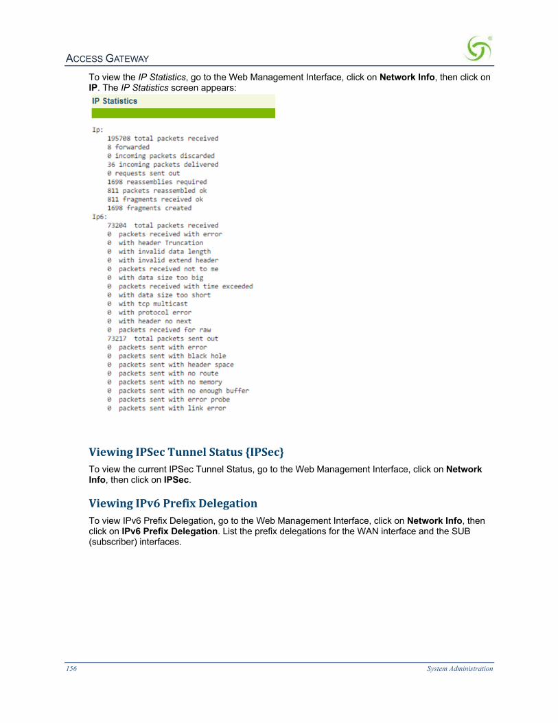
ACCESS GATEWAY
156 System Administration
To view the IP Statistics, go to the Web Management Interface, click on Network Info, then click on IP. The IP Statistics screen appears:
ViewingIPSecTunnelStatus{IPSec}To view the current IPSec Tunnel Status, go to the Web Management Interface, click on Network Info, then click on IPSec.
ViewingIPv6PrefixDelegationTo view IPv6 Prefix Delegation, go to the Web Management Interface, click on Network Info, then click on IPv6 Prefix Delegation. List the prefix delegations for the WAN interface and the SUB (subscriber) interfaces.

ACCESS GATEWAY
System Administration 157
ViewingNATIPAddressUsage{NATIPUsage}To view the current NAT IP Address Usage, go to the Web Management Interface, click on Network Info, then click on NAT IP Usage. The NAT IP Usage summary screen appears:
DisplayingtheRoutingTables{Routing}You can display the current Routing Tables, including any dynamically generated routes, unreachable routes, or wildcard routes. To view the Routing Tables, select Network Info> Routing. The Routing Tables screen appears:

ACCESS GATEWAY
158 System Administration
DisplayingtheActiveIPConnections{Sockets}You can display a table that provides a detailed listing of all currently active IP (Internet Protocol) connections.
To view the Socket Table, go to the Web Management Interface, click on Network Info, then click on Sockets. The Socket Table screen appears:

ACCESS GATEWAY
System Administration 159
DisplayingtheStaticPortMappingTable{StaticPort-Mapping}You can display a table which provides a detailed listing of the currently active static port mapping scheme.
To view the Static Port-Mapping Table, go to the Web Management Interface, click on Network Info, then click on Static Port-Mapping. The Static Port-Mapping Table screen appears:

ACCESS GATEWAY
160 System Administration
DisplayingTCPStatistics{TCP}You can display the TCP (Transmission Control Protocol) statistics, which are presented as a detailed listing of all TCP elements and their current status. TCP is a standard protocol that manages data transmissions across networks.
To view the TCP Statistics, go to the Web Management Interface, click on Network Info, then click on TCP. The TCP Statistics screen appears:
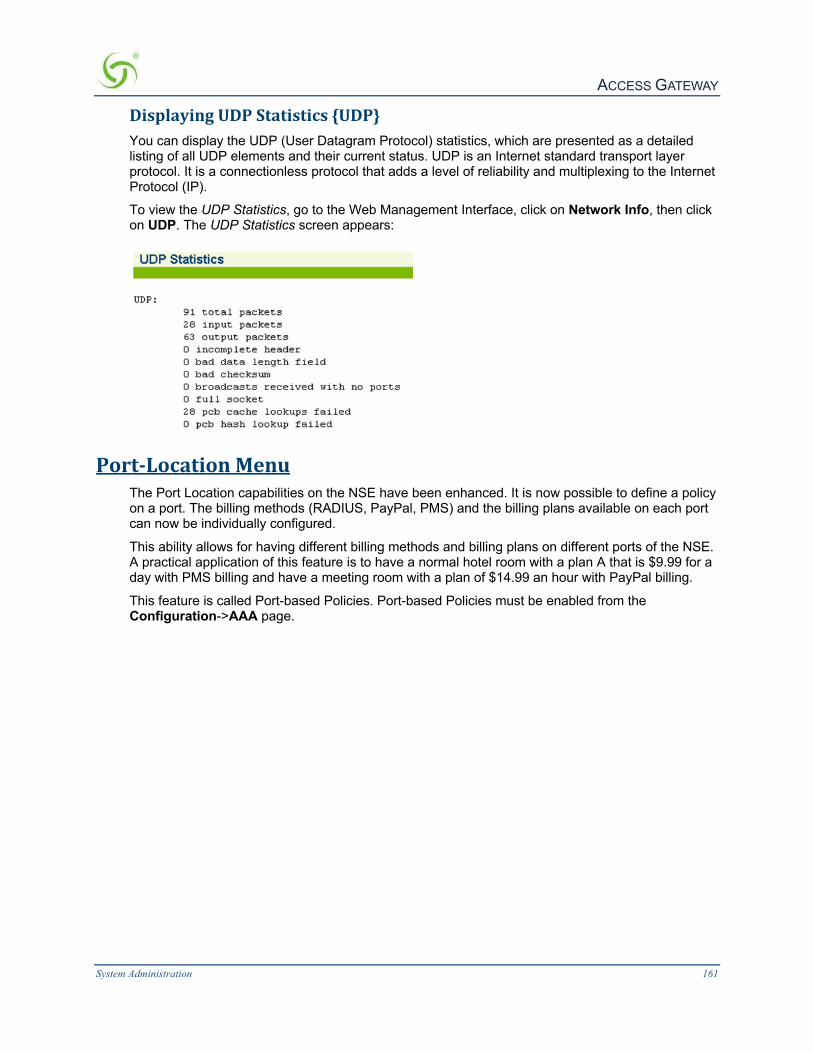
ACCESS GATEWAY
System Administration 161
DisplayingUDPStatistics{UDP}You can display the UDP (User Datagram Protocol) statistics, which are presented as a detailed listing of all UDP elements and their current status. UDP is an Internet standard transport layer protocol. It is a connectionless protocol that adds a level of reliability and multiplexing to the Internet Protocol (IP).
To view the UDP Statistics, go to the Web Management Interface, click on Network Info, then click on UDP. The UDP Statistics screen appears:
Port-LocationMenuThe Port Location capabilities on the NSE have been enhanced. It is now possible to define a policy on a port. The billing methods (RADIUS, PayPal, PMS) and the billing plans available on each port can now be individually configured.
This ability allows for having different billing methods and billing plans on different ports of the NSE. A practical application of this feature is to have a normal hotel room with a plan A that is $9.99 for a day with PMS billing and have a meeting room with a plan of $14.99 an hour with PayPal billing.
This feature is called Port-based Policies. Port-based Policies must be enabled from the Configuration->AAA page.

ACCESS GATEWAY
162 System Administration
AddingandUpdatingPort-LocationAssignments{Add}Port-locations can be assigned at any level (for example, a specific room in a hotel or apartment building, a floor number, wing, or building). There may even be multiple ports assigned to a single room or location. The Access Gateway uses a port-location authorization table to manage the assigned ports and ensure accurate billing for the services used by a particular port.
AddingaPort-LocationAssignment
This procedure shows you how to add a port-location assignment. If you want to update an existing assignment, go to Updating a Port-Location Assignment.
1. From the Web Management Interface, click on Port-Location, then Add. The Add Port- Location Assignments screen appears:

ACCESS GATEWAY
System Administration 163
2. Enter a location identifier in the Location field. Locations can be assigned as an alpha, numeric,
or alphanumeric value unless a PMS interface is used (see note).
If you are using a PMS interface, ensure that the “Location” field consists only of numbers (no alpha characters or symbols).
All alpha characters (used for locations and descriptions) are case-sensitive.
3. In the Port field, enter the port (the VLAN ID when using 802.1Q 2-way).
4. In the Description field, enter a meaningful description for this port-location assignment.

ACCESS GATEWAY
164 System Administration
5. “Provide DHCP Service” is selected by default. Deselect this option if you wish to disable subscriber-side DHCP for this port location. See Managing the DHCP service options {DHCP} on page 88.
6. Enter a Subnet for the port assignment you are adding.
You must now assign a State for this port-location. Possible states are, No Charge for using this port-location, Charge for Use, and Blocked. If you do not assign a conditional state, the state is registered as “No Charge” by default.
7. If applicable, select the Default Group Bandwidth Management Policy to enable the feature and set the bandwidth limits for this VLAN.
NOTE: Group bandwidth policies must be enabled for this assignment to have an effect.
8. If applicable, select the Default QoS Policy for the port assignment you are adding.
9. If applicable, select the Default CBQ Class for the port assignment you are adding.
NOTE: Class-based queueing must be enabled for the default assignment to have an effect.
10. Select the conditional state you want to assign to this port-location.
l If you choose Charge for Use additional configurations are available. Refer to the Note. Port-based Policies should be enabled from the Configuration->AAA page for these settings to take effect.
l Choose Enable Facebook Login to allow Facebook authentication.
l Choose Enable RADIUS Billing if you want RADIUS billing to be enabled on this port.
l Choose Enable PMS Billing if you want PMS based room billing to be enabled on this port.
l Choose Enable PayPal Billing if you want PayPal based billing to be enabled on this port
You can select any number of billing methods per port.
l Select from Billing Plan(s) available on port. You can assign a specific billing plan to a port, enable all existing billing plans, or assign specific billing plans to the port.
Please note that while it is possible to set the value of a per-port configuration parameter independently of the value of the corresponding global parameter, the feature itself is disabled for a port unless both the per-port and global parameters are set to enabled. Thus:
l RADIUS authentication for a port is enabled only if the RADIUS Client is globally enabled AND the per-port enable RADIUS billing parameter is set.
l PayPal billing for a port is enabled only if PayPal Services is globally enabled AND the per-port enable PayPal billing parameter is set.
l PMS billing for a port is enabled only if PMS Services is globally enabled AND the per-port enable PMS billing parameter is set.
l Facebook authentication for a port is enabled only if Port-Based Policies is enabled and that port allows Facebook as an authentication type.
11. Click on the Add button to save your changes (the message: Entry added or updated in the location file appears), or click on the Restore button if you want to reset all the values to their previous state.
UpdatingaPort-LocationAssignment
The procedure for updating a port-location assignment is similar to adding a port-location assignment. The difference between the two procedures is how they are presented to you. For example, if you already have port-locations assigned and you enter an existing “port” value, each

ACCESS GATEWAY
System Administration 165
data field that you go through (port, location, state, and description) displays the value currently assigned to the field.
To update a Port-Location assignment, simply update the fields with new values.
If you have updated a port-location assignment, you may want to change its description to distinguish from the old assignment. Although the old assignment will no longer exist in the system, a meaningful description can often be a valuable quick reference guide.
ExportingPort-LocationAssignments{Export}This procedure shows you how to export your current port-location assignments to the “location.txt” file. The location.txt file is stored in: /flash/location.txt (resident in the Access Gateway’s flash memory).
Exporting your current port-location assignments to the Access Gateway’s flash memory will overwrite the existing location.txt file.
1. From the Web Management Interface, click on Port-Location, then Export. The Export Port-Location Assignments screen appears:
2. Click on the Export button to export port-location assignment to the /flash/location.txt. file.
FindingPort-LocationAssignmentsbyDescription{FindbyDescription}This procedure shows you how to find a port-location assignment, based on its description. This procedure is useful if you want to review the details of a specific port-location. You can also find port-locations based on their location or port.
1. From the Web Management Interface, click on Port-Location, then Find by Description. The Find a Port-Location Assignment by Description screen appears:
2. In the Enter Description field, enter the description of the assignment you want to find.
The system ignores the case (upper or lower) of the characters you enter.
3. Click on the Show button to view the specified port-location assignment, or click on the Restore button if you want to reset the “description” value to its blank state. The requested port-location is displayed:

ACCESS GATEWAY
166 System Administration
FindingPort-LocationAssignmentsbyLocation{FindbyLocation}This procedure shows you how to find a port-location assignment, based on its location. This procedure is useful if you want to review the details of a specific port-location. You can also find port-locations based on their description or port.
1. From the Web Management Interface, click on Port-Location, then Find by Location. The Find a Port-Location Assignment by Location screen appears:
2. In the Enter Location field, enter the location of the assignment you want to find.
The system ignores the case (upper or lower) of the characters you enter.
3. Click on the Show button to view the specified port-location assignment, or click on the Restore button if you want to reset the “location” value to its blank state. The requested port-location is displayed:
FindingPort-LocationAssignmentsbyPort{FindbyPort}This procedure shows you how to find a port-location assignment, based on its port. This procedure is useful if you want to review the details of a specific port-location. You can also find port-locations based on their description or location.

ACCESS GATEWAY
System Administration 167
1. From the Web Management Interface, click on Port-Location, then Find by Port. The Find a Port-Location Assignment by Port screen appears:
2. In the Enter Port field, enter the port you want to find.
The “port” is the VLAN ID (when using 802.1Q 2-way).
3. Click Show to view the Process Port-Location Assignments screen, or click Restore if you want to reset the “port” value to its blank state. From this screen you can click the port number to modify the port configuration, or click Delete to delete the port.
ImportingPort-LocationAssignments{Import}This procedure shows you how to import port-location assignments from the “location.txt” file. The location.txt file is stored in: /flash/location.txt (resident in the Access Gateway’s flash memory).
If you have never exported port-location assignments (since installing the Access Gateway at this site), the location.txt is empty. See also Exporting Port-Location Assignments {Export} on page 165. You can create your own location.txt file, FTP to the Access Gateway’s flash directory (for example, [IP address]/flash/ location.txt), and upload the file. See also Creating a “location.txt” File on page 168.
1. From the Web Management Interface, click on Port-Location, then Import. The Import Port-Location Assignments screen appears:
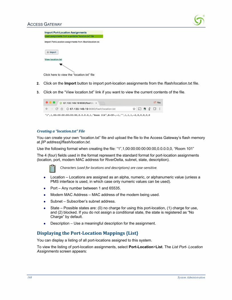
ACCESS GATEWAY
168 System Administration
Click here to view the “location.txt” file
2. Click on the Import button to import port-location assignments from the /flash/location.txt file.
3. Click on the “View location.txt” link if you want to view the current contents of the file.
Creatinga“location.txt”File
You can create your own “location.txt” file and upload the file to the Access Gateway’s flash memory at [IP address]/flash/location.txt.
Use the following format when creating the file: “1”,1,00:00:00:00:00:00,0.0.0.0,0, “Room 101”
The 4 (four) fields used in the format represent the standard format for port-location assignments (location, port, modem MAC address for RiverDelta, subnet, state, description).
Characters (used for locations and descriptions) are case-sensitive.
l Location – Locations are assigned as an alpha, numeric, or alphanumeric value (unless a PMS interface is used, in which case only numeric values can be used).
l Port – Any number between 1 and 65535.
l Modem MAC Address – MAC address of the modem being used.
l Subnet – Subscriber’s subnet address.
l State – Possible states are: (0) no charge for using this port-location, (1) charge for use, and (2) blocked. If you do not assign a conditional state, the state is registered as “No Charge” by default.
l Description – Use a meaningful description for the assignment.
DisplayingthePort-LocationMappings{List}You can display a listing of all port-locations assigned to this system.
To view the listing of port-location assignments, select Port-Location>List. The List Port- Location Assignments screen appears:

ACCESS GATEWAY
System Administration 169
DeletingPort-LocationAssignmentsTo delete port-location assignments:
1. From the Web Management Interface, select Port-Location>List. 2. Click on the Delete link to delete a particular port-location assignment.
You can also delete port-location assignments from the Find by Description, Find by Location, or Find by Port results.
EnablingFacebookLoginforaPortLocation1. Click Port-Location -> List. Click on the Port number. The Process Port-Location Assignment
screen appears.
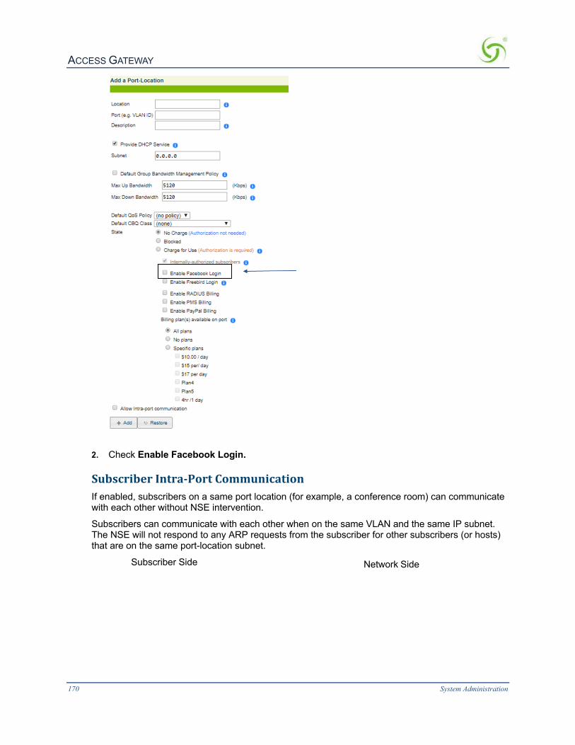
ACCESS GATEWAY
170 System Administration
2. Check Enable Facebook Login.
SubscriberIntra-PortCommunicationIf enabled, subscribers on a same port location (for example, a conference room) can communicate with each other without NSE intervention.
Subscribers can communicate with each other when on the same VLAN and the same IP subnet. The NSE will not respond to any ARP requests from the subscriber for other subscribers (or hosts) that are on the same port-location subnet.
Subscriber Side Network Side

ACCESS GATEWAY
System Administration 171
Subscribers in same port/location
Use the following steps to enable intra-port communication
1. Click Port-Location > List. Click on the Port number. The Process Port-Location Assignment screen appears.
2. Click Allow Intra-port communication.
3. Click Update.
SubscriberAdministrationMenu
AccessCodesThis procedure illustrates how to create, edit and print/reprint Access Codes

ACCESS GATEWAY
172 System Administration
6. Warning - before getting started it is important to allow pop-up for printing, if you plan on printing Access Codes
7. Create an Access Code Plan by a clicking on the Launch Plan Icon.
8. Enter the Fundamentals, Format and Session Parameters for the Access Codes
Access Codes Fundamentals
ü Enter the “Plan Name” (example The Oscars)
ü Enter the “Maximum Device” for the Access Code Plan (example 100)
ü DHCP type “Private” or “Public” (example Private)
ü DHCP Subnet
ü Configure the “Bandwidth Upstream” (example 1Mb)
ü Configure the “Bandwidth Downstream” (example 20Mb)
ü Select BW Class (example none)
ü Select “QoS Policy” (example none) Access Codes Format
ü Enter a Prefix (example 2019)
ü Pick a format (example nnnn-nn mixed digits and letters)
ü Enter as Suffix (example WOW) Access Codes Session Parameters
ü Configure the Session time: weeks , days, hours and minutes (example 3d, 0hr, and 0m)
ü Enter the Activate time/ Valid until date (example 2019-05-01 @ 06:00am)
Add the Plan
ü Depress the +Add

ACCESS GATEWAY
System Administration 173
9. Simple and easy to create, edit, print or delete Access Code Plans.
10. Printing Access Codes in a Batch of 1 to 100.
Access Codes are added to Subscriber Administration >> List Profiles and are ready for use.
The following is an example of the Access Code just created ready for print!
AddingSubscriberProfiles{Add}This procedure shows you how to add subscriber profiles into a table of authorized users.
Three types of subscriber profiles are provided; see the following sections for configuration information for the different profile types:
l Adding a Subscriber Type Profile on page 174
l Adding a Device Type Profile on page 175
l Adding a Group Type Profile on page 177
For more information about subscriber access and billing options, see the following sections:

ACCESS GATEWAY
174 System Administration
l Authorization and Billing on page 223
l Subscriber Management on page 227
l Subscriber Management Models on page 227
l Configuring the Subscriber Management Models on page 227
AddingaSubscriberTypeProfile
1. From the Web Management Interface, click on Subscriber Administration, then Add. The Add a Subscriber Profile to the Database screen appears:
2. Choose the Subscriber account type.
3. Define the DHCP Address Type: Public or Private (only used when the IP Upsell feature is enabled, otherwise leave this set to “private”).
4. Enter a valid MAC Address for the subscriber. If you have chosen to manage this subscriber by user name only, you do not need to enter a MAC address (but you must enter a user name).
5. Enter the IP Address of the subscriber. 6. Enter a valid Subnet address for this subscriber.
7. Enter the IPv6 address for this subscriber.
8. In the Username field, enter a user name for this subscriber. If you entered a MAC address and you do not want to assign a user name, skip Step 9 (password).

ACCESS GATEWAY
System Administration 175
User names and passwords are case-sensitive. Having a user name and password is an optional service that subscribers may request (for example, if they are using more than one machine, or moving between locations and they want an additional level of security). If they request this service, they are prompted at the login screen for the user name and password you assign here. Solution providers can charge a fee for this service, at their discretion.
9. If you assigned a user name, you must now assign a Password.
10. In the Expiration Time field, define the duration (in hours and minutes) for the subscriber’s authorized access time. When the assigned time expires, the subscriber must “re-subscribe” to the service.
11. Enter an amount in the Paid field.
12. The next two fields (User Definable 1 and User Definable 2) are optional. Use these fields for simple notations about the subscriber.
13. Define the Max Upstream Bandwidth and Max Downstream Bandwidth range for this subscriber (in Kbps).
14. If using Class-Based Queuing, enter the primary and subclass for this subscriber in the Class field. Enter these values in the format: <top-level class>.<subclass> (top-level class and subclass separated by a period). See Class-Based Queueing on page 8 and Class-Based Queueing on page 80.
15. Select a policy from the QoS Policy menu. See Setting up Quality of Service {QoS} on page 127 for more information.
16. Enable Countdown after login if you want the timeout amount to take effect after the user logins. If the option is not enabled, user timeouts take effect the moment the subscriber is added.
17. Enable STMP Redirection to allow the specified user to have their SMTP traffic redirected by the global SMTP redirect configuration.
18. Click on the Add button to add this subscriber to the database, or click on the Restore button if you want to reset all the values to their previous state.
AddingaDeviceTypeProfile
1. From the Web Management Interface, click on Subscriber Administration, and then Add. The Add a Subscriber Profile to the Database screen appears:

ACCESS GATEWAY
176 System Administration
2. Choose the Device account type for this profile.
3. If required, enable the Proxy Arp For Device feature.
4. Set the 802.1Q Device Port if the device is connected to a specific VLAN.
5. Enter a valid MAC Address for the device.
6. Enter the IP Address of the device.
7. Enter a valid Subnet address for this device.
8. Enter the IPv6 address for this device.
9. In the Username field, enter a user name for this device.
10. The next two fields (User Definable 1 and User Definable 2) are optional. Use these fields for simple notations about the device.
11. Define the Min Upstream Bandwidth and Max Upstream Bandwidth range for this device (in Kbps).
12. Define the Min Downstream Bandwidth and Max Downstream Bandwidth range for this device (in Kbps).
13. If using Class-Based Queuing, enter the primary and subclass for this device in the Class field. Enter these values in the format: <top-level class>.<subclass> (top-level class and subclass separated by a period). See Class-Based Queueing on page 8 and Class-Based Queueing on page 80.
14. Select a policy from the QoS Policy menu. See Setting up Quality of Service {QoS} on page 127

ACCESS GATEWAY
System Administration 177
for more information.
15. Enable STMP Redirection to allow the specified user to have their SMTP traffic redirected by the global SMTP redirect configuration.
16. Click Add to add this device to the database, or click Restore if you want to reset all the values to their previous state.
AddingaGroupTypeProfile
1. From the Web Management Interface, click on Subscriber Administration, then Add.
The Add a Subscriber Profile to the Database screen appears:
2. Choose the Group Account type for this profile.
3. Set the Account valid until field to set an expiration date for the group account.
4. Define the DHCP Address Type: Public or Private (only used when the IP Upsell feature is enabled, otherwise leave this set to “private”).
5. Enter a valid Subnet address for this subscriber.
6. In the Username field, enter a user name for this subscriber.
User names and passwords are required for Group Accounts.
7. If you assigned a user name, you must now assign a Password.
8. In the Expiration Time field, define the duration (in hours and minutes) for the subscriber’s authorized access time. When the assigned time expires, the subscriber must “re-subscribe” to the service.
9. Enter an amount in the Paid field.
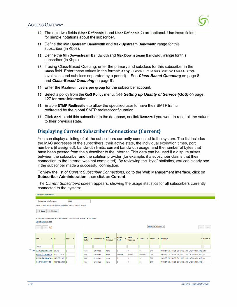
ACCESS GATEWAY
178 System Administration
10. The next two fields (User Definable 1 and User Definable 2) are optional. Use these fields for simple notations about the subscriber.
11. Define the Min Upstream Bandwidth and Max Upstream Bandwidth range for this subscriber (in Kbps).
12. Define the Min Downstream Bandwidth and Max Downstream Bandwidth range for this subscriber (in Kbps).
13. If using Class-Based Queuing, enter the primary and subclass for this subscriber in the Class field. Enter these values in the format: <top-level class>.<subclass> (top-level class and subclass separated by a period). See Class-Based Queueing on page 8 and Class-Based Queueing on page 80.
14. Enter the Maximum users per group for the subscriber account.
15. Select a policy from the QoS Policy menu. See Setting up Quality of Service {QoS} on page 127 for more information.
16. Enable STMP Redirection to allow the specified user to have their SMTP traffic redirected by the global SMTP redirect configuration.
17. Click Add to add this subscriber to the database, or click Restore if you want to reset all the values to their previous state.
DisplayingCurrentSubscriberConnections{Current}You can display a listing of all the subscribers currently connected to the system. The list includes the MAC addresses of the subscribers, their active state, the individual expiration times, port numbers (if assigned), bandwidth limits, current bandwidth usage, and the number of bytes that have been passed from the subscriber to the Internet. This data can be used if a dispute arises between the subscriber and the solution provider (for example, if a subscriber claims that their connection to the Internet was not completed). By reviewing the “byte” statistics, you can clearly see if the subscriber made a successful connection.
To view the list of Current Subscriber Connections, go to the Web Management Interface, click on Subscriber Administration, then click on Current. The Current Subscribers screen appears, showing the usage statistics for all subscribers currently connected to the system:

ACCESS GATEWAY
System Administration 179
In the State field, “Valid” denotes that the subscriber has been authenticated. “Pending” indicates that the subscriber is still waiting for authentication.
To view individual subscribers, click on the linked MAC address.
You can select specific fields to display, and can sort the Current Subscribers table on any field. Click any table header to sort on that field.
DeletingSubscriberProfilesbyMACAddress{DeletebyMAC}This procedure shows you how to delete a subscriber profile from the Access Gateway’s database of authorized subscribers, based on the profile’s MAC address.
To see a current listing of the subscriber database, sorted by MAC addresses, go to Listing Subscriber Profiles {List Profiles} on page 227.
1. From the Web Management Interface, click on Subscriber Administration, then Delete by MAC. The Delete a Subscriber Profile (by MAC) screen appears:
2. In the Enter MAC Address field, enter the MAC address of the profile you want to delete.
3. Click on the Delete button to delete this subscriber profile, or click on the Restore button if you want to reset the “MAC Address” value to the 00 state.
DeletingSubscriberProfilesbyUserName{DeletebyUser}This procedure shows you how to delete a subscriber profile from the Access Gateway’s database of authorized subscribers, based on the profile’s user name.
To see a current listing of the subscriber database, sorted by user name, go to Finding Subscriber Profiles by User Name {Find by User} on page 181.
1. From the Web Management Interface, click on Subscriber Administration, then Delete by User. The Delete a Subscriber Profile (by User) screen appears:

ACCESS GATEWAY
180 System Administration
2. In the Username field, enter the user name of the profile you want to delete.
3. Click Delete to delete this subscriber profile, or click Restore if you want to reset the “Username” value to its blank state.
DisplayingtheCurrentlyAllocatedDHCPLeases{DHCPLeases}You can display a listing of the DHCP (Dynamic Host Configuration Protocol) leases that are currently active on the system’s DHCP server. DHCP is a standard method for assigning IP addresses automatically to network devices. DHCP leases define the amount of time that subscribers can utilize the system’s DHCP service.
To view the list of Currently Allocated DHCP Leases, go to the Web Management Interface, click on Subscriber Administration, then click on DHCP Leases.
To use this feature, your Access Gateway must be set to act as its own DHCP Server. The DHCP function cannot be set to DHCP Relay. Refer to Managing the DHCP service options {DHCP} on page 88.
The Currently Allocated DHCP Leases screen appears:
You can Delete Expired Leases or Delete All Leases.
Deleting an active DHCP lease may cause IP conflicts.
DeletingAllExpiredSubscriberProfiles{Expired}This procedure shows you how to delete all expired subscriber profiles from the Access Gateway’s database of authorized subscribers. Use this procedure when you want to “clean up” the subscriber database.
1. From the Web Management Interface, click on Subscriber Administration, then Expired. The Remove Expired Profiles screen appears:
2. Click on the OK button to remove all expired profiles.
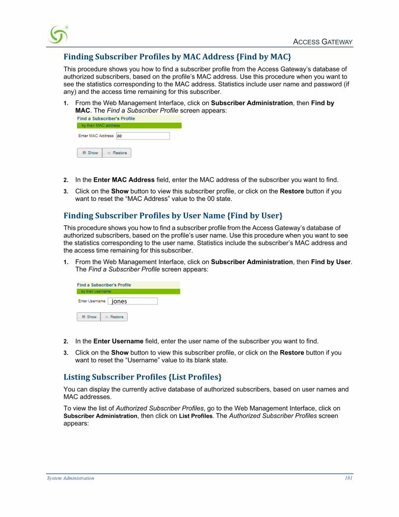
ACCESS GATEWAY
System Administration 181
FindingSubscriberProfilesbyMACAddress{FindbyMAC}This procedure shows you how to find a subscriber profile from the Access Gateway’s database of authorized subscribers, based on the profile’s MAC address. Use this procedure when you want to see the statistics corresponding to the MAC address. Statistics include user name and password (if any) and the access time remaining for this subscriber.
1. From the Web Management Interface, click on Subscriber Administration, then Find by MAC. The Find a Subscriber Profile screen appears:
2. In the Enter MAC Address field, enter the MAC address of the subscriber you want to find.
3. Click on the Show button to view this subscriber profile, or click on the Restore button if you want to reset the “MAC Address” value to the 00 state.
FindingSubscriberProfilesbyUserName{FindbyUser}This procedure shows you how to find a subscriber profile from the Access Gateway’s database of authorized subscribers, based on the profile’s user name. Use this procedure when you want to see the statistics corresponding to the user name. Statistics include the subscriber’s MAC address and the access time remaining for this subscriber.
1. From the Web Management Interface, click on Subscriber Administration, then Find by User. The Find a Subscriber Profile screen appears:
2. In the Enter Username field, enter the user name of the subscriber you want to find.
3. Click on the Show button to view this subscriber profile, or click on the Restore button if you want to reset the “Username” value to its blank state.
ListingSubscriberProfiles{ListProfiles}You can display the currently active database of authorized subscribers, based on user names and MAC addresses.
To view the list of Authorized Subscriber Profiles, go to the Web Management Interface, click on Subscriber Administration, then click on List Profiles. The Authorized Subscriber Profiles screen appears:

ACCESS GATEWAY
182 System Administration
-1 indicates a subscriber added by Admin or XML useradd with no associated plans.
ViewingRADIUSProxyAccountingLogs{RADIUSSessionHistory}These settings are available under Subscriber Administration/RADIUS Session History menu.
EnableLogfilecheckbox
When this setting is enabled any RADIUS proxy accounting messages sent or received by the RADIUS proxy application are logged into a file named “RADHIST.RAD” in the /flash directory. This log contains accounting messages exchanged with downstream servers, and upstream NASs. The size of the log file is limited to 2000 records (accounting messages) or 320000 bytes -- when and if necessary the oldest records are purged to make room for new records.
If the logfile is disabled the current logfile is purged from the flash. If this is re-enabled again, only RADIUS accounting message sent/received from that point in time forward will be stored in the log.

ACCESS GATEWAY
System Administration 183
EnableSyslogscheckbox
If enabled then the same information described above is sent to the configured Syslog server. The content of the syslogs is sent in human-readable format.
The configuration page of the syslog server to which these RADIUS proxy accounting messages are sent is available under the Configuration/Logging menu as described above. The third set of Syslog parameters on that page pertains to the RADIUS History Log.
DisplayingCurrentProfilesandConnections{Statistics}You can view the total number of profiles and connections currently stored in the Access Gateway’s database of authorized subscribers. The displayed list includes the number of subscribers currently in the database (Current Table) and a numerical breakdown of how the subscribers can utilize the system (for example, free access, PayPal, etc.). The total number of user profiles stored in the Access Gateway’s internal database is also shown.
To view the Subscriber Statistics, go to the Web Management Interface, click Subscriber Administration > Statistics. The Subscriber Statistics screen appears:
The “Subscriber licenses in use” is helpful when a large number of subscriber- side devices are defined, and it is otherwise difficult to determine how many license slots are actually in use.
SubscriberInterfaceMenu
DefiningtheBillingOptions{BillingOptions}• Duration-based Billing Plans l Setting Up a “Normal” Billing Plan, including pricing and bandwidth.
l Setting Up an X over Y Billing Plan
l Messages displayed to subscribers, including an Introduction Message, Offer Message and Policy Message.
l Billing schemes (units of access).
l Free billing options (free access).

ACCESS GATEWAY
184 System Administration
l Promotional code options (for example, when offering a percentage discount).
Duration-basedBillingPlans
The purpose of this feature is to let hotels create billing plans that work in a similar fashion to pre-paid telephone cards. This means that an operator can set the Access Gateway’s Internal Web Server (IWS) to allow users online on a time “X” over period “Y” basis. Standard billing plans (where time “X” = period “Y”) can be used concurrently with “X” over “Y” plans. For example, multiple plans with flexible billing event options can be rolled out, such as:
l Plan A: 24 hours, 256kbit/s downstream, 128Kbit/s upstream, public IP address, $15 charge.
l Plan B: 8 hours to be used over 5 days, 512Kbit/s downstream, 256Kbit/s upstream, private IP address, $35 charge.
l Plan C: 1 week, 1Mbit/s downstream, 1Mbit/s upstream, public IP address, $99 charge.
In addition to PayPal billing, Property Management Systems used by hotels are also supported along with the internal data base of the Access Gateway and billing via Nomadix' secure XML API.
See also Assigning a PMS Service {PMS} on page 118 (see following note).
Your product license must support the PMS feature.
1. From the Web Management Interface, click on Subscriber Interface, then Billing Options. The Internal Billing Options Setup screen appears:
2. Review the billing plans (normal plans and X over Y plans) that are currently active. To view or
edit a billing plan, click the View/Edit/Delete button opposite the corresponding plan. The Internal Billing Options Plan Setup or Internal Billing Options XoverY Plan Setup screen appears for the billing plan (and type) you selected.

ACCESS GATEWAY
System Administration 185

ACCESS GATEWAY
186 System Administration
Sample of Internal Billing Options XoverY Plan Setup Screen:
Depending on the type of plan you want to set up, go to:
l Setting Up a “Normal” Billing Plan on page 186.
l Setting Up an X over Y Billing Plan on page 187.
SettingUpa“Normal”BillingPlan
1. If required, click on the Enable check box to enable (make active) this billing plan. 2. Define a “label” for this billing plan in the Label field.
Each plan must have a unique label, different from other plans.
3. Enter a description for this billing plan in the Description of Service field. 4. If desired, enable Facebook Login and specify a plan duration. 5. Define the Pricing schemes for this billing plan (rate per minute, per hour, per day, per week,
and per month).
6. Define the Time Unit of the billable event (either Minute, Hour, Day, Week, or Month). One time unit is assigned to each billing plan.
The Access Gateway allows you to define multiple billing plans with different time units at the same time. For example, you can define one billing plan that changes by the hour (e.g. $2.95 per hour) and a second plan that charges per day (e.g. $12.95 per day).
7. Define the Up (to network) and Down (to subscribers) bandwidth range for this billing plan.

ACCESS GATEWAY
System Administration 187
8. Define the DHCP Pool (public or private) -- see following note.
The Access Gateway allows you to define multiple billing plans with different time units at the same time. For example, you can define one billing plan that changes by the hour (e.g. $2.95 per hour) and a second plan that charges per day (e.g. $12.95 per day).
9. If using Class-Based Queuing, enter the primary and subclass for this subscriber in the Class field. Enter these values in the format: <top-level class>.<subclass> (top-level class and subclass separated by a period). See Class-Based Queueing on page 8 and Class-Based Queueing on page 80.
10. Click on the Save this Plan button to save your changes and establish this billing plan. Alternatively, you can click on the Delete this Plan button if you want to delete this plan, or click on the Clear button if you want to reset all the values to their original state.
11. Click on the Back button at any time to return to the Internal Billing Options Setup (previous) screen.
12. Repeat Steps 2 through 11 for each billing plan. You can enable (make active) any or all of the available billing plans.
13. Define the messages you want to present to subscribers, including: l Introduction Message
l Offer Message
l Policy Message
14. Define the Units of Access (Minute, Hour, Day, Week, or Month) you want to make available to subscribers.
15. If you want to allow free access to subscribers, you can define the following free billing options:
l Default Free Access Time (in days)
l Maximum Subscriber Lifetime (in days)
16. Define any Promotional Code Options in the Code Definition and Percentage Discount fields, as required. You can define up to 5 Promotional Code Options.
The “Percentage Discount” parameter must be between 1 and 100.
17. Click Save to save your changes, or click Restore if you want to reset all the values to their previous state.
SettingUpanXoverYBillingPlan
1. If required, click on the Enable check box to enable (make active) this billing plan.
2. Define a “label” for this billing plan in the Label field.
Each plan must have a unique label, different from other plans.
3. Enter a description for this billing plan in the Description of Service field.
4. Enter the cost the plan in the Plan Cost field.
5. Enter a duration value for this plan in the Plan Duration (X) field.
6. Define the “time unit” for the duration value you entered in Step 5. The time unit can be defined as either Minute, Hour, or Day.
7. Enter plan validity value for this plan in the Plan Validity (Y) field.

ACCESS GATEWAY
188 System Administration
8. Define the “time unit” for the plan validity value you entered in Step 7. The time unit can be defined as Day, Week, or Month.
9. Define the Up (to network) and Down (to subscribers) bandwidth range for this billing plan.
10. Define the DHCP Pool (public or private) -- see following note.
The “public” option requires IP Upsell to be turned on, otherwise subscribers will receive private IP addresses.
11. Click on the Save this Plan button to save your changes and establish this billing plan. Alternatively, you can click on the Delete this Plan button if you want to delete this plan, or click on the Clear button if you want to reset all the values to their original state.
12. Click on the Back button at any time to return to the Internal Billing Options Setup (previous) screen.
SettingUptheInformationandControlConsole{ICCSetup}The Nomadix ICC is a HTML pop-up window that is presented to subscribers, allowing them to select their bandwidth and billing plan options quickly and efficiently, and displays a dynamic “time” field to inform them of the time remaining on their account. The ICC also offers service providers an opportunity to display advertising banners and provide a choice of redirection options.
The Access Gateway also lets System Administrators define a simple HTML-based pop-up window for explicit Logout that can be used as an alternative to the more fully featured ICC (described above). The pop-up Logout Console offers the opportunity to display the elapsed/ count-down time and one logo for intra-session service branding.
This procedure allows you to set up how the ICC is displayed to subscribers. For more information about the ICC, go to Information and Control Console (ICC) on page 228.
1. From the Web Management Interface, click on Subscriber Interface, then ICC Setup. The ICC Setup screen appears:

ACCESS GATEWAY
System Administration 189
2. If you want subscribers to see the ICC (pop-up window), click on the check box for
Display ICC (Information and Control Console) to enable this feature.
3. Choose which ICC you want to be displayed (either the featured ICC or the simple Logout Console). Enable one of the following:
a. ICC (Information and Control Console)
b. Nomadix Logout Console
4. If you enabled either of the ICC pop-up options, you can choose a unique name for the console. Simply type a meaningful name in the Title field.
5. Define the physical location where you want the Nomadix Logout Console to appear on the subscriber’s screen.
Choose one of the following options: a. Upper Left Corner
b. Upper Right Corner
c. Lower Left Corner
d. Lower Right Corner

ACCESS GATEWAY
190 System Administration
6. Define how you want to display the subscriber session time: a. Elapsed Time (how much time has elapsed since the start of the session)
b. Time Remaining (how much time is remaining for the session)
7. You must now decide what you want the ICC to do if the subscriber closes it. Choose one of the following options:
a. Redisplay itself
b. Logout (return the subscriber to a “pending” state) – valid only with RADIUS and Post Paid PMS.
8. You must now assign the buttons that you want to display to subscribers.
AssigningButtons
When assigning the redirect buttons that will appear in the ICC, you can define one ISP Logo Button (large button) and up to 8 smaller buttons (Button 2 through Button 9), with the following parameters:
l Name/Text – The name of the button and the mouse-over text. The mouse-over text is the text that appears in the ICC’s Message Bar when your mouse pointer “rolls” over a button image.
l Target URL – Where subscribers are sent when they click on the button.
l Image Name – The representative image file you want to use for the button.
When assigning images for buttons, refer to Pixel Sizes on page 191.
If you assign (or change) button images or banner images, the Access Gateway must be rebooted for your changes to take effect.
When you have completed assigning all your redirect buttons, click on the Save button to save your changes, or click on the Restore button if you want to reset all the values to their previous state.
You can now assign the banners that you want to display to subscribers.
AssigningBanners
l From the Subscriber Console (Information and Control Console - ICC) Setup screen, click on the Configure Banners link. The Subscriber Console (Information and Control Console - ICC) Banners Setup screen appears:

ACCESS GATEWAY
System Administration 191
You can display up to 5 banners, but they must be defined here. Banners require all the same parameters that “buttons” use (see Assigning Buttons on page 190), with the addition of 3 (three) more. These are:
l Duration – Defines how long the banner is displayed in the ICC.
l Start Time – This is an optional parameter that you set if you want to assign a “start” time (for when the banner is displayed).
l Stop Time – This is an optional parameter that you set if you want to assign a “stop” time (for when the displayed banner closes).
When assigning images and times for banners, refer to Pixel Sizes on page 191 and Time Formats on page 192.
2. Define the parameters for your banner(s):
l Name/Text
l Target URL
l Image Name (see following note)
l Duration (secs)
l Start Time (Optional)
l Stop Time (Optional)
If you assign (or change) button images or banner images, the Access Gateway must be rebooted for your changes to take effect.
3. When finished, click on the Save button to save your changes, click on Save then Reboot to reboot the Access Gateway and make the changes take effect immediately, or click on the Restore button if you want to reset all the values to their previous state. (Only changes to Image Name definitions require a reboot).
4. To return to the previous screen, click on the Configure ICC link.
PixelSizes
Use the following parameters when defining images for buttons and banners:
l Banners – 373 pixels (width) x 32 pixels (height)
l ISP Button – 98 pixels (width) x 26 pixels (height)

ACCESS GATEWAY
192 System Administration
l Small buttons – 45 pixels (width) x 26 pixels (height) Banner (373 x 32 pixels)
Small Buttons
(45 x 26 pixels) ISP Button
(98 x 26 pixels)
TimeFormats
Use the following formats when defining times:
l Duration for Banners – 1 through 9999, or more
l Start or Stop times for Banners – hh:mm PM/AM (for example, 2:35 PM)
DefiningLanguages{LanguageSupport}The Access Gateway allows you to define the text displayed to your users by the Internal Web Server (IWS) without any HTML or ASP knowledge. The language you select here will determine the language encoding that the Access Gateway’s Internal Web Server instructs the browser to use.
The available language options are:
l English l Chinese (Big 5) l French l German l Japanese (Shift_JIS) l Spanish
For localizing the user-facing text into other languages, the following character sets are supported:
l Western ISO-8859-1 l Chinese (Big5, EUC-CN, EUC-TW, GB2312) l Japanese (EUC-JP, ISO-2022-JP, Shift_JIS) l Korean (EUC-KR, ISO-2022-KR, KS_C_5601) l UTF-8

ACCESS GATEWAY
System Administration 193
You can also change the language of the Web Management Interface. See “Selecting the language of the Web Management Interface” on page 78.
1. From the Web Management Interface, click on Subscriber Interface, then Language Support. The Language Support screen appears:
2. Select the language you want to use (see notes).
There are currently 6 (six) “pre-translated” language options. If you want to have the ICC pre-translated into Japanese and enter and display Japanese characters on the Web Management Interface and the subscriber’s portal page, choose the Japanese (Shift_JIS) option. If you want to have the ICC displayed in English but enter and display Japanese characters on the Web Management Interface and the subscriber’s portal page, choose the Other option, then choose one of the available Japanese character sets from the drop-down menu.
If sufficient space is available, the Access Gateway’s Internal Web Server also supports multiple languages at the same time.
The following sample image shows the Web Management Interface (WMI) displayed with Asian language characters.

ACCESS GATEWAY
194 System Administration
EnableServingofLocalWebPages{LocalWebServer}Here are the quick setup instructions to enable serving of local web pages.
1. Upload the required pages and images to the /flash/web directory using FTP. Total file size of all pages and images cannot exceed 200 KB. File names should be labeled using the 8.3 format. The pages can now be served by referencing the URL http://nseip:1111/web/<filename> or at https://nseip:1112/web/<filename> for preauthenticated end users. The post-authentication pages and images are available at http://nseip:3111/web/<filename>.
2. Go to Subscriber Interface > Local Web Server and add the names of the HTML or image files that were uploaded to the /flash/web directory.

ACCESS GATEWAY
System Administration 195
3. Click the Reread Files button to refresh the memory of the currently loaded files whenever there are any changes to the files or their names.
WebPageFileName
This text box lets you add or remove the names of the web pages that you intend to serve to the end users. Note: The name of the web page has to be added in order for it to be served to the end users. Uploading the web page to the /web directory is not sufficient.
ImageFileName
This text box lets you add or remove the names of the image files that you intend to server to the end users. Note: The name of the image file has to be added in order for it to be served to the end users. Uploading the image file to the /web directory is not sufficient.

ACCESS GATEWAY
196 System Administration
DefiningtheSubscriber’sLoginUI{LoginUI}This procedure allows you to set up the presentation and content of the subscriber’s login User Interface (UI).
1. From the Web Management Interface, click on Subscriber Interface, then Login UI. The Subscriber Login User Interface Settings screen appears:
2. Define the messages you want subscribers to see when they log in. Keep messages brief and
to the point. Available message categories include:
l Service Selection Message
l Existing Username Message
l New Username Message
l Contact Message
l PMS Username Message

ACCESS GATEWAY
System Administration 197
3. If any of your devices do not support Java™ scripts, you have the option of disabling the Access Gateway’s JavaScript™ support (JavaScript support is enabled by default). If necessary (and if JavaScript support is already enabled), click on the check box for Enable Javascript to disable this feature.
4. Click on the check box for Enable “Remember Me” option if you want to enable (or disable) this feature. This option enables the Access Gateway to “remember” logins for a predetermined duration.
The “Remember Me” option requires JavaScript to be enabled.
5. If you enabled the “Remember Me” option, define the duration (in days) in the Remember for how many days field.
6. If required, define a Help Hyperlink Message and a corresponding Help Hyperlink URL.
7. Define the location in the Locale field.
8. Define the currency labeling (for example, $) in the Currency field.
The currency must be defined using an IS0 4217 currency code (for example, USD for US Dollars, GBP for Great British Pounds).
9. Enter a numeric value for the Number of decimals for amount. This field defines the number of decimal places that are shown for the displayed amounts.
10. Define the appearance of the internal login screen. Appearance settings include:
l Image File Name (if you want to include a unique image)
l Page Background Color
l Table Background Color
l Page Title Font
l Line Item Font
Take care when mixing font and background colors. You may want to experiment before establishing these settings to ensure that your chosen color scheme is both presentable and readable to subscribers (see notes).
You must reboot the Access Gateway for the “Image File Name” or “Partner Image File Name” settings to take effect.
You can view a grid of acceptable screen colors. To view the grid, simply click on the “View Color Grid” link.
If you click on the “View Color Grid” link, the Browser Safe Background Colors by RGB screen appears:

ACCESS GATEWAY
198 System Administration
Click on the check box for Partner Image to enable this feature, then enter the name of the image file in the Partner Image File Name field. See Subscriber Login Screen (Sample) on page 199.
11. Click on the Save button to save your changes, click on Save then Reboot to reboot the Access Gateway and make the changes take effect immediately, or click on the Restore button if you want to reset all the values to their previous state. (If you made changes to the Image File Name or Partner Image File Name fields, you must reboot the Access Gateway for your changes to take effect).
The partner image (splash screen) is not the same screen that is defined by the Image File Name (IWS screen) field.

ACCESS GATEWAY
System Administration 199
SubscriberLoginScreen(Sample)
The following sample shows a subscriber login screen:
DefiningthePostSessionUserInterface(PostSessionUI)The Post Session UI (Goodbye Page) can be defined either as a RADIUS VSA or be driven by the Access Gateway’s Internal Web Server (IWS). Using the IWS option means that this functionality is available for other post-paid billing mechanisms (for example, post-paid PMS—if your product license supports PMS). The IWS page displays the details of the user's connection, such as:
l IP address of the user.
l Type of AAA.
l Start/Stop time.
l Bytes sent/received.
l Freely configurable hypertext link (in case the ISP wants to link the user back to a sign-up/help page).

ACCESS GATEWAY
200 System Administration
Sample of Post Session UI (Goodbye Page)
1. From the Web Management Interface, click on Subscriber Interface, then Post Session UI. The Subscriber Post Session User Interface Settings screen appears:
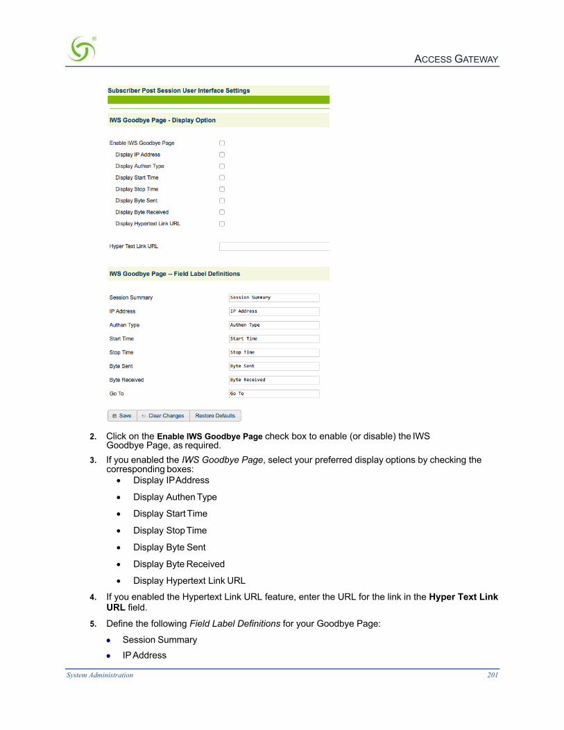
ACCESS GATEWAY
System Administration 201
2. Click on the Enable IWS Goodbye Page check box to enable (or disable) the IWS
Goodbye Page, as required. 3. If you enabled the IWS Goodbye Page, select your preferred display options by checking the
corresponding boxes: • Display IP Address
• Display Authen Type
• Display Start Time
• Display Stop Time
• Display Byte Sent
• Display Byte Received
• Display Hypertext Link URL
4. If you enabled the Hypertext Link URL feature, enter the URL for the link in the Hyper Text Link URL field.
5. Define the following Field Label Definitions for your Goodbye Page:
l Session Summary l IP Address

ACCESS GATEWAY
202 System Administration
l Authen Type l Start Time l Stop Time l Byte Sent
l Byte Received l Go To
The partner image (splash screen) is not the same screen that is defined by the Image File Name (IWS screen) field.
6. Click on the Save button to save your changes. Alternatively, you can click on the Clear Changes button to reset all values to their previous state, or click on the Restore button to revert all values to their default state.
DefiningSubscriberUIButtons{SubscriberButtons}This procedure allows you to define how each of the control buttons are displayed to subscribers.
1. From the Web Management Interface, click on Subscriber Interface, then Subscriber Buttons. The Subscriber Page -- Control Button Definitions screen appears:
2. Enter the definitions you want for each control button in the corresponding fields.
Only the Login button should be named “Login.” Do not assign this name to any other button.
3. Click on the Save button to save your changes, or click on the Clear Changes button if you want to reset all the values to their previous state. If you want to reset all field values to their default state, click on the Restore Defaults button.
DefiningSubscriberUILabels{SubscriberLabels}This procedure allows you to define how the user interface (UI) field labels are displayed to subscribers.
1. From the Web Management Interface, click on Subscriber Interface, then Subscriber Labels. The Subscriber Page -- Field Label Definitions screen appears:
See Caution

ACCESS GATEWAY
System Administration 203
2. Enter the definitions you want for each label in the corresponding fields. 3. Click Save to save your changes, or click Clear Changes if you want to reset all the values to
their previous state. If you want to reset all field values to their default state, click Restore Defaults.
DefiningSubscriberErrorMessages{SubscriberErrors}This procedure allows you to define how error messages are displayed to subscribers.
There are 2 (two) pages of error messages available.
1. From the Web Management Interface, click on Subscriber Interface, then Subscriber Errors, 1 of 2. The Subscriber Page -- Error Message Definitions, 1 of 2 screen appears:

ACCESS GATEWAY
204 System Administration
2. Enter the definitions you want for each error message in the corresponding fields. 3. Click on the Save button to save your changes, or click on the Clear Changes button if you
want to reset all the values to their previous state. If you want to reset all field values to their default state, click on the Restore Defaults button.
4. Repeat Steps 1 – 3 for page 2 of 2.
DefiningSubscriberMessages{SubscriberMessages}This procedure allows you to define how “other” subscriber messages are displayed.
There are 3 (three) pages of subscriber messages available.
1. From the Web Management Interface, click on Subscriber Interface, then Subscriber Messages, 1 of 3. The Subscriber Page -- Other Message Definitions, 1 of 3 screen appears:

ACCESS GATEWAY
System Administration 205
2. Enter the definitions you want for each subscriber message in the corresponding fields.
3. Click on the Save button to save your changes, or click on the Clear Changes button if you want to reset all the values to their previous state. If you want to reset all field values to their default state, click on the Restore Defaults button.
4. Repeat Steps 1 – 3 for page 2 of 3.
5. Repeat Steps 1 – 3 for page 3 of 3.
SystemMenu
AddingandDeletingARPTableEntriesARP (Address Resolution Protocol) is used to dynamically bind a high level IP address to a low level physical hardware (MAC) address. ARP is limited to a single physical network that supports hardware broadcasting. This procedure shows you how to add or delete an ARP table entry.
1. From the Web Management Interface, click on System, then ARP. The ARP Tables screen appears. You can view, delete, or add new ARP table entries from this screen.

ACCESS GATEWAY
206 System Administration
ConfigurableGatewayARPRefreshIntervalThe NSE will periodically refresh its ARP cache entry for the gateway IP. When gateway redundancy is implemented via the use of multiple gateway devices with the same IP address, the periodic refresh enables the NSE to quickly discover the new MAC address of the gateway.
You can set the refresh frequency on the Location page. The frequency must be between 30 and 600 seconds. 600 seconds is half of the ARP cache refresh interval, so the ARP entry can never expire.
Use the following steps to change the ARP Refresh Interval:

ACCESS GATEWAY
System Administration 207
1. Choose Configuration>Ethernet Ports/WAN.
2. Click the interface you wish to configure (in this example, the WAN interface).
3. Enter the desired value for the Gateway ARP Refresh Interval. Press Enter to accept the new
value.
EnablingtheBridgeModeOption{BridgeMode}Bridge Mode allows complete and unconditional access to devices on the subscriber side of the Access Gateway. When the Bridge Mode option is enabled, the Access Gateway is effectively transparent to the network in which it is located, allowing clusters of switches (especially Cisco Systems switch clusters) to be managed using the STP (Spanning Tree Protocol), or any other

ACCESS GATEWAY
208 System Administration
algorithm/protocol. The Access Gateway forwards any and all packets (except those addressed to the Access Gateway network interface). The packets are unmodified and can be forwarded in both directions. This is a very useful feature when troubleshooting your entire network as it allows administrators to effectively “remove” the Access Gateway from the network without physically disconnecting the unit.
You can still manage the Access Gateway when Bridge Mode is enabled, but you have no other functionality. If you enable the Bridge Mode option and then plug the Access Gateway into a network, all you need to do is assign it routable IP addresses. You can then set up all other features and disable the Bridge Mode option whenever you want to start using the Access Gateway in that network.
This procedure shows you how to enable the Bridge Mode option.
1. From the Web Management Interface, click on System, then Bridge Mode. The Bridge Mode (Passthrough) Settings screen appears:
2. Click on the check box for Bridge Mode to enable this feature.
The Access Gateway should be rebooted if this setting is changed.
3. If you want the changes to take effect immediately, Select Save then Reboot.
4. Click Save to save your changes, or click Restore if you want to reset the “Enable” option to its previous state.
ExportingConfigurationSettingstotheArchiveFile{Export}This procedure shows you how to export the current system authentication settings to an archive file for future retrieval. This function is useful if you want to change the configuration settings and you are unsure of the effect that the changes will have. You can restore the archived system configuration settings at any time with the import function.
1. From the Web Management Interface, click on System, then Export. The Export Configuration screen appears:
Click to view the archive.txt and current.txt files

ACCESS GATEWAY
System Administration 209
2. Click on the OK button to export the current authentication settings to the archive.txt file.
ImportingtheFactoryDefaults{Factory}This procedure shows you how to replace the current authentication settings with the settings that were established at the factory.
You will need to reboot the system for some of the imported default settings to take effect.
1. From the Web Management Interface, click on System, then Factory. The Factory Configuration screen appears:
Click to view the factory.txt and current.txt files
2. Click on the Restore then Reboot button to replace the current system configuration settings with the factory default settings and reboot the Access Gateway.
DefiningtheFailOverOptions{FailOver}
Your product license may not support this feature.
Many large scale networks require fail-over support for all devices in the public access network. The Fail Over Options feature allows two Nomadix Gateways to act as siblings, where one device will take up the users should the other device become disconnected from the network. As part of this functionality, the settings (except IP addresses) between the two devices will be synchronized automatically.
1. From the Web Management Interface, click on System, then Fail Over. The Fail Over screen appears:

ACCESS GATEWAY
210 System Administration
2. Enable or disable the Fail Over feature, as required.
3. If you enabled Fail Over, define the Sibling Status (Primary or Secondary).
4. Enter an IP address in the Sibling IP Address field.
5. Define the port in the Fail Over Port field.
6. Select the Secondary To Primary Fail Over Time. The time set here is how long the Secondary will wait while not receiving messages from the Primary before it takes over.
If you are using RADIUS, it is recommended to add both Nomadix gateways to the RADIUS server.
7. Click on the Save button to save your changes, Save then Reboot to make the changes take effect immediately, or click on the Restore button to reset all values to their previous state.
ViewingtheHistoryLog{History}You can view a history log of the system’s Access, Reboot, and Uptime activities. The history log contains up to 500 entries. Over 500 entries and each new log item removes the oldest entry in the list. The latest entry is always at the top of the list.
To view the history log, go to the Web Management Interface and click on System, then History. The Uptime and Access/Reboot History screen appears:
The “Uptime” field displays the time (in days, hours, minutes, and seconds) that the system has been up and running.

ACCESS GATEWAY
System Administration 211
The “Access and reboot History” log fields include:
l Message – Administrator/Operator action.
l Login – User name of the Administrator/Operator.
l IP – Source IP address (see note).
The source IP displayed may be the source IP of a NAT router instead of the client of the person accessing the Access Gateway.
EstablishingICMPBlockingParameters{ICMP}The Access Gateway includes the option to block all ICMP traffic from “pending” or “non-authenticated” users that are destined to addresses other than those defined in the pass-through (walled garden) list. The default setting for this option is “disabled” because ICMP pass- through is a useful end-user troubleshooting feature and is also required by certain smart clients (for example, GRIC).
1. From the Web Management Interface, click on System, then ICMP. The ICMP screen appears:
2. Click on the check box for Block ICMP from pending users to enable (or disable) this
feature, as required.
3. You can Ping a host via the network port by entering either an IP address or DNS name of host. This is the site that you want the ping to be sent to from the NSE.
4. Click on the Save button to save your changes, or click on the Restore button to reset all values to their previous state.
ImportingConfigurationSettingsfromtheArchiveFile{Import}This procedure shows you how to restore the system configuration settings from an archive file (previously created with the export function).
You will need to reboot the system for some of the imported default settings to take effect (especially DHCP).
1. From the Web Management Interface, click on System, then Import. The Import Configuration screen appears:

ACCESS GATEWAY
212 System Administration
Click here to view the “archive.txt” or “current.txt” files.
2. Click OK to replace the current system configuration settings with the settings contained in the archive.txt file (see notes above).
EstablishingLoginAccessLevels{Login}System Menu Login allows for different levels of access and use when servicing the authentication request.
Access methods supported are (1) telnet, (2) CLI -- Command Line Interface via the console port, (3) WMI – WEB Managed Interface, (4) FTP and SFTP, (5) SSH Shell Access and (6) SSL.
The Access Gateway allows you to define (4) concurrent access levels:

ACCESS GATEWAY
System Administration 213
1. From the Web Management Interface, click on System Menu, then Login. The Login Name and Password screen appears:
2. Click on the check box for Administration Concurrency if you want to limit logins to 1 Manager
and 3 operators and/or staff simultaneously. When this feature is enabled, one Manager and up to three Operators and/or Staff can connect to the Access Gateway at any one time (the default is “disabled”). (See Defining the AAA Services {AAA} on page 62.)
3. Configure the Access Levels
Login and passwords are case-sensitive. Use login and passwords that are (up to 11 characters, any character type).
If you forget your password, you will need to contact technical support. See also, “Technical Support” on page 347.

ACCESS GATEWAY
214 System Administration
Access Level Description
Man
ager
Manager Login Managers -- Administrative privileges with read/write access, hasthe ability to perform all write commands (Submit, Reset, Reboot, Add, Delete, Save, FTP and SFTP etc.) 1-11 ASCII characters case sensitive
Manager Password 1-11 ASCII characters case sensitive
Confirm Password 1-11 ASCII characters case sensitive (must match Manager Password)
Ope
rato
r
Operator Login Operators -- Administrative restricted access: Read only access rights. No save and no reboot. Reprint Access Codes. 1-11 ASCII characters case sensitive must enable Administration Concurrency
Operator Password 1-11 ASCII characters case sensitive
Confirm Password 1-11 ASCII characters case sensitive (re-enter password must match password)
Staf
f
Staff Login Staff -- Administrative restricted access to the Subscriber Administration functionality only. Create/delete Access Codes, manage the Current Table, List Profiles and review Statistics. 1-11 ASCII characters case sensitive must enable Administration Concurrency
Staff Password 1-11 ASCII characters case sensitive
Confirm Password 1-11 ASCII characters case sensitive (re-enter password must match password)
XML
Serv
er XML Login XML Server using Basic Authentication using HTTP:// submits
1-11 ASCII characters case sensitive must enable Administration Concurrency
XML Password 1-11 ASCII characters case sensitive
Confirm Password 1-11 ASCII characters case sensitive (re-enter password must match password)
Rad
ius
Radius Remote Test Login
Remote Radius Testing
Only Manager can assign a login and password for the RADUS testing login option.
1-11 ASCII characters case sensitive
Radius Remote Password
1-11 ASCII characters case sensitive
RemoteRADIUSTestingAs part of its Smart Client feature, the Access Gateway offers a remote RADIUS testing feature (enabled by default). With this feature, the Access Gateway provides a password- protected Web page. From this Web page, technical support can type a username and password and instruct the Access Gateway to send a RADIUS access request to the RADIUS server—following the same basic rules as if the request was from a user.
1. In a separate browser window, visit the URL for the test page at http://<Nomadix Access Gateway IP>/radtest/testradius.htm. This URL can be accessed from the network side of the Access Gateway. The “Framed IP” field is configurable by the user and can be set to any IP address.

ACCESS GATEWAY
System Administration 215
2. Click on the check box for Radius Authentication Enable to enable the Centralized
Authentication mechanism. If chosen, the system will first try to authenticate against the local database and then will check against the RADIUS Service Profiles that are configured.
3. Select the RADIUS Service Profile from the pop-up list. The list of available profiles is defined in Realm-Based Routing.
4. Enter a Session Timeout value in minutes. This defines the time of validity period of the cookie passed to the Web browser from the WMI Session and RADIUS session.
5. Managers Only: If RADIUS is enabled, you can enter a login name in the RADIUS Remote Test Login field.
For RADIUS logins, the maximum number of characters for usernames is 96. The maximum number of characters for passwords is 128.
6. Managers Only: If you entered a login name in Step 7, enter a password in the RADIUS Remote Test Password field.
7. Managers Only: Click on the Save button to save the login and password parameters, or click on the Restore button if you want to reset all the values to their previous state.
DefiningtheMACFilteringOptions{MACFiltering}MAC Address filtering enhances Nomadix' access control technology by allowing System Administrators to block malicious users based on their MAC address. Up to 600 MAC addresses can be blocked at any one time (see caution).
MAC addresses that you enter here will cause the subscribers at these addresses to be blocked from service. Please make sure that you enter the correct addresses before submitting the data.
1. From the Web Management Interface, click on System, then MAC Filtering. The MAC Filtering screen appears:

ACCESS GATEWAY
216 System Administration
2. Click on the check box for MAC Filtering to enable (or disable) this feature, as required.
3. Enter a MAC address in the MAC field, then click on the Add button to add this address to the “blocked” list, or click on the Remove button to remove this address from the list.
For advanced security, see Establishing Session Rate Limiting {Session Limit} on page 219.
UtilizingPacketCapturing{PacketCapture}The Packet Capture feature provides NSE administrators with an on-system utility to capture network traffic on each of the NSE network interfaces. The captured network traffic will be accessible for FTP download and viewing on a remote host, in the form of a PCAP-formatted file. (Note that a utility that is capable of reading and displaying PCAP-formatted files, such as Wireshark®, is required in order to view the results).
1. From the Web Management Interface, click on System, then Packet Capture. The Packet Capture Settings screen appears:
2. To initiate a capture on a given interface, click that interface’s associated Start button. The button
label will change to Stop, indicating that a capture is in progress. Click the button again to stop the capture.
3. When a capture has been stopped, the captured traffic can be viewed by clicking the Download link for the given interface.
4. To modify capture settings, click the Show button for the desired interface. This will display the parameters that can be adjusted. Filtering expressions must be entered in the form of a PCAP-style string:

ACCESS GATEWAY
System Administration 217
RebootingtheSystem{Reboot}This procedure shows you how to reboot the Access Gateway.
The “reboot” procedure outlined on this page allows you to decide when to reboot (if you are making multiple changes to different menu functions and you want to reboot just one time after completing all your changes).
1. From the Web Management Interface, click on System, then Reboot. The Reboot Device screen appears:
2. Click OK to reboot the operating system
RoutingTables{Routing}This command allows you to configure static routes and pick the WAN interface for a specific destination network. The display provides information on network routes and their system connections. You can also add or delete routes from this screen.
To use this feature, WAN Load Balancing must be enabled. See Load Balancing on page 110.

ACCESS GATEWAY
218 System Administration
To view the routing tables, choose System > Routing. The Routing Tables screen appears.
You can view the routes associated with each physical NSE port by clicking on the tab for the port. In the screen shot above, only the WAN port is in use.
AddingaRoute
Use the following steps to add a route:
1. On the Routing Tables screen, scroll to Add a New Static or Persistent Route.
2. Enter the Destination IP/Prefix Length address of the route you want to add to the routing table.
This is the Destination IP or Subnet that the Route is trying to reach, with the prefix length to determine how large the subnet might be.
3. Enter the Gateway IP address for the Route being added so that the NSE knows what to use to try to reach the destination IP/Subnet.
4. Choose the Port Name, the physical NSE Port to which the route is attached. 5. Choose the Role based on what the route is designed for. This will normally be wan. 6. Choose the Type, Static or Persistent. 7. Click Add to add this route to the routing table, or click Restore if you want to reset all the values
to their previous state.

ACCESS GATEWAY
System Administration 219
DeletingaRoute
To deleted a route, click the Delete link in the routing table. The route is immediately deleted.
To restore a deleted route, reboot the NSE (which will restore auto-generated routes) or manually re-enter the route.
EstablishingSessionRateLimiting{SessionLimit}Session Rate Limiting (SRL) significantly reduces the risk of “Denial of Service” attacks by allowing administrators to limit the number of DAT sessions any one user can take over a given time period and, if necessary, then block malicious users.
1. From the Web Management Interface, click on System, then Session Limit. The Session Rate Limiting screen appears:
2. Click on the check box for Session Rate Limiting to enable (or disable) this feature, as required.
3. Enter values for the following session “limiting” parameters:
l Mean Rate
l Burst Size
l Time Interval (in seconds)
4. Click on the Save button to save your changes.
For advanced security, see also Defining the MAC Filtering Options {MAC Filtering} on page 215.
Adding/DeletingStaticPorts{StaticPort-Mapping}Static Port-Mapping allows the network administrator to setup a port mapping scheme that forwards packets received on a specific port to a particular static IP (typically private and misconfigured) and port number on the subscriber side of the Access Gateway. The advantage for the network administrator is that free private IP addresses can be used to manage devices (such as Access Points) on the subscriber side of the Access Gateway without setting them up with public IP addresses.
Toaddstaticports
1. From the Web Management Interface, click on System, then Static Port-Mapping. The Static Port-Mapping screen appears:

ACCESS GATEWAY
220 System Administration
2. Enter the Internal IP Address.
Ensure that the device with the Internal IP Address has been added to the subscriber’s table.
3. Enter the Internal Port reference.
4. Enter a valid MAC Address.
5. Enter the External IP Address.
The External IP address field will default to the IP address of the Access Gateway.
6. Enter the External Port reference.
7. Optional: Enter the Remote IP Address. Leave this field set to zero if you want to connect to the internal device from any network-side workstation.
8. Optional: Enable the Protect with Source IP-based Access Control option. Enabling this will only allow address in the source-based access control list to connect on this port mapping. Source-based access control needs to be enabled for this to be in effect.
9. Optional: Enter the Remote Port reference. Leave this field set to zero if you want to connect to the device from any TCP/UDP port of a network-side workstation.
10. Select the protocol (TCP or UDP) from the pull-down menu.

ACCESS GATEWAY
System Administration 221
11. Click Add to add this static port, or click Restore to reset all values to their previous state.
Todeletestaticports
1. From the Web Management Interface, click on System, then Static Port-Mapping. The Static Port-Map screen appears.
2. Select the item you want to delete.
3. Click on the Delete button to delete the static port, or click on the Restore button to reset your changes to their previous state.
For more information about Static Port-Mapping, see also Displaying the Static Port Mapping Table {Static Port-Mapping} on page 159.
UpdatingtheAccessGatewayFirmware{Upgrade}Upgrading the Access Gateway firmware is performed from the Access Gateway’s Command Line Interface (CLI) only. Refer to the Firmware Upgrade Procedure (separate document available from Nomadix Technical Support).
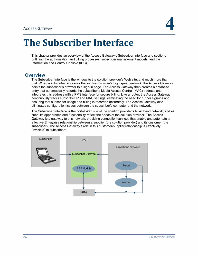
ACCESS GATEWAY 4
222 The Subscriber Interface
TheSubscriberInterface
This chapter provides an overview of the Access Gateway’s Subscriber Interface and sections outlining the authorization and billing processes, subscriber management models, and the Information and Control Console (ICC).
Overview The Subscriber Interface is the window to the solution provider’s Web site, and much more than that. When a subscriber accesses the solution provider’s high speed network, the Access Gateway points the subscriber’s browser to a sign-in page. The Access Gateway then creates a database entry that automatically records the subscriber’s Media Access Control (MAC) address and integrates this address with a PMS interface for secure billing. Like a router, the Access Gateway continuously tracks subscriber IP and MAC settings, eliminating the need for further sign-ins and ensuring that subscriber usage and billing is recorded accurately. The Access Gateway also eliminates configuration issues between the subscriber’s computer and the network.
The Subscriber Interface is the portal Web site of the solution provider’s broadband network, and as such, its appearance and functionality reflect the needs of the solution provider. The Access Gateway is a gateway to this network, providing connection services that enable and automate an effective Enterprise relationship between a supplier (the solution provider) and its customer (the subscriber). The Access Gateway’s role in this customer/supplier relationship is effectively “invisible” to subscribers.

ACCESS GATEWAY
The Subscriber Interface 223
AuthorizationandBillingAs a gateway device, the Access Gateway enables plug-and-play access to broadband networks. Broadband network solution providers can now offer their subscribers a wide range of high speed services, including access to the Internet. Of course, a high speed Internet connection is not free – subscribers pay an access fee, based on the duration of their connection. Additionally, subscribers may want to take advantage of the solution provider’s local network services (for example, purchasing goods and local services). In either case, the subscriber is required to pay. Naturally, subscribers expect to pay only for the services rendered to them.
In any environment, billing is a complex process. It requires accurate data collection and reconciliation, a means to validate and protect the data, and an efficient method for collecting payments.
The Access Gateway offers powerful billing support functionality called “Authentication, Authorization, and Accounting.” This feature (also known as AAA) employs a combination of command routines designed to create a flexible, efficient, and secure billing environment. For example, when a subscriber logs into the system, their unique MAC address is placed into an authorization table. The system then authenticates the subscriber’s MAC address and billing information before allowing them to access the Internet and make online purchases.
TheAAAStructureThe Access Gateway’s Authentication, Authorization, and Accounting (AAA) module enables the solution provider to provision, track, and bill new or returning subscribers. This includes:

ACCESS GATEWAY
224 The Subscriber Interface
l Allowing the solution provider (for example, a hotel) to bill its guests for the high speed network services it provides, track usage on the network, and deny service to those guests who have not paid.
l Allowing the solution provider to bill subscribers for services rendered, either directly on their hotel bill (in the hotel scenario), via a mailed invoice, or directly to the subscriber’s PayPal account.
The following illustration shows the functional relationship between the Access Gateway’s internal modules and the external support systems.
The Authentication module is responsible for ensuring that when subscribers log in to the system they are correctly identified. It can identify subscribers in many different ways. For example:
l Based on their hardware (MAC) address.
l By validating their user name and password.
l By looking up subscribers on a local (flash) database.
l By looking up subscribers on a remote database.
The Authentication module can support user name and MAC address authentication simultaneously.
The initial login page can be presented in various ways, depending on the system’s configuration. The Access Gateway supports any of the following methods and tools:
l Internal and external Web pages.
l External “portal” page for redirection.

ACCESS GATEWAY
The Subscriber Interface 225
l User name and MAC-based logins (simultaneous or stand-alone).
l User-selectable options and parameters (for example, defining the time purchased).
l Interaction with a Property Management System (PMS) and Web interfaces enabling administrators to edit the subscriber’s input.
Only subscribers that are correctly identified and authenticated are authorized to access the system. Once authorized, the subscriber’s activity is logged and billed through the Access Gateway’s Accounting module. The Accounting module fully supports the following functions:
l PayPal billing
l User name and password verification.
l Billing verification.
l Per port-location (for example, room or unit) billing.
ProcessFlow(AAA)The following flowchart outlines the AAA and billing process. All actions depicted in the chart are administered and tracked by the Access Gateway.
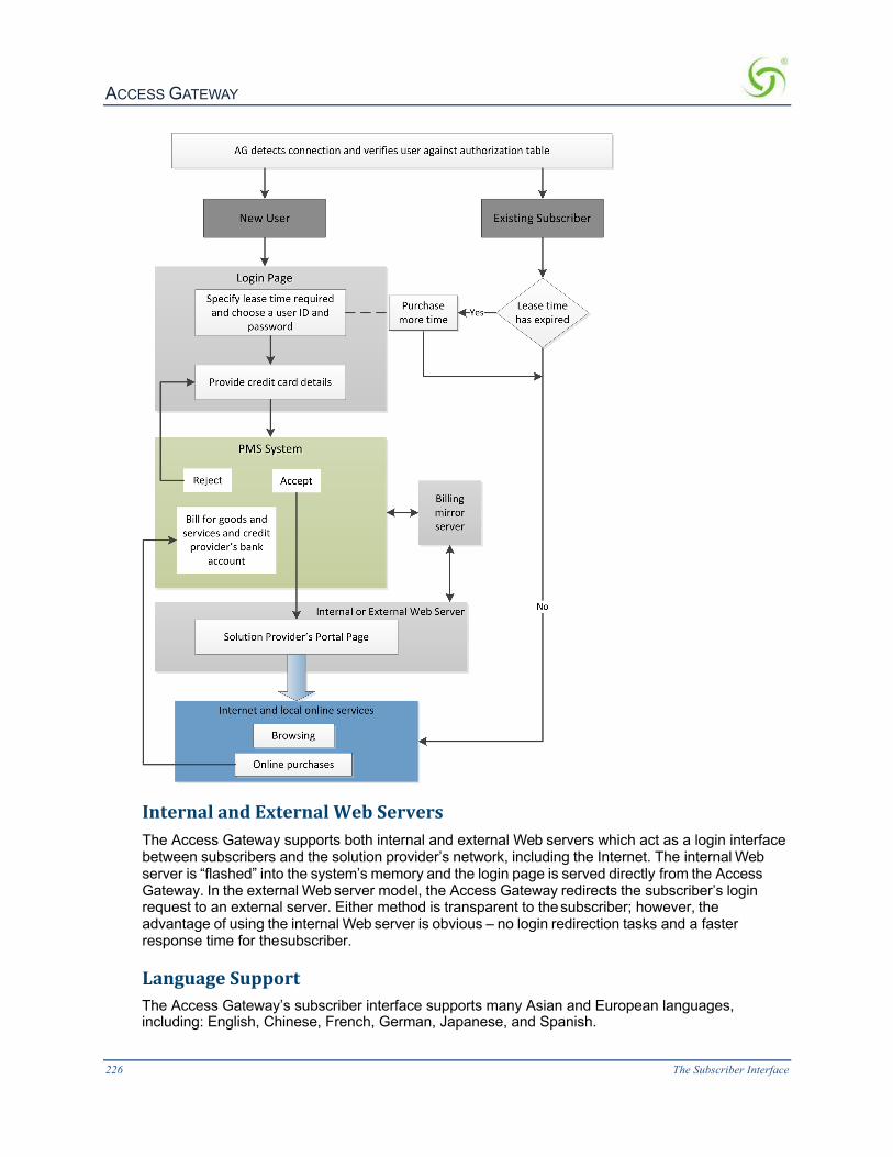
ACCESS GATEWAY
226 The Subscriber Interface
InternalandExternalWebServersThe Access Gateway supports both internal and external Web servers which act as a login interface between subscribers and the solution provider’s network, including the Internet. The internal Web server is “flashed” into the system’s memory and the login page is served directly from the Access Gateway. In the external Web server model, the Access Gateway redirects the subscriber’s login request to an external server. Either method is transparent to the subscriber; however, the advantage of using the internal Web server is obvious – no login redirection tasks and a faster response time for the subscriber.
LanguageSupportThe Access Gateway’s subscriber interface supports many Asian and European languages, including: English, Chinese, French, German, Japanese, and Spanish.
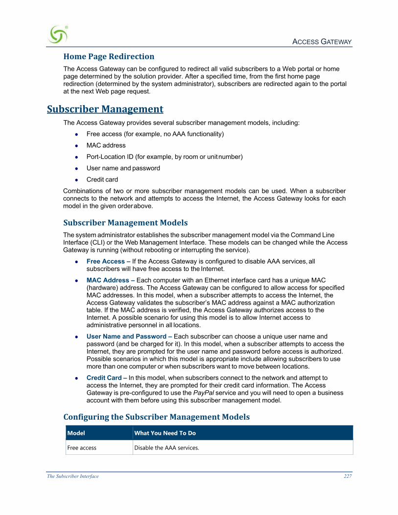
ACCESS GATEWAY
The Subscriber Interface 227
HomePageRedirectionThe Access Gateway can be configured to redirect all valid subscribers to a Web portal or home page determined by the solution provider. After a specified time, from the first home page redirection (determined by the system administrator), subscribers are redirected again to the portal at the next Web page request.
SubscriberManagementThe Access Gateway provides several subscriber management models, including:
l Free access (for example, no AAA functionality)
l MAC address
l Port-Location ID (for example, by room or unit number)
l User name and password
l Credit card
Combinations of two or more subscriber management models can be used. When a subscriber connects to the network and attempts to access the Internet, the Access Gateway looks for each model in the given order above.
SubscriberManagementModelsThe system administrator establishes the subscriber management model via the Command Line Interface (CLI) or the Web Management Interface. These models can be changed while the Access Gateway is running (without rebooting or interrupting the service).
l Free Access – If the Access Gateway is configured to disable AAA services, all subscribers will have free access to the Internet.
l MAC Address – Each computer with an Ethernet interface card has a unique MAC (hardware) address. The Access Gateway can be configured to allow access for specified MAC addresses. In this model, when a subscriber attempts to access the Internet, the Access Gateway validates the subscriber’s MAC address against a MAC authorization table. If the MAC address is verified, the Access Gateway authorizes access to the Internet. A possible scenario for using this model is to allow Internet access to administrative personnel in all locations.
l User Name and Password – Each subscriber can choose a unique user name and password (and be charged for it). In this model, when a subscriber attempts to access the Internet, they are prompted for the user name and password before access is authorized. Possible scenarios in which this model is appropriate include allowing subscribers to use more than one computer or when subscribers want to move between locations.
l Credit Card – In this model, when subscribers connect to the network and attempt to access the Internet, they are prompted for their credit card information. The Access Gateway is pre-configured to use the PayPal service and you will need to open a business account with them before using this subscriber management model.
ConfiguringtheSubscriberManagementModels
Model What You Need To Do
Free access Disable the AAA services.

ACCESS GATEWAY
228 The Subscriber Interface
Model What You Need To Do
MAC address Enable the AAA services and add a subscriber profile to the database for each MAC address you want to enable.
User Name and Password
Enable the AAA services and Usernames. Add a subscriber profile to the database for each user name and password you want to enable. You will need to request a unique user name and password when they pay for the service. The user name and password are optional (the MAC address will be substituted), but in this event the service is not transferable between computers.
PayPal Enable the AAA services. You have the choice of enabling the Access Gateway’s internal authorization module or using PayPal as an authorization server. Internal Authorization Enabled Enter PayPal’s App Name, Client ID, Webhook ID, set the proper secret code, and select if you are using a Live Environment information obtained from your PayPal account. If you have NOT enabled Internal Authorization Set up your own external authorization server with your own PayPal or Credit Card options. Enter the external authorization server’s URL; then enter its IP address as a pass-through IP address.
InformationandControlConsole(ICC)The ICC is a HTML pop-up window that is presented to subscribers, allowing them to select their bandwidth and billing options quickly and efficiently, and displays a dynamic “time” field to inform them of the time remaining on their account. The ICC also offers service providers an opportunity to display advertising banners and provide a choice of redirection options.
For information about configuring the ICC, refer to Defining Languages {Language Support} on page 192.

ACCESS GATEWAY
The Subscriber Interface 229
ICCPop-UpWindowThe ICC displays a HTML-based applet in the form of a pop-up window from which subscribers can dynamically control their billing options and bandwidth, and which allows service providers to display advertising banners and redirect their subscribers to predetermined Web sites.
The pop-up window automatically displays at Home Page Redirection (HPR) or whenever the subscriber brings up a new browser window.
LogoutConsoleThe Access Gateway allows System Administrators to define a simple HTML-based pop-up window for explicit logout that can be used as an alternative to the more fully featured ICC. The pop-up Logout Console can display the elapsed/count-down time and one logo for intra- session service branding.
Banner
Time remaining
Bandwidth selection (pull down)
Redirect buttons Message Bar

ACCESS GATEWAY
230 The Subscriber Interface
QuickReferenceGuide
This chapter contains product reference information, organized by topic. Use this chapter to locate the information you need quickly and efficiently.

ACCESS GATEWAY
Quick Reference Guide 231
WebManagementInterface(WMI)MenusThe following tables contain a listing and brief explanation of all menus and menu items contained in the Access Gateway’s Web Management Interface (WMI), listed as they appear on screen.
Menus Description
Configuration Menu
Displays the Configuration menu. Items in this menu let you establish IP parameters, set DHCP options, set DNS and home page redirection options, set MAC-based authentication, display configuration settings, and set the system date and time, SNMP and SYSLOG parameters.
Network Info Menu
Displays the Network Info menu. The items in this menu are used to monitor and review network connections, routings, protocols, and network session statistics.
Port-Location Menu
Displays the Port-Location menu. Items in this menu let you find, add, remove, and update the Port-Location Assignments (for example, VLAN tags).
Subscriber Administration Menu
Displays the Subscriber Administration menu. The items in this menu allow you to add, remove, and monitor subscriber profiles, display the current DHCP leases, and monitor the subscribers currently connected to the network.
Subscriber Interface Menu
Displays the Subscriber Interface menu. The items in this menu allow you to define how the subscriber interface is displayed to users and what information it contains.
System Menu Displays the System menu. Items in this menu let you manage login names and passwords, configuration settings, and routings.
ConfigurationMenuItems
Item Description
AAA Establishes the AAA service options.
Access Control To enable secure administration of the product, the Nomadix Access Gateway incorporates a master access control list that checks the source (IP address) of administrator logins. A login is permitted only if a match is made with the master list contained on the Nomadix Access Gateway. If a match is not made, the login is denied, even if a correct login name and password are supplied. The access control list supports up to 50 (fifty) entries in the form of a specific IP address or range of IP addresses. Additionally, the Nomadix Access Gateway offers access control based on the type of Interface being used. This feature allows administrators to block access from Telnet, Web Management, and FTP sources.
Auto Configuration Provides an effortless and rapid method for configuring devices for fast network roll-outs.
Bandwidth Management Manages the bandwidth for subscribers, defined in Kbps (Kilobits per seconds) for both upstream and downstream data transmissions.
Bill Record Mirroring Configures the Nomadix Access Gateway to send copies of billing records to external servers.

ACCESS GATEWAY
232 Quick Reference Guide
Item Description
Class-Based Queueing Define multiple groups (classes) of users, to support priority and guaranteed minimum bandwidth on a per-group basis
Clustering Automatically distribute subscribers across gateways.
Destination HTTP Redirection
Configure redirection of HTTP requests to one or more portal page URLs.
DHCP Assigns the Nomadix Access Gateway as its own DHCP server, or enables the DHCP relay for an external server.
DNS Sets up the DNS parameters, including the host name, domain, and the primary and secondary DNS servers.
Dynamic DNS Sets parameters for Dynamic DNS.
Fast Forwarding Enable Fast Forwarding mode for improved throughput.
GRE Tunneling Sets GRE Tunneling parameters.
Home Page Redirect Redirects the subscriber’s browser to a specified home page.
iNAT™ Enables Intelligent Address Translation for Transparent VPN Access.
Interface Monitoring The ability to actively monitor each WAN/ISP/ and VLAN connection to assure that full network functionality exists
IPSec IPsec is an end-to-end security scheme operating in the Internet Layer of the Internet Protocol Suite. It can be used in protecting data flows between a pair of hosts (host-to-host), between a pair of security gateways (network-to-network), or between a security gateway and a host (network-to-host). Can be used in the transport layer or used to create a secure tunnel
IPv6 Allows direct network management through IPv6
Load Balancing Ensures that demands placed on high-speed Internet access (HSIA) are balanced based on the capability of each WAN/ISP connection.
Location Sets up your location and IP addresses for the network, subscriber, subnet mask, and default gateway.
Logging Enables logging options for the system and AAA functions.
MAC Authentication Enables MAC authentication, retry frequency, MAC address format, MAC address hex-alpha case, and RADIUS service profile.
Passthrough Addresses Establishes IP pass-through addresses (up to 300).
PMS Enables one of the listed PMS options, or allows you to disable the PMS feature.
Port-Location Establishes the Access Concentrator settings.
QoS Configure mode and polices for Quality of Service metrics.
RADIUS Client Set up the RADIUS client.

ACCESS GATEWAY
Quick Reference Guide 233
Item Description
RADIUS Proxy Establishes RADIUS proxies, where different realms can be set up to directly channel RADIUS messages to the various RADIUS servers.
Realm-Based Routing Realm-Based Routing provides advanced NAI (Network Access Identifier) routing capabilities, enabling multiple service providers to share a HotSpot location, further supporting a Wi- Fi wholesale model. This functionality allows users to interact only with their chosen provider in a seamless and transparent manner.
Routed Subscribers Allows Routed network hops on the Subscriber side of the Nomadix.
SMTP Enables the SMTP (E-mail) redirection functions.
SNMP Establishes the SNMP parameters.
Subnets Enables dynamic multiple subnet support.
Summary Displays a summary listing of all configuration settings.
Time Sets the system date and time.
Traffic Descriptors Bandwidth consumed over time, active allocated bandwidth, number of using bandwidth and network capacity,
URL Filtering Dynamically adds or removes up to 300 specific IP addresses and domain names to be filtered for each property.
User-Agent Filtering User agent Filtering is a capability that can filter software that is acting on behalf of a user, such as browsers.
Zone Migration The present disclosure is directed to providing a network user the ability to travel between different zones or locations within a network environment, such as, for example, a hospitality location, without requiring a user to re-login to the new location.
NetworkInfoMenuItemsItem Description
ARP Displays the ARP table, including the destination IP address and the gateway MAC address.
DAT Displays the DAT session table.
DNSSEC DNSSEC support adds authentication and integrity capability to DNS systems. The DNSSEC feature in the NSE allows DNSSEC queries and responses to traverse the NSE between subscribers and the NSE's configured DNS servers. The NSE itself does not participate in DNSSEC trust relationships with subscribers.
Hosts Displays the host table, including host names, associated IP addresses and any assigned aliases.
ICMP Displays the ICMP (Internet Control Message Protocol) performance statistics.
Interfaces Displays statistics for the interfaces.

ACCESS GATEWAY
234 Quick Reference Guide
Item Description
IP Displays the IP performance statistics.
IPSec IPsec is an end-to-end security scheme operating in the Internet Layer of the Internet Protocol Suite. It can be used in protecting data flows between a pair of hosts (host-to-host), between a pair of security gateways (network-to-network), or between a security gateway and a host (network-to-host). Can be used in the transport layer or used to create a secure tunnel.
Login Page Failover For installations that use an External Web Server or a Portal Server to provision their Login and Authentication Pages to the subscribers, the Login Page Failover feature provides a way for administrators to configure secondary or tertiary Login Pages in case the primary Login Page becomes unavailable. This mechanism guarantees that the subscribers will have some way of authenticating themselves and accessing the Internet if the External and Portal Servers fail.
NAT IP Interface A new separate iNAT interface page shows the settings for each port in either WAN or OOS modes. Ports in SUB mode are not shown. Each of the displayed ports has individual iNAT / Subscriber tunnel settings accessible by clicking on that port's link. A new improved interface allows easy deletion of any iNAT address range.
Packet Capture Summary
Displays the different interfaces and the information of how many packets are seen and captured when the Packet capture feature under System -> Packet capture is running for that interface.
Routing Displays the routing tables and performance statistics.
Sockets Displays the active Internet connections.
Static Port-Mapping Displays the currently active static port-mapping scheme.
TCP Displays the TCP performance statistics.
UDP Displays the UDP performance statistics.
Port-LocationMenuItemsItems Description
Add Adds or updates port-location assignments.
Delete All Deletes all port-location assignments. Use this command with caution.
Export Exports specified port-location assignments to the location.txt file.
Find by Description Finds a port-location assignment, based on a unique description.
Find by Location Finds a port-location assignment, based on a specified location.
Find by Port Finds a port-location assignment, based on a specified port.
Import Imports specified port-location assignments from the location.txt file.
List Displays the port-location file, listing all port-location assignments.

ACCESS GATEWAY
Quick Reference Guide 235
SubscriberAdministrationMenuItemsItems Description
Add Adds subscriber profiles to the database.
Current Displays a list of all currently connected subscribers.
Delete by MAC Deletes a subscriber, based on a specific MAC address.
Delete by User Deletes a subscriber, based on a specific user name.
DHCP Leases Sets up the current subscriber DHCP leases.
Expired Removes expired profiles.
Find by MAC Finds a subscriber profile, based on a specified MAC address.
Find by User Finds a subscriber profile, based on a specified user name.
List Profiles Displays a list of authorized subscriber profiles.
RADIUS Session History
These logs record RADIUS proxy accounting messages sent or received by the RADIUS proxy.
Statistics Displays the current subscriber profile statistics (for example, how many profiles are currently in the database).
SubscriberInterfaceMenuItemsItems Description
Billing Options Establishes the various billing plans and rates (schemes), including messages and appearance.
ICC Setup Sets up the Information and Control Console (ICC) for subscribers.
Language Support Defines the language to be displayed on the Web Management Interface and the subscriber’s portal page.
Local Web Server Upload the required pages and images to the /flash/web directory using FTP. Total file size of all pages and images cannot exceed 200 KB.
Login UI Defines the appearance of the internal subscriber login user interface, including all the login messages and fonts, etc., and establishes the currency.
Post Session UI Defines the post session “Goodbye” page.
Subscriber Buttons Defines how each of the subscriber’s user interface control buttons are displayed.
Subscriber Labels Defines how the subscriber’s user interface field labels are displayed.
Subscriber Errors, 1/2 Defines how error messages are displayed to subscribers (page 1 of 2).
Subscriber Errors, 2/2 Defines how error messages are displayed to subscribers (page 2 of 2).
Subscriber Messages, 1/3 Defines how “other” general messages are displayed to subscribers (page 1 of 3).
Subscriber Messages, 2/3 Defines how “other” general messages are displayed to subscribers (page 2 of 3).
Subscriber Messages, 3/3 Defines how “other” general messages are displayed to subscribers (page 3 of 3).
Subscriber Messages, TOA Text for Terms of Agreement. Can be created using the internal web server.
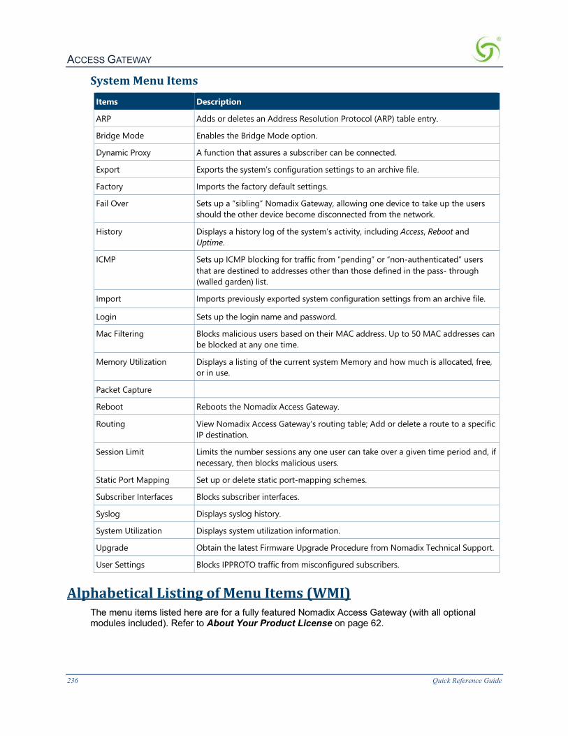
ACCESS GATEWAY
236 Quick Reference Guide
SystemMenuItemsItems Description
ARP Adds or deletes an Address Resolution Protocol (ARP) table entry.
Bridge Mode Enables the Bridge Mode option.
Dynamic Proxy A function that assures a subscriber can be connected.
Export Exports the system’s configuration settings to an archive file.
Factory Imports the factory default settings.
Fail Over Sets up a “sibling” Nomadix Gateway, allowing one device to take up the users should the other device become disconnected from the network.
History Displays a history log of the system’s activity, including Access, Reboot and Uptime.
ICMP Sets up ICMP blocking for traffic from “pending” or “non-authenticated” users that are destined to addresses other than those defined in the pass- through (walled garden) list.
Import Imports previously exported system configuration settings from an archive file.
Login Sets up the login name and password.
Mac Filtering Blocks malicious users based on their MAC address. Up to 50 MAC addresses can be blocked at any one time.
Memory Utilization Displays a listing of the current system Memory and how much is allocated, free, or in use.
Packet Capture
Reboot Reboots the Nomadix Access Gateway.
Routing View Nomadix Access Gateway’s routing table; Add or delete a route to a specific IP destination.
Session Limit Limits the number sessions any one user can take over a given time period and, if necessary, then blocks malicious users.
Static Port Mapping Set up or delete static port-mapping schemes.
Subscriber Interfaces Blocks subscriber interfaces.
Syslog Displays syslog history.
System Utilization Displays system utilization information.
Upgrade Obtain the latest Firmware Upgrade Procedure from Nomadix Technical Support.
User Settings Blocks IPPROTO traffic from misconfigured subscribers.
AlphabeticalListingofMenuItems(WMI)The menu items listed here are for a fully featured Nomadix Access Gateway (with all optional modules included). Refer to About Your Product License on page 62.

ACCESS GATEWAY
Quick Reference Guide 237
Item Description Menu
AAA Set AAA options Configuration
Access Control Enables secure administration of the Access Gateway Configuration
Add Add or update port-location assignments Port-Location
Add Add subscriber profiles to the database. Subscriber Admin
ARP Display the ARP table Network Info
ARP Add Add an ARP table entry System
ARP Delete Delete an ARP table entry System
Bandwidth Management
Define upstream and downstream bandwidth Configuration
Billing Options Establish the billing options Subscriber Interface
Bill Record Mirroring
Enable bill record copying to external servers Configuration
Bridge Mode Enable the Bridge Mode option System
Current Display currently connected subscribers Subscriber Admin
Clustering Set Clustering options Configuration
DAT Display the DAT session table Network Info
Delete All Delete all port-location assignments Port-Location
Delete by Location Delete port-location assignments by location Port-Location
Delete by MAC Delete subscriber profiles by MAC address Subscriber Admin
Delete by Port Delete port-location assignments by port Port-Location
Delete by User Delete subscriber profiles by user Subscriber Admin
DHCP Set the DHCP service options Configuration
DHCP Leases Set the current subscriber DHCP leases Subscriber Admin
DNS Set the DNS parameters Configuration
Expired Remove all expired subscriber profiles from database Subscriber Admin
Export Export configuration settings to the archive file System
Export Export port-location assignments to file Port-Location
Factory Import the factory default configuration settings System
FailOver Sets up a “sibling” Nomadix Gateway System
Find by Description Find port-location assignments by description Port-Location
Find by Location Find port-location assignments by location Port-Location
Find by MAC Find a subscriber profile by MAC address Subscriber Admin
Find by Port Find port-location assignments by port Port-Location
Find by User Find a subscriber profile by user name Subscriber Admin

ACCESS GATEWAY
238 Quick Reference Guide
Item Description Menu
History Display the system’s history log System
Home Page Redirect
Redirect the subscriber’s browser. Configuration
Hosts Display the host table Network Info
ICC Setup Sets up the Information and Control Console Subscriber Interface
ICMP Display ICMP performance statistics Network Info
ICMP. Sets up ICMP blocking System
Import Import configuration settings from the archive file System
Import Import port-location assignments from file Port-Location
iNAT Enable translation for transparent VPN access Configuration
Interfaces Display performance statistics for interfaces Network
Info IP Display IP performance statistics Network Info
Language Support Define different languages Subscriber Interface
List Display the room file Port-Location
List by MAC List the subscriber database, sorted by MAC address Subscriber Admin
List by User List the subscriber database, sorted by user name Subscriber Admin
Location Establish your location and network IP parameters Configuration
Logging Enable system and AAA logging options Configuration
Login Establish access for managers and operators. System
Login UI Establish the internal login screen settings Subscriber Interface
Mac Filtering Blocks traffic based on MAC address System
Passthrough Addresses
Establish up to 100 IP pass-through addresses Configuration
Port-Location Establish the access concentrator settings Configuration
Post Session UI Sets up the post session “Goodbye” page Subscriber Interface
RADIUS Client Sets up RADIUS client options Configuration
RADIUS Proxy Establishes RADIUS proxies Configuration
RADIUS Routing Sets up service profiles and realm-based routing policies Configuration
Reboot Reboot the operating system System
Route Add Add a route to the routing table System
Route Delete Delete a route from the routing table System
Routing Display routing performance statistics and tables Network Info
Session Limit Limits subscriber sessions System
SMTP Set the SMTP redirection options Configuration

ACCESS GATEWAY
Quick Reference Guide 239
Item Description Menu
SNMP Establish the SNMP parameters Configuration
Sockets Display the active IP connections Network Info
Static Port-Mapping
Displays currently active static port-mapping schemes Network Info
Static Port-Mapping Add
Adds a static port-mapping scheme System
Static Port-Mapping Delete
Deletes a static port-mapping scheme System
Statistics Display the subscriber profile statistics Subscriber Admin
Subnets Enable dynamic multiple subnet support Configuration
Subscriber Buttons Define how control buttons are displayed to subscribers Subscriber Interface
Subscriber Interfaces
Blocks subscriber interfaces System
Subscriber Labels Define how field labels are displayed Subscriber Interface
Subscriber Errors Define how error messages are displayed Subscriber Interface
Subscriber Messages
Define how “other” general messages are displayed Subscriber Interface
Summary Display a summary of the configuration settings Configuration
TCP Display the TCP performance statistics Network Info
Time Set the system date and time Configuration
UDP Display the UDP performance statistics Network Info
Upgrade Upgrade the Access Gateway system firmware System
URL Filtering Define URLs for filtering Configuration
Default(Factory)ConfigurationSettingsThe following table shows a partial listing of the Access Gateway’s primary default configuration settings (the settings established at manufacturing). For a complete listing of the factory default settings, refer to the factory.txt file. For more information, go to Importing the Factory Defaults {Factory} on page 209.
Function Default Setting
Version Nomadix Access Gateway ID Network Interface MAC Subscriber Interface MAC
Nomadix Access Gateway v8.12 (depends on firmware version) AG5900 MAC address is unique for each product MAC address is unique for each product
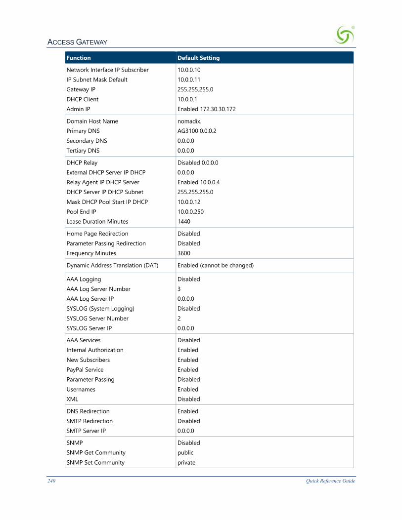
ACCESS GATEWAY
240 Quick Reference Guide
Function Default Setting
Network Interface IP Subscriber IP Subnet Mask Default Gateway IP DHCP Client Admin IP
10.0.0.10 10.0.0.11 255.255.255.0 10.0.0.1 Enabled 172.30.30.172
Domain Host Name Primary DNS Secondary DNS Tertiary DNS
nomadix. AG3100 0.0.0.2 0.0.0.0 0.0.0.0
DHCP Relay External DHCP Server IP DHCP Relay Agent IP DHCP Server DHCP Server IP DHCP Subnet Mask DHCP Pool Start IP DHCP Pool End IP Lease Duration Minutes
Disabled 0.0.0.0 0.0.0.0 Enabled 10.0.0.4 255.255.255.0 10.0.0.12 10.0.0.250 1440
Home Page Redirection Parameter Passing Redirection Frequency Minutes
Disabled Disabled 3600
Dynamic Address Translation (DAT) Enabled (cannot be changed)
AAA Logging AAA Log Server Number AAA Log Server IP SYSLOG (System Logging) SYSLOG Server Number SYSLOG Server IP
Disabled 3 0.0.0.0 Disabled 2 0.0.0.0
AAA Services Internal Authorization New Subscribers PayPal Service Parameter Passing Usernames XML
Disabled Enabled Enabled Enabled Disabled Enabled Disabled
DNS Redirection SMTP Redirection SMTP Server IP
Enabled Disabled 0.0.0.0
SNMP SNMP Get Community SNMP Set Community
Disabled public private
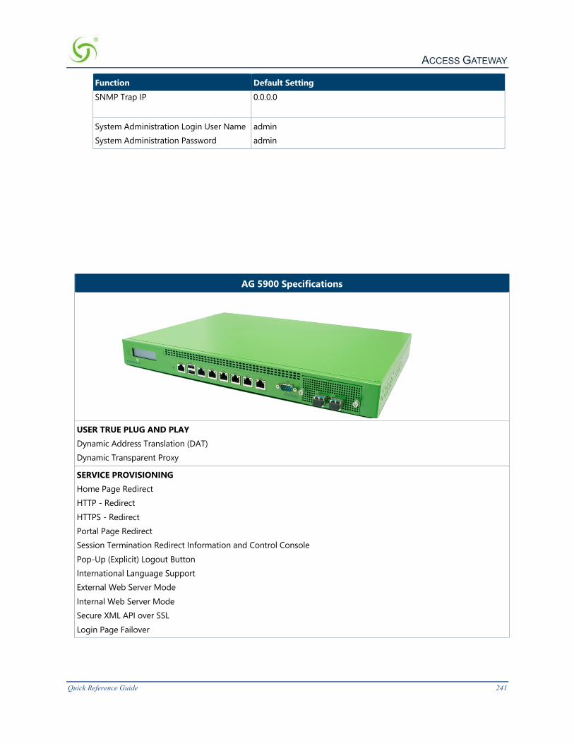
ACCESS GATEWAY
Quick Reference Guide 241
Function Default Setting SNMP Trap IP 0.0.0.0
System Administration Login User Name System Administration Password
admin admin
AG 5900 Specifications
USER TRUE PLUG AND PLAY Dynamic Address Translation (DAT) Dynamic Transparent Proxy
SERVICE PROVISIONING Home Page Redirect HTTP - Redirect HTTPS - Redirect Portal Page Redirect Session Termination Redirect Information and Control Console Pop-Up (Explicit) Logout Button International Language Support External Web Server Mode Internal Web Server Mode Secure XML API over SSL Login Page Failover

ACCESS GATEWAY
242 Quick Reference Guide
AG 5900 Specifications
BILLING PLAN ENABLEMENT RADIUS Client RADIUS (AAA) Proxy Port Based Policies Port Mapping Local Database PayPal Interface Bill Mirroring
ACCESS CONTROL AND AUTHENTICATION Authorization, Authentication and Accounting (AAA) Walled Garden Group Accounts Tri Mode Authentication Universal Access Method over SSL IEEE 802.1x Smart Client Support (Boingo, iPass) MAC Authentication Remember Me Log-in
ADVANCED SECURITY iNAT IPSec Support PPTP Support Session Rate Limiting (SRL) User Agent Filtering Mac Address Filtering URL Filtering ICMP Blocking Proxy ARP for device to device communication
POLICY BASED TRAFFIC SHAPING Bandwidth Management QoS Tagging Group Bandwidth Management
IP ADDRESS MANAGEMENT IEEE 802.3/3u/3ab IEEE 802.1d DHCP Server DHCP Relay Multiple Subnet Support IP Upsell DHCP Client PPPoE Client

ACCESS GATEWAY
Quick Reference Guide 243
AG 5900 Specifications
INTELLIGENT ROAMING Realm-Based Routing Zone Migration
BRANDING Parameter Passing-enabled branding
NETWORK MANAGEMENT Web Management Interface (WMI) Command Line Interface (CLI) Integrated VPN Client for Management RADIUS-Driven Configuration Multi-level Admin Support Centralized Radius Authentication SMTP Redirection Access Control Bridge Mode SNMPv2c Syslog/AAA Log
MEDIA ACCESS CONTROL CSMA/CA
PORTS 10/100/1000 Base-T Ethernet, RJ-45 (UTP): WAN 5 – 10/100/1000 Base-T Ethernet, RJ-45 (UTP): LAN Front access RJ-45 port for serial System Console DB9 serial port: Property Management Interface
POWER 100 – 240 VAC, 50/60Hz, 220 watts
ENVIRONMENT Operating temperature: 0°C to 40° C Storage temperature: -20°C to 70° C Operating humidity: 5 - 90% RH Storage humidity: 5 - 95% RH non-condensing
REGULATORY FCC Class A UL, UL (US and Canada) CE EN 55022: 2010 Class A, EN 61000-3-2:2006/A1:2009/A2:2009, EN 61000-3-3:2008 EN55024:2010 (IEC 61000-4-2:2008, IEC 61000-4-3:2006/A1:2007/A2:2010, IEC 6100-4-4:2004/A1:2010, IEC 6100-4-5:2006, IEC 61000-4-6:2008, IEC 61000-4-8:2009, IEC 6100-4-11:2004), Australian Standard AZ/NZS CISPR 22:2009 Class A CB Scheme

ACCESS GATEWAY
244 Quick Reference Guide
AG 5900 Specifications
PHYSICAL 1U rack space in a 19” rack 17”(L) x 12”(W) x 1.75”(H) 431mm (L) x 305.0mm (W) x 44.4mm (H) Weight: 10.2 lbs Weight: 7 Kg
LED INDICATORS Power Indicator Status Indicator Memory Indicator ACT/LINK and 10/100/1000 for each Ethernet port
PERFORMANCE User Support: Up to 8000 users or devices concurrently Throughput: up to 1425Mbits/s, as defined by RFC1242, Section 3.18
OPTIONAL MODULE The AG 5900 supports an optional plug-in module that provides two SFP+10 Gigabit fiber interface slots. If you are using this optional module, be aware of the following: The system MUST be powered down before inserting or removing the module. Also, it is highly recommended that the power cord be removed from the unit as a precaution). Severe damage to the module and/or the NSE could result if the module is inserted or removed while power is applied. Transceivers may be inserted or removed from the SFP+ slots with power either on or off. The 10G SFP+ ports only support 10 Gigabit transceivers at this time. 1G standard SFP transceivers are not supported. When the SFP+ slots are present and configured in the WAN role, they become the highest priority interfaces on the system. For example, if the SFP+0 slot is configured as WAN, system traffic will be routed through that interface.
SampleAAALogThe following table shows a sample AAA log. This log is generated by the Access Gateway and sent to the SYSLOG server that is assigned to AAA logging.
Date
Time
Access Gateway Name
Type of Data
Log Code
Log Message
Subscriber MAC Address
Expiration Time
Mar 31 18:23:10 nomad237.nomadix.com
INFO AAA: 4207 AAA_Authentication Successful
00:00:0E:32:2 C:BC 2 hrs 1 min
Mar 31 18:23:26 nomad237.nomadix.com
INFO AAA: 4207 AAA_Authentication Successful
00:10:5A:61:40:FF 12 hrs 0 min
Mar 31 18:21:53 nomad237.nomadix.com
INFO AAA: 4106 AAA_lookup Added_in_memory_table_pending
00:00:0E:32:2 C:BC
Mar 31 18:43:54 nomad237.nomadix.com
INFO AAA: 4208 AAA_Authentication Unsuccessful_Error
00:60:08:B4:20:6A

ACCESS GATEWAY
Quick Reference Guide 245
Mar 31 21:34:21 nomad237.nomadix.com
INFO AAA: 4007 AAA_Interface Added_by_administrator
00:00:0:12:34:56 20 hrs 34 min
Mar 31 21:35:15 nomad237.nomadix.com
INFO AAA: 4009 AAA Interface Updated_by_administrator
00:00:0:12:34:56 2 hrs 34 min
Mar 31 21:36:05 nomad237.nomadix.com
INFO AAA: 4006 AAA Interface Removed_by_administrator
00:00:0:12:34:56
MessageDefinitions(AAALog)The six basic messages are defined as follows:
Message Definition
AAA_Authentication Successful Subscriber profile was successfully added to the Access Gateway authorization table after being authenticated by the PayPal server.
AAA_Authentication Unsuccessful_Error
Subscriber profile was not added to the Access Gateway authorization table because the PayPal server did not recognize the transaction.
AAA_lookup Added_inmemory_table_pending
Subscriber profile has been recognized and the Access Gateway is waiting to authenticate the user.
AAA_Interface Added_by_administrator
Subscriber profile was manually added to the authorization table.
AAA_Interface Updated_by_administrator
Subscriber profile was updated.
AAA_Interface Removed_by_administrator
Subscriber profile was manually removed from the authorization table.
SampleSYSLOGReportSyslog reports are generated by the Access Gateway and sent to the syslog server that is assigned to general error detection and reporting.
2003-02-10 11:25:53 Local2.Info 1.2.3.4 INFO [Access Gateway v51.4.126]
DHCP: ndxDHCPInit: 0021 DHCP initialized
2003-02-10 11:25:53 Local2.Info 1.2.3.4 INFO [Access Gateway v51.4.126]
CLISRD: 0206 Setting COM1 to 9600 baud
2003-02-10 11:25:53 Local2.Info 1.2.3.4 INFO [Access Gateway v51.4.126]
CLISRD: Starting CLI on the serial port
2003-02-10 11:25:53 Local2.Info 1.2.3.4 INFO [Access Gateway v51.4.126]
INIT: Access Gateway v51.4.126 with ID 010384 Initialized
SampleHistoryLogA history log is generated by the Access Gateway which includes the system’s activity (Access, Reboot and Uptime).

ACCESS GATEWAY
246 Quick Reference Guide
More Listings…
KeyboardShortcutsThe following table shows the most common keyboard shortcuts.
Action Keyboard Shortcut
Cut selected data and place it on the clipboard. Ctrl + X
Copy selected data to the clipboard. Ctrl + C
Paste data from the clipboard into a document (at the insertion point).
Ctrl + V
Copy the active window to the clipboard. Alt + Print Screen
Copy the entire desktop image to the clipboard. Print Screen
Abort an action at any time. Esc
Go back to the previous screen. b
Access the Help screen. ?
HyperTerminalSettingsUse the following settings when establishing a HyperTerminal session.
Item Setting
Bits per second 9600
Data bits 8
Parity None

ACCESS GATEWAY
Quick Reference Guide 247
Stop bits 1
Flow control None
RADIUSAttributesRADIUS (Remote Authentication Dial-In User Service) was originally created to allow remote authentication to the dial-in networks of corporations and dial-up ISPs. It is defined and standardized by the IETF (Internet Engineering Task Force) and several RADIUS server packages exist in both the public domain and for commercial sale.
RADIUS software stores a database of attributes about their valid subscriber base. For example, usernames, passwords, access privileges, account limits and subscriber attributes can all be stored in a RADIUS database. RADIUS works in conjunctions with NAS (Network Access Server) devices to determine if access to the service network should be granted, and if so, with what privileges.
When a subscriber attempts to access the service provider's network, the Access Gateway delivers a Web page to the subscriber asking for a login name and password. This information (password) is encrypted and sent across the network to the ISP's RADIUS server. The RADIUS server decrypts the information and compares it against its list of valid users. If the subscriber can be authenticated, the RADIUS server replies to the Access Gateway with a message instructing it to grant access to the subscriber. Optionally, the RADIUS server can instruct the NAS to perform other functions; for example, the RADIUS server can tell the Access Gateway what upstream and downstream bandwidth the subscriber should receive. If RADIUS cannot authenticate the subscriber, it will instruct the NAS to deny access to the network.
The Nomadix Access Gateway RADIUS functionality can be broken down into the following categories:
l Authentication-Request
l Authentication-Reply (Accept)
l Accounting-Request
l Selected Detailed Descriptions
l Nomadix Vendor-Specific RADIUS Attributes
Authentication-Requestl Username
l Password

ACCESS GATEWAY
248 Quick Reference Guide
l Service-Type
l NAS-Port (port number)
l NAS-Identifier
l Framed-IP Address
l NAS-IP Address
l NAS-Port-Type
l Acct-Session-ID
l Log-Off-URL
l EAP-Packet (used for 802.1x)
l Message-Authenticator (used for 802.1x)
l State (used/tested for 802.1x)
l Called-Station-ID
l Calling-Station-ID
Authentication-Reply(Accept)l Reply-Message
l Reject-Message
l State (used/tested for 802.1x)
l Class l Session-Timeout l Idle-Timeout l EAP-Packet (used for 802.1x) l Message-Authenticator (used for 802.1x) l Acct-Interim-Interval l Nomadix VSAs:
l Nomadix-Bw-Up l Nomadix-Bw-Down l Nomadix-URL-Redirection l Nomadix-IP-Upsell l Nomadix-MaxBytesUp l Nomadix-MaxBytesDown l Nomadix-Net-VLAN l Nomadix-Session-Terminate-End-Of-Day l Nomadix-Subnet l Nomadix-Expiration
Accounting-Requestl Username l Acct-Status-Type (Start/Stop/Update)

ACCESS GATEWAY
Quick Reference Guide 249
l Acct-Session-ID l Acct-Output-Octets l Acct-Input-Octets l Acct-Output-Packets l Acct-Input-Packets l Class
l Nomadix VSAs: l Nomadix-Subnet l Nomadix-URL-Redirection l Nomadix-IP-Upsell
l Acct-Session-Time (Stop)
l Terminate-Cause (Stop)
l NAS ID
l NAS-IP Address
l NAS-Port-Type
l NAS-Port
l Framed-IP Address
l Acct-Delay-Time
l Called-Station-ID
l Calling-Station-ID
l MaxBytesTotal
l MaxGigawordsTotal
SelectedDetailedDescriptions
Acct-Session-ID
The Acct-Session-ID is created when the RADIUS authentication request is built. It is transmitted in both the Access-Request and the Accounting-Request.
SessionTimeout
There is currently no default session timeout that you can set in the Access Gateway Web Management Interface (WMI). If the Radius server does not send a Session-Timeout, the Access Gateway will set the subscriber expiration time to 0, which means access forever.
Log-Off-URL
Allows for the placement of a log off URL (for example, 1.1.1.1) on an external portal page.
MaxBytesTotal
Number of total bytes, to support volume-based billing for total of upstream and downstream traffic. Note that MaxBytesTotal will reset to zero at 4 gigabytes. Use with MaxGigawordsTotal if volume of data may exceed 4 gigabytes.

ACCESS GATEWAY
250 Quick Reference Guide
MaxGigawordsTotal
Number of total gigabytes, to support volume-based billing for total of upstream and downstream traffic. Note that MaxGigawordsTotal is an integer value; use with MaxBytesTotal if you need volume granularity of more than 4 gigabytes.
IdleTimeout
The WMI allows the setting of a default timeout. If the Radius server does not send an Idle- Timeout in the Radius Access-Accept, the Access Gateway will use the default one to disconnect subscribers. “0” means forever.
TimeoutDetection
If a subscriber is sending traffic through the Access Gateway, the Access Gateway will immediately detect a Session-Timeout. However in the case of an Idle-Timeout or an inactive subscriber Session-Timeout, the Access Gateway detects it via a clean-up function that is currently called every 2 minutes. Thus the current precision for sending the Acct-Stop is about 2 minutes.
SubscriberSessionDuration
Acct-Session-Time is calculated the following way (for each transmitted/retransmitted Acct- Stop):
Acct-Session-Time = time of last sent packet - subscriber login time.
Another attribute, Acct-Delay-Time, will take into consideration the time spent in retransmissions.
InterimAccountingUpdates
The Access Gateway parses the attribute Acct-Interim-Interval in an Access-Accept. If this attribute is present the Access Gateway tries every [Acct-Interim-Interval] seconds to send a Radius Accounting Interim message for the specific subscriber. If this attribute is not present or equal to 0, no Interim message is sent.
The precision is 2 minutes. The Access Gateway will not send Interim messages more frequently than every 2 minutes.
Called-Station-ID
This is the Media Access Control (MAC) address of the Access Gateway.
Calling-Station-ID
This is the Media Access Control (MAC) address of the client's computer.
NewAttributesinAcct-Request
The Access Gateway has to send the following attributes in an Accounting-Stop:
l Acct-Output-Packets: number of packets sent by subscriber.
l Acct-Input-Packets: number of packets received by subscriber.
Upon a reboot, these 2 attributes are saved in currfile.dat the same way as for Acct-Input- Octets and Acct-Input-Octets.
If you plan to implement RADIUS, go to “Contact Information” on page 347 for Nomadix Technical Support.

ACCESS GATEWAY
Quick Reference Guide 251
NomadixVendor-SpecificRADIUSAttributesNomadix provides the following vendor-specific RADIUS attributes. This list may vary depending on your configuration.
Attribute Integer Value Description
Nomadix-BW-Up 1 Value (in Kbps) restricts the speed at which uploads are performed.
Nomadix-BW-Down 2 Value (in Kbps) restricts the speed at which downloads are performed.
Nomadix-Url-Redirection 3 Allows the administrator to redirect the user to a page of the administrator’s choice each time the user logs in
Nomadix-IP-Upsell 4 Allows the user to receive a public address from a DHCP pool when the NSE has This feature enabled.
Nomadix-Expiration 5 Allows the administrator to set an expiration date and time for a user.
Nomadix-Subnet 6 Specifies which DHCP pool the user should receive their DHCP lease from.
Nomadix-MaxBytesUp 7 When the number of bytes sent exceeds this value, the user will be logged out of their Radius session. To continue their Internet access the user would have to log in again.
Nomadix-MaxBytesDown 8 When the number of bytes received exceeds this value, the user will be logged out of their Radius session. To continue their Internet access the user would have to log in again.
Nomadix-Session-Terminate- End-Of-Day
9 When this attribute is enabled for the user, the NSE will log the user out at midnight.
Nomadix-Logoff-Url 10 Passed in the Access Request to the Radius server. This is a required attribute for WISPr. Implementation is determined by the property owner.
Nomadix-Net-Vlan 11 Specifies which vlan number NSE should tag the packets with when going out the network port
Nomadix-Config-Url 12 The ftp URL that the NSE will use to download its auto- configuration file
Nomadix-Goodbye-Url 13 The URL that the NSE will redirect the user to after they log out
Nomadix-Qos-Policy 14 Specifies which QoS policy will be applied to the user.
Nomadix-SMTP-Redirect 17 Specifies whether or not the user will be redirected to the configured SMTP server.
Nomadix-Centralized-Mgmt
18 Sets the access for users to the Web Management Interface, Telnet/CLI interface, FTP and the Remote Radius Login test page.
Nomadix-Group-Bw-Policy-ID
19 The ID for the bandwidth group.
Nomadix-Group-Max-Up 20 Value (in Kbps) restricts the speed at which uploads for the entire group are performed

ACCESS GATEWAY
252 Quick Reference Guide
Attribute Integer Value Description
Nomadix-Group-Max-Down
21 Value (in Kbps) restricts the speed at which downloads for the entire group are performed
Nomadix-MaxGigaWords-UP
22 Allows for volume based sessions greater than 4gig
Nomadix-MaxGigaWords- Down
23 Allows for volume based sessions greater than 4gig
Nomadix-Preferred-WAN 24 Either WAN, Eth1, Eth2, Eth3, Eth4, or Eth5 to identify what interface the user will try to send traffic on.
Nomadix-Bw-Class-Name 27 Class name in dotted notation
Nomadix-MaxBytesTotal 28 Total amount of traffic up and down for a user before being logged off
Nomadix-MaxGigawordsTotal
29 Allow more than 4 gig of total traffic to be monitored before logging user off
SettingUptheSSLFeatureThis section describes how to set up the Access Gateway’s SSL feature.
Prerequisitesl You should be a business that is qualified to obtain an SSL secure server ID from different
Certificate Authorities (CAs), such as VeriSign. The Certificate Authority sets this qualification criterion.
l You will need to generate your own Private Key and Certificate Signing Request (these instructions are provided below).
l You must obtain your own Signed Public Key from the Certificate Authority. The selected Certificate Authority should be commonly supported in the subscribers' browser. We recommend that you use VeriSign (all instructions in this document are based on obtaining a key from VeriSign). Please contact Nomadix Technical Support if you want to use a different Certificate Authority.
For Nomadix technical support, go to Contact Information on page 267.
ObtainaPrivateKeyFile(cakey.pem)To create a Private Key File, you must install OpenSSL on your Windows 9x or NT operating system on a PC with Internet access.
RequirementsforCertificateSigningRequest(CSR)andKeyGeneration
l Cygwin and OpenSSL application installed on Windows 9x or NT.
l 5 large random files residing on the workstation (large compressed log files recommended by VeriSign). These files are put in as file1:file2:file3:file4:file5 in the key generation command.
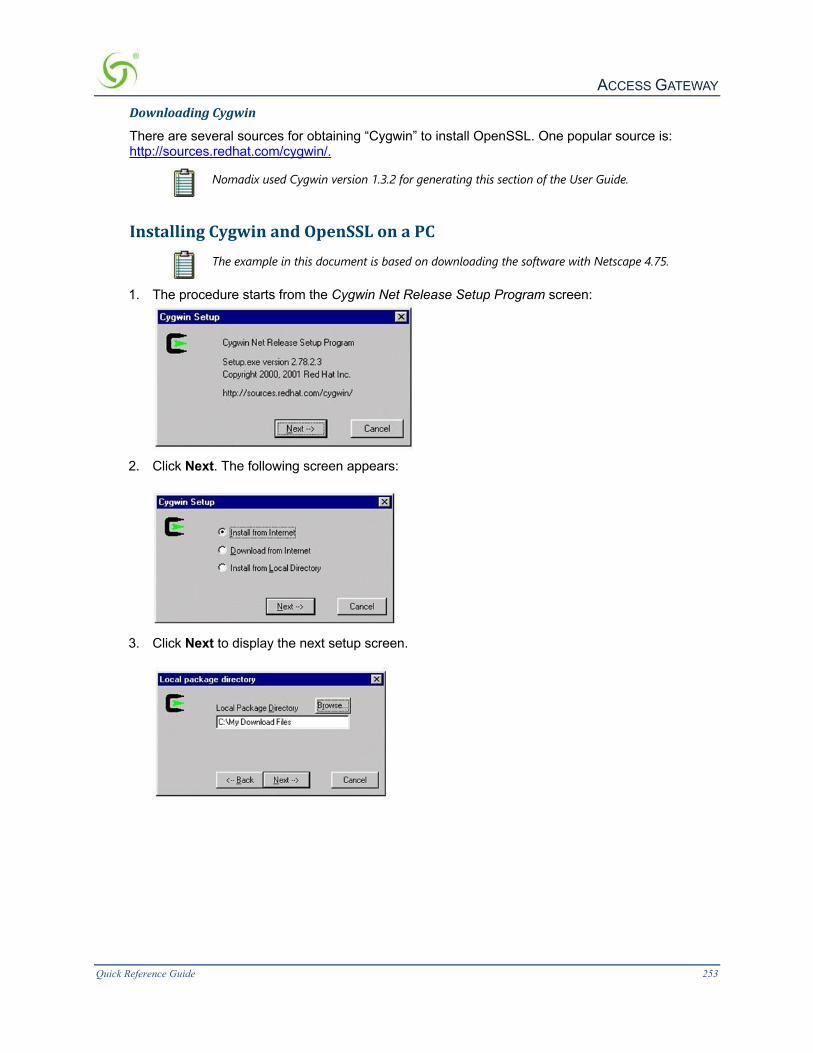
ACCESS GATEWAY
Quick Reference Guide 253
DownloadingCygwin
There are several sources for obtaining “Cygwin” to install OpenSSL. One popular source is: http://sources.redhat.com/cygwin/.
Nomadix used Cygwin version 1.3.2 for generating this section of the User Guide.
InstallingCygwinandOpenSSLonaPC
The example in this document is based on downloading the software with Netscape 4.75.
1. The procedure starts from the Cygwin Net Release Setup Program screen:
2. Click Next. The following screen appears:
3. Click Next to display the next setup screen.

ACCESS GATEWAY
254 Quick Reference Guide
4. Click Next to display the next setup screen.
5. Click Next to display the next setup screen
. 6. Click Next to display the next setup screen.
7. Select a location and click Next.
For the purposes of this document, Nomadix used: ftp://planetmirror.com.
8. In the following screens, skip all packages except “cygwin” and “openssl,” then click Next when you are done.
At the time of this writing, there are more than 70 packages to install. Please ensure that you “skip” all of them except the two packages mentioned above.

ACCESS GATEWAY
Quick Reference Guide 255
9. Click Next to start the download process. Wait for the download process to complete.
10. Click Next to start the install process. Wait for the install process to complete.
11. There will be a pop-up dialog to inform you that the installation process is completed. At the
pop-up dialog, click OK.

ACCESS GATEWAY
256 Quick Reference Guide
PrivateKeyGeneration1. Create a directory from Root and put 5 random files, a.dat, b.dat, c.dat, d.dat, and e.dat (see
note) into the C:\cygwin\bin\ directory (or the directory where you installed openssl.exe).
These random files can be any file type, such as Word, Excel, etc. Change the files to .dat files (shown above). All files must follow the DOS naming format (maximum 8 characters).
2. Run the “command” prompt from Windows, then click on the OK button.
3. Go to the c:\cygwin\bin\ directory and run the following command:
>openssl genrsa -rand file1:file2:file3:file4:file5 1024 > cakey.pem The following table provides an explanation of the command elements:
Command Description
openssl “openssl” command.
genrsa A parameter for “openssl” to generate an RSA key.
Rand A parameter for “openssl” to generate a random number from the files list.
file1:file2…:file5 These five large random files are residing on the workstation (large compressed log files recommended by VeriSign). These files are entered in the key generation command as file1:file2:file3:file4:file5
> Output to.
cakey.pem The file that contains the private key. You must have the file name “cakey.pem” to be used in the Access Gateway.
Because there is a parameter buffer size limitation of the “openssl” command, the argument length should not have more than 80 characters.
If you are creating multiple keys, please output them into different directories and save them as different names. However, if you are saving them as different names, you must change the names back to “cakey.pem” when trying to FTP to the Access Gateway.

ACCESS GATEWAY
Quick Reference Guide 257
Do not include “-des3” option to keep the private key in an unencrypted form.
Here is the output of cakey.pem:
CreateaCertificateSigningRequest(CSR)File1. Run the following command to generate the certificate signing request: >openssl req -new -key cakey.pem > server.csr
The following table provides an explanation of the command elements:
Command Description
openssl “openssl” command
req A parameter for creating a request
new Defining a “new” request …
key … from private key
> Output to …
server.csr … the output file
2. Fill in your company information. If “States” or “Province” names do not exist in your country, please repeat the “Locality Name.”
The “Common Name” is the name used in the Access Gateway->AAA->SSL Certificate Domain Name. The Common Name in the Public Key must match the SSL Certificate Domain Name in the

ACCESS GATEWAY
258 Quick Reference Guide
Web Management Interface of the Access Gateway (refer to the Access Gateway setup information later in this document).
Here is the output of server.csr:
CreateaPublicKeyFile(server.pem)
VeriSignPurchasingProcess
The signing process varies by Certificate Authority. Generally, you will need to send a Certificate Signing Request to the Certificate Authority (CA) and the CA will create a public key base on the certificate request.
This is the procedure to get a 40-bit encryption or 128-bit Public Key from VeriSign.
1. With IE or Netscape, go to www.verisign.com/products/site/index.html.

ACCESS GATEWAY
Quick Reference Guide 259
2. Select Buy for Secure Site Service.
3. Select Buy Now for 40-bit SSL (Secure Server) ID or 128-bit SSL (Global Server) ID.
Some older versions of popular browsers only support 40-bit or 56-bit encryption. Since it impossible to forecast the browsers that may be used in a visitor-based network, Nomadix recommends implementing a 40-bit Public Key.
During the process, VeriSign will ask for your business information and verification. There are several ways to proof the existence of your business. Please follow the instruction from VeriSign carefully. In addition, there is one section about generating a CSR; however, since you have already created the CSR in step 2 with OpenSSL, you can skip the instructions.
CSR Submission to VeriSign:
4. Please select “Apache Freeware” to submit the CSR to VeriSign. The Certificate Signing
Request is in the server.csr (created in the previous step). Open server.csr and copy and paste all data into the edit box.
5. Select the purchase method and submit the required contact information.
For Expedited Service, you will typically be able to get the Public Key by email within two days. For Regular Service, you will typically be able to obtain the key within seven days.

ACCESS GATEWAY
260 Quick Reference Guide
6. When you receive an email from VeriSign with “Secure Server ID” (Global Server ID if you create a 128-bit key) that contains the Public Key information, cut and paste the key to paste it into a new file, named server.pem. The file, “server.pem” will look like this:
You have now finished the process of obtaining a public key.
SettingUpAccessGatewayforSSLSecureLogin1. FTP the “cakey.pem” and “server.pem” files into the Access Gateway platform's flash directory.
2. FTP to the Access Gateway by Netscape: ftp://username:password@[Access Gateway Network IP]/flash
3. Drag and drop the “cakey.pem” and “server.pem” files into the directory.
ChangingSettingsintheWMITo change settings in the Web Management Interface (WMI), go to Configuration Menu on page 62.
SettingUpthePortalPage
System administrators can create login button(s) on the Portal Page, and can setup “http” links for regular logins, secure logins, or both. When subscribers enter the Portal Page, they can then choose either a regular login or a secure login. To setup the Portal Page, add the following:
ForRegularLogins:
http://Access_Gateway_ip:1111/usg/login?OS=http://after_login_finished_page.html
ForSecureLogins:
https://Certificate_DNS_Name:1112/usg/login?OS=http://after_login_finished_page.html
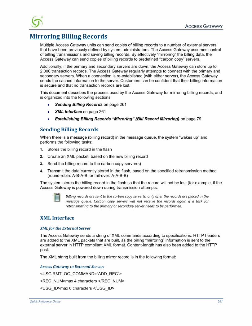
ACCESS GATEWAY
Quick Reference Guide 261
MirroringBillingRecordsMultiple Access Gateway units can send copies of billing records to a number of external servers that have been previously defined by system administrators. The Access Gateway assumes control of billing transmissions and saving billing records. By effectively “mirroring” the billing data, the Access Gateway can send copies of billing records to predefined “carbon copy” servers.
Additionally, if the primary and secondary servers are down, the Access Gateway can store up to 2,000 transaction records. The Access Gateway regularly attempts to connect with the primary and secondary servers. When a connection is re-established (with either server), the Access Gateway sends the cached information to the server. Customers can be confident that their billing information is secure and that no transaction records are lost.
This document describes the process used by the Access Gateway for mirroring billing records, and is organized into the following sections:
l Sending Billing Records on page 261
l XML Interface on page 261
l Establishing Billing Records “Mirroring” {Bill Record Mirroring} on page 79
SendingBillingRecordsWhen there is a message (billing record) in the message queue, the system “wakes up” and performs the following tasks:
1. Stores the billing record in the flash
2. Create an XML packet, based on the new billing record
3. Send the billing record to the carbon copy server(s)
4. Transmit the data currently stored in the flash, based on the specified retransmission method (round-robin: A-B-A-B, or fail-over: A-A-B-B)
The system stores the billing record in the flash so that the record will not be lost (for example, if the Access Gateway is powered down during transmission attempts.
Billing records are sent to the carbon copy server(s) only after the records are placed in the message queue. Carbon copy servers will not receive the records again if a task for retransmitting to the primary or secondary server needs to be performed.
XMLInterface
XMLfortheExternalServer
The Access Gateway sends a string of XML commands according to specifications. HTTP headers are added to the XML packets that are built, as the billing “mirroring” information is sent to the external server in HTTP compliant XML format. Content-length has also been added to the HTTP post.
The XML string built from the billing mirror record is in the following format:
AccessGatewaytoExternalServer:
<USG RMTLOG_COMMAND="ADD_REC">
<REC_NUM>max 4 characters </REC_NUM>
<USG_ID>max 6 characters </USG_ID>

ACCESS GATEWAY
262 Quick Reference Guide
<PROPERTY_ID>max 64 characters</PROPERTY_ID>
<DATE>max 10 characters </DATE>
<TIME>max 8 characters</TIME>
<ROOM_NUM>max 20 characters</ROOM_NUM>
<AMOUNT>max 10 characters</AMOUNT>
<TRANS_TYPE>max 5 characters </TRANS_TYPE>
</USG>
Formatforeachfield:
REC_NUM:00923 (numbers only, no alpha characters)
Access Gateway_ID:00020b
PROPERTY_ID:Any regular string
DATE:03/30/2001 (mm/dd/yyyy)
TIME:23:41:38 (24 hour format)
ROOM_NUM:Any regular string
AMOUNT:234.34
TRANS_TYPE:CC
RESULT_VALUE:OK or ERROR
IP:Standard IP address format (123.123.123.123)
The packet after the HTTP headers added looks like this:
XMLtoAccessGateway
The Access Gateway accepts a single line of XML text in the specified format. The XML string is a command sent by the External Server to the Access Gateway product. In this case, the acknowledgement received from the External Server forms the command. The Access Gateway expects the acknowledgement in the following format:
ExternalServertoAccessGateway:
<USG COMMAND="RMTLOG_ACK">

ACCESS GATEWAY
Quick Reference Guide 263
<ACK_VALUE>RESULT_VALUE</ACK_VALUE>
<IP_ADDR>Server IP</IP_ADDR>
<ERROR_CODE>ERROR_CODE</ERROR_CODE>
</USG>
ExampleofaPositiveAcknowledgement:
<USG COMMAND="RMTLOG_ACK">
<ACK_VALUE>OK</ACK_VALUE>
<IP_ADDR>11.22.33.44</IP_ADDR>
<ERROR_CODE>1</ERROR_CODE>
</USG>
ExampleofaNegativeAcknowledgement:
<USG COMMAND="RMTLOG_ACK">
<ACK_VALUE>ERROR</ACK_VALUE>
<IP_ADDR>11.22.33.44</IP_ADDR>
<ERROR_CODE>5</ERROR_CODE>
</USG>
FormatforeachField:
RESULT_VALUE:OK or ERROR
IP:Standard IP format (123.123.123.123)
ERROR_CODE1 for OK, or any other number
Please contact Nomadix Technical Support for the complete XML DTD. Refer to “Contact Information” on page 347.
For more information about Billing Records Mirroring, see also:
l Billing Records Mirroring on page 8
l Establishing Billing Records “Mirroring” {Bill Record Mirroring} on page 79
ACCESS GATEWAY 6
264 Troubleshooting
Troubleshooting
This chapter provides information to help you resolve common hardware and software problems. It also contains a list of known error messages associated with the Management Interface.
l General Hints and Tips
l Management Interface Error Messages
l Common Problems

ACCESS GATEWAY 6
Troubleshooting 265
General Hints and Tips The Access Gateway is both a hardware device and a powerful software utility. As a hardware computing device, the Access Gateway requires careful handling. It should be positioned in a dust-free and temperature-controlled environment. Never block the unit’s ventilation holes, and do not stack with other equipment (unless correctly mounted in a rack). If you suspect the unit is overheating, check that the internal cooling fan is operating correctly. The fan should run freely and silently at all times. The power cord and the UTP patch cables must have an unrestricted path between the unit and their destinations. Ensure that the RJ45 connectors are firmly located in their receptacles. Applying these guidelines should ensure trouble-free operation.
ManagementInterfaceErrorMessagesThe following table contains the error messages associated with the Management Interface (CLI and Web). All messages are listed alphabetically.
Error Message Cause
AAA must be enabled before adding a subscriber to the profile database.
You are attempting to add a subscriber profile while AAA is disabled.
Command not available “xx” The system does not recognize your command (“xx” denotes your input).
Current settings were not archived. This message is displayed if you answer “no” when prompted to overwrite the configuration archive file with new settings.
Current settings were not changed. This is either a response to your decision not to change settings, or the message is generated by the system when it fails to locate the data it needs.
Error loading factory settings. The system cannot find the default configuration file when attempting to restore the factory settings.
Error occurred, ARP entry not added. The IP or MAC address is invalid. Ensure that you input the correct format for these fields.
NFS client support not included. This message is displayed when the system reboots and NFS clients are not supported.
No matching MAC address found in profile database.
The system could not match the MAC address you defined while attempting to remove a subscriber profile.
[not defined] This is the factory default for some system parameters.
The system must be reset to function properly. The system must be rebooted to function properly!
You have made changes to the system’s configuration that requires you to reboot before your changes become effective.
Warning: before using this command you must FTP a valid boot image to the flash.
When upgrading the software, the system needs the new boot image file. You must FTP the file from NOMADIX™ to your local hard drive.

ACCESS GATEWAY
266 Troubleshooting
Warning: no DHCP services are available to subscribers.
This message is displayed because you have disabled both the external DHCP relay and the system’s DHCP service. To make DHCP available to subscribers, at least one of these functions must be enabled.
“x” is ambiguous. The system has more than one option it can display. You must provide additional characters to narrow the system’s choices down to just one.
“xxx” is invalid, enter ... Your input is not recognized by the system.
CommonProblemsIf you are having problems, you may find the answers here.
Problem Possible Cause Solution
When using the internal AAA login Web server, you cannot communicate with PayPal.
The internal AAA login server communicates with PayPal on a specified port which is not enabled within the company’s firewall.
Enable communications with PayPal on port 1111 and make sure that the SSL port on the Nomadix is still 443.
When a subscriber who is enabled with DHCP logs onto the system, they are not assigned an IP address.
The DHCP relay is enabled with an incorrect IP address for the external DHCP server.
Check the IP address for the external DHCP server. If necessary, test the communication with the “ping” command.
The DHCP relay is enabled with the correct IP address for the external DHCP server, but the DHCP server is misconfigured.
Check the external DHCP server settings (for example, is it configured to a routable class of IP addresses? Are there enough IP address specified? If you specified a subnet, is it correct?). If you suspect the subnet, try using 255.255.255.0
The DHCP relay is disabled and the DHCP service settings in the Access Gateway are misconfigured.
Check the internal DHCP service settings.
Subscribers are unable to route to a domain name, but they can route to an IP address.
The DNS server settings are misconfigured.
Check the DNS settings (host, domain, and the primary, secondary, and tertiary DNS).
The DNS server is down. Check with the service provider. Is the DNS server down?
When a subscriber logs in for the first time, their browser is not redirected to the specified home page.
Home page redirection is not enabled in the Access Gateway.
Enable home page redirection.
The home page URL was entered into the Access Gateway incorrectly.
Re-enter the correct URL.
The server that hosts the home page is down, or the service provider (if different from the host) is not able to route to your page.
Check that the server is operational and that the home page can be accessed through your service provider (if different).
DNS is misconfigured in the Access Gateway.
Check the DNS settings (host, domain, and the primary, secondary, and tertiary DNS).

ACCESS GATEWAY A
Technical Support 267
AppendixA:TechnicalSupport
We have tried to ensure that you get the most up-to-date information available about the Access Gateway, and we hope this User Guide has met all your operational and performance needs. However, we understand that occasionally you may run into problems that require additional technical support.
Troubleshooting on page 264 provides some basic troubleshooting information and procedures that will help you to diagnose and solve your problem (if the problem is related to the Access Gateway). Additionally, you should check with your network documentation to verify that the network components are functioning correctly.
If you cannot resolve the problem with your documentation resources, try visiting our corporate Web site. We may have new information posted here that addresses your issues.
If you are still having problems, our friendly and experienced technical support team is always ready to assist you.
When contacting technical support, please have your Access Gateway’s serial number available. The serial number is located on the bottom panel of your Access Gateway.
ContactInformation
You can contact us by Email, fax, telephone, or regular mail.
Telephone ++1.818.575.2590
Fax ++1.818.597.1502
Address
Nomadix, Inc.
21600 Oxnard St, Suite 1900
Woodland Hills, CA 91367 USA
Attn: Technical Support

ACCESS GATEWAY
268 Glossary of Terms
AppendixB:LogFilesExamples
SystemLogFile(Example)
AAALog(Example)
RADIUSHistoryLog(Example)
SystemReportLog(Example)
SubscriberTrackingLog(Example)

ACCESS GATEWAY C
Glossary of Terms 269
AppendixC:GlossaryofTerms
Term Definition
802.11x Refers to a family of specifications developed by the IEEE for wireless LAN technology. 802.11 specifies an over-the- air interface between a wireless client and a base station, or between two wireless clients. The IEEE accepted the specification in 1997. There are several specifications in the 802.11 family:
802.11 Applies to wireless LANs and provides 1 or 2 Mbps transmission in the 2.4 GHz band using either Frequency Hopping Spread Spectrum (FHSS) or Direct Sequence Spread Spectrum (DSSS).
802.11a An extension to 802.11 that applies to wireless LANs and provides up to 54 Mbps in the 5GHz band. 802.11a uses an Orthogonal Frequency Division Multiplexing (OFDM) encoding scheme rather than FHSS or DSSS.
802.11b (also referred to as 802.11 High Rate or Wi-Fi™) An extension to 802.11 that applies to wireless LANs and provides 11 Mbps transmission (with a fallback to 5.5, 2 and 1 Mbps) in the 2.4 GHz band. 802.11b uses only DSSS. 802.11b was a 1999 ratification to the original 802.11 standard, allowing wireless functionality comparable to Ethernet.
802.11g Applies to wireless LANs and provides 20+ Mbps in the 2.4 GHz band.
802.1Q An IEEE standard for providing a virtual LAN capability within a campus network. 802.1Q establishes a standard format for frame tagging (Layer 2 VLAN markings), enabling the creation of VLANs that use equipment from multiple vendors.
10/100 Ethernet
See Ethernet.
AAA
(Authentication, Authorization, and Accounting) A combination of commands used by Nomadix Gateways to authenticate, authorize, and subsequently bill subscribers for their use of the customer’s network. When a subscriber logs into the system, their unique MAC address is placed into an authorization table. The system then authenticates the subscriber’s MAC address and billing information before allowing them to access the Internet and make online purchases. See also, MAC Address.
Access Concentrator
A type of multiplexer that combines multiple channels onto a single transmission medium in such a way that all the individual channels can be simultaneously active. For example, ISPs use concentrators to combine their dial-up modem connections onto faster T-1 lines that connect to the Internet. Concentrators are also used in Local Area Networks (LANs) to combine transmissions from a cluster of nodes. In this case, the concentrator is often called a hub.
Access Router A router at a customer site, which connects to the network service provider. Also known as a Customer Premises Equipment (CPE) router. See also, Router.
ACK (ACKnowledgment) If all the transmitted data is present and correct, the receiving device sends an ACK signal, which acts as a request for the next data packet.

ACCESS GATEWAY
270 Glossary of Terms
Term Definition
Adaptive Configuration Technology
A Nomadix, Inc. patented technology that enables Dynamic Address Translation. See also, DAT.
ad-hoc mode An 802.11x networking framework in which devices or stations communicate directly with each other, without the use of an Access Point (AP). Ad-hoc mode is also referred to as peer-to-peer mode, or an Independent Basic Service Set (IBSS). Ad-hoc mode is useful for establishing a network where wireless infrastructure does not exist or where services are not required.
ADSL (Asynchronous Digital Subscriber Line) A method for moving data at high speed over regular phone lines.
AP (Access Point) A hardware device or a computer's software that acts as a communication hub for users of a wireless device to connect to a wired LAN. APs are important for providing heightened wireless security and for extending the physical range of service a wireless user has access to.
ARP (Address Resolution Protocol) Used to dynamically bind a high level IP address to a low level physical hardware address. ARP is limited to a single physical network that supports hardware broadcasting.
ATM (Asynchronous Transfer Mode) A network technology based on transferring data in “cells” or packets of a fixed size (53 bytes each). The cell used with ATM is relatively small compared to units used with older technologies. The small, constant cell size allows ATM equipment to transmit video, audio, and computer data over the same network, and assures that no single type of data monopolizes the line. ATM can offer multi-gigabit bandwidth. See also, Bandwidth and Packet.
Bandwidth The maximum speed at which data can be transmitted between computers across a network, usually measured in bits per second (bps). If you think of the communication path as a water pipe, the bandwidth represents the width of the pipe which consequently determines how many gallons of water can flow through it at any given time. See also, Broadband.
Beacon Interval The frequency interval of the beacon, which is a packet broadcast by a router to synchronize a wireless network.
Broadband A high speed data transmission medium capable of supporting a wide range of varying frequencies. Broadband can carry multiple signals at fast rates of speed by dividing the total capacity of the medium into multiple, independent bandwidth channels, where each channel operates only on a specific range of frequencies. See also, Bandwidth.
BSS (Basic Service Set) See infrastructure mode.
Carrier frequency A frequency in a communications channel modulated to carry analog or digital signal information. For example, an FM radio transmitter modulates the frequency of a carrier signal and the receiver processes the carrier signal to extract the analog information. An AM radio transmitter modulates the amplitude of a carrier signal.
CoS (Class of Service) A category based on the type of user, type of application, or some other criteria that QoS systems can use to provide differentiated classes of service. The characteristics of the CoS may be appropriate for high throughput traffic, for traffic with a requirement for low latency, or simply for best effort. The QoS experienced by a particular flow of traffic will be dependent

ACCESS GATEWAY
Glossary of Terms 271
Term Definition on the number and type of other traffic flows admitted to its class. See also, QoS.
Daemon A program that runs continuously in the background, or is activated by a particular event (for example, an error may trigger Syslog). The word daemon is Greek for “spirit” or “soul.” See also, SYSLOG.
DAT (Dynamic Address Translation) Nomadix Gateways provide “plug-and-play” access to subscribers who are misconfigured with static (permanent) IP addresses, or subscribers that do not have DHCP functionality on their computers. DAT is a Nomadix, Inc. patented technology that allows all users to obtain network access, regardless of their computer’s network settings. See also, DHCP.
DHCP (Dynamic Host Configuration Protocol) A standard method for assigning IP addresses automatically to devices connected on a TCP/IP network. When a new device connects to the network, the DHCP server assigns an IP address from a list of its available addresses. The device retains this IP address for the duration of the session. When the device disconnects from the network, the IP address becomes available for reassignment to another device. See also, Dynamic IP Address, IP Address, Static IP Address, and TCP/IP.
DNS (Domain Name System) A system that maps meaningful domain names with complex numeric IP addresses. See also, Domain Name and IP Address.
Domain Name A unique and meaningful name representing each addressable computing device on a dynamic network (for example, the Internet). Some devices have more than one domain name. When a user types a domain name, requesting a connection to the device, DNS converts the domain name into a numeric IP address. The location of the device on the network is known by its IP address. WWW.YAHOO.COM is an example of a commercial domain name on the World Wide Web. See also, DNS, Internet, and IP Address.
Driverless Print Servers
Servers that can bill subscribers’ rooms for printing their documents without them having to install printers. See also, Print Billing Command.
DSSS (Direct Sequence Spread Spectrum) One of two types of spread spectrum radio—the other being Frequency Hopping Spread Spectrum (FHSS). DSSS is a transmission technology used in WLAN transmissions where a data signal at the sending station is combined with a higher data rate bit sequence, or “chipping” code, that divides the user data according to a spreading ratio. The chipping code is a redundant bit pattern for each bit that is transmitted, which increases the signal's resistance to interference. If one or more bits in the pattern are damaged during transmission, the original data can be recovered due to the redundancy of the transmission.
DTIM (Delivery Traffic Indication Message) A message included in data packets that can increase wireless efficiency.
Dynamic IP Address
A temporary IP address that is assigned by the DHCP server to a device. Devices retain dynamic IP addresses only for the duration of their networking session. When a device disconnects from the network, the IP address is recaptured by the DHCP server and becomes available for reassignment to another device. See also, DHCP, IP Address, IP Address Translation, Static IP Address, and Translation.
EAP (Extensible Authentication Protocol) An extension to PPP. EAP is a general protocol for authentication that also supports multiple authentication methods

ACCESS GATEWAY
272 Glossary of Terms
Term Definition (for example, public key authentication and smart cards). IEEE 802.1x specifies how EAP should be encapsulated in LAN frames. In wireless communications using EAP, a user requests connection to a WLAN through an AP, which then requests the identity of the user and transmits that identity to an authentication server such as RADIUS. The server asks the AP for proof of identity, which the AP gets from the user and then sends back to the server to complete the authentication.
ECommerce A business venture between a supplier and its customers using online services (for example, the Internet). Both parties use online services to conduct business transactions. Transactions may include generating orders, invoices, and payments, and submitting inquiries. Also known as Enterprise.
ESS (Extended Service Set) See infrastructure mode.
Ethernet A Local Area Network (LAN) protocol developed by Xerox Corporation in cooperation with DEC and Intel in 1976. Ethernet uses a bus or star topology and supports data transfer rates of 10 Mbps. The Ethernet specification served as the basis for the IEEE 802.3 standard, which specifies the physical and lower software layers. Ethernet is one of the most widely implemented LAN standards. A newer version of Ethernet, called 100Base-T (or Fast Ethernet), supports data transfer rates of 100 Mbps. The latest version, Gigabit Ethernet, supports data rates of 1 Gigabit (1,000 Mbps) per second. See also, Mbps.
Fast Ethernet See Ethernet.
FCC (Federal Communications Commission) US wireless regulatory authority. The FCC was established by the Communications Act of 1934 and is charged with regulating Interstate and International communications by radio, television, wire, satellite and cable.
FDM (Frequency Division Multiplexing) A multiplexing technique that uses different frequencies to combine multiple streams of data for transmission over a communications medium. FDM assigns a discrete Carrier frequency to each data stream and then combines many modulated carrier frequencies for transmission. For example, television transmitters use FDM to broadcast several channels at once.
FHSS (Frequency Hopping Spread Spectrum) One of two types of spread spectrum radio—the other being Direct-Sequence Spread Spectrum (DSSS). FHSS is a transmission technology used in WLAN transmissions where the data signal is modulated with a narrowband carrier signal that “hops” in a random but predictable sequence from frequency to frequency as a function of time over a wide band of frequencies. The signal energy is spread in time domain rather than chopping each bit into small pieces in the frequency domain. This technique reduces interference because a signal from a narrowband system will only affect the spread spectrum signal if both are transmitting at the same frequency at the same time. If synchronized properly, a single logical channel is maintained. The transmission frequencies are determined by a “spreading” or “hopping” code. The receiver must be set to the same hopping code and must listen to the incoming signal at the right time and correct frequency in order to properly receive the signal. Current FCC regulations require manufacturers to use 75 or more frequencies per transmission channel with a maximum dwell time (the time spent at a particular frequency during any single hop) of 400 ms.

ACCESS GATEWAY
Glossary of Terms 273
Term Definition
Flash Memory A special type of EEPROM (Electrically Erasable Programmable Read Only Memory) that can be erased and reprogrammed in blocks instead of one byte at a time. Many modern PCs have their BIOS stored on a flash memory chip so that it can easily be updated. Such a BIOS is sometimes called a flash BIOS. Flash memory is also popular in modems because it enables the modem manufacturer to support new protocols as they become standardized.
Forwarding Rate The maximum rate at which 64K packets can be delivered to their destination. See also, Packet, Packet Switching Network, pps, and Throughput.
Fragment Length (Fragmentation)
Breaking a packet into smaller units when transmitting over a network medium that cannot support the original size of the packet. The fragment length value should remain at its default setting unless you experience a high packet error rate. Setting the fragment length too low may result in poor performance.
FTP (File Transfer Protocol) A standard protocol used for copying and moving files quickly, efficiently, and securely across public and private networks. An FTP site is one where files are available for downloading and uploading. FTP sites usually require a secure login (name and password) to gain access.
Gateway Any device that provides a seamless connection between otherwise incompatible systems.
Gopher A computer program, and an accompanying data transfer protocol, for reading information that has been made available to the public on the Internet. Gopher is gradually being superseded by HTML.
Home Page Usually the first page users see when they visit a Web site (if they address the home page’s URL). A well-constructed Web site will normally consist of a home page that provides a clear and concise overview of the entire Web site, together with the tools for accessing other pages and topics quickly and efficiently. In this case, the home page is the “portal” to the Web site. See also, Portal and URL.
Host Any computer that provides services to other computers that are linked to it by a network. Generally, the host is the more remote of the computers. For example, if a user in California accesses a computer in New York, the computer in New York is considered the host.
HPR (Home Page Redirection) Nomadix Gateways enable solution providers to redirect subscribers to a “portal” home page of their choice. This allows the solution provider to generate online advertising revenues and increase business exposure. See also, Home Page.
HTML (HyperText Markup Language) The programming language used to create hypertext documents for use on the Internet. See also, HTTP, Hypertext, and Internet.
HTTP (HyperText Transfer Protocol) The standard method used for publishing hypertext documents in HTML format on the Internet. See also, HTML and Internet.
Hypertext Electronic documents that are structured to enable readers to go directly to the source of the information they need by following directional links (unlike books which are generally read sequentially). Web pages and help file are examples of hypertext documents.

ACCESS GATEWAY
274 Glossary of Terms
Term Definition
ICMP (Internet Control Message Protocol) A standard Internet protocol that delivers error and control messages from hosts to message requesters. An ICMP echo test can determine whether a target destination is reachable. An ICMP echo test is also called a ping. See also, Ping.
IEEE (Institute of Electrical and Electronics Engineers) Founded in 1884, the IEEE is an organization composed of engineers, scientists, and students. The IEEE is best known for developing standards for the computer and electronics industry. In particular, the IEEE 802 standards for Local Area Networks are widely followed.
iNAT™ (Intelligent Network Address Translation) Nomadix’ iNAT™ feature creates an intelligent mapping of IP addresses and their associated VPN tunnels allowing multiple tunnels to be established to the same VPN server—creating a seamless connection for all the users at the public-access location.
infrastructure mode
An 802.11x networking framework in which devices communicate with each other by first going through an Access Point (AP). In infrastructure mode, wireless devices can communicate with each other or can communicate with a wired network. When one AP is connected to a wired network and a set of wireless stations it is referred to as a Basic Service Set (BSS). An Extended Service Set (ESS) is a set of two or more BSSs that form a single subnetwork. Most corporate wireless LANs operate in infrastructure mode because they require access to the wired LAN in order to use services such as file servers or printers. See also, ad-hoc mode.
Internet Originally developed by the U.S. Defense Department, the Internet is now a global collection of networks that transfer information between each other using the Internet Protocol (IP). Additionally, the Internet carries the hypertext system commonly known as the World Wide Web. See also Hypertext and Internet Protocol.
Internet Protocol The global standard used to regulate data transmissions between computers and the Internet. Data is broken up into packets which are then sent over the network. By using IP addressing, Internet Protocol ensures that the data reaches its destination, even though different packets may pass through different networks to get to the same location. See also, Internet and IP Address.
Internet Service Provider
The agency that provides you with access to the Internet. Your Internet Service Provider (ISP) may be a large commercial organization (for example, America Online) or, if you access the Internet via your employer, then your employer is your Internet Service Provider. See also, Internet.
Intranet A network confined to a single organization (but not necessarily a single site). Usually thought of as a corporate mini Internet.
IP See Internet Protocol.
IP Address The numeric address of a device, in the format used on the Internet. The actual numeric value takes the form of a 32- bit binary number broken up into four 8-bit groups, with each group separated by a period (for example, 198.43.7.85). To make it easier for the user, the IP address is mapped to a meaningful domain name. IP addresses can be static (permanent) or dynamic (assigned each time you connect). See also, Domain Name, Dynamic IP Address, Internet Protocol, and Static IP Address.

ACCESS GATEWAY
Glossary of Terms 275
Term Definition
IP Address Translation
Nomadix Gateways use adaptive configuration technology which can accommodate all network configurations, including dynamic and static IP address assignments. This enables it to solve IP addressing problems in environments where the service provider does not have control over the subscriber’s network settings. Whenever a subscriber logs on, your Nomadix Gateway automatically translates their computer’s network settings to provide them with seamless access to the broadband network. Subscribers no longer need to alter their computer’s settings. See also, Dynamic IP Address, IP Address, and Static IP Address.
ISDN (Integrated Services Digital Network) An international communications standard for sending voice, video, and data over digital telephone lines or normal telephone wires. ISDN supports data transfer rates of 64 Kbps (64,000 bits per second).
ISP See Internet Service Provider.
LAWN (Local Area Wireless Network) A type of Local Area Network that uses high-frequency radio waves rather than wires to communicate between nodes. Also referred to as WLAN. See also, Node.
LDAP (Lightweight Directory Access Protocol) Directories containing information such as names, phone numbers, and addresses are often stored on a variety of incompatible systems. LDAP provides a simple protocol that allows you to access and search these disparate directories over the Internet. LDAP is commonly used for online billing applications.
MAC Address (Media Access Control) The hardware address that uniquely identifies each node of a network. In IEEE 802 networks, the Data Link Control (DLC) layer of the OSI Reference Model is divided into two sub layers – the Logical Link Control (LLC) layer and the Media Access Control (MAC) layer. The MAC layer interfaces directly with the network media. Consequently, each type of network media requires a different MAC layer. On networks that do not conform to the IEEE 802 standards but do conform to the OSI Reference Model, the node address is called the Data Link Control (DLC) address.
Mbps (Megabits per second) A standard measure for data transmission speeds (for example, the rate at which information travels over the Internet). 1 Mbps denotes one million bits per second. Several factors can influence how quickly data travels, including modem speed, bandwidth capacity, and Internet traffic levels at the time of transmission. Not to be confused with MegaBytes per second (MBps). See also, Throughput.
MIB (Management Information Base) A set of parameters an SNMP management station can query or establish in the SNMP agent of a network device (for example, a router). Standard minimal MIBs have been defined, and vendors often have their own private enterprise MIBs. In theory, any SNMP manager can talk to any SNMP agent with a properly defined MIB. See also, SNMP.
Misconfigured User
A Nomadix, Inc. term used to describe users who have IP address configurations that are different from the current network. For example, if the current network is 123.45.67.89 but the user’s IP address is 10.10.10.15, then this user is considered to be “misconfigured.”
NAT (Network Address Translation) An Internet standard that enables a Local Area Network (LAN) to use one set of IP addresses for internal traffic and a second set of IP addresses for external traffic. A NAT box located where the

ACCESS GATEWAY
276 Glossary of Terms
Term Definition LAN meets the Internet performs all the necessary IP address translations. NAT provides a type of firewall by hiding its internal IP addresses. Additionally, NAT enables companies to use more internal IP addresses (because the addresses are only used internally and there’s no possibility of conflicting with IP addresses used by other companies). NAT also allows companies to combine multiple ISDN connections into a single Internet connection. See also, ISDN.
Node An addressable point on a network. A node can connect a computer system, a terminal, or various peripheral devices to the network. Each node on a network has a distinct name. On the Internet, a node is a host computer with a unique domain name and IP address. See also, Domain Name and IP Address.
NTP (Network Time Protocol) An Internet standard protocol (built on top of TCP/IP) that assures accurate synchronization (to the millisecond) of computer clock times in a network of computers. Based on UTC, NTP synchronizes client workstation clocks to the U.S. Naval Observatory master clocks. Running as a continuous background client program on a computer, NTP sends periodic time requests to servers, obtaining server time stamps and using them to adjust the client's clock.
OFDM (Orthogonal Frequency Division Multiplexing) An FDM modulation technique for transmitting large amounts of digital data over a radio wave. OFDM works by splitting the radio signal into multiple smaller sub-signals that are then transmitted simultaneously at different frequencies to the receiver. OFDM reduces the amount of crosstalk in signal transmissions. 802.11a WLAN technology uses OFDM.
OSPF (Open Shortest Path First) This routing protocol was developed for IP networks based on the shortest path first or link- state algorithm. Routers use link-state algorithms to send routing information to all nodes on a network by calculating the shortest path to each node based on a topography of the Internet constructed by each node. Routers send that portion of the routing table (keeping track of routes to particular network destinations) that describes the state of its own links, and it also sends the complete routing structure (topography). The advantage of shortest path first algorithms is that they result in smaller more frequent updates everywhere. They converge quickly, thus preventing such problems as routing loops and count-to-infinity (when routers continuously increment the hop count to a particular network). This makes for a stable network. OSPF (version 2) is defined in RFC 1583 and is rapidly replacing RIP on the Internet as the preferred routing protocol. See also, RFC and Router.
Packet How data is distributed over the Internet. A packet contains the source and destination addresses, as well as the data. An ethernet packet is normally 1,518 bytes. In IP networks, packets are often called datagrams. See also, Forwarding Rate, Packet Switching Network, pps, and Throughput.
Packet Switching Network
Refers to protocols in which messages are divided into packets before they are sent. Each packet is then transmitted individually and can even follow different routes to its destination. Once all the packets forming a message arrive at its destination, they are recompiled into the original message. Most modern Wide Area Network (WAN) protocols, including TCP/IP, X.25, and Frame Relay, are based on packet-switching technologies. By contrast, normal telephone services use a circuit-switching technology in which a

ACCESS GATEWAY
Glossary of Terms 277
Term Definition dedicated line is allocated for transmission between two parties. Circuit-switching is ideal for fast data transmissions where the data must arrive in the same order in which it is sent. This is the case with most real-time data, such as live audio and video. Packet switching is more efficient and robust for data that can withstand some delays in transmission, such as e-mail messages and Web pages. See also, Forwarding Rate, Packet, pps, and Throughput.
PDF (Portable Document Format) A type of file format developed by Adobe Systems© that displays documents identically on any computer system. PDF files retain their original formatted design, unlike HTML documents which adjust the format depending on the users viewing medium (for example, monitor size).
Ping (Packet INternet Groper) A program that transmits a signal to a host and expects a response within a predetermined time. This is useful when troubleshooting network transmission problems. See also, ICMP.
Portal A portal is a Web site. The portal consists of a collection of links to the most popular Web services on the Internet. Generally speaking, a portal is a door to the Internet. See also, Internet.
PPP (Point-to-Point Protocol) PPP has superseded SLIP as the standard protocol for serial data communications over the Internet. See also, SLIP.
pps (packets per second) The rate at which packets are delivered to their destination. See also, Forwarding Rate, Packet, and Packet Switching Network.
PPTP (Point-to-Point Tunneling Protocol) Developed jointly by Microsoft Corporation, U.S. Robotics, and several remote access vendor companies, known collectively as the PPTP Forum, PPTP is a new technology used for creating Virtual Private Networks (VPNs). Because the Internet is essentially an open network, PPTP is used to ensure that messages transmitted from one VPN node to another are secure. PPTP allows users to dial in to their corporate networks via the Internet. See also, Internet, Tunneling, and VPN.
Preamble In wireless networks, part of the wireless signal that synchronizes network traffic.
Print Billing Command
Authentication, Authorization and Accounting configuration that allows the NSE to support Driverless Print servers that can bill subscribers’ rooms for printing their documents without them having to install printers.
Profile An electronic file that defines how subscribers normally interact with the service provider’s network.
Protocol A standard process consisting of a set of rules and conditions that regulates data transmissions between computing devices. Some examples of protocols include HTTP (HyperText Transfer Protocol), FTP (File Transfer Protocol), TCP/IP (Transmission Control Protocol/Internet Protocol), and POP (Post Office Protocol). All these protocols are responsible for regulating the transmission of their specific data file types.
QoS (Quality of Service) A collective measure of the level of service delivered to the customer. QoS can be characterized by several basic performance criteria, including availability (low downtime), error performance, response time and throughput, lost calls or transmissions due to network congestion, connection set-up time, and the speed of fault detection and correction.

ACCESS GATEWAY
278 Glossary of Terms
Term Definition Service providers may guarantee a particular level of QoS (defined by a service level agreement) to their subscribers. QoS-enabled hardware and software solutions sort and classify IP packet requests into different traffic classes and allocate the proper resources to direct traffic based on various criteria, including application type, user or application ID, source or destination IP address, time of day, and other user-specified variables. See also, CoS and ToS.
RADIUS (Remote Authentication Dial-In User Service) An authentication and accounting system used by many Internet Service Providers (ISPs). When you dial in to the ISP you must enter your username and password. This information is passed to a RADIUS server which checks that the information is correct and then authorizes access to the ISP system.
RFC (Request for Comments) A series of notes about the Internet, started in 1969 (when the Internet was the ARPANET). An RFC note can be submitted by anyone. Each RFC is designated by an RFC number. Once published, an RFC never changes. Any modifications to an original RFC are assigned a new RFC number.
Roaming In wireless networking, roaming refers to the ability to move from one AP coverage area to another without interruption in service or loss in connectivity.
Round Robin Queuing
An algorithm that services each queue in a predefined sequence. For example, it might empty 1,500 bytes apiece from queue 1 (high priority), queue 2 (medium priority), and queue 3 (low priority), servicing each in turn.
Router A hardware device that connects two or more networks and routes the incoming data packets to the appropriate network.
RTS (Length) (Request to Send) A packet sent when a computer has data to transmit. The computer will wait for a CTS (Clear To Send) message before sending data. The RTS Length value should remain at its default setting unless you encounter inconsistent data flow. Only minor modifications to this value are recommended.
SLIP (Serial Line Internet Protocol) SLIP is a standard protocol for connecting to the Internet with a modem over a phone line. It has trouble with noisy dial-up lines and other error-prone connections, so look to higher-level protocols like PPP for error correction.
SMTP (Simple Mail Transfer Protocol) A standard protocol that regulates how e-mail is distributed over the Internet. See also, Protocol.
SNMP (Simple Network Management Protocol) A standard protocol that regulates network management over the Internet. SNMP uses TCP/IP to communicate with a management platform, and offers a standard set of commands that make multi-vendor interoperability possible. SNMP uses a standard set of definitions, known as a MIB (Management Information Base), which can be supplemented with enterprise-specific extensions. See also, TCP/IP and MIB.
Socket A communication path between two computer programs, not necessarily running on the same machine. Sockets are managed by a “socket device driver” that establishes network connections, as needed. Programs that communicate through sockets need not know anything about how the network functions.

ACCESS GATEWAY
Glossary of Terms 279
Term Definition
Solution Provider Vendors are considered to be solution providers when they provide products and/or services that meet their customer’s specific needs. Normally, a solution provider is offering a solution that isn’t readily available on the open market. For example, NOMADIX™ is a solution provider to its customers (broadband network service providers), and those customers are solution providers to their end users (network subscribers).
SSID (Service Set Identifier) A 32-character unique identifier attached to the header of packets sent over a WLAN that acts as a password when a mobile device tries to connect to the BSS. The SSID differentiates one WLAN from another, so all access points and all devices attempting to connect to a specific WLAN must use the same SSID. A device will not be permitted to join the BSS unless it can provide the unique SSID. Because an SSID can be “sniffed” in plain text from a packet it does not supply any security to the network. An SSID is also referred to as a “network name” because essentially it is a name that identifies a wireless network.
SSL (Secure Sockets Layer) A protocol developed by Netscape for transmitting private documents via the Internet. SSL works by using a private key to encrypt data that is transferred over the SSL connection. Both Netscape Navigator and Internet Explorer support SSL, and many Web sites use the protocol to obtain confidential user information, such as credit card numbers. See also, Protocol.
Static IP Address An IP address that is assigned to a computing device permanently (or until the user changes it manually), unlike a dynamic IP address which is assigned to a device temporarily by the DHCP server. See also, DHCP, IP Address and Dynamic IP Address.
STP (Spanning Tree Protocol) A link management protocol that is part of the IEEE 802.1 standard for media access control bridges. Using the spanning tree algorithm, STP provides path redundancy while preventing undesirable loops in a network that are created by multiple active paths between stations. Loops occur when there are alternate routes between hosts. To establish path redundancy, STP creates a tree that spans all of the switches in an extended network, forcing redundant paths into a standby (or blocked) state. STP allows only one active path at a time between any two network devices (this prevents the loops) but establishes the redundant links as a backup if the initial link should fail. If STP costs change, or if one network segment in the STP becomes unreachable, the spanning tree algorithm reconfigures the spanning tree topology and reestablishes the link by activating the standby path. Without spanning tree in place, it is possible that both connections may be simultaneously “live,” which could result in an endless loop of traffic on the LAN.
Subnet A portion of a network, which may be a physically independent network segment, which shares a network address with other portions of the network and is distinguished by a unique subnet address. In general, a subnet is to a network what a network is to the Internet.
Subnet Address The subnet portion of an IP address that is dedicated to the subnet. In a subnetted network, the host portion of an IP address is split into a subnet portion and a host portion using an address (subnet) mask. See also, IP Address and Subnet.
Subnet Mask See Subnet Address.
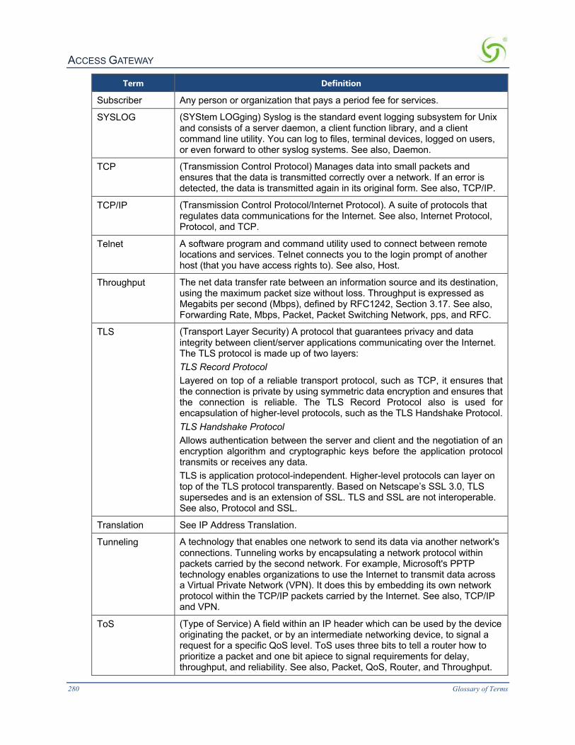
ACCESS GATEWAY
280 Glossary of Terms
Term Definition
Subscriber Any person or organization that pays a period fee for services.
SYSLOG (SYStem LOGging) Syslog is the standard event logging subsystem for Unix and consists of a server daemon, a client function library, and a client command line utility. You can log to files, terminal devices, logged on users, or even forward to other syslog systems. See also, Daemon.
TCP (Transmission Control Protocol) Manages data into small packets and ensures that the data is transmitted correctly over a network. If an error is detected, the data is transmitted again in its original form. See also, TCP/IP.
TCP/IP (Transmission Control Protocol/Internet Protocol). A suite of protocols that regulates data communications for the Internet. See also, Internet Protocol, Protocol, and TCP.
Telnet A software program and command utility used to connect between remote locations and services. Telnet connects you to the login prompt of another host (that you have access rights to). See also, Host.
Throughput The net data transfer rate between an information source and its destination, using the maximum packet size without loss. Throughput is expressed as Megabits per second (Mbps), defined by RFC1242, Section 3.17. See also, Forwarding Rate, Mbps, Packet, Packet Switching Network, pps, and RFC.
TLS (Transport Layer Security) A protocol that guarantees privacy and data integrity between client/server applications communicating over the Internet. The TLS protocol is made up of two layers: TLS Record Protocol Layered on top of a reliable transport protocol, such as TCP, it ensures that the connection is private by using symmetric data encryption and ensures that the connection is reliable. The TLS Record Protocol also is used for encapsulation of higher-level protocols, such as the TLS Handshake Protocol. TLS Handshake Protocol Allows authentication between the server and client and the negotiation of an encryption algorithm and cryptographic keys before the application protocol transmits or receives any data. TLS is application protocol-independent. Higher-level protocols can layer on top of the TLS protocol transparently. Based on Netscape’s SSL 3.0, TLS supersedes and is an extension of SSL. TLS and SSL are not interoperable. See also, Protocol and SSL.
Translation See IP Address Translation.
Tunneling A technology that enables one network to send its data via another network's connections. Tunneling works by encapsulating a network protocol within packets carried by the second network. For example, Microsoft's PPTP technology enables organizations to use the Internet to transmit data across a Virtual Private Network (VPN). It does this by embedding its own network protocol within the TCP/IP packets carried by the Internet. See also, TCP/IP and VPN.
ToS (Type of Service) A field within an IP header which can be used by the device originating the packet, or by an intermediate networking device, to signal a request for a specific QoS level. ToS uses three bits to tell a router how to prioritize a packet and one bit apiece to signal requirements for delay, throughput, and reliability. See also, Packet, QoS, Router, and Throughput.

ACCESS GATEWAY
Glossary of Terms 281
Term Definition
URL (Uniform Resource Locator) The standard method used for identifying the location of information available to the Internet. This is effectively the “address” of a document or file, expressed in the form: protocol://domain.filename/path.type (for example, http://www.myfile.com/nextpage.html).
UTC (Coordinated Universal Time) A time scale that couples Greenwich Mean Time (GMT), which is based solely on the Earth's inconsistent rotation rate, with highly accurate atomic time. When atomic time and Earth time approach a one second difference, a leap second is calculated into UTC. UTC was devised on January 1, 1972 and is coordinated in Paris by the International Bureau of Weights and Measures. UTC, like GMT, is set at 0 degrees longitude on the prime meridian
VoIP (Voice over IP) An emerging technology for transporting integrated digital voice, video, and data over IP networks. A major advantage of VoIP and Internet telephony is that it avoids the tolls charged by ordinary telephone services. See also, Internet and IP.
VPN (Virtual Private Network) A network that is constructed by using public wires to connect nodes. For example, there are a number of systems that enable you to create networks using the Internet as the medium for transporting data. These systems use encryption and other security mechanisms to ensure that only authorized users can access the network and that the data cannot be intercepted.
VxWorks ® A real-time operating system, manufactured and sold by Wind River Systems of California, USA. VxWorks program development requires a host machine running Unix or Windows.
W3C (World Wide Web Consortium) An international consortium of companies involved with the Internet and the Web. The organization's purpose is to develop open standards so that the Web evolves in a single direction rather than being splintered among competing factions. The W3C is the chief standards body for HTTP and HTML. See also, HTML and HTTP.
WAN (Wide Area Network) Take two local area networks, hook them together, and you've got a WAN. Wide area networks can be made up of interconnected smaller networks spread throughout a building, a state, a country, or the entire globe.
WEP (Wired Equivalent Privacy) A security protocol for wireless local area networks (WLANs) defined in the 802.11b standard. WEP is designed to provide the same level of security as that of a wired LAN. LANs are inherently more secure than WLANs because LANs are somewhat protected by the physicality of their structure, having some or all of the network inside a building that can be protected from unauthorized access. WLANs, which are over radio waves, do not have the same physical structure and therefore are more vulnerable to tampering. WEP aims to provide security by encrypting data over radio waves so that it is protected as it is transmitted from one endpoint to another.
Wi-Fi™ (Wireless Fidelity) Used generically when referring of any type of 802.11 network, whether 802.11b, 802.11a, dual- band, etc. The term is promulgated by the Wi-Fi Alliance. Any products tested and approved as “Wi-Fi Certified” (a registered trademark) by the Wi-Fi Alliance are certified as interoperable with each other, even if they are from different manufacturers. A user with a

ACCESS GATEWAY
282 Glossary of Terms
Term Definition “Wi-Fi Certified” product can use any brand of access point with any other brand of client hardware that also is certified. Typically, however, any Wi-Fi product using the same radio frequency (for example, 2.4GHz for 802.11b or 802.11g, or 5GHz for 802.11a) will work with any other product, even if that product is not “Wi-Fi Certified.”
WLAN (Wireless Local Area Network) Also referred to as LAWN. A type of local-area network that uses high-frequency radio waves rather than wires to communicate between nodes. See also, Node.
WMI (Web Management Interface) The browser-based system administrators interface for all Nomadix Gateways.
WPA (Wi-Fi™ Protected Access) A Wi-Fi™ standard that was designed to improve upon the security features of WEP. The technology is designed to work with existing Wi-Fi products that have been enabled with WEP (as a software upgrade to existing hardware), but the technology includes two improvements over WEP: Improved data encryption through the temporal key integrity protocol (TKIP). TKIP scrambles the keys using a hashing algorithm and, by adding an integrity-checking feature, ensures that the keys haven’t been tampered with. User authentication, which is generally missing in WEP, through the extensible authentication protocol (EAP). WEP regulates access to a wireless network based on a computer’s hardware-specific MAC address, which is relatively simple to be “sniffed out” and stolen. EAP is built on a more secure public-key encryption system to ensure that only authorized network users can access the network. It should be noted that WPA is an interim standard that will be replaced with the IEEE’s 802.11i standard upon its completion.
XML (eXtensible Markup Language) A specification developed by the W3C. XML is a pared down version of SGML, designed especially for Web documents. It enables designers to create their own customized tags to provide functionality not available with HTML. For example, XML supports links that point to multiple documents, as opposed to HTML links, which can reference just one destination each. For all Nomadix Gateways, XML is used by the subscriber management module for port location and user administration. Enabling the XML interface allows your Nomadix Gateway to accept and process XML commands from an external source. XML commands are appended to a URL in the form of an encoded query string. Nomadix Gateways parse the query string, executes the commands specified by the string, and return data to the system that initiated the command request. See also, HTML, TCP, and W3C.

ACCESS GATEWAY
Glossary of Terms 283