
first and second law analysis of compact heat exchangers ...
Upload
khangminh22Category
view
2download
0
NBSIR 78-1542
State-of-the-Art Study of HeatExchangers Used With SolarAssisted Domestic Hot WaterSystems(Potential Contamination of
Stable Water Supply)
F. Eugene MetzMary Jane Orloski
Building Economics and Regulatory Technology Division
Center for Building Technology
National Engineering Laboratory
National Bureau of Standards
Washington, D C. 20234
July 1978
Prepared for
Office of the Assistant Secretary
Conservation and Solar Applications
Department of EnergyWashington, D.C. 20545
.QC—100
U56^78 -15^2


NBSIR 78-1542t
STATE-OF-THE-ART STUDY OF HEATEXCHANGERS USED WITH SOLARASSISTED DOMESTIC HOT WATERSYSTEiViS
(POTENTIAL CONTAMINATION OFPOTABLE WATER SUPPLY)
Itmt tf Sta»4«rto
-AV 1 1
^xiiDO
,u C
I
^
L'A
F. Eugene MetzMary Jane Orloski
Building Economics and Regulatory Technology Division
Center for Building Technology
National Engineering Laboratory
National Bureau of Standards
Washington, D.C. 20234
July 1978
Prepared for
Office of the Assistant Secretary
Conservation and Solar Applications
Department of Energy
Washington, D.C. 20545
U.S. DEPARTMENT ©F COMMERCE. JysReta M. Kreps, Secretary
Dr. NsrmiR, Undm §@@misirf
Jordan J. iaryelii, Smir&ianf Ssimca aetd Technology
NATIONAL BUREAU OF STANDARDS, Ernest Ambler, Director
PREFACE
In discussing the state of the art of solar system heat exchangers, certaincommercial and proposed products are identified and judgments inferred in orderto provide a descriptive characterization of their features. Inclusion of agiven product in no case implies a recommendation or endorsement by the NationalBureau of Standards, and the presentation should not be construed as a certifica-tion that any product would provide the indicated performance. Similarly, theomission of a product does not imply that its capabilities are less than thoseof the included products. Many diverse heat transfer processes and safetystandards are discussed but there is no intent to advocate or censure thesepractices.

ACKNOWLEDGMENTS
The authors wish to express appreciation to the following individuals for
their help, advice and encouragement in the preparation of this publication
Carl W. Conner, U.S. Department of EnergyRobert D. Dikkers, National Bureau of StandardsWilliam Freeborne, U.S. Department of Housing and Urban DevelopmentRobert Sparkes, Dubin-Bloome AssociatesDavid Waksman, National Bureau of StandardsMichael E. McCabe, National Bureau of StandardsJames H. Pielert, National Bureau of Standards


State-of-the-Art Study of Heat ExchangersUsed With Solar Assisted Domestic Hot Water Systems(Potential Contamination of Potable Water Supply)
PAGE
1.0 INTRODUCTION 1
1.1 Criteria for Solar Demonstration Programs 1
1.2 Potential Hazards 1
1.3 Double Failure Concept 5
2.0 HEAT TRANSFER FLUIDS 6
2.1 Characteristics of Fluids used in the Demonstration Programs 6
2.2 Toxicity of Heat Transfer Fluids 11
2.3 Contamination Hazards 15
2.4 Selection of Heat Transfer Fluids 17
3.0 HEAT EXCHANGERS 17
3.1 Causes of Failure 17
3.2 Discussion of Generic Heat Exchanger Types 19
3.3 Availability of Heat Exchangers for Solar 273.4 Heat Exchanger Selection 28
4.0 RELATED APPLICATIONS 29
4.1 Heat Exchangers Used in Food Processing 294.2 Heat Exchangers Used in Food and Beverage Dispensing 30
5.0 EXISTING CODES AND STANDARDS 32
5.1 Codes and Standards for Solar Hot Water Systems 325.2 Related Codes and Standards...,. 34
5.3 Current Activity and Research 385.4 Need for Safety Guidelines 40
6.0 SUMMARY AND RECOMMENDATIONS 40
REFERENCES 44
APPENDIX A - Illustrations of Heat Exchanger Types A-1
APPENDIX B - Toxicity Studies of Heat Transfer Fluids andCommon Additives B-1
APPENDIX C - Refrigerating Systems Classification by Types C-1

ABSTRACT
This report presents the results of a non quantitative state-of-the-art studyof heat exchangers used with solar assisted domestic hot water systems wherea heat exchange Interface exists between the potable water supply and a heattransfer fluid. Emphasis is placed on the potential for contaminating the potablewater supply if failures should occur. The study considers (1) characteristicsof various heat exchanger types and their relative safety; (2) characteristicsof heat exchanger fluids (toxicity, corrosivity, thermal properties, etc.);
(3) regulatory considerations; and (4) designs of similar systems with potentialfor contamination.
Key Words: contamination; corrosion; heat exchanger; heat transfer fluids;
potable water; solar energy; standards; toxicity.
ii

1. INTRODUCTION
1.1 CRITERIA FOR SOLAR DEMONSTRATION PROGRAMS
The Solar Heating and Cooling Demonstration Act of 1974 (PL 93-409), providesfor a "demonstration within a three-year period of the practical use of solarheating technology, and for the development and demonstration within a five-yearperiod of the practical use of combined heating and cooling technology." TheAct called for the development of performance criteria to assure safe, reliableand efficient solar equipment to further public acceptance of solar heating andcooling systems.
The development of "interim performance criteria" within 120 days after enactmentwas called for by PL 93-409. These criteria were developed by the NationalBureau of Standards (NBS) and published for residential application by the Depart-ment of Housing and Urban Development (HUD) under the title "Interim PerformanceCriteria for Solar Heating and Combined Heating and Cooling Systems for Dwellings",January 1975
[1]*
*.
Subsequent publications include: "Interim Performance Criteria for Solar Heatingand Cooling Systems in Commercial Buildings" (IPC)[2] prepared for the EnergyResearch and Development Administration (ERDA)^ by NBS, and "Intermediate MinimumProperty Standards Supplement - Solar Heating and Domestic Hot Water Systems"(S/MPS)[3] prepared for HUD by NBS.
"The overall philosophy of the S/MPS and IPC documents with regard tosafety is to prevent the creation of a hazard due to the presenceof solar equipment, which is greater than that which would be found ina non-solar building" [4]
.
1.2 POTENTIAL HAZARDS
There are potential safety problems involved in the transfer of heat energyfrom solar collectors to potable hot water supplies used for bathing, washingand food preparation. These potential problems are both chemical and mechani-cal in nature and apply primarily to liquid transfer and storage systems wherea heat exchange interface exists with the potable water supply. Both thechemical composition of heat transfer fluids (e.g., their pH, toxicity andchemical durability) and the mechanical reliability of various system compo-nents, i.e., heat exchangers and back flow devices, are of concern.
Except in most unusual cases, it is appropriate to consider the energy trans-port fluid as non-potable and having the potential for contaminating potablewater during the heat transfer process. Even potable or "non-toxic" fluids,in closed systems, are likely to become non-potable due to contamination frommetal tubes, solder joints, packing, etc., or by inadvertent installation of
a toxic fluid at a later date. The growth of bacteria and fungi within the
solid storage of air systems also represents a potential hazard.
^ Now Department of Energy* Numbers in brackets represent references given on page 44.
1

The extent of non-po table characteristics or the degree of toxicity of the
transport medium may range from unknown or slight to extreme. The reader is
referred to the following publications for detailed information relative to
toxicity, [5, 6, 7, 8]
Some of the common sources of contamination within the transfer medium are as
follows
:
o antifreeze additives such as ethylene glycolo chemical inhibiters to retard corrosion, scaling, etc,
o chemical additives to neutralize decomposition products formed in the
fluid over time (e.g., by thermal degradation)o impurities from the tubes, containers, joints and fabrication compounds,
or even outgasslng products from various componentso the possibility of dust, bacteria, fungi etc,, as may be the case in
air storage systemso decomposition products formed in the transfer medium
Heat transfer to potable water requires an interface with the collector heattransfer fluids. During this process contaminants may enter the potable watersupply, because of certain failures within the components. These failures maybe individual or in combination and may be brought about by the following:
o faulty fabrication resulting in such flaws as open seams
o faulty Installation or damageo thermal shock (including expansion and contraction)o mechanical stresses such as overpressure and water hammero erosion and/or corrosion (especially pitting)o significant drop in pressure of water supply where such pressure is
intended as a primary means of protection against contamination
In order to prejsent a hazard, such failures must occur of course within a con-text leading to a mixing of the contaminant with the potable water. This
occurrence may be Immediate, i.e., if there is a leak in a single wall heatexchanger which is immersed within the potable water, or gradual, i.e., a
leak into an intermediate fluid or from an external jacket. Increasing the
thickness of a single wall tube may be of little advantage in preventing leakswhen pitting occurs, but rather only delays the results.
Similarly in double wall devices in which the walls are in intimate contact,
corrosion of one may continue in a straight line path and corrode through the
adjacent wall. This is based on the strong chance that a corrosive pit in
one wall will be self sustaining beyond the elimination of the Initial impu-rity, Oxygen depletion within the pit results in favorable conditions for the
development of a galvanic cell between the pit and the heat transfer fluid
thereby sustaining a corrosive action which will continue through an adjacentwall in direct contact or until a source of oxygen is contacted.
The high potential of this occurrence requires that the double walls be sepa-
rated in order to interrupt this continuous action. This separation may beaccomplished by an air space or by an intervening material which will act to
stop the corrosion. It is desirable that the separation also aid in the
2

detection of the leaks by providing a path or other means of exposing theleaking fluid to routine observation.
Some of the materials that may be used as intermediate layers are:
o solder or brazingo a "noble" metalo a potable fluido conducting fins, etc.o conductive adhesive
The layer, to be effective, should stop corrosion due to pitting.
In double wall heat exchangers, failures must occur in two components whichare adjacent or into an intermediate medium and then into the potable water asa result of a second failure. Again, contamination of the potable water maybe dependent upon a leak as well as pressure differential resulting in flowfrom the transfer medium to the potable water.
The techniques employed in safeguarding against the contamination of potablewater in the heat exchanger process tend to follow this general sequence:
o avoidance of non-potable heat transfer mediao creating increasing degrees of physical separation between the heat
transfer medium and the potable water supplyo visual detection of leaks or contaminationo electronic sensing of leakso safety switching, activated by pressure sensors (or contamination
sensors)
The S/MPS and IPC documents do not present standards to determine the degreeof toxicity presented by various liquids. They are primarily concerned withthe provision of adequate protection when potentially hazardous substancesare used.
The following provision taken from the S/MPS (similar to 4.6.2 of the IPC)addresses the issue of the protection of potable water and provides this cri-terion for the heat exchange interface that may exist between a non-potableliquid and potable water.
(S-515-9 . 1
)
When non-potable liquid is used in a solar energy systemto transfer heat to domestic (potable) hot water, the design of theheat exchanger shall be such that either a minimum of two walls or
interfaces are maintained between the non-potable liquid and the potablewater supply or protection is provided in such a manner that equivalentsafety is provided.
Commentary: Double wall heat exchanger designs are one way of meetingthe intent of this criterion. When double wall heat exchanger designsconsisting of two single wall heat exchangers in combination with anintermediary potable heat transfer liquid are used, leakage throughone of the walls would result in a single wall configuration. Although
3

this design is considered to meet the Intent of this criterion, thereare several other designs that avoid this problem.
The use of single wall configurations which solely rely upon potablewater pressure to prevent contamination is not considered to be anacceptable solution. Similarly, extra thick single walls are notconsidered to meet the intent of this criterion. For approval of otherthan double wall designs, the procedures described in S-101 should beutilized.
Application of this criterion has caused confusion and concern among varioussegments of the solar industry, building code officials, and evaluators ofsolar demonstration systems. These concerns include:
A. Definition of non-potable liquidsB. Definition of equivalent safetyC. Interpretation of criteria to require "double wall" heat exchangers
which are allegedly more costly and less thermally efficient thanequivalent "single wall" heat exchangers
D. Relationship of heat transfer fluid characteristics (chemical charac-teristics, thermal properties, stability, hydraulic properties, etc.)to safety of solar systems and service life expectancy of the systems
E. Inadvertent use of toxic transfer liquids in systems not designed to
provide an adequate level of protection
The preceeding provision is concerned with the safety of the building occupantsdue to a failure of a heat exchanger leading to contamination of their domestichot water (DHW) system in addition to protection of the system supplying waterto the building. A complementary provision extends this concern to the potablewater supply itself and to the safety of those beyond the immediate occupants.Pollution of the potable water supply can occur by way of backflow^ caused byback pressure and/or back-siphonage within a cross connection^ between the
potable fluid in the system. Back pressure may occur with elevated tanks orpumps and back-siphonage can occur when the potable water supply system is undervacuum such as might occur with a broken street water main.
Provision S-61 5-1 0.1,3 of the S/MPS supplement provides for backflow prevention.
Backflow of nonpotable heat transfer fluids into the
potable water system shall be prevented in a mannerapproved by the local administrative code authority.
^ BACKFLOW . The flow of water or other liquids, mixtures, or substances into the
distributing pipes of a potable supply of water from any source other than its
intended source, Back-siphonage is one type of backflow. [9]
OCROSS CONNECTION . A cross connection is any physical connection or arrangementbetween two otherwise separate piping systems, one of which contains potable waterand the other of unknown or questionable safety, whereby water may flow from one
system to the other, the direction of flow depending on the pressure differentialbetween the two systems. [9]
4

Commentary: The use of air gaps and/or mechanical back-flow preventers are two possible solutions to this problem.The following are some recognized standards that may beacceptable to the local administrative code authority:
Air Gaps -ANSI-Al 12. 1.
2
Backflow preventers -FCCCHR Chapter 10
lAPMO PS 31-74AWWA C506-69A.S.S.E. 1011A.S.S.E. 1012A.S.S.E. 1013A.S.S.E. 1015A.S.S.E. 1020ANSI-All 2. 1.1
With the passage of the Safe Drinking Water Act of 1974 [10] and subsequentEnvironmental Protection Agency (EPA) promulgations establishing maximum con-taminant level in the National Interim Primary Drinking Water Regulations [11,12], new emphasis has been placed on controlling possible cross-connectionsthat might result in contamination of the potable water supply. If a failureshould occur along the common wall of a single-wall heat exchanger, there isthen a cross-connection between the potable water and the non-potable heattransfer fluid.
The environmental impact of disposing of large quantities of non-potable heattransfer fluids while outside the scope of this report must be recognized asa long-range problem accompanying the increasing shift to solar heating andcooling (SHAC) systems.
This report is concerned primarily with the potential hazards of heat exchangerfailure
.
1.3 DOUBLE FAILURE CONCEPT
Growing out of the S/MPS provision. . .a minimum of two walls or Interfaces aremaintained between the non-potable liquid and the potable water...or equivalentsafety is provided, is the concept of "double failure" or "double protection."The rationale is that failure of a single component should not result in con-tamination. With the use of hazardous liquids this implies the use of heatexchanger designs necessitating the independent failure of two components beforethe potable water is contaminated. The chance of an independent failure of a
second component so compounds the risk probabilities that contamination is seenas remote. This raises the issue of detection of the initial failure or leak.
The "double failure" concept suggests that means other than physical separationmight be utilized to provide equal reliability. This provides for flexibilityand increased alternatives for reducing the risk without sacrificing thermal
efficiency that often occurs with double wall separation.
Double wall heat exchangers are one way of meeting the intent of the criterionand efforts are being made to develop Innovative and cost effective designs.Many of these designs are discussed in Section 3.2, Analysis of Generic Heat
5

Exchanger Types. Efforts are also being made to provide leak and/or contami-nation detection.
Trade-offs between thermal efficiency, cost effectiveness, and risk for bothheat exchangers and heat transfer fluids may be necessary to provide acceptablesafety. It is the combination of fluid toxicity and heat exchanger reliabilitythat determines the level of hazard,
2.0 HEAT TRANSFER FLUIDS
2.1 CHARACTERISTICS OF FLUIDS USED IN THE DEMONSTRATION PROGRAMS
The cause of concern for heat exchangers ultimately involves the non-potablecharacteristics of the heat transfer fluids used in many solar energy systemsand an appraisal of the contamination risk to the domestic hot water supplyif a leak should occur. The degree of contamination and severity of the dangerwould be determined by the volume flow of fluid leakage and volume of potablewater as well as the toxicity of the fluid composition.
It was mentioned in the introduction that protection against damage by freezingand corrosion results in the use of non-potable heat transfer fluids in manysolar heating and cooling systems. Water is the most thermally efficient heattransfer fluid (HTF) but freeze protectants such as the glycols are added to
the water (or used to replace it) in many freeze prone areas and corrosioninhibitors such as phosphates and nitrates are commonly used. This is similarto use of coolants in automotive engines.
It is generally thought that the glycols account for about 70% of the antifreezefluids currently used in solar energy systems, with glycerin and silicone oils
about 10%, and manufacturers* brands of unknown or proprietary mixtures the
remaining 20%, There is some confirmation of this by the HUD Residential Demon-stration Project description data made available to NBS to date. This data further
reveals that there is roughly equal use of ethylene glycol and propylene glycol.
Although the information is limited, there is evidence that about half of the
demonstration projects using liquid type collectors use water without additivesand a small percentage use water with additives such as corrosion inhibitors.
This suggests that more than half of the liquid systems are drain down or drain
back and therefore do not use antifreeze solutions.
The toxicity of a limited number of pertinent heat transfer fluids and addi-
tives are discussed here. A more complete analysis can be found in the Appendixand in referenced documents. Tables 1, 2, 3 and 4 give characteristics, pro-
perties and general comparisons of some commonly used heat transfer fluids.
6

TABLE 1 CHARACTERISTICS OF HEAT TRANSFER FLUID (Relative to Water)
FLUID CHARACTERISTICS POTENTIAL EFFECT ON SOLAR SYSTEM
1. Toxici ty Potential health hazard
2. Higher viscosity May require greater pumping power andlarger pipes to circulate a given volumeof a thicker fluid
3. Low Specific Heat Necessary to circulate more fluid (volume)to transfer a given amount of heat
4. Flash point may be reachedunder worst case "no-flow"(stagnation) collector con-dition
Possible fire hazard
5. Relatively Shorter fluid life(before degrading or decomposing)
System owner must monitor, replace, ordispose of fluid periodically or risksystem damage
6. Cost and Availability Owner may replace heat transfer fluid withone that is not compatible with the system
7. Poorer oxidative stability Oxidized (degrades) at low temperatures;may be accelerated by presence of certainmetals
8. Poorer thermal stability Decomposes at higher temperatures intoa fluid that accelerates corrosion andmay also be more toxic
9. Inhibitor-selection not
optimalMay cause premature scaling orcorrosion
7

cn
OJ
•H4-1
GJ
CXOVj
P-i
'H3cr
03
H
03
(U
33
a
U3
0)
i-H
aE03
Xw
wD3<cH
•H 6^5O(U vru>> 8^rH OO vO
iJ uO
U ^
<
c —o —2: —
Bt,
O
« J? wQ. ^ CO
Coso> o uUS tH AH ^—
*J -o .H£ e ^QO 0» 75a X Vw « e «M ^ «4 S
® - 3U G
O bV oU « 4J
(S •>4
b e J3V 4^ >p4
a O.XQ « Cr *o
4> *H 70O.X S0) C 0)0 7-19
5"^
§JB «“
!3
« 4)a >k
5,.
<0 4J
•a 7-1
e X® -H 75ax «« cs «O tH 9
<g U]3 Z
'*•* O
C oO I 4.>
•b01 o a
e c oeg o» cj
b 0 o4> a lAb o9 O’ X bw to 4>
u o eg bw u. <9 I Z
4) O bC uA <g
O ^ *9
e « <b
o ««M a
8 b2575 75(UU 9
b bV X
>> b (0
S (0 84> b o*9 V Oip4 b
9O b ^b U b
flB U
<g a b
•9 4» -b
X 'b bi
8

TABLE 3 - GENERAL COMPARISON OF TYPICALHEAT EXCHANGER FLUIDS*
Fluid Advantages Disadvantages
Water, untreated 1 . nontoxic 1 . freezes at 32°F2 . environmentally safe 2 . supports galvanic corrosion
• 3. inexpensive 3. bolls at 212°F4. high thermal efficiency 4. promotes scale formation
5. may change composition in closedsystem
Water/glycolmixtures
1 , will not freeze down to 1 .
-35°F2 , inhibitor technology
for ethylene glycol 2 ,
well-suited to offeringprotection in a multi- 3 ,
metal system3, boils at temperatures 4 ,
higher than water 5 ,
fluid must be replaced fre-quently or maintained properly(by monitoring ph)problem of disposal of largeamountsdecomposes around 280-300°Fforming sludge and organic acidstoxic (ethylene glycol)can degrade building material(roofs)
Hydrocarbons 1. low cost 1. poor oxidation stability2. nonvolatile 2. poor thermal stability at3. less toxic than
ethylene glycolhigh temperatures resultingin sludge and acid formation
3, high viscosity at low temperatures4, environmental effects similar to
motor oil5, typical closed-cup flashpoints
run 300-320“F, fluids withhigher flashpoints have ahigher viscosity
6 , damage to building from leakagemay be irreparable due to odorand low volatility
7, low heat conductivity
Silicones 1 . do not freeze l,2 . do not boil 2 ,
3. do not corrode 3 ,
common metals 4 ,
4. long life 5 ,
5. high flashpoint 6 .
6 . low toxicity, if any 7 ,
low heat capacityhigh viscosityexpensivenot biodegradabledifficult to sealstrong tendency to leakmay require more expensivepump (may also be true for hydrocarbons)
*Based on mfr, claimsNot an NBS endorsement
9

Some commonly used heat transfer fluids are better known by their trade namesthan for their principal chemical ingredients. The following table lists someof these fluids and their principle ingredients.
TABLE 4 - SOLAR HEAT TRANSFER FLUIDS
Trade Name
*UCAR-17
*DOWTHERM SR-1
UCON-500
*UCON-30
*DOWFROST
*UCAR-35
MOBILTHERM 603
MOBILTHERM LIGHT
SUNTEMP 1
CALORIA HT-43
THERMIA 33
PROCESS OIL-3029
*D0W CORNING 200
SF 96
*THERMIN0L 66
*D0WTHERM A
SOLARGARD G
Manufacturer
Union Carbide
Dow Chemical
Union Carbide
Union Carbide
Dow Chemical
Union Carbide
Mobil Oil
Mobil Oil
Resource Technology Corp.
Exxon
Shell
Exxon
Dow Corning
General Electric
Monsanto
Dow Corning
Daystar
Composition^
Ethylene glycol
Ethylene glycol inhibitor < 5%and red dye < 1%
Polyglycols - may containphenyl g naphthyl amine < 10%
Ethylene oxide
Propylene glycol - containsinhibitor
Propylene glycol
Paraffinic, neutral oil
Paraffinic, high aromatic oil
Paraffinic, low aromatic oilcontains red dye (< 1%)
Paraffinic, low (14%)aromatic oil
Paraffinic oil - aromaticcontent 20-25%
Naphthenic mineral oil
aromatic content < 10%
Silicone oil
Po1ydime thyl s iloxan
Terphenyl mixture
Diphenyl and diphenyl oxidemixture
Glycerol (USP) 60%/water 40%
^Data provided by Sandia report [13] or manufacturers; materials obtained from Sandia
Laboratories
*Toxicity information on these products are included in Appendix B (Gosselin et al)[6]
10

2.2 TOXICITY OF HEAT TRANSFER MEDIA
Much of the following information is taken from "Clinical Toxicology of
Commercial Products" [6] and from draft reports of work presently underway
at Sandia Laboratories [13] and Energy and Environmental Analysis, Inc, [14],
As an aid to the understanding of this material the following definitionsand explanations are offered:
o Toxic dose defines the amount of a chemical required to produce some
harm in an animal, and is usually given in units of mg /kg [milligrams
(mg) of the substance administered per kilogram (kg) of subject's
body weight]
o LD^q - a statistically obtained virtual value which represents the
best estimation of the dose required to produce death in 50 percent
of a statistically defined (significant) population of test animals
o - the lowest lethal dose (given over any period of time) reported
For the toxicity ratings of Gosselin et al, [6] Table 1 and Appendix B, the
following explanations are noted.
(1) The rating is based on mortality, not morbidity, i.e,, it is really
a lethality rating. In general a clinically significant illnessmay be expected after doses of about one-tenth the probable lethal.
(2) Unless otherwise noted, each rating is based on the acute toxicityof a single dose when taken by mouth or gavage.
(3) The toxicity rating reflects an estimate of the probable or mean
lethal dose, not the minimal fatal dose, (Suggested in Gosselinet al, that minimal lethal doses recorded in the clinical literature
are usually lower than those implied by current ratings.)
(4) Implicit in the use of data based on laboratory animals is the
conventional assumption that the mean lethal dose in man lies
in the same class as does the LDcq for test animals. (Suggested
in Gosselin et al, that the glycols may be even more hazardous to
man than to test animals).
(5) For patients who are heavier or lighter, (than the reference 150
lbs adult) probable lethal doses are proportionally larger or
smaller and can be readily estimated from the values of mg/kg
recorded in the table,
(6) Information in Gosselin et al includes toxicity ratings for
complete commercial products as marketed, as well as for single
substances (usually technical grade).
Glycols applicable to solar use include ethylene glycol, propylene glycol and
perhaps dipropylene glycol. Aqueous solutions of 50 percent (by weight) and
greater of both ethylene and propylene glycol are commonly used. "When using
11

glycols in these situations, simultaneous use of oxidative corrosion inhibitors
should be avoided, as these latter substances will degrade glycol to glycolic
acid—a contributing agent to metal corrosion." [14] (dipotassium phosphate
is frequently used as a corrosion inhibitor with glycol antifreeze).
The following quote from unpublished minutes of the recently-held Semi-Annual
Program Review Meeting for Environmental-Related Projects in Solar Heating and
Cooling of Buildings and Agricultural and Industrial Process Heat, Washington,
D.C., February 1978, sponsored by the Department of Energy addressed the
problem of the formation of glycolic acids.
"A significant finding of the discussions at the meeting dealt with the
potential toxicity of the glycols. Glycols may form glycolic acids under
conditions present in solar systems. These glycolic acids can then form
glycolate salts which are highly toxic compounds."
Another source also indicates the problem of the formation of organic acidsunder some operating conditions but suggests that these would be in smallquantities [ 15]
.
Generally under ordinary conditions of industrial use, the most commonly usedglycol, ethylene glycol is considered to be only moderately toxic. However,severe and even fatal poisoning has occurred following its ingestion.
The following information taken from. Draft Environmental Impact Statement of
the National Solar Heating and Cooling Program, [14] discusses the toxicitycharacteristics of the glycols as well as most of the common freeze pro-tectants used in solar heating and cooling systems. For a more completecoverage including corrosion inhibitors, miscellaneous heat-transfer media,bactericides, insulation and sealing materials, see Appendix B. An attempt is
made to include the lowest lethal dose repoi;ted (LDj^q) and the equivalentlethal dose for a child.
Toxicity of Glycols
o "Ethylene Glycol — Ingestion may produce injury of sufficient severityas to threaten life following acute ingestion of large doses. Ingestionof small doses over time can cause moderately toxic systemic effects(2)^.The LD^ (oral) for humans of ethylene glycol has been reported at
1500 mg/kg (3). More than 50 human fatatities from the ingestion of
^ References 2, 3, 4, of the report cited above correspond to references [17,
8, 6] of this report.
^ Another source cites, "Up to 60 deaths in a single year have been reported
from ethylene glycol or diethylene glycol," Poisoning; Diagnosis and Treat-
ment ,Driesback, Robert H., Lange Medical publications, 1974.
12

oethylene glycol have been reported and the mean lethal dose (LDcq)appears to be about 100 milliliters (ml) in adults (4). For a childto ingest the equivalent of the LDj^q( 1500 mg/kg), approximately30 ml of ethylene glycol or 0,15 liters or 0.04 gallons (5.1 oz.)of a 20 percent solution would have to be consumed"
o "Propylene Glycol - Propylene glycol has low toxicity. Industrially,its uses include serving as a general food additive. Orally adminstereddoses of propylene glycol to rats have resulted in an LD^q of 21 g/kg(2). This would correspond to a child consuming approximately 2 litersor 0,55 gallons (70 oz.) of a 20 percent propylene glycol solution.However, at this dose, a theoretical could be surpassed"
o "Dipropylene Glycol — Similar to propylene glycol (i.e., having a lowtoxicity). Oral doses to rats have given an LD^q of 15 g/kg (3). Thehuman oral lethal dose is probably between 100 and 300 ml of pure solu-tion for adult, or between 100 and 300 ml of pure solution for a child
(4), For a child, the probable oral lethal dose is between 0.5 and 1.5liters (17,5 to 53 oz.) of a 20 percent solution."
"Siloxanes (Silicon Fluids) - Siloxanes, are of the general formula - R2Si0 -
in which R is usually an alkyl group. The toxicity of these compounds generallyis low; many studied do not have toxic properties at all and most have littleor no irritant effect (2),"
"Dow Corning 200 has been fed to rats in oral doses as high as 20 g/kg with nodiscernable effects. Transitory conjunctive irritation may be caused by intro-ducing Dow Corning 200 to the eye, but no permanent effects have been observed.No evidence that silicone fluids are absorbed through the skin exists (5),"
" Paraffins (Alkanes) - Effects of Paraffin hydrocarbons vary with volatility.For solar system fluid use, high molecular weight hydrocarbons would be used.These high molecular weight (and less volatile) compounds exhibit anestheticeffects and, at the same time, an increasing irritant action as molecularweight accrues. The semi-refined, fully-refined, and crude paraffins are recog-nized carcinogens; implanted paraffins in mice produced tumors in doses as
low as 600 mg/kg (3), Such effects from acute oral ingestion are unlikely,however, (oral data were not available),"
"Aromatic and Other Synthetic Hydrocarbons - This family of synthetic fluidsprimarily encompasses organic compounds containing modified (polychlorinated)triphenyls (the Therminol Fluids), The polychlorinated triphenyls are a seriesof technical mixtures containing products that vary in composition and degreeof chlorination, Therminol 66 (modified triphenyl by Monsanto) has an oral
LD^q of 10,2 g/kg to rats and a dermal LD^q of approximately 6.8 g/kg to albino
rabbits, Therminol 55 (synthetic hydrocarbons from Monsanto) has an oral LD^qof 15.8 g/kg to rats and a dermal LD^q of 7.9 g/kg to albino rabbits (6).
To equal the 1-D^q dose level of Therminol 66 (10.2 g/kg), a child would have to
ingest approximately 200 ml (6.8 ounces) of the solution. It should be notedthat, at this dose level, a theoretical LDj^^ could be surpassed."
13

The results of two comprehensive toxicity studies [5, 6] of heat transfer fluidsand common additives were compared in a recent draft report on HazardousProperties and Environmental Effects of Materials Used in Solar Heating andCooling (SHAG) Technologies [13]. Excerpts from these studies are includedin Appendix B 1 through B 7 and relate to (1) heat transfer fluids; (2) fluidtreatment chemicals; (3) outgassing products; (4) thermal degradation products;(5) thermal storage media; (6) solids, outgassing products; and (7) combustionproducts.
The following examples give some insight into the scope of the hazard createdby some commonly used chemicals.
On a scale of 1 to 6, one of the studies Gosselin, et al [6] rates the followingmaterials:
Transfer fluids
propylene glycol class 1 practically non-toxic
ethylene glycol class 2 slightly toxic
Fluid treatment chemicals
sodium nitrate class 4 very toxic
*potassium dichromate . . .class 5 extremely toxic
Other studies have given similar ratings for these transfer fluids and
inhibitors [5].
The above ratings are defined and given some relevance in table 5. The
ratings are based on the acute toxicity of a single dose taken orally. Theratings presented in table 5 are based on LD^q's in mg/kg obtained in laboratoryanimals
.
*Chromate salts are also recognized carcinogens of the lungs, nasal cavityand paranasal sinus; and suspected carcinogens of the stomach and larynx.
14

TABLE 5 (From Gosselin, et al.)
Toxicity Rating Probable Oral LETHAL Dose (Human)
or classDose For 70 kg person (150 lb)
6 Super toxic less than 5 mg /kg A taste (less than 7 drops)
5 Extremely toxic 5-50 mg /kg Between 7 drops and 1 tsp.
4 Very toxic 50-500 mg /kg Between 1 tsp. and 1 ounce
3 Moderately toxic 0.5-5 gm/kg Between 1 oz. and 1 pint
(or 1 lb.)
2 Slightly toxic 5-15 gm/kg Between 1 pt. and 1 qt.
1 Practicallynontoxic
Above 15 gm/kg More than 1 quart (2.2 lb.)
2 . 3 CONTAMINATION HAZARD
The fact that the heat transfer fluids used in solar energy systems are a com-
bination of several treatment fluids is of concern and does not appear to be
adequately addressed in the available literature. In some instances, corro-
sion inhibitors and other additives are more toxic than the antifreeze solutions
themselves. Although these are usually used in small concentration, it is
important to know their effect on the toxicity of the fluid as a whole.
In considering the hazard to man from the use of any compound, there are several
factors which must be considered. In reality, almost any material can have
toxic properties under certain circumstances. The toxicity of a material is
determined by its potential to produce a deleterious response upon contacting
or entering the body. The hazard is determined not only on the basis of its
toxicity but also on the basis of probability that a person will be exposed
to the material under various conditions of use.
The following scenario suggests the level of hazard that might exist in
a somewhat realistic context,
A penetration in the common wall of a single-wall heat exchanger would
permit mixing of the heat transfer fluid and the potable water with
a dilution factor. For example, suppose the heat transfer loop to
the collector contained 6 gallons of 50% ethylene glycol and water,
and the hot water tank had a 120 gallon capacity. Total loss of the
heat transfer fluid into the potable water would result in a mixture
of concentration: '
3 gallons _ ^
120 gallons* °
15

This assumes no additional water is Introduced into the tank.
Table 6 indicates the number of quarts of fluid a person, by body weight wouldhave to drink of a certain concentration of ethylene glycol solution to obtain
a lethal dose. The quantities to be consumed for children are relatively small
considering that the concentration of the resulting mixture could be on the orderof 2.5%. This represents the "acute toxicity level" as defined in reference [17],
i.e., single dose size. It is not known how the "chronic toxicity level" whichis the ingestion over time is related to the "acute toxicity level."
TABLE 6 - LETHAL DOSE OF ETHYLENE GLYCOL SOLUTION^
Person'sBody Weight
Number of Quartsby
to be Consumed for2Concentration
a Lethal Dose
1% 2% 2.5% 3%
25 lb. 1.7 qt. 0,8 qt. (25.6 oz) 0.7 (22.4 oz) 0.6 qt. (18.1 oz.)
50 lb. 3.4 qt. 1.7 qt. 1.3 1.1 qt.
75 lb. 5.0 qt. 2.5 qt. 2.0 1.7 qt.
100 lb. 6.7 qt. 3.4 qt. 2.7 2.2 qt.
200 lb. 13.4 qt. 6.7 qt. 5.4 4.5 qt.
The preceding table is developed from the following calculations.The lethal dose of ethylene glycol by body weight [15] is;
1,4 ml (volume of ethylene glycol)(body weight of person)1 kg
Converting this to pounds:1.4 ml
Converting to quarts/lb;U
1 gal3785 ml
IL2.205 lb
= 0.6349lb
X X 0.6349 ^ = 0.000671 ^gal lb lb
Therefore, a lethal dose is 0,000671lb
For example, a 100 lb person would ingest a lethal dose from:
0.000671 X 100 = .0671 qt (2.15)
(This is equivalent to 1 quart (32 oz.) of 6,7% concentration of ethylene glycolor 6,7 quarts of a 1% concentration).
This represents the "acute toxicity level" as defined in reference [16],i.e,, single dose size. It is not known how the "chronic toxicity level"
which is the ingestion over time is related to the "acute toxicity level.
16

It is to be noted that these examples do not assume the presence of inhibitorsor stabilizers in the heat transfer solution and the corresponding effect they
might have on the toxicity of the solution. It is also noted that this scenariodoes not account for additional water supply coming into the tank to replacethat which is drawn off. If this factor is taken into account the resultingconcentration may be reduced by as much as 50%.
2.4 SELECTION OF HEAT TRANSFER FLUIDS
There is growing awareness of the importance of the selection of the heattransfer fluid to the performance and reliability of the solar energy systems.
Many factors are to be considerd in this choice. Basic considerations includethermal performance, cost effectiveness, reliability and safety. Considerationmust also be given to system type, size and materials, operating conditions,
climate, and level of maintenance and monitoring capability. Similar considera-tion should be given to the selection of additives such as Inhibitors and detec-tants as well as liquid concentration.
The following fluid characteristics summarize some of the most important selec-tion considerations.
(a) Stability, both thermal and oxidative, for the operating temperatures
including stagnation, liquid range (freezing to boiling temperatures),
decomposition temperature and vapor pressure.
(b) Thermal properties i.e. specific heat and thermal conductivity.
(c) Flash point and fire point.
(d) Hydraulic or transport properties such as specific gravity and viscosity
at operating temperatures.(e) Metal comptability , dielectric and corrosive characteristics.
(f) Toxicity (including additives and products of decomposition), local
health department approval.
(g) Cost and service life estimates under operating conditions.
Since the heat transfer fluid is "common" to most other components within the
solar loop, it's early selection within the design process will influence other
design decisions with respect to operating temperatures, flow rates, materials
and protection.
The reader is referred back to tables 1,2 and 3 for information on fluid charac-
teristics listed above.
3 . HEAT EXCHANGERS
3.1 CAUSES OF FAILURE
Heat exchangers used in solar assisted domestic hot water systems are subject
to a wide variety of degradation mechanisms some of which are unique to this
particular application. Corrosion is a threat at both the interface with potable
water and the heat exchange fluid. The composition of the heat transfer fluid
can be modified to retard corrosion but of course alteration of the potable
water supply is usually not considered except in the case of water softeners.
In different areas of the country there is a wide difference in the mineral
content and pH characteristics of the water supply. Consideration must also
17
be given to the use of individual well water and the water variations that areintroduced because of them. Heat exchangers will be subject to the same con-ditions that have led to the very rapid deterioration of conventional hot waterheaters in parts of California and New England, Conditions of highly conductivewater (California) and nonconductive water (New England) have greatly reducedthe service life of hot water heaters in some cases (sometimes as short as 2
years) [18]. But in solar hot water systems, the potable water is also exposed
to the threat of contamination by the heat transfer fluid. Special efforts are
needed to resolve these kind of problems.
A range of metals may be used for heat exchangers or in the immediately adjacentplumbing system. These may include steel, galvanized iron, copper, bronze,brass and aluminum; however, copper and steel are most commonly used in heatexchangers. Each of these metals, to a greater or lesser degree, adds its ownparticular corrosion problems to a closed recirculating system even if dielec-tric isolation of dissimilar metals is provided.
In fresh water supply systems, the corrosion resistance of copper depends on the
presence of a surface oxide film through which oxygen must diffuse in order forcorrosion to continue. The film is easily disturbed by high velocity water or
is dissolved by either carbonic acid or the organic acids which are found insome fresh waters or soils, leading to an appreciably higher corrosion rate.The following discussion is taken from Corrosion and Corrosion Controls [19],
"For example, in hot water in Michigan, zeolite softened with resultanthigh concentration of H
2CO
2 , was found to perforate copper water pipewithin 6 to 30 months. The same water unsoftened, on the other hand,was not nearly as corrosive because a protective film of CaCO^ containingsome silicate was deposited on the metal surface."
Heat transfer fluids are most often pumped through heat exchanger componentsat a wide range of temperatures and in various systems at a range of pressuresand flow rates. It is generally recognized that flow rates should be maintainedbelow 4 to 6 fps to prevent erosion corrosion. These factors have significantaffect on corrosion rate as well as mechanical stresses within heat exchangercoils. Very high temperatures (350 to 400 °F) which may occur under "stagnation"conditions will cause some heat transfer fluid components (such as the glycols)to break down and become acidic. Under these conditions the fluid is more cor-rosive and probably more toxic.
The manner in which the system is fabricated greatly affects its susceptibilityto attack. Crevices, deposits and miscellaneous debris can obstruct accessof dissolved oxygen to the metal surface and thereby set up differentialaeration cells. The latter are detrimental to all of the metals involved,but especially to aluminum, monel and stainless steels.
Inappropriate combinations of different metals in a single system cause severegalvanic corrosion. Direct couples may develop during operation of the system.Traces of metals dissolved from upstream portions of the system frequentlydeposit on contact with more active components which can lead to serious attackof the more active metals. Impingement attack of copper is a rather commonsource of trouble in some larger installations such as apartment and institu-tional buildings. According to Hatch [20] the difficulty often stems from
18

an unfortunate choice of materials, because copper is particularly susceptibleto attack of this nature. Impingement attack on copper can also be caused by
the separation of dissolved air from the water due to excessive pressure reduc-
tion or excessive flow velocity.
"Copper also may suffer localized attack (i.e,, pitting) which does not involve
excessive flow velocities. It is fortunate that pitting of this type seldom is
encountered because its causes are not fully understood," [20]
The following list elaborates on some of the causes of heat exchanger failuresmentioned earlier in the introduction,
o Corrosion- Increases with temperature- increases with excessive velocity or flow rate (corrosion and erosion)
- pH affects both type and velocity of corrosion- affected by cavitation- affected by crevices, deposits and miscellaneous debris (deposit
attack)- affected by amount of dissolved oxygen and presence of trace
impurities (chlorides, heavy metal ions, etc,)- affected by the composition of the heat transfer fluid- affected by stress (stress corrosion-cracking)
o Thermal Stress- expansion and contraction- thermal shock- freeze up (expansion)
o Mechanical Stress- fabrication and installation- impact- bending, cracking- faulty seams- loss of strength and ductility (Intergranular corrosion)
Current corrosion test methods that are applicable to solar energy components
are listed in Table 7,
See also Section S-515-2.3.2.3 (pp 5-16 to 5-30) of the S/MPS for further
discussion of corrosive conditions,
3.2 DISCUSSION OF GENERIC HEAT EXCHANGER TYPES
Thermal performance is the parallel, if not equal, consideration to safety in
heat exchangers. The thermal performance of the heat exchanger is a key ingre-
dient to the total domestic hot water (DHW) system efficiency. In a basic
sense, safety is increased with an increase in separation (e,g,, the use of
multiple walls) between the potable water and the heat transfer fluid (HTF)
(which may be non-potable) whereas thermal efficiency is often decreased by
such an increase in separation of the two fluids.
19

TABLE 7 - CURRENT CORROSION TEST METHODS [3]^
Title Comment
NACE TM-01-71 Autoclave Corrosion Testingof Metals in High TemperatureWater
Modify to reflectconditions presentin solar systems
NACE TM02-74 Dynamic Corrosion Testing of
Metal in High TemperatureWater
Modify to reflectconditions presentin solar systems
NACE TM-02-70 Conducting Controlled VelocityLaboratory Corrosion Tests
Modify to reflectconditions presentin solar systems
NACE TM-01-69 (1972) Laboratory Corrosion Testingof Metals for the ProcessIndustries
Describes factorsto consider in
corrosion testing
ASTM DI384-70 (1973) Corrosion Test for EngineAntifreeze in Glassware
Modify to reflectconditions presentin solar systems
ASTM D2570-73 Simulated Corrosion Testingof Engine Coolants
Modify to reflectconditions presentin solar systems
ASTM D2776-72 Corrosivity of Water in the
Absence of Heat Transfer
^Modification of test procedures developed for purposes other than collector materialtesting shall adequately reflect all expected collector conditions includingno-flow conditions.
20

Overall conductance for a heat exchanger is the product of the overall heattransfer coefficient (which depends on the thermal properties of each fluid,the fluid mass flow rate and the heat exchanger geometry) and the associatedheat transfer surface area. The extent of separation, as required for safety,is greatly affected by the heat exchanger geometry. The other variables whichdeserve much design considerations are fluid thermal properties, mass flow rateand transfer surface area.
There are wide variations in the effectiveness of heat exchangers used in andproposed for solar DHW systems. There is not widespread knowledge of their rela-tive efficiencies or thermal performances in varied applications. Calculationmethods for heat exchanger performance are described in the ASHRAE Handbook ofFundamentals. [21] A minimum effectiveness value of 0.7 is a typical value thatis used. This value was also used in the correlation studies which provide thebasis for the calculation method used in the S/MPS supplement for solar installa-tions.
The following brief descriptions are taken from the point of view of solarassisted domestic hot water systems. The description covers a broad range ofpertinent type heat exchangers but does not represent an exhaustive study. Thediscussion includes proposed as well as commercially available heat exchangers.
Unless otherwise stated, the comments are made without regard to materials ortransfer fluid types. The comments regarding relative performance and cost aremade in a general sense without consideration of transfer fluids, flow ratesand specific manufacturing processes. The comments are based on judgment butare appropriate for the evaluation of heat exchanger types. Transfer fluids aretaken as non-potable without regard to degree of toxicity.
The graphic illustrations are intended only to express essential relationships;more literal illustrations are included in Appendix A. The illustrations inAppendix A are accompanied by the "key” sketch in the text. These illustrationsare not detailed and are used to provide an understanding of the relationshipbetween the heat transfer fluid and the potable water and general configurationof the heat exchangers. The following legend is used with these illustrations:
fe^^heat transfer fluidIlllllllJintermediate exchange fluid^=^potable water
Tube in Shell
Heat exchangers of this type usually consist of a coil (or bundle) of a singletube, usually containing the transfer fluid, immersed in the potable water. Theoutside surface of the tube is sometimes covered with fins to provide greatersurface contact for the heat exchanger process. The tube-ln-shell heat exchangeris categorized here as relatively high in thermal efficiency. The efficiencyis improved with optimum placement in the water tank and with outer surface con-figuration to increase heat exchanger contact. This type is categorized here aslow in cost as compared to other heat exchangers discussed. See illustrations,page A-1,
21

The tube-in-shell heat exchanger provides only a low category of safety. A
failure of the tube creates an immediate potential for contamination of the
potable water by the transfer fluid. Corrosion can attack the tube from eitherside of the tube wall. Increasing the wall thickness of the tube wall increases
the time to failure due to corrosion but is not likely to stop it. There is
little means of detecting a leak if one occurs and pressure differential cannotalways be considered adequate to prevent contamination. Although the potablewater pressure would normally be higher than that of the heat transfer fluid,
a drop in water pressure would remove the protection.
This is a very common type of heat exchanger and is frequently used especially
in applications not involving potable water. The use of single wall heatexchangers was permitted by local code officials in demonstration projects
recently sponsored by the New England Electric Company; however, contractors were
required to submit evidence that heat transfer fluids used were not toxic.
Double Tube in Shell
Most of the preceding discussion applies to this type as well. The major dis-tinction is that the tube is double formed in a process in which an inner tube
is swaged or expanded inside an outer tube so that there is intimate mechanical
contact. This increases the cost and lowers, at least slightly, the thermalefficiency. Although it technically meets the safety criterion of providinga double wall between the transfer fluid and potable water, it is still vulner-
able to the pit corrosion phenomenon which is likely to proceed in a self-sustaining process in a path through both walls. It is questionable as to
whether the extremely tight fit between the two walls aids in the detection of
a leak or helps retard contamination. If the two tubes are swaged together and
form a tight bond they are essentially one tube..
There is increasing use of this type in solar demonstration programs, althoughthere is continuing controversy as to the margin of safety it provides.
A proposed modification of this type has a spiral formed tube inside anothertube i*n a way that only the ridge of the spiral of the inner tube contacts thewall of the outer tube. This configuration greatly enhances the safety and pro-vides an inner channel for potential leakage to flow out and aid in detection.However, the reduced inner surface contact may reduce efficiency. If the innerchannel was filled with an intermediate fluid it would increase the efficiencybut would also eliminate leak detection. See illustrations, page A-1.
Tube on Shell. .. .Separated (or double wall separation)
A common version of this type which is currently in use is the wrap-around or"jacket" type. The jacket may consist of, multiple passages or tubes, or a
single void surrounding the potable water tank, for circulation of the heattransfer liquid. In some installations, a single tube is wrapped around theperimeter of the potable water tank. Heat transfer efficiency is largely deter-mined by the quality of the contact between tube or jacket and the tank. Seeillustrations, page A-3,
22

A separation between the double walls provides an additional element of safety.This separation may be achieved by a layer of solder or a conductive materialbetween the adjacent walls. The thermal efficiency of the heat exchangers may beimproved or reduced depending by how the separation is achieved. There are someheat conductive adhesives which the manufacturers claim will greatly increase theperformance of the heat transfer process. The separating material should inhibitthe corrosive tendency to penetrate the two adjacent walls, A similar heatexchanger, being developed at this time, consists of two coils of tubes (in thiscase one is copper and one aluminum) attached by a layer of solder as well asencased in solder. The fabrication involves placing the coils in an ultrasonicvat of molten solder which drives off impurities as well as totally encasingall tube surfaces. The solder is of high zinc content which acts as an anodeto the aluminum and copper and inhibits corrosion. The solder encasement alsoenhances heat transfer between the tubes.
The thermal performance of this particular exchanger is thought to be high.Others of this type vary from medium to high in performance depending on the
characteristics of the material or separation between the heat exchanger walls.The cost as well as the level of safety will also vary between medium and high.
The safety level of this type should rank clearly above those of double wallsin intimate contact. It is noted that the double wall with separation providesthe level of protection that NBS currently proposes as appropriate for use inthe solar demonstration programs.
One proposed design of this type enhances the safety by inserting a higher alloyor more noble metal as an interface between the two tubes. The plausible theoryhere is that the noble metal will intercept the corrosion of either tube andreverse it rather than penetrate the higher alloy interface and the second tube.
This type consists of two tubes, one containing potable water and the other aheat transfer fluid, both immersed in an intermediate exchange fluid. The inter-mediate fluid adequately separates the potable water from the heat transfer or thecollector loop fluid but is probably somewhat non-potable itself by reason of beingstagnated in a closed system or it may contain additives or it may be contaminatedby the heat transfer fluid by way of a leak. See illustration, page A-2.
If the tube containing the heat transfer fluid fails due to corrosion, the corrosionpit will contact the intermediate fluid and the electrochemical cell will be dis-rupted. If the intermediate fluid becomes non-potable because of stagnation orleak, this heat exchange type may be considered single wall, providing only a onewall separation between the non-potable intermediate fluid and the domestic hotwater. However, dilution by the potable water of any metal ion by the
Intermediate fluid would most likely result in a minimal hazard.
One major advantage of this type exchanger is that a strong potential for leakdetection is possible if a view glass is placed in the intermediate fluid con-tainer and if a concentrated dye is added to the heat transfer or solar loop
fluid. This of course does jiot aid detection of a leak of the intermediate fluid
into the potable water.
Shell and Double Tube
23

The performance as well as the cost of this type Is depiendent upon the detailsof the design but generally the performance as well as the cost is in the mediumrange. The safety aspects have been suggested in the previous paragraph. It
is Important however to not overlook the observation and leak detection potentialwithin the intermediate fluid.
Double Shell and Tube
This heat exchanger type has many similarities with the Shell and Double Tube,An intermediate exchange fluid is conveyed by the tube, taking on heat from thesolar loop, transporting it and giving it up to the potable water storage.
There are essentially two heat exchangers in the process; one with the solarloop and another with the potable storage. The potable water is adequatelyseparated from the transfer fluid of the solar loop. but it is susceptable tocontamination by the intermediate exchange fluid in much the same way as inthe double shell. The intermediate fluid will act as a barrier to a corrosivepit continuing and will generally intercept any leakage of the heat transferfluid. It is therefore a double wall heat exchanger relative to the heat trans-fer fluid, though it may be considered only single wall relative to the inter-mediate fluid. Again there is opportunity for leak detection by providing a
view glass in the intermediate tube. There are further similarities in the per-formance and cost categories both falling into the medium range. See illustra-tion, page A-2.
Tubes and Fins
The "fin coil" heat exchanger was initially developed for theindustry but more recently has been applied to solar assisted domestic hotwater systems. It consists of rows of tubes alternately containing heat exchangefluid and potable water connected by closely spaced fins of the same materials,usually copper. The fins conduct heat between alternate rows of tubes andserve to separate the potable water tubes from the non-potable tubes. The finsalso provide an area for leaking fluid to drain and become observable. Seeillustration, page A-4.
Following the claim of the manufacturer and some users as well as engineeringjudgment these exchangers will be rated here as high in peformance and mediumin cost. The extent of separation between potable and non-potable and thepotential for leak detection would cause this type to have a very high safetyranking.
The "tube in a block" exchanger might be considered a variation on the "fincoil" exchanger. As the title suggests, this heat exchanger is distinguishedby separate tubes containing the heat transfer fluid and the potable water,which are cast in a solid block of metal. In a way similar to the fins ofthe fin coil, the solid block (usually aluminum) conducts the heat fromone tube to the other. The thermal performance and cost of this type wouldto a great extent depend upon the metal used as the "block". Generally,both cost and peformance will probably be in the medium to high range.
24

Triple Tube
This type consists of three separate tubes for (1) the heat exchanger fluid,(2) potable water, (3) and intermediate "dead” passage. The dead passage ispositioned between the other two tubes and conducts heat between them throughits walls. This provides a four wall separation between the exchanger fluidand the potable water. The dead passage provides a means of drainage forpotential leaks and detection of leaks if proper "weep" holes are provided.There are strong similarities between this exchanger and the "fin coil"previously discussed, with the dead passage functioning in much the sameway as the fins in exposing potential leaks but is a more "closed" detail.See illustration, page A-4.
The heat conductance paths through the dead passage tube walls is somewhatindirect and may result in some loss in efficiency. • This design is just comingon the market and its cost would be greatly dependant on the manufacturer'sprocess. Use of pressure welded metal sheets may simplify fabrication but couldcreate potential for crevice corrosion.
Because of the extent of physical separation between the exchange fluid and thepotable water, as well as the potential for leak detection, the safety for thisdesign is assumed as better than adequate,
Shell/Film and Pressure
This heat exchanger type might also be described as a "cascade" design. Thepotable water is contained in a conventional tank such as galvanized steel witha glass lining. The heat exchange fluid flows over the tank in a cascade bathingthe entire surface in a film of exchange fluid. The cascading film is in a
non-pressurized chamber so that under normal conditions the potable water is at
a higher pressure than the exchange fluid therefore protecting the potable waterin the event that a leak occurs. If the potable water pressure should drop forany reason a pressure sensor is actuated and the pump automatically stops thecascade of transfer fluid which drains to a harmless location beneath the tank.It is important to note that the transfer fluid reservoir is below the tank andtherefpre the container of the potable water is not in contact with the fluidwhen the film flow is stopped. See illustration, page A-3.
Although only a single wall separation is provided between the exchanger fluidand potable water, the uniqueness of the design stops the pump which stops the
flow of the exchange fluid causing it to "fail safe" or in a mode avoiding a
hazard. More than one failure would be required to create a hazard, i.e,, a
leak and a flow control failure, and thus essentially double protection is
provided.
The thermal performance of this process is taken to be in the high categorybecause of the efficiency of the heat transfer film. The cost may be consideredto be moderate since many of the components are conventional water heater element
Heat Pipe
The heat pipe is not currently used within solar energy systems but its poten-
tial for such application deems it appropriate for discussion in this context.
25

It is a very effective heat exchanger that has successfully been used in wasteheat recovery processes.
The operating mechanism of the heat pipe is very straightforward. The devicemakes use of a working fluid whose latent heat of evaporation is transferred froma heat source to a heat-utilizing medium by means of an evaporation-condensationcycle. Condensed liquid is returned to the heat source (the heat pipe evaporator)usually by gravity or by a self-contained pumping mechanism, i,e,, wicking. Theeffectiveness of the process is such that heat pipes have been constructed withan equivalent thermal conductance more than ten thousand times greater than copper.Such highly effective heat transfer capability is not, however, the only attributeof the heat pipe. By suitable design, heat pipes can be constructed to serve suchfunctions as precision temperature control, one-way transmission of heat (thermaldiode) and heat flux amplification or diminution. The working fluids that can beused to achieve these effects range from liquid hydrogen for cryogenic temperaturesto silver and copper at very high temperatures. Ammonia, freon or water would beappropriate working fluids for solar applications. See illustration, page A-4,
The thermal performance potential for heat pipes in both air and liquid solarenergy systems is obviously very high but so is the cost at this time. Researchand development is currently underway for passive solar applications of heatcollection and storage which are strongly indicating cost effectiveness at thistime. The working fluids of the heat pipe vary widely with the specific appli-cations and it is premature to discuss the degree of toxicity at this time. Thephysical separations from the potable water would be single or double wall dependingon the design integration with the potable water storage.
Liquid to Liquid (Direct Contact)
Investigation is in progress at Colorado State University [22] with a heat trans-fer process that eliminates the mechanical heat transfer surfaces in the heatexchanger. This process would utilize an immiscible heat transfer liquid indirect contact with the storage water. Although there are no stated intentionsof using the process to heat potable water, extensive toxicological evaluationis being made of the liquids proposed for use.
The liquid is delivered to the top of the storage tank, is broken up into drop-lets by a perforated plate and after flowing by gravity through the storage water(without mixing with it) collects in the bottom of the tank. It would then be
drawn off and recirculated through the solar collector loop. Efficient heattransfer would occur across the large collective area of the droplets at temper-ature differences between the droplets and the storage water of only about 1°F or
less, A temperature differential of up to 10 to 15®F is required in some of themore conventional heat exchangers. See illustration, page A-3,
It would be premature to try to evaluate the process as to efficiency, safetyand cost. However, if suitable liquids are discovered, the potential for highthermal performance is great,
Plate Heat Exchanger
The plate type is a simple heat exchanger, resembling a plate and frameIt is made up of a "package" of gasketed plates, aligned top and bottom on carrying
filter.
26

bars between two covers, and held by bolts. The plates have corner ports and
nozzles with gaskets around these ports which control the flow of the liquids
(HTF and potable water) in alternate spaces between the plates. Configurationof the gaskets at the port and perimeter provide two separated gasket wallsbetween the two liquids at the entry port and provides an atmospheric drainchannel to prevent possibility of gasket leakage between liquids. Plates can
be designed so that there are no contact points between adjacent plates or so
that there will be metal-to-metal contact between plates. The plates are stamped
or pressed of thin sheets of stainless steel or a variety of other materials.Although there are two gaskets separating the liquids at the ports, there
is only a single wall (plate) separating them in the process of heat transfer,therefore as currently used it is a single wall heat exchanger. See illustration,
page A-5.)
The plate heat exchanger has been. -."used extensively by industries having sani-
tary requirements," [23] e.g., the dairy industry for handling all types of
milk and cream and for other beverages and food industries. As discussed in
Section 4, the emphasis in these applications is on frequent cleaning and closemonitoring of the heat transfer components. The consideration of using this
type heat exchanger for solar DHW application is, as with food processing, based
strongly upon the potential for disassembly and inspection of the components as
well as its high thermal performance. The flexibility of this type lends itselfto size and capacity modification, component replacement and cleaning on site.
Although simple in fabrication, the relative cost of this type is likely to
depend on the feasibility of installation at the scale appropriate to DHW.
Thermal performance is very high relative to most of the other types discussedand safety would be contingent upon the reliability of routine inspection, as
mentioned above. This may be difficult to achieve and perhaps Inappropriatefor residential installation with toxic liquids. Consideration might be given
to increased safety by introducing two walls or an intermediate transfer fluid on
an alternating basis between the potable water and the heat transfer liquid (solar
loop). The double wall or intermediate fluid would have the same advantages and
be subject to similar conditions as those discussed in earlier examples.
3.3 AVAILABILITY OF HEAT EXCHANGERS FOR SOLAR
There has been a growing concern for the availability of double wall heat
exchangers and general lack of awareness of who makes them. Contractors claim
difficulty in obtaining them and yet a recent publication, "Solar Engineering
Magazine", March 1978, indicates "More manufacturers offer double wall protection
than single wall protection. There are 26 with double wall, 10 with single
wall and 6 offering both features." [24]
Further investigation by the authors indicates that there are a small number of
manufacturers making most of the heat exchangers and domestic hot water tanks
being used. Many others, basically commercial firms, are marketing these and
other components usually as a package solar DHW systems under a wide range of
brand names. There is strong evidence that additional heat exchangers, some
manufactured for other processes, are becoming available for solar application.
27

Five of the largest manufacturers accounting for a large majority (greater than
2/3) of solar related DHW components have received the following certificationfrom the International Association of Plumbing and Mechanical Officials (lAPMO):
MANUFACTURER TYPE OF lAPMO STATUS
American Appliance (Mor-Flo) wrap around jacket type approvedby lAPMO as Double Wall
approved by lAPMO as Double Wall
cascade or film flow type approvedby lAPMO as Single Wall (lAPMO is
currently considering Rheem’s"Double protection" which is providedby a pressure switch)
internal "flue" type coil, glasslined pressure drop warning andleak detection, approved by lAPMOas Single Wall
tube in a tube, somewhat controversialbecause of tight contact betweenthe two tubes but has been acceptedin some demonstration programs as
double protecting. Ford has requestedlAPMO application.
The W. L. Jackson Manufacturing Co., uses a wrap around, double wall heat exchangertype made by Energy Converters Inc. and may be considered among the large suppliers.
This is not intended to be an all inclusive list of manufacturers of heat exchangersfor solar application. Others are listed in the above referenced issue of SolarEngineering Magazine. Still others are achieving double wall protection by usingdual single wall exchangers and an intermediate fluid.
3.4 HEAT EXCHANGER SELECTION
Heat exchangers to a great extent determine the effectiveness at which collectedenergy is made available to heat domestic water. It is also the device that
separates and protects the potable water supply from contamination if non potableheat transfer fluids are used. Similar to the selection of the fluids, basicconsiderations for heat exchanger selection include thermal performance, cost
effectiveness, reliability and safety.
The following characteristics are important selection considerations:
(a) Heat exchange effectiveness(b) Pressure drop-operating power, flow rate(c) Physical design, configuration, size, materials and location in the
system(d) Cost(s) and availability
A. 0. Smith
Rheem/Rudd
State Industries
Ford Products
28

(e) Protection of the potable water supply from contamination by the heat
transfer fluids, reliability(f) Leak detection, inspection, maintainability
(g) Material compatability with other system elements i.e. metals and
fluids(h) Thermal compatability with system design parameters, i.e. operating
tempertures, flow rate, fluid thermal properties.
Some of these characteristics are discussed in Section 3.2 and illustrations
are given in Appendix A. The interdependence of choice of heat exchangers and
heat transfer fluids is to be noted with respect to safety as well as thermal
performance
.
4 . RELATED APPLICATIONS
4.1 HEAT EXCHANGERS USED IN FOOD PROCESSING
The uses of heat exchangers in food processing is in many ways an analogous
situation to that of domestic water heating in solar assisted systems. Heat
transfer fluids very similar to those used in some solar energy systems are
brought into close proximity to foods or beverages in a variety of processes.
Heat exchangers are used in various phases such as manufacturing, preparation
and temperature retention. The processes Include such widely divergent activities
as scalding poultry and hogs with a mixture of propylene glycol and water, use
of ethylene glycol in heat exchangers to cool milk or to make ice cream and
other heat transfer means to heat or cool beverages in dispensing machines. The
heat transfer process in water fountains and ice making will be covered in a
subsequent section.
The major emphasis with food product related exchangers is cleanliness, frequent
inspection and accessibility for cleaning. Stainless steel is most frequently
used with specific attention given to gaskets and fittings. The heat exchangers
most frequently used are single wall ,usually of the plate type and frequently
"scraped" or with surface configurations to create turbulent flow. The major
point to be made is that few standards exist to regulate heat exchangers in
food processing and none that determine the types used (such as double wall.)
Occasionally in the processing of milk but more frequently in the freezing of
ice cream an aqueous solution of ethylene glycol is used as a heat transfer
fluid. The stainless steel, plate type, heat exchangers used provide only a
single wall separation between the ice cream and the ethylene glycol solution.
According to one authority with the Dairy and Food Industries Supply Association
(DFISA) this is common practice [25].
Some heat transfer fluids used in solar heating and cooling systems such as
propylene glycol and glycerin are known to be used in the preparation of and
even as additives to foods, pharmaceuticals, and other products. However, the
fluids as used above would most likely be chemically pure, contain no harmful
additives and would not be exposed to temperatures that could result in thermal
decomposition. Fluids used in solar energy systems are frequently degraded and
complicated by some or all of these factors. Furthermore, in most of these food
29

related processes there is a system of control and monitoring of the productswhich is not the case with domestic hot water. Frequently there is also a largeamount of product compared to the amount of heat transfer fluid used.
The use of propylene glycol is a common and accepted practice in the scaldingof poultry, tripe and hogs. Its use is permitted at "sufficient" levels if
removed by rinsing. Labeling is required for chemicals used in washing, denudingor otherwise processing poultry, tripe or hog carcasses including maximum allowableconcentrations of use for the preparation. Polyethylene glycol is used as a
boiler water additive for steam preparation of similar foods.
Heat exchangers used in food processing are not generally regulated with regardto design or extent of separation of heat exchange fluids and food products.Provisions covering materials used, and accessibility for cleaning dominate thestandards written for food related heat exchangers.
The following excerpts taken from "3-A Sanitary Standard for Tubular Heat Exchangersfor Milk and Milk Products" (serial #1204) [26] are typical and are cited herefor their relevance to issues raised in this report.
Materials
C.l All product contact surfaces shall be of stainless steel ofthe American Iron and Steel Institute (AlSl) 300 series of
corresponding Alloy Casting Institute (ACl) types, or equallycorrosion resistant metal that is non-toxic and non-absorbentexcept that:
C.1.1 Optional metal alloy may be used formulated by: InternationalAssociation of Milk, Food and Environmental Sanitarian, UnitedStates Public Health Service, The Dairy Industry Committee, butonly in applications requiring disassembly and manual cleaning.(See Appendix, Section G for the composition of an acceptableoptional metal alloy.)*
The standard developed for plate type heat exchangers for milk and milk productshas the following provision under FABRICATION :
D-7A leak protector groove of sufficient width to be readily cleanableand open to the atmosphere at both ends shall be provided to allowleakage past gaskets to drain to waste.
4.2 HEAT EXCHANGERS USED IN FOOD AND BEVERAGE DISPENSING
The following is taken from the National Sanitation Foundation, Standard forAutomatic Ice Making Equipment: [27]
*An Alloy of the composition given above is properly designated "nickel silver",or according to ASTM Specification #B 149-70, may be entitled, "leaded nickelbronze." Copper makes up approximately 62% of this alloy.
30

4.30 Refrigeration Components: (4.30.1) Coils and Tubing: Evaporationcoils and refrigerant tubing shall be of such material that it will notcontaminate the product and shall conform to cleaning requirements.Refrigeration coils, if exposed within the ice storage bin, shallbe finless type and so located that they can be easily cleaned.
Similar wording is used in a provision covering refrigeration componentsfor Vending Machines for Foods and Beverages (Standard #25) but the followingis added:
If a blower or fin type evaporator is used, it shall be enclosed in a
housing to protect against spillage of food or beverage, and suchhousing shall provide for drainage of any accumulation of condensate.Refrigeration coils shall be protected against spillage of foodsor beverages.
According to the National Automatic Merchandising Association (NAMA) , the mostcommon and almost universal method of heat transfer used to cool potable water,syrup and (in pre-mix units) carbonated soft drinks has been through immersionof the potable liquid in "pre-cooling" coils or submerged syrup wells in
rigsrated , atmospheric waterbath compartments [28]. For many years, theimmersed water tubing in vending machines was single wall copper in 20-25 footcoils about 12 inches in diameter. For copper poisoning protection, all vendersnow use stainless steel for both the product water and the syrup tubes (whichalso are submerged for cooling).
NAMA has never had a report involving accidental contamination of productsas a result of tubing Immersion. This, of course, does not guarantee thatruptures have not occurred. However, a rupture would result immediatelyin overflow of the water bath into the waste pail cut-off control (a Manualrequirement) and failure of the carbonator to function. A service call wouldresult and probably be reported to the NAMA.
NAMA publishes a Vending Machine Evaluation Manual used in their Machine Certi-fication Program. Last year (1977) their Health-Industry Council approved a
proposal to spell out a prohibition of any plumbing connections or fittingsin potable cooling water. This has been an unwritten rule and industry practicewhich has not been included in earlier drafts of the Evaluation Manual. Whileexplaining that waterbath cooling liquids of a toxic nature have not been used,NAMA expressed reluctance to such a practice unless there were standards for:
(a) tubing materials gauge and ductility
(b) pressure tests after forming
(c) corrosion resistance to the coolant used
(d) freedom from fittings on other connections below the overflow
spill level(e) if possible, a shut-off in case of pressure loss or vacuum in the
potable water
31

5. EXISTING CODES AND STANDARDS
5.1 CODES AND STANDARDS FOR SOLAR HOT WATER SYSTEMS
Standards and codes for solar energy systems are not yet broadly developed sincethis represents a relatively new technology. NBS has recently completedreview of statutes and state legislation related to solar energyof buildings [29, 30]. With some notable exceptions there is little definitivework at this time especially on the subject of heat exchangers. There is however,growing commitment and activity to meet the need for standards at the Nationalas well as state levels among standard promulgating organizations.
The building codes of most states and local jurisdictions do not deal specifi-cally with the installation of solar hot water systems. However, minimum guide-lines for solar systems were recently proposed in the city of Los Angeles andare undergoing public hearings [31], The guidelines set out the building permitand operating requirements for installation of solar systems. These guidelines arethe only code document in which double-wall designs are specifically required forheat exchangers used with solar assisted domestic hot water systems. The pertinentcriterion is:
"Heat Exchangers Containing Potable Water: Double wall separationis required between any toxic fluids and the potable water supply.In addition, the heat exchanger must have an exposed area where leaksin the system can be seen. Only single wall separation is requiredif a non-toxic fluid is used. However, the system must be undermanufacturer's control of guarantee that no toxic fluid will be usedin the system. Evidence shall be provided that a quality assuranceprogram is employed by the manufacturer. If the system is not undermanufacturer's control, the Testing Laboratory will not approve singlewall systems,"
This imposes a severe requirement on the heat exchanger manufacture if a singlewall design is used. Essentially, he must guarantee that toxic fluid will neverbe used in the system. There is however a similar provision for the control of
heat transfer fluids in refrigeration systems.
The following is taken from the BOCA (Building Officials and Code Administrators)Basic Mechanical Code, 1978. [32]
M-812.2 Refrigerant substitution : Substitution of kind of refrigerantin a system shall not be made without the permission of the administrativeauthority, the user, and the makers of the original equipment, and withdue observance of safety requirements including:
1) the effects of the substituted refrigerant of materials in the system;
2) the possibility of overloading the liquid receiver which should not bemore than eighty (80) percent full of liquid;
3) the liability of exceeding motor horsepower, design working pressure or
any other element that would violate any of the provisions of this article;
32

4) the proper size of refrigerants controls;
5) the effect of the operation and setting of safety devices;
6) the possible hazards created by mixture of the original andsubstituted refrigerant; and
7) effect of the classification of the refrigerant as providedin this article.
The following provisions from SMACNA (Sheet Metal and Air Conditioning Contrac-tor’s National Association) [33] demonstrate the position of this group.
SMACNA - Heating and Air-Conditioning System Installation Standards ForOne and Two Family Dwellings and Multi-Family Housing
Section 25,4 - Domestic Water Preheating Systems
(a) Collectors - Domestic water can be preheated by circulating the potablewater supply through solar collectors.
(b) Preheat Coil in Storage - A suitable sized coil installed in the thermalstorage container of a solar space heating system allows the potablewater supply to pass through the heated container prior to entering theauxiliary storage tank. Unless the coil and piping has double wallconstruction, this method can only be used for liquid type solar systemsemploying non-toxic storage media.
(c) Preheat Tank in Storage - The domestic water preheat storage tank is locatedwithin the thermal storage container of a solar space heating system. Thewater supply passes through the storage to the preheat tank where it is
heated, stored, and piped to the auxiliary water heater prior to distribu-tion, Double wall construction will be necessary unless a non-toxic storagemedia is used.
(d) Preheat Coil or Tank Outside of Storage - Heated liquid from the thermalstorage container of a solar space heating system is pumped to a heatexchanger - coil or tank - for domestic water preheating. If liquidfrom thermal storage is toxic, the required separation is achieved by two
separate heat exchanger colls with a preheat tank or by use of a double-walled heat exchanger.
The preceeding standards of SMACNA follow very close to the S/MPS (IntermediateMinimum Property Standard, HUD) provisions in the introduction. However, there
is no recognition of ,. .providing equivalent safety.
The problem is complicated by the lack of definitive standards as to what consti-tutes acceptable double wall or equivalent protection as well as the lack of concisedefinition of non-potable and toxic liquids. Standards for double wall designs
are currently being developed by American Society of Mechanical Engineers (ASME),
The Toxic Substances Control Act (P.L. 94-469; October 12, 1976) [34] authorizesEPA to protect health and environment from harmful chemicals and mixtures (35).
33

The Act creates new requirements for testing, reporting and recordkeeping.A preliminary listing of chemicals listed for further consideration (as toxic)under that Act was published in July 1977 [36],
A summary of provisions directly related to solar energy installations is
included in Table 8. Survey of Recommended Installation Procedures for HeatTransfer Systems and Heat Exchangers . [37]
Although there is considerable controversy and local exceptions, current enforce-ment by building authorities is following close to the attitude expressed inthese provisions. The Washington Surburban Sanitary Commission (WSSC) for exampletakes a very similar approach to the problem "while awaiting more officialguidelines from the state" [38]. The WSSC plumbing board recently (June 1978)passed a resolution permitting the use of propylene glycol as a heat transferfluid with single wall heat exchangers in solar DHW systems which are closedloop systems with pressure fill requirements. Similar criteria are used inapproval of systems in which domestic water is heated by more conventional oilor gas fired furnaces. If a toxic transfer liquid is used, double wall separa-tion is required. If there is exposure only to the combustion gases or if a
closed loop of stagnant water is used, double wall heat exchangers are notmandatory.
An oil fired boiler by the New Yorker Steel Boiler Co. provides as an option a
factory-installed tankless copper coil for domestic hot water. It is frequentlyused (as are other makes) for outside installations for houses without flues orchimneys. The New Yorker Co. recommends propylene glycol inhibited with dlpotas-sium phosphate as a "non-toxic" heat transfer liquid in such installations. [39]
5.2 RELATED CODES AND STANDARDS
The following are citations from codes and standards regarding double-wall sepa-ration between potable and non-potable fluids in refrigerant systems.
1. ANSI A112.11.1, 1973 (ART Standard 1010-73), "Standard for DrinkingFountains and Self-Contained, Mechanically Refrigerated DrinkingWater Coolers " [40]:
"4.4.3 - If a precooler is used, it shall provide more than a
single thickness of metal between the potable water and thewaste water in the heat exchanger."
2. Military Specification, "Cooler, Drinking Water, Mechanically Refrigerated,
Self-Contained, Naval Shipboard " 1965 [41]:
"3.10.1.1 - Refrigerant Coil . The Refrigerant coil shall benonferrous, external to the water storage tank and continuouslybonded to it. The use of additional refrigerant to water coolingby means of tube in tube or tube on tube exchanger will not bepermitted. Sufficient coil surface shall be provided to permitoperation in accordance with the requirements of 3.12."
34

TABLE 8 - SURVEY OF RECOMMENDED INSTALLATION PROCEDURESFOR HEAT TRANSFER SYSTEMS AND HEAT EXCHANGERS(Excerpted from Solar Engineering Magazine, August 1977) [37]
HUD SMACNA lAPMO LOS ANGELESINTERMEDIATE Installation Solar Mayor '
s
STANDARD Standards Code Committee Code
PipingS-615: Refers to Pages 3-2: Page 36, Sectionlocal plumbing Outlines basic 402B: Non-potablecode design information; water lines must
no standards or be posted, "Dangercodes given Unsafe Water,"
PumpsS-515-6 and Pages 3-2,2:
Other pages listacceptable piping
Page 25, SectionS-615-5: Shall Pump capacity 301: Componentsbe in compliance must match shall conform withwith the require- required head acceptable codes.ments of the and gpm rules, regulations.Hydraulic ordinancesInstitute
HEAT TRANSFER FLUIDS
SeparationS-615-10.1.1Systems musthave minimum2 walls betweenpotable and non-potable water...
( , , .or provisionfor equivalentsafety)
None Pages 35-36
Sections 401 and402: Directconnections be-tween potable andnon-potable linesrequire backflowprevention devices
Toxic MaterialsS-615-8: Anytoxic solutionmust carry a
strong non-toxicdye or other meansof leak detection(and warning)
Page 8-1 : Adouble wall heatexchanger is man-datory with toxicfluids
None A double wall heatexchanger is man-datory with toxicfluids (Manufacturermust guarantee thattoxic fluids are notused with single wall)
HEAT STORAGE SYSTEMS
Heat ExchangerS-515-9 andS-615-12: Manu-factured by TEMArequirements.Double-wall be-tween potable andnon-potable liquids
Page 4-2, Must be
manufactured tocomply with TEMArequirement
Page 37, Section403E: Copper tubeheat exchangerbundle shall be
constructed of notless than TypeL copper tube
Copper tube heatexchanger bundleshall be constructedof not less thanType L copper tube
35

"3.10.4 - A precooler, where provided, shall be constructed onnon-ferrous seamless tubing. Both inlet and drain water passagesshall be fully enclosed with two walls of metal separatingthe incoming drinking water from the drain water,
3. Chicago Building Code, 1976 [42]:
"Refrigerant Condensers, 83-44
Refrigerant Condensers. No refrigerant condenser of the waterjacket type with a common wall between the refrigerant gas andthe cooling water shall be directly connected to the city watersupply.
"
It should be noted that provisions for water cooler applications relate to circum-stances in which there is direct and usually complete ingestion of the potentiallyaffected potable water. Although the level of toxicity of transfer fluids usedin these water coolers may not be as great as some used in solar assisted waterheaters, the probability of dilution is also less.
The regulatory control of refrigerants in various refrigerating systems offersanother comparison that is pertinent to the consideration of transfer fluidsand heat exchangers used with solar assisted domestic hot water systems. Themechanical codes of the model code organizations [BOCA [32], Sect. M-803-805,ICBO [43], Sect. 1503-1507, SBCC [44], Sect. 401-404) contain the followingprovisions which are outlined here and cited below.
o Refrigerating systems are classified by the method employed forextracting heat. (Determined by the directness the evaporaterefrigerant is in contact with the material or space refrigerantis in contact with the material or space refrigerated)
o Refrigerants are classified and grouped by their toxicity or flamma-bility. (ICBO uses two groups, BOCA and SBCC use the same but add a
third group)
o The above classifications determine a variety of restrictions andrequirements
The BOCA Basic Mechanical Code, [32] 1978 Sections M-803.0, 804.0, 805.0,
(pp. 170 to 175) are Included in Appendix C.
The following definition of potable water and non-potable water and the provisiontaken from Section 10.4 (Protection of Potable Water Supply) are taken fromthe National Standard Plumbing Code [45] and are appropriate to state here.(The same language is included in Section P-1605.0 of the BOCA Basic PlumbingCode )
.
Potable water - Water free from impurities present in amounts sufficient tocause disease or harmful physiological effects and conforming in its bacterio-logical and chemical quality to the requirements of Public Health Service DrinkingWater Standards or the regulations of the public health authority having juris-diction.
36
Non-potable water ; Water not safe for drinking, personal, or culinary use,
10,4,11 - Refrigerant unit condensers and cooling jacke t s
:
Excent where potable water provided for a refrigerator condenseror cooling jacket is entirely outside the piping or tank containinga toxic or flammable refrigerant as defined in ANSI B9,l, Paragraphs5,1,2 and 5,1,3 with two (2) separate thickness separating therefrigerant from the potable water supply, inlet connectionshall be provided with an approved check valve. Also adjacentto and at the outlet side of the check valve, an approved pressurerelief valve set to relieve at five (5) psi above the maxi mumwater pressure at the point of Installation shall be providedif the refrigeration units contain more than twenty (20) poundsof refrigerants.
The above definition of potable water is helpful but it does not necessarilyprovide a definition of potable substances other than water. This also impliesthat there is no standard definition for non-potable substances such as mightbe used as heat transfer fluids in solar energy systems.
The precedent established by the classification and grouping of refrigerantsmay provide a means of utilizing various heat transfer fluids by groups insolar assisted domestic hot water systems with adequate safety. The precedentof classifying refrigerating systems by type may also suggest requirements forthe extent of separation of solar loop fluids and potable water.
The separation of services such as water service piping and building drainor sewer offers an additional point of view of protection by separation. Mostmodel codes require a separation by at least 10 feet of compacted earth betweenthese services.
The following provision related to fixtures and devices, including heat exchangers,is cited in the proposed (1978) plumbing code by ICBO (International Conferenceof Building Officials) [46] under Cross-connection Control.
Sec, 1604, (a) General, 1, Measurement, The minimum reauired air san
shall be measured vertically from the lowest end of a potable wateroutlet to the floor rim or line of the fixture or receptacle into whichit discharges,
2, Size, The minimum required air gap shall be twice the effectiveopening of a potable water outlet unless the outlet is a distanceless than three times the effective opening away from a wall or
similar vertical surface, in which cases the minimum required airgap shall be three times the effective opening of the outlet. In
no case shall the minimum required air gap be less than shown in
Table No, 16-A,(b) Devices, Approved backflow preventers or vacuum breakers shall
be installed with all plumbing fixtures or equipment, the potablewater supply outlet of which may be submerged and not protected by
a minimum air gap.
The potable water supply system shall be protected against back-flow from the following fixtures or equipment by one or more back-flow-prevention devices as indicated:
37

1. Low inlet to receptacles containins toxic substances
(vats, storage containers, plumbing fixtures);
a. An approved air-gas fitting,
b. Reduced-pressure unit.
c. Pressure vacuum unit,
d. Atmospheric vacuum breaker unit
2 .
3.
4. Coils or jackets used as heat exchangers in compressors,degreasers and other such equipment involving toxic substances;
A. An approved air-gap fittingB. Reduced-pressure unit
C. Pressure vacuum breaker unit
In section 1602, Installation-General, these provisions are made for protectionof the potable water supply and for the labeling and warning of non-potable
water lines.
4, Refrigeration Equipment, Except where potable water provided
for a refrigerator condensor or cooling jacket is entirely outside
the piping or tank containing a toxic or inflammable refrigerant
with two separate thickness of metal separating the refrigerant from
the potable water supply, inlet connection shall be provided with
an approved check valve. Also, adjacent to and at the outlet side
of the check valve, an approved pressure-relief valve set to relieve
at 5 psi above the maximum water pressure at the point of installationshall be provided if the refrigeration units contain more than 20
pounds of refrigerants.(f) Identification. In all buildings where dual water-distribution
systems are installed, one potable water and other non-potable water,
each system shall be identified either by color marking or metal tags
or other appropriate method such as may be approved by the building
official. Each outlet on the non-potable water line which may be used
for drinking or domestic purposes shall be posted; DANGER-UNSAFE WATER
5.3 CURRENT ACTIVITY AND RESEARCH
Sandia Laboratories is currently revising an interim report which will be titled
"Hazardous Properties and Environmental Effects of Materials Used in Solar
Heating and Cooling (SHAC) Technologies" [13], A draft report has been circu-
lated for comments and contains useful information on toxicity and other char-
acteristics of a large number of chemicals used as heat transfer fluids, fluid
treatment, thermal degradation and outgassing products. Much of this Information
has been taken from work cited earlier in this report (Gosselin et al and Durham),
[5, 6] excerpts of which are included in the appendix.
The objective of the Sandia report is to ultimately provide a handbook of
hazardous properties and environmental effects of potential SHAC materials.
38

The intent is to produce a handbook that layman and professional alike can useas a guide in selecting materials for the various SHAG techniques.
Research is underway at Lovelace Biomedical and Environmental Research Institute,Albuquerque, New Mexico on the toxicology of solar heating and cooling materials.This work, supported by the Department of Energy (DoE) addresses itself to theneed for characterization of toxicity under normal and abnormal conditions suchas combustion and over pressure. The objective is to conduct hazards assessmentas needed to define and quantify health effects associated with the large-scaleutilization of solar heating and cooling.
This research should add significantly to the knowledge of toxicity of fluidsused in solar energy systems and should provide an assessment as to the accuracyof literature on the effects of ingestion of these materials.
The American Society of Mechanical Engineers (ASME) has established a Solar EnergvStandards Development Committee which in its scope includes:
"the preparation of a standard for design, materials, fabrication,installation and testing of solar collectors, thermal storagesubsystems, energy transport subsystems, heat exchangers, pumps,fittings and valves."
The subcommittee (of the Standards Development Committee) concerned with heatexchangers is active and has taken the direction of seeking classificationof heat transfer fluids into three groups and will attempt to determine heatexchanger design standards which correspond to the hazard level establishedfor these vrouos. General discussion has suggested the following groups althoughthere is apparent difficulty in defining adequate heat exchanger protectionas well as leyels of toxicity.
HTF GROUPS
(A) Potable Fluids(B) Non-potable, practically
non-toxic fluids(C) Toxic fluids
HEAT EXCHANGER PROTECTION
(1) Single wall with no (leak) detection(2) Double wall with no (leak) detection
(3) Single wall with (leak) detection oradditional level of protection
(4) Double wall with (leak) detection oradditional level of protection
Defining non-toxic as distinguished from non-potable fluids is also difficult.The Federal Hazardous Substances Act specifies that:
"The term ’toxic’ shall apply to any substance (other than a radio-actiye substance) which has capacity to produce personal injuryor illness to man through ingestion, inhalation or absorption throughany body surface,"
Referring to definitions for potable and non-potable water stated earlier in thisreport it is difficult to discern any clear difference between the definitionsof "non-potable" and "toxic".
39

5.4 need for safety GUIDELINES
The solar energy industry represents a new and emerging technology. In spite of itssuccesses, some technical problems still need to be solved. The heat transfermedium and the heat exchanger are among the more significant components of theindividual systems. If unduely restrictive requirements are placed on these orother major components progress could be restrained. On the other hand, thesecomponents may constitute a real hazard in some systems, A serious breach ofsafety would not only be a threat to individual health but to the credibilityof solar technology. This dilemma requires thorough consideration to assurereasonable cost effective solutions with adequate protection of life and health,
"It is very difficult for the system designer to assess the safety of the heattransfer fluids that are currently on the market. It is also very difficultfor the designer to determine the safeguards that must be taken to ensure safesystem operation. Data are available in the literature that rank various heattransfer liquids on the basis of their relative toxicity. However, these datado not indicate the cut-off points at which various degrees of protection mustbe taken. For example, a number of the toxicity tables list propylene glycol asslightly toxic, A substance with such a ranking most likely does not fit underthe definition of potable in which case no safety precautions need to be taken,yet it is not as hazardous as many other substances that are used in heat transferfluids. This problem is compounded by factors such as: (1) the use of additivesto modify fluid properties; (2) the possible formation of harmful decompositionproducts, e,g,, by thermal degradation; (3) the fact that liquids are generallyavailable in varying grades of chemical purity; (4) the possibility that thesystem will be refilled in the future with a hazardous liquid; and (5) thepossibility that circulation in a closed loop system for prolonged periods oftime will eventually result in the contamination of potable liquids, e,g,, bymetal ion buildup," [4]
Adequate precedents exist in related systems such as refrigeration systemsto establish a concept for safety guideline for these solar energy components.Many of the same trades and individuals familiar with conventional mechanicalsystems will be involved with the solar energy systems. There is a safetymargin to be gained by remaining consistent with established criteria.
Strong consideration should be given to creating an informed and responsiblepublic. An assessment should be made of probable owner involvement with themaintenance and operation of the solar energy systems. Creating a foolproofsystem may not be necessary or even desirable. With proper instruction,operating manuals, labeling, tagging, etc., it is not unreasonable to expecta responsible role for the home owner or occupants in regards to inspectionfor leaks, malfunctions, potential hazards and assuring against the use ofimproper fluids. Again, there is a margin of safety to be gained developingowner and public awareness and creating an attitude for responsibility. Itis when people are unaware that they are most vulnerable,
6, SUMMARY AND RECOMMENDATIONS
Findings : The need to utilize a heat exchanger fluid other than water in solarhot water systems coupled with the lack of service experience of these systemshas raised an important safety issue with regard to the design of the heat
40

exchanger in the collector/storage loop. That is, possible contamination of
the potable water supply if failure of a heat exchanger should occur. The levelof protection might be developed in keeping with the level of the hazard, butit is important that the complexity of the hazard is not overlooked. Thesecomplexities include; the combined effects of a mixture of toxic fluids, volumeof contaminant leakage, and dilution within the potable water. It seems appro-priate that individuals with training in health and medicine be included inthe determination of the hazard level. Risk analyses which include the extentof the hazard as well as the probabilities of failure of the heat exchangercomponents, pressure differentials and leak detection would be in order.
The margin of safety may be increased by use of back-up measures and fall-safedevices with little increase in cost or effort. These include measures suchas; a concentrated tracer dye, pressure drop safety switch and contaminationdetection safety switch. Warning labels or tagging as well as special fit designof the fluid filler cap will add further to the safety margin.
The objective of this study was to review available information of a technicaland regulatory nature relative to the issue which may provide a basis for evalu-ating solar heat exchanger designs. Another objective was to identify areasof needed research.
The findings of this study relative to this issue are as follows:
A. A clear definition of toxicitv which can be uniformly applied is
lacking. Test methods which can evaluate the hazard associatedwith the accidental missuse of heat transfer fluids are not available.
B. Currentlv available standard tests for heat transfer fluids to evaluateboth short-term and long-term effects may not be applicable to solarequipment operating conditions. Tests are needed in the area of cor-rosivity and degradation of the fluids over time.
C. Generally, building codes contain little in regard to the heatexchanger toxicity question. Those regulations which are availableare inconsistent.
D. An insufficient data base is available for the satisfactory predictionof the loss of thermal efficiency when using a "double-wall" heatexchanger as compared to "single-wall" construction in the same
system.
E. The historical development of "double-wall" construction in the
refrigerant system of drinking water coolers demonstrates theprecedent for a conservative approach to the problem of potentialcontamination of potable water in a solar hot water system as long
as failure rate of the materials involved and service life of the
system cannot be documented.
F. Even though a solar hot water system is designed to use a "non-toxic" heat exchanger fluid, consideration should be given to the
possibility that a "toxic" fluid could inadvertently be installedat a later date. .. _
41

G, There is concern that "non-toxic" fluids will become toxic by the useof contaminating additives, decomposition products or from impuritieswithin closed loop systems. There is also concern that the quality or"purity" of some fluids used in solar energy systems may be inferiorto those for which toxicity ratings are given or those used in otherprocesses such as food production,
H, Data accumulated during the study will not allow a quantification of
"equivalent safety", as specified in Criterion 4,6,2 of the IPC [2],It is recognized that systems could utilize leak detection techniquessuch as color change detection, pressure change detection, contamina-tion detection or other means to determine when a heat exchanger hasfailed and perhaps deactivate the system. These should be evaluatedon a case-by-case basis,
I, The selection of a heat transfer fluid requires the consideration of
several variables which have impact on system design. No single heattransfer fluid is optimal in all the desired characteristics and trade-offs should be considered. For example, the desirable property of
low toxicity may be offset by high viscosity which may require the
increased cost of a larger pumping capacity and piping system,
J, While the design pressure in the collector/storage loop is usuallylower than that in the hot water storage tank and therefore would tendto keep the heat transfer fluid in the collector loop from mixing com-pletely with the potable water in the tank in the event of a wallrupture; this is not sufficient protection because it does not accom-modate the emergency situation of a loss of city water pressure,
K, There is no direct data available to determine the cost impactof "double wall" heat exchangers,
RECOMMENDATIONS : While this state-of-the-art study has identified a largeamount of data relative to solar heat exchangers, considerable data are stillneeded before a less conservative approach relative to Criterion 4,6,2 canbe taken. At the present time, approval for the use of liquids other thanpotable water (or documented non-toxic fluids) in conjunction with single wallheat exchangers should be on a case-by-case basis.
Efforts at this time should be placed on the "double failure" concept to provideequivalent protection, A closer correlation between health risk and protectionlevel should be sought. Trade-offs between, heat exchanger protection, transferfluid toxicity and effectiveness and double failure Innovations should lead tocost effective designs for solar DHW systems with retention of high safety stan-dards, As results are obtained from the efforts to classify and group heat trans-fer fluids and to assess their toxicity under actual operating conditions, thecurrent criterion may be relaxed. Data relative to toxicity, corrosivity, thermalefficiency, etc,, can be obtained in part by conducting research listed below,as well as, from documentation of system performance in the DoE and HUD SolarDemonstration Programs.
Specific research and standards needs are as follows:
42

1. Thermal performance of "double-wall" heat exchangers as compared to
"single-wall" designs in similar systems. Theoretical predictons should
be validated by laboratory testing,
2. Tests methods and standards for evaluating the characteristics of
heating transfer fluids such as toxicity, long-term degradation etc,
,
should be developed,
3. Long-term effects of heat transfer fluids on the solar system components
(heat exchanger, piping, etc,) should be studied and uniform methods
of evaluation developed.
4. Work should be continued in the development of uniform building regulations
relative to the safety of solar energy systems.
43

REFERENCES
1. "Interim Performance Criteria for Solar Heating and Combined Heating/CoolingSystems and Dwellings," National Bureau of Standards, Washington, D.C,January 1, 1975, (Available through Superintendent of Documents, U.S,Government Printing Office, Washington, D.C. 20402, Stock No. 0324-01043).
2. "Interim Performance Criteria for Solar Heating and Cooling Systems inCommerical Buildings," National Bureau of Standards Report NBSIR 77-1187,November 1976 (Available from NTIS, Order No. PB-262-114).
3. "HUD Intermediate Minimum Property Standards Supplement - Solar Heatingand Domestic Hot Water Systems," U.S. Department of Housing and UrbanDevelopment, 1977 Edition.
4. Waksman, David and Holton, John., "Environmental and Safety Considerationsfor Solar Heating and Cooling Applications," (publication in preparation)
National Bureau of Standards, Washington, D.C.
5. Durham, W.F., "Toxicology" in Dangerous Properties of Industrial Materials ,
1975, (Sd) N. I. Sax, ed. Van Norstrant Reinhold Co., Baltimore, Maryland.
6. Gosselin, Hodge, Smith and Gleason, "Clinical Toxicology of CommercialProducts," 1975, 4th edition, Williams and Welkins Co., Baltimore, Maryland.
7. Registering the Toxic Effects of Chemical Substances , HEW Publication No.
(H 10 SH) 76-191, 1976 Edition.
8. Registry of Toxic Effects on Chemical Substances ,Christensen, H.S. and
Fairchild, E.J., National Institute for Occupational Safety and Health,
U.S. Department of Health, Education, and Welfare, Rockville, MD, 1976Edition.
9. "Evaluation of Backflow Prevention Devices: A State-of-the-Art Report,"National Bureau of Standards Report NBSIR 76-1070, June 1976.
10. Safe Water Drinking Act, Public Law 93-523, 40 FR 11990.
11. National Interim Primary Drinking Water Regulations, Federal Register,December 24, 1975.
12. National Secondary Drinking Water Regulations, Federal Register,
March 1977.
13. Searcy, J. Q. , "Hazardous Properties and Environmental Effects of Materials
Used in Solar Heating and Cooling (SHAC) Technologies," rough draft, Sandia
Laboratories Interim Report, SAND 78-0842, June 1978.
14. Energy and Environmental Analysis, Inc., Draft Environmental ImpactStatement of the National Solar Heating and Cooling Program, draftreport for the Department of Energy, December 1977.
44

15 .
16.
17.
18.
19.
20 .
21 .
22 .
23.
24.
25.
26.
27.
28.
29.
30.
Benyon, Eric, Inhibited Ethylene Glycol as thp Mqvho " t ..
Corrslon Foru., San FranclsL, Callfo?nl" ^rcfl977’
'Glycols!'^Second Edition (1962), Chapter XXXV,
"Dangerous Properties of Industrial MaterialsReinhold Publishing Corporation, New York (1957),*
J.^C. Harms, A.O. Smith Manufacturing Co, private communication, July
Zn®WeSrrLns,°?nc!"‘°"Control, Second Edition,
Hatch, George B., "Inhibitors for Potable Water ” rr»rT-r>c-i ^r. t u • ..
National Association of Corrosion EngLe:r!:l';sto:r?eL“,
ASHRAE Handbook of Fundamentals, American Socletv of Hpar-fno o e ^and Mr-Condltlonlng Engineers
,
’inc., 345 Kt^1^th^t"re\“:*Ne„^1:Jf:^
Co^ra^rr El-7l%"5^:28^Jrsf°tf:h"r
Hargis, Alice M., Beckman, Arthur, Lolscono, John, "The Plate Heat Exrhan,^,-"American Society of Mechanical Engineers, 1966.Exchanger
,
Solar Hot Water Packages, Solar Engineering Magazine, March 1978.
B. H. Williams, Dairy and Food Industries Supply Association, privatecommunicatxon, January 17, 1978.
Se^lfri'im^L^^onf C>«^hangers for Milk and Milk Products
Vor35!^No!ir"'^'^ Technology, ’March 197^"
NBSIR 76-1082, "A Survey of State Legislation Relating to Solar Energv "
Robert M. Eisenhard, National Bureau of Standards, April 1976.’
NBSIR 77-1279, "State Solar Energy Legislation of 1976; A Review of Statutes
September 1977!"*^’" National Bureau of Standards,
45

31. City of Los Angeles, "Guidelines for Laboratory Approval of SolarSystems," (proposed rule of general application—public hearings held onJuly 12, 1977) Department of Building and Safety, 402 City Hall,Los Angeles, California 90012.
32. Basic Mechanical Code, Building Oficials and Code Administrators, 1978.
33. "Heating and Air-Conditioning Standards for One and Two Family Dwellingsand Multifamily Housing Including Solar," Sheet Metal and Air-ConditioningContractors National Association, Inc., 1977,
34. Toxic Substance Control Act, Public Law 94-469, October 11, 1976,
35. Christensen, Herbert E,, and Lugenby D., Thomas T., editors, "The ToxicSubstances List 1974 Edition," U.S, Department of Health Education andWelfare: Public Health Service, Center for Disease Control, NationalInstitute for Occupational Safety and Health, June 1974,
36. "Preliminary List of Chemical Substances for Further Evaluation," ToxicSubstances Control Act Interagency Testing Committee, U.S, EnvironmentalProtection Agency, Office of Toxic Substances, July 1977.
37. Solar Engineering Magazine, August 1977,
38. L. G. Norrington, Washington Suburban Sanitary Commission, privatecommunication, February 1978.
39. Steve Amicone, New Yorker Steel Boiler Co,,Colman, Pa, private communication,
February 1978.
40. ANSI A112.11.1, 1973 (also ARI Standard 1010-73), "Standard for DrinkingFountains and Self-Contained, Mechanically Refrigerated Drinking WaterCoolers.
"
41. Military Specifications, "Cooler, Drinking Water, Mechanically Refrigerated,Self-Contained," Naval Shipboard, MIL-C024116A (SHIPS).
42. Chicago Building Code, Volume 23, Paragraph 83-44, 308 West Randolph Street,Chicago, Illinois 60603, February 1976.
43. Uniform mechanical Code, International Conference of Building Officials(ICBO), 1976.
44. Southern Standard Mechanical Code, Southern Building Code Congress (SBCC),
1976.
45. National Standard Plumbing Code, National Association of Plumbing-Heating-Coollng Contractors, 1978.
46. Plumbing Code, draft of proposal. International Conference of BuildingOfficials (ICBO), first printing 1978,
46

^jpendix A - Illustrations of Heat Exchanger Types
Wee-t #ImicI
utmirfir barter
toe.KT»*M Di*»6,rAi.h
be^ic. «ualt
hea-t «xc.h«i^frr
Tuec IK ^H€.U_
Dcueue Tuee. m Shcll
^P»R/<LC.O INKIC.R ToBK
-it
A-1

>
Loc.Ak'Moh Di^crkh
ufoirer lie»+er
A-
2

Tau)tilisiri( ujm'ter h«»ter
Loc./k'TIOM
W/////7!^.
.M—'UTW hamtj
Liquid to LiQWto

Tubs.% ^ FimsC fih ooiO
TR»PUE- Tubgl
A-4
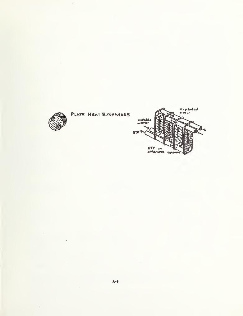


APPENDIX B - TOXICITY STUDIES OF HEAT TRANSFER FLUIDS AND CCMMON ADDITIVES^^
Table E-1
Toxicity of Heat Transfer Fluids
CHEMICAL SUBSTANCE(GENERIC) PRODUCT
AmmoniaNH,
anhydrous
TOXICITY RATING*-GOSSELIN^^^^i
TOXICITY RATING
TOXIC HAZARD RATING®
DURHAM^^®*
Acute Chronic
Irritant
InqestionInhalationSkin absorption
Bromides IrritantIngestionInhalation
1
2 22
1
22
Chlorodifluoromethane Freon 22Syn; Freon 22CIHCF^
Toxicity:Asphyxlnnt inhigh cone.
Dichlorodi f luoro-inothane
Syn.: Freon 12CCljFj
Freon 12 Irritant 0 U
Ingestion 0Inhalation 0 1
Skin absorption 0
UU 1
U
Dichlorotetra- Freon 114fluoroe thane
Syn.: Freon 114F^ClCCClFj
Irritant 1 0 U
IngestionInhalation 1 1Skin absorption
UUU
UUU
Di ethylene Glycol^Syn.S diglycolCHjOHCH^OClljCHjOII
Oral-human /an.LDjq 1000 mgAg' ' 3
Irritant 1 1 U
Ingestion 2
Inhalation 2
Skin absorption
UUU
Dipropylene glycolSyn.: 2,2’-
dihydrcxyi sopropylether
(CIt3CIIOHCH2)20
Oral-ratLDjq 15 gm/lg (81)
1
Irritant U U
Ingestion U 2
Inhalation USkin absorption U
U 2
U 1
U
F.thyJcne GlycolSyn.; I » I-cth.nncd j ol:
glycol; ethylenealcchnl; glycolalcohol
CH^OHClIjOJI
^owthermSR-1; UCAR-’‘thernof luid17
Oral -humanLDLo 1500 ng/kg
Oral -ratr,D,. 5840 mg/kg
(81)
(81)
—^Extracted from reference [13], Sandla Laboratories, SAND 78-0842, 1978
Irritant low
Ingestion low 3
Inhalation lowSkin absorption low
1
2
* Commonly used manufacturer's fluids
^Durham: 0-none; 1-sllght; 2-moderate; 3-hlgh; U-unknown. Gosselln “ 1-practlcally non-toxic; 2-sllghtly toxic; 3-moderately toxic; 4-very toxic; 5-extremely toxic; 6-super-toxlc (See Section 13).
'^Suspected carcinogen of bladder (1).
'^Experimental carcinogen (1).
'^References 7S a.. .9 of the report cited above correspond to references 5 and 6 of
this report.
B-1

CHEMICAL SUBSTANCE(GENERIC) PRODUCT
TOXICITY RATING^-GOSSELIN^^^^
TOXICITY RATING
TOXIC HAZARD RATING^
DURHAM
Acute Chronic
Ethylene Oxide^ * UCON 30 Oral-rat .gj^,
Syn . : l.Z-cpoxy*- ^*^50 n>g/Jcg 4
ethane oxirane(ClI^) 2°
Irritant 3 2 U
IngestionInhalation 2
Skin absorption
UUU
Fluo rotrlchloro- Freon 11
methaneSyn.: trichloro-
f luoromethaneFCClj
Irritant 1
Ingestion 1
Inhalation 2
Skin absorption I
1
1
2
1
Glycerine Oral -guinea pigLDjg 77S0 mgAg '
' 2
IrritantSyn . : 1,2, 3-propanc-
triol; glycerolCH
2OJICHOHCH
2OH
Ingestion
Lithium BromideLiBr See bromides £
lithium compounds
Lithium ChlorideLiCl -lljO
Oral-ratLD^q 757 n.g/kg 3
See lithium com-pounds
Lithium Compounds Irritant 2 U
IngestionInhalationSkin absorption
3 U2 U
U
2
2
Mot hanolSyn.: metltyl alcoholenroll
Irritant 1
Innention 3
Inlialation 1 2
Skin absorption 2
1
12
2
2
rhciiyl other-diphenyl *Dowtherm A Oral-ratmixture LDLo 4380 mg/kg 3 »’ol to'^t-
but mildlvIrritant
B-2
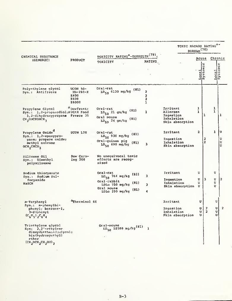
CHEMICAL SUBSTANCE(GENERIC) PRODUCT
TOXICITY RATING*-GOSSELIN^^^^
TOXICITY RATING
.
Polyethylene glycol UCON 50-Syn.: Antifreeze HB-280-X
E400E600E6000
Oral-rat fai\LDjq 6130 mgAg 2
221
TOXIC HAZARD RATING^
DURHAM^^®'
Acute Chronic
U VHE e
0-i t) u« tz
0 Vs c0 >,
tn ^
Propylene Glycol Dowfrost;Syn. : 1, 2-propanediol;*UCAR Food
1, 2-dihydroxypropane Freeze 35CHjOIlCHOHCHj
Oral -ratLDjq 21 gmAg
Oral mouse
“so gmAg
(81)
(81)
1
Irritant 1
Allergen 1
Ingestion 1
InhalationSlcin absorption
1
1
1
dPropylene Oxide OCON L20Syn . ; 1 , 2-epoxypro-
pane: propene oxide
t
methyl oxiraneOCH^CHCHj
Oral -ratLDjq 930 mgAg
Oral-guinea pigLDjq 690 mgAg
(81)
(81)3
Irritant 2 1 u
Ingestion 2
Inhalation 2
Skin absorption
UUu
Silicone OilSyn.: Dimethyl
polysiloxane
Dow Corn- No unequivocal toxicing 200 effects are recog-
nized
Sodium thiocyanateSyn. : Sodium Sul-
focyanideNaSCN
Oral -ratLDjq 764 mgAg
Oral -rabbitLDLo 750 mgAg
Oral mouseLDLo 290 mgAg
(81)
(81)
(81)
3
3
4
Irritant U U
Ingestion U 3
Inhalation USkin absorption U
U 2
UU
m-Terphenyl ’^herminol 66Syn.: m-phcnylbi-
phenyl; benzene- 1,3-d ipljcnyl
«V'5>2V'4
Irritant U U
Ingestion U 2
Inhalation U 2
Skin absorption U
U 2
UU
Triethylene glycolSyn: 2 ,
2 ' -ethylenedioxydiethaiic*! ;glycol;bi s (hydroxycthyl
)
ether(CIl20Cll2CH20!l)j
Oral-mouse failLDjq 18500 mgAg' ' 1
B-3
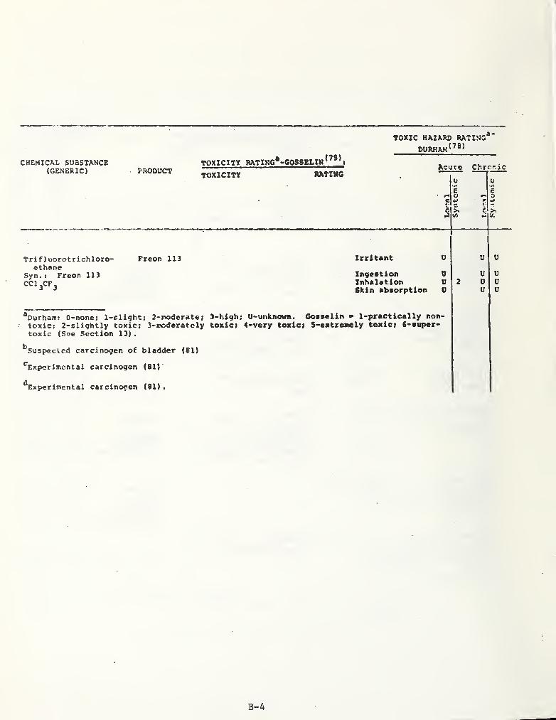
CHEMICAL SUaSTANCE(GENERIC)
Tri fluorot rich loro-ethane
Syn.< Freon 113CCl jCF^
PRODUCTTOXICITY RATIWG*-G0SSEL1N^^^^
TOXICITY RXTmC
Freon 113
TOXIC HAZARD RATING*
OURHAM^^®^
Irritant
Acucc Chrrr.ic
Xngeatlon 0Inhalation USkin absorption 0
2U0u
uuu
^Durham: 0-none; l-slight; 2-jt»derate; 3-high; U-unknown. Gosselin 1-practically non-toxicj 2-6lightly toxic; 3-moderatoly toxic; 4-very toxiei 5-e*tre»ely toxic; 6-tuper-toxic (See Section 13)
.
^Suspected carcinogen of bladder (81)
^^Experimental carcinogen (81)
^^Experimental carcinogen (81) .
B-4

Table B-2
Toxicity of Fluid Treatment Chemicals
CHEMICAL SUBSTANCE(GENERIC) PRODUCT
Arsenic Compounds^
Benzotriazole
Boron Compounds
Chlorinated Phenols
ChroBiiuni Compounds
2-cthy) JiozanolSyn.: 7-ethyl
alcohol
Hypochlorites
Lithium ChromateLi jtrO^. 211^0
TOXICITY RATING* -GOSSELIN*^^^fcnrrcTTY
Oral-rat jouLDLo 500 mgAg 3
Oral-ratLDj^p 3200 mg/kg'"*'
Oral -mouseLDg^ 3200 ng/kg‘"^'
TOXIC HAZARD RATING*
DURHAM^^®^
Acute Chronic
mH
cu01-9
Systemic
j
Loca
1
IuHE0PCft
>1A
Irritant 2 2
Allergen 2 2
Ingestion 3 3 3
Inhalation 3 3
Irritant U 0
Ingestion 2 U 0 2
Inhalation 2 U 0 2
Skin absorption U 0 2
Irritant 3 uAllergen uIngestion 3 3 U 3
Inhalation 3 3 U 3
Skin absorption 3 U 3
Irritant 3 U 3
UIngestion 3 U 3 3
Inhalation 3 U 3 3
Skin absorption U
Irritant 2 U UU u
Ingestion 2 U uInhalation 2 U uSkin absorption U u
sec chromiumcompounds
B-5

CHEMICAL SUBSTAKCE(GENERIC)
TOXICITY RATING* -GOSSELIN^^*'PRODUCT
TOXIC HAZARD RATING*
DURHAM^^®^
Acute Chronic
u
E0
cu 0)
c >«
Lithium Com;x>unds Irritant 2AllergenIngestion 3
Inhalation 2S)cin absorption
Lithium HydroxideSyn.: Lithium hydroxidemonohydrate
LiOH
Lithium NitrateLiNO^
Mercaptans
Mercury compounds,organic
Nitrates
Ni trites
Very caustic« toxic. Seelithium com-pounds i sodiumhydroxide.
see nitrates
Irritant 3 U
IngestionInhalationSkin absorption
Irritant 3Allergen 2Ingestion 3Inhalation 3Skin absorption 2
2
3
3
3
3
Irritant u u
IngestionInhalationSkin absorption
U 2
U 2
U
Irritant U u
Ingestion UInhalation USkin absorption U
33
U 3
U 3
U
B-6
Txacn
1Systemic

CHEMICAL SUBSTANCE(GENEniC) PRODUCT
Pal athionSyn.t 0,0-diethyl 0-P-
nl trophcnyl thlo-phoephate; "Alkron"
i
TOt->pound 3422?DNTP; DrP; E-605;genlthion; niran;paradust; paraflow; >
paraspray; parawetjpenphon; phos-kllthiopt»sj vapophoriand many others
Pentachlorophenol
CL^CgOU
Phenylmercuriet riothanol
airrioninm lactate
Dowicidc G
TOXICITY RATING*-GOSSEI,IN^’®^toxieiTV RJrlTj!?
Oral-humanLDLo 240 tng/kg
Oral -rat
(81)
o-Phenyl phenol
Phosphates, organic
Polassiuo Ai senateSyn; potassium
dihydroqeri arsenate;P.acquer's salt
KII,AsO.
Potassium di chromate*Syn.s tolansium bi-
chror.wTie; redp<«tas:; lum chromate
K^Cr^Oy
I*>^50 2 mgAg (81)
Oral -humanLDLo 29 mgAg'
Oral-rat ....W>50 50 mgAg'"*'
Oral-rat*'*'50 mgAg**'^
Dowicide 1 Oral -ratLDjq 2700 mgAg (81)
Oral -human child
LDLO 50 mgAg^®^'
TOXIC HAZARD RATING,(78)DURHAM’
Acute Chronic
IQ
00U in
Irritant U
Ingestion VInhalation USlcln absorption V
IrritantIngestionInhalationSkin Absorption
See mercury com-pounds, organic
IrritantIngestion
see parathion
Arsenic com-pounds
Sec chromium com-pounds .
B-7
Loca
I
Sy
s
tenue

CHEMICAL SUBSTANCE(GENERIC)
TOXICITY RATINg“-GOSSELIN^’**PRODUCT TOXiClW" RATlNff
TOXIC HAZARD RATING
DURHAM
Acute Chi;onic
•Q
I
Potassiun HydrogenPhosphate
Syn.: potassiumphosphate, dibasic
K2«P0^
Sodium BenzoateSyn. : Benzoate of sodaNaC^HjOj
Sodium BorateSyn.t Sodium tetra*borate
Na2B^0.^
Oral -ratLDjjj 4100 mgA9
Oral-rabbitLDLo 2000 agAg
(81)
(81)
Sodium ChromateNa^CrO^
Sodium HydroxideSyn.: Caustic soda;
Sodium hydrate: lye:white caustic.
NaOH
Sodium HypochloriteNaClO
Sodium Metasilicate
Sodium NitrateSyn.; Soda niter:
nitratincNaNO,
Sodium- o- PhosphateSyn.: trisodiumphosphate
Na^PO^-12 lIjO
Sodi'jm Sulfate(Sol. Sulfate Saltsof Sodium)
Oral-rabbitLDLO 500 mgAg (81)
Oral-ratLDj.q 1280 mgAg (81)
Oral -ratLDLo 200 mgAg (81)
Atmount of r.ulfateanion usually absorbedhas no toxifoloejicalsignificance.
Toxic hazardrating: U
Irritant
IngestionInhalation
00
Slcin absorption 0
See boron com-pounds
See chromiumcompounds
Irritant
Ingestion 3
Inhalation 2Skin absorption
See hypochlorites
See nitrates
Irritant
IngestionInhalationS)tin absorption
B-8

CHEMICAL SUBSTANCE(GENERIC) PRODUCT
TOXICITY RATING*-GOSSELIN^’*^WxTCItY RAflHir
TOXIC HKZARD RATIVG®"
Acute Chronic
o U•MB Co « O
c Co cn 0c 0 >.¥-^ M y;
Sod i un 2, 4, S-
t r i ch 1oropheno
1
Dovicide B Oral-ratLDjq 1620 3
.3,4.6-tr1ch 1oropheno
1
Dowicide 6 Oral-ratLDjq 140 ingAg (61)
Oral-guinea pig
^'^SO »9Ag (81)
4
See Chloronated phenols
See chlorinated phenols
2.4,5-trichlorophenol
Dovicide 2 Oral-rat •
LOjjj 820 mgAg'®^' 3
See chlorinated phenols
2,4.6-trichlorophenol g
Dovicide 2S Oral-rat ....LDjjj 820 »gAg*"*' 3
See chlorinated phenols
*Durhaia: 0-none; l-slighti 2-moderate; 3-hlgh; U-unknovn. Gosaelin “ 1-practically non--toxic;toxic; 2-slightly toxic; 3-iDoderately toxic; 4-very toxic; S-extremely toxic; 6-super-toxic (Sec Section 13)
.
^Recognized carcinogen of akin (81)
*So»e chromium salts are recognised carclnogena (81)
^Recognized carcinogen*^
^Recognized carcinogen (81)
^Recognized carcinogen (81)
^Carcinogen (81)
B-9

Table B-3
Toxicity of Outgassing Products from Heat Transfer Liquids
TOXtC ll,'.7.Apn RATlNt;'’'
riUPIIAM(70)
OUTGASSING SUBSTANCE(GENERIC)
FROM TOXICITY RATING^-GOSELLIN*’®^ Ai'ti 0 Oil «M1 i cPRODUCT TOXlclTY RAfirlS"
u u
e c0 4)
u0 v> u0 0,4 W (/)
Argon SF 96, silicone; Irritant 0 U uA Exxon Caloria Ingestion 0 u u
HT 43; UCON Inhalation 0 1 u u500; Therininol66; Mobiltherin£0 3; Mobil thermLight; DowthermA
S)cin absorption 0 u u
Carbon Dioxide SF 96, silicone; Irritant 0 0CO, UCON 500; Exxon Ingestion 0 0
Process Oil 3029; Inhalation 0 1 0 1Exxon Caloria HT-43; Dowtherm A;Therminol 66;Mobiltherm 603;Mobil therm Light
Skin Absorption 0 0
Carbon Monoxide SF 96, silicone; Irritant 0 0CO UCON 500; Exxon Ineestion 0 0
Process Oil 3029; Inhalation 0 3 0 1
Exxon Caloria liT-
43; Dowtherm A;Therminol 66;Mobiltherm 603;
' Mobiltherm Light
Skin absorption 0 0
Ethane SF 96, silicone; Irritant 0 0Syn.: bimethyl; Exxon Process Oil Ingestion 0 0
me thy Ime thane; 3029; Mobiltherm Inhalation 0 2 0 1dimethyl; 603; Mobiltherm Skin absorption 0 nethyl hydride
^2«6Light
Ethylene SF 96, silicone; Irritant 0 0 0Syn. : ethene; UCON 500; Exxon Ingestion 0 0 0
elayl; etherin Process Oil 3029; Inhalation 0 2 0 0CHjCHj Therminol 66; Skin absorption 0 0 0
Mobiltherm 603;Mobiltherm Light
Hydrogen SF 96, silicone; Irritant 0 0 0
“2 Exxon Process Ingestion 0 0 0
Oil 3029; Exxon Inhalation 0 1 0 0
Caloria HT-43;Therminol 66;Mobiltherm 603;Mobiltherm Light
Skin absorption 0 0 0
B-10

OUTGASSING SUBSTANCE(GENERIC)
MethaneSyn.i marsh gas;
methyl hydride
FROMPRODUCT
TOXICITV RATING^-GOSSELIN^^®*Toxicirt Rating
TOXIC HAZARD R.^TINC^
durha: i
^^^^
Acute Chro'
n
SF 96, silicone;UCON 500; ExxonProcess Oil 3029;Exxon Caloria HT-43; Dowtherm A;Therminol 66;Mobiltherro 603;Mobiltherm Light
Irritant 0Ingestion 0Inhalation 0 1
Skin absorption 0
0
0
00
Nitrogen SF 96, silicone;N, Exxon Process Oil^ 3029; Exxon
Caloria HT-43;Dowtherm A;UCON SOO; Therminol66; Mobiltherm603; MobilthermLight
Toxicity: None
^Durham: 0-none; 1-slight; 2-moderate; 3-high; U-unknown. Goeselin 1-practically non-toxic;2-slightly toxic; 3-moderately toxic; 4-very toxic; 5-extremely toxic; 6-super-toxic.
; <
B-11

Table B-4
Toxicity of Thermal Degradation Products
CHOaCAL SUBSTAMCE(ccNrmc)
Aistonia, anhydroua$yn.
s
anaonia qaa
rKODUCT
Nylon t,6
TOXICITY »ATmC*-G08»eLIN<’*>foxIcIT? KatTOC
TOXIC HAIAIU) RATING*
DllRHAW*^**
Acuta Chrcnte
Irritant 3 0Ingeatien 3 UInhalation 3 0Skin abaorptlen 0
u
r•* <1
5
1
>•<A
VVuu
henaane^Syn.: benzol > phenyl
hydride] coalnaphtha
Ceon] HalontPlexiglaas;Lucitc; PVC]Neoprene t
Nylon HT-4
Irritant 2 .
Znqeatlon 1 ,Inhalation 1 1
Skin abaorption
00 3
0 3
0 3
Butadiene-1,3 NeopreneUninhibitedSyn.t erythreneCHjCHCHCHj
Irritant 3Invention 2
Inhalation 2 2
Skin abaorption
1 UUuu
Carbon Dioxide Nylon C,C;Syn.: carbonic acid: Nylon HT-4
carbonic anhydride
Irritant 0Invaatioo 3Inhalation 0 1
Skla abaorption 0
0000
1
Carbon Tetraf luoride Teflon,Syn.: tetraf luoro- PTFEethane
0^4
IrritantInvartiooInhalation 2 2
Skin abaorption
U D0 U0 U0 U
Ethylene Novacalk 600)Syn.) ethane) elayl) CPDN rubber
etherinCHjCHj
Irritant 0Invention 0Inhalation 0 3
Skin abaorption 0
0 0
0 0
0 00 0
Ethyl MercaptanSyn.: elhancthiol:
ethyl hydtoaulfidcethyl thioalcohol;ethyl sulf hydrate
Novacalk 600 Irritant 3Invention 2
Inhalation 3Skin abaorption
U UU U0 UU U
Nc xa f 1 ooropropy lencSyn.: pcrfluoro-
propeneCrjCDCFj
Teflon, »-EP
PTPEToxic Hazard Ratinv:O. Toxicity:Animal experiawntaauvvent ni^eratetoxicity.
Hydrochloric AcidSyn.; Buiriatic AcidcMorohydric acid:hyJroqon chloride
HCl
Hydrocyanic AcidSyn. : hydrocen
cyanide: prunsicaetd
HCN
Tedlar; PVC:Neoprene;C.con; Halon
Nylon 6,6:Nylon MT-4
Irritant 3
Invention 3
Inhalation 3
Skin absorption
UUU
Irritant 3Invention 3
Inhalation 3
Skin absorption 3
U UU UU U0 U
Rydrcifluoric Acid TedlarSyn.: hydroven
fluoride: fluoro-hydxlc acid
HP
Irritant 3Invention 3
Inhalation 3
Skin absorption
*Durham: 0-none: 1-aliqht: 2-modcrate: 3-hivh: U-unknown, Coasclin • 1-practieally non-toxir; 2-slivhtly toxic: 3-n»lcrately toxic: 4-very toxic: S-extremely toxic: 6-super-toxic (See Section 13).
B-12

CHKMICAU SUBSTANCE(GENERIC)
Hydro9enH2
Toxicm rating'-gossrlim*’**PRODUCT TojcTclTY hATl)4'6
EDPM rubber
TOXIC HAZARD RATING*.
DURHAW^^**
IrritentIngettionInhalationSkin abaorptlon
Acute Chronic
Hydrogen Sulfide Novacalk 600Syn. : sulfucettedhydrogen
Irritant I
IngestionInhalation 3Skin Absorption
Uuuu
3
IsobutancSyn.: 2-sicthyl
propane; trl-ncthyl methane
Novacalk 420 Irritant 0Ingestion 0Inhalation 0 1
Skin absorption 0
0 00 U0 U0 U
MethaneSyn.; marsh gasi
eiethyl hydride
Dow Corning 7S1;Novacalk 420;EPDM rubber;Nylon HT-4
Irritant 0
Ingestion 0Inhalation 0 1
Skin absorption 0
0000
1
Methyl Methacrylate Plexiglass;(BonoBor) LuciteCHjC(CHj)COOCHj
Irritant 1Ingestion 3Inhalation 1
Skin ab.sorption
UU 1
U 1
U
PropyleneSyn.
;propene
EPOM rubber
SilicaSyn.: silicon
dioxide: silicicanhydride;cristobalite
TolueneSyn.; methy Ibcnrene;
phe iiy 1 rac t hanc
;
toluol
Dov Corning 781
Geon; Ha Ion;PVC; Neoprene
Vinyl Chloride PVC; Ceon;Syn.: chloroolhylenc; Halon
chloroethencCH^CIICl
Irritant 0Inoestion 0Inhalation 0 2Skin absorption 0
0 00 00 0
0 0
Irritant 0Ingestion 0Inhalation 3 0Skin Absorption 0
3 1
Irritant 1
Ingestion 3
Inhalation 3
Skin absorption 1
3
3
2
IrritantIngestionInhalationSkin absorption
3
3
*Durha*: 0-nonc; 1-sliqht; 2-SK>dcrate2>slightly toxic: 1-modcrately toxic;
3-highj U-unknown. Cosselin ~ 1-piact ically non-toxic;4-very toxic; S-extrenely toxic; 6-super-toxic.
B-13

Table B-5
CHEMICAL SUBSTANCE(GENERIC)
Armnonium BromideNH^Br
Barium Compounds(soluble)
Barium HydroxideSyn.: Barium Hydrate
caustic barytaBa (OH)2-8H20
Benzamide
Benzoic AcidSyn.; phenyl formic
acidC.H^COOHb o
BiphenylSyn.; Diphenyl
Bromides
Calcium BromideCaBr,.6H20
Calcium ChlorideCaCl2
Calcium Compounds
Toxicity of Thermal Storage Media
TOXICITY RATING*-GOSSELIN*^^^
PRODUCT TOXICITY RATING'
TOXIC HAZARD BATING^
DURHAM
Acute Chronic
see bromides
IrritantIngestionInhalation
1
1 3
1 3
1
22
sec bariumcompounds
Oral-mouse
LDjq 1160 mgAg 3
Oral-ratLDsq 3040
Oral-mouse
LDjq 2370
mgAg**^* 3
mgAg<«>
Irritant 1Ingestion 1 1
Inhalation 1Skin Absorption
Oral-rat3280 mgAg'"^'
Oral -rabbit .
LDjp 2400 mgAg'^^'
Irritant UIngestion UInhalation USkin Absorption U
2
2
0UUU
2
2
IrritantIngestionInhalation
12 2
2
122
see 'bromides
Oral-ratLD^q 1000
Oral-rabbitLDLq 1384
mgAo^®^^ 3
see calciumcompounds
IrritantIngestion
'
Inhalation,,
1
Skin Absorption
UUUU
1 UUUU.
B-14
Local
systemic

CHtrMlCAL SUBSTAKCE-(GENERIC) PRODUCT
TOXICITY RATING*-GOSSELIN^^®' .
TOXICITY RATING'
Caprylic AcidSyn.: octanoic acidCH^jCH^) gCOOH
TOXIC HAZARD RATING®-
DURRAM
Acute Chronic
Experimentaldata suggestlow toxicity
u•ac
aoo
o
(D
A
U
— O13 -»
O A0 >»A
Diphenyl oxide(CBjljO
Oral-ratLDjq 3370 tng/)cg
(81)3
Glaubers Salt See sol. sulfate saltsof sodium
Laurie Acid '
Syn.: dodecanoic acidCHj(CH2) j^qCOOH
Myristic Acid Nontoxic by oralSyn. I tetradecanoic administration
acid
Animal data sug-gest low toxicityfor lauric acidesters. Detailsunknown.
NaphthaleneSyn.: moth flakes;white tar; tarcampher.
Oral-rat /«n\LDjq 1780 itigAg 3
Oral-human childLDLo 100 mg/kg'
4
Irritant 2IngestionInhalationSkin absorption
22
2
1
2
1'
2
Nitrates
Paraffin Wax^
Irritant UIngestion UInhalation USkin absorption U
22
Irritant 0Ingestion 0Inhalation 0Skin absorption 0
0000
Uuuu
2
2
Polyethylene Glycol 400iicx:ii,(cn,ocM,) ch,oh
/ A X n /(i» varies from 8-10)
2 Toxic Hazard^Rating: U
Polyethylene Glycol 600 2
Polyethvlenc Glycol6000
Oral-ratLDLo 50 gmsAg' 1 Toxicity; U
B-15

CHF.MICAL SUBSTANCE(GENERIC) PRODUCT
TOXICITY RATING*-G05SELIN^*^’*fojfICIT)? RATlNfi
TOXIC HAZARD RATING^
DURHAM
Acute Chronic
u
uo
'A
>1lA
Sodium Sulfate(sol. sulfate salts ofsodium)
Amount of sulfate anionusually absorbed has notoxicologicalsignificance
Stearic AcidSyn.; octadecanoic
acidCH^(CH2) j^^COOH
Toxicity:Slight
Zinc Nitratezn (NOj)
Oral-rat1190 mgAs' ' 3 nitrates
^Durham; 0-none; 1-sllght; 2-moderate; 3-high; U-unknown. Gosaelin = 1-practicallynon-toxic; 2-slightly toxic; 3-moderat»»ly toxic; 4-verty toxic; 5-extremely toxic;6-super- toxic (See Section 13)
.
^Recognlxed carcinogens of skin (81)
B-16

Table B-6
Toxicity of Outgassing Products from Solids
TOXIC HAZARD RATING®-
DURHAM^^®^
chemical substance(GENERIC)
FROM TOXICITY RATING*- GOSSELIK^^*^ Acute ChronicPRODUCT ToxTcTty RAfTTSc
Local
1
Systemic
1'
c(j
o•J
Systemic
|
Argon Kovacalk 420, Irritant 0 u uA butyl rubber; Ingestion 0 U u
Novacalk 600, Inhalation 0 1 U upolysulfide Skin absorption 0 u u
Carbon Dioxide Novacalk 420, Irritant 0 0
CO butyl rubber; Ingestion 0 0A Novacalk 600, Inhalation 0 1 0 1
polysulfide; Skin absorption 0 0
polyisocyanuratefoam with aurethane mod-idier; tanpolyurethanefoam; supra-thane; pinkfiborglassinsulation withphenolic bind-er
Carbon Monoxide Novacalk 420, Irritant 0 0
CO butyl rubber; Ingestion 0 0
Novacalk 600, Inhalation 0 3 0 1
polysulfide Skin absorption 0 0
FI uorot rich lor ome thane Freon 11; poly- Irritant 1 1
Syn.i trichlorof luoro -* phenyl isocyanur- Ingestion 1 1
methane ate foam with a Inlialation 2 2
reel. urethane modifier; Skin absorption 1 1
tan, Dol vurethanefoam; Suprathane
Hydrogen Novacalk €00, Irritant 0 0 0
polysulfide Ingestion 0 0 0A Inhalation 0 1 0 0
Skin absorption 0 . 0 0
Hydrochloric Acid polyphenyl- Irritant 3 2 u
Syn.: muriatic isocyanurate Ingestion 3 u
acid, chlorohydric foeim with a Inhalation 3 u
acid hydrogen urethane mod- Skin absorption u
chloride ifier; tanHCl polyurethane
foam; Supra-thane
B-17

CHEMICAL SU3STAKCE(GENERIC
)
PROM TOXICITY RATIKG*-.COSSELXM*’*^PRODUCT roxiclTi^ ' SaTTRg
MethaneSyn.i marsh east
methyl hydride
Novaealk 420,butyl rubber;Novaealk 600,polysulfide
Methyl Styrene common whitestyrofoam
TOXIC HAZARD RATING*-
DURHAM
Acute
V
Chronic
Irritant 0Ingestion 0Inhalation 0 1
Skin absorption 0
000
01
IrritantIngestionInhalationSkin absorption
U0UU
0UUU
NitrogenM2
Novaealk 420,butyl rubber;Novaealk 600,polysulfide
Toxicity; None
PhenylethyleneSyn.i vinylbenxene,
styrene (monomer)
,
cinnameneCgHjCHCHj
common whitestyrofoam
IrritantIngestionInhalationSkin absorption
^Durham; 0-none; 1-sllght; 2-moderate; 3-hlgh; U-unknown. Gosselin «• 1-practically non-toxic;2-slightly toxic; 3-moderately toxic; 4-very toxic; S-extreswly toxic; 6-super-toxic
B-18
Systemic

Table B-7
Toxicity of Combustion Products
CHEMICAL Sl’BSTANCE(GENERIC)
TOXICITY RXTING*-COSSELIN^’**PRODUCT foxIcTIW TWTWr
TOXIC HAZARD RATING -
DURHAM^’®’
Acute Chronic
Acetone Nylon RT-4Syn^: dimethyl ketone;ketone propane;propanone
CHjCOCHj
'Acetylene Butyl rubber.Syn.: ethyne; ethine Kovacalk 420;RCCB
Afliaonia
Syn.: ancnonia gasHH,
lfRf?''*bcn*ol; phenylhydride; coal
*
'
naphtha
Butadienc-1 ,
3
(uninhibited) -
Syn. : erythreneCHjCHCHCHj
Carbon DioxideSyn. I carbonic acid;
caibonir anhydride
“2
Carbon MonoxideCO
Carbonyl rluoridoSyn.: fluoro(or»yl
fluorideCOfj
Nylon 6,6
Nylon 6,6
Neoprene: PVC;Goon; Kalon
Neoprene
Neoprene;Dow Corning 781;Novacalk 600;PolyEulfide, C9;butyl rubber,Novacalk 420:Teflon, PTFE:Teflon, PEP;Teflon, PFA;Tcdlar; Lucite;Plexiglass; PVC;Geon; Ha Ion;Nylon HT-4; Nylon6,6
Neoprene; DowCorning 781;polysulfidc,Novacalk 600;polysulfide, C9;butyl rubber,Novacalk 420;Teflon, PTFE;Teflon, FEP;Teflon. PFA;Lucite:Plexiglass;PVC : Geon
;
Ha Ion: Nylon HT-4; Nylon 6,6
Teflon. PTFE
IrritantIngestionInhalationSkin absorption
Inhalation
IrritantIngestionInhalation
IrritantIngestionInhalationSkin absorption
IrritantIngestionInhalation
Inhalation
Inhalation
IrritantInhalation
Durham: 0-none: I'sHght; 2-modoratc; 3-higti; U'unknown. Gosselin: 1-practically nontoxic;2-sligiitly toxic; 3-moJerately toxic: 4-very toxic: S-extremcly toxic; 6-supertoxic.
^Kecognirod carcinogen of the blood-forming tissues (81).
B-19

TOXIC HX7ARD RATING
DUPHA><’**
CHIXICAL SUBSTANCE(GENERIC) PRODUCT
TOXICITY RATING*- GOSSr.UN*^*>fbxrtlfi IRTIIK Acute Chronic
EthaneSyn.: bimethyl;
methyl nethane;dimethyl; ethylhydride
C2«6
Ethyl AlcoholSyn.t ethanol;
methyl carbinol;spirit of wine
CHjCHjOH
EthyleneSyn.: ethene;
elayli etherinCHjCHj
Fluorides
Porstaldehyde^Syn.: Mthanal;
methyl aldehyde;formalin
HCHO
Formic AcidSyn.: methanoic acid;hydrogen carboxylicacid
HCOOH
Hydrochloric AcidSyn. I muriatic acid;chlorohydric acid;hydrogen chloride
HCl
Hydrocyanic AcidSyn.: hydrogen
cyanide; prussicacid
HCN
Hydrofluoric AcidSyn.: hydrogen
fluoride; fluoro-hydric acid
HP
Hydrogen
a
NeoprenePVC; Ccon;Ralon
Polysulfide,Novacal): 600;Polysulfide,C9
Neoprene;Nylon 6,6
Dow Coming 7tl
Dow Corning 7B1
Neoprene; PVC;Geon; Ralon
Nylon HT-4;Nylon 6,6
Tedlar
Neoprene;butyl rubber,Novacalk 420;Lucite;Plexiglass
Inhalation
IrritantIngestionInhalationSkin absorption
Inhalation 2 0
IrritantIngestionInhalation
IrritantAllergenIngestionInhalation
IrritantIngestionInhalation
IrritantIngestionInhalation
IrritantIngestionInhalationSkin absorption
IrritantIngestionInhalation
Inhalation
'Durham: 0-none; 1-slight; 2-moderate; 3-high; 0-unknown. Cosselin; 1-practically nontoxie;2-slightly toxic; 3-moderately toxic; 4-very toxic; S-extremely toxic; 6-supertexie.
*A suspected carcinogen of the lung.
B-20
Local
Systemic

TOXIC HAZARD RATIMG*-
DORHAM*’®’
CHrMICAL r.URSTAMCE TOXICITY RAT1NG*-G0SSEMM*’*'(CF.NRRIC) PRODUCT foXICl'fT RATING
0 O
F. cV «>
m 4i
•
•S (A •J U)
Methane Neoprene; PVC; Inhalation 0 1 0 1
Syn. 1 marsh gas; Ceon: Ha Ion:methyl hydride
CH,Nylon 6,6
Methyl Chloride PVC ; Ceon
;
Irritant 1 USyn.: chloromethaneCHjCl
Ha Ion Inhalation 1 3 u 2
Methyl Methacrylate Lucltc; Irritant 1 u(nonoiocr) Plexiglass Ingestion 2 u 1CHjClCHjlCOOCHj Inhalation 1 u 1
Nitromethane Nylon HT-4 Irritant 2 0 VCHjMOj Ingestion 3 u V
Inhalation *3 0 V
Silicon Tetrafluoride Teflon, PTFE; See fluoridesSyn.z tetrafluoro- Teflon, FEP;
silane Teflon, PPASIP^
Toluene PVC; Ceon; Irritant 1 1Syn.: molhylbcnzciie; Ha Ion; Neoprene Ingestion 2 2
phenyln« thane; Inhalation 2 2toluol Skin absorption 1 2
CjHjClli
Vinyl Chloride^ PVC ; Geon
;
Irritant 3 2Syn.: cMoroethylene: Halon Inhalation 2 3chloroethene
CHjCHCl
Vinyl FluorideSyn.: f 1 uoroethylcneCHjzCHF
Tcxllar See fluorides
Xylene Tedlar Irritant 1 1
Inhalation 2 2
Skin absorption 2 2
Duiiiaoi: 0-none; l-sli^ht; 2-modoratc; 3-high; 0-unV.nown. Coasclin: 1-practical ly nontoxic;2-sliyhtIy toxic; 3-modcrotcly toxic: 4-very toxic; &-extrenely toxic; C-supertoxic.
dA recognized carcinogen of the liver (81).
B-21

it
I i:
* iv.
‘i"-
no ! . ;, . i.r.1.1
f- .
' -• ' 1*?^ 4/
.'f >>*.£ %-i-tf. .
'i'
''-<'•4 ^
.-S,
.
i' \ <•* ,’• ;»v.!|
'
. fs-X-t' V.'
"o >
.ViW
-
'.J-'
' ar
; *M S?vt3f»utr>*«wrt
I r-'i. 'X-;
IJM.
,.'0i
* , J r> if ,--l
A,.
C A.
--i-j ;• .X
,i
f' / i»4 .' V < c*
ia*nr, "V '
tic “i (If ft.^;1; lb*
«ft'
is-'' s '
,S ' - -
.. 'i•'-
Irtv
m'--:
I i,
•' 1tolc
'• •-
5'-'S
A
^ ^ • ) ' /iVi? “ ^ ’ '^ ji *1 -' —t-
•j
- |r,’ M
TaifetSf"/_
-siuuwrt^.‘ jjjL.y »< f*
. ,•( Ii ’»
. A‘^
*' » *
y'
'if-,, -•w»
,
-' .• ‘,
1V
'' S'.
•>,''''If}'.'- |,,'ij»i )
r.'. • t“.l:!p:«^».-'.ji...-<«-*>» tVSi •' > i • ,-. 'TC3 7 .' .Hv I, t «rt;
. J -St-fJ lo
*”i-i•
53

m
BOCA
BASIC
MfCHANiCAL
COD^
i?**
'’
Anpc
iul
ix
C
MECHANICAL
BEFBIGERATION
c
§ I
c
il bt ‘-
E oc .r*c O CJ
C c-
“• c s;^ fc
’t
C> w
0 £ .s;
•- £!’£
E 5'•-
tU^ C ^: ^ Ili-S^.£ f
Li 1c c: o
^ —^ c ^0—0
1
t'Sg = S
> cr c' P Ec
E gi -=K4) bC
c .Et» •—
V. OS ^o r:
'£
^ ''
Ct; —cc~ 5
r: ca: £ *§o C/ tIE K E:
£ C«>'
_ ofc 'o
ccc
- o 20 C ^
^ tj
*c sr- ^ ''
1w. >• 5>' - o
O (/>
r:
r oO.t: o
!cT
"tJ c“ £ '^
5^ 1? O^ ot S 'vc/*" C
C 1- t;—
O CZ- =
1 E.-B"
> . tI- c
-- c c Xo c: ^^
- E
£*r&
ilc ooc z
•coIE>
o ce c- $ t; 2bCc
1-P,
-no
« c
° c— j:: o
JJ bC3 .EV •—C C
occ
o sir. ^
O*"
5 tA' O-2 —"o
o o ^t T3 r2 i c
s-n^ eE *o^.£ E- - 8
O
SO .t JT' £ t 3^ *n ii ^ ^ c
«? £ o c
o oM. 1_C O"c ^c 5;t-- .~r.
£.s
c *pS' £§-£
t:-^££ ^-
E £ •
=
> - 5c t:
8•b f£^ !C= c ^— Co
C ^ fcC
C — =^ o oc> b
•^a-o £
2 •= £_E —
S r. 5
t! r
= c,c ^
‘= o-S S'*- c-^ if
^*-C-'TC- Cs ^
uu oO X•£ cC ft
c ~C
t*o
oc
s: oo
c
£ J;'
Ow —b
c
^'ir*— c
^ Er.
£^ co
r,
t^.
C •
oi/5
£ E ^»— O C
^ t,. C -S
£ 'S C2
C = EU ^'!1
z:
E 2c or: ^^ U‘.
rsi
I
U
.S c- -A- u:
~
^ E •=
o o
o c
c
>
z>-
mSo5 tt
o
CL. ;:tr w
Ok.
-E ^ >.VC
c £ ^6 £ £
c: .t:
•b EgE >
ӣ "^
't:
^ c _c
Ir _rt
£l.i.h o
Co>’Ec
VCeok_cc
cc
r:o
cc
ct p
— V“ —
c. oVi fcX
- 2t'^T'i-£
o
Cl.'^> <=CL-oc
^ "2.JC
^ cc-J= -i
C-5 -3 Oo c"? c'g^ f o
oocc
'3t
.;:: tc3 Cbf v-
•E c
I
o
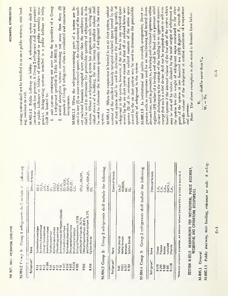
THE
Bcr;.
MfCHrtNICSl
COOE/IOTB
MECHAHIC»l
BErmCERBTION
>I
1
>
C
C
occ
I
1
ti
1
1
lT o> _n
> JB
i
o Uk. E -£ 11 i-T*- nT CD 'c
CD uT o CD\ w. — —1 - ^lT—! — -I" — ^ »oo^_ —jOCD'D>=::.--XXX<DOCD •
k*.
CD
Lt-
0 <-.
1 o
CJ
'eCD
I CD X O0 u
E0^
c XX X^ X^ ^ XCDOCDOOOOEDCDCDCDCD CD CD CD O G CD X Z CO CD CD CD CD CD CD
z0
c c_
ft cr
*<Uc «/; 1/;
'Z Csltr. \r
~ vO-co ooC' rr» CO
kT>CaC
cr
C/£ QJ
%> >.. e. C O) oJi»ca.a> ojoj-c-^pc c: aJ
fZ
w un ^ rz fz
oc-'-^X? CS -c
oc3
Ow 0k-
I’E^^^o'CtoSSSEEoE E-c cccS; = o-?o r~ c>^ pCSJ
Cj 0>
*o ^ -o
0es&exooj §= =-E 5 - 1 = -S &-§ = EgE 5 o£=:^-sg- =
Ecw^Ec^oBo^o^^coc=cOc 3 oo 3 c>
c, o•O
si
^ wo oO ^JD C
5k»
Dz •=_o E o*5 o TO ‘-S
g =
C
6 C ^a> g Qj P
*^jc:^ E o**c^ oE £ £ E CL
o>
£C « P 3 £TO Ci re j^Z -- cj -Z — ^ o ^
•— OCDCCih- OCDO*— OOOO c j=ro CD
C TOTO CD c?i raZ 4- 4 E 3z 2 < CO Z
•P 0 3 0 JPG c. no -!C wfcj
c. C-o 3o 4 0 «
ZT ®®CD ^ cT> — O-^CNirnrn^— PsjO — '^O
rsio U CO
o —• r«».
«pc V
C3 ^ 00 0 0 — L.O— — •— — cdlt> cr> r^ ifi r*N» w r>. C7^ CD —
•
<N< VC' CO —oracocococficozoircaEraccacrtfCc fiC fiC '« or fic OC fib cc cc cc cc cco O' 0 a>
oc cc GO cc
s
CO
tc
k-
<
CD COO UJ*»-G
C3 CJ
=J C3
_ cc
ttC
o Zt .
I
k4J
cc O
e:
£
1 -S CJ
o4*J</9
C O00 00
s s
mI
o
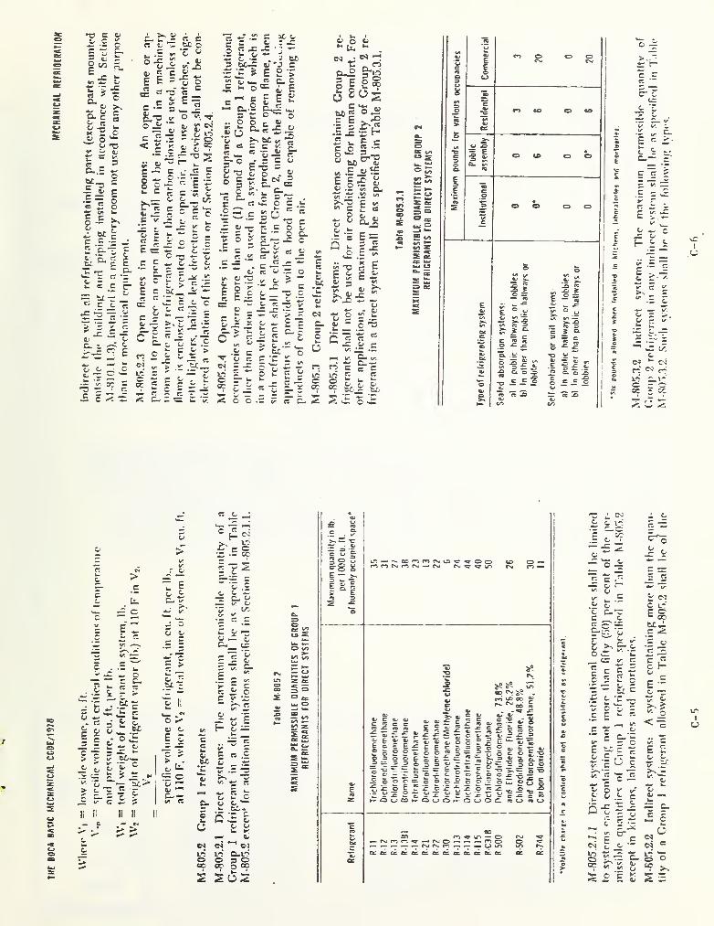
THE
BOCA
BA^IC
MfCHANICAL
CCDC/197B
cfa c 1/*. cL 2Em W fa *K
c r: Cv ^ fcC’ O P£ ^ ka fa -E s •fa
_o
o X rfa B:
. fa
Sfa
^X u fa g EfaX ^ X
a. c^ p:
i:i o
t: =
S-.E
ca
r jc
o _>N 1- ^C — 3cC3
k«
v:
o-fa
c i; !5T3Cj
< £ r
CS cft/ p =:
=> V— .Co “•-.
c sn ci
K Cr= c
= E
i: o— VI ug.E b4 “.I“ “
"c
ti ^ C £
i: "c p.
^ ^ ^ zfc- C C C"
gc c — E 'g X® = C I g
- ^_c/^
.2 C aC ft)
c «j : jct; X J= • J
—u. fj
.
ft. •- . a bc- bc-^ c 'J c•B ^ E £ >
£ £ o= i“i= -^
g £ I^
” §- •.= §^' ^3 fc.C O
.. O o C. 4)V fa r- ~ _er gjt> r 1 ^ i —
g .£ £ t“ O ftu
>,= ^
o
•s 6^ «
£ ?® g ..— fa <« - _. —r; C. C £ SC ts O Cc
C = EE T3 ^ft/ C .
>'C-
•— “X*^C
"S-
r:
X .£ J:
!2 "ct
- ^ r:C -
s g £ C •= £E =g t BC -r fa
C = — fa X fa’-fa E fa >^-
r c" E Z-^fa 1, > XE c B:
“
•= = T5
c; C O•- = C fa — OVI O V 5 X.£ C
c .!£C X
= g; fa^ VC V,
K —
cfa
c.c
« fa
•fa ~ • c -fa •£fa « fa .t:
£ £ ^ .s fc^
- o -
± c fa c^ '••X c
= c c fa _ ~ cfax fa = fax
I <- fa r: — V.
-3 -P 3 C fa
^ -E _ ,
^ fa
>-c E
fa^oB
B 5 X
cfa
C
«-£j -X .
L-i ^£-^1 L-Ib § £^.2'^-Lr-Bti'c' o"siE.fa s c««g
C fa >V, fa
fa .i:
_ tcK p •:: £
ft; O fafa rT fa
M Xo-B g'go I S®6 SosM.|
•Ex-fH" fa « *=c .o £ —
rrX3^ ^ fl >fa* bC ''
fa
V, .2 fa?E
E g£ £fa -2 C; Cfar
t; -t: .sc >«
P cr*" C £ CS
fa fa .," D-2
fab£
fak.
05
C.
5uo
•X
i=gE-5
TJ S Efa C fa
S-
v.X .. -j^ •. ej^
C •=
uo
c
c»
' -= .2 c
*fa £ g =
i< p- r X :
fa v:? iL
£ ~ X
O) fa XLO ,c = ,
* E - - ES O O .= V
- ct -
C-
05 CLO PS "oc
l/S
g-facr
.fa V c: C- 2 S
fa £ fa
•Ef'-fa .Ef
O vX
o ~
cr faX_fa 'C
4^ cr* c
E I"
-i"
g j I
c: «
v_fa _ c
Hit
^ CACv
c4OQ ^
L*? C- 1.':0-0°r - ^^ w S
I
>_c
.t.
X c
E‘t
-- oc
M t
wO ^rt 3O OE c^ up ?^ W"
fa B"fa wX fa
V. C
fc fa
'o £— faX ^bCkk. 1
•fac
•s - ~ '
fa £
fa
>
fa i:X V. >.
fa fa
c E
g >u *o
£ ''
o ^c; cE £
oo
o0^
C- —u*. Ct
II II
cx
> >
,2 -H
‘c s
I -E g
It/ t —•O c:-
C; tA
•£ ^ •£
£ fa •-
x” cc
E e'Efa t; fa-
ll
fa
Hkv __
fa.gfa —
fa C CS fa
.fafa fa ^ xfa V •= -fa
- kP ^r 1 >_
C. C/
^ r,
c 2fa6i.
Ou (5 :h Efa faU K
CnJ c4 ^ Cliri L^’ O-LOo 0^0oo CC O oc*
S OS
C9
-c iLCvi 4 c
fa c. 1- — »o•X c-xp C/C•E fa ‘ ^ o- B X« ' 2 faw
-fa“o ,2
M- *“
c z=
E c »‘*- ^i/*.
E - •-.2 fa
wc t-f
fa xrc £ Sp faK cc
£ c ‘E- ix 2
w:^c ^
1 b ^1/*
•E!e ^czO ’ u
^ X V r: CC5 _ X — C HII £ c
Uc
c •••
fa _w E cO -o
tr C.£ E
-E c..
=
c>
oCv
^1<BV fa
E £fa fa
X Cfa
O05oi «
O ‘o« >.
S X
mI
u

NBS-1 14A (REV. 7-73)
U.S. DEPT. OF COMM.BIBLIOGRAPHIC DATA
SHEET
1. PUBLICATION OR REPORT NO.
NBSIR 78-1542
2. Gov’t AccessionNo.
4. TITLE AND SUBTITLE
State- of- the-Art Study of Heat Exchangers Used with SolarAssisted Domestic Hot Water Systems (Potential Contaminationof Potable Water Supply)
3. Recipient’s Accession No.
5. Publication Date
October 1978
6. Performing Organization Co(Je
7. AUTHOR(S)F. Eugene Metz and Mary Jane Orloski
8 , Performing Organ. Report No.
9. PERFORMING ORGANIZATION NAME AND ADDRESS
NATIONAL BUREAU OF STANDARDSDEPARTMENT OF COMMERCEWASHINGTON, D.C. 20234
10. Project/Task/Work Unit No.
744650511. Contract /Grant No.
lAA EA- 77 -A- 01- 601012. Sponsoring Organization Name and Complete Address (Street, City, State, ZIP)
Division of Solar EnergyDepartment of Energy20 Nfessachusetts Avenue, MWWashington. D.C. 20545
13. Type of Report & PeriodCovered
Final14. Sponsoring Agency Code
15. SUPPLEMENTARY NOTES
16. ABSTRACT (A 200-word or less factual summary of most si^ificant information. If document includes a significant
bibliography or literature survey, mention it here.)
This report presents the results of a non quantitative state-of-the-art study ofheat exchangers used with solar assisted domestic hot water systems vtiere a heatexchanger interface exists between the potable water supply and a heat transferfluid. Emphasis is placed on the potential for contaminating the potable watersupply if failures should occur. The study considers (1) characteristics ofvarious heat exchanger types and their relative safety; (2) characteristics ofheat exchanger fluids (toxicity, corrosivity, thermal properties, etc.); (3)regulatory considerations; and (4) designs of similar systems with potentialfor contamination.
17. KEY WORDS (six to twelve entries; alphabetical order; capitalize only the first letter of the first key word unless a proper
name; separated by semicolons)
Contamination; corrosion; heat exchanger; heat transfer fluids; potable water;solar energy; standards; toxicity.
18. AVAILABILITY [X] Unlimited
[3^ For Official Distribution. Do Not Release to NTIS
C J Order F rom Sup. of Doc., U.S. Government Printing OfficeWashington, D.C. 20402, SD Cat. No. C13
[X Order From National Technical Information Service (NTIS)Springfield, Virginia 22151
19. SECURITY CLASS(THIS REPORT)
UNCL ASSIFIED
20. SECURITY CLASS(THIS PAGE)
UNCLASSIFIED
21. NO. OF PAGES
81
22. Price
$6.00
USCOMM-DC 29042-P74


1
I
<
Copyright © 2022 FDOKUMEN