A computer program for designing of shell-and-tube heat exchangers
9
A computer program for designing of shell-and-tube heat exchangers Yusuf Ali Kara * , € Ozbilen G€ uraras Department of Mechanical Engineering, Faculty of Engineering, University of Atat€ urk, 25240 Erzurum, Turkey Received 24 August 2003; accepted 23 December 2003 Available online 4 February 2004 Abstract In a computer-based design, many thousands of alternative exchanger configurations may be examined. Computer codes for design are organized to vary systematically the exchanger parameters such as, shell diameter, baffle spacing, number of tube-side pass to identify configurations that satisfy the specified heat transfer and pressure drops. A computer-based design model was made for preliminary design of shell-and- tube heat exchangers with single-phase fluid flow both on shell and tube side. The program covers seg- mentally baffled U-tube, and fixed tube sheet heat exchangers one-pass and two-pass for tube-side flow. The program determines the overall dimensions of the shell, the tube bundle, and optimum heat transfer surface area required to meet the specified heat transfer duty by calculating minimum or allowable shell-side pressure drop. Ó 2004 Elsevier Ltd. All rights reserved. Keywords: Heat exchanger; Shell-and-tube; Sizing; Single-phase flow 1. Introduction The design of a new heat exchanger (HE) is referred to as the sizing problem. In a broad sense, it means the determination of exchanger construction type, flow arrangement, tube and shell material, and physical size of an exchanger to meet the specified heat transfer and pressure drop. This sizing problem is also referred to as the design problem. Inputs to the sizing problem are: flow rates, inlet temperatures and one outlet temperature at least, and heat transfer rate. * Corresponding author. Tel.: +90-442-231-4845; fax: +90-442-236-0957. E-mail address: [email protected] (Y. Ali Kara). 1359-4311/$ - see front matter Ó 2004 Elsevier Ltd. All rights reserved. doi:10.1016/j.applthermaleng.2003.12.014 Applied Thermal Engineering 24 (2004) 1797–1805 www.elsevier.com/locate/apthermeng
Transcript of A computer program for designing of shell-and-tube heat exchangers
Applied Thermal Engineering 24 (2004) 1797–1805www.elsevier.com/locate/apthermeng
A computer program for designing of shell-and-tubeheat exchangers
Yusuf Ali Kara *, €Ozbilen G€uraras
Department of Mechanical Engineering, Faculty of Engineering, University of Atat€urk, 25240 Erzurum, Turkey
Received 24 August 2003; accepted 23 December 2003
Available online 4 February 2004
Abstract
In a computer-based design, many thousands of alternative exchanger configurations may be examined.
Computer codes for design are organized to vary systematically the exchanger parameters such as, shell
diameter, baffle spacing, number of tube-side pass to identify configurations that satisfy the specified heat
transfer and pressure drops. A computer-based design model was made for preliminary design of shell-and-tube heat exchangers with single-phase fluid flow both on shell and tube side. The program covers seg-
mentally baffled U-tube, and fixed tube sheet heat exchangers one-pass and two-pass for tube-side flow. The
program determines the overall dimensions of the shell, the tube bundle, and optimum heat transfer surface
area required to meet the specified heat transfer duty by calculating minimum or allowable shell-side
pressure drop.
� 2004 Elsevier Ltd. All rights reserved.
Keywords: Heat exchanger; Shell-and-tube; Sizing; Single-phase flow
1. Introduction
The design of a new heat exchanger (HE) is referred to as the sizing problem. In a broad sense,it means the determination of exchanger construction type, flow arrangement, tube and shellmaterial, and physical size of an exchanger to meet the specified heat transfer and pressure drop.This sizing problem is also referred to as the design problem. Inputs to the sizing problem are:flow rates, inlet temperatures and one outlet temperature at least, and heat transfer rate.
* Corresponding author. Tel.: +90-442-231-4845; fax: +90-442-236-0957.
E-mail address: [email protected] (Y. Ali Kara).
1359-4311/$ - see front matter � 2004 Elsevier Ltd. All rights reserved.
doi:10.1016/j.applthermaleng.2003.12.014
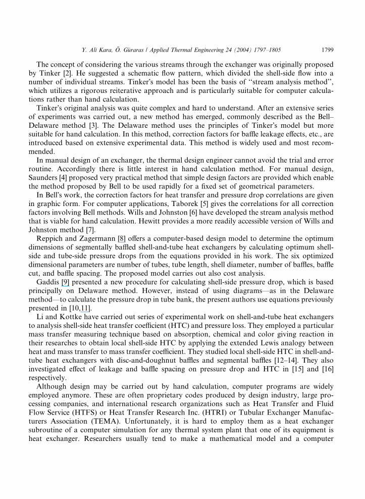
Nomenclature
A area (m2)C heat capacity (W/K)cp specific heat (J/kgK)d tube diameter (m)F correction factor for multi-pass and crossflow heat exchangerh convective heat transfer coefficient (W/m2 K)k thermal conductivity (W/mK)L length (m)_m mass flow rate (kg/s)N numberQ heat rate (W)R thermal resistanceT temperature (�C)Pt tube pitchU overall heat transfer coefficient (W/m2 K)DP pressure drop (Pa)DT temperature difference (�C)
Subscripts
b bafflec coldcb central bafflecf counter flowex exchangerf foulingh hoti inlet, innerib inlet bafflelm logarithmic meanm meano outlet, outers shellt tubew wall
1798 Y. Ali Kara, O. G€uraras / Applied Thermal Engineering 24 (2004) 1797–1805
Kern [1] provided a simple method for calculating shell-side pressure drop and heat transfercoefficient. However, this method is restricted to a fixed baffle cut (25%) and cannot adequatelyaccount for baffle-to-shell and tube-to-baffle leakage. Kern method is not applicable in laminarflow region where shell-side Reynolds number is less than 2000. Although the Kern equation isnot particularly accurate, it does allow a very simple and rapid calculation of shell-side heattransfer coefficient and pressure drop to be carried out.
Y. Ali Kara, O. G€uraras / Applied Thermal Engineering 24 (2004) 1797–1805 1799
The concept of considering the various streams through the exchanger was originally proposedby Tinker [2]. He suggested a schematic flow pattern, which divided the shell-side flow into anumber of individual streams. Tinker�s model has been the basis of ‘‘stream analysis method’’,which utilizes a rigorous reiterative approach and is particularly suitable for computer calcula-tions rather than hand calculation.
Tinker�s original analysis was quite complex and hard to understand. After an extensive seriesof experiments was carried out, a new method has emerged, commonly described as the Bell–Delaware method [3]. The Delaware method uses the principles of Tinker�s model but moresuitable for hand calculation. In this method, correction factors for baffle leakage effects, etc., areintroduced based on extensive experimental data. This method is widely used and most recom-mended.
In manual design of an exchanger, the thermal design engineer cannot avoid the trial and errorroutine. Accordingly there is little interest in hand calculation method. For manual design,Saunders [4] proposed very practical method that simple design factors are provided which enablethe method proposed by Bell to be used rapidly for a fixed set of geometrical parameters.
In Bell�s work, the correction factors for heat transfer and pressure drop correlations are givenin graphic form. For computer applications, Taborek [5] gives the correlations for all correctionfactors involving Bell methods. Wills and Johnston [6] have developed the stream analysis methodthat is viable for hand calculation. Hewitt provides a more readily accessible version of Wills andJohnston method [7].
Reppich and Zagermann [8] offers a computer-based design model to determine the optimumdimensions of segmentally baffled shell-and-tube heat exchangers by calculating optimum shell-side and tube-side pressure drops from the equations provided in his work. The six optimizeddimensional parameters are number of tubes, tube length, shell diameter, number of baffles, bafflecut, and baffle spacing. The proposed model carries out also cost analysis.
Gaddis [9] presented a new procedure for calculating shell-side pressure drop, which is basedprincipally on Delaware method. However, instead of using diagrams––as in the Delawaremethod––to calculate the pressure drop in tube bank, the present authors use equations previouslypresented in [10,11].
Li and Kottke have carried out series of experimental work on shell-and-tube heat exchangersto analysis shell-side heat transfer coefficient (HTC) and pressure loss. They employed a particularmass transfer measuring technique based on absorption, chemical and color giving reaction intheir researches to obtain local shell-side HTC by applying the extended Lewis analogy betweenheat and mass transfer to mass transfer coefficient. They studied local shell-side HTC in shell-and-tube heat exchangers with disc-and-doughnut baffles and segmental baffles [12–14]. They alsoinvestigated effect of leakage and baffle spacing on pressure drop and HTC in [15] and [16]respectively.
Although design may be carried out by hand calculation, computer programs are widelyemployed anymore. These are often proprietary codes produced by design industry, large pro-cessing companies, and international research organizations such as Heat Transfer and FluidFlow Service (HTFS) or Heat Transfer Research Inc. (HTRI) or Tubular Exchanger Manufac-turers Association (TEMA). Unfortunately, it is hard to employ them as a heat exchangersubroutine of a computer simulation for any thermal system plant that one of its equipment isheat exchanger. Researchers usually tend to make a mathematical model and a computer
1800 Y. Ali Kara, O. G€uraras / Applied Thermal Engineering 24 (2004) 1797–1805
simulation of thermal systems for their theoretical analysis and when a heat exchanger exists inthe system, a subroutine will be needed to solve thermo-hydraulic performance of heat exchanger.Our program can be easily employed as a subroutine to any simulation program for preliminarydesign purposes.
2. Model description
The number of tubes that can be placed within a shell depends on tube layout, tube outerdiameter, pitch size, number of passes, and shell diameter. These design parameters have beenstandardized and given as tabulated form that usually called ‘‘tube counts’’. Many tube counttables are available in open literature [4,17,18]. In this work we use tube counts given by Saunders[4]. He presented a tube counts table for fixed tube sheet, U-tube and split backing ring floatingtype exchangers, having the 24-shell diameter from 203 to 3048 mm and 13 tube configurations. Inthese tube count tables both full count, which gives the maximum number of tubes that can beaccommodated under the conditions specified, and reduced count, due to an internally fittedimpingement baffles are given for every case.
Because tube counts are used in this study, from the view point of quantitative analysis, we willconsider that the selection of exchanger construction type, flow arrangement, tube layout andmaterials have already been completed, and the sizing problem is then reduced to determine thelength of HE, heat transfer surface area, baffle sizing, and baffle number. Now, specification of ashell-and-tube HE that meets the process requirements can be achieved by successive iteration.This will constitute our design method. Although this can be carried out by hand calculation, acomputer program is made for this purpose. Because there are many alternative designs thatwould satisfy a particular duty, it is necessary to optimize the design either in terms of capital costor running cost. Capital cost involves minimization of heat transfer surface area to meet heattransfer service while running cost involves with minimum pressure drops. Our computer programconsiders minimum or allowable shell-side pressure drop as constraining criteria for optimumdesign. The program examines a series of exchangers from tube counts and chooses the optimaldesign on the basis of constraining criteria, namely running cost.
Calculations for heat transfer and pressure loss for fluid flowing inside tubes is relatively simple.On the other hand, because of the complex flow conditions, the associated heat transfer rate andpressure loss within the shell of the exchanger are not straightforward. The calculation procedureshave evolved over the years as discussed in the introduction. In order to calculate shell-side heattransfer coefficient and pressure drop, the model given by Taborek [5] based on the Bell–Delawaremethod is employed. Taborek version of Delaware method is more suitable for computer-based applications than Bell�s original work since correlations for the correction factors areprovided.
Kakac� and Liu [18] gives a detailed review for tube-side heat transfer coefficient for bothlaminar and forced convection flow conditions. Considering his recommendations, to calculatetube-side heat transfer coefficient for laminar flow Schl€under correlation is used and, Gnielinskiequation is used for transition flow in the range of 2300 < Re < 104 and, Petukov–Kirillov cor-relation is employed for turbulent flow in the range of 104 < Re < 5� 106 [18].
Y. Ali Kara, O. G€uraras / Applied Thermal Engineering 24 (2004) 1797–1805 1801
The governing equations for design problem are usually given as follows:Heat rate
Q ¼ ChðThi � ThoÞ ¼ CcðTco � TciÞ ð1Þ
where heat capacity rate for hot or cold fluidC ¼ _mcp ð2Þ
Log mean temperature difference for pure counter flowDTlm;cf ¼ðThi � ThoÞ � ðTho � TciÞln½ðThi � TcoÞ=ðTho � TciÞ�
ð3Þ
The effective mean temperature difference for crossflow
DTm ¼ FDTlm;cf ð4Þ
where F is correction factor for multi-pass and crossflow heat exchanger and given for two-passshell-and-tube heat exchangers as follows:F ¼ffiffiffiffiffiffiffiffiffiffiffiffiffi
R2 þ 1p
ln½ð1� P Þ=ð1� PRÞ�ðR� 1Þ ln½ð2� PfðRþ 1�
ffiffiffiffiffiffiffiffiffiffiffiffiffi
R2 þ 1p
ÞgÞ=ð2� PfðRþ 1Þ þffiffiffiffiffiffiffiffiffiffiffiffiffi
R2 þ 1p
gÞ�ð5Þ
where
R ¼ Cc
Ch
¼ ðThi � ThoÞðTco � TciÞ
ð6Þ
and
P ¼ ðTco � TciÞðThi � TciÞ
ð7Þ
Overall heat transfer coefficient
Uf ¼1
dodi ht
þ doRfi
diþ do lnðdo=diÞ
2kwþ Rfo þ
1
hs
ð8Þ
Heat transfer surface area
Aex ¼Q
Uf DTmð9Þ
and length of the exchanger
Lex ¼Aex
pdoNt
ð10Þ
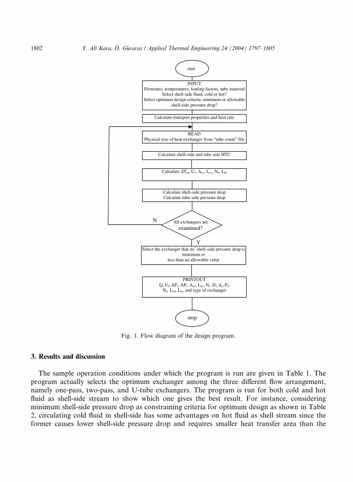
A FOTRAN 90 code is developed based on the model described above. Baffle spaces at inlet andoutlet of the exchanger are assumed to be equal for simplicity. The program allows the user tochoose the shell-side fluid and also to select optimization constraints, i.e., one is minimum shell-side pressure drop and the other is allowable shell-side pressure drop. The flow diagram of thecomputer program is illustrated in the Fig. 1.
READ Physical size of heat exchanger from “tube count” file
Calculate shell-side and tube side HTC
Calculate ∆Tm, Uf, Aex, Lex, Nb, Lib
Calculate shell-side pressure drop Calculate tube-side pressure drop
All exchangers areexamined?
Select the exchanger that its’ shell-side pressure drop is minimum or
less than an allowable value
PRINTOUT Q, Uf, ∆ ∆Ps, Pt, Aex, Lex, Nt, Ds, do, Pt,
Nb, Lcb, Lib, and type of exchanger
Y
N
Calculate transport properties and heat rate
INPUT Flowrates, temperatures, fouling factors, tube material
Select shell-side fluid; cold or hot? Select optimum design criteria; minimum or allowable
shell-side pressure drop?
start
stop
Fig. 1. Flow diagram of the design program.
1802 Y. Ali Kara, O. G€uraras / Applied Thermal Engineering 24 (2004) 1797–1805
3. Results and discussion
The sample operation conditions under which the program is run are given in Table 1. Theprogram actually selects the optimum exchanger among the three different flow arrangement,namely one-pass, two-pass, and U-tube exchangers. The program is run for both cold and hotfluid as shell-side stream to show which one gives the best result. For instance, consideringminimum shell-side pressure drop as constraining criteria for optimum design as shown in Table2, circulating cold fluid in shell-side has some advantages on hot fluid as shell stream since theformer causes lower shell-side pressure drop and requires smaller heat transfer area than the

Table 1
Sample operating conditions
Hot fluid Cold fluid
Fluid Water Water
Fouling resistance [m2K/W] 0.000176 0.000176
Mass flow rate [kg/s] 13.88 8.33
Inlet temperature [�C] 67 17
Outlet temperature [�C] – 40
Limitations Maximum allowable pressure drop¼ 12 000 Pa
Tube material Carbon steel, thermal conductivity¼ 60 W/mK
Table 2
Optimum design based on minimum shell-side pressure drop criteria
Cold fluid is on shell-side Hot fluid is on shell-side
Type of exchanger Two-pass U-pass
Shell-pressure drop [Pa] 100 947
Tube-side pressure drop [Pa] 78 56
Heat rate [W] 801 368 801 368
Total HTC [W/m2 �C] 422 80
Heat transfer area [m2] 64.15 340
Exchanger (tube) length [m] 0.516 4.82
Inside shell diameter [m] 1.219 1.219
Outer tube diameter [m] 0.01905 0.031
Number of tubes 2077 706
Central baffle spacing [m] 0.258 0.548
Inlet/outlet baffle spacing [m] 0.258 0.216
Number of baffles 1 9
Y. Ali Kara, O. G€uraras / Applied Thermal Engineering 24 (2004) 1797–1805 1803
latter�s. As a consequent, if there are no restrictions to allocation of streams, i.e., which fluid willflow through the shell, such as fouling fluid flow, high-pressure fluid flow or corrosive fluid, ingeneral, it is better to put the stream with lower mass flow rate on the shell-side because of thebaffled space.
As it is shown from Table 2, minimum shell-side pressure drop as the constraining criteria foroptimum design may always not give practically good results. For example, for cold fluid as shellstream in Table 2, shell diameter and tube length of the selected exchanger that has the lowestshell-side pressure drop are 1.219 and 0.516 m respectively. It is larger in diameter and shorter inlength and such an exchanger is not practical. This can be explained with central baffle spacingthat has a significant effect on shell-side pressure loss. Although there is no any correlation forcentral baffle spacing, some recommendations are available in HEDH. The recommended bafflespacing is somewhere between 0.4 and 0.6 of the shell diameter [4,5,18] for 25% baffle cut.According to this assumption, the larger the shell diameter, the larger the central baffle spacingresulting in lower pressure drop. As a result, this is why the program selects the exchanger largerin shell diameter and shorter in exchanger length as an optimum design. In order to avoid thisobstacle, allowable shell-side pressure drop can be considered as the optimum design constraintssince, in general speaking, tube side pressure drop is expected to be lower than that of shell-side.
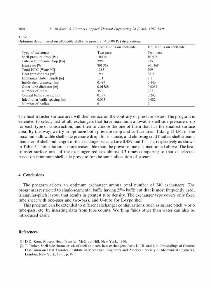
Table 3
Optimum design based on allowable shell-side pressure (<12000 Pa) drop criteria
Cold fluid is on shell-side Hot fluid is on shell-side
Type of exchanger Two-pass Two-pass
Shell-pressure drop [Pa] 10 836 10 602
Tube-side pressure drop [Pa] 2960 875
Heat rate [W] 801 368 801 368
Total HTC [W/m2 �C] 1383 709
Heat transfer area [m2] 19.6 38.2
Exchanger (tube) length [m] 1.11 2.1
Inside shell diameter [m] 0.489 0.540
Outer tube diameter [m] 0.01588 0.0254
Number of tubes 353 227
Central baffle spacing [m] 0.197 0.243
Inlet/outlet baffle spacing [m] 0.063 0.082
Number of baffles 6 9
1804 Y. Ali Kara, O. G€uraras / Applied Thermal Engineering 24 (2004) 1797–1805
The heat transfer surface area will then reduce on the contrary of pressure losses. The program isextended to select, first of all, exchangers that have maximum allowable shell-side pressure dropfor each type of construction, and then to choose the one of them that has the smallest surfacearea. By this way, we try to optimize both pressure drop and surface area. Taking 12 kPa of themaximum allowable shell-side pressure drop, for instance, and choosing cold fluid as shell stream,diameter of shell and length of the exchanger selected are 0.489 and 1.11 m, respectively as shownin Table 3. This solution is more reasonable than the previous one just mentioned above. The heattransfer surface area of the exchanger reduces almost 3.3 times comparing to that of selectedbased on minimum shell-side pressure for the same allocation of stream.
4. Conclusions
The program selects an optimum exchanger among total number of 240 exchangers. Theprogram is restricted to single-segmental baffle having 25% baffle cut that is most frequently used,triangular-pitch layout that results in greatest tube density. The exchanger type covers only fixedtube sheet with one-pass and two-pass, and U-tube for E-type shell.
This program can be extended to different exchanger configurations, such as square pitch, 4 or 6tube-pass, etc. by inserting data from tube counts. Working fluids other than water can also beintroduced easily.
References
[1] D.Q. Kern, Process Heat Transfer, McGraw-Hill, New York, 1950.
[2] T. Tinker, Shell-side characteristic of shell-and-tube heat exchangers, Parts II, III, and I, in: Proceedings of General
Discussion on Heat Transfer, Institute of Mechanical Engineers and American Society of Mechanical Engineers,
London, New York, 1951, p. 89.
Y. Ali Kara, O. G€uraras / Applied Thermal Engineering 24 (2004) 1797–1805 1805
[3] K.J. Bell, Final report of the cooperative research program on shell-and-tube heat exchangers, University of
Delaware Eng. Exp. Stat. Bull. 5 (1963).
[4] E.A.D. Saunders, Heat Exchangers, John Wiley & Sons, New York, 1988 (Chapter 12).
[5] J Taborek, Recommended method: principles and limitations, in: G.F. Hewitt (Ed.), HEDH, Begell House, New
York, 2002 (Section 3.3.3).
[6] M.J.N. Wills, D Johnston, A new and accurate hand calculation method for shell-side pressure drop and flow
distribution, in: 22nd National Heat Transfer Conference, HTD, vol. 36, ASME, 1984.
[7] G.F. Hewitt, Flow stream analysis method for segmentally baffled shell and tube heat exchangers, in: G.F. Hewitt
(Ed.), HEDH, Begell House, New York, 2002 (Section 3.3.3).
[8] M. Reppich, S. Zagermann, New design method for segmentally baffled heat exchangers, Comput. Chem. Eng. 19
(Suppl.) (1995) S137–S142.
[9] S.E. Gaddis, V. Gnielinski, Pressure drop on shell side of shell-and-tube heat exchangers with segmental baffles,
Chem. Eng. Process. 36 (1997) 149–159.
[10] S.E. Gaddis, V. Gnielinski, Druckverlust in querdurchstr€omten Rohurb€undelin, Vt verfahrenstechnick 17 (1988)
410–418.
[11] S.E. Gaddis, V. Gnielinski, Pressure drop in crossflow across tube bundles, Int. Chem. Eng. 25 (1985) 1–15.
[12] H. Li, V. Kottket, Local heat transfer in the first baffle compartment of shell-and-tube heat exchangers for
staggered tube arrangement, Exp. Thermal Fluid Sci. 16 (1998) 342–348.
[13] H. Li, V. Kottket, Visualization and determination of local heat transfer coefficients in shell-and-tube heat
exchangers for staggered tube arrangement by mass transfer measurements, Exp. Thermal Fluid Sci. 17 (1998) 210–
216.
[14] H. Li, V. Kottket, Analysis of local shell-side heat and mass transfer in the shell-and-tube heat exchanger with disc-
and-doughnut baffles, Int. J. Heat Mass Transfer 42 (1999) 3509–3521.
[15] H. Li, V. Kottket, Effect of the leakage on pressure drop and local heat transfer in shell-and-tube heat exchangers
for staggered tube arrangement, Int. J. Heat Mass Transfer 41 (2) (1998) 425–433.
[16] H. Li, V. Kottket, Effect of baffle spacing on pressure drop and local heat transfer in shell-and-tube heat exchangers
for staggered tube arrangement, Int. J. Heat Mass Transfer 41 (10) (1998) 1303–1311.
[17] K.J. Bell, Delaware method for shell-side design, in: R.K. Shah, E.C. Subbarao, R.A. Mashelke (Eds.), Heat
Transfer Equipment Design, Hemisphere Publishing, New York, 1988, p. 145.
[18] S. Kakac�, H. Liu, Heat Exchangers, Selection, Rating, and Thermal Design, CRC Press, New York, 1998
(Chapters 3 and 8).