New Plates for Different Types of Plate Heat Exchangers
19
Title: New plates for different types of plate heat exchangers 1 2 3 4 5 6 7 8 9 Short running title: Plate heat exchangers by Carla S. Fernandes a , Ricardo P. Dias b,c , João M. Maia d a Department of Mathematics, Escola Superior de Tecnologia e de Gestão, Instituto Politécnico de Bragança, Campus de Santa Apolónia, 5301-854 Bragança, Portugal, tel.: +351273303150, fax: +351273313051, e-mail: [email protected] 10 11 12 b Department of Chemical and Biological Technology, Escola Superior de Tecnologia e de Gestão, Instituto Politécnico de Bragança, Campus de Santa Apolónia, 5301-854 Bragança, Portugal, tel.: +351273303150, fax: +351273313051, e-mail: [email protected] 13 14 15 16 17 c CEFT - Centro de Estudos de Fenómenos de Transporte, Faculdade de Engenharia da Universidade do Porto, Rua Dr. Roberto Frias, 4200-465 Porto, Portugal d IPC - Institute for Polymers and Composites, Departamento de Engenharia de Polímeros, Universidade do Minho, 4800-058 Guimarães, Portugal; tel: +351253510320, fax: +351253510339, e-mail: [email protected] 18 19 20 21 (b) Address correspondence 1
-
Upload
independent -
Category
Documents
-
view
1 -
download
0
Transcript of New Plates for Different Types of Plate Heat Exchangers

Title: New plates for different types of plate heat exchangers 1
2
3
4
5
6
7
8
9
Short running title: Plate heat exchangers
by
Carla S. Fernandes a, Ricardo P. Dias b,c, João M. Maia d
a Department of Mathematics, Escola Superior de Tecnologia e de Gestão, Instituto
Politécnico de Bragança, Campus de Santa Apolónia, 5301-854 Bragança, Portugal, tel.:
+351273303150, fax: +351273313051, e-mail: [email protected] 10
11
12
b Department of Chemical and Biological Technology, Escola Superior de Tecnologia e de
Gestão, Instituto Politécnico de Bragança, Campus de Santa Apolónia, 5301-854 Bragança,
Portugal, tel.: +351273303150, fax: +351273313051, e-mail: [email protected] 13
14
15
16
17
c CEFT - Centro de Estudos de Fenómenos de Transporte, Faculdade de Engenharia da
Universidade do Porto, Rua Dr. Roberto Frias, 4200-465 Porto, Portugal
d IPC - Institute for Polymers and Composites, Departamento de Engenharia de Polímeros,
Universidade do Minho, 4800-058 Guimarães, Portugal; tel: +351253510320, fax:
+351253510339, e-mail: [email protected] 18
19
20
21
(b) Address correspondence
1

Abstract 22
23
24
25
26
27
28
29
30
31
32
33
34
35
36
37
38
39
40
41
42
43
44
45
The first patent for a plate heat exchanger was granted in 1878 to Albretch Dracke, a
German inventor. The commercial embodiment of these equipments has become available in
1923. However, the plate heat exchanger development race began in the 1930’s and these
gasketed plate and frame heat exchangers were mainly used as pasteurizers (e.g. for milk and
beer). Industrial plate heat exchangers were introduced in the 1950’s and initially they were
converted dairy models. Brazed plate heat exchangers were developed in the late 1970’s.
However, copper brazed units did not start selling until the early 80’s. Nickel brazing came to
market around ten years later, since copper presents compatibility problems with some
streams (e.g. ammonia). All-welded and semi-welded (laser weld) plate heat exchangers were
developed during the 1980’s and early 90’s. Shell and plate heat exchangers were recently
introduced in the market and can withstand relatively high pressures and temperatures, as the
shell and tube does. The fusion bonded plate heat exchangers (100% stainless steel) are a
technology from the 21st century, these equipments being more durable than brazed plate heat
exchangers. The plates are the most important elements from the different plate heat
exchangers mentioned above. This paper initially introduces the gasketed plate and frame heat
exchanger and common chevron-type plates. Resorting to computer fluid dynamics
techniques, the complex 3D flow in cross-corrugated chevron-type plate heat exchanger
passages is visualized. Recent patents related with the plates from different plate heat
exchangers are then outlined.
Keywords: Gasketed plate heat exchangers, brazed plate heat exchangers, all-welded plate
heat exchangers, semi-welded plate heat exchangers, double-wall plate heat exchangers, shell
and plate heat exchangers, fusion plate heat exchangers, computer fluid dynamics.
2

1. INTRODUCTION 46
47
48
49
50
51
52
53
54
55
56
57
58
59
60
61
62
63
64
65
66
67
68
69
70
Around 1850, French wine producers invited Louis Pasteur to solve a problem related
with wine deterioration. Comparing samples of good wine with samples of deteriorated wine,
Pasteur found several strains of micro-organisms. Some of them were predominant in the
wines with good quality, while other strains were abundant in the wines with low quality.
Hence, Pasteur concluded that a proper selection of micro-organisms could guarantee a
consistent high quality production. In order to do that, he destroyed the micro-organisms
present in the new wine of the grapes by heating it between 50º and 60 ºC and re-inoculated
the new wine with wine of high quality, the latter wine containing the desirable micro-
organisms. These experiments were useful to understand the role of micro-organisms in
fermentations and showed that it was possible - using temperature – to control infestations
provoked by harmful micro-organisms. Therefore, pasteurization was invented, this operation
being widely used nowadays in the dairy and food industries. Later on, Pasteur broaden his
studies to beer and, in 1857, he published one work showing that milk sours due to the
presence of some micro-organisms [1].
The bacteria Mycobacterium tuberculosis can be present in raw milk and catalysed (in the
late years of the 19th century) the development of plate heat exchangers, since they are very
efficient and can be easily disassembled for cleaning and sterilization to meet health and
sanitation requirements [2, 3]. The first patent for a plate heat exchanger was granted, in
1878, to Albretch Dracke, a German inventor, but the commercial embodiment of these
equipments has become available from APV International, England, in 1923. Around 1930,
the company Alfa Laval, Sweden, launched an analogous commercial plate heat exchanger
[3].
In 1996 the total market for heat exchangers in Europe amounted to USD 3.6 billion and
the plate heat exchanger had a market share of 13 % (second position after the conventional
3
71
72
73
74
75
76
77
78
79
80
81
82
83
84
85
86
87
88
89
90
shell-and-tube heat exchanger) [4]. Modern plate heat exchangers provide higher working
temperatures, larger working pressures, higher resistance to chemicals, etc.. Due to this,
different types of plate heat exchangers are nowadays applied in a very broad range of
industrial heat exchanger needs [2-6].
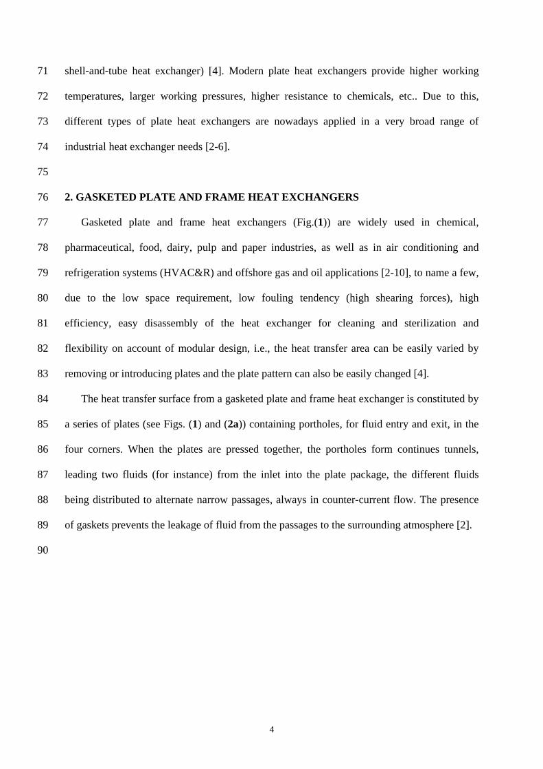
2. GASKETED PLATE AND FRAME HEAT EXCHANGERS
Gasketed plate and frame heat exchangers (Fig.(1)) are widely used in chemical,
pharmaceutical, food, dairy, pulp and paper industries, as well as in air conditioning and
refrigeration systems (HVAC&R) and offshore gas and oil applications [2-10], to name a few,
due to the low space requirement, low fouling tendency (high shearing forces), high
efficiency, easy disassembly of the heat exchanger for cleaning and sterilization and
flexibility on account of modular design, i.e., the heat transfer area can be easily varied by
removing or introducing plates and the plate pattern can also be easily changed [4].
The heat transfer surface from a gasketed plate and frame heat exchanger is constituted by
a series of plates (see Figs. (1) and (2a)) containing portholes, for fluid entry and exit, in the
four corners. When the plates are pressed together, the portholes form continues tunnels,
leading two fluids (for instance) from the inlet into the plate package, the different fluids
being distributed to alternate narrow passages, always in counter-current flow. The presence
of gaskets prevents the leakage of fluid from the passages to the surrounding atmosphere [2].
4

91
92
93
94
95
96
97
98
99
100
Fig. (1). Gasketed plate and frame heat exchanger (courtesy from Alfa Laval).
The most used gasketed plate and frame heat exchangers consist of plates with chevron-
type corrugations [11] that have a sinusoidal shape [7-10] (Figs. (1) and (2)). The thermal-
hydraulic performance of plate heat exchangers is strongly dependent on the geometrical
properties of the chevron plates [2, 5, 12], namely on the corrugation angle, β, area
enlargement factor, φ, defined as the ratio between the effective plate area and projected plate
area, and channel aspect ratio (Fig. (2)).
The channel aspect ratio, γ, can be defined by [9]:
2
x
bp
γ = , (1) 101
102
103
104
px being the corrugation pitch in the main flow direction and b the inter-plates distance (Fig.
(2)).
5

105
106
107
108
109
Fig. (2). (a) Schematic representation of a chevron plate. I, II, III and IV: portholes; (b)
corrugation dimensions.
The area enlargement factor can be estimated by [9]:
0.50.5 222 21 1 1 4 1
6 2cos( ) 2 2 cos( )π πφ γ
β β
⎧ ⎫⎡ ⎤⎡ ⎤ ⎛ ⎞⎛ ⎞⎪ ⎪⎢ ⎥⎢ ⎥= + + + +⎨ ⎬⎜ ⎟⎜ ⎟ ⎢ ⎥⎢ ⎥⎝ ⎠ ⎝ ⎠⎪ ⎪⎣ ⎦ ⎣ ⎦⎩ ⎭
γ110
111
112
113
114
115
116
117
118
. (2)
Typically, the area enlargement factor assumes values between 1.1 and 1.5, b normally
lies in the range 2-5 mm and β is typically located in the range 22-65º [2-10, 12]. The length
of the plates may vary between 0.3 and 4.3 m [2, 3], the minimum value of the ratio
length/width being of the order of 1.8 [2].
The thermal-hydraulic performance of the channels formed by cross-corrugated chevron-
type plates can be studied making use of computational fluid dynamics techniques [7-10].
Due to the periodicity of the flow along the width of the channel (zz axis in Fig (2)) the
referred study can be carried out using unitary cells (Fig. (3)) [9, 10]. It is important to note
6
119
120
121
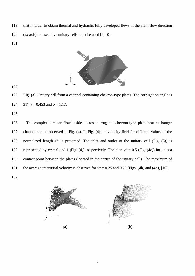
that in order to obtain thermal and hydraulic fully developed flows in the main flow direction
(xx axis), consecutive unitary cells must be used [9, 10].
122
123
124
125
126
127
128
129
130
131
132
Fig. (3). Unitary cell from a channel containing chevron-type plates. The corrugation angle is
31º, γ = 0.453 and φ = 1.17.
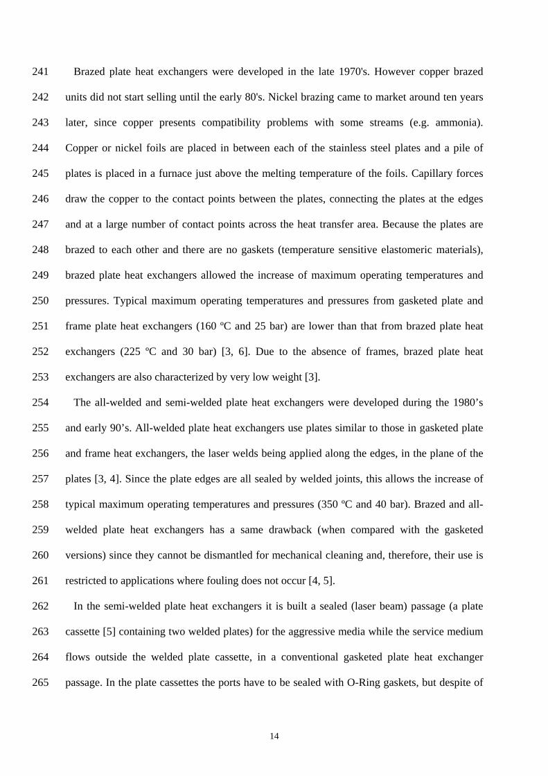
The complex laminar flow inside a cross-corrugated chevron-type plate heat exchanger
channel can be observed in Fig. (4). In Fig. (4) the velocity field for different values of the
normalized length x* is presented. The inlet and outlet of the unitary cell (Fig. (3)) is
represented by x* = 0 and 1 (Fig. (4)), respectively. The plan x* = 0.5 (Fig. (4c)) includes a
contact point between the plates (located in the centre of the unitary cell). The maximum of
the average interstitial velocity is observed for x* = 0.25 and 0.75 (Figs. (4b) and (4d)) [10].
(a)
(b)
7

(c)
(d)
(e)
133 134 135 136
137
138
139
140
141
142
143
144
145
146
147
Fig 4. Velocity vectors in different planes. (a) x* = 0; (b) x* = 0.25; (c) x* = 0.5; (d) x* = 0.75; (e) x* = 1.
As happens in granular beds [13-16], the flow in chevron-type passages is highly tortuous
(see Fig. (4)). Fernandes et al. [9] estimated the tortuosity coefficient in chevron-type plate
heat exchanger passages, this coefficient being used by plate heat exchanger producers
(CIAT) [17] in order to determine friction factors and convective heat transfer coefficients.
The model from CIAT [17] was developed resorting to an analogy [18] developed for fixed
beds. The similitude between the flow and heat transfer in chevron-type plate heat exchangers
passages and granular beds was also emphasized by Edwards et al. [19].
3. NEW PLATES FOR PLATE HEAT EXCHANGERS
In order to obtain a higher number of transfer units (NTU-VALUE) than that from
conventional chevron-type plates (Figs. (2) and (3)), Bojesen [20] disclosed the inclusion of a
8

148
149
150
151
152
153
series of dents/indents, recesses/protrusions and/or additional corrugations in the surface of
conventional chevron plates (Fig. (5)). In Fig. (5) it is shown the location of protrusions (16)
and recesses (17) and contact points (15), these points being generated by the conventional
corrugations ((12) and (13)) when two plates are pressed together to form a channel. The
projections (16) and recessions (17) are located between the contact points (15).
154
155
156
157
158
159
160
161
162
Fig 5. Schematic top view of a heat exchanger plate (for the complete description of the
numbers see [20]).
The difference between conventional chevron-type plate heat exchangers channels and the
channels obtained with the disclosed plates may be better seen in Fig. (6), these figure
showing a schematic sectional view in the direction of arrow 30 (main flow direction), along
line IV-IV (Fig. (5)). Observing Fig. (6c) it can be induced that the fluid passing through the
disclosed passage (Fig. (6a)) has to change its flow direction much more (higher tortuosity
9

coefficient [9]) than by flowing through a conventional passage (Fig. (6b)). This happens due
to the presence, in the disclosed passage, of protrusions (26´) and recesses (27´). Due to this,
more turbulences are generated and the NTU-VALUE increases. In the patent [20] it is
referred that by providing modifications as shown in Fig. (6) the NTU-VALUE (a measure of
the heat transfer surface area requirements for a given heat duty or size of the heat exchanger
[3]) can be surprisingly increased (more than 5%).
163
164
165
166
167
168
169
170
171
172
173
174
175
176
177
178
179
180
181
182
Fig 6. Schematic sectional view along line IV-IV from Fig. (5). (a) embodiment of the
invention; (b) conventional chevron-type passage; (c) difference between the embodiment of
the invention and the conventional chevron-type passage (for the complete description of the
numbers see [20]).
In order to promote the production of a turbulent flow through all, or the major part, of a
passage defined by two heat exchanger plates, Rausing [21] disclosed the use (see Fig. (7)) of
turbulent-promoting protrusions (spherical, ellipsoid, waves or grooves), these protrusions (4)
containing a surface profile (6) that also promotes turbulence. The surface profile consists of
spherical or ellipsoid segments, concavely or convexly arranged relative to the protrusions.
When the protrusions are hemispherical and the surface profile is concavely arranged, this
complex may be compared to the surface of a golf ball [21].
10

183
184
185
186
187
188
189
190
191
192
193
194
195
196
197
198
199
200
201
202
203
Fig 7. Schematic protuberances (4) and turbulent-promoting surface profile (6) (for the
complete description of the numbers see [21])
The fact that the surface profile consists of spherical or ellipsoid segments contributes to the
heat exchanger plate not having any sharp edges or corners that can create dead spaces which
conventional cleaning methods cannot reach [21]. The author emphasizes that soft geometric
transition is most important from the aspect of hygiene since plate heat exchangers when used
in the food industry require frequent and very careful cleaning. Any sharp geometric
transitions can form growth zones for bacteria and other organisms Due to this, the author
also recommends the use of a smooth geometrical transition between the flat part of the plate
((1) in Fig. (7)) and the protrusions (4). Besides promoting turbulence, the presence of a
surface profile generates higher plates surface area [21].
In distilleries, sugar mills, paper industry, textile industry, food industry, pharmaceutical
industry, etc., the fluids processed in plate heat exchangers can be very viscous and contain
particles, fibres or other difficult components [22]. Due to this, Gustafsson [22] developed a
porthole (see Figs. (2) and (8)) that mitigates the attachment of particles or fibres to the
porthole edge ((19) in Fig. (8)). Close to the porthole (18), in the area between the gasket
groove (23) and the porthole edge there is a corrugation which forms a wall towards the
gasket groove which ensures that the gasket is held in place in the gasket groove. It is
important to note that the referred corrugations are, normally, also present in the portholes
11

without O-Ring gasket (porthole I and II in Fig. (2)) and that conventional portholes contain
the referred corrugation in the entire perimeter. In order to reduce the risk that particles or
fibres get attached to the porthole edge, Gustafsson [22] designed a porthole which is
characterized in that the first edge portion ((19’) in Fig. (8)) has a corrugation and that the
second edge portion (19’’) has a substantially flat shape.
204
205
206
207
208
209
210
211
212
213
214
215
216
217
218
219
220
221
Fig 8. Schematic representation of a porthole (for the complete description of the numbers see
[22]).
After the introduction of a heat exchange fluid from the inlet porthole (porthole I in Fig.
(2a), for instance), the distribution area promotes the expansion of the flow to the entire width
of the heat transfer area [23]. When the fluid is effectively spread to every corner of the plate,
the heat exchange performance is improved [23] and the plate is less prone to heat transfer
fouling [24] or particulate fouling [25], due to the absence of low velocity regions.
The distribution area contains a small amount of contact points between the two plates from
a plate heat exchanger passage. On the transition region between the distribution area and heat
transfer area, contact points are scarcer. In the heat transfer area the number of contact points
12

(or support points) increase with the increase of the corrugation angle (see Fig. (2a)), the
number of contact points from a chevron-type plate with β = 65º being approximately the
double than that from a plate with β = 25º [26]. Due to this, a passage with low corrugation
angle can be mechanically unstable, i.e., the inter-plates distance can vary during the
operation. In order to improve the strength of a passage containing chevron plates with low
corrugation angle (25º for instance) Blomgren and Krantz [26] disclosed a passage (see Fig.
(9)) containing two corrugated transition areas (58), located between the distribution areas
(34) and heat transfer area (33). In this invention, the transition areas - in Fig. (9) is only
shown one of two the transition areas - contain corrugations with a high value of β (65º for
instance) in order to obtain a high number of contact points (64) between the plates and,
therefore, improved strength.
222
223
224
225
226
227
228
229
230
231
232
233
234
235
236
237
238
239
240
Fig 9. Schematic top view of two adjacent plates (for the complete description of the numbers
see [26]).
The above mentioned inventions from Gustafsson [22] and Blomgren and Krantz [26] can
be applied to gasketed plate and frame heat exchangers (Fig. (1)) as well as to brazed plate
heat exchangers [27, 28] and welded plate heat exchangers [29].
13
241
242
243
244
245
246
247
248
249
250
251
252
253
254
255
256
257
258
259
260
261
262
263
264
265
Brazed plate heat exchangers were developed in the late 1970's. However copper brazed
units did not start selling until the early 80's. Nickel brazing came to market around ten years
later, since copper presents compatibility problems with some streams (e.g. ammonia).
Copper or nickel foils are placed in between each of the stainless steel plates and a pile of
plates is placed in a furnace just above the melting temperature of the foils. Capillary forces
draw the copper to the contact points between the plates, connecting the plates at the edges
and at a large number of contact points across the heat transfer area. Because the plates are
brazed to each other and there are no gaskets (temperature sensitive elastomeric materials),
brazed plate heat exchangers allowed the increase of maximum operating temperatures and
pressures. Typical maximum operating temperatures and pressures from gasketed plate and
frame plate heat exchangers (160 ºC and 25 bar) are lower than that from brazed plate heat
exchangers (225 ºC and 30 bar) [3, 6]. Due to the absence of frames, brazed plate heat
exchangers are also characterized by very low weight [3].
The all-welded and semi-welded plate heat exchangers were developed during the 1980’s
and early 90’s. All-welded plate heat exchangers use plates similar to those in gasketed plate
and frame heat exchangers, the laser welds being applied along the edges, in the plane of the
plates [3, 4]. Since the plate edges are all sealed by welded joints, this allows the increase of
typical maximum operating temperatures and pressures (350 ºC and 40 bar). Brazed and all-
welded plate heat exchangers has a same drawback (when compared with the gasketed
versions) since they cannot be dismantled for mechanical cleaning and, therefore, their use is
restricted to applications where fouling does not occur [4, 5].
In the semi-welded plate heat exchangers it is built a sealed (laser beam) passage (a plate
cassette [5] containing two welded plates) for the aggressive media while the service medium
flows outside the welded plate cassette, in a conventional gasketed plate heat exchanger
passage. In the plate cassettes the ports have to be sealed with O-Ring gaskets, but despite of
14

266
267
268
269
270
271
272
273
274
275
276
277
278
279
280
281
282
283
this, there is a reduction of 90% of the gasket length necessary for the aggressive media [4, 5].
The semi-welded plate heat exchanger is therefore partially dismountable, the maximum
operating temperatures and pressures being at the same level of the conventional gasketed
plate and frame heat exchangers [3-5].
The double-wall plate heat exchanger contains double plates, sealed by conventional
gaskets, which replace the single plate that usually separates two streams. They are many
times designed for a reacting media and if this aggressive media reacts with the surface of the
double-wall plates, the leakage is directed in the passages between the double plates [3].
In the invention from Rehberg [30] it is disclosed a plate heat exchanger comprising a stack
of double-walled heat exchanger plates with which the search for leaks is facilitated (see Fig.
(10)). The two plate members ((33) and (34)) are in close mutual engagement in the heat
transfer area (35) and this is continued in an edge portion (36) which is upwardly bent with
the respect of the heat transfer area (35). Neighbouring double-plates ((31) an (32), for
instance) are connected by soldering material (39) in the area of their upwardly bent portions
(36). Since there is a spacing (37) between the outer edges ((33a) and (34a)) of a double-plate,
any fluid getting between the two plate members ((33) and (34)) will become visible (region
(38)) from outside and, therefore, be seen by monitoring or operating staff [30].
15

284
285
286
287
288
289
290
291
292
293
294
295
296
297
298
299
300
301
Fig 10. Schematic sectional view of an edge portion of a plate heat exchanger (for the
complete description of the numbers see [30]).
4. CURRENT & FUTURE DEVELOPMENTS
Shell and plate heat exchangers [5, 31-33] were recently introduced in the market, being
composed by round welded plates inserted in a shell [5, 31-33]. These equipments combine
the advantages of shell and tube and plate and frame technologies, i.e., the high mechanical
integrity of shell and tube (up to and beyond 400 bar and 800 ºC [34]) and the superior
thermal performances of plate and frame [5, 31]. Kontu and Virtanen [32] disclosed several
new uses for shell and plate heat exchangers. In order to achieve that, the referred authors
suggested the use of plates, shell and inlet/outlet passages made of carbon steel, a cheap and
abundant material.
The already rich selection guides [3] of plate heat exchangers will continue to be enriched
with products such as the 100% stainless steel fusion bonded plate heat exchangers, these
equipments being much more durable compared to brazed plate heat exchangers.
In years to come, with increased choice of better heat exchange equipment, the impetus of
adopting equipment that a different industry already uses will decrease [34].
16

5. ACKNOWLEDGEMENTS 302
303
304
305
306
307
308
309
310
311
312
313
314
315
316
317
318
319
320
321
322
323
324
325
The kind assistance provided by Mr. Johan Persson (Alfa Laval, Lund, Sweden) is greatly
appreciated.
REFERENCES
[1] Mota M, Empis J, Teixeira, J. A biotecnologia na indústria agro-alimentar, Federação das
Indústrias Portuguesas Agro-Alimentares, 1998, pp. 1-38.
[2] Kakaç S, Liu H. Heat Exchangers Selection, Rating, and Thermal Design, CRC Press,
2002, 2nd edn, pp. 373-412.
[3] Wang L, Sundén B, Manglik RM. Plate heat exchangers: design, applications and
performance, WIT Press, 2007, pp. 1-6.
[4] Reppich M. Use of high performance plate heat exchangers in chemical and process
industries. Int. J. Thermal Sci. 1999; 38: 999-1008.
[5] Ayub ZH. Plate heat exchanger survey and new heat transfer and pressure drop
correlations for refrigerant evaporators. Heat Transfer Eng. 2003; 24: 3-16.
[6] Palm B, Claesson J. Plate heat exchangers: calculation methods for single-and two-phase
flow. Heat Transfer Eng. 2006; 27: 88-98.
[7] Fernandes CS, Dias RP, Nóbrega JM, Afonso IM, Melo LF, Maia JM. Simulation of
stirred yoghurt processing in plate heat exchangers. J. Food Eng. 2005; 69: 281-290.
[8] Fernandes CS, Dias RP, Nóbrega JM, Afonso IM, Melo LF, Maia JM. Thermal behaviour
of stirred yoghurt during cooling in plate heat exchangers. J. Food Eng. 2006; 76: 433-439.
[9] Fernandes CS, Dias RP, Nóbrega JM, Maia JM. Laminar flow in chevron-type plate heat
exchangers: CFD analysis of tortuosity, shape factor and friction factor. Chem. Eng. Proc.
2007; 46: 825-833.
17

326
327
328
329
330
331
332
333
334
335
336
337
338
339
340
341
342
343
344
345
346
347
348
349
350
[10] Fernandes CS, Dias RP, Nóbrega JM, Maia JM. Friction factors of power-law fluids in
chevron-type plate heat exchangers. J. Food Eng. 2008; 89: 441-447.
[11] Heggs PJ, Sandham P, Hallam RA, Walton C. Local heat transfer coefficients in
corrugated plate heat exchanger channels. Trans. Inst. Chem. Eng. 1997; 75: 641-645.
[12] Kumar H. The plate heat exchanger: construction and design. In: Proceedings First UK
National Conference on Heat Transfer, United Kingdom, (1984)
[13] Dias RP, Fernandes CS, Teixeira JA, Mota M, Yelshin A. Permeability analysis in
bisized porous media: Wall effect between particles of different size. J. Hydrol. 2008; 349:
470-474.
[14] Dias RP, Fernandes CS, Teixeira JA, Mota M, Yelshin A. Permeability and effective
thermal conductivity of bisized porous media. Int. J. Heat Mass Transfer 2007; 50: 1295-
1301.
[15] Dias RP, Teixeira JA, Mota M, Yelshin A. Tortuosity variation in low density binary
particulate bed. Sep. Purif. Technol. 2006; 51: 180-184.
[16] Dias RP. Size fractionation by slalom chromatography and hydrodynamic
chromatography. Recent Patents on Engineering 2008; 2: 95-103.
[17] Charre O, Jurkowski R, Bailly A, Meziani S, Altazin M. General Model for plate heat
exchanger performance prediction. J. Enhanced Heat Transfer 2002; 9: 181-186.
[18] Carman PC. Fluid flow through granular beds. Trans. Inst. Chem. Eng. 1937; 15: 150-
166.
[19] Edwards MF, Vaie AAC, Parrott DL. Heat transfer and pressure drop characteristics of a
plate heat exchanger using Newtonian and non-Newtonian liquids. The Chem. Eng. 1974;
286-288, 293.
[20] Bojesen, C.: WO2008071356A1 (2008).
[21] Rausing, H.: US20070144711A1 (2007).
18

351
352
353
354
355
356
357
358
359
360
361
362
363
364
365
366
367
[22] Gustafsson, H.: WO2007142590A1 (2007).
[23] Matsuzaki, T., Tagata-Gun, S-K: EP1813901A2 (2007).
[24] Kho TK, Müller-Steinhagen H. An experimental and numerical investigation of heat
transfer fouling and fluid flow in flat plate heat exchangers. Trans. Inst. Chem. Eng. 1999; 77:
124-130.
[25] Thonon B, Grandgeorge S, Jallut, C. Effect of geometry and flow conditions on
particulate fouling in plate heat exchangers. Heat Transfer Eng. 1999; 20: 12-24.
[26] Blomgren, R., Krantz, J.: WO2007004939A1 (2007).
[27] Rassmus, J.E.J., Sjodin, P.E.: US20080127494A1 (2008).
[28] Martin, M.A., Vanderwees, D.:US7404434B2 (2008).
[29] Mathur, A.P., Gu, C., Fulmer, J.M.: US6516874B2 (2003).
[30] Rehberg, P.: US7204297B2 (2007).
[31] Ayub ZH. Are we on the right track? Heat Transfer Eng. 2003; 24: 1-2.
[32] Kontu, M.O., Virtanen, M.: WO2008046952A1 (2008).
[33] Mathur, A.P., Fulmer, J.M.:US7004237B2 (2006).
[34] Stehlík P, Wadekar VV. Different strategies to improve industrial heat exchange. Heat
Transfer Eng. 2002; 23: 36-48.
19