
Simulation of performance of centrifugal circulators with vaneless diffuser for GCR applications
15
Nuclear Engineering and Design 240 (2010) 2421–2435 Contents lists available at ScienceDirect Nuclear Engineering and Design journal homepage: www.elsevier.com/locate/nucengdes Simulation of performance of centrifugal circulators with vaneless diffuser for GCR applications N. Tauveron ∗ , I. Dor CEA, DEN, DER/SSTH, 17 rue des Martyrs, F-38054 Grenoble, France article info abstract In the frame of the international forum GenIV, CEA has selected various innovative concepts of gas-cooled nuclear reactor. Thermal hydraulic performances are a key issue for the design. For transient conditions and decay heat removal situations, the thermal hydraulic performance must remain as high as possible. In this context, all the transient situations, the incidental and accidental scenarii must be evaluated by a validated system code able to correctly describe, in particular, the thermal hydraulics of the whole plant. As concepts use a helium compressor to maintain the flow in the core, a special emphasis must be laid on compressor modelling. Centrifugal circulators with a vaneless diffuser have significant properties in term of simplicity, cost, ability to operate over a wide range of conditions. The objective of this paper is to present a dedicated description of centrifugal compressor, based on a one-dimensional approach. This type of model requires various correlations as input data. The present contribution consists in establishing and validating the numerical simulations (including different sets of correlations) by comparison with representative experimental data. The results obtained show a qual- itatively correct behaviour of the model compared to open literature cases of the gas turbine aircraft community and helium circulators of high temperature gas reactors. The model is finally used in a depressurised transient simulation of a small power gas fast reactor (ALLEGRO concept). Advantages of this model versus first preliminary simulations are shown. Further work on modelling and validation are nevertheless needed to have a better confidence in the simulation predictions. © 2010 Elsevier B.V. All rights reserved. 1. Introduction In the frame of Generation IV, the French Commissariat l’Energie Atomique is developing an innovative concept of high temperature gas-cooled reactor as a promising milestone toward sustainable nuclear energy Carré et al. (2001). The use for the nuclear core of a refractory fuel with high thermal conductivity and fission prod- uct confinement capability is intended to ensure high robustness in case of accidental transients, and therefore a high level of safety and reliability. Additional advantages come from low interaction between the primary reactor coolant (pressurized helium) and the reactor physics (almost no reactivity effect, no chemical interac- tion). In the GFR development plan, ALLEGRO reactor is the first step toward the electricity generating prototype GFR and thus ambitions to be the first GFR ever built. Preliminary simulations performed Abbreviations: CFD, computational fluid dynamics; DHR, decay heat removal; GCR, gas-cooled reactor; GFR, gas fast reactor; HTGR, high temperature gas reactor; IHX, intermediate heat exchanger; LOCA, loss of coolant accident. ∗ Corresponding author. E-mail addresses: [email protected] (N. Tauveron), [email protected] (I. Dor). with the CATHARE code were performed. These introductory con- siderations are detailed in Section 2. For the safety analysis, a particular attention on mass and energy transfers in the core during transients is needed. As a helium compressor is used to maintain the flow in the core (the decay heat removal blower) during the depressurised transients, a spe- cial emphasis must be laid on compressor modelling, especially on off-design regimes. In this context, a description of the turbomachinery has been developed, based on a one-dimensional approach. In the previ- ous years we have treated the case of axial machines (Tauveron et al., 2007; Tauveron, 2010). Centrifugal machines are also of great interest and constitute a serious candidate technology for the main circulator and shutdown cooling circulator, as general and histor- ical considerations tell us (Section 3). The objective of this paper is to provide models, which are able to describe centrifugal com- pressor behaviour in off-design (Section 4). An important part of the present contribution consists in validating the numerical sim- ulations by comparison with representative experimental data. A preliminary validation process is presented in Sections 5 and 6. The model is then applied to a circulator of high temperature gas reactors (Section 7). Finally the model is used in a depressurised transient simulation of ALLEGRO concept (Section 8). Advantages 0029-5493/$ – see front matter © 2010 Elsevier B.V. All rights reserved. doi:10.1016/j.nucengdes.2010.05.066
Transcript of Simulation of performance of centrifugal circulators with vaneless diffuser for GCR applications
Sw
NC
a
1
Agnauiabrttt
GI
(
0d
Nuclear Engineering and Design 240 (2010) 2421–2435
Contents lists available at ScienceDirect
Nuclear Engineering and Design
journa l homepage: www.e lsev ier .com/ locate /nucengdes
imulation of performance of centrifugal circulatorsith vaneless diffuser for GCR applications
. Tauveron ∗, I. DorEA, DEN, DER/SSTH, 17 rue des Martyrs, F-38054 Grenoble, France
r t i c l e i n f o a b s t r a c t
In the frame of the international forum GenIV, CEA has selected various innovative concepts of gas-coolednuclear reactor. Thermal hydraulic performances are a key issue for the design. For transient conditionsand decay heat removal situations, the thermal hydraulic performance must remain as high as possible.In this context, all the transient situations, the incidental and accidental scenarii must be evaluated by avalidated system code able to correctly describe, in particular, the thermal hydraulics of the whole plant.As concepts use a helium compressor to maintain the flow in the core, a special emphasis must be laidon compressor modelling. Centrifugal circulators with a vaneless diffuser have significant properties interm of simplicity, cost, ability to operate over a wide range of conditions.
The objective of this paper is to present a dedicated description of centrifugal compressor, based on aone-dimensional approach. This type of model requires various correlations as input data. The present
contribution consists in establishing and validating the numerical simulations (including different setsof correlations) by comparison with representative experimental data. The results obtained show a qual-itatively correct behaviour of the model compared to open literature cases of the gas turbine aircraftcommunity and helium circulators of high temperature gas reactors. The model is finally used in adepressurised transient simulation of a small power gas fast reactor (ALLEGRO concept). Advantagesof this model versus first preliminary simulations are shown. Further work on modelling and validationto hav
are nevertheless needed. Introduction
In the frame of Generation IV, the French Commissariat l’Energietomique is developing an innovative concept of high temperatureas-cooled reactor as a promising milestone toward sustainableuclear energy Carré et al. (2001). The use for the nuclear core ofrefractory fuel with high thermal conductivity and fission prod-ct confinement capability is intended to ensure high robustness
n case of accidental transients, and therefore a high level of safetynd reliability. Additional advantages come from low interactionetween the primary reactor coolant (pressurized helium) and the
eactor physics (almost no reactivity effect, no chemical interac-ion). In the GFR development plan, ALLEGRO reactor is the first stepoward the electricity generating prototype GFR and thus ambitionso be the first GFR ever built. Preliminary simulations performedAbbreviations: CFD, computational fluid dynamics; DHR, decay heat removal;CR, gas-cooled reactor; GFR, gas fast reactor; HTGR, high temperature gas reactor;
HX, intermediate heat exchanger; LOCA, loss of coolant accident.∗ Corresponding author.
E-mail addresses: [email protected] (N. Tauveron), [email protected]. Dor).
029-5493/$ – see front matter © 2010 Elsevier B.V. All rights reserved.oi:10.1016/j.nucengdes.2010.05.066
e a better confidence in the simulation predictions.© 2010 Elsevier B.V. All rights reserved.
with the CATHARE code were performed. These introductory con-siderations are detailed in Section 2.
For the safety analysis, a particular attention on mass and energytransfers in the core during transients is needed. As a heliumcompressor is used to maintain the flow in the core (the decayheat removal blower) during the depressurised transients, a spe-cial emphasis must be laid on compressor modelling, especially onoff-design regimes.
In this context, a description of the turbomachinery has beendeveloped, based on a one-dimensional approach. In the previ-ous years we have treated the case of axial machines (Tauveron etal., 2007; Tauveron, 2010). Centrifugal machines are also of greatinterest and constitute a serious candidate technology for the maincirculator and shutdown cooling circulator, as general and histor-ical considerations tell us (Section 3). The objective of this paperis to provide models, which are able to describe centrifugal com-pressor behaviour in off-design (Section 4). An important part ofthe present contribution consists in validating the numerical sim-
ulations by comparison with representative experimental data. Apreliminary validation process is presented in Sections 5 and 6.The model is then applied to a circulator of high temperature gasreactors (Section 7). Finally the model is used in a depressurisedtransient simulation of ALLEGRO concept (Section 8). Advantages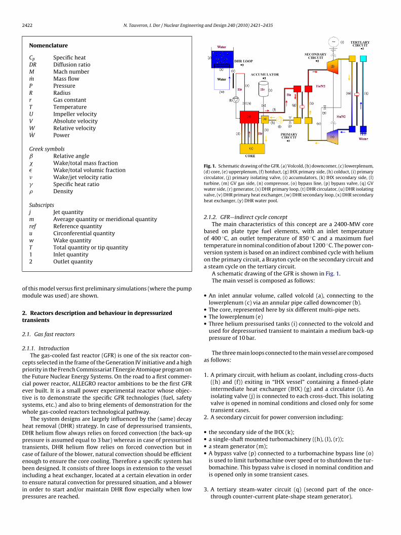
2422 N. Tauveron, I. Dor / Nuclear Engineering and Design 240 (2010) 2421–2435
Nomenclature
Cp Specific heatDR Diffusion ratioM Mach numberm Mass flowP PressureR Radiusr Gas constantT TemperatureU Impeller velocityV Absolute velocityW Relative velocityW Power
Greek symbolsˇ Relative angle� Wake/total mass fraction� Wake/total volumic fraction� Wake/jet velocity ratio� Specific heat ratio� Density
Subscriptsj Jet quantitym Average quantity or meridional quantityref Reference quantityu Circonferential quantityw Wake quantityT Total quantity or tip quantity
om
2t
2
2
cptcetsw
hDptcebitip
Fig. 1. Schematic drawing of the GFR. (a) Volcold, (b) downcomer, (c) lowerplenum,(d) core, (e) upperplenum, (f) hotduct, (g) IHX primary side, (h) colduct, (i) primarycirculator, (j) primary isolating valve, (i) accumulators, (k) IHX secondary side, (l)
1 Inlet quantity2 Outlet quantity
f this model versus first preliminary simulations (where the pumpodule was used) are shown.
. Reactors description and behaviour in depressurizedransients
.1. Gas fast reactors
.1.1. IntroductionThe gas-cooled fast reactor (GFR) is one of the six reactor con-
epts selected in the frame of the Generation IV initiative and a highriority in the French Commissariat l’Energie Atomique program onhe Future Nuclear Energy Systems. On the road to a first commer-ial power reactor, ALLEGRO reactor ambitions to be the first GFRver built. It is a small power experimental reactor whose objec-ive is to demonstrate the specific GFR technologies (fuel, safetyystems, etc.) and also to bring elements of demonstration for thehole gas-cooled reactors technological pathway.
The system designs are largely influenced by the (same) decayeat removal (DHR) strategy. In case of depressurised transients,HR helium flow always relies on forced convection (the back-upressure is assumed equal to 3 bar) whereas in case of pressurisedransients, DHR helium flow relies on forced convection but inase of failure of the blower, natural convection should be efficientnough to ensure the core cooling. Therefore a specific system haseen designed. It consists of three loops in extension to the vessel
ncluding a heat exchanger, located at a certain elevation in ordero ensure natural convection for pressured situation, and a blowern order to start and/or maintain DHR flow especially when lowressures are reached.
turbine, (m) GV gas side, (n) compressor, (o) bypass line, (p) bypass valve, (q) GVwater side, (r) generator, (s) DHR primary loop, (t) DHR circulator, (u) DHR isolatingvalve, (v) DHR primary heat exchanger, (w) DHR secondary loop, (x) DHR secondaryheat exchanger, (y) DHR water pool.
2.1.2. GFR—indirect cycle conceptThe main characteristics of this concept are a 2400-MW core
based on plate type fuel elements, with an inlet temperatureof 400 ◦C, an outlet temperature of 850 ◦C and a maximum fueltemperature in nominal condition of about 1200 ◦C. The power con-version system is based on an indirect combined cycle with heliumon the primary circuit, a Brayton cycle on the secondary circuit anda steam cycle on the tertiary circuit.
A schematic drawing of the GFR is shown in Fig. 1.The main vessel is composed as follows:
• An inlet annular volume, called volcold (a), connecting to thelowerplenum (c) via an annular pipe called downcomer (b).
• The core, represented here by six different multi-pipe nets.• The lowerplenum (e)• Three helium pressurised tanks (i) connected to the volcold and
used for depressurised transient to maintain a medium back-uppressure of 10 bar.
The three main loops connected to the main vessel are composedas follows:
1. A primary circuit, with helium as coolant, including cross-ducts((h) and (f)) exiting in “IHX vessel” containing a finned-plateintermediate heat exchanger (IHX) (g) and a circulator (i). Anisolating valve (j) is connected to each cross-duct. This isolatingvalve is opened in nominal conditions and closed only for sometransient cases.
2. A secondary circuit for power conversion including:
• the secondary side of the IHX (k);• a single-shaft mounted turbomachinery ((h), (l), (r));• a steam generator (m);• A bypass valve (p) connected to a turbomachine bypass line (o)
is used to limit turbomachine over speed or to shutdown the tur-bomachine. This bypass valve is closed in nominal condition and
is opened only in some transient cases.3. A tertiary steam-water circuit (q) (second part of the once-through counter-current plate-shape steam generator).
ering and Design 240 (2010) 2421–2435 2423
c
•
•
•
ug
2
smasdst
2
rpr
••
•••
•
•
wcwtfsmettpi
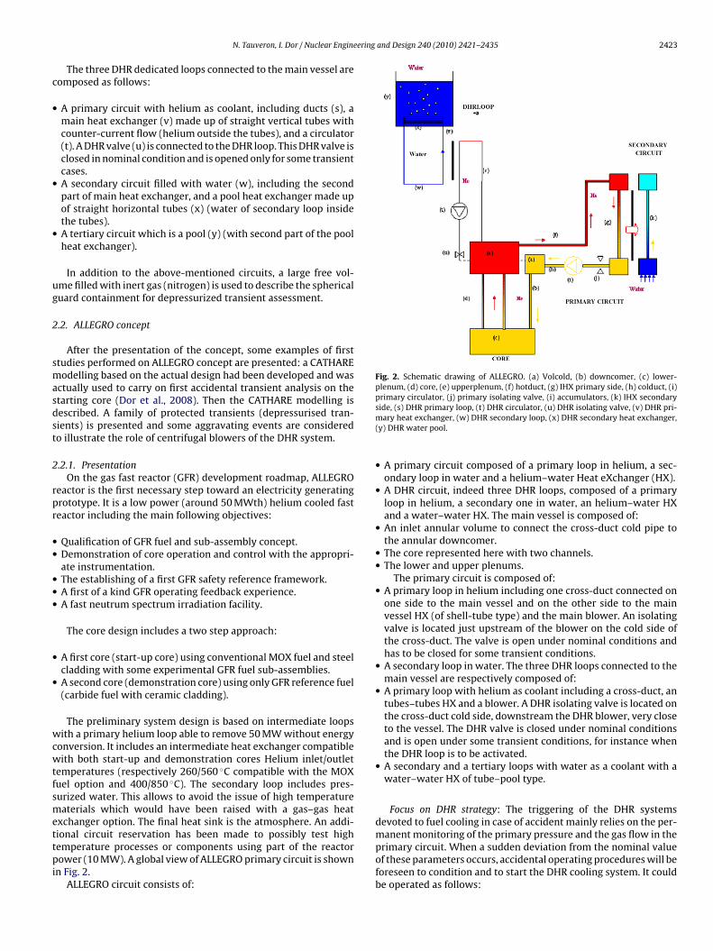
Fig. 2. Schematic drawing of ALLEGRO. (a) Volcold, (b) downcomer, (c) lower-plenum, (d) core, (e) upperplenum, (f) hotduct, (g) IHX primary side, (h) colduct, (i)primary circulator, (j) primary isolating valve, (i) accumulators, (k) IHX secondary
N. Tauveron, I. Dor / Nuclear Engine
The three DHR dedicated loops connected to the main vessel areomposed as follows:
A primary circuit with helium as coolant, including ducts (s), amain heat exchanger (v) made up of straight vertical tubes withcounter-current flow (helium outside the tubes), and a circulator(t). A DHR valve (u) is connected to the DHR loop. This DHR valve isclosed in nominal condition and is opened only for some transientcases.A secondary circuit filled with water (w), including the secondpart of main heat exchanger, and a pool heat exchanger made upof straight horizontal tubes (x) (water of secondary loop insidethe tubes).A tertiary circuit which is a pool (y) (with second part of the poolheat exchanger).
In addition to the above-mentioned circuits, a large free vol-me filled with inert gas (nitrogen) is used to describe the sphericaluard containment for depressurized transient assessment.
.2. ALLEGRO concept
After the presentation of the concept, some examples of firsttudies performed on ALLEGRO concept are presented: a CATHAREodelling based on the actual design had been developed and was
ctually used to carry on first accidental transient analysis on thetarting core (Dor et al., 2008). Then the CATHARE modelling isescribed. A family of protected transients (depressurised tran-ients) is presented and some aggravating events are consideredo illustrate the role of centrifugal blowers of the DHR system.
.2.1. PresentationOn the gas fast reactor (GFR) development roadmap, ALLEGRO
eactor is the first necessary step toward an electricity generatingrototype. It is a low power (around 50 MWth) helium cooled fasteactor including the main following objectives:
Qualification of GFR fuel and sub-assembly concept.Demonstration of core operation and control with the appropri-ate instrumentation.The establishing of a first GFR safety reference framework.A first of a kind GFR operating feedback experience.A fast neutrum spectrum irradiation facility.
The core design includes a two step approach:
A first core (start-up core) using conventional MOX fuel and steelcladding with some experimental GFR fuel sub-assemblies.A second core (demonstration core) using only GFR reference fuel(carbide fuel with ceramic cladding).
The preliminary system design is based on intermediate loopsith a primary helium loop able to remove 50 MW without energy
onversion. It includes an intermediate heat exchanger compatibleith both start-up and demonstration cores Helium inlet/outlet
emperatures (respectively 260/560 ◦C compatible with the MOXuel option and 400/850 ◦C). The secondary loop includes pres-urized water. This allows to avoid the issue of high temperatureaterials which would have been raised with a gas–gas heat
xchanger option. The final heat sink is the atmosphere. An addi-
ional circuit reservation has been made to possibly test highemperature processes or components using part of the reactorower (10 MW). A global view of ALLEGRO primary circuit is shownn Fig. 2.ALLEGRO circuit consists of:
side, (s) DHR primary loop, (t) DHR circulator, (u) DHR isolating valve, (v) DHR pri-mary heat exchanger, (w) DHR secondary loop, (x) DHR secondary heat exchanger,(y) DHR water pool.
• A primary circuit composed of a primary loop in helium, a sec-ondary loop in water and a helium–water Heat eXchanger (HX).
• A DHR circuit, indeed three DHR loops, composed of a primaryloop in helium, a secondary one in water, an helium–water HXand a water–water HX. The main vessel is composed of:
• An inlet annular volume to connect the cross-duct cold pipe tothe annular downcomer.
• The core represented here with two channels.• The lower and upper plenums.
The primary circuit is composed of:• A primary loop in helium including one cross-duct connected on
one side to the main vessel and on the other side to the mainvessel HX (of shell-tube type) and the main blower. An isolatingvalve is located just upstream of the blower on the cold side ofthe cross-duct. The valve is open under nominal conditions andhas to be closed for some transient conditions.
• A secondary loop in water. The three DHR loops connected to themain vessel are respectively composed of:
• A primary loop with helium as coolant including a cross-duct, antubes–tubes HX and a blower. A DHR isolating valve is located onthe cross-duct cold side, downstream the DHR blower, very closeto the vessel. The DHR valve is closed under nominal conditionsand is open under some transient conditions, for instance whenthe DHR loop is to be activated.
• A secondary and a tertiary loops with water as a coolant with awater–water HX of tube–pool type.
Focus on DHR strategy: The triggering of the DHR systemsdevoted to fuel cooling in case of accident mainly relies on the per-
manent monitoring of the primary pressure and the gas flow in theprimary circuit. When a sudden deviation from the nominal valueof these parameters occurs, accidental operating procedures will beforeseen to condition and to start the DHR cooling system. It couldbe operated as follows: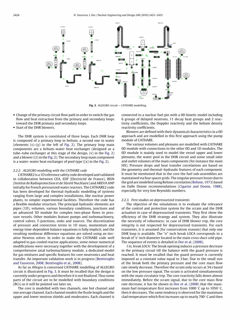
2424 N. Tauveron, I. Dor / Nuclear Engineering and Design 240 (2010) 2421–2435
uit — C
•
•
i(ctai
2
i(ihrpapascoeraamcfta
ccp(
ou
Fig. 3. ALLEGRO circ
Change of the primary circuit flow path in order to switch the gasflow and heat extraction from the primary and secondary loopstoward the DHR primary and secondary loops.Start of the DHR blowers.
The DHR system is constituted of three loops. Each DHR loops composed of a primary loop in helium, a second one in waterelements (s)–(y) in the left of Fig. 2). The primary loop mainomponents are a helium–water heat exchanger (designed as aube–tube exchanger at this stage of the design, (v) in the Fig. 2)nd a blower ((t) in the Fig. 2). The secondary loop main components a water–water heat exchanger of pool type ((x) in the Fig. 2).
.2.2. ALLEGRO modelling with the CATHARE codeCATHARE2 is a 1D reference safety code developed and validated
n collaboration between CEA, EDF (Electricité de France), IRSNInstitut de Radioprotection et de Sûreté Nucléaire) and AREVA ANPnitially for French pressurized water reactors. The CATHARE2 codeas been developed for thermal–hydraulic modelling of systemsanging from large and complex installations, like nuclear powerlants, to simpler experimental facilities. Therefore the code hasflexible modular structure. The principal hydraulic elements areipes (1D), volumes, various boundary conditions, junctions andn advanced 3D module for complex two-phase flows in pres-ure vessels. Other modules feature pumps and turbomachinery,ontrol valves, T-junctions, sinks and sources. The discretizationf pressure and convection terms in 1D mass, momentum andnergy time-dependent balance equations is fully implicit, and theesulting nonlinear difference equations are solved using an iter-tive Newton solver. In order to make the CATHARE code welldapted to gas-cooled reactor applications, some minor numericalodifications were necessary together with the development of a
omprehensive axial turbomachinery module, a dedicated modelor gas mixtures and specific features for core neutronics and heatransfer. An important validation work is in progress (Bentivogliond Tauveron, 2008; Bentivoglio et al., 2008).
As far as Allegro is concerned CATHARE modelling of ALLEGROircuit is illustrated in Fig. 3. It must be recalled that the design isurrently under progress and therefore it is not finalized. Thus some
arts of the circuit are to be modelled with boundary conditionsBCs) as it will be pointed out later on.The core is modelled with two channels, one hot channel andne average channel. Each channel models the fissile length and thepper and lower neutron shields and moderators. Each channel is
ATHARE modelling.
connected to a nuclear fuel pin with a 0D kinetic model including6 groups of delayed neutrons, 11 decay heat groups and 2 reac-tivity coefficients, the Doppler reactivity and the helium densityreactivity coefficients.
Blowers are defined with their dynamical characteristics in a 0Dapproach and are modelled in this first approach using the pumpmodule of CATHARE.
The various volumes and plenums are modelled with CATHARE0D module with connections to the other 0D and 1D modules. The0D module is mainly used to model the vessel upper and lowerplenums, the water pool in the DHR circuit and some small inletand outlet volumes of the main components (for instance the mainHX). Pressure drops and heat transfer correlations are based onthe geometry and thermal–hydraulic features of each component.It must be mentioned that in the core the fuel sub-assemblies aremaintained via four spacer grids. The singular pressure losses due tothe grid are modelled using Rehme correlation (Rehme, 1973) basedon Dalle Donne recommendations (Cigarini and Donne, 1988),especially for very low Reynolds numbers.
2.2.3. First studies on depressurized transientsThe objective of the simulations is to evaluate the relevance
of the control and protection system for the scram and the DHRactuation in case of depressurised transients. They first show theefficiency of the DHR strategy and system. They also illustratethe necessity of robustness: in case of DHR blower trip, the coreintegrity is not respected for depressurised transients. For eachtransients, it is assumed (for conservatism reasons) that only oneDHR loop is available. The “x” inch break LOCA corresponds to abreak of ‘x’ inch diameter located in the main cross-duct cold pipe.The sequence of events is detailed in Dor et al. (2008).
1 in. break LOCA: The break opening induces a pressure decreasein the primary circuit till the balance with the guard pressure isreached. It must be recalled that the guard pressure is currentlyimposed as a constant value equal to 3 bar. Due to the small sizeof the break both the primary pressure and the core mass flowrate slowly decrease. Therefore the scram only occurs at 34 s basedon the low pressure signal. The scram is activated simultaneouslywith the main circulator trip. The core reactivity falls down almost
immediately. Before the scram signal, due to the core mass flowrate decrease, it has be shown in Dor et al. (2008) that the maxi-mum fuel temperature first increases from 1000 ◦C up to 1050 ◦C,then it decreases. The same tendency is observed for the maximumclad temperature which first increases up to nearly 700 ◦C and then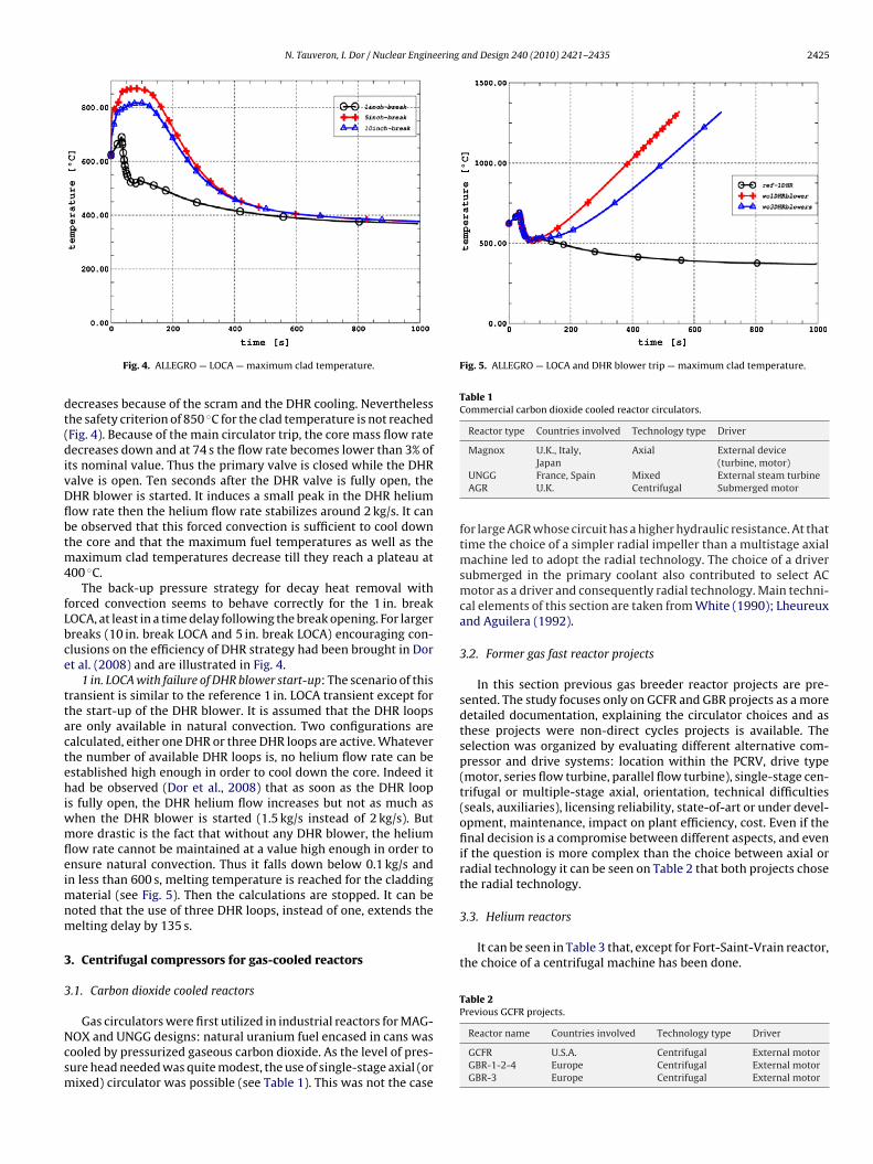
N. Tauveron, I. Dor / Nuclear Engineering and Design 240 (2010) 2421–2435 2425
dt(divDflbtm4
fLbce
ttactehiwmfleimnm
3
3
Ncsm
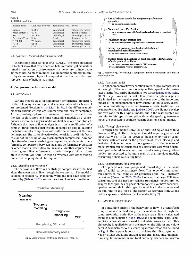
Fig. 5. ALLEGRO — LOCA and DHR blower trip — maximum clad temperature.
Table 1Commercial carbon dioxide cooled reactor circulators.
Reactor type Countries involved Technology type Driver
Magnox U.K., Italy, Axial External device
3.3. Helium reactors
It can be seen in Table 3 that, except for Fort-Saint-Vrain reactor,the choice of a centrifugal machine has been done.
Table 2Previous GCFR projects.
Fig. 4. ALLEGRO — LOCA — maximum clad temperature.
ecreases because of the scram and the DHR cooling. Neverthelesshe safety criterion of 850 ◦C for the clad temperature is not reachedFig. 4). Because of the main circulator trip, the core mass flow rateecreases down and at 74 s the flow rate becomes lower than 3% of
ts nominal value. Thus the primary valve is closed while the DHRalve is open. Ten seconds after the DHR valve is fully open, theHR blower is started. It induces a small peak in the DHR heliumow rate then the helium flow rate stabilizes around 2 kg/s. It cane observed that this forced convection is sufficient to cool downhe core and that the maximum fuel temperatures as well as the
aximum clad temperatures decrease till they reach a plateau at00 ◦C.
The back-up pressure strategy for decay heat removal withorced convection seems to behave correctly for the 1 in. breakOCA, at least in a time delay following the break opening. For largerreaks (10 in. break LOCA and 5 in. break LOCA) encouraging con-lusions on the efficiency of DHR strategy had been brought in Dort al. (2008) and are illustrated in Fig. 4.
1 in. LOCA with failure of DHR blower start-up: The scenario of thisransient is similar to the reference 1 in. LOCA transient except forhe start-up of the DHR blower. It is assumed that the DHR loopsre only available in natural convection. Two configurations arealculated, either one DHR or three DHR loops are active. Whateverhe number of available DHR loops is, no helium flow rate can bestablished high enough in order to cool down the core. Indeed itad be observed (Dor et al., 2008) that as soon as the DHR loop
s fully open, the DHR helium flow increases but not as much ashen the DHR blower is started (1.5 kg/s instead of 2 kg/s). Butore drastic is the fact that without any DHR blower, the helium
ow rate cannot be maintained at a value high enough in order tonsure natural convection. Thus it falls down below 0.1 kg/s andn less than 600 s, melting temperature is reached for the cladding
aterial (see Fig. 5). Then the calculations are stopped. It can beoted that the use of three DHR loops, instead of one, extends theelting delay by 135 s.
. Centrifugal compressors for gas-cooled reactors
.1. Carbon dioxide cooled reactors
Gas circulators were first utilized in industrial reactors for MAG-OX and UNGG designs: natural uranium fuel encased in cans wasooled by pressurized gaseous carbon dioxide. As the level of pres-ure head needed was quite modest, the use of single-stage axial (orixed) circulator was possible (see Table 1). This was not the case
Japan (turbine, motor)UNGG France, Spain Mixed External steam turbineAGR U.K. Centrifugal Submerged motor
for large AGR whose circuit has a higher hydraulic resistance. At thattime the choice of a simpler radial impeller than a multistage axialmachine led to adopt the radial technology. The choice of a driversubmerged in the primary coolant also contributed to select ACmotor as a driver and consequently radial technology. Main techni-cal elements of this section are taken from White (1990); Lheureuxand Aguilera (1992).
3.2. Former gas fast reactor projects
In this section previous gas breeder reactor projects are pre-sented. The study focuses only on GCFR and GBR projects as a moredetailed documentation, explaining the circulator choices and asthese projects were non-direct cycles projects is available. Theselection was organized by evaluating different alternative com-pressor and drive systems: location within the PCRV, drive type(motor, series flow turbine, parallel flow turbine), single-stage cen-trifugal or multiple-stage axial, orientation, technical difficulties(seals, auxiliaries), licensing reliability, state-of-art or under devel-opment, maintenance, impact on plant efficiency, cost. Even if thefinal decision is a compromise between different aspects, and evenif the question is more complex than the choice between axial orradial technology it can be seen on Table 2 that both projects chosethe radial technology.
Reactor name Countries involved Technology type Driver
GCFR U.S.A. Centrifugal External motorGBR-1-2-4 Europe Centrifugal External motorGBR-3 Europe Centrifugal External motor
2426 N. Tauveron, I. Dor / Nuclear Engineering and Design 240 (2010) 2421–2435
Table 3Real HTGR circulators.
Reactor name Countries involved Technology type Driver
Dragon O.E.C.D. Centrifugal Submerged motorPeach Bottom 1 U.S.A. Centrifugal External motorAVR W. Germ. Centrifugal Submerged motorFort-Saint-Vrain U.S.A. Axial External turbine
3
iratr
4
4
IaeAtqActdtofocgn
4
adf
THTR-300 W. Germ. Centrifugal Submerged motorHTTR Japan Centrifugal Submerged motorHTR-10 China Centrifugal Submerged motor
.4. Synthesis: the need of air machines data
Except some other test loops (CFTL, ADI, ...) the cases presentedn Table 3 show that experience on helium centrifugal circulatorsemains limited. As a consequence it is necessary to investigateir machines. As Mach number is an important parameter in cen-rifugal compressor physics, low-speed air machines are the mostepresentative of helium machines.
. Compressor performance model
.1. Introduction
Various models exist for compressor performance prediction.n the following sections general characteristics of each modelre presented (Sections 4.1.1–4.1.4). In Fig. 6 the different mod-ls with various criteria are summarized and briefly compared.t the pre-design phase of component it seems natural to use
he less sophisticated and time consuming model: as a conse-uence a meanline analysis model was first developed and studied.lthough this type of flow analysis is a strong simplification of aomplex three-dimensional system, it should be able to describehe behaviour of a compressor with sufficient accuracy at the pre-esign phase. The major objective of our work is to see if this fact isrue or not for helium or low Mach number compressors. A minorbjective of our work is to bring some quantitative elements in per-ormance comparisons between meanline performance predictionr other models, when data are available. Another argument forhoosing meanline performance analysis is the possibility to inte-rate it within CATHARE 1D-models, whereas with other modelsumerical coupling should be required.
.1.1. Meanline analysis model
The behaviour of flow in a centrifugal compressor is describedlong the mean streamline through the compressor. The model isetailed in Section 4.2. Pioneering work and tool have been per-ormed by (Galvas, 1973); we used various elements from them.
Fig. 6. Comparison of centrifugal compressor models.
Fig. 7. Methodology for centrifugal compressor model development and use: aniterative process.
4.1.2. Two-zone modelThe phenomenon of flow separation in centrifugal compressor is
at the origin of the two-zone model type. This type of model postu-lates that the flow can be divided into two parts (den Braembussche,2007): the jet flow and the wake flow. This description is gener-ally limited to the impeller part. However due to the importantimpact of the phenomenon of flow separation on velocity distri-bution, recent attempts to extend two-zone model to diffuser hasbeen performed (Dubitsky and Japikse, 2005). We did not developour own code for this type of model, but in the cases treated wecan refer to this type of description. Generally speaking, two-zonemodel are expected to be more realistic than “one zone” model.
4.1.3. Through-flow modelThrough-flow models solve 2D or quasi-2D equations of fluid
flow on a 2D grid. Thus this type of model requires geometricalinput spanwise. As for the previous models, empirical or semi-empirical data are used for the prediction of losses, blockage anddeviation. This type model is more general than the ‘one zone”model (which can be considered as a particular case with a span-wise grid reduced to one cell) and results using through-flowmodels are expected to be more realistic than previous models,consuming a short calculating time.
4.1.4. Computational fluid dynamicsCFD procedures have progressed remarkably in the anal-
ysis of radial turbomachinery flow. This type of simulationscan addressed real complex 3D geometries and (real) unsteadybehaviour (Tauveron, 2003, 2010). However the large CPU timeconsuming and the need for reliable turbulence models are notadapted to the pre-design phase of components. We have not devel-oped our own code for this type of model, but in the cases treatedwe can refer to this type of description as reference simulations(when experimental data are not available) (Fig. 7).
4.2. Meanline analysis model
In a meanline analysis, the behaviour of flow in a centrifugalcompressor is described along the mean streamline through thecompressor. Ideal outlet flow at the mean streamline is calculatedowing to Euler Equation Dixon (1975) and geometrical data. Semi-empirical correlations are used to calculate losses and slip. This
philosophy is applied for both the impeller, the diffuser and voluteparts. A schematic view of a centrifugal compressor can be foundin Fig. 8. The approach consists in solving the 1D axisymmetricNavier–Stokes equations on a axi-radial grid: mass, linear momen-tum, angular momentum and total enthalpy balances are written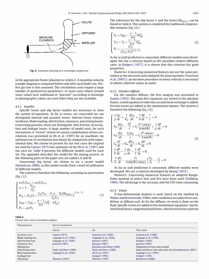
N. Tauveron, I. Dor / Nuclear Engineering
itfnso
4
tdiCtmroisost
(o
(⎧⎪⎪⎪⎪⎪⎪⎪⎨⎪⎪⎪⎪⎪⎪⎪⎩TC
Fig. 8. Schematic drawing of a centrifugal compressor.
n the appropriate frame (absolute or relative). A meanline velocityriangle diagram is computed before and after each blade row. Per-ect gas law is also assumed. The correlations used require a largeumber of geometrical parameters; in some cases where treatedome values lack, traditional or “guessed” (according to drawingsr photographs) values are used when they are not available.
.2.1. ImpellerSpecific losses and slip factor models are necessary to close
he system of equations. As far as losses, are concerned we canistinguish internal and parasitic losses. Internal losses contain:
ncidence, blade loading, skin friction, clearance, and mixing losses.oncerning parasitic losses we distinguish: disk friction, recircula-ion and leakage losses. A large number of model exist, for each
echanism. A “recent” review of various combinations of loss cor-elations was presented in Oh et al. (1997) for air machines. Anptimum set of correlations was found, by comparison with exper-mental data. We choose to present for our test cases the originalet used by Galvas (1973),the optimum set by Oh et al. (1997) andur own set. Table 4 presents the different models used for eachet. The appendix describes the model for the mixing process. Inhe following parts of the paper sets are called I, II and III.
Concerning slip factor, we choose to try a recent modelBackstrom, 2006), as this model results from a work of unificationf different models.
The system is therefore the following, assuming no-prerotationEq. (1)).
�1S1Vm,1 = �2S2Vm,2
� = 1 − V�,2
U2C (T − T ) − Dh �/(�−1)
PT2 = PT1[1 + p T2 T1 i losses,i
CpTT1]
TTR2 = TTR1 + � − 12�r
(U22 − U2
1m)
P2 = �2rT2
(1)
able 4losure laws used in meanline analysis.
Phenomenon Set of correlations
Galvas Oh
Incidence loss Galvas (1973) Conrad et al. (198Blade loading loss Coppage et al. (1956) Coppage et al. (19Skin friction loss Coppage et al. (1956) Janssen (1967)Clearance loss Janssen (1967) Janssen (1967)Mixing loss – Johnston and DeaDisk friction loss Daily and Nece (1960) Daily and Nece (1Recirculation loss Coppage et al. (1956) Oh et al. (1997)Leakage loss – Aungier (1995)Slip factor Wiesner (1967) Wiesner (1967)
and Design 240 (2010) 2421–2435 2427
The references for the slip factor � and the losses Dhlosses,i can befound in Table 4. This system is completed by traditional compress-ible relations (Eq. (2)):⎧⎪⎪⎪⎪⎨⎪⎪⎪⎪⎩
T2 = TTR2 − � − 12�r
W22m
TT2 = T2 + � − 12�r
V22m
P2 = PT2
[TT2/T2]�/(�−1)
(2)
As far as stall prediction is concerned, different models were devel-oped. We use a criterion based on the meanline relative diffusionratio: in Rodgers (1977), it is shown that this criterion has goodproperties.
Numerics: Concerning numerical features we use the same pro-cedure as the one used (and validated) for axial machines (Tauveronet al. (2007)): an iteration procedure on linear velocity is necessaryto obtain coherent values at outlet.
4.2.2. Vaneless diffuserFor the vaneless diffuser, the first analysis was presented in
Stanitz (1952). The main five equations are solved in the absoluteframe; a sixth equation to take into account heat exchange is added.Friction terms are added in the momentum balance. The system istherefore the following (Eq. (3)).⎧⎪⎪⎪⎪⎪⎪⎪⎪⎪⎪⎪⎪⎪⎪⎪⎪⎪⎨⎪⎪⎪⎪⎪⎪⎪⎪⎪⎪⎪⎪⎪⎪⎪⎪⎪⎩
1�
d�
dr+ 1
Vm
dVm
dr+ 1
b
db
dr+ 1
r= 0
VmdVm
dr− V2
�
r+ Cf
V2 cos(˛)b sin()
+ 1�
dP
dr= 0
VmdV�
dr− V�Vm
r+ Cf
V2 sin(˛)b sin()
= 0
CpdT
dr+ Vm
dVm
dr+ V�
d�
dr= 0
1P
dP
dr− 1
�
d�
dr− 1
T
dT
dr= 0
1Tt
dTt
dr− Cf
h sin() cos(˛)
(Tw
Tt− 1)
= 0
(3)
As far as stall prediction is concerned, different models weredeveloped. We use a criterion developed by Kenny (1972).
Numerics: Concerning numerical features an adaptive Runge-Kutta method of orders four and five have been used (Fehlberg,1969). The advantage is the accuracy and the CPU time consuming.
4.2.3. Volute
A one-dimensional analysis is used, based on the method byWeber and Koronowski (1986). Inlet conditions are taken from con-ditions at diffuser exit. As for the diffuser, no work is done on thefluid. Specific losses are added in the momentum equations: merid-ional head losses, tangential head losses, skin friction losses and exit
This work
0) Conrad et al. (1980)56) Coppage et al. (1956)
Aungier (1995)Janssen (1967)
n (1966) Adaptation of two-zone model960) Daily and Nece (one side only, den Braembussche, 2007)
Coppage et al. (1956)Aungier (1995)Backstrom (2006)
2428 N. Tauveron, I. Dor / Nuclear Engineering and Design 240 (2010) 2421–2435
ct1Wtt
cv
5
bfittdtvd
5
e
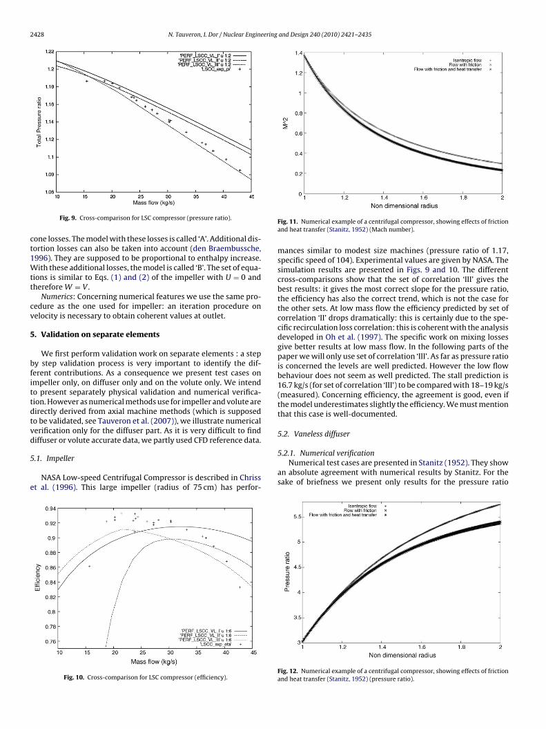
Fig. 9. Cross-comparison for LSC compressor (pressure ratio).
one losses. The model with these losses is called ‘A’. Additional dis-ortion losses can also be taken into account (den Braembussche,996). They are supposed to be proportional to enthalpy increase.ith these additional losses, the model is called ‘B’. The set of equa-
ions is similar to Eqs. (1) and (2) of the impeller with U = 0 andherefore W = V .
Numerics: Concerning numerical features we use the same pro-edure as the one used for impeller: an iteration procedure onelocity is necessary to obtain coherent values at outlet.
. Validation on separate elements
We first perform validation work on separate elements : a stepy step validation process is very important to identify the dif-erent contributions. As a consequence we present test cases onmpeller only, on diffuser only and on the volute only. We intendo present separately physical validation and numerical verifica-ion. However as numerical methods use for impeller and volute areirectly derived from axial machine methods (which is supposedo be validated, see Tauveron et al. (2007)), we illustrate numericalerification only for the diffuser part. As it is very difficult to findiffuser or volute accurate data, we partly used CFD reference data.
.1. Impeller
NASA Low-speed Centrifugal Compressor is described in Chrisst al. (1996). This large impeller (radius of 75 cm) has perfor-
Fig. 10. Cross-comparison for LSC compressor (efficiency).
Fig. 11. Numerical example of a centrifugal compressor, showing effects of frictionand heat transfer (Stanitz, 1952) (Mach number).
mances similar to modest size machines (pressure ratio of 1.17,specific speed of 104). Experimental values are given by NASA. Thesimulation results are presented in Figs. 9 and 10. The differentcross-comparisons show that the set of correlation ‘III’ gives thebest results: it gives the most correct slope for the pressure ratio,the efficiency has also the correct trend, which is not the case forthe other sets. At low mass flow the efficiency predicted by set ofcorrelation ‘II’ drops dramatically: this is certainly due to the spe-cific recirculation loss correlation: this is coherent with the analysisdeveloped in Oh et al. (1997). The specific work on mixing lossesgive better results at low mass flow. In the following parts of thepaper we will only use set of correlation ‘III’. As far as pressure ratiois concerned the levels are well predicted. However the low flowbehaviour does not seem as well predicted. The stall prediction is16.7 kg/s (for set of correlation ‘III’) to be compared with 18–19 kg/s(measured). Concerning efficiency, the agreement is good, even ifthe model underestimates slightly the efficiency. We must mentionthat this case is well-documented.
5.2. Vaneless diffuser
5.2.1. Numerical verificationNumerical test cases are presented in Stanitz (1952). They show
an absolute agreement with numerical results by Stanitz. For thesake of briefness we present only results for the pressure ratio
Fig. 12. Numerical example of a centrifugal compressor, showing effects of frictionand heat transfer (Stanitz, 1952) (pressure ratio).
N. Tauveron, I. Dor / Nuclear Engineering and Design 240 (2010) 2421–2435 2429
Fa
(wfdc
5
mmrrdwmtab
5
Ssw
F(
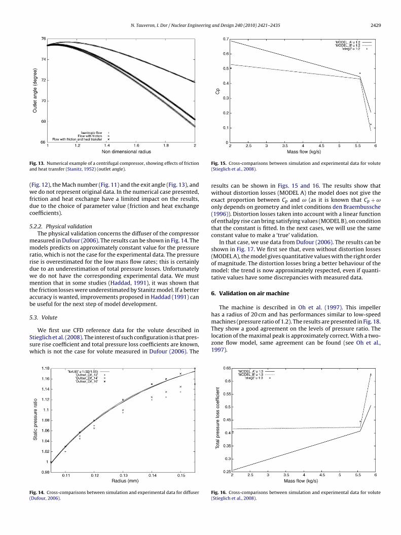
ig. 13. Numerical example of a centrifugal compressor, showing effects of frictionnd heat transfer (Stanitz, 1952) (outlet angle).
Fig. 12), the Mach number (Fig. 11) and the exit angle (Fig. 13), ande do not represent original data. In the numerical case presented,
riction and heat exchange have a limited impact on the results,ue to the choice of parameter value (friction and heat exchangeoefficients).
.2.2. Physical validationThe physical validation concerns the diffuser of the compressor
easured in Dufour (2006). The results can be shown in Fig. 14. Theodels predicts on approximately constant value for the pressure
atio, which is not the case for the experimental data. The pressureise is overestimated for the low mass flow rates; this is certainlyue to an underestimation of total pressure losses. Unfortunatelye do not have the corresponding experimental data. We mustention that in some studies (Haddad, 1991), it was shown that
he friction losses were underestimated by Stanitz model. If a betterccuracy is wanted, improvements proposed in Haddad (1991) cane useful for the next step of model development.
.3. Volute
We first use CFD reference data for the volute described intieglich et al. (2008). The interest of such configuration is that pres-ure rise coefficient and total pressure loss coefficients are known,hich is not the case for volute measured in Dufour (2006). The
ig. 14. Cross-comparisons between simulation and experimental data for diffuserDufour, 2006).
Fig. 15. Cross-comparisons between simulation and experimental data for volute(Stieglich et al., 2008).
results can be shown in Figs. 15 and 16. The results show thatwithout distortion losses (MODEL A) the model does not give theexact proportion between Cp and ω (as it is known that Cp + ωonly depends on geometry and inlet conditions den Braembussche(1996)). Distortion losses taken into account with a linear functionof enthalpy rise can bring satisfying values (MODEL B), on conditionthat the constant is fitted. In the next cases, we will use the sameconstant value to make a ‘true’ validation.
In that case, we use data from Dufour (2006). The results can beshown in Fig. 17. We first see that, even without distortion losses(MODEL A), the model gives quantitative values with the right orderof magnitude. The distortion losses bring a better behaviour of themodel: the trend is now approximately respected, even if quanti-tative values have some discrepancies with measured data.
6. Validation on air machine
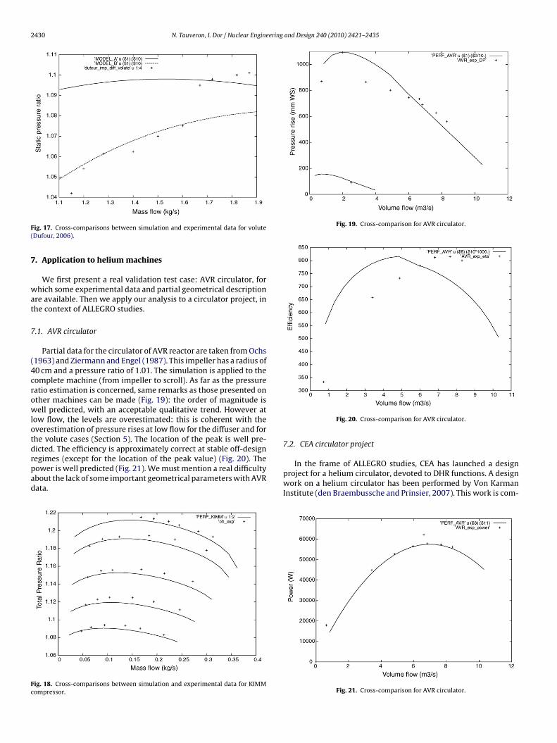
The machine is described in Oh et al. (1997). This impellerhas a radius of 20 cm and has performances similar to low-speedmachines (pressure ratio of 1.2). The results are presented in Fig. 18.
They show a good agreement on the levels of pressure ratio. Thelocation of the maximal peak is approximately correct. With a two-zone flow model, same agreement can be found (see Oh et al.,1997).Fig. 16. Cross-comparisons between simulation and experimental data for volute(Stieglich et al., 2008).
2430 N. Tauveron, I. Dor / Nuclear Engineering and Design 240 (2010) 2421–2435
F(
7
wat
7
(4crowlotdrpad
Fc
Fig. 19. Cross-comparison for AVR circulator.
ig. 17. Cross-comparisons between simulation and experimental data for voluteDufour, 2006).. Application to helium machines
We first present a real validation test case: AVR circulator, forhich some experimental data and partial geometrical description
re available. Then we apply our analysis to a circulator project, inhe context of ALLEGRO studies.
.1. AVR circulator
Partial data for the circulator of AVR reactor are taken from Ochs1963) and Ziermann and Engel (1987). This impeller has a radius of0 cm and a pressure ratio of 1.01. The simulation is applied to theomplete machine (from impeller to scroll). As far as the pressureatio estimation is concerned, same remarks as those presented onther machines can be made (Fig. 19): the order of magnitude isell predicted, with an acceptable qualitative trend. However at
ow flow, the levels are overestimated: this is coherent with theverestimation of pressure rises at low flow for the diffuser and forhe volute cases (Section 5). The location of the peak is well pre-icted. The efficiency is approximately correct at stable off-design
egimes (except for the location of the peak value) (Fig. 20). Theower is well predicted (Fig. 21). We must mention a real difficultybout the lack of some important geometrical parameters with AVRata.ig. 18. Cross-comparisons between simulation and experimental data for KIMMompressor.
Fig. 20. Cross-comparison for AVR circulator.
7.2. CEA circulator project
In the frame of ALLEGRO studies, CEA has launched a designproject for a helium circulator, devoted to DHR functions. A designwork on a helium circulator has been performed by Von KarmanInstitute (den Braembussche and Prinsier, 2007). This work is com-
Fig. 21. Cross-comparison for AVR circulator.
N. Tauveron, I. Dor / Nuclear Engineering and Design 240 (2010) 2421–2435 2431
Fc
paR3cTcta
8t
8
ecp
•
•
•
Fc
ig. 22. CEA, VKI two-zone model and VKI reference simulation data (CFD) for CEAompressor.
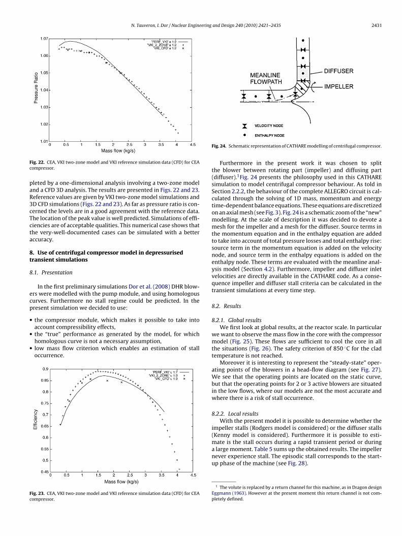
leted by a one-dimensional analysis involving a two-zone modelnd a CFD 3D analysis. The results are presented in Figs. 22 and 23.eference values are given by VKI two-zone model simulations andD CFD simulations (Figs. 22 and 23). As far as pressure ratio is con-erned the levels are in a good agreement with the reference data.he location of the peak value is well predicted. Simulations of effi-iencies are of acceptable qualities. This numerical case shows thathe very-well-documented cases can be simulated with a betterccuracy.
. Use of centrifugal compressor model in depressurisedransient simulations
.1. Presentation
In the first preliminary simulations Dor et al. (2008) DHR blow-rs were modelled with the pump module, and using homologousurves. Furthermore no stall regime could be predicted. In theresent simulation we decided to use:
the compressor module, which makes it possible to take into
account compressibility effects,the “true” performance as generated by the model, for whichhomologous curve is not a necessary assumption,low mass flow criterion which enables an estimation of stalloccurrence.ig. 23. CEA, VKI two-zone model and VKI reference simulation data (CFD) for CEAompressor.
Fig. 24. Schematic representation of CATHARE modelling of centrifugal compressor.
Furthermore in the present work it was chosen to splitthe blower between rotating part (impeller) and diffusing part(diffuser).1Fig. 24 presents the philosophy used in this CATHAREsimulation to model centrifugal compressor behaviour. As told inSection 2.2.2, the behaviour of the complete ALLEGRO circuit is cal-culated through the solving of 1D mass, momentum and energytime-dependent balance equations. These equations are discretizedon an axial mesh (see Fig. 3). Fig. 24 is a schematic zoom of the “new”modelling. At the scale of description it was decided to devote amesh for the impeller and a mesh for the diffuser. Source terms inthe momentum equation and in the enthalpy equation are addedto take into account of total pressure losses and total enthalpy rise:source term in the momentum equation is added on the velocitynode, and source term in the enthalpy equations is added on theenthalpy node. These terms are evaluated with the meanline anal-ysis model (Section 4.2). Furthermore, impeller and diffuser inletvelocities are directly available in the CATHARE code. As a conse-quence impeller and diffuser stall criteria can be calculated in thetransient simulations at every time step.
8.2. Results
8.2.1. Global resultsWe first look at global results, at the reactor scale. In particular
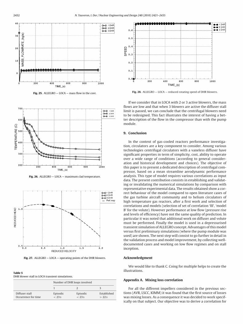
we want to observe the mass flow in the core with the compressormodel (Fig. 25). These flows are sufficient to cool the core in allthe situations (Fig. 26). The safety criterion of 850 ◦C for the cladtemperature is not reached.
Moreover it is interesting to represent the “steady-state” oper-ating points of the blowers in a head-flow diagram (see Fig. 27).We see that the operating points are located on the static curve,but that the operating points for 2 or 3 active blowers are situatedin the low flows, where our models are not the most accurate andwhere there is a risk of stall occurrence.
8.2.2. Local resultsWith the present model it is possible to determine whether the
impeller stalls (Rodgers model is considered) or the diffuser stalls(Kenny model is considered). Furthermore it is possible to esti-mate is the stall occurs during a rapid transient period or during
a large moment. Table 5 sums up the obtained results. The impellernever experience stall. The episodic stall corresponds to the start-up phase of the machine (see Fig. 28).1 The volute is replaced by a return channel for this machine, as in Dragon designEggmann (1963). However at the present moment this return channel is not com-pletely defined.
2432 N. Tauveron, I. Dor / Nuclear Engineering and Design 240 (2010) 2421–2435
Fig. 25. ALLEGRO — LOCA — mass flow in the core.
Fig. 26. ALLEGRO — LOCA — maximum clad temperature.
Fig. 27. ALLEGRO — LOCA — operating points of the DHR blowers.
Table 5DHR blower stall in LOCA transient simulations.
Number of DHR loops involved
1 2 3
Diffuser stall Episodic Episodic EstablishedOccurrence for time < 23 s < 23 s > 22 s
Fig. 28. ALLEGRO — LOCA — reduced rotating speed of DHR blowers.
If we consider that in LOCA with 2 or 3 active blowers, the massflows are low and that when 3 blowers are active the diffuser stalllimit is passed, we can conclude that the centrifugal blowers needto be redesigned. This fact illustrates the interest of having a bet-ter description of the flow in the compressor than with the pumpmodule.
9. Conclusion
In the context of gas-cooled reactors performance investiga-tion, circulators are a key component to consider. Among varioustechnologies centrifugal circulators with a vaneless diffuser havesignificant properties in term of simplicity, cost, ability to operateover a wide range of conditions (according to general consider-ation and historical development and choices). The objective ofthis paper is to present a dedicated description of centrifugal com-pressor, based on a mean streamline aerodynamic performanceanalysis. This type of model requires various correlations as inputdata. The present contribution consists in establishing and validat-ing or invalidating the numerical simulations by comparison withrepresentative experimental data. The results obtained show a cor-rect behaviour of the model compared to open literature cases ofthe gas turbine aircraft community and to helium circulators ofhigh temperature gas reactors, after a first work and selection ofcorrelations and models (selection of set of correlation ‘III’, ‘modelB’ for the volute). However performance at low flow (pressure riseand levels of efficiency) have not the same quality of prediction. Inparticular it was noted that additional work on diffuser and volutemust be performed. Finally the model is used in a depressurisedtransient simulation of ALLEGRO concept. Advantages of this modelversus first preliminary simulations (where the pump module wasused) are shown. The next step will consist to go further in detail inthe validation process and model improvement, by collecting well-documented cases and working on low flow regimes and on stallinception.
Acknowledgment
We would like to thank C. Coing for multiple helps to create theillustrations.
Appendix A. Mixing loss correlation
For all the different impellers considered in the previous sec-tions (AVR, LSCC, KIMM) it was found that the first source of losseswas mixing losses. As a consequence it was decided to work specif-ically on that subject. Our objective was to derive a correlation for
ering and Design 240 (2010) 2421–2435 2433
maaa
A
A
T
I
M
wB
W
Ttsh
T
O
�
a
�
Fo(
afwfl
�
wBtt
V
V
V
G
M
T
N. Tauveron, I. Dor / Nuclear Engine
ixing losses from more general two-zone models. To present ourpproach we use the framework on two-zone modelling presentednd well-detailed in Oh et al. (2002). Some important elements arelso taken from den Braembussche (2007).
.1. Basic equations
.1.1. Jet zone equationsThe constant rothalpy equation is:
TR2j = TTR1m + � − 12�r
(U22 − U2
1m) (4)
nstead of writing W2j = (W1T /DR) as in Oh et al. (2002), we write:
R2j = Msep (5)
here ‘sep’ characterise the point of separation, defined as (denraembussche, 2007):
sep = W1T
DR
otal relative and static temperature of this point are found throughhe application of constant rothalpy equation between inlet andeparation point (supposed to be located at a radius situatedalfway between inlet and outlet).
The definition of total relative temperature gives:
2j = TTR2j
1 + (� − 1)/2M2R2j
(6)
ne defines:
= mw
m(7)
nd:
= 1 − A2j
Ageo(8)
or simplicity the jet flow angle is supposed to be equal to mixed-ut state flow angle. As a consequence Eqs. (6)–(8) from Oh et al.2002) are not used.
A relation between � is necessary. Whereas in Oh et al. (2002)n empirical correlation is introduced, we can directly write theollowing relation, from mass conservations (total flow, jet flow,ake flow), assuming no change of density between total flow, jetow, wake flow:
= ��1 − �(1 − �)
(9)
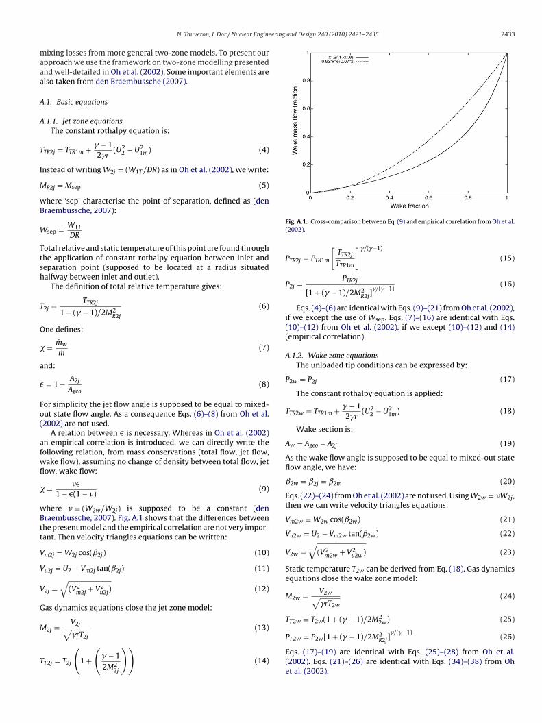
here � = (W2w/W2j) is supposed to be a constant (denraembussche, 2007). Fig. A.1 shows that the differences betweenhe present model and the empirical correlation are not very impor-ant. Then velocity triangles equations can be written:
m2j = W2j cos(ˇ2j) (10)
u2j = U2 − Vm2j tan(ˇ2j) (11)
2j =√
(V2m2j
+ V2u2j
) (12)
as dynamics equations close the jet zone model:
2j = V2j√ (13)
�rT2jT2j = T2j
(1 +(
� − 1
2M22j
))(14)
Fig. A.1. Cross-comparison between Eq. (9) and empirical correlation from Oh et al.(2002).
PTR2j = PTR1m
[TTR2j
TTR1m
]�/(�−1)
(15)
P2j = PTR2j
[1 + (� − 1)/2M2R2j
]�/(�−1)
(16)
Eqs. (4)–(6) are identical with Eqs. (9)–(21) from Oh et al. (2002),if we except the use of Wsep. Eqs. (7)–(16) are identical with Eqs.(10)–(12) from Oh et al. (2002), if we except (10)–(12) and (14)(empirical correlation).
A.1.2. Wake zone equationsThe unloaded tip conditions can be expressed by:
P2w = P2j (17)
The constant rothalpy equation is applied:
TTR2w = TTR1m + � − 12�r
(U22 − U2
1m) (18)
Wake section is:
Aw = Ageo − A2j (19)
As the wake flow angle is supposed to be equal to mixed-out stateflow angle, we have:
ˇ2w = ˇ2j = ˇ2m (20)
Eqs. (22)–(24) from Oh et al. (2002) are not used. Using W2w = �W2j ,then we can write velocity triangles equations:
Vm2w = W2w cos(ˇ2w) (21)
Vu2w = U2 − Vm2w tan(ˇ2w) (22)
V2w =√
(V2m2w + V2
u2w) (23)
Static temperature T2w can be derived from Eq. (18). Gas dynamicsequations close the wake zone model:
M2w = V2w√�rT2w
(24)
TT2w = T2w(1 + (� − 1)/2M22w) (25)
PT2w = P2w[1 + (� − 1)/2M2R2j]
�/(�−1)(26)
Eqs. (17)–(19) are identical with Eqs. (25)–(28) from Oh et al.(2002). Eqs. (21)–(26) are identical with Eqs. (34)–(38) from Ohet al. (2002).
2 ering
A
iw
V
F
V
F
V
I
V
F
T
F
T
Vz
V
T
P
E(a
A
e
D
w
D
F
D
l
F
W
F
A
F
�Fmix
�m= −mref ((� − 1)�min cos2(ˇ2m)/(1 − cs5)(1 − �min)(� − 1)
+ � cos (ˇ2m)2+(�−1)�min/(1 − cs5)(�min ∗ (� − 1)/2 + 1)
434 N. Tauveron, I. Dor / Nuclear Engine
.1.3. Mixed-out state equationsJet and wake are supposed to be rapidly mixed after leaving the
mpeller. Conservations of momentum, mass and total energy areritten. For the tangential momentum conservation:
u2m = (1 − �)Vu2j + �Vu2w (27)
or the radial momentum conservation:
m2m + (P2m − P2j)A2/m = (1 − �)Vm2j + �Vm2w (28)
or the mass conservation:
m2m = (1 − �)Vm2j�2j
�2m+ �Vm2w
�2w
�2m(29)
f density differences are small, we can replace Eq. (29) by Eq. (30):
m2m = (1 − �)Vm2j + �Vm2w (30)
or the energy conservation:
Tm2m = (1 − �)TTm2j + �TTm2w + � − 1�rm
(Wdf + Wrc + Wlk) (31)
or the correlation determination, we simplify Eq. (31) by Eq. (32):
Tm2m = (1 − �)TTm2j + �TTm2w (32)
elocity triangle and gas dynamics equation close the mixed-outone model:
2m =√
(V2m2m + V2
u2m) (33)
m2m = TTm2m − � − 12�r
V22m (34)
T2m = P2m
[TT2m
T2m
]�/(�−1)(35)
qs. (27) and (28) are identical with Eqs. (39)–(41) from Oh et al.2002). Eqs. (31)–(35) are identical with Eqs. (42)–(46) from Oh etl. (2002).
.1.4. Mixing lossesWe can define mixing losses by the difference between total
nthalpy gain through impeller Dhimp minus other losses:
hmix = Dhimp − iDhlosses,i (36)
here:
himp = CpTTin
(TTm2m
TTin−[
PTm2m
PTin
](�−1)/�)
(37)
or the correlation determination, we simplify Eq. (36) by Eq. (38):
hmix = Dhimp (38)
Mixing losses fraction is defined by the ratio between mixingosses and actual enthalpy gain Dhact:
mix = Dhimp − iDhlosses,i
Dhact(39)
e can also simplify 39 into Eq. (40):
mix =TTm2m − TTin[ PTm2m
PTin](�−1)/�
TTm2m − TTin(40)
.2. Non-dimensional equations
We can put the previous system in a non-dimensional form:
mix =�1�2 −
(�−1)/�1
1−�1/(2�1)
�1�2 − 1(41)
and Design 240 (2010) 2421–2435
where:⎧⎪⎪⎪⎪⎪⎪⎪⎪⎪⎪⎪⎪⎪⎪⎪⎪⎪⎪⎪⎪⎪⎪⎪⎪⎪⎪⎪⎪⎪⎪⎪⎪⎪⎪⎪⎪⎪⎪⎪⎪⎪⎪⎪⎪⎪⎪⎪⎪⎨⎪⎪⎪⎪⎪⎪⎪⎪⎪⎪⎪⎪⎪⎪⎪⎪⎪⎪⎪⎪⎪⎪⎪⎪⎪⎪⎪⎪⎪⎪⎪⎪⎪⎪⎪⎪⎪⎪⎪⎪⎪⎪⎪⎪⎪⎪⎪⎪⎩
M20 = U2√�rTTin
M1T = Vm1T√�rTTin
fM10 = m
(A2PTin)√
�rTTin
Msep =
√M2
1T + (U1T /U2M20)2
DR√
(1 + (� − 1))(−M21T /DR + .5M2
20)/2
�2 = 1 + ((� − 1)M220)/2
1 + ((� − 1)M2sep)/2
2 = (1 + (−(� − 1)�2M2sep/(2) + ((� − 1)M2
20)/2))(�/(�−1))
C = fM10/(cos(ˇ2m))/Msep/ 2√
�2
� = − 1 − C
� − 1
� = (1 − C)/(−� + 1)�/C
�1 = (1 + ((� − 1)M2sep + (� − 1)M2
20/�2
−2(1 − � + ��)(� − 1)MsepM20√
�2sin(ˇ2m))/2)
1 = (1 + (cos(ˇ2m)Msep)2�C(� − �)(� − 1)) 2
�1 = ((� − 1)M2sep(1 + �2 cos2(ˇ2m) + �2 sin2(ˇ2m))(� − 1)2
+ 2(� − 1)(� cos2(ˇ2m) + � sin2(ˇ2m)) + (� − 1)M2
20�2
− 2(� − 1)MsepM20√
�2sin(ˇ2m)(1 − � + ��))
(42)
A.3. Model
At this step, we introduce two mass flows: m0 and m∗. m0 corre-sponds to the flow where we have: � = 1 while m∗ corresponds tothe flow where we have: � = �min. With simplifications of system42, based on low Mach number hypothesis, we obtain:⎧⎨⎩
m0 = mref
(R1T
R2M20/M1T
)/√
1/cs6 − 1
m∗ = mref
(R1T
R2M20/M1T
)/√
1/cs5 − 1(43)
where:⎧⎪⎪⎪⎨⎪⎪⎪⎩
cs2 = DR2/ cos2(ˇ2m)cs3 = (fM10/M1T )2
cs4 = (1 − �min + ��min)2
cs5 = cs4/(cs3cs2)cs6 = �2/(cs3cs2)
(44)
Between flows m0 and m∗, Fmix is supposed to have a linear varia-tion. The slope �Fmix
�mcan be calculated as follows:
+ 0.5)M20/M1T
√1/cs5 − 1
R1T
R2DR2 (45)
For flows fewer than m0, we have: Fmix(m) = Fmix(m0). For flowsgreater than m∗, a symmetrical expression is supposed.
ering
R
A
B
B
B
C
C
C
C
C
D
d
d
d
D
D
D
D
E
F
G
INEL-DOE contract DE-AC07-76IDO1570.Wiesner, F.J., 1967. A review of slip factors for centrifugal impellers. ASME J. Eng.
N. Tauveron, I. Dor / Nuclear Engine
eferences
ungier, R.H., 1995. Mean streamline aerodynamic performance analysis of cen-trifugal compressor. ASME J. Turbomach. 117, 360–366.
ackstrom, T.W., 2006. A unified correlation for slip factor in centrifugal impellers.ASME J. Turbomach. 128, 1–10.
entivoglio, F., Tauveron, N., 2008. Validation of the CATHARE2 code against Ober-hausen II data. Nucl. Technol. 164, 55–75.
entivoglio, F., Tauveron, N., Geffraye, G., Gentner, H., 2008. Validation of theCATHARE2 code against experimental data from Brayton-cycle plants. Nucl. Eng.Des. 238, 3145–3159.
arré, F., Thomas, J.-B., Boidron, M., 2001. Significance of the fuel cycle aspects in CEAstudies on future nuclear systems. In: Proceedings of the GLOBAL Conference.
hriss, R.M., Hathaway, M., Wood, J., 1996. Experimental and computational resultsfrom the NASA Lewis LSC Impeller at design and part-flow conditions. ASME J.Turbomach. 118, 55–65.
igarini, M., Donne, M.D., 1988. Thermodynamic optimization of heterogeneousadvanced pressurized water reactors. Nucl. Technol. 80, 107–132.
onrad, O., Raif, K., Wessels, M., 1980. The calculation of performance maps forcentrifugal compressor with vane-islands diffusers. In: Proceedings of the Inter-national Gas Turbine and Aeroengine Congress and Exposition.
oppage, J.E., Dallenbach, F., Eichenberger, H.P., Hlavaka, H.P., Knoernschild, G.E.,Lee, N.V., 1956. Study of supersonic radial compressors for refrigeration andpressurization systems. Tech. Rep., WADC, pp. 55–257.
aily, J.W., Nece, R.E., 1960. Chamber dimension effects on induced flow and fric-tional resistance of enclosed rotating disks. ASME J. Basic Eng. 82, 217–232.
en Braembussche, R.A.V., 1996. Flow and loss mechanism in volutes of centrifugalcompressors and pumps. In: Von Karman Institute Course. Note 55.
en Braembussche, R.A.V., 2007. Centrifugal compressors analysis and design. In:Von Karman Institute Course. Note 192.
en Braembussche, R.A.V., Prinsier, J., 2007. Evaluation of performance of a heliumcirculator at different operating conditions. Tech. Rep., VKI-Contract Report2007-29.
ixon, S.L., 1975. Fluid Mechanics, Thermodynamics of Turbomachinery, 2nd ed.Pergamon Press.
or, I., Pignatel, J.-F., Poette, C., Morin, F., Bertrand, F., 2008. ETDR Project – Inves-tigation of system effects with the CATHARE code. In: Proceedings of the 16thInternational Conference on Nuclear Engineering (ICONE-16). Paper ICONE16-48619.
ubitsky, O., Japikse, D., 2005. Vaneless diffuser advanced model. In: Proceedings ofthe International Gas Turbine and Aeroengine Congress and Exposition. PaperGT2005-68130.
ufour, G., 2006. Contribution à la modélisation et au calcul des écoulements dansles compresseurs centrifuges: application à la conception par lois de similitude.Ph.D. Thesis. Institut National Polytechnique de Toulouse.
ggmann, J., 1963. The main circulators for the Dragon reactor. Brown Boveri Rev.50, 409–416.
ehlberg, E., 1969. Low-order classical Runge-Kutta formulas with step size controland their application to some heat transfer problems. Tech. Rep., NACA. TR 315.
alvas, M., 1973. Fortran program for predicting off-design performance of centrifu-gal compressors. Tech. Rep., NASA. TN 7487.
and Design 240 (2010) 2421–2435 2435
Haddad, B. A., 1991. Detérmination théorique et numérique des performances etlimites de fonctionnement des compresseurs centrifuges. Ph.D. Thesis. UniversitParis VI.
Janssen, W., 1967. A method for calculating the flow in a centrifugal impeller whenentropy gradients are present. In: Proceedings of the Royal Society Conferenceon Internal Aerodynamics.
Johnston, J.P., Dean, R.C., 1966. Losses in vaneless diffusers of centrifugal compres-sors and pumps. ASME J. Eng. power 88, 49–62.
Kenny, D., 1972. A comparison of the predicted and measured performance of highpressure ratio centrifugal compressors diffusers. In: Von Karman Institute Lec-ture Series. VKI-LS-50.
Lheureux, R., Aguilera, A., 1992. Safety criteria and provisions for the evacuation ofresidual heat from graphite gas cooled reactors. In: IAEA Specialists’ Meeting onDecay Heat Removal and Heat Transfer Under Normal and Accident Conditionsin Gas Cooled Reactors, pp. 30–41.
Ochs, P., 1963. The circulators for the Julich reactor. Brown Boveri Rev. 50, 401–408.Oh, H., Yoon, E., Chung, M.K., 1997. An optimum set of loss models for performance
prediction of centrifugal compressors. Proc. IME 211, 331–338.Oh, H., Yoon, E., Chung, M.K., 2002. Systematic two-zone modelling for performance
prediction of centrifugal compressors. Proc. IME 216, 75–87.Rehme, K., 1973. Pressure drop correlations for fuel element spacers. Nucl. Technol.
17, 15–23.Rodgers, C., 1977. Impeller stalling as influenced by diffusion limitations. ASME J.
Fluids Eng. 99, 84–97.Stanitz, J., 1952. One dimensional compressible flow in vaneless diffusers of radial
and mixed flow centrifugal compressors including effects of friction heat trans-fer and area change. Tech. Rep., NACA. TN 2610.
Stieglich, T., Kitzinger, J., Seume, J.R., den Braembussche, R.A.V., Prinsier, J., 2008.Improved diffuser/volute combinations for centrifugal compressors. ASME J.Turbomach. 130, 1–9.
Tauveron, N., Saez, M., Ferrand, P., Leboeuf, F., 2007. Axial turbomachine modellingwith a 1D axisymmetric approach — application to gas cooled nuclear reactor.Nucl. Eng. Des. 237, 1679–1692.
Tauveron, N., 2003. Thermal fluctuations in the lower plenum of an high temperaturereactor. Nucl. Eng. Des. 222, 125–137.
Tauveron, N., 2010. Simulation of a compressor cascade with stalled flow using LargeEddy Simulation with two-layer approximate boundary conditions. Nucl. Eng.Des. 240, 321–335.
Weber, C.R., Koronowski, M.E., 1986. Meanline performance prediction of volutes incentrifugal compressors. In: Proceedings of the International Gas Turbine andAeroengine Congress and Exposition, Paper 86-GT-216.
White, L.S., 1990. A review of existing gas-cooled reactor circulators with applicationto the lessons learned to the new production reactor circulators. Tech. Rep.,
Power 89, 558–572.Ziermann, E.L., Engel, J., 1987. Two decades of excellent AGR circulator operating
performance at AVR Juelich. In: IAEA Specialists’ Meeting on Gas-cooled ReactorCoolant Circulator and Blower Technology.