WATER JET CONTROL TECHNIQUE FOR SWIRLING FLOWS IN FRANCIS TURBINES DIFFUSER
8
3 rd International Conference on Energy and Environment CIEM2007, Bucharest, 22-23 November WATER JET CONTROL TECHNIQUE FOR SWIRLING FLOWS IN FRANCIS TURBINES DIFFUSER Sebastian MUNTEAN 1* , Romeo SUSAN-RESIGA 2 , Alin BOSIOC 3 , Sandor BERNAD 4 , Ioan ANTON 5 Operating Francis turbines at partial discharge is often hindered by the development of the helical vortex (so-called vortex rope) downstream the runner, in the draft tube cone. The unsteady pressure field induced by the precessing vortex rope may also lead to hydro-acoustic resonance. We introduce in this paper a novel, simple and robust, method to mitigate the vortex rope by using a water jet issued from the crown tip. The vortex rope jet control method is investigated using 2D unsteady numerical simulation, and the benefits of this novel technique are quantified. Keywords: swirling flow, water jet control, Francis turbine. 1. Introduction The variable demand on the energy market, as well as the limited energy storage capabilities, requires a great flexibility in operating hydraulic turbines. As a result, turbines tend to be operated over an extended range of regimes quite far from the best efficiency point. In particular, Francis turbines operated at partial discharge have a high level of residual swirl at the draft tube inlet as a result of the mismatch between the swirl generated by the guide vanes and the angular momentum extracted by the turbine runner. Further downstream, the decelerated swirling flow in the draft tube cone often results in vortex breakdown, which is recognized now as the main cause of severe flow instabilities and pressure fluctuations experienced by hydraulic turbines operated at part load. In an analysis of the swirling flow downstream a Francis turbine runner [6] we have found that the flow stability characteristics change when decreasing the discharge. It is shown that the swirling flow in the survey section downstream the runner, in the draft tube cone, reaches a critical state in the neighborhood of the 1 Senior Researcher, Center for Advanced Research in Engineering Sciences, Romanian Academy – Timisoara Branch, Romania (*Corresponding author) 2 Prof., Hydraulic Machinery Department, “Politehnica” University of Timisoara, Romania 3 Asist. Prof., Hydraulic Machinery Department, “Politehnica” University of Timisoara, Romania 4 Senior Researcher, Center for Advanced Research in Engineering Sciences, Romanian Academy – Timisoara Branch, Romania 5 Prof., Member of the Romanian Academy, Hydraulic Machinery Department, “Politehnica” University of Timisoara, Romania
Transcript of WATER JET CONTROL TECHNIQUE FOR SWIRLING FLOWS IN FRANCIS TURBINES DIFFUSER

3rd International Conference on Energy and Environment CIEM2007, Bucharest, 22-23 November
WATER JET CONTROL TECHNIQUE FOR SWIRLING FLOWS IN FRANCIS TURBINES DIFFUSER
Sebastian MUNTEAN1*, Romeo SUSAN-RESIGA2, Alin BOSIOC3, Sandor BERNAD4, Ioan ANTON5
Operating Francis turbines at partial discharge is often hindered by the development of the helical vortex (so-called vortex rope) downstream the runner, in the draft tube cone. The unsteady pressure field induced by the precessing vortex rope may also lead to hydro-acoustic resonance. We introduce in this paper a novel, simple and robust, method to mitigate the vortex rope by using a water jet issued from the crown tip. The vortex rope jet control method is investigated using 2D unsteady numerical simulation, and the benefits of this novel technique are quantified.
Keywords: swirling flow, water jet control, Francis turbine.
1. Introduction
The variable demand on the energy market, as well as the limited energy storage capabilities, requires a great flexibility in operating hydraulic turbines. As a result, turbines tend to be operated over an extended range of regimes quite far from the best efficiency point. In particular, Francis turbines operated at partial discharge have a high level of residual swirl at the draft tube inlet as a result of the mismatch between the swirl generated by the guide vanes and the angular momentum extracted by the turbine runner. Further downstream, the decelerated swirling flow in the draft tube cone often results in vortex breakdown, which is recognized now as the main cause of severe flow instabilities and pressure fluctuations experienced by hydraulic turbines operated at part load.
In an analysis of the swirling flow downstream a Francis turbine runner [6] we have found that the flow stability characteristics change when decreasing the discharge. It is shown that the swirling flow in the survey section downstream the runner, in the draft tube cone, reaches a critical state in the neighborhood of the 1 Senior Researcher, Center for Advanced Research in Engineering Sciences, Romanian Academy – Timisoara Branch, Romania (*Corresponding author) 2 Prof., Hydraulic Machinery Department, “Politehnica” University of Timisoara, Romania 3 Asist. Prof., Hydraulic Machinery Department, “Politehnica” University of Timisoara, Romania 4 Senior Researcher, Center for Advanced Research in Engineering Sciences, Romanian Academy – Timisoara Branch, Romania 5 Prof., Member of the Romanian Academy, Hydraulic Machinery Department, “Politehnica” University of Timisoara, Romania
Hydro-Power Engineering and Water Management
best efficiency operating point. For larger discharge, the swirling flow is supercritical, and thus it is not able to sustain axi-symmetrical perturbations. However, at partial discharge the flow becomes subcritical and it is able to sustain axi-symmetric perturbations. Further investigations [7] revealed that the axial velocity and specific energy deficit in the central region are responsible for the helical vortex breakdown, also known as „precessing vortex rope”. This conclusion led to the idea of using a water jet injected axially, from the runner crown downstream along the axis of the draft tube cone, to reduce or eliminate the pressure fluctuations associated with the vortex rope, as shown in Fig. 1. Many recent studies have been focused on the precessing vortex rope dynamics in Francis turbines operated at part load. Detailed PIV investigations and numerical simulations [1, 3, 5, 8], have revealed the structure of the unsteady 3D hydrodynamic field for helical vortex breakdown in conical diffusers.
Figure 1. Jet control technique for swirling flow in the discharge cone of Francis turbines, [7].
The paper presents our ongoing developments of the jet control technique for swirling flows in the discharge cone of Francis hydraulic turbines. Numerical experiments presented in this paper have shown that the control jet discharge in order to effectively mitigate the vortex breakdown.
2. Jet control of decelerated swirling flow
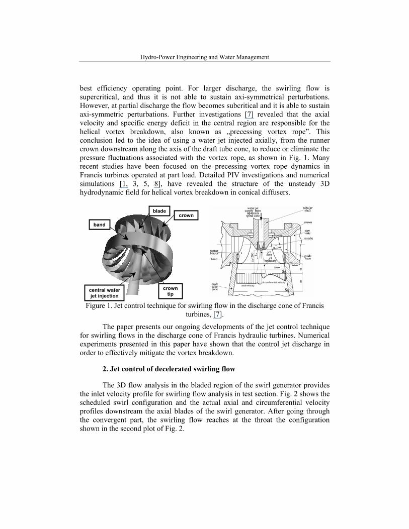
The 3D flow analysis in the bladed region of the swirl generator provides the inlet velocity profile for swirling flow analysis in test section. Fig. 2 shows the scheduled swirl configuration and the actual axial and circumferential velocity profiles downstream the axial blades of the swirl generator. After going through the convergent part, the swirling flow reaches at the throat the configuration shown in the second plot of Fig. 2.
central water jet injection
crown tip
crown
band
blade
Water Jet Control Technique for Swirling Flows in Francis Turbines Diffuser
Figure 2. Inlet velocity profile on the annular section of swirl generator (left). The circles correspond to the 3D flow simulation in the bladed region, and the dashed lines are the
axial/circumferential velocity profiles used for 2D axi-symmetric flow simulation. Swirling flow configuration at the throat (right).
The axi-symmetric turbulent flow model is employed for the present numerical investigations. The axial-symmetry assumption rends the problem two-dimensional, although there are four equations to solve corresponding to the continuity equation (1), axial (2), radial (3) and circumferential (4) momentum equations. A stress-omega turbulence model is used because of its ability to better capture the flow detachment as well as the swirling flow behavior. The above model is available in the FLUENT 6.3 commercial code.
( ) ( ) 0rz r
VV Vt z r rρ ρρ ρ∂ ∂ ∂+ + + =
∂ ∂ ∂ (1)
( ) ( ) ( )
( )
1 1
1 2 123
z z z r z
z z r
pV r V V r V Vt r z r r z
V V Vr V rr z z r r r z
ρ ρ ρ
µ µ
∂ ∂ ∂ ∂+ + = −
∂ ∂ ∂ ∂∂ ∂ ∂ ∂ ∂ + − ∇⋅ + + ∂ ∂ ∂ ∂ ∂
r (2)
( ) ( ) ( )
( ) ( )2
2
1 1
1 2 22 23 3
r z r r r
r r
pV r V V r V Vt r z r r r
V V Vr V Vr r r r r r
θ
ρ ρ ρ
µµ µ ρ
∂ ∂ ∂ ∂+ + = −
∂ ∂ ∂ ∂∂ ∂ + − ∇⋅ − + ∇⋅ + ∂ ∂
r r (3)
( ) ( ) ( )
32
1 1
1 1
z r
r
V r V V r V Vt r z r r
V V V Vr rr z z r r r r r
θ θ θ
θ θ θ
ρ ρ ρ
µ µ ρ
∂ ∂ ∂+ + =
∂ ∂ ∂∂ ∂ ∂ ∂ + − ∂ ∂ ∂ ∂
(4)
The axial and circumferential velocity profiles obtained from the 3D blade flow simulation, Fig. 2 are used as inlet conditions on the annular upstream section of the computational domain. Radial pressure equilibrium is used on the outlet section. Of course, the computational domain is considered only in a meridian half-plane.
Hydro-Power Engineering and Water Management
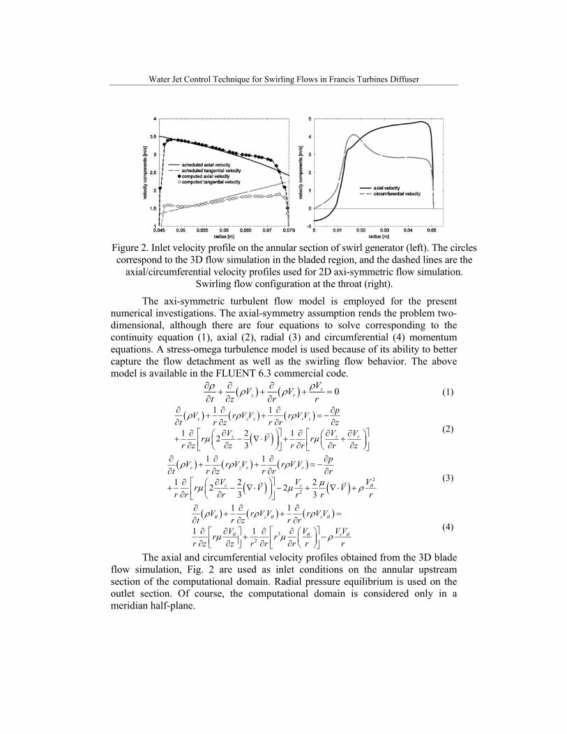
Figure 3. Streamline pattern for the test section. The control jet is represented as the
dark grey region, while the quasi-stagnant central region is shown in light grey.
Fig. 3 shows the flow pattern in test section, without and with control jet. The streamlines correspond to the inlet main swirling flow, and the blue region represents the control jet. The central quasi-stagnant region corresponding to the vortex breakdown is shown in red. When the control jet is switched-off, the main flow occupies an annular region near the wall, leaving a large stagnant region in the center. For the real 3D flow, the boundary of the central region is a vortex sheet which rolls-up in a precessing helical vortex. When a jet is injected along the axis, the central stagnant region is pushed downstream in the cone, and it is no-longer connected to the nozzle cone. This is the type of vortex breakdown computed by Keller et al. [2] for swirling flow in a diffuser. By further increasing the jet discharge, the central breakdown region leaves the cone and eventually develops in the cylindrical part of the diffuser. For large enough jet discharge, the vortex breakdown is eliminated completely.
On the other hand, the streamline pattern from Fig. 3 shows that as the control jet discharges increases the main flow begins to detach from the cone wall, and as the breakdown region is pushed further downstream the flow is fully detached from the cone wall. The flow eventually reattaches on the cylindrical pipe wall after leaving the cone. This conclusion is quantitatively supported by
Water Jet Control Technique for Swirling Flows in Francis Turbines Diffuser
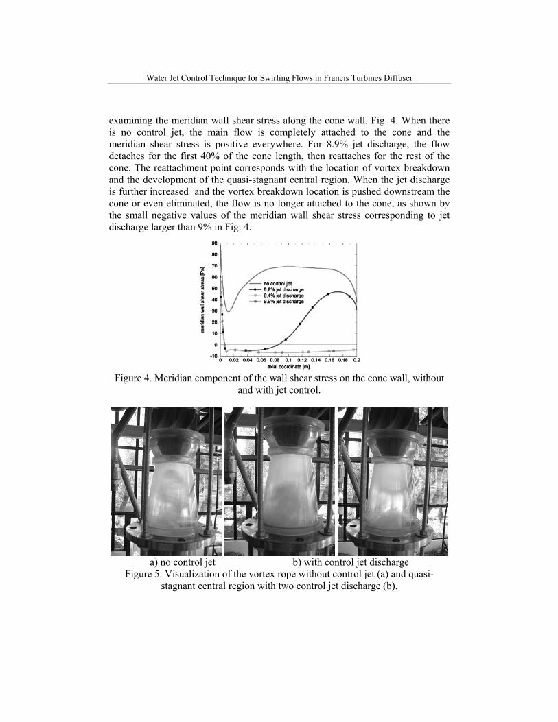
examining the meridian wall shear stress along the cone wall, Fig. 4. When there is no control jet, the main flow is completely attached to the cone and the meridian shear stress is positive everywhere. For 8.9% jet discharge, the flow detaches for the first 40% of the cone length, then reattaches for the rest of the cone. The reattachment point corresponds with the location of vortex breakdown and the development of the quasi-stagnant central region. When the jet discharge is further increased and the vortex breakdown location is pushed downstream the cone or even eliminated, the flow is no longer attached to the cone, as shown by the small negative values of the meridian wall shear stress corresponding to jet discharge larger than 9% in Fig. 4.
Figure 4. Meridian component of the wall shear stress on the cone wall, without
and with jet control.
a) no control jet b) with control jet discharge
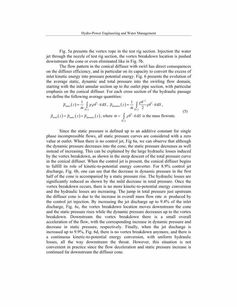
Figure 5. Visualization of the vortex rope without control jet (a) and quasi-stagnant central region with two control jet discharge (b).
Hydro-Power Engineering and Water Management
Fig. 5a presents the vortex rope in the test rig section. Injection the water jet through the nozzle of test rig section, the vortex breakdown location is pushed downstream the cone or even eliminated like in Fig. 5b.
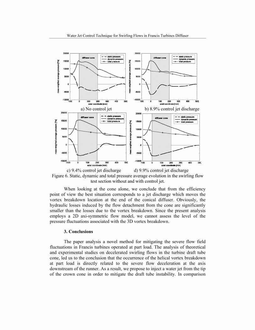
The flow pattern in the conical diffuser with swirl has direct consequences on the diffuser efficiency, and in particular on its capacity to convert the excess of inlet kinetic energy into pressure potential energy. Fig. 6 presents the evolution of the average static, dynamic and total pressure into the swirling flow domain, starting with the inlet annular section up to the outlet pipe section, with particular emphasis on the conical diffuser. For each cross section of the hydraulic passage we define the following average quantities:
( )( )
static1 d
S z
p z p V n Sm
ρ= ⋅∫r r
&, ( )
( )
2
dynamic1 d
2S z
Vp z V n Sm
ρ ρ= ⋅∫r r
&,
( ) ( ) ( )total static dynamicp z p z p z= + , where ( )
dS z
m V n Sρ= ⋅∫r r
& is the mass flowrate. (5)
Since the static pressure is defined up to an additive constant for single
phase incompressible flows, all static pressure curves are considered with a zero value at outlet. When there is no control jet, Fig 6a, we can observe that although the dynamic pressure decreases into the cone, the static pressure decreases as well instead of increasing. This can be explained by the large hydraulic losses induced by the vortex breakdown, as shown in the steep descent of the total pressure curve in the conical diffuser. When the control jet is present, the conical diffuser begins to fulfill its role of kinetic-to-potential energy converter. For 8.9% control jet discharge, Fig. 6b, one can see that the decrease in dynamic pressure in the first half of the cone is accompanied by a static pressure rise. The hydraulic losses are significantly reduced as shown by the mild decrease in total pressure. Once the vortex breakdown occurs, there is no more kinetic-to-potential energy conversion and the hydraulic losses are increasing. The jump in total pressure just upstream the diffuser cone is due to the increase in overall mass flow rate m& produced by the control jet injection. By increasing the jet discharge up to 9.4% of the inlet discharge, Fig. 6c, the vortex breakdown location moves downstream the cone and the static pressure rises while the dynamic pressure decreases up to the vortex breakdown. Downstream the vortex breakdown there is a small overall acceleration of the flow, with the corresponding increase in dynamic pressure and decrease in static pressure, respectively. Finally, when the jet discharge is increased up to 9.9%, Fig. 6d, there is no vortex breakdown anymore, and there is a continuous kinetic-to-potential energy conversion, with uniform hydraulic losses, all the way downstream the throat. However, this situation is not convenient in practice since the flow deceleration and static pressure increase is continued far downstream the diffuser cone.
Water Jet Control Technique for Swirling Flows in Francis Turbines Diffuser
a) No control jet b) 8.9% control jet discharge
c) 9.4% control jet discharge d) 9.9% control jet discharge
Figure 6. Static, dynamic and total pressure average evolution in the swirling flow test section without and with control jet.
When looking at the cone alone, we conclude that from the efficiency point of view the best situation corresponds to a jet discharge which moves the vortex breakdown location at the end of the conical diffuser. Obviously, the hydraulic losses induced by the flow detachment from the cone are significantly smaller than the losses due to the vortex breakdown. Since the present analysis employs a 2D axi-symmetric flow model, we cannot assess the level of the pressure fluctuations associated with the 3D vortex breakdown.
3. Conclusions
The paper analysis a novel method for mitigating the severe flow field fluctuations in Francis turbines operated at part load. The analysis of theoretical and experimental studies on decelerated swirling flows in the turbine draft tube cone, led us to the conclusion that the occurrence of the helical vortex breakdown at part load is directly related to the severe flow deceleration at the axis downstream of the runner. As a result, we propose to inject a water jet from the tip of the crown cone in order to mitigate the draft tube instability. In comparison

Hydro-Power Engineering and Water Management
with other solutions which address the same problem, the jet control of the flow is shown to eliminate the well known drawbacks while presenting the following main advantages: a) it successfully addresses directly the main cause of the flow instability, rather than the effects; b) it does not require geometrical modifications of the runner, and no other devices need to be installed in the draft tube; c) it is continuously adjustable according to the operating point, and it can be switched-off when it is not needed; d) the practical implementation is simple and robust; e) although a fraction of the discharge bypasses the bladed region, the overall turbine efficiency does not suffer thanks to the improvement in both runner and draft tube efficiencies when the jet is on.
Acknowledgements
The present research has been supported by the Romanian National University Research Council under consortium grant No. 33, „Vortex Dominated Flows and Applications”, by the Swiss National Science Foundation under the Joint Research Project IB7320-110942/1, and by the Romanian National Authority for Scientific Research through the CEEX-C2-M1-1185, C64/2006-2008 „iSMART-flow” project.
R E F E R E N C E S
[1]. F. Avellan, „Flow Investigation in a Francis Draft Tube: The FLINDT Project”, in Proceedings of the 20th IAHR Symposium on Hydraulic Machinery and Systems, Charlotte, Alabama, U.S.A., 2000, Paper DY-03.
[2]. J.J. Keller, W. Egli and R. Althaus, „Vortex Breakdown as a Fundamental Element of Vortex Dynamics”, in Journal of Applied Mathematics and Physics (ZAMP), vol. 39, 1988, pp. 404-440.
[3]. O. Kirschner and A. Ruprecht, „Vortex Rope Measurement in a Simplified Draft Tube”, in Proceedings of the 2nd IAHR International Meeting of the Workgroup on Cavitation and Dynamic Problems in Hydraulic Machinery and Systems, Scientific Bulletin of Politehnica University of Timisoara, Transaction on Mechanics, tom 52(66), no. 6., 2007, pp. 173-184.
[4]. A.T. McDonald, R.W. Fox and R.V. Van Dewoestine, “Effects of Swirling Inlet Flow on Pressure Recovery in Conical Diffusers”, in AIAA Journal, vol. 9, no. 10, 1971, pp. 2014-2018.
[5]. P. Stein, Miriam Sick, P. Doerfler, P. White and A. Braune, „Numerical Simulation of the Cavitating Draft Tube Vortex in a Francis Turbine”, in Proceedings of the 23rd IAHR Symposium on Hydraulic Machinery and Systems, 2006, Paper 228.
[6]. R. Susan-Resiga, G.D. Ciocan, I. Anton and F. Avellan, „Analysis of the Swirling Flow Downstream a Francis Turbine Runner”, in Journal of Fluids Engineering, vol. 128, 2006, pp.177-189.
[7]. R. Susan-Resiga, T.C. Vu, S. Muntean, G.D. Ciocan and B. Nennemann, „Jet Control of the Draft Tube Vortex Rope in Francis Turbines at Partial Discharge”, in Proceedings of the 23rd IAHR Symposium on Hydraulic Machinery and Systems, 2006, Paper 192.
[8]. T.C. Vu, B. Nennemann, G.D. Ciocan, Monica Sanda Iliescu, O. Braun and F. Avellan, „Experimental Study and Unsteady Simulation of the FLINDT Draft Tube Rotating Vortex Rope”, in Proceedings of the Hydro2004 Conference, 2004, FE-05-1175.