
Inducer and Centrifugal Pump Contributions to the ...
12
HAL Id: hal-01890063 https://hal.archives-ouvertes.fr/hal-01890063 Submitted on 8 Oct 2018 HAL is a multi-disciplinary open access archive for the deposit and dissemination of sci- entific research documents, whether they are pub- lished or not. The documents may come from teaching and research institutions in France or abroad, or from public or private research centers. L’archive ouverte pluridisciplinaire HAL, est destinée au dépôt et à la diffusion de documents scientifiques de niveau recherche, publiés ou non, émanant des établissements d’enseignement et de recherche français ou étrangers, des laboratoires publics ou privés. Inducer and Centrifugal Pump Contributions to the Rotordynamic Fluid Forces Acting on a Space Turbopump Giovanni Pace, Dario Valentini, Angelo Pasini, Lucio Torre, Ruzbeh Hadavandi, Luca D’agostino To cite this version: Giovanni Pace, Dario Valentini, Angelo Pasini, Lucio Torre, Ruzbeh Hadavandi, et al.. Inducer and Centrifugal Pump Contributions to the Rotordynamic Fluid Forces Acting on a Space Turbopump. 16th International Symposium on Transport Phenomena and Dynamics of Rotating Machinery, Apr 2016, Honolulu, United States. hal-01890063
-
Upload
khangminh22 -
Category
Documents
-
view
1 -
download
0
Transcript of Inducer and Centrifugal Pump Contributions to the ...
HAL Id: hal-01890063https://hal.archives-ouvertes.fr/hal-01890063
Submitted on 8 Oct 2018
HAL is a multi-disciplinary open accessarchive for the deposit and dissemination of sci-entific research documents, whether they are pub-lished or not. The documents may come fromteaching and research institutions in France orabroad, or from public or private research centers.
L’archive ouverte pluridisciplinaire HAL, estdestinée au dépôt et à la diffusion de documentsscientifiques de niveau recherche, publiés ou non,émanant des établissements d’enseignement et derecherche français ou étrangers, des laboratoirespublics ou privés.
Inducer and Centrifugal Pump Contributions to theRotordynamic Fluid Forces Acting on a Space
TurbopumpGiovanni Pace, Dario Valentini, Angelo Pasini, Lucio Torre, Ruzbeh
Hadavandi, Luca D’agostino
To cite this version:Giovanni Pace, Dario Valentini, Angelo Pasini, Lucio Torre, Ruzbeh Hadavandi, et al.. Inducer andCentrifugal Pump Contributions to the Rotordynamic Fluid Forces Acting on a Space Turbopump.16th International Symposium on Transport Phenomena and Dynamics of Rotating Machinery, Apr2016, Honolulu, United States. �hal-01890063�

Inducer and Centrifugal Pump Contributions to the Rotordynamic Fluid Forces Acting on a Space TurbopumpGiovanni Pace1*, Dario Valentini1, Angelo Pasini1, Lucio Torre2, Ruzbeh Hadavandi1, Luca d’Agostino3
ISROMAC 2016
International Symposium on
TransportPhenomena and
Dynamics of Rotating Machinery
Hawaii, Honolulu April 10-15, 2016
AbstractThe fluid induced rotordynamic forces acting on a whirling space turbopump composed
by an inducer and a radial impeller have been compared to the same forces measured on each single component of the turbomachine (i.e. on the inducer and on the radial impeller). The experimental campaign has been carried out in cold water at design and off- design conditions (80%, 100% and 120% of the design flow rate) both in non-cavitating and cavitating regimes. The paper illustrates the different trends of the rotordynamic forces on the axial and radial pumps and highlights their contributions on the overall turbomachine. At positive whirl ratios, the behavior of the inducer is dominant while, at negative ones, both the pumps show the same trends in such a way that the overall behavior is roughly the sum of each single component.
KeywordsRotordynamic — Radial Impeller — Inducer — Cavitation
1 Sitael S.p.A., Via Gherardesca 5, 56121 Pisa, Italy 2GMYS-Space, Via di Broccoletto, 55100 Lucca, Italy3 Department of Industrial and Civil Engineering, University of Pisa, Pisa, Italy*Corresponding author: [email protected]
1. INTRODUCTION The recent interest in low cost access to space
focuses on the development of innovative yet implementable, affordable and financially sustainable solutions enabling the delivery of nano- and micro- satellites to Low Earth Orbit (LEO).
To face this new challenge, chemical rocket propulsion and its derivative concepts will continue to play a central role, being the only viable technology capable of generating the relatively high levels of thrusts necessary for launch and most primary propulsion purposes in a large number of space missions.
In the development of small launchers powered by liquid rocket engines, the significant reduction of cost is currently pursued by a modular and clustering approach together with the reduction of complexity such as the introduction of electric motors powered by batteries for the actuation of the turbopumps [1].
However, propellant feed turbopumps are still an essential component of all primary propulsion concepts powered by Liquid Propellant Rocket Engines (LPREs). They typically comprise an axial pump (the inducer) and a radial pump (the radial impeller).
Rotordynamic forces, together with the flow instabilities possibly triggered by the occurrence of cavitation, are one of the universally recognized and most dangerous sources of vibrations in turbomachines [2,3,4,5]. These forces can affect the impeller itself, and all the components of the machine [6].
Even if steady and rotordynamic forces acting on
centrifugal pump impellers [4,7,8,9] and axial inducers [2,3,5,10,11,12] have already been extensively studied, the identification of their contributions on the rotordynamic fluid forces acting on the overall turbopump has not yet been investigated in great detail.
The present paper experimentally investigates the typical trends in the rotordynamic forces on a turbopump having a three bladed inducer and an unshrouded six bladed centrifugal pump by comparing them to the experimental results obtained on each single component of the machine, such as the inducer and the radial impeller.
The experimental test campaign has been carried out at the Cavitating Pump Rotordynamic Test Facility (CPRTF, see [13] for further information) at SITAEL (formerly ALTA). This closed loop test rig is specifically intended for the analysis of steady and unsteady fluid forces and moments acting on the impeller as a consequence of its whirl motion under cavitating or fully-wetted flow conditions, with special emphasis on the onset and development of lateral rotordynamic instabilities. The rotordynamic forces have been assessed at discrete values of the whirl ratio with the procedure proposed at Caltech [3,4,7] and with a special procedure, recently developed and validated at ALTA S.p.A. [11], that allows for measuring the continuous spectrum of rotordynamic forces as functions of the whirl-to-rotational speed ratio [11,14].
2. EXPERIMENTAL APPARATUSThe experimental activity reported in the present
paper has been carried out in SITAEL’s Cavitating Pump Rotordynamic Test Facility (CPRTF), illustrated

Inducer and Centrifugal Pump Contributions to the Rotordynamic Fluid Forces Acting on a Space Turbopump — 2 in Fig. 1 and specifically designed for characterizing the performance of cavitating and/or non-cavitating turbopumps in a wide variety of alternative configurations: axial, radial or mixed flow, with or without an inducer [13]. The facility exploits water as working fluid at temperatures up to 90 °C and is intended as a flexible apparatus readily adaptable to conduct experimental investigations on virtually any kind of fluid dynamic phenomena relevant to high performance turbopumps [13]. The pump housing and the inlet section can be easily adapted to host full-scale machines and inducers with different sizes and geometries used in space applications.
Fig. 1: The CPRTF lay-out in SITAEL S.p.A.
In its rotordynamic configuration, the facility instrumentation (transducers, optical devices, etc.) allows for the measurement of:
1. the pump inlet static pressure, 𝑝1 (cavitating regime, 𝜎)
2. the pump total pressure rise, Δ𝑝𝑡 (head coefficient, Ψ)
3. the volumetric flow rate on the discharge line, �� (flow coefficient, Φ)
4. the fluid temperature inside the main tank 5. the absolute angular position of the driving shaft 6. the absolute angular position of the eccentric
shaft which generates the whirl motion 7. the forces acting on the impeller The eccentricity generation is realized by means
of a two-shaft mechanism. The shafts are assembled one inside the other by means of a double eccentric mount and their eccentricity can be finely adjusted from 0 to 2 mm before each test by changing the relative angular position of the double eccentric mount. The whirl motion is generated by a brushless motor driving the external shaft, while the impeller rotation is imparted by connecting the internal shaft to the main motor by means of an isokinetic joint.
The forces and moments acting on the impeller are measured by means of a squirrel-cage rotating dynamometer connecting the shaft to the impeller in the test section. The rotating dynamometer is manufactured in one piece of phase hardening steel AISI 630 H1025 and consists of two flanges connected by four square cross-section posts acting
as flexible elements. The deformation of the posts is sensed by 40 semiconductor strain gauges arranged in 10 full Wheatstone bridges, which provide redundant measurements of the forces and moments acting on the impeller. The outputs of the Wheatstone bridges are routed out from the rotating force balance through a slip ring assembly. Each bridge is temperature self-compensated, with separate bipolar excitation and read-out for better reduction of cross-talking. The sizing of the sensing posts is the result of a trade-off between sensibility and structural resistance, operational stability and position control (stiffness). The measurement errors of the dynamometer in the rotating frame (𝑧 is the rotating axis direction) are reported in Table 1. Table 1: Maximum measurement errors given by the
rotating dynamometer.
Component Maximum Error 𝐹𝑥 ±1.4 𝑁 𝐹𝑦 ±1.1 𝑁 𝐹𝑧 ±4.2 𝑁
The rotating dynamometer is placed between the impeller and the driving shaft, thus the impeller is suspended. In order to reduce cantilever effects on the impeller shaft, the impeller has been recessed with respect to the optical access at the test section inlet. In this configuration, the impeller blades are contained within the “inlet duct”. A nominal clearance of 2 mm has been selected in order to accommodate sufficiently large whirl eccentricities for generating measurable rotordynamic forces without excessively increasing tip leakage effects.
Three different configurations have been tested: an inducer (named DAPROT3), a centrifugal pump (named VAMPIRE), and the VAMPIRE with the DAPROT3 upstream (named VAMPDAP).
DAPROT3 VAMPIRE VAMPDAP
Fig. 2: Cut-out drawing of the Cavitating Pump Rotordynamic Test Facility (CPRTF).
Test Articles The VAMPIRE pump, manufactured in 7075-T6
aluminum alloy, comprises a six-bladed unshrouded impeller (Fig. 3), a vaneless diffuser, and a single-spiral volute. The DAPROT3 high-head, tapered-hub, three-bladed inducer, is also manufactured in 7075-
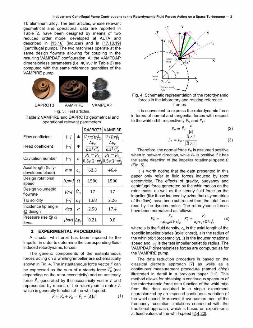
Inducer and Centrifugal Pump Contributions to the Rotordynamic Fluid Forces Acting on a Space Turbopump — 3 T6 aluminum alloy. The test articles, whose relevant geometrical and operational data are reported in Table 2, have been designed by means of two reduced order model developed at ALTA and described in [15,16] (inducer) and in [17,18,19] (centrifugal pump). The two machines operate at the same design flowrate allowing for coupling in the resulting VAMPDAP configuration. All the VAMPDAP dimensionless parameters (i.e. Φ, Ψ, 𝜎 in Table 2) are computed with the same reference quantities of the VAMPIRE pump.
DAPROT3 VAMPIRE VAMPDAPFig. 3: Test articles.
Table 2 VAMPIRE and DAPROT3 geometrical and operational relevant parameters.
DAPROT3 VAMPIRE Flow coefficient [--] Φ ��/𝜋Ω𝑟𝑇2
3 ��/Ω𝑟𝑇23
Head coefficient [--] Ψ Δ𝑝𝑡
𝜌Ω2𝑟𝑇22
Δ𝑝𝑡
𝜌Ω2𝑟𝑇22
Cavitation number [--] 𝜎 𝑝1 − 𝑝𝑣
0.5𝜌Ω2𝑟𝑇22
𝑝1 − 𝑝𝑣
0.5𝜌Ω2𝑟𝑇22
Axial length (fully-developed blade) mm 𝑐𝑎 63.5 46.4
Design rotational speed [rpm] Ω 1500 1500
Design volumetric flowrate [l/s] ��𝐷 17 17
Tip solidity [--] 𝜎𝑇 1.68 2.26 Incidence tip angle @ design deg 𝛼 2.58 17.4
Pressure rise @ 𝑐𝑙 =
2𝑚𝑚[bar] Δ𝑝𝑡 0.21 0.8
3. EXPERIMENTAL PROCEDUREA circular whirl orbit has been imposed to the
impeller in order to determine the corresponding fluid-induced rotordynamic forces.
The generic components of the instantaneous forces acting on a whirling impeller are schematically shown in Fig. 4. The instantaneous force vector �� can be expressed as the sum of a steady force 𝐹0
(not depending on the rotor eccentricity) and an unsteady force ��𝑅 generated by the eccentricity vector 𝜀 and represented by means of the rotordynamic matrix 𝑨which is generally function of the whirl speed:
�� = ��0 + ��𝑅 = ��0 + [𝑨]𝜀 (1)
Fig. 4: Schematic representation of the rotordynamic forces in the laboratory and rotating reference
frames. It is convenient to express the rotordynamic force
in terms of normal and tangential forces with respect to the whirl orbit, respectively 𝐹𝑁 and 𝐹𝑇:
𝐹𝑁 = ��𝑅 ⋅𝜀
|𝜀|(2)
𝐹𝑇 = ��𝑅 ⋅Ω ∧ ε
|Ω ∧ ε|(3)
Therefore, the normal force 𝐹𝑁 is assumed positive when in outward direction, while 𝐹𝑇 is positive if it has the same direction of the impeller rotational speed Ω(Fig. 5).
It is worth noting that the data presented in this paper only refer to fluid forces induced by rotor eccentricity. The effects of gravity, buoyancy and centrifugal force generated by the whirl motion on the rotor mass, as well as the steady fluid force on the impeller (like those induced by azimuthal asymmetries of the flow), have been subtracted from the total force read by the dynamometer. The rotordynamic forces have been normalized as follows:
𝐹𝑁∗ =
𝐹𝑁
𝜋𝜌𝑐𝑎𝜀Ω2𝑟𝑇22 𝐹𝑇
∗ =𝐹𝑇
𝜋𝜌𝑐𝑎𝜀Ω2𝑟𝑇22 (4)
where 𝜌 is the fluid density, 𝑐𝑎 is the axial length of the specific impeller blades (axial chord), 𝜀 is the radius of the whirl orbit (eccentricity), Ω is the inducer rotational speed and 𝑟𝑇2 is the test impeller outlet tip radius. The VAMPDAP dimensionless forces are computed as for the VAMPIRE pump.
The data reduction procedure is based on the classical discrete approach [7] as wells as a continuous measurement procedure (named chirp)illustrated in detail in a previous paper [11]. This method allows for obtaining a continuous spectrum of the rotordynamic force as a function of the whirl ratio from the data acquired in a single experiment characterized by an imposed continuous variation of the whirl speed. Moreover, it overcomes most of the frequency resolution limitations connected with the traditional approach, which is based on experiments at fixed values of the whirl speed [2,4,20].
X
Y
W
0W
0w
w
e
vO
iO
Orbitcenter
Circular whirlOrbit
Inducercenter
y
x
T N
X
Y
FR
FY
FX
Fy
FxFT
FN
F0
F
0
0
Inducer and Centrifugal Pump Contributions to the Rotordynamic Fluid Forces Acting on a Space Turbopump — 4
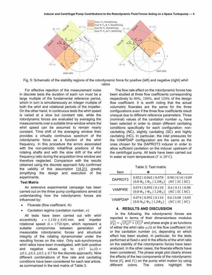
Fig. 5: Schematic of the stability regions of the rotordynamic force for positive (left) and negative (right) whirl
ratios
For effective rejection of the measurement noise in discrete tests the duration of each run must be a large multiple of the fundamental reference period, which in turn is simultaneously an integer multiple of both the whirl and rotational periods of the impeller. On the other hand, in continuous tests the whirl speed is varied at a slow but constant rate, while the rotordynamic forces are evaluated by averaging the measurements over a suitable time-window where the whirl speed can be assumed to remain nearly constant. Time shift of the averaging window then provides a virtually continuous spectrum of the rotordynamic force as a function of the whirl frequency. In this procedure the errors associated with the non-periodic initial/final positions of the rotating shafts and with the slow drift of the whirl frequency ratio during the acquisition time window are therefore neglected. Comparison with the results obtained using the discrete approach fully confirmed the validity of this assumption [14,21], greatly simplifying the design and execution of the experiments. Test Matrix
An extensive experimental campaign has been carried out on the three pump configurations aimed at understanding how the rotordynamic forces are influenced by: Flowrate (flow coefficient, Φ) Cavitation regime (cavitation number, 𝜎)
All tests have been carried out with whirl eccentricity 𝜀 = 1.130 ± 0.05 mm and impeller rotational speed Ω = 1750 rpm, which represent a suitable compromise between generation of measurable rotordynamic forces and structural integrity of the rotating dynamometer under the resulting forces on the rotor. Only sub-synchronous whirl ratios have been investigated, with both positive and negative values up to ±0.7 (𝜔/Ω =±0.1, ±0.3, ±0.5 ± 0.7 for the discrete approach). Nine different combinations of flow rate and cavitating conditions have been considered for each test article, as summarized in the test matrix of Table 3.
The flow rate effect on the rotordynamic forces has been studied at three flow coefficients corresponding respectively to 80%, 100%, and 120% of the design flow coefficient. It is worth noting that the actual volumetric flowrates are the same for the three configurations even if the three flow coefficients result unequal due to different reference parameters. Three (nominal) values of the cavitation number 𝜎𝑁 have been selected in order to obtain different cavitating conditions specifically for each configuration: non-cavitating (NC), slightly cavitating (SC) and highly cavitating (HC). In particular, the inlet pressures for the VAMPDAP configuration are the same as the ones chosen for the DAPROT3 inducer in order to allow sufficient cavitation on the inducer upstream of the centrifugal pump. All tests have been carried out in water at room temperature (𝑇 ≅ 20°𝐶).
Table 3: Test matrix.
Item 𝚽 𝝈𝑵
DAPROT3 0.052 | 0.065 | 0.078 (0.8 Φ𝐷 | Φ𝐷 | 1.2Φ𝐷)
0.98 | 0.14 | 0.09 (𝑁𝐶 | 𝑆𝐶 | 𝐻𝐶)
VAMPIRE 0.074 | 0.092 | 0.110 (0.8 Φ𝐷 | Φ𝐷 | 1.2Φ𝐷)
0.6 | 0.11 | 0.08 (𝑁𝐶 | 𝑆𝐶 | 𝐻𝐶)
VAMPDAP 0.074 | 0.092 | 0.110 (0.8 Φ𝐷| Φ𝐷 | 1.2Φ𝐷)
0.6 | 0.08 | 0.05 (𝑁𝐶 | 𝑆𝐶 | 𝐻𝐶)
4. RESULTS AND DISCUSSION In the following, the rotordynamic forces are
reported in terms of their dimensionless modulus |𝐹𝑅
∗| = √(𝐹𝑁∗ )2 + (𝐹𝑇
∗)2 and phase angle 𝜙 as functions of either the whirl ratio 𝜔/Ω or the flow coefficient (Φ) or the cavitation number (σ), depending on which effect has been studied. In particular, for the tests performed at fixed σ and Φ the effects of the whirl ratio on the stability of the rotordynamic forces have been analyzed. In the other cases, the flowrate effects have been considered. The phase angle plot clearly shows the effects of the two components of the rotordynamic force (𝐹𝑁
∗ and 𝐹𝑇∗) on the pump whirl motion by using
different colors. The colors highlight the
Zone III: FN DestabilizingZone IV: FN & FT Stabilizing
Zone I: FT DestabilizingZone II: FN & FT Destabilizing
Ωϕ
Φ=270 Φ=360
Φ=90 Φ=180
ω>0X
Y
whirl orbit
Ωϕ
Φ=270 Φ=360
Φ=90 Φ=180
ω<0
X
Y
whirl orbit

Inducer and Centrifugal Pump Contributions to the Rotordynamic Fluid Forces Acting on a Space Turbopump — 5 stabilizing/destabilizing region of either one or both of the components of the rotordynamic force. The phase angle is defined accordingly to Fig. 5. Only the most relevant results are reported for each pump according to the procedures already shown: the discrete tests results and the continuous ones are respectively shown by individual markers and lines. Since the forces are dimensionless by means of different geometrical parameters, their magnitudes are not directly comparable.
The results of the tests at varying the whirl ratio are shown in Fig. 6, Fig. 7, and Fig. 8 respectively for the DAPROT3, the VAMPIRE and the VAMPDAP. Trends in the Rotordynamic Force on the DAPROT3
The results shown in Fig. 6 clearly point out that the rotordynamic forces are not significantly affected by cavitation at the investigated cavitation numbers (all far from breakdown conditions). This is particularly true for the lowest flow rate tested where the curves are everywhere superimposed. Higher flow rates clearly show some departure between the curves, especially for the lowest σ. In all the tested conditions the behavior is quite similar, but not identical. At highly negative 𝜔/Ω the force behaves in a quadratic way. After reaching a minimum, the force increases and reaches a maximum for positive 𝜔/Ω and then decreases to another minimum. For increasing flowrates, the minima and the maxima shift from higher to lower whirl ratios, and the maxima tend to decrease in magnitude. The maximum of the rotordynamic force can be explained by means of a possible coupling between the whirl motion and the backflow structure, which is more relevant at lower flowrates and occurs because of the high clearance needed for the tests execution. The backflow structure depends on the flowrate and rotates around the machine with a velocity, which is a positive fraction of the impeller main rotational speed. Therefore, the reduction of the rotordynamic force maximum at flow rate increase can be so explained.
In all the cases the force for very low 𝜔/Ω is outward with the tendency to increase the inducer orbit radius but with a tangential component which opposes to whirl motion. As the whirl ratio changes from negative to positive values the rotordynamic force direction remains unchanged, but the effect on the whirl motion changes. In particular, the effect concerns the tangential component, whereas the normal component is still inward and so stabilizing. As the 𝜔/Ω increases the behavior is different depending on the flow rate. At very low flow rates the effects concern mostly the tangential component whose behavior changes from stabilizing to destabilizing several times, whereas the normal component shows always an inward direction. At increasing flow coefficient, also the normal component is affected by the whirl ratio as well as by cavitation. The explanation
of the observed behavior is not so simple. Indeed, the magnitude and the direction of the whirl motion affect the flow pressure distribution in the clearance and, in turn, the forces acting on the impeller. Trends in the Rotordynamic Force on the VAMPIRE
The behavior of the VAMPIRE impeller is different w.r.t. the inducer especially at positive whirl ratios. The trend at negative 𝜔/Ω is the classical one characterized by a parabolic behavior which shows its minimum at almost the null whirl ratio. At positive 𝜔/Ω the trend is almost linear and no particular differences are visible in the magnitude of the force at varying the cavitation number. The trend of the VAMPIRE resembles the inducer at very low whirl ratios with a destabilizing normal component whereas the tangential component tends to slow down the whirl motion. For positive whirl ratios the behavior of the pump is almost the same per each flowrate: at increasing whirl ratios the rotordynamic force rotates clockwise (see Fig. 5). The rotation is more significant increasing both cavitation and flow rate. At the highest tested Φ, both the normal and tangential rotordynamic components are destabilizing in cavitating condition at high whirl ratios. Anyway, in the performed cavitation has not significantly affected the amplitude of the rotordynamic forces. Trends in the Rotordynamic Force on the VAMPDAP
The behavior of the overall pump (Fig. 8) is different to the one recorded for the inducer and pump alone, even if some trends are similar to those observed also in one or both the other pumps. The trend shown at negative whirl ratios is almost parabolic like in the previous cases. The behavior at positive whirl ratios looks very influenced by the inducer dynamics and a maximum and minima are evident. The dimensionless parameters used for the VAMPDAP and the VAMPIRE are the same and so the forces magnitude can be easily compared. However, the forces for the cavitating conditions cannot be directly compared between the VAMPIRE and the VAMPDAP, because the tested cavitating conditions correspond to those tested for the inducer, given that it has not been possible to let the centrifugal pump cavitate with the inducer assembled upstream. The forces acting on the VAMPDAP are much higher than those experienced by the VAMPIRE. This is especially true for very negative whirl ratios, where the forces are even almost 4 times those recorded for the VAMPIRE. At positive whirl ratios, the forces acting on the VAMPDAP are still higher than on the VAMPIRE, but the difference is less evident. The behavior of the rotordynamic components is quite similar to that shown in the VAMPIRE at negative whirl ratios, but for positive whirl ratios the behavior seems to be more influenced by the inducer.

Inducer and Centrifugal Pump Contributions to the Rotordynamic Fluid Forces Acting on a Space Turbopump — 6
Fig. 6: Continuous and discrete tests: effect of the flow coefficient Φ on 𝐹𝑁
∗ , 𝐹𝑇∗, |𝐹𝑅
∗|, and 𝜙 at different cavitation numbers for DAPROT3.
|FR*|
w/W
DAPROT3 W=1750 rpm
-1 -0.8 -0.6 -0.4 -0.2 0 0.2 0.4 0.6 0.8 10
0.2
0.4
0.6
0.8
1
1.2
1.4
1.6
1.8
2
=0.0905, =0.052, T=20°C
=0.1385, =0.052, T=20°C
=0.9786, =0.052, T=20°C
w/W
DAPROT3 W=1750 rpm
-1 -0.8 -0.6 -0.4 -0.2 0 0.2 0.4 0.6 0.8 10
50
100
150
200
250
300
350 Zone I: FT DESTAB.
Zone II: FT & FN DESTAB.
Zone III: FN DESTAB.
Zone IV: FN & FT STABIL.
=0.0905, =0.052, T=20°C
=0.1385, =0.052, T=20°C
=0.9786, =0.052, T=20°C
Zone I
Zone IV
Zone III
Zone III
Zone IV
Zone I
Zone II
|FR*|
w/W
DAPROT3 W=1750 rpm
-1 -0.8 -0.6 -0.4 -0.2 0 0.2 0.4 0.6 0.8 10
0.2
0.4
0.6
0.8
1
1.2
1.4
1.6
1.8
2
=0.0902, =0.065, T=20°C
=0.1381, =0.065, T=20°C
=0.9823, =0.065, T=20°C
w/W
DAPROT3 W=1750 rpm
-1 -0.8 -0.6 -0.4 -0.2 0 0.2 0.4 0.6 0.8 10
50
100
150
200
250
300
350 Zone I: FT DESTAB.
Zone II: FT & FN DESTAB.
Zone III: FN DESTAB.
Zone IV: FN & FT STABIL.
=0.0902, =0.065, T=20°C
=0.1381, =0.065, T=20°C
=0.9823, =0.065, T=20°C
Zone I
Zone IV
Zone III
Zone III
Zone IV
Zone I
Zone II
|FR*|
w/W
DAPROT3 W=1750 rpm
-1 -0.8 -0.6 -0.4 -0.2 0 0.2 0.4 0.6 0.8 10
0.2
0.4
0.6
0.8
1
1.2
1.4
1.6
1.8
2
=0.0886, =0.078, T=20°C
=0.1354, =0.078, T=20°C
=0.9759, =0.078, T=20°C
w/W
DAPROT3 W=1750 rpm
-1 -0.8 -0.6 -0.4 -0.2 0 0.2 0.4 0.6 0.8 10
50
100
150
200
250
300
350 Zone I: FT DESTAB.
Zone II: FT & FN DESTAB.
Zone III: FN DESTAB.
Zone IV: FN & FT STABIL.
=0.0886, =0.078, T=20°C
=0.1354, =0.078, T=20°C
=0.9759, =0.078, T=20°C
Zone I
Zone IV
Zone III
Zone III
Zone IV
Zone I
Zone II

Inducer and Centrifugal Pump Contributions to the Rotordynamic Fluid Forces Acting on a Space Turbopump — 7
Fig. 7: Continuous and discrete tests: effect of the flow coefficient Φ on 𝐹𝑁
∗ , 𝐹𝑇∗, |𝐹𝑅
∗|, and 𝜙 at different cavitation numbers for VAMPIRE.
|FR*|
w/W
VAMPIRE W=1750 rpm
-1 -0.8 -0.6 -0.4 -0.2 0 0.2 0.4 0.6 0.8 10
0.2
0.4
0.6
0.8
1
1.2
1.4
1.6
1.8
2
=0.0808, =0.074, T=20°C
=0.1098, =0.074, T=20°C
=0.5993, =0.074, T=20°C
w/W
VAMPIRE W=1750 rpm
-1 -0.8 -0.6 -0.4 -0.2 0 0.2 0.4 0.6 0.8 10
50
100
150
200
250
300
350 Zone I: FT DESTAB.
Zone II: FT & FN DESTAB.
Zone III: FN DESTAB.
Zone IV: FN & FT STABIL.
=0.0808, =0.074, T=20°C
=0.1098, =0.074, T=20°C
=0.5993, =0.074, T=20°C
Zone II
Zone I
Zone IV
Zone III
Zone IV
Zone I
Zone II
|FR*|
w/W
VAMPIRE W=1750 rpm
-1 -0.8 -0.6 -0.4 -0.2 0 0.2 0.4 0.6 0.8 10
0.2
0.4
0.6
0.8
1
1.2
1.4
1.6
1.8
2
=0.0803, =0.093, T=20°C
=0.1094, =0.093, T=20°C
=0.5995, =0.093, T=20°C
w/W
VAMPIRE W=1750 rpm
-1 -0.8 -0.6 -0.4 -0.2 0 0.2 0.4 0.6 0.8 10
50
100
150
200
250
300
350Zone I: FT DESTAB.
Zone II: FT & FN DESTAB.
Zone III: FN DESTAB.
Zone IV: FN & FT STABIL.
=0.0803, =0.093, T=20°C
=0.1094, =0.093, T=20°C
=0.5995, =0.093, T=20°C
Zone II
Zone I
Zone IV
Zone III
Zone IV
Zone I
Zone II
|FR*|
w/W
VAMPIRE W=1750 rpm
-1 -0.8 -0.6 -0.4 -0.2 0 0.2 0.4 0.6 0.8 10
0.2
0.4
0.6
0.8
1
1.2
1.4
1.6
1.8
2
=0.0798, =0.111, T=20°C
=0.1095, =0.111, T=20°C
=0.5971, =0.111, T=20°C
w/W
VAMPIRE W=1750 rpm
-1 -0.8 -0.6 -0.4 -0.2 0 0.2 0.4 0.6 0.8 10
50
100
150
200
250
300
350Zone I: FT DESTAB.
Zone II: FT & FN DESTAB.
Zone III: FN DESTAB.
Zone IV: FN & FT STABIL.
=0.0798, =0.111, T=20°C
=0.1095, =0.111, T=20°C
=0.5971, =0.111, T=20°C
Zone II
Zone I
Zone IV
Zone III
Zone IV
Zone I
Zone II
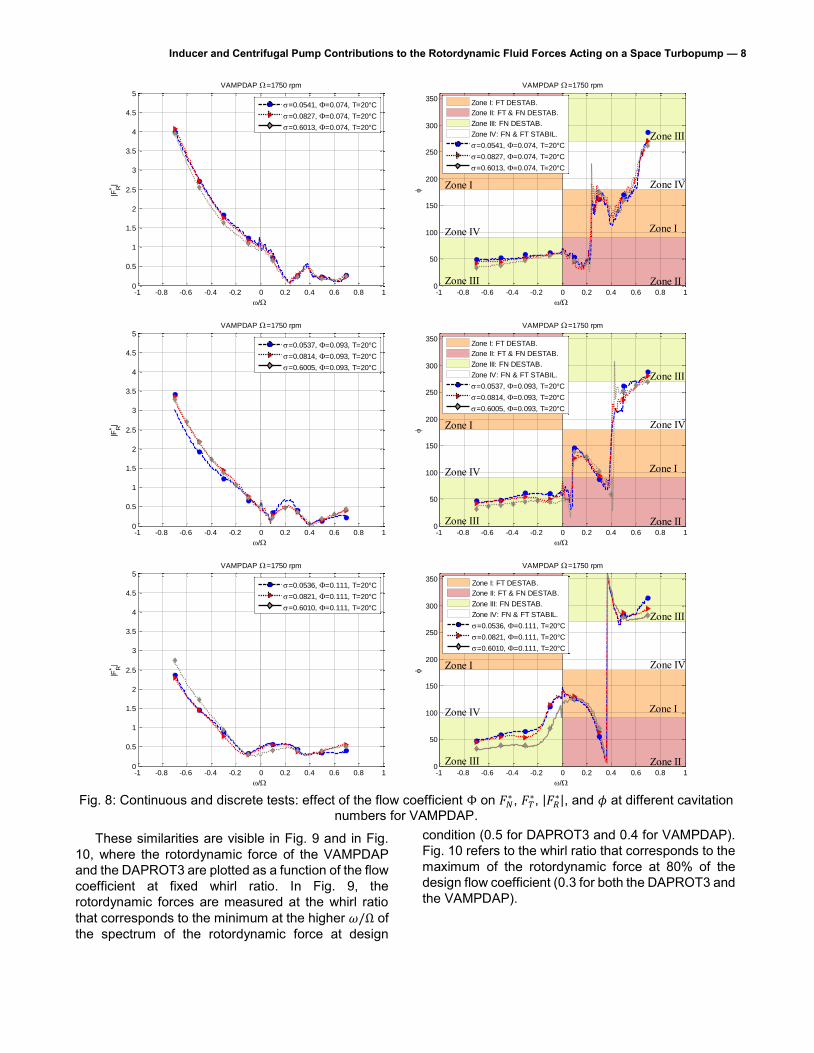
Inducer and Centrifugal Pump Contributions to the Rotordynamic Fluid Forces Acting on a Space Turbopump — 8
Fig. 8: Continuous and discrete tests: effect of the flow coefficient Φ on 𝐹𝑁
∗ , 𝐹𝑇∗, |𝐹𝑅
∗|, and 𝜙 at different cavitation numbers for VAMPDAP.
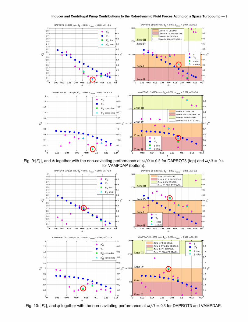
These similarities are visible in Fig. 9 and in Fig. 10, where the rotordynamic force of the VAMPDAP and the DAPROT3 are plotted as a function of the flow coefficient at fixed whirl ratio. In Fig. 9, the rotordynamic forces are measured at the whirl ratio that corresponds to the minimum at the higher 𝜔/Ω of the spectrum of the rotordynamic force at design
condition (0.5 for DAPROT3 and 0.4 for VAMPDAP). Fig. 10 refers to the whirl ratio that corresponds to the maximum of the rotordynamic force at 80% of the design flow coefficient (0.3 for both the DAPROT3 and the VAMPDAP).
|FR*|
w/W
VAMPDAP W=1750 rpm
-1 -0.8 -0.6 -0.4 -0.2 0 0.2 0.4 0.6 0.8 10
0.5
1
1.5
2
2.5
3
3.5
4
4.5
5
=0.0541, =0.074, T=20°C
=0.0827, =0.074, T=20°C
=0.6013, =0.074, T=20°C
w/W
VAMPDAP W=1750 rpm
-1 -0.8 -0.6 -0.4 -0.2 0 0.2 0.4 0.6 0.8 10
50
100
150
200
250
300
350Zone I: FT DESTAB.
Zone II: FT & FN DESTAB.
Zone III: FN DESTAB.
Zone IV: FN & FT STABIL.
=0.0541, =0.074, T=20°C
=0.0827, =0.074, T=20°C
=0.6013, =0.074, T=20°C
Zone I
Zone IV
Zone III
Zone IV
Zone I
Zone II
Zone III
|FR*|
w/W
VAMPDAP W=1750 rpm
-1 -0.8 -0.6 -0.4 -0.2 0 0.2 0.4 0.6 0.8 10
0.5
1
1.5
2
2.5
3
3.5
4
4.5
5
=0.0537, =0.093, T=20°C
=0.0814, =0.093, T=20°C
=0.6005, =0.093, T=20°C
w/W
VAMPDAP W=1750 rpm
-1 -0.8 -0.6 -0.4 -0.2 0 0.2 0.4 0.6 0.8 10
50
100
150
200
250
300
350Zone I: FT DESTAB.
Zone II: FT & FN DESTAB.
Zone III: FN DESTAB.
Zone IV: FN & FT STABIL.
=0.0537, =0.093, T=20°C
=0.0814, =0.093, T=20°C
=0.6005, =0.093, T=20°C
Zone I
Zone IV
Zone III
Zone III
Zone IV
Zone I
Zone II
|FR*|
w/W
VAMPDAP W=1750 rpm
-1 -0.8 -0.6 -0.4 -0.2 0 0.2 0.4 0.6 0.8 10
0.5
1
1.5
2
2.5
3
3.5
4
4.5
5
=0.0536, =0.111, T=20°C
=0.0821, =0.111, T=20°C
=0.6010, =0.111, T=20°C
w/W
VAMPDAP W=1750 rpm
-1 -0.8 -0.6 -0.4 -0.2 0 0.2 0.4 0.6 0.8 10
50
100
150
200
250
300
350Zone I: FT DESTAB.
Zone II: FT & FN DESTAB.
Zone III: FN DESTAB.
Zone IV: FN & FT STABIL.
=0.0536, =0.111, T=20°C
=0.0821, =0.111, T=20°C
=0.6010, =0.111, T=20°C
Zone I
Zone IV
Zone III
Zone IV
Zone I
Zone II
Zone III
Inducer and Centrifugal Pump Contributions to the Rotordynamic Fluid Forces Acting on a Space Turbopump — 9
Fig. 9:|𝐹𝑅
∗|, and 𝜙 together with the non-cavitating performance at 𝜔 𝛺⁄ = 0.5 for DAPROT3 (top) and 𝜔 𝛺⁄ = 0.4 for VAMPDAP (bottom).
Fig. 10: |𝐹𝑅
∗|, and 𝜙 together with the non-cavitating performance at 𝜔 𝛺⁄ = 0.3 for DAPROT3 and VAMPDAP.
|FR*
|
DAPROT3, W=1750 rpm, D = 0.065,
mean = 1.089, w/W=0.5
0 0.01 0.02 0.03 0.04 0.05 0.06 0.07 0.08 0.09 0.10
0.1
0.2
0.3
0.4
0.5
0.6
0.7
0.8
0.9
1
1.1
1.2
1.3
1.4
1.5
1.6
1.7
1.8
1.9
2
0 0.01 0.02 0.03 0.04 0.05 0.06 0.07 0.08 0.09 0.10
0.1
0.2
0.3
0.4
0.5
0.6
0.7
0.8
0.9
1
T
|FR*|
T
|FR*| disc
|FR*| chirp
DAPROT3, W=1750 rpm, D = 0.065,
mean = 1.089, w/W=0.5
0 0.01 0.02 0.03 0.04 0.05 0.06 0.07 0.08 0.09 0.10
90
180
270
360
0 0.01 0.02 0.03 0.04 0.05 0.06 0.07 0.08 0.09 0.10
0.1
0.2
0.3
0.4
0.5
0.6
0.7
0.8
0.9
1
T
T
disc
chirp
Zone I: FT DESTAB.
Zone II: FT & FN DESTAB.
Zone III: FN DESTAB.
Zone IV: FN & FT STABIL.Zone III
Zone I
Zone II
Zone IV
|FR*|
VAMPDAP, W=1750 rpm, D = 0.092,
mean = 0.591, w/W=0.4
0 0.02 0.04 0.06 0.08 0.1 0.12 0.140
0.2
0.4
0.6
0.8
1
1.2
1.4
1.6
1.8
2
0 0.02 0.04 0.06 0.08 0.1 0.12 0.140
0.1
0.2
0.3
0.4
0.5
0.6
0.7
0.8
0.9
1
T
|FR* |
T
|FR* | comp disc
|FR* | comp chirp
VAMPDAP, W=1750 rpm, D = 0.092,
mean = 0.591, w/W=0.4
0 0.02 0.04 0.06 0.08 0.1 0.12 0.140
90
180
270
360
0 0.02 0.04 0.06 0.08 0.1 0.12 0.140
0.1
0.2
0.3
0.4
0.5
0.6
0.7
0.8
0.9
1
T
T
disc
chirp
Zone I: FT DESTAB.
Zone II: FT & FN DESTAB.
Zone III: FN DESTAB.
Zone IV: FN & FT STABIL.
Zone III
Zone IV
Zone I
Zone II
|FR*
|
DAPROT3, W=1750 rpm, D = 0.065,
mean = 1.093, w/W=0.3
0 0.01 0.02 0.03 0.04 0.05 0.06 0.07 0.08 0.09 0.10
0.1
0.2
0.3
0.4
0.5
0.6
0.7
0.8
0.9
1
1.1
1.2
1.3
1.4
1.5
1.6
1.7
1.8
1.9
2
0 0.01 0.02 0.03 0.04 0.05 0.06 0.07 0.08 0.09 0.10
0.1
0.2
0.3
0.4
0.5
0.6
0.7
0.8
0.9
1
T
|FR*|
T
|FR*| disc
|FR*| chirp
DAPROT3, W=1750 rpm, D = 0.065,
mean = 1.093, w/W=0.3
0 0.01 0.02 0.03 0.04 0.05 0.06 0.07 0.08 0.09 0.10
90
180
270
360
0 0.01 0.02 0.03 0.04 0.05 0.06 0.07 0.08 0.09 0.10
0.1
0.2
0.3
0.4
0.5
0.6
0.7
0.8
0.9
1
T
T
disc
chirp
Zone I: FT DESTAB.
Zone II: FT & FN DESTAB.
Zone III: FN DESTAB.
Zone IV: FN & FT STABIL.Zone III
Zone IV
Zone I
Zone II
|FR*|
VAMPDAP, W=1750 rpm, D = 0.092,
mean = 0.589, w/W=0.3
0 0.02 0.04 0.06 0.08 0.1 0.12 0.140
0.2
0.4
0.6
0.8
1
1.2
1.4
1.6
1.8
2
0 0.02 0.04 0.06 0.08 0.1 0.12 0.140
0.1
0.2
0.3
0.4
0.5
0.6
0.7
0.8
0.9
1
T
|FR* |
T
|FR* | comp disc
|FR* | comp chirp
VAMPDAP, W=1750 rpm, D = 0.092,
mean = 0.589, w/W=0.3
0 0.02 0.04 0.06 0.08 0.1 0.12 0.140
90
180
270
360
0 0.02 0.04 0.06 0.08 0.1 0.12 0.140
0.1
0.2
0.3
0.4
0.5
0.6
0.7
0.8
0.9
1
T
T
disc
chirp
Zone I: FT DESTAB.
Zone II: FT & FN DESTAB.
Zone III: FN DESTAB.
Zone IV: FN & FT STABIL.Zone III
Zone IV
Zone I
Zone II
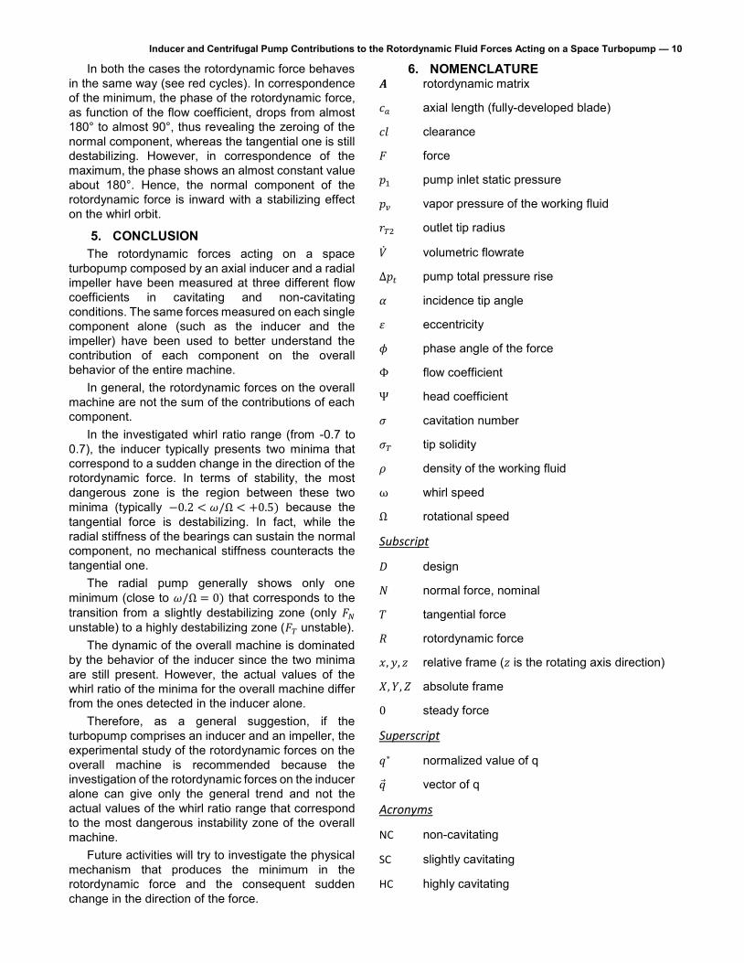
Inducer and Centrifugal Pump Contributions to the Rotordynamic Fluid Forces Acting on a Space Turbopump — 10 In both the cases the rotordynamic force behaves
in the same way (see red cycles). In correspondence of the minimum, the phase of the rotordynamic force, as function of the flow coefficient, drops from almost 180° to almost 90°, thus revealing the zeroing of the normal component, whereas the tangential one is still destabilizing. However, in correspondence of the maximum, the phase shows an almost constant value about 180°. Hence, the normal component of the rotordynamic force is inward with a stabilizing effect on the whirl orbit.
5. CONCLUSION The rotordynamic forces acting on a space
turbopump composed by an axial inducer and a radial impeller have been measured at three different flow coefficients in cavitating and non-cavitating conditions. The same forces measured on each single component alone (such as the inducer and the impeller) have been used to better understand the contribution of each component on the overall behavior of the entire machine.
In general, the rotordynamic forces on the overall machine are not the sum of the contributions of each component.
In the investigated whirl ratio range (from -0.7 to 0.7), the inducer typically presents two minima that correspond to a sudden change in the direction of the rotordynamic force. In terms of stability, the most dangerous zone is the region between these two minima (typically −0.2 < 𝜔/Ω < +0.5) because the tangential force is destabilizing. In fact, while the radial stiffness of the bearings can sustain the normal component, no mechanical stiffness counteracts the tangential one.
The radial pump generally shows only one minimum (close to 𝜔/Ω = 0) that corresponds to the transition from a slightly destabilizing zone (only 𝐹𝑁 unstable) to a highly destabilizing zone (𝐹𝑇 unstable).
The dynamic of the overall machine is dominated by the behavior of the inducer since the two minima are still present. However, the actual values of the whirl ratio of the minima for the overall machine differ from the ones detected in the inducer alone.
Therefore, as a general suggestion, if the turbopump comprises an inducer and an impeller, the experimental study of the rotordynamic forces on the overall machine is recommended because the investigation of the rotordynamic forces on the inducer alone can give only the general trend and not the actual values of the whirl ratio range that correspond to the most dangerous instability zone of the overall machine.
Future activities will try to investigate the physical mechanism that produces the minimum in the rotordynamic force and the consequent sudden change in the direction of the force.
6. NOMENCLATURE 𝑨 rotordynamic matrix
𝑐𝑎 axial length (fully-developed blade)
𝑐𝑙 clearance
𝐹 force
𝑝1 pump inlet static pressure
𝑝𝑣 vapor pressure of the working fluid
𝑟𝑇2 outlet tip radius
�� volumetric flowrate
Δ𝑝𝑡 pump total pressure rise
𝛼 incidence tip angle
𝜀 eccentricity
𝜙 phase angle of the force
Φ flow coefficient
Ψ head coefficient
𝜎 cavitation number
𝜎𝑇 tip solidity
𝜌 density of the working fluid
ω whirl speed
Ω rotational speed
Subscript
𝐷 design
𝑁 normal force, nominal
𝑇 tangential force
𝑅 rotordynamic force
𝑥, 𝑦, 𝑧 relative frame (𝑧 is the rotating axis direction)
𝑋, 𝑌, 𝑍 absolute frame
0 steady force
Superscript
𝑞∗ normalized value of q
�� vector of q
Acronyms
NC non-cavitating
SC slightly cavitating
HC highly cavitating

Inducer and Centrifugal Pump Contributions to the Rotordynamic Fluid Forces Acting on a Space Turbopump — 11 7. ACKNOWLEDGEMENTS
The present work has been supported by the European Space Agency under Contract No. 4000102585/10/NL/Sfe. The authors would like to express their gratitude to Dr. Giorgio Saccoccia, ESA-ESTEC, Nordwijk, The Netherlands, for his constant attention and encouragement.
8. REFERENCES [1] Rocket Lab Website. [Online].
http://www.rocketlabusa.com/ [2] Bhattacharyya A., Acosta A.J., Brennen C.E., and
Caughey T.K., 1997, "Rotordynamic Forces in Cavitating Inducers", J. Fluids Eng., 119(4), pp. 768-774. DOI: 10.1115/1.2819496
[3] Bhattacharyya A., 1994, "Internal Flows and Force Matrices in Axial Flow Inducers", Ph.D. Thesis, California Institute of Technology, Pasadena.
[4] Franz R.J., 1989, "Experimental investigation of the effect of cavitation on the rotordynamic forces on a whirling centrifugal pump impeller", Ph.D. Thesis, California Institute of Technology, Pasadena.
[5] Rosenmann W., 1965, "Experimental Investigations of Hydrodynamically Induced Shaft Forces With a Three Bladed Inducer," in ASME Symp. on Cavitation in Fluid Machinery, pp. 172-195.
[6] Ehrich F. and Childs S.D., 1984, "Self-Excited Vibrations in High Performance Turbomachinery", Mechanical Engineering, pp. 66-79.
[7] Jery B., 1987, "Experimental Study of Unsteady Hydrodynamic Force Matrices on Whirling Centrifugal Pump Impellers", Report N. E200.22, Pasadena.
[8] Suzuki T. et al., 2007, "Measurements of Rotordynamic Forces on an Artificial Heart Pump Impeller", J. Fluids Eng., 129(11), pp. 1422-1427. DOI: 10.1115/1.2786477
[9] Valentini D., Pace G., Pasini A., Hadavandi R., and d'Agostino L., 2016, "Fluid-Induced Rotordynamic Forces on a Whirling Centrifugal Pump," in ISROMAC XVI, Honolulu, HI.
[10] Torre L., Pasini A., Cervone A., and d'Agostino L., 2011, "Experimental Characterization of the Rotordynamic Forces on Space Rocket Axial Inducers", J. Fluids Eng., 133(10), p. 101102. DOI: 10.1115/1.4005100
[11] Pasini A., Torre L., Cervone A., and d'Agostino L., 2011, "Continuous Spectrum of the Rotordynamic Forces on a Four Bladed Inducer", J. Fluids Eng, 133(12), p. 121101. DOI: 10.1115/1.4005258
[12] Valentini D., Pace G., Torre L., Pasini A., and d'Agostino L., 2015, "Influences of the Operating
Conditions on the Rotordynamic Forces Acting on a Three-Bladed Inducer Under Forced Whirl Motion", J. Fluids Eng, 137(7), p. 071304. DOI: 10.1115/1.4029887
[13] Pace G., Pasini A., Torre L., Valentini D., and d’Agostino L., 2012, "The Cavitating Pump Rotordynamic Test Facility at ALTA SpA: Upgraded Capabilities of a Unique Test Rig," in Space Propulsion Conference, Bordeaux, France.
[14] Torre L., Pasini A., Cervone A., and d'Agostino L., 2011, "Continuous Spectrum of the Rotordynamic Forces on a Four Bladed Inducer," in ASME-JSME-KSME Joint Fluids Engineering Conference, vol. 1, Hamamatsu, Shizuoka, Japan, pp. 211-222.
[15] d'Agostino L., Torre L., Pasini A., and Cervone A., 2008, "On the Preliminary Design and Noncavitating Performance of Tapered Axial Inducers", J. Fluids Eng., 130(11), p. 111303. DOI: 10.1115/1.2979007
[16] d'Agostino L. et al., 2008, "A Reduced Order Model for Preliminary Design and Performance Prediction of Tapered Inducers: Comparison with Numerical Simulations," in 44th AIAA/ASME/SAE/ASEE Joint Propulsion Conference, vol. 8, Hartford, pp. 5866-5878.
[17] d'Agostino L., Pasini A., and Valentini D., 2011, "A Reduced Order Model for Preliminary Design and Performance Prediction of Radial Turbopumps," in 47th AIAA/ASME/SAE/ASEE Joint Propulsion Conference & Exhibit, San Diego, California, USA.
[18] d’Agostino L. et al., 2012, "A REDUCED ORDER MODEL FOR OPTIMAL CENTRIFUGAL PUMP DESIGN," in 14th International Symposium on Transport Phenomena and Dynamics of Rotating Machinery, ISROMAC-14, Honolulu, HI, USA.
[19] Valentini D. P.A..P.G..T.L..d.L., 2013, "Experimental Validation of a Reduced Order for Radial Turbopump Design," in 49th AIAA/ASME/SAE/ASEE Joint Propulsion Conference, San Jose, California, USA.
[20] Brennen C.E., Franz R., and Arndt N., 1988, "Rotor/Stator Unsteady Pressure Interaction," in 3rd Earth to Orbit Propulsion Conf., vol. 3012, Huntsville, AL, USA, pp. 240-253.
[21] Torre L., Cervone A., Pasini A., and d’Agostino L., 2011, "Experimental Characterization of Thermal Cavitation Effects on Space Rocket Axial Inducers", J. Fluids Eng, 133(11), p. 111303. DOI: 10.1115/1.4005257