Sensitivity Analysis of Different Parameters on Dynamic Loads ...
11
Science Arena Publications Specialty Journal of Engineering and Applied Science ISSN: 2520-5943 Available online at www.sciarena.com 2019, Vol, 4 (2): 6-16 Sensitivity Analysis of Different Parameters on Dynamic Loads due to Water Hammer in Water Pipe Lines Projects (GRP Pipe) M. Emami 1 , M. H. Mohebi 2 , R. Aghamajidi 3 * 1 Msc of civil engineering, project manager of Kermanshah water pipe lines, farassan industrial company, Iran. 2 Msc of Civil Engineering, Islamic Azad University (IAU), Sepidan Branch, Iran. 3 Professor Assistant, Islamic Azad University (IAU), Sepidan Branch, Iran. *Corrsponding Author Abstract: Using water distribution pipes is one of the water transferring methods. This method while reducing water loss makes it possible to transfer the desired volume of water with the desired intensity. Unsteady flows in the pipes can occur in various forms that one of their variants is transient flow which is known as water hammer. These flows appeared as pressure waves and if one cannot restrain them in some ways, they can cause irreparable damages. The current research tries to introduce water hammer phenomenon and investigates the effects of changing diameter, thickness and different flow rates on dynamic loads caused by water hammer. Finally, it was observed that, in the same conditions, the effect of GRP pipe in reducing the maximum rate of water hammer is 25% less than steel pipe. Increasing the maximum rate of water hammer due to a very small increase in the thickness of the tube is about 1%. Doubling the moment of inertia reduced the maximum rate of water hammer about 42%, which was done by the water hammer software. Keywords: Water hammer, numerical software, negative pressure, surge tank INTRODUCTION Water hammer phenomenon due to the pressure fluctuations and negative pressures is one of the main threating factors of pipes. Conejero et al (2016) have defined water hammer as a pressure wave that occurs, accidentally or intentionally, in a filled liquid pipeline when a tap is suddenly closed, or a pump starts or stops, or when a valve closes or opens. Therefore, as Kumar et al. (2018) proposed the transient water hammer pressure can produce large dynamic forces which can damage the pipes and other assemblies in the feed line of a reaction control system (RCS). Water hammer has been responsible for water distribution network component failure, pipeline breakage or collapse, loose connections, and intrusion of dirty water into the water distribution system. Therefore, water hammer is considered to be a threat to the public in terms of cost, health, and safety. In the present research, the water hammer phenomenon and the effects of changing diameter, thickness and water flows have been investigated on the dynamic loads caused by water hammer. By mean of case study method, water supply lines in the Saqqez city in Kermanshah province were selected and WaterGems and Hammer software were used for modeling. When the water hammer phenomenon occurs,
-
Upload
khangminh22 -
Category
Documents
-
view
1 -
download
0
Transcript of Sensitivity Analysis of Different Parameters on Dynamic Loads ...
Science Arena Publications
Specialty Journal of Engineering and Applied Science ISSN: 2520-5943
Available online at www.sciarena.com 2019, Vol, 4 (2): 6-16
Sensitivity Analysis of Different Parameters on Dynamic Loads due to Water Hammer in Water Pipe
Lines Projects (GRP Pipe)
M. Emami1, M. H. Mohebi2, R. Aghamajidi3*
1Msc of civil engineering, project manager of Kermanshah water pipe lines, farassan industrial company, Iran.
2Msc of Civil Engineering, Islamic Azad University (IAU), Sepidan Branch, Iran. 3Professor Assistant, Islamic Azad University (IAU), Sepidan Branch, Iran.
*Corrsponding Author
Abstract: Using water distribution pipes is one of the water transferring methods. This method while reducing water loss makes it possible to transfer the desired volume of water with the desired intensity. Unsteady flows in the pipes can occur in various forms that one of their variants is transient flow which is known as water hammer. These flows appeared as pressure waves and if one cannot restrain them in some ways, they can cause irreparable damages. The current research tries to introduce water hammer phenomenon and investigates the effects of changing diameter, thickness and different flow rates on dynamic loads caused by water hammer. Finally, it was observed that, in the same conditions, the effect of GRP pipe in reducing the maximum rate of water hammer is 25% less than steel pipe. Increasing the maximum rate of water hammer due to a very small increase in the thickness of the tube is about 1%. Doubling the moment of inertia reduced the maximum rate of water hammer about 42%, which was done by the water hammer software. Keywords: Water hammer, numerical software, negative pressure, surge tank
INTRODUCTION
Water hammer phenomenon due to the pressure fluctuations and negative pressures is one of the main threating factors of pipes. Conejero et al (2016) have defined water hammer as a pressure wave that occurs, accidentally or intentionally, in a filled liquid pipeline when a tap is suddenly closed, or a pump starts or stops, or when a valve closes or opens. Therefore, as Kumar et al. (2018) proposed the transient water hammer pressure can produce large dynamic forces which can damage the pipes and other assemblies in the feed line of a reaction control system (RCS). Water hammer has been responsible for water distribution network component failure, pipeline breakage or collapse, loose connections, and intrusion of dirty water into the water distribution system. Therefore, water hammer is considered to be a threat to the public in terms of cost, health, and safety. In the present research, the water hammer phenomenon and the effects of changing diameter, thickness and water flows have been investigated on the dynamic loads caused by water hammer. By mean of case study method, water supply lines in the Saqqez city in Kermanshah province were selected and WaterGems and Hammer software were used for modeling. When the water hammer phenomenon occurs,
Specialty J. Eng. Appl. Sci., 2019, Vol, 4 (2): 6-16
7
pressure waves are created at the site of obstruction and they are spread across the pipeline. If one cannot restrain these pressures waves, they will cause irreparable damages. Despite the fact that the mechanism of water hammer formation is well understood, due to the extent and extensiveness of the dimensions of the water hammer problem and the existence of various spatial and temporal conditions in this process, researchers are still conducting studies in this field and there is still a wide world of unknowns and problems caused by water hammering against the researchers and attempts to resolve them can create suitable context for further research. Among the conducted researches in this field, the following cases can be mentioned: Pham Ha et al. (2017), in their study, adequately simulated water hammer phenomena applying for actual water distribution systems. Their examination verified that pipe wall with defect was damaged under the pressure surge value. Urban owicz et al. (2016) analyzed the model of water hammer in viscoelastic pipelines presenting an appropriate mathematical model of water hammer in polymer pipelines. In their study, they described the mechanical behavior of viscoelastic material by generalized Kelvin-Voigt model. Kou, et al. (2016) presented a water hammer protection method for mine drainage system based on velocity adjustment of HCV (Hydraulic Control Valve). They took a mine drainage system as an example, and the compared results between simulations and experiments indicated that the proposed method and the optimized valve-closing strategy were effective. Kamanbadast et al. (2010) evaluated a numerical method to Analyze hammer effects in a turbine Penstock Pipe in hydro power plants, and declared that the pressure wave in the hydropower station with long conduits can cause major problems due to noise and vibration to a pipe which may lead to its collapse and consequently affects the power system. Namdari and Taleb Bidokhti (2008) in line with investigating challenges and problems caused by water hammer and analyzing them in the water supply lines of Lamard city in Fars province by means of Hammer applied software, reported that the results obtained from water hammer analysis are consistent with the reality. However, there are a few errors that may be due to lack of access to required information. Karimidona et al. (2013) investigated the way of solving the problem of water hammer by means of mobile loading and finite element methods. Different scientists also investigate the water hammer phenomenon from different perspectives. Hemmat (1975) by elastic behavior of pipe assumption, Khamlichi et al. (1995) according to the behavior of pipe in the elastic-plastic area, Tijsseling (2007) in line with thick layer pipes and Keramat et al. (2012) and Meniconi et al. (2012) investigated the water hammer phenomenon by taking into account the viscoelastic behavior of pipes [14, 15, 19].
Method
Water hammer and WaterGems software The WaterGems program is, in fact, the updated version of the Water Cad software which was designed by Haestade and Bentley companies. This product, with the capacity of being supported by the ArcGis Geographic Information Software, is capable of performing and transmitting the results of geographic calculations. The full functionality of Water cad program is available in the WaterGems program, and the technology of calculating and reporting the number of operating costs and energy costs are also available in this applied program. This product has other capabilities, such as supporting Hammer software, which is one of the most powerful programs in line with analyzing and calculating the water hammer phenomenon. The software solves nonlinear differential equations by using method of Characteristics. Firstly, hydraulic transients for various operational cases are investigated using some scenarios. Then, a surge tank, protective device, for water hammer, is added to the system and for the same operational Cases, hydraulic transients are studied again. In addition to the hydraulic modeling, this program can perform qualitative modeling and conduct relevant analyses. Water hammer phenomenon When a fluid is moving in the line (pipe), internal or external factors, such as velocity and pressure changes due to the valve opening and closing, cause a hit to the pipe body. This phenomenon causes a sudden change
Specialty J. Eng. Appl. Sci., 2019, Vol, 4 (2): 6-16
8
in flow and creates a pressure drop in the form of a pressure wave along the tube and moves and causes the pressure increase and decrease. In addition, resonant vibrations can damage poorly anchored pipes if they are not properly fixed. Pressure transients are common when operating a pipe system, where the challenge lies in keeping the pressure transients and associated phenomena within controllable limits. The damage caused by unexpected violent surge pressures is not always predictable. Overview and status quo
• Study area Saqqez Koliaie is one of the cities of Kermanshah province in the west of Iran. If we consider the cities of Hamedan, Kermanshah and Sanandaj as the vertices of a triangle, Saqqez Koliaie city with an area of about 2242 square kilometers is located almost at the center of the triangle in the northeast of Kermanshah province between 47 ̊ 19 ′ and 47̊ 57′ minutes eastern longitude, and 34 ̊ 44 ′, and 35 ̊ 4 ′ northern latitude.
• Characteristics of the study area The study area with regard to sedimentation and stratigraphy is classified as Zagros folded belt. The Zagros fold in Iran starts from the northern Marivan and in the west and southwest margins continues to the south and finally at the north of Persian Gulf to the Strait of Hormuz. The end of the Zagros fold as a narrow line extends in the north to the east margin of the Strait of Hormuz extends to Bandar-e Jask and ends in the northern southern subduction zone of Makran.
• The tank volume According to the recommendation of journal No. 117-3, the Water Engineering Standard of the Ministry of Energy, the useful volume of the tanks at the end of the period is 50 to 70 percent of the maximum daily volume, the volume of the midway tank is 200 m3 and the volume of the terminal tank is 2000 cubic meters.
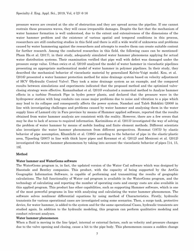
The components of the water supply plan from the plain to Sonqor County
Constructing pumping stations
Constructing a water transferring pipeline
Figure 1: Water supply plan from Gilan-e Gharb wells to Sonqor County
Table1: Summary of the preferred option’s features
Piece Length (m) Pipe diameter (millimeter)
Way of transferring
Pipe material
The first digits
The last digits
1 20500 400 Pumping Steel 48 249
2 9100 400 Pumping Steel 249 322
3 7900 350 Pumping Steel 322 436
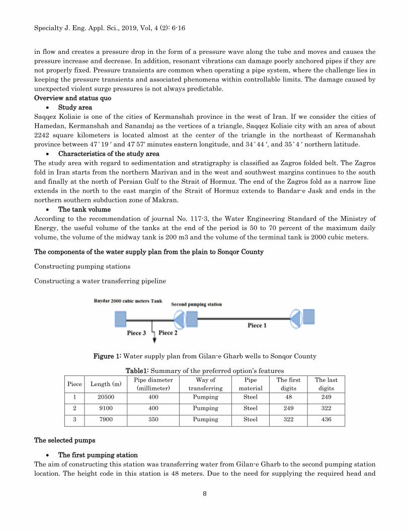
The selected pumps
• The first pumping station The aim of constructing this station was transferring water from Gilan-e Gharb to the second pumping station location. The height code in this station is 48 meters. Due to the need for supplying the required head and
Specialty J. Eng. Appl. Sci., 2019, Vol, 4 (2): 6-16
9
discharge flow rate, two high voltage parallel pumps (WKL125/6) with a power of 200 KW were introduced and chosen for this station.
Table 2: The characteristics of the first pumping station
Pump model Factory Count Impeller diameter
Discharge of each pump )Liters per second(
Pumping head (m)
Electromotor power (Kw)
WHL125/6 Made in Iran 2 295 35 201 200
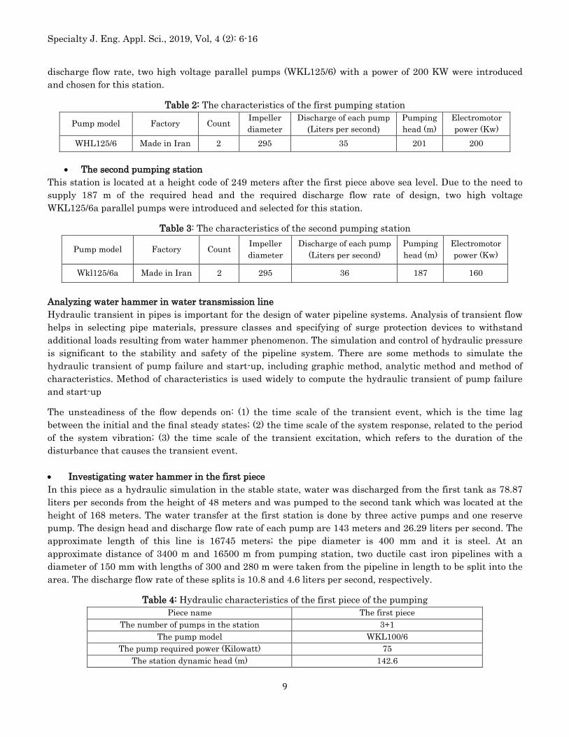
• The second pumping station This station is located at a height code of 249 meters after the first piece above sea level. Due to the need to supply 187 m of the required head and the required discharge flow rate of design, two high voltage WKL125/6a parallel pumps were introduced and selected for this station.
Table 3: The characteristics of the second pumping station
Pump model Factory Count Impeller diameter
Discharge of each pump (Liters per second)
Pumping head (m)
Electromotor power (Kw)
Wkl125/6a Made in Iran 2 295 36 187 160
Analyzing water hammer in water transmission line Hydraulic transient in pipes is important for the design of water pipeline systems. Analysis of transient flow helps in selecting pipe materials, pressure classes and specifying of surge protection devices to withstand additional loads resulting from water hammer phenomenon. The simulation and control of hydraulic pressure is significant to the stability and safety of the pipeline system. There are some methods to simulate the hydraulic transient of pump failure and start-up, including graphic method, analytic method and method of characteristics. Method of characteristics is used widely to compute the hydraulic transient of pump failure and start-up
The unsteadiness of the flow depends on: (1) the time scale of the transient event, which is the time lag between the initial and the final steady states; (2) the time scale of the system response, related to the period of the system vibration; (3) the time scale of the transient excitation, which refers to the duration of the disturbance that causes the transient event. • Investigating water hammer in the first piece In this piece as a hydraulic simulation in the stable state, water was discharged from the first tank as 78.87 liters per seconds from the height of 48 meters and was pumped to the second tank which was located at the height of 168 meters. The water transfer at the first station is done by three active pumps and one reserve pump. The design head and discharge flow rate of each pump are 143 meters and 26.29 liters per second. The approximate length of this line is 16745 meters; the pipe diameter is 400 mm and it is steel. At an approximate distance of 3400 m and 16500 m from pumping station, two ductile cast iron pipelines with a diameter of 150 mm with lengths of 300 and 280 m were taken from the pipeline in length to be split into the area. The discharge flow rate of these splits is 10.8 and 4.6 liters per second, respectively.
Table 4: Hydraulic characteristics of the first piece of the pumping Piece name The first piece
The number of pumps in the station 3+1 The pump model WKL100/6
The pump required power (Kilowatt) 75 The station dynamic head (m) 142.6
Specialty J. Eng. Appl. Sci., 2019, Vol, 4 (2): 6-16
10
The pump RPM 1450 The discharge of each pump (liters per second) 26.29
The piece length (m) 16745 The line diameter (mm) 400
The speed of fluid in line (m / sec) 0.6 The beginning of the piece and height RE1 tank at 48 meters height code
The terminal part of the piece and height RE2 tank at 168 meters height code The static head (m) 120 The line material Steel
The Hazen-Williams Coefficient 110
The tube thickness (mm) Up to 9 km of transmission line the thickness is 7/9 and in the rest of the line it is 6/3
In Table 5 the results of calculating some of the water hammer analysis parameters have been mentioned.
Table 5: Hydraulic characteristics of the first piece of the pumping Hydraulic characteristics Quantity
The rotational inertia of the pump (Nm2) 2.2 The rotational inertia of electromotor (Nm2) 14.7
The total rotational inertia (Nm2) 16.9 The average velocity of pressure wave dissemination (m/s) 1175
The critical time (pressure wave travel time in seconds) 28 The maximum pressure drop due to pump shutdown (m) 72
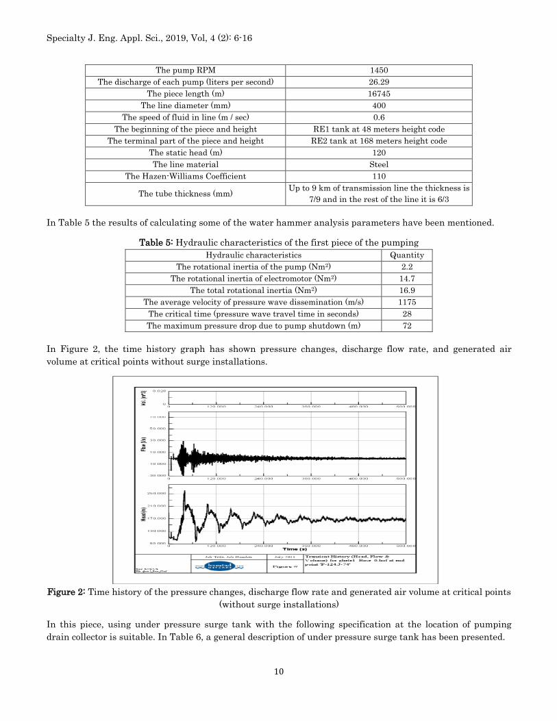
In Figure 2, the time history graph has shown pressure changes, discharge flow rate, and generated air volume at critical points without surge installations.
Figure 2: Time history of the pressure changes, discharge flow rate and generated air volume at critical points
(without surge installations)
In this piece, using under pressure surge tank with the following specification at the location of pumping drain collector is suitable. In Table 6, a general description of under pressure surge tank has been presented.
Specialty J. Eng. Appl. Sci., 2019, Vol, 4 (2): 6-16
11
Table 6: The specifications of under pressure surge tank Required air volume (m 3) 1.5
The volume of water inside the tank (m3) 1-meter cubic meter - with a percentage increase as a confidence coefficient of 1.3 cubic meters
The pressure drop coefficient (from the tank to the main pipeline) 1
The ratio of the pressure drop in the direction of the outlet current from the pipeline to the tank 2.5
The tank main pipe diameter (millimeter) 100 The power in gas law 1.2
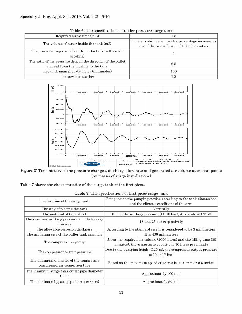
Figure 3: Time history of the pressure changes, discharge flow rate and generated air volume at critical points
(by means of surge installations)
Table 7 shows the characteristics of the surge tank of the first piece.
Table 7: The specifications of first piece surge tank
The location of the surge tank Being inside the pumping station according to the tank dimensions and the climatic conditions of the area
The way of placing the tank Vertically The material of tank sheet Due to the working pressure (P> 10 bar), it is made of ST-52
The reservoir working pressure and its leakage pressure 18 and 25 bar respectively
The allowable corrosion thickness According to the standard size it is considered to be 3 millimeters The minimum size of the buffer tank manhole It is 400 millimeters
The compressor capacity Given the required air volume (2000 liters) and the filling time (30 minutes), the compressor capacity is 70 liters per minute
The compressor output pressure Due to the pumping height (120 m), the compressor output pressure is 15 or 17 bar.
The minimum diameter of the compressor compressed air connection tube Based on the maximum speed of 15 m/s it is 10 mm or 0.5 inches
The minimum surge tank outlet pipe diameter (mm) Approximately 100 mm
The minimum bypass pipe diameter (mm) Approximately 50 mm
Specialty J. Eng. Appl. Sci., 2019, Vol, 4 (2): 6-16
12
Investigating water hammer in the second piece In this piece according to the hydraulic simulation in the stable mode, water is pumped from the second tank at the height of 168 to the third tank at the height of 301 with the discharge rate of 61.7 liters/sec. Water transfer at the second station is carried out by three active pumps and one reserve pump. The design head and discharge flow rate of each pump are 152 meters and 19.2 liters per second. The approximate length of this line is 9633 meters, the diameter of the line is 350 mm and it is made of steel. At a distance of 6100 m from pumping station, one ductile cast iron pipeline with a diameter of 150 mm with the length of 128 m was taken from the pipeline to be split into the nearby villages. The discharge flow rate of this split is 0.75 liters per second.
Table 8: The hydraulic characteristics of the second piece pumping Piece name The second piece
The way of water transferring Pumping The number of pumps in the station 3+1
The pump model WKL100/6 The pump required power (Kilowatt) 75
The station dynamic head (m) 152.4 The pump RPM 1450
The discharge of each pump (liters per second) 19.2 The piece length (m) 9633
The line diameter (mm) 350 The speed of fluid in line (m / sec) 0.7
The beginning of the piece and height RE2 tank at 168 meters height code The terminal part of the piece and height RE3 tank at 301 meters height code
The static head (m) 133 The line material Steel
The Hazen-Williams Coefficient 110 The tube thickness (mm) 6/3
In Table 9, the results of calculating some of the parameters of the water hammer analysis are shown.
Table 9: The hydraulic characteristics of the second piece pumping Hydraulic characteristics Quantity
The rotational inertia of the pump (Nm2) 2.2 The rotational inertia of electromotor (Nm2) 14.7
The total rotational inertia (Nm2) 16.9 The average velocity of pressure wave dissemination (m/s) 1150
The critical time (pressure wave travel time in seconds) 17 The maximum pressure drop due to pump shutdown (m) 82.1
The results of the water hammer analysis (after the sudden and simultaneous shutdown of the pumps)
In the following, the diagram shows the effect of water hammer on the sudden and simultaneous shutdown of the pumps.
Table 10: The specifications of the under pressure surge tank of the second piece Required air volume (m3) 2
The volume of water inside the tank (m3) 0.7-meter cubic meter - with a percentage increase as a confidence coefficient of 1cubic meters
The pressure drop coefficient (from the tank to the main 1
Specialty J. Eng. Appl. Sci., 2019, Vol, 4 (2): 6-16
13
pipeline) The ratio of the pressure drop in the direction of the outlet
current from the pipeline to the tank 2.5
Tank main pipe diameter (millimeter) 100 The power in gas law 1.2
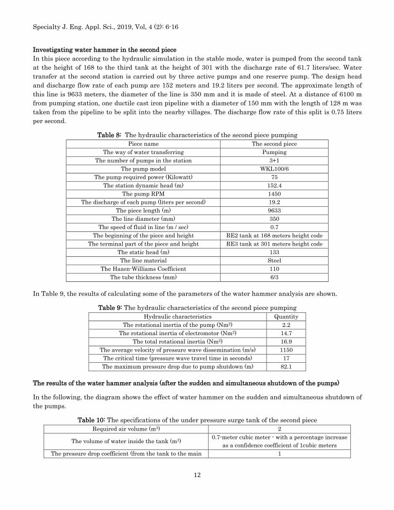
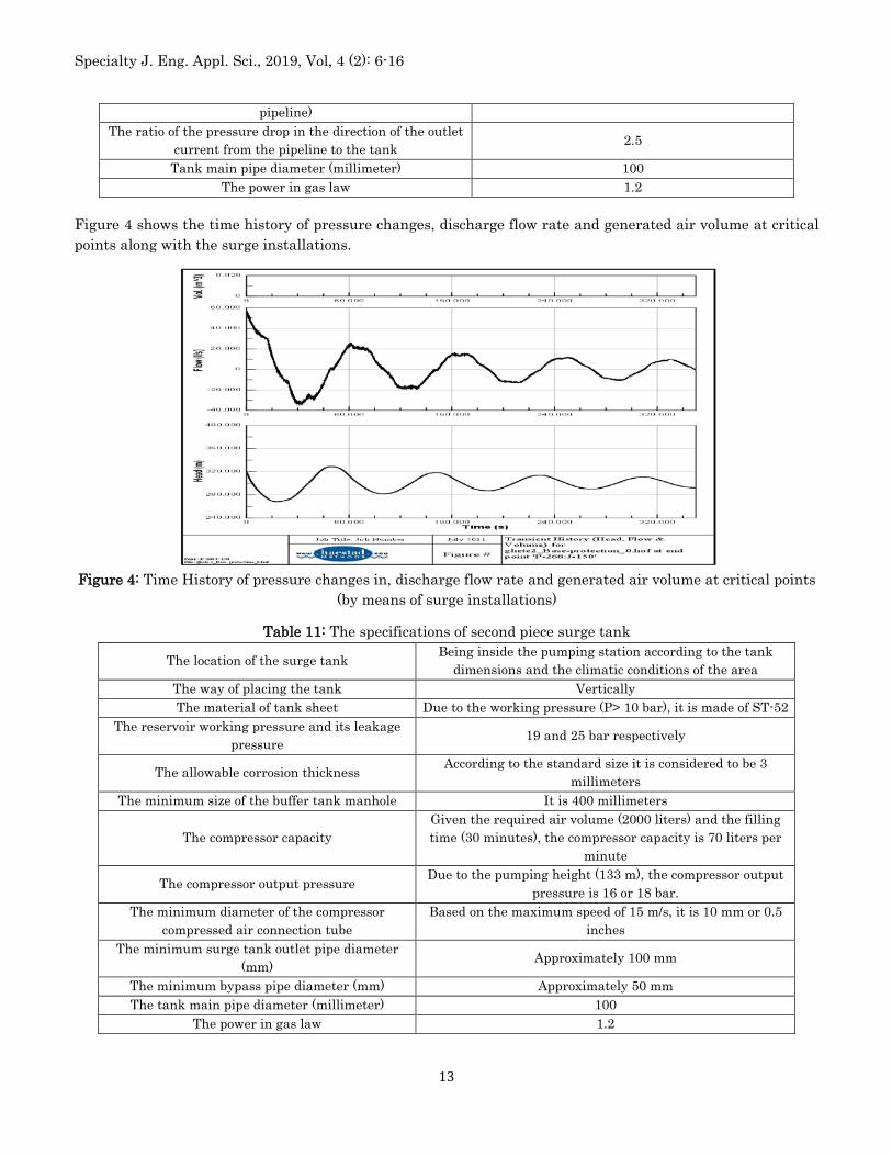
Figure 4 shows the time history of pressure changes, discharge flow rate and generated air volume at critical points along with the surge installations.
Figure 4: Time History of pressure changes in, discharge flow rate and generated air volume at critical points
(by means of surge installations)
Table 11: The specifications of second piece surge tank
The location of the surge tank Being inside the pumping station according to the tank dimensions and the climatic conditions of the area
The way of placing the tank Vertically The material of tank sheet Due to the working pressure (P> 10 bar), it is made of ST-52
The reservoir working pressure and its leakage pressure 19 and 25 bar respectively
The allowable corrosion thickness According to the standard size it is considered to be 3 millimeters
The minimum size of the buffer tank manhole It is 400 millimeters
The compressor capacity Given the required air volume (2000 liters) and the filling time (30 minutes), the compressor capacity is 70 liters per
minute
The compressor output pressure Due to the pumping height (133 m), the compressor output pressure is 16 or 18 bar.
The minimum diameter of the compressor compressed air connection tube
Based on the maximum speed of 15 m/s, it is 10 mm or 0.5 inches
The minimum surge tank outlet pipe diameter (mm) Approximately 100 mm
The minimum bypass pipe diameter (mm) Approximately 50 mm The tank main pipe diameter (millimeter) 100
The power in gas law 1.2
Specialty J. Eng. Appl. Sci., 2019, Vol, 4 (2): 6-16
14
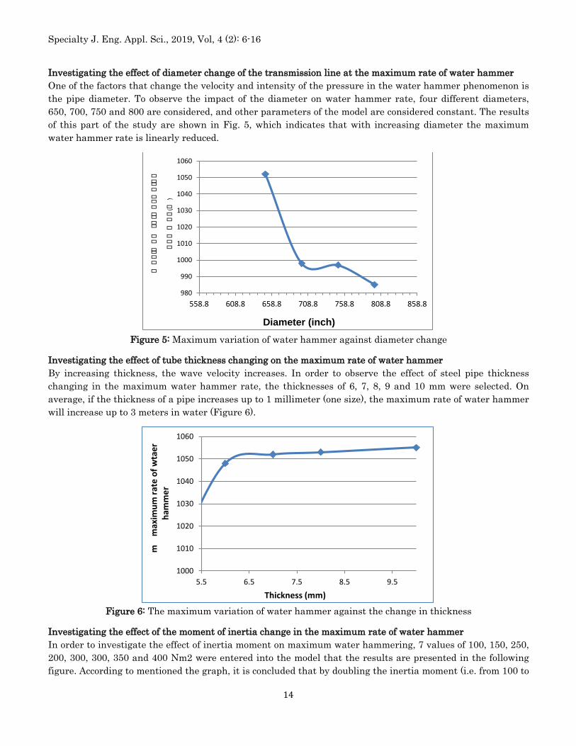
Investigating the effect of diameter change of the transmission line at the maximum rate of water hammer One of the factors that change the velocity and intensity of the pressure in the water hammer phenomenon is the pipe diameter. To observe the impact of the diameter on water hammer rate, four different diameters, 650, 700, 750 and 800 are considered, and other parameters of the model are considered constant. The results of this part of the study are shown in Fig. 5, which indicates that with increasing diameter the maximum water hammer rate is linearly reduced.
Figure 5: Maximum variation of water hammer against diameter change
Investigating the effect of tube thickness changing on the maximum rate of water hammer By increasing thickness, the wave velocity increases. In order to observe the effect of steel pipe thickness changing in the maximum water hammer rate, the thicknesses of 6, 7, 8, 9 and 10 mm were selected. On average, if the thickness of a pipe increases up to 1 millimeter (one size), the maximum rate of water hammer will increase up to 3 meters in water (Figure 6).
Figure 6: The maximum variation of water hammer against the change in thickness
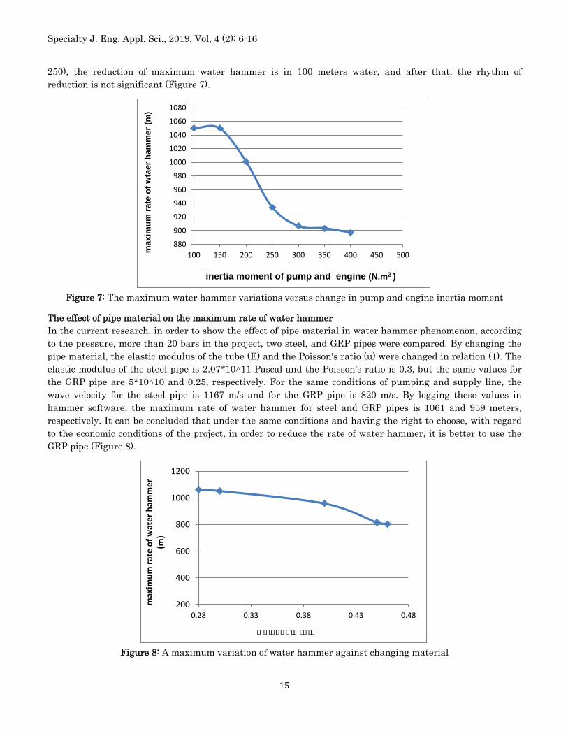
Investigating the effect of the moment of inertia change in the maximum rate of water hammer In order to investigate the effect of inertia moment on maximum water hammering, 7 values of 100, 150, 250, 200, 300, 300, 350 and 400 Nm2 were entered into the model that the results are presented in the following figure. According to mentioned the graph, it is concluded that by doubling the inertia moment (i.e. from 100 to
980
990
1000
1010
1020
1030
1040
1050
1060
558.8 608.8 658.8 708.8 758.8 808.8 858.8
mmm
mmmm
mmmm
mm m
mmmm
mmm
mmm
(m)
Diameter (inch)
1000
1010
1020
1030
1040
1050
1060
5.5 6.5 7.5 8.5 9.5
m
max
imum
rate
of w
taer
ha
mm
er
Thickness (mm)
Specialty J. Eng. Appl. Sci., 2019, Vol, 4 (2): 6-16
15
250), the reduction of maximum water hammer is in 100 meters water, and after that, the rhythm of reduction is not significant (Figure 7).
Figure 7: The maximum water hammer variations versus change in pump and engine inertia moment
The effect of pipe material on the maximum rate of water hammer In the current research, in order to show the effect of pipe material in water hammer phenomenon, according to the pressure, more than 20 bars in the project, two steel, and GRP pipes were compared. By changing the pipe material, the elastic modulus of the tube (E) and the Poisson's ratio (u) were changed in relation (1). The elastic modulus of the steel pipe is 2.07*10˄11 Pascal and the Poisson's ratio is 0.3, but the same values for the GRP pipe are 5*10˄10 and 0.25, respectively. For the same conditions of pumping and supply line, the wave velocity for the steel pipe is 1167 m/s and for the GRP pipe is 820 m/s. By logging these values in hammer software, the maximum rate of water hammer for steel and GRP pipes is 1061 and 959 meters, respectively. It can be concluded that under the same conditions and having the right to choose, with regard to the economic conditions of the project, in order to reduce the rate of water hammer, it is better to use the GRP pipe (Figure 8).
Figure 8: A maximum variation of water hammer against changing material
880
900
920
940
960
980
1000
1020
1040
1060
1080
100 150 200 250 300 350 400 450 500max
imum
rate
of w
taer
ham
mer
(m)
inertia moment of pump and engine (N.m2 )
200
400
600
800
1000
1200
0.28 0.33 0.38 0.43 0.48
max
imum
rate
of w
ater
ham
mer
(m
)
P P PPPP P PP PP PP
Specialty J. Eng. Appl. Sci., 2019, Vol, 4 (2): 6-16
16
Conclusion The effects of diameter variation, pipe thickness and different flow rates on the dynamic loads caused by water hammer were investigated in this research. According to what was mentioned in this research, and the aim of research that is investigating the effect of diameter variation, thickness, a moment of inertia and temperature in line with the rate of water hammer in pumping project of Maroun to Abelsh Plain, it can be concluded that: On average, each time as the diameter increased up to one size, the maximum water hammer reduction
is about 74 meters of water. Under the same conditions, the effect of GRP pipe on reducing the maximum rate of water hammer is 15
meters of water more than the steel pipe. Increasing the maximum rate of water hammer due to an increase in the thickness of the tube up to one
millimeter is about 3 meters of water. Doubling the inertia moment will reduce the maximum rate of water hammer in 115 meters water (about
half the total water hammer (230 meters water)) which is done by Flywheel, then by means of doubling the inertia moment, the maximum water hammer reduction is about 15 meters water.
Reference
1. Conejero, J.A. Lizama,C. ,F. (2016). Dynamics of the solutions of the water hammer equations. Topology and its Applications. 203, pp. 67-83.
2. Kamanbadast, A.A. Shahosseini, M. & Aghamajidi, R. (2010). Evaluation of Numerical Method to Analyzed Hammer Effects in a Turbine Penstock Pipe in Hydro Power Plant. World Applied Science Journal 2010; 9: 689-94.
3. Keramat, A., Tijsseling, A. S., Hou, Q, Ahmadi, A., (2012), Fluid–structure interaction with pipe-wall viscoelasticity during water hammer", Journal of Fluids and Structures 28: 434–455.
4. Khamlichi, A., Jezequel L, Tephany, F., (1995), Elastic-plastic water hammer analysis in piping systems, Wave Motion 22: 279-295.
5. Kou, Y. Yang, J.& Kou, Z. (2016) A Water Hammer Protection Method for Mine Drainage System Based on Velocity Adjustment of Hydraulic Control Valve. Shock and Vibration. Volume 2016, Article ID 2346025, 13 pages.
6. Kumar, A. Satya Prasad, P. Rao, R .(2018). Experimental studies of water hammer in propellant feed system of reaction control system. Propulsion and Power Research 7(1), pp. 52-59.
7. Meniconi, S, Brunone, B, Ferrante, M., (2012), Water-hammer pressure waves interaction at cross section changes in series in viscoelastic pipes, Journal of Fluids and Structures 33: 44-58.
8. Pham Ha, H. Thi Minh, L. P. Tang Van, L. Bulgakov, B. & Bazhenova, S. (2017). Assessment of water pipes durability under pressure surge. IOP Conference Series: Earth and Environmental Science. 90 012223. Available at h.
9. Tijsseling, A.S., (2007), Water hammer with fluid–structure interaction in thick-walled pipes, Computers and Structures 85: 844–851.
10. Urbanowicz,K. Firkowski,M. & Zarzycki,Z. (2016). Modelling water hammer in viscoelastic pipelines: short brief. Journal of Physics: Conference Series. 760 (1). 012037. Available at doi:10.1088/1742-6596/760/1/012037.