Sensitivity of the final properties of tailored hot stamping components to the process and material...
12
Please cite this article in press as: Abdollahpoor, A., et al., Sensitivity of the final properties of tailored hot stamping components to the process and material parameters. J. Mater. Process. Tech. (2015), http://dx.doi.org/10.1016/j.jmatprotec.2014.11.033 ARTICLE IN PRESS G Model PROTEC-14197; No. of Pages 12 Journal of Materials Processing Technology xxx (2015) xxx–xxx Contents lists available at ScienceDirect Journal of Materials Processing Technology jo ur nal ho me page: www.elsevier.com/locate/jmatprotec Sensitivity of the final properties of tailored hot stamping components to the process and material parameters Amir Abdollahpoor a,∗ , Xiangjun Chen b,c , Michael P. Pereira a , Namin Xiao b , Bernard F. Rolfe a a School of Engineering, Deakin University, Geelong, Australia b Institute of Metal Research, Chinese Academy of Sciences, Shenyang, China c State Key Laboratory of Advanced Design and Manufacturing for Vehicle Body, Hunan University, Changsha, China a r t i c l e i n f o Article history: Received 16 July 2014 Received in revised form 30 October 2014 Accepted 16 November 2014 Available online xxx Keywords: Hot stamping Tailoring Numerical modeling Phase transformation a b s t r a c t The final mechanical properties of hot stamped components are affected by many process and mate- rial parameters due to the multidisciplinary nature of this thermal–mechanical–metallurgical process. The phase transformation, which depends on the temperature field and history, determines the final microstructure and consequently the final mechanical properties. Tailored hot stamping parts – where the cooling rates are locally chosen to achieve structures with graded properties – has been increasingly adopted in the automotive industry. In this case, the robustness of final part properties is more criti- cal than in the conventional hot stamping parts, where the part is fully quenched. In this study, a wide range of input parameters in a generalized hot stamping model have been investigated, examining the effect on the temperature history and resulting final material properties. A generic thermo-mechanical finite element model of hot stamping was created and a modified phase transformation model, based on Scheil’s additive principle, has been applied. The comparison between modeling and experiments shows that the modified phase transformation model coupled with the incubation time provides higher accu- racy on the simulation of transformation kinetics history. The robustness of four conditions relevant to tailored hot stamping was investigated: heated tooling (with low and high tool conductance), air cooling, and conventional hot stamping. The results show the high robustness of the conventional hot stamping compared to tailored hot stamping, with respect to the stamped component’s final material properties (i.e. phase fraction and hardness). Furthermore, tailored hot stamping showed higher robustness when low conductivity tools are used relative to high conductivity tools. © 2014 Elsevier B.V. All rights reserved. 1. Introduction Hot stamping has been used for many years to produce high strength structural automotive components. The high tensile strength achievable by hot stamping is beneficial where the intru- sion during a vehicle crash is not desirable – e.g. for the vehicle occupant compartment. On the other hand, there is a need for high ductility in the crumple zones to absorb crash energy via plastic work. Fig. 1 shows an example of a B-Pillar component, where both requirements should be satisfied. To achieve increased ductility in the local zones of the final part, the cooling rate during hot stamping should be slower than the critical value of 20 ◦ C/s–30 ◦ C/s (depend- ing on the steel grade) to produce softer steel phases such as bainite, ∗ Corresponding author at: Deakin University, Locked Bag 20000, Geelong, VIC 3220, Australia. Tel.: +61 415214139. E-mail address: [email protected] (A. Abdollahpoor). ferrite and pearlite in these zones. The local adjustment of the final properties within different areas in a single part using hot stamp- ing is commonly referred to as tailored hot stamping. In tailored hot stamping, the accurate prediction of the temperature history is critical to determine the final phase fractions and the hardness val- ues. Unlike the conventional hot stamping process, which has been well established in production for a number of years, the tailored hot stamping process is new and still needs more attention in terms of specification of the final mechanical properties as functions of the input (process and material) parameters. The main challenge in the accurate prediction of the final mechanical properties in the hot stamped components is the accurate prediction of the temperature history and the phase trans- formation kinetics. As shown in Fig. 2, there are a large number of interacting thermal–mechanical–metallurgical parameters that must be considered. When designing the tailored hot stamping pro- cess, each of these parameters must be carefully considered so that the desired cooling rates (and resulting microstructure/properties) http://dx.doi.org/10.1016/j.jmatprotec.2014.11.033 0924-0136/© 2014 Elsevier B.V. All rights reserved.
Transcript of Sensitivity of the final properties of tailored hot stamping components to the process and material...

P
Sc
ABa
b
c
a
ARRAA
KHTNP
1
hssodwrtsi
3
h0
ARTICLE IN PRESSG ModelROTEC-14197; No. of Pages 12
Journal of Materials Processing Technology xxx (2015) xxx–xxx
Contents lists available at ScienceDirect
Journal of Materials Processing Technology
jo ur nal ho me page: www.elsev ier .com/ locate / jmatprotec
ensitivity of the final properties of tailored hot stampingomponents to the process and material parameters
mir Abdollahpoora,∗, Xiangjun Chenb,c, Michael P. Pereiraa, Namin Xiaob,ernard F. Rolfea
School of Engineering, Deakin University, Geelong, AustraliaInstitute of Metal Research, Chinese Academy of Sciences, Shenyang, ChinaState Key Laboratory of Advanced Design and Manufacturing for Vehicle Body, Hunan University, Changsha, China
r t i c l e i n f o
rticle history:eceived 16 July 2014eceived in revised form 30 October 2014ccepted 16 November 2014vailable online xxx
eywords:ot stampingailoringumerical modelinghase transformation
a b s t r a c t
The final mechanical properties of hot stamped components are affected by many process and mate-rial parameters due to the multidisciplinary nature of this thermal–mechanical–metallurgical process.The phase transformation, which depends on the temperature field and history, determines the finalmicrostructure and consequently the final mechanical properties. Tailored hot stamping parts – wherethe cooling rates are locally chosen to achieve structures with graded properties – has been increasinglyadopted in the automotive industry. In this case, the robustness of final part properties is more criti-cal than in the conventional hot stamping parts, where the part is fully quenched. In this study, a widerange of input parameters in a generalized hot stamping model have been investigated, examining theeffect on the temperature history and resulting final material properties. A generic thermo-mechanicalfinite element model of hot stamping was created and a modified phase transformation model, based onScheil’s additive principle, has been applied. The comparison between modeling and experiments showsthat the modified phase transformation model coupled with the incubation time provides higher accu-racy on the simulation of transformation kinetics history. The robustness of four conditions relevant to
tailored hot stamping was investigated: heated tooling (with low and high tool conductance), air cooling,and conventional hot stamping. The results show the high robustness of the conventional hot stampingcompared to tailored hot stamping, with respect to the stamped component’s final material properties(i.e. phase fraction and hardness). Furthermore, tailored hot stamping showed higher robustness whenlow conductivity tools are used relative to high conductivity tools.. Introduction
Hot stamping has been used for many years to produceigh strength structural automotive components. The high tensiletrength achievable by hot stamping is beneficial where the intru-ion during a vehicle crash is not desirable – e.g. for the vehicleccupant compartment. On the other hand, there is a need for highuctility in the crumple zones to absorb crash energy via plasticork. Fig. 1 shows an example of a B-Pillar component, where both
equirements should be satisfied. To achieve increased ductility in
Please cite this article in press as: Abdollahpoor, A., et al., Sensitivity oprocess and material parameters. J. Mater. Process. Tech. (2015), http:
he local zones of the final part, the cooling rate during hot stampinghould be slower than the critical value of 20 ◦C/s–30 ◦C/s (depend-ng on the steel grade) to produce softer steel phases such as bainite,
∗ Corresponding author at: Deakin University, Locked Bag 20000, Geelong, VIC220, Australia. Tel.: +61 415214139.
E-mail address: [email protected] (A. Abdollahpoor).
ttp://dx.doi.org/10.1016/j.jmatprotec.2014.11.033924-0136/© 2014 Elsevier B.V. All rights reserved.
© 2014 Elsevier B.V. All rights reserved.
ferrite and pearlite in these zones. The local adjustment of the finalproperties within different areas in a single part using hot stamp-ing is commonly referred to as tailored hot stamping. In tailoredhot stamping, the accurate prediction of the temperature history iscritical to determine the final phase fractions and the hardness val-ues. Unlike the conventional hot stamping process, which has beenwell established in production for a number of years, the tailoredhot stamping process is new and still needs more attention in termsof specification of the final mechanical properties as functions of theinput (process and material) parameters.
The main challenge in the accurate prediction of the finalmechanical properties in the hot stamped components is theaccurate prediction of the temperature history and the phase trans-formation kinetics. As shown in Fig. 2, there are a large number
f the final properties of tailored hot stamping components to the//dx.doi.org/10.1016/j.jmatprotec.2014.11.033
of interacting thermal–mechanical–metallurgical parameters thatmust be considered. When designing the tailored hot stamping pro-cess, each of these parameters must be carefully considered so thatthe desired cooling rates (and resulting microstructure/properties)

ARTICLE ING ModelPROTEC-14197; No. of Pages 12
2 A. Abdollahpoor et al. / Journal of Materials Pro
autrpeeparpctwtifs(sst4o
traditional stamping processes, is formed by the action of the top
Fig. 1. A sample B-Pillar with tailored mechanical properties.
re achieved precisely during production. Therefore, a soundnderstanding of the influence of each of the parameters on theemperature history and final phase fractions is necessary. Someesearchers have investigated the effects of some of the inputarameters on the phase fraction and/or the final mechanical prop-rties, with tool temperature being the most common parameterxamined. Feuser et al. (2011) showed that increasing the tool tem-erature from 200 ◦C to 400 ◦C decreases the tensile strength bybout 32%. The same decrease in the Vickers hardness has beeneported by George et al. (2011) for the same change in the tool tem-erature. The effects of the tool temperature and the heat contactonductance between the blank and tool material on the tempera-ure history have been shown by Oldenburg and Lindkvist (2011). Itas shown that the most important parameter is the tool tempera-
ure, while the process sensitivity to the heat contact conductances low. The effects of tool temperature, contact pressure, trans-er time, die closure time and the blank thickness on the tensiletrength and bending angle have been investigated by Feuser et al.2011), which seems to be the most comprehensive parametrictudy in this field to the authors’ knowledge. The fully marten-itic microstructure in the final component was achieved at tool
Please cite this article in press as: Abdollahpoor, A., et al., Sensitivity oprocess and material parameters. J. Mater. Process. Tech. (2015), http:
emperatures below 200 ◦C and the tool temperatures higher than00 ◦C was necessary to obtain other phases. At tool temperaturef 500 ◦C, other parameters had less significant effects due to the
Fig. 2. Interaction of thermal–mechanical–metallurgical paramete
PRESScessing Technology xxx (2015) xxx–xxx
cooling down and keeping the specimens at a temperature higherthan martensitic start temperature. No clear dependency of thematerial properties to the process parameters was observed in thiscase. This implies the necessity of more investigations to obtain abetter understanding of the process sensitivity with respect to evenmore input parameters at different process conditions.
In this study, a thermal–mechanical–metallurgical model of asimple hot stamping process is created. The model includes internaldependencies of many parameters and a modified phase transfor-mation model – based on JMAK-type equations and Scheil’s additiverule with the inclusion of incubation time for the austenite decom-position into ferrite, pearlite and bainite – which increases theaccuracy of the results. The paper provides detailed explanation ofthe mechanical–thermal–metallurgical model used, and validationof selected results with experimentation and the literature, whichwill be of benefit to future studies in this area.
Based on the developed and validated model, a series of para-metric studies have been performed under four different processconditions. The significance of this study is the consideration of alarge number of input parameters which is the first comprehensiveparametric study in this field. In this study, the sensitivity of thephase fractions and the final mechanical properties to an arbitraryvariation of ±10% in the input parameters have been investigatedfor four process scenarios. These scenarios were chosen to simulatea conventional hot-stamping process, and three possible methodsin which tailored hot stamping can be achieved. The purpose isto understand the sensitivity of the hot stamping process to smallvariations of the input parameters under a number of operatingcondition scenarios.
2. Methodology
2.1. Thermal–mechanical model
The finite element software ABAQUS Standard V6.12 was usedto simulate the hot stamping of a simple hat-shaped compo-nent (Fig. 3), including transfer from furnace to the tool, forming,quenching and air cooling processes. The model does not include ablank holder, representing the crash-forming-type process oftenused when hot stamping long structural members. The flangeregion of the part, which is typically formed by the blank holder in
f the final properties of tailored hot stamping components to the//dx.doi.org/10.1016/j.jmatprotec.2014.11.033
tool (punch) at the end of the forming stroke (as shown in Fig. 3).Symmetry boundary conditions were applied to the blank and toolwhich allows just one quarter of the geometry to be modelled.
rs in hot stamping modelling (Karbasian and Tekkaya, 2010).
ARTICLE IN PRESSG ModelPROTEC-14197; No. of Pages 12
A. Abdollahpoor et al. / Journal of Materials Processing Technology xxx (2015) xxx–xxx 3
Fig. 3. (a) Schematic of hat-shaped tooling for hot stamping model. (b) One-quarter symmetric FE model of hot stamping process used in this study.
Table 1The thermo-mechanical properties of the tool material AISI H11 (Tondini et al.,2011).
Conductivity Specificheat
Density Young’smodulus
Poisson’sratio
Tatpt
bT
Q
wbm
tttt
Q
w5osa
emidncstr
tf
Q
Table 2Thermo-mechanical properties as a function of temperature for boron steel 22MnB5(Shapiro, 2009).
Temperature (◦C) E (GPa) � K (W/m ◦C) Cp (J/kg ◦C)
20 212 0.284 30.7 444100 207 0.286 31.1 487200 199 0.289 30.0 520300 193 0.293 27.5 544400 166 0.298 21.7 561500 158 0.303 – 573600 150 0.310 23.6 581700 142 0.317 – 586800 134 0.325 25.6 590900 126 0.334 – 596
42.2 W/m K 526 J/kg K 7700 kg/m3 210 GPa 0.3
he clearance between the punch and the die has been selecteds 1 mm. The tool cooling system was not modelled and the toolemperature was defined as an initial condition, which allows tem-erature rise to occur at the tool surface due to the interaction ofhe heated blank.
During the transfer process from the furnace to the die, thelank temperature reduces due to the convection and radiation.he convection heat transfer follows Newton’s law of cooling:
Conv = hConv(Tb − Ta) (1)
here hConv is the convection heat transfer coefficient, Tb is thelank temperature and Ta is the ambient temperature. In thisodel, hConv = 17 W/m2 K was used (Ertürk et al., 2011).The radiation heat transfer can be modelled either by modelling
he emitting energy from the blank to the ambient or also modellinghe energy exchange of the blank surface with other surfaces. Inhis model, the emitting energy to ambient was modelled usinghe Stefan–Boltzmann law:
Rad = ε�(T4b − T4
a ) (2)
here � is Stefan–Boltzmann constant which equals to.669 × 10−8 and ε is the emissivity which directly dependsn the surface type. ε equals 1 for a true black body, while it is verymall for an oxide-free surface. In this model, ε = 0.8 was used forn oxidized surface (Holman, 1997).
The punch and die were considered as deformable bodies, whichnables the study of heat transfer through the tooling. The thermo-echanical properties of the tool material AISI H11 are reported
n Table 1. Significant variations have been observed in availableata particularly in the conductivity for this tool material, and alsooting that HTC is also sensitive to contact pressure which is diffi-ult to measure experimentally. The Böhler-Edelstahl (2014) dataheet has reported the conductivity values of 26–29.2 W/m K in theemperature range of 100–700 ◦C, while Tondini et al. (2011) haveeported the value of 42.2 W/m K.
During the quenching process, the hot blank is cooled down after
Please cite this article in press as: Abdollahpoor, A., et al., Sensitivity oprocess and material parameters. J. Mater. Process. Tech. (2015), http:
he forming process in the same die. Eq. (3) shows the relationshipor heat transfer between the blank and the tool:
Quench = HTC(Tb − Ta) (3)
1000 118 0.343 27.6 603
where HTC is the contact heat transfer coefficient and needs to beaccurately defined to achieve precise temperature history. Accord-ing to the work of Lechler (2009), the HTC can be linearly fittedas:
HTC = 53.4p + 1316 W/m2 K (4)
where p is the contact pressure. The mechanical contact wasdefined using a Penalty friction formulation, with a friction coef-ficient of 0.4.
Coupled temperature–displacement 4-node tetrahedron ele-ments, C3D4T, were used to mesh the die and the punch. Biasedmeshing, which allows non-uniform distribution of elements alongselected edges, was used for the die and the punch in order torefine the mesh at the tool surfaces and tool radii and to coarsenthe mesh in other regions (as shown in Fig. 3). The coarsest andthe finest element sizes of 5 mm and 1 mm were chosen respec-tively. The blank was meshed using 8-node brick elements, C3D8T.Blank elements size was chosen to be 1 mm × 1 mm × 0.5 mm(length × width × thickness). The mesh size was chosen based ona mesh convergence analysis, with the final mesh providing a goodbalance between a converged solution and computational time.
Boron steel sheet (22MnB5) was modelled with temperaturedependant thermo-mechanical properties. Temperature depend-ent and strain rate sensitive stress–strain curves for boron steel22MnB5 are used in this study as shown in Fig. 4.
The properties of the blank, including Young’s modulus (E), Pois-son’s ratio (�), thermal conductivity (k) and specific heat (CP) weredefined to include temperature dependency, and are shown in
f the final properties of tailored hot stamping components to the//dx.doi.org/10.1016/j.jmatprotec.2014.11.033
Table 2. The inelastic heat fraction parameter, which defines theheating associated with plastic work of the blank material, was setto the default value of 0.9.

ARTICLE IN PRESSG ModelPROTEC-14197; No. of Pages 12
4 A. Abdollahpoor et al. / Journal of Materials Processing Technology xxx (2015) xxx–xxx
n stee
2
2
irbsptthy
wm(
F
wtptceni
ibtt∑
wTi�
vB
F
wpa
heat generated during the phase transformation. It is necessary toconsider the latent heat released due to the austenite transforma-tion to each phase – ferrite, pearlite, bainite and martensite – toincrease the accuracy of temperature history predictions during
200
250
300
350
400
450
500
550
600
650
700
750
Ms
20o/s
Mf=220o
=420o
A
B
F+P
B+M
Calculate (99%) Calculate (1%)M
Experiment (99%) Experi ment (1% )
Tem
pera
ture
(o C
)
Fig. 4. Stress–strain curves for boro
.2. Metallurgical model
.2.1. Austenite decomposition modelThe models used to describe the transformation of austen-
te to martensite, bainite, pearlite and ferrite are based on theecent work by Chen et al. (2014) and will be discussed hereriefly. The models were implemented using the ABAQUS userubroutine USDFLD (Hibbitt et al., 2001). The austenite decom-osition at arbitrary cooling paths for 22MnB5 steel is based onime–temperature–transformation (TTT) curve and Scheil’s addi-ive reaction principle. Using the thermal dilation curve at eacholding temperature and the metallographic microstructure anal-sis, the TTT diagram for the 22MnB5 was obtained.
The kinetics of the isothermal diffusional phase transformationas modelled using the Johnson–Mehl–Avrami–Kolmogorov typeodel, modified to consider the incubation time, as shown in Eq.
5).
= 1 − e−b(t−ts)n(5)
here F is the phase volume fraction, t is the elapsed time fromhe beginning of the transformation; ts is the real starting time ofhase transformation (i.e. the incubation time for the isothermalransformation); b is a constant depending on the temperature,omposition and grain size of parent phase; n is a constant depend-nt on the mechanism of phase transformation. The constants, b and, can be obtained empirically by using two points on the measured
sothermal transformation kinetics curve (Chen et al., 2014).Scheil’s additive reaction rule was used to describe the non-
sothermal transformation behaviour. This model considers thatoth nucleation and growth stages of non-isothermal transforma-ion occurs through a series of small isothermal steps. According tohis rule, transformation occurs when:
i
�ti
�i= 1 (6)
here �ti is the time at the small isothermal step and �i is theTT incubation time or the time required to transform the fractionsothermally at the current isotherm Ti. For finite element models,
ti can be considered as the current time increment.For the case of the diffusionless martensite transformation, the
olume fraction of the martensite Fm was calculated using theuchmayr and Kirkaldy (1990) empirical model:
−0.011(Ms−T)
Please cite this article in press as: Abdollahpoor, A., et al., Sensitivity oprocess and material parameters. J. Mater. Process. Tech. (2015), http:
m = Fa(1 − e ) (7)
here Fa is the volume fraction of austenite remaining from therevious transformations, Ms is the martensite start temperaturend T is the current temperature.
l 22MnB5 (Oberpriller et al., 2008).
To validate the austenite decomposition model, simulations ofcontinuous cooling were performed at a constant cooling rate andcompared with the experimental Continuous Cooling Transforma-tion (CCT) diagram (see Fig. 5). The predicted phase transformationstart and finish times using the models described are compared toexperimental measurements (Chen et al., 2014). The result showsthat the simulated start time and finish time of austenite decom-position into ferrite, pearlite and bainite agree well with the CCTdiagram. The predicted critical cooling rate for full martensitetransformation (20 ◦C/s) also compares well with the experimen-tal observation. These results imply that the present model showsa good capability to simulate the austenite decomposition intothe daughter phases. It is notable that the effects of stress onphase transformation and the transformation induced plasticity arenot included in the current model. However, Chen et al. (2013)have investigated the effects of transformation plasticity on thegeometry precision and the residual stress, but this has not beenexperimentally verified. The authors believe that these effects willnot change the trends of the simulation models.
2.2.2. Latent heatThe HETVAL subroutine in ABAQUS was used to define the latent
f the final properties of tailored hot stamping components to the//dx.doi.org/10.1016/j.jmatprotec.2014.11.033
10Time (s)
100001000100
Fig. 5. The predicted starting and finishing times using the models described, com-pared to the experimental measurements (Chen et al., 2014).
IN PRESSG ModelP
als Processing Technology xxx (2015) xxx–xxx 5
ttco
�
f
q
wpaf�a2b
2
r
H
wfHf
ic
H
H
H
w−
2
ttmTwtdopicfi
ARTICLEROTEC-14197; No. of Pages 12
A. Abdollahpoor et al. / Journal of Materi
he cooling process. The energy balance equation (Eq. (8)) includeshe term of q̇ which is generated energy within the element andan include the heat generated due to the plastic work, latent heatr any other external heat sources.
Cp∂T
∂t= q̇ + ∂
∂x
(k
∂T
∂x
)+ ∂
∂y
(k
∂T
∂y
)+ ∂
∂z
(k
∂T
∂z
)(8)
The heat generation rate per unit volume, q̇lat, can be calculatedor transformation of austenite to each phase (Sjöström, 1982):
˙ lat = �h · �x
�t(9)
here �h is the transformation enthalpy related to eachhase, �x is the phase fraction transformed in each incrementnd �t is the time increment. The transformation enthalpyor ferrite, pearlite, bainite and martensite were chosen as
hf = 5.9 × 10⁸ J m−3, �hp = 5.9 × 10⁸ J m−3, �hb = 5.9 × 10⁸ J m−3
nd �hm = 6.4 × 10⁸ J m−3 respectively (Akerstrom and Oldenburg,006). Then, the total latent heat released during the cooling cane calculated as:
q̇lat =∑5
i=2q̇lati
q̇ =∑i=5
i=2Xi · Hi
�t
(10)
.2.3. Hardness calculationThe resulting hardness of the material was calculated using the
ule of mixtures:
= xmHm + xbHb + (xf + xp)Hf +p (11)
here H is the Vickers hardness; xm, xb, xf and xp are the volumeraction of martensite, bainite, ferrite and pearlite respectively. Hm,b, Hf+p are the hardness of martensite, bainite and the mixture of
errite and pearlite respectively.The hardness of different phases (Hm, Hb and Hf+p) was empir-
cally predicted as functions of the chemical composition and theooling rate (Maynier et al., 1978).
m = 127 + 949C + 27Si + 11Mn + 8Ni + 16Cr + 21 log Vr (12)
b = −323 + 185C + 330Si + 153Mn + 65Ni + 144Cr
+ 191Mo + A log Vr (13)
f +p = 42 + 223C + 53Si + 30Mn + 1206Ni + 7Cr + 19Mo
+ (10 − 19Si + 4Ni + 8Cr + 130V) log Vr (14)
here the Vr is the cooling rate and A = 89 + 53C − 55Si − 22Mn 10Ni − 20Cr − 33Mo.
.3. Jominy end-quenching tests and FE model
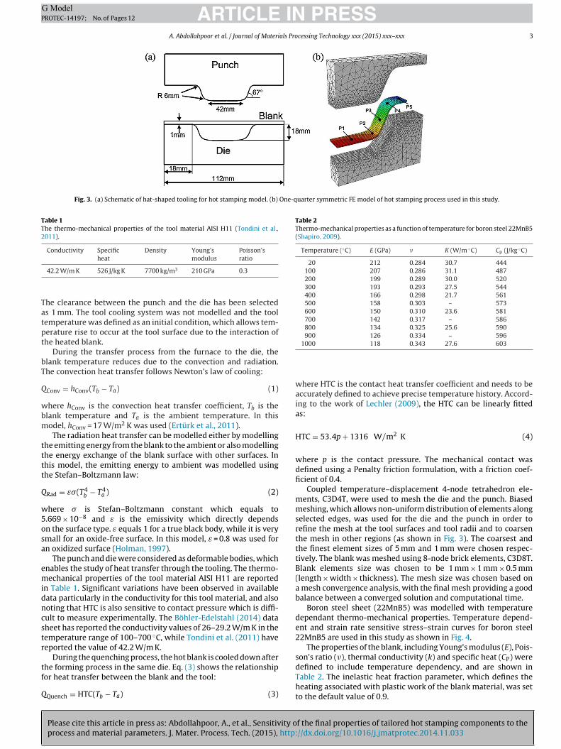
Jominy end-quenching tests were conducted to validate thehermal FE model and metallurgical model developed. In theseests, the 30 mm diameter bar of 22MnB5 was heated and instru-
ented with thermocouples at position A and B shown in Fig. 6a.he bar was heated to 900 ◦C for 5 min and then the end (A) wasater-cooled with a controlled and standardized jet of water, while
he remainder of the bar air cooled. After quenching, the steel cylin-er is cut into several parts for the metallographical microstructurebservation and hardness measurement (Fig. 6b). Jominy tests
Please cite this article in press as: Abdollahpoor, A., et al., Sensitivity oprocess and material parameters. J. Mater. Process. Tech. (2015), http:
rovide a large range of cooling rates. This range of cooling ratess predicted in the model when changing the material and pro-ess parameters in the parametric studies. The thermo-mechanicalnite element model of the Jominy test was specified with heat
Fig. 6. (a) The finite element model of Jominy test, (b) the experimental sample ofJominy test cut for the microstructural and hardness examinations.
transfer coefficients in water and air as a function of temperature(Chen et al., 2014).
2.4. Parametric study
In the hot stamping of boron steels, the final microstructuralphase fractions and the hardness values are closely dependantto the cooling rate and the temperature history, hence the needfor accurate prediction of temperature history via modelling ofthe thermal–mechanical–metallurgical phenomena. It is also nec-essary to investigate the process robustness, in terms of smallvariations of the input parameters and their effect on the finalmicrostructural phase fractions of the stamped part. This under-standing will provide insights into the possible process windowsavailable in order to achieve a desired hardness for local tailoredzones, and the relative significance of the input parameters for hotstamping process modelling.
This paper investigates four cases: higher tool temperatures toachieve soft phases (low and high tooling conductance), air cooling,and conventional hot stamping (i.e. room temperature, high con-ductivity tooling). Table 3 shows the input parameters that wereconsidered in each study, for these following four scenarios:
1. A high conductivity tool material with a high tool temperatureof 450 ◦C that reduces the cooling rate to achieve softer phases.
2. A low conductivity tool material with a tool temperature of175 ◦C, as this results in the same final properties as the firstcondition.
3. Pure air cooling, which is selected to achieve softer phasesincluding ferrite and pearlite.
4. A high conductivity tool material with a tool temperature of25 ◦C, which results in fast cooling rates and a final martensiticmicrostructure.
These scenarios were chosen to simulate a conventional hot-stamping process (Study #4), and three possible methods in whichtailored hot stamping can be achieved (Studies #1 to #3). In Para-metric Study #2 and #3, only the parameters with significant effectsin Parametric Study #1 were considered. In Study #3, the die closuretime and tool temperature were not included, because the primarycooling occurs in air and not in the die.
In each of the parametric studies, the effects of an arbitrary vari-ation of ±10% in the input parameters on the outputs, final phase
f the final properties of tailored hot stamping components to the//dx.doi.org/10.1016/j.jmatprotec.2014.11.033
fractions and hardness, have been investigated. Table 4 shows theinput parameters considered in Parametric Studies #1 and #4,showing the baseline parameter values (0) and the lower and upperlevels (+/−1). For the parameters which are functions of other
ARTICLE IN PRESSG ModelPROTEC-14197; No. of Pages 12
6 A. Abdollahpoor et al. / Journal of Materials Processing Technology xxx (2015) xxx–xxx
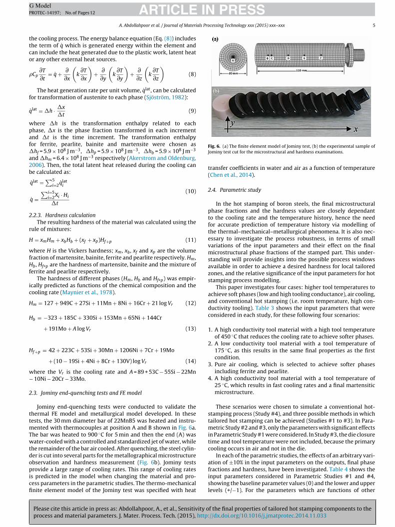
Table 3The parametric studies performed in this paper.
Study #1 Study #2 Study #3 Study #4
Processcondition
Cooling method In-die quenching In-die quenching Air cooling In-die quenchingTool material AISI H11 Macor® – AISI H11Tool temperature 450 ◦C 175 ◦C – 25 ◦CPhases Bainite–martensite Bainite–martensite Ferrite–pearlite–bainite–martensite Martensite
Inputparameters
Die closure time × × – ×Convection film coefficient × × × ×Emissivity in radiation × × × ×Blank specific heat × × × ×Tool temperature × × – ×Latent heat × × × ×Tool conductivity × – – ×Tool specific heat × – – ×Friction coefficient × – – ×Contact pressure × – – ×Heat contact conductance × – – ×Inelastic heat fraction × – – ×Punch speed × – – ×Transfer time × – – ×Blank conductivity × – – ×
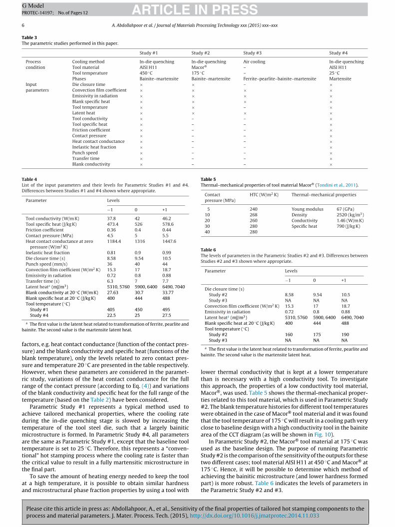
Table 4List of the input parameters and their levels for Parametric Studies #1 and #4.Differences between Studies #1 and #4 shown where appropriate.
Parameter Levels
−1 0 +1
Tool conductivity (W/m K) 37.8 42 46.2Tool specific heat (J/kg K) 473.4 526 578.6Friction coefficient 0.36 0.4 0.44Contact pressure (MPa) 4.5 5 5.5Heat contact conductance at zero
pressure (W/m2 K)1184.4 1316 1447.6
Inelastic heat fraction 0.81 0.9 0.99Die closure time (s) 8.58 9.54 10.5Punch speed (mm/s) 36 40 44Convection film coefficient (W/m2 K) 15.3 17 18.7Emissivity in radiation 0.72 0.8 0.88Transfer time (s) 6.3 7 7.7Latent heata (mJ/m3) 5310, 5760 5900, 6400 6490, 7040Blank conductivity at 20 ◦C (W/m K) 27.63 30.7 33.77Blank specific heat at 20 ◦C (J/kg K) 400 444 488Tool temperature (◦C)
Study #1 405 450 495
b
fsbsHrrot
adtmatttt
aa
Table 5Thermal–mechanical properties of tool material Macor® (Tondini et al., 2011).
Contactpressure (MPa)
HTC (W/m2 K) Thermal–mechanical properties
5 240 Young modulus 67 (GPa)10 268 Density 2520 (kg/m3)20 260 Conductivity 1.46 (W/m K)30 280 Specific heat 790 (J/kg K)40 280
Table 6The levels of parameters in the Parametric Studies #2 and #3. Differences betweenStudies #2 and #3 shown where appropriate.
Parameter Levels
−1 0 +1
Die closure time (s)Study #2 8.58 9.54 10.5Study #3 NA NA NA
Convection film coefficient (W/m2 K) 15.3 17 18.7Emissivity in radiation 0.72 0.8 0.88Latent heata (mJ/m3) 5310, 5760 5900, 6400 6490, 7040Blank specific heat at 20 ◦C (J/kg K) 400 444 488Tool temperature (◦C)
Study #2 160 175 190Study #3 NA NA NA
Study #4 22.5 25 27.5
a The first value is the latent heat related to transformation of ferrite, pearlite andainite. The second value is the martensite latent heat.
actors, e.g. heat contact conductance (function of the contact pres-ure) and the blank conductivity and specific heat (functions of thelank temperature), only the levels related to zero contact pres-ure and temperature 20 ◦C are presented in the table respectively.owever, when these parameters are considered in the paramet-
ic study, variations of the heat contact conductance for the fullange of the contact pressure (according to Eq. (4)) and variationsf the blank conductivity and specific heat for the full range of theemperature (based on the Table 2) have been considered.
Parametric Study #1 represents a typical method used tochieve tailored mechanical properties, where the cooling rateuring the in-die quenching stage is slowed by increasing theemperature of the tool steel die, such that a largely bainitic
icrostructure is formed. In Parametric Study #4, all parametersre the same as Parametric Study #1, except that the baseline toolemperature is set to 25 ◦C. Therefore, this represents a “conven-ional” hot stamping process where the cooling rate is faster thanhe critical value to result in a fully martensitic microstructure in
Please cite this article in press as: Abdollahpoor, A., et al., Sensitivity oprocess and material parameters. J. Mater. Process. Tech. (2015), http:
he final part.To save the amount of heating energy needed to keep the tool
t a high temperature, it is possible to obtain similar hardnessnd microstructural phase fraction properties by using a tool with
a The first value is the latent heat related to transformation of ferrite, pearlite andbainite. The second value is the martensite latent heat.
lower thermal conductivity that is kept at a lower temperaturethan is necessary with a high conductivity tool. To investigatethis approach, the properties of a low conductivity tool material,Macor®, was used. Table 5 shows the thermal-mechanical proper-ties related to this tool material, which is used in Parametric Study#2. The blank temperature histories for different tool temperatureswere obtained in the case of Macor® tool material and it was foundthat the tool temperature of 175 ◦C will result in a cooling path veryclose to baseline design with a high conductivity tool in the bainitearea of the CCT diagram (as will be shown in Fig. 10).
In Parametric Study #2, the Macor® tool material at 175 ◦C wasused as the baseline design. The purpose of running ParametricStudy #2 is the comparison of the sensitivity of the outputs for thesetwo different cases; tool material AISI H11 at 450 ◦C and Macor® at175 ◦C. Hence, it will be possible to determine which method of
f the final properties of tailored hot stamping components to the//dx.doi.org/10.1016/j.jmatprotec.2014.11.033
achieving the bainitic microstructure (and lower hardness formedpart) is more robust. Table 6 indicates the levels of parameters inthe Parametric Study #2 and #3.
ARTICLE IN PRESSG ModelPROTEC-14197; No. of Pages 12
A. Abdollahpoor et al. / Journal of Materials Processing Technology xxx (2015) xxx–xxx 7
Fq
iipaclaha
iriaTei
3
3
3
ab
Fig. 9. Comparison of experimental and numerical temperature histories (Point P1
ig. 7. Finite element and experimental temperature histories during Jominy end-uenching tests. Refer to Fig. 6 for the locations of Points A–F.In both above parametric studies, the baseline designs resultedn only bainite and the martensite phases. It is interesting to exam-ne the process conditions that result in other phases e.g. ferrite andearlite in addition to the bainite and martensite. To achieve thisim, the slower cooling rates are needed. Such softer steel phasesan appear during the phase transformation with slow cooling ratesike free air cooling. In the experimental approach, this could bechieved by just having in-die quenching for the sections whichigh strength is desired but keeping the other sections free in their to achieve ductile properties (Mori and Okuda, 2010).
In Parametric Study #3, the sensitivity of the outputs to the fournput parameters will be investigated with a baseline designed toesult in ferrite and pearlite in addition to the bainite and martens-te. In this case, there is no forming and in-die quenching processesnd the blank only cools down in the air after austenitization.he parameters include the convection film coefficient, radiationmissivity, blank specific heat and the latent heat with the levelsndicated in Table 6.
. Results and discussion
.1. Validation with experimental results
Please cite this article in press as: Abdollahpoor, A., et al., Sensitivity oprocess and material parameters. J. Mater. Process. Tech. (2015), http:
.1.1. Jominy end-quenching testsThe temperature histories results from the finite element model
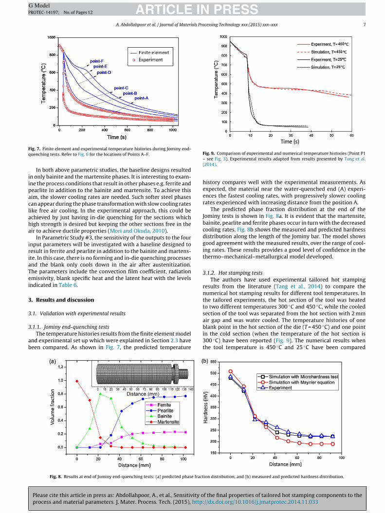
nd experimental set up which were explained in Section 2.3 haveeen compared. As shown in Fig. 7, the predicted temperature
Fig. 8. Results at end of Jominy end-quenching tests: (a) predicted phase fract
– see Fig. 3). Experimental results adapted from results presented by Tang et al.(2014).
history compares well with the experimental measurements. Asexpected, the material near the water-quenched end (A) experi-ences the fastest cooling rates, with progressively slower coolingrates experienced with increasing distance from the position A.
The predicted phase fraction distribution at the end of theJominy tests is shown in Fig. 8a. It is evident that the martensite,bainite, pearlite and ferrite phases occur in turn with the decreasedcooling rates. Fig. 8b shows the measured and predicted hardnessdistribution along the length of the Jominy bar. The model showsgood agreement with the measured results, over the range of cool-ing rates. These results provides a good level of confidence in thethermo–mechanical–metallurgical model developed.
3.1.2. Hot stamping testsThe authors have used experimental tailored hot stamping
results from the literature (Tang et al., 2014) to compare thenumerical hot stamping results for different tool temperatures. Inthe tailored experiments, the hot section of the tool was heatedto two different temperatures 300 ◦C and 450 ◦C, while the cooledsection of the tool was separated from the hot section with 2 mmair gap and was water cooled. The temperature histories of one
f the final properties of tailored hot stamping components to the//dx.doi.org/10.1016/j.jmatprotec.2014.11.033
blank point in the hot section of the die (T = 450 ◦C) and one pointin the cold section (when the temperature of the hot section is300 ◦C) have been reported (Fig. 9). The numerical results whenthe tool temperature is 450 ◦C and 25 ◦C have been compared
ion distribution, and (b) measured and predicted hardness distribution.
IN PRESSG ModelP
8 als Processing Technology xxx (2015) xxx–xxx
wFgenedtFmu
3
mtp
3
eTscfltpib
Pmibi
itsdflf04dtc
outputs. When the tailored hot stamping parts are achieved using
ARTICLEROTEC-14197; No. of Pages 12
A. Abdollahpoor et al. / Journal of Materi
ith the experimental results presented by Tang et al. (2014) inig. 9. Although the air gap can provide sufficiently high thermalradient between the hot and cold sections of the die (Tangt al., 2014), this effect has not been considered in the authors’umerical simulations. Also, even though the materials in thexperimental and simulation processes are similar, the minorifferences in chemical compositions may have effect on theirhermo–mechanical–metallurgical behaviour. The comparison inig. 9 shows an acceptable level of agreement between the experi-ental and numerical results and provide sufficient confidence to
se the numerical model in the parametric studies.
.2. Parametric study
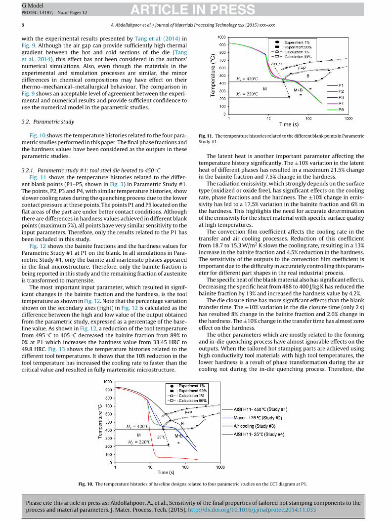
Fig. 10 shows the temperature histories related to the four para-etric studies performed in this paper. The final phase fractions and
he hardness values have been considered as the outputs in thesearametric studies.
.2.1. Parametric study #1: tool steel die heated to 450 ◦CFig. 11 shows the temperature histories related to the differ-
nt blank points (P1–P5, shown in Fig. 3) in Parametric Study #1.he points, P2, P3 and P4, with similar temperature histories, showlower cooling rates during the quenching process due to the lowerontact pressure at these points. The points P1 and P5 located on theat areas of the part are under better contact conditions. Althoughhere are differences in hardness values achieved in different blankoints (maximum 5%), all points have very similar sensitivity to the
nput parameters. Therefore, only the results related to the P1 haseen included in this study.
Fig. 12 shows the bainite fractions and the hardness values forarametric Study #1 at P1 on the blank. In all simulations in Para-etric Study #1, only the bainite and martensite phases appeared
n the final microstructure. Therefore, only the bainite fraction iseing reported in this study and the remaining fraction of austenite
s transformed to martensite.The most important input parameter, which resulted in signif-
cant changes in the bainite fraction and the hardness, is the toolemperature as shown in Fig. 12. Note that the percentage variationhown on the secondary axes (right) in Fig. 12 is calculated as theifference between the high and low value of the output obtainedrom the parametric study, expressed as a percentage of the base-ine value. As shown in Fig. 12, a reduction of the tool temperaturerom 495 ◦C to 405 ◦C decreased the bainite fraction from 89% to% at P1 which increases the hardness value from 33.45 HRC to9.8 HRC. Fig. 13 shows the temperature histories related to the
Please cite this article in press as: Abdollahpoor, A., et al., Sensitivity oprocess and material parameters. J. Mater. Process. Tech. (2015), http:
ifferent tool temperatures. It shows that the 10% reduction in theool temperature has increased the cooling rate to faster than theritical value and resulted in fully martensitic microstructure.
Fig. 10. The temperature histories of baseline designs relate
Fig. 11. The temperature histories related to the different blank points in ParametricStudy #1.
The latent heat is another important parameter affecting thetemperature history significantly. The ±10% variation in the latentheat of different phases has resulted in a maximum 21.5% changein the bainite fraction and 7.5% change in the hardness.
The radiation emissivity, which strongly depends on the surfacetype (oxidized or oxide free), has significant effects on the coolingrate, phase fractions and the hardness. The ±10% change in emis-sivity has led to a 17.5% variation in the bainite fraction and 6% inthe hardness. This highlights the need for accurate determinationof the emissivity for the sheet material with specific surface qualityat high temperatures.
The convection film coefficient affects the cooling rate in thetransfer and air cooling processes. Reduction of this coefficientfrom 18.7 to 15.3 W/m2 K slows the cooling rate, resulting in a 13%increase in the bainite fraction and 4.5% reduction in the hardness.The sensitivity of the outputs to the convection film coefficient isimportant due to the difficulty in accurately controlling this param-eter for different part shapes in the real industrial process.
The specific heat of the blank material also has significant effects.Decreasing the specific heat from 488 to 400 J/kg K has reduced thebainite fraction by 13% and increased the hardness value by 4.2%.
The die closure time has more significant effects than the blanktransfer time. The ±10% variation in the die closure time (only 2 s)has resulted 8% change in the bainite fraction and 2.6% change inthe hardness. The ±10% change in the transfer time has almost zeroeffect on the hardness.
The other parameters which are mostly related to the formingand in-die quenching process have almost ignorable effects on the
f the final properties of tailored hot stamping components to the//dx.doi.org/10.1016/j.jmatprotec.2014.11.033
high conductivity tool materials with high tool temperatures, thelower hardness is a result of phase transformation during the aircooling not during the in-die quenching process. Therefore, the
d to four parametric studies on the CCT diagram at P1.

ARTICLE IN PRESSG ModelPROTEC-14197; No. of Pages 12
A. Abdollahpoor et al. / Journal of Materials Processing Technology xxx (2015) xxx–xxx 9
results
fip
3r
PtiTdittt
F
Fig. 12. The bainite fraction (above) and hardness (below)
nal properties are not sensitive to the forming or in-die quenchingarameters significantly, as shown by this parametric study.
.2.2. Parametric study #2: low conductivity tool material ateduced temperature
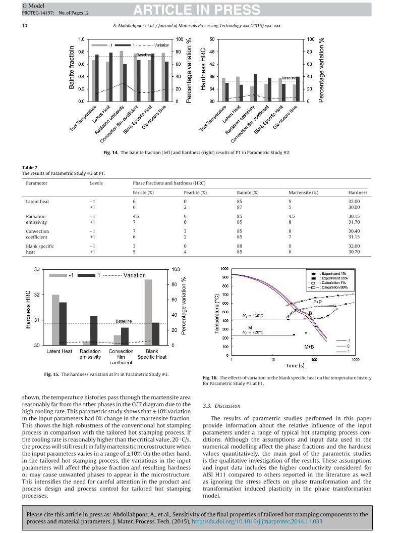
Fig. 14 shows the results of hardness and bainite fraction of1 for Parametric Study #2. Among these parameters, the radia-ion emissivity reflects the most significant effects (11% variationn hardness) which was 6% in Parametric Study #1 at this point.he outputs have a similar sensitivity to the latent heat and theie closure time. The variation in the outputs is 7% in the hardness
n the case of ±10% change in these parameters. The sensitivity of
Please cite this article in press as: Abdollahpoor, A., et al., Sensitivity oprocess and material parameters. J. Mater. Process. Tech. (2015), http:
he results to the tool temperature is significantly lower comparedo the AISI H11 tool material at 450 ◦C. A ±10% change in the toolemperature causes 4.5% variation in the hardness value that is very
ig. 13. The temperature histories related to the different tool temperatures at P1.
of parametric study for the tool temperature 450 ◦C at P1.
low when compared to the 44% change in the case of AISI H11 toolmaterial at 450 ◦C.
3.2.3. Parametric study #3: pure air coolingPure air cooling results in cooling rates that are slower than
the in-die quenching with a low conductivity tool material. As aresult, the softer phases appear in the microstructure for Paramet-ric Study #3. Table 7 shows the phase fractions including ferrite,pearlite, bainite and martensite and also the hardness values in thepure air cooling. Although significant variations in the ferrite andpearlite fractions can be observed, the maximum fraction of fer-rite or pearlite in these conditions was only 7%. On the other hand,unlike the previous parametric studies, the bainite fraction showsa very small sensitivity to the input parameters in this case keepingthe final hardness more stable. Fig. 15 shows the variation of thehardness related to this study. A ±10% change in the latent heat,emissivity, convection film coefficient and the blank specific heatleads to 3.5%, 5%, 2.4% and 6.2% change respectively in the hard-ness values at P1. Fig. 16 shows the effects of variation in the blankspecific heat on the temperature history.
3.2.4. Parametric study #4: tool steel die kept at 25 ◦CAs the final part of the parametric study, the sensitivity of
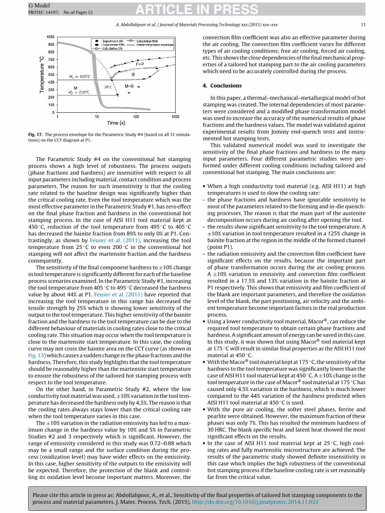
the outputs to the input parameters was investigated at thebaseline design (Table 4) with AISI H11 tool material kept at thetemperature of 25 ◦C. Fig. 17 shows the process envelope for theParametric Study #4 on the CCT diagram at P1. This process enve-lope shows the range of temperature histories predicted for P1 for
f the final properties of tailored hot stamping components to the//dx.doi.org/10.1016/j.jmatprotec.2014.11.033
all simulations in Parametric Study #4, in order to highlight thepossible variation in temperatures, and thus cooling rates, basedon the range of parameters examined. This is not intended to showthe individual temperature history curves for each simulation. As
ARTICLE IN PRESSG ModelPROTEC-14197; No. of Pages 12
10 A. Abdollahpoor et al. / Journal of Materials Processing Technology xxx (2015) xxx–xxx
Fig. 14. The bainite fraction (left) and hardness (right) results of P1 in Parametric Study #2.
Table 7The results of Parametric Study #3 at P1.
Parameter Levels Phase fractions and hardness (HRC)
Ferrite (%) Pearlite (%) Bainite (%) Martensite (%) Hardness
Latent heat −1 6 0 85 9 32.00+1 6 2 87 5 30.00
Radiationemissivity
−1 4.5 6 85 4.5 30.15+1 7 0 85 8 31.70
Convectioncoefficient
−1 7 3 85 8 30.40+1 6 2 85 7 31.15
Blank specificheat
−1 3 0 88 9 32.60+1 5 4 85 6 30.70
srhiTptttipoTpp
Fig. 15. The hardness variation at P1 in Parametric Study #3.
hown, the temperature histories pass through the martensite areaeasonably far from the other phases in the CCT diagram due to theigh cooling rate. This parametric study shows that ±10% variation
n the input parameters had 0% change in the martensite fraction.his shows the high robustness of the conventional hot stampingrocess in comparison with the tailored hot stamping process. Ifhe cooling rate is reasonably higher than the critical value, 20 ◦C/s,he process will still result in fully martensitic microstructure whenhe input parameters varies in a range of ±10%. On the other hand,n the tailored hot stamping process, the variations in the inputarameters will affect the phase fraction and resulting hardness
Please cite this article in press as: Abdollahpoor, A., et al., Sensitivity oprocess and material parameters. J. Mater. Process. Tech. (2015), http:
r may cause unwanted phases to appear in the microstructure.his intensifies the need for careful attention in the product androcess design and process control for tailored hot stampingrocesses.
Fig. 16. The effects of variation in the blank specific heat on the temperature historyfor Parametric Study #3 at P1.
3.3. Discussion
The results of parametric studies performed in this paperprovide information about the relative influence of the inputparameters under a range of typical hot stamping process con-ditions. Although the assumptions and input data used in thenumerical modelling affect the phase fractions and the hardnessvalues quantitatively, the main goal of the parametric studiesis the qualitative investigation of the results. These assumptionsand input data includes the higher conductivity considered forAISI H11 compared to others reported in the literature as well
f the final properties of tailored hot stamping components to the//dx.doi.org/10.1016/j.jmatprotec.2014.11.033
as ignoring the stress effects on phase transformation and thetransformation induced plasticity in the phase transformationmodel.
ARTICLE ING ModelPROTEC-14197; No. of Pages 12
A. Abdollahpoor et al. / Journal of Materials Pro
Ft
p(iprtmos4httsc
iptvitofdcccFhstr
cptw
iSrmcIbl
–
–
–
results of the parametric study showed definite insensitivity in
ig. 17. The process envelope for the Parametric Study #4 (based on all 31 simula-ions) on the CCT diagram at P1.
The Parametric Study #4 on the conventional hot stampingrocess shows a high level of robustness. The process outputsphase fractions and hardness) are insensitive with respect to allnput parameters including material, contact condition and processarameters. The reason for such insensitivity is that the coolingate related to the baseline design was significantly higher thanhe critical cooling rate. Even the tool temperature which was the
ost effective parameter in the Parametric Study #1, has zero effectn the final phase fraction and hardness in the conventional hottamping process. In the case of AISI H11 tool material kept at50 ◦C, reduction of the tool temperature from 495 ◦C to 405 ◦Cas decreased the bainite fraction from 89% to only 0% at P1. Con-rastingly, as shown by Feuser et al. (2011), increasing the toolemperature from 25 ◦C to even 200 ◦C in the conventional hottamping will not affect the martensite fraction and the hardnessonsequently.
The sensitivity of the final component hardness to ±10% changen tool temperature is significantly different for each of the baselinerocess scenarios examined. In the Parametric Study #1, increasinghe tool temperature from 405 ◦C to 495 ◦C decreased the hardnessalue by about 44% at P1. Feuser et al. (2011) have reported thatncreasing the tool temperature in this range has decreased theensile strength by 25% which is showing lower sensitivity of theutput to the tool temperature. This higher sensitivity of the bainiteraction and the hardness to the tool temperature can be due to theifferent behaviour of materials in cooling rates close to the criticalooling rate. This situation may occur when the tool temperature islose to the martensite start temperature. In this case, the coolingurve may not cross the bainite area on the CCT curve (as shown inig. 13) which causes a sudden change in the phase fractions and theardness. Therefore, this study highlights that the tool temperaturehould be reasonably higher than the martensite start temperatureo ensure the robustness of the tailored hot stamping process withespect to the tool temperature.
On the other hand, in Parametric Study #2, where the lowonductivity tool material was used, ±10% variation in the tool tem-erature has decreased the hardness only by 4.5%. The reason is thathe cooling rates always stays lower than the critical cooling ratehen the tool temperature varies in this case.
The ±10% variation in the radiation emissivity has led to a max-mum change in the hardness value by 10% and 5% in Parametrictudies #2 and 3 respectively which is significant. However, theange of emissivity considered in this study was 0.72–0.88 whichay be a small range and the surface condition during the pro-
ess (oxidization level) may have wider effects on the emissivity.
Please cite this article in press as: Abdollahpoor, A., et al., Sensitivity oprocess and material parameters. J. Mater. Process. Tech. (2015), http:
n this case, higher sensitivity of the outputs to the emissivity wille expected. Therefore, the protection of the blank and control-
ing its oxidation level become important matters. Moreover, the
PRESScessing Technology xxx (2015) xxx–xxx 11
convection film coefficient was also an effective parameter duringthe air cooling. The convection film coefficient varies for differenttypes of air cooling conditions; free air cooling, forced air cooling,etc. This shows the close dependencies of the final mechanical prop-erties of a tailored hot stamping part to the air cooling parameterswhich need to be accurately controlled during the process.
4. Conclusions
In this paper, a thermal–mechanical–metallurgical model of hotstamping was created. The internal dependencies of most parame-ters were considered and a modified phase transformation modelwas used to increase the accuracy of the numerical results of phasefractions and the hardness values. The model was validated againstexperimental results from Jominy end-quench tests and instru-mented hot stamping tests.
This validated numerical model was used to investigate thesensitivity of the final phase fractions and hardness to the manyinput parameters. Four different parametric studies were per-formed under different cooling conditions including tailored andconventional hot stamping. The main conclusions are:
• When a high conductivity tool material (e.g. AISI H11) at hightemperatures is used to slow the cooling rate:
the phase fractions and hardness have ignorable sensitivity tomost of the parameters related to the forming and in-die quench-ing processes. The reason is that the main part of the austenitedecomposition occurs during air cooling after opening the tool.
the results show significant sensitivity to the tool temperature. A±10% variation in tool temperature resulted in a 125% change inbainite fraction at the region in the middle of the formed channel(point P1).
the radiation emissivity and the convection film coefficient havesignificant effects on the results, because the important partof phase transformation occurs during the air cooling process.A ±10% variation in emissivity and convection film coefficientresulted in a 17.5% and 13% variation in the bainite fraction atP1 respectively. This shows that emissivity and film coefficient ofthe blank are important parameters, and therefore the oxidationlevel of the blank, the part positioning, air velocity and the ambi-ent temperature become important factors in the real productionprocess.
• Using a lower conductivity tool material, Macor®, can reduce therequired tool temperature to obtain certain phase fractions andhardness. A significant amount of energy can be saved in this case.In this study, it was shown that using Macor® tool material keptat 175 ◦C will result in similar final properties as the AISI H11 toolmaterial at 450 ◦C.
• With the Macor® tool material kept at 175 ◦C, the sensitivity of thehardness to the tool temperature was significantly lower than thecase of AISI H11 tool material kept at 450 ◦C. A ±10% change in thetool temperature in the case of Macor® tool material at 175 ◦C hascaused only 4.5% variation in the hardness, which is much lowercompared to the 44% variation of the hardness predicted whenAISI H11 tool material at 450 ◦C is used.
• With the pure air cooling, the softer steel phases, ferrite andpearlite were obtained. However, the maximum fraction of thesephases was only 7%. This has resulted the minimum hardness of30 HRC. The blank specific heat and latent heat showed the mostsignificant effects on the results.
• In the case of AISI H11 tool material kept at 25 ◦C, high cool-ing rates and fully martensitic microstructure are achieved. The
f the final properties of tailored hot stamping components to the//dx.doi.org/10.1016/j.jmatprotec.2014.11.033
this case which implies the high robustness of the conventionalhot stamping process if the baseline cooling rate is set reasonablyfar from the critical value.
ING ModelP
1 als Pro
R
A
B
B
C
C
E
F
G
Tang, B., Bruschi, S., Ghiotti, A., Bariani, P., 2014. Numerical modelling of the tail-ored tempering process applied to 22MnB5 sheets. Finite Elem. Anal. Des. 81,
ARTICLEROTEC-14197; No. of Pages 12
2 A. Abdollahpoor et al. / Journal of Materi
eferences
kerstrom, P., Oldenburg, M., 2006. Austenite decomposition during press harden-ing of a boron steel – computer simulation and test. J. Mater. Process. Technol.174, 399–406.
öhler-Edelstahl, 2014. Hot Work Tool Steel-W300. Böhler Edelstahl GMBH & Co.KG.
uchmayr, B., Kirkaldy, J., 1990. Modeling of the temperature field, transformationbehavior, hardness and mechanical response of low alloy steels during coolingfrom the austenite region. J. Heat Treat. 8, 127–136.
hen, X., Xiao, N., Li, D., Li, G., Sun, G.,2013. The coupled thermo-mechanical-microstructural finite element modeling of hot stamping process in 22MnB5steel, NUMISHEET, 2014. In: The 9th International Conference and Workshopon Numerical Simulation of 3D Sheet Metal Forming Processes. AIP Publishing,pp. 552–555.
hen, X., Xiao, N., Li, D., Li, G., Sun, G., 2014. The finite element analysis of austen-ite decomposition during continuous cooling in 22MnB5 steel. Modell. Simul.Mater. Sci. Eng. 22 (6), 065005.
rtürk, S., Sester, M., Selig, M., Feuser, P., Roll, K., 2011. A Thermo-mechanical-metallurgical FE approach for simulation of tailored tempering. In: 3rdInternational Conference on Hot Sheet Metal Forming of High-PerformanceSteel, Kassel, Germany, pp. 447–454.
euser, P., Schweiker, T., Merklein, M., 2011. Partially hot-formed parts from22MnB5-process window material characteristics and component test results.
Please cite this article in press as: Abdollahpoor, A., et al., Sensitivity oprocess and material parameters. J. Mater. Process. Tech. (2015), http:
Proc. ICTP, 408–413.eorge, R., Bardelcik, A., Worswick, M., 2011. Hot forming of a lab-scale b-pillar with
tailored properties – experiment and modeling. In: 3rd International Conferenceon Hot Sheet Metal Forming of High-Performance Steel, Kassel, Germany, pp.31–37.
PRESScessing Technology xxx (2015) xxx–xxx
Hibbitt, Karlsson, Sorensen, 2001. ABAQUS/Standard User’s Manual. Hibbitt, Karls-son & Sorensen.
Holman, J., 1997. Heat Transfer. McGraw-Hill, New York.Karbasian, H., Tekkaya, A.E., 2010. A review on hot stamping. J. Mater. Process.
Technol. 210, 2103–2118.Lechler, J., 2009. Beschreibung und Modellierung des Werkstoffverhaltens von
presshärtbaren Bor-Manganstählen. Meisenbach.Maynier, P., Dollet, J., Bastien, P., 1978. Hardenability Concepts with Applications to
Steels. AIME, New York.Mori, K., Okuda, Y., 2010. Tailor die quenching in hot stamping for producing ultra-
high strength steel formed parts having strength distribution. Cirp. Ann.-Manuf.Technol. 59, 291–294.
Oberpriller, B., Burkhardt, L., Griesbach, B., 2008. Benchmark 3-Continuous PressHardening, Part A: Physical Tryout Report, Numisheet 2008 , Interlaken,Switzerland, pp. 115–118.
Oldenburg, M., Lindkvist, G., 2011. Tool thermal conditions for tailored materialproperties. J. Heat Treat. Mater., 6.
Shapiro, A.B., 2009. Using LS-Dyna for Hot Stamping, Seventh European LS-DynaConference. Livemore, CA, USA.
Sjöström, S., 1982. The Calculation of Quench Stresses in Steel. Division of SolidMechanics and Strength of Materials, Department of Mechanical Engineering[Inst. för konstruktions-och produktionsteknik], Univ.
f the final properties of tailored hot stamping components to the//dx.doi.org/10.1016/j.jmatprotec.2014.11.033
69–81.Tondini, F., Bosetti, P., Bruschi, S., 2011. Heat transfer in hot stamping of high-
strength steel sheets. P. I. Mech. Eng. B.-J. Eng. 225, 1813–1824.