11OBDG11 Parameters(12)
246
This document is intended to meet the requirements documented in section 1968.2 of Title 13, California Code of Regulations entitled Modifications to Malfunction and Diagnosis System Requirements for 2004 and Subsequent Model-Year Passenger Cars, Light-Duty Trucks, and Medium-Duty Vehicles and Engines (OBD II), paragraphs (i)(2.2) for a table detailing calibration parameter data for OBD II Group 11OBDG11. Section 1 : S1-11OBDG11 Contains information that is common to all applications within 11OBDG11 GMT911 - Chevrolet Silverado HD GMT912 - GMC Sierra HD Section 2 : S2-11OBDG11_Glow Plug Module Contains diagnostic information that performed within the Glow Plug Control Module and common to all applications within 11OBDG11 The diagnostic algorithms are contained within the Glow Plug Control Module, but the Fault Code storage handling and MIL Illumination are performed within the ECM Section 3 : S3-11OBDG11-LGH_Specific Contains information that is specific to the LGH applications within 11OBDG11 GMT911 - Chevrolet Silverado HD GMT610 - Chevrolet Express GMT912 - GMC Sierra HD Parameter Definition Contains definitions of secondary parameters which are used in the parameter document. These secondary parameters conditions are shown in the respective physical parameters which define each condition. Calibration Look-Up Tables Contains the calibration look-up tables from both the Section 1 and the Parameter Definitions Inhibit Tables Contains the matrix of diagnostics which are inhibited from being executed if an active DTC is stored in the ECM 11 OBDG11 Engine Diagnostics Contents Contents Page 1 of 2
-
Upload
khangminh22 -
Category
Documents
-
view
3 -
download
0
Transcript of 11OBDG11 Parameters(12)

This document is intended to meet the requirements documented in section 1968.2 of Title 13, California Code of Regulations entitled Modifications to Malfunction and Diagnosis System Requirements for 2004 and Subsequent Model-Year Passenger Cars, Light-Duty Trucks, and Medium-Duty Vehicles and Engines (OBD II), paragraphs (i)(2.2) for a table detailing calibration parameter data for OBD II Group 11OBDG11.
Section 1 : S1-11OBDG11
Contains information that is common to all applications within 11OBDG11GMT911 - Chevrolet Silverado HDGMT912 - GMC Sierra HD
Section 2 : S2-11OBDG11_Glow Plug Module
Contains diagnostic information that performed within the Glow Plug Control Module and common to all applications within 11OBDG11
The diagnostic algorithms are contained within the Glow Plug Control Module,but the Fault Code storage handling and MIL Illumination are performed within the ECM
Section 3 : S3-11OBDG11-LGH_Specific
Contains information that is specific to the LGH applications within 11OBDG11GMT911 - Chevrolet Silverado HD GMT610 - Chevrolet ExpressGMT912 - GMC Sierra HD
Parameter DefinitionContains definitions of secondary parameters which are used in the parameter document. �
These secondary parameters conditions are shown in the respective physical parameters which define each condition.
Calibration Look-Up TablesContains the calibration look-up tables from both the Section 1 and the Parameter Definitions�
Inhibit TablesContains the matrix of diagnostics which are inhibited from being executed if an active DTC is stored in the ECM
11 OBDG11 Engine Diagnostics Contents
Contents Page 1 of 2

Enable TablesContains the matrix of additional enable conditions which need to be satisfied for each diagnotic to be enabled
11 OBDG11 Engine Diagnostics Contents
Contents Page 2 of 2

COMPONENT/ SYSTEM FAULT CODE
MONITOR STRATEGY DESCRIPTION MALFUNCTION CRITERIA SECONDARY PARAMETERS TIME REQUIRED MIL ILLUM.
P0088 rail pressure deviation from t i t l l t d t f
< -80000 to -20000
kPa Path 1: B
THRESHOLD VALUE ENABLE CONDITIONS
Fuel Rail Pressure Measured rail pressure is h k d i t d i d il
fail conditions i t f 8setpoint calculated out of
difference between desired and actual value (see Look-Up-Table #54)
20000
setpoint volume flow of the metering unit out of rail pressure
control
> 1310680 mm^3/rev
and
[FRP] Too High checked against desired rail pressure to detect high rail pressure conditions.
exists for 8 smonitor runs with
0.02 s rate whenever enable
conditions are met
current injection quantity > 8 mm^3/rev
andfuel temperature > -40.04 °C
andstate machine rail pressure
control equal to metering unit l d
= TRUE -
control modeand
basic enable conditions met: = see sheet enable tables
-
andmetering unit actuator test active = FALSE -metering unit actuator test active = FALSE -
andNO Pending or Confirmed DTCs: = see
sheet inhibit tables
-
rail pressure deviation from setpoint calculated out of difference between desired and actual value
< -20000 kPa (
state machine rail pressure control equal to pressure control
valve
= TRUE -
orstate machine rail pressure
control equal coupled pressure control (rail pressure is controlled
by metering unit and pressure control valve)
= TRUE -
11 OBDG11 Engine Diagnostics COMMON SECTION1 OF 3 SECTIONS
COMMON SECTION Page 1 of 104 1 OF 3 SECTIONS

COMPONENT/ SYSTEM FAULT CODE
MONITOR STRATEGY DESCRIPTION MALFUNCTION CRITERIA SECONDARY PARAMETERS TIME REQUIRED MIL ILLUM.THRESHOLD VALUE ENABLE CONDITIONS
)
andpressure setpoint of rail pressure
control<= 327670 kPa
andbasic enable conditions met: = see
sheet enable tables
-
andNO Pending or Confirmed DTCs: = see
sheet inhibit tables
-
P008F Path 1: engine-off time >= 28800 sec B
|(a) - (b)| (see Look-Up-Table #12)
> 100 to 999 °C and
with ambient temperature > -60.04 °C( and
(a) captured engine coolant temperature at start
= measured parameter
- Engine Running = TRUE rpm
d ith f
Engine Coolant Temperature (ECT)-Fuel Temperature Not Plausible
Detects a biased ECT or fuel temperature by comparing start-up temperatures between the two sensors.
fail conditions exists for 0.2 s
monitor runs once per trip with 0.2 s
rate whenever enable conditions
are met
and with for(b) captured fuel temperature at start
= measured parameter
- time > 0 sec
) andor engine post drive/ afterun = FALSE -Path 2: and( diagnostic performed in current
d i l= FALSE -
drive cycle|(a) - (b)| (see Look-Up-Table #12)
<= 100 to 999 °C and
with basic enable conditions met: = see sheet enable tables
-
(a) captured engine coolant andtemperature at startand with NO Pending or Confirmed DTCs: = see
sheet inhibit tables
-
(b) captured fuel temperature at start
11 OBDG11 Engine Diagnostics COMMON SECTION1 OF 3 SECTIONS
COMMON SECTION Page 2 of 104 1 OF 3 SECTIONS

COMPONENT/ SYSTEM FAULT CODE
MONITOR STRATEGY DESCRIPTION MALFUNCTION CRITERIA SECONDARY PARAMETERS TIME REQUIRED MIL ILLUM.THRESHOLD VALUE ENABLE CONDITIONS
and|(a) - (b)| (see Look-Up-Table #13)
> 20 to 999 °C#13)with(a) captured engine coolant temperature at start
= measured parameter
-
and with(b) captured fuel temperature at start
= measured parameter
-
dand(status of block heater = FALSEactive under following condition(engine speed > 500 rpmforfortime > 60 secand(a) - (b) < 1.8 °Cwith(a) reference temperature (engine coolant temperature) captured d i t t
= measured parameter
-
during startand with(b) engine coolant temperature value for the comparision with the reference temperature
= measured parameter
-
)ort t f l d d t ti FALSEstatus of sun-load detection = FALSE
active under following condition
(vehicle speed > 14.92 mphfortime > 300 secandEngine Running = TRUE -fortime > 600 secand
11 OBDG11 Engine Diagnostics COMMON SECTION1 OF 3 SECTIONS
COMMON SECTION Page 3 of 104 1 OF 3 SECTIONS

COMPONENT/ SYSTEM FAULT CODE
MONITOR STRATEGY DESCRIPTION MALFUNCTION CRITERIA SECONDARY PARAMETERS TIME REQUIRED MIL ILLUM.THRESHOLD VALUE ENABLE CONDITIONS
(a) - (b) < 4.5 °Cwith(a) captured intake air temperature at start
= measured parameter
-
and with
(b) minimum intake air temperature value for the comparision with the reference temperature during driving cycle
= measured parameter
-
p g g y
)))
P0191 fuel pressure regulator 2 adaptation factor
>= 1.25 factor fuel pressure regulator 2 in closed loop control
= TRUE - AFuel Rail Pressure [FRP] Sensor
Detects a drifted fuel rail pressure sensor by determining the
fail conditions exists for 0.01 s
or andfuel pressure regulator 2 adaptation factor
<= 0.75 factor adaptation for fuel pressure regulator 2 active
= TRUE -
means(
counter for successful adaptation > 0 counts
[FRP] Sensor Performance
adaptation factor of the fuel rail pressure regulator 2.
monitor runs with 0.01 s rate
whenever enable conditions are met
orcounter for the successful
calculation of the adaptation> 9 counts
andenable condition stability counter > 60 counts
(((
engine speed < 400 rpmand
engine speed > 1000 rpm)
andvehicle speed <= 1.86 mph
and(
fuel rail pressure control in fuel pressure regulator 2 mode
= TRUE -
orfuel rail pressure control in
combined pressure control (CPC) mode
= TRUE -
11 OBDG11 Engine Diagnostics COMMON SECTION1 OF 3 SECTIONS
COMMON SECTION Page 4 of 104 1 OF 3 SECTIONS

COMPONENT/ SYSTEM FAULT CODE
MONITOR STRATEGY DESCRIPTION MALFUNCTION CRITERIA SECONDARY PARAMETERS TIME REQUIRED MIL ILLUM.THRESHOLD VALUE ENABLE CONDITIONS
)))
andand
basic enable conditions met: = see sheet enable tables
-
( engine post drive/ afterun = TRUE -il lt 0 352 V d
Detects a biased sensor by determining the FRP sensor
fail conditions exists for morerail pressure sensor voltage < 0.352 V and
or fuel temperature > -0.04 °Crail pressure sensor voltage > 0.65 V and) engine has already run in this
driving cycle= TRUE -
andrail pressure is reduced = TRUE -
determining the FRP sensor voltage to be in the correct range for atmospheric pressure at engine off and with sufficient pressure bleed-off time.
exists for more than 0.30 s
monitor runs once per driving cycle with 0.01 s rate
whenever enable conditions are met
meansrail pressure does not exceed < 0 kPa
andfuel pressure regulator 2 current <= 1.7 Amps
andengine off time > 30.08 sec
ornumber of measurements during
engine postdrive/ afterun> 10 counts
andbasic enable conditions met: = see
sheet enable
-
enable tables
andNO Pending or Confirmed DTCs: = see
sheet inhibit tables
-
P0234 control deviation of the boost pressure calculated out of difference between desired and actual value (see Look-Up-Table #46)
< -35.0 to -11.5 kPa injection quantity >= 132 mm^3/rev
BTurbocharger Engine Overboost
Detects an Overboost condition by comparing desired to measured boost values.
fail conditions exists for 10 s
monitor runs with 0.02 s rate
whenever enable
11 OBDG11 Engine Diagnostics COMMON SECTION1 OF 3 SECTIONS
COMMON SECTION Page 5 of 104 1 OF 3 SECTIONS

COMPONENT/ SYSTEM FAULT CODE
MONITOR STRATEGY DESCRIPTION MALFUNCTION CRITERIA SECONDARY PARAMETERS TIME REQUIRED MIL ILLUM.THRESHOLD VALUE ENABLE CONDITIONS
injection quantity <= 480 mm^3/rev
conditions are met
engine speed >= 1450 rpm engine speed <= 3200 rpm
turbo charger control deviation >= -100 %turbo charger control deviation <= 100 %desired turbo charger position < 100 %
(injection quantity is stable = TRUE -
meansincrease of injection quantity < 60.00 (mm^3/r
ev)/secand
engine speed is stable = TRUE -means
increase of engine speed < 75 rpm/secand
turbo charger (VNT) wiping is active
= FALSE -
andoffset learning for turbo charger
(VNT) act ator position sensor is= FALSE -
(VNT) actuator position sensor is active during idling
- in order to compensate sensor drift and valve aging the valve is
closed and opened fully once in a driving cycle during engine idling,
the read positions for opening and closing are averaged and used for the calculation of offset drift of the
valve
andworking range of boost pressure
is in closed-loop= TRUE -
means(
engine speed > 1200 rpmand
injection quantity > 20 mm^3/rev
and
11 OBDG11 Engine Diagnostics COMMON SECTION1 OF 3 SECTIONS
COMMON SECTION Page 6 of 104 1 OF 3 SECTIONS

COMPONENT/ SYSTEM FAULT CODE
MONITOR STRATEGY DESCRIPTION MALFUNCTION CRITERIA SECONDARY PARAMETERS TIME REQUIRED MIL ILLUM.THRESHOLD VALUE ENABLE CONDITIONS
NO Pending or Confirmed DTCs: see sheet inhibit
-
inhibit tables
)for
time > 2 secand
basic enable conditions met: see sheet
-sheet enable tables
P026A Detects insufficient charge-air cooler. Actual cooler efficiency readings are compared to a
filtered charge-air cooler efficiency calculated out of temperature upstream of the
< (a) + (b) + (c) - vehicle speed >= 31.08 mph BCAC Efficiency Below Threshold
fail conditions exists for 30 s
monitor runs once threshold as an indication of cooling efficiency.
cooler, temperature downstream of the cooler and ambient temperature
with and(a) temperature correction of efficiency-threshold
= 0 - (
and with mass air flow >= 13.89 g/sec
per driving cycle with 100 ms rate whenever enable
conditions are met
(b) threshold of charge-air cooler efficiency
= 0.150024 factor and
and with mass air flow (see Look-Up-Table #11)
<= 55.56 to 277.78
g/sec
(c) correction factor for efficiency threshold depending on temperature after charge air cooler
= 0 factor )
coolerand
(engine coolant temperature >= -3549.9 °C
andengine coolant temperature <= 122.96 °C
)andand
((maximum of (a) and (b)) / (b) >= 1.21997 -
with
11 OBDG11 Engine Diagnostics COMMON SECTION1 OF 3 SECTIONS
COMMON SECTION Page 7 of 104 1 OF 3 SECTIONS

COMPONENT/ SYSTEM FAULT CODE
MONITOR STRATEGY DESCRIPTION MALFUNCTION CRITERIA SECONDARY PARAMETERS TIME REQUIRED MIL ILLUM.THRESHOLD VALUE ENABLE CONDITIONS
(a) boost pressure downstream compressor
= measured
paramet
-
parameter
and with(b) ambient pressure = measure
d paramet
er
-
)and
(control value of the throttle valve <= 5.0049 %
)and
diagnostic performed in current = FALSE -drive cycle
and(a) - (b) >= 40 °C
with(a) temperature after compressor
(b) ambient air temperatureand
injection quantity >= 80 mm^3/rev
injection quantity <= 480 mm^3/rev
andfor
time > 0 sec and
ambient pressure > 74.8 kPaand
ambient temperature > -7.04 °Cand
basic enable conditions met: = see sheet enable tables
-
and
11 OBDG11 Engine Diagnostics COMMON SECTION1 OF 3 SECTIONS
COMMON SECTION Page 8 of 104 1 OF 3 SECTIONS

COMPONENT/ SYSTEM FAULT CODE
MONITOR STRATEGY DESCRIPTION MALFUNCTION CRITERIA SECONDARY PARAMETERS TIME REQUIRED MIL ILLUM.THRESHOLD VALUE ENABLE CONDITIONS
NO Pending or Confirmed DTCs: = see sheet inhibit
-
inhibit tables
P0299 control deviation of the boost pressure calculated out of the difference between desired and actual value (see Look-Up-Table
> 17.5 to 40.0 kPa engine speed >= 1450 rpm BTurbochager Engine Underboost
Detects an Underboost condition by comparing desired to measured boost values.
fail conditions exists for 10 s
monitor runs with 0.02 s rate ( p
#45)engine speed <= 2000 rpm
injection quantity >= 132 mm^3/rev
injection quantity <= 480 mm^3/rev
(
whenever enable conditions are met
injection quantity is stable = TRUE -
means
increase of injection quantity < 60.00 (mm^3/rev)/s
andengine speed is stable = TRUE -
meansincrease of engine speed < 75 rpm/sec
andturbo charger (VNT) wiping is
active = FALSE -
andoffset learning for turbo charger = FALSE -g g
(VNT) actuator position sensor is active during idling
- in order to compensate sensor drift and valve aging the valve is
closed and opened fully once in a driving cycle during engine idling,
the read positions for opening andthe read positions for opening and closing are averaged and used for the calculation of offset drift of the
valve
and
11 OBDG11 Engine Diagnostics COMMON SECTION1 OF 3 SECTIONS
COMMON SECTION Page 9 of 104 1 OF 3 SECTIONS

COMPONENT/ SYSTEM FAULT CODE
MONITOR STRATEGY DESCRIPTION MALFUNCTION CRITERIA SECONDARY PARAMETERS TIME REQUIRED MIL ILLUM.THRESHOLD VALUE ENABLE CONDITIONS
working range of boost pressure is in closed-loop
means((
engine speed > 1200 rpmand
injection quantity > 20 mm^3/rev
andNO Pending or Confirmed DTCs: = see
sheet inhibit tables
-
)for
time > 2 secand
basic enable conditions met: = see sheet enable tables
-
Crankshaft Position System Variation Not Learned
P0315 Wheel Learn - Fuel Balance System - Tooth Wheel Variation and Crankshaft Dynamics not learned quickly enough
fuel balance wheel learn complete = FALSE - fuel system is in fuel cut off = TRUE - B
particulate filter regeneration = FALSE -Path 1:Low Speed Learn Range engine speed > 900 rpm
fail conditions exists for 5000 s cumulative time
monitor runs with 1 s rate whenever
enable conditions are met
or engine speed < 1450 rpmPath 2: orMid Speed Learn Range engine speed >= 1450 rpm
engine speed < 1900 rpm
fuel balance wheel learn complete = FALSE -
Inhibit Status ( no inhibiting faults )
( No pending or stored DTC )
= see sheet inhibit tables
-
11 OBDG11 Engine Diagnostics COMMON SECTION1 OF 3 SECTIONS
COMMON SECTION Page 10 of 104 1 OF 3 SECTIONS

COMPONENT/ SYSTEM FAULT CODE
MONITOR STRATEGY DESCRIPTION MALFUNCTION CRITERIA SECONDARY PARAMETERS TIME REQUIRED MIL ILLUM.THRESHOLD VALUE ENABLE CONDITIONS
Exhaust Gas Recirculation(EGR)
P0400 Detects excessive EGR flow. Actual MAF readings are compared to desired MAF values
controller deviation of the air mass = actual minus desired value
> 2 g/rev ( fail conditions exists for 10 s
monitor runs 0 02
A
Flow Excessivecompared to desired MAF values as an indication of how much EGR is flowing.
value
EGR controler is active = TRUEand
(change of injection quantity
between current and last value< 80.00 (mm^3/r
ev)/s
monitor runs 0.02 s rate whenever
enable conditions are met
between current and last value ev)/s)
and(
change of engine speed between currentl and last value
< 75 rpm/sec
)and
maximum setpoint for air-mass flow
< (a) / (b) * (c) * (d) / ((e) / (f)) / (g) * (h)
with((
(a) gas mass flow into the engine
and with(b) pressure in the intake manifold
and with(c) pressure in the induction
lvolumeand with
(d) system constant 33333and with
(e) number of engine cylinders 8and with
(f) number of cylinder banks 1( ) yand with
(g) engine speedand with
(h) correction factor 1)
11 OBDG11 Engine Diagnostics COMMON SECTION1 OF 3 SECTIONS
COMMON SECTION Page 11 of 104 1 OF 3 SECTIONS

COMPONENT/ SYSTEM FAULT CODE
MONITOR STRATEGY DESCRIPTION MALFUNCTION CRITERIA SECONDARY PARAMETERS TIME REQUIRED MIL ILLUM.THRESHOLD VALUE ENABLE CONDITIONS
andsetpoint valve position of exhaust- > 5.0049 %
gas recirculation
andengine speed >= 1150 rpm
andengine speed <= 1600 rpm
andinjection quantity >= 160 mm^3/reinjection quantity >= 160 mm 3/re
vand
injection quantity <= 480 mm^3/rev
andDesired value for mass flow
through the EGR valve<= 194.44 g/sec
andandnot disabled during following
conditionssee
sheet disable tables
andNO Pending or Confirmed DTCs: see
sheet inhibit tables
)for
time >= 1.5 sec
P0401 Detects insufficient EGR flow. controller deviation of the exhaust < -2.4 to -0.5 g/rev engine speed >= 625 rpm BExhaust Gas fail conditionsP0401 Detects insufficient EGR flow. Actual MAF readings are compared to desired MAF values as an indication of how much EGR is flowing.
controller deviation of the exhaust gas recirculation (EGR) - calculated out of desired and actual value (see Look-Up-Table #9)
2.4 to 0.5 g/rev engine speed 625 rpm B
engine speed <= 2000 rpminjection quantity >= 20 mm^3/re
vinjection quantity <= 120 mm^3/re
Exhaust Gas Recirculation(EGR) Flow Insufficient
fail conditions exists for 10 s
monitor runs 0.02 s rate whenever
enable conditions are met
injection quantity 120 mm 3/rev
maximum EGR mass flow > 1.00 g/revEGR valve position > 5.01 %
throttle valve position < 5.00 %(
11 OBDG11 Engine Diagnostics COMMON SECTION1 OF 3 SECTIONS
COMMON SECTION Page 12 of 104 1 OF 3 SECTIONS

COMPONENT/ SYSTEM FAULT CODE
MONITOR STRATEGY DESCRIPTION MALFUNCTION CRITERIA SECONDARY PARAMETERS TIME REQUIRED MIL ILLUM.THRESHOLD VALUE ENABLE CONDITIONS
EGR controller is active = TRUE -and
(change of injection quantity
between actual and previous value
< 80.00 (mm^3/rev)/s
withlow-pass filter time = 0.25 sec
)and
(change of engine speed between
actual and previous value< 75 rpm/sec
withlow-pass filter time = 1.00 sec
)and
maximum setpoint for air-mass flow
< (a) / (b) * (c) * (d) / ((e) / (f)) / (g) * (h)
-
with(
(a) gas mass flow into the engine = calculated
parameter
-
and with(b) pressure in the intake manifold = measure
d-
d paramet
erand with
(c) pressure in the induction volume
= calculated
parameter
-
d ithand with(d) system constant = 33333 -
and with(e) number of engine cylinders = 8 -
and with(f) number of cylinder banks = 1 -
11 OBDG11 Engine Diagnostics COMMON SECTION1 OF 3 SECTIONS
COMMON SECTION Page 13 of 104 1 OF 3 SECTIONS

COMPONENT/ SYSTEM FAULT CODE
MONITOR STRATEGY DESCRIPTION MALFUNCTION CRITERIA SECONDARY PARAMETERS TIME REQUIRED MIL ILLUM.THRESHOLD VALUE ENABLE CONDITIONS
and with(g) engine speed = measure
d-
d paramet
erand with
(h) correction factor = 1 factor)
andsetpoint valve position of exhaust- > 5 0049 %setpoint valve position of exhaust-
gas recirculation> 5.0049 %
andbasic enable conditions met: = see
sheet enable tables
-
andNO Pending or Confirmed DTCs: = see
sheet inhibit tables
-
)for
time >= 3 sec
P0402 Detects excessive EGR flow. Actual MAF readings are compared to desired MAF values as an indication of how much EGR is flowing.
controller deviation of the exhaust gas recirculation (EGR) - calculated out of desired and actual value (see Look-Up-Table #8)
> 0.4 to 1.2 g/rev engine speed >= 1150 rpm B
i d 1600
Exhaust Gas Recirculation(EGR) Flow Excessive
fail conditions exists for 8 s
monitor runs 0.02 s rate whenever
enable conditions are metengine speed <= 1600 rpm
injection quantity >= 160 mm^3/rev
injection quantity <= 480 mm^3/rev
maximum EGR mass flow < 0.96 g/rev(
EGR controller is active = TRUE -
are met
and(
change of injection quantity between actual and previous
value
< 80.00 (mm^3/rev)/sec
with
11 OBDG11 Engine Diagnostics COMMON SECTION1 OF 3 SECTIONS
COMMON SECTION Page 14 of 104 1 OF 3 SECTIONS

COMPONENT/ SYSTEM FAULT CODE
MONITOR STRATEGY DESCRIPTION MALFUNCTION CRITERIA SECONDARY PARAMETERS TIME REQUIRED MIL ILLUM.THRESHOLD VALUE ENABLE CONDITIONS
low-pass filter time = 0.25 sec)
and(
change of engine speed between actual and previous value
< 75 rpm/sec
withlow-pass filter time = 1.00 sec
))and
maximum setpoint for air-mass flow
< (a) / (b) * (c) * (d) / ((e) / (f)) / (g) * (h)
-
with((
(a) gas mass flow into the engine = calculated
parameter
-
and with(b) pressure in the intake manifold = measure
d -
parameter
and with(c) pressure in the induction
volume= calculate
d paramet
er
-
and withand with(d) system constant = 33333 -
and with(e) number of engine cylinders = 8 -
and with(f) number of cylinder banks = 1 -
and with( ) i d(g) engine speed = measure
d paramet
er
-
and with(h) correction factor = 1 factor
)
11 OBDG11 Engine Diagnostics COMMON SECTION1 OF 3 SECTIONS
COMMON SECTION Page 15 of 104 1 OF 3 SECTIONS

COMPONENT/ SYSTEM FAULT CODE
MONITOR STRATEGY DESCRIPTION MALFUNCTION CRITERIA SECONDARY PARAMETERS TIME REQUIRED MIL ILLUM.THRESHOLD VALUE ENABLE CONDITIONS
andbasic enable conditions met: = see
h t-
sheet enable tables
andNO Pending or Confirmed DTCs: = see
sheet inhibit tables
-
)for
time >= 1.5 sec
Exhaust Gas Recirculation(EGR) T t S
P040F Detects biased EGR temperature sensors by comparing the two EGR cooler temp sensor after an
Path 1: |(a) - (b)| <= 20 °C Bfail conditions exists for 0.1 s
monitor runs with Temperature Sensor Correlation (EGR 1/ EGR 2)
engine off soak time
|(a) - (b)| (see Look-Up-Table #4) > 100 to 999 °C with
with (a) captured EGR sensor 2 temperature at start
= measured
paramet
-
0.1 s rate whenever enable
conditions are met
parameter
(a) captured EGR sensor 2 temperature at start
= measured parameter
- and with
and with (b) captured EGR sensor 1 temperature at start as reference
temperature
= measured
parameter
-
(b) captured EGR sensor 1 temperature at start
= measured parameter
- and
or engine-off time >= 28800 secPath 2: and( ambient temperature > -60.04 °C|(a) - (b)| (see Look-Up-Table #4) <= 100 to 999 °C and
with Engine Running = TRUEwith Engine Running = TRUE -(a) captured EGR sensor 2 temperature at start
= measured parameter
- for
and with time > 0 sec(b) captured EGR sensor 1 temperature at start
= measured parameter
- and
and engine post drive/ afterun = FALSE -
11 OBDG11 Engine Diagnostics COMMON SECTION1 OF 3 SECTIONS
COMMON SECTION Page 16 of 104 1 OF 3 SECTIONS

COMPONENT/ SYSTEM FAULT CODE
MONITOR STRATEGY DESCRIPTION MALFUNCTION CRITERIA SECONDARY PARAMETERS TIME REQUIRED MIL ILLUM.THRESHOLD VALUE ENABLE CONDITIONS
|(a) - (b)| (see Look-Up-Table #7) > 20 to 999 °C and
with diagnostic performed in current = FALSE -with diagnostic performed in current drive cycle
FALSE
(a) captured EGR sensor 2 temperature at start
= measured parameter
- and
and with basic enable conditions met: = see sheet enable tables
-
(b) captured EGR sensor 1 temperature at start
= measured parameter
- and
and NO Pending or Confirmed DTCs: = see sheet inhibit tables
-
(status of block heater = FALSEstatus of block heater = FALSEactive under following condition(engine speed > 500 rpmfortime > 60 secand(a) - (b) < 1.8 °Cwith(a) reference temperature (engine coolant temperature) captured during startand with(b) engine coolant temperature(b) engine coolant temperature value for the comparision with the reference temperature)orstatus of sun-load detection = FALSE
active under following condition(vehicle speed > 14.92 mphfortime > 300 secand
11 OBDG11 Engine Diagnostics COMMON SECTION1 OF 3 SECTIONS
COMMON SECTION Page 17 of 104 1 OF 3 SECTIONS

COMPONENT/ SYSTEM FAULT CODE
MONITOR STRATEGY DESCRIPTION MALFUNCTION CRITERIA SECONDARY PARAMETERS TIME REQUIRED MIL ILLUM.THRESHOLD VALUE ENABLE CONDITIONS
Engine Running = TRUE -fortime > 600 secand(a) - (b) < 4.5 °Cwith(a) captured intake ait temperature at start
and withand with(b) minimum intake air temperature value for the comparision with the reference temperature during driving cycle
))))
P0420 HC conversion rate < 0.199951 factor evaluation of the HC conversion rate for monitoring of the OxiCat
is released
= TRUE - B
means(
NMHC Catalyst Efficiency Below Threshold Bank 1
Detects insufficient conversion rate in oxidation catalyst. Actual conversion rate is compared to a conversion rate threshold as an indication of how much HC is
fail conditions exists for more than 1 event
monitor runs once per driving cycle(
HC mass converted in the oxidation catalyst since monitor
start
> 140 g
andaverage HC mass flow > 0.0009 g/sec
andsimulated heat quantity in > 0 kJ
indication of how much HC is converted in the oxidation catalyst.
per driving cycle with 0.1 s rate
whenever enable conditions are met
simulated heat quantity in oxidation catalyst
0 kJ
andparticulate filter regeneration = TRUE -
andno reset condition for evaluation
is activetherefore
(regeneration was not aborted to assure that HC conversion was
not disturbed
= TRUE -
and
11 OBDG11 Engine Diagnostics COMMON SECTION1 OF 3 SECTIONS
COMMON SECTION Page 18 of 104 1 OF 3 SECTIONS

COMPONENT/ SYSTEM FAULT CODE
MONITOR STRATEGY DESCRIPTION MALFUNCTION CRITERIA SECONDARY PARAMETERS TIME REQUIRED MIL ILLUM.THRESHOLD VALUE ENABLE CONDITIONS
evaluation took place one time step before
= FALSE -
))and
monitoring evaluation scheduling -condition from TRUE to FALSE in order to determine the end of HC
conversion
= TRUE -
means((
set conditionparticulate filter regeneration = TRUE -
measured temperature upstream of the oxidation catalyst
> 249.96 °C
and(
engine speed > 700 rpmand
engine speed < 3400 rpm)
anddiagnostic performed in current
drive cycle= FALSE -
dandreset condition = FALSE -
becomes FALSE under following conditions
(converted HC mass in the
oxidation catalyst during monitoring
< 140 g
gor
particulate filter regeneration = FALSE -or
regeneration was not aborted to assure that HC converion was
disturbed
= TRUE -
andNO Pending or Confirmed DTCs: = see
sheet inhibit tables
-
)and
11 OBDG11 Engine Diagnostics COMMON SECTION1 OF 3 SECTIONS
COMMON SECTION Page 19 of 104 1 OF 3 SECTIONS

COMPONENT/ SYSTEM FAULT CODE
MONITOR STRATEGY DESCRIPTION MALFUNCTION CRITERIA SECONDARY PARAMETERS TIME REQUIRED MIL ILLUM.THRESHOLD VALUE ENABLE CONDITIONS
basic enable conditions met: = see sheet enable
-
enable tables
P0495 fan speed (see Look-Up-Table #34)
> 400 to 1500 rpm indication that the fan clutch is pumped out
= TRUE - B
meansfluid volume in Clutch (see Look-
Up-Table #35)< 0.005 to
0 0115liter
Cooling Fan Speed High
Detects a locked fan. When fan speed control solenoid is off, the fan speed should follow accessory drive input speed plus some slip.
fail conditions exists for 0.02s
monitor runs with 0.1 s rate
whenever enable Up Table #35) 0.0115and
fan speed > 1500 rpmand
PWM of fan driver output < 44.9951 %and
ambient pressure > 55.5 kPa
conditions are met
andintake air temperature > -40.04 °C
andengine off time > 0 sec
and(
Engine Running = TRUE -Engine Running = TRUE -for
time > 0 sec)
andnumber of failure events >= 800 counts
andbasic enable conditions met: = see
sheet enable tables
-
P0567 CAN message stays in high state too long
= TRUE - ignition = on - Special CCruise Control Resume Switch
Resume switch state indicates problem with the circuit
fail conditions exists for 90 s
andinput circuit active = TRUE -
and
Resume Switch Circuit
monitor runs with 0.005 s rate
whenever enable conditions are met
11 OBDG11 Engine Diagnostics COMMON SECTION1 OF 3 SECTIONS
COMMON SECTION Page 20 of 104 1 OF 3 SECTIONS

COMPONENT/ SYSTEM FAULT CODE
MONITOR STRATEGY DESCRIPTION MALFUNCTION CRITERIA SECONDARY PARAMETERS TIME REQUIRED MIL ILLUM.THRESHOLD VALUE ENABLE CONDITIONS
basic enable conditions met: = see sheet enable
-conditions are met
enable tables
andNO Pending or Confirmed DTCs: = see
sheet inhibit tables
-
P0568 CAN message stays in high state too long
= TRUE - ignition = on - Special C
andinput circuit active = TRUE -
and
Cruise Control Set Switch Circuit
Set switch state indicates problem with the circuit
fail conditions exists for 90 s
monitor runs with 0.005 s rate
whenever enable a dbasic enable conditions met: = see
sheet enable tables
-
andNO Pending or Confirmed DTCs: = see
sheet inhibit
-
conditions are met
inhibit tables
P0575 amount of errors in consecutive frames
>= 3 counts ignition = on - Special C
with and
Cruise Control Input Circuit
Cruise control CAN communication monitoring
fail conditions exists for 0.005 ms monitor runs withwith and
number of consecutive frames = 10 counts input circuit active = TRUE -and
basic enable conditions met: = see sheet enable tables
-
and
monitor runs with 0.005 s rate
whenever enable conditions are met
NO Pending or Confirmed DTCs: = see sheet inhibit tables
-
11 OBDG11 Engine Diagnostics COMMON SECTION1 OF 3 SECTIONS
COMMON SECTION Page 21 of 104 1 OF 3 SECTIONS

COMPONENT/ SYSTEM FAULT CODE
MONITOR STRATEGY DESCRIPTION MALFUNCTION CRITERIA SECONDARY PARAMETERS TIME REQUIRED MIL ILLUM.THRESHOLD VALUE ENABLE CONDITIONS
P0606 SPI communication, data transfer = TRUE - ignition = on - AControl Module Monitors that ECM is operating fail conditions f 0lost
andbasic enable conditions met: = see
sheet enable tables
-
Internal Performance correctly at proper voltage. All internal hardware modules are communicating correctly.
exists for 0.5 s test performed
continuously with 0.01 s rate
faults detected in the SPI communication
> 184 counts ignition = on - A
IC internal andNO Pending or Confirmed DTCs: = see
sheet inhibit tables
-
fail conditions exists for at least
0.64 secmonitor runs once per trip during pre
driveperformed at 0 04tables
P0606 i t l l lt 4 2 V i iti A
performed at 0.04 s rate whenever
enable conditions are met
f il ditiP0606 internal supply voltage < 4.2 V ignition = on - Aor and
internal supply voltage > 5.25 V counter of reactivation attempt of power output stage
>= 2 counts
andNO Pending or Confirmed DTCs: = see
sheet -
fail conditions exists for at least
0.08 secmonitor runs once per trip during pre
driveperformed at 0.04 s rate whenever
inhibit tables
P0606 |(a) - (b)| > 50 us programmed energizing time for fuel injection has been read back
= TRUE - A
enable conditions are met
fail conditions exists for 0.15 s
monitor runs withwith means(a) measured energizing time for fuel injection
programmed energizing time for fuel injection
>= 0 -
and with and
monitor runs with 0.01 s rate
whenever enable conditions are met
11 OBDG11 Engine Diagnostics COMMON SECTION1 OF 3 SECTIONS
COMMON SECTION Page 22 of 104 1 OF 3 SECTIONS

COMPONENT/ SYSTEM FAULT CODE
MONITOR STRATEGY DESCRIPTION MALFUNCTION CRITERIA SECONDARY PARAMETERS TIME REQUIRED MIL ILLUM.THRESHOLD VALUE ENABLE CONDITIONS
(b) programmed energizing time for fuel injection
measured energizing time for fuel injection has been read back
= TRUE -
meansmeasured energizing time for fuel
injection>= 0 -
andengine speed > 1200 rpm
andil 20000 kPrail pressure > 20000 kPa
andengine test active via diagnostic
tester= FALSE -
P0606 Path 1: engine speed > 1200 rpm A( and
l f i j ti tit 32 983 d i t t ti i di ti FALSE
fail conditions exists for at least
0.5sangle for pre injection quantity < -32.983 degrees engine test active via diagnostic tester
= FALSE -
orangle for pre injection quantity > 102.9921 degrees)orPath 2:(
0.5smonitor runs with
0.01 s rate whenever enable
conditions are met
(angle for main injection quantity < -32.983 degrees
orangle for main injection quantity > 45.0247 degrees
)ororPath 3:(angle for post injection quantity 1 < -360 degrees
orangle for post injection quantity 1 > -66.9987 degrees
)orPath 4:(angle for post injection quantity 2 < -82.9958 degrees
11 OBDG11 Engine Diagnostics COMMON SECTION1 OF 3 SECTIONS
COMMON SECTION Page 23 of 104 1 OF 3 SECTIONS

COMPONENT/ SYSTEM FAULT CODE
MONITOR STRATEGY DESCRIPTION MALFUNCTION CRITERIA SECONDARY PARAMETERS TIME REQUIRED MIL ILLUM.THRESHOLD VALUE ENABLE CONDITIONS
orangle for post injection quantity 2 > 45.0247 degrees
)
P0606 A( ignition = on -energizing times of the correction value for pre injection quantity (see Look-Up-Table #43)
< -500 to -50 us andfail conditions
exists for at least 5 events
monitor runs with
or engine test active via diagnostic tester
= FALSE -
energizing times of the correction value for pre injection quantity (see Look-Up-Table #42)
> 50 to 500 us
)
0.04 s rate whenever enable
conditions are met
)
P0606 APath 1: post injection 2 = ACTIVE -
( andefficiency factor for post injection < 0 factor engine test active via diagnostic = FALSE -
fail conditions exists for at least
15smonitor runs with
0 04 s rate2 testerorefficiency factor for post injection 2
> 1 factor
)orPath 2:
0.04 s rate whenever enable
conditions are met
start angle of energising for post injection 2
> (a) + (b) -
with(a) earliest possible start angle for post injection 2
9.9982 degrees
and with(b) measured base angle for post ( ) g pinjection 2
orPath 3:time for exhaust gas system operation mode changes
>= 2621.4 sec
11 OBDG11 Engine Diagnostics COMMON SECTION1 OF 3 SECTIONS
COMMON SECTION Page 24 of 104 1 OF 3 SECTIONS

COMPONENT/ SYSTEM FAULT CODE
MONITOR STRATEGY DESCRIPTION MALFUNCTION CRITERIA SECONDARY PARAMETERS TIME REQUIRED MIL ILLUM.THRESHOLD VALUE ENABLE CONDITIONS
P0606 post injection quantity 2 > 130 mm^3 ignition = on - Aand
fail conditions exists for at leastand
particulate filter regeneration = FALSE -and
engine test active via diagnostic tester
= FALSE -
exists for at least 0.5s
monitor runs with 0.04 s rate
whenever enable conditions are met
P0606 ( post injection 3 = ACTIVE - Aefficiency factor of post injection 3 < -1 factor and
or engine test active via diagnostic tester
= FALSE -
efficiency factor of post injection 3 > 1 factor
fail conditions exists for at least
0.5smonitor runs with
0.04 s rate whenever enable
conditions are met)
P0606 averaged wave correction quantity for pre injection
= 0 mm^3 Engine Running = TRUE - A
or andaveraged wave correction = 0 mm^3 engine test is active via diagnostic = FALSE -
fail conditions exists for at least
10 events monitor runs with
0.04 s rate quantity for main injection tester
oraveraged wave correction quantity for post injection 3
= 0 mm^3
oraveraged wave correction quantity for post injection 2
= 0 mm^3
whenever enable conditions are met
quantity for post injection 2
AP0606 rail pressure gradient > 202400 kPa ( A
voltage of rail pressure sensor < 1.855 Vor
voltage of rail pressure sensor > 4.8145 V
fail conditions exists for 2.67 s
monitor runs with 0.01 s rate
whenever enable)
anddelay time > 2.1 sec
andengine test active via diagnostic
tester= FALSE -
whenever enable conditions are met
11 OBDG11 Engine Diagnostics COMMON SECTION1 OF 3 SECTIONS
COMMON SECTION Page 25 of 104 1 OF 3 SECTIONS

COMPONENT/ SYSTEM FAULT CODE
MONITOR STRATEGY DESCRIPTION MALFUNCTION CRITERIA SECONDARY PARAMETERS TIME REQUIRED MIL ILLUM.THRESHOLD VALUE ENABLE CONDITIONS
AAP0606 internal supply voltage < 4.2 V ignition = on - A
or
internal supply voltage > 5.25 V
A
fail conditions exists for 0.05 s test performed
continuously with 0.01 s rate
P0606 WDA (watch dog) shut off due to undervoltage
= TRUE - shut off path test active = FALSE - A
means andinternal supply voltage < 4.2 V battery voltage > 8 V
fortime > 1 secand
fail conditions exists for 0.01 s
monitor runs with 0.01 s rate
whenever enable conditions are met
WDA (watch daog) line active = TRUE -
AP0606 WDA (watch dog) shut off due to
overvoltage= TRUE - shut off path test active = FALSE - A
means andinternal supply voltage > 5.25 V WDA (watch daog) line active = TRUE -
fail conditions exists for 0.01 s
monitor runs with 0.01 s rate
whenever enable
AP0606 WDA (watch dog) shut off due to
internal security error= TRUE - shut off path test active = FALSE - A
and
fail conditions exists for 0.01 s
monitor runs with
whenever enable conditions are met
andWDA (watch dog) line active = TRUE -
WDA (watch dog) shut off b f t ti d
= TRUE - ignition = on -
0.01 s rate whenever enable
conditions are met
fail conditions i t f 0 01because of corrupt question-and-
answer communication and
WDA (watch dog) line active = TRUE -and
shut off path test active = FALSE -
exists for 0.01 s monitor runs with
0.01 s rate whenever enable
conditions are met
11 OBDG11 Engine Diagnostics COMMON SECTION1 OF 3 SECTIONS
COMMON SECTION Page 26 of 104 1 OF 3 SECTIONS

COMPONENT/ SYSTEM FAULT CODE
MONITOR STRATEGY DESCRIPTION MALFUNCTION CRITERIA SECONDARY PARAMETERS TIME REQUIRED MIL ILLUM.THRESHOLD VALUE ENABLE CONDITIONS
the actual response time from processor is not equal to the requested response-time
= TRUE - ignition = on -
andNO Pending or Confirmed DTCs: = see
sheet inhibit
-
fail conditions exists for more than 2 events
monitor runs 0.04 s rate whenever
enable conditions are met
tables
redudnant, independent algorithm for plausibility fault of accelerator pedal signal for safety reasons:
fail conditions exists for 0.28 s
monitor runs with 0 04 s rate
Path 1: ignition = on -
|(maximum (a) (b)) - 2 * (maximum (c) (b))|
> 0.29 V
with(a) voltage accelerator pedal 1 = measured
parameter-
0.04 s rate whenever enable
conditions are met
and with(b) lower limit for accelerator pedal voltage
= 0.8 V
and with(c) voltage accelerator pedal 2 = measured
parameter-
andand(voltage accelerator pedal 1 > 1.45 Vorvoltage accelerator pedal 2 > 1.45 V)orPath 2:|(maximum (a) (b)) - 2 * (maximum (c) (b))|
> 0.41 V
with(a) voltage accelerator pedal 1 = measured
parameter-
and with
11 OBDG11 Engine Diagnostics COMMON SECTION1 OF 3 SECTIONS
COMMON SECTION Page 27 of 104 1 OF 3 SECTIONS

COMPONENT/ SYSTEM FAULT CODE
MONITOR STRATEGY DESCRIPTION MALFUNCTION CRITERIA SECONDARY PARAMETERS TIME REQUIRED MIL ILLUM.THRESHOLD VALUE ENABLE CONDITIONS
(b) lower limit for accelerator pedal voltage
= 0.80 V
d ithand with(c) voltage accelerator pedal 2 = measured
parameter-
and(voltage accelerator pedal 1 <= 1.45 Vorvoltage accelerator pedal 2 <= 1 45 Vvoltage accelerator pedal 2 <= 1.45 V)
no response to an injection request
= TRUE - ignition = on -
processor internal andNO Pending or Confirmed DTCs: = see
sheet-
fail conditions exists for more than 2 events
monitor runs 0.04 s rate whenever
bl ditisheet inhibit tables
no response to shut-off path test = TRUE - ignition = on -
enable conditions are met
fail conditions exists for more
processor internal andNO Pending or Confirmed DTCs: = see
sheet inhibit tables
-
than 184 eventsmonitor runs with
0.04 s rate whenever enable
conditions are met
no response to hardware activation request
= TRUE - ignition = on -
processor internal andNO Pending or Confirmed DTCs: = see
sheet inhibit
-
fail conditions exists for more than 98 events
monitor runs with 0.04 s rate
whenever enable conditions are mettables
no response from processor operative system
= TRUE - ignition = on -
conditions are met
fail conditions exists for more th 2 t
11 OBDG11 Engine Diagnostics COMMON SECTION1 OF 3 SECTIONS
COMMON SECTION Page 28 of 104 1 OF 3 SECTIONS

COMPONENT/ SYSTEM FAULT CODE
MONITOR STRATEGY DESCRIPTION MALFUNCTION CRITERIA SECONDARY PARAMETERS TIME REQUIRED MIL ILLUM.THRESHOLD VALUE ENABLE CONDITIONS
processor internal andNO Pending or Confirmed DTCs: = see
h t-
than 2 eventsmonitor runs with
0 04 s ratesheet inhibit tables
Path 1: ignition = on -
0.04 s rate whenever enable
conditions are met
fail conditions exists for morerepetitions of injection shut-off
path test>= 184 counts and
or injection shut-off path test = ACTIVE -Path 2:(number of a powerstage test too few
< 2 counts
and
exists for more than 16 events
monitor runs with 0.04 s rate
whenever enable conditions are met
andnumber of cylinders >= 8 -)
prevention of the execution of the shut-off path test
= TRUE - ignition = on - fail conditions exists for 0.08 s
andinjection shut-off path test = ACTIVE -
too few bytes received by = TRUE - ignition = on -
monitor runs with 0.04 s rate
whenever enable conditions are met
fail conditions y ymonitoring module from CPU
g
meansbytes received by monitoring module from CPU as response
< 4 bytes
exists for more than 10 events
monitor runs with 0.04 s rate
whenever enable conditions are met
ECM detects interruption in the SPI communication
= TRUE - ignition = on -
processor internal-
fail conditions exists for more than 2 events
monitor runs with 0 04 s rate
11 OBDG11 Engine Diagnostics COMMON SECTION1 OF 3 SECTIONS
COMMON SECTION Page 29 of 104 1 OF 3 SECTIONS

COMPONENT/ SYSTEM FAULT CODE
MONITOR STRATEGY DESCRIPTION MALFUNCTION CRITERIA SECONDARY PARAMETERS TIME REQUIRED MIL ILLUM.THRESHOLD VALUE ENABLE CONDITIONS
0.04 s rate whenever enable
conditions are met
ECM detects plausibility error of the communication between controller and the monitoring module (2 processors in ECU)
= TRUE - ignition = on - fail conditions exists for more than 5 events
monitor runs with processor internal 0.04 s rate
whenever enable conditions are met
supply voltage to injector chip 1 < 3.10 V ignition = on -or andsupply voltage to injector chip 1 > 3.50 V battery voltage > 8.00 V
fail conditions exists for 0.05 s
monitor runs with 0.01 s rate
whenever enable conditions are met
supply voltage to injector chip 2 < 3.10 V ignition = on -
or and
supply voltage to injector chip 2 > 3.50 V battery voltage > 8.00 V
fail conditions exists for 0.05 s
monitor runs with 0.01 s rate
whenever enable diti t
pp y g j p y g
internal injector driver chip error = TRUE - Engine Running = TRUE -
conditions are met
fail conditions
IC internal andbasic enable conditions met: = see
sheet enable tables
-
exists for more than 10 events
monitor runs with 0.01 s rate
whenever enable conditions are met
11 OBDG11 Engine Diagnostics COMMON SECTION1 OF 3 SECTIONS
COMMON SECTION Page 30 of 104 1 OF 3 SECTIONS

COMPONENT/ SYSTEM FAULT CODE
MONITOR STRATEGY DESCRIPTION MALFUNCTION CRITERIA SECONDARY PARAMETERS TIME REQUIRED MIL ILLUM.THRESHOLD VALUE ENABLE CONDITIONS
piezo injector actuator internal feedback voltage
< 0 V main injection = ACTIVE -
orpiezo injector actuator internal feedback voltage
> 3.3 V
fail conditions exists for more than 10 events
monitor runs with 0.01 s rate
whenever enable conditions are met
Path 1: injection cut off demand from ECM internal monitoring
= TRUE -
engine speed > 1500 rpm
conditions are met
fail conditions exists for 0.02 s
monitor runs with 0 02or
Path 2:engine speed > 1600 rpm
0.02 s rate whenever enable
conditions are met
security torque limitation request by air system control due to implausible air system control requests
= TRUE - ignition = on - fail conditions exists for more
than 5secruns with 0.01 s
rate
security torque limitation request by rail pressure control due to implausible rail pressure request
= TRUE - ignition = on -
security torque limitation request by injection quantity setpoint
= TRUE - ignition = on -
fail conditions exists for more
than 5secruns with 0.01 s
rate
fail conditions exists for moreby injection quantity setpoint
control due to implausible quantity setpoint control requests
exists for more than 5sec
runs with 0.01 s rate
11 OBDG11 Engine Diagnostics COMMON SECTION1 OF 3 SECTIONS
COMMON SECTION Page 31 of 104 1 OF 3 SECTIONS

COMPONENT/ SYSTEM FAULT CODE
MONITOR STRATEGY DESCRIPTION MALFUNCTION CRITERIA SECONDARY PARAMETERS TIME REQUIRED MIL ILLUM.THRESHOLD VALUE ENABLE CONDITIONS
indicated torque > (a) + (b) + (c) + (d)
- engine speed > 600 to 850
rpm
ith
fail conditions exists for more than 12 eventswith
(a) modeled inner engine torque = calculated parameter
-
and with(b) torque tolerance offset (see Look-Up-Table #41)
= 11.72 to 99.61 %
and with
than 12 eventsmonitor runs with
0.04 s rate whenever enable
conditions are met
(c) torque of engine speed controller
= calculated parameter
-
and with(d) torque of surge damper control
= calculated parameter
-
SW reset = TRUE ignition = on fail conditionsSW reset = TRUE - ignition = on -evaluation of SW reset after each reset
fail conditions exists for 0.02 stest performed
continuously with 0.02 s rate
voltage of charging switch > 210 V ECM is in startup before injections are released
= TRUE -
orvoltage of charging switch if buffer of a bank is not charged completely, or not at all
> 100 V
fail conditions exists for more than 4 events
monitor runs with 0.01 s rate
whenever enable conditions are met
error at startup of DC/DC converter of one bank
= TRUE - ignition = on -
andDC/DC converter is in startup = TRUE -
and
fail conditions exists for 0.01 ms monitor runs with
0.01 s rate whenever enable
conditions are metandbasic enable conditions met: = see
sheet enable tables
-conditions are met
11 OBDG11 Engine Diagnostics COMMON SECTION1 OF 3 SECTIONS
COMMON SECTION Page 32 of 104 1 OF 3 SECTIONS

COMPONENT/ SYSTEM FAULT CODE
MONITOR STRATEGY DESCRIPTION MALFUNCTION CRITERIA SECONDARY PARAMETERS TIME REQUIRED MIL ILLUM.THRESHOLD VALUE ENABLE CONDITIONS
DC/DC converter cannot be switched off.
= TRUE - ignition = on -
Traction Control Input Signal
P0856 Detects a failure when a certain number of Traction Control System torque request messages within a defined message group checksum or rolling count values
Error counter for Traction Control torque request message group
>= 3 counts Traction Control Torque Request CAN Message Received
= TRUE - fault exists for 1 message group ;
monitor runs whenever enable
conditions are
Special C
checksum or rolling count values are incorrect
conditions are met.
andNO Pending or Confirmed DTCs: = see
sheet inhibit tables
-
andandignition on = TRUE -
Internal Control Module Vehicle Performance
P150A difference of time periods of two consecutive pulses received from the tooth wheel
> 5 % ( BElectronic ECM circuitry determines if faults related to the TPU chip used to calculate Vehicle speed exist
fail conditions exists for more
than 30smonitor runs withPerformance
and sensed vehicle speed > 12.43 mph( andnumber of deviations > 2 counts sensed vehicle speed < 93.23 mph
Previously P062C in initial submission
and )
number of deviations < 40 counts and
Vehicle speed exist. monitor runs with 0.02 s rate
whenever enable conditions are met
) basic enable conditions met: = see sheet enable tables
-
P0851 ECM (on-board control unit) sensed position based on PNP switch inputs to ECM indicates park or neutral and the GMLAN message from the TCM disagrees
= TRUE - ( BPark/Neutral Position (PNP) Switch Circuit High Voltage
Detects high voltage condition on the PNP circuit by comparing the ECM sensed input to the broadcasted state from the TCM over GMLAN serial data
fail conditions exist for more than 3smonitor runs with
0.01 s rate whenever enable
conditions are met
11 OBDG11 Engine Diagnostics COMMON SECTION1 OF 3 SECTIONS
COMMON SECTION Page 33 of 104 1 OF 3 SECTIONS

COMPONENT/ SYSTEM FAULT CODE
MONITOR STRATEGY DESCRIPTION MALFUNCTION CRITERIA SECONDARY PARAMETERS TIME REQUIRED MIL ILLUM.THRESHOLD VALUE ENABLE CONDITIONS
battery voltage > 11.00 Vand
conditions are met
battery voltage < 655.34 V)
andengine speed >= 650 rpm
andvehicle speed >= 14.92 mph
andengine torque >= 120 Nm
andaccelerator pedal position >= 0 %
and(
selected gear position is park = FALSE -oror
selected gear position is neutral = FALSE -)
andno validation fault in the
transmission shift lever position received via CAN from TCM
= TRUE -
anda dbasic enable conditions met: = see
sheet enable tables
-
andNO Pending or Confirmed DTCs: = see
sheet inhibit
-
inhibit tables
P0852 GMLAN Message for PNP position indicates park neutral and disagrees with ECM (on-board control unit) sensed
= TRUE - ( BPark/Neutral Position (PNP) Switch Circuit Low Voltage
Detects low voltage condition on the PNP circuit by comparing the ECM sensed input to the broadcasted state from the TCM
fail conditions exist for more than 3smonitor runs with
0.01 s rate position based on PNP switch inputs to ECM
battery voltage > 11.00 Vand
battery voltage < 655.34 V)
over GMLAN serial data whenever enable conditions are met
11 OBDG11 Engine Diagnostics COMMON SECTION1 OF 3 SECTIONS
COMMON SECTION Page 34 of 104 1 OF 3 SECTIONS

COMPONENT/ SYSTEM FAULT CODE
MONITOR STRATEGY DESCRIPTION MALFUNCTION CRITERIA SECONDARY PARAMETERS TIME REQUIRED MIL ILLUM.THRESHOLD VALUE ENABLE CONDITIONS
andengine speed <= 7000 rpm
and(
selected gear position is park = TRUE -or
selected gear position is neutral = TRUE -)
andno validation fault in the
transmission shift lever position received via CAN from TCM
= TRUE -
andbasic enable conditions met: = see
sheet enable t bl
-
tablesand
NO Pending or Confirmed DTCs: = see sheet inhibit tables
-
P111C Path 1: |(a) - (b)| <= 35 °C B|(a) - (b)| (see Look-Up-Table #3) > 100 to 999 °C with
with (a) captured charge air cooler downstream temperature at start
= measured
parameter
-
(a) captured charge air cooler = measured - and with
Charge Air Cooler Temperature Sensor Performance
Detects bias charge air cooler temperature sensor downstream or charge air cooler temperature sensor upstream by comparing the start-up values.
fail conditions exists for 0.1 s
monitor runs once per trip with 0.1 s
rate whenever enable conditions
are met(a) captured charge air cooler downstream temperature at start
measured parameter
and with
and with (b) captured charge air cooler upstream temperature at start as
reference temperature
= measured
parameter
-
(b) captured charge air cooler upstream temperature at start
= measured parameter
- and
or engine off time >= 28800 secor engine-off time >= 28800 secPath 2: and( ambient temperature > -60.04 °C|(a) - (b)| (see Look-Up-Table #3) <= 100 to 999 °C and
with Engine Running = TRUE -
11 OBDG11 Engine Diagnostics COMMON SECTION1 OF 3 SECTIONS
COMMON SECTION Page 35 of 104 1 OF 3 SECTIONS

COMPONENT/ SYSTEM FAULT CODE
MONITOR STRATEGY DESCRIPTION MALFUNCTION CRITERIA SECONDARY PARAMETERS TIME REQUIRED MIL ILLUM.THRESHOLD VALUE ENABLE CONDITIONS
(a) captured charge air cooler downstream temperature at start
= measured parameter
- for
and with time > 0 sec(b) captured charge air cooler upstream temperature at start
= measured parameter
- and
and engine post drive/ afterun = FALSE|(a) - (b)| (see Look-Up-Table #6) > 35 to 999 °C and
with diagnostic performed in current = FALSE -with diagnostic performed in current drive cycle
FALSE
(a) captured charge air cooler downstream temperature at start
= measured parameter
- and
and with basic enable conditions met: = see sheet enable tables
-
tables(b) captured charge air cooler upstream temperature at start
= measured parameter
- and
and NO Pending or Confirmed DTCs: = see sheet inhibit tables
-
(t t f bl k h t FALSEstatus of block heater = FALSE -
active under following condition(engine speed > 500 rpmfortime > 60 secand(a) - (b) < 1.8 °Cwith(a) reference temperature (engine coolant temperature) captured during start
= calculated parameter
-
and with(b) engine coolant temperature
l f th i i ith th= measured
t-
value for the comparision with the reference temperature
parameter
)orstatus of sun-load detection = FALSE -active under following condition
11 OBDG11 Engine Diagnostics COMMON SECTION1 OF 3 SECTIONS
COMMON SECTION Page 36 of 104 1 OF 3 SECTIONS

COMPONENT/ SYSTEM FAULT CODE
MONITOR STRATEGY DESCRIPTION MALFUNCTION CRITERIA SECONDARY PARAMETERS TIME REQUIRED MIL ILLUM.THRESHOLD VALUE ENABLE CONDITIONS
(vehicle speed > 14.92 mphfortime > 300 secandEngine Running = TRUE -fortime > 600 secand(a) - (b) < 4.5 °Cwith(a) captured intake ait temperature at start
= measured parameter
-
and with(b) minimum intake air temperature value for the
= measured parameter
-
comparision with the reference temperature during driving cycle
)))
P111D Path 1: |(a) - (b)| <= 20 °C BFuel Temperature Detects bias Fuel Temperature Sensor or Intake Air Temperature
fail conditions exists for 0 1 s|(a) - (b)| (see Look-Up-Table #2) > 100 to 999 °C with
with (a) captured intake air temperature at start
= measured
parameter
-
(a) captured intake air temperature at start
= measured parameter
- and with
Sensor Performance Sensor or Intake Air Temperature Sensor by comparing thier start-up values.
exists for 0.1 smonitor runs once per trip with 0.1 s
rate whenever enable conditions
are met
and with (b) captured fuel temperature at start as reference temperature
= measured
parameter
-
(b) captured fuel temperature at start
= measured parameter
- and
or engine-off time >= 28800 secPath 2: andPath 2: and( ambient temperature > -60.04 °C|(a) - (b)| (see Look-Up-Table #2) <= 100 to 999 °C and
with Engine Running = TRUE -
11 OBDG11 Engine Diagnostics COMMON SECTION1 OF 3 SECTIONS
COMMON SECTION Page 37 of 104 1 OF 3 SECTIONS

COMPONENT/ SYSTEM FAULT CODE
MONITOR STRATEGY DESCRIPTION MALFUNCTION CRITERIA SECONDARY PARAMETERS TIME REQUIRED MIL ILLUM.THRESHOLD VALUE ENABLE CONDITIONS
(a) captured intake air temperature at start
= measured parameter
- for
and with time > 0 sec(b) captured fuel temperature at start
= measured parameter
- and
and engine post drive/ afterun = FALSE -|(a) - (b)| (see Look-Up-Table #5) > 20 to 999 °C and
with diagnostic performed in current drive cycle
= FALSE -drive cycle
(a) captured intake air temperature at start
= measured parameter
- and
and with basic enable conditions met: = see sheet enable tables
-
(b) captured fuel temperature at = measured - andstart parameterand NO Pending or Confirmed DTCs: = see
sheet inhibit tables
-
(status of block heater = FALSE -active under following conditionactive under following condition(engine speed > 500 rpmfortime > 60 secand(a) - (b) < 1.8 °Cwithwith(a) reference temperature (engine coolant temperature) captured during start
= calculated parameter
-
and with(b) engine coolant temperature value for the comparision with the
= measured parameter
-
reference temperature
)orstatus of sun-load detection = FALSEactive under following condition
11 OBDG11 Engine Diagnostics COMMON SECTION1 OF 3 SECTIONS
COMMON SECTION Page 38 of 104 1 OF 3 SECTIONS

COMPONENT/ SYSTEM FAULT CODE
MONITOR STRATEGY DESCRIPTION MALFUNCTION CRITERIA SECONDARY PARAMETERS TIME REQUIRED MIL ILLUM.THRESHOLD VALUE ENABLE CONDITIONS
(vehicle speed > 14.92 mphforfortime > 300 secandEngine Running = TRUE -fortime > 600 secand( ) (b) 4 5 °C(a) - (b) < 4.5 °Cwith(a) captured intake air temperature at start
= measured parameter
-
and with(b) minimum intake air temperature value for the
i i ith th f
= measured parameter
-
comparision with the reference temperature during driving cycle
)))
P11B5 (a) / (b) < 0.1 ratio (( BHO2S Current Compares the ratio of valid fail conditions ( ) ( ) (((a) The time for which lambda signal is valid, once the lambda feedback diagnosis is enabled
= calculated parameter
- NOx sensor’s heater temperature has reached the set point
= TRUE -
(b) The time duration for which lambda feedback diagnosis is enabled
= calculated parameter
- for time > 2 sec
)
HO2S Current Performance Bank 1 Sensor 2
plambda signal time to total time with a threshold
exists for more than 20 sec
monitor runs with 0.02 s rate
whenever enable conditions are met
for time > 120 sec)
andEnabling Downstream NOx
sensor heater diagnosis (please see the definition)
= TRUE -
and(
| (a) - (b)| (see Look-Up-Table #76)
<= 0.1 to 22 -
11 OBDG11 Engine Diagnostics COMMON SECTION1 OF 3 SECTIONS
COMMON SECTION Page 39 of 104 1 OF 3 SECTIONS

COMPONENT/ SYSTEM FAULT CODE
MONITOR STRATEGY DESCRIPTION MALFUNCTION CRITERIA SECONDARY PARAMETERS TIME REQUIRED MIL ILLUM.THRESHOLD VALUE ENABLE CONDITIONS
(a) Reciprocal lambda signal after combustion
= measured
paramet
-
parameter
(b) Filtered reciprocal lambda signal after combustion
= measured
parameter
-
for time > 5 sec))
NO Pending or Confirmed DTCs: = see sheet inhibit tables
-
basic enable conditions met: = see sheet enable t bl
-
tables
NOx Sensor Performance - Signal High Bank 1 Sensor 1
P11CB Detects a high deviation of the measured NOx sensor concentration from the modeled NO i
Filtered NOx concentration deviation from model
> 0.699951 - The signal of the NOx sensor is ready
= TRUE - Bfault exists for more than 10s
monitor runs once i i h 0 1High Bank 1 Sensor 1 NOx concentration
Normal Mode (Particulate Filter Regeneration not active)
= TRUE -
for time 15 secambient pressure >= 75 kPa
per trip with 0.1 s rate whenever
enable conditions are met
ambient pressure <= 106 kPaambient temperature >= -7.04 °Cambient temperature <= 37.96 °C
steady range upper delta of filtered modeled NOx-
concentration upstream of the
<= 0.0500488 to
0.07495
-
SCR (see Look-Up-Table #63) 12steady range lower delta of
filtered modeled NOx-concentration upstream of the SCR (see Look-Up-Table #64)
<= 0.0500488 to
0.0749512
-
11 OBDG11 Engine Diagnostics COMMON SECTION1 OF 3 SECTIONS
COMMON SECTION Page 40 of 104 1 OF 3 SECTIONS

COMPONENT/ SYSTEM FAULT CODE
MONITOR STRATEGY DESCRIPTION MALFUNCTION CRITERIA SECONDARY PARAMETERS TIME REQUIRED MIL ILLUM.THRESHOLD VALUE ENABLE CONDITIONS
dynamic ratio of filtered modeled O f
>= 0.512573
-NOx-concentration upstream of
the SCR (see Look-Up-Table #65)
3 to 1.02502
4
for time > 1 secOR
dynamic ratio of filtered modeled NOx-concentration upstream of
<= 0.974976
-
the SCRfor time > 1 sec
for time > 2 sectime since engine start > 30 sec
engine coolant temperature >= 68.96 °Cengine coolant temperature <= 123 06 °Cengine coolant temperature <= 123.06 C
Exhaust gas temperature enable range for the plausibility check of
the NOx sensor upstream from the SCR (see Look-Up Table #75)
>0 0 to 1 -
Fuel Injection pattern (see Look-Up-Table #68)
= 0 to 58 -Up Table #68)
24 = pilot 1 main
56 = pilot 2, pilot 1,
main
58 = pilot 2, pilot 1,
main, post 2
0 = all off (overrun)
11 OBDG11 Engine Diagnostics COMMON SECTION1 OF 3 SECTIONS
COMMON SECTION Page 41 of 104 1 OF 3 SECTIONS

COMPONENT/ SYSTEM FAULT CODE
MONITOR STRATEGY DESCRIPTION MALFUNCTION CRITERIA SECONDARY PARAMETERS TIME REQUIRED MIL ILLUM.THRESHOLD VALUE ENABLE CONDITIONS
Engine speed and injection quantity enable range for the plausibility check of the NOx
≠0 0 to 1 -
plausibility check of the NOx sensor upstream from the SCR
(see Look-Up-Table #66)
for time > 0.5 secmeasured air mass per cylinder >= 0.0 g/revmeasured air mass per cylinder <= 4 g/rev
for time > 5 secDiagnostic has not already
completed this driving cycle= FALSE -
NO Pending or Confirmed DTCs = see sheet inhibit tables
-
basic enable conditions met: = see -sheet enable tables
NOx Sensor Performance - Signal
P11CC Detects a high deviation of the measured NOx sensor concentration from the modeled
Filtered NOx concentration deviation from model (see Look-Up Table #77)
< -0.699951 to -0.36999
- The signal of the NOx sensor is ready
= TRUE - Bfault exists for more than 10s
monitor runs onceg
Low Bank 1 Sensor 1concentration from the modeled NOx concentration
Up-Table #77)
Normal Mode (Particulate Filter Regeneration not active)
= TRUE -
for time > 15 secambient pressure >= 75.0 kPa
monitor runs once per trip with 0.1 s
rate whenever enable conditions
are met
ambient pressure <= 106 kPaambient temperature >= -7.04 °Cambient temperature <= 37.96 °C
steady range upper delta of filtered modeled NOx-
concentration upstream of the
<= 0.0500488 to
0.07495
-
SCR (see Look-Up-Table #63) 12steady range lower delta of
filtered modeled NOx-concentration upstream of the SCR (see Look-Up-Table #64)
<= 0.0500488 to
0.0749512
-
11 OBDG11 Engine Diagnostics COMMON SECTION1 OF 3 SECTIONS
COMMON SECTION Page 42 of 104 1 OF 3 SECTIONS

COMPONENT/ SYSTEM FAULT CODE
MONITOR STRATEGY DESCRIPTION MALFUNCTION CRITERIA SECONDARY PARAMETERS TIME REQUIRED MIL ILLUM.THRESHOLD VALUE ENABLE CONDITIONS
dynamic ratio of filtered modeled O f
>= 0.512573
-NOx-concentration upstream of
the SCR (see Look-Up-Table #65)
3 to 1.02502
4
for time 1 secOR
dynamic ratio of filtered modeled NOx-concentration upstream of
th SCR
<= 0.974976
-
the SCR
for time 1 sec
for time 2 sectime since engine start > 30 sec
engine coolant temperature >= 68.96 °Ci l t t t 123 06 °Cengine coolant temperature <= 123.06 °C
Exhaust gas temperature enable range for the plausibility check of
the NOx sensor upstream from the SCR (see Look-Up Table #75)
>0 0 to 1 -
Fuel Injection pattern (see Look-Up-Table #68)
0 to 58Up Table #68)
24 = pilot 1 main
56 = pilot 2, pilot 1,
main
58 = pilot 2, pilot 1,
main, post 2
0 = all off (overrun)
Engine speed and injection quantity enable range for the plausibility check of the NOx
sensor upstream from the SCR (see Look-Up-Table #67)
≠0 0 to 1 -
11 OBDG11 Engine Diagnostics COMMON SECTION1 OF 3 SECTIONS
COMMON SECTION Page 43 of 104 1 OF 3 SECTIONS

COMPONENT/ SYSTEM FAULT CODE
MONITOR STRATEGY DESCRIPTION MALFUNCTION CRITERIA SECONDARY PARAMETERS TIME REQUIRED MIL ILLUM.THRESHOLD VALUE ENABLE CONDITIONS
for time 0.5 secmeasured air mass per cylinder >= 0.0 g/revmeasured air mass per cylinder <= 6 g/rev
for time > 5 secDiagnostic has not already
completed this driving cycle= FALSE -
NO Pending or Confirmed DTCs = see sheet inhibit tables
-
tablesbasic enable conditions met: = see
sheet enable tables
-
NOx Sensor P f Si l
P11CD Compares the average NOx concentration of downstream NOx
Average downstream NOx concentration during NOx peak
< Min [(a), [b)] - Average SCR catalyst temperature
> 199.96 °C Bfail conditions exists for morePerformance - Signal
Insufficient Peak Value Bank 1 Sensor 2
concentration of downstream NOx sensor with a threshold based on upstream NOx sensor signal
concentration during NOx peak NOxDs_State_3 (please see the definition)
temperature
((a) Minimum average downstream NOx concentration for activation
= 500 ppm Current state of state machine of Downstream NOx sensor peak
= NOxDs_State_5
-
exists for more than 1 events
monitor runs with 0.01 s rate
whenever enable conditions are met
Peak monitoring monitoring (please see the definition)
(b) = (( c) * (d)) + Min[(e), (f)] Average upstream NOx mass flow in NOxDs_State_3 (please see
the definition)
>= 0.03 g/sec
( Average upstream NOx concentration in NOxDs_State_3
(please see the definition)
>= 120 ppm
( c) Weighting factor for = 0.1 factor )( ) g gcalculating the peak limit value based on the SCR temperature and the NOx mass flow
)
(d) Average upstream NOx concentration in NOxDs_State_3 (please see the definition)
= calculated parameter
-
(e) Offset limitation within peak plausibility check
= calculated parameter
- and
(f) stored downstream NOx 0 ppm ((f) stored downstream NOx concentration at the end of NOxDs_State_1 (please see the definition)
0 ppm (
) Status of NOx signal of upstream NOx sensor (please see the
definition)
= TRUE -
11 OBDG11 Engine Diagnostics COMMON SECTION1 OF 3 SECTIONS
COMMON SECTION Page 44 of 104 1 OF 3 SECTIONS

COMPONENT/ SYSTEM FAULT CODE
MONITOR STRATEGY DESCRIPTION MALFUNCTION CRITERIA SECONDARY PARAMETERS TIME REQUIRED MIL ILLUM.THRESHOLD VALUE ENABLE CONDITIONS
Status of NOx signal of downstream NOx sensor (please
see the definition)
= TRUE -
see the definition)exhaust gas massflow >= 11.11 g/sec
and(
for time > 10 secwith
engine speed > 100 rpm)
Filtered and estimated NOx conversion efficiency of SCR
catalyst
<= 1 -
and(
status of Reductant slip detection (please see the definition)
= FALSE -(please see the definition)
for time > 0.5 sec)
and(
Request for pre controlled dosing (please see the definition)
= FALSE -(please see the definition)
for time > 0.5 sec)
andDPF Regeneration inactive = TRUE -
)ambient pressure >= 5 5 kPaambient pressure >= 5.5 kPa
ambient temperature >= -40.04 °CNO Pending or Confirmed DTCs: = See
sheetinhibit table
-
basic enable conditions met: = see sheet
bl
-
enable tables
11 OBDG11 Engine Diagnostics COMMON SECTION1 OF 3 SECTIONS
COMMON SECTION Page 45 of 104 1 OF 3 SECTIONS

COMPONENT/ SYSTEM FAULT CODE
MONITOR STRATEGY DESCRIPTION MALFUNCTION CRITERIA SECONDARY PARAMETERS TIME REQUIRED MIL ILLUM.THRESHOLD VALUE ENABLE CONDITIONS
P12B3 ( intake charge temperature entering cylinder - model
> -7.04 °C B
t d i i ti f th ( ) (b) d
Cylinder 1 Injection Timing Retarded
Monitors the correction values for the energizing time of each cylinder
fail conditions exists for more
than 1 scorrected energising time for the rail pressure calibration points and cylinder 1
> (a) - (b) - and
( (with fuel temperature >= 0.06 °C(a) maximum injection energizing time (see Look-Up-Table #17)
= 353.2 to 670.8 us and
cylinder. A correction value for the energizing time is learned for each cylinder at three different rail pressure operating point.
than 1 smonitor runs with
0.01 s rate whenever enable
conditions are met
and with fuel temperature <= 79.96 °C(b) offset of the maximum filtered energizing time (see Look-Up-Table #18)
= 10 to 16 us )
) andfor
Detects a fault when the corrected energizing time exceeds the allowed limit and the signal deviation is falling below a limit.
rail pressure point (see Look-Up-Table #16)
= 30000 to 90000 kPa engine coolant temperature > 49.96 °C
andbattery voltage > 10 V
andcombustion chamber is not
cooled offmeans
time since lst combustion (see Look-Up-Table #73)
>= 5 to 30 sec
andlimitation frequency > 0 counts
andintake manifold pressure > 75 kPa
andaccelerator pedal position < 0.04883 %
andparticulate filter regeneration = FALSE -
andFuel system status = Fuel cutFuel system status Fuel cut
offfor
time > 0 msand
(
11 OBDG11 Engine Diagnostics COMMON SECTION1 OF 3 SECTIONS
COMMON SECTION Page 46 of 104 1 OF 3 SECTIONS

COMPONENT/ SYSTEM FAULT CODE
MONITOR STRATEGY DESCRIPTION MALFUNCTION CRITERIA SECONDARY PARAMETERS TIME REQUIRED MIL ILLUM.THRESHOLD VALUE ENABLE CONDITIONS
engine speed > (a) - (b) -and
engine speed < (a) + (c) -with
(a) value of engine speed = 30 rpmand with
(b) minimum engine speed = 950 rpmand with
(c) maximum engine speed = 1850 rpm(c) maximum engine speed 1850 rpm)
andclutch closed = TRUE -
andcurrent gear (see Look-Up-Table
#72)= 0 to 1 -
andandvehicle speed > 0 mph
andrail pressure deviation from
setpoint calculated out of difference between desired and
actual value
< 2200 kPa
andandrail pressure is stable for at least > 0.1 sec
andno gear change is occurred = TRUE -
andlambda probes are adapted = TRUE -
andand4 wheel mode = FALSE -
andexhaust brake is not active = TRUE -
andbasic enable conditions met: = see
sheet enable
-
enable tables
andNO Pending or Confirmed DTCs: = see
sheet inhibit tables
-
11 OBDG11 Engine Diagnostics COMMON SECTION1 OF 3 SECTIONS
COMMON SECTION Page 47 of 104 1 OF 3 SECTIONS

COMPONENT/ SYSTEM FAULT CODE
MONITOR STRATEGY DESCRIPTION MALFUNCTION CRITERIA SECONDARY PARAMETERS TIME REQUIRED MIL ILLUM.THRESHOLD VALUE ENABLE CONDITIONS
P12B5 ( intake charge temperature entering cylinder - model
> -7.04 °C B
corrected energising time for the rail pressure calibration points and cylinder 2
> (a) - (b) - and
( (with fuel temperature >= 0 06 °C
Cylinder 2 Injection Timing Retarded
Monitors the correction values for the energizing time of each cylinder. A correction value for the energizing time is learned for each cylinder at three different rail pressure operating point
fail conditions exists for more
than 1 smonitor runs with
0.01 s rate whenever enable
conditions are metwith fuel temperature >= 0.06 C(a) maximum injection energizing time (see Look-Up-Table #17)
= 353.2 to 670.8 us and
and with fuel temperature <= 79.96 °C(b) offset of the maximum filtered energizing time (see Look-Up-Table #18)
= 10 to 16 us )
pressure operating point. conditions are met
Detects a fault when the corrected energizing time exceeds the allowed limit and the signal )
) and)for engine coolant temperature > 49.96 °Crail pressure point (see Look-Up-Table #16)
= 30000 to 90000 kPa and
battery voltage > 10 V
gdeviation is falling below a limit.
andcombustion chamber is not
cooled off
meanstime since lst combustion (see
Look-Up-Table #73)>= 5 to 30 sec
andlimitation frequency > 0 counts
andintake manifold pressure > 75 kPa
andaccelerator pedal position < 0.04883 %
andparticulate filter regeneration = FALSEparticulate filter regeneration = FALSE -
andFuel system status = Fuel cut
off-
fortime > 0 sec
11 OBDG11 Engine Diagnostics COMMON SECTION1 OF 3 SECTIONS
COMMON SECTION Page 48 of 104 1 OF 3 SECTIONS

COMPONENT/ SYSTEM FAULT CODE
MONITOR STRATEGY DESCRIPTION MALFUNCTION CRITERIA SECONDARY PARAMETERS TIME REQUIRED MIL ILLUM.THRESHOLD VALUE ENABLE CONDITIONS
and(
engine speed > (a) (b)engine speed > (a) - (b) -and
engine speed < (a) + (c) -with
(a) value of engine speed = 30 rpmand with
(b) minimum engine speed = 950 rpmand with
(c) maximum engine speed = 1850 rpm)
andclutch closed = TRUE -
andcurrent gear (see Look-Up-Table = 0 to 1 -
#72)and
vehicle speed > 0 mphand
rail pressure deviation from setpoint calculated out of
difference between desired and
< 2200.00 kPa
actual valueand
rail pressure is stable for at least > 0.1 sec
andno gear change is occurred = TRUE -
andlambda probes are adapted = TRUE -
and4 wheel mode = FALSE -
andexhaust brake is not active = TRUE -
andbasic enable conditions met: = see -
sheet enable tables
and
11 OBDG11 Engine Diagnostics COMMON SECTION1 OF 3 SECTIONS
COMMON SECTION Page 49 of 104 1 OF 3 SECTIONS

COMPONENT/ SYSTEM FAULT CODE
MONITOR STRATEGY DESCRIPTION MALFUNCTION CRITERIA SECONDARY PARAMETERS TIME REQUIRED MIL ILLUM.THRESHOLD VALUE ENABLE CONDITIONS
NO Pending or Confirmed DTCs: = see sheet inhibit
-
inhibit tables
P12BF ( intake charge temperature entering cylinder - model
> -7.04 °C B
corrected energising time for the rail pressure calibration points
d li d 3
> (a) - (b) - and
Cylinder 7 Injection Timing Retarded
Monitors the correction values for the energizing time of each cylinder. A correction value for the energizing time is learned for
fail conditions exists for more
than 1 smonitor runs with
0.01 s rate and cylinder 3
( (with fuel temperature >= 0.06 °C(a) maximum injection energizing time (see Look-Up-Table #17)
= 353.2 to 670.8 us and
and with fuel temperature <= 79.96 °C(b) ff t f th i filt d 10 t 16 )
g geach cylinder at three different rail pressure operating point.
whenever enable conditions are met
D t t f lt h th t d (b) offset of the maximum filtered energizing time (see Look-Up-Table #18)
= 10 to 16 us )
) and)for engine coolant temperature > 49.96 °Crail pressure point (see Look-Up-Table #16)
= 30000 to 90000 kPa and
Detects a fault when the corrected energizing time exceeds the allowed limit and the signal deviation is falling below a limit.
Table #16)battery voltage > 10 V
andcombustion chamber is not
cooled offmeans
time since lst combustion (see >= 5 to 30 sectime since lst combustion (see Look-Up-Table #73)
5 to 30 sec
andlimitation frequency > 0 counts
andintake manifold pressure > 75 kPa
and
accelerator pedal position < 0 04883 %accelerator pedal position < 0.04883 %and
particulate filter regeneration = FALSE -and
Fuel system status = Fuel cut off
-
11 OBDG11 Engine Diagnostics COMMON SECTION1 OF 3 SECTIONS
COMMON SECTION Page 50 of 104 1 OF 3 SECTIONS

COMPONENT/ SYSTEM FAULT CODE
MONITOR STRATEGY DESCRIPTION MALFUNCTION CRITERIA SECONDARY PARAMETERS TIME REQUIRED MIL ILLUM.THRESHOLD VALUE ENABLE CONDITIONS
fortime > 0 secand
(engine speed > (a) - (b) -
andengine speed < (a) + (c) -
with(a) value of engine speed = 30 rpm
and with(b) minimum engine speed = 950 rpm
and with(c) maximum engine speed = 1850 rpm
)and
clutch closed = TRUE -and
current gear (see Look-Up-Table #72)
= 0 to 1 -
andvehicle speed > 0 mph
andrail pressure deviation from < 2200.00 kPa
setpoint calculated out of difference between desired and
actual value
andrail pressure is stable for at least > 0.1 sec
andno gear change is occurred = TRUE -
andlambda probes are adapted = TRUE -
and4 wheel mode = FALSE -
andexhaust brake is not active = TRUE -
andbasic enable conditions met: = see
sheet enable tables
-
and
11 OBDG11 Engine Diagnostics COMMON SECTION1 OF 3 SECTIONS
COMMON SECTION Page 51 of 104 1 OF 3 SECTIONS

COMPONENT/ SYSTEM FAULT CODE
MONITOR STRATEGY DESCRIPTION MALFUNCTION CRITERIA SECONDARY PARAMETERS TIME REQUIRED MIL ILLUM.THRESHOLD VALUE ENABLE CONDITIONS
NO Pending or Confirmed DTCs: = see sheet inhibit
-
inhibit tables
P12C1 ( intake charge temperature entering cylinder - model
> -7.04 °C B
corrected energising time for the > (a) - (b) - and
Cylinder 8 Injection Timing Retarded
Monitors the correction values for the energizing time of each cylinder. A correction value for the
fail conditions exists for more
than 1 smonitor runs withg g
rail pressure calibration points and cylinder 4
( ) ( )
( (with fuel temperature >= 0.06 °C(a) maximum injection energizing time (see Look-Up-Table #17)
= 353.2 to 670.8 us and
A correction value for the energizing time is learned for each cylinder at three different rail pressure operating point.
monitor runs with 0.01 s rate
whenever enable conditions are met
and with fuel temperature <= 79.96 °C(b) offset of the maximum filtered energizing time (see Look-Up-Table #18)
= 10 to 16 us )
) and
Detects a fault when the corrected energizing time exceeds the allowed limit and the signal deviation is falling below a limit.
)for engine coolant temperature > 49.96 °Crail pressure point (see Look-Up-Table #16)
= 30000 to 90000 kPa and
battery voltage > 10 V
andcombustion chamber is not
cooled offmeans
time since lst combustion (see Look-Up-Table #73)
>= 5 to 30 sec
andlimitation frequency > 0 counts
andintake manifold pressure > 75 kPa
andaccelerator pedal position < 0.04883 %
and
11 OBDG11 Engine Diagnostics COMMON SECTION1 OF 3 SECTIONS
COMMON SECTION Page 52 of 104 1 OF 3 SECTIONS

COMPONENT/ SYSTEM FAULT CODE
MONITOR STRATEGY DESCRIPTION MALFUNCTION CRITERIA SECONDARY PARAMETERS TIME REQUIRED MIL ILLUM.THRESHOLD VALUE ENABLE CONDITIONS
particulate filter regeneration = FALSE -
andFuel system status = Fuel cut
off-
fortime > 0 sec
and(
engine speed > (a) - (b) -
andengine speed < (a) + (c) -
with(a) value of engine speed = 30 rpm
and with(b) minimum engine speed = 950 rpm
d ithand with(c) maximum engine speed = 1850 rpm
)and
clutch closed = TRUE -
andcurrent gear (see Look-Up-Table = 0 to 1 -
#72)and
vehicle speed > 0 mph
andrail pressure deviation from
setpoint calculated out of difference between desired and
< 2200.00 kPa
actual value and
rail pressure is stable for at least > 0.1 sec
and
no gear change is occurred = TRUE -
andandlambda probes are adapted = TRUE -
and4 wheel mode = FALSE -
and
exhaust brake is not active = TRUE -
11 OBDG11 Engine Diagnostics COMMON SECTION1 OF 3 SECTIONS
COMMON SECTION Page 53 of 104 1 OF 3 SECTIONS

COMPONENT/ SYSTEM FAULT CODE
MONITOR STRATEGY DESCRIPTION MALFUNCTION CRITERIA SECONDARY PARAMETERS TIME REQUIRED MIL ILLUM.THRESHOLD VALUE ENABLE CONDITIONS
andbasic enable conditions met: = see
h t-
sheet enable tables
andNO Pending or Confirmed DTCs: = see
sheet inhibit tables
-
P12B9 ( intake charge temperature entering cylinder - model
> -7.04 °C B
corrected energising time for the il lib ti i t
> (a) - (b) - and
Cylinder 4 Injection Timing Retarded
Monitors the correction values for the energizing time of each cylinder. A correction value for the
fail conditions exists for more
than 1 smonitor runs withrail pressure calibration points
and cylinder 5( (with fuel temperature >= 0.06 °C(a) maximum injection energizing time (see Look-Up-Table #17)
= 353.2 to 670.8 us and
and with fuel temperature <= 79 96 °C
A correction value for the energizing time is learned for each cylinder at three different rail pressure operating point.
monitor runs with 0.01 s rate
whenever enable conditions are met
and with fuel temperature <= 79.96 C(b) offset of the maximum filtered energizing time (see Look-Up-Table #18)
= 10 to 16 us )
) and
)
Detects a fault when the corrected energizing time exceeds the allowed limit and the signal deviation is falling below a limit.
)for engine coolant temperature > 49.96 °C
rail pressure point (see Look-Up-Table #16)
= 30000 to 90000 kPa and
battery voltage > 10 V
andb ti h b i tcombustion chamber is not
cooled offmeans
time since lst combustion (see >= 5 to 30 secand
limitation frequency > 0 counts
11 OBDG11 Engine Diagnostics COMMON SECTION1 OF 3 SECTIONS
COMMON SECTION Page 54 of 104 1 OF 3 SECTIONS

COMPONENT/ SYSTEM FAULT CODE
MONITOR STRATEGY DESCRIPTION MALFUNCTION CRITERIA SECONDARY PARAMETERS TIME REQUIRED MIL ILLUM.THRESHOLD VALUE ENABLE CONDITIONS
andintake manifold pressure > 75 kPa
andaccelerator pedal position < 0.04883 %
andparticulate filter regeneration = FALSE -
andFuel system status = Fuel cut
off-
forfor
time > 0 sec
and
(
engine speed > (a) - (b) -
and
engine speed < (a) + (c)engine speed < (a) + (c) -
with
(a) value of engine speed = 30 rpm
and with
(b) minimum engine speed = 950 rpm
and with
(c) maximum engine speed = 1850 rpm(c) maximum engine speed = 1850 rpm
)
and
clutch closed = TRUE -
and
current gear (see Look-Up-Table #72)
= 0 to 1 -)
andvehicle speed > 0 mph
andrail pressure deviation from
setpoint calculated out of difference between desired and
actual value
< 2200.00 kPa
andrail pressure is stable for at least > 0.1 sec
andno gear change is occurred = TRUE -
11 OBDG11 Engine Diagnostics COMMON SECTION1 OF 3 SECTIONS
COMMON SECTION Page 55 of 104 1 OF 3 SECTIONS

COMPONENT/ SYSTEM FAULT CODE
MONITOR STRATEGY DESCRIPTION MALFUNCTION CRITERIA SECONDARY PARAMETERS TIME REQUIRED MIL ILLUM.THRESHOLD VALUE ENABLE CONDITIONS
andlambda probes are adapted = TRUE -
and4 wheel mode = FALSE -
andexhaust brake is not active = TRUE -
andbasic enable conditions met: = see
sheet bl
-
enable tables
andNO Pending or Confirmed DTCs: = see
sheet inhibit tables
-
P12BB ( intake charge temperature entering cylinder - model
> -7.04 °C B
corrected energising time for the rail pressure calibration points and cylinder 6
> (a) - (b) - and
( (with fuel temperature >= 0.06 °C
Cylinder 5 Injection Timing Retarded
Monitors the correction values for the energizing time of each cylinder. A correction value for the energizing time is learned for each cylinder at three different rail pressure operating point.
fail conditions exists for more
than 1 smonitor runs with
0.01 s rate whenever enable
conditions are metp
(a) maximum injection energizing time (see Look-Up-Table #17)
= 353.2 to 670.8 us and
and with fuel temperature <= 79.96 °C(b) offset of the maximum filtered energizing time (see Look-Up-Table #18)
= 10 to 16 us )Detects a fault when the corrected energizing time exceeds the allowed limit and the signal d i i i f lli b l li i
) and
)for engine coolant temperature > 49.96 °Crail pressure point (see Look-Up-Table #16)
= 30000 to 90000 kPa and
for battery voltage > 10 V
deviation is falling below a limit.
andcombustion chamber is not
cooled offmeans
11 OBDG11 Engine Diagnostics COMMON SECTION1 OF 3 SECTIONS
COMMON SECTION Page 56 of 104 1 OF 3 SECTIONS

COMPONENT/ SYSTEM FAULT CODE
MONITOR STRATEGY DESCRIPTION MALFUNCTION CRITERIA SECONDARY PARAMETERS TIME REQUIRED MIL ILLUM.THRESHOLD VALUE ENABLE CONDITIONS
time since lst combustion (see Look-Up-Table #73)
>= 5 to 30 sec
dandlimitation frequency > 0 counts
andintake manifold pressure > 75 kPa
andaccelerator pedal position < 0.04883 %
andparticulate filter regeneration = FALSE -
andFuel system status = Fuel cut
off-
fortime > 0 secand
(engine speed > (a) - (b) -
andengine speed < (a) + (c) -
with(a) value of engine speed = 30 rpm
and with(b) minimum engine speed = 950 rpm
and with(c) maximum engine speed = 1850 rpm
)and
clutch closed = TRUE -andand
current gear (see Look-Up-Table #72)
= 0 to 1 -
andvehicle speed > 0 mph
andrail pressure deviation from
setpoint calculated out of< 2200.00 kPa
setpoint calculated out of difference between desired and
actual valueand
rail pressure is stable for at least > 0.1 sec
11 OBDG11 Engine Diagnostics COMMON SECTION1 OF 3 SECTIONS
COMMON SECTION Page 57 of 104 1 OF 3 SECTIONS

COMPONENT/ SYSTEM FAULT CODE
MONITOR STRATEGY DESCRIPTION MALFUNCTION CRITERIA SECONDARY PARAMETERS TIME REQUIRED MIL ILLUM.THRESHOLD VALUE ENABLE CONDITIONS
andno gear change is occurred = TRUE -
andlambda probes are adapted = TRUE -
and4 wheel mode = FALSE -
andexhaust brake is not active = TRUE -
andbasic enable conditions met: = see -basic enable conditions met: see
sheet enable tables
andNO Pending or Confirmed DTCs: = see
sheet inhibit tables
-
tables
P12BD ( intake charge temperature entering cylinder - model
> -7.04 °C B
corrected energising time for the rail pressure calibration points and cylinder 7
> (a) - (b) - and
Cylinder 6 Injection Timing Retarded
Monitors the correction values for the energizing time of each cylinder. A correction value for the energizing time is learned for
fail conditions exists for more
than 1 smonitor runs with
0 01 s rateand cylinder 7( (with fuel temperature >= 0.06 °C(a) maximum injection energizing time (see Look-Up-Table #17)
= 353.2 to 670.8 us and
and with fuel temperature <= 79.96 °C
energizing time is learned for each cylinder at three different rail pressure operating point.
0.01 s rate whenever enable
conditions are met
(b) offset of the maximum filtered energizing time (see Look-Up-Table #18)
= 10 to 16 us )
) and)for engine coolant temperature > 49.96 °Crail pressure point (see Look-Up- = 30000 to 90000 kPa and
Detects a fault when the corrected energizing time exceeds the allowed limit and the signal deviation is falling below a limit.
p p ( pTable #16)for battery voltage > 10 V
andcombustion chamber is not
cooled off
11 OBDG11 Engine Diagnostics COMMON SECTION1 OF 3 SECTIONS
COMMON SECTION Page 58 of 104 1 OF 3 SECTIONS

COMPONENT/ SYSTEM FAULT CODE
MONITOR STRATEGY DESCRIPTION MALFUNCTION CRITERIA SECONDARY PARAMETERS TIME REQUIRED MIL ILLUM.THRESHOLD VALUE ENABLE CONDITIONS
meanstime since lst combustion (see
L k U T bl #73)>= 5 to 30 sec
Look-Up-Table #73)and
limitation frequency > 0 countsand
intake manifold pressure > 75 kPaand
accelerator pedal position < 0.04883 %and
particulate filter regeneration = FALSE -and
Fuel system status = Fuel cut off
-
fortime > 0 secand
(engine speed > (a) - (b) -
andengine speed < (a) + (c) -
with(a) value of engine speed = 30 rpm
and with(b) minimum engine speed = 950 rpm
and with(c) maximum engine speed = 1850 rpm
)and
clutch closed = TRUE -and
current gear (see Look-Up-Table #72)
= 0 to 1 -
andvehicle speed > 0 mph
andrail pressure deviation from
setpoint calculated out of difference between desired and
< 2200.00 kPa
difference between desired and actual value
andrail pressure is stable for at least > 0.1 sec
and
11 OBDG11 Engine Diagnostics COMMON SECTION1 OF 3 SECTIONS
COMMON SECTION Page 59 of 104 1 OF 3 SECTIONS

COMPONENT/ SYSTEM FAULT CODE
MONITOR STRATEGY DESCRIPTION MALFUNCTION CRITERIA SECONDARY PARAMETERS TIME REQUIRED MIL ILLUM.THRESHOLD VALUE ENABLE CONDITIONS
no gear change is occurred = TRUE -and
lambda probes are adapted = TRUElambda probes are adapted = TRUE -and
4 wheel mode = FALSE -and
exhaust brake is not active = TRUE -and
basic enable conditions met: = see sheet
-
enable tables
andNO Pending or Confirmed DTCs: = see
sheet inhibit tables
-
P12B7 ( intake charge temperature entering cylinder - model
> -7.04 °C B
corrected energising time for the rail pressure calibration points and cylinder 8
> (a) - (b) - and
( (
Cylinder 3 Injection Timing Retarded
Monitors the correction values for the energizing time of each cylinder. A correction value for the energizing time is learned for each cylinder at three different rail pressure operating point.
fail conditions exists for more
than 1 smonitor runs with
0.01 s rate whenever enable
conditions are metwith fuel temperature >= 0.06 °C(a) maximum injection energizing time (see Look-Up-Table #17)
= 353.2 to 670.8 us and
and with fuel temperature <= 79.96 °C(b) offset of the maximum filtered energizing time (see Look-Up-Table #18)
= 10 to 16 us )Detects a fault when the corrected energizing time exceeds the allowed limit and the signal Table #18)
) and)for engine coolant temperature > 49.96 °Crail pressure point (see Look-Up-Table #16)
= 30000 to 90000 kPa and
battery voltage > 10 V
allowed limit and the signal deviation is falling below a limit.
andcombustion chamber is not
cooled offmeans
time since lst combustion (see Look-Up-Table #73)
>= 5 to 30 sec
11 OBDG11 Engine Diagnostics COMMON SECTION1 OF 3 SECTIONS
COMMON SECTION Page 60 of 104 1 OF 3 SECTIONS

COMPONENT/ SYSTEM FAULT CODE
MONITOR STRATEGY DESCRIPTION MALFUNCTION CRITERIA SECONDARY PARAMETERS TIME REQUIRED MIL ILLUM.THRESHOLD VALUE ENABLE CONDITIONS
andlimitation frequency > 0 counts
andandintake manifold pressure > 75 kPa
andaccelerator pedal position < 0.04883 %
andparticulate filter regeneration = FALSE -
andFuel system status = Fuel cut -
offfor
time > 0 secand
(engine speed > (a) - (b) -
andengine speed < (a) + (c) -engine speed (a) (c)
with(a) value of engine speed 30 rpm
and with(b) minimum engine speed 950 rpm
and with(c) maximum engine speed 1850 rpm
))and
clutch closed = TRUE -and
current gear (see Look-Up-Table #72)
= 0 to 1 -
andvehicle speed > 0 mph
andrail pressure deviation from
setpoint calculated out of difference between desired and
actual value
< 2200.00 kPa
andrail pressure is stable for at least > 0.1 sec
andno gear change is occurred = TRUE -
andlambda probes are adapted = TRUE -
and4 wheel mode = FALSE -
11 OBDG11 Engine Diagnostics COMMON SECTION1 OF 3 SECTIONS
COMMON SECTION Page 61 of 104 1 OF 3 SECTIONS

COMPONENT/ SYSTEM FAULT CODE
MONITOR STRATEGY DESCRIPTION MALFUNCTION CRITERIA SECONDARY PARAMETERS TIME REQUIRED MIL ILLUM.THRESHOLD VALUE ENABLE CONDITIONS
andexhaust brake is not active = TRUE -
andandbasic enable conditions met: = see
sheet enable tables
-
andNO Pending or Confirmed DTCs: = see
sheet -
inhibit tables
Power Take Off P1591 If the number of communication errors in a calibrated number of frames exceeds a threshold a permanent error is detected
Number of errors in window >= 4 counts Number of frames received >= 10.00 counts immediatelytest performed continuously
Special C
C B I iti li dCan Bus Initializedconsisting of:
ignition = TRUE -for
time 3.00 secbattery voltage > 11.00 Vbattery voltage < 655.34 Vbattery voltage 655.34 V
Reductant Injector P202E This diagnostic checks the Number of times the ECM detects > 10 counts Flag for successful measurement = TRUE - Bfault exists for jPerformance Reductant Injector performance
during operation.that the commanded state of the Reductant Injector driver and the actual state of the control circuit do not match.
of current in opening phase of Reductant Injector
(Reductant Dosing System sub-
state metering control= TRUE -
(
more than 80 events monitor runs with 0.1 s rate whenever
enable conditions are met
(Calculated Reductant Injector coil
temperature>= -6.64 °C
Calculated Reductant Injector coil temperature
<= 99.96 °C
)
11 OBDG11 Engine Diagnostics COMMON SECTION1 OF 3 SECTIONS
COMMON SECTION Page 62 of 104 1 OF 3 SECTIONS

COMPONENT/ SYSTEM FAULT CODE
MONITOR STRATEGY DESCRIPTION MALFUNCTION CRITERIA SECONDARY PARAMETERS TIME REQUIRED MIL ILLUM.THRESHOLD VALUE ENABLE CONDITIONS
(battery voltage >= 11.00 Vbattery voltage <= 655.34 V
)(
Reductant Dosing System pump relative pressure
>= 350.00 kPa
Reductant Dosing System pump relative pressure
<= 650.00 kParelative pressure
)(
ambient pressure >= 74.80 kPaambient pressure <= 130.00 kPa
)NO Pending or Confirmed DTCs = see -NO Pending or Confirmed DTCs see
sheet inhibit tables
)(
ambient pressure > 74.80 kPaambient temperature > -6.64 °Cp
)basic enable conditions met: = see
sheet enable tables
-
Reductant Level P203B Path 1:Reductant Level Sensor 1 Performance
Reductant level plausibility check error from CAN
CAN message: Reductant Level Plausability Check Error from Reductant tank level evaluation module
= TRUE - ignition = on - B
which means ambient pressure >= 50.0 kPa
fail conditions exists for more
than 5 smonitor runs with
0.1 s rate ( ambient temperature >= -6.04 ºC( measured tank level sensor 2 voltage after 1.5 ms since a test impulse was applied )
= ( 0.0 to 1.7 ) V Reductant Tank Temperature from discrete level sensor
>= -40.04 ºC
whenever enable conditions are met
11 OBDG11 Engine Diagnostics COMMON SECTION1 OF 3 SECTIONS
COMMON SECTION Page 63 of 104 1 OF 3 SECTIONS

COMPONENT/ SYSTEM FAULT CODE
MONITOR STRATEGY DESCRIPTION MALFUNCTION CRITERIA SECONDARY PARAMETERS TIME REQUIRED MIL ILLUM.THRESHOLD VALUE ENABLE CONDITIONS
( measured tank level sensor 1 voltage after 1.5 ms since a test impulse was applied )
= ( 1.71 to 3.56 ) V Reductant Tank Temperature from discrete level sensor
<= 69.96 ºC
impulse was applied )
) basic enable conditions met: = see sheet enable tables
-
or((( measured tank level sensor 3 voltage after 1.5 ms since a test impulse was applied )
= ( 0.0 to 1.7 ) V
( measured tank level sensor 1 voltage after 1.5 ms since a test impulse was applied )
= ( 1.71 to 3.56 ) V
))
or(( measured tank level sensor 3 voltage after 1.5 ms since a test impulse was applied )
= ( 0.0 to 1.7 ) V
( measured tank level sensor 2 voltage after 1.5 ms since a test impulse was applied )
= ( 1.71 to 3.56 ) V
Reductant System Performance Bank 1
P204F Path 1: B
Performance Bank 1 Compare Reductant tank pressure with upper threshold under metering control
Reductant Pump Module Pressure
> 650 kPa status of SCR control sub state (please see the defintion)
= Metering control
-
status byte in substate METERING CONTROL
= Running -
Dwell time in Metering control > 1.00 sec
fail conditions exists for more
than 14 smonitor runs with
0.1 s rate whenever enable
conditions are met
substateambient pressure >= 0 kPa
ambient temperature >= -30.04 °CNO Pending or Confirmed DTCs: = see
inhibit tables
-
11 OBDG11 Engine Diagnostics COMMON SECTION1 OF 3 SECTIONS
COMMON SECTION Page 64 of 104 1 OF 3 SECTIONS

COMPONENT/ SYSTEM FAULT CODE
MONITOR STRATEGY DESCRIPTION MALFUNCTION CRITERIA SECONDARY PARAMETERS TIME REQUIRED MIL ILLUM.THRESHOLD VALUE ENABLE CONDITIONS
basic enable conditions met: = see sheet enable
-
enable tables
Path 2:OrCompare Reductant tank
ith l th h ldReductant Pump Module P
< 400 kPa status of SCR control sub state ( l th d fi ti )
= Metering t l
- fail conditions i t fpressure with lower thresholds
under metering control Pressure (please see the defintion) control
status byte in substate METERING CONTROL
= Running -
Dwell time in Metering control substate
> 1.00 sec
ambient pressure >= 0 kPaambient temperature >= 30 04 °C
exists for more than 60.0 s
monitor runs with 0.1 s rate
whenever enable conditions are met
ambient temperature >= -30.04 CNO Pending or Confirmed DTCs: = see
inhibit tables
-
basic enable conditions met: = see sheet enable tables
-
Path 3:OrCompare Reductant tank pressure with lower thresholds under metering control
Reductant Pump Module Pressure
< 300 kPa status of SCR control sub state (please see the defintion)
= Metering control
- fail conditions exists for more
than 11.0 sgstatus byte in substate
METERING CONTROL= Running
Dwell time in Metering control substate
> 1.00 sec
ambient pressure >= 0 kPaambient temperature >= -30.04 °C
NO Pending or Confirmed DTCs: = see -
monitor runs with 0.1 s rate
whenever enable conditions are met
ginhibit tables
basic enable conditions met: = see sheet enable tables
-
11 OBDG11 Engine Diagnostics COMMON SECTION1 OF 3 SECTIONS
COMMON SECTION Page 65 of 104 1 OF 3 SECTIONS

COMPONENT/ SYSTEM FAULT CODE
MONITOR STRATEGY DESCRIPTION MALFUNCTION CRITERIA SECONDARY PARAMETERS TIME REQUIRED MIL ILLUM.THRESHOLD VALUE ENABLE CONDITIONS
Path 4:OrReductant tank pressure high Unfiltered Reductant Pump
Module Pressure> 795 kPa ambient pressure > 0 kPa
for time > 1 sec ambient temperature > -30.04 °C
basic enable conditions met: = see sheet
-
fail conditions exists for more
than 2. 0 smonitor runs with
0.1 s rate whenever enablesheet
enable tables
Path 5:
whenever enable conditions are met
OrUnsuccessful reductant pressure build up
Reductant Pump Module Pressure
< 350 kPa status of SCR control sub state (please see the defintion)
= PRESSURE
BUILDUP
-
Reductant Defrost check (please see the definition)
= TRUE -
ambient pressure > 0 hPa
fail conditions exists for more than 1 event
monitor runs with 0.1 s rate
whenever enable conditions are metambient pressure > 0 hPa
ambient temperature > -30.04 °Cand
(number of pressure build-up
attempts>= 3 counts
(system pressurizes in pressure
buildup and ventilation states > 10 counts
andDwell time in Pressure Build up
substate>= 10 sec
))and
NO Pending or Confirmed DTCs: = see inhibit tables
-
basic enable conditions met: = see sheet enable tables
-
11 OBDG11 Engine Diagnostics COMMON SECTION1 OF 3 SECTIONS
COMMON SECTION Page 66 of 104 1 OF 3 SECTIONS

COMPONENT/ SYSTEM FAULT CODE
MONITOR STRATEGY DESCRIPTION MALFUNCTION CRITERIA SECONDARY PARAMETERS TIME REQUIRED MIL ILLUM.THRESHOLD VALUE ENABLE CONDITIONS
Reductant Tank Temperature Sensor Performance
P205B Path 1: ( B
temperature difference between ambient temperature and Reductant tank temperature
(a) - (b) > 34.96 °C ignition = TRUE -
fail conditions exists for more than 0.5 sec
monitor runs with 0.1 s rate
whenever enable conditions are metp
(a) Reductant tank temperature = measured parameter
- status of SCR control state (please see the defintion)
= No Pressure control
-
(b) Ambient Temperature = calculated parameter
- the following temperature difference is met:
(Max [(a), (b), (c)] - Min [(a), (b), <= 6.96 °C
conditions are met
(c)](a) ambient temperature = calculate
d paramet
er
-
(b) Reductant catalyst upstream Temperature
= calculated
paramet
-
parameter
(c) engine coolant temperature = measured
parameter
-
)NO Pending or Confirmed DTCs: = See -
inhibit maxtrix table
basic enable conditions met: = see sheet enable tables
-
Path 2:OR (
11 OBDG11 Engine Diagnostics COMMON SECTION1 OF 3 SECTIONS
COMMON SECTION Page 67 of 104 1 OF 3 SECTIONS

COMPONENT/ SYSTEM FAULT CODE
MONITOR STRATEGY DESCRIPTION MALFUNCTION CRITERIA SECONDARY PARAMETERS TIME REQUIRED MIL ILLUM.THRESHOLD VALUE ENABLE CONDITIONS
temperature difference between ambient temperature and Reductant tank temperature
(a) - (b) < -35.04 °C ignition = TRUE - fail conditions exists for more than 0 5 secReductant tank temperature
(a) Reductant tank temperature measured parameter
- status of SCR control state (please see the defintion)
= No Pressure control
-
(b) Ambient Temperature calculated parameter
- the following temperature difference is met:
(
than 0.5 secmonitor runs with
0.01 s rate whenever enable
conditions are met
(Max [(a), (b), (c)] - Min [(a), (b),
(c)]<= 6.96 °C
(a) ambient temperature = calculated
parameter
-
(b) Reductant catalyst upstream T t
= calculated
-Temperature d
parameter
(c) engine coolant temperature = measured
parameter
-
)NO Pending or Confirmed DTCs: = See
inhibit maxtrix table
-
basic enable conditions met: = see sheet enable tables
-
tables
P20EE SCR Average NOx conversion efficiency
< NOx mass upstream SCR output of main integrator
> 2.5 g B
and
(
SCR NOx Catalyst Efficiency Below Threshold Bank 1
Compare average measured NOx conversion efficiency over SCR converter with a threshold value
offset-corrected modeled SCR
converter efficiency
(please see the
fail conditions exists for more
than 15smonitor runs with
0.01 s rate (
Up/down condition counter for state machine for temperature
= 0 -
)
general description for
details)
whenever enable conditions are met
11 OBDG11 Engine Diagnostics COMMON SECTION1 OF 3 SECTIONS
COMMON SECTION Page 68 of 104 1 OF 3 SECTIONS

COMPONENT/ SYSTEM FAULT CODE
MONITOR STRATEGY DESCRIPTION MALFUNCTION CRITERIA SECONDARY PARAMETERS TIME REQUIRED MIL ILLUM.THRESHOLD VALUE ENABLE CONDITIONS
and(
for time > 3 sec(
time since the this monitor is released without the following
inhibition conditions
> 420 sec
NO Pending or Confirmed DTCs: = see sheet
-
inhibit tables
)and
Status of NOx signal of upstream NOx sensor (please see the
definition)
= TRUE -
for time > 10 secfor time > 10 secand
Status of NOx signal of downstream NOx sensor (please
see the definition)
= TRUE -
for time > 10 sec
and((
Release of the dosing strategy (please see the definition)
= TRUE -
for time >= (a)+(b) -(a) Turn on delay time 1 of status
metering strategy= 230 sec
g gy(b) Turn on delay time 2 of status
metering strategy= 20 sec
)or(
Reductant dosing valve was activated at least once
= TRUE -activated at least once
and(
11 OBDG11 Engine Diagnostics COMMON SECTION1 OF 3 SECTIONS
COMMON SECTION Page 69 of 104 1 OF 3 SECTIONS

COMPONENT/ SYSTEM FAULT CODE
MONITOR STRATEGY DESCRIPTION MALFUNCTION CRITERIA SECONDARY PARAMETERS TIME REQUIRED MIL ILLUM.THRESHOLD VALUE ENABLE CONDITIONS
Status for disabling the SCR Efficiency monitor following an
SCR Adaptation cycle completion
= FALSE -
SCR Adaptation cycle completion (please see the definition)
for time > (a) + (b) -(a) delay time of status of
adaptation= 0.5 sec
(b) delay time of status of adaptation
= 80 secadaptation
)
and(
Status of disabling the SCR efficiency monitor following a
it h t t ll d d i
= FALSE -
switch to pre contolled dosing (please see the defintion)
for time > (a) + (b) -(a) Debounce time for low or high
after pre controlled dosing= 0.5 sec
(b) Delay time for status signal of pre controlled dosing
= 180 sec
)
and(
Status fill level decrease (please see the definition)
= FALSE -
for time > 200 secfor time > 200 sec)
and(
Average slow filtered NOx mass flow upstream SCR
<= 0.3 g/sec
for time > (a) + (b) -(a) Debouncing time of high NOx
mass flow detection (1->0)= 0.5 sec
(b) Delay time for disabling after high NOx mass flow detection
= 0.5 sec
11 OBDG11 Engine Diagnostics COMMON SECTION1 OF 3 SECTIONS
COMMON SECTION Page 70 of 104 1 OF 3 SECTIONS

COMPONENT/ SYSTEM FAULT CODE
MONITOR STRATEGY DESCRIPTION MALFUNCTION CRITERIA SECONDARY PARAMETERS TIME REQUIRED MIL ILLUM.THRESHOLD VALUE ENABLE CONDITIONS
Remaining disable time = 0 sec)
and(
ambient pressure >= 74.8 kPaambient temperature >= -7.04 °C
)
and(
Status of the SCR adaptation plausibility check active (please
see the definition)
= FALSE -
for time > 600 sec
orstatus of Reductant slip detection
(please see the definition)= FALSE -
or(
Release of efficency monitoring with active adaptation but without
Reductant slip (please see the definition)
= TRUE -
))
andSCR NOx Catalyst Efficiency
check was performed this drive cycle
= FALSE -
andtime since the following conditions > 0 sectime since the following conditions
were met> 0 sec
(engine speed >= 600 rpmengine speed <= 3000 rpm
)
11 OBDG11 Engine Diagnostics COMMON SECTION1 OF 3 SECTIONS
COMMON SECTION Page 71 of 104 1 OF 3 SECTIONS

COMPONENT/ SYSTEM FAULT CODE
MONITOR STRATEGY DESCRIPTION MALFUNCTION CRITERIA SECONDARY PARAMETERS TIME REQUIRED MIL ILLUM.THRESHOLD VALUE ENABLE CONDITIONS
and(
time since the following conditions are met
> 0.3 sec
(Filtered and delayed upsteam
NOx raw emission< 800 ppm
Filtered and delayed NOx raw < 0.25 g/secFiltered and delayed NOx raw emission mass flow upstream of
SCR
0.25 g/sec
Filtered exhaust gas mass flow < 152.78 g/sec)
and((
Average SCR Temperature >= 249.96 °CAverage SCR Temperature <= 289.96 °C
Filtered and delayed upsteam NOx raw emission
>= 0 ppm
Filtered and delayed upsteam NOx raw emission
<= 800 ppm
Filtered and delayed NOx raw emission mass flow upstream of
SCR
>= 0 g/sec
Filtered and delayed NOx raw emission mass flow upstream of
SCR
<= 0.25 g/sec
Filtered exhaust gas mass flow >= 0 g/secFilt d h t fl < 152 78 /Filtered exhaust gas mass flow <= 152.78 g/sec
andbasic enable conditions met: = see
sheet enable tables
-
Incorrect Reductant Composition
P207F Compare Measured NOx conversion efficiency over SCR converter with a threshold value
SCR Average NOx conversion efficiency
< (a) * (b) -
11 OBDG11 Engine Diagnostics COMMON SECTION1 OF 3 SECTIONS
COMMON SECTION Page 72 of 104 1 OF 3 SECTIONS

COMPONENT/ SYSTEM FAULT CODE
MONITOR STRATEGY DESCRIPTION MALFUNCTION CRITERIA SECONDARY PARAMETERS TIME REQUIRED MIL ILLUM.THRESHOLD VALUE ENABLE CONDITIONS
(a) Efficiency threshold dependent on SCR temperature
and NOx mass flow
= 0.2 factor NOx mass upstream SCR output of main integrator
> 1 g Bfail conditions exists for more than 1 eventand NOx mass flow
(b) Efficiency threshold dependent on SCR temperature
and exhaust gas mass flow
= 1 factor and
(Up/down condition counter for state machine for temperature
= 0 -
)
than 1 eventmonitor runs with
0.01 s rate whenever enable
conditions are met
)
and(
for time > 3 sec(
time since the this monitor is > 420 secreleased without the following
inhibition conditionsNO Pending or Confirmed DTCs: = see
sheetinhibit tables
andandStatus of NOx signal of upstream
NOx sensor (please see the definition)
= True
for time > 10 secand
Status of NOx signal of d NO ( l
= Truedownstream NOx sensor (please
see the definition)
for time > 10 sec
and((
Release of dosing of the dosing = trueg gstrategy (please see the
definition)
for time >= 30 sec(a) Turn on delay time 1 of status
metering strategy= 300 sec
11 OBDG11 Engine Diagnostics COMMON SECTION1 OF 3 SECTIONS
COMMON SECTION Page 73 of 104 1 OF 3 SECTIONS

COMPONENT/ SYSTEM FAULT CODE
MONITOR STRATEGY DESCRIPTION MALFUNCTION CRITERIA SECONDARY PARAMETERS TIME REQUIRED MIL ILLUM.THRESHOLD VALUE ENABLE CONDITIONS
(b) Turn on delay time 2 of status metering strategy
= 20 sec
))or(
Reductant dosing valve was once activated
= True
Status for disabling the SCR Efficiency monitor following an
SCR Ad t ti l l ti
= False
SCR Adaptation cycle completion (Please see definition)
for time > 80.5 sec(a) delay time of status of
adaptation= 0.5 sec
(b) delay time of status of adaptation
= 80 secadaptation
)
and(
Status of disabling the SCR efficiency monitor following a
= False
switch to pre contolled dosing (please see the defintion)
for time > 180.5 sec(a) Debounce time for low or high
after pre controlled dosing= 0.5 sec
(b) Delay time for status signal of pre controlled dosing
= 180 sec
)
and(
Status fill level decrease (please see the definition)
= False
for time > 200 sec)
and(
11 OBDG11 Engine Diagnostics COMMON SECTION1 OF 3 SECTIONS
COMMON SECTION Page 74 of 104 1 OF 3 SECTIONS

COMPONENT/ SYSTEM FAULT CODE
MONITOR STRATEGY DESCRIPTION MALFUNCTION CRITERIA SECONDARY PARAMETERS TIME REQUIRED MIL ILLUM.THRESHOLD VALUE ENABLE CONDITIONS
Average slow filtered NOx mass flow upstream SCR
<= 0.300 g/sec
time > 1.0 secfor time = 0.5 sec
(b) = 0.5 secRemaining disable time = 0 sec
)
andand(
ambient pressure >= 74.8 kPaambient temperature >= -7.04 °C
)
and(
Status of the SCR adaptation plausibility check active (please
see the definition)
= False
for time > 600 sec
ororstatus of Reductant slip detection
(please see the definition)= False
or(
R l f ffi it i TRelease of efficency monitoring with active adaption but without Reductant slip (please see the
definition)
= True
))
andSCR efficiency check was performed this drive cycle
= False
andtime since the following conditions
were met> 0 sec
11 OBDG11 Engine Diagnostics COMMON SECTION1 OF 3 SECTIONS
COMMON SECTION Page 75 of 104 1 OF 3 SECTIONS

COMPONENT/ SYSTEM FAULT CODE
MONITOR STRATEGY DESCRIPTION MALFUNCTION CRITERIA SECONDARY PARAMETERS TIME REQUIRED MIL ILLUM.THRESHOLD VALUE ENABLE CONDITIONS
(engine speed >= 600 rpmengine speed <= 3000 rpm
)
and(
time since the following conditions are met
> 0.3 secare met
(Filtered and delayed upsteam
NOx raw emission< 800 ppm
Filtered and delayed NOx raw emission mass flow upstream of
SCR
< 1.000 g/sec
Filt d h t fl 152 78 /Filtered exhaust gas mass flow < 152.78 g/sec)
and(
Average SCR Temperature >= 249.96 °CAverage SCR Temperature <= 289 96 °CAverage SCR Temperature < 289.96 C
Filtered and delayed upsteam NOx raw emission
>= 100 ppm
Filtered and delayed upsteam NOx raw emission
<= 800 ppm
Filtered and delayed NOx raw emission mass flow upstream of
SCR
>= 0.001 g/sec
Filtered and delayed NOx raw emission mass flow upstream of
SCR
<= 1.00 g/sec
Filtered exhaust gas mass flow >= 69.44 g/secFiltered exhaust gas mass flow <= 152.78 g/sec
andand((
Status of Reductant quality level information (please see the
definition) (service only)
< 80 (status)
Average SCR Temperature >= 249.96 °C
11 OBDG11 Engine Diagnostics COMMON SECTION1 OF 3 SECTIONS
COMMON SECTION Page 76 of 104 1 OF 3 SECTIONS

COMPONENT/ SYSTEM FAULT CODE
MONITOR STRATEGY DESCRIPTION MALFUNCTION CRITERIA SECONDARY PARAMETERS TIME REQUIRED MIL ILLUM.THRESHOLD VALUE ENABLE CONDITIONS
Average SCR Temperature <= 289.96 °C
Filtered and delayed upsteam >= 100 ppmy pNOx raw emission
pp
Filtered and delayed upsteam NOx raw emission
<= 800 ppm
Filtered and delayed NOx raw emission mass flow upstream of
SCR
>= 0.001 g/sec
Filtered and delayed NOx raw <= 1.00 g/secemission mass flow upstream of
SCRFiltered exhaust gas mass flow >= 69.44 g/sec
Filtered exhaust gas mass flow <= 152.78 g/sec
)or((
Status of Reductant quality level information (please see the
definition)
= 80 (status)
Average SCR Temperature >= 249.96 °CAverage SCR Temperature <= 399.96 °C
Filtered and delayed upsteam NOx raw emission
>= 35 ppmNOx raw emission
Filtered and delayed upsteam NOx raw emission
<= 800 ppm
Filtered and delayed NOx raw emission mass flow upstream of
SCR
>= 0.001 g/sec
Filtered and delayed NOx raw emission mass flow upstream of
<= 1.00 g/secp
SCRFiltered exhaust gas mass flow >= 0.00 g/secFiltered exhaust gas mass flow <= 222.22 g/sec
))disabled during following
conditions= see
sheet disable tables
11 OBDG11 Engine Diagnostics COMMON SECTION1 OF 3 SECTIONS
COMMON SECTION Page 77 of 104 1 OF 3 SECTIONS

COMPONENT/ SYSTEM FAULT CODE
MONITOR STRATEGY DESCRIPTION MALFUNCTION CRITERIA SECONDARY PARAMETERS TIME REQUIRED MIL ILLUM.THRESHOLD VALUE ENABLE CONDITIONS
Exhaust Temperature Sensor 1
P2080 Path 1: B
Performancecompares an accumulated heat quantitybased on the temperature differencebetween the sensor value and the simulated value with a maximum threshold
Heat quantity value of Exahust temperature sensor 1
> Integration of [ (a) * (b) * (( ( ( c) /3600) * 1050 ) /
1000) ]
kJ ( fail conditions exists for more
than 5smonitor runs with
0.02 s rate whenever enable
conditions are metthreshold
(a) Maximum permissible temperature deviation for sensor 1
= 100 °C engine speed > 100 rpm
(b) weighing factor on the heat flow quantity for sensor 1
= 1 factor (
( c) Exhaust mass flow at Exhaust = calculated value - for time >= 327 sec
conditions are met
( c) Exhaust mass flow at Exhaust gas temperature sensor 1
calculated value for time 327 sec
or(
for time >= 1500 secwhen
i ff ti 3600engine off time < 3600 secand
active regeneration when ignition switched off during previous drive
cycle
= TRUE -
)))and
(exhaust gas temperature sensor
1> -60.04 °C
Path 2: exhaust gas temperature sensor 1
< 1999.96 °C
compares an accumulated heat quantitybased on the temperature
Heat quantity value of Exahust temperature sensor 1
< Integration of [ (a) * (b) * (( ( ( c) /3600) * 1050 ) /
kJ )
based on the temperature differencebetween the sensor value and the simulated value with a minimum threshold
/3600) 1050 ) / 1000) ]
11 OBDG11 Engine Diagnostics COMMON SECTION1 OF 3 SECTIONS
COMMON SECTION Page 78 of 104 1 OF 3 SECTIONS

COMPONENT/ SYSTEM FAULT CODE
MONITOR STRATEGY DESCRIPTION MALFUNCTION CRITERIA SECONDARY PARAMETERS TIME REQUIRED MIL ILLUM.THRESHOLD VALUE ENABLE CONDITIONS
(a) Minimum permissible temperature deviation for sensor 1
= 100 °C and
1
(b) weighing factor on the heat flow quantity for sensor 1
= 1 factor (
( c) Exhaust mass flow at Exhaust gas temperature sensor 1
= calculated value - exhaust gas temperature change over a time
<= 7 °C
for time < 5 sec))
engine speed >= 700 rpmengine speed <= 3000 rpm
andcurrent injection quantity >= 20 mm^3/re
vcurrent injection quantity <= 200 mm^3/re
vand
for time > 0.05 sec)
andDetection of sufficient change of > 4 °Csimulated temperature at sesnor 1 since the last monitoring cycle
and(
Integrated heat quantity of the exahust
> 10 kJ
)and
(for time since the following
condition is met> 1500 sec
DPF Regeneration inactive = TRUE -))
NO Pending or Confirmed DTCs: = see inhibit tables
-
11 OBDG11 Engine Diagnostics COMMON SECTION1 OF 3 SECTIONS
COMMON SECTION Page 79 of 104 1 OF 3 SECTIONS

COMPONENT/ SYSTEM FAULT CODE
MONITOR STRATEGY DESCRIPTION MALFUNCTION CRITERIA SECONDARY PARAMETERS TIME REQUIRED MIL ILLUM.THRESHOLD VALUE ENABLE CONDITIONS
basic enable conditions met: = see sheet enable
-
enable tables
Exhaust Temperature Sensor 2
P2084 Path 1: B
Performancecompares an accumulated heat quantitybased on the temperature differencebetween the sensor value and the simulated value with a maximum threshold
Heat quantity value of Exahust temperature sensor 2
> Integration of [ (a) * (b) * (( ( ( c) /3600) * 1050 ) /
1000) ]
kJ ( fail conditions exists for more
than 5smonitor runs with
0.02 s rate whenever enable
conditions are metthreshold
(a) Maximum permissible temperature deviation for sensor 2
= 100 °C engine speed > 100 rpm
(b) weighing factor on the heat flow quantity for sensor 2
= 1 factor (
( c) Exhaust mass flow at Exhaust t t 2
= calculated value - for time >= 327 sec
conditions are met
gas temperature sensor 2
or(
for time >= 1500 secwhen
engine off time < 3600 secand
active regeneration when ignition switched off during previous drive
cycle
= TRUE -
)))and
((Path 2: exhaust gas temperature at
sensor 2> -60.04 °C
11 OBDG11 Engine Diagnostics COMMON SECTION1 OF 3 SECTIONS
COMMON SECTION Page 80 of 104 1 OF 3 SECTIONS

COMPONENT/ SYSTEM FAULT CODE
MONITOR STRATEGY DESCRIPTION MALFUNCTION CRITERIA SECONDARY PARAMETERS TIME REQUIRED MIL ILLUM.THRESHOLD VALUE ENABLE CONDITIONS
compares an accumulated heat quantitybased on the temperature
Heat quantity value of Exahust temperature sensor 2
< Integration of [ (a) * (b) * (( ( ( c) /3600) * 1050 ) /
kJ exhaust gas temperature at sensor 2
< 1999.96 °C
based on the temperature differencebetween the sensor value and the simulated value with a minimum threshold
/3600) 1050 ) / 1000) ]
(a) Minimum permissible temperature deviation for sensor 2
= 100 °C )
(b) weighing factor on the heat flow quantity for sensor 2
= 1 factor and
( c) Exhaust mass flow at Exhaust gas temperature sensor 2
= calculated value - )
and((
exhaust gas temperature at sensor 2
> -60.04 °C
exhaust gas temperature at sensor 2
< 1999.96 °C
)and
((exhaust gas temperature change
over a time<= 7 °C
for time < 5 sec)
engine speed >= 700 rpmengine speed <= 3000 rpm
andcurrent injection quantity >= 20 mm^3/re
vcurrent injection quantity <= 200 mm^3/re
vand
for time > 0.05 sec))
and
11 OBDG11 Engine Diagnostics COMMON SECTION1 OF 3 SECTIONS
COMMON SECTION Page 81 of 104 1 OF 3 SECTIONS

COMPONENT/ SYSTEM FAULT CODE
MONITOR STRATEGY DESCRIPTION MALFUNCTION CRITERIA SECONDARY PARAMETERS TIME REQUIRED MIL ILLUM.THRESHOLD VALUE ENABLE CONDITIONS
Detection of sufficient change of simulated temperature at sesnor 2 since the last monitoring cycle
> 4 °C
2 since the last monitoring cycle
and(
Integrated heat quantity of the exahust
> 10 kJ
)and
(for time since the following
condition is met> 1500 sec
DPF Regeneration inactive = TRUE -)
NO Pending or Confirmed DTCs: = see inhibit tables
-
basic enable conditions met: = see sheet enable tables
-
Turbo Boost System Performance
P2263 Detects if the Turbocharger is severely over or under boosting based on MAP sensor output
manifold air pressure sensor > 350 kPa ignition = on - A
andbasic enable conditions met: see
sheet -
fail conditions i t f 15enable
tables
andNO Pending or Confirmed DTCs: see
sheet inhibit
-
exists for 15 s test performed
continuously 0.01 s rate
tables
manifold air pressure sensor (see Look-Up-Table #78)
< 100 to 155 kPa ignition = on - A
and
11 OBDG11 Engine Diagnostics COMMON SECTION1 OF 3 SECTIONS
COMMON SECTION Page 82 of 104 1 OF 3 SECTIONS

COMPONENT/ SYSTEM FAULT CODE
MONITOR STRATEGY DESCRIPTION MALFUNCTION CRITERIA SECONDARY PARAMETERS TIME REQUIRED MIL ILLUM.THRESHOLD VALUE ENABLE CONDITIONS
actuator position of throttle valve > 2000 % basic enable conditions met: see - fail conditions
sheet enable tables
andNO Pending or Confirmed DTCs: see
sheet inhibit
-
exists for 15 s test performed
continuously 0.01 s rate
tables
Exhaust Temperature Sensor 3 Performance
P242B Path 1: B
compares an accumulated heat Heat quantity value of Exahust > Integration of [ kJ ( fail conditionscompares an accumulated heat quantitybased on the temperature differencebetween the sensor value and the simulated value with a maximum threshold
Heat quantity value of Exahust temperature sensor 3
> Integration of [ (a) * (b) * (( ( ( c) /3600) * 1050 ) /
1000) ]
kJ (
(a) Maximum permissible = 100 °C engine speed > 100 rpm
fail conditions exists for more
than 5smonitor runs with
0.02 s rate whenever enable
conditions are met
temperature deviation for sensor 3
(b) weighing factor on the heat flow quantity for sensor 3
= 1 factor (
( c) Exhaust mass flow at Exhaust gas temperature sensor 3
= calculated value - for time >= 327 sec
or(
for time >= 1500 secwhen
engine off time < 3600 secand
active regeneration when ignition = TRUEactive regeneration when ignition switched off during previous drive
cycle
= TRUE -
)))and
(
11 OBDG11 Engine Diagnostics COMMON SECTION1 OF 3 SECTIONS
COMMON SECTION Page 83 of 104 1 OF 3 SECTIONS

COMPONENT/ SYSTEM FAULT CODE
MONITOR STRATEGY DESCRIPTION MALFUNCTION CRITERIA SECONDARY PARAMETERS TIME REQUIRED MIL ILLUM.THRESHOLD VALUE ENABLE CONDITIONS
Path 2: exhaust gas temperature at sensor 3
> -60.04 °C
compares an accumulated heat Heat quantity value of Exahust < Integration of [ kJ exhaust gas temperature at < 1999 96 °Ccompares an accumulated heat quantitybased on the temperature differencebetween the sensor value and the simulated value with a minimum threshold
Heat quantity value of Exahust temperature sensor 3
< Integration of [ (a) * (b) * (( ( ( c) /3600) * 1050 ) /
1000) ]
kJ exhaust gas temperature at sensor 3
< 1999.96 C
(a) Minimum permissible = 100 °C )temperature deviation for sensor 3(b) weighing factor on the heat flow quantity for sensor 3
= 1 factor and
( c) Exhaust mass flow at Exhaust gas temperature sensor 3
= calculated value - (
h t t t h 7 °Cexhaust gas temperature change over a time
<= 7 °C
for time < 5 sec)
engine speed >= 700 rpmengine speed <= 3000 rpm
andcurrent injection quantity >= 20 mm^3/re
vcurrent injection quantity <= 200 mm^3/re
vand
for time > 0.05 sec)
andDetection of sufficient change of simulated temperature at sesnor 3 since the last monitoring cycle
> 4 °C
and((
Integrated heat quantity of the exahust
> 10 kJ
)and
(
11 OBDG11 Engine Diagnostics COMMON SECTION1 OF 3 SECTIONS
COMMON SECTION Page 84 of 104 1 OF 3 SECTIONS

COMPONENT/ SYSTEM FAULT CODE
MONITOR STRATEGY DESCRIPTION MALFUNCTION CRITERIA SECONDARY PARAMETERS TIME REQUIRED MIL ILLUM.THRESHOLD VALUE ENABLE CONDITIONS
for time since the following condition is met
> 1500 sec
DPF Regeneration inactive = TRUE -)
NO Pending or Confirmed DTCs: = see inhibit tables
-
basic enable conditions met: = see -sheet enable tables
Exhaust Temperature Sensor 4 Performance
P246F Path 1: B
compares an accumulated heat quantitybased on the temperature differencebetween the sensor value and the simulated value with a maximum threshold
Heat quantity value of Exahust temperature sensor 4
> Integration of [ (a) * (b) * (( ( ( c) /3600) * 1050 ) /
1000) ]
kJ (
(a) Maximum permissible = 100 °C engine speed > 100 rpm
fail conditions exists for more
than 5smonitor runs with
0.02 s rate whenever enable
conditions are met
(a) Maximum permissible temperature deviation for sensor 4
= 100 °C engine speed > 100 rpm
(b) weighing factor on the heat flow quantity for sensor 4
= 1 factor (
(c) Exhaust mass flow at Exhaust gas temperature sensor 4
= calculated value - for time >= 327 sec
or(
for time >= 1500 secwhen
engine off time < 3600 secand
active regeneration when ignition switched off during previous drive
cycle
= TRUE -
)))and
(
11 OBDG11 Engine Diagnostics COMMON SECTION1 OF 3 SECTIONS
COMMON SECTION Page 85 of 104 1 OF 3 SECTIONS

COMPONENT/ SYSTEM FAULT CODE
MONITOR STRATEGY DESCRIPTION MALFUNCTION CRITERIA SECONDARY PARAMETERS TIME REQUIRED MIL ILLUM.THRESHOLD VALUE ENABLE CONDITIONS
Path 2: exhaust gas temperature at sensor 4
> -60.04 °C
compares an acc m lated heat Heat q antit al e of E ah st < Integration of [ kJ e ha st gas temperat re at < 1999 96 °Ccompares an accumulated heat quantitybased on the temperature differencebetween the sensor value and the simulated value with a minimum threshold
Heat quantity value of Exahust temperature sensor 4
< Integration of [ (a) * (b) * (( ( ( c) /3600) * 1050 ) /
1000) ]
kJ exhaust gas temperature at sensor 4
< 1999.96 °C
(a) Minimum permissible = 100 °C )( ) ptemperature deviation for sensor 4
)
(b) weighing factor on the heat flow quantity for sensor 4
= 1 factor and
( c) Exhaust mass flow at Exhaust gas temperature sensor 4
= calculated value - (
exhaust gas temperature change over a time
<= 7 °C
for time < 5 sec)
engine speed >= 700 rpmengine speed <= 3000 rpm
andandcurrent injection quantity >= 20 mm^3/re
vcurrent injection quantity <= 200 mm^3/re
vand
for time > 0.05 sec)
andDetection of sufficient change of simulated temperature at sesnor 4 since the last monitoring cycle
> 4 °C
and(
Integrated heat quantity of the exahust
> 10 kJ
)and
11 OBDG11 Engine Diagnostics COMMON SECTION1 OF 3 SECTIONS
COMMON SECTION Page 86 of 104 1 OF 3 SECTIONS

COMPONENT/ SYSTEM FAULT CODE
MONITOR STRATEGY DESCRIPTION MALFUNCTION CRITERIA SECONDARY PARAMETERS TIME REQUIRED MIL ILLUM.THRESHOLD VALUE ENABLE CONDITIONS
(for time since the following > 1500 sec
condition is metDPF Regeneration inactive = TRUE -
)
NO Pending or Confirmed DTCs: = see inhibit tables
-
basic enable conditions met: = see sheet enable tables
-
Reductant Heater 1 Performance
P20BA Reductant tank temperature is used to verify heating has occurred
Tank temperature difference between current temperature and
start temperature of the current monitoring cycle:
Reductant tank heating active = True - B
(a) - (b) < 0.56 °C for time > 0 sec(a) filtered current tank
temperature= measured
parameter-
fail conditions exists whenever
enable conditions are met
(b) tank temperature captured at the beginning of current
monitoring cycle
= measured parameter
- Remaining quantity of reducing agent in [%] percent of total tank
volume
>= 26.0 %
Reductant tank Temperature < -16.04 °CThe above functionality is the functionality which is primarily
used to diagnose tank temperature response
Reductant tank Temperature > 14.96 °C
temperature response
Vehicle speed >= 3.11 mphfor time > 1.00 sec
Tank heater activation time (see Look-Up-Table #74)
>= 1000 to 32767
sec
continuation of previously started tank temperature performance
monitoring cycle (see definition)
= FALSE -
monitoring cycle (see definition)
(ignition on for time > 60 sec
or
11 OBDG11 Engine Diagnostics COMMON SECTION1 OF 3 SECTIONS
COMMON SECTION Page 87 of 104 1 OF 3 SECTIONS

COMPONENT/ SYSTEM FAULT CODE
MONITOR STRATEGY DESCRIPTION MALFUNCTION CRITERIA SECONDARY PARAMETERS TIME REQUIRED MIL ILLUM.THRESHOLD VALUE ENABLE CONDITIONS
ice detection by tank temperature difference:
(a) (b) < 0 14 °C(a) - (b) <= -0.14 °C(a) filtered current tank
temperature
(b) tank temperature captured at the beginning of current
monitoring cycle
)NO Pending or Confirmed DTCs: = see
sheet inhibit tables
-
Basic enable conditions met = See sheet enable table
-
table
P20E2 Path 1: engine-off time >= 28800 sec B|(a) - (b)| (see Look-Up-Table #28)
> 100 to 999 °C and
with ambient temperature > -60.04 °C
Exhaust Gas Temperature (EGT) Sensors 1-2 not plausible
Detects biased exhaust temperature sensors by comparing the two oxidation catalyst temperature sensors after an engine off soak time
fail conditions exists for 0.05 s
monitor runs with 0.05 s rate
whenever enable
(a) captured oxidation catalyst downstream temperature at start
= measured parameter
- and
and with Engine Running = TRUE -(b) captured oxidation catalyst upstream temperature at start as reference temperature
= measured parameter
- for
conditions are met
time > 0 secor andPath 2: engine post drive/ afterun = FALSE -|(a) - (b)| (see Look-Up-Table #28)
<= 100 to 999 °C and
with diagnostic performed in current drive cycle
= FALSE -
(a) captured oxidation catalyst downstream temperature at start
= measured parameter
- and
and with basic enable conditions met: = see sheet enable tables
-
11 OBDG11 Engine Diagnostics COMMON SECTION1 OF 3 SECTIONS
COMMON SECTION Page 88 of 104 1 OF 3 SECTIONS

COMPONENT/ SYSTEM FAULT CODE
MONITOR STRATEGY DESCRIPTION MALFUNCTION CRITERIA SECONDARY PARAMETERS TIME REQUIRED MIL ILLUM.THRESHOLD VALUE ENABLE CONDITIONS
(b) captured oxidation catalyst upstream temperature at start as reference temperature
= measured parameter
- and
reference temperatureand NO Pending or Confirmed DTCs: = see
sheet inhibit tables
-
|(a) - (b)| (see Look-Up-Table #81)
> 30 to 9999 °C
and(status of block heater = FALSEorsun load detection status = FALSE
NOx Sensor P2201 If when transitioning from engine l d t th t t hi h
Time it takes for the NOx t ti l l t f ll f
> 2.3 sec State of the NOx sensor dynamic it i t t hi
= Evaluate f lli
- Bfail conditions exist f 7 t t iPerformance Bank 1
Sensor 1
load to overrun, the rate at which the NOx concentration falls is slower than a calibrated threshold a fault is set.
concentration level to fall from 70% to 40% of the initial NOx concentration value
monitoring state machine falling edge of
NOx concentr
ation signal
orUpstream NOx concentration > 40% of Initial Injection quantity for current < 2 mm^3/re
for 7s test is performed in the
0.01 ms rate when enable conditions
are met
Upstream NOx concentration > 40% of Initial NOx
Concentration Level
- Injection quantity for current cylinder
< 2 mm 3/rev
for fortime > 5 sec time < 1.05 sec
NOx Sensor Performance Bank 1 Sensor 2
P229F Detection of sufficient downstream NOx sensor
NOx sensor response deviation from beginning to end of response test phase
< Minimum of: B
response during transient conditions
5 ppm Average SCR catalyst temperature
> 199.96 °C
7 sec minimum (depending on test
conditions) for each test result,2 tests minimum required - when
(Current state of state machine of
Downstream NOx sensor peak monitoring (please see the
definition)
= NOxDs_State_5
-
enable conditions are met
11 OBDG11 Engine Diagnostics COMMON SECTION1 OF 3 SECTIONS
COMMON SECTION Page 89 of 104 1 OF 3 SECTIONS

COMPONENT/ SYSTEM FAULT CODE
MONITOR STRATEGY DESCRIPTION MALFUNCTION CRITERIA SECONDARY PARAMETERS TIME REQUIRED MIL ILLUM.THRESHOLD VALUE ENABLE CONDITIONS
Average upstream NOx mass flow in NOxDs_State_3 (please see
the definition)
>= 0.03 g/sec
the definition)Average upstream NOx
concentration in NOxDs_State_3 (please see the definition)
>= 500 ppm
)
andand(
Status of NOx signal of upstream NOx sensor (please see the
definition)
= TRUE -
Status of NOx signal of downstream NOx sensor (please
see the definition)
= TRUE -
)exhaust gas massflow >= 2.78 g/sec
and(
for time > 10 secwith
engine speed > 100 rpm))
Filtered and estimated NOx conversion efficiency of SCR
catalyst
<= 1 -
and(
status of Reductant slip detection ( l th d fi iti )
= FALSE -(please see the definition)
for time > 0.5 sec)
and(
Request for pre controlled dosing = FALSE -(please see the definition)
for time > 0.5 sec)
andDPF Regeneration inactive = TRUE -
11 OBDG11 Engine Diagnostics COMMON SECTION1 OF 3 SECTIONS
COMMON SECTION Page 90 of 104 1 OF 3 SECTIONS

COMPONENT/ SYSTEM FAULT CODE
MONITOR STRATEGY DESCRIPTION MALFUNCTION CRITERIA SECONDARY PARAMETERS TIME REQUIRED MIL ILLUM.THRESHOLD VALUE ENABLE CONDITIONS
)ambient pressure >= 55 kPa
ambient temperature >= -40.04 °CNO Pending or Confirmed DTCs: = See
sheetinhibit table
-
basic enable conditions met: = see sheet enable
-
enable tables
Exhaust Gas Recirculation (EGR) Flow Insufficient
P2413 Detects insufficient EGR flow. Actual MAF readings are compared to desired MAF values as an indication of how much EGR is flowing.
controller deviation of the air mass = actual minus desired value (see Look-Up-Table #79)
> -2.4 to -1.8 g/rev ( fail conditions exists for 10 s
monitor runs 0.02 s rate whenever
enable conditions
B
are met
EGR controler is active = TRUEand
(change of injection quantity
between current and last value< 80.00 (mm^3/r
ev)/s))
and(
change of engine speed between currentl and last value
< 75 rpm/sec
)dand
maximum setpoint for air-mass flow
< (a) / (b) * (c) * (d) / ((e) / (f)) / (g) * (h)
with(
(a) gas mass flow into the engine
and with(b) pressure in the intake manifold
and with
11 OBDG11 Engine Diagnostics COMMON SECTION1 OF 3 SECTIONS
COMMON SECTION Page 91 of 104 1 OF 3 SECTIONS

COMPONENT/ SYSTEM FAULT CODE
MONITOR STRATEGY DESCRIPTION MALFUNCTION CRITERIA SECONDARY PARAMETERS TIME REQUIRED MIL ILLUM.THRESHOLD VALUE ENABLE CONDITIONS
(c) pressure in the induction volume
and withand with(d) system constant 33333
and with(e) number of engine cylinders 8
and with(f) number of cylinder banks 1
and with(g) engine speed
and with(h) correction factor 1
)and
setpoint valve position of exhaust-i l ti
> 5.0049 %gas recirculation
andengine speed >= 625 rpm
andengine speed <= 950 rpm
andinjection quantity >= 20 mm^3/reinjection quantity 20 mm 3/re
vand
injection quantity <= 72 mm^3/rev
andDesired value for mass flow
through the EGR valve> 1.04 g/rev
andEGR valve position > 5.0049 %
andthrottle position < 5 %
andbasic enable conditions met: see
sheet -
enabletables
and
11 OBDG11 Engine Diagnostics COMMON SECTION1 OF 3 SECTIONS
COMMON SECTION Page 92 of 104 1 OF 3 SECTIONS

COMPONENT/ SYSTEM FAULT CODE
MONITOR STRATEGY DESCRIPTION MALFUNCTION CRITERIA SECONDARY PARAMETERS TIME REQUIRED MIL ILLUM.THRESHOLD VALUE ENABLE CONDITIONS
NO Pending or Confirmed DTCs: see sheet inhibit
-
inhibit tables
)for
time >= 1.5 sec
Diesel Particulate P2459 soot mass in the particulate filter - soot mass in the particulate filter
> ((a) * (b) + (c)) + ((d) * (e))
- particulate filter regeneration - transition FALSE to TRUE
= TRUE - BDetects a DPF that is regeneration too frequency by
fail conditions exists for moreFilter Regeneration
Frequency
soot mass in the particulate filter at the end of the last regeneration
((d) * (e)) transition FALSE to TRUE
with and(a) engine out soot mass flow in the exhaust-gas
= calculated value - last particulate filter regeneration successful
= TRUE -
and with or
regeneration too frequency by comparing a threshold to a soot model.
exists for more than 1 event
monitor runs 0.1 s rate whenever
enable conditions are met
(b) delta time step = software loop rate
- particulate filter regeneration must have been completed
= TRUE -
and with and(c) simulated maximum base soot mass from previous time step - soot mass in the particulate filter at the end of the last regeneration
= calculated value - soot mass in the particulate filter at the end of the last regeneration
<= 70 g
g
and with and(d) factor for calculation of a soot mass value offset depending on the simulated maximal base soot mass - soot mass in the particulate filter at the end of the
= 0 to 464 g basic enable conditions met: = see sheet enable tables
-
last regeneration (see Look-Up-Table #80)
and with and(e) factor for determination of correction factor for ash in the particulate filter
= 1 - NO Pending or Confirmed DTCs: = see sheet inhibit tables
-
tables
P249E long term adaptation factor of Reductant quantity
< 0.41 factor long term adaptation triggered = TRUE - BClosed loop Reductant Injection
Detects an out of range low of the long term Reductant quantity d t ti f t
fault exists for more than 0.1s
it t 0 1
11 OBDG11 Engine Diagnostics COMMON SECTION1 OF 3 SECTIONS
COMMON SECTION Page 93 of 104 1 OF 3 SECTIONS

COMPONENT/ SYSTEM FAULT CODE
MONITOR STRATEGY DESCRIPTION MALFUNCTION CRITERIA SECONDARY PARAMETERS TIME REQUIRED MIL ILLUM.THRESHOLD VALUE ENABLE CONDITIONS
NO Pending or Confirmed DTCs = see sheet inhibit
-j
Control at Limit-Flow too low
adaptation factor monitor runs at 0.1 s whenever enable conditions are metinhibit
tablesbasic enable conditions met: = see
sheet enable tables
-
too low conditions are met
Closed loop Reductant Injection
P249D Detects an out of range high of the long term SCR adaptation factor
long term adaptation factor of Reductant quantity
> 1.69 factor long term adaptation triggered = TRUE - Bfault exists for more than 0.1s
monitor runs at 0 1Control at Limit-Flow too high
factor
NO Pending or Confirmed DTCs = see sheet inhibit tables
-
b i bl diti t
monitor runs at 0.1 s whenever enable conditions are met
basic enable conditions met: = see sheet enable tables
-
U010E CAN f t i d ft th > 40 t CAN B i A ti TRUE 1000 BR d t t C t l t h i tU010E CAN frame not received after the specified number of times
> 40 counts CAN Bus is Active = TRUE - 1000 ms B
Can Bus Initialized ( CAN Bus is Active )
ignition = TRUE -
Reductant Control Module - Discrete level sensor CAN message
counts up when message is not received in the base time interval (1.0 sec)
ignition TRUE
for
time > 3.00 sec
battery voltage > 11.00 V
battery voltage < 27 V
11 OBDG11 Engine Diagnostics COMMON SECTION1 OF 3 SECTIONS
COMMON SECTION Page 94 of 104 1 OF 3 SECTIONS

COMPONENT/ SYSTEM FAULT CODE
MONITOR STRATEGY DESCRIPTION MALFUNCTION CRITERIA SECONDARY PARAMETERS TIME REQUIRED MIL ILLUM.THRESHOLD VALUE ENABLE CONDITIONS
Detects a failure when a certain number of discrete level sensor switch 1 messages within a defined message group checksum or rolling count values are incorrect
Error count for engine out discrete level sensor switch 1 message
group
> 8 counts Discrete level sensor switch 1 CAN Message Received
= TRUE - fault exists for 1 message group ;
monitor runs whenever enable
conditions are met.
andNO Pending or Confirmed DTCs: = see
sheet inhibit tables
-
andDiscrete level sensor switch 1
CAN Message Enabled= TRUE -
andignition on = TRUE -
Detects a failure when a certain number of discrete level sensor switch 2 messages within a
Error count for engine out discrete level sensor switch 2 message group
> 8 counts Discrete level sensor switch 2 CAN Message Received
= TRUE - fault exists for 1 message group ;
monitor runs defined message group checksum or rolling count values are incorrect
whenever enable conditions are
met.
andNO Pending or Confirmed DTCs: = see
sheet inhibit tables
-
tablesand
Discrete level sensor switch 2 CAN Message Enabled
= TRUE -
andignition = TRUE -
Detects a failure when a certain number of discrete level sensor switch 3 messages within a defined message group checksum or rolling count values are incorrect
Error count for engine out discrete level sensor switch 3 message group
> 8 counts Discrete level sensor switch 3 CAN Message Received
= TRUE - fault exists for 1 message group ;
monitor runs whenever enable
conditions are met.
11 OBDG11 Engine Diagnostics COMMON SECTION1 OF 3 SECTIONS
COMMON SECTION Page 95 of 104 1 OF 3 SECTIONS

COMPONENT/ SYSTEM FAULT CODE
MONITOR STRATEGY DESCRIPTION MALFUNCTION CRITERIA SECONDARY PARAMETERS TIME REQUIRED MIL ILLUM.THRESHOLD VALUE ENABLE CONDITIONS
andNO Pending or Confirmed DTCs: = see -
sheet inhibit tables
andDiscrete level sensor switch 3
CAN Message Enabled= TRUE -
andignition = TRUE -ignition TRUE
U029D Error count for engine out NOx relative NOx concentration
message group
>= 8 counts Engine out NOx sensor CAN Message 1 Received
= TRUE - BLost Communication with NOx Bank 1 Sensor 1
Detects a failure when a certain number of Engine Out NOx sensor relative NOx concentration messages within a defined
fault exists for 1 message group ;
monitor runs whenever enable
and
NO Pending or Confirmed DTCs: = see sheet inhibit tables
-
and
messages within a defined message group checksum or rolling count values are incorrect
whenever enable conditions are
met.
andEngine out NOx sensor CAN
Message 1 Enabled= TRUE -
andignition = ON -
Error count for engine out NOx >= 8 counts Engine out NOx sensor CAN = TRUE -Detects a failure when a certain fault exists for 1Error count for engine out NOx sensor status message group
>= 8 counts Engine out NOx sensor CAN Message 1 Received
= TRUE -
and
NO Pending or Confirmed DTCs: = see sheet inhibit tables
-
and
Detects a failure when a certain number of Engine Out NOx sensor linear lambda messages within a defined message group checksum or rolling count values are incorrect
fault exists for 1 message group ;
monitor runs whenever enable
conditions are met.
andEngine out NOx sensor CAN
Message 1 Enabled= TRUE -
andignition = ON -
11 OBDG11 Engine Diagnostics COMMON SECTION1 OF 3 SECTIONS
COMMON SECTION Page 96 of 104 1 OF 3 SECTIONS

COMPONENT/ SYSTEM FAULT CODE
MONITOR STRATEGY DESCRIPTION MALFUNCTION CRITERIA SECONDARY PARAMETERS TIME REQUIRED MIL ILLUM.THRESHOLD VALUE ENABLE CONDITIONS
counts up when message is not > 5 counts Can Bus Initialized ( CAN Bus is )
= TRUE -Engine out NOx sensor CAN #1 f
fault exists for 20received in the base time interval Active )
consisting of:
ignition = TRUE -
fortime > 3 sec
message #1 frame not received after the specified number of times
more than 20 seconds ; monitor runs every 0.05 s whenever enable
conditions are met.
time > 3 secbattery voltage > 11 Vbattery voltage < 27 V
Error count for engine out NOx >= 8 counts Engine out NOx sensor CAN = TRUE -Detects a failure when a certain fault exists for 1 sensor error status message
groupMessage 2 Received
andNO Pending or Confirmed DTCs: = see
sheet inhibit tables
and
number of Engine Out NOx sensor error messages within a defined message group checksum or rolling count values are incorrect
message group ; monitor runs
whenever enable conditions are
met.
andEngine out NOx sensor CAN
Message 2 Enabled= TRUE -
andignition = on -
Error count for engine out NOx linear lambda signal message
group
>= 8 counts Engine out NOx sensor CAN Message 2 Received
= TRUE -
and
NO Pending or Confirmed DTCs: = see
Detects a failure when a certain number of Engine Out NOx sensor linear lambda messages within a defined message group checksum or rolling count values are incorrect
fault exists for 1 message group ;
monitor runs whenever enable
conditions are met.
NO Pending or Confirmed DTCs: see sheet inhibit tables
andEngine out NOx sensor CAN
Message 2 Enabled= TRUE -
11 OBDG11 Engine Diagnostics COMMON SECTION1 OF 3 SECTIONS
COMMON SECTION Page 97 of 104 1 OF 3 SECTIONS

COMPONENT/ SYSTEM FAULT CODE
MONITOR STRATEGY DESCRIPTION MALFUNCTION CRITERIA SECONDARY PARAMETERS TIME REQUIRED MIL ILLUM.THRESHOLD VALUE ENABLE CONDITIONS
andignition = on -
counts up when message is not received in the base time interval
> 5 counts Can Bus Initialized ( CAN Bus is Active )
consisting of:ignition = TRUE -
NOx Sensor CAN Message #2 frame not received after the specified number of times
fault exists for more than 20
seconds ; monitor runs every 0.005 s whenever enable
conditions arefor
time 3.00 secbattery voltage > 11.00 Vbattery voltage < 27 V
conditions are met.
counts up when message is not received in the base time interval
> 5 counts Can Bus Initialized ( CAN Bus is Active )
consisting of:ignition = TRUE -
for
Engine out NOx sensor CAN message #3 frame not received after the specified number of times
fault exists for more than 20
seconds ; monitor runs every 0.005 s whenever enable
conditions are met.
time 3.00 secbattery voltage > 11.00 Vbattery voltage < 27 V
Detects a failure when a certain b f E i O t NO
Error count for engine out NOx bi l bd i l
>= 8 counts Engine out NOx sensor CAN M 3 R i d
= TRUE - fault exists for 1 number of Engine Out NOx sensor binary lambda messages within a defined message group checksum or rolling count values are incorrect
binary lambda signal message group
Message 3 Received message group ; monitor runs
whenever enable conditions are
met.
andNO Pending or Confirmed DTCs: = see -NO Pending or Confirmed DTCs: = see
sheet inhibit tables
-
andEngine out NOx sensor CAN
Message 3 Enabled= TRUE -
11 OBDG11 Engine Diagnostics COMMON SECTION1 OF 3 SECTIONS
COMMON SECTION Page 98 of 104 1 OF 3 SECTIONS

COMPONENT/ SYSTEM FAULT CODE
MONITOR STRATEGY DESCRIPTION MALFUNCTION CRITERIA SECONDARY PARAMETERS TIME REQUIRED MIL ILLUM.THRESHOLD VALUE ENABLE CONDITIONS
andignition on = TRUE -
counts up when message is not received in the base time interval
> 25 counts Can Bus Initialized ( CAN Bus is Active )
consisting of:ignition = TRUE
Engine out NOx sensor CAN message #4 frame not received after the specified number of times
fault exists for more than 20
seconds ; monitor runs every 0.005 s whenever enable
conditions areignition = TRUE -for
time 3.00 secbattery voltage > 11.00 Vbattery voltage < 27 V
conditions are met.
Detects a failure when a certain number of Engine Out NOx sensor oxygen concentration messages within a defined message group checksum or rolling count values are incorrect
Error count for engine out NOx oxygen concentration signal message group
>= 8 counts Engine out NOx sensor CAN Message 3 Received
= TRUE - fault exists for 1 message group ;
monitor runs whenever enable
conditions are met.
dandNO Pending or Confirmed DTCs: = see
sheet inhibit tables
-
andEngine out NOx sensor CAN
Message 3 Enabled= TRUE -
Message 3 Enabled
andignition on = TRUE -
Detects a failure when a certain number of Engine Out NOx sensor heater messages within a defined message group checksum
Error count for engine out NOx heater signal message group
>= 8 counts Engine out NOx sensor CAN Message 4 Received
= TRUE - fault exists for 1 message group ;
monitor runs whenever enabledefined message group checksum
or rolling count values are incorrect
whenever enable conditions are
met.
and
11 OBDG11 Engine Diagnostics COMMON SECTION1 OF 3 SECTIONS
COMMON SECTION Page 99 of 104 1 OF 3 SECTIONS

COMPONENT/ SYSTEM FAULT CODE
MONITOR STRATEGY DESCRIPTION MALFUNCTION CRITERIA SECONDARY PARAMETERS TIME REQUIRED MIL ILLUM.THRESHOLD VALUE ENABLE CONDITIONS
NO Pending or Confirmed DTCs: = see sheet inhibit
-
inhibit tables
andEngine out NOx sensor CAN
Message 4 Enabled= TRUE -
andignition on = TRUE -
counts up when message is not received in the base time interval
> 25 counts Can Bus Initialized ( CAN Bus is Active )
consisting of:ignition = TRUE -
for
Engine out NOx sensor CAN message #5 frame not received after the specified number of times
fault exists for more than 20
seconds ; monitor runs every 0.1 s whenever enable
conditions are met.for
time 3.00 secbattery voltage > 11.00 Vbattery voltage < 27 V
U029E Error count for post catalyst NOx >= 8 counts Post Catalyst NOx sensor CAN = TRUE - BLost Communication Detects a failure when a certain fault exists for 1 sensor relative NOx concentration
message groupMessage 1 Received
and
NO Pending or Confirmed DTCs: = see sheet inhibit
-
Lost Communication with NOx Bank 1 Sensor 2
number of Post Catalyst NOx sensor relative NOx concentration messages within a defined message group checksum or rolling count values are incorrect
message group ; monitor runs
whenever enable conditions are
met.
tablesand
NOx sensor CAN Message 1 Enabled
= TRUE -
andignition = TRUE -
Error count for post catalyst NOx sensor status message group
>= 8 counts Post Catalyst NOx sensor CAN Message 1 Received
= TRUE -
and
Detects a failure when a certain number of Post Catalyst NOx sensor linear lambda messages within a defined message group checksum or rolling count values are incorrect
fault exists for 1 message group ;
monitor runs whenever enable
conditions are met.
11 OBDG11 Engine Diagnostics COMMON SECTION1 OF 3 SECTIONS
COMMON SECTION Page 100 of 104 1 OF 3 SECTIONS

COMPONENT/ SYSTEM FAULT CODE
MONITOR STRATEGY DESCRIPTION MALFUNCTION CRITERIA SECONDARY PARAMETERS TIME REQUIRED MIL ILLUM.THRESHOLD VALUE ENABLE CONDITIONS
NO Pending or Confirmed DTCs: = see sheet inhibit
-
inhibit tables
andNOx sensor CAN Message 1
Enabled= TRUE -
andignition = TRUE -
counts up when message is not received in the base time interval
> 5 counts Can Bus Initialized ( CAN Bus is Active )
consisting of:ignition = TRUE -
for
Post Catalyst NOx sensor CAN message #1 frame not received after the specified number of times
fault exists for more than 21
seconds ; monitor runs every 0.005 s whenever enable
conditions are met.for
time >= 3.00 secbattery voltage > 11.00 Vbattery voltage < 27 V
Error count for post catalyst NOx >= 8 counts Post Catalyst NOx sensor CAN = TRUE -Detects a failure when a certain fault exists for 1 sensor error status message
groupMessage 2 Received
and
NO Pending or Confirmed DTCs: = see sheet inhibit
-
number of Post Catalyst NOx sensor error messages within a defined message group checksum or rolling count values are incorrect
message group ; monitor runs
whenever enable conditions are
met.
tablesand
NOx sensor CAN Message 2 Enabled
= TRUE -
andignition = TRUE -
Error count for post catalyst NOx linear lambda signal message
group
>= 8 counts Post Catalyst NOx sensor CAN Message 2 Received
= TRUE -Detects a failure when a certain number of Post Catalyst NOx sensor linear lambda messages within a defined message group
fault exists for 1 message group ;
monitor runs whenever enable
11 OBDG11 Engine Diagnostics COMMON SECTION1 OF 3 SECTIONS
COMMON SECTION Page 101 of 104 1 OF 3 SECTIONS

COMPONENT/ SYSTEM FAULT CODE
MONITOR STRATEGY DESCRIPTION MALFUNCTION CRITERIA SECONDARY PARAMETERS TIME REQUIRED MIL ILLUM.THRESHOLD VALUE ENABLE CONDITIONS
and
NO Pending or Confirmed DTCs: = see -
within a defined message group checksum or rolling count values are incorrect
whenever enable conditions are
met.NO Pending or Confirmed DTCs: see sheet inhibit tables
andNOx sensor CAN Message 2
Enabled= TRUE -
andignition = TRUE -
NOx Sensor CAN Message #2 frame not received after the specified number of times
counts up when message is not received in the base time interval
> 5 counts Can Bus Initialized ( CAN Bus is Active )
consisting of:ignition = TRUE
fault exists for more than
21seconds ; monitor runs every 0.005 s whenever
ignition = TRUE -for
time 3.00 secbattery voltage > 11.00 Vbattery voltage < 27 V
enable conditions are met.
counts up when message is not received in the base time interval
> 5 counts Can Bus Initialized ( CAN Bus is Active )
consisting of:
ignition = TRUE -
for
Post Catalyst NOx sensor CAN message #3 frame not received after the specified number of times
fault exists for more than 21
seconds ; monitor runs every 0.005 s whenever enable
conditions are met.
fortime 3.00 sec
battery voltage > 11.00 Vbattery voltage < 27 V
Detects a failure when a certain Error count for post catalyst NOx >= 8 counts Post Catalyst NOx sensor CAN = TRUE - fault exists for 1 number of Post Catalyst NOx sensor binary lambda messages within a defined message group checksum or rolling count values are incorrect
binary lambda signal message group
Message 3 Received message group ; monitor runs
whenever enable conditions are
met.
11 OBDG11 Engine Diagnostics COMMON SECTION1 OF 3 SECTIONS
COMMON SECTION Page 102 of 104 1 OF 3 SECTIONS

COMPONENT/ SYSTEM FAULT CODE
MONITOR STRATEGY DESCRIPTION MALFUNCTION CRITERIA SECONDARY PARAMETERS TIME REQUIRED MIL ILLUM.THRESHOLD VALUE ENABLE CONDITIONS
andNO Pending or Confirmed DTCs: = see -
sheet inhibit tables
andNOx sensor CAN Message 3
Enabled= TRUE -
andignition on = TRUE -ignition on TRUE
Detects a failure when a certain number of Post Catalyst NOx sensor oxygen concentration messages within a defined message group checksum or
Error count for post catalyst NOx oxygen concentration signal message group
>= 8 counts Post Catalyst NOx sensor CAN Message 3 Received
= TRUE - fault exists for 1 message group ;
monitor runs whenever enable
conditions are g g prolling count values are incorrect met.
andNO Pending or Confirmed DTCs: = see
sheet inhibit tables
-
dandNOx sensor CAN Message 3
Enabled= TRUE -
andignition on = TRUE -
counts up when message is not received in the base time interval
> 25 counts Can Bus Initialized ( CAN Bus is Active )
consisting of:ignition = TRUE -
forti 3 00
Post Catalyst NOx sensor CAN message #4 frame not received after the specified number of times
fault exists for more than 21
seconds ; monitor runs every 0.005 s whenever enable
conditions are met.
time 3.00 secbattery voltage > 11.00 Vbattery voltage < 27 V
11 OBDG11 Engine Diagnostics COMMON SECTION1 OF 3 SECTIONS
COMMON SECTION Page 103 of 104 1 OF 3 SECTIONS

COMPONENT/ SYSTEM FAULT CODE
MONITOR STRATEGY DESCRIPTION MALFUNCTION CRITERIA SECONDARY PARAMETERS TIME REQUIRED MIL ILLUM.THRESHOLD VALUE ENABLE CONDITIONS
Detects a failure when a certain number of Post Catalyst NOx sensor heater messages within a defined message group checksum or rolling count values are incorrect
Error count for post catalyst NOx heater signal message group
>= 8 counts Post Catalyst NOx sensor CAN Message 4 Received
= TRUE - fault exists for 1 message group ;
monitor runs whenever enable
conditions are metincorrect met.
andNO Pending or Confirmed DTCs: = see
sheet inhibit tables
-
andNO CAN M 4 TRUENOx sensor CAN Message 4
Enabled= TRUE -
andignition on = TRUE -
counts up when message is not > 25 counts Can Bus Initialized ( CAN Bus is Post Catalyst NOx sensor CAN fault exists for received in the base time interval Active )
consisting of:ignition = TRUE -
fortime 3.00 sec
battery voltage > 11 00 V
message #5 frame not received after the specified number of times
more than 21 seconds ; monitor runs every 0.1 s whenever enable
conditions are met.
battery voltage > 11.00 Vbattery voltage < 27 V
11 OBDG11 Engine Diagnostics COMMON SECTION1 OF 3 SECTIONS
COMMON SECTION Page 104 of 104 1 OF 3 SECTIONS

COMPONENT/ SYSTEM FAULT CODE
MONITOR STRATEGY DESCRIPTION MALFUNCTION CRITERIA SECONDARY PARAMETERS TIME REQUIRED MIL ILLUM.
Glow Plug switch defect and open
P064C Electronic circuitry determines fault with GP switch
Glow Plug CurrentandGlow plug is commandedand voltage at glow plug
<
=
=
6.6
On
0
A
volts
glow plugs are commanded on
DTCs P163E, P163C, P0671-P0678
= True
Not set
500ms (Internal) + 75% failure rate over 4 seconds.
(Same as x out of y 75% failure out
of 4 sec of sample time ie out of 8 samples 6 must
fail to log a failure)
B
ROM error Checksum error between calculated and stored values are compared
Checksums match = NO - Module power = On 1.5 seconds (internal)+75%
failure rate over 4 seconds.
B
RAM error Compariarson of read write values Read write values match = NO - Module power = On 200ms (internal) + 75% failure rate over 4 seconds.
B
EEPROM error Checksum error between calculated and stored values
Checksums match = NO - Module power = On 200ms (internal) + 75% failure rate over 4 seconds.
B
Charge Pump Under Voltage
measured voltage of charge pump is determined to be out of tolerance
Charge Pump Voltage <= Battery voltage at GPCM + 7
volts Battery voltage at GPCM > 6 volts 130ms (internal) + 75% failure rate over 4 seconds.
B
Charge Pump Over Voltage
measured voltage of charge pump is determined to be out of tolerance
Charge Pump Voltage >= Battery voltage at GPCM + 18
volts Battery < 19.9 volts 160ms (internal) + 75% failure rate over 4 seconds.
B
GPCM reverse polarity switch "high voltage drop"
Elecrtonic circuitry determines that the reverse polarity protection voltage drop is in range
Path 1 [Battery voltage at GPCM - mean glow plug voltage value]
Path 2 (Battery voltage at GPCM - mean glow plug voltage value with charge pump off) - (Battery - mean glow plug voltage value with charge pump on) ie. delta from charge pump on to charge p
>
<
2.3
300
volts
mvolts
glow plugs are commandedBattery voltage at GPCM
GP currentGP current
P0671,P0672, P0675, P0676Battery voltage at GPCM
stable for 30ms
=>>< =<
On 6 660
Not set2
voltsampsamps
volts
path16000ms, path2
10 seconds + 75% failure rate over 4
seconds.
B
THRESHOLD VALUE ENABLE CONDITIONS
11 OBDG11 Engine Diagnostics GPCM SECTION2 OF 3 SECTIONS
GPCM SECTION Page 1 of 11 2 OF 3 SECTIONS

COMPONENT/ SYSTEM FAULT CODE
MONITOR STRATEGY DESCRIPTION MALFUNCTION CRITERIA SECONDARY PARAMETERS TIME REQUIRED MIL ILLUM.THRESHOLD VALUE ENABLE CONDITIONS
GPCM running reset Internal and external Watchdogs are monitored for interuptionMonitor for undefined instruction code interuptMonitor for osolation stop detection
number of running resetsor undefined instruction code detectedorOsolation stop detection
> 9 events in a row
none 2 seconds (internal) + 75%
failure rate over 4 seconds.
B
difference between internal and external value of battery voltage too high
GMLAN Battery voltage from ECM is compared to GPCM internal measured battery voltage
abs[GPCM internal measured battery voltage - GMLAN Battery voltage]
'> 3 voltsglow plugs are commanded
GMLAN battery signalglow command messageBattery voltage at GPCM
RPMRPM
===>
<=<=
Onvalidvalid
610
400
volts
190ms (internal) + 75% failure rate over 4 seconds.
B
system basic chip VSUPLOW
monitor internal chip supply voltage
internal chip supply voltage < = 5.8 volts Intake Air Heater commandedBattery supply at GPCM
=>
On9 volts
130ms (internal) + 75% failure rate over 4 seconds.
B
system basic chip (SBC) over temperature
measure temperature of the SBC temperature of the high side switch inside the SBC
> 155 degC Internal GPCM temperature < 100 deg C 130ms (internal) + 75% failure rate over 4 seconds.
B
NOx sensor power supply fault
Electronic circuitry detects a failure in the NOx sensor power supply
Path1: DC/DC booster current.For Path 2: DC/DC booster current.
Path 3: Voltage at main switch
Path 4: (DC/DC Booster voltage - GPCM battery voltage)
> > >
=
=
25640
> 60 amps by hardware
protection (time varies with
temperature)
0
± 3
amps msecamps
volts
volts
Battery voltage at the GPCM
Battery voltage at the GPCM
>
=
6
8 to 14
volts
volts
6 seconds (internal) + 75%
failure rate over 4 seconds.
B
DEF heater current not calibrated.
Checksum error between calculated and stored values
Checksums match = No Ignition on 200ms (internal) + 75% failure rate over 4 seconds.
B
11 OBDG11 Engine Diagnostics GPCM SECTION2 OF 3 SECTIONS
GPCM SECTION Page 2 of 11 2 OF 3 SECTIONS

COMPONENT/ SYSTEM FAULT CODE
MONITOR STRATEGY DESCRIPTION MALFUNCTION CRITERIA SECONDARY PARAMETERS TIME REQUIRED MIL ILLUM.THRESHOLD VALUE ENABLE CONDITIONS
glow plug open P0671-P0678
Electronic circuitry determines a fault exists on GP circuit
Glow Plug Current andVoltage at glow plug pin
<
>
4.25and6.0
A
Volt
Ignition- glow plugs are commanded
on P163E,P163D,P163C
Supply voltage
=>
>
On5
not set6
secs
volts
130ms (internal) + 66% failure rate
over 1.5 seconds.
B
glow plug short Electronic circuitry determines a fault exists on GP circuit
Path 1: Glow Plug Current
Path 2: Hardware over current
>
>
60
80
A
A
Ignitionglow plug command
over temperature conditionover voltage condition
abs[Battery supply at GPCM - IGN voltage at GPCM]
====
<
onon
falsefalse
6.0 Volts
Condition 1 : 130ms, Condition
2: 260ms (internal) + 66%failure over
1.5 seconds.
B
glow plug high resistance
Electronic circuitry determines a fault exists on GP circuit
Glow Plug Resistance ANDGlow Plug Current
>
>=
1.0
4.25
Ohm
A
Ignition on Battery voltage at GPCM
glow plugs are commanded on over temperature condition
over voltage conditionabs[Battery supply at GPCM -
IGN voltage at GPCM]
=>==
<
on7.0on
falsefalse7.0
volts
volts
160ms (internal) + 66% failure over
1.5 seconds.
B
Glow plug low resistance
Electronic circuitry determines a fault exists on GP circuit
Glow Plug Resistance < 250 mOhm glow plugs are commanded on over temperature condition
over voltage condition- abs[Battery supply at GPCM -
IGN voltage at GPCM]
===
<
onfalsefalse
7.0 volts
160ms (internal) + 66% failure over
1.5 seconds.
B
Engine Calibration Information Not Programmed – GPCM
P160C ECM monitors serial data from GPCM for P160C Error Message indicating GPCM is not programmed with injector trim values.
Glow Plug Control Module determines IQA data has not been programmed in the GPCM
Ignition ON 200ms (internal) + 66% failure over
1.5 seconds.
A
11 OBDG11 Engine Diagnostics GPCM SECTION2 OF 3 SECTIONS
GPCM SECTION Page 3 of 11 2 OF 3 SECTIONS

COMPONENT/ SYSTEM FAULT CODE
MONITOR STRATEGY DESCRIPTION MALFUNCTION CRITERIA SECONDARY PARAMETERS TIME REQUIRED MIL ILLUM.THRESHOLD VALUE ENABLE CONDITIONS
Intake Air (IA) Heater Feedback Circuit
P154A Electronic GPCM circuitry determines if faults related to the IA heater feedback circuit exist.
PATH1: IAH indicates its state is ANDIAH current
OR
PATH2: IAH indicates its state is
>
=
OFF
20
ON
A
DTCs not active
Path1 IAH Commanded
and Battery Voltage at IAH
OR
Path2 IAH Commanded
=>
=
P0640, P154B, P154D, P154C, P166B
ON8.6
OFF
volts
650ms (internal) + 75% failure over 4
seconds.
B
Intake Air (IA) Heater Voltage Signal Circuit
P154B Electronic GPCM circuitry determines if faults related to the voltage level present at the IA heater exist.
PATH1: IAH Battery voltageANDGPCM Battery Voltage GPCM Battery Voltage
OR
PATH2: Voltage signal line IAH Battery voltage
OR
PATH3: IAH Battery voltageANDGPCM IGN voltageANDGPCM Battery VoltageIAH Battery voltage
>
> <
>
<
>
<>
16.0
9.5 14.0
1.5
6.9
6.9
16.09.5
Volt
volts Volt
Volt
Volt
Volt
voltVolt
DTCs not active
Path 1 IAH Commanded
Path 2 IAH Commanded
Path 3 DTCs not active
IAH Commanded
=
=
=
P0640, P154D, P154C, P166B
ON
OFF for more
then 65 msec
P064C, P154D, P154C, P166B
ON
1s (internal) + 75% failure over 4
seconds.
B
11 OBDG11 Engine Diagnostics GPCM SECTION2 OF 3 SECTIONS
GPCM SECTION Page 4 of 11 2 OF 3 SECTIONS

COMPONENT/ SYSTEM FAULT CODE
MONITOR STRATEGY DESCRIPTION MALFUNCTION CRITERIA SECONDARY PARAMETERS TIME REQUIRED MIL ILLUM.THRESHOLD VALUE ENABLE CONDITIONS
Intake Air (IA) Heater Current Signal Circuit
P154C Electronic GPCM circuitry determines if faults related to the IA heater current signal circuit or heater grid exist.
PATH1: IAH current IAH voltage signal feedback to GPCM
or
PATH2: IAH currentIAH voltage signal feedback to GPCM
or
PATH3:IAH current signal feedback to GPCM
or
PATH 4:IAH grid current IAH heater grid calculated resistance
< >
<<
>
>>
200.9
200.9
4.96
20500
AmpsVolts
AmpsVolts
Volts
AmOhm
DTC’s are not set
IAH Commanded Battery Voltage at IAHGPCM Ignition voltage
or
DTC’s are not set
IAH Commanded Battery Voltage at IAHGPCM Ignition voltage
or
IAH Command
or
DTC’s are not set
IAH Commanded Battery Voltage at IAH
=>
>=
=>
>=
=
=>
P154B, P154D, P0640, P0154A
ON6.96.9
P154B, P154D, P0640, P0154A
ON6.96.9
off
P154B, P154D, P0640, P0154A
ON8 0
VoltVolt
VoltVolt
Volt
up to 5000ms (internal) + 75%
failure over 4 seconds.
B
11 OBDG11 Engine Diagnostics GPCM SECTION2 OF 3 SECTIONS
GPCM SECTION Page 5 of 11 2 OF 3 SECTIONS

COMPONENT/ SYSTEM FAULT CODE
MONITOR STRATEGY DESCRIPTION MALFUNCTION CRITERIA SECONDARY PARAMETERS TIME REQUIRED MIL ILLUM.THRESHOLD VALUE ENABLE CONDITIONS
Intake Air (IA) Heater Temperature Signal Circuit
P154D Electronic GPCM circuitry determines if faults related to the temperature feedback circuit of the IA heater exist.
PATH1: IAH temperature signal feedback line
or
PATH2: IAH temperatureANDGMLAN signal "IntakeAirTemperature"
or
PATH3:IAH temperature signal feedback line
or
PATH4: IAH temperature signal feedback line
<
<
>
=
>
0.156
-20
+20
Open
4.96
Volt
°C
°C
Volt
DTC’s are not set
IAH Commanded Battery Voltage at IAH
PWM IAH IAH running time
or
DTC’s are not set
IAH Commanded Battery Voltage at IAH
Engine General Status (engine sensor info)
IntakeAirtemperature message from ECM
or
IAH Commandedact
=>>>
=>==
==
=><
P154B, P0640,
P0154A, P154C, P166B
ON11.090.0
2
P154B, P0640,
P0154A, P154C, P166B
ON11.0valid valid
OFFON
P154B, P0640,
P0154A, P154C, P166B
ON6 0
Volts %
minutes
Volts
VoltsVolts
650ms (internal) + 75% failure over 4
seconds.
B
Intake Air (IA) Heater Switch/Control Circuit
P0640 Electronic GPCM circuitry determines if faults related to the control circuit of the IA heater exist.
Activation Reply signal (digital response) from IAH = high when
heartbeat signal is activated
DTC's are not set
IAH Commanded =
P154A
OFF
2000ms (internal) + 75% failure over
4 seconds.
B
11 OBDG11 Engine Diagnostics GPCM SECTION2 OF 3 SECTIONS
GPCM SECTION Page 6 of 11 2 OF 3 SECTIONS

COMPONENT/ SYSTEM FAULT CODE
MONITOR STRATEGY DESCRIPTION MALFUNCTION CRITERIA SECONDARY PARAMETERS TIME REQUIRED MIL ILLUM.THRESHOLD VALUE ENABLE CONDITIONS
Intake Air (IA) Heater Over Temperature
P166B ECM monitors serial data from GPCM for P166B Error Message indicating GPCM detects IAH overtemperature
Internal Temperature of IAH module
> 80 °C DTC’s are not set
IAH Commanded engine run time
Battery Voltage at IAH
=><
P154B,P154C, P0640, P154D
ON40 sec6.9 Volt
secVolt
650ms (internal) + 75% failure over 4
seconds.
B
Glow Plug Control Module Not Programed
P161A ECM monitors serial data from GPCM for P161A. GPCM is configured as service part by calibration parameter
Glow Plug Control Module determines settings of configuration parameter located in calibration data set
IGNITION = ON 200ms (internal) + 75% failure over
4.0 seconds.
B
Glow Plug Module Primary Circuit
P163C Electronic GPCM circuitry determines the voltage supply to GPCM is out of range
PATH 1: Voltage supply to the GPCM
or
PATH 2: Voltage supply to GPCM
or
PATH 3: (IGN - Voltage supply to GPCM)
or
PATH 4: (ECM reported voltage via CAN - Voltage supply to GPCM)
>
<
>
>
16.5
6.0
+/-5
+/-3
Volt
volts
volts
volts
GPCM Ignition voltage
or
GPCM Ignition voltage
or
GPCM Voltage supplyGPCM Ignition Voltage
or
GPCM supply voltage Engine speed
> <
> <
>>
>
9.0 14
9.0 16
6.04.0
610< rpm
>400
Volts Volts
Volts Volts
VoltVolt
volts
1000ms (internal) + 75% failure over
4.0 seconds.
B
11 OBDG11 Engine Diagnostics GPCM SECTION2 OF 3 SECTIONS
GPCM SECTION Page 7 of 11 2 OF 3 SECTIONS

COMPONENT/ SYSTEM FAULT CODE
MONITOR STRATEGY DESCRIPTION MALFUNCTION CRITERIA SECONDARY PARAMETERS TIME REQUIRED MIL ILLUM.THRESHOLD VALUE ENABLE CONDITIONS
Glow Plug Module Secondary Circuit
P163D Electronic GPCM circuitry determines serveral signal voltage levels to GPCM are out of range
Path 1 glow plug activation request from ECM
or
Path 2: Electronic circuitry determines voltage at glow plug pin
or
Path 3: [GPCM ground - GP ground]
=
>
>
ON
6.0
1.5
Volt
Volts
Path 1: Key state (Ign 1)
or
Path 2 GP commanded
or
Path 3 GP commanded DTCs not set IAH dutycycle
=
=
=
=
OFF
or
Off
or
ONP0671,P
06750 or 100
%
1000ms (internal) + 75% failure over
4.0 seconds.
B
Glow Plug Module Overtemperature
P163E ECM monitors serial data from GPCM for P163E Error Message indicating GPCM detects GPCM overtemperature
GPCM Temperature > 85 °C GMLAN signal "coolant temperature"
< 60 °C 650ms (internal) + 75% failure over
4.0 seconds.
B
Reductant Heater 1 Control Circuit
P20B9 ECM monitors serial data from GPCM for P20B9Error Message indicating GPCM detects reductant heater not connected to GPCM or an interruption
Active test function; Connected heater must discharge internal capicitor. Voltage at capacitor checked by GPCM
DTCs not set:reductan heater commanded:
GPCM temperature GPCM battery supply voltage
and
=<>
<
P220BON1237.0
16.0
°CVolts
Volts
3440ms (internal) + 50% failure over
1.0 seconds.
B
Reductant Heater 1 Control Circuit Low Voltage
P20BB ECM monitors serial data from GPCM for P20BB Error Message indicating GPCM detects reductant heater output shorted to ground or an overload condition
Path 1: Glow Plug Current
or
Path 2: Hardware over current
>
>
25
or
80
A
A
reductan heater commanded:GPCM temperature
GPCM Battery supply voltage
or
reductan heater commanded:GPCM temperature
GPCM Battery supply voltage
=<> <
or
=<> <
ON1237.0
16.5
or
ON1237.0
16.5
°CVolts Volts
or
°CVolts Volts
1000ms (internal) + 50% failure over
1.0 seconds.
B
11 OBDG11 Engine Diagnostics GPCM SECTION2 OF 3 SECTIONS
GPCM SECTION Page 8 of 11 2 OF 3 SECTIONS

COMPONENT/ SYSTEM FAULT CODE
MONITOR STRATEGY DESCRIPTION MALFUNCTION CRITERIA SECONDARY PARAMETERS TIME REQUIRED MIL ILLUM.THRESHOLD VALUE ENABLE CONDITIONS
Reductant Heater 1 Control Circuit High Voltage
P20BC ECM monitors serial data from GPCM for P20BCError Message indicating GPCM detects reductant heater to be shorted to battery
Electronic circuitry determines voltage at reductant heater pin
> 3.5 volts reductan heater commanded: = OFF 2000ms (internal) + 50% failure over
1.0 seconds.
B
Reductant Heater 2 Control Circuit
P20BD ECM monitors serial data from GPCM for P20BD Error Message indicating GPCM detects reductant heater not connected to GPCM or an interruption
Active test function; Connected heater must discharge internal capicitor. Voltage at capacitor checked by GPCM
DTCs not set:reductan heater commanded:
GPCM temperature GPCM battery supply voltage
and
=<>
<
P20BFON1237.0
16.0
°CVolts
Volts
3440ms (internal) + 50% failure over
1.0 seconds.
B
Reductant Heater 2 Control Circuit Low Voltage
P20BF ECM monitors serial data from GPCM for P20BF Error Message indicating GPCM detects reductant heater output shorted to ground or an overload condition
Path 1: Reductant Heater Plug Current
or
Path 2: Hardware over current
>
>
25
or
80
A
A
reductan heater commanded:GPCM temperature
GPCM supply voltage KL30
or
reductan heater commanded:GPCM temperature
GPCM supply voltage KL30
=<> <
or
=<> <
ON1237.0
16.5
or
ON1237.0
16.5
°CVolts Volts
or
°CVolts Volts
1000ms (internal) + 50% failure over
1.0 seconds.
B
Reductant Heater 2 Control Circuit High Voltage
P20C0 ECM monitors serial data from GPCM for P20C0Error Message indicating GPCM detects reductant heater to be shorted to battery
Electronic circuitry determines voltage at reductant heater pin
> 3.5 volts reductan heater commanded: = OFF 2000ms (internal) + 50% failure over
1.0 seconds.
B
Reductant Heater 3 Control Circuit
P20C1 ECM monitors serial data from GPCM for P20C1 Error Message indicating GPCM detects reductant heater not connected to GPCM or an interruption
Active test function; Connected heater must discharge internal capicitor. Voltage at capacitor checked by GPCM
DTCs not set:reductan heater commanded:
GPCM temperature GPCM battery supply voltage
and
=<><
P20C3ON1237.016.0
°CVolts Volts
3440ms (internal) + 50% failure over
1.0 seconds.
B
11 OBDG11 Engine Diagnostics GPCM SECTION2 OF 3 SECTIONS
GPCM SECTION Page 9 of 11 2 OF 3 SECTIONS

COMPONENT/ SYSTEM FAULT CODE
MONITOR STRATEGY DESCRIPTION MALFUNCTION CRITERIA SECONDARY PARAMETERS TIME REQUIRED MIL ILLUM.THRESHOLD VALUE ENABLE CONDITIONS
Reductant Heater 3 Control Circuit Low Voltage
P20C3 ECM monitors serial data from GPCM for P20C3 Error Message indicating GPCM detects reductant heater output shorted to ground or an overload condition
Path 1: Glow Plug Current
or
Path 2: Hardware over current
>
>
25
or
80
A
A
reductan heater commanded:GPCM temperature
GPCM supply voltage KL30
or
reductan heater commanded:GPCM temperature
GPCM supply voltage KL30
=<> <
or
=<> <
ON1237.0
16.5
or
ON1237.0
16.5
°CVolts Volts
or
°CVolts Volts
1000ms (internal) + 50% failure over
1.0 seconds.
B
Reductant Heater 3 Control Circuit High Voltage
P20C4 ECM monitors serial data from GPCM for P20C4Error Message indicating GPCM detects reductant heater to be shorted to battery
Electronic circuitry determines voltage at reductant heater pin
> 3.5 volts reductan heater commanded: = OFF 2000ms (internal) + 50% failure over
1.0 seconds.
B
Nox Sensor Supply Voltage Circuit Bank 1 Sensor 1
P220A ECM monitors serial data from GPCM for P220A Error Message indicating GPCM detects DC/DC booster output shorted to ground or shorted to battery
PATH 1:GPCM Electronic circuitry determines voltage at DC/DC booster output pin
or
PATH 2: DC/DC booster output currentduration
or
PATH 3: DC/DC booster output currentduration
>
> >
>>
5.0
5.010
37.520
Volt
Ams
Aµs
status DC/DC booster
or
status DC/DC booster
or
status Dc/DC booster
=
=
=
OFF, power up procedur
e has started after reset
ON
ON
5000ms (internal) + 50% failure over
1.0 seconds.
B
11 OBDG11 Engine Diagnostics GPCM SECTION2 OF 3 SECTIONS
GPCM SECTION Page 10 of 11 2 OF 3 SECTIONS

COMPONENT/ SYSTEM FAULT CODE
MONITOR STRATEGY DESCRIPTION MALFUNCTION CRITERIA SECONDARY PARAMETERS TIME REQUIRED MIL ILLUM.THRESHOLD VALUE ENABLE CONDITIONS
Nox Sensor Supply Voltage Circuit Bank 1 Sensor 2
P220B ECM monitors serial data from GPCM for P220B Error Message indicating GPCM detects DC/DC booster output shorted to ground or shorted to battery
PATH 1:Electronic circuitry determines voltage at DC/DC booster output pin
or
PATH 2: DC/DC booster output currentduration
or
PATH 3: DC/DC booster output currentduration
>
>>
>>
5.0
5.010
37.520
Volt
Ams
Aµs
status DC/DC booster
or
status DC/DC booster
or
status Dc/DC booster
=
=
=
OFF, power up procedur
e has started after reset
or
ON
or
ON
5000ms (internal) + 50% failure over
1.0 seconds.
B
11 OBDG11 Engine Diagnostics GPCM SECTION2 OF 3 SECTIONS
GPCM SECTION Page 11 of 11 2 OF 3 SECTIONS

COMPONENT/ SYSTEM FAULT CODE
MONITOR STRATEGY DESCRIPTION MALFUNCTION CRITERIA SECONDARY PARAMETERS TIME REQUIRED MIL ILLUM.
Primary Fuel Sensor Performance
P0461 Detects an error in the primary fuel tank sensor performance by comparing the decrease of the fuel level for a certain driven mileage to a threshold.
(a) - (b) >= 100 miles engine speed (see Look-Up-Table #1)
> 475 to 830
rpm B
with for(a) total vehicle distance = measured
parameter- time >= 60 sec
and with and(b) change in mileage = measured
parameter- diagnosis tester = FALSE -
andand fuel transfer pump active = FALSE -(c) - (d) < 4.21 % meanswith ((c) maximum volume of fuel reached in primary tank during driving cycle
= measured parameter
- filtered fuel volume in primary tank
> 83.16 %
and with and
(c) minimum volume of fuel reached in primary tank during driving cycle
= measured parameter
- filtered fuel volume in secondary tank
< 6.62 %
fortime >= 300 secand
cumulative transfer pump on time in current ignition cycle
> 32767 sec
)and
fuel level zone 3 = TRUE -means
(filtered fuel volume in primary
tank< 93.58 %
andfiltered fuel volume in secondary
tank> 1.32 %
)or
fuel level zone 4 = TRUE -means
THRESHOLD VALUE ENABLE CONDITIONS
fail conditions exists for 0.02 s
monitor runs 0.02 s rate whenever
enable conditions are met
11 OBDG11 Engine Diagnostics LGH SPECIFIC SECTION3 OF 3 SECTIONS
LGH SPECIFIC SECTION Page 1 of 7 3 OF 3 SECTIONS

COMPONENT/ SYSTEM FAULT CODE
MONITOR STRATEGY DESCRIPTION MALFUNCTION CRITERIA SECONDARY PARAMETERS TIME REQUIRED MIL ILLUM.THRESHOLD VALUE ENABLE CONDITIONS
(filtered fuel volume in primary
tank< 93.5789 %
andfiltered fuel volume in secondary
tank<= 1.3245 %
)and
basic enable conditions met: = see sheet enable tables
-
andNO Pending or Confirmed DTCs: = see
sheet inhibit tables
-
Secondary Fuel Sensor Performance
P2066 Detects an error in the secondary fuel tank sensor performance by comparing the decrease of the fuel level for a certain driven mileage to a threshold.
(a) - (b) < 100 miles engine speed (see Look-Up-Table #1)
> 475 to 830
rpm B
with for(a) total vehicle distance time >= 60 secand with and(b) change in mileage diagnosis tester = FALSE -and and(c) - (d) < 2.65 % fuel transfer pump active = FALSE -with means(c) maximum volume of fuel reached in secondary tank during driving cycle
(
and with (
(d) minimum volume of fuel reached in secondary tank during driving cycle
filtered fuel volume in primary tank
> 83.16 %
and or
filtered fuel volume in secondary tank
> 0 % filtered fuel volume in secondary tank
< 6.62 %
for
fail conditions exists for 0.02 s
monitor runs 0.02 s rate whenever
enable conditions are met
11 OBDG11 Engine Diagnostics LGH SPECIFIC SECTION3 OF 3 SECTIONS
LGH SPECIFIC SECTION Page 2 of 7 3 OF 3 SECTIONS

COMPONENT/ SYSTEM FAULT CODE
MONITOR STRATEGY DESCRIPTION MALFUNCTION CRITERIA SECONDARY PARAMETERS TIME REQUIRED MIL ILLUM.THRESHOLD VALUE ENABLE CONDITIONS
time > 300 secand
cumulative transfer pump on time in current ignition cycle
> 32767 sec
)and
fuel level zone 1means
(filtered fuel volume in primary
tank>= 93.58 %
andfiltered fuel volume in secondary
tank>= 1.32 %
)and
basic enable conditions met: = see sheet enable tables
-
andNO Pending or Confirmed DTCs: = see
sheet inhibit tables
-
Power Take Off CAN Communication
P1598 If the number of communication errors in a calibrated number of frames exceeds a threshold a permanent error is detected
Number of errors in window >= 4 counts Number of frames received >= 10 counts Special C
Can Bus Initializedconsisting of:ignition = TRUE -fortime > 3 secbattery voltage > 9.8 Vbattery voltage < 655.35 V
immediatelytest performed continuously
11 OBDG11 Engine Diagnostics LGH SPECIFIC SECTION3 OF 3 SECTIONS
LGH SPECIFIC SECTION Page 3 of 7 3 OF 3 SECTIONS

COMPONENT/ SYSTEM FAULT CODE
MONITOR STRATEGY DESCRIPTION MALFUNCTION CRITERIA SECONDARY PARAMETERS TIME REQUIRED MIL ILLUM.THRESHOLD VALUE ENABLE CONDITIONS
Turbocharger Vane Position Slow Response - Increasing Position
P168D Detects slow responding turbo charger vanes. Actual positional readings are compared to desired values.
average negative gradient of the turbocharger vane commanded position - calculated by accumulating deviation between desired and actual value of vane position over a calibrated sampling time
>= 9.9976 % ( B
turbocharger vane desired position gradient
> -9.16 %/sec
andturbocharger vane desired
position gradient< -1.83 %/sec
)and
control deviation of turbocharger vane position calculated out of
difference between desired and actual value
< 0 %
))
fortime > 0.05 secand
(engine speed >= 1000 rpm
andengine speed <= 3000 rpm
)and
ambient pressure > 74.8 kPaand
engine temperature > 69.96 °Cand
ambient air temperature > -7.04 °Cand
basic enable conditions met: = see sheet enable tables
-
and
fail conditions exists for 15 s
monitor runs with 0.1 s rate
whenever enable conditions are met
11 OBDG11 Engine Diagnostics LGH SPECIFIC SECTION3 OF 3 SECTIONS
LGH SPECIFIC SECTION Page 4 of 7 3 OF 3 SECTIONS

COMPONENT/ SYSTEM FAULT CODE
MONITOR STRATEGY DESCRIPTION MALFUNCTION CRITERIA SECONDARY PARAMETERS TIME REQUIRED MIL ILLUM.THRESHOLD VALUE ENABLE CONDITIONS
NO Pending or Confirmed DTCs: = see sheet inhibit tables
-
Turbocharger Vane Position Slow Response - Decreasing Position
P168C
Detects slow responding turbo charger vanes. Actual positional readings are compared to desired values.
average positive gradient of the turbocharger vane commanded position - calculated by accumulating deviation between desired and actual value of vane position over a calibrated sampling time
>= 9.9976 % ( B
turbocharger vane desired position gradient
> 1.83 %/sec
andturbocharger vane desired
position gradient< 9.16 %/sec
)and
control deviation of turbocharger vane position calculated out of
difference between desired and actual value
> 0 %
))
fortime > 0.05 secand
(engine speed >= 1000 rpm
andengine speed <= 3000 rpm
)and
ambient pressure > 74.8 kPaand
engine temperature > 69.96 °Cand
ambient air temperature > -7.04 °Cand
fail conditions exists for 15 s
monitor runs with 0.1 s rate
whenever enable conditions are met
11 OBDG11 Engine Diagnostics LGH SPECIFIC SECTION3 OF 3 SECTIONS
LGH SPECIFIC SECTION Page 5 of 7 3 OF 3 SECTIONS

COMPONENT/ SYSTEM FAULT CODE
MONITOR STRATEGY DESCRIPTION MALFUNCTION CRITERIA SECONDARY PARAMETERS TIME REQUIRED MIL ILLUM.THRESHOLD VALUE ENABLE CONDITIONS
basic enable conditions met: = see sheet enable tables
-
andNO Pending or Confirmed DTCs: = see
sheet enable tables
-
Fuel Transfer Pump Performance
P2636 Detects an error in the fuel tank transfer pump performance by comparing the decrease of the fuel level in both tanks.
Path 1: ( B
change in fuel volume in primary tank
< 0.8 l engine speed (see Look-Up-Table #1)
> 475 to 830
rpm
and andchange in fuel volume in secondary tank
< 0.8 l fuel transfer pump active = TRUE -
or meansPath 2: (change in fuel volume in primary tank
< 0.8 l (
and filtered fuel volume in primary tank
< 72.63 %
change in fuel volume in secondary tank
>= 0.8 l or
or filtered fuel volume in secondary tank
> 6.62 %
Path 3: andchange in fuel volume in primary tank
>= 0.8 l time between activations of transfer pump
> 5 sec
and andchange in fuel volume in secondary tank
< 0.8 l fuel level zone 5
means(
filtered fuel volume in primary tank
< 93.58 %
andfiltered fuel volume in secondary
tank> 2.11 %
)
fail conditions exists for 327 s
monitor runs 0.02 s rate whenever
enable conditions are met
11 OBDG11 Engine Diagnostics LGH SPECIFIC SECTION3 OF 3 SECTIONS
LGH SPECIFIC SECTION Page 6 of 7 3 OF 3 SECTIONS

COMPONENT/ SYSTEM FAULT CODE
MONITOR STRATEGY DESCRIPTION MALFUNCTION CRITERIA SECONDARY PARAMETERS TIME REQUIRED MIL ILLUM.THRESHOLD VALUE ENABLE CONDITIONS
)vehicle speed <= 0 mph
anddiagnosis tester = FALSE -
andNO Pending or Confirmed DTCs: = see
sheet inhibit tables
-
)for
time > 20 secand
basic enable conditions met: = see sheet enable tables
-
end of table
11 OBDG11 Engine Diagnostics LGH SPECIFIC SECTION3 OF 3 SECTIONS
LGH SPECIFIC SECTION Page 7 of 7 3 OF 3 SECTIONS

Parameter Definitions
Contains definitions of secondary parameters which are used in the parameter document.These secondary parameters conditions are shown in the respective physical parameters which define each condition.
COMPONENT / STATE OR STATUS DESCRIPTION OF STATE OR STATUS
ENABLE ENABLE
SYSTEM SUB-GROUPING FOUND IN 11OBDG11 LOGIC VALUES
Battery Voltage Battery Voltage Correction Factor battery voltage correction factor= Nominal Declared Battery Voltage = 13.6 Vdivided by measured battery voltage
Engine Cooling System States Status of the Block Heater active under following conditions(
engine speed > 500 rpmfor
time > 60 secand
(a) - (b) < 1.8 °Cwith
(a) reference temperature (engine coolant temperature) captured during start
= measured parameter
-
and with(b) engine coolant temperature value for the comparision with the reference temperature
= measured parameter
-
)
Status of Sun Load Detection active under following condition(
( high thermal input from the sun Vehicle speed > 14.92 mphwhich influences system behavior ) for
time > 300 secand
engine speed (see Look-Up-Table #15) > 600 to 850 rpmfor
ENABLE UNITS
DEFINED BY:
11 OBDG11 Engine Diagnostics Parameter Definitions
Parameter Definitions Page 1 of 46

COMPONENT / STATE OR STATUS DESCRIPTION OF STATE OR STATUS
ENABLE ENABLE
SYSTEM SUB-GROUPING FOUND IN 11OBDG11 LOGIC VALUES
ENABLE UNITS
DEFINED BY:
time > 600 secand
(a) - (b) < 4.5 °Cwith
(a) intake ait temperature at start = measured parameter
-
and with(b) minimum intake air temperature value for the
comparision with the reference temperature during driving cycle
= measured parameter
-
)
ECM Operating States Engine Pre-Drive processor operating normally = TRUE -ignition = OFF -
processor powerup boot initialization = complete -or
key off bookkeeping cleanup = complete -( accessory, post-wake-up, pre-sleep)
Engine Running ignition = ON -(see Look-Up table #70) engine speed >= 100 rpm
engine speed was at start > 850 rpm
Engine Post-Drive/ Afterun processor operating normally = TRUE -also includes ignition = OFF -
"engine stopping" key off bookkeeping cleanup = in process -during engine spin down
Engine Operating Modes Exhaust Operating Mode focus Normal Mode
Particulate Filter Regeneration Mode
Particulate Filter Regen Service Mode
11 OBDG11 Engine Diagnostics Parameter Definitions
Parameter Definitions Page 2 of 46

COMPONENT / STATE OR STATUS DESCRIPTION OF STATE OR STATUS
ENABLE ENABLE
SYSTEM SUB-GROUPING FOUND IN 11OBDG11 LOGIC VALUES
ENABLE UNITS
DEFINED BY:
Exhaust Gas Temperature (Active) Management Mode
= Warm Up or
Maintain Temperature
-
also known asEngine Operating Mode = Exhaust
Warm-up
Exhaust Gas Recirculation (EGR) Exhaust Gas Recirculation (EGR) EGR controler is activeControl is enabled continuously with exceptions
for failures detectedEGR controler is active
OverrunLong IdleTransmission Gear ShiftCold Startextreme temperature or pressureCritical Regeneration Modes
Overrun
Gear Shifting
Overlong Idle
permanent control deviation
Demand of the drift compensation
11 OBDG11 Engine Diagnostics Parameter Definitions
Parameter Definitions Page 3 of 46

COMPONENT / STATE OR STATUS DESCRIPTION OF STATE OR STATUS
ENABLE ENABLE
SYSTEM SUB-GROUPING FOUND IN 11OBDG11 LOGIC VALUES
ENABLE UNITS
DEFINED BY:
System error
Error exhaust gas recirculation valve
Error throttle valve
Engine Brake Status
Atmospheric pressure too low
Battery voltage too low
Switch-off coordinator
Environmental temperature too low
Environmental temperature too high
Engine temperature too low
Engine temperature too high
11 OBDG11 Engine Diagnostics Parameter Definitions
Parameter Definitions Page 4 of 46

COMPONENT / STATE OR STATUS DESCRIPTION OF STATE OR STATUS
ENABLE ENABLE
SYSTEM SUB-GROUPING FOUND IN 11OBDG11 LOGIC VALUES
ENABLE UNITS
DEFINED BY:
Cold start
Injection quantity too large
Operating-mode coordinator
Rich Idle
External control intervention
Rich Idle Regen
Environmental Temperature too low in Regeneration
EGR Stroking
EGR controller is active in Overrun (warm exhaust system)
EGR controller is active in Overrun (Cold exhaust system)
AFS Faults
Request via SCR monitoring (NOx sensor plausibility check)
11 OBDG11 Engine Diagnostics Parameter Definitions
Parameter Definitions Page 5 of 46

COMPONENT / STATE OR STATUS DESCRIPTION OF STATE OR STATUS
ENABLE ENABLE
SYSTEM SUB-GROUPING FOUND IN 11OBDG11 LOGIC VALUES
ENABLE UNITS
DEFINED BY:
Atmospheric Pressure too low in Regeneration
Engine Temperature too low in Regeneration
Engine Temperature too high in Regeneration
Engine Position Management Engine Position Sync Complete synchronisation completedconsisting of:
crankshaft sensor pulses receivedcamshaft sensor pulse received
and aligned properlyor sync via crank only invoked
then crankshaft rotations >= 4 counts
Fuel System Fuel System is in Fuel Shut Off engine running = TRUE -also known as required actual engine torque < 1 Nm
Decel Fuel Shut Off or Over-Run - - - -
Status of Diesel Fuel Refill Detection ((Filtered total fuel volume available > (a) + (b) -
(a) Amount of fuel volume change that indicates a refuelling event occurred
= 25.26 %
(b) captured remaining diesel fuel volume under the following conditions
= measured parameter
-
(Vehicle speed <= 1.24 mph
time > 10 sec)
and(
Vehicle speed <= 1.24 mphtime > 30 sec
11 OBDG11 Engine Diagnostics Parameter Definitions
Parameter Definitions Page 6 of 46

COMPONENT / STATE OR STATUS DESCRIPTION OF STATE OR STATUS
ENABLE ENABLE
SYSTEM SUB-GROUPING FOUND IN 11OBDG11 LOGIC VALUES
ENABLE UNITS
DEFINED BY:
))or
at initialization of Diesel fuel level = TRUE -
Idle Speed Control Idle Speed Controller Active no overrides for:"normal" low idle speed governor Gear-Shift Harmonization
Intrusive Diagnosis ActionPower Take Off
or other working load handling
Engine Idling Time Ratio = ( time accumulated at idledivided by time since engine start )
NOx Sensor Status of NOx signal of upstream NOx sensor(
following condition met for time: > 30 sec(
Integrated heat quantity (see Look-Up-Table #1) >= 375 to 500 kJNOx status signal received via CAN message
(Please see the definition) = TRUE -
for time > 0.5 seccalculated lambda value based on air mass flow
and injection quantity> 0.90 -
for time > 0.5 secengine speed > 100 rpm
for time > 20 secNO Pending or Confirmed DTCs: = see inhibit
tables-
))
11 OBDG11 Engine Diagnostics Parameter Definitions
Parameter Definitions Page 7 of 46

COMPONENT / STATE OR STATUS DESCRIPTION OF STATE OR STATUS
ENABLE ENABLE
SYSTEM SUB-GROUPING FOUND IN 11OBDG11 LOGIC VALUES
ENABLE UNITS
DEFINED BY:
Status of NOx signal of downstream NOx sensor
(following condition met for time: > 30 sec
(Integrated heat quantity (see Look-Up-Table #2) >= 0 to 350 kJ
NOx status signal received via CAN message (Please see the definition)
= TRUE -
for time > 0.5 seccalculated lambda value based on air mass flow
and injection quantity> 0.90 -
for time > 0.5 secengine speed > 100 rpm
for time > 20 secNO Pending or Confirmed DTCs: = see inhibit
tables-
))
Enabling Downstream NOx sensor heater diagnosis
( SCR Catalyst downstream temperature >= 94.96 °CSCR Catalyst downstream temperature <= 3003.56 °C
battery voltage >= 12 Vbattery voltage <= 655.34 V
andIntegrated heat quantity (see Look-Up-Table #2) >= 0 to 350 kJ
for time > 30 sec)
and for time > 1 sec
NO Pending or Confirmed DTCs: = See inhibit tables
-
11 OBDG11 Engine Diagnostics Parameter Definitions
Parameter Definitions Page 8 of 46

COMPONENT / STATE OR STATUS DESCRIPTION OF STATE OR STATUS
ENABLE ENABLE
SYSTEM SUB-GROUPING FOUND IN 11OBDG11 LOGIC VALUES
ENABLE UNITS
DEFINED BY:
Rail Pressure Control SystemOperating States Rail Control at ECM Start reset condition = TRUE -
orNO Pending or Confirmed DTCs: = See Inhibit
Tables-
Rail Pre-Control (Just after start) Rail Control at ECU Start = TRUEand
engine speed <= 300 rpmand
(rail pressure >= 15000 kPa
or(a) - (b) < 5000 kPa
(a)Fuel Rail Pressure Setpoint = measured paramter
-
(b)Maximum Rail Pressure for last 10ms = measured paramter
-
)
Rail Control - PCV Closed Loop Control Only (Rail Pressure Precontrol (Just after start) = TRUE -
PCV = Pressure Control Valve andNumber of Crankshaft revolutions since entering
Rail Pressure Precontrol>= 10 revs
)or
(state machine rail pressure control transitioning
pressure control valve mode= TRUE -
andsetpoint volume flow of the metering unit out of rail
pressure control (see Look-Up-Table #5)> 15000 to
56000mm^3/sec
or(
11 OBDG11 Engine Diagnostics Parameter Definitions
Parameter Definitions Page 9 of 46

COMPONENT / STATE OR STATUS DESCRIPTION OF STATE OR STATUS
ENABLE ENABLE
SYSTEM SUB-GROUPING FOUND IN 11OBDG11 LOGIC VALUES
ENABLE UNITS
DEFINED BY:
Fuel system pressure and high pressure pump outlet
< 0 kPa
andengine status = RUNNING -
)
Rail Control - Metering Unit Closed Loop Control state machine rail pressure control equal transitioning to metering unit pressure control
mode
= TRUE -
andController for PCV not wound-up (large corrective
control)= TRUE -
Rail Control - Metering Unit + PCV Closed Loop Control
state machine rail pressure control transitioning to coupled pressure control mode (rail pressure is controlled by metering unit and pressure control
valve)
= TRUE -
and(a) + (b) (see Look-Up-Table #6) < 12 to 400 mm^3/rev
(a)Torque Generating fuel injection quantity = calculated parametet
-
(b)Non-Torque generating fuel injection quantity = calculated parametet
-
Switchover Between Metering Unit + PCV Closed Loop Control to Metering Unit Closed Loop Control only
(
state machine rail pressure control equal to pressure control valve
orstate machine rail pressure control transitioning
pressure control valve mode
)and
(a) + (b) < (c) + (d) -
11 OBDG11 Engine Diagnostics Parameter Definitions
Parameter Definitions Page 10 of 46

COMPONENT / STATE OR STATUS DESCRIPTION OF STATE OR STATUS
ENABLE ENABLE
SYSTEM SUB-GROUPING FOUND IN 11OBDG11 LOGIC VALUES
ENABLE UNITS
DEFINED BY:
(a)Torque Generating fuel injection quantity = calculated parametet
-
(b)Non-Torque generating fuel injection quantity = calculated parametet
-
(c) (see Look-Up-Table #6) = 12 to 400 mm^3/rev
(d) = 12 mm^3/rev
andNO Pending or Confirmed DTCs: = See Inhibit
Tables-
or(
state machine rail pressure control equal to metering unit control mode
orstate machine rail pressure control equal
transitioning to metering unit pressure control mode
)and
NO Pending or Confirmed DTCs: = See Inhibit Tables
-
(Fuel system pressure and high pressure pump
outlet< 0 kPa
andengine status = RUNNING -
))
andNO Pending or Confirmed DTCs: = See Inhibit
Tables-
)
11 OBDG11 Engine Diagnostics Parameter Definitions
Parameter Definitions Page 11 of 46

COMPONENT / STATE OR STATUS DESCRIPTION OF STATE OR STATUS
ENABLE ENABLE
SYSTEM SUB-GROUPING FOUND IN 11OBDG11 LOGIC VALUES
ENABLE UNITS
DEFINED BY:
Switchover between PCV or Metering Unit closed loop control to Metering Unit + PCV Closed Loop Control
(
state machine rail pressure control equal to pressure control valve
= TRUE -
orstate machine rail pressure control equal coupled
pressure control (rail pressure is controlled by metering unit and pressure control valve)
= TRUE -
orstate machine rail pressure control transitioning
pressure control valve mode= TRUE -
orstate machine rail pressure control equal
transitioning to metering unit pressure control mode
= TRUE -
)and
((
exhaust gas system regeneration mode != REGEN -)
andNO Pending or Confirmed DTCs: = See Inhibit
Tables-
Switchover Between Metering Unit + PCV Closed Loop Control to PCV Closed Loop Control only
(
state machine rail pressure control equals coupled pressure control (rail pressure is controlled by
metering unit and pressure control valve)
= TRUE
orstate machine rail pressure control transitioning to
coupled pressure control mode (rail pressure is controlled by metering unit and pressure control
valve)
= TRUE
11 OBDG11 Engine Diagnostics Parameter Definitions
Parameter Definitions Page 12 of 46

COMPONENT / STATE OR STATUS DESCRIPTION OF STATE OR STATUS
ENABLE ENABLE
SYSTEM SUB-GROUPING FOUND IN 11OBDG11 LOGIC VALUES
ENABLE UNITS
DEFINED BY:
)and
(a) + (b) (see Look-Up-Table #6) < 12 to 400 mm^3/rev(a)Torque Generating fuel injection quantity = calculated
parametet-
(b)Non-Torque generating fuel injection quantity = calculated parametet
-
Regeneration of the Diesel Particulate Filter
Status thermal regeneration active
Reduced particle mass flow in simulation by thermal regeneration
(a) * (b) * ( c) > 0 -(a) Correction factor for thermical soot burn-out
dependent on on lambda and oxygen mass flow (see Look-Up-Table #4)
= 0 to 2.662598
factor
(b) Effect of temperature on regenerated particle mass
= 1 -
( c) Basis value of produced soot mass flow dependent on actual soot mass (see Look-Up-
Table #3)
= 0.020 to 0.240
g/s
Release of dosing of the dosing strategy
status of SCR control state (please see the defintion)
= Metering Control
-
SCR System NOx Control System Reductant Dosing Strategy Active State
11 OBDG11 Engine Diagnostics Parameter Definitions
Parameter Definitions Page 13 of 46
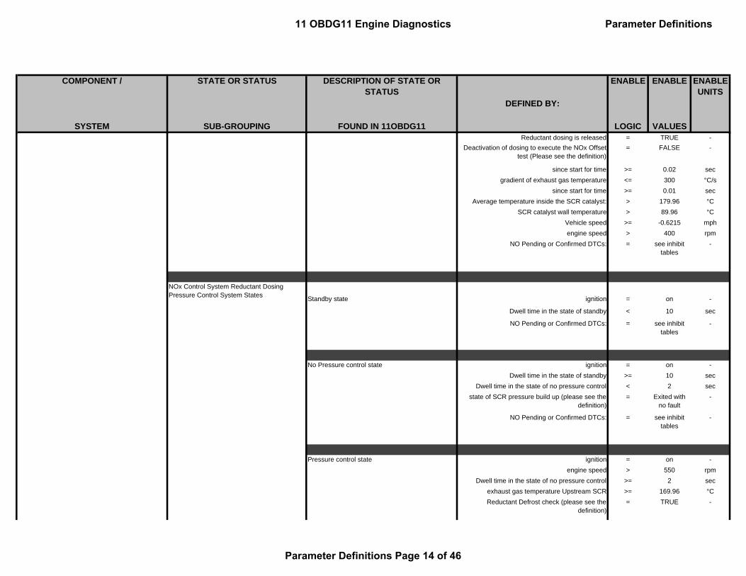
COMPONENT / STATE OR STATUS DESCRIPTION OF STATE OR STATUS
ENABLE ENABLE
SYSTEM SUB-GROUPING FOUND IN 11OBDG11 LOGIC VALUES
ENABLE UNITS
DEFINED BY:
Reductant dosing is released = TRUE -Deactivation of dosing to execute the NOx Offset
test (Please see the definition)= FALSE -
since start for time >= 0.02 secgradient of exhaust gas temperature <= 300 °C/s
since start for time >= 0.01 secAverage temperature inside the SCR catalyst: > 179.96 °C
SCR catalyst wall temperature > 89.96 °CVehicle speed >= -0.6215 mphengine speed > 400 rpm
NO Pending or Confirmed DTCs: = see inhibit tables
-
Standby state ignition = on -
Dwell time in the state of standby < 10 sec
NO Pending or Confirmed DTCs: = see inhibit tables
-
No Pressure control state ignition = on -Dwell time in the state of standby >= 10 sec
Dwell time in the state of no pressure control < 2 secstate of SCR pressure build up (please see the
definition) = Exited with
no fault-
NO Pending or Confirmed DTCs: = see inhibit tables
-
Pressure control state ignition = on -engine speed > 550 rpm
Dwell time in the state of no pressure control >= 2 secexhaust gas temperature Upstream SCR >= 169.96 °CReductant Defrost check (please see the
definition)= TRUE -
NOx Control System Reductant Dosing Pressure Control System States
11 OBDG11 Engine Diagnostics Parameter Definitions
Parameter Definitions Page 14 of 46

COMPONENT / STATE OR STATUS DESCRIPTION OF STATE OR STATUS
ENABLE ENABLE
SYSTEM SUB-GROUPING FOUND IN 11OBDG11 LOGIC VALUES
ENABLE UNITS
DEFINED BY:
The component protection release of the heater control (please see the definition)
= TRUE -
Preliminary release of the heater control for themain state machine (please see the definition)
= TRUE -
NO Pending or Confirmed DTCs: = see inhibit tables
-
Refill substate of Pressure control state status of SCR control state (please see the defintion)
= Pressure Control
-
(Reductant filling state in the pressure line < 80 %
andReductant Pump Module Pressure < 200 kPa
)Set-point dutycycle for Reductant dosing valve = 100 %
Set-point dutycycle for the Reductant Pump pressure Motor actuator
= 80.0049 %
NO Pending or Confirmed DTCs: = see inhibit tables
-
Pressure build up substate of Pressure control state
status of SCR control state (please see the defintion)
= Pressure Control
-
(Reductant filling state in the pressure line >= 80 %
orReductant Pump Module Pressure >= 200 kPa
)Reductant Pump Module Pressure < 350 kPa
Set-point dutycycle for Reductant dosing valve = 0 %Set-point dutycycle for the Reductant Pump
pressure Motor actuator= 80.0049 %
NO Pending or Confirmed DTCs: = see inhibit tables
-
11 OBDG11 Engine Diagnostics Parameter Definitions
Parameter Definitions Page 15 of 46

COMPONENT / STATE OR STATUS DESCRIPTION OF STATE OR STATUS
ENABLE ENABLE
SYSTEM SUB-GROUPING FOUND IN 11OBDG11 LOGIC VALUES
ENABLE UNITS
DEFINED BY:
Metering control substate of Pressure control state
status of SCR control state (please see the defintion)
= Pressure Control
-
Reductant Pump Module Pressure >= 350 kPaSet-point dutycycle for Reductant dosing valve = 0 %
Set-point dutycycle for the Reductant Pump pressure Motor actuator
= 80.0049 %
NO Pending or Confirmed DTCs: = see inhibit tables
-
Ventilation substate of Pressure control statestatus of SCR control state (please see the
defintion)= Pressure
Control -
Reductant Pump Module Pressure < 350 kPaDwell time in Pressure Build up substate > 6 sec
system pressurizes in pressure buildup and ventilation states
< 15.0 counts
Set-point dutycycle for Reductant dosing valve = 100 %Set-point dutycycle for the Reductant Pump
pressure Motor actuator= 80.0049 %
Dwell time in the sub state ventilation < 0.23 secNO Pending or Confirmed DTCs: = see inhibit
tables-
Pressure reduction stateignition = off -
dwell time in the state of pressure reduction < 5 secActivation state of Reductant reverting valve
power stage = On -
Set-point dutycycle for Reductant dosing valve = 0 %Set-point dutycycle for the Reductant Pump
pressure Motor actuator= 15.0024 %
NO Pending or Confirmed DTCs: = see inhibit tables
-
11 OBDG11 Engine Diagnostics Parameter Definitions
Parameter Definitions Page 16 of 46

COMPONENT / STATE OR STATUS DESCRIPTION OF STATE OR STATUS
ENABLE ENABLE
SYSTEM SUB-GROUPING FOUND IN 11OBDG11 LOGIC VALUES
ENABLE UNITS
DEFINED BY:
SCR Engine State required for operation SCR Engine State Ignition = TRUE -engine speed > 550 rpm
Reductant Dosing Strategy based on DPF Fload
Status fill level decrease (please see the definition)
Particulate Filter Regeneration demand on = TRUE -
orReductant fill level of the SCR catalyst lowed to
the target value under Particle filter Regeneration request
(a) - (b) >= 0 -(a) Nominal value of Reductant fill level in the
catalyst
(b) Estimated current Reductant load( c) Reductant Dosing quantity limitation = 100 factor
orSCR catalyst temperature too high to convert Reductant under Particle filter Regeneration
request
Average temperature inside the SCR catalyst: > 999.96 °C
NOx Reduction State Machine upstream of Reducing Catalyst
NOxDs_State_0 : starting state and waiting for low upstream NOx mass flow / concentration
for time < 4.1 sec(
Release for Downstream NOx sensor peak monitoring
= TRUE -
Filtered upstream NOx mass flow < 0.0098 g/sFiltered NOx concentration < 200 ppm
Exhaust mass flow message < 25 g/s)
11 OBDG11 Engine Diagnostics Parameter Definitions
Parameter Definitions Page 17 of 46

COMPONENT / STATE OR STATUS DESCRIPTION OF STATE OR STATUS
ENABLE ENABLE
SYSTEM SUB-GROUPING FOUND IN 11OBDG11 LOGIC VALUES
ENABLE UNITS
DEFINED BY:
NOxDs_State_1 : low upstream NOx mass flow /concentration reached
for time > 4.1 sec(
Old state of state machine of Downstream NOx sensor peak monitoring (please see the definition)
= NOxDs_State_0
-
Release for Downstream NOx sensor peak monitoring
= TRUE -
Filtered upstream NOx mass flow < 0.0098 g/sFiltered NOx concentration < 200 ppm
Exhaust mass flow message < 25 g/s)
NOxDs_State_2 : start Upstream NOx peakOld state of state machine of Downstream NOx
sensor peak monitoring (please see the definition) = NOxDs_Stat
e_1
for time < 1 sec(
Filtered upstream NOx mass flow >= 0.0098 g/sor
Filtered NOx concentration >= 200 ppmor
Exhaust mass flow message >= 25 g/s)
NOxDs_State_3 : Upstream NOx peak detectionOld state of state machine of Downstream NOx
sensor peak monitoring (please see the definition) = NOxDs_Stat
e_2-
for time > 1 sec
11 OBDG11 Engine Diagnostics Parameter Definitions
Parameter Definitions Page 18 of 46

COMPONENT / STATE OR STATUS DESCRIPTION OF STATE OR STATUS
ENABLE ENABLE
SYSTEM SUB-GROUPING FOUND IN 11OBDG11 LOGIC VALUES
ENABLE UNITS
DEFINED BY:
NOxDs_State_4 : delay for downstream NOx peak evaluation
Old state of state machine of Downstream NOx sensor peak monitoring (please see the definition)
= NOxDs_State_3
-
for time > 3 sec
NOxDs_State_5 : end of downstream NOx peak and evaluation
Old state of state machine of Downstream NOx sensor peak monitoring (please see the definition)
= NOxDs_State_4
-
for time > 0.5 sec
Reductant Heater and Defrost System Control States and Status
Reductant Defrost check status of reductant tank heater temperature (please see the definition)
= TRUE -
State of the defrosting check of pressure line (please see the definition)
= TRUE -
State of the defrosting check of supply module (please see the definition)
= TRUE -
(duration, for which the conditions for a hydraulic release reset of pressure line heater circuit are
satisfied
<= 1200 sec
ambient temperature > -4.04 °CRelease heater pressure line = FALSE -
andduration, for which the conditions for a hydraulic
release reset of supply module heater circuit are satisfied
<= 1200 sec
ambient temperature > -4.04 °CRelease heater supply module = FALSE -
)
11 OBDG11 Engine Diagnostics Parameter Definitions
Parameter Definitions Page 19 of 46

COMPONENT / STATE OR STATUS DESCRIPTION OF STATE OR STATUS
ENABLE ENABLE
SYSTEM SUB-GROUPING FOUND IN 11OBDG11 LOGIC VALUES
ENABLE UNITS
DEFINED BY:
Status of reductant tank heater temperature status of reductant tank heater temperature (please see the definition)
Reductant tank heat temperature at Standby state > 4.96 °C
orEngine off Time > 7200 sec
Reductant tank heat temperature at Standby state > -9.04 °C
State of the defrosting check of pressure line State of the defrosting check of pressure line (please see the definition)
time since pressue line heating on under pressure line defrost mode
>= 0 to 300 sec
orstatus of SCR control state (please see the
defintion)= No Pressure
Control-
Pressure line defrost timer = 0 secor
ignition = on secengine speed > 550 rpm
(Pressure line defrost check in last driving cycle = TRUE -
status of SCR control state (please see the defintion)
= No Pressure Control
-
Engine off Time < 0 secNO Pending or Confirmed DTCs: = TRUE -
State of the defrosting check of supply module State of the defrosting check of supply module (please see the definition)
time since supply moduel heating on under supply module defrost mode
>= 0 to 300 sec
orstatus of SCR control state (please see the
defintion)= No Pressure
Control-
11 OBDG11 Engine Diagnostics Parameter Definitions
Parameter Definitions Page 20 of 46

COMPONENT / STATE OR STATUS DESCRIPTION OF STATE OR STATUS
ENABLE ENABLE
SYSTEM SUB-GROUPING FOUND IN 11OBDG11 LOGIC VALUES
ENABLE UNITS
DEFINED BY:
Supply module defrost timer = 0 secor
ignition = on secengine speed > 550 rpm
(Pressure line defrost check in last driving cycle = TRUE -
status of SCR control state (please see the defintion)
= No Pressure Control
-
Engine off Time < 0 secNO Pending or Confirmed DTCs: = TRUE -
The component protection release of the heater control
Current time for heating / not heating of heater circuit 1 (tank)
>= 0 to 1500 sec
Reductant Defrost check (please see the definition)
= FALSE -
Preliminary release of the heater control for the main state machine
Preliminary release of the heater control for themain state machine (please see the definition)
(Current time for heating / not heating of heater
circuit 1 (tank)>= 0 to 3276 sec
status of reductant tank heater defrost = FALSE -status of reductant tank heater temperature
(please see the definition)= FALSE -
State of the defrosting check of pressure line (please see the definition)
= TRUE -
State of the defrosting check of supply module (please see the definition)
= TRUE -
)or
(ignition = on sec
engine speed > 550 rpmEngine off Time <= 0 sec
11 OBDG11 Engine Diagnostics Parameter Definitions
Parameter Definitions Page 21 of 46

COMPONENT / STATE OR STATUS DESCRIPTION OF STATE OR STATUS
ENABLE ENABLE
SYSTEM SUB-GROUPING FOUND IN 11OBDG11 LOGIC VALUES
ENABLE UNITS
DEFINED BY:
State of the defrosting check of pressure line (please see the definition)
= TRUE -
State of the defrosting check of supply module (please see the definition)
= TRUE -
andif the following conditions were met in previous
driving cycle= TRUE -
(ignition = on sec
engine speed > 550 rpmEngine off Time <= 0 sec
State of the defrosting check of pressure line (please see the definition)
= TRUE -
State of the defrosting check of supply module (please see the definition)
= TRUE -
))
Release of tank heater circuit (Requested defrosting time for Reductant tank
heater (see Look-Up-Table #16)>= 0 to 3900 sec
orRequested heating time for Reductant tank heater
(see Look-Up-Table #17)>= 0 to 3277 sec
)
or((
Requested defrosting time for Reductant tank heater (see Look-Up-Table #16)
>= 0 to 3900 sec
orRequested heating time for Reductant tank heater
(see Look-Up-Table #17)>= 0 to 3277 sec
)and
(
11 OBDG11 Engine Diagnostics Parameter Definitions
Parameter Definitions Page 22 of 46

COMPONENT / STATE OR STATUS DESCRIPTION OF STATE OR STATUS
ENABLE ENABLE
SYSTEM SUB-GROUPING FOUND IN 11OBDG11 LOGIC VALUES
ENABLE UNITS
DEFINED BY:
Requested defrosting time for pressure line heater (see Look-Up-Table #18)
>= 0 to 300 sec
orRequested heating time for pressure line heater
(see Look-Up-Table #20)>= 0 to 3276.7 sec
))
or((
Requested defrosting time for Reductant tank heater (see Look-Up-Table #16)
>= 0 to 3900 sec
orRequested heating time for Reductant tank heater
(see Look-Up-Table #17)>= 0 to 3277 sec
)and
(Requested defrosting time for supply module
heater (see Look-Up-Table #19)>= 0 to 300 sec
orRequested heating time for supply module heater
(see Look-Up-Table #21)>= 0 to 3276.7 sec
))
or((
Requested defrosting time for Reductant tank heater (see Look-Up-Table #16)
>= 0 to 3900 sec
orRequested heating time for Reductant tank heater
(see Look-Up-Table #17)>= 0 to 3277 sec
)and
(Requested defrosting time for pressure line heater
(see Look-Up-Table #18)>= 0 to 300 sec
11 OBDG11 Engine Diagnostics Parameter Definitions
Parameter Definitions Page 23 of 46

COMPONENT / STATE OR STATUS DESCRIPTION OF STATE OR STATUS
ENABLE ENABLE
SYSTEM SUB-GROUPING FOUND IN 11OBDG11 LOGIC VALUES
ENABLE UNITS
DEFINED BY:
orRequested heating time for pressure line heater
(see Look-Up-Table #20)>= 0 to 3276.7 sec
)and
(Requested defrosting time for supply module
heater (see Look-Up-Table #19)>= 0 to 300 sec
orRequested heating time for supply module heater
(see Look-Up-Table #21)>= 0 to 3276.7 sec
))
andNO Pending or Confirmed DTCs: = TRUE -
Release of pressure line heater circuit (Requested defrosting time for pressure line heater
(see Look-Up-Table #18)>= 0 to 300 sec
orRequested heating time for pressure line heater
(see Look-Up-Table #20)>= 0 to 3276.7 sec
)
or((
Requested defrosting time for pressure line heater (see Look-Up-Table #18)
>= 0 to 300 sec
orRequested heating time for pressure line heater
(see Look-Up-Table #20)>= 0 to 3276.7 sec
)and
(
11 OBDG11 Engine Diagnostics Parameter Definitions
Parameter Definitions Page 24 of 46

COMPONENT / STATE OR STATUS DESCRIPTION OF STATE OR STATUS
ENABLE ENABLE
SYSTEM SUB-GROUPING FOUND IN 11OBDG11 LOGIC VALUES
ENABLE UNITS
DEFINED BY:
Requested defrosting time for supply module heater (see Look-Up-Table #19)
>= 0 to 300 sec
orRequested heating time for supply module heater
(see Look-Up-Table #21)>= 0 to 3276.7 sec
))
andNO Pending or Confirmed DTCs: = see inhibit
tables-
Release of tank heater circuit (Requested defrosting time for supply module
heater (see Look-Up-Table #19)>= 0 to 300 sec
orRequested heating time for supply module heater
(see Look-Up-Table #21)>= 0 to 3276.7 sec
)
or((
Requested defrosting time for Reductant tank heater (see Look-Up-Table #16)
>= 0 to 3900 sec
orRequested heating time for Reductant tank heater
(see Look-Up-Table #17)>= 0 to 3277 sec
)and
(Requested defrosting time for supply module
heater (see Look-Up-Table #19)>= 0 to 300 sec
orRequested heating time for supply module heater
(see Look-Up-Table #21)>= 0 to 3276.7 sec
))
11 OBDG11 Engine Diagnostics Parameter Definitions
Parameter Definitions Page 25 of 46

COMPONENT / STATE OR STATUS DESCRIPTION OF STATE OR STATUS
ENABLE ENABLE
SYSTEM SUB-GROUPING FOUND IN 11OBDG11 LOGIC VALUES
ENABLE UNITS
DEFINED BY:
or((
Requested defrosting time for pressure line heater (see Look-Up-Table #18)
>= 0 to 300 sec
orRequested heating time for pressure line heater
(see Look-Up-Table #20)>= 0 to 3276.7 sec
)and
(Requested defrosting time for supply module
heater (see Look-Up-Table #19)>= 0 to 300 sec
orRequested heating time for supply module heater
(see Look-Up-Table #21)>= 0 to 3276.7 sec
))or((
Requested defrosting time for Reductant tank heater (see Look-Up-Table #16)
>= 0 to 3900 sec
orRequested heating time for Reductant tank heater
(see Look-Up-Table #17)>= 0 to 3277 sec
)and
(Requested defrosting time for pressure line heater
(see Look-Up-Table #18)>= 0 to 300 sec
orRequested heating time for pressure line heater
(see Look-Up-Table #20)>= 0 to 3276.7 sec
)and
(Requested defrosting time for supply module
heater (see Look-Up-Table #19)>= 0 to 300 sec
11 OBDG11 Engine Diagnostics Parameter Definitions
Parameter Definitions Page 26 of 46

COMPONENT / STATE OR STATUS DESCRIPTION OF STATE OR STATUS
ENABLE ENABLE
SYSTEM SUB-GROUPING FOUND IN 11OBDG11 LOGIC VALUES
ENABLE UNITS
DEFINED BY:
orRequested heating time for supply module heater
(see Look-Up-Table #21)>= 0 to 3276.7 sec
))
andNO Pending or Confirmed DTCs: = see inhibit
tables-
Status of the battery voltage being in the valid working range for Reductant tank heater
battery voltage < 100 Vbattery voltage > 11 V
for time > 2 sec
Status of the battery voltage being in the valid working range for pressure line heater
battery voltage < 100 Vbattery voltage > 11 V
for time > 2 sec
Status of Reductant Tank Heater Release(
status of reductant tank heater temperature (please see the definition)
= TRUE -
Waiting time after tank heater release expired > 0 sec)
or((
Waiting time before tank heater released < 1800 secstarted with
11 OBDG11 Engine Diagnostics Parameter Definitions
Parameter Definitions Page 27 of 46

COMPONENT / STATE OR STATUS DESCRIPTION OF STATE OR STATUS
ENABLE ENABLE
SYSTEM SUB-GROUPING FOUND IN 11OBDG11 LOGIC VALUES
ENABLE UNITS
DEFINED BY:
status of reductant tank heater temperature (please see the definition)
= FALSE -
)and
(status of reductant tank heater temperature
(please see the definition)= TRUE -
Waiting time after tank heater release expired > 0 sec))
or((
Waiting time before tank heater released > 1800 secstarted with
status of reductant tank heater temperature (please see the definition)
= FALSE -
)and
(status of reductant tank heater temperature
(please see the definition)= TRUE -
Waiting time after tank heater release expired > 61 sec))
Reductant Tank Level System States and Status
status of Reductant tank level Tank level > full (100%) = Full -
Warning (66.67%) < tank level < full (100%) = OK -Restriction (33.33%) < tank level < Warning
(66.67%)= Warning -
Empty < tank level < Restriction (33.33%) = Restriction -Tank level < = 0.1% = Empty -
11 OBDG11 Engine Diagnostics Parameter Definitions
Parameter Definitions Page 28 of 46

COMPONENT / STATE OR STATUS DESCRIPTION OF STATE OR STATUS
ENABLE ENABLE
SYSTEM SUB-GROUPING FOUND IN 11OBDG11 LOGIC VALUES
ENABLE UNITS
DEFINED BY:
Status of Reductant tank level reset when refilling is detected
(time since the following conditions are met >= 12 sec
Derivation of the PT1 filtered level signal (DT1) >= 1.00098 %/secand
(Engine on timer is expired (please see the
defintion)= TRUE -
< 3600 sec12 sec20 -
(ignition = on sec
engine speed > 550 rpmVehicle speed >= 6.2150404 mph
))or
time since the following conditions are met >= 8 secand
(Derivation of the PT1 filtered level signal (DT1) >= 1.00098 %/sec
and(
filter release for Reductant tank level calculation at T15 on (Please see the definition)
= TRUE -
)))
or(
filter release for Reductant tank level calculation at T15 on (Please see the definition)
= TRUE -
and
11 OBDG11 Engine Diagnostics Parameter Definitions
Parameter Definitions Page 29 of 46

COMPONENT / STATE OR STATUS DESCRIPTION OF STATE OR STATUS
ENABLE ENABLE
SYSTEM SUB-GROUPING FOUND IN 11OBDG11 LOGIC VALUES
ENABLE UNITS
DEFINED BY:
(ignition = on -
time > 1 sec(
Reductant low warning level (Please see the definition)
= 96 -
orstatus of Deisel fuel refill detection (please see the
definition) = TRUE -
))
Status of Reductant Tank Level Release status of reductant tank level release (please see the definition)
Status of Filter release for reductant tank level calculation (please see the defintion)
= TRUE -
and((
ambient temperature >= -9.04 °C((
status of reductant tank heater temperature (please see the definition)
= FALSE -
Waiting time before tank heater released < 1800 secand
status of reductant tank heater temperature (please see the definition)
= TRUE -
Waiting time after tank heater release expired > 0 sec)
or(
status of reductant tank heater temperature (please see the definition)
= FALSE -
Waiting time before tank heater released >= 1800 secand
status of reductant tank heater temperature (please see the definition)
= TRUE -
11 OBDG11 Engine Diagnostics Parameter Definitions
Parameter Definitions Page 30 of 46

COMPONENT / STATE OR STATUS DESCRIPTION OF STATE OR STATUS
ENABLE ENABLE
SYSTEM SUB-GROUPING FOUND IN 11OBDG11 LOGIC VALUES
ENABLE UNITS
DEFINED BY:
Waiting time after tank heater release expired >= 61 sec))or
Frozen state is active during a certain warning level (please see the defintion)
= TRUE -
)Vehicle speed >= 6.2150404 mph
)or
filter release for Reductant tank level calculation at T15 on (Please see the definition)
= TRUE -
Status of Filter release for reductant tank level calculation
Reductant tank Temperature >= -9.04 °Cor
Reductant low warning level (Please see the definition)
>= 64 -
NO Pending or Confirmed DTCs: = TRUE -or
Frozen state is active during a certain warning level (please see the defintion)
= TRUE -
Filter release for Reductant tank level calculation at Ignition on
(Reductant low warning level (Please see the
definition)>= 49 -
Vehicle speed >= 0.62150404 mphTerminal 15 status after debouncing = on -
Engine on timer is expired (please see the defintion)
= FALSE -
Raw Reductant tank level >= (a), or (b), or ( c)
-
((a) Raw Reductant tank level threshold = 100 %
11 OBDG11 Engine Diagnostics Parameter Definitions
Parameter Definitions Page 31 of 46

COMPONENT / STATE OR STATUS DESCRIPTION OF STATE OR STATUS
ENABLE ENABLE
SYSTEM SUB-GROUPING FOUND IN 11OBDG11 LOGIC VALUES
ENABLE UNITS
DEFINED BY:
with((
Remaing Reductant quantity (a) - (b): >= (a) - (b) g(a) Tank level for reserve mode (Warning level) in
[g]= 3214 g
(b) Tank level threshold range below WARNING threshold for T15 refill detection release
= 0 g
AndRemaing Reductant quantity (a) - (b): >= (a) - (b) g
(a) Tank level for reserve mode (Restriction level) in [g]
= 700 g
(b) Tank level threshold range below Restriction threshold for T15 refill detection release
= 0 g
)
or(b) Raw Reductant tank level threshold = 66.667 %
(Remaing Reductant quantity (a) - (b): < (a) - (b) g
(a) Tank level for reserve mode (Warning level) in [g]
= 3214 g
(b) Tank level threshold range below WARNING threshold for T15 refill detection release
= 0 g
AndRemaing Reductant quantity (a) - (b): >= (a) - (b) g
(a) Tank level for reserve mode (Restriction level) in [g]
= 700 g
(b) Tank level threshold range below Restriction threshold for T15 refill detection release
= 0 g
)
or(
( c) Raw Reductant tank level threshold = 33.33 %
11 OBDG11 Engine Diagnostics Parameter Definitions
Parameter Definitions Page 32 of 46

COMPONENT / STATE OR STATUS DESCRIPTION OF STATE OR STATUS
ENABLE ENABLE
SYSTEM SUB-GROUPING FOUND IN 11OBDG11 LOGIC VALUES
ENABLE UNITS
DEFINED BY:
Remaing Reductant quantity (a) - (b): < (a) - (b)(a) Tank level for reserve mode (Restriction level)
in [g]= 700 g
(b) Tank level threshold range below Restriction threshold for T15 refill detection release
= 0 g
))
Status of Refill detection of Reductant tank Status of Refill detection of Reductant tank (please see the definition)
Reductant tank level changed = TRUE -((
Captured Reductant tank level at last tank level change
= Empty -
orCaptured Reductant tank level at last tank level
change= Restriction -
)
and(
one or more of following conditions are metstatus of Reductant tank level (please see the
definition) = Warning -
orstatus of Reductant tank level (please see the
definition) = OK -
orstatus of Reductant tank level (please see the
definition) = Full -
))or((
Captured Reductant tank level at last tank level change
= Warning -
or
11 OBDG11 Engine Diagnostics Parameter Definitions
Parameter Definitions Page 33 of 46

COMPONENT / STATE OR STATUS DESCRIPTION OF STATE OR STATUS
ENABLE ENABLE
SYSTEM SUB-GROUPING FOUND IN 11OBDG11 LOGIC VALUES
ENABLE UNITS
DEFINED BY:
Captured Reductant tank level at last tank level change
= OK -
)
and(
status of Reductant tank level (please see the definition)
= Full -
)or(
Captured Reductant tank level at last tank level change
= OK -
status of Reductant tank level (please see the definition)
= Full -
))
Engine on timer is expired Engine on timer is expired (please see the defintion)
time since engine started >= (a) * (b) sec12 sec20 -
After(
ignition = on secengine speed > 550 rpm
Vehicle speed >= 6.22 mph)
Reducant Tank Level Low Warning StatesReductant low warning level 0
status of Reductant tank level (please see the definition)
>= 100 %
Status of Refill detection of Reductant tank (please see the definition)
= TRUE -
11 OBDG11 Engine Diagnostics Parameter Definitions
Parameter Definitions Page 34 of 46

COMPONENT / STATE OR STATUS DESCRIPTION OF STATE OR STATUS
ENABLE ENABLE
SYSTEM SUB-GROUPING FOUND IN 11OBDG11 LOGIC VALUES
ENABLE UNITS
DEFINED BY:
Reductant low warning level 1 - Sub State : 0x01status of Reductant tank level (please see the
definition)
< 100 %
or(
status of Reductant tank level (please see the definition)
< 100 %
Reductant remaining mileage > 1106.4375 miles
Status of Refill detection of Reductant tank (please see the definition)
= TRUE -
)
Reductant low warning level 1 - Sub State : 0x02Reductant remaining mileage Under Reductant
warning level 1 - substate 0x01
<= 1106.44 miles
or(
Reductant remaining mileage <= 1106.44 miles
status of Reductant tank level (please see the definition)
< 100 %
Status of Refill detection of Reductant tank (please see the definition)
= TRUE -
)
Reductant low warning level 1 - Main State : 0x10Reductant remaining mileage Under Reductant
warning level 1 - substate 0x02
<= 402.5 miles
or
key cycle Under Reductant warning level 1 - substate 0x02
= TRUE -
Reductant low warning level 2 - Main State : 0x20Reductant remaining mileage Under Reductant
warning level 1 - main state 0x10
<= 402.5 miles
or
11 OBDG11 Engine Diagnostics Parameter Definitions
Parameter Definitions Page 35 of 46

COMPONENT / STATE OR STATUS DESCRIPTION OF STATE OR STATUS
ENABLE ENABLE
SYSTEM SUB-GROUPING FOUND IN 11OBDG11 LOGIC VALUES
ENABLE UNITS
DEFINED BY:
(
Reductant remaining mileage <= 402.5 miles
Reductant remaining mileage > 176.25 miles
status of Reductant tank level (please see the definition)
< 100 %
Status of Refill detection of Reductant tank (please see the definition)
= TRUE -
)
Reductant low warning level 3 - Main State : 0x30Reductant remaining mileage Under Reductant
warning level 2 - Main state 0x20
<= 176.25 miles
or(
Reductant remaining mileage <= 176.25 miles
Reductant remaining mileage > 100.63 miles
status of Reductant tank level (please see the definition)
< 100 %
Status of Refill detection of Reductant tank (please see the definition)
= TRUE -
)
Reductant low warning level 4 - Sub State : 0x31Reductant remaining mileage Under Reductant
warning level 3 - Main state 0x30
<= 100.63 miles
or(
status of low Reductant pump pressure (please see the definition) Under Reductant warning level
3 - Main state 0x30
= TRUE -
Reductant remaining mileage Under Reductant warning level 3 - Main state 0x30
<= 100.63 miles
)
Reductant low warning level 4 - Main State : 0x40 ( = 64 decimal) key cycle Under Reductant warning level 4 -
substate 0x31
= TRUE -
11 OBDG11 Engine Diagnostics Parameter Definitions
Parameter Definitions Page 36 of 46

COMPONENT / STATE OR STATUS DESCRIPTION OF STATE OR STATUS
ENABLE ENABLE
SYSTEM SUB-GROUPING FOUND IN 11OBDG11 LOGIC VALUES
ENABLE UNITS
DEFINED BY:
or
(
Reductant remaining mileage <= 100.63 miles
Status of Refill detection of Reductant tank (please see the definition)
= TRUE -
)
Reductant low warning level 5 - Sub State : 0x41 Vehicle mileage exceeds in Reductant Warning level 4 - main state (0x40)
> 100.625 miles
Reductant low warning level 5 - Main State : 0x50key cycle Under Reductant warning level 5 -
substate 0x41
= TRUE -
or
(
status of low Reductant pump pressure (please see the definition) Under Reductant warning level
3 - Main state 0x30
= TRUE -
status of Deisel fuel refill detection (please see the definition)
= TRUE -
)
Reductant low warning level 6 - Sub State : 0x51 Vehicle mileage exceeds in Reductant Warning level 5 - main state (0x50)
> 450 miles
status of low Reductant pump pressure (please see the definition) Under Reductant warning level
3 - Main state 0x30
= TRUE -
Reductant low warning level 6 - Sub State : 0x60 ( = 96 decimal) key cycle Under Reductant warning level 5 -
substate 0x41
= TRUE -
status of Deisel fuel refill detection (please see the definition)
= TRUE -
11 OBDG11 Engine Diagnostics Parameter Definitions
Parameter Definitions Page 37 of 46

COMPONENT / STATE OR STATUS DESCRIPTION OF STATE OR STATUS
ENABLE ENABLE
SYSTEM SUB-GROUPING FOUND IN 11OBDG11 LOGIC VALUES
ENABLE UNITS
DEFINED BY:
Reductant frozen System States Frozen state is active during a certain warning level
Frozen state is active during a certain warning level (please see the defintion)
Reductant low warning level (Please see the definition)
>= 49 -
and(
Engine off Time > 14400 secReductant tank Temperature < -11.04 °C
)or(
Engine off Time <= 7200 sectime since the following conditions are met <= 7200 sec
(status of reductant tank heater defrost = On or Defrost -
Vehicle speed > 6.2150404 mphStatus of urea tank as frozen (please see the
definition)= TRUE -
))
Status of Reductant tank as frozen (
Engine off Time > 14400 secReductant tank Temperature < -11.04 °C
)or(
Engine off Time <= 7200 sectime since the following conditions are met <= 7200 sec
(status of reductant tank heater defrost = On or Defrost
Vehicle speed > 6.2150404 mphStatus of urea tank as frozen (please see the
definition)= TRUE
11 OBDG11 Engine Diagnostics Parameter Definitions
Parameter Definitions Page 38 of 46

COMPONENT / STATE OR STATUS DESCRIPTION OF STATE OR STATUS
ENABLE ENABLE
SYSTEM SUB-GROUPING FOUND IN 11OBDG11 LOGIC VALUES
ENABLE UNITS
DEFINED BY:
))
SCR System Pressure State Status of Low Reductant Pump Pressure - Under Reductant warning level 3 - Main state 0x30
Reductant low warning level (Please see the definition)
>= 64 -
number of pressure build-up attempts >= 2 countsand
(status of SCR control sub state (please see the
defintion)= Pressure
Build up-
Reductant Pump Module Pressure < 3500 hPaDwell time in Pressure Build up substate > 6000 ms
system pressurizes in pressure buildup and ventilation states
>= 15 counts
Reductant Defrost check (please see the definition)
= TRUE -
)
SCR System Diagnosis SCR System Long Term Adaptation Release States
Long-term Adaption Triggered
underdosing detected (please see the definition) = TRUE -
ORoverdosing detected (please see the definition) = TRUE -
Underdosing detectedDifference between the NOx mass of the sensor
and of the model during first functional evaluation (see Look-Up-Table #9)
>= 3 to 6 g
ORDifference between the NOx mass of the sensor
and of the model during second functional evaluation (see Look-Up-Table #10)
>= 3 to 6 g
OR
11 OBDG11 Engine Diagnostics Parameter Definitions
Parameter Definitions Page 39 of 46

COMPONENT / STATE OR STATUS DESCRIPTION OF STATE OR STATUS
ENABLE ENABLE
SYSTEM SUB-GROUPING FOUND IN 11OBDG11 LOGIC VALUES
ENABLE UNITS
DEFINED BY:
Difference between the NOx mass of the sensor and of the model during third functional evaluation
(see Look-Up-Table #11)
>= -0.2 to -0.08 g
Overdosing detectedDifference between the NOx mass of the sensor
and of the model during first functional evaluation<= -5 g
ORDifference between the NOx mass of the sensor
and of the model during second functional evaluation
<= -5 g
ORDifference between the NOx mass of the sensor
and of the model during third functional evaluation (see Look-Up-Table #8)
<= -0.36 to -0.18 g
Status of the SCR adaptation plausibility check active
Difference between nominal and estimated Reductant
>= -0.05 g
Release plausibility of Reductant Load (Please see the definition)
= TRUE
debounced Reductant mass flow (see Look-Up-Table #7)
>= 0 to 0.04 g
Elapsed time of the fill level timer >= 20 sec
State of the NH3 (Ammonia) slip detectionReductant concentration downstream SCR < 32767 ppm
and(a) - (b) < 0 g/s
(a) Filtered NOx mass flow downstream SCR measured by the sensor
= measured parameter
-
(b) Filtered and delayed NOx raw emission mass flow upstream of SCR
= measured parameter
-
11 OBDG11 Engine Diagnostics Parameter Definitions
Parameter Definitions Page 40 of 46

COMPONENT / STATE OR STATUS DESCRIPTION OF STATE OR STATUS
ENABLE ENABLE
SYSTEM SUB-GROUPING FOUND IN 11OBDG11 LOGIC VALUES
ENABLE UNITS
DEFINED BY:
Deactivation of dosing to execute the NOx Offset test
SCR catalyst temperature > 400.06 °CSCR catalyst temperature < 999.96 °C
time > 60 sec
andCurrently dosed Reductant mass flow <= 0.005 g/s
time > 30 sec
andFeed ratio
(a ) / (( b) * ( c)) <= 0.1 ratio(a) Currently dosed Reductant mass flow = measured
parameter-
(b) NOx raw emission mass flow = measured parameter
-
( c) Stoichiometric conversion factor NOx to Reductant
= calculated parameter
-
time > 10 sec
andEstimated current Reductant load <= 0.3 g
time > 10 sec
Release plausibility of Reductant Load Release plausibility timer active >= 600 sec
or(
Release plausibility timer active >= 50 secIntegrated NOx raw emission since fill level
adaptation and plausibility have been locked>= 2 g
)
Status for disabling the SCR Efficiency monitor following an SCR Adaptation cycle completion
11 OBDG11 Engine Diagnostics Parameter Definitions
Parameter Definitions Page 41 of 46

COMPONENT / STATE OR STATUS DESCRIPTION OF STATE OR STATUS
ENABLE ENABLE
SYSTEM SUB-GROUPING FOUND IN 11OBDG11 LOGIC VALUES
ENABLE UNITS
DEFINED BY:
Maximum dosing quantity < 0.6 g/s
or(a) - (b) > 0
(a) Reductant Dosing quantity = measured parameter
-
(b) Maximum Reductant Dosing quantity = calculated parameter
-
or(a) - (b) > 0
(a) Reductant Desired value = calculated parameter
-
(b) Reductant Dosing quantity limitation due to frozen tank
= calculated parameter
-
Request for pre controlled dosing
Filtered exhaust gas mass flow > (a) * (b) -(a) Correction factor for the upper hysteresis threshold for filtered exhaust-gas mass flow,
dependent on HC- contamination
= 1 factor
(b) Upper hysteresis threshold for filtered exhaust-gas mass flow, dependent on thermal ageing
= 388.89 g/sec
andFiltered NOx mass flow upstream SCR > (a) * (b) -
(a) Correction factor for the upper hysteresis threshold for filtered exhaust-gas mass flow,
dependent on HC- contamination SCR
= 1 factor
(b) Upper hysteresis threshold for filtered exhaust-gas mass flow, dependent on thermal ageing SCR
= 69.44 g/sec
andEngine coolant temperature < (a) + (b)
11 OBDG11 Engine Diagnostics Parameter Definitions
Parameter Definitions Page 42 of 46

COMPONENT / STATE OR STATUS DESCRIPTION OF STATE OR STATUS
ENABLE ENABLE
SYSTEM SUB-GROUPING FOUND IN 11OBDG11 LOGIC VALUES
ENABLE UNITS
DEFINED BY:
(a) Lower hysteresis threshold for engine temperature
= 105.06 °C
(b) Offset for lower hysteresis switch on threshold for engine temperature
=
Engine coolant temperature > 108.06 °C
andambient pressure > (a) + (b)
(a) Upper hysteresis threshold for environment pressure
= 74.5 kPa
(b) Offset for upper hysteresis switch on threshold for environment pressure
= 65 kPa
orambient pressure < 74 kPa
andIntake air temperature > (a) + (b)
(a) Lower hysteresis switch on threshold for inlet air temperature
= -5.04 °C
(b) Offset for upper hysteresis switch on threshold for inlet air temperature
= 48 °C
orIntake air temperature < -8.04 °C
)
and(
ambient temperature >= -7.04 °Cambient pressure >= 75.0 kPa
Selected temperature used for locking pre controlled mode
>= 209.96 °C
Selected temperature used for locking pre controlled mode
<= 349.96 °C
engine operationre in normal mode = TRUE -
11 OBDG11 Engine Diagnostics Parameter Definitions
Parameter Definitions Page 43 of 46

COMPONENT / STATE OR STATUS DESCRIPTION OF STATE OR STATUS
ENABLE ENABLE
SYSTEM SUB-GROUPING FOUND IN 11OBDG11 LOGIC VALUES
ENABLE UNITS
DEFINED BY:
SCR Nox Catalyst Efficiency check was performed this drive cycle
= FALSE -
Incorrect Reductant Composition check was performed this drive cycle
= FALSE -
NO Pending or Confirmed DTCs: = TRUE -)
(( (k) + (l) + ( m) > 75 -
(k) = (a) * (b)(a) entry condition for pre controlled dosing at sea
level (see Look-Up-Table #14)= 0 to 100 -
(b) Altitude multiplier factor for sea level = measured paramter
-
(l) = ( c) * (d) * (e)( c) entry condition for online dosing at Mid level
(see Look-Up-Table #13)= 0 to 100 -
(d) Multiplier to Mid Level enable speed load map = 1 factor
(e) Altitude multiplier factor for medium altitude = measured paramter
-
(m) = ( f) * (g) * (h)(f) Entry condition for online dosing at Hi level (see
Look-Up-Table #12)= 0 to 100 -
(g) Multiplier to Hi Level enable speed load map = 1 factor
(h) Altitude multiplier factor for high altitude = measured paramter
-
)and
Low pass filtered rNOxNSCDs signal > 2000 -)
11 OBDG11 Engine Diagnostics Parameter Definitions
Parameter Definitions Page 44 of 46

COMPONENT / STATE OR STATUS DESCRIPTION OF STATE OR STATUS
ENABLE ENABLE
SYSTEM SUB-GROUPING FOUND IN 11OBDG11 LOGIC VALUES
ENABLE UNITS
DEFINED BY:
Reductant Tank Heater Performance Diagnosis Status
start temperature is captured in EERPOM if monitoring is active over several driving cycles
continuation of previously started tank temperature performance monitoring cycle (see
definition)
= 1.56 °C
or(
start temperature is captured in EERPOM if monitoring is not active over several driving cycles
continuation of previously started tank temperature performance monitoring cycle (see
definition)
= FALSE -
(ignition on for time > 60 sec
or = TRUEice detection by tank temperature difference:
(a) - (b) <= -0.14 °C(a) filtered current tank temperature = measured
paramter-
(b) tank temperature captured at the beginning of current monitoring cycle
= measured paramter
-
))or
(a) - (b) <= -0.14 °C(a) filtered current tank temperature = measured
paramter-
(b) tank temperature captured at the beginning of current monitoring cycle
= measured paramter
-
ormonitoring was performed in previous driving
cycle
continuation of previously started tank temperature performance monitoring cycle
temperature difference: (a) - (b) <= 1.56 °C
(a) filtered current tank temperature = measured paramter
-
(b) tank temperature of the previous driving cycle = measured paramter
-
temperature difference: (a) - (b) <= 0 °C
11 OBDG11 Engine Diagnostics Parameter Definitions
Parameter Definitions Page 45 of 46

COMPONENT / STATE OR STATUS DESCRIPTION OF STATE OR STATUS
ENABLE ENABLE
SYSTEM SUB-GROUPING FOUND IN 11OBDG11 LOGIC VALUES
ENABLE UNITS
DEFINED BY:
(a) tank temperature of the previous driving cycle = measured paramter
-
(b) filtered current tank temperature = measured paramter
-
temperature difference: (a) - (b) >= 0 °C(a) tank temperature of the previous driving cycle = measured
paramter-
start tank temperature of current monitoring cycle from EEPROM (see definition)
= measured paramter
-
Engine off Time <= 2000 secThis monitor was complete in the last driving cycle = FALSE
ice detection by tank temperature difference:(a) - (b) > -0.14 °C
(a) filtered current tank temperature = measured paramter
-
(b) tank temperature captured at the beginning of current monitoring cycle
= measured paramter
-
Turbo Charger Turbocharger (VNT) wiping active The Variable Nozzle Turbocharger Control has an intrusive mode where:
VNT wiping is a sweep of the vane position control throughout its range of motion which is used to:
avoid a binding of the VNT vanes due to soot accumulation during long idle operation with a cold engine.
11 OBDG11 Engine Diagnostics Parameter Definitions
Parameter Definitions Page 46 of 46

S1-11OBDG11 - Calibration TablesCalibration Look-Up Table Differences from Initial Submission are Highlighted
Table no. Fault Codes Label (Internal Manufacturer Reference)
2 P111D Air_tDiffMaxHiTAFS_CUR
Engine Off Time (sec) 600 700 800 900 1000 2000 3000 4000 5000 8000 17999 18000 28799 28800 30000 32000Delta Temperature (°C) 999 999 999 999 999 999 999 999 999 999 999 999 999 100 100 100
3 P111C Air_tDiffMaxHiTCACDs_CUR
Engine Off Time (sec) 600 700 800 900 1000 2000 3000 4000 5000 8000 17999 18000 28799 28800 30000 32000Delta Temperature (°C) 999 999 999 999 999 999 999 999 999 999 999 999 999 100 100 100
4 P040F Air_tDiffMaxHiTEGRClr2Ds_CUR
Engine Off Time (sec) 600 700 800 900 1000 2000 3000 4000 5000 8000 10000 18000 28799 28800 30000 32000Delta Temperature (°C) 999 999 999 999 999 999 999 999 999 999 999 999 999 100 100 100
6 P111C Air_tDiffMaxLoTCACDs_CUR
Engine Off Time (sec) 600 700 800 900 1000 2000 3000 4000 5000 8000 17999 18000 28799 28800 30000 32000Delta Temperature (°C) 999 999 999 999 999 999 999 999 999 999 999 999 999 35 35 35
8 P0402 AirCtl_mMaxDvt_MAP
Inj. Qty (mm^3/rev) / Eng Speed (rpm) 1200 1300 1400 1500 1600 1800 1850 20000 0.48 0.50 0.40 0.50 0.50 0.50 0.49 0.49
160 0.48 0.50 0.44 0.60 0.50 0.50 0.49 0.49180 0.50 0.50 0.44 0.60 0.50 0.50 0.49 0.49200 0.80 0.80 0.70 0.60 0.50 0.50 0.49 0.49220 0.86 0.80 0.80 0.80 0.60 0.60 0.49 0.49240 0.92 0.87 0.87 0.90 0.70 0.70 0.49 0.49280 1.03 1.00 1.00 1.02 1.02 0.90 0.51 0.51340 1.20 1.20 1.20 1.20 1.20 1.20 0.51 0.51
11 OBDG11 Engine Diagnostics Calibration Tables
Calibration Tables Page 1 of 5

9 P0401 AirCtl_mMinDvt_MAP
Inj. Qty (mm^3/rev) / Eng Speed (rpm) 600 650 1000 1200 1300 1400 1500 1600 2000 2200 2400 2600 2800 3000 3200 34000 -0.7 -0.7 -0.7 -0.72 -0.8584 -1.1604 -1.1604 -1.1604 -1.3 -1.3 -1.3 -1.3 -1.3 -1.3 -1.3 -1.3 0.00
20 -0.7 -0.7 -0.7 -0.7 -0.9 -1.1604 -1.1604 -1.1604 -1.3 -1.35 -1.4 -1.4 -1.4 -1.4 -1.4 -1.4 80.0040 -0.7 -0.7 -0.7 -0.7 -0.9 -1 -1 -1.2 -1.2 -1.4 -1.4 -1.4 -1.4 -1.4 -1.4 -1.4 160.0060 -0.7 -0.7 -0.7 -0.7 -0.9 -1 -0.9 -1.2 -1.2 -1.4 -1.4 -1.4 -1.4 -1.4 -1.4 -1.4 240.0080 -0.7 -0.7 -0.7 -0.7 -0.9 -1 -0.9 -1.2 -1.2 -1.4 -1.4 -1.4 -1.4 -1.4 -1.4 -1.4 320.00
120 -0.7 -0.7 -0.7 -0.7 -0.8 -1 -0.8 -0.9 -1.2 -1 -1 -1 -1 -1 -1 -1 480.00160 -0.5 -0.5 -0.5 -0.5 -0.5 -0.5 -0.7 -0.7 -0.6 -0.6 -0.6 -0.6 -0.6 -0.6 -0.6 -0.6 640.00200 -0.5 -0.5 -0.5 -0.5 -0.5 -0.5 -0.7 -0.7 -0.7 -0.65 -0.6 -0.6 -0.6 -0.6 -0.6 -0.6 800.00240 -0.5 -0.5 -0.5 -0.5 -0.5 -0.5 -0.7 -0.7 -0.7 -0.65 -0.6 -0.6 -0.6 -0.6 -0.6 -0.6 960.00280 -0.5 -0.5 -0.5 -0.5 -0.5 -0.5 -0.7 -0.7 -0.7 -0.65 -0.6 -0.6 -0.6 -0.6 -0.6 -0.6 1120.00320 -0.5 -0.5 -0.5 -0.5 -0.5 -0.5 -0.7 -0.7 -0.7 -0.65 -0.6 -0.6 -0.6 -0.6 -0.6 -0.6 1280.00360 -0.5 -0.5 -0.5 -0.5 -0.5 -0.5 -0.7 -0.7 -0.7 -0.65 -0.6 -0.6 -0.6 -0.6 -0.6 -0.6 1440.00380 -0.5 -0.5 -0.5 -0.5 -0.5 -0.5 -0.7 -0.7 -0.7 -0.65 -0.6 -0.6 -0.6 -0.6 -0.6 -0.6 1520.00400 -0.5 -0.5 -0.5 -0.5 -0.5 -0.5 -0.7 -0.7 -0.7 -0.65 -0.6 -0.6 -0.6 -0.6 -0.6 -0.6 1600.00440 -0.5 -0.5 -0.5 -0.5 -0.5 -0.5 -0.7 -0.7 -0.7 -0.65 -0.6 -0.6 -0.6 -0.6 -0.6 -0.6 1760.00480 -0.5 -0.5 -0.5 -0.5 -0.5 -0.5 -0.7 -0.7 -0.7 -0.65 -0.6 -0.6 -0.6 -0.6 -0.6 -0.6 1920.00
12 P008F CEngDsT_tDiffMaxHi_CUR
Engine Off Time (sec) 600 700 800 900 1000 2000 3000 4000 5000 8000 17999 18000 28799 28800 30000 32767Delta Temperature (°C) 999 999 999 999 999 999 999 999 999 999 999 999 999 100 100 100
17 P12B3, P12B4, P12B5, P12B6, P12B7, P12B8, P12B9, P12BA, P12BB, P12BC, P12BD, P12BE, P12BF, P12C0, P12C1, P12C2
ETClb_tiET_MAX_CA
Energizing Time (us) 670.8 384.4 353.2
28 P20E2 Exh_tDiffMaxHiTOxiCatDs_CUR
Engine Off Time (sec) 600 700 800 900 1000 2000 3000 4000 5000 8000 17999 18000 28799 28800 30000 32000Delta Temperature (°C) 999 999 999 999 999 999 999 999 999 999 999 999 999 100 100 100
54 P0088 Rail_pMeUnDvtMin_CUR
Engine Speed (rpm) 0 540 590 650 1000 1200 1400 1600 1800 2000 2300 2400 3200 3400 3800 4000Rail Pressure (kPa) -80000 -80000 -20000 -20000 -20000 -20000 -20000 -20000 -20000 -20000 -20000 -20000 -20000 -20000 -20000 -20000
11 OBDG11 Engine Diagnostics Calibration Tables
Calibration Tables Page 2 of 5

63 P11CB, P11CC SCRChk_facMaxStyNOxUsPlaus_GMAP
Inj. Qty. (mm^3/rev) / Engine Speed (rpm) 1100 1200 1300 1350 1400 1450 1500 1600 1650 200060 0.0750 0.0750 0.0750 0.0750 0.0750 0.0500 0.0500 0.0500 0.0500 0.050080 0.0750 0.0750 0.0750 0.0750 0.0750 0.0500 0.0500 0.0500 0.0500 0.0500
100 0.0750 0.0750 0.0750 0.0750 0.0750 0.0500 0.0500 0.0500 0.0500 0.0500120 0.0750 0.0750 0.0750 0.0750 0.0750 0.0500 0.0500 0.0500 0.0500 0.0500140 0.0750 0.0750 0.0750 0.0750 0.0750 0.0500 0.0500 0.0500 0.0500 0.0500160 0.0750 0.0750 0.0750 0.0750 0.0750 0.0500 0.0500 0.0500 0.0500 0.0500180 0.0750 0.0750 0.0750 0.0750 0.0750 0.0500 0.0500 0.0500 0.0500 0.0500200 0.0750 0.0750 0.0750 0.0750 0.0750 0.0500 0.0500 0.0500 0.0500 0.0500220 0.0750 0.0750 0.0750 0.0750 0.0750 0.0500 0.0500 0.0500 0.0500 0.0500240 0.0750 0.0750 0.0750 0.0750 0.0750 0.0500 0.0500 0.0500 0.0500 0.0500
64 P11CB, P11CC SCRChk_facMinStyNOxUsPlaus_GMAP
Inj. Qty. (mm^3/rev) / Engine Speed (rpm) 1100 1200 1300 1350 1400 1450 1500 1600 1650 200060 0.0750 0.0750 0.0750 0.0750 0.0750 0.0500 0.0500 0.0500 0.0500 0.050080 0.0750 0.0750 0.0750 0.0750 0.0750 0.0500 0.0500 0.0500 0.0500 0.0500
100 0.0750 0.0750 0.0750 0.0750 0.0750 0.0500 0.0500 0.0500 0.0500 0.0500120 0.0750 0.0750 0.0750 0.0750 0.0750 0.0500 0.0500 0.0500 0.0500 0.0500140 0.0750 0.0750 0.0750 0.0750 0.0750 0.0500 0.0500 0.0500 0.0500 0.0500160 0.0750 0.0750 0.0750 0.0750 0.0750 0.0500 0.0500 0.0500 0.0500 0.0500180 0.0750 0.0750 0.0750 0.0750 0.0750 0.0500 0.0500 0.0500 0.0500 0.0500200 0.0750 0.0750 0.0750 0.0750 0.0750 0.0500 0.0500 0.0500 0.0500 0.0500220 0.0750 0.0750 0.0750 0.0750 0.0750 0.0500 0.0500 0.0500 0.0500 0.0500240 0.0750 0.0750 0.0750 0.0750 0.0750 0.0500 0.0500 0.0500 0.0500 0.0500
73 P12B3, P12B4, P12B5, P12B6, P12B7, P12B8, P12B9, P12BA, P12BB, P12BC, P12BD, P12BE, P12BF, P12C0, P12C1, P12C2
ZFC_tiCldCham_CUR
IAT (°C) 0.06 9.96 16.86 26.86 36.86 46.86 56.86 66.86 76.86 86.86 96.86 106.86Time (sec) 5000 15000 20000 27000 30000 30000 30000 30000 30000 30000 30000 30000
74 P20BA SCRPOD_tiUTnkTExpi_CUR
Reductant Tank Temp (°C) -25.04 -20.04 -17.54 -15.94 -15.84 15.46 15.56 32.96Tank Heater Activation Time (sec) 1000 1000 1200 1200 32767 32767 1200 1200
76 P11B5 Hegn_facLamDiaFdbk_CUR
11 OBDG11 Engine Diagnostics Calibration Tables
Calibration Tables Page 3 of 5

- 1 3 5 6 8 9 10 16- 0.1 0.2 5 7.696 11 12.968 20 22
77 P11CC SCRChk_rNOxDiffThresBasMinUs_GMAP
Inj. Qty. (mm^3/rev) / Engine Speed (rpm) 1100 1200 1300 1350 1400 1450 1500 1600 1650 200060 -0.7000 -0.7000 -0.7000 -0.7000 -0.7000 -0.7000 -0.7000 -0.7000 -0.7000 -0.700080 -0.7000 -0.7000 -0.7000 -0.7000 -0.4700 -0.4700 -0.4700 -0.7000 -0.7000 -0.7000
100 -0.3300 -0.3300 -0.4000 -0.4399 -0.4700 -0.4700 -0.4700 -0.7000 -0.7000 -0.7000120 -0.3300 -0.3300 -0.4000 -0.4399 -0.4700 -0.4700 -0.4700 -0.7000 -0.7000 -0.7000140 -0.3300 -0.3300 -0.3900 -0.4200 -0.4399 -0.4399 -0.4399 -0.7000 -0.7000 -0.7000160 -0.3300 -0.3300 -0.3900 -0.4200 -0.4000 -0.4000 -0.4000 -0.7000 -0.7000 -0.7000180 -0.7000 -0.7000 -0.7000 -0.7000 -0.3700 -0.3700 -0.3700 -0.7000 -0.7000 -0.7000200 -0.7000 -0.7000 -0.7000 -0.7000 -0.3700 -0.3700 -0.3700 -0.7000 -0.7000 -0.7000220 -0.7000 -0.7000 -0.7000 -0.7000 -0.7000 -0.7000 -0.7000 -0.7000 -0.7000 -0.7000240 -0.7000 -0.7000 -0.7000 -0.7000 -0.7000 -0.7000 -0.7000 -0.7000 -0.7000 -0.7000
78 P2263 Air_pPhysRngMinThresPIntkVUs_MAP
Inj. Qty. (mm^3/rev) / Ambient Air Press (kPa) 60 65 70 75 82 95 100 120 130 140 150 160 170 180 190 2000 40 45 50 55 65 75 80 100 110 120 45 45 45 45 45 45
40 40 45 50 55 65 75 80 100 110 120 45 45 45 45 45 4580 40 45 50 55 65 75 80 100 110 120 45 45 45 45 45 45
120 40 45 50 55 65 75 80 100 110 120 45 45 45 45 45 45160 45 50 55 60 70 80 85 105 115 125 50 50 50 50 50 50240 45 50 55 60 70 80 85 105 115 125 50 50 50 50 50 50260 45 50 55 60 70 80 85 105 115 125 50 50 50 50 50 50280 52.5 57.5 62.5 67.5 76.8 87.5 92.5 112.5 122.5 132.5 50 50 50 50 50 50340 75 80 85 90 97 110 115 135 145 155 50 50 50 50 50 50360 75 80 85 90 97 110 115 135 145 155 50 50 50 50 50 50400 75 80 85 90 97 110 115 135 145 155 50 50 50 50 50 50440 75 80 85 90 97 110 115 135 145 155 50 50 50 50 50 50480 75 80 85 90 97 110 115 135 145 155 50 50 50 50 50 50520 75 80 85 90 97 110 115 135 145 155 50 50 50 50 50 50560 75 80 85 90 97 110 115 135 145 155 50 50 50 50 50 50600 75 80 85 90 97 110 115 135 145 155 50 50 50 50 50 50
79 P2413 AirCtl_mMinDvtPwr_MAP
Inj. Qty. (mm^3/rev) / Engine Speed (rpm) 0 250 500 750 850 950 1000 1750 2000 2250 2500 2750 3000 3250 3500 37500 -0.5 -0.5 -0.5 -0.5 -0.5 -0.5 -2.4 -2.4 -2.4 -2.4 -2.4 -2.4 -2.4 -2.4 -2.4 -2.4
10 -0.5 -0.5 -0.5 -0.5 -0.5 -0.5 -2.4 -2.4 -2.4 -2.4 -2.4 -2.4 -2.4 -2.4 -2.4 -2.420 -0.5 -0.5 -0.5 -0.5 -0.5 -0.5 -2.4 -2.4 -2.4 -2.4 -2.4 -2.4 -2.4 -2.4 -2.4 -2.430 -0.5 -0.5 -0.5 -0.5 -0.5 -0.5 -2.4 -2.4 -2.4 -2.4 -2.4 -2.4 -2.4 -2.4 -2.4 -2.440 -0.5 -0.5 -0.5 -0.5 -0.5 -0.5 -2.4 -2.4 -2.4 -2.4 -2.4 -2.4 -2.4 -2.4 -2.4 -2.450 -0.5 -0.5 -0.5 -0.5 -0.5 -0.5 -2.4 -2.4 -2.4 -2.4 -2.4 -2.4 -2.4 -2.4 -2.4 -2.460 -0.5 -0.5 -0.5 -0.5 -0.5 -0.5 -2.4 -2.4 -2.4 -2.4 -2.4 -2.4 -2.4 -2.4 -2.4 -2.470 -0.5 -0.5 -0.5 -0.5 -0.5 -0.5 -2.4 -2.4 -2.4 -2.4 -2.4 -2.4 -2.4 -2.4 -2.4 -2.480 -0.5 -0.5 -0.5 -0.5 -0.5 -0.5 -2.4 -2.4 -2.4 -2.4 -2.4 -2.4 -2.4 -2.4 -2.4 -2.490 -0.5 -0.5 -0.5 -0.5 -0.5 -0.5 -2.4 -2.4 -2.4 -2.4 -2.4 -2.4 -2.4 -2.4 -2.4 -2.4
100 -0.5 -0.5 -0.5 -0.5 -0.5 -0.5 -2.4 -2.4 -2.4 -2.4 -2.4 -2.4 -2.4 -2.4 -2.4 -2.4110 -0.5 -0.5 -0.5 -0.5 -0.5 -0.5 -2.4 -2.4 -2.4 -2.4 -2.4 -2.4 -2.4 -2.4 -2.4 -2.4120 -0.5 -0.5 -0.5 -0.5 -0.5 -0.5 -2.4 -2.4 -2.4 -2.4 -2.4 -2.4 -2.4 -2.4 -2.4 -2.4130 -0.5 -0.5 -0.5 -0.5 -0.5 -0.5 -2.4 -2.4 -2.4 -2.4 -2.4 -2.4 -2.4 -2.4 -2.4 -2.4140 -0.5 -0.5 -0.5 -0.5 -0.5 -0.5 -2.4 -2.4 -2.4 -2.4 -2.4 -2.4 -2.4 -2.4 -2.4 -2.4
11 OBDG11 Engine Diagnostics Calibration Tables
Calibration Tables Page 4 of 5

150 -0.5 -0.5 -0.5 -0.5 -0.5 -0.5 -2.4 -2.4 -2.4 -2.4 -2.4 -2.4 -2.4 -2.4 -2.4 -2.4
80 P2459 PFlt_mSotThresRgnFreq_CUR
Soot Mass (g) 0 5 10 20 30 45g 0 52 103 206 309 464
81 P20E2 Exh tDiffMaxLoTOxiCatDs CUR
Engine Off Time (sec) 600 700 800 900 1000 2000 3000 4000 5000 8000 17999 18000 28799 28800 30000 32767Delta Temperature (°C) 999 999 999 999 999 999 999 999 999 999 999 999 999 20 20 20
11 OBDG11 Engine Diagnostics Calibration Tables
Calibration Tables Page 5 of 5

This document is intended to meet the requirements documented in section 1968.2 of Title 13, California Code of Regulations entitled Modifications to Malfunction and Diagnosis System Requirementsfor 2004 and Subsequent Model-Year Passenger Cars, Light-Duty Trucks, and Medium-Duty Vehicles and Engines (OBD II),paragraphs (i)(2.2) for a table detailing supplemental calibration parameter data for OBD II Group 11OBDG11.
Inhibit Matrix for Diagnostic System Manager
Revised 3/10/2010SW Step V240
ACTIVE DTC
P0016 - Crankshaft to Camshaft CorrelationP0191 - Fuel Rail Pressure Sensor
Performance
P0315 - Crankshaft
Position System Variation Not
Learned
P0045 - Turbocharger Boost Control CircuitP0234 -
Turbocharger Engine Overboost
P0299 - Turbocharger
Engine Underboost
P0401 - Exhaust Gas Recirculation Flow Insufficient
P0402 - Exhaust Gas Recirculation Flow Excessive
P0047 - Turbocharger Boost Control Circuit Low Voltage
P0234 - Turbocharger
Engine Overboost
P0299 - Turbocharger
Engine Underboost
P0401 - Exhaust Gas Recirculation Flow Insufficient
P0402 - Exhaust Gas Recirculation Flow Excessive
P0048 - Turbocharger Boost Control Circuit High Voltage
P0234 - Turbocharger
Engine Overboost
P0299 - Turbocharger
Engine Underboost
P0401 - Exhaust Gas Recirculation Flow Insufficient
P0402 - Exhaust Gas Recirculation Flow Excessive
P006E - Turbocharger Boost High Control Circuit Low Voltage
P0234 - Turbocharger
Engine Overboost
P0299 - Turbocharger
Engine Underboost
P0401 - Exhaust Gas Recirculation Flow Insufficient
P0402 - Exhaust Gas Recirculation Flow Excessive
P006F - Turbocharger Boost High Control Circuit High Voltage
P0234 - Turbocharger
Engine Overboost
P0299 - Turbocharger
Engine Underboost
P0401 - Exhaust Gas Recirculation Flow Insufficient
P0402 - Exhaust Gas Recirculation Flow Excessive
P2510 - ECM Power Relay
Circuit Performance
P007C - CAC Temperature Sensor Circuit Low Voltage
P0234 - Turbocharger
Engine Overboost
P0299 - Turbocharger
Engine Underboost
P0401 - Exhaust Gas Recirculation Flow Insufficient
P0402 - Exhaust Gas Recirculation Flow Excessive
P2080 - Exhaust Temperature
Sensor 1 Performance
P2084 - Exhaust Temperature
Sensor 2 Performance
P242B - Exhaust Temperature
Sensor 3 Performance
P246F - Exhaust Temperature
Sensor 4 Performance
INHIBITED DTCs
11 OBDG11 Engine Diagnostics Inhibit Tables
Inhibit Tables Page 1 of 19

ACTIVE DTC INHIBITED DTCs
P007D - CAC Temperature Sensor Circuit High Voltage
P0234 - Turbocharger
Engine Overboost
P0299 - Turbocharger
Engine Underboost
P0401 - Exhaust Gas Recirculation Flow Insufficient
P0402 - Exhaust Gas Recirculation Flow Excessive
P2080 - Exhaust Temperature
Sensor 1 Performance
P2084 - Exhaust Temperature
Sensor 2 Performance
P242B - Exhaust Temperature
Sensor 3 Performance
P246F - Exhaust Temperature
Sensor 4 Performance
P008F - Engine Coolant Temperature (ECT)-Fuel Temperature Not Plausible
P0101 - Mass Air Flow Sensor Performance
P0097 - Intake Air Temperature Sensor 2 Circuit Low
P2080 - Exhaust Temperature
Sensor 1 Performance
P2084 - Exhaust Temperature
Sensor 2 Performance
P242B - Exhaust Temperature
Sensor 3 Performance
P246F - Exhaust Temperature
Sensor 4 Performance
P0098 - Intake Air Temperature Sensor 2 Circuit High
P2080 - Exhaust Temperature
Sensor 1 Performance
P2084 - Exhaust Temperature
Sensor 2 Performance
P242B - Exhaust Temperature
Sensor 3 Performance
P246F - Exhaust Temperature
Sensor 4 Performance
P0101 - Mass Air Flow Sensor PerformanceP0401 - Exhaust Gas Recirculation Flow Insufficient
P0402 - Exhaust Gas Recirculation Flow Excessive
P11CB - NOx Sensor
Performance - Signal High Bank
1 Sensor 1
P11CC - NOx Sensor
Performance - Signal Low Bank
1 Sensor 1
P2002 - Diesel Particulate Filter
(DPF) Low Efficiency
P2080 - Exhaust Temperature
Sensor 1 Performance
P2084 - Exhaust Temperature
Sensor 2 Performance
P242B - Exhaust Temperature
Sensor 3 Performance
P2453 - Diesel Particulate Filter
Differential Pressure Sensor
Performance
P2459 - Diesel Particulate Filter
Regeneration Frequency
P246F - Exhaust Temperature
Sensor 4 Performance
P249D - Closed loop Reductant Injection Control at Limit-Flow too
low
P249E - Closed Loop Reductant Injection Control at Limit-Flow too
High
P0102 - Mass Air Flow Sensor Circuit LowP0101 - Mass Air
Flow Sensor Performance
P0234 - Turbocharger
Engine Overboost
P0299 - Turbocharger
Engine Underboost
P0401 - Exhaust Gas Recirculation Flow Insufficient
P0402 - Exhaust Gas Recirculation Flow Excessive
P2080 - Exhaust Temperature
Sensor 1 Performance
P2084 - Exhaust Temperature
Sensor 2 Performance
P242B - Exhaust Temperature
Sensor 3 Performance
P246F - Exhaust Temperature
Sensor 4 Performance
P0103 - Mass Air Flow Sensor Circuit HighP0101 - Mass Air
Flow Sensor Performance
P0234 - Turbocharger
Engine Overboost
P0299 - Turbocharger
Engine Underboost
P0401 - Exhaust Gas Recirculation Flow Insufficient
P0402 - Exhaust Gas Recirculation Flow Excessive
P2080 - Exhaust Temperature
Sensor 1 Performance
P2084 - Exhaust Temperature
Sensor 2 Performance
P242B - Exhaust Temperature
Sensor 3 Performance
P246F - Exhaust Temperature
Sensor 4 Performance
P0106 - Manifold Absolute Pressure Sensor Performance
P0101 - Mass Air Flow Sensor Performance
P0234 - Turbocharger
Engine Overboost
P0299 - Turbocharger
Engine Underboost
P0401 - Exhaust Gas Recirculation Flow Insufficient
P0402 - Exhaust Gas Recirculation Flow Excessive
P0107 - Manifold Absolute Pressure (MAP) Sensor Circuit Low Voltage
P0101 - Mass Air Flow Sensor Performance
P0106 - Manifold Absolute
Pressure Sensor Performance
P0234 - Turbocharger
Engine Overboost
P0299 - Turbocharger
Engine Underboost
P0401 - Exhaust Gas Recirculation Flow Insufficient
P0402 - Exhaust Gas Recirculation Flow Excessive
P2080 - Exhaust Temperature
Sensor 1 Performance
P2084 - Exhaust Temperature
Sensor 2 Performance
P2263 - Turbo Boost System Performance
P242B - Exhaust Temperature
Sensor 3 Performance
P246F - Exhaust Temperature
Sensor 4 Performance
11 OBDG11 Engine Diagnostics Inhibit Tables
Inhibit Tables Page 2 of 19

ACTIVE DTC INHIBITED DTCs
P0108 - Manifold Absolute Pressure (MAP) Sensor Circuit High Voltage
P0101 - Mass Air Flow Sensor Performance
P0106 - Manifold Absolute
Pressure Sensor Performance
P0234 - Turbocharger
Engine Overboost
P0299 - Turbocharger
Engine Underboost
P0401 - Exhaust Gas Recirculation Flow Insufficient
P0402 - Exhaust Gas Recirculation Flow Excessive
P2080 - Exhaust Temperature
Sensor 1 Performance
P2084 - Exhaust Temperature
Sensor 2 Performance
P2263 - Turbo Boost System Performance
P242B - Exhaust Temperature
Sensor 3 Performance
P246F - Exhaust Temperature
Sensor 4 Performance
P0112 - Intake Air Temperature Sensor 1 Circuit Low
P0101 - Mass Air Flow Sensor Performance
P0401 - Exhaust Gas Recirculation Flow Insufficient
P0402 - Exhaust Gas Recirculation Flow Excessive
P040F - Exhaust Gas
Recirculation(EGR) Temperature
Sensor Correlation (EGR
1/ EGR 2)
P2080 - Exhaust Temperature
Sensor 1 Performance
P2084 - Exhaust Temperature
Sensor 2 Performance
P20E2 - Exhaust Gas Temperature (EGT) Sensors 1-
2 not plausible
P242B - Exhaust Temperature
Sensor 3 Performance
P246F - Exhaust Temperature
Sensor 4 Performance
P0113 - Intake Air Temperature Sensor 1 Circuit High
P0101 - Mass Air Flow Sensor Performance
P0401 - Exhaust Gas Recirculation Flow Insufficient
P0402 - Exhaust Gas Recirculation Flow Excessive
P040F - Exhaust Gas
Recirculation(EGR) Temperature
Sensor Correlation (EGR
1/ EGR 2)
P2080 - Exhaust Temperature
Sensor 1 Performance
P2084 - Exhaust Temperature
Sensor 2 Performance
P20E2 - Exhaust Gas Temperature (EGT) Sensors 1-
2 not plausible
P242B - Exhaust Temperature
Sensor 3 Performance
P246F - Exhaust Temperature
Sensor 4 Performance
P0106 - Manifold Absolute
Pressure Sensor Performance
P0191 - Fuel Rail Pressure Sensor
Performance
P0234 - Turbocharger
Engine Overboost
P0263 - Cly 1 Balance System
P0266 - Cly 2 Balance System
P0269 - Cly 3 Balance System
P0272 - Cly 4 Balance System
P0275 - Cly 5 Balance System
P0278 - Cly 6 Balance System
P0281 - Cly 7 Balance System
P0284 - Cly 8 Balance System
P0299 - Turbocharger
Engine Underboost
P0300 - Engine Misfire Detected
P0301 - Cylinder 1 Misfire Detected
P0302 - Cylinder 2 Misfire Detected
P0303 - Cylinder 3 Misfire Detected
P0304 - Cylinder 4 Misfire Detected
P0305 - Cylinder 5 Misfire Detected
P0306 - Cylinder 6 Misfire Detected
P0307 - Cylinder 7 Misfire Detected
P0308 - Cylinder 8 Misfire Detected
P0401 - Exhaust Gas Recirculation Flow Insufficient
P0402 - Exhaust Gas Recirculation Flow Excessive
P0506 - Idle Speed Low
P0507 - Idle Speed High
P2080 - Exhaust Temperature
Sensor 1 Performance
P2084 - Exhaust Temperature
Sensor 2 Performance
P242B - Exhaust Temperature
Sensor 3 Performance
P246F - Exhaust Temperature
Sensor 4 Performance
P0106 - Manifold Absolute
Pressure Sensor Performance
P0191 - Fuel Rail Pressure Sensor
Performance
P0234 - Turbocharger
Engine Overboost
P0263 - Cly 1 Balance System
P0266 - Cly 2 Balance System
P0269 - Cly 3 Balance System
P0272 - Cly 4 Balance System
P0275 - Cly 5 Balance System
P0278 - Cly 6 Balance System
P0281 - Cly 7 Balance System
P0284 - Cly 8 Balance System
P0299 - Turbocharger
Engine Underboost
P0300 - Engine Misfire Detected
P0301 - Cylinder 1 Misfire Detected
P0302 - Cylinder 2 Misfire Detected
P0303 - Cylinder 3 Misfire Detected
P0304 - Cylinder 4 Misfire Detected
P0305 - Cylinder 5 Misfire Detected
P0306 - Cylinder 6 Misfire Detected
P0307 - Cylinder 7 Misfire Detected
P0308 - Cylinder 8 Misfire Detected
P0401 - Exhaust Gas Recirculation Flow Insufficient
P0402 - Exhaust Gas Recirculation Flow Excessive
P0506 - Idle Speed Low
P0507 - Idle Speed High
P2080 - Exhaust Temperature
Sensor 1 Performance
P0117 - Engine Coolant Temperature Sensor Circuit Low
P0118 - Engine Coolant Temperature Sensor Circuit High
11 OBDG11 Engine Diagnostics Inhibit Tables
Inhibit Tables Page 3 of 19

ACTIVE DTC INHIBITED DTCs
P2084 - Exhaust Temperature
Sensor 2 Performance
P242B - Exhaust Temperature
Sensor 3 Performance
P246F - Exhaust Temperature
Sensor 4 Performance
P0128 - Engine Coolant Temperature Below Thermostat Regulating Temperature
P0101 - Mass Air Flow Sensor Performance
P0192 - Fuel Rail Pressure Sensor Circuit LowP0191 - Fuel Rail Pressure Sensor
Performance
P0193 - Fuel Rail Pressure Sensor Circuit HighP0191 - Fuel Rail Pressure Sensor
Performance
P0234 - Turbocharger Engine Overboost
P11CB - NOx Sensor
Performance - Signal High Bank
1 Sensor 1
P11CC - NOx Sensor
Performance - Signal Low Bank
1 Sensor 1
P0299 - Turbocharger Engine Underboost
P11CB - NOx Sensor
Performance - Signal High Bank
1 Sensor 1
P11CC - NOx Sensor
Performance - Signal Low Bank
1 Sensor 1
P02E0 - Intake Air Flow Valve Control CircuitP0234 -
Turbocharger Engine Overboost
P0299 - Turbocharger
Engine Underboost
P0401 - Exhaust Gas Recirculation Flow Insufficient
P0402 - Exhaust Gas Recirculation Flow Excessive
P122D - Diesel Intake Air Flow Position Sensor
Exceeded Learning Limit
P2510 - ECM Power Relay
Circuit Performance
P02E7 - Diesel Intake Air Flow Position Sensor Circuit Range Performance
P0401 - Exhaust Gas Recirculation Flow Insufficient
P0402 - Exhaust Gas Recirculation Flow Excessive
11 OBDG11 Engine Diagnostics Inhibit Tables
Inhibit Tables Page 4 of 19

ACTIVE DTC INHIBITED DTCs
P02E8 - Diesel Intake Air Flow Position Sensor Circuit Low
P0234 - Turbocharger
Engine Overboost
P0299 - Turbocharger
Engine Underboost
P0401 - Exhaust Gas Recirculation Flow Insufficient
P0402 - Exhaust Gas Recirculation Flow Excessive
P2080 - Exhaust Temperature
Sensor 1 Performance
P2084 - Exhaust Temperature
Sensor 2 Performance
P242B - Exhaust Temperature
Sensor 3 Performance
P246F - Exhaust Temperature
Sensor 4 Performance
P02E9 - Diesel Intake Air Flow Position Sensor Circuit High
P0234 - Turbocharger
Engine Overboost
P0299 - Turbocharger
Engine Underboost
P0401 - Exhaust Gas Recirculation Flow Insufficient
P0402 - Exhaust Gas Recirculation Flow Excessive
P2080 - Exhaust Temperature
Sensor 1 Performance
P2084 - Exhaust Temperature
Sensor 2 Performance
P242B - Exhaust Temperature
Sensor 3 Performance
P246F - Exhaust Temperature
Sensor 4 Performance
P02EB - Intake Air Flow Valve Control Motor Current Performance
P0234 - Turbocharger
Engine Overboost
P0299 - Turbocharger
Engine Underboost
P0401 - Exhaust Gas Recirculation Flow Insufficient
P0402 - Exhaust Gas Recirculation Flow Excessive
P122D - Diesel Intake Air Flow Position Sensor
Exceeded Learning Limit
P0335 - Crankshaft Position Sensor CircuitP0102 - Mass Air
Flow Sensor Circuit Low
P0103 - Mass Air Flow Sensor Circuit High
P0191 - Fuel Rail Pressure Sensor
Performance
P0315 - Crankshaft
Position System Variation Not
Learned
P0506 - Idle Speed Low
P0507 - Idle Speed High
P0336 - Crankshaft Position Sensor PerformanceP0102 - Mass Air
Flow Sensor Circuit Low
P0103 - Mass Air Flow Sensor Circuit High
P0191 - Fuel Rail Pressure Sensor
Performance
P0315 - Crankshaft
Position System Variation Not
Learned
P0506 - Idle Speed Low
P0507 - Idle Speed High
P0340 - Camshaft Position Sensor CircuitP0191 - Fuel Rail Pressure Sensor
Performance
P0315 - Crankshaft
Position System Variation Not
Learned
P0341 - Camshaft Position Sensor PerformanceP0191 - Fuel Rail Pressure Sensor
Performance
P0315 - Crankshaft
Position System Variation Not
Learned
P0401 - Exhaust Gas Recirculation Flow Insufficient
P11CB - NOx Sensor
Performance - Signal High Bank
1 Sensor 1
P11CC - NOx Sensor
Performance - Signal Low Bank
1 Sensor 1
P2080 - Exhaust Temperature
Sensor 1 Performance
P2084 - Exhaust Temperature
Sensor 2 Performance
P242B - Exhaust Temperature
Sensor 3 Performance
P2459 - Diesel Particulate Filter
Regeneration Frequency
P246F - Exhaust Temperature
Sensor 4 Performance
P249D - Closed loop Reductant Injection Control at Limit-Flow too
low
P249E - Closed Loop Reductant Injection Control at Limit-Flow too
High
P0402 - Exhaust Gas Recirculation Flow Excessive
P11CB - NOx Sensor
Performance - Signal High Bank
1 Sensor 1
P11CC - NOx Sensor
Performance - Signal Low Bank
1 Sensor 1
P2080 - Exhaust Temperature
Sensor 1 Performance
P2084 - Exhaust Temperature
Sensor 2 Performance
P242B - Exhaust Temperature
Sensor 3 Performance
P2459 - Diesel Particulate Filter
Regeneration Frequency
P246F - Exhaust Temperature
Sensor 4 Performance
P249D - Closed loop Reductant Injection Control at Limit-Flow too
low
P249E - Closed Loop Reductant Injection Control at Limit-Flow too
High
11 OBDG11 Engine Diagnostics Inhibit Tables
Inhibit Tables Page 5 of 19

ACTIVE DTC INHIBITED DTCs
P0403 - Exhaust Gas Recirculation (EGR) Motor Control Circuit
P0101 - Mass Air Flow Sensor Performance
P0234 - Turbocharger
Engine Overboost
P0299 - Turbocharger
Engine Underboost
P0401 - Exhaust Gas Recirculation Flow Insufficient
P0402 - Exhaust Gas Recirculation Flow Excessive
P049D - EGR Control Position
Not Learned
P2080 - Exhaust Temperature
Sensor 1 Performance
P2084 - Exhaust Temperature
Sensor 2 Performance
P242B - Exhaust Temperature
Sensor 3 Performance
P246F - Exhaust Temperature
Sensor 4 Performance
P2510 - ECM Power Relay
Circuit Performance
P0405 - Exhaust Gas Recirculation Position Sensor Circuit Low
P0401 - Exhaust Gas Recirculation Flow Insufficient
P0402 - Exhaust Gas Recirculation Flow Excessive
P049D - EGR Control Position
Not Learned
P2080 - Exhaust Temperature
Sensor 1 Performance
P2084 - Exhaust Temperature
Sensor 2 Performance
P242B - Exhaust Temperature
Sensor 3 Performance
P246F - Exhaust Temperature
Sensor 4 Performance
P0406 - Exhaust Gas Recirculation Position Sensor Circuit High
P0401 - Exhaust Gas Recirculation Flow Insufficient
P0402 - Exhaust Gas Recirculation Flow Excessive
P049D - EGR Control Position
Not Learned
P2080 - Exhaust Temperature
Sensor 1 Performance
P2084 - Exhaust Temperature
Sensor 2 Performance
P242B - Exhaust Temperature
Sensor 3 Performance
P246F - Exhaust Temperature
Sensor 4 Performance
P040C - Exhaust Gas Recirculation(EGR) Temperature Sensor 1 Circuit Low Voltage
P040F - Exhaust Gas
Recirculation(EGR) Temperature
Sensor Correlation (EGR
1/ EGR 2)
P040D - Exhaust Gas Recirculation(EGR) Temperature Sensor 1Circuit High Voltage
P040F - Exhaust Gas
Recirculation(EGR) Temperature
Sensor Correlation (EGR
1/ EGR 2)
P041C - Exhaust Gas Recirculation(EGR) Temperature Sensor 2 Circuit Low Voltage
P040F - Exhaust Gas
Recirculation(EGR) Temperature
Sensor Correlation (EGR
1/ EGR 2)
11 OBDG11 Engine Diagnostics Inhibit Tables
Inhibit Tables Page 6 of 19

ACTIVE DTC INHIBITED DTCs
P041D - Exhaust Gas Recirculation(EGR) Temperature Sensor 2 Circuit High Voltage
P040F - Exhaust Gas
Recirculation(EGR) Temperature
Sensor Correlation (EGR
1/ EGR 2)
P0420 - NMHC Catalyst Efficiency Below Threshold Bank 1
P249D - Closed loop Reductant Injection Control at Limit-Flow too
low
P249E - Closed Loop Reductant Injection Control at Limit-Flow too
High
P046C - Exhaust Gas Recirculation(EGR) Position Sensor Performance
P0101 - Mass Air Flow Sensor Performance
P0234 - Turbocharger
Engine Overboost
P0299 - Turbocharger
Engine Underboost
P2080 - Exhaust Temperature
Sensor 1 Performance
P2084 - Exhaust Temperature
Sensor 2 Performance
P242B - Exhaust Temperature
Sensor 3 Performance
P246F - Exhaust Temperature
Sensor 4 Performance
P0545 - Exhaust Gas Temperature (EGT) Sensor 1 Circuit Low Voltage
P2080 - Exhaust Temperature
Sensor 1 Performance
P2084 - Exhaust Temperature
Sensor 2 Performance
P20E2 - Exhaust Gas Temperature (EGT) Sensors 1-
2 not plausible
P244D - Catalyst Temperature Too
High During Regeneration
P0546 - Exhaust Gas Temperature (EGT) Sensor 1 Circuit High Voltage
P2080 - Exhaust Temperature
Sensor 1 Performance
P2084 - Exhaust Temperature
Sensor 2 Performance
P20E2 - Exhaust Gas Temperature (EGT) Sensors 1-
2 not plausible
P244D - Catalyst Temperature Too
High During Regeneration
P0606 - Control Module Internal Performance
P2146 - Injector Positive Voltage Control Circuit
Group 1
P2149 - Injector Positive Voltage Control Circuit
Group 2
P2152 - Injector Positive Voltage Control Circuit
Group 3
P2155 - Injector Positive Voltage Control Circuit
Group 4
P062C - TPU error on VSS signal
P0106 - Manifold Absolute
Pressure Sensor Performance
P0300 - Engine Misfire Detected
P0301 - Cylinder 1 Misfire Detected
P0302 - Cylinder 2 Misfire Detected
P0303 - Cylinder 3 Misfire Detected
P0304 - Cylinder 4 Misfire Detected
P0305 - Cylinder 5 Misfire Detected
P0306 - Cylinder 6 Misfire Detected
P0307 - Cylinder 7 Misfire Detected
P0308 - Cylinder 8 Misfire Detected
P0506 - Idle Speed Low
P0507 - Idle Speed High
P064C - Glow Plug Control Module Performance
P11DB - NOx Sensor Current Performance
Bank 1 Sensor 1
P2209 - N0x Heater
Performance Bank 1 Sensor 1
11 OBDG11 Engine Diagnostics Inhibit Tables
Inhibit Tables Page 7 of 19

ACTIVE DTC INHIBITED DTCs
P1045 - Reductant Purge Valve High Control Circuit Low Voltage
P20A1 - Reductant Purge
Valve Performance
P1048 - Reductant Injector High Control Circuit Low Voltage
P202E - Reductant
Injector Performance
P1049 - Reductant Injector High Control Circuit High Voltage
P202E - Reductant
Injector Performance
P2510 - ECM Power Relay
Circuit Performance
P111C - Charge Air Cooler Temperature-Intake Air Temperature (IAT) Sensor 2 Not Plausible
P0101 - Mass Air Flow Sensor Performance
P2080 - Exhaust Temperature
Sensor 1 Performance
P2084 - Exhaust Temperature
Sensor 2 Performance
P242B - Exhaust Temperature
Sensor 3 Performance
P246F - Exhaust Temperature
Sensor 4 Performance
P111D - Intake Air Temperature (IAT) Sensor 1 - Fuel Temperature Sensor 2 Not Plausible
P0101 - Mass Air Flow Sensor Performance
P2080 - Exhaust Temperature
Sensor 1 Performance
P2084 - Exhaust Temperature
Sensor 2 Performance
P242B - Exhaust Temperature
Sensor 3 Performance
P246F - Exhaust Temperature
Sensor 4 Performance
P113A - Exhaust Gas Temperature Sensors 3-4 Not Plausible
P242B - Exhaust Temperature
Sensor 3 Performance
P246F - Exhaust Temperature
Sensor 4 Performance
P11DB - NOx Sensor Current Performance Bank 1 Sensor 1
P249D - Closed loop Reductant Injection Control at Limit-Flow too
low
P249E - Closed Loop Reductant Injection Control at Limit-Flow too
High
P11DC - NOx Sensor Current Performance Bank 1 Sensor 2
P249D - Closed loop Reductant Injection Control at Limit-Flow too
low
P249E - Closed Loop Reductant Injection Control at Limit-Flow too
High
11 OBDG11 Engine Diagnostics Inhibit Tables
Inhibit Tables Page 8 of 19

ACTIVE DTC INHIBITED DTCs
P1224 - Injector 1 Control Circuit Shorted P0201 - Injector 1 Control Circuit
P0606 - Control Module Internal
Performance
P2146 - Injector Positive Voltage Control Circuit
Group 1
P1227 - Injector 2 Control Circuit Shorted P0202 - Injector 2 Control Circuit
P0606 - Control Module Internal
Performance
P2152 - Injector Positive Voltage Control Circuit
Group 3
P122A - Injector 3 Control Circuit Shorted P0203 - Injector 3 Control Circuit
P0606 - Control Module Internal
Performance
P2155 - Injector Positive Voltage Control Circuit
Group 4
P122D - Diesel Intake Air Flow Position Sensor Exceeded Learning Limit
P0234 - Turbocharger
Engine Overboost
P0299 - Turbocharger
Engine Underboost
P0401 - Exhaust Gas Recirculation Flow Insufficient
P0402 - Exhaust Gas Recirculation Flow Excessive
P1233 - Injector 4 Control Circuit Shorted P0204 - Injector 4 Control Circuit
P0606 - Control Module Internal
Performance
P2146 - Injector Positive Voltage Control Circuit
Group 1
P1236 - Injector 5 Control Circuit Shorted P0205 - Injector 5 Control Circuit
P0606 - Control Module Internal
Performance
P2152 - Injector Positive Voltage Control Circuit
Group 3
P1239 - Injector 6 Control Circuit Shorted P0206 - Injector 6 Control Circuit
P0606 - Control Module Internal
Performance
P2149 - Injector Positive Voltage Control Circuit
Group 2
P1242 - Injector 7 Control Circuit Shorted P0207 - Injector 7 Control Circuit
P0606 - Control Module Internal
Performance
P2149 - Injector Positive Voltage Control Circuit
Group 2
P1247 - Injector 8 Control Circuit Shorted P0208 - Injector 8 Control Circuit
P0606 - Control Module Internal
Performance
P2155 - Injector Positive Voltage Control Circuit
Group 4
11 OBDG11 Engine Diagnostics Inhibit Tables
Inhibit Tables Page 9 of 19

ACTIVE DTC INHIBITED DTCs
P140B - Exhaust Gas Recirculation Slow Response-Increasing Flow
P11CB - NOx Sensor
Performance - Signal High Bank
1 Sensor 1
P11CC - NOx Sensor
Performance - Signal Low Bank
1 Sensor 1
P249D - Closed loop Reductant Injection Control at Limit-Flow too
low
P249E - Closed Loop Reductant Injection Control at Limit-Flow too
High
P140C - Exhaust Gas Recirculation Slow Response-Decreasing Flow
P11CB - NOx Sensor
Performance - Signal High Bank
1 Sensor 1
P11CC - NOx Sensor
Performance - Signal Low Bank
1 Sensor 1
P249D - Closed loop Reductant Injection Control at Limit-Flow too
low
P249E - Closed Loop Reductant Injection Control at Limit-Flow too
High
P140F - Exhaust Gas Recirculation (EGR) Motor Current Performance
P0101 - Mass Air Flow Sensor Performance
P0234 - Turbocharger
Engine Overboost
P0299 - Turbocharger
Engine Underboost
P0401 - Exhaust Gas Recirculation Flow Insufficient
P0402 - Exhaust Gas Recirculation Flow Excessive
P049D - EGR Control Position
Not Learned
P1414 - Exhaust Gas Recirculation (EGR) Cooler Bypass Valve Current Performance
P0401 - Exhaust Gas Recirculation Flow Insufficient
P0402 - Exhaust Gas Recirculation Flow Excessive
P140A - EGR Cooler BY Pass Position Sensor
Exceded Learning Limit
P163C - Glow Plug Control Module Primary Circuit
P11DB - NOx Sensor Current Performance
Bank 1 Sensor 1
P2209 - N0x Heater
Performance Bank 1 Sensor 1
P16A0 - Throttle Sensor Communication Circuit Low Voltage
P0401 - Exhaust Gas Recirculation Flow Insufficient
P0402 - Exhaust Gas Recirculation Flow Excessive
P16A1 - Throttle Sensor Communication Circuit High Voltage
P0401 - Exhaust Gas Recirculation Flow Insufficient
P0402 - Exhaust Gas Recirculation Flow Excessive
P16A2 - Throttle Sensor Communication Circuit Performance
P0401 - Exhaust Gas Recirculation Flow Insufficient
P0402 - Exhaust Gas Recirculation Flow Excessive
11 OBDG11 Engine Diagnostics Inhibit Tables
Inhibit Tables Page 10 of 19

ACTIVE DTC INHIBITED DTCs
P2002 - Diesel Particulate Filter (DPF) Low Efficiency
P2459 - Diesel Particulate Filter
Regeneration Frequency
P2032 - Exhaust Gas Temperature (EGT) Sensor 2 Circuit Low Voltage
P2080 - Exhaust Temperature
Sensor 1 Performance
P2084 - Exhaust Temperature
Sensor 2 Performance
P20E2 - Exhaust Gas Temperature (EGT) Sensors 1-
2 not plausible
P242B - Exhaust Temperature
Sensor 3 Performance
P244D - Catalyst Temperature Too
High During Regeneration
P2033 - Exhaust Gas Temperature (EGT) Sensor 2 Circuit High Voltage
P2080 - Exhaust Temperature
Sensor 1 Performance
P2084 - Exhaust Temperature
Sensor 2 Performance
P20E2 - Exhaust Gas Temperature (EGT) Sensors 1-
2 not plausible
P242B - Exhaust Temperature
Sensor 3 Performance
P244D - Catalyst Temperature Too
High During Regeneration
P2047 - Reductant Injector Control Circuit
P202E - Reductant
Injector Performance
P2048 - Reductant Injector Control Circuit Low Voltage
P202E - Reductant
Injector Performance
P2049 - Reductant Injector Control Circuit High Voltage
P202E - Reductant
Injector Performance
P2510 - ECM Power Relay
Circuit Performance
P204B - Reductant Pump Pressure Sensor Performance
P204F - Reductant
System Performance
Bank 1
P204C - Reductant Pump Pressure Sensor Circuit Low
P204B - Reductant Pump Pressure Sensor
Performance
P20A1 - Reductant Purge
Valve Performance
P204D - Reductant Pump Pressure Sensor Circuit High
P204B - Reductant Pump Pressure Sensor
Performance
P20A1 - Reductant Purge
Valve Performance
11 OBDG11 Engine Diagnostics Inhibit Tables
Inhibit Tables Page 11 of 19

ACTIVE DTC INHIBITED DTCs
P205C - Reductant Tank Temperature Sensor Circuit Low
P20BA - Reductant Heater
1 Performance
P205D - Reductant Tank Temperature Sensor Circuit High
P205B - Reductant Tank
Temperature Sensor
Performance
P20BA - Reductant Heater
1 Performance
P207F - Incorrect Reductant Composition
P249D - Closed loop Reductant Injection Control at Limit-Flow too
low
P249E - Closed Loop Reductant Injection Control at Limit-Flow too
High
P208A - Reductant Pump Control Circuit
P204F - Reductant
System Performance
Bank 1
P20A1 - Reductant Purge
Valve Performance
P208D - Reductant Pump Control Circuit High Voltage
P204F - Reductant
System Performance
Bank 1
P20A1 - Reductant Purge
Valve Performance
P2510 - ECM Power Relay
Circuit Performance
P20A0 - Reductant Purge Valve Control Circuit
P204F - Reductant
System Performance
Bank 1
P20A1 - Reductant Purge
Valve Performance
P20A2 - Reductant Purge Valve Control Circuit Low Voltage
P204F - Reductant
System Performance
Bank 1
P20A1 - Reductant Purge
Valve Performance
P20A3 - Reductant Purge Valve Control Circuit High Voltage
P204F - Reductant
System Performance
Bank 1
P20A1 - Reductant Purge
Valve Performance
P2510 - ECM Power Relay
Circuit Performance
P20E2 - Exhaust Gas Temperature (EGT) Sensors 1-2 not plausible
P0101 - Mass Air Flow Sensor Performance
P2080 - Exhaust Temperature
Sensor 1 Performance
P2084 - Exhaust Temperature
Sensor 2 Performance
P242B - Exhaust Temperature
Sensor 3 Performance
P246F - Exhaust Temperature
Sensor 4 Performance
11 OBDG11 Engine Diagnostics Inhibit Tables
Inhibit Tables Page 12 of 19

ACTIVE DTC INHIBITED DTCs
P2122 - Accelerator Pedal Position Sensor 1 Circuit Low
P2138 - Accelerator Pedal
Position (APP) Sensor 1-2 Correlation
P2123 - Accelerator Pedal Position Sensor 1 Circuit High
P2138 - Accelerator Pedal
Position (APP) Sensor 1-2 Correlation
P2127 - Accelerator Pedal Position Sensor 2 Circuit Low
P2138 - Accelerator Pedal
Position (APP) Sensor 1-2 Correlation
P2128 - Accelerator Pedal Position (APP) Sensor 2 Circuit High Voltage
P2138 - Accelerator Pedal
Position (APP) Sensor 1-2 Correlation
P2146 - Injector Positive Voltage Control Circuit Group 1
P0606 - Control Module Internal
Performance
P2149 - Injector Positive Voltage Control Circuit Group 2
P0606 - Control Module Internal
Performance
P2152 - Injector Positive Voltage Control Circuit Group 3
P0606 - Control Module Internal
Performance
P2155 - Injector Positive Voltage Control Circuit Group 4
P0606 - Control Module Internal
Performance
P2146 - Injector Positive Voltage Control Circuit
Group 1
P2149 - Injector Positive Voltage Control Circuit
Group 2
P2152 - Injector Positive Voltage Control Circuit
Group 3
11 OBDG11 Engine Diagnostics Inhibit Tables
Inhibit Tables Page 13 of 19

ACTIVE DTC INHIBITED DTCs
P2200 - N0x Sensor Circuit Bank 1 Sensor 1
P11DB - NOx Sensor Current Performance
Bank 1 Sensor 1
P249D - Closed loop Reductant Injection Control at Limit-Flow too
low
P249E - Closed Loop Reductant Injection Control at Limit-Flow too
High
P2202 - N0x Sensor Circuit Low Bank 1 Sensor 1
P249D - Closed loop Reductant Injection Control at Limit-Flow too
low
P249E - Closed Loop Reductant Injection Control at Limit-Flow too
High
P2203 - N0x Sensor Circuit High Bank 1 Sensor 1
P249D - Closed loop Reductant Injection Control at Limit-Flow too
low
P249E - Closed Loop Reductant Injection Control at Limit-Flow too
High
P2205 - N0x Heater Control Circuit Bank 1 Sensor 1
P11DB - NOx Sensor Current Performance
Bank 1 Sensor 1
P249D - Closed loop Reductant Injection Control at Limit-Flow too
low
P249E - Closed Loop Reductant Injection Control at Limit-Flow too
High
P2209 - N0x Heater Performance Bank 1 Sensor 1
P249D - Closed loop Reductant Injection Control at Limit-Flow too
low
P249E - Closed Loop Reductant Injection Control at Limit-Flow too
High
P220A - N0x Sensor Supply Voltage Out Of Range Bank 1 Sensor 1
P11DB - NOx Sensor Current Performance
Bank 1 Sensor 1
P2209 - N0x Heater
Performance Bank 1 Sensor 1
P220B - N0x Sensor Supply Voltage Out Of Range Bank 1 Sensor 2
P11DB - NOx Sensor Current Performance
Bank 1 Sensor 1
P2209 - N0x Heater
Performance Bank 1 Sensor 1
11 OBDG11 Engine Diagnostics Inhibit Tables
Inhibit Tables Page 14 of 19

ACTIVE DTC INHIBITED DTCs
P2228 - Barometric Pressure Sensor Circuit Low
P0106 - Manifold Absolute
Pressure Sensor Performance
P0234 - Turbocharger
Engine Overboost
P0299 - Turbocharger
Engine Underboost
P0401 - Exhaust Gas Recirculation Flow Insufficient
P0402 - Exhaust Gas Recirculation Flow Excessive
P11CB - NOx Sensor
Performance - Signal High Bank
1 Sensor 1
P11CC - NOx Sensor
Performance - Signal Low Bank
1 Sensor 1
P2002 - Diesel Particulate Filter
(DPF) Low Efficiency
P2080 - Exhaust Temperature
Sensor 1 Performance
P2084 - Exhaust Temperature
Sensor 2 Performance
P242B - Exhaust Temperature
Sensor 3 Performance
P246F - Exhaust Temperature
Sensor 4 Performance
P2229 - Barometric Pressure Sensor Circuit High
P0106 - Manifold Absolute
Pressure Sensor Performance
P0234 - Turbocharger
Engine Overboost
P0299 - Turbocharger
Engine Underboost
P0401 - Exhaust Gas Recirculation Flow Insufficient
P0402 - Exhaust Gas Recirculation Flow Excessive
P11CB - NOx Sensor
Performance - Signal High Bank
1 Sensor 1
P11CC - NOx Sensor
Performance - Signal Low Bank
1 Sensor 1
P2002 - Diesel Particulate Filter
(DPF) Low Efficiency
P2080 - Exhaust Temperature
Sensor 1 Performance
P2084 - Exhaust Temperature
Sensor 2 Performance
P242B - Exhaust Temperature
Sensor 3 Performance
P2459 - Diesel Particulate Filter
Regeneration Frequency
P246F - Exhaust Temperature
Sensor 4 Performance
P2263 - Turbo Boost System PerformanceP0101 - Mass Air
Flow Sensor Performance
P0106 - Manifold Absolute
Pressure Sensor Performance
P0234 - Turbocharger
Engine Overboost
P0299 - Turbocharger
Engine Underboost
P0401 - Exhaust Gas Recirculation Flow Insufficient
P0402 - Exhaust Gas Recirculation Flow Excessive
P229E - NOx Sensor Circuit Bank 1 Sensor 2
P249D - Closed loop Reductant Injection Control at Limit-Flow too
low
P249E - Closed Loop Reductant Injection Control at Limit-Flow too
High
P229F - NOx Sensor Performance Bank 1 Sensor 2
P249D - Closed loop Reductant Injection Control at Limit-Flow too
low
P249E - Closed Loop Reductant Injection Control at Limit-Flow too
High
P22A3 - NOx Heater Control Circuit Bank 1 Sensor 2
P249D - Closed loop Reductant Injection Control at Limit-Flow too
low
P249E - Closed Loop Reductant Injection Control at Limit-Flow too
High
P22A7 - NOx Heater Performance Bank 1 Sensor 2
P249D - Closed loop Reductant Injection Control at Limit-Flow too
low
P249E - Closed Loop Reductant Injection Control at Limit-Flow too
High
P2413 - Exhaust Gas Recirculation System Performance
P11CB - NOx Sensor
Performance - Signal High Bank
1 Sensor 1
P11CC - NOx Sensor
Performance - Signal Low Bank
1 Sensor 1
P249D - Closed loop Reductant Injection Control at Limit-Flow too
low
P249E - Closed Loop Reductant Injection Control at Limit-Flow too
High
11 OBDG11 Engine Diagnostics Inhibit Tables
Inhibit Tables Page 15 of 19

ACTIVE DTC INHIBITED DTCs
P242C - Exhaust Gas Temperature (EGT) Sensor 3 Circuit Low Voltage
P242B - Exhaust Temperature
Sensor 3 Performance
P244D - Catalyst Temperature Too
High During Regeneration
P246F - Exhaust Temperature
Sensor 4 Performance
P242D - Exhaust Gas Temperature (EGT) Sensor 3 Circuit High Voltage
P242B - Exhaust Temperature
Sensor 3 Performance
P244D - Catalyst Temperature Too
High During Regeneration
P246F - Exhaust Temperature
Sensor 4 Performance
P2453 - Diesel Particulate Filter Differential Pressure Sensor Performance
P0234 - Turbocharger
Engine Overboost
P0299 - Turbocharger
Engine Underboost
P0401 - Exhaust Gas Recirculation Flow Insufficient
P0402 - Exhaust Gas Recirculation Flow Excessive
P2002 - Diesel Particulate Filter
(DPF) Low Efficiency
P2459 - Diesel Particulate Filter
Regeneration Frequency
P2454 - Diesel Particulate Filter Differential Pressure Sensor Circuit Low Voltage
P2002 - Diesel Particulate Filter
(DPF) Low Efficiency
P2453 - Diesel Particulate Filter
Differential Pressure Sensor
Performance
P2455 - Diesel Particulate Filter
Differential Pressure Sensor
Circuit High Voltage
P2459 - Diesel Particulate Filter
Regeneration Frequency
P2455 - Diesel Particulate Filter Differential Pressure Sensor Circuit High Voltage
P2002 - Diesel Particulate Filter
(DPF) Low Efficiency
P2453 - Diesel Particulate Filter
Differential Pressure Sensor
Performance
P2454 - Diesel Particulate Filter
Differential Pressure Sensor
Circuit Low Voltage
P2459 - Diesel Particulate Filter
Regeneration Frequency
P245A - Exhaust Gas Recirculation (EGR) Cooler Bypass Valve Control Circuit
P0401 - Exhaust Gas Recirculation Flow Insufficient
P0402 - Exhaust Gas Recirculation Flow Excessive
P140A - EGR Cooler BY Pass Position Sensor
Exceded Learning Limit
P2080 - Exhaust Temperature
Sensor 1 Performance
P2084 - Exhaust Temperature
Sensor 2 Performance
P242B - Exhaust Temperature
Sensor 3 Performance
P246F - Exhaust Temperature
Sensor 4 Performance
P2510 - ECM Power Relay
Circuit Performance
P2470 - Exhaust Gas Temperature (EGT) Sensor 4 Circuit Low Voltage
P244D - Catalyst Temperature Too
High During Regeneration
P246F - Exhaust Temperature
Sensor 4 Performance
P2471 - Exhaust Gas Temperature (EGT) Sensor 4 Circuit High Voltage
P244D - Catalyst Temperature Too
High During Regeneration
P246F - Exhaust Temperature
Sensor 4 Performance
11 OBDG11 Engine Diagnostics Inhibit Tables
Inhibit Tables Page 16 of 19

ACTIVE DTC INHIBITED DTCs
P2493 - EGR Cooler BY Pass Position Sensor Performance
P0401 - Exhaust Gas Recirculation Flow Insufficient
P0402 - Exhaust Gas Recirculation Flow Excessive
P2080 - Exhaust Temperature
Sensor 1 Performance
P2084 - Exhaust Temperature
Sensor 2 Performance
P242B - Exhaust Temperature
Sensor 3 Performance
P246F - Exhaust Temperature
Sensor 4 Performance
P2494 - EGR Cooler BY Pass Position Sensor Circuit Low
P0234 - Turbocharger
Engine Overboost
P0299 - Turbocharger
Engine Underboost
P0401 - Exhaust Gas Recirculation Flow Insufficient
P0402 - Exhaust Gas Recirculation Flow Excessive
P140A - EGR Cooler BY Pass Position Sensor
Exceded Learning Limit
P2080 - Exhaust Temperature
Sensor 1 Performance
P2084 - Exhaust Temperature
Sensor 2 Performance
P242B - Exhaust Temperature
Sensor 3 Performance
P246F - Exhaust Temperature
Sensor 4 Performance
P2495 - EGR Cooler BY Pass Position Sensor Circuit High
P0234 - Turbocharger
Engine Overboost
P0299 - Turbocharger
Engine Underboost
P0401 - Exhaust Gas Recirculation Flow Insufficient
P0402 - Exhaust Gas Recirculation Flow Excessive
P140A - EGR Cooler BY Pass Position Sensor
Exceded Learning Limit
P2080 - Exhaust Temperature
Sensor 1 Performance
P2084 - Exhaust Temperature
Sensor 2 Performance
P242B - Exhaust Temperature
Sensor 3 Performance
P246F - Exhaust Temperature
Sensor 4 Performance
P2564 - Turbocharger Boost Control Position Sensor Circuit Low
P0234 - Turbocharger
Engine Overboost
P0299 - Turbocharger
Engine Underboost
P0401 - Exhaust Gas Recirculation Flow Insufficient
P0402 - Exhaust Gas Recirculation Flow Excessive
P2510 - ECM Power Relay
Circuit Performance
P2565 - Turbocharger Boost Control Position Sensor Circuit High
P0234 - Turbocharger
Engine Overboost
P0299 - Turbocharger
Engine Underboost
P0401 - Exhaust Gas Recirculation Flow Insufficient
P0402 - Exhaust Gas Recirculation Flow Excessive
P2598 - Turbocharger Boost Control Position Sensor "A" Circuit Range / Performance - Stuck
Low
P0101 - Mass Air Flow Sensor Performance
P2599 - Turbocharger Boost Control Position Sensor "A" Circuit Range / Performance - Stuck
High
P0101 - Mass Air Flow Sensor Performance
U0073 - CAN A BUS OFF
P0851 - Park/Neutral
Position (PNP) Switch Circuit Low Voltage
P0852 - Park/Neutral
Position (PNP) Switch Circuit High Voltage
11 OBDG11 Engine Diagnostics Inhibit Tables
Inhibit Tables Page 17 of 19

ACTIVE DTC INHIBITED DTCs
U0101 - Lost Communications With Transmission Control System
P0851 - Park/Neutral
Position (PNP) Switch Circuit Low Voltage
P0852 - Park/Neutral
Position (PNP) Switch Circuit High Voltage
U029D - N0x Sensor Bank 1 Sensor 1 Loss of Communication
P249D - Closed loop Reductant Injection Control at Limit-Flow too
low
P249E - Closed Loop Reductant Injection Control at Limit-Flow too
High
U029E - N0x Sensor Bank 1 Sensor 2 Loss of Communication
P249D - Closed loop Reductant Injection Control at Limit-Flow too
low
P249E - Closed Loop Reductant Injection Control at Limit-Flow too
High
11 OBDG11 Engine Diagnostics Inhibit Tables
Inhibit Tables Page 18 of 19

ACTIVE DTC INHIBITED DTCs
P0087 - Fuel Rail Pressure Too
Low
P0088 - Fuel Rail Pressure Too
High
P0191 - Fuel Rail Pressure Sensor
Performance
P0263 - Cly 1 Balance System
P0266 - Cly 2 Balance System
P0269 - Cly 3 Balance System
P0272 - Cly 4 Balance System
P0275 - Cly 5 Balance System
P0278 - Cly 6 Balance System
P0281 - Cly 7 Balance System
P0284 - Cly 8 Balance System
P0300 - Engine Misfire Detected
P0301 - Cylinder 1 Misfire Detected
P0302 - Cylinder 2 Misfire Detected
P0303 - Cylinder 3 Misfire Detected
P0304 - Cylinder 4 Misfire Detected
P0305 - Cylinder 5 Misfire Detected
P0306 - Cylinder 6 Misfire Detected
P0307 - Cylinder 7 Misfire Detected
P0308 - Cylinder 8 Misfire Detected
P11AF - HO2S Performance -
Signal High During Moderate
Load Bank 1 Sensor 2
P11B2 - HO2S Performance -
Signal Low During Moderate Load
Bank 1 Sensor 2
P128E - Fuel Rail Pressure
Performance
Fuel Level less than 15%
11 OBDG11 Engine Diagnostics Inhibit Tables
Inhibit Tables Page 19 of 19

This document is intended to meet the requirements documented in section 1968.2 of Title 13, California Code of Regulations entitled Modifications to Malfunction and Diagnosis System Requirementsfor 2004 and Subsequent Model-Year Passenger Cars, Light-Duty Trucks, and Medium-Duty Vehicles and Engines (OBD II),paragraphs (i)(2.2) for a table detailing supplemental calibration parameter data for OBD II Group 11OBDG11.
Disable Matrix for Diagnostic System Manager
Revised 3/20/2010SW Step V240
DTC
P0016 - Crankshaft to Camshaft Correlation
Engine not in afterrun mode (defined as engine speed greater
than 0 rpm)
engine is not in standby state (standby state occurs after ECM
initialization or following after-run)
Engine is running which means the engine speed is greater than 600 to
850 rpm
engine is not in ready state (which is active when the ignition is on or
following a stall of the engine)
P003A - Turbocharger Boost Control Position Not Learned
Engine not in afterrun mode (defined as engine speed greater
than 0 rpm)
Engine speed greater than 600 to 850 rpm
engine is not in standby state (standby state occurs after ECM
initialization or following after-run)
Engine is running which means the engine speed is greater than 600 to
850 rpm
engine is not in ready state (which is active when the ignition is on or
following a stall of the engine)
P0045 - Turbocharger Boost Control Circuit
Engine not in afterrun mode (defined as engine speed greater
than 0 rpm)
engine is not in standby state (standby state occurs after ECM
initialization or following after-run)
Engine is running which means the engine speed is greater than 600 to
850 rpm
P0047 - Turbocharger Boost Control Circuit Low Voltage
Engine not in afterrun mode (defined as engine speed greater
than 0 rpm)
engine is not in standby state (standby state occurs after ECM
initialization or following after-run)
Engine is running which means the engine speed is greater than 600 to
850 rpm
P0048 - Turbocharger Boost Control Circuit High Voltage
Engine not in afterrun mode (defined as engine speed greater
than 0 rpm)
engine is not in standby state (standby state occurs after ECM
initialization or following after-run)
Engine is running which means the engine speed is greater than 600 to
850 rpm
ADDITIONAL BASIC ENABLE CONDITIONS
11OBDG11 Engine Diagnostics Enable Tables
Enable Tables Page 1 of 52

DTC ADDITIONAL BASIC ENABLE CONDITIONS
P006E - Turbocharger Boost High Control Circuit Low Voltage
Engine not in afterrun mode (defined as engine speed greater
than 0 rpm)
engine is not in standby state (standby state occurs after ECM
initialization or following after-run)
Engine is running which means the engine speed is greater than 600 to
850 rpm
P006F - Turbocharger Boost High Control Circuit High Voltage
engine is not in standby state (standby state occurs after ECM
initialization or following after-run)
Engine not in afterrun mode (defined as engine speed greater
than 0 rpm)
Engine speed greater than 600 to 850 rpm
engine is not in standby state (standby state occurs after ECM
initialization or following after-run)
Engine Run Time greater than 10 seconds (engine speed greater
than 600 to 850 rpm to indicate the engine is running)
Engine is running which means the engine speed is greater than 600 to
850 rpm
engine is not in ready state (which is active when the ignition is on or
following a stall of the engine)
P0087 - Fuel Rail Pressure Too Low
ambient air temperature is above -7 deg C ambient pressure is above 74.8kPa
engine is not in ready state (which is active when the ignition is on or
following a stall of the engine)
P0088 - Fuel Rail Pressure Too High
ambient air temperature is above -7 deg C ambient pressure is above 74.8kPa
engine is not in ready state (which is active when the ignition is on or
following a stall of the engine)
P008F - Engine Coolant Temperature (ECT)-Fuel Temperature Not Plausible
Engine not in afterrun mode (defined as engine speed greater
than 0 rpm)
Engine speed greater than 600 to 850 rpm
engine is not in standby state (standby state occurs after ECM
initialization or following after-run)
Engine is running which means the engine speed is greater than 600 to
850 rpm
engine is not in ready state (which is active when the ignition is on or
following a stall of the engine)
P007C - CAC Temperature Sensor Circuit Low Voltage
P007D - CAC Temperature Sensor Circuit High Voltage
11OBDG11 Engine Diagnostics Enable Tables
Enable Tables Page 2 of 52

DTC ADDITIONAL BASIC ENABLE CONDITIONS
P0090 - Fuel Pressure Regulator 1 Control Circuit/Open
Engine not in afterrun mode (defined as engine speed greater
than 0 rpm)
engine is not in standby state (standby state occurs after ECM
initialization or following after-run)
Engine is running which means the engine speed is greater than 600 to
850 rpm
P0091 - Fuel Pressure Regulator 1 Control Circuit Low
Engine not in afterrun mode (defined as engine speed greater
than 0 rpm)
engine is not in standby state (standby state occurs after ECM
initialization or following after-run)
Engine is running which means the engine speed is greater than 600 to
850 rpm
P0092 - Fuel Pressure Regulator 1 Control Circuit High
Engine not in afterrun mode (defined as engine speed greater
than 0 rpm)
engine is not in standby state (standby state occurs after ECM
initialization or following after-run)
Engine is running which means the engine speed is greater than 600 to
850 rpm
Engine not in afterrun mode (defined as engine speed greater
than 0 rpm)
Engine speed greater than 600 to 850 rpm
engine is not in standby state (standby state occurs after ECM
initialization or following after-run)
Engine Run Time greater than 10 seconds (engine speed greater
than 600 to 850 rpm to indicate the engine is running)
Engine is running which means the engine speed is greater than 600 to
850 rpm
engine is not in ready state (which is active when the ignition is on or
following a stall of the engine)
P00C9 - Fuel Pressure Regulator 1 High Control Circuit Low Voltage
Engine not in afterrun mode (defined as engine speed greater
than 0 rpm)
engine is not in standby state (standby state occurs after ECM
initialization or following after-run)
Engine is running which means the engine speed is greater than 600 to
850 rpm
P0097 - Intake Air Temperature Sensor 2 Circuit Low
P0098 - Intake Air Temperature Sensor 2 Circuit High
11OBDG11 Engine Diagnostics Enable Tables
Enable Tables Page 3 of 52

DTC ADDITIONAL BASIC ENABLE CONDITIONS
P00CA - Fuel Pressure Regulator 1 High Control Circuit High Voltage
engine is not in standby state (standby state occurs after ECM
initialization or following after-run)
Engine not in afterrun mode (defined as engine speed greater
than 0 rpm)
Engine speed greater than 600 to 850 rpm
engine is not in standby state (standby state occurs after ECM
initialization or following after-run)
ambient air temperature is above -7 deg C ambient pressure is above 74.8kPa
battery voltage is above 11 V for at least 3s
Engine Run Time greater than 10 seconds (engine speed greater
than 600 to 850 rpm to indicate the engine is running)
Engine is running which means the engine speed is greater than 600 to
850 rpm
engine is not in ready state (which is active when the ignition is on or
following a stall of the engine)
Engine not in afterrun mode (defined as engine speed greater
than 0 rpm)
Engine speed greater than 600 to 850 rpm
engine is not in standby state (standby state occurs after ECM
initialization or following after-run)
Engine Run Time greater than 10 seconds (engine speed greater
than 600 to 850 rpm to indicate the engine is running)
Engine is running which means the engine speed is greater than 600 to
850 rpm
engine is not in ready state (which is active when the ignition is on or
following a stall of the engine)
P0106 - Manifold Absolute Pressure Sensor Performance
Engine speed greater than 600 to 850 rpm
engine is not in standby state (standby state occurs after ECM
initialization or following after-run)
battery voltage is above 11 V for at least 3s
Engine is running which means the engine speed is greater than 600 to
850 rpm
engine is not in ready state (which is active when the ignition is on or
following a stall of the engine)
P0101 - Mass Air Flow Sensor Performance
P0102 - Mass Air Flow Sensor Circuit Low
P0103 - Mass Air Flow Sensor Circuit High
11OBDG11 Engine Diagnostics Enable Tables
Enable Tables Page 4 of 52

DTC ADDITIONAL BASIC ENABLE CONDITIONS
Engine not in afterrun mode (defined as engine speed greater
than 0 rpm)
Engine speed greater than 600 to 850 rpm
engine is not in standby state (standby state occurs after ECM
initialization or following after-run)
Engine Run Time greater than 10 seconds (engine speed greater
than 600 to 850 rpm to indicate the engine is running)
Engine is running which means the engine speed is greater than 600 to
850 rpm
engine is not in ready state (which is active when the ignition is on or
following a stall of the engine)
P0117 - Engine Coolant Temperature Sensor Circuit Low
engine is not in standby state (standby state occurs after ECM
initialization or following after-run)
P0107 - Manifold Absolute Pressure (MAP) Sensor Circuit Low Voltage
P0108 - Manifold Absolute Pressure (MAP) Sensor Circuit High Voltage
P0112 - Intake Air Temperature Sensor 1 Circuit Low
P0113 - Intake Air Temperature Sensor 1 Circuit High
11OBDG11 Engine Diagnostics Enable Tables
Enable Tables Page 5 of 52

DTC ADDITIONAL BASIC ENABLE CONDITIONS
P0118 - Engine Coolant Temperature Sensor Circuit High
engine is not in standby state (standby state occurs after ECM
initialization or following after-run)
P0128 - Engine Coolant Temperature Below Thermostat Regulating Temperature
Engine not in afterrun mode (defined as engine speed greater
than 0 rpm)
Engine speed greater than 600 to 850 rpm
engine is not in standby state (standby state occurs after ECM
initialization or following after-run)
Engine is running which means the engine speed is greater than 600 to
850 rpm
engine is not in ready state (which is active when the ignition is on or
following a stall of the engine)
Engine not in afterrun mode (defined as engine speed greater
than 0 rpm)
Engine speed greater than 600 to 850 rpm
engine is not in standby state (standby state occurs after ECM
initialization or following after-run)
Manufacturer Enable Counter is zero (value of 0 means ECM is
locked and out of assembly plant mode)
battery voltage is above 11 V for at least 3s
Engine Run Time greater than 10 seconds (engine speed greater
than 600 to 850 rpm to indicate the engine is running)
Engine is running which means the engine speed is greater than 600 to
850 rpm
engine is not in ready state (which is active when the ignition is on or
following a stall of the engine)
Engine not in afterrun mode (defined as engine speed greater
than 0 rpm)
Engine speed greater than 600 to 850 rpm
engine is not in standby state (standby state occurs after ECM
initialization or following after-run)
Engine Run Time greater than 10 seconds (engine speed greater
than 600 to 850 rpm to indicate the engine is running)
Engine is running which means the engine speed is greater than 600 to
850 rpm
P0137 - HO2S Bank 1 Sensor 2 circuit low
P0138 - HO2S Bank 1 Sensor 2 circuit high
P0182 - Fuel Temperature Sensor 1 Circuit Low
P0183 - Fuel Temperature
11OBDG11 Engine Diagnostics Enable Tables
Enable Tables Page 6 of 52

DTC ADDITIONAL BASIC ENABLE CONDITIONS
engine is not in ready state (which is active when the ignition is on or
following a stall of the engine)
Engine not in afterrun mode (defined as engine speed greater
than 0 rpm)
Engine speed greater than 600 to 850 rpm
engine is not in standby state (standby state occurs after ECM
initialization or following after-run)
Engine Run Time greater than 10 seconds (engine speed greater
than 600 to 850 rpm to indicate the engine is running)
Engine is running which means the engine speed is greater than 600 to
850 rpm
engine is not in ready state (which is active when the ignition is on or
following a stall of the engine)
P0191 - Fuel Rail Pressure Sensor Performance
engine is not in ready state (which is active when the ignition is on or
following a stall of the engine)
P0192 - Fuel Rail Pressure Sensor Circuit Low
engine is not in standby state (standby state occurs after ECM
initialization or following after-run)
P0193 - Fuel Rail Pressure Sensor Circuit High
engine is not in standby state (standby state occurs after ECM
initialization or following after-run)
Sensor 1 Circuit High
P0187 - Fuel Temperature Sensor 2 Circuit Low
P0188 - Fuel Temperature Sensor 2 Circuit High
11OBDG11 Engine Diagnostics Enable Tables
Enable Tables Page 7 of 52

DTC ADDITIONAL BASIC ENABLE CONDITIONS
Engine not in afterrun mode (defined as engine speed greater
than 0 rpm)
Engine speed greater than 600 to 850 rpm
engine is not in standby state (standby state occurs after ECM
initialization or following after-run)
ambient air temperature is above -7 deg C ambient pressure is above 74.8kPa
Engine Run Time greater than 10 seconds (engine speed greater
than 600 to 850 rpm to indicate the engine is running)
Engine is running which means the engine speed is greater than 600 to
850 rpm
engine is not in ready state (which is active when the ignition is on or
following a stall of the engine)
P0263 - Cly 1 Balance System Power Take-Off (PTO) is not engaged
P0266 - Cly 2 Balance System Power Take-Off (PTO) is not engaged
P0269 - Cly 3 Balance System Power Take-Off (PTO) is not engaged
Engine not in afterrun mode (defined as engine speed greater
than 0 rpm)
Engine speed greater than 600 to 850 rpm
engine is not in standby state (standby state occurs after ECM
initialization or following after-run)
ambient air temperature is above -7 deg C ambient pressure is above 74.8kPa
Engine Run Time greater than 10 seconds (engine speed greater
than 600 to 850 rpm to indicate the engine is running)
Engine is running which means the engine speed is greater than 600 to
850 rpm
engine is not in ready state (which is active when the ignition is on or
following a stall of the engine)
P0272 - Cly 4 Balance System Power Take-Off (PTO) is not engaged
P0275 - Cly 5 Balance System Power Take-Off (PTO) is not engaged
P0234 - Turbocharger Engine Overboost
P026A - CAC Effiecientcy Below Threshold
11OBDG11 Engine Diagnostics Enable Tables
Enable Tables Page 8 of 52

DTC ADDITIONAL BASIC ENABLE CONDITIONS
P0278 - Cly 6 Balance System Power Take-Off (PTO) is not engaged
P0281 - Cly 7 Balance System Power Take-Off (PTO) is not engaged
P0284 - Cly 8 Balance System Power Take-Off (PTO) is not engaged
Engine not in afterrun mode (defined as engine speed greater
than 0 rpm)
Engine speed greater than 600 to 850 rpm
engine is not in standby state (standby state occurs after ECM
initialization or following after-run)
ambient air temperature is above -7 deg C ambient pressure is above 74.8kPa
Engine Run Time greater than 10 seconds (engine speed greater
than 600 to 850 rpm to indicate the engine is running)
Engine is running which means the engine speed is greater than 600 to
850 rpm
engine is not in ready state (which is active when the ignition is on or
following a stall of the engine)
P02E0 - Intake Air Flow Valve Control Circuit
engine is not in standby state (standby state occurs after ECM
initialization or following after-run)
P02E2 - Intake Air Flow Valve Control Circuit 1 Low Voltage
engine is not in standby state (standby state occurs after ECM
initialization or following after-run)
P02E3 - Intake Air Flow Valve Control Circuit 1 High Voltage
engine is not in standby state (standby state occurs after ECM
initialization or following after-run)
Engine not in afterrun mode (defined as engine speed greater
than 0 rpm)
Engine speed greater than 600 to 850 rpm
engine is not in standby state (standby state occurs after ECM
initialization or following after-run)
Engine Run Time greater than 10 seconds (engine speed greater
than 600 to 850 rpm to indicate the engine is running)
Engine is running which means the engine speed is greater than 600 to
850 rpm
P0299 - Turbocharger Engine Underboost
P02E7 - Diesel Intake Air Flow Position Sensor Circuit Range
11OBDG11 Engine Diagnostics Enable Tables
Enable Tables Page 9 of 52

DTC ADDITIONAL BASIC ENABLE CONDITIONS
engine is not in ready state (which is active when the ignition is on or
following a stall of the engine)
Engine not in afterrun mode (defined as engine speed greater
than 0 rpm)
Engine speed greater than 600 to 850 rpm
engine is not in standby state (standby state occurs after ECM
initialization or following after-run)
Engine Run Time greater than 10 seconds (engine speed greater
than 600 to 850 rpm to indicate the engine is running)
Engine is running which means the engine speed is greater than 600 to
850 rpm
engine is not in ready state (which is active when the ignition is on or
following a stall of the engine)
P02EB - Intake Air Flow Valve Control Motor Current Performance
engine is not in standby state (standby state occurs after ECM
initialization or following after-run)
P0300 - Engine Misfire Detected engine is not in ready state (which is active when the ignition is on or
following a stall of the engine)
P0301 - Cylinder 1 Misfire Detected
engine is not in ready state (which is active when the ignition is on or
following a stall of the engine)
Position Sensor Circuit Range Performance
P02E8 - Diesel Intake Air Flow Position Sensor Circuit Low
P02E9 - Diesel Intake Air Flow Position Sensor Circuit High
11OBDG11 Engine Diagnostics Enable Tables
Enable Tables Page 10 of 52

DTC ADDITIONAL BASIC ENABLE CONDITIONS
P0302 - Cylinder 2 Misfire Detected
engine is not in ready state (which is active when the ignition is on or
following a stall of the engine)
P0303 - Cylinder 3 Misfire Detected
engine is not in ready state (which is active when the ignition is on or
following a stall of the engine)
P0304 - Cylinder 4 Misfire Detected
engine is not in ready state (which is active when the ignition is on or
following a stall of the engine)
P0305 - Cylinder 5 Misfire Detected
engine is not in ready state (which is active when the ignition is on or
following a stall of the engine)
P0306 - Cylinder 6 Misfire Detected
engine is not in ready state (which is active when the ignition is on or
following a stall of the engine)
P0307 - Cylinder 7 Misfire Detected
engine is not in ready state (which is active when the ignition is on or
following a stall of the engine)
P0308 - Cylinder 8 Misfire Detected
engine is not in ready state (which is active when the ignition is on or
following a stall of the engine)
P0335 - Crankshaft Position Sensor Circuit
Engine not in afterrun mode (defined as engine speed greater
than 0 rpm)
engine is not in standby state (standby state occurs after ECM
initialization or following after-run)
Engine is running which means the engine speed is greater than 600 to
850 rpm
engine is not in ready state (which is active when the ignition is on or
following a stall of the engine)
P0336 - Crankshaft Position Sensor Performance
Engine not in afterrun mode (defined as engine speed greater
than 0 rpm)
engine is not in standby state (standby state occurs after ECM
initialization or following after-run)
Engine is running which means the engine speed is greater than 600 to
850 rpm
engine is not in ready state (which is active when the ignition is on or
following a stall of the engine)
11OBDG11 Engine Diagnostics Enable Tables
Enable Tables Page 11 of 52

DTC ADDITIONAL BASIC ENABLE CONDITIONS
P0340 - Camshaft Position Sensor Circuit
Engine not in afterrun mode (defined as engine speed greater
than 0 rpm)
engine is not in standby state (standby state occurs after ECM
initialization or following after-run)
Engine is running which means the engine speed is greater than 600 to
850 rpm
engine is not in ready state (which is active when the ignition is on or
following a stall of the engine)
P0341 - Camshaft Position Sensor Performance
Engine not in afterrun mode (defined as engine speed greater
than 0 rpm)
engine is not in standby state (standby state occurs after ECM
initialization or following after-run)
Engine is running which means the engine speed is greater than 600 to
850 rpm
engine is not in ready state (which is active when the ignition is on or
following a stall of the engine)
P0381 - Wait to Start Lamp Control Circuit
Engine not in afterrun mode (defined as engine speed greater
than 0 rpm)
engine is not in standby state (standby state occurs after ECM
initialization or following after-run)
Engine is running which means the engine speed is greater than 600 to
850 rpm
Engine not in afterrun mode (defined as engine speed greater
than 0 rpm)
Engine speed greater than 600 to 850 rpm
engine is not in standby state (standby state occurs after ECM
initialization or following after-run)
ambient air temperature is above -7 deg C ambient pressure is above 74.8kPa
Engine Run Time greater than 10 seconds (engine speed greater
than 600 to 850 rpm to indicate the engine is running)
System is not in active regeneration mode
Engine is running which means the engine speed is greater than 600 to
850 rpm
engine is not in ready state (which is active when the ignition is on or
following a stall of the engine)
P0403 - Exhaust Gas Recirculation (EGR) Motor Control Circuit
engine is not in standby state (standby state occurs after ECM
initialization or following after-run)
Engine not in afterrun mode (defined as engine speed greater
than 0 rpm)
Engine speed greater than 600 to 850 rpm
engine is not in standby state (standby state occurs after ECM
initialization or following after-run)
Engine Run Time greater than 10 seconds (engine speed greater
than 600 to 850 rpm to indicate the engine is running)
Engine is running which means the engine speed is greater than 600 to
850 rpm
P0401 - Exhaust Gas Recirculation Flow Insufficient
P0402 - Exhaust Gas Recirculation Flow Excessive
P0405 - Exhaust Gas Recirculation Position Sensor
11OBDG11 Engine Diagnostics Enable Tables
Enable Tables Page 12 of 52

DTC ADDITIONAL BASIC ENABLE CONDITIONS
engine is not in ready state (which is active when the ignition is on or
following a stall of the engine)
Engine not in afterrun mode (defined as engine speed greater
than 0 rpm)
Engine speed greater than 600 to 850 rpm
engine is not in standby state (standby state occurs after ECM
initialization or following after-run)
Engine Run Time greater than 10 seconds (engine speed greater
than 600 to 850 rpm to indicate the engine is running)
Engine is running which means the engine speed is greater than 600 to
850 rpm
engine is not in ready state (which is active when the ignition is on or
following a stall of the engine)
P040F - Exhaust Gas Recirculation(EGR) Temperature Sensor Correlation (EGR 1/ EGR 2)
Engine not in afterrun mode (defined as engine speed greater
than 0 rpm)
Engine speed greater than 600 to 850 rpm
engine is not in standby state (standby state occurs after ECM
initialization or following after-run)
Engine is running which means the engine speed is greater than 600 to
850 rpm
engine is not in ready state (which is active when the ignition is on or
following a stall of the engine)
Recirculation Position Sensor Circuit Low
P0406 - Exhaust Gas Recirculation Position Sensor Circuit High
P040C - Exhaust Gas Recirculation(EGR) Temperature Sensor 1 Circuit Low Voltage
P040D - Exhaust Gas Recirculation(EGR) Temperature Sensor 1Circuit High Voltage
11OBDG11 Engine Diagnostics Enable Tables
Enable Tables Page 13 of 52

DTC ADDITIONAL BASIC ENABLE CONDITIONS
Engine not in afterrun mode (defined as engine speed greater
than 0 rpm)
Engine speed greater than 600 to 850 rpm
engine is not in standby state (standby state occurs after ECM
initialization or following after-run)
Engine Run Time greater than 10 seconds (engine speed greater
than 600 to 850 rpm to indicate the engine is running)
Engine is running which means the engine speed is greater than 600 to
850 rpm
engine is not in ready state (which is active when the ignition is on or
following a stall of the engine)
Engine not in afterrun mode (defined as engine speed greater
than 0 rpm)
Engine speed greater than 600 to 850 rpm
engine is not in standby state (standby state occurs after ECM
initialization or following after-run)
ambient air temperature is above -7 deg C ambient pressure is above 74.8kPa
Engine Run Time greater than 10 seconds (engine speed greater
than 600 to 850 rpm to indicate the engine is running)
Engine is running which means the engine speed is greater than 600 to
850 rpm
engine is not in ready state (which is active when the ignition is on or
following a stall of the engine)
Engine not in afterrun mode (defined as engine speed greater
than 0 rpm)
Engine speed greater than 600 to 850 rpm
engine is not in standby state (standby state occurs after ECM
initialization or following after-run)
Engine Run Time greater than 10 seconds (engine speed greater
than 600 to 850 rpm to indicate the engine is running)
Engine is running which means the engine speed is greater than 600 to
850 rpm
P041C - Exhaust Gas Recirculation(EGR) Temperature Sensor 2 Circuit Low Voltage
P041D - Exhaust Gas Recirculation(EGR) Temperature Sensor 2 Circuit High Voltage
P0420 - NMHC Catalyst Efficiency Below Threshold Bank 1
P0461 - Fuel Level Sensor Performance
P0462 - Fuel Level Sensor
11OBDG11 Engine Diagnostics Enable Tables
Enable Tables Page 14 of 52

DTC ADDITIONAL BASIC ENABLE CONDITIONS
engine is not in ready state (which is active when the ignition is on or
following a stall of the engine)
Engine not in afterrun mode (defined as engine speed greater
than 0 rpm)
Engine speed greater than 600 to 850 rpm
engine is not in standby state (standby state occurs after ECM
initialization or following after-run)
Engine Run Time greater than 10 seconds (engine speed greater
than 600 to 850 rpm to indicate the engine is running)
Engine is running which means the engine speed is greater than 600 to
850 rpm
engine is not in ready state (which is active when the ignition is on or
following a stall of the engine)
P046C - Exhaust Gas Recirculation(EGR) Position Sensor Performance
Engine not in afterrun mode (defined as engine speed greater
than 0 rpm)
Engine speed greater than 600 to 850 rpm
engine is not in standby state (standby state occurs after ECM
initialization or following after-run)
Engine is running which means the engine speed is greater than 600 to
850 rpm
engine is not in ready state (which is active when the ignition is on or
following a stall of the engine)
P0480 - Cooling Fan Speed Output Circuit
Engine not in afterrun mode (defined as engine speed greater
than 0 rpm)
engine is not in standby state (standby state occurs after ECM
initialization or following after-run)
Engine is running which means the engine speed is greater than 600 to
850 rpm
Engine not in afterrun mode (defined as engine speed greater
than 0 rpm)
Engine speed greater than 600 to 850 rpm
engine is not in standby state (standby state occurs after ECM
initialization or following after-run)
Manufacturer Enable Counter is zero (value of 0 means ECM is
locked and out of assembly plant mode)
ambient pressure is above 74.8kPa
Engine Run Time greater than 10 seconds (engine speed greater
than 600 to 850 rpm to indicate the engine is running)
Engine is running which means the engine speed is greater than 600 to
850 rpm
engine is not in ready state (which is active when the ignition is on or
following a stall of the engine)
P0489 - Exhaust Gas Recirculation (EGR) Motor Control Circuit 1 Low Voltage
engine is not in standby state (standby state occurs after ECM
initialization or following after-run)
Circuit Low
P0463 - Fuel Level Sensor Circuit High
P0483 - Cooling Fan System Performance
11OBDG11 Engine Diagnostics Enable Tables
Enable Tables Page 15 of 52

DTC ADDITIONAL BASIC ENABLE CONDITIONS
P0490 - Exhaust Gas Recirculation (EGR) Motor Control Circuit 1 High Voltage
engine is not in standby state (standby state occurs after ECM
initialization or following after-run)
Engine not in afterrun mode (defined as engine speed greater
than 0 rpm)
Engine speed greater than 600 to 850 rpm
engine is not in standby state (standby state occurs after ECM
initialization or following after-run)
Manufacturer Enable Counter is zero (value of 0 means ECM is
locked and out of assembly plant mode)
Engine Run Time greater than 10 seconds (engine speed greater
than 600 to 850 rpm to indicate the engine is running)
Engine is running which means the engine speed is greater than 600 to
850 rpm
engine is not in ready state (which is active when the ignition is on or
following a stall of the engine)
P049D - EGR Control Position Not Learned
engine is not in standby state (standby state occurs after ECM
initialization or following after-run)
P0506 - Idle Speed Low
Engine Run Time greater than 10 seconds (engine speed greater
than 600 to 850 rpm to indicate the engine is running)
engine is not in ready state (which is active when the ignition is on or
following a stall of the engine)
P0507 - Idle Speed High
Engine Run Time greater than 10 seconds (engine speed greater
than 600 to 850 rpm to indicate the engine is running)
engine is not in ready state (which is active when the ignition is on or
following a stall of the engine)
Engine not in afterrun mode (defined as engine speed greater
than 0 rpm)
Engine speed greater than 600 to 850 rpm
engine is not in standby state (standby state occurs after ECM
initialization or following after-run)
Engine Run Time greater than 10 seconds (engine speed greater
than 600 to 850 rpm to indicate the engine is running)
Engine is running which means the engine speed is greater than 600 to
850 rpm
engine is not in ready state (which is active when the ignition is on or
following a stall of the engine)
P0495 - Cooling Fan Speed High
P0526 - Cooling Fan Speed Sensor Circuit
11OBDG11 Engine Diagnostics Enable Tables
Enable Tables Page 16 of 52

DTC ADDITIONAL BASIC ENABLE CONDITIONS
P0545 - Exhaust Gas Temperature (EGT) Sensor 1 Circuit Low Voltage
Engine not in afterrun mode (defined as engine speed greater
than 0 rpm)
Engine speed greater than 600 to 850 rpm
engine is not in standby state (standby state occurs after ECM
initialization or following after-run)
Engine is running which means the engine speed is greater than 600 to
850 rpm
P0546 - Exhaust Gas Temperature (EGT) Sensor 1 Circuit High Voltage
Engine not in afterrun mode (defined as engine speed greater
than 0 rpm)
Engine speed greater than 600 to 850 rpm
engine is not in standby state (standby state occurs after ECM
initialization or following after-run)
Engine is running which means the engine speed is greater than 600 to
850 rpm
Engine not in afterrun mode (defined as engine speed greater
than 0 rpm)
Engine speed greater than 600 to 850 rpm
engine is not in standby state (standby state occurs after ECM
initialization or following after-run)
Engine Run Time greater than 10 seconds (engine speed greater
than 600 to 850 rpm to indicate the engine is running)
Engine is running which means the engine speed is greater than 600 to
850 rpm
engine is not in ready state (which is active when the ignition is on or
following a stall of the engine)
P0609 - Vehicle Speed Output Circuit 2
Engine not in afterrun mode (defined as engine speed greater
than 0 rpm)
engine is not in standby state (standby state occurs after ECM
initialization or following after-run)
P062C - TPU error on VSS signal
Engine not in afterrun mode (defined as engine speed greater
than 0 rpm)
engine is not in standby state (standby state occurs after ECM
initialization or following after-run)
Manufacturer Enable Counter is zero (value of 0 means ECM is
locked and out of assembly plant mode)
P062F - Control Module Long Term Memory Performance
engine is not in standby state (standby state occurs after ECM
initialization or following after-run)
P0640 - Intake Air (IA) Heater Switch/Control Circuit
engine is not in standby state (standby state occurs after ECM
initialization or following after-run)
P0641 - 5 Volt Reference 1 Circuit
engine is not in standby state (standby state occurs after ECM
initialization or following after-run)
P0606 - Control Module Internal Performance
11OBDG11 Engine Diagnostics Enable Tables
Enable Tables Page 17 of 52

DTC ADDITIONAL BASIC ENABLE CONDITIONS
P0645 - Air Conditioning Clutch Relay Control Circuit
Engine not in afterrun mode (defined as engine speed greater
than 0 rpm)
engine is not in standby state (standby state occurs after ECM
initialization or following after-run)
P0646 - Air Conditioning Clutch Relay Control Circuit Low
Engine not in afterrun mode (defined as engine speed greater
than 0 rpm)
engine is not in standby state (standby state occurs after ECM
initialization or following after-run)
P0647 - Air Conditioning Clutch Relay Control Circuit High
Engine not in afterrun mode (defined as engine speed greater
than 0 rpm)
engine is not in standby state (standby state occurs after ECM
initialization or following after-run)
P064C - Glow Plug Control Module Performance
engine is not in standby state (standby state occurs after ECM
initialization or following after-run)
P0650 - Malfunction Indicator Lamp Control Circuit
Engine not in afterrun mode (defined as engine speed greater
than 0 rpm)
engine is not in standby state (standby state occurs after ECM
initialization or following after-run)
Engine is running which means the engine speed is greater than 600 to
850 rpm
P0651 - 5 Volt Reference 2 Circuit
engine is not in standby state (standby state occurs after ECM
initialization or following after-run)
P0671 - Glow Plug 1 Control Circuit
engine is not in standby state (standby state occurs after ECM
initialization or following after-run)
P0672 - Glow Plug 2 Control Circuit
engine is not in standby state (standby state occurs after ECM
initialization or following after-run)
P0673 - Glow Plug 3 Control Circuit
engine is not in standby state (standby state occurs after ECM
initialization or following after-run)
11OBDG11 Engine Diagnostics Enable Tables
Enable Tables Page 18 of 52

DTC ADDITIONAL BASIC ENABLE CONDITIONS
P0674 - Glow Plug 4 Control Circuit
engine is not in standby state (standby state occurs after ECM
initialization or following after-run)
P0675 - Glow Plug 5 Control Circuit
engine is not in standby state (standby state occurs after ECM
initialization or following after-run)
P0676 - Glow Plug 6 Control Circuit
engine is not in standby state (standby state occurs after ECM
initialization or following after-run)
P0677 - Glow Plug 7 Control Circuit
engine is not in standby state (standby state occurs after ECM
initialization or following after-run)
P0678 - Glow Plug 8 Control Circuit
engine is not in standby state (standby state occurs after ECM
initialization or following after-run)
P0697 - 5 Volt Reference 3 Circuit
engine is not in standby state (standby state occurs after ECM
initialization or following after-run)
P06A3 - 5 Volt Reference 4 Circuit
engine is not in standby state (standby state occurs after ECM
initialization or following after-run)
P06D2 - 5 Volt Reference 5 Circuit
engine is not in standby state (standby state occurs after ECM
initialization or following after-run)
P0700 - Transmission Control Module Requested Malfunction Indicator Lamp Illumination
engine is not in standby state (standby state occurs after ECM
initialization or following after-run)
11OBDG11 Engine Diagnostics Enable Tables
Enable Tables Page 19 of 52

DTC ADDITIONAL BASIC ENABLE CONDITIONS
P0856 - Traction Control Torque Request Signal Message Counter Incorrect
Engine not in afterrun mode (defined as engine speed greater
than 0 rpm)
engine is not in standby state (standby state occurs after ECM
initialization or following after-run)
Engine Run Time greater than 10 seconds (engine speed greater
than 600 to 850 rpm to indicate the engine is running)
Engine not in afterrun mode (defined as engine speed greater
than 0 rpm)
Engine speed greater than 600 to 850 rpm
engine is not in standby state (standby state occurs after ECM
initialization or following after-run)
Engine Run Time greater than 10 seconds (engine speed greater
than 600 to 850 rpm to indicate the engine is running)
Engine is running which means the engine speed is greater than 600 to
850 rpm
engine is not in ready state (which is active when the ignition is on or
following a stall of the engine)
P1044 - Reductant Pump High Control Circuit High Voltage
Engine speed greater than 600 to 850 rpm
engine is not in standby state (standby state occurs after ECM
initialization or following after-run)
Engine Run Time greater than 10 seconds (engine speed greater
than 600 to 850 rpm to indicate the engine is running)
Engine is running which means the engine speed is greater than 600 to
850 rpm
engine is not in ready state (which is active when the ignition is on or
following a stall of the engine)
Engine not in afterrun mode (defined as engine speed greater
than 0 rpm)
Engine speed greater than 600 to 850 rpm
engine is not in standby state (standby state occurs after ECM
initialization or following after-run)
Engine Run Time greater than 10 seconds (engine speed greater
than 600 to 850 rpm to indicate the engine is running)
Engine is running which means the engine speed is greater than 600 to
850 rpm
engine is not in ready state (which is active when the ignition is on or
following a stall of the engine)
P1043 - Reductant Pump High Control Circuit Low Voltage
P1045 - Reductant Purge Valve High Control Circuit Low Voltage
P1048 - Reductant Injector High Control Circuit Low Voltage
11OBDG11 Engine Diagnostics Enable Tables
Enable Tables Page 20 of 52

DTC ADDITIONAL BASIC ENABLE CONDITIONS
Engine not in afterrun mode (defined as engine speed greater
than 0 rpm)
Engine speed greater than 600 to 850 rpm
engine is not in standby state (standby state occurs after ECM
initialization or following after-run)
Engine Run Time greater than 10 seconds (engine speed greater
than 600 to 850 rpm to indicate the engine is running)
Engine is running which means the engine speed is greater than 600 to
850 rpm
engine is not in ready state (which is active when the ignition is on or
following a stall of the engine)
P10CC - Exhaust Aftertreatment Fuel Injector Control Circuit Shorted
Engine not in afterrun mode (defined as engine speed greater
than 0 rpm)
engine is not in standby state (standby state occurs after ECM
initialization or following after-run)
Engine is running which means the engine speed is greater than 600 to
850 rpm
P10CD - Exhaust Aftertreatment Fuel Injector High Control Circuit Low Voltage
Engine not in afterrun mode (defined as engine speed greater
than 0 rpm)
engine is not in standby state (standby state occurs after ECM
initialization or following after-run)
Engine is running which means the engine speed is greater than 600 to
850 rpm
P10CE - Exhaust Aftertreatment Fuel Injector High Control Circuit High Voltage
Engine not in afterrun mode (defined as engine speed greater
than 0 rpm)
engine is not in standby state (standby state occurs after ECM
initialization or following after-run)
Engine is running which means the engine speed is greater than 600 to
850 rpm
P111C - Charge Air Cooler Temperature-Intake Air Temperature (IAT) Sensor 2 Not Plausible
Engine not in afterrun mode (defined as engine speed greater
than 0 rpm)
Engine speed greater than 600 to 850 rpm
engine is not in standby state (standby state occurs after ECM
initialization or following after-run)
Engine is running which means the engine speed is greater than 600 to
850 rpm
engine is not in ready state (which is active when the ignition is on or
following a stall of the engine)
P111D - Intake Air Temperature (IAT) Sensor 1 - Fuel Temperature Sensor 2 Not Plausible
Engine not in afterrun mode (defined as engine speed greater
than 0 rpm)
Engine speed greater than 600 to 850 rpm
engine is not in standby state (standby state occurs after ECM
initialization or following after-run)
Engine is running which means the engine speed is greater than 600 to
850 rpm
engine is not in ready state (which is active when the ignition is on or
following a stall of the engine)
P113A - Exhaust Gas Temperature Sensors 3-4 Not Plausible
Engine not in afterrun mode (defined as engine speed greater
than 0 rpm)
Engine speed greater than 600 to 850 rpm
engine is not in standby state (standby state occurs after ECM
initialization or following after-run)
Engine is running which means the engine speed is greater than 600 to
850 rpm
engine is not in ready state (which is active when the ignition is on or
following a stall of the engine)
Engine not in afterrun mode (defined as engine speed greater
than 0 rpm)
Engine speed greater than 600 to 850 rpm
engine is not in standby state (standby state occurs after ECM
initialization or following after-run)
Manufacturer Enable Counter is zero (value of 0 means ECM is
locked and out of assembly plant mode)
battery voltage is above 11 V for at least 3s
P1049 - Reductant Injector High Control Circuit High Voltage
P11AF - HO2S Performance - Signal High During Moderate
11OBDG11 Engine Diagnostics Enable Tables
Enable Tables Page 21 of 52

DTC ADDITIONAL BASIC ENABLE CONDITIONSEngine Run Time greater than 10 seconds (engine speed greater
than 600 to 850 rpm to indicate the engine is running)
Engine is running which means the engine speed is greater than 600 to
850 rpm
engine is not in ready state (which is active when the ignition is on or
following a stall of the engine)
Engine not in afterrun mode (defined as engine speed greater
than 0 rpm)
Engine speed greater than 600 to 850 rpm
engine is not in standby state (standby state occurs after ECM
initialization or following after-run)
Manufacturer Enable Counter is zero (value of 0 means ECM is
locked and out of assembly plant mode)
battery voltage is above 11 V for at least 3s
Engine Run Time greater than 10 seconds (engine speed greater
than 600 to 850 rpm to indicate the engine is running)
Engine is running which means the engine speed is greater than 600 to
850 rpm
engine is not in ready state (which is active when the ignition is on or
following a stall of the engine)
Engine not in afterrun mode (defined as engine speed greater
than 0 rpm)
Engine speed greater than 600 to 850 rpm
engine is not in standby state (standby state occurs after ECM
initialization or following after-run)
Manufacturer Enable Counter is zero (value of 0 means ECM is
locked and out of assembly plant mode)
ambient air temperature is above -7 deg C
ambient pressure is above 74.8kPa battery voltage is above 11 V for at least 3s
Engine Run Time greater than 10 seconds (engine speed greater
than 600 to 850 rpm to indicate the engine is running)
System is not in active regeneration mode
Engine is running which means the engine speed is greater than 600 to
850 rpm
engine is not in ready state (which is active when the ignition is on or
following a stall of the engine)
Signal High During Moderate Load Bank 1 Sensor 2
P11B2 - HO2S Performance - Signal Low During Moderate Load Bank 1 Sensor 2
P11B5 - HO2S Current Performance Bank 1 Sensor 2
P11CB - NOx Sensor Performance - Signal High Bank 1 Sensor 1
11OBDG11 Engine Diagnostics Enable Tables
Enable Tables Page 22 of 52

DTC ADDITIONAL BASIC ENABLE CONDITIONS
Engine not in afterrun mode (defined as engine speed greater
than 0 rpm)
Engine speed greater than 600 to 850 rpm
engine is not in standby state (standby state occurs after ECM
initialization or following after-run)
Manufacturer Enable Counter is zero (value of 0 means ECM is
locked and out of assembly plant mode)
ambient air temperature is above -7 deg C
ambient pressure is above 74.8kPa battery voltage is above 11 V for at least 3s
Engine Run Time greater than 10 seconds (engine speed greater
than 600 to 850 rpm to indicate the engine is running)
System is not in active regeneration mode
Engine is running which means the engine speed is greater than 600 to
850 rpm
engine is not in ready state (which is active when the ignition is on or
following a stall of the engine)
Engine not in afterrun mode (defined as engine speed greater
than 0 rpm)
Engine speed greater than 600 to 850 rpm
engine is not in standby state (standby state occurs after ECM
initialization or following after-run)
Manufacturer Enable Counter is zero (value of 0 means ECM is
locked and out of assembly plant mode)
battery voltage is above 11 V for at least 3s
P11CC - NOx Sensor Performance - Signal Low Bank 1 Sensor 1
P11CD - NOx Sensor Performance - Signal Insufficient Peak Value Bank 1 Sensor 2
P11DB - NOx Sensor Current
11OBDG11 Engine Diagnostics Enable Tables
Enable Tables Page 23 of 52

DTC ADDITIONAL BASIC ENABLE CONDITIONSEngine Run Time greater than 10 seconds (engine speed greater
than 600 to 850 rpm to indicate the engine is running)
System is not in active regeneration mode
Engine is running which means the engine speed is greater than 600 to
850 rpm
engine is not in ready state (which is active when the ignition is on or
following a stall of the engine)
Engine not in afterrun mode (defined as engine speed greater
than 0 rpm)
Engine speed greater than 600 to 850 rpm
engine is not in standby state (standby state occurs after ECM
initialization or following after-run)
Manufacturer Enable Counter is zero (value of 0 means ECM is
locked and out of assembly plant mode)
battery voltage is above 11 V for at least 3s
Engine Run Time greater than 10 seconds (engine speed greater
than 600 to 850 rpm to indicate the engine is running)
System is not in active regeneration mode
Engine is running which means the engine speed is greater than 600 to
850 rpm
engine is not in ready state (which is active when the ignition is on or
following a stall of the engine)
P122C - Intake Air Flow Valve Control Circuit Shorted
engine is not in standby state (standby state occurs after ECM
initialization or following after-run)
P122D - Diesel Intake Air Flow Position Sensor Exceeded Learning Limit
engine is not in standby state (standby state occurs after ECM
initialization or following after-run)
P122E - Intake Air Flow Valve Control Circuit 2 Low Voltage
engine is not in standby state (standby state occurs after ECM
initialization or following after-run)
P122F - Intake Air Flow Valve Control Circuit 2 High Voltage
engine is not in standby state (standby state occurs after ECM
initialization or following after-run)
P125A - Fuel Pressure Regulator 2 High Control Circuit Low Voltage
Engine not in afterrun mode (defined as engine speed greater
than 0 rpm)
engine is not in standby state (standby state occurs after ECM
initialization or following after-run)
Engine is running which means the engine speed is greater than 600 to
850 rpm
Performance Bank 1 Sensor 1
P11DC - NOx Sensor Current Performance Bank 1 Sensor 2
11OBDG11 Engine Diagnostics Enable Tables
Enable Tables Page 24 of 52

DTC ADDITIONAL BASIC ENABLE CONDITIONS
P125B - Fuel Pressure Regulator 2 High Control Circuit High Voltage
engine is not in standby state (standby state occurs after ECM
initialization or following after-run)
P128E - Fuel Rail Pressure Performance
engine is not in ready state (which is active when the ignition is on or
following a stall of the engine)
P12B3 - Cylinder 1 Injection Timing Retarded
ambient air temperature is above -7 deg C ambient pressure is above 74.8kPa
engine is not in ready state (which is active when the ignition is on or
following a stall of the engine)
P12B4 - Cylinder 1 Injection Timing Advanced
ambient air temperature is above -7 deg C ambient pressure is above 74.8kPa
engine is not in ready state (which is active when the ignition is on or
following a stall of the engine)
P12B5 - Cylinder 2 Injection Timing Retarded
ambient air temperature is above -7 deg C ambient pressure is above 74.8kPa
engine is not in ready state (which is active when the ignition is on or
following a stall of the engine)
P12B6 - Cylinder 2 Injection Timing Advanced
ambient air temperature is above -7 deg C ambient pressure is above 74.8kPa
engine is not in ready state (which is active when the ignition is on or
following a stall of the engine)
P12B7 - Cylinder 3 Injection Timing Retarded
ambient air temperature is above -7 deg C ambient pressure is above 74.8kPa
engine is not in ready state (which is active when the ignition is on or
following a stall of the engine)
P12B8 - Cylinder 3 Injection Timing Advanced
ambient air temperature is above -7 deg C ambient pressure is above 74.8kPa
engine is not in ready state (which is active when the ignition is on or
following a stall of the engine)
P12B9 - Cylinder 4 Injection Timing Retarded
ambient air temperature is above -7 deg C ambient pressure is above 74.8kPa
engine is not in ready state (which is active when the ignition is on or
following a stall of the engine)
11OBDG11 Engine Diagnostics Enable Tables
Enable Tables Page 25 of 52

DTC ADDITIONAL BASIC ENABLE CONDITIONS
P12BA - Cylinder 4 Injection Timing Advanced
ambient air temperature is above -7 deg C ambient pressure is above 74.8kPa
engine is not in ready state (which is active when the ignition is on or
following a stall of the engine)
P12BB - Cylinder 5 Injection Timing Retarded
ambient air temperature is above -7 deg C ambient pressure is above 74.8kPa
engine is not in ready state (which is active when the ignition is on or
following a stall of the engine)
P12BC - Cylinder 5 Injection Timing Advanced
ambient air temperature is above -7 deg C ambient pressure is above 74.8kPa
engine is not in ready state (which is active when the ignition is on or
following a stall of the engine)
P12BD - Cylinder 6 Injection Timing Retarded
ambient air temperature is above -7 deg C ambient pressure is above 74.8kPa
engine is not in ready state (which is active when the ignition is on or
following a stall of the engine)
P12BE - Cylinder 6 Injection Timing Advanced
ambient air temperature is above -7 deg C ambient pressure is above 74.8kPa
engine is not in ready state (which is active when the ignition is on or
following a stall of the engine)
P12BF - Cylinder 7 Injection Timing Retarded
ambient air temperature is above -7 deg C ambient pressure is above 74.8kPa
engine is not in ready state (which is active when the ignition is on or
following a stall of the engine)
P12C0 - Cylinder 7 Injection Timing Advanced
ambient air temperature is above -7 deg C ambient pressure is above 74.8kPa
engine is not in ready state (which is active when the ignition is on or
following a stall of the engine)
P12C1 - Cylinder 8 Injection Timing Retarded
ambient air temperature is above -7 deg C ambient pressure is above 74.8kPa
engine is not in ready state (which is active when the ignition is on or
following a stall of the engine)
P12C2 - Cylinder 8 Injection Timing Advanced
ambient air temperature is above -7 deg C ambient pressure is above 74.8kPa
engine is not in ready state (which is active when the ignition is on or
following a stall of the engine)
11OBDG11 Engine Diagnostics Enable Tables
Enable Tables Page 26 of 52

DTC ADDITIONAL BASIC ENABLE CONDITIONS
Engine not in afterrun mode (defined as engine speed greater
than 0 rpm)
Engine speed greater than 600 to 850 rpm
engine is not in standby state (standby state occurs after ECM
initialization or following after-run)
Engine Run Time greater than 10 seconds (engine speed greater
than 600 to 850 rpm to indicate the engine is running)
Engine is running which means the engine speed is greater than 600 to
850 rpm
engine is not in ready state (which is active when the ignition is on or
following a stall of the engine)
P1407 - Exhaust Gas Recirculation (EGR) Motor Control Circuit Shorted
engine is not in standby state (standby state occurs after ECM
initialization or following after-run)
P140A - EGR Cooler BY Pass Position Sensor Exceded Learning Limit
engine is not in standby state (standby state occurs after ECM
initialization or following after-run)
Engine not in afterrun mode (defined as engine speed greater
than 0 rpm)
Engine speed greater than 600 to 850 rpm
engine is not in standby state (standby state occurs after ECM
initialization or following after-run)
ambient air temperature is above -7 deg C ambient pressure is above 74.8kPa
Engine Run Time greater than 10 seconds (engine speed greater
than 600 to 850 rpm to indicate the engine is running)
System is not in active regeneration mode
Engine is running which means the engine speed is greater than 600 to
850 rpm
engine is not in ready state (which is active when the ignition is on or
following a stall of the engine)
P140D - Exhaust Gas Recirculation (EGR) Motor Control Circuit 2 Low Voltage
engine is not in standby state (standby state occurs after ECM
initialization or following after-run)
P140B - Exhaust Gas Recirculation Slow Response-Increasing Flow
P140C - Exhaust Gas Recirculation Slow Response-Decreasing Flow
P1400 - Cold Start Injection Monitor
11OBDG11 Engine Diagnostics Enable Tables
Enable Tables Page 27 of 52

DTC ADDITIONAL BASIC ENABLE CONDITIONS
P140E - Exhaust Gas Recirculation (EGR) Motor Control Circuit 2 High Voltage
engine is not in standby state (standby state occurs after ECM
initialization or following after-run)
P140F - Exhaust Gas Recirculation (EGR) Motor Current Performance
engine is not in standby state (standby state occurs after ECM
initialization or following after-run)
P1411 - Exhaust Gas Recirculation (EGR) Cooler Bypass Valve Control Circuit 2 Low Voltage
engine is not in standby state (standby state occurs after ECM
initialization or following after-run)
P1412 - Exhaust Gas Recirculation (EGR) Cooler Bypass Valve Control Circuit 2 High Voltage
engine is not in standby state (standby state occurs after ECM
initialization or following after-run)
P1413 - Exhaust Gas Recirculation (EGR) Cooler Bypass Valve Control Circuit Shorted
engine is not in standby state (standby state occurs after ECM
initialization or following after-run)
P1414 - Exhaust Gas Recirculation (EGR) Cooler Bypass Valve Current Performance
engine is not in standby state (standby state occurs after ECM
initialization or following after-run)
Engine not in afterrun mode (defined as engine speed greater
than 0 rpm)
Engine speed greater than 600 to 850 rpm
engine is not in standby state (standby state occurs after ECM
initialization or following after-run)
Engine Run Time greater than 10 seconds (engine speed greater
than 600 to 850 rpm to indicate the engine is running)
Engine is running which means the engine speed is greater than 600 to
850 rpm
engine is not in ready state (which is active when the ignition is on or
following a stall of the engine)
Engine not in afterrun mode (defined as engine speed greater
than 0 rpm)
Engine speed greater than 600 to 850 rpm
engine is not in standby state (standby state occurs after ECM
initialization or following after-run)
Engine Run Time greater than 10 seconds (engine speed greater
than 600 to 850 rpm to indicate the engine is running)
Engine is running which means the engine speed is greater than 600 to
850 rpm
P144B - Closed Loop Diesel Particulate Filter (DPF) Regeneration Control At Limit - Stage 1 Temperature Too Low
P144C - Closed Loop Diesel Particulate Filter (DPF)
11OBDG11 Engine Diagnostics Enable Tables
Enable Tables Page 28 of 52

DTC ADDITIONAL BASIC ENABLE CONDITIONS
engine is not in ready state (which is active when the ignition is on or
following a stall of the engine)
Engine not in afterrun mode (defined as engine speed greater
than 0 rpm)
Engine speed greater than 600 to 850 rpm
engine is not in standby state (standby state occurs after ECM
initialization or following after-run)
Engine Run Time greater than 10 seconds (engine speed greater
than 600 to 850 rpm to indicate the engine is running)
Engine is running which means the engine speed is greater than 600 to
850 rpm
engine is not in ready state (which is active when the ignition is on or
following a stall of the engine)
P150C - TCM Engine Speed Request Signal Message Counter Incorrect
engine is not in standby state (standby state occurs after ECM
initialization or following after-run)
P154A - Intake Air (IA) Heater Feedback Circuit
engine is not in standby state (standby state occurs after ECM
initialization or following after-run)
P154B - Intake Air (IA) Heater Voltage Signal Circuit
engine is not in standby state (standby state occurs after ECM
initialization or following after-run)
Regeneration Control At Limit - Stage 1 Temperature Too High
P144E - Closed Loop Diesel Particulate Filter (DPF) Regeneration Control At Limit - Stage 2 Temperature Too Low
P144F - Closed Loop Diesel Particulate Filter (DPF) Regeneration Control At Limit - Stage 2 Temperature Too High
11OBDG11 Engine Diagnostics Enable Tables
Enable Tables Page 29 of 52

DTC ADDITIONAL BASIC ENABLE CONDITIONS
P154C - Intake Air (IA) Heater Current Signal Circuit
engine is not in standby state (standby state occurs after ECM
initialization or following after-run)
P154D - Intake Air (IA) Heater Temperature Signal Circuit
engine is not in standby state (standby state occurs after ECM
initialization or following after-run)
P160C - Engine Calibration Information Not Programed In The Control Module
Manufacturer Enable Counter is zero (value of 0 means ECM is
locked and out of assembly plant mode)
P161A - Glow Plug Control Module Not Programed
engine is not in standby state (standby state occurs after ECM
initialization or following after-run)
P1631 - Theft Deterrent Fuel Enable Signal Not Correct
Engine not in afterrun mode (defined as engine speed greater
than 0 rpm)
engine is not in standby state (standby state occurs after ECM
initialization or following after-run)
Manufacturer Enable Counter is zero (value of 0 means ECM is
locked and out of assembly plant mode)
P163C - Glow Plug Control Module Primary Circuit
engine is not in standby state (standby state occurs after ECM
initialization or following after-run)
battery voltage is above 11 V for at least 3s
P163D - Glow Plug Control Module Secondary Circuit
Engine not in afterrun mode (defined as engine speed greater
than 0 rpm)
engine is not in standby state (standby state occurs after ECM
initialization or following after-run)
P163E - Glow Plug Control ModuleOvertemperature
engine is not in standby state (standby state occurs after ECM
initialization or following after-run)
Engine not in afterrun mode (defined as engine speed greater
than 0 rpm)
Engine speed greater than 600 to 850 rpm
engine is not in standby state (standby state occurs after ECM
initialization or following after-run)
Manufacturer Enable Counter is zero (value of 0 means ECM is
locked and out of assembly plant mode)
battery voltage is above 11 V for at least 3s
P163F - Reductant Module
11OBDG11 Engine Diagnostics Enable Tables
Enable Tables Page 30 of 52

DTC ADDITIONAL BASIC ENABLE CONDITIONSEngine Run Time greater than 10 seconds (engine speed greater
than 600 to 850 rpm to indicate the engine is running)
Engine is running which means the engine speed is greater than 600 to
850 rpm
engine is not in ready state (which is active when the ignition is on or
following a stall of the engine)
P166B - Intake Air (IA) Heater Over Temperature
engine is not in standby state (standby state occurs after ECM
initialization or following after-run)
Engine not in afterrun mode (defined as engine speed greater
than 0 rpm)
Engine speed greater than 600 to 850 rpm
engine is not in standby state (standby state occurs after ECM
initialization or following after-run)
Engine Run Time greater than 10 seconds (engine speed greater
than 600 to 850 rpm to indicate the engine is running)
Engine is running which means the engine speed is greater than 600 to
850 rpm
engine is not in ready state (which is active when the ignition is on or
following a stall of the engine)
Engine not in afterrun mode (defined as engine speed greater
than 0 rpm)
Engine speed greater than 600 to 850 rpm
engine is not in standby state (standby state occurs after ECM
initialization or following after-run)
ambient air temperature is above -7 deg C ambient pressure is above 74.8kPa
Performance
P16A0 - Throttle Sensor Communication Circuit Low Voltage
P16A1 - Throttle Sensor Communication Circuit High Voltage
P16A2 - Throttle Sensor Communication Circuit Performance
P2002 - Diesel Particulate Filter
11OBDG11 Engine Diagnostics Enable Tables
Enable Tables Page 31 of 52

DTC ADDITIONAL BASIC ENABLE CONDITIONSEngine Run Time greater than 10 seconds (engine speed greater
than 600 to 850 rpm to indicate the engine is running)
Engine is running which means the engine speed is greater than 600 to
850 rpm
engine is not in ready state (which is active when the ignition is on or
following a stall of the engine)
SCR Reductant Level not in restriction or empty level state (see reductant level warning definition)
Engine not in afterrun mode (defined as engine speed greater
than 0 rpm)
Engine speed greater than 600 to 850 rpm
engine is not in standby state (standby state occurs after ECM
initialization or following after-run)
battery voltage is above 11 V for at least 3s
Status of the Reductant Tank is not Frozen which means ambient air temperature is >= -7°C and the
reductatn tank temperature is >= -7°C
Engine Run Time greater than 10 seconds (engine speed greater
than 600 to 850 rpm to indicate the engine is running)
Engine is running which means the engine speed is greater than 600 to
850 rpm
engine is not in ready state (which is active when the ignition is on or
following a stall of the engine)
P2032 - Exhaust Gas Temperature (EGT) Sensor 2 Circuit Low Voltage
Engine not in afterrun mode (defined as engine speed greater
than 0 rpm)
Engine speed greater than 600 to 850 rpm
engine is not in standby state (standby state occurs after ECM
initialization or following after-run)
Engine is running which means the engine speed is greater than 600 to
850 rpm
P2033 - Exhaust Gas Temperature (EGT) Sensor 2 Circuit High Voltage
Engine not in afterrun mode (defined as engine speed greater
than 0 rpm)
Engine speed greater than 600 to 850 rpm
engine is not in standby state (standby state occurs after ECM
initialization or following after-run)
Engine is running which means the engine speed is greater than 600 to
850 rpm
Engine not in afterrun mode (defined as engine speed greater
than 0 rpm)
Engine speed greater than 600 to 850 rpm
engine is not in standby state (standby state occurs after ECM
initialization or following after-run)
Manufacturer Enable Counter is zero (value of 0 means ECM is
locked and out of assembly plant mode)
battery voltage is above 11 V for at least 3s
Status of the Reductant Tank is not Frozen which means ambient air temperature is >= -7°C and the
reductatn tank temperature is >= -7°C
Engine Run Time greater than 10 seconds (engine speed greater
than 600 to 850 rpm to indicate the engine is running)
Engine is running which means the engine speed is greater than 600 to
850 rpm
engine is not in ready state (which is active when the ignition is on or
following a stall of the engine)
Engine not in afterrun mode (defined as engine speed greater
than 0 rpm)
Engine speed greater than 600 to 850 rpm
engine is not in standby state (standby state occurs after ECM
initialization or following after-run)
Manufacturer Enable Counter is zero (value of 0 means ECM is
locked and out of assembly plant mode)
battery voltage is above 11 V for at least 3s
(DPF) Low Efficiency
P202E - Reductant Injector Performance
P203B - Reductant Level Sensor 1 Performance
P203C - Reductant Level
11OBDG11 Engine Diagnostics Enable Tables
Enable Tables Page 32 of 52

DTC ADDITIONAL BASIC ENABLE CONDITIONSEngine Run Time greater than 10 seconds (engine speed greater
than 600 to 850 rpm to indicate the engine is running)
Engine is running which means the engine speed is greater than 600 to
850 rpm
engine is not in ready state (which is active when the ignition is on or
following a stall of the engine)
Engine not in afterrun mode (defined as engine speed greater
than 0 rpm)
Engine speed greater than 600 to 850 rpm
engine is not in standby state (standby state occurs after ECM
initialization or following after-run)
Manufacturer Enable Counter is zero (value of 0 means ECM is
locked and out of assembly plant mode)
battery voltage is above 11 V for at least 3s
Engine Run Time greater than 10 seconds (engine speed greater
than 600 to 850 rpm to indicate the engine is running)
Engine is running which means the engine speed is greater than 600 to
850 rpm
engine is not in ready state (which is active when the ignition is on or
following a stall of the engine)
Engine not in afterrun mode (defined as engine speed greater
than 0 rpm)
Engine speed greater than 600 to 850 rpm
engine is not in standby state (standby state occurs after ECM
initialization or following after-run)
Engine Run Time greater than 10 seconds (engine speed greater
than 600 to 850 rpm to indicate the engine is running)
Engine is running which means the engine speed is greater than 600 to
850 rpm
Sensor 1 Circuit Low
P203D - Reductant Level Sensor 1 Circuit High
P2047 - Reductant Injector Control Circuit
P2048 - Reductant Injector Control Circuit Low Voltage
P2049 - Reductant Injector
11OBDG11 Engine Diagnostics Enable Tables
Enable Tables Page 33 of 52

DTC ADDITIONAL BASIC ENABLE CONDITIONS
engine is not in ready state (which is active when the ignition is on or
following a stall of the engine)
P204B - Reductant Pump Pressure Sensor Performance
engine is not in standby state (standby state occurs after ECM
initialization or following after-run)
Engine not in afterrun mode (defined as engine speed greater
than 0 rpm)
Engine speed greater than 600 to 850 rpm
engine is not in standby state (standby state occurs after ECM
initialization or following after-run)
battery voltage is above 11 V for at least 3s
Engine Run Time greater than 10 seconds (engine speed greater
than 600 to 850 rpm to indicate the engine is running)
Engine is running which means the engine speed is greater than 600 to 850 rpm
engine is not in ready state (which is active when the ignition is on or
following a stall of the engine)
P204D - Reductant Pump Pressure Sensor Circuit High
engine is not in standby state (standby state occurs after ECM
initialization or following after-run)
SCR Reductant Level not in restriction or empty level state (see reductant level warning definition)
Engine not in afterrun mode (defined as engine speed greater
than 0 rpm)
Engine speed greater than 600 to 850 rpm
engine is not in standby state (standby state occurs after ECM
initialization or following after-run)
battery voltage is above 11 V for at least 3s
Engine Run Time greater than 10 seconds (engine speed greater
than 600 to 850 rpm to indicate the engine is running)
Engine is running which means the engine speed is greater than 600 to
850 rpm
engine is not in ready state (which is active when the ignition is on or
following a stall of the engine)
Engine not in afterrun mode (defined as engine speed greater
than 0 rpm)
Engine speed greater than 600 to 850 rpm
engine is not in standby state (standby state occurs after ECM
initialization or following after-run)
Manufacturer Enable Counter is zero (value of 0 means ECM is
locked and out of assembly plant mode)
battery voltage is above 11 V for at least 3s
Engine is running which means the engine speed is greater than 600 to
850 rpm
engine is not in ready state (which is active when the ignition is on or
following a stall of the engine)
Control Circuit High Voltage
P204C - Reductant Pump Pressure Sensor Circuit Low
P204F - Reductant System Performance Bank 1
P205B - Reductant Tank Temperature Sensor Performance
11OBDG11 Engine Diagnostics Enable Tables
Enable Tables Page 34 of 52

DTC ADDITIONAL BASIC ENABLE CONDITIONS
Engine not in afterrun mode (defined as engine speed greater
than 0 rpm)
Engine speed greater than 600 to 850 rpm
engine is not in standby state (standby state occurs after ECM
initialization or following after-run)
battery voltage is above 11 V for at least 3s
Engine Run Time greater than 10 seconds (engine speed greater
than 600 to 850 rpm to indicate the engine is running)
Engine is running which means the engine speed is greater than 600 to
850 rpm
engine is not in ready state (which is active when the ignition is on or
following a stall of the engine)
Engine not in afterrun mode (defined as engine speed greater
than 0 rpm)
Engine speed greater than 600 to 850 rpm
engine is not in standby state (standby state occurs after ECM
initialization or following after-run)
battery voltage is above 11 V for at least 3s
Engine Run Time greater than 10 seconds (engine speed greater
than 600 to 850 rpm to indicate the engine is running)
Engine is running which means the engine speed is greater than 600 to
850 rpm
engine is not in ready state (which is active when the ignition is on or
following a stall of the engine)
SCR Reductant Level not in restriction or empty level state (see reductant level warning definition)
Engine not in afterrun mode (defined as engine speed greater
than 0 rpm)
Engine speed greater than 600 to 850 rpm
engine is not in standby state (standby state occurs after ECM
initialization or following after-run)
Manufacturer Enable Counter is zero (value of 0 means ECM is
locked and out of assembly plant mode)
battery voltage is above 11 V for at least 3s
Status of the Reductant Tank is not Frozen which means ambient air temperature is >= -7°C and the
reductatn tank temperature is >= -7°C
Engine Run Time greater than 10 seconds (engine speed greater
than 600 to 850 rpm to indicate the engine is running)
Engine is running which means the engine speed is greater than 600 to
850 rpm
engine is not in ready state (which is active when the ignition is on or
following a stall of the engine)
P2080 - Exhaust Temperature Sensor 1 Performance
Engine speed greater than 600 to 850 rpm
Manufacturer Enable Counter is zero (value of 0 means ECM is
locked and out of assembly plant mode)
Engine Run Time greater than 10 seconds (engine speed greater
than 600 to 850 rpm to indicate the engine is running)
Engine is running which means the engine speed is greater than 600 to
850 rpm
engine is not in ready state (which is active when the ignition is on or
following a stall of the engine)
P2084 - Exhaust Temperature Sensor 2 Performance
Engine speed greater than 600 to 850 rpm
Manufacturer Enable Counter is zero (value of 0 means ECM is
locked and out of assembly plant mode)
Engine Run Time greater than 10 seconds (engine speed greater
than 600 to 850 rpm to indicate the engine is running)
Engine is running which means the engine speed is greater than 600 to
850 rpm
engine is not in ready state (which is active when the ignition is on or
following a stall of the engine)
Engine not in afterrun mode (defined as engine speed greater
than 0 rpm)
Engine speed greater than 600 to 850 rpm
engine is not in standby state (standby state occurs after ECM
initialization or following after-run)
Engine Run Time greater than 10 seconds (engine speed greater
than 600 to 850 rpm to indicate the engine is running)
Engine is running which means the engine speed is greater than 600 to
850 rpm
P205C - Reductant Tank Temperature Sensor Circuit Low
P205D - Reductant Tank Temperature Sensor Circuit High
P207F - Incorrect Reductant Composition
P208A - Reductant Pump
11OBDG11 Engine Diagnostics Enable Tables
Enable Tables Page 35 of 52

DTC ADDITIONAL BASIC ENABLE CONDITIONS
engine is not in ready state (which is active when the ignition is on or
following a stall of the engine)
P208B - Reductant Pump Performance
SCR Reductant Level not in restriction or empty level state (see reductant level warning definition)
engine is not in standby state (standby state occurs after ECM
initialization or following after-run)
Manufacturer Enable Counter is zero (value of 0 means ECM is
locked and out of assembly plant mode)
Status of the Reductant Tank is not Frozen which means ambient air temperature is >= -7°C and the
reductatn tank temperature is >= -7°C
Engine not in afterrun mode (defined as engine speed greater
than 0 rpm)
Engine speed greater than 600 to 850 rpm
engine is not in standby state (standby state occurs after ECM
initialization or following after-run)
Engine Run Time greater than 10 seconds (engine speed greater
than 600 to 850 rpm to indicate the engine is running)
Engine is running which means the engine speed is greater than 600 to
850 rpm
engine is not in ready state (which is active when the ignition is on or
following a stall of the engine)
P20A1 - Reductant Purge Valve Performance
engine is not in standby state (standby state occurs after ECM
initialization or following after-run)
Status of the Reductant Tank is not Frozen which means ambient air temperature is >= -7°C and the
reductatn tank temperature is >= -7°C
Engine not in afterrun mode (defined as engine speed greater
than 0 rpm)
Engine speed greater than 600 to 850 rpm
engine is not in standby state (standby state occurs after ECM
initialization or following after-run)
Engine Run Time greater than 10 seconds (engine speed greater
than 600 to 850 rpm to indicate the engine is running)
Engine is running which means the engine speed is greater than 600 to
850 rpm
Control Circuit
P208D - Reductant Pump Control Circuit High Voltage
P20A0 - Reductant Purge Valve Control Circuit
P20A2 - Reductant Purge Valve
11OBDG11 Engine Diagnostics Enable Tables
Enable Tables Page 36 of 52

DTC ADDITIONAL BASIC ENABLE CONDITIONS
engine is not in ready state (which is active when the ignition is on or
following a stall of the engine)
Engine not in afterrun mode (defined as engine speed greater
than 0 rpm)
Engine speed greater than 600 to 850 rpm
engine is not in standby state (standby state occurs after ECM
initialization or following after-run)
Engine Run Time greater than 10 seconds (engine speed greater
than 600 to 850 rpm to indicate the engine is running)
Engine is running which means the engine speed is greater than 600 to
850 rpm
engine is not in ready state (which is active when the ignition is on or
following a stall of the engine)
P20B9 - Reductant Heater 1 Control Circuit
engine is not in standby state (standby state occurs after ECM
initialization or following after-run)
SCR Reductant Level not in restriction or empty level state (see reductant level warning definition)
Engine not in afterrun mode (defined as engine speed greater
than 0 rpm)
engine is not in standby state (standby state occurs after ECM
initialization or following after-run)
Manufacturer Enable Counter is zero (value of 0 means ECM is
locked and out of assembly plant mode)
battery voltage is above 11 V for at least 3s
Engine is running which means the engine speed is greater than 600 to
850 rpm
P20BB - Reductant Heater 1 Control Circuit Low
engine is not in standby state (standby state occurs after ECM
initialization or following after-run)
P20BC - Reductant Heater 1 Control Circuit High
engine is not in standby state (standby state occurs after ECM
initialization or following after-run)
P20BD - Reductant Heater 2 Control Circuit
engine is not in standby state (standby state occurs after ECM
initialization or following after-run)
Control Circuit Low Voltage
P20A3 - Reductant Purge Valve Control Circuit High Voltage
P20BA - Reductant Heater 1 Performance
11OBDG11 Engine Diagnostics Enable Tables
Enable Tables Page 37 of 52

DTC ADDITIONAL BASIC ENABLE CONDITIONS
P20BF - Reductant Heater 2 Control Circuit Low
engine is not in standby state (standby state occurs after ECM
initialization or following after-run)
P20C0 - Reductant Heater 2 Control Circuit High
engine is not in standby state (standby state occurs after ECM
initialization or following after-run)
P20C1 - Reductant Heater 3 Control Circuit
engine is not in standby state (standby state occurs after ECM
initialization or following after-run)
P20C3 - Reductant Heater 3 Control Circuit Low
engine is not in standby state (standby state occurs after ECM
initialization or following after-run)
P20C4 - Reductant Heater 3 Control Circuit High
engine is not in standby state (standby state occurs after ECM
initialization or following after-run)
P20CB - Exhaust Aftertreatment Fuel Injector Control Circuit
Engine not in afterrun mode (defined as engine speed greater
than 0 rpm)
engine is not in standby state (standby state occurs after ECM
initialization or following after-run)
Engine is running which means the engine speed is greater than 600 to
850 rpm
P20CC - Exhaust Aftertreatment Fuel Injector Performance
Engine not in afterrun mode (defined as engine speed greater
than 0 rpm)
Engine speed greater than 600 to 850 rpm
engine is not in standby state (standby state occurs after ECM
initialization or following after-run)
Engine is running which means the engine speed is greater than 600 to
850 rpm
engine is not in ready state (which is active when the ignition is on or
following a stall of the engine)
P20CD - Exhaust Aftertreatment Fuel Injector Control Circuit Low Voltage
Engine not in afterrun mode (defined as engine speed greater
than 0 rpm)
engine is not in standby state (standby state occurs after ECM
initialization or following after-run)
Engine is running which means the engine speed is greater than 600 to
850 rpm
P20CE - Exhaust Aftertreatment Fuel Injector Control Circuit High Voltage
Engine not in afterrun mode (defined as engine speed greater
than 0 rpm)
engine is not in standby state (standby state occurs after ECM
initialization or following after-run)
Engine is running which means the engine speed is greater than 600 to
850 rpm
11OBDG11 Engine Diagnostics Enable Tables
Enable Tables Page 38 of 52

DTC ADDITIONAL BASIC ENABLE CONDITIONS
P20E2 - Exhaust Gas Temperature (EGT) Sensors 1-2 not plausible
Engine not in afterrun mode (defined as engine speed greater
than 0 rpm)
Engine speed greater than 600 to 850 rpm
engine is not in standby state (standby state occurs after ECM
initialization or following after-run)
Engine is running which means the engine speed is greater than 600 to
850 rpm
engine is not in ready state (which is active when the ignition is on or
following a stall of the engine)
SCR Reductant Level not in restriction or empty level state (see reductant level warning definition)
Engine not in afterrun mode (defined as engine speed greater
than 0 rpm)
Engine speed greater than 600 to 850 rpm
engine is not in standby state (standby state occurs after ECM
initialization or following after-run)
Manufacturer Enable Counter is zero (value of 0 means ECM is
locked and out of assembly plant mode)
battery voltage is above 11 V for at least 3s
Status of the Reductant Tank is not Frozen which means ambient air temperature is >= -7°C and the
reductatn tank temperature is >= -7°C
Engine Run Time greater than 10 seconds (engine speed greater
than 600 to 850 rpm to indicate the engine is running)
Engine is running which means the engine speed is greater than 600 to
850 rpm
engine is not in ready state (which is active when the ignition is on or
following a stall of the engine)
Engine not in afterrun mode (defined as engine speed greater
than 0 rpm)
Engine speed greater than 600 to 850 rpm
engine is not in standby state (standby state occurs after ECM
initialization or following after-run)
Manufacturer Enable Counter is zero (value of 0 means ECM is
locked and out of assembly plant mode)
battery voltage is above 11 V for at least 3s
P20EE - SCR Nox Catalyst Efficiency Below Threshold Bank 1
P21AA - Reductant Level Sensor 2 Circuit Low
P21AB - Reductant Level Sensor 2 Circuit High
P21AF - Reductant Level
11OBDG11 Engine Diagnostics Enable Tables
Enable Tables Page 39 of 52

DTC ADDITIONAL BASIC ENABLE CONDITIONSEngine Run Time greater than 10 seconds (engine speed greater
than 600 to 850 rpm to indicate the engine is running)
Engine is running which means the engine speed is greater than 600 to
850 rpm
engine is not in ready state (which is active when the ignition is on or
following a stall of the engine)
Engine not in afterrun mode (defined as engine speed greater
than 0 rpm)
Engine speed greater than 600 to 850 rpm
engine is not in standby state (standby state occurs after ECM
initialization or following after-run)
Manufacturer Enable Counter is zero (value of 0 means ECM is
locked and out of assembly plant mode)
battery voltage is above 11 V for at least 3s
Engine Run Time greater than 10 seconds (engine speed greater
than 600 to 850 rpm to indicate the engine is running)
Engine is running which means the engine speed is greater than 600 to
850 rpm
engine is not in ready state (which is active when the ignition is on or
following a stall of the engine)
Engine not in afterrun mode (defined as engine speed greater
than 0 rpm)
Engine speed greater than 600 to 850 rpm
engine is not in standby state (standby state occurs after ECM
initialization or following after-run)
Manufacturer Enable Counter is zero (value of 0 means ECM is
locked and out of assembly plant mode)
battery voltage is above 11 V for at least 3s
Engine Run Time greater than 10 seconds (engine speed greater
than 600 to 850 rpm to indicate the engine is running)
System is not in active regeneration mode
Engine is running which means the engine speed is greater than 600 to
850 rpm
engine is not in ready state (which is active when the ignition is on or
following a stall of the engine)
Engine not in afterrun mode (defined as engine speed greater
than 0 rpm)
Engine speed greater than 600 to 850 rpm
engine is not in standby state (standby state occurs after ECM
initialization or following after-run)
Manufacturer Enable Counter is zero (value of 0 means ECM is
locked and out of assembly plant mode)
battery voltage is above 11 V for at least 3s
Sensor 3 Circuit Low
P21B0 - Reductant Level Sensor 3 Circuit High
P2200 - N0x Sensor Circuit Bank 1 Sensor 1
P2201 - N0x Sensor Performance Bank 1 Sensor 1
P2202 - N0x Sensor Circuit Low
11OBDG11 Engine Diagnostics Enable Tables
Enable Tables Page 40 of 52

DTC ADDITIONAL BASIC ENABLE CONDITIONSEngine Run Time greater than 10 seconds (engine speed greater
than 600 to 850 rpm to indicate the engine is running)
Engine is running which means the engine speed is greater than 600 to
850 rpm
engine is not in ready state (which is active when the ignition is on or
following a stall of the engine)
Engine not in afterrun mode (defined as engine speed greater
than 0 rpm)
Engine speed greater than 600 to 850 rpm
engine is not in standby state (standby state occurs after ECM
initialization or following after-run)
Manufacturer Enable Counter is zero (value of 0 means ECM is
locked and out of assembly plant mode)
battery voltage is above 11 V for at least 3s
Engine Run Time greater than 10 seconds (engine speed greater
than 600 to 850 rpm to indicate the engine is running)
Engine is running which means the engine speed is greater than 600 to
850 rpm
engine is not in ready state (which is active when the ignition is on or
following a stall of the engine)
Engine not in afterrun mode (defined as engine speed greater
than 0 rpm)
Engine speed greater than 600 to 850 rpm
engine is not in standby state (standby state occurs after ECM
initialization or following after-run)
Manufacturer Enable Counter is zero (value of 0 means ECM is
locked and out of assembly plant mode)
battery voltage is above 11 V for at least 3s
Engine Run Time greater than 10 seconds (engine speed greater
than 600 to 850 rpm to indicate the engine is running)
Engine is running which means the engine speed is greater than 600 to
850 rpm
engine is not in ready state (which is active when the ignition is on or
following a stall of the engine)
Engine not in afterrun mode (defined as engine speed greater
than 0 rpm)
Engine speed greater than 600 to 850 rpm
engine is not in standby state (standby state occurs after ECM
initialization or following after-run)
Manufacturer Enable Counter is zero (value of 0 means ECM is
locked and out of assembly plant mode)
battery voltage is above 11 V for at least 3s
Engine Run Time greater than 10 seconds (engine speed greater
than 600 to 850 rpm to indicate the engine is running)
Engine is running which means the engine speed is greater than 600 to
850 rpm
engine is not in ready state (which is active when the ignition is on or
following a stall of the engine)
P220A - N0x Sensor Supply Voltage Out Of Range Bank 1 Sensor 1
engine is not in standby state (standby state occurs after ECM
initialization or following after-run)
Bank 1 Sensor 1
P2203 - N0x Sensor Circuit High Bank 1 Sensor 1
P2205 - N0x Heater Control Circuit Bank 1 Sensor 1
P2209 - N0x Heater Performance Bank 1 Sensor 1
11OBDG11 Engine Diagnostics Enable Tables
Enable Tables Page 41 of 52

DTC ADDITIONAL BASIC ENABLE CONDITIONS
P220B - N0x Sensor Supply Voltage Out Of Range Bank 1 Sensor 2
engine is not in standby state (standby state occurs after ECM
initialization or following after-run)
Engine not in afterrun mode (defined as engine speed greater
than 0 rpm)
Engine speed greater than 600 to 850 rpm
engine is not in standby state (standby state occurs after ECM
initialization or following after-run)
Engine Run Time greater than 10 seconds (engine speed greater
than 600 to 850 rpm to indicate the engine is running)
Engine is running which means the engine speed is greater than 600 to
850 rpm
engine is not in ready state (which is active when the ignition is on or
following a stall of the engine)
Engine not in afterrun mode (defined as engine speed greater
than 0 rpm)
Engine speed greater than 600 to 850 rpm
engine is not in standby state (standby state occurs after ECM
initialization or following after-run)
battery voltage is above 11 V for at least 3s
Engine Run Time greater than 10 seconds (engine speed greater
than 600 to 850 rpm to indicate the engine is running)
Engine is running which means the engine speed is greater than 600 to
850 rpm
engine is not in ready state (which is active when the ignition is on or
following a stall of the engine)
P2295 - Fuel Pressure Regulator 2 Control Circuit Low Voltage
Engine not in afterrun mode (defined as engine speed greater
than 0 rpm)
engine is not in standby state (standby state occurs after ECM
initialization or following after-run)
Engine is running which means the engine speed is greater than 600 to
850 rpm
P2228 - Barometric Pressure Sensor Circuit Low
P2229 - Barometric Pressure Sensor Circuit High
P2263 - Turbo Boost System Performance
11OBDG11 Engine Diagnostics Enable Tables
Enable Tables Page 42 of 52

DTC ADDITIONAL BASIC ENABLE CONDITIONS
P2296 - Fuel Pressure Regulator 2 Control Circuit High Voltage
Engine not in afterrun mode (defined as engine speed greater
than 0 rpm)
engine is not in standby state (standby state occurs after ECM
initialization or following after-run)
Engine is running which means the engine speed is greater than 600 to
850 rpm
Engine not in afterrun mode (defined as engine speed greater
than 0 rpm)
Engine speed greater than 600 to 850 rpm
engine is not in standby state (standby state occurs after ECM
initialization or following after-run)
Manufacturer Enable Counter is zero (value of 0 means ECM is
locked and out of assembly plant mode)
battery voltage is above 11 V for at least 3s
Engine Run Time greater than 10 seconds (engine speed greater
than 600 to 850 rpm to indicate the engine is running)
Engine is running which means the engine speed is greater than 600 to
850 rpm
engine is not in ready state (which is active when the ignition is on or
following a stall of the engine)
Engine not in afterrun mode (defined as engine speed greater
than 0 rpm)
Engine speed greater than 600 to 850 rpm
engine is not in standby state (standby state occurs after ECM
initialization or following after-run)
Manufacturer Enable Counter is zero (value of 0 means ECM is
locked and out of assembly plant mode)
ambient air temperature is above -7 deg C
ambient pressure is above 74.8kPa battery voltage is above 11 V for at least 3s
Engine Run Time greater than 10 seconds (engine speed greater
than 600 to 850 rpm to indicate the engine is running)
System is not in active regeneration mode
Engine is running which means the engine speed is greater than 600 to
850 rpm
engine is not in ready state (which is active when the ignition is on or
following a stall of the engine)
Engine not in afterrun mode (defined as engine speed greater
than 0 rpm)
Engine speed greater than 600 to 850 rpm
engine is not in standby state (standby state occurs after ECM
initialization or following after-run)
Manufacturer Enable Counter is zero (value of 0 means ECM is
locked and out of assembly plant mode)
battery voltage is above 11 V for at least 3s
Engine Run Time greater than 10 seconds (engine speed greater
than 600 to 850 rpm to indicate the engine is running)
Engine is running which means the engine speed is greater than 600 to
850 rpm
engine is not in ready state (which is active when the ignition is on or
following a stall of the engine)
P229E - NOx Sensor Circuit Bank 1 Sensor 2
P229F - NOx Sensor Performance Bank 1 Sensor 2
P22A0 - NOx Sensor Circuit Low Bank 1 Sensor 2
11OBDG11 Engine Diagnostics Enable Tables
Enable Tables Page 43 of 52

DTC ADDITIONAL BASIC ENABLE CONDITIONS
Engine not in afterrun mode (defined as engine speed greater
than 0 rpm)
Engine speed greater than 600 to 850 rpm
engine is not in standby state (standby state occurs after ECM
initialization or following after-run)
Manufacturer Enable Counter is zero (value of 0 means ECM is
locked and out of assembly plant mode)
battery voltage is above 11 V for at least 3s
Engine Run Time greater than 10 seconds (engine speed greater
than 600 to 850 rpm to indicate the engine is running)
Engine is running which means the engine speed is greater than 600 to
850 rpm
engine is not in ready state (which is active when the ignition is on or
following a stall of the engine)
Engine not in afterrun mode (defined as engine speed greater
than 0 rpm)
Engine speed greater than 600 to 850 rpm
engine is not in standby state (standby state occurs after ECM
initialization or following after-run)
ambient air temperature is above -7 deg C ambient pressure is above 74.8kPa
Engine Run Time greater than 10 seconds (engine speed greater
than 600 to 850 rpm to indicate the engine is running)
Engine is running which means the engine speed is greater than 600 to
850 rpm
engine is not in ready state (which is active when the ignition is on or
following a stall of the engine)
P242B - Exhaust Temperature Sensor 3 Performance
Engine speed greater than 600 to 850 rpm
Manufacturer Enable Counter is zero (value of 0 means ECM is
locked and out of assembly plant mode)
Engine Run Time greater than 10 seconds (engine speed greater
than 600 to 850 rpm to indicate the engine is running)
Engine is running which means the engine speed is greater than 600 to
850 rpm
engine is not in ready state (which is active when the ignition is on or
following a stall of the engine)
P22A1 - NOx Sensor Circuit High Bank 1 Sensor 2
P22A3 - NOx Heater Control Circuit Bank 1 Sensor 2
P22A7 - NOx Heater Performance Bank 1 Sensor 2
P2413 - Exhaust Gas Recirculation System Performance
11OBDG11 Engine Diagnostics Enable Tables
Enable Tables Page 44 of 52

DTC ADDITIONAL BASIC ENABLE CONDITIONS
P242C - Exhaust Gas Temperature (EGT) Sensor 3 Circuit Low Voltage
Engine not in afterrun mode (defined as engine speed greater
than 0 rpm)
Engine speed greater than 600 to 850 rpm
engine is not in standby state (standby state occurs after ECM
initialization or following after-run)
Engine is running which means the engine speed is greater than 600 to
850 rpm
P242D - Exhaust Gas Temperature (EGT) Sensor 3 Circuit High Voltage
Engine not in afterrun mode (defined as engine speed greater
than 0 rpm)
Engine speed greater than 600 to 850 rpm
engine is not in standby state (standby state occurs after ECM
initialization or following after-run)
Engine is running which means the engine speed is greater than 600 to
850 rpm
P244D - Catalyst Temperature Too High During Regeneration
Engine not in afterrun mode (defined as engine speed greater
than 0 rpm)
Engine speed greater than 600 to 850 rpm
engine is not in standby state (standby state occurs after ECM
initialization or following after-run)
Engine is running which means the engine speed is greater than 600 to
850 rpm
engine is not in ready state (which is active when the ignition is on or
following a stall of the engine)
Engine not in afterrun mode (defined as engine speed greater
than 0 rpm)
Engine speed greater than 600 to 850 rpm
engine is not in standby state (standby state occurs after ECM
initialization or following after-run)
Manufacturer Enable Counter is zero (value of 0 means ECM is
locked and out of assembly plant mode)
battery voltage is above 11 V for at least 3s
Engine Run Time greater than 10 seconds (engine speed greater
than 600 to 850 rpm to indicate the engine is running)
Engine is running which means the engine speed is greater than 600 to
850 rpm
engine is not in ready state (which is active when the ignition is on or
following a stall of the engine)
Engine not in afterrun mode (defined as engine speed greater
than 0 rpm)
Engine speed greater than 600 to 850 rpm
engine is not in standby state (standby state occurs after ECM
initialization or following after-run)
Engine Run Time greater than 10 seconds (engine speed greater
than 600 to 850 rpm to indicate the engine is running)
Engine is running which means the engine speed is greater than 600 to
850 rpm
P2453 - Diesel Particulate Filter Differential Pressure Sensor Performance
P2454 - Diesel Particulate Filter Differential Pressure Sensor Circuit Low Voltage
P2455 - Diesel Particulate Filter Differential Pressure Sensor
11OBDG11 Engine Diagnostics Enable Tables
Enable Tables Page 45 of 52

DTC ADDITIONAL BASIC ENABLE CONDITIONS
engine is not in ready state (which is active when the ignition is on or
following a stall of the engine)
Engine not in afterrun mode (defined as engine speed greater
than 0 rpm)
Engine speed greater than 600 to 850 rpm
engine is not in standby state (standby state occurs after ECM
initialization or following after-run)
ambient air temperature is above -7 deg C ambient pressure is above 74.8kPa
Engine Run Time greater than 10 seconds (engine speed greater
than 600 to 850 rpm to indicate the engine is running)
Engine is running which means the engine speed is greater than 600 to
850 rpm
engine is not in ready state (which is active when the ignition is on or
following a stall of the engine)
P2459 - Diesel Particulate Filter Regeneration Frequency
ambient air temperature is above -7 deg C ambient pressure is above 74.8kPa
P245A - Exhaust Gas Recirculation (EGR) Cooler Bypass Valve Control Circuit
engine is not in standby state (standby state occurs after ECM
initialization or following after-run)
P245C - Exhaust Gas Recirculation (EGR) Cooler Bypass Valve Control Circuit 1 Low Voltage
engine is not in standby state (standby state occurs after ECM
initialization or following after-run)
P245D - Exhaust Gas Recirculation (EGR) Cooler Bypass Valve Control Circuit 1 High Voltage
engine is not in standby state (standby state occurs after ECM
initialization or following after-run)
Engine not in afterrun mode (defined as engine speed greater
than 0 rpm)
Engine speed greater than 600 to 850 rpm
engine is not in standby state (standby state occurs after ECM
initialization or following after-run)
Engine Run Time greater than 10 seconds (engine speed greater
than 600 to 850 rpm to indicate the engine is running)
Engine is running which means the engine speed is greater than 600 to
850 rpm
engine is not in ready state (which is active when the ignition is on or
following a stall of the engine)
Differential Pressure Sensor Circuit High Voltage
P2457 - Exhaust Gas (EGR) Cooler Performance
P2463 - Diesel Particulate Filter -Soot Accumulation
11OBDG11 Engine Diagnostics Enable Tables
Enable Tables Page 46 of 52

DTC ADDITIONAL BASIC ENABLE CONDITIONS
P246F - Exhaust Temperature Sensor 4 Performance
Engine speed greater than 600 to 850 rpm
Manufacturer Enable Counter is zero (value of 0 means ECM is
locked and out of assembly plant mode)
Engine Run Time greater than 10 seconds (engine speed greater
than 600 to 850 rpm to indicate the engine is running)
Engine is running which means the engine speed is greater than 600 to
850 rpm
engine is not in ready state (which is active when the ignition is on or
following a stall of the engine)
P2470 - Exhaust Gas Temperature (EGT) Sensor 4 Circuit Low Voltage
Engine not in afterrun mode (defined as engine speed greater
than 0 rpm)
Engine speed greater than 600 to 850 rpm
engine is not in standby state (standby state occurs after ECM
initialization or following after-run)
Engine is running which means the engine speed is greater than 600 to
850 rpm
P2471 - Exhaust Gas Temperature (EGT) Sensor 4 Circuit High Voltage
Engine not in afterrun mode (defined as engine speed greater
than 0 rpm)
Engine speed greater than 600 to 850 rpm
engine is not in standby state (standby state occurs after ECM
initialization or following after-run)
Engine is running which means the engine speed is greater than 600 to
850 rpm
Engine not in afterrun mode (defined as engine speed greater
than 0 rpm)
Engine speed greater than 600 to 850 rpm
engine is not in standby state (standby state occurs after ECM
initialization or following after-run)
Engine Run Time greater than 10 seconds (engine speed greater
than 600 to 850 rpm to indicate the engine is running)
Engine is running which means the engine speed is greater than 600 to
850 rpm
engine is not in ready state (which is active when the ignition is on or
following a stall of the engine)
Engine not in afterrun mode (defined as engine speed greater
than 0 rpm)
Engine speed greater than 600 to 850 rpm
engine is not in standby state (standby state occurs after ECM
initialization or following after-run)
Engine Run Time greater than 10 seconds (engine speed greater
than 600 to 850 rpm to indicate the engine is running)
Engine is running which means the engine speed is greater than 600 to
850 rpm
P2493 - EGR Cooler BY Pass Position Sensor Performance
P2494 - EGR Cooler BY Pass Position Sensor Circuit Low
P2495 - EGR Cooler BY Pass
11OBDG11 Engine Diagnostics Enable Tables
Enable Tables Page 47 of 52

DTC ADDITIONAL BASIC ENABLE CONDITIONS
engine is not in ready state (which is active when the ignition is on or
following a stall of the engine)
SCR Reductant Level not in restriction or empty level state (see reductant level warning definition)
Engine not in afterrun mode (defined as engine speed greater
than 0 rpm)
Engine speed greater than 600 to 850 rpm
engine is not in standby state (standby state occurs after ECM
initialization or following after-run)
Manufacturer Enable Counter is zero (value of 0 means ECM is
locked and out of assembly plant mode)
battery voltage is above 11 V for at least 3s
Status of the Reductant Tank is not Frozen which means ambient air temperature is >= -7°C and the
reductatn tank temperature is >= -7°C
Engine Run Time greater than 10 seconds (engine speed greater
than 600 to 850 rpm to indicate the engine is running)
Engine is running which means the engine speed is greater than 600 to
850 rpm
engine is not in ready state (which is active when the ignition is on or
following a stall of the engine)
Engine not in afterrun mode (defined as engine speed greater
than 0 rpm)
Engine speed greater than 600 to 850 rpm
engine is not in standby state (standby state occurs after ECM
initialization or following after-run)
Engine Run Time greater than 10 seconds (engine speed greater
than 600 to 850 rpm to indicate the engine is running)
Engine is running which means the engine speed is greater than 600 to
850 rpm
engine is not in ready state (which is active when the ignition is on or
following a stall of the engine)
Position Sensor Circuit High
P249D - Closed loop Reductant Injection Control at Limit-Flow too low
P249E - Closed Loop Reductant Injection Control at Limit-Flow too High
P24A0 - Closed Loop Exhaust Aftertreatment Fuel Injector Diesel Particulate Filter (DPF) Regeneration Control At Limit - Temperature Too Low
11OBDG11 Engine Diagnostics Enable Tables
Enable Tables Page 48 of 52

DTC ADDITIONAL BASIC ENABLE CONDITIONS
Engine not in afterrun mode (defined as engine speed greater
than 0 rpm)
Engine speed greater than 600 to 850 rpm
engine is not in standby state (standby state occurs after ECM
initialization or following after-run)
Engine Run Time greater than 10 seconds (engine speed greater
than 600 to 850 rpm to indicate the engine is running)
Engine is running which means the engine speed is greater than 600 to
850 rpm
engine is not in ready state (which is active when the ignition is on or
following a stall of the engine)
P2598 - Turbocharger Boost Control Position Sensor "A" Circuit Range / Performance - Stuck Low
Engine not in afterrun mode (defined as engine speed greater
than 0 rpm)
Engine speed greater than 600 to 850 rpm
engine is not in standby state (standby state occurs after ECM
initialization or following after-run)
Engine is running which means the engine speed is greater than 600 to
850 rpm
engine is not in ready state (which is active when the ignition is on or
following a stall of the engine)
P24A1 - Closed Loop Exhaust Aftertreatment Fuel Injector Diesel Particulate Filter (DPF) Regeneration Control At Limit - Temperature Too High
P2564 - Turbocharger Boost Control Position Sensor Circuit Low
P2565 - Turbocharger Boost Control Position Sensor Circuit High
11OBDG11 Engine Diagnostics Enable Tables
Enable Tables Page 49 of 52

DTC ADDITIONAL BASIC ENABLE CONDITIONSP2599 - Turbocharger Boost Control Position Sensor "A" Circuit Range / Performance - Stuck High
Engine not in afterrun mode (defined as engine speed greater
than 0 rpm)
Engine speed greater than 600 to 850 rpm
engine is not in standby state (standby state occurs after ECM
initialization or following after-run)
Engine is running which means the engine speed is greater than 600 to
850 rpm
engine is not in ready state (which is active when the ignition is on or
following a stall of the engine)
P2610 - Control Module Ignition Off Timer Performance
engine is not in standby state (standby state occurs after ECM
initialization or following after-run)
P268A - Fuel Injector Calibration Not Programmed
Manufacturer Enable Counter is zero (value of 0 means ECM is
locked and out of assembly plant mode)
P268C - Cylinder 1 Injector Data Incorrect
Manufacturer Enable Counter is zero (value of 0 means ECM is
locked and out of assembly plant mode)
P268D - Cylinder 2 Injector Data Incorrect
Manufacturer Enable Counter is zero (value of 0 means ECM is
locked and out of assembly plant mode)
P268E - Cylinder 3 Injector Data Incorrect
Manufacturer Enable Counter is zero (value of 0 means ECM is
locked and out of assembly plant mode)
P268F - Cylinder 4 Injector Data Incorrect
Manufacturer Enable Counter is zero (value of 0 means ECM is
locked and out of assembly plant mode)
P2690 - Cylinder 5 Injector Data Incorrect
Manufacturer Enable Counter is zero (value of 0 means ECM is
locked and out of assembly plant mode)
P2691 - Cylinder 6 Injector Data Incorrect
Manufacturer Enable Counter is zero (value of 0 means ECM is
locked and out of assembly plant mode)
11OBDG11 Engine Diagnostics Enable Tables
Enable Tables Page 50 of 52

DTC ADDITIONAL BASIC ENABLE CONDITIONS
P2692 - Cylinder 7 Injector Data Incorrect
Manufacturer Enable Counter is zero (value of 0 means ECM is
locked and out of assembly plant mode)
P2693 - Cylinder 8 Injector Data Incorrect
Manufacturer Enable Counter is zero (value of 0 means ECM is
locked and out of assembly plant mode)
U0073 - CAN A BUS OFFEngine not in afterrun mode
(defined as engine speed greater than 0 rpm)
engine is not in standby state (standby state occurs after ECM
initialization or following after-run)
U0074 - CAN B BUS OFFEngine not in afterrun mode
(defined as engine speed greater than 0 rpm)
engine is not in standby state (standby state occurs after ECM
initialization or following after-run)
U0101 - Lost Communications With Transmission Control System
Engine not in afterrun mode (defined as engine speed greater
than 0 rpm)
engine is not in standby state (standby state occurs after ECM
initialization or following after-run)
U0106 - Lost Communication With Glow Plug Control Module
Engine not in afterrun mode (defined as engine speed greater
than 0 rpm)
engine is not in standby state (standby state occurs after ECM
initialization or following after-run)
Engine not in afterrun mode (defined as engine speed greater
than 0 rpm)
Engine speed greater than 600 to 850 rpm
engine is not in standby state (standby state occurs after ECM
initialization or following after-run)
Manufacturer Enable Counter is zero (value of 0 means ECM is
locked and out of assembly plant mode)
battery voltage is above 11 V for at least 3s
Engine Run Time greater than 10 seconds (engine speed greater
than 600 to 850 rpm to indicate the engine is running)
Engine is running which means the engine speed is greater than 600 to
850 rpm
engine is not in ready state (which is active when the ignition is on or
following a stall of the engine)
Engine not in afterrun mode (defined as engine speed greater
than 0 rpm)
Engine speed greater than 600 to 850 rpm
engine is not in standby state (standby state occurs after ECM
initialization or following after-run)
Manufacturer Enable Counter is zero (value of 0 means ECM is
locked and out of assembly plant mode)
battery voltage is above 11 V for at least 3s
U029D - N0x Sensor Bank 1 Sensor 1 Loss of
U010E - Lost Communications With Reductant Control Module
11OBDG11 Engine Diagnostics Enable Tables
Enable Tables Page 51 of 52

DTC ADDITIONAL BASIC ENABLE CONDITIONSEngine Run Time greater than 10 seconds (engine speed greater
than 600 to 850 rpm to indicate the engine is running)
Engine is running which means the engine speed is greater than 600 to
850 rpm
engine is not in ready state (which is active when the ignition is on or
following a stall of the engine)
Engine not in afterrun mode (defined as engine speed greater
than 0 rpm)
Engine speed greater than 600 to 850 rpm
engine is not in standby state (standby state occurs after ECM
initialization or following after-run)
Manufacturer Enable Counter is zero (value of 0 means ECM is
locked and out of assembly plant mode)
battery voltage is above 11 V for at least 3s
Engine Run Time greater than 10 seconds (engine speed greater
than 600 to 850 rpm to indicate the engine is running)
Engine is running which means the engine speed is greater than 600 to
850 rpm
engine is not in ready state (which is active when the ignition is on or
following a stall of the engine)
Sensor 1 Loss of Communication
U029E - N0x Sensor Bank 1 Sensor 2 Loss of Communication
11OBDG11 Engine Diagnostics Enable Tables
Enable Tables Page 52 of 52