Landing gear loads resulting from taxying airplane over a ...
64
NATIONAL BUREAU OF STANDARDS REPORT bSlb LANDING GEAR LOADS RESULTING PROM TAXYING AIRPLANE OVER A PROJECTING RUNWAY LIGHT Progress Report 1 To Equipment Laboratory Wright Air Development Center Department of the Air Force <NBS> U. S. DEPARTMENT OF COMMERCE NATIONAL BUREAU OF STANDARDS
-
Upload
khangminh22 -
Category
Documents
-
view
0 -
download
0
Transcript of Landing gear loads resulting from taxying airplane over a ...

NATIONAL BUREAU OF STANDARDS REPORT
bSlb
LANDING GEAR LOADS RESULTING PROMTAXYING AIRPLANE OVER A PROJECTING
RUNWAY LIGHT
Progress Report 1
To
Equipment LaboratoryWright Air Development CenterDepartment of the Air Force
<NBS>U. S. DEPARTMENT OF COMMERCE
NATIONAL BUREAU OF STANDARDS

U. S. DEPARTMENT OF COMMERCESinclair Weeks, Secretary
NATIONAL BUREAU OF STANDARDSA. V. Astin, Director
THE NATIONAL BUREAU OF STANDARDS
The scope of activities of the National Bureau of Standards is suggested in the following listing
of the divisions and sections engaged in technical work. In general, each section is engaged in
specialized research, development, and engineering in the field indicated by its title. A brief
description of the activities, and of the resultant reports and publications, appears on the inside
of the back cover of this report.
Electricity and Electronics. Resistance and Reactance. Electron Tubes. Electrical Instru-
ments. Magnetic Measurements. Process Technology. Engineering Electronics. Electronic
Instrumentation. Electrochemistry.
Optics and Metrology. Photometry and Colorimetry. Optical Instruments. Photographic
Technology. Length. Engineering Metrology.
Heat and Power. Temperature Measurements. Thermodynamics. Cryogenic Physics.
Engines and Lubrication. Engine Fuels.
Atomic and Radiation Physics. Spectroscopy. Radiometry. Mass Spectrometry. Solid
State Physics. Electron Physics. Atomic Physics. Nuclear Physics. Radioactivity. X-rays.
Betatron. Nucleonic Instrumentation. Radiological Equipment. AEC Radiation Instruments.
Chemistry. Organic Coatings. Surface Chemistry. Organic Chemistry. Analytical Chemistry.
Inorganic Chemistry. Electrodeposition. Gas Chemistry. Physical Chemistry. Thermo-
chemistry. Spectrochemistry. Pure Substances.
Mechanics. Sound. Mechanical Instruments. Fluid Mechanics. Engineering Mechanics.
Mass and Scale. Capacity, Density, and Fluid Meters. Combustion Controls.
Organic and Fibrous Materials. Rubber. Textiles. Paper. Leather. Testing and Specifica-
tions. Polymer Structure. Organic Plastics. Dental Research.
MetaUurgy. Thermal Metallurgy. Chemical Metallurgy. Mechanical Metallurgy. Corrosion.
Mineral Products. Porcelain and Pottery. Glass. Refractories. Enameled Metals. Con-
creting Materials. Constitution and Microstructure.
Building Technology. Structural Engineering. Fire Protection. Heating and Air Con-
ditioning. Floor, Roof, and Wall Coverings. Codes and Specifications.
Applied Mathematics. Numerical Analysis. Computation. Statistical Engineering. Mathe-
matical Physics.
Data Processing Systems. Components and Techniques. Digital Circuitry. Digital Systems.
Analogue Systems.
Cryogenic Engineering. Cryogenic Equipment. Cryogenic Processes. Properties of Materials.
Gas Liquefaction.
Radio Propagation Physics. Upper Atmosphere Research. Ionospheric Research. Regular
Propagation Services.
Radio Propagation Engineering. Frequency Utilization Research. Tropospheric Propagation
Research.
Radio Standards. High Frequency Standards. Microwave Standards.
• Office of Basic Instrumentation • Office of Weights and Measures

NATIONAL BUREAU OF STANDARDS REPORTNBS PROJECT NBS REPORT
0201-20-2331 March 1956 lj.574.
LANDING GEAR LOADS RESULTING FROMTAXYING AIRPLANE OVER A PROJECTING
RUTWAY LIGHT
Progress Report 1
To
Equipment LaboratoryWright Air Development CenterDepartment of the Air Force
NBS Lab. No. 6.I+/295, PR-1
U. S. DEPARTMENT OF COMMERCE
NATIONAL BUREAU OF STANDARDS
TL Ll .
Approved for public release by theThe publication, ref
'
director of the National Institute of
25 .D.C. Suchper, Standards and Technology (NIST)
cal ly prepared If tt On October 9, 2015
n part, is prohibited
indards, Washington
lort has been specifi-
port for its own use.


LANDING GEAR LOADS RESULTING FROMTAXYING AIRPLANE OVER A PROJECTING RUNWAY LIGHT
by
Wilhelmina D, Kroll
1. INTRODUCTION
Eor the modern airport, runways are being built wider inorder to accomodate the larger, heavier airplanes that are cominginto use. The need for better lighting of the runways has be-come more important with the increased traffic in night flightand with the higher landing speeds of present aircraft. Flush-mounted units have been used for runway lights so as to put noobstacle in the path of the plane as it taxies for landing ortakeoff, A more efficient lighting system could be devised ifthe lights were mounted so as to project slightly above therunway surface. Although this type of light might be approvedfor lights at the sides of runways in the expectation that theairplane wheels would not run over them, they would not be usedto light a runway across its intersection with another runwayunless it can be shown that this would permit safe operation ofall airplanes using the runway. It was the purpose of this in-vestigation to determine what the loads on the gears of an air-plane would be if, while taxying on a runway, the airplanetaxied over a runway light of a particular shape and height, andwhat the optimum shape of light would be.
As a result of an increased number of accidents caused bycollapse or failure of the landing gear, numerous studies havebeen made to determine the loads imposed on the structure dur-ing landing of an airplane or taxying it on a runway ( referen-ces 1-8), Although some of these reports consider wing flex-ibility, it is pointed out in references 9 and 10 that slightlyconservative results are obtained when wing flexibility is neg-lected,., It was felt, therefore, that an analysis in which theairplane is represented by a two-degree-of-freedom system as isdone in reference 7, would give, with sufficient accuracy, theincrease of load on the landing gear when the airplane taxiesover a runway light and would indicate the best shape for a pro-jecting runway light without an excessive amount of computationaleffort.
2. METHOD OF ANALYSIS
The airplane is represented by a single mass riding on asystem of springs and dampers with a small additional mass

iM •
I
I
I
II
II
(i

NBS Lab. No. 6.4/295, PR-1 page 2
representing the wheel. The two-degree-of-freedom system shownin figure 1 represents one of the landing gears of the airplaneand the proportionate part of the airplane mass that it sup-ports.
In figure 1, the portion of the airplane mass carried byone landing gear is m-^. The shock strut between the airplaneand the wheel is represented by a spring and a damper. Thespring constant k-j_ is obtained from the load- stroke curve ofthe strut for slow closure, and the damping constant c from
drop test data of the oleo strut, m2 is the mass of the wheelincluding the parts of the shock strut that participate in themotion of the wheel. The tire is a simple spring whose con-stant, k2 , is given by the load-deflection curve of the tire.W is the vertical force, other than the impact force, actingon the airplane (airplane weight minus lift). W^, then, is thepart of W attributed to one landing gear.
For an airplane taxying down a smooth runway, the differ-ential equations of motion of the masses are?
where
m2^2 + k2X2 - k]_( x]_“x2) - = ^
l-^x^ + k-j_( X]_“X2 ) + c( x^-X2 )= W-^m n
X1
is the
x2
is the
X1 is the
f •
x2 is the
2 ) is the
2 ) is the
is the acceleration of mass m,
(la)
(lb)
Other symbols are defined above,
If the airplane, while taxying, hits an obstruction on therunway such as a light projecting above the runway surface, theterm ^2X2 in equation (la), which is the force on the tire,would have to be replaced by k2 [x2+h(t)], where h(t) is theheight of the light at time t, or


NBS Lab, No 6.1+/295, PR-1 page 3
m2^2 + k2^x2 + h(t)] - ki(xi~x2 ^
" c ( x ]_-x2 )= 0 ( 2a)
mlxl
+ k-^C xi"x2 ) + c( x2“x2 )= ( 2b)
At some time during or following the run over the light,the value of [x^+hCt)] may become zero or less than zero*This would indicate that the wheel was no longer in contactwith the light or the ground but the oleo would still be partlyclosed. The equation to use instead of (2a) would be
m2x*2 - k1(x
1-x2 )
- c(
x
1-x2 ) =0 (3)
as the force on the tire would be zero* Equations (2b) and (3)would be solved simultaneously for the motion of the masses un-til [xp 4- h(t)] became greater than zero again, when equations( 2a) ana ( 2b) apply.
If the stroke of the oleo strut ( xi~xp) becomes zero orless than zero during the time the motion of the airplane isbeing studied, it would mean that the oleo strut was fully ex-tended and the airplane was air borne. For this condition, theequation to be satisfied is
ral^l
= W1 (4)
At time t=0 when the airplane wheel would be at the edgeof the light and before it had started to run over it, the de-flections of the masses are
X1
and
x2 = Wl^>
(5)
(6)
With these values of displacement as the initial values, a modifi cation of Newton’s method was used to solve the differentialequations after replacing the first and second derivatives bythe following difference equations given in Appendix B of ref-erence 11


NBS Labe No. 6.4/295? PR-1 page 4
(7)
Xt = fltF2X
t‘ 5Xt-At
+ ^t-2At-Xt-3At (8)
and defining h(t) by a particular shape of light. By thismethod, a time history of the motion of the masses and of theloads on the landing gear was obtained.,
The 6 different shaped lights shown in figure 2 were usedto determine which was the optimum shape® Each light had acenter portion 6 inches long and 3 inches high with fairingsto the center section in the shape of a triangle, circular arc,ellipse, parabola or sine curve. The lengths of the trapezoi-dal-shaped lights were determined by varying the base anglefrom 5 degrees to 45 degrees in 5 degree steps. The 9 lengthsof light corresponding to these angles for the trapezoidallight, table 1, were then used for the remaining shapes oflight. The lights drawn in figure 2 have a length of 18.8? in.which is the length of the trapezoidal-shaped light with abase angle of 25 degrees and a maximum height of 3 inches.
The load-deflection curves of the tire and of the shockstrut for a particular airplane were used in the computation.The damping constant was determined from the drop test datafor the landing gear of the airplane. The strut stroke andthe force on the oleo as a function of time were read from therecords of a particular drop test. The spring force was readfrom the load- stroke curve of the shock strut for slow closure.The damping force is the difference between the oleo force andthe spring force. The velocity of closure was obtained fromthe slope of the stroke-time curve. In reference 12, the damp-ing force in an oleo strut was found to vary as vl«4&. Forour purpose, it was believed to be sufficiently accurate toconsider the damping force proportional to v-*-°5 0 Although itis realized that the oleo strut exhibits different character-istics in extension than it does on compression, it was as-sumed that the strut would have the characteristics associatedwith its compressive action at all times.
3. ANALYSIS FOR REAR MAIN GEAR OF THE B-4? AIRPLANE
As the data needed in our study were available for the B-47airplane, reference 13 9 it was decided to use this airplane inour first study. The data are given in table 2. The load-


NBS Lab. No. 6 . 4/295 ,PH-1 page 5
deflection curve for the tire, and the load-stroke curve forthe shock strut are given in figures 3 and 4., respectively.The curves of figures 5 and 6 were used to obtain, in conjunc-tion with figure 4 ,
the damping constant as a function ofstroke. With the data from these curves and from table 2
,the
time histories of the displacements of the masses were obtainedin SEAC, Standards Eastern Automatic Computer.
4 . RESULTS FOR B-47 REAR MAIN GEAR AND DISCUSSION
Figure 7 shows the time history of the compression of thetire, X2 + h(t), as the airplane taxies at 10 miles per hourover a rectangular- shaped light of the dimensions given infigure 2 . The corresponding loads on the tire are obtainedfrom the load-deflection curve of the tire, figure 3.
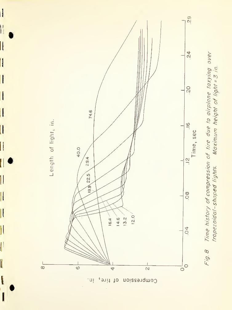
Figure 8 shows the time history of the compression of thetire as the airplane taxies over the series of trapezoidal-shaped lights of the lengths given in table 1 . Results forthe other shaped lights, circular arc, ellipse, parabola, andsine, were very similar to those for the trapezoidal light,the only difference being in the slope of the curve from time0 to the maximum value of tire deflection.
The loads corresponding to the maximum compression of thetire are given in table 3. Although these loads are quitehigh, particularly for the shorter length lights, they arebelow the values that would cause tire bottoming and it isassumed, therefore, that the landing gear could safely takethese loads.
It is noted from table 3 that for the longest light, thetrapezoidal shape seems to be best as the load on the tire isleast for that light. For all other lengths of light, themaximum difference in impact load for the shapes studied didnot exceed 3 percent. This would indicate that the shape ofthe light was not important and that any of the shapes investi-gated could be used. This result agrees with that of reference14 where it was found that the obstacle edge had little effecton the vertical loads in the main gears when taxying a B-36airplane over obstacles from 1.5 to 4*5 inches high.
In a later series of tests on the B-36 airplane, reference15, it was reported that taxying over a platform obstacle (20ft long) produced a more severe loading condition than taxyingover a short obstacle (1 ft long). From our analysis, theloads seem to be more severe for the short obstacle but are of

-
:
r
f
i

NBS Lab, No, 6.4/295, PR-1 page 6*
shorter duration. See figure 8. However, a comparison of thetime histories of the displacements of the airplane and wheelmasses for the longest and shortest trapezoidal lights, figure9, shows that taxying over the longer light causes a greaterrebound of the masses. This could result in undesirable load-ing, particularly if the airplane taxied over a series of theselights as was done with the B- 36 .
5, ANALYSIS FOR THE NOSE GEAR OF THE F-86H AIRPLANE
After completing the analysis for the B-47 airplane, itwas decided to make a similar one for the nose wheel of afighter aircraft. The F-86H airplane was chosen for thisstudy. As it was found in the previous work that the shape oflight has little, if any, effect on the loads on the tire asthe airplane taxi es over the light, it was decided to limitour study on the F-86H to the trapezoidal shape of light.
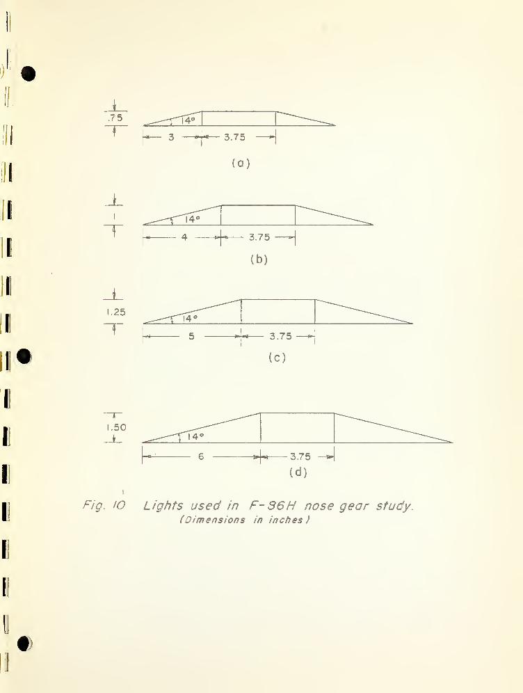
Four heights of light were used, 0.75, 1.00, 1.25, and1.50 inches. A base angle of 14 degrees was used to determinethe length of lights for these heights. This value of baseangle was decided upon since it had been used in a preliminarydesign of a runway light and would be about the largest baseangle that could be tolerated because of other considerationssuch as snow removal from runway, et cetera. The dimensionsof the lights are given in figure 10 which shows the relativesize of the 4 lights to be studied. Taxying speeds of 50, 80,110, and 140 miles per hour were used for each light. For thisseries of computations, it was assumed that the nose wheelcarried the entire portion of the airplane weight attributedto it, i.e., lift was not taken into account. To determinethe effect of lift, however, four of the cases were repeatedin which ¥]_ had a value of 900 pounds, approximately half ofthe weight used in the first computation. Other data for theF-86H airplane (reference 16) are given in table 2. The load-deflection curve for the tire is given in figure 11. Thedamping coefficient and load-stroke curves were obtained, aspreviously described, from data in references 16 and 17. Thetime histories of the displacement of the masses were computedin SEAC. Loads corresponding to the wheel displacement wereobtained from figure 11.
6. RESULTS FOR F-86H NOSE GEAR AND DISCUSSION
The results obtained for the lowest light, figure 10(a),are shown in figure 12 for the 4 taxying speeds investigated.
I


NBS Lab. No. 6.4/295, PR-1 page 7
In taxying over this particular light, the compression of thetire and therefore the load on it was approximately the same,about 5,000 lb for all taxying speeds. After the wheel is overthe light, the shock strut extends slightly but soon returnswith small oscillations to its initial position when taxying.The extension of the strut after the first compression islargest for the slowest taxying speed.
A comparison of the maximum impact loads, table 4, showslarger differences between the loads obtained for the lowestand the highest taxying speeds as the height of light is in-creased from 0.75 inch to 1.50 inches. It is also evident fromtable 4 and figure 13 that, as the height of the light is in-creased, the compression of the tire and therefore the load onit, for any particular taxying speed is larger and the exten-sion of the shock strut greater following its rolling over thelight.
The time histories of the displacement of the part of theairplane mass attributed to the nose gear and of the wheel massare shown in figure 14 considering no lift or W]_ = l8ll lb.These are for taxying speeds of 50 and 140 mph. In order todetermine the effect of lift, these cases were recomputed as-suming that the part of the airplane mass attributed to thenose gear was only about 50 percent of its previous value orWX = 900 lb. A comparison of the figures shows that lift ofthis order of magnitude on the airplane would reduce the tiredeflection by about 0.24 in., or the load by about 1,000 lband, at the lower speed of taxying, would cause the wheel tolift off the ground. It is to be noted that the time historiesof the displacement of the airplane mass show a very slightmovement, much smaller than it was in the case of the mainrear gear of the B-47 airplane, figure 9. This would indicatethat all of the reaction of a nose wheel running over a lightof 0.75 in. in height was taken by the shock strut with littlediscemable reaction on the airplane. One would not expect apitching of the airplane even though the nose gear raised offthe ground.
6. CONCLUSIONS
From the preliminary studies made on the main rear wheelof the B-47 airplane and the nose wheel of the F-86H airplane,the following conclusions seem to be indicated regarding thelanding gear loads resulting from taxying an airplane over araised runway light:

-

NBS Lab. No. 6.1j./295, PR-1 page 8
1. The height of light is an important factor in themagnitude of the landing gear loads but the shape of thelight edge has little, if any, effect.
2. At high taxying speeds, there is little reaction ofthe F-86H airplane when its nose wheel taxies over a raisedrunway light of moderate height.
3. At high taxying speeds, the landing gear loads in-crease as the height of the light is increased, and, somewhatless, as the taxying speeds increase. The latter may be offsetby an increase in lift at the higher taxying speeds.
On the basis of the results obtained, it is recommendedthat:
(1) Analyses be made of other representative landinggears using the SEAC code developed for the present study.
(3) The application of the analysis to the landing con-dition be investigated.
7. RECOMMENDATIONS
For the Director,
B. L. Wilson, Chief,
UUi.01,Engineering Mechanics Section,Division of Mechanics.
Washington, D. CMarch 1958

I
I
I
I
i
i
I

NBS Lab. No. 6 . 1+/295 ,PH-1 page 9
REFERENCES
1. McBrearty, J. F.A Critical Study of Aircraft Landing GearsJour. Aero. Sciences, Vol. 15, No. 5, o. 263, May 1
2. Lindquist, D. C.Effects of Wing Lift and Weight on Landing - Gear LoadsNACA TN26J+5, March 1952
3. AnonFlexural Transients in Model Wing Following Vertical
"Landing Imoact” at Point Below Center of GravityNBS Lab. No. 65l8l, PR-1, 19ij.6
ij.. Kroll, W. D. and Levy, S.
A Step-by-Step Method of Determining the Dynamic Responseof Aircraft in LandingNBS Lab. No. 6 .l+/l-l 8l, PR- 6 ,
19l;9
5. Milwitzky, B. and Cook, F. E.Analysis of Landing Gear BehaviorNACA TN 2755, 1952
6. Stevens, J. E.Nose Gear Loads and Airolane Motion During ArrestedLanding of Model 7FN-1 Airnlane
Chance Vought Aircraft Reoort 8l7U> 19li9
7. Fliigye, W.Landing - Gear ImoactNACA TN27I4.3, October 1952
8 . Houbolt, John C.,Walls, James H. and Smiley, Robert F.
On Spectral Analysis of Runway Roughness and Loads Devel-oped During Taxying
NACA TN3 I4.8 I4., July 1955
9* McPherson, A. E. ,Evans, J. Jr., and Levy, S.
Influence of Wing Flexibility on Force Time Relation inShock Strut Following Vertical Landing Impact
TN1995, November, 19i|9
10. Bisplinghoff ,R. L., Isakson, G.
,Plan, T. H, H.
,
Flom enhoft, H. I. and O’Brien, T. F.An Investigation of* Stresses in Aircraft Structures under
Dynamic LoadingMIT reoort for Bureau of Aero. Contract No. N0a(s) 8790,
191+9 po • I 36 -II4J4.


NBS Lab. No 6 .I4./295 ,PR-1 page 10
11. Houbolt, John C.A Recurrence Matrix Solution for the Dynamic Resoonse ofAircraft in GustsNACA TN2060, March 1950
12. Durand, H. P. and Rosenberg, R. M.A New Approach to the Design of Metering Pins in Oleo
StrutsUniversity of Washington Exoeriment Station Bulletin No.
113, 19£L
13. Data for B-lj.7 AirolaneCommunications from Wichita Division, Boeing Aircraft
Comoany
ll|.. AnonB-36 Taxi Tests over Obstacles at High Airplane GrossWeights
Conrair Reoort FZS- 36-293, December 1952
15. AnonB-36 Taxi Tests over Obstacles at High Airplane GrossWeights
Convair Reoort FZS-36-293 Addendum 1 November 1953
16. Data for F- 86 H AirplaneCommunications from North American Aviation, Inc.
17. Prescott, D. B.Model F- 06H Airplane, Main Gear - Aerol No. 9203, Nose
Gear - Aerol. No. 9202The Cleveland Pneumatic Tool Company Reoort 9203-02 DT
for North American Aviation, Inc. October 20, 1952

fl
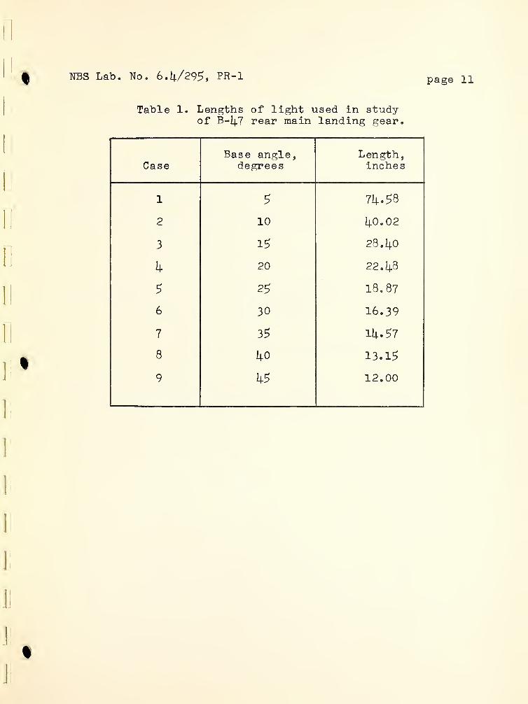
NBS Lab. No. 6. 4/295 ,PR-1 page 11l
Table 1. Lengths of light used in studyof B-I4.7 rear main landing gear.
CaseBase angle,
degreesLength,inches
1 5 74.58
2 10 40.02
3 15 28.40
4 20 22.48
5 25 18.87
6 30 16.39
7 35 14.57
8 40 13.15
9 45 12.00


No. 6.4/295, PH-1 page 12Q NBS Lab
.
Table 2. Data for B— 14.7 and F-86H airplanes.
B— 1|_7 Airnlane - Rear Main Dear
Unsprung weight - 2200 lbWeight of airnlane - 100,300 lbWeight support by rear main gear - 100,200 lb or 54,
per wheelAt t ime t=0, under weight supported by rear gear
= 15.01 in.
X2
=I].. 11 in.
Taxying speed - 10 miles/hr or 176 in. /secW-j_ = 48,700 lb (weight supported by wheel reduced 10
to account for lift)
F-86H Airplane - Nose Wheel
Ilbnose wheel, W-, = l8ll lbweight supported by nose wheel
in.
in.
Unsprung weight - 60Weight attributed toAt time
*\0II-p under
X1
= 6.845
x2
= 0. 665
For W^ = 900 :lb
xi
= 4.53 in.
Xp = 0.43 in.
100 lb
percent

rrr

1
IJ
page
13
hts
5
inches
Sine
curve
76,000
86
,
500
OOto
oCD
91,800 92,500
ooo
ON
ftCD
94,900 96,600 96,700
1
bD•H cO
i—
1
rH o o O o o o o o oo o o O o o o o o o
!>s joi 03 03 CD 1—
1
o 03 CO CD CD g
cd cO ON ON «N Ov ON on On on On
£ Ph ft ft CD 1—
1
03 ft ft CD CDP cd £> co CO CD CD CD CD CD CD2 PMPh
Ph
0 0 O o O O O O O O O> w o o o O o o o O Oo ft LO O' o to o o to 1
1 CO I
X3 •H ON «N •N ON On On on on On
bD 1 1 i
—1 cd CD o 1
1 to ft in CD CDP i
—I !> CO CD CD CD CD CD CD CD
•H ON wt>» TO
cO
Q-P 1—
1
oPh
P £ cO
0 s o O o O O o o O Oh £ Ph o O o O O o o o o& *H cO CO LO 03 in CO o 03 o 03 1
X 11
«N On ON On On ON ON «N ON
!> cO P ft to O 1—
1
ft in CD 0- 0-ft S o £> CO CD CD CD CD CD CD CD
i Ph
PQ •Ho
<PO
TOcc! •H O o O O O o O o O0 o o o O O O o O o obD e N CO cd to 03 CD o 03 o o 1
Ph 0 ON •v ON ON On On on On on
P P ft o m o 03 to CD CD 0- 0-•H C cO 00 CD CD CD CD CD CD CDas .a Ph
£Ph
Ph 0
Eh
CO Ph0 0Ph 0
1
—I o
f—
1 © bO oi P rH P o
ffi O »H cO 1 t 1 1 1 g 1 1 | On
Pm £ P> OT3 o o
o, cO O 0 rHID O rH «CD 1
—1
03b if
ft 3 cO ft• s . O *
CO •H £ •P co 03 o CO O' CD C*- m o oK bD ,P ,P • LO O ft ft co to in l
—1 o o
ctf#H P bO P • • • 0 0 • • 0 • •
o S JP hO #H *H ft o co 03 CO CD ft to 03 toP H ft 03 03 I
—1 1 1 l
—
1
rH rH0
• • ftD3 tocd
J ©I
—1 0
CO M I
—1 03 to ft LO CD o CO CD o
CQ CO co rHa &H o
J

'

NBS Lab. No. 6.4/295, PR-1 page ll|
Table 4* Maximum loads on nose wheel of F-86H when taxying overtrapezoidal light
Case
Height oflight,in. W-, ,
lb
Velocair
mi /hr
ity of•planein. /sec
Maximumdeflection
of tirein.
Maximumload on
tire, lb
la 0.75 1811 50 880 1.360 4860lb 1811 80 1408 1.375 4910lc 1811 110 1936 1.393 5010Id 1811 1^0 2464 1.390 4990le 900 50 880 1.108 3740If 900 llj.0 2464 1.153 3930
2a 1.00 1811 50 880 1.530 56302b 1811 80 1408 1.625 60702c 1811 110 1936 1.620 60402d 1811 140 214.6U. 1.645 6150
3a 1,25 1811 50 880 1.760 66903b 1811 80 1408 1. 800 68703c 1811 110 1936 1.870 72003d 1811 1^0 2464 1.895 7300
4® i.5o 1811 50 880 1.895 73004b 1811 80 1408 2.04.3 8000U-C 1811 110 1936 2.070 8130k& 1811 IkO 2464 2.092 8230ke 900 50 880 1.590 5900hr 900 80 1408 1.787 6820

1

Fig . / Representation of airplane.


t
I]
]
Rectangle
Fig. 2 Shapes of tights investigated
.


Fig. 3 Load- deflection curve for tire of B-47 rear main gear.

Il
0
n
Q
I
I
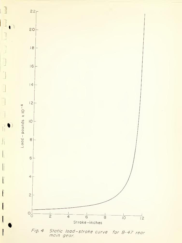
Fig. 4 Static load -stroke curve for B-47 rearmam gear.


Fig.
5
Dynamic
load
-
stroke
curve
for
B-47
rear
main
gear.


Fig.
6
Velocity
-
stroke
curve
for
B-47
rear
mom
gear
.


I
Dn
Fig.
7
Time
history
of
compression
of
tire
due
to
airplane
taxymg
over
square
-
shaped
light.
Height
of
light
-
3in.

[
r
!
[
[
i
I
[
l
1
GDCVJ
III
I!
II
>1
II
II
I
l
9j(4 jo uojssajduuoo
Fig.
8
Time
history
of
compression
of
tire
due
to
airplane
taxying
trcpezoidai-shoped
fights.
Maximum
height
of
tight
=
3in.


Light
length,
in.
)
c*
"v.
k
Ul ^USUUSODldSIQ
Time,
sec
Displacement
of
airplane
,m
/t
and
wheel
,m
2t
of
6-47
when
foxy
mg
over
trapezoidal
light,
3in.
high,
at
10
mph

f •01
ill
If
II
II
II
I
I!
II
II
II
I
i -
Fig. IO Lights used in F-96H nose gear study.(Dimensions in inches)


I
Fig. II Load -deflection curve for tire of F-86H nose wheel.


D
D
I0*>
U|]
IJ
|]
\J
i i)
IJ
NI
Time,
sec
Fig.
12
Time
history
of
deflections
of
nose
wheel
tire
when
taxying
F-86
over
a
run
way
light
0.75
in.
high
at
various
speeds.

f
[
.

II
11
.
Fig. 13 Deflection of tire of nose wheel as F-86
H
airplane is taxied over trapezoid lights of
different heights at 110 mph.
ia€
JJ

(I
.

Taxying
speed
,
mph
140
Oin
CD CD
ui ‘ssduu auD|djio
uojioaijao
Fig.
14
Displacement
of
airplane
and
of
wheel
when
taxying
over
trapezoidal
tight
0.75
in.
high.
IV,
=1811
lb.


jo- uoijoaijaa
;§
N
&fe
<b
Fig.
15
Displacement
of
airplane
and
of
wheel
when
taxymg
light
0.
75
in.
high.
W,
=
900
lb


THE NATIONAL BUREAU OF STANDARDS
Functions and Activities
The functions of the National Bureau of Standards are set forth in the Act of Congress, March
3, 1901, as amended by Congress in Public Law 619, 1950. These include the development and
maintenance of the national standards of measurement and the provision of means and methods
for making measurements consistent with these standards; the determination of physical constants
and properties of materials; the development of methods and instruments for testing materials,
devices, and structures; advisory services to Government Agencies on scientific and technical
problems; invention and development of devices to serve special needs of the Government; and the
development of standard practices, codes, and specifications. The work includes basic and applied
research, development, engineering, instrumentation, testing, evaluation, calibration services, and
various consultation and information services. A major portion of the Bureau’s work is performed
for other Government Agencies, particularly the Department of Defense and the Atomic Energy
Commission. The scope of activities is suggested by the listing of divisions and sections on the
inside of the front cover.
Reports and Publications
The results of the Bureau’s work take the form of either actual equipment and devices or
published papers and reports. Reports are issued to the sponsoring agency of a particular project
or program. Published papers appear either in the Bureau’s own series of publications or in the
journals of professional and scientific societies. The Bureau itself publishes three monthly peri-
odicals, available from the Government Printing Office: The Journal of Research, which presents
complete papers reporting technical investigations; the Technical News Bulletin, which presents
summary and preliminary reports on work in progress; and Basic Radio Propagation Predictions,
which provides data for determining the best frequencies to use for radio communications throughout
the world. There are also five series of nonperiodical publications: The Applied Mathematics
Series, Circulars, Handbooks, Building Materials and Structures Reports, and Miscellaneous
Publications.
Information on the Bureau’s publications can be found in NBS Circular 460, Publications of
the National Bureau of Standards ($1.25) and its Supplement ($0.75), available from the Superin-
tendent of Documents, Government Printing Office. Inquiries regarding the Bureau’s reports and
publications should be addressed to the Office of Scientific Publications, National Bureau of
Standards, Washington 25, D. C.

1
a
c
*r
•i
f:
(i