737-700/800/900 - (With Winglets) - Airplane Characteristics for
214
737-700/800/900 (With Winglets) Airplane Characteristics for Airport Planning Boeing Commercial Airplanes D6-58325-5 SEPTEMBER 2003 i
-
Upload
khangminh22 -
Category
Documents
-
view
0 -
download
0
Transcript of 737-700/800/900 - (With Winglets) - Airplane Characteristics for
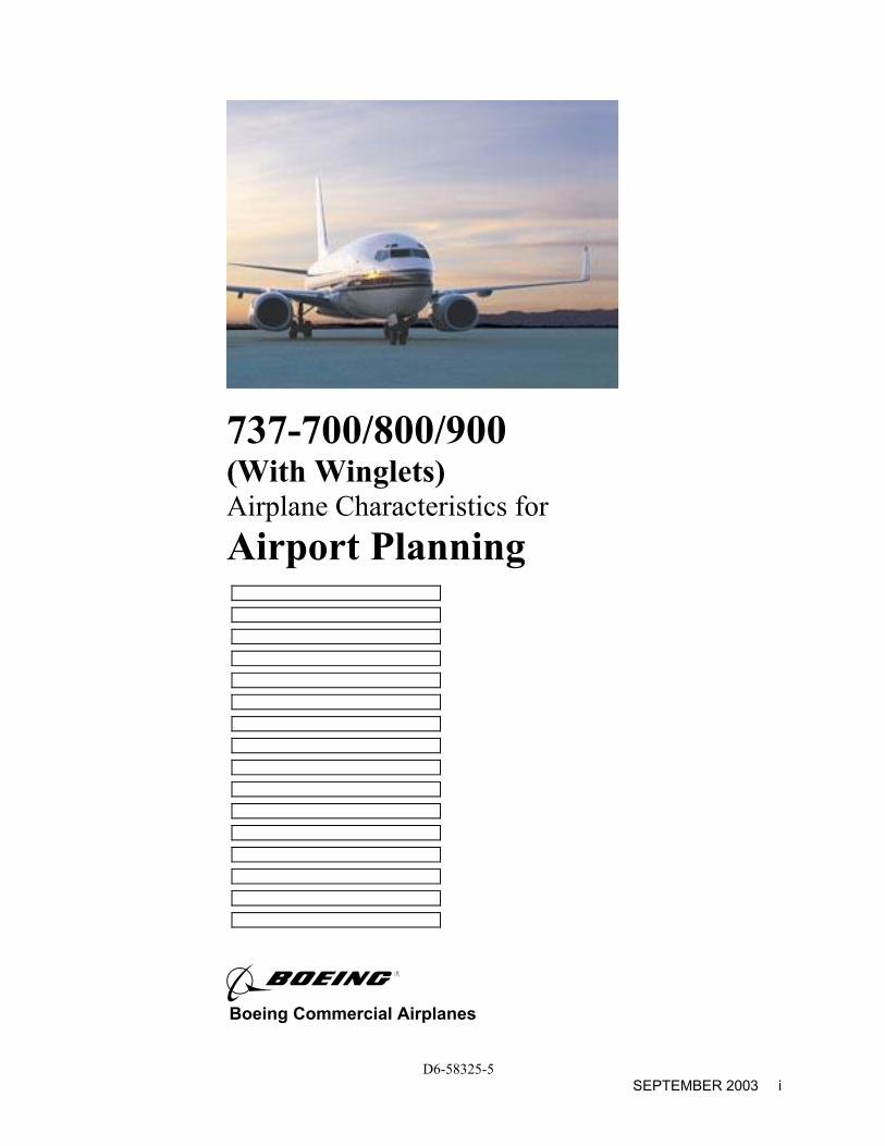
737-700/800/900 (With Winglets) Airplane Characteristics for Airport Planning
Boeing Commercial Airplanes
D6-58325-5 SEPTEMBER 2003 i
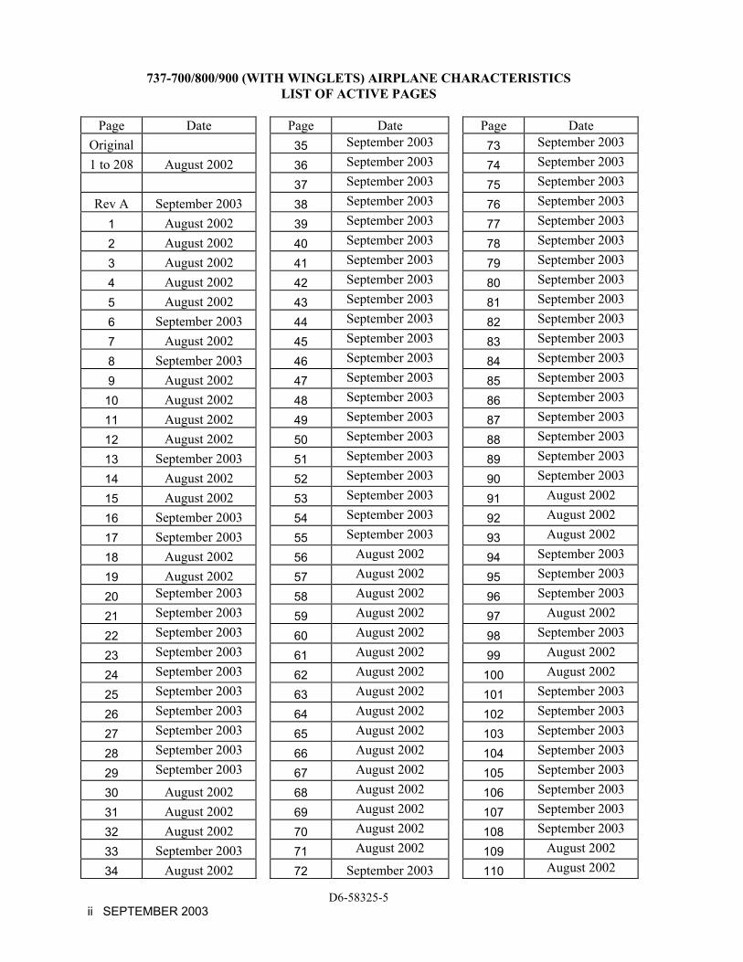
737-700/800/900 (WITH WINGLETS) AIRPLANE CHARACTERISTICS LIST OF ACTIVE PAGES
Page Date Page Date Page Date
Original 35 September 2003 73 September 2003
1 to 208 August 2002 36 September 2003 74 September 2003
37 September 2003 75 September 2003
Rev A September 2003 38 September 2003 76 September 2003
1 August 2002 39 September 2003 77 September 2003
2 August 2002 40 September 2003 78 September 2003
3 August 2002 41 September 2003 79 September 2003
4 August 2002 42 September 2003 80 September 2003
5 August 2002 43 September 2003 81 September 2003
6 September 2003 44 September 2003 82 September 2003
7 August 2002 45 September 2003 83 September 2003
8 September 2003 46 September 2003 84 September 2003
9 August 2002 47 September 2003 85 September 2003
10 August 2002 48 September 2003 86 September 2003
11 August 2002 49 September 2003 87 September 2003
12 August 2002 50 September 2003 88 September 2003
13 September 2003 51 September 2003 89 September 2003
14 August 2002 52 September 2003 90 September 2003
15 August 2002 53 September 2003 91 August 2002
16 September 2003 54 September 2003 92 August 2002
17 September 2003 55 September 2003 93 August 2002
18 August 2002 56 August 2002 94 September 2003
19 August 2002 57 August 2002 95 September 2003
20 September 2003 58 August 2002 96 September 2003
21 September 2003 59 August 2002 97 August 2002
22 September 2003 60 August 2002 98 September 2003
23 September 2003 61 August 2002 99 August 2002
24 September 2003 62 August 2002 100 August 2002
25 September 2003 63 August 2002 101 September 2003
26 September 2003 64 August 2002 102 September 2003
27 September 2003 65 August 2002 103 September 2003
28 September 2003 66 August 2002 104 September 2003
29 September 2003 67 August 2002 105 September 2003
30 August 2002 68 August 2002 106 September 2003
31 August 2002 69 August 2002 107 September 2003
32 August 2002 70 August 2002 108 September 2003
33 September 2003 71 August 2002 109 August 2002
34 August 2002 72 September 2003 110 August 2002
D6-58325-5 ii SEPTEMBER 2003
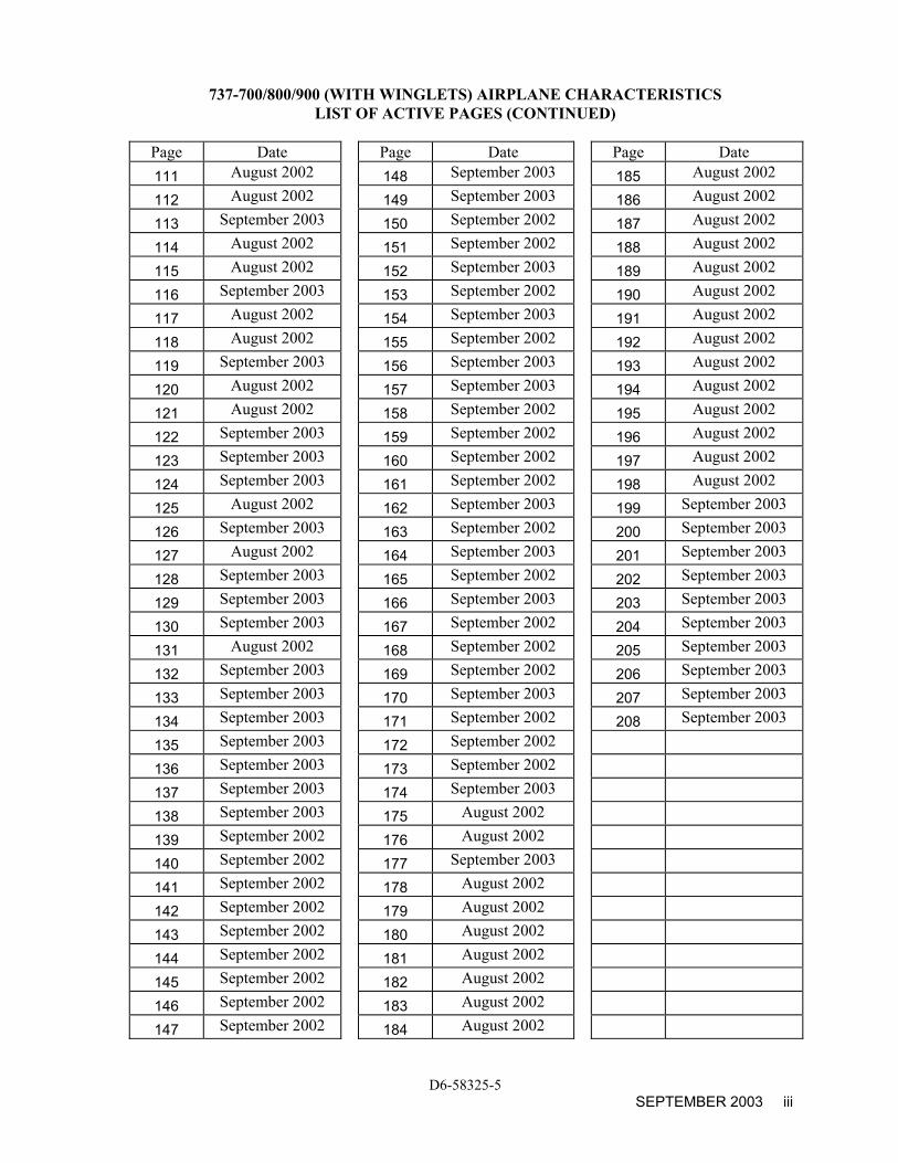
737-700/800/900 (WITH WINGLETS) AIRPLANE CHARACTERISTICS LIST OF ACTIVE PAGES (CONTINUED)
Page Date Page Date Page Date 111 August 2002 148 September 2003 185 August 2002
112 August 2002 149 September 2003 186 August 2002
113 September 2003 150 September 2002 187 August 2002
114 August 2002 151 September 2002 188 August 2002
115 August 2002 152 September 2003 189 August 2002
116 September 2003 153 September 2002 190 August 2002
117 August 2002 154 September 2003 191 August 2002
118 August 2002 155 September 2002 192 August 2002
119 September 2003 156 September 2003 193 August 2002
120 August 2002 157 September 2003 194 August 2002
121 August 2002 158 September 2002 195 August 2002
122 September 2003 159 September 2002 196 August 2002
123 September 2003 160 September 2002 197 August 2002
124 September 2003 161 September 2002 198 August 2002
125 August 2002 162 September 2003 199 September 2003
126 September 2003 163 September 2002 200 September 2003
127 August 2002 164 September 2003 201 September 2003
128 September 2003 165 September 2002 202 September 2003
129 September 2003 166 September 2003 203 September 2003
130 September 2003 167 September 2002 204 September 2003
131 August 2002 168 September 2002 205 September 2003
132 September 2003 169 September 2002 206 September 2003
133 September 2003 170 September 2003 207 September 2003
134 September 2003 171 September 2002 208 September 2003
135 September 2003 172 September 2002 136 September 2003 173 September 2002 137 September 2003 174 September 2003 138 September 2003 175 August 2002 139 September 2002 176 August 2002 140 September 2002 177 September 2003 141 September 2002 178 August 2002 142 September 2002 179 August 2002 143 September 2002 180 August 2002 144 September 2002 181 August 2002 145 September 2002 182 August 2002 146 September 2002 183 August 2002 147 September 2002 184 August 2002
D6-58325-5 SEPTEMBER 2003 iii
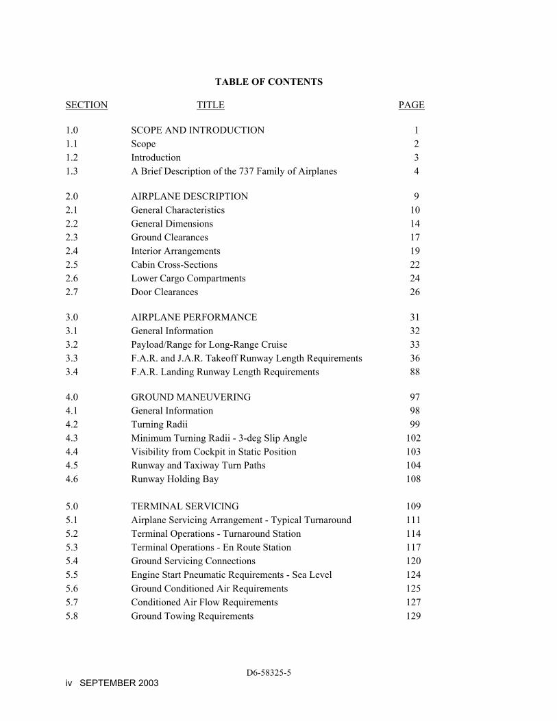
TABLE OF CONTENTS
SECTION TITLE PAGE 1.0 SCOPE AND INTRODUCTION 1 1.1 Scope 2 1.2 Introduction 3 1.3 A Brief Description of the 737 Family of Airplanes 4 2.0 AIRPLANE DESCRIPTION 9 2.1 General Characteristics 10 2.2 General Dimensions 14 2.3 Ground Clearances 17 2.4 Interior Arrangements 19 2.5 Cabin Cross-Sections 22 2.6 Lower Cargo Compartments 24 2.7 Door Clearances 26 3.0 AIRPLANE PERFORMANCE 31 3.1 General Information 32 3.2 Payload/Range for Long-Range Cruise 33 3.3 F.A.R. and J.A.R. Takeoff Runway Length Requirements 36 3.4 F.A.R. Landing Runway Length Requirements 88 4.0 GROUND MANEUVERING 97 4.1 General Information 98 4.2 Turning Radii 99 4.3 Minimum Turning Radii - 3-deg Slip Angle 102 4.4 Visibility from Cockpit in Static Position 103 4.5 Runway and Taxiway Turn Paths 104 4.6 Runway Holding Bay 108 5.0 TERMINAL SERVICING 109 5.1 Airplane Servicing Arrangement - Typical Turnaround 111 5.2 Terminal Operations - Turnaround Station 114 5.3 Terminal Operations - En Route Station 117 5.4 Ground Servicing Connections 120 5.5 Engine Start Pneumatic Requirements - Sea Level 124 5.6 Ground Conditioned Air Requirements 125 5.7 Conditioned Air Flow Requirements 127 5.8 Ground Towing Requirements 129
D6-58325-5 iv SEPTEMBER 2003

TABLE OF CONTENTS (CONTINUED)
SECTION TITLE PAGE 6.0 JET ENGINE WAKE AND NOISE DATA 131 6.1 Jet Engine Exhaust Velocities and Temperatures 132 6.2 Airport and Community Noise 139 7.0 PAVEMENT DATA 143 7.1 General Information 144 7.2 Landing Gear Footprint 148 7.3 Maximum Pavement Loads 149 7.4 Landing Gear Loading on Pavement 150 7.5 Flexible Pavement Requirements - U.S. Army Corps of Engineers Method (S-77-1) 153 7.6 Flexible Pavement Requirements - LCN Method 155 7.7 Rigid Pavement Requirements - Portland Cement Association Design Method 157 7.8 Rigid Pavement Requirements - LCN Conversion 160 7.9 Rigid Pavement Requirements - FAA Method 163 7.10 ACN/PCN Reporting System - Flexible and Rigid Pavements 166 8.0 FUTURE 737 DERIVATIVE AIRPLANES 175 9.0 SCALED 737 DRAWINGS 177
D6-58325-5 SEPTEMBER 2003 v

THIS PAGE INTENTIONALLY LEFT BLANK
D6-58325-5 vi SEPTEMBER 2003
1.0 SCOPE AND INTRODUCTION
1.1 Scope
1.2 Introduction
1.3 A Brief Description of the 737 Family of Airplanes
D6-58325-5 AUGUST 2002 1
1.0 SCOPE AND INTRODUCTION
1.1 Scope
This document provides, in a standardized format, airplane characteristics data for general airport planning. Since operational practices vary among airlines, specific data should be coordinated with the using airlines prior to facility design. Boeing Commercial Airplanes should be contacted for any additional information required.
Content of the document reflects the results of a coordinated effort by representatives from the following organizations:
● Aerospace Industries Association
● Airports Council International - North America
● Air Transport Association of America
● International Air Transport Association
The airport planner may also want to consider the information presented in the "CTOL Transport Aircraft, Characteristics, Trends, and Growth Projections," available from the US AIA, 1250 Eye St., Washington DC 20005, for long-range planning needs. This document is updated periodically and represents the coordinated efforts of the following organizations regarding future aircraft growth trends:
● International Coordinating Council of Aerospace Industries Associations
● Airports Council International - North America
● Air Transport Association of America
● International Air Transport Association
D6-58325-5 2 AUGUST 2002
1.2 Introduction
This document conforms to NAS 3601. It provides characteristics of the Boeing Model 737-700, -800, and -900 airplanes with winglets for airport planners and operators, airlines, architectural and engineering consultant organizations, and other interested industry agencies. Airplane changes and available options may alter model characteristics. The data presented herein reflect typical airplanes in each model category.
For additional information contact:
Boeing Commercial Airplanes P.O. Box 3707 Seattle, Washington 98124-2207 U.S.A. Attention: Manager, Airport Technology Mail Stop 67-KR
D6-58325-5 AUGUST 2002 3
1.3 A Brief Description of the 737 Family of Airplanes
The 737 is a twin-engine airplane designed to operate over short to medium ranges from sea level runways of less than 6,000 ft (1,830 m) in length.
Significant features of interest to airport planners are described below:
● Underwing-mounted engines provide eye-level assessability. Nearly all system maintenance may be performed at eye level.
● Optional airstairs allow operation at airports where no passengers loading bridges or stairs are available.
● Auxiliary power unit can supply energy for engine starting, air conditioning, and electrical power while the airplane is on the ground or in flight.
● Servicing connections allow single-station pressure fueling and overwing gravity fueling.
● All servicing of the 737 is accomplished with standard ground equipment.
737-100
The 737-100 is the standard short body version of the 737 family. It is 94 ft (28.63 m) long from nose to the tip of the horizontal stabilizer.
737-200
The 737-200 is an extended body version of the 737 family and is 100 ft 2 in (30.53 m) long. Two sections were added to the 737-100 fuselage; a 36-in section forward of the wing and a 40-in section aft of the wing. All other dimensions are the same as the 737-100.
Advanced 737-200
The advanced 737-200 is a high gross weight airplane that has significant improvements over the 737-200, which result in improved performance, e.g. longer range, greater payload, and shorter runway requirement. The advanced 737-200 has dimensions identical to the 737-200.
D6-58325-5 4 AUGUST 2002
737-200C, Adv 737-200C
The convertible version differs from the passenger model in that it has an 86 by 134-in (2.18 by 3.40 m) main deck cargo door, increased floor strength, and additional seat tracks. Either of two cargo handling systems, the cargo (C) or quick change (QC) can be installed to allow conversion from a passenger configuration to a cargo or a mixed passenger/cargo configuration, and vice-versa.
737-200 Executive Airplane
The 737-200 and Adv 737-200 were also delivered with an executive interior. The interior comes in a variety of configurations depending on customer requirements. Some airplanes were delivered without any interior furnishings for customer installation of special interiors.
737-300
The 737-300 is a second-generation stretched version of the 737 family of airplanes and is 109 ft 7 in long. Two sections were added to the 737-200 fuselage; a 44-in section forward of the wing and a 60-in section aft of the wing. Wing and stabilizer spans are also increased. The 737-300 incorporates new aerodynamic and engine technologies in addition to the increased payload and range. The -300 can seat as many as 149 passengers in an all-economy configuration.
737-400
The 737-400 is 120 inches longer that the -300. Two sections were added to the -300 fuselage; a 72-in section forward of the wing and a 48-in section aft of the wing. The -400 can seat as many as 168 passengers in all-economy configuration.
737-500
The 737-500 is the shortened version of the 737-300. The -500 is 101 ft 9 in long and can seat up to 132 passengers in an all-economy configuration.
737-600
The 737-600, along with the 737-700, -800, and -900 is the latest derivative in the 737 family of airplanes. This airplane has the same fuselage as the 737-500 and fitted with new wing, stabilizer, and tail sections. This enables the airplane to fly over longer distances. The 737-600 is 102 ft 6 in long and can carry up to 130 passengers in an all-economy configuration.
D6-58325-5 AUGUST 2002 5
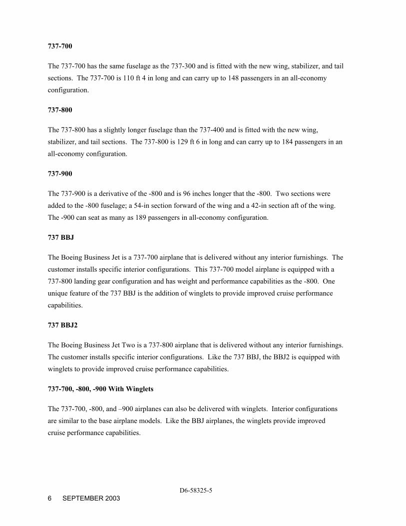
737-700
The 737-700 has the same fuselage as the 737-300 and is fitted with the new wing, stabilizer, and tail sections. The 737-700 is 110 ft 4 in long and can carry up to 148 passengers in an all-economy configuration.
737-800
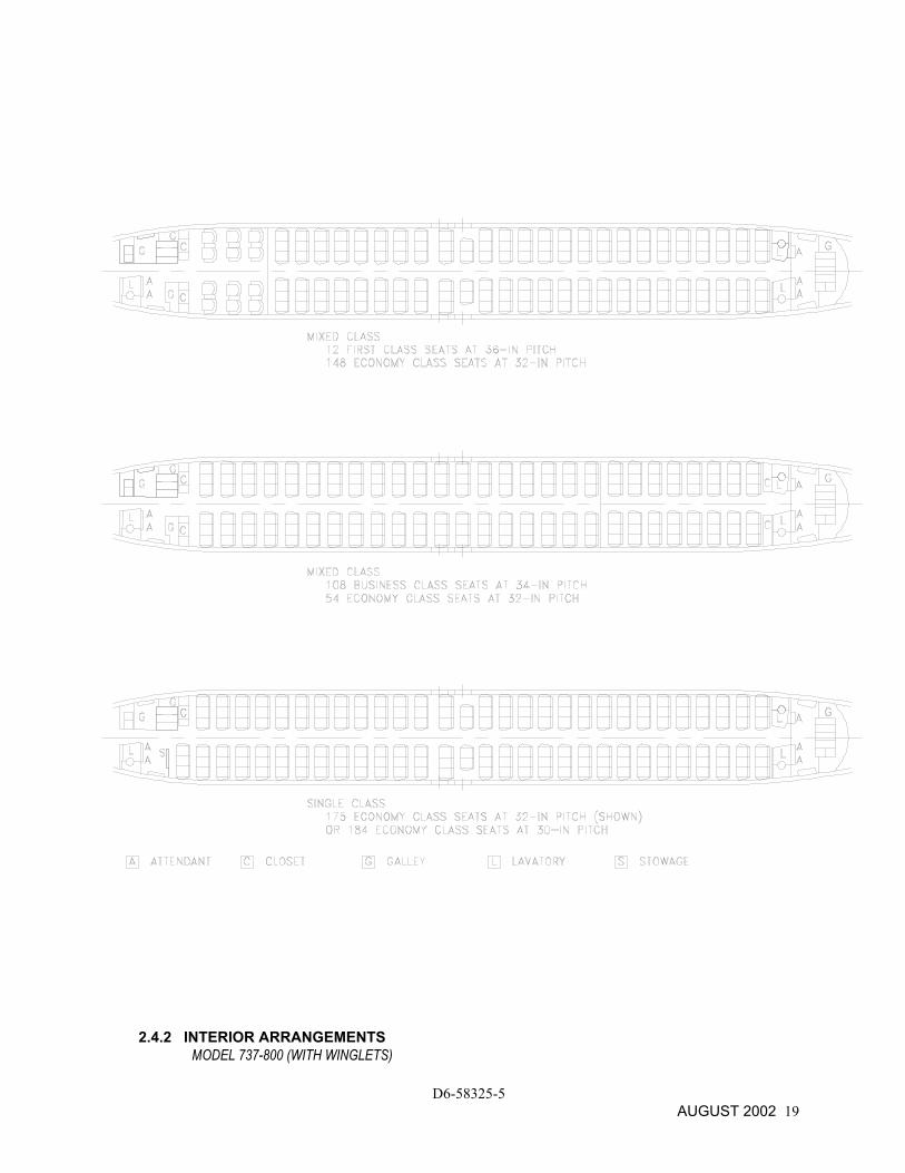
The 737-800 has a slightly longer fuselage than the 737-400 and is fitted with the new wing, stabilizer, and tail sections. The 737-800 is 129 ft 6 in long and can carry up to 184 passengers in an all-economy configuration.
737-900
The 737-900 is a derivative of the -800 and is 96 inches longer that the -800. Two sections were added to the -800 fuselage; a 54-in section forward of the wing and a 42-in section aft of the wing. The -900 can seat as many as 189 passengers in all-economy configuration.
737 BBJ
The Boeing Business Jet is a 737-700 airplane that is delivered without any interior furnishings. The customer installs specific interior configurations. This 737-700 model airplane is equipped with a 737-800 landing gear configuration and has weight and performance capabilities as the -800. One unique feature of the 737 BBJ is the addition of winglets to provide improved cruise performance capabilities.
737 BBJ2
The Boeing Business Jet Two is a 737-800 airplane that is delivered without any interior furnishings. The customer installs specific interior configurations. Like the 737 BBJ, the BBJ2 is equipped with winglets to provide improved cruise performance capabilities.
737-700, -800, -900 With Winglets
The 737-700, -800, and –900 airplanes can also be delivered with winglets. Interior configurations are similar to the base airplane models. Like the BBJ airplanes, the winglets provide improved cruise performance capabilities.
D6-58325-5 6 SEPTEMBER 2003
D6-58325-5 AUGUST 2002 7
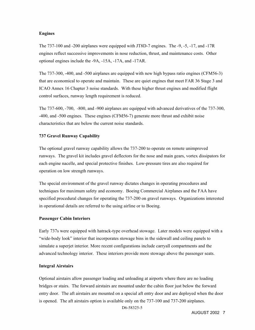
Engines
The 737-100 and -200 airplanes were equipped with JT8D-7 engines. The -9, -5, -17, and -17R engines reflect successive improvements in nose reduction, thrust, and maintenance costs. Other optional engines include the -9A, -15A, -17A, and -17AR.
The 737-300, -400, and -500 airplanes are equipped with new high bypass ratio engines (CFM56-3) that are economical to operate and maintain. These are quiet engines that meet FAR 36 Stage 3 and ICAO Annex 16 Chapter 3 noise standards. With these higher thrust engines and modified flight control surfaces, runway length requirement is reduced.
The 737-600, -700, -800, and -900 airplanes are equipped with advanced derivatives of the 737-300, -400, and -500 engines. These engines (CFM56-7) generate more thrust and exhibit noise characteristics that are below the current noise standards.
737 Gravel Runway Capability
The optional gravel runway capability allows the 737-200 to operate on remote unimproved runways. The gravel kit includes gravel deflectors for the nose and main gears, vortex dissipators for each engine nacelle, and special protective finishes. Low-pressure tires are also required for operation on low strength runways.
The special environment of the gravel runway dictates changes in operating procedures and techniques for maximum safety and economy. Boeing Commercial Airplanes and the FAA have specified procedural changes for operating the 737-200 on gravel runways. Organizations interested in operational details are referred to the using airline or to Boeing.
Passenger Cabin Interiors
Early 737s were equipped with hatrack-type overhead stowage. Later models were equipped with a “wide-body look” interior that incorporates stowage bins in the sidewall and ceiling panels to simulate a superjet interior. More recent configurations include carryall compartments and the advanced technology interior. These interiors provide more stowage above the passenger seats.
Integral Airstairs
Optional airstairs allow passenger loading and unloading at airports where there are no loading bridges or stairs. The forward airstairs are mounted under the cabin floor just below the forward entry door. The aft airstairs are mounted on a special aft entry door and are deployed when the door is opened. The aft airstairs option is available only on the 737-100 and 737-200 airplanes.
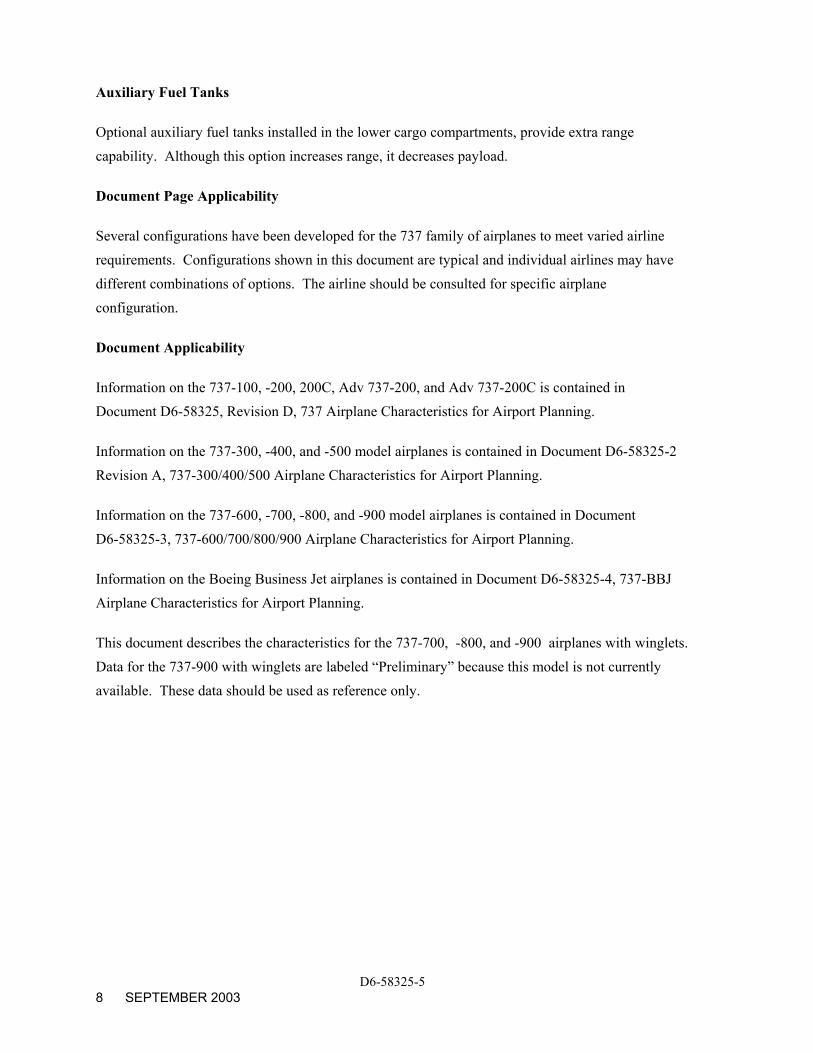
Auxiliary Fuel Tanks
Optional auxiliary fuel tanks installed in the lower cargo compartments, provide extra range capability. Although this option increases range, it decreases payload.
Document Page Applicability
Several configurations have been developed for the 737 family of airplanes to meet varied airline requirements. Configurations shown in this document are typical and individual airlines may have different combinations of options. The airline should be consulted for specific airplane configuration.
Document Applicability
Information on the 737-100, -200, 200C, Adv 737-200, and Adv 737-200C is contained in Document D6-58325, Revision D, 737 Airplane Characteristics for Airport Planning.
Information on the 737-300, -400, and -500 model airplanes is contained in Document D6-58325-2 Revision A, 737-300/400/500 Airplane Characteristics for Airport Planning.
Information on the 737-600, -700, -800, and -900 model airplanes is contained in Document D6-58325-3, 737-600/700/800/900 Airplane Characteristics for Airport Planning.
Information on the Boeing Business Jet airplanes is contained in Document D6-58325-4, 737-BBJ Airplane Characteristics for Airport Planning.
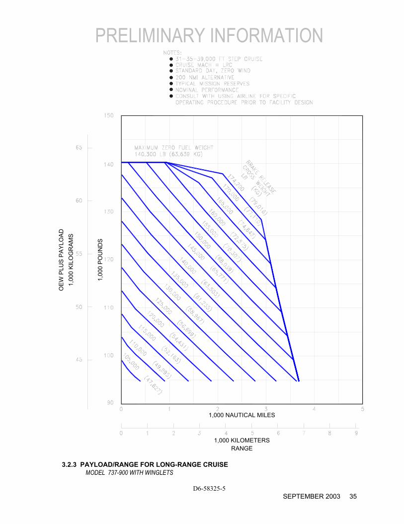
This document describes the characteristics for the 737-700, -800, and -900 airplanes with winglets. Data for the 737-900 with winglets are labeled “Preliminary” because this model is not currently available. These data should be used as reference only.
D6-58325-5 8 SEPTEMBER 2003

2.0 AIRPLANE DESCRIPTION
2.1 General Characteristics
2.2 General Dimensions
2.3 Ground Clearances
2.4 Interior Arrangements
2.5 Cabin Cross Sections
2.6 Lower Cargo Compartments
2.7 Door Clearances
D6-58325-5 AUGUST 2002 9
2.0 AIRPLANE DESCRIPTION
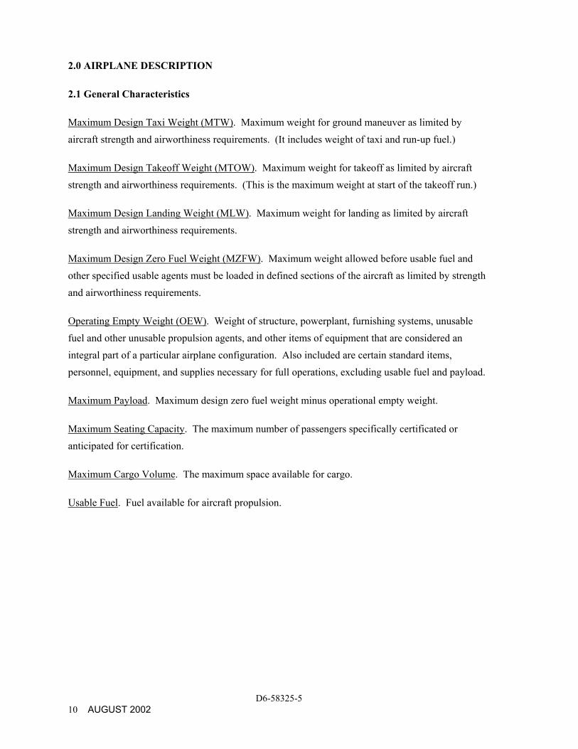
2.1 General Characteristics
Maximum Design Taxi Weight (MTW). Maximum weight for ground maneuver as limited by aircraft strength and airworthiness requirements. (It includes weight of taxi and run-up fuel.)
Maximum Design Takeoff Weight (MTOW). Maximum weight for takeoff as limited by aircraft strength and airworthiness requirements. (This is the maximum weight at start of the takeoff run.)
Maximum Design Landing Weight (MLW). Maximum weight for landing as limited by aircraft strength and airworthiness requirements.
Maximum Design Zero Fuel Weight (MZFW). Maximum weight allowed before usable fuel and other specified usable agents must be loaded in defined sections of the aircraft as limited by strength and airworthiness requirements.
Operating Empty Weight (OEW). Weight of structure, powerplant, furnishing systems, unusable fuel and other unusable propulsion agents, and other items of equipment that are considered an integral part of a particular airplane configuration. Also included are certain standard items, personnel, equipment, and supplies necessary for full operations, excluding usable fuel and payload.
Maximum Payload. Maximum design zero fuel weight minus operational empty weight.
Maximum Seating Capacity. The maximum number of passengers specifically certificated or anticipated for certification.
Maximum Cargo Volume. The maximum space available for cargo.
Usable Fuel. Fuel available for aircraft propulsion.
D6-58325-5 10 AUGUST 2002
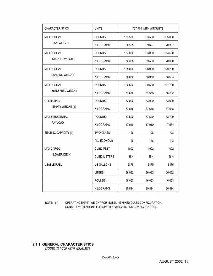
CHARACTERISTICS UNITS 737-700 WITH WINGLETS
MAX DESIGN POUNDS 133,500 153,500 155,000
TAXI WEIGHT KILOGRAMS 60,555 69,627 70,307
MAX DESIGN POUNDS 133,000 153,000 154,500
TAKEOFF WEIGHT KILOGRAMS 60,328 69,400 70,080
MAX DESIGN POUNDS 128,000 128,000 129,200
LANDING WEIGHT KILOGRAMS 58,060 58,060 58,604
MAX DESIGN POUNDS 120,500 120,500 121,700
ZERO FUEL WEIGHT KILOGRAMS 54,658 54,658 55,202
OPERATING POUNDS 83,000 83,000 83,000
EMPTY WEIGHT (1) KILOGRAMS 37,648 37,648 37,648
MAX STRUCTURAL POUNDS 37,500 37,500 38,700
PAYLOAD KILOGRAMS 17,010 17,010 17,554
SEATING CAPACITY (1) TWO-CLASS 128 128 128
ALL-ECONOMY 148 148 148
MAX CARGO CUBIC FEET 1002 1002 1002
- LOWER DECK CUBIC METERS 28.4 28.4 28.4
USABLE FUEL US GALLONS 6875 6875 6875
LITERS 26,022 26,022 26,022
POUNDS 46,063 46,063 46,063
KILOGRAMS 20,894 20,894 20,894
NOTE: (1) OPERATING EMPTY WEIGHT FOR BASELINE MIXED CLASS CONFIGURATION. CONSULT WITH AIRLINE FOR SPECIFIC WEIGHTS AND CONFIGURATIONS.
2.1.1 GENERAL CHARACTERISTICS MODEL 737-700 WITH WINGLETS
D6-58325-5 AUGUST 2002 11
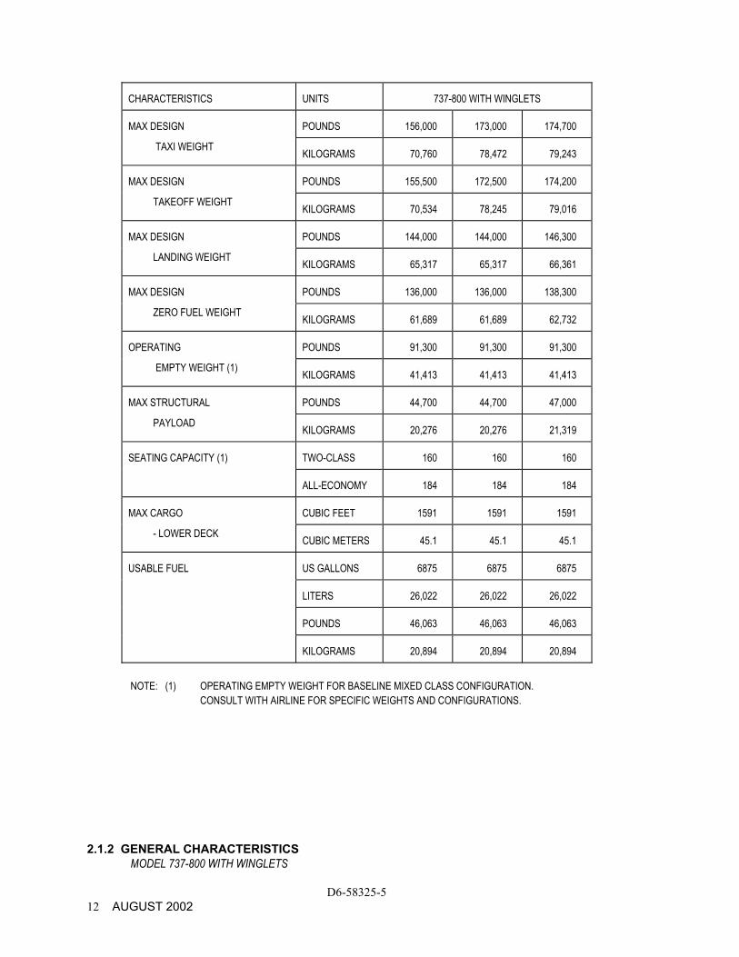
CHARACTERISTICS UNITS 737-800 WITH WINGLETS
MAX DESIGN POUNDS 156,000 173,000 174,700
TAXI WEIGHT KILOGRAMS 70,760 78,472 79,243
MAX DESIGN POUNDS 155,500 172,500 174,200
TAKEOFF WEIGHT KILOGRAMS 70,534 78,245 79,016
MAX DESIGN POUNDS 144,000 144,000 146,300
LANDING WEIGHT KILOGRAMS 65,317 65,317 66,361
MAX DESIGN POUNDS 136,000 136,000 138,300
ZERO FUEL WEIGHT KILOGRAMS 61,689 61,689 62,732
OPERATING POUNDS 91,300 91,300 91,300
EMPTY WEIGHT (1) KILOGRAMS 41,413 41,413 41,413
MAX STRUCTURAL POUNDS 44,700 44,700 47,000
PAYLOAD KILOGRAMS 20,276 20,276 21,319
SEATING CAPACITY (1) TWO-CLASS 160 160 160
ALL-ECONOMY 184 184 184
MAX CARGO CUBIC FEET 1591 1591 1591
- LOWER DECK CUBIC METERS 45.1 45.1 45.1
USABLE FUEL US GALLONS 6875 6875 6875
LITERS 26,022 26,022 26,022
POUNDS 46,063 46,063 46,063
KILOGRAMS 20,894 20,894 20,894
NOTE: (1) OPERATING EMPTY WEIGHT FOR BASELINE MIXED CLASS CONFIGURATION.
CONSULT WITH AIRLINE FOR SPECIFIC WEIGHTS AND CONFIGURATIONS.
2.1.2 GENERAL CHARACTERISTICS MODEL 737-800 WITH WINGLETS
D6-58325-5 12 AUGUST 2002
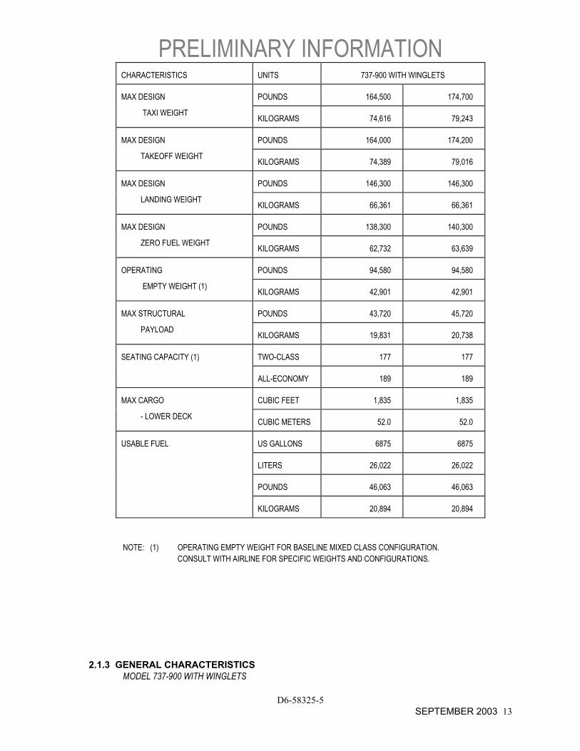
PRELIMINARY INFORMATION CHARACTERISTICS UNITS 737-900 WITH WINGLETS
MAX DESIGN POUNDS 164,500 174,700
TAXI WEIGHT KILOGRAMS 74,616 79,243
MAX DESIGN POUNDS 164,000 174,200
TAKEOFF WEIGHT KILOGRAMS 74,389 79,016
MAX DESIGN POUNDS 146,300 146,300
LANDING WEIGHT KILOGRAMS 66,361 66,361
MAX DESIGN POUNDS 138,300 140,300
ZERO FUEL WEIGHT KILOGRAMS 62,732 63,639
OPERATING POUNDS 94,580 94,580
EMPTY WEIGHT (1) KILOGRAMS 42,901 42,901
MAX STRUCTURAL POUNDS 43,720 45,720
PAYLOAD KILOGRAMS 19,831 20,738
SEATING CAPACITY (1) TWO-CLASS 177 177
ALL-ECONOMY 189 189
MAX CARGO CUBIC FEET 1,835 1,835
- LOWER DECK CUBIC METERS 52.0 52.0
USABLE FUEL US GALLONS 6875 6875
LITERS 26,022 26,022
POUNDS 46,063 46,063
KILOGRAMS 20,894 20,894
NOTE: (1) OPERATING EMPTY WEIGHT FOR BASELINE MIXED CLASS CONFIGURATION. CONSULT WITH AIRLINE FOR SPECIFIC WEIGHTS AND CONFIGURATIONS.
2.1.3 GENERAL CHARACTERISTICS
MODEL 737-900 WITH WINGLETS
D6-58325-5 SEPTEMBER 2003 13
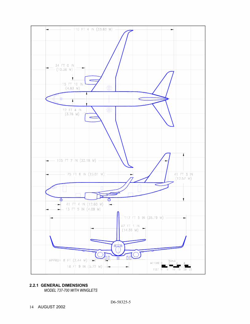
2.2.1 GENERAL DIMENSIONS MODEL 737-700 WITH WINGLETS
D6-58325-5 14 AUGUST 2002
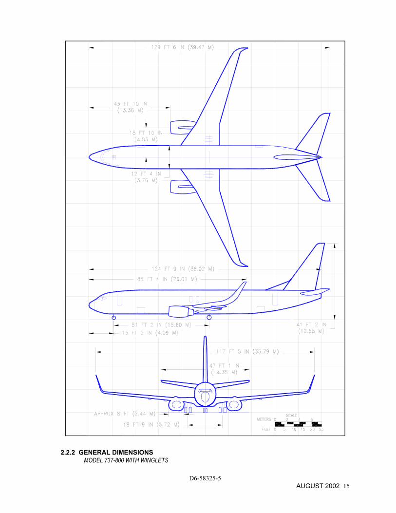
2.2.2 GENERAL DIMENSIONS MODEL 737-800 WITH WINGLETS
D6-58325-5 AUGUST 2002 15
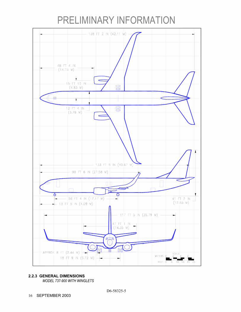
PRELIMINARY INFORMATION
D6-58325-5 16 SEPTEMBER 2003
2.2.3 GENERAL DIMENSIONS MODEL 737-900 WITH WINGLETS

PRELIMINARY FOR -900 WITH WINGLETS
D6-58325-5 SEPTEMBER 2003 17
737-700 WITH WINGLETS 737-800 WITH WINGLETS 737-900 WITH WINGLETS
DESCRIPTION MAX (OEW) MIN (MTW) MAX (OEW) MIN (MTW) MAX (OEW) MIN (MTW)
FT - IN M FT - IN M FT - IN M FT - IN M FT - IN M FT - IN M
A TOP OF FUSELAGE 18 - 3 5.56 17 - 9 5.41 18 - 1 5.49 17 - 1 5.20 18 - 4 5.59 17 - 10 5.41
B ENTRY DOOR NO 1 9 - 0 2.74 8 - 6 2.59 9 - 5 2.88 8 - 6 2.59 9 - 0 2.74 8 - 6 2.59
C FWD CARGO DOOR 4 - 9 1.45 4 - 3 1.30 5 - 0 1.52 4 - 9 1.44 4 - 9 1.45 4 - 3 1.30
D ENGINE 2 - 0 0.61 1 - 6 0.46 2 - 0 0.60 1 - 6 0.47 2 - 1 0.64 1 - 7 0.48
E WINGTIP 21 - 9 6.63 21 - 3 6.48 20 - 7 6.27 20 - 3 6.18 20 10 6.35 20 - 0 6.10
F AFT CARGO DOOR 5 - 10 1.78 5 - 4 1.63 5 - 8 1.73 4 - 9 1.44 5 - 11 1.80 5 - 5 1.65
G ENTRY DOOR NO 2 10 - 2 3.10 9 - 8 2.95 10 - 10 3.05 8 - 9 2.66 10 - 3 3.12 9 - 9 2.97
H STABILIZER 18 - 5 5.61 17 - 11 5.46 18 - 5 5.61 16 - 7 5.05 18 - 7 5.66 18 - 1 5.51
J VERTICAL TAIL 41 - 7 12.67 40 - 10 12.45 41 - 6 12.64 39 - 11 12.16 41 - 5 12.62 40 - 7 12.37
K BOTTOM OF WINGLET (APPROX)
13 - 9 4.19 13 - 3 4.04 12 - 8 3.86 12 - 3 3.73 12 - 10 3.91 12 - 0 3.66
NOTES: CLEARANCES SHOWN ARE NOMINAL. ADD PLUS OR MINUS 3 INCHES TO ACCOUNT FOR VARIATIONS IN
LOADING, OLEO AND TIRE PRESSURES, CENTER OF GRAVITY, ETC.
DURING ROUTINE SERVICING, THE AIRPLANE REMAINS RELATIVELY STABLE, PITCH AND ELEVATION CHANGES OCCURRING SLOWLY.
2.3 GROUND CLEARANCES
MODEL 737-700, -800, -900 WITH WINGLETS
D6-58325-5 18 AUGUST 2002
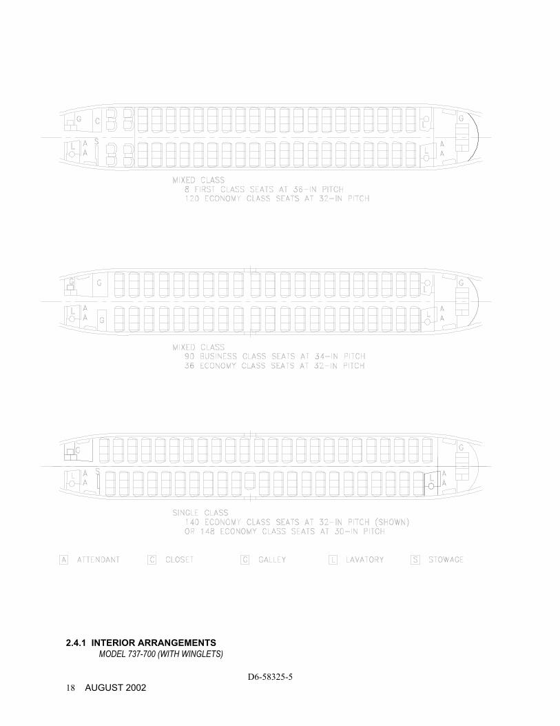
2.4.1 INTERIOR ARRANGEMENTS
MODEL 737-700 (WITH WINGLETS)
D6-58325-5 AUGUST 2002 19
2.4.2 INTERIOR ARRANGEMENTS MODEL 737-800 (WITH WINGLETS)
PRELIMINARY INFORMATION
D6-58325-5 20 SEPTEMBER 2003
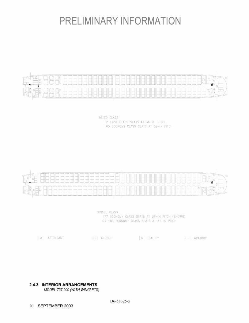
2.4.3 INTERIOR ARRANGEMENTS MODEL 737-900 (WITH WINGLETS)
PRELIMINARY FOR –900 WITH WINGLETS
D6-58325-5 SEPTEMBER 2003 21
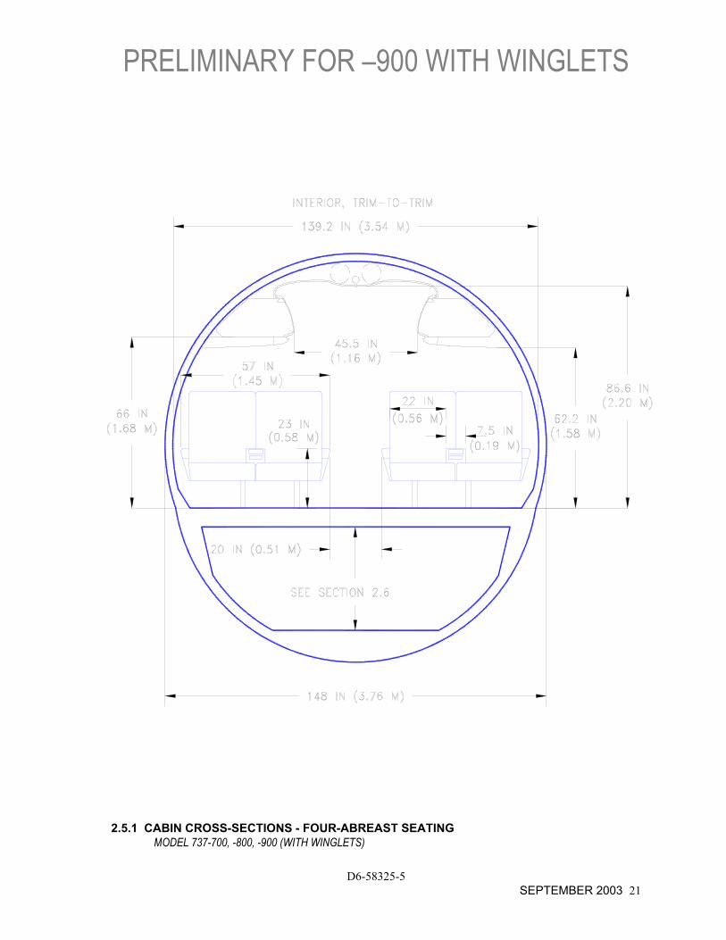
2.5.1 CABIN CROSS-SECTIONS - FOUR-ABREAST SEATING
MODEL 737-700, -800, -900 (WITH WINGLETS)
PRELIMINARY FOR –900 WITH WINGLETS
D6-58325-5 22 SEPTEMBER 2003
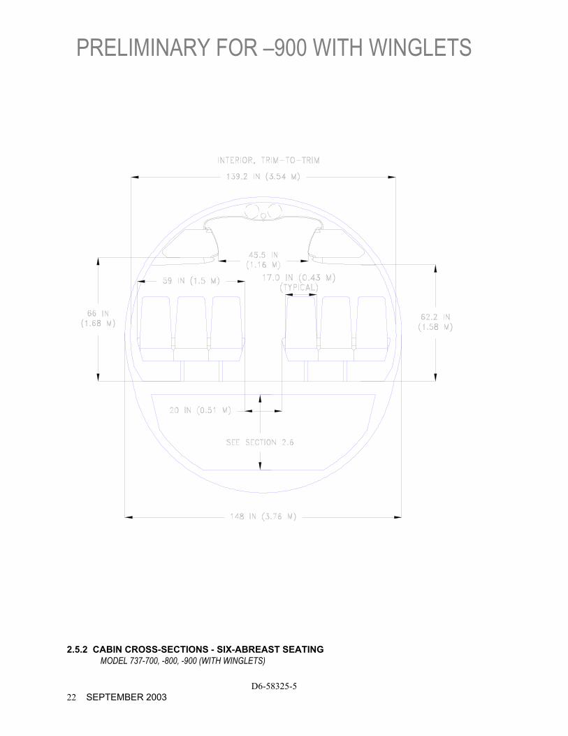
2.5.2 CABIN CROSS-SECTIONS - SIX-ABREAST SEATING
MODEL 737-700, -800, -900 (WITH WINGLETS)
PRELIMINARY FOR –900 WITH WINGLETS
D6-58325-5 SEPTEMBER 2003 23
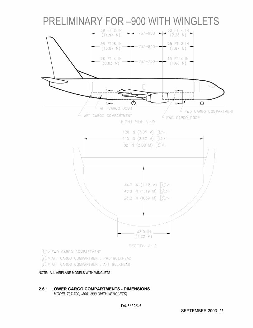
NOTE: ALL AIRPLANE MODELS WITH WINGLETS
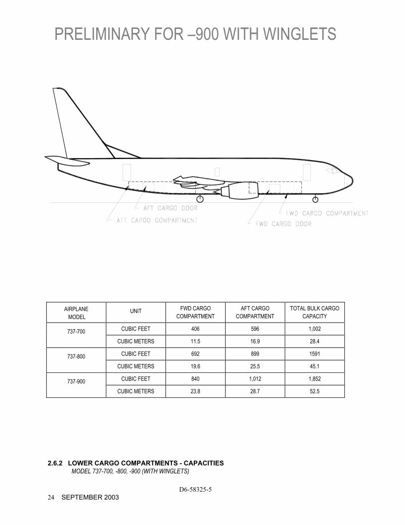
2.6.1 LOWER CARGO COMPARTMENTS - DIMENSIONS MODEL 737-700, -800, -900 (WITH WINGLETS)
PRELIMINARY FOR –900 WITH WINGLETS
D6-58325-5 24 SEPTEMBER 2003
AIRPLANE MODEL
UNIT FWD CARGO COMPARTMENT
AFT CARGO COMPARTMENT
TOTAL BULK CARGO CAPACITY
737-700 CUBIC FEET 406 596 1,002
CUBIC METERS 11.5 16.9 28.4
737-800 CUBIC FEET 692 899 1591
CUBIC METERS 19.6 25.5 45.1
737-900 CUBIC FEET 840 1,012 1,852
CUBIC METERS 23.8 28.7 52.5
2.6.2 LOWER CARGO COMPARTMENTS - CAPACITIES MODEL 737-700, -800, -900 (WITH WINGLETS)
PRELIMINARY FOR –900 WITH WINGLETS
D6-58325-5 SEPTEMBER 2003 25
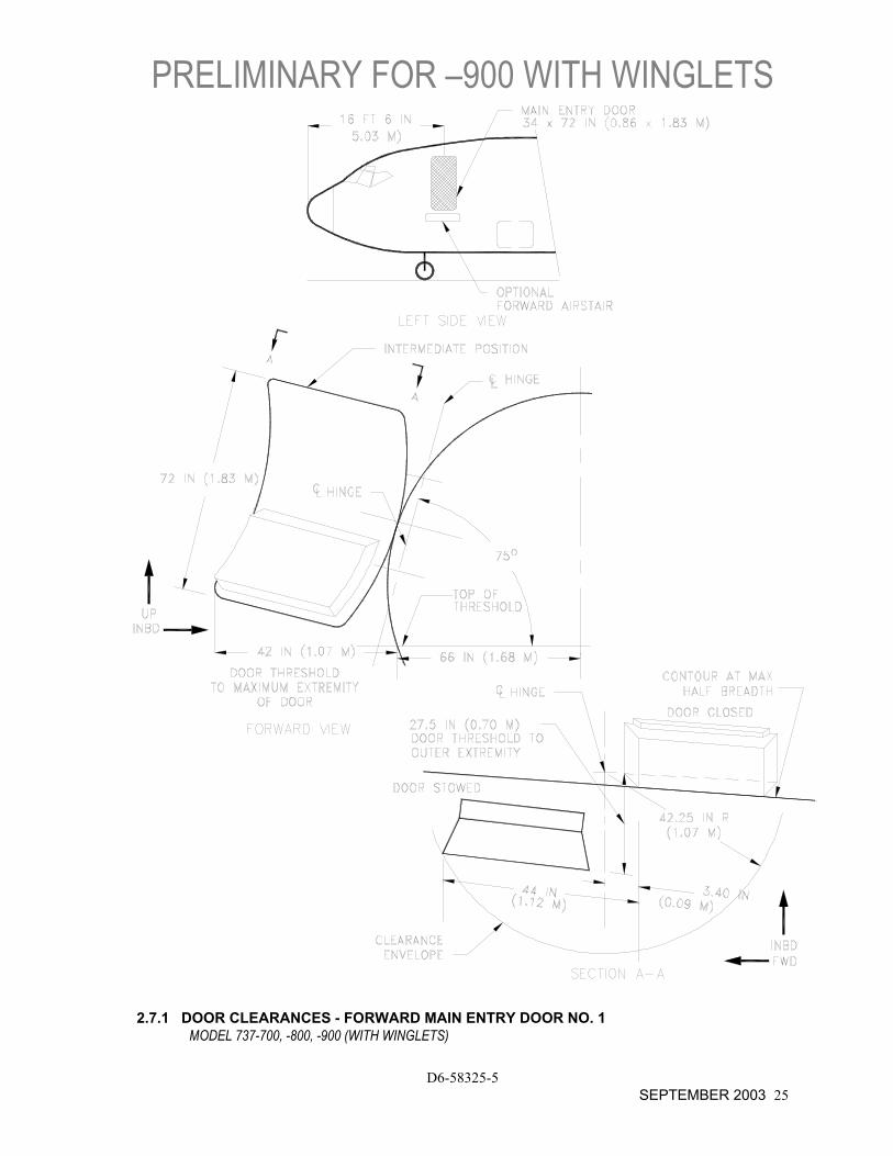
2.7.1 DOOR CLEARANCES - FORWARD MAIN ENTRY DOOR NO. 1
MODEL 737-700, -800, -900 (WITH WINGLETS)
PRELIMINARY FOR –900 WITH WINGLETS
D6-58325-5 26 SEPTEMBER 2003
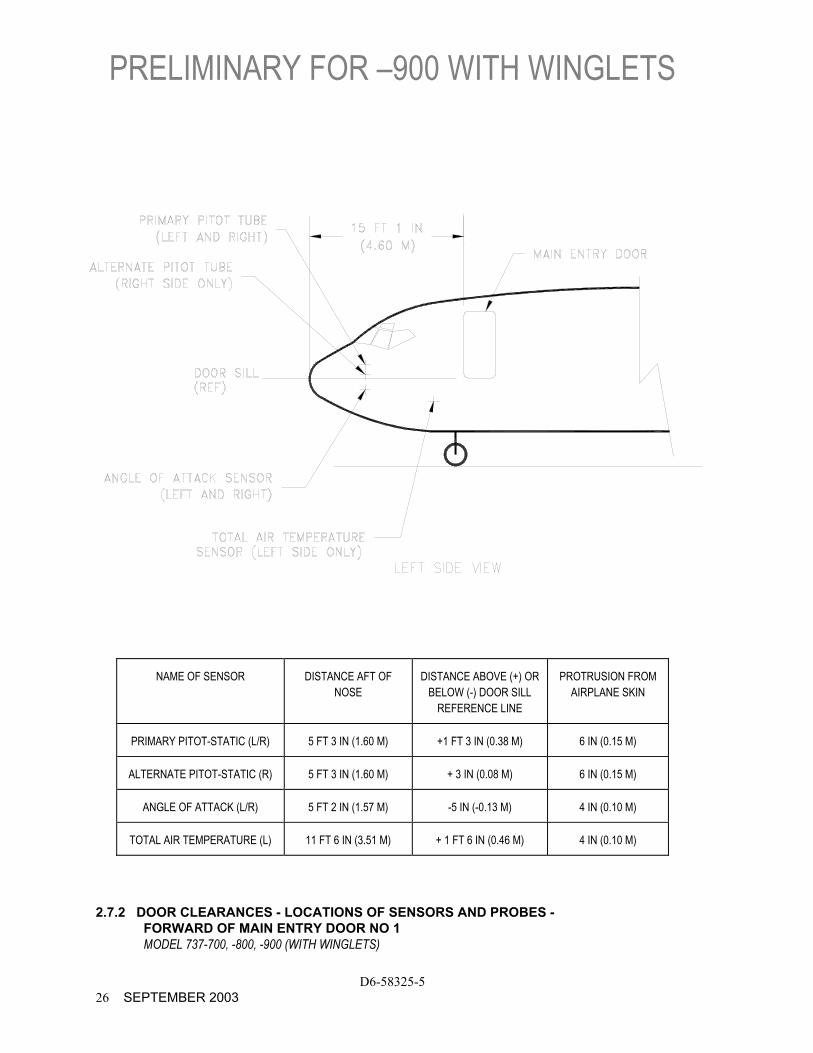
NAME OF SENSOR DISTANCE AFT OF NOSE
DISTANCE ABOVE (+) OR BELOW (-) DOOR SILL
REFERENCE LINE
PROTRUSION FROM AIRPLANE SKIN
PRIMARY PITOT-STATIC (L/R) 5 FT 3 IN (1.60 M) +1 FT 3 IN (0.38 M) 6 IN (0.15 M)
ALTERNATE PITOT-STATIC (R) 5 FT 3 IN (1.60 M) + 3 IN (0.08 M) 6 IN (0.15 M)
ANGLE OF ATTACK (L/R) 5 FT 2 IN (1.57 M) -5 IN (-0.13 M) 4 IN (0.10 M)
TOTAL AIR TEMPERATURE (L) 11 FT 6 IN (3.51 M) + 1 FT 6 IN (0.46 M) 4 IN (0.10 M)
2.7.2 DOOR CLEARANCES - LOCATIONS OF SENSORS AND PROBES - FORWARD OF MAIN ENTRY DOOR NO 1 MODEL 737-700, -800, -900 (WITH WINGLETS)
PRELIMINARY FOR –900 WITH WINGLETS
D6-58325-5 SEPTEMBER 2003 27
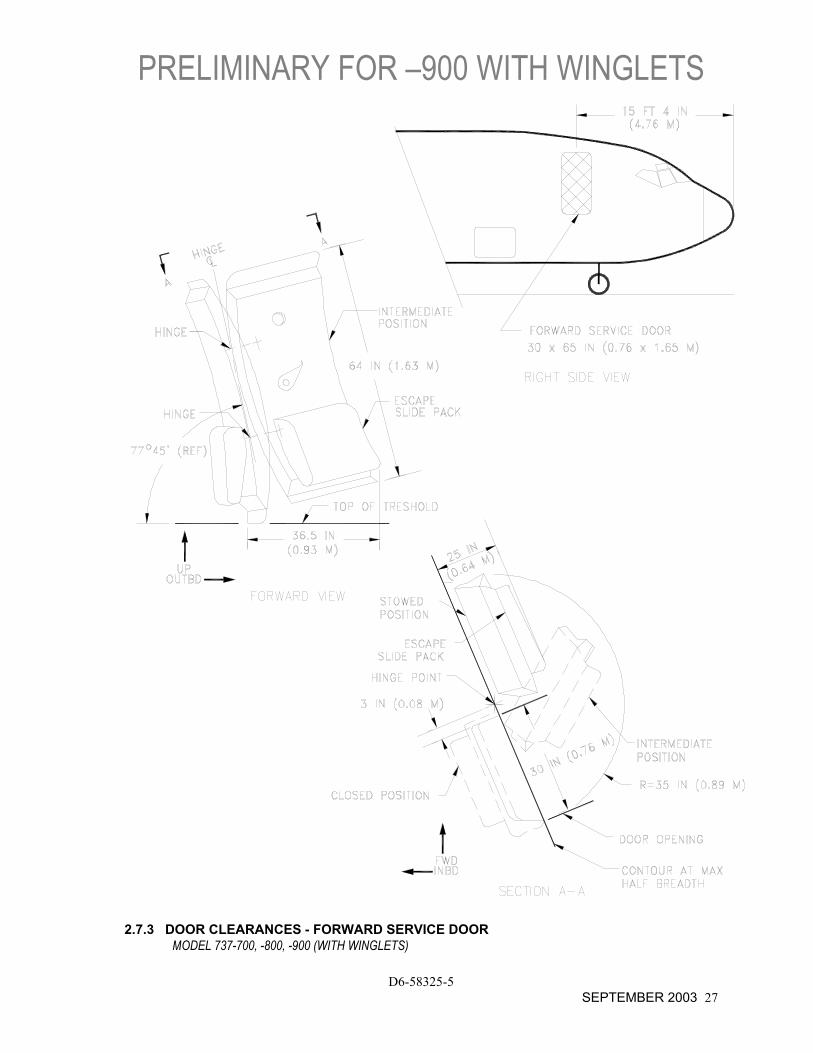
2.7.3 DOOR CLEARANCES - FORWARD SERVICE DOOR
MODEL 737-700, -800, -900 (WITH WINGLETS)

PRELIMINARY FOR –900 WITH WINGLETS
D6-58325-5 28 SEPTEMBER 2003
2.7.4 DOOR CLEARANCES - AFT SERVICE DOOR
MODEL 737-700, -800, -900 (WITH WINGLETS)
PRELIMINARY FOR –900 WITH WINGLETS
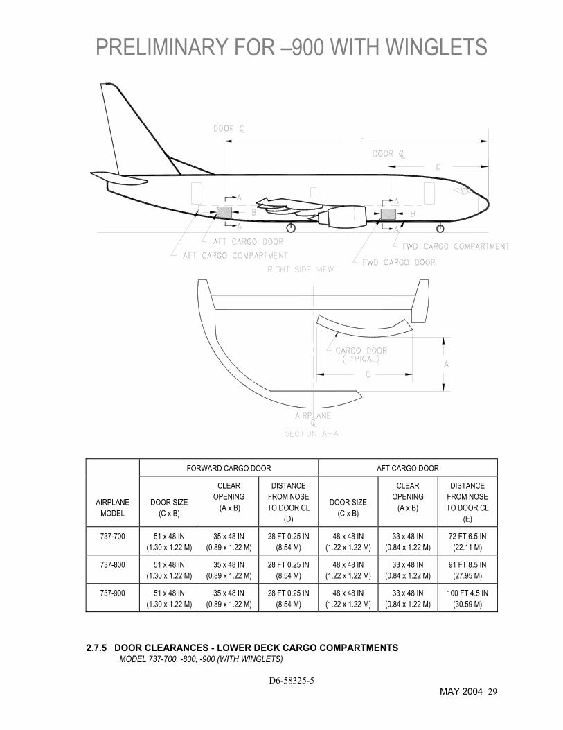
FORWARD CARGO DOOR AFT CARGO DOOR
AIRPLANE MODEL
DOOR SIZE (C x B)
CLEAR OPENING
(A x B)
DISTANCE FROM NOSE TO DOOR CL
(D)
DOOR SIZE (C x B)
CLEAR OPENING
(A x B)
DISTANCE FROM NOSE TO DOOR CL
(E)
737-700 51 x 48 IN (1.30 x 1.22 M)
35 x 48 IN (0.89 x 1.22 M)
28 FT 0.25 IN (8.54 M)
48 x 48 IN (1.22 x 1.22 M)
33 x 48 IN (0.84 x 1.22 M)
72 FT 6.5 IN (22.11 M)
737-800 51 x 48 IN (1.30 x 1.22 M)
35 x 48 IN (0.89 x 1.22 M)
28 FT 0.25 IN (8.54 M)
48 x 48 IN (1.22 x 1.22 M)
33 x 48 IN (0.84 x 1.22 M)
91 FT 8.5 IN (27.95 M)
737-900 51 x 48 IN (1.30 x 1.22 M)
35 x 48 IN (0.89 x 1.22 M)
28 FT 0.25 IN (8.54 M)
48 x 48 IN (1.22 x 1.22 M)
33 x 48 IN (0.84 x 1.22 M)
100 FT 4.5 IN (30.59 M)
2.7.5 DOOR CLEARANCES - LOWER DECK CARGO COMPARTMENTS MODEL 737-700, -800, -900 (WITH WINGLETS)
D6-58325-5 MAY 2004 29

THIS PAGE INTENTIONALLY LEFT BLANK
D6-58325-5 30 AUGUST 2002
3.0 AIRPLANE PERFORMANCE
3.1 General Information
3.2 Payload/Range for Long Range Cruise
3.3 F.A.R. and J.A.R. Takeoff Runway Length Requirements
3.4 F.A.R. Landing Runway Length Requirements
D6-58325-5 AUGUST 2002 31
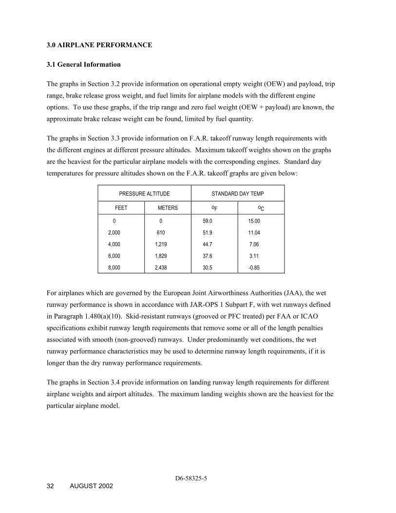
3.0 AIRPLANE PERFORMANCE
3.1 General Information
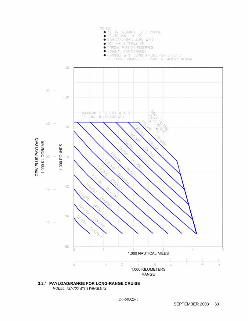
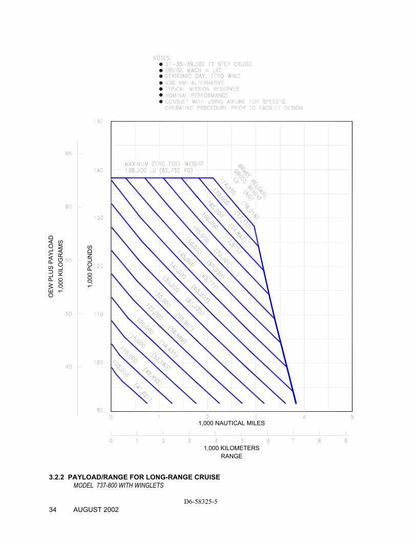
The graphs in Section 3.2 provide information on operational empty weight (OEW) and payload, trip range, brake release gross weight, and fuel limits for airplane models with the different engine options. To use these graphs, if the trip range and zero fuel weight (OEW + payload) are known, the approximate brake release weight can be found, limited by fuel quantity.
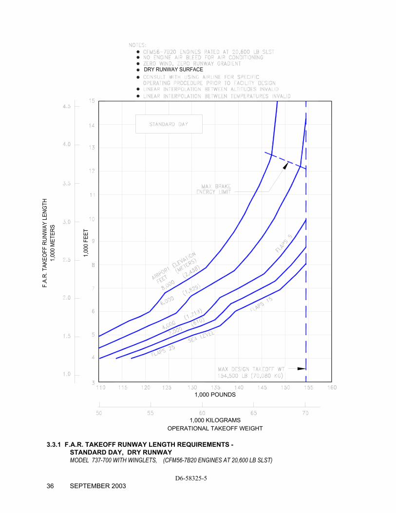
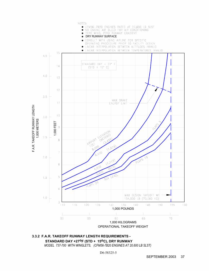
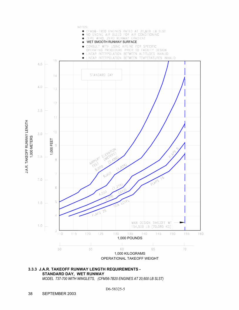
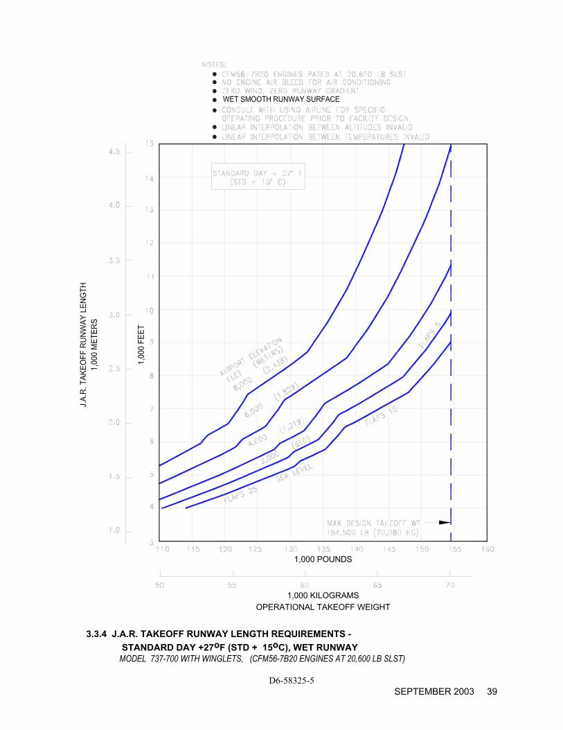
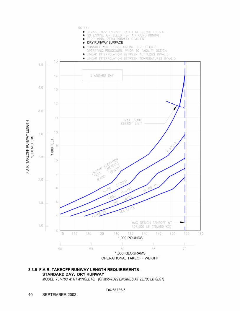
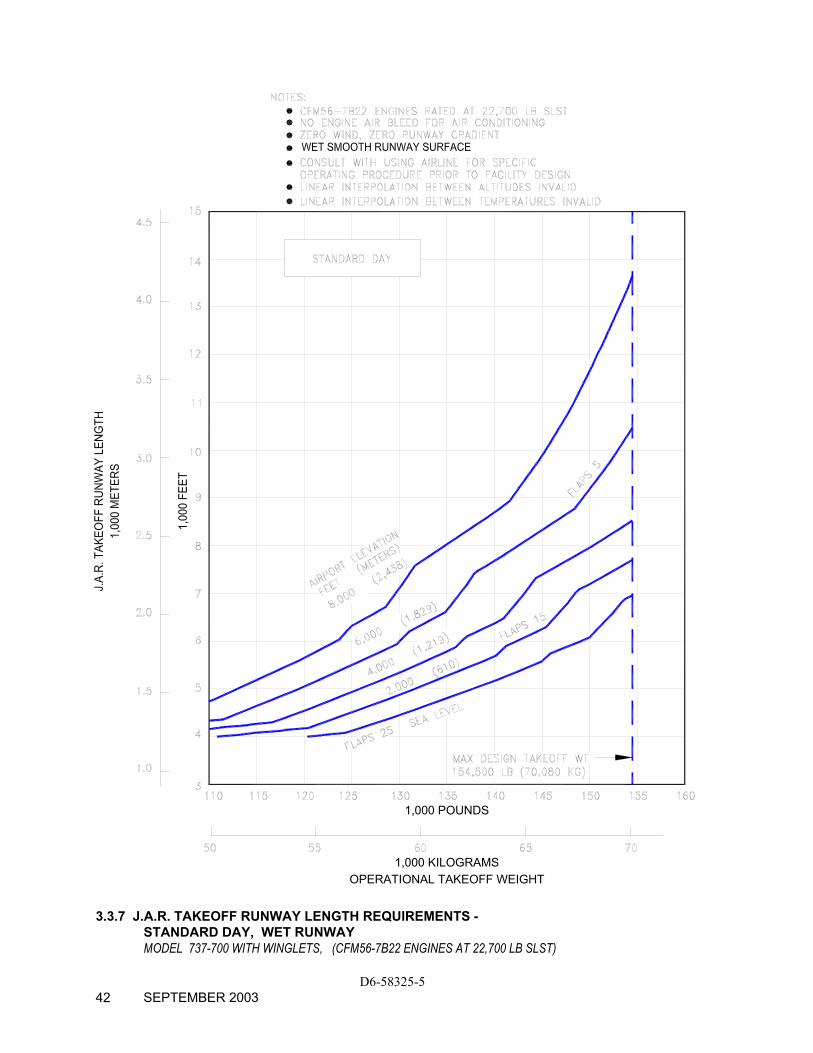
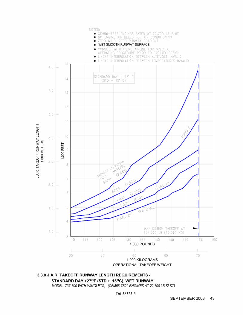
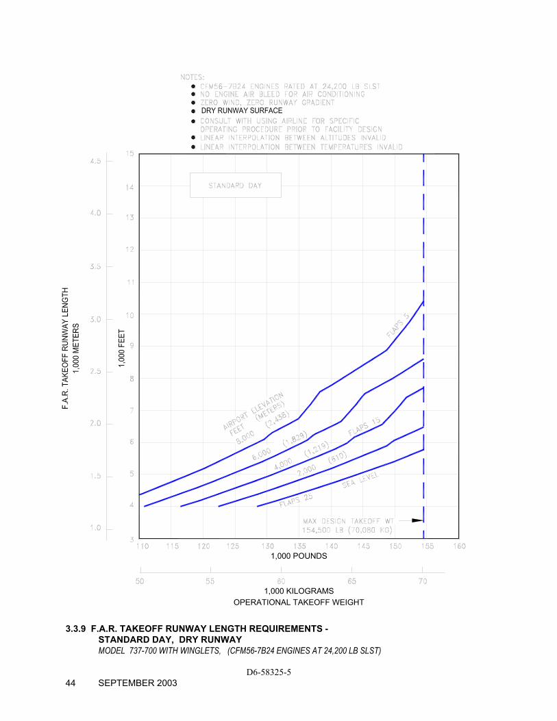
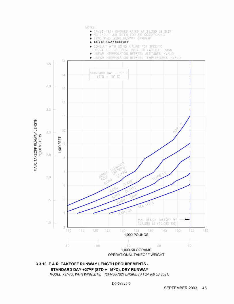
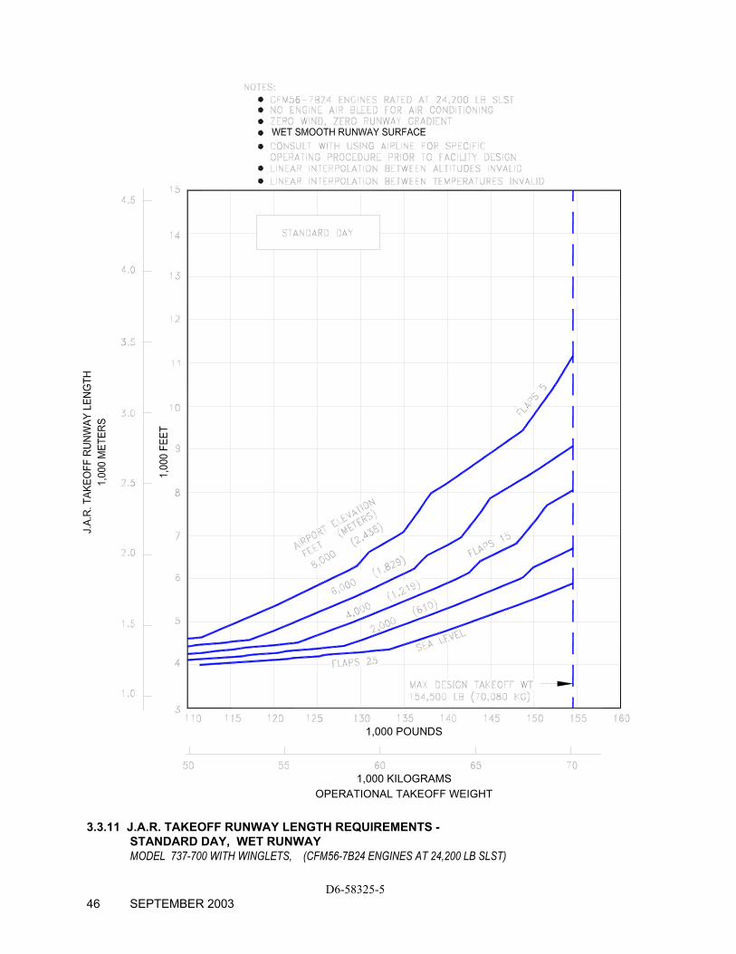
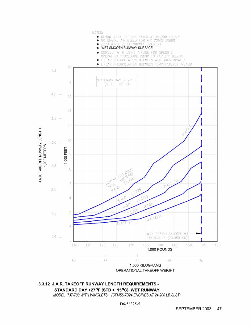
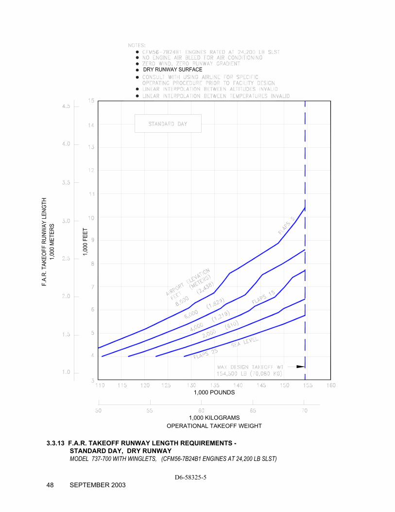
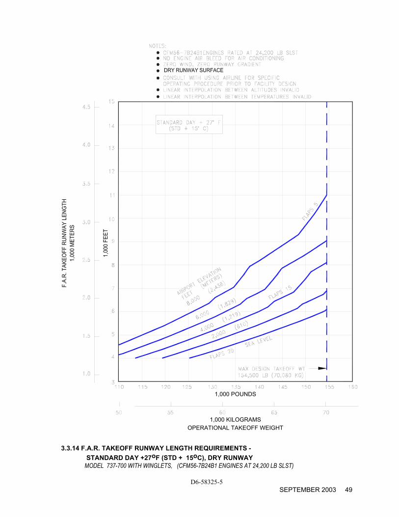
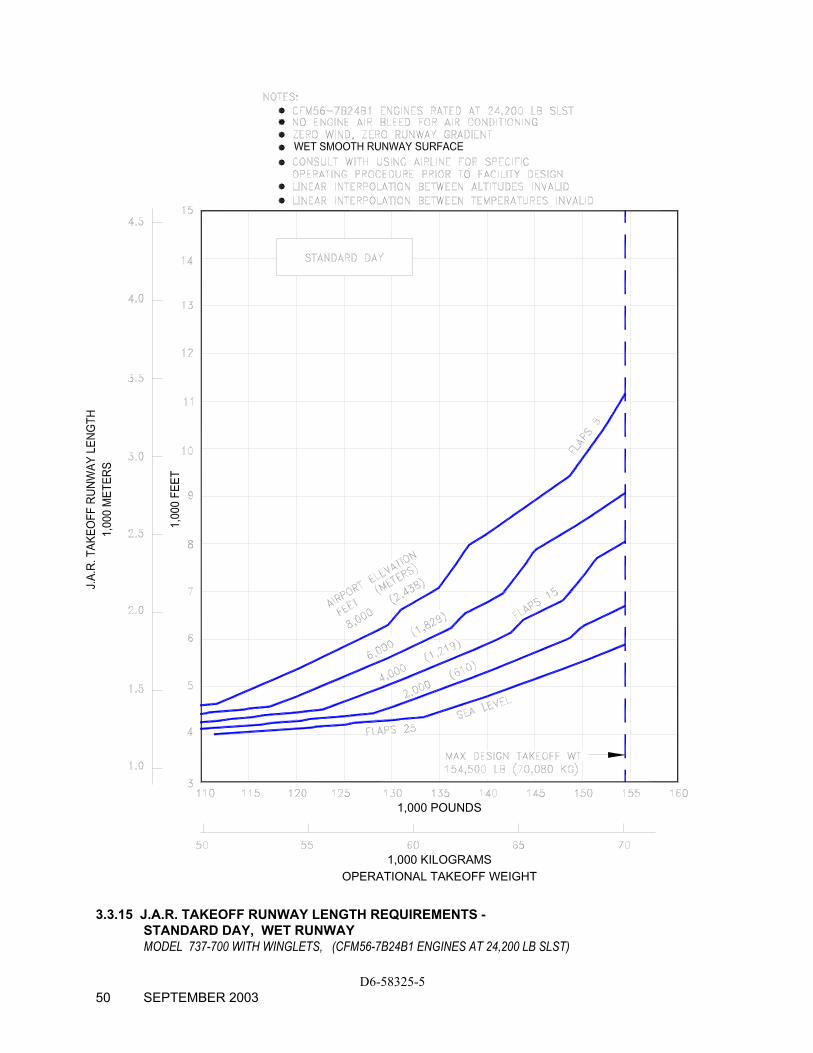
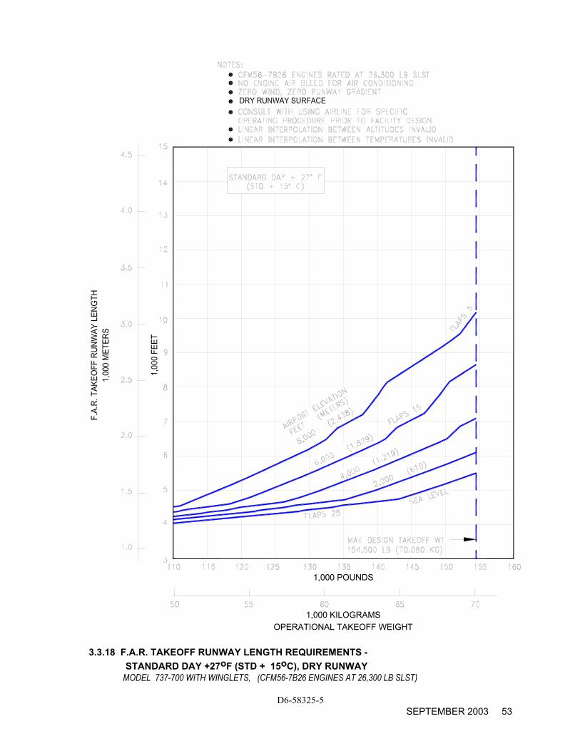
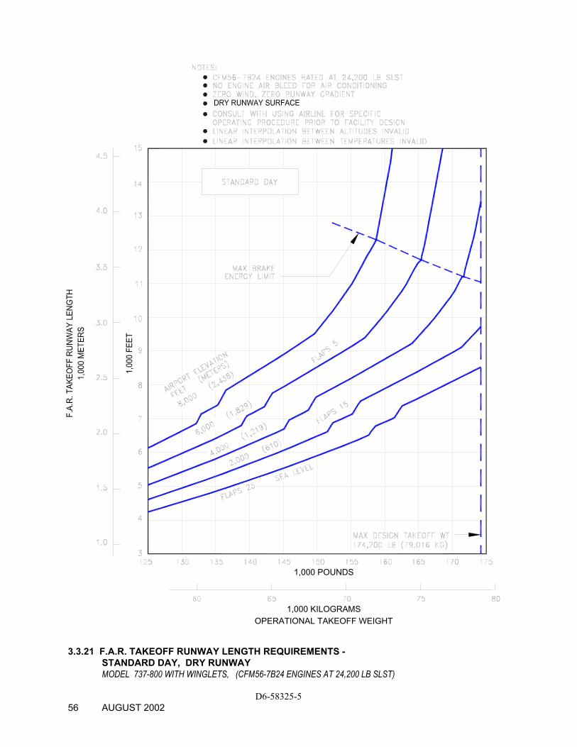
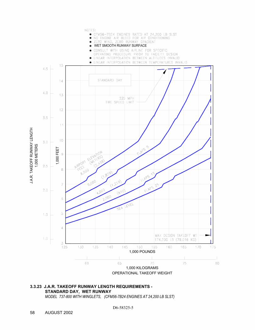
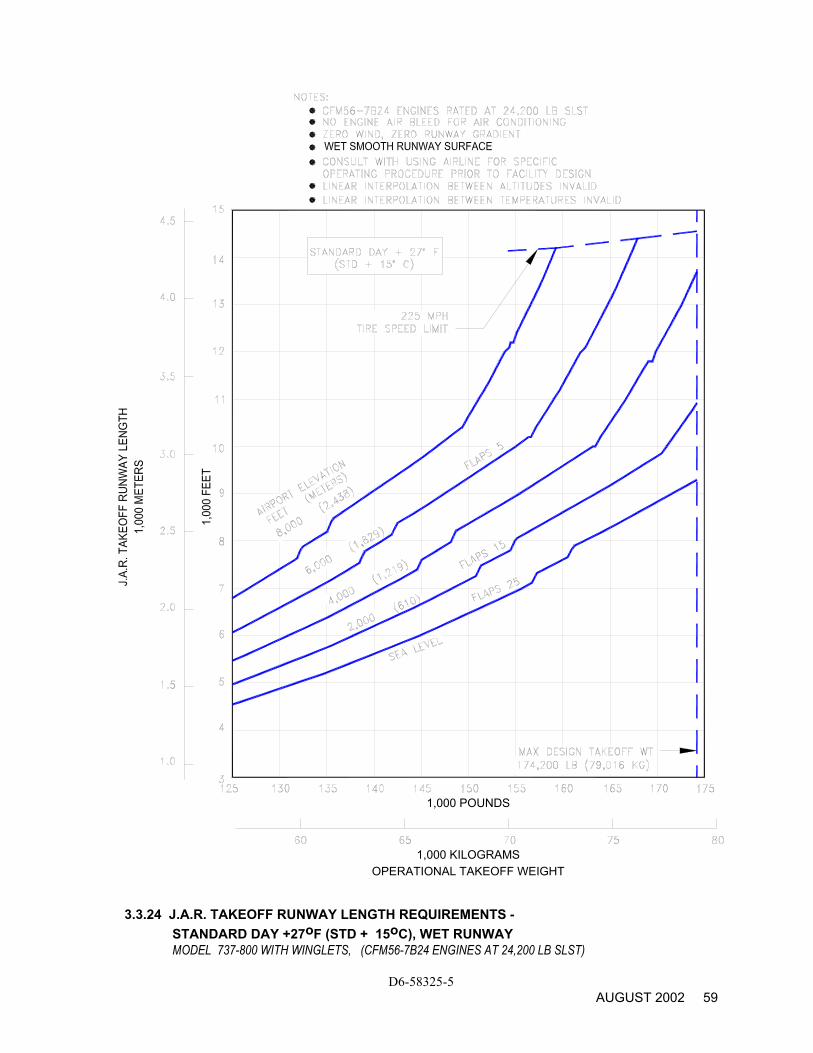
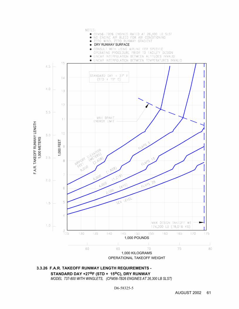
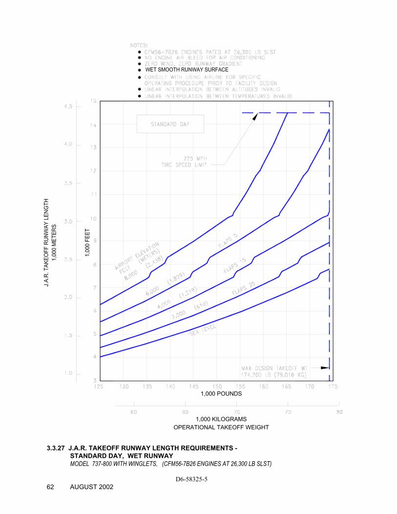
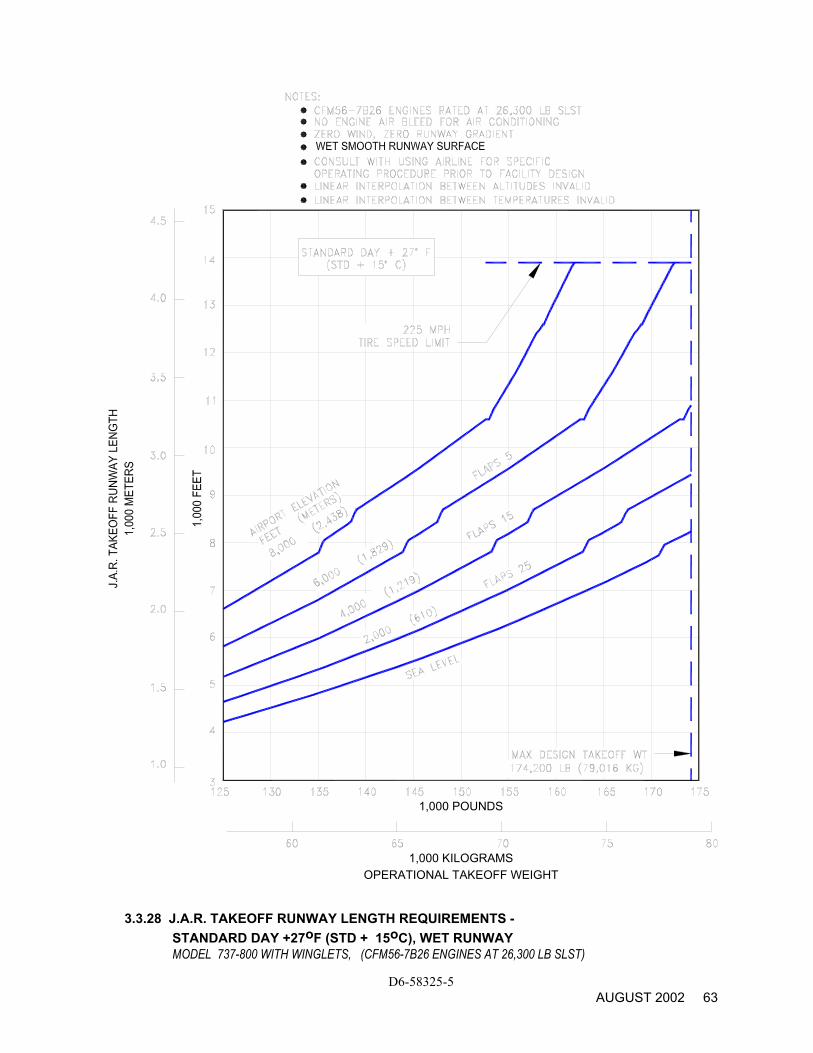
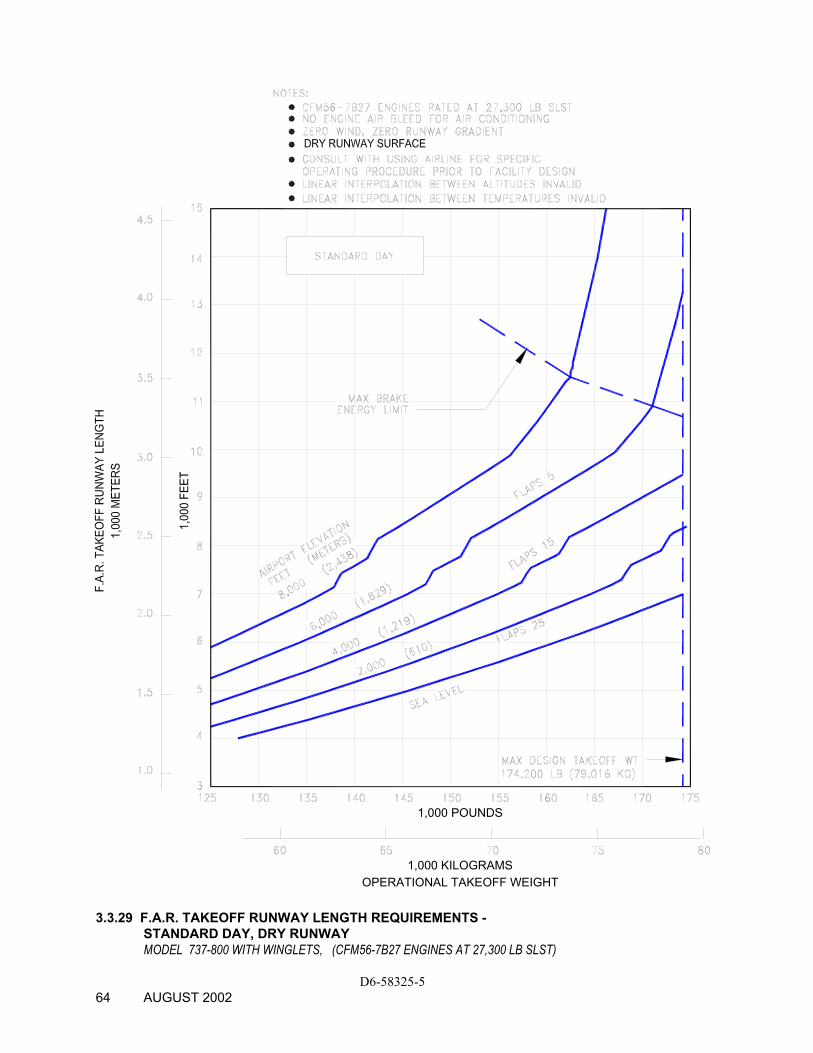
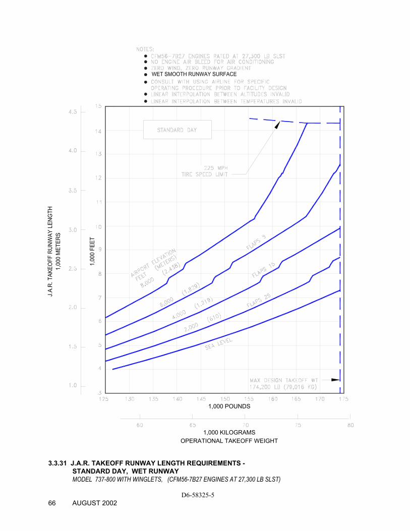
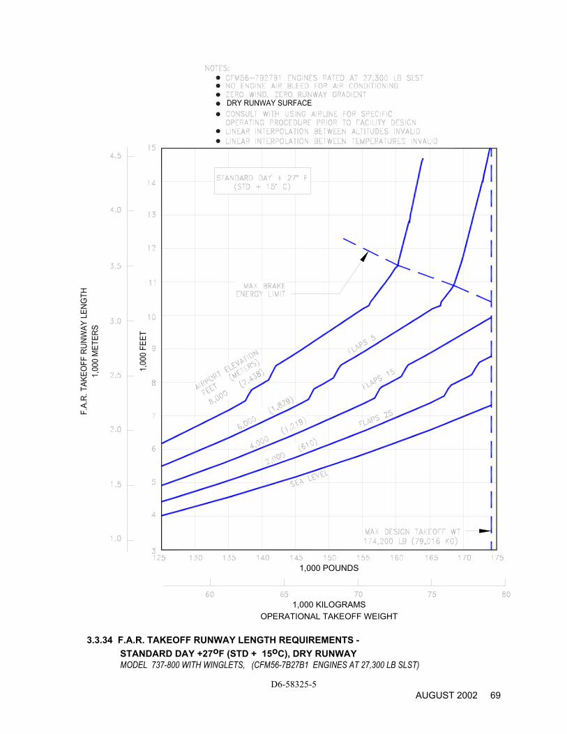
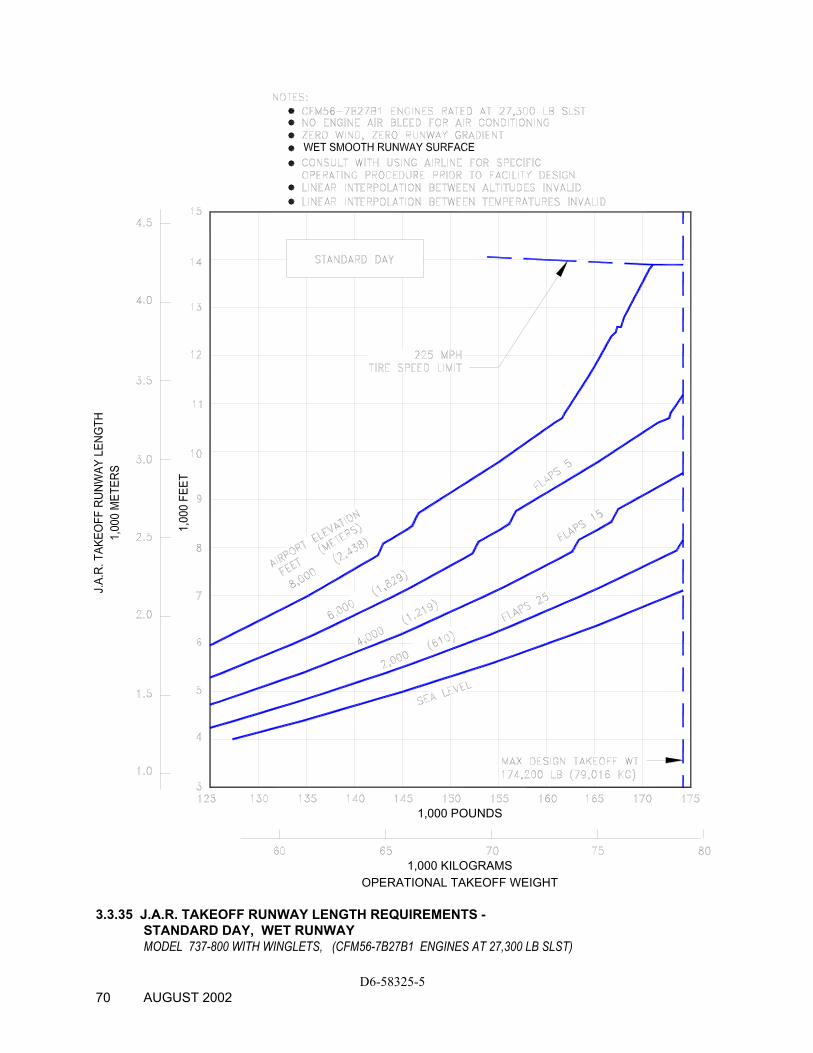
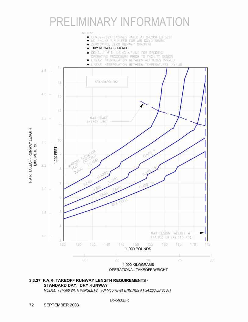
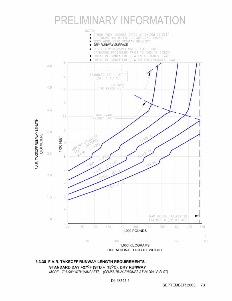
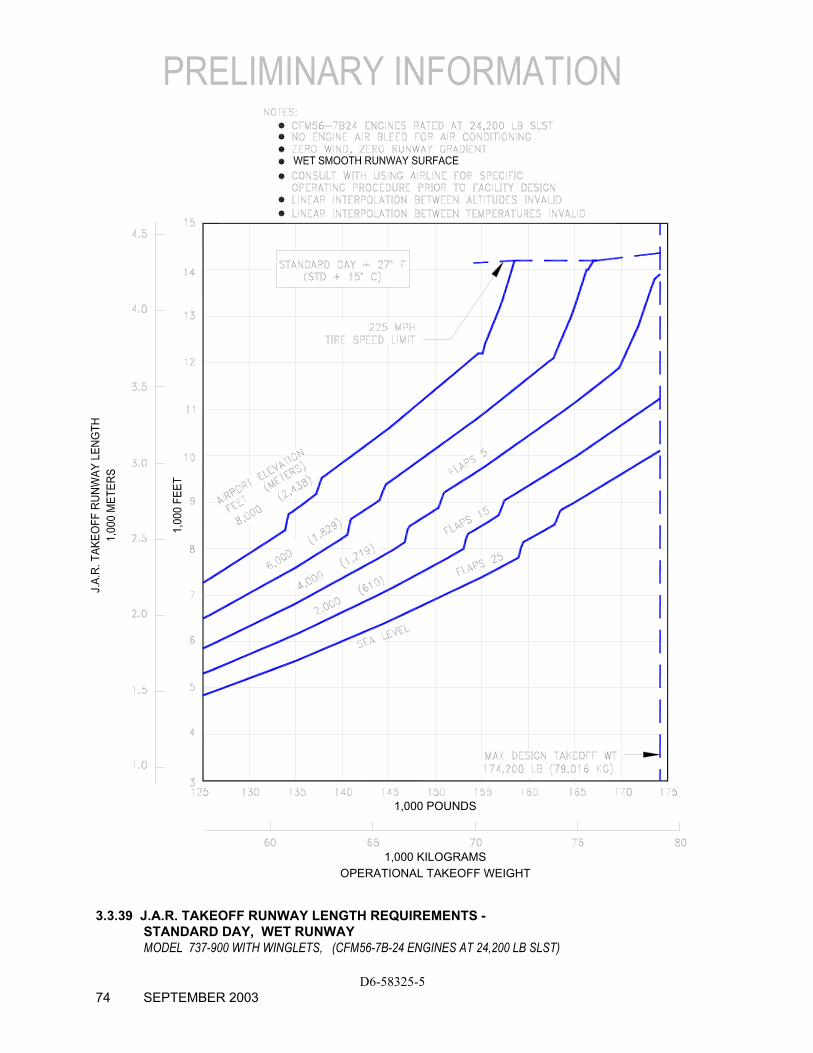
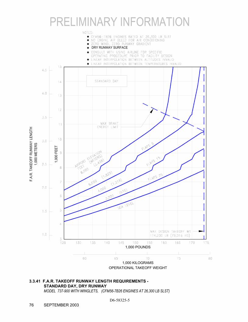
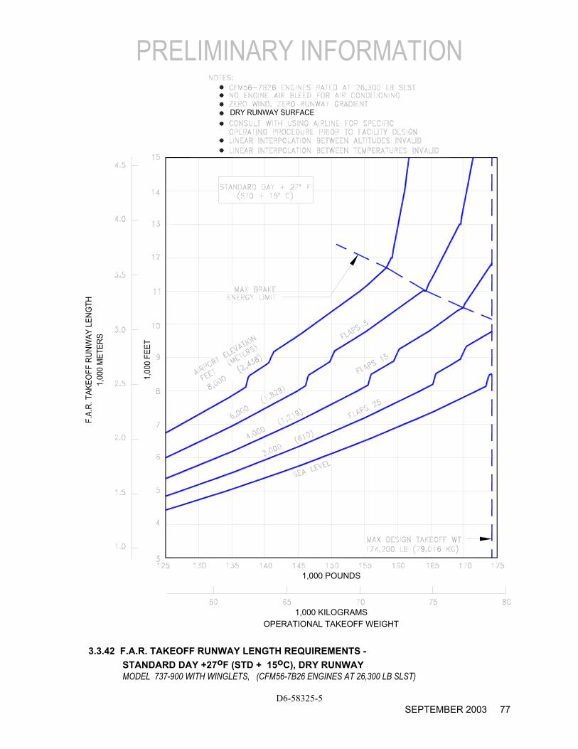
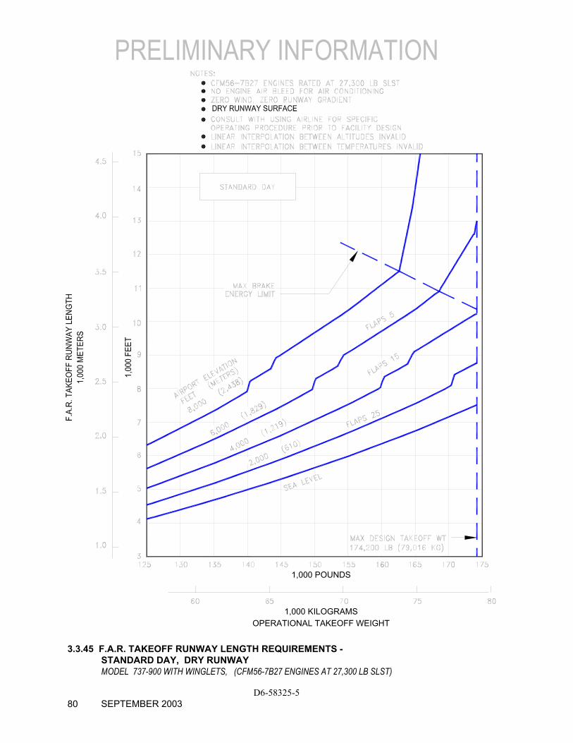
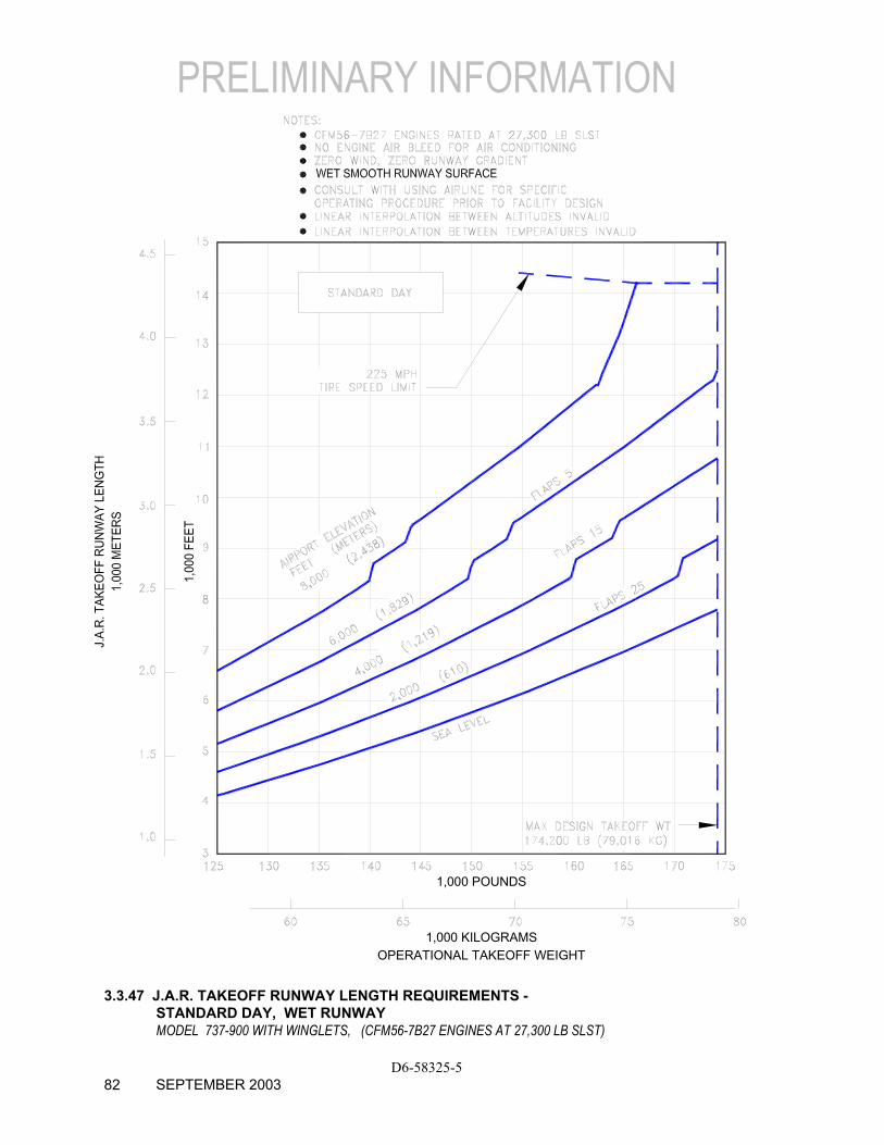
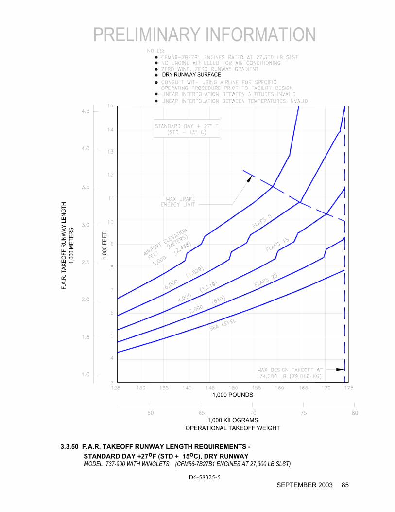
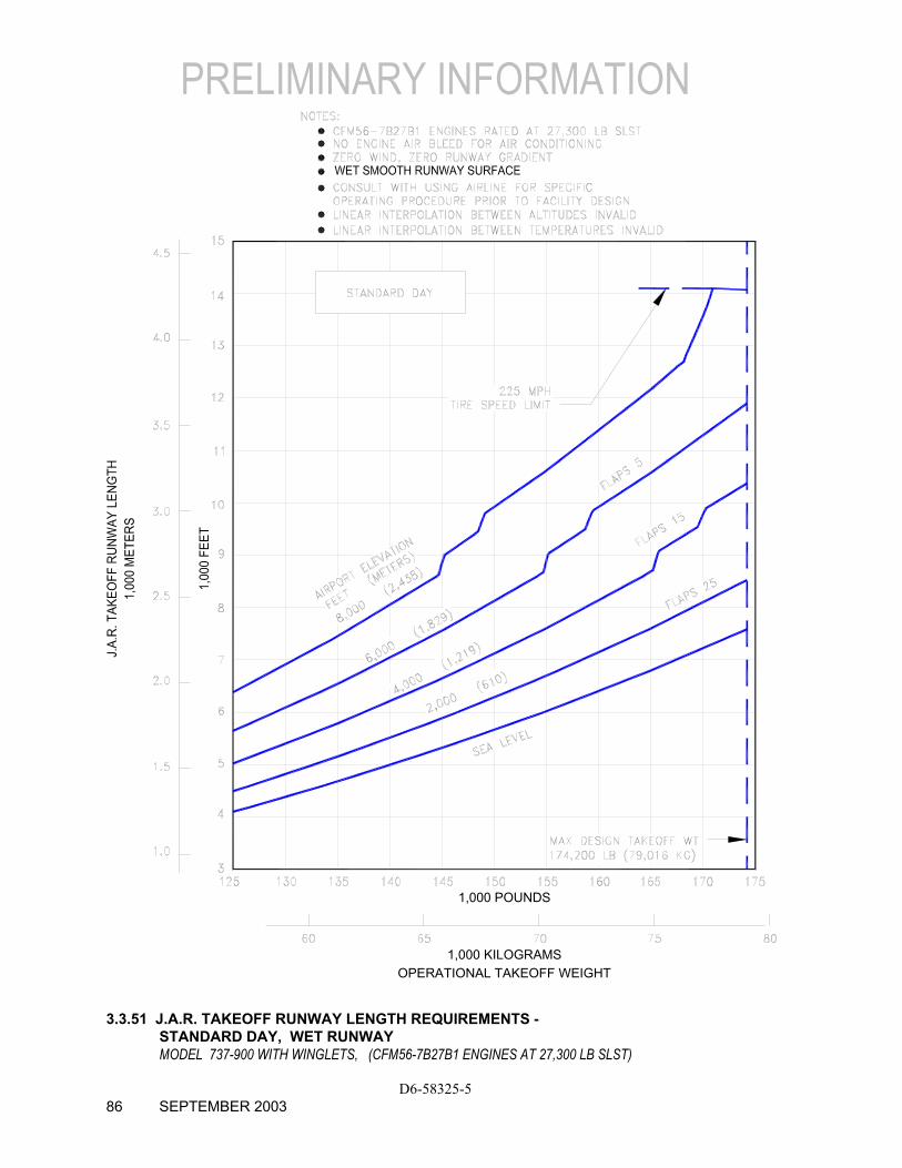
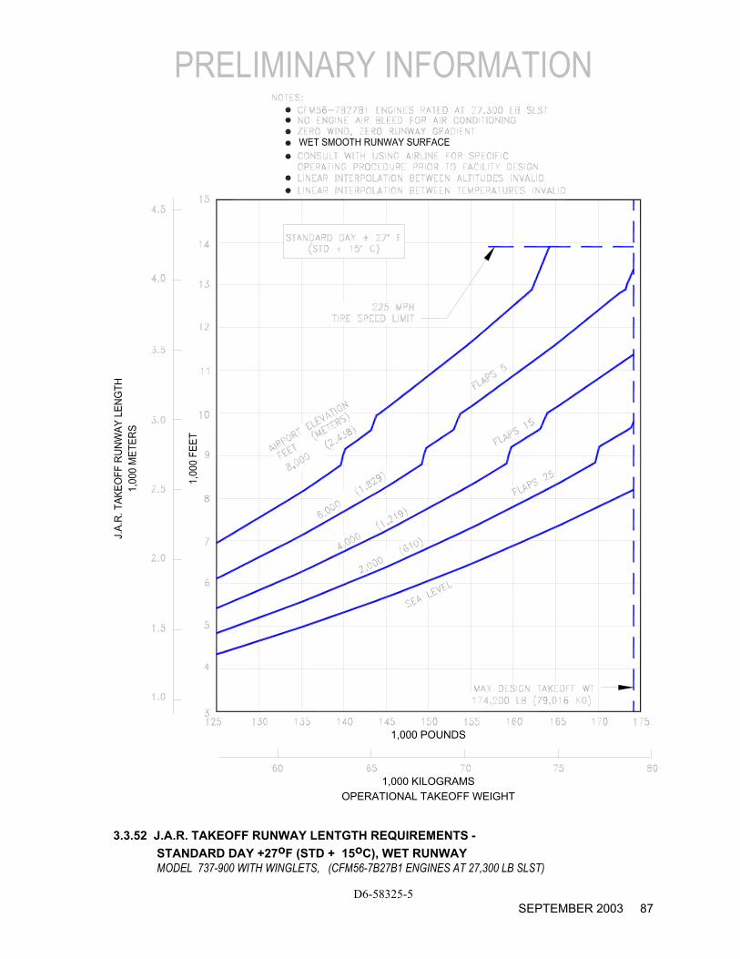
The graphs in Section 3.3 provide information on F.A.R. takeoff runway length requirements with the different engines at different pressure altitudes. Maximum takeoff weights shown on the graphs are the heaviest for the particular airplane models with the corresponding engines. Standard day temperatures for pressure altitudes shown on the F.A.R. takeoff graphs are given below:
PRESSURE ALTITUDE STANDARD DAY TEMP
FEET METERS oF oC
0 0 59.0 15.00
2,000 610 51.9 11.04
4,000 1,219 44.7 7.06
6,000 1,829 37.6 3.11
8,000 2,438 30.5 -0.85
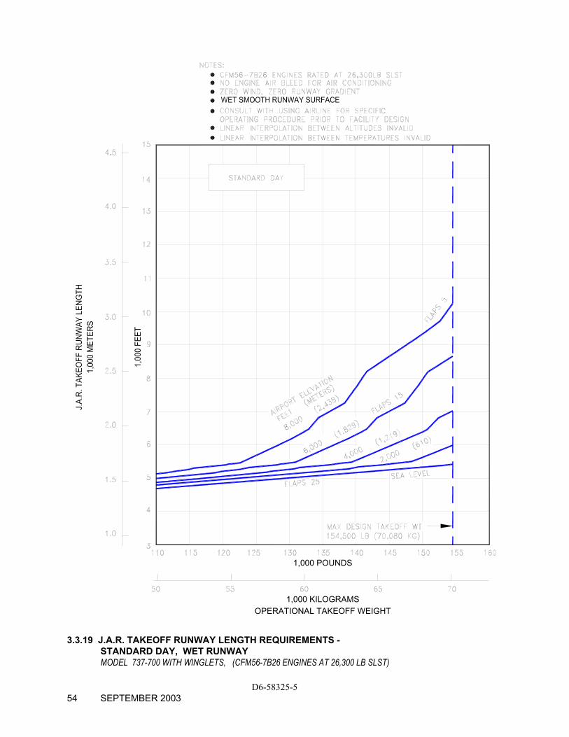
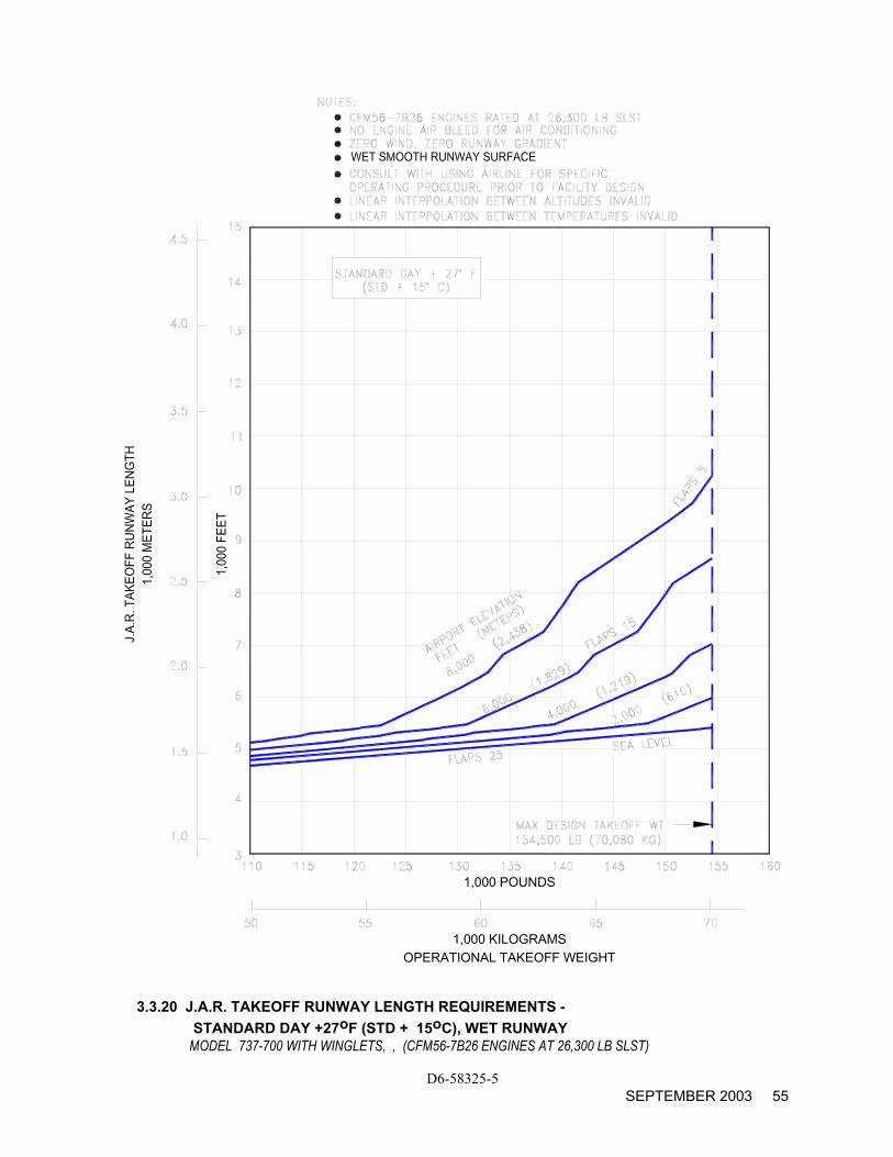
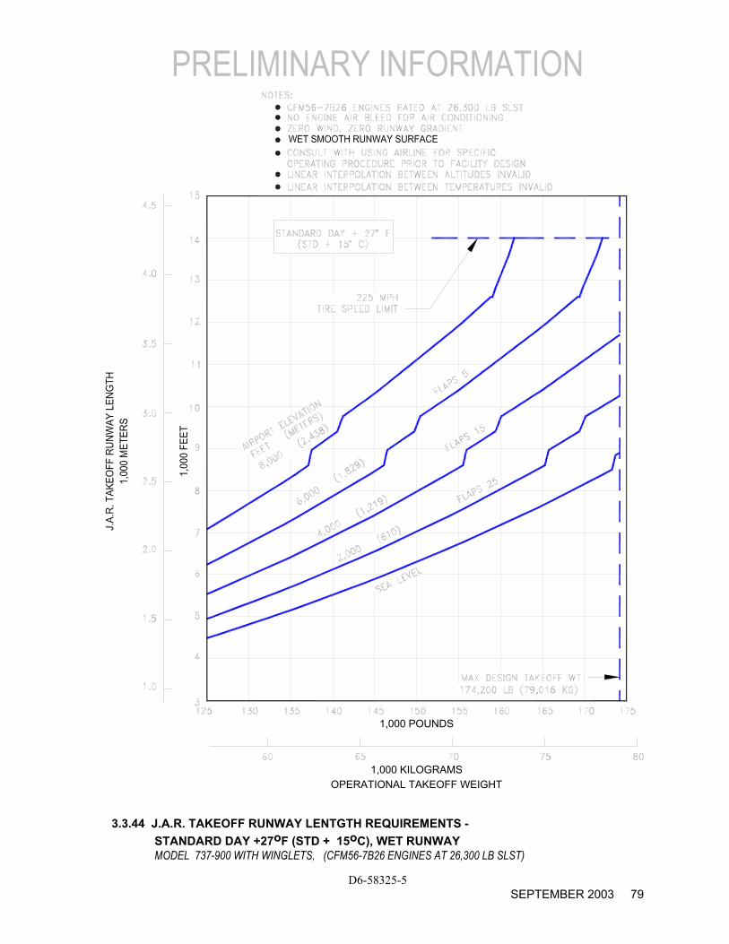
For airplanes which are governed by the European Joint Airworthiness Authorities (JAA), the wet runway performance is shown in accordance with JAR-OPS 1 Subpart F, with wet runways defined in Paragraph 1.480(a)(10). Skid-resistant runways (grooved or PFC treated) per FAA or ICAO specifications exhibit runway length requirements that remove some or all of the length penalties associated with smooth (non-grooved) runways. Under predominantly wet conditions, the wet runway performance characteristics may be used to determine runway length requirements, if it is longer than the dry runway performance requirements.
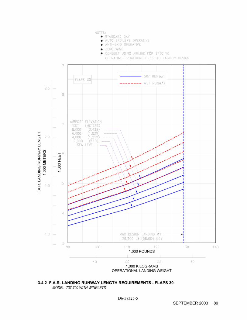
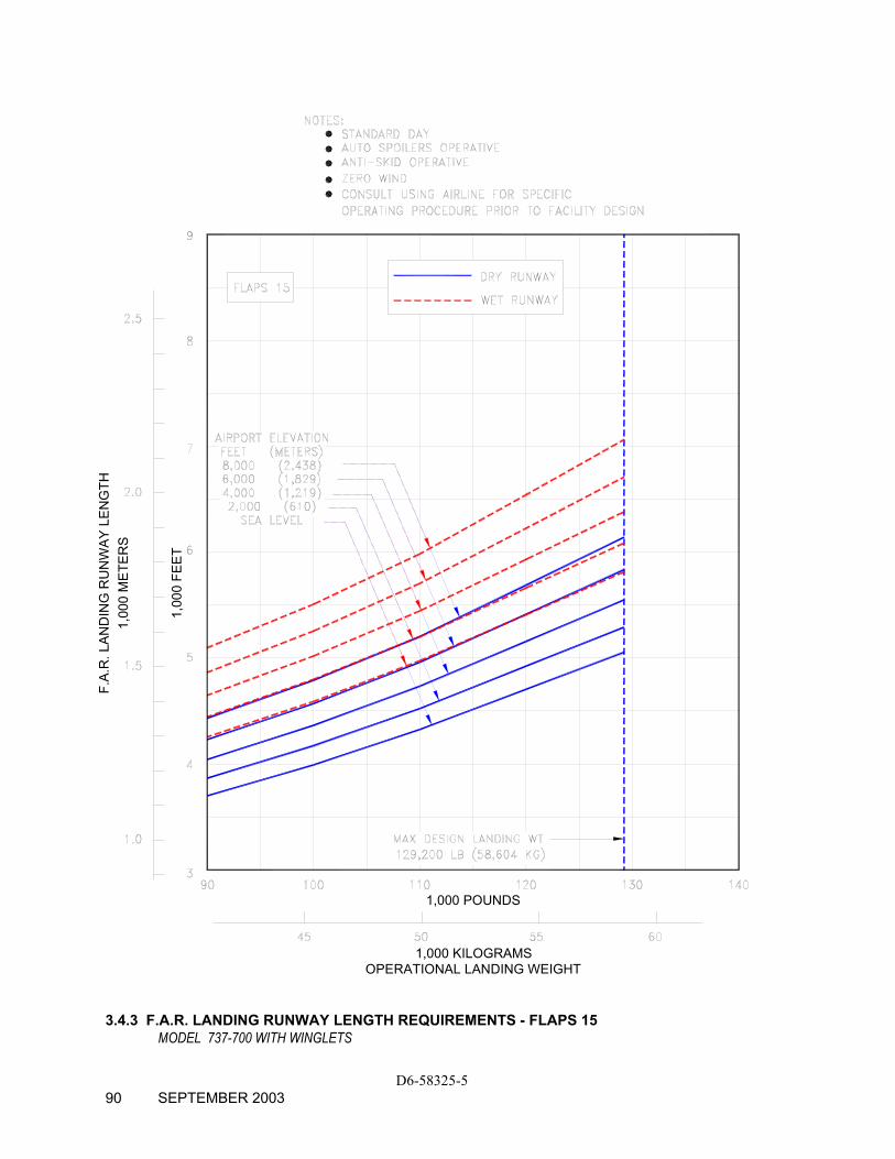
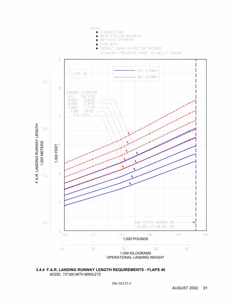
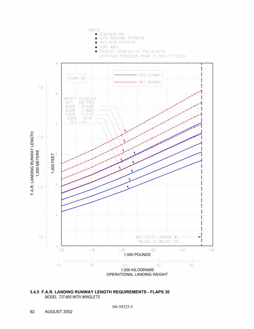
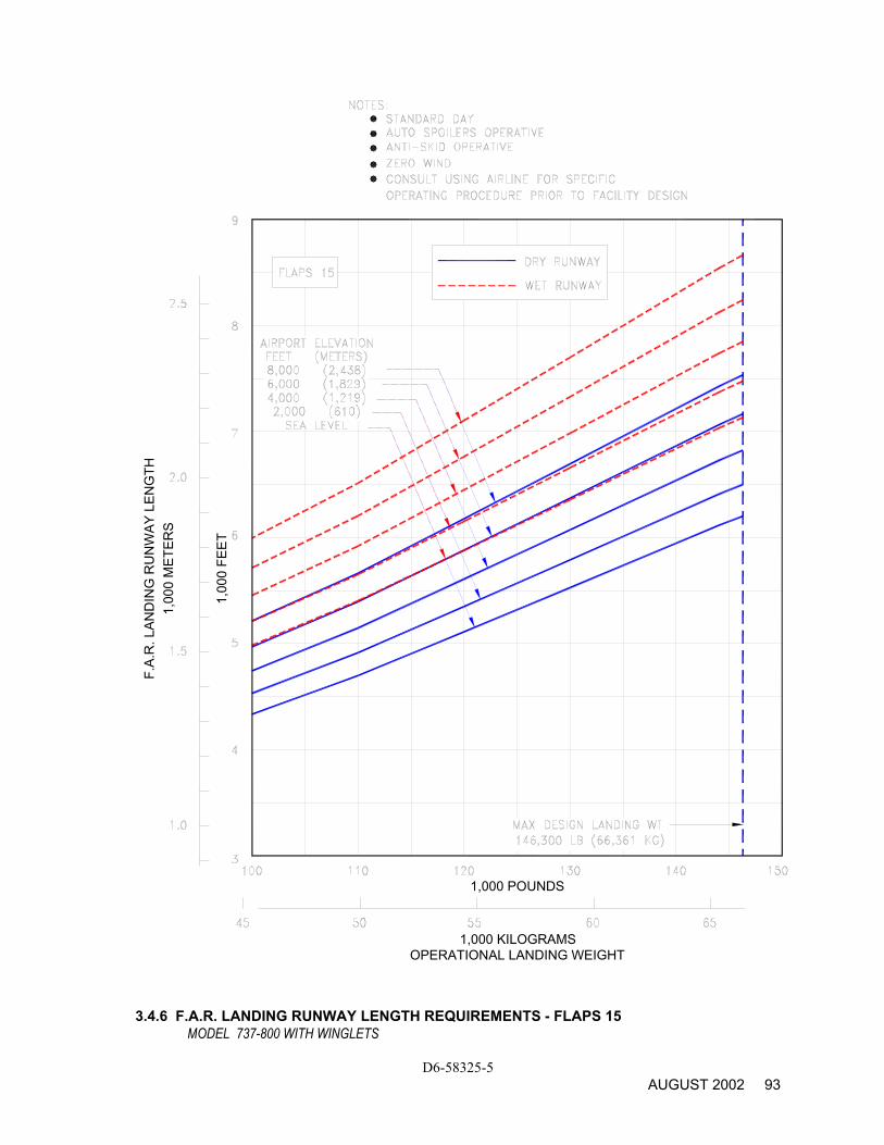
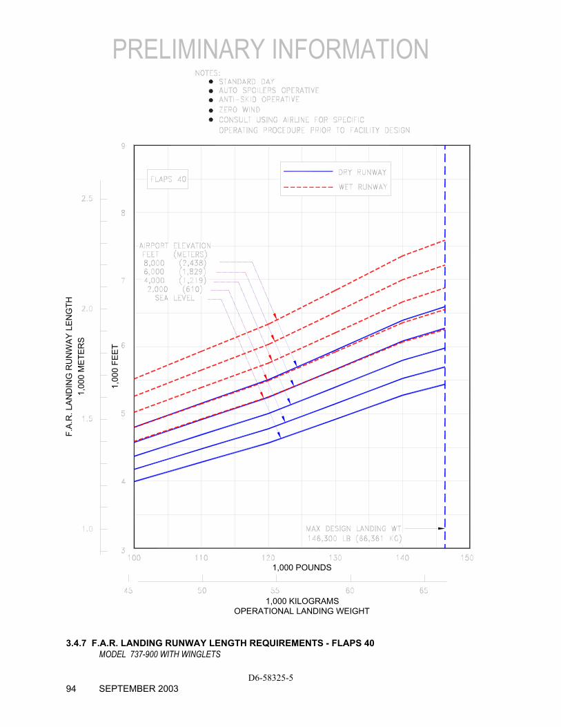
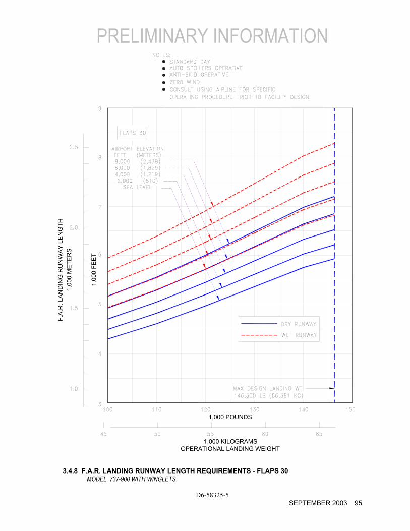
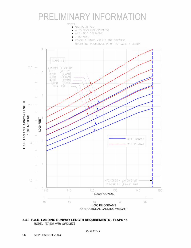
The graphs in Section 3.4 provide information on landing runway length requirements for different airplane weights and airport altitudes. The maximum landing weights shown are the heaviest for the particular airplane model.
D6-58325-5 AUGUST 2002 32
OEW
PLU
S PA
YLO
AD1,
000
KILO
GR
AMS
1,00
0 PO
UN
DS
1,000 NAUTICAL MILES
RANGE1,000 KILOMETERS
3.2.1 PAYLOAD/RANGE FOR LONG-RANGE CRUISE MODEL 737-700 WITH WINGLETS
D6-58325-5 SEPTEMBER 2003 33
O
EW P
LUS
PAYL
OAD
1,00
0 KI
LOG
RAM
S
1,00
0 PO
UN
DS
1,000 NAUTICAL MILES
RANGE1,000 KILOMETERS
3.2.2 PAYLOAD/RANGE FOR LONG-RANGE CRUISE
MODEL 737-800 WITH WINGLETS
D6-58325-5 AUGUST 2002 34
PRELIMINARY INFORMATION
D6-58325-5 SEPTEMBER 2003 35
OEW
PLU
S PA
YLO
AD1,
000
KILO
GR
AMS
1,00
0 PO
UN
DS
1,000 NAUTICAL MILES
RANGE1,000 KILOMETERS
3.2.3 PAYLOAD/RANGE FOR LONG-RANGE CRUISE
MODEL 737-900 WITH WINGLETS
OPERATIONAL TAKEOFF WEIGHT1,000 KILOGRAMS
1,000 POUNDS
3.3.1 F.A.R. TAKEOFF RUNWAY LENGTH REQUIREMENTS -
STANDARD DAY, DRY RUNWAY MODEL 737-700 WITH WINGLETS, (CFM56-7B20 ENGINES AT 20,600 LB SLST)
D6-58325-5 SEPTEMBER 2003 36
OPERATIONAL TAKEOFF WEIGHT1,000 KILOGRAMS
1,000 POUNDS
3.3.2 F.A.R. TAKEOFF RUNWAY LENGTH REQUIREMENTS -
STANDARD DAY +27oF (STD + 15oC), DRY RUNWAY MODEL 737-700 WITH WINGLETS, (CFM56-7B20 ENGINES AT 20,600 LB SLST)
D6-58325-5 SEPTEMBER 2003 37
OPERATIONAL TAKEOFF WEIGHT1,000 KILOGRAMS
1,000 POUNDS
3.3.3 J.A.R. TAKEOFF RUNWAY LENGTH REQUIREMENTS -
STANDARD DAY, WET RUNWAY MODEL 737-700 WITH WINGLETS, (CFM56-7B20 ENGINES AT 20,600 LB SLST)
D6-58325-5 SEPTEMBER 2003 38
OPERATIONAL TAKEOFF WEIGHT1,000 KILOGRAMS
1,000 POUNDS
3.3.4 J.A.R. TAKEOFF RUNWAY LENGTH REQUIREMENTS -
STANDARD DAY +27oF (STD + 15oC), WET RUNWAY MODEL 737-700 WITH WINGLETS, (CFM56-7B20 ENGINES AT 20,600 LB SLST)
D6-58325-5 SEPTEMBER 2003 39
OPERATIONAL TAKEOFF WEIGHT1,000 KILOGRAMS
1,000 POUNDS
3.3.5 F.A.R. TAKEOFF RUNWAY LENGTH REQUIREMENTS -
STANDARD DAY, DRY RUNWAY MODEL 737-700 WITH WINGLETS, (CFM56-7B22 ENGINES AT 22,700 LB SLST)
D6-58325-5 SEPTEMBER 2003 40

OPERATIONAL TAKEOFF WEIGHT1,000 KILOGRAMS
1,000 POUNDS
3.3.6 F.A.R. TAKEOFF RUNWAY LENGTH REQUIREMENTS -
STANDARD DAY +27oF (STD + 15oC), DRY RUNWAY MODEL 737-700 WITH WINGLETS, (CFM56-7B22 ENGINES AT 22,700 LB SLST)
D6-58325-5 SEPTEMBER 2003 41
OPERATIONAL TAKEOFF WEIGHT1,000 KILOGRAMS
1,000 POUNDS
3.3.7 J.A.R. TAKEOFF RUNWAY LENGTH REQUIREMENTS -
STANDARD DAY, WET RUNWAY MODEL 737-700 WITH WINGLETS, (CFM56-7B22 ENGINES AT 22,700 LB SLST)
D6-58325-5 SEPTEMBER 2003 42
OPERATIONAL TAKEOFF WEIGHT1,000 KILOGRAMS
1,000 POUNDS
3.3.8 J.A.R. TAKEOFF RUNWAY LENGTH REQUIREMENTS -
STANDARD DAY +27oF (STD + 15oC), WET RUNWAY MODEL 737-700 WITH WINGLETS, (CFM56-7B22 ENGINES AT 22,700 LB SLST)
D6-58325-5 SEPTEMBER 2003 43
OPERATIONAL TAKEOFF WEIGHT1,000 KILOGRAMS
1,000 POUNDS
3.3.9 F.A.R. TAKEOFF RUNWAY LENGTH REQUIREMENTS -
STANDARD DAY, DRY RUNWAY MODEL 737-700 WITH WINGLETS, (CFM56-7B24 ENGINES AT 24,200 LB SLST)
D6-58325-5 SEPTEMBER 2003 44
OPERATIONAL TAKEOFF WEIGHT1,000 KILOGRAMS
1,000 POUNDS
3.3.10 F.A.R. TAKEOFF RUNWAY LENGTH REQUIREMENTS -
STANDARD DAY +27oF (STD + 15oC), DRY RUNWAY MODEL 737-700 WITH WINGLETS, (CFM56-7B24 ENGINES AT 24,200 LB SLST)
D6-58325-5 SEPTEMBER 2003 45
OPERATIONAL TAKEOFF WEIGHT1,000 KILOGRAMS
1,000 POUNDS
3.3.11 J.A.R. TAKEOFF RUNWAY LENGTH REQUIREMENTS -
STANDARD DAY, WET RUNWAY MODEL 737-700 WITH WINGLETS, (CFM56-7B24 ENGINES AT 24,200 LB SLST)
D6-58325-5 SEPTEMBER 2003 46
OPERATIONAL TAKEOFF WEIGHT1,000 KILOGRAMS
1,000 POUNDS
3.3.12 J.A.R. TAKEOFF RUNWAY LENGTH REQUIREMENTS -
STANDARD DAY +27oF (STD + 15oC), WET RUNWAY MODEL 737-700 WITH WINGLETS, (CFM56-7B24 ENGINES AT 24,200 LB SLST)
D6-58325-5 SEPTEMBER 2003 47
OPERATIONAL TAKEOFF WEIGHT1,000 KILOGRAMS
1,000 POUNDS
3.3.13 F.A.R. TAKEOFF RUNWAY LENGTH REQUIREMENTS -
STANDARD DAY, DRY RUNWAY MODEL 737-700 WITH WINGLETS, (CFM56-7B24B1 ENGINES AT 24,200 LB SLST)
D6-58325-5 SEPTEMBER 2003 48
OPERATIONAL TAKEOFF WEIGHT1,000 KILOGRAMS
1,000 POUNDS
3.3.14 F.A.R. TAKEOFF RUNWAY LENGTH REQUIREMENTS -
STANDARD DAY +27oF (STD + 15oC), DRY RUNWAY MODEL 737-700 WITH WINGLETS, (CFM56-7B24B1 ENGINES AT 24,200 LB SLST)
D6-58325-5 SEPTEMBER 2003 49
OPERATIONAL TAKEOFF WEIGHT1,000 KILOGRAMS
1,000 POUNDS
3.3.15 J.A.R. TAKEOFF RUNWAY LENGTH REQUIREMENTS -
STANDARD DAY, WET RUNWAY MODEL 737-700 WITH WINGLETS, (CFM56-7B24B1 ENGINES AT 24,200 LB SLST)
D6-58325-5 SEPTEMBER 2003 50

OPERATIONAL TAKEOFF WEIGHT1,000 KILOGRAMS
1,000 POUNDS
3.3.16 J.A.R. TAKEOFF RUNWAY LENGTH REQUIREMENTS -
STANDARD DAY +27oF (STD + 15oC), WET RUNWAY MODEL 737-700 WITH WINGLETS, (CFM56-7B24B1 ENGINES AT 24,200 LB SLST)
D6-58325-5 SEPTEMBER 2003 51

OPERATIONAL TAKEOFF WEIGHT1,000 KILOGRAMS
1,000 POUNDS
3.3.17 F.A.R. TAKEOFF RUNWAY LENGTH REQUIREMENTS -
STANDARD DAY, DRY RUNWAY MODEL 737-700 WITH WINGLETS, (CFM56-7B26 ENGINES AT 26,300 LB SLST)
D6-58325-5 SEPTEMBER 2003 52
OPERATIONAL TAKEOFF WEIGHT1,000 KILOGRAMS
1,000 POUNDS
3.3.18 F.A.R. TAKEOFF RUNWAY LENGTH REQUIREMENTS -
STANDARD DAY +27oF (STD + 15oC), DRY RUNWAY MODEL 737-700 WITH WINGLETS, (CFM56-7B26 ENGINES AT 26,300 LB SLST)
D6-58325-5 SEPTEMBER 2003 53
OPERATIONAL TAKEOFF WEIGHT1,000 KILOGRAMS
1,000 POUNDS
3.3.19 J.A.R. TAKEOFF RUNWAY LENGTH REQUIREMENTS -
STANDARD DAY, WET RUNWAY MODEL 737-700 WITH WINGLETS, (CFM56-7B26 ENGINES AT 26,300 LB SLST)
D6-58325-5 SEPTEMBER 2003 54
OPERATIONAL TAKEOFF WEIGHT1,000 KILOGRAMS
1,000 POUNDS
3.3.20 J.A.R. TAKEOFF RUNWAY LENGTH REQUIREMENTS -
STANDARD DAY +27oF (STD + 15oC), WET RUNWAY MODEL 737-700 WITH WINGLETS, , (CFM56-7B26 ENGINES AT 26,300 LB SLST)
D6-58325-5 SEPTEMBER 2003 55
OPERATIONAL TAKEOFF WEIGHT1,000 KILOGRAMS
1,000 POUNDS
3.3.21 F.A.R. TAKEOFF RUNWAY LENGTH REQUIREMENTS -
STANDARD DAY, DRY RUNWAY MODEL 737-800 WITH WINGLETS, (CFM56-7B24 ENGINES AT 24,200 LB SLST)
D6-58325-5 AUGUST 2002 56

OPERATIONAL TAKEOFF WEIGHT1,000 KILOGRAMS
1,000 POUNDS
3.3.22 F.A.R. TAKEOFF RUNWAY LENGTH REQUIREMENTS -
STANDARD DAY +27oF (STD + 15oC), DRY RUNWAY MODEL 737-800 WITH WINGLETS, (CFM56-7B24 ENGINES AT 24,200 LB SLST)
D6-58325-5 AUGUST 2002 57
OPERATIONAL TAKEOFF WEIGHT1,000 KILOGRAMS
1,000 POUNDS
3.3.23 J.A.R. TAKEOFF RUNWAY LENGTH REQUIREMENTS -
STANDARD DAY, WET RUNWAY MODEL 737-800 WITH WINGLETS, (CFM56-7B24 ENGINES AT 24,200 LB SLST)
D6-58325-5 AUGUST 2002 58
OPERATIONAL TAKEOFF WEIGHT1,000 KILOGRAMS
1,000 POUNDS
3.3.24 J.A.R. TAKEOFF RUNWAY LENGTH REQUIREMENTS - STANDARD DAY +27oF (STD + 15oC), WET RUNWAY MODEL 737-800 WITH WINGLETS, (CFM56-7B24 ENGINES AT 24,200 LB SLST)
D6-58325-5 AUGUST 2002 59

OPERATIONAL TAKEOFF WEIGHT1,000 KILOGRAMS
1,000 POUNDS
3.3.25 F.A.R. TAKEOFF RUNWAY LENGTH REQUIREMENTS -
STANDARD DAY, DRY RUNWAY MODEL 737-800 WITH WINGLETS, (CFM56-7B26 ENGINES AT 26,300 LB SLST)
D6-58325-5 AUGUST 2002 60
OPERATIONAL TAKEOFF WEIGHT1,000 KILOGRAMS
1,000 POUNDS
3.3.26 F.A.R. TAKEOFF RUNWAY LENGTH REQUIREMENTS -
STANDARD DAY +27oF (STD + 15oC), DRY RUNWAY MODEL 737-800 WITH WINGLETS, (CFM56-7B26 ENGINES AT 26,300 LB SLST)
D6-58325-5 AUGUST 2002 61
OPERATIONAL TAKEOFF WEIGHT1,000 KILOGRAMS
1,000 POUNDS
3.3.27 J.A.R. TAKEOFF RUNWAY LENGTH REQUIREMENTS -
STANDARD DAY, WET RUNWAY MODEL 737-800 WITH WINGLETS, (CFM56-7B26 ENGINES AT 26,300 LB SLST)
D6-58325-5 AUGUST 2002 62
OPERATIONAL TAKEOFF WEIGHT1,000 KILOGRAMS
1,000 POUNDS
3.3.28 J.A.R. TAKEOFF RUNWAY LENGTH REQUIREMENTS -
STANDARD DAY +27oF (STD + 15oC), WET RUNWAY MODEL 737-800 WITH WINGLETS, (CFM56-7B26 ENGINES AT 26,300 LB SLST)
D6-58325-5 AUGUST 2002 63
OPERATIONAL TAKEOFF WEIGHT1,000 KILOGRAMS
1,000 POUNDS
3.3.29 F.A.R. TAKEOFF RUNWAY LENGTH REQUIREMENTS -
STANDARD DAY, DRY RUNWAY MODEL 737-800 WITH WINGLETS, (CFM56-7B27 ENGINES AT 27,300 LB SLST)
D6-58325-5 AUGUST 2002 64

OPERATIONAL TAKEOFF WEIGHT1,000 KILOGRAMS
1,000 POUNDS
3.3.30 F.A.R. TAKEOFF RUNWAY LENGTH REQUIREMENTS -
STANDARD DAY +27oF (STD + 15oC), DRY RUNWAY MODEL 737-800 WITH WINGLETS, (CFM56-7B27 ENGINES AT 27,300 LB SLST)
D6-58325-5 AUGUST 2002 65
OPERATIONAL TAKEOFF WEIGHT1,000 KILOGRAMS
1,000 POUNDS
3.3.31 J.A.R. TAKEOFF RUNWAY LENGTH REQUIREMENTS -
STANDARD DAY, WET RUNWAY MODEL 737-800 WITH WINGLETS, (CFM56-7B27 ENGINES AT 27,300 LB SLST)
D6-58325-5 AUGUST 2002 66

OPERATIONAL TAKEOFF WEIGHT1,000 KILOGRAMS
1,000 POUNDS
3.3.32 J.A.R. TAKEOFF RUNWAY LENGTH REQUIREMENTS -
STANDARD DAY +27oF (STD + 15oC), WET RUNWAY MODEL 737-800 WITH WINGLETS, (CFM56-7B27 ENGINES AT 27,300 LB SLST)
D6-58325-5 AUGUST 2002 67

OPERATIONAL TAKEOFF WEIGHT1,000 KILOGRAMS
1,000 POUNDS
3.3.33 F.A.R. TAKEOFF RUNWAY LENGTH REQUIREMENTS -
STANDARD DAY, DRY RUNWAY MODEL 737-800 WITH WINGLETS, (CFM56-7B27B1 ENGINES AT 27,300 LB SLST)
D6-58325-5 AUGUST 2002 68
OPERATIONAL TAKEOFF WEIGHT1,000 KILOGRAMS
1,000 POUNDS
3.3.34 F.A.R. TAKEOFF RUNWAY LENGTH REQUIREMENTS -
STANDARD DAY +27oF (STD + 15oC), DRY RUNWAY MODEL 737-800 WITH WINGLETS, (CFM56-7B27B1 ENGINES AT 27,300 LB SLST)
D6-58325-5 AUGUST 2002 69
OPERATIONAL TAKEOFF WEIGHT1,000 KILOGRAMS
1,000 POUNDS
3.3.35 J.A.R. TAKEOFF RUNWAY LENGTH REQUIREMENTS -
STANDARD DAY, WET RUNWAY MODEL 737-800 WITH WINGLETS, (CFM56-7B27B1 ENGINES AT 27,300 LB SLST)
D6-58325-5 AUGUST 2002 70

OPERATIONAL TAKEOFF WEIGHT1,000 KILOGRAMS
1,000 POUNDS
3.3.36 J.A.R. TAKEOFF RUNWAY LENTGTH REQUIREMENTS -
STANDARD DAY +27oF (STD + 15oC), WET RUNWAY MODEL 737-800 WITH WINGLETS, (CFM56-7B27B1 ENGINES AT 27,300 LB SLST )
D6-58325-5 AUGUST 2002 71
PRELIMINARY INFORMATION
D6-58325-5 SEPTEMBER 2003 72
OPERATIONAL TAKEOFF WEIGHT1,000 KILOGRAMS
1,000 POUNDS
3.3.37 F.A.R. TAKEOFF RUNWAY LENGTH REQUIREMENTS -
STANDARD DAY, DRY RUNWAY MODEL 737-900 WITH WINGLETS, (CFM56-7B-24 ENGINES AT 24,200 LB SLST)
PRELIMINARY INFORMATION
D6-58325-5 SEPTEMBER 2003 73
OPERATIONAL TAKEOFF WEIGHT1,000 KILOGRAMS
1,000 POUNDS
3.3.38 F.A.R. TAKEOFF RUNWAY LENGTH REQUIREMENTS -
STANDARD DAY +27oF (STD + 15oC), DRY RUNWAY MODEL 737-900 WITH WINGLETS, (CFM56-7B-24 ENGINES AT 24,200 LB SLST)
PRELIMINARY INFORMATION
D6-58325-5 SEPTEMBER 2003 74
OPERATIONAL TAKEOFF WEIGHT1,000 KILOGRAMS
1,000 POUNDS
3.3.39 J.A.R. TAKEOFF RUNWAY LENGTH REQUIREMENTS -
STANDARD DAY, WET RUNWAY MODEL 737-900 WITH WINGLETS, (CFM56-7B-24 ENGINES AT 24,200 LB SLST)

PRELIMINARY INFORMATION
D6-58325-5 SEPTEMBER 2003 75
OPERATIONAL TAKEOFF WEIGHT1,000 KILOGRAMS
1,000 POUNDS
3.3.40 J.A.R. TAKEOFF RUNWAY LENGTH REQUIREMENTS -
STANDARD DAY +27oF (STD + 15oC), WET RUNWAY MODEL 737-900 WITH WINGLETS, (CFM56-7B-24 ENGINES AT 24,200 LB SLST)
PRELIMINARY INFORMATION
D6-58325-5 SEPTEMBER 2003 76
OPERATIONAL TAKEOFF WEIGHT1,000 KILOGRAMS
1,000 POUNDS
3.3.41 F.A.R. TAKEOFF RUNWAY LENGTH REQUIREMENTS -
STANDARD DAY, DRY RUNWAY MODEL 737-900 WITH WINGLETS, (CFM56-7B26 ENGINES AT 26,300 LB SLST)
PRELIMINARY INFORMATION
D6-58325-5 SEPTEMBER 2003 77
OPERATIONAL TAKEOFF WEIGHT1,000 KILOGRAMS
1,000 POUNDS
3.3.42 F.A.R. TAKEOFF RUNWAY LENGTH REQUIREMENTS -
STANDARD DAY +27oF (STD + 15oC), DRY RUNWAY MODEL 737-900 WITH WINGLETS, (CFM56-7B26 ENGINES AT 26,300 LB SLST)

PRELIMINARY INFORMATION
D6-58325-5 SEPTEMBER 2003 78
OPERATIONAL TAKEOFF WEIGHT1,000 KILOGRAMS
1,000 POUNDS
3.3.43 J.A.R. TAKEOFF RUNWAY LENGTH REQUIREMENTS -
STANDARD DAY, WET RUNWAY MODEL 737-900 WITH WINGLETS, (CFM56-7B26 ENGINES AT 26,300 LB SLST)
PRELIMINARY INFORMATION
D6-58325-5 SEPTEMBER 2003 79
OPERATIONAL TAKEOFF WEIGHT1,000 KILOGRAMS
1,000 POUNDS
3.3.44 J.A.R. TAKEOFF RUNWAY LENTGTH REQUIREMENTS -
STANDARD DAY +27oF (STD + 15oC), WET RUNWAY MODEL 737-900 WITH WINGLETS, (CFM56-7B26 ENGINES AT 26,300 LB SLST)
PRELIMINARY INFORMATION
D6-58325-5 SEPTEMBER 2003 80
OPERATIONAL TAKEOFF WEIGHT1,000 KILOGRAMS
1,000 POUNDS
3.3.45 F.A.R. TAKEOFF RUNWAY LENGTH REQUIREMENTS -
STANDARD DAY, DRY RUNWAY MODEL 737-900 WITH WINGLETS, (CFM56-7B27 ENGINES AT 27,300 LB SLST)

PRELIMINARY INFORMATION
D6-58325-5 SEPTEMBER 2003 81
OPERATIONAL TAKEOFF WEIGHT1,000 KILOGRAMS
1,000 POUNDS
3.3.46 F.A.R. TAKEOFF RUNWAY LENGTH REQUIREMENTS -
STANDARD DAY +27oF (STD + 15oC), DRY RUNWAY MODEL 737-900 WITH WINGLETS, (CFM56-7B27 ENGINES AT 27,300 LB SLST)
PRELIMINARY INFORMATION
D6-58325-5 SEPTEMBER 2003 82
OPERATIONAL TAKEOFF WEIGHT1,000 KILOGRAMS
1,000 POUNDS
3.3.47 J.A.R. TAKEOFF RUNWAY LENGTH REQUIREMENTS -
STANDARD DAY, WET RUNWAY MODEL 737-900 WITH WINGLETS, (CFM56-7B27 ENGINES AT 27,300 LB SLST)

PRELIMINARY INFORMATION
D6-58325-5 SEPTEMBER 2003 83
OPERATIONAL TAKEOFF WEIGHT1,000 KILOGRAMS
1,000 POUNDS
3.3.48 J.A.R. TAKEOFF RUNWAY LENTGTH REQUIREMENTS -
STANDARD DAY +27oF (STD + 15oC), WET RUNWAY MODEL 737-900 WITH WINGLETS, (CFM56-7B27 ENGINES AT 27,300 LB SLST)

PRELIMINARY INFORMATION
D6-58325-5 SEPTEMBER 2003 84
OPERATIONAL TAKEOFF WEIGHT1,000 KILOGRAMS
1,000 POUNDS
3.3.49 F.A.R. TAKEOFF RUNWAY LENGTH REQUIREMENTS -
STANDARD DAY, DRY RUNWAY MODEL 737-900 WITH WINGLETS, (CFM56-7B27B1 ENGINES AT 27,300 LB SLST)
PRELIMINARY INFORMATION
D6-58325-5 SEPTEMBER 2003 85
OPERATIONAL TAKEOFF WEIGHT1,000 KILOGRAMS
1,000 POUNDS
3.3.50 F.A.R. TAKEOFF RUNWAY LENGTH REQUIREMENTS -
STANDARD DAY +27oF (STD + 15oC), DRY RUNWAY MODEL 737-900 WITH WINGLETS, (CFM56-7B27B1 ENGINES AT 27,300 LB SLST)
PRELIMINARY INFORMATION
D6-58325-5 SEPTEMBER 2003 86
OPERATIONAL TAKEOFF WEIGHT1,000 KILOGRAMS
1,000 POUNDS
3.3.51 J.A.R. TAKEOFF RUNWAY LENGTH REQUIREMENTS -
STANDARD DAY, WET RUNWAY MODEL 737-900 WITH WINGLETS, (CFM56-7B27B1 ENGINES AT 27,300 LB SLST)
PRELIMINARY INFORMATION
D6-58325-5 SEPTEMBER 2003 87
OPERATIONAL TAKEOFF WEIGHT1,000 KILOGRAMS
1,000 POUNDS
3.3.52 J.A.R. TAKEOFF RUNWAY LENTGTH REQUIREMENTS -
STANDARD DAY +27oF (STD + 15oC), WET RUNWAY MODEL 737-900 WITH WINGLETS, (CFM56-7B27B1 ENGINES AT 27,300 LB SLST)

1,00
0 FE
ET
1,00
0 M
ETER
SF.
A.R
. LAN
DIN
G R
UN
WAY
LEN
GTH
OPERATIONAL LANDING WEIGHT1,000 KILOGRAMS
1,000 POUNDS
3.4.1 F.A.R. LANDING RUNWAY LENGTH REQUIREMENTS - FLAPS 40
MODEL 737-700 WITH WINGLETS
D6-58325-5 SEPTEMBER 2003 88
1,00
0 FE
ET
1,00
0 M
ETER
SF.
A.R
. LAN
DIN
G R
UN
WAY
LEN
GTH
OPERATIONAL LANDING WEIGHT1,000 KILOGRAMS
1,000 POUNDS
3.4.2 F.A.R. LANDING RUNWAY LENGTH REQUIREMENTS - FLAPS 30
MODEL 737-700 WITH WINGLETS
D6-58325-5 SEPTEMBER 2003 89
1,00
0 FE
ET
1,00
0 M
ETER
SF.
A.R
. LAN
DIN
G R
UN
WAY
LEN
GTH
OPERATIONAL LANDING WEIGHT1,000 KILOGRAMS
1,000 POUNDS
3.4.3 F.A.R. LANDING RUNWAY LENGTH REQUIREMENTS - FLAPS 15
MODEL 737-700 WITH WINGLETS
D6-58325-5 SEPTEMBER 2003 90
1,00
0 FE
ET
1,00
0 M
ETER
SF.
A.R
. LAN
DIN
G R
UN
WAY
LEN
GTH
OPERATIONAL LANDING WEIGHT1,000 KILOGRAMS
1,000 POUNDS
3.4.4 F.A.R. LANDING RUNWAY LENGTH REQUIREMENTS - FLAPS 40
MODEL 737-800 WITH WINGLETS
D6-58325-5 AUGUST 2002 91
1,00
0 FE
ET
1,00
0 M
ETER
SF.
A.R
. LAN
DIN
G R
UN
WAY
LEN
GTH
OPERATIONAL LANDING WEIGHT1,000 KILOGRAMS
1,000 POUNDS
3.4.5 F.A.R. LANDING RUNWAY LENGTH REQUIREMENTS - FLAPS 30
MODEL 737-800 WITH WINGLETS
D6-58325-5 AUGUST 2002 92
1,00
0 FE
ET
1,00
0 M
ETER
SF.
A.R
. LAN
DIN
G R
UN
WAY
LEN
GTH
OPERATIONAL LANDING WEIGHT1,000 KILOGRAMS
1,000 POUNDS
3.4.6 F.A.R. LANDING RUNWAY LENGTH REQUIREMENTS - FLAPS 15
MODEL 737-800 WITH WINGLETS
D6-58325-5 AUGUST 2002 93
PRELIMINARY INFORMATION
D6-58325-5 SEPTEMBER 2003 94
1,00
0 FE
ET
1,00
0 M
ETER
SF.
A.R
. LAN
DIN
G R
UN
WAY
LEN
GTH
OPERATIONAL LANDING WEIGHT1,000 KILOGRAMS
1,000 POUNDS
3.4.7 F.A.R. LANDING RUNWAY LENGTH REQUIREMENTS - FLAPS 40
MODEL 737-900 WITH WINGLETS
PRELIMINARY INFORMATION
D6-58325-5 SEPTEMBER 2003 95
1,00
0 FE
ET
1,00
0 M
ETER
SF.
A.R
. LAN
DIN
G R
UN
WAY
LEN
GTH
OPERATIONAL LANDING WEIGHT1,000 KILOGRAMS
1,000 POUNDS
3.4.8 F.A.R. LANDING RUNWAY LENGTH REQUIREMENTS - FLAPS 30
MODEL 737-900 WITH WINGLETS
PRELIMINARY INFORMATION
D6-58325-5 SEPTEMBER 2003 96
1,00
0 FE
ET
1,00
0 M
ETER
SF.
A.R
. LAN
DIN
G R
UN
WAY
LEN
GTH
OPERATIONAL LANDING WEIGHT1,000 KILOGRAMS
1,000 POUNDS
3.4.9 F.A.R. LANDING RUNWAY LENGTH REQUIREMENTS - FLAPS 15
MODEL 737-900 WITH WINGLETS
4.0 GROUND MANEUVERING
4.1 General Information
4.2 Turning Radii
4.3 Clearance Radii
4.4 Visibility From Cockpit in Static Position
4.5 Runway and Taxiway Turn Paths
4.6 Runway Holding Bay
D6-58325-5 AUGUST 2002 97

PRELIMINARY FOR –900 WITH WINGLETS
D6-58325-5 98 SEPTEMBER 2003
4.0 GROUND MANEUVERING
4.1 General Information
The 737 landing gear system is a conventional tricycle-type. The main gear consists of two dual wheel assemblies, one on each side of the fuselage. The nose gear is a dual-wheel assembly.
Sections 4.2 and 4.3 show turning radii for various nose gear steering angles. Radii for the main and nose gears are measured from the outside edge of the tire, rather than from the center of the wheel strut.
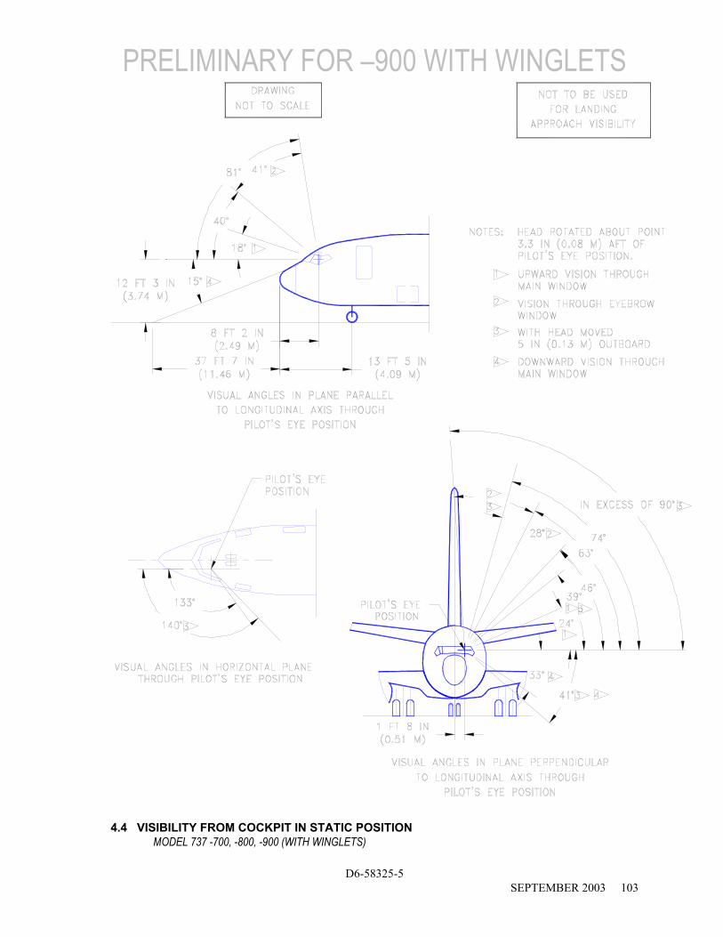
Section 4.4 shows the range of pilot’s visibility from the cockpit within the limits of ambinocular vision through the windows. Ambinocular vision is defined as the total field of vision seen by both eyes at the same time.
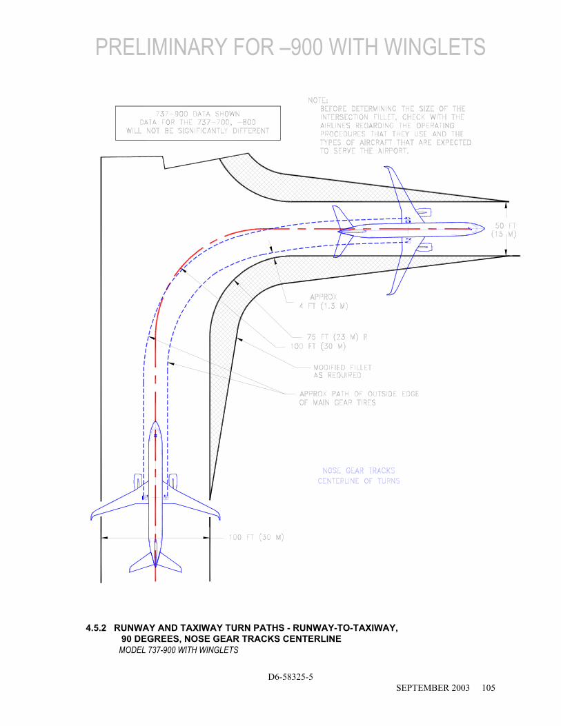
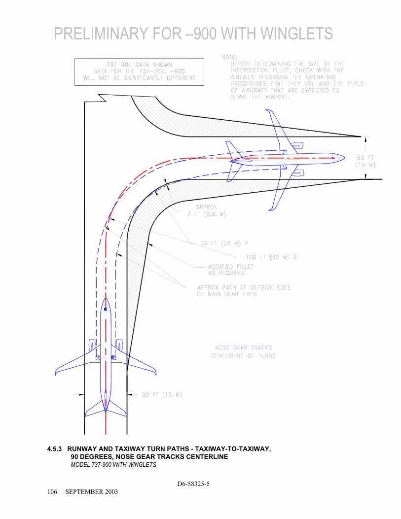
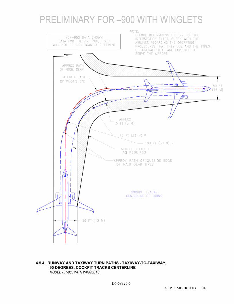
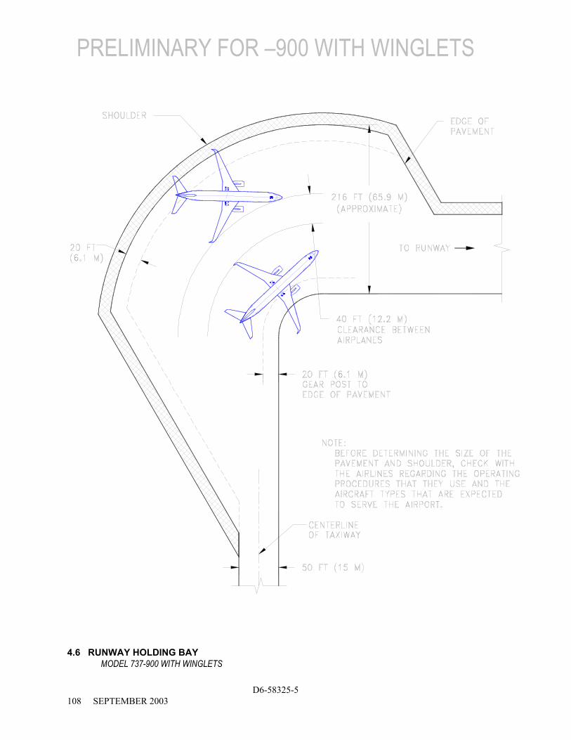
The runway-taxiway turns in Section 4.5 show a model 737-900 on a 100-ft (30-m) runway and 50-ft (15-m) taxiway system. Boeing 737 Series aircraft, including the 737-700/-800/-900 operate on 100-foot wide runways worldwide. However, the FAA recommends the runway width criteria for the 737-700/-800/-900 is 150 ft (45 m) due to its maximum certificated takeoff weight.
Section 4.6 shows minimum holding apron requirements for the 737-900. Holding aprons for larger aircraft should be adequate for the 737-900.

NOTES:
* ACTUAL OPERATING TURNING RADII MAY BE GREATER THAN SHOWN * CONSULT WITH AIRLINE FOR SPECIFIC OPERATING PROCEDURE * DIMENSIONS ROUNDED TO NEAREST 0.1 FOOT AND 0.1 METER.
R1 R2 R3 R4 R5 R6 STEERING
ANGLE INNER GEAR
OUTER GEAR
NOSE GEAR
WING TIP NOSE TAIL
(DEGREES) FT M FT M FT M FT M FT M FT M 30 59.9 18.3 83.0 25.3 83.5 25.5 131.8 40.2 90.0 27.4 110.1 33.6 35 47.4 14.4 70.5 21.5 72.5 22.1 119.4 36.4 80.4 24.5 99.5 30.3 40 37.6 11.5 60.7 18.5 64.8 19.8 109.8 33.5 73.5 22.4 91.6 27.9 45 29.7 9.1 52.8 16.1 59.0 18.0 102.0 31.1 68.5 20.9 85.5 26.0 50 23.0 7.0 46.2 14.1 54.6 16.7 95.5 29.1 64.7 19.7 80.5 24.5 55 17.3 5.3 40.4 12.3 51.2 15.6 89.9 27.4 61.8 18.8 76.5 23.3 60 12.3 3.7 35.4 10.8 48.5 14.8 85.0 25.9 59.6 18.2 73.1 22.3 65 7.7 2.3 30.8 9.4 46.4 14.2 80.5 24.5 58.0 17.7 70.2 21.4 70 3.5 1.1 26.6 8.1 44.8 13.7 76.4 23.3 56.7 17.3 67.7 20.6
78 (MAX) -2.8 -0.8 20.3 6.2 43.1 13.1 70.4 21.5 55.4 16.9 64.4 19.6
4.2.1 TURNING RADII - NO SLIP ANGLE MODEL 737-700 WITH WINGLETS
D6-58325-5 AUGUST 2002 99
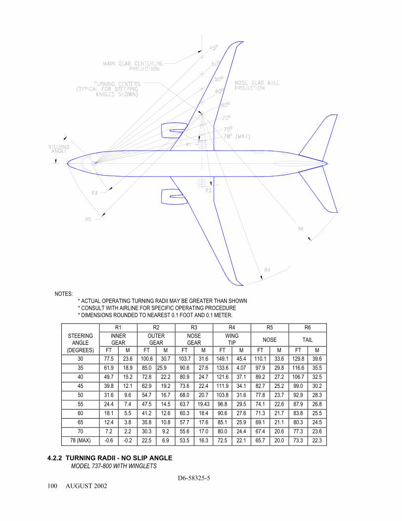
NOTES:
* ACTUAL OPERATING TURNING RADII MAY BE GREATER THAN SHOWN * CONSULT WITH AIRLINE FOR SPECIFIC OPERATING PROCEDURE * DIMENSIONS ROUNDED TO NEAREST 0.1 FOOT AND 0.1 METER.
R1 R2 R3 R4 R5 R6 STEERING
ANGLE INNER GEAR
OUTER GEAR
NOSE GEAR
WING TIP NOSE TAIL
(DEGREES) FT M FT M FT M FT M FT M FT M 30 77.5 23.6 100.6 30.7 103.7 31.6 149.1 45.4 110.1 33.6 129.8 39.6 35 61.9 18.9 85.0 25.9 90.6 27.6 133.6 4.07 97.9 29.8 116.6 35.5 40 49.7 15.2 72.8 22.2 80.9 24.7 121.6 37.1 89.2 27.2 106.7 32.5 45 39.8 12.1 62.9 19.2 73.6 22.4 111.9 34.1 82.7 25.2 99.0 30.2 50 31.6 9.6 54.7 16.7 68.0 20.7 103.8 31.6 77.8 23.7 92.9 28.3 55 24.4 7.4 47.5 14.5 63.7 19.43 96.8 29.5 74.1 22.6 87.9 26.8 60 18.1 5.5 41.2 12.6 60.3 18.4 90.6 27.6 71.3 21.7 83.8 25.5 65 12.4 3.8 35.8 10.8 57.7 17.6 85.1 25.9 69.1 21.1 80.3 24.5 70 7.2 2.2 30.3 9.2 55.6 17.0 80.0 24.4 67.4 20.6 77.3 23.6
78 (MAX) -0.6 -0.2 22.5 6.9 53.5 16.3 72.5 22.1 65.7 20.0 73.3 22.3
4.2.2 TURNING RADII - NO SLIP ANGLE MODEL 737-800 WITH WINGLETS
D6-58325-5 100 AUGUST 2002
PRELIMINARY INFORMATION
D6-58325-5 SEPTEMBER 2003 101
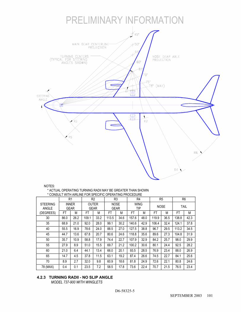
NOTES: * ACTUAL OPERATING TURNING RADII MAY BE GREATER THAN SHOWN * CONSULT WITH AIRLINE FOR SPECIFIC OPERATING PROCEDURE
R1 R2 R3 R4 R5 R6 STEERING
ANGLE INNER GEAR
OUTER GEAR
NOSE GEAR
WING TIP NOSE TAIL
(DEGREES) FT M FT M FT M FT M FT M FT M 30 86.0 26.2 109.1 33.2 113.5 34.6 157.6 48.0 119.9 36.5 138.8 42.3 35 68.9 21.0 92.0 28.0 99.1 30.2 140.6 42.9 106.4 32.4 124.1 37.8 40 55.5 16.9 78.6 24.0 88.5 27.0 127.5 38.8 96.7 29.5 113.2 34.5 45 44.7 13.6 67.8 20.7 80.6 24.6 118.8 35.6 89.6 27.3 104.8 31.9 50 35.7 10.9 58.8 17.9 74.4 22.7 107.9 32.9 84.2 25.7 98.0 29.9 55 27.9 8.9 51.0 15.5 69.7 21.2 100.2 30.6 80.1 24.4 92.5 28.2 60 21.0 6.4 44.1 13.4 66.0 20.1 93.5 28.5 76.9 23.4 88.0 26.9 65 14.7 4.5 37.8 11.5 63.1 19.2 87.4 26.6 74.5 22.7 84.1 25.6 70 8.9 2.7 32.0 9.8 60.9 18.6 81.8 24.9 72.6 22.1 80.8 24.6
78 (MAX) 0.4 0.1 23.5 7.2 58.5 17.8 73.6 22.4 70.7 21.5 76.5 23.4 4.2.3 TURNING RADII - NO SLIP ANGLE
MODEL 737-900 WITH WINGLETS
PRELIMINARY FOR –900 WITH WINGLETS
D6-58325-5 102 SEPTEMBER 2003
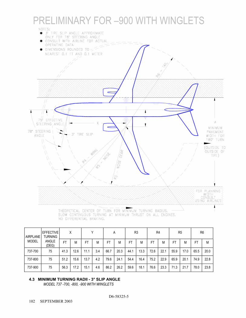
AIRPLANE
EFFECTIVE TURNING
X Y A R3 R4 R5 R6
MODEL ANGLE (DEG)
FT M FT M FT M FT M FT M FT M FT M
737-700 75 41.3 12.6 11.1 3.4 66.7 20.3 44.1 13.3 72.6 22.1 55.9 17.0 65.5 20.0
737-800 75 51.2 15.6 13.7 4.2 79.6 24.1 54.4 16.4 75.2 22.9 65.9 20.1 74.9 22.8
737-900 75 56.3 17.2 15.1 4.6 86.2 26.2 59.6 18.1 76.6 23.3 71.3 21.7 78.0 23.8
4.3 MINIMUM TURNING RADII - 3° SLIP ANGLE
MODEL 737 -700, -800, -900 WITH WINGLETS
PRELIMINARY FOR –900 WITH WINGLETS
D6-58325-5 SEPTEMBER 2003 103
4.4 VISIBILITY FROM COCKPIT IN STATIC POSITION MODEL 737 -700, -800, -900 (WITH WINGLETS)

PRELIMINARY FOR –900 WITH WINGLETS
D6-58325-5 104 SEPTEMBER 2003
4.5.1 RUNWAY AND TAXIWAY TURN PATHS - RUNWAY-TO-TAXIWAY, MORE THAN 90 DEGREES, NOSE GEAR TRACKS CENTERLINE MODEL 737-900 WITH WINGLETS
PRELIMINARY FOR –900 WITH WINGLETS
D6-58325-5 SEPTEMBER 2003 105
4.5.2 RUNWAY AND TAXIWAY TURN PATHS - RUNWAY-TO-TAXIWAY, 90 DEGREES, NOSE GEAR TRACKS CENTERLINE MODEL 737-900 WITH WINGLETS
PRELIMINARY FOR –900 WITH WINGLETS
D6-58325-5 106 SEPTEMBER 2003
4.5.3 RUNWAY AND TAXIWAY TURN PATHS - TAXIWAY-TO-TAXIWAY, 90 DEGREES, NOSE GEAR TRACKS CENTERLINE MODEL 737-900 WITH WINGLETS
PRELIMINARY FOR –900 WITH WINGLETS
D6-58325-5 SEPTEMBER 2003 107
4.5.4 RUNWAY AND TAXIWAY TURN PATHS - TAXIWAY-TO-TAXIWAY, 90 DEGREES, COCKPIT TRACKS CENTERLINE MODEL 737-900 WITH WINGLETS
PRELIMINARY FOR –900 WITH WINGLETS
D6-58325-5 108 SEPTEMBER 2003
4.6 RUNWAY HOLDING BAY MODEL 737-900 WITH WINGLETS
5.0 TERMINAL SERVICING
5.1 Airplane Servicing Arrangement - Typical Turnaround
5.2 Terminal Operations - Turnaround Station
5.3 Terminal Operations - En Route Station
5.4 Ground Servicing Connections
5.5 Engine Starting Pneumatic Requirements
5.6 Ground Pneumatic Power Requirements
5.7 Conditioned Air Requirements
5.8 Ground Towing Requirements
D6-58325-5 AUGUST 2002 109

5.0 TERMINAL SERVICING
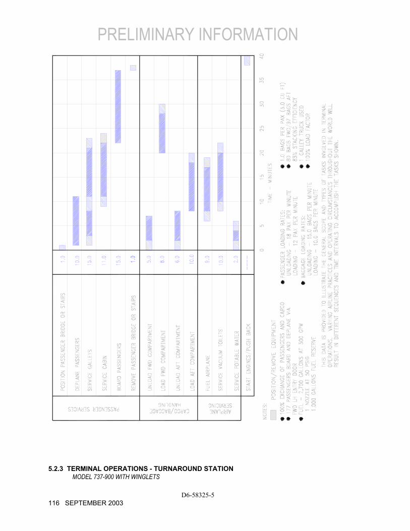
During turnaround at the terminal, certain services must be performed on the aircraft, usually within a given time, to meet flight schedules. This section shows service vehicle arrangements, schedules, locations of service points, and typical service requirements. The data presented in this section reflect ideal conditions for a single airplane. Service requirements may vary according to airplane condition and airline procedure.
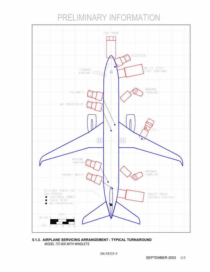
Section 5.1 shows typical arrangements of ground support equipment during turnaround. As noted, if the auxiliary power unit (APU) is used, the electrical, air start, and air-conditioning service vehicles would not be required. Passenger loading bridges or portable passenger stairs could be used to load or unload passengers.
Sections 5.2 and 5.3 show typical service times at the terminal. These charts give typical schedules for performing service on the airplane within a given time. Service times could be rearranged to suit availability of personnel, airplane configuration, and degree of service required.
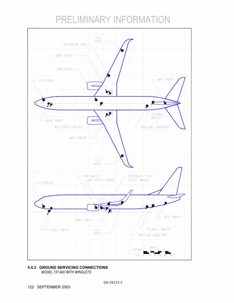
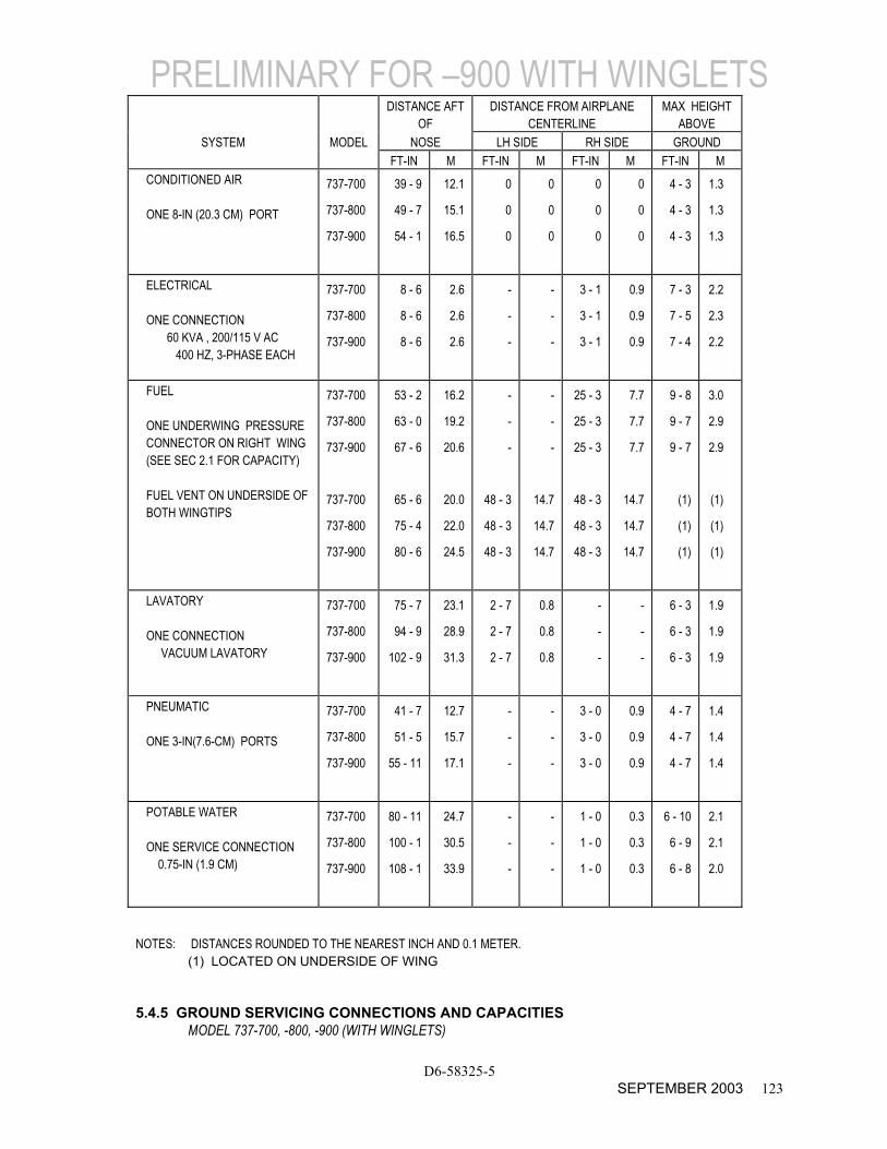
Section 5.4 shows the locations of ground service connections in graphic and in tabular forms. Typical capacities and service requirements are shown in the tables. Services with requirements that vary with conditions are described in subsequent sections.
Section 5.5 shows typical sea level air pressure and flow requirements for starting different engines. The curves are based on an engine start time of 90 seconds.
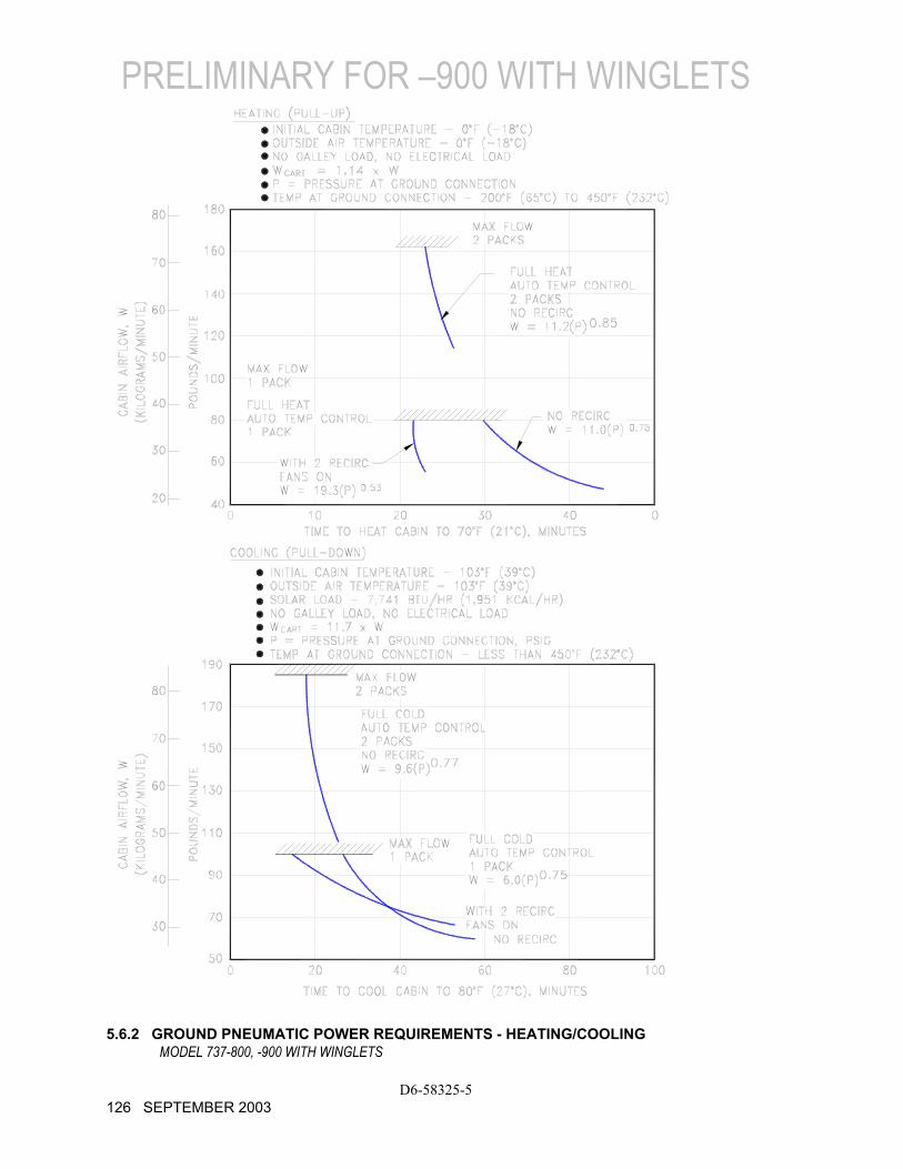
Section 5.6 shows pneumatic requirements for heating and cooling (air conditioning) using high pressure air to run the air cycle machine. The curves show airflow requirements to heat or cool the airplane within a given time and ambient conditions. Maximum allowable pressure and temperature
for air cycle machine operation are 60 psia and 450oF, respectively.
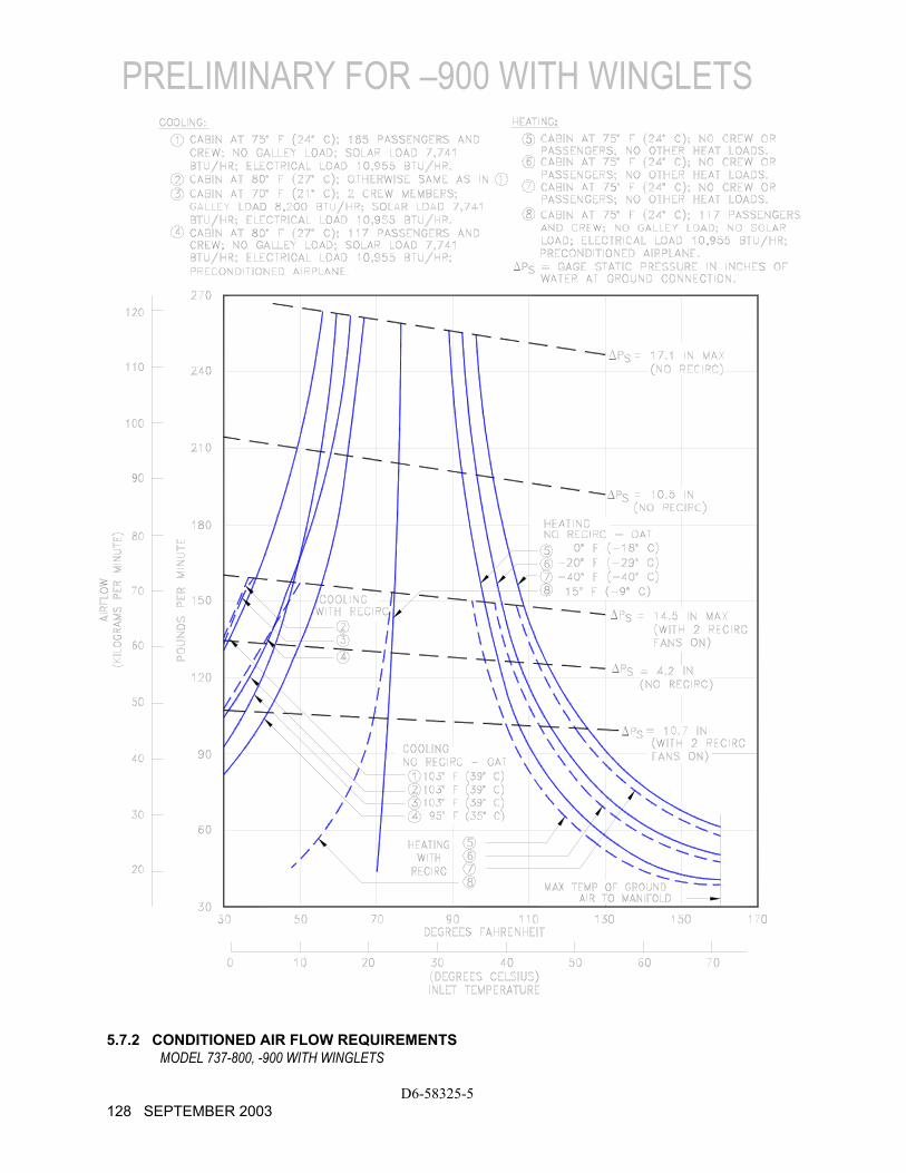
Section 5.7 shows pneumatic requirements for heating and cooling the airplane, using low pressure conditioned air. This conditioned air is supplied through an 8-in ground air connection (GAC) directly to the passenger cabin, bypassing the air cycle machines.
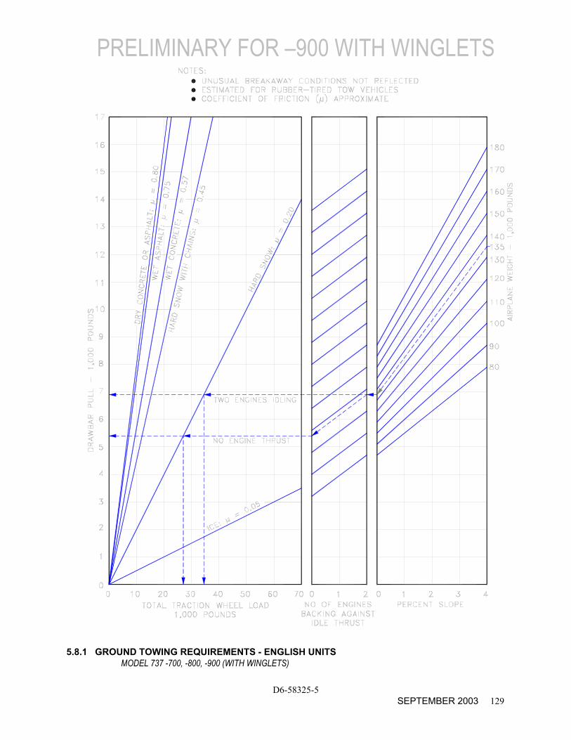
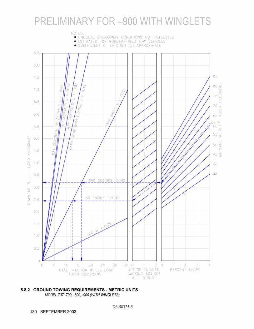
Section 5.8 shows ground towing requirements for various ground surface conditions.
D6-58325-5 110 AUGUST 2002

5.1.1 AIRPLANE SERVICING ARRANGEMENT - TYPICAL TURNAROUND
MODEL 737-700 WITH WINGLETS
D6-58325-5 AUGUST 2002 111
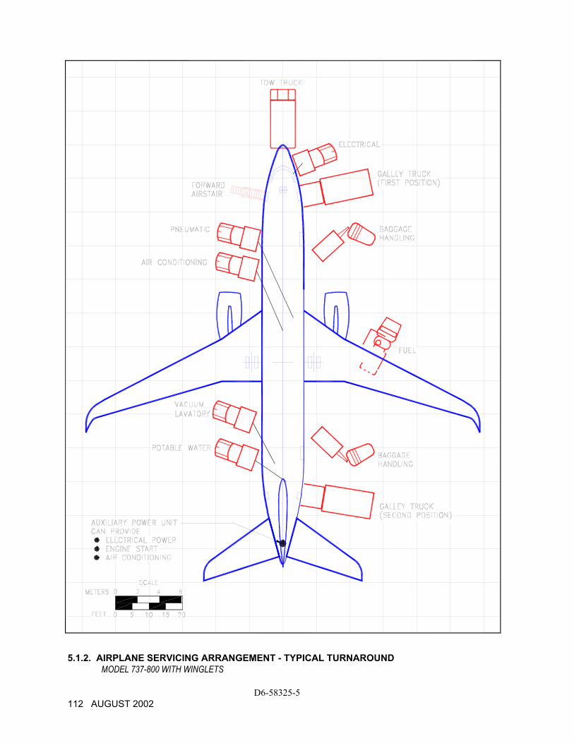
5.1.2. AIRPLANE SERVICING ARRANGEMENT - TYPICAL TURNAROUND MODEL 737-800 WITH WINGLETS
D6-58325-5 112 AUGUST 2002
PRELIMINARY INFORMATION
D6-58325-5 SEPTEMBER 2003 113
5.1.3. AIRPLANE SERVICING ARRANGEMENT - TYPICAL TURNAROUND MODEL 737-900 WITH WINGLETS
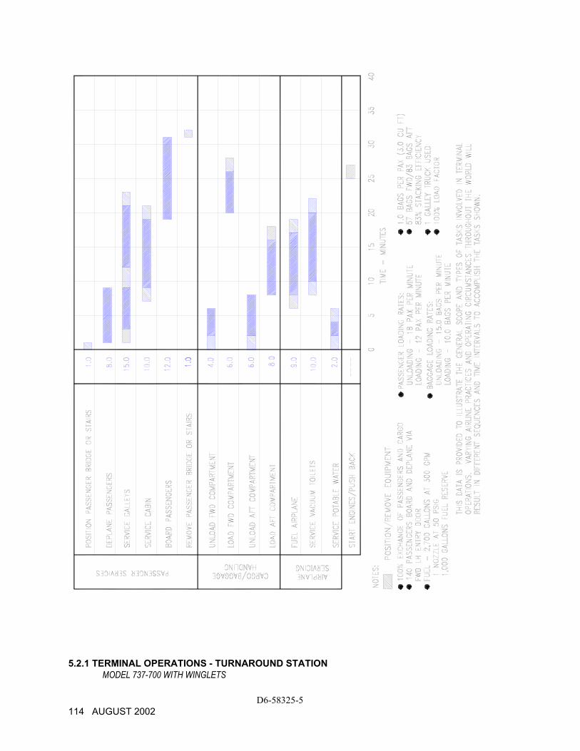
5.2.1 TERMINAL OPERATIONS - TURNAROUND STATION MODEL 737-700 WITH WINGLETS
D6-58325-5 114 AUGUST 2002
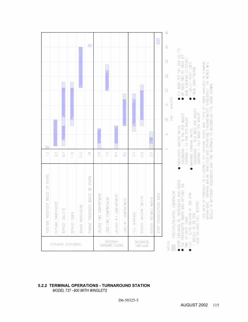
5.2.2 TERMINAL OPERATIONS - TURNAROUND STATION MODEL 737 –800 WITH WINGLETS
D6-58325-5 AUGUST 2002 115
PRELIMINARY INFORMATION
D6-58325-5 116 SEPTEMBER 2003
5.2.3 TERMINAL OPERATIONS - TURNAROUND STATION MODEL 737-900 WITH WINGLETS
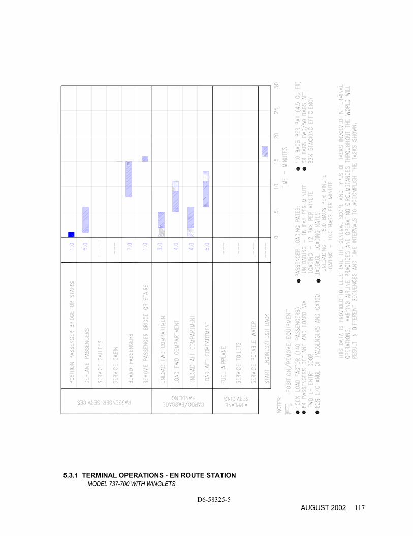
5.3.1 TERMINAL OPERATIONS - EN ROUTE STATION MODEL 737-700 WITH WINGLETS
D6-58325-5 AUGUST 2002 117
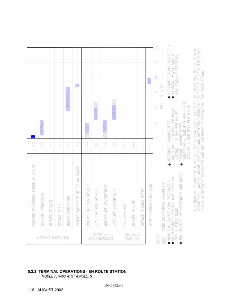
5.3.2 TERMINAL OPERATIONS - EN ROUTE STATION MODEL 737-800 WITH WINGLETS
D6-58325-5 118 AUGUST 2002
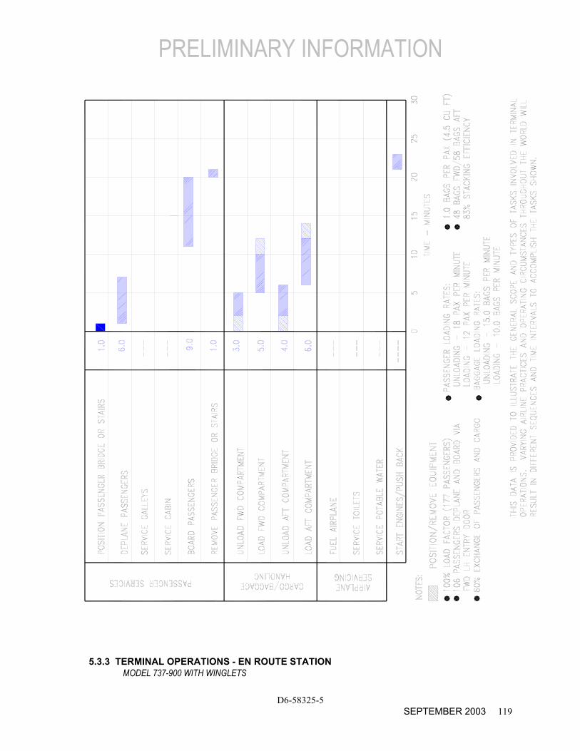
PRELIMINARY INFORMATION
D6-58325-5 SEPTEMBER 2003 119
5.3.3 TERMINAL OPERATIONS - EN ROUTE STATION MODEL 737-900 WITH WINGLETS
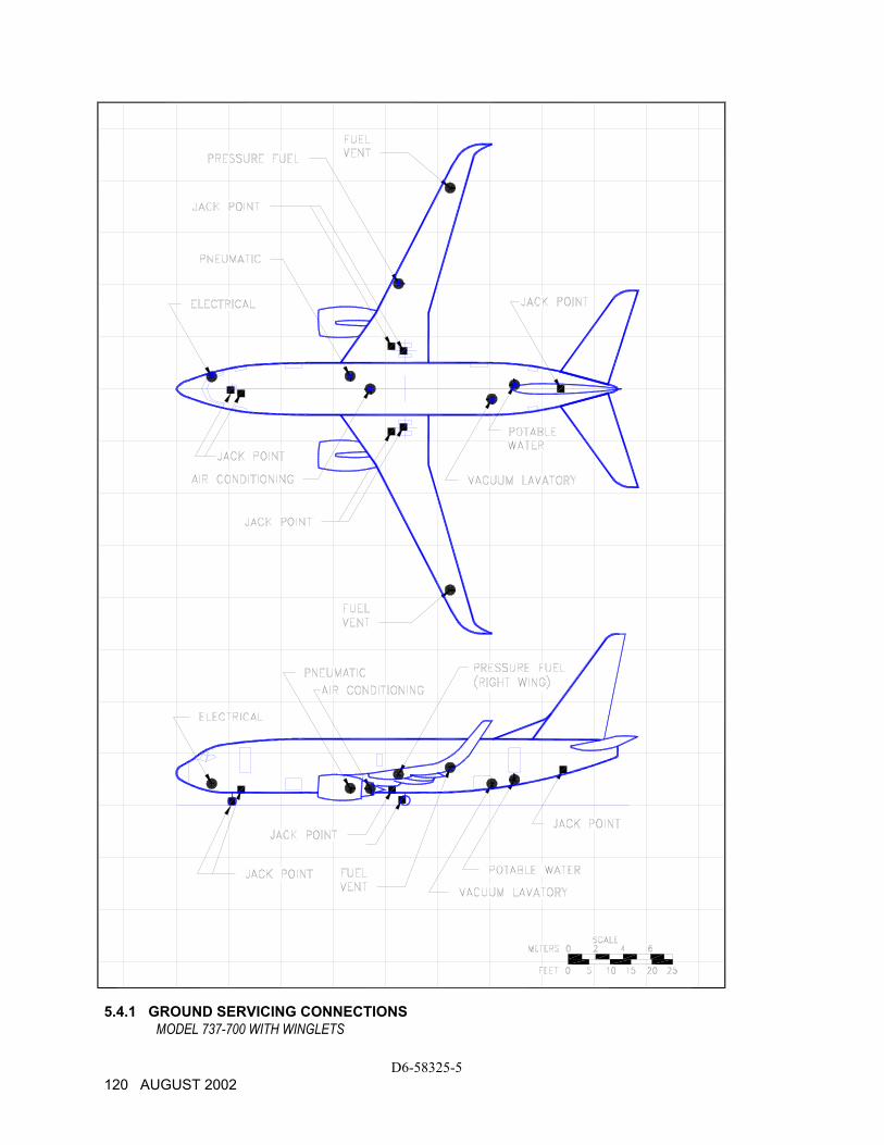
5.4.1 GROUND SERVICING CONNECTIONS
MODEL 737-700 WITH WINGLETS
D6-58325-5 120 AUGUST 2002
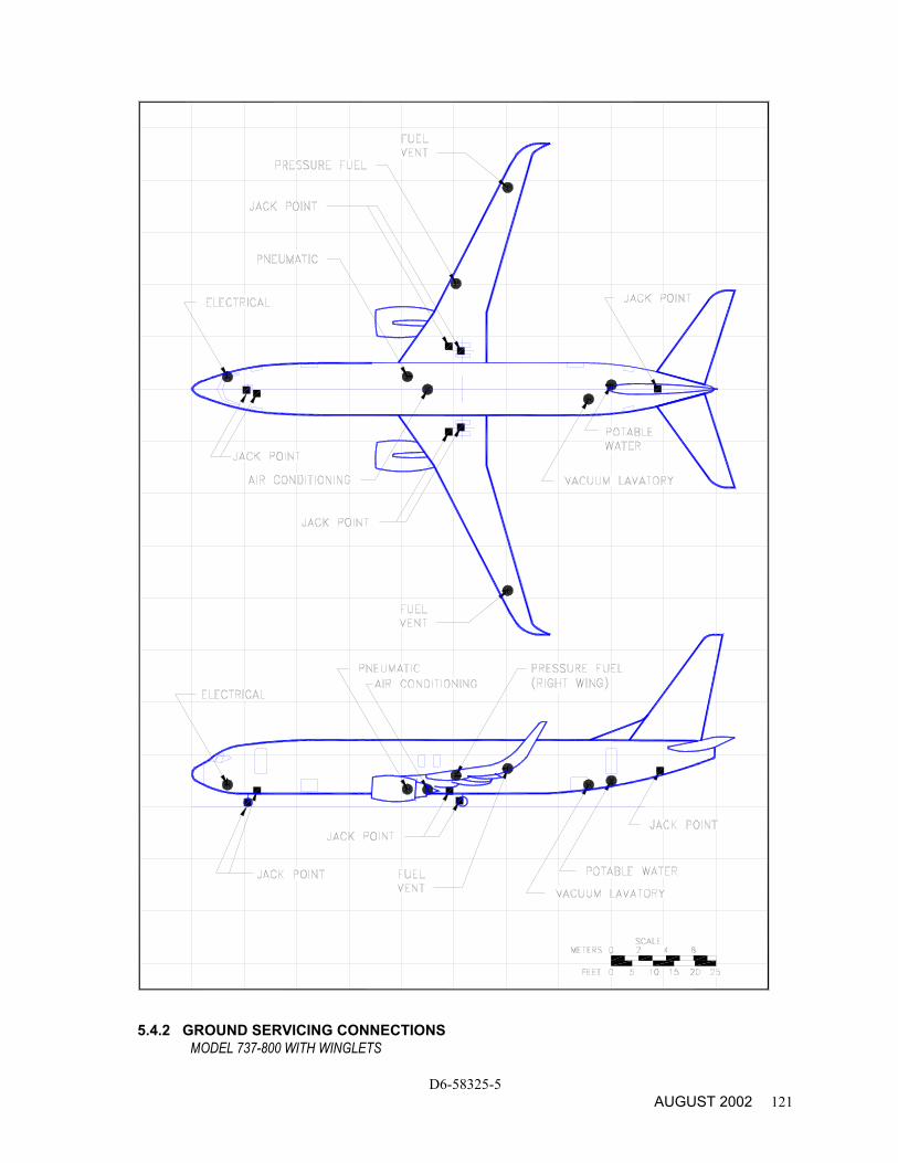
5.4.2 GROUND SERVICING CONNECTIONS MODEL 737-800 WITH WINGLETS
D6-58325-5 AUGUST 2002 121
PRELIMINARY INFORMATION
D6-58325-5 122 SEPTEMBER 2003
5.4.3 GROUND SERVICING CONNECTIONS
MODEL 737-900 WITH WINGLETS
PRELIMINARY FOR –900 WITH WINGLETS
D6-58325-5 SEPTEMBER 2003 123
DISTANCE AFT OF
DISTANCE FROM AIRPLANE CENTERLINE
MAX HEIGHT ABOVE
SYSTEM MODEL NOSE LH SIDE RH SIDE GROUND FT-IN M FT-IN M FT-IN M FT-IN M
CONDITIONED AIR ONE 8-IN (20.3 CM) PORT
737-700
737-800
737-900
39 - 9
49 - 7
54 - 1
12.1
15.1
16.5
0
0
0
0
0
0
0
0
0
0
0
0
4 - 3
4 - 3
4 - 3
1.3
1.3
1.3
ELECTRICAL ONE CONNECTION 60 KVA , 200/115 V AC 400 HZ, 3-PHASE EACH
737-700
737-800
737-900
8 - 6
8 - 6
8 - 6
2.6
2.6
2.6
-
-
-
-
-
-
3 - 1
3 - 1
3 - 1
0.9
0.9
0.9
7 - 3
7 - 5
7 - 4
2.2
2.3
2.2
FUEL ONE UNDERWING PRESSURE CONNECTOR ON RIGHT WING (SEE SEC 2.1 FOR CAPACITY) FUEL VENT ON UNDERSIDE OF BOTH WINGTIPS
737-700
737-800
737-900
737-700
737-800
737-900
53 - 2
63 - 0
67 - 6
65 - 6
75 - 4
80 - 6
16.2
19.2
20.6
20.0
22.0
24.5
-
-
-
48 - 3
48 - 3
48 - 3
-
-
-
14.7
14.7
14.7
25 - 3
25 - 3
25 - 3
48 - 3
48 - 3
48 - 3
7.7
7.7
7.7
14.7
14.7
14.7
9 - 8
9 - 7
9 - 7
(1)
(1)
(1)
3.0
2.9
2.9
(1)
(1)
(1)
LAVATORY ONE CONNECTION VACUUM LAVATORY
737-700
737-800
737-900
75 - 7
94 - 9
102 - 9
23.1
28.9
31.3
2 - 7
2 - 7
2 - 7
0.8
0.8
0.8
-
-
-
-
-
-
6 - 3
6 - 3
6 - 3
1.9
1.9
1.9
PNEUMATIC ONE 3-IN(7.6-CM) PORTS
737-700
737-800
737-900
41 - 7
51 - 5
55 - 11
12.7
15.7
17.1
-
-
-
-
-
-
3 - 0
3 - 0
3 - 0
0.9
0.9
0.9
4 - 7
4 - 7
4 - 7
1.4
1.4
1.4
POTABLE WATER ONE SERVICE CONNECTION 0.75-IN (1.9 CM)
737-700
737-800
737-900
80 - 11
100 - 1
108 - 1
24.7
30.5
33.9
-
-
-
-
-
-
1 - 0
1 - 0
1 - 0
0.3
0.3
0.3
6 - 10
6 - 9
6 - 8
2.1
2.1
2.0
NOTES: DISTANCES ROUNDED TO THE NEAREST INCH AND 0.1 METER. (1) LOCATED ON UNDERSIDE OF WING 5.4.5 GROUND SERVICING CONNECTIONS AND CAPACITIES
MODEL 737-700, -800, -900 (WITH WINGLETS)

PRELIMINARY FOR –900 WITH WINGLETS
D6-58325-5 124 SEPTEMBER 2003
5.5. ENGINE START PNEUMATIC REQUIREMENTS - SEA LEVEL
MODEL 737 -700, -800, -900 (WITH WINGLETS)
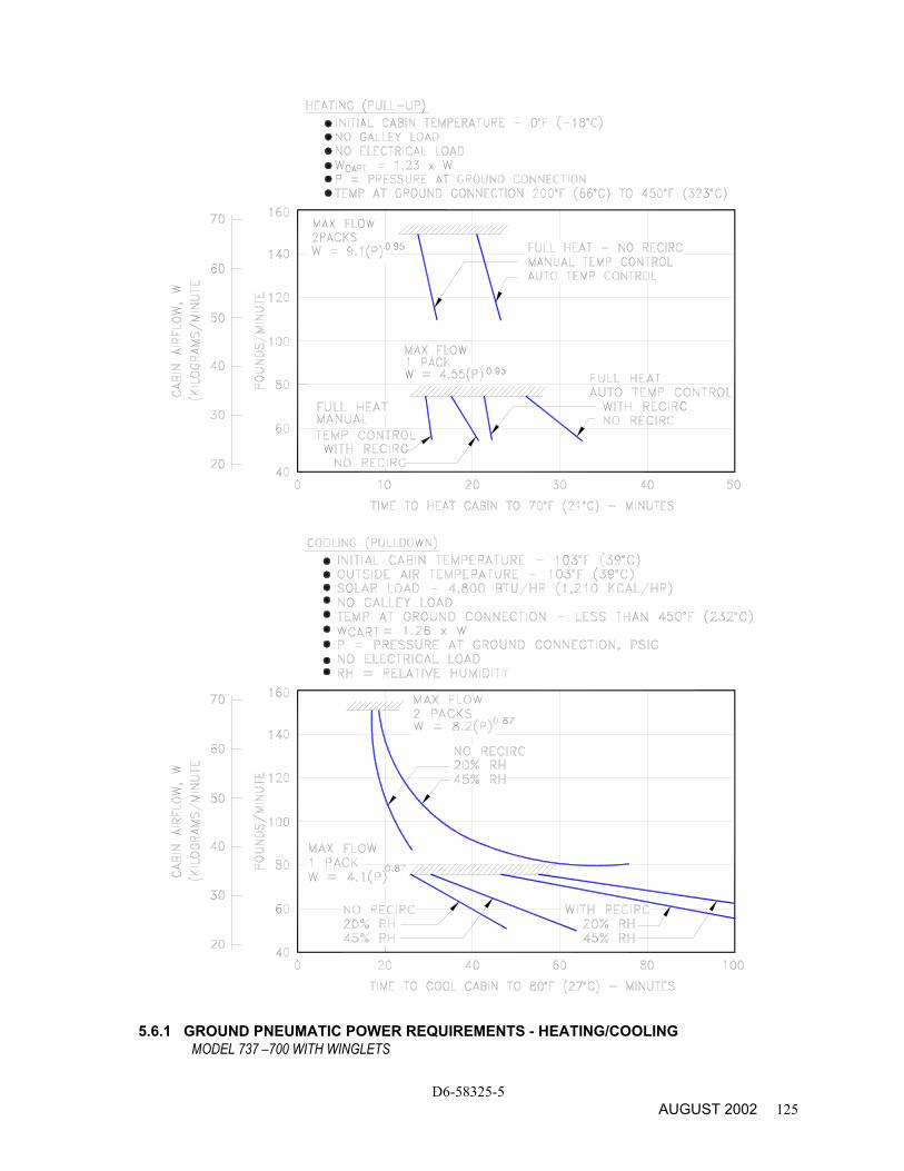
5.6.1 GROUND PNEUMATIC POWER REQUIREMENTS - HEATING/COOLING
MODEL 737 –700 WITH WINGLETS
D6-58325-5 AUGUST 2002 125
PRELIMINARY FOR –900 WITH WINGLETS
D6-58325-5 126 SEPTEMBER 2003
5.6.2 GROUND PNEUMATIC POWER REQUIREMENTS - HEATING/COOLING
MODEL 737-800, -900 WITH WINGLETS
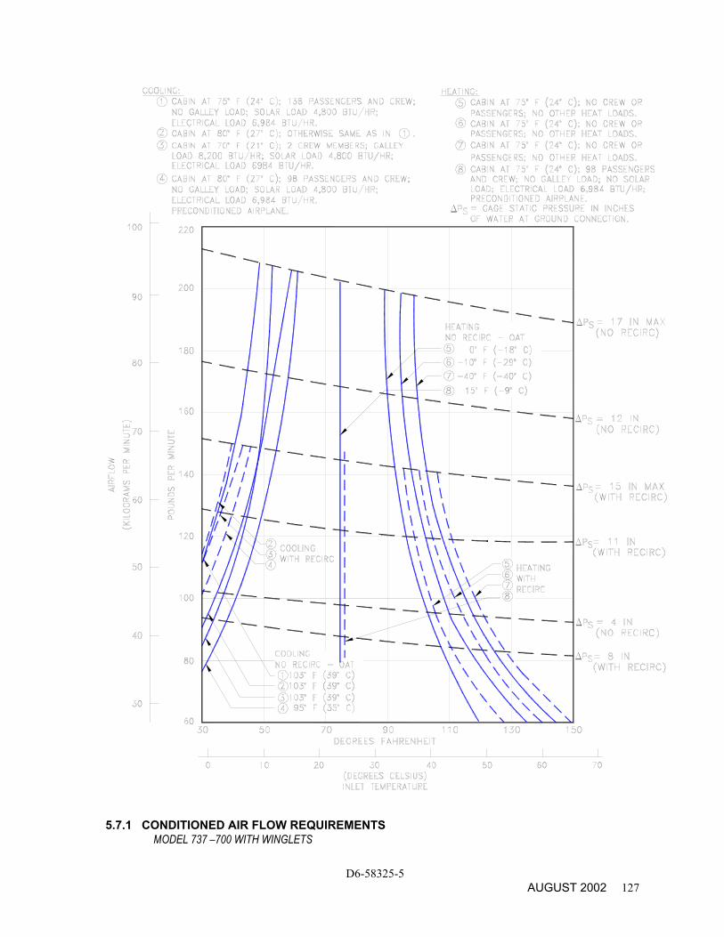
5.7.1 CONDITIONED AIR FLOW REQUIREMENTS MODEL 737 –700 WITH WINGLETS
D6-58325-5 AUGUST 2002 127
PRELIMINARY FOR –900 WITH WINGLETS
D6-58325-5 128 SEPTEMBER 2003
5.7.2 CONDITIONED AIR FLOW REQUIREMENTS MODEL 737-800, -900 WITH WINGLETS
PRELIMINARY FOR –900 WITH WINGLETS
D6-58325-5 SEPTEMBER 2003 129
5.8.1 GROUND TOWING REQUIREMENTS - ENGLISH UNITS
MODEL 737 -700, -800, -900 (WITH WINGLETS)
PRELIMINARY FOR –900 WITH WINGLETS
D6-58325-5 130 SEPTEMBER 2003
5.8.2 GROUND TOWING REQUIREMENTS - METRIC UNITS
MODEL 737 -700, -800, -900 (WITH WINGLETS)
6.0 JET ENGINE WAKE AND NOISE DATA
6.1 Jet Engine Exhaust Velocities and Temperatures
6.2 Airport and Community Noise
D6-58325-5 AUGUST 2002 131
PRELIMINARY FOR -900 WITH WINGLETS
D6-58325-5 132 SEPTEMBER 2003
6.0 JET ENGINE WAKE AND NOISE DATA
6.1 Jet Engine Exhaust Velocities and Temperatures
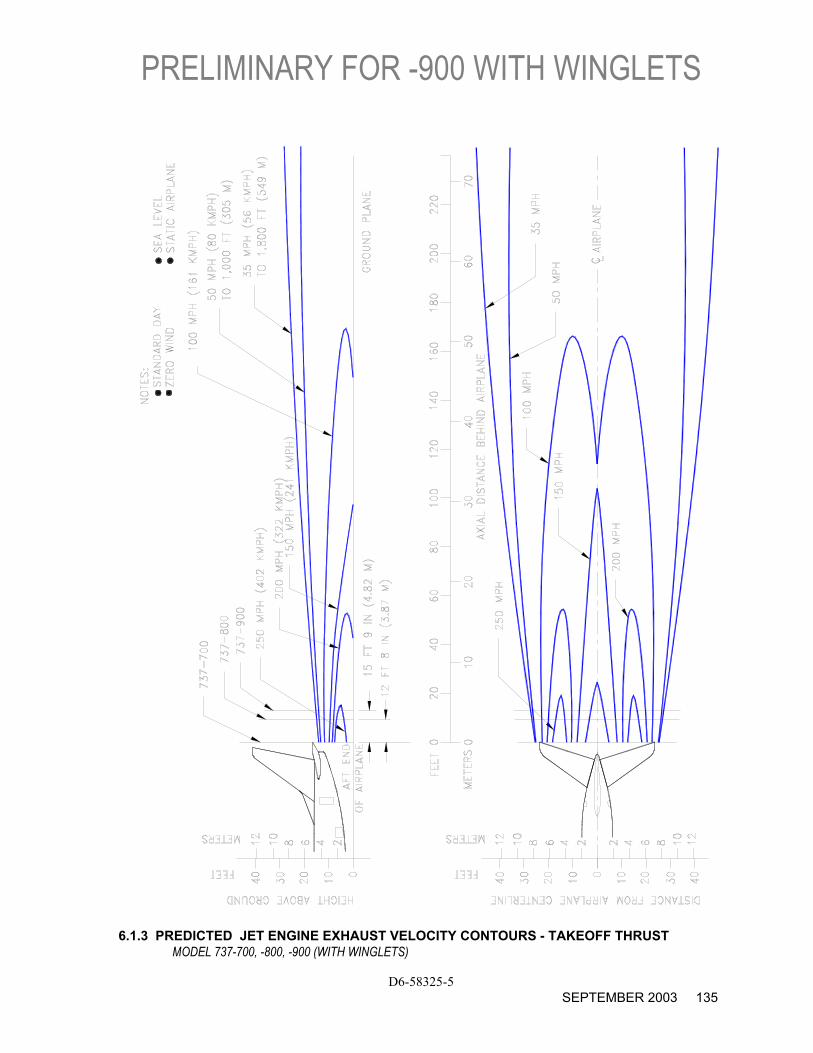
This section shows exhaust velocity and temperature contours aft of the 737-700/-800/-900. The contours were calculated from a standard computer analysis using three-dimensional viscous flow equations with mixing of primary, fan, and free-stream flow. The presence of the ground plane is included in the calculations as well as engine tilt and toe-in. Mixing of flows from the engines is also calculated. The analysis does not include thermal buoyancy effects which tend to elevate the jet wake above the ground plane. The buoyancy effects are considered to be small relative to the exhaust velocity and therefore are not included.
The graphs show jet wake velocity and temperature contours are valid for sea level, static, standard day conditions. The effect of wind on jet wakes was not included. There is evidence to show that a downwind or an upwind component does not simply add or subtract from the jet wake velocity, but rather carries the whole envelope in the direction of the wind. Crosswinds may carry the jet wake contour far to the side at large distances behind the airplane.
PRELIMINARY FOR -900 WITH WINGLETS
D6-58325-5 SEPTEMBER 2003 133
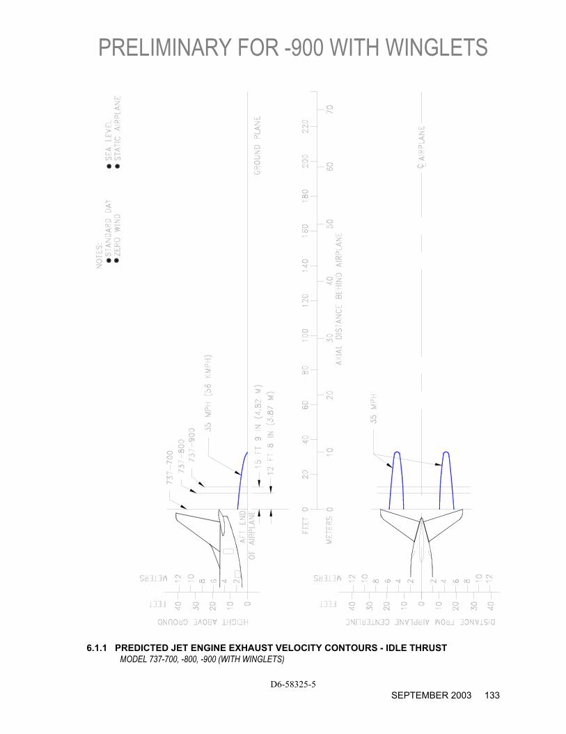
6.1.1 PREDICTED JET ENGINE EXHAUST VELOCITY CONTOURS - IDLE THRUST
MODEL 737-700, -800, -900 (WITH WINGLETS)
PRELIMINARY FOR –900 WITH WINGLETS
D6-58325-5 134 SEPTEMBER 2003
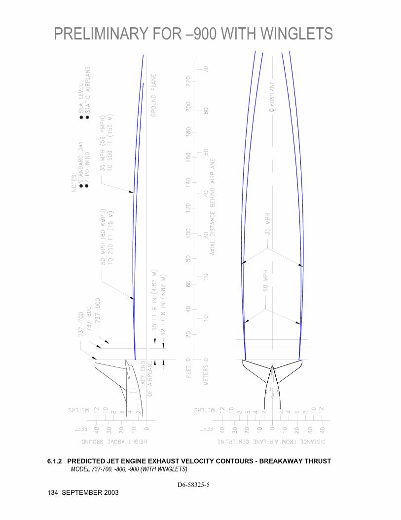
6.1.2 PREDICTED JET ENGINE EXHAUST VELOCITY CONTOURS - BREAKAWAY THRUST
MODEL 737-700, -800, -900 (WITH WINGLETS)
PRELIMINARY FOR -900 WITH WINGLETS
D6-58325-5 SEPTEMBER 2003 135
6.1.3 PREDICTED JET ENGINE EXHAUST VELOCITY CONTOURS - TAKEOFF THRUST MODEL 737-700, -800, -900 (WITH WINGLETS)
PRELIMINARY FOR –900 WITH WINGLETS
D6-58325-5 136 SEPTEMBER 2003
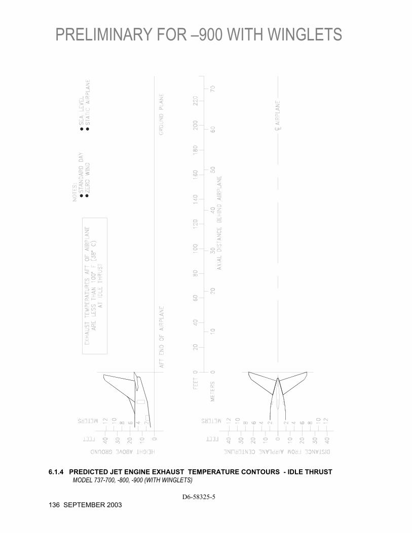
6.1.4 PREDICTED JET ENGINE EXHAUST TEMPERATURE CONTOURS - IDLE THRUST
MODEL 737-700, -800, -900 (WITH WINGLETS)
PRELIMINARY FOR -900 WITH WINGLETS
D6-58325-5 SEPTEMBER 2003 137
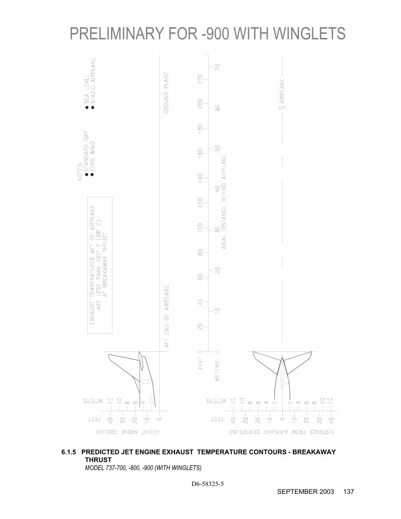
6.1.5 PREDICTED JET ENGINE EXHAUST TEMPERATURE CONTOURS - BREAKAWAY
THRUST MODEL 737-700, -800, -900 (WITH WINGLETS)
PRELIMINARY FOR –900 WITH WINGLETS
D6-58325-5 138 SEPTEMBER 2003
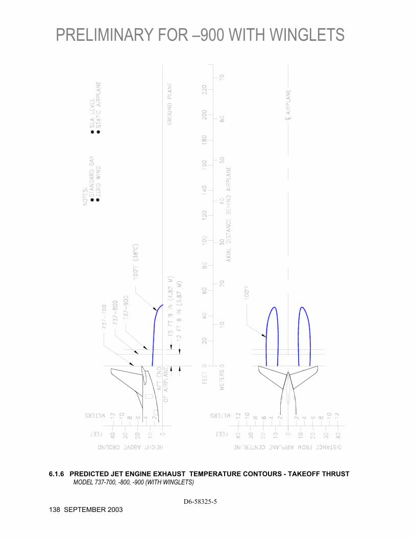
6.1.6 PREDICTED JET ENGINE EXHAUST TEMPERATURE CONTOURS - TAKEOFF THRUST
MODEL 737-700, -800, -900 (WITH WINGLETS)
6.2 Airport and Community Noise
Airport noise is of major concern to the airport and community planner. The airport is a major element in the community's transportation system and, as such, is vital to its growth. However, the airport must also be a good neighbor, and this can be accomplished only with proper planning. Since aircraft noise extends beyond the boundaries of the airport, it is vital to consider the impact on surrounding communities. Many means have been devised to provide the planner with a tool to estimate the impact of airport operations. Too often they oversimplify noise to the point where the results become erroneous. Noise is not a simple subject; therefore, there are no simple answers.
The cumulative noise contour is an effective tool. However, care must be exercised to ensure that the contours, used correctly, estimate the noise resulting from aircraft operations conducted at an airport.
The size and shape of the single-event contours, which are inputs into the cumulative noise contours, are dependent upon numerous factors. They include the following:
1. Operational Factors
(a) Aircraft Weight-Aircraft weight is dependent on distance to be traveled, en route winds, payload, and anticipated aircraft delay upon reaching the destination.
(b) Engine Power Settings-The rates of ascent and descent and the noise levels emitted at the source are influenced by the power setting used.
(c) Airport Altitude-Higher airport altitude will affect engine performance and thus can influence noise.
D6-58325-5 AUGUST 2002 139
2. Atmospheric Conditions-Sound Propagation
(a) Wind-With stronger headwinds, the aircraft can take off and climb more rapidly relative to the ground. Also, winds can influence the distribution of noise in surrounding communities.
(b) Temperature and Relative Humidity-The absorption of noise in the atmosphere along the transmission path between the aircraft and the ground observer varies with both temperature and relative humidity.
3. Surface Condition-Shielding, Extra Ground Attenuation (EGA)
(a) Terrain-If the ground slopes down after takeoff or before landing, noise will be reduced since the aircraft will be at a higher altitude above ground. Additionally, hills, shrubs, trees, and large buildings can act as sound buffers.
D6-58325-5 140 AUGUST 2002
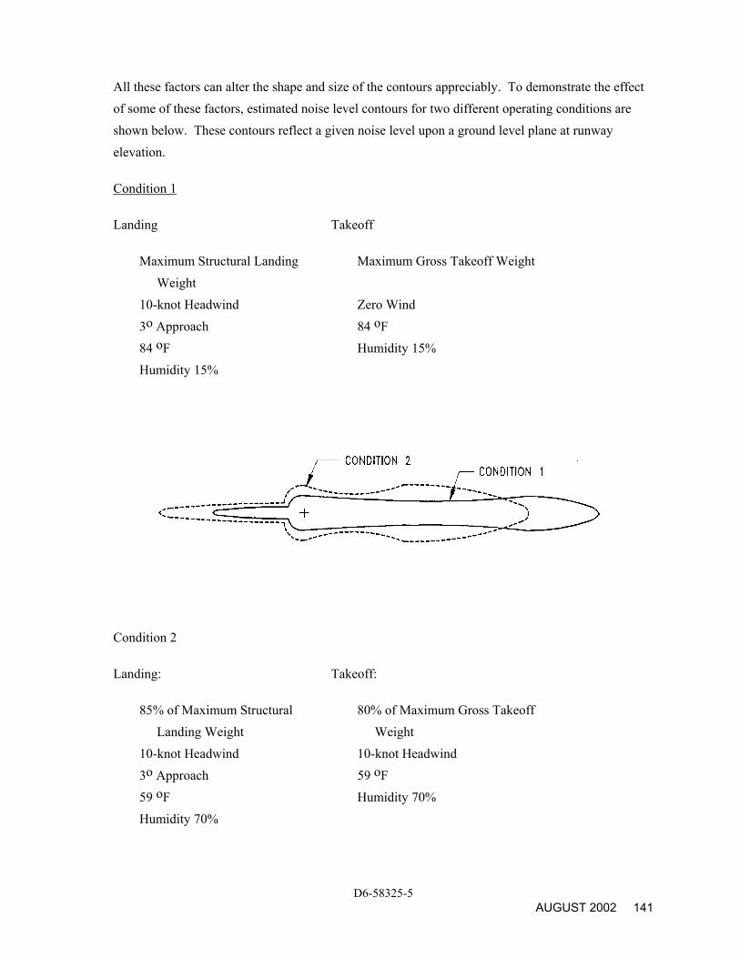
All these factors can alter the shape and size of the contours appreciably. To demonstrate the effect of some of these factors, estimated noise level contours for two different operating conditions are shown below. These contours reflect a given noise level upon a ground level plane at runway elevation.
Condition 1
Landing Takeoff
Maximum Structural Landing Weight
Maximum Gross Takeoff Weight
10-knot Headwind Zero Wind 3o Approach 84 oF 84 oF Humidity 15% Humidity 15%
Condition 2
Landing: Takeoff:
85% of Maximum Structural Landing Weight
80% of Maximum Gross Takeoff Weight
10-knot Headwind 10-knot Headwind 3o Approach 59 oF 59 oF Humidity 70% Humidity 70%
D6-58325-5 AUGUST 2002 141
As indicated from these data, the contour size varies substantially with operating and atmospheric conditions. Most aircraft operations are, of course, conducted at less than maximum gross weights because average flight distances are much shorter than maximum aircraft range capability and average load factors are less than 100%. Therefore, in developing cumulative contours for planning purposes, it is recommended that the airlines serving a particular city be contacted to provide operational information.
In addition, there are no universally accepted methods for developing aircraft noise contours or for relating the acceptability of specific zones to specific land uses. It is therefore expected that noise contour data for particular aircraft and the impact assessment methodology will be changing. To ensure that the best currently available information of this type is used in any planning study, it is recommended that it be obtained directly from the Office of Environmental Quality in the Federal Aviation Administration in Washington, D.C.
It should be noted that the contours shown herein are only for illustrating the impact of operating and atmospheric conditions and do not represent the single-event contour of the family of aircraft described in this document. It is expected that the cumulative contours will be developed as required by planners using the data and methodology applicable to their specific study.
D6-58325-5 142 AUGUST 2002
7.0 PAVEMENT DATA
7.1 General Information
7.2 Landing Gear Footprint
7.3 Maximum Pavement Loads
7.4 Landing Gear Loading on Pavement
7.5 Flexible Pavement Requirements - U.S. Army Corps of Engineers Method S-77-1 and FAA Design Method
7.6 Flexible Pavement Requirements - LCN Conversion
7.7 Rigid Pavement Requirements - Portland Cement Association Design Method
7.8 Rigid Pavement Requirements - LCN Conversion
7.9 Rigid Pavement Requirements - FAA Design Method
7.10 ACN/PCN Reporting System - Flexible and Rigid Pavements
D6-58325-5 SEPTEMBER 2002 143
7.0 PAVEMENT DATA
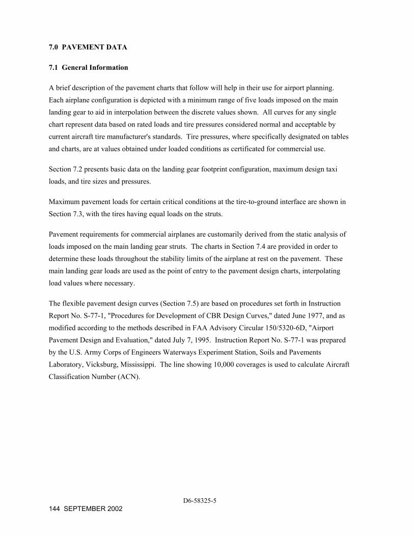
7.1 General Information
A brief description of the pavement charts that follow will help in their use for airport planning. Each airplane configuration is depicted with a minimum range of five loads imposed on the main landing gear to aid in interpolation between the discrete values shown. All curves for any single chart represent data based on rated loads and tire pressures considered normal and acceptable by current aircraft tire manufacturer's standards. Tire pressures, where specifically designated on tables and charts, are at values obtained under loaded conditions as certificated for commercial use.
Section 7.2 presents basic data on the landing gear footprint configuration, maximum design taxi loads, and tire sizes and pressures.
Maximum pavement loads for certain critical conditions at the tire-to-ground interface are shown in Section 7.3, with the tires having equal loads on the struts.
Pavement requirements for commercial airplanes are customarily derived from the static analysis of loads imposed on the main landing gear struts. The charts in Section 7.4 are provided in order to determine these loads throughout the stability limits of the airplane at rest on the pavement. These main landing gear loads are used as the point of entry to the pavement design charts, interpolating load values where necessary.
The flexible pavement design curves (Section 7.5) are based on procedures set forth in Instruction Report No. S-77-1, "Procedures for Development of CBR Design Curves," dated June 1977, and as modified according to the methods described in FAA Advisory Circular 150/5320-6D, "Airport Pavement Design and Evaluation," dated July 7, 1995. Instruction Report No. S-77-1 was prepared by the U.S. Army Corps of Engineers Waterways Experiment Station, Soils and Pavements Laboratory, Vicksburg, Mississippi. The line showing 10,000 coverages is used to calculate Aircraft Classification Number (ACN).
D6-58325-5 144 SEPTEMBER 2002
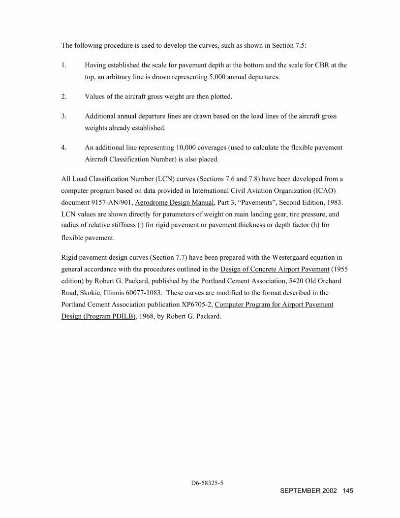
The following procedure is used to develop the curves, such as shown in Section 7.5:
1. Having established the scale for pavement depth at the bottom and the scale for CBR at the top, an arbitrary line is drawn representing 5,000 annual departures.
2. Values of the aircraft gross weight are then plotted.
3. Additional annual departure lines are drawn based on the load lines of the aircraft gross weights already established.
4. An additional line representing 10,000 coverages (used to calculate the flexible pavement Aircraft Classification Number) is also placed.
All Load Classification Number (LCN) curves (Sections 7.6 and 7.8) have been developed from a computer program based on data provided in International Civil Aviation Organization (ICAO) document 9157-AN/901, Aerodrome Design Manual, Part 3, “Pavements”, Second Edition, 1983. LCN values are shown directly for parameters of weight on main landing gear, tire pressure, and radius of relative stiffness ( ) for rigid pavement or pavement thickness or depth factor (h) for
flexible pavement.
Rigid pavement design curves (Section 7.7) have been prepared with the Westergaard equation in general accordance with the procedures outlined in the Design of Concrete Airport Pavement (1955 edition) by Robert G. Packard, published by the Portland Cement Association, 5420 Old Orchard Road, Skokie, Illinois 60077-1083. These curves are modified to the format described in the Portland Cement Association publication XP6705-2, Computer Program for Airport Pavement Design (Program PDILB), 1968, by Robert G. Packard.
D6-58325-5 SEPTEMBER 2002 145
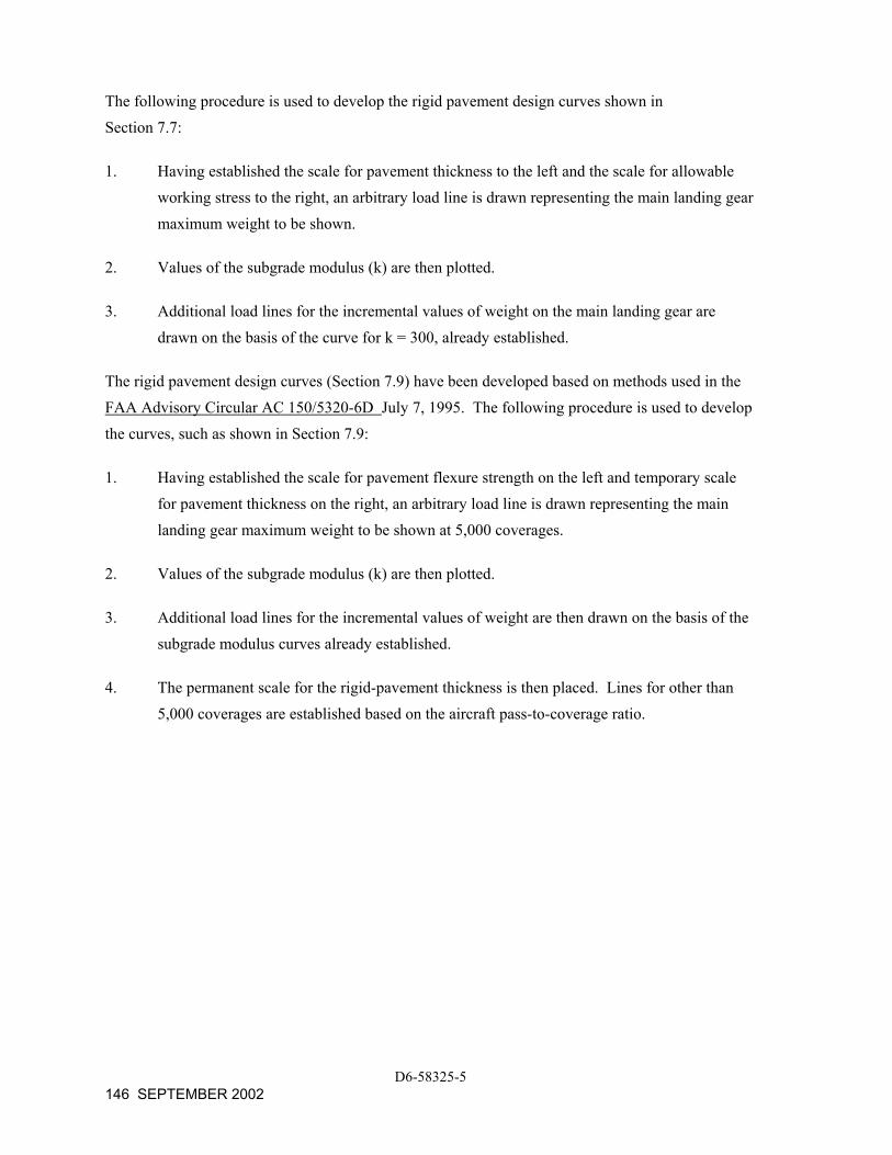
The following procedure is used to develop the rigid pavement design curves shown in Section 7.7:
1. Having established the scale for pavement thickness to the left and the scale for allowable working stress to the right, an arbitrary load line is drawn representing the main landing gear maximum weight to be shown.
2. Values of the subgrade modulus (k) are then plotted.
3. Additional load lines for the incremental values of weight on the main landing gear are drawn on the basis of the curve for k = 300, already established.
The rigid pavement design curves (Section 7.9) have been developed based on methods used in the FAA Advisory Circular AC 150/5320-6D July 7, 1995. The following procedure is used to develop the curves, such as shown in Section 7.9:
1. Having established the scale for pavement flexure strength on the left and temporary scale for pavement thickness on the right, an arbitrary load line is drawn representing the main landing gear maximum weight to be shown at 5,000 coverages.
2. Values of the subgrade modulus (k) are then plotted.
3. Additional load lines for the incremental values of weight are then drawn on the basis of the subgrade modulus curves already established.
4. The permanent scale for the rigid-pavement thickness is then placed. Lines for other than 5,000 coverages are established based on the aircraft pass-to-coverage ratio.
D6-58325-5 146 SEPTEMBER 2002
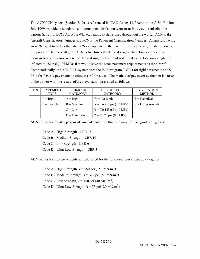
The ACN/PCN system (Section 7.10) as referenced in ICAO Annex 14, "Aerodromes," 3rd Edition, July 1999, provides a standardized international airplane/pavement rating system replacing the various S, T, TT, LCN, AUW, ISWL, etc., rating systems used throughout the world. ACN is the Aircraft Classification Number and PCN is the Pavement Classification Number. An aircraft having an ACN equal to or less than the PCN can operate on the pavement subject to any limitation on the tire pressure. Numerically, the ACN is two times the derived single-wheel load expressed in thousands of kilograms, where the derived single wheel load is defined as the load on a single tire inflated to 181 psi (1.25 MPa) that would have the same pavement requirements as the aircraft. Computationally, the ACN/PCN system uses the PCA program PDILB for rigid pavements and S-77-1 for flexible pavements to calculate ACN values. The method of pavement evaluation is left up to the airport with the results of their evaluation presented as follows:
PCN PAVEMENT TYPE
SUBGRADE CATEGORY
TIRE PRESSURE CATEGORY
EVALUATION METHOD
R = Rigid A = High W = No Limit T = Technical
F = Flexible B = Medium X = To 217 psi (1.5 MPa) U = Using Aircraft
C = Low Y = To 145 psi (1.0 MPa)
D = Ultra Low Z = To 73 psi (0.5 MPa)
ACN values for flexible pavements are calculated for the following four subgrade categories:
Code A - High Strength - CBR 15 Code B - Medium Strength - CBR 10 Code C - Low Strength - CBR 6 Code D - Ultra Low Strength - CBR 3
ACN values for rigid pavements are calculated for the following four subgrade categories:
Code A - High Strength, k = 550 pci (150 MN/m3) Code B - Medium Strength, k = 300 pci (80 MN/m3) Code C - Low Strength, k = 150 pci (40 MN/m3) Code D - Ultra Low Strength, k = 75 pci (20 MN/m3)
D6-58325-5 SEPTEMBER 2002 147
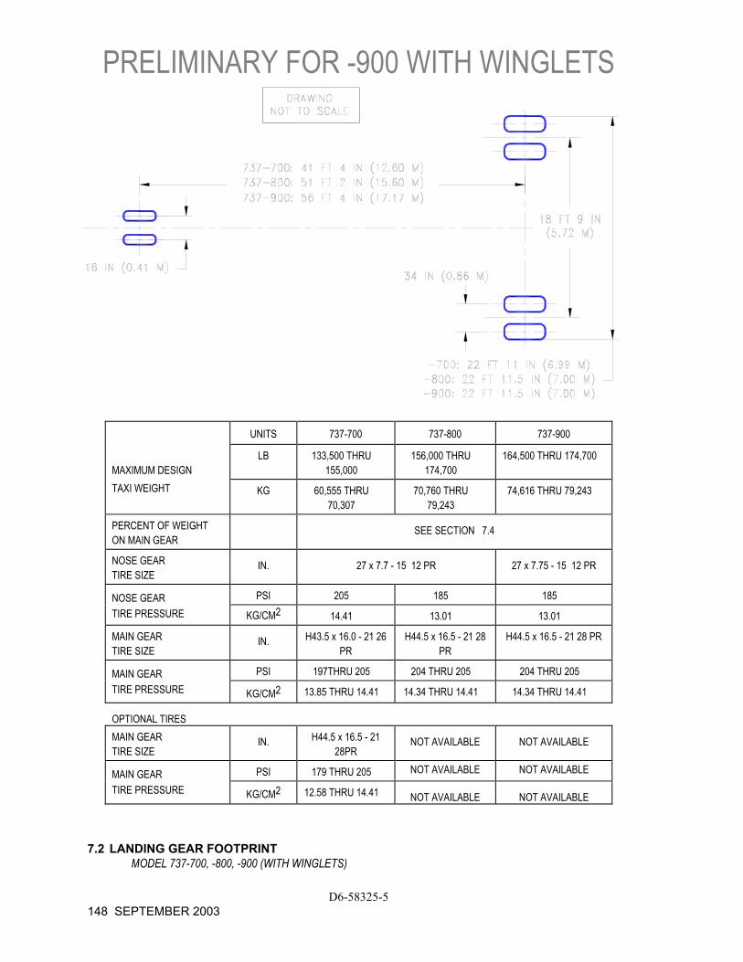
PRELIMINARY FOR -900 WITH WINGLETS
D6-58325-5 148 SEPTEMBER 2003
UNITS 737-700 737-800 737-900
MAXIMUM DESIGN LB 133,500 THRU
155,000 156,000 THRU
174,700 164,500 THRU 174,700
TAXI WEIGHT KG 60,555 THRU 70,307
70,760 THRU 79,243
74,616 THRU 79,243
PERCENT OF WEIGHT ON MAIN GEAR
SEE SECTION 7.4
NOSE GEAR TIRE SIZE
IN. 27 x 7.7 - 15 12 PR 27 x 7.75 - 15 12 PR
NOSE GEAR PSI 205 185 185 TIRE PRESSURE KG/CM2 14.41 13.01 13.01
MAIN GEAR TIRE SIZE
IN. H43.5 x 16.0 - 21 26 PR
H44.5 x 16.5 - 21 28 PR
H44.5 x 16.5 - 21 28 PR
MAIN GEAR PSI 197THRU 205 204 THRU 205 204 THRU 205 TIRE PRESSURE KG/CM2 13.85 THRU 14.41 14.34 THRU 14.41 14.34 THRU 14.41
OPTIONAL TIRES MAIN GEAR TIRE SIZE
IN. H44.5 x 16.5 - 21 28PR
NOT AVAILABLE NOT AVAILABLE
MAIN GEAR PSI 179 THRU 205 NOT AVAILABLE NOT AVAILABLE
TIRE PRESSURE KG/CM2 12.58 THRU 14.41 NOT AVAILABLE NOT AVAILABLE
7.2 LANDING GEAR FOOTPRINT MODEL 737-700, -800, -900 (WITH WINGLETS)
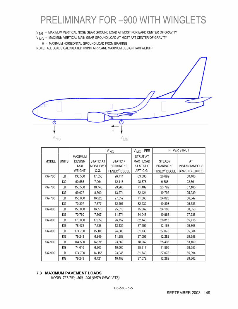
PRELIMINARY FOR –900 WITH WINGLETS V NG = MAXIMUM VERTICAL NOSE GEAR GROUND LOAD AT MOST FORWARD CENTER OF GRAVITY V MG = MAXIMUM VERTICAL MAIN GEAR GROUND LOAD AT MOST AFT CENTER OF GRAVITY H = MAXIMUM HORIZONTAL GROUND LOAD FROM BRAKING NOTE: ALL LOADS CALCULATED USING AIRPLANE MAXIMUM DESIGN TAXI WEIGHT
V NG V MG PER H PER STRUT
MODEL
UNITS
MAXIMUM DESIGN
TAXI WEIGHT
STATIC AT MOST FWD
C.G.
STATIC +
BRAKING 10 FT/SEC2 DECEL
STRUT AT MAX LOAD AT STATIC AFT C.G.
STEADY
BRAKING 10 FT/SEC2 DECEL
AT
INSTANTANEOUS BRAKING (µ= 0.8)
737-700 LB 133,500 17,558 26,711 63,000 20,692 50,400 KG 60,555 7,964 12,116 28,576 9,386 22,861
737-700 LB 153,500 18,740 29,265 71,482 23,792 57,185 KG 69,627 8,500 13,274 32,424 10,792 25,939
737-700 LB 155,000 16,925 27,552 71,060 24,025 56,847 KG 70,307 7,677 12,497 32,232 10,898 25,785
737-800 LB 156,000 16,770 25,510 75,062 24,180 60,050 KG 70,760 7,607 11,571 34,048 10,968 27,238
737-800 LB 173,000 17,059 26,752 82,143 26,815 65,715 KG 78,472 7,738 12,135 37,259 12,163 29,808
737-800 LB 174,700 15,100 24,886 81,730 27,078 65,384 KG 79,243 6,849 11,288 37,059 12,282 29,658
737-900 LB 164,500 14,998 23,369 78,962 25,498 63,169 KG 74,616 6,803 10,600 35,817 11,566 28,653
737-900 LB 174,700 14,155 23,045 81,743 27,078 65,394 KG 79,243 6,421 10,453 37,078 12,282 29,662
7.3 MAXIMUM PAVEMENT LOADS MODEL 737-700, -800, -900 (WITH WINGLETS)
D6-58325-5 SEPTEMBER 2003 149
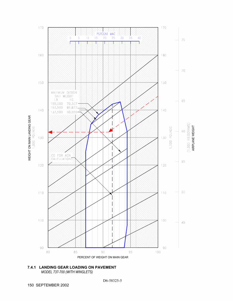
7.4.1 LANDING GEAR LOADING ON PAVEMENT
MODEL 737-700 (WITH WINGLETS)
D6-58325-5 150 SEPTEMBER 2002

7.4.2 LANDING GEAR LOADING ON PAVEMENT
MODEL 737-800 (WITH WINGLETS)
D6-58325-5 SEPTEMBER 2002 151
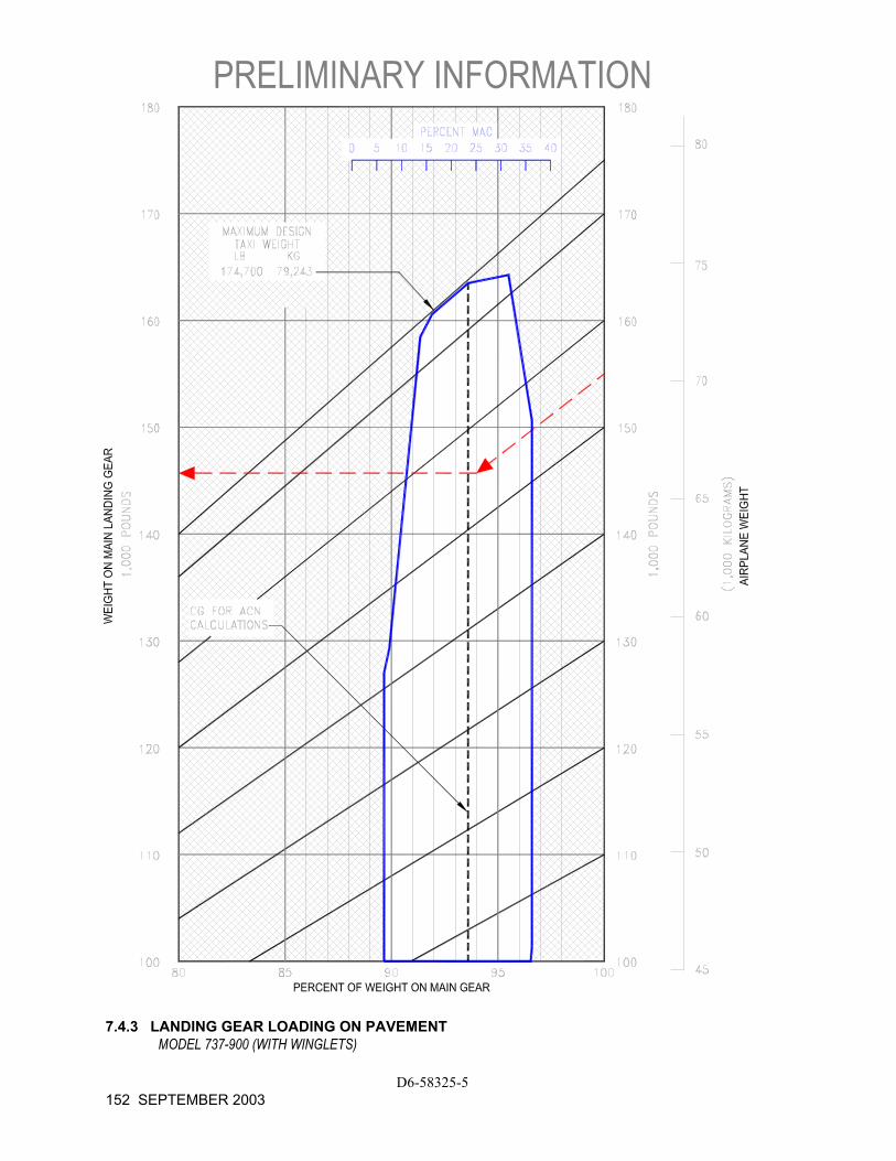
PRELIMINARY INFORMATION
D6-58325-5 152 SEPTEMBER 2003
7.4.3 LANDING GEAR LOADING ON PAVEMENT MODEL 737-900 (WITH WINGLETS)
7.5 Flexible Pavement Requirements - U.S. Army Corps of Engineers Method (S-77-1) and FAA Design Method
The following flexible-pavement design chart presents the data of five incremental main-gear loads at the minimum tire pressure required at the maximum design taxi weight.
In the example shown, for a CBR of 25 and an annual departure level of 5,000, the required flexible pavement thickness for an airplane with a main gear loading of 140,000 pounds is 12.0 inches.
The line showing 10,000 coverages is used for ACN calculations (see Section 7.10).
The FAA design method uses a similar procedure using total airplane weight instead of weight on the main landing gears. The equivalent main gear loads for a given airplane weight could be calculated from Section 7.4.
D6-58325-5 SEPTEMBER 2002 153
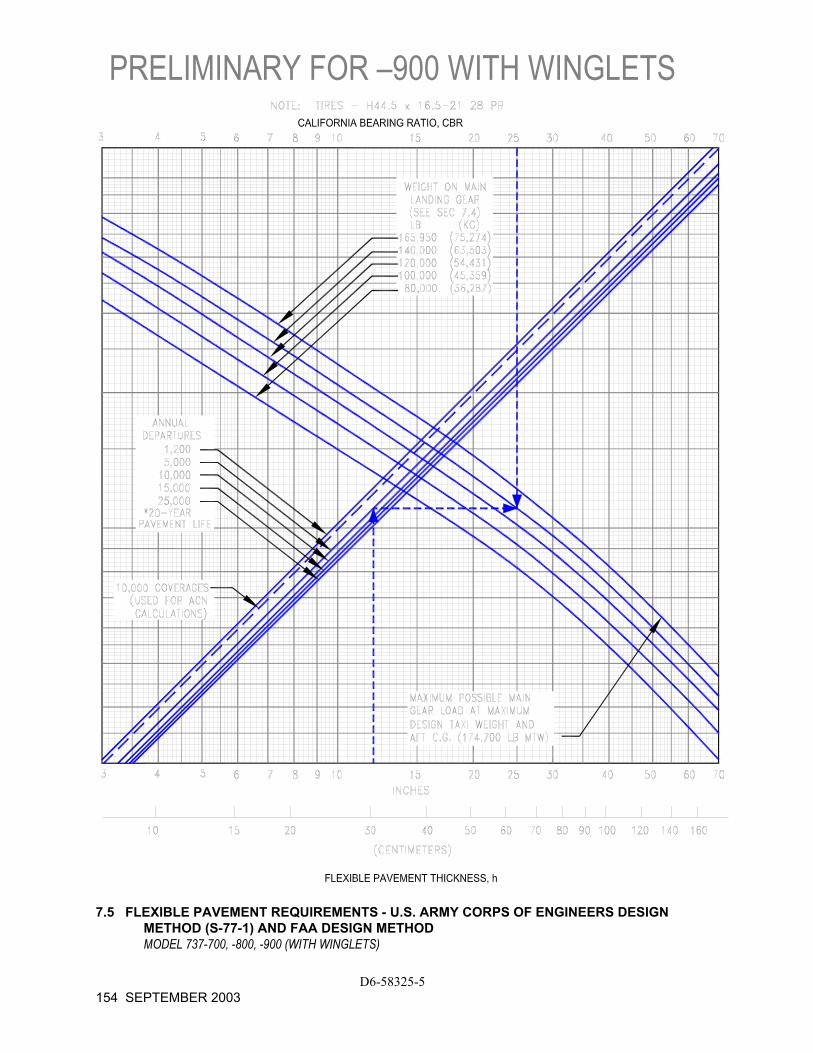
PRELIMINARY FOR –900 WITH WINGLETS
D6-58325-5 154 SEPTEMBER 2003
7.5 FLEXIBLE PAVEMENT REQUIREMENTS - U.S. ARMY CORPS OF ENGINEERS DESIGN
METHOD (S-77-1) AND FAA DESIGN METHOD MODEL 737-700, -800, -900 (WITH WINGLETS)
7.6 Flexible Pavement Requirements - LCN Method
To determine the airplane weight that can be accommodated on a particular flexible pavement, both the Load Classification Number (LCN) of the pavement and the thickness must be known.
In the example shown on the next page, flexible pavement thickness is shown at 16.8 in. with an LCN of 45. For these conditions, the apparent maximum allowable weight permissible on the main landing gear is 100,000 lb for an airplane with 204-psi main gear tires.
Note: If the resultant aircraft LCN is not more that 10% above the published pavement LCN, the bearing strength of the pavement can be considered sufficient for unlimited use by the airplane. The figure 10% has been chosen as representing the lowest degree of variation in LCN that is significant (reference: ICAO Aerodrome Manual, Part 2, "Aerodrome Physical Characteristics," Chapter 4, Paragraph 4.1.5.7v, 2nd Edition dated 1965).
D6-58325-5 SEPTEMBER 2002 155
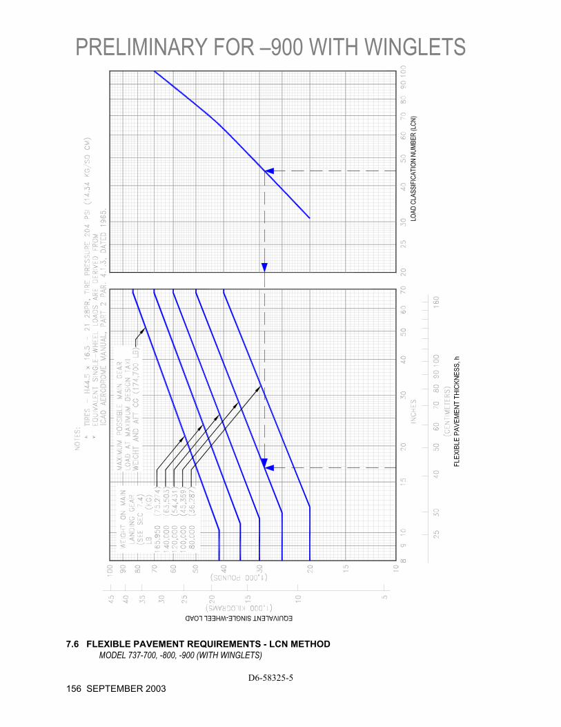
PRELIMINARY FOR –900 WITH WINGLETS
D6-58325-5 156 SEPTEMBER 2003
7.6 FLEXIBLE PAVEMENT REQUIREMENTS - LCN METHOD
MODEL 737-700, -800, -900 (WITH WINGLETS)
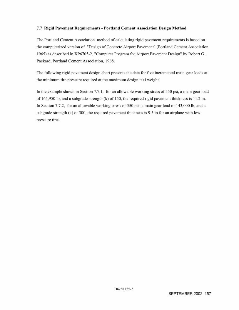
7.7 Rigid Pavement Requirements - Portland Cement Association Design Method
The Portland Cement Association method of calculating rigid pavement requirements is based on the computerized version of "Design of Concrete Airport Pavement" (Portland Cement Association, 1965) as described in XP6705-2, "Computer Program for Airport Pavement Design" by Robert G. Packard, Portland Cement Association, 1968.
The following rigid pavement design chart presents the data for five incremental main gear loads at the minimum tire pressure required at the maximum design taxi weight.
In the example shown in Section 7.7.1, for an allowable working stress of 550 psi, a main gear load of 165,950 lb, and a subgrade strength (k) of 150, the required rigid pavement thickness is 11.2 in. In Section 7.7.2, for an allowable working stress of 550 psi, a main gear load of 143,000 lb, and a subgrade strength (k) of 300, the required pavement thickness is 9.5 in for an airplane with low-pressure tires.
D6-58325-5 SEPTEMBER 2002 157
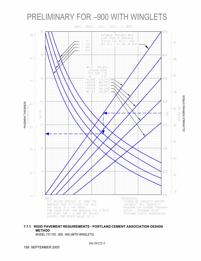
PRELIMINARY FOR –900 WITH WINGLETS
D6-58325-5 158 SEPTEMBER 2003
7.7.1 RIGID PAVEMENT REQUIREMENTS - PORTLAND CEMENT ASSOCIATION DESIGN
METHOD MODEL 737-700, -800, -900 (WITH WINGLETS)
7.7.2 RIGID PAVEMENT REQUIREMENTS - PORTLAND CEMENT ASSOCIATION DESIGN
METHOD MODEL 737 -700 (WITH WINGLETS) (OPTIONAL TIRES)
D6-58325-5 SEPTEMBER 2002 159
7.8 Rigid Pavement Requirements - LCN Conversion
To determine the airplane weight that can be accommodated on a particular rigid pavement, both the LCN of the pavement and the radius of relative stiffness (ι) of the pavement must be known.
In the example shown in Section 7.8.2, for a rigid pavement with a radius of relative stiffness of 29 with an LCN of 55, the maximum allowable weight permissible on the main landing gear is 100,000 lb.
Note: If the resultant aircraft LCN is not more that 10% above the published pavement LCN, the bearing strength of the pavement can be considered sufficient for unlimited use by the airplane. The figure 10% has been chosen as representing the lowest degree of variation in LCN that is significant (reference: ICAO Aerodrome Manual, Part 2, "Aerodrome Physical Characteristics," Chapter 4, Paragraph 4.1.5.7v, 2nd Edition dated 1965).
D6-58325-5 160 SEPTEMBER 2003
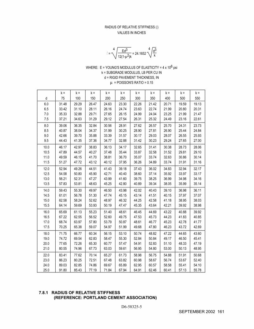
RADIUS OF RELATIVE STIFFNESS ( ) VALUES IN INCHES
= 4 Ed3
12(1-µ2)k = 24.1652
4 d3k
WHERE: E = YOUNG'S MODULUS OF ELASTICITY = 4 x 10⁶ psi
k = SUBGRADE MODULUS, LB PER CU IN d = RIGID PAVEMENT THICKNESS, IN
µ = POISSON'S RATIO = 0.15
k = k = k = k = k = k = k = k = k = k = d 75 100 150 200 250 300 350 400 500 550
6.0 31.48 29.29 26.47 24.63 23.30 22.26 21.42 20.71 19.59 19.13 6.5 33.42 31.10 28.11 26.16 24.74 23.63 22.74 21.99 20.80 20.31 7.0 35.33 32.88 29.71 27.65 26.15 24.99 24.04 23.25 21.99 21.47 7.5 37.21 34.63 31.29 29.12 27.54 26.31 25.32 24.49 23.16 22.61
8.0 39.06 36.35 32.84 30.56 28.91 27.62 26.57 25.70 24.31 23.73 8.5 40.87 38.04 34.37 31.99 30.25 28.90 27.81 26.90 25.44 24.84 9.0 42.66 39.70 35.88 33.39 31.57 30.17 29.03 28.07 26.55 25.93 9.5 44.43 41.35 37.36 34.77 32.88 31.42 30.23 29.24 27.65 27.00
10.0 46.17 42.97 38.83 36.13 34.17 32.65 31.41 30.38 28.73 28.06 10.5 47.89 44.57 40.27 37.48 35.44 33.87 32.58 31.52 29.81 29.10 11.0 49.59 46.15 41.70 38.81 36.70 35.07 33.74 32.63 30.86 30.14 11.5 51.27 47.72 43.12 40.12 37.95 36.26 34.89 33.74 31.91 31.16
12.0 52.94 49.26 44.51 41.43 39.18 37.43 36.02 34.83 32.94 32.17 12.5 54.58 50.80 45.90 42.71 40.40 38.60 37.14 35.92 33.97 33.17 13.0 56.21 52.31 47.27 43.99 41.60 39.75 38.25 36.99 34.98 34.16 13.5 57.83 53.81 48.63 45.25 42.80 40.89 39.34 38.05 35.99 35.14
14.0 59.43 55.30 49.97 46.50 43.98 42.02 40.43 39.10 36.98 36.11 14.5 61.01 56.78 51.30 47.74 45.15 43.14 41.51 40.15 37.97 37.07 15.0 62.58 58.24 52.62 48.97 46.32 44.25 42.58 41.18 38.95 38.03 15.5 64.14 59.69 53.93 50.19 47.47 45.35 43.64 42.21 39.92 38.98
16.0 65.69 61.13 55.23 51.40 48.61 46.45 44.69 43.22 40.88 39.92 16.5 67.22 62.55 56.52 52.60 49.75 47.53 45.73 44.23 41.83 40.85 17.0 68.74 63.97 57.80 53.79 50.87 48.61 46.77 45.23 42.78 41.77 17.5 70.25 65.38 59.07 54.97 51.99 49.68 47.80 46.23 43.72 42.69
18.0 71.75 66.77 60.34 56.15 53.10 50.74 48.82 47.22 44.65 43.60 19.0 74.72 69.54 62.83 58.47 55.30 52.84 50.84 49.17 46.50 45.41 20.0 77.65 72.26 65.30 60.77 57.47 54.91 52.83 51.10 48.33 47.19 21.0 80.55 74.96 67.73 63.03 59.61 56.95 54.80 53.00 50.13 48.95
22.0 83.41 77.62 70.14 65.27 61.73 58.98 56.75 54.88 51.91 50.68 23.0 86.23 80.25 72.51 67.48 63.82 60.98 58.67 56.74 53.67 52.40 24.0 89.03 82.85 74.86 69.67 65.89 62.95 60.57 58.58 55.41 54.10 25.0 91.80 85.43 77.19 71.84 67.94 64.91 62.46 60.41 57.13 55.78
7.8.1 RADIUS OF RELATIVE STIFFNESS (REFERENCE: PORTLAND CEMENT ASSOCIATION)
D6-58325-5 SEPTEMBER 2002 161
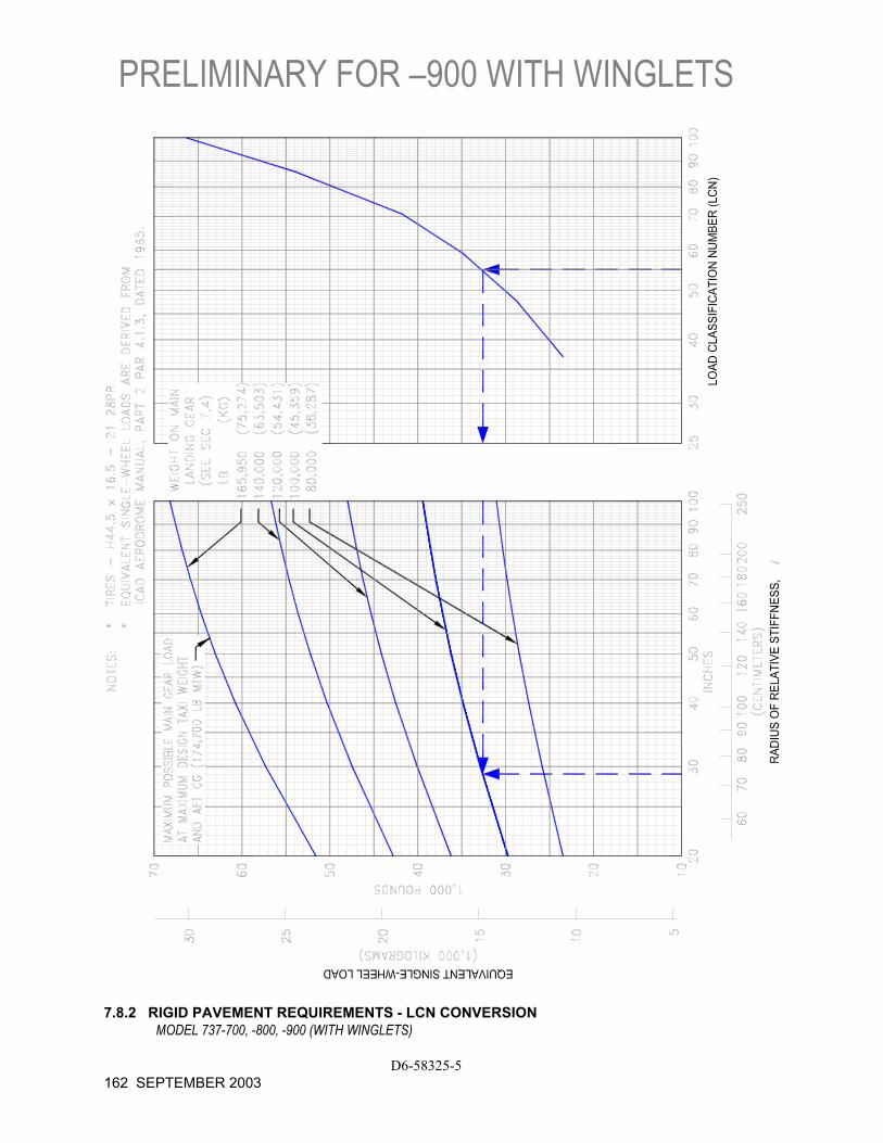
PRELIMINARY FOR –900 WITH WINGLETS
D6-58325-5 162 SEPTEMBER 2003
7.8.2 RIGID PAVEMENT REQUIREMENTS - LCN CONVERSION
MODEL 737-700, -800, -900 (WITH WINGLETS)
7.9 Rigid Pavement Requirements - FAA Design Method
The following rigid pavement design charts present data on five incremental main gear loads at the minimum tire pressure required at the maximum design taxi weight.
In the example shown in 7.9.1, the pavement flexural stress is shown at 700 psi, the subgrade strength is shown at k = 300, and the annual departure level is 3,000. For these conditions, the required rigid pavement thickness for an airplane with main gear load of 120,000 pounds is 9.9 inches. In 7.9.2, with the same pavement conditions and departure level, the required rigid pavement thickness for a 737-700 airplane with a main gear load of 115,900 pounds and optional low-pressure tires, is 8.8 inches.
D6-58325-5 SEPTEMBER 2002 163
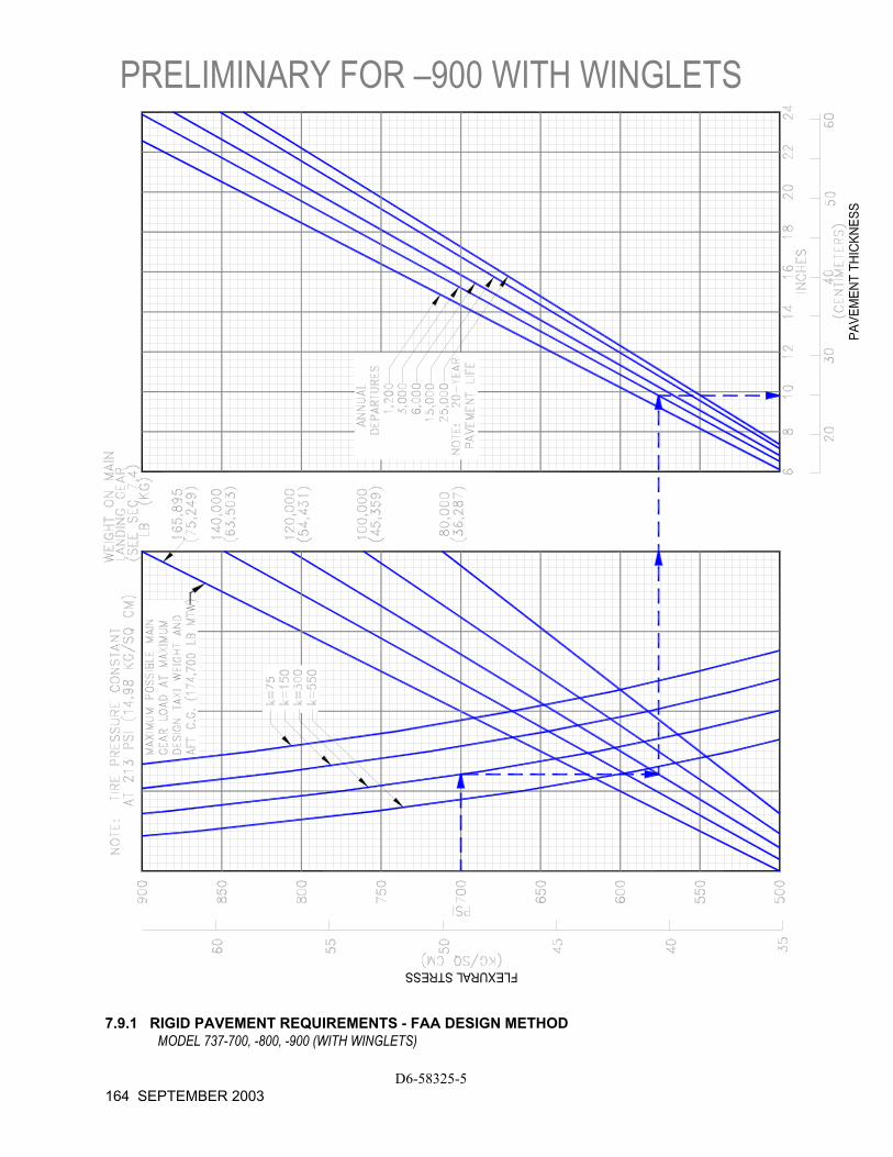
PRELIMINARY FOR –900 WITH WINGLETS
D6-58325-5 164 SEPTEMBER 2003
7.9.1 RIGID PAVEMENT REQUIREMENTS - FAA DESIGN METHOD
MODEL 737-700, -800, -900 (WITH WINGLETS)
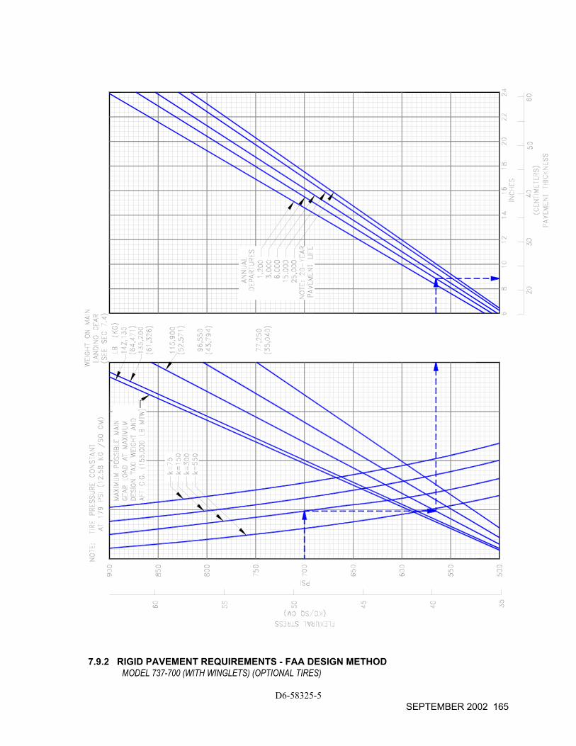
7.9.2 RIGID PAVEMENT REQUIREMENTS - FAA DESIGN METHOD MODEL 737-700 (WITH WINGLETS) (OPTIONAL TIRES)
D6-58325-5 SEPTEMBER 2002 165
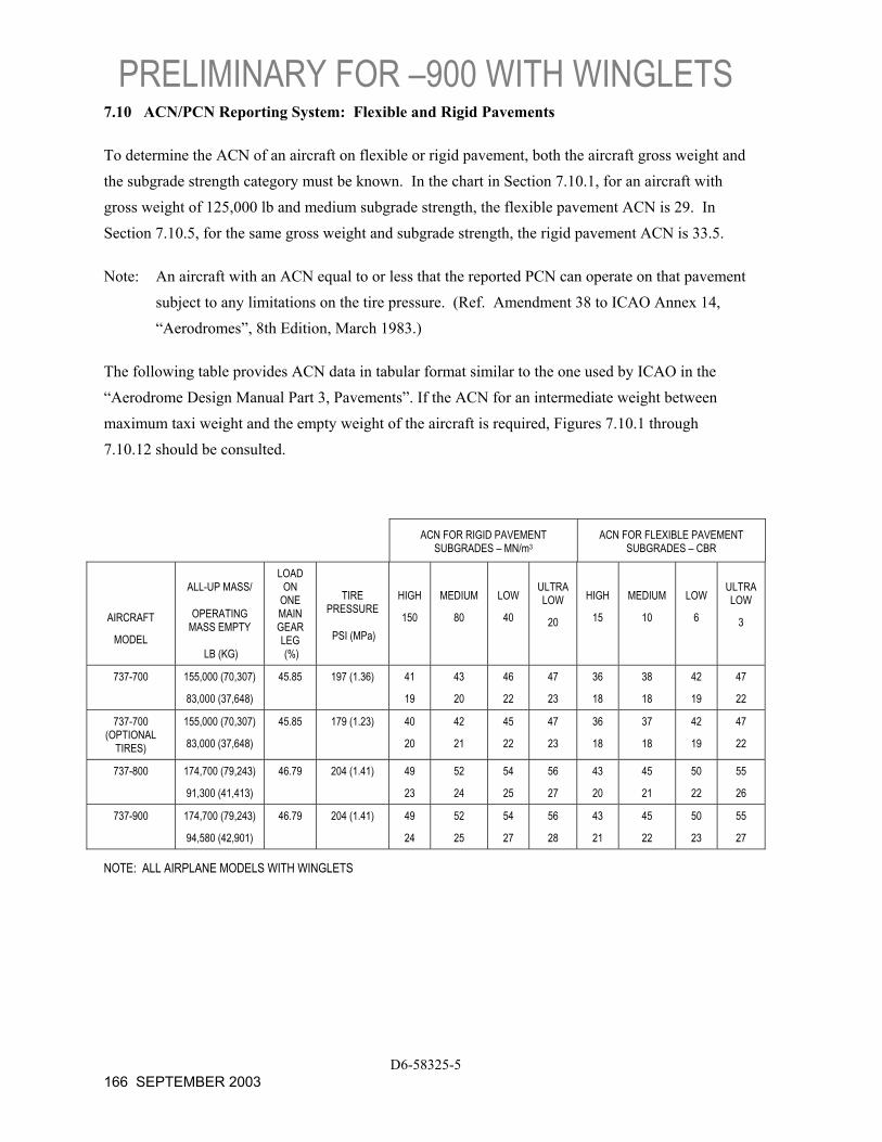
PRELIMINARY FOR –900 WITH WINGLETS
D6-58325-5 166 SEPTEMBER 2003
7.10 ACN/PCN Reporting System: Flexible and Rigid Pavements
To determine the ACN of an aircraft on flexible or rigid pavement, both the aircraft gross weight and the subgrade strength category must be known. In the chart in Section 7.10.1, for an aircraft with gross weight of 125,000 lb and medium subgrade strength, the flexible pavement ACN is 29. In Section 7.10.5, for the same gross weight and subgrade strength, the rigid pavement ACN is 33.5.
Note: An aircraft with an ACN equal to or less that the reported PCN can operate on that pavement subject to any limitations on the tire pressure. (Ref. Amendment 38 to ICAO Annex 14, “Aerodromes”, 8th Edition, March 1983.)
The following table provides ACN data in tabular format similar to the one used by ICAO in the “Aerodrome Design Manual Part 3, Pavements”. If the ACN for an intermediate weight between maximum taxi weight and the empty weight of the aircraft is required, Figures 7.10.1 through 7.10.12 should be consulted.
ACN FOR RIGID PAVEMENT SUBGRADES – MN/m3
ACN FOR FLEXIBLE PAVEMENT SUBGRADES – CBR
AIRCRAFT
MODEL
ALL-UP MASS/
OPERATING
MASS EMPTY
LB (KG)
LOAD ON
ONE MAIN GEAR LEG (%)
TIRE PRESSURE
PSI (MPa)
HIGH
150
MEDIUM
80
LOW
40
ULTRA LOW
20
HIGH
15
MEDIUM
10
LOW
6
ULTRA LOW
3
737-700 155,000 (70,307)
83,000 (37,648)
45.85 197 (1.36) 41
19
43
20
46
22
47
23
36
18
38
18
42
19
47
22
737-700 (OPTIONAL
TIRES)
155,000 (70,307)
83,000 (37,648)
45.85 179 (1.23) 40
20
42
21
45
22
47
23
36
18
37
18
42
19
47
22
737-800 174,700 (79,243)
91,300 (41,413)
46.79 204 (1.41) 49
23
52
24
54
25
56
27
43
20
45
21
50
22
55
26
737-900 174,700 (79,243)
94,580 (42,901)
46.79 204 (1.41) 49
24
52
25
54
27
56
28
43
21
45
22
50
23
55
27
NOTE: ALL AIRPLANE MODELS WITH WINGLETS

7.10.1 AIRCRAFT CLASSIFICATION NUMBER - FLEXIBLE PAVEMENT
MODEL 737-700 (WITH WINGLETS)
D6-58325-5 SEPTEMBER 2002 167

7.10.2 AIRCRAFT CLASSIFICATION NUMBER - FLEXIBLE PAVEMENT
MODEL 737-700 (WITH WINGLETS) (OPTIONAL TIRES)
D6-58325-5 168 SEPTEMBER 2002
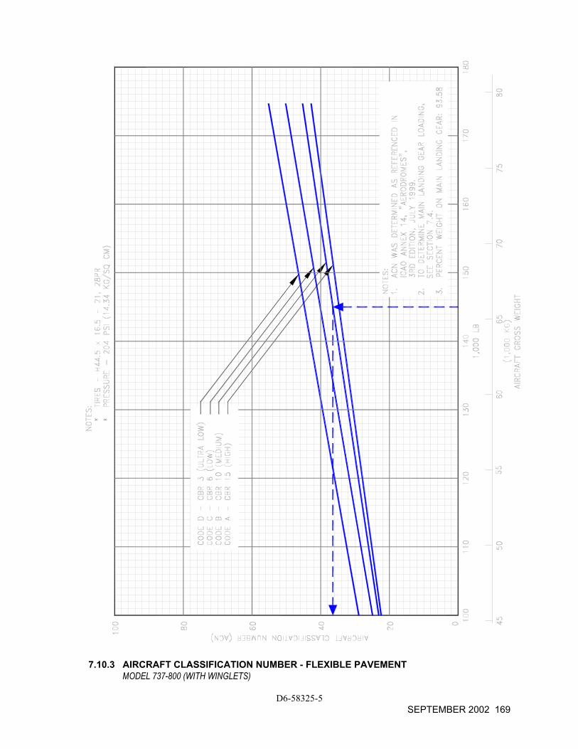
7.10.3 AIRCRAFT CLASSIFICATION NUMBER - FLEXIBLE PAVEMENT
MODEL 737-800 (WITH WINGLETS)
D6-58325-5 SEPTEMBER 2002 169
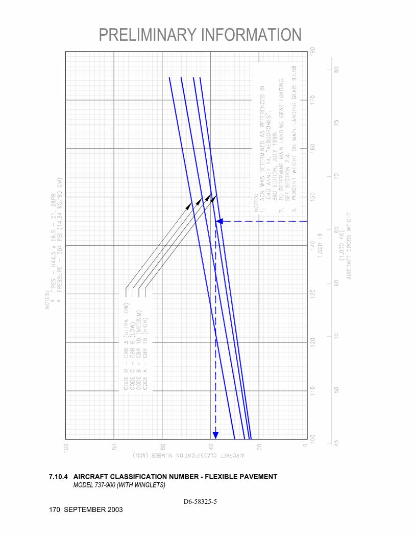
PRELIMINARY INFORMATION
D6-58325-5 170 SEPTEMBER 2003
7.10.4 AIRCRAFT CLASSIFICATION NUMBER - FLEXIBLE PAVEMENT
MODEL 737-900 (WITH WINGLETS)
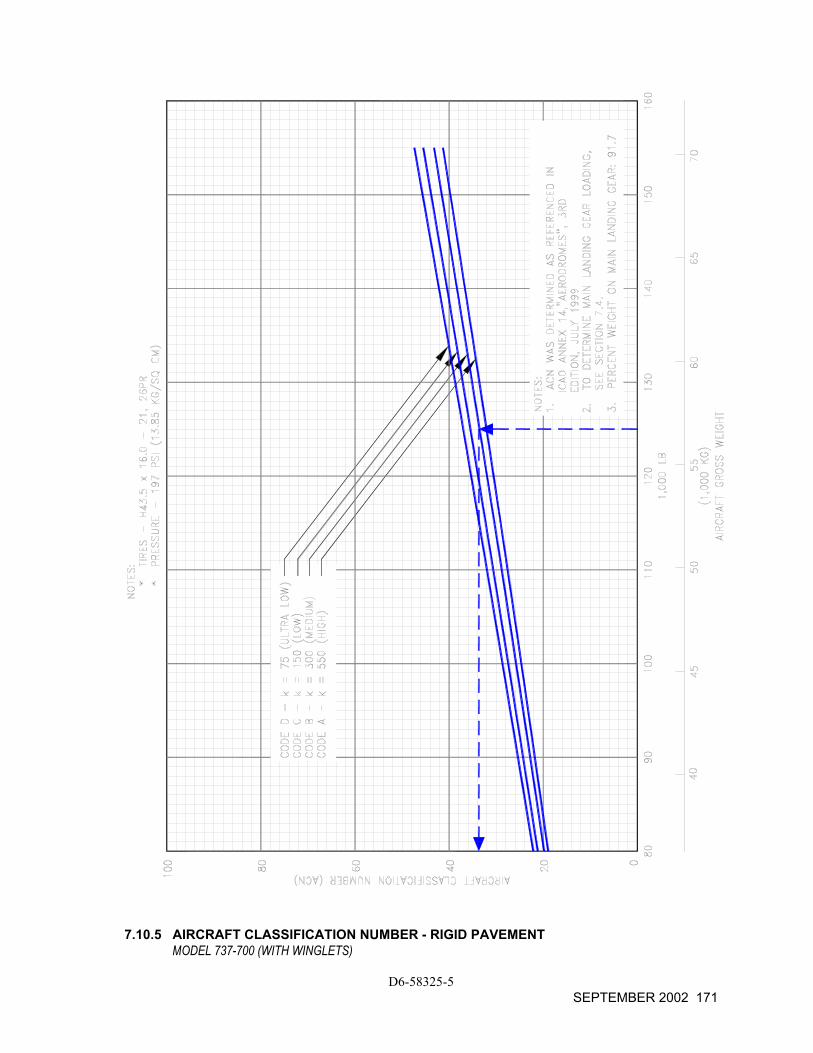
7.10.5 AIRCRAFT CLASSIFICATION NUMBER - RIGID PAVEMENT
MODEL 737-700 (WITH WINGLETS)
D6-58325-5 SEPTEMBER 2002 171
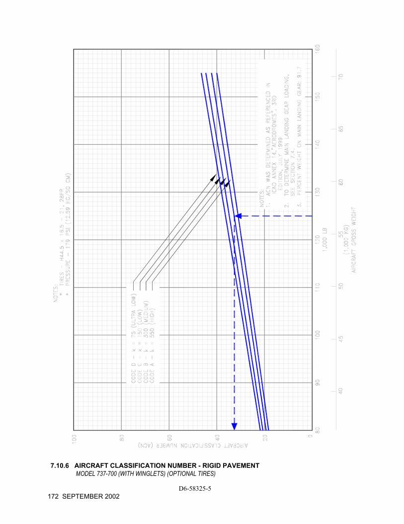
7.10.6 AIRCRAFT CLASSIFICATION NUMBER - RIGID PAVEMENT
MODEL 737-700 (WITH WINGLETS) (OPTIONAL TIRES)
D6-58325-5 172 SEPTEMBER 2002
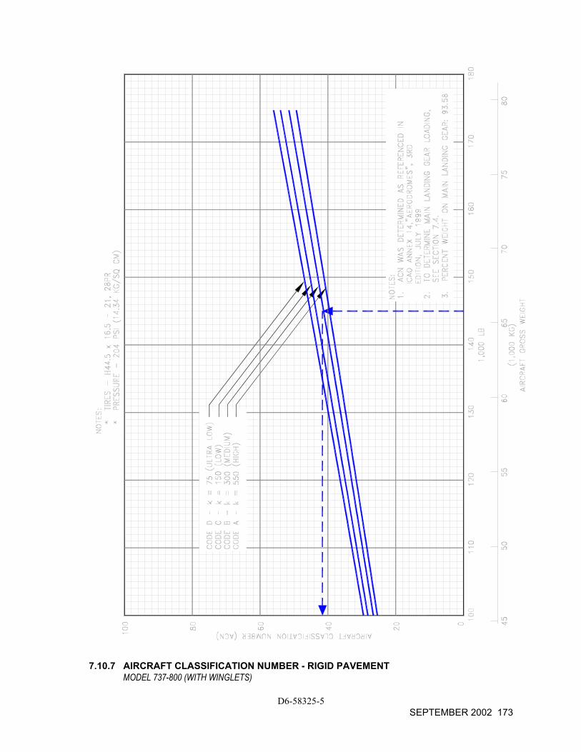
7.10.7 AIRCRAFT CLASSIFICATION NUMBER - RIGID PAVEMENT
MODEL 737-800 (WITH WINGLETS)
D6-58325-5 SEPTEMBER 2002 173
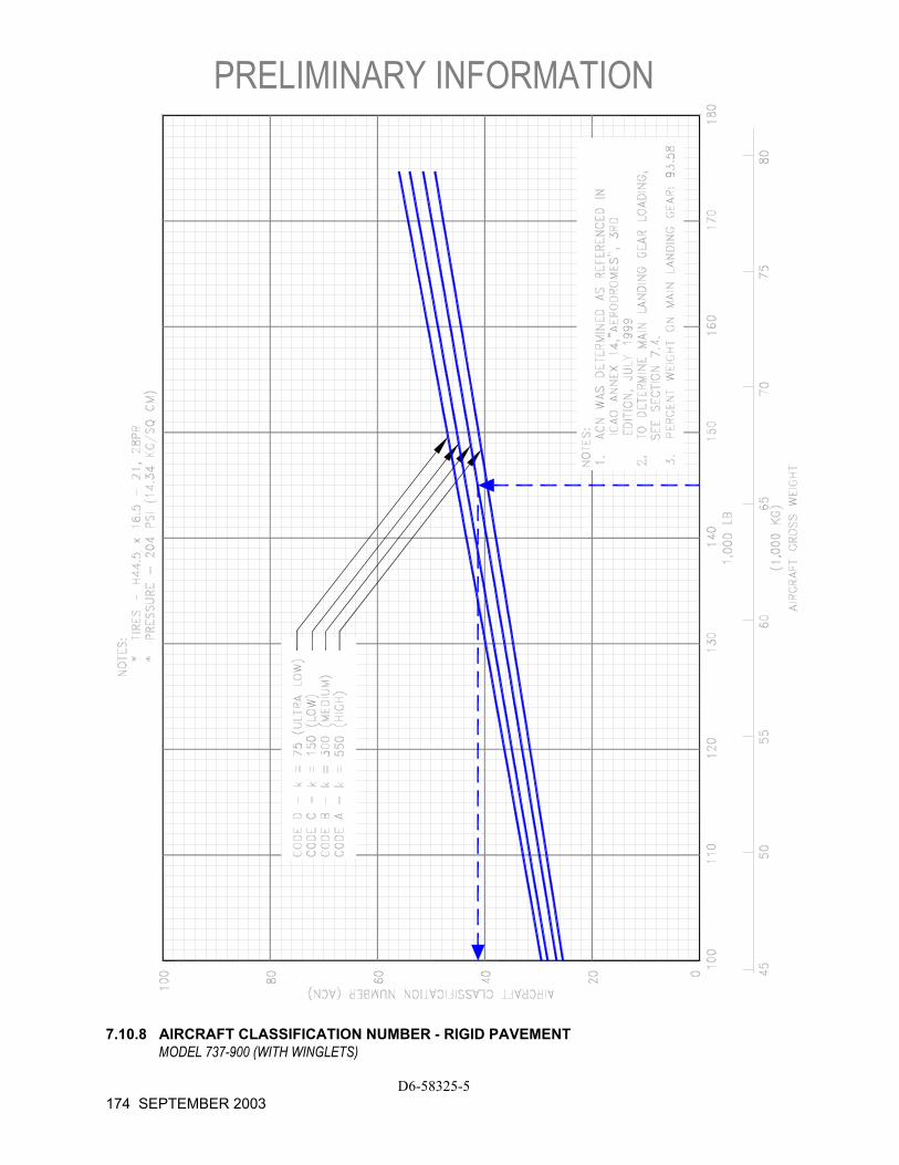
PRELIMINARY INFORMATION
D6-58325-5 174 SEPTEMBER 2003
7.10.8 AIRCRAFT CLASSIFICATION NUMBER - RIGID PAVEMENT
MODEL 737-900 (WITH WINGLETS)

8.0 FUTURE 737 DERIVATIVE AIRPLANES
D6-58325-5 AUGUST 2002 175
8.0 FUTURE 737 DERIVATIVE AIRPLANES
Development of these derivatives will depend on airline requirements. The impact of airline requirements on airport facilities will be a consideration in the configuration and design of these derivatives.
D6-58325-5 176 AUGUST 2002
PRELIMINARY FOR –900 WITH WINGLETS
9.0 SCALED 737-700, -800, -900 DRAWINGS
9.1 - 9.5 Scaled Drawings, 737-700 With Winglets
9.6 - 9.10 Scaled Drawings, 737-800 With Winglets
9.11 - 9.15 Scaled Drawings, 737-900 With Winglets
D6-58325-5 SEPTEMBER 2003 177
9.0 SCALED DRAWINGS
The drawings in the following pages show airplane plan view drawings, drawn to approximate scale as noted. The drawings may not come out to exact scale when printed or copied from this document. Printing scale should be adjusted when attempting to reproduce these drawings. Three-view drawing files of the 737 airplane models, along with other Boeing airplane models, can be downloaded from the following website:
http://www.boeing.com/airports
D6-58325-5 178 AUGUST 2002

NOTE: WHEN PRINTING THIS DRAWING, MAKE SURE TO ADJUST FOR PROPER SCALING 9.1.1 SCALED DRAWING - 1 IN. = 32 FT
MODEL 737-700 WITH WINGLETS
D6-58325-5 AUGUST 2002 179

NOTE: WHEN PRINTING THIS DRAWING, MAKE SURE TO ADJUST FOR PROPER SCALING 9.1.2 SCALED DRAWING - 1 IN. = 32 FT
MODEL 737-700 WITH WINGLETS
D6-58325-5 180 AUGUST 2002
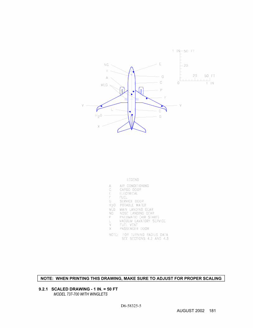
NOTE: WHEN PRINTING THIS DRAWING, MAKE SURE TO ADJUST FOR PROPER SCALING 9.2.1 SCALED DRAWING - 1 IN. = 50 FT
MODEL 737-700 WITH WINGLETS
D6-58325-5 AUGUST 2002 181

NOTE: WHEN PRINTING THIS DRAWING, MAKE SURE TO ADJUST FOR PROPER SCALING 9.2.2 SCALED DRAWING - 1 IN. = 50 FT
MODEL 737-700 WITH WINGLETS
D6-58325-5 182 AUGUST 2002
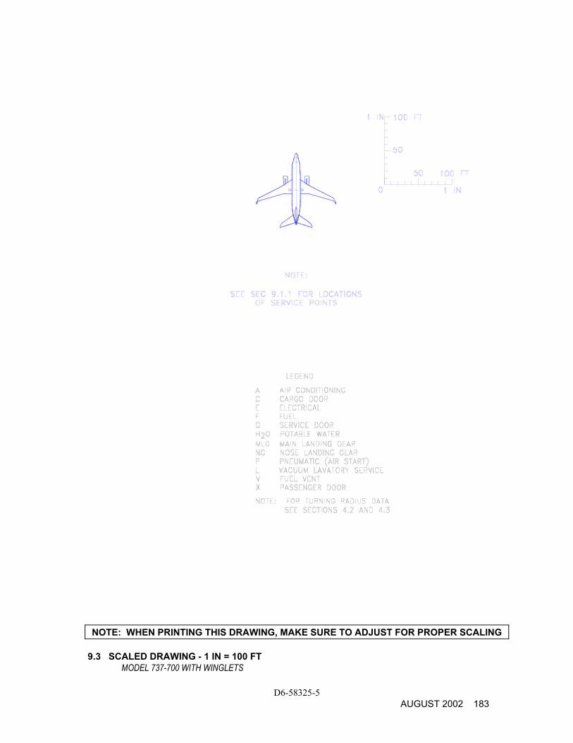
NOTE: WHEN PRINTING THIS DRAWING, MAKE SURE TO ADJUST FOR PROPER SCALING 9.3 SCALED DRAWING - 1 IN = 100 FT
MODEL 737-700 WITH WINGLETS
D6-58325-5 AUGUST 2002 183

THIS PAGE INTENTIONALLY LEFT BLANK
D6-58325-5 184 AUGUST 2002

NOTE: WHEN PRINTING THIS DRAWING, MAKE SURE TO ADJUST FOR PROPER SCALING 9.4.1 SCALED DRAWING - 1:500
MODEL 737-700 WITH WINGLETS
D6-58325-5 AUGUST 2002 185

NOTE: WHEN PRINTING THIS DRAWING, MAKE SURE TO ADJUST FOR PROPER SCALING 9.4.2 SCALED DRAWING - 1:500
MODEL 737-700 WITH WINGLETS
D6-58325-5 186 AUGUST 2002

NOTE: WHEN PRINTING THIS DRAWING, MAKE SURE TO ADJUST FOR PROPER SCALING 9.5 SCALED DRAWING - 1:1000
MODEL 737-700 WITH WINGLETS
D6-58325-5 AUGUST 2002 187

THIS PAGE INTENTIONALLY LEFT BLANK
D6-58325-5 188 AUGUST 2002
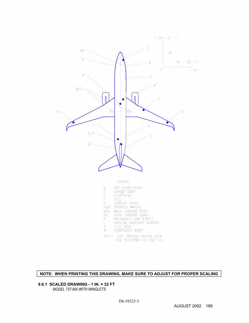
D6-58325-5 AUGUST 2002 189
NOTE: WHEN PRINTING THIS DRAWING, MAKE SURE TO ADJUST FOR PROPER SCALING 9.6.1 SCALED DRAWING - 1 IN. = 32 FT
MODEL 737-800 WITH WINGLETS
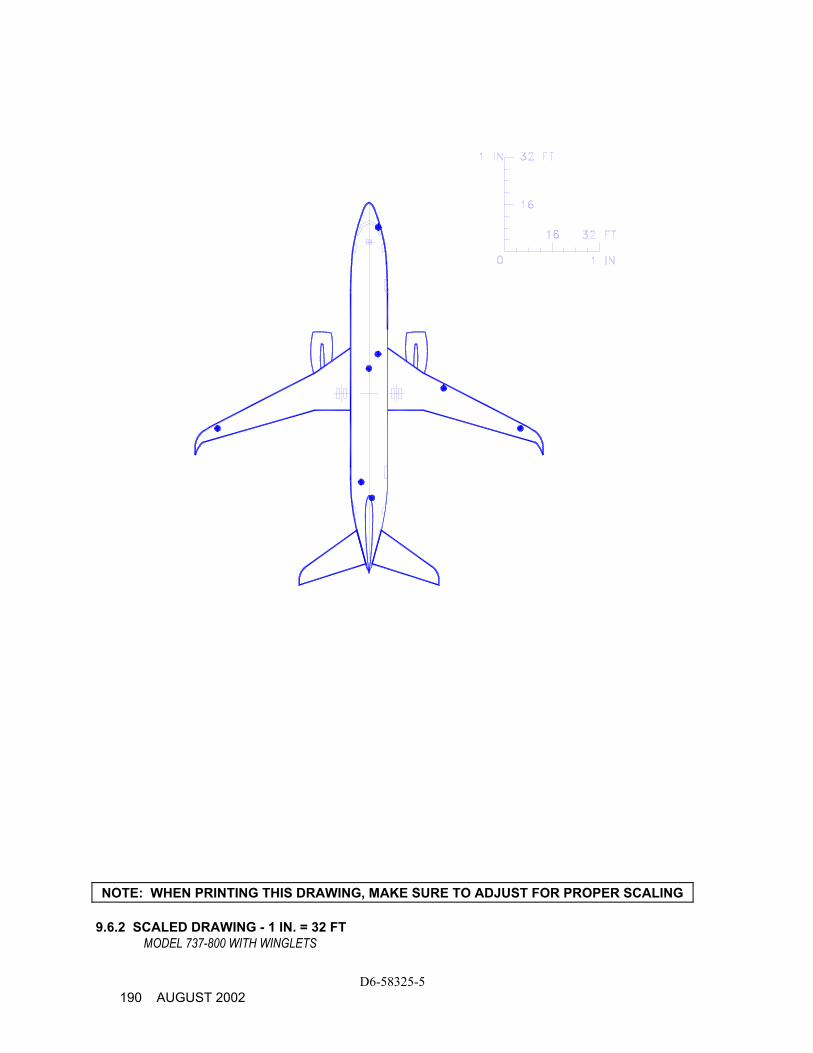
D6-58325-5 190 AUGUST 2002
NOTE: WHEN PRINTING THIS DRAWING, MAKE SURE TO ADJUST FOR PROPER SCALING 9.6.2 SCALED DRAWING - 1 IN. = 32 FT
MODEL 737-800 WITH WINGLETS
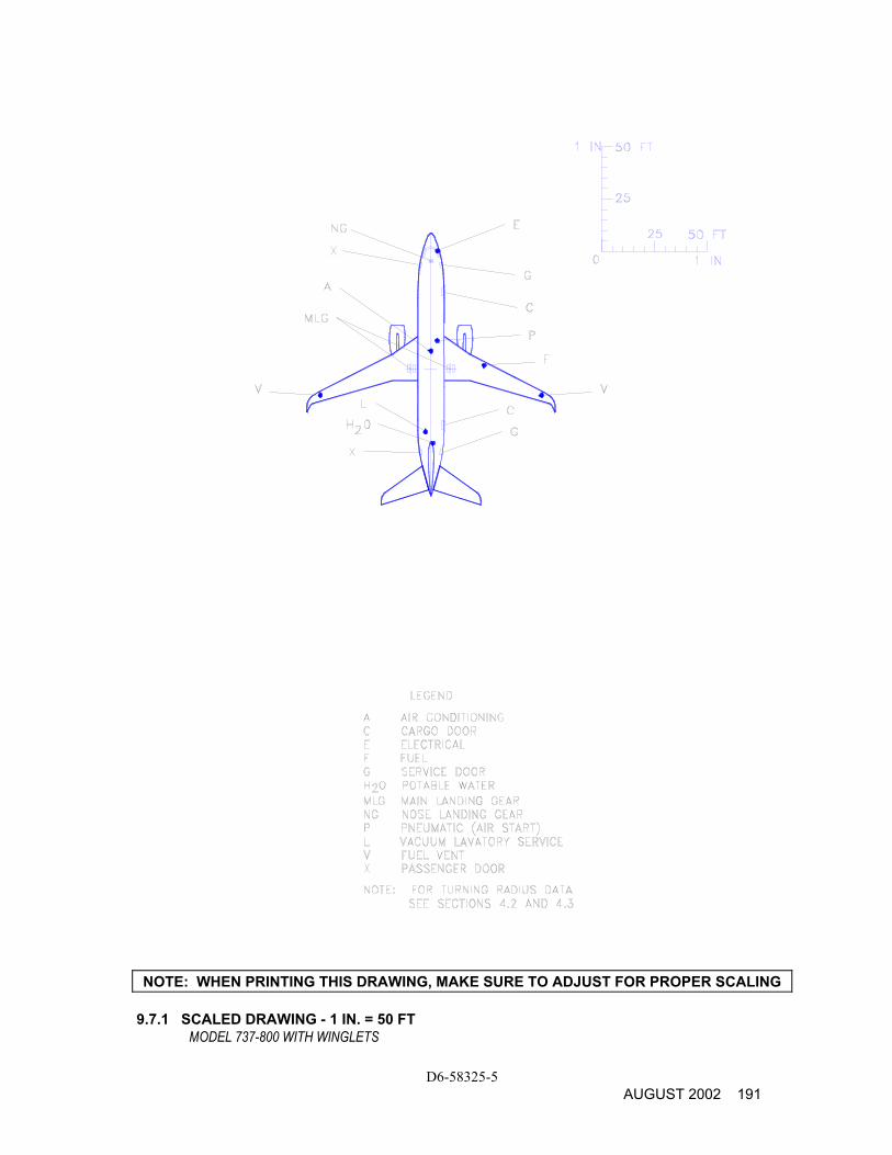
D6-58325-5 AUGUST 2002 191
NOTE: WHEN PRINTING THIS DRAWING, MAKE SURE TO ADJUST FOR PROPER SCALING 9.7.1 SCALED DRAWING - 1 IN. = 50 FT
MODEL 737-800 WITH WINGLETS

D6-58325-5 192 AUGUST 2002
NOTE: WHEN PRINTING THIS DRAWING, MAKE SURE TO ADJUST FOR PROPER SCALING 9.7.2 SCALED DRAWING - 1 IN. = 50 FT
MODEL 737-800 WITH WINGLETS
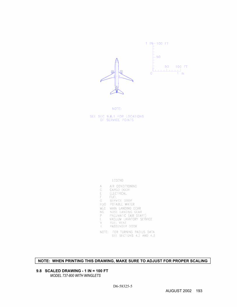
D6-58325-5 AUGUST 2002 193
NOTE: WHEN PRINTING THIS DRAWING, MAKE SURE TO ADJUST FOR PROPER SCALING 9.8 SCALED DRAWING - 1 IN = 100 FT
MODEL 737-800 WITH WINGLETS

THIS PAGE INTENTIONALLY LEFT BLANK
D6-58325-5 194 AUGUST 2002
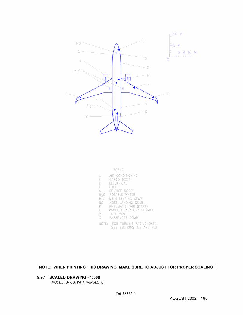
D6-58325-5 AUGUST 2002 195
NOTE: WHEN PRINTING THIS DRAWING, MAKE SURE TO ADJUST FOR PROPER SCALING 9.9.1 SCALED DRAWING - 1:500
MODEL 737-800 WITH WINGLETS
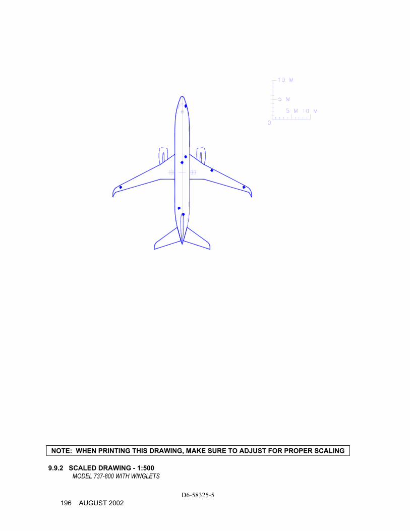
D6-58325-5 196 AUGUST 2002
NOTE: WHEN PRINTING THIS DRAWING, MAKE SURE TO ADJUST FOR PROPER SCALING 9.9.2 SCALED DRAWING - 1:500
MODEL 737-800 WITH WINGLETS
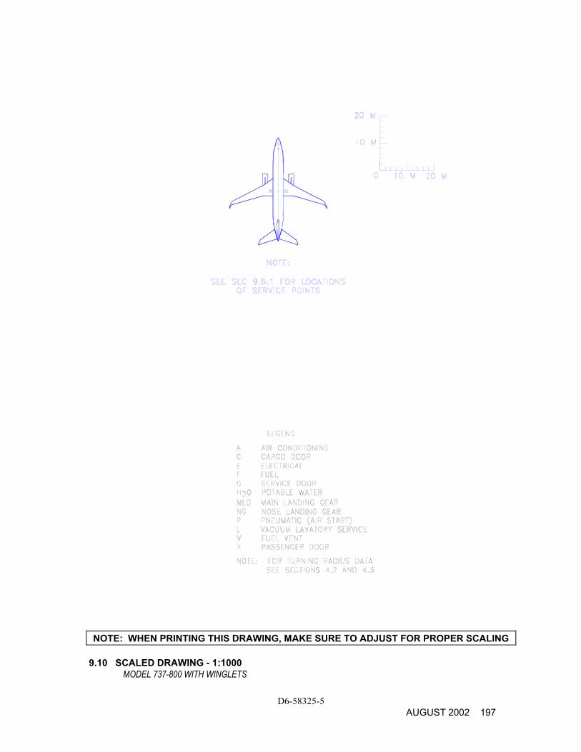
D6-58325-5 AUGUST 2002 197
NOTE: WHEN PRINTING THIS DRAWING, MAKE SURE TO ADJUST FOR PROPER SCALING 9.10 SCALED DRAWING - 1:1000
MODEL 737-800 WITH WINGLETS

THIS PAGE INTENTIONALLY LEFT BLANK
D6-58325-5 198 AUGUST 2002
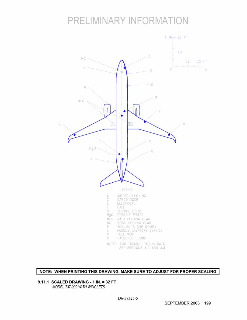
PRELIMINARY INFORMATION
D6-58325-5 SEPTEMBER 2003 199
NOTE: WHEN PRINTING THIS DRAWING, MAKE SURE TO ADJUST FOR PROPER SCALING 9.11.1 SCALED DRAWING - 1 IN. = 32 FT
MODEL 737-900 WITH WINGLETS
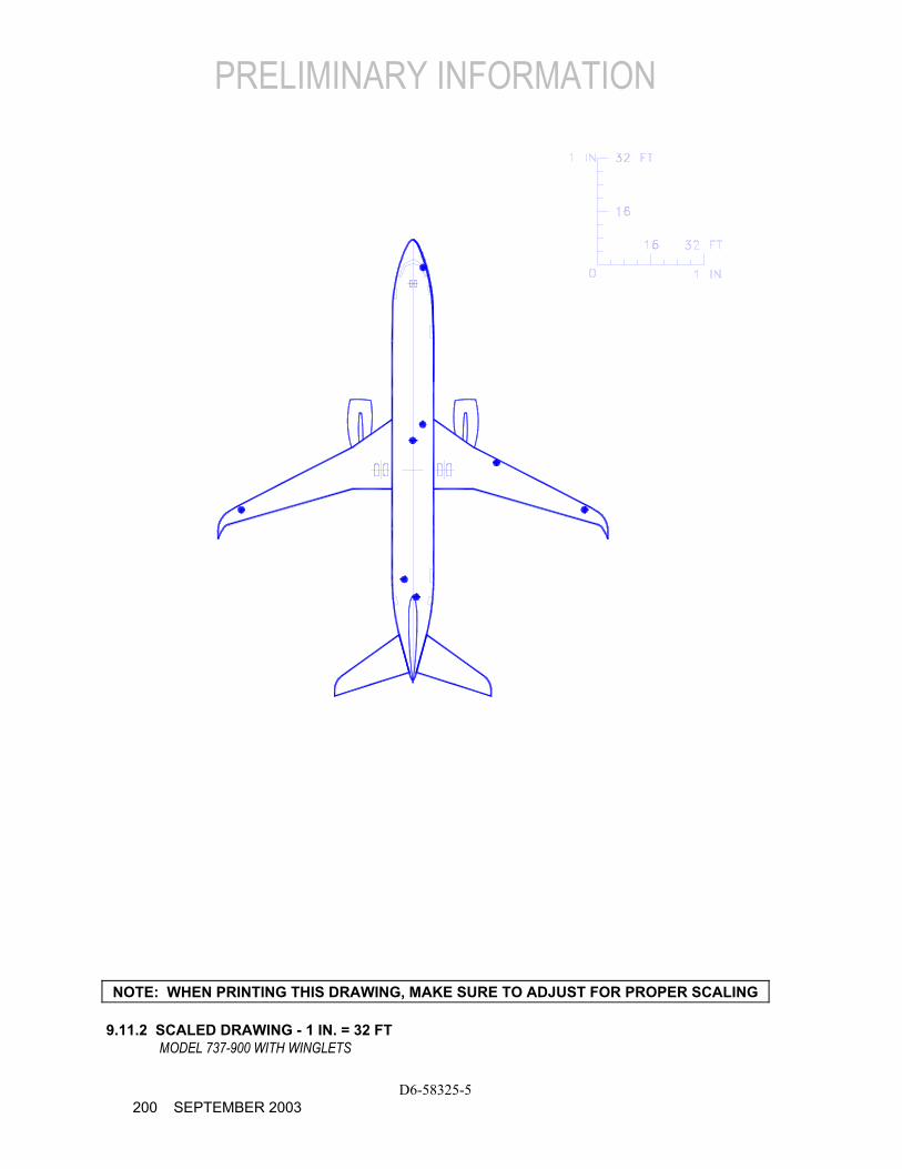
PRELIMINARY INFORMATION
D6-58325-5 200 SEPTEMBER 2003
NOTE: WHEN PRINTING THIS DRAWING, MAKE SURE TO ADJUST FOR PROPER SCALING 9.11.2 SCALED DRAWING - 1 IN. = 32 FT
MODEL 737-900 WITH WINGLETS
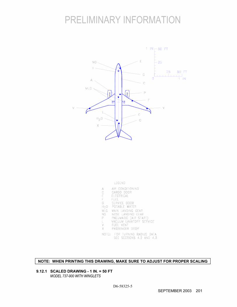
PRELIMINARY INFORMATION
D6-58325-5 SEPTEMBER 2003 201
NOTE: WHEN PRINTING THIS DRAWING, MAKE SURE TO ADJUST FOR PROPER SCALING
9.12.1 SCALED DRAWING - 1 IN. = 50 FT MODEL 737-900 WITH WINGLETS
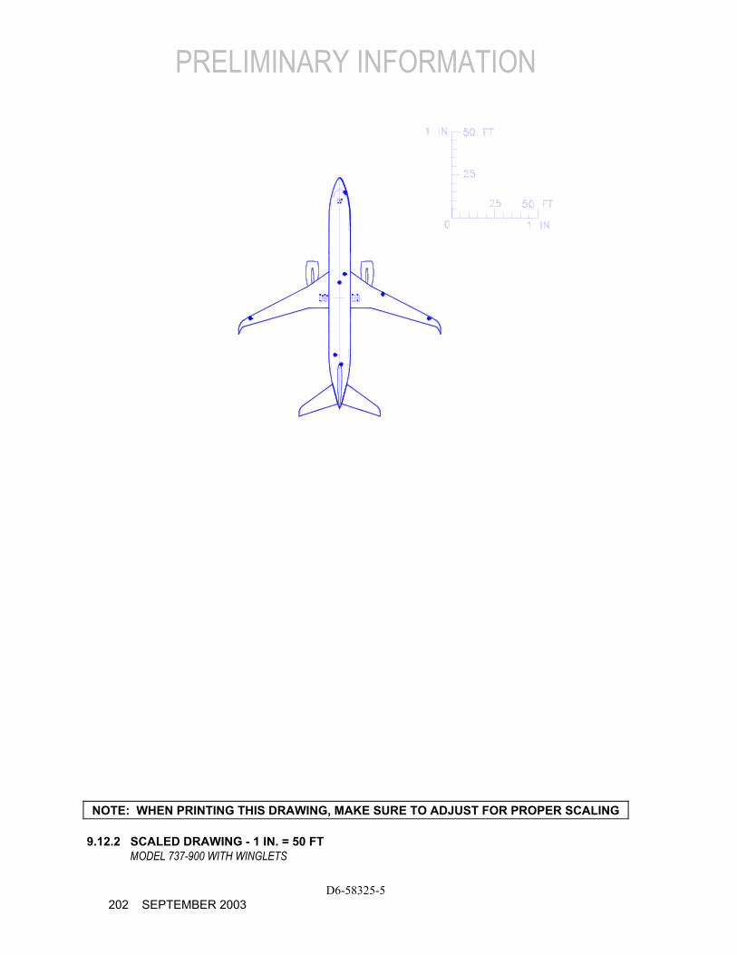
PRELIMINARY INFORMATION
D6-58325-5 202 SEPTEMBER 2003
NOTE: WHEN PRINTING THIS DRAWING, MAKE SURE TO ADJUST FOR PROPER SCALING 9.12.2 SCALED DRAWING - 1 IN. = 50 FT
MODEL 737-900 WITH WINGLETS
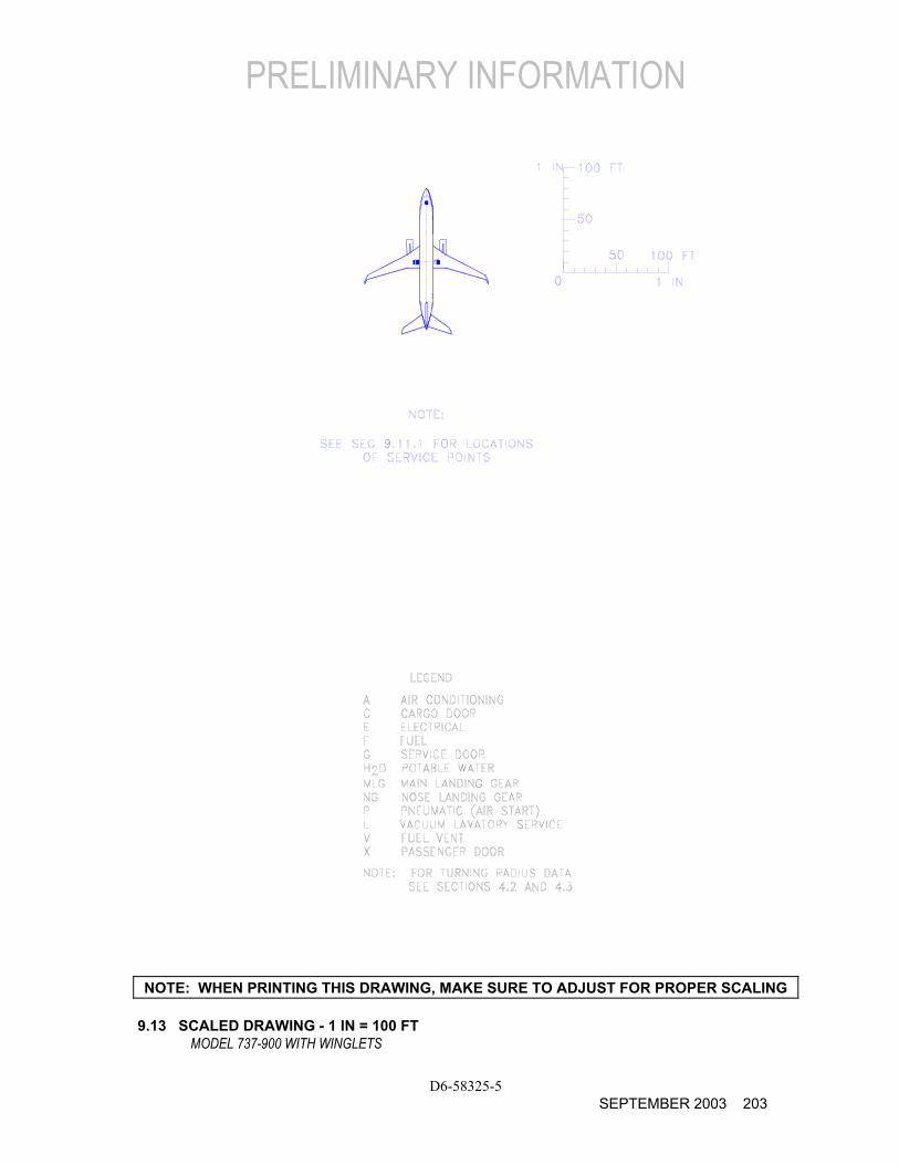
PRELIMINARY INFORMATION
D6-58325-5 SEPTEMBER 2003 203
NOTE: WHEN PRINTING THIS DRAWING, MAKE SURE TO ADJUST FOR PROPER SCALING 9.13 SCALED DRAWING - 1 IN = 100 FT
MODEL 737-900 WITH WINGLETS

PRELIMINARY INFORMATION
THIS PAGE INTENTIONALLY LEFT BLANK
D6-58325-5 204 SEPTEMBER 2003
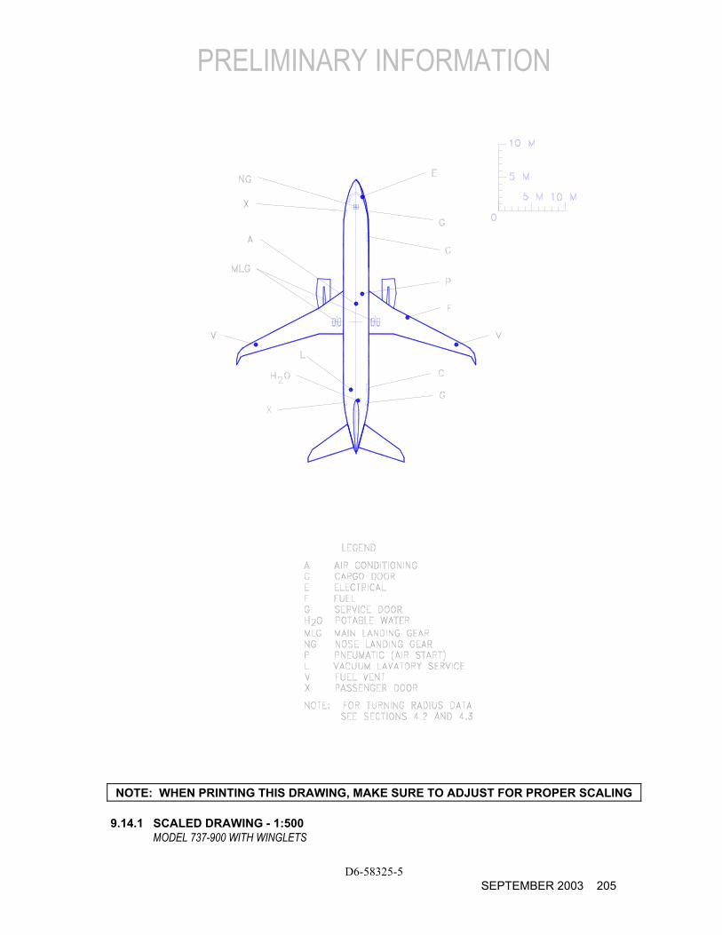
PRELIMINARY INFORMATION
D6-58325-5 SEPTEMBER 2003 205
NOTE: WHEN PRINTING THIS DRAWING, MAKE SURE TO ADJUST FOR PROPER SCALING 9.14.1 SCALED DRAWING - 1:500
MODEL 737-900 WITH WINGLETS
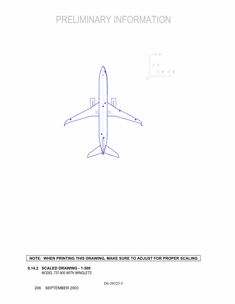
PRELIMINARY INFORMATION
D6-58325-5 206 SEPTEMBER 2003
NOTE: WHEN PRINTING THIS DRAWING, MAKE SURE TO ADJUST FOR PROPER SCALING 9.14.2 SCALED DRAWING - 1:500
MODEL 737-900 WITH WINGLETS
PRELIMINARY INFORMATION
D6-58325-5 SEPTEMBER 2003 207
NOTE: WHEN PRINTING THIS DRAWING, MAKE SURE TO ADJUST FOR PROPER SCALING 9.15 SCALED DRAWING - 1:1000
MODEL 737-900 WITH WINGLETS

PRELIMINARY INFORMATION
THIS PAGE INTENTIONALLY LEFT BLANK
D6-58325-5 208 SEPTEMBER 2003