Performances of a small hypersonic airplane (HyPlane)
13
65 th International Astronautical Congress, Toronto, Canada. Copyright ©2014 by the Authors. Published by the IAF, with permission and released to the IAF to publish in all forms. IAC-14-2.4 Page 1 of 13 IAC-14-D2.4 PERFORMANCES OF A SMALL HYPERSONIC AIRPLANE (HYPLANE) Raffaele Savino Department of Industrial Engineering, University of Naples “Federico II”, Italy Gennaro Russo Trans-Tech srl and Space Renaissance Italia, Italy Vera D’Oriano*, Michele Visone Blue Engineering, Italy Manuela Battipede, Piero Gili Department of Mechanical and Aerospace Engineering, Polytechnic of Turin, Italy In the present work a preliminary performance study regarding a small hypersonic airplane named HyPlane is presented. It is designed for long duration sub-orbital space tourism missions, in the frame of the Space Renaissance (SR) Italia Space Tourism Program. The vehicle is also consistent with a point-to-point medium range hypersonic trip, within the “urgent business travel” market segment. The design of such a hypersonic airplane is based on the concept of integrating available technologies developed for aeronautical and space atmospheric re-entry systems. The vehicle, characterized by high aerodynamic efficiency and low wing loading, is able to provide aerodynamic stability and manoeuvrability along the flight path and to produce a reduced sonic boom during cruise and supersonic descent approach, ensuring a very limited environmental impact. HyPlane, powered by Turbine Based Combined Cycle (TBCC) engines plus a throtteable Rocket, is able to perform Horizontal Takeoff and Horizontal Landing (HTHL) on runways. Aerodynamic and propulsive performances for the different flight regimes encountered during the missions are studied. Aerodynamic heating effects are analyzed, in order to identify suitable structures and materials design to sustain the hypersonic flight conditions. Different flight paths are also investigated, including hypersonic cruise and sub-orbital parabolic trajectories, which provide Space tourists with the opportunity of long duration missions, offering short and repeated periods of low-gravity, in the high stratosphere where a large view of the Earth is ensured. I. INTRODUCTION In recent years some private enterprises have been approaching Space flight with a relatively low-cost philosophy, in antithesis with the one followed by government agencies in the past years. In fact, some examples of small reusable airplane-like vehicles have been developed to perform sub-orbital missions, which could represent a first step towards a safer, more comfortable and less expensive access to Space in the near future. Main idea is to merge part of technological solutions developed for aeronautical and atmospheric re-entry purposes in order to design such vehicles, as also discussed in 1-4 . Scaled Composite launched for the first time the Space Ship One (SS1) in 2004. The vehicle reached 100 km altitude on a sub-orbital trajectory 36 years after the X-15, developed by NASA at the turn of 50s and 60s. *Ph.D. student at University of Naples "Federico II" The company is presently test qualifying an enlarged version of the SS1, named SS2, which is intended to carry passengers for a short-duration Space flight at a fare of about 250 k$ per seat. This sub-orbital flight should allow space tourists to experiment weightlessness for a few minutes and to see a large area of the Earth, along with its curvature 7 . Other projects which are included in this frame are the BSP Ascender, the EADS spaceplane and the XCOR Lynx 7-9 , all of which could be used even for technological flight test 10 . Recent survey studies assessed the potential market for sub-orbital vehicles 9,11 . The one performed by EADS and IPSOS 9 shows that there is a sizable market for sub-orbital tourism and that people willing to pay around 200 k€ for that could be in the order of 50000, just 16 years after the market start. This market is of course much larger than the one related to orbital Space tourism missions on the ISS. In this case, in fact, only 7 people had the opportunity, up to now, to perform this experience paying from 20 M$ to 40 M$. It is obvious that these
Transcript of Performances of a small hypersonic airplane (HyPlane)

65th International Astronautical Congress, Toronto, Canada. Copyright ©2014 by the Authors. Published by the IAF, with permission and released to the IAF to publish in all forms.
IAC-14-2.4 Page 1 of 13
IAC-14-D2.4
PERFORMANCES OF A SMALL HYPERSONIC AIRPLANE (HYPLANE)
Raffaele Savino Department of Industrial Engineering, University of Naples “Federico II”, Italy
Gennaro Russo
Trans-Tech srl and Space Renaissance Italia, Italy
Vera D’Oriano*, Michele Visone Blue Engineering, Italy
Manuela Battipede, Piero Gili
Department of Mechanical and Aerospace Engineering, Polytechnic of Turin, Italy In the present work a preliminary performance study regarding a small hypersonic airplane named HyPlane is
presented. It is designed for long duration sub-orbital space tourism missions, in the frame of the Space Renaissance (SR) Italia Space Tourism Program. The vehicle is also consistent with a point-to-point medium range hypersonic trip, within the “urgent business travel” market segment. The design of such a hypersonic airplane is based on the concept of integrating available technologies developed for aeronautical and space atmospheric re-entry systems. The vehicle, characterized by high aerodynamic efficiency and low wing loading, is able to provide aerodynamic stability and manoeuvrability along the flight path and to produce a reduced sonic boom during cruise and supersonic descent approach, ensuring a very limited environmental impact. HyPlane, powered by Turbine Based Combined Cycle (TBCC) engines plus a throtteable Rocket, is able to perform Horizontal Takeoff and Horizontal Landing (HTHL) on runways. Aerodynamic and propulsive performances for the different flight regimes encountered during the missions are studied. Aerodynamic heating effects are analyzed, in order to identify suitable structures and materials design to sustain the hypersonic flight conditions. Different flight paths are also investigated, including hypersonic cruise and sub-orbital parabolic trajectories, which provide Space tourists with the opportunity of long duration missions, offering short and repeated periods of low-gravity, in the high stratosphere where a large view of the Earth is ensured.
I. INTRODUCTION
In recent years some private enterprises have been
approaching Space flight with a relatively low-cost philosophy, in antithesis with the one followed by government agencies in the past years. In fact, some examples of small reusable airplane-like vehicles have been developed to perform sub-orbital missions, which could represent a first step towards a safer, more comfortable and less expensive access to Space in the near future.
Main idea is to merge part of technological solutions developed for aeronautical and atmospheric re-entry purposes in order to design such vehicles, as also discussed in 1-4.
Scaled Composite launched for the first time the Space Ship One (SS1) in 2004. The vehicle reached 100 km altitude on a sub-orbital trajectory 36 years after the X-15, developed by NASA at the turn of 50s and 60s.
*Ph.D. student at University of Naples "Federico
II"
The company is presently test qualifying an enlarged version of the SS1, named SS2, which is intended to carry passengers for a short-duration Space flight at a fare of about 250 k$ per seat. This sub-orbital flight should allow space tourists to experiment weightlessness for a few minutes and to see a large area of the Earth, along with its curvature7.
Other projects which are included in this frame are the BSP Ascender, the EADS spaceplane and the XCOR Lynx7-9, all of which could be used even for technological flight test10.
Recent survey studies assessed the potential market for sub-orbital vehicles9,11. The one performed by EADS and IPSOS9 shows that there is a sizable market for sub-orbital tourism and that people willing to pay around 200 k€ for that could be in the order of 50000, just 16 years after the market start.
This market is of course much larger than the one related to orbital Space tourism missions on the ISS. In this case, in fact, only 7 people had the opportunity, up to now, to perform this experience paying from 20 M$ to 40 M$. It is obvious that these

65th International Astronautical Congress, Toronto, Canada. Copyright ©2014 by the Authors. Published by the IAF, with permission and released to the IAF to publish in all forms.
IAC-14-2.4 Page 2 of 13
fares can be paid only by the so called Ultra High Net Worth Individuals (UHNWI).
Sub-orbital Space tourism may also be seen as an intermediate step towards a novel concept of orbital Space tourism, based on reusable winged vehicles.
Indeed, the employment of reusable components could strongly reduce the cost per seat up to 2 orders of magnitude, depending on the number of flights scheduled. In addition, the development of a winged re-entry vehicle could represent a safer and more comfortable way to cross the atmosphere11-15.
Secondary markets directly linked to the commercial sub-orbital flights may include microgravity research, high altitude aerospace technological testing and development, astronauts training, remote sensing, and so forth.
A longer term perspective is also characterized by point-to-point hypersonic transportation. In this frame, up to now, Skylon seems to be the most promising project16. It uses the hydrogen-powered Combined-Cycle SABRE engines to reach a cruise altitude around 26 km and a Mach number around 517. For this vehicle reaction Engines Limited (REL) predicted a preliminary development cost of around 12B$, including airframe and engine development14. In addition, the company foresees to lower payload costs per kilogram from the current 18000 €/kg to 750 €/kg.
University of Naples “Federico II”, in the wider frame of the Space Renaissance (SR) Italia Space Tourism Program16 and with the support of other universities and small and medium enterprises (including Polytechnic of Turin, Blue Engineering and Trans-Tech), is investigating a new vehicle concept for long-duration space tourism missions and hypersonic transportation over transcontinental distances.
SR Italia is a cultural association of individuals, whose main purposes are focused on two fundamental concepts: push toward a more efficient, economically sustainable, routine-type access to Space and make use of Space not only for scientific activities. The association promotes Space Industrialization starting from Space Tourism, which seems to be the only industrial and commercial activity having the potential to grow up on itself, generating from market the feedback of capitals needed for raising the capabilities of civilian astronautics to carry passengers in Space. As longer term perspective, SR Italia looks at the possibility for the humanity to expand into Space and to exploit the huge amount of resources available on asteroids, planets and moons16.
The present study refers to a six seats small hypersonic airplane-like vehicle, named HyPlane, designed for a long duration Space tourism mission and also consistent with a point-to-point hypersonic
trip in the frame of the "urgent business travel" market segment. Previous supersonic or hypersonic commercial designs tended toward large aircrafts, characterized by hundreds of tons of mass and hundreds of passengers. This has resulted in great difficulty in determining a valid and sustainable operational concept, because of the system high complexity, requiring very long time to reach the sufficient technology readiness level.
A small passenger hypersonic plane may take advantage of previous experiences and represent a first step towards the development of larger and more complex systems, but at the same time it may open new markets and applications.
The paper is organized as follows. In Section II the vehicle configuration and mission profiles are summarized. The aerodynamic database (obtained by means of numerical analysis) is discussed in section III. Section IV discusses the expected surface temperatures and possible materials for the structural components; a preliminary mass budget is also reported. Section V shows in detail the turbo-ramjet supersonic inlet design, carried out by means of CFD analysis and the computations of the complete configuration, including engines. Main flight performances for different mission scenarios are presented and discussed in Section VI. Conclusions are presented in Section VII.
II. SYSTEM CONFIGURATION AND MISSION REQUIREMENTS
HyPlane is a new concept of hypersonic
transportation system designed by the first two authors to offer access to stratospheric and space flights as safe, convenient and commonplace as today's commercial air transportation, by integrating state-of-the-art aeronautic and space technologies.
The HyPlane conceptual design is defined by the complex interplay of aerodynamics, atmospheric heating, materials and structures, propulsion, fuel selection, cabin, tank and subsystems sizing.
HyPlane analysis team includes experts from universities, small and medium enterprises, involved in system engineering, aerothermodynamics, propulsion, trajectory and performance analysis, materials and structural analysis. By combining academic education, industry experience and creative thinking, the HyPlane team has carried out the preliminary vehicle configuration (shown in Fig. I) and the performance analysis, through the implementation of appropriate models and simulations.
The vehicle is a six-seat small-size spaceplane with a high performance wing and a vertical tail providing good flight characteristics both in subsonic

65th International Astronautical Congress, Toronto, Canada. Copyright ©2014 by the Authors. Published by the IAF, with permission and released to the IAF to publish in all forms.
IAC-14-2.4 Page 3 of 13
and super/hypersonic regimes. The spaceplane features a proper design to maximize internal volume.
The cabin environment is designed to maintain a comfortable temperature and pressure for the passengers, while providing an excellent view of the Earth from Space.
(a)
(b)
Fig. I: HyPlane hypersonic vehicle
II.I Mission requirements The vehicle, powered by Turbine Based
Combined Cycle plus a throtteable Rocket, will perform Horizontal Takeoff and Horizontal Landing (HTHL) on short-medium length runways (<1000 m), taking advantage from the lift forces resulting from the relatively large wing surface, and will be accelerated to speeds around Mach 4-4.5 to execute point-to-point sub-orbital parabolic flights, providing the sensation of weightlessness for some minutes, or hypersonic cruise transportation over transcontinental distances.
The HyPlane mission profile begins with a horizontal takeoff with engine operating in turbojet mode. The total weight of the vehicle at takeoff is about 26000 kg.
Then, an ascent phase is performed to reach suitable conditions to the sub-orbital parabolic manoeuvres or for the hypersonic cruise. In particular this phase consists in an initial subsonic ascent to altitude between 5 and 10 km and in a subsequent acceleration through transonic/supersonic speed range and climbing along a constant dynamic pressure trajectory, using combined cycle engines (maximum sensed acceleration on ascent around 1.2 g).
During the acceleration, when the aircraft reaches a sufficient altitude and speed, the engine operating mode undergoes a transition to ramjet.
Then the HyPlane performs its nominal mission, namely the hypersonic cruise using ramjet (transcontinental range around 6000 km) or a sequence of sub-orbital parabolas using the rocket. Finally the aircraft performs gliding descent and powered horizontal landing on a runway.
The total duration of the mission in both cases is less than 2 hours. II.II Aerodynamics
HyPlane is characterized by high aerodynamic efficiency and low wing loading and is designed to provide aerodynamic stability and manoeuvrability along the nominal flight path. The high-lift-to-drag ratio guarantees the minimization of the required thrust (so that the propellant mass at takeoff can be small) and the improvement of the manoeuvring performances.
The wing area is large enough to aerodynamically sustain the aircraft gross takeoff weight with relatively low velocities and to reduce, at relatively high altitudes, aerodynamic heating and sonic boom during cruise and supersonic descent approach (efficient overland routes) and the consequent environmental impact.
The variable-delta planform of the wing is combined with the fuselage shape to provide aerodynamic stability and manoeuvrability over a broad speed range, and also enough space to hold propellants. High altitude flight, possible thanks to the low wing loading, offers also a better Earth view and may open to new applications (e.g. remote sensing, high altitude technological demonstrations, etc.).
II.III Propulsion System
Turbine-based combined cycle engines operate by using a gas turbine propulsion cycle that pass to a ramjet cycle at high Mach number. In this condition, in fact, the air-flow bypasses the turbomachinery, because pressure, temperature, and flow velocity would make such turbine impractical, redundant, or both. Turbojet propulsion systems are generally limited to Mach 3, due to the rise in inlet temperature present at the compressor face.
An example of operative TBCC engine is the J-58 utilized in the Lockheed SR-71 Blackbird, working in multiple cycles depending on the flight regime (with cruise conditions of approximately Mach 3.2 at an altitude of 23 km). More recent advanced hypersonic systems, such as the DARPA Blackswift, have been proposed using TBCC-class propulsion system22.

65th International Astronautical Congress, Toronto, Canada. Copyright ©2014 by the Authors. Published by the IAF, with permission and released to the IAF to publish in all forms.
IAC-14-2.4 Page 4 of 13
The performances at different flight conditions of the TBCC using JP-7 hydrocarbon fuel identified for the present work are illustrated in figure II24; in particular the figure shows the maximum thrust and the specific impulse as functions of Mach number for different altitudes.
(a)
(b)
Fig. II: Performances of Turbine-Based Combined Cycle : Maximum Thrust per engine (a) and Specific Impulse (b) as a function of Mach number at different altitudes
The rocket guarantees adequate propulsive
characteristic to fly sub-orbital trajectories and is based on the utilization of hydrogen peroxide (H2O2) as oxidiser, which has several advantages.
This engine offers the versatility of operating in monopropellant mode (offering a small thrust for attitude control) and bipropellant mode, using
Kerosene as fuel. The high available thrust offered by the latter mode is crucial in a space tourism mission scenario, where high accelerations are necessary to perform sub-orbital jumps.
Since the H2O2 decomposes into a mixture of superheated steam and oxygen to a temperature of about 1000K, a propulsion unit without a requirement for a separate ignition system offers a higher system reliability.
Moreover the H2O2 is considered a green propellant due to the reduced emissions and the low toxicity, ensuring a very limited environmental impact. The average performances of the rocket identified for this work are showed in Table I.
Engine Average Thrust [kN]
Average Specific Impulse [s]
Rocket 200 310 Table I: Rocket engine main performances
III. AERODYNAMIC ANALYSIS
The aerodynamic characteristics of the vehicle are
evaluated by means of semi-empirical aerodynamic prediction codes, including DATCOM, that offer the possibility to quickly and economically carry out aerodynamic analysis of aircrafts.
The aerodynamic data include aerodynamic and moment coefficients, stability and control derivatives (longitudinal and lateral-directional, static and dynamic). These results can be also obtained varying the flight parameters (angle of attack, sideslip angle, Mach number, altitude and control surface deflections) for subsonic, transonic, supersonic and hypersonic regimes.
Aerodynamic characteristics of the HyPlane have been continuously determined during the configuration upgrading in order to ensure a high hypersonic aerodynamic efficiency and longitudinal static stability around trim conditions.
CFD analysis are carried out to accomplish a more accurate aerodynamic analysis of the vehicle configuration without the engines and to completely assess the flow field in the critical flight conditions.
The computational domain consists of a fully unstructured 6.5 million cells grid. The grid is based on polyhedral cells and prismatic elements to help refine the boundary layer region. Special attention is paid to the fuselage nose and to the leading and trailing edges of the wings and vertical tail, because of their small curvature radii, in order to better capture the flow gradients in the solution. Figure III shows the final surface grid.
The solutions are obtained solving steady state, compressible RANS equations. The adopted
65th International Astronautical Congress, Toronto, Canada. Copyright ©2014 by the Authors. Published by the IAF, with permission and released to the IAF to publish in all forms.
IAC-14-2.4 Page 5 of 13
commercial solver uses a 2nd order implicit coupled Roe Flux Differencing Scheme (FDS).
The boundary layer is assumed to be fully turbulent everywhere and is modelled using the two equations k-ω Shear Stress Transport (SST) turbulence model.
Fig. IV illustrates the pressure distribution on the vehicle and the vortical structures forming over the delta wing in high-subsonic and hypersonic regimes computed by CFD analysis.
Fig. III: Unstructured polyhedral 6.5 million cells
computational grid
(a) (b)
Fig. IV: Pressure distribution on the vehicle computed with CFD simulations; a refers to the condition M=0.7, H=10 km and AoA=8°, b to M=4, H=30 km and AoA=4°
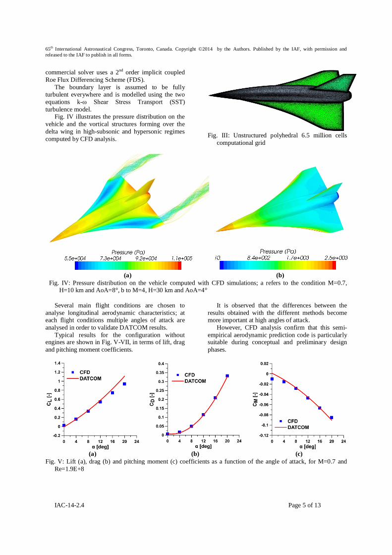
Several main flight conditions are chosen to
analyse longitudinal aerodynamic characteristics; at each flight conditions multiple angles of attack are analysed in order to validate DATCOM results.
Typical results for the configuration without engines are shown in Fig. V-VII, in terms of lift, drag and pitching moment coefficients.
It is observed that the differences between the results obtained with the different methods become more important at high angles of attack.
However, CFD analysis confirm that this semi-empirical aerodynamic prediction code is particularly suitable during conceptual and preliminary design phases.
(a) (b) (c)
Fig. V: Lift (a), drag (b) and pitching moment (c) coefficients as a function of the angle of attack, for M=0.7 and Re=1.9E+8

65th International Astronautical Congress, Toronto, Canada. Copyright ©2014 by the Authors. Published by the IAF, with permission and released to the IAF to publish in all forms.
IAC-14-2.4 Page 6 of 13
(a) (b) (c)
Fig. VI : Lift (a), drag (b) and pitching moment (c) coefficients as a function of the angle of attack, for M=2 and Re=2E+8
(a) (b) (c)
Fig. VII: Lift (a), drag (b) and pitching moment (c) coefficients as a function of the angle of attack, for M=4.5 and Re=2E+7
IV. MATERIALS & STRUCTURES
The aerothermal heating is one of the problems
during hypersonic flight, due to the high heat fluxes on the outer surface of the vehicle, dictated by the very high speeds.
The analysis of the aerothermal environment and its effect on surface heat flux has been carried out by means of CFD simulations, in order to guess a preliminary materials selection, based on thermal resistance performances. The surface temperature distribution, obtained by imposing the radiative balance for a hypersonic cruise condition (Mach number of 4, altitude of 30 km and angle of attack of 0°), is reported in Fig. VIII.
On the basis of the computed temperature distributions, three different areas have been identified with a possible material pre-selection. The main idea is to apply advanced but available structural technologies with special thermal protection only for localized elements.
In particular, the following zones have been identified:
Nose, wing and vertical tail leading edges, control surfaces (elevons and rudder) that reach temperatures above 400°C; for these areas Carbon fiber reinforced ceramics (e.g B4C or SiC) materials could be used, as well as actively cooled solutions.
Fuselage and wing surfaces are expected to be at temperature in the range 300-400°C; for such areas Titanium alloys could be employed.
For the aft fuselage, estimated to be exposed at temperature below 300°C, light temperature carbon fiber composite materials (e.g. BMI) could be selected to gain weight with respect to titanium although the last remains to be applicable.
Such zone identification is shown in Fig. IX.

65th International Astronautical Congress, Toronto, Canada. Copyright ©2014 by the Authors. Published by the IAF, with permission and released to the IAF to publish in all forms.
IAC-14-2.4 Page 7 of 13
(a)
(b)
Fig. VIII: Radiation equilibrium temperature
distribution for M=4, H=30 km and AoA=0°; a refers to the leeside and b to the windside
(a)
(b)
Fig. IX: Preliminary structure and materials assessment
A preliminary mass budget has been elaborated in order to assess the feasibility of the vehicle configuration, according to the main mission requirements. This study is based on both statistical correlation and engineering design of specific subsystems. Some assumptions have been made in order to obtain the vehicle mass budget and the mass breakdown among its main subsystems, in particular:
1. the payload and crew weights have been determined considering all adult and male passengers travelling in winter (i.e. 100 kg per person, according to the Federal Aviation Administration);
2. the fuel weight depends on the aircraft configuration and on the mission requirements;
3. the vehicle empty weight can be estimated from statistics on the basis of the HASA model proposed in literature26.
In the present analysis 6 passengers, 2 crew members and a propellant mass of about 60% of the total gross weight have been considered.
According to the statistical model, the overall vehicle weight has been computed by iteratively solving a number of equations for different parameters, including the total volume and the total gross weight of the vehicle.
After having added a proper mass design margin, the method has an overall accuracy around 20% for the total gross mass estimation, while the errors regarding the mass breakdowns are estimated to be larger.
Although the ongoing estimations are suggesting an increase in overall mass, the takeoff weight of the aircraft considered in the present work is 26000 kg. The structural weight is around 5500 kg; in particular it is split up as follows: 60% for fuselage, 16% and 7% for wing and vertical tail, respectively, 12% for landing gear and 5% for the localized Thermal Protection System. The propulsive components are about the 9% of the vehicle total weight, followed by subsystem (5%), crew and payload (4%).
The center of gravity has been preliminarily estimated assuming the mass of the main vehicle components concentrated in their geometrical centres. As the propellant is consumed during the flight, the center of gravity has a significant longitudinal excursion while it is possible to neglect its vertical position variation. In particular it moves forward of about 2 m (the vehicle total length is 23.6 m): the CoG is approximately located at 16 m and at 14 m from the apex of the nose, at takeoff and at zero-fuel condition, respectively.
B4C or SiC Titatium alloys BMI

65th International Astronautical Congress, Toronto, Canada. Copyright ©2014 by the Authors. Published by the IAF, with permission and released to the IAF to publish in all forms.
IAC-14-2.4 Page 8 of 13
V. TURBO-RAMJET INLET DESIGN
The extent of the HyPlane operating speed and altitude ranges necessitates a variable-geometry turbo-ramjet inlet, able to supply a flow of air to the engine at correct pressure and velocity throughout the flight envelope.
An axisymmetric mixed internal/external compression supersonic inlet, using a translating spike (pointed conical body) has been considered.
CFD simulations validated against experimental and numerical results available in literature over supersonic inlets, including Lockheed SR-71, are carried out for the preliminary design of such an air intake.
The considered air intake is designed to produce, at nominal conditions (at hypersonic cruising speed
and altitude), a cone-shaped shock impinging at the cowl lip (external compression) and getting reflected along the duct enclosed by the spike and cowl internal surface, leading to a further internal compression which terminates with a normal shock in the throat (at Mach number near one), ensuring subsonic conditions at the entrance of the combustion chamber and producing a relatively high total pressure recovery.
In operation, the spike moves forward and aft within the inlet duct as a function of altitude and Mach number, varying the position of the cone shaped shock wave and the size of the inlet throat area, in order to capture and maintain the normal shock wave in the optimal position.
Fig. X presents the geometry of the inlet and the schematic of flow at the nominal cruise condition (at 30 km of altitude and at a Mach number of 4).
Fig. X: Schematic of flow field for a typical turbo-ramjet inlet at the nominal hypersonic
CFD analysis is carried out using a structured grid of 0.12 million quadrilateral cells. Steady state, axisymmetric RANS equations are solved with k-ε turbulence model using a commercial software. A density based solver with 2nd order implicit Roe FDS is used. The effect of the presence of the combustion chamber is taken into account by imposing a high back pressure at the exit of the engine inlet.
The distributions of Mach number, pressure, temperature, total pressure and streamlines for the nominal condition and a supersonic condition (M=2, H=15 km) at zero angle of attack are presented in Fig. XI and XII respectively.
The throat area increase from 0.17 m2 to 0.4 m2, resulted from the spike forward translation of 0.66 m, allows to catch and retain the normal shock wave that translates the supersonic flow to subsonic condition.
Moreover, a three-dimensional structured grid of 0.78 million hexahedral cells is created in order to evaluate the alteration of the inlet performances as the angle of attack increases during the hypersonic cruise.
Fig. XIII shows the flow field at an angle of attack of six degrees (expected maximum angle of attack during the hypersonic cruise).
The computed performances in terms of mass capture and total pressure recovery for the different cases reported in table II, are in agreement with experimental and numerical results for similar air intakes available in literature27.
Furthermore, the very limited deterioration of the inlet performances due to the asymmetry of the shock structures, ensures a stable combustion during the hypersonic cruise.

65th International Astronautical Congress, Toronto, Canada. Copyright ©2014 by the Authors. Published by the IAF, with permission and released to the IAF to publish in all forms.
IAC-14-2.4 Page 9 of 13
(a) (b)
Fig. XI: Mach number, pressure (a), streamlines and temperature (b) distributions for M=4, H=30 km and AoA=0° computed by CFD simulations
(a) (b)
Fig. XII: Pressure, temperature (a), streamlines and total pressure (b) distributions for M=2, H=15 km and AoA=0° computed by CFD simulations
(a) (b)
Fig. XIII: Mach number (a) and pressure (b) distributionsfor M=4, H=30 km and AoA=6° computed by CFD simulations
Flight
Condition Mach Altitude [km]
AoA [°]
Mass capture [%]
Total Pressure Recovery [%]
Nominal Hypersonic 4 30 0 100 61.7 Supersonic 2 15 0 35 66.2
Off-design Hypersonic 4 30 6 91 60.5 Table II: Turbo-ramjet supersonic inlet main performances
Further CFD analysis are carried out to study the
effects of the engines on the aerodynamic performances of the aircraft in hypersonic cruise condition (at Mach number of 4, altitude of 30 km).
Fig. XV shows the comparison between the computed surface pressure distributions for the
configurations without and with engines, at zero angle of attack. It has been observed that in these conditions the presence of the engines causes a relatively slight increase of drag force acting on the aircraft and a tolerable reduction of the aerodynamic efficiency, as summarized in Table III.

65th International Astronautical Congress, Toronto, Canada. Copyright ©2014 by the Authors. Published by the IAF, with permission and released to the IAF to publish in all forms.
IAC-14-2.4 Page 10 of 13
(a) (b)
Fig. XIV: Pressure distribution for M=4, H=30 km and AoA=0° on the configuration without (a) and with engines
(b) computed by CFD simulations
Flight Condition CFD Results Configuration Mach H [km] AoA [°] CL CD L/D
No Engines 4 30 0 -0.0072 0.0090 -0.797 No Engines 4 30 4 0.0572 0.012 4.498
With Engines 4 30 0 -0.0105 0.0094 -1.116 With Engines 4 30 4 0.0529 0.0145 3.648
Table II: Aerodynamic performances during hypersonic cruise of the configuration with and without engines computed by CFD simulations
V. FLIGHT PERFORMANCES
The preliminary flight performances reported in
this section show the possibility to realize long duration missions, both for Space tourism purposes and 6000 km range hypersonic cruise. This can be achieved optimizing the propulsion performances of the TBCC and the Rocket in the different phases of the flight envelopes.
A mathematical 12-state, six-degree-of-freedom, non-linear model has been recently implemented to simulate the vehicle’s dynamics and analyse the performance capabilities. The model is based on a rigid-body, single point-mass approximation, which encompasses state-of-the-art mathematical descriptions of the geometrical, inertial, aerodynamic and propulsive characteristics.
Trajectory simulations are performed to evaluate the flight profile in the climbing phase such that a Mach number of 4 at an altitude of about 28 km could be achieved.
The ascent phase begins at the altitude of 10 km and a Mach number of 0.8. A level acceleration from the above mentioned conditions until the achievement of a constant dynamic pressure is considered.
Then, the vehicle accelerates along a constant dynamic pressure flight path to the maximum Mach number. The final altitude is reached after 15 minutes,
with a relatively low fuel consumption (almost 6 tons), due to the relatively high specific impulse.
The hypersonic cruise is performed with a small flight path angle (0.05°) to maintain the aerodynamic efficiency relatively high (about 4), in order to maximize the downrange.
The main performances of the HyPlane in a possible hypersonic cruise scenario are plotted in Fig XV. During cruise and supersonic descent approach the sonic boom felt on the ground is far below 100 Pa, the threshold at which the probability of structural damages becomes unacceptable; moreover such a overpressure is below 50 Pa, the limit value at which the sonic boom becomes annoying. This ensures a very limited environmental impact.
Similarly to subsonic airplanes performing parabolic flight, HyPlane will be also able to conduct specific mission profiles executing 3 sub-orbital jumps, each providing up of two minutes of low gravity.
During this periods passengers will be able to experience weightlessness conditions and to enjoy a beautiful view of the Earth from the Space.
Before each sub-orbital jump, the vehicle begins flying at hypersonic speed in a steady horizontal attitude with an approximate altitude and speed of 30 km and Mach 4, respectively. During this steady flight the gravity level is 1g.
65th International Astronautical Congress, Toronto, Canada. Copyright ©2014 by the Authors. Published by the IAF, with permission and released to the IAF to publish in all forms.
IAC-14-2.4 Page 11 of 13
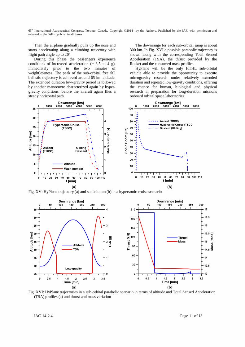
Then the airplane gradually pulls up the nose and starts accelerating along a climbing trajectory with flight path angle up to 20°.
During this phase the passengers experience conditions of increased acceleration (~ 3.5 to 4 g), immediately prior to the two minutes of weightlessness. The peak of the sub-orbital free fall ballistic trajectory is achieved around 65 km altitude. The extended duration low-gravity period is followed by another manoeuvre characterized again by hyper-gravity conditions, before the aircraft again flies a steady horizontal path.
The downrange for each sub-orbital jump is about 300 km. In Fig. XVI a possible parabolic trajectory is shown along with the corresponding Total Sensed Acceleration (TSA), the thrust provided by the Rocket and the consumed mass profiles.
HyPlane will be the only HTHL sub-orbital vehicle able to provide the opportunity to execute microgravity research under relatively extended duration and repeated low-gravity conditions, offering the chance for human, biological and physical research in preparation for long-duration missions onboard orbital space laboratories.
(a) (b)
Fig. XV: HyPlane trajectory (a) and sonic boom (b) in a hypersonic cruise scenario
(a) (b)
Fig. XVI: HyPlane trajectories in a sub-orbital parabolic scenario in terms of altitude and Total Sensed Acceleration (TSA) profiles (a) and thrust and mass variation

65th International Astronautical Congress, Toronto, Canada. Copyright ©2014 by the Authors. Published by the IAF, with permission and released to the IAF to publish in all forms.
IAC-14-2.4 Page 12 of 13
VI. CONCLUDING REMARKS
The increasing number of projects regarding airplane-like vehicles for space tourism and hypersonic point-to-point trip perspectives induce to reasonably expect the aviation to include in the near future very high speed systems, able to offer fast transportation of persons and products.
Meanwhile, Space Tourism is believed to provide much cheaper ticket cost than 250k€/pers offered today, becoming affordable for a growing number of potential tourists.
The integration of a proper mix of technological solutions, coming from both the aeronautical and space sectors, will make technically feasible the design and the development of a small Mach 4-5 spaceplane vehicle able to fly 6000 km distances in less than 2 hours with cruise altitude of about 30 km and also to perform a series of parabolas dedicated to space tourism at maximum altitude of above 65 km.
Such a vehicle will be able to take-off and land horizontally from short runways, in compliance with the common airport current regulations. Such a small hypersonic plane may complement the already running studies concerning hundred-seat supersonic and hypersonic civil transport aircrafts, through the
opening of new market segments and applications like “urgent business travel”, business jet, taxi aircraft for individuals, specific goods, human organs and so forth.
In this scenario new super-hypersonic aircraft designers and manufacturers, as well as new airline companies able to provide the above mentioned services will emerge.
ACKNOWLEDGMENTS
The authors wish to thank Space Renaissance
Italia team that welcome and supported the idea since its inception.
The authors are grateful to Prof. S. De Rosa, Prof. F. Franco, Prof. F. Marulo (University of Naples "Federico II"), Dr. U. Savarese and Dr. R. Avagliano(Desà Engineering) for their contribution to the project, and to Dr. D. Ashford, Prof. C. Bruno, Prof. S. Chiesa and Prof. R. Monti for the fruitful discussions.
The Ph.D. scholarship of Miss V. D’Oriano is supported by the Campania Region (POR Campania FSE 2007-2013).
1 G. Russo, Next Generations Space Transportation Systems: R&D and Need for Flying Test Beds, "AIAA/NAL/NASDA/ISAS 10th International Space Planes and Hypersonic Systems and Technologies Conference", Kyoto, Japan, (2001). 2 G. Russo, Next Generations Space Transportation Systems, Aerotecnica Missili e Spazio, 81(2), pp. 65-72 (2002). 3 G. Russo, PRORA-USV: Closer Space and Aeronautics, Keynote Lecture at the "West-East High Speed Flow Field (WEHSFF-2007) Conference", Moscow, Russia, (2007). 4 R. Savino, G. Russo, V. Carandente, V. D’Oriano, HyPlane for Space Tourism and Business Transportation, "22nd Conference of the Italian Association of Aeronautics and Astronautics", Naples, Italy, (2013). 5 V. Carandente, V. D’Oriano, A. Gallina, G. Russo, R. Savino, Aerothermodynamic and system analysis of a small hypersonic airplane (HyPlane), "64th International Astronautical Congress", Beijing, China, (2013) 6 R. Savino, G. Russo, V. Carandente, V. D’Oriano, HyPlane: Challenges for Space Tourism and Business Transportation, Journal of Aeronautics & Aerospace Engineering, (2013) 7 D. Ashford, An aviation approach to Space transportation, The Aeronautical Journal, 113(1146), pp. 499–515 (2009). 8 C. Lauer, Suborbital Spaceplane Vehicle Development Programs for Future Point-To-Point Transportation Services, "International Astronautical Congress", Daejeon, Republic of Korea, (2009). 9 T. Le Goff, A. Moreau, Astrium suborbital spaceplane project: Demand analysis of suborbital Space tourism, Acta Astronautica, 92(2), pp. 144–149, (2013). 10 Paul A. Czysz, S.N.B. Murthy, SSTO Launcher Demonstrator for Flight Test, "7th International Space Planes and Hypersonic Systems and Technologies Conferences", Norfolk, VA, (1996). 11 The Tauri Group, Suborbital Reusable Vehicles: A 10-Year Forecast of Market Demand, (2012). 12 R. Monti, D. Paterna, A low risk reentry: looking backward to step forward, Aerospace Science and Technology, 10(2), pp. 156–167 (2006). 13 R. Janovsky, M. Tausche, M. Scheper, M. Orth, R. Monti, R. Savino, Spaceplane. A new way for atmospheric reentry, "1st International ARA Days Atmospheric Reentry Systems, Missions and Vehicles", Arcachon, France, (2006). 14 M. Tausche, R. Janovsky, M. Scheper, J. Apeldoorn, R. Monti, R. Savino, M. De Stefano Fumo, D. Paterna, E. Di Sotto, J. Branco, PHOEBUS: a high lift-over-drag vehicle for re-entry, "60th International Astronautical Conference", Daejeon, Republic of Korea, (2009).

65th International Astronautical Congress, Toronto, Canada. Copyright ©2014 by the Authors. Published by the IAF, with permission and released to the IAF to publish in all forms.
IAC-14-2.4 Page 13 of 13
15 M. Tausche, R. Janovsky, M. Scheper, J. Apeldoorn, R. Monti, R. Savino, M. De Stefano Fumo, D. Paterna, E. Di Sotto, J. Branco, R. Molina, PHOEBUS: A High Lift-over-Drag Vehicle for Re-entry, "16th AIAA/DLR/DGLR International Space Planes and Hypersonic Systems and Technologies Conference", Bremen, Germany, (2009). 16 European Space Agency, Skylon Assessment Report, (2011). 17 Reaction Engines Limited, SKYLON System Requirements Review - SABRE Engine, SKY-REL-PR-0006, (2010). 18 G. Russo, A. Autino, The Space Tourism Program of Space Renaissance Italia, "22nd Conference of the Italian Association of Aeronautics and Astronautics", Naples, Italy, (2013). 19 D. Webber, Point-to-Point People with Purpose, "2nd International IAA Conference on Private Human Access to Space", Arcachon, France, (2011). 20 R.D. Quinn, L. Gong, A new method for calculating transient surface temperatures and surface heating for high speed aircraft, NASA Technical Paper 2000-209034, (2000). 21 W.J. Escher, J.D. Williams, B.J. Fornes, A study of composite propulsion for advanced launch vehicle applications, The Marquard Corporation, Final Report for NASA contract NAS7-377, (1967). 22 K.J. Kloesel, N.A. Ratnayakey, C.M. Clarkz, A Technology Pathway for Airbreathing, Combined-Cycle, Horizontal Space Launch Through SR-71 Based Trajectory Modeling, "17th AIAA International Space Planes and Hypersonic Systems and Technologies Conference", San Francisco, California, (2011). 23 W. H. Heiser,D. T. Pratt, Hypersonic Airbreathing Propulsion Sonic, AIAA Education Series, 1994. 24 M. A. Brock , Performance study of two-stage-toorbit reusable launch vehicle propulsion alternatives (Master's Thesis), Air Force Institute of Technology, Wright-Patterson Air Force Base, Ohio (2004) 25 S.Saha, D. Chakraborty, Hypersonic Intake Starting Characteristics–A CFD Validation Study, Defence Science Journal, Vol. 62, No. 3, pp. 147-152, (2012). 26 G.J. Harloff and B.M. Berkowitz, HASA-Hypersonic Aerospace Sizing Analysis for the Preliminary Design of Aerospace Vehicles, NASA Contractor Report 1822262, (1988). 27 S. Saha, D. Chakraborty, Hypersonic Intake Starting Characteristics–A CFD Validation Study, Defence Science Journal, Vol. 62, No. 3, pp. 147-152 (2012)