Radiative heat transfer from supersonic flow with suspended ...
Upload
independentCategory
view
1download
0
American Institute of Aeronautics and Astronautics
1
Supersonic and Hypersonic Slender Air-breathing Configurations
Derived From 2D Flowfields
Frederick Ferguson,* and Mookesh Dhanasar
†
North Carolina A&T State University
Reginald Williams‡
NAVAIR, Paxtuxent River, MD
Isaiah M. Blankson§ and David Kankam
**
NASA Glenn Research Center
Abstract This research explores the design of supersonic and hypersonic slender air-breathing
configurations from prescribed Two-Dimensional shock waves. Through the coupled use of the
exact solutions of shock waves in an ideal gas, and the exact representations of planar and
axisymmetric geometric shapes, a series of elementary configurations are developed and analyzed.
The design process is accomplished through the use of specially developed subroutines,
programmed in FORTRAN, to manipulate and assemble these elementary configurations into
either completed vehicle configurations or propulsion system configurations. The elementary
shapes of interest to this study include the star-shaped leading edges, the caret-shaped inlets, and
cylindrical combustors, convergent and divergent nozzles and plug nozzle after-bodies. This paper
describes the generation of these elementary shapes, the aerodynamic basis for their creation and
the technical requirements used during the final configuration assembly process. As part of this
effort an existing FORTRAN code is modified and enhanced. As its output, the design code
generates the aircraft configuration and analyzes its aerodynamic performance. Further, the
algorithms used to evaluate the resulting aero-thermo-dynamic and geometric characteristics of the
resulting configurations; such as the local heat fluxes, the lift and drag, the surface areas and the
configuration volume, are based on empirical engineering correlations and strict geometric
principles. In general, the code developed as part of this research effort was used to conduct the
following studies: Generate propulsion systems configurations from prescribed 2-D shock waves;
Evaluate the resulting vehicle wetted surface area and volume; Evaluate the thrust performance of
the system; Conduct an aero-thermo-dynamic analysis of the resulting system, and; Identify the
design parameters that affect the vehicle’s overall performance and shape. The outcome of this
research can be classified in the following two categories. First, the propulsion system design and
assembly process led to the discovery of engineering parameters that directly influence the
aerodynamic performance of the resulting configuration. These parameters were manipulated to
generate configurations with superior aerodynamic and thrust properties. Second, routines were
developed that led to the design and analysis of a morphing ramjet-to-scramjet configuration.
Nomenclature
= angle of attack
= shock wave angle
Cf = skin friction coefficient
Cp = pressure coefficient
*Professor & Director, Center for Aerospace Research, and AIAA Senior Member.
†Graduate Student, Center for Aerospace Research, and AIAA Member.
‡Aerospace Engineer, NAVAIR, Patuxent River, Maryland, and AIAA Senior Member.
§Senior Scientist, NASA Glenn Research Center, Cleveland, Ohio, and AIAA Associate Member.
**University Affairs Officer, NASA Glenn Research Center, Cleveland, Ohio, and AIAA Senior Member.

American Institute of Aeronautics and Astronautics
2
D = Drag, force component parallel to the freestream velocity
= specific heats ratio
L = Lift, force component perpendicular to the freestream velocity
M = Mach number
= wedge angle
P = pressure
u = velocity component parallel to the freestream velocity
S = Surface area
T = temperature
OOP = Object Oriented Programming
I. Introduction
his paper is motivated by the need to rebuild the air-breathing hypersonics infrastructure in the USA by
conducting a joint, unclassified research and development program involving industry, academia, DOD and
other Government agencies. This can be achieved by focusing on the development of a manned, half global
range Mach 5 or greater waverider cruise vehicle that serves as a multidisciplinary research test bed for the
development of air-breathing sustained hypersonic flight technologies. In essence, the proposed project mimics the
highly successful X-15 program, but through the use of a manned air-breathing vehicle. In another sense, the
proposed vehicle may be regarded as a replacement for the SR-71. Moreover, the Flight Demonstration of such a
vehicle will help to develop a design database that can potentially satisfy the critical need for a fully reusable
hypersonic research vehicle. This vehicle can potentially be used to demonstrate integrated aerodynamic,
propulsion, control, and structural technologies for hypersonic vehicle design, and for reducing the risk involved in
the development of future operational hypersonic vehicles.
In general, hypersonic vehicles will operate at flight conditions very different from those experienced by
subsonic or low supersonic aircraft1-2
. Designers’ experience with wind tunnel facilities, computational capacity,
and flight research has provided the framework for the lower speed regimes. This is not the case for air-breathing
hypersonic flight, where verification and development through experiment will not be possible in ground facilities,
current or in the foreseeable future1-2
. The problems of hypersonic flight are primarily associated with the high
stagnation temperatures/enthalpies associated with very high speeds. These higher temperatures result in high heat
transfer to the vehicles, changes in the gas characteristics around the vehicles, and changes in the chemical
constituents of air, which can directly affect the classical combustion phenomena. For air-breathing hypersonic
vehicles the severe operational environment, the need to totally or partially integrate the propulsion system with the
air-frame, the ultimate disciplinary coupling of the vehicle subsystems, and the long residence times in an
environment at high levels of aerodynamic heating and dynamic pressure introduce technical problems that will be
with us for a long time to come1-2
. It may be possible, that in the Mach 4-6 range most of the needed technologies
are either conventional or of near-term maturity, making applications in this range immediately attractive. This
paper focuses on an idealized concept the can potentially lead to the development and analysis of complete
hypersonic vehicle and propulsion systems concepts. In turn, the results of this study can provide the aerodynamic
performance data necessary to guide designers in their quest to develop a Mach 5 – 7 vehicle demonstrator concept.
II. Technical Approach
A. Aerodynamic Concepts
The basic approach to the effective design of waverider configurations comes mainly from the exact solution of
supersonic flowfields. Exact solutions are available in the form of either oblique shock waves or expansion waves.
This concept is illustrated Fig. 1. Consider a shockwave in a supersonic flow that is induced by the wedge, ABC. As
indicated in Fig. 1, in the case of an inverse design approach, for a given Mach number, M, and for a given oblique
shock wave angle, β, there is a corresponding wedge deflection angle, θ, which dictates the basic geometry of the
wedge. In addition, for any point, A, on the shockwave, and for the purposes of this analysis, two lines emanate
down stream, namely, line AB, representing a free stream streamline on the wedge upper surface and line AC,
representing a streamline processed by the shock wave will be carved. In this case, the freestream streamlines will
make up the upper surface and the shock processed streamline will make up the lower surface of the wedge. In a
similar manner, a typical waverider from any prescribed shock wave is derived. Using this approach, each point
T

American Institute of Aeronautics and Astronautics
3
lying on a leading edge curve that lies on the shock wave can contribute to the construction of the resulting
waverider geometry. This concept is illustrated in Fig. 2 in the case of a wedge. This design concept is not limited to
the wedge configuration3-10
. In fact, an entire class of configurations can be generated as described in the following
sections of this paper.
Figure 1. 2D Waverider Design Figure 2. Wedge Construction
As part of the research efforts sponsored by the NASA URC Program and conducted at North Carolina A&T
State University7-10
, an Object Oriented Approach (OOA) is adopted in the development of a FORTRAN code that
generates and analyzes elementary aerodynamic shapes and assembling them into entire vehicle or propulsion
system configurations. In general, the elementary shapes are developed from 2-D shock and expansion waves. In
addition, aerodynamic routines capable of conducting Quasi-1D flowfield analyses with heating and friction, and
routines with elementary combustion models are also available. The code is equipped with routines that carefully
assemble these elementary shapes into completed hypersonic vehicle configurations. In this paper, the design
concept of constructing the appropriate geometries and the unique manner in which they are assembled in defining
the final vehicle configuration is detailed. Also, the algorithms behind the construction and analysis of each sub-
assemble are presented.
B. Elementary Geometric Surface Concepts
This section describes the geometric principles used to generate the surfaces that make up a typical waverider
configuration. In general, the waverider configuration is
composed of intersecting planes. In this analysis, the planes and
lines of interest are described in the Cartesian system of
coordinates, x, y and z. For example a typical plane in the
Cartesian System of Coordinates is defined by the equation:
0 DCzByAx (1)
where the coefficients; A, B, C and D, represent the constants
that control the nature of the surface. It is of interest to note that
a plane is infinite in space if the values of coordinates, x, y and
z, are not restricted by certain limits. The waverider
configuration is made up of finite planes that are limited by the
results of rigid aerodynamic analysis. In this design process, the
appropriate aerodynamic analysis is conducted with the goal of
identifying the geometric requirements of the vehicle surfaces.
As an illustrative example10
, consider Fig. 3. The algorithm of generating a finite plane or a plane surface with
boundaries is explained through the use of Fig. 3. If a plane A is projected to the xy-plane, the x and y values of the
plane can be programmed based on their relationship on the xy-plane, in this case, the projection is oabc, then the z
value can be derived from the line’s equation, refer to Eq. (1). Another geometric entity of interest to this study is
the straight line. The equation of a line can be obtained from the unique solution derived from the following two
intersecting planes;
β
θ A
B
Shock wave
θ
B
A
Freestream
β A A
B
C C
B
Shock wave Shock wave
Freestream
x
y
z
A
o a
b
c
Figure 3. Projection of a Plane on xy-plane

American Institute of Aeronautics and Astronautics
4
0
0
2222
1111
DzCyBxA
DzCyBxA (2)
An alternative to Eq. (2) is the geometric tool used to define a straight line through the use of the following
equation:
p
zz
n
yy
m
xx )()()( 000
(3)
where the symbols, m, n and p, are non-zero constants and the coordinates, x0, y0, and z0, represent an arbitrary point
of interest on the line. Also, in this study a line is used to divide an infinite plane into smaller pieces. Using this
definition, a typical surface can be readily projected onto any of the three Cartesian planes, namely, the yz-plane, xz-
plane and xy-plane. Based on the geometric principles underlining Eqs. (1) through (3), and their derivations, a
group of subroutines were developed in FORTRAN. These routines are programmed to effectively handle the
waverider design process, by quickly generating basic planes and lines as required.
C. Vehicle Configuration Assembly Concepts
In this section, a typical Caret shaped waverider, as illustrated in Fig. 4, is generated using the principles
described earlier. Consider an oblique shock wave in a supersonic flow. In the case of a caret shaped waverider, the
shock wave is prescribed along with the leading edge lines, namely, EF and EG. Next, the equation for the line EH
is prescribed using the free stream information. The point, HL, can be calculated through the use of the shock wave
relations. Once these basic line equations are obtained the appropriate surfaces, EHG, EHLG, EHF and EHLF are
constructed through the appropriate use of the available FORTRAN routines. The illustration of a typical caret
shaped waverider constructed through the use of this process is shown in Fig. 4. It is of interest to note that the
resulting caret waverider is constructed such that it induces the prescribed shock wave. This concept was
demonstrated in Ref. 7-10. Moreover, this design approach demonstrates that a unique caret waverider can be
constructed when two leading edges on a shock wave are prescribed.
Consider a second example, that of a wedge inlet that can be used to prepare the hypersonic flow for scramjet
processing. Fig. 5 illustrates the shape of a hypersonic fore-body that was constructed using this design philosophy.
Splitting the caret waverider, which is illustrated in Fig. 4, at line EH and adding an appropriate wedge in between
can lead to the construct of this idealized forebody configuration. As demonstrated in the case of the caret
waverider, here too, a unique forebody configuration is constructed such that it satisfies the given freestream
conditions and the leading edges on the shockwave. It is of interest to note that the cross sectional area described by
the points GEFH dictates the mass flow available to the scramjet. In addition, when compared to that generated by
the caret waverider, the mass flow rate is greatly enlarged. In a similar manner the configurations illustrated in Figs.
6 and 7 are constructed. Refer to Ref. 7 – 10 for further details.
Figure 4. A Caret Shaped Waverider Figure 5. An Inlet Waverider
A
H
G
C
E
Shock wave
β
θ
B
D
F
Freestream
E
F
G
H
HL
Shock wave
β
θ
Freestream

American Institute of Aeronautics and Astronautics
5
E
F
G
H
HL
Shock wave II
Shock wave
Freestream
Sock wave II
Shock wave I
Shock wave
Freestream
Figure 6. A Star-shaped Waverider Figure 7. A waverider derived forebody with wings
III. Propulsion Integration Approach
A. The Generic Hypersonic Propulsion Concept and its Limitations
Typically, subsonic aircraft feature propulsion systems that are mounted as distinct components hanging off its
wings. For example, the engine pods of the Boeing 747 are easily identifiable. Even designs intended for low-
supersonic speeds, like the Concorde, feature distinct engine pods. However, in the design of hypersonic air-
breathing vehicles this is certainly not the case. Since thin shock layers are a common occurrence in hypersonic
flight11
designers must be careful to prevent the shock wave from one component of the aircraft to adversely
interfere with others. In addition, a hypersonic vehicle will more than likely utilize a ramjet or a scramjet engine for
propulsion12
. These engines are similar to turbojets except that they dispense with the compressor and turbine stages.
Instead, these engines rely on the motion of the vehicle itself to compress the incoming flow before combustion
occurs12, 13
.
The vehicle configuration and its design consideration are the most important requirements for understanding the
aerothermodynamics of the hypersonic air-breathing engines. At hypersonic speeds, the shock interactions and the
need for ideal engine operation conditions dictate that the propulsion system be highly integrated into the overall
airframe design14
. The most closely integrated engine/vehicle integration is observed in the case of a propulsion
system with a scramjet engine14
. The scramjet engine occupies the entire lower surface of the vehicle body.
Typically, the scramjet propulsion system consists of the following major components: internal inlet, isolator,
combustor, internal nozzle and the fuel supply subsystem. The vehicle fore-body is an essential part of the air
induction system while the vehicle after-body is a critical part of the nozzle component. As a result of these and
other aerodynamics considerations, it is predicted that the most promising hypersonic vehicle will be defined by
highly integrated configurations such as the one illustrated in Fig. 8a and 8b.
a) An Integrated Scramjet Concept16
b) X-43A First Free Flight15
Figure 8: Illustration of Integrated Scramjet Propulsion Systems
The scramjet propulsion system is a hypersonic air-breathing engine in which heat addition, due to combustion
of fuel and air, occurs in the flow that is supersonic relative to the engine11-13
. In a conventional ramjet engine the
incoming supersonic airflow is decelerated to subsonic speeds by means of a multi-shock intake system and

American Institute of Aeronautics and Astronautics
6
diffusion process. Fuel is added to the subsonic airflow, the mixture combusts and then re-accelerates through a
mechanical choke to supersonic speeds. By contrast, the airflow in a pure scramjet remains supersonic throughout
the combustion process and does not require a choking mechanism.
The scramjet engine of interest to this study is one that seamlessly makes the transition between ramjet and
scramjet during operation. Unfortunately, as important as propulsion integration is for the hypersonic vehicle,
focusing solely on integration does not lead to a realistic design. The vehicle must be capable of getting off the
ground and quickly accelerates to hypersonic speeds, with engines capable of seamlessly transitioning from one
flight regime to the next. In light of these realities, this paper focuses on a more realistic concept, such as the one
illustrated in Fig. 9, which was conceptually developed at NASA GRC. It is of interest to note that the concept
illustrated in Fig. 9 has the potential to continuous morph as it traverse the entire flight spectrum, from low subsonic
to hypersonic speeds.
B. The ‘Exoskeletal’ Engine Concept
Even though this research effort is geared toward the design of an entire hypersonic aircraft configuration, this
section explores the preliminary design elements associated with an “exoskeletal” engine with the goal of integrating
it into the vehicle configuration illustrated in Fig. 7 at a later stage. A schematic of this engine is illustrated in Fig. 9.
The engine is designed to operate as a combined-cycle propulsion plant from ground to Mach 6 and greater. The
‘exoskeletal’ engine concept is a revolutionary class of gas turbine engines, in which the rotating components are
mounted concentrically within a drum structure around a central core channel. This provides numerous postulated
advantages over a conventional engine, primarily because the rotating components are in compression instead of
tension. Of great interest for application to a combined-cycle engine is the fact that the central core of this engine
could function as a ramjet, and possibly even a scramjet, enabling the engine to operate on a hybrid cycle up to
hypersonic speeds.
Figure 9. NASA GRC Exoskeletal Mach 5 Turboramjet Concept
The exoskeletal design lends itself naturally to the combined cycle concept. At low speed, both the outer drum
and central core would be open; the drum would provide primary propulsion and the central core would either not be
combusting, or would be burning fuel occasionally for needed thrust augmentation. At higher speeds, flow would be
directed down the central core alone, with continuous combustion in this region providing thrust in a ramjet mode.
This central core is ideally suited for ramjet operation, and the process of closing off the compressor assembly could
be accomplished without the ducting losses of a traditional hybrid design. Another advantage is that the core and
duct nozzles can be designed and optimized separately. The combined-cycle exoskeletal engine thus holds the
promise of generating thrust from static conditions through the Mach 6 upper limit of a ramjet, with applications
ranging from rapid-response missiles, high-speed cruisers, and first stage access-to-space.
This paper focused on fostering the development of the NASA GRC exoskeletal engine with primary interest in
the ‘morphing ramjet to scramjet configuration’ design and construction issues. Once the propulsion system design
requirements are determined and a working configuration obtained, attention will be given to the integration of the
turbojet design requirements on the exterior of the ‘morphing ramjet to scramjet’.
Ramjet Only
Turbojet & Ramjet
Turbojet Inlet Compressor Turbine
Ramjet Burner Ramjet Nozzle
Turbojet Nozzle Turbojet Exhaust Duct & Afterburner
American Institute of Aeronautics and Astronautics
7
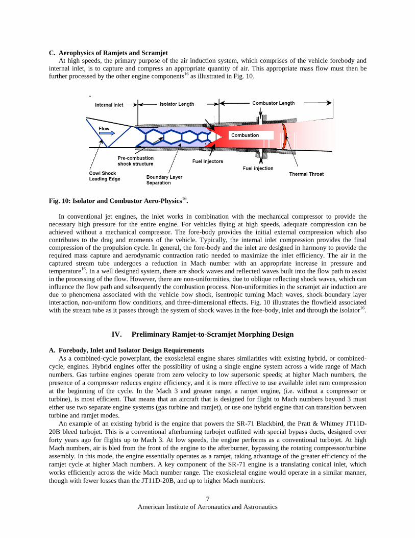
C. Aerophysics of Ramjets and Scramjet
At high speeds, the primary purpose of the air induction system, which comprises of the vehicle forebody and
internal inlet, is to capture and compress an appropriate quantity of air. This appropriate mass flow must then be
further processed by the other engine components16
as illustrated in Fig. 10.
Fig. 10: Isolator and Combustor Aero-Physics16
.
In conventional jet engines, the inlet works in combination with the mechanical compressor to provide the
necessary high pressure for the entire engine. For vehicles flying at high speeds, adequate compression can be
achieved without a mechanical compressor. The fore-body provides the initial external compression which also
contributes to the drag and moments of the vehicle. Typically, the internal inlet compression provides the final
compression of the propulsion cycle. In general, the fore-body and the inlet are designed in harmony to provide the
required mass capture and aerodynamic contraction ratio needed to maximize the inlet efficiency. The air in the
captured stream tube undergoes a reduction in Mach number with an appropriate increase in pressure and
temperature16
. In a well designed system, there are shock waves and reflected waves built into the flow path to assist
in the processing of the flow. However, there are non-uniformities, due to oblique reflecting shock waves, which can
influence the flow path and subsequently the combustion process. Non-uniformities in the scramjet air induction are
due to phenomena associated with the vehicle bow shock, isentropic turning Mach waves, shock-boundary layer
interaction, non-uniform flow conditions, and three-dimensional effects. Fig. 10 illustrates the flowfield associated
with the stream tube as it passes through the system of shock waves in the fore-body, inlet and through the isolator16
.
IV. Preliminary Ramjet-to-Scramjet Morphing Design
A. Forebody, Inlet and Isolator Design Requirements
As a combined-cycle powerplant, the exoskeletal engine shares similarities with existing hybrid, or combined-
cycle, engines. Hybrid engines offer the possibility of using a single engine system across a wide range of Mach
numbers. Gas turbine engines operate from zero velocity to low supersonic speeds; at higher Mach numbers, the
presence of a compressor reduces engine efficiency, and it is more effective to use available inlet ram compression
at the beginning of the cycle. In the Mach 3 and greater range, a ramjet engine, (i.e. without a compressor or
turbine), is most efficient. That means that an aircraft that is designed for flight to Mach numbers beyond 3 must
either use two separate engine systems (gas turbine and ramjet), or use one hybrid engine that can transition between
turbine and ramjet modes.
An example of an existing hybrid is the engine that powers the SR-71 Blackbird, the Pratt & Whitney JT11D-
20B bleed turbojet. This is a conventional afterburning turbojet outfitted with special bypass ducts, designed over
forty years ago for flights up to Mach 3. At low speeds, the engine performs as a conventional turbojet. At high
Mach numbers, air is bled from the front of the engine to the afterburner, bypassing the rotating compressor/turbine
assembly. In this mode, the engine essentially operates as a ramjet, taking advantage of the greater efficiency of the
ramjet cycle at higher Mach numbers. A key component of the SR-71 engine is a translating conical inlet, which
works efficiently across the wide Mach number range. The exoskeletal engine would operate in a similar manner,
though with fewer losses than the JT11D-20B, and up to higher Mach numbers.

American Institute of Aeronautics and Astronautics
8
A key to the success of any combined-cycle engine is minimizing the inevitable compromises that are made in
designing a single engine that can operate in different modes. Consequently, the inlet must be designed so that it
can operate across the Mach number spectrum, while accommodating the proper management of the central core and
the compressor flowfields. Shock locations and uniformity requirements must also be met, since the compressor face
is much more sensitive to the peripheral flow gradients when compared to traditional engine design. The star-shaped
fore-bodies, generated in this research effort and illustrated in Fig. 11a, 11b and 11c, meet these requirements.
a) Front View
b) Side View
12c) Isometric View
Figure 11. Star-Shaped Inlets for the Exoskeletal Ramjet-to-Scramjet Concept.
In a similar manner the inlet and isolator configurations are generated. In the case of the inlet geometry, the final
configuration is completely determined by a secondary shock wave that is reflected off of the cowl lip, such that the
inlet flow turns and enters the isolator parallel to the freestream. Illustrative examples of the inlet, highlighting the
variation of the cross-sectional geometry resulting from the secondary shock, and the accompanying isolator are
presented in Fig. 12a, 12b and 12c.
In an effort to accommodate the technical requirements explained above, an inverse design approach based on
the waverider concept outlined in Section I is explored; refer to Ref. 7-10 for greater details. This effort focused on
the design of an inlet capable of operating over a wide Mach number range, and providing high quality flow to three
distinct regions of the engine; namely, the forebody, the inlet and the isolator. Using the vehicle design methodology
described in Sections I and II, an appropriate class of star-shaped inlets was derived, and a representative of that
class is illustrated in Fig. 11. Similarly, the inlet and isolator designs are illustrated in Figs. 12a, 12b and 12c. It is of
interest to note that the FORTRAN Code developed as part of this analysis can generate star-shaped fore-bodies
with the number of blades ranging from one through eight. Illustrative views of the inlet and the isolator resulting
from the four-point star-shaped forebody are illustrated in Fig. 13a, 13b, and 13c.
a) Inlet Front View
b) Inlet Isometric View
c) Isolator Isometric View
Figure 12: Illustrative Examples of the Inlet and Isolator

American Institute of Aeronautics and Astronautics
9
a) Inlet Front View
b) Inlet Side View
c) Inlet Isometric View
Fig. 13 Illustrative Views of the Fore-body-Inlet Combination
B. Designing for Ramjet-Scramjet Transformation
The ramjet was designed to work at supersonic speeds. Unlike turbojets, ramjets have no moving parts. The air is
captured by the inlet and compressed by the primary shock wave. A typical ramjet configuration17, 18
is illustrated in
Fig. 14. As observed in Fig. 14, the compressed air is slowed down as it approaches the burner, and combustion
takes place in subsonic conditions. A nozzle is then employed to accelerate the hot gas back to supersonic speeds.
This mode of operation gives the ramjets a leap in speed to Mach numbers ranging from 3 – 5. It is of interest to
note that the air speed in the ramjet compressor remains high. In addition, the air in the combustor is brought to
subsonic conditions prior to burning, resulting in both high temperature and pressure in the engine with temperatures
in the range of 6,000ºF. These and other effects, force the ramjet to favor operations at low Mach numbers17-18
.
Figure 14: Schematic Diagram of the Ramjet Figure 15: Schematic Diagram of the Scramjet
In an effort to mitigate this problem designers came up with the scramjet concept, a supersonic combustion
ramjet which solved the overheating problem of the ramjet. This concept is illustrated in Fig. 15. The difficulties
associated with mixing air with the fuel at supersonic speeds, and completing combustion within milliseconds, have
both been solved as demonstrated in the two successful X-34 test flights15
. In this effort, a deliberate attempt is made
to construct a variable ‘diffuser-to-plug-nozzle’ concept that allows for the seamless engine transition from ramjet to
scramjet operation modes. This design concept was first illustrated in Fig. 9. In a similar manner, this concept was
implemented in the generation of the preliminary ramjet-to-scramjet configurations that are illustrated in Fig. 16.
The combustor accepts the inlet/isolator airflow with variations in geometric inflow profiles and provides
efficient fuel air mixing within the available combustor length16
as shown in Fig. 10. The fuel supply subsystem is
required to deliver fuel to the flow path at appropriate locations with the desired physical properties. The combustor
fuel is scheduled to stay within the engine operability limits while optimizing engine thrust potential. The expansion
system, consisting of the internal nozzle and vehicle after-body, completes the propulsion flow path and controls the
expansion of the high pressure and temperature gas mixture to produce net thrust. During the expansion process, the
potential energy generated by the combustor is converted into kinetic energy. The nozzle must process the
accumulated flow distortions generated by the air induction system, isolator and combustor. The phenomena of
importance to the scramjet nozzle design include flow chemistry, boundary layer effects, non-uniform flow

American Institute of Aeronautics and Astronautics
10
conditions, shear layer interaction, and three-dimensional effects11-22
. The design of the nozzle has a major effect on
the efficiency of the propulsion system and the vehicle due to its ability to influence vehicle pitching moment and
lift22
.
a) Rear View b) Front View c) Side View
d) Transparent Isometric View e) Isometric View with Cut away
Fig. 16: Illustration of A Morphing Ramjet-to-Scramjet Configuration
V. Preliminary Ramjet Analysis
A. Ramjet-Scramjet Design from 2D Flowfields
This research project is in its infancy and its immediate objectives are: to design ramjet configurations carved
from 2D flowfields, and to investigate their aerodynamic performance. For this purpose, conceptual design routines
written in an OOP using FORTRAN are developed. In general, the geometric design concept originates from the 2D
planar and axisymetric theories described in Section I of this paper.
Using the waverider theory as a starting point and the propulsion systems concept described in Ref. 12, a typical
ramjet C-sectional flowfield illustrated in Figure 17 can be derived. The details of the aerodynamic analysis efforts
related to the performance of this configuration are described in the next section. This section, however, focuses on
the construction of a 3D ramjet-to-scramjet configuration that uses Fig. 17 as its defining inputs. The geometric
points, A through G, lying on the x-axis not only define the various components of the ramjet propulsion system
such as it’s forebody, inlet, isolator, diffuser, combustor and nozzle, they also serves as the key indicators for the 3D
construction of these components.
Fig. 17: Illustration of A Ramjet-to-Scramjet Mid-Section with Morphing Design Points
Primary
Shock
Zone
A
Reflected
Shock
Zone
Isolator
Zone Diffuser
Zone
Combustor
Zone
Nozzle
Zone
B D C E F G
x

American Institute of Aeronautics and Astronautics
11
For example, using the information at points D and E along the x-axis and the geometric information resulting from
the star-shaped, fore-body configuration illustrated in Figure 11, an appropriate 3D configuration representing the
diffuser can be constructed. In this case, the geometry of the resulting diffuser is illustrated in Figure 18.
a) Diffuser Base View
b) Diffuser Side View
c) Diffuser Isometric View
Figure 18: Illustration of the diffuser Component Derived from a star-shaped fore-body
It is of interest to note that by choosing the design points, A – G, in the form of design parameters and
independent of each other, the resulting integrated configuration can have its E-point beyond its F-point location
with respect to the x-axis. This approach provides a great deal of flexibility in arriving at candidates with desirable
aerodynamic characteristics. In addition, when generating the 3-D configurations, the choice of the fore-body is of
great importance, since it provides the geometric information need from the third dimension. In this research, star-
shaped, fore-bodies are generated with the number of blades ranging from two to eight. Once the appropriate
forebody information is obtained, following the approach already outlined, each component of the ramjet can be
uniquely defined in 3D and constructed, using the routines already established. Examples of the types of propulsion
system components and the manner in which they are pieced together to result in an integrated ramjet configuration
are illustrated in Figure 19.
a) Side View of A Variable Geometry Ramjet Configuration
b) Isometric View of Ramjet
c) Transparent Isometric View of Ramjet
Figure 19: Illustration of Ramjet Derived from a 4-Point Star-Shaped Fore-body

American Institute of Aeronautics and Astronautics
12
B. Ramjet-Scramjet Analysis
The analysis of the propulsion system consists of the evaluation of the following six major components; namely, the
primary shock zone, the inlet, the isolator, the diffuser and mixing region, the combustor and the nozzle. The
evaluation of the primary shock zone, the inlet and the nozzle is straight forward and is conducted in accordance
with Ref. 11-12, 19-20. However, the evaluation of the flowfield parameters is somewhat complicated and is
conducted in accordance with Ref. 12.
The isolator, diffuser and combustor sections of the ramjet engine, illustrated in Figure 20, are modeled using a
quasi-one-dimensional analysis19-20
. The main equation describing the quasi-one-dimensional flow through these
sections includes area variation, friction and mass injection, and can be written in the following form12
:
dx
md
mM
MM
D
c
M
MM
dx
dT
TM
MM
dx
dA
AM
M
dx
dM
M h
f
1
1
124
1
1
1
11
1
212
2
2
20
02
2
2
2
2
(4)
where the parameter, M , is defined as follows:
2
2
11 MM
In Eq. (4), the symbols; M represents the local Mach number, To the total temperature, cf the skin friction coefficient,
m the mass flow rate and x the independent parameter, which represents the local distance along the ramjet
centerline. In order to integrate Eq. (4), the design parameters; such as, the cross sectional area, A(x), the stagnation
temperature, T0(x), the mass flow rate, m , and the coefficient of friction, cf, must be specified as functions of the
variable, x.
Figure 20: Designation of Axial Locations for the Propulsion System Geometry
The area variation, A(x), is calculated based on the engine configuration, T0(x) is assumed constant except for the
regions where combustion is simulated through the use of Eq. (5), and as suggested in Ref. 12. Combustion is
simulated as an increase in the stagnation temperature of the flow in the combustor up to a specified maximum; this
temperature release profile is described using a rational function20
;
x
x
T
T
T
xT
1111
02
04
02
0
(5)
where the parameter, x , is defined as follows:
34
3
xx
xxx
Isolator
Reflected Shock
Ramjet Burner
Ramjet Nozzle
Primary Shock Mixing
2 3 4

American Institute of Aeronautics and Astronautics
13
and the symbols, x is the horizontal distance measured from the combustor starting location to its ending point,
namely, ix and 4x . On the other hand the non-dimensional parameter, , is a factor greater than 1. Typically, a
value in the range of 40 - 50 is chosen for the symbol, , in the case of subsonic ramjet combustion12
.
The local cross-sectional area and equivalent width are combined and used in the Reference Temperature
method21
, for evaluating the local skin friction, cf,. It is of interest to note that the fuel injection influence is
simulated in the mass flow rate term, m . For realistic ramjet operations, a sonic point needs to be located in the
combustor, corresponding to choking of the flow at the throat. In Ramjet mode of operations, finding the sonic point
is obvious, however, in the case of the scramjet the sonic location is found as described in Ref. 12 and 20. Using
l’Hospital’s rule in relations to Eq. (4) as the Mach number approaches unity an appropriate value for x is found at
which location the Mach number is equal to one. Once the sonic point is found, Eq. (4) is integrated backwards to
obtain the properties at the combustor entrance.
The flow through the isolator is also obtained by the integration of Eq. (4). The driving functions are again
specified in a similar manner, and the integration is performed from the isolator entrance to exit in order to obtain
the flow conditions. Although the isolator is expected to contain a ‘shock train’ that brings the flow to the subsonic
conditions required at the combustor entrance, no analytical models are available to provide the solution to such
phenomena, see Fig. 10. Therefore, a single normal shock wave is assumed to perform the same function as the
‘shock train’. The appropriate integration of Eq. (4) is conducted in an iterative manner, varying the location of the
normal shock wave until a solution is found where the isolator exit conditions match the required combustor
entrance conditions. These ideas are also described in Ref. 18, 20 and 22. After the isolator and combustor flowfield
solutions are obtained, the momentum thrust of the engine is calculated as the difference between the impulse
function at the combustor exit and the isolator entrance20
:
)()( 24 xIxIT (6)
where, the impulse function, I, is defined as,
21 MpAI
VI. Conclusion and Future Plans
This paper gives a preliminary report on efforts to design a reconfigurable propulsion system; morphing from
ramjet to scramjet mode of operation in flight. Performance requirements will almost certainly dictate the use of a
translating center body and associated outer ‘clamshell’. The design of forebody-inlet-isolator was accomplished
through the use of 2D planar flowfields. In addition, realistic ramjet-to-scramjet propulsion systems were derived
and analysis from 2D planar shock waves, expansion waves, and from Quasi-1D flows with heat addition and
friction. The next step is to redesign these components by using 2D axisymetric flowfields. This task can be
accomplished with minimum effort since the authors have already used axisymmetric flowfields to generate
waveriders7-11
. The ramjet-scramjet transition mechanism does demand a great deal of aerodynamic and structural
analysis. The current approach focused on using the ideal situation; however, phase two of this effort will improve
the analysis methods by introducing combustion and quasi-1D nozzle modules with real gas effects. Detailed
analysis of the ‘ramjet-to-scramjet propulsion systems’ performance at various Mach numbers is of interest to this
study and will form a significant element of this research project as it develops. This includes developing the
geometric concepts, calculating inlet flowfields, and estimating performance and losses at key Mach numbers;
ranging from Mach 2 up to Mach 6. Managing the shock locations on the inlet, especially to provide good flow
conditions into both the core and compressor duct, is of great interest. The inward turning diffuser concepts are
already employed in the design process, as they lend themselves to concentric engine flowfields. With the
development of a suitable inlet and ram-scramjet configuration, a detailed combined-cycle engine model will be
developed, covering the Mach number range from static to near-hypersonic and beyond. The ultimate product of
this effort will be a recommended geometry for use as a CFD and wind tunnel or flight test bed for the
demonstration of a turbine-based combined-cycle exoskeletal engine.
Acknowledgments
This work has been partially sponsored by the following agencies; NAVAIR, NASA Glenn and Langley
Research Centers. In addition, special appreciation is extended to the Space Vehicle Technology Institute at the

American Institute of Aeronautics and Astronautics
14
University of Maryland, one of the NASA University Institutes, with joint sponsorship from the Department of
Defense. Appreciation is expressed to Dr. Isaiah Blankson of NASA Glenn Research Center and Dr. Reginal
Williams of the Naval Airforce Base at Patuxent River in Maryland.
References 1I. M. . Blankson, et al., ‘Air-Breathing Hypersonic Cruise: Prospects for Mach 4-7 Waverider Aircraft,’ ASME
Journal of Propulsion and Power, January-April, 1994. 2I. M. . Blankson, et al. ‘Anatomy of a Hypersonic Air-breather: A Turbine Based Combined - Cycle Hypersonic
Cruise Application-Vehicle,’ International Symposium on Air Breathing Engines, ISABE Paper 1999, Florence,
Italy. Sept 1999. 3Nonweiler, T., “Aerodynamic Problems of Manned Space Vehicles,” Journal of Royal Aeronautical Society,
Vol. 67, Jan. 1963. 4Nonweiler, T., “Delta wings of Shapes Amendable to Exact Shock Wave Theory,” Journal of Royal
Aeronautical Society, Vol. 67, Jan. 1963. 5Bowcutt, Kevin G., “Optimization of hypersonic Waveriders Derived from Cone Flows Including Viscous
Effects”, Ph.D. Dissertation, Department of Aerospace Engineering, University of Maryland, College Park,
Maryland, 1986 6Bowcutt, Kevin G., Anderson, John D. Jr., and Capriotti, D.P., “Viscous Optimized Hypersonic Waveriders,”
AIAA paper 87-0272, 1987. 7Ferguson, F., “Expanding the Waverider Design Space Using Arbitrary Generating Flowfields”, Ph.D.
Dissertation, Department of Aerospace Engineering, University of Maryland, College Park, Maryland, 1993. 8Frederick Ferguson, Terry L. Corbett, Jr., Stephen Akwaboa, and Haile Lindsay, “The Development of
Waveriders From an Axisymmetric Flowfield”, AIAA 2007-847, 45th
American Institute of Aeronautics and
Astronautics Aerospace Sciences Meeting and Exhibit, Reno, NV 2007. 9Hydar Apdin and Frederick Ferguson, ‘A Design Concept for the Construction of Completed Hypersonic
Vehicles’, 13th AIAA/CIRA International Space Planes and Hypersonic Systems and Technologies Conference,
CIRCA, Italy, May 2005 10
J. Zhang and F. Ferguson, ‘Construction and Analysis of Hypersonic Vehicle Configurations’, 13th
AIAA/CIRA International Space Planes and Hypersonic Systems and Technologies Conference, CIRCA, Italy, May
2005. 11
John J, Bertin “Hypersonic Aerothermodynamics.” AIAA Education Series. ISBN: 1-56347-036-5, Published
by American Institute of Aeronautics and Astronautics, 1994 12
William H. Heiser, David T. Pratt “Hypersonic Airbreathing Propulsion.” AIAA Education Series. ISBN: 1-
56347-035-7, Published by American Institute of Aeronautics and Astronautics, 1994. 13
E. T. Curran and S.N.B. Murthy, “Scramjet Propulsion”, Vol. 189, AIAA, 2000. 14
Kuchemann, D. “The Aerodynamic Design of Aircarft”, Pergamon Press, New York, 1978. 15
NASA Dryden Flight Research Center, PAO, “NASA’s X-43A Proves Hypersonic Scramjet Flight, March 27,
2004. 16
Dean Andreadis, “Scramjet Engines Enabling The Seamless Integration Of Air & Space Operations”, Pratt &
Whitney Space Propulsion, Hypersonics, West Palm Beach, FL. 17
Hill, P., and Patterson, C., ‘Mechanics and Thermodynamics of Propulsion’, Addison-Wesley Publishing
Company, 1992. 18
Billig F. S.; “Research on Supersonic Combustion” Journal of Propulsion and Power, Vol. 9, No 4, July-Aug
1993 19
John D. Anderson “Fundamentals of Aerodynamics” Third Edition, McGraw-Hill, New York, 2001. 20
Marcus Lobbia and Kojiro Suzuki, Numerical investigation of Waverider-Derived Hypersonic Transport
Configurations’, AIAA Paper 2003-3804 21
White. F. M., ‘Viscous Fluid Flow’, McGraw-Hill, New York, 1974. 22
O’Neil, M, K. and Lewis, M. J., “Design Tradeoffs on Scramjet Engine Integrated Hypersonic Waverider
Vehicles,” Journal of Aircraft, Vol. 30, No. 6, 1993, pp 943-952.

7/25/2014 46th AIAA Aerospace Sciences
Meeting and Exhibit
1
Hypersonic Vehicle Design
Mookesh Dhanasar
PhD Student, CAR
North Carolina A&T State University
January 9th 2008

7/25/2014 2
Outline
1. Justification For Hypersonic Technology Development
2. A Brief Review of the Waverider Concept
3. Hypersonic Vehicle Design from 2D Flowfields
4. Propulsion Systems Design from 2D Flowfields
4i: Geometric Design
4ii: Thrust Analysis
5. Conclusion

7/25/2014 3
Justification for Hypersonic Technology Development
Section 1: Introduction

7/25/2014 4
Hypersonic Technology Applications
• Access to Space
– Transportation on Demand to ISS, Lunar Base, etc
• Civilian Transatlantic, Transpacific Transport
– Transportation for long hauls/flights (flight times reduction, potentially reduces >12hrs to <3hrs)
• Military Applications
– Missiles, etc
What are the potential benefits of hypersonic technology?

7/25/2014 5
Characteristics of Hypersonic Flows
Hypersonic Flow (M = 5) is defined as the flight regime where the following flow phenomena gets progressively more important as the Mach number increases:
Thin Shock Layers
Entropy Layer
Viscous Interaction
High Temperature Effects
Low Density Flow

7/25/2014 6
Integrated Hypersonic Vehicle Designs
Flight Performance Data:
Justification for the Integrated Hypersonic Vehicle Design
Observation and Independent study

7/25/2014 7
Integrated Hypersonic Vehicle Designs
Flight Performance Data:
Justification for the Integrated Hypersonic Vehicle Design
Kuchemann

7/25/2014 8
Idealized Hypersonic Vehicles • Idealized Hypersonic Vehicles

7/25/2014 9
Propulsion Systems & Their Capability
This is what is known about various propulsion systems.

7/25/2014 10
Propulsion System Driven Configurations
Ultimately, the Aircraft Mission & the Propulsion System drive the configuration of the Hypersonic Aircraft

7/25/2014 11
A Brief Review of the Waverider Concept
Section 2: Hypersonic Vehicle Design

7/25/2014 12
Background
A waverider is any hypersonic vehicle that uses its own shock
wave to improve its overall aerodynamic performance
What are Waveriders?
Re-entry Vehicle with High Lift Capabilities
Terence Nonweiler, UK, 1959
Star shaped Bodies with Minimum Drag Capabilities
Maikapar, Russia, 1959
2-D plane shockwave
7/25/2014 13
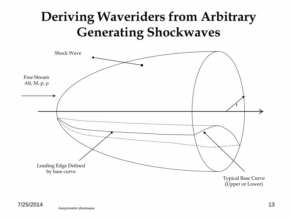
Deriving Waveriders from Arbitrary Generating Shockwaves
r
Shock Wave
Free Stream Alt, M, p, ρ
Leading Edge Defined by base curve
Typical Base Curve (Upper or Lower)
Axisymmetric shockwave

7/25/2014 14
Coupled Inviscid Streamline & Boundary Layer Theories
Solid Streamline
Calculation of the Local Shear Stress & Local Heat Flux
0
n
P
Boundary Layer
streamlinesolidedgeBL PP ,
Inviscid Streamline
h, Cf
LTransition
transitionturbstH
transitionlamstH
H
transitionturbst
transitionlamst
LLengthLocalC
LLengthLocalCC
LLengthLocal
LLengthLocal
,
,
,
,
,,
,,
,
,
stst
sttrTransition
VL
*
*Re
641.2*0001209.0421.610Re
Me
tr
Viscous effects

7/25/2014 15
• Force due to Pressure, P
• Force due to Shear stress, FFF p
kzdSjydSixdSSd
S
SdF
S
SpdpF
i
j
k
• Integrate over the whole wetted surface to obtain the components
F
Sd
P
Aerodynamic Analysis Objective: To calculate L, D, and L/D
kGjLiDF
The force vector is a function of pressure and shear stress F

7/25/2014 16
Cone-Derived Waveriders
Reviewing

7/25/2014 17
1=Flat Upper 2=Flat Lower 3=Upper Opt. 1 4=Lower Opt.1
5=Upper H’bolic 6=Lower H’bolic 7=Upper Opt.2 8=Lower Opt. 2
Illustrations of Waverider Generated from Conical Flowfields

7/25/2014 18
9=Upper Elliptical 10=Lower Elliptical 11=Upper P’bolic 12=Lower P’bolic
13=Upper Circular Arc
14=Lower Circular Arc
15=Upper Opt. 3 16=Lower Opt. 3
Illustrations of Waverider Generated from Conical Flowfields

7/25/2014 19
17=Upper Opt. 4 18=Lower Opt.4 19=Upper Min. Drag
20=Lower Min. Drag
21=Upper Fixed Base to Width Ratio
22 = Lower Fixed Base to Width Ratio
23=Bat Wing
Illustrations of Waverider Generated from Conical Flowfields

7/25/2014 20
Results
4.5
4.7
4.9
5.1
5.3
5.5
5.7
5.9
6 8 10 12 14 16 18 20
Mach Number
L/D
Flat Bottom Lower Circular Arc
Bat Wing Kuchemann

7/25/2014 21
Waverider Design Validation
Reinforces the waverider design process

7/25/2014 22
Hypersonic Vehicle Design from 2D Flowfields
Section 3: Research Plans
Plane or axisymmetric

7/25/2014 23
Characteristics of Hypersonic Vehicles
Integrated Configurations Air-breathing Propulsion Systems
Favorable Dynamic Pressure Environments
reviewing

7/25/2014 24
Hypersonic Vehicle with Morphing Capability
An NCAT-CAR Proposed Concept
Agard
Complex

7/25/2014 25
Ramjet Only
Turbojet & Ramjet Turbojet Only
Turbojet Inlet Compressor
Burner
Turbine
Ramjet Burner Ramjet Nozzle
Turbojet Nozzle Turbojet Exhaust Duct
& Afterburner
A NASA-GRC Proposed Concept
Hypersonic Propulsion System with Morphing Capability
Exo-Skeletal Engine Concept The engine is design to operate as a combined-cycle propulsion plant from
ground to Mach 6 and greater. The ‘exoskeletal’ engine concept is a revolutionary
class of gas turbine engines, in which the rotating components are mounted
concentrically within a drum structure around a central core channel. This
provides numerous postulated advantages over a conventional engine, primarily
because the rotating components are in compression instead of tension. Of great
interest for application to a combined-cycle engine is the fact that the central
core of this engine could function as a ramjet, and possibly even a scramjet,
enabling the engine to operate on a hybrid cycle up to hypersonic speeds.

7/25/2014 26
NASA GRC Exo-Skeletal Engine Concept
Duct In which the Ram-Scramjet is Constructed

7/25/2014 27
Ramjet Only
Turbojet & Ramjet
Turbojet Inlet Compressor
Turbine
Ramjet Burner Ramjet Nozzle
Turbojet Nozzle Turbojet Exhaust Duct
& Afterburner
Propulsion System Design Challenge
Identify The Engineering Design Parameters as Functions of the Mach
Number that optimally morphs the ramjet into the scramjet as the propulsion
System traverse the Mach range of 3 to 8.
1. Exoskeletal Turbine Cycle Concept, NASA GRC
2. Ramjet-Scramjet Morphing Concept, NASA GRC, NCAT

7/25/2014 28
Propulsion Systems Design from 2D Flowfields
4.i: Geometric Design
4.ii: Thrust Analysis
Section 4: Ramjet-Scramjet Concept

7/25/2014 29
1. AERODYMANICS REQUIREMENTS DRIVES THE GEOMETRIC SHAPES
MORPHING RAMJET-SCRAMJET DESIGN CHALLENGES
2. THE GEOMETRIC SHAPES DRIVES THE AERO-PROPULSION ANALYSIS
Lower M require a nozzle to simulate the thermal Throat.

7/25/2014 30
Primary
Shock
Zone
A
Reflected
Shock
Zone
Isolator
Zone Diffuser
Zone
Combust
or
Zone
Nozzle
Zone
B D C E F G
x
GEOMETRIC DESIGN ASPECTS
A 2D Ramjet-Scramjet Cross-Section is Constructed, using a
parametric approach
The engineering design parameters are chosen such that the
Cross-Sectional Geometry Changes from Ramjet to Scramjet
Modes.
Based on the Waverider-Design Approach, a 3D Forebody/Inlet is
carefully chosen.
The Fore-body introduces the 3rd Dimension need for the
construction of the Closed Geometrical Shape of the
Morphing ‘Ramjet-Scramjet’ Configuration.
Develop a FORTRAN code

7/25/2014 31
2
2 5 3 4 6 7 1
A
B
C D
E F
G
H
I
J
K
Illustration of the RAMJET-SCRAM Design Coordinates
(Data for Two-Shockwaves Design Concept)

7/25/2014 32
11,M
2
1,
M
22,M
11,M
2
1,
M
22,M
22cos2
12sin2cot2tan
1
1
11
)β(γM
βMβθ
1
1,1
sin
nMM
2
1
211
2,
2,
21,
n
n
n
M
M
M
)sin( 1, MMn
Vehicle Forebody Design Procedures
1
2
1
2
1
2
1
2
y
x
A C D B
H = Alt
M = Mach
E
1. Geometric Construction Methods
2. Aerodynamic Analysis Methods

7/25/2014 33
GEOMETRIC DESIGN ASPECTS
Figure 11: Star-Shaped Inlets for the Exoskeletal Ramjet-to-Scramjet Concept
Fig. 11c: Front View Fig. 11b: Isometric View Fig. 11a: Side View
A Sample of Possible Forebodies
For Simplicity the 4 Star-Shaped Fore Body is Chosen
Y
X
Z
Frame 001 14 Feb 2007
X Y
Z
V4
4068.21
4036.09
4003.97
3971.85
3939.72
3907.6
3875.48
3843.36
3811.23
3779.11
3746.99
3714.86
3682.74
3650.62
3618.5
Pressure Distribution
Penetrator
Frame 001 14 Feb 2007

7/25/2014 34
ILLUSTRATION OF AN INLET WITH A REFLECTED SHOCK
Using the 4-Point Star-Shaped Body, and Two-Shocks:
E
F
G
H
HL
Shock wave II
Shock wave
Freestream
1
2
h
LCowl L2
H2
2 4
3
1
2
3 3
2

7/25/2014 35
Primary
Shock
Zone
A
Reflected
Shock
Zone
Isolator
Zone Diffuser
Zone
Combust
or
Zone
Nozzle
Zone
B D C E F G
x
3D Geometric Construction from Prescribed 2D C-Section & Forebody Shapes

7/25/2014 36
Rear View Front View Side View
Transparent Isometric View Isometric View with Cut away
Fig. 16: Illustration of A Morphing Ramjet-to-Scramjet Configuration
3D ILLUSTRATION OF THE RAMJET-SCRAMJET
Derived from Prescribed 2D C-Section & Forebody Shapes
7/25/2014 37
Propulsion Systems Design from 2D Flowfields
4.i: Geometric Design
4.ii: Thrust Analysis
Section 4: Ramjet-Scramjet Concept

7/25/2014 38
The Ideal Ramjet Engine Thermodynamic Analysis
The ideal engine thrust is given by (Hill, Paterson):
where f is the fuel-air ratio, uexit and u3 velocities at locations 3 and the exit.
Isolator
Reflected Shock
Ramjet Burner
Ramjet Nozzle
Primary Shock
Mixing
2 3 4 Exit
33 1 uufmT Exit
)1()(
)()(
2
3
MpAxI
xIxIT exit
Alternate Form for Thrust,
Impulse function

7/25/2014 39
Isolator
Reflected Shock
Ramjet
Burner
Ramjet
Nozzle
Primary Shock Mixing
2 3 4
The Ideal Ramjet Engine Thermodynamic Analysis
dx
md
mM
MM
D
c
M
MM
dx
dT
TM
MM
dx
dA
AM
M
dx
dM
M h
f
1
1
124
1
1
1
11
1
212
2
2
20
02
2
2
2
2
2
2
11 MM
where the parameter, M , is defined as follows: mand the mass flow rate
1. Mach Number Evaluation:
The cross sectional area, A(x), is obtained from the design inputs.
The skin friction Coefficient, cf , is evaluated using the Reference Temperature method.
2. Skin Friction Coefficient:
The stagnation temperature, T0(x) is computed as follows:
34
3
02
04
02
0 ,5040,11
11xx
xxx
x
x
T
T
T
xT
3. Stagnation temperature Evaluation:

7/25/2014 40
PRELIMINARY RESULTS
ISP vs Mach Number
(4-Point Star Configuration)
2000
3000
4000
5000
6000
2 4 6 8 10 12
Mach Number
ISP

7/25/2014 41
Discussion
ISP vs Mach Number
(4-Point Star Configuration)
2000
3000
4000
5000
6000
2 4 6 8 10 12
Mach Number
ISP

7/25/2014 42
CONCLUSION
• When looking at hypersonic technology development
there is :
– Need for an integrated vehicle design:- Waverider concept.
– Need for an integrated propulsion system: Combine cycle
concept.
• Preliminary results are encouraging but needs
validation.

7/25/2014 43
Thank You!
Any Questions?

7/25/2014 44
Back-up Slides

7/25/2014 45

7/25/2014 46

7/25/2014 47
Thin Shock Layers Thin Shock Layers
As the Mach number increases, the shock angle becomes smaller, as illustrated in the figure below. The resulting flowfield between the surface and shock is often referred to as a shock layer. This thin layer can produce many complications in vehicle design, e.g. the shock layer may merge with the boundary layer at low Reynolds numbers to form a fully viscous shock layer.
Shock waves and streamlines over a 20° half-angle wedge at (a) Mach 2 and (b) Mach 20 [from Anderson, 2000]
At high Reynolds numbers, the shock layer can be treated as inviscid (meaning there is no friction). In the limit as Mach number goes to infinity, the shock layer forms an infinitely thin, infinitely dense sheet, or, essentially, a flat plate. The infinite flat plate is the most efficient lifting surface at hypersonic velocities, and the inviscid shock layer can therefore be used to develop simplified theories to predict hypersonic aerodynamic properties.
Sect 3.1

7/25/2014 48
Entropy Layer Entropy Layer Shock theory tells us that entropy increases across a shock, and the entropy increase becomes greater as the shock strength increases. Since flow near the nose passes through a nearly normal shock, it will experience a much greater change in entropy compared to flow passing through the much shallower shock angle further from the body centerline. Thus, strong entropy gradients exist near the leading edge generating an "entropy layer" that flows downstream along the body surface.
Entropy layer formation [from Anderson, 2000]
The classical boundary layer grows within this entropy layer and may be greatly affected by the entropy gradients. In addition, the entropy layer is a region of strong vorticity that can generate large gradients in the velocity flowfield near the surface, a phenomenon called "vorticity interaction." The large velocity and thermodynamic gradients induced by the sharply curved oblique shock become troublesome when attempting to predict aerodynamic performance, heat transfer results, and boundary layer shape for a hypersonic vehicle.
Sect 3.1
7/25/2014 49
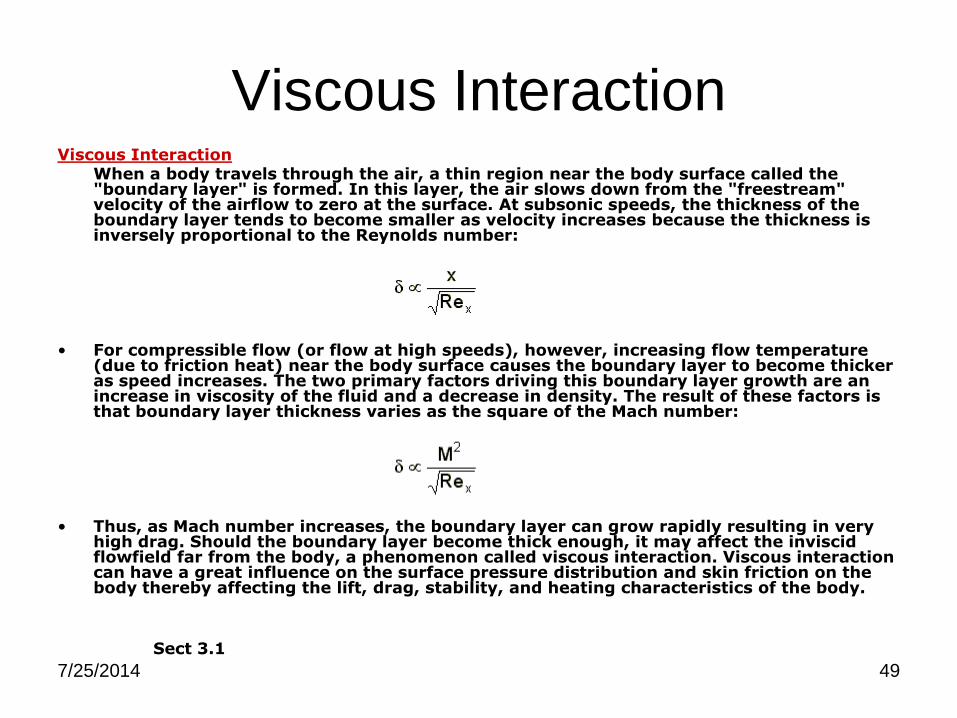
Viscous Interaction Viscous Interaction When a body travels through the air, a thin region near the body surface called the
"boundary layer" is formed. In this layer, the air slows down from the "freestream" velocity of the airflow to zero at the surface. At subsonic speeds, the thickness of the boundary layer tends to become smaller as velocity increases because the thickness is inversely proportional to the Reynolds number:
• For compressible flow (or flow at high speeds), however, increasing flow temperature
(due to friction heat) near the body surface causes the boundary layer to become thicker as speed increases. The two primary factors driving this boundary layer growth are an increase in viscosity of the fluid and a decrease in density. The result of these factors is that boundary layer thickness varies as the square of the Mach number:
• Thus, as Mach number increases, the boundary layer can grow rapidly resulting in very
high drag. Should the boundary layer become thick enough, it may affect the inviscid flowfield far from the body, a phenomenon called viscous interaction. Viscous interaction can have a great influence on the surface pressure distribution and skin friction on the body thereby affecting the lift, drag, stability, and heating characteristics of the body.
Sect 3.1

7/25/2014 50
High Temperature Flow High Temperature Flow Any body traveling at high speeds in air produces friction and heat. Part of the kinetic
energy of the body's motion is absorbed by the air and carried away from the body through a process called viscous dissipation. However, hypersonic vehicles create so much heat and such high temperatures that they can actually cause chemical changes to occur in the fluid through which they fly. The most notable changes air undergoes as temperature increases are summarized below.
High Temperature Effects on Air As temperature increases, assumptions about the properties of the air are no longer valid
and the vehicle is said to be traveling through a chemically reacting boundary layer. When the properties of the working fluid change, namely density and heat transfer properties, the aerodynamic characteristics and heating properties of the body can change drastically.
Temperature [K] Chemical Change
800 Molecular vibration
2000 Oxygen molecules (O 2) dissociate
4000 Nitrogen molecules (N 2) dissociate
Nitric oxide (NO) forms
9000 Oxygen and nitrogen atoms ionize
Sect 3.1

7/25/2014 51
Low Density Flow Low Density Flow Most hypersonic vehicles are intended to cruise at high altitudes in low density fluids. In
low density flows, air can no longer be considered to be a continuum because the distance between individual particles of air becomes so great that each particle begins to affect the aerodynamic properties of a body. Under these conditions, common aerodynamic relations, like the Euler and Navier-Stokes equations, break down. Instead, aerodynamic properties must be analyzed using the kinetic theory. Some of the most important differences between low density flows and continuous flows include
– Velocity slip: The viscous no-slip condition that says the velocity of air particles going past a body must be zero at the body surface, fails. Since friction is negligible in low density, the flow velocity at the body surface is no longer zero.
– Temperature slip: The assumption that gas temperature at the body surface becomes equal to the temperature of the body surface material fails.
Sect 3.1
Drag coefficient of a sphere at hypersonic speeds transitioning from continuum to free-molecule flow [from Anderson, 2000]

7/25/2014 52
Calculating Shear Stress & Stanton Number (cont’d.)
2*2
1, ststE VstQ
stEstfst QC ,, *
• Local Dynamic Pressure at the edge
• Local Shear Stress
45.210 eRlog176.0
sturbtS
21
2, 158.032.00.1
Re
664.0
T
TMC w
s
lamf
2132 RePr332.0 slamtS
2.0,eR
0592.0
s
turbfC
svsRe
sv
seR
• Local Skin Friction Coefficient
• Local Reynolds Number
• Local Stanton Number

7/25/2014 53
Shape Generation
• Two-Dimensional Flowfield in terms of x and r
• Waverider Shape needs to be Three-Dimensional
• Third Dimension introduced with Shape Angle

7/25/2014 54
Shape Generation (Shape Angle)
y
z
Streamline Coordinates
Azimuthal Angle, f(r)
Conical Shockwave
Waverider Base f

7/25/2014 55
Models : The Ideal & Real Ramjet Engine
The ideal engine thrust is given by (Hill, Paterson):
where f is the fuel-air ratio, uexit and u3 velocities at locations 3 and the exit.
ExitEExit AppuufmT 333 1
Schematic Diagram of a Typical Ramjet. (Hill, Peterson)

7/25/2014 56
i. Since the compression phases are dictated by two oblique shock waves. The
total pressures across these waves can be calculated as described in Anderson,
Oblique Shockwave Theory.
ii. Assuming that combustion occurs at constant pressure, the stagnation pressure
does not change across and through the nozzle.
iii. Assuming that the fluid properties, R and gamma, do not change in any of the
processes, we can relate the pressure at station 3 and the exit to the Mach
numbers representative at those points, as shown in the following equations:
The Ramjet Engine Thermodynamic Analysis
03,0 PP Exit
1
23
3
3,0
2
11
M
P
P
1
2,0
2
11
exit
Exit
ExitM
P
P
Ideal Case:
Real Case:
Nozzle
Combustor
Combustor
DiffuserExitExit
P
P
P
P
P
P
P
PPP
,0
,0
,0
3,0
03
,0
03
,003,0 ;

7/25/2014 57
In the case of an ideal ramjet engine, the enthalpy of the incoming fuel is neglected.
The energy equation then becomes:
where QR is the heating value of the fuel. Assuming a constant specific heat, we can state that the fuel-air ratio now becomes:
Combining several of these equations we can get the thrust per unit mass flow to be:
The Ideal Ramjet Engine Thermodynamic Analysis
03,0 PP Exit
Ideal Case:
fQhhf R 02041
020402
0204 1
TTTcQ
TTf
pR
12
111
212
0204222
MTTfRTMm
T

7/25/2014 58
Combining several of these equations we can get the thrust per unit mass flow to be:
The ‘Real Ramjet’ Engine Thermodynamic Analysis
Real Case:
Nozzle
Combustor
Combustor
DiffuserExitExit
P
P
P
P
P
P
P
PPP
,0
,0
,0
3,0
03
,0
03
,003,0 ;
The departure of isentropic processes leads to significant changes in the
compression, combustion and expansion segments of the ramjet. Stagnation
pressure ratios can be formulated for each of these and are as follows:
020402
0204 1
TTTcQ
TTf
pR
12
11
1
21
2
02
,022
2
Exit
ExitExit
p
p
p
pMM
ExitEExit Appm
uufm
T3
33
3
11

7/25/2014 59
Copyright © 2022 FDOKUMEN