
Current and future hypersonic threats, scenarios and defence ...
134
Defence Research and Development Canada Scientific Report DRDC-RDDC-2022-R046 March 2022 CAN UNCLASSIFIED CAN UNCLASSIFIED Current and future hypersonic threats, scenarios and defence technologies for the security of Canada Paul Labbé DRDC – Centre for Security Science Ahmed Ghanmi Mohamed Abdelazez DRDC – Centre for Operational Research and Analysis Terms of Release: This document is approved for public release.
-
Upload
khangminh22 -
Category
Documents
-
view
0 -
download
0
Transcript of Current and future hypersonic threats, scenarios and defence ...

Defence Research and Development Canada Scientific Report
DRDC-RDDC-2022-R046
March 2022
CAN UNCLASSIFIED
CAN UNCLASSIFIED
Current and future hypersonic threats, scenarios and defence technologies for the security of Canada
Paul Labbé DRDC – Centre for Security Science Ahmed Ghanmi Mohamed Abdelazez DRDC – Centre for Operational Research and Analysis Terms of Release: This document is approved for public release.

CAN UNCLASSIFIED
Template in use: EO Publishing App for SR-RD-EC Eng 2021-02-11.dotm © Her Majesty the Queen in Right of Canada (Department of National Defence), 2022
© Sa Majesté la Reine en droit du Canada (Ministère de la Défense nationale), 2022
CAN UNCLASSIFIED
IMPORTANT INFORMATIVE STATEMENTS
This document was reviewed for Controlled Goods by Defence Research and Development Canada (DRDC) using the Schedule to the Defence Production Act.
Disclaimer: This publication was prepared by Defence Research and Development Canada an agency of the Department of National Defence. The information contained in this publication has been derived and determined through best practice and adherence to the highest standards of responsible conduct of scientific research. This information is intended for the use of the Department of National Defence, the Canadian Armed Forces (“Canada”) and Public Safety partners and, as permitted, may be shared with academia, industry, Canada’s allies, and the public (“Third Parties”). Any use by, or any reliance on or decisions made based on this publication by Third Parties, are done at their own risk and responsibility. Canada does not assume any liability for any damages or losses which may arise from any use of, or reliance on, the publication.
Endorsement statement: This publication has been peer-reviewed and published by the Editorial Office of Defence Research and Development Canada, an agency of the Department of National Defence of Canada. Inquiries can be sent to: [email protected].
CAN UNCLASSIFIED
DRDC-RDDC-2022-R046 i
CAN UNCLASSIFIED
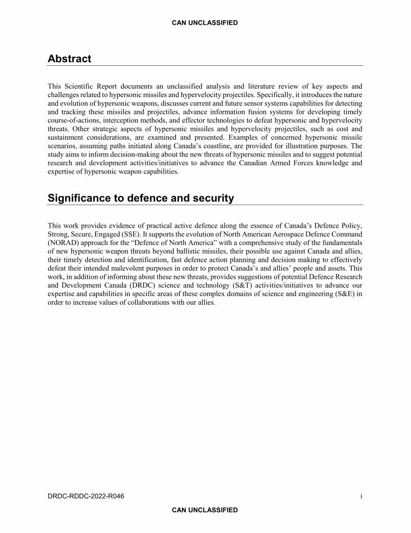
Abstract
This Scientific Report documents an unclassified analysis and literature review of key aspects and challenges related to hypersonic missiles and hypervelocity projectiles. Specifically, it introduces the nature and evolution of hypersonic weapons, discusses current and future sensor systems capabilities for detecting and tracking these missiles and projectiles, advance information fusion systems for developing timely course-of-actions, interception methods, and effector technologies to defeat hypersonic and hypervelocity threats. Other strategic aspects of hypersonic missiles and hypervelocity projectiles, such as cost and sustainment considerations, are examined and presented. Examples of concerned hypersonic missile scenarios, assuming paths initiated along Canada’s coastline, are provided for illustration purposes. The study aims to inform decision-making about the new threats of hypersonic missiles and to suggest potential research and development activities/initiatives to advance the Canadian Armed Forces knowledge and expertise of hypersonic weapon capabilities.
Significance to defence and security
This work provides evidence of practical active defence along the essence of Canada’s Defence Policy, Strong, Secure, Engaged (SSE). It supports the evolution of North American Aerospace Defence Command (NORAD) approach for the “Defence of North America” with a comprehensive study of the fundamentals of new hypersonic weapon threats beyond ballistic missiles, their possible use against Canada and allies, their timely detection and identification, fast defence action planning and decision making to effectively defeat their intended malevolent purposes in order to protect Canada’s and allies’ people and assets. This work, in addition of informing about these new threats, provides suggestions of potential Defence Research and Development Canada (DRDC) science and technology (S&T) activities/initiatives to advance our expertise and capabilities in specific areas of these complex domains of science and engineering (S&E) in order to increase values of collaborations with our allies.

CAN UNCLASSIFIED
ii DRDC-RDDC-2022-R046
CAN UNCLASSIFIED
Résumé
Le présent rapport scientifique fournit une analyse et une revue de la littérature non classifiées des principaux aspects et obstacles liés aux missiles hypersoniques et aux projectiles à hypervitesse. Plus précisément, il présente la nature et l’évolution des armes hypersoniques, traite des capacités actuelles et futures des systèmes de détection servant à détecter et à suivre ces missiles et projectiles, des systèmes avancés de fusion de l’information pour élaborer des plans d’action en temps opportun, des méthodes d’interception et des technologies relatives aux effecteurs pour vaincre les menaces hypersoniques et en hypervitesse. D’autres aspects stratégiques des missiles hypersoniques et des projectiles à hypervitesse, tels que les considérations de coûts et de maintien en puissance, sont également examinés et présentés dans ce rapport. De plus, des exemples de scénarios de missiles hypersoniques préoccupants, supposant des trajectoires initiées le long du littoral canadien, sont fournis à titre d’illustration. L’étude vise à éclairer la prise de décisions concernant les nouvelles menaces que représentent les missiles hypersoniques, et à suggérer des activités et initiatives de recherche et de développement pour faire progresser les connaissances et l’expertise des Forces armées canadiennes au sujet des capacités d’armes hypersoniques.
Importance pour la défense et la sécurité
Ce rapport fournit la preuve d’une défense active concrète en accord avec la politique de défense du Canada : Protection, Sécurité, Engagement. De plus, il appuie l’évolution de l’approche du Commandement de la défense aérospatiale de l’Amérique du Nord (NORAD) en ce qui concerne la défense de l’Amérique du Nord grâce à une étude approfondie des principes fondamentaux des nouvelles menaces que représentent les armes hypersoniques au-delà des missiles balistiques, de leur utilisation possible contre le Canada et ses alliés, de leur détection et de leur identification en temps opportun, ainsi que de la planification d’actions de défense et de la prise de décision rapides en vue de contrer efficacement leurs intentions malveillantes et ainsi protéger la population et les biens du Canada et de ses alliés. Enfin, ce rapport fournit non seulement des renseignements sur ces nouvelles menaces, mais aussi des suggestions d’activités et d’initiatives en science et technologie pour l’agence de Recherche et développement pour la défense Canada visant à renforcer notre expertise et nos capacités dans certains secteurs des domaines complexes de la science et du génie en vue d’accroître la valeur de la collaboration avec nos alliés.

CAN UNCLASSIFIED
DRDC-RDDC-2022-R046 iii
CAN UNCLASSIFIED
Table of contents
Abstract . . . . . . . . . . . . . . . . . . . . . . . . . . . . . . . . . . . i
Significance to defence and security . . . . . . . . . . . . . . . . . . . . . . . . . i
Résumé . . . . . . . . . . . . . . . . . . . . . . . . . . . . . . . . . . . ii
Importance pour la défense et la sécurité . . . . . . . . . . . . . . . . . . . . . . . ii
Table of contents . . . . . . . . . . . . . . . . . . . . . . . . . . . . . . . iii
List of figures . . . . . . . . . . . . . . . . . . . . . . . . . . . . . . . . . v
List of tables . . . . . . . . . . . . . . . . . . . . . . . . . . . . . . . . . vii
Acknowledgements . . . . . . . . . . . . . . . . . . . . . . . . . . . . . . viii
1 Introduction and document structure . . . . . . . . . . . . . . . . . . . . . . . 1
2 Hypersonic and hypervelocity weapons . . . . . . . . . . . . . . . . . . . . . . 4
2.1 Earth’s atmosphere and phenomenology of superfast flights . . . . . . . . . . . . 5
2.2 Electrical, hydraulic, cooling and heat sources (weapon power supply) . . . . . . . 10
2.3 From gliding to propulsion toward target . . . . . . . . . . . . . . . . . . 12
2.3.1 Projectile . . . . . . . . . . . . . . . . . . . . . . . . . . . 14
2.3.2 Hypersonic glider . . . . . . . . . . . . . . . . . . . . . . . . 16
2.3.3 Hypersonic cruise missile and rocket . . . . . . . . . . . . . . . . . 19
2.3.4 Difference in path lengths . . . . . . . . . . . . . . . . . . . . . 19
2.4 Propulsion . . . . . . . . . . . . . . . . . . . . . . . . . . . . . . 21
2.4.1 Air breathing propulsion mechanisms . . . . . . . . . . . . . . . . . 21
2.5 Non-traditional propulsion approaches (low TRLs) . . . . . . . . . . . . . . . 24
2.6 Attitude control, navigation and guidance . . . . . . . . . . . . . . . . . . 24
2.6.1 Attitude control . . . . . . . . . . . . . . . . . . . . . . . . . 25
2.6.1.1 How much aerodynamic lift is needed? . . . . . . . . . . . . . 25
2.6.2 Remote, radio, global navigation satellite system (GNSS) and inertial navigation . 26
2.6.3 Guidance and proportional navigation . . . . . . . . . . . . . . . . . 27
2.6.4 Specific target identification . . . . . . . . . . . . . . . . . . . . 27
2.6.4.1 Electromagnetic wave propagation . . . . . . . . . . . . . . 28
2.7 Warhead . . . . . . . . . . . . . . . . . . . . . . . . . . . . . . 29
2.8 Examples of non-kinetic effects . . . . . . . . . . . . . . . . . . . . . . 32
3 Scenarios of typical missile paths to Canadian targets . . . . . . . . . . . . . . . . 33
3.1 Hypersonic weapons expected range and area coverage . . . . . . . . . . . . . 36
3.2 Missile flight path altitudes impact on detection time . . . . . . . . . . . . . . 37
4 Sensing and tracking new HWs . . . . . . . . . . . . . . . . . . . . . . . . 38
4.1 HW detection and expected potential war escalation . . . . . . . . . . . . . . 40
4.2 Missile identification and warhead ambiguity . . . . . . . . . . . . . . . . . 41
4.3 IR signatures . . . . . . . . . . . . . . . . . . . . . . . . . . . . . 42
4.4 HW detection probability by a typical early warning radar system . . . . . . . . . 43

CAN UNCLASSIFIED
iv DRDC-RDDC-2022-R046
CAN UNCLASSIFIED
4.5 HW detection with cognitive multistatic radar networks . . . . . . . . . . . . . 44
4.5.1 Connectivity offered by LEO and UAS constellations . . . . . . . . . . . 44
4.5.2 Cognitive radars and other cognitive sensors . . . . . . . . . . . . . . 46
4.5.2.1 One example of a military cognitive radar in development . . . . . . 48
4.5.3 Multistatic sensors . . . . . . . . . . . . . . . . . . . . . . . . 48
4.5.4 Multiband . . . . . . . . . . . . . . . . . . . . . . . . . . . 49
5 Multisensor fusion and action planning . . . . . . . . . . . . . . . . . . . . . 51
5.1 Fusion frameworks . . . . . . . . . . . . . . . . . . . . . . . . . . 52
5.2 Fusion techniques . . . . . . . . . . . . . . . . . . . . . . . . . . . 53
5.2.1 Signal level fusion . . . . . . . . . . . . . . . . . . . . . . . . 54
5.2.2 Feature level fusion . . . . . . . . . . . . . . . . . . . . . . . . 55
5.2.3 Decision level fusion . . . . . . . . . . . . . . . . . . . . . . . 56
5.3 Multisensor fusion for hypersonic weapon detection and tracking . . . . . . . . . 57
5.4 Information fusion systems for developing timely course-of-actions . . . . . . . . 58
5.5 Adaptivity and architectures . . . . . . . . . . . . . . . . . . . . . . . 61
5.6 Action planning and resource assignment . . . . . . . . . . . . . . . . . . 62
6 Effectors to defeat new cruise missiles . . . . . . . . . . . . . . . . . . . . . . 64
6.1 Effectors [11] . . . . . . . . . . . . . . . . . . . . . . . . . . . . . 64
6.1.1 Directed energy weapon . . . . . . . . . . . . . . . . . . . . . . 65
6.1.2 Jammer and information security . . . . . . . . . . . . . . . . . . . 67
7 Cost and sustainment considerations . . . . . . . . . . . . . . . . . . . . . . 69
8 Likely interception success rate . . . . . . . . . . . . . . . . . . . . . . . . 71
9 Conclusion and future work. . . . . . . . . . . . . . . . . . . . . . . . . . 73
References . . . . . . . . . . . . . . . . . . . . . . . . . . . . . . . . . 74
Annex A Standard Earth atmosphere . . . . . . . . . . . . . . . . . . . . . . . 99
Annex B Technology readiness levels (TRLs) compared . . . . . . . . . . . . . . . . 100
B.1 Canadian Innovation and Commercialization Program TRLs . . . . . . . . . . . 108
Annex C Spectrum; a critical and unique asset . . . . . . . . . . . . . . . . . . . . 109
List of symbols/abbreviations/acronyms/initialisms . . . . . . . . . . . . . . . . . . 111
Glossary . . . . . . . . . . . . . . . . . . . . . . . . . . . . . . . . . . 119

CAN UNCLASSIFIED
DRDC-RDDC-2022-R046 v
CAN UNCLASSIFIED
List of figures
Figure 1: There are a large variety of objects capable of hypersonic speed such as intercontinental ballistic missiles (ICBMs), meteors and space shuttles but they are not the focus of this analysis. . . . . . . . . . . . . . . . . . . . . . . . . . . . . . . . 4
Figure 2: Typical wall heat flux as function of time for some missions during re-entry [18]. . . . 6
Figure 3: Notional Earth’s atmosphere layers illustrating where near-space phenomenology could be considered (not to scale, e.g., Earth’s diameter is 12,742 km). . . . . . . . . . . . 7
Figure 4: This US standard atmosphere may help understanding the differences in the medium as function of altitude [20]. . . . . . . . . . . . . . . . . . . . . . . . . . . 8
Figure 5: Context of deorbiting for various flight paths [18]. . . . . . . . . . . . . . . . 9
Figure 6: Overall notional aspect of hypersonic phenomenology [18]. . . . . . . . . . . . . 9
Figure 7: Illustration of the progressive challenges from speeds below the sound barrier to much higher speed up to the point where small airframes are engulfed into a hot shock layer with plasma [18]. . . . . . . . . . . . . . . . . . . . . . . . . . . . . 10
Figure 8: Ragone plot of gravimetric density of power versus energy. . . . . . . . . . . . 12
Figure 9: Illustration of multiuse HVP using a sabot from a presentation to US Congress. . . . 15
Figure 10: Notional illustration of trajectories for ballistic missile, MaRV, HGV and HCM. . . 18
Figure 11: A simple model showing the differences between ballistic trajectories (HT, MET and DT) and hypersonic cruise missile trajectory just above Earth’s surface. . . . . . . . . 20
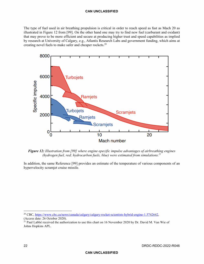
Figure 12: Illustration from [99] where engine-specific impulse advantages of airbreathing engines (hydrogen fuel, red; hydrocarbon fuels, blue) were estimated from simulations. . . . 22
Figure 13: Steady-state temperatures versus cruise Mach number for its critical components at an altitude of 24.8 km [99]. . . . . . . . . . . . . . . . . . . . . . . . . . 23
Figure 14: This chart shows, for altitudes below 100 km, that the orbital speed converges to 7.9 km/s or Mach 23. . . . . . . . . . . . . . . . . . . . . . . . . . . . . . . 26
Figure 15: Yields of various nuclear warheads including lower yield tactical nuclear bombs. . . 29
Figure 16: Kinetic energy, idealized spherical 325-ton meteoroids (entry at 20 km/s and 60°) [131]. 31
Figure 17: North American Canadian operational areas, new Canadian Air Defence Identification Zone (CADIZ), distance vectors and population densities for Canada, Northern Canada, Canadian Arctic Archipelago and Toronto [141, 142, 144]. . . . . . . . . . . . 34
Figure 18: Notional missile trajectories assuming Canadian stationary targets, A–D long range ICBM or HW trajectories, and E–H short range HW trajectories. . . . . . . . . . . . 35
Figure 19: Expected range and circular area achievable by HW under the stated assumptions (adapted from) [31]. . . . . . . . . . . . . . . . . . . . . . . . . . . . . . . 36
Figure 20: Due to radar horizon limits, ballistic flights are detected earlier than HGV. HCM being at lower altitude might be detected much later than HGV. . . . . . . . . . . . . 37

CAN UNCLASSIFIED
vi DRDC-RDDC-2022-R046
CAN UNCLASSIFIED
Figure 21: Simplified proposed communications architecture for HW sensor networks. . . . . 45
Figure 22: Differences between basic (a), adaptive (b) and cognitive (c) radars. . . . . . . . 46
Figure 23: Monostatic, bistatic and multistatic radar systems. . . . . . . . . . . . . . . . 49
Figure 24: The update JDL framework (adapted from) [213]. . . . . . . . . . . . . . . . 52
Figure 25: Visual representation of the three information fusion categories [216–218]. . . . . 54
Figure 26: (Top) Centralized fusion architecture. (Bottom) Distributed fusion architecture (adapted from [230]). . . . . . . . . . . . . . . . . . . . . . . . . . . . . . . 58
Figure 27: Notional architecture changes to accelerate the StEL to defeat time-sensitive targets [31]. . . . . . . . . . . . . . . . . . . . . . . . . . . . . . . 59
Figure 28: Space Defense Architecture planned by Space Defense Agency [236]. . . . . . . 60
Figure 29: Battle management from strategic to operational down to tactical. . . . . . . . . 62
Figure 30: Typical radiating power required for specific counter attack [278]. . . . . . . . . 65
Figure 31: Ragone plot projections from available information collected about the E-Cat SKL. . 66
Figure 32: Specific jamming techniques discussed in literature, mapped according to key jammer capabilities (Illustration from) [282]. . . . . . . . . . . . . . . . . . . . . 68
Figure 33: Twenty-year life-cycle costs for the BMD systems examined in this Report. . . . . . 70
Figure 34: Notional HW Interception rate trend chart as function of information delay and accuracy (inverse of CUA radius) assuming fix interceptor’s homing in on target capability. . 72
Figure A.1: Comparison of the 1962 US Standard Atmosphere graph of geometric altitude against air density, pressure, the speed of sound and temperature with approximate altitudes of various objects. . . . . . . . . . . . . . . . . . . . . . . . . . . . . . 99
Figure B.1: Canadian Innovation TRL diagram. . . . . . . . . . . . . . . . . . . . . 108
Figure C.1: Percentage transmission through Earth’s atmosphere, along the vertical direction, under clear sky conditions.. . . . . . . . . . . . . . . . . . . . . . . . . . . 109
Figure C.2: NASA chart of electromagnetic wave. . . . . . . . . . . . . . . . . . . . 110
Figure C.3: IEEE Standard Radar Band Nomenclature chart. . . . . . . . . . . . . . . . 110

CAN UNCLASSIFIED
DRDC-RDDC-2022-R046 vii
CAN UNCLASSIFIED
List of tables
Table 1: Nuclear energy comparison [31, 32]. . . . . . . . . . . . . . . . . . . . . 11
Table 2: Selected relevant hypersonic past, present and future missiles, projectiles and trials. . 13
Table 3: Missile detection probability assuming “Indication 2” [71]. . . . . . . . . . . . 44
Table 4: Summary of features (adapted from [221] and [224]). . . . . . . . . . . . . . 56
Table B.1: TRL definition comparison.. . . . . . . . . . . . . . . . . . . . . . . . 100

CAN UNCLASSIFIED
viii DRDC-RDDC-2022-R046
CAN UNCLASSIFIED
Acknowledgements
We want to thank the peer reviewers of this Report for their suggestions to improve it, and DRDC for providing resources allowing to conduct this study and to publish the results. We also want to thank research colleagues and management for their comments during the evolution of this initiative during this challenging period imposed by Coronavirus Disease 2019 (COVID-19). We also recognize the substantial contributions from organizations and experts that authorized using some key references and illustrations, making the Report an accessible comprehensive source of information for concerned people (decision makers, managers, military, engineers and scientists).
Thanks to the publication office, especially Michel Ducharme, for ensuring that the Report be published in face of time pressure caused by the retirement of the lead author.

CAN UNCLASSIFIED
DRDC-RDDC-2022-R046 1
CAN UNCLASSIFIED
1 Introduction and document structure
This research, current and future hypersonic threats, scenarios and defence technologies for the security of Canada, focuses on intrinsic nature of things rather than current and next hypes. It starts by distinguishing the notions of hypervelocity and hypersonic in near space and lower Earth’s atmosphere, spelling out some of the challenges encountered by hypersonic airframes at lower altitudes. Having a better idea of the realm of hypersonic weapon (HW) capabilities, it summarizes how they can be detected timely, persistently observed and tracked, up to how to intercept them. Then the Scientific Report elaborates on what research and development initiatives could be done collaboratively in order to progress in providing advantages to our forces and our allies.
This is aligned with the essence of Canada’s Defence Policy, Strong, Secure, Engaged (SSE) [1] active defence, which encompasses three tenets: 1-Strong at home, its sovereignty well defended by a Canadian Armed Forces also ready to assist in times of natural disaster, other emergencies and search and rescue; 2-Secure in North America, active in a renewed defence partnership in North American Aerospace Defence Command (NORAD) and with the United States; and 3-Engaged in the world, with the Canadian Armed Forces doing its part in Canada’s contributions to a more stable, peaceful world, including through peace support operations and peacekeeping. Active defence requires to: 1-ANTICIPATE and better understand potential threats to Canada and Canadian interests so as to enhance our ability to identify, prevent or prepare for, and respond to a wide range of contingencies; 2-ADAPT proactively to emerging challenges by harnessing new technologies, fostering a resilient workforce, and leveraging innovation, knowledge, and new ways of doing business; and 3-ACT with decisive military capability across the spectrum of operations to defend Canada, protect Canadian interests and values, and contribute to global stability.
It is worth noticing the claimed exceptional manoeuvrability of hypersonic boost-glide vehicles and hypersonic cruise missiles. They are supposed to be difficult targets to discern until the last few minutes before impact. In addition it is difficult to identify the type of warhead they carry (kinetic, high performance explosive or nuclear). With some HWs flying at lower altitude than intercontinental ballistic missiles (ICBMs), it appears that current anti-ballistic missile (ABM) defence systems are not fully optimized for these types of threats. “Hypersonic missiles—specifically, hypersonic glide vehicles and hypersonic cruise missiles—are a new class of threat able to penetrate most missile defences and to further compress the timelines for a response by a nation under attack. Such missiles are being developed by the United States, Russia, and China. Their proliferation beyond these three nations could result in lesser powers setting their strategic forces on hair-trigger states of readiness and more credibly being able to threaten attacks on major powers [2].”
Given that hypersonic missiles and hypervelocity projectiles have claimed exceptional properties [2] that may disrupt the force balance observed since the 80s [3] (“new arms race promises to upend strategic calculations…which could undermine nuclear deterrence [4].”) For several decades the mutually assured destruction (MAD) concept was the foundation to prevent a nuclear war but now with a larger number of nations with nuclear weapons what will happen? This is exacerbated by HWs difficult to detect and intercept with current ballistic defence systems [5–7]. In addition, as reported by the National Air and Space Intelligence Center (NASIC) in collaboration with the Defense Intelligence Ballistic Missile Analysis Committee (DIBMAC) in [8] “Ballistic and Cruise Missiles, with their relatively low operating costs, their potential to penetrate defence systems, and their value as a symbol of national power, will continue to be

CAN UNCLASSIFIED
2 DRDC-RDDC-2022-R046
CAN UNCLASSIFIED
the offensive weapons of choice for many nations. As such, they are threats that must be carefully considered in future military planning and operations.”
This Scientific Report is an unclassified analysis and literature review about dominant aspects and challenges of new/future (cruise or glider) hypersonic missiles/rockets and hypervelocity projectiles (with and without propulsion) assuming future sensor system capabilities, fusion and decision systems, possible interception methods, and likelihood of affecting or diverting such missiles’/projectiles’ intended effects. The following summarizes the document structure.
Section 2 covers Earth’s atmosphere where new HWs fly, probable characteristics of them (either new missiles, rockets and projectiles) capable of manoeuvring at low altitude, range and type of effectors (kinetic, high energy explosives, nuclear warhead or non-nuclear electromagnetic pulse [EMP]),1 attitude control and navigation, seeker head technology, type of fuse mechanism (kinetic, delayed, remote, Doppler, electromagnetic, pressure, etc.), airframe and propulsion: no propulsion such as gliders or projectiles, traditional propulsion methods (high technology readiness levels, [TRLs]),2 and non-traditional propulsion (low TRLs) such as nuclear propulsion.
Section 3 provides examples of concerned scenarios assuming paths initiated along Canada’s coastline, the longest in the world (244,781 km), or paths from the North making it difficult to detect and to track cruise missiles in a timely fashion, and expected effects for a variety of missile warheads, e.g., nuclear, non-nuclear EMP, and kinetic.
Section 4 introduces potential/novel sensor systems (combining radars and infrared [IR]/ultraviolet [UV] multispectral sensors3 from space, air and terrestrial) to detect and track such missiles/projectiles. Proposed architectures may exploit technologies such as low Earth orbit (LEO) satellite constellations and other dual use technologies.
Section 5 speculates on expected performance of advanced information fusion systems for developing timely courses of action to outmatch extremely short warning times imposed by hypersonic and hypervelocity threats. This provides an opportunity to examine a cognitive sensor-to-shooter loop (CStSL) [9, 10], or more generally, including non-kinetic effects, a cognitive sensor-to-effector loop (CStEL) [11].
Section 6 identifies several types of effectors to defeat hypersonic and hypervelocity threats, their advantages and weaknesses, and their combinations to achieve intended effects. As an example, claimed efficiency of advanced hypervelocity projectiles will be provided in terms of leaker4 probability.
1 National Technical Systems (NTS), a non-nuclear EMP is a transient electromagnetic disturbance from a short burst of electromagnetic energy. It falls under the electromagnetic compatibility (EMC) and electromagnetic interference (EMI) engineering and could be seen as a type of directed energy weapon (DEW). EMP’s origin may be of a natural occurrence or man-made and can occur as a radiated, electric or magnetic field or a conducted electric current, depending on the source. Such interference is generally only disruptive but could also damage electronic equipment and at higher energy levels a powerful EMP event such as a lightning strike can damage physical objects such as buildings and aircraft structures. More information could be found from various sources such as the National Technical Systems (NTS): https://www.nts.com/services/testing/emc/electromagnetic-pulse-testing/, (Access date: 17 November 2020). 2 See Annex B for relevant definitions of TRLs. 3 Infrared (IR) is currently used but ultraviolet (UV) may prove to be offering a better signal-to-noise ratio. 4 Leaker: a threat that has escaped an interception attempt.

CAN UNCLASSIFIED
DRDC-RDDC-2022-R046 3
CAN UNCLASSIFIED
Section 7 considers strategic aspects such as cost and sustainment considerations given the usual ratios of higher cost to defend compared to attack, and provides examples of projected cost of interception means per attempt versus projected cost of opposing force weapons.
Section 8 expresses naïve assessments with illustrations using over-the-horizon interception trends derived from training exercises and simulations. Using estimated sensor detection timeliness and accuracy, time to develop a course of action, interceptor time to closest point to interception, taking into account the opposing force weapon flight progression toward a target, assessing damage to opposing force weapons, up to likelihood of interception or interception success rate.
Section 9 suggests a few activities to further some of the topics mentioned in the core of this Report and presents a summary of findings with discussion about the overall observations and their meanings for decision makers.
Annex A provides useful information about Earth’s atmosphere such as the various layers, air density and temperature as function of altitude.
Annex B compares relevant technology readiness levels definitions.

CAN UNCLASSIFIED
4 DRDC-RDDC-2022-R046
CAN UNCLASSIFIED
2 Hypersonic and hypervelocity weapons
This section provides some basic information about the environment (Earth’s atmospheric layers) where hypersonic/hypervelocity weapons fly, including some historical facts and the distinctive phenomenological notions of hypervelocity and hypersonic. Then it covers probable characteristics of HWs (missiles, gliders, rockets and projectiles) with hypersonic or hypervelocity capabilities when approaching a designated target. Figure 1 provides a snapshot of the HWs this study focusses on, i.e., hypersonic cruise missile (HCM) using a scramjet (supersonic-combustion ramjet), hypersonic rocket (HR) [12] (aka hybrid system between cruise and ballistic missile), hypervelocity projectile (HVP) or gun-launched guided projectile (GLGP), and hypersonic glide vehicle (HGV). This illustration was inspired by an article written by Richard Stone [4]. For information about HGV see [13].
Figure 1: There are a large variety of objects capable of hypersonic speed such as intercontinental ballistic missiles (ICBMs), meteors and space shuttles but they are not the focus of this analysis.
Structure of this section: A short overview of supersonic flight phenomenology will set the scene for this type of vehicle flights. Then a sub-section presents a summary of possible power supplies for the hydraulic and electronics of these advanced weapons (e.g., for sensors, navigation, control, telemetry). A subsection will identify a variety of propulsion approaches from no propulsion like for gliding missiles and projectiles, then will introduce traditional propulsion (high TRLs, air breathing or not) versus non-traditional propulsion (low TRLs) such as nuclear. Another subsection will look at aerodynamic and manoeuvrability of such proposed weapons (including claimed miss distance or accuracy). Another subsection will look at selected weapons warheads or effector mechanisms such as kinetic, explosive, nuclear warhead and non-nuclear EMP. A subsection will describe some fuse mechanisms such as kinetic or contact at impact, delayed, remote, Doppler, electromagnetic, local temperature / signature and pressure.

CAN UNCLASSIFIED
DRDC-RDDC-2022-R046 5
CAN UNCLASSIFIED
2.1 Earth’s atmosphere and phenomenology of superfast flights
First observations of objects flying through Earth’s atmosphere at high enough velocity to get extremely hot were meteors. Meteoroids become meteors when entering the atmosphere at speeds ranging from 11 km/s to 72 km/s, and if they survived ablation, they hit Earth’s surface as meteorites creating distinctive marks. Studies in the 1930s to develop models of hypervelocity effects were done using analysis of meteorite impacts. Models reviewed in [14] provided some insight but early models needed major improvements in order to predict the effect on space vehicles and terrestrial installations. To improve the prediction of hypervelocity impact effects, tests needed to produce projectile speeds in excess of 10 km/s in order to be closer to what meteorites exhibit. As early as after World War II, engineers were trying to achieve hypersonic speed [15]. The first manufactured object to achieve hypersonic flight was the two-stage Bumper rocket, consisting of a without attitude control (WAC) Corporal5 second stage set on top of a V-2 first stage. In February 1949, at White Sands, the rocket reached a speed of 2.3 km/s, or approximately Mach6 6.7.7 On Saturday, 29 July 1950, Bumper-WAC No. 7 was launched. The resulting flight achieved the highest kinematic performance of the Bumper Program. The WAC upper stage burned-out at Mach 9. So atmospheric hypersonic flights require material resisting high temperature due to aerodynamic heat.
For this section, HWs are divided into hypersonic and hypervelocity phenomenology. Following paragraphs provide current definitions of hypersonic velocity and hypervelocity as two important phenomena at the centre of this literature survey and analysis Report.
“Hypersonic flight is arbitrarily defined as flight at speeds beyond Mach 5 although no drastic flow changes are evident to define this.… Several formidable problems are encountered at these speeds. First, the shock waves generated by a body trail back at such a high angle that they may seriously interact with the boundary layers about the body. For the most part, these boundary layers are highly turbulent in nature. Secondly, across the strong shocks, the air undergoes a drastic temperature increase. Aerodynamic heating of the body is a major problem. For sustained hypersonic flight most normal metals used in today’s airplanes would quickly melt; therefore new materials or methods that can withstand the high-temperature effects are required [16].” Ballistic missiles travel most of their path in space encountering no resistance from air. Their reentry vehicles (RVs) experience Earth’s atmosphere aerodynamic heating only once for few seconds before destruction. For that reason, although they travel at speed much higher than Mach 5, they are not considered as new hypersonic missiles in this Report. Space vehicles spend more time reentering Earth’s high air density atmosphere in order to safely deliver their cargo or passengers, they select specific trajectories (corridors) in order to reduce heat.
5 A 1944 US Army Ordnance Department sounding rocket called WAC Corporal. WAC means “without attitude control.” 6 Mach number is a dimensionless quantity in fluid dynamics representing the ratio of flow velocity past a boundary to the local speed of sound. It is named after Austrian physicist and philosopher Ernst Mach known for his unprecedented photo of a bullet Mach wave. Mach numbers are commonly defined based on the speed of sound in dry air at 20°C at sea level (Mach 1 ≈ 343 m/s), so Mach 5 ≈ 1715 m/s or 6174 km/h. Speed of sound varies mainly with the local ambient temperature around a moving object. Temperature varies with altitude as illustrated by Figure A.1. At an altitude of 15 km, Mach 1 is 296 m/s and at an altitude of 85 km it is 275 m/s. So one needs to be careful when expressing or interpreting speeds using Mach numbers. 7 NASA, https://www.hq.nasa.gov/office/pao/History/Timeline/1945-49.html, (Access date: 17 November 2020).

CAN UNCLASSIFIED
6 DRDC-RDDC-2022-R046
CAN UNCLASSIFIED
Hypervelocity is defined differently. It is based on material properties when two objects hit each other at a very high relative velocity, at approximately over 3 km/s (11,000 km/h or Mach 8.8). In particular, an impact at hypervelocity realizes so much kinetic energy that the strength of materials upon impact is very small compared to inertial stresses [17]. Thus, under hypervelocity impact, solid metals and some other solid material start reacting or behaving like fluids. Hypervelocity weapon system developments have moved beyond research and development (high TRLs) during the last decades to reach a time where several of the options are currently moving into the acquisition and deployment phases, the same for HWs.
Current ballistic missiles (BMs) offer a variety of ranges making them either of strategic or tactical value. BMs can be classified by range or maximum distance they can travel:
1. Short-range: less than 1,000 km, also known as “tactical” BMs.
2. Medium-range: from 1,000 to 3,000 km, also known as “theater” BMs.
3. Intermediate-range: from 3,000 to 5,500 km.
4. Long-range: more than 5,500 km, also known as ICBMs
Another RV aspect to consider is that it can be designed for single use like for a missile warhead while others include delivery of equipment and/or passengers as illustrated in Figure 2.
Figure 2: Typical wall heat flux as function of time for some missions during re-entry [18].8
Figure 2 shows that the challenge of managing the aerodynamic heat depends on how much time a warhead or airframe must endure such heat without affecting its functionality. Shorter the interval, higher the manageable heat density. So if HCM and HR fly at lower altitudes than HGV, they might be limiting their maximum speed comparatively to the HGV. Apollo 10 had the fastest maximum entry velocity at 11 km/s Mach 32 in the near-space zone. Layers of plastic resin were used as ablative heat shields. The layers of the ablative material simply burn off one at a time dissipating the heat energy [19]. Other Apollo mission reentry speeds were much lower to increase safety of astronauts.
8 On 30 November 2020, Dr. Javier Urzay of the Center for Turbulence Research, Stanford University, provided Paul Labbé the authorization of using illustrations of this reference.

CAN UNCLASSIFIED
DRDC-RDDC-2022-R046 7
CAN UNCLASSIFIED
Types of environment where HWs navigate affect what they can and cannot do. In upper layers of Earth’s atmosphere, it is like free space with low density of gas and particles, drag and lift are not significant. However, at lower altitudes, the density of air increases and creates resistance with dominant aerodynamic phenomena such as aerodynamic heat, drag and lift. An object travelling at hypersonic speed near Earth’s surface compresses air in its path. This air compression generates a lot of heat as observed during reentry of satellites, space shuttles and meteors. Figure 3 provides a simple notional taxonomy of Earth’s atmosphere layers with an indication for space and near space. At an altitude of 100 km, a boundary line based on Kármán’s work9 was proposed to define a boundary between Earth’s atmosphere and outer space for legal and regulatory measures since aircraft and spacecraft fall under different jurisdictions and are subject to different treaties.
Figure 3: Notional Earth’s atmosphere layers illustrating where near-space phenomenology could be considered (not to scale, e.g., Earth’s diameter is 12,742 km).
Figure 3 can be used in relation to the medium parameters of Figure 4, which illustrates the significant changes in air density and pressure that missiles and spacecraft need to deal with to go across from troposphere, stratosphere, mesosphere and thermosphere, flying from surface through near space and then into space, and vice versa. Such drastic differences require distinct aerodynamic profiles more or less incompatible. This is part of the challenges architects and engineers of superfast vehicles have to deal with, striking the appropriate balance and compromise to deliver viable airframes for intended missions and flight paths.
9 Note that Theodore von Kármán, a Hungarian American engineer and physicist, calculated the altitude at which the atmosphere becomes too thin to support aeronautical flight with air breathing propulsion to be at 83.6 km.

CAN UNCLASSIFIED
8 DRDC-RDDC-2022-R046
CAN UNCLASSIFIED
Figure 4: This US standard atmosphere may help understanding the differences in the medium as function of altitude [20].
From these profiles of density and pressure, one may conclude that claims of weapons striking at low altitude (even ground or sea level) at terminal high hypersonic speeds such as Mach 20 is challenging given the current advances in materials and cooling systems. Such missiles could easily fly at high hypersonic speeds at higher altitudes, above 20 km. To avoid self-destruction, they have to slow down according to their intrinsic properties. For example, they could be able to achieve hypervelocity at Mach 9 in order to have high kinetic energy at impact with the target. For missiles with nuclear warheads, high hypersonic speed is not necessary, except to make them difficult to intercept.
Figure 6 uses specific symbols in expressing variables at play in characterizing phenomenology for very fast vehicles travelling through Earth’s atmosphere layers. In most practical applications related to hypersonic, the velocities �� associated with airframe piercing through the Earth’s atmosphere are within the range of �� ≈ 1.7–12.6 km/s. This range of velocities approximately translate into flight Mach numbers 5 ≥ ��� ≥ 42 in the stratospheric and mesospheric layers (near space conditions) with ��� being defined as:
��� =��
�� (1)
based on the speed of the sound waves in free stream �� (i.e., without obstacles). The lower end of this interval corresponds to applications of low-altitude high-speed flight and impact of warheads on ground targets, whereas the upper end represents conditions encountered by deorbiting satellites, HGVs and ICBM reentry vehicles [18] as illustrated in Figure 5.

CAN UNCLASSIFIED
DRDC-RDDC-2022-R046 9
CAN UNCLASSIFIED
Figure 5: Context of deorbiting for various flight paths [18].
Figure 6: Overall notional aspect of hypersonic phenomenology [18].
Figure 6 indicates an area where telemetry and communication are blacked out due to plasma generated by the heated air. For larger airframe such as the space shuttle this was not a major issue since antennas could be moved back where the plasma vanishes. However, this option is not available for small airframes engulfed into a hot-shock layer with plasma as shown by Figure 7, so techniques were explored to address this issue [21] in order to allow appropriate telemetry monitoring and other communication exchanges such as aborting a missile engagement [22].

CAN UNCLASSIFIED
10 DRDC-RDDC-2022-R046
CAN UNCLASSIFIED
Figure 7: Illustration of the progressive challenges from speeds below the sound barrier to much higher speed up to the point where small airframes are engulfed into a hot shock layer with plasma [18].
2.2 Electrical, hydraulic, cooling and heat sources (weapon power supply)
In order to reach stability and control (attitude control), and sense and navigate toward the intended target, agile projectiles, missiles and spacecraft need appropriate sensors and actuators. These capabilities come with the cost of powering them, e.g., an air driven electric and hydraulic power supply [23]. On several missiles, this power come from a gas turbine, batteries, super-capacitors, heat conversion devices such as thermoelectric generators, fuel cells, solar energy and radioisotope generators. Examples of such technologies could be found in various references such as [24, 25]. Here are some patents related to weapon power supply technologies that can address some of the challenges of HWs attitude control, navigation and guidance.
“It is common practice in the missile art to steer a guided missile by means of thrust vectoring or by aerodynamic controls. In the latter case, the missile is usually steered by fins which are depressed or elevated in a certain manner to stabilize the missile in roll, pitch and azimuth. Thrust vectoring is accomplished by means of vanes disposed in the stream of propulsive gases discharged from the rocket motor, by swivel nozzles, or by jetavators. Generally, the fins, vanes, jetavators or swivel nozzles are powered by a hydraulic actuator or a D.C. motor which operates in response to input signals generated by the guidance section of the missile. In the past, it has been the practice to power the electric motors by hydraulic powered alternators, and to power the alternators by means of high pressure fluid. Both of these

CAN UNCLASSIFIED
DRDC-RDDC-2022-R046 11
CAN UNCLASSIFIED
systems require an auxiliary hydraulic power unit for generating the necessary high pressure fluid. In the past, this has been accomplished by a motor-pump arrangement wherein the motor is powered by an electrical power supply or by a turbine-pump arrangement powered by high energy gases such for example as those generated by a cartridge containing a propellant. Both of these systems add to the complexity of an already complex missile and tend to slightly decrease reliability since there is always a danger of malfunctioning of the turbine or the motor which drives the pump. It is therefore an object of this invention to provide a new and improved auxiliary power supply for a rocket propelled vehicle which power supply derives its energy from the main propulsive gases of the rocket motor [23].”
“The present invention relates to servo mechanisms of the type wherein electrical control signals or impulses are translated into appropriate mechanical forces and to controls for such servo mechanisms. The invention is more particularly directed to servo mechanisms of the type wherein stability, light weight, and high torque output are essential and especially necessary. A particular application of the invention is in connection with the operating of the control surfaces of a guided missile or homing rocket of the kind wherein guidance is in response to electrical signals initiated by a radiant energy responsive device or other similar seeking or tracking mechanism [26].”
The power needed to control the missiles can be drawn from multiple sources. The propellant of the missile can be used to power an auxiliary engine that can generate the power needed for the control systems and a pneumatic system that could control the flight surfaces. Compressed gases stored in tanks can be used to control the trajectory of the missile. The latest advances include using power stored in thermal batteries which has been shown to have high energy density and to be stable at a wide range of operating environments [27, 28]. In addition to using thermal batteries, latest missiles are using hybrid energy systems to harness energy during launch and flight by using a piezoelectric generator to capture vibrations and convert them to electrical energy [29].
New technologies in development here and abroad are expected to deliver several orders of magnitude more gravimetric and volumetric energy densities [30]. These technologies could not only address weapon power supply requirements but also propulsion as discussed in the next sub-section. National Aeronautics and Space Administration (NASA) Langley Research Centre Chief Scientist Dr. Dennis Bushnell believed that such technology is maturing and will be available soon. “Low energy nuclear reactions (LENR) is a form of nuclear energy that potentially has over 4000 times the density of chemical energy with zero greenhouse gas or hydrocarbon emissions [31, 32].”
Table 1: Nuclear energy comparison [31, 32].
LENR Fusion Fission
Theoretical max energy Density
8,000,000 times chemical
7,300,000 times chemical
1,900,000 times chemical
Fundamental force weak strong strong

CAN UNCLASSIFIED
12 DRDC-RDDC-2022-R046
CAN UNCLASSIFIED
Figure 8: Ragone plot of gravimetric density of power versus energy.10
Although this is from trustable sources, it is obvious that proving such statement with some control experiments is a big challenge.11 Most recent experiments on E-Cat SKL tests are occurring currently (2021) but subject to COVID-19 constrains. Examples of applications include underwater, land and air transportation.12
2.3 From gliding to propulsion toward target
This subsection identifies a variety of propulsion approaches from no propulsion (during area of interest approach and final path to target) like for gliding missiles and projectiles, then will introduce traditional propulsion (high TRLs) versus non-traditional propulsion (low TRLs) such as nuclear (air breathing or not). Projectile, glider, rocket and air breathing approaches are considered in Table 2.
10 Paul Labbé received the authorization to use this chart on 16 November 2020 by Professor Dimitri Mavris, Georgia Institute of Technology. 11 Experiments were initiated by Dr. Dimiter Alexandrov, Professor of Electrical Engineering and Head of the Semiconductor Research Centre at Lakehead University in Thunder Bay. In addition, some prototypes are quite advanced: In September 2020 Andrea Rossi reported via the Journal of Nuclear Physics that he is progressing with certifications for the E-Cat SKL testing for industry and domestic applications. 12 ECat, https://www.ecat.tech/ResearchAndDevelopment/Aviation-And-Supersonic-Transport, (Access date: 11 February 2021).

CAN UNCLASSIFIED
DRDC-RDDC-2022-R046 13
CAN UNCLASSIFIED
Information presented in Table 2 should not be construed as accurate specifications. It is based on unclassified sources. In some instances of contradictions among different sources, the authors selected values that make sense [2–7, 12, 13, 15, 16, 33–77].
Table 2: Selected relevant hypersonic past, present and future missiles, projectiles and trials.
Name + country
Type function
Length + diameter
Guidance system
Weight Altitude speed
Range War-head Launch platform
Avangard Russia
HGV 100 km Mach 20 6.86 km/s
6000 km Nuclear 2 MT SS-19 ICBM
KH-47M2 Kinzhal Russia
HR Air-to-surface missile (ASM) Air-to-air missile (AAM)
8 m 1 m
inertial navigation system (INS) RF seeker optical?
500 kg 20 km Mach 10 3.4 km/s
1500–2000 km
high energy with fragmentation (HEwF) nuclear
Mig-31K Tu-22M3 SU-57
3M22 Zircon Russia
Cruise Anti-ship missile (AShM)
8–10 m ? 0.7 m
INS IR Active + Passive Radar
300–400 kg ? 30 km Mach 8 2.7 km/s
350–500 km HEwF nuclear Air, sub, ship and ground
Kh-90 Russia TRL 9
Cruise AShM
8–9 m 0.8–0.9 m
INS IR Active + Passive Radar
13600 kg ? 30 km Mach 6 2 km/s
3,000 km HEwF nuclear Air, sub, ship and ground
BrahMos-II India (Russia)
Cruise ASM AAM Surface-to-surface missile (SSM) Land-attack missile (LAM)
? 8–10 m 0.7 m
INS ? 30 km Mach 8 2.7 km/s
450 to 1000 km Air, sub, ship and ground
14-X [63] Brazil TRL 5
Waverider scramjet with 3 motors
One motor 2 m 0.8 m
? pilot 30.5 km Mach 6 2 km/s
8 km NA VSB-30 rocket [64]
X-51 US TRL9
Cruise
7.62 m 0.61 m
INS Empty Weight 1,800 kg
21.3 km Mach 5.1 1.7 km/s
740 km 210 s
none B-52
X-15 US TRL9
Cruise
15 m 4 m
INS+ pilot Empty Weight 6,622 kg
30 km Mach 6.7 2 km/s
450 km none B-52
HSTDV India
Cruise 5.6 m
? 32.5 km Mach 6 2 km/s
40 km none Agni-I
Xingkong-2 China
Cruise waverider scramjet
- - 30 km Mach 5.5–6 1.9–2 km/s
40 s Nuclear? Rocket boost
DF-17 China
Glide-boost HGV
11 m -
HGV nav 15,000 kg 60 km Mach 5 1.7 km/s
1,800–2,500 km 600 s in ground test
Nuclear Rocket boost mobile
DF-ZF China
Glide-boost - - - Mach 10 3.4 km/s
600 s in a ground test
Nuclear Rocket boost
Projectile US TRL6
Canon or railgun
- - - Mach 8 2.7 km/s
50–100 km Kinetic or high energy
Ship, Air, Sub or land

CAN UNCLASSIFIED
14 DRDC-RDDC-2022-R046
CAN UNCLASSIFIED
Most launch vehicles use combustion of propellants consisting of oxidizer and fuel for deriving energy. Air breathing propulsion systems use atmospheric oxygen, which is abundant up to about 40 km of Earth’s surface to burn the fuel stored on-board thereby making the system much lighter, more efficient and cost effective. Air breathing propulsion is a solution for a powered long return cruise flight necessary for reusable launch vehicles.13
2.3.1 Projectile
Early use of projectiles goes to throwing stones and arrows. The energy is transferred to projectiles from shooting devices. Technology advances allowed adding more capabilities (electronics, sensors and actuators) in projectiles launched from cannons (like howitzers and railguns). These projectiles are designed with some level of autonomy and they can manoeuvre toward a target during their terminal approach, reducing the effective miss distance and increasing the likelihood of successful intended effects. In addition, they may include pre-fragmented metal bars to be dispersed by the detonation of a high-energy explosive warhead set by a smart fuse system (detection of time-of-closest approach [TCA] or optimal time as per pre-program schemes). Tests with traditional guns/cannons showed that projectiles could reach hypervelocity and produce significant damage to armored platforms and bunker structures. More spectacular impact effects were observed with an electromagnetic railgun. Among advantages of railguns over traditional guns were the range reached and maximum speed obtained. Railguns offer deeper magazine and high rate of consecutive shots over traditional guns/cannons as long as enough energy and power are available on the launching platform (base, ship or aircraft).
Among the advantages of traditional cannons are their current maturity, deployment and availability to our forces. They come with updates of their firing systems at reasonable cost. They can be used with early detection and tracking systems in order to adopt a shoot-look-shoot strategy to increase mission success rate. A shoot-look-shoot strategy is also advantageous to railguns, but railguns represent a major investment and require significant electrical energy and power demands which are not met by our current and planned platforms.
Here is a United States (US) example of recent HVP tests [74, 78]: “The Navy’s Mk. 45 deck gun fires 70-pound conventional explosive shells at a muzzle velocity of around Mach 2.2 out to a distance of 13 miles. The 28-pound hypervelocity projectile reportedly travels as far as 50 miles at Mach 7.3. The HVP is a next-generation, common, low-drag, guided projectile capable of executing multiple missions for a number of gun systems, such as the Navy five-inch; Navy, Marine Corps and Army 155-mm systems and future electromagnetic railguns… BAE Systems, which builds the hypervelocity shell…” One can assume that Mach 7.3 is the muzzle speed and that since these projectiles fly unpowered, so their velocities are highest at leaving the muzzle and drop off steadily because of air resistance, even if they have low drag. It is worth noting that drag force increases quadratically with regard to speed, not exponentially.
Currently HVP precision capabilities are under research and development to advance and mature critical gun-hardened guidance electronics, projectile structural components, control surfaces and mechanical systems for railgun and canons tests.
13 The Times of India, https://timesofindia.indiatimes.com/india/what-is-hypersonic-technology-demonstrator-vehicle-all-you-need-to-know/articleshow/77990190.cms#:~:text=HSTDV%20can%20cruise%20at%20a,a%20speed%20of%20Mach%206, (Access date: 17 November 2020).

CAN UNCLASSIFIED
DRDC-RDDC-2022-R046 15
CAN UNCLASSIFIED
Figure 9: Illustration of multiuse HVP using a sabot from a presentation to US Congress.
One can find references to manmade projectile record speed [20] such as reported in The New York Times 1994 science capsule14 “Sandia National Laboratories have blasted a small projectile to a speed of 10 miles a second (Mach 47), which is thought to be the highest velocity ever reached on Earth by any object larger than a speck of dust…The gun will also help engineers to design and test protective shields for orbiting communications satellites.”
As reported in [34] “For decades, militaries have used ultra-dense ‘kinetic energy penetrators,’ also known as kinetic energy penetrators (KEPs), specially designed shells often wrapped in an outer shell (a ‘sabot’) and fired at high velocity rather than dropped from the sky, to defeat defense armor. That’s the fundamental logic underpinning the U.S. Navy’s highly touted electromagnetic railgun, which can blast a 25-pound ‘hypervelocity projectile’ with 32-megajoule muzzle energy through seven steel plates and obliterate whatever that armor is supposed to protect.”
The Canadian Armed Forces15 (CAF) selected the M777 for some deployments. CAF got it through the acquisition of the M777 light-weight 155-mm towed howitzer from the United Kingdom’s BAE Systems which is fit for the new HVP next-generation, common, low-drag, guided projectile capable of executing multiple missions for a number of gun systems [79].
It is worth noting that hypervelocity vehicles [80] have been studied in the past in relation to ballistic missiles. Although, hypersonic glide vehicles (HGVs) could be seen as projectiles with no sustained propulsion during their target approach, because they are launched from space (or near space) benefiting from Earth’s gravity, they are described in the next subsection.
14 New York Times, https://www.nytimes.com/1994/03/22/science/fastest-gun-on-earth-goals-go-beyond-planet.html, (Access date: 17 November 2020). 15 NATO Association, http://natoassociation.ca/on-target-the-procurement-of-canadian-artillery, (Access date: 17 November 2020).

CAN UNCLASSIFIED
16 DRDC-RDDC-2022-R046
CAN UNCLASSIFIED
2.3.2 Hypersonic glider
There are several reports of HGV developments, trials and claimed readiness for deployment. Lockheed Martin developed the Hypersonic Test Vehicle (HTV-2) as part of the Force Application and Launch from Continental United States (FALCON) project, a joint project of the United States Air Force (USAF) and the Defense Advanced Research Projects Agency (DARPA). The HTV-2, which had a wedge-shaped design and an intended range of 17,000 km, was flight tested twice, in April 2010 and August 2011. In both cases it was boosted by a Minotaur IV missile (modified Minuteman II and Peacekeeper ICBMs). Neither test was fully successful. In the first test, the HTV-2 reportedly achieved controlled flight in the atmosphere before telemetry was lost nine minutes into the flight. In the second, it successfully separated from the booster and transitioned to Mach 20 aerodynamic flight but soon after crashed into the ocean, a result of damage to the glider’s surface from excessive heat. No further flight tests are planned [46].
A report [46] prepared by United Nations Institute for Disarmament Research provides useful information on HW implications, programs and technologies, e.g., Hypersonic International Flight Research Experimentation (HIFiRE) Program.16 Bigras and Whittaker [13] provide a summary of worldwide activities related to HGV and associated research programs.
“The United States Army has been working on an HGV known as the Advanced Hypersonic Weapon (AHW), subsequently renamed as the Alternative Reentry System, since 2006. This glide vehicle is designed for placement on a booster missile of shorter range than the Minotaur-IV and it could be land, ship or submarine-based. It has a conical design, making it easier to distribute heat across its surface than was the case for the HTV-2. The current prototype has a range of 8000 km. The AHW was successfully flight tested from a booster derived from the Polaris ballistic missile in November 2011. The glider flew 3,800 km on a non-ballistic trajectory; the system’s second flight test in August 2014 was a failure with the vehicle destroyed by controllers seconds after launch due to problems detected with the booster. In October 2017, the US Navy conducted a third test of a modified AHW, scaled down to fit on a submarine-launched ballistic missile, which was deemed a success. Future tests are planned [46].” This is also related to DARPA Falcon HTV-2 prototype launched on a rocket to reach suborbital space and then reenter Earth’s atmosphere at speeds of about Mach 20 [69]. “DARPA and United States Air Force (USAF) are partnering on the Tactical Boost Glide Programme, which commenced in 2014. Under this programme, Lockheed Martin was awarded a $480 million contract in April 2018 to develop the Air-launched Rapid Response Weapon (ARRW). Information about the intended range of this system is not currently available. Lockheed Martin was also selected for the USAF Hypersonic Conventional Strike Weapon (HCSW) contract. As opposed to the ARRW, which has been described as “pushing the art of the possible”, the HCSW is based on relatively mature technologies and would be of longer range than the ARRW. DARPA and the US Army recently commenced the Operational Fires programme, awarding three contracts in 29 November 2018. This programme aims to “demonstrate a novel ground-launched system enabling hypersonic boost glide weapons to penetrate modern enemy air defences and rapidly and precisely engage critical time sensitive targets.” Information about range is not currently available. The US Air Force Research Laboratory partnered with Australia’s Defence Science and Technology Organisation on the HIFiRE programme from 2007 to 2017. While the programme was primarily concerned with scramjet (supersonic combustion ramjet) technology, it also involved the development and flight test of an HGV in July 2017 [46].”
16 University of Queensland, Centre for Hypersonics. http://hypersonics.mechmining.uq.edu.au/hifire, (Access date: 7 February 2019).

CAN UNCLASSIFIED
DRDC-RDDC-2022-R046 17
CAN UNCLASSIFIED
“Russia has explored HGV technology since at least the 1980s through the development of the Yu-70 HGV. While little is known about the Yu-70, analysts believe it was flight tested twice in 1990, and again in June 2001 and February 2004, with the UR-100NUTTH/SS-19 ICBM used as a booster. Avangard consists of an HGV, sometimes referred to as Yu-71, deployed on a UR-100NUTTH/SS-19 ICBM. The Yu-71 appears to be a modernized version of the Yu-70. Avangard is thought to have been involved in a number of test flights, a mixture of failures and successes, between 2011 and 2019. Its range is estimated to be around 10,000 km, although this has not been demonstrated in tests. In his March 2018 state of the union address, Russian President Vladimir Putin said that the Avangard had successfully completed tests and confirmed that the Russian Strategic Missile Forces would receive these systems, which he described as capable of manoeuvring laterally and vertically at speeds in excess of Mach 20, “in the near future.” A video accompanying the speech depicted a wedge-shaped vehicle. In October 2018, Russian media quoted an industry source saying the Avangard would be deployed by the end of 2019 with the UR-100NUTTH/SS-19 ICBM as a booster. There has also been speculation that the Avangard could be used with Russia’s new ICBM, the RS-28 Sarmat, expected to enter service in 2021. Although there is no public statement available on whether the Avangard would be nuclear-armed, most expect this would be the case given that the Strategic Missile Forces are responsible for the country’s land-based nuclear missiles. In announcing the December 2018 test, President Putin reaffirmed that the system would enter into service in 2019 [46].” When approaching a target, the glider is capable of sharp high speed horizontal and vertical evasive manoeuvres in flight, which Russian officials claim makes it “invulnerable to any missile defence system [39].”
Another HGV in development is China DF-ZF. “The DF-ZF39 HGV has been flight tested nine times since 2014, most recently in November 2017. Six of those tests were deemed to be broadly successful by outside observers, although the specific objectives for each test are unknown. During these tests, the DF-ZF reportedly covered distances between 1,250 and 2,100 km and reached speeds of Mach 10. The November 2017 tests reportedly involved a DF-17 medium range ballistic missile (MRBM) booster specifically designed for use with HGVs. Experts assess the DF-ZF will eventually be used with a DF-31 ICBM. Whether the DF-ZF will carry a nuclear or conventional warhead remains an open question [46].” More information about China’s advanced weapons and system could be found in [67].
India is also developing a HGV. “There is very little publicly available information on India’s possible hypersonic boost-glide system, the Shourya (also spelled Sharuya). According to one source, it is a two-stage solid-fuel missile, capable of carrying a conventional or nuclear warhead. There are reports of test flights in 2004, 2008, 2011 and 2016, with the most recent test involving manoeuvring and successfully impacting its target. The version of the Shourya tested to date. Also known as Wu-14.Tate Nurkin, p. 188. Available January, August and December 2014, June, August and November 2015, April 2016, and twice in November 2017 [46].” France and Japan are also pursuing HGV, but their programs are in the early stages [46].
Various tests of HGV were conducted using rockets and supersonic aircraft to launch them. The current applications of HGVs are related to RVs designed for ICBMs, especially for the multiple independently targetable reentry vehicles (MIRVs) with manoeuvrable reentry vehicles (MARVs or MaRVs). An HGV is similar to a MaRV as illustrated in Figure 10 but with the distinction of the shortcut used by the HGV gliding in the near space layer where air density and gravity is low just above Earth’s atmosphere. The advantage of HGV is a shorter path to target than MaRV but MaRV arrives with a larger speed vector down to the target. The HGV kinetic energy drops a bit due to its flying in the near space which offers little but some drag. Once closer to the latitude and longitude of the target, it starts a reentry decent using an appropriate reentry corridor dictated by its aerodynamic configurations and heat management capabilities.

CAN UNCLASSIFIED
18 DRDC-RDDC-2022-R046
CAN UNCLASSIFIED
HGV gains vertical falling speed under increased Earth’s gravity at lower altitude (9.5 m/s2 at 100 km and 9.8 m/s2 at sea level, 3.2%).
Figure 10: Notional illustration of trajectories for ballistic missile, MaRV, HGV and HCM.
The maximum velocity (terminal velocity) near sea level without active propulsion, for a free fall from space or near space, could be estimated using a set of equations17 and parameters of North Atlantic Treaty Organization (NATO) N1G missile model as described in [81]. Assuming a tungsten rod the parameters were set as follows: total mass 200 kg, diameter 10 cm (cross section area 78 cm2) with a drag coefficient of 0.03, air medium density at sea level 1.5 kg/m3, and Earth’s gravity 9.8 m/s2. The resulting estimated terminal velocity is 3343 m/s or Mach 9.7 which is similar to ICBM MaRV terminal velocity in excess to Mach 13.18 Another source is Figure 9 of Tracy and Wright [45]. Since this is at hypervelocity this represents a lot of kinetic energy and heat from air compression. As mentioned previously, gravity hasn’t always been necessary, gun were used to produce high kinetic energy but early proposals of weapons included a super weapon under “Project Thor” using tungsten rods also known as “Rods from God” producing a lot of kinetic energy with no needs of chemical explosion. But the cost of deploying these rods in space was too high during the Cold War. So the project was cancelled.
It is worth noting the use of the upper atmosphere as a way to slow down reentry vehicles such as the Soyuz space capsule. This is the way it is done today: to use the upper atmosphere as a brake, then slowly parachute to the surface or glide down in the lower atmosphere as for HGVs. How easy that is to do, depends on the spacecraft/vehicle design. If it is a heavy one like the Space Shuttle (now retired of course) then it can only slow down deep in the upper atmosphere, where it starts to be dense. Then it gets very hot. That’s why the Space Shuttle use ceramic tiles able to withstand temperatures up to 3,000°F (1,650°C). For the Rod of
17 CALC Tool, http://www.calctool.org/CALC/eng/aerospace/terminal, (Access date: 17 November 2020). 18 Defence Talk, “Minuteman III Missile Launch—California to Kwajalein Atoll” 4444 m/s, https://www.defencetalk.com/military/forums/t/what-is-a-terminal-velocity-of-an-icbm.11609/, (Access date: 27 January 2022).

CAN UNCLASSIFIED
DRDC-RDDC-2022-R046 19
CAN UNCLASSIFIED
God, due to the properties of tungsten remarkable for its robustness, especially for the fact that it has the highest melting point of all the elements discovered, melting at 3,422°C (6,192°F; 3,695 K). Hafnium DiBoride (HfB₂) melts at 3,250°C (5,882°F) is currently used for ICBM reentry shields and leading edges. Titanium and zirconium DiBoride have similar properties. Using aerobraking reduce considerably the amount of fuel required for returning to Earth. Here are examples of skin temperatures of the hottest parts of spacecraft and planes:
Space Shuttle reentry: 1,650°C.
Skylon [82, 83] reentry: 830°C.
US SR-71 Blackbird supersonic spy plane which flew at Mach 3—external temperatures for the titanium around its cockpit windows of 232°C.
Concorde 153°C when flying at Mach 2.2.
When a satellite is in a LEO orbit, its speed toward Earth is null. If a spacecraft deorbit from a Moon’s orbit to a LEO’s one, its falling speed toward Earth’s atmosphere due to this orbit transfer make it hitting the atmosphere at 11 km/s, thus requiring some manoeuvres to reduce its reentry speed to avoid burning like a meteor [84, 85].
2.3.3 Hypersonic cruise missile and rocket
The main distinction between HCM using a scramjet (supersonic-combustion ramjet) and HR [12] (aka hybrid system probably between cruise and ballistic missile) is the fact that HCM are air breathing using oxygen in Earth’s atmosphere as oxidant, while HR carry internally its own oxidant. Consequently HCM can afford larger range flying at altitude below the Kármán limit, it cannot propel above this altitude. HRs are limited in range by their booster (single or multiple stages) but can propel in space above the Kármán limit.
2.3.4 Difference in path lengths
A simple geometric model can show the difference between space ballistic flight path lengths and HW atmospheric fight path lengths. For illustration purpose of Figure 11, simple geometric calculations were used along the following assumptions: a ballistic path is represented by an arc of a parabola of length b, the ballistic apogee is the altitude h (set to 1,400 km for example) above Earth’s surface, s is the 10,000 km launch to target distance along a great circle (arc), the chord length is c, R�
is the average Earth’s radius (6,378 km), and the sagitta (sa) of a circular arc is the distance from the centre of the arc to the centre of its base. Using Figure 11 equations, one can find that the length of energy optimal ballistic paths is about twice the great circle distances at play, so some HWs may reach targets a bit faster but not much as demonstrated later in this subsection.
“For each flight range and altitude at burnout, there is a unique ballistic missile trajectory that is most energy efficient. This is known as the minimum-energy trajectory (MET). If flown over less than maximum range, an submarine launched ballistic missile (SLBM)19 can use its excess fuel to fly on a less energy-efficient, lower- or higher apogee trajectory [86].” Lower ballistic trajectories are usually called “depressed trajectories” (DTs) with reentry angles around 5–10°. Here we label higher trajectories, HTs. Because of DT trajectory low reentry angle, the trajectory spends more time in Earth’s atmosphere, terminal
19 SLBM: submarine launched ballistic missile.

CAN UNCLASSIFIED
20 DRDC-RDDC-2022-R046
CAN UNCLASSIFIED
speed may be lower and there is a higher likelihood of larger circular error probability (CEP) than MET and HT. Ballistic flights can be specified (calculated) for MET, DT or HT apogees with corresponding booster capacities, launch angles and required average speeds for a given target range.
Figure 11: A simple model showing the differences between ballistic trajectories (HT, MET and DT) and hypersonic cruise missile trajectory just above Earth’s surface.
Using appropriate simulation tools, illustration from [45] showed calculated flight paths of an hypersonic glider, MET and DT, “fired at a target 8,100 km down-range. All missiles use identical Minotaur IV boosters. The hypersonic and ballistic depressed trajectory launches use similar boost phase trajectories based on those used in HTV-2 flight tests. Part (a) shows the total flight paths, while parts (b) and (c) show details of the boost and terminal phases at the start and end of missile flight. The hypersonic and depressed trajectory missiles make relatively sharp turns toward the down-range direction during the boost phase, and the depressed trajectory vehicle reenters the atmosphere at a relatively shallow angle [45].”
Another set of simulation results from [45] showed the expected slowing down of the HGV starting with different initial speed from 5 km/s to 7 km/s with terminal ground distances (glide ranges) of 4,250 to 12,250 km (“Hypersonic vehicle speed as a function of glide range for various initial glide speeds, illustrating how atmospheric drag slows the vehicle throughout the glide phase”). It is important to observe that HGV initial speed drops from atmospheric drag and any manoeuvre decreases speed and the maximum range.
Using computational modelling of hypersonic flight, Figure 7 of Tracy and Wright [45] compared BM and HGV trajectories in terms of flight lengths and flight times. “Delivery times include boost, ballistic, reentry, pull-up, glide, and terminal phases, where applicable. Ballistic missiles fired on depressed trajectories reach

CAN UNCLASSIFIED
DRDC-RDDC-2022-R046 21
CAN UNCLASSIFIED
their targets most quickly. Their delivery time advantage over hypersonic gliders increases with range.” These computational modelling results indicate that ballistic missiles fired on depressed trajectories can fly intercontinental distances significantly faster than can hypersonic boost-glide systems. Figure 8 of [45] shows that for 8,500 km trajectories, HGV delivery time is about 10% earlier than a ballistic MET path. However, a DT ballistic path offers a 14% earlier delivery than an HGV path.
So one may conclude that claims that HGVs are twice faster than ICBMs are misleading as it does not account for the longer atmospheric terminal phase where HGV slows down.
2.4 Propulsion
HCM traditional propulsion mechanisms include scramjet (supersonic combustion ramjet), solid fuel and liquid fuel (air breathing or not). In some references, HCM can include rocket propulsion since short range manoeuvrable ballistic missiles behave almost like HCM. In [12] they are listed as guided HR. HRs could either use solid or liquid propellant engines. In solid propellant, oxidizer and fuel are factory mixed in carefully controlled conditions. Using liquid propellants imply a more complex though more versatile approach where the oxidizer and fuel mixture is injected at the top of the combustion chamber and could be throttled to control the generated thrust. Alternatives to these traditional propulsion mechanisms will be introduced under non-traditional mechanisms such as nuclear [87, 88], laser and plasma. It is worth mentioning technologies such as dual-mode ramjet (DMRJ) related to the United Kingdom (UK) synergistic air-breathing rocket engine (SABRE) development program.
Missile and rocket, ground or sea vertical launches could be improved by using electromagnetic boost as in “Results from Sandia national laboratories/Lockheed Martin electromagnetic missile launcher (EMML) [89]” which extends missile’s range and reduce heat signature of the launching installations, e.g., heat signature of a launching cruise ship. Another experiment reported in [90] confirmed the results reported previously in [89].
2.4.1 Air breathing propulsion mechanisms
There are a variety of methods for studying air breathing propulsion of hypersonic cruise missiles as illustrated by Doolan [91] in his performance and sensitivity analysis of hypersonic missiles. Currently the most discussed air breathing propulsion mechanism is the scramjet [92] also known as shock induced combustion engine (scramjet) or oblique detonation wave engine (ODWE) or simply referred to as shock-ramjet engine (note there might be significant differences in performance between these technologies but [93] showed they are quite equivalent in a range of speeds from Mach 7 to 12). ODWE is a concept of air-breathing ramjet engine, proposed to be used for hypersonic, as well as, single-stage-to-orbit (SSTO) propulsion applications. More details about scramjet could be found in DRDC and NATO reports as well as in open literature documents [4, 12, 40, 46, 57, 59, 91, 93–98].
CAN UNCLASSIFIED
22 DRDC-RDDC-2022-R046
CAN UNCLASSIFIED
The type of fuel used in air breathing propulsion is critical in order to reach speed as fast as Mach 20 as illustrated in Figure 12 from [99]. On the other hand one may try to find new fuel (carburant and oxidant) that may prove to be more efficient and secure at producing higher trust and speed capabilities as implied by research at University of Calgary, e.g., Atlantis Research Labs and government funding, which aims at creating novel fuels to make safer and cheaper rockets.20
Figure 12: Illustration from [99] where engine-specific impulse advantages of airbreathing engines (hydrogen fuel, red; hydrocarbon fuels, blue) were estimated from simulations.21
In addition, the same Reference [99] provides an estimate of the temperature of various components of an hypervelocity scramjet cruise missile.
20 CBC, https://www.cbc.ca/news/canada/calgary/calgary-rocket-scientists-hybrid-engine-1.5742642, (Access date: 26 October 2020). 21 Paul Labbé received the authorization to use this chart on 16 November 2020 by Dr. David M. Van Wie of Johns Hopkins APL.

CAN UNCLASSIFIED
DRDC-RDDC-2022-R046 23
CAN UNCLASSIFIED
Figure 13: Steady-state temperatures versus cruise Mach number for its critical components at an altitude of 24.8 km [99].22
Examples of cruise missiles using scramjet technologies include Russia’s Zircon (aka Tsirkon) and India’s Hypersonic Technology Demonstrator Vehicle (HSTDV) Brahmos-II probably developed in collaboration with Russia (similar to Zircon). The scramjet-powered Zircon hypersonic missile is claimed to fly at speeds of about Mach 9 and have a range of 1,000 km. An India-Russia’s joint venture in developing Brahmos-II hypersonic cruise missile [27] is expected to exhibit cruising speed of Mach 5 to 7. It is still under development, which may be quite similar to the Russian Zircon. Both use airbreathing scramjet propulsion whose configuration appears to draw heavily from the American X-51A (Mach 5). Another hypersonic cruise missile Russia is building is KH-47M2 Kinzhal, a nuclear-capable air-launched ballistic missile (ALBM). It has a claimed range of more than 2,000 km at Mach 10 speed, and an ability to perform evasive
22 Paul Labbé received the authorization to use this chart on 16 November 2020 by Dr. David M. Van Wie of Johns Hopkins APL.

CAN UNCLASSIFIED
24 DRDC-RDDC-2022-R046
CAN UNCLASSIFIED
manoeuvres at every stage of its flight (it sounds like a HCM or HR). A Russian nuclear powered missile in development adds to this sample of HCMs, see next sub-section.
2.5 Non-traditional propulsion approaches (low TRLs)
Examples of non-traditional propulsion approaches are abundant but only a few are worth mentioning here. A way to reduce weight for propulsion is to replace onboard heat generation by an external source to heat a fuel, liquid, solid or gas. NASA explored some of them assuming that one day it will be possible to build at low cost microwave transmitters and lasers to generate and focus enough energy on a spacecraft energy harvester and transfer that energy to a fuel to propel the spacecraft. Although high-power microwave amplifiers and lasers are currently available, they haven’t reached the level of energy required for an effective demonstration of such technology [100].
However, some onboard technologies have progressed to a point that they are ready for deployment such as plasma, photonic and nuclear propulsion. Current electrohydrodynamic thrust includes plasma, photonic or ionic and the laser driven photonic drive [101]. It is worth noting that current electrohydrodynamic thrust density using positive corona-induced ionic winds for in-atmosphere propulsion could be useful for very small drones or insects like sensors but thrust density is low compared to current air breathing engines [102] for military applications.
For space projects, NASA is planning the use of nuclear reactors [54, 103, 104] to generate energy to various types of propulsion either ionic [105] and electromagnetic drive (EmDrive) [106, 107]. These drives are not applicable for accelerating vehicles within Earth’s atmosphere. Note that NASA plans to activate the nuclear reactor once off Earth’s atmosphere.
Although it is not legal to use nuclear reactors for propulsion within Earth’s atmosphere, it seems that Russia is developing such propulsion for cruise missiles in order to keep them loitering for long periods (could be years) over areas of interest [108]. The 9M730 Burevestnik (Russian: Буревестник; Petrel, NATO reporting name: SSC-X-9 Skyfall) is a Russian experimental nuclear-powered, nuclear-armed cruise missile under development for the Russian Armed Forces. The missile is claimed to have virtually unlimited range. Tests have resumed in 2020 according to recent news in October 2020 [34, 109].
The motivation of Russia to develop SSC-X-9 Skyfall is to reduce the impression of imbalance in the nuclear game. Skyfall offers a new deterrence that matches other countries antiballistic defence systems. It is worth noting that such HW orbiting Earth provides a persistent capability to intercept or deviate large meteor that threaten life on our planet.
2.6 Attitude control, navigation and guidance
Although, the integrated field that studies the combination of sensors, actuators and algorithms is called guidance, navigation and control (GNC), here attitude control will be presented first, then navigation to finally introduce guidance in order to have a stable vehicle to navigate and then guide it to a destination (target). It is worth noting that future missile must be able to identify a specific target among several potential targets in an area of search, for example new lethal ship-killing missiles use new sophisticated guidance system using multi-modal sensor suite, weapon data link, and enhanced digital anti-jam global navigation satellite system (GNSS) to detect and destroy specific targets within a group of numerous ships at sea, so they can pick out what ships are their intended targets from a group of ships.

CAN UNCLASSIFIED
DRDC-RDDC-2022-R046 25
CAN UNCLASSIFIED
2.6.1 Attitude control
Attitude control uses sensors and actuators. Flight control actuation could be done using aerodynamic structures such as fins or jets depending on the environment and flight speed. At hypersonic speed using winglets or fins when flying hypersonic in lower atmosphere may represent some difficult challenges. Using the propulsion system may act too fast, putting exceptional stress on the fuselage causing the destruction of the vehicle as reported by McWhinney in [38]. Attitude control of hypersonic body flying at high altitude in near space and then in lower layers of Earth’s atmosphere is complex and requires appropriate sensors and feedback loops. There are a variety of approaches as exemplified in several references [110–116]. With advances in sensors, processors and material used in drones, satellite mega-constellations, autonomous systems [117], smartphones and robots, reliability of these systems for applications with high vibration and adverse environment such as temperature, humidity and radiation, attitude control components and systems are more available at cost never seen before.
Basic and advanced attitude controls are necessary for obtaining predictable flight paths from a flying vehicle. At hypersonic speed this is a bit more difficult given the lack of references for such flights. Essentially effects of controls need to be measured at high tempo in order to maintain stable flight patterns. As demonstrated by failures of several test flights of hypersonic experimental vehicles, achieving long distance flights with manoeuvres at hypersonic speed is very challenging and costly. Advances in inertial components due to their extensive use in commercial technologies such as cellular phones, virtual reality equipment and drones, in addition to commercial aircraft navigation systems and autonomous car, provide an unprecedented level of low-cost miniaturized efficient capabilities.
Attitude controls, using micro electro mechanical systems (MEMS) inertial measurement unit (IMU) at low cost and high precision, are intensively used in drone, domestic (e.g., smartphone), industrial, robot, aerospace and military (e.g., UxV)23 platforms [118, 119].
2.6.1.1 How much aerodynamic lift is needed?
For HWs, there are some trade-off that needs to be achieved in order to strike a balance between attitude control and navigation. If a vehicle design offers a lot of lift, this may increase drag (breaking force) that may generate more aerodynamic heat and require more thrust (more energy or fuel). Depending on how much manoeuvrability is sought, instead of increasing wing size for a desired level of manoeuvrability, one may use jets, especially with rockets (HRs). In addition at hypersonic speed in the order of 8 km/s, due to orbital forces at play, aerodynamic lift to counter gravity could be minimal since this is like an object in orbit with its orbital speed V� expressed by the following equation:
V� = �µ�
h + R� (2)
where µL is Kepler’s constant (398,600 km3/s2), h is the altitude of the vehicle in km and R� is the average Earth’s radius (6,378 km). Figure 14 shows relevant altitude values and makes it evident that for altitude values much smaller than Earth’s radius, the orbital speed approach asymptotically 7.9 km/s or Mach 23.
23 UxV stands for four kinds of unmanned vehicles—air, land, sea surface and underwater.

CAN UNCLASSIFIED
26 DRDC-RDDC-2022-R046
CAN UNCLASSIFIED
Figure 14: This chart shows, for altitudes below 100 km, that the orbital speed converges to 7.9 km/s or Mach 23.
2.6.2 Remote, radio, global navigation satellite system (GNSS) and inertial navigation
In most scenarios of concern in this study, remote control needs to be considered with precaution because radio signal could be jammed. We can anticipate that via radio telemetry link, while collecting information from all sensors of a hypersonic vehicle, one can send command to perform a specific manoeuvre or abort the mission.
In these scenarios of concern, non-cooperative environment will require a certain level of inertial navigation capability [118, 119] since inertial navigation is insensitive to jamming and cyber-attacks [120]. An important role of hypersonic adapted navigation is to consider not only the aerodynamic of an airframe but various constraints to avoid loss of control and exceeding airframe capabilities, e.g., temperature limits before irreversible damages [116]. In addition, there are various atmospheric anomalies that need to be compensated for in order to maintain a planned flight path.
Also GNSS anti-jamming interference mitigation technologies are becoming more available which contribute to missile seeker-head hardening to other threats such as EMP.
Navigation capabilities include manoeuvring (within vehicle’s manoeuvring limits) in order to avoid interceptors, anti-hypersonic systems like antiballistic systems and air and space sensor systems either multiband radars or multispectral optical systems, e.g., high-frequency (HF) radars and UV/IR sensors, either terrestrial, air and space borne.
Moon
geostationary
LEO at 1200 km
ISS at 408 km
0
1
2
3
4
5
6
7
8
0
5
10
15
20
25
0.1 1 10 100 1000 10000 100000 1000000
Mac
h
km/s
Altidude in km
Orbital speed as function of altitude
Below an altitude of100 km the orbital speed is about 7.9 km/s or Mach 23

CAN UNCLASSIFIED
DRDC-RDDC-2022-R046 27
CAN UNCLASSIFIED
2.6.3 Guidance and proportional navigation
Once desired navigation capabilities and stable controlled flight are accomplished, various types of guidance approaches could be devised based on the desired way (strategy like sea skimming)24 of approaching or intercepting a target. For long paths there is a need for navigation aids such as GNSS, terrain recognition and other geolocalization techniques. Target may be tagged by a radar signal or a laser. A classic example is the semi-active approach for air target interception with radar illuminating the scene including a target and the semi-active missile. Then the semi-active missile compares the direct illuminating radar signal with the reflected signal to establish the distance to the target. In addition the seeker-head beamforming antenna provides directional information from the signal reflected by the intended target. Using these two signals and deduced direction of arrival, the missile can apply an effective guidance approach to the target. Time-to-closest approach could be estimated in order to pre-emptively fuse the warhead for optimal effect (especially when using fragmentation to increase hit probability). Otherwise, it could be a simple anti-radiation approach25 to seek a target emitting one way or another. New efficient missile seekers may use RF, visible and infrared (IR) signatures of targets. Some missile seekers can do advanced analysis (for target identification) of the returned signals or patterns of a user specified target for locking in on it.
The best guidance approach for intercepting a moving target is still the pure proportional navigation (PPN) as documented in [121]. Alternatives falling in a second category consist of line-of-sight (LOS) referenced systems such as true proportional navigation (TPN), generalized true proportional navigation (GTPN) and generalized guidance laws did not perform as well as PPN because they can cause impossible demands on the intercepting missile, aka kill vehicle (KV), or wasting fuel necessary to reach interception or the closest point of approach (CPA), and may result in increasing the time to closest point of approach (TCPA). The facts that alternatives to PPN reduce the likelihood of a direct hit or a delayed TCPA may result in depleting more resource in a shoot-look-shoot strategy to ensure no leakers. Another reference [122] supports the previous conclusions for exoatmospheric interception scenarios with ideal proportional navigation (IPN) (here we assume that IPN is identical to PPN): it proved that the capture capability of IPN is much stronger than TPN, no matter the target manoeuvres or not. Simulation results indicated that IPN/PPN is more effective than TPN in exoatmospheric interception scenarios.
2.6.4 Specific target identification
In order to increase targeting precision, missiles need to correctly sense a target of interest. HWs have some disadvantages relative to some other weapons because the heat and plasma generated by their speed in lower atmospheric layers. They have the tendency to be more or less blind. For example, special processing is required to see a target IR signature across a very hot window (radome) [123, 124]. To alleviate this, advances in cooling systems could mitigate missile surface and radome heat by cooling the radome in order to better track IR signatures.
Because of these challenges, HWs cannot be more precise than current ones. So without appropriate advances, HWs would yield no more accurate targeting than currently-existing missile technologies.
24 Sea skimming is an anti-ship missile technique used to avoid radar and infrared detection so to lower probability of being shot down during target approach. 25 An anti-radiation missile (ARM) is a good example. It is a missile designed to detect and home in on an enemy electromagnetic emission source (radar, communication, light detection and ranging [lidar]).

CAN UNCLASSIFIED
28 DRDC-RDDC-2022-R046
CAN UNCLASSIFIED
2.6.4.1 Electromagnetic wave propagation
Some basic notions need to be introduced here in order to understand missile seeker head limitations due to electromagnetic wave propagation (radio frequencies up to ultraviolet emission) properties in Earth’s atmosphere. It is possible for radio waves to be refracted in the same way as light waves. As both light and radio waves are forms of electromagnetic waves, they are both subject to the same basic laws and principles.
The phenomenon of refraction in optic is well illustrated by the formation of rainbows due to light traversing air and liquid with different index of refraction. Also hot air and colder air have slightly different values of refractive index and this causes the light to bend. In just the same way that light waves are refracted, so radio waves can undergo refraction. The classic case for refraction occurs at the boundary of two media. At the boundary, some of the electromagnetic waves will be reflected, and some will enter the new medium and be refracted. So, within Earth’s atmosphere under normal conditions, radar horizon distance is longer than the geometrical distance at play. For this reason when estimating radio horizon or line-of-site a 4/3 correcting factor for standard atmosphere (refraction decreases uniformly with altitude) is used. This correcting factor is only an approximation. In remote sensing when estimating target elevation and distance, appropriate higher resolution methods must be used (in addition to local atmospheric changes causing phenomena like inversion).
The geometrical horizon distance, ghd, from a source or observation at a height h is:
ghd = �h� + 2hR� . (3)
R� is the average Earth’s radius (6,378 km). Within 1% error, Equation (3) for h smaller than 100 km becomes:
ghd = �2hR� . (4)
Then using the standard atmosphere, this equation becomes for Earth’s electromagnetic wave horizon distance, hd:
hd = ��
�2hR�
. (5)
The maximum target detection range dr can be estimated by combining hd for the sensor height, h, and the target height, th, as follows:
dr = ��
�2hR�
+ ��
�2thR�
. (6)
For a hypersonic missile flying at 7 km/s (≈ Mach 20) at an altitude h = 100 m, targeting a bomber at an altitude th = 1000 m, the maximum range to lock on this target is about 172 km. The warning time for the bomber is less than 25 s. A ship radar at a nominal height of 100 m start detecting a sea skimmer cruise missile flying at 100 m above sea level when it is quite close, i.e., 82 km. For such a sea skimmer flying at

CAN UNCLASSIFIED
DRDC-RDDC-2022-R046 29
CAN UNCLASSIFIED
3 km/s (Mach 8.7) and assuming that the ship defending missile can achieve the same speed, if the decision and acceleration are done within 20 s, the interception may occur at a distance about 11 km from the ship (a big if here since interception and destruction of the skimmer is not sure).
2.7 Warhead
In order to compare potential effects of various warheads we start with the assumption that a typical thermonuclear warhead may weigh about 1000 kg (one metric ton) and can release energy equal to one million tons of trinitrotoluene (TNT) or five PJ. So a nuclear device no larger than traditional bombs can devastate an entire city by blast, fire, and radiation.
Figure 15: Yields of various nuclear warheads including lower yield tactical nuclear bombs.26
“Russia believes that low-yield precision ‘clean’ nuclear weapons provide a viable alternative to advanced conventional weapons. Clean nuclear weapons use a small amount (one kilogram or less) of plutonium (Pu) or highly enriched uranium (HEU) to ignite a deuterium/tritium mix to create a predominantly fusion explosion with minimal residual radiation. Explosive yields can range from as little as 10 tons of equivalent trinitrotoluene (TNT) to 1000 tons of TNT (one kiloton), and with available guidance accuracy can kill most targets of interest, to include hardened intercontinental ballistic missile (ICBM) silos [125].”
26 Reference Wikimedia Commons, https://en.wikipedia.org/wiki/Nuclear_weapon_yield, (Access date: 20 October 2020).

CAN UNCLASSIFIED
30 DRDC-RDDC-2022-R046
CAN UNCLASSIFIED
According to the author of [125] “Russia also has neutron weapons, which are significantly more effective than U.S. neutron weapons.” Also this author reported the following “attacks on adversary military forces, bases, fleets, and critical infrastructure to achieve conflict objectives could consist of:
Accurate, low-yield, ‘clean’ weapons to kill targets;
Neutron weapons to kill military personnel and leadership;
EMP weapons (discrete and wide area) to kill electronics;
X-Ray weapons to kill satellites and RVs (nuclear weapons may play a major role in future space warfare scenarios); and
Gamma rays and other tailored effects, the purpose of which is to be determined [125].”
Several explosion events are reported by various news feeds. The phenomenon of blast wave which is relevant to understand what happens when an explosion happens uses the following terminology [126, 127]:
Shock Wave: Supersonic propagation of pressure pulse.
Positive Phase: The initial outward movement of shock wave pressures from the source of the detonation, characterized by a nearly instantaneous rise in peak pressure followed by an exponential decay.
Negative Phase: The subsequent under pressure that trails the outward moving shock wave, creating a partial vacuum as air particles are moved with the shock front.
Incident Pressure: Shock wave overpressure that propagates unobstructed away from the detonation.
Reflected Pressure: Overpressures that are stagnated by obstructions in the path of the shock wave and are amplified in magnitude.
Dynamic Pressure: The drag forces applied to objects by the flow of air particles following the shock wave.
The 5 August 2020 Beirut explosion triggered expert opinions about its intensity. Their assumptions start with the ammonium nitrate (AN) TNT RE (relative effectiveness) factor of about 0.42, so this equates for 2,750 tons of AN to slightly more than one kiloton of TNT. However the scene showed that only a small fraction of the 2750 tons actually detonated so only hundreds of tons of TNT equivalent, not thousands exploded. The death toll was estimated to 204 people. With an explosive yield of a few hundred tons, the Beirut blast has been dozens of times less powerful than the atomic bomb that devastated Hiroshima, which had an estimated yield of about 15 kilotons.
For a Hiroshima population of 350,000, of which 40,000 were military personnel, before the 6 August 1945 bombing, the estimated death toll, including those who died from radiation-related injuries and illness through 31 December 1945, was 140,000. New technology allowed to estimate the radiation level that victims of Hiroshima were exposed [128]: “We obtained a reconstructed dose of 9.46 ± 3.4 Gy from the jawbone, which was compatible with the dose distribution in different locations as measured in non-biological materials such as wall bricks and roof tiles [129].” This is a fatal dose of radiation compared to those used for cancer treatments.

CAN UNCLASSIFIED
DRDC-RDDC-2022-R046 31
CAN UNCLASSIFIED
Nevertheless, the Beirut explosive power27 is comparable to the lowest yield B61 nuclear gravity bomb, which is believed to have an explosive yield of around 300 tons (see low-yield tactical nuclear bombs Figure 15).
In general chemical explosives deliver TNT RE (relative effectiveness) factor from 0.1 to 2, see different equivalent TNT common explosives in [130]. Only nuclear explosions and kinetic weapons offer much larger REs.
When one considers kinetic energy of a warhead, in addition to the chemical energy if any, Figure 16 shows TNT RE figures much larger than 2 and more capable of approaching REs of some nuclear warheads [131]. In fact, United States of America (USA) is considering meteor like projectiles as part of future arsenal based on positive results from Pentagon’s new super weapon (basically a weaponized meteor strike) [132].
Figure 16: Kinetic energy, idealized spherical 325-ton meteoroids (entry at 20 km/s and 60°) [131].
27 Science Alert, https://www.sciencealert.com/beirut-s-devastating-port-explosion-100-times-bigger-than-the-mother-of-all-bombs, (Access date: 17 November 2020).

CAN UNCLASSIFIED
32 DRDC-RDDC-2022-R046
CAN UNCLASSIFIED
“Highly energetic weapons with explosive power greater than about 100 times TNT are deployed. Kinetic energy projectiles come in many types (pellets, cubes, rods, and penetrators), sizes (millimetres to metres), and weights (grams to 30,000-pound penetrators), enabling them to attack a wide variety of targets—from ships, aircraft, and tanks, to ICBM silos and industrial facilities. Even area targets can now be attacked by cost-effective conventional weapons. For example, 5,000 pounds of 10-gram pellets could destroy a weapons plant that was a one-quarter square mile. The addition of a pyrophoric coating on the kinetic projectile to cause fires can increase the lethality as well as the lethal radius [125].” NASA studied the effects of simulated orbital debris at the White Sands Test Facility Remote Hypervelocity Test Laboratory (RHTL) [2]. These tests offered an understanding into the impact of light kinetic HWs, such as 10-gram pellets, on various structures and hardened installations (e.g., armoured platforms, tanks and bunkers). Some of the results are documented under the theme of piercing warheads [131, 133, 134].
2.8 Examples of non-kinetic effects
A non-nuclear EMP is a transient electromagnetic disturbance from a short burst of electromagnetic energy. It falls under the electromagnetic compatibility (EMC) and electromagnetic interference (EMI) engineering and could be seen as a type of directed energy weapon (DEW). EMP’s origin may be a natural occurrence or man-made, and can occur as a radiated, electric, or magnetic field or a conducted electric current, depending on the source. Such interference is generally only disruptive but could also damage electronic equipment and at higher energy levels a powerful EMP event such as a lightning strike can damage physical objects such as buildings and aircraft structures. More information could be found from various sources such as the National Technical Systems (NTS).28
“Explosively driven non-nuclear EMP in an approximately 2,000-pound class bomb can kill all electronics and destroy circuits up to 400–500 metres (away). Repeated pulsed EMP warheads in a cruise missile can attack many targets, or repeatedly attack one or a few targets [125].”
Other types of warheads could have been discussed in this subsection, such as the advantages of pre-fragmented hard shells of bombs to improve impacts on various targets as well as chemical, biological, radiological, and nuclear (CBRN) but these are well documented in the literature [135–139].
28 NTS, https://www.nts.com/services/testing/emc/electromagnetic-pulse-testing/, (Access date: 17 November 2020).

CAN UNCLASSIFIED
DRDC-RDDC-2022-R046 33
CAN UNCLASSIFIED
3 Scenarios of typical missile paths to Canadian targets
This section provides examples of concerned scenarios assuming paths initiated along Canada’s coastline, the longest in the world (244,781 km), or paths from the North making it difficult to detect and to track cruise missiles in a timely fashion, and expected effects for a variety of missile warheads, e.g., nuclear, EMP, and kinetic, especially if HWs are launched from a hostile submarine navigating along Canada’s coast or into Hudson Bay targeting major urban areas or military bases. However, identifying potential intended targets could help mitigating the efficiency or success of hostile plans.
The agreement to expand cooperation on continental defence and in the Arctic, including modernizing NORAD and expanding US-Canada Arctic dialogue, is part of the roadmap29 developed by concerned committees. Given that this study focuses on priorities stated in Canada’s Defence Policy, Strong, Secure, Engaged (SSE), which reaffirmed Canada’s commitment to effective operations in the extended Canadian Air Defence Identification Zone (CADIZ) [140–142], it includes the entire Canadian Arctic Archipelago and the Pacific and Atlantic coastlines as illustrated in Figure 17. This is in the context of overall NORAD modernization efforts towards an improved North Warning System (NWS) requiring high-throughput low-latency30 communications between sensors, analysis asset, decision support systems, command and control and exploitation of defence systems [143]. Essentially, this is the defence of North America.
29 High North News, https://www.highnorthnews.com/en/usa-and-canada-agree-modernize-norad, (Access date: 17 November 2020). 30 Latency is the delay, usually measured in milliseconds (ms), that occurs in a round-trip data exchange. round-trip times (RTTs) for fibre optic cable (FOC) in large networks using content delivery network (CDN) show useful latency around 18 ms over a distance of 1,400 km.

CAN UNCLASSIFIED
34 DRDC-RDDC-2022-R046
CAN UNCLASSIFIED
Figure 17: North American Canadian operational areas, new Canadian Air Defence Identification Zone (CADIZ),31 distance vectors and population densities for Canada, Northern Canada,
Canadian Arctic Archipelago and Toronto [141, 142, 144].
Terrorist groups, rogue nations and major opposing forces may attack by affecting Canada capabilities, asset/infrastructure and population, in order to deter Canada of contributing to current allied alliances and agreements (e.g., NATO, NORAD, and Australia, Canada, New Zealand, the United Kingdom, and the United States [AUSCANNZUKUS]). Consequently the scenarios could focus on energy and water infrastructures, defence capabilities/HQs and major cities. Paths for approaching Canada assets to attack, disturb or damage are via our longest coastal areas in the world, including Hudson Bay. This study focuses on HWs launched from potential capable platforms such as submarines, ships and air as illustrated by Figure 18. This enemy strategy tries to optimize the disturbances on Canadian energy sources and distribution assets, clean water and food processing and communication networks in order to affect
31 Built over the map published by NAVCAN: https://www.navcanada.ca/en/spa-2018-adiz-en.pdf, (Access date: 17 November 2020).

CAN UNCLASSIFIED
DRDC-RDDC-2022-R046 35
CAN UNCLASSIFIED
populations of large Canadian cities, military personnel, main installations and military capabilities. Interceptions of moving Canadian targets (such as satellites, aircraft, ships, submarines and land platforms) are beyond the scope of this study but could be addressed in subsequent studies, although outcomes of such military actions could be extrapolated from the information provided in this Report.
Figure 18: Notional missile trajectories assuming Canadian stationary targets, A–D long range ICBM or HW trajectories, and E–H short range HW trajectories. Google map modified.
Figure 18 notional trajectories to Canadian stationary targets with A–D representing potential long range ICBM or HW trajectories and E–H showing effective short range HW trajectories demonstrating the clear advantage of an opposing force to attack Canadian targets using short trajectories due to the very short flight times. The long range trajectories offer the advantage of acting remotely without risking expensive assets such as submarines. Since the defence against A–D types of scenarios is similar to ICBM ones which are already well addressed by concerned organizations, these aspects are not the focus of this study. The

CAN UNCLASSIFIED
36 DRDC-RDDC-2022-R046
CAN UNCLASSIFIED
short range HW trajectories are the main concerns to be addressed given the challenges they impose on defence systems with extremely short response time and extraordinary capabilities imposed on kinetic kill vehicles or non-kinetic interception systems such as directed energy weapons and electronic warfare.
The potential impact on Canada’s assets and capabilities were discussed under the previous subsection discussing HW warhead.
3.1 Hypersonic weapons expected range and area coverage
Here are simple views of potential range and area coverage of HW as function of average speed and three fly out time intervals. The circular area is calculated as the area of a circle of radius equal to the achieved range for a given average speed over a specific fly out time.
0 E+0
2 E+3
4 E+3
6 E+3
8 E+3
1 E+4
1 E+4
1 E+4
0,5 1 2 3 4 5 6 7 8 9 10 11 12 13 14 15 16 17 18 19 20 21 22 23 24 25 26 27 28 29 30
ran
ge in
km
Mach number
range as function of average speed for three time intervals
5 minutes 10 minutes 20 minutes
0 E+0
1 E+8
2 E+8
3 E+8
4 E+8
5 E+8
6 E+8
7 E+8
0,2 0,3 0,7 1,0 1,4 1,7 2,1 2,4 2,7 3,1 3,4 3,8 4,1 4,5 4,8 5,1 5,5 5,8 6,2 6,5 6,9 7,2 7,5 7,9 8,2 8,6 8,9 9,3 9,6 9,9 10,3
circular area in km2 versus average speed for three flyout time intervals
5 minutes 10 minutes 20 minuteskm/s
Figure 19: Expected range and circular area achievable by HW under the stated assumptions (adapted from) [31].

CAN UNCLASSIFIED
DRDC-RDDC-2022-R046 37
CAN UNCLASSIFIED
3.2 Missile flight path altitudes impact on detection time
Here are some distinctions between ballistic, MaRV, HGV and HCM paths and predictability of intended target or impact point. Figure 20 shows that sensors near the target location due to line-of-sight horizon limitations can detect ballistic missile much earlier than HGV and HCM (HR may exhibit similar advantages as HCM). The delayed detection of HWs compared to ballistic is confirmed by several studies such as [38]. “This delayed detection compresses the timeline for decision makers assessing their response options and for a defensive system to intercept the attacking weapon—potentially permitting only a single intercept attempt [42].”
Figure 20: Due to radar horizon limits, ballistic flights are detected earlier than HGV. HCM being at lower altitude might be detected much later than HGV.
It is worth noting that ballistic displays the most predictable target impact location, with MaRV manoeuvres adding some uncertainty, as for the HGV and HCM. HCM offers the least reaction time for interception since it is the latest to be detected by a ground sensor (radar or optical) near the target location.

CAN UNCLASSIFIED
38 DRDC-RDDC-2022-R046
CAN UNCLASSIFIED
4 Sensing and tracking new HWs
Time sensitive HW targets drive the battlefield tempo and selection of resources (e.g., sensors and effectors) to counter them. Intelligence and sensors allow to track targets of interest in order to evaluate if there are requirements for devising some courses of action (CoAs), spelling time and location to consider and consequently assign assets to execute them. The following sections will cover sensing and tracking and sharing such data in real time, multisensory fusion and action planning, and then effectors to defeat HWs.
Plume during propulsion and plasma induced by the high-temperature shock layer around HW’s vehicle surface emit not only in IR but also in UV [145] within the solar blind wavelengths, 270–290 nm. Because hypersonic vehicles emit in ultraviolet where there is little solar background [146], this makes UV detection of HW more feasible at various angles and times of day, which might be an issue with IR. For a vehicle at a velocity of 3.5 km/s (about Mach 11), the UV peak absolute intensity at an altitude of 38 km is two orders of magnitude higher than that at 53.5 km [146].
Paper [123] documents how one can sense, track and intercept an hypervelocity missile using IR sensors, although an important phenomenology of hypersonic flight in near space is the emission in the ultraviolet band [146, 147]. So an improvement over the aforementioned IR sensing approach is to use ultraviolet spectral features from the shock layer of near-space hypersonic vehicles in the “solar blind” band region, which may offer a much better contrast than IR in both cases of looking up (toward the sky) or down (toward Earth’s surface over water or land) assuming that the UV blocking atmosphere is not between the sensor and the HW. Performances of one type of UV detectors is provided in [148]. In addition to sensor processing, detection and tracking performances can be improved by using heuristic predictive capabilities as reported in [123], or use convolutional neural network trajectory classification exemplified in [149].
Multi-wavelength (from radio waves to ultraviolet) space sensors offer great opportunities for early warning detection of HWs and ballistic missiles. UV radiation is divided in three bands: UV-A (400–315 nm), UV-B (315–280 nm), and UV-C (280–100 nm), which can penetrate nitrogen but UV-C is entirely screened out by a combination of dioxygen (< 200 nm) and ozone (> about 200 nm) by around 35 km altitude. “In practice, the detection of theater targets utilizes the mid-wave infrared (IR) spectral region (3–5 µm) as a baseline and distinctive ultraviolet (UV) or visible spectral regions as a second detection band. Note that, in the so-called ‘solar blind’ band covering 200–300 nm, the dark sky background allows one to detect a vehicle as a signature source against a very low background with a striking contrast. In this typical band region, ultraviolet emissions from the shock layer have great potential for the early warning systems (EWS), target intercept guidance techniques to monitor, identify and track unfriendly aircraft, and also for suppression of radiative noise through the optical window [146].”
In [46] “to assess the visibility of this IR emission to early warning systems, we compared the calculated radiant intensities of a glider with the IR sensitivities of both existing U.S. space-based detection systems, using data available in the open literature. The U.S. space-based early warning system is composed of two sets of satellites: the Defense Support Program (DSP), first deployed in the 1970s, and the Space-Based Infrared System (SBIRS), currently under development with the first satellite launched in 2011.”
In [46] simulation results for HGV initial speeds from 5 km/s to 7 km/s show overhead radiant intensity in the short-wavelength infrared (SWIR) band (1.4–3.0 mm) as a function of glide time. For all cases, glider

CAN UNCLASSIFIED
DRDC-RDDC-2022-R046 39
CAN UNCLASSIFIED
radiance remains above the approximate 6 kW/sr SBIRS32 detection threshold for essentially the entire glide phase [150]. These results demonstrate “that HWs are not invulnerable to detection by early warning systems but will instead remain visible to space based sensors during launch and the majority of the glide phase. They are thus unlikely to meaningfully reduce the time available for a targeted adversary to respond [45].”
However, using ground base microwave, IR and UV sensors mostly limited to LOS for detecting incoming missiles does not provide much time for timely interception. In order to increase early warning of incoming HWs, sensing approaches must include satellite surveillance and over-the-horizon (OTH) detection using HF. Effective coverage using LEO satellite constellations are becoming ubiquitous and may prove less vulnerable to attacks due to the large number of satellites and multiband-sensors. Studies of the plasma sheath generated by hypersonic vehicles showed that the plasma resonance frequency ranges from 284 MHz to 28 GHz in [151], so radar signals above and below these frequencies work well for detecting HW vehicles. Above 28 GHz there is a lot of absorption in the atmosphere, but a LEO constellation of Ka-band radars could provide short-medium range detection capabilities in impenetrable grid like patents. Below 284 MHz, it was proven that for HF radars the signal could travel beyond line of sight (BLOS) and be effectively reflected back by the missile plasma [151] because plasma conductivity is excellent at such low frequency.
For traditional radar sensors (typically in the L, S, C, and X bands, i.e., from 1 to 12 GHz), Song et al. [152] report the following observations: “The degradations of hypersonic vehicle-borne radar target detection under time-varying plasma sheath are studied through real hypersonic vehicle flight cases. Simulation results shows that high electron density of time-varying plasma sheath will cause significant attenuation, which will lead to decrease of detection probability. In some cases, the signal-noise ratio (SNR) threshold that target can be detected increases more than 40 dB compared with situation without time-varying plasma sheath.” The additional 40 dB effective power of such radar means, for example, moving from one kilowatt to 10000 kilowatts, which is difficult to achieve for a satellite borne radar.
At Mach 8, HW can close a 1000 km distance in 7 minutes, so a good defence posture is to identify HW launching platforms before they get too close.
Multistatic radars [153–158] may prove to be an effective approach to detect, identify and track HWs and their potential launching platforms due to the recent mega-constellation of LEO satellite systems as reported by the author in [159]. In addition, one of the most sophisticated LEO satellite constellation system is designed by Telesat which demonstrated reliable satellite services over decades with the advantage of having its headquarters in Canada. Their advanced design offers onboard signal processing, internet protocol (IP) management, demodulation, re-modulation and exploitation of active electronically scanned array (AESA) which allows to focus power on specific area. Each satellite is planned to have a total power of 5 kW, shared by all onboard systems and transceiving units. “Pole-to-Pole Mesh Space Relay Network, Telesat Lightspeed™, our advanced, global Low Earth Orbit network, will soon provide unparalleled survivable and assured network connectivity. The network will leverage Optical Inter-Satellite Links (OISLs) and can dynamically allocate additional capacity to areas with high demand, ensuring secure, reliable and cost-effective global connectivity for government and defence applications.”33
32 SBIRS is a constellation of satellites in geosynchronous equatorial orbit (GEO) and high elliptical orbit (HEO) that use IR for early missile warning, technical intelligence, and battlespace awareness. 33 Telesat, https://www.telesat.com/defence/, (Access date: 26 October 2021).

CAN UNCLASSIFIED
40 DRDC-RDDC-2022-R046
CAN UNCLASSIFIED
Another aspect is the detection of underwater HW launching platforms in order to avoid being surprised in a short distance engagement which is difficult to manage. For example, Underwater Acoustic Sensor Networks (UASNs) are under study and development [160], which may deter opposing force intention to deploy HW launching capable submarines in our littoral. Note that in sea water the speed of sound is much faster: 1,450 to 1,570 m/s or Mach 4.4 to 4.7. This network of underwater sensors can connect to LEO satellite systems via floating transceiver gateways.
4.1 HW detection and expected potential war escalation
It is important to notice that HGVs can be launched using the same or similar rockets as those used for BMs. Current defence systems using early-warning satellites were designed to detect ICBMs / tactical BMs from their early launching by detecting plume signatures of the rockets boosting warhead RVs to altitudes where they glide along prescribed orbits or space flight paths to reach their targets. It is possible that states with ballistic defence systems might detect such missile manoeuvres and may conclude they are under attack while the missile could only be passing through their space to another state. Not targeted states may have been warned but such situation increase tension and may result in unintended war conflict. ICBMs have never been used in combat and it is impossible to know how the existing early-warning and command and control systems would react to their use. “Even if a hypersonic vehicle is detected and properly identified, it may not be known until the very last moment whether it is targeting conventional forces and facilities or nuclear forces, potentially leading to nuclear escalation” [46]. HGVs and HRs could be sea-base, land or air launched with conventional or nuclear warheads. “It would be extremely difficult to remove the ambiguity regarding the type of payload that these systems carry, so the probability of miscalculation and escalation could be very high [46].”
“The capabilities and efficacy of pseudo satellites threatens disruption to a legal paradigm that is long overdue for evolution. The legal delimitation between airspace and outer space has been obdurately added to the agenda of the Committee on the Peaceful Uses of Outer Space, or its Legal Sub Committee, every year since 1959 in the vain hope of igniting some impetus among member States to resolve the issue. Ostensibly, it is difficult to understand why States have been so reticent to support a legal delimitation between airspace and outer space—the altitude at which airspace becomes outer space would seem to be consequential. States enjoy sovereignty in their national airspace (over their land and out to 12 nm off their coasts)—they can lawfully prescribe regulation of it, exclude others from it, and enforce their laws within it [161].”
Current National Security Space (NSS) assets, critical to U.S. warfighting capabilities, traditionally reside in geosynchronous orbit (such as the SBIRS) to deliver persistent overhead access to any point on the globe. These exquisite, costly, and monolithic systems have become vulnerable targets. DARPA’s Blackjack program34 aims to develop and demonstrate the critical elements for a global high-speed network in LEO that provides the Department of Defense (DoD) with highly connected, resilient, and persistent coverage.
34 DARPA, https://www.darpa.mil/program/blackjack, (Access date: 26 April 2021).

CAN UNCLASSIFIED
DRDC-RDDC-2022-R046 41
CAN UNCLASSIFIED
“The key program objectives are:
1. Develop payload and mission-level autonomy software and demonstrate autonomous orbital operations including on-orbit distributed decision processors.
2. Develop and implement advanced commercial manufacturing for military payloads and the spacecraft bus.
3. Demonstrate payloads in LEO to augment NSS assets. The driver will be to show LEO performance that is on par with current systems in geosynchronous orbit with the spacecraft combined bus, payload(s), and launch costs under $6 million per orbital node while the payloads meet size, weight, and power constraints of the commercial bus.”
The DARPA Blackjack program intends to enable tasking, collection, processing, exploitation, and dissemination (TCPED) to occur autonomously on-orbit within its LEO constellation at mission speed. It will provide intelligent and autonomous software systems for land, sea, air, and space systems, global positioning system (GPS)-denied navigation systems, collaborative, adversarial, and artificial intelligence (AI) enabled autonomy and mission planning systems. One of the risk reduction payload Wildcard is to include software defined radio capability that could link LEO satellites directly to tactical radios on the ground.
4.2 Missile identification and warhead ambiguity
A variety of identification systems currently in operation facilitate maritime and air traffic around the world. The automatic identification system (AIS) brought the biggest technological advances in maritime navigation since the introduction of radar. The service is a shipboard broadcast system that acts like a transponder, operating in the very high frequency (VHF) maritime band and transmitting real time information of a vessel. Similarly, the automatic dependent surveillance-broadcast (ADS-B) system, the most important system used by air traffic controllers (ATC), relies on GNSS as primary data source, to obtain aircraft’s horizontal positions. The Vessel Traffic Service (VTS) provides active monitoring and navigation advice for vessels in particularly confined and busy waterways. It operates in a command and control function using information from sources such as radar and AIS. These systems and services operate in cooperative environments.
Non-cooperative environment systems use automatic target recognition (ATR) algorithms and tools to recognize targets or other objects based on data obtained from sensors. ATR can identify manmade objects such as ground and air vehicles, as well as biological entities such as animals, humans, and vegetative clutter. In order to avoid targeting civilian and friendly entities (subsurface, surface, air and space) these systems use information collected in cooperative environments.
Although ATRs have seen great improvements [149, 162–168], there are circumstances where and when ambiguities subsist [169]. For example if an HW is capable of carrying different warheads like nuclear, high energy explosive, penetration tip or just kinetic, it may inadvertently trigger unexpected responses from (countries) jurisdictions along its potential trajectories and from the intended target (country) jurisdiction.

CAN UNCLASSIFIED
42 DRDC-RDDC-2022-R046
CAN UNCLASSIFIED
For most HWs with nuclear warhead options, long-range detection of a nuclear warhead cannot be achieved with sufficient standoff distance between observer and incoming missile. A non-shielded standard nuclear warhead (containing kilogram quantities of weapon grade plutonium or uranium-238) can be detected by neutron or gamma counters at a distance of about 10 metres. Any shielded nuclear grade material can only be detected using high-intensity X-rays.
“Hypersonic military systems can deliver conventional or nuclear payloads. Thus, HWs are characterized by ‘warhead ambiguity.’ This means that it is not clear to adversaries if the weapons are nuclear-armed or armed with conventional payloads. In such a situation, the tendency is for adversaries to assume that the weapons are nuclear-armed. Combined with minimal reaction time afforded by hypersonic missiles, in the event that one is launched, a nuclear-armed adversary might well assume that it is under nuclear attack and respond accordingly. The result could be nuclear war, even if unintended [38].”
“Military Command and Control Systems have to deal with a wide range of different sensors and sources. Besides traditional information sources like IFF,35 Tactical Data Links and electronic support measures (ESM)36 sensors additional sources like AIS, Blue Force Tracking and ground-moving-target indicator (GMTI)37 Radar become important sources for target identification and classification. A correct identification is an important prerequisite to prevent fratricide and civilian collateral damages and to complete the Situational Awareness [162].”
An Institute of Electrical and Electronics Engineers (IEEE) special issue on AI for data fusion [170] confirms important progress in this domain but concludes [171] that more need to be done in order to substantially benefit from such advancements [172–175]. Two additional papers address the ethical, public perception, moral assistance, strategic planning, and political context, owning and handling of mass data of AI and fusion systems [176, 177].
Interestingly, a “fourth article, ‘Artificial Intelligence and Data Fusion at the Edge,’ presents a cyberphysical command guided architecture for performing distributed command and control amongst various human teams, distributed sensors, and Internet of Things (IoT)38-devices, where data fusion and AI are performed at the edge of a distributed network to condense information and herewith reduce the amount of data to be distributed in the cloud [175].”
4.3 IR signatures
There are a variety of simulation tools for estimating the IR signatures of high velocity flying targets as discussed in [178]. “The LOWTRAN (Low Resolution Transmission Model) code and its higher variants are predominantly used in standard IR signature predictions codes like spectral infrared imaging of targets and scenes (SPIRITS), Infrared Seeker Trade-Off Requirements Model (IRSTORM), MIRSAT, etc. The LOWTRAN code and the higher-resolution MODTRAN (MODerate resolution atmospheric TRANsmission) code, take fixed number of discrete sea-level air temperatures. In the LOWTRAN code, the adiabatic lapse rate for each of the discrete model atmospheres is not explicitly defined [179]. Measurable error occurs whenever the assumed temperature deviates from the implicit model atmospheric temperature. This error is significant while modelling IR signatures from small, low flying, subsonic targets
35 Identification, friend or foe. 36 Electronic support measures. 37 Ground-moving-target indicator. 38 Internet-of-Things.

CAN UNCLASSIFIED
DRDC-RDDC-2022-R046 43
CAN UNCLASSIFIED
that are dominated by skin heating. Skin heating is determined by the speed of the target, sea-level air temperature, and the adiabatic lapse rate of the atmosphere [179]. The model having a sea-level air temperature with the smallest absolute error relative to the specified air temperature in model is used [179].” These simulations and systems when through several generations of testing, e.g., [180].
DRDC – Valcartier Research Centre has accumulated over decades a large variety of experiment results and specialized simulation tools, data collection of target signatures and background types for a large variety of environment conditions. Simulation facilities are still available with knowledgeable experts to exploit them. Tools and facilities are in constant evolution in order to meet current and future challenges. It is likely that our experts could provide within a few months accurate information relevant to the challenges of identifying IR signatures of new hypersonic missiles based on little information available on them. This includes describing potential IR system deployment capabilities to detect and track such missiles. It might be possible to estimate the conditions for projected surveillance/tracking systems to deliver tracks of engagement quality.
For example, “National Missile Defense (NMD) system … designed to protect the United States from a limited attack by intercontinental ballistic missiles (ICBMs) … would operate as an integrated system that would rely on a variety of sensors to detect and track incoming missiles. One key program element is to upgrade the existing early warning radars (EWR) so that they can detect and track the incoming missiles sooner. These upgrades include both hardware and software modifications to the existing radars. The earlier detection and tracking allows a ‘shoot-look-shoot’ strategy, i.e., sequential launching of multiple interceptors at each incoming missile to increase the probability of intercept [181].”
4.4 HW detection probability by a typical early warning radar system
In [71] they evaluated the probability of detecting HWs when an EWR system received information from satellite surveillance. The approach can be applied to any such EWR systems for which there are available specifications. The estimates provided are based on unclassified specifications (RCS = 10 m2) of a PAVE PAWS radar and assumed that space sensors provided data on HW azimuth, altitude and velocity (labelled as “Indication 2” in [71]). Estimates assuming that RCS of incoming missile is 0.1 m2, then maximum operation range of radar Rmax is 1361 km. Radar beam dwell time is to = 100.8 ms. The assumed delay of data from space sensors is 20 seconds with a probability of 0.95. Several space operational IR sensors are geosynchronous equatorial orbit (GEO) satellite systems have a median latency (run trip delay message exchange) of nearly 600 ms, which includes a median delay of 120 ms incurred by equipment processing speed and network delays in both directions.

CAN UNCLASSIFIED
44 DRDC-RDDC-2022-R046
CAN UNCLASSIFIED
Table 3: Missile detection probability assuming “Indication 2” [71].
Range Average
speed 2 s 4 s 6 s 8 s 10 s
1000–3000 km 1.37 km/s 0.74 0.90 0.94 0.95 0.95
3000–5000 km 1.925 km/s 0.51 0.74 0.91 0.95 0.95
5000–7000 km 2.32 km/s 0.39 0.62 0.83 0.94 0.94
These are unclassified data.
In [71] there were other results for less information from space based sensors showing the importance of such information on the probability of detection and the time required by the EWR to complete a search across its entire search space or field of view. Timeliness, completeness and accuracy of space based sensor data are critical in the timely detection of opposing force HWs.
This aspect needs to be considered for HW interceptors that use their seeker head sensors for homing in on targets.
4.5 HW detection with cognitive multistatic radar networks
According to previous studies [144] on LEO satellite constellations, LEO end users may obtain latency between 30 to 90 ms compared to GEO median latency of 600 ms. This means that these new constellations can possibly support improved real-time data exchange between constellations of sensors, in addition to do substantial distributed processing and decision making within seconds [182]. This may allow to establish course of actions suitable to a fast sensor to effector loop capable of timely defeating HWs.
4.5.1 Connectivity offered by LEO and UAS constellations
A possible communications architecture studied for Northern communications [183] seem perfectly suitable to support pervasive real-time information sharing via networks of sensors to track in real time HWs, stealth warplanes and other possible HW launching platforms. Unmanned air systems (UAS) gateways (either aerostats, hot air balloon, buoyant gas air balloon, tethered or free-flying, unpowered or powered, dirigibles or high-altitude high-endurance autonomous drones) [184] provide possible communication solutions that merit attention. The Internet.org consortium has conducted some research into the feasibility of using UAS as communication platforms for remote and underserved locations [15]. Such UAS could be deployed at an altitude of approximately 20 km. By using solar power, UAS systems would be capable of maintaining station above a geographic location, thereby reducing complexity and cost of ground infrastructure when compared to microwave links, without requiring active tracking by the antenna on the ground typically used for medium Earth orbit (MEO) and LEO satellite systems. As the UAS would be relatively close to ground, cheaper low-power transmitters could be used, while still enabling high-throughput communications with low latency across user terminals and various sensors. However, UAS would be more susceptible to atmospheric weather than satellites. With intervening technology advances, such UAS might be sufficiently reliable today for commercial broadband and military applications.

CAN UNCLASSIFIED
DRDC-RDDC-2022-R046 45
CAN UNCLASSIFIED
Architecture options offered by new LEO satellite constellations and terrestrial communications, such as UAS and FOC given advances in signal processing, multi-beam antennas, spatial diversity and low cost software-defined radios have the potential to substantially improve telecommunication systems availability and reliability for most challenging demands and time constrained situations. Figure 21 illustrates a hybrid-technology architecture where inter satellite links (ISL) and inter UAS links (IUASLs) play important roles. Long endurance UAS could use solar with hydrogen fuel-cells. UAS requiring refueling LENR every six months could be a convenient option.
Figure 21: Simplified proposed communications architecture for HW sensor networks.
An important factor is the appropriate use of relevant radio spectrum. Annex C shows two useable bands for communications and radar applications, one above and one under the K-band water-vapour absorption band: Ka-band at 27–40 GHz and Ku-band at 12–18 GHz. Some satellite constellations are or will use the Ka-band such as Telesat Lightspeed LEO.39 Such satellite constellations offer significant transmitter opportunities to illuminate scenes of interest such as incoming air platforms anywhere over Canada large territory and its surroundings using appropriate space based or UAS multistatic radar receivers and signal processors with the capabilities to share in real time detected moving targets. The Ka-frequency band falls mainly above 284 MHz to 28 GHz HW plasma resonance frequency range. Consequently radar systems operating in the Ka-frequency band should be quite advantaged by such dense transmitters of opportunity in detecting HWs.
It is important to recall that one of the most sophisticated LEO satellite constellation system is designed by Telesat. Their advanced design offers onboard signal processing, IP management, demodulation, re-modulation and exploitation of active electronically scanned array (AESA) which allows to focus power on specific area. Each satellite is planned to have a total power of 5 kW to be shared by all onboard systems and transceiving units.
39 Telesat, https://www.telesat.com/wp-content/uploads/2021/02/Lightspeed_Specifications_Sheet.pdf, (Access date: 26 April 2021).

CAN UNCLASSIFIED
46 DRDC-RDDC-2022-R046
CAN UNCLASSIFIED
4.5.2 Cognitive radars and other cognitive sensors
The basic radar illustrated in Figure 22 (a) shows that the transmitter signal drives an antenna that illuminates the scene. That signal bounces back from scene objects to the same antenna (monostatic) which feeds the receiver. Processing of signal echoes allows performing a variety of measurements such as location, velocity and trajectory. The circular arrows in Figure 22 (b) for traditional active radar (TAR) show its adaptive capabilities compared to basic radar. TARs were improved with adaptive receiver processing, beamforming, and detection constant false alarm rate. Basic radar and TAR relied heavily on the cognitive abilities of their expert operators to select, for example, waveforms and time on an observation area where a target is suspected to be. Cognitive radar (CR) [185] provides some of these abilities through a learning process using statistical methods and retention of information from previous observations. A first step toward CR capabilities, besides what experienced operators could perform, was achieved by adding feedback from the receiver to the transmitter, as described by Kershaw and Evans [186]. This closed-loop feedback control radar system or fully adaptive radar was labelled fore-active radar (FAR) by Haykin [187]. FARs are advanced radar systems with feedback loops between fully adaptive receivers and adaptive transmitters including antenna beamforming [187].
Figure 22: Differences between basic (a), adaptive (b) and cognitive (c) radars.
Guerci [188] proposed a practical definition of CR as: “a system that is capable of sensing, learning, and adapting (SLA) to complex situations with performance approaching or exceeding that achievable by a subject matter expert (SME), especially for real time operations which demand automation.” Figure 22 (c) provides a simplified block diagram of a CR adopting SLA as one block. Haykin [187] states that: CR “differs from TAR as well as FAR by virtue of the following capability: the development of rules of behaviour in a self-organized manner through a process called learning from experience that results from continued interactions with the environment.”

CAN UNCLASSIFIED
DRDC-RDDC-2022-R046 47
CAN UNCLASSIFIED
“The key idea behind this new paradigm is to mimic the human brain as well as that of other mammals with echolocation capabilities (bats, dolphins, whales, etc.) [189].” This overarching principle of a CR was inspired by the ability of bats and dolphins to track and home in on their prey. The principle was extended keeping in mind that CR must track multiple targets [190]. In addition, long-range detections may require different strategies or principles than biology-inspired close target optimization techniques.
In general we can say that adaptive systems react to their environment using predefined rules; on the other hand, cognitive systems develop new rules in real time with or without supervision. Cognitive systems use different machine learning (ML) techniques and memory retention to reach goals such as:
1. Address immediate reaction types (parasensory and premotor);
2. Plan tactics (complex and abstract information of perceptual or executive character); or
3. Change strategy toward goal(s) (dynamics of the perception-action cycle in sequential behaviour and reasoning).
A CR can learn from the observed effects triggered by stimuli that the CR designed and generated. It can create new algorithms based on observations of its manipulation of the environment (operational space). CRs are proactive (anticipative or predictive) while TARs are responsive—they wait until something happens without probing the environment to see what happens if they transmit with a given waveform or pulse shape.
CR’s cognitive approach can be applied to a large variety of sensors such as sonar and lidar. In [191] the author reports that CRs outperform non-CRs in most circumstances. CRs provide higher accuracy and range detection in short processing time assuming same filter, antenna and transmitted power.
For example in [191] we reported that the root-mean-square error (RMSE) of the velocity (the error) is minimized much more rapidly by CR than TAR. To reach an RMSE velocity error of about 7.5 m/s, CR took 0.17 s and TAR 2.4 s, CR is more than one order of magnitude faster. In general, the results obtained show significant improvements in all measurements CR radars can provide on a target such as speed, acceleration, distance, altitude and jet engine modulation, including earlier target detection. In most operational scenarios, providing earlier detection time is critical. Some of the reported simulation results showed one order of magnitude improvement with the advanced signal processing of CR for performance metric [187]. In a real environment using a CR, [188] reported improvement of 10 to 15 dB signal-to-interference ratio (SINR) for GMTI against non-homogenous clutter.
In addition, using AESAs with transmit/receive modules (TRMs) for each antenna element or group of antennas, enables them to accomplish multiple functions simultaneously such as: radio communications and multi-pencil beams. For example, this can support an adaptive multiple input-multiple output (MIMO) radar communication transceiver with a waveform design approach for communicating data with some anti-jamming properties. Simulation results from [192] showed an improvement in target impulse response (TIR) estimation and target detection probability while offering a data transmitting capacity of several Mbps with low symbol error rates.

CAN UNCLASSIFIED
48 DRDC-RDDC-2022-R046
CAN UNCLASSIFIED
4.5.2.1 One example of a military cognitive radar in development
Current development of cognitive multitask radars is exemplified by work reported by Barbaresco et al. [193] on an M3R (multifunctional, mobile and modular radar). M3Rs are claimed to be able to detect targets featuring low radar cross section such as stealth aircraft and cruise missiles. The capabilities of M3Rs include realtime new sensor control strategies including the most obvious: the sensor management imperative of developing optimal realtime waveform scheduling algorithms. For this purpose, they are studying intelligent radar time resources management for multi-mission extended air defence radar used for both air and ballistic missile defence, based on innovative AESA technology. The study describes the functional architecture of radar resources management used for adaptive time budget optimization and key enablers for advanced cognition, agility and autonomy capabilities. Simulation results show tracks generated by radar manager in case of different radar time budgets, different mode selections and different static priorities. An automatic selection between track-while-scan (TWS) and active track (AT) has been implemented to increase radar performances and track quality. Simulated overload scenarios in rotating mode, tested strategies using different search frame time budgets and dynamic TWS/AT dwell selection for tracking.
4.5.3 Multistatic sensors
Figure 23 illustrates differences between monostatic, bistatic and multistatic radars. Monostatic radar uses one antenna for transmitting a signal illuminating the scene that may include a target and uses the same antenna for receiving reflections of the signal. Bistatic displays a single beam angle between the transmitted beam and the reflected one. Multistatic radar uses at least either two transmitting or two receiving antennas, providing multistatic beam angles between the illuminating signal(s) and the reflected ones. When these beam angles are sufficiently large, such complex radar configurations are outweighed by the potential advantages of early detection of cruise missiles and stealth platforms, which increases the likelihood of successfully intercepting incoming threats [194]. Different types of multistatic radar systems exist: active and passive [153]. Passive radar systems use transmitters of opportunity while active radar uses its own transmitter. Currently, transmitters of opportunity are not ubiquitous in the extended CADIZ. The modernization of the NWS not only needs to address this extended CADIZ but the range of potential threats to the continent which are more complex and increasingly difficult to detect, such as threats posed by adversarial new BMs and HWs. However, with the advent of new LEO satellite constellations, new transmitters of opportunity [195] illuminating the Canadian Arctic are becoming a reality to consider.

CAN UNCLASSIFIED
DRDC-RDDC-2022-R046 49
CAN UNCLASSIFIED
Figure 23: Monostatic, bistatic and multistatic radar systems.
4.5.4 Multiband
Radar operating in one band (one frequency or wavelength) offers advantages and disadvantages specific to that band. A multiband radar may optimally combine advantages from operating in several bands for predefined operational goals, e.g., using the S-band for its strong immunity against weather, clutter and good detection range, X-band to generate narrower beams for target tracking and improving spatial resolution, Ka-band to improve the detection of HWs, VHF for extended range and HF OTH for its abilities to detect stealth targets. Multiband radar systems allow enhancing target classification and detection, and exploiting multispectral imaging of complex targets [196]. In fact multispectral applies to IR and UV passive optical sensors where UV sensors offer advantage over the classic IR detection of HWs [197].
It is possible to use an intelligent multi-agent system (MAS) structure and information processing mechanism to better detect and recognize HWs as reported by Xia et al. [70].
Assuming a large constellation of LEO satellites equipped with radar receivers, UV and IR sensors, the likelihood of good multistatic angles and observing HW radiations within the field of view is high [143]. This may offer a real-time persistent multidimensional view of all objects within an area of interest as described in [198] in which the authors assume the availability of low cost wide field of view (WFOV) overhead persistent infrared (OPIR) sensors.
CubeSats may use air-breathing electric propulsion (ABEP) systems for atmospheric drag compensation in order to achieve persistent Earth’s observation and measurements: CubeSat missions at very low Earth orbits (V-LEOs) [199].

CAN UNCLASSIFIED
50 DRDC-RDDC-2022-R046
CAN UNCLASSIFIED
Multi-wavelength (from radio waves to ultraviolet) space sensors [200] offer great opportunities for early warning detection of HWs and ballistic missiles. UV radiation is divided in three bands: UV-A (400–315 nm), UV-B (315–280 nm), and UV-C (280–100 nm), which can penetrate nitrogen. However it is important to note that UV-C is entirely screened out from the ground, by a combination of oxygen (< 200 nm) and ozone (> about 200 nm) at around 35 km altitude. The authors of [146] report that “In practice, the detection of theater targets utilizes the mid-wave IR spectral region (3–5 µm as a baseline and distinctive UV or visible spectral regions as a second detection band). Note that, in the so-called ‘solar blind’ band covering 200–300 nm, the dark sky background allows one to detect a vehicle as a signature source against a very low background with a striking contrast. In this typical band region, UV emissions from the shock layer have great potential for the early warning systems (EWS) (from satellite UV sensors for missiles below 90 km but above 35 km, and from terrestrial UV sensors for targets below 35 km), target intercept guidance techniques to monitor, identify and track unfriendly aircraft, and also for suppression of radiative noise through the optical window.”

CAN UNCLASSIFIED
DRDC-RDDC-2022-R046 51
CAN UNCLASSIFIED
5 Multisensor fusion and action planning
This section expands on expected performance of advance information fusion systems for developing timely course-of-actions. The previous section introduced the potential of cognitive sensors in detecting and providing some evidence for target recognition and identification using a variety of data processing, including machine learning and artificial intelligence techniques (as distinguished in [201, 202]), here considerations of multisensory fusion try showing the potential advantages such approach may offer. Next, hypothesized action plans based on more accurate and timely information provide opportunities to tentatively (or rhetorically) simulate actions and potential outcomes.
Recent tests by China of a HW that was capable of partially circling the globe in a low-orbit space before cruising down to the target demonstrate the need for early warning systems that cover the globe [203]. The HW that was tested might be capable of flying over the South Pole, which has not been a priority of early warning systems [204]. Considering the speed and reach of HW, early warning systems have to cover a large area and only have seconds to detect, analyze and respond to potential threats. No single sensing modality can cover the entire globe and typically multiple modalities are needed. Additionally, single sensing modalities may lead to false alarms, such as the case of the 1983 Soviet early warning system false alarm [205]. This false alarm brought the world to the brink of world war 3 as the alarm indicated that the US had launched a strike against the Soviet Union and the Soviet Union was ready to strike back. Further analysis in the false alarm uncovered that a reflection of the sun landed on the sensing module triggering the alarm. By employing multiple sensor modalities, an alarm could be verified independently. Multisensor fusion is an approach to utilize multiple sensor modalities to improve the monitoring capabilities of a single sensor. A formal definition of multisensor fusion is the process of combining data to refine state estimates and predictions [206]. The advantages of multisensor fusion over a single sensor include [207, 208]:
Improved estimation and observation of a phenomenon;
Reduction of interference, ambiguity, and uncertainty;
Expanded situational awareness; and
Improved reliability and robustness.
The improvement in estimation and observation stems from the statistical advantage gained from fusing multiple sources of the same type. As an example, using an array of radars improves the estimate of the range of an object. In addition to improved estimation and observation, fusion of multiple sources of the same type reduces natural interferences, such as electromagnetic interference in radars, and ambiguity and uncertainty in the physical characteristics estimation. By fusing another source such as an IR imager with the radar array, situational awareness is expanded to include range, physical characteristics, and identity of the object. By having multiple pieces of information, the intelligence is reliable and robust against failure of sources and attacks due to redundancies.
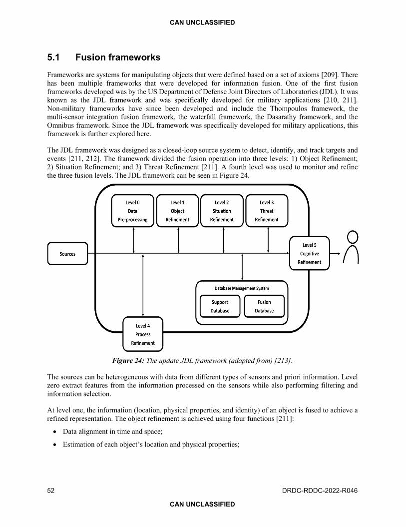
CAN UNCLASSIFIED
52 DRDC-RDDC-2022-R046
CAN UNCLASSIFIED
5.1 Fusion frameworks
Frameworks are systems for manipulating objects that were defined based on a set of axioms [209]. There has been multiple frameworks that were developed for information fusion. One of the first fusion frameworks developed was by the US Department of Defense Joint Directors of Laboratories (JDL). It was known as the JDL framework and was specifically developed for military applications [210, 211]. Non-military frameworks have since been developed and include the Thompoulos framework, the multi-sensor integration fusion framework, the waterfall framework, the Dasarathy framework, and the Omnibus framework. Since the JDL framework was specifically developed for military applications, this framework is further explored here.
The JDL framework was designed as a closed-loop source system to detect, identify, and track targets and events [211, 212]. The framework divided the fusion operation into three levels: 1) Object Refinement; 2) Situation Refinement; and 3) Threat Refinement [211]. A fourth level was used to monitor and refine the three fusion levels. The JDL framework can be seen in Figure 24.
Figure 24: The update JDL framework (adapted from) [213].
The sources can be heterogeneous with data from different types of sensors and priori information. Level zero extract features from the information processed on the sensors while also performing filtering and information selection.
At level one, the information (location, physical properties, and identity) of an object is fused to achieve a refined representation. The object refinement is achieved using four functions [211]:
Data alignment in time and space;
Estimation of each object’s location and physical properties;

CAN UNCLASSIFIED
DRDC-RDDC-2022-R046 53
CAN UNCLASSIFIED
Assignment of information to objects to facilitate statistical estimation techniques; and
Estimation refinement of the identity of each object.
At level two, the information on the refined objects is fused to identify relationships within the current environment. The identified relationships between the objects are based on relational information including but not limited to communications, temporal, causal, and physical proximity [211]. Based on the identified relationships, the objects are clustered into meaningful groups, such as a regiment.
At level three, the information from level one and two is utilized to predict threats, vulnerabilities of friendly forces and enemy forces, and opportunities by projecting the current situation into the future. Compared to levels one and two, fusion at level three is difficult to achieve, since it has to deal with uncertain information such as the enemy’s intent, future supply, and the political environment.
In addition to the three fusion levels, there is a fourth level, a meta-process, which monitors and refines the fusion levels to improve the fusion outcome. At this level information is logged on the fusion levels for real-time adjustments of the fusion process and long-term improvement. Additionally, the information needed to improve the three fusion levels and the sources, such as sensors and databases, is identified. At the fourth level the identified information and sources are allocated to the appropriate fusion level based on the current objective [211].
The data management block is one of the most crucial blocks in the framework as it provides vital functions to the fusion levels by compressing, storing, archiving, protecting, and retrieving raw data and fusion products. Database management is particularly challenging as the raw data could be varied in form (1D signals, images, and text).
A level 5 was introduced to highlight the importance of human computer interaction. At this level, the fusion products and information displayed to the user presenting the query are adapted in a manner that enhances situational awareness and improves decision making [214]. The fusion products are displayed such that the operator’s attention is directed toward important information while augmenting cognition to overcome data analysis difficulties experienced by the operator, such as processing negative information [211]. Negative information is the absence of evidence which can be indicative of a certain pattern, such as flights avoiding a certain area of an airspace alluding that the area is a no fly zone, since a launch of a HW might be taking place [213].
5.2 Fusion techniques
In this section, fusion techniques that could be used for levels one, two, and three in the JDL framework are discussed. Multisensor fusion can be mainly organized into three categories [215]:
Complementary: Information that represent different aspects of a phenomenon such that fusing the complementary information provided expanded situational awareness (e.g., fusing radar and IR imager to detect a HW and to obtain the range and speed);
Cooperative: Information from different sources is combined to derive a single aspect of a phenomenon (e.g., fusing information from at least three satellites to derive the position of an HW); and

CAN UNCLASSIFIED
54 DRDC-RDDC-2022-R046
CAN UNCLASSIFIED
Competitive: Information from independent sources representing the same aspect of a phenomenon is fused to reduce interference, ambiguity, and uncertainty and improve reliability and robustness of the fusion system (e.g., fusing information from an array of radars).
Figure 25: Visual representation of the three information fusion categories [216–218].
A single fusion system can perform fusion under a single category or multiple categories. As an example, a system that fuses an array of radars and an IR imager can fuse the array of radars in a competitive manner while fusing the product of that operation in a complementary manner with the IR imager.
In addition to the fusion categories, the fusion operation can be abstracted to three levels [219]:
Signal level: raw information from the sources is fused together (e.g., averaging out the signals from radars in an array to reduce interference);
Feature level: information from the sources is reduced to a set of features that are then used for the fusion operation (e.g., fusing information from different source types such as a radar and a IR imager); and
Decision level: independent decisions are fused together to reduce ambiguity and uncertainty (e.g., fusing the estimated identities of HW from radars and IR imager based on known signatures).
The fusion operation can take place on a central node or on a distributed network [207]. The assessment of the three abstraction levels is based on the communication load, processing complexity, information loss, and performance loss [220]. The communication load assess how much information has to be moved through the network in order to perform the fusion. The processing complexity assess the computational complexity of the fusion techniques at the abstraction level. The information loss reflects the decrease in the information available for fusion as a result of the abstraction. Performance loss assesses the reduction in the performance of the fusion system due to the abstraction.
5.2.1 Signal level fusion
Signal level fusion operates directly on the information reported from the sources. Fusion at this level is mainly used for redundancy, calibration, and reduction of interference, ambiguity, and uncertainty by fusing information from homogenous sources; however, information from heterogeneous sources can still be fused at the signal level by utilizing ML to improve situational awareness [221, 222]. From the perspective of the JDL framework, signal level fusion will typically take place at level one. Due to operating directly on the information from the sources, signal level fusion has no information and performance loss at the expense of high communication load (due to the large amount of information) and processing complexity [220].

CAN UNCLASSIFIED
DRDC-RDDC-2022-R046 55
CAN UNCLASSIFIED
Signal level fusion typically takes place in the competitive category to improve the estimation of a phenomenon, such as averaging out the radar signals from an array to reduce interference and to enhance the estimation of the range of an object. Complementary and cooperative signal level fusion could be achieved through ML.
The simplest signal level fusion is weighted averaging of the information from the various sources [221]. The weights are used to account for the erroneous information that could have been obtained from a malfunctioning or a compromised source. The information from incredible sources is still being included in the fusion operation, albeit at a less importance to the information from credible sources.
One of the challenges of signal level fusion is extreme outliers which can degrade the performance of some object tracking techniques, such as Kalman filter [223]. Other challenges include information synchronization [220] and security. Sources can be collecting the information at different time intervals, so synchronization is required to align the information from the various sources temporally. Signal level fusion requires the transfer of raw information from the sources to a central node for fusion which can expose vital information to the enemy if the communication network is compromised.
5.2.2 Feature level fusion
Feature level fusion is a step higher than signal level fusion as it is operating on features derived from the raw information. This level of fusion can occur under any of the fusion categories. In terms of the JDL model, feature fusion will take place at levels one, two, and three. Since the feature level fusion operates on a representation of the raw information, it has lower communication load and processing costs at the expense of information and performance losses when compared to signal level fusion [220].
Feature level fusion can be divided into three steps: 1) feature extraction; 2) feature selection; and 3) classification/regression. The third step is typically performed by ML algorithms, which can be classified into supervised, unsupervised, and semi-supervised techniques. Supervised techniques are used when the ground truth labels are available while unsupervised and semi-supervised techniques are used when labels are missing or only a small amount of the available information is labelled. Feature extraction can be performed in the time domain, the frequency domain, and a hybrid of them [221]. Table 4 summarizes some of the features that could be extracted [221, 224].
In addition to the curse of dimensionality (the reduction of the performance of the ML system due to the number of features exceeding the number of measurements leading to the statistical challenge of modelling these points [225]), feature level challenges include extracting the correct features that represent the phenomenon being observed and using the appropriate machine learning algorithm to fuse the features. If the extracted features do not represent the observed phenomenon then the output of the fusion process will not represent the phenomenon regardless of the feature selection operation or the chosen machine learning algorithm.

CAN UNCLASSIFIED
56 DRDC-RDDC-2022-R046
CAN UNCLASSIFIED
Table 4: Summary of features (adapted from [221] and [224]).
Time domain Frequency domain Hybrid
Waveform characteristics (e.g., gradient, slope, Maxima location, Minima location, Zero crossing rate, pulse duration, amplitude, envelop, pulse repetition intervals)
Spectral features (e.g., power bandwidth, spectral entropy, energy, spectral peaks, spectral roll-off, spectral flux)
Wigner-Ville distribution-based analysis
Waveform statistics (e.g., mean, median, standard deviation, kurtosis, skewness, peak-to-valley ratio, energy, entropy moments)
Power spectral density Time-frequency principal component and short-term Fourier transform (STFT)
Chaotic models and fractal features
Fourier and Chebyshev coefficients
Cyclostationary representations (e.g., cyclic (cross-) correlations, cyclic (cross-) spectra)
Ringing, overshoot phenomena, and pulse/ambient noise floor relationship
Periodic structures in the frequency domain
Wavelet representation
5.2.3 Decision level fusion
Decision level fusion is the highest fusion level and is usually characterized as an expert system [220]. The decisions performed by the different sources on a specific phenomenon are fused to reduce ambiguity and uncertainty. In terms of the JDL model, decision level fusion could take place at levels one, two or three to either reach a decision on an object property, the relationship between objects of interest, or to identify current and future threats. This level of fusion has low communication load if only the decisions performed by the sources are communicated, but it can have a high communication load if the sources send their raw information for processing and fusion at a central node. The computational complexity is low as the algorithms used are simple, but there is information and performance losses due to abstraction of the information [220]. Decision level fusion can be complementary, cooperative, or competitive. Expert systems can be based on voting, probabilistic methods, or fuzzy logic [221]. Challenges with decision level fusion include quantification of the uncertainty in a decision (as shown in [226]) and the availability of priories. Probabilistic methods such as Bayes theorem require the availability of priories, however, not all phenomena have been previously observed and modelled. Solutions to this challenge include using approaches such as the Dempster-Shafer theory (DST) that does not need a priori to fuse decisions; however, DST has been critiqued in the past due to it producing counterintuitive results in the case of conflicting decisions being fused [227].

CAN UNCLASSIFIED
DRDC-RDDC-2022-R046 57
CAN UNCLASSIFIED
5.3 Multisensor fusion for hypersonic weapon detection and tracking
Hypersonic weapon (HW) is mainly detected and tracked using radars and IR imagers that could be integrated into satellites and ground monitoring stations. These sensors could be fused together to detect and track the HW birth-to-death by augmenting their disadvantages such as blind spots of satellites and the horizon for the radar ground-based ground monitoring stations. Target detection and tracking could be performed using estimation-based or learning-based algorithms.
Estimation-based algorithms take in information from the sensors on the target, such as the current location and velocity, and estimate the location of the target in the future while accounting for noise in the information. A Kalman Filter (KF) is an estimation algorithm that features prominently in the literature and has been used successfully for target tracking and robotic navigation [228]. KF works by estimating the next position of a target by using noisy measurements. KF operates on linear problems, however, it was extended to work on non-linear problems [229]. A variation of KF that operates on non-linear problems is known as unscented KF and it integrates a non-linear transform step of the tracking problem. Gaitanakis et al. [230] proposed two different HW tracking systems that are based on non-linear variations of KF. The first system was based on a centralized fusion architecture where all of the information from the sensors were fused in a central unit. This is an example of feature fusion as the features derived from the sensors signals including but not limited to the speed, heading, and current location are fused to obtain a better estimate of these measurements. The fuser combined the features by using the known measurement errors from each sensor to reduce the mean square error of the measurements. The fused measurements were provided to the KF for estimation of the next position of the HW. The second system was based on a distributed fusion architecture such that the KF was applied on each sensor input to estimate the next position of the HW and then the fuser improved the position estimates. Figure 26 shows the first and second systems. A challenge of using estimation-based algorithms is the requirement for knowing prior information, such as the measurement error or the distribution of the measurements.
ML could be used as a multisensor fusion approach that does not require prior information on the data being fused. ML is a data-drive set of algorithms that learn patterns in the data such that new points of data can be associated with these patterns automatically without human intervention. Bartusiak et al. [231] proposed using a convolutional neural network (CNN), a deep learning algorithm, to identify the type of HW based on their trajectories. The CNN was tested in the presence of measurement noise and was shown that it was resilient against the noise achieving between 60 and 80% accuracy and F1 score depending on the noise level. Gaiduchenko et al. [149] proposed a different CNN architecture to identify HW based on trajectory achieving F1 score of 0.91 based on average noise. He et al. [232] proposed a system that combined estimation-based algorithms and ML to track multiple targets using multisensor fusion. Each sensor performed its own processing to track targets and then a ML algorithm was used to separate the tracks by clustering similar tracks from each sensor together and assigning them to a specific target. Simulations illustrated that the proposed system was successful in tracking multiple targets using multisensor fusion.

CAN UNCLASSIFIED
58 DRDC-RDDC-2022-R046
CAN UNCLASSIFIED
Figure 26: (Top) Centralized fusion architecture. (Bottom) Distributed fusion architecture (adapted from [230]).
5.4 Information fusion systems for developing timely course-of-actions
Depending on their launch location, a HW can reach its target within minutes or even seconds, which requires fusion systems to detect, track, and recommend the intercept course in a matter of seconds. The automated process of detecting, tracking, and intercepting a target is known as sensor-to-effector loop (StEL). Figure 27 shows the breakdown of the StEL, such that a timely intercept of a HW is achieved. The speed of fusion systems and by association the StEL mainly depend on the communication links between the sensors, the sensor’s processing power, and the StEL architecture.

CAN UNCLASSIFIED
DRDC-RDDC-2022-R046 59
CAN UNCLASSIFIED
Figure 27: Notional architecture changes to accelerate the StEL to defeat time-sensitive targets [31]. 40
Ground-based sensors such as radars can be connected to high performance computers for timely analysis and fusion of the produced signals, however, space-based sensors such as IR imagers can have limited processing power due to their limited power sources. These space-based sensors will most likely have to transfer their data down to a ground station for processing. Satellites in geosynchronous orbits have median latency of 724 ms [233]. Considering that the StEL need to be performed on the order of seconds, such high latency may not be acceptable. LEO satellites, such as the ones forming Starlink, have a median latency of 45 ms [233]. The Missile Defense Agency (MDA) is currently working on developing new space based sensors that are capable of detecting and tracking HW. “The Hypersonic and Ballistic Space Sensor (HBTSS) program is aimed at building a constellation of satellites in Low Earth Orbit (between about 100 kilometres and 2,000 kilometres up) that can keep tabs on manoeuvring hypersonic missiles flying below the range of today’s ballistic missile detection satellites and above the radar of terminal-phase targeting systems. The HBTSS satellites would be cued by the SBIRS and Defence Support Satellites—and in future the Next-Generation Overhead Persistent Infrared System satellites—that detect the infrared plumes from missile launches. The HBTSS sensors would track the missiles in their high-speed glide phase, then ‘hand off’ targeting coordinates to shooters such as the Navy’s Aegis Ballistic Missile Defence system and the Army’s Theater High Altitude Area Defence interceptors [234].” The Persistent Infrared System satellites will have a Prototype Infrared Payload (PIRPL). The PIRPL is a multispectral infrared camera that will be used to collect on the Earth’s infrared background that would later be subtracted from HW IR tracking systems [235].
The Space Development Agency (SDA) is planning the launch of 150 satellites for the purpose of detecting and monitoring missiles. “The new satellites, to be launched in September 2024, will comprise what SDA calls ‘Tranche 1’ of its planned seven-layer National Defense Space Architecture. They will follow-on the 20 Transport Layer satellites for porting data to users and the 10 Tracking Layer missile warning and tracking sats planned for launch in March 2023 to demonstrate capabilities, Tournear told the SmallSat
40 Paul Labbé received the authorization to use this chart on 16 November 2020 by Dr. David M. Van Wie of Johns Hopkins APL.

CAN UNCLASSIFIED
60 DRDC-RDDC-2022-R046
CAN UNCLASSIFIED
Symposium today [236].” Figure 28 shows the National Defense Space Architecture with the transport layers that aim at reducing latency and improving the communication links between space-based sensors and ground stations.
Figure 28: Space Defense Architecture planned by Space Defense Agency [236].
An alternative to the expensive satellites are nanosatellites, also known as CubeSats [237]. The MDA launched two CubeSats in 30 June 2021 into LEO. “These satellites will test key technologies that mitigate risk for systems, such as the Hypersonic and Ballistic Tracking Space Sensor,” Walt Chai, MDA director for space sensors, said. “The CNCE Block 1 mission will demonstrate the viability of advanced communications technologies using reduced size, weight and power in support of missile defence communications architectures [237].” Blackjack is a DARPA program that aims to develop a high speed network in LEO [238]. The satellites will be interconnected using an optical link that will be acting as the transport layer of the Space Defence Architecture [239]. Blackjack will also explore increasing the processing power of CubeSats. “Mandrake 1, is a cubesat that will carry supercomputer processing chips. The second, Mandrake 2, is a pair of small satellites that will carry optical inter-satellite links for broadband data. DARPA says these could form the basis of future optically meshed networks in LEO. A third payload scheduled to launch is called Wildcard, a software-defined radio that will experiment with links from LEO to tactical radios [240].”
LEO satellites and CubeSats are not the only approach to monitoring the aerospace for HW with low latency. The Japanese Ministry of Defense is considering unmanned aerial vehicles (UAVs) with an infrared imager as an early warning HW sensor. “The same report notes that the unmanned aerial vehicles

CAN UNCLASSIFIED
DRDC-RDDC-2022-R046 61
CAN UNCLASSIFIED
would be equipped with an undisclosed but existing infrared detection system originally designed to identify ballistic missile attacks, “technology verification” of which was apparently completed in 2019. The “small infrared sensor” would be carried aloft by a drone that would “operate in an airspace closer to the enemy” and which would be able to remain aloft for long periods [241].”
The Space Defense Architecture is expected to provide local and global monitoring for HW, but the information generated would need to be fused automatically to ensure a speedy response. The UK Royal Navy used AI to counter supersonic weapons at the Formidable Shield NATO exercise. “The Formidable Shield exercise gives a glimpse of how supersonic and faster missiles could be defeated in the future using artificial intelligence and machine learning. Though AI systems aren’t intelligent in any human sense of the term, they do have the ability to learn from large sets of data and extract patterns from them. In this way, they can take the huge influx of data from increasingly sophisticated sensor input, and identify and track missile threats. The systems used were Startle, which monitors the air environment for the ship’s operation room and gives real-time recommendations and alerts, and Sycoiea, which takes the results from Startle and helps to identify incoming missiles and recommends which weapon to use to counter them. According to the Navy, the AI systems allowed operators to identify live-fire threats more quickly, and even to outwit the operations room, which now had a lower workload [242].”
5.5 Adaptivity and architectures
As demonstrated by previous works [243] such as in [244], development of fuzzy logic-based adaptive Kalman filter (FL-AKF) suitable to adaptive centralized, decentralized, and federated Kalman filters allows to build Adaptive MultiSensor Data Fusion (AMSDF) systems, which are more effective and accurate than blind data correlation alternatives. AMSDF offers the ability to adaptively adjusting the measurement noise covariance matrix of each local FL-AKF to fit the actual statistics of the noise profiles present in the incoming measured data. Such fuzzy inference system (FIS) using covariance-matching technique showed adaptation mechanism in simulation with improved timeliness and accuracy of detection and tracking target of interest. “HAMSDF architectures are effective in situations where there are several sensors measuring the same parameters, but each one has different measurement dynamic and noise statistics.”
Advances in data fusion led by Erick Blasch [171, 174, 175, 245–248] showed evidences of advantages over risk of integrating AI and ML in AMSDF. As stated in [171]: “These challenges can also be opportunities as AI/ML spawned new research in deploying physics-based and human-derived information fusion (PHIF), learning about context, tracking with graph fusion, coordinating Internet of Things (IoT) security, as well as facilitating dynamic network analysis for multi-domain operations (MDO).”
Pervasive information sharing is addressed by the real-time information sharing discussed in the previous section.

CAN UNCLASSIFIED
62 DRDC-RDDC-2022-R046
CAN UNCLASSIFIED
5.6 Action planning and resource assignment
Theatre battle management and planning could be divided in two categories [249] relative to operational situation in terms of time available and degree of urgency: a) deliberate planning and b) crisis action planning aka time-sensitive planning. “The deliberate planning process is not generally subject to the immediate time lines or prevailing threats. It develops operation plans for contingencies and for later execution. The crisis action planning process is needed when the degree of urgency of the crisis demands an accelerated operation planning process. The most significant factor to consider in such planning is time. Consequently, the crisis action planning process is characterized by quick response, decisive action, and flexibility to adapt to the contingency situation.” They are interrelated when considering that deliberate planning may include strategic posture ensuring that appropriate assets and actions will be made timely at specified locations as illustrated in Figure 29.
Figure 29: Battle management from strategic to operational down to tactical.
More information could be found in several references such as [250, 251] which exemplify the following notions: “Assisting ISR/Joint Fires enablers in the digitization of the Decision-Action Cycle, TIFAV (Total ISR and Fire Asset Visibility) is an automated Sense-and-Respond proof-of concept decision support capability, delivering optimized effector-sensor mix automation at the tactical edge, and paving the way toward a sensor-decider-shooter solution integration. It automates sensor-task / weapon-target matchmaking and optimization to derive best collection/fire plans [250].”
The StEL needs to be shortened as described by several authors, e.g., CStEL [11]. An example of defence systems to address HW threat in the European context is reported by a Poland expert [37]. As the DoD deliberates future missile warning plans, senior officials say the second iteration of the Next-Generation Overhead Persistent Infrared (Next-Gen OPIR) constellation could include multiple satellites in LEO, a revolution in the traditional US approach to early warning. Instead of building ground stations around the world to link to the hundreds of satellites planned for its LEO architecture, the SDA plans to rent commercial capacity—a move that likely will both save money and speed operational capability.

CAN UNCLASSIFIED
DRDC-RDDC-2022-R046 63
CAN UNCLASSIFIED
Here are some relevant references about cruise missile defence [169, 252–265] including force employment [266, 267], e.g., FORCEnet [268] “focuses on the development of a conceptual anti-ship cruise missile defense (CMD) model that integrates FORCEnet architecture components with the technical requirements of the Program Executive Office for Integrated Warfare System (PEO IWS) Open Architecture (OA) functional domain model. FORCEnet is the enabler of the CNO’s vision of SEAPOWER 21 as the transformer of Navy and Marine Corps combat power projection.”
“Research and analysis verified that OA provides the framework for the development of FORCEnet design concepts that enables implementation of a CMD Integrated Fire Control (IFC) and command structure. PEO IWS, chair of the Open Architecture Enterprise Team (OAET), disseminates OA policies and standards iteratively and plans for its implementation in next generation surface and subsurface combatants. Fusion of the FORCEnet information architecture and an OA functional domain model pose challenges and risks to be identified, managed, and mitigated. To realize the potential of this new architecture, FORCEnet will need to be an operational construct supporting all U. S. Navy forces prior to implementation. The goal of the conceptual architecture is to fuse time-dependent tactical information from distributed sensor and platform nodes with minimal error and disseminate it in real-time to the decision-makers and Composite Warfare Commanders (CWC). The power of OA rests with the ease in which technology refresh occurs and its promotion of force-wide joint interoperability on the same distributed network. According to the Israeli Navy and Ground Forces Command, a lack of force wide joint interoperability caused the Hanit mission kill. FORCEnet, through OA, will expedite data flow enabled by common services and will reduce human interaction in the kill chain. IFC is fundamental to improved cruise missile defence and refers to platform- independent sensor fusion and weapons pairing to overcome radar horizon or Earth’s curvature effects that effectively constrain the battlespace volume. Through automated IFC, weapons are not limited to local surveillance and fire control. IFC capitalizes on networked sensors, reduces horizon and terrain limitations, and improves the layered defence against stressing CMD threats. Two fundamental differences between PEO IWS’s and the proposed architectures are that the proposed architecture contains a re-engagement loop after the first salvo is fired and it is horizontally integrated. The re-engagement loop following the kill assessment hastens message flow while horizontal integration simplifies and minimizes the functional interfaces. While the simulation model was based on the discrete-event model, it was built in the process-view of Arena version 10.0 simulation software. The kill chain functions were represented in the simulation in the context of the higher-level aggregation of the OODA loop. Uncertainty was represented by statistical distributions of stressor threat inter-arrival and service times that provides predictive forecasting through statistical inference, which was absent from the conventional OODA loop. The measures of performance used in the simulation were the means of the following: the number of IA attacks; the number of electronic countermeasures softkills; the number of threat missiles killed by interceptor missiles; the number of reengagements; and the number of leakers. The PEO IWS architecture simulation results were the control group in both the raid and the stream cases [268].” To reflect uncertainty in the C2 response, the OODA loop needs a prediction function inserted into a revised observe-orient-predict-decide-act (OOPDA) loop.

CAN UNCLASSIFIED
64 DRDC-RDDC-2022-R046
CAN UNCLASSIFIED
6 Effectors to defeat new cruise missiles
Given the resources available for this Report and its unclassified content, the types of effectors, their advantages and weaknesses, and their combinations to achieve intended effects will be limited to the following summary.
Currently, non-kinetic effectors include electronic warfare (EW), directed energy weapons (DEWs) and EMPs (described in Section 2.7). Available kinetic effectors are similar to the HW technologies described in Section 2, i.e., HCM, HVP, HR and HGV. Here are examples of initiatives that were cancelled: The US exoatmospheric kill vehicle (EKV) interceptor is essentially boosted like a BM toward the incoming warhead by a Ground-based Midcourse Defense (GMD), part of the larger US National Missile Defense system. Once the EKV is separated from the boost vehicle, EKV autonomously collides with the incoming warhead (design review deferment in December 2018). The EKV’s own rockets and fuel are for corrections in the trajectory. The newer version of the EKV is the redesigned kill vehicle (RKV) scheduled to debut in 2025 (cancelled 21 August 2019).
As discussed previously, proportional navigation (PN) is the best navigation algorithm to effectively reach a moving target. Yang studied the defender triangle approach [269]; his paper focuses on hypersonic vehicles penetration problem. One of the effective penetration strategies is to release a defender from the aircraft to confront the interceptor. In this case, the hypersonic vehicle, the defender and the interceptor constitute the triangle interception relationship. The analysis shows that the defender has advantages in target detection and guidance. The simulation results show that the proposed method is suitable for solving the problem of hypersonic vehicles penetration. Triangle interception problems early lead by the Boyell [270] PN guidance law, assumed constant bearing collision courses. Using the closed-form expression for the intercept point and conditions on speed ratios were also derived. PN guidance law always requires missile have stronger manoeuvre ability than the target, hence the methods did not fully exploit the position advantages of the defender.
6.1 Effectors [11]
The term effector was selected instead of weapon to expand the system beyond hardkill to include softkill interventions such as electronic countermeasures (ECM), jamming, EW and its cognitive version CEW [271–275]. Then the defence system could demonstrate its electronic combat effectiveness with an EW softkill as simulated in [268]. For hardkill and softkill, predicting outcomes against threat targets requires comparing CoAs and their time lines. Most of the time there are no silver bullets against threats and alternative actions need to be pre-planned. Fleetingness, the fact that actions happen over a very short time, requires anticipating that one countermeasure or missile interception may fail. Using some prediction techniques helps to build the sequence of actions required to attain a high degree of confidence of successfully intercepting the threatening target(s).
If the effector is a hardkill type like a missile with specific characteristics (cognitive or not) for successfully homing in on a target, then these characteristics specify the minimum track quality for valid engagement. In the case of smarter missile with some cognitivity and autonomy that would be different and difficult to predict the outcomes. Another aspect is the railgun. A US Navy projected 64 MJ railgun may require 16 MW for 6 MA peak at a shooting pace of 6 shots per minute with a maximum range of 350 km. Such railgun would shoot 10 times further than normal ship mounted guns (a definite advantage in combat) and

CAN UNCLASSIFIED
DRDC-RDDC-2022-R046 65
CAN UNCLASSIFIED
save a lot of money (improving sustainability) for its operation per shot compared to current guns + ammunitions and missiles.
Laser type of effectors usually need more time to lock on a target due to their narrow beam but their time to reach the target is almost immediate compared to a missile. Jammers, EW and cognitive EW (CEW) offer similar performances at the speed of light [271–276] but don’t need to lock on a target so they offer immediate effect or distraction.
6.1.1 Directed energy weapon
This section was adapted from [277, 278]. Directed energy weapon (DEW) technologies (these include technologies such as: high energy laser [HEL], radio frequency [RF] DEWs, and relativistic particle beams [RPBs] and high power microwave [HPM]) require usually large and heavy high power sources although technologies advanced made them more deployable. However, such electricity demand still represents a major challenge to accommodate, especially on legacy platforms. Various types of DEWs are currently in deployment phases for air, land and naval platforms with a large variety of electrical energy demands. Figure 30 shows that the pulse power depends on type of targets, use and range.
Figure 30: Typical radiating power required for specific counter attack [278].
For an hypothetical HPM, the authors [279] assume an efficiency similar to radar technologies, i.e., 17% of the input power results in radiating power. They consider that 3.7 GW of input power is required to deliver, at a range of 10 km, a power flux of 10 kW/m2 on a 30 mrad spot size of 300 m. References [280, 281] provide information on damage level of DEWs.
It is critical to recognize that these technologies, directed energy weapons, are power hungry while persistent surveillance and C4ISR (command, control, communications, computers, intelligence, surveillance and reconnaissance) ones are energy hungry.
It is worth noting that new energy systems are at the cusp of being made available for such systems, either power hungry or energy hungry. “A different picture of nuclear energy is emerging, however, in the form of micro-reactors that could fit on the back of a truck or inside a rocket to space. The promise of these micro-reactors is to provide the same reliable, zero-carbon power in remote settings or to support electrical power grid recovery. Experts at the U.S. Department of Energy’s (DOE) Argonne National Laboratory are
High power lasers: Application vs laser power
Plus an hypothetical HPM radiating 500 MW
Ocular Dazzling
10 W 100 W 1 kW 10 kW 100 kW1 W
DIRCM
C-ISR
C-IED C-UXO
C-RAM
C-UAV
DIRCM: Directional InfraRed Countermeasures; ISR: Intelligence, Surveillance, Reconnaissance; UAV: Unmanned Aerial Vehicles; RAM: Rockets, Artillery, Mortars; IED: Improvised Explosive Devices; UXO: Unexploded Ordnance
C-missile
1 MW
C-satellite
1 GW
HPM C-computers,radios, vehicles and command centers

CAN UNCLASSIFIED
66 DRDC-RDDC-2022-R046
CAN UNCLASSIFIED
developing strategies to bring micro-reactor concepts closer to commercial reality, working together with private industry and federal regulators. A micro-reactor might have a capacity of anywhere from a few kilowatts to 20 megawatts—far less than even the smallest operating U.S. nuclear power plant, which has a capacity of 581 megawatts.”41 This is done under DOE’s Advanced Research Projects Agency-Energy (ARPA-E).
An alternative is also sought by ARPA-E for development of new energy sources with low radiation emission during operations and with no highly radioactive wastes. In order to better define such program ARPA-E held a workshop 21–22 October 2021:42 “The objective of this workshop was to explore compelling R&D opportunities in Low-Energy Nuclear Reactions (LENR) in support of developing metrics for a potential ARPA-E Research & Development (R&D) program in LENR.”
Figure 31 provides an example of LENR results compiled in a Ragone plot from available information collected about the E-Cat SKL.43
Figure 31: Ragone plot projections from available information collected about the E-Cat SKL.44
41 EnergyPost, https://energypost.eu/micro-nuclear-reactors-up-to-20mw-portable-safer/, (Access date: 16 November 2021). 42 ARPA-E, https://arpa-e.energy.gov/events/workshops, (Access date: 16 November 2021). 43 E-Cat, https://www.ecat.tech/news/first-cold-fusion-reactor-available-market-place, (Access date: 16 November 2021). 44 Permission to use this chart granted by Greg Daigle on 13 November 2020 via LinkedIn https://uploads.disquscdn.com/images/00f3d7a849cf463945473db4a4c678cf7a9b35c16b772fff6c0cc9480b2f631a.png, (Access date: 20 November 2020).

CAN UNCLASSIFIED
DRDC-RDDC-2022-R046 67
CAN UNCLASSIFIED
It is worth noting that the E-Cat SKL provides power and energy densities well above chemical reactions. Once such technology, with no nuclear radiation and radioactive wastes, reaches commercialisation, it could power a variety of platforms and applications over long period of time never seen before.
6.1.2 Jammer and information security
Assuming that some HWs may use telemetry, radio control and radar for navigation (e.g., GNSS) and homing in on targets, here is some useful information about jamming technologies and methods. Typical jammer capabilities from Figure 32 allow devising an even better jammer strategy by deducing the type of protocol and error correction capabilities of the communication to disturb, this is protocol jamming. Reading reference [282], we find that the authors’ intent of the jamming taxonomy paper is “to help researchers place newly discovered jamming or anti-jamming strategies within a larger context of known strategies in a way that is consistent with modern electronic warfare.” The authors refer to the Common Attack Pattern Enumeration and Classification (CAPEC)45 which “is a catalog and taxonomy of cyber-attack patterns, created to assist in the building of secure software. Each attack pattern provides a challenge that the attacker must overcome, common methods used to overcome that challenge, and recommended methods for mitigating the attack.” For example, performance improvements in terms of energy efficiency, data streaming speed and accuracy require using system and network self-awareness at various layer levels of the IoT stack [283–289] in order to counter interference or jamming, These networks may share quality of service (QOS) information about the receiving spectrum as seen by the wideband front end of their SDR from each participant location.
A jammer can have one or more of the following major capabilities: time correlated, protocol-aware, ability to learn and signal spoofing.
When a jammer has no knowledge of the protocol to be defeated, it may use digital radio frequency memory (DRFM) jamming (aka repeater jamming or follower jamming) in the simplest form of correlated jamming. Also it can estimate the automatic gain control (AGC) time constant of the receiver to be jammed.
45 CAPEC, https://capec.mitre.org, (Access date: 22 April 2017).

CAN UNCLASSIFIED
68 DRDC-RDDC-2022-R046
CAN UNCLASSIFIED
Figure 32: Specific jamming techniques discussed in literature, mapped according to key jammer capabilities (Illustration from) [282].46
More information about radio communication jamming and network security could be found in [282, 290]. In addition we have to consider the significant research and findings on self-healing networks and sensor networks [290–301] which offer an adaptive approach to counter jamming, adverse propagation, interferences and noise.
Next we have to consider the information security (INFOSEC) and communication security (COMSEC) aspects assuming that attacks are within the internetworking. In such cases encryption, randomization and utilisation of blockchain should be sufficient to protect the information. Also this creates a big challenge in managing crypto keys over a large number of IoTs via wireless links [302–304]. Other studies show techniques to increase security at the physical layer (PHYLAW) [305–308]. INFOSEC/COMSEC could be seen from the viewpoint of offence and defence. It depends on the game at play, e.g., for our forces to get into opposing force weapon INFOSEC/COMSEC, it may include disabling an impending HW including using some form of jamming or other counter attack as illustrated by Figure 30. For the opposing forces it may include disabling our defence systems, from sensors, communications up to effectors, this is a threat like when being jammed.
46 With the permission from the authors; Labbé-Lichtman, 3 April 2017.

CAN UNCLASSIFIED
DRDC-RDDC-2022-R046 69
CAN UNCLASSIFIED
7 Cost and sustainment considerations
Although HWs are quite expensive and difficult to test and manufacture, their interceptors are also very expensive, especially when one needs to consider that more than one tentative of interception might be required to ensure successful interception. The interceptor missile must outmanoeuvre the intended target. Some HWs have more agility and endurance than others. One may expect the HCM to have more agility than a HGV. Depending on design, HR may have some agility like the HCM when its rocket motor still propels the warhead.
Here is an example of interceptors cost. The Iron Dome unit cost is around $50 million per battery. Depending of the selected rockets, each interception tentative costs $100,000 to $150,000. If the interceptor is the Tamir missile, a range of 4 to 70 km could be achieved. Each Iron Dome battery can defend about 159 km2. In order to keep the interception timely and with some success, automation with ML/AI is exploited as documented in “Categorization of AI-Enabled Command and Control in Ballistic Missile Defence [309].”
Another example is the terminal high altitude area defense (THAAD). THAAD element provides the Ballistic Missile Defense System (BMDS) with a globally-transportable, rapidly-deployable capability to intercept and destroy ballistic missiles inside or outside the atmosphere during their final, or terminal, phase of flight. The current estimate for just THAAD and Patriot Advanced Capability (PAC-3) is more than $20 billion and is likely to rise further. Likewise, the time it will take to deploy those systems has expanded significantly from the original timelines assumed. One Russian S-300 missile system is estimated to cost some $115 million, the cost of each missile is over one million US$. “The THAAD interceptor carries no warhead, but relies on its kinetic energy of impact to destroy the incoming missile. A kinetic energy hit minimizes the risk of exploding conventional-warhead ballistic missiles, and the warhead of nuclear-tipped ballistic missiles will not detonate upon a kinetic-energy hit [310].”
The Patriot system has four major operational functions: communications, command and control, radar surveillance, and missile guidance. Patriot Guided Missile: Unit cost US$1 to 6 million.
Note that these systems cannot share missiles because they were specifically designed for optimal performance for a given system (probably manufacturer IP protection), they are not interchangeable.
A report from the National Research Council (NRC) titled “Making sense of ballistic missile defence: An assessment of concepts and systems for US boost-phase missile defence in comparison to other alternatives [311]” offers values of 20 years of operations and support (O&S) cost, this provides a comprehensive comparison of selected anti-air and missile systems. NRC selected the following systems for the study: GMD system, the Aegis, PAC-3, and THAAD systems currently being fielded, as well as their proposed upgrades and all boost-phase missile defence systems that had been considered, including the airborne laser (ABL), the kinetic energy interceptor (KEI), and other existing or contemplated boost-phase technology demonstrations (e.g., space-based interceptors and airborne interceptors launched from tactical air platforms). In addition, the committee examined the planned phased adaptive approach (PAA)—that is, the Aegis BMD system. Figure 33 summarizes the findings of this Report.

CAN UNCLASSIFIED
70 DRDC-RDDC-2022-R046
CAN UNCLASSIFIED
Figure 33: Twenty-year life-cycle costs for the BMD systems examined in this Report. (1) Where applicable, MILCON costs included as part of procurement costs; (2) Sunk investments based on kinetic energy interceptor heritage; (3) Sunk investment based on Aegis block development upgrade, design, and
production heritage of SM-2 Block IV; (4) CONOPS based on multisession use of retrofitted available F-15Cs and/or F-35s; (5) Procurement cost includes MILCON estimates for recommended missile field and
facilities infrastructure construction costs on new northeastern CONUS site; and (6) Sunk investment cost for THAAD does not include separately identified past funds for AN/TPY-2 radar. MILCON, military
construction; CONOPS, concept of operations; CONUS, continental United States; THAAD, Terminal High-Altitude Area Defense; AN/TPY, Army Navy transportable radar surveillance; FWD, Forward Defense.
With DEWs, issues include distance of only a few hundred km and maintain precision tracking for enough time on target for effect. The capital cost is high but the O&S is impressively low. When powered by high-power and low cost energy source, the cost per interception is low, one may say it is like having an infinite magazine, if not, a deep one. For example a high power laser projects a large amount of energy at the speed of light over several hundred kilometres onto a modest-sized (~1 m) spot on an airframe body for several seconds. “During that time sufficient energy per unit area (fluence) is delivered to cause enough heating to result in mechanical failure of the missile body itself, thus disabling it and preventing the payload from reaching its target. The advantage of this system is that it delivers a lethal fluence to the threat missile in a matter of seconds from a great distance. Because the laser beam travels at the speed of light, the distance from which the threat can be intercepted is not limited by the flight time of a rocket interceptor. Rather, the range is limited by the fluence required, the laser power, and the ability to focus the beam onto the target at low elevation angles through the atmosphere. The ability to focus depends on the laser beam quality and issues of light propagation in the atmosphere itself. The beam propagation limitations are complex and are provided in the classified annex [311].”

CAN UNCLASSIFIED
DRDC-RDDC-2022-R046 71
CAN UNCLASSIFIED
8 Likely interception success rate
The current literature is sparse on information regarding interception success rate and cannot provide conclusive results on the interception success rate of HW. However, some previous experiments and announcements could shed some light on the different approaches that could be taken to improve interception success rate.
In 2018 the Pentagon’s Strategic Capabilities Office announced that it will test a new missile system. The system will use a relatively cheap, $86,000, HVP that can be fired from an ordinary cannon and will reach a speed of 5,600 miles per hour [312]. When compared to the Patriot missiles, the HVP provides a cheap augmentation that would be capable of improving the interception success rate. Patriot missiles are expensive, $3 million each, and require special launchers. This way the enemy cannot easily count the number of HPV systems but could count the number BMD systems such as Patriot and THAAD setups. Current systems require bulky launch systems an enemy can easily detect: a trailer for Patriot, a truck for THAAD, a silo for ground-based interceptor (GBI). As such, the enemy can count the number of interceptors that could be launched in a given time window in an area.
These systems could potentially have a high interception success rate, but the enemy could fire more HWs than these systems could handle. The HVP alleviates this challenge by providing a cheap fast ammunition that could be fired consecutively to improve the interception success rate.
In simulation, if the Probability of Kill Pk of a weapon/target engagement is 30% (or 0.30), then every random number generated that is less than 0.3 is considered a “kill”; every number greater than 0.3 is considered a “no kill.” After n repetitions, the resulting probability RPk increases as follow RPk = 1 – (1 – Pk)n , so about 97% for n = 10 [313]. It approaches 100% asymptotically. For the $3 million price of one late-model Patriot, you could buy about 35 HVPs. The advent of practical rail guns offering deep magazines to shoot targets at fair distances using HVPs offers a lower cost per interception.
“The more missile defence units you have, and the more mobile they are, the more you can disperse them to cover multiple angles of attack on many potential targets. Dispersion also makes it much harder for the enemy to find your missile defences and wipe them out. The enemy’s problem gets even harder if those missile defences can also take out his launchers preemptively, as guns firing HVP could do. (Remember, the Hyper Velocity Projectile is also capable of hitting static targets) [312].”
In the absence of extensive data, a model could be built of the likely interception success rate. The cybernetic models used in analyzing coalition live and simulated exercises where the decision-making processes at command centres can be interpreted as a cognitive adaptive-control system [314]. By using cybernetic models to interpret data and information collected during experiments, one can execute and evaluate the stages through a set of measures of performance (MOPs). Similarly, measures of effectiveness (MOEs) can provide an assessment [246] of the resulting degree of mission accomplishment in scenarios to scale MOPs relatively to MOEs, i.e., asserting both that the system performs its tasks well and that those are the correct relevant tasks to perform.
Using the original trend charts of interception success rate as function of data delay and circular uncertainty area (CUA) radius (inverse of accuracy), one can build notional trend charts adapted to possible HW interception. In these trend charts positive values indicate constructive or desired interception of opposing

CAN UNCLASSIFIED
72 DRDC-RDDC-2022-R046
CAN UNCLASSIFIED
force assets and negative values indicate non-constructive or un-desired interception (such as fratricide or civilian). Figure 34 illustrates steep improvement of the interception success rate as function of target track data timeliness and accuracy. The author hopes that, in the near future, several analysts would confirm and scale this notional interception trend chart based on field trials using specific effector characteristics to intercept various HWs.
Figure 34: Notional HW Interception rate trend chart as function of information delay and accuracy (inverse of CUA radius) assuming fix interceptor’s homing in on target capability.
The analysis and information presented in this chapter are preliminary and drawing conclusions on the likely interception success rate are not possible. The simulations described provide some insight, but they are inconclusive. The HVP approach could improve the likelihood of interception success rate, but the degree of improvement could not be ascertained.

CAN UNCLASSIFIED
DRDC-RDDC-2022-R046 73
CAN UNCLASSIFIED
9 Conclusion and future work
In this study, we conducted a literature review and an unclassified analysis of current and future HWs to inform decision-making on the opportunities and potential threats of these capabilities. Our observations from this study are summarized as follows:
HWs are not as disruptive as claimed in recent news based on public declarations. Indeed, the development of these weapons has gradually evolved during the last decades, but there is still some technical and operational challenges for the employment of HWs. In particular, current defence systems need to adapt to HW capabilities beyond classical BMs. Effectors to intercept HWs have also evolved and offer new opportunities for adapting command and control approaches to match the required time compression of the sensor-to-effector loop.
Future HW systems would leverage emerging and disruptive technologies in AI, data fusion, autonomy, and quantum computing to address some of the HW challenges by enhancing human cognitive activities at play. For example, AI cognitive sensors and communication networks would speed up the development of a more accurate and timely shared operational picture to support decision-making and would provide real-time data for tracking and intercepting time sensitive targets.
When HW launch platforms are closer to intended targets, it seems more practical to intercept such platforms because close defence weapons cannot offer a high likelihood of successful interception without damage to the intended target. Adopting an appropriate strategic posture reduces HW or tactical BM advantage offered by launch platforms in the area surrounding the targets.
For scenarios with paths initiated along Canada’s coastline, it would be difficult to detect and track hypersonic missiles in a timely fashion, especially if these missiles are launched from a hostile submarine navigating along Canada’s coastline targeting major urban areas or military bases. However, identifying potential intended targets could help mitigating the efficiency or success of hostile plans.
This research is a preliminary attempt to review the fundamentals of HWs and discuss new methods and techniques to defeat hypersonic threats. Further studies would be required to examine details related to other technical aspects of HWs, such as navigation and guidance, propulsion, defence against hypersonic systems, detection and tracking of hypersonic objects, sensing in a hypersonic environment, ground test facilities and instrumentation, etc.

CAN UNCLASSIFIED
74 DRDC-RDDC-2022-R046
CAN UNCLASSIFIED
References
[1] Canada: Department of National Defence and Canadian Armed Forces. Strong, Secure, Engaged. Canada’s Defence Policy, 2017.
[2] R. H. Speier, G. Nacouzi, C. A. Lee, and R. M. Moore, “Hypersonic Missile Nonproliferation; Hindering the Spread of a New Class of Weapons,” RAND Corporation, Santa Monica, Ca, USA, 2017.
[3] J. T. Watts, C. Trotti, and M. J. Massa, “Primer on Hypersonic Weapons in the Indo-Pacific Region,” Atlantic Council, Scowcroft Centre for Strategy and Security, ISBN-13: 978-1-61977-111-6, August 2020. [Online]. https://www.atlanticcouncil.org/wp-content/uploads/2020/08/Hypersonics-Weapons-Primer-Report.pdf, (Access date: 20 November 2020).
[4] R. Stone, “National pride is at stake. Russia, China, United States race to build hypersonic weapons,” Science magazine, 2020.
[5] A. F. Woolf, “Russia’s Nuclear Weapons: Doctrine, Forces, and Modernization,” 2020: Library of Congress Washington United States, 2020.
[6] D. B. Fergusson, “Hypersonic Glide Vehicles: Implications for Strategic Stability in the Coming Hypersonic Era,” Carleton University, 2019.
[7] S. R. Aarten, “The impact of hypersonic missiles on strategic stability; Russia, China, and the US,” Militaire Spectator, vol. JAARGANG 189, no. 4, pp. 182–193, [Online]. https://www.militairespectator.nl/thema/strategie/artikel/impact-hypersonic-missiles-strategic-stability, (Access date: 21 April 2020).
[8] NASIC, “Ballistic and cruise missile threat,” National Air and Space Intelligence Centre (NASIC) in collaboration with the Defence intelligence ballistic missile analysis committee (DIBMAC), Wright-Patterson AFB, OH, NASIC-1031-0985-17, June 2017.
[9] P. Labbé, “Cognitive Networks and Systems to Improve Coalition Operations Effectiveness,” in 2019 IEEE 6th Asian Conference on Defence Technology (ACDT), Bali, Indonesia, I. ACDT, Ed., 1 3–15 November 2019: IEEE, pp. 182–187.
[10] P. Labbé, “Implications of cognitive networks on Canadian Armed Forces capabilities,” ADM(S&T) / DRDC Corporate, Defence Research and Development Canada, Scientific Letter, DRDC-RDDC-2019-L104, April 2019.
[11] P. Labbé, “Potential advantages of cognitive sensor-to-effector loops (CStELs),” in 23rd International Command and Control Research and Technology Symposium (23rd ICCRTS), Florida Institute for Human & Machine Cognition (IHMC), Pensacola, Florida, USA, CCRP, Ed., 6–9 November 2018, vol. Topic 4: Cognitive and Socio-technical Challenges, Paper No. 84: ICCRTS, International Command and Control Institute, pp. 1–20.

CAN UNCLASSIFIED
DRDC-RDDC-2022-R046 75
CAN UNCLASSIFIED
[12] R. Stowe, A. Jeffrey, R. Pimentel, E. Gagnon, and F. Chan, “Progress in subsonic, supersonic, and hypersonic long-range weapons,” Defence Research and Development Canada, Scientific Letter, DRDC-RDDC-2019-L310, November 2019.
[13] N. L. T. Bigras and R. E. Whittaker, “World-wide hypersonic glide vehicle (HGV) technology summary,” Defence Research and Development Canada, Scientific Letter, DRDC-RDDC-2020-L153, September 2020.
[14] D. R. Christman, J. W. Gehring, C. J. Maiden, and A. B. Wenzel, “Study of the phenomena of hypervelocity impact,” Space Flight Center, NASA, Huntsville, Alabama, TR63-216 1963.
[15] T. Hallen and M. Spencer, “Hypersonic air power,” in “Beyond The Planned Air Force (BPAF) Series,” Royal Australian Air Force; Air Power Development Centre, Australia, November 2017. [Online]. https://airpower.airforce.gov.au/sites/default/files/2021-03/BPAF01-Hypersonic-Air-Power.pdf, (Access date: 25 November 2020).
[16] T. A. Talay, Introduction to the Aerodynamics of Flight. Scientific and Technical Information Office, National Aeronautics and Space Agency (NASA), 1975.
[17] K. Thoma, U. Hornemann, M. Sauer, and E. Schneider, “Shock waves—Phenomenology, experimental, and numerical simulation,” Meteoritics & Planetary Science, vol. 40, no. 9–10, pp. 1283–1296, 2005.
[18] J. Urzay, “The physical characteristics of hypersonic flows,” Center for Turbulence Research, Stanford University, Stanford CA, 2020.
[19] B. Dunbar, “Apollo 10 was Moon Landing Rehearsal, EFT-1 Preps for Trips Beyond (Page last updated: 7 August 2017),” National Aeronautics and Space Administration, 3 June 2014. [Online]. https://www.nasa.gov/content/apollo-10-was-moon-landing-rehearsal-eft-1-preps-for-trips-beyond, (Access date: 03 December 2020).
[20] W. D. Reinhart, “Sandia National Laboratories Star Facility Yesterday Today Tomorrow,” Sandia National Lab (SNL-NM), Albuquerque, NM (United States), SAND2017-2564C, 2017.
[21] N. Mehra, R. K. Singh, and S. C. Bera, “Mitigation of communication blackout during re-entry using static magnetic field,” Progress in Electromagnetics Research, vol. 63, pp. 161–172, 2015.
[22] Y. Wang, S. Liu, and S. Zhong, “Studies on the effects of the plasma wake flow fields of hypersonic reentry blunt cone on electromagnetic wave,” IEEE Transactions on Plasma Science, vol. 47, no. 8, pp. 3991–3996, 2019.
[23] J. W. D. Teague and J. S. Jaquith, “Air driven power supply,” ed: Google Patents, 1960.
[24] S. Shruthi and V. Chayapathy, “Design and Development of 22W, Three Isolated Outputs Smart Converter for Missile Application,” International Journal of Advanced Research in Electrical, Electronics and Instrumentation Engineering (IJAREEIE), vol. 5, no. 10, October 2016.

CAN UNCLASSIFIED
76 DRDC-RDDC-2022-R046
CAN UNCLASSIFIED
[25] H. Kuqshal, “Power Supply Considerations for Missile Applications,” presented at the A Workshop on Futuristic Aerospace Vehicles Integration and Testing (FAVIT 2014), Research Centre Imarat, Hyderabad, India, 20–21 February 2014.
[26] W. B. Mclean, S. R. Crockett, H. A. Montank, and K. Michael, “Propellant servo and power supply for missile guidance,” ed: Google Patents, 1961.
[27] A. Valenti, “Researchers address future of missile electrical power.” [Online]. https://www.shephardmedia.com/news/defence-notes/researchers-address-future-of-missile-electrical-p/, (Access date: 28 February 2022).
[28] E. Technologies, “Missiles and munitions.” [Online]. https://www.eaglepicher.com/markets/defense/missiles-and-munitions/, (Access date: 28 February 2022).
[29] Army Armament Research Development and Engineering, K. Amabile, R. Dratier, C. McMullan, H.-L. Nguyen, C. Pereira, M. Ding, F. Kreiger, and J. Swank, “An Overview of Novel Power Sources for Advanced Munitions,” Department of Defense, Defense Technical Information Centre, 2009. [Online]. https://apps.dtic.mil/sti/citations/ADA519962, (Access date: 28 February 2022).
[30] P. Labbé et al., Evidence base for the development of an enduring DND/CAF Operational Energy Strategy (DOES). Defence Research and Development Canada, 2015.
[31] D. P. Wells and D. N. Mavris, “The Application of LENR to Synergistic Mission Capabilities,” in 14th AIAA Aviation Technology, Integration, and Operations Conference, p. 3009, 2014.
[32] D. P. Wells et al., “Low Energy Nuclear Reaction Aircraft-2013 ARMD Seedling Fund Phase I Project,” 2014.
[33] M. S. Ali, “Hypersonic Weapons and Strategic Stability,” CISS Insight Journal, vol. 8, no. 1, pp. P28–47, 2020.
[34] DIBMAC, “2020 Ballistic and cruise missile threat,” Defense Intelligence Ballistic Missile Analysis Committee (DIBMAC), National Air and Space Intelligence Center (NASIC), 2 October 2020.
[35] K. Forbes, “HGV technical assessment summary document,” Calian Ltd. for Defence Research and Development Canada – Centre for Operational Research and Analysis Task No. 80, All Domain Situational Awareness S&T Program Advisory Team, Ottawa, 25 March 2020.
[36] M. Gault, Russia’s New Nuclear Missiles Squeeze Response Time. Scientific American, Engineering, 27 March 2019.
[37] P. Malinowski, “Hypersonic Weapon as a New Challenge for the Anti-aircraft Defense Command and Control System,” Safety & Defense, vol. 6, no. 2, pp. 89–99, 2020.
[38] M. McWhinney, The risks of hypersonic weapons. Spotlight. 12. [Online]. https://ploughshares.ca/wp-content/uploads/2020/12/Spotlight_Hypersonic-Weapons.pdf, (Access date: 28 February 2022).

CAN UNCLASSIFIED
DRDC-RDDC-2022-R046 77
CAN UNCLASSIFIED
[39] D. F. Reding and J. Eaton, “Science & Technology Trends, 2020–2040; Exploring the S&T Edge,” NATO Science & Technology Organization (STO), March 2020.
[40] K. M. Sayler, “Hypersonic Weapons: Background and Issues for Congress,” Congressional Research Service, R45811, 17 March 2020.
[41] K. M. Sayler, “Hypersonic Weapons: Background and Issues for Congress (6 November Update),” Congressional Research Service, R45811, 6 November 2020.
[42] K. M. Sayler, “Emerging Military Technologies: Background and Issues for Congress (1 December 2020 update),” Congressional Research Service Washington United States, 2020.
[43] K. M. Sayler, “Emerging Military Technologies: Background and Issues for Congress (26 April 2021),” Congressional Research Service Washington United States, 2020.
[44] R. Stone, Need for speed; Despite hype and technological hurdles, a hypersonic arms race is accelerating. Sciencemag, (2020). [Online]. https://www.science.org/doi/epdf/10.1126/science.367.6474.134, (Access date: 28 February 2022).
[45] C. L. Tracy and D. Wright, Modelling the Performance of Hypersonic Boost-Glide Missiles. Science & Global Security (Taylor & Francis Group, LLC), (2020, 1 September). pp. 1–27. [Online]. http://scienceandglobalsecurity.org/archive/sgs28tracy.pdf, (Access date: 28 February 2022).
[46] UN, “Hypersonic weapons: A Challenge and Opportunity for Strategic Arms Control; A Study Prepared on the Recommendation of the Secretary-General’s Advisory Board on Disarmament Matters,” United Nations Office for Disarmament Affairs; United Nations Institute for Disarmament Research, New York, 2019.
[47] S. Worldview, Russia’s New Weapons: From Doomsday Nuclear Torpedoes to Skyfall Missiles. The National Interest, 20 August 2019.
[48] A. Baldinelli, L. Barelli, G. Bidini, G. Cinti, A. Di Michele, and F. Mondi, “How to Power the Energy–Water Nexus: Coupling Desalination and Hydrogen Energy Storage in Mini-Grids with Reversible Solid Oxide Cells,” Processes, vol. 8, no. 11, p. 1494, 2020.
[49] J. J. Bertin and R. M. Cummings, “Fifty years of hypersonics: where we’ve been, where we’re going,” Progress in Aerospace Sciences, vol. 39, no. 6–7, pp. 511–536, 2003.
[50] N. S. Board and N. R. Council, Technology for the United States Navy and Marine Corps, 2000–2035: Becoming a 21st-Century Force: Volume 2: Technology. National Academies Press, 1997.
[51] J. Campbell, “Report to congress of the United States on review of Manned Aircraft Nuclear Propulsion (ANP) program,” Atomic Energy Commission (AEC) and Department of Defense (DoD), Report to the Congress of the United States, February 1963.

CAN UNCLASSIFIED
78 DRDC-RDDC-2022-R046
CAN UNCLASSIFIED
[52] C. Cui et al., “Review of molten carbonate-based direct carbon fuel cells,” Materials for Renewable and Sustainable Energy, vol. 10, no. 2, p. 12, 2 July 2021, doi: 10.1007/s40243-021-00197-7.
[53] D. Göge, D. Zimper, H. Besser, M. Huggins, and S. Alan, “Hypersonic vehicles-game changers for future warfare?” Transforming Joint Air Power: The Journal of the JAPCC, no. 24, pp. 11–27, 2017.
[54] C. M. Gonzalez, The Future of Nuclear Rockets for Space Travel. The American Society of Mechanical Engineers (ASME), (2020, 24 January). [Online]. https://www.asme.org/topics-resources/content/the-future-of-nuclear-rockets-for-space-travel, (Access date: 28 February 2022).
[55] P. R. Gradl and P. Valentine, “Carbon-Carbon Nozzle Extension Development in Support of In-space and Upper-Stage Liquid Rocket Engines,” in 53rd AIAA/SAE/ASEE Joint Propulsion Conference, p. 5064, 2017.
[56] P. Labbé et al., “Evidence base for the development of an enduring DND/CAF Operational Energy Strategy (DOES); Expressing Canadian values through defence operational energy stewardship here and abroad,” Defence Research and Development Canada, Scientific Report, DRDC-RDDC-2014-R65, 2015. [Online]. https://cradpdf.drdc-rddc.gc.ca/PDFS/unc197/p800726_A1b.pdf, (Access date: 1 December 2021).
[57] S. Roblin, Air Force Seeks Proposals For Scramjet-Powered Hypersonic “Mayhem” Missile Demonstrator. Forbes, Aerospace & Defense, 13 August 2020.
[58] RTO, “Technologies for Future Precision Strike Missile Systems,” in RTO lecture series 221, Atlanta, USA,Turin, Italy, and Ankara, Turkey, NATO, Ed., 2000, vol. RTO-EN-13, AC/323(SCI)TP/25: North Atlantic Treaty Organization (NATO), Research And Technology Organization (RTO), Neuilly-Sur-Seine Cedex, France, p. 98.
[59] M. Senay, “Hypersonic/Hypervelocity Vehicles and Weapons Scientometric Study,” National Research Council of Canada, October 2017.
[60] J. M. Acton, Silver Bullet?: Asking the Right Questions about Conventional Prompt Global Strike. Carnegie Endowment for International Peace Washington, DC, 2013.
[61] M. Krepon, T. Wheeler, and S. Mason, The Lure & Pitfalls of MIRVs: From the First to the Second Nuclear Age. Stimson Center, 2016.
[62] A. Mehrotra, “A review on hypersonic propulsion technology: From history to present scenario with a brief overview of hypersonic propulsion programs in India,” International journal of creative research and studies, vol. 4, no. 10, [Online]. http://www.ijcrs.org/issue_image/IJCRS-4.10.02.pdf, (Access date: 10 October 2020).
[63] J. F. de Araujo Martos, I. da Silveira Rêgo, S. N. Pachon Laiton, B. C. Lima, F. J. Costa, and P. G. de Paula Toro, “Experimental investigation of Brazilian 14-XB hypersonic scramjet aerospace vehicle,” International Journal of Aerospace Engineering, [Online]. https://downloads.hindawi.com/journals/ijae/2017/5496527.pdf, (Access date: 2 May 2017).

CAN UNCLASSIFIED
DRDC-RDDC-2022-R046 79
CAN UNCLASSIFIED
[64] S. Trimble, LAAD11: Brazil reveals details of 14-X hypersonic vehicle. FlightGloba. [Online]. https://www.flightglobal.com/laad11-brazil-reveals-details-of-14-x-hypersonic-vehicle/99378.article, (Access date: 13 April 2011).
[65] J. Anderson, “Hypersonic Flight,” [Online]. https://airandspace.si.edu/stories/editorial/hypersonic-flight, (Access date: 30 May 2012).
[66] NASEM, “A Threat to America’s Global Vigilance, Reach, and Power High-Speed, Maneuvering Weapons: Unclassified Summary,” National Academies of Sciences, Engineering, and Medicine (NASEM), Washington, DC, 2016.
[67] T. Nurkin, K. Bedard, J. Clad, C. Scott, and J. Grevatt, China’s Advanced Weapons Systems. Jane’s by IHS Markit, 2018.
[68] P. E. Ross, “Flying beyond mach 5 is back, decades after the original need-for-speed arms race ended: Going Hypersonic,” IEEE Spectrum, vol. 57, no. 12, pp. 32–37, 2020.
[69] J. J. Spravka and T. R. Jorris, “Current hypersonic and space vehicle flight test instrumentation challenges,” in AIAA Flight Testing Conference, p. 3224, 2015.
[70] W. Xia et al., “Investigation of MAS structure and intelligent+ information processing mechanism of hypersonic target detection and recognition system,” Journal of Systems Engineering and Electronics, vol. 31, no. 6, pp. 1105–1115, 2020.
[71] Q. Yongjie, L. Jinrong, B. Liping, D. Hong, and L. Xiangru, “Detection probability of early warning radar against hypersonic cruise missile,” in Proceedings of 2011 IEEE CIE International Conference on Radar, vol. 2: IEEE, pp. 1733–1736, 2011.
[72] T. N. Canning, A. Seiff, and C. S. James, Ballistic-range technology, August 1970.
[73] P. Vedula, “Hypersonic Weapons Market Report,” The Institute for Defence and Government Advancement New York United States, 2020.
[74] D. Axe, Mach 7.3 “Bullets”: The U.S. Navy Tested a “Hypervelocity Cannon Round,” the National Interest, 9 January 2019.
[75] C. Carrasco, R. Osegueda, O. Melchor-Lucero, and L. A. Espino, “Modelling hypervelocity impact for kill enhancement of ballistic missile warheads,” FAST Center for Structural Integrity of Aerospace Systems, The University of Texas at El Paso, 2004.
[76] P. Dewar, “The D2 hypervelocity projectile program,” IEEE transactions on magnetics, vol. 31, no. 1, pp. 144–149, 1995.
[77] R. O’Rourke, “Navy Lasers, Railgun, and Hypervelocity Projectile: Background and Issues for Congress (updated 2020),” Congressional Research Service, R44175 U, updated 28 July 2020.
[78] R. O’Rourke, “Navy Aegis Ballistic Missile Defense (BMD) Program: Background and Issues for Congress (updated 28 July 2020),” Congressional Research Service, 1437932770 RL33745, 2011.

CAN UNCLASSIFIED
80 DRDC-RDDC-2022-R046
CAN UNCLASSIFIED
[79] BAE Systems, “Hypervelocity Projectile,” [Online]. https://www.baesystems.com/en/product/hyper-velocity-projectile-hvp, (Access date: 28 February 2022).
[80] A. J. Eggers, H. J. Allen, and S. E. Neice, “A comparative analysis of the performance of long-range hypervelocity vehicles, ” National Advisory Committee for Aeronautics, 1957.
[81] A. Şumnu, İ. H. Güzelbey, and O. Öğücü, “Aerodynamic Shape Optimization of a Missile Using a Multiobjective Genetic Algorithm,” International Journal of Aerospace Engineering, vol. 2020, 2020.
[82] M. Hempsell, “Progress on the SKYLON and SABRE,” in Proceedings of the International Astronautical Congress, vol. 11, pp. 8427–8440, 2013.
[83] R. Varvill and A. Bond, “The Skylon spaceplane: progress to realisation,” Journal of the British Interplanetary Society, vol. 61, no. 10, pp. 412–418, 2008.
[84] C. A. Bilbey, “Investigation of the Performance Characteristics of Re-Entry Vehicles,” Master of Science (Space Systems) Air Force Inst of Tech Wright-Patterson AFB OH, 2005.
[85] K. D. Hicks, “Introduction to astrodynamic reentry,” Air Force Inst of Tech Wright-Patterson AFB OH Graduate school of space, AFIT/EN/TR-09-03, 2009.
[86] L. Gronlund and D. C. Wright, “Depressed trajectory SLBMS: A technical evaluation and arms control possibilities,” Science & Global Security, vol. 3, no. 1–2, pp. 101–159, 1992.
[87] D. Buden and R. Miller, “Direct cycle nuclear power plant stability analysis,” IRE Transactions on Automatic Control, vol. 6, no. 2, pp. 237–244, 1961.
[88] B. Mitrica et al., “The possibility to use a nuclear reactor as source of energy for a jet engine,” Journal of Science and Arts, vol. 10, no. 2 (13), pp. 397–402, 2010.
[89] M. S. Aubuchon et al., “Results from Sandia national laboratories/Lockheed Martin electromagnetic missile launcher (EMML),” in 2005 IEEE Pulsed Power Conference, IEEE, pp. 75–78, 2005.
[90] T. Zhang et al., “Experimental results from a 4-stage synchronous induction coilgun,” IEEE Transactions on plasma science, vol. 41, no. 5, pp. 1084–1088, 2013.
[91] C. J. Doolan, “Hypersonic missile performance and sensitivity analysis,” Journal of spacecraft and rockets, vol. 44, no. 1, pp. 81–87, 2007.
[92] C. Segal, “Propulsion systems for hypersonic flight,” in RTO-EN-AVT-116, the von Kármán Institute, Rhode-St-Genèse, Belgium, N. RTO, Ed., 10–14 May 2004: RTO AVT Lecture Series on “Critical Technologies for Hypersonic Vehicle Development.”
[93] D. Couture, A. deChamplain, R. Stowe, P. Harris, W. Halswijk, and J.-L. Moerel, “Comparison of scramjet and shcramjet propulsion for a hypersonic waverider configuration,” in 44th AIAA/ASME/SAE/ASEE Joint Propulsion Conference & Exhibit, p. 5171, 2008.

CAN UNCLASSIFIED
DRDC-RDDC-2022-R046 81
CAN UNCLASSIFIED
[94] C. J. Doolan, “An air-launched hypersonic vehicle performance model,” in 44th Aerospace Sciences Meeting and Exhibit, pp. 9–12, 2006.
[95] F. Lesage, R. Stowe, R. Lestage, P. Harris, R. Farinaccio, N. Hamel, N., and R. Pimentel, “Development of hypersonic technologies for long-range precision strike,” Defence R&D Canada – Valcartier, Technical Report, TR 2011-004, August 2013.
[96] R. Lestage, F. Lesage, R. Stowe, and N. Hamel, “Multidisciplinary integrated analysis for engagement simulation of hypersonic weapons,” Defence R&D Canada – Valcartier, Technical Memorandum, TM 2010-085, May 2010.
[97] J. Pike, “Hypersonic Cruise Missile (HCM) / Hyper Velocity Gliding Projectile (HVGP),” GlobalSecurity. [Online]. https://www.globalsecurity.org/military/world/japan/hypersonic.htm, (Access date: 28 February 2022).
[98] D. Sen, A. Pesyridis, and A. Lenton, “A scramjet compression system for hypersonic air transportation vehicle combined cycle engines,” Energies, vol. 11, no. 6, p. 1568, 2018.
[99] D. M. Van Wie, S. M. D’Alessio, and M. E. White, “Hypersonic airbreathing propulsion,” Johns Hopkins APL technical digest, vol. 26, no. 4, pp. 430–437, 2005.
[100] P. Patel, “Laser Propulsion Could Beam Rockets into Space, ” Space. [Online] https://www.space.com/10658-laser-rocket-propulsion-technology.html, (Access date: 21 January 2011).
[101] Y. K. Bae, “Photonic laser propulsion: proof-of-concept demonstration,” Journal of Spacecraft and Rockets, vol. 45, no. 1, pp. 153–155, 2008.
[102] C. K. Gilmore and S. R. Barrett, “Electrohydrodynamic thrust density using positive corona-induced ionic winds for in-atmosphere propulsion,” Proceedings of the Royal Society A: Mathematical, Physical and Engineering Sciences, vol. 471, no. 2175, p. 20140912, 2015.
[103] S. Borowski, R. Corban, M. McGuire, and E. Beke, “Nuclear thermal rocket/vehicle design options for future NASA missions to the Moon and Mars,” in Space Programs and Technologies Conference and Exhibit, p. 4170, 1995.
[104] G. McLafferty, “Survey of advanced concepts in nuclear propulsion,” Journal of Spacecraft and Rockets, vol. 5, no. 10, pp. 1121–1128, 1968.
[105] S. Mazouffre, “Electric propulsion for satellites and spacecraft: established technologies and novel approaches,” Plasma Sources Science and Technology, vol. 25, no. 3, p. 033002, 2016.
[106] M. Tajmar, M. Kößling, M. Weikert, and M. Monette, “The SpaceDrive project–first results on EMDrive and Mach-Effect thrusters,” in 69th International Astronautical Congress (IAC), Bremen, Germany, pp. 1–5, 2018.

CAN UNCLASSIFIED
82 DRDC-RDDC-2022-R046
CAN UNCLASSIFIED
[107] C. Cataldo, “Towards a New Concept of Closed System: from the Oscillating Universe to the EM-Drive,” International Journal of Advanced Engineering Research and Science, vol. 6, no. 2, 2019.
[108] L. Walker, “Nuclear-Powered Cruise Missiles: Burevestnik and its Implications,” Journal of Science Policy & Governance, vol. 16, no. 1, p. 6, April 2020.
[109] D. Barrie and H. Boyd, “Burevestnik: US intelligence and Russia’s ‘unique’ cruise missile,” International Institute for Strategic Studies (IISS) Military Balance Blob, [Online]. https://www.iiss.org/blogs/military-balance/2021/02/burevestnik-russia-cruise-missile, (Access date: 5 February 2021).
[110] D. Schmidt, “Dynamics and control of hypersonic aeropropulsive/aeroelastic vehicles,” in Guidance, Navigation and Control Conference, p. 4326, 1992.
[111] X. Luo and J. Li, “Fuzzy dynamic characteristic model based attitude control of hypersonic vehicle in gliding phase,” Science China Information Sciences, vol. 54, no. 3, pp. 448–459, 2011.
[112] R. Zhai, R. Qi, and J. Zhang, “Compound fault-tolerant attitude control for hypersonic vehicle with reaction control systems in reentry phase,” ISA transactions, vol. 90, pp. 123–137, 2019.
[113] X. Liu, Y. Zhang, S. Wang, and W. Huang, “Backstepping attitude control for hypersonic gliding vehicle based on a robust dynamic inversion approach,” Proceedings of the Institution of Mechanical Engineers, Part I: Journal of Systems and Control Engineering, vol. 228, no. 8, pp. 543–552, 2014.
[114] D.-x. Gao, Z.-q. Sun, X. Luo, and T.-r. Du, “Fuzzy adaptive control for hypersonic vehicle via backstepping method,” Control Theory & Applications, vol. 25, no. 5, pp. 805–810, 2008.
[115] J. Song, L. Wang, G. Cai, and X. Qi, “Nonlinear fractional order proportion-integral-derivative active disturbance rejection control method design for hypersonic vehicle attitude control,” Acta Astronautica, vol. 111, pp. 160–169, 2015.
[116] J. R. Cloutier and P. H. Zipfel, “Hypersonic guidance via the state-dependent Riccati equation control method,” in Proceedings of the 1999 IEEE International Conference on Control Applications (Cat. No.99CH36328), 22–27 August 1999, vol. 1, pp. 219–224 vol. 1, doi: 10.1109/CCA.1999.806179.
[117] L. Kunze, N. Hawes, T. Duckett, M. Hanheide, and T. Krajník, “Artificial intelligence for long-term robot autonomy: A survey,” IEEE Robotics and Automation Letters, vol. 3, no. 4, pp. 4023–4030, 2018.
[118] K. Froyum, S. Goepfert, J. Henrickson, and J. Thorland, “Honeywell micro electro mechanical systems (MEMS) inertial measurement unit (IMU),” in Proceedings of the 2012 IEEE/ION Position, Location and Navigation Symposium, IEEE, pp. 831–836, 2012.

CAN UNCLASSIFIED
DRDC-RDDC-2022-R046 83
CAN UNCLASSIFIED
[119] R. R. Minor and D. W. Rowe, “Utilization of GPS/MEMS-IMU for measurement of dynamics for range testing of missiles and rockets,” in IEEE 1998 Position Location and Navigation Symposium (Cat. No. 98CH36153), IEEE, pp. 602–607, 1996.
[120] D. S. Alberts, “Cyber Risk to Mission: Parametric Screening Model,” presented at the 2021 International Command and Control Research and Technology Symposium (26th ICCRTS): Artificial Intelligence, Automation and Autonomy: C2 Implications, Opportunities and Challenges, Virtual, 18–29 October, 2021.
[121] U. S. Shukla and P. R. Mahapatra, “The proportional navigation dilemma-pure or true?” IEEE Transactions on Aerospace and Electronic Systems, vol. 26, no. 2, pp. 382–392, 1990, doi: 10.1109/7.53445.
[122] K. Li, T. Zhang, and L. Chen, “Ideal proportional navigation for exoatmospheric interception,” Chinese Journal of Aeronautics, vol. 26, no. 4, pp. 976–985, 2013.
[123] E. Oron, Y. Bar-Shalom, and M. Lachish, “Advanced IR imaging and tracking for hypersonic intercept,” in 1997 IEEE Aerospace Conference, vol. 1: IEEE, pp. 139–148, 1997.
[124] Y. Hu, M. Xiao, K. Zhang, and X. Wang, “Aerial Infrared Target Tracking in Complex Background Based on Combined Tracking and Detecting,” Mathematical Problems in Engineering, vol. 2019, p. 2419579, 14 March 2019, doi: 10.1155/2019/2419579.
[125] S. Blank, “The Russian military in contemporary perspective. Chapter 10. Future russian strategic nuclear and non-nuclear forces: 2022 by James R. Howe,” Strategic Studies Institute and US Army War College Press, 2019.
[126] FEMA, “FEMA-426: Reference Manual to Mitigate Potential Terrorist Attacks against Buildings,” ed: Federal Emergency Management Agency (FEMA) Washington, DC, 2003.
[127] FEMA, “FEMA-426 BIPS-06: Reference Manual to Mitigate Potential Terrorist Attacks against Buildings (2nd edition),” ed: Federal Emergency Management Agency (FEMA), Building and Infrastructure Publications (BIPS), Washington, DC, 2011.
[128] K. Phillips. A single jawbone has revealed just how much radiation Hiroshima bomb victims absorbed. The Washington Post. [Online]. https://www.washingtonpost.com/news/retropolis/wp/2018/05/02/a-single-jawbone-has-revealed-just-how-much-radiation-hiroshima-bomb-victims-absorbed/, (Access date: 2 May 2018).
[129] A. Kinoshita, O. Baffa, and S. Mascarenhas, “Electron spin resonance (ESR) dose measurement in bone of Hiroshima A-bomb victim,” Plos one, vol. 13, no. 2, p. e0192444, 2018.
[130] E. Mohamed, S. Mohamed, and M. Alaa, “Blast loads on structures,” CSCE, Vancouver, 13–16 June 2018.
[131] R. Preston, D. J. Johnson, S. J. Edwards, M. D. Miller, and C. Shipbaugh, “Space weapons earth wars,” Rand Corporation, 2002.

CAN UNCLASSIFIED
84 DRDC-RDDC-2022-R046
CAN UNCLASSIFIED
[132] J. Keller, “The Pentagon’s new super weapon is basically a weaponized meteor strike. Task & Purpose,” [Online] https://taskandpurpose.com/gear-tech/kinetic-bombardment-kep-weaponry, (Access date: 7 June 2017).
[133] Q. Shi, F. Xiong, F. Liu, and C. Chen, “Effect of nose shape on semi-armor-piercing warhead penetration performance,” Journal of Shanghai Jiaotong University (Science), vol. 20, no. 4, pp. 468–471, 2015.
[134] F. Ye, J. Liu, and F. Wang, “Numerical simulation on performance of broadside protection structure subjected to semi-armor-piercing missile warhead,” Chinese Journal of Ship Research, vol. 13, no. 3, 2018.
[135] A. H. Cordesman and K. R. Al-Rodhan, “The Gulf Military Forces in an Era of Asymmetric War United Arab Emirates,” Centre for Strategic and International Studies (CSIS) Arleigh A. Burke Chair in Strategy, 2006.
[136] M. Criss, “Accomplishing the mission of National Missile Defense with current technology,” Naval postgraduate school Monterey CA, 2000.
[137] K. Cross, O. Dullum, N. Jenzen-Jones, and M. Garlasco, “Explosive weapons in populated areas, Technical consideration relevant to their use and effects,” Armament Research Services.
[138] T. Duffy, “Changes give missile defence agency more control over testing,” Inside Missile Defence, vol. 8, no. 1, pp. 1–7, 2002.
[139] S. Majumdar, “Arrow ATBM: Lethal Evolution,” Vayu Aerospace and Defence Review, no. 3, pp. 75–77, 2018.
[140] M. Dawson, “NORAD: Remaining Relevant,” The School of Public Policy Publications, vol. 12, p. 40, 2019.
[141] J. Edmonstone, “Canada’s expanded ADIZ,” in “Exercise Solo Flight,” Canadian Forces College, 2018.
[142] NAV Canada, “Notice of Change: Adjustment to the Canada Air Defence Identification Zone,” [Online] https://www.navcanada.ca/en/spa-2018-adiz-en.pdf, (Access date: 1 March 2022).
[143] P. Labbé, “Command and control perspective of defence against intelligent hypersonic weapons,” presented at the 2021 International Command and Control Research and Technology Symposium (26th ICCRTS): Artificial Intelligence, Automation and Autonomy: C2 Implications, Opportunities and Challenges, Virtual, 18–29 October, 2021.
[144] P. Labbé, “LEO Satellite Constellations: An Opportunity to Improve Terrestrial Communications in the Canadian Arctic,” in Twelfth International Conference on Advances in Satellite and Space Communications (SPACOMM), Lisbon, Portugal, International Academy, Research, and Industry Association (IARIA), 23–27 February 2020.

CAN UNCLASSIFIED
DRDC-RDDC-2022-R046 85
CAN UNCLASSIFIED
[145] D. Kilpin, “Ultraviolet emission from rocket motor plumes,” DSTO Aeronautical and Maritime Research Lab, Melbourne (Australia), 01 June 1994.
[146] Q. Niu, Z. He, and S. Dong, “Prediction of shock-layer ultraviolet radiation for hypersonic vehicles in near space,” Chinese Journal of Aeronautics, vol. 29, no. 5, pp. 1367–1377, 2016.
[147] A. T. Stair and J. D. Mill, “The Midcourse Space Experiment (MSX),” presented at the 1997 IEEE Aerospace Conference, Snowmass at Aspen, CO, USA, February, 1997.
[148] E. Ozbay, N. Biyikli, I. Kimukin, T. Tut, T. Kartaloglu, and O. Aytur, “High-performance solar-blind AlGaN photodetectors,” in The 17th Annual Meeting of the IEEELasers and Electro-Optics Society, 2004. LEOS 2004. 11 November 2004, vol. 1, pp. 290–291, doi: 10.1109/LEOS.2004.1363225.
[149] N. E. Gaiduchenko and P. A. Gritsyk, “Hypersonic Vehicle Trajectory Classification Using Convolutional Neural Network,” in 2019 International Conference on Engineering and Telecommunication (EnT), 20–21 November 2019 2019, pp. 1–4, doi: 10.1109/EnT47717.2019.9030537.
[150] C. L. Tracy and D. Wright, “Modelling the Performance of Hypersonic Boost-Glide Missiles,” Science & Global Security, vol. 28, no. 3, pp. 135–170, 2020.
[151] R. L. Musselman and S. H. Chastain, “Beyond LOS Detection of Hypersonic Vehicles,” in 2020 International Applied Computational Electromagnetics Society Symposium (ACES), IEEE, pp. 1–2, 2020.
[152] L. Song, X. Li, and Y. Liu, “Effect of Time-Varying Plasma Sheath on Hypersonic Vehicle-Borne Radar Target Detection,” IEEE Sensors Journal, vol. 21, no. 15, pp. 16880–16893, 2021, doi: 10.1109/JSEN.2021.3077727.
[153] M. Ben Kilani, “Multistatic Radar Optimization for Radar Sensor Network Applications,” Ph.D., École de Technologie Supérieure Université du Québec, Montréal, 2018.
[154] P. Bezoušek and V. Schejbal, “Bistatic and multistatic radar systems,” Radioengineering, vol. 17, no. 3, p. 53, 2008.
[155] H. El-Kamchouchy, K. Saada, and A. E.-D. S. Hafez, “Optimum stealthy aircraft detection using a multistatic radar,” in 16th International Conference on Advanced Communication Technology, IEEE, pp. 337–342, 2014.
[156] V. Koch and R. Westphal, “New approach to a multistatic passive radar sensor for air/space defence,” IEEE Aerospace and Electronic Systems Magazine, vol. 10, no. 11, pp. 24–32, 1995.
[157] T. Lindgren and D. M. Akos, “A multistatic GNSS synthetic aperture radar for surface characterization,” IEEE Transactions on Geoscience and Remote Sensing, vol. 46, no. 8, pp. 2249–2253, 2008.

CAN UNCLASSIFIED
86 DRDC-RDDC-2022-R046
CAN UNCLASSIFIED
[158] J. Verzeilberg, “Coherent Multistatic Radar Imaging,” Master of Science (MSc) MSc Thesis, Telecommunications, Delft University of Technology and TNO, The Hague, The Netherlands, 2011.
[159] P. Labbé, “Cognitive radars (CRs) could improve target engagement success rate,” in “Twelfth International Conference on Advances in Satellite and Space Communications (SPACOMM 2020),” IARIA, Lisbon, Portugal. Defence Research and Development Canada, External Literature, DRDC-RDDC-2020-P167, 23 February 2020.
[160] M. Barbeau, S. Blouin, G. Cervera, J. Garcia-Alfaro, and E. Kranakis, “Location-free link state routing for underwater acoustic sensor networks,” presented at the 28th Canadian Conference on Electrical and Computer Engineering (CCECE 2015) Halifax, Canada, hal-01263407. [Online]. https://hal.archives-ouvertes.fr/hal-01263407/document, (Access date: May, 2015).
[161] M. Spencer, “Pseudosatellites: Disrupting Air Power Impermanence,” Royal Australian Air Force; Air Power Development Centre, May 2019.
[162] A. Bodenmüller, “Bayesian multi-sensor data fusion for target identification,” in 7th International Conference on Sensor Networks, Funchal, Madeira, Portugal, pp. 22–24, 2018.
[163] R. J. Martel and J. J. Sudano, “Reduction of decision error in track identification by utilization of data fusion,” in Proceedings of the IEEE 1998 National Aerospace and Electronics Conference. NAECON 1998. Celebrating 50 Years (Cat. No. 98CH36185), 17–17 July 1998, pp. 486–491, doi: 10.1109/NAECON.1998.710173.
[164] J. M. Irvine and E. Nelson, “Image quality and performance modelling for automated target detection,” in Automatic Target Recognition XIX, 2009, vol. 7335: International Society for Optics and Photonics, p. 73350L.
[165] K. El-Darymli, E. W. Gill, P. McGuire, D. Power, and C. Moloney, “Automatic target recognition in synthetic aperture radar imagery: A state-of-the-art review,” IEEE access, vol. 4, pp. 6014–6058, 2016.
[166] D. Cristallini, I. Pisciottano, and H. Kuschel, “Multi-Band Passive Radar Imaging Using Satellite Illumination,” in 2018 International Conference on Radar (RADAR), Brisbane, QLD, Australia, 27–31 August 2018, pp. 1–6, doi: 10.1109/RADAR.2018.8557260.
[167] J. Liu, C. Zhou, and J. Huang, “Techniques for Aerial Target Recognition Based on Belief Rule Base and Evidential Reasoning,” in 2020 International Conference on Intelligent Computing and Human-Computer Interaction (ICHCI), 2020: IEEE, pp. 304–309.
[168] O. Kechagias-Stamatis and N. Aouf, “Automatic Target Recognition on Synthetic Aperture Radar Imagery: A Survey,” IEEE Aerospace and Electronic Systems Magazine, vol. 36, no. 3, pp. 56–81, 2021.

CAN UNCLASSIFIED
DRDC-RDDC-2022-R046 87
CAN UNCLASSIFIED
[169] C. A. Paiva, “Navy theater ballistic missile defence boost multispectral discrimination requirements for low-resolution detection, classification, and high-resolution aimpoint selection,” in Applications and Science of Computational Intelligence, vol. 3390: International Society for Optics and Photonics, pp. 532–550, 1998.
[170] D. Fränken, W. Koch, and C.-Y. Chong, “From the Editors of the Special Issue on Artificial Intelligence for Data Fusion,” IEEE Aerospace and Electronic Systems Magazine, vol. 36, no. 7, pp. 6–7, 2021.
[171] E. Blasch et al., “Machine Learning / Artificial Intelligence for Sensor Data Fusion–Opportunities and Challenges,” IEEE Aerospace and Electronic Systems Magazine, vol. 36, no. 7, pp. 80–93, 2021.
[172] K. Dästner, S. Haaga, B. v. H. zu Roseneckh-Köhler, C. Mohrdieck, F. Opitz, and E. Schmid, “Machine Learning Support for Radar-Based Surveillance Systems,” IEEE Aerospace and Electronic Systems Magazine, vol. 36, no. 7, pp. 8–25, 2021.
[173] A. Wrabel, R. Graef, and T. Brosch, “A Survey of Artificial Intelligence Approaches for Target Surveillance With Radar Sensors,” IEEE Aerospace and Electronic Systems Magazine, vol. 36, no. 7, pp. 26–43, 2021.
[174] A. Vakil, J. Liu, P. Zulch, E. Blasch, R. Ewing, and J. Li, “A survey of multimodal sensor fusion for passive RF and EO information integration,” IEEE Aerospace and Electronic Systems Magazine, vol. 36, no. 7, pp. 44–61, 2021.
[175] A. Munir, E. Blasch, J. Kwon, J. Kong, and A. Aved, “Artificial Intelligence and Data Fusion at the Edge,” IEEE Aerospace and Electronic Systems Magazine, vol. 36, no. 7, pp. 62–78, 2021.
[176] W. Koch, “On Digital Ethics for Artificial Intelligence and Information Fusion in the Defence Domain,” IEEE Aerospace and Electronic Systems Magazine, vol. 36, no. 7, pp. 94–111, 2021.
[177] Y. Hofstetter, “The Fusion of Human Data: A European Essay,” IEEE Aerospace and Electronic Systems Magazine, vol. 36, no. 7, pp. 112–119, 2021.
[178] S. P. Mahulikar, H. R. Sonawane, and G. A. Rao, “Infrared signature studies of aerospace vehicles,” Progress in Aerospace Sciences, vol. 43, no. 7–8, pp. 218–245, 2007.
[179] J. D. McGlynn and S. P. Auerbach, “IR signature prediction errors for skin-heated aerial targets,” in Targets and Backgrounds: Characterization and Representation III, vol. 3062: International Society for Optics and Photonics, pp. 22–30, 1997.
[180] D. B. Beasley, J. B. Cooper, D. A. Saylor, and J. A. Buford Jr, “Calibration and nonuniformity correction of MICOM’s diode-laser-based infrared scene projector,” in Technologies for Synthetic Environments: Hardware-in-the-Loop Testing II, vol. 3084: International Society for Optics and Photonics, pp. 91–101, 1997.
[181] CRS, “National missile defence and early warning radars: Background and issues,” Congressional Research Service: Report for Congress, RL30654, August 2002.

CAN UNCLASSIFIED
88 DRDC-RDDC-2022-R046
CAN UNCLASSIFIED
[182] A. Ponsford, “Role of cognition in a future naval combat management system,” Breckenhill Inc. for Peter Moo of Defence Research and Development Canada, Contract Report, DRDC-RDDC-2018-C070, September 2018.
[183] P. Labbé, “Improving Critical Communications in Northern Canada,” International Journal on Advances in Telecommunications, Full paper vol. 13, no. 3 and 4, p. 19, 30 December 2020.
[184] G. Colman et al., “Communications in the North,” Communications Research Centre (CRC), Ottawa, 2014.
[185] M. Bockmair, C. Fischer, M. Letsche-Nuesseler, C. Neumann, M. Schikorr, and M. Steck, “Cognitive Radar Principles for Defence and Security Applications,” IEEE Aerospace and Electronic Systems Magazine, vol. 34, no. 12, pp. 20–29, 2019.
[186] D. J. Kershaw and R. J. Evans, “Optimal waveform selection for tracking systems,” IEEE Transactions on Information Theory, vol. 40, no. 5, pp. 1536–1550, 1994.
[187] S. Haykin, Y. B. Xue, and P. Setoodeh, “Cognitive Radar: Step Toward Bridging the Gap Between Neuroscience and Engineering,” P IEEE, vol. 100, no. 11, pp. 3102–3130, November 2012, doi: 10.1109/Jproc.2012.2203089.
[188] J. R. Guerci, R. M. Guerci, M. Ranagaswamy, J. S. Bergin, and M. C. Wicks, “CoFAR: Cognitive Fully Adaptive Radar,” in 2014 IEEE Radar Conference, Cincinnati, OH, USA, 19–23 May 2014, pp. 984–989.
[189] A. D. Maio and A. Farina, “Cognitive Radar Signal Processing,” North Atlantic Treaty Organization (NATO), Science and Technology Organization (STO) NATO HQ, Brussels 2015.
[190] S. Haykin and J. M. Fuster, “On cognitive dynamic systems: Cognitive neuroscience and engineering learning from each other,” P IEEE, vol. 102, no. 4, pp. 608–628, 2014.
[191] P. Labbé, “Cognitive radars (CRs) and their implications,” Defence Research and Development Canada, Scientific Letter, DRDC-RDDC-2019-L025, Ottawa, February 2019.
[192] Y. Yao, J. Zhao, and L. Wu, “Adaptive waveform design for MIMO radar-communication transceiver,” Sensors, vol. 18, no. 6, p. 1957, 2018.
[193] F. Barbaresco, J. Deltour, G. Desodt, B. Durand, T. Guenais, and C. Labreuche, “Intelligent M3R radar time resources management: Advanced cognition, agility & autonomy capabilities,” in 2009 International Radar Conference “Surveillance for a Safer World” (RADAR 2009), IEEE, pp. 1–6, 2009.
[194] A. G. Westra, “Radar versus stealth: Passive radar and the future of US military power,” JFQ, vol. 4th quarter, no. 55, pp. 136–143, 2009.
[195] M. Cherniakov, D. Nezlin, and K. Kubik, “Air target detection via bistatic radar based on LEOS communication signals,” IEE Proceedings-Radar, Sonar and Navigation, vol. 149, no. 1, pp. 33–38, 2002.

CAN UNCLASSIFIED
DRDC-RDDC-2022-R046 89
CAN UNCLASSIFIED
[196] F. Scotti, F. Laghezza, P. Ghelfi, and A. Bogoni, “Multi-Band Software-Defined Coherent Radar Based on a Single Photonic Transceiver,” IEEE Transactions on Microwave Theory and Techniques, vol. 63, no. 2, pp. 546–552, 2015, doi: 10.1109/TMTT.2014.2386877.
[197] D. A. Levin, D. M. Mann, C. B. Phillips, M. Lovern, and C. Howlett, “Multi-Spectral Shocklayer Radiance from a Hypersonic Slender,” George Washington Univ Washington DC, 1999.
[198] J. Trevithick, “Work begins on Starlink-like constellation of small hypersonic missile-tracking satellites—The Pentagon’s grand space strategy envisions a shift from larger, expensive satellites to massive constellations of smaller, easier to replace ones. The War Zone, ” [Online]. https://www.thedrive.com/the-war-zone/36909/work-begins-on-starlink-like-constellationof-small-hypersonic-missile-tracking-satellites, (Access date: 6 October 2020).
[199] P. Nadal Vila, “Sensitivity study of the implementation of Air-Breathing Electric Propulsion systems as atmospheric drag compensation measures Earth Observation CubeSat missions at Very Low Earth Orbits,” Universitat Politècnica de Catalunya, 2019.
[200] R. F. Teehan, “Responsive space situation awareness in 2020,” Air War Coll Maxwell AFB AL Center for Strategy and Technology, 2007.
[201] S. Martínez-Fernández et al., “Software Engineering for AI-Based Systems: A Survey,” arXiv preprint arXiv:2105.01984. [Online]. https://arxiv.org/pdf/2105.01984, (Access date: 1 March 2022).
[202] J. Piorkowski, “Unraveling Data Science, Artificial Intelligence, and Autonomy,” in Data Analytics and AI: Auerbach Publications, pp. 1–20, 2020.
[203] E. Nakashima, “China’s test of Hypersonic Vehicle is part of a program to rapidly expand strategic and Nuclear Systems,” in The Washington Post, ed, 2021.
[204] K. Hille, “China tests new space capability with Hypersonic Missile,” ed: Financial Times, 2021.
[205] S. Shuster, “Interview: Stanislav Petrov, Russian who averted nuclear war,” ed: Time, 2017.
[206] A. N. Steinberg, C. L. Bowman, and F. E. White, “Revisions to the JDL Model,” in Sensor Fusion: Architectures, Algorithms, and Applications, Orlando, FL, USA, 1999, vol. 3719, pp. 430–441.
[207] M. E. Liggins II, D. L. Hall, and J. Llinas, “Handbook of Multisensor Data Fusion: Theory and Practice,” New York: CRC Press, 2017.
[208] E. Bosse, J. Roy, and D. Grenier, “Data fusion concepts applied to a suite of dissimilar sensors,” in Proceedings of 1996 Canadian Conference on Electrical and Computer Engineering, Calgary AB, Canada, vol. 2, 1996.
[209] M. Bedworth and J. O’Brien, “The Omnibus model: a new model of data fusion?” IEEE Aerospace and Electronic Systems Magazine, vol. 15, no. 4, pp. 30–36, 2000.
[210] F. E. White, “Data fusion lexicon,” Joint Directors of Labs, Washington DC, 1991.

CAN UNCLASSIFIED
90 DRDC-RDDC-2022-R046
CAN UNCLASSIFIED
[211] J. Llinas and D. L. Hall, “An introduction to multi-sensor data fusion,” in ISCAS ’98. Proceedings of the 1998 IEEE International Symposium on Circuits and Systems (Cat. No.98CH36187), Monterey, CA, USA, vol. 6, pp. 537–540, 1998.
[212] E. Blasch et al., “Revisiting the JDL model for information Exploitation,” in Proceedings of the 16th International Conference on Information Fusion, pp. 129–136, 2013.
[213] D. L. Hall, S. A. H. McMullen, and C. M. Hall, “New perspectives on level-5 information fusion: The impact of advances in information technology and user behaviour,” in 2015 IEEE International Conference on Multisensor Fusion and Integration for Intelligent Systems (MFI), San Diego, CA, USA, pp. 214–219, 2015.
[214] E. P. Blasch and S. Plano, “JDL Level 5 fusion model: user refinement issues and applications in group tracking,” in Signal processing, sensor fusion, and target recognition XI, Orlando, FL, USA, vol. 4729: International Society for Optics and Photonics, pp. 270–279, 2002.
[215] E. Debie et al., “Multimodal Fusion for Objective Assessment of Cognitive Workload: A Review,” IEEE Transactions on Cybernetics, vol. 51, no. 3, pp. 1542–1555, 2021.
[216] CdnMCG, “Signals - Electronic Ranging (NATO APP-6 & APP-6B),” Wikimedia Commons, 2022.
[217] Maxxl, “Satellite icon for Featured Pictures,” vol. 2048 × 2048, F. S. icon.svg, Ed., ed: Wikimedia Commons, 2014.
[218] R. N. Style, “lidar,” ed: Noun Project, 28 February 2022.
[219] X. Li et al., “Data Fusion for Intelligent Crowd Monitoring and Management Systems: A Survey,” IEEE Access, vol. 9, pp. 47069–47083, 2021.
[220] R. Gravina, P. Alinia, H. Ghasemzadeh, and G. Fortino, “Multi-sensor fusion in body sensor networks: State-of-the-art and research challenges,” Information Fusion, vol. 35, pp. 68–80, 2017.
[221] G.-Z. Yang, J. Andreu-Perez, X. Hu, and S. Thiemjarus, “Multi-sensor Fusion,” in Body Sensor Networks. London. UK: Springer London, pp. 301–354, 2014.
[222] C. Zhang, Z. Yang, X. He, and L. Deng, “Multimodal Intelligence: Representation Learning, Information Fusion, and Applications,” IEEE Journal of Selected Topics in Signal Processing, vol. 14, no. 3, pp. 478–493, 2020.
[223] B. Khaleghi, A. Khamis, F. O. Karray, and S. N. Razavi, “Multisensor data fusion: A review of the state-of-the-art,” Information fusion, vol. 14, no. 1, pp. 28–44, 2013.
[224] D. L. Hall and S. A. McMullen, “Mathematical techniques in multisensor data fusion,” Norwood, MA, USA: Artech House, 2004.
[225] I. Goodfellow, Y. Bengio, and A. Courville, “Deep learning,” Cambridge, MA, USA: MIT press Cambridge, 2016.

CAN UNCLASSIFIED
DRDC-RDDC-2022-R046 91
CAN UNCLASSIFIED
[226] G. Gross, R. Nagi, and K. Sambhoos, “A fuzzy graph matching approach in intelligence analysis and maintenance of continuous situational awareness,” Information Fusion, vol. 18, pp. 43–61, 2014.
[227] U. Mönks, H. Dörksen, V. Lohweg, and M. Hübner, “Information Fusion of Conflicting Input Data,” Sensors, vol. 16, no. 11, 2016.
[228] Y. Kim and H. Bang, “Introduction to Kalman Filter and Its Applications,” in Introduction and Implementations of the Kalman Filter, F. Govaers Ed. London, UK: IntechOpen, ch. 2, 2019.
[229] X. Chen, X. Wang, and J. Xuan, “Tracking multiple moving objects using unscented Kalman filtering techniques,” arXiv preprint arXiv:1802.01235, 2018.
[230] G.-K. Gaitanakis, K. C. Zikidis, and G. P. Kladis, “Multi-sensor data fusion for 3D target tracking: a synergy of radar and IRST (InfraRed search and track),” in Int’l Scientific Conference eRA-12, 2017.
[231] E. R. Bartusiak, N. X. Nguyen, M. W. Chan, M. L. Comer, and E. J. Delp, “A Machine Learning Approach to Classify Hypersonic Vehicle Trajectories,” in 2021 IEEE Aerospace Conference (50100), 2021: IEEE, pp. 1–14.
[232] S. He, H. Shin, and A. Tsourdos, “Multi-Sensor Multi-Target Tracking Using Domain Knowledge and Clustering,” IEEE Sensors Journal, vol. 18, no. 19, pp. 8074–8084, 2018, doi: 10.1109/JSEN.2018.2863105.
[233] S. Vaughan-Nichols. “Starlink is better than its satellite competition but not as fast as landline internet,” ZDNet. https://breakingdefense.com/2021/11/mda-hypersonic-missile-tracking-prototypes-on-point-for-2023-launch/, (Access date: 2021).
[234] T. Hitchens. “MDA: Hypersonic missile tracking prototypes on point for 2023 launch.” Breaking Defense. https://breakingdefense.com/2021/11/mda-hypersonic-missile-tracking-prototypes-on-point-for-2023-launch/, (Access date: 2021).
[235] T. Hitchens. “DoD Launching Experiment for Space-Based Hypersonic Missile Detection,” Breaking Defense. https://breakingdefense.com/2021/08/dod-launching-experiment-for-space-based-hypersonic-missile-detection/, (Access date: 2021).
[236] T. Hitchens. “Operational Comms, Missile Tracking Sats Up in 2024: SDA,” Breaking Defense. https://breakingdefense.com/2021/02/operational-comms-missile-tracking-sats-up-in-2024-sda/, (Access date: 2021).
[237] D. Vergun. “Nanosatellites Could Play Pivotal Role in Defence Against Enemy Missiles,” U.S. Department of Defense. https://www.defense.gov/News/News-Stories/Article/Article/2685840/nanosatellites-could-play-pivotal-role-in-defense-against-enemy-missiles/, (Access date: 2021).
[238] S. Forbes. “Blackjack,” DARPA. https://www.darpa.mil/program/blackjack, (Access date: 2021).

CAN UNCLASSIFIED
92 DRDC-RDDC-2022-R046
CAN UNCLASSIFIED
[239] N. Strout. “The Pentagon wants help for its satellites to talk to each other,” C4ISRNET. https://www.c4isrnet.com/battlefield-tech/c2-comms/2020/01/16/the-pentagon-wants-help-for-its-satellites-to-talk-to-each-other/, (Access date: 2021).
[240] S. Erwin. “DARPA to begin launching Blackjack satellites in late 2020,” SpaceNews. https://spacenews.com/first-launches-of-darpa-blackjack-satellites-planned-for-late-2020/, (Access date: 2021).
[241] T. Newdick. “Japan Wants To Detect Incoming Hypersonic Missiles With Unmanned Aircraft,” The Warzone. https://www.thedrive.com/the-war-zone/41909/japan-wants-to-detect-incoming-hypersonic-missiles-with-unmanned-aircraft, (Access date: 2021).
[242] D. Szondy. “Royal Navy pits AI systems against live supersonic missiles,” New Atlas. [Online]. https://newatlas.com/military/royal-navy-artificial-intelligence-intercept-live-supersonic-missiles/, (Access date: 2021).
[243] M. Liggins II, D. Hall, and J. Llinas, “Handbook of multisensor data fusion: theory and practice,” CRC press, 2017.
[244] P. J. Escamilla-Ambrosio and N. Mort, “Hybrid Kalman filter-fuzzy logic adaptive multisensor data fusion architectures,” in 42nd IEEE International Conference on Decision and Control (IEEE Cat. No. 03CH37475), vol. 5: IEEE, pp. 5215–5220, 2003.
[245] E. Blasch, J. Sung, T. Nguyen, C. P. Daniel, and A. P. Mason, “Artificial intelligence strategies for national security and safety standards,” arXiv preprint arXiv:1911.05727, 2019.
[246] E. P. Blasch, R. Breton, and P. Valin, “Information fusion measures of effectiveness (MOE) for decision support,” in Signal Processing, Sensor Fusion, and Target Recognition XX, vol. 8050: International Society for Optics and Photonics, p. 805011, 2011.
[247] E. P. Blasch, R. Breton, P. Valin, and E. Bosse, “User information fusion decision making analysis with the C-OODA model,” in 14th International Conference on Information Fusion, 5–8 July 2011, pp. 1–8, 2011.
[248] E. P. Blasch et al., “High level information fusion (hlif): Survey of models, issues, and grand challenges,” IEEE Aerospace and Electronic Systems Magazine, vol. 27, no. 9, pp. 4–20, 2012.
[249] A. Boukhtouta, A. Bedrouni, J. Berger, F. Bouak, and A. Guitouni, “A survey of military planning systems,” in The 9th ICCRTS Int. Command and Control Research and Technology Symposium, pp. 5–7, 2004.
[250] A.-C. Boury-Brisset and J. Berger, “A unified framework combining semantic matchmaking and multi-objective optimization applied to dynamic collection and effect tasking problems,” presented at the 2021 International Command and Control Research and Technology Symposium (26th ICCRTS): Artificial Intelligence, Automation and Autonomy: C2 Implications, Opportunities and Challenges, Virtual, T3-P051, 18–29 October, 2021.

CAN UNCLASSIFIED
DRDC-RDDC-2022-R046 93
CAN UNCLASSIFIED
[251] S. Mitrovic-Minic, D. Thomson, J. Berger, and J. Secker, “Collection Planning and Scheduling for Multiple Heterogeneous Satellite Missions: Survey, Optimization Problem, and Mathematical Programming Formulation,” in Modelling and Optimization in Space Engineering: Springer, pp. 271–305, 2019.
[252] J. C. Fletcher, “The technologies for ballistic missile defense,” Issues in Science and Technology, vol. 1, no. 1, pp. 15–29, 1984.
[253] V. H. Shui and N. A. Thyson, “Passive optical cueing and discrimination of thrusting theater missiles through cloud,” Textron defense systems Wilmington MA, 1994.
[254] R. R. Fogleman, “Theater ballistic missile defense,” National defense university Washington, DC, Institute for national strategic studies, 1995.
[255] D. S. DeYoung, “Ground-based intercept of a ballistic missile infrared sensor design,” Air force institute of technology Wright-Patterson AFB OH, 1999.
[256] D. A. Wilkening, “Airborne boost-phase ballistic missile defense,” Science and Global Security, vol. 12, no. 1–2, pp. 1–67, 2004.
[257] F. Minhas, “Hypervelocity missiles for defense,” Market Forces, vol. 1, no. 3, 2005.
[258] B. Liu, J. Shi, L. Jin, and W. Zhou, “The RCS simulation of plasma plume of missile,” in 2006 CIE International Conference on Radar, 2006: IEEE, pp. 1–4.
[259] T. Ender et al., “Systems-of-Systems Analysis of Ballistic Missile Defense Architecture Effectiveness Through Surrogate Modelling and Simulation,” IEEE Systems Journal, vol. 4, no. 2, pp. 156–166, 2010, doi: 10.1109/JSYST.2010.2045541.
[260] F. Imado and T. Kuroda, “Family of local solutions in a missile-aircraft differential game,” Journal of guidance, control, and dynamics, vol. 34, no. 2, pp. 583–591, 2011.
[261] F. Imado and T. Kuroda, “Engagement tactics for two missiles against an optimally maneuvering aircraft,” Journal of guidance, control, and dynamics, vol. 34, no. 2, pp. 574–582, 2011.
[262] H.-y. Sun, M.-z. Dong, and Y.-f. Yu, “Predictive Guidance of Intercepting Tactical Ballistic Missile in Boost Phase [J],” Science Technology and Engineering, vol. 6, 2011.
[263] J. Yoon et al., “Performance simulation model for a new MWIR camera for missile plume detection,” in Electro-Optical and Infrared Systems: Technology and Applications X, vol. 8896: International Society for Optics and Photonics, p. 88960M, 2013.
[264] E. Garcia, D. W. Casbeer, K. Pham, and M. Pachter, “Cooperative aircraft defense from an attacking missile,” in 53rd IEEE conference on decision and control, 2014: IEEE, pp. 2926–2931.

CAN UNCLASSIFIED
94 DRDC-RDDC-2022-R046
CAN UNCLASSIFIED
[265] E. Garcia, D. W. Casbeer, and M. Pachter, “Cooperative strategies for optimal aircraft defense from an attacking missile,” Journal of Guidance, Control, and Dynamics, vol. 38, no. 8, pp. 1510–1520, 2015.
[266] J. A. Poirier, E. Bates, and M. Tempestilli, “How much is a pound of C4ISR worth? An assessment methodology to evolve network centric measures and metrics for application to FORCEnet,” Science applications international corp (saic) Arlington VA, 2003.
[267] S. Darbes and J. Fuller, “The Growing Threat to Air Force Mission-Critical Electronics: Lethality at Risk: Unclassified Summary” The National Academies Press, Washington, DC, 2019.
[268] J. G. Camacho et al., “Open architecture as an enabler for FORCEnet Cruise Missile Defense,” Monterey, California. Naval Postgraduate School, 2007.
[269] G. Yang, G. Qinhe, X. Jian, Q. Yukun, and H. Xiaoxiang, “Hypersonic vehicles against a guided missile: A defender triangle interception approach,” in Proceedings of 2014 IEEE Chinese Guidance, Navigation and Control Conference, 2014: IEEE, pp. 2506–2509.
[270] R. L. Boyell, “Defending a Moving Target Against Missile or Torpedo Attack,” IEEE Transactions on Aerospace and Electronic Systems, vol. AES-12, no. 4, pp. 522–526, 1976, doi: 10.1109/TAES.1976.308338.
[271] M. Cummings, “Artificial intelligence and the future of warfare,” Chatham House for the Royal Institute of International Affairs, 1784131989, [Online], (Access date: January 2017).
[272] P. du Plessis, “Electronic-Warfare Training Using Low-Cost Software-Defined Radio Platforms,” in Defence Operational Applications Symposium (SIGE), Sao Jose dos Campos, Brazil, pp. 119–123, 2013.
[273] R. Qiu et al., “A Unified Framework for Cognitive Radio, Cognitive Radar, and Electronic Warfare—Tutorial, Theory, and Multi-GHz Wideband Testbed,” Sensors, vol. 9, no. 8, p. 6530, 2009.
[274] Q. Xiao, “Cognitive Electronic Warfare: Evolution from Adaptive to Cognitive Technology,” Defence Research and Development Canada, November 2017.
[275] Q. Xiao, “A Conceptual Architecture of Cognitive Electronic Warfare System,” in COGNITIVE 2018: The Tenth International Conference on Advanced Cognitive Technologies and Applications, Barcelona, Spain, 18–22 February 2018: International Academy, Research, and Industry Association (IARIA), p. 5.
[276] B. W. Young, “Future Integrated Fire Control: Integrated Fire Control for Future Aerospace Warfare,” in 10th International Command and Control Research and Technology Symposium (10th ICCRTS): The future of command and control, McLean, VA., 13–16 June 2005: Command and Control Research Program (U.S.).

CAN UNCLASSIFIED
DRDC-RDDC-2022-R046 95
CAN UNCLASSIFIED
[277] P. Labbé, “DND/CAF Energy Horizons from Historical Data to the Potential Exploitation of Emerging Technologies,” presented at the 7th International Conference on Modelling and Simulation in Nuclear Science and Engineering (7ICMSNSE), Ottawa, Canada, 2015, 7ICMSNSE-53.
[278] J. Fortin, D. Pudo, F. Théberge, and J.-F. Daigle, “Directed Energy Weapons; Impact Assessment of Emerging Disruptive Technologies (EDT),” ed: Defence Research and Development Canada, p. 20, 2015.
[279] F. Peterkin and R. L. Gardner, “System Design and Assessment Notes, Note 42, High Power Microwave Applications,” Directed Energy Warfare Office, Naval Surface Warfare Centre, September 2014. [Online]. http://ece-research.unm.edu/summa/notes/SDAN/0042.pdf, (Access date: 9 April 2015).
[280] L. Palíšek, “Directed Energy Weapons in Modern Battlefield,” Advances in Military Technology (AiMT), vol. 4, no. 2, p. 12, [Online]. http://aimt.unob.cz/articles/09_02/09_02%20(5).pdf, (Access date: December 2009).
[281] Y.-D. Yao, “Introduction to Directed Energy,” Department of Electrical and Computer Engineering, Stevens Institute of Technology. [Online]. http://aoc-gardenstate.org/archive/AOC-DE-Seminar-10-15-2014.pdf, (Access date: 9 April 2015).
[282] J. P. M. Lichtman, S. Amuru, C. Shahriar, T. C. Clancy, R. M. Buehrer, J. H. Reed, “A Communications Jamming Taxonomy,” IEEE Security & Privacy, February 2016.
[283] M. Möstl, J. Schlatow, R. Ernst, H. Hoffmann, A. Merchant, and A. Shraer, “Self-aware systems for the Internet-of-Things,” in 2016 International Conference on Hardware/Software Codesign and System Synthesis (CODES+ ISSS), 2016: IEEE, pp. 1–9.
[284] S. Kounev et al., “The Notion of Self-aware Computing,” in Self-Aware Computing Systems: Springer, pp. 3–16, 2017.
[285] A. F. Cattoni, M. Musso, and C. S. Regazzoni, “Integration Between Navigation and Data-Transmission Systems in a Software Defined Radio Framework,” 2007.
[286] A. F. Cattoni, M. Musso, and C. S. Regazzoni, “SDR Analog Front-End Architecture for Simultaneous Digitalization of Data Transmission and Navigation Signals,” in SDR Forum Technical Conference, 2007.
[287] P. Labbé, D. Arden, L. Li, and Y. Ge, “Self-Aware / Situation Aware; Integrated Handhelds for Dispersed Civil and Military Urban Operations,” Inside GNSS, vol. 2, no. 2, pp. 34–45, [Online]. http://www.insidegnss.com/auto/igm_034-045.pdf, (Access date: 1 March 2022).
[288] P. Labbé, “GPS and GIS Integration in Mobile Equipment for Improved Mobile Emergency Operations,” in Proceedings of the 12th International Technical Meeting of the Satellite Division of The Institute of Navigation (ION GPS 1999), Nashville, TN, 14–17 September 1999, pp. 545–554. [Online]. https://www.ion.org/publications/abstract.cfm?articleID=3201, (Access date: March/April 2007).

CAN UNCLASSIFIED
96 DRDC-RDDC-2022-R046
CAN UNCLASSIFIED
[289] P. Labbé, D. Arden, and L. Li, “GPS-INS-Radio and GIS Integration into Handheld Computers for Disperse Civilian and Military Urban Operations,” in Proceedings of the 2007 National Technical Meeting of The Institute of Navigation, The Catamaran Resort Hotel, San Diego, CA, ION, Ed., 22–24 January 2007, pp. 998–1010. [Online]. https://www.ion.org/publications/abstract.cfm?articleID=7194, (Access date: 1 March 2022).
[290] J. A. Stankovic, “Robust and Secure Localisation,” Virginia Univ, Charlottesville 2009.
[291] J. A. Stankovic, “Adaptive and Reactive Security for Wireless Sensor Networks,” Non Paid ADAS, [Online]. http://search.ebscohost.com/login.aspx?direct=true&db=nts&AN=ADP023722%2fXAB&site=ehost-live, (Access date: 2007).
[292] D. Waller, I. Chapman, and M. Michaud-Shields, “Concept of Operations for the Self-healing Autonomous Sensor Network,” Defence R&D Canada – Centre for Operational Research and Analysis, Technical Memorandum, DRDC CORA TM 2008-052. [Online]. http://candid.drdc-rddc.gc.ca/cowdocs/cow1_e.html, (Access date: 1 July 2009).
[293] L. Kant, W. Chen, C. Lee, A. Sethi, and M. Natu, “D-FLASH: Dynamic Fault Localization and Self-Healing for Battlefield Networks,” presented at the Proceedings for the Army Science Conference (24th), Orlando, Florida, 29 November–2 December 2005. [Online]. https://apps.dtic.mil/sti/pdfs/ADA432120.pdf, (Access date: 1 March 2022).
[294] S. Zhu, G. Cao, and P. Liu, “Distributed Self-healing Mechanisms for Securing Sensor Networks,” State Univ. of New York at Buffalo, Amherst Research Foundation 2010.
[295] Y. Zhou, J. Schembri, L. Lamont, and J. Bird, “Experiments and analysis of stand-alone GPS for relative location discovery for SASNet,” Defence R&D Canada – Ottawa, Technical Memorandum, DRDC Ottawa TM 2010-140, [Online]. http://cradpdf.drdc-rddc.gc.ca/PDFS/unc107/p533710_A1b.pdf, (Access date: 01 August 2010).
[296] B. Ricard, “Le noeud de capteur SASNet,” Defence Research and Development Canada, Scientific Report, DRDC-RDDC-2014-R70, [Online]. http://candid.drdc-rddc.gc.ca/cowdocs/cow1_e.html, (Access date: 01 December 2014).
[297] L. Li, “Localization in Self-Healing Autonomous Sensor Networks (SASNet): Studies on Cooperative Localization of Sensor Nodes Using Distributed Maps,” Defence R&D Canada – Ottawa, Technical Report, DRDC Ottawa TR-2008-020, [Online]. http://candid.drdc-rddc.gc.ca/cowdocs/cow1_e.html, (Access date: 01 January 2008).
[298] M. Deziel, “A Reliable Transport Protocol for Resource Constrained Nodes / Un Protocole de transport avec garantie de livraison pour les appareils de communications aux ressources limitées,” Defence Research and Development Canada, Contract Report, DRDC-RDDC-2014-C109. [Online]. http://cradpdf.drdc-rddc.gc.ca/PDFS/unc198/p800537_A1b.pdf, (Access date: 1 June 2014).

CAN UNCLASSIFIED
DRDC-RDDC-2022-R046 97
CAN UNCLASSIFIED
[299] C. Widdis, “SASNet Sensor Signal Processing Algorithms: Part 1,” MacDonald Dettwiler and Associates Ltd, Dartmouth, NS. Defence R&D Canada –Valcartier, Contractor Report, DRDC Valcartier CR 2009-010, 1 January 2009.
[300] W. Shen, “Self-Reconfigurable Robots for Adaptive and Multifunctional Tasks,” presented at the AIAA SPACE 2009 Conference & Exposition, AIAA SPACE Forum, Pasadena, California, 2008.
[301] D. Waller, “A Simulation Study of the Effectiveness of the Self-healing Autonomous Sensor Network for Early Warning Detection,” Defence R&D Canada – Centre for Operational Research and Analysis, Technical Memorandum, DRDC CORA TM 2009-019. [Online]. http://cradpdf.drdc-rddc.gc.ca/PDFS/unc87/p531821.pdf, (Access date: 01 July 2009).
[302] A. Al-Fuqaha, M. Guizani, M. Mohammadi, M. Aledhari, and M. Ayyash, “Internet of things: A survey on enabling technologies, protocols, and applications,” IEEE Communications Surveys & Tutorials, vol. 17, no. 4, pp. 2347–2376, 2015.
[303] C. Kolias, A. Stavrou, J. Voas, I. Bojanova, and R. Kuhn, “Learning Internet-of-Things Security Hands-On,” IEEE Security & Privacy, vol. 14, no. 1, pp. 37–46, 2016.
[304] H. Ning, H. Liu, and L. T. Yang, “Cyberentity Security in the Internet of Things,” Computer, vol. 46, no. 4, pp. 46–53, 2013, doi: 10.1109/MC.2013.74.
[305] Y. Deng, L. Wang, K.-K. Wong, A. Nallanathan, M. Elkashlan, and S. Lambotharan, “Safeguarding massive MIMO aided hetnets using physical layer security,” in 2015 International Conference on Wireless Communications & Signal Processing (WCSP), 2015: IEEE, pp. 1–5.
[306] F. Delaveau, A. Evesti, J. Suomalainen, and N. Shapira, “Active and passive eavesdropper threats within public and private civilian wireless-networks–existing and potential future countermeasures–a brief overview,” Proceedings of SDR, pp. 11–20, 2013.
[307] M. R. Palattella et al., “Internet of things in the 5G era: Enablers, architecture, and business models,” IEEE Journal on Selected Areas in Communications, vol. 34, no. 3, pp. 510–527, 2016.
[308] P. Pirinen, “A brief overview of 5G research activities,” in 2014 1st International Conference on 5G for Ubiquitous Connectivity (5GU), 2014: IEEE, pp. 17–22.
[309] M. H. Byun and I. C. Moon, “Byun—Categorization of AI-Enabled Command and Control in Ballistic Missile Defense,” presented at the 2021 International Command and Control Research and Technology Symposium (26th ICCRTS): Artificial Intelligence, Automation and Autonomy: C2 Implications, Opportunities and Challenges, Virtual, 18–29 October, 2021.
[310] B. Systems, “THADD Anit-Missile Radar,” [Online]. https://www.bcpowersys.com/military-programs/thadd-anti-missile-radar/, (Access date: 18 January 2022).
[311] National Research Council, “Making sense of ballistic missile defence: An assessment of concepts and systems for US boost-phase missile defence in comparison to other alternatives,” National Academies Press, 2012.

CAN UNCLASSIFIED
98 DRDC-RDDC-2022-R046
CAN UNCLASSIFIED
[312] S. J. Freedberg Jr., “$86,000 + 5,600 MPH = Hyper Velocity Missile Defense,” Breaking Defense. [Online]. https://breakingdefense.com/2018/01/86000-5600-mph-hyper-velocity-missile-defense/, (Access date: 20 January 2022).
[313] R. Farris and R. Hunt, “Battle group air defense analysis, the Johns Hopkins APL technical digest,” Johns Hopkins APL Technical Digest, vol. 2, no. 4, pp. 302–307, 1981.
[314] P. Labbé and Z. Maamar, “Telecommunications Requirements for Nomadic Users of Dynamic Information,” presented at the Winter 2002 La Scuola Superiore Guglielmo Reiss Romoli (SSGRR), L’Aquila, Italy, 2002.
[315] F. T. Ulaby et al., “Microwave radar and radiometric remote sensing (no. 5),” University of Michigan Press Ann Arbor, p. 1116, 2014.
[316] The Department of National Defence and Canadian Armed Forces Data Strategy, D2-421/2019E-, 2019.

CAN UNCLASSIFIED
DRDC-RDDC-2022-R046 99
CAN UNCLASSIFIED
Annex A Standard Earth atmosphere
The intent here is to collect information useful for some readers but that could distract other readers if presented in the core Report.
Figure A.1: Comparison of the 1962 US Standard Atmosphere graph of geometric altitude against air density, pressure, the speed of sound and temperature with approximate
altitudes of various objects.47
47 Wikipedia, https://en.wikipedia.org/wiki/Atmospheric_temperature, (Access date: 29 October 2020).

CAN UNCLASSIFIED
100 DRDC-RDDC-2022-R046
CAN UNCLASSIFIED
Annex B Technology readiness levels (TRLs) compared
There are several technology readiness level (TRL) definitions. Here is a compile selection of those relevant to our organization and to this study and analysis: NASA48-DOE49-DoD50-Public Services and Procurement Canada (PWGSC).51
Table B.1: TRL definition comparison.
TRL NASA DOE
Description DoD
Description
DoD Supporting Information
Canadian Innovation and Commercialization
Program
1 Basic principles observed and reported: Transition from scientific research to applied research. Essential characteristics and behaviours of systems and architectures. Descriptive tools are mathematical formulations or algorithms.
Scientific research begins translation to applied R&D—Lowest level of technology readiness. Scientific research begins to be translated into applied research and development. Examples might include paper studies of a technology’s basic properties.
Lowest level of technology readiness. Scientific research begins to be translated into applied research and development (R&D). Examples might include paper studies of a technology’s basic properties.
Published research that identifies the principles that underlie this technology. References to who, where, when.
At this level scientific research begins to be translated into applied research and development. Activities might include paper studies of a technology’s basic properties.
48 NASA, extracted from a previous version of https://www.nasa.gov/pdf/458490main_TRL_Definitions.pdf, (Access date: 11 November 2020). 49 DOE, extracted from Table 1 of a previous version of https://www.directives.doe.gov/directives-documents/400-series/0413.3-EGuide-04-admchg1/@@images/file, (Access date: 11 November 2020). 50 DoD, extracted from the 2011 DoD Technology Readiness Assessment (TRA) Guidance reference Section 2.5, https://apps.dtic.mil/dtic/tr/fulltext/u2/a554900.pdf, (Access date: 11 November 2020). 51 buyandsell.gc.ca, extracted from https://buyandsell.gc.ca/sites/buyandsell.gc.ca/files/trl_diagram.pdf, (Access date: 11 November 2020).

CAN UNCLASSIFIED
DRDC-RDDC-2022-R046 101
CAN UNCLASSIFIED
TRL NASA DOE
Description DoD
Description
DoD Supporting Information
Canadian Innovation and Commercialization
Program
2 Technology concept and/or application formulated: Applied research. Theory and scientific principles are focused on specific application area to define the concept. Characteristics of the application are described. Analytical tools are developed for simulation or analysis of the application.
Invention begins—Once basic principles are observed, practical applications can be invented. Applications are speculative and there may be no proof or detailed analysis to support the assumptions. Examples are limited to analytic studies.
Idem Publications or other references that out-line the application being considered and that provide analysis to support the concept.
At this level invention begins. Once the basic principles are observed, practical applications can be invented. Activities are limited to analytical studies.
3 Analytical and experimental critical function and/or characteristic proof-of concept: Proof of concept validation. Active research and development (R&D) is initiated with analytical and laboratory studies. Demonstration of technical feasibility using breadboard or brassboard implementations that are exercised with representative data.
Active R&D is initiated—Active research and development is initiated. This includes analytical studies and laboratory studies to physically validate analytical predictions of separate elements of the technology. Examples include components that are not yet integrated or representative.
Active R&D is initiated. This includes analytical studies and laboratory studies to physically validate the analytical predictions of separate elements of the technology. Examples include components that are not yet integrated or representative.
Results of laboratory tests performed to measure parameters of interest and comparison to analytical predictions for critical subsystems. References to who, where, and when these tests and comparisons were performed.
Analytical and experimental critical function and/or proof of concept: At this level active research and development is initiated. Activities might include components that are not yet integrated or representative.

CAN UNCLASSIFIED
102 DRDC-RDDC-2022-R046
CAN UNCLASSIFIED
TRL NASA DOE
Description DoD
Description
DoD Supporting Information
Canadian Innovation and Commercialization
Program
4 Component/subsystem validation in laboratory environment: Standalone prototyping implementation and test. Integration of technology elements. Experiments with full-scale problems or data sets.
Component and/or breadboard validation in laboratory environment: Basic technological components are integrated—Basic technological components are integrated to establish that the pieces will work together.
Component and/or breadboard validation in laboratory environment: Basic technological components are integrated to establish that they will work together. This is relatively “low fidelity” compared with the eventual system. Examples include integration of “ad hoc” hardware in the laboratory.
System concepts that have been considered and results from testing laboratory-scale breadboard(s). References to who did this work and when. Provide an estimate of how breadboard hardware and test results differ from the expected system goals.
Component and/or validation in a laboratory environment: At this level basic technological components are integrated to establish that they will work together. Activities include integration of “ad hoc” hardware in the laboratory.

CAN UNCLASSIFIED
DRDC-RDDC-2022-R046 103
CAN UNCLASSIFIED
TRL NASA DOE
Description DoD
Description
DoD Supporting Information
Canadian Innovation and Commercialization
Program
5 System/subsystem/component validation in relevant environment: Thorough testing of prototyping in representative environment. Basic technology elements integrated with reasonably realistic supporting elements. Prototyping implementations conform to target environment and interfaces.
Component and/or breadboard validation in relevant environment: Fidelity of breadboard technology improves significantly—The basic technological components are integrated with reasonably realistic supporting elements so it can be tested in a simulated environment. Examples include “high fidelity” laboratory integration of components.
Idem. Results from testing laboratory breadboard system are integrated with other supporting elements in a simulated operational environment. How does the “relevant environment” differ from the expected operational environment? How do the test results compare with expectations? What problems, if any, were encountered? Was the breadboard system refined to more nearly match the expected system goals?
Component and/or validation in a simulated environment: At this level the basic technological components are integrated for testing in a simulated environment. Activities include laboratory integration of components.

CAN UNCLASSIFIED
104 DRDC-RDDC-2022-R046
CAN UNCLASSIFIED
TRL NASA DOE
Description DoD
Description
DoD Supporting Information
Canadian Innovation and Commercialization
Program
6 System/subsystem model or prototyping demonstration in a relevant end-to-end environment (ground or space): Prototyping implementations on full-scale realistic problems. Partially integrated with existing systems. Limited documentation available. Engineering feasibility fully demonstrated in actual system application.
System/subsystem model or prototype demonstration in a relevant environment: Model/prototype is tested in relevant environment—Representative model or prototype system, which is well beyond that of TRL 5, is tested in a relevant environment. Represents a major step up in a technology’s demonstrated readiness. Examples include testing a prototype in a high-fidelity laboratory environment or in simulated operational environment.
System/subsystem model or prototype demonstration in a relevant environment: Representative model or prototype system, which is well beyond that of TRL 5, is tested in a relevant environment. Represents a major step up in a technology’s demonstrated readiness. Examples include testing a prototype in a high-fidelity laboratory environment or in a simulated operational environment.
Results from laboratory testing of a prototype system that is near the desired configuration in terms of performance, weight, and volume. How did the test environment differ from the operational environment? Who performed the tests? How did the test compare with expectations? What problems, if any, were encountered? What are/were the plans, options, or actions to resolve problems before moving to the next level?
System/subsystem model or prototype demonstration in a simulated environment: At this level a model or prototype is developed that represents a near desired configuration. Activities include testing in a simulated operational environment or laboratory.

CAN UNCLASSIFIED
DRDC-RDDC-2022-R046 105
CAN UNCLASSIFIED
TRL NASA DOE
Description DoD
Description
DoD Supporting Information
Canadian Innovation and Commercialization
Program
7 System prototyping demonstration in an operational environment (ground or space): System prototyping demonstration in operational environment. System is at or near scale of the operational system, with most functions available for demonstration and test. Well integrated with collateral and ancillary systems. Limited documentation available.
System prototype demonstration in an operational environment: Prototype near or at planned operational system—Represents a major step up from TRL 6, requiring demonstration of an actual system prototype in an operational environment.
System prototype demonstration in an operational environment: Prototype near or at planned operational system. Represents a major step up from TRL 6 by requiring demonstration of an actual system prototype in an operational environment (e.g., in an aircraft, in a vehicle, or in space).
Results from testing a prototype system in an operational environment. Who performed the tests? How did the test compare with expectations? What problems, if any, were encountered? What are/were the plans, options, or actions to resolve problems before moving to the next level?
Prototype ready for demonstration in an appropriate operational environment: At this level the prototype should be at planned operational level and is ready for demonstration of an actual prototype in an operational environment. Activities include prototype field testing.

CAN UNCLASSIFIED
106 DRDC-RDDC-2022-R046
CAN UNCLASSIFIED
TRL NASA DOE
Description DoD
Description
DoD Supporting Information
Canadian Innovation and Commercialization
Program
8 Actual system completed and “mission qualified” through test and demonstration in an operational environment (ground or space): End of system development. Fully integrated with operational hardware and software systems. Most user documentation, training documentation, and maintenance documentation completed. All functionality tested in simulated and operational scenarios. Verification and validation (V&V) completed.
Actual system completed and qualified through test and demonstration: Technology is proven to work—Actual technology completed and qualified through test and demonstration.
Actual system completed and qualified through test and demonstration: Technology has been proven to work in its final form and under expected conditions. In almost all cases, this TRL represents the end of true system development. Examples include developmental test and evaluation (DT&E) of the system in its intended weapon system to determine if it meets design specifications.
Results of testing the system in its final configuration under the expected range of environmental conditions in which it will be expected to operate. Assessment of whether it will meet its operational requirements. What problems, if any, were encountered? What are/were the plans, options, or actions to resolve problems before finalizing the design?
Actual technology completed and qualified through tests and demonstrations: At this level the technology has been proven to work in its final form and under expected conditions. Activities include developmental testing and evaluation of whether it will meet operational requirements.

CAN UNCLASSIFIED
DRDC-RDDC-2022-R046 107
CAN UNCLASSIFIED
TRL NASA DOE
Description DoD
Description
DoD Supporting Information
Canadian Innovation and Commercialization
Program
9 Actual system “mission proven” through successful mission operations (ground or space): Fully integrated with operational hardware/software systems. Actual system has been thoroughly demonstrated and tested in its operational environment. All documentation completed. Successful operational experience. Sustaining engineering support in place.
Actual system proven through successful mission operations: Actual application of technology is in its final form—Technology proven through successful operations.
Actual system proven through successful mission operations: Actual application of the technology in its final form and under mission conditions, such as those encountered in operational test and evaluation (OT&E). Examples include using the system under operational mission conditions.
OT&E reports. Actual technology proven through successful deployment in an operational setting: At this level there is actual application of the technology in its final form and under real-life conditions, such as those encountered in operational test and evaluations. Activities include using the innovation under operational conditions.

CAN UNCLASSIFIED
108 DRDC-RDDC-2022-R046
CAN UNCLASSIFIED
B.1 Canadian Innovation and Commercialization Program TRLs
Figure B.1: Canadian Innovation TRL diagram.52
52 Extracted from https://buyandsell.gc.ca/sites/buyandsell.gc.ca/files/trl_diagram.pdf, (Access date: 11 November 2020).

CAN UNCLASSIFIED
DRDC-RDDC-2022-R046 109
CAN UNCLASSIFIED
Annex C Spectrum; a critical and unique asset
It is important to recognize that available spectrum also depends on what is feasible for a given distance through the atmosphere and what type of targets one wants to track.
Figure C.1: Percentage transmission through Earth’s atmosphere, along the vertical direction, under clear sky conditions.53
From this figure one can notice the low opacity of Earth’s atmosphere at lower frequencies with a first window at 35 GHz after a water-vapour absorption peak around 22.24 GHz. The K-band spectrum is identified as two bands one above and one under this water-vapour absorption band, Ka-band at 27–40 GHz and Ku-band at 12–18 GHz. Some satellite constellations are or will use the Ka-band such as Telesat Lightspeed LEO.54 Such satellite constellations offer significant transmitter opportunities to illuminate scenes of interest such as incoming air platforms anywhere over Canada large territory and its surroundings using appropriate space based multistatic radar receivers and signal processors with the capabilities to share in real time detected moving targets. The Ka-frequency band detection of HWs should be quite advantageous in such dense transmitters of opportunity given the HW plasma resonance frequency range of 284 MHz to 28 GHz.
53 From [315] F. T. Ulaby et al., Microwave radar and radiometric remote sensing (no. 5). University of Michigan Press Ann Arbor, 2014, p. 1116. Permission from the authors; Labbé-Ulaby, 5 February 2018. 54 Telesat, https://www.telesat.com/wp-content/uploads/2021/02/Lightspeed_Specifications_Sheet.pdf, (Access date: 26 April 2021).

CAN UNCLASSIFIED
110 DRDC-RDDC-2022-R046
CAN UNCLASSIFIED
Figure C.2: NASA chart of electromagnetic wave.55
Figure C.3: IEEE Standard Radar Band Nomenclature chart.56
55 NASA, https://www.nasa.gov/sites/default/files/thumbnails/image/spectrum_graphic_web_updated_small_0.png, (Access date: 24 May 2021). 56 StudyLib, https://studylib.net/doc/9027976/radio-frequency-band-designations, (Access date: 24 May 2021).

CAN UNCLASSIFIED
DRDC-RDDC-2022-R046 111
CAN UNCLASSIFIED
List of symbols/abbreviations/acronyms/initialisms
AAM Air-to-air missile
ABEP air-breathing electric propulsion
ABL airborne laser
ABM anti-ballistic missile
ADS-B Automatic Dependent Surveillance-Broadcast
AESA active electronically scanned array
AGC automatic gain control
AHW Advanced Hypersonic Weapon (US)
AI artificial intelligence
AIS automatic identification system
ALBM air-launched ballistic missile
AMSDF Adaptive MultiSensor Data Fusion
AN ammonium nitrate
AN/TPY Army Navy transportable radar surveillance
ARM anti-radiation missile
ARPA-E Advanced Research Projects Agency-Energy
ARRW Air-launched Rapid Response Weapon
ASM air-to-surface missile
AT active track
ATC Air Traffic Controllers
ATR automatic target recognition
AUSCANNZUKUS Australia, Canada, New Zealand, the United Kingdom, and the United States also known as Five Eyes (FVEY)
BLOS beyond line of sight
BM ballistic missile
BMDS Ballistic Missile Defence System
C4ISR command, control, communications, computers, intelligence, surveillance and reconnaissance
CADIZ Canadian Air Defence Identification Zone
CAF Canadian Armed Forces

CAN UNCLASSIFIED
112 DRDC-RDDC-2022-R046
CAN UNCLASSIFIED
CAPEC Common Attack Pattern Enumeration and Classification
CBRN chemical, biological, radiological, and nuclear
CDN content delivery network
CEP circular error probable or circular error probability
CEW cognitive EW
CMD cruise missile defence
CNCE Cubesat Networked Communications Experiment
CNN convolutional neural network
CNO Chief of Naval Operations
CoA course of action
COMSEC communication security
CONOPS concept of operations
CONUS continental United States
COVID-19 Coronavirus Disease 2019
CPA closest point of approach
CR cognitive radar
CStEL cognitive sensor-to-effector loop
CStSL cognitive sensor-to-shooter loop
CUA circular uncertainty area
CWC Composite Warfare Commanders
DARPA Defense Advanced Research Projects Agency
DEW directed energy weapon
DIBMAC Defence Intelligence Ballistic Missile Analysis Committee
DMRJ dual-mode ramjet
DND Department of National Defence
DoD US Department of Defense
DOE Department of Energy’s
DRDC Defence Research and Development Canada
DRFM digital radio frequency memory
DSP Defence Support Program
DST Dempster-Shafer theory
DT&E developmental test and evaluation

CAN UNCLASSIFIED
DRDC-RDDC-2022-R046 113
CAN UNCLASSIFIED
DTs depressed trajectories
ECM electronic countermeasures
EKV exoatmospheric kill vehicle
EMC electromagnetic compatibility
EmDrive electromagnetic drive
EMI electromagnetic interference
EMML electromagnetic missile launcher
EMP electromagnetic pulse
ESM electronic support measures
EW electronic warfare
EWR early warning radars
EWS early warning systems
FALCON Force Application and Launch from Continental United States
FAR fore-active radar
FIS fuzzy inference system
FL-AKF fuzzy logic-based adaptive Kalman filter
FOC fiber optic cable
FORCEnet US Navy enterprise network
GBI ground-based interceptor
GEO geosynchronous equatorial orbit
GLGP gun-launched guided projectile
GMD Ground-based Midcourse Defence
GMTI ground-moving-target indicator
GNC guidance, navigation and control
GNSS global navigation satellite system
GPS global positioning system
GTPN generalized true proportional navigation
HAMSDF hybrid adaptive multisensor data fusion
HBTSS hypersonic and ballistic space sensor
HCM hypersonic cruise missile
HCSW Hypersonic Conventional Strike Weapon (USA)
HEL high energy laser

CAN UNCLASSIFIED
114 DRDC-RDDC-2022-R046
CAN UNCLASSIFIED
HEO high elliptical orbit
HEU highly enriched uranium
HEwF high energy with fragmentation
HF high frequency
HfB₂ Hafnium DiBoride
HGV hypersonic glide vehicles
HIFiRE Hypersonic International Flight Research Experimentation
HPM high power microwave
HR hypersonic rocket
HSTDV Hypersonic Technology Demonstrator Vehicle
HT higher trajectories
HTV hypersonic test vehicle
HVGP hyper-velocity gliding projectile
HVP hypervelocity projectile
HW hypersonic weapon
ICBM intercontinental ballistic missile
IEEE Institute of Electrical and Electronics Engineers
IFC integrated fire control
IFF identification, friend or foe
IMU inertial measurement unit
INFOSEC information security
INS inertial navigation system
IoT Internet of things
IP internet protocol
IPN ideal proportional navigation
IR infrared
IRSTORM Infrared Seeker Trade-Off Requirements Model
ISL Inter Satellite Links
IUASLs Inter UAS Links
JDL Joint Directors of Laboratories
KEI kinetic energy interceptor
KEP kinetic energy penetrators

CAN UNCLASSIFIED
DRDC-RDDC-2022-R046 115
CAN UNCLASSIFIED
KF Kalman Filter
KV kill vehicle
LAM land-attack missile
LENR low-energy nuclear reactions
LEO low Earth orbit
lidar light detection and ranging
LOS line of sight
LOWTRAN Low Resolution Transmission Model
M3R multifunctional, mobile and modular radar
MAD mutually assured destruction
MARV or MaRV manoeuvrable reentry vehicle
MAS multi-agent system
MDA Missile Defence Agency
MDO multi-domain operations
MEMS micro electro mechanical systems
MEO medium Earth orbit
MET minimum-energy trajectory
MICOM US Army Missile Command’s (MICOM) RDEC
MILCON military construction
MIMO multiple input-multiple output
MIRSAT US RDEC MICOM IR Seeker Analysis Tool
MIRV multiple independently targetable reentry vehicle
ML machine learning
MODTRAN MODerate resolution atmospheric TRANsmission
MOEs measures of effectiveness
MOPs measures of performance
MRBM medium range ballistic missile
NASA National Aeronautics and Space Administration
NASIC National Air and Space Intelligence Centre
NATO North Atlantic Treaty Organization
NAVCAN NAV Canada
Next-Gen OPIR Next Generation Overhead Persistent Infrared

CAN UNCLASSIFIED
116 DRDC-RDDC-2022-R046
CAN UNCLASSIFIED
NMD National Missile Defence
NORAD North American Aerospace Defence Command
NRC National Research Council
NSS National Security Space
NTS National Technical Systems
NWS North Warning System
O&S operations and support
OA open architecture
OAET Open Architecture Enterprise Team
ODWE oblique detonation wave engine
OISLs Optical Inter-Satellite Links
OOPDA Observe-Orient-Predict-Decide-Act
OPIR overhead persistent infrared
OT&E operational test and evaluation
OTH over-the-horizon
PAA phased adaptive approach
PAC-3 Patriot Advanced Capability
PEO IWS Program Executive Office for Integrated Warfare System
PHIF physics-based and human-derived information fusion
PHYLAW physical layer
PIRPL Prototype Infrared Payload
PJ petajoule
PN proportional navigation
PPN pure proportional navigation
Pu plutonium
PWGSC Public Services and Procurement Canada
QOS quality of service
R&D Research and development
R&D research and development
radar radio detection and ranging
RCS radar cross section
RDEC Research, Development, and Engineering Center

CAN UNCLASSIFIED
DRDC-RDDC-2022-R046 117
CAN UNCLASSIFIED
RE relative effectiveness
RF radio frequency
RHTL Remote Hypervelocity Test Laboratory
RKV redesigned kill vehicle
RMSE root-mean-square error
RPB relativistic particle beam
RTTs round-trip times
RV reentry vehicle
S&E science and engineering
S&T science and technology
SABRE synergistic air-breathing rocket engine, like a dual-mode ramjet (DMRJ)
SBIRS Space-Based Infrared System (US)
SDA Space Development Agency
SINR signal-to-interference ratio
SLA sensing, learning, and adapting
SLBM submarine launched ballistic missile
SME subject matter expert
SNR signal-noise ratio
SPIRITS spectral infrared imaging of targets and scenes
SSE Strong, Secure, Engaged
SSM Surface-to-surface missile
SSTO single-stage-to-orbit
StEL sensor-to-effector loop
STFT short-term Fourier transform
SWIR short-wavelength infrared
TAR traditional active radar
TCA time-of-closest approach
TCPA time to closest point of approach
TCPED tasking, collection, processing, exploitation, and dissemination
THAAD terminal high altitude area defence
TIFAV Total ISR and Fire Asset Visibility
TIR target impulse response

CAN UNCLASSIFIED
118 DRDC-RDDC-2022-R046
CAN UNCLASSIFIED
TNT trinitrotoluene
TPN true proportional navigation
TRA Technology Readiness Assessment
TRL Technology Readiness Level
TRMs transmit/ receive modules
TWS track-while-scan
UAS unmanned air systems
UASNs Underwater Acoustic Sensor Networks
UAVs unmanned aerial vehicles
UK United Kingdom
UV ultraviolet
UxV unmanned vehicles—air, land, sea surface and underwater
V&V verification and validation
VHF very high frequency
V-LEOs very low earth orbits
VTS Vessel Traffic Service
WAC is assumed to mean “without attitude control”
WFOV wide field of view

CAN UNCLASSIFIED
DRDC-RDDC-2022-R046 119
CAN UNCLASSIFIED
Glossary
Ragone plot
A Ragone plot is a gravimetric or volumetric plot of power density against energy density, or vice versa. It is often done in logarithmic scales in order to compare extremely different densities or capabilities.
create and/or obtain
Creating data through operational processes, or obtaining the data through data exchange or acquisition from another organization.
operational data57
Data used in an operational setting to address an operational objective.
alternative energy
The energy derived from non-fossil fuel sources. Typically used interchangeably for renewable energy. Examples include: wind, solar, biomass, wave and tidal energy.
Ansys
Ansys (Analysis System) develops and markets engineering simulation software for use across the product life cycle. Ansys Mechanical finite element analysis software is used to simulate computer models of structures, electronics, or machine components for analyzing strength, toughness, elasticity, temperature distribution, electromagnetism, fluid flow, and other attributes. For example, Ansys HFSS (high-frequency structure simulator) simulation suite consists of a comprehensive set of solvers to address diverse electromagnetic problems.
biofuel
Fuel produced from renewable biomass material, commonly used as an alternative, cleaner fuel source.
black swan
The “black swan” theory is a metaphor that describes a high-profile, hard-to-predict, and unprecedented event that comes as a surprise and has a major effect.
capacity factor
The actual energy output over a period of time against generation potential. Typical capacity factors of nuclear power plant about 90%, hydroelectricity about 50%, solar and wind about 30% (in the northern hemisphere, solar is much lower during winter and larger during summer).
57 In industry, operational data is data generated through the operations of the organization, what is termed corporate data within DND/CAF. So it is critical to recognize this distinction for our purpose [316] (2019). D2-421/2019E-, The Department of National Defence and Canadian Armed Forces Data Strategy.

CAN UNCLASSIFIED
120 DRDC-RDDC-2022-R046
CAN UNCLASSIFIED
disruptive technology
Disruptive technologies are technological innovations that disrupt the status quo and improve a product or service in an unexpected manner. They may displace existing technology, or introduce an entirely novel concept to society that will transform the way we operate.
energy commodity price (ECP)
The FBCE first price element for consideration is the energy commodity itself. This is the rate that is charged to military customers by a vendor. The actual contracted delivery price should be used where available.
energy conversion efficiency
The ability to convert the maximum amount of source energy toward the desired work, function or amenity. For examples, fuel energy conversion to mechanical work of a gasoline engine is about 20% and diesel engine is about 30%.
energy intensity
A measure of the energy efficiency of a nation’s economy. It is calculated as units of energy per unit of GDP. High energy intensities indicate a high price or cost of converting energy into GDP.
full DND cost
It “is the sum of incremental cost plus the salaries of Regular Force personnel, equipment depreciation, command and support cost, as well as the operating cost of some major equipment, such as aircraft, that are within normal planned activity rates and, therefore, had not been included in incremental cost.”
gross domestic product (GDP)
The market value of all officially recognized final goods and services produced within a country in a given period of time. GDP per capita is often considered an indicator of a country’s standard of living which equals to the gross domestic income (GDI) per capita.
hypersonic speed
In aerodynamics, a hypersonic speed is one that greatly exceeds the speed of sound, often stated as starting at speeds of Mach 5 and above. The precise Mach number at which a craft can be said to be flying at hypersonic speed varies, since individual physical changes in the airflow (like molecular dissociation and ionization) occur at different speeds; these effects collectively become important around Mach 5–10. The hypersonic regime can also be alternatively defined as speeds where specific heat capacity changes with the temperature of the flow as kinetic energy of the moving object is converted into heat (Wikipedia).
hypersonic weapon
A hypersonic weapon (HW) is a missile that travels at Mach 5 or higher, which is at least five times faster than the speed of sound. But the speed of sound varies with the environment and the local temperature. So we can say a hypersonic weapon can travel at about 1715 metres per second.

CAN UNCLASSIFIED
DRDC-RDDC-2022-R046 121
CAN UNCLASSIFIED
hypervelocity
It is very high velocity, approximately over 3,000 metres per second (11,000 km/h or Mach 8.8). This velocity is so high that the strength of materials upon impact is very small compared to inertial stresses. Metals and fluids behave alike under hypervelocity impact. Extreme hypervelocity results in vaporization of the impactor and target (Wikipedia).
incremental DND cost
It “is the additional costs for personnel and equipment that are directly attributable to the Canadian Forces operation. More specifically, incremental costs include the additional cost to deploy troops and equipment and to provide ongoing maintenance and support during the applicable operation, in addition to any specialized training required for the operation. DND does not include the full capital acquisition cost of major equipment in incremental cost, unless procured specifically for the mission with no life expectancy post operation, as this equipment will not be used in other CAF operations. However, the full cost includes depreciation of major equipment.”
Mach number
A Mach number (Mach 1 or Mach 17) is a dimensionless value defined as the ratio between the object speed “V” and the local surrounding sound speed “a,” so the Mach number=V/a. Look at the definition of “speed of sound” which depends on the temperature of the local atmosphere.
SBIRS
The US Space Based Infrared System (SBIRS) includes four geostationary satellites, two hosted payloads on satellites in highly elliptical orbit, two replenishment satellites and sensors, and fixed and mobile ground stations.
speed of sound
The speed of sound “�” in a gas medium, e.g., air, is proportional (∝) to the square root of the gas temperature (����), as follows: � ∝. The speed of sound in dry air at 20°C at sea level is approximatively 343 m/s, i.e., Mach 1 ≈ 343 m/s.
subsonic
An object travelling slower than the speed of sound of its surroundings, i.e., typically air, is said to be in the subsonic regime. Large modern airliners travel at the upper end of the subsonic regime. An object travelling faster than the speed of sound, but less than Mach 5, is said to be moving supersonically.
supersonic travel
Supersonic travel is a rate of travel of an object that exceeds the speed of sound (Mach 1). For objects travelling in dry air of a temperature of 20°C at sea level, this speed is approximately 343 m/s (1,236 km/h). Speeds greater than five times the speed of sound (Mach 5) are often referred to as hypersonic. Flights during which only some parts of the air surrounding an object, such as the ends of rotor blades, reach supersonic speeds are called transonic. This occurs typically somewhere between Mach 0.8 and Mach 1.2 (Wikipedia).

CAN UNCLASSIFIED
122 DRDC-RDDC-2022-R046
CAN UNCLASSIFIED
wild card
A “wild card” is an unpredictable or unforeseeable factor that occurs outside of normal rules and expectations.

CAN UNCLASSIFIED
CAN UNCLASSIFIED
DOCUMENT CONTROL DATA *Security markings for the title, authors, abstract and keywords must be entered when the document is sensitive
1. ORIGINATOR (Name and address of the organization preparing the document. A DRDC Centre sponsoring a contractor's report, or tasking agency, is entered in Section 8.)
DRDC – Centre for Security Science NDHQ (Carling), 60 Moodie Drive, Building 7 Ottawa, Ontario K1A 0K2 Canada
2a. SECURITY MARKING (Overall security marking of the document including special supplemental markings if applicable.)
CAN UNCLASSIFIED
2b. CONTROLLED GOODS
NON-CONTROLLED GOODS DMC A
3. TITLE (The document title and sub-title as indicated on the title page.)
Current and future hypersonic threats, scenarios and defence technologies for the security of Canada
4. AUTHORS (Last name, followed by initials – ranks, titles, etc., not to be used)
Labbé, P.; Ghanmi, A.; Abdelazez, M.
5. DATE OF PUBLICATION (Month and year of publication of document.)
March 2022
6a. NO. OF PAGES (Total pages, including Annexes, excluding DCD, covering and verso pages.)
130
6b. NO. OF REFS (Total references cited.)
316
7. DOCUMENT CATEGORY (e.g., Scientific Report, Contract Report, Scientific Letter.)
Scientific Report
8. SPONSORING CENTRE (The name and address of the department project office or laboratory sponsoring the research and development.)
DRDC – Centre for Security Science NDHQ (Carling), 60 Moodie Drive, Building 7 Ottawa, Ontario K1A 0K2 Canada
9a. PROJECT OR GRANT NO. (If appropriate, the applicable research and development project or grant number under which the document was written. Please specify whether project or grant.)
Analytical Support for Strategic Portfolio Management
9b. CONTRACT NO. (If appropriate, the applicable number under which the document was written.)
10a. DRDC PUBLICATION NUMBER (The official document number by which the document is identified by the originating activity. This number must be unique to this document.)
DRDC-RDDC-2022-R046
10b. OTHER DOCUMENT NO(s). (Any other numbers which may be assigned this document either by the originator or by the sponsor.)
11a. FUTURE DISTRIBUTION WITHIN CANADA (Approval for further dissemination of the document. Security classification must also be considered.)
Public release
11b. FUTURE DISTRIBUTION OUTSIDE CANADA (Approval for further dissemination of the document. Security classification must also be considered.)
12. KEYWORDS, DESCRIPTORS or IDENTIFIERS (Use semi-colon as a delimiter.)
hypersonic; guided missile; rockets; kinetic attack; effector; electromagnetics; satellite; artificial intelligence; machine learning based artificial intelligence; automated target recognition and identification (R&I); cognitive systems; interceptors; directed energy weapons; laser weapons; non‑lethal weapons; weapon; strategic

CAN UNCLASSIFIED
CAN UNCLASSIFIED
13. ABSTRACT (When available in the document, the French version of the abstract must be included here.)
This Scientific Report documents an unclassified analysis and literature review of key aspects and challenges related to hypersonic missiles and hypervelocity projectiles. Specifically, itintroduces the nature and evolution of hypersonic weapons, discusses current and future sensor systems capabilities for detecting and tracking these missiles and projectiles, advance information fusion systems for developing timely course-of-actions, interception methods, and effector technologies to defeat hypersonic and hypervelocity threats. Other strategic aspects of hypersonic missiles and hypervelocity projectiles, such as cost and sustainment considerations, are examined and presented. Examples of concerned hypersonic missile scenarios, assuming paths initiated along Canada’s coastline, are provided for illustration purposes. The study aims to inform decision-making about the new threats of hypersonic missiles and to suggest potential research and development activities/initiatives to advance the Canadian Armed Forces knowledge and expertise of hypersonic weapon capabilities.
Le présent rapport scientifique fournit une analyse et une revue de la littérature non classifiées des principaux aspects et obstacles liés aux missiles hypersoniques et aux projectiles à hypervitesse. Plus précisément, il présente la nature et l’évolution des armes hypersoniques, traite des capacités actuelles et futures des systèmes de détection servant à détecter et à suivre ces missiles et projectiles, des systèmes avancés de fusion de l’information pour élaborer des plans d’action en temps opportun, des méthodes d’interception et des technologies relatives aux effecteurs pour vaincre les menaces hypersoniques et en hypervitesse. D’autres aspects stratégiques des missiles hypersoniques et des projectiles à hypervitesse, tels que les considérations de coûts et de maintien en puissance, sont également examinés et présentés dans ce rapport. De plus, des exemples de scénarios de missiles hypersoniques préoccupants, supposant des trajectoires initiées le long du littoral canadien, sont fournis à titre d’illustration. L’étude vise à éclairer la prise de décisions concernant les nouvelles menaces que représentent les missiles hypersoniques, et à suggérer des activités et initiatives de recherche et de développement pour faire progresser les connaissances et l’expertise des Forces armées canadiennes au sujet des capacités d’armes hypersoniques.