
PERFORMANCE OF AIR-BREATHING AND ROCKET ...
36
PERFORMANCE OF AIR-BREATHING AND ROCKET ENGINES FOR HYPERVELOCITYAIRCRAFT CHARLES A. LINDLEY Senior Staff Engineer, Applied Mechanics Division Aerospace Corporation, El Segundo, California ABSTRACT Rockets, propellant augmented hypervelocity air-breathers, and aero- thermally augmented cycles may be profitably treated as a continuous spectrum of related chemical propulsion devices. On this basis, their per- formance is developed and correlated in terms of energy and flight velocity. Based upon energy considerations arid Reynolds analogy, some limitations on application of aerothermal thrust augmentation are developed. The performance of a propellant augmented air-breather is shown to be superior to that of the unaugmented air-breather with a separate rocket. Tentative conclusions are drawn regarding the relative merits of various air-breathing and rocket propulsion schemes for several classes of hyper- velocity flight missions. INTRODUCTION Over t he past five years whole new vistas of air-breathing propulsion pot en tiali t ies have been opening up at a rate t hat is somewhat breat ht aking to t hose of us in t he field. Some of t he new concept s have been discussed before this and other int ernational audiences by fordell and Swithenbank, Dugger, and others [1-5]. It. is now abundant ly clear that, in theory at least, I he air-breat hing powerplant is capable of performing at. any desired speed in the at mosphere. Under these circumst ances it must be considered that the air-breathing engine is eit her present ly or potentially a competitor of t he rocket for every 941
-
Upload
khangminh22 -
Category
Documents
-
view
1 -
download
0
Transcript of PERFORMANCE OF AIR-BREATHING AND ROCKET ...
PERFORMANCE OF AIR-BREATHING AND
ROCKET ENGINES FOR
HYPERVELOCITY AIRCRAFT
CHARLES A. LINDLEY
Senior Staff Engineer, Applied Mechanics Division Aerospace Corporation, El Segundo, California
ABSTRACT
Rockets, propellant augmented hypervelocity air-breathers, and aero-thermally augmented cycles may be profitably treated as a continuousspectrum of related chemical propulsion devices. On this basis, their per-formance is developed and correlated in terms of energy and flight velocity.Based upon energy considerations arid Reynolds analogy, some limitationson application of aerothermal thrust augmentation are developed.
The performance of a propellant augmented air-breather is shown to besuperior to that of the unaugmented air-breather with a separate rocket.Tentative conclusions are drawn regarding the relative merits of variousair-breathing and rocket propulsion schemes for several classes of hyper-velocity flight missions.
INTRODUCTION
Over t he past five years whole new vistas of air-breathing propulsionpot en tiali t ies have been opening up at a rate t hat is somewhat breat ht akingto t hose of us in t he field. Some of t he new concept s have been discussedbefore this and other int ernational audiences by fordell and Swithenbank,Dugger, and others [1-5]. It. is now abundant ly clear that, in theory atleast, I he air-breat hing powerplant is capable of performing at. any desiredspeed in the at mosphere.
Under these circumst ances it must be considered that the air-breathingengine is eit her present ly or potentially a competitor of t he rocket for every
941
942 FOURTH CONGRESS - AERONAUTICAL SCIENCES
atmospheric propulsion task. Propulsion Hutt clearly must occur outsidethe atmosphere is still the exclusive province of the various types of rockets.The air-breathing powerplants will retain their primacy in the low-speedand low-altitude regimes which they now dominate. But all purely atmos-pheric propulsion tasks in the hypervelocity-speed regime, and all taskswhich could be done on a trajectory either inside or outside the atmosphere,such as orbital boost, must be considered present or future competitivegrounds for the rocket and air breather.
To this competition the rocket brings the inherent advantages ofsimplicity, reliability, low installed engine weight , and present availability.The only clear advantage of the air- breather is a drastically improved fuelspecific impulse. Its chief drawback is a low t hrust coefficient at extremevelocities, which may lead to large, heavy engine installations such as thosesketched in Ref. 3. To minimize this weakness, considerable emphasis herewill be placed on various forms of thrust augmentation for the basic air-breathing engine.
We cannot accurately assess the weight penalties of various hyper-velocity air-breathing devices at present. We will, however, show certainfundamental performance relationships and limits which will give a partialindication of the powerplant selection appropriate to various missions.
METHOD OF ANALYSIS
Most of the cycle analysis shown here has been done by a simple,accurate, analytic form of cycle analysis, developed over recent yearsspecifically for use in the hypervelocity regime. The essential features ofthis analysis are the use of enthalpy and velocity to occupy the centralpositions held by temperature and 'Mach number in 1he older perfect-gasanalysis. An energy conversion parainet er can t hen be used to account forreal-gas effects. A few essentials of the met hod are reproduced in AppendixA. Further information is available ill Ref. 6.
In consonance with the method of analysis, all assumptions and resultsare presented in terms of velocity and enthalpy as prime variables, ratherthan Mach number and temperat tire. This has many advantages, some ofwhich will become evident.
MATRIX OF ENGINE VARIABLES
The entire family of chemical rocket s and hypervelocity air-breathingengines with fuel-rich, oxidizer addition and aerot hernial thrust augmen-tation may be treated as a continuous spectrum of devices, with varyingproportions of fuel, oxidizer and air flow, and varying amounts of aero-thermal heat addition. With so many variables involved, a geometric
AIR-BREATHING AND ROCKET ENGINES 943
representation of the continuum with which we will deal may be of con-siderable help in understanding the results. For this purpose we willconstruct a three-dimensional framework of the three prime parameters ofthe study.
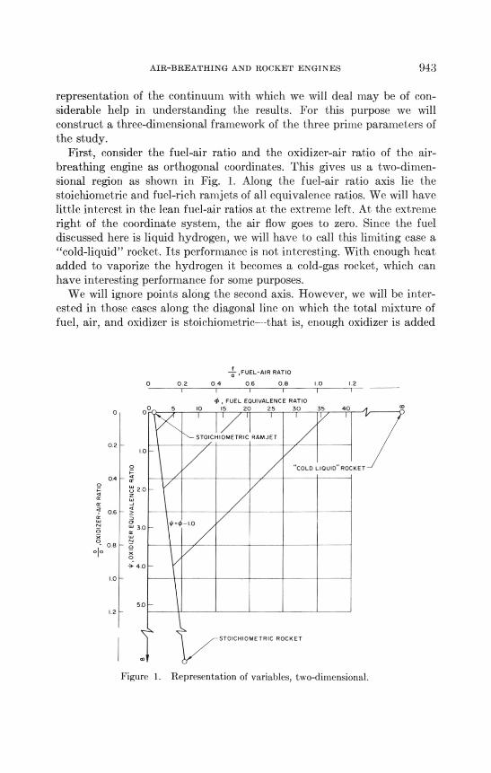
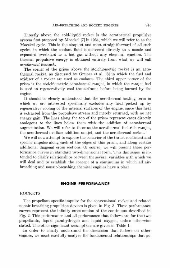
First, consider the fuel-air ratio and the oxidizer-air ratio of the air-breathing engine as orthogonal coordinates. This gives us a two-dimen-sional region as shown in Fig. I. Along the fuel-air ratio axis lie thestoichiometric and fuel-rich ramjets of all equivalence ratios. We will havelittle interest in the lean fuel-air ratios at the extreme left. At the extremeright of the coordinate system, the air flow goes to zero. Since the fueldiscussed here is liquid hydrogen, we will have to call this limiting case a"cold-liquid" rocket. Its performance is not interesting. With enough heatadded to vaporize the hydrogen it becomes a cold-gas rocket, which canhave interesting performance for some purposes.
We will ignore points aleng the second axis. However, we will be inter-ested in those cases along the diagonal line on which the total mixture offuel, air, and oxidizer is stoichiometric—that is, enough oxidizer is added
4 ,FUEL-AIR RATIO
0 0.2 0 4 0 6 0 8 LO
, FUEL EQUIVALENCE RATIO
5 10 I5 20 25 30 35 40
STOICHIOMETRIC RAMJET
0 210
O
04o
06
o
° 08
10
502
"COLD LIQUID" ROCKET
STOICHIOMETRIC ROCKET
Figure 1. Representation of variables, two-dimensional.
944 FOURTH CONGRESS - AERONAUTICAL SCIENCES
to burn all the excess fuel injected into the engine. This line begins at thestoichiometric ramjet and goes through a series of cases in which excessfuel and oxidizer are added in stoichiometricproportions, ending in theextreme case of the stoichiometricrocket. Thus the conventional ramjet,rocket, and a close kin of the cold-gas rocket all appear in this plane. Wewill be studying the trends of performance along the lines between them.
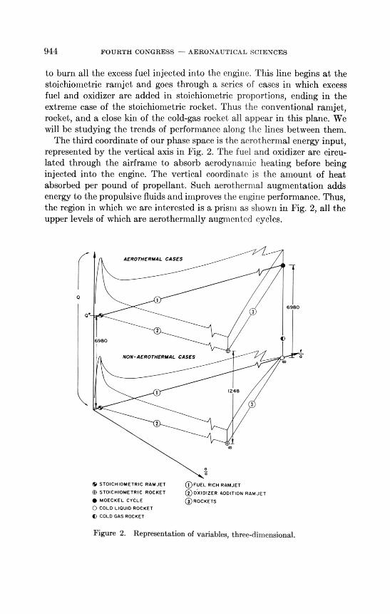
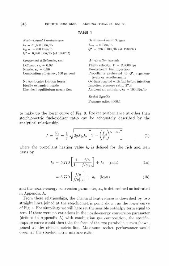
The third coordinate of our phase space is the aerothermal energy input,represented by the vertical axis in Fig. 2. The fuel and oxidizer are circu-lated through the airframe to absorb aerodynamic heating before beinginjected into the engine. The vertical coordinate is the amount of heatabsorbed per pound of propellant. Such aerotherinal augmentation addsenergy to the propulsive fluids and improves the engine performance. Thus,the region in which we are interested is a prism as shown in Fig. 2, all theupper levels of which are aerothermally augmented cycles.
AEROTHE ANAL CASES
0.3
6980
2
6980
NON- AEROTHERMAL CASES
1248
3
2
STOICHIOMETRIC RAMJET
(f) STOICHIOMETRIC ROCKET
• MOECKEL CYCLE
0 COLD LIQUID ROCKET
C COLD GAS ROCKET
()FUEL RICH RAMJET
190.x1DIZER ADDITION RAMJET
® ROCKETS
Figure 2. Representation of variables, three-dimensional.
AIR-BREATHING AND ROCKET ENGINES 945
Directly above the cold-liquid rocket is the aerothermal propulsivesystem first proposed by Moeckel [7]in 1954, which we will refer to as theMoeckel cycle. This is the simplest and most straightforward of all suchcycles, in which the coolant fluid is delivered directly to a nozzle andexpanded overboard as a hot gas without any chemical reaction. Thethermal propulsive energy is obtained entirely from what we will callaerothermal feedback.
The corner of the prism above the stoichiometric rocket is an aero-thermal rocket, as discussed by Greiner et al. [8] in which the fuel andoxidizer of a rocket are used as coolants. The third upper corner of theprism is the stoichiometric aerothermal ramjet, in which the ramjet fuelis used to regeneratively cool the airframe before being burned by theengine.
It should be clearly understood that the aerothermal-heating term inwhich we are interested specifically excludes any heat picked up byregenerative cooling of the internal surfaces of the engine, since this heatis extracted from the propulsive stream and merely returned, with no netenergy gain. The lines along the top of the prism represent cases directlyanalogous to the lines below them with the addition of aerothermalaugmentation. We will refer to these as the aerothermal fuel-rich ramjet,the aerothermal oxidizer addition ramjet, and the aerothermal rocket.
We will now attempt to explore the behavior of the thrust coefficient andspecific impulse along each of the edges of this prism, and along certainadditional diagonal cross sections. Of course, we will present these per-formance curves in standard two-dimensional form. This discussion is in-tended to clarify relationships between the several variables witb which wewill deal and to establish the concept of a continuum in which all air-breathing and nonair-breathing chemical engines have a place.
ENGINE PERFORMANCE
ROCKETS
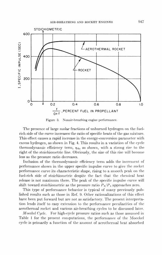
The propellant specific impulse for the conventional rocket and relatednonair-breathing propulsion devices is given in Fig. 3. These performancecurves represent the infinity cross section of the continuum described inFig. 2. This performance and all performance that follows are for the twopropellants, liquid parahydrogen and liquid oxygen, unless otherwisestated. The other significant assumptions are given in Table 1.
In order to clearly understand the discussion that follows on otherengines, we must carefully analyze the fundamental relationships that go
946 FOURTH CONGRESS - AERONAUTICAL SCIENCES
TABLE 1
Fuel—Liquid Parahydrogen
51,600 Btu/lbhof = —230 Btu/lbQs = 6,980 Btu/lb (at 1980°R)
Component Efficiencies, etc.
Diffuser, nD = 0.92Nozzle, 7.1„ = 0.96
Combustion efficiency, 100 percent
No combustor friction lossesIdeally expanded nozzleChemical equilibrium nozzle flow
Oxidizer—Liquid Oxygen
hoo, = 0 Btu,lb
Q* = 526.9 Btu/lb (at 1980°R)
Air-Breather Specific
Flight velocity, V = 20,000 fpsDownstream fuel injectionPropellants preheated to (2*, regenera-
tively or aerot hermally
Oxidizer reacted with fuel before injectionInjection pressure ratio, 27.4
Ambient air enthalpy, ho = 100 Btu/lb
Rocket Specific
Pressure ratio, 4000:1
to make up the lower curve of Fig. 3. Rocket performance at other thanstoichiometric fuel-oxidizer ratio can be adequately described by theanalytical relationship
V 0 1I = — = - 2g.Innk t [1 — (P) n99P4
(1)
where the propellant heating value h.( is defined for the rich and leancases by
= 5,770
= 5 '770
[ 1f/o ho(rich)
(lean)ho
(la)
(lb)
1 — f/oist
[ .1/0
f/o1„,
and the nozzle-energy conversion parameter, u„, is del ermined as indicatedin Appendix A.
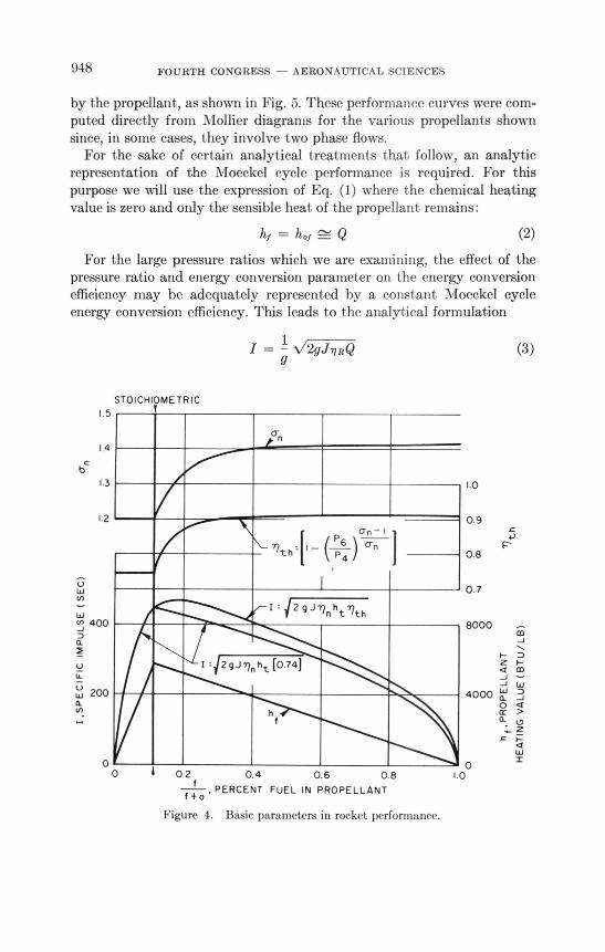
From these relationships, the chemical heat release is described by twostraight lines joined at the stoichiometric point shown as I he lower curveof Fig. 4. For simplicity we will here set the sensible cnthalpy term equal tozero. If 1 here were no variations in t he nozzle-energy conversion parameter(defined in Appendix A) Ivith combustion gas composition, the specific-impulse curve would then take the form of t he two parabolic curves shown,joined at the stoichiometric line. Maximum rocket performance wouldoccur at I he stoichiometric mixture ratio.
I,SPECIFIC
IMPULSE
(SEC)
600
400
200
0o
AIR-BREATHING AND ROCKET ENGINES
STOICHIOMETRIC
AEROTHERMAL ROCKET
ROCKET
0 20.40.60.8
947
1.0
0+ f, PERCENT FUEL IN PROPELLANT
Figure 3. Nonair-breathing engine performance.
The presence of large molar fractions of unburned hydrogen on the fuel-rich side of the curve increases the ratio of specific heats of the gas mixture.This effect causes a rapid increase in the energy-conversion parameter withexcess hydrogen, as shown in Fig. 4. This results in a variation of the cyclethermodynamic efficiency term, no, as shown, with a strong rise to theright of the stoichiometric line. Obviously, the size of this rise will becomeless as the pressure ratio decreases.
Inclusion of the thermodynamic efficiency term adds the increment ofperformance shown in the upper specific impulse curve to give the rocketperformance curve its characteristic shape, rising to a smooth peak on t hefuel-rich side of stoichiometric despite the fact t hat the chemical heatrelease is not: maximum there. The peak of the specific impulse curve willshift toward stoichiometric as t he pressure ratio P6/P4 approaches zero.
This type of performance behavior is typical of many previously pub-lished results such as those in lief. 9. Other rationalizations of this effecthave been put forward but are not as satisfactory. The present interpreta-tion lends itself to easy extension to the performance peculiarities of 1 heaerot hernial rocket and various air-breathing cycles to be discussed later.
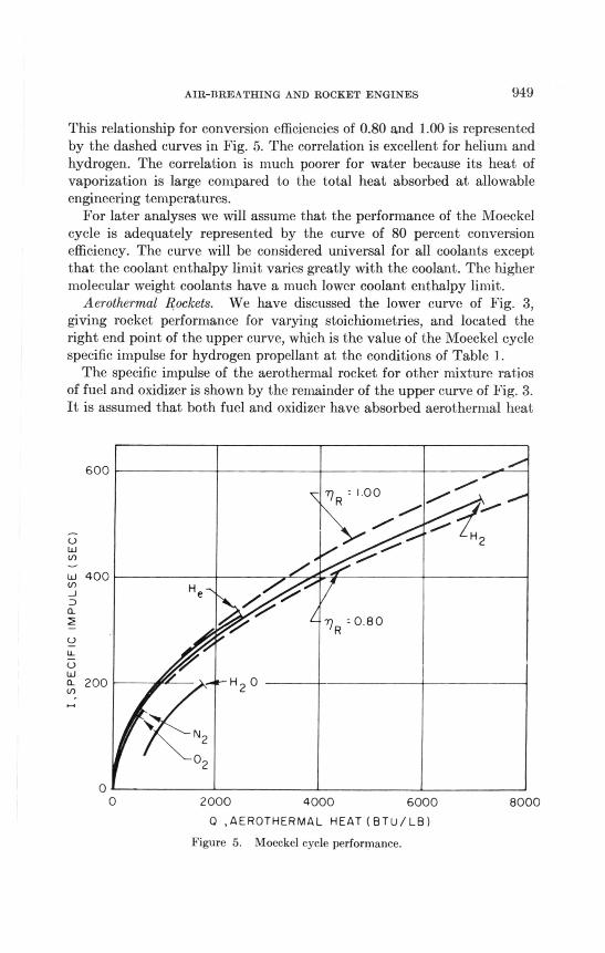
illoeckel Cycle. For high-cycle pressure ratios such as those assumed inTable I for the present computations, the perfortnance of t he Moeckelcycle is primarily a function of the amount of aerot hernial heat absorbed
948 FOURTH CONGRESS — AERONAUTICAL SCIENCES
by the propellant, as shown in Fig. 5. These performance curves were com-puted directly from Mollier diagrams for the various propellants shownsince, in some cases, they involve two phase flows.
For the sake of certain analytical treatments that. follow, an analyticrepresentation of the Moeckel cycle performance is required. For thispurpose we will use the expression of Eq. (1) where the chemical heatingvalue is zero and only the sensible heat of the propellant remains:
hf = hof Q (2)
For the large pressure ratios which we are examining, the effect of thepressure ratio and energy conversion parameter on the energy conversionefficiency may be adequately represented by a constant Moeckel cycleenergy conversion efficiency. This leads to the analytical formulation
I = —\./ 2gJ nRQ (3)
STOICHIOMETRIC
bc
1 5
14crn
I =12 9.177, ht Tith
I 2 -9nht [ 0.74]
0 2 0.4 0.6 0.8
PERCENT FUEL IN PROPELLANTf +
Figure 4. Basic parameters in rocket performance.
1.3
1.2
I,SP
ECIFIC
IMPULSE
(SEG)
400
200
oO 1.0
0
1.0
0.9
0.8
0 7
8000
4000
hf'
PROPELLANT
HEATING
VALUE
(BTU/LB)
AIR-BREATHING AND ROCKET ENGINES 949
This relationship for conversion efficiencies of 0.80 and 1.00 is representedby the dashed curves in Fig. 5. The correlation is excellent for helium andhydrogen. The correlation is much poorer for water because its heat ofvaporization is large compared to the total heat absorbed at allowableengineering temperatures.
For later analyses we will assume that the performance of the Moeckel
cycle is adequately represented by the curve of 80 percent conversionefficiency. The curve will be considered universal for all coolants exceptthat the coolant enthalpy limit varies greatly with the coolant. The highermolecular weight coolants have a much lower coolant enthalpy limit.
Aerothermal Rockets. We have discussed the lower curve of Fig. 3,
giving rocket performance for varying stoichiometries, and located theright end point of the upper curve, which is the value of the Moeckel cyclespecific impulse for hydrogen propellant at the conditions of Table 1.
The specific impulse of the aerothermal rocket for other mixture ratiosof fuel and oxidizer is shown by the remainder of the upper curve of Fig. 3.It is assumed that both fuel and oxidizer have absorbed aerothermal heat
I,SPECIFIC
IMPULSE
(SEC)
600
400He
.../ri R : I 00.."*".
..."".. i7: ••••°
/"‘....0'
,1 ./.......*.2
200
0
H2 0
0 2000 4000 6000 8000
0 ,AEROTHERMAL HEAT (81-li/L8)
Figure 5. Moeckel cycle performance.
950 FOURTH CONGRESS - AERONAUTICAL SCIENCES
to the maximum allowable temperature. Because of the great heat contentof the hydrogen, the total of combustion and aerothermal heat is practicallyconstant from stoichiometric mixture ratio to pure fuel. Therefore thevariation of specific impulse near the stoichiometric mixture is caused al-most entirely by the variation of gas properties as discussed in the rocketcase. The excess hydrogen in the fuel-rich combustion products causes anincrease of the energy conversion efficiency.
The curve is practically constant from 30 percent to 100 percent fuel,reflecting the nearly constant enthalpy and conversion efficiency. Thus theaerothermal rocket gives us practically constant specific impulse over avery broad variation of propellant-mixture ratios provided an adequateamount of aerothermal heating is available. This property of the aero-thermal rocket will be explored further.
AIR-BREATHING ENGINES
The ideal thrust coefficient of a fuel-rich air-breathing engine is given by
CF, -[ WO
+ 1a V
where= 4) 1
= h1/4.; 1
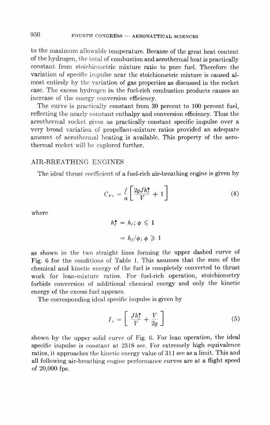
as shown in the two straight lines forming the upper dashed curve ofFig. 6 for the conditions of Table 1. This assumes that the sum of thechemical and kinetic energy of the fuel is completely converted to thrustwork for lean-mixture ratios. For fuel-rich operation, stoichiometry
forbids conversion of additional chemical energy and only the kineticenergy of the excess fuel appears.
The corresponding ideal specific impulse is given by
.*
ji = [/1/-17--L + --
V 2g(5)
shown by the upper solid curve of Fig. 6. For lean operation, the idealspecific impulse is constant at 2318 sec. For extremely high equivalenceratios, it approachest he kinetic energy value of 311 sec as a limit. This andall followingair-breat hing engine performance curves are at a flight speedof 20,000 fps.
(4)
AIR-BREATHING AND ROCKET ENGINES 951
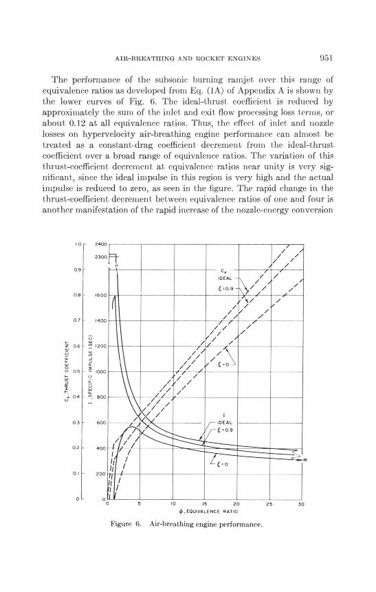
The performance of the subsonic burning ramjet over this range ofequivalence ratios as developed from Eq. (I A) of Appendix A is shown bythe lower curves of Fig. 6. The ideal-thrust coefficient is reduced byapproximately the sum of the inlet and exit flow processing loss terms, orabout 0.12 at all equivalence ratios. Thus, the effect of inlet and nozzlelosses on hypervelocity air-breathing engine performance can almost betreated as a constant-drag coefficient decrement from the ideal-thrustcoefficient over a broad range of equivalence ratios. The variation of thisthrust-coefficient decrement at equivalence ratios near unity is very sig-nificant, since the ideal impulse in this region is very high and the actualimpulse is reduced to zero, as seen in the figure. The rapid change in thethrust-coefficient decrement between equivalence ratios of one and four isanother manifestation of the rapid increase of the nozzle-energy conversion
1.0
09
08
0 7
z 06
La..
8 as
1-
.. 04u
0 3
02
0 1
o
.
,n.
(...1I,
...
•-•
2400
2300
1600
1400
1200
l000
800
600
400
200
Is
It /I /
/
_/
//1/
/
//
//
/
/
/
CF
IDEAL
C=0.9
/ //
C .0
IDEAL
C =0 9
o
/
/
z
/
z
/
zz
5 10 15 20 25 30
, EQUIVALENCE RATIO
Figure 6. Air-breathing engine performance.
952 FOURTH CONGRESS - AERONAUTICAL SCIENCES
parameters of the exhaust gases with increasing amounts of excess hydro-
gen, as previously described in the rocket cases.
Since the ideal thermodynamic cycle losses for the subsonic combustion
ramjet are negligible at this velocity and the flow processing losses make up
most of the performance loss, the most effective way to obtain increased
performance is to change to the supersonic combustion ramjet cycle to
reduce the flow processing losses. This change also drastically reduces the
engine internal pressure containment and local heat transfer rate problems,
as has been pointed out in Refs. 1 and 2.Let us now look at the performance for diffusion of only 10 percent of the
inlet kinetic energy (e = 0.9). If we assume that the inlet and exit losses
are proportional to the diffuser kinetic energy reduction [Eqs. (12A) and
(13A), Appendix A], the flow processing losses will be one tenth of the sub-
sonic combustion ramjet losses. The thermodynamic cycle loss increases
slightly, but the performance moves sharply toward the ideal, especially at
low equivalence ratios, as shown by the middle curves in Fig. 6. This allows
us to obtain most of the theoretical performance at an equivalence ratio of
one. Thus, supersonic combustion gives us the option of obtaining ex-
tremely high impulses if the corresponding low values of thrust coefficient
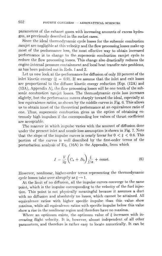
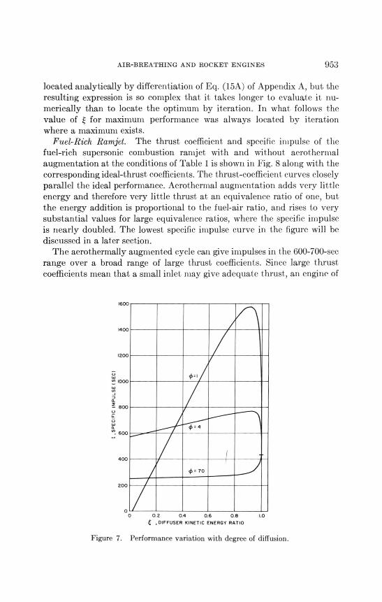
are acceptable.The manner in which impulse varies with the amount of diffusion done
under the present inlet and nozzle loss assumption is shown in Fig. 7. Note
that the slope of the impulse curves is nearly linear for 0 < < 0.6. This
portion of the curves is well described by the first-order terms of the
perturbation analysis of Eq. (16A) in the Appendix, from which
V(C0 + Do)const.
2gf/a(6)
However, nonlinear, higher-order terms representing the thermodynamic
cycle losses take over abruptly as e —> 1.At the limit of no diffusion, all the impulse curves converge to the same
point, which is the impulse corresponding to the velocity of the fuel injec-
tion. This point is not physically meaningful because it assumes a duct
with no diffusion and absolut ely no losses, which cannot be attained. All
equivalence ratios with higher specific impulse than this value show
maxima, while all equivalence ratios with specific impulse below this value
show a rise in the nonlinear region and therefore have no maxima.Where an optimum exists, I he optimum value of e increases with in-
creasing flight velocity. It is, however, almost independent of all other
parameters, and therefore is rather easy to locate numerically. It can be
AIR-BREATHING AND ROCKET ENGINES 953
located analytically by differentiation of Eq. (15A) of Appendix A, but. theresulting expression is so complex that it takes longer to evaluate it nu-merically than to locate the optimum by iteration. In what follows thevalue of E for maximum performance was always located by iterationwhere a maximum exists.
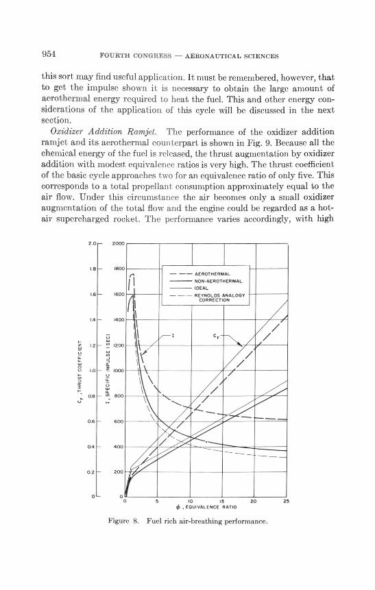
Fuel-Rich Ramjet. The thrust coefficient and specific impulse of thefuel-rich supersonic combustion ramjet with and wit bout aerothermalaugmentation at the conditions of Table 1 is shown in Fig. 8 along with thecorresponding ideal-thrust coefficients. The thrust-coefficient curves closelyparallel the ideal performance. Aerothermal augmentation adds very lit tleenergy and therefore very little thrust at an equivalence ratio of one, butthe energy addition is proportional to the fuel-air ratio, and rises to verysubstantial values for large equivalence ratios, where the specific impulseis nearly doubled. The lowest specific impulse curve in the figure will bediscussed in a later section.
The aerothermally augmented cycle can give impulses in the 600-700-secrange over a broad range of large thrust. coefficients. Since large thrustcoefficients mean that a small inlet may give adequate thrust, an engine of
1600
1400
1200
." 1000
eoo
600
400
= 70
200
0o 02 04 06 08
, DIFFUSER KINETIC ENERGY RATIO
Figure 7. Performance variation with degree of diffusion.
<VI
954 FOURTH CONGRESS — AERONAUTICAL SCIENCES
this sort may find useful application. It must be remembered, however, thatto get the impulse shown it is necessary to obtain the large amount ofaerothermal energy required to heat the fuel. This and other energy con-siderations of the application of this cycle will be discussed in the nextsection.
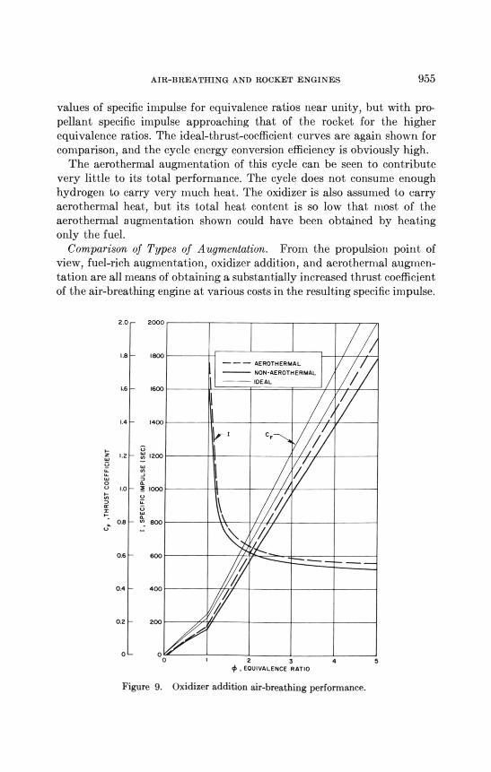
Oxidizer Addition Ramjet. The performance of the oxidizer additionramjet and its aerothermal counterpart is shown in Fig. 9. Because all thechemical energy of the fuel is released, the thrust augmentation by oxidizeraddition with modest equivalence ratios is very high. The thrust coefficientof the basic cycle approaches t wo for an equivalence ratio of only five. Thiscorresponds to a total propellant consumption approximately equal to theair flow. Under this circumstance the air becomes only a small oxidizeraugmentation of the total flow and the engine could be regarded as a hot-air supercharged rocket. The performance varies accordingly, with high
2.0 2000
1.8 1800
1.6 1600
14 1400
1200
1000
800
0.6 600
0.4 400
200
- - AE ROTH ERMAL
NON -AEROTHER MAL
IDEAL
- - REYNOLDS ANA LOGYCORRECTION
c,
1,
SPECIFIC
IMPULSE
(SEC)1.2
C,
,THRUST
COEFFICIENT1.0
0.8
fi
o oo5 10 15 20 25
• EQUI VALENCE R ATIO
Figure 5. Fuel rich air-breathing performance.
AIR—BREATHING AND ROCKET ENGINES 955
values of specific impulse for equivalence ratios near unity, but with pro-pellant specific impulse approaching that of the rocket for the higherequivalence ratios. The ideal-thrust-coefficient curves are again shown forcomparison, and the cycle energy conversion efficiency is obviously high.
The aerothermal augmentation of this cycle can be seen to contributevery little to its total performance. The cycle does not consume enoughhydrogen to carry very much heat. The oxidizer is also assumed to carryaerothermal heat, but its total heat content is so low that most of theaerothermal augmentation shown could have been obtained by heatingonly the fuel.
Comparison of Types of Augmentation. From the propulsion point ofview, fuel-rich augmentation, oxidizer addition, and aerothermal augmen-tation are all means of obtaining a substantially increased thrust coefficientof the air-breathing engine at various costs in the resulting specific impulse.
2.0
1.8
2000
1800
— — — AEROTHERMAL
NON-AEROTHERMAL
IDEALL6 1600
1.4 1400
1.2 1200 __
1.0 1000
08 a":. 800
\ /0.6 600
0.4 400
0.2 200
0 2 3 4 5, EQUIVALENCE RATIO
Figure 9. Oxidizer addition air-breathing performance.
CF
,THRUST
COEFFICIENT
I,SPECIFIC
IMPULSE
(SEC)
956 FOURTH CONGRESS — AERONAUTICAL SCIENCES
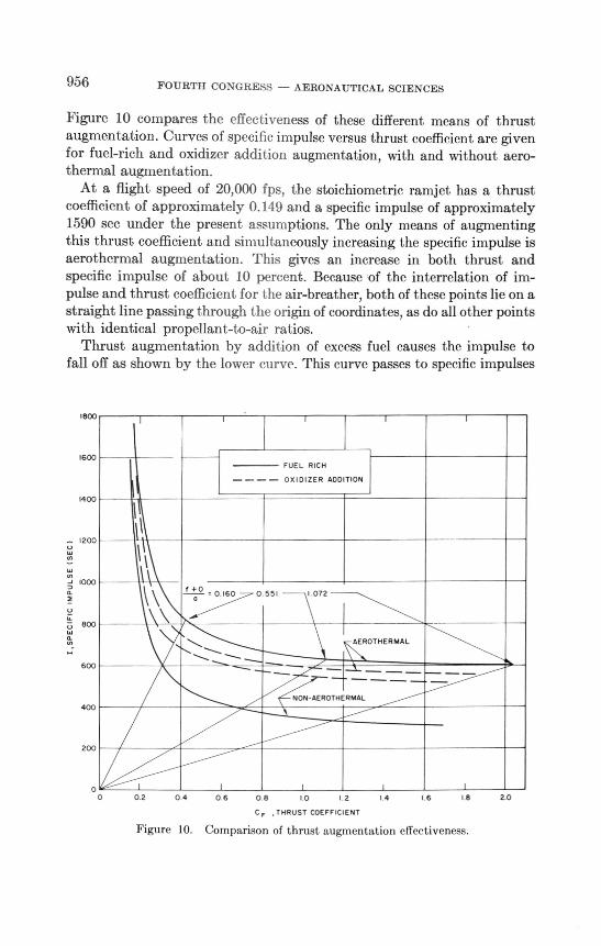
Figure 10 compares the effectiveness of these different means of thrustaugmentation. Curves of specific impulse versus thrust coefficient are givenfor fuel-rich and oxidizer addition augmentation, with and without aero-thermal augmentation.
At a flight speed of 20,000 fps, the stoichiometric ramjet has a thrustcoefficient of approximately 0.119 and a specific impulse of approximately1590 sec under the present assumptions. The only means of augmentingthis thrust coefficient and simultaneously increasing the specific impulse isaerothermal augmentation. This gives an increase in both thrust andspecific impulse of about 10 percent. Because of the interrelation of im-pulse and thrust coefficient for t he air-breather, both of these points lie on astraight line passing through the origin of coordinates, as do all other pointswith identical propellant-to-air ratios.
Thrust augmentation by addition of excess fuel causes the impulse tofall off as shown by the lower curve. This curve passes to specific impulses
1800
1600
1400
1200
1000
800
600
400
200
0o
,
0.2
f
2.0
—
FUEL RICH
— —OXIDIZER ADDITION
0 5511 072
AEROTHERMAL
21 4
NON-AEROTHERMAL
0 81 0I
C, THRUST COEFFICIENT
0 4 0 6 1.6 1 8
Figure 10. Comparison of thrust augmentation effectiveness.
AIR-BREATHING AND ROCKET ENGINES 957
below 600 sec for about, double the unaugmented thrust. The next highercurve is the performance with stoichiometric oxidizer addition. This tech-nique can quadruple the thrust before the specific impulse drops to 600 sec,and the performance always exceeds that of a rocket. The combination ofaerothermal augmentation with oxidizer addition is only slightly better, asshown. The upper curve of the figure shows the performance attained withmaximum aerothermal augmentation of the fuel-rich engine. The specificimpulse does not fall below 600 sec until the thrust has increased by morethan ten times. However, this performance is possible only if an extremelylarge amount of aerothermal heat is available. The restrictions that thisrequirement implies are examined in the following sections.
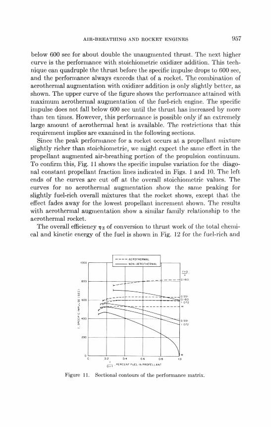
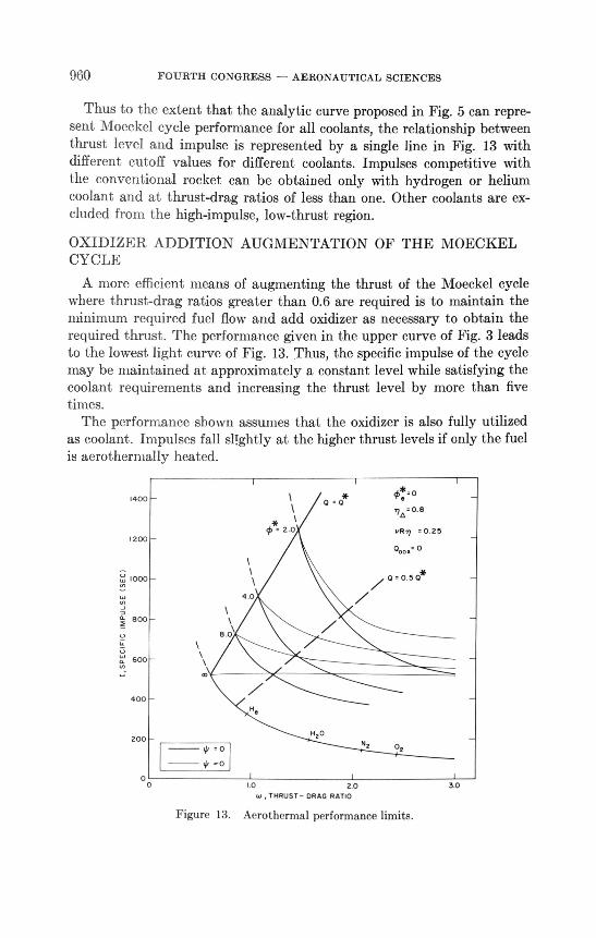
Since the peak performance for a rocket occurs at a propellant mixtureslightly richer than stoichiometric, we might expect the same effect in thepropellant augmented air-breathing portion of the propulsion continuum.To confirm this, Fig. 11 shows the specific impulse variation for the diago-nal constant propellant fraction lines indicated in Figs. 1 and 10. The leftends of the curves are cut off at the overall stoichiometric values. Thecurves for no aerothermal augmentation show the same peaking forslightly fuel-rich overall mixtures that the rocket shows, except that theeffect, fades away for the lowest propellant increment, shown. The resultswith aerothermal augmentation show a similar family relationship to theaerothermal rocket.
The overall efficiency n z of conversion to thrust work of the total chenn-cal and kinetic energy of the fuel is shown in Fig. 12 for the fuel-rich and
AEROTHERMAL
NON AEROTHERMAL.000
800
55.
0 .60
072
0 55.
• 072
200
0 2 0 4 06 0 8
0 , PE RC E NT PAL ,N PROPELLANT
Figure 11. Sectional contours of the performance matrix.

958 FOURTH CONGRESS — AERONAUTICAL SCIENCES
771 , OVERALL ENERGY EFFICIENCY
AEROTHERMAL ENERGY EFFICIENCY
FUEL RICH
5 10 15 20 25• EQUIVALENCE RATIO
Ox I DI Z ER ADDITION
'12
o e
0 6 0
2 34 5
, EQUIVALENCERATIO
Figure 12. Energy conversion efficiencies of the air-breathers.
oxidizer addition ramjets. The efficiencynA of conversion of the aerothermalenergy into an increment of thrust-work is also shown. This aerothermalenergy conversion efficiency will be discussed again.
COOLING LIMITATIONS ON AEROTHERMAL PROPULSION
We have analyzed the aerothermal propulsion devices as though aero-dynamic heat were available in unlimited quantities. We have recognizedonly that there is a limit on the amount of heat that can be absorbed perpound of coolant fluid. This corresponds to the difference between thefluid enthalpy in the condition in which it is stored, usually a liquid, andthe enthalpy at the maximum allowable coolant temperature, a little lowerthan the allowable working temperature of the heat-exchanger materials.A second limitation on the aerothermal heat energy available for pro-pulsion augmentation arises from conservation of energy and the applica-tion of Reynolds analogy as developed in Ref. 10.
The rate at which energy is dissipated by the aerodynamic drag of thevehicle is
DV = drag energy rate (7)
Of this energy, only the frictional drag fraction, which we will define as
1 .0
0.8
0.60
I 0 r
(8)
AIR-BREATHING AND ROCKET ENGINES 959
is actually dissipated in the boundary layer adjacent to the vehicle. Only afraction R of the heat so generated in the boundary layer is actually ab-sorbed by the body. R may take on values front zero up to approximatelyone half, where the Prandtl number is one and the wall is cold.
0 < R < R*; R*1
(9)
The value of R will usually be close to R* in the hypervelocity regimebecause practical aircraft materials cannot tolerate temperatures that areappreciable compared to the recovery temperature. This conclusion wouldbe modified if an appreciable fraction of the surface heating were removedby radiation, but the fourth-power relationship keeps the amount ofradiation small if the surface temperature is significantly below the radia-tion equilibrium value. The aerothermal heating rate is thus defined as
li)QJ = vRDV (10)
The primary methods available for increasing the frictional drag fractionare the use of slender bodies and wings, and flight at low angles of at tack.Under these circumstances the frictional drag fraction can be pushed toperhaps 0.6 with reasonable engineering configurations.
PERFORNIANCE LIMITS OF lOEC NEL CYCLE
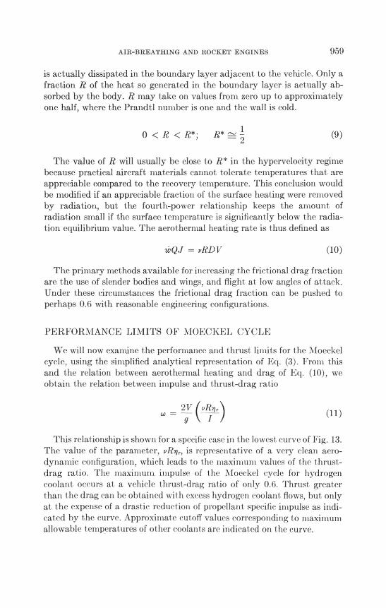
We will now examine the performance and thrust limits for the Moeckelcycle, using the simplified analytical representation of Eq. (3). From thisand t he relation between aerot hernial heating and drag of Eq. (10), weobtain the relation between impulse and t hrust-drag ratio
u.)217 g I
This relat ionship is shown for a specific case ill t he lowest curve of Fig. 13.The value of tlw parameter, vRnr, is represent ative of a very clean aero-dynannc configuration, which leads to the maximum values of 1 he 1 hrust-drag ratio. The maximum impulse of t he iNfoeckel cycle for hydrogencoolant occurs at a vehicle t hrust -drag ratio of only 0.6. Thrust great ert han t he drag can be obtained wit h excess hydrogen coolant flows, but onlyat I he expense of a drastic reduct ion of propellant. specific impulse as indi-cat ed by the curve. Approximat e cutoff values corresponding t o ntaximumallowable 1 emperat tires of of her coolants are indicat ed on the curve.
960 FOURTH CONGRESS — AERONAUTICAL SCIENCES
Thus to the extent that the analytic curve proposed in Fig. 5 can repre-sent Moeckel cycle performance for all coolants, the relationship betweenthrust level and impulse is represented by a single line in Fig. 13 withdifferent cutoff values for different coolants. Impulses competitive withthe conventional rocket can be obtained only with hydrogen or heliumcoolant and at thrust-drag ratios of less than one. Other coolants are ex-cluded from the high-impulse, low-thrust region.
OXIDIZER ADDITION AUGMENTATION OF THE MOECKELCYCLE
A more efficient means of augmenting the thrust of the Moeckel cyclewhere thrust-drag ratios greater than 0 6 are required is to maintain theminimum required fuel flow and add oxidizer as necessary to obtain therequired thrust. The performance given in the upper curve of Fig. 3 leadsto the lowest light curve of Fig. 13. Thus, the specific impulse of the cyclemay be maintained at approximately a constant level while satisfying thecoolant requirements and increasing the thrust level by more than fivetimes.
The performance shown assumes that the oxidizer is also fully utilizedas coolant. Impulses fall slIghtly at the higher thrust levels if only the fuelis aerothermally heated.
1400
1200
1000
2 0
0776.0.8
v/377 . 0.25
0.... 0
0.5 0*
4 0
0-800
8.0
600
400
H.
420
200
- 0
N2 0,
0
p
oo10 2.0 3.0
, THRUST- DRAG RATIO
Figure 13. Aerothermal performance limits.
AIR-BREATHING AND ROCKET ENGINES 961
A significant disadvantage of such a system is that the desired ratio ofpropellants at takeoff cannot be predicted for applications where thethrust schedule cannot be predicted in advance. The method also requiresconsiderable flexibility in the metering and control system of the engine.Nevertheless, the increased performance and flexibility must surely make itconsiderably more attractive than the pure Moeckel cycle for applicationssuch as the synergetic plane change in which thrust-drag ratios of one orgreater are required and flexibility of thrust programing may be of sig-nificant benefit.
PERFORMANCE LIMITATIONS OF AEROTHERMAL RAMJETS
We will now develop the same sort of performance and t hrust level rela-tions for the case of the aerothermal ramjets. Since we have an additionalparameter at work, the sizing of the engine and resultant airflow, the rela-tions will be a little more complex in this case.
At this point we make use of the aerothermal energy conversion efficiencyfor the fuel-rich case shown in Fig. 12 and defined in terms of the aero-thermal specific impulse increment by
= na Cc" )
(12)
We specify the vehicular component of aerothermal heating to emphasizethe fact that in the air-breathing aerothermal engine a significant amountof fuel cooling capacity may be used for internal regenerative cooling of theengine itself. Since energy obtained from this source does not represent anet profit to the cycle, it must be subtracted from the enthalpy balance.Making these adjustments, the impulse of the aerot hermal air-breathingcycle becomes
I = Io(o) + naji7Q` (13)
For the accuracy required here, we will assume that the efficiency curves ofFig. 12 are adequately represented by the constant , na = 0.80.
The aerothermal energy conversion efficiency usually has a value lessthan unity, and is treated here loosely as an "efficiency." However,because of the highly nonlinear int eraction of 1he aerot hernial energy wit hthe other input energies of the cycle, aerothermal augmentation can some-times result in the conversion of more thrust work than the aerothermalenergy input. The awkward situation of a conversion efficiency greaterthan unity (and highly variable) would occur here for the Moeckel cycle
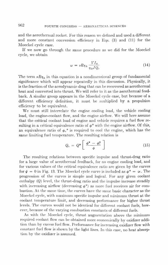
962 FOURTH CONGRESS - AERONAUTICAL SCIENCES
and the aerothermal rocket. For this reason we defined and used a differentand more constant conversion efficiency in Eqs. (3) and (11) for theMoeckel cycle case.
If we now go through the same procedure as we did for the Moeckelcycle, we obtain
co= vRnAVI 0
(14)
The term vRnA in this equation is a nondimensional group of fundamentalsignificance which will appear repeatedly in this discussion. Physically, itis the fraction of the aerodynamic drag that can be recovered as aerothermalheat and converted into thrust. We will refer to it as the aerothermal feed-back. A similar group appears in the Moeckel cycle case, but because of adifferent efficiency definition, it must be multiplied by a propulsionefficiency to be equivalent.
We must still interrelate the engine cooling load, the vehicle coolingload, the engine-coolant flow, and the engine airflow. We will here assumethat the critical coolant load of engine and vehicle requires a fuel flow re-sulting in a critical equivalence ratio of cp*with the engine airflow. Of this,an equivalence ratio of oe* is required to cool the engine, which has thesame limiting fuel temperature. The resulting relation is
= Q*[(I)* ()5' (15)
The resulting relations between specific impulse and thrust-drag ratiofor a large value of aerothermal feedback, for no engine cooling load, andfor various values of the critical equivalence rat io are given by the curvesfor 4, = () in Fig. 13. The Moeckel cycle curve is included as 0* = oc. Theprogression of the curves is simple and logical. For ally given coolantenthalpy (Q) level, t he thrust-drag rat io and the impulse increase steadilywith increasing airflow (decreasing 43*) as more fuel receives air for com-bustion. At the same 11111e, the curves have the same basic character as theMoeckel cycle, wit h maximum specific impulse and minimum thrust at thecoolant t emperat tire limit, and decreasing performance for higher thrustlevels. The curves would not be identical for different coolant fuels, how-ever, because of t he varying c(onbust ion constants of different fuels.
As with the loeckel cycle, t hrust augmentation above 1he minimumrequired cm,lant flow can be obtained more economically bv oxidizer addi-tion t han by excess fuel flow. Performance for increasing oxidizer flow withconstant fuel flow is shown by the light lines. In this case, no heat absorp-tion by t he oxidizer is assumed.

AIR-BREATHING AND ROCKET ENGINES 963
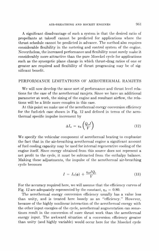
The effects of parameter changes for the fuel-rich cases are shown inFig. 14. The performance map for an engine with a cooling requirement ofone equivalence ratio (4e* = 1.0) is shown by the heavy lines, with thebasic map of Fig. 13 shown in light lines for comparison. The difference issignificant only for small critical equivalence ratios (large airflows), wherethe specific impulse is slightly lower because of decreased aerothermalaugmentation, and the thrust level is much higher because a larger engineis required for a given net airframe cooling capacity.
The very compressed performance map at the left of Fig. 14 shows howthe basic map changes when the aerothermal feedback becomes very small,as it does for high-angle-of-attack flight and relatively blunt lifting bodies.The value of the aerothermal feedback chosen is representative of a bodylike the NASA M-2 shape at a high angle of attack. The specific impulselevel remains the same, but the thrust level scales down in proportion tothe aerothermal feedback. Large thrust levels can be obtained only at thelower specific impulses. A decrease in flight velocity has the same effect.
INTERNAL COOLING LIMITS
We should note in passing that an analogous set of aerothernial energylimits occur within the engine. For the air-breathing engines without aero-thermal augmentation, we have assumed that the propellants are injected
1400
04: =0
03776 = 0.025
01= ovR-qa.o.25
se:=1.0
1200
oi-q=0.25
1000
= 2 0
BOO
0= 4 0
600
020
400 95=40 *
4, 8041=8 0
200
oo1.0 2.0 3.0
w , THRUST-DRAG RATIO
Figure 14. Aerothermal performance limits.
[,SPECIF
IC
trAPULSE
(SEC)
964 FOURTH CONGRESS - AERONAUTICAL SCIENCES
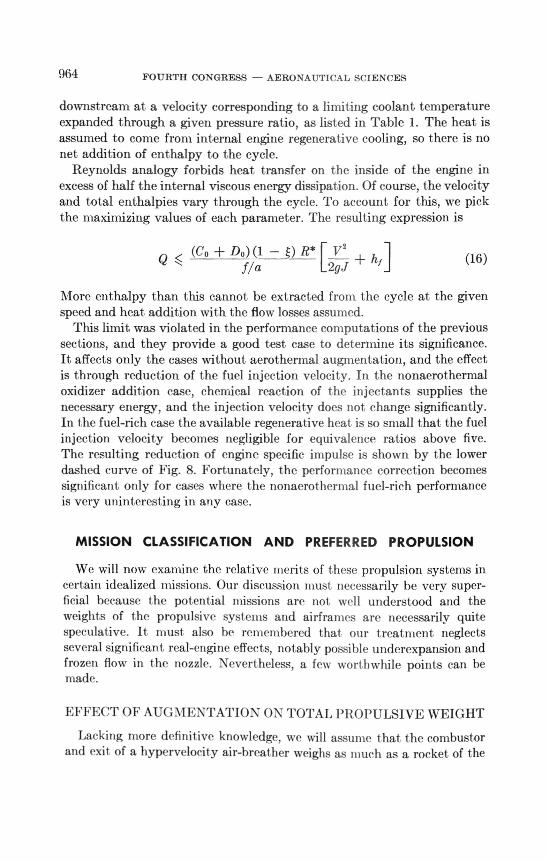
downstream at a velocity corresponding to a limiting coolant temperatureexpanded through a given pressure ratio, as listed in Table 1. The heat isassumed to come from internal engine regenerative cooling, so there is nonet addition of enthalpy to the cycle.
Reynolds analogy forbids heat transfer on the inside of the engine inexcess of half the internal viscous energy dissipation. Of course, the velocityand total enthalpies vary through the cycle. To account for this, we pickthe maximizing values of each parameter. The resulting expression is
Q (Co -I- Do) (1 — )R* [V2 ,
f/a2gJ(16)
More enthalpy than this cannot be extracted from the cycle at the givenspeed and heat addition with the flow losses assumed.
This limit was violated in the performance computations of the previoussections, and they provide a good test case to determine its significance.It affects only the cases without aerothermal augmentation, and the effectis through reduction of the fuel injection velocity. In the nonaerothermaloxidizer addition case, chemical reaction of the injectants supplies thenecessary energy, and the injection velocity does not change significantly.In the fuel-rich case the available regenerative heat is so small that the fuelinjection velocity becomes negligible for equivalence ratios above five.The resulting reduction of engine specific impulse is shown by the lowerdashed curve of Fig. 8. Fortunately, the performance correction becomessignificant only for cases where the nonaerot hernial fuel-rich performanceis very uninteresting in any case.
MISSION CLASSIFICATION AND PREFERRED PROPULSION
We will now examine the relative merits of these propulsion systems incertain idealized missions. Our discussion must necessarily be very super-ficial because the potential missions are not well understood and theweights of the propulsive systems and airframes are necessarily quitespeculative. It must also be renwnibered that our treatment neglectsseveral significant real-engine effects, notably possible underexpansion andfrozen flow in the nozzle. Nevertheless, a few worthwhile points can bemade.
EFFECT OF AUGMENTATION ON TOTAL PROPULSIVE WEIGHT
Lacking more definitive knowledge, we will assume that the combustorand exit of a hypervelocity air-breather weighs as much as a rocket of the
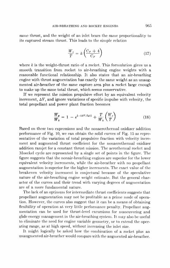
AIR-BREATHING AND ROCKET ENGINES 965
same thrust, and the weight of an inlet bears the same proportionalit y toits captured stream thrust. This leads to the simple relation
T(
C F(17)
where k is the weight-thrust ratio of a rocket. This formulation gives us asmooth transition from rocket to air-breathing engine weights with areasonable functional relationship. It also states that an air-breathingengine with thrust augmentation has exactly the same weight as an unaug-mented air-breather of the same capture area plus a rocket large enoughto make up the same total thrust, which seems conservative.
If we represent the mission propulsive effort by an equivalent velocityincrement, AV, and ignore variations of specific impulse with velocity, thetotal propellant and power plant fraction becomes
W e[—(d17 /Ion --T--WP 1 e TWo(18)
Based on these two expressions and the nonaerothermal oxidizer additionperformance of Fig. 10, we can obtain the solid curves of Fig. 15 as repre-sentative of the variation of total propulsive fraction with velocity incre-ment and augmented thrust coefficient for the nonaerothermal oxidizeraddition ramjet for a constant thrust mission. The aerothermal rocket. andMoeckel cycle are represented by a single set of points in the figure. Thefigure suggests that the nonair-breathing engines are superior for the lowerequivalent velocity increments, while t.he air-breather with no piopellantaugmentation is superior for the higher increments. The exact value of t hebreakeven velocity increment is conjectural because of the speculativenature of the air-breathing engine weight estimate. But t.he general char-acter of the curves and their trend with varying degrees of augmentationare of a more fundamental nature.
The lack of an optimum for intermediat e thrust coefficients suggests 1,Itatpropellant augmentation may not be profitable as a prime mode of opera-tion. However, the curves also suggest that. it can be a means of obtainingflexibility of operation at. very lit tle performance penalt y. Propellant aug-mentation can be used for thrust-level excursions for maneuvering andglide energy management in the air-breat hing systeni. It may also be usefulto eliminate the need for engine variable geomet Ty, or t o extend the oper-ating range, as at high speed, wit hout increasing t he inlet size.
It might logically be asked how the combination of a rocket plus anunaugmented air-breather would compare wit h the augmented air-breat her.
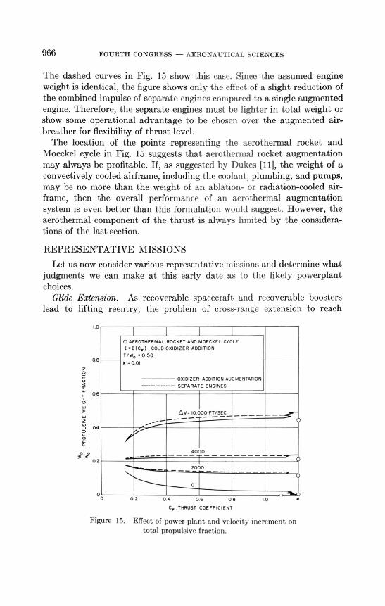
966 FOURTH CONGRESS — AERONAUTICAL SCIENCES
The dashed curves in Fig. 15 show this case. Since the assumed engineweight is identical, the figure shows only the effect of a slight reduction ofthe combined impulse of separate engines compared to a single augmentedengine. Therefore, the separate engines must be lighter in total weight orshow some operational advantage to be chosen over the augmented air-breather for flexibility of thrust level.
The location of the points representing the aerothermal rocket andMoeckel cycle in Fig. 15 suggests that aerot hernial rocket augmentationmay always be profitable. If, as suggested by Dukes [11], the weight of aconvectively cooled airframe, including the coolant, plumbing, and pumps,may be no more than the weight of an ablation- or radiation-cooled air-frame, then the overall performance of an aerothermal augmentationsystem is even better than this formulation would suggest. However, theaerothermal component of the thrust is always limited by the considera-tions of the last section.
REPRESENTATIVE MISSIONS
Let us now consider various representative missions and determine whatjudgments we can make at this early date as to the likely powerplantchoices.
Glide Extension. As recoverable spacecraft. and recoverable boosterslead to lifting reentry, the problem of cross-lunge extension to reach
10
AEROTHERMAL ROCKET AND MOECKEL CYCLE
I = I (CO COLD OXIDIZER ADDITION
T/Wc, = 0.50as
k = 0.01
OXIDIZER ADDITION AUGMENTATIONler
SEPARATE ENGINES
aso
Ay .10,000 FT/SEC-
04
2o
4000_ _ I
az2000
o
oo0.2 0 4 0 6 0 8 10
,THRUST COEFFICIENT
Figure 15. Effect of power plant and velocit y increment on
total propulsive fraction.
AIR-BREATHING AND ROCKET ENGINES 967
desired landing points will receive greater attention. While cross-rangeextension can be obtained by increased lift-drag ratio at the cost of sig-nificant structural weight, we should not overlook the alternative possi-bility of gaining cross-range by direct propulsion. Of particular interest arethe aerothermal propulsion schemes to cool the airframe during reentry.
The required velocity increment for significant glide extension is notlarge, perhaps 5,000 fps. The required thrust level is very low, probablyless than the drag.
The Moeckel cycle appears to be most. attractive for t his mission, perhapswith moderate oxidizer augmentation. Provision for thrust reversal nnghtbe very effective for increasing t he ability to adjust the landing site if thecoolant flow cannot be shut off. If orbital retrothrust is required, t he enginecould probably be converted to a pure rocket very easily.
Cruise. Another typical class of missions is represented by cruise atconstant speed in the atMosphere. The thrust-drag ratio is unity, andhigher thrust for acceleration is nonnallytieeded only in the initial accelera-tion, where the cruise air-breather would usually have a thrust margin.The installed thrust requirement is considerably smaller than that as-sumed in Fig. 15, so the air-breathers excel for very moderate velocityincrements. The stoichiometric air-breather has a clear advantage forpractically all cases. Aerot hernial augmentation is profitable if it costspractically no airframe weight and if the engine requires less than st oichio-metric flow for cooling.
Synergetic Plane Change. Certain space maneuvers between low- earthorbits, such as orbital plane change and phase change, can be accomplishedmore efficiently by aerodynamic use of the upper at mosphere than bydirect space propulsion. The velocity lost to at mospheric drag must. beregained by some propulsive device t o ret urn to orbit.
This maneuver is representative of a large class of related missions.Space propulsion is needed, which demands a rocket. Large variations inthrust. level are required. The required velocity increment is generally inthe middle range of the values shown in Fig.15.
The coolittg problein is severe because t he vehicle should plunge int o 1 heai mosphere far below the equilibrium glide corridor. This suggests aero-t hernial propulsion schemes, which would lead to large t hrust while in t heat niosphere. However, 1 he dynamically preferred thrust schedule is toallow the velocity to decrease during t he atmospheric traverse and to-ccelerat e back to nearly orbital speed upon leaving the atmosphere. Thesevem aerodynamic heating also makes the design of an air-breat herdifficult.
The choice of powerplant for such missions cannot be made without moredetailed information. The rocket will probably be the best choice, with
968 FOURTH CONGRESS - AERONAUTICAL SCIENCES
aerothermal augmentation worth considering. The effect of active coolingon airframe weight will be a critical factor in the decision.
Boost. The last type of typical hypervelocity mission we will consideris the boost mission. Usually this is a portion of t he acceleration from zerospeed at sea level to orbital velocity at an altitude outside the atmosphere.Of the missions discussed, this one can most. clearly be performed eitherinside or outside the atmosphere.
The required thrust level of the air-breather may be higher than thatassumed in Fig. 15, and the air-breather may also require more airframeweight in heat protection than the competitive rocket vehicle. Thereforethe velocity increment for which our formulation gives the air-breatherthe advantage would shift to an even higher value.
On the other hand, the velocity increment required by the mission isextremely high. Also, this case is the most sensitive to the validity of thecrude assumptions we made for the engine weight and to the omission ofthe variation of specific impulse with velocity. Therefore we must considerthe present analysis entirely inadequate to judge the boost case andawait more definitive weight estimates.
CONCLUSIONS
Many of the characteristics of hypervelocity chemical propulsionsystems can be adequately analyzed and correlated on a simplevelocity and energy basis.Rockets, propellant augmented air-breathers, and aerothermallyaugmented cycles may be treated profit ably as a continuous spec-trum of related chemical propulsion systems.In an air-breathing engine at high flight speeds, the loss of availablekinetic energy of the captured airflow in the inlet and nozzle mayexceed the chemical heat addition. Good performance may beregained if the flow processing losses can be reduced substantiallyby resorting to supersonic combustion.If the flow processing losses are kept small, the performance canclosely approach ideal energy conversion at any speed in the hyper-velocity range.Fundamental energy limits restrict high specific impulse per-formance of the air-breathing engine to very low t hrust coefficients,making for heavy engines and engine-vehicle nit egration problems.Higher 1 hrust, coefficients may be obt ained at lower specific impulseby the injection of additional fuel and oxidizer. The highest specificimpulse for propellant t hrust augment ation usually is obtainedwith a slightly fuel-rich mixture of fuel, oxidizer, and air.
AIR-BREATHING AND ROCKET ENGINES 969
Propellant thrust augmentation of an air-breathing engine can pro-vide operational flexibility, extend velocity range, and reducevariable geometry requirements but probably cannot reduce totalpropulsive weight as a prime operating mode.Aerotherrnal thrust augmentation of both rocket and air-breathingpowerplants is clearly profitable in cases where active cooling doesnot increase the airframe weight.The degree of aerothermal-thrust augmentation available is subjectto certain upper limits dictated by Reynolds analogy and conserva-tion of energy, and also to lower limits if the airframe cannot survivethe aerothermal environment without coolant flow.A rocket-type engine capable of multimode operation as a con-ventional rocket, Moeckel cycle, and aerothermal rocket is anattractive combination for certain applications, giving simplicity,flexibility, and high specific impulse.
APPENDIX A
SUMMARY OF ANALYTIC CYCLE ANALYSIS FORHYPERVELOCITY PROPULSION
The following is an abbreviated summary of the analytic method ofcycle analysis used in this paper. It is closely parallel in form to perfect-gas-cycle analysis, to which it reduces at low flight velocity. Its chief charac-teristic is that it makes enthalpy and velocity the prime variables ofanalysis to replace the central position of temperature and Mach numberin the perfect-gas formulation. All the real-gas properties essential to theanalysis are contained in nozzle and inlet, energy conversion parameters,which occupy the same position in the analysis as the specific heat ratio inconventional perfect-gas analysis, but which are redefined in such a way asto make the analytical formulation exact.
In principle, these energy conversion parameters should be functions ofpressure level, t emperature level, gas composition, nozzle-pressure ratio,inlet-pressure ratio, and all other parameters of the cycle analysis. Inpractice, they prove to have negligible relation to any parameters exceptinitial enthalpy and stoichiometry. Because of this circumstance andbecause computed hypervelocity propulsion performance is only a weakfunction of the numerical value of the expansion parameter, these parame-ters may be picked by relatively simple correlation methods for mostpurposes, or even assumed constant.
970 FOURTH CONGRESS - AERONAUTICAL SCIENCES
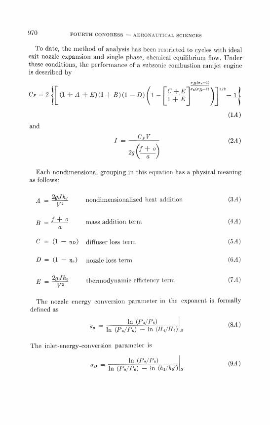
To date, the method of analysis has been restricted to cycles with idealexit nozzle expansion and single phase, chemical equilibrium flow. Underthese conditions, the performance of a subsonic combustion ramjet engineis described by
C F = 2 /[(1 + A + E)(1 B)(1 — D) (1[c E l on(oD-1))11/2
— 1+ E
and
CFV / —
2g (f
a
(1A)
(2A)
Each nondimensional grouping in this equal ion has a physical meaningas follows:
2gJhf172
nondimensionalized heat addition (3A)
B = oa
mass addition term(4,1)
C = — 77D) diffuser loss term (5A)
D = (1 — 71”) nozzle loss term (GA)
2gJho t hermodynamic efficiency Ierm (7A)V2
The nozzle energy conversion paramet er in the exponent is formallydefined as
ln (P4/1)6)
(rn — In (P4/P6) — ln (114///6) s
The inlet-energy-conversion parameter is
In (P2/P0)aD ln (1'2/1)0) — ln (h2/h09
(8A)
(9A )
AIR-BREATHING AND ROCKET ENGINES 971
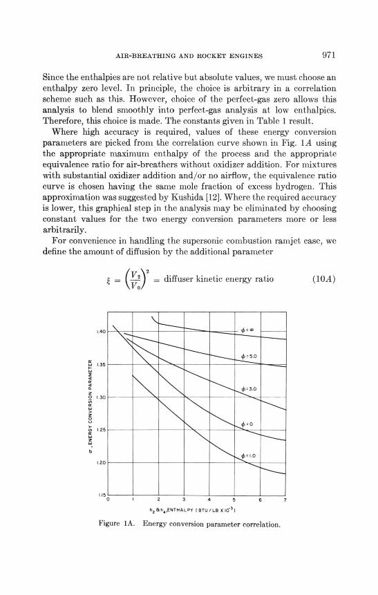
Since the enthalpies are not relative but absolute values, we must choose anenthalpy zero level. In principle, the choice is arbitrary in a correlationscheme such as this. However, choice of the perfect-gas zero allows thisanalysis to blend smoothly into perfect-gas analysis at low enthalpies.Therefore, this choice is made. The constants given in Table 1 result.
Where high accuracy is required, values of these energy conversionparameters are picked from the correlation curve shown in Fig. 1A usingthe appropriate maximum enthalpy of the process and the appropriateequivalence ratio for air-breathers without oxidizer addition. For mixtureswith substantial oxidizer addition and/or no airflow, the equivalence ratiocurve is chosen having the same mole fraction of excess hydrogen. Thisapproximation was suggested by Kushida [12].Where the required accuracyis lower, this graphical step in the analysis may be eliminated by choosingconstant values for the two energy conversion parameters more or lessarbitrarily.
For convenience in handling the supersonic combustion ramjet case, wedefine the amount of diffusion by the additional parameter
(E= Y2 2= diffuser kinetic energy ratioVo
(I OA)
140 9,
4,5 0
1.1 I 35
2
o. 0.3.0
oI 30
8125
Orl.0
120 -f
1 150 2 3 4 5 6 7
h, B 50,ENTHALPY ( BTU/LB X10 3)
Figure 1A. Energy conversion parameter correlation.
972 FOURTH CONGRESS — AERONAUTICAL SCIENCES
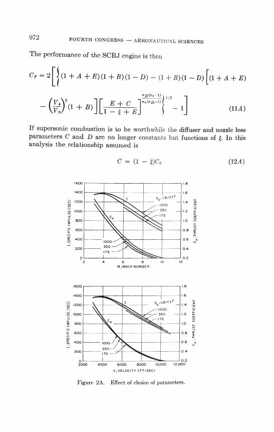
The performance of the SCRJ engine is then
CF = 2 (1 + A + E) (1 B) (1 — D) — (1 + B)(1 — D)[(1 + A + E)
I/2 1—1)E C °""— (KA 1) 2(1 + B)][i
V o+E— 1 j (11A)
If supersonic combustion is to be worthwhile the diffuser and nozzle lossparameters C and D are no longer constants but functions of E. In thisanalysis the relationship assumed is
C = (1 — E)C0 (12A)
1600
1 8
1400
clo,LB/FT2
1.6
1200
i000I 4
1000
350 1.2
800C,
175
o
•
600
0.8
400
0.6
1000
200350
0.4
175
o
0.2
2 4 68 io 12
M ,MACH NUMBER
1600
1.8
1400
1200
go:::FT2
6
1.4
1000
350 1.2
'75
800C,
600
0.8
400 1000
0.6
200350
)75
0 4
0
0 2
2000 4000 60008000 10,00012,000
V,VELOCITY ( FT/SEC)
Figure 2A. Effect of choice of parameters.
I
,SPECIFIC
IMPULSE
(SEC)
I
,SPECIFIC
IMPULSE
(SEC)
CF
,THRUST
COEFFICIENT
o
u".
AIR-BREATHING AND ROCKET ENGINES 973
and
D = (1 — OD° (13A)
where Co and Do are constants. This amounts to assuming a fixed thermo-dynamic process kinetic energy efficiency for the expansion and diffusionprocesses.
Since the fuel injection velocity is significant in the performance of thesupersonic ramjet engine, we will define the parameter
Y=VVo
(14A)
If we now assume that the mixing and combustion occur at constantpressure and the fuel injection is downstream, we eliminate the velocityratio from the equation and obtain
Cf = 2 H (1 + A + E)(1 + B)(1 — D) — (1 + B)(1 — D)[(1 + A + E)
(1 + BYE-112)2 1F c + E In(") " — 11(1 + B) JL 1 - + E
,,D("n- ) 1 /2
(15A)
Under the restrictions that aD = a„ , and assuming the terms of Eqs. (3A)and (7A) small compared to unity, a perturbation treat ment extractsfirst- and second-order terms as follows:
Cp = (A + B C D) — (A 2 + B2 + C2 + D2)
1+ -2 (AB — AC — AD — B (' — BD + CD — 2AE)
1 —(C + E) [A + 13(1 — 21' Cl2)] (16A )
This relation is useful in understanding I he approximate effect of thevarious items.
In partial justification of the choice of velocity rather than Machnumber as the prime variable in hypervelocity engine performance, con-sider Fig. 2A, where Fig. 2 of Dugger's Ref. 2 is first reproduced and thenconverted to an equivalent velocity plot. The subsonic combustion per-formance curves for various alt it udes are brought toget her wit hin less t hanthe width of the lines of the original over most of their lengths, showing
974 FOURTH CONGRESS - AERONAUTICAL SCIENCES
that altitude is a much weaker parameter than it appeared. This repre-sentation also points up the fact that at a velocity of 3000 fps, the twocurves have the same impulse at different thrust coefficients, suggesting aminor discrepancy. Similar reduction of the apparent altitude effect isobtained by replotting supersonic combustion ramjet performance curvessuch as those of Ref. 1.
SYMBOLS
Symbol Description Units
CF engine thrust coefficientCo inlet-loss factor (see Appendix, Eq. 12)
vehicle drag lbDo exit-loss factor (see Appendix, Eq. 13)f/a fuel-air ratiof o fuel-oxidizer ratio(f o)/a propellant-air ratio
gravitational constant ft/sec2static enthalpy Btu/lbpropellant (fuel) heating value Btu/lbdiffuser isentropic reexpansion enthalpy Btu/lbfuel or propellant specific impulse secJoule's constant ft-lb/Btuengine thrust-weight factor lb/lb thrustpressure lb/ft2propellant aerothermal heat, Btu/lbfriction-heat-absorption fractionengine thrust lb
V velocity ft/secweight lbfuel-weight flow rate lb/secfuel-injection velocity ratioincrement of
nD diffuser kinetic energy efficiencynozzle kinetic energy efficiency
nth thermodynamic cycle efficiencynR loeckel cycle energy efficiencynA aerothermal energy conversion efficiency
overall efficiencyfrictional-drag fractiondiffuser kinetic-energy ratio
AIR-BREATHING AND ROCKET ENGINES 975
o- energy conversion parameter (see Appendix)fuel equivalence ratiooxidizer equivalence ratiothrust-drag ratio
Subscripts
a aerothermal, airdiffuserenginefuel, frictionidealnozzle
o unaugmented condition, full diffusion limit, initialox oxidizer
constant entropyst stoichioinetric
vehicular
Superscripts
coolant enthalpy limit, Reynolds analogy limit,stoichiometry limit
Stations
ACKNOWLEDGMENTS
The author would like to express his appreciation to Airs. Alice (;. Taylorfor 1he computation and plot ting of t he performalnP curves present ed in1lUs paper. For aid and const met ive criticism in t he earlier development ofthe cycle analysis methods, the author is indebted to Mr. Fred Falconer,Dr. Raymond Kushida, the late Dr. Frank Billet, and ot hers.
REFERENCES
I. Mordell, L., and J. Swithenbank, "Hypersonic Ramjets," ICAS-4, Zurich,
Switzerland (S ( ptember 1900).Dugger, G. L., "Comparison of Ifypersonic Ramjet Engines with Sul)sonic and
Supersonic Combustion," A ( AR1), Milan (April 1900).Ferri, A., "Vossible Directions of Future Research in Air-Breathing Engines,"
AGAR D, Milan (April 1960).
4 Drake, J. A., "Hypersonic Ramjet Development," AGARD, Milan (April I900).5. Weber, R. J., and J. S. MacKay, "An Analysis of Ramjet Engines Using Super-
sonic Combustion," NACA TN 4386 (September 1958).

976 FOURTH CONGRESS - AERONAUTICAL SCIENCES
Simkin, D., and G. C. Szego (eds.), Elements of Space Propulsion, New York:Wiley, (0000).Moeckel, W. E., "Use of Aerodynamic Heating to Provide Thrust by Vaporizationof Surface Coolants," NACA TN 3140 (1954).Greiner, L., I. Micholson, and J. Rubenowitz, "Hypersonic Flight without Over-heating: I. Friction Heat Absorption and Thrust Gain by Use of Coolant Fuels,"AFOSR TN-57-374, Ordin Associates, Pasadena, California (June 1957).Gordon, S., and B. J. McBride, "Theoretical Performance of Liquid Hydrogenwith Liquid Oxygen as a Rocket Propellant," NASA Memo 5-21-59E (June 1959).Eggers, A. J., Jr., and H. J. Allen, "A Comparative Analysis of the Performance ofLong-Range Hypervelocity Vehicles," NACA TN 4046 (October 1957).Dukes, W. H., "Protection of Aircraft Structures against High Temperatures,"ICAS-4, Zurich, Switzerland (September 1960).Kushida, Raymond, private communication.