Transport Airplane Position Paper
18
Transport Airplane Position Paper Subject: Use of Dissimilarity in Critical System Implementations Reference No. TAPP 25.1309-2 Page 1 of 18 Regulatory Ref.: 14 CFR 25.1309(b) National Policy Ref.: AC 25.1309-1A, AC 20-115D, AC 20-152, AC 20-152A, AC 20-174 Statement of Issue: This Transport Airplane Position Paper (TAPP) provides guidance on the use of design dissimilarity in showing compliance to Title 14 of the Code of Federal Regulations (14 CFR) § 25.1309 for type certificated, transport category airplanes. This paper also summarizes the safety risk and consequent certification considerations when relying solely on dissimilar architecture solutions. Background: This position paper will focus on the use of dissimilarity in support of showing and finding of compliance to the current § 25.1309 regulation (Amdt 25-123 DTD Nov 2007), paragraphs (b)(1) and (b)(2). The fail-safe design concepts outlined in AC 25.1309-1A (and in the harmonized draft AC 25.1309-Arsenal, which the Aviation Rulemaking Advisory Committee’s System Design and Analysis Harmonization Working Group, or ARAC SDAHWG, recommended to the FAA in 2002 1 ) are used in showing compliance to § 25.1309(b). Pertaining to failures, the objectives of the basic fail-safe design concepts are to ensure that: 1) In any system or subsystem, the failure of any single element, component, or connection during any one flight should be assumed, regardless of its probability. Such single failures should not be catastrophic. 2) Subsequent failures during the same flight, whether detected or latent, and combinations thereof, should also be assumed, unless their joint probability with the first failure is shown to be extremely improbable. AC 25.1309-1A identifies design principles or techniques, which should be applied in order to accomplish the fail-safe design concepts. The concepts from AC 25.1309-1A are summarized in 1 The Arsenal version is an updated draft of AC 25.1309 1A, developed by the ARAC SDHWG. It can be used in conjunction with requesting an ELOS for §§ 25.1301 and 25.1309, per FAA Policy PS ANM100-00-113-1034, Use of ARAC (Aviation Rulemaking Advisory Committee) Recommended Rulemaking not yet formally adopted by the FAA, as a basis for equivalent level of safety or exemption to Part 25, dated January 4, 2001 (available on the Internet at http://rgl.faa.gov/). The Arsenal version is available on the Internet at https://www.faa.gov/regulations_policies/rulemaking/committees/documents/media/TAEsdaT2-5241996.pdf.
-
Upload
khangminh22 -
Category
Documents
-
view
0 -
download
0
Transcript of Transport Airplane Position Paper

Transport Airplane Position Paper Subject: Use of Dissimilarity in Critical System Implementations
Reference No. TAPP 25.1309-2
Page 1 of 18
Regulatory Ref.: 14 CFR 25.1309(b) National Policy Ref.: AC 25.1309-1A, AC 20-115D, AC 20-152, AC 20-152A,
AC 20-174
Statement of Issue:
This Transport Airplane Position Paper (TAPP) provides guidance on the use of design dissimilarity in showing compliance to Title 14 of the Code of Federal Regulations (14 CFR) § 25.1309 for type certificated, transport category airplanes. This paper also summarizes the safety risk and consequent certification considerations when relying solely on dissimilar architecture solutions.
Background:
This position paper will focus on the use of dissimilarity in support of showing and finding of compliance to the current § 25.1309 regulation (Amdt 25-123 DTD Nov 2007), paragraphs (b)(1) and (b)(2). The fail-safe design concepts outlined in AC 25.1309-1A (and in the harmonized draft AC 25.1309-Arsenal, which the Aviation Rulemaking Advisory Committee’s System Design and Analysis Harmonization Working Group, or ARAC SDAHWG, recommended to the FAA in 20021) are used in showing compliance to § 25.1309(b). Pertaining to failures, the objectives of the basic fail-safe design concepts are to ensure that:
1) In any system or subsystem, the failure of any single element, component, or connection during any one flight should be assumed, regardless of its probability. Such single failures should not be catastrophic.
2) Subsequent failures during the same flight, whether detected or latent, and combinations thereof, should also be assumed, unless their joint probability with the first failure is shown to be extremely improbable.
AC 25.1309-1A identifies design principles or techniques, which should be applied in order to accomplish the fail-safe design concepts. The concepts from AC 25.1309-1A are summarized in
1 The Arsenal version is an updated draft of AC 25.1309 1A, developed by the ARAC SDHWG. It can be used in conjunction with requesting an ELOS for §§ 25.1301 and 25.1309, per FAA Policy PS ANM100-00-113-1034, Use of ARAC (Aviation Rulemaking Advisory Committee) Recommended Rulemaking not yet formally adopted by the FAA, as a basis for equivalent level of safety or exemption to Part 25, dated January 4, 2001 (available on the Internet at http://rgl.faa.gov/). The Arsenal version is available on the Internet at https://www.faa.gov/regulations_policies/rulemaking/committees/documents/media/TAEsdaT2-5241996.pdf.

Transport Airplane Position Paper Subject: Use of Dissimilarity in Critical System Implementations
Reference No. TAPP 25.1309-2
Page 2 of 18
Table 1. Failure toleration, failure detection, and failure removal ensure fail-safe design characteristics. The AC also notes the following: “The use of only one of these principles or techniques is seldom adequate. A combination of two or more is usually needed to provide a fail-safe design; i.e., to ensure that major failure conditions are improbable and that catastrophic failure conditions are extremely improbable.”
Table 1. AC 25.1309-1A Design Principles/Technique Summary
Principle/Technique Characteristic
Failure Mitigation Technique
Designed Integrity & Quality Ensure intended function and prevent failures Tolerance Redundancy / Backup System Enable continued function after any single failure Detection /
Tolerance System, Component, Element Isolation
Ensure failure of one does not cause failure of another
Tolerance
Proven Reliability Multiple, independent failures are unlikely to occur during the same flight
Avoidance
Failure Warning / Indication Enable failure detection and annunciation Detection Flight Crew Procedures Enable CSFL by specifying crew corrective action Detection /
Tolerance Checkability Ensure capability to check a component’s
condition Detection
Designed Failure Effect Limits Provide capability to sustain a failure and limit the safety impact or effects of a failure
Tolerance
Designed Failure Path Provide control to direct the effects of a failure in a way that limits its safety impact
Tolerance
Safety Margins or Factors Provide allowances for undefined or unforeseeable adverse conditions
Tolerance
Error Tolerance Consider the adverse effects of foreseeable errors during the airplanes design, test, manufacture, operation and maintenance.
Tolerance / Detection / Removal
Applicants have recently preferred to establish the above mentioned draft AC 25.1309-Arsenal as the project means of compliance through either an issue paper or equivalent level of safety finding process due to the more up to date certification information and terminology. This updated draft guidance also recommends industry guidelines that contain system-level material and methods for performing the system safety assessment process, and system, airborne software, and airborne electronic hardware (AEH) development assurance processes available to
Transport Airplane Position Paper Subject: Use of Dissimilarity in Critical System Implementations
Reference No. TAPP 25.1309-2
Page 3 of 18
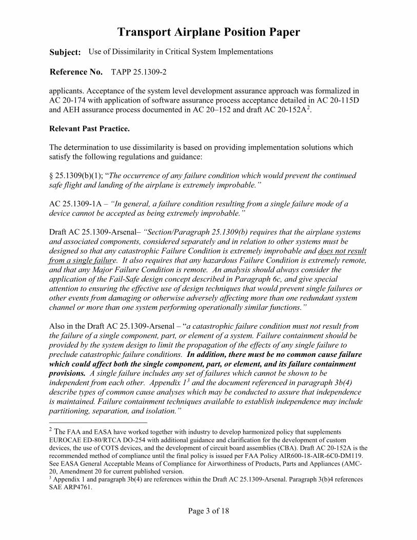
applicants. Acceptance of the system level development assurance approach was formalized in AC 20-174 with application of software assurance process acceptance detailed in AC 20-115D and AEH assurance process documented in AC 20–152 and draft AC 20-152A2. Relevant Past Practice. The determination to use dissimilarity is based on providing implementation solutions which satisfy the following regulations and guidance: § 25.1309(b)(1); “The occurrence of any failure condition which would prevent the continued safe flight and landing of the airplane is extremely improbable.” AC 25.1309-1A – “In general, a failure condition resulting from a single failure mode of a device cannot be accepted as being extremely improbable.” Draft AC 25.1309-Arsenal– “Section/Paragraph 25.1309(b) requires that the airplane systems and associated components, considered separately and in relation to other systems must be designed so that any catastrophic Failure Condition is extremely improbable and does not result from a single failure. It also requires that any hazardous Failure Condition is extremely remote, and that any Major Failure Condition is remote. An analysis should always consider the application of the Fail-Safe design concept described in Paragraph 6c, and give special attention to ensuring the effective use of design techniques that would prevent single failures or other events from damaging or otherwise adversely affecting more than one redundant system channel or more than one system performing operationally similar functions.” Also in the Draft AC 25.1309-Arsenal – “a catastrophic failure condition must not result from the failure of a single component, part, or element of a system. Failure containment should be provided by the system design to limit the propagation of the effects of any single failure to preclude catastrophic failure conditions. In addition, there must be no common cause failure which could affect both the single component, part, or element, and its failure containment provisions. A single failure includes any set of failures which cannot be shown to be independent from each other. Appendix 13 and the document referenced in paragraph 3b(4) describe types of common cause analyses which may be conducted to assure that independence is maintained. Failure containment techniques available to establish independence may include partitioning, separation, and isolation.” 2 The FAA and EASA have worked together with industry to develop harmonized policy that supplements EUROCAE ED-80/RTCA DO-254 with additional guidance and clarification for the development of custom devices, the use of COTS devices, and the development of circuit board assemblies (CBA). Draft AC 20-152A is the recommended method of compliance until the final policy is issued per FAA Policy AIR600-18-AIR-6C0-DM119. See EASA General Acceptable Means of Compliance for Airworthiness of Products, Parts and Appliances (AMC-20, Amendment 20 for current published version. 3 Appendix 1 and paragraph 3b(4) are references within the Draft AC 25.1309-Arsenal. Paragraph 3(b)4 references SAE ARP4761.
Transport Airplane Position Paper Subject: Use of Dissimilarity in Critical System Implementations
Reference No. TAPP 25.1309-2
Page 4 of 18
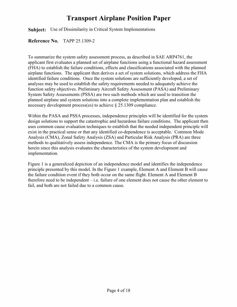
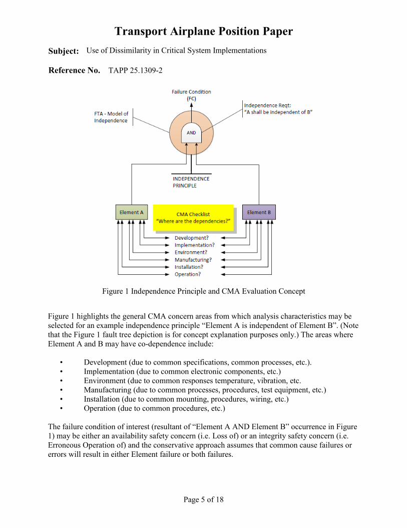
To summarize the system safety assessment process, as described in SAE ARP4761, the applicant first evaluates a planned set of airplane functions using a functional hazard assessment (FHA) to establish the failure conditions, effects and classifications associated with the planned airplane functions. The applicant then derives a set of system solutions, which address the FHA identified failure conditions. Once the system solutions are sufficiently developed, a set of analyses may be used to establish the safety requirements needed to adequately achieve the function safety objectives. Preliminary Aircraft Safety Assessment (PASA) and Preliminary System Safety Assessments (PSSA) are two such methods which are used to transition the planned airplane and system solutions into a complete implementation plan and establish the necessary development process(es) to achieve § 25.1309 compliance. Within the PASA and PSSA processes, independence principles will be identified for the system design solutions to support the catastrophic and hazardous failure conditions. The applicant then uses common cause evaluation techniques to establish that the needed independent principle will exist in the practical sense or that any identified co-dependence is acceptable. Common Mode Analysis (CMA), Zonal Safety Analysis (ZSA) and Particular Risk Analysis (PRA) are three methods to qualitatively assess independence. The CMA is the primary focus of discussion herein since this analysis evaluates the characteristics of the system development and implementation. Figure 1 is a generalized depiction of an independence model and identifies the independence principle presented by this model. In the Figure 1 example, Element A and Element B will cause the failure condition event if they both occur on the same flight. Element A and Element B therefore need to be independent – i.e. failure of one element does not cause the other element to fail, and both are not failed due to a common cause.
Transport Airplane Position Paper Subject: Use of Dissimilarity in Critical System Implementations
Reference No. TAPP 25.1309-2
Page 5 of 18
Figure 1 Independence Principle and CMA Evaluation Concept
Figure 1 highlights the general CMA concern areas from which analysis characteristics may be selected for an example independence principle “Element A is independent of Element B”. (Note that the Figure 1 fault tree depiction is for concept explanation purposes only.) The areas where Element A and B may have co-dependence include:
• Development (due to common specifications, common processes, etc.). • Implementation (due to common electronic components, etc.) • Environment (due to common responses temperature, vibration, etc. • Manufacturing (due to common processes, procedures, test equipment, etc.) • Installation (due to common mounting, procedures, wiring, etc.) • Operation (due to common procedures, etc.)
The failure condition of interest (resultant of “Element A AND Element B” occurrence in Figure 1) may be either an availability safety concern (i.e. Loss of) or an integrity safety concern (i.e. Erroneous Operation of) and the conservative approach assumes that common cause failures or errors will result in either Element failure or both failures.

Transport Airplane Position Paper Subject: Use of Dissimilarity in Critical System Implementations
Reference No. TAPP 25.1309-2
Page 6 of 18
The use of dissimilarity primarily affects the Implementation and Development co-dependency areas of concern. Each of these concern areas are discussed separately in the following sections. In all cases, application of a structured development assurance (DA) process such as that described in SAE ARP4754A is warranted, to assure the system is safe and compliant. It is important to note that the DA process includes all necessary system safety assessments as described in SAE ARP4761. Note: The following examples illustrate previous and/or contemporary applications where dissimilarity has been applied by the applicants, or not applied with justification. The examples do not imply any policy position other than a discussion perspective. FAA position on dissimilarity is presented in the FAA Position section. A. Implementation Co-Dependency Cases 1. Postulate the following example scenario: A PSSA has identified an independence principle that Element A must be independent of Element B in order to satisfy an FHA safety objective (see Figure 1). Consider then the failure cases in a CMA questionnaire evaluation of “What might be the implementation dependencies?” An example case of a microprocessor based controlling mechanism as Element A and an independent microprocessor based monitoring mechanism as Element B is evaluated. This classic implementation architecture has been proposed by applicants to mitigate an FHA erroneous operation failure condition classified as catastrophic.
The CMA would identify that the initial planned strategy to use commercial-off-the-shelf (COTS) microprocessor electronic components executing the same instruction set for both functions (i.e. control -element A and monitor -element B) would have extensive implementation codependence. An unidentified “bug” in the microprocessor logic, instruction set execution, etc., may result in an erroneous calculation in both Element A and Element B instantiations. This may result in an erroneous control calculation not being identified and mitigated by the monitoring safeguard as needed. In this case, an applicant may propose that the use of COTS microprocessor electronic components, executing different instruction sets, would enhance independence. (Further analysis may be required to determine if the commonality issues are constrained solely to the microprocessors.) The different implementation designs between Element A and B has been accepted as providing adequate independence between the controlling mechanism and its associated safeguard to mitigate any unknown microprocessor operational characteristics. (Just such a historical failure mechanism event manifested itself in the Intel Pentium II series of microprocessors in 1997. The microcode execution of two instructions, together with specific data, resulted in erroneous execution results.)

Transport Airplane Position Paper Subject: Use of Dissimilarity in Critical System Implementations
Reference No. TAPP 25.1309-2
Page 7 of 18
2. Consider another example scenario of Element A independent of Element B, where both elements use the same family4 of Programmable Logic Device (PLD) electronic components to implement identical functional logic. Again, applicants have proposed this implementation architecture to mitigate an erroneous operation failure condition. The selected programmable devices are generally accepted as “complex electronic devices” within a DO-254 (Design Assurance Guidance for Airborne Electronic Hardware) electronic development process. As “complex” devices, it may be impossible or impractical for the applicant to completely test and analyze the implemented functionality. However, the functionality programmed into the electronic item may be inherently “simple” by design. That is, a hardware item may be classified as “simple” if a technical assessment of the design content supports the ability of the device to be verified by a “comprehensive combination of deterministic tests and analyses appropriate to the design assurance level can ensure correct functional performance under all foreseeable operating conditions with no anomalous behavior.” (Reference DO-254 section 1.6 and Draft AC 20-152A section 5.2)
The CMA would identify that Element A and Element B may fail to provide their intended function due to a codependency resulting from a common failure in the PLD devices or due to an error in requirements for the PLD devices or an error in the device programming due to development support tools. In this case, the safety analyst should consider the electronic development process as well as the planned and required component programmed functionality. Two major potential subcase examples, a) and b): a) The Element A and B programmable devices are identical family electronic parts and
satisfy the definition of “simple hardware item” per DO-254 and AC 20-152A. A comprehensive combination of requirements based tests and analyses will be conducted to ensure no anomalous behavior and correct functional performance under all foreseeable operating conditions. A functional example might be: Element A and B PLDs provide a memory to memory move capability that repeats on a repetitive, deterministic timeline. The data being moved from memory to memory contains an embedded protection mechanism on the data being moved (e.g. parity, CRC). In this case, the CMA identified codependency, resulting from identical PLDs, would be acceptable due to the layered failure and error mitigation strategies. A design process commensurate with the functional hazard (Functional Development
4 A group of electronic components related by common characteristics.

Transport Airplane Position Paper Subject: Use of Dissimilarity in Critical System Implementations
Reference No. TAPP 25.1309-2
Page 8 of 18
Assurance Level A, per ARP4754A, for a catastrophic failure condition); development of the simple hardware item at AEH Level A per DO-254 and the applicable objectives of AC 20-152A5 to verify correct functional electronics operation; and a system layer detection mechanism (an architectural requirement derived from the PSSA and CMA) provide an acceptable level of common mode mitigation. For this subcase example, component dissimilarity between Element A and B is not warranted.
b) Element A and B programmable devices are identical family electronic parts which calculate complex mathematical equations using multi-variable inputs where functionality is relied upon throughout the flight. Element A functions as an effector controller and Element B provides the safeguard. The programmed devices are characterized per DO-254 as “complex” and the PHAC identifies a Level A development process. In this case, the CMA may highlight that erroneous complex calculations by both Element A and B programmable devices, due to common failure or error mechanism, may be undetected since the ability to comprehensively test and analyze the design may not be possible. The applicants’ selection of different PLD electronic components may be justified when the function hosted on the programmable logic device is used throughout the flight and the airplane function being implemented has a failure condition of catastrophic. If the programmable devices are implementing a non-full time function or a backup function then dissimilarity may not be warranted due to the limited exposure time to the common mode failure or error.
The need for difference in a PLD implementation (e.g. between control and safeguard) greatly depends on the functionality programmed into the device. The use of dissimilar PLD electronic component types may be appropriate if the resultant programming is identical and erroneous or failed operation is not detectable by any other means. Irrespective of dissimilarity application, the FAA has considered DA as necessary to assure the entire system and safety process. The DA should have steps to ensure implementing dissimilarity would not create unmanageable integration of different systems and components, or introduce more errors, undetected failure modes, or unmanaged risk due to increased complexity. 5 E.g. comprehensive requirements based testing and analysis

Transport Airplane Position Paper Subject: Use of Dissimilarity in Critical System Implementations
Reference No. TAPP 25.1309-2
Page 9 of 18
The use of dissimilar electronic component implementations may be appropriate when failure mechanisms are difficult to ascertain, predict or detect. Use of COTS microprocessors and programmable devices are typical examples of complex design solutions where an acceptable level of testing and analysis to identify all failure mechanisms prior to certification may not be achievable. As for non-complex electronic components (such as analog power supplies, switches and relays), there has been no demonstrated or analytical evidence produced to support the concept that independent principles require implementations using all different electronic components (i.e. different equipment parts lists between Element A and Element B). Nor has there been any evidence that this philosophy has been effective at mitigation of common mode failure mechanisms. It remains an unsupported paradigm without corroboration. B) Development Co-Dependency Cases Paragraph 9b(1)(iii) of the draft AC 25.1309-Arsenal states that any analysis necessary to show compliance with § 25.1309(b) should consider the possibility of requirement, design, and implementation errors during the development process. “Errors made during the design and development of systems have traditionally been detected and corrected by exhaustive tests conducted on the system and its components, by direct inspection, and by other direct verification methods capable of completely characterizing the performance of the system. These direct techniques may still be appropriate for simple systems which perform a limited number of functions and which are not highly integrated with other airplane systems. For more complex or integrated systems, exhaustive testing may either be impossible because all of the system states cannot be determined or impractical because of the number of tests, which must be accomplished. For these types of systems, compliance may be shown by the use of Development Assurance.” The intent of this guidance is that a comprehensive and appropriate application of the development assurance process, from the aircraft/system level, down to the software and hardware level, should result in a compliant system design. “Errors may cause failures but they are not considered to be failures”6. Unlike ‘single failures’, § 25.1309 and associated guidance do not require that single errors be assumed or that no single error may cause a catastrophic event. Because a single failure may result from one or more errors in the chain of development, manufacturing, and maintenance processes, the advisory materials provide the development assurance techniques to minimize the potential of errors, and the fail-safe design concept to tolerate any errors that may remain.
6 Part of the definition of Failure in Draft AC 25.1309-Arsenal.

Transport Airplane Position Paper Subject: Use of Dissimilarity in Critical System Implementations
Reference No. TAPP 25.1309-2
Page 10 of 18
Together, fail-safe design techniques and development assurance, provide the foundations for compliance with the no-catastrophic-single-failure criterion, and for addressing the common mode failure concerns. Errors may occur in the development process for the airborne implementation; an error may occur in the design tools used to create the implementation; an error may occur in the method and tools used to manufacture the implementation; an error may be in the crew and product maintenance manuals. All of these error source examples should be evaluated within a CMA when working with catastrophic failure conditions. The highest profile error sources occur within the development process. Table 2 presents an example error source and mitigation summary of development process error sources and the historical acceptable mitigations.
Table 2 Example Error Sources & Historical Mitigation Strategies
Error Source Accepted Mitigations
Requirement Set
Development assurance applied from aircraft to system to item at appropriate level of rigor using ARP4754A guidelines that include the required system safety assessment and adequate testing.
Design • Required functionality • Design tools (e.g. compilers, VHDL
tools)
Electronics – DO-254 with development assurance at appropriate level of rigor Software – DO-178 with development assurance at appropriate level of rigor. However, application of these assurance processes alone is not sufficient without also applying the aircraft/system level assurance process above.
Implementation
Incremental requirements based verification testing from item to system to aircraft using DO-254/DO-178 guidance and ARP4754A guidelines.
Development Assurance (DA), commensurate with the level of effect from a function failure condition, is an acceptable means of addressing errors that may occur in requirements, implementation and design. The DA processes, inclusive of the safety assessment process, ensure a comprehensive, top-down failure and error mitigation strategy that provides tools for making design decisions. The DA process ensures the correctness of system architecture and guides the implementation of dissimilarity used to mitigate common mode failure cases.
Transport Airplane Position Paper Subject: Use of Dissimilarity in Critical System Implementations
Reference No. TAPP 25.1309-2
Page 11 of 18
The three mitigation strategies in Table 2 are necessary and codependent because the results from the aircraft/system level assurance interface with the software and hardware level assurance. However, within each strategy there are requirements for independent verification for level A processes. These development assurance strategies, applied together, and at the appropriate level of rigor associated with the function failure condition classification, are the primary recognized means for ensuring errors are adequately detected and corrected before and after a design is implemented. This is consistent even within the guidance provided in AC 25.1309-1A with references to AC 20-115A and the application of RTCA/DO-178A, where the referenced guidance identifies that software must be developed to the level appropriate to the failure conditions to which the software contributes. Within the design strata, the perceived need to use different design tools, programming languages (AEH or software) and programming teams often arises. Design Tools Dependency Let’s re-examine the previous example, in which Element A is independent of Element B for codependency created by the use of the same design tools.
Scenario 1: Element A and Element B will be packaged on two separate Printed Wiring Boards (PWBs). A single schematic capture and layout tool will be used to imprint the defined electrical design onto the PWB. A CMA evaluation would highlight that the capture/layout tool creates a codependency which may result in a common PWB implementation error. However, it is unlikely that the electronic schematics for both elements would be identical since they have some different functions that will cause the tool to create different layouts. Any minor codependency that remains could rely on AEH functional testing, AEH equipment qualification and system verification to mitigate an erroneous toolset error. Thus, any codependency for this common mode source is acceptable. Scenario 2a: This scenario refers to programmable failure subcase A.2.a) where Element A and B programmable devices provide a memory-to-memory move capability that repeats on a specific timeline. Since the CMA evaluation of the failure case has accepted the codependency due to repetitive functionality, with failures detected by comprehensive testing and system level detection mechanisms, errors created by a common component programming toolset would also be identified and removed. Different toolsets are therefore unwarranted in this scenario. Scenario 2b: This scenario refers to programmable failure subcase A.2.b) where Element A and B programmable devices are identical electronic family parts which calculate

Transport Airplane Position Paper Subject: Use of Dissimilarity in Critical System Implementations
Reference No. TAPP 25.1309-2
Page 12 of 18
complex mathematical equations. Element A functions as an effector controller and Element B provides the safeguard throughout the flight. In this case, erroneous calculations by both A and B programmable devices, due to common error mechanism, may be undetected. In this case, different programming tools for different electronic parts may be acceptable mitigation, if the function hosted on programmable logic device is full-time flight critical. Conversely, if the programmable devices are implementing a non-full time flight critical function or a backup function then toolset dissimilarity is not warranted.
The necessity for toolset dissimilarity between control and safeguard greatly depends on functionality programmed into the electronic components and the programmed function exposure time. It is possible that the use of different design tools sets commensurate with different component types may be appropriate if the resultant programming is identical and erroneous or failed operation is undetectable by any other means. Whether or not the applicants employ dissimilar tools, they should take steps to ensure correct operations of the tools.
Programming Languages When a solution to a common mode microprocessor failure case has used dissimilarity, the resulting software solution will also, by default, contain a level of dissimilarity in the coded solution. This results from the programming toolset creating different software executables or loadable images for the different microprocessor components. This level of “inherited” dissimilarity has been accepted for full-time flight critical systems. However as in the case of tools, there has not been any demonstrated or analytical evidence produced to support the concept that different software toolsets provide additional software error mitigation over a single programming language tool set using two different microprocessor targets. Studies completed to date have concluded “changing development tools or methods, or any other simple technique, would not reduce significantly the incidence of correlated failures in N-version software”.7 Different Development Teams Some in industry also advocate that where software independence is necessary between two elements, the software must be developed by different teams of software engineers in order to accomplish independence. Such advocacy is not based on data driven results or scientific studies;
7 Brilliant, Knight, Leveson, “Analysis of Faults in N-Version Software Experiment, IEEE Transactions on Software Engineering, Vol 16, No. 2, 1990

Transport Airplane Position Paper Subject: Use of Dissimilarity in Critical System Implementations
Reference No. TAPP 25.1309-2
Page 13 of 18
nor is there a need for software independence given the track history of existing software design assurance processes. However, analytical evidence does indicate that N-version programming (i.e., software created through the use of independent software developers generating the software to the same requirements) is an unsupported hypothesis8. The whole field of psychology is predicated on the assumption that human behavior (including that involved in making mistakes) is not random.9 Thus, the use of different people to accomplish software development or firmware development should not be factored into successful project compliance. Current Regulatory and Advisory Material 1. Section 25.1309 Airworthiness Standards: Transport Category Airplanes 2. AC 25.1309-1A, DTD 6/88 System Design and Analysis 3. AC 25.1309-Arsenal, System Design and Analysis (RTCA SDAHWG Arsenal
Draft DTD 6/2002 Draft) 4. AC 20-115D, Airborne Software Development Assurance Using
DTD 7/2017 EUROCAE ED-12( ) and RTCA DO-178() 5. AC 20-152, Development Assurance for Airborne Electronic Hardware
DTD 6/2005 6. AC 20-152A Development Assurance for Airborne Electronic Hardware
Draft 7. AC 20-174, DTD 9/30/2011 Development of Civil Aircraft and Systems Dissimilarity Application Without Safety Substantiation A development project that focuses solely on a requirement for implementation of dissimilar elements, irrespective of other architectural and development assurance error source mitigation practices, will be introducing additional safety concerns that should be evaluated. The application of dissimilarity without the meticulous safety assessment rationale and the development assurance activities necessary to manage the complexity and independence characteristics provides greater concern that errors and mistakes will occur. The application of dissimilar electronic hardware and software implementations complicate system integration activities resulting in new concerns about completeness and correctness of the verification efforts. Enhanced processes with associated configuration management should
8 Knight, Leveson, “An Experimental Evaluation of the Assumption of Independence in Mulit-Version Programming”, NASA grant NAG1-242 9 Shimeall, Leveson, “An Empirical Comparison of Software Fault Tolerance and Fault Elimination”, IEEE Transactions on Software Engineering, Vol. 17, No. 2 February 1991

Transport Airplane Position Paper Subject: Use of Dissimilarity in Critical System Implementations
Reference No. TAPP 25.1309-2
Page 14 of 18
manage the additional, redundant and independent development activities to mitigate the potential increase in error sources and occurrences. Dissimilar implementations increase the level of difficulty in overall life cycle support. Maintenance of the independent airborne electronic support structures and procedures as well as the independent software development and its support structures with trained personnel may be problematic for applicants to establish and maintain. The applicant should address the risk associated with increased complexity of life cycle maintenance for dissimilar implementations. From a system operational perspective, dissimilarity may introduce unidentified failure modes or create confusing system operating modes which have not been adequately considered during the development process. These situations may create additional safety impacts of significance (i.e. major or hazardous consequences). The dissimilar implementation may also require compromises in detection of failure modes or control actions due to the need for greater tolerances to accommodate asynchronicity of the solutions. The application of extensive dissimilar system and implementation characteristics should be extensively evaluated to ensure the concerns associated with the diverse implementation are addressed.
FAA Position:
This position is to be applied when showing or finding compliance with § 25.1309 with regards to common cause failures or common cause errors for flight critical systems. As defined in the draft AC 25.1309-Arsenal, although errors in development, design, manufacturing, and operations may cause failures, they are not considered to be failures. Consequently, unlike for single failures, § 25.1309(b) and associated guidance do not require that catastrophic single errors be assumed. Instead, the correct and comprehensive application of development assurance techniques (which can include the full range of system safety assessment techniques in ARP4761) provides acceptable mitigations for errors. Development assurance processes that comprehensively apply ARP4754A in addition to DO-178C, DO-254, and the Draft AC 20-152A are accepted, demonstrated methodologies for mitigating errors. The systematic use of assurance processes and techniques increases confidence that errors in requirements, design and integration, and/or interaction effects have been adequately identified and corrected. Rigorous and well-structured design and development procedures play an essential role in facilitating a methodical safety assessment process and provide visibility to the means of compliance. A comprehensive development assurance process is one that encompasses generation of correct and complete safety requirements, as well as showing the aircraft/system is correctly designed. DA is not only about the latter.

Transport Airplane Position Paper Subject: Use of Dissimilarity in Critical System Implementations
Reference No. TAPP 25.1309-2
Page 15 of 18
The need for dissimilarity in a safety-critical system is established through the DA process, which often includes the full range of applicable safety analyses described in ARP4761. The need for dissimilarity should not be assumed prior to being identified by the DA/safety analysis process. The fail-safe design strategy for a flight critical function, including the use of Development Assurance supplemented with dissimilarity should be developed and documented as part of the aircraft safety process (i.e. FHA, PASA and PSSA, and supporting CMA). The primary focus when establishing a need for dissimilarity should be based on reasonable common mode concerns. Unproven or theoretical common modes should not drive a requirement to implement dissimilarity solutions. For example, it is not reasonable to assume lack of independence when evaluating random failures of identical simple components such as analog power supplies installed in separate components of the same system. The risk due to random combination of such component failures are adequately assessed using traditional statistical methods. Dissimilarity should be discretely applied only where there is a likelihood that an identified common mode threat can be most effectively identified, eliminated or mitigated though the use of this technique. The use of dissimilarity should be derived by an applicant, based on a top-down development assurance process, for the failure conditions applicable to the product. Application of “what worked on the applicant’s prior airplane” or “what worked on another applicant’s airplane” should be evaluated and considered as, at best, anecdotal information. Applicable service history may be used to substantiate confidence in a repeatable DA process and its resultant designs. Such designs may or may not have employed dissimilarity. However, service history alone is not sufficient to satisfy the no-catastrophic-single-failure criterion. Whenever dissimilarity is used, the DA process should also ensure that such use does not create unmanageable integration of different systems in the design process as well as in service (e.g. creating confusing system operating modes, or difficulties in maintenance), nor introduce failure modes that could create additional safety impacts (including impacts that are classified as hazardous or major.) The goal of the policy is not to “guarantee” that no common cause threat persists for catastrophic functions, but to establish that an acceptable safety level for equipment and systems as installed on the airplane will be and has been achieved for the unique aircraft type being developed. The successful application of the standard environmental test conditions and procedures identified in guidance material is acceptable to mitigate environmental common cause concerns and support compliance.

Transport Airplane Position Paper Subject: Use of Dissimilarity in Critical System Implementations
Reference No. TAPP 25.1309-2
Page 16 of 18
Applicants should expect that certificating officials will consider this position paper when showing compliance to § 25.1309. ACOs should consider this policy for proposed development and implementation strategies when discussing findings of § 25.1309 compliance.
Conclusion:
Applicants may use this Transport Airplane Position Paper when:
• The airplane model(s) is a transport category airplane,
• The applicant verifies with the FAA that the FAA position on this issue did not change, and
• The applicant refers to the reference number for this Transport Airplane Position Paper intheir project specific certification plan.
Sheila Mariano – AIR-633 Policy & Innovation Division Aircraft Certification Service
Date
8/20/2021

Transport Airplane Position Paper Subject: Use of Dissimilarity in Critical System Implementations
Reference No. TAPP 25.1309-2
Page 17 of 18
Appendix A – Acronyms & Definitions A.1 Acronyms and Abbreviations AC Advisory Circular AEH Airborne Electronic Hardware Aka Also known as Amdt Amendment ARAC Aviation Rulemaking Advisory Committee ARP Aerospace Recommended Practice CFR Code of Federal Regulations CMA Common Mode Analysis CRC Cyclic Redundancy Check DA Development Assurance DTD Dated FC Failure Condition FHA Functional Hazard Assessment FTA Fault Tree Analysis PASA Preliminary Aircraft Safety Assessment PHAC Plan for Hardware Aspects of Certification PLD Programmable Logic Device PRA Particular Risk Analysis PSSA Preliminary System Safety Assessment PWB Printed wiring board SDAHWG System Design and Analysis Harmonization Working Group SSA System Safety Assessment ZSA Zonal Safety Analysis A.2 Definitions Common Cause: A single failure, error or event that can produce undesirable effects on two or more systems, equipment, items or functions. Common Cause Error: An error which effects a number of elements otherwise considered to be independent (aka common mode error). Complex: A system is Complex when its operation, failure modes, or failure effects are difficult to comprehend without the aid of analytical methods. Development Assurance: All of those planned and systematic actions used to substantiate, to an adequate level of confidence, that errors in requirements, design and implementation have been identified and corrected such that the system satisfies the applicable certification basis.

Transport Airplane Position Paper Subject: Use of Dissimilarity in Critical System Implementations
Reference No. TAPP 25.1309-2
Page 18 of 18
Development Error: A mistake in requirements, design or implementation. Dissimilarity: A design concept which provides a defense against common cause failure or common cause error mechanisms through the use of different elements. Error: An omitted or incorrect action by a crewmember or maintenance person or a mistake in requirements, design or implementation. Event: An occurrence which has its origin distinct from the airplane, such as atmospheric conditions (e.g. gusts, temperature variations, icing and lightning strikes), runway conditions, conditions of communication, navigation, and surveillance services, bird-strike, cabin and baggage fires. The term is not intended to cover sabotage. Failure: An occurrence which affects the operation of a component, part or element such that it can no longer function as intended (this includes both loss of function and malfunction). Note: Errors may cause failures but are not considered to be failures. Failure Condition: A condition having an effect on the airplane and/or its occupants, either direct or consequential, which is caused or contributed to by one or more failures or errors, considering flight phase and relevant adverse operational or environmental conditions, or external events. Independence: A characteristic that minimizes the likelihood of common failure or error. Independence Principle: Features of an intended implementation where independence has been determined to be necessary. Programmable Logic Device: A component that is purchased as an electronic component and altered to perform an application specific function. PLDs include, but are not limited to, Programmable Array Logic components, Programmable Logic Array components, General Array Logic components, Field Programmable Gate Array components, and Erasable Programmable Logic Devices. Simple Hardware Item: A hardware custom device is classified as simple only if a technical assessment of the design content supports the ability of the device to be verified by a comprehensive combination of deterministic tests and analyses can ensure correct functional performance under all foreseeable operating conditions with no anomalous behavior. System: A combination of components, parts and elements which are inter-connected to perform one or more functions.