Self-assembled dithiothreitol on Au surfaces for biological applications: phospholipid bilayer...
8
Self-assembled dithiothreitol on Au surfaces for biological applications: phospholipid bilayer formation Taˆnia B. Creczynski-Pasa, a M. Antonieta Daza Millone, b Maximiliano L. Munford, c Vaˆnia R. de Lima, a Tiago O. Vieira, a Guillermo A. Benitez, b Andre´ A. Pasa,* a Roberto C. Salvarezza b and Marı´a E. Vela* b Received 17th July 2008, Accepted 5th November 2008 First published as an Advance Article on the web 24th December 2008 DOI: 10.1039/b811964c Self-assembly of dithiothreitol (DTT) on Au(111) from solution deposition has been studied by X-ray photoelectron spectroscopy and electrochemical data. DTT molecules self-assemble on Au(111) in a lying-down configuration irrespective of the concentration and temperature. XPS and electrochemical data indicate a DTT surface coverage of y E 0.16 with two S-head–Au covalent bonds per DTT molecule. The DTT monolayer turns the Au surface hydrophilic enough to allow the formation of fluid dimyristoylphosphatidylcholine (DMPC) bilayer domains by vesicle fusion as revealed by in situ atomic force imaging. Methylene blue (MB) and flavin adenine dinucleotide (FAD) have been used as probes to study molecule transport across the bilayer. 1. Introduction Lipid membranes of living cells are the most important barriers to control the majority of cellular processes. They play a fundamental role in cell-to-cell communication involving the exchange of ions and biomolecules, including calcium, neuro- transmitters, proteins, reactive species, and drugs among others. Phospholipid bilayers can be taken as a model system of cell membranes because they preserve 2-D fluidity and can be modified with membrane proteins, ion channels, receptors and transporters, and can be used for various biotechnological applications. 1–3 Liposomes, in which phospholipid composi- tion, structure and dynamics can be fully controlled, are generally accepted as a suitable model for in vitro studies of cell membrane structures and properties. 4–6 Liposomes are vesicles formed by a lipidic bilayer, structurally similar to the lipidic matrix of a cell membrane. However, to perform studies with atomic force microscopy (AFM), a technique that allows the determination of morphological and mechanical properties of structures, the immobilization of the lipidic bilayer on a solid surface 7–10 is required. There exist several methods to spread phospholipids on a solid substrate in order to achieve a supported bilayer. 11 Among the most widely used methods are sequential transfer of two monolayers from the air–water interface via Langmuir–Blodgett (LB) and Langmuir–Schaefer (LS) techniques, 12,13 single bilayer spreading 14 and vesicle fusion. 15 Lipidic membranes supported on inorganic material surfaces, e.g. gold and mica, yield important results related to phase transition, stability and morphology of the layers and are promising structures for the development of biosensors. 16–18 On these surfaces, however, the physical–chemical properties of the lipidic layers are significantly different from membranes in fluid environments. 19 A promising approach is to use self- assembled monolayers (SAMs) of thiol molecules on gold, since they can act as a bridge or a spacer between the inorganic surface and the assembled macromolecules. Modification of solid surfaces with a spacer to link phospholipids bilayers provides a selective anchoring layer to accommodate hydro- philic domains of proteins and enables the charge transport from one side of the membrane to the other side. 4–6,20 Concerning the inorganic surface there is a particular interest in metallic substrates because they can be used as electrodes in electrochemical-based biosensors. Gold substrates are particularly attractive because they are biocompatible and inert materials that can be modified by simple solution chemistry without significant contamination. Several approaches have been developed to support phospho- lipid bilayers on gold. Hybrid bilayers of phospholipids on alkanethiol 21 or thiophospholipid 22 SAMs on gold lead to well ordered and blocking artificial membranes but they lack a proper fluidity to resemble a biomimetic system. Adding a long thiolated linker to the phospholipid tethered bilayers 5,6 or performing vesicle fusion over long (C n 4 11) hydroxyl-terminated thiols 20,23 (as a hydrophilic surface is required for this strategy) improve fluid properties. However an increase in the length of the linker chain should hinder electron transfer. 24 Therefore the use of a very short spacer that turns the gold surface hydrophilic enough for vesicle fusion and allows an easy electron transfer should be a suitable choice to build an electrochemical biosensor. Unfortunately, short hydroxyalkanethiol SAMs, e.g. 2-mercaptoethanol, have a lower stability against reductive desorption 25 which greatly decrease the range of electrochemical sensing ability. a Departamento de Cie ˆncias Farmace ˆuticas and Departamento de Fı´sica, UFSC, C. P. 476, Floriano ´polis, 88.040-900, Brazil. E-mail: pasa@fisica.ufsc.br; Fax: +55 48 3234 0599 b INIFTA, CONICET-UNLP, La Plata, CC 16 Suc. 4, Argentina. E-mail: [email protected]; Fax: +54 221 425 4642 c Departamento de Fı´sica, UFV, Vic ¸ osa, Brazil This journal is c the Owner Societies 2009 Phys. Chem. Chem. Phys., 2009, 11, 1077–1084 | 1077 PAPER www.rsc.org/pccp | Physical Chemistry Chemical Physics Published on 24 December 2008. Downloaded by Universidade Federal de Santa Catarina (UFSC) on 14/10/2014 14:51:10. View Article Online / Journal Homepage / Table of Contents for this issue
Transcript of Self-assembled dithiothreitol on Au surfaces for biological applications: phospholipid bilayer...

Self-assembled dithiothreitol on Au surfaces for biological
applications: phospholipid bilayer formation
Tania B. Creczynski-Pasa,a M. Antonieta Daza Millone,b
Maximiliano L. Munford,cVania R. de Lima,
aTiago O. Vieira,
a
Guillermo A. Benitez,bAndre A. Pasa,*
aRoberto C. Salvarezza
b
and Marıa E. Vela*b
Received 17th July 2008, Accepted 5th November 2008
First published as an Advance Article on the web 24th December 2008
DOI: 10.1039/b811964c
Self-assembly of dithiothreitol (DTT) on Au(111) from solution deposition has been studied by
X-ray photoelectron spectroscopy and electrochemical data. DTT molecules self-assemble on
Au(111) in a lying-down configuration irrespective of the concentration and temperature. XPS
and electrochemical data indicate a DTT surface coverage of y E 0.16 with two S-head–Au
covalent bonds per DTT molecule. The DTT monolayer turns the Au surface hydrophilic enough
to allow the formation of fluid dimyristoylphosphatidylcholine (DMPC) bilayer domains by
vesicle fusion as revealed by in situ atomic force imaging. Methylene blue (MB) and flavin
adenine dinucleotide (FAD) have been used as probes to study molecule transport across the
bilayer.
1. Introduction
Lipid membranes of living cells are the most important barriers
to control the majority of cellular processes. They play a
fundamental role in cell-to-cell communication involving the
exchange of ions and biomolecules, including calcium, neuro-
transmitters, proteins, reactive species, and drugs among others.
Phospholipid bilayers can be taken as a model system of cell
membranes because they preserve 2-D fluidity and can be
modified with membrane proteins, ion channels, receptors and
transporters, and can be used for various biotechnological
applications.1–3 Liposomes, in which phospholipid composi-
tion, structure and dynamics can be fully controlled, are
generally accepted as a suitable model for in vitro studies of
cell membrane structures and properties.4–6 Liposomes are
vesicles formed by a lipidic bilayer, structurally similar to the
lipidic matrix of a cell membrane. However, to perform studies
with atomic force microscopy (AFM), a technique that allows
the determination of morphological and mechanical properties
of structures, the immobilization of the lipidic bilayer on a
solid surface7–10 is required. There exist several methods to
spread phospholipids on a solid substrate in order to achieve a
supported bilayer.11 Among the most widely used methods are
sequential transfer of two monolayers from the air–water
interface via Langmuir–Blodgett (LB) and Langmuir–Schaefer
(LS) techniques,12,13 single bilayer spreading14 and vesicle
fusion.15
Lipidic membranes supported on inorganic material surfaces,
e.g. gold and mica, yield important results related to phase
transition, stability and morphology of the layers and are
promising structures for the development of biosensors.16–18
On these surfaces, however, the physical–chemical properties of
the lipidic layers are significantly different from membranes in
fluid environments.19 A promising approach is to use self-
assembled monolayers (SAMs) of thiol molecules on gold, since
they can act as a bridge or a spacer between the inorganic
surface and the assembled macromolecules. Modification of
solid surfaces with a spacer to link phospholipids bilayers
provides a selective anchoring layer to accommodate hydro-
philic domains of proteins and enables the charge transport
from one side of the membrane to the other side.4–6,20
Concerning the inorganic surface there is a particular interest
in metallic substrates because they can be used as electrodes
in electrochemical-based biosensors. Gold substrates are
particularly attractive because they are biocompatible and
inert materials that can be modified by simple solution
chemistry without significant contamination.
Several approaches have been developed to support phospho-
lipid bilayers on gold. Hybrid bilayers of phospholipids on
alkanethiol21 or thiophospholipid22 SAMs on gold lead to well
ordered and blocking artificial membranes but they lack a proper
fluidity to resemble a biomimetic system. Adding a long thiolated
linker to the phospholipid tethered bilayers5,6 or performing
vesicle fusion over long (Cn 4 11) hydroxyl-terminated thiols20,23
(as a hydrophilic surface is required for this strategy) improve fluid
properties. However an increase in the length of the linker chain
should hinder electron transfer.24 Therefore the use of a very short
spacer that turns the gold surface hydrophilic enough for vesicle
fusion and allows an easy electron transfer should be a suitable
choice to build an electrochemical biosensor. Unfortunately, short
hydroxyalkanethiol SAMs, e.g. 2-mercaptoethanol, have a lower
stability against reductive desorption25 which greatly decrease the
range of electrochemical sensing ability.
aDepartamento de Ciencias Farmaceuticas and Departamento deFısica, UFSC, C. P. 476, Florianopolis, 88.040-900, Brazil.E-mail: [email protected]; Fax: +55 48 3234 0599
b INIFTA, CONICET-UNLP, La Plata, CC 16 Suc. 4, Argentina.E-mail: [email protected]; Fax: +54 221 425 4642
cDepartamento de Fısica, UFV, Vicosa, Brazil
This journal is �c the Owner Societies 2009 Phys. Chem. Chem. Phys., 2009, 11, 1077–1084 | 1077
PAPER www.rsc.org/pccp | Physical Chemistry Chemical Physics
Publ
ishe
d on
24
Dec
embe
r 20
08. D
ownl
oade
d by
Uni
vers
idad
e Fe
dera
l de
Sant
a C
atar
ina
(UFS
C)
on 1
4/10
/201
4 14
:51:
10.
View Article Online / Journal Homepage / Table of Contents for this issue
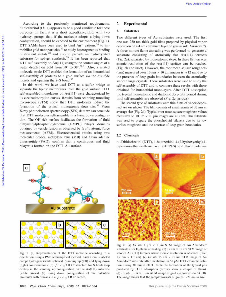
According to the previously mentioned requirements,
dithiothreitol (DTT) appears to be a good candidate for these
purposes. In fact, it is a short a,o-alkanedithiol with two
hydroxyl groups that, if the molecule adopts a lying-down
configuration, should be exposed to the environment (Fig. 1).
DTT SAMs have been used to bind Ag+ cations,26 to im-
mobilize gold nanoparticles,27 to study heterogeneous binding
of divalent metals,28 and also to provide an hydroxylated
substrate for sol–gel synthesis.29 It has been reported that
DTT self-assembly on Au(111) changes the contact angles of a
water droplet on gold from 501 to 381.30,31 Also, a related
molecule, cyclo-DTT enabled the formation of an hierarchical
self-assembly of proteins to a gold surface via the disulfide
moiety and opening the S–S bond.32
In this work, we have used DTT as a sulfur bridge to
separate the lipidic membranes from the gold surface. DTT
self-assembled monolayers on Au(111) were characterized by
its electrodesorption curves. Results from scanning tunneling
microscopy (STM) show that DTT molecules induce the
formation of the typical monoatomic deep pits.33 From
X-ray photoelectron spectroscopy (XPS) data we can conclude
that DTT molecules self-assemble in a lying down configura-
tion. The OH-rich surface facilitates the formation of fluid
dimyristoylphosphatidylcholine (DMPC) bilayer domains
obtained by vesicle fusion as observed by in situ atomic force
measurements (AFM). Electrochemical results using two
molecular probes, methylene blue (MB) and flavin adenine
dinucleotide (FAD), confirm that a continuous and fluid
bilayer is formed on the DTT–Au surface.
2. Experimental
2.1 Substrates
Two different types of Au substrates were used. The first
one was 250 nm thick gold films prepared by physical vapor
deposition on a 4 nm chromium layer on glass (Gold Arrandeet).
A three minute flame annealing was performed to generate a
substrate consisting of atomically flat Au(111) terraces
(Fig. 2a), separated by monoatomic steps. In these flat terraces
atomic resolution of the Au(111) surface can be reached
(Fig. 2b and inset). However, the root mean square roughness
(rms) measured over 10 mm � 10 mm images is E12 nm due to
the presence of deep grain boundaries between the atomically
smooth large crystals. These substrates were used to study the
self-assembly of DTT and to compare these results with those
obtained for butanethiol monolayers. After DTT adsorption
the typical monoatomic and diatomic deep pits formed during
thiol self-assembly are observed (Fig. 2c, arrows).
The second type of substrates were thin films of vapor-depos-
ited Au on silicon. The film consists of small grains of 20 nm in
average size (Fig. 2d). Typical root mean square roughness values
measured on 10 mm � 10 mm images are E3 nm. This substrate
was used to prepare the phospholipid bilayers due to its low
surface roughness and the absence of deep grain boundaries.
2.2 Chemicals
DL-Dithiothreitol (DTT), 1-butanethiol, 4-(2-hydroxyethyl)-1-
piperazineethanesulfonic acid (HEPES) and flavin adenine
Fig. 1 (a) Representation of the DTT molecule according to a
calculation using a PM3 semiempirical method. Each atom is labeled
except hydrogens (white spheres). Standing up (left) and lying down
(right) conformations. (b) O3 � O3 R301 structure for S heads (top
circles) in the standing up configuration on the Au(111) substrate
(white circles). (c) Lying down configuration of the bidentate
molecules with S heads in a O3 � O3 R301 lattice.
Fig. 2 (a) Ex situ 1 mm � 1 mm STM image of Au Arrandeet
substrate after H2 flame annealing. (b) 75 nm � 75 nm STM image of
smooth Au (111) terraces where atomic resolution is observed (inset
1.7 nm � 1.7 nm). (c) Ex situ 75 nm � 75 nm STM image of Au
Arrandeet substrate after incubation in 50 mM DTT ethanolic solu-
tion during 30 min at 60 1C. Note the formation of the typical pits
produced by DTT adsorption (arrows show a couple of them).
(d) Ex situ 1 mm � 1 mm AFM image of gold evaporated on Si(100).
The image shows that the sample consists of grains B20 nm in size.
1078 | Phys. Chem. Chem. Phys., 2009, 11, 1077–1084 This journal is �c the Owner Societies 2009
Publ
ishe
d on
24
Dec
embe
r 20
08. D
ownl
oade
d by
Uni
vers
idad
e Fe
dera
l de
Sant
a C
atar
ina
(UFS
C)
on 1
4/10
/201
4 14
:51:
10.
View Article Online

dinucleotide (FAD, Fig. 3a) were purchased from Sigma,
dimyristoylphosphatidylcholine (DMPC) was purchased from
Avanti and methylene blue (MB, Fig. 3b) from Merck. All
other supplies used were of the best analytical grade commer-
cially available.
2.3 Self-assembly and characterization of DTT SAMs
DTT SAMs were prepared by immersion of the gold substrates
in 5 mM or 50 mM DTT ethanolic solution either at 25 1C or
60 1C for different times (t). Blank experiments using 50 mMbutanethiol ethanolic solutions were also performed.
DTT SAMs were then analyzed by XPS, electrochemical
measurements and ex situ STM. XPS measurements were
performed using an Mg-Ka source (XR50, Specs GmbH) and
a hemispherical electron energy analyzer (PHOIBOS 100, Specs
GmbH). Spectra were acquired with 10 eV pass energy and a
Shirley-type background was subtracted to each region. A two
point calibration of the energy scale was performed using
sputtered cleaned gold (Au 4f 7/2, binding energy = 84.00 eV)
and copper (Cu 2p 3/2, binding energy = 933.67 eV) samples.
C 1s at 285 eV was used as charging reference.
STM measurements were carried out with a Nanoscope IIIa
(Veeco, Santa Barbara, USA). The presence of etched pits
characteristic for chemisorption of thiols on gold are clearly
visible (Fig. 2c). No molecular resolution was achieved under
the experimental conditions used in this work.
Electrochemical measurements were performed in a conven-
tional glass-made cell using the DTT-covered Au substrate as
working electrode and a large Pt plate and a saturated calomel
electrode as counter and reference electrodes, respectively,
using a TEQ-2 potentiostat with data acquisition capability.
Solutions were prepared with analytical-grade chemicals and
Milli-Q water.
Reductive desorption measurements of DTT and butane-
thiol self-assembled monolayers were made following the
procedure described elsewhere.34,35 Briefly, a potential sweep
was applied to the SAM-covered Au substrate immersed in a
three-electrode electrochemical cell containing 0.1 M NaOH at
0.05 V s�1 from �0.4 V to �1.4 V.
Each solution was freshly prepared just before each series of
measurements and deaerated with purified nitrogen.
2.4 Self-assembly of phospholipidic bilayers on DTT-covered
Au substrates
DTT-covered Au prepared from 50 mM ethanolic solution at
60 1C for t = 30 min were used as substrates for supported
bilayer formation by vesicle fusion.30
DMPC vesicles were obtained by evaporating, under a
stream of nitrogen, the solvent of a phospholipidic solution
(10 mg mL�1) prepared in chloroform. The samples were dried
under vacuum to eliminate solvent traces. Subsequently, multi-
lamellar vesicles were obtained by the addition of a buffer
containing 10 mM HEPES + 0.9% NaCl and vortexing. The
multilamellar suspension was then extruded through a poly-
carbonate filter with 400 nm pore from Nuclepore to form
unilamellar vesicles.36,37
DTT-covered Au substrates were immersed in 10 mg mL�1
DMPC unilamellar vesicle suspension for 90 min at B30 1C
(above DMPC phase transition temperature Tm = 23.9 1C) to
allow vesicle fusion. The samples were then fast rinsed with
10 mM HEPES + 0.9% NaCl solution to remove the
unbounded lipids, and immediately transferred to the AFM
liquid cell. All AFM measurements were performed at pH 7.4
with a Molecular Imaging PicoScan microscope inside the
fluid cell with temperature control, i.e. in situ, containing
10 mM HEPES + 0.9% NaCl, under contact mode with
silicon nitride probes (triangular cantilevers with nominal
spring constant of 0.12 N m�1, Veeco Probes). The images
were analyzed using the program VS � M 2.1 (Nanotec
Electronica).
2.5 Electrochemical measurements with redox biomolecules
The experiments with the redox couples were performed in
phosphate buffer 0.1 M pH = 7.0. The DTT–Au electrodes
with or without the phosphilipidic bilayer were dipped in 0.1 mM
methylene blue (MB) or 0.1 mM flavin adenine dinucleotide
(FAD) aqueous solutions for 30 min at T = 37 1C. Potentials in
the text are referred to the saturated calomel electrode (SCE).
3. Results and discussion
The self-assembly of DTT (DL-dithiothreitol) can be compared
with the well-known self-assembly of short alkanethiolates. In
principle, the DTT molecule can adopt two different configura-
tions (standing up or lying down) on the Au(111) surface as
schematically shown in Fig. 1a. Possible surface structures for
those configurations considering the well-known surface struc-
ture reported for thiols,33,38 dithiols39–41 and DTT on Au(111)30
are depicted in Fig. 1b and c.
Typical XPS data obtained for DTT-covered Au(111)
surfaces prepared by immersion in 50 mM ethanolic solutions
for t = 30 min at T = 60 1C are shown in Fig. 4a. After self-
assembly, the sample was removed from the solution, carefully
Fig. 3 (a) Flavin adenine dinucleotide and (b) methylene blue, both
in their oxidized forms.
This journal is �c the Owner Societies 2009 Phys. Chem. Chem. Phys., 2009, 11, 1077–1084 | 1079
Publ
ishe
d on
24
Dec
embe
r 20
08. D
ownl
oade
d by
Uni
vers
idad
e Fe
dera
l de
Sant
a C
atar
ina
(UFS
C)
on 1
4/10
/201
4 14
:51:
10.
View Article Online

rinsed with ethanol and dried under a nitrogen flux before
transferring to the UHV chamber. A broad XPS S 2p signal at
162–163 eV can be observed, a clear indication that thiols are
present on the gold surface.42 The S 2p signal was fitted by two
doublets at 162 eV and 163.4 eV. The main component at
162 eV (Fig. 4a) corresponds to the S-head–Au covalent bonds
as already reported43 for different thiols on metal surfaces.42
The smaller doublet at 163.4 eV corresponds to free SH groups
which can be assigned either to physisorbed molecules that
remain on the sample after the cleaning procedure or a small
amount of molecules in standing up configuration (Fig. 1a).
Therefore, it can be concluded that the DTT molecules are
chemisorbed mainly in a lying down configuration with two
S-head–Au bonds per molecule (Fig. 1a, right). In fact, for
DTT in the standing up configuration (Fig. 1a, left) we expect
a significant contribution of the SH signal at 163.4 eV, which
in this case is a minor contribution.
The S 2p (162 eV)/Au 4f signal ratio is a measure of the
chemisorbed thiol coverage. We have used a self-assembled
monolayer (SAM) formed on Au(111) by immersion in
50 mM butanethiol (C4) ethanolic solutions for t = 24 h
(Fig. 4b) as reference system because, in this case, the SAM
reaches its maximum surface coverage value y E 0.33, which
corresponds to a O3 � O3 R301 surface structure of alkane-
thiol molecules in standing up configuration. Note that even in
this case a small contribution of physisorbed thiol molecules at
163.4 eV is observed. In the C4 SAM (Fig. 4b) the S 2p
(162 eV)/Au 4f signal ratio is E0.07. The spectrum shown in
Fig. 4a for the DTT SAM also shows a S 2p/Au 4f signal
ratio E0.07, which for a dithiol in the lying down configura-
tion (Fig. 1, right) implies y = 0.16. Similar results were
obtained using a higher concentration (5 mM) either at the
same temperature (T = 60 1C) or lower (T = 25 1C) although
for this concentration a greater contribution of the 163.4 eV
component was observed. On the other hand, attempts to
prepare the DTT SAM from 50 mM ethanolic solution at 25 1C
for a self-assembly time of 30 min failed because we found a
smaller S/Au ratio, i.e. the SAM does not completely cover the
Au substrate. Based on the previous results we select 50 mMand 60 1C as the best experimental conditions to form a dense
layer of lying down DTT molecules able to turn the Au highly
hydrophilic.
In all cases the XPS spectra (Fig. 4) show no traces of
oxidized S, such as sulfonates, since no signal was observed at
167–168 eV. Ageing of the sample in ambient condition leads
to degradation of the DTT layer characterized by a strong S 2p
signal at binding energies 4167 eV. It is interesting to note
that all DTT samples exhibit a clear O 1s signal contribution
arising from the OH groups of the DTT molecules (data not
shown).
Fig. 4 XPS spectra (S 2p) taken from different thiol adlayers: (a) 30 min DTT 50 mM at 60 1C on Au(111), (b) 24 h butanethiol 50 mM at 25 1C on
Au(111), (c) DTT on polycrystalline gold, incubated with the same conditions as for (a). Experimental points are represented by dots and the best
fits by a continuous line. Main contributions are marked with dashed lines.
1080 | Phys. Chem. Chem. Phys., 2009, 11, 1077–1084 This journal is �c the Owner Societies 2009
Publ
ishe
d on
24
Dec
embe
r 20
08. D
ownl
oade
d by
Uni
vers
idad
e Fe
dera
l de
Sant
a C
atar
ina
(UFS
C)
on 1
4/10
/201
4 14
:51:
10.
View Article Online

We have obtained the same XPS results for DTT self-
assembled on a vapor-deposited polycrystalline Au substrate
(lying down configuration, y = 0.16) as can be seen in Fig. 4c.
The self-assembly of a DTT monolayer on this surface is
important for the preparation of continuous lipidic bilayers.
As was mentioned in the Experimental section, polycrystalline
Au (see Fig. 2d) exhibits a smooth surface consisting of
nanometer-sized grains. On the other hand, preferred oriented
Au(111) substrates have atomically smooth surface but they
have deep grain boundaries that may produce discontinuities
in the DMPC bilayer.
We have performed reductive electrodesorption curves to
confirm the presence of the DTT covalently attached to the
gold substrate. The electrolyte used in this case was NaOH
0.1 M because at neutral pH the current peak related to the
thiol electrodesorption overlaps partially with the hydrogen
evolution reaction (HER). The cathodic polarization curve
shown in Fig. 5a corresponds to a clean (thiol SAM-free)
preferentially oriented Au (111) substrate recorded from
�0.4 to�1.4 V. Typical double layer response of gold, withoutany Faradaic current contributions, is observed preceding the
large cathodic current related to HER. Fig. 5b shows
typical curves recorded for DTT-SAM on the Au(111)
prepared from the 50 mM ethanolic solutions for t = 30 min
at T = 60 1C.
These polarization curves are compared with those obtained
for butanethiol SAMs prepared by immersing the Au(111)
substrate in 50 mM butanethiol ethanolic solution at 25 1C for
24 h (Fig. 5c). We have also included the polarization curve
corresponding to a DTT SAM on polycrystalline Au prepared
from 50 mM ethanolic solutions for t = 30 min at T = 60 1C
(Fig. 5d).
In all cases, the current/potential profiles recorded for the
thiol SAM-covered Au substrates show well defined cathodic
current peaks followed by one or two humps preceding HER.
As already reported the main cathodic current peak C corres-
ponds to the reductive thiol desorption from the Au surface
according to the reaction:33
1e + Au(111)–S–R - R–S� + Au(111) (1)
Note that the current peak recorded for DTT electro-
desorption from the polycrystalline Au is broader than those
recorded in the preferred (111) oriented substrate due to the
presence of different crystallographic faces, grain boundaries
and large amount of defects.
First, we analyze the information related to the main peak
C in Fig. 5. The peak potential (Ep) for DTT desorption from
the Au(111) surface (Fig. 5b) is slightly negative in relation to
that measured for a butanethiol (C4) SAM on the same
substrate (Fig. 5c). Integration of the current involved in the
electrodesorption peaks gives the charge density (q) corres-
ponding to the amount of chemisorbed species. We have
obtained a charge density of 73 � 10 mC cm�2 which is
consistent with S-head–Au bonds coverage E0.33 taking into
account reaction (1) (one electron per chemisorbed sulfur
atom) and a O3 � O3 R301 surface structure on the
Au(111) surface. Note that this q value can be expected either
for the DTT molecules chemisorbed in standing up (y = 0.33)
or lying down (y = 0.16) configurations. Nevertheless, the
standing up configuration is incompatible with XPS results
(Fig. 4a).
Besides the main peak C, two humps H1 and H2 are
observed at more negative potentials for DTT-SAM on
Au(111). H1 is located on the negative side of the main
desorption peak while H2 appears at �1.2 V. In contrast,
only a small peak rather than a hump at �1.1 V is observed
for butanethiol electrodesorption. This peak has been assigned
to thiol molecules strongly chemisorbed at defects of the
Au(111) surface such as steps.44 Therefore, hump H2 can be
assigned to DTT molecules adsorbed on Au defects. However,
at present we have no clear interpretation on the origin of
hump H1.
We have imaged the DTT SAM-covered Au samples by
STM. Unlike butanethiol SAMs that exhibit the well-known
O3 � O3 R301 and c(4 � 2) surface structures,45 no molecular
resolution could be achieved with DTT SAMs. As reported
previously, this could be attributed to a more disordered
layer.30 However, DTT SAM formation can be inferred from
the presence of the typical nanometer sized monoatomic and
diatomic deep pits (Fig. 2c).
In principle, the lying down phase of DTT molecules
(Fig. 1a, right) could provide a hydrophilic environment for
anchoring different types of biomolecules. In the next
paragraph we show that the DTT-SAMs can be used to form
ordered phospholipidic bilayer domains on the polycrystalline
Au surfaces. As mentioned above these substrates are
particularly suitable for the formation of high quality bilayers
due to its low roughness (Fig. 2d).
Fig. 5 j vs. E profiles for the reductive desorption of DTT and
butanethiol SAMs. (a) Bare Au(111), (b) Au(111) incubated 30 min in
DTT 50 mM at 60 1C, (c) Au (111) 24 h in butanethiol 50 mM at 25 1C
and (d) polycrystalline gold 30 min in DTT 50 mM60 1C.Measurements
were made in NaOH 0.1 M at a sweep rate of 0.05 V s�1.
This journal is �c the Owner Societies 2009 Phys. Chem. Chem. Phys., 2009, 11, 1077–1084 | 1081
Publ
ishe
d on
24
Dec
embe
r 20
08. D
ownl
oade
d by
Uni
vers
idad
e Fe
dera
l de
Sant
a C
atar
ina
(UFS
C)
on 1
4/10
/201
4 14
:51:
10.
View Article Online

Fig. 6a–c shows in situ AFM images in buffer HEPES
pH = 7.4 NaCl 0.9% of a vapor deposited polycrystalline
Au covered by a DTT-SAM after immersion in a suspension
of DMPC vesicles.
The surface morphology of the lipidic bilayer on DTT-SAM
has the same characteristics (rms, grain size, etc.) as those
exhibited by the clean polycrystalline Au substrate (Fig. 2d in
Experimental section). As shown in Fig. 6a, large size areas
(more than 10 mm � 10 mm) were in situ scanned with the
AFM tip remaining stable during the time period of the
experiments (E4 h). In order to determine the presence of
the lipidic layer we have used a lithographic step by applying
an additional force to the cantilever probe. This procedure
removes the material present in the scanned region opening a
clear squared window, as displayed in Fig. 6b. This evidences
that a soft material deposit covers the DTT–Au surface. In
fact, complementary XPS data (not shown) of these samples
reveal P, N and C, supporting the presence of a DMPC layer.
A line scan through the opened window region (Fig. 6b)
provided a thickness of about 5 nm (Fig. 6d). Note that this
value is slightly higher than the expected value for a DMPC
bilayer (Fig. 7) due to the hydration of the DTT–DMPC
interface.8 It is interesting to note that on clean Au we were
unable to form a lipidic layer since vesicles remained sphere-
shaped on the surface. In consequence, a highly hydroxylated
surface is needed for vesicle fusion necessary to form a
bilayer film.
We have also been able to image the self-healing of this layer
by lateral motion of phospholipids indicating that it is not
rigid at 22 1C (Fig. 6c). The sequential AFM images allow a
rough estimation of the lateral diffusion coefficient (D) of the
phospholipids of the window (Fig. 6b and c). Taking a front
displacement L for the time interval Dt and using L2 = 2DDtwe obtained DD 10�11 cm2 s�1. This value is somewhat lower
than that reported for DMPC bilayers supported on glass at
this temperature (2� 10�10 cm2 s�1).46 The discrepancy can be
explained either by a self-limiting spreading as discussed by
Boxer47 or by an increased interaction of DMPC with the
underlying DTT/Au with respect to the glass substrate used by
Smith et al.46
The DMPC lateral motion points toward the maintenance
of membrane dynamics, which is a signal that this system
could be adequate for fundamental studies in general pheno-
mena of natural membranes, such as the incorporation of
biomolecules (enzyme cofactors, proteins, drugs, etc.).
Concerning this point, we have tested the behavior of our
DMPC bilayer–DTT–Au arrangement when it was exposed to
two electrochemically active molecules: methylene blue (MB), a
lipophilic molecule able to penetrate biological membranes, and
flavin adenine dinucleotide (FAD), an electron carrier, that is
known to be unable to diffuse across the membrane.48,49 The
DMPC bilayer–DTT–Au substrates were immersed for 30 min
in an aqueous solution containing MB or FAD at 37 1C in
order to immobilize these molecules in the fluid bilayer. After-
wards, the substrates were removed from the solution, carefully
rinsed with water to eliminate the MB and FAD molecules
weakly bonded to the bilayer, and finally immersed in an
electrochemical cell containing phosphate buffer at pH = 7.0
to detect the presence of the redox couples corresponding to
immobilized molecules. The electrochemical response of the
DMPC bilayer–DTT–Au substrates exposed to MB or FAD
molecules was also compared to that exhibited for the bilayer-
free DTT–Au substrates exposed to the same molecules under
the same experimental conditions.
The voltammetric profiles (Fig. 8, dotted lines) show that
the DTT–Au substrates have been able to immobilize certain
amount of MB and FAD molecules since their redox couples
are clearly observed.
On the other hand, for the DMPC bilayer–DTT–Au system
only the redox couple of MB is electrochemically detected
(Fig. 8, solid line) indicating that these molecules have been
incorporated into the phospholipidic bilayer. The more
irreversible electrochemical response of trapped MB into the
bilayer demonstrates that they are placed at a larger distance
from the DTT–Au substrate than in the absence of the bilayer.
When FAD molecules are used as electrochemical probes, no
electrochemical response is observed, i.e. they are not incor-
porated in the DMPC bilayer.
The electrochemical behavior of these molecular probes
demonstrates the continuity and fluidity of our supported
bilayers.
Bilayer continuity can be tested using the FAD probe. It is
well established that FAD can not diffuse across membranes
due to the presence of the pyrophosphate group48 (Fig. 3a).
Fig. 6 AFM images of DMPC bilayer formed on a lying down DTT
SAM formed on polycrystalline gold. (a) Large covered area with a
lipid layer. (b) Square window defined by the removal of the lipid layer
using the AFM tip. (c) DMPC layer recovering the surface of the
square window, taken 120 s after image (b). (d) Cross section profile
corresponding to the black line of image (b).
Fig. 7 Scheme showing two DMPC molecules linked by their lipidic
tails.
1082 | Phys. Chem. Chem. Phys., 2009, 11, 1077–1084 This journal is �c the Owner Societies 2009
Publ
ishe
d on
24
Dec
embe
r 20
08. D
ownl
oade
d by
Uni
vers
idad
e Fe
dera
l de
Sant
a C
atar
ina
(UFS
C)
on 1
4/10
/201
4 14
:51:
10.
View Article Online

FAD could only reach the DTT–Au interface and be
electrochemically detected if significant defects like pores or
discontinuities were present in the bilayer.
In addition to in situ AFM measurements, the MB probe
permits fluidity testing. Diffusion of liposoluble molecules
through rigid crystalline bilayers would be largely impeded.
4. Conclusions
* DTT molecules self-assemble on Au(111) mainly in a lying
down configuration irrespective of the concentration and
temperature. XPS and electrochemical data indicate a DTT
surface coverage y=0.16 with two S-head–Au covalent bonds
per DTT molecule.
* The charge density involved in the electrodesorption
curves for the DTT SAMs is the same that found for alkane-
thiols SAMs because the number of S-head–Au bonds remains
constant.
* The peak potential for electrodesorption indicates that the
stability of the DTT SAM is similar to that observed for
butanethiolate SAM.
* DTT-SAMs on Au (111) are not highly ordered as no
molecular resolution by STM was found during our STM
imaging.
* DMPC bilayer membranes can be formed on DTT–Au
because the surface is highly hydroxylated. The membranes
exhibit self-healing behavior.
* The DMPC–DTT–Au system was used to test electro-
chemically the transport behavior of methylene blue and
FAD across the bilayer, verifying that it is both fluid and
continuous.
Acknowledgements
The authors wish to thank FAPESC, CAPES, CNPq/MCT,
CONICET, ANPCyT (PICT 06-621, PAE 22771), for research
grants and fellowships. V. R. de Lima is currently a PhD
student of the Programa de Pos-Graducao em Quımica,
UFSC. M. E. Vela is member of the research career of
CIC BsAs.
References
1 Y. H. Chan and S. G. Boxer, Curr. Opin. Chem. Biol., 2007, 11,581–587.
2 E. T. Castellana and P. S. Cremer, Surf. Sci. Rep., 2006, 61,429–444.
3 R. P. Richter, R. Berat and A. R. Brisson, Langmuir, 2006, 22,3497–3505.
4 H. Lang, C. Duschl and H. Vogel, Langmuir, 1994, 10, 197–210.5 R. Naumann, A. Jonczyk, C. Hampel, H. Ringsdorf, W. Knoll,N. Bunjes and P. Graber, Bioelectrochemistry and Bioenergetics,1997, 42, 241–247.
6 N. Bunjes, E. K. Schmidt, A. Jonczyk, F. Rippmann, D. Beyer,H. Ringsdorf, P. Graber, W. Knoll and R. Naumann, Langmuir,1997, 13, 6188–6193.
7 J. Schneider, Y. F. Dufrene, W. R. Barger, Jr and G. U. Lee,Biophys. J., 2000, 79, 1107–1118.
8 F. Tokumasu, A. J. Jin and J. A. Dvorak, J. Electron. Microsc.(Tokyo), 2002, 51, 1–9.
9 T. Spangenberg, N. F. De Mello, T. B. Creczynski-Pasa,A. A. Pasa and H. Niehus, Physica Status Solidi (A) AppliedResearch, 2004, 201, 857–860.
10 M. L. Munford, V. R. Lima, T. O. Vieira, G. Heinzelmann,T. B. Creczynski-Pasa and A. A. Pasa, Microscopy and Micro-analysis, 2005, 11, 90–93.
11 E. Sackmann and M. Tanaka, Trends Biotechnol., 2000, 18, 58–64.12 L. K. Tamm and H. M. McConnell, Biophys. J., 1985, 47, 105–113.13 A. Ulman, An Introduction to Ultrathin Organic Films From
Langmuir-Blodgett to Self-Assembly, Academic Press, Inc., SanDiego, 1991.
14 J. Raedler, H. Strey and E. Sackmann, Langmuir, 1995, 11,4539–4548.
15 A. A. Brian and H. M. McConnell, Proc. Natl. Acad. Sci. USA,1984, 81, 6159–6163.
16 P. K. W.Mary, L. Kraft, Marjorie L. Longo, Ian D. Hutcheon andSteven G. Boxer, Science, 2006, 313, 1948–1951.
17 R. P. Richter and A. R. Brisson, Biophys. J., 2005, 88, 3422–3433.18 S. Xu, G. Szymanski and J. Lipkowski, J. Am. Chem. Soc., 2004,
126, 12276–12277.19 F. Tokumasu, A. J. Jin, G. W. Feigenson and J. A. Dvorak,
Biophys. J., 2003, 84, 2609–2618.20 W. Bucking, G. A. Urban and T. Nann, Sensors and Actuators, B:
Chemical, 2005, 104, 111–116.21 A. L. Plant, M. Gueguetchkeri and W. Yap, Biophys. J., 1994, 67,
1126–1133.22 M. B. Smith, J. Tong, J. Genzer, D. Fischer and P. K. Kilpatrick,
Langmuir, 2006, 22, 1919–1927.23 M. Twardowski and R. G. Nuzzo, Langmuir, 2003, 19, 9781–9791.24 A. J. Bard and L. R. Faulkner, Electrochemical methods: Funda-
mentals and Applications, John Wiley & Sons, Inc., New York,2001.
25 D. E. Weisshaar, M. M. Walczak and M. D. Porter, Langmuir,1993, 9, 323–329.
26 B. Zeng, X. Ding, D. Pan and F. Zhao, Talanta, 2003, 59, 501–507.
Fig. 8 Selective permeation of biomolecules. Cyclic voltammograms performed in phosphate buffer 0.1 M pH 7.0 at scan rate: 0.05 V s�1. Full
lines correspond to voltammograms for DMPC bilayer–DTT–Au (111) substrates incubated 30 min either in MB 0.1 mM (a) or FAD 0.1 mM (b)
aqueous solutions to immobilize these molecules. Dotted lines correspond to the voltammograms recorded for DTT–Au(111) electrodes subjected
to the same procedure.
This journal is �c the Owner Societies 2009 Phys. Chem. Chem. Phys., 2009, 11, 1077–1084 | 1083
Publ
ishe
d on
24
Dec
embe
r 20
08. D
ownl
oade
d by
Uni
vers
idad
e Fe
dera
l de
Sant
a C
atar
ina
(UFS
C)
on 1
4/10
/201
4 14
:51:
10.
View Article Online

27 L. Wang, J. Bai, P. Huang, H. Wang, L. Zhang and Y. Zhao,Electrochem. Commun., 2006, 8, 1035–1040.
28 D. Burshtain and D. Mandler, Phys. Chem. Chem. Phys., 2006, 8,158–164.
29 J. T. Banks, T. T. Yu and H. Z. Yu, J. Phys. Chem. B, 2002, 106,3538–3542.
30 A. R. MacDairmid, M. C. Gallagher and J. T. Banks, J. Phys.Chem. B, 2003, 107, 9789–9792.
31 R. G. Nuzzo and D. L. Allara, J. Am. Chem. Soc., 1983, 105,4481–4483.
32 H. Wackerbarth, A. Pernille Tofteng, K. J. Jensen, I. Chorkendorffand J. Ulstrup, Langmuir, 2006, 22, 6661–6667.
33 C. Vericat, M. E. Vela, G. A. Benitez, J. A. Martin Gago,X. Torrelles and R. C. Salvarezza, J. Phys.: Condens. Matter,2006, 18, R867–R900.
34 O. Azzaroni, M. E. Vela, G. Andreasen, P. Carro andR. C. Salvarezza, J. Phys. Chem. B, 2002, 106, 12267–12273.
35 M. E. Vela, H. Martin, C. Vericat, G. Andreasen, A. HernandezCreus and R. C. Salvarezza, J. Phys. Chem. B, 2000, 104,11878–11882.
36 L. D. Mayer, M. J. Hope and P. R. Cullis, Biochim. Biophys. Acta,1986, 858, 161–168.
37 F. Olson, C. A. Hunt, F. C. Szoka, W. J. Vail andD. Papahadjopoulos, Biochim Biophys Acta, 1979, 557, 9–23.
38 C. Love, L. A. Estroff, J. K. Kriebel, R. G. Nuzzo andG. M. Whitesides, Chem. Rev., 2005, 105, 1103–1169.
39 M. J. Esplandiu, M. L. Carot, F. P. Cometto, V. A. Macagno andE. M. Patrito, Surface Science, 2006, 600, 155–172.
40 M. J. Esplandiu, H. Hagenstrom and D. M. Kolb, Langmuir, 2001,17, 828–838.
41 T. Y. B. Leung, M. C. Gerstenberg, D. J. Lavrich, G. Scoles,F. Schreiber and G. E. Poirier, Langmuir, 2000, 16, 549–561.
42 D. G. Castner, K. Hinds and D. W. Grainger, Langmuir, 1996, 12,5083–5086.
43 C. Vericat, M. E. Vela, G. Andreasen, R. C. Salvarezza,L. Vazquez and J. A. Martın-Gago, Langmuir, 2001, 17,4919–4924.
44 C. Vericat, G. Andreasen, M. E. Vela, H. Martin andR. C. Salvarezza, J. Chem. Phys., 2001, 115, 6672–6678.
45 F. Teran Arce, M. E. Vela, R. C. Salvarezza and A. J. Arvia,Langmuir, 1998, 14, 7203–7212.
46 B. A. Smith and H. M. McConnell, Proc. Natl. Acad. Sci. USA,1978, 75, 2759–2763.
47 S. G. Boxer, Curr. Opin. Chem. Biol., 2000, 4, 704–709.48 M. Barile, C. Brizio, D. Valenti, C. De Virgilio and S. Passarella,
Eur. J. Biochem., 2000, 267, 4888–4900.49 F. Depeint, W. R. Bruce, N. Shangari, R. Mehta and P. J. O’Brien,
Chem. Biol. Interact., 2006, 163, 94–112.
1084 | Phys. Chem. Chem. Phys., 2009, 11, 1077–1084 This journal is �c the Owner Societies 2009
Publ
ishe
d on
24
Dec
embe
r 20
08. D
ownl
oade
d by
Uni
vers
idad
e Fe
dera
l de
Sant
a C
atar
ina
(UFS
C)
on 1
4/10
/201
4 14
:51:
10.
View Article Online