Preparation and characterization of bilayer carbon/polymer membranes
9
Journal of Membrane Science 326 (2009) 27–35 Contents lists available at ScienceDirect Journal of Membrane Science journal homepage: www.elsevier.com/locate/memsci Preparation and characterization of bilayer carbon/polymer membranes Husnul Maab, Sergey Shishatskiy, Suzana Pereira Nunes ∗ Department of Membranes for Energy, Institute of Polymer Research, GKSS Research Centre Geesthacht GmbH, Max-Planck-Str. 1, D-21502 Geesthacht, Germany article info Article history: Received 14 March 2008 Received in revised form 14 August 2008 Accepted 7 September 2008 Available online 17 September 2008 Keywords: Carbon molecular sieve Fuel cell Alcohol DMFC abstract The objective of the present research work was to develop a membrane with a high H 2 O/alcohol selectivity for pervaporation and for use in direct alcohol fuel cells. Sulfonated poly (ether ether ketone) (SPEEK) was coated with a thin continuous carbon molecular sieve (CMS) layer. The membranes obtained had 180- and 400-nm thick CMS layers that led to a clear reduction of alcohol crossover. The water/alcohol selectivity increased with the size of the alcohol molecules as follows: methanol < ethanol < n-propanol < iso- propanol. A water/n-propanol selectivity of up to 34,000 was obtained, confirming the molecular sieving effect. The system was tested in a direct methanol fuel cell using standard electrodes, and demonstrated a better performance than with plain membranes. In a later stage Pt was introduced in the CMS layer during the preparation of the membrane electrode assemblies, this had the advantage that the CMS layer not only acted as an alcohol barrier but also as a catalyst support. © 2008 Elsevier B.V. All rights reserved. 1. Introduction Membrane technology has been used for alcohol/water sep- aration at least since the early 1980s when the first industrial scale pervaporation plants were installed [1]. For this task compos- ite membranes with a dense selective layer based on hydrophilic (for water removal) or organophilic (for removal of alcohol or other organic chemicals) polymers are used. Such membranes are able to separate via a solution–diffusion mechanism. Inorganic membranes based on zeolites or amorphous silica coatings on an inorganic porous substrate have been also used in large scale for pervaporation. In this case molecular sieving effects determine the separation, eventually in combination with preferential sorption and surface diffusion in the pores. Over the last decade the importance of the membrane technol- ogy in the energy sector has substantially increased. A reason for this is the need for new clean alternative energy conversion tech- niques. Fuel cell technology is a very attractive energy conversion system. For portable applications the use of direct alcohol fuel cells (DAFCs) is seen as a good option with the fuel delivery infrastruc- ture being much more established than for hydrogen. The main drawback of the DAFC technology currently lies in the available materials. Our group has been investigating materials for DAFC for many years, recently coordinating the development of a 500 W pro- totype for portable application in the framework of the European ∗ Corresponding author. Tel.: +49 4152872440. E-mail address: [email protected] (S.P. Nunes). project MOREPOWER. As far as the membrane is concerned, besides proton conductivity, alcohol transport is the most important issue. Alcohol crossover should be as low as possible. The water balance in the membrane is also relevant. Most of the currently available membranes for DAFC are based on sulfonated polymers where proton transport is highly dependent on the water content in the membrane. Water helps the protons to diffuse through the mem- brane by a vehicle mechanism (formation of the H 3 O + or CH 3 OH 2 + ions diffusing through the bulk of the proton exchange polymer). Therefore, the presence of dissolved water in membranes up to a certain extent improves proton conductivity. Another important issue is the availability of effective catalysts, with high levels of alcohol tolerance, for alcohol conversion to protons and CO 2 at the anode and for oxygen reduction at the cathode. These aspects are of course related. For an ideal membrane, which could completely hinder the alcohol transport to the cathode, the requirement for alcohol tolerance cathode catalysts would diminish. At the cathode water is produced by the reaction between oxygen and the protons crossing the membrane. As soon as water is produced, it should leave the catalyst surface, thus avoiding flooding and making the surface free for further reaction. Good catalyst dispersion is essen- tial in any case to ensure a high surface area, thus enhancing the catalytic activity and leading to effective reaction kinetics even with low catalyst levels. The development of new membranes and catalysts for DAFC is being addressed worldwide by a large number of groups. A recent review of membranes for direct methanol fuel cell (DMFC) has been published by Deluca and Elabd [2]. In previous work the main approach chosen by our group to reduce methanol crossover in polymeric membranes has been the development of different forms 0376-7388/$ – see front matter © 2008 Elsevier B.V. All rights reserved. doi:10.1016/j.memsci.2008.09.014
Transcript of Preparation and characterization of bilayer carbon/polymer membranes

P
HD
a
ARRAA
KCFAD
1
asi(oamipsa
otns(tdmmt
0d
Journal of Membrane Science 326 (2009) 27–35
Contents lists available at ScienceDirect
Journal of Membrane Science
journa l homepage: www.e lsev ier .com/ locate /memsci
reparation and characterization of bilayer carbon/polymer membranes
usnul Maab, Sergey Shishatskiy, Suzana Pereira Nunes ∗
epartment of Membranes for Energy, Institute of Polymer Research, GKSS Research Centre Geesthacht GmbH, Max-Planck-Str. 1, D-21502 Geesthacht, Germany
r t i c l e i n f o
rticle history:eceived 14 March 2008eceived in revised form 14 August 2008ccepted 7 September 2008
a b s t r a c t
The objective of the present research work was to develop a membrane with a high H2O/alcohol selectivityfor pervaporation and for use in direct alcohol fuel cells. Sulfonated poly (ether ether ketone) (SPEEK) wascoated with a thin continuous carbon molecular sieve (CMS) layer. The membranes obtained had 180- and
vailable online 17 September 2008
eywords:arbon molecular sieveuel celllcohol
400-nm thick CMS layers that led to a clear reduction of alcohol crossover. The water/alcohol selectivityincreased with the size of the alcohol molecules as follows: methanol < ethanol < n-propanol < iso-propanol. A water/n-propanol selectivity of up to 34,000 was obtained, confirming the molecular sievingeffect. The system was tested in a direct methanol fuel cell using standard electrodes, and demonstrateda better performance than with plain membranes. In a later stage Pt was introduced in the CMS layerduring the preparation of the membrane electrode assemblies, this had the advantage that the CMS layer
ol bar
ppAimpmbiTciaaohawcls
MFC not only acted as an alcoh
. Introduction
Membrane technology has been used for alcohol/water sep-ration at least since the early 1980s when the first industrialcale pervaporation plants were installed [1]. For this task compos-te membranes with a dense selective layer based on hydrophilicfor water removal) or organophilic (for removal of alcohol orther organic chemicals) polymers are used. Such membranes areble to separate via a solution–diffusion mechanism. Inorganicembranes based on zeolites or amorphous silica coatings on an
norganic porous substrate have been also used in large scale forervaporation. In this case molecular sieving effects determine theeparation, eventually in combination with preferential sorptionnd surface diffusion in the pores.
Over the last decade the importance of the membrane technol-gy in the energy sector has substantially increased. A reason forhis is the need for new clean alternative energy conversion tech-iques. Fuel cell technology is a very attractive energy conversionystem. For portable applications the use of direct alcohol fuel cellsDAFCs) is seen as a good option with the fuel delivery infrastruc-ure being much more established than for hydrogen. The main
rawback of the DAFC technology currently lies in the availableaterials. Our group has been investigating materials for DAFC forany years, recently coordinating the development of a 500 W pro-otype for portable application in the framework of the European
∗ Corresponding author. Tel.: +49 4152872440.E-mail address: [email protected] (S.P. Nunes).
tcl
brbap
376-7388/$ – see front matter © 2008 Elsevier B.V. All rights reserved.oi:10.1016/j.memsci.2008.09.014
rier but also as a catalyst support.© 2008 Elsevier B.V. All rights reserved.
roject MOREPOWER. As far as the membrane is concerned, besidesroton conductivity, alcohol transport is the most important issue.lcohol crossover should be as low as possible. The water balance
n the membrane is also relevant. Most of the currently availableembranes for DAFC are based on sulfonated polymers where
roton transport is highly dependent on the water content in theembrane. Water helps the protons to diffuse through the mem-
rane by a vehicle mechanism (formation of the H3O+ or CH3OH2+
ons diffusing through the bulk of the proton exchange polymer).herefore, the presence of dissolved water in membranes up to aertain extent improves proton conductivity. Another importantssue is the availability of effective catalysts, with high levels oflcohol tolerance, for alcohol conversion to protons and CO2 at thenode and for oxygen reduction at the cathode. These aspects aref course related. For an ideal membrane, which could completelyinder the alcohol transport to the cathode, the requirement forlcohol tolerance cathode catalysts would diminish. At the cathodeater is produced by the reaction between oxygen and the protons
rossing the membrane. As soon as water is produced, it shouldeave the catalyst surface, thus avoiding flooding and making theurface free for further reaction. Good catalyst dispersion is essen-ial in any case to ensure a high surface area, thus enhancing theatalytic activity and leading to effective reaction kinetics even withow catalyst levels.
The development of new membranes and catalysts for DAFC is
eing addressed worldwide by a large number of groups. A recenteview of membranes for direct methanol fuel cell (DMFC) haseen published by Deluca and Elabd [2]. In previous work the mainpproach chosen by our group to reduce methanol crossover inolymeric membranes has been the development of different forms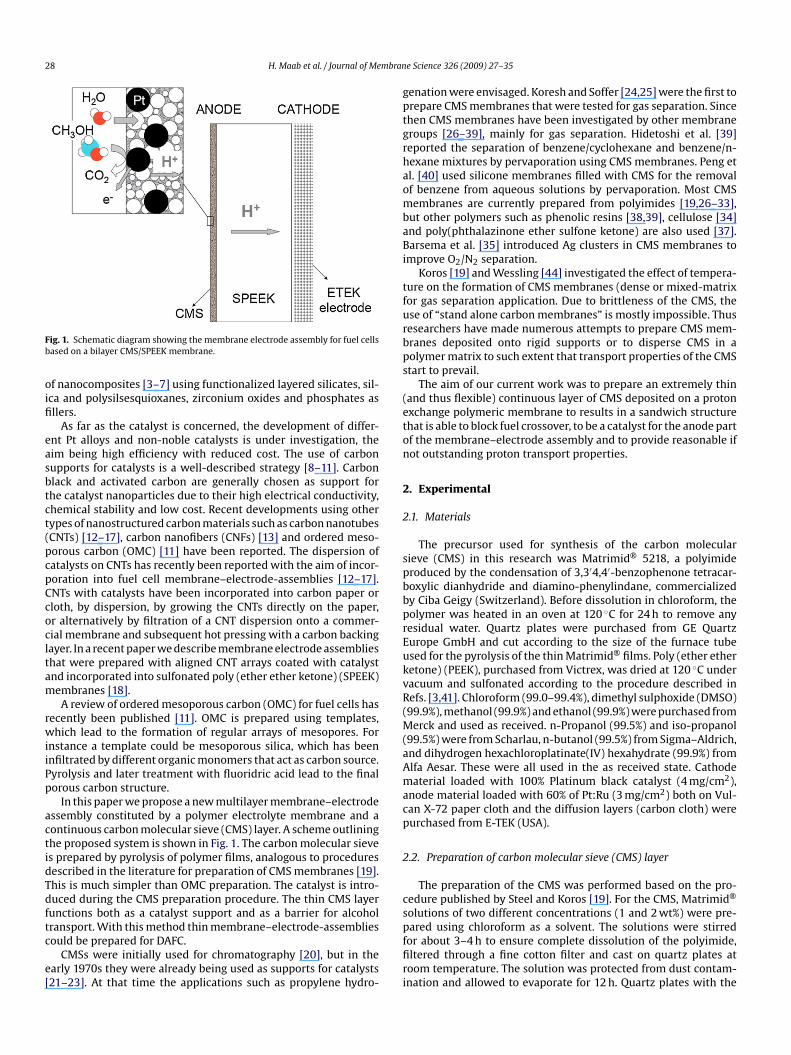
28 H. Maab et al. / Journal of Membran
Fb
oifi
easbtct(pcpCcocltam
rwiiPp
actidTdftc
e[
gptgrhaombaBi
tfurbps
(eton
2
2
spbbprEukvR(M(aAmacp
2
cs
ig. 1. Schematic diagram showing the membrane electrode assembly for fuel cellsased on a bilayer CMS/SPEEK membrane.
f nanocomposites [3–7] using functionalized layered silicates, sil-ca and polysilsesquioxanes, zirconium oxides and phosphates asllers.
As far as the catalyst is concerned, the development of differ-nt Pt alloys and non-noble catalysts is under investigation, theim being high efficiency with reduced cost. The use of carbonupports for catalysts is a well-described strategy [8–11]. Carbonlack and activated carbon are generally chosen as support forhe catalyst nanoparticles due to their high electrical conductivity,hemical stability and low cost. Recent developments using otherypes of nanostructured carbon materials such as carbon nanotubesCNTs) [12–17], carbon nanofibers (CNFs) [13] and ordered meso-orous carbon (OMC) [11] have been reported. The dispersion ofatalysts on CNTs has recently been reported with the aim of incor-oration into fuel cell membrane–electrode-assemblies [12–17].NTs with catalysts have been incorporated into carbon paper orloth, by dispersion, by growing the CNTs directly on the paper,r alternatively by filtration of a CNT dispersion onto a commer-ial membrane and subsequent hot pressing with a carbon backingayer. In a recent paper we describe membrane electrode assemblieshat were prepared with aligned CNT arrays coated with catalystnd incorporated into sulfonated poly (ether ether ketone) (SPEEK)embranes [18].A review of ordered mesoporous carbon (OMC) for fuel cells has
ecently been published [11]. OMC is prepared using templates,hich lead to the formation of regular arrays of mesopores. For
nstance a template could be mesoporous silica, which has beennfiltrated by different organic monomers that act as carbon source.yrolysis and later treatment with fluoridric acid lead to the finalorous carbon structure.
In this paper we propose a new multilayer membrane–electrodessembly constituted by a polymer electrolyte membrane and aontinuous carbon molecular sieve (CMS) layer. A scheme outlininghe proposed system is shown in Fig. 1. The carbon molecular sieves prepared by pyrolysis of polymer films, analogous to proceduresescribed in the literature for preparation of CMS membranes [19].his is much simpler than OMC preparation. The catalyst is intro-uced during the CMS preparation procedure. The thin CMS layerunctions both as a catalyst support and as a barrier for alcohol
ransport. With this method thin membrane–electrode-assembliesould be prepared for DAFC.CMSs were initially used for chromatography [20], but in thearly 1970s they were already being used as supports for catalysts21–23]. At that time the applications such as propylene hydro-
pffiri
e Science 326 (2009) 27–35
enation were envisaged. Koresh and Soffer [24,25] were the first torepare CMS membranes that were tested for gas separation. Sincehen CMS membranes have been investigated by other membraneroups [26–39], mainly for gas separation. Hidetoshi et al. [39]eported the separation of benzene/cyclohexane and benzene/n-exane mixtures by pervaporation using CMS membranes. Peng etl. [40] used silicone membranes filled with CMS for the removalf benzene from aqueous solutions by pervaporation. Most CMSembranes are currently prepared from polyimides [19,26–33],
ut other polymers such as phenolic resins [38,39], cellulose [34]nd poly(phthalazinone ether sulfone ketone) are also used [37].arsema et al. [35] introduced Ag clusters in CMS membranes to
mprove O2/N2 separation.Koros [19] and Wessling [44] investigated the effect of tempera-
ure on the formation of CMS membranes (dense or mixed-matrixor gas separation application. Due to brittleness of the CMS, these of “stand alone carbon membranes” is mostly impossible. Thusesearchers have made numerous attempts to prepare CMS mem-ranes deposited onto rigid supports or to disperse CMS in aolymer matrix to such extent that transport properties of the CMStart to prevail.
The aim of our current work was to prepare an extremely thinand thus flexible) continuous layer of CMS deposited on a protonxchange polymeric membrane to results in a sandwich structurehat is able to block fuel crossover, to be a catalyst for the anode partf the membrane–electrode assembly and to provide reasonable ifot outstanding proton transport properties.
. Experimental
.1. Materials
The precursor used for synthesis of the carbon molecularieve (CMS) in this research was Matrimid® 5218, a polyimideroduced by the condensation of 3,3′4,4′-benzophenone tetracar-oxylic dianhydride and diamino-phenylindane, commercializedy Ciba Geigy (Switzerland). Before dissolution in chloroform, theolymer was heated in an oven at 120 ◦C for 24 h to remove anyesidual water. Quartz plates were purchased from GE Quartzurope GmbH and cut according to the size of the furnace tubesed for the pyrolysis of the thin Matrimid® films. Poly (ether etheretone) (PEEK), purchased from Victrex, was dried at 120 ◦C underacuum and sulfonated according to the procedure described inefs. [3,41]. Chloroform (99.0–99.4%), dimethyl sulphoxide (DMSO)99.9%), methanol (99.9%) and ethanol (99.9%) were purchased from
erck and used as received. n-Propanol (99.5%) and iso-propanol99.5%) were from Scharlau, n-butanol (99.5%) from Sigma–Aldrich,nd dihydrogen hexachloroplatinate(IV) hexahydrate (99.9%) fromlfa Aesar. These were all used in the as received state. Cathodeaterial loaded with 100% Platinum black catalyst (4 mg/cm2),
node material loaded with 60% of Pt:Ru (3 mg/cm2) both on Vul-an X-72 paper cloth and the diffusion layers (carbon cloth) wereurchased from E-TEK (USA).
.2. Preparation of carbon molecular sieve (CMS) layer
The preparation of the CMS was performed based on the pro-edure published by Steel and Koros [19]. For the CMS, Matrimid®
olutions of two different concentrations (1 and 2 wt%) were pre-
ared using chloroform as a solvent. The solutions were stirredor about 3–4 h to ensure complete dissolution of the polyimide,ltered through a fine cotton filter and cast on quartz plates atoom temperature. The solution was protected from dust contam-nation and allowed to evaporate for 12 h. Quartz plates with the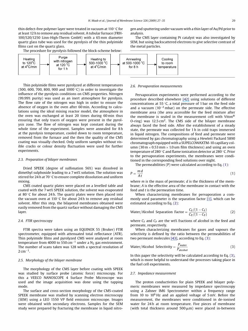
mbran
ta1qfi
(i(Talteywarcie
2
dsm
catsel
2
sTtT2
2
wtum
S(ws
ga
St
2
pcamtOasidcuttt
P
wbf
me
W
wp
st
W
Iwt
2
m
H. Maab et al. / Journal of Me
hin defect-free polymer layer were treated in vacuum at 110 ◦C fort least 12 h to remove any residual solvent. A tubular furnace (FRH-00/520/1250 Linn-High-Therm GmbH) with a 65 mm diameteruartz glass tube was used for the pyrolysis of the thin polyimidelms cast on the quartz glass.
The procedure for pyrolysis followed the block-scheme below:
Thin polyimide films were pyrolyzed at different temperatures500, 600, 700, 800, 900 and 1000 ◦C) in order to investigate thenfluence of the pyrolysis conditions on CMS properties. Nitrogen99.99% purity) was used as an inert atmosphere for pyrolysis.he flow rate of the nitrogen was high in order to ensure thebsence of oxygen in the oven after 60 min. According to calcu-ations using the ideal mixing reactor model, the atmosphere inhe oven was exchanged at least 20 times during 60 min thusnsuring that only traces of oxygen were present in the pyrol-sis zone. The flow of nitrogen was kept constant during thehole time of the experiment. Samples were annealed for 8 h
t the pyrolysis temperature, cooled down to room temperature,emoved from the furnace and the then the quality of the CMSoating was visually checked. Only uniform samples without vis-ble cracks or colour density fluctuation were used for furtherxperiments.
.3. Preparation of bilayer membranes
Dried SPEEK (degree of sulfonation 56%) was dissolved inimethyl sulphoxide leading to a 7 wt% solution. The solution wastirred for 24 h at 70 ◦C to ensure complete dissolution and uniformixing.CMS coated quartz plates were placed on a levelled table and
oated with the 7 wt% SPEEK solution, the solvent was evaporatedt 80 ◦C for about 24 h. The quartz plates were then placed intohe vacuum oven at 110 ◦C for about 24 h to remove any residualolvent. After this step, the bilayered membranes obtained wereasily removed from the quartz surface without damaging the CMSayer.
.4. FTIR spectroscopy
FTIR spectra were taken using an EQUINOX 55 (Bruker) FTIRpectrometer, equipped with attenuated total reflectance (ATR).hin polyimide films and pyrolyzed CMS were analysed at roomemperature from 4000 to 550 cm−1 under a N2 gas environment.he number of scans taken was 128 with a spectral resolution ofcm−1.
.5. Morphology of the bilayer membrane
The morphology of the CMS layer before coating with SPEEKas studied by surface probe (atomic force) microscopy. For
his a VEECO NANOSCOPE 4 Surface Probe Microscope wassed and the image acquisition was done using the tappingode.
The surface and cross-section morphology of the CMS-coatedPEEK membrane was studied by scanning electron microscopySEM) using a LEO 1550 VP field emission microscope. Imagesere obtained with secondary electrons. Samples for the SEM
tudy were prepared by fracturing the membrane in liquid nitro-
ufmw(
e Science 326 (2009) 27–35 29
en and sputtering under vacuum with a thin layer of Au/Pd prior tonalysis.
The CMS layer containing Pt catalyst was also investigated byEM, but using backscattered electrons to give selective contrast ofhe metal particles.
.6. Pervaporation measurements
Pervaporation experiments were performed according to therocedure described elsewhere [42] using solutions of differentoncentrations at 55 ◦C, a total pressure of 1 bar on the feed sidend a vacuum (10−2 mbar) on the permeate side. The effectiveembrane area (the area accessible for the feed mixture after
he membrane is sealed in the measurement cell with Viton®
-ring) was 12.5 cm2. The CMS side of the bilayer membranelways faced the feed side. After the establishment of a steadytate, the permeate was collected for 1 h in cold traps immersedn liquid nitrogen. The compositions of feed and permeate wereetermined by gas chromatography using a Hewlett Packard 5890hromatograph equipped with a SUPELCOWAXTM-10 capillary col-mn (30 m × 0.53 mm × 1.0 um film thickness) and using an ovenemperature of 280 ◦C and flame ionization detector at 280 ◦C. Prioro the pervaporation experiments, the membranes were condi-ioned in the corresponding feed solutions over night.
The permeabilities (P) were calculated according to Eq. (1):
= m d
A t(1)
here m is the mass of permeate; d is the thickness of the mem-rane; A is the effective area of the membrane in contact with theeed and t is the permeation time.
When characterizing membranes for pervaporation a com-only used parameter is the separation factor [1], which can be
stimated according to Eq. (2):
ater/Alcohol Separation Factor = CF/(1 − CF)CP/(1 − CP)
(2)
here CF and CP are the wt% fractions of alcohol in the feed andermeate, respectively.
When characterizing membranes for gases and vapours theelectivity is defined by the ratio between the permeabilities ofwo permeant molecules [43], according to Eq. (3):
ater/Alcohol Selectivity = Pwater
Palcohol(3)
n this paper the selectivity will be calculated according to Eq. (3),hich is more helpful to understand the processes taking place in
he fuel cell experiments.
.7. Impedance measurement
The proton conductivities for plain SPEEK and bilayer poly-eric membranes were measured by impedance spectroscopy
sing a Zahner IM6 Spectrometer within a frequency rangerom 10 to 106 Hz and an applied voltage of 5 mV. Before the
easurement, the membranes were conditioned in de-ionisedater for 24 h at room temperature. Five pieces of membrane
with total thickness around 500 �m) were placed in-between
3 mbrane Science 326 (2009) 27–35
ttwat
2
fCt1ao
mwarTmTpb(iatli
2
Dus
wi(amor
w
3
3
a[laptpowa
F(tm
mt1awm((sCbdrmidiimt[
fgcbdfm
obtt
0 H. Maab et al. / Journal of Me
he two diffusion layers (carbon cloth) in a cell, which allowshe proton conductivity measurement across the membrane,ith constant humidification. Measurements were carried out
t 100% relative humidity and at temperatures varying from 40o 100 ◦C.
.8. Membrane electrode assembly (MEA) preparation
The membrane electrode assemblies (MEA) for plain SPEEK andor bilayer CMS/SPEEK membranes (without Pt dispersed in theMS layer) were prepared by hot pressing membranes betweenwo E-TEK electrodes. The E-TEK cathode electrode was loaded with00% pure platinum black catalyst (4 mg/cm2), while the E-TEKnode electrode was loaded with an alloy of 60% Pt Ru (3 mg/cm2)n Vulcan XC-72 paper cloth.
Additionally MEAs were prepared with bilayer CMS/SPEEKembranes with Pt dispersed in the CMS layer. 0.2 g of H2PtCl4as added to 100 ml of a 3% Matrimid® solution in chloroform
nd stirred for one day. A 3 wt% Matrimid® solution was usedather than the lower (1 or 2 wt%) concentrations used previously.his was because Matrimid® solution containing Pt gave rise touch thinner CMS layers than those prepared in the absence of Pt.
he solution was cast onto quartz plates as described earlier andyrolyzed at 800 ◦C. After coating with SPEEK, the bilayer mem-rane was pressed against an E-TEK electrode in the cathode side4 mg Pt/cm2). The MEA without an additional gas diffusion layern the anode side was then tested as described above. Taking inccount the concentration of Pt salt relative to the polymer concen-ration in the casting solution, the thickness of the polymer film and,ater, CMS film, it was estimated that 1.2 mg of Pt was distributedn the 1 cm2 area of CMS layer.
.9. Fuel cell test
The membrane performances were evaluated in a commercialMFC test stand with an Electrochem. Inc. (Comu Cell-DM) gas flownit and a Scribner Associate (Model 1890B Fuel-Cell Test System)ystem controller.
The exact procedure for DMFC experiments is described else-here [5]. The MEA (25 cm2) was fed with 5% methanol solution
n water (30 ml/min, 1 bar) on the anode side and synthetic air0.5 l/min at 2–3 bar) on the cathode side. The operating temper-ture was 60 ◦C. The CO2 concentration at the cathode outlet wasonitored by a CO2 sensor (EasyLine IR, Advance Optima EM) in
rder to evaluate the methanol crossover, assuming that all the CO2esulted from methanol conversion at the cathode.
Additionally hydrogen fuel cell experiments were performedith bilayer membranes containing Pt in the CMS layer.
. Results and discussion
.1. CMS preparation by pyrolysis
A number of papers have been published on the preparationnd characterization of CMS membranes by pyrolysis of polyimides19,26–33,44]. Matrimid®, a commercial polyimide, available inarge quantities, was chosen as a precursor. There are many temper-ture treatment programs that have been reported to work in theresence of inert gases (N2, Ar) or in vacuum. For practical reasons,
he pyrolysis in this work was performed in a N2 atmosphere. Theyrolysis temperature was varied from 500 to 1000 ◦C to find theptimum conditions. The chemical structure of the resulting CMSas investigated by FTIR and the morphology was observed usingtomic force microscopy.
moola
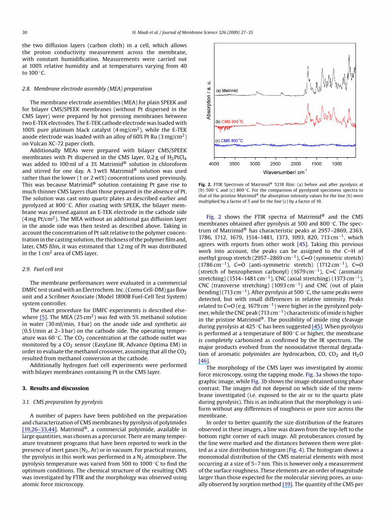
ig. 2. FTIR Spectrum of Matrimid® 5218 film: (a) before and after pyrolysis atb) 500 ◦C and (c) 800 ◦C. For the comparison of pyrolyzed specimens spectra tohat of the pristine Matrimid® the absorption intensity values for the line (b) were
ultiplied by a factor of 5 and for the line (c) by a factor of 10.
Fig. 2 shows the FTIR spectra of Matrimid® and the CMSembranes obtained after pyrolysis at 500 and 800 ◦C. The spec-
rum of Matrimid® has characteristic peaks at 2957–2869, 2363,786, 1712, 1679, 1514–1481, 1373, 1093, 820, 713 cm−1, whichgrees with reports from other work [45]. Taking this previousork into account, the peaks can be assigned to the C H ofethyl group stretch (2957–2869 cm−1), C O (symmetric stretch)
1786 cm−1), C O (anti-symmetric stretch) (1712 cm−1), C Ostretch of benzophenon carbonyl) (1679 cm−1), C C (aromatictretching) (1514–1481 cm−1), CNC (axial stretching) (1373 cm−1),NC (transverse stretching) (1093 cm−1) and CNC (out of plainending) (713 cm−1). After pyrolysis at 500 ◦C, the same peaks wereetected, but with small differences in relative intensity. Peakselated to C O (e.g. 1679 cm−1) were higher in the pyrolyzed poly-er, while the CNC peak (713 cm−1) characteristic of imide is higher
n the pristine Matrimid®. The possibility of imide ring cleavageuring pyrolysis at 425 ◦C has been suggested [45]. When pyrolysis
s performed at a temperature of 800 ◦C or higher, the membranes completely carbonized as confirmed by the IR spectrum. The
ajor products evolved from the nonoxidative thermal degrada-ion of aromatic polyimides are hydrocarbon, CO, CO2 and H2O46].
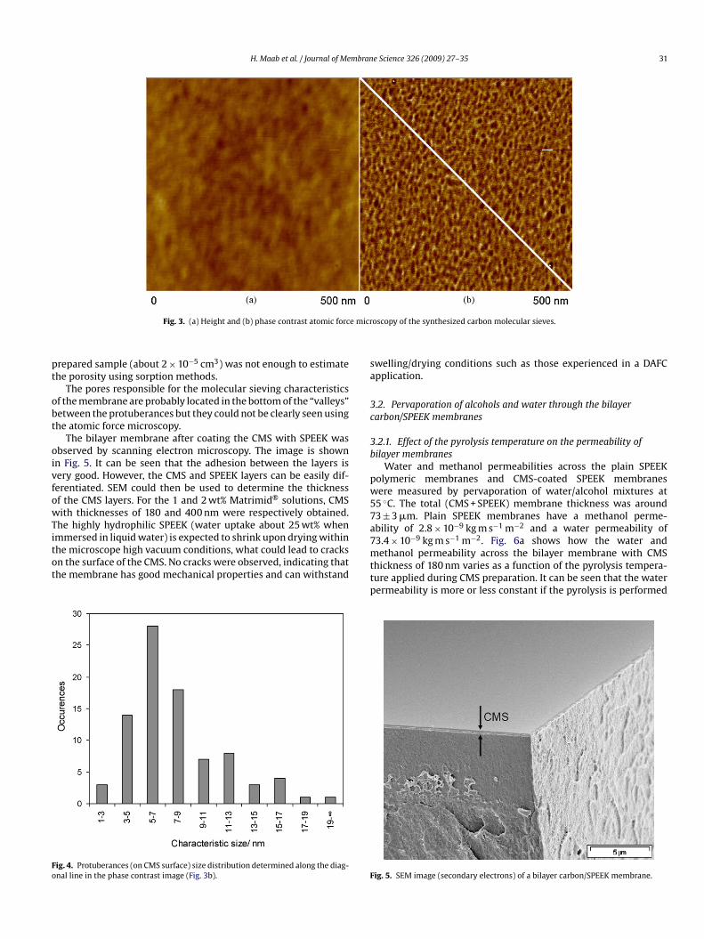
The morphology of the CMS layer was investigated by atomicorce microscopy, using the tapping mode. Fig. 3a shows the topo-raphic image, while Fig. 3b shows the image obtained using phaseontrast. The images did not depend on which side of the mem-rane investigated (i.e. exposed to the air or to the quartz plateuring pyrolysis). This is an indication that the morphology is uni-orm without any differences of roughness or pore size across the
embrane.In order to better quantify the size distribution of the features
bserved in these images, a line was drawn from the top-left to theottom right corner of each image. All protuberances crossed byhe line were marked and the distances between them were plot-ed as a size distribution histogram (Fig. 4). The histogram shows a
onomodal distribution of the CMS material elements with mostccurring at a size of 5–7 nm. This is however only a measurementf the surface roughness. These elements are an order of magnitudearger than those expected for the molecular sieving pores, as usu-lly observed by sorption method [19]. The quantity of the CMS per
H. Maab et al. / Journal of Membrane Science 326 (2009) 27–35 31
e micr
pt
obt
oivfowTitot
Fo
sa
3c
3b
pw57a
Fig. 3. (a) Height and (b) phase contrast atomic forc
repared sample (about 2 × 10⁻⁵ cm3) was not enough to estimatehe porosity using sorption methods.
The pores responsible for the molecular sieving characteristicsf the membrane are probably located in the bottom of the “valleys”etween the protuberances but they could not be clearly seen usinghe atomic force microscopy.
The bilayer membrane after coating the CMS with SPEEK wasbserved by scanning electron microscopy. The image is shownn Fig. 5. It can be seen that the adhesion between the layers isery good. However, the CMS and SPEEK layers can be easily dif-erentiated. SEM could then be used to determine the thicknessf the CMS layers. For the 1 and 2 wt% Matrimid® solutions, CMSith thicknesses of 180 and 400 nm were respectively obtained.
he highly hydrophilic SPEEK (water uptake about 25 wt% when
mmersed in liquid water) is expected to shrink upon drying withinhe microscope high vacuum conditions, what could lead to cracksn the surface of the CMS. No cracks were observed, indicating thathe membrane has good mechanical properties and can withstandig. 4. Protuberances (on CMS surface) size distribution determined along the diag-nal line in the phase contrast image (Fig. 3b).
7mttp
F
oscopy of the synthesized carbon molecular sieves.
welling/drying conditions such as those experienced in a DAFCpplication.
.2. Pervaporation of alcohols and water through the bilayerarbon/SPEEK membranes
.2.1. Effect of the pyrolysis temperature on the permeability ofilayer membranes
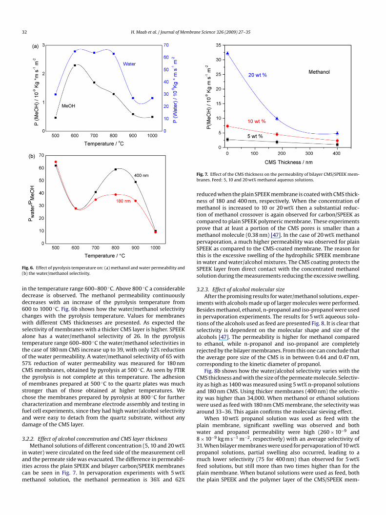
Water and methanol permeabilities across the plain SPEEKolymeric membranes and CMS-coated SPEEK membranesere measured by pervaporation of water/alcohol mixtures at5 ◦C. The total (CMS + SPEEK) membrane thickness was around3 ± 3 �m. Plain SPEEK membranes have a methanol perme-bility of 2.8 × 10⁻⁹ kg m s−1 m−2 and a water permeability of3.4 × 10−9 kg m s−1 m−2. Fig. 6a shows how the water and
ethanol permeability across the bilayer membrane with CMShickness of 180 nm varies as a function of the pyrolysis tempera-ure applied during CMS preparation. It can be seen that the waterermeability is more or less constant if the pyrolysis is performed
ig. 5. SEM image (secondary electrons) of a bilayer carbon/SPEEK membrane.
32 H. Maab et al. / Journal of Membrane Science 326 (2009) 27–35
F(
idd6cwsatto5Ctosccfad
3
iaicm
Fb
rnmtcpmpStiSs
3
iBitsatrtc
Ciaiwa
pw83
ig. 6. Effect of pyrolysis temperature on: (a) methanol and water permeability andb) the water/methanol selectivity.
n the temperature range 600–800 ◦C. Above 800 ◦C a considerableecrease is observed. The methanol permeability continuouslyecreases with an increase of the pyrolysis temperature from00 to 1000 ◦C. Fig. 6b shows how the water/methanol selectivityhanges with the pyrolysis temperature. Values for membranesith different CMS thicknesses are presented. As expected the
electivity of membranes with a thicker CMS layer is higher. SPEEKlone has a water/methanol selectivity of 26. In the pyrolysisemperature range 600–800 ◦C the water/methanol selectivities inhe case of 180 nm CMS increase up to 39, with only 12% reductionf the water permeability. A water/methanol selectivity of 65 with7% reduction of water permeability was measured for 180 nmMS membranes, obtained by pyrolysis at 500 ◦C. As seen by FTIRhe pyrolysis is not complete at this temperature. The adhesionf membranes prepared at 500 ◦C to the quartz plates was muchtronger than of those obtained at higher temperatures. Wehose the membranes prepared by pyrolysis at 800 ◦C for furtherharacterization and membrane electrode assembly and testing inuel cell experiments, since they had high water/alcohol selectivitynd were easy to detach from the quartz substrate, without anyamage of the CMS layer.
.2.2. Effect of alcohol concentration and CMS layer thicknessMethanol solutions of different concentration (5, 10 and 20 wt%
n water) were circulated on the feed side of the measurement cellnd the permeate side was evacuated. The difference in permeabil-ties across the plain SPEEK and bilayer carbon/SPEEK membranesan be seen in Fig. 7. In pervaporation experiments with 5 wt%ethanol solution, the methanol permeation is 36% and 62%
pmfpt
ig. 7. Effect of the CMS thickness on the permeability of bilayer CMS/SPEEK mem-ranes. Feed: 5, 10 and 20 wt% methanol aqueous solutions.
educed when the plain SPEEK membrane is coated with CMS thick-ess of 180 and 400 nm, respectively. When the concentration ofethanol is increased to 10 or 20 wt% then a substantial reduc-
ion of methanol crossover is again observed for carbon/SPEEK asompared to plain SPEEK polymeric membrane. These experimentsrove that at least a portion of the CMS pores is smaller than aethanol molecule (0.38 nm) [47]. In the case of 20 wt% methanol
ervaporation, a much higher permeability was observed for plainPEEK as compared to the CMS-coated membrane. The reason forhis is the excessive swelling of the hydrophilic SPEEK membranen water and water/alcohol mixtures. The CMS coating protects thePEEK layer from direct contact with the concentrated methanololution during the measurements reducing the excessive swelling.
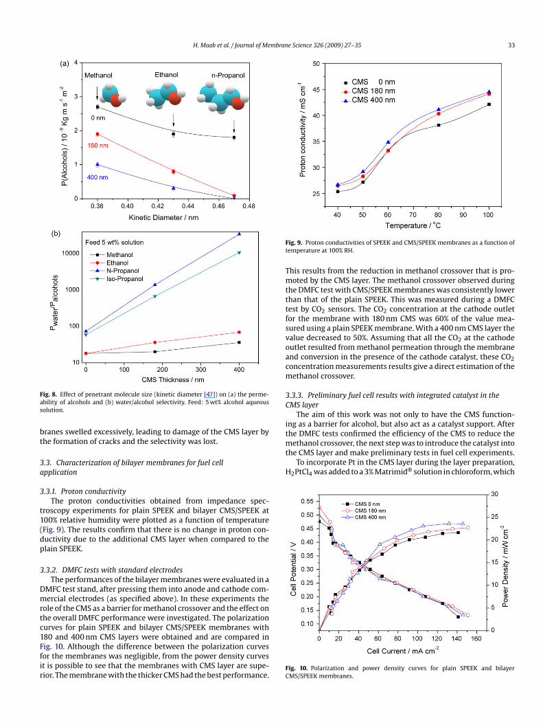
.2.3. Effect of alcohol molecular sizeAfter the promising results for water/methanol solutions, exper-
ments with alcohols made up of larger molecules were performed.esides methanol, ethanol, n-propanol and iso-propanol were used
n pervaporation experiments. The results for 5 wt% aqueous solu-ions of the alcohols used as feed are presented Fig. 8. It is clear thatelectivity is dependent on the molecular shape and size of thelcohols [47]. The permeability is higher for methanol comparedo ethanol, while n-propanol and iso-propanol are completelyejected by the bilayer membranes. From this one can conclude thathe average pore size of the CMS is in between 0.44 and 0.47 nm,orresponding to the kinetic diameter of propanol.
Fig. 8b shows how the water/alcohol selectivity varies with theMS thickness and with the size of the permeate molecule. Selectiv-
ty as high as 1400 was measured using 5 wt% n-propanol solutionsnd 180 nm CMS. Using thicker membranes (400 nm) the selectiv-ty was higher than 34,000. When methanol or ethanol solutions
ere used as feed with 180 nm CMS membrane, the selectivity wasround 33–36. This again confirms the molecular sieving effect.
When 10 wt% propanol solution was used as feed with thelain membrane, significant swelling was observed and bothater and propanol permeability were high (260 × 10−9 and× 10−9 kg m s−1 m−2, respectively) with an average selectivity of1. When bilayer membranes were used for pervaporation of 10 wt%
ropanol solutions, partial swelling also occurred, leading to auch lower selectivity (75 for 400 nm) than observed for 5 wt%eed solutions, but still more than two times higher than for thelain membrane. When butanol solutions were used as feed, bothhe plain SPEEK and the polymer layer of the CMS/SPEEK mem-
H. Maab et al. / Journal of Membrane Science 326 (2009) 27–35 33
Fas
bt
3a
3
t1(dp
3
Dmrtc1Ffir
Ft
Tmtttfsvoacm
3C
ithe DMFC tests confirmed the efficiency of the CMS to reduce themethanol crossover, the next step was to introduce the catalyst intothe CMS layer and make preliminary tests in fuel cell experiments.
To incorporate Pt in the CMS layer during the layer preparation,H2PtCl4 was added to a 3% Matrimid® solution in chloroform, which
ig. 8. Effect of penetrant molecule size (kinetic diameter [47]) on (a) the perme-bility of alcohols and (b) water/alcohol selectivity. Feed: 5 wt% alcohol aqueousolution.
ranes swelled excessively, leading to damage of the CMS layer byhe formation of cracks and the selectivity was lost.
.3. Characterization of bilayer membranes for fuel cellpplication
.3.1. Proton conductivityThe proton conductivities obtained from impedance spec-
roscopy experiments for plain SPEEK and bilayer CMS/SPEEK at00% relative humidity were plotted as a function of temperatureFig. 9). The results confirm that there is no change in proton con-uctivity due to the additional CMS layer when compared to thelain SPEEK.
.3.2. DMFC tests with standard electrodesThe performances of the bilayer membranes were evaluated in a
MFC test stand, after pressing them into anode and cathode com-ercial electrodes (as specified above). In these experiments the
ole of the CMS as a barrier for methanol crossover and the effect onhe overall DMFC performance were investigated. The polarizationurves for plain SPEEK and bilayer CMS/SPEEK membranes with
80 and 400 nm CMS layers were obtained and are compared inig. 10. Although the difference between the polarization curvesor the membranes was negligible, from the power density curvest is possible to see that the membranes with CMS layer are supe-ior. The membrane with the thicker CMS had the best performance.FC
ig. 9. Proton conductivities of SPEEK and CMS/SPEEK membranes as a function ofemperature at 100% RH.
his results from the reduction in methanol crossover that is pro-oted by the CMS layer. The methanol crossover observed during
he DMFC test with CMS/SPEEK membranes was consistently lowerhan that of the plain SPEEK. This was measured during a DMFCest by CO2 sensors. The CO2 concentration at the cathode outletor the membrane with 180 nm CMS was 60% of the value mea-ured using a plain SPEEK membrane. With a 400 nm CMS layer thealue decreased to 50%. Assuming that all the CO2 at the cathodeutlet resulted from methanol permeation through the membranend conversion in the presence of the cathode catalyst, these CO2oncentration measurements results give a direct estimation of theethanol crossover.
.3.3. Preliminary fuel cell results with integrated catalyst in theMS layer
The aim of this work was not only to have the CMS function-ng as a barrier for alcohol, but also act as a catalyst support. After
ig. 10. Polarization and power density curves for plain SPEEK and bilayerMS/SPEEK membranes.
34 H. Maab et al. / Journal of Membrane Science 326 (2009) 27–35
Fl
wplIdPmi[wmts1leaebcahctpCm
FmC
attcfIbocf
4
lchfwrmieoDaci
A
s
R
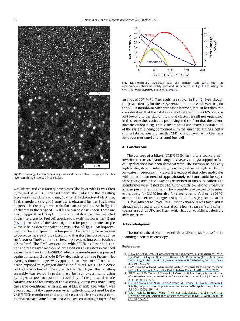
ig. 11. Scanning electron microscopy (backscattered electrons image) of the CMSayer containing dispersed Pt as catalyst.
as stirred and cast onto quartz plates. The layer with Pt was thenyrolyzed at 800 ◦C under nitrogen. The surface of the resulting
ayer was then observed using SEM with backscattered electrons.n this mode a very good contrast is obtained for the Pt clustersispersed in the polymer matrix. Such an image is shown in Fig. 11.t clusters in the range of 30–100 nm can be clearly seen. These areuch bigger than the optimum size of catalyst particles reported
n the literature for fuel cell application, which is lower than 3 nm48,49]. Particles of this size might also be present in the sampleithout being detected with the resolution of Fig. 11. An improve-ent of the Pt dispersion technique will be certainly be necessary
o decrease the size of the clusters and therefore increase the activeurface area. The Pt content in the sample was estimated to be about.2 mg/cm2. The CMS was coated with SPEEK as described ear-ier and the bilayer membrane obtained was evaluated in fuel cellxperiments. For this the SPEEK side of the membrane was pressedgainst a standard cathode E-Tek electrode with 4 mg Pt/cm2. Notven gas diffusion layer was applied to the CMS side of the mem-rane exposed to hydrogen during the fuel cell tests. The electricontact was achieved directly with the CMS layer. The resultingssembly was tested in preliminary fuel cell experiments usingydrogen as feed to test the accessibility of the prepared anodeatalyst and the feasibility of the assembly. A test was done using
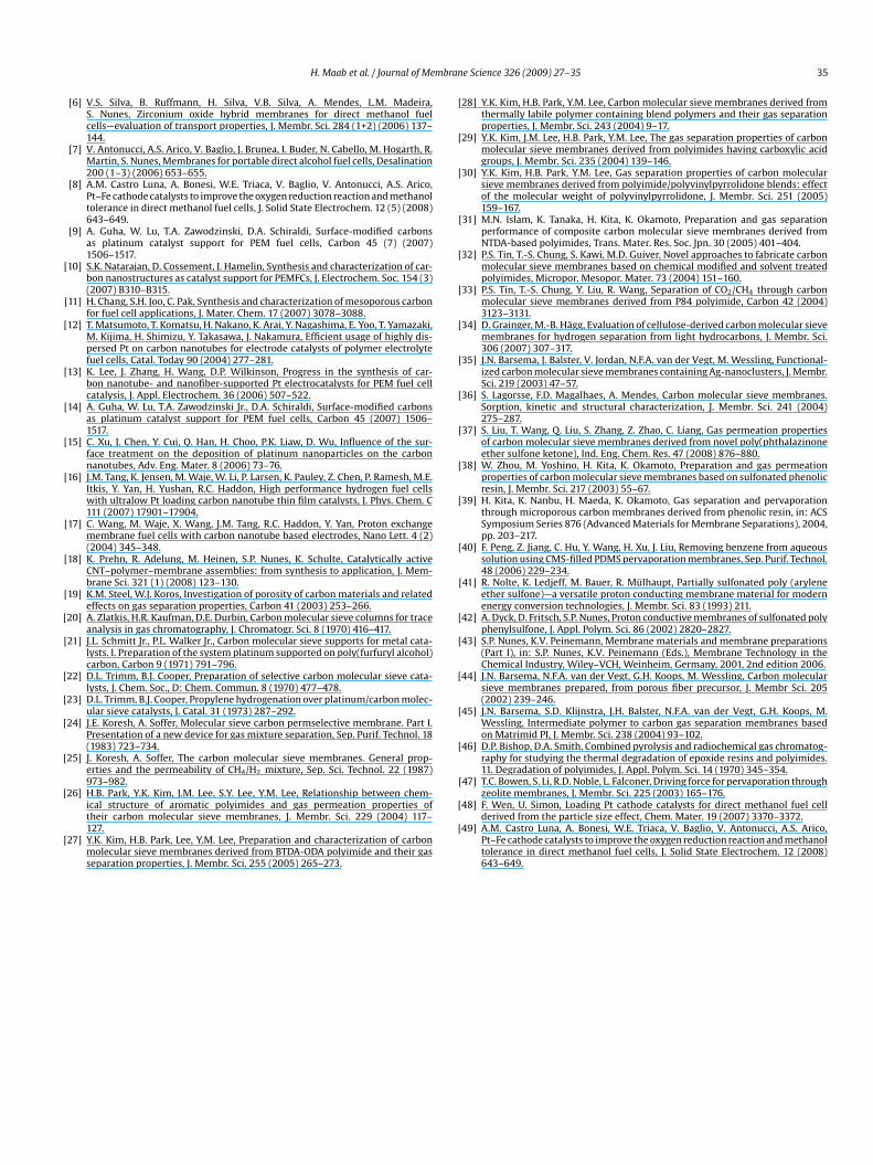
he same conditions, with a plain SPEEK membrane, which wasressed against the same commercial cathode catalyst used for theMS/SPEEK membrane and as anode electrode in this case a com-ercial one available for the test was used, containing 3 mg/cm2 ofig. 12. Preliminary hydrogen fuel cell (single cell) tests with theembrane–electrode-assembly prepared as depicted in Fig. 1 and using the
MS layer with dispersed Pt shown in Fig. 11.
n alloy of 60% Pt Ru. The results are shown in Fig. 12. Even thoughhe power density for the CMS/SPEEK membrane was lower than forhe SPEEK membrane with standard electrode, it must be taken intoonsideration that the total amount of catalyst in the CMS was 2.5-old lower and the size of the metal clusters is still not optimized.n this sense the results are promising and confirm that the assem-lies described in Fig. 1 could be prepared and tested. Optimizationf the system is being performed with the aim of obtaining a betteratalyst dispersion and smaller CMS pores, as well as further testsor direct methanol and ethanol fuel cell.
. Conclusions
The concept of a bilayer CMS/SPEEK membrane working withow alcohol crossover and using the CMS as a catalyst support in fuelell applications has been demonstrated. The membrane has veryigh water/alcohol selectivity, reaching values as high as 34,000
or water/n-propanol mixtures. It is expected that other moleculesith kinetic diameters of approximately 0.47 nm could be sepa-
ated using such a CMS layer as described in this publication. Theembranes were tested for DMFC, for which low alcohol crossover
s an important requirement. The assembly is expected to be inter-st not only for DMFC but also for direct ethanol fuel cells (DEFC)r other fuel cell technologies using liquid fuels (e.g. formic acid).EFC has advantages over DMFC, since ethanol is less toxic and islready produced on an industrial scale from sugar cane and corn inountries such as USA and Brazil which have an established deliverynfrastructure.
cknowledgment
The authors thank Marion Aderhold and Karen M. Prause for thecanning electron microscopy.
eferences
[1] H.E.A. Brüschke, State-of-art of pervaporation processes in the chemical indus-try (Part II, Chapter 3), in: S.P. Nunes, K.V. Peinemann (Eds.), MembraneTechnology in the Chemical Industry, Wiley–VCH, Weinheim, Germany, 2001,2nd edition 2006.
[2] N.W. Deluca, Y.A. Elabd, Polymer electrolyte membranes for the direct methanolfuel cell: a review, J. Polym. Sci. Part B: Polym. Phys. 44 (2006) 2201–2225.
[3] S.P. Nunes, B. Ruffmann, E. Rikowski, S. Vetter, K. Richau, Inorganic modificationof conductive polymer membranes for direct methanol fuel cell, J. Membr. Sci.203 (2002) 215–225.
[4] C.S. Karthikeyan, S.P. Nunes, L.A.S.A. Prado, M.L. Ponce, H. Silva, B. Ruffmann, K.Schulte, Polymer nanocomposite membranes for DMFC application, J. Membr.Sci. 254 (2005) 139–146.
[5] V.S. Silva, B. Ruffmann, S. Vetter, A. Mendes, L.M. Madeira b, S.P. Nunes, Charac-terization and application of composite membranes in DMFC, Catal. Today 104(2005) 205–212.
mbran
[
[
[
[
[
[
[
[
[
[
[
[
[
[
[
[
[
[
[
[
[
[
[
[
[
[
[
[
[
[
[
[
[
[
[
[
[
[
H. Maab et al. / Journal of Me
[6] V.S. Silva, B. Ruffmann, H. Silva, V.B. Silva, A. Mendes, L.M. Madeira,S. Nunes, Zirconium oxide hybrid membranes for direct methanol fuelcells—evaluation of transport properties, J. Membr. Sci. 284 (1+2) (2006) 137–144.
[7] V. Antonucci, A.S. Arico, V. Baglio, J. Brunea, I. Buder, N. Cabello, M. Hogarth, R.Martin, S. Nunes, Membranes for portable direct alcohol fuel cells, Desalination200 (1–3) (2006) 653–655.
[8] A.M. Castro Luna, A. Bonesi, W.E. Triaca, V. Baglio, V. Antonucci, A.S. Arico,Pt–Fe cathode catalysts to improve the oxygen reduction reaction and methanoltolerance in direct methanol fuel cells, J. Solid State Electrochem. 12 (5) (2008)643–649.
[9] A. Guha, W. Lu, T.A. Zawodzinski, D.A. Schiraldi, Surface-modified carbonsas platinum catalyst support for PEM fuel cells, Carbon 45 (7) (2007)1506–1517.
10] S.K. Natarajan, D. Cossement, J. Hamelin, Synthesis and characterization of car-bon nanostructures as catalyst support for PEMFCs, J. Electrochem. Soc. 154 (3)(2007) B310–B315.
11] H. Chang, S.H. Joo, C. Pak, Synthesis and characterization of mesoporous carbonfor fuel cell applications, J. Mater. Chem. 17 (2007) 3078–3088.
12] T. Matsumoto, T. Komatsu, H. Nakano, K. Arai, Y. Nagashima, E. Yoo, T. Yamazaki,M. Kijima, H. Shimizu, Y. Takasawa, J. Nakamura, Efficient usage of highly dis-persed Pt on carbon nanotubes for electrode catalysts of polymer electrolytefuel cells, Catal. Today 90 (2004) 277–281.
13] K. Lee, J. Zhang, H. Wang, D.P. Wilkinson, Progress in the synthesis of car-bon nanotube- and nanofiber-supported Pt electrocatalysts for PEM fuel cellcatalysis, J. Appl. Electrochem. 36 (2006) 507–522.
14] A. Guha, W. Lu, T.A. Zawodzinski Jr., D.A. Schiraldi, Surface-modified carbonsas platinum catalyst support for PEM fuel cells, Carbon 45 (2007) 1506–1517.
15] C. Xu, J. Chen, Y. Cui, Q. Han, H. Choo, P.K. Liaw, D. Wu, Influence of the sur-face treatment on the deposition of platinum nanoparticles on the carbonnanotubes, Adv. Eng. Mater. 8 (2006) 73–76.
16] J.M. Tang, K. Jensen, M. Waje, W. Li, P. Larsen, K. Pauley, Z. Chen, P. Ramesh, M.E.Itkis, Y. Yan, H. Yushan, R.C. Haddon, High performance hydrogen fuel cellswith ultralow Pt loading carbon nanotube thin film catalysts, J. Phys. Chem. C111 (2007) 17901–17904.
17] C. Wang, M. Waje, X. Wang, J.M. Tang, R.C. Haddon, Y. Yan, Proton exchangemembrane fuel cells with carbon nanotube based electrodes, Nano Lett. 4 (2)(2004) 345–348.
18] K. Prehn, R. Adelung, M. Heinen, S.P. Nunes, K. Schulte, Catalytically activeCNT–polymer–membrane assemblies: from synthesis to application, J. Mem-brane Sci. 321 (1) (2008) 123–130.
19] K.M. Steel, W.J. Koros, Investigation of porosity of carbon materials and relatedeffects on gas separation properties, Carbon 41 (2003) 253–266.
20] A. Zlatkis, H.R. Kaufman, D.E. Durbin, Carbon molecular sieve columns for traceanalysis in gas chromatography, J. Chromatogr. Sci. 8 (1970) 416–417.
21] J.L. Schmitt Jr., P.L. Walker Jr., Carbon molecular sieve supports for metal cata-lysts. I. Preparation of the system platinum supported on poly(furfuryl alcohol)carbon, Carbon 9 (1971) 791–796.
22] D.L. Trimm, B.J. Cooper, Preparation of selective carbon molecular sieve cata-lysts, J. Chem. Soc., D: Chem. Commun. 8 (1970) 477–478.
23] D.L. Trimm, B.J. Cooper, Propylene hydrogenation over platinum/carbon molec-ular sieve catalysts, J. Catal. 31 (1973) 287–292.
24] J.E. Koresh, A. Soffer, Molecular sieve carbon permselective membrane. Part I.Presentation of a new device for gas mixture separation, Sep. Purif. Technol. 18(1983) 723–734.
25] J. Koresh, A. Soffer, The carbon molecular sieve membranes. General prop-erties and the permeability of CH4/H2 mixture, Sep. Sci. Technol. 22 (1987)973–982.
26] H.B. Park, Y.K. Kim, J.M. Lee, S.Y. Lee, Y.M. Lee, Relationship between chem-
ical structure of aromatic polyimides and gas permeation properties oftheir carbon molecular sieve membranes, J. Membr. Sci. 229 (2004) 117–127.27] Y.K. Kim, H.B. Park, Lee, Y.M. Lee, Preparation and characterization of carbonmolecular sieve membranes derived from BTDA-ODA polyimide and their gasseparation properties, J. Membr. Sci. 255 (2005) 265–273.
[
[
e Science 326 (2009) 27–35 35
28] Y.K. Kim, H.B. Park, Y.M. Lee, Carbon molecular sieve membranes derived fromthermally labile polymer containing blend polymers and their gas separationproperties, J. Membr. Sci. 243 (2004) 9–17.
29] Y.K. Kim, J.M. Lee, H.B. Park, Y.M. Lee, The gas separation properties of carbonmolecular sieve membranes derived from polyimides having carboxylic acidgroups, J. Membr. Sci. 235 (2004) 139–146.
30] Y.K. Kim, H.B. Park, Y.M. Lee, Gas separation properties of carbon molecularsieve membranes derived from polyimide/polyvinylpyrrolidone blends: effectof the molecular weight of polyvinylpyrrolidone, J. Membr. Sci. 251 (2005)159–167.
31] M.N. Islam, K. Tanaka, H. Kita, K. Okamoto, Preparation and gas separationperformance of composite carbon molecular sieve membranes derived fromNTDA-based polyimides, Trans. Mater. Res. Soc. Jpn. 30 (2005) 401–404.
32] P.S. Tin, T.-S. Chung, S. Kawi, M.D. Guiver, Novel approaches to fabricate carbonmolecular sieve membranes based on chemical modified and solvent treatedpolyimides, Micropor. Mesopor. Mater. 73 (2004) 151–160.
33] P.S. Tin, T.-S. Chung, Y. Liu, R. Wang, Separation of CO2/CH4 through carbonmolecular sieve membranes derived from P84 polyimide, Carbon 42 (2004)3123–3131.
34] D. Grainger, M.-B. Hägg, Evaluation of cellulose-derived carbon molecular sievemembranes for hydrogen separation from light hydrocarbons, J. Membr. Sci.306 (2007) 307–317.
35] J.N. Barsema, J. Balster, V. Jordan, N.F.A. van der Vegt, M. Wessling, Functional-ized carbon molecular sieve membranes containing Ag-nanoclusters, J. Membr.Sci. 219 (2003) 47–57.
36] S. Lagorsse, F.D. Magalhaes, A. Mendes, Carbon molecular sieve membranes.Sorption, kinetic and structural characterization, J. Membr. Sci. 241 (2004)275–287.
37] S. Liu, T. Wang, Q. Liu, S. Zhang, Z. Zhao, C. Liang, Gas permeation propertiesof carbon molecular sieve membranes derived from novel poly(phthalazinoneether sulfone ketone), Ind. Eng. Chem. Res. 47 (2008) 876–880.
38] W. Zhou, M. Yoshino, H. Kita, K. Okamoto, Preparation and gas permeationproperties of carbon molecular sieve membranes based on sulfonated phenolicresin, J. Membr. Sci. 217 (2003) 55–67.
39] H. Kita, K. Nanbu, H. Maeda, K. Okamoto, Gas separation and pervaporationthrough microporous carbon membranes derived from phenolic resin, in: ACSSymposium Series 876 (Advanced Materials for Membrane Separations), 2004,pp. 203–217.
40] F. Peng, Z. Jiang, C. Hu, Y. Wang, H. Xu, J. Liu, Removing benzene from aqueoussolution using CMS-filled PDMS pervaporation membranes, Sep. Purif. Technol.48 (2006) 229–234.
41] R. Nolte, K. Ledjeff, M. Bauer, R. Mülhaupt, Partially sulfonated poly (aryleneether sulfone)—a versatile proton conducting membrane material for modernenergy conversion technologies, J. Membr. Sci. 83 (1993) 211.
42] A. Dyck, D. Fritsch, S.P. Nunes, Proton conductive membranes of sulfonated polyphenylsulfone, J. Appl. Polym. Sci. 86 (2002) 2820–2827.
43] S.P. Nunes, K.V. Peinemann, Membrane materials and membrane preparations(Part I), in: S.P. Nunes, K.V. Peinemann (Eds.), Membrane Technology in theChemical Industry, Wiley–VCH, Weinheim, Germany, 2001, 2nd edition 2006.
44] J.N. Barsema, N.F.A. van der Vegt, G.H. Koops, M. Wessling, Carbon molecularsieve membranes prepared, from porous fiber precursor, J. Membr Sci. 205(2002) 239–246.
45] J.N. Barsema, S.D. Klijnstra, J.H. Balster, N.F.A. van der Vegt, G.H. Koops, M.Wessling, Intermediate polymer to carbon gas separation membranes basedon Matrimid PI, J. Membr. Sci. 238 (2004) 93–102.
46] D.P. Bishop, D.A. Smith, Combined pyrolysis and radiochemical gas chromatog-raphy for studying the thermal degradation of epoxide resins and polyimides.11. Degradation of polyimides, J. Appl. Polym. Sci. 14 (1970) 345–354.
47] T.C. Bowen, S. Li, R.D. Noble, L. Falconer, Driving force for pervaporation throughzeolite membranes, J. Membr. Sci. 225 (2003) 165–176.
48] F. Wen, U. Simon, Loading Pt cathode catalysts for direct methanol fuel cellderived from the particle size effect, Chem. Mater. 19 (2007) 3370–3372.
49] A.M. Castro Luna, A. Bonesi, W.E. Triaca, V. Baglio, V. Antonucci, A.S. Arico,Pt–Fe cathode catalysts to improve the oxygen reduction reaction and methanoltolerance in direct methanol fuel cells, J. Solid State Electrochem. 12 (2008)643–649.