The enigma of eugregarine epicytic folds: where gliding motility originates?

Saw-tooth structures and curved veins related to folds in the south-centralPyrenees (Spain)
F. Bastida a,*, J. Aller a, R.J. Lisle b, N.C. Bobillo-Ares c, C.O. Menéndez c
aDepartamento de Geología, Universidad de Oviedo, Jesús Arias de Velasco s/n, 33005 Oviedo, Spainb School of Earth and Ocean Sciences, Cardiff University, Cardiff, CF10 3AT, UKcDepartamento de Matemáticas, Universidad de Oviedo, 33007 Oviedo, Spain
a r t i c l e i n f o
Article history:Received 4 April 2011Received in revised form6 October 2011Accepted 31 October 2011Available online 10 November 2011
Keywords:FoldsFracturesVeinsPyrenees
a b s t r a c t
Two generation of folds (F1 and F2) and associated structures, developed in the Eocene turbidites of thesouth-central Pyrenees, are analyzed in this paper. F1 folds are close, have sub-horizontal axes andsouthwards vergence. They have an associated cleavage S1. Competent layers were folded by layer-parallel shortening, tangential longitudinal strain, some possible flexural flow and an obliquely super-imposed homogeneous strain due mainly to simple shear. Flexural slip is also an important mechanismin the whole multilayer. F2 folds are gentle and scarce; they fold the S1 cleavage.
Among the structures associated with F1 folds, there are sets of veins with curved form in thecompetent layers. The displacement of each vein gave rise usually to a step in the layer boundary, so thata set of veins produces a structure that is named “saw-tooth structure”. The veins initiated as small faultsthat made flexural slip difficult and gave rise to a concentration of stress on the steps, leading to anopening of the fractures and a propagation of them along a curved path, as suggested by a simplemechanical model. This propagation agrees with finite element models developed by other authors.
� 2011 Elsevier Ltd. All rights reserved.
1. Introduction
In the Eocene turbidites (Hecho Group) of the south-centralPyrenees, abundant metric folds developed during the Alpinedeformation. It is observed in some areas that on their limbs, thecompetent layers contain a notable variety of veins with curiousgeometry. In many cases the veins have a curved wedge shapeopening towards a bed boundary and involve a displacement thatgives rise to the development of steps on this boundary, which isusually the stratigraphical base of the bed. As a consequence, anexotic structure not previously described in the geological litera-ture often appears, which is named in this paper ‘saw-toothstructure’.
The aim of this paper is to make an analysis of these folds andveins and to construct a mechanical model to explain their devel-opment. In the first part of the paper, the folds are described andthe kinematical mechanisms involved in their evolution areanalyzed. In order to accomplish that, in addition to observationsand field data, computer simulations of folds have been used. Thisfirst part of the paper is necessary to explain the context anddevelopment of veins and saw-tooth structures, which are analyzed
in the second part of the paper. In the latter, a mesoscopic andmicroscopic description of these structures is made and amodel fortheir development is presented.
2. Geological setting
The Pyrenees is an Alpine belt that includes the boundarybetween the Iberian Peninsula and the rest of the Europeancontinent, following an E�Wdirection (Fig.1). It can be divided intothree parts: a central part (Axial Zone), with outcrops of a Paleozoicbasement involved in the structure, and two thrust systems,a northern system with vergence to the north (North PyreneanZone) and a southern system with vergence to the south (SouthPyrenean Zone). Despite this arrangement, the belt is asymmetrical,since the South Pyrenean Zone is wider than the North PyreneanZone, and overall a southerly vergence dominates. Alpine defor-mation took place between the Late Cretaceous and the EarlyMiocene. In the western and central parts of the South PyreneanZone (Jaca-Pamplona sector), a major foredeep basin developed,where syntectonic turbiditic sediments belonging to the HechoGroup were deposited during the Early-Middle Eocene. The studiedstructures developed in rocks of this group, and they have beenanalyzed along the NeS valleys that cross thesewestern and centralparts (Fig. 1).
* Corresponding author. Fax: þ34 985103103.E-mail address: [email protected] (F. Bastida).
Contents lists available at SciVerse ScienceDirect
Journal of Structural Geology
journal homepage: www.elsevier .com/locate/ jsg
0191-8141/$ e see front matter � 2011 Elsevier Ltd. All rights reserved.doi:10.1016/j.jsg.2011.10.009
Journal of Structural Geology 34 (2012) 43e53

The Hecho Group (Mutti et al., 1972) consists of a succession ofarenites (hybrid arenites e sensu (Zuffa, 1980), calclithites e sensuPettijohn et al., 1972, and siliciclastic sandstones) and shales inturbidite facies that reaches a maximum thickness of about 4500 m(Mansurbeg et al., 2009; Caja et al., 2010). The siliciclastic sand-stones and the hybrid arenites contain calcite and/or dolomitecement that occludes the primary porosity.
The structure of the Jaca-Pamplona sector consists of severalminor thrust systems with a basal décollement located withinTriassic rocks (Gavarnie-Guarga thrust system) and a broadsyncline with the trough zone in the southern part of the sector(Fig. 2). Teixell and García-Sansegundo (1995) and Teixell (1996)distinguished two generations of structures in this sector. Thefirst consists of gently dipping thrusts with scarce associated foldsand the second consists of an imbricate thrust system withnumerous associated folds at mesoscopic to macroscopic scales.These folds are very common in the turbidites of the Hecho Groupand have an associated cleavage in the incompetent layers. Thesefolds and their associated veins are the main structures consideredin this paper.
3. Analysis of folding
Observations of folds in the field permit two folding phases (F1and F2) to be distinguished. F1 folds are the most frequent andcorrespond to the second generation of regional structures; theyare close folds with vergence to the southwest and an associatedcleavage, S1 (Fig. 3). F2 folds are scarce; they are gentle folds uprightor weakly vergent towards the NNE, and they fold the S1 cleavage(Fig. 4). The main features of F1 folds are described below.
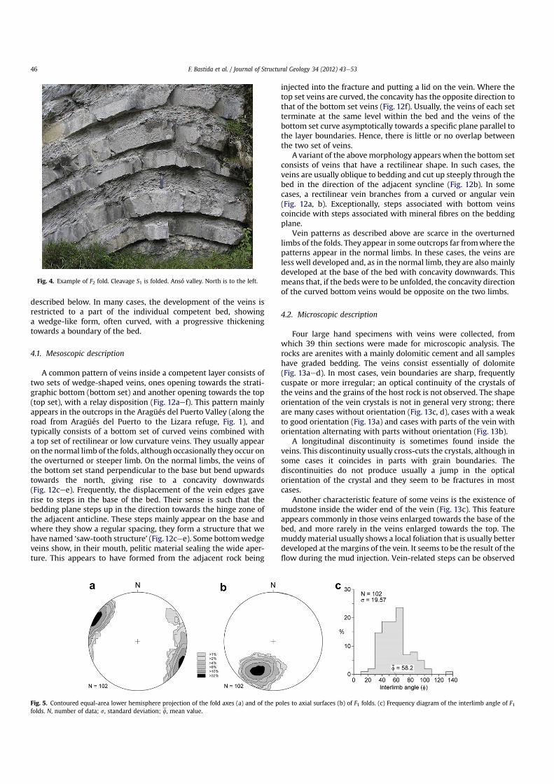
F1 folds have axes sub-horizontal or gently plunging towards thesoutheast or the northwest (Fig. 5a). Their axial surfaces are steeplyor moderately dipping towards the NNE (Fig. 5b). Most of them areclose folds (Fig. 5c). In most cases the aspect ratio (height/widthratio of the fold limb between the hinge and inflection points takingthe tangent to the hinge point as horizontal) is lower than 3 and thefolds mainly range in shape from chevron to parabolic (Fig. 6a),though fractures and the disorganised character of the bedsprevent classification in some cases. Hence, the chevron shape ismore frequent in the outcrops than it is reflected in Fig. 6a. Thegeometry of the competent folded beds is shown by the s1es2diagram of Bastida et al. (2005) of Fig. 6b; there is a great dispersionof points, although class 1C folds are dominant.
An S1 cleavage, associated with F1 folds, is well developed in theincompetent layers, mainly when the incompetent/competentthickness ratio is high. In most cases the cleavage shows divergentfanning, mainly in the hinge area (Fig. 7); nevertheless, in cases inwhich the incompetent beds are dominant, the cleavage tends to be
parallel to the axial plane. In the competent layers, the cleavage isnot developed or appears as a widely spaced convergent cleavage(Fig. 7), in which many cleavage surfaces have the appearance offractures.
Folds approximating to chevron style have typical accommo-dation structures described by Ramsay (1974), such as bulboushinges (Fig. 8a) and reverse limb faults, both associated withanomalously thick competent layers, and dilation spaces in thehinge zones with hinge collapse (Fig. 8) or flow of incompetentmaterial towards them. Some remarkable structures have beenobserved on some limbs of F1 folds. These are mainly curvedwedge-shaped carbonate veins in competent folded beds; they aredescribed below.
Structures associated with folding by tangential longitudinalstrain are frequent, such as wedge-shaped extension fracturesopening towards the outer arc in the hinge zone of competent beds(Fig. 9). These fractures are usually filled with carbonate mineralsand represent a brittle expression of the tangential longitudinalstrain with area change (PTLS of Bobillo-Ares et al., 2006). Excep-tionally, concentric extension veins can be observed close to theinner arc of the hinge zone of the competent folded layers, alsoindicating tangential longitudinal strain (Fig. 7b).
Syntectonic carbonate fibres along S0 can be observed in manycases in the competenteincompetent interface or inside theincompetent material. They have been found preferentially on thereverse limbs and their direction always makes an angle greaterthan 75� with the axial direction (Fig. 10). When fibre steps can beseen, they indicate a slip sense in agreement with the flexural slipfolding mechanism, which can be associated with the tangentiallongitudinal strain of the competent layers.
The folds of the competent layers have a slight layer thickeningin the hinge zone. Ramsay’s classification of a fold in the Roncalvalley made by Gil et al. (2006) suggests a flattening value ð
ffiffiffiffiffiffiffiffiffiffiffiffil2=l1
pÞ
between 0.7 and 0.85. However, the asymmetry between the twolimbs requires an obliquity of the axes of the superimposed strainellipse with respect to the axial plane and some heterogeneity inthe flattening. This heterogeneity is also suggested by the disper-sion of points in the s1es2 diagram (Fig. 6b).
A folded competent layer with an axial plane dipping 57�
southwards and located in the same train of folds as the foldanalyzed by Gil et al. (2006) has been fitted by Aller et al. (2010) bya fold simulated by computer using the program ‘Fold Modeler’(Bobillo-Ares et al., 2004) (Fig. 11). A good fit of this fold is obtainedwith a first folding step of isochoric layer-parallel shorteningðffiffiffiffiffiffiffiffiffiffiffiffil2=l1
p¼ 0:49Þ, a second step of tangential longitudinal strain
without area change (ETLS of Bobillo-Ares et al., 2006) with anaspect ratio of 0.67, and a third step of flattening (pure shear withffiffiffiffiffiffiffiffiffiffiffiffil2=l1
p¼ 0:71) with a
ffiffiffiffiffil1
pdirection making an angle of 20� with
the axial trace (angle measured clockwise facing west from the foldaxial trace) (oblique flattening of Hudeleston, 1973). The consider-able initial layer-parallel shortening agrees with the convergentarrangement of the cleavage present in the competent layers. Theconsistent direction of vergence of the folds towards the forelandand their association with thrusts with the same vergence, some ofthem forming duplexes at the outcrop scale near the analyzed folds(Gil et al., 2006), suggest that the folds of this area probablyresulted within a rotational bulk deformation regime. Assuminga regime of simple shear strain, the strain ellipse axial ratio citedabove would correspond to a foreland-directed simple shear withg ¼ 0.35 superimposed on a pre-existing fold and with a top-to-the-south shear sense and a direction plunging 17� north. Oncethe shear direction is obtained, and the g value and the present dipof the fold axial plane are known (Aller et al., 2010), the dip of theaxial plane prior to the superimposition of the simple shear can bedetermined; this dip was about 66� northwards and it could be
Fig. 1. Geological map of the Pyrenees with the location of the cross-section shown inFig. 2 (after Mansurbeg et al., 2009). Isaba, Ansó, Aragüés del Puerto and Jaca arelocalities in the NeS valleys where the study folds are located.
F. Bastida et al. / Journal of Structural Geology 34 (2012) 43e5344

produced, in a bulk simple shear regime, by buckling of layersoblique to the shear direction.
The competent layers of another three folds of this area havebeen modeled using Fold Modeler in this study. The results aresimilar to those obtained in the above fold, with some variations inthe amount of tangential longitudinal strain without area changedepending on the fold aspect ratio and minor operation of flexuralflow at the end of buckling. Considering all the folds analyzed withFold Modeler, we can infer the following kinematical evolution:
(1) A first stage of layer-parallel shortening with affiffiffiffiffiffiffiffiffiffiffiffil2=l1
pvalue
between 0.49 and 0.64.(2) A stage of tangential longitudinal strain without area change.
The aspect ratio acquired by the fold by this mechanism rangesbetween 0.29 and 0.75.
(3) A stage of flexural flow producing an aspect ratio incrementbetween 0 and 0.19. Thus the contribution from this mecha-nism is small and it does not appear in all cases.
(4) A superimposition of a small homogeneous deformation, withthe major axis of the strain ellipse oblique to the axial plane.
The corresponding value ranges between 0.71 and 0.96. Thevergence of folds and the context of the deformation suggestthat the superimposed deformation was probably non-coaxial,close to a simple shear, with a top-to-the-SSW shear sense andplunging north between 17� and 28�.
The above folds show competent layers with convergentcleavage. Nevertheless, there are many folds whose competentlayers do not exhibit cleavage. These folds cannot be analyzed usingFold Modeler (Bobillo-Ares et al., 2004). The higher competence ofthese rocks suggests a small amount of layer-parallel shortening atthe beginning of folding and operation of tangential longitudinalstrain with area change, as indicated by the radial veins describedabove.
4. Veins and saw-tooth structures
Veins are very common in the rocks of the Hecho Group. Theyare mainly composed of carbonate minerals, chiefly dolomite.These veins often exhibit distinctive geometries that will be
Fig. 2. Geological cross-section along the southern slope of the Pyrenees (after Teixell and García-Sansegundo, 1995). Location in Fig. 1.
Fig. 3. Examples of F1 folds in the study area. Note the development of cleavage S1 mainly in the incompetent layers. (a), (b) and (c) South of Isaba; (d) Near Ansó. In (a), (b) and (c),north is to the right; in (d) north is to the left.
F. Bastida et al. / Journal of Structural Geology 34 (2012) 43e53 45
described below. In many cases, the development of the veins isrestricted to a part of the individual competent bed, showinga wedge-like form, often curved, with a progressive thickeningtowards a boundary of the bed.
4.1. Mesoscopic description
A common pattern of veins inside a competent layer consists oftwo sets of wedge-shaped veins, ones opening towards the strati-graphic bottom (bottom set) and another opening towards the top(top set), with a relay disposition (Fig. 12aef). This pattern mainlyappears in the outcrops in the Aragüés del Puerto Valley (along theroad from Aragüés del Puerto to the Lizara refuge, Fig. 1), andtypically consists of a bottom set of curved veins combined witha top set of rectilinear or low curvature veins. They usually appearon the normal limb of the folds, although occasionally they occur onthe overturned or steeper limb. On the normal limbs, the veins ofthe bottom set stand perpendicular to the base but bend upwardstowards the north, giving rise to a concavity downwards(Fig. 12cee). Frequently, the displacement of the vein edges gaverise to steps in the base of the bed. Their sense is such that thebedding plane steps up in the direction towards the hinge zone ofthe adjacent anticline. These steps mainly appear on the base andwhere they show a regular spacing, they form a structure that wehave named ‘saw-tooth structure’ (Fig. 12cee). Some bottomwedgeveins show, in their mouth, pelitic material sealing the wide aper-ture. This appears to have formed from the adjacent rock being
injected into the fracture and putting a lid on the vein. Where thetop set veins are curved, the concavity has the opposite direction tothat of the bottom set veins (Fig. 12f). Usually, the veins of each setterminate at the same level within the bed and the veins of thebottom set curve asymptotically towards a specific plane parallel tothe layer boundaries. Hence, there is little or no overlap betweenthe two set of veins.
A variant of the abovemorphology appears when the bottom setconsists of veins that have a rectilinear shape. In such cases, theveins are usually oblique to bedding and cut up steeply through thebed in the direction of the adjacent syncline (Fig. 12b). In somecases, a rectilinear vein branches from a curved or angular vein(Fig. 12a, b). Exceptionally, steps associated with bottom veinscoincide with steps associated with mineral fibres on the beddingplane.
Vein patterns as described above are scarce in the overturnedlimbs of the folds. They appear in some outcrops far fromwhere thepatterns appear in the normal limbs. In these cases, the veins areless well developed and, as in the normal limb, they are also mainlydeveloped at the base of the bed with concavity downwards. Thismeans that, if the beds were to be unfolded, the concavity directionof the curved bottom veins would be opposite on the two limbs.
4.2. Microscopic description
Four large hand specimens with veins were collected, fromwhich 39 thin sections were made for microscopic analysis. Therocks are arenites with a mainly dolomitic cement and all sampleshave graded bedding. The veins consist essentially of dolomite(Fig. 13aed). In most cases, vein boundaries are sharp, frequentlycuspate or more irregular; an optical continuity of the crystals ofthe veins and the grains of the host rock is not observed. The shapeorientation of the vein crystals is not in general very strong; thereare many cases without orientation (Fig. 13c, d), cases with a weakto good orientation (Fig. 13a) and cases with parts of the vein withorientation alternating with parts without orientation (Fig. 13b).
A longitudinal discontinuity is sometimes found inside theveins. This discontinuity usually cross-cuts the crystals, although insome cases it coincides in parts with grain boundaries. Thediscontinuities do not produce usually a jump in the opticalorientation of the crystal and they seem to be fractures in mostcases.
Another characteristic feature of some veins is the existence ofmudstone inside the wider end of the vein (Fig. 13c). This featureappears commonly in those veins enlarged towards the base of thebed, and more rarely in the veins enlarged towards the top. Themuddymaterial usually shows a local foliation that is usually betterdeveloped at the margins of the vein. It seems to be the result of theflow during the mud injection. Vein-related steps can be observed
Fig. 4. Example of F2 fold. Cleavage S1 is folded. Ansó valley. North is to the left.
Fig. 5. Contoured equal-area lower hemisphere projection of the fold axes (a) and of the poles to axial surfaces (b) of F1 folds. (c) Frequency diagram of the interlimb angle of F1folds. N, number of data; s, standard deviation; f, mean value.
F. Bastida et al. / Journal of Structural Geology 34 (2012) 43e5346

in some cases in the base of the layer (Fig. 13d). The step corner canappear rounded as a result of the deformation due to the flow of theadjacent incompetent material.
4.3. Origin and development of the veins and saw-tooth structures
Some features described provide evidence of the geologicalconditions that controlled the development of the veins and saw-tooth structures. The different development of these structureson the two limbs of the folds, the different facing-direction of thesteps of the saw-tooth structures and the different facing-directionof the concavity of the bottom veins on the two limbs if they areunfolded suggest that the development of these structures iscontemporaneous with the folds. Another argument supportingthis interpretation is the parallelism between the vein/beddingintersection lineation and fold hinges. This geometrical relationsuggests that the development of these remarkable structures wasrelated to the stresses and strains generated during folding.
A specific factor that could favour the development of veins wasthe existence of a high pore pressure in the rocks during deforma-tion, mainly in the incompetent pelitic material, where a largevolume of diagenetic fluids was probably concentrated. The exis-tence of these fluids is supported by the dolomitization processesundergone by the rocks and for the mineralizations involved in thedevelopment of the veins, which sometimes appear concentrated in
swarms. High pore pressure is indicated by the pelitic materialinjected into the part of the veins where these meet the layerboundary (Fig.13c). This pressure should favour a brittle behavior ofthe rock and the development of fractures in the competent layers.
As regards the relation between the foldingmechanisms and thedevelopment of veins and saw-tooth structure, the tangentiallongitudinal strain and the homogeneous strain must be rejected asresponsible for these exotic structures. Tangential longitudinalstrain does not produce appreciable strain on limbs where thecurvature of the layers is negligible, and the homogeneous straincannot explain a brittle deformation located in bands adjacent andparallel to the layer boundaries. The fit of several folds using thecomputer program ‘Fold Modeler’ shows a limited participation offlexural flow in their development. Nevertheless, the foldedcompetent layers fitted by ‘Fold Modeler’ have cleavage, whereasthe layers with veins and saw-tooth structure lack an obviouscleavage. This suggests a greater competence contrast in the caseswhere these structures are observed and less favourable conditionsfor flexural flow. Therefore, the more probable mechanism toexplain ‘a priori’ the development of vein and saw-tooth structuresis flexural slip. This agrees with the existence in one outcrop ofsteps that are common to veins and to mineral fibres associated toflexural slip.
Any explanation of the formation of the veins and saw-toothstructure requires clarifying, in particular the origin of the steps
Fig. 6. (a) Diagram of aspect ratio vs. normalised area for F1 folds. (b) Diagram of s1 vs. s2 for F1 folded layers.
Fig. 7. Examples of cleavage S1 showing the different fan pattern in competent and incompetent layers. South of Isaba. North to the right.
F. Bastida et al. / Journal of Structural Geology 34 (2012) 43e53 47

and the opening of the fracture and the development of its curva-ture. The steps involve a displacement tangential to the fracturesurface that is characteristic of shear fractures, but on the otherhand the opening associated with the veins suggests extensionfractures. It is probable that the complex displacement patternobserved is the result of the formation of the veins by the operationof different fracture mechanisms during a progressive evolution. Ina first stage, a significant slip along a boundary of the bed shouldinvolve a stress state with the principal directions oblique to thebedding in zones adjacent to the boundary between layers. Fav-oured by a high fluid pressure, this stress state could generate smallfaults in the competent layer near to the boundary that form a highangle with the layer boundary. These faults formed a conjugatefault set with the bedding fault involved in the mechanism offlexural slip. The existence of graded bedding in the competentlayers probably favoured a better development of the fracturesfrom the base of the bed than at the top; in fact, structural andmicrostructural changes in the sandstones have a notable effect onthe development on fractures and veins in the study area as shownin the example of Fig. 14.
Once the steps had initiated, they could have operated asobstacles to flexural slip and this could have given rise to a stressconcentration on the steps that could have contributed to theopening of the veins. In addition, the difficulty of continued flexuralslip caused by the development of the faults would have favouredoperation of an alternative mechanism of folding. The highcompetence of the layer would prevent the development of
appreciable ductile strain and should favour brittle fracture. Underthese conditions, the stresses inside the competent layer shouldgive rise to a propagation of the small faults as tension gashes inagreement with the orientation of the principal stresses inside thelayer, producing a curved path for the fractures. Opening of thefractures with curved trends should enable balancing of the sliploss at the end of the fault inside the layer. The character of surfacesof weakness represented by the faults enabled their propagationinstead of the development of new fractures. The rock anisotropycould favour in some cases that the propagation of the gash tendsasymptotically to parallelism with the bedding (Fig. 12d). In a fewcases, straight veins branch obliquely from the fault indicatinga spatial interference of two fractures instead of a propagation ofthe fault (Fig. 12a, b).
A simple 2D mechanical model produces the characteristics ofthe stress driving the growth and curvature of the gashes. Let usassume a layer containing several fractures initiated as small faultsand separated by a distance l (Fig. 15a). Let us consider the forcesthat operate on a rock element laterally bounded by two adjacentfaults (Fig. 15b). In this figure, s and s0 are shear stresses on the
Fig. 8. Structures associated with chevron folds. (a) bulbous hinge; (b) hinge collapse. North of Aragües del Puerto. North to the right.
Fig. 9. Hinge zone showing wedge-shaped veins opened towards the outer arc ina competent layer. Tension gashes associated with a shear zone can be seen in thelower part of the picture. South of Isaba. North to the right.
Fig. 10. Orientation of the syntectonic quartz fibres along S0 and the correspondingfold axes. The points representative of fibres define a subvertical plane approximatelyperpendicular to the fold axes.
F. Bastida et al. / Journal of Structural Geology 34 (2012) 43e5348

lower and the upper boundaries respectively, s is the normalstress on the lower boundary, and F is the force on the stepgenerated previously by the a small fault (AC in Fig. 15a, b). Thelateral forces operating on the wall of the fractures have not beenconsidered nor represented in Fig. 15b, since they do not generateresulting force or moment. Under normal conditions, using thevector basis ðe1; e2Þ shown in Fig. 15a, the involved force vectorsare se1, �s0e1, se2 and Fe1, being s, s0, s, F positive numbers. In theabove basis, the stress tensor in the proximity of point C is rep-resented by the matrix:
S ¼�s11 s12s21 s22
�; s12 ¼ s21 (1)
In order to determine the elements of the matrix, let us obtainthe forces Fh and Fv that operate on two perpendicular surfaceelements at C (Fig. 15c, d):
Fh ¼ Fh1 e1 þ Fh2 e2 (2)
Fv ¼ Fv1 e1 þ Fv2 e2 (3)
From the surface elements shown in Fig. 15c, d, we canwrite thefollowing matrix equations:
�s11 s12s21 s22
� 0
� l2
!¼ Fh1Fh2
!(4)
�s11 s12s21 s22
� � l20
!¼�Fv1Fv2
�(5)
This relations lead to:
s12 ¼ s21 ¼ �2lFh1 (6)
s22 ¼ �2lFh2 (7)
Fv2 ¼ Fh1 (8)
s11 ¼ �2lFv1 (9)
In order to simplify the model, we replace the normal stresses onthe boundary CD by three forces F1, F2 and F3 concentrated at thepoints C, M and D, respectively (Fig. 15b). The asymmetry of theapplied forces implies that F1, F2 and F3 are different in magnitude.Nevertheless, we assume a linear variation of the forces along theline CD, that is,
F1� F2¼ F2� F3 (10)
Equilibrium requires
SFx ¼ Fþ sl� s0l 0 (11)
Fig. 11. Fit of a F1 syncline (a) using ‘FoldModeler’ (south of Isaba; looking to the west). (b) Superimposition of the theoretical fold on the natural fold. The fold has been rotated tohave its coordinate axes superposed on those of the numerical fold. Details of the modelling are given in the text. (c) and (d) Comparison of qea curves for the numerical fold (redline) with the data of the natural fold (black points). (e) Comparison of the Ramsay’s classification for the theoretical (red line) and the natural fold (black points) (after Aller et al.,2010).
F. Bastida et al. / Journal of Structural Geology 34 (2012) 43e53 49

SFy ¼ F1þ F2þ F3þ sl ¼ 0 (12)
SMA ¼ s0lhþ F2l2þ F3lþ s
l2
2¼ 0 (13)
where MA are the moments about point A. The fourth term of Eq.(13) corresponds to the moment of the distributed force associatedwith the normal stress s. Eqs. (10)e(13) form a system of linearequations that enables all the forces operating on the consideredrock element to be obtained.
F1 ¼ �13slþ s0h (14)
F2 ¼ �13sl (15)
F3 ¼ �13sl� s0h (16)
s0 ¼ sþ Fl
(17)
Addition of the forces that operate on a surface element in the e1direction through the point C gives (Fig. 15c):
Fh ¼ s0l3e1 � ðF3 þ F1Þe2 (18)
F3þ F1 includes the forces on C of the two adjacent walls of thefracture. We have associated with the point C the shear force½ðs0lÞ=3�e1, which is the third part of the total shear force on CD.Taking into accountEqs. (14), (16) and (17), Eq. (18) acquires the form
Fh ¼ 13ðF þ slÞe1 þ
23sle2 (19)
Taking into account Eqs. (6) and (7), we have:
s12 ¼ �23
�Flþ s�
(20)
s22 ¼ �43s (21)
For the calculation of Fv, the remaining question is the determinationof Fv1 , since, in agreement with Eq. (8), Fv2 ¼ Fh1 ¼ ð1=3ÞðF þ slÞ.
Fig. 12. Small dolomite veins developed inside the competent layers. (a, b) General aspect of the veins. (c, d) Detail showing the different morphology of the bottom and top veinsets. (e) Saw-tooth structure at the base of a competent layer. (f) Curved vein developed near the top of a competent layer; note the rotation of the hanging wall. North of Aragüésdel Puerto. North to the right.
F. Bastida et al. / Journal of Structural Geology 34 (2012) 43e5350

Because the forces along the layer operate in an approximatelyuniformway, it is expected that the force Fv1 exerted by the left side ofthe layeron the right side is zero (it is a similar situation to that a trainwith self-propelling carriages; the interaction between them is null).Hence:
Fv1 ¼ 0 and s11 ¼ 0 (22)
From the above considerations:
S ¼�
0 �b�b �c
�(23)
where b ¼ ð2=3ÞððF=lÞ þ sÞ and c ¼ 4s=3. The eigenvalues of S are:
s1 ¼ �cþffiffiffiffiffiffiffiffiffiffiffiffiffiffiffiffiffiffiffic2 þ 4b2
p2
; ðs1>0; tensile stressÞ (24)
s2 ¼ �c�ffiffiffiffiffiffiffiffiffiffiffiffiffiffiffiffiffiffiffic2 þ 4b2
p2
; ðs2 < 0; compressive stressÞ (25)
The associated eigenvectors are;
vi ¼�
1�li=b
�; ði ¼ 1;2Þ (26)
Since the fractures open as tension gashes after their formation assmall faults, their trends must coincide with the direction of theeigenvector v2 corresponding to the maximum compressive stresss2. The angle that this vector forms with the e1 direction is givenby:
tan 4 ¼ �s2b
¼ 12
�cbþ
ffiffiffiffiffiffiffiffiffiffiffiffiffiffiffiffiffiffi�cb
�2þ4
r �;
cb¼ 2sl
F þ sl(27)
This equation shows that the angular inclination of the propagationpath of a fracture will be greater the lower the value of the forces (Fand sl) acting in the e1 direction with respect to the force sl actingin the e2 direction (Fig. 16). This obliquity, although it is moderate,alters the geometry of the model analyzed in Fig. 15 in such a waythat once the oblique propagation of the fracture is initiated, theforce distribution must change and leads probably to a new changein the propagation direction. This change can be analyzed using thefinite element method. In this sense, curved fractures with shapesresembling those described here have been described in severalnon-geological studies that analyze processes as surface crackingduring orthogonal machining of glass (Chiu et al., 2001), edgechipping in ceramic materials (Cao, 2001), and chipping in glassplates from line-wedge loading (Chai and Ravichandran, 2007) orfrom a uniformly applied edge load (Chiu et al., 1998). Analysesconducted by the finite element method in these studies show thatstresses acting on a surface of a material can induce cracks in thismaterial that in some cases can show the systematic developmentof a progressive curvature. The analyses draw conclusions about thestructures obtained during abrasion and cutting of different non-
Fig. 13. Details of the microscopic aspect of the dolomite veins. (a) Elongate blocky texture. (b) Blocky texture combined with elongate blocky texture near the borders. (c) Blockytexture and mud injection in the mouth of the vein. (d) Blocky texture and deformed step in the base of the bed. Cross polarized light; width of the photographs: 8 mm.
Fig. 14. Lithological control on vein development. East of Aragüés del Puerto.
F. Bastida et al. / Journal of Structural Geology 34 (2012) 43e53 51

geological materials, but the results can be applied to the structuresthat can be expected during geological deformation by concentra-tion of shear stresses on the surface of brittle materials.
Chai and Ravichandran (2007) used the finite element methodto analyze the fracture patterns obtained for top-surface spallingwith different indentation angles. The crack is produced by anindenter whose geometry probably resembles the stress concen-tration on the steps produced in the small faults of the naturalexamples analyzed here. In the models of Chai and Ravichandran(2007) (see their Fig. 17), the crack originates from the tip of theindenter and curves progressively. In the models, two sectors canbe distinguished in the fracture. The initial part is a stable fracturethat develops progressively as the load is applied. In a second stageunstable fracture takes over and the crack deviates towards thespecimen surface, producing spalling. It is probable that thisunstable part of the fracture is inhibited in the natural cases studiedby the stresses acting perpendicular to the bedding planes. The factthat the conditions of themodelling give rise to characteristic shape
parameters of the fractures can explain the similar morphologies ofadjoining veins found in our outcrops in many cases.
5. Conclusions
Two generations of folds (F1 and F2) at the outcrop scaledeveloped in the Eocene turbidites (arenites and shales) of thecentral part of South Pyrenean zone. F1 folds are the most commonand represent the second generation of structures at the regionalscale. They are close folds, verge towards the foreland of the orogenand exhibit an associated cleavage S1. Geometry of the foldedsurface profiles mainly ranges between the chevron and parabolicshape. Class 1C folds are dominant in the competent beds. Kine-matics of the individual folded competent layers involves a variableinitial layer-parallel shortening, tangential longitudinal strain,small or null flexural flow, and superposed small homogeneousdeformation close to a simple shear with a shear direction towardsthe foreland and plunging between 17� and 28�. Flexural slip is animportant mechanism when the whole multilayer is considered.
Dolomite veins, formed during the development of F1 folds, arecommon in competent beds. Usually, the veins show a wedge-likeform with a progressively thickening towards the boundary of thelayer. A typical array of veins consists of a curved bottom set withthe concavity downwards that alternates with a top set withstraight or low curvature veins. Mainly in the base of the bed, thedisplacements involved in the vein development gave risefrequently to steps by which the bedding plane steps up in thedirection towards the hinge zone of the adjacent anticline, witha structural pattern that has been named ‘saw-tooth structure’.
Favoured by an initial high fluid pressure, the veins were initi-ated as small faults conjugated with bedding faults due to flexuralslip folding. These small faults gave rise to steps. With the progressof folding, the angle between the direction of the main compressivestress due to the adjacent incompetent material and the beddingincreased. On the other hand, the steps hampered the operation ofthe flexural slip mechanism, and a stress concentration took place
Fig. 15. Simple mechanical model to explain the development of the veins. (a) General scheme previous to the development of the widening and curving of the veins. (b) Forcesacting on an element ABCD between two adjacent fractures. (c) Resultant force on a surface element in the e1 direction and passing though C. (d) Resultant force on a surfaceelement in the e2 direction and passing through C.
Fig. 16. Variation of the angular inclination f of the maximum compressive stressdirection at point C of Fig. 15 as a function of the parameter c/b.
F. Bastida et al. / Journal of Structural Geology 34 (2012) 43e5352

on them. Then, opening and propagation of the fractures as tensiongashes were produced and they became veins. The analysis of theforces acting in the vein tip shows that the angle between themaximum compressive stress direction and the bed decreases withthe increase of the ratio between the value of the forces operating ina tangential direction of the bed and those operating perpendicu-larly to the bed. The obliquity between this main direction and thebed explains the change in the propagation direction of the veins,whose curved form can be shown using finite element methods.
Acknowledgements
The present work was supported by Spanish CGL2008-03786/BTE and CGL2011-23628 projects funded by Ministerio de Ciencia eInnovación y and Fondo Europeo de Desarrollo Regional (FEDER)and the project ‘Topo-Iberia’ (CSD2006-0041) of the SpanishCONSOLIDER-INGENIO 2010 Program. The authors are grateful toDeepak C. Srivastava and Tom Benkinsop for many valuablesuggestions that notably improved the manuscript.
References
Aller, J., Bobillo-Ares, N.C., Bastida, F., Lisle, R.J., Menéndez, C.O., 2010. Kinematicanalysis of asymmetric folds in competent layers using mathematical modeling.Journal of Structural Geology 32, 1170e1184.
Bastida, F., Aller, J., Bobillo-Ares, N.C., Toimil, N.C., 2005. Fold geometry: a basis fortheir kinematical analysis. Earth-science Reviews 70, 129e164.
Bobillo-Ares, N.C., Toimil, N.C., Aller, J., Bastida, F., 2004. ‘Fold modeler’: a tool forthe geometrical and kinematical analysis of folds. Computer & Geosciences 30,147e159.
Bobillo-Ares, N.C., Aller, J., Bastida, F., Lisle, R.J., Toimil, N.C., 2006. The problem ofarea change in tangential longitudinal strain folding. Journal of StructuralGeology 28, 1835e1848.
Caja, M.A., Marfil, R., García, D., Remacha, E., Morad, S., Mansurbeg, H., Amorosi, A.,Martínez-Calvo, C., Lahoz-Beltrá, R., 2010. Provenance of siliciclastic and hybridturbiditic arenites of the Eocene Hecho group, Spanish Pyrenees: implicationsfor the tectonic evolution of a foreland basin. Basin Research 22, 157e180.
Cao, Y., 2001. Failure analysis of exit edges in ceramic machining using finiteelement analysis. Engineering Failure Analysis 8, 325e338.
Chai, H., Ravichandran, G., 2007. On the mechanics of surface and side-wall chip-ping from line-wedge indentation. International Journal of Fracture 148,221e231þ.
Chiu, W.C., Thouless, M.D., Endres, W.J., 1998. An analysis of chipping in brittlematerials. International Journal of Fracture 90, 287e298.
Chiu, W.C., Endres, W.J., Thouless, M.D., 2001. An analysis of surface duringorthogonal machining of glass. Machining Science and Technology 5, 195e215.
Gil, A., Simón, J.L., Pueyo, O., Millán, H., Pocoví, A., Andrés, J.A., Arantegui, A.,Arlegui, L.E., Arranz, E., Liesa, C.L., Artieda, A., Corella, J.P., Edo, V., Galindo, G.,Maestro, A., Sánchez, E., Rico, M.T., Simón, M., Tyrrell, J., 2006. Desarrollosimultáneo de pliegues, esquistosidad y cabalgamientos en el Eoceno inferiorde Isaba (Valle del Roncal, Pirineo Navarro). Geogaceta 40, 31e34.
Hudeleston, P.J., 1973. Fold morphology and some geometrical implications oftheories of fold development. Tectonophysics 16, 1e46.
Mansurbeg, H., Caja, M.A., Morad, S., Remacha, E., García, D., Martín-Crespo, T., El-Ghali, M.A.C., Nystuen, J.P., 2009. Diagenetic evolution and porosity destructionof turbiditic hybrid arenites and siliciclastic sandstones of foreland basins:evidence from the Eocene Hecho group, Pyrenees, Spain. Journal of Sedimen-tary Research 79, 711e735.
Mutti, E., Luerbacher, H.P., Ferrer, J., Rosell, J., 1972. Schema stratigrafico e line-amenti di facies del Paleogene marino della zona centrale sudpirenaica traTremp (Catalogna) e Pamplona (Navarra). Memorie Della Società GeologicaItaliana 11, 391e416.
Pettijohn, F.J., Potter, P.E., Siever, R., 1972. Sand and Sandstone. Harper and Row,New York.
Ramsay, J.G., 1974. Development of chevron folds. Bulletin of the Geological Societyof America 85, 1741e1754.
Teixell, A., 1996. The Ansó transect of the southern Pyrenees: basement and coverthrust geometries. Journal of the Geological Society 153, 301e310.
Teixell, A., García-Sansegundo, J., 1995. Estructura del sector central de la Cuenca deJaca (Pirineos meridinales). Revista de la Sociedad Geológica de España 8,215e228.
Zuffa, G.G., 1980. Hybrid arenites: their composition and classification. Journal ofSedimentary Petrology 50, 21e29.
F. Bastida et al. / Journal of Structural Geology 34 (2012) 43e53 53
Copyright © 2022 FDOKUMEN