SACLANTr ASW * RESEARCH CENTRE - DTIC
109
C. ;I A.T4rf%' s/cLTCEN Contw~e Proco..oa Um. 36 SACLANTr ASW * RESEARCH CENTRE *i - RE8EAACH APPUCA1JQM ND OPEATMO ¶dVLASX t M~.PAM-4 P"CaLWWG OF 1; CIMPMNE M"L AT "* X4E cm a 21-4 OCTOM 1084 Im - * J . A 9 4 - 6 iwa. 3b lgoomtd""~s A It ASITC vft wwmto of mwo is ose.4 sme.s Ing ~ ~ ~ ~ ~ ~ 4 d VfeWt 0w g"ot a ft. wm o 181 9 CO %W*M0 ".woaC t *so tv fomf o-.~ w Owa NT %& a * ?L I7~ ~. ~ we~aw4114
-
Upload
khangminh22 -
Category
Documents
-
view
2 -
download
0
Transcript of SACLANTr ASW * RESEARCH CENTRE - DTIC

C. ;I A.T4rf%'
s/cLTCEN Contw~e Proco..oa Um. 36
SACLANTr ASW* RESEARCH CENTRE
*i -
RE8EAACH APPUCA1JQM ND OPEATMO
¶dVLASX t M~.PAM-4
P"CaLWWG OF 1; CIMPMNEM"L AT "* X4E cm a 21-4 OCTOM 1084
Im - * J
. A9 4 -
6 iwa. 3b lgoomtd""~s
A It ASITC vft wwmto of mwo is ose.4 sme.sIng ~ ~ ~ ~ ~ ~ 4 d VfeWt 0w g"ot a ft. wm o 181 9CO %W*M0 ".woaC t
*so tv fomf o-.~ w Owa NT %& a
* ?L I7~ ~. ~ we~aw4114
-7'7-
It bo 0"""S tk a w __oma
. i a. i WiM *I th WIA- 4 W
.1 t"s comm. oe (w~ woolsw 1* 00 "
more" 0b~ obS ubi soi p S a. 4 O
too 0WOMP07 pWIS~iuo f
i. t *aS *ws I0b-Sb %* W fto 00 comm 1* 0 04TOappa1 gts
.Orw".vsm .60"47 amgod, "M OfmmewIv.WS.0 NAI'VOst '____- aw- %wa o
*mm-e ftodby 5, be~ War assaU s
j.

REPRODUCTION QUALITY NOTICE
This document is the best quality available. The copy furnishedto DTIC contained pages that may have the following qualityproblems:
"* Pages smaller or larger than normal.
"* Pages with background color or light colored printing.
"* Pages with small type or poor printing; and or
"* Pages with continuous tone material or colorphotographs.
Due to various output media available these conditions may ormay not cause poor legibility in the microfiche or hardcopy outputyou receive.
D If this block is checked, the copy furnished to DTICcontained pages with color printing, that when reproduced inBlack and White, may change detail of the original copy.

SACLANTCEN CONFERENCE PROCEEDINGS NO. 36
N*44TH AT! ANTI('. TR*ATY ;-RGANIZATION
SAt L ANT ASW R~seirch CentreViale S~in [14ri(1604m0 400,
1- 9026 San t3d'1(*oETne0 I SP). Italy.
.e4 n.atu~li 0187 540111'wtternatw,ona * 39 187 540)111
teiom: 2 71148 SACE4T I
SILENT SH~k
RESEAfRCH APPLICATIONSAND OPtRAT10ft
Proceedings of a Conference hold at SACLAN7C[Non 2-4 OCTMEBR 19P4
Pizvrre~ B1.jvier
15 January 1985
6) "a 601bet. mepreaea awe thwe of 00 ~60"et a" a.a"t -10"0091 INO soth.. t%* I*C*W %" hee0ere Comtte.
b) 1~o Leet~itt o ato taut fig.... mflomte tbe qe*169of tow sto" p"01"ld , fre the aftere 8" iemrev'redor g..as u"eeam, alld bw 969 SAIM ~Am
4 CANN ft.
5 V~Let-SAR 2 i

List of Participants
LIST OF PARTICIPANTS
CANAA FRANCE (Cont.}
Mr Alexander P. Brown Mr Alain JulienneNational Defence Headquarters Office National d'Etudes et de
Rechercdes A~rospati alesMr Richard F. Brown
.Defence Research Establishment Mr Andr# KermabonSYMINEX
Mr james H. (ostainNational Defence Headquarters Mr Robert Laval
Soc i(td AERO
DEKMARK Mr Jean-Pierre Le GaffD.R.E.T. (MOD)Mr O~e V. Olesen
Briel & Kjaer Mr Claude C. Le-oySintra-Alcatel
Mr Lars ThieleOedegdard & Danneskoild-Samsoee K/S Mr Sylvain Karcou'youx
DCAN Toulon/CERDrA4 CERTSM
FRANCE Mr Yves MorettiSURF
Dr Claude BercyUniversite Pierre et Marie Curie Mr Dominique Odero
Sintra-AlcatelMr Georges BienvenuThomson-CSF DASM -Mr Alain Plaisant
Thomson-CSF OASI'Ms Fran~oise BriolleDCAN rjulon/GEROSN Mr'Beno~t Rafine
0CAN Toulon/GEROSMMr Jean-Guy CaillouxDCAN Toulon/GEROSM Mr Thierry Rohan
DCMN Toulon/CEROAM CERTSMDr Hubert DebartSINTRA Mr Jean-4ouis Vernet
Thomson-CSF ijASI4-Mr Benard De Raigniac.CAN Toulon/GEROSM
Mr Georges Elias, Office National d'Etudes at do Mr Robert Hagen
-lacherch*s Adrospatiel@s IABG
ft Anne Frances Dr, Piter 14rtens,Co• Toulon/CERMN CERTSM Kruppo-Atl.. Elektronik GmbHS- Georges Goouilet Mr Srnd Schmtlfeldt
DCAXi Toulon/GERDS, MriBe Tndtchnft e ...
SA•cLATCEN CP-36 I I .
List of Participants
GERMANY (Cont.) NETHERLANDS (Cont.)
WDir Wolfganq Schmidt Mr Hendrik F. Steenhoek
For-chungsenstalt der ',ndeswehr TPD, Institute of Applied Physics
fur Wasserschall-und Geophysik Mr Jan Van' Der Kooij
BCir Marfred Tode NSMP-MarinForschungsanstalt der Bundeswehr
fur Wasserschall-und GeophyslK SPAIN
Dr Gerhard WittekFraunhofer-Institut fUr Hydroakustik CDR Antonio Arredondode Rio, SN
Estado Mayor
I TALY Mr Rafael Carbo-FiteInstituto de Acustica
CDR Lucid AccardoMARICONAVARMI - CEIMM. CDR Fernando Cominges de Molins, SN
Estado Mayor
In(. Pier Luigi Ausonio Mr Carlos kanz-GuerraCantieri Navali, 'Italiani S.$.A Cartod AcuerraInstituto de Acustica
Dr ing. Franco BauCantieri Navali Italiani S.p.A
UNITED KfNGDOMlng. Fnzo CernichSonomar SpA Mr Cedric P. Hubbard
LYCA8 ALGADA (Marine) LtdDr Agostino ColomboI
CETENA (Italian Ship Research Center) Mr 'Stephen J. Ryder
Ing. Renato Faresi ARE, Portland
CETENA (Italian Ship Research Center) Mr Gwily E. Thomas
Ing. Giovanni Guzzo ARE, TeddingtonSonomarSpA
Dr Luciana Ricciardiello UNITED STATES
CETENA (Italian Ship Research Centeo) or George C. Connolly
Prof G. Tacconi NUSC, New London
Istituto dl Elettroacustica Mr John W. FayMARIPERMAN NUSC, New London
!ng. Giancarlu Vettori Dr David FeitUSEA David W.Taylor Naval Ship R&D Center
NETHERLANDS Wr Aria| W. George
Bolt Beranek & Newmn
Dr Ir Alex Do Dr'uJn Mr Keith W. KauluiTPO, Institute of Applied Physics ONi, Arlington
Ir Jan H. Janssun Mr Job" ";. K•e•nTPD. Instituts of Applied Physics *iSC. Now London
SACL.MTCEN CP-36 f
L ist
PT. , ! . , ",( i ,nt', ,
• *t, r
e " erruu
SArLANTCEN CP-36117.-

Table of Contents
TABLE OF CONTENTS
Pages
INTRODUCTION 1
(Sessions 1, ? and 3 were classified, see SAC1.ANTCEN CP-3h)
SES\ION 4 MINTENANCE OF SILENT SHIPS- -
TChair-nan: ,James H. King)
a.fifferent approaches to economic cruising speeds on aC.,DOG frigate with due regard to radiated noise,by L. A,-cardo and M. Stori a) 1-1 to 1-8
Propeller leading edge trimming and maintenance:effects on 0hip's noise operational performances4
hy L. Accardo and F. Bau b) 2-1 to 2-8
SESSION 5--_PPLICATIONS OF SILENT SHIPS-"(Chalrman: Benolt Rafine)
Inciderce du bruit acoustique tie thonier., ligneurs etsonneurs francais sur leurs performarceS de pechehy C. Bercy. a. Bordeau. C. Depoutot c) 3-1 to 3-14
The implications of a silent ship for the investlga~ onof low-frequency acoustic/seismic propagation * 1, )
jy Hassan B. Ali d) 4-1 to 4-22
SFSIn0 6 -JfCHNIQUES FOR REDUC T ION AND MEASUREMENTSOF OWN-SHIP NOISE --
,Chairman: Howard Schloemer)
-%ear tield propeller radiated noise measurements:model and full scale ewperlm•ntal data comparison tby L. Accardo and A. Colombo -0 e) 5-1 to 5-15
ISome near-field acoustic imaging~techniques in noiserang', n
by B. PoIne and G. Elias f) 6-I to 6-8
SMutual coherence and silence.. !by H.P. Debart ......... g) 7-1 to 7-9
Sm Mobile range for measuring ship radiated acoustic noise,by E. Cernich and G.C. Vettori h) 8-I to 8-15
SACLANTCEN CP-36 iv
717 7
Introduction
IINIROflUCT ION
Ronald S. ThomasDeputy Director
SACLANT ASW Research CentreLa Spezia, Italy
Tne project to cnnstruct an acoustically quiet research ship for theSACLANI ASW ReF:.arch Centre provided a reason for SACLANTCEN to organize aconference on silent ships, their operation and applications. The ship, tohe delivered in 1986, will have a strong impact on the Centre's ability toundertake research and to meet its mandate to provide scientific andtechnical advice on ASW to SACLANT. This is especially true since there isan increasing trend towards research at lower acoustic frequencies, wheremost of the underwater background noise is generated by ships.'
The new ship, the first actually owned by NATO, will be operated by acommercial firm and will, as with the present research ship, be used by aNATO ;nternational scientific staff serving on relatively short-termcontracts. This higher-than-normal rate of turnover in the research staffleaves flexibility for adjusting scientific programmes, but alsoaccentuates the need for good planning.
The conference was an opportunity to discuss problems related to theoperation and applications of quiet ships in a forum in which theparticipints had an unusual combination of disciplines. The result was aseries of stimulating exchanges and a broadening of perspectives for all.
Undoubtedly the conference will. influence the rentre in its planning forthe management of this specialized quiet ship and will affect thinking forstaffing. At the same time it has made more people aware of the new shipthat will often participate with NATO nations in joint experimentalstudies, following the tradition, established with SACLANTCEN,'s, previouschartered ships: the MARIA PAOLINA G. and the ARAGONESE.
SACLANTCEN is 'grateful for the contribution of all participants and hopesthat they have also found the conference both informative and enjoyable.
SACLANTCEN"CP-36 1
ACCARDO & STORI. CODOG frigate
DIFFER'ENT HPPSCF4FHCIACH TO ECCi.-'1MI1C C'PUI; r016 ON'EC' A't Cl *CCCFRIkC'--ITE WITH OLIE REC-FiRD To? RHiUIHTrEO HOCI,_.E
Lucic' Rcci4rdo %c.CTRIN.) iý.r.d M-i.ssimn'$or IOR W)
Rome~, Italy
F411tbi~s in re-,cenjt ;,eakrs, hav'e been mnuch. mrrcr e~ r. inecono':mic cru.izing zpeieds of .5hips. Frititate t5ype ,''~1 r
mj.I ,char-actevrized by two zhatts, by rtiu I+ xp 1le- p.ropeu Is i onervannes per sha'tt, and b,, cdi++eren+ 'types of 41s~u .ion erig i rse~i
'c+starbir,.s and AieseIs.). When economic cr uj~n isirgP i 3,essential (+ocr example during tr~r~sit, missions) navstl Shipz are0U.,~a 1llv oper ated at asymmr~etr ical r haft revo lu t io 3~ , xt th crnep:rQopulsitJ@o shatt and the other trailing. Thir. p~parer1lrt;+he Ampact on catvitation kancI theretoro on rakdiatead rc~'ol3z-mnr(#*trical rhatt revolutions mode of operatio~n cojt-.l. to tr,.4e.w' 'n shatt re.o lUt ionIs r..ocie of operation.
It ir. mell k.no~wn that sp#Cific fuel consumption o~ + 3a +uric,irsresiricrewses elith cdecreasinig poweovr, output. When a gas. t..rkine shipis underway at relatively low speeds the mod~e of Pperat ion' withone .-1hatt propel1led and the oth-er trai ling is mor e t~~+haan operation with two picopwlIlpd zha+ts. Fuel toriSuptAConl irnthis condition 1ii lower, in spite o+ the atJditional drag ofs thetrai Iling shaft.
:ODOoo ships have the acivaritaqe o# been able to' rrach ecinotattainable with diesel propulsion in an unconvientional wav, thatis with one shaft propelled by diti-sl &nqiti*at nominal rpeed,and the other, shaft pr~oplled b~y a gas turbine. In, thiscorndition the drag ofo the slow shaft Is reduced, the 'r.p. m.diffoerenc. 'between 'the two shavtts is also reduced, and anloverall lower' Pu. I conssumption has been measured.
specific trials have beon c.arried. out to investigate this3unconventional machinery line-up. The speeds investigated welrethose corresponding to a Froude number o+ 0. 337 wrid 0.363.These ship's speeds aea attainable with the i'ollowing propulsionmachinery llrwe-ups s
- on* 9as turbine on each shaf-t- one gas turbinie on onal shaft and the o-theor tral ling '
- on* gas turbine on one sha-ft.and a diosel engine at nom inal 1' '
r .p m. on the other shaft
SACLANTCEN CP-36'
ACCARDO & STORI: CODOG frigate
An IJ di t*- -~~. . e t* 1,- --4 i ri M io,5 P:,et f'or,'hqd -t 31 Frcoude rtuutok~er' 003. at.' t z1-1- ir, le _ri Iv tu th one. ~,i ttar b iroe on Oa~h ,A'sat o~r101 th :rle iZ..s turirq- ovn t Zr hat -4nco +how o~ther shatt tr-L ling~.
I 1 - > t. iT1 F P I F T [,I C,
TV-. tr i. , I in " k c 7.rr Id :,--& irt the nrtcr1hern T-.,rr'fnL ~n -Z--I r) h row-roth 6tFpr I. I 1:I We,.A1-wai conditi ions louare .3ood, twith
ri~ za :ý ~.-A: rx -K le min-d torce 1. The _ihip ova~s at h tia,Ai?~ L A: tir~ra1-e + i h lw:w) ~ ha 1 1 ~iod p'r ope 11cer s.
P- InX -L 'n ,.r't f + r I .k I i A, ' le ta h ?'r Q-e I tier s tot z.i.t t- the
T V, tc I .... ira.i '--v 1 le.; xer e meay-sur e-Ad ur ir;'g the tr ial.x3
- ~4~t3 1c~r .jLuw 1;_ tcor'-4uen,.,.-+*eP r. p..ri. lc.-,- .o-armter5
+-.w onzuC'sLption. l .:;b- nb + itr .0 meters
The :'itce met:e wc~ro +".en on. the Pozort zh- equirppedi +Io- pr~r op I It-r .'i ew 1 rig mU 1 rndcws.
T A.k lcsr 1.. 2., ikrd 3. SUM~r ~I Ze the conspw.-ted va lues o* thovtoz-r Aue C~ti~ctK- akirec o+ the c~avitation, index on based on1-hei -alue-~ .- t r-_-'er ;*red shakt-t r. p. ns. measu.red cdurxncj the trialts.
Th& I-. I Ow I n-j re laktior'iships have been ussed a
793 P~d 1
A So
ACCARDO & SIORI. CODOG frigate
- F-n is the Fruc.I? ris'alr.-rv- L is the ship's 1e-i-.ýht in rfietars
-s P Ii te romcer irs Vhor zcrvcwerN iz +h%: prtope 1cr' r-.P.r.
i r.i the rr:r:re Iier di~xijet-cr in rsetrers-1 15 the~cp~ 1c certtE-r *di z- draftt iti r. n+cterF,
The cavitakticn =;Lctches :At Frcouda rikartoi.ers of 0. 30~7, 0. 337 zr-sdL . r-,8 s ui th the zhip rprope led at *%)en shaft r. P. fli. by a ?,..I+ur'birte P;z- 5hatt, are *ji-cns in Fi;,ý. 1, F 1 .1., 2, .n~d F i
re~ectiiv.
The ci.'+at i on ý-Letches ;At Froude n'orsnberz of 0i. 307, 0I. 3 37 Apc4Swith th* ship poropelled at asyrrsrrsietrical hA).-t r.p.m. *uitn'
ak +a urbijrie on on~e shaft and +he other shatt +r A- lrs'a, air r*3voen in Fi._. 4, Fi--,. 5., arid Figw. 6 resv-ecti,.e ly.
The ~i.,o sý,etdhes at Frceude rsumbrvrs of 0. 3327 0rc4c. .368,wuith +he ship propoel led at ax,,'nsmetrical Shaft r. p. ir. itli th a *3aStisarbirie on ore .5hait and4 at dieselI en-sc-ine at noroirs-I wetEd on thei:ther z-haft, are *~vn in F i -. 7 andc Fij. Ck r t i ktie V'-'Frou.d:e rJMIDr.br o+. 0.__107 hzas not been ccrssickored sin~ce it is not-%ttakirab I* in +his propulIsikve Lond I ti.:'n.
3 07~irIm~r;T Oll TPIFIL RESULTS
E x-'is r akt i, r. of cakk-i taktion. wietchne leakdS t.b +he fo I 10W 1013
3. 1. at e.vssh-Dpt r *p.m. e\ ~ensi'on of cavitation iz r~tiniriurn. -as
*Xepoctad.
3.2. at as~vfrnreetrical shaft r.p.m. 3
* '3.2.1. fast shaft
* bac- cavitation is always pr*:..-it, and the e. tension islarger with increa~sing saI~at r.p.m,. difference etween thetwo shafts.
- flaco ca.'itatlon is present on I- in the I ast r.p.m.diflerence between the two shafts.
3.2.2. stow'rhaft 't
back cavitation is present at Froudo numbers of 0.337 and0.368 only when the slow shaft is connected to the diosolengine..-.face cavitation is always present, and the' e tens ion is,
- ~larger with increasing shaf*t r.p.m. difference etween the-twIo shafltx.
SACLANTCEN CP-36 1-3

ACCAROO & STORI: COGOG frigate
4 1r1-fliLI.C.1C0f
The~ tri~l --a rrie~d c.tut hac corotirrn~d thatt s
- *.p i.-~1 *.:di ic~~.t'rc'n +-he ?:cirit o t *p1iqm of cavitation, w-,p=-+ir,- with .. e ,t r.p'.r.
t. he -- r-s1 r*:k.i tat icn i-tý,ir has beeon obz~roe'J wh~in thoiShlpc is propelIled bv :ýne shJjt-t -Anci the other ir. traili1ng.
- h P';prot:,kisi:.r one i*-- tUrk i ne akred one d i wsel I -k~ l' :rr,*$ i~ishatt ra.prm. is thrx best f~ront the 1kiue I
ofPt ~ :Ir *~'1 wEr: p .*o dj~ C.-.:rftr o -i e z i ror..th V)i I 10( tiIic ,i I tit of k)I e II.
*1 SACLANTCEN CP-36 1-4--

ACCARDO & STORI: CODOG frigate
-a *w'. 0 *a a,
0,~ * Is **A)O~ turbin
* 0.0 1
a* 0
* 0
a a #a bS A wbr
*%~an 0
4. M
* 0
Tab~ ~ ~ to 2 F.ui u~ r q.3 - opu~ o e , 4 n n
SMLANUN CP36 P
.4*

ACCARDO & STORI: CODOG frigate
0 t Fr at t ;tart-ciar.4.V ;hart
EI 0 *- i06
2 4 az t a.s bir,. 0 trat lsn~
1.3 0 50
Proplsio 1ri~s 0 1&& turbine-
0
3 03
p.4 m*3 o-oe m e a 0.3"c~ Cooue vaue o k aod6* 4
rSMATE CF-363.-6

ACCARDO & STORI: CODOG frigate
100,
- -, N, 60d
Ndo
Pig. 3Fig. 2
two sh.aft r.p.s. with both shofts ANVenrl* shaft r.p. P. with COOhtat
an 94WIga turbine mta 0orsanthaha
pwLUTC CP-36 U

ACCAERDO &STORI: CODOOG frigatpe
-1. ., r'W,.9 .
Fiq. 6A :-"wnvtrjc-a4 shaft r.p.m. W.Ch one Asvintrical shaft r.p.mr. with one
n ~-i as turbzne. id Olme other shaft on gas turbine and thtw- ottm-r;.g~ trj.&nqshaft trailing
*..... ...... ,
shaf an. -i~ hfta l
SACLAPTEN.CPI.3

ACCAROO & BALI: Propeller leading edge trim ing
PROPELLER LEADING EDGE ThIMI1G AND RAINTINANCIEVCTS ON SHIPoS NOISE OPErAIONAL EOR7OANICES
by
L. A'~cardo - .R.I. -C.I.I.M.N. -Rose (Italy)F. B&au - PCWýIIRI - ~Nl.-Ganova (Italy)
ABSTRACT
In the last ten years, considerable experience ha been gathered atCEIMs cavitation tusmel (Ceptro Eaperiense Idrodinimiche Marine Miuits-re) on the effects of propeller leading edge geometry an cavitation (andnoise) perfor~man-es. The experlioce has beow gained on both model andfull sa lse testa. carried out by using various techniques. Same conside-rat ions are also mde" on the design. eniufacture end maintanence needs isposed by today's ailent ship deeaign and operation.
IINTROD(UCTION
It in Well known that a fluid surrounding a lifting surface, with~ foiltypo sect ions. odergoei the mot important velocity variations in the vicafaity of the section's lending edge (1,2).
During one revolution of a propeller blae,. the velocity variations arerelated to the wake distribution at the propeller disc, the propellerworking conditions, end the cavitation rba'(3, Q).
At the initial piopeler. dsetwr stage, sme peempatere can be suitablychosn to delay cavitation, via. low RM. reguI!r uwak fieid; loading di-atributican. skew, etc. , (5,6). Althoughs the whole blade gso-try is re-sponsible for a given cavitation beftaviour, the, lesadng odr., It the re-Sion where the cavitation first starts end develops. Dow to the iapotecorrelation between cavitation end nalse,(7,S). my operational require-
sent which Impl ies qkaietnemu makesr, therefowrs, the le"Adin edw aeme
Un~fortunately. the leading ed~ region is difficult to hI~ properly atthe production stage, end evei owe difficult to. AheM end control occurately end maintain efficiently.
SACLMPTCEN CP-3% -

ALCARDO & AU: Propeliter leading edqe trimming
In this paper some examples or propeller leading edge geometry effects on
,~vVVian td noise behasviour of both ful scale and L_ le propellers.
aire t~ri.-fly presented and discussed. The analytical illust~rationofM thes-If-'ts of geome~trical detailIs. working conditions and local Reynolds flumt-er 'r~n the fluid velocity aistribution and cavitation onset~ of propeller
n~~ý i;rot. the scope of this paper; considerable literature -an he
f t nd irt t h is f ield4
Wten lc noit" p-opel lers are to be designed. several computer liropramsCain provide rather accuirate theoretical predictions on the cavitation anit
vibrat ion performadnces of a given propeller geometry operating at givenconditions !I
Dne fundamental deaign pftrameter is the local full scaile wake. Field.
sti11 ill known at thts stage. Therefore all designs are developed andoptimized imider some assusptionsabsout the wake field.
Ttie leading edge is the most sensitive part of the blade with respecý tobotl- !-ie local wake pattern and the cavitation. Definite risk exist*. Uflocal 'inadequacy of the propeller geometry when the wake field shows un-expected variations. However, leading edge trimming can give positive
solution to. the problem (i2).
2 EXISTING _STANDARD' AND PROPiELL CAVITATION
Propellers manufactured to the tole so prescribed by' the interrwtiunaL.ISO,484-081 standard will in genera have propulsive performaces corre-sponding to the design and model ting sta"e predictions.
On the other hands. generrous ~toleruV-aso are allowe In thoe. parts of the,blade where the cavitation powasfirst occur (tip, leading edge re-gion, blade root region). Sectio& thickness distribution tolerances become quite significant at the, lemdii edge. Experience gathered leads eventually to the conclusion that a " case by came "I tolerance must bestudied and adopted when spec ial qu tnesss is Imposed by operationall requiresenta to a given propeler. tin ecccticy acc ord. ~xing to intern.i-tional standards,* doesr not. repreeint In such cases a sufficient safeguardagainst cavitation onset.
Propeler geometry' check procm In blade regions where largo curve-
-:ACLAUTCEN CP-36 2-2

ACCARIO & BAUW Propeller leading edge trimming
ture variations occur, .are difficult. Templates can be used only at givenpositiors, and even there the resulting accuracy is at least doubtful.
Check problems exist also for nilerically controlled manufacturing. Spot-cherks are possible hy using the same manufacturing equipment, but the ne-cessary quasi-continuous (high density) ch-ck is impractical (13).
3 NMAMIENANCE PROBLEMS
Low noise propeller maintenance during the operational life of the vessel
is extremely important.
The usc of grtnJing machines can be allowed for :leaning flat areastsub-ject tc some precautions). Their use must be absolutely forbidden wherelocal surface rurvature variations exist or wtere air. injection systemsare used. Frequent maintenance ay suitable brushing -*d compressed aircleaning must. be adk)pted.•
A special problem is encountered when geometry check mast be performed on
ship propeller muring drydock. This check should be performed on a routine basis or when local damages occur. Difficulties in carrying out thisgeometry checks " an the spot " impose disassembly of blades (in a C.P.P)or dismoumting of the whole propeller.
4 LEADING ED ThMT NG ffCIS - A SAMP!. CASS
A practical came might well illustrate the leading eage trimming effects
on propellers of twin 'screw naval vessels. During the design and -modeltesting phases particular care had been paid to propulsion performancesoptimization, a well am noise and vibration minisisation.
Final trials well confirmed predicted performees, but during the strobo-scopic tests an mexpected local cavitation pteq mn was oberv on the _
face of the propeller, at the leading edge, when the blades were at anangular position of aout 300 de e (0 degreoe 'uprd) (14).
Accurate chec•Uo led to the conmluslon that blade leaing edges were to bemanufactuwed seeording to a cloar tolerance, snd corrective actions werethen undertken. A successive stroboscopic test did show an imprtomenst,but ams problems still existed (15).
Studies were then carried out by mue of model taste, wher a e field
SACLAUTCEN CP-36 2-3
-A V, i, &A-
ACCARDO & BAU: Propeller leading edge trimming
scale effects were systematically varied, assuming difterent scale fac-
tors. Local wake effects on cavitation onset were also investigated.
A loral le-idinp edge trimming was defined as possible soluLlon : a consi-
derable i',crease on face cavitation inception speed was expected tog.ther
with a very slight decrease of cavitation performance of the back and,with
out modifying in practice, propulsive performances (!6).
* k del modifications and succesnive tes..s at the cavitation tunnel proved
such a solution. Fi2. I shows the maximum extent of modifications. After
Applying the above modifications to the full scale propellers, sea trials
were carried out, and a full dconfirmation of the model cavitation perform-
ance was found. Table 1 gives the cavitation onset Froude number valuesfor various cavitation phenomena before and after the trimmlng (iC7.
I LEADING EDGE AIMI MANCI - A SAW.E CASE
Stroboscopic tests carried out on board another elms of naval vessels,
shew a propeller cavitation behaviour somewhat similar to what already mentioned under para 4 above. A very thin, flashing face (and partially
back) leading edge cavitation was observed at rather low speeds (Froude
number Vbout O.19),at about 0.5 R aot th3 propeller' blades, am shown in
Fig. 2, (18). Local defects (scratches) at the leading edgewhere cavita-
tion was observed, were found during successive drydock inspection. Dimen-
slions of scretches were asout 80 me long. 2 1 wide. and 2 m deep. Theycould have been caused during one of the blades handling and mount.in,'
or by cables in mooring or towing operations or to improper maintenaice.
Proper corrective maintenance actions, leading to the elimination of such
scratches, kept again the cavitation onset speed at the original value
(Froude number 0.23).
6 CONCLUSONS
Stroboscopic tests results gathered during see trials W compared withtheoretical cavitation predictions can show the presence of umexpected lo-
cal wake disturbancies •m•dlor Seomtricl inadequacies at the leading edgeof the propeller. Corrective actions are p .aible,in fact the results ob-
tained stressed the impo•tamce of both shaping and successive maintenance
of the leading oft*.
Accurate blede msnufacturaing a rigorove checking prcees am also ne-
SACLANTCENCP-36 *2-4
K ' .• ,.

ACCARDO & BAU: Propeller leading edge triming
cessary. The development and the systematic use of a leading edge goose-try measuring equipment (potsibly portable) will be a powerful tool for
improving the present ^coustic performances of silent vessels.
OPIGIMAL TRIMMEDrHEIOOEA LEADING EDS LEA1ING EDGE
Back sheet cavitation
(at leading edge) 0.231 0.231
Face sheet cavitation 0 0.207(at leading ',)fe)
Back bubble% 0.415 0.415Hub vortex I 0.415
Table I - Froude numbers of cavitatio. onseta
AC(O•HMODG1MNT
The authors thank Miss. L. Ravazsano for her valuable contribution in the
preparation of the paper.
I.
SSACLANTCEN CP-36 2-5"... t•

ACCARDO & BAO: Pvopeller leading edge. trimming
1) - At-bo,, I.H; Von Doenho'f A.E.; Stivera L.S., " Sumaary of air-foil data, NACA Report 824, 1945.
2) - 9rockett, T. " Steady Two Dimensional Pressure Distribution onArbitrary Profiles ", DTMB Report 1821 - 1965.
3) Van 0assanen, P. " Calculation of Performance and CavitationCharacteristics of Propeller Inducing effects on Nqn-unifurmF!ow and Viscosity - NSMB Publication No. 547.
4) Colombo A., Chilb B. - " Propeller Induced Pressur" in a Non-uniform flow - Program PRESS - CZTENA Report no, '1367 - 1981
-) Brown, N.A. " Minimization of Unsteady Propeller Forces that Ex-cite Vibration of the Propulsion System " Propeller '81 SNAME -
1981.
6) Cumming, R.A., Morgan W.B., Boswell R.S. " Highly Skewed Propellers " - Transaction SNAME, 1972.
7) - ,Nilp~on, A.C., Persson B., Tyvand, N.B. " Propeller InducedNoise in Ships " - Propeller '81 SNAME - 1981.
.8) De Bruijn " Measurement and Pri-diction of Sound Inboard and Out-boara of Ships as Generated by Cavitating Propellers I" Symposiumon High Powered Propulsion of Large Ships - 1974.
9) Kaplan 'P., Bentson J. Breslin J.i'., " Theoretical Analysis ofPropeller Radiated Pressure and Blade Forces due to Cavitatton
R.T.N.A. Symposium - 1979.
10) Valentine, D.T. - " The Effect of Nose Radius on the CavitationInception Characteristics of Two-dimensional Hydrofoils " -
N S R D C Report No. 3813 - 1974.
11) eBae F., Bellone G., Colombo A., Chil6 A., " Propeller DesignOptimization : An Integrul Theoretical and Experimental Proce-dure " - Propeller '81 SNAME - 1981.
12) - . Report 13/80.
13) - C.E.I.M.N. Report 2/83.
14) - C.E.X.N.N. Report 0/78 17) - C.E.I.N.W. Report 13/80
15) - C.3.I.NM. Report 2/78 16) - C.E.I.N.N. Report 17/82.
.... •" 16) - C.K.I.N.N. Report 3/80 -J
SACLATCEN CP-36

ACCARDO & BAU: Propeller leading edge trimming
MUCWi or A" IN-
"*STW'4 AT 0.40 W-
---------------------------------
,~CY-WQu AT &2.V-Fig. I
____90 Mobs" SGAM

ACCARDO & BAU: Propeller leading edge trimming
D.1 s CUJSS 10N
G. Fhon.as (United Kingdom): Wha. is the. significance of Froude number inthe context ot this study? Is speed the cnly parameter that is changing?
L.. Accardo: The Froude nwunber indicates the increase in ship speed inrelation to' some other parameters (revolutions, power output, etc.). It'ha, bee-n sabstituted for ship speed in this unclassified presentation.
IS
" " SACLANTCEMt CP-36 2"8 ,
BERCY et al: Bruit acoustique de thaniers
"-INCIDENCE IJU BRUIT ACOUSTIQUE DE THONIERS LIGNEURS El
SENNEURS FRANCA IS SUR LEURS PERFORMANCES PE PECHE"
C. BERCY - B. BORIJEAU C-C. DEPOUTOT
R~ESUME
Los auteurs pr6sentents quelques expertises ac oustiquesprovenant de deux t~tudes lr~alis~es .par le G.E.R.B.A.M. .I
*la premiý-re, sur 95 thoniers ligneurs pratiquant la pichedu germon (Thurnus ala'lun~)
*la seconde, surT Ithan iers senneurs oratiquant la p~ched~u listao (Katsuwonus peldmisl et .de l'albAcore (Thunnus albacares).
La structure speptrale du bruit de chaque navire est analyse'ecorrdlativement ý ses resultats de p~che et aux( capacitds auditivesdu poisson.
Des r6sultats significatifs mettent en evidence l'effet n~gatifde raies importantes dans la gamme 200-700 Hz (bande auditive desThonid~s), sur les perfcrmcrices de p~che.
Ure 6tude statistique de la flottille germoni~re, hasde surI'analyse f -actorielle des caract~ristiques des bateaux (Age, longueur,tonnage, puissance, type de coque. r~sultats de p~che) confirmeces r6sultats.
Ces premi~res rnesures constituent une base de r~flexion pourla r~all'sation d'e navires de p~che "peu bruyan'ts" dans la gammeauditive des espoeces qul'ils recherchent.
INTRODUCTION
Ces dix dernieres ann~es, le droit international en mati ' red'exploitation des ressources halieutiques a 6volu6 dane le sensd'une forte augmentation des contraintes pour lea professionnelsde la p~che :misc en place' de zones de peiche e~t de quotas, lihli-tation des engiras de capture...
Les Armements Franqais doivent donc faire face a cdes diffi-cult6,s techniques et 6conomiques croissantes.
La pfiche thoni~re dana son ensemble, confront~e a -,Ine compe-titi *on internationale tris vivý, eat plus particuli~rement expos~e..L'a~ustement des charges ef dib chiffre dlaffaires -st de plus enplus difficile a realiser. La rentabilit6 des arm, 'ts est soumise:
1 ala stagnation, voire Ia baisse des-cours du t~han sur lemarchL4 mondial,
-aux difficult~a d'coulement rencontrde& par lea conser--veurs,
au prix du carburant (1kg de-than 6quivaut.1 0,85 1 de fuel),- ala diminution des stocks de thonid~s.
Ainsi, la p~che~germoniire connait un d~clin important, lenombre d~unites passannt de 480 en 1967 4 106 en 1983.
La grande piche du 1.hon tropical (30 unit~a) reste,, cependant,un secteur dynaimique,.mais menace.S ~Une intensification de -la'recherche appliqu~e dans ce domain.se justifie donc particulieirement.-
____SACLANTCEN CP-36 3-1

RERCY et al: Bruit acoustique de thoniers
I jRt ITT A WROI) r4:- NAVNIS IT~ cWH xiii:r PERCEPTION' ACouSTrQC:E DES ,:PECE21
I I .PARAMUFTRES INFItA;Ar_5';U8 115 EfFORMAW.CES DE PECHE D111,14 !W1MIER
De t r(s nombreux tac ,teurs Inuent sur It- rendeinent di un thonier,et i i scrait vain 1-. -,nor f dresser une 1.iste exhaust ive.
[Li pecnt, du jer^Ion est prijt iqjue en 6t6e cians I At-lant iqueNord par des t honicers I itneur.,. I, t hon est capturfe. en surf ace,au moyen de I iqnes tr~ine ýt es ( 18 1 ignes par bateau au maximum).Cette technique de p't~chc k)t Liýe sur It: comportenk.-nt alimcn--.edu thon, et le brui t, genet par It, bateau, ai priori et~ dux fi resdes p~'chleurs, 3oue un r,',Ie imnportant surl'e rendement..
On dist inque tr-is grcupt-s .de facteurs influant sur 1c. d~bcii-quemen t global Au thC onie-r ( Fig; I
L-L'ensembhle Aes c~iracteristiqucs du bateau (longueur. puis-sarice, tvp', do coque, tonnage. . .) conditiouine directernent loff ici-(2 it6 du nay ire en presonce- du banc do thon -ou "puiý-s~anrlr ki P-ci-locale" . NotorF qUfe dOs caracteristiques trý-s fines,. ttieLle, iueliqne d'eau et silla ge, intervierinent (6_qalement.
-La valeur de Iq. ae(experience &Li patron, habtiltFýdes rarins p~cheurs. ... ) joue sur la "puissance de p~'che c emais surtout sur la "capacicestr~it~gique", clest-ai-dirc 'aitýareperer et se rendre au bon momen .t sur Ics zones de p~chc ICS
plus favorables.-Enfin, les facteurs ext6rieurs, tels que les conditio-ns
clim-itiques et hydrologiques, !a densit6 et Ilaccessibilit6 dupoisson, conditionnent en partie le d~barquernent global.
Le bruit du bateau ne d6pend que des.caract~r,-stique's dunavire et aqira donc sur le d~barquement par _Iinterm6diaire dela "puissance do p~che locale".
La pý-che a la senne est pratiqu6e toute l'ann~ie dansl'Atlantique tropical et, depuis peu, Clans l'Oc~an Indien. La
* technique utilis~e est I-eaucoup plus brutale :le ban-c de thons* est encercl6 rapidement dans iin filet circulaire, la senne, qui
ýCouvre plusieurs hectaresLes principaux factet.s d'6chec sont- la fuite du bdnc lors de l'appi'oche du bateau,- la plongee en profondeur des thons pendant'la manoeuvre
d'encerclement du banc et Ie d6ploiement de la senne, qui dure unetrentaine de minutes avant la fe:-neture totale du filet.,
-Les m~me's groupies de facteurs jduant suar le rendement, citksci-avant, se r~etrouvent avec,.en plus, quelques param~tres propresaux senneurs, connie les. dimensions du filet, et l'u.til~isation ounon dlun h~licoptbre de recherche'
D'autre part, ..u bruit genere par l'appareil propulsFc Oubateau, s'ajoute celui de puissants propulseurs d'ditraves (3C0 CV)qui permettent de positionner le navire lors de-1a manoeuvre'd'enceiclement, et de "skiffs" (600 CV) , embarcations ar.,nexes rapide'..
1.2. CAPACITES AUDITIVES DES POISSONS
L'appareil auditif pr6sente, chez les poissons, urie variabi-bilit6 macro et micro structurale considdrable. Cependant, leurpercept. on sonore depend principalement de I'oreille interne, dela vessie natatoire et ses annexes, et dusyst-me lat~ral.
compexes i[1). 6e plus important est sans doute cel~ui pos6 parl'~rxistence de deuk qrandeurp li~es au ph~nom~ne sonere: la pres-sion acoustique et la vitesse particulaire. Ac-tuellemeh't,; des dis-
f ~positifs sophistiqu~s perm~uttent d6 co~ntr6le~r ce's deux grandeurs.SACLANTCtN CP-36 3-2. . . .

BERCY et a): Bruit acoustique de thoniers
T[ 1171711ONI NJ' MUTT DES 71*)I'JIRi LI@WUIRS (G-ER14tW.ERS) SUR _LURS CAPTU'RES
2. D.H1VJA4ES D CAPWPFTES EN~ FR-c1WrI' tU -TYPE DE S;PEC'T-iE
N,-us avonsl retenu, Comrnc resultats de p~che, les de~barquementsnj riux , vn on , !,e ceux premileres mareýes de 3uilIlet *et dciat
A letx~amen de ' histoqramme des d~barquements rumuleis sur lescleux rrie (Fiý, 6. . on remarque un groupe de 9 bateaux ayant desr-esul?-.,s rncttement plu~s eýlevies que le reste de la flottille, avec(,ifs Iebn.rquements cumules superieurs ak 25 tonnes. Ces unit~s ontI-u!#es un spectre de ý-pe C. Ve plus, il est frap~ant de cons-tatrque, r~rm les 410 meilleures unite~s, se trouvent 9C et 1B et, ai ir..'~rse, p~irmi Iles 10 moins bonnes, se trouvent 7A et 3B.
1.#-s histoqrammes par type de spectre montrent une superioriti-s~lnitmcative des navires C sur les B, et du type B sur le type A.
DPautre part, les 3 unites a coque polyester se trouventparmi les 9 ineilleu.-es. ce qui confirme la bonne qualiti. de Cemaeriau stir le plan de l'acoustique sous--marine.
La fii-ure 7 fait' apparaitre les resultats de chaque maree.;e -ruije" des points reprtesontant les bateaux C so d~marque not-,terment du reste de la flottille. ce qui prouve leur superiorite,p-ur .chacune des deux marees.
Les moyennes calculees sur 62 bateaux sont priesnteesdansle tableau suivznt
aoy'?nno mowvuw. desma yonn des mayavw dom % aupentationgenral: bate"u A bateaux 5 batomin C C par rapprt it A
(Kq) (K9) (K91 (V9) _______I
lire mar** 1040 9 239 9 451 12 349 + ,6-(64 bateauu) 1046 (26) (13) (23) 3s6.
2imo mar** 7 294 8 2S4 9 460t63 bateaux) S271 (27) (14)- U22) 29,97 %
m~oul tat.euoulaour is 71 16 263 is 049 22 024354%mar~es I Ot 2 (26) (14) (22) * 4 I(62 bateaux)
Ainsi. 1limportance du factour bruit eat tell. qu~el.e appa,-'rafý clairement sur los d.4barquoments.globaux. bien quo, commo nousl'avons Vu. de nombreux autres param~tres interviennent.
2. 2.. ANALYSE 7rELL"z ru C DcA rw~muzL cE~]NrIp
Un. mothodw dlanalyac multivartable, a 4ftii sopp1quii* auxdonnie. recuoilliao our lea qormoniort pour. d~une part avoir unovision synthitique do I 'a ýflottillo, dlautre part pour tenterdlexpliquor la diff~rionce doefficacit4 *ntre lea ligneurs. Pourcotte analysec, nouo n~avono rotionu quo lea caractiristiquowo ees
* -~bateaux obtenuos pour Ia majorit4 des liqnioure exp~rtcir6 on 1963:Ago, lonquour, tonnage du navire. puissance nowinale du moteur,d~barquomonts eumules, nature do Is coquo. origins, q6oqraphiq~ui.Leonsemblo do coo donnie.o a 44, enti~rom t raooembl6 pour 56- lignours.
SACLANTCEN CP-36 3-3
BERCY et a]: Bruit acaustiqrie de thoniers
*sr. mr: ~i mt- p, u-. Iequd I le po iss-_ýn repundt t~~u. i s~ tt tr,i c~s d 'ýud i qr.immes p issf-n t
*~ ~~~~ csŽ , i' . ' -ri it ,rint-enp t Jiiretiv idu 7. I s
~ t~;~.rc. Au sys teme- ;,U1l if it,-* . 1. r. irtý ps..rfl .1-i
7 F FT~i PRIrS :.Er; F.ATFA:
~Th.rje t 1 at Th rn Ir eŽ
tt _T. n e 0t, t )00 f~ . cun optiu". 0fznc Uit iuCýtCuS t I qUe ent re~ le:t's eýf is ties
r. r At t. If Awe a la presencte d'une VeSSLe nitait-irex aý v ce iI i Thon ine~ et 4 ur.Fe Litesse de
'U Li i : ls atut rcs '!hcn ides f ont rtef..au t . 1t pendin t!, tt r 0 4u s t*sp.-ces t ixciomiquement pL',>ctcs in!l J#-s
Sse-I I1 t %s 1 1 ,st prb~abie que les capacites *iudlt ivesFoa ci.nt compatrables. voire mte iIleures,
I..~~ s ijr~s t ruit s*t b)rl Ies b,steaux de p~che so~t. nom-4., -s ,VY ¼. ns- I-p ulsi! ~---cur. relurteur. arbre, helice).
,,s i.l ,i s* , T~v s.so u:ý cen t r ae h~drasilique . ficha.pptmen t s* r c ; .,s v i rrj *i -s enr.'enLdrees au spectre 4cous t que
-wr ir. ispe'r'. I enre, 4iur e. de la qualitei des isalements. *tinsiJt's m 1 es J e r - sc n r-sn 7 (I e s5struectures.
'-us a.irns vrr cq s tr e et .*natiýs*e les brutts souis--.arknS Lieine..urs vt *-> so'n.curs, dJans les mqemes econditxr.-jn. Le oruit.'-r ir.trfer Ijre. mt Ic"*r.i4-re' f-t ble Sur 14 quali~te- des exper -sc' ust 1]ues . ', it's rfte et# Teiis.e's pour descaitd's 1e ,er
iv*,r -- rsa 4. L.4-3 spe"r! r5ý on? E6e classcis selon leur allure clansi.c2,)0 - '00. IA i r'lr rvspýýno 4 14 bande J auditi i .n opt imale1
Jo s Th ri iit. s ( t 4. 1-T,ýpe A s,.perres tr*ts perturbes. priesentant Its pics de
P~us le 1O.cIs.IT- TPe 4~sec? rea dont lea pies ont une aMPIltude comprise
ent re 5 et 10 dR.-Type C spectres rejuliers.. no pre-sentant pas de pics do
pliss de 5 d".*En ratpport4nit lea .'udinqrammeu a IVERSEN (51 Jk cern types9 do-
specres (Fig 5.1, on ronsteele qu'un bateau do typo A. *or& bedmucpupmieux perqu qu'un tltmtau de t~ype C.
Cette deo~arche eat cbmpar~able, a cello adopt~tv par EKICKSON(4). doni l'etude porte sur 154 gormontots am~rmeails.
SACLMNTCEN CPI-36 3-4

BERCY et. al: Bruit acoustique do thoniers
METHn1rJF
Chaqute variable est decoupee en quatre ou cinq classes, defa,;:an que chacune ait lec ;m "poids" en nombre de bateaux. Ondefinit 24 classes:
(7'1 M CUIMS :debarquements de 9 a 30 tonnesAGE1 ak AGE4 :Age des bateaux de 1946 a 1982LoNI aLON4 :lonqueur des bateaux de 15 a 31 me~tresIAUI a JAU4 :tonnage "de 29 i 143 tonneauxPUS1 4 PU54 :puissance " - de 1501 a 510 CV
CtB C-OQA. COQP :bateaux ;i coque en bois, acier ou polyester.Le decoupaqe des variables en classes pernet de bitir deux
matrices*un -tableau disjonctif complet",*un "tableau de continqence" (tableau de BURT) qui croise
It's 24 classes entre elles..A partir du tableau de BURT, on construit un nuaqe de 24
*classes dana un espace a 24 dimensions'. chaque dimension corres-pondant a une classe. La distan~ce entre deux points du~nuagerepresentant deux classes, traduit le degri de liaison entre tiles,celle-ci itant d~autant plus forte qu~eles seront proches dans1 espace.
Comme ii ost impossible de se representer visuellement unespace a 24 dimensions, on analysera le nuage do points par coupessuccessives. Un plan do coupe cat appele plan factoriel et definipar deux axes orth,,qonaux correspondant 1 deux valeurs propresdu tableau de BURT.
La f:qure 8 represent. a 'axe 3 crois6ik l'axe' 4, lc planfactoriel ainsi considere rep-esente 20,15 % do l'.inertie du nuage.L'analyse de cc plan conduit a distinguer quatre quadrants deter-minis en fonction do la variable CUM, qui reprisento les reisultatsde piche.
RESULTA'?S
La figure 9 montro, en fonction du type do spectre A. B, C, lenombre do bateaux (oxprimi en pourcentage) corriles avoc, leursresultats do picho.
oeux riutt significatifs ressortent*50 5 des bateaux A ont des performane~s CUMI, ainsi que
55 % en CUMZ,6 3 %,des bateaux C ont des Performanrces CUM5.
* L'opposition pyramidal* des bateaux A et C ost tout I fait repri--sentative (Fig 10.).
L~inflocdoIcopstospcrldubut n&20 &i.~t 70 Hz, our lot risuLtats globaux do p~che est
D'auitres remarques peuvent dtre diduttes do cett. analystfactorielle
-I& particularit4 des navires, h coque 'polyester, corr~lisi do grand.. dimensions (LON4, JAU4), do fortes puissance* (PUS4).ricents (AGE4). ot de~tris bons rendements (CUPlS);
144e navires do *etilt.. dimensions' ot it foible, tonnage(JA~, LOl, US2) ont do falblets gisultats;
I*@e bateaux moyone (1.0(3) r~allsint do fortes captures-7ý ICUMS),. Its grand.. unitia ayant. *cues, do* rioultats (CUM4) £ntd-
* riours a re qu-une relation liniaire lonqueur-effhcacItd laisseraltprivolr.
SACLMITCEN CP-36 3-5

BERCY et 51I: Bruit acoustique de thoniers
Fnt~r un.- Jist inct icn des navires par origir~e 'g~ographique1.'9 unýý Ju Finxst?.re, 4 Ju 4nrbirian, 23 de Ver~d~e) met en 6vi-
Jvreri: I j des navires finist~riens sur les vend~ens.!',i~squadrint 4 de la figure 8, L1 nly a ainsi que 3
verIt'tris sur '40 unit es.
k F Ji .7ATS 1J. i '(THE EN LIAISON AVEC LA QUALrTE ACOUSTIQUE
En ralson de 1Prnportance economique de la p~che 4 la sennetcurnainte, I'P'tude de lincilence des bruitsades bateaux sur leursrfesultats a paru evidente.
IActuc1elleent, une tr-entaine d'unitis indurtrielles opL~rentdanflS e Go~lfe de Gu~nee et IlOcean Indien. Dix-huit senneurs decette flottille franco-ivoiro-se6n~galaise ont etci expertises en* 983.
* On peut distinguer trois classes do bateauxl a classe 1 comprend 7 nenneurs de grande dimefsion,(70m),
Je forte puissance (3600 a 4000 CV). de groase capacite6 de stockage11300 m I
l a classe 2 compte 9 senneurs de taille moyenne (50 ai 60m)et de puissance moyenne (2000 ai 3000 CV);
* -la classe 3 est representee par 2 petites 'initis d'autonomiere~dui te.
Dains un mý-me groupe, d~un bateau a Ilautre. lea spectrespeuvent 4itre trEis differents (Fig 11.).1
L'analyse des signatures acoustiques retenue eat basee sur* la 'typologie A. B, C. diija utilisee pour lea germoniers.
Les chiftres de tonnage global debarqui etant Insuffisantspour apprecier l-efficacite des senneurs, nous utiliserons un indicerepresentant la *puissance de p~che global.". Cot indice est detinicomme un rendement de peche independant des facteurs exterlours.
* La figure 12 fait apparaltre asset clairement que la puissancede piche globale, et par consequent le tonnage moyen, eat d'autantplus forte que la taille et I& puizssance des ndwvxr-s sdnt importantes.
Cependant, le bruit intervient lui aussi aur los'puissancesglobales :lea rendements do peche des navires do spectre C sont,supericurs de 34,64 % a ceu~x des bateaux de apectre A, et do 47,41.%a ceux des bateaux Jo spectreR.
'11 Aemblerait qu'un. bonn*'qualit6.acouatique, conteproraitaux bateaux C un6 "puissanc, locale" importantv, lour'"capacitistratilique" ayan4t alors moins d-impor'tance aur lour '-puissa~nceglob~le..
SACLANICEN CP-36 36
BERCY et &I: Bruit acoustique de thoniers
IV -CONCLUSION
11 est evident que le proble-me de llame~lioration acoustiquedes navires de pe'che ne Be pose pas de la mime fagon, selon lataille et le type de bateau.
Dans tous lea cas, il doit #tre aborde DES LA CONCEPTIONdu navire, et particulierement au moment du montage du moteur'princi~pal.
Divers points sont importants pour la r~duction du bruit*choxi du materiau pour la coque (acier, bois, fibrp do verre),*choix du moteur,*type do lonqerons du biti moteur,* choix do la suspension (souple ou solide),*degagement de l'helice.*choix du systeme dlichappement (vertical, direct ou ainjection dleau),*isolation acoustique du compartiment moteur,*Isolation antivibratile systesatique do tout. la machinerie.
La conception d~un navire do piche "silencioux" doit main-tenant itre abord~ee et faire appel aux techniques antivibratileslea plus sophistiqu6es. Apr** une sensibilisation accrue desprofessionnels do la piche aux problmem. acoustiques, un dialogueconstructif doit slinstaurer entre out et lea chantiers navalslea industriels, lea scientifiques, afin do prendre en compte lesresultats significatifs presentes ci-avant.
R EN 9R CIZNE NT S
La r6alisation decoe travail n~aurait pu so faire &&no Iecon tours actif do I& Direction dos P~ches/Secr6triat d'EtatIs Nor, do l'ORSTOM/D6parteaont C, do 11IFRENER/COS statistique ;du Comit6 Intorprofossionnol. du Thon, ot do tous lea Armoponts oPatrons qui ont accept6 do donnor lour concours, Ainsi quo lea,organisation's prefessionnellesCCPN at UAPr.
SMLWENI'CP-3 3-

BERCY et al: Bruit acoustique de thoniers
P 'F I. I ()G R A P H I E
TAVOLGA, W.N., POPPER, A.N., FAY, R.R.. 1981 (Eds)."Hearinq and sound communication in fishes".Sprinqer Vcrlaq, Nt.w-York.
[2] IVERSEN, R.T.B.. 1967."Response ot yellowfin tuna (Thunnus albacares) to underwatersound".In : Marine Plo-Acoustics, Vol 2, 105-121, TAVOLGA, W.N.(Ed)Perqamon Press, Oxford.
[31 IVERSEN, R.T.B. 1969."Auditory thesholTsof Scombrid fish: Euthynnus affinis,with comment onthe use of sound in tuna fishing".FAO Fish REP.. 62, (3), 849-859.
4
[41 ERICKSON G.J.. 1979."Some frequencies of underwatcr noise produced by boatsaffecting albacore catch".J.A.S.A., Vol 66 (I), 296-299.
[5) DEPOUTOT C., 1983."Typologie acoustique des germoniers franqais en liaisonavec leurs captures. Etude preliminaire".Rapport GERBAM. These ENSA/Rennes.
(61 BERCY C.. 1984."Campagne germoniire 1983. Synthese de le6tude acous.tiquemenee sur'65 bateaux de la flottille de p~che".Rapport GERBAM. Universite P. et N. Cu.rie.
'(7) BERCY C., N4EPHON D., DEPOUTOT C'., 1984."Etude statistiqu- de la flottille germoniire venddo-bretonne.Analyse factorielle des caracteristiques des bateaux enliaison avec leurs performances et qualite acoustique".Rapport GERBAM. Universit6 P. et N. Currie.
. SACLATCEN C0-36 3-S
- , , 41
BERCY et al: Bruit acoustique de thoniers
Figure 1Paraimtres jnfluant sur Ies porformances
do piche d~un thofizer ligneur.
LO
a -m aa
Figure 2 : AWIoqrmM$ 401. * OSOique .oices lIS8"es t 18 Phh*fh apiein ot Albacore d4srit IVERENC (1967,1969)Liseaf. ot Carrolot 0 CNAPMW st SANG (1973)
Liee.,Lie * gleie a CNADWA (1973)Nora CNADWA ot NAWKINS (1974)
(lee el~qs.. do- preseis aS~ eaosot itabiiS I be ott erL111).
A~. -SACLAMiCEN CP- 36 3-9 ,1
BIRCý O-t dil: Bruit acoustique de thoniers
400
0 4) %hmkI
10 *a to low"
fef"caIet
Figurea C Fiue 4
M.. -3
____Figure 54ocpiAd o IISprlttoils
4'LNTE CP3 3-10t lssgn e ~.te e ~Olft en
BERCY et al: Bruit acous'tique d e thoniers
SOS
R4 hlAi1 I. w
.*TUE a*-*5
fa:a a=::
& Svf -
0 00" uma
* 3*hit
a , [&
* ""C
Fige itoam ~cpures '7es Cerrmotlers Iscpvrids rGCpar~o typeie "rig sp1te9ere 98)
SACLANTCN CP-36 3-A

BIRCY e~t a]: Bruit acoustique de thoniers
*"e A seeA
C 00
F I gr 1ue1
Caio *e de0slasd ih rootond aeu yn nseteden~ ~ ~ ~ ~~~- focind yedosete yeC isIsa lassd atrs
S ACA E CP3 3-1
BERCY et al: Bruit acoustique de thoniers
so- -V
40 \
E-301
CO 0 42 044 OA 0.6 1 3 A I 1 .6
F igure I1I0spectrejtype v 3 ft"
U') ,' 041" 'pectre, A et tt'e aeux thonlierSs enneursz GO.- ý:fl vitess,ý V1'~f.Jro,,he de bancs.
CL40 -
30
0 0.2 0.4 as as I t.2 IA 1,6 IA 3
F A tQUE NC E
(KHz i
F~~gureVý 12imam")c. Qa~m.
cc T. 0 b.SFiur 12ODM e 4
-Mel *. 0.0 m O
.- meT~a e c c
" "ago$ i~m a Cwrteag,) w

.0. . • o ,
BERCY et al: Bruit acousiique de thoniers
1) [ SCISS ION
I It. J.itis!,ii (Not hlrit-I I, s i : .Jlst to he sari,: What were thle distances at
ýhl, h It lirtt'et Il , se ;pe'tra were me-asured? Were they measured in
I .hi I i Utiv tai rwa.ter noise sp,('•(-ra were measured at approximately
III) t, I tive t liiia I i n'- f l.i si ng boalt indi ai L I00 m for the tuna trawler
tIll II•: t,,,.It (W r ,applarat -us was I ocaat ed in a stationary rubber launch
, 1., 1 , Wiltl tihe ti a,-h ng boat circl Inang irounl the launch. All records
mae;v a *a the At lantit" (Azores or Gulf of Guinea) in a water depth of
.4000In Oiir h vd rophone was placed It m below the launrh. The levels
1, , cct, td zzir macropa sc.als were at these IlstanceS.
• Sthmallelt ,;Germany: l) id you correct the radiated noise spectra youA.mh e, Ito I m last ijalt','?
* iertiv: The radiated noise of each flshing boat was measured at approx-am,•atelv )0 m (laite) o,"- 100 m (trawl). The distance was measured using anopt a. telemeter (precision +Y mi). Except for Fig.3, where the levels aret-eterenced to 1l, har/I m, the spectra were .not corrected to I m but werertetererted to l1/ Pa. Because we are mainly interested in relative noisel-velIs hetweeaa three kinds of spectra (type A, B or C) it is not of prime)nport.al(e to; correct noise spectra to I m.
AC
' SACLANTCENC•P-36 . 3-1'4 -,.-,.

NATO UNCLASSIFIED ALl: Investigation of low-frequency propagation
THE IMPLICATIONS OF A SILENT SHIP FOR THE INVESTIGATION OF LuW-FREQUENCY
ACOUSTIC/SEISMIC PROPAGATION
Hassan B. AllSACLANT ASW Research Centre
La Spezia, Italy
ABSTRACT
In certain circumstances the energy emitted from a sound source, includinga ship, may travel more readily in the sea floor, as a seismic wave, thanin the water column itself. This is particularly true in those cases, suchas encountered in shallow water propagation, in which a "cut-off' frequencyexists, below which acoustic "propagation" as such does hot exist in thewater coijmn. The 'energy in the bottom, on the other hand, contains apotential wealth of information, in the form of seismic interface waves, onboth the feasibility of the bottom as a propagation path and on theproperties of the bottom itself. The use of a ship to investigate thisimportant regime is, however, complicated by the interfer'ence caused by theradiated noise of the ship., The present paper discusses some aspects ofvery-low-frequency acoustic/seismic propagation and the' potential value ofa silent ship in the investigation of the latter. Following a briefoverview of the ambient noise spectrum in the ocean, including thecontribution of ship noise, some comments are 'mnde on the effects of thesea bottom on low-frequency propagation. This is followed by a discussionof' measurement techniques found useful, at SACLANTCEN (and elsewhere) toinvestigate the propagation of seismic (interface) waves. 'It is shown thata good deal of useful information hae been obtained from thesemeasureiments. Nevertheless, questions rewtin. The tole of a silent 'shipin resolving some of these questions is discussed. In particular, a silentship can be an invaluable .sset in the investigation of such importantitems as the coupling between the sound source and sea bottom, the ambientnoise directionality (using an array of seismic sensors), and. the area-dependent behaviour of interface waves. It is concluded that a silent shipwill fill a need 'in the very low frequency region of the noise spectrum ofthe ocean., Conversely, seismic sensing can provide a nwasure of what"silent" might mean in this regime.
INTRODUCTION
The propagation of underwater sound is, dependent on the circumstances,reatly affected by the properties of the sea bottom. This is particularlyrue or shallow water, or equivalently for lowefreo'jency propagatton, for
wich theo interaction with the bottom increases with increasing wavelength,
It has been known for several decades that shallow water propagation is
SACLANTCEN CP-36 4-1 NATO UNCLASSIFIED ,

N' , 7) a' I: Investigation of low-frpquency pro)aqation
", v .. vp-,;iu'de offert. -- that is, helow a cer.I in " j tt-.)ft r, ,thP" , p1, (Ind, primri -, on water depth ana r•,
1ti vt, s-vind
•,-,',',, r_, < per. ,C t T )z tion does not t, p! N' o N tr , r 1 rl•,.,I • • rij f rP,., ipdfý rwa er acousticians s ha , vin. i r,-r r I- I
,O-orl V. -or" , - f.' . I the re!ime, hbelow cut-off A' . i;t ijal kyr
on or, , 'pro h,• be a d nrowinnq awareness that thef .one-7r ,n this,,'m'B.-, or t,,.5 iO i "lost", onrldl. ns d potential wedl',I of inf r, ,In in,, o'.• • ro irn qwit ion of soi smi c interface waves,. Th!,o nt-?rfar0,,. ,rV • 7e it on a "new" propagation pat'h hut, by v; , o' tei r
0,n hFv ou r , in opportuin i ty to investigate tho ctritire o'f
"0 "' ', ,,t ii, kn, wl h,+g of the exi stence and properttec, of theýoe7'rt d( wav;s haid±rdly new, going back to at least Rrfyleiqh. M',r-..ver,
;i,2(],)(' n y are quite f.miliar with them -ns A .) )f'", e 1 " t,! -),j rm ý et I fromn their data. F-om an acou-,tir v i_, Lo i nt ,I
however, trp !YnPerimnirta! investigation of interface waves is p,, nti al yvory promising, ailtpit relatively recent.
ForI r.,isons that wi II emertgn later, the most effective p" tfrri forsteadying these phenomena is a research ship. However, its use is tedged sword. A, often happens in scientific investigations, the mtoosuri'gtechniques can distort the thing to be measured. In this . tleradliated sound from the research ship can contaminate 'the low-frequencyacoustic and seismic propagation being investigated. Thus it is essertialtnat an effective investigation of this area be performed with d silentship. The purpose cf the present paper is thus to examine some aspe(ts ofthose areas in which the use of a silent ship is potentially most valuableand to suggest relevant measurements.
The subsequent presentation is therefore structured as follows. Reginningwitn a brief overview of the noise spectrum of the sea, the impo-tance oftihe low-frequency acoustic/seismic regime stressed. This is fnl~owed n,some general comments on the nature of the problem posed by ships- i-e..the characteristics of their radiated noise. The effects of the sea botrmare then discussed within the general context of the propagation of sour'7in the sea. A quick look at the results of earlier measurements ofwaterborne/seismic propagation is followed by a discussion of relevantSACLANTCEN experiments. Finally, suggestions are made on the use of asilent ship to investigate those areas warranting further examination.
BRIEF SURVEY OF AMBIENT NOISE
Figure I <1> is the well-known Wenz curve of the sound-pressure spectrumlevels of noise sources in the sea. The frequency regime of primaryinterest here is the infrasonic region, although, because of its effects onthe latter, the region dominatod by ship noise is also of interest.
Some aspects of this spectrum are not adequately understood, and the lastword is yet to be said. However, the following observations relevant forthis paper csn be made based on this curve and more recenL data:
SACLANTCEN CP-36 4-2 NATO UNCLASSIFIED, I -I '.

%ATO UNCLASSIFIED ALl: Investigation of low-frequency propagation
1.1 Very-low-frequency (infrasonic) regime (<10 Hz)
The region below 10 Hz is dominated by oceanic turbulence and seismicactivity, the spectral slope being dpproximately -8 to -10 dB/oct'. We_ areinterested primarily in the region greater than I Hz, since, anK)ng other
reasons, thc geophones we are using are generally insensitive below th-isfrequency. However. th'e region oelow I Hz is in itself quite interestingIespecially for seismologists) since it is by no means a "dead" region. Inparticular, the noise spectrum of microseisms below I Hz is chiracterizedby two peals occurring at about 0.07 Hz and 0.14 Hz. with an evergy ratioof the peaks greater than 100. The smaller, primary peak. occoirs dt theprimary frequency at which most ocean waves are observed and has beenattributed to the action of waves on coasts (Wiechert, 19G4. <2>). Thelarger, secondary peak, was explatned by Longuet-Higgins in 1950 as due tothe pressure on the sea bottom below standing ocean waves, which may beforied by waves travalling in opposite directions in a source region of a
storm or near the coast. The resulting mlcroseOsmic frequency is twicethat of ocean wes (Aki and Richards, <2>). There is a some agreementthat primary T:tcroselsms derive fv"m shallow waters, and secondary onesfrom either shallow water or deep water.
Therp -s a great deal of evidence that microseisms propagate essentially asR:yieigh waves, although a Love-wave mode of propagation is not uncomwcn;9ath,.<3>).
Seismic activity is by no means confihed to frequencies less than a fewhertz. On the contrary, its effects can be felt at frequencies in thehundreds of hertz (Wenz I> ; McGrath, <4>).
Measurements by Perrone <5- and subsequently by McGrath <4> suggest thatwind-deoendent noise is important in the region from approximately I to 4or 5 Hz. but above this range distant shipping noise predominates in theinfrasonic and low-frequency ranges. As wile be seen later, relevantseitmlc measurements in this area are few and far between.
1.? The Frequency Regime from approximately 10 to 300 Hz
"!hipping is the dominant Source In this region, the average noise levelshaving increased in recent years. The spectra in this range, are verydepe-ident on proximity tO sea lanes and are characterized by tonals, sincea major part of the excitation Is rotating machinery of propulsion systems.The main sources of ship-radiated noise are well understood. The principl*radiators are Ihe propeller (cavitation noise, &specially at shaft- andblafd-rate frequencies), the hull, and machinery Items.
Figure 2 Schematically sumarizes the fr.- jrty regimes of thesecomponents. The radiation mechanisms are under. ood well enough to aI!owsimple predictions cf gross levels in many cases. Figure 3, for example,-presents a somewhat simplified view of these mechanisms particularlyapplicable to the behaviour of a slender body (e.g., a submarine).
The probloms posed by shipping noise on the investigation of low-frequevcyacousttc/s'eisaic investigations will become increasingly evident when we
4-SA..C7 • X _ -LA |1 IC, i CP-..... ,AT ......SI ..

AL! Investigation of law-fr quency propagation
Iss. qurnty .1"S..jss these investigations. However. S,-o•e ,general3jservatilnns can ie nmcde at this point. In particular:
Pressjre flictations in the ocean, including those arisiT-'. '-on ships,ii t t•p s•ismic hackground noise in the sea. r -)mverse. of
is .ilsj tr'e.
- Fv'ince exi'sts t"at, it least for deep water, distant s•inq noiseiom:natos "*e infrasonc region at leas't down to 4 or 5 Hz <3. 5.,.
- ,sta't shipoinf no o'se is restricted. primarily to refractite pathsi'tp',-•et1~cted siqnals are grea'ly attenuated) the noise tntensity in
, , ncy tDand i significantly higher for angles ,I•'se to 'the•",•; nta Olane ýabout .* 150).
Near'y Sot.p passages ai'tet lower frequercy infrasonic noase levelsearlier an,1- for longer periods thAr higher frequencies <4).
-- de,*a.jse of tve greater absorption effects on higher frewc•en'tas, th,i•iatp' noise .from a neartiy ship Covers .3 far greater freqvten¢c 'an1 thantnat of distant. shipping.
Directional-ity effects on a received level aor influenced not only by
"le propagat"on distances involved but also by the (firectivity poattern of anear),y ship's'aco..stic radiation.
In short, one arrives at the impOrtant, albeit sow~at obvious conclisicn,that if a ship is to be used in investigations in the infrisnovic re ion.then klther the ship be'relatively silent or effective mthods be pfipyellto separate the signal and noise. As will be seen, this separation is notalways possible in the very-low-frequency acoustic/setsoic case since noiseand signal have stiilar propagation characteristics.,
2 THE EFFECTS OF TfE SEA BOTTOM ON LOW-FREQEMMSIO PROPAGATT14
In order to place in, its proper perspective the discussion on sei',"cinterface wevet, it is necessary to briefly review som well-known aspectsof sound propagation. The interest here is primarily on shallow'waterpropagation. By "snallow-water" we shall generally an depths less thanan order of magnitude or so, of the acoustic wavelengths involved. Impliciti.n the, use of the term shallow watr is significant interaction of apropagating signal with the bottom' and surface boundaries. Th@ 'likelihoodof -ottom interaction is determined largely by the sound-spe#d profile,"whereas the degree to which the signal is affected by the interaction isdependennt upon signs! frequvicy, signal-to-noise ratio, grazing angle, andbottom prooerties (particularly absorption coetficint).
Generally, a negative gradient in sound-speed profile (as In sum rconditions) leads to a greater likelihood of bottom Interaction and, heice,.greater bottom losses. The experimental results of Aklal in Fig. 4 06),illustrate this effect quite clearly. .
SACLANTCEN CP-36 -4 NATO UNCLASSIFIED
'.1 ______________.__,__i. : . . , • • . .:, ! . ,; "

4 SST • >f Al : Investigation of !ow-frequency propagation
Flur 5. 41s, d•.,e to Ahai, demonstrates the effect of water depth onpropagation loss. As see', the shallower the water, the greater the lossesand the higher the optimum frequency of propagation. This is becausebottom interaction increases with increasing ratio of wavelength to waterdeptn.
Ine effect of the ,cype of bottom is we'll illustrated ->y Fig. 6, from Akaland Jensen <(1. The fiqure shows the predicted (FFP model) transmissionloss it 10) am #;)r various *.iottom types arising from a sound source locatedat a 1•eth of 5,) w in 1001 - isovelocity (1500 m/s) water. The geoacousticparameters used in the ,eodel are shown in Table 1.
TABLE I
6;E0ACOUSTIC PARAM.TERS FOR DIFFERENT BOTTOM TYPES
Compress. Shear Compress. Shear3ott, ,m Dens I vy speed speed attenuation attenuation
Type gicm" ) 'm/s) (W's) (d0!4) (dBl/)
SILT 1.8 16J)0 200 1.0 2.0SANO 2.0 1800 600 0.7 1.5
.*LIMSTONE 2.2 2250 1000 0.4 1.0BASALT 2.6 5250 2500 0.2 0.5
Several features of interest aIre noted. With the exception of basalt, thepropagation is seen to be divided into two'regions: the high-frequencyregion (5 Hz and above) represents the waterborne path; the region belowabout S Hi represents the seismic path. It is well-known from the work ofRauch and Scrwalfeldt (<8, among others, that the sound in the lower regionp.opagates essentiaiy in the form of l'nterface waves. Thus seismicinterface waves offer an important propagation path below the cut-offfrequency of waterborne propagation.
3 PiOPRETIES OF ,INTERFACE WAVES
Interface waves, also called surface waves, are so-named because their
exponentially decaying amplitude away from the interface between a Solid* and another radium effectively restricts them to the immediate vicinity of
the interface.. Since these waves depend on shear properties for theirexistence, at least one of the interface media must be a solid. The othermedium can be vacuum, liquid, or solid, th*, orresponding interface wavebeing denoted a Rayleigh wave, a Scholte wave, or a Stoneley wave,respectively, as Indicated in Fig. 7. Additional relevant characteristicsof interface waves are the following <8):
a. Particle motion is confined to the radial/vertical plane (withrespect to source/receiver direction and guiding interface). Thus there isno transverse deflection.
SACLANTCEN C-36 44 NATO UNCLASSIFIEO

%ATI) HNCLAýSSFlffD AL : Investigation of *low-frequency propagation
1). There is a hig)h coherence and stabl e phase shift of abnut 1i'2!%etween the radi'al and the vertical ground displacements. resultrng in!tihny r*>9ular elliptical orbilts or hodographs.
C The "oýtom prescure in the~ water column and the vertical particleVe 1 Ity are chiracterizedr by phase relations Similar to those in (b). Ther .3tIn ,,) f thoese quantities is proportional to the bottom impedance.
.1. The energy carried in these waves decreases exponentially in thevrprtion perpenlicular to the interface. the "penetration depth" beingcharacteriied, roughly, by one wavelength. Due to this confinement by theitprfdce' i t icý quite obvious that the excitation of this wae-e type*i,,rovesý as the source is located closer to'the interface.
e* Th~e 4sso(iated phase velocities are usually of the order of 100 to?'Y) m's and alwivs less than the sound spi'ed in the water column anIo thfl-shear velocity i~n the bottom (these velocities are to be considered d5fro.quency-,depender average values weighted over the lenoth of thepenetration derlWi).
The outlined pr Ia tiion cliaracteristics are mainly affected by thegonacoustical prope.-ses of the upper sediment layers and havegqenerally
~e tde ncneto'with experiments in whicht the interface waveswere exci~ted by P ý'osive charges detonated close to the bottom.Nevertheless, the characteristic behaviour of these waves 'is not predicate~djPon their excitation by any particular type of source. It is this factthat ran lead to difficaltieS in separating "signal"~ from 'noise". as~wlllnecome evident subsequently.
4 PREVI00S RELEVANT EXPERIMENTS
Although these characteristics have been known for some time, only recentlyhas there been a recognition of their potential value 'in the investigationof sound propagation in he bottom. Experiments performed to ascertain therelative merits of wat r oe versus seismic paths have not been entirelysuccessful. Table 2 <9> Summarizes some of these earlier measurements, Afew general Observations are in order.
A great deal of useful information was obtained from these, measurements;nevertheless, a number o' shortcomings are evident in these results. Withfew exceptions, there er to be a generalI lack of awareness, of theimportant role played bypienaterrface wave 'propagation. Although the seismicdetection of waterborne ounds was the primary objective of many of thesemeasurements,. this 'was t clearly demonstrated. Further, a number, ofapparent contradictions were observed between the various experimentalresults. For example, I particular situations the siqnal-to-noise ratiosof hydroph~nons were eith r higher or lower than those for Veophonts. Thatis, the "seismic galne was not consistently positive or negative, butvaried from experiment t experiment as well as for geophont orientation.However, it Is probabl misleading to consider these results to hecontradictory,, since suec a' view assumes, Implicitly, that these varioussensors were. responding to Identical phenomena. It 'IS difficult to
SCATE0-64.6 NATO UNCLASSIFIED

NATO UNCLASSIFIED ALl: Investigation of low-frequency propagation
substantiate such a view for at least 'two reesons: inadequateunderstanding of *the acoustical characteristics of the sea bottom, anddifferences in sensor dynamics and/or sensor-to-medium coupling, In
particular, some of these measurements did not include aiy information onseismic ambient noise, let alone its directionality. Further, oftenneither the structure of the bottom nor the nature of the sensor-to-mediumcoupling were adequately Known. Without this information, the relativemerits of waterborne and bottom paths for detection can be little more thanconjecture. Further discussions on this questlon dre given in <9>.
It will suffice, at this point, to give two examples of the differences inresponse, erising solely from, different sensor-to-medium coupling, (Hecht,<10>). Figure 8a shows the, differences in background noise. "formeasurements using a tripod-mounted geophone and one attached to a probethat penetrateq the bottom. The probe geophone is much quieter and showsno response to the tide. Even at slack tide more than 6 dB reduction in
background noise' is obtained by the proper sensor implementation.Figure 8b shows a similar improvement in the signal response to anexplosion of a probe geophone over that of a t,ripod-mounted geophone. Theprobe': trace is sharp and distinct in character and less noisy tha~n thatof the 'other geophone. It is thus not surprising that apparentcontradictions have arisen in earlier results. In fact, unless thecharacteristicsi of the medium and1 its coupling to the sensok are betterunderstood, contradictions will continue to appear.
S THE SACLANTCEN MEASUREItNTS
The SACLANTCEN measurements have removed some of the preceding ambiguities,although questions still remain. A detailed discussion of thesemeasurements is out of place here, and can, in any case, be found in <9>.A brief discussion is warranted, however.
Figure 9 illustrates a typical deployment of the measurement system. Theocean bottom seismomettr (O'S) consists of a trn-axial 'geophone and anomni-directional hydrophone mounted outside the OSS or floating above it<11>. Since the digitized data from the 06S were transmitted to thereceiving shipj normally the SACLANTCEN Research Vessel FARIA PAOLINA G.(MPG), as an fm-modulated, vhf signal, the MPG was anchored at a distanceof approximately I km from the 08S unit. This required proximity of theMPG to the 06S is clearly a limitation if one is interested ininvestigating the background sound free from ship-interference. On theother hand, -if it is the ship's noise' that is to be seismically sensed,then this closeness increases the likelihood of such sensing. This isclearly illustrated by Figure 10, which shows the power spectral density ofthe horizontal (X) component of the geophones response (solid line.)compared with the background seismic noise. Over most of the frequency
range shown, the ship's response is clearly higher than the imbient noise -
particularly at 3 Nz, corresponding to the 180 rev/min shaft rate of theMPG.
""The distribution of the power spectral density with azimuthal angle-(bearing) is shown in Fig. 11. Although not evident here, the axis'of the
SACLANTCEN CM-36 4-7 NATO UNCLASSIFIED.
NATO UNCLASSIFIED ALI: Investigation of low-freouency propagation
dipole-like pattern points in the direction of the MPG, as explained in<Q>. It is clear that the transverse component of the particle velocity isnegligible compared with the radial component.,
Further information on the mechanism and direction of the propagation isrevealed by exarlnatian of the relevant coherence and phase spectra, shownin Fig. 12. Figure. 12a shows the squared coherence between the radial andvertical components, p2 while the corresponding phase spectrum SRz is
shown in Fig. 12h. As seen. a remarkably high value of approximately 0.9is obtained for the squared coherence in the vicinity of the 3 Hz sourcefrequency. Further, a reasonably stable phase shift of +r12 i-s evident inthe same frequency interval, the positIive sign of this shift indicatingpropagation in the direction from the MPG to the 08S. Similar plots forthe transverse component, not shown here, reveal insignificant coherenceard phase behaviour in the same frequency interval. The, correspondinghodograph, that is, the trace of the particle orbit in the radial/verticalplane, Fig. 13, shows the expected elliptical patterns.
Figures 11 to 13 confirm that the disturbance from the source to' the OBS ispropagated as a seismic interface., wave. Several comments, as well ascaveats, are in order concerning this result. On the one hand, it is clearthat the presence of a nearby ship can seriously complicate theinvestigation of low-frequency acoustic/seismic phenomena. On the otherhand, the seemingly obvious conclusion that waterborne sound sources can beseismically detected below cut-off frequencies must be tempered with otherinformation. It is well-known, for example, that there is a correlationbetween the nature of the sea-bottom material and the propagationcharacteristics of interface waves. In fact, this characteristic behaviourallows one to use interface waves to study bottom properties. Thissuggests, hovever, that clear seismic detection of waterborne sounds in oneparticular location ooes not allow one to infer, a priori, similarly gooddetection in another area. This result has been diionstrated by Sevaldsenin a recent SACLANTCEN conference <12:-.
Moreover, total reliance on the previously described properties ofinterface waves to resolve ambiguities is,unwarranted. In particular, theuse of these wave characteristics to separate signal from noise -
regardless of which is which - is not as easy as miqfht be thought.' It hasalready been pointed out that the "natural," seismic background disturbanceshave been found to travel as interface waves. This has also beerdemonstrated by the SACLANTCEN measurements.
In particular., Fig. 14 shows, for the ambient nois#. the squared coherenceand phase between the vertical particle velocity and the bottom pressure inthe water column. The very high coherence and stable phase Shift of w/2 upto approximately 3 Hz suggests that the seismic ambient noise ' ispropagating in the form of interface waves. Further evidence is providedby Fig. 15, which compares the measured seismic noise sensed by the tri-axial geophone with the predicted vertical and horizontal responses ofinterface wave propagation. (The measured response below I Hz (Fig. 1Sa)has been deleted since the 'geophones are insensitive in this region]. Thepredictions are based on SACLARTCEN's Fast Field Program (SAFARI), acompletely modified version of the FFP model. The- bulk wave shear"attenuation assumed in the model was O.25 d8/1 , the sao as the measured
SACLANTCEN CP-36 4-8 NATO UNCLASSIFIED

NATO UNCLASSIFIED AL!: ,nvestigation of low-frequency propagation
interface wave attenuation. It turns out <13> that the replacement ofinterface wave attenuation for bulk shear attenuation is not unreasonable.On the other hand, several choices of compresslional wave attenuation
revealed little effect on the behaviour at the lower frequencies.
Figure 15 clearly suggests that the seismic ambient noise has a beha fourthat is ch3racteristic of interface wave propagation (the region belowabout 6 Hz in the theoretical result) and not of waterborne propagation.The qualitative agreement between these two plots is more striking if onetakes into account the fict that the model assumes a rather specializedacoustic input (white noise), and, therefore, the source characteristics ofthe two cases are different. A brief investigation of the predictedresponses for several ranges produced best agreement with the measuredresults for a source distance of 40 km. The inference that the soundsources of the measured data are therefore at a distance of 40 km isprobably an unwarranted speculative jump, tantalizing though it may be.
It is therefore apparent that the separation between seismic signal andnoise may not be a trivial task. Moreover, one cannot rely on presumeddirectionality characteristics of the signal to permit such a separation.It is well known that waterborne ambient noise does display directionality,often "pointing', as it were, in the direction 'of busy ports and the like.From what has been said before, it is not unreasonable to expect thatseismic ambient noise, too, will display directionality. Therefore, inpotential applications, this directivity must be determined, if not for itsown sake, then in order that it be "subtracted* from the data to preventpossible confusion with whatever signal is to be sensed.
As a final point on the data, we would like to comment on a somewhat
puzzling res;It from the SACLANTCEN measurements, concerning largedifferences in measured results even from the same area. In particular, up
to 25 dB differences in very-low-frequency spectral density levels wereobserved between runs that differed, essentially, only in the aspect of theMPG relative to the receiving 08S. Propagation effects, induced byvariations in sedimentary layering of the sub-bottom, appear to be a likely
-explanation. However, until the mechanisms whereby waterborne sound isconverted into seismic waves are better understood, this explanation ismerely conjecture. It is generally taken for granted that at those verylow frequencies, (leSs than S Hz) directivity effects should be negligiblebecause of the presumed large wavelength. However, this view may, in fact,be, erroneous, since the low frequenry is offset by the very low phasevelocity of interface waves., For example, for an interface wave travellingwith a phase speed of 70 m/s at a 5 Hz frequency, the associated wavelengthwould be 14 m. A 14 m sound wave in water, on the other hand, would beassociated with a frequency of .107 Hz.' Put differently, directivityeffects can be important in interface wave propagation at frequencies 'wellbelow those required to observe similar effects in waterborne sound.
SACLANTCEN CP-36 4-9 'NATO UNCLASSIFIED
NATO UNCLASSIFIED ALI: Investigation of low-frequency propagation
h ACOUSTIC SPECIFICATIONS OF SACLANCFN'S NEW RESEARCH SHIP
In the preceding it has heen stressed, convincely we hope, that ship-radiated noise ca.) interfere with the investigation of low-frequencyacoust1c/seismic prcpagation. In view of all that has been said, thequestion of the degree of interference posed by SACLANTCEN's new ship begsitself. Regrettably, the question cannot be answered now. An examinationOf the proposed acoustic specifications of the new ship, Figure 16, helpsexplain why. As seen, the important region below 20 Hz is conspicuous byits absence. Therefore, it seems to me, if Interest in this region isreally genuine, high priority should be given to conducting a radiatednoise"survey in the frequency regime from I to 20 Hz. Such a survey wou l dsatisfy two needs. Apart from providing the low-frequency noise levels ofihe ship, it would - assuming the ship really is "quiet" in this regime-a!low an effective test of the feasibility of seismically %ensing low-levelwaterborne sounds. In other words, the ship, could serve as a "calibrationpoint', as it .were, of the seismic sensing system.
The question still remains as to what radiated noise levels would causeinterference with seismic measurements. This is a difficult question,requiring for its answer a realistic transfer function between waterbornesound sources and seismic responses in the bottom. However, this pre-supposes an understanding of the relevant coupling mechanisms.. Or, at thev.ry least, one needs realistic values of what Urick calls the "seismicgain": the difference in decibels between the signal-to-noise ratio of ageophone and that of a hydrophone. But clearly this is precisely one ofthe unknown Quantities that the investigation is attempting to understand.Nevertheless, based on the results. of earlier measurements, and usingpredicted transfer functions such as shown in Fig. 15b, some veryapproximate answers may be obtained.
In a recent experiment, the response of a distant ship was monitored urtiithe received signal recorded on the bottom-mounted hydrophone was barelyperceptible above the background noise. Using this level, coupled with'reasonable assumptions concerning the spreading loss and rate of shearattenuation of interface wave propagation, one arrives at the number 140 da _
reluPla at I m as the source level at which one would expect interferencewith seismic noise ,measurements at 2 Hz. The calculation has' assumed10 log R (cylindrical) spreading losses, a shear attenution of 0.25 dB/tan interface wave phase -velocity of 600 m/s and a ship distance of 10 km.'The assumptions are believed to be "reasonable*, not infallible. It isassumed, In particular, that a large part of the 10 km range is traversedthrough the bottom, that a phase velocity of 600 m/s is a conservativenumber, albeit somewhit larger than 'the usually measured numbers, and thatthe shear attenuation of 0.25 dR/A is most reasonable, since It agrees with4easurements. At these low frequencies a 1/3 octave band correction is a.jbtlety unwarranted by the grossness of the other assumptions. It cannotbe overemphasized that the resulting number is little more than an educatedguess. The expectation of more precise nuotiers at this stage runs the riskof falling into the well-known trap of confusing precision with accuracy.
S0
. ALNCNCP-36 4-1"0 NATO UNCLASSIFIED' 11

NATO UNCLASSIFIED ALI: Investigation of low-frequency propagation
CONCLUSIONS AND RECOMMENDATIONS
An attempt has been made to indicate the importance of the low-frequency(infrasonic). regime 'for the investigation of acoustic and seismicpropagation. An understanding of this area will not only clarify theconditions * under which one can expect effective seismic sensing ofw~terborne sounds, but lead also to a reliable means of probing thestructure of the sea-bottom. As already indicated, numerous unresolvedquestions remain in both areas.
It has been emphasized that a silent ship can play an essential role inthis effort, particularly in the study of the nature of the ambient noise,background and the mechanisms involved in coupling waterborne sounds intothe sea bottom. By way of summary, a few comments are made on each area.
a) Seismic ambient background
Current knowledge of the nature of the seismic ambient background isinadequate. Among the items requiring further investigation are itsdirectionality, statistics, fluctuations, the nature of its propagation,and its origin.
As already indicated, the determination of directionality is necessary toavoid confusion with the directivity of other sources, particularly that ofa nearby ship. A single OBS unit 'is inadequate for this purpose. What isneeded is an array of OBS units, as shown schematically in Fig. 17 <9>.
The statistics of seismic noise, including analysis of its temporalfluctuations, would help clarify some problems. Auto- and, cross-spectraldensities between several OBS units would be most helpful In this analysis,providing coherence information as a function of sensor separation, amongother things. Similarly, additional information on the nature and originof interface waves would be useful. The Wenz curve <1> is somewhatqualitative in the very- low infrasonic region. A correlation of results. ofseismic measurements in this region with, a thorough analysis of shippingdistributions would perhaps fill in some of the gaps. Currently, long-termseismic noise measurements'are being conducted by SACLANTCEN's EAG group.
b). Coupling of Waterborne sound into the sea bottom
From earlier results it is quite evident tnat the mechanism wherebyoriginally waterborne sound Is converted into an interface wave is poorlyiinderstood. This was exemplified by the larile differences in measuredresults for ship runs that differed merely in relative geometry.
A step in the right direction would be to conduct an experiment using bothfixed and towed sources, cw as well as explosive, to excite interfacewaves. St ice interface waves are excited better the closer the source Isto the bottom,, towing sources at .various depths, and also at severaldistances from the receiving 06S, would allow one to study some aspects of
SACLANTCEN CP-36 4-11, NATO UNCLASSIFIED
NATO UNCLASSIFIED ALl: Investigation of low-frequency propagation
the coupling. Naturally, such a thorough study should be conducted inseveral areas characterized by different bottom structures.
The comparison of the responses of geophones and both bottom-mounted andfree-field nydrophones to sources with clearly understood characteristics(e.g., cw sources) would enable the measurement of seismic gain and therebyprovide some information on the acoustic-source/seismic-response transferfunction.
REFERENCES
1. WENZ, G. M. Acoustical ambient noise in the ocean: spectra andsources. Journal of the Acousical Society of America, 34, 1962:1936-1956.
2. AKI, K. and RICHARDS, P.G. Quantitative Seismology: theory andmethods. Vol. 1, San Francisco, CA, W.H. Freeman and Company, 1980.
3. BATH, M. .Spectral Analysis in Geophysics. Amsterdam, TheNetherlands, 1974.
4. McGRATH, J.R. Infrasonic sea noise at the Mid-Atlantic Ridge near37 0 N. Journal of the Acoustical Society of America, 60, 1976:1290-1299.
5. PERRONE, 'A.J. Infrasonic and low-frequency ambient noise measurementson the Grand Banks. Journal of the Acoustical Society of America, 55,1974: 754-758.
6. AKAL, T. Sea floor effects on shallew-water acoustic propagation.In: Kuperman, W.A. and Jensen, F.B. eds. Bottom-Interacting OceanXoustics. Proceedings of a conferen?-e-held June 9-12, 1980 at theNATO SACLANT ASW Research Centre, La Spezia, Italy. New York, NY,Plenum Press, 1980: pp. 557-575.
7. AKAL, T and JENSEN FoB. Effects of the sea-bed on acousticpropagation. 'In: Pace, N.G. eds. Acoustics and the Sea-bed.Proceedings of Iin Institute of AK5iistics, Underwater Acoustics GroupConference held at Bath University on 6-8 April, 1983. Bath, U.K.Bath. Bath University Press, 1983: pp. 225-232.
8. SCHMALFELDT, B. and RAUCH, D0 Explosion-generated seismic, interfacewaves in s.allow water : Experimental Results, SACLANTCEN SR-71,La Spezia, Italy, $ACLANT ASW Research Centre, 1983. [AD A 134 551]
9. ALl, H.B. and SCHMALFELDT, B. Sefimic sensing of low-frequencyradiated ship noise, SACLANTCEN SR-71, La Spezia, Italy,- SACLANT ASWResearch Centre, 1984.
10. HECHT, R.J. Background of the problems associated with seismicdetection of signal sources in the ocean. In: Proceedings, workshopon seismic propagation in shallow water. 6-7July, 1978, Arlington,Va,, Office of Naval Research, 1978: 1/1-1/23. [AD A 063 163]
'SACLANTCENCP-36 4-12 NATO UNCLASSIFIED
/
NATO UNCLASSIFIED ALl: Investigation of low-frequency propagation
11. BARBAGELATA, A., MICHELOZZI, E., RAUCH, D., and SCHMALFELDT, B.Seismic sensing of extremely-low-frequency sounds In coastal waters.In: Institute of Electrical and Electronics Engineers, AcousticsSpeech and Signal Processing Society. Proceedings, IEEE InternationalConference on Acoustics, Speech and Signal Processing, (ICASSP 82)Paris, France, 3-5 May 1;82. Piscataway, N.J., IEEE Service Center,1982: pp. 1878-1881.
12. SEVALDSEN, E. Low frequency seismic and hyd!-oacoustic ' noisemeasurements in a Fjord. In: Wagstaff, R.A. ano Bluy, O.Z. eds.Underwater Amnbient Noise. -Proceedings of a conference heldatSACLANTCEN on 11-14 May 1982. La Spezia, Italy, SACLANT ASW ResearchCentre, CP-32, Pt 1, .1982: 4-1 to 4-25.
13. SCHMIDT, 'H. 'SACLANT ASW Research Centre, La Spezia, Italy. Privatecommunication.
4
I,
•SACLANTC.N, CP-36, '4-13 NAT UNCLASSIFIED
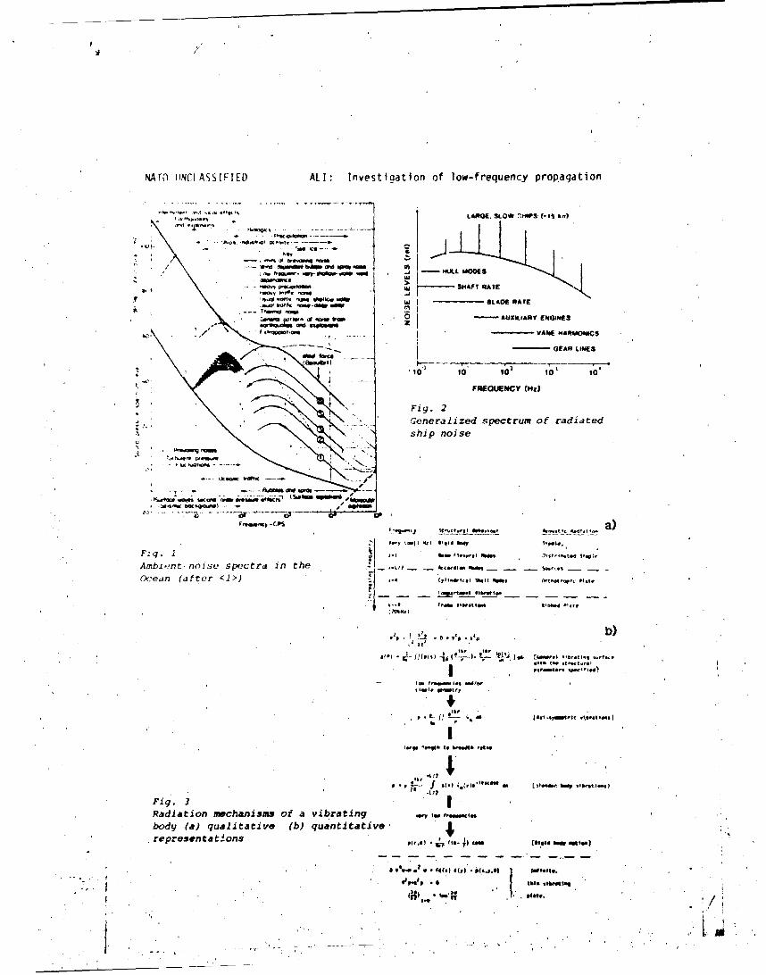
NATO UINCLASSIFIED ALI: Investioation of low-frequency propagation
''a'. *LARGE. 3LOW ý#NP& (-IS Ion)
Tot- 1 -
NN*IV (Woldo bIMW "Re 9hah" m oo- MIAL MaCES
-a" PW4~ Us SHAFT RATE
P- 1%"* awfi W BLADE RATE-, tmtfo Qtow s-do
W. of 0t ro AUXILIARY ENO&IE S
GEAR LINES
'0 10 103 lot 101
FREQUENCY 0Hz0
Fi g. 2
* Generalized spectrum of radiatedship noise
_7- - PA9f a"i"M
01o
bloenp -CPS a
Fig. I~I I V.- I4 I l*p to I.. ,
Ambi-_-nt* noise spe~ctra in2 the ,.-,, -cdo OloOcea.n (after <1>) CI11.s# %061.,. %dsi of .t.
"Vt, t,_
- f....cInj
4w. VI',
* * *~* .*~aF. ~ 4~ (,I~~ bods .10n't 1_0
Fig. 3Radiation mechanisms of a vibrating Ir "f"ps'body (a) qualitative (b) quantitative4*representat~ons P(,*&) ** i(ca- co 194meair
41' $4 044..41 too .tol .,tbs.
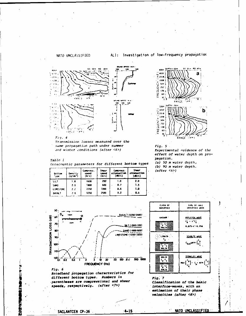
NATO UNCLASSIFIED ALI: Investigation of low-frequency propagatior.
so., So - no so . .00 me* 1 064 oftw w sr 5'r.. 40 40.
032 a$11i J, ,go ,e
Sumner.L 1 S14
z ZS2
C1. 1m 26
AN, 4 0." RANE
Tr~~usmissM io lo0e mesrdoe hsdme~~~~~~ prpAto path une uime Fg
Jfld~~~~~~~~~~~C6 wtr -niios(fe 6)EpimnPtal svdeeoftheffec oFBItzdpt npo
Table ~paIgazon.
Sit 1. 600 1.0 2.0 .-
SAN q .. 4 RAN00 60I..Trasmissio losse meaur0 1000 0. h 1.
BsameT prpaato pat0 un500 sume 0.2.
and~ winter codtin (afte <6> Exeietleiec f te
effe3Pct ofEIAC wa11dpt 1o0po
Ta l 1. p aCLam 40LIoS A
SILT BAAL.SZOSO
SAN -'.0 1 .8W 16,00 0*011*.0
LI- !WSTONE 2(''2250ow 0. 1.00
INTERFAC 1. _ _ _ _ _ ~fWAI
ig60 R _______(550/500
Broadand rop.gacin chaacteiVtisUfMC; n'4
CP-361 251003904 LIQUID, UNCL-T AVE

NATO UNCLASSIFIE[J AL I Investigation of low-fro-oie'nry prooagation
e& dprtev 'his rmfiasurevments on wa1to~rbxlle/bot torn-~j-omptfri 'sons ,j t(,r (~
.. . . .. . . . -- ý.. V---
1, s ph s. S
2?
Worl- ( I~ý r.rt" n 4- 11rf n
mrt o Irpe On. t r I..II geh. I@ aa-, r cc Svrd A
i 14ý arnd t.nk.,. One trielavlA g,ce'o..TOtne k
WIr-n Fxplit.srri- Arraw 'if 7' tr~alllxt*I 30 0(
sourc, mounted lwdrorphonem sIk
---.-- .--- -- - - - - - - _ _
'Shirme. txPlostone Three trl-anI.I gorphon.-s(I916) n1.8-6 km
F06#n et 41 I
0.5-1.2 ke
12 welsnn..ters 6to aLoper 1sland lxp',slone and lne Ihydrophono I a&hw(1978) mechanical bottom Vartoty of
tramelente I -standard *ywt*Qmm distance@
[-oft hrop axplostoom Hydropnon~sVmafiprojector Trieclalt geophooma U
~SACLANTCEN CP-36 4416 , - NATO 'UNCLAq';rFtFn9- ---
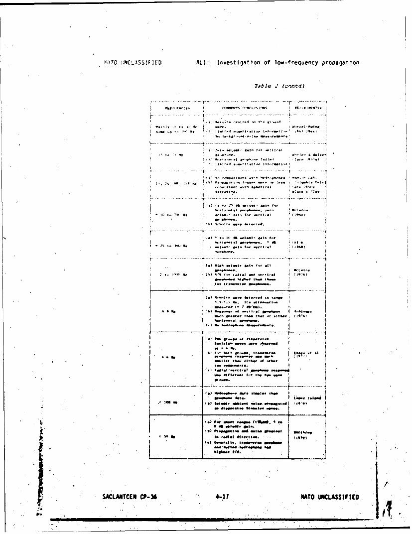
r!"TO !:RCLISSiFI[.D AL!: Investigation of low-frequency propagation
Table 2 lcontld)
I t V, 'diI
V..............- --
r. - A~~ -
- -- ----- ------ - ....- -. .- . .
fa pimp moteml m ~ ~ r' oi
1----~.........
ItI
IN I-ol
(4! .? .4 .,f0 04 #I 40pe I
(I % bytk~. do v trIoe
0"11&1~- 4160 ft tpe e
11444 "ft tre. st mD.Oftimme "O.0
*a,!.llaS mail. 16. ,66mi
(6) PON ~t1 evammeta tg(900. % t
l M * *4eS#S. I
SACLANTCEN _______36__ 4-1 NAT ,, ,*ASIF *1
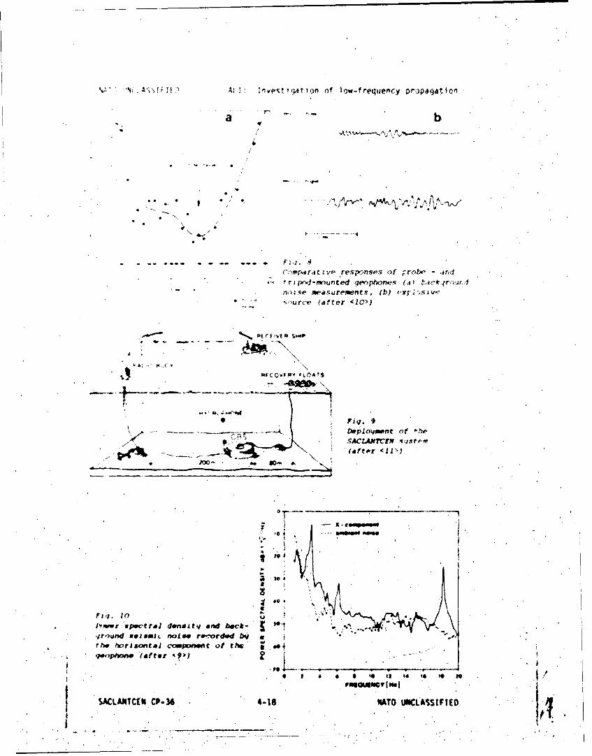
'~(;A~;sF:K ~ k, Investiq~tion of 1ow-frequen~cy propagationl
a b
*~~Fq 8 AA--~.~
Coprtv 9 s-ne o rb n
tr-'iS~nedgohoe ,
0*0
ee .10
lly(partmv 'spectral don e andb bak
baurft(ate (0>
SACLANT ~ ~ ~ ~ t/tN ~ SN3IP1 AO NLSSFE

M4TO UINCLASSIFIED ALI: Investigation of low-frequency propagation
GEO X
Distribution with azimutha.l angleof the Pavr spectral density ofthe horizsontal component of the
9"I'o,(fer9,
a
OM _____Oa
* V.3
fig . -2
a * 1b)Po 4W* 0 Oto 0 40)I
SACLATCENCF-ýM MM OCLASIFaE
BOO
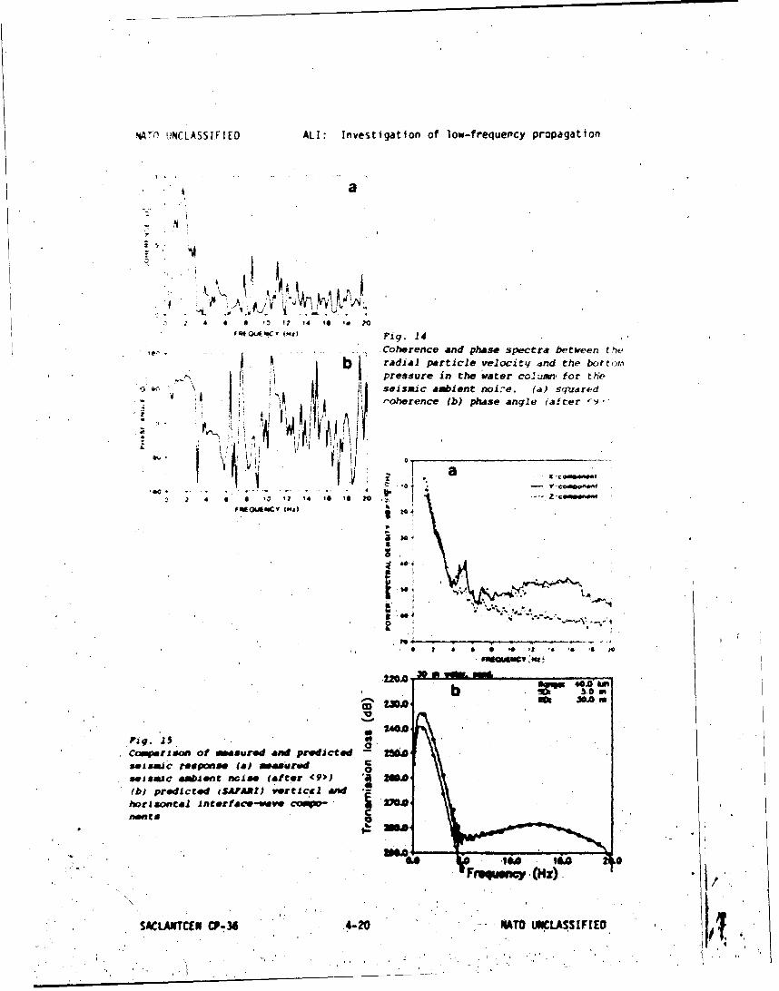
VJ(O UNCLASSIFIED ALI: Investigation of low-frequentcy propagation
a
S& '
£ * '0 17 14 is is 70F FO'L V s MR Fig. 14
, Coherence and phase spectra between fv
Sb radial particle velocitq dnd the bottom"" pressure in the water colunwr for the
i; IseISmic ambient noire. (a) squaredV ft -oherence (b) phase angle (ifter 'q',t t1
F . --.'1
•comparison of awasur"d and prmaic'to 256A,svismic response Wa m~easire €0seismic a4mbien Wise (attt 1(9>) " MM"OA(b) prdiced (SAFARI) vertical and .-
hotl •ntai Incorf oco-Wave 2 MP"A
0 , i. .,
SC- 2
--- -- --
Fi.1
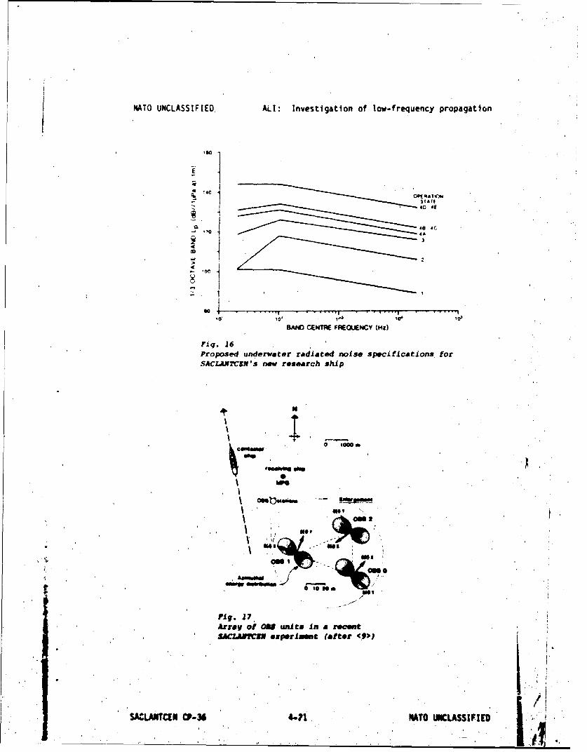
NATO UNCLASSIFIED, ALI: Investigation of low-frequency propagation
S10
40 40 4C
'10 4A
32
sooBAND CENTR~E FREOLAENCY (Hz)
Fig. 26Proposed underwater radiated noise, specifications. for-SACLAPTCEN's new research ship
saw,
neww
035VofO units In a rftcntSACZANYCNN ose~prl mm (after <.")
SACLA5TCEN CP-36 441, NATO UNCLASSIFIED
NATO UNCLASSIFIED ALI: Investigation of low-frequency propagation
DISCUSSION
B. Hatine (France): Is it possible to calibrate your sources and sensor.A such very low frequencies?
H. Ali: Our geophones are calibrated in the laboratory using very lowfrequency exciters (shake tables), as is done in acceleroweter calibra-'tions. The geophones we use are quite sensitive do"u to about I lz, belowwhich there is a rapid drop-off in sensitivity.
b. Schmalfeidt (Germany): Usually you calibrate the OBS system on a shakotatile, which we have not done yet. I know that there is a facility forthis at the Centre Oceanologique du Bretagne (COB) in Brest (France)..
+ SACLANTCEN CP-34 4-22 NATO ,UNCLASSIFIED

ACCAROO & COLOMBO: Propeller noise measurements
NEAR FIELD PROPELLER RADIATED NOISE MEASUREMENTSf
44)DEI. AND FULL SCALE EXPERIMENTAL DATA COMPARISON
by
Luci, Accardo, (CDR.lN). .1ARICONAVAR1I, MDM, Roma
"Agostino Colombo, CETENA, Cenova
ASSTRACT
The ever rising interest related to the underwater noise originating fromcavitating propellers ptompted the Italian Navy to study this aspect of na-
va.l architecture in an experimental way.
"ehis was accomplished carrying out extensive model tests, in the Italian Navycavitation tunnel (CEI.4) and full-scale tests in cooperation with CEtENA.
This paper ojtlines the measuring technique theacoustic behaviour of the ca-vication tunnel as well as the measuring technique and analysis of full sca-le tests carried out with hull-mounted hydrophones.
Some problems arising from both these kinds of measurements and their analy-sis methodology are highlighted. A technique, to take account hull boundaryand hull vibrations, during full-scale tests, is also discussed,.
Finally some results of. "near field" propeller noise, obtained from both mo-del and full-scale measurements, are shown and compared.
IMODUCTION
w The noise radiated' by the external elemencs of the ship's propulsion systemand in particular by the propeller can become predominant and representativeof the global noise level if the operative conditions of the propeller are'Such as to-cause inception and development of cavitation phenomena on itsblades /I/I.
Under thee conditions, the propeller radiatas directly into the flov a noi-
solevel, which-not only cnsitaois certain number of- distinat lines in
SACLANTCEN CP-36 •-1 *

ACCARO0 & COLOMBO: Propeller noise measurements
the low frequency range (linked to tne blade frequency and to Itsmultiples), but also becomes predominant in the whole field of highfrequencies which ore essentially related to cavitationol phenomena.
It therefore appears obvious how important the propeller is in the "acousticqignoture" of a ship ond thus In the possible Identiftcation of the shipitself by modern detection systems of underwater weapons.
In this light one of the mpin aisms of the measurements carried out by meansof hydrophones, located at the ship stern above the propeller disk,donsistsIn defining both this source of noise and its 'levels related to the, variousoperative conditions of the Ahip.
The problem of propeller radiated noise is furthermore considered to be asubject for experimental research at cavitation tunnels world-wide and inparticular at the Italian 4avy Cavitation Tunnel /2/.
The present method of recording and analysing noise dots at this specifictunnel has been established as a result of numerous tests, carried ott bothon two-dimensional foils as well as on propeller models in order to opti~msethe cpl•bratiosm of the' adopted measurement set-up and essentially toinvestigate the effects, in terms of scousttc noise, which the inception ofthe various types of cavitation Involve /3/. /4/.
One of the aspects which is still under Investigation in this modelexperimental research is a univoc*l 'definition of the parameters able toformulate correct transfer lows, from model to full-scale conditions, of thenoise level generated by the propeller
To this purpose and independently of the various solutions to-this problemformulated by different researchers, the availability of full-scaleexperiments1l data of the 'quantities under review, provides a 'usefulopportunity to verify the prediction lawsadopted.
This report describes the testing methodology 'and the setting-up of thetests, used both in model and full-scale conditions.
Some of the results obtained from this experimenal Investigation aredescribed below.
I TESTING METHODOLOGY AND SETTING UP OF INSTUmmENTATION
I .I FULL-SCALE MEASURDEMNTS
The uswl sesessment of, this kind of test consists In installing some(generally twO) hydrophones at the hull bottom above the propeller disc *awell as a number of pressure transducers (4-6) *ad a number of
accelerometers located 'in proxmilty of the hydrophones 'themselves.
SACLMNTCEN CP-3 6 5-2 ' '

ACCARDO & COLOMBO: Propeller noise measurements
The hull transducers, used for noise measurements, are 8&K hydrophones, typeA103 (the technI.ca I chara,7terlsttcs and relative response curve ore
well-known). The signal, via a B&K amplifier, type 2635, to visualizedatirinR the cqu *Isltion on on oscilloscope and recorded direc.tly onto
naignetit( tape. "Scotc7h 3M, using a Nagro IVS.J. tape recorder (recordingspeed : 38 -m/sec).
The trorneducers used to measure the pressure Induced on the hull are of theinductive type PlI from HF14, whereas the accelerometers located close to,hoth the pressure transducers and the hydrophones are of the B&K type 4311
i t h .i :ut-off frequency of around 2500 hz.
The signals of the pressure transducers and of the accelerometers, suitablyampltfied, are recorded on magnetic tape by means of a Sangomo tape recorderfor further processing.
A general outline of the set of instruments used It shown in fig.1 in which,the dislocAtlon along the ship of the various transducers and of theacqutsition terminal Is also shown, for the measurements which constitutethe subject of th 4 s paper. The positioning on the hull of the twohydrophones and of the pressure transducers is better illustrated in fig.2In which the stern ores of r naval vessel, on which this kind of
measurements were performed. is shown.
More details on the Instrumentation set adopted by CETER4A In such full-scaletests is reported in /5/.
1.2 N0ISE 14EASLREMNT SET, UP AND, ACOUSTIC CHARACTERISTIC CF THE
C.E.I..I.M. CAVITATION TUNNEL
M- easurement chain
The noise measurement chain used at the C.E.I.N M. tunnel is illustrated inthe block dligr#m in. flg.3. It corresponds essentially, to the' onesuggested by the ITTC /6/.
- Positioning of the hydrophone, receiver
Several expertments and meosurements were carr ed out In order to establishthe best geometric position for the hydrop receiver and the mostsuitable link between the structure of the tunnel and the csoing of thehydrophone, so so to reduce to a minium the ai nat distortions /7/, /8/.
The hydrophone positioning used at the present by C.E.I.N.N.' for noise-tests is as follows (compare fig.4)
a) in correspondence with the propeller plane, a , water filled box mountedon the testing section, from which it Is parated by a perspes windowwhich guarantees acoustic trasparency. This box Is resiliently mountedon the tunnel window;
b) at 1.65 a from the propeller modeir, elt r well flush-mounted or In a
SACLANTCEN CP-36 5-3

ACCARDO & COLOMBO: Propeller noise measurements
water filled box resiliently mounted on the tunnel wail.
- Aroustic charseteristic of the tunnel
The freqtuency responce of the working section of the tunnel has beenobtained by using a hydrophone emitter placed in correspondence with thepropel'er shaft., This type of hydrophone enits a noise signal, produced bya generator and then amplified, its spectral components beinguniformlydistributed along the frequency range concerned (white noise).
In order to check the scousttc characteristics of the tunnel testing%ection, two series of tests, using the same C.E.I.M.H. measurement set up,were carried out at I.N.S.E.A.N. towing tank basin n.1 (430mx13mx6.80m).These experiment5 were carried out by placing the hydrophones along the,-entre line of the basin, at a depth of 3.4 m, at a distance between theemitter and the receiver of respectively 0.4 m and 0.8 a. The results ofthe above-mentloned tests are shown in fig.5 from which the followinKobservations can be deduced
a) the acoustic characteristic of the tunnel is fairly similar to that otthe boasin;
h) It is possible to transfer with fair approximation the noise levelsobtained, from measurements arried out at 0.4 a (tunnel) between thesource and the receiver to the standard distance of I m, between thepropeller and the receiver, by applying the low of spherical propagationof sound.
- Background noise of the tu-nel
The roliabil'ty of the m-, surements carried out on propeller models dependsto a large extent on the acoustic behaviour of the tunnel.
The C.E.I.N.M. tunnel was built (1962-1964) without specific considerationfor the attenuation of the background noi-se.
In order to identify both the frequencies themselves end their rangesInfluenced by background noise in the tunnel (due to dynamometer, mainrotor, stator, etc.,) a series of esperiments were carried out,systematically varyIng the number o. revolutions of the dynamometer, thenumber of revolutions of the maitn rotor and the, pressure in the testingsection.
The results of the investigation have shown that the pressure in the testingsection, the flow speed and the number of revolutions contribute indifferent ways to the background noise
- the vorlation in the number of revolutions of the dynamometer has mostinfluence on the background nolse and it becomes louder as the speed of.the moter decresses
- the variation of -the, pressure in the testing sectlon influences thebackground noise on frequencies above 10 W,-"
SACLANTCEN CP-36 5-4 4."
A,,.:AkDO & COLOMBO: Pr'opeller- noise measurements
- Th ,.y tet ian of t 1 ow s pe , d in the t e ring seetIon Influences the
".,, •r,+ilwn,; o , iat flow speedi of more than 9 m/sec.
.21,, ,,x;.e?:ne :s -.. rr~ed eut 'Ifitil now h.dve; nrenvere, shown notse levels forI., e, ' o, i wh .t i - t he re I tevn t source h;s been identified.
It 1,,wvw*r, im Port on t Io Ft res th1,t the, background noise can be
dIis ev•'~,ed when the noitse level ' of the propeller under, testitig isr-e h r'. I hi • r (M0 d R) t han the background noise level associated with
the same fun,,tioning condittIons. Otherwise, the levels and the neise
-;wc'ra of the prope.''er nmust be Corrected f-"r the level of the background
not ge .
The ~gu�n�-�• i,)I-se ot the C.E. I..t.. .'iivitatlon tunnel, recorded for the
.;pi,, -t , lrrled out .inttl now, h.4s always been negligible, p.irticularly
In the freqaien(v field tvp•col of -avitation.
- T,'itg_ et _hoa,o"Ogy
The tunnel a'avitation experiments are carried out disregarding the Froudenunmber parity in order to achieve, for a given cavitntion index and a given
advance coefficient, a Reynolds number sufficiently high to reduce as far aspos~sib'e ,:.kvitaL~on •tcale etltcts.
This eseotiLtoly involves crrying out the experiment using a high number of
propeller-revoluttors, the highest possible in relation to the strength of-
the rondel and therefore at a higher static pressure than would be' necessary
ta ,,arpt i.-ninrding to Froude's 1,tw.
S•rch a testing -nethod also hosadvantages related to noise testing, as it
ilI Iows 4 reduction in the quantity of air, bubbles which form in the testing
section thus ensuring the !orrect acoustic transmission of the water.
I.t should also be noted that"by using high pressure values it is possible, to
perform the, tests with a fairly high air content (around 0.6) which is
positive for what concerns the tunnel-sea correlation in terms Of cavitation
phenomena /2/.
2 ANALYSIS METHODOLOGY AND DATA PROCESSING
Given the complex nature of the acoustic noise signal, the methods of
analysis o.f the signal can be differentiated, depending on the type of
information which needs to be obtained.
There are boslclly two ways of onslizing, the radiated .hydrodynamic noise
a) the so-called "brood-band" enslysis which, depending on the type of
analyser, can be carried out in octave bonds, one third octave bands
(more ,common), one tenth octave bands, etc.
,• SA.CLANICEN CP-36 .".5"5
ACCARDO & COLOMBO: Propeller noise measurements
b) the "narrow-hbnd" nalysis, which involves analysing the signal with ahigher frequency r,'solution so as to define the energy content of the-i•om e ;,n a mut-h higher number of frequencies.
The first is typical of the noise, measurements radiated at relativelylong distances from the qhip ("Far-Field") and the reaults are shown. as afunttion of the values of the central frequency of the various bonds asbeing twenty times the logarithm of the root mean sqared value (R..oS.)of pressure referred to a reference value (Po Q !4 Pascal), thus(Band level) Bl - 10 Ig [P rmE/P oJ - 20 Ig [Prms/Iol.
Cene'rally, the "level" is shown In a spectral form (and thus correctedfor the width of the band so as to refer it to 1 4z according to theformula :("Spectrum Level") SL - 81 - 10 lg (Af),and finally reduced to the distance of 1 metre fromthe source, by meansof the formula("Spectrum Level") SL - SLI - 10 Ig (R/! m),where R - distance In metres, according to the hypothesis it;omnidirectional spherical waves. The usual notation Is thus as follows"Spectrum Level" SL (dB) . ref lIPs. IM, I Hz.
The second type of analysis, on the other hand, provides more detailedInformation about the frequency field by Identifying .ll the predominanclines of- the spectrum. The presentation is simply -ade in terms of"levels" (referred to lpPs and to I m), indicating the width of thenarrow bond used.
2.'1 TECHNIQUES-USED
Both of these analysis techniques were applied to the data obtained.
The broad-band analysis was carried out in one third octave bonds using aBruel & Kiser type 2131 anslyser. which supplles, directly onto video, theacoustic "levels" as a function of the -frequency centres of the variousbands starting from 1.6 Hz up to 160 KB:. The levels vere obtained withi'near averages snd relative mean times of 32-64 seconds.
Some results will be Illustrated In the next paragraph.
The full scale data analysis was limited to the up frequency of 20 KBz and
a!l the relevant results are reported in /9/.
As far os the analysis relative to the signals of the pressure transducersand the accelerometers placed on the ship stern is concerned, this was
* carried out using the Fast Fourier Analyzer, type .P. 5451 1, in use at
CETERA Dtsa Processing Centre,'which allows the spectral distribution of thepressure values induced by the propeller and the vibration values in termsof local acceleration, to be obtained. All the relevant results are
Sreported in detail In /10/.
,SACLAO~TCEN 0`-36 5-6
ACCARDO & COLOMBO: Propeller noise measurements
2.2 EFFFECT OF THE HULL ON THE FULL-SCALE MEASUREMENT AND CORRECTIONMETIJODS
The -omplementary measurements carried out by means of pressure anda3-relerometer transducers aim 'to define both the pressure It -"!l induced bythe propeller at low frequencies (first blade frequency and its multiples)and the n- o, as well as global visration lecels wnich occur Incorreqpondence with the hydrophones thereby affecting the response.
The simultaneous adalysis of these signalsallows the right corrections atnoise level picked up by the hull-mounted hydrophones to be carried out soas to elimlnate both the effect of the presence of the hull (solid boundary)as well as the 'effect due to the vibrations of the hull itself.
The corrective facto.: du4 to the first effect is defined as the relationshipbetween the pressure measured at the hull and the pressure radiated in thefree field and it is of course, a function of the form and material of thesurrounding surface.
In the case of a rigid plate of infinite dimension, this factor takes on thevalue 2. Moreover, this value has teen confirmed also for stern shapessimilar to those 'of the above-mentioned ship as proved by previousexperimental tests /11/.
Therefore, all the collected pressure values must be divided by 2, whichmeans a reduction of 6 dB (in the low frequency range) on the directlymeasured noise levels.
A second problem which must be taken into consideration is that of theglobal and local structural vibrations, (of penels) to which the hydrophones,rigidly mounted on the hull,, are subjected.
It is above all the local vibrations which can induce very 'high pressurevalues in the immediate vicinity of the hull surface so that the- hydrophone
'in the hull also records' the, effects of this contribution due to thevibrations.
In order to obtain noise levels comparable with the tunnel test results, itis therefore necessary to establish the influence of the global and localvibrations and thus the pressure by them,induced.
As far as the effect of the global vibration of the hull is concerned, it isnecessary to measure the pressure and the vibration both in conditions offorced excitaton (by means of a hydraulic exciter) as well as in naturalexcitation when the ship is underway.
Relative to the effect of local (panel) vibration, a series of additional' measurements, using accelerometers, are needed by locally exciting the panel
in order to define its resonance frequency (or frequencies). Bysimultaneously recording the signal from the hydrophonemounted-on the panelthe transfer function betwen pressure and vibration can also be obtained.
SFor frequenclus near the loc*! resonance frequency of the panei, variations
","
AA rmr- I

ArGARDO & COI OM3O. Propeller noise measurements
of pre i.ire. i:an be found in the nearby flow whl:h can even be far higher tothose Indiued by the ,Avita•ting propel'er, 4s experimentally proved by','veral rese.,r-her, I/1"2/I whfh requ.fre c-orrections of up to i5 d3 on thesp)•itral contlT1t_ Of the measitred noise levelis.
A n*e on the etfetts of the vibration of the ship stern structure, byme?,nq of , 've!,rmeters, waos ý-rried out during the trials the results ofwhich Are. disc(4sa.;ed in this report.
The j're'snre due to the global vibratlon- was obtafned from these.eosutemont5s ,nd vas of the order of 5% of the total one fto the first blade
hnrmon 4 c and of 'thp order of 25% for the second one.
This requi-res 4 further coorrectioh of the noise level measured by thehvdronhonn- of *he o, der of 1-2 dB.
The loco, ppnel vibration measurements, for which It I's necess.try to use a,..•_-elerometer (piezoelectric) with a high cut-off frequency (with a line.*rresponse from 0 HL to al least 12000 Hz) were not ,:arrIed out on thIsoccasion. Thierefore .a check on 'the actual correction to be made to thespectral noise levels, due to this local vibrational effects, was notpossible.
The unce:tainty con'cerning the validity of a comparison between noise levelsremains, within the middle-frequency range, ever if these experimentshave enabled a more correct methodology to be identified, both foracquisition as well as analysis to be used in the future.
3 PRESENTATION OF RESL'LTS
All the results obtained from the experimental full-scale trials performedon, an Italian Navy frigate'are reported in detail In /9/.
Neasurementsand anal ysis ctpropeller radiated noise have been carried outat Increasing ship speed from a ship' FN - 0.140 up to,FN.0. 409 in orderto Investigate both on the effects that the different propeller cavitatingconditions have on the 'radiated noise as well as on the efficiency of twoair Insufflatlon system with which the ship is equipped.
In this report the radiated noise spectrum levels measured by means of thehull flush-mounted hydrophone for two most significative ship speeds(FN - 0.246, correspondIng to back shet and tip vortex cavitation inception,and N - 0.400 corresponding to the highest investigated speed) arereported.
The two noise spectrum' levels are shown in fig.6 and 7 respeitive.y, wherethe corresponding spectra obtained from test carried out 'in model 'scale atCavitation Tunnel for the same propeller operating conditilons, are shown andcompared. In the same figures the "far field" ship radiated noise spectra,as measured by the fixed hydrophones of on- acoustic range, are -also
ACCAROO & COLOMBO: Propeller noise measurements
Tl!, tz..-ie-r !.-ws *d, ted r:) scr 'e-up both frequencles o.nd sound piepisure'eve In f r5,1 *.'Ae' t o f~lIsco'ts c,.oui t~ions or ~uis.orinot zi1 r, fig .8 ;- ire
A• ,,;' r he" "!iwc resl. t It " Ve pro'ivv*! Ier 'v t.-w o<n p.-! torns .,I) ser v,-,i "-*h in
A~ .n1 moie - onn di t, Ion', tt,e v A r* o-stiown t n t i ~ , , d! i't-e th
Froim-he result dl .cussed in this ;p.p-eýr tlte following ,n te noted
- the noise rr!trp aepsured in the t:innev ond sg.cled ore lower thAn tho Se
ohtpined in ftl1-sc••c conditions.
Po-iKfb!e ex."•n.t lon for this dinrvep.snry hn he fV-nd frron the t!lowtnir
- f1 e14 tinne' the noise emitted from t he propel ter A'one Is ,uI e.i
whereiss in ful 1-srle. the mea•streont ore ol$so Intluenced by the globhonoise prodO.eeA by the snip
- trhe extent of the covItetion on full-*4aple propeller blodes, PilthouKh
f.lrly reproducIng the slmulated one in the e.pwitotlon tunnel, shovw some
,prled leal phennena wtitch Pro unreproducibte in the tunnel due to many
phisl~e, reasons, not lepet different monufoctoring toleronces /14/
between, the mode' Pnd full-scale propeller
- the Pdopted noieo scaling law, according to the TMG foroulation /I)/,
should be refined of the -boots of both further tunnel anr.d full-siole
experliments.
In this context It oust be pointed out that on* of themsm recom.ndat ions put
forwrd' by the last ITTC'"4 Cevitation Comit tee concerns "the-lmplerontottoes of noise saling low* by urtilizing r*eu from this kind of,f ul 1-Seerii .t ests".
5COOMUS!OhI
This report hoe described eawn fuedierntwl aspect* related to the probiseo ofnotie edisted by a ship (ti particular by its propeller) at sea and somegeneral concepts relating to Oeperliontol tochaeliqs and SOle* processingore *Is* sumrised.
Predictiom of the propeller redisted oelee in full sAlo eonditoionS is not,
SACNANTCEN CP-36
r .. .,1 ..IIII i i . > ..

ACCAROG CO~OMBO. Propeller -,oil~e neasuresents
* ' ., ' No! .e irl m t *~k ,. ~ .
V T%0 pe r3. >A 11Z. . rw (I 3 t I'
'ý%b, 4 Aur r.'d ot v 1--' -3 a,. Cx tot io '*in'nflw3
L1 h reIrot
s I3V
'3'i 3V sm.'.r.Ni-of P3v'13 opoe"4 f4Vt-sn od ln t he. 01 p lkiil f !. rw, fs*g%4 -
"-we~ !nt . A< 34331q 4'e .11 t f 0.r.- unlldA- V '1on ittiofns wet e r. t he t %ft
ýeA j i r ~ ~ % vq m.; wtil .h A' *)*- .t' d-) j, e vo I uAt ed i. Ing :Ilp 1e MW r, !'oI,4-4 4
e3 kid.33 V3*' me%
f'.' vAt1V.I 3nne' I it W1 t I Imi swnt.- ri o.l e quIton t revresentI r't~' #A(-, *'ý . It V I'Y .¾3 ve ef' 3W' t$ t. t of of t !3C no i e
,%r s~e me n I. ~u4jAr t -d h.f C Y' 3PI f ton ((initttee crtird out. bv soee
1~~,npol Tun-& S u th o "1, proupe'ler aodeý inde r, dittcrentAv .t ,nIt -- , d It I nu .s re rrpp4.rt .d in figg.11*13. wh~ere CEJ!9I' result
Pc oI~C ~no. - md t' m /oIe /
t bVýe a tit hors o ond t hetr rt.*er f 9 ve Or 1on I stf~i Dim*t to e~oftflInue t he
s, tici e s rie ern i n1( ori rI rI inria of both notse ltv*.# and propeller inducedpres~sures het wrn ino4el (Cov. Tunnel) end full-SC410 oxper1tmntol
)f ours# t he osount of fulI scole. experitmentill dot* w~lI definitely belflereoted ce o n Omemustic range Is oval leble in Italy.
SXACLTC[N P-30S 5-10

ACCARGO & COLOMBO. Propeller noise medsurements
REFERENCES
I/ H.G. F~vnn. "PhisIC8 of aCuStIC C3vitttlon in liqulids", A.P.L. Dept.E'ectr. Eng.. Rochester UnJverstty, 4ew York.
2/ L. Accardo. V. Gregoretti. "'CvItatIon prediction by model
expertmentol teints vt Italian Navy Cavitation Tunnel", R.14/90, CEI.)4.
/ 3/ L.AC*.rdo, A.Gsuzollmo, "Noise measurements at CEIME CavitationTunn*el R. 4/83, CEIIOI presented at "Noise Control on bord ships',CrETNA Symposium, Genova, June 1983.
/ '4 L. Accardo,. "Sydney Express Prop. HSVA. -28. Kodlted Noise4easurements", R.5/83. CEUPI.
S 5/ A. Colombo, "Hydrodynamic radiated noite. Full scale measurements andstinal analysi* methodologies". Paper presented at 'Noise control onboard shlpe° CETENA Symposium, Genova, June 1983.
/ 6/ 15th ITTC Proceedings, "Proposed procedures for documenting cavitatocnoise test". 1978.
/ 7/ V. Gregoretti, L. Accordo. N. ."Irino, "A.oustic measurements on scalemodel propeller", R.9/01. CEXID. Presented at "INAEK.81°. Trieste.
/ 8/ u. Accardo. L. Fabbrini, "Studies on notse radiated by cavitatingfoil* and propeller", 1.5/82. CUIM.
/ 9/ A. Colombo, S.D lr.aetano.t aeca. "Propeller Radiated Noise. Full-scalemeasurements by smens of hull stern mounted hydrophoneos, CETENAReport, n.1709, W',ch 1983.
/10/ S. Do Catano. G. iMeca'. F. Scavis, "Propeller Induced pressuremeasurements at stern of an Italian Navy Frigate". CETENA Reportn.1767. April 1983.
II11 S. Martinelli. A. Della Loasi, L. Cortelliml, A. Colombo,"Experimental ieestigotion on propeller induced pressures on a navalship stern, and their correlation vith tavitatlon phenomena".Presented at 'Advanced fydrodinmsc Testing Facilitiee Sympoeium', TheHogue. The Netherlande, April 1982.
/12/ A.C. Mllsso.w "Propeller induced holl plate vibrations", Journal .ýC
Sound Pad Vibration, 1900.
/13/ A. Do Iruijn, 1. Tie Weld, "Nfaeurewents and preoiwtioa of sound inboard and out board of ships *a generated by 'cavitatina propellers',
SlTWO, - TN Report. Dolf'f The Netherlands.
/14/ L. Accardo, F. No. *Propeller leading edge trtlintng and maintenance:effect* on ship's noise operational perforstseW, Piaper Presented at"Silent Ship ......... " Sympoeium, ta Speuia, October 1964.
/1/ L. Accardo. A. Colombo. "CovtttioNo Noi" Neosuroents with the Sydney
Expressahip propeller pn4de0". CITRJA Report n. 1878, WrittenContrIbutIon tn the Cavitation Committee of ITTC'54.
, C/'SACLNICEN CP-3 . '5-1 "
•,;4.
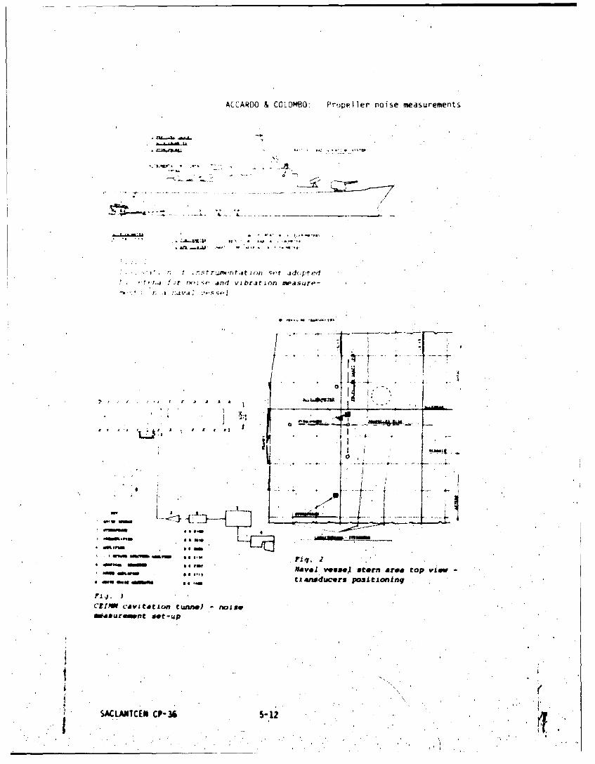
ACCARDO & COLOMBO Propeller noise measurements
o of
elf,
mrjvwmj
so to* . N ava s St
- - .----.-• - -- C
MINMSm ~6
• -• Na val ve8useA stern area eop vIv -
401 , *0 tia"4aiducers posi.tioning
FRa ,. I
CE1Mw cavztatoln Cute,) - noise
measuremnt sot-up
SACLATCEN CP-36 5-12 .
ACCARDO &COLOMBO0: Propeller noise measurements
.- .- .. . . . . . .
Fig 5* I S
CFIMMavtaio tunnel~f tnnl
77- 1
h.~dophole psit vnin
+ +
P4~L -I
Mi- firw 900M U~O
Sound sjactru Isevel I w~reis Sou"e apwctrsL lMVIA coffogisonShip's Pv O.J .24ship's ?Fy 0.40
SACLAPTCEN CP-36 5- 13
ACCARDO & COLOMBO: Propeller noise measurements
PP6
P. P CJCp nIt... fl .-
. . . .. .. . . . . . C _ - 1
- - C -
P
S.....,..,.d.
.° "_•t _[•
7 ...
. •' ,, ,
-'"
Frequency and sound pressure level scaling laws
C . . 44,,/ .
C.. ll,
p. _______t i l It ••* Dr .
a n m o , '
* , .,*
, '@ 9
"
4. 0 pM
Prope-ler cavitation
p-
- .rn
Fig. 1Oobs e vT i o ¢n
Propellor cavitat aion obsolrvatiJon
t' SACLANTCEN C :P- 36 -4.
-. Fx.q. 8,:.,
'
ACCARDO & COLOMBO: Propeller noise measurements
1,10ni
IIi'
140 t-
tIto
6~0 'k I" ý
t Ir 4-
OR 1,6 3,15 6,3 12,5 2D5QD 5 9)
F!RE(RINCY IN ket o *z
Cuvitrating propeller noise
-- Background noise
dB I `LI IH.-L.0,8 1,6 1I5 6V 12.5.50 50,0
13 L, FREQUENCY IN k~z
Catqtation Propeller raoise
-Background noise
Ito0 Fig. 12.
Noise measureaents of conventionalZ, t - unnels
L" go .4- -
48 3 5 43 1ZS2W 540,FREQUENCY IN kHz
-Background* noise3 kg. 1JI
Nois mesuronesof conventional
kunnes (p~au" ide cavitation)
SACLANTCEN CP3
Al.

RAFINE & ELIAS: Acoustic imaging
.~:2 x;X-F': El;:., t zIVI.. rZST ;:ý 11;0fI;lQUES IN WEM
by
DCX. TRIU)Nt - GIEflSV41,e hrusc 83140 SIX MiARS LM PLAIZC MJE
G. u:;.[,'•.;
'3ffice National d'tudes et de Rcercrhes
29 avCenue 6C la Divis.oLi Leclerc
92320 - CHATTLrDN FXCE
ABS`IhPC
,i)Ustical i•uring of ship radiating, noise sources requires theck:veli.:i•t of near field array processing. Performance analysis of alinear processinq withi static sources together with its adaptation to-vvirw sources iutAg4,ng are prresented. •[•lication of this prucesslng toextxrimental measur(crents with static and moving electroacoustic sourcesis shown. Experinental results and theoretical analysis are in good,*redment .
IhNMMUCT" ION'
Improvem-nt of ship acoustic discretion tx•-uires the idetitification ofradiating noise sources. An interesting way to achieve this purpose is tolocate the radiating regions on the hull of the ship.
The acoustical facility could be a measurement station where the shipshould follow, with fixed pop-atrng mccdition, a straight line parallel toa multihydraphones linear array.
Usually the aim of acoustic imaging is to identify the directions of a setof indivickiai independent sources. I here, the situation is different.Sources are distrxLuted on a ship of finite length, and t/hey are to beseparated spatially along the ship length in his own frane, rather than inangular direction in the observation frame. The relevant representation istherefore the amplitude of the noise source pressure as a function offrequency and axial positirx. on the ship. The st-xncture of the noisesorces function miy be complex, aue to 'the nmwier of indeper•dent' so4rces,to their spatial duiensions (compact or distributed), and to theirspectral or temporal content. In addition, this acoustic irmaging mast takeinto account the mtion of the ship.
"Although other techniques .y b-, deoveloped, the qaproach followd in thispaper consists in adapting to imaging the classical beamforming technique.
•SACLANTCEN 'CP- 36 6-1 L"L i . .. . .. _ _ -

RAFINE & ELIAS: Acoustic imaging
-iL,:•X.;:•i .eardonr-ra ni -with sources in the far field of tfe array (pi,-'-,, : : , ~ &allows tioe spatial position of the sources to A-u
•i •':at,: : i` tber rc.uai oistaxce D is knowr (se4e fig. 1 for, iw,). ttzi ::L.dsurEI't of 0, yields W 6 190 e an-lllar
IK A .f stxh, .i, array ixiryj approxriacely A~G)-~(~i hr th
- ,' -- " W,.veenqt h), its T."ts1al resolution will be
(1) Ax ,,/, 5 r
.re ;-est* resolution see m o be obtained whi2 D 4 L but tie plane waveý,ri)xirnation becomes irrelevant . The-. shortest distance D for thisJ•.•i•l:•-ti(1• is controlled by the limit of the Fresnel zone of tde array
D XT, so that tte minir-'u value of 4X is
* (2) zr , L /WR
:r nalrove the angular resolution, the length of the array must be largewi tn rxsp.cm~t to the waveleffjth, so that: W(,. >> . Tb obtain aL* ter spatial resolution, the measurement has to be made in theracdr-fielld of the array, and the curvature of the ýeve fronts has to be
t{ninto accout.
E%,en in this case, the spatial resoiution will re-ver be very nuch smlier*tfa tie wavelanqth, If addit~onal infoonation on the sources is notKzrcjati. wit!"ut such at ,rforeti.a, the source function is not uniquely;6terruned by tie radiated pressure field, according to the Kirthhoffi'Ltewral. One nust tt:hn choose a particular representation for the noisesource pressure de,.ription. Here, this representation will be thesin)lest one . an equivalent umon•ule source distribution along a straightline. 7Te array processing presented here is the adaptation to thisnedr-field inagij of9 the classical linear beaaiforming.
2 NEAR-FIEU) ARRA P M3ST' AND PR.'X1MANCE ANALYSIS IN ThE STATICCASE (ref..I)
In pr,--'#ca of a single plane ave and additive uncorrelated noise of samevariance w" on each sensor, the optimal estimation for its anplitude anddirection is obtained by classical beafnforming. Fbr a near-field array ofN sensors, the equivalent of the plane wamv is given by a single monopolarsourcp of -•,,litude A-sid locat;.on • (fig.l). The pressure on thesensor i of location y. is
It can be Owkts that the optimal estimate X of mxmizes thefunction
SACLANTCEN CP-36J . .

RAFINE & ELIAS: Acoustic itraging
-n
z
AA
16s;. Xt a, d-.t te st* irj-te•ts wi] . u even •) aroandF a f ti• ' (2 D,1 , :.u t thror . l ery ar e f obstainted y focusing the
mu: 0 fo ,. lues of the rI!Vz e(3ivil( the xe-st contrast. Me erL and
4, -, -
al.'Ifl2Wo rrtzer(?-CrOss.iitý ot H () around -2 z is
("1 ;f L C2A. 1 1 6 cl IOst to J(-0 k I((. so) that
(V)
a i fxux d dis t nce D. :t i s therefor'e not very useful to inczrease the
F.:pure 2 shows sirzuldted results for H WX when the souirce is at locationX for \Alricois values of the reduced wave-numter K kL, with 13 L and
- iep•p i of 'field is c4oxr('ixiinwtively
Fipure 3 shous sirmulated results for the samw source and array parametersas in figure,2 and for som values of K.
* -with N s.nsors equidistant 'o A L&` ' LJ 5x) sioe spatial
side-lobes like in classical beamfnrming. Also spatial aliasing appears,at anular posit•ions f i. v0,1 1 / , but'with sape and
dxplitude different frrt far-field beawforming (fig4).
t.*'* *I;* SACLANTCENCP-36 6-3 /1
RAFINE & ELIAS:' Acoustic imaging
S,,, ,' -. .. . ..; A 1i neat -field d'rray, ain x•cx;rirTzn_, a.s" .ý-ý3xe* jA~ sf;ac 11't.y of Gi1, . h array rCA1'Jit (if
* * :, . 2. 4 .1•,i'••, 1 f i ), [j ,V .I l tr, t'I'I.tSed her i ZCoflt.d I I lt- 20 o,. 'V.•
,s ,ki;-;" i;" 2, i.a tv.' ln Vlace5i in fronLt of the airniy atS:i. i r , , ,o . :, driven. at (ilff tret. frexit-qncies (sintu or,.-" ar., :t..:;' . :~. rvsults of t'-ho It-ray PrOC,•SSi j are si )o•t, in
S.... . ; '. .- :,t.,t : . h e x ri u tin i ..Žrfortuiwce in Sca.t dld: . ; .u.,'>* A t (iel f t.Le array are i:i qcrxx agdTroeortt with the
'.r.-.t---ti, ar-y prncssinq can be xlapted when the sources are;n t. ai c;nstt spet-e V. Thlie :rinciple is then to catch a set of
:.,c ;-icture f t.he surcts in the? franc of the array, e(ah of them--. :sowiar~cj tc, a . i i d~spicenont SX of the sources. The pictures are
"* ..n :averaqcd after slifting tihý:m in the sources frare with the help ofa.q.tiori Infritna ton related to its trajectory.
:A-* T *tA!he duration for a sinale picture cr = iX/V), and A. ther,'ý.;ecy reso.uir on ( L.4 /I" ). Due to the Doppler effect, the
Va• :o(A.us urray sens&-rs do not rtceive tlhe sall frequency for a source at a!rowrinc- t. "i a x-inuixr difference between twD received frequencies rustrtf.ýin wt thin A•. for asignificative coxputation.of B (X). Let Cf be
xiW nglt giving the position of the source with respect to sensor i(;.lxTh Dqpler shift on this sensor is =4snf( Y<i
,.1: 'it, :ixul, differential DcxYJlr shift is sj .= .M Q•004-?
1 i Uw spatial resolution Ax
* 2-eref ore g,/&T if
In conclusion, the condition required to get each picture is that thedisplacnlent of the source mustl be snaller than the spatial resolution ofthe array.
n uxperuimitation ws (lone at the Lake Castillon facility with a vertical* array of 19 hydrphvones and an electrodynamic transducer mounted in a
guided streamlined body (fig.8). The source location information ws givenby a revolution counter. 1h- speed of the source ws about 3 mn/s. Figures9-10 give typical results of this test that show the ability of thet., ANTCEechni6que.
__ I SACILANTiCEN CP-3,6 . 6-.4 * ':

RAFINE & ELIAS: Acoustic imaging
* ~ r aresI ri shrw that. unagir~nq t~echnicai1e baod' o~n~rrv r~eŽ;s ~;is valuable for static or ivKYvinq soltices.
S)1 IS "his 1 iiiar nrorexssinq are limitedf 5y tfy- spatital* ':~* fiiWxcx)r1(e source ~r~e Tespatibal re-solut ion 1i T:!fe(
-- vio-o I coill's %N~ry )c~rr at low fr.'quF~ncies and(I this tchiOfpW* -:j~ r'.fwir en tNý he ielenqth is not sinal 1 with rvspý.-ct t') fh('
1,; 1.7. RIof I, f;ou: cv s 1 y IV i f ficu 1 1 to rei if 1ýv eair , fic 5,n -r henqj of a 'Tr)1op01ar ,tye. 'lb ovy-rcoI111 2i,jci
":' ;.ý!ICUlar 3r;iqla procossiflc tectiniques already c ¼ x6f )* * - *- x. t 1'4 COL mii bO Ad.Npto( to the! near-field si tua& ior K
ý' *-; , , I i tKo i n to )COL M the P DORIer ef fec t ard have r(-I e vint
& :'~W C.~ fUtilisation d'antenine fccalis~es ,)our 1.K~a -0 i ;o1e S 0iA Qtioý:3t iqjues 11th ICA Paris 9-//3?Voý 6
SACLANTCEN C?-.36 6-5 *

RAFINM & ELIAS: Acoustic imaging
0
0 ~ / Saa, lo
/ fID .
.6
".4 K.4OFg - Neow field orray g*eornetry . K,20
.2 K
F .2 .4 X/.
Fig 2 Seew res•oMlu121 -M.2 L,B (0)/Blo) Pou~lm of fte soco X.o
Ias
0 I 2 3 4 .5 D/L
F, 1 , C}l, Pt:. of field N-N 21Poslloý ot the. .sc( D/L .- X-0
a 1XI /94018 . 11 .o
O '1
,4 4 At ,,. .
$"go ....

[~ NE & E L rib. t-ic I n'q1 9
Arbitary
'0Source I
o05 . 6 r~~t
F i Acus,c .y* .iO w I'octQ 405r *110twed -tI j s*-e .V.
If I
Source
X-
Y ~C
5 IDJI '
fi _ _ _ js vI
oi III 3 , 0 2
itf
Fig 7-Depth of- flelld Aco-stic irmage of an .'ctrgaKoatic source oxcited oy
0 Sau wowt of 1- 4 Wit N- 1.9 La m
Source po~fl . X- Orn D- .7,Z I

i*ray of 19-
4.4
Wv 1s m"ot o f-u a/*wo wm
10.
aft " I. Pt*
IN
AS III
tI S - ~
if I'., j %.&if! f o
P - r i r 44r r t'affp *flf
-' M. A fo," ~ r jt'lf" 1 r 1etermind.7>e ft. PnpO
L*P !Pie -p e !,) ri -;lure,
-tFp nq lea 0- *he *-Y- *e-1 -,outn
.)I*'#r If Sr .ý' ISIIe'w!~ ~n~~ to be Molifled to Make
ho. 'Pi i;v re,,cl tion" va~tIods w" 0 f ~r.p4'writ 'of th~e covarlarce Mltjtrix ofrl~ir r~w t),snd sig~.t. hnals sent, by th~e shPip to a set of sensors.
1 0.1i4 t hI1 % oup Ie, ote f orre,.ponO i n1; term of tP'e matIri x.Its
'ACiANT I f CF.- 3* ~
Df FAR T Mutua I roh#erence arid s I 1ePnCe
rrrrrýInl to 14n
*qa i *- 9noVV 4 oP band and
r 4 4, f,.P-t01 two~ Pont on
ee of2jd toi ý4* d Y mn~r o arid ytlC S I9Pnd S
"r I vieo h9 e r hand, we (- e.,I er a rpýe i vIq i a rea (antenna) and ( 1X ) a"*:CAJD¼ C) polnt)ý on I '
is tp'e M(I aOciated to this couple.
A(,rordtng to these hypothCejes the W )heys to asecond order wave equ~ationl
a nd t o a >JGHEN S prinriple" ass-ciated (fig.1).
It .afl be written~
mfr is the wave Aufter for the Centre of the band, r,, r,.the distances
too c *4s -c L An
I

GEBART:' Mutual coherence and silence
., w..r~ ,] • *b *ene ;trv jt, ir 11,onIn¼ - .ftl.-,, ( t)
v . •. . ., In : 2 (2)n
Tre quntty f se orlntod~tln nafomul r(1)~ iisth*1, 2112
Pjfi jr I~t *S)f l'1Epin ut) to .e(,ord ordo, .n ' A
i 1z2 2 ,12 12 2
R '(01- %in sin:, + -sin. S--inf- o (4)
The quaOt ity of use for introdution in formula (1) isX ; X2.
.11 1
X2._
1 X2 .2+ sin ii (5)
The MC for • cn be expressed in terms of the MC for . ,. 1L) by
use of the iormula 1;
'.ACtANYCIN CP-16 1.3

DMRART $41tuajI cot,er'ence dnd ,ilence
. - I Y P N, • F
I~ ~ ~ ~ ~ ~ ~ ~~~, re! yineedntoethohrthSiuion }+ is eya tlytea
v •fn ý,a I wu,. o ' , ++, ini wr the optica sour es l 5fi gtw point oJf the sum
f i +xim l ar in ipe n ,
+ . I
" .... .+ "*++.,+,'••+ '+,.,. ,+v+front drid ,dUows the deti•runalttOn Ot he
1 2
"", 'th acloustol in t ens itylp in ePna pn anOd'tudl acOUStICal sources,,v•~ 1.nde~penddnt to edf.h other, the situat1onl is e~4tctly the astro-
(,ft1,d! •Itudtilon *, in whl'~h ,th• optical SOUrCeS 1f'.two po~int.S qf the Sum
Si', the d(.oustlcal Intensity in each pinOft., anid the Integral J reduces •
'o a simple integral
(X I' 2).J • (C+ (8)•
sACIMc[N CP-36 -4 . .

DEBART: Mutual,.coherence and silence
.,.-' t -o- f urr tion I a u-!u 1t-l1 power on
- , , 'w• in, -eterred b'y the a;'tronoms as
., " ,t ",, : + •, 'o' I, it i¶. ',)nve.iient to suppOse
(9)
',-*t:',P(1,13nr to• -•i" .1 n, t. t ontributionf' . If the antenna has a verywtin. _ v otw •r. ire %Pen dS dlitfltct. if not they, are seen as
r, in, jue ,•. t•w,,' -nq)usr lo( ation is between the extremities of the
"s•,itj.i Ijn i % mod i i od if h•e ,hnip bear, a repartition of drcousticalwi i .) M! #rn I ion fivite between ay couole of points.
") 1,t ',n, pn(.fnflNorio, let u%, suppose that this MK takes the form
,I _ (10)
, rIud* i' dteýre,s i n; with the distance,, is, a radius of correlationin ribe suppo',ed aIso that the argument is wariable (linearly) with a
h,ir, teristi( length (c an be infinite if no variation of the argument
'erne iPt Cfn be written
iKV 1o2.)
j e e X..
2 X (j.2 2) exp' 1 2 sin sin:- iK + I_'2- O 2tn a~iK 1 2 V.idf,z I)
In order to evaluate this Integral 'letus suppose that p Is very smallversus
a'nd adopt new varL.ables, according to the transformation
SIACLATCEN CP-36 7-5 ,. ir.;..

DEBARI. Mutual coherence and silence
V
1K'" 9 rsfnil' I tkieimts of integrdtion
2t i K n R--- in ,- -L-dudv (12)
- (13)
"'• .! , oý?, wf• , f1hevP1 wth no trouble dnd gives
K 2
X +X,)sin sin;fl -ik
* " "R dV (14)
2 X I V 2sn st v
:'*' ,,.f, rj' e, , On rt I remote, the V -t rm in the ex.ponentidl can
.i- f-ne , i f we .1rop tt onstdnt fdctor'
" " -(1'5)
2 K1R n K +X )s ' is t (16)
4W 1 2'h K I Y +X )sin sin.-
" i, ,,r1)n of the jrqument of ,J versus (X I.X2l is approximately the
,me a�d" the variation of. the argument of a+ib
Arq(di6) * Arctfn ) .:n, trg Jd
SACLAiTCEN 'CP- 36 7-6
DEBAR!. Mutual coherence and silence
V,- ',III Inl(17)
x , A s % I nr
o ý ofnliI 1t 1 , ol .~r p -.Tx, te ,our, p
I)". jl , ( if ,orr L-ItIn I., vP-y ',mdll, /? for any distance'1. #wen n, ',•n',or, . A. tA t if, igaqin the case of d totally incoherent
nf oIt l-.t usrp, i thit ')¶-,X) vary from -L to +L if L is the length
•.' u'iP•*(nr*,e i r.jdiuw of (orrelPitlon from the condition
÷ for A X, +441
u',.u,i ondi ion%) 4 iIs n
S 1or (20)
.The drgument of J vary quasi-linearly from - td t - if X -X vary from
-L to +L and the angular freasurement the antenna can achieve Is false(the ,irgunent of the characteristic factor takes any value accordingto X I-x2).
If, for example L 20 m , Kcos. 2- coVI,
* lm 1 =4 •:"
Im
* o. - ..
S.SACLANrCEM CP-316 *:. ' 7-7 4' -
_a .. 1. (
DEBART: Mutual coherence and silence
,.,,. ,- whose -orrel,,tion i shaped il)
I if ''nve ,y sum of soure,, of certain structures and random ampli-":e ioordninq to 'he tLoeve-:.,tihunen theorem
n n
1 in o-tended ';ourf.e whose repdrtition is roughly sinusoTdal
n' n 0 ( n(a n:)
"• r orrtI,ition fun t1o0n (.an he dpproXimdted by a few sources.
- NCL ; 1~ ON'
" h neo-retirl poSsbiit/ to make ineffiient, the high resolution method*"m, shown. However, achievinq this result involves a modification of
#, ou'te,! emission of the ship, and this problem must he studied from,,.- poin,, of view of its practical realization.
/
SACLAN'fCEI4 CP-36 ",7-8 i

Dl BAfU: MUtUdl COhl;-re0(. arid silence
FI1 Secod~orrier Huyghens Princi~pe
P,k)
'7Fig. Configuration ship-antenna0
SACLANTCEN CP-36 7-9ifi

CEtRNICH & VETTORI: Mobile range
M( F II.E RANGE
"(E MF1A.;r1JP1N,; ';H I IHADIATEID AC()UJTIC NO'ISE
by
-rnzo Cernich
S;flomar- S. p.A.
Sarzaria, Italy,ind
G iancar lo Vettori
USEA S.p.A.Lerici, Italy
ABSTRACT
T:e Mobile Range described in * this paper allows measurements of rnise.
r'~iated 'rom both surface ships and submarines in open seas with bottom
JUptl ! from I-.s than 100C)m to 40() met ers. The range is being developc:d and
buiL, by Sonomar under contract with the Italian Navy. The system is
semifixfed, that is, it can be launched, utilized and recovered in short'
time 'or else, with some precaution, can be left operational for longer
periods. In this paper a description of the system is given; the designcriteria for the at-sea measuring equipment, the navigation of the vessel
bering tested' and forat-shore data analysis are discussed.
INTROW)UCT ION
The system described in this paper will be used to meacure the noiseradiated 'by surface ships and submarines in both, dynamic and staticconditions,, in open. sea with a bottom depth fronm less than 100m.t to 400meters.
The system is semi-fixed, that is, it can be launched, at sea, utilized andrecovered in a short spice of time, or else it can be left operational forlonger periods, pr-)vided. certain .irautions are taken.
The mobile range is now being developed anid built under contract with th2* •Italian Navy.
* * In this paper a description of the system is given; the design criteria for
, t1h ""A,..
,. .It (•-• •ANICp•:d #,• . .-%f -
,/
CERNICH & VEfTORI: Mob iI ranq,,
• " . : .i • • , :,' ,,• ;; ' Z.1 ' L 1j"'. 1'.i Ionr ()t' A wh• ve':,•;,• , f' ' k' !';
SV itc'. !411r!' W
. : .. , ir ,t:; with tot ton Aepth ;AP th .1', M-ti.r:
""L,:r,., iv i, ,V v;il of' the i n-watf'r q'ii prnm n. .it.
v; .... ., ,I'~ i I nui- it --r equ ipment. tA- bo perror-mo=f thi a raI
......[11 b I fe parts
I~ ~~c Iil rec APove r t he mainge an d to nz iict: 'thet ,,':,C ; :; t h I ; r'ft " o ;hnIip to be test, ed
Y ,.x .r.:..,. r*- i• •tb) cnmerci;aly' avai lable equipment.
' nily:-1V;In exi, ;tin, faci 11 tieS:
L; ;- il t'li co,,rls 1 o; t- o I
1 n-wat er S;ubsystem, formcd by three mooring supporting the required
hydr.ophone- Stations, a markt.r buoy and a radio buoy transmitting data to
'In ssl ship.
t, N'v I giontI, sib.,ystem, located on the test vessel.having the purpose otf
ý'ving nrivivational control with respect to the moorings.
r.;igcal acquisition subsystem, located on the assist ship 'or else, on the
test vtwsel if' it is a surface ship), with the purpose of receiving and
•rcording on magnetic tape the signals trar-uintitted from the radio-buoy
and ::ontrolling the.quality of them.
d) Signal ana1ysis subsystem, locate-d on land, utilizing part. of the-.
SACLANTCCN CP-36 8-.? j - i

CERNICH & VETTORI: Mobile range
11 1• . v t.1 : • ,,y t ,:Tn In( ,I ý .11-1 ' c I (rmp k'ý r .
H. H, ! , :cht.,,,t r c •,onfiwur-at-,n of the in-w;iter stubsystem:,d. *5• -r ,,-,er'ai ný 'rii , on t p ir bottom of K) meter!; dpth. It consists of"
h,'o: A.i',. Th, hv:'dophoie stations (H 1 H 1 , i andtI H I -'r- suspended
r'•',Scr'I!':' A nd H ;i is r , di ca ted in the d iagraam and it the re q u 1 red
v-,. 1 ,i and H ar, cal led Beam hydrophones and H is cal lel Track.
iTh,. r v tr' ion 1:; flexible so that, ,starting with the basic
n, ,,gurat ion in Fig.I, 1t can be adapted for either surface ships or
si•b•marines or changed according to marine' currents or to the bottom depth
,,n whic(h the s.3yst-m must, operate. For operations with submarines hydrophone
Ht is lint uIsed.4
The •'o•-q)site structure of the cable enables the position or the hydrophone
st-ations to t)e 'chanved and also iýo intervene on each connecting electric
-;tbles separat~ely.
Mrinw; A arid 1H both have a Release-Transponder unit (RT) suspended at a
depth of l!U,)mt. These units act as an acoustic responder and free the!!oorings whe-n receiving an appropriate acoustic control signal.
The iwo moorings A and B are anchored to the bottom (AN in the diagram).They are supplied with two buoyancy uLnits and connected together at' the
.connect;ion Unit (UC) by' means of a hydrophone cable (CAB-3). Mooring A is
connkcted to the Radio-buoy by means of a Vibrating Insulation Module (VIM)
that has the purpose of isolating the buoy's oscillations from the. mooring
and by the piece of cable, CAB.7, which also has a damping function.
-The radio-buoy contains the electronics (EL)* necessary for the conditioningthe hydrophone sipna]s and for the transmission via radio link of thesignals and reception of commands from the assist ship to 'the buoy.
The radio buoy is easy to connect and disconnect from mooring A in case itis required to disactivate the range and leave it ýn the sea for a periodof time.
The radio buoy is about 5 meter high above the sea surface to make it
Svisible from a distance both optically by periscope and by radar (this-- applies also 'to the marker buoy). Oseilitions. due to sea motion are
limited within the vertical aperture, of the transmitting/receiving antenna. I,-2 - ,
a,!

TA V !i -1 r .' r A~
t it[ in I i0'' i it ic
t rr i *r d '1. r I
wt i7 I~"1 ,. I i I I. I1. provid .Žs nign~~ tic rec-or-dii_
;I .0 v" raI -0 An .d a p~rel i ml nir~y data qual i t~y
n ~ ~ . ~na I y's- r ,ind proper recorder. ) 1g i t~a I c. ir k d it
)r;ý tj(,orit ncg uac-* rS )I the e-lectronics are also recorded.
V I er-t I ',S rl( oi tu f it- hydrnphone ':harinel s to be- iýoed as wel 1
:j_ 7'. 1,.' 1 . i n I i7r alA , ii I ibra te t hem.
% .,x iiry rw ti ! cc ro1I vi b-d Ly + he ocibsystlem are:
Mt- cu-mrit.fthe ,,,oretric 17'] e Irma tion of' the range due to the W_ ter
cur. ,-(,t t. y in terroga tio (,~I' the t.WO tranlSp(Vnder ln'itS.
n 'Me p os~s.ibui ity to i'itet-ririgt the 'test vessel from 'the assist ship;this
fontri t ion- dupli c.q t- r i*e on..' ir ' .... r,' I ,n bo ard the te zit ves:,iel1 an,! is
SACLANTCEN -f.; -4.

CERNICH & VEtORI: Mobile range
part iclT',Arly relevant. for operations with a subnirine.
-:4 Fil el.troac-)utti c calibration in si tu cf the var,.ous hyd'iE hone
I -,s ibiIi 1ty ot I as.r'.ng preciseIy the distance between the ttos". '..ssel
anid each hydrophone.
e Ac-tivw;ion ol the rfIease function of the transponder- for recovery of
the it-sea e'luipment.
.:.4 - n-land analysis subsystem
iiz.4 is a block diagram of the subsystem. It eables the fP.llowing
*.,•erations to be carried out for. each hydrophone channel.
' Hiconstruction of the distance between the test vensel and the
hydrophone aad choice of the sections of the run to be used forsignature data.It makes use of aome of the components of both the acquisition and
navigation subsystem.
b) Analysis and signature in 1/3 octave bands from 10 to 4000OHz.
c) Narrow band analysis and signature between 5 And 5000Hz.
d) Compensation for the effects of surface and bottom interference.
e) Calculation of statistical averages.
3 -'ANALYSIS OF SOW CPITICAL DESIGN PAPTS
The periormances ind reliability of a mobile range is a large number of
factors and operztions. While setting up the system it has been found thatafter designing the data telemetry and vibration isolation of. thehydrophones the moat challenging problems, to solve were:
N easurinr hydrop•hfe positions in the range.* Navigation accurancy and mtfety of vessel naiigating inside the' range.
SLamunching and recovering of at-eao equipment.* Compensating of ourface and bottom interference in the measurements.
SACLANTCEK CP-36 8-5 (
CLRNICH r, VEIrORI: Mobile range
1!, 1u p.tl,!: tti, :h l Ut I r b i ri-. impIem'ented of the atbove
S :, ,i. t-v v r, it i on i} area ,a current -. I II be
S., , . ,..... . . , i ,.v- !,t ,r r, I ',; ar ,m ,i •t;raigtht line. In t-he!,i :nf,. b..... ualyinc ies andf ;tnchnrs
; . : ' , " i,.'. *- •'. ) l' r.. i , I, ,,;irn ¢ .*. d i ,r itP•. 'rl o rn J r u. h t i' , '; ,e. I' the , rr n t is j •y ,
sr! h>.,w th,- .letrmanit on of' mtthring A and F4 Whten -it
... .t..... . tn ., tfe fl. ing " eurren t profin Ihe :I r
.*1. . s'.. ~ [.?wee' 1, .,ieter, ind the b mttr.
.. ~ h.* ri U:,ossumedI perpend 1 (,u I air to thet phasoe
r~ ri n, tri I in P the -urrent is assumed parallel ta
t~a, snA it ý an be )bserved that theý, is an offset betoeen tho,
*Xs t- Vise lIne H .-H andJ the ax is ),* base line joining the two,ri .- 1.•.,•-rs ;.s - ft.,r orram-,i, n tf" the vessel under tc-st.
7heref ro in, *)r~ier to a rigrat.- the ship under test wv-r H A( T1ACKHv.ir-:4 hone, the offsetl murt be taken Into ac-count. It can be observed tha?
"rr r"ivg.it ion purpoes tcly the o'f.set in the Y/Z plane is relevant.7..-re.ore .•i i•iple la'st mean sq~are algorithm is used to estimate precisely
!he proJPctitins 6an plaine YZ of distances between H , H H ,H , A 4 and the-
two transponders. Meatiurome.ts are taken f'ro the assist ships before the
,essel under test star'ts a measurement run. Estimated navigation accuracyover H is of the order of ' meters.
4
3.2 - 9bservations on the test vessel's navigation system
reterence in made to Fig.8. This digram represents ait example of thepositions on the horizontal plane of the buoys (B -rmdio buoy) the two
responders RT and RT1 and the hydrophbnes Hl an H4 at the, hood'ofmoorings A and 0 respectively. Because of the defor•ation caused by the
SACLTCEN CP-36 8-6

CERNICH & VETTORI: Mobile range
o•rr',t' H .oind H art, fispl icTed with renpe, t to RT and PT
I'he navi,: at ion' f the teot vessel will have several phases (see Fig.8):
ric:r,,,jch .inc r.idar-,ptical a] lignm-.nt.
Th, e:;t ,.,'e:;n,' " " the t h ,joys P, and H and sets an appropriate
i,: in corr,ýspondenice to the radar axis perpendicular to B -B and
r,,l; i ri t hr iu h the n.,point.
Thl!i ;I, ' pre'.','J,- ih#h h !;f- of the aoust ic navigation data and, in the;, ; nar ne. takes p1acP at periscope depth, before dliving.
te Apprn,'ch and aco ust ic: al ir gnent.The test vesel moxiifies its course, moving into the acoustic navigationAXIS by Uiflizing the data supplied by thn HP-183h3 computer.
Miintenanc- of the course.
Tihe test vessel must be on the correct course -,)me time before reachingthe maximum distance [i4 at which radiated noise measurements begin. (DM
; i,,ut lW.',m t for HT I-PT .,'VOmt and minimum aspect angle of 100).
The test vessel continues on its course with small corrections, asinIicated hy the computer, up until the end of the course (a distance [N
ne-yond the range).
1- Manoeuvre for moving away with an eventual return tcwards the range fromthe Opposite side, repeating the above mentioned operations.
The following observations should be made regarding navigation across therange.
S;afe navigation for the suibmarine.
The navigation sy'xem must ensure a 100% non-interference with 'thestructure of the raij',U. The system has been designed to offer thissf#ty; it. has infact been verified that when the distance between thean(chor:iges; is 200mt. the deformation of the range. even under theinfluence of unusual current conditions., 'leaves ample space for
navigation.Moreover the system supplies the datp with a precision far superior (im)to' that required to ensure the non-interference,.
Validity of the measurement, .
The most critical came is the passag*e of a surface ship acroes thehydrophone track (H ). The assist ship should pass above the .yd'rophone
4H4 with an offset error not greater than the width of the surface vessel.This can be achieved by means of the proposed system that, owing to thecombination of high precision measurements with filttring, &Ilow@ ,one to
SACL•ATCtN CP-36 8-7 .:

CERNICH & VETTORI: Mebile range
"'.. ,ri-. 'i .t iz• hardware a) ready widely tested both for its
, Ir o, re I, I *v i n the" oflshlrei fie Id and suitably adapted to•
1 may navi"V t," at. maximum speed ( 30 knots) provided that the
i the, trr,.sduo'er installed or, the test vessel is conta ted
ht .sOat'i :,thed l imnits.
. I ci;,ri the range that are required for the navigation, of
""it- he two responders PT and .T consisting of the. RT
*,1, l-,1 as shy-wn in Fig.8 and defining a system of cartesian
* i, • :" r, ; i:rf i tr h reference poi nts with respect to which the test
ai,-,ff'ttes its position. To do this the test vessel interrogates the
* rir.sp,,lers WT and PT at a frequency f1 ; these respond at different
. '.~ v-s•;Pi r-ceivs the two responses and recognizes the two units on
• , i,;.; t. the ir f requencic e.s. Using the time intervals between
i. ,io. )nJ response. h',istances k and R between the test vessel and1 2
•••• •••••he test vessel and PT are measured.
, .- p. :in I' Trh test vessel is found from the distances R and R .. The
W * 4. (t;nputer elaborates this information by numerically filItering.*lrt :r:,k •.s usel o el iminate the effect of the delay in the estimation of
t.-A, :t ,,m oausod by ,crustIc propagation time. to estimate the direction
it;I ",)- 1ty of rT,'lgation withoit, the necessity of a gyrocompass and log*
trim -.o reduce the effect of measurement erfrs on the global precision of
*he system.
Errors are essentially:
- Error in the measurement of the delays due to variations in the soundspeed."The effect is minimized by estimating the appropriate average value fromthe temperature./velocity profile. . .
Ar intrinsic error in the measurement of the time delays due to theinstruments used for the measurements.
"Error in the estimation of the transponder positionm.The preliminary measurements for estimating the precision of the system
SCLMNTCEN CP-36 8-0 .

CERNICH & VETTORI: Mobile range
*:r~A .'',. thils ,rr'or.
c" ,'x 1, ' : v , .. lati•,n -stlidy has been carried out in order to calculate
tKl ,rr.-rs in th- positioning of the navigation system.. These have
ft . thhe order of I meter relative to HT aind HT . Ther .. i : Ir: .t he rmi.'.',a 1 )n system. inc:Iud inng the operator, has a f'so been
- i•o-J ;n r-ir toi v-.rify the ,a:;e with whirch it can be used.' Fig.'9 isI. ,X iI If- this simulation showing graphically the horizontal plane
n t: h.' ratZe HT and PT 1.
"-h, - axis repr-'sents the navigition axis desired V , X , Y and.":;ire:;.nts respectisely the speed, the coordinates and the heading of thetst "ess.l me~asured with respect to the Y axis at. starting point. The
-rf,•es are the successive positions of the vessel estimated by the system.
t.r nystem also s•upplies numerically the successive X andh Y values togetherwith the angle. The solid curve represents the real course of the te3t
vessel.
3.3 - Launching and recovering of the systemt
The method for launching and recovering the range has been designed to
operate with an assist ship provided with one derrick, one winch and twoauxiliary craft (rubber dinghies).
To carry out the operation with the above hypotheses and the limited
manoeuvring capability of the assist ship the sea state must be less orequal to 2 and the direction of the wind must be constant.
The procedure for launching the moorings A and B is a combination of the"anchor first" and "anchor after' methods: each mooring is launched in twosections as shown in Fig.lO (the bottom setting lowered in depth and thetop section floating).
The submerged sections are. suspended frnm a reinforced balloon andconnected by means of a rapid-release hook.
The two.moorings A and B, as shown in Fig.l1 are then spaced apart so thatthere is the desired distance between them (about 200mt). 'The rubberdinghies are =reed to join together on the surface the two section ofconnecting hydrophone cable together with the sinker, kept temporarily onthe surface by means of a suitable balloon.
The rubber dinghies ore used to uncouple the two supporting balloons.
/pi
SACLAMTCEN CP-3 -9., •, A

CERNICH & VETTORI: Mobile range
,,-r rvcnverv, the assist ship activates acoust ic.ally the uncoupling of the
mwrin• A releaser and subsequently that. on mooring B. The rubber dinghy
tIk.ie; the radi-bhuoy back to the as;sist ship and recovery on board begins
,t,'•)rd1ng to the :,equence: radiu-bujoy,, mooring A, mooring B.
"Ar -nergenc" rorcycry method has been foreseen. This would take place, with
, he•lp ,: -fivort,, and -.niy in theunlikely situation in which one of the
Aoee'sIs ' t work.
S.. - l -sttvn f';r the effects of surface and bottom interference
:r, <)rlvr to Lialcilate the acoustic levels at the reference distance of Ino.-re fr)m th- source using the measured levels, it is necessary to know
the p rop-igat ion loss between test vessel and hydrophone.
*i•hi!c: !he geometric conditions foreseen for the range, such losses can be-. iel ising the classical law (spherical divergence + absorption minust,,e inc,,herent con•t. i hut i on of the surface reflections) only for
!r'fluences atove IKHz. For lower frequencies, the difference between the
rropagatl,,)n mAdel required and the classical model, becomes greatcr (and,hence also con)ensation), the lower the frequency.
The o,,rder of magnitude of the systematic error by utilizing the aboveSssi=al model can be of l0-1AdB for frequencies of hundreds of Herz and
: P i-,dH for frequencies below 100Hz.
This error is caused by interference formed at the hydrophone between the,irect sound, field and the surface, reflected and botto' reflect-d fields.The bottom reflected field depends upon the frequency rAd the geometry andnd,ture of the nottom.
A preliminary study, conducted in cooperation with Mr. Schmidt (Salcantcen)using models NISSM and FFP,. on propagation over a. reflecting bottom has!ndicated that for frequencies above 1000Hz compenisation for incoherentaddition of surface and bottom contribution and averaging over valuesobtained from the'3 hydophones (spacial diversity) gives a reliable resultif bottom characteristics are known.
For frequencies below 1O00Hz there Is no simple rule available. Somemodelling work has been started and shall be verified in known areas usingthe range Itself.
4 - CONCLUSION
The system must be delivered foracceptance test in summer 185. Sea trials
are also foreseen in order to verify at see operations' f the various parts"of the system in Fell '85.
SsALAu CE CP-36 , 6-10 .
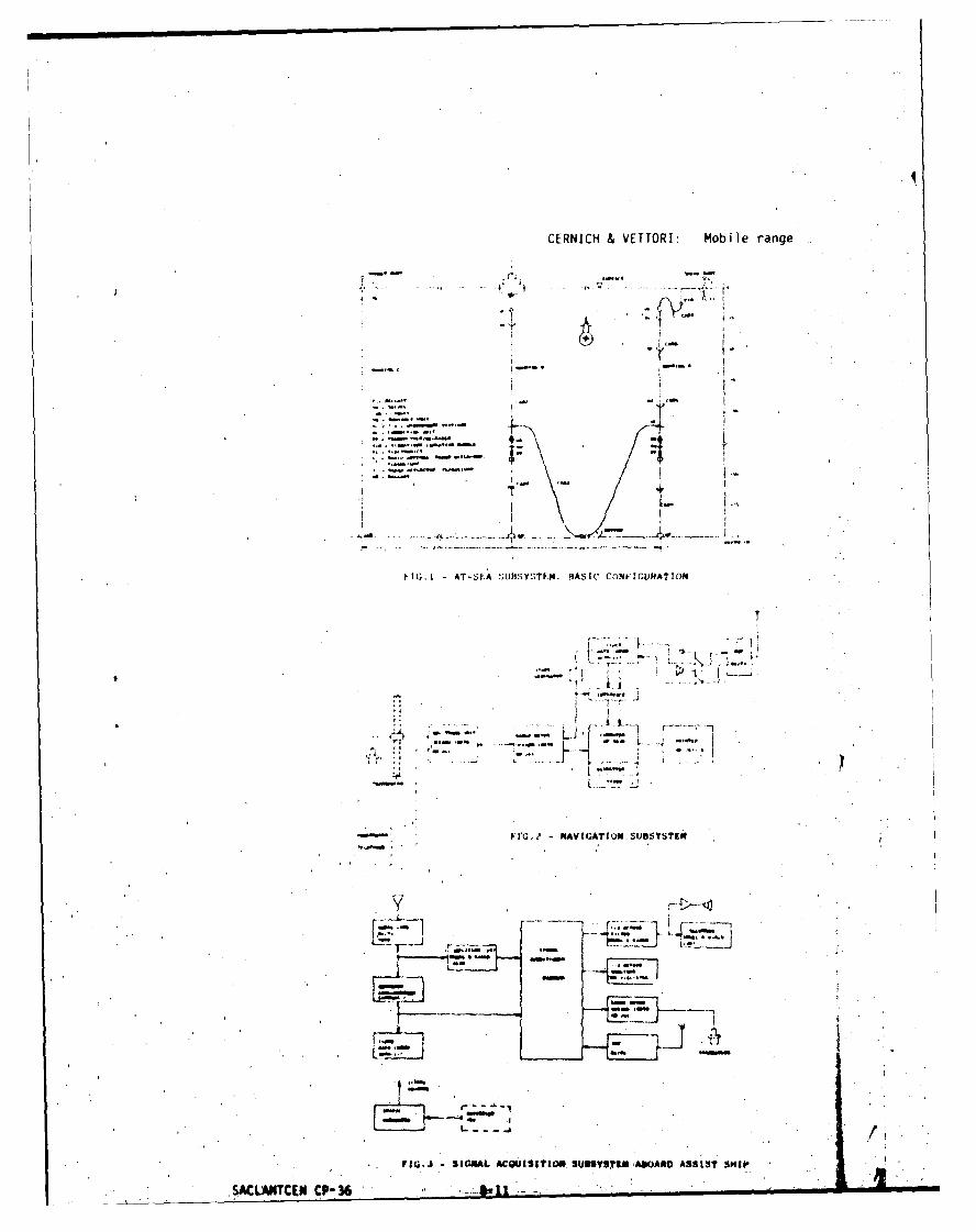
CERNICH & VETTORI: Mobile range
e~~* /47.
f1G. AT-EA nHSYSEN.HASI CONIGURT 'D
I .-,
-- '4- - 4 4,-
Fw. mvGTo.USEIi
L l.
31ALAItII*3&YSlNAADASSSISKLAUTCN CP-3
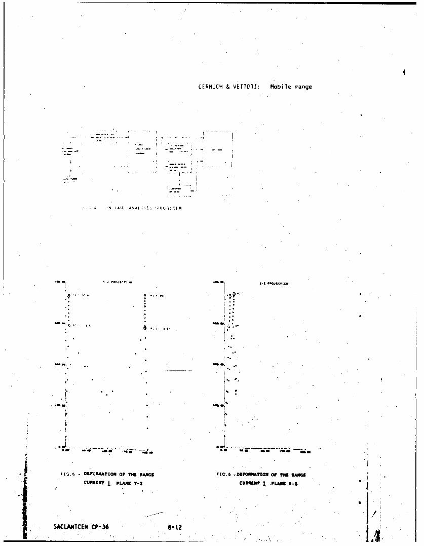
CERNICH & VETTOR!: Mobile range
.1 N I N ii 1 -
. . . . . . . .. ....... .. " 4
4641 la -m .16. a
i INS
* . . D
S.. . . ., .. ..
C PLN C ...
* CP-.36 8. 12
* ACgLANTC CP3 IiI•~~ ,m• .tI~lj"Tg1I........... ".
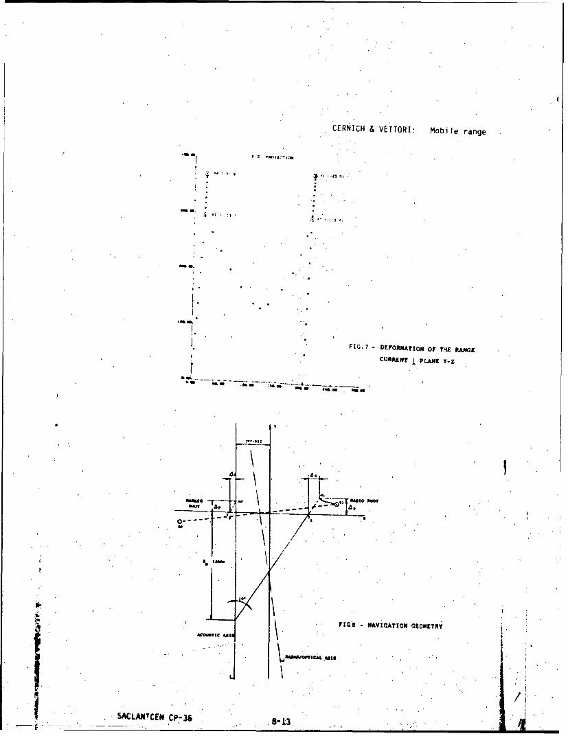
CERNICH & VETTORI: Mobile range
.A!
FIG.7 - DEFORMATION Or ?THE RANOGE
CURRENT PLANE Y-Z
SALMCm CP.3 -1
"8,,
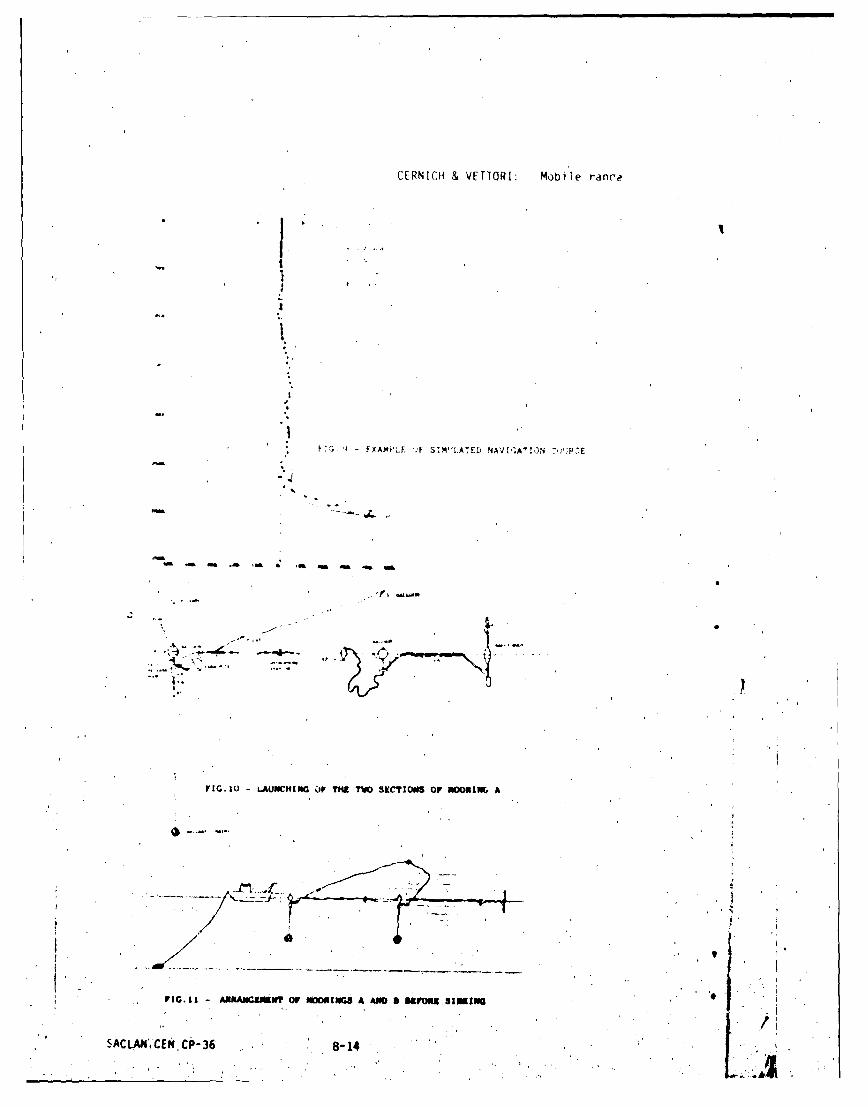
CERN[CH & VErTORI: Mobile rance
f ~XAMPrF ')F SW"LATEL) NAV I AA1N "P'
rI.0 ANHIGOVTETV ICI. O OOI
FIGA'I ANA SK& Of -DPII A_ AMa- OUS
SACLAN',CENP-368-1

CERNICH & VETTORI: Mobile range
DI) SI ss I ON
A.D. S I ii.irt 4 ni ted St at e% ) Ioe the mce.isccrement rarinx h.~ve the ahb iitytcMo niiitor the .cspet t anxie )f the- ''target." or' teSt. vessel, as Well aSits racrige" It "'), how is this toc be'doi
K.. C-.ni~h: 9on:toriing e.lijipmen:t iinstal led or) boadri the dSSiSL Ship dIcesnot ha ve the cap ihil I itv toi mot:iittr ttic .*.spe, t ot tilie test vesselI. Howeve r,the est i-iscte-t aspec t .aic1 I" of ttic test vessel ( al lhe macde .tvzi lahic on-l ine"i nboa rd the test vessel thv r et'ireni e to Oe I ranrspcniciers'' bhse I trip; acshioreit .-al be measo red by ret erenc e to the hvctroicliarc Wt1-144 basel I ile RealI-t imei raaiges t o hydi ophcines HI I nct H14 iLc- ont i ntlocusly di:splayed ol boa r'dtie 'ssist ship.
A.ý.. George (United Ftates) lDovs the on-hoazd monitoring (quick-look)systec.. hsve range correction?
K. Cerni l.h Ranges are meacsuredt direct to the two t ranspondcers. Oil boardthe assist ship ranges tc, hydrophories HI and H4 aire di rect ly dlisplayed,thereby p)rovidinig correct raliges to the above hydropohonus.
...............Le r ny (France): Is there any security dlanger in transmitting thereceived signals by radio'?
E._Cernich: The need to avoid broadcacsting the data'was taken into con-sideration. We shoul n !rot forget, that the transmitting and receivingantennake 3re operating. over the sea surface. By an appropriate choice ofthe transmitting frequency, the "ertical Ilir-eCtiVity pAtrtern of the trans-sitting anterinae, and the transmitter output power, the surface reflectionallow% the useful r-ecept ion distance fr~a the buoy to' he limited to a rangeof about one mile centred at one mite.
SACLADETCEN 0P-36 8-5..

'A, IANTrEfN. CP-36
mNIFAI. DISTRIBEITION.
~.IIHsOF D)FF.NCE Copies
1iI 2 CNR _FO R SACL4JITCENS10 SCHR Belgium
IH') Jb-i~mark 8 SCNR CanadaAq1) F I j: , f. 8 SCNR Denmark
1i)Grerr..i e SCNR GermanyI) Ir' ~ eI SCNR Greece1
i h til her a d SCNR Italy1.'~l N't~.~aj~5 12 SCNk Nether~andi 1I hI ~z..y10 SCNR Norway .1
4()1 Spori i n 2 SCNR Portugal IMillI) Ttpune 2 SCNR TurkeyI
010)1 U.K.~e 5 SCNR V. K. IMof U.I. . 20 SCNR U.S. 251.0F 1.568 SECCEN Rep. SCNR
NATo AUTH6HITIES MAflILCOM Rep. FCNR
NATIONALLIAISOQN OrI CERS['1-311111119 COmsi Lee 3NAW'I.Com 2 NLO Canada 'SAUI4NTRFR 10 NLO D-.nmark1
SAUANRJPERI NW1 GermanytI4c~wvsrl-,.../COtWV-ANI.AM 1 NLO Italy1(:OISTY I KIJTAJT I nio U X.1('OM IBFN jANT 1 NWL U.S.(ANCEASTLkNT ICOMSUBACI:ANT I NLR TO SACLAJITLOMPIA I t.ASTLAJIT ISACEUKl 2 VLR Relgi'umC1NCNORTH ~ Cadici NcsouTH I NLR CenmadaCOIINAVSOiJTH L emr
COSRKOSUHII NLR GermanyCOMMENTRIFEO I MIA Greece1COM ARIEDCENT I ILA Italy1
I NLR NetbcrlaA4SCINHA~ .3 NLt Norway1
NLR Portugal1MIA TurkeyVLR UKILRS us
COUTERZCK ATTKIDNi5 69
Total initial distrib'ution 316SACLANTCKS Library 10stock 22?OW~ aumber of copleg 350
_ _ _ _ _ E N D-~'7,
t%'M~~. A'