Roto-Cycloid propelled airship dimensioning and energetic equilibrium
11
Abstract Rotocycloid propulsion presents interesting performance as a possible long-term alternative to helicopters in a far future. It will lead to increase the energy efficiency of VTOL vehicles. This paper focuses on optimization of an airship with the possibility up to 2000 h/year of photovoltaic propelled flight at a cruise speed about 20 m/s. This paper demonstrates the feasibility of this airship concept and presents a full dimensioning according to the CDE (Constructal Design for Efficiency) developed at University of Modena and Reggio Emilia. The proposed solution has been deeply analyzed and the analysis of performances has been presented. The results allow thinking to a novel class of vehicles designed specifically to take the maximum advantage by this propulsion method. Introduction CROP (Cycloidal Rotor Optimized for Propulsion) project [1, 2, 3] aims to design a radically different new and “Green” propulsion system for manned and unmanned aerial vehicles based on a rotocycloid architecture [1]. A possible application of CROP propellers comes from airships. With airships, different goal toward a competitive green air vehicle can be achieved: standard airships are the most efficient transport system in terms of ratio between operative speed and energy requirements [4] as shown in Figure 1. The wide dimensions of airships allows a large photovoltaic energy production by means of solar panels mounted on the top of the hull; as the lift is guaranteed by buoyancy, propellers power can be used exclusively for thrust and take off and landing operations. CROP can be adopted as a propulsion system for an airship. This application can present some analogies with Voith Schneider [5, 6] propeller used as a specialized marine propulsion system. The insertion of rotocycloid propulsion in an airship is expected to produce a vehicle with a very high manoeuvrability. It is able to change the direction of flight almost instantaneously and it is widely used on tugs and ferries. The adoption of rotocycloid propulsion on an airship could allow increasing the system manoeuvrability without the necessity of engines and propellers mounted on rotating pods such as on Zeppelin NT. Figure 1. Energy efficiency of different transport systems vs. operative speed. This paper aims to produce and effective energetic optimization of a transport airship equipped by CROP rotocycloid propulsion system. It has a commercial payload of 5,000 kg, maximum service ceiling of 4000 m and a standard operative altitude about 2000 m. In order to balance the increased weight due to photovoltaic modules volume of the balloon increases proportionally. In order to maximize the effective surface of illumination, a bi-ellipsoidal shape configuration has be chosen Roto-Cycloid Propelled Airship Dimensioning and Energetic Equilibrium 2014-01-2107 Published 09/16/2014 Michele Trancossi and Antonio Dumas Universita di Modena e Reggio Emilia Carlos Xisto and Jose Pascoa Universidade Da Beira Interior Andrea Andrisani Universita' di Modena e Reggio Emilia CITATION: Trancossi, M., Dumas, A., Xisto, C., Pascoa, J. et al., "Roto-Cycloid Propelled Airship Dimensioning and Energetic Equilibrium," SAE Technical Paper 2014-01-2107, 2014, doi:10.4271/2014-01-2107. Copyright © 2014 SAE International
-
Upload
independent -
Category
Documents
-
view
3 -
download
0
Transcript of Roto-Cycloid propelled airship dimensioning and energetic equilibrium

AbstractRotocycloid propulsion presents interesting performance as a possible long-term alternative to helicopters in a far future. It will lead to increase the energy efficiency of VTOL vehicles. This paper focuses on optimization of an airship with the possibility up to 2000 h/year of photovoltaic propelled flight at a cruise speed about 20 m/s. This paper demonstrates the feasibility of this airship concept and presents a full dimensioning according to the CDE (Constructal Design for Efficiency) developed at University of Modena and Reggio Emilia. The proposed solution has been deeply analyzed and the analysis of performances has been presented. The results allow thinking to a novel class of vehicles designed specifically to take the maximum advantage by this propulsion method.
IntroductionCROP (Cycloidal Rotor Optimized for Propulsion) project [1, 2, 3] aims to design a radically different new and “Green” propulsion system for manned and unmanned aerial vehicles based on a rotocycloid architecture [1]. A possible application of CROP propellers comes from airships. With airships, different goal toward a competitive green air vehicle can be achieved: standard airships are the most efficient transport system in terms of ratio between operative speed and energy requirements [4] as shown in Figure 1.
The wide dimensions of airships allows a large photovoltaic energy production by means of solar panels mounted on the top of the hull; as the lift is guaranteed by buoyancy, propellers power can be used exclusively for thrust and take off and landing operations. CROP can be adopted as a propulsion
system for an airship. This application can present some analogies with Voith Schneider [5, 6] propeller used as a specialized marine propulsion system.
The insertion of rotocycloid propulsion in an airship is expected to produce a vehicle with a very high manoeuvrability. It is able to change the direction of flight almost instantaneously and it is widely used on tugs and ferries. The adoption of rotocycloid propulsion on an airship could allow increasing the system manoeuvrability without the necessity of engines and propellers mounted on rotating pods such as on Zeppelin NT.
Figure 1. Energy efficiency of different transport systems vs. operative speed.
This paper aims to produce and effective energetic optimization of a transport airship equipped by CROP rotocycloid propulsion system. It has a commercial payload of 5,000 kg, maximum service ceiling of 4000 m and a standard operative altitude about 2000 m. In order to balance the increased weight due to photovoltaic modules volume of the balloon increases proportionally. In order to maximize the effective surface of illumination, a bi-ellipsoidal shape configuration has be chosen
Roto-Cycloid Propelled Airship Dimensioning and Energetic Equilibrium
2014-01-2107
Published 09/16/2014
Michele Trancossi and Antonio DumasUniversita di Modena e Reggio Emilia
Carlos Xisto and Jose PascoaUniversidade Da Beira Interior
Andrea AndrisaniUniversita' di Modena e Reggio Emilia
CITATION: Trancossi, M., Dumas, A., Xisto, C., Pascoa, J. et al., "Roto-Cycloid Propelled Airship Dimensioning and Energetic Equilibrium," SAE Technical Paper 2014-01-2107, 2014, doi:10.4271/2014-01-2107.
Copyright © 2014 SAE International
Downloaded from SAE International by Jose Pascoa, Saturday, October 11, 2014

with an almost flat top surface which is the most energetically efficient shape such as demonstrated by Trancossi and others [7, 8, 9, 10].
CROP Propulsion ConceptThe CROP concept is based on a rotating wing system, where the axis of rotation is parallel to the blade span (Fig. 2). A mechanical system controls the pitch of the blades. By changing pitch, it modifies direction and magnitude of the thrust and consequently increases the control capability of the aircraft (Fig.3).
CROP introduces several potential advantages in comparison with traditional VTOL or fixed wing air vehicles as verified by Leger Monteiro and Pascoa [11, 12]. It uses common surfaces to achieve lift and thrust along the full range of flight speeds, this can be helpful for eliminating wing drag at high advance speed.
Figure 2. 3D representation of a cyclorotor with six NACA0012 blades and a maximum pitch angle of 40 degree.
Figure 3. Possible configuration for the pitch control mechanism [3].
The use of a wing rotating around the longitudinal axis creates lift, and thrust. When the blades move backward in relation to the direction of the vehicle, it is possible to obtain an intermittent lift, with a very high value, generated by the unsteady pitching of the blades.
Each blade of the cyclorotor operates in similar conditions (angle of attack, velocity, Reynolds number) so, in principle, the blades are easier to optimize in terms of aerodynamic performance. The unsteady flow mechanisms, generated by the pitching schedule of the blades, play a significant role in the aerodynamic efficiency of a cycloidal rotor. They can delay blade stall, thus increasing the lift that can be produced by each blade.
The rotational speed and pitching schedule of the cyclorotor does not need to increase with vehicle speed, since the achievable thrust increases with forward airspeed for a constant rotor angular velocity.
The proposed air vehicle is capable to attain high subsonic velocities and VTOL operations, without the need to reconfigure its geometry. It opens enormous operative possibilities: rapid disaster/rescue response, commercial transportation, flexible multi-mission, military defence vehicles, green friendly vehicles able to be powered by renewable or photovoltaic electricity, and airships.
CDE Optimization MethodThe optimization method adopted is the CDE (Constructal design for Efficiency) defined by Trancossi [8, 9, 10, 11] to allow an effective implementation of Constructal Principle into the design of a complex system such as transport vehicles. It is based on the controversial Constructal theory theorized by Adrian Bejan [16, 17, 18] and assumes that the configuration of any system, in which a flow of any nature flows, is subject to a basic principle which is named Constructal law [19]: “For a finite-size flow system to persist in time to survive its configuration must evolve in such a way that it provides an easier access to the currents that flow through it”.
The Constructal law aims to be a summary of all design generation and evolution phenomena in nature, bio and non-bio and represent the natural process evolution steps, and attribute the design processes to the exclusive dominion of physics [20]. Designs have the universal tendency to evolve in a certain direction in time [21] and nature tends to generate designs that facilitates facilitate flow [22]. The results produced are not necessarily the better one, but the most efficient for the predefined objective. It means that it produces the best distribution of the imperfections [23].
Trancossi has the intuition to integrate the costructal principle at any level of product design. It has been defined focusing on energy efficient airship design and on thermodynamic and industrial optimization of an entropic wall for a more efficient building insulation [24]. A still embryonic formulation of this design method by Trancossi [8-9] has produced the actual formulation of the CDE method which can be reassumed in the following steps:
Downloaded from SAE International by Jose Pascoa, Saturday, October 11, 2014

1. a preliminary top-down design process to ensure that the full system has an effectively acceptable configurations for the specified goals (contour conditions for constructal optimization could be stated ensuring an effective optimization at full-system level);
2. the constructal optimization of the elemental components to maximize the system performances;
3. a comparison between different configurations even future, if they exists, identifying the better possible solution for the predefined goals.
The preliminary top-down optimization process produces an effective constructal optimization of the full system, which is considered as a subsystem of the external environment.
From this consideration it can be produced an effective definition of CDE optimization method:
These reflections help the formulation of an effective definition of CDE method: “A complex system can meet optimal performances if it has been optimized as a whole, defining the ideal performance required by the system considered as a whole and the requirements of its subsystems for optimal performances”.
Constitutive Relations
SpecificationsThe general optimization of this airship will follow the specification in Table 1.
Table 1. Design specifications
Figure 4. Forces acting on an airship
The schema of the forces acting on an airship has represented in Figure 4. At this preliminary level the effects due to the ailerons L” and D” are neglected because there are supposed to be introduced only for dynamic equilibrium of the system.
The considered architecture is a semi-rigid one, with the external shape and volume are kept constant at varying the altitude by means of two air ballonets (Figure 3). It is also considered a photovoltaic field on the top of the hull.
According to Trancossi [7, 8 and 10] and Dumas [9] a minimal set of systemic equation for a solar airship can be derived from Khoury [4].
Figure 5. Airship scheme (PV modules and ballonets are visible).
They can be adapted for the specific use:
Buoyancy equation:
(1)
where
(2)
Aerodynamic drag equation:
(3)
Aerodynamic lift equation:
(4)
In equilibrium conditions drag can be considered equal to thrust.
Atmosphere ModelAerostatic performances of an airship are connected with the thermodynamic states of the air and of the gas filling the hull. These are highly affected by the altitude h. It is adopted the US Standard Atmosphere [14] equation for temperature T and pressure P of air can be calculated by:
Downloaded from SAE International by Jose Pascoa, Saturday, October 11, 2014

These equations are valid up to 11 km of altitude.
The density of a gas can be approximated by means of the perfect gas law
(5)
To maintain the shape a semi-rigid airship needs to maintain its shape, by a little over-pressure ΔP. For the Zeppelin NT [25, 26] it is ΔP=500 Pa, so keeping this value eq. (13) becomes
(6)
This formula applies to the gas inside the hull; for air, (5) is actually valid. It is assumed to use helium as buoyant gas.
Goals of Optimization ProcessShape and dimensions for the airship are designed in order to
1. minimal drag force D 2. maximum the cruising speed. 3. maximum the photovoltaic production energy 4. maximum the hours of flight per year. 5. maximum the endurance without solar energy. 6. LTA static aerostatic equilibrium at any operative altitude. 7. minimal overall size and weight for a given payload.
Obviously, these conditions are not independent: for example setting the total volume affects almost all the elements on the list above. Besides some points seems to be contrasting, as points 1 and 2 or 2 and 4. A compromise solution has then to be obtained.
Shape DefinitionIn order to achieve such requests we have considered a bi-ellipsoidal configuration for the airship.
Figure 6. General shape characterization
The general shape of the airship is modeled as the union of four quarter of different ellipsoids (Figure 6).
Since the volume of a generic ellipsoid of axis (a,b,c) is
(7)
the external volume of the airship is
(8)
The weight of the balloons can be defined by the surface of an ellipsoid. The external surface of the airship can be calculated from the well known Thomsen approximated formula [24].
It is also necessary to evaluate the internal ballonets for volume regulation. They can be calculated under the hypothesis of being completely filled by air at h=0 and completely empty at service ceiling hmax. If Mgas is the mass of the gas inside the balloon, the volume Vb of a ballonet is
(9)
The mass of buoyant gas Mgas is connected with the external volume Vext by assuming the volume of internal ballonets negligible at service ceiling:
(10)
Equation (9) can be then expressed as follows:
(11)
By assuming that the ballonets has a spherical shape their surface is
(12)
The mass of the aerostatic envelope is given by
(13)
where σs,ext and σs,b are the density of the materials.
Downloaded from SAE International by Jose Pascoa, Saturday, October 11, 2014

By supposing to use the composite high tech material covering the Zeppelin NT [25, 26], it is assumed a density of external hull equal to 0.25 kg/m2. Ballonets are also considered less than 0.20 kg/m2.
The effective volume occupied by helium is Vn(h) is
(14)
By equations (5), (6) and (14), it is possible to calculate the aerostatic lift:
(15)
Drag and Energy ConsumptionAssuming a cruise speed u for the airship, the average drag force is
(16)
At a given velocity u and altitude h, Drag depends on external volume Vext and drag coefficient CD,V. It is influenced by angle of attack and the angle of sideslip, on the shape of the vehicle, viscosity of air and on skin friction. By CFD activity on the considered kind of shape Trancossi [8] it can be assumed a conservative value CD,V=0.05, for zero angle of attack and zero sideslip.
Considering an electrical propulsion system, propulsive efficiency of the propeller allows calculating the power Pw required to maintain the velocity u in equilibrium conditions
(12)
and daily energy required is
(13)
Equations can be evaluated at cruise speed and operative altitude of 2 km.
Photovoltaic Energy's ProductionThe present airship is designed to be a green vehicle. In order to guarantee enough autonomy at the top of the hull a layer of solar panels is placed. Obviously it would be useless to completely fill the top surface, since there will be panels that will receive few solar energy while affecting the total weight of the vehicle.
So in any section of the airship we will assume a photovoltaic arc limited in first approximation by a local curvature with a tangential direction of 45°. The generic sections of three possible shapes have shown in Figure 7.
It is considered that the optimal photovoltaic production is limited by a tangential angle less than or equal to 45°.
Considering the shape of the hull with the same length
the sections must have the same area. It appears immediately that configuration (a), the common Parsifal configuration, presents a limited area for photovoltaic plant. The elliptic configuration (a) presents an increased space for solar energy caption. It is clear that only configuration (3), which presents a bi-ellipsoidal section, ensures the maximum possible total surface available for the photovoltaic modules and at the same times ensuring a sufficient buoyancy.
Figure 7. Transversal sections of different shapes.
Considering the equation of the ellipse (Figure 5)
(14)
it can be obtained the exact limit to photovoltaic plant by deriving equations (14).
Figure 8. Graphical definition of photovoltaic surface.
It can be then possible to obtain the dimensions indicated in Figure 5.
Downloaded from SAE International by Jose Pascoa, Saturday, October 11, 2014

and In the same way
Figure 9. Top view of photovoltaic surface.
Considering that the photovoltaic surface has a random orientation it can be assumed a photovoltaic useful photovoltaic area equal to the projection of the surface on the horizontal plane. From the previous consideration it can be calculated
(15)
Instead for estimating the total mass of the PV plant it is necessary to consider the evaluation of the area of segment of elliptic dome by adapting Thomsen formula [9].
Now in order to determine the energy production and the overall panels' weight, a preliminary analysis on PV modules disposable on the market is necessary. It can be assumed an high performance experimental laminated PV module [27] for aeronautic applications with superficial mass σPV = 0.8 kg/m2 and efficiency ηPV = 0,18. Estimating ηE = 0,83 the overall efficiency of the electric plant, the total daily energy produced is
(16)
with a mean power of
(17)
Here G is the global daily solar radiation on a horizontal surface. It depends on several parameters, but mainly on the latitude.
By (17) and (13) it is possible to evaluate the hours of flight
(18)
It is then possible to evaluate the mass of PV modules:
(19)
Propulsion and energy storage can be consequently evaluated by specifications.
Evaluation of the Energy SystemOn the basis of the proposed energy system it is possible to estimate the main parameters.
Together with the mass of the modules, inverters, cabling and structural masses must be added. A cable with a section of 6mm2 is necessary for cabling length major than 10m. This kind of cables has a density about 75kg/km.
The amount of solar energy available and the hours of flight per year are reported below, for different latitudes.
Table 2. Energy production per year at different latitudes
Evaluation of Cycloidal Propulsion SystemPropulsion system is a cycloid propeller based on the CROP concept. The technical characteristics of the cycloid propeller are reported in Table 3 taking into consideration the reference ones published by Kim [28] and called “Seoul 100 Kg Quad-Cyclocopter UAV” (Figure 10 and Table 3).
Figure 10. Seoul 100 Kg Quad-Cyclocopter UAV
Downloaded from SAE International by Jose Pascoa, Saturday, October 11, 2014
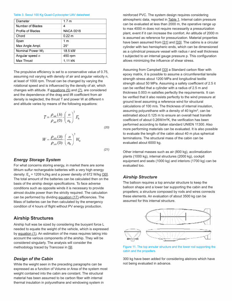
Table 3. Seoul 100 Kg Quad-Cyclocopter UAV datasheet
The propulsive efficiency is set to a conservative value of 0.75, assuming not varying with density of air and angular velocity n, at least of 1000 rpm. Thrust can be changed by varying the rotational speed and is influenced by the density of air, which changes with altitude. If equations (5) and (7), are considered and the dependence of the drag and lift coefficient from air density is neglected, the thrust T and power W at different n and altitude varies by means of the following equations:
(20)
(21)
Energy Storage SystemFor what concerns storing energy, in market there are some lithium sulfur rechargeable batteries with a very high energy density: Ed = 1209 kJ/kg and a power density of 672 W/kg [30]. The total amount of the batteries can be calculated then on the basis of the airship design specifications. To face adverse conditions such as opposite winds it is necessary to provide almost double power than the strictly required. The calculation can be performed by dividing equation (17) efficiencies. The Mass of batteries can be then calculated by the emergency condition of 4 hours of flight without PV energy production.
Airship StructuresAirship hull was be sized by considering the buoyant force L needed to equate the weight of the vehicle, which is expressed by equation (1). An estimation of the mass requires taking into account the various components of the airship. They will be considered singularly. The analysis will consider the methodology traced by Trancossi in [9].
Design of the CabinWhile the weight seen in the preceding paragraphs can be expressed as a function of Volume or Area of the system most weight contained into the cabin are constant. The structural material has been assumed to be carbon fiber with internal thermal insulation in polyurethane and windowing system in
reinforced PVC. The system design requires considering atmospheric data, reported in Table 1. Internal cabin pressure can be evaluated at less than 2000 m, the operative range up to max 4000 m does not require necessarily a pressurization plant, event if it can increase the comfort. An altitude of 2000 m is assumed as reference for pressurization. Material properties have been assumed from [31] and [33]. The cabins is a circular cylinder with two hemispheric ends, which can be dimensioned as a cylindrical pressure vessel with radius r and wall thickness t subjected to an internal gauge pressure p. This configuration allows minimizing the influence of shear stress.
Assuming from Campbell [33] a Standard carbon fiber with epoxy matrix, it is possible to assume a circumferential tensile strength stress about 1200 MPa and longitudinal textile strength about 50 MPa. Assuming a safety coefficient of 2.5 it can be verified that a cylinder with a radius of 2.5 m and thickness 0.003 m satisfies perfectly the requirements. It can be verified that it also resists perfectly to the wind pressure at ground level assuming a reference wind for structural calculations of 100 m/s. The thickness of internal insulation, assuming polyurethane with a density of 40 kg/m3, can be estimated about 0.125 m to ensure an overall heat transfer coefficient of about 0.26W/m2K, the verification has been performed according to Italian standard UNIEN 11300. Also more performing materials can be evaluated. It is also possible to evaluate the length of the cabin about 40 m plus spherical terminations. The structural mass of the cabin can be evaluated about 6000 kg.
Other internal masses such as air (800 kg), acclimatization plants (1000 kg), internal structures (2000 kg), cockpit equipment and seats (1000 kg) and interiors (1700 kg) can be evaluated too.
Airship StructureThe balloon requires a top annular structure to keep the balloon shape and a lower bar supporting the cabin and the propellers; a structure composed by rods and wires connects these elements. An evaluation of about 3500 kg can be assumed for this internal structure.
Figure 11. The top annular structure and the lower rod supporting the cabin and the propellers.
300 kg have been added for considering aleirons which have not being evaluated in advance.
Downloaded from SAE International by Jose Pascoa, Saturday, October 11, 2014

ResultsThe previous calculation method adopting initial hypothesis and the evaluated structural constant masses allows obtaining an effective preliminary dimensioning of the airship.
Most important results can be reported in Table 4.
Table 4. Main vehicle characteristics
Some further considerations are necessary about propulsion system. By adopting three quad-cyclocopters, by (13) and (17) the required angular rotations for a given velocity of the airship is
(22)
Fixed the cruising velocity at u=20m/s from the previously assigned values about the parameters appearing in (24), it results n=780 rpm. Since a most powerful motor is now required for such rotations, and different displacement for single rotors might be considered, the weight of a single quad-cyclocopter is supposed to be increased to 150 kg.
Here the calculated properties of the modified Seoul quad-cyclocopter:
Table 5. Some parameters about the modified quadcyclocopter.
The increase in terms of payload can be included in the ballast, reducing it to 600 kg, which are sufficient and completely adequate for the flight operations.
DesignOn the basis of the preceding optimization process also design of the airship is then derived as shown in Fig.12 and Fig13.
Figure 12. 3D views of the optimized airship
Downloaded from SAE International by Jose Pascoa, Saturday, October 11, 2014

Figure 13. Drawings of the optimized airship
ConclusionsThe present paper has demonstrated that CDE design method works properly on the design also of unconventional propelled airship.
In this case a fully optimization has been performed by setting up a complete optimization method. The results seems very interesting and allow verifying that the rotation speed of the rotocycloid propellers remains in an acceptability range lower than 1000 rpm, which ensures a very good level of confidence.
On the basis of the obtained results, it can be verified also that rotocycloid propellers can be suitable in an adequate scale to fulfil the propulsive needs of a large aircraft.
Even if some problems connected to affordability and system reliability must still be solved it is possible that such a propulsive system could allow adequate performances and better energy efficiency if compared to traditional propellers.
Higher costs seem acceptable because of higher manoeuvrability.
References1. Bowles J., “Flying Without Wings or Motors”, Popular
Science, November, 1934”.2. Kirsten F. K., “Cycloidal Propulsion Applied to Aircraft,”
Transactions of the American Society of Mechanical Engineers, Vol. 50, No. AER-50-12, 1928, pp. 25-47.
3. Garrick I. E., “Propulsion of a flapping and oscillating airfoil”. Report National Advisory Committee for Aeronautics, NACA Report No. 567, pp. 419-427, 1936.
4. Brasseur, G.P., Cox R.A., and others, “1998: European scientific assessment of the atmospheric effects of aircraft emissions”. Atmospheric Environment, 32, 2327-2422.
5. VV. AA., “Voith Schneider Propeller Designer Manual”, Voith, 2009.
6. VV. AA., “Types and Dimensions - Voith Schneider Propeller”, Voith, 2011.
7. Trancossi M., Dumas A., and Madonia M., “Morfoplane: energetic analysis of a novel green aerial system,” ASME ES-FuelCell 2013, Paper n. ESFuelCell2013-18166, Minneapolis, MN, USA, 2013.
8. Trancossi, M., Dumas, A., and Madonia, M., “Optimization of Airships with Constructal Design for Efficiency Method,” SAE Technical Paper 2013-01-2168, 2013, doi:10.4271/2013-01-2168.
9. Dumas, A., Trancossi, M., and Madonia, M., “Energetic Design and Optimization of a Large Photovoltaic Stratospheric Unconventional Feeder Airship,” SAE Int. J. Aerosp. 5(2):354-370, 2012, doi:10.4271/2012-01-2166.
10. Trancossi M., Dumas A. Madonia M, Constructal design for efficiency: the case of airship Design, ASME IMECE 2013, paper n. IMECE2013-63448, 2013.
11. Monteiro, J., Pascoa, J., and Xisto, C., “Analytical Modeling of a Cyclorotor in Forward Flight,” SAE Technical Paper 2013-01-2271, 2013, doi:10.4271/2013-01-2271.
12. Leger Monteiro, J., Pascoa J., and Xisto C., “Parametric Design of Cycloidal Rotor Thursters,” ASME IMECE 2013, Paper n. IMECE2013-65238, 2013.
13. Khoury, G.A. and Gillett, J.D., “Airship Technology”, Cambridge University Press, 2004.
14. U.S. Standard Atmosphere, U.S. Government Printing Office, Washington, D.C., 1976.
15. Bejan A., and Lorente S., “Constructal theory of generation of configuration in nature and engineering”, J. Appl. Phys., 100, 2006, doi:10.1063/1.2221896.
16. Bejan A., and Lorente S., “The constructal law of design and evolution in nature”, Philosophical Transactions of the Royal Society B, 365: 1335-1347, 2010.
17. Bejan A., and Lorente S., “The Constructal law and the evolution of design in nature”, Physics of Life Reviews, 8:209-240, 2011.
18. Bejan A., “Advanced Engineering Thermodynamics,” (2nd ed.). New York: Wiley, 1997.
19. Reis A. H., Constructal theory: from engineering to physics, and how flow systems develop shape and structure, Appl. Mech. Rev., 59:269-281, 2006, doi:10.1115/1.2204075.
20. Wang L., Universality of design and its evolution. Phys Life Rev 8:257-258, 2011.
21. Miguel A. F., Natural flow systems: acquiring their constructal morphology. Int J Design & Nature Ecodyn 5:230-240, 2010.
22. Bejan A.; and Lorente S., “Design with Constructal Theory,” Hoboken: Wiley, 2008.
23. Trancossi M., Madonia M., Dumas A., “Constructal Design for Efficiency: The Case of an Entropic Wall With Circulating Water, ASME International Mechanical Engineering Conference 2013, American Society of Mechanical Engineers, 2013;
Downloaded from SAE International by Jose Pascoa, Saturday, October 11, 2014

24. Thomsen K., in Spheroids & Scalene Ellipsoids, Numericana, email reported, 2004. www.numericana.com/answer/ellipsoid.htm#spheroid
25. VV. AA., EASA Type Certificate Data Sheet - Zeppelin LZ N07, European Aviation Safety Agency, 2007 http://www.easa.europa.eu/certification/typecertificates/docs/airships/EASA-TCDS-AS.001_Zeppelin_LZ_N07-100-03-23122009.pdf
26. VV. AA., Technical data of the Zeppelin NT 07 in Zeppelin Luftschifftechnik GmbH & Co KG, http://zeppelinflug.de/technik-356.html
27. VV. AA., “Solar World e-ONE”, PC-Aero, 2014 http://www.aircraft-certification.de/index.php/home.html
28. Kim S. J., Yun, C. Y., Park, I., Lee, H. Y., Jung, J. S., Hwang, I. S., and Jung, S. N., 2004. “A new vtol uav cyclocopter with cycloidal blades system”. American Helicopter Society International.
29. Benedict M., Shrestha E., Hrishikeshavan V., and Chopra I., “Development of a Micro Twin-Rotor Cyclocopter Capable of Autonomous Hover”. Journal of Aircraft, AIAA, 2014, doi:10.2514/1.C032218
30. http://sionpower.com/pdf/articles/LIS%20Spec%20Sheet%2010-3-08.pdf
31. VV. AA., “ANSI/AIAA S-080-1998, “Space Systems - Metallic Pressure Vessels”, Pressurized Structures, and Pressure Components,” ANSI, 1998.
32. VV.AA., “Polyurethane Handbook”, Hanser Fachbuchverlag; Hanser / Gardner Publications. ed. 2009.
33. Campbell F. C., “Structural Composite Material,” ASM, 2010.
Contact InformationMichele [email protected]
Andrea [email protected]
AcknowledgmentsThe present work was supported by European Project CROP (Cycloidal Rotor Optimized for Propulsion), Grant No. 323047.
Definitions/Abbreviationsρair - density of air [kg/m3]
ρair - density of buoyant gas [kg/m3]
Ρb - density of the balloon tissue [kg/m2]
ΡPV - density of the photovoltaic modules [kg/m2]
D - aerodynamic drag body [N]
D′ - aerodynamic drag due to ailerons [N]
L - aerostatic lift [N]
L′ - Aerodynamic lift [N]
L” - aerodynamic lift due to ailerons [N]
u - velocity [m/s]
g - Acceleration of Gravity [m/s2]
h - altitude [m]
hmax - maximum altitude [m]
T - temperature [K]
P - pressure [Pa]
a,b,b1,c, c1 - hemi axes of ellipsoids [m]
a′, c′, a1′, b1′ - hemi axes of the PV layer ellipsoid
V - volume [m3]
Vb - volume of the ballast [m3]
Vext - external volume of the airship [m3]
Vn - useful buoyant gas volume [m3]
S - surface of an ellipsoid [m2]
Sext - external surface of the balloon [m2]
Sb - surface of a single ballonet [m2]
Sbal - total surface of the balloon [m2]
SPV - surface covered with PV modules [m2]
Sef - effective irradiated surface [m2]
Mgas - mass of the buoyant gas [kg]
Mbal - mass of the balloon [kg]
MPV - mass of PV modules [kg]
Mbat - batteries mass [kg]
MP - propulsion system mass [kg]
Mtot - total mass of the airship (no payload and buoyant gas) [kg]
Mpay - commercial payload mass [kg]
G - global daily solar radiation on a horizontal surface [kWh/m2 day]
Ereq - energy required by the airship to balance the drag force D [kWh]
Wreq - power required by the airship to balance the drag force D [kW]
Egen - daily energy generated by PV panels [kWh]
Wgen - power generated by PV panels [kW]
N - standard angular velocity of quad-cyclocopters [rpm]
n0 - angular velocity of a quad-cyclocopter installed on the airship [rpm]
F0 - standard thrust of the quad-cyclocopter [N]
F - thrust of a quad-cyclocopter installed on the airship [N]
W0 - standard power of the quad-cyclocopter [kW]
W - power of a quad-cyclocopter installed on the airship [kW]
N - hours of flight per year [h]
Nd - endurance [h]
ηp - Propulsive efficiency
ηPV - Efficiency of solar caption
ηe - Efficiency of the electric plant
CD - Drag coefficient
CL - lift coefficient
Downloaded from SAE International by Jose Pascoa, Saturday, October 11, 2014

The Engineering Meetings Board has approved this paper for publication. It has successfully completed SAE’s peer review process under the supervision of the session organizer. The process requires a minimum of three (3) reviews by industry experts.
All rights reserved. No part of this publication may be reproduced, stored in a retrieval system, or transmitted, in any form or by any means, electronic, mechanical, photocopying, recording, or otherwise, without the prior written permission of SAE International.
Positions and opinions advanced in this paper are those of the author(s) and not necessarily those of SAE International. The author is solely responsible for the content of the paper.
ISSN 0148-7191
http://papers.sae.org/2014-01-2107
Downloaded from SAE International by Jose Pascoa, Saturday, October 11, 2014