Design, dimensioning and construction of the suspension of ...
166
Trabajo Fin de Máster Adrián Rivas Artazcoz Norbert Bahlmann & Pablo Sanchis Gúrpide Pamplona, 26/06/2019 E.T.S. de Ingeniería Industrial, Informática y de Telecomunicación Máster Universitario en Ingeniería Industrial Design, dimensioning and construction of the suspension of the IRT19 for the Formula Student season 2019
-
Upload
khangminh22 -
Category
Documents
-
view
1 -
download
0
Transcript of Design, dimensioning and construction of the suspension of ...

Trabajo Fin de Máster
Adrián Rivas Artazcoz
Norbert Bahlmann & Pablo Sanchis Gúrpide
Pamplona, 26/06/2019
E.T.S. de Ingeniería Industrial,
Informática y de Telecomunicación
Máster Universitario en
Ingeniería Industrial
Design, dimensioning and construction
of the suspension of the IRT19 for the
Formula Student season 2019

2
3
This project was written in the Hochschule Osnabrück during the academic year 2018-
2019. It has been done in the facilities of the Ignition racing Team electric in the
Hochschule Osnabrück in collaboration in parallel with the work of the other students
of the team and with direct contribution of them in the results of the project.
Director of the master thesis in the Hochschule Osnabrück: Prof. Norbert Bahlmann
Director of the master thesis in the Public university of Navarre: Pablo Sanchis Gúrpide
Abstract:
During the European Project Semester (EPS) a team of interdisciplinary students from
different universities carry on a project together. The project took part with the
Ignition Racing Team electric, the Formula Student team of the Hochschule Osnabrück.
In particular, the work carried out during this Master’s Thesis deals with the
suspension of the vehicle.
In the first semester the design part took place with the Catia software. The
suspension of the year 2017 was taken as a basis and the new requirements of this
year were implemented, such as, the new geometry of the suspension, the new sensor
of displacement and a system of adjustment of the pushrod. In the second semester
the technical drawings were sent to the manufacturer and the commercial parts were
bought and the building of the car was accomplished.
In a parallel way, mechanical tests were performed to carbon fibre tubes for the
dimensioning of the suspension. Tensile, compression and bending test were carried
out to test four different CFK tube diameters. Stress-strain graphs, maximum
deformation, strength and stress of the CFK tubes were calculated and compared with
the solicitations of the suspension to choose the optimal solution for the suspension of
the vehicle.

4
5
INDEX
1 INTRODUCTION, OBJECTIVE AND SCOPE .................................................................. 8
2 BACKGROUND ......................................................................................................... 10
2.1 INTRODUCTION ............................................................................................... 10
2.2 GENERAL VEHICLE DYNAMICS ......................................................................... 11
2.2.1 Definition .................................................................................................... 11
2.2.2 Forces ......................................................................................................... 11
2.2.3 Dynamics in linear motion .......................................................................... 13
2.2.4 Dynamics on lateral motion ....................................................................... 14
2.2.5 Understeer and oversteer .......................................................................... 14
2.3 THE SUSPENSION GEOMETRY ......................................................................... 15
2.3.1 Elements of the suspension ....................................................................... 15
2.3.2 Types of suspension ................................................................................... 16
2.4 THE WORKING PRINCIPLE AND ADVANTAGES/DISADVANTAGES OF A
PUSHROD-SYSTEM .................................................................................................................. 17
2.4.1 Comparison pull-rod and push-rod systems .............................................. 17
2.4.2 Advantages of a push-rod suspension ....................................................... 17
2.4.3 Disadvantages of a push-rod suspension ................................................... 18
2.5 ANALYSIS OF THE KINEMATICS OF THE 2017 CAR .......................................... 18
2.6 SUSPENSION 2018 SEASON ............................................................................. 19
3 DESIGNING PROCESS ............................................................................................... 20
3.1 SUSPENSION GEOMETRY................................................................................. 20
3.2 METHOD OF ADJUSTMENT OF THE PUSHROD LENGTH .................................. 22
3.2.1 Introduction and objective ......................................................................... 22
3.2.2 Gage blocks ................................................................................................ 23
3.2.3 Self-manufactured gage blocks with disc geometry .................................. 23
3.2.4 Adjustable tool ........................................................................................... 24
3.2.5 Sensor ......................................................................................................... 25
3.2.6 Final solution .............................................................................................. 26
3.3 ATTACHMENT OF THE ROTATION SENSOR OF THE ROCKER........................... 26
3.4 TECHNICAL DRAWINGS FOR THE MANUFACTURERS ...................................... 28
4 MECHANICAL TEST FOR DIMENSIONING THE DIAMETERS OF THE CFRP TUBES .... 28
4.1 INTRODUCTION ............................................................................................... 28
4.2 SOLICITATIONS ................................................................................................ 29
4.2.1 Forces ......................................................................................................... 29
4.2.2 A-Arm low ................................................................................................... 29
6
4.2.3 A-Arm up .................................................................................................... 31
4.2.4 Pushrod of the suspension ......................................................................... 33
4.2.5 Stress on each carbon tube ........................................................................ 34
4.3 DESIGN OF THE EXPERIMENTS ........................................................................ 34
4.4 TESTING MACHINE .......................................................................................... 35
4.5 TENSILE TEST ................................................................................................... 36
4.5.1 Introduction ................................................................................................ 36
4.5.2 Results and calculations ............................................................................. 36
4.5.3 Stress strain graph ...................................................................................... 36
4.5.4 Conclusions ................................................................................................. 37
4.6 COMPRESSION TEST ........................................................................................ 38
4.6.1 Introduction ................................................................................................ 38
4.6.2 Results and calculations ............................................................................. 39
4.6.3 stress strain graph ...................................................................................... 39
4.6.4 Conclusions ................................................................................................. 41
4.7 BENDING TEST ................................................................................................. 45
4.7.1 Introduction ................................................................................................ 45
4.7.2 Results and calculations ............................................................................. 46
4.7.3 Stress strain graph ...................................................................................... 46
4.7.4 Conclusions ................................................................................................. 48
4.8 CONCLUSION OF THE MATERIAL TESTS .......................................................... 49
5 BUILDING PROCESS ................................................................................................. 50
5.1 Introduction..................................................................................................... 50
5.2 PROGRESS PLAN .............................................................................................. 50
5.3 ASSEMBLY BOX ................................................................................................ 51
5.4 MANUFACTURING ........................................................................................... 52
5.5 ASSEMBLING.................................................................................................... 54
5.6 PUSHROD ADJUSTMENT PROBLEM................................................................. 55
5.7 BRACKETS MOUNTING .................................................................................... 56
6 FINAL RESULT .......................................................................................................... 57
6.1 EUROPEAN PROJECT SEMESTER ...................................................................... 57
6.2 IGNITION RACING TEAM ................................................................................. 57
6.3 FUTURE LINES .................................................................................................. 60
6.3.1 Symmetry in the A-arms ............................................................................. 60
6.3.2 Carbon tube diameter ................................................................................ 61
6.3.3 Positioning of the pushrod ......................................................................... 61

7
6.3.4 Adjustment of the pushrod ........................................................................ 61
7 BIBLIOGRAPHY ......................................................................................................... 62
8 ANNEXES.................................................................................................................. 63
8.1 KINEMATICS OF THE 2017 IRT VEHICLE ........................................................... 63
8.2 VALIDITY OF THE BOLTED UNION OF THE ADJUSTMENT OF THE PUSHROD .. 63
8.3 TECHNICAL DRAWINGS ................................................................................... 63
8.4 PROGRESS PLAN .............................................................................................. 63
8.5 EUROPEAN PROJECT SEMESTER REPORT ........................................................ 63
8.6 HALL-EFFECT ABSOLUTE ENCODER SERIES MAB12A DATA SHEET ................. 63
8.7 RADAUFHANGUNG KLEBEN (A-ARMS CONSTRUCTION INSTRUCTION).......... 63
8
1 INTRODUCTION, OBJECTIVE AND SCOPE
The scope of this project is both a team work project and a technical project during one-
year period in the Hochschule of Osnabrück.
The first semester was part of the program “European Project Semester” (EPS). This is a
program offered in several universities of Europe to develop engineering projects. It is based on
a mixture of “Project Related Courses” and project organized/problem-based learning. It is
crafted to address the design requirements of the degree and prepare engineering students with
all the necessary skills to face the challenges of today’s world economy. The students are divided
in interdisciplinary teams formed by 3 to 6 students to develop a common project. Teams are
composed by students of different nationalities and different engineering fields to encourage
cultural diversity and skills. Projects are done in cooperation with commercial businesses and
industries or with research centres.
The general aspects of the EPS are the following:
• Semester lasts at least 15 weeks
• EPS is oriented to a project.
• English is the official language of the project and the courses
• 30 ECTS per semester are offered in total, whereof the project covers min. 20 ECTS,
accompanying subjects 5 to 10 ECTS
• Accompanying subjects must support the project subject English and a basic crash
course in the local language must be an option
• Subjects include Teambuilding and Project Management
• Project groups are composed multinational, group size 3-6 students, min. 3 nationalities
multi disciplinarily desired
• The Main focus in EPS is the team work
• Project supervision focuses on the process as well as the product
• EPS must have continuous assessment including an Interim report and a final report.
Some of the providers of the EPS are the following universities:
• St. Pölten University of Applied Sciences, Austria
• AP University College Antwerp, Belgium
• University of Antwerp, Belgium
• Novia University of Applied Sciences, Finland
• Ecole Nationale d'Ingénieurs de Tarbes, France
• Kiel University of Applied Sciences, Germany
• Hochschule Osnabrück, Germany
• HS Augsburg, Germany
• The Hague University of Applied Sciences, The Netherlands
• Avans University of Applied Sciences, The Netherlands
• Saxion university of applied sciences, The Netherlands
• Oslo Metropolitan University, Norway
• Lodz University of Technology, Poland
• Instituto Superior de Engenharia do Porto, Portugal
• University Politehnica of Bucharest, Romania
• Glasgow Caledonian University, Scotland
9
• Universitat Politècnica de València, Spain
• Vilanova i la Geltrú School of Engineering, Spain
• Nottingham Trent University, England
In the European Project Semester Mariana Carbajal Curiel (México), Stefano Segneri
(Italy), Laura Hernandez Wilches (Colombia) and I joined the “Ignition Racing Team electric”
(IRTe) in the Hochschule of Osnabrück to participate in the design of the vehicle for the formula
student competition of the season 2018-2019. The IRTe has been working in the Hochschule for
12 seasons with a best ranking in 2015 with 6th position in the events of Barcelona and
Hockenheim. The team has also achieved first position in efficiency in 2014. The team is
currently composed by 43 people, 19 members with previous experience in the team and 24
new members or “Trainees”. The team has over 60 sponsors from which the main ones are the
Hochschüle of Osnabrück, Harting and dSpace. It counts with a budget of over 100.000 € and
also with some of the manufacturing capacities of the sponsors.
The IRTe at the same time is divided in different sub teams: monocoque, chassis, drive
train, electric and electronic department and management. These each team have tasks and
responsibilities:
Monocoque
• Construction and production of a brake air duct
• Development and construction of a Drag Reduction System (DRS)
• Manufacturing monocoque
• Development and construction of the front wing
• Development and construction of the rear wing
• Development and construction of the diffuser
• Construction and production of the side box
• Computational comparison between monocoque and tubular frame
• Structure analysis monocoque
• Development and construction of a subfloor
Chassis
• Design, construction and installation of the suspension
• Performing various strength calculations
• Care of the tires and care of the rims
• Design Development and construction of stabilizers
Drive train
• Design, simulation and subsequent assembly of a drive chain
• Design, simulation and subsequent installation of a cooling system
• Development and construction of the homemade gearbox multiplier
10
Electric
• Design, implementation and support of dynamic control
• Design, implementation and support of static control
• Development, simulation and subsequent installation of a battery management
system (BMS)
• Detailed data acquisition of the engines on a test bench
• Development and construction of the battery (mechanical)
• Development and production of a wiring harness
• Design, development and installation of various circuit boards
Management
• Promotional videos
• Graphic Designer
• Treasurer
• Social media expert
• Event management
• Photograph
• 3D modeling
The objective of the EPS project in the Ignition Racing Team was to join the team and
work with the german team developing a team project in the design part of the season (first
semester). During the first semester only, the developing of the new ideas, the 3D modelling,
the technical drawings are completed. In the end of the semester the materials are ordered, the
commercial items purchased, and the technical drawings sent to the manufacturers.
The second semester of the year the EPS is already over, however, this is period of the
year when actual the building of the car is done.
The design part has also a side part: The dimensioning of the carbon tubes for the
suspension. For that purpose, the forces in the carbon tubes and each of the carbon tubes will
be calculated. Then some mechanical tests in tensile strength, compression and bending for the
carbon tubes will be performed and compare the data collected with the forces to choose the
optimal diameter for the suspension.
2 BACKGROUND
2.1 INTRODUCTION
The first task for anyone to join the team is a ‘’Trainee Project’’, a short project of a need
that the IRTe team has. Some of these projects have been from a barbecue cart or holders for
the computer, to analysis of certain data from the sensor or just research projects of
information. In my case some topics where delivered to me for a presentation that was
completed the 11/10/18.
11
2.2 GENERAL VEHICLE DYNAMICS
2.2.1 Definition
The vehicle dynamics is based in the study of a vehicle and how it behaves in movement.
We can divide the study in the three basic situations:
• Longitudinal dynamics: Study of the behaviour of the vehicle in a straight line i.e. during
acceleration, braking, straight line stability etc.
• Lateral dynamics: Study of the behaviour of the vehicle taking a turn i.e. taking a turn,
during overtaking etc.
• Vertical dynamics: Study of the behaviour of the vehicle in the vertical direction i.e.
encountering a speed breaker, or a puddle etc.
2.2.2 Forces
2.2.2.1 Acting point
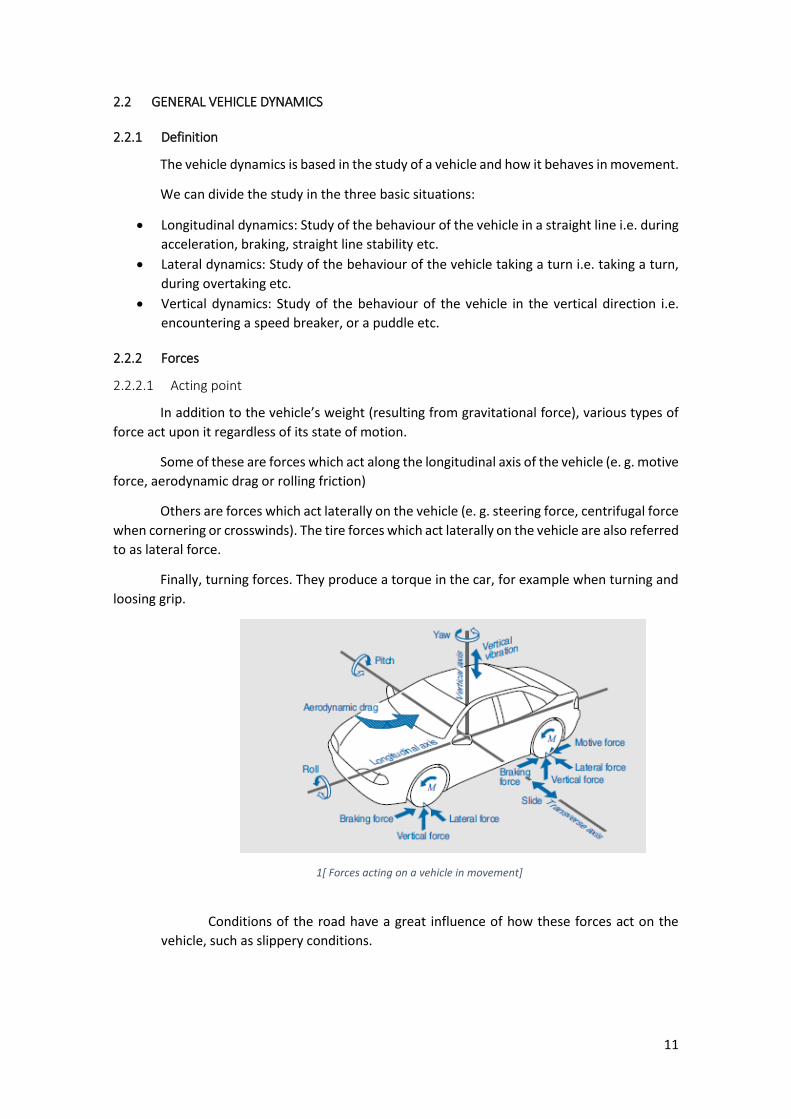
In addition to the vehicle’s weight (resulting from gravitational force), various types of
force act upon it regardless of its state of motion.
Some of these are forces which act along the longitudinal axis of the vehicle (e. g. motive
force, aerodynamic drag or rolling friction)
Others are forces which act laterally on the vehicle (e. g. steering force, centrifugal force
when cornering or crosswinds). The tire forces which act laterally on the vehicle are also referred
to as lateral force.
Finally, turning forces. They produce a torque in the car, for example when turning and
loosing grip.
1[ Forces acting on a vehicle in movement]
Conditions of the road have a great influence of how these forces act on the
vehicle, such as slippery conditions.
12
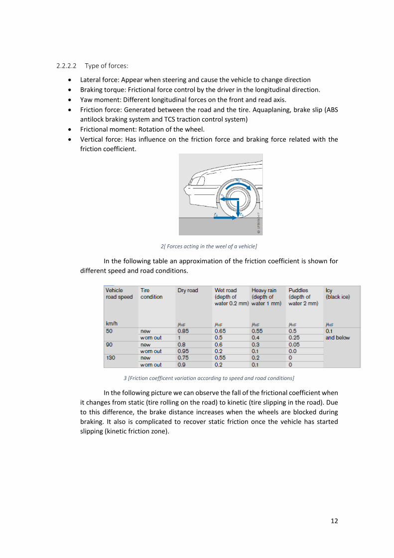
2.2.2.2 Type of forces:
• Lateral force: Appear when steering and cause the vehicle to change direction
• Braking torque: Frictional force control by the driver in the longitudinal direction.
• Yaw moment: Different longitudinal forces on the front and read axis.
• Friction force: Generated between the road and the tire. Aquaplaning, brake slip (ABS
antilock braking system and TCS traction control system)
• Frictional moment: Rotation of the wheel.
• Vertical force: Has influence on the friction force and braking force related with the
friction coefficient.
2[ Forces acting in the weel of a vehicle]
In the following table an approximation of the friction coefficient is shown for
different speed and road conditions.
3 [Friction coefficent variation according to speed and road conditions]
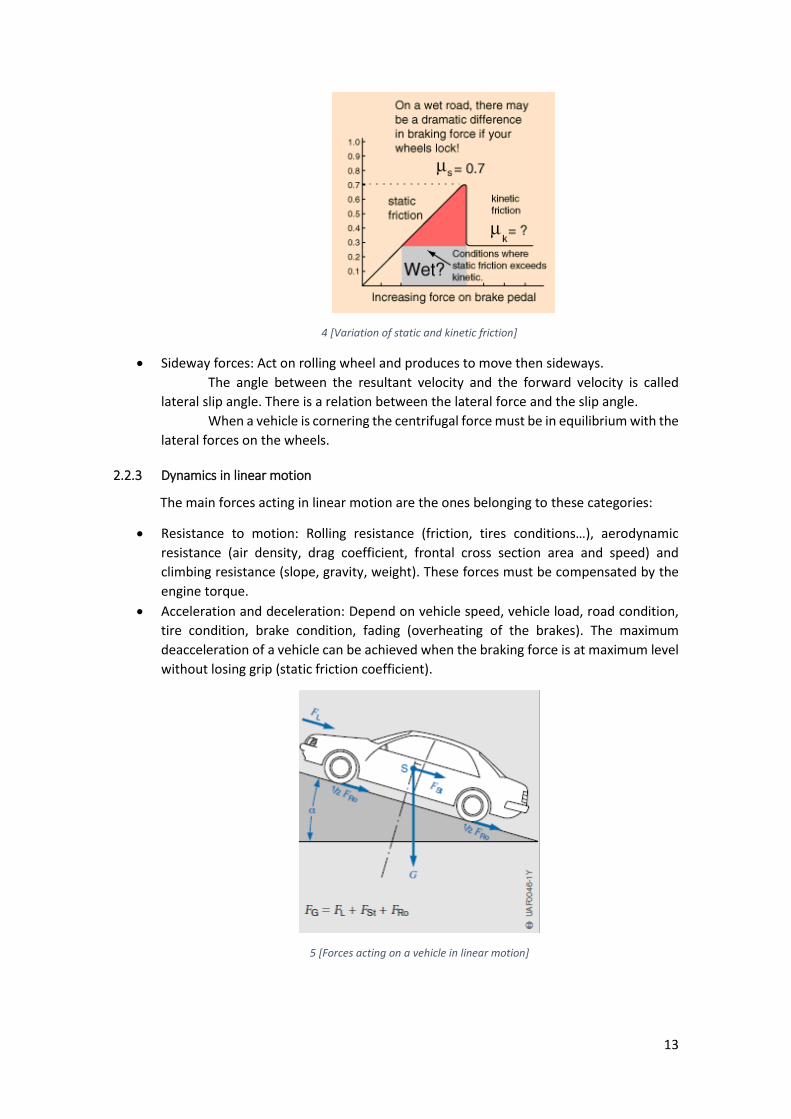
In the following picture we can observe the fall of the frictional coefficient when
it changes from static (tire rolling on the road) to kinetic (tire slipping in the road). Due
to this difference, the brake distance increases when the wheels are blocked during
braking. It also is complicated to recover static friction once the vehicle has started
slipping (kinetic friction zone).
13
4 [Variation of static and kinetic friction]
• Sideway forces: Act on rolling wheel and produces to move then sideways.
The angle between the resultant velocity and the forward velocity is called
lateral slip angle. There is a relation between the lateral force and the slip angle.
When a vehicle is cornering the centrifugal force must be in equilibrium with the
lateral forces on the wheels.
2.2.3 Dynamics in linear motion
The main forces acting in linear motion are the ones belonging to these categories:
• Resistance to motion: Rolling resistance (friction, tires conditions…), aerodynamic
resistance (air density, drag coefficient, frontal cross section area and speed) and
climbing resistance (slope, gravity, weight). These forces must be compensated by the
engine torque.
• Acceleration and deceleration: Depend on vehicle speed, vehicle load, road condition,
tire condition, brake condition, fading (overheating of the brakes). The maximum
deacceleration of a vehicle can be achieved when the braking force is at maximum level
without losing grip (static friction coefficient).
5 [Forces acting on a vehicle in linear motion]
14
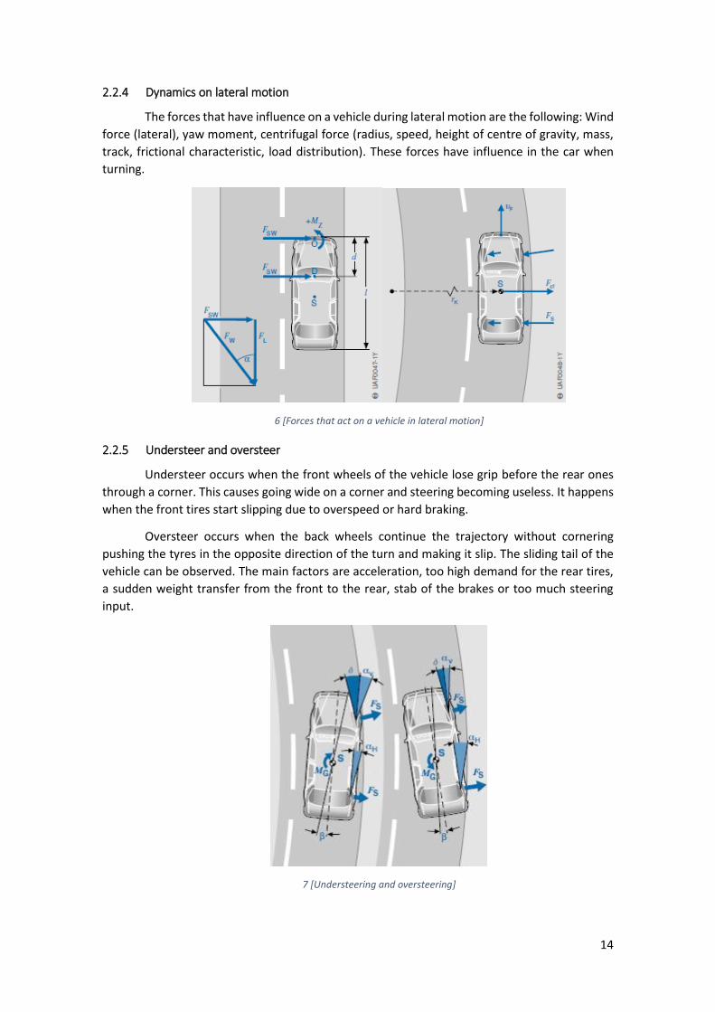
2.2.4 Dynamics on lateral motion
The forces that have influence on a vehicle during lateral motion are the following: Wind
force (lateral), yaw moment, centrifugal force (radius, speed, height of centre of gravity, mass,
track, frictional characteristic, load distribution). These forces have influence in the car when
turning.
6 [Forces that act on a vehicle in lateral motion]
2.2.5 Understeer and oversteer
Understeer occurs when the front wheels of the vehicle lose grip before the rear ones
through a corner. This causes going wide on a corner and steering becoming useless. It happens
when the front tires start slipping due to overspeed or hard braking.
Oversteer occurs when the back wheels continue the trajectory without cornering
pushing the tyres in the opposite direction of the turn and making it slip. The sliding tail of the
vehicle can be observed. The main factors are acceleration, too high demand for the rear tires,
a sudden weight transfer from the front to the rear, stab of the brakes or too much steering
input.
7 [Understeering and oversteering]
15
2.3 THE SUSPENSION GEOMETRY
2.3.1 Elements of the suspension
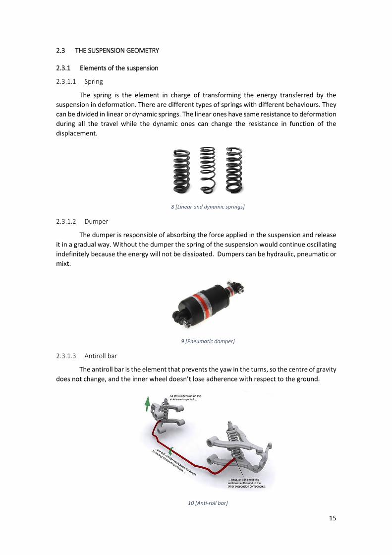
2.3.1.1 Spring
The spring is the element in charge of transforming the energy transferred by the
suspension in deformation. There are different types of springs with different behaviours. They
can be divided in linear or dynamic springs. The linear ones have same resistance to deformation
during all the travel while the dynamic ones can change the resistance in function of the
displacement.
8 [Linear and dynamic springs]
2.3.1.2 Dumper
The dumper is responsible of absorbing the force applied in the suspension and release
it in a gradual way. Without the dumper the spring of the suspension would continue oscillating
indefinitely because the energy will not be dissipated. Dumpers can be hydraulic, pneumatic or
mixt.
9 [Pneumatic damper]
2.3.1.3 Antiroll bar
The antiroll bar is the element that prevents the yaw in the turns, so the centre of gravity
does not change, and the inner wheel doesn’t lose adherence with respect to the ground.
10 [Anti-roll bar]
16
2.3.2 Types of suspension
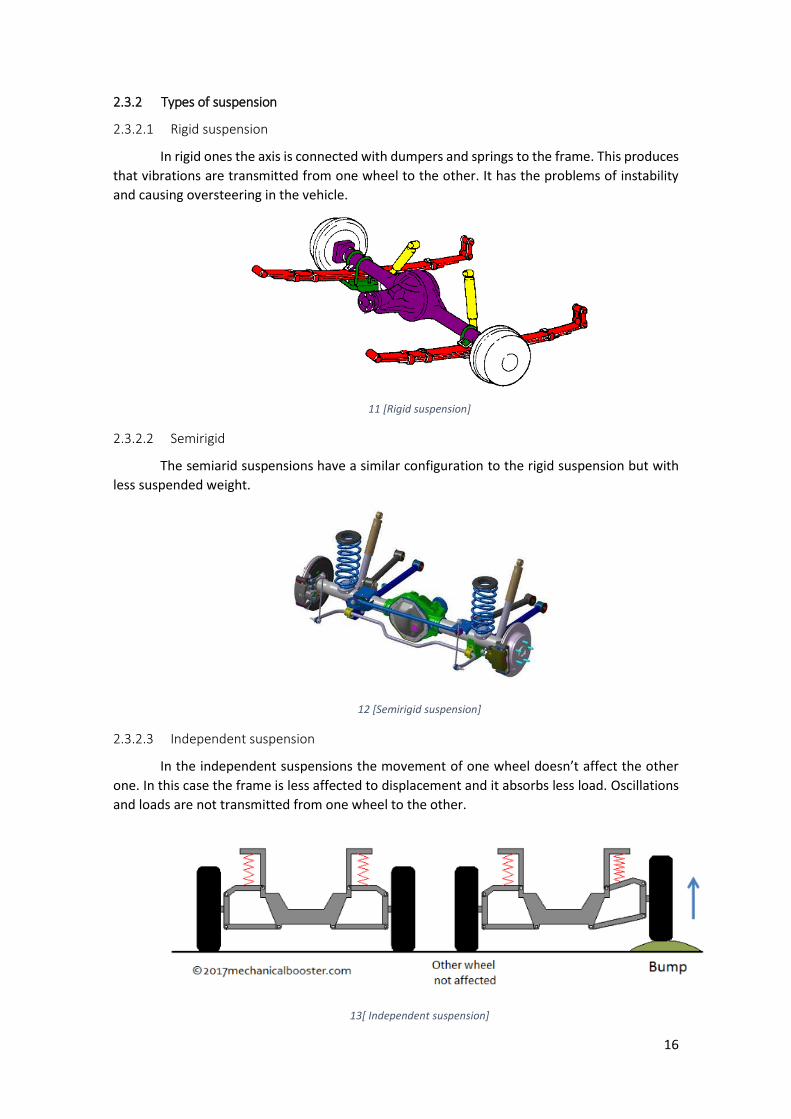
2.3.2.1 Rigid suspension
In rigid ones the axis is connected with dumpers and springs to the frame. This produces
that vibrations are transmitted from one wheel to the other. It has the problems of instability
and causing oversteering in the vehicle.
11 [Rigid suspension]
2.3.2.2 Semirigid
The semiarid suspensions have a similar configuration to the rigid suspension but with
less suspended weight.
12 [Semirigid suspension]
2.3.2.3 Independent suspension
In the independent suspensions the movement of one wheel doesn’t affect the other
one. In this case the frame is less affected to displacement and it absorbs less load. Oscillations
and loads are not transmitted from one wheel to the other.
13[ Independent suspension]
17
2.4 THE WORKING PRINCIPLE AND ADVANTAGES/DISADVANTAGES OF A PUSHROD-SYSTEM
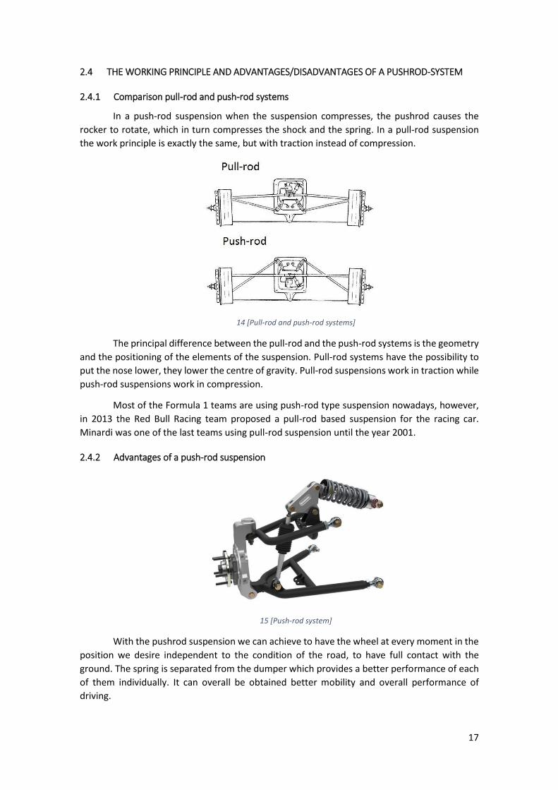
2.4.1 Comparison pull-rod and push-rod systems
In a push-rod suspension when the suspension compresses, the pushrod causes the
rocker to rotate, which in turn compresses the shock and the spring. In a pull-rod suspension
the work principle is exactly the same, but with traction instead of compression.
14 [Pull-rod and push-rod systems]
The principal difference between the pull-rod and the push-rod systems is the geometry
and the positioning of the elements of the suspension. Pull-rod systems have the possibility to
put the nose lower, they lower the centre of gravity. Pull-rod suspensions work in traction while
push-rod suspensions work in compression.
Most of the Formula 1 teams are using push-rod type suspension nowadays, however,
in 2013 the Red Bull Racing team proposed a pull-rod based suspension for the racing car.
Minardi was one of the last teams using pull-rod suspension until the year 2001.
2.4.2 Advantages of a push-rod suspension
15 [Push-rod system]
With the pushrod suspension we can achieve to have the wheel at every moment in the
position we desire independent to the condition of the road, to have full contact with the
ground. The spring is separated from the dumper which provides a better performance of each
of them individually. It can overall be obtained better mobility and overall performance of
driving.

18
The geometry of a push-rod suspension permits the maximum moments of force to be
transmitted, so permits to minimize the size of the equipment and the weight.
It provides a good absorption of vibrations and noise in the car due to the contact of the
tires with the ground.
The design allows modification of the angles with which the best configuration for height
and strength can be obtained. This flexibility of design and the way that it can be implemented
are also advantages of this type of suspension. The flexibility allows the desired kinematics
without compromising the geometry.
Push-rod suspension allows short spindle length and a small negative scrub radius.
It also provides a good response for aerodynamics and downforce. The flow of the air
along the suspension is important for the effect of the downforce.
Before they only knew the classic way of putting the dumper and the spring in the
outside, which was a difficulty for the airflow. Thanks to the pushrod system the location of the
spring and the dumper can be changed. Minimizes drag of the suspension components and helps
the air to go directly to the radiators who help the performance of the engine.
In formula 1 cars the shape of the rods is modified to have a better aerodynamic
behaviour.
16 [F1 suspension rods modification for aerodynamic purposes]
2.4.3 Disadvantages of a push-rod suspension
A push-rod suspension implies higher cost and complexity. That is why is designed
especially for high requirement vehicles as racing cars. It requires modification of the length and
continuous adjustment. It is a type of suspension that is not so used for production cars.
2.5 ANALYSIS OF THE KINEMATICS OF THE 2017 CAR
The analysis of the kinematics has as objective to give solution to the main parameters
of the chassis, for example, the use of tyre compounds, their size, the size of the rim, the
positioning of the elements of the suspension, the camber angle, the caster, the heave ratio, the
toe angle and the king pin angle.
19
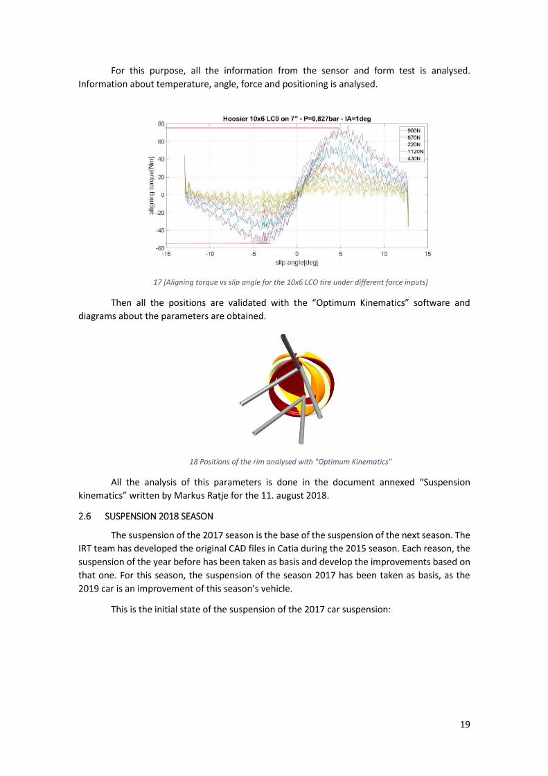
For this purpose, all the information from the sensor and form test is analysed.
Information about temperature, angle, force and positioning is analysed.
17 [Aligning torque vs slip angle for the 10x6 LCO tire under different force inputs]
Then all the positions are validated with the “Optimum Kinematics” software and
diagrams about the parameters are obtained.
18 Positions of the rim analysed with "Optimum Kinematics"
All the analysis of this parameters is done in the document annexed “Suspension
kinematics” written by Markus Ratje for the 11. august 2018.
2.6 SUSPENSION 2018 SEASON
The suspension of the 2017 season is the base of the suspension of the next season. The
IRT team has developed the original CAD files in Catia during the 2015 season. Each reason, the
suspension of the year before has been taken as basis and develop the improvements based on
that one. For this season, the suspension of the season 2017 has been taken as basis, as the
2019 car is an improvement of this season’s vehicle.
This is the initial state of the suspension of the 2017 car suspension:

20
19 [Suspension design for the season 2017]
3 DESIGNING PROCESS
3.1 SUSPENSION GEOMETRY
The suspension for the 2018-2019 season will have the same shape as the suspension in
the previous year. For that purpose, most of the CAD files of the previous seasons are reutilized
and made the necessary modifications in them to fit the new requirements and features.
All the main points of the assembly are built over a structure of points and lines
representing the centre and the rotation points of the main elements. These points are
simulated with the software “Optimum Kinematics” to have the desired behaviour.
20 [Example of the suspension geometry of the 2018/2019 season]
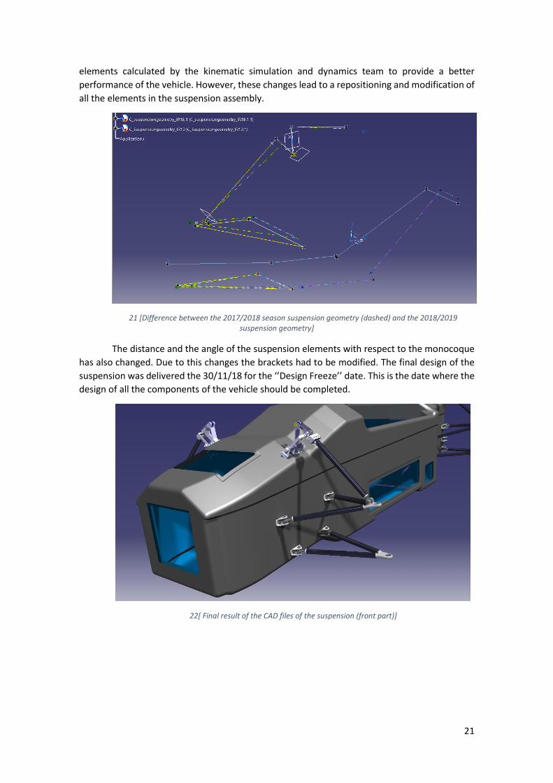
For this new season the geometry of the suspension had some changes with respect to
the previous year geometry. This geometry had minor changes of the positioning of the
21
elements calculated by the kinematic simulation and dynamics team to provide a better
performance of the vehicle. However, these changes lead to a repositioning and modification of
all the elements in the suspension assembly.
21 [Difference between the 2017/2018 season suspension geometry (dashed) and the 2018/2019 suspension geometry]
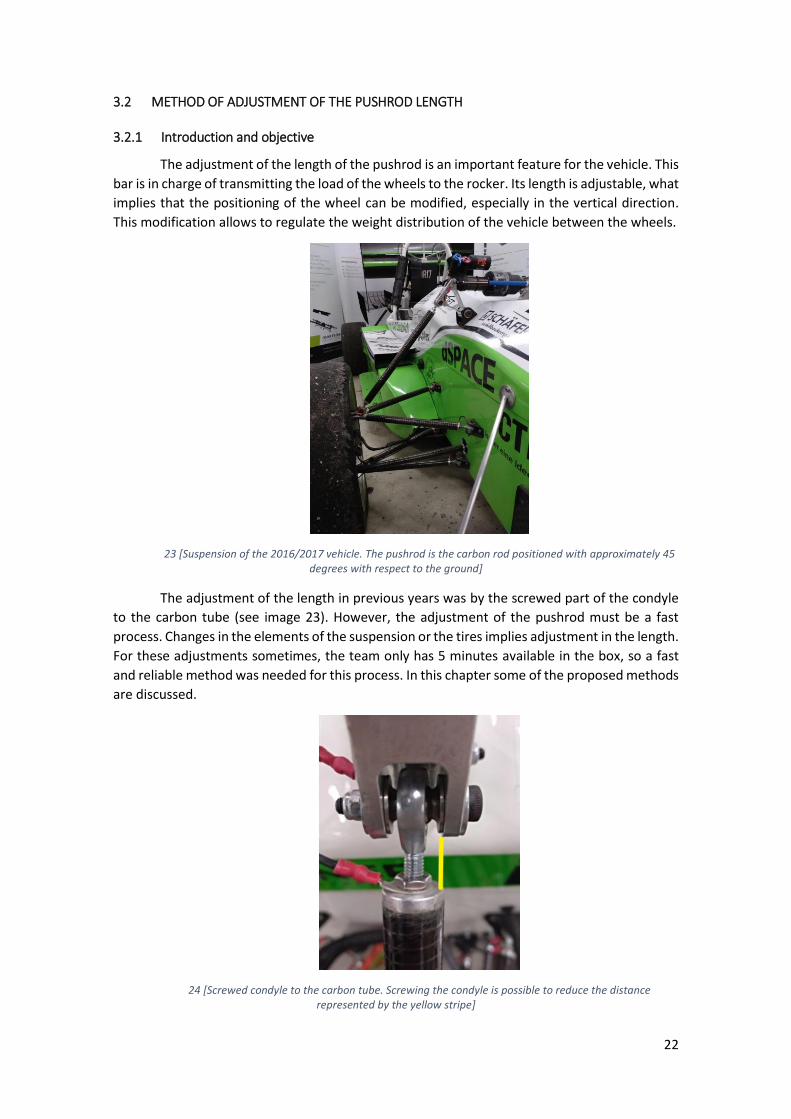
The distance and the angle of the suspension elements with respect to the monocoque
has also changed. Due to this changes the brackets had to be modified. The final design of the
suspension was delivered the 30/11/18 for the ‘’Design Freeze’’ date. This is the date where the
design of all the components of the vehicle should be completed.
22[ Final result of the CAD files of the suspension (front part)]
22
3.2 METHOD OF ADJUSTMENT OF THE PUSHROD LENGTH
3.2.1 Introduction and objective
The adjustment of the length of the pushrod is an important feature for the vehicle. This
bar is in charge of transmitting the load of the wheels to the rocker. Its length is adjustable, what
implies that the positioning of the wheel can be modified, especially in the vertical direction.
This modification allows to regulate the weight distribution of the vehicle between the wheels.
23 [Suspension of the 2016/2017 vehicle. The pushrod is the carbon rod positioned with approximately 45 degrees with respect to the ground]
The adjustment of the length in previous years was by the screwed part of the condyle
to the carbon tube (see image 23). However, the adjustment of the pushrod must be a fast
process. Changes in the elements of the suspension or the tires implies adjustment in the length.
For these adjustments sometimes, the team only has 5 minutes available in the box, so a fast
and reliable method was needed for this process. In this chapter some of the proposed methods
are discussed.
24 [Screwed condyle to the carbon tube. Screwing the condyle is possible to reduce the distance represented by the yellow stripe]

23
3.2.2 Gage blocks
25 [Commercial box of gage blocks]
3.2.2.1 Concept
Gage blocks are blocks with paralepidid shape that have a very good surface polish in
two of their sides that provide very good parallelism and flatness being able to have a length
with high precision. They are of different sizes and just by the combination of them it can be
reproduced any length with a precision of 0.5 µm.
Once the adjustment of the pushrod is done the first time in the regular way, the
distance between the pushrod and the camber can be measured and reproduced with gage
blocks. Then if any change is done, the pattern blocks will be placed in the space between the
pushrod and the camber and the pushrod will be fastened until it touches the surface gage block.
For example, in image 23 the distance with the yellow stripe would be formed with the
gage blocks. Then for the adjustment the gage blocks would be placed in that gap and fasten the
condyle until that exact distance.
3.2.2.2 Price
The price of gage blocks can be very diverse according to the accuracy that they can
provide, however, for the team purposes a regular set can be used that can be obtained for a
price of around 300 €.
3.2.2.3 Advantages
This method provides high precision of the measurement of the distance due to the
accuracy of the gage blocks.
3.2.2.4 Disadvantages
It is slow and uncomfortable to build the measurement with the pattern blocks. Also,
some tests must be done to check the validity of the system.
3.2.3 Self-manufactured gage blocks with disc geometry
26 [Example of a possible shape for the adjustment with self-manufactured gage blocks]
24
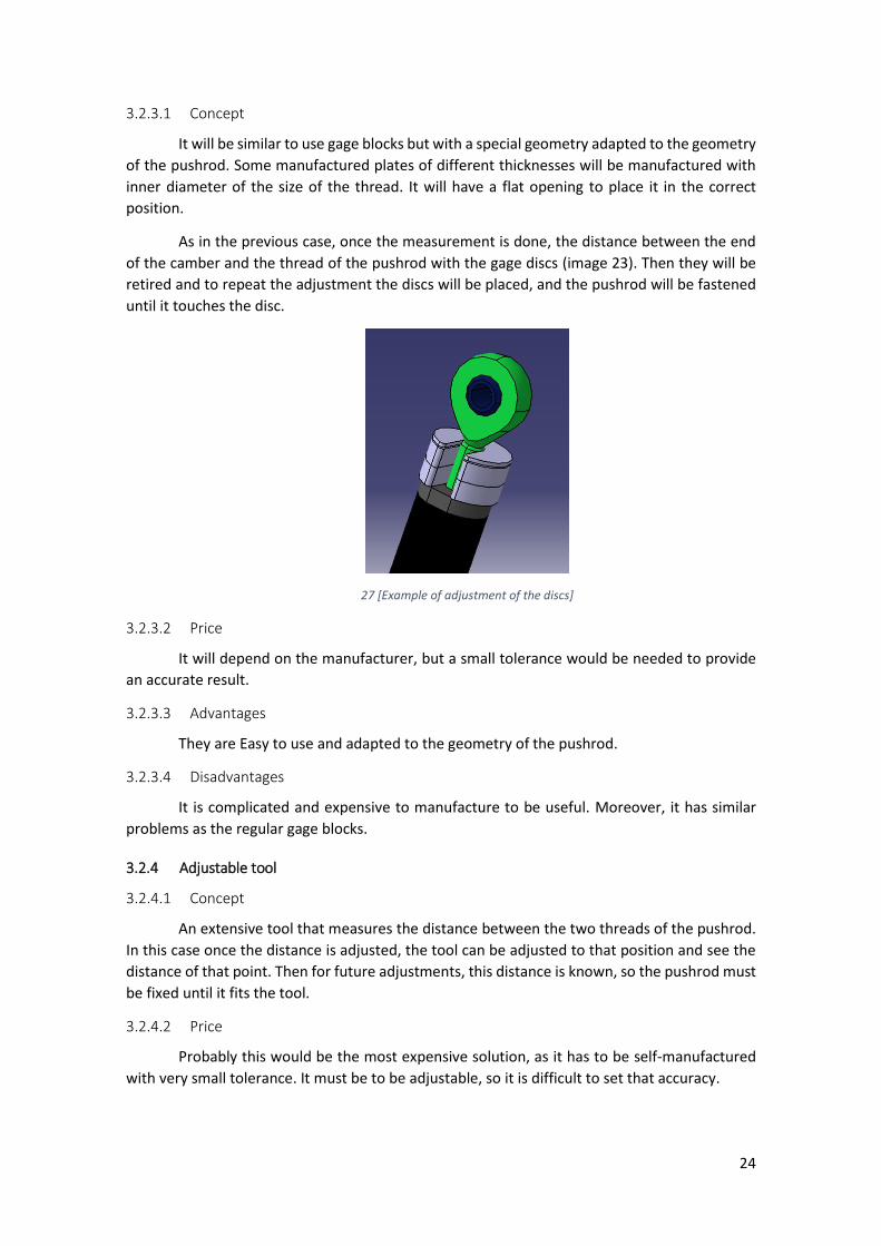
3.2.3.1 Concept
It will be similar to use gage blocks but with a special geometry adapted to the geometry
of the pushrod. Some manufactured plates of different thicknesses will be manufactured with
inner diameter of the size of the thread. It will have a flat opening to place it in the correct
position.
As in the previous case, once the measurement is done, the distance between the end
of the camber and the thread of the pushrod with the gage discs (image 23). Then they will be
retired and to repeat the adjustment the discs will be placed, and the pushrod will be fastened
until it touches the disc.
27 [Example of adjustment of the discs]
3.2.3.2 Price
It will depend on the manufacturer, but a small tolerance would be needed to provide
an accurate result.
3.2.3.3 Advantages
They are Easy to use and adapted to the geometry of the pushrod.
3.2.3.4 Disadvantages
It is complicated and expensive to manufacture to be useful. Moreover, it has similar
problems as the regular gage blocks.
3.2.4 Adjustable tool
3.2.4.1 Concept
An extensive tool that measures the distance between the two threads of the pushrod.
In this case once the distance is adjusted, the tool can be adjusted to that position and see the
distance of that point. Then for future adjustments, this distance is known, so the pushrod must
be fixed until it fits the tool.
3.2.4.2 Price
Probably this would be the most expensive solution, as it has to be self-manufactured
with very small tolerance. It must be to be adjustable, so it is difficult to set that accuracy.

25
3.2.4.3 Advantages
It is easy to use and very intuitive.
3.2.4.4 Disadvantages
It is complex to manufacture and probably more expensive than other methods.
As it must be adjusted for every case it is difficult to provide the same accuracy as with
other methods.
3.2.5 Sensor
28 [Commercial laser sensor to measure distances]
3.2.5.1 Concept
This method is very similar to the previous one, but instead of having a mechanical tool,
we measure the distance with a laser sensor.
This sensor measures the distance between his position and a screen or receptor. Once
the pushrod is adjusted the sensor and the screen will be placed in their respective places. Then
the sensor will provide the exact distance between the points. To repeat the same adjustment
the pushrod must be extended until the sensor provides the same measurement.
A tool must be manufactured to link the sensor and the screen to their respective bolts.
29 [Sensor with tool adjusted to the bolt of the rocker]
30 [Screen adjusted to the lower bolt of the pushrod]
26
3.2.5.2 Price
The sensor has a price of around 150 €.
3.2.5.3 Advantages
It can provide a very accurate measurement.
Once installed and calibrated it can be very easy and fast to use.
The sensor can be also used for other applications.
3.2.5.4 Disadvantages
The compatibility and the use method must be studied.
It has more complexity than other systems.
The sensor is a delicate item that the user must know how to use.
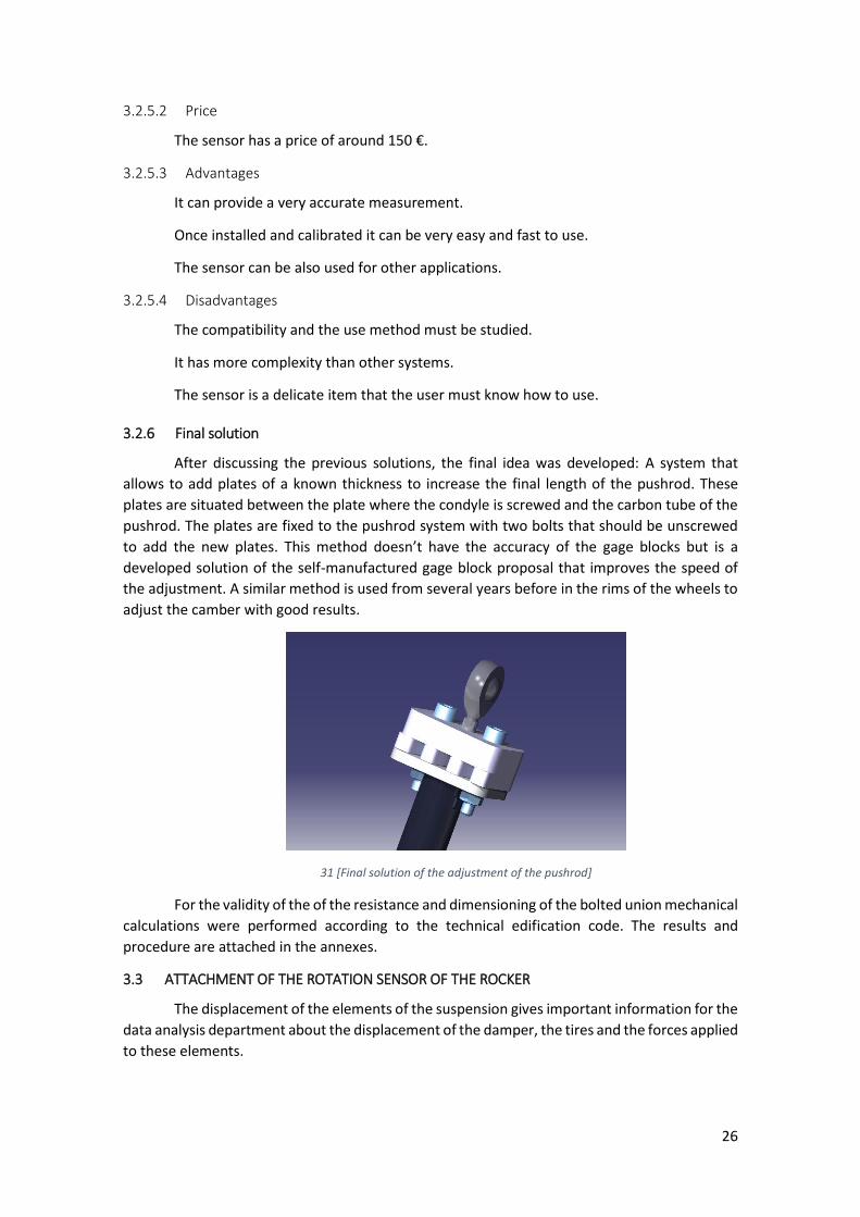
3.2.6 Final solution
After discussing the previous solutions, the final idea was developed: A system that
allows to add plates of a known thickness to increase the final length of the pushrod. These
plates are situated between the plate where the condyle is screwed and the carbon tube of the
pushrod. The plates are fixed to the pushrod system with two bolts that should be unscrewed
to add the new plates. This method doesn’t have the accuracy of the gage blocks but is a
developed solution of the self-manufactured gage block proposal that improves the speed of
the adjustment. A similar method is used from several years before in the rims of the wheels to
adjust the camber with good results.
31 [Final solution of the adjustment of the pushrod]
For the validity of the of the resistance and dimensioning of the bolted union mechanical
calculations were performed according to the technical edification code. The results and
procedure are attached in the annexes.
3.3 ATTACHMENT OF THE ROTATION SENSOR OF THE ROCKER
The displacement of the elements of the suspension gives important information for the
data analysis department about the displacement of the damper, the tires and the forces applied
to these elements.
27
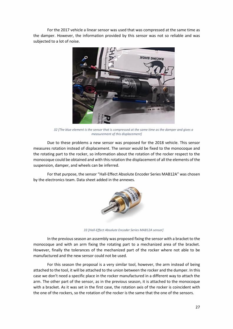
For the 2017 vehicle a linear sensor was used that was compressed at the same time as
the damper. However, the information provided by this sensor was not so reliable and was
subjected to a lot of noise.
32 [The blue element is the sensor that is compressed at the same time as the damper and gives a measurement of this displacement]
Due to these problems a new sensor was proposed for the 2018 vehicle. This sensor
measures rotation instead of displacement. The sensor would be fixed to the monocoque and
the rotating part to the rocker, so information about the rotation of the rocker respect to the
monocoque could be obtained and with this rotation the displacement of all the elements of the
suspension, damper, and wheels can be inferred.
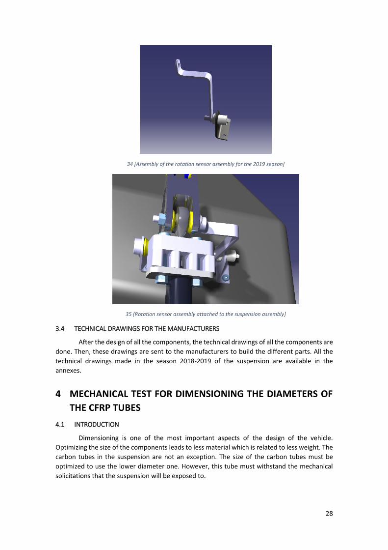
For that purpose, the sensor “Hall-Effect Absolute Encoder Series MAB12A” was chosen
by the electronics team. Data sheet added in the annexes.
33 [Hall-Effect Absolute Encoder Series MAB12A sensor]
In the previous season an assembly was proposed fixing the sensor with a bracket to the
monocoque and with an arm fixing the rotating part to a mechanized area of the bracket.
However, finally the tolerances of the mechanized part of the rocker where not able to be
manufactured and the new sensor could not be used.
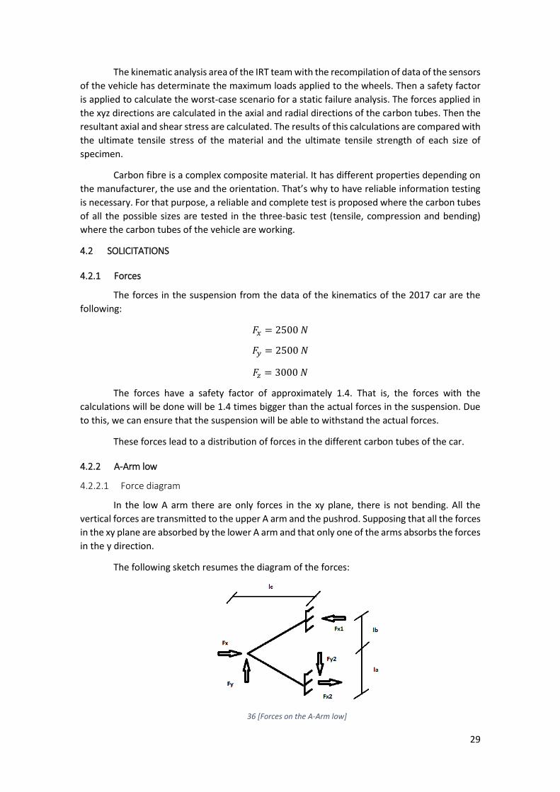
For this season the proposal is a very similar tool, however, the arm instead of being
attached to the tool, it will be attached to the union between the rocker and the dumper. In this
case we don’t need a specific place in the rocker manufactured in a different way to attach the
arm. The other part of the sensor, as in the previous season, it is attached to the monocoque
with a bracket. As it was set in the first case, the rotation axis of the rocker is coincident with
the one of the rockers, so the rotation of the rocker is the same that the one of the sensors.
28
34 [Assembly of the rotation sensor assembly for the 2019 season]
35 [Rotation sensor assembly attached to the suspension assembly]
3.4 TECHNICAL DRAWINGS FOR THE MANUFACTURERS
After the design of all the components, the technical drawings of all the components are
done. Then, these drawings are sent to the manufacturers to build the different parts. All the
technical drawings made in the season 2018-2019 of the suspension are available in the
annexes.
4 MECHANICAL TEST FOR DIMENSIONING THE DIAMETERS OF
THE CFRP TUBES
4.1 INTRODUCTION
Dimensioning is one of the most important aspects of the design of the vehicle.
Optimizing the size of the components leads to less material which is related to less weight. The
carbon tubes in the suspension are not an exception. The size of the carbon tubes must be
optimized to use the lower diameter one. However, this tube must withstand the mechanical
solicitations that the suspension will be exposed to.
29
The kinematic analysis area of the IRT team with the recompilation of data of the sensors
of the vehicle has determinate the maximum loads applied to the wheels. Then a safety factor
is applied to calculate the worst-case scenario for a static failure analysis. The forces applied in
the xyz directions are calculated in the axial and radial directions of the carbon tubes. Then the
resultant axial and shear stress are calculated. The results of this calculations are compared with
the ultimate tensile stress of the material and the ultimate tensile strength of each size of
specimen.
Carbon fibre is a complex composite material. It has different properties depending on
the manufacturer, the use and the orientation. That’s why to have reliable information testing
is necessary. For that purpose, a reliable and complete test is proposed where the carbon tubes
of all the possible sizes are tested in the three-basic test (tensile, compression and bending)
where the carbon tubes of the vehicle are working.
4.2 SOLICITATIONS
4.2.1 Forces
The forces in the suspension from the data of the kinematics of the 2017 car are the
following:
𝐹𝑥 = 2500 𝑁
𝐹𝑦 = 2500 𝑁
𝐹𝑧 = 3000 𝑁
The forces have a safety factor of approximately 1.4. That is, the forces with the
calculations will be done will be 1.4 times bigger than the actual forces in the suspension. Due
to this, we can ensure that the suspension will be able to withstand the actual forces.
These forces lead to a distribution of forces in the different carbon tubes of the car.
4.2.2 A-Arm low
4.2.2.1 Force diagram
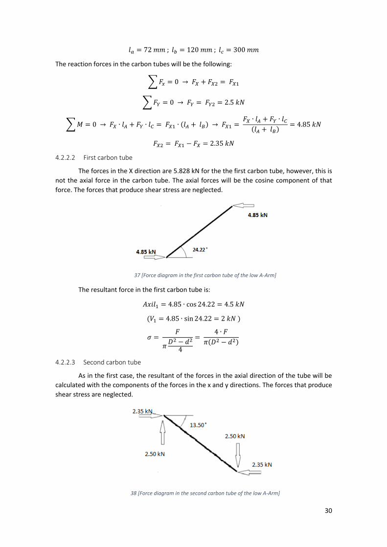
In the low A arm there are only forces in the xy plane, there is not bending. All the
vertical forces are transmitted to the upper A arm and the pushrod. Supposing that all the forces
in the xy plane are absorbed by the lower A arm and that only one of the arms absorbs the forces
in the y direction.
The following sketch resumes the diagram of the forces:
36 [Forces on the A-Arm low]
30
𝑙𝑎 = 72 𝑚𝑚 ; 𝑙𝑏 = 120 𝑚𝑚 ; 𝑙𝑐 = 300 𝑚𝑚
The reaction forces in the carbon tubes will be the following:
∑ 𝐹𝑥 = 0 → 𝐹𝑋 + 𝐹𝑋2 = 𝐹𝑋1
∑ 𝐹𝑌 = 0 → 𝐹𝑌 = 𝐹𝑌2 = 2.5 𝑘𝑁
∑ 𝑀 = 0 → 𝐹𝑋 ∙ 𝑙𝐴 + 𝐹𝑌 ∙ 𝑙𝐶 = 𝐹𝑋1 ∙ (𝑙𝐴 + 𝑙𝐵) → 𝐹𝑋1 = 𝐹𝑋 ∙ 𝑙𝐴 + 𝐹𝑌 ∙ 𝑙𝐶
(𝑙𝐴 + 𝑙𝐵)= 4.85 𝑘𝑁
𝐹𝑋2 = 𝐹𝑋1 − 𝐹𝑋 = 2.35 𝑘𝑁
4.2.2.2 First carbon tube
The forces in the X direction are 5.828 kN for the the first carbon tube, however, this is
not the axial force in the carbon tube. The axial forces will be the cosine component of that
force. The forces that produce shear stress are neglected.
37 [Force diagram in the first carbon tube of the low A-Arm]
The resultant force in the first carbon tube is:
𝐴𝑥𝑖𝑙1 = 4.85 ∙ cos 24.22 = 4.5 𝑘𝑁
(𝑉1 = 4.85 ∙ sin 24.22 = 2 𝑘𝑁 )
𝜎 = 𝐹
𝜋𝐷2 − 𝑑2
4
= 4 ∙ 𝐹
𝜋(𝐷2 − 𝑑2)
4.2.2.3 Second carbon tube
As in the first case, the resultant of the forces in the axial direction of the tube will be
calculated with the components of the forces in the x and y directions. The forces that produce
shear stress are neglected.
38 [Force diagram in the second carbon tube of the low A-Arm]
31
The resultant force in the second carbon tube is:
𝐴𝑥𝑖𝑙2 = 2.35 ∙ cos 13.50 + 2.5 ∙ sin 13.50 = 2.87 𝑘𝑁
(𝑉2 = 2.35 ∙ sin 13.50 − 2.5 ∙ cos 13.50 = 1.88 𝑘𝑁)
𝜎 = 𝐹
𝜋𝐷2 − 𝑑2
4
= 4 ∙ 𝐹
𝜋(𝐷2 − 𝑑2)
4.2.3 A-Arm up
4.2.3.1 Force diagram
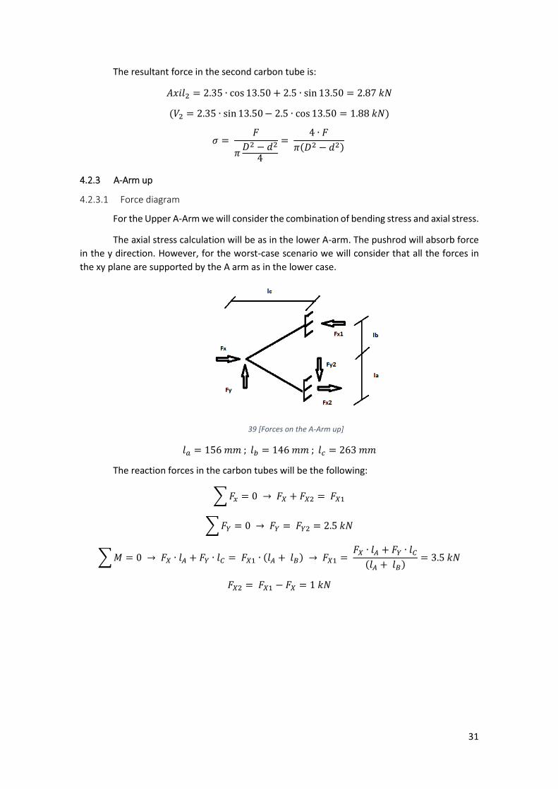
For the Upper A-Arm we will consider the combination of bending stress and axial stress.
The axial stress calculation will be as in the lower A-arm. The pushrod will absorb force
in the y direction. However, for the worst-case scenario we will consider that all the forces in
the xy plane are supported by the A arm as in the lower case.
39 [Forces on the A-Arm up]
𝑙𝑎 = 156 𝑚𝑚 ; 𝑙𝑏 = 146 𝑚𝑚 ; 𝑙𝑐 = 263 𝑚𝑚
The reaction forces in the carbon tubes will be the following:
∑ 𝐹𝑥 = 0 → 𝐹𝑋 + 𝐹𝑋2 = 𝐹𝑋1
∑ 𝐹𝑌 = 0 → 𝐹𝑌 = 𝐹𝑌2 = 2.5 𝑘𝑁
∑ 𝑀 = 0 → 𝐹𝑋 ∙ 𝑙𝐴 + 𝐹𝑌 ∙ 𝑙𝐶 = 𝐹𝑋1 ∙ (𝑙𝐴 + 𝑙𝐵) → 𝐹𝑋1 = 𝐹𝑋 ∙ 𝑙𝐴 + 𝐹𝑌 ∙ 𝑙𝐶
(𝑙𝐴 + 𝑙𝐵)= 3.5 𝑘𝑁
𝐹𝑋2 = 𝐹𝑋1 − 𝐹𝑋 = 1 𝑘𝑁
32
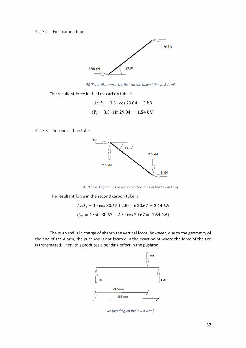
4.2.3.2 First carbon tube
40 [Force diagram in the first carbon tube of the up A-Arm]
The resultant force in the first carbon tube is:
𝐴𝑥𝑖𝑙1 = 3.5 ∙ cos 29.04 = 3 𝑘𝑁
(𝑉1 = 3.5 ∙ sin 29.04 = 1.54 𝑘𝑁)
4.2.3.3 Second carbon tube
41 [Force diagram in the second carbon tube of the low A-Arm]
The resultant force in the second carbon tube is:
𝐴𝑥𝑖𝑙2 = 1 ∙ cos 30.67 +2.5 ∙ sin 30.67 = 2.14 𝑘𝑁
(𝑉2 = 1 ∙ sin 30.67 − 2.5 ∙ cos 30.67 = 1.64 𝑘𝑁)
The push rod is in charge of absorb the vertical force, however, due to the geometry of
the end of the A arm, the push rod is not located in the exact point where the force of the tire
is transmitted. Then, this produces a bending effect in the pushrod.
42 [Bending on the low A-Arm]

33
∑ 𝐹 = 0 → 3 = 𝐹𝑉𝑃 + 𝐹𝑏
∑ 𝑀 = 0 → 𝐹𝑉𝑃 ∙ 237 = 3 ∙ 263 → 𝐹𝑉𝑃 = 3.33 𝑘𝑁
𝑀𝑚𝑎𝑥 = 3 𝑘𝑁 ∙ 26 𝑚𝑚 = 78 𝑁𝑚
43 [Moment distribution in the low A-Arm]
This moment is absorbed by both arms, so the stress due to bending in each of the
carbon tube will be considering half of the maximum bending moment.
𝐼 = 𝜋(𝑅4 − 𝑟4)
4
𝜎𝑏𝑒𝑛𝑑 =
𝑀𝑚𝑎𝑥2⁄ ∙ 𝑅
𝐼=
144 ∙ 103 ∙ 4 ∙ 𝑅
𝜋(𝑅4 − 𝑟4)
This stress due to bending will be added to the stress due to axial forces.
𝜎 = 4 ∙ 𝐹
𝜋(𝐷2 − 𝑑2)+
𝑀𝑚𝑎𝑥2⁄ ∙ 4 ∙ 𝑅
𝜋(𝑅4 − 𝑟4)
4.2.4 Pushrod of the suspension
For the calculation of the forces in the pushrod we will consider that the pushrod is
responsible of absorbing all the forces in x and z directions to consider the worst-case scenario.
The pushrod has freedom of rotation in the two unions. It will only withstand axial force.
Not bending is applied in the pushrod.
44 [Force diagram in the pushrod]
𝐴𝑥𝑖𝑙 = 2.5 ∙ cos 44.61 +3 ∙ sin 44.61 = 3.89 𝑘𝑁
(𝑉2 = 2.5 ∙ sin 44.61 − 3 ∙ cos 44.61 = 0.38 𝑘𝑁)
34
𝜎 = 𝐹
𝜋𝐷2 − 𝑑2
4
= 4 ∙ 𝐹
𝜋(𝐷2 − 𝑑2)
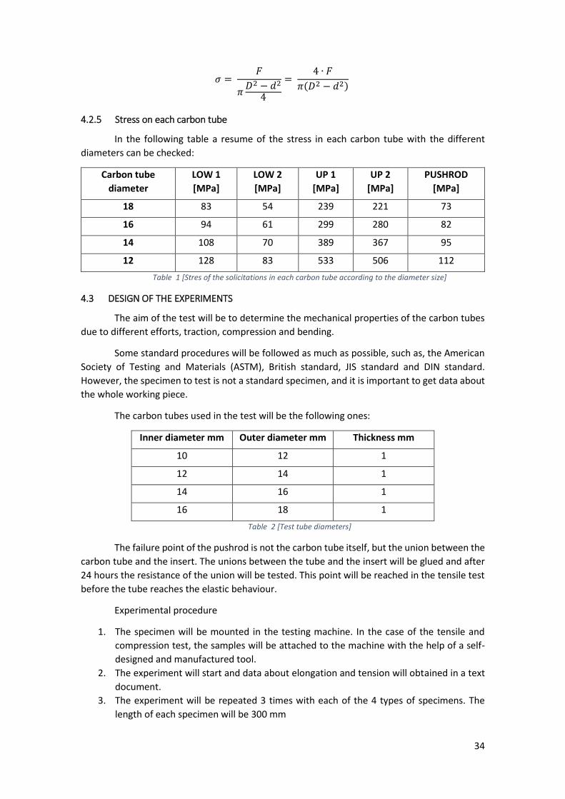
4.2.5 Stress on each carbon tube
In the following table a resume of the stress in each carbon tube with the different
diameters can be checked:
Carbon tube
diameter
LOW 1
[MPa]
LOW 2
[MPa]
UP 1
[MPa]
UP 2
[MPa]
PUSHROD
[MPa]
18 83 54 239 221 73
16 94 61 299 280 82
14 108 70 389 367 95
12 128 83 533 506 112
Table 1 [Stres of the solicitations in each carbon tube according to the diameter size]
4.3 DESIGN OF THE EXPERIMENTS
The aim of the test will be to determine the mechanical properties of the carbon tubes
due to different efforts, traction, compression and bending.
Some standard procedures will be followed as much as possible, such as, the American
Society of Testing and Materials (ASTM), British standard, JIS standard and DIN standard.
However, the specimen to test is not a standard specimen, and it is important to get data about
the whole working piece.
The carbon tubes used in the test will be the following ones:
Inner diameter mm Outer diameter mm Thickness mm
10 12 1
12 14 1
14 16 1
16 18 1
Table 2 [Test tube diameters]
The failure point of the pushrod is not the carbon tube itself, but the union between the
carbon tube and the insert. The unions between the tube and the insert will be glued and after
24 hours the resistance of the union will be tested. This point will be reached in the tensile test
before the tube reaches the elastic behaviour.
Experimental procedure
1. The specimen will be mounted in the testing machine. In the case of the tensile and
compression test, the samples will be attached to the machine with the help of a self-
designed and manufactured tool.
2. The experiment will start and data about elongation and tension will obtained in a text
document.
3. The experiment will be repeated 3 times with each of the 4 types of specimens. The
length of each specimen will be 300 mm
35
45 [Specimen with the self-manufactured tool to perform the tests]
The ultimate tensile strength and the force that the tube withstands in each test will be
analysed and compared with the solicitations of each tube.
A safety factor will be applied to compare the resistance of the tube with the actual
forces, increasing the solicitations to guaranty the static integrity of the tubes under the actual
forces.
Carbon fibre is a fragile material, the calculation of the stress will be always calculated
using the initial radii and the reduction of the area and the strain-hardening during the test will
be neglected.
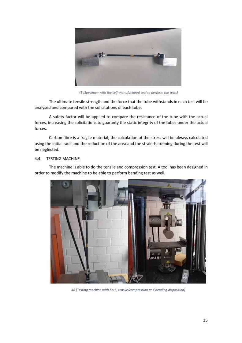
4.4 TESTING MACHINE
The machine is able to do the tensile and compression test. A tool has been designed in
order to modify the machine to be able to perform bending test as well.
46 [Testing machine with both, tensile/compression and bending disposition]
36
4.5 TENSILE TEST
4.5.1 Introduction
The tensile testing is one of the most fundamental tests in engineering, where a sample
is subjected to an axial force opposite to the section of the specimen until its failure. The
ultimate tensile strength, the breaking strength, the maximum elongation and the reduction of
the area can be obtained from this test. From this date the young modulus, the Poisson’s ratio,
the yield strength and the strain- hardening can be obtained.
During the test, the elongation of the specimen is determined, and a force-elongation
or stress-strain graph is obtained.
𝜀 = 𝐿 − 𝐿0
𝐿0
𝜎 = 𝐹𝐴⁄
With this test we will be able to set the resistance of the insert.
The procedure of the experiment will be as mentioned in the previous point.
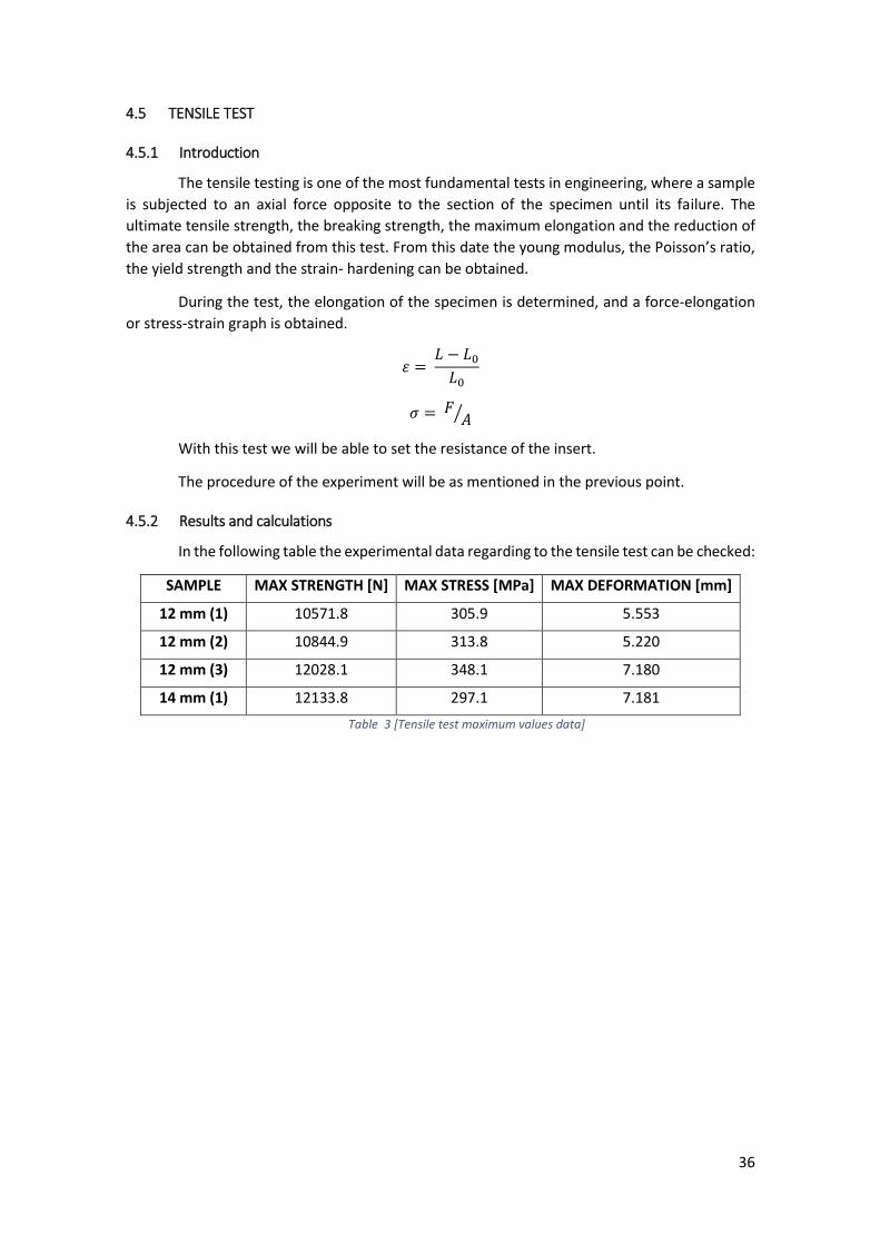
4.5.2 Results and calculations
In the following table the experimental data regarding to the tensile test can be checked:
SAMPLE MAX STRENGTH [N] MAX STRESS [MPa] MAX DEFORMATION [mm]
12 mm (1) 10571.8 305.9 5.553
12 mm (2) 10844.9 313.8 5.220
12 mm (3) 12028.1 348.1 7.180
14 mm (1) 12133.8 297.1 7.181
Table 3 [Tensile test maximum values data]
37
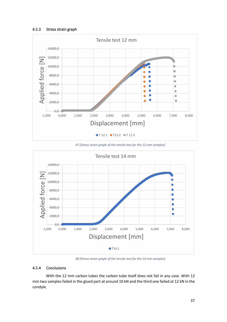
4.5.3 Stress strain graph
47 [Stress strain graph of the tensile test for the 12 mm samples]
48 [Stress strain graph of the tensile test for the 14 mm samples]
4.5.4 Conclusions
With the 12 mm carbon tubes the carbon tube itself does not fail in any case. With 12
mm two samples failed in the glued part at around 10 kN and the third one failed at 12 kN in the
condyle.
0,0
2000,0
4000,0
6000,0
8000,0
10000,0
12000,0
14000,0
-1,000 0,000 1,000 2,000 3,000 4,000 5,000 6,000 7,000 8,000
Ap
plie
d f
orc
e [N
]
Displacement [mm]
Tensile test 12 mm
T 12.1 T12.2 T 12.3
0,0
2000,0
4000,0
6000,0
8000,0
10000,0
12000,0
14000,0
-1,000 0,000 1,000 2,000 3,000 4,000 5,000 6,000 7,000 8,000
Ap
plie
d f
orc
e [N
]
Displacement [mm]
Tensile test 14 mm
T14.1
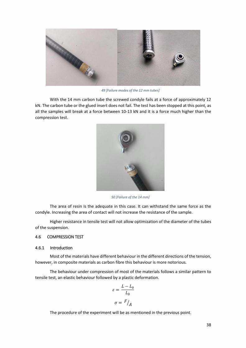
38
49 [Failure modes of the 12 mm tubes]
With the 14 mm carbon tube the screwed condyle fails at a force of approximately 12
kN. The carbon tube or the glued insert does not fail. The test has been stopped at this point, as
all the samples will break at a force between 10-13 kN and it is a force much higher than the
compression test.
50 [Failure of the 14 mm]
The area of resin is the adequate in this case. It can withstand the same force as the
condyle. Increasing the area of contact will not increase the resistance of the sample.
Higher resistance in tensile test will not allow optimization of the diameter of the tubes
of the suspension.
4.6 COMPRESSION TEST
4.6.1 Introduction
Most of the materials have different behaviour in the different directions of the tension,
however, in composite materials as carbon fibre this behaviour is more notorious.
The behaviour under compression of most of the materials follows a similar pattern to
tensile test, an elastic behaviour followed by a plastic deformation.
𝜀 = 𝐿 − 𝐿0
𝐿0
𝜎 = 𝐹𝐴⁄
The procedure of the experiment will be as mentioned in the previous point.
39
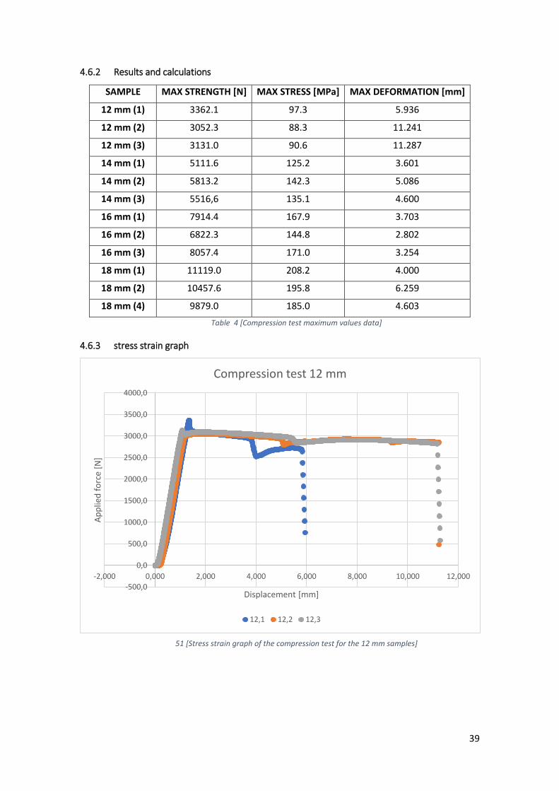
4.6.2 Results and calculations
SAMPLE MAX STRENGTH [N] MAX STRESS [MPa] MAX DEFORMATION [mm]
12 mm (1) 3362.1 97.3 5.936
12 mm (2) 3052.3 88.3 11.241
12 mm (3) 3131.0 90.6 11.287
14 mm (1) 5111.6 125.2 3.601
14 mm (2) 5813.2 142.3 5.086
14 mm (3) 5516,6 135.1 4.600
16 mm (1) 7914.4 167.9 3.703
16 mm (2) 6822.3 144.8 2.802
16 mm (3) 8057.4 171.0 3.254
18 mm (1) 11119.0 208.2 4.000
18 mm (2) 10457.6 195.8 6.259
18 mm (4) 9879.0 185.0 4.603
Table 4 [Compression test maximum values data]
4.6.3 stress strain graph
51 [Stress strain graph of the compression test for the 12 mm samples]
-500,0
0,0
500,0
1000,0
1500,0
2000,0
2500,0
3000,0
3500,0
4000,0
-2,000 0,000 2,000 4,000 6,000 8,000 10,000 12,000
Ap
plie
d f
orc
e [N
]
Displacement [mm]
Compression test 12 mm
12,1 12,2 12,3

40
52 [Stress strain graph of the compression test for the 14 mm samples]
53 [Stress strain graph of the compression test for the 16 mm samples]
-1000,0
0,0
1000,0
2000,0
3000,0
4000,0
5000,0
6000,0
7000,0
-1,000 0,000 1,000 2,000 3,000 4,000 5,000 6,000
Ap
plie
d f
orc
e [N
]
Displacement [mm]
Compression test 14 mm
C 14.1 C 14.2 C 14.3
-1000,0
0,0
1000,0
2000,0
3000,0
4000,0
5000,0
6000,0
7000,0
8000,0
9000,0
0,000 0,500 1,000 1,500 2,000 2,500 3,000 3,500 4,000
Ap
plie
d f
orc
e [N
]
Displacement [mm]
Compression test 16 mm
16,1 16,2 16,3
41
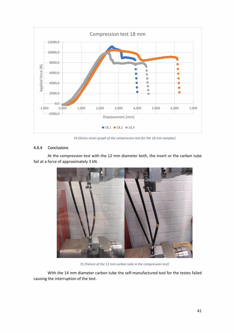
54 [Stress strain graph of the compression test for the 18 mm samples]
4.6.4 Conclusions
At the compression test with the 12 mm diameter both, the insert or the carbon tube
fail at a force of approximately 3 kN.
55 [Failure of the 12 mm carbon tube in the compression test]
With the 14 mm diameter carbon tube the self-manufactured tool for the testes failed
causing the interruption of the test.
-2000,0
0,0
2000,0
4000,0
6000,0
8000,0
10000,0
12000,0
-1,000 0,000 1,000 2,000 3,000 4,000 5,000 6,000 7,000
Ap
plie
d f
orc
e [N
]
Displacement [mm]
Compression test 18 mm
18,1 18,2 18,4
42
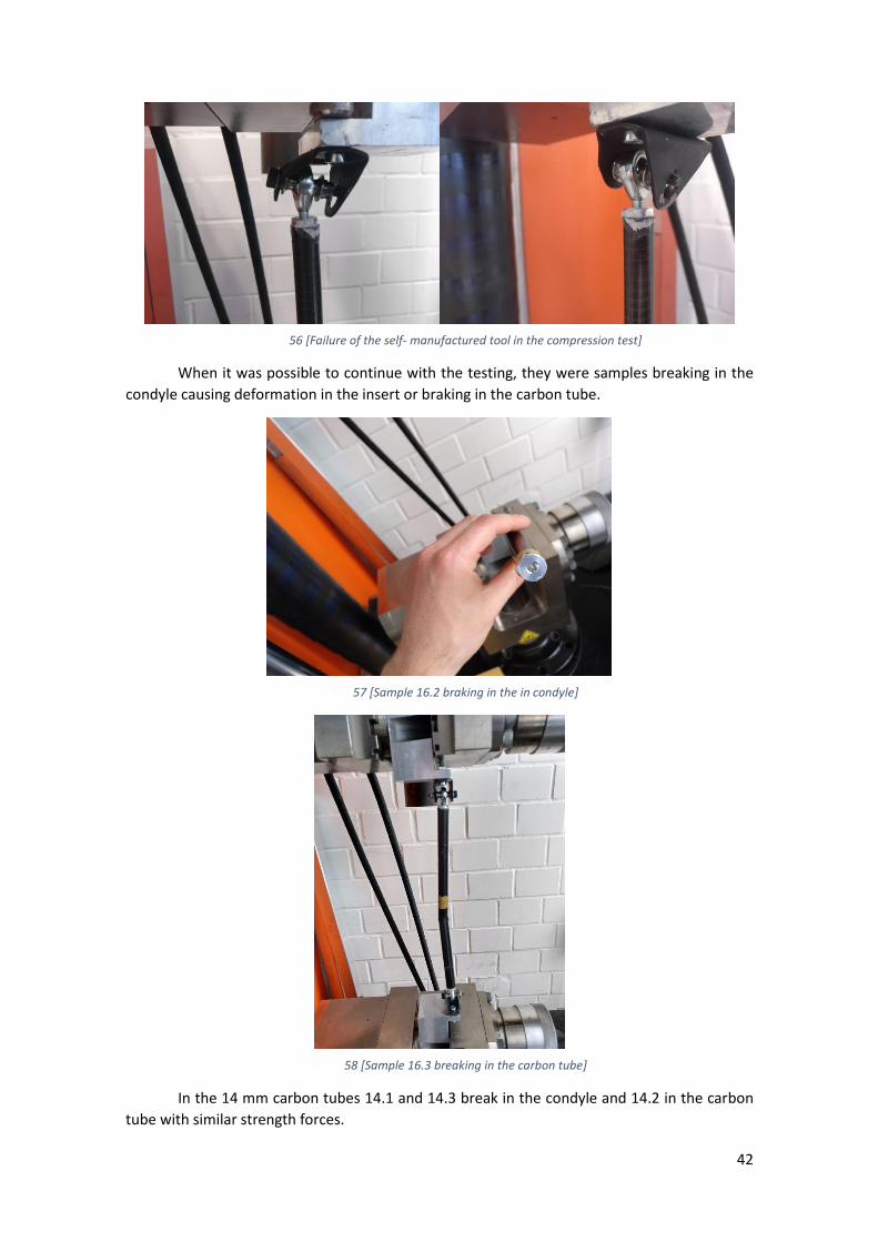
56 [Failure of the self- manufactured tool in the compression test]
When it was possible to continue with the testing, they were samples breaking in the
condyle causing deformation in the insert or braking in the carbon tube.
57 [Sample 16.2 braking in the in condyle]
58 [Sample 16.3 breaking in the carbon tube]
In the 14 mm carbon tubes 14.1 and 14.3 break in the condyle and 14.2 in the carbon
tube with similar strength forces.
43
In 16 mm and 18 mm some of the condyles may have failed with lower strength due to
fatigue of the material. In the case of the 18.3 for example the condyle failed with lower value
than before. That’s why it was changed and repeated the experiment. We can also appreciate
in the graph of 16 mm a lower value of break of the condyle of the 16.1 compared with the 16.2.
The 16.3 on the other side break in the carbon tube.
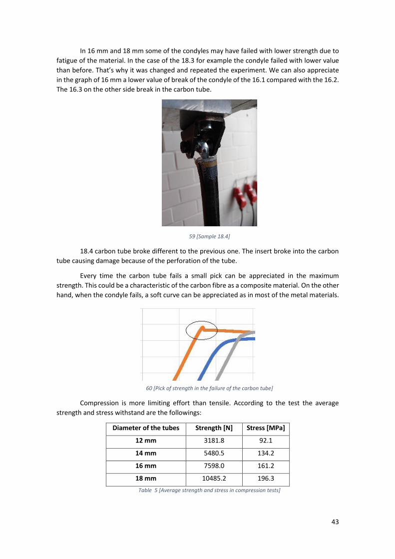
59 [Sample 18.4]
18.4 carbon tube broke different to the previous one. The insert broke into the carbon
tube causing damage because of the perforation of the tube.
Every time the carbon tube fails a small pick can be appreciated in the maximum
strength. This could be a characteristic of the carbon fibre as a composite material. On the other
hand, when the condyle fails, a soft curve can be appreciated as in most of the metal materials.
60 [Pick of strength in the failure of the carbon tube]
Compression is more limiting effort than tensile. According to the test the average
strength and stress withstand are the followings:
Diameter of the tubes Strength [N] Stress [MPa]
12 mm 3181.8 92.1
14 mm 5480.5 134.2
16 mm 7598.0 161.2
18 mm 10485.2 196.3
Table 5 [Average strength and stress in compression tests]
44
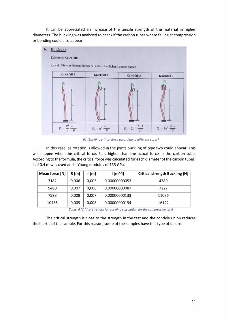
It can be appreciated an increase of the tensile strength of the material in higher
diameters. The buckling was analysed to check if the carbon tubes where failing at compression
or bending could also appear.
61 [Buckling critical force according to different cases]
In this case, as rotation is allowed in the joints buckling of type two could appear. This
will happen when the critical force, Fk is higher than the actual force in the carbon tube.
According to the formula, the critical force was calculated for each diameter of the carbon tubes.
L of 0.4 m was used and a Young modulus of 135 GPa.
Mean force [N] R [m] r [m] I [m^4] Critical strength Buckling [N]
3182 0,006 0,005 0,00000000053 4389
5480 0,007 0,006 0,00000000087 7227
7598 0,008 0,007 0,00000000133 11086
10485 0,009 0,008 0,00000000194 16122
Table 6 [Critical strength for buckling calculation for the compression test]
The critical strength is close to the strength in the test and the condyle union reduces
the inertia of the sample. For this reason, some of the samples have this type of failure.
45
4.7 BENDING TEST
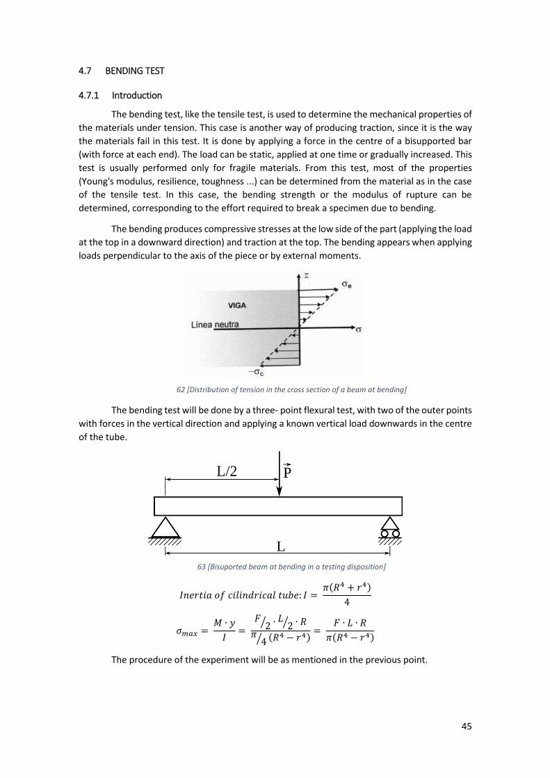
4.7.1 Introduction
The bending test, like the tensile test, is used to determine the mechanical properties of
the materials under tension. This case is another way of producing traction, since it is the way
the materials fail in this test. It is done by applying a force in the centre of a bisupported bar
(with force at each end). The load can be static, applied at one time or gradually increased. This
test is usually performed only for fragile materials. From this test, most of the properties
(Young's modulus, resilience, toughness ...) can be determined from the material as in the case
of the tensile test. In this case, the bending strength or the modulus of rupture can be
determined, corresponding to the effort required to break a specimen due to bending.
The bending produces compressive stresses at the low side of the part (applying the load
at the top in a downward direction) and traction at the top. The bending appears when applying
loads perpendicular to the axis of the piece or by external moments.
62 [Distribution of tension in the cross section of a beam at bending]
The bending test will be done by a three- point flexural test, with two of the outer points
with forces in the vertical direction and applying a known vertical load downwards in the centre
of the tube.
63 [Bisuported beam at bending in a testing disposition]
𝐼𝑛𝑒𝑟𝑡𝑖𝑎 𝑜𝑓 𝑐𝑖𝑙𝑖𝑛𝑑𝑟𝑖𝑐𝑎𝑙 𝑡𝑢𝑏𝑒: 𝐼 = 𝜋(𝑅4 + 𝑟4)
4
𝜎𝑚𝑎𝑥 = 𝑀 ∙ 𝑦
𝐼=
𝐹2⁄ ∙ 𝐿
2⁄ ∙ 𝑅𝜋
4⁄ (𝑅4 − 𝑟4)=
𝐹 ∙ 𝐿 ∙ 𝑅
𝜋(𝑅4 − 𝑟4)
The procedure of the experiment will be as mentioned in the previous point.
46
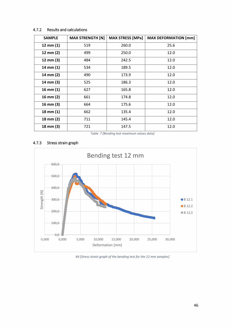
4.7.2 Results and calculations
SAMPLE MAX STRENGTH [N] MAX STRESS [MPa] MAX DEFORMATION [mm]
12 mm (1) 519 260.0 25.6
12 mm (2) 499 250.0 12.0
12 mm (3) 484 242.5 12.0
14 mm (1) 534 189.5 12.0
14 mm (2) 490 173.9 12.0
14 mm (3) 525 186.3 12.0
16 mm (1) 627 165.8 12.0
16 mm (2) 661 174.8 12.0
16 mm (3) 664 175.6 12.0
18 mm (1) 662 135.4 12.0
18 mm (2) 711 145.4 12.0
18 mm (3) 721 147.5 12.0
Table 7 [Bending test maximum values data]
4.7.3 Stress strain graph
64 [Stress strain graph of the bending test for the 12 mm samples]
0,0
100,0
200,0
300,0
400,0
500,0
600,0
-5,000 0,000 5,000 10,000 15,000 20,000 25,000 30,000
Stre
ngt
h [
N]
Deformation [mm]
Bending test 12 mm
B 12.1
B 12.2
B 12,3

47
65 [Stress strain graph of the bending test for the 14 mm samples]
66 [Stress strain graph of the bending test for the 16 mm samples]
-100,0
0,0
100,0
200,0
300,0
400,0
500,0
600,0
-2,000 0,000 2,000 4,000 6,000 8,000 10,000 12,000 14,000
Stre
ngt
h [
N]
Deformation [mm]
Bending test 14 mm
B 14.1
B 14.2
B 14.3
-100,0
0,0
100,0
200,0
300,0
400,0
500,0
600,0
700,0
-2,000 0,000 2,000 4,000 6,000 8,000 10,000 12,000 14,000
Stre
ngt
h [
N]
Deformation [mm]
Bending test 16 mm
B 16.1
B 16.2
B 16.3
48
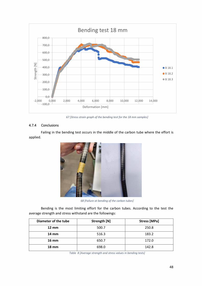
67 [Stress strain graph of the bending test for the 18 mm samples]
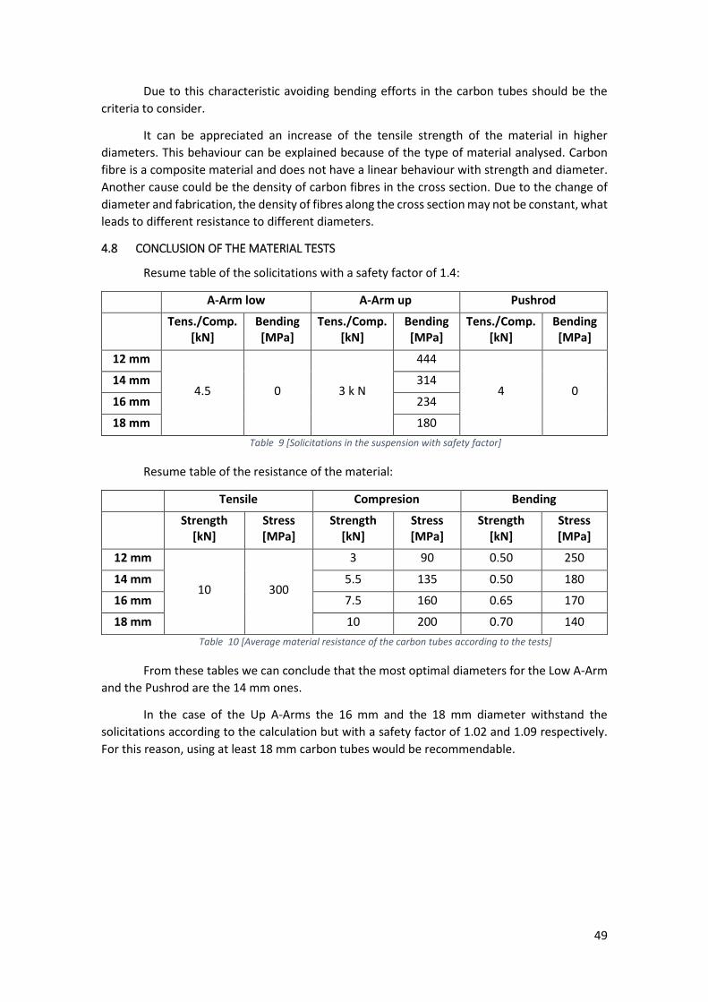
4.7.4 Conclusions
Failing in the bending test occurs in the middle of the carbon tube where the effort is
applied.
68 [Failure at bending of the carbon tubes]
Bending is the most limiting effort for the carbon tubes. According to the test the
average strength and stress withstand are the followings:
Diameter of the tube Strength [N] Stress [MPa]
12 mm 500.7 250.8
14 mm 516.3 183.2
16 mm 650.7 172.0
18 mm 698.0 142.8
Table 8 [Average strength and stress values in bending tests]
-100,0
0,0
100,0
200,0
300,0
400,0
500,0
600,0
700,0
800,0
-2,000 0,000 2,000 4,000 6,000 8,000 10,000 12,000 14,000
Stre
ngt
h [
N]
Deformation [mm]
Bending test 18 mm
B 18.1
B 18.2
B 18.3
49
Due to this characteristic avoiding bending efforts in the carbon tubes should be the
criteria to consider.
It can be appreciated an increase of the tensile strength of the material in higher
diameters. This behaviour can be explained because of the type of material analysed. Carbon
fibre is a composite material and does not have a linear behaviour with strength and diameter.
Another cause could be the density of carbon fibres in the cross section. Due to the change of
diameter and fabrication, the density of fibres along the cross section may not be constant, what
leads to different resistance to different diameters.
4.8 CONCLUSION OF THE MATERIAL TESTS
Resume table of the solicitations with a safety factor of 1.4:
A-Arm low A-Arm up Pushrod
Tens./Comp. [kN]
Bending [MPa]
Tens./Comp. [kN]
Bending [MPa]
Tens./Comp. [kN]
Bending [MPa]
12 mm
4.5 0 3 k N
444
4 0 14 mm 314
16 mm 234
18 mm 180
Table 9 [Solicitations in the suspension with safety factor]
Resume table of the resistance of the material:
Tensile Compresion Bending
Strength [kN]
Stress [MPa]
Strength [kN]
Stress [MPa]
Strength [kN]
Stress [MPa]
12 mm
10 300
3 90 0.50 250
14 mm 5.5 135 0.50 180
16 mm 7.5 160 0.65 170
18 mm 10 200 0.70 140
Table 10 [Average material resistance of the carbon tubes according to the tests]
From these tables we can conclude that the most optimal diameters for the Low A-Arm
and the Pushrod are the 14 mm ones.
In the case of the Up A-Arms the 16 mm and the 18 mm diameter withstand the
solicitations according to the calculation but with a safety factor of 1.02 and 1.09 respectively.
For this reason, using at least 18 mm carbon tubes would be recommendable.
50
5 BUILDING PROCESS
5.1 Introduction
The building process is the part when all the theoretical part of the design is
materialised. Around the 90% of the parts are manufactured while the remaining are bought to
different suppliers, such as the engine, the accumulator or the bearings among others. All the
parts are collected in the workshop and then used to build the car. The main deadline is the Roll-
Out, the event where the car makes an official showing at the 23/05/2019.
5.2 PROGRESS PLAN
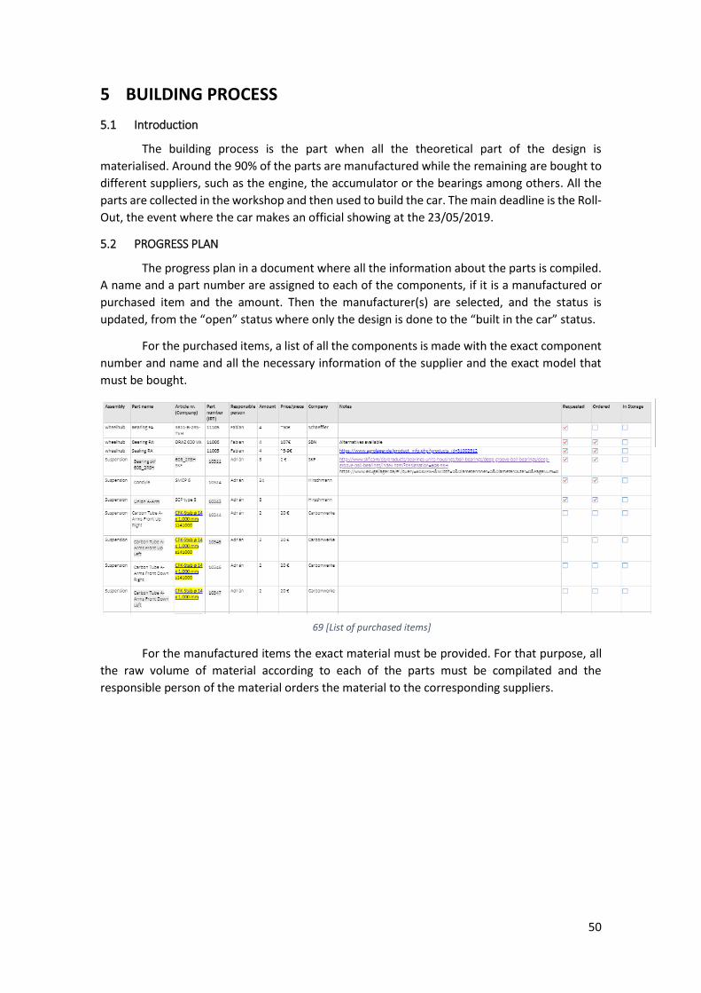
The progress plan in a document where all the information about the parts is compiled.
A name and a part number are assigned to each of the components, if it is a manufactured or
purchased item and the amount. Then the manufacturer(s) are selected, and the status is
updated, from the “open” status where only the design is done to the “built in the car” status.
For the purchased items, a list of all the components is made with the exact component
number and name and all the necessary information of the supplier and the exact model that
must be bought.
69 [List of purchased items]
For the manufactured items the exact material must be provided. For that purpose, all
the raw volume of material according to each of the parts must be compilated and the
responsible person of the material orders the material to the corresponding suppliers.
51
70 [Progress plan]
The progress plan is a living document, it changes with the progress of the vehicle,
however and example of the 02/05/2019 is available in the annexes.
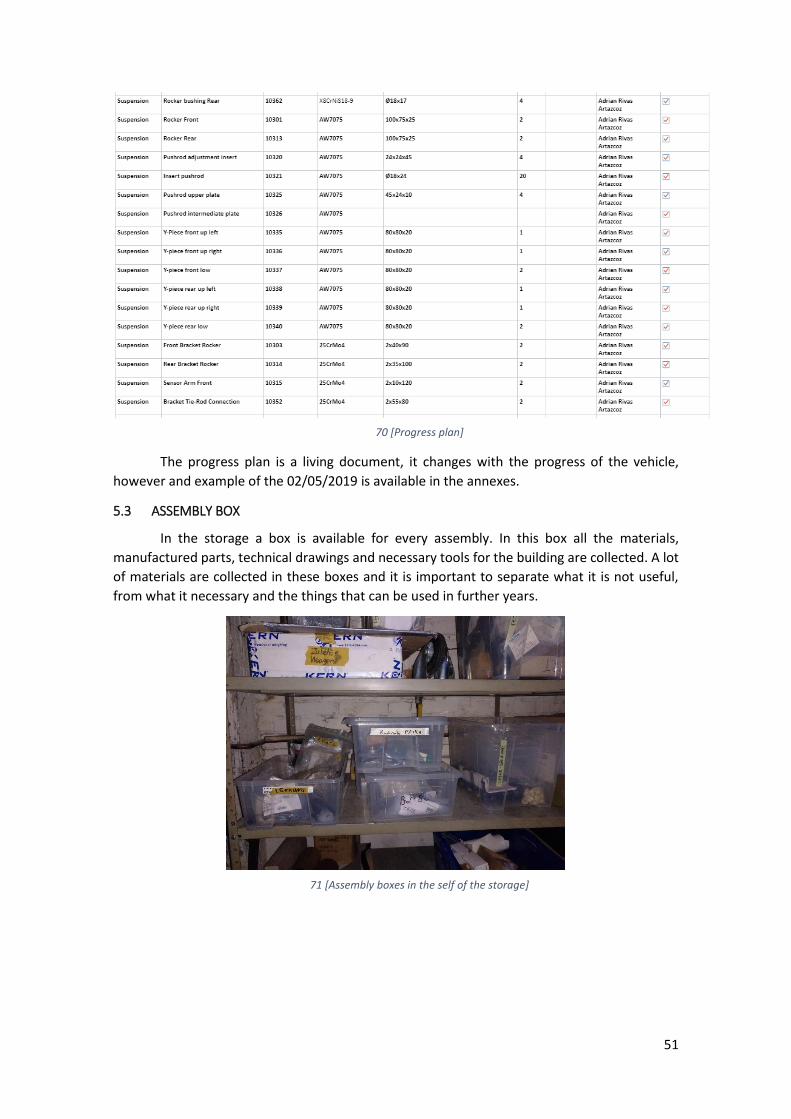
5.3 ASSEMBLY BOX
In the storage a box is available for every assembly. In this box all the materials,
manufactured parts, technical drawings and necessary tools for the building are collected. A lot
of materials are collected in these boxes and it is important to separate what it is not useful,
from what it necessary and the things that can be used in further years.
71 [Assembly boxes in the self of the storage]
52
5.4 MANUFACTURING
The materials are sent to the manufacturers to manufacture the parts in the exact
material desired. For that purpose, once the raw material arrives to the workshop is prepared
in the bruto material blocks and classified in the different places for the manufacturers with its
corresponding label. Then the responsible of the manufacturer takes all the materials to that
provider and put the final part in its corresponding place. It is possible that this process is
repeated more than once, as there are parts that require more than one manufacturer.
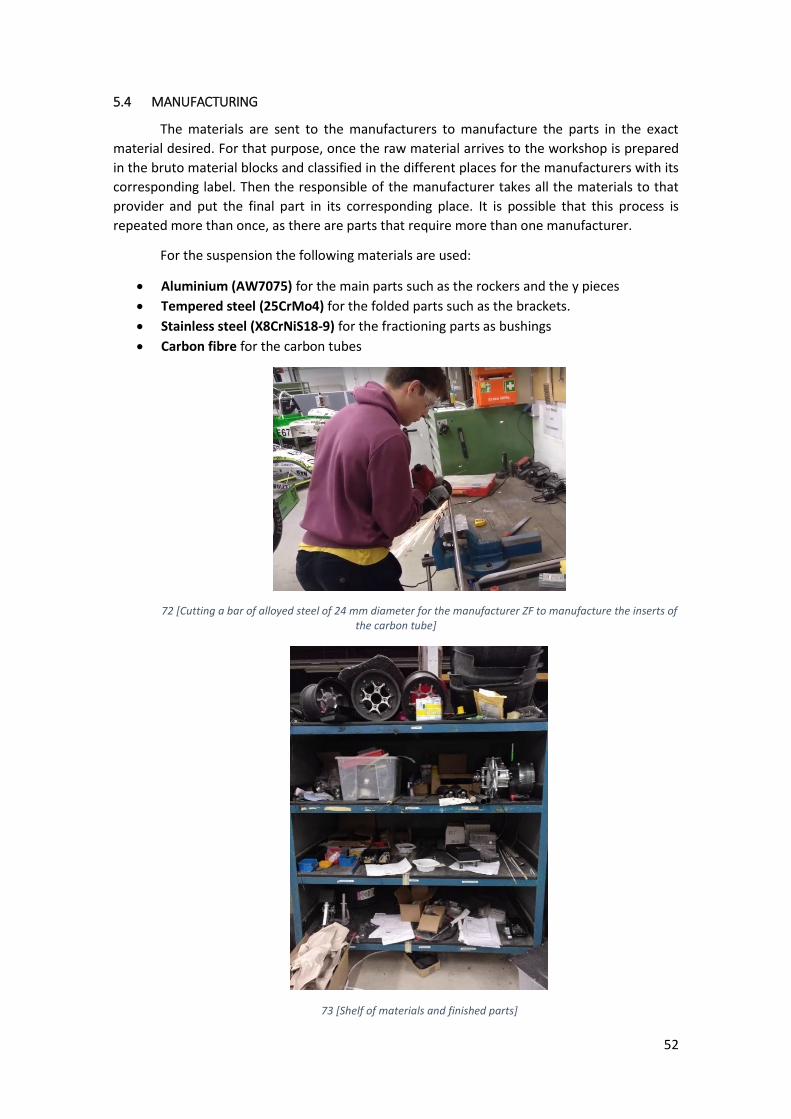
For the suspension the following materials are used:
• Aluminium (AW7075) for the main parts such as the rockers and the y pieces
• Tempered steel (25CrMo4) for the folded parts such as the brackets.
• Stainless steel (X8CrNiS18-9) for the fractioning parts as bushings
• Carbon fibre for the carbon tubes
72 [Cutting a bar of alloyed steel of 24 mm diameter for the manufacturer ZF to manufacture the inserts of the carbon tube]
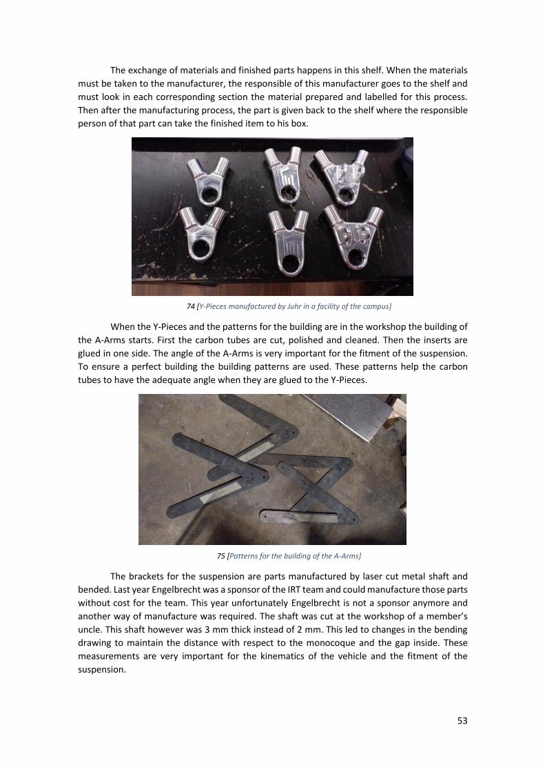
73 [Shelf of materials and finished parts]
53
The exchange of materials and finished parts happens in this shelf. When the materials
must be taken to the manufacturer, the responsible of this manufacturer goes to the shelf and
must look in each corresponding section the material prepared and labelled for this process.
Then after the manufacturing process, the part is given back to the shelf where the responsible
person of that part can take the finished item to his box.
74 [Y-Pieces manufactured by Juhr in a facility of the campus]
When the Y-Pieces and the patterns for the building are in the workshop the building of
the A-Arms starts. First the carbon tubes are cut, polished and cleaned. Then the inserts are
glued in one side. The angle of the A-Arms is very important for the fitment of the suspension.
To ensure a perfect building the building patterns are used. These patterns help the carbon
tubes to have the adequate angle when they are glued to the Y-Pieces.
75 [Patterns for the building of the A-Arms]
The brackets for the suspension are parts manufactured by laser cut metal shaft and
bended. Last year Engelbrecht was a sponsor of the IRT team and could manufacture those parts
without cost for the team. This year unfortunately Engelbrecht is not a sponsor anymore and
another way of manufacture was required. The shaft was cut at the workshop of a member’s
uncle. This shaft however was 3 mm thick instead of 2 mm. This led to changes in the bending
drawing to maintain the distance with respect to the monocoque and the gap inside. These
measurements are very important for the kinematics of the vehicle and the fitment of the
suspension.
54
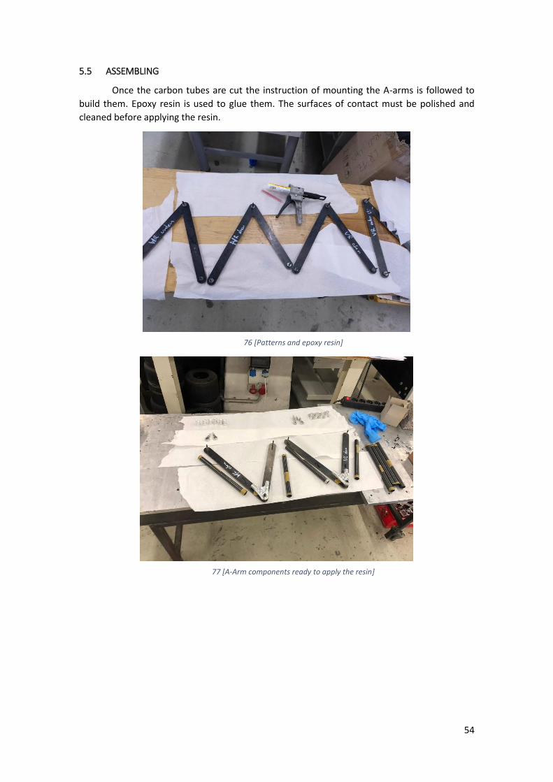
5.5 ASSEMBLING
Once the carbon tubes are cut the instruction of mounting the A-arms is followed to
build them. Epoxy resin is used to glue them. The surfaces of contact must be polished and
cleaned before applying the resin.
76 [Patterns and epoxy resin]
77 [A-Arm components ready to apply the resin]
55
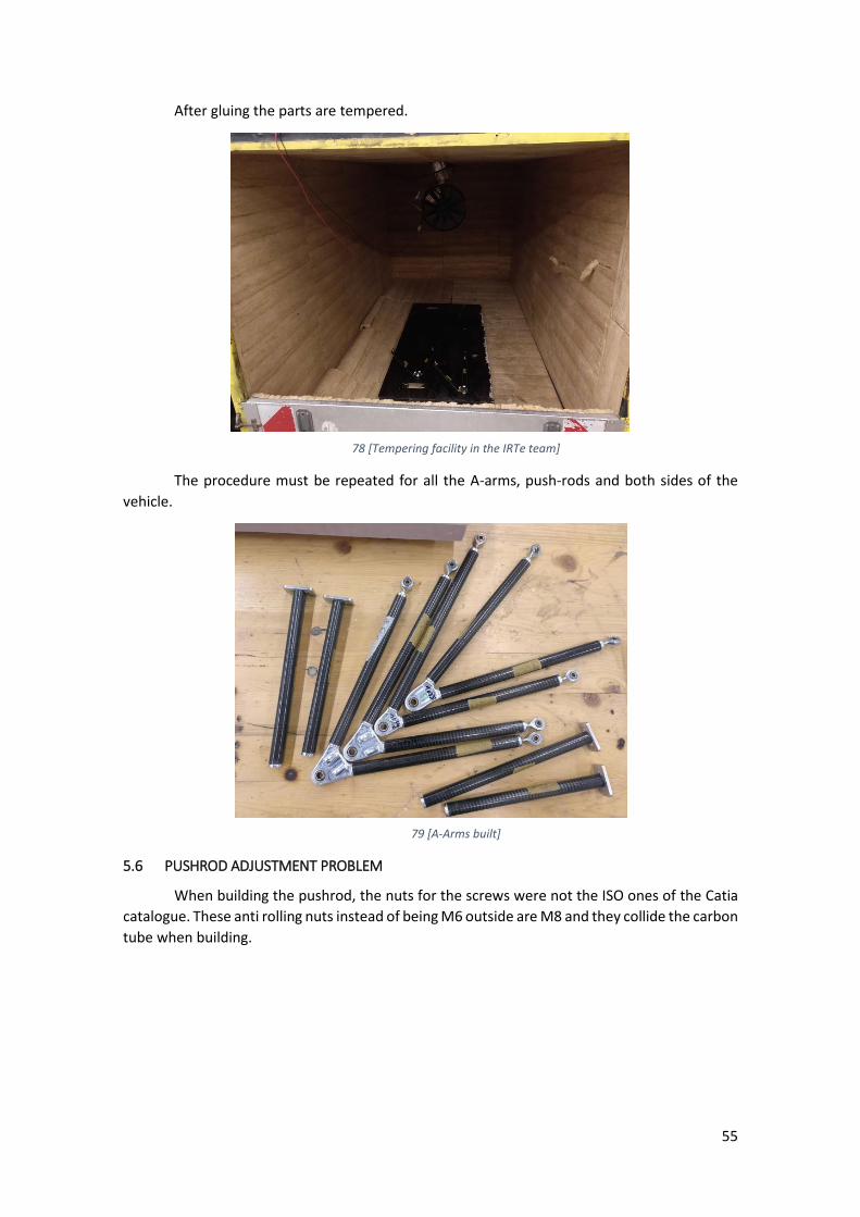
After gluing the parts are tempered.
78 [Tempering facility in the IRTe team]
The procedure must be repeated for all the A-arms, push-rods and both sides of the
vehicle.
79 [A-Arms built]
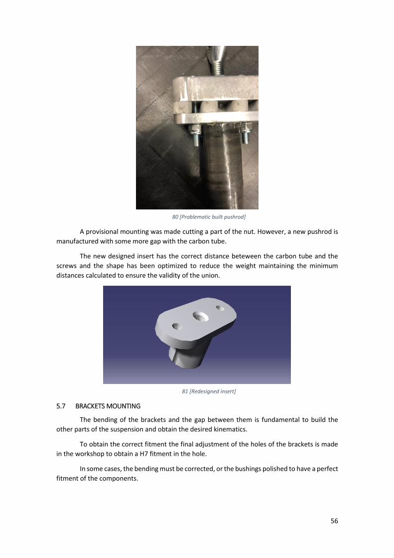
5.6 PUSHROD ADJUSTMENT PROBLEM
When building the pushrod, the nuts for the screws were not the ISO ones of the Catia
catalogue. These anti rolling nuts instead of being M6 outside are M8 and they collide the carbon
tube when building.
56
80 [Problematic built pushrod]
A provisional mounting was made cutting a part of the nut. However, a new pushrod is
manufactured with some more gap with the carbon tube.
The new designed insert has the correct distance beteween the carbon tube and the
screws and the shape has been optimized to reduce the weight maintaining the minimum
distances calculated to ensure the validity of the union.
81 [Redesigned insert]
5.7 BRACKETS MOUNTING
The bending of the brackets and the gap between them is fundamental to build the
other parts of the suspension and obtain the desired kinematics.
To obtain the correct fitment the final adjustment of the holes of the brackets is made
in the workshop to obtain a H7 fitment in the hole.
In some cases, the bending must be corrected, or the bushings polished to have a perfect
fitment of the components.
57
6 FINAL RESULT
6.1 EUROPEAN PROJECT SEMESTER
During their European Project Semester, students from partner universities carry out an
engineering project at Osnabrück University of Applied Sciences for one semester in an
international and interdisciplinary team of students. The project is accompanied by project
related subjects in English such as Intercultural Communication, Team Building, Project
Management (all in English), and German classes.
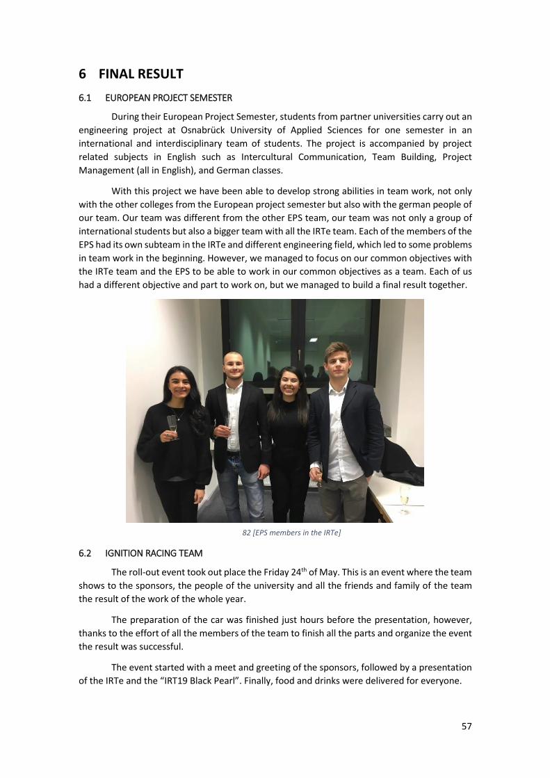
With this project we have been able to develop strong abilities in team work, not only
with the other colleges from the European project semester but also with the german people of
our team. Our team was different from the other EPS team, our team was not only a group of
international students but also a bigger team with all the IRTe team. Each of the members of the
EPS had its own subteam in the IRTe and different engineering field, which led to some problems
in team work in the beginning. However, we managed to focus on our common objectives with
the IRTe team and the EPS to be able to work in our common objectives as a team. Each of us
had a different objective and part to work on, but we managed to build a final result together.
82 [EPS members in the IRTe]
6.2 IGNITION RACING TEAM
The roll-out event took out place the Friday 24th of May. This is an event where the team
shows to the sponsors, the people of the university and all the friends and family of the team
the result of the work of the whole year.
The preparation of the car was finished just hours before the presentation, however,
thanks to the effort of all the members of the team to finish all the parts and organize the event
the result was successful.
The event started with a meet and greeting of the sponsors, followed by a presentation
of the IRTe and the “IRT19 Black Pearl”. Finally, food and drinks were delivered for everyone.
58
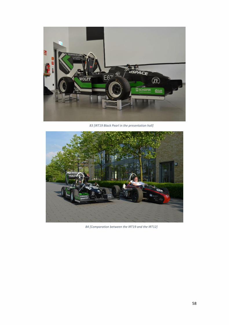
83 [IRT19 Black Pearl in the presentation hall]
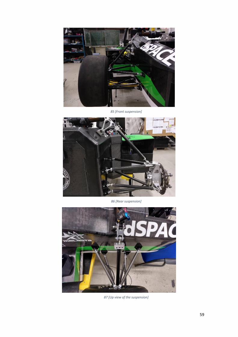
84 [Comparation between the IRT19 and the IRT12]
59
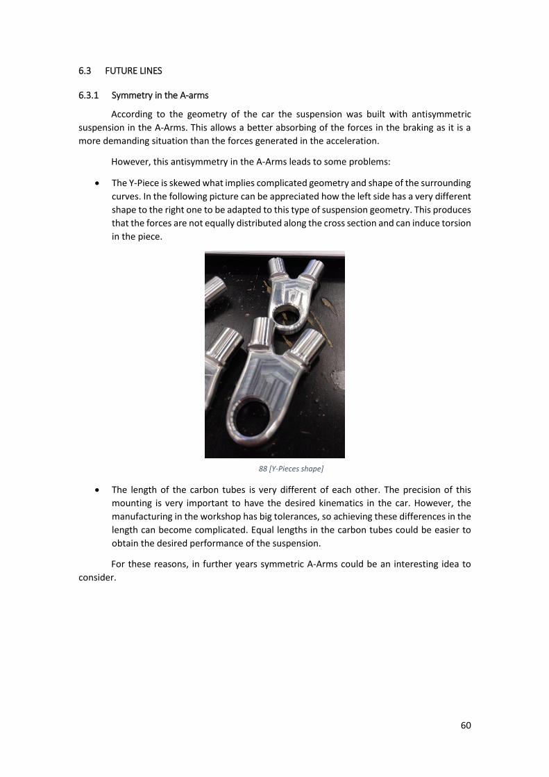
85 [Front suspension]
86 [Rear suspension]
87 [Up view of the suspension]
60
6.3 FUTURE LINES
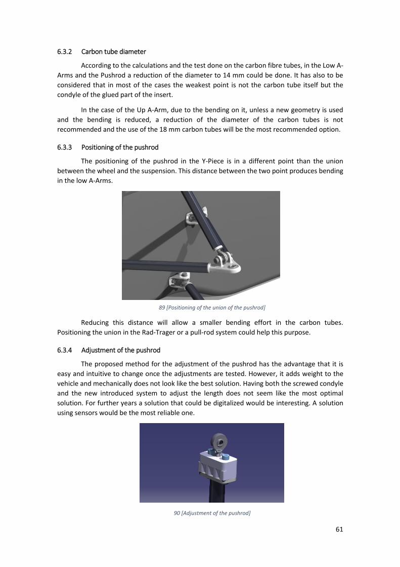
6.3.1 Symmetry in the A-arms
According to the geometry of the car the suspension was built with antisymmetric
suspension in the A-Arms. This allows a better absorbing of the forces in the braking as it is a
more demanding situation than the forces generated in the acceleration.
However, this antisymmetry in the A-Arms leads to some problems:
• The Y-Piece is skewed what implies complicated geometry and shape of the surrounding
curves. In the following picture can be appreciated how the left side has a very different
shape to the right one to be adapted to this type of suspension geometry. This produces
that the forces are not equally distributed along the cross section and can induce torsion
in the piece.
88 [Y-Pieces shape]
• The length of the carbon tubes is very different of each other. The precision of this
mounting is very important to have the desired kinematics in the car. However, the
manufacturing in the workshop has big tolerances, so achieving these differences in the
length can become complicated. Equal lengths in the carbon tubes could be easier to
obtain the desired performance of the suspension.
For these reasons, in further years symmetric A-Arms could be an interesting idea to
consider.
61
6.3.2 Carbon tube diameter
According to the calculations and the test done on the carbon fibre tubes, in the Low A-
Arms and the Pushrod a reduction of the diameter to 14 mm could be done. It has also to be
considered that in most of the cases the weakest point is not the carbon tube itself but the
condyle of the glued part of the insert.
In the case of the Up A-Arm, due to the bending on it, unless a new geometry is used
and the bending is reduced, a reduction of the diameter of the carbon tubes is not
recommended and the use of the 18 mm carbon tubes will be the most recommended option.
6.3.3 Positioning of the pushrod
The positioning of the pushrod in the Y-Piece is in a different point than the union
between the wheel and the suspension. This distance between the two point produces bending
in the low A-Arms.
89 [Positioning of the union of the pushrod]
Reducing this distance will allow a smaller bending effort in the carbon tubes.
Positioning the union in the Rad-Trager or a pull-rod system could help this purpose.
6.3.4 Adjustment of the pushrod
The proposed method for the adjustment of the pushrod has the advantage that it is
easy and intuitive to change once the adjustments are tested. However, it adds weight to the
vehicle and mechanically does not look like the best solution. Having both the screwed condyle
and the new introduced system to adjust the length does not seem like the most optimal
solution. For further years a solution that could be digitalized would be interesting. A solution
using sensors would be the most reliable one.
90 [Adjustment of the pushrod]
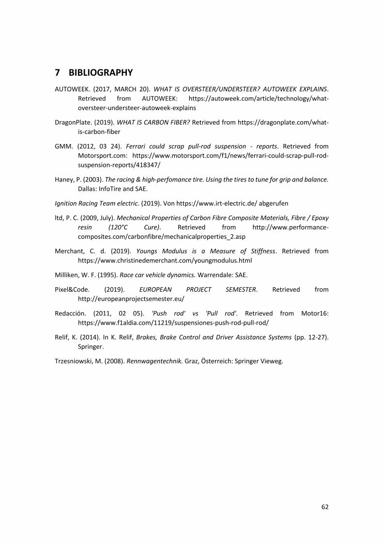
62
7 BIBLIOGRAPHY
AUTOWEEK. (2017, MARCH 20). WHAT IS OVERSTEER/UNDERSTEER? AUTOWEEK EXPLAINS.
Retrieved from AUTOWEEK: https://autoweek.com/article/technology/what-
oversteer-understeer-autoweek-explains
DragonPlate. (2019). WHAT IS CARBON FIBER? Retrieved from https://dragonplate.com/what-
is-carbon-fiber
GMM. (2012, 03 24). Ferrari could scrap pull-rod suspension - reports. Retrieved from
Motorsport.com: https://www.motorsport.com/f1/news/ferrari-could-scrap-pull-rod-
suspension-reports/418347/
Haney, P. (2003). The racing & high-perfomance tire. Using the tires to tune for grip and balance.
Dallas: InfoTire and SAE.
Ignition Racing Team electric. (2019). Von https://www.irt-electric.de/ abgerufen
ltd, P. C. (2009, July). Mechanical Properties of Carbon Fibre Composite Materials, Fibre / Epoxy
resin (120°C Cure). Retrieved from http://www.performance-
composites.com/carbonfibre/mechanicalproperties_2.asp
Merchant, C. d. (2019). Youngs Modulus is a Measure of Stiffness. Retrieved from
https://www.christinedemerchant.com/youngmodulus.html
Milliken, W. F. (1995). Race car vehicle dynamics. Warrendale: SAE.
Pixel&Code. (2019). EUROPEAN PROJECT SEMESTER. Retrieved from
http://europeanprojectsemester.eu/
Redacción. (2011, 02 05). 'Push rod' vs 'Pull rod'. Retrieved from Motor16:
https://www.f1aldia.com/11219/suspensiones-push-rod-pull-rod/
Relif, K. (2014). In K. Relif, Brakes, Brake Control and Driver Assistance Systems (pp. 12-27).
Springer.
Trzesniowski, M. (2008). Rennwagentechnik. Graz, Österreich: Springer Vieweg.

63
8 ANNEXES
8.1 KINEMATICS OF THE 2017 IRT VEHICLE
8.2 VALIDITY OF THE BOLTED UNION OF THE ADJUSTMENT OF THE PUSHROD
8.3 TECHNICAL DRAWINGS
8.4 PROGRESS PLAN
8.5 EUROPEAN PROJECT SEMESTER REPORT
8.6 HALL-EFFECT ABSOLUTE ENCODER SERIES MAB12A DATA SHEET
8.7 RADAUFHANGUNG KLEBEN (A-ARMS CONSTRUCTION INSTRUCTION)
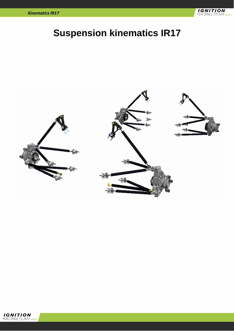
Kinematics IR17
Suspension kinematics IR17

Kinematics IR17
Main goals for IR17
Optimized the kinematics for Hoosier R25B
tyres
More steering angle in the front
Reduce the wheelbase
New geometry for the monocoque
Optimized ratio rocker for “Fox” air spring
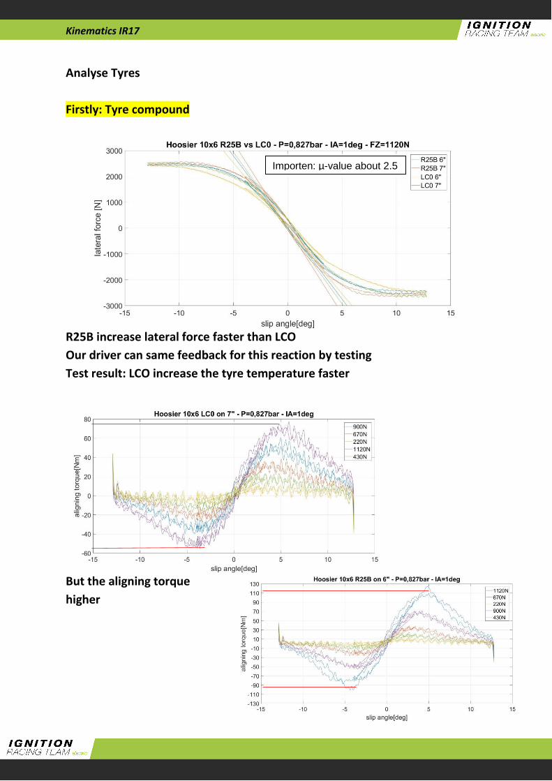
Kinematics IR17
Analyse Tyres
Firstly: Tyre compound
R25B increase lateral force faster than LCO
Our driver can same feedback for this reaction by testing
Test result: LCO increase the tyre temperature faster
But the aligning torque
higher
Importen: µ-value about 2.5
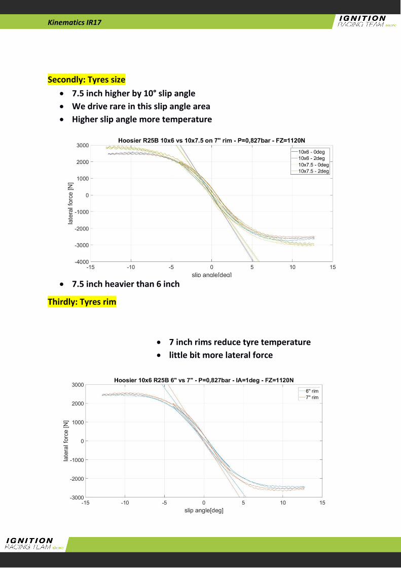
Kinematics IR17
Secondly: Tyres size
7.5 inch higher by 10° slip angle
We drive rare in this slip angle area
Higher slip angle more temperature
7.5 inch heavier than 6 inch
Thirdly: Tyres rim
7 inch rims reduce tyre temperature
little bit more lateral force
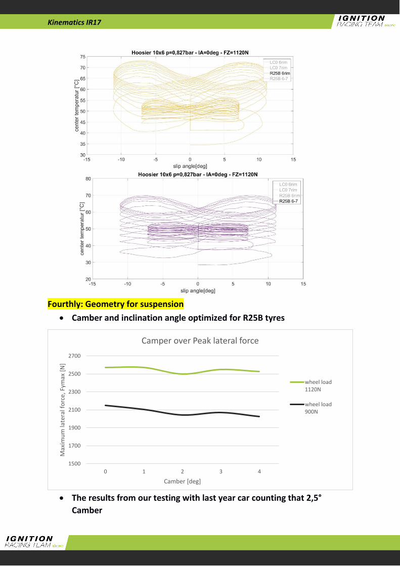
Kinematics IR17
Fourthly: Geometry for suspension
Camber and inclination angle optimized for R25B tyres
The results from our testing with last year car counting that 2,5°
Camber
1500
1700
1900
2100
2300
2500
2700
0 1 2 3 4
Max
imu
m la
tera
l fo
rce,
Fym
ax [
N]
Camber [deg]
Camper over Peak lateral force
wheel load1120N
wheel load900N

Kinematics IR17
Main goals for the kinematics
Constant toe angle over wheel travel for unchanged driving
characteristics
Smaller wheelbase for smaller turning circle
More maximum angle of turn without contact A-Arms and tie rods
Maximum camber of 3.5° during steer and compress
Constant caster angle over wheel travel
Anti-dive front and rear first time
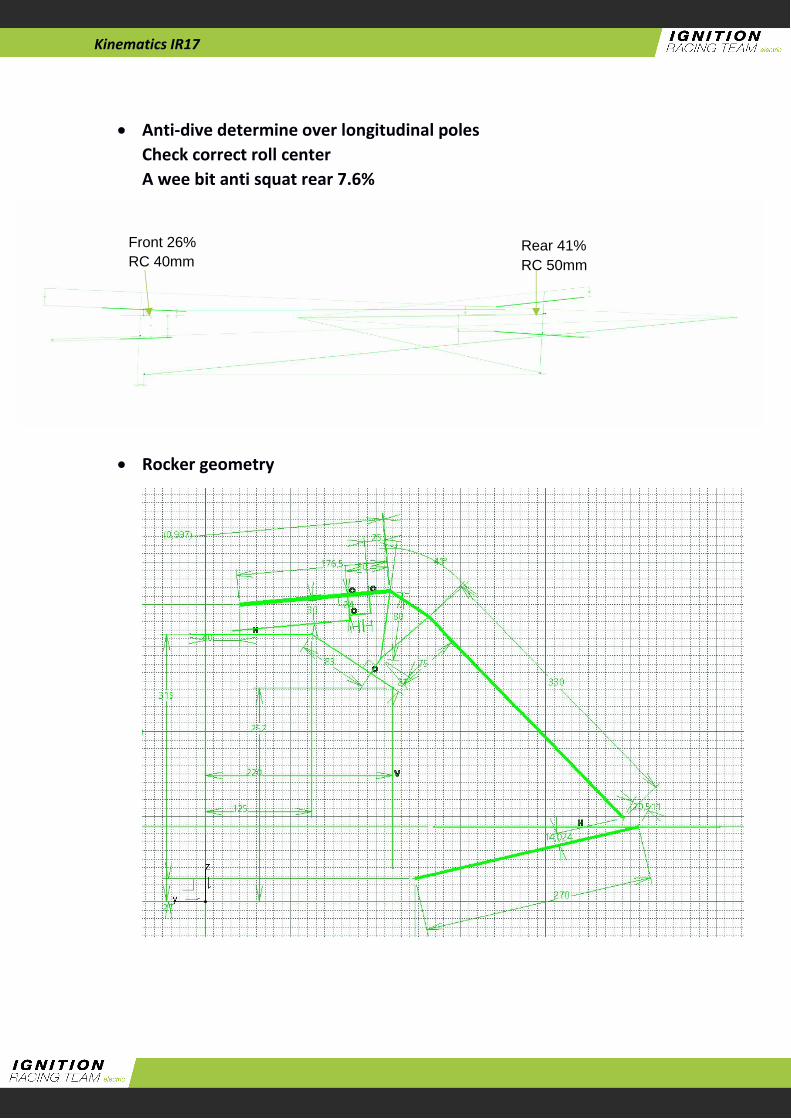
Kinematics IR17
Anti-dive determine over longitudinal poles
Check correct roll center
A wee bit anti squat rear 7.6%
Rocker geometry
Front 26%
RC 40mm Rear 41%
RC 50mm
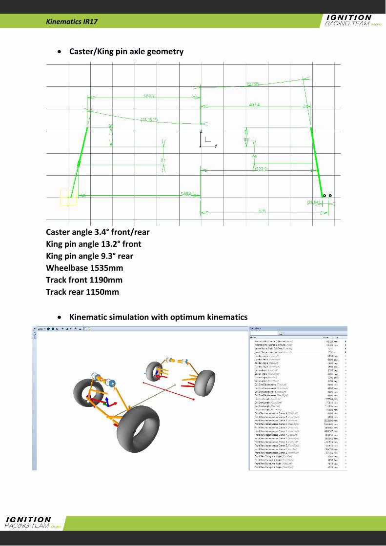
Kinematics IR17
Caster/King pin axle geometry
Caster angle 3.4° front/rear
King pin angle 13.2° front
King pin angle 9.3° rear
Wheelbase 1535mm
Track front 1190mm
Track rear 1150mm
Kinematic simulation with optimum kinematics
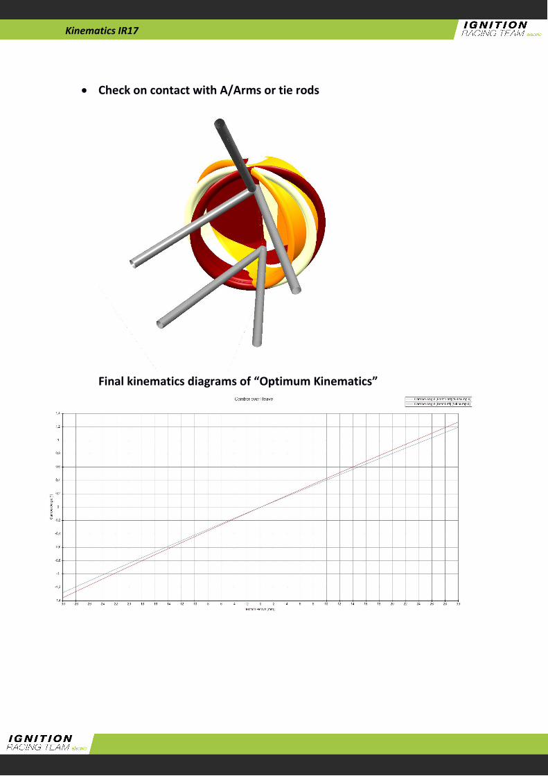
Kinematics IR17
Check on contact with A/Arms or tie rods
Final kinematics diagrams of “Optimum Kinematics”
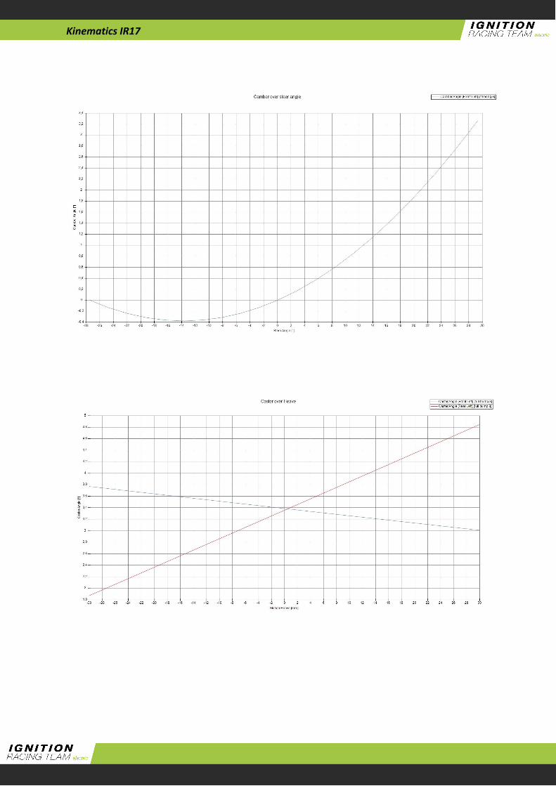
Kinematics IR17

Kinematics IR17

BOLTED UNION OF THE ADJUSMENT OF THE PUSHROD
We will check if the validity of the M4 screws for the adjustment of the pushrod.
The validity of the union will be calculated according to the edification technical norm.
GENERAL DATA
For this bolts and type of union the norm ensures:
fyb = 240 MPa (Elastic limit stress)
fub = 400 MPa (Ultimate tensile stress)
YMb = 1.25 (Safety factor)
DIMENSIONS OF THE PLATE AND POSITIONING OF THE BOLTS
𝑒1 ≥ 1.2 ∙ 𝑑0
8 𝑚𝑚 ≥ 1.2 ∙ 4 = 4.8 𝑚𝑚
𝑒2 ≥ 1.5 ∙ 𝑑0
9 𝑚𝑚 ≥ 1.5 ∙ 4 = 6 𝑚𝑚
𝑝1 ≥ 2.2 ∙ 𝑑0
12 𝑚𝑚 ≥ 2.2 ∙ 4 = 8.8 𝑚𝑚
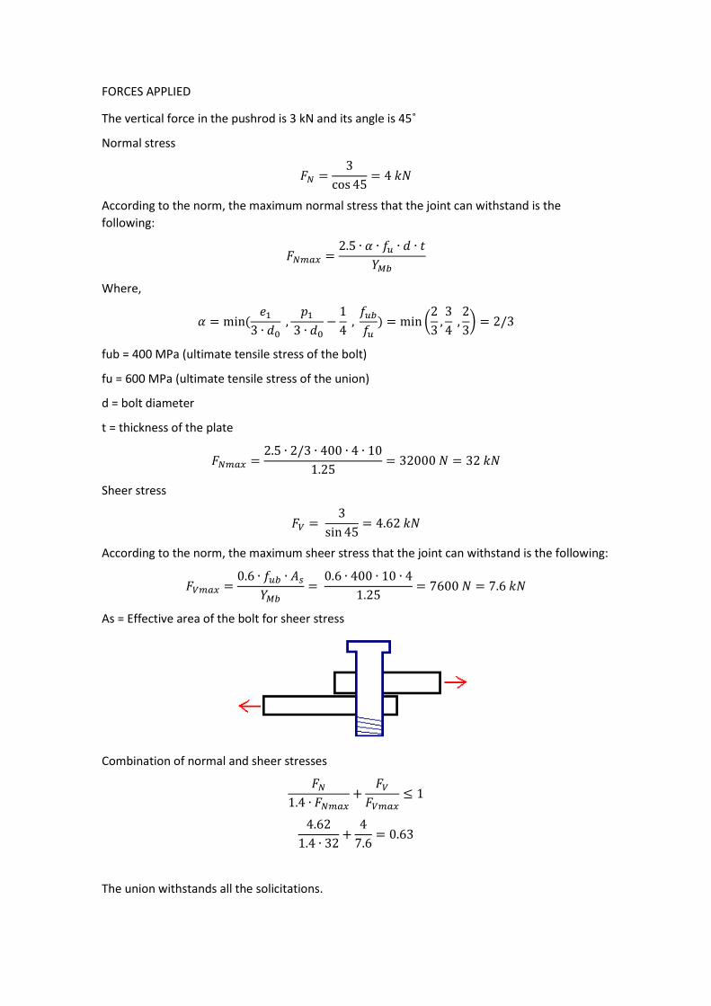
FORCES APPLIED
The vertical force in the pushrod is 3 kN and its angle is 45˚
Normal stress
𝐹𝑁 =3
cos 45= 4 𝑘𝑁
According to the norm, the maximum normal stress that the joint can withstand is the
following:
𝐹𝑁𝑚𝑎𝑥 =2.5 ∙ 𝛼 ∙ 𝑓𝑢 ∙ 𝑑 ∙ 𝑡
𝑌𝑀𝑏
Where,
𝛼 = min(𝑒1
3 ∙ 𝑑0 ,
𝑝1
3 ∙ 𝑑0−
1
4 ,
𝑓𝑢𝑏
𝑓𝑢) = min (
2
3,3
4 ,
2
3) = 2/3
fub = 400 MPa (ultimate tensile stress of the bolt)
fu = 600 MPa (ultimate tensile stress of the union)
d = bolt diameter
t = thickness of the plate
𝐹𝑁𝑚𝑎𝑥 =2.5 ∙ 2/3 ∙ 400 ∙ 4 ∙ 10
1.25= 32000 𝑁 = 32 𝑘𝑁
Sheer stress
𝐹𝑉 = 3
sin 45= 4.62 𝑘𝑁
According to the norm, the maximum sheer stress that the joint can withstand is the following:
𝐹𝑉𝑚𝑎𝑥 =0.6 ∙ 𝑓𝑢𝑏 ∙ 𝐴𝑠
𝑌𝑀𝑏=
0.6 ∙ 400 ∙ 10 ∙ 4
1.25= 7600 𝑁 = 7.6 𝑘𝑁
As = Effective area of the bolt for sheer stress
Combination of normal and sheer stresses
𝐹𝑁
1.4 ∙ 𝐹𝑁𝑚𝑎𝑥+
𝐹𝑉
𝐹𝑉𝑚𝑎𝑥≤ 1
4.62
1.4 ∙ 32+
4
7.6= 0.63
The union withstands all the solicitations.
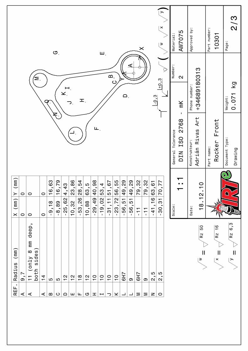
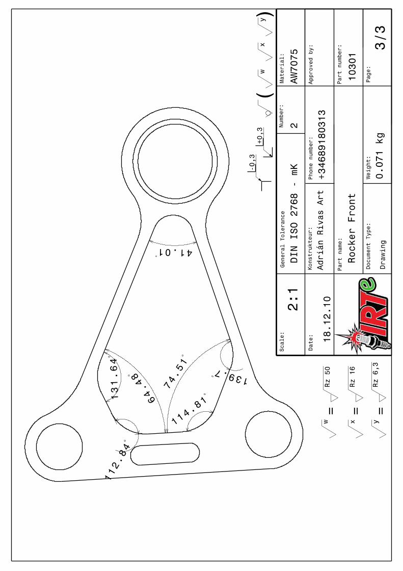
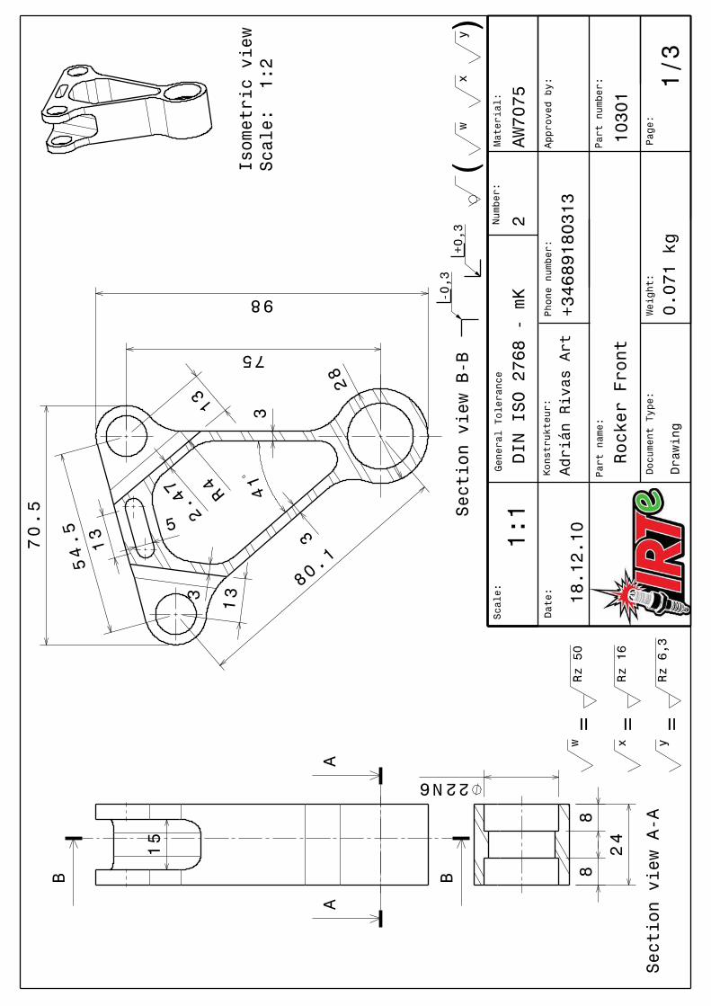
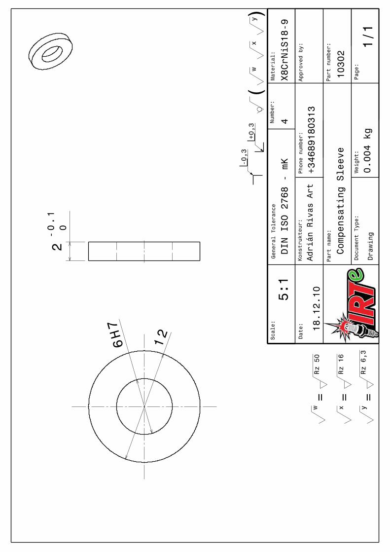
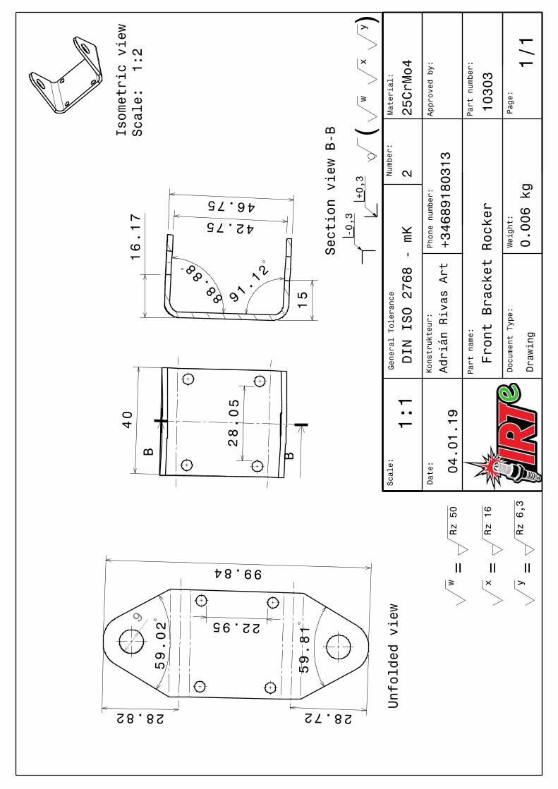
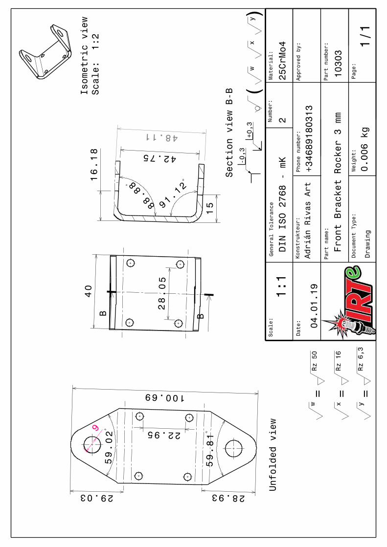


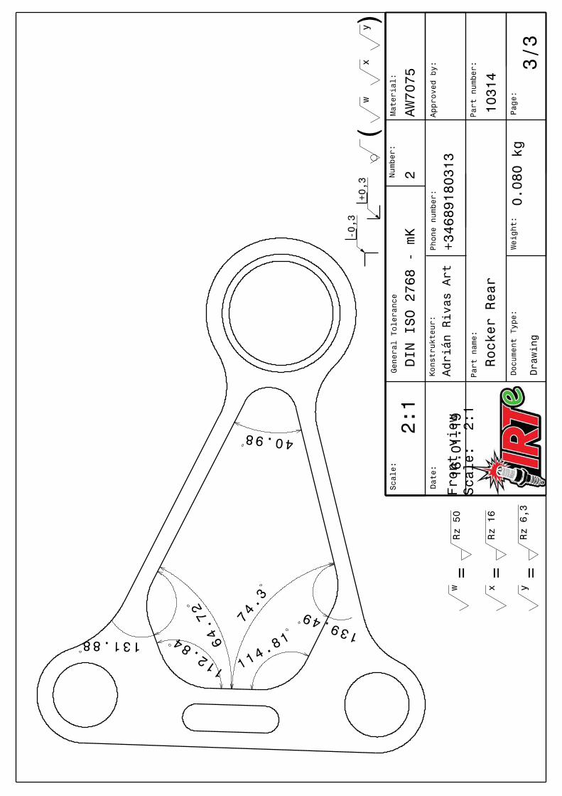
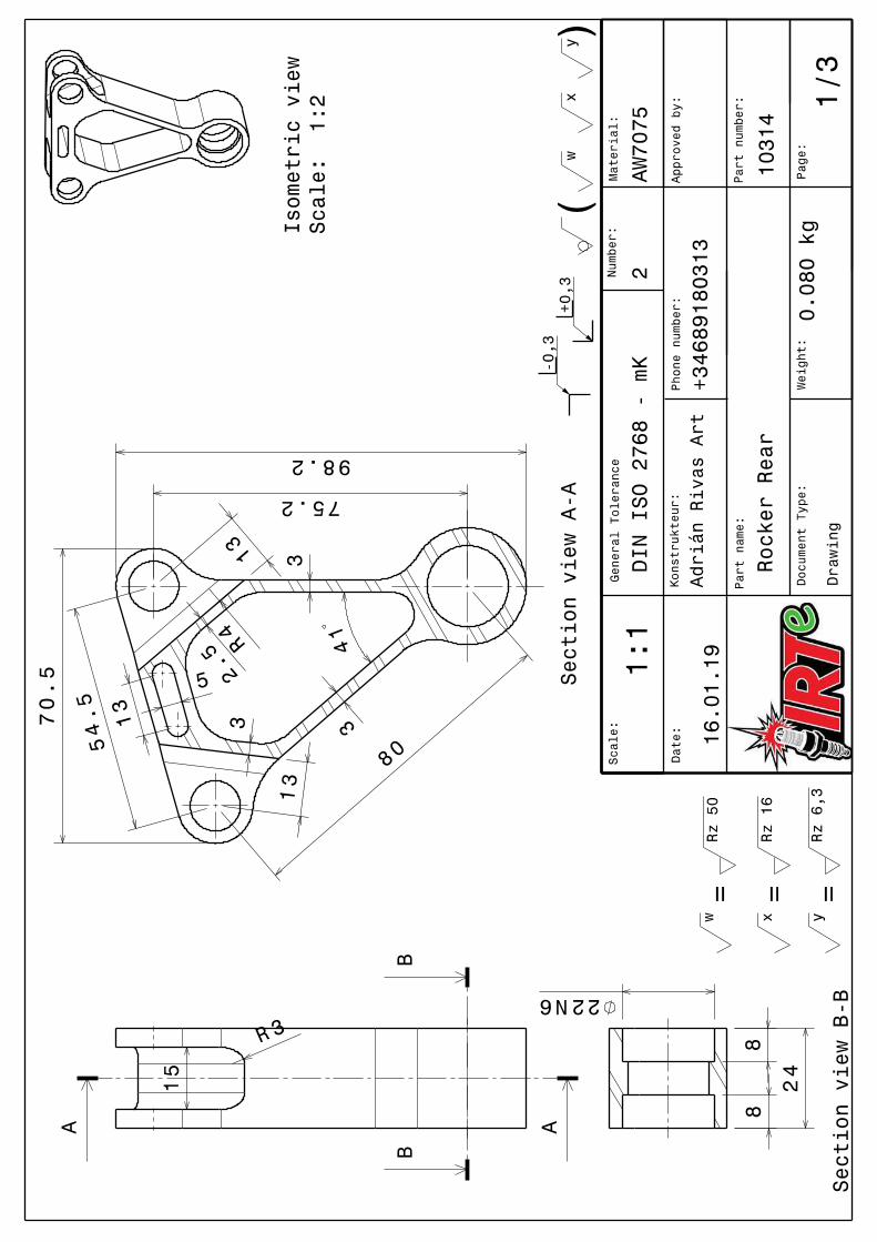
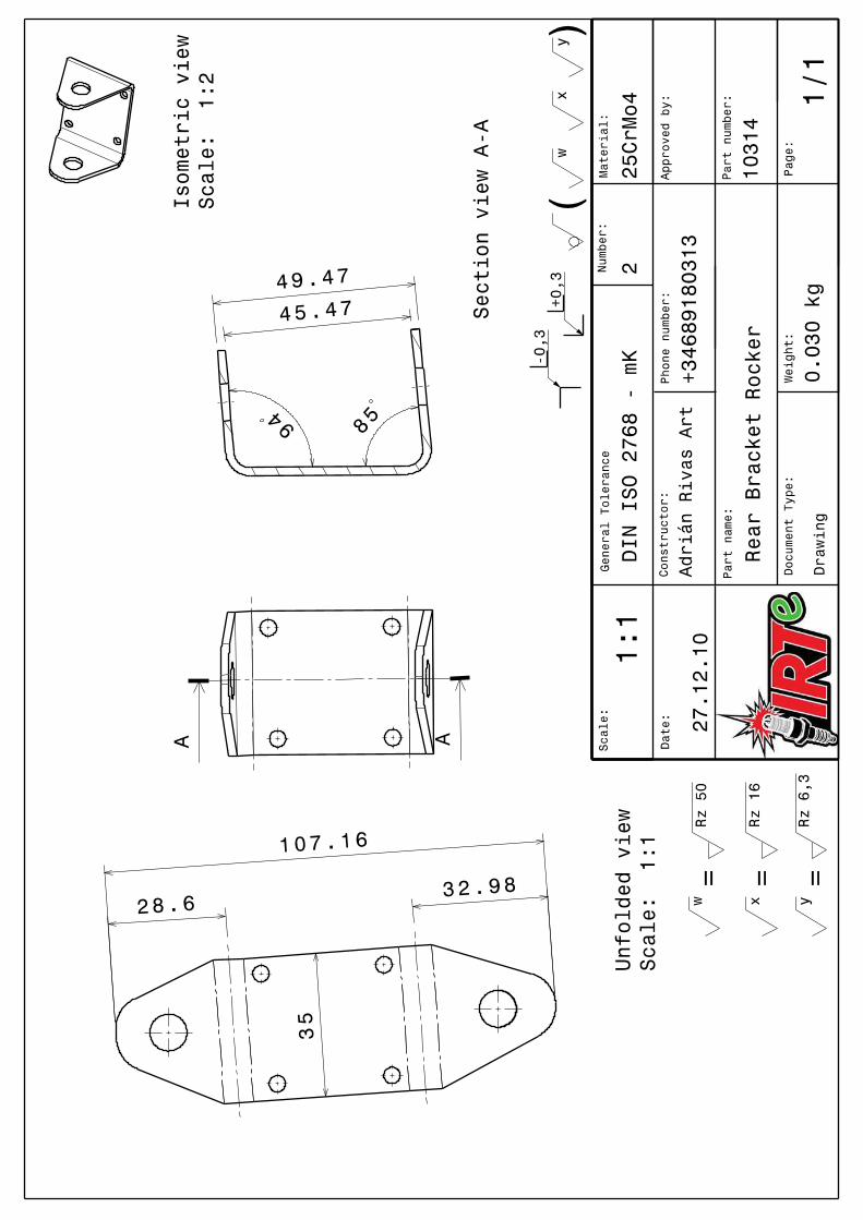
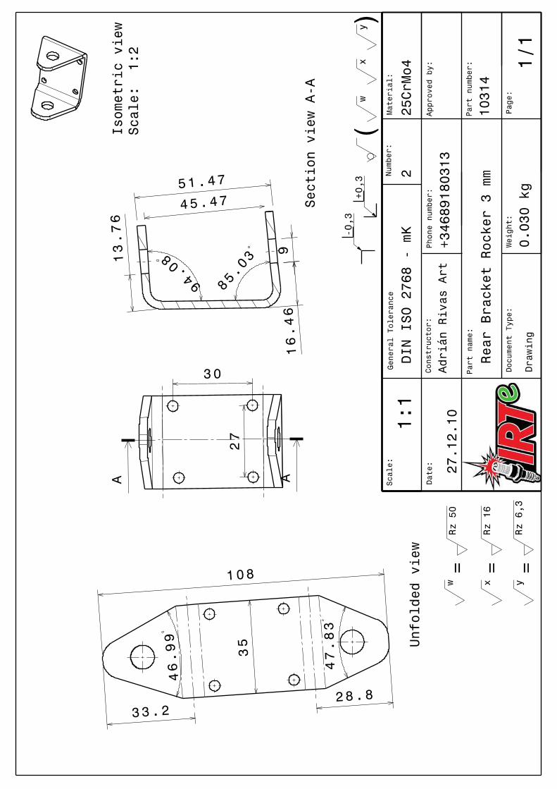
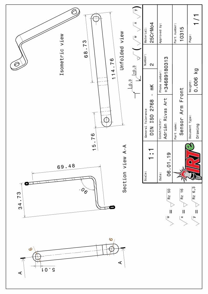
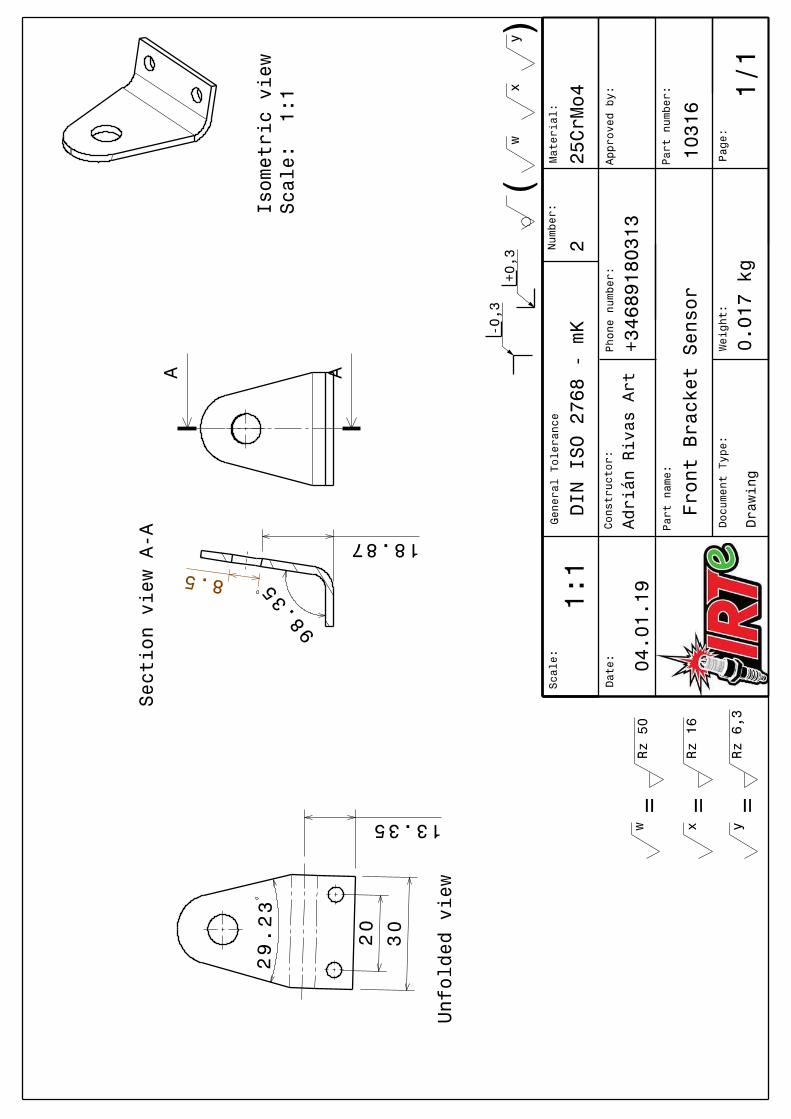
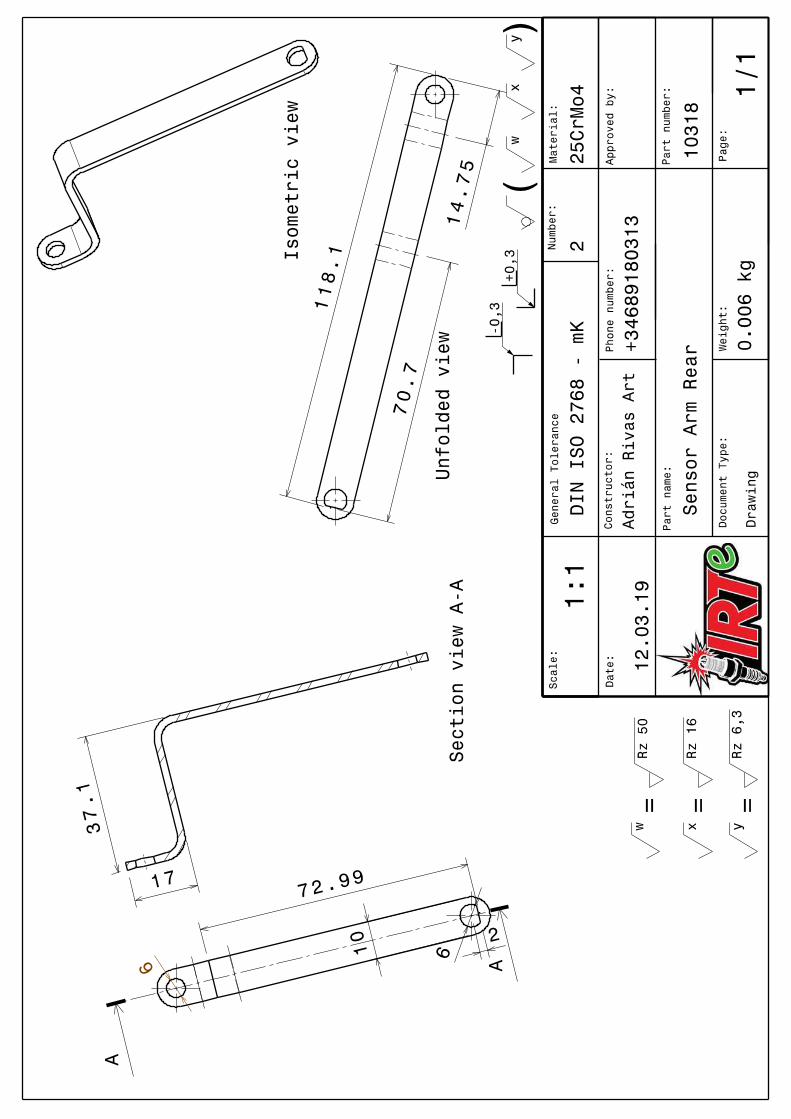
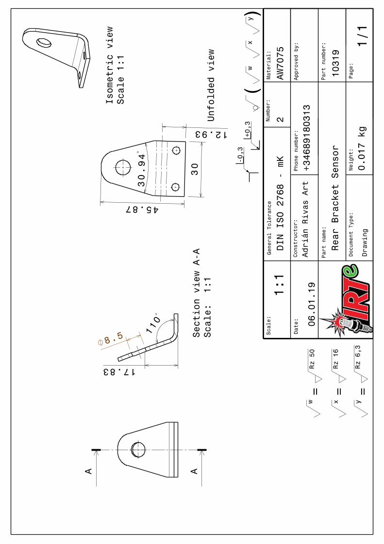
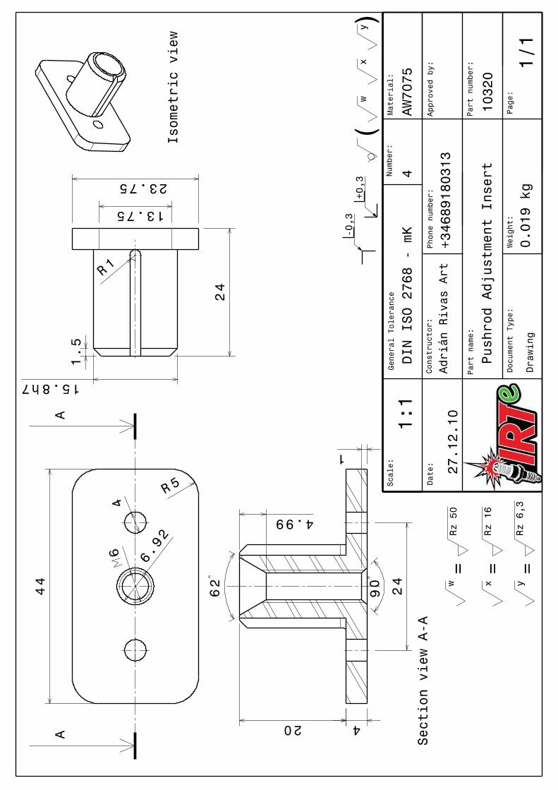
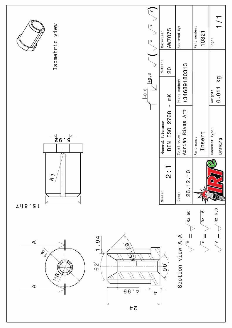
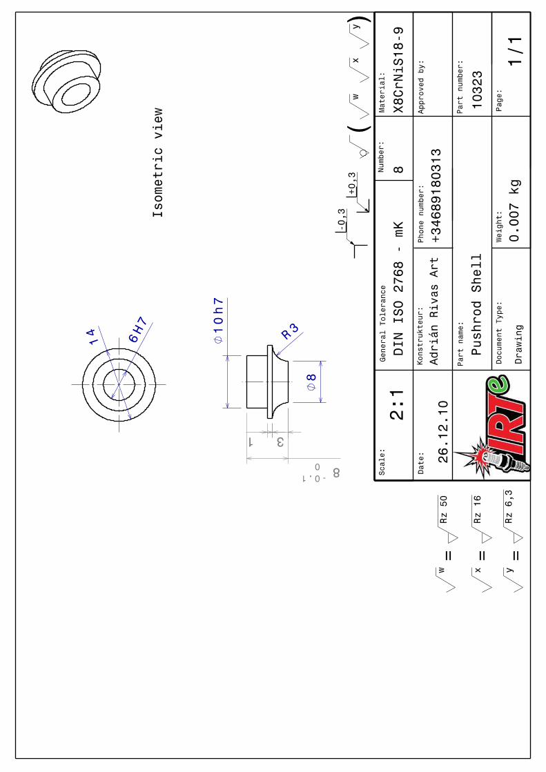
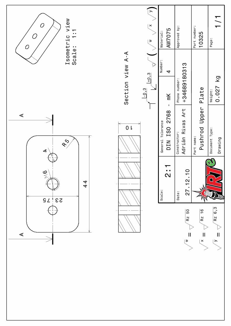
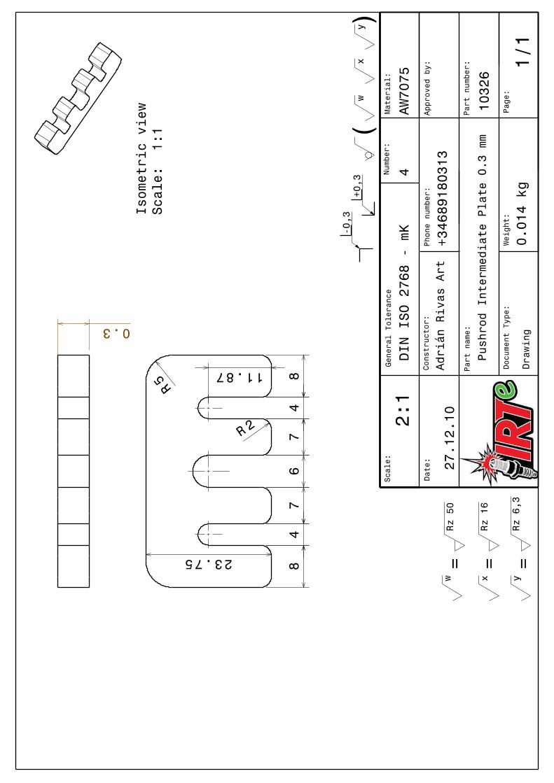
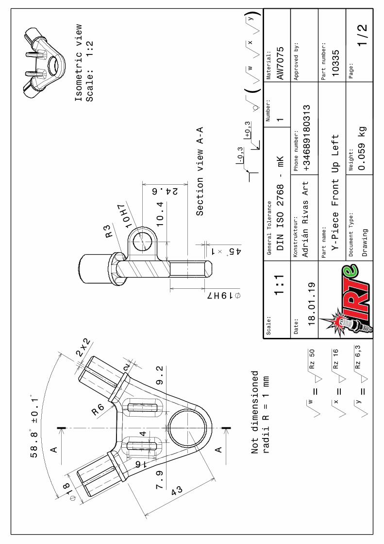
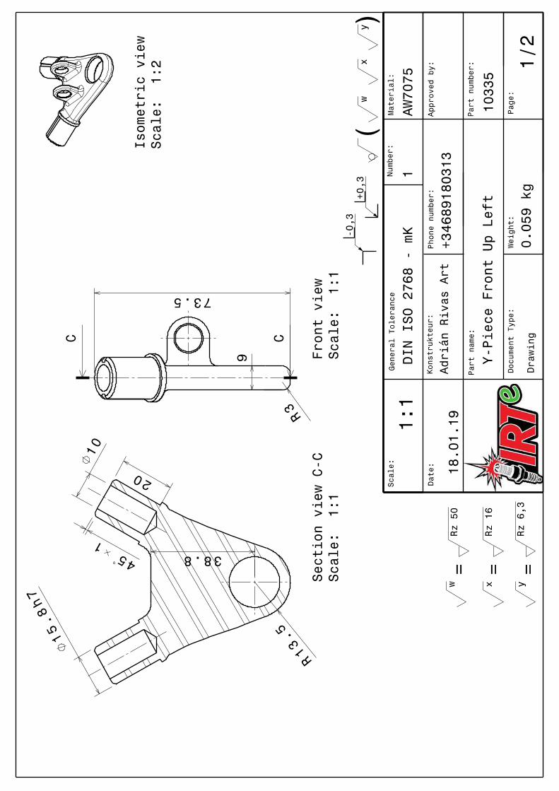
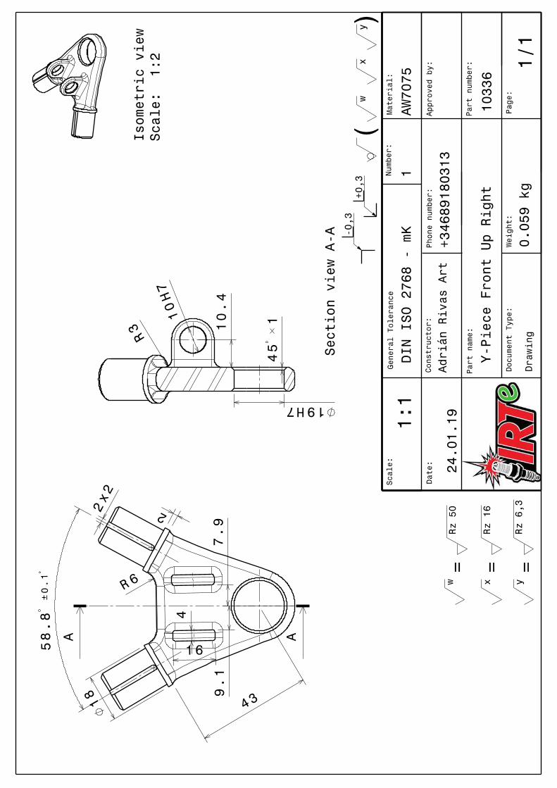
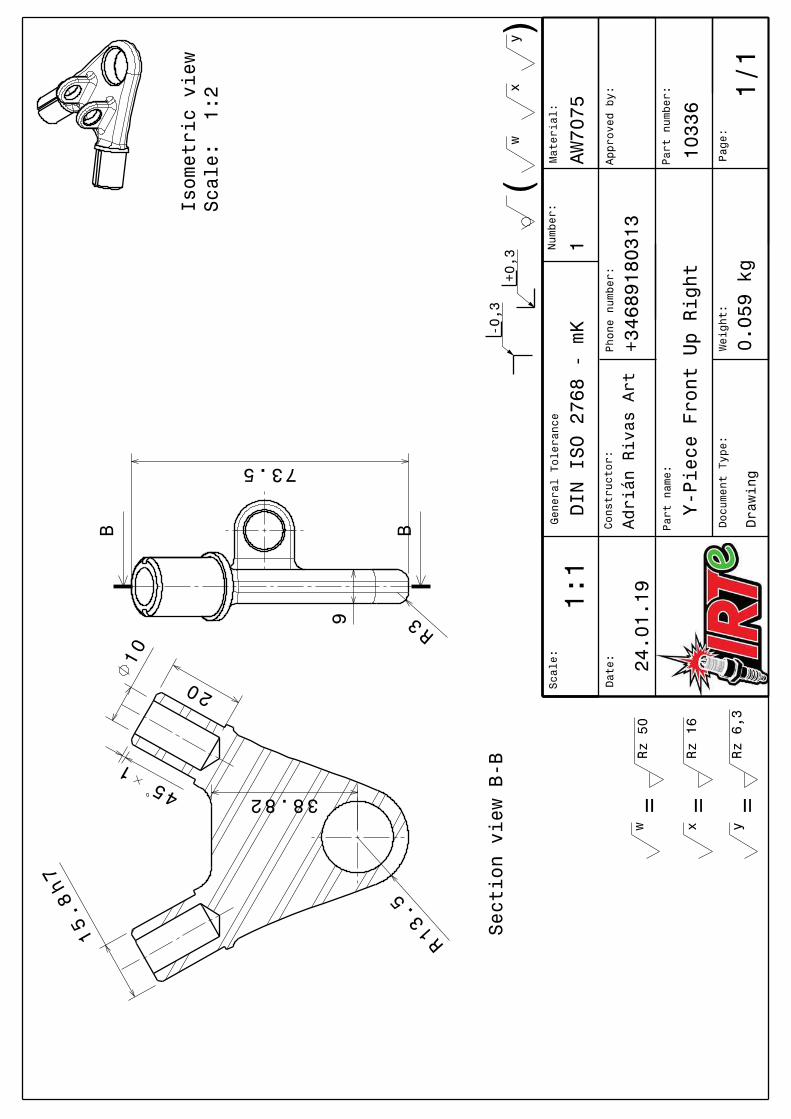
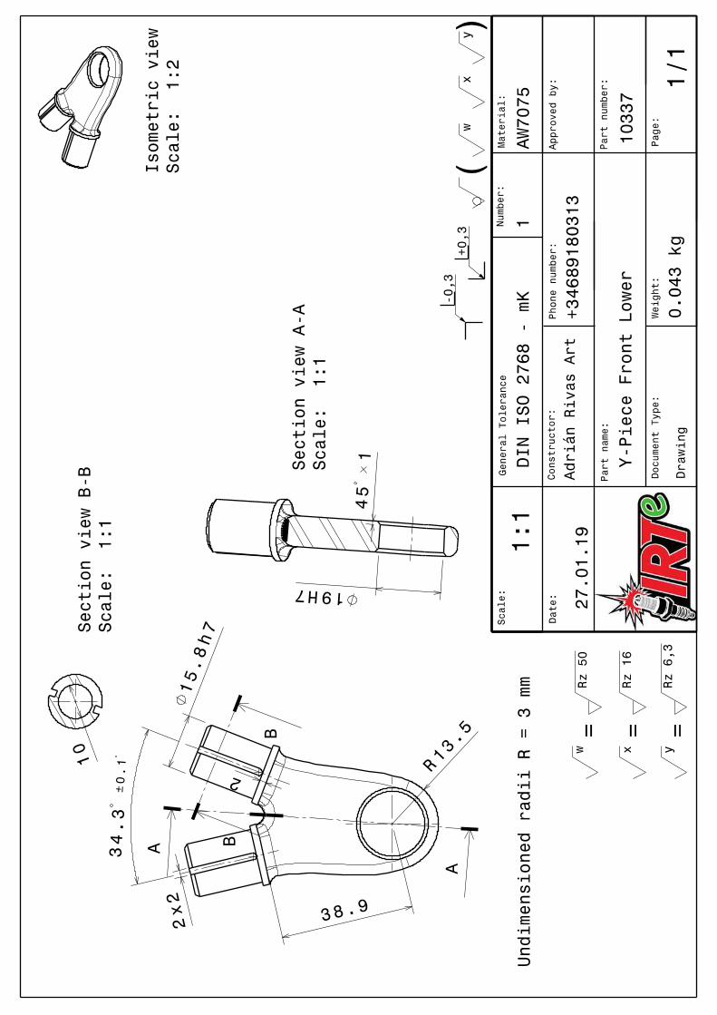
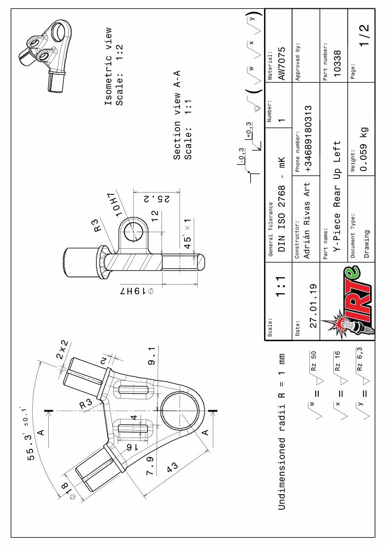
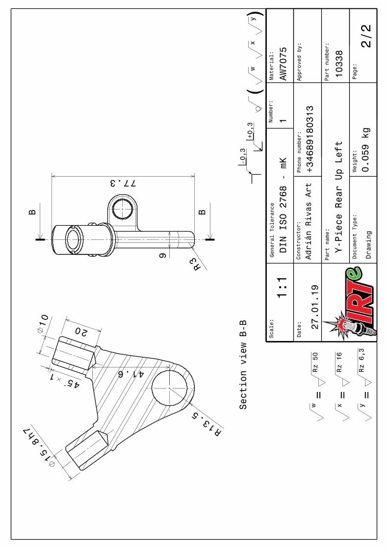

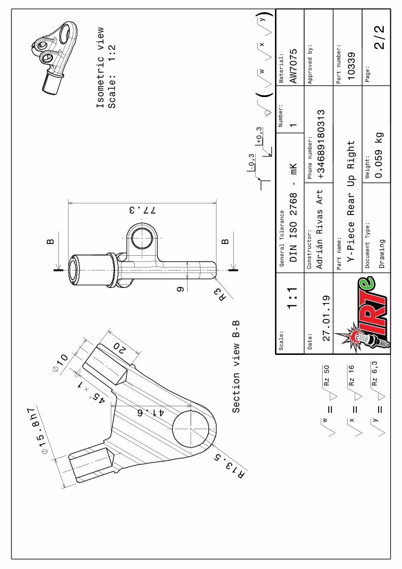

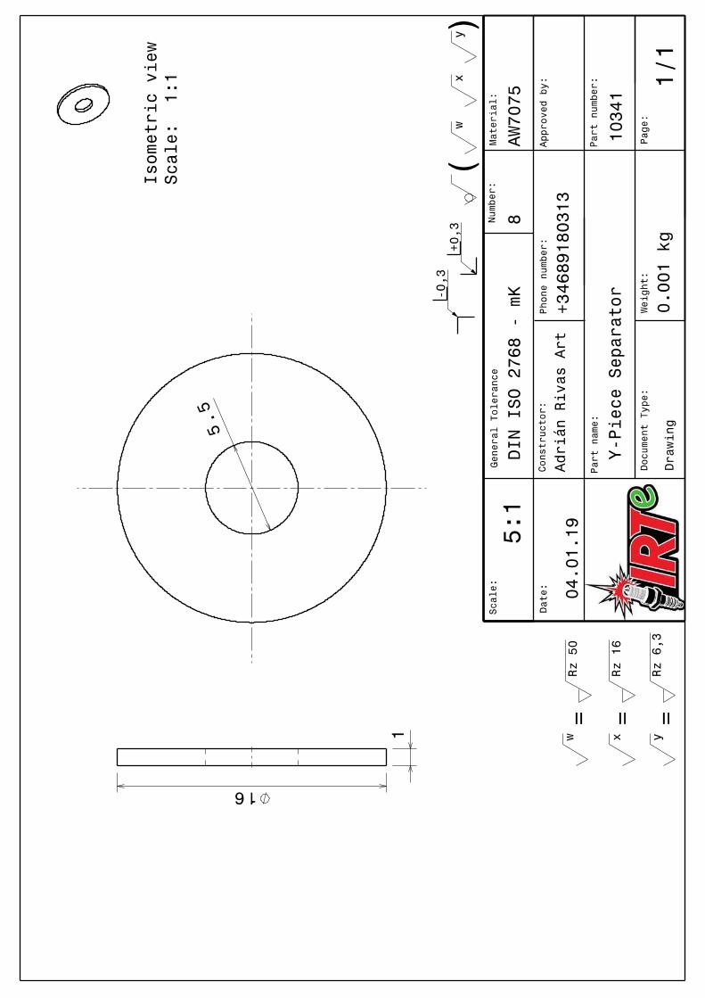


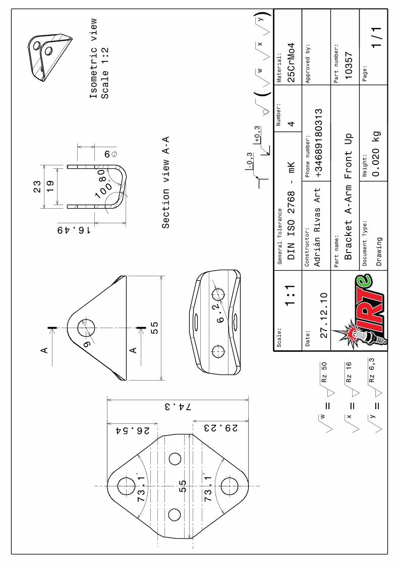


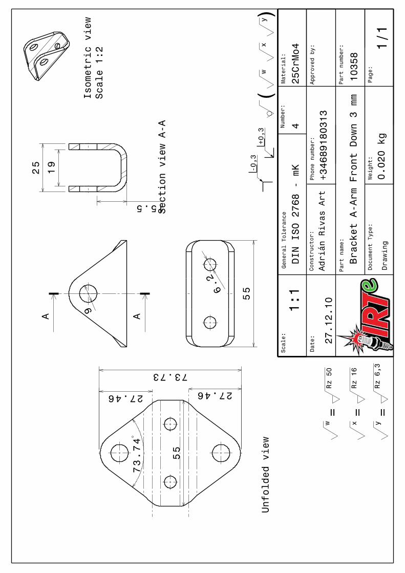

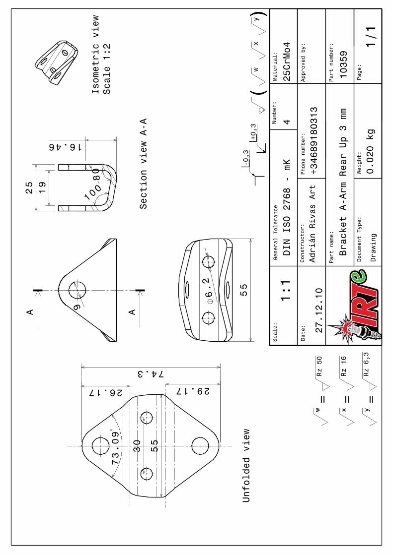


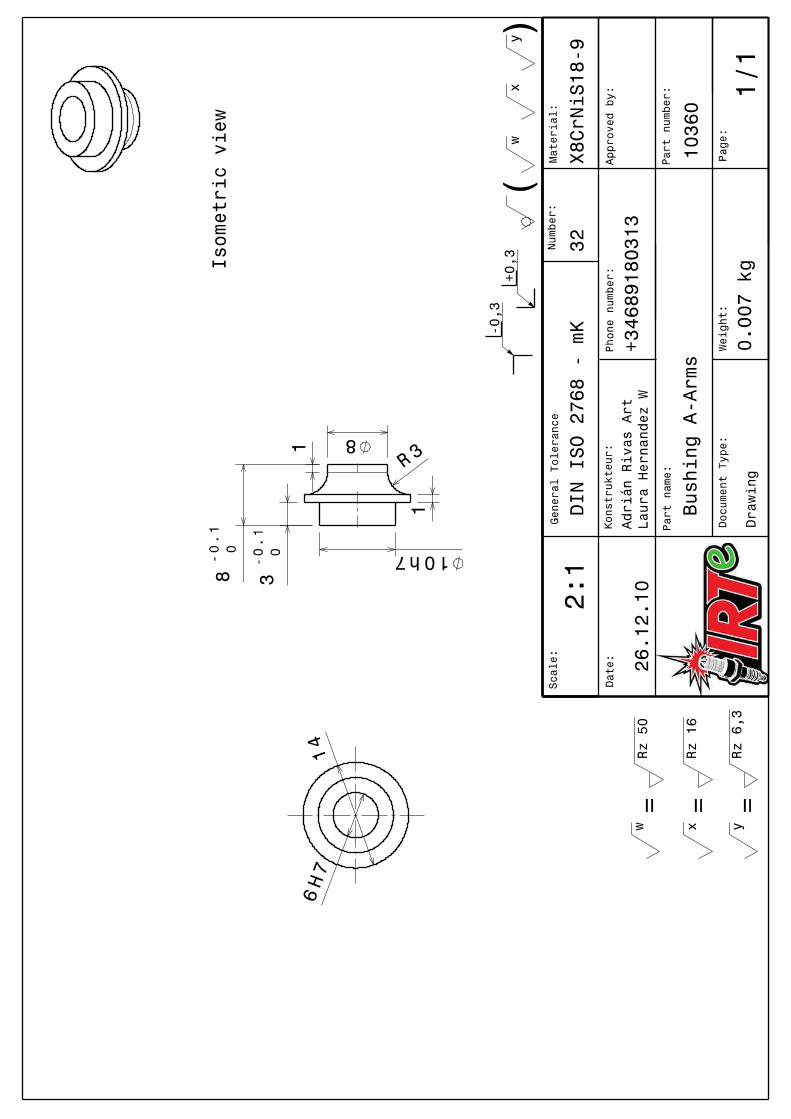
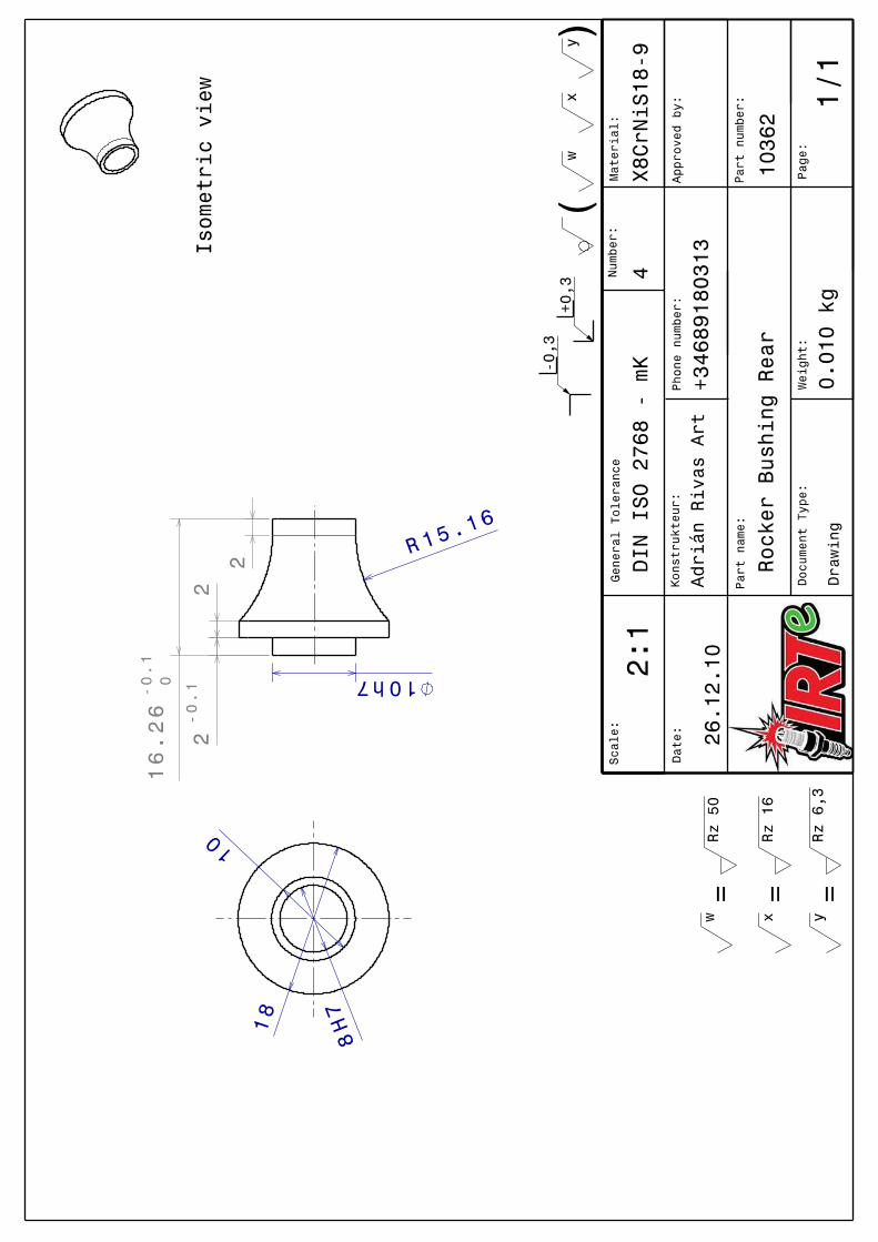
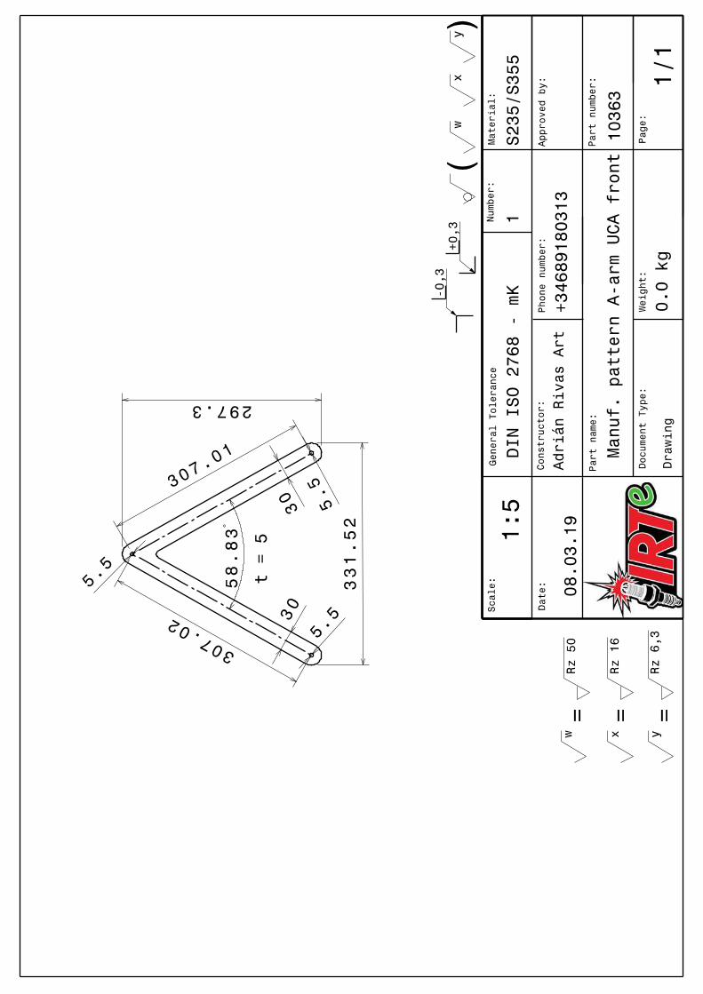
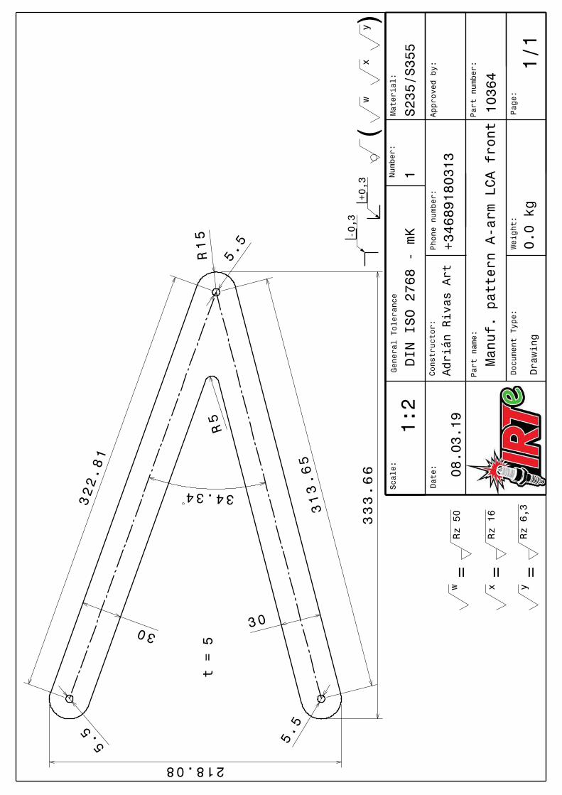
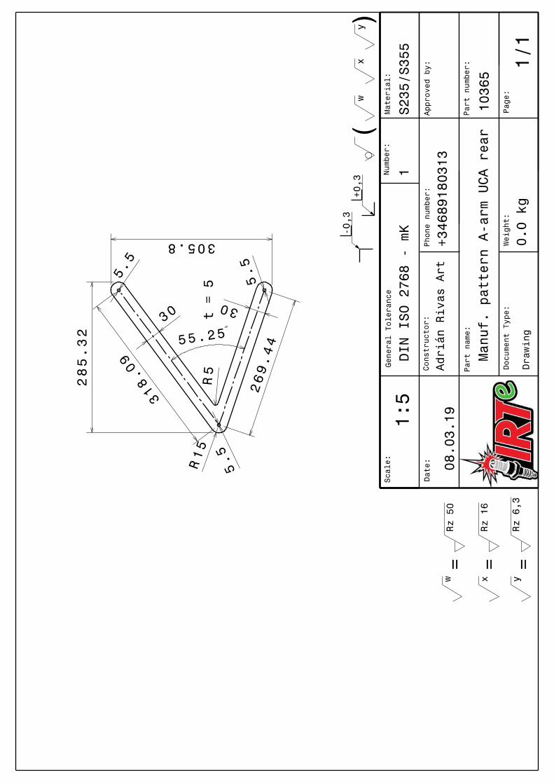
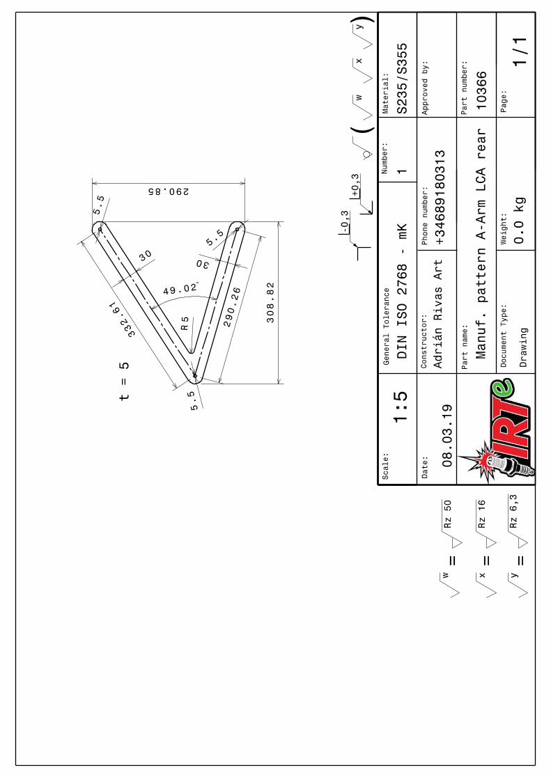
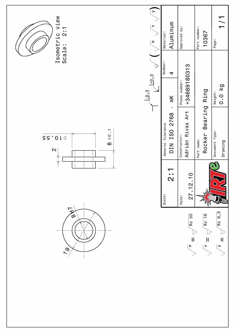
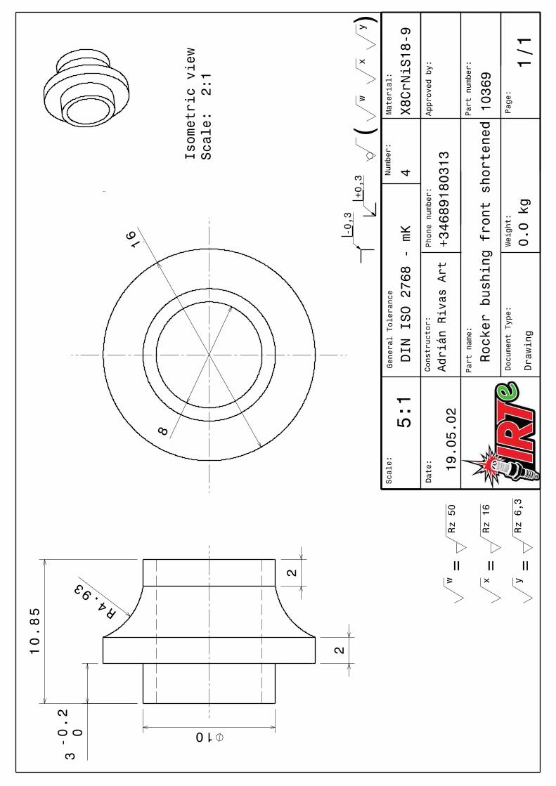
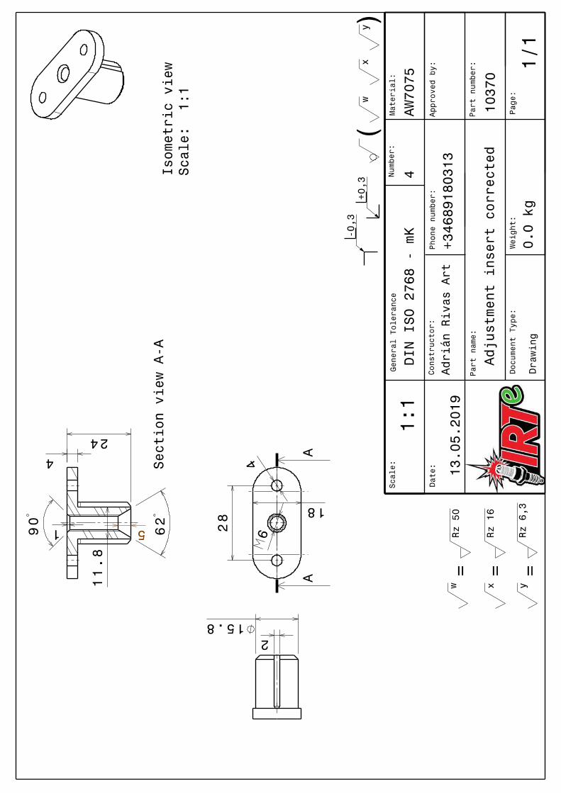
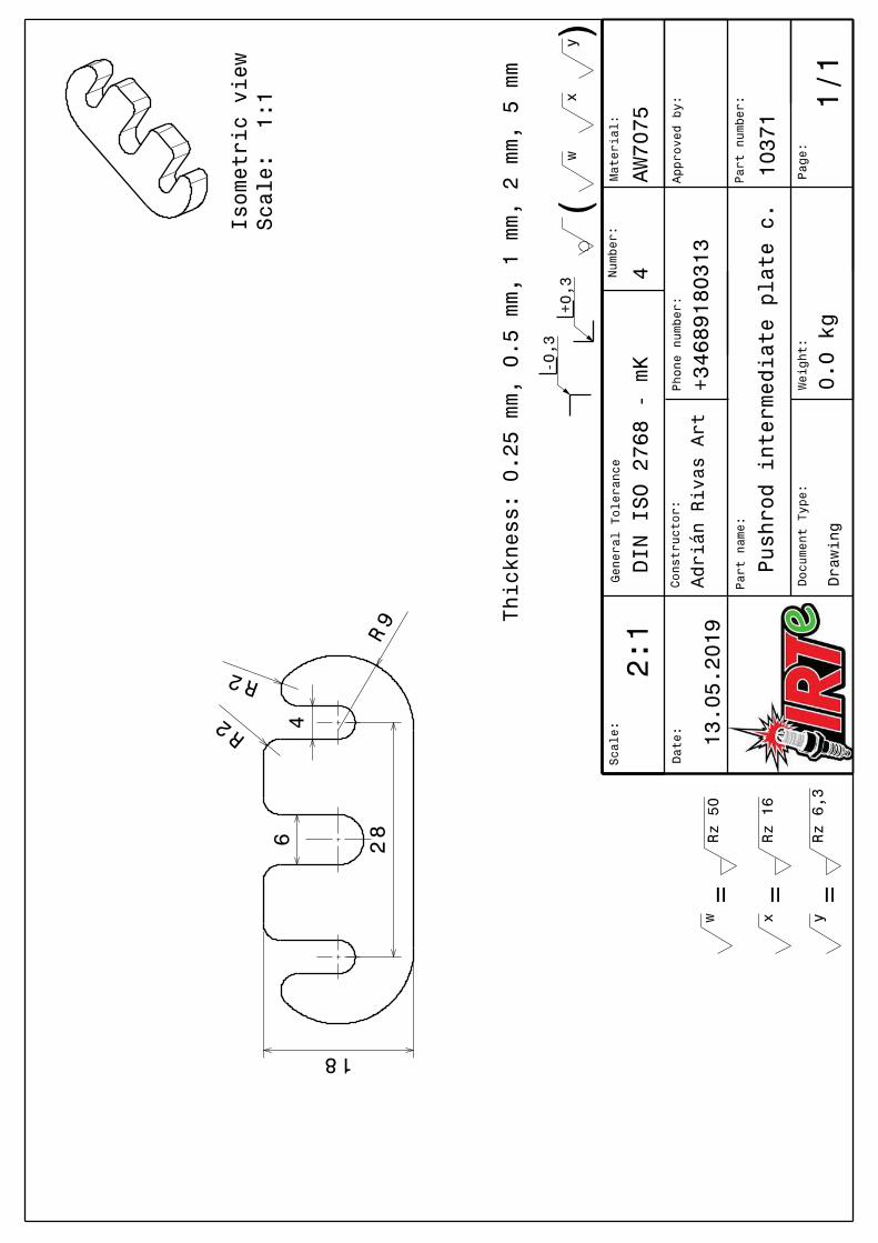
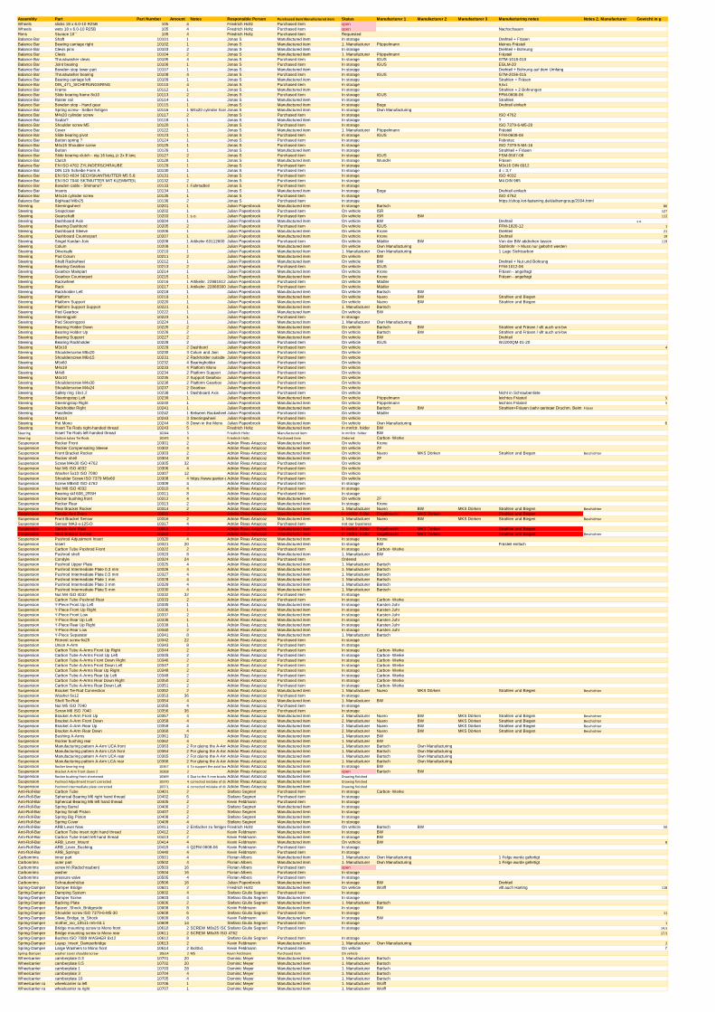
Assembly Part Part Number Amount Notes Responsible Person Purchased item/ Manufactured item Status Manufacturer 1 Manufacturer 2 Manufacturer 3 Manufacturing notes Notes 2. Manufacturer Gewicht in gWheels slicks 18 x 6.0-10 R25B 105 4 Friedrich Holtz Purchased item openWheels wets 18 x 6.0-10 R25B 105 4 Friedrich Holtz Purchased item open NachschauenRims Sturace 10´´ 105 4 Friedrich Holtz Purchased item RequestedBalance Bar Shaft 10101 1 Jonas S Manufactured item In storage Drehteil + FräsenBalance Bar Bearing carriage right 10102 1 Jonas S Manufactured item 1. Manufacturer Pöppelmann kleines FrästeilBalance Bar Clevis pins 10103 2 Jonas S Manufactured item In storage Drehteil + BohrungBalance Bar Clevis 10104 2 Jonas S Manufactured item 1. Manufacturer Pöppelmann Frästeil Balance Bar Thrustwasher clevis 10105 4 Jonas S Purchased item In storage IGUS GTM-1018-010Balance Bar Joint bearing 10106 1 Jonas S Purchased item In storage IGUS EGLM-20Balance Bar Bowden stop lower part 10107 1 Jonas S Manufactured item In storage Drehteil + Bohrung auf dem UmfangBalance Bar Thrustwasher bearing 10108 4 Jonas S Purchased item In storage IGUS GTM-2036-015Balance Bar Bearing carriage left 10109 1 Jonas S Manufactured item In storage Strahlen + FräsenBalance Bar DIN_471_SICHERUNGSRING 10110 4 Jonas S Purchased item In storage 9,6x1Balance Bar Frame 10112 1 Jonas S Manufactured item In storage Strahlen + 2 BohrungenBalance Bar Slide bearing frame 8x10 10113 2 Jonas S Purchased item In storage IGUS FFM-0608-06Balance Bar Raster rail 10114 1 Jonas S Manufactured item In storage StrahlenBalance Bar Bowden stop - Hand gear 10115 1 Jonas S Manufactured item In storage Boge Drehteil einfachBalance Bar Spring screw - Selber fertigen 10116 1 M4x20 cylinder Screw ISO 4762Jonas S Manufactured item In storage Own ManufacturingBalance Bar M4x20 cylinder screw 10117 2 Jonas S Purchased item In storage ISO 4762Balance Bar Scalar? 10118 1 Jonas S Manufactured item In storage ?Balance Bar Shoulder screw M5 10120 1 Jonas S Purchased item In storage ISO 7379-6-M5-20Balance Bar Cover 10122 1 Jonas S Manufactured item 1. Manufacturer Pöppelmann FrästeilBalance Bar Slide bearing pivot 10123 1 Jonas S Purchased item In storage IGUS FFM-0608-06Balance Bar Button spring ? 10124 1 Jonas S Purchased item In storage FebrotecBalance Bar M4x15 Shoulder screw 10125 1 Jonas S Purchased item In storage ISO 7379-5-M4-16Balance Bar Button 10126 1 Jonas S Manufactured item In storage Strahlteil + FräsenBalance Bar Slide bearing clutch - eig 16 lang, jz 2x 8 lang 10127 2 Jonas S Purchased item In storage IGUS FSM-0507-08Balance Bar Clutch 10128 1 Jonas S Manufactured item In storage WundH FräsenBalance Bar EN ISO 4762 ZYLINDERSCHRAUBE 10129 1 Jonas S Purchased item In storage M3x16 DIN 6912 Balance Bar DIN 125 Scheibe Form A 10130 1 Jonas S Purchased item In storage d = 3,7Balance Bar EN ISO 4034 SECHSKANTMUTTER M5 5,6x8 10131 1 Jonas S Purchased item In storage ISO 4032Balance Bar EN ISO 7040 SKTMUTTER MIT KLEMMTEIL 10132 2 Jonas S Purchased item In storage M4 DIN 985Balance Bar Bowden cable - Shimano? 10133 1 Fahrradteil Jonas S Purchased item In storageBalance Bar Inserts 10134 1 Jonas S Manufactured item In storage Boge Drehteil einfachBalance Bar M4x16 cylinder screw 10135 1 Jonas S Purchased item In storage ISO 4762Balance Bar BigHead M6x25 10136 2 Jonas S Purchased item In storage https://shop.kvt-fastening.de/de/itemgroup/2004.htmlSteering Steeringwheel 10201 1 Julian Papenbrock Manufactured item In storage Bartsch 86
Steering Snapcloser 10202 1 Julian Papenbrock Purchased item On vehicle ISR 127
Steering Gearschaft 10203 1 s.o. Julian Papenbrock Purchased item On vehicle ISR BW 112
Steering Dashboard Axis 10204 1 Julian Papenbrock Manufactured item On vehicle BW Drehteil s.o.
Steering Bearing Dashbord 10205 2 Julian Papenbrock Purchased item On vehicle IGUS FFM-1820-12 1
Steering Dashboard Sleeve 10206 1 Julian Papenbrock Manufactured item On vehicle Krone Drehteil 21
Steering Dashboard Counterpart 10207 1 Julian Papenbrock Manufactured item On vehicle Krone Drehteil 19
Steering Singel Kardan Join 10208 1 Artikelnr.63112600 Julian Papenbrock Purchased item On vehicle Mädler BW Von der BW abdrehen lassen 119
Steering Colum 10209 1 Julian Papenbrock Manufactured item On vehicle Own Manufacturing Stahlrohr -> Muss nur gebohrt werdenSteering Driversafe 10210 1 Julian Papenbrock Manufactured item 1. Manufacturer Own Manufacturing 1 Lage SichtcarbonSteering Pod Colum 10211 2 Julian Papenbrock Manufactured item On vehicle BWSteering Shaft Rackwheel 10212 1 Julian Papenbrock Manufactured item On vehicle BW Drehteil + Nut und BohrungSteering Bearing Gearbox 10213 2 Julian Papenbrock Purchased item On vehicle IGUS FFM-1012-06Steering Gearbox Mainpart 10214 1 Julian Papenbrock Manufactured item On vehicle Krone Fräsen - angefragtSteering Gearbox Counterpart 10215 1 Julian Papenbrock Manufactured item On vehicle Krone Fräsen - angefragtSteering Rackwheel 10216 1 Artikelnr. 22881812 Julian Papenbrock Purchased item On vehicle MädlerSteering Rack 10217 1 Artikelnr. 22868300 Julian Papenbrock Purchased item On vehicle MädlerSteering Rackholder Left 10218 1 Julian Papenbrock Manufactured item On vehicle Bartsch BWSteering Platform 10219 1 Julian Papenbrock Manufactured item On vehicle Nuero BW Strahlen und BiegenSteering Platform Support 10220 1 Julian Papenbrock Manufactured item On vehicle Nuero BW Strahlen und BiegenSteering Platform Support Support 10221 1 Julian Papenbrock Manufactured item 1. Manufacturer BartschSteering Pod Gearbox 10222 1 Julian Papenbrock Manufactured item On vehicle BWSteering Steeringpoti 10223 1 Julian Papenbrock Purchased item In storageSteering Pod Steeringpoti 10224 1 Julian Papenbrock Manufactured item 1. Manufacturer Own ManufacturingSteering Bearing Holder Down 10225 2 Julian Papenbrock Manufactured item On vehicle Bartsch BW Strahlen und Fräsen / vllt auch uni-bwSteering Bearing Holder Up 10226 2 Julian Papenbrock Manufactured item On vehicle Bartsch BW Strahlen und Fräsen / vllt auch uni-bwSteering Bearing Support 10227 2 Julian Papenbrock Manufactured item On vehicle BW DrehteilSteering Bearing Rackholder 10228 2 Julian Papenbrock Purchased item On vehicle IGUS WJ200QM-01-20Steering M3x18 10229 2 Dashbord Julian Papenbrock Purchased item On vehicle 4
Steering Shoulderscrew M6x20 10230 3 Colum and Join Julian Papenbrock Purchased item On vehicleSteering Shoulderscrew M6x15 10231 2 Rackholder outside Julian Papenbrock Purchased item On vehicleSteering M5x60 10232 4 Bearingholder Julian Papenbrock Purchased item On vehicleSteering M4x19 10233 4 Platform Mono Julian Papenbrock Purchased item On vehicleSteering M4x8 10234 2 Platform Support Julian Papenbrock Purchased item On vehicleSteering M4x10 10235 2 Support Gearbox Julian Papenbrock Purchased item On vehicleSteering Shoulderscrew M4x30 10236 2 Platform Gearbox Julian Papenbrock Purchased item On vehicleSteering Shoulderscrew M4x24 10237 2 Gearbox Julian Papenbrock Purchased item On vehicleSteering Safety ring 19x1,2 10238 1 Dashboard Axis Julian Papenbrock Purchased item On vehicle Nicht in SchraubenlisteSteering Steeringstop Left 10239 1 Julian Papenbrock Manufactured item On vehicle Pöppelmann leichtes Frästeil 5
Steering Steeringstop Right 10240 1 Julian Papenbrock Manufactured item On vehicle Pöppelmann leichtes Frästeil 5
Steering Rackholder Right 10241 1 Julian Papenbrock Manufactured item On vehicle Bartsch BW Strahlen+Fräsen (sehr geringer Druchm. Beim Fräsen)Fräser
Steering Passfeder 10242 1 Between Rackwheel and AxisJulian Papenbrock Purchased item On vehicle MädlerSteering M4x14 10243 3 Steeringwheel Julian Papenbrock Purchased item On vehicleSteering Pot Mono 10244 8 Down in the Mono Julian Papenbrock Manufactured item On vehicle Own Manufacturing 6Steering Insert Tie Rods right-handed thread 10243 5 Friedrich Holtz Manufactured item In mnfctr. folder BWSteering Insert Tie Rods left-handed thread 10244 5 Friedrich Holtz Manufactured item In mnfctr. folder BWSteering Carbon tubes Tie Rods 10245 5 Friedrich Holtz Purchased item Ordered Carbon- WerkeSuspension Rocker Front 10301 2 Adrián Rivas Artazcoz Manufactured item On vehicle KroneSuspension Rocker Compensating Sleeve 10302 4 Adrián Rivas Artazcoz Manufactured item On vehicle ZFSuspension Front Bracket Rocker 10303 2 Adrián Rivas Artazcoz Manufactured item On vehicle Nuero MKS Dörken Strahlen und Biegen Beschichter
Suspension Rocker shell 10304 8 Adrián Rivas Artazcoz Manufactured item On vehicle ZFSuspension Screw M4x30 ISO 4762 10305 32 Adrián Rivas Artazcoz Purchased item On vehicleSuspension Nut M5 ISO 4032 10306 4 Adrián Rivas Artazcoz Purchased item On vehicleSuspension Washer 5x10 ISO 7090 10307 12 Adrián Rivas Artazcoz Purchased item On vehicleSuspension Shoulder Screw ISO 7379 M6x60 10308 4 https://www.ganter-griff.de/de/produkte/3.2-Befestigen-Positionieren-Nivellieren-mit-Schraub-Klemm-und-Auflageelementen/Augenschrauben-Passschrauben-Druckschrauben/ISO-7379-Passschrauben#d2%3Du(88dc7f1c-368c-4f21-a596-5599c73962f1)_autosel%3Bd1%3Dc(8)Adrián Rivas Artazcoz Purchased item On vehicleSuspension Screw M8x50 ISO 4762 10309 4 Adrián Rivas Artazcoz Purchased item In storageSuspension Nut M8 ISO 4032 10310 4 Adrián Rivas Artazcoz Purchased item In storageSuspension Bearing skf 608_2RSH 10311 8 Adrián Rivas Artazcoz Purchased item In storageSuspension Rocker bushing front 10312 4 Adrián Rivas Artazcoz Manufactured item On vehicle ZFSuspension Rocker Rear 10313 2 Adrián Rivas Artazcoz Manufactured item In storage KroneSuspension Rear Bracket Rocker 10314 2 Adrián Rivas Artazcoz Manufactured item 1. Manufacturer Nuero BW MKS Dörken Strahlen und Biegen Beschichter
Suspension Sensor Arm Front 10315 2 Adrián Rivas Artazcoz Manufactured item In mnfctr. folder Engelbrecht MKS Dörken Strahlen und BiegenSuspension Front Bracket Sensor 10316 2 Adrián Rivas Artazcoz Manufactured item 1. Manufacturer Nuero BW MKS Dörken Strahlen und Biegen Beschichter
Suspension Sensor MA3-x-125-D 10317 4 Adrián Rivas Artazcoz Purchased item not our businessSuspension Sensor Arm Rear 10318 2 Adrián Rivas Artazcoz Manufactured item In mnfctr. folder Engelbrecht MKS Dörken Strahlen und BiegenSuspension Rear Bracket Sensor 10319 2 Adrián Rivas Artazcoz Manufactured item In mnfctr. folder Engelbrecht MKS Dörken Strahlen und Biegen Beschichter
Suspension Pushrod Adjustment Insert 10320 4 Adrián Rivas Artazcoz Manufactured item In storage KroneSuspension Insert 10321 20 Adrián Rivas Artazcoz Manufactured item In storage BW Frästeil einfachSuspension Carbon Tube Pushrod Front 10322 2 Adrián Rivas Artazcoz Purchased item In storage Carbon- WerkeSuspension Pushrod shell 10323 8 Adrián Rivas Artazcoz Manufactured item 1. Manufacturer BWSuspension Condyle 10324 24 Adrián Rivas Artazcoz Purchased item OrderedSuspension Pushrod Upper Plate 10325 4 Adrián Rivas Artazcoz Manufactured item 1. Manufacturer BartschSuspension Pushrod Intermediate Plate 0,3 mm 10326 4 Adrián Rivas Artazcoz Manufactured item 1. Manufacturer BartschSuspension Pushrod Intermediate Plate 0,5 mm 10327 4 Adrián Rivas Artazcoz Manufactured item 1. Manufacturer BartschSuspension Pushrod Intermediate Plate 1 mm 10328 4 Adrián Rivas Artazcoz Manufactured item 1. Manufacturer BartschSuspension Pushrod Intermediate Plate 3 mm 10329 4 Adrián Rivas Artazcoz Manufactured item 1. Manufacturer BartschSuspension Pushrod Intermediate Plate 5 mm 10330 4 Adrián Rivas Artazcoz Manufactured item 1. Manufacturer BartschSuspension Nut M4 ISO 4032 10332 32 Adrián Rivas Artazcoz Purchased item In storageSuspension Carbon Tube Pushrod Rear 10333 2 Adrián Rivas Artazcoz Purchased item In storage Carbon- WerkeSuspension Y-Piece Front Up Left 10335 1 Adrián Rivas Artazcoz Manufactured item In storage Karsten JuhrSuspension Y-Piece Front Up Right 10336 1 Adrián Rivas Artazcoz Manufactured item In storage Karsten JuhrSuspension Y-Piece Front Low 10337 2 Adrián Rivas Artazcoz Manufactured item In storage Karsten JuhrSuspension Y-Piece Rear Up Left 10338 1 Adrián Rivas Artazcoz Manufactured item In storage Karsten JuhrSuspension Y-Piece Rear Up Right 10339 1 Adrián Rivas Artazcoz Manufactured item In storage Karsten JuhrSuspension Y-Piece Rear Low 10340 2 Adrián Rivas Artazcoz Manufactured item In storage Karsten JuhrSuspension Y-Piece Separator 10341 8 Adrián Rivas Artazcoz Manufactured item 1. Manufacturer BartschSuspension Fitment screw 6x25 10342 22 Adrián Rivas Artazcoz Purchased item In storageSuspension Union A-Arm 10343 8 Adrián Rivas Artazcoz Purchased item In storageSuspension Carbon Tube A-Arms Front Up Right 10344 2 Adrián Rivas Artazcoz Purchased item In storage Carbon- WerkeSuspension Carbon Tube A-Arms Front Up Left 10345 2 Adrián Rivas Artazcoz Purchased item In storage Carbon- WerkeSuspension Carbon Tube A-Arms Front Down Right 10346 2 Adrián Rivas Artazcoz Purchased item In storage Carbon- WerkeSuspension Carbon Tube A-Arms Front Down Left 10347 2 Adrián Rivas Artazcoz Purchased item In storage Carbon- WerkeSuspension Carbon Tube A-Arms Rear Up Right 10348 2 Adrián Rivas Artazcoz Purchased item In storage Carbon- WerkeSuspension Carbon Tube A-Arms Rear Up Left 10349 2 Adrián Rivas Artazcoz Purchased item In storage Carbon- WerkeSuspension Carbon Tube A-Arms Rear Down Right 10350 2 Adrián Rivas Artazcoz Purchased item In storage Carbon- WerkeSuspension Carbon Tube A-Arms Rear Down Left 10351 2 Adrián Rivas Artazcoz Purchased item In storage Carbon- WerkeSuspension Bracket Tie-Rod Connection 10352 2 Adrián Rivas Artazcoz Manufactured item 1. Manufacturer Nuero MKS Dörken Strahlen und Biegen Beschichter
Suspension Washer 6x12 10353 36 Adrián Rivas Artazcoz Purchased item In storageSuspension Shell Tie-Rod 10354 4 Adrián Rivas Artazcoz Manufactured item 1. Manufacturer BWSuspension Nut M5 ISO 7040 10355 4 Adrián Rivas Artazcoz Purchased item In storageSuspension Screw M6 ISO 7040 10356 36 Adrián Rivas Artazcoz Purchased item In storageSuspension Bracket A-Arm Front Up 10357 4 Adrián Rivas Artazcoz Manufactured item 2. Manufacturer Nuero BW MKS Dörken Strahlen und Biegen Beschichter
Suspension Bracket A-Arm Front Down 10358 4 Adrián Rivas Artazcoz Manufactured item 2. Manufacturer Nuero BW MKS Dörken Strahlen und Biegen Beschichter
Suspension Bracket A-Arm Rear Up 10359 4 Adrián Rivas Artazcoz Manufactured item 2. Manufacturer Nuero BW MKS Dörken Strahlen und Biegen Beschichter
Suspension Bracket A-Arm Rear Down 10360 4 Adrián Rivas Artazcoz Manufactured item 2. Manufacturer Nuero BW MKS Dörken Strahlen und Biegen Beschichter
Suspension Bushing A-Arms 10361 32 Adrián Rivas Artazcoz Manufactured item 1. Manufacturer BWSuspension Rocker bushing rear 10362 4 Adrián Rivas Artazcoz Manufactured item 1. Manufacturer BWSuspension Manufacturing pattern A-Arm UCA front 10363 2 For gluing the A-ArmsAdrián Rivas Artazcoz Manufactured item 1. Manufacturer Bartsch Own ManufacturingSuspension Manufacturing pattern A-Arm LCA front 10364 2 For gluing the A-ArmsAdrián Rivas Artazcoz Manufactured item 1. Manufacturer Bartsch Own ManufacturingSuspension Manufacturing pattern A-Arm UCA rear 10365 2 For gluing the A-ArmsAdrián Rivas Artazcoz Manufactured item 1. Manufacturer Bartsch Own ManufacturingSuspension Manufacturing pattern A-Arm LCA rear 10366 2 For gluing the A-ArmsAdrián Rivas Artazcoz Manufactured item 1. Manufacturer Bartsch Own ManufacturingSuspension Rocker bearing ring 10367 4 To support the axial load of the bearingsAdrián Rivas Artazcoz Manufactured item In storage BWSuspension Bracket A-Arm front down 2 10368 2 Adrián Rivas Artazcoz Manufactured item open Bartsch BWSuspension Rocker bushing front shortened 10369 4 Due to the 3 mm bracket the gap changedAdrián Rivas Artazcoz Manufactured item Drawing finished
Suspension Pushrod Adjustment Insert corrected 10370 4 corrected mistake of distance and updated shapeAdrián Rivas Artazcoz Manufactured item Drawing finished
Suspension Pushrod intermediate plate corrected 10371 4 corrected mistake of distance and updated shapeAdrián Rivas Artazcoz Manufactured item Drawing finished
Anti-Roll-Bar Carbon Tube 10401 2 Stefano Segneri Purchased item In storage Carbon- WerkeAnti-Roll-Bar Spherical Bearing M6 right hand thread 10402 6 Stefano Segneri Purchased item In storageAnti-Roll-Bar Spherical Bearing M6 left hand thread 10405 2 Kevin Feldmann Purchased item In storageAnti-Roll-Bar Spring Barrel 10406 2 Stefano Segneri Manufactured item In storageAnti-Roll-Bar Spring Small Piston 10407 2 Stefano Segneri Manufactured item In storageAnti-Roll-Bar Spring Big Piston 10408 2 Stefano Segneri Manufactured item In storageAnti-Roll-Bar Spring Cover 10409 4 Stefano Segneri Manufactured item In storageAnti-Roll-Bar ARB Lever New 10411 2 Einfacher zu fertigenFriedrich Holtz Manufactured item On vehicle Bartsch BW 50
Anti-Roll-Bar Carbon Tube insert right hand thread 10412 2 Kevin Feldmann Manufactured item In storage BWAnti-Roll-Bar Carbon Tube Insert left hand thread 10413 2 Kevin Feldmann Manufactured item In storage BWAnti-Roll-Bar ARB_Lever_Mount 10414 4 Kevin Feldmann Manufactured item On vehicle BW 8
Anti-Roll-Bar ARB_Lever_Bushing 10415 4 Q2FM 0608-06 Kevin Feldmann Purchased item In storageAnti-Roll-Bar ARB_Springs 10440 4 Kevin Feldmann Purchased item In storageCarbonrims inner part 10501 4 Florian Albers Manufactured item 1. Manufacturer Own Manufacturing 1 Felge wurde gefertigtCarbonrims outer part 10502 4 Florian Albers Manufactured item 1. Manufacturer Own Manufacturing 1 Felge wurde gefertigtCarbonrims screw M (Radschrauben) 10503 16 Florian Albers Purchased item openCarbonrims washer 10504 16 Florian Albers Purchased item In storageCarbonrims pressure valve 10505 4 Florian Albers Purchased item In storageCarbonrims Schraubenhülse 10506 16 Julian Papenbrock Manufactured item In storage BW DrehteilSpring-Damper Damper Bridge 10601 2 Friedrich Holtz Manufactured item On vehicle Wolff vllt auch Harting 118
Spring-Damper Damping System 10602 4 Stefano Giulio Segneri Purchased item In storageSpring-Damper Damper Screw 10603 4 Stefano Giulio Segneri Manufactured item In storageSpring-Damper Backing Plate 10606 2 Stefano Giulio Segneri Manufactured item 1. Manufacturer BartschSpring-Damper Spacer_Shock_Bridgeside 10608 8 Kevin Feldmann Manufactured item In storage BWSpring-Damper Shoulder screw ISO 7379-6-M5-30 10608 6 Stefano Giulio Segneri Purchased item In storage 11
Spring-Damper Sleve_Bridge_to_Shock 10609 8 Kevin Feldmann Manufactured item In storage BWSpring-Damper mother_iso_10511-m5-04.1 10609 14 Stefano Giulio Segneri Purchased item In storage 1
Spring-Damper Bridge mounting screw to Mono front 10610 2 SCREW M8x25 ISO 4762Stefano Giulio Segneri Purchased item In storage 14,5
Spring-Damper Bridge mounting screw to Mono rear 10611 2 SCREW M8x35 ISO 4762 17,5
Spring-Damper Bushes ISO 7089 WASHER 6x12 10612 8 Stefano Giulio Segneri Purchased item In storageSpring-Damper Layup_Insert_Damperbridge 10613 2 Kevin Feldmann Manufactured item 1. Manufacturer Own Manufacturing 2
Spring-Damper Large Washers to Mono front 10614 2 8x30x1 Kevin Feldmann Purchased item On vehicle 7Spring-Damper washer Lever shoulderscrew 10614 2 M5 Kevin Feldmann Purchased item On vehicle
Wheelcarrier camberplate 0.3 10701 20 Dominic Meyer Manufactured item 1. Manufacturer BartschWheelcarrier camberplate 0.5 10702 20 Dominic Meyer Manufactured item 1. Manufacturer BartschWheelcarrier camberplate 1 10703 28 Dominic Meyer Manufactured item 1. Manufacturer BartschWheelcarrier camberplate 3 10704 4 Dominic Meyer Manufactured item 1. Manufacturer BartschWheelcarrier camberplate 10 10705 4 Dominic Meyer Manufactured item 1. Manufacturer BartschWheelcarrier ra wheelcarrier ra left 10706 1 Dominic Meyer Manufactured item 1. Manufacturer WolffWheelcarrier ra wheelcarrier ra right 10707 1 Dominic Meyer Manufactured item 1. Manufacturer Wolff
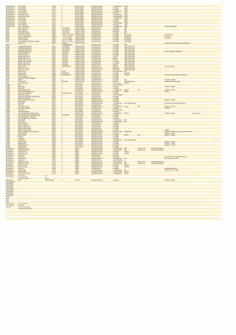
Wheelcarrier ra UCA bracket 10708 2 Dominic Meyer Manufactured item 1. Manufacturer KroneWheelcarrier ra UCA bushing 10709 4 Dominic Meyer Manufactured item In storage BogeWheelcarrier ra LCA bushing 10710 4 Dominic Meyer Manufactured item In storage BogeWheelcarrier ra tie rod bracket 10711 2 Dominic Meyer Manufactured item 1. Manufacturer KroneWheelcarrier ra tie rod bushing 10712 4 Dominic Meyer Manufactured item In storage BogeWheelcarrier fa wheelcarrier fa left 10713 1 Dominic Meyer Manufactured item 1. Manufacturer WolffWheelcarrier fa wheelcarrier fa right 10714 1 Dominic Meyer Manufactured item 1. Manufacturer WolffWheelcarrier fa UCA bracket 10715 2 Dominic Meyer Manufactured item 1. Manufacturer KroneWheelcarrier fa UCA bushing 10716 4 Dominic Meyer Manufactured item In storage BogeWheelcarrier fa LCA bushing 10717 4 Dominic Meyer Manufactured item In storage BogeWheelcarrier fa tie rod bracket 10718 2 Dominic Meyer Manufactured item 1. Manufacturer KroneWheelcarrier fa tie rod bushing 10719 4 Dominic Meyer Manufactured item In storage BogeWheelcarrier fa sensor attachment 10720 2 Dominic Meyer Manufactured item 1. Manufacturer Nuero Strahlen und BiegenBrake brake caliper front 10801 2 22-048-OB Frederik Gerdes Purchased item In storage ISRBrake brake caliper HL 10802 1 22-049-OD Frederik Gerdes Purchased item Requested ISRBrake brake caliper HR 10803 1 22-049-OC Frederik Gerdes Purchased item Requested ISRBrake main brake cylinder 10804 2 21-010.OA Frederik Gerdes Purchased item In storage ISRBrake aluminium brake line 10805 1 Best.-Nr.:E104062 Frederik Gerdes Purchased item In storage ISA-Racing D4,75mm 3m Brake screw-in nipple M10x1 10806 ? Art.-Nr.: 2121-0 Frederik Gerdes Purchased item In storage ISA-Racing D4,75mm Brake banjo bolt M10x1 10807 ? Art.-Nr.: 2035-2 Frederik Gerdes Purchased item In storage ISA-Racing Alu 2035-2Brake T-Stück 3xM10x1 10808 2 Art.-Nr.: 2136-0 Frederik Gerdes Purchased item In storage ISA-RacingBrake Kreuzverteiler mit Entlüfter 4xM10x1 10809 1 Best.-Nr.: 2145-2 Frederik Gerdes Purchased item In storage ISA-Racing
Brakebrake lining 10810 12 EAN-Nr.:
5050953002359Frederik Gerdes
Purchased item In storage EBCFA184 Blackstuff Bremsbeläge (organisch)
Brake Variofitting (Ringstück) 10811 3 MV10B20S Frederik Gerdes Purchased item In storage TRW moto/LukasBrake Variofitting (Ringstück) 10812 5 MV10A00S Frederik Gerdes Purchased item In storage TRW moto/LukasBrake Variofitting (Ringstück) 10813 3 MV10C45S Frederik Gerdes Purchased item In storage TRW moto/LukasBrake Variofitting (Ringstück) 10814 7 MVG100E Frederik Gerdes Purchased item In storage TRW moto/Lukas screw-in nipple for flexible lineBrake banjo bolt M10x1,25 10815 7 MCH901 Frederik Gerdes Purchased item In storage TRW moto/LukasBrake banjo bolt M10x1 10816 5 MCH921 Frederik Gerdes Purchased item In storage TRW moto/LukasBrake flexible brake line VR 10817 1 MV113S Frederik Gerdes Purchased item Ordered TRW moto/LukasBrake flexible brake line VL 10818 1 MV075S Frederik Gerdes Purchased item Ordered TRW moto/LukasBrake flexible brake line HAL 10819 1 MV023S Frederik Gerdes Purchased item Ordered TRW moto/LukasBrake flexible brake line HAR 10820 1 MV035S Frederik Gerdes Purchased item In storage TRW moto/LukasBrake flexible brake line HL 10821 1 MV075S Frederik Gerdes Purchased item In storage TRW moto/LukasBrake flexible brake line HR 10822 1 MV053S Frederik Gerdes Purchased item Ordered TRW moto/LukasBrake Dichtringsatz 10823 1 MCH991W50 Frederik Gerdes Purchased item Ordered TRW moto/Lukas Im Lager guckenBrake brake disc V 4mm 10825 2 Frederik Gerdes Manufactured item Requested Ronge MotorsportBrake brake disc H 3mm 10826 2 Frederik Gerdes Manufactured item Requested Ronge MotorsportBrake brake sensor 10827 2 VSP Frederik Gerdes Purchased item not our business I2SBrake Federscheibe 10828 26 0W61350 Frederik Gerdes Purchased item In storage FebrotecBrake Federscheibe 10828 26 0W0622-006 Frederik Gerdes Purchased item In storage Febrotec Checken, ob genügend im Lager sindBrake wave locking disc 10829 Frederik Gerdes Purchased item In storageBrake Unterlegbleche Bremsbeläge 10830 Frederik Gerdes Purchased item In storageBrake Floater 10831 24 Frederik Gerdes Manufactured item In storage BW Einfaches DrehteilBrake Variozubehör 10832 1 MV1518 Frederik Gerdes Purchased item Ordered TRWmoto/Lucas Checken ob wir das haben…Brake Brakezylinder Spacer 10833 6 Friedrich Holtz Manufactured item 1. Manufacturer BartschPedals BOT 10901 1 Felix Gümpel Purchased item Not our businessPedals BOT Mount 10902 1 Felix Gümpel Manufactured item In storage Strahlen + BiegenPedals Brake Bolt 10903 1 Felix Gümpel Purchased item In storagePedals Brake Stopper Block 10904 1 Friedrich Holtz Manufactured item 1. Manufacturer Bartsch BW Strahlen + BohrenPedals Brake Masterzylinder Mount 10905 1 Felix Gümpel Manufactured item In storage Bartsch StrahlenPedals Brake IGUS Gleitlager 10906 2 Q2FM 0810 10 Felix Gümpel Purchased item In storagePedals Brake Recu Sensor 10907 2 Felix Gümpel Purchased item not our businessPedals Brake IGUS Gleitlager Springzylinder 10908 2 Felix Gümpel Purchased item In storagePedals Brake Fluid Reservoir 10909 2 Felix Gümpel Purchased item In storagePedals Brake Fluid Reservoir Mount 10910 1 Felix Gümpel Manufactured item In storage Strahlen + BiegenPedals Brake Pedal 10911 1 Felix Gümpel Manufactured item In storagePedals Gas Pedal 10912 1 Felix Gümpel Manufactured item 1. Manufacturer Own Manufacturing Alu Pedal aus IR18 wird angepasstPedals Gas Bolt 10913 1 Felix Gümpel Purchased item In storagePedals Gas Stopper Block 10914 1 Friedrich Holtz Manufactured item 1. Manufacturer Bartsch BW Strahlen + BohrenPedals Gas IGUS Gleitlager 10915 2 Felix Gümpel Purchased item In storage Welches?Pedals Gas LinPot 10916 2 Felix Gümpel Purchased item not our businessPedals Gas Springzylinder 10917 2 Felix Gümpel Purchased item In storagePedals Gas Springzylinder Bearing Braket 10918 2 Friedrich Holtz Manufactured item 1. Manufacturer Bartsch Strahlen+ Bohren Bohren (genau)
Pedals Gas Springzylinder Sondermannauge 10919 2 EF-E066S Felix Gümpel Purchased item In storagePedals Gas Springzylinder Hollowbolt 10920 2 Felix Gümpel Purchased item In storagePedals Gas Springzylinder Lockingring 10921 2 Felix Gümpel Purchased item In storagePedals Gas Steppin 10923 1 Felix Gümpel Manufactured item 1. Manufacturer BWPedals Gas Tappet 10924 1 Felix Gümpel Manufactured item 1. Manufacturer BWPedals Master Adapter 10925 2 Felix Gümpel Purchased item In storagePedals Master Push Rod 10926 2 Felix Gümpel Purchased item In storagePedals Master Cylinder Left 10927 1 Felix Gümpel Purchased item In storagePedals Master Cylinder Right 10928 1 Felix Gümpel Purchased item In storagePedals Master Cylinder Mount 10929 1 Felix Gümpel Manufactured item In storage StrahlenPedals Master Cylinder Connection Mount 10930 1 Felix Gümpel Manufactured item In mnfctr. folder Engelbrecht Strahlen + Biegen/ In Ordner "Laser-Kant Teile"Pedals Outerrail Brake 10931 1 Felix Gümpel Manufactured item In storage Strahlen + FräsenPedals Outerrail Gas 10932 1 Felix Gümpel Manufactured item In storage Bartsch BW Strahlen + FräsenPedals Footrest 10933 2 Felix Gümpel Manufactured item In storagePedals Pedal Toe 10934 2 Felix Gümpel Manufactured item In storagePedals Pedal Recu 10935 1 Felix Gümpel Manufactured item 1. Manufacturer Own ManufacturingPedals Adjusting Rod 10936 1 Felix Gümpel Manufactured item In storage Strahlen + FräsenPedals Railingsystem 10937 1 Felix Gümpel Manufactured item In storage Strahlen + Fräsen Pedals Sliding Element 10938 1 Felix Gümpel Manufactured item In storage Strahlen + Fräsen Pedals Springholder 10939 1 Felix Gümpel Manufactured item In storageWheelhub ra wheelhub RA left 11001 1 Fabian Manufactured item 3. Manufacturer BW Karsten Juhr Schornberg GalvanikWheelhub ra wheelhub RA right 11002 1 Fabian Manufactured item 3. Manufacturer BW Karsten Juhr Schornberg GalvanikWheelhub ra hubnut RA left 11003 1 Fabian Manufactured item In storage WundHWheelhub ra hubnut RA right 11004 1 Fabian Manufactured item In storage WundHWheelhub ra sealing RA 11005 4 Fabian Purchased item In storageWheelhub ra bearing RA 11006 4 Fabian Purchased item Requested INA CSEA 030 or SBN DRAZ 030 VAWheelhub ra thread inserts 11007 8 Fabian Manufactured item 1. Manufacturer BW same on FA, 16 in totalWheelhub ra axle boot 11008 2 Fabian Purchased item not our businessWheelhub fa wheelhub FA left 11101 1 Fabian Manufactured item 3. Manufacturer BW Karsten Juhr Schornberg GalvanikWheelhub fa wheelhub FA right 11102 1 Fabian Manufactured item 3. Manufacturer BW Karsten Juhr Schornberg GalvanikWheelhub fa hubnut FA left 11103 1 Fabian Manufactured item In storage WundHWheelhub fa hubnut FA right 11104 1 Fabian Manufactured item In storage WundHWheelhub fa bearing FA 11105 4 Fabian Purchased item In storage Schaeffler 3811-2RSWheelhub fa thread inserts 11106 8 Fabian Manufactured item 1. Manufacturer BW same on RA, 16 in totalWheelhub fa inkrementring 11107 2 Fabian Manufactured item 1. Manufacturer BartschWheelhub fa inkrementrinh holder 11108 2 Fabian Manufactured item 1. Manufacturer BartschPush & Pull-Bar U-Profil Stahl 1m
Push & Pull-Bar Vierkantrohr Stahl 3m
Schaumstoff (500mm) 3mx2m
Balance Bar Lever BeschichterMu 1 Jonas S Manufactured item In storage Drehteil + FräsenGesamtgewicht 0
Anti-Roll-BarAnti-Roll-BarAnti-Roll-BarAnti-Roll-BarAnti-Roll-BarAnti-Roll-BarAnti-Roll-BarAnti-Roll-BarWheelsRimsRimsRimsPush & Pull-Bar Schaumstoff/Gummi
Push & Pull-Bar Rohr 20mm
Quick-Jack Vierkantrohr Stahl (Dick)
Vierkantrohr Stahl (schmal)

FACULTY OF ENGINEERING AND COMPUTER SCIENCE
PROJECT MANAGEMENT DOCUMENTS
IGNITION RACING TEAM
VERSION 1.0
2
EPS IRT 2018
1. Modification History
Modification
Changed Chapter Description of Changes Author Nr. Date Version
1 05.11.2018 1.0 All Creation of Document EPS IRT
2 10.12.2018 2.0 Risks,
communication Add more informaion EPS IRT
3 04.01.2019 3.0 Individual report Add individual results EPS IRT
3
EPS IRT 2018
2. Table of Contents
1. Modification History 2
3. Statement of work 4
4. Project Scope 4
5. Introduction 5
1.1 General remarks 5
1.2 Description of the Undertaking 5
6. Requirements 5
7. Project Schedule (Gantt Chart) 6
8. Work Packages 7
9. RISK ANALYSIS 8
10. Statement of work 13
11. Stakeholders & communication plan 13
12. Mariana Carbajal Curiel 15
13. Laura Milena Hernández Wilches 17
14. Adrián Rivas Artazcoz 18
15. Stefano Segneri 21
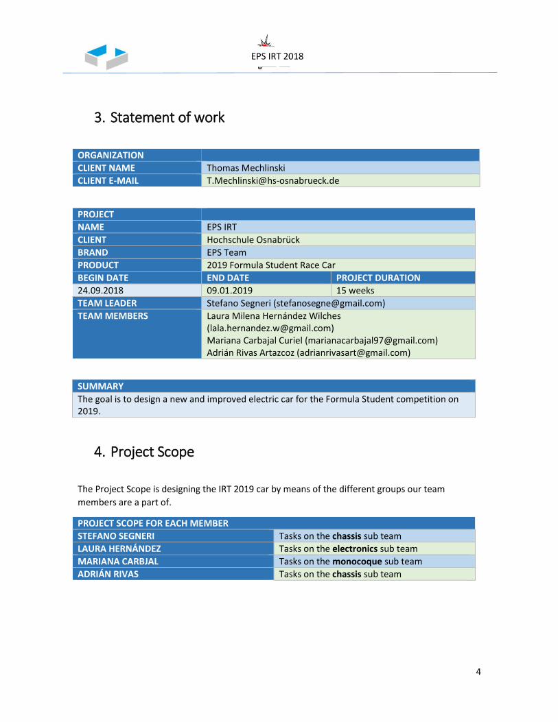
4
EPS IRT 2018
3. Statement of work
ORGANIZATION
CLIENT NAME Thomas Mechlinski
CLIENT E-MAIL [email protected]
PROJECT
NAME EPS IRT
CLIENT Hochschule Osnabrück
BRAND EPS Team
PRODUCT 2019 Formula Student Race Car
BEGIN DATE END DATE PROJECT DURATION
24.09.2018 09.01.2019 15 weeks
TEAM LEADER Stefano Segneri ([email protected])
TEAM MEMBERS Laura Milena Hernández Wilches ([email protected]) Mariana Carbajal Curiel ([email protected]) Adrián Rivas Artazcoz ([email protected])
SUMMARY
The goal is to design a new and improved electric car for the Formula Student competition on 2019.
4. Project Scope
The Project Scope is designing the IRT 2019 car by means of the different groups our team
members are a part of.
PROJECT SCOPE FOR EACH MEMBER
STEFANO SEGNERI Tasks on the chassis sub team
LAURA HERNÁNDEZ Tasks on the electronics sub team
MARIANA CARBJAL Tasks on the monocoque sub team
ADRIÁN RIVAS Tasks on the chassis sub team
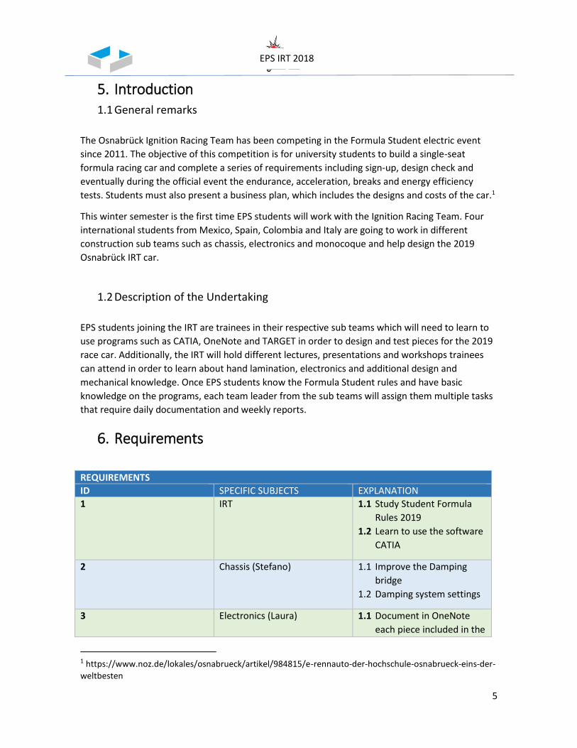
5
EPS IRT 2018
5. Introduction 1.1 General remarks
The Osnabrück Ignition Racing Team has been competing in the Formula Student electric event
since 2011. The objective of this competition is for university students to build a single-seat
formula racing car and complete a series of requirements including sign-up, design check and
eventually during the official event the endurance, acceleration, breaks and energy efficiency
tests. Students must also present a business plan, which includes the designs and costs of the car.1
This winter semester is the first time EPS students will work with the Ignition Racing Team. Four
international students from Mexico, Spain, Colombia and Italy are going to work in different
construction sub teams such as chassis, electronics and monocoque and help design the 2019
Osnabrück IRT car.
1.2 Description of the Undertaking
EPS students joining the IRT are trainees in their respective sub teams which will need to learn to
use programs such as CATIA, OneNote and TARGET in order to design and test pieces for the 2019
race car. Additionally, the IRT will hold different lectures, presentations and workshops trainees
can attend in order to learn about hand lamination, electronics and additional design and
mechanical knowledge. Once EPS students know the Formula Student rules and have basic
knowledge on the programs, each team leader from the sub teams will assign them multiple tasks
that require daily documentation and weekly reports.
6. Requirements
REQUIREMENTS
ID SPECIFIC SUBJECTS EXPLANATION
1 IRT 1.1 Study Student Formula
Rules 2019
1.2 Learn to use the software
CATIA
2 Chassis (Stefano) 1.1 Improve the Damping
bridge
1.2 Damping system settings
3 Electronics (Laura) 1.1 Document in OneNote
each piece included in the
1 https://www.noz.de/lokales/osnabrueck/artikel/984815/e-rennauto-der-hochschule-osnabrueck-eins-der-
weltbesten
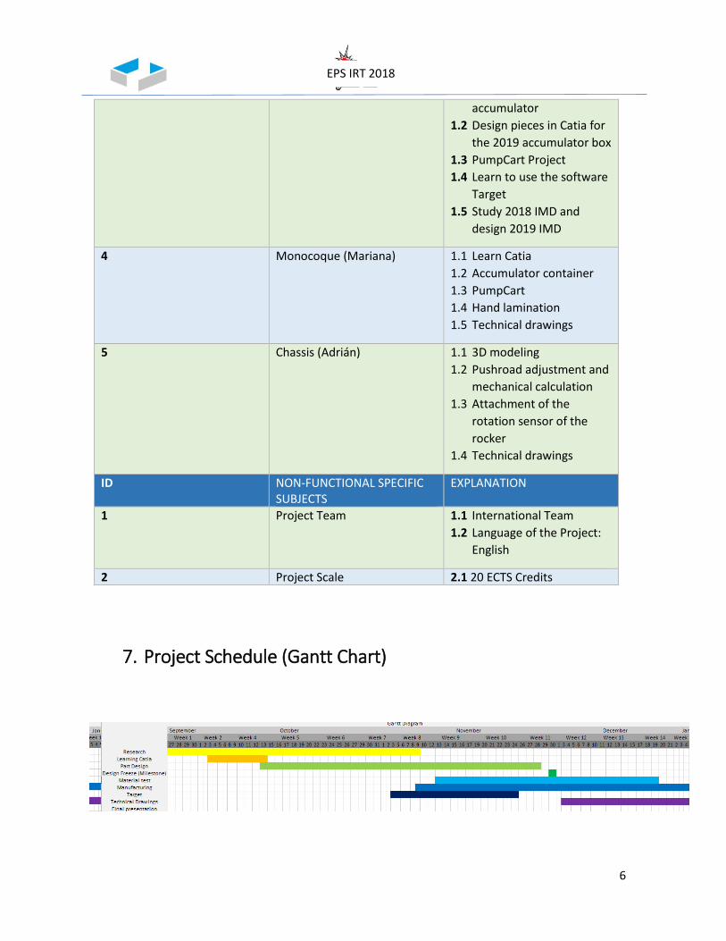
6
EPS IRT 2018
accumulator
1.2 Design pieces in Catia for
the 2019 accumulator box
1.3 PumpCart Project
1.4 Learn to use the software
Target
1.5 Study 2018 IMD and
design 2019 IMD
4 Monocoque (Mariana) 1.1 Learn Catia
1.2 Accumulator container
1.3 PumpCart
1.4 Hand lamination
1.5 Technical drawings
5 Chassis (Adrián) 1.1 3D modeling
1.2 Pushroad adjustment and
mechanical calculation
1.3 Attachment of the
rotation sensor of the
rocker
1.4 Technical drawings
ID NON-FUNCTIONAL SPECIFIC SUBJECTS
EXPLANATION
1 Project Team 1.1 International Team
1.2 Language of the Project:
English
2 Project Scale 2.1 20 ECTS Credits
7. Project Schedule (Gantt Chart)
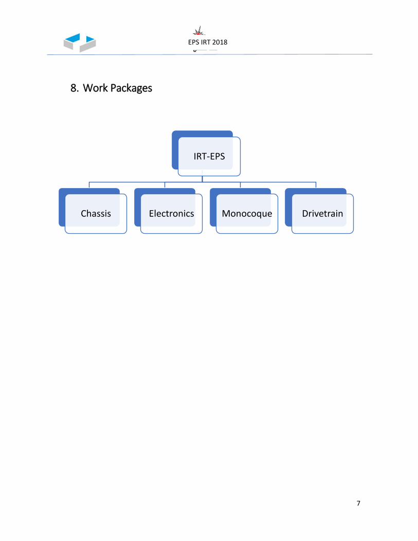
7
EPS IRT 2018
8. Work Packages
IRT-EPS
Chassis Electronics Monocoque Drivetrain

8
EPS IRT 2018
9. RISK ANALYSIS
Possible risks during the project.
Possible risks manufacturing
Risk Management
Risk assement Matrix
Risk Analysis manufacturing:
Risk What can happen Impact How to
prevent it Measures
Someone doesn´t know how to do a task
Task is not finished, poorly
done,
Waste time correcting or doing
it out of time Explain and ask
Ask the other IRT members
Team members don’t show up or late
Work won’t get done, people get
angry
Get behind on schedule
Set up rules Talk to a professor
Laptop doesn´t work Work won’t get done on time
Get behind on schedule
Be careful with it
Work in the library, borrow
one
Miss milestone Delay everything Bad reputation with
the IRT members Work hard and
on time Skip parties
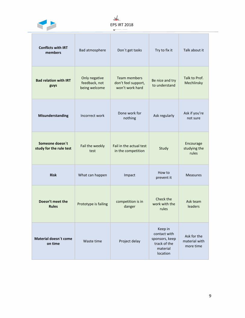
9
EPS IRT 2018
Conflicts with IRT members
Bad atmosphere Don´t get tasks Try to fix it Talk about it
Bad relation with IRT guys
Only negative feedback, not
being welcome
Team members don’t feel support, won’t work hard
Be nice and try to understand
Talk to Prof. Mechlinsky
Misunderstanding Incorrect work Done work for
nothing Ask regularly
Ask if you’re not sure
Someone doesn´t study for the rule test
Fail the weekly test
Fail in the actual test in the competition
Study Encourage
studying the rules
Risk What can happen Impact How to
prevent it Measures
Doesn’t meet the Rules
Prototype is failing competition is in
danger
Check the work with the
rules
Ask team leaders
Material doesn´t come on time
Waste time Project delay
Keep in contact with
sponsors, keep track of the
material location
Ask for the material with
more time

10
EPS IRT 2018
Not enough material We don´t have
enough materials to produce
Prototype delay Buy the
material with time
Have a timeplan
Product fails to accomplish the rules
of the formula student Project failed Project failed
Put it on a safe place and put contact nr. on
it
If there is time build that part again. Talk to
principal
Design failures Doesn´t resists or perform properly
Project is in danger Double check
everything Think of a solution
4.3 Risk Management
There are many risks in the project, part relates to project management and the other part relates
to building the prototype. The risks can be managed the according to the figure below.
Identification
Avoid
Stop
Outcours
Accept
Self insure
Reduce
Research development
Technology training
Transfer
Costumer
Company

11
EPS IRT 2018
Risk Assement Matrix
Likelihood
Rare (1) Unlikely (2) Possible (3) Likely (4) Almost Certain (5)
Catastrophic (5) Moderate Risk Moderate Risk High Risk Critical Risk Critical Risk
Major (4) Low Risk Moderate Risk High Risk High Risk Critical Risk
Impact Medium (3) Low Risk Moderate Risk Moderate Risk High Risk High Risk
Minor (2) Low Risk Low Risk Moderate Risk Moderate Risk Moderate Risk
Insignificant (1) Low Risk Low Risk Low Risk Low Risk Moderate Risk
Legend
Risk Score Level Description
1 to 4 Low Risk
Manage by routine procedures and operations; should not require
much attention but should be reviewed at least every 2 months.
5 to 10 Moderate Risk
Manage by specific monitoring or response procedures; should be
monitored and reviewed monthly.
11 to 18 High Risk
Requires escalation to project team; should be constantly
monitored and reviewed every 2 weeks.
19 to 25 Critical Risk
Requires escalation to project leader for risk management
overview; should be constantly monitored and reviewed weekly.
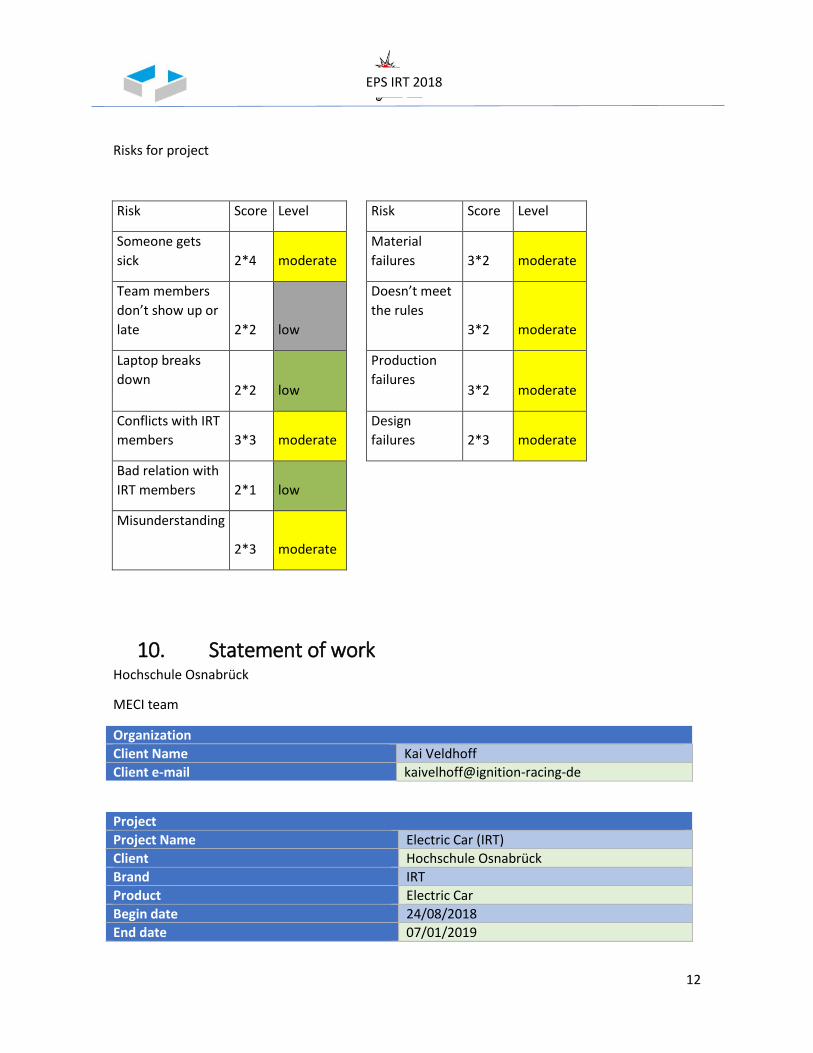
12
EPS IRT 2018
Risks for project
Risk Score Level Risk Score Level
Someone gets
sick 2*4 moderate
Material
failures 3*2 moderate
Team members
don’t show up or
late 2*2 low
Doesn’t meet
the rules
3*2 moderate
Laptop breaks
down 2*2 low
Production
failures 3*2 moderate
Conflicts with IRT
members 3*3 moderate
Design
failures 2*3 moderate
Bad relation with
IRT members 2*1 low
Misunderstanding
2*3 moderate
10. Statement of work Hochschule Osnabrück
MECI team
Organization
Client Name Kai Veldhoff
Client e-mail kaivelhoff@ignition-racing-de
Project
Project Name Electric Car (IRT)
Client Hochschule Osnabrück
Brand IRT
Product Electric Car
Begin date 24/08/2018
End date 07/01/2019

13
EPS IRT 2018
Project duration 15 weeks
Team leader Stefano Segneri
Team members Mariana Carbajal Curiel Adrian Rivas Artazcos Laura Milena Hernandez Wilches
11. Stakeholders & communication plan A stakeholder is the one who is impacted by the outcome of a project. They have an interest in the
success of the project, and can be within or outside.
In this case we have several stakeholders given the size of our project, the way of communication
and the way we works is very hierarchical, for us the EPS memebers is easier to communicate with
each other given we all speak English and we share the same goal, after that we have to
communicate with our sudteam leaders so we get feedback and new tasks. The communication
with other IRT members if for general information or help regarding our work.
After that is professor Mechlinsky because we don´t have contact daily, we do have every week
and he is the one that helps us with some problems with our project. Professor magwood helps us
with communication with our teams and give us tips for presentations.
At the end we have Sponsors and material suppliers, with them we don´t have direct contact but
their presence and how they work affects our times. And finally the University which is the one
that gave us the opportunity to join the EPS.
The way of communications we try to do it in person but we also use Whatsapp and the most
important one is OneNote.
EPS
members
Team leaders
Other IRT members
Prof. Mechlinsky
Prof. Magwood
Sponsors
Material Suppliers
University
14
EPS IRT 2018
12. Mariana Carbajal Curiel This is the report about the knowledge and the work done during the time of the European Project
Semester in the Ignition Raing Team; subteam Monocoque. During the first weeks the most
important task was learning how to use the CATIA program and also learning all of the rules or at
least understand them. The rules were about the car, the regulations, what is allowed, what is not
allowed, the parameters, etc.
My main goal at the beginning was to design and construct the accumulator container, these
pieces are located on the sides of the car and they are the boxes surrounding the accumulator
which is the battery of the car. I had to also reasearch about some possible materials for this
containers and a new way to access the accumulator, the final decisions were: Steel for the
material and access from the top of the container.
The tasks that I managed to finish for the container were the exploration of the form, and also to
construct the different pieces that go inside and over the container. I also gave some ideas about
how to access the accumulator in an easier way, because the entire car had to be lifted and the
access was from the bottom of the container. My suggesions were to access the accumulator from
the sides and secure it like a drawer.
In the block week I had to swap my work from the accumulator to a trainee Project which was a
pumpcart, this Project was planed to last just one week and I did it with my other teammate Laura.
We were asked to follow some requirements, to create a Gantt diagram, sketches, CATIA 3D
models, technical drawings and finally a presentation to show the monocoque members how we
did it.
When we had the monocoque weekly meetings we had to solve a rules test about the monocoque
rules, I did the test once. This meetings were usefull because we had feedback and got help from
the guys that had more experience with CATIA. Also in one of the meetings I had to give a
presentation about hand lamination because I already had experience with this technique.
Because during the block week the side pod and the container needed to be finished I wasn´t able
to continue with that, so my next task was to help with the SES test plates. This test plates are
some panels where we arranged in different ways the layers of carbon fibers, the point of this was
to find the most convenient arrangement, for this the team leader wanted to make 4 different
arrangements with 12 different plates. This process was really long because we had to cut the
material, prepare the glass table, prepare the resin, layer all of the layers, put in place and set
everything for the pum infusuion, wait for the resin to get hard let the plates for 24 hours over the
glass table which change temperatura every 3 hours, and finally cut the plates in small rectangles
so they could be tested. The way they knew which was the best was to weight them and put the
plate under 2 different tests: the 3- point bedind test and the hit test. At the end 2 different
arrangements were chosen for the different parts of the monocoque.
Other tasks regarding hand lamination were me starting to laminate the seat for the driver, and
also making test holders for the accumulator container with glass fibers, in this task I spent a lot of
time in the preparation rather tan in the actual process, working with both of the fibers was really
interesting because I saw the advantages and disadvantages of both.
15
EPS IRT 2018
After our main milestone that was the design freeze I was given some pieces to correct, the brake
light holder and the head restraint, the monocoque team was late 3 days for the design freeze but
at the end it was done wit no mistakes.
For the main work that was laminating the monocoque I helped cutting material, laminate the
middle part of the monocoque and when the first layers were finished we had to make some foam
shapes that fit perfectly over them.
During this experience my main knowledge was how to use a new software, I got new knowledge
in different techniques of laminating and the most important one was to work in a really big team
which is really similar to an actual job. Being in the IRT was a really interesting experience.
16
EPS IRT 2018
13. Laura Milena Hernández Wilches
This Winter semester at Osnabrück Hochschule I was a part of the European Project Semester
(EPS) and a trainee at the IRT, a student-led project whose goal is the design and construction of
an electric race car.
For us trainees to clearly understand the main goal of the Formula Student competition it was
essential to read carefully through the official 2019 rules. These rules include: Administrative
Regulations, General Technical Requirements and specific rules for Electric Vehicles as well as for
Technical Inspections, Static Events and Dynamic Events. To guarantee that we understood and
clearly know the rules, there were weekly quizzes about the Formula Student Rules and three
general quizzes to prepare for the official quiz held during the 2019 competition.
During the first phase of the project the main goal was learning to use CATIA, a software suite for
computer design, manufacturing, engineering and 3D models. After understanding and the basics
CATIA and being a trainee for the electronics group, I began to develop 3D models of components
for the race car´s accumulator (Energy storage device). These components were: Fuse, cable shoes
and the Inductive Voltage Transformer (IVT).
Once the 3D model for the accumulator was finished on the 30th of November (Design Freeze), I
moved onto my next task. During this next phase of the project, I worked on the actual circuits of
the Low Voltage (LV) Distribution System of the car. For this I had to learn to use TARGET 3001!,
which is a CAD computer program that supports the design of electronic schematics, Printed
Circuit Boards (PCBs) and device front panels. For this, I worked hand in hand with my electronics
team leader Konstantin Book on the LV, more specifically on the car´s connectors, fuses, sensors,
voltage regulator and controller. We had to correct last years circuits, by placing new resistors,
Schmitt triggers, changing the routes for multiple connections, improving the controller and by
grounding more circuits. Once the circuits were finished, we moved on to the LV schematic, which
is the 3D model of the PCB, were we must place the physical components in an ordered and logical
manner.
Finally, for the last phase of the project I had to practice welding PCBs, this in order to be able to
solder the official LV Distribution System PCB. I practiced welding millimetric LEDs onto a 4cmx4cm
PCB and later one Konstantin´s last years projects which involved multiple components such as
bigger LEDs, buttons, capacitors, resistors and other components. However, I was not able to
solder the actual LV PCB since the components will arrive once the EPS is over.
Additionally, me and my teammate Mariana Carbajal were in charge of a mini project called
PumpCart during the block week from the 26th to the 29th of November. For this project we had to
create a Gantt diagram, make sketches, CATIA 3D models, technical plans and a final presentation
of the Pumpcart needed to store the pumps that are used in the IRT lab.
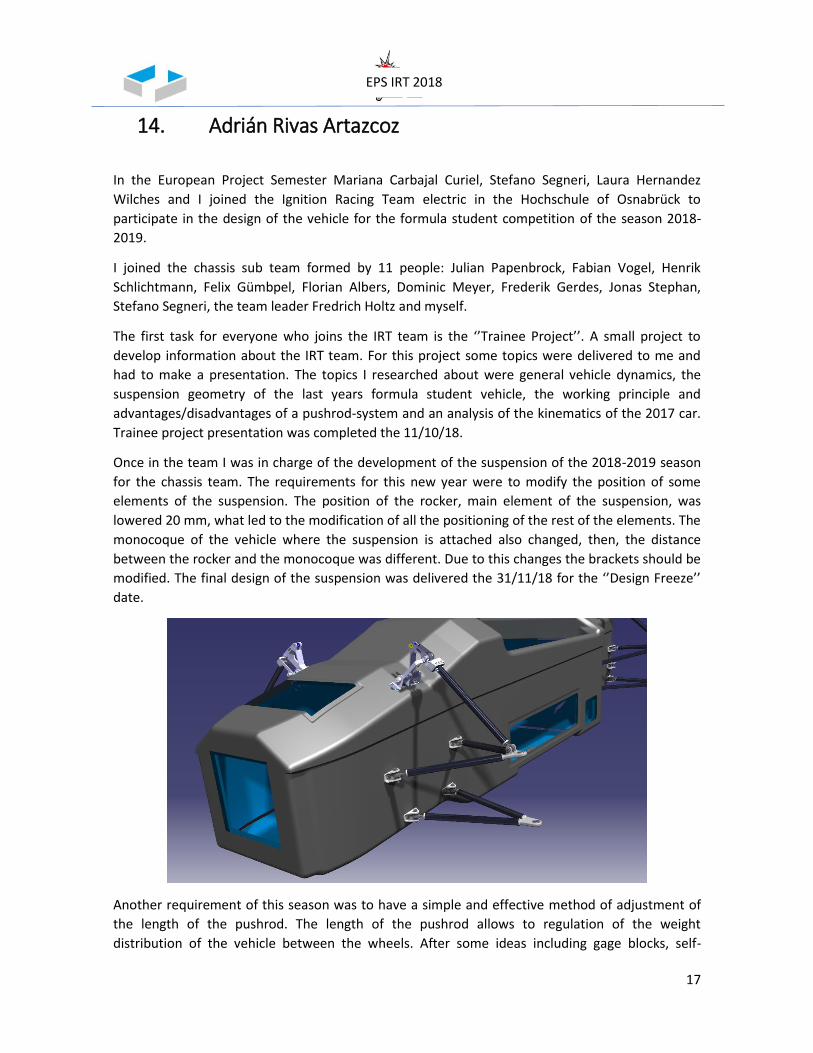
17
EPS IRT 2018
14. Adrián Rivas Artazcoz
In the European Project Semester Mariana Carbajal Curiel, Stefano Segneri, Laura Hernandez
Wilches and I joined the Ignition Racing Team electric in the Hochschule of Osnabrück to
participate in the design of the vehicle for the formula student competition of the season 2018-
2019.
I joined the chassis sub team formed by 11 people: Julian Papenbrock, Fabian Vogel, Henrik
Schlichtmann, Felix Gümbpel, Florian Albers, Dominic Meyer, Frederik Gerdes, Jonas Stephan,
Stefano Segneri, the team leader Fredrich Holtz and myself.
The first task for everyone who joins the IRT team is the ‘’Trainee Project’’. A small project to
develop information about the IRT team. For this project some topics were delivered to me and
had to make a presentation. The topics I researched about were general vehicle dynamics, the
suspension geometry of the last years formula student vehicle, the working principle and
advantages/disadvantages of a pushrod-system and an analysis of the kinematics of the 2017 car.
Trainee project presentation was completed the 11/10/18.
Once in the team I was in charge of the development of the suspension of the 2018-2019 season
for the chassis team. The requirements for this new year were to modify the position of some
elements of the suspension. The position of the rocker, main element of the suspension, was
lowered 20 mm, what led to the modification of all the positioning of the rest of the elements. The
monocoque of the vehicle where the suspension is attached also changed, then, the distance
between the rocker and the monocoque was different. Due to this changes the brackets should be
modified. The final design of the suspension was delivered the 31/11/18 for the ‘’Design Freeze’’
date.
Another requirement of this season was to have a simple and effective method of adjustment of
the length of the pushrod. The length of the pushrod allows to regulation of the weight
distribution of the vehicle between the wheels. After some ideas including gage blocks, self-
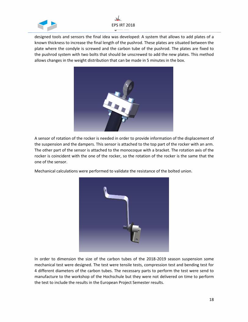
18
EPS IRT 2018
designed tools and sensors the final idea was developed: A system that allows to add plates of a
known thickness to increase the final length of the pushrod. These plates are situated between the
plate where the condyle is screwed and the carbon tube of the pushrod. The plates are fixed to
the pushrod system with two bolts that should be unscrewed to add the new plates. This method
allows changes in the weight distribution that can be made in 5 minutes in the box.
A sensor of rotation of the rocker is needed in order to provide information of the displacement of
the suspension and the dampers. This sensor is attached to the top part of the rocker with an arm.
The other part of the sensor is attached to the monocoque with a bracket. The rotation axis of the
rocker is coincident with the one of the rocker, so the rotation of the rocker is the same that the
one of the sensor.
Mechanical calculations were performed to validate the resistance of the bolted union.
In order to dimension the size of the carbon tubes of the 2018-2019 season suspension some
mechanical test were designed. The test were tensile tests, compression test and bending test for
4 different diameters of the carbon tubes. The necessary parts to perform the test were send to
manufacture to the workshop of the Hochschule but they were not delivered on time to perform
the test to include the results in the European Project Semester results.

19
EPS IRT 2018
Finally, the technical drawings of the self-designed parts were made to send to the manufacturers.
For the bought parts, all the providers must be found and the exact product that should be
ordered. The tracking of all the products and the technical drawings was completed for the
06/01/18.
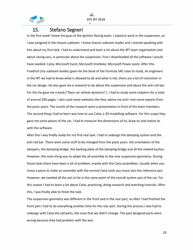
20
EPS IRT 2018
15. Stefano Segneri In the first week I knew the guys of the Ignition Racing team. I asked to work in the suspension, so
I was assigned in the chassis subteam. I knew chassis subteam leader and I started speaking with
him about my first task. I had to understand and learn a lot about the IRT team organization and
about racing cars, in particular about the suspension. First I downloaded all the software I would
have needed: Catia, Microsoft Excel, Microsoft OneNote, Microsoft Power point. After this
Friedrich (my subteam leader) gave me the book of the Formula SAE rules to study. As engineers
in the IRT we had to know what is allowed to do and what is not, there are a lot of restriction in
the car design. He also gave me a research to do about the suspension and about the anti-roll bar.
For this he gave me a book (“Race car vehicle dynamics”). I had to study some chapters for a total
of around 200 pages. I also used some websites the they advise me and I met some experts from
the pasts years. The results of the research were a presentation in front of the team members.
The second thing I had to learn was how to use Catia, a 3D modelling software. For this scope they
gave me some pieces of the car, I had to measure the dimensions of its, draw its and realize its
with the software.
After this I was finally ready for my first real task. I had to redesign the damping system and the
anti-roll bar. There were some stuff to be changed from the pasts years: the orientation of the
dampers, the damping bridge, the backing plate of the damping bridge and all the related bushes.
However, the main thing was to adapt the all assembly to the new suspension geometry. During
those tasks there have been a lot of problem, mainly with the Catia assemblies. Usually when you
move a piece to make an assembly with the normal Catia tools you move also the reference axis.
However, we needed all the axis to be in the same point of the overall system axis of the car. For
this reason I had to learn a lot about Catia, practicing, doing research and watching tutorials. After
this, I was finally able to finish the task.
The suspension geometry was different in the front and in the rear part, so after I had finished the
front part I had to do everything another time for the rear part. During the process I also had to
redesign with Catia the old parts, the ones that we didn’t change. The past designed parts were
wrong because they had problem with the axis.
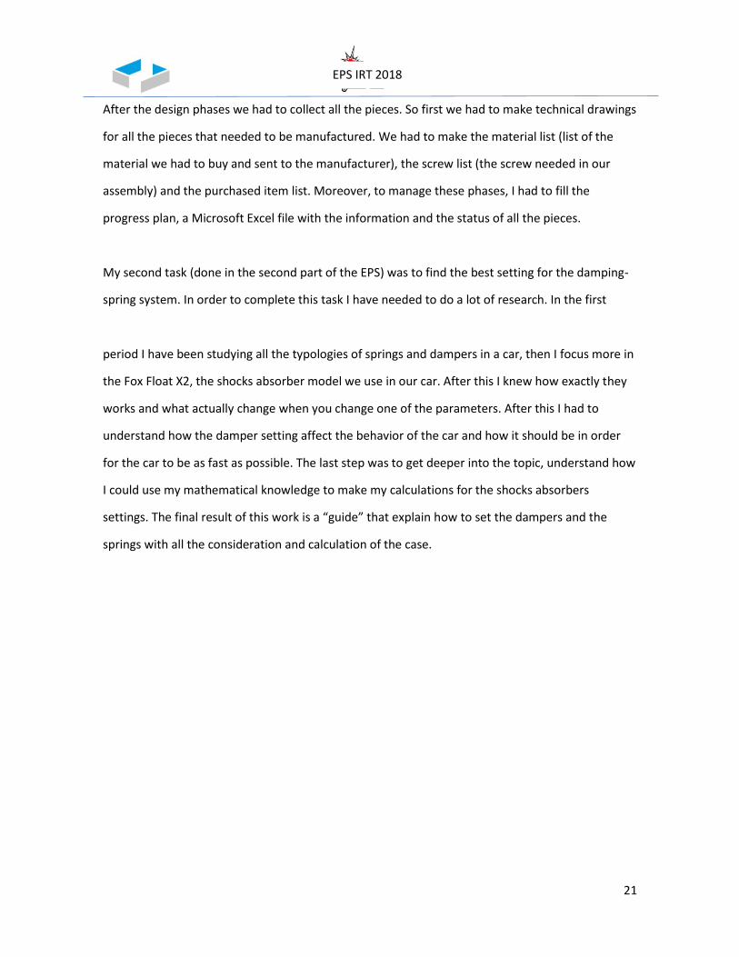
21
EPS IRT 2018
After the design phases we had to collect all the pieces. So first we had to make technical drawings
for all the pieces that needed to be manufactured. We had to make the material list (list of the
material we had to buy and sent to the manufacturer), the screw list (the screw needed in our
assembly) and the purchased item list. Moreover, to manage these phases, I had to fill the
progress plan, a Microsoft Excel file with the information and the status of all the pieces.
My second task (done in the second part of the EPS) was to find the best setting for the damping-
spring system. In order to complete this task I have needed to do a lot of research. In the first
period I have been studying all the typologies of springs and dampers in a car, then I focus more in
the Fox Float X2, the shocks absorber model we use in our car. After this I knew how exactly they
works and what actually change when you change one of the parameters. After this I had to
understand how the damper setting affect the behavior of the car and how it should be in order
for the car to be as fast as possible. The last step was to get deeper into the topic, understand how
I could use my mathematical knowledge to make my calculations for the shocks absorbers
settings. The final result of this work is a “guide” that explain how to set the dampers and the
springs with all the consideration and calculation of the case.
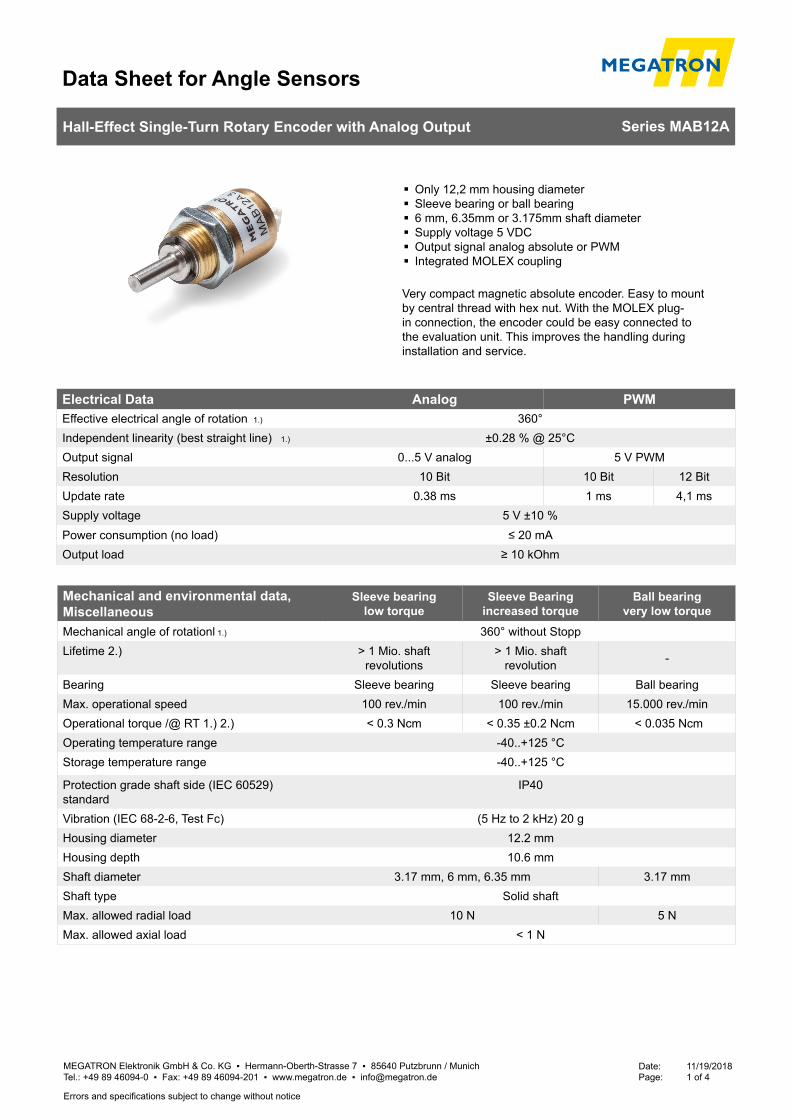
Data Sheet for Angle Sensors
MEGATRON Elektronik GmbH & Co. KG ▪ Hermann-Oberth-Strasse 7 ▪ 85640 Putzbrunn / Munich Tel.: +49 89 46094-0 ▪ Fax: +49 89 46094-201 ▪ www.megatron.de ▪ [email protected]
Date: 11/19/2018Page: 1 of 4
Hall-Effect Single-Turn Rotary Encoder with Analog Output Series MAB12A
Errors and specifications subject to change without notice
� Only 12,2 mm housing diameter � Sleeve bearing or ball bearing � 6 mm, 6.35mm or 3.175mm shaft diameter � Supply voltage 5 VDC � Output signal analog absolute or PWM � Integrated MOLEX coupling
Very compact magnetic absolute encoder. Easy to mount by central thread with hex nut. With the MOLEX plug-in connection, the encoder could be easy connected to the evaluation unit. This improves the handling during installation and service.
Electrical Data Analog PWMEffective electrical angle of rotation 1.) 360°Independent linearity (best straight line) 1.) ±0.28 % @ 25°COutput signal 0...5 V analog 5 V PWMResolution 10 Bit 10 Bit 12 BitUpdate rate 0.38 ms 1 ms 4,1 msSupply voltage 5 V ±10 %Power consumption (no load) ≤ 20 mA Output load ≥ 10 kOhm
Mechanical and environmental data, Miscellaneous
Sleeve bearinglow torque
Sleeve Bearing increased torque
Ball bearingvery low torque
Mechanical angle of rotationl 1.) 360° without StoppLifetime 2.) > 1 Mio. shaft
revolutions> 1 Mio. shaft
revolution -
Bearing Sleeve bearing Sleeve bearing Ball bearingMax. operational speed 100 rev./min 100 rev./min 15.000 rev./minOperational torque /@ RT 1.) 2.) < 0.3 Ncm < 0.35 ±0.2 Ncm < 0.035 NcmOperating temperature range -40..+125 °CStorage temperature range -40..+125 °C
Protection grade shaft side (IEC 60529) standard
IP40
Vibration (IEC 68-2-6, Test Fc) (5 Hz to 2 kHz) 20 gHousing diameter 12.2 mmHousing depth 10.6 mmShaft diameter 3.17 mm, 6 mm, 6.35 mm 3.17 mmShaft type Solid shaftMax. allowed radial load 10 N 5 NMax. allowed axial load < 1 N

Data Sheet for Angle Sensors
MEGATRON Elektronik GmbH & Co. KG ▪ Hermann-Oberth-Strasse 7 ▪ 85640 Putzbrunn / Munich Tel.: +49 89 46094-0 ▪ Fax: +49 89 46094-201 ▪ www.megatron.de ▪ [email protected]
Date: 11/19/2018Page: 2 of 4
Hall-Effect Single-Turn Rotary Encoder with Analog Output Series MAB12A
Errors and specifications subject to change without notice
1.) According IEC 603932.) Determined by climatic conditions according to IEC 68-1, para. 5.3.1 without load collectives
ImmunityESD Human Body Model
MIL-STD-883E, Method 3015.7 ± 2 kV
Mechanical and Environmental Data, Miscellaneous
Sleeve bearinglow torque
Sleeve Bearing increased torque
Ball bearingvery low torque
Connection type Molex connector: 53398-0371Connection position AxialSensor mounting BushingMass app. 14 g app. 11 gFastening parts included in delivery Hex nut and tooth washerFastening torque mounting nut < 2.25 NmMaterial shaft Stainless steel Brass
Material housing Brass
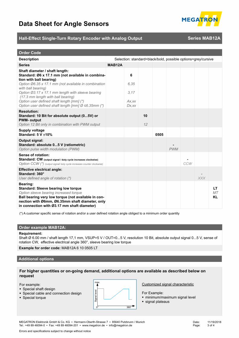
Data Sheet for Angle Sensors
MEGATRON Elektronik GmbH & Co. KG ▪ Hermann-Oberth-Strasse 7 ▪ 85640 Putzbrunn / Munich Tel.: +49 89 46094-0 ▪ Fax: +49 89 46094-201 ▪ www.megatron.de ▪ [email protected]
Date: 11/19/2018Page: 3 of 4
Hall-Effect Single-Turn Rotary Encoder with Analog Output Series MAB12A
Errors and specifications subject to change without notice
Order example MAB12A:Requirement: Shaft Ø 6.00 mm / shaft length 17,1 mm, VSUP=5 V / OUT=0...5 V, resolution 10 Bit, absolute output signal 0...5 V, sense of rotation CW, effective electrical angle 360°, sleeve bearing low torque Example for order code: MAB12A 6 10 0505 LT
Order CodeDescription Selection: standard=black/bold, possible options=grey/cursiveSeries MAB12AShaft diameter / shaft length:Standard: Ø6 x 17.1 mm (not available in combina-tion with ball bearing)Option Ø6.35 x 17.1 mm (not available in combination with ball bearing)Option Ø3.17 x 17.1 mm length with sleeve bearing (17.3 mm length with ball bearing)Option user defined shaft length [mm] (*)Option user defined shaft length [mm] Ø ≤6.35mm (*)
6
6,35
3,17
Ax,xxDx,xx
Resolution:Standard: 10 Bit for absolute output (0...5V) or PWM- outputOption 12 Bit only in combination with PWM output
10
12Supply voltage Standard: 5 V ±10% 0505Output signal:Standard: absolute 0...5 V (ratiometric)Option pulse width modulation (PWM)
-PWM
Sense of rotation: Standard: CW (output signal / duty cycle increases clockwise)
Option CCW (*) (output signal/ duty cycle increases counter clockwise)
-CCW
Effective electrical angle: Standard: 360°User defined angle of rotation (*)
-XXX
Bearing:Standard: Sleeve bearing low torqueOption sleeve bearing increased torqueBall bearing very low torque (not available in con-nection with Ø6mm, Ø6.35mm shaft diameter, only in connection with Ø3.17 mm shaft diameter)
LTMTKL
(*) A customer specific sense of rotation and/or a user defined rotation angle obliged to a minimum order quantity
For higher quantities or on-going demand, additional options are available as described below on request
For example: � Special shaft design � Special cable and connection design � Special torque
0° 360°
Sig
nal l
evel
max. Customized signal characteristic
For Example: � minimum/maximum signal level � signal plateaus
Additional options
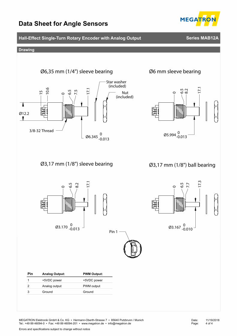
Data Sheet for Angle Sensors
MEGATRON Elektronik GmbH & Co. KG ▪ Hermann-Oberth-Strasse 7 ▪ 85640 Putzbrunn / Munich Tel.: +49 89 46094-0 ▪ Fax: +49 89 46094-201 ▪ www.megatron.de ▪ [email protected]
Date: 11/19/2018Page: 4 of 4
Hall-Effect Single-Turn Rotary Encoder with Analog Output Series MAB12A
Errors and specifications subject to change without notice
Drawing
Pin 1
Ø12.2
Ø6.345 -00.013
0
10.
6
15
6.5
7
.5
17.
1Nut
(included)
Star washer(included)
3/8-32 Thread
Ø6,35 mm (1/4") sleeve bearing
Ø5.994 -00.013
0
6.5
8
.2
17.
1
Ø6 mm sleeve bearing
Ø3.170 -00.013
0
6.5
8.2
17.
1
Ø3,17 mm (1/8") sleeve bearing
Ø3.167 -00.010
0
6.5
7
.7
17.
3
Ø3,17 mm (1/8") ball bearing
Analog Output:Pin
1 +5VDC power
2 Analog output
3 Ground
PWM Output:
+5VDC power
PWM output
Ground
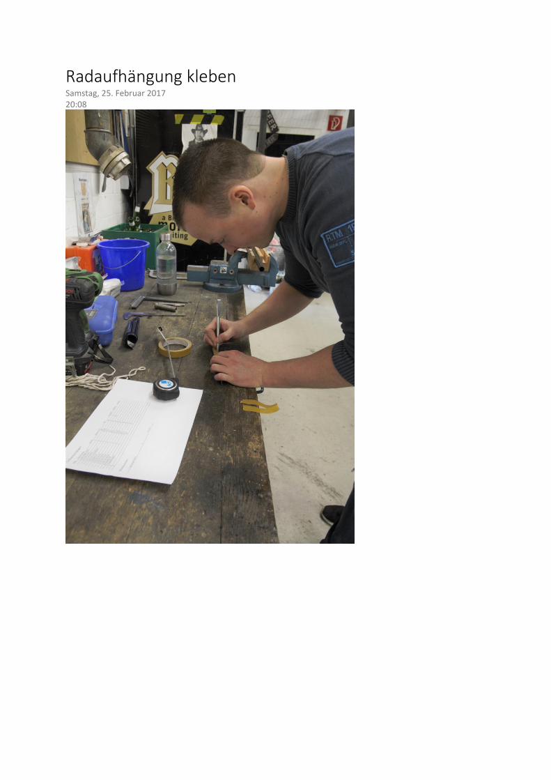
Radaufhängung kleben Samstag, 25. Februar 2017 20:08
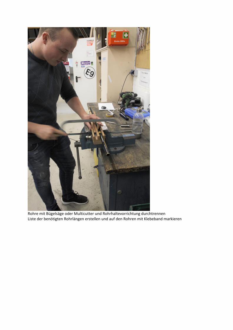
Rohre mit Bügelsäge oder Multicutter und Rohrhaltevorrichtung durchtrennen Liste der benötigten Rohrlängen erstellen und auf den Rohren mit Klebeband markieren
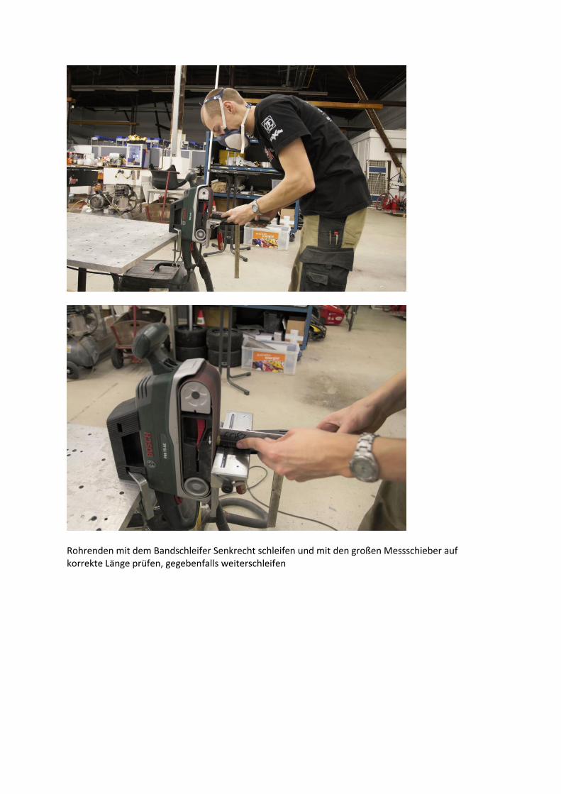
Rohrenden mit dem Bandschleifer Senkrecht schleifen und mit den großen Messschieber auf korrekte Länge prüfen, gegebenfalls weiterschleifen
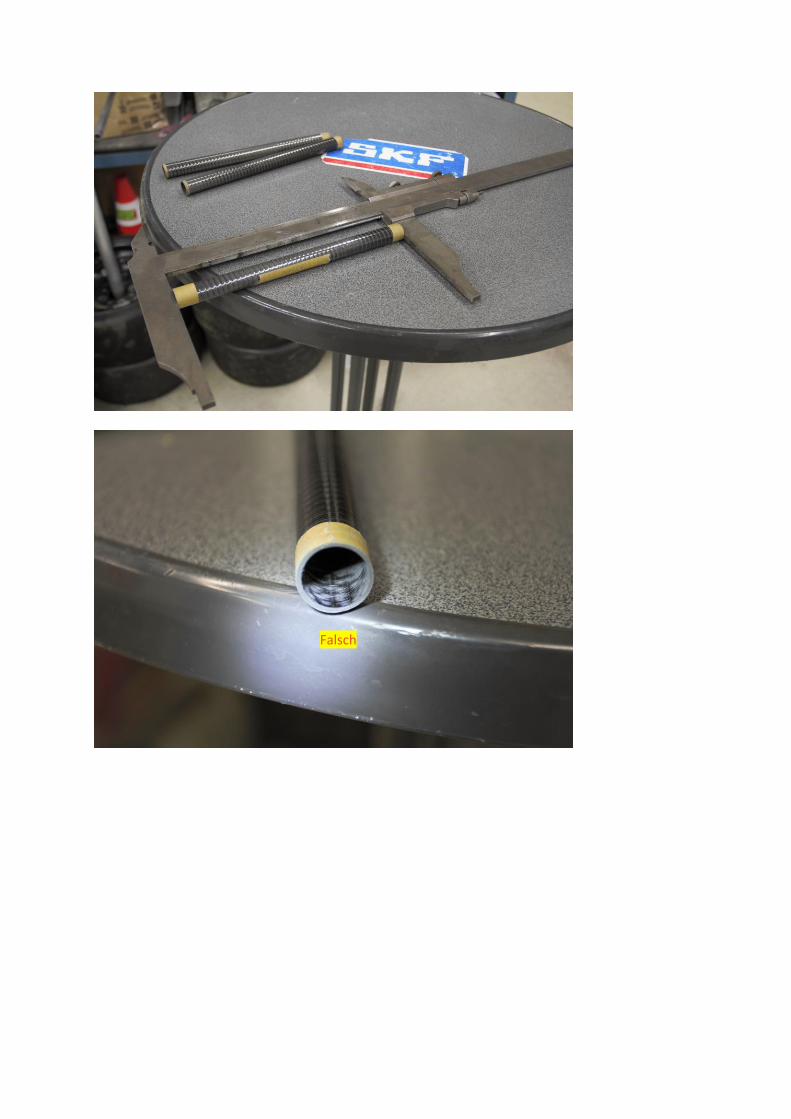
Falsch
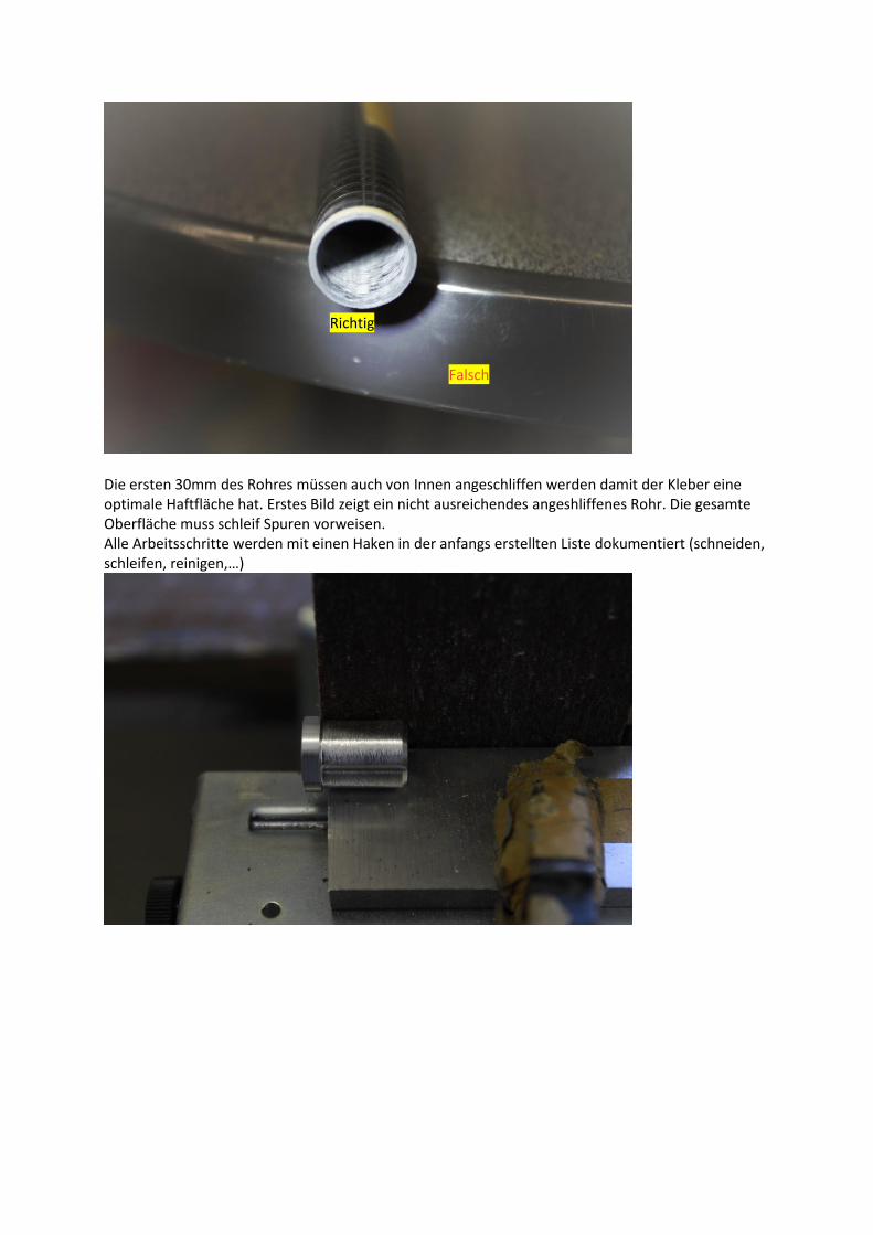
Die ersten 30mm des Rohres müssen auch von Innen angeschliffen werden damit der Kleber eine optimale Haftfläche hat. Erstes Bild zeigt ein nicht ausreichendes angeshliffenes Rohr. Die gesamte Oberfläche muss schleif Spuren vorweisen. Alle Arbeitsschritte werden mit einen Haken in der anfangs erstellten Liste dokumentiert (schneiden, schleifen, reinigen,…)
Richtig
Falsch
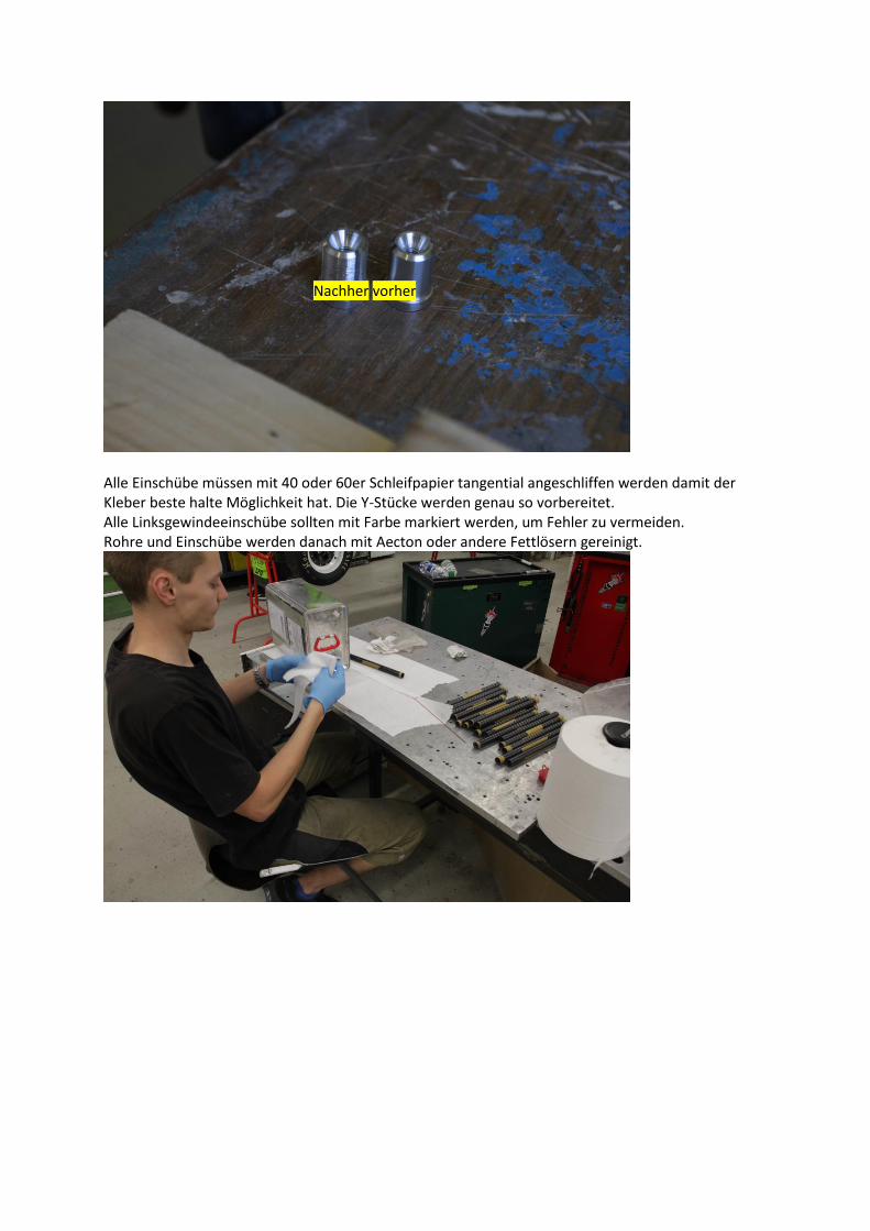
Alle Einschübe müssen mit 40 oder 60er Schleifpapier tangential angeschliffen werden damit der Kleber beste halte Möglichkeit hat. Die Y-Stücke werden genau so vorbereitet. Alle Linksgewindeeinschübe sollten mit Farbe markiert werden, um Fehler zu vermeiden. Rohre und Einschübe werden danach mit Aecton oder andere Fettlösern gereinigt.
Nachher vorher
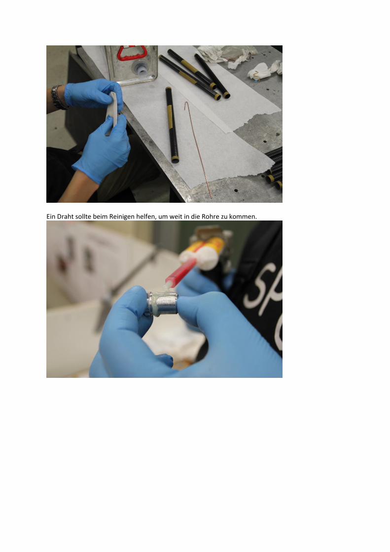
Ein Draht sollte beim Reinigen helfen, um weit in die Rohre zu kommen.
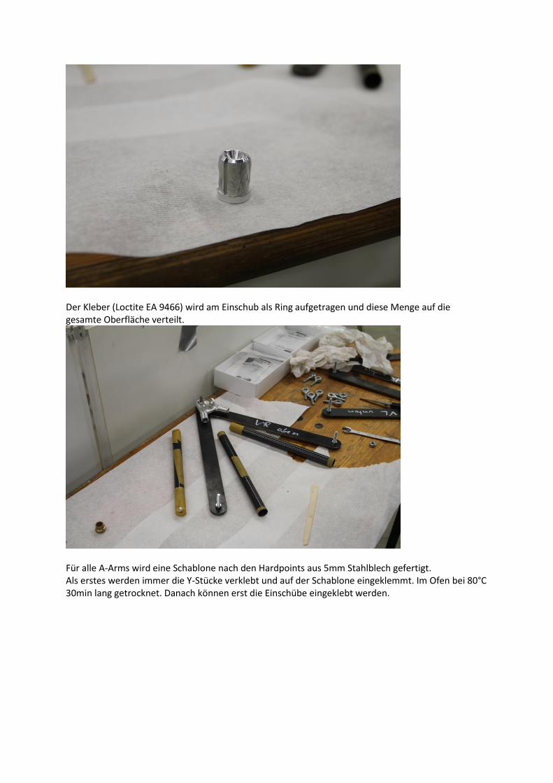
Der Kleber (Loctite EA 9466) wird am Einschub als Ring aufgetragen und diese Menge auf die gesamte Oberfläche verteilt.
Für alle A-Arms wird eine Schablone nach den Hardpoints aus 5mm Stahlblech gefertigt. Als erstes werden immer die Y-Stücke verklebt und auf der Schablone eingeklemmt. Im Ofen bei 80°C 30min lang getrocknet. Danach können erst die Einschübe eingeklebt werden.
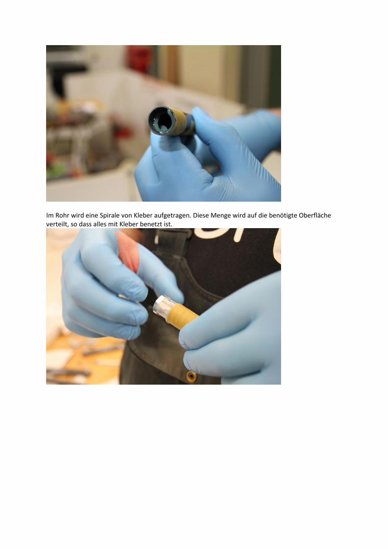
Im Rohr wird eine Spirale von Kleber aufgetragen. Diese Menge wird auf die benötigte Oberfläche verteilt, so dass alles mit Kleber benetzt ist.
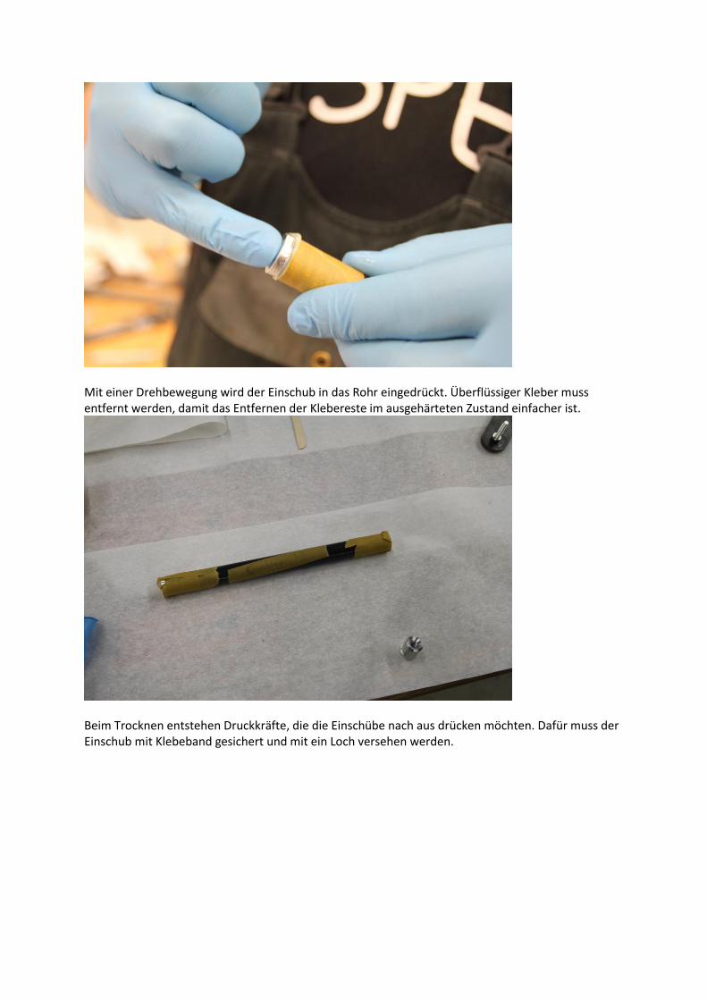
Mit einer Drehbewegung wird der Einschub in das Rohr eingedrückt. Überflüssiger Kleber muss entfernt werden, damit das Entfernen der Klebereste im ausgehärteten Zustand einfacher ist.
Beim Trocknen entstehen Druckkräfte, die die Einschübe nach aus drücken möchten. Dafür muss der Einschub mit Klebeband gesichert und mit ein Loch versehen werden.