MGB SUSPENSION DISCUSSION - Sprite Car Club ...
31
1 MGB SUSPENSION DISCUSSION An Australian Owner’s perspective with particular emphasis on dampers. Prepared by Rick Foster RPEQ This paper has been developed as a guide to MGB owners on how the suspension system functions and provides advice as to the suitability of “after market” suspension modifications that are commonly seen on road registered cars. The paper purposely ignores the many suspension systems found on MGBs that are prepared for racing; however it does reference the Confederation of Australian Motorsport (CAMS) regulations for “Historic events”. With reference to road registered cars, it should be noted that most countries and indeed many States within those countries have restrictions regarding modifications – mainly safety related – to body corrosion, lights, brakes, steering and suspension components. Within Queensland, Australia; there are limitations on altering road registered vehicles from the relevant Australian Design Rules in force at the time of import, local manufacture, “type” importation or importation by an individual as appropriate. In preparing this guide I have made reference to the Official (Bentley) MG Workshop Manual for the years 1962 – 1974, hereinafter referred to as the Bentley manual The Bentley manual contains all the official specifications and should you be using it, it would be wise to know your car and engine number prefixes in order to identify the precise specifications. Many people like the “Haynes” manuals but they are targeted towards home mechanics showing illustrations of how to carry out most repair or replacement functions and are a bit short on detailed specifications which you may need for purchasing parts. Note that this paper addresses the Chrome Bumper model. It is known that Rubber Bumper models in the USA have a raised suspension and that some after market” cars’ suspensions are up to 50mm higher. This will influence the choice of rear suspension modifications. Note that anecdotal evidence suggests that a large number of American rubber bumper models were imported into Australia, converted to RHD and the grille changed to the more popular vertical element grille. Accordingly it is important to be wary of differences found in respect to suspension types and dimensions. In order to properly address the suspension functions, I include in this paper details of how each component works together with diagrams photographs and, at the end of the paper, I address handling characteristics which are influenced by the design of the suspension and how modifications will affect it. This paper is divided into the following sections:- 1. Background – including Australian production 2. Typical MGB Suspension setup • Front Suspension • Rear Suspension 3. Dampers • Description • How they work • Regulating valve • Fluid for Armstrong dampers • Fluid leaks • Repair 4. Replacement or Reconditioning
-
Upload
khangminh22 -
Category
Documents
-
view
3 -
download
0
Transcript of MGB SUSPENSION DISCUSSION - Sprite Car Club ...

1
MGB SUSPENSION DISCUSSION An Australian Owner’s perspective with particular emphasis on dampers.
Prepared by Rick Foster RPEQ This paper has been developed as a guide to MGB owners on how the suspension system functions and provides advice as to the suitability of “after market” suspension modifications that are commonly seen on road registered cars.
The paper purposely ignores the many suspension systems found on MGBs that are prepared for racing; however it does reference the Confederation of Australian Motorsport (CAMS) regulations for “Historic events”.
With reference to road registered cars, it should be noted that most countries and indeed many States within those countries have restrictions regarding modifications – mainly safety related – to body corrosion, lights, brakes, steering and suspension components.
Within Queensland, Australia; there are limitations on altering road registered vehicles from the relevant Australian Design Rules in force at the time of import, local manufacture, “type” importation or importation by an individual as appropriate.
In preparing this guide I have made reference to the Official (Bentley) MG Workshop Manual for the years 1962 – 1974, hereinafter referred to as the Bentley manual
The Bentley manual contains all the official specifications and should you be using it, it would be wise to know your car and engine number prefixes in order to identify the precise specifications.
Many people like the “Haynes” manuals but they are targeted towards home mechanics showing illustrations of how to carry out most repair or replacement functions and are a bit short on detailed specifications which you may need for purchasing parts.
Note that this paper addresses the Chrome Bumper model. It is known that Rubber Bumper models in the USA have a raised suspension and that some after market” cars’ suspensions are up to 50mm higher. This will influence the choice of rear suspension modifications. Note that anecdotal evidence suggests that a large number of American rubber bumper models were imported into Australia, converted to RHD and the grille changed to the more popular vertical element grille. Accordingly it is important to be wary of differences found in respect to suspension types and dimensions.
In order to properly address the suspension functions, I include in this paper details of how each component works together with diagrams photographs and, at the end of the paper, I address handling characteristics which are influenced by the design of the suspension and how modifications will affect it.
This paper is divided into the following sections:-
1. Background – including Australian production
2. Typical MGB Suspension setup
• Front Suspension
• Rear Suspension
3. Dampers
• Description
• How they work
• Regulating valve
• Fluid for Armstrong dampers
• Fluid leaks
• Repair
4. Replacement or Reconditioning

2
5. Telescopic Damper Conversions
• General
• Front Suspension
• Rear Suspension
6. Mechanical Fixing Data
7. Handling Characteristics
8. Safety
9. Lawful Alterations
10. Summary
1 BACKGROUND For some time now I have been contemplating addressing some of the last things on my 1973 MGB restoration list. The car is a UK build Mk II with conversion to chrome grille and chrome bumper. The body number is “GHN-5……..” and engine number “”18V 582 F……..”. The illustrations and technical data in this paper are based on that model. From available records my MGB was built in late 1971 but first registered in Australia in 1973. Originally in red, it was repainted with a Toyota “Pearl Racing Green” sometime in 2008.
.
Figure 1 - My MGB Although I am relatively pleased with the ride, the damping seems to be a bit harsh compared with others that I have been in. Consequently, as an engineer, I researched the subject of the installed Armstrong dampers and found many and varied opinions on not only how they (are supposed to) work and required maintenance. Likewise I identified a number of telescopic damper modifications. During my investigations I found an anomaly in that the rear dampers had the term “made in Australia” on the casting. While it is known that a large percentage of the 500,000 built were exported to the USA, some 9,000 were assembled in Australia or built from local components. The US models were generally used in the west coast States and accordingly were relatively free from rust. The MG Car Club in the UK, in their magazine “Safety Fast” published in 2012 featured an article titled “History of the Australian Assembled MGB”, an extract of which appears below in Figure 2. The article went on to advise that some British suppliers set up manufacturing in Australia to support this production. I have independently established that Armstrong also set up an Australian manufacturing facility in Victoria – see extract from a Melbourne paper below – to supply the MGB and other British cars being manufactured by British Leyland in Australia. Consequently this information suggests that as time progressed spare parts in the form of complete damper assemblies would have been available. That scenario is what I believe has occurred with my MGB.
3
Figure 2 – MG “Safety Fast” Magazine Article
2 SUSPENSION The design of the MGB suspension using rear leaf springs and front “wishbone’ type suspension, both using lever arm dampers. These dampers can be found in many British cars from the late 1950s through to the mid 1970s including premium makes like Jaguar and Aston Martin. Generally the arrangement was the two lever unit at the front – Figure 3, and the single lever unit installed at the rear – Figure 4 – photos courtesy of Apple Hydraulics USA. First of all it should be remembered that the “shock absorber” on a vehicle is the spring, whether it be leaf, coil or torsion bar. In fact a torsion bar act exactly the same as a coil except that it is straight, the same twist occurs to resist movement. Note also as discussed later, the anti-roll bar or “sway” bar includes the characteristic of a torsion bar. Note that in discussing the suspension hereafter, the words “bump” and “rebound” are used. Bump relates to the action of the road surface irregularities forcing the wheel(s) up into the guard (fender) whilst rebound (often called “droop” in America) is the opposite where wheel(s) drop into a depression in the road. The bump action is exactly the same as the “nose dip” attitude under braking and subsequently the “nose up” under acceleration. Note that because of the combined roll centres between the front and rear suspension, the nose dip is accompanied by the rear rising. The hydraulic device connecting the sprung portion to the chassis or monocoque is called a “damper” and I shall use that term onwards from here. Note also that the stiffness of the suspension has no relationship with the type of damper; this is entirely the property of the spring. Note that the front damper shown in Figure 3 is the same for both sides and the single lever shown in Figure 4 is different for each side. Note also that the dampers are shown generally in the correct orientation, with the front dampers having the removable cover up against the inner guard and the rear dampers with the removable cover at the top. Photos and illustrations later in this paper provide greater clarity. The twin arm damper is a very clever design which acts as the upper part of a twin wishbone suspension unit. The design allows the lowest possible vehicle height with the uppermost portion of the assembly being lower than the top of the wheel. Compared with the modern McPherson Strut unit where the upper strut mounting is considerably above the top of the wheel; by comparison, the MGB suspension gives the vehicle a correspondingly low centre of gravity.
TWO LEVER UNIT FOUND AT FRONT
Figure 3 - Two Lever – Front
SINGLE LEVER UNIT FOUND AT REAR
Figure 4 – Figure 4 – Single Lever Rear

4
Front Suspension Figure 5 below shows the general arrangement of the front suspension with the cross member supporting the engine and, on either side, supporting the suspension components being as follows:-
• Two lower (one at front and one at rear) A arm members “2” shown as A to B, each fixed to the cross member “1” at “A” and the lower end of the trunion (stub axle) “3’ at “B”. Note that each end is freely rotating, “A” at the fixed point on the cross member and “B” at the trunion (stub axle) connection. Figure 8 shows the trunion clearer.
• One twin arm damper “4” with each of the twin arms “5” connected to the damper at point “C” and to the upper end of the trunion (stub axle) at point “D”. Note that at point “C” the damper provides the resistance to rotation and that point “D” is freely rotating on the trunion (stub axle).
• The spring “6” connecting the lower “A” arm assembly via the spring pan between the two lower “A” arms and a similar connection below the damper at the underside of the cross member.
• A “sway” or anti-roll bar was fitted to most cars, excluding early cars in the UK and the USA as shown in Figure 7.
SPRING PAN FIXED POINT ROTATING POINT
CROSSMEMBER
B
C
A
FRONT SUSPENSION - LHS FROM FRONT
A
A
D
6
2
15
4
5
1
2
4
5
6 3
2
BUMP STOPS
Figure 5 – Front Suspension Details
Note in Figure 4 how the lower “A” arm is pointed downwards, this is because in the base sketch from the Official (Bentley) MG Workshop Manual, the cross member and suspension components are free floating, i.e. with no load taken by the wheel.
The primary suspension element is the coil spring fitted between the cross member at it upper part and the spring pan between the two lower “A” arms shown as Item “6” in Figure 5 above.
Spring specifications are as shown in Figure 6 below.
Figure 6 – Spring Specifications

5
Sway Bar The sway bar is fixed to the cross member in two places and to each of the lower “A” brackets. Each end of the bar is connected to an end link connected in turn to the outer end of the “A” arm, transferring forces from a heavily-loaded axle to the opposite side. Figure 7 below shows the sway bar link and the end part of the bar.
Note that sway bars were not fitted to early British or American export models. The purpose of the sway bar or “anti roll bar” is to provide additional front end stiffness when cornering. It is fixed to the cross member in two places and to each of the lower “A” brackets. If during suspension travel, the wheels move up or down relative to each other, the bar is subjected to torsion and forced to twist thus tending to force the suspension into a more even attitude. However if the vertical movement of the wheels is different, e.g. one up and one down, the sway bar imparts no forces on the suspension. Figure 7 below shows the sway bar connected to the lower ”A” arm and to the cross member and Figure 8 a diagrammatic of the system where the “twist” imparted on one end of the sway bar results in a corresponding force downwards on the other side.
SWAY BAR & DROP LINK
TRUNION
Figure 7 – Sway Bar Visual
Figure 8 – Sway Bar Principle Figure 9 below shows the sway bar sizes fitted to various “generations” of MGBs.
A rear bar was fitted to both roadster and the GT for the 1977 model onwards. Note also that a ¾” bar is now also available as a standard accessory.
LHSRHS LHS
LHSRHS

6
Figure 9 – Sway Bar Specification
Bump Stops Figure 10 below (with the coil spring removed) shows how the suspension travel is limited by having “stops” fixed to the cross member. The rebound stops act on the damper arms thus preventing the suspension from dropping and the bump stops acting on the spring pan preventing the suspension from rising beyond the design limits..
REBOUND STOP
BUMP STOP
Figure 10 – Bump & Rebound Stops The rear view in Figure 11 shows the damper lever “pad” hard up against the cross member “stop” circled in red, showing that the suspension is in full rebound.
Figure 11 - LHS Rear View
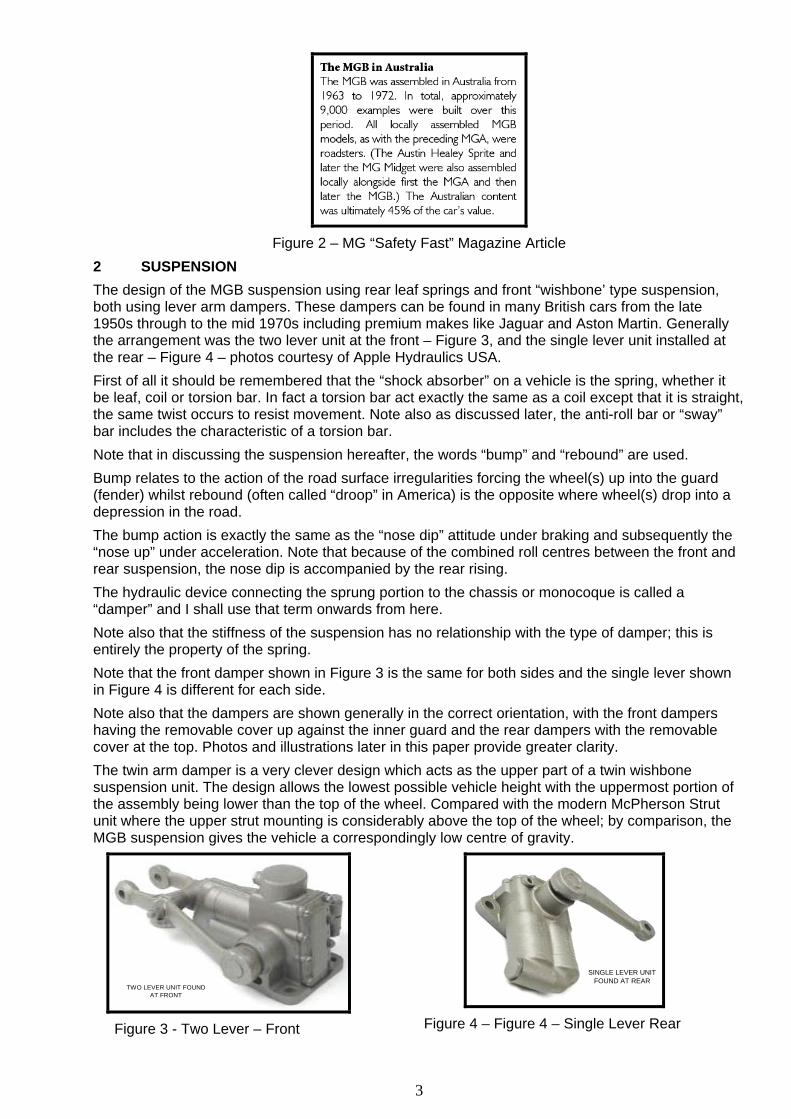
Figure 12 below shows the front suspension diagrammatically from top and side; refer to Figure 5 for the view orientation A - A. This then shows how:-
• Point “A”, being the front and rear pivot points for the lower “A” arm;
• Point “B” being the fulcrum pin for the front and rear pivot points for the trunion;
• Point “D” being the front and rear pivot points for trunion distance piece connected to the damper arms;
7
• Point “C” and are the ends of the damper shaft, and
• The lower and upper ends of the spring “S” rest in the spring pan and under the cross member respectively.
KING PIN
A
D
AA
B
CC
D
S
DETAIL B - VIEW A - ADETAIL A - VIEW FROM TOP
SPRING PAN
STUB AXLE 6
5
3
6
54
4
2
2
2 2
3
5C
A
D
C
B
D
Figure 12 – Front Suspension Details
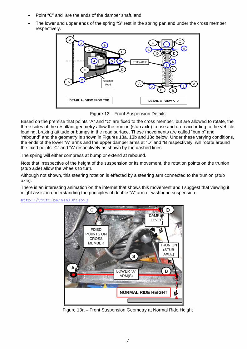
Based on the premise that points “A” and “C” are fixed to the cross member, but are allowed to rotate, the three sides of the resultant geometry allow the trunion (stub axle) to rise and drop according to the vehicle loading, braking attitude or bumps in the road surface. These movements are called “bump” and “rebound” and the geometry is shown in Figures 13a, 13b and 13c below. Under these varying conditions, the ends of the lower “A” arms and the upper damper arms at “D” and “B respectively, will rotate around the fixed points “C” and “A’ respectively as shown by the dashed lines.
The spring will either compress at bump or extend at rebound.
Note that irrespective of the height of the suspension or its movement, the rotation points on the trunion (stub axle) allow the wheels to turn. Although not shown, this steering rotation is effected by a steering arm connected to the trunion (stub axle). There is an interesting animation on the internet that shows this movement and I suggest that viewing it might assist in understanding the principles of double “A” arm or wishbone suspension. http://youtu.be/hshkDnis5yE
NORMAL RIDE HEIGHT
C
BA
D
LOWER "A" ARM(S)
TRUNION (STUB AXLE)S
DAMPER LEVER
FIXED POIINTS ON
CROSS MEMBER
Figure 13a – Front Suspension Geometry at Normal Ride Height

8
FULL BUMP
C
A
D
S B
Figure 13b Geometry at Bump
REBOUND
C
B
A
D
S
Figure 13c Geometry at Rebound
Note that Figure 13a is at normal ride height, 13b at full bump and 13c at full rebound. Note that the measured dimensions from the road surface to the underneath of the lower “A” arm next to the wheel are as follows:-
• Normal ride height 193mm • Full bump height 315mm • Rebound height 90mm
Rear Suspension The MGB rear suspension is achieved by semi-elliptic leaf springs positioned under the Salisbury (tube) axle – see Figure 14. The springs at located at the front with a fixed connection and at the rear by a swivel shackle. Note the “centre bolt” which locates the spring assembly to the correct position in the spring mounting plate under the axle. If this is not centred properly, the axle and subsequently the wheel(s) will not be centred within the wheel arch. This misalignment will also affect the differential operation. The spring is attached to the axle by means of a bracket welded to the axle and two “U” bolts with locating brackets. Damping is effected by an Armstrong lever arm hydraulic unit with the drop link attached to this bracket – see Figure 15.
REAR EYEFRONT EYECENTRE BOLT
Figure 14 – Leaf Spring
Figure 15 below shows the left hand side view and a partial rear view of the leaf spring and Armstrong damper setup. The lower part of the illustration shows the suspension geometry.
Figure 15 – Damper – left hand side shown

9
Figure 16 below shows the range of leaf springs applicable to the car versions.
Figure 16 – Rear Spring Specification
Figure 17 below shows the suspension arrangement for the rear right hand side with the damper geometry shown for normal ride height as well as bump and rebound configurations. Note that this sketch is not to scale,
350m
m
B
CBUMP
A
20mm
WHEEL & TYRE
175 - 75 - 14
AXLE STRAP
CHROME STRIP
NORMAL RIDE HEIGHT
B
C
A
BUMP = 50mm
B
C
A
REBOUND = 60mm
B
C
A
375m
m
NORMAL RIDE HEIGHT
D
D
D
20mm
DROP LINK
DROP LINK
DROP LINK
NO
RM
AL
RID
E H
EIG
HT
CALCULATED
MEASURED
FIXED BODY POINT
Figure 17 – Rear Suspension Setup

10
In examining this figure, note the following:- 1. The illustration and geometry are for the rear right hand side. Note that the Armstrong dampers
are “handed” in that the lever always points to the rear of the car and the rotation, either clockwise or anti-clockwise is specific to the handing.
2. Dimensions in a yellow filled box are measured units based on a new leaf spring. 3. Dimensions in a blue filled box are calculated from the measured dimensions. 4. The figure is based on the normal ride height with the centerline of the wheel at 375mm +/- 5mm
to the underside of the chrome trim strip. 5. The wheel / tyre size is 175 75-14 although other wheel / tyre sizes will make no difference as long
as the rolling diameter is maintained. 6. Bump at 50mm and rebound at 60mm are measured distances using the bump stops and rebound
strap as appropriate. The geometry in the lower part of the figure shows:-
• Point “A” is a fixed point on the car suspension where the damper is connected.
• Point "B" is in mid air, horizontal to point "A" & vertical to point "C".
• Dimension "A" to "C" varies as per suspension travel & is the damper travel.
• As the suspension rises during bump, the point where the drop link is connected to the spring bracket “A” rises and, doing so, pushes the top of the drop link “D” upwards. This upwards movement rotates the lever arm of the damper at point “C” clockwise with resistance being effected by the damper mechanism.
• As the suspension drops during rebound, the point where the drop link is connected to the spring bracket “A” drops and, doing so, lowers the top of the drop link “D” downwards. This movement rotates the lever arm of the damper at point “C” anti- clockwise with resistance being effected by the damper mechanism.
• Axle strap 200mm long at rebound and 140mm at normal ride height. Figure 18 below shows details of the damper and the drop link connection to the spring bracket.
The drop link is joined to the lever arm is by a tapered and threaded connection and to the lower bracket by a threaded connection.
LEVER = 140mm
LOWER DAMPER BRACKET
CD
A
ADAMPER DETAILS
DROP LINK = 210mm
Figure 18 – Damper and Spring Connection
3 DAMPERS Subsequent to my research into the availability of replacement and / or refurbished Armstrong dampers and my preference for adjustable units, I decided to replace the leaking rear dampers with telescopic units and the following sections of this paper cover that process.
This decision has given me the opportunity to disassemble both rear dampers and determine their construction and operation.

11
Based on descriptions published by various people including from the Singer and Morgan Car Clubs, the damper is of the vertical cylinder (rear) or horizontal (front) type with many variants in appearance during the production period from pre-war to 1990. Note that in the installed position, the “topping up” methodology differs and is addressed later.
The principal difference that you may see in the variants in manufacture is the location of the regulating valve, in Figure 19 below it is shown horizontal beneath the two cylinders and on others it may be vertical nestled alongside the two vertical cylinders.
Note that Figure 19 is for a rear damper – right hand side shown looking outward from mid point under the car. This illustration is developed from my disassembly, provides a reasonably good description of a rear single lever damper although the front two lever damper is essentially the same construction.
All working parts are submerged in fluid, the type and quantity / level being discussed later.
Description The rear single arm damper body and top are a zinc alloy die cast units with the lever being forged steel.
The front damper body however, is ductile cast iron (close grain spheroidal graphite) required for the additional strength of the front suspension unit.
The body A1 and top A2 are bolted directly on to the frame of the car. The two cylinders J are connected by passages K and L through to the regulating valve M.
The crank E is on a splined (D) portion of the spindle C. On the single lever type, the arm B is a press fit on the splined (D) end of the spindle. On the two lever front damper (see Figure 2), one of the lever arms is a force fit on the spindle and the other a press fit on the splined (D) end with a tightening bolt.
Connecting rods F and G connect the crank E to the pistons H in which non-return ( named recuperating valves by Armstrong) valves I are fitted. Fluid can only flow through the non-return valves downwards from the body above to the cylinder below. The arm B is connected to the leaf spring at the axle location by drop links as shown in Figures 7 and 15.
Figure 19 – General Assembly

12
Figure 20 shows the crank (E), connecting rods (F and G) and pistons (H). This picture was sent to me by Michael Hoffman in Germany who is carrying out a similar investigation on an MG Midget.
Figure 20 – Crank, connecting rods and pistons
How They Work As the front suspension or the leaf spring rear suspension moves upwards or downwards, this vertical movement is transferred by the drop link to the lever arm on the rear damper, and the twin lever arms on the front damper, into a rotating movement of the spindle and thence to a vertical movement of the pistons within their respective cylinders pumping fluid from one to the other.
On the bump stroke, the spindle E rotates counter-clockwise moving the piston H downwards with fluid in the left hand cylinder J being forced through the orifice K into the regulating valve which regulates the quantity of fluid passed into the right hand cylinder J through orifice L.
As the piston H in the right hand cylinder J moves upwards, fluid from above this cylinder passes through the non-return valve (I) ensuring that there is an equal pressure in the cylinders.
During the rebound phase, the spindle E rotates clockwise moving the piston H with fluid in the right hand cylinder J being forced through the orifice L into the regulating valve which regulates the quantity of fluid passed into the left hand cylinder J through orifice K.
The interior of the body is filled with “fluid” to within ~9mm (3/8") from top of cover at level N, any shortage of fluid beneath the pistons is instantly made good though the non-return valves I. Removable plug O allows fluid top up.
With the correct filling level, the fluid in the body is not under pressure and is only there to provide a reservoir and should not be filled greater than about 3/8” from the top. Any higher will cause leakage due to thermal expansion as it heats up due to “working” and promote leaking. Regulating Valve Figure 21 shows the regulating valve which controls the rate of transfer of fluid from one cylinder to the other thus providing both the bump and rebound characteristics of the damper.
The spring settings are factory set although there is room for adjustment by the fitment of shim washers to pre-load the springs or otherwise.
The factory settings are such that the variable resistance obtained from the crank movement makes this shock absorber entirely self-regulating, the resistance automatically increasing as required thus enabling the car to pass over bad roads with comfort equal to good roads.
Figure 21 – Regulating valve
As described before, bump action causes the damper piston to “pump” fluid through port I and thence into Port A in the regulating valve. High pressure at port A will push the larger concentric poppet off the valve seat, compressing the larger spring A. Hydraulic damping action in this direction is a function of force on the larger spring, and is adjustable (within a small range for fine tuning) by way of adjusting shims A.

13
In bump action high pressure at port B will push the small center poppet off the valve seat, pulling on the central rod to compress the smaller inner spring. Hydraulic damping action in this direction is a function of force on the smaller spring, and is adjustable (within a small range for fine tuning) by way of the adjusting nut B. For very fast motion (big harsh bumps at speed) the small bore of the port orifices will further restrict flow to create higher pressure at higher flow rates. Therefore fast motion for big bumps will give more resistance and stronger damping, while slow speed up/down oscillating motion will give lower damping and reasonably soft ride. Before you try adjusting these things, bear in mind that the small nut and shims were intended for fine tuning the intended pressure limits, and adjustments in this manner will make only small changes in damping force. For pressure change on the order of say 30%, you would have to install different springs. Some MG competition cars have the regulating valve removed with the installation of an external needle valve to allow for adjustment as shown in Figure 22 below.
Figures 22 – Externally adjustable dampers
Fluid for Armstrong Dampers As discussed in an earlier paper, there are widely held opinions regarding the type of fluid to be used, including engine oil, gearbox oil, auto transmission oil, motorcycle fork oil and hydraulic jack oil. My opinion is that if the manufacturers specified certain fluids such as the Castrol or Penrite shock fluids, then those should be used. One issue that I take particular issue with is the suggested use of engine oil. Most modern engine oils have a detergent base to provide flushing of the oil passages in the engine. This type of oil tends to froth and that is a feature that will tend to air lock the regulating valve and thus prevent good damping. Based on my research, I would recommend the range of Penrite’s “Shocker Fluid 1” as detailed in their Australian catalogue.
http://www.penriteoil.com.au/products.php?id_categ=13&id_subcateg=73&id_products=86 Whilst the “Bentley” workshop manual is silent on the issue of replenishing the fluid in the dampers, the MG “T” Series manuals suggest examining levels every 3,000 miles. Filling the rear dampers is effected by following the instructions in Figure 23.
Figure 23 – Rear Damper Fluid Fill
Access to the front damper is behind the wheels as shown in Figure 24 below. Arrow “B” shows the filling port and arrow “A” shows that in order to access the damper for internal cleaning it will have to be removed to access the cover.

14
Figure 24 – Front Damper Fluid Fill
Fluid Leaks You will know when its time to repair / recondition or replace your dampers when you get small puddles of fluid at each corner of the car. This is likely to be from the spindle end(s) in both front and rear dampers as shown at point “A” in Figure 25 or the push fit seal over the spindle end of the rear damper as shown at point “B”. This hidden leak is often overlooked because the back face of the rear damper is hard up against the chassis rail. The following sections of this paper provide the range of options available.
A B
Figure 25 – Leak Points
Repair The first thing that I recommend prior to disassembling any item is the carefully mark each piece and lay them out for subsequent photographing.
Figure 26 below shows how the left and right rear dampers were disassembled and specifically how the damper regulating valves (in square red and green boxes respectively) were shown to be different, one with an “O” Ring and the other without!
This is not necessarily a bad thing as long as both have been set up to exhibit the same damping characteristics.
Figure 26 – Disassembled Dampers

15
As discussed earlier, the decision to replace the rear dampers has given me the opportunity to disassemble them to see the internal workings and to determine if a satisfactory repair can be effected.
The first thing that I found out was that the rear damper aluminium body was easily damaged when disassembled, especially at the point where the spindle emerges from the body where a press fit spring washer seal is located and the lip is crimped
The front damper, being cast iron and therefore more robust seemed not to be so susceptible.
Figure 27 below shows the difference between damaged and undamaged bosses, the damage prevents the proper engagement of the retaining “washer” designed to hold the “O” Rings in place.
Whilst I persisted and was able to effect a short term repair to the damaged unit, it was never going to be satisfactory. However an effective repair is possible where the boss is undamaged.
DAMAGED UNDAMAGED
Figure 27 – Boss Damage
Figure 28 below shows the top view of a rear damper with cutaways showing how the two spindle ends are sealed in the body. There are two “O” Ring seals Q held in place with a “cup” R, which is removable with the two “O-Rings” in situ. See later Figure 30 for details of this “cup” which, if lucky, can be removed for refurbishment.
Figure 28 – Rear Damper – Top View
These “O-Rings”, when compressed by the spring steel retaining ‘washer’ P (shown in Figures 28 and 30) in the machined groove in the boss, provide the sealing necessary between the boss and the spindle E. For the rear damper, the non working end of the spindle is sealed with a rubber seal and malleable aluminium washer V which is crimped over into the body.

16
Figure 29 – Spring Steel Retaining Washer
Figure 30 – View of Boss and Spindle
On disassembling my two rear dampers I found that:-
1. In one damper, the “O-Rings” had been compressed for so long that they had become deformed and no longer provided a seal.
2. In the second damper, someone had made attempts to remove the “cup” and “O-Rings” with only succeeding to destroy the top of the boss and the groove as shown in Figure 27 which also shows to the right, an undamaged boss and spring washer groove.
Whilst I was able to effect a makeshift repair to the “cup” there was insufficient meat left on the boss to provide a satisfactory mechanical seal to the spring steel retaining washer.
If you find that the bosses are of an acceptable standard and you feel confident, I would recommend using double lipped oil sells as long as the spindle is undamaged. I found both replacement “O”-Rings and double lipped oil seals on ebay literally for cents.
Figure 26 below shows the replacement seals that may be used.
5 mm Dia
NEW O-RING NEW DOUBLE LIP SHAFT SEAL
32 mm22 mm
7 mm
32 mm
22 mm
Figure 31 – Oil Seal and “O”-Ring
In summary, and considering the options of professional refurbishment and / or replacement, home repair will not effect long term reliability, although when you are retired and have time, the process is interesting.

17
4 REPLACEMENT OR RECONDITIONING Replacement and / or reconditioning services for your original Armstrong dampers are offered by a number of UK and US Companies with some having Australian “distributors”. Local reconditioning can be effected by any capable engineering machine shop as long as you can direct them to the most appropriate methodology and parts.
Reconditioners generally require a deposit returnable when the old unit is returned. This means extremely costly freight charges. Where a “core deposit” is required and refunded after return of the old unit, my enquiries suggest that forfeiting this deposit is cheaper than freighting your old unit(s) back.
The following Companies have been identified as being able to supply dampers. Some offer both “new” and “reconditioned” units although im not sure if the new ones are really new! This list covers the supply of a “like for like” units which should always be your first choice.
There is some thought that the “new” units are those that have been completely disassembled with honed bores and spindles and new seals. Otherwise I‘ve see some ‘reconditioned” units where the lever arm has simply been removed and thick composite washer / bush placed over the spindle with the arm being pressed back on, see the blue circled detail in Figure 30! This would rely on a pressure fit between the arm and the body boss to prevent fluid leaks. Ultimately you must make appropriate enquiries.
1. MG Owners Club – UK http://www.mgownersclub.co.uk cite the following:-
To avail yourself of this suppler, you must be a member with membership fees for Australia, New Zealand, Far East being £49.00 (total £54.00 inc. Joining Fee of £5) 54.00 GBP
Contact MGOC for pricing.
2. Moss Europe www.moss-europe.co.uk
Moss offers a range of standard and uprated dampers.
Contact MGOC for pricing.
3. Apple Hydraulics. [email protected] All offer a range of refurbished dampers. Contact Apple for pricing.
4. MG Spare Parts and Services Melbourne [email protected]
5 TELESCOPIC DAMPER CONVERSIONS The consensus of opinion in all the technical articles that I have read is that with proper maintenance, the original Armstrong dampers should be retained and that with the use of the proper fluid, the correct filing process and flushing out impurities from the regulating valve and cylinder assembly will provide an acceptable ride.
As discussed earlier, some competition MGs retain the original damper and only change to an external adjustment needle valve.
As discussed later, Queensland registered cars require approval from the Queensland Department of Transport for modifications to certain elements including suspension, steering and brakes. The Department lists some modifications that do not require assessment including the MGF conversion from hydra-gas to coil spring) in the “minor modifications” section but other modifications including those to suspension will require a specific application with details of the modification required to be provided.
A Registered Professional Engineer (Mechanical) in Queensland (RPEQ) may be assessed as being permitted to assess modifications to motor vehicles that fall outside the listed specific and generic modifications.
The Engineer may assess the proposed modifications using first principles of suspension design with assessment of the suitability of materials and fixings.
Alternatively, an Engineer can assess modifications on a “comparative” basis where the proposed modifications are assessed against the original design. This may include:-
• Assessment of the potential for failure of the proposed design to impact on the safety of the vehicle in terms of steering and suspension adequacy.
• Comparison of strength of materials proposed.

18
• Satisfaction that the geometry of the proposed design fulfils the required outcomes without undue mechanical forces.
Note that the following assessments in this paper are shown purely as demonstrating how various suspension modifications can be assessed as being compliant or otherwise using comparative methodology.
Owners of MGBs wishing to modify suspension components should, in the first instance, seek written confirmation from prospective suppliers as to the approval of the components offered. This should be in the form of a letter or report from the relevant Country or State Department or a design assessment from an acceptably qualified and registered Mechanical Engineer.
General It is my opinion that any replacement suspension should meet the following criteria:-
• The replacement damper should have the same linear geometry, i.e. on the centerline of the suspension assembly If it is offset to one side, the imbalance of support and resultant forces will likely be imposed on the supporting structure.
• The replacement telescopic damper should be selected as having the required travel without bottoming out or being extended beyond its limits.
• Brackets to support damper end(s) where required to accommodate the required travel should have appropriate metallurgy and mechanical strength.
• Mechanical failure of the telescopic damper or its brackets should not affect the integrity or performance of the spring assembly, brake hoses or steering components.
• Fasteners for replacement suspension components should be high tensile bolts and nuts unless engineering calculations deem them unnecessary.
• Fasteners for replacement suspension components should be visible and readily accessible for inspection and maintenance – including ongoing tightening and corrosion checking. Nuts within concealed structural components are not considered acceptable unless they are “captive” within the structure. Note that welding high tensile nuts to the structure or any suspension component will affect the high tensile strength properties unless both are heat treated before and annealed after welding!
Front Suspension Note in my introduction that approval of suspension modifications are generally not required for cars used in motor sport, i.e. not registered. However note that the Confederation of Australian Motor Sport (CAMS) allow only for telescopic modifications to rear dampers when used in Historic events and scrutineers at those events will rule on the safety and adequacy of the system.
My first task in assessing the range of available telescopic damper conversions was to select some that utilised the original Armstrong double arm upper damper as the principal element of the suspension.
These offer telescopic conversions requiring the damper be drained of “most” of its fluid and have the crank, pistons and regulating valve components removed (retaining the main body). In this scenario the damper continues to provide the upper wishbone component of the front suspension which is a logical solution with the alignment of the original suspension retained.
Whilst retaining some fluid will tend to provide continued lubrication of the spindle, my preference would be to drill the bosses and install grease nipples to ensure consistent lubrication.
I have considered the following units and have refrained from naming the suppliers instead naming them “Type A” and so on. Any criticism I have of these units is based on my professional qualifications as a mechanical engineer and their likelihood of receiving a positive assessment from the Queensland Department of Transport.
1. Type “A” – This uses the original Armstrong damper arms and supplies a telescopic damper, a new upper mounting for installation under the original damper and a lower bracket for installation to the rear lower suspension “A” arm.
Figure 32 below shows the geometry of this installation

19
A
B
D
A
B
D
DETAIL B - VIEW A - ALHS FRONT FROM SIDE
DETAIL A - VIEW FROM TOP
A
LOWER FIXING
SPRING PAN
BRAKE LINE
C
CA
B
D
D
A
B
D
S
S
Figure 32 – “Type A” Replacement Telescopic Damper
Whilst this design has merits, a comparative assessment indicates that:-
• Any replacement suspension component should have the same linear geometry as the originally approved unit. Whilst this telescopic damper’s lower and upper mounting locations are not on the centerline of the suspension, there could be an argument that the resultant torsional forces on the lower “A” arm fall outside the requirement that undue mechanical forces are generated. However the forces generated by the sway bay during cornering are greater than those generated by the damper during bump and rebound, it is considered that the lower attachment is satisfactory.
• The supplied bracket for attachment of the upper eye of the damper appears to be of substantial construction and is in line with the original damper pivot point.
• Because the lower damper attachment point is further inboard that the original design where the “lever” pivots on the trunion (stub axle) connection, the degree of damping is less than original. This lesser degree of damping will only affect ride comfort and is not considered as a detriment to the performance.
• There is an issue with the requirement that the brake hose has to be replaced. In order that failure of the damper does not affect the brake hose, the hose should be carefully routed so as not to be at risk from damper failure.
• Fixings should be high tensile steel –see the later section on mechanical fixing data.
Accordingly, this model of replacement damper appears to be satisfactory and I can support its use.
2. Type “B” – This uses the original Armstrong damper arms and supplies a telescopic shock absorber, a new upper mounting for installation to the outside of the original damper, above the cross member and a lower bracket for installation to the rear lower suspension “A” arm.
Figure 33 below shows the geometry of this installation with Figure 34 another picture showing the design of the upper fixings.
A
A
B
B
D
D
AA
B B
C
D
DETAIL B - VIEW A - ALHS FRONT FROM SIDEDETAIL A - VIEW FROM TOP
D
C
C1
C2
A
LOWER FIXING
SPRING PAN
~150mmBRAKE
LINE
S
S
Figure 33 – “Type B” Replacement Telescopic Damper

20
Figure 34 – “Type B” Replacement Telescopic Damper
A comparative assessment indicates that:- • Any replacement suspension component should have the same linear geometry as the
originally approved unit. Whilst this telescopic damper’s lower and upper mounting locations are not on the centerline of the suspension, there could be an argument that the resultant torsional forces on the lower “A” arm fall outside the requirement that undue mechanical forces are generated. However the forces generated by the sway bay during cornering are greater than those generated by the damper during bump and rebound, it is considered that the lower attachment is satisfactory.
• Because the lower damper attachment point is further inboard that the original design where the “lever” pivots on the trunion (stub axle) connection, the degree of damping is less than original. This lesser degree of damping will only affect ride comfort and is not considered as a detriment to the performance.
• There is an issue with the requirement that the brake hose has to be replaced. In order that failure of the damper does not affect the brake hose, the hose should be carefully routed so as not to be at risk from damper failure.
• Fixings should be high tensile steel, see the later section on mechanical fixing data. • Perhaps the most serious design fault is the methodology for supporting the damper top. This
is effected by a fabricated cross arm under which are affixed what appears to be tubular pieces – possibly pipes from the top down into below the part of the cross member outboard of the original damper. These act as spacers for through bolts into the top of the cross member. This arrangement results in excessive turning moments. Additionally and because the fixing nuts are beneath the cross member, inspection and tightening will be a problem. See Figure 35 below
Figure 35 – Non Acceptable Turning Moment
A well respected MG workshop in the USA – University Motors, has indicated that they have experienced a number of potentially catastrophic failures where the upper connections have come adrift. Whilst they say the constant tightening of the bolts might be a solution, the nuts are hidden and inaccessible under the cross member. The following youtube footage is provided by John Twist of University Motors to substantiate their concern.

21
https://www.youtube.com/watch?v=H5WJZl_RZPg Figure 36 below is a still taken at the 2 minutes 54 second point and shows, circled, the fractured tube assemblies. At the beginning, and after the wheel was removed, this entire assembly as seen to be “flapping” around in the wheel arch with subsequent damage shown. Note also that the bolts have “disappeared” On line comments include the following observation from the UK:- “I think I should say it for John the design is rubbish, we had over here in GB, came out about 82. I never liked the design of the brackets and they impart a torsional load. The system tries to get round the fact that the MGB suspension is too short for telescopic shocks. I would never fit this system or one like it, if the cars could do the Monte Carlo and Le Mans on levers that will do me fine.”
Figure 36 - Damaged Support Bracket
Accordingly, I cannot support its use. Users may seek alternative opinions from other qualified engineers or, indeed, from the supplier for submission to the Queensland Government Depart of Transport.
3. Type “C” – This uses the original Armstrong damper arms and supplies a new combined spring and telescopic damper – termed “coil over”, a new extended spring pan and upper mounting for the spring and damper installation. Figure 37 below shows the geometry of this assembly.
A2A1
B1 B2
C2C1
D2D1S1
DETAIL B - VIEW A - WITH KING PIN NOT SHOWN
TELESCOPIC DAMPER SHOWNLHS FROM SIDE
DETAIL A - TELESCOPIC DAMPER SHOWN IN "COIL OVER SHOCK" CONFIGURATION
LHS FROM FRONT
S2
A
FRONT SUSPENSION - LHS FROM FRONT
DAMPER INSIDE COIL SPRING
Figure 37 – “Coil Over” Suspension.

22
A comparative assessment of this arrangement indicates that the resultant geometry replicates that of the original; this means that there is adequate linearity of movement. Any additional force imposed by the damper on the spring pan assembly should be within the capacity of the replacement support. Any failure of the damper will be confined within the substantial cross member structure. Accordingly, I can support its use subject to the fixings to the spring pan and upper cross member being high tensile steel.
Rear Suspension All of the proposed telescopic damper designs are similar and require the removal of the original dampers. Suppliers include GAZ, KONI, MONROE and SPAX.
4. Type “D” – This uses the original Armstrong damper locating positions except that :- • A new upper locating bracket is supplied which uses the original chassis holes but moves the damper pivot upward and forwards. • The existing lower drop link bracket is retained but swapped from side to side and upside down. These two modifications allow for a telescopic damper of suitable length to be used which has adequate length to cater for expected bump and rebound. However there is anecdotal evidence on several MG Technical Forums that suggest that these brackets on early MGB cars have insufficient dimensions to allow for the design to succeed. Accordingly I support those who recommend that new brackets be used. Figure 38 below shows the lower spring bracket (new) used to support the lower end of the damper. Note the fitment of new polyurethane spring slide pads and the extrusion of the special lubricant for these pads.
Figure 38 – Lower Bracket
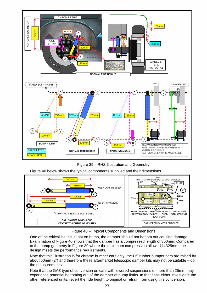
Figure 39 below is the right hand side illustration and the geometry of the assembly and the measured and calculated dimensions within which the proposed telescopic damper conversion fits.
23
350m
m
A
BA
B
BA
170mm170mm
170mm
REBOUND = 60mmNORMAL RIDE HEIGHT
BUMP = 50mm
B
CBUMP
A
325mm
GAZ
COMPARISON BETWEEN GAZ AND ARMSTRONG DAMPER ALIGNMENT AT NORMAL RIDE HEIGHTREAR VIEW LINEARITY IS ACCEPTABLE
= =
20mm
WHEEL & TYRE
175 - 75 - 14
AXLE STRAP
CHROME STRIP
170mm
FIXED BODY POINT
CCC C
NORMAL RIDE HEIGHT
275mm325mm 325mm 421mm 385mm367mm
20mm
CALCULATED
MEASURED
375m
m
NO
RM
AL R
IDE
HEI
GH
T
A
ARMSTRONG
Figure 39 – RHS Illustration and Geometry
Figure 40 below shows the typical components supplied and their dimensions.
300mm
185mm
435mm
250mmFULLY EXTENDED
FULLY COMPRESSED
DAMPER MOUNTING POINT 10mm UP AND 22.5mm FORWARD COMPARE WITH ARMSTRONG DAMPER
PIVOT POINT
GAZ UPPER DAMPER BRACKET
1/2" UNF HIGH TENSILE BOLTS USED
GAZ DAMPER DIMENSIONSCENTRE TO CENTRE OF MOUNTS
C
CA
A
C
Figure 40 – Typical Components and Dimensions
One of the critical issues is that on bump, the damper should not bottom out causing damage. Examination of Figure 40 shows that the damper has a compressed length of 300mm. Compared to the bump geometry in Figure 39 where the maximum compression allowed is 325mm; the design meets the performance requirements. Note that this illustration is for chrome bumper cars only, the US rubber bumper cars are raised by about 50mm (2”) and therefore these aftermarket telescopic damper kits may not be suitable – do the measurements. Note that the GAZ type of conversion on cars with lowered suspensions of more than 25mm may experience potential bottoming out of the damper at bump limits. In that case either investigate the other referenced units, revert the ride height to original or refrain from using this conversion.

24
Likewise on rebound, the extended length of 435mm can accommodate the maximum rebound length of 421mm From the rear view shown to the right in Figure 39, a comparison between the linearity of the Armstrong and propose telescopic damper installations, indicates acceptability Any failure of the damper will be no different to the original installation using Armstrong dampers. Based on a comparative assessment, I can support their use.
6 MECHANICAL FIXING DATA Removing and replacing suspension components should be carried out with care noting that in most cases connections are made using high tensile bolts and nuts.
This section of the paper serves to familiarise readers with identifying marks on such equipment.
Firstly it is important to note the difference between a bolt and a setscrew, shown in Figures 40 and 41 respectively. Considering the requirement for high tensile bolts and nuts, Figure 38 shows common bolt and nut markings with the number “5” indicating AS2465 Grade 5 and the number “8” for AS2465 Grade 8, both with high tensile attributes.
A set screw has the thread along the entire length and a bolt only as far as required. It is unusual for setscrews to be used on suspension components. If they are found, discard them and replace with correct bolts. Similarly you may find bolts and nuts without high tensile identifying marks, probably used in error by previous owners.
Figure 40 - Setscrew
Figure 41 - Bolt
Figure 42 - Bolt & Nut Markings
Figure 43 below shows typical applications where high tensile bolts, nuts and u-bolts are used. They include:-
• Bolts supporting spring eyes etc are in shear. They should be high tensile units. Whilst it is not critical that the nuts in this application be high tensile –they only locate the bolt, it is good practice to match high tensile bolts and nuts together.
• The U-bolt around the axle supporting the spring bracket. The u-bolt and the nut are both in tension. This and the retaining nut should be high tensile with the not being of the nyloc type. Note that nyloc nuts should only be used once after which they should be recycled into general use with spring washers or discarded. The nylon insert is degraded after the first use and may not effect proper resistance when worn.
LOAD
HT BOLTAS2465 GRADE 5
HT
HT NYLOCK NUTAS2465 GRADE8
LOAD
HT
Figure 43 – Typical Applications

25
Figures 44 and 45 below show the HT markings on Nyloc nuts.
Figure 44 - Nyloc nut AS2465 Grade 5
Figure 45 - Nyloc nut AS2465 Grade 8
The Bentley manual provides various torque figures for each part of the suspension and steering.
When installing new equipment or re-installing old, make sure that the torque settings specified in either the Bentley manual or those advised with aftermarket kits are adhered to.
Please note that when tightening up the “U”-Bolt nuts as shown in Figure 38, you need to assess the torque against the compression of the slip pad. If you leave the old rubber pads in place, even a modest torque will squeeze the old rubber out of the joint resulting in a metal to metal connection. Always replace pads and bushes with new ones – preferably with poly-urethane ones.
The full range of available high tensile nuts and bolts together with illustrations can be found in the AJAX Fastener Handbook purchased from their web site at http://www.ajaxfast.com.au/ Or downloaded (5.6MB) from one of their distributors at
http://www.westcoastfasteners.com.au/pdf/ajax%20handbook.pdf 7 HANDLING CHARACTERISTICS The handling characteristics or drivability of the MGB when first introduced included good steering and rather neutral handling although the photo shown in Figure 46 at the 1962 US release promotion seems to contradict this. However the “Commendably little body roll” statement is in the context of American cars!
Figure 46 – Commendably little body roll!
With its 4 ½” wheels and cross ply tyres it was easy to induce a four wheel drift, However because we now fit wide wheels and low profile radial ply tyres, they will mask shortcomings in suspension modifications to the point where loss of steering and grip occur suddenly.
Accordingly I consider that the following explanations of the different handling characteristics should be understood.
For many, the first consideration is ride comfort. This is influenced by the suspension set up of spring rates, sway bar stiffness, damper settings (if available), camber, caster (castor), toe-in and tyre pressure. Change any one and ride comfort can be dramatically changed.
Similarly if driver response is important, those same suspension settings have similar effects. Accordingly I will try to explain the various suspension settings.

26
Note that there are as many opinions on suspension settings as there are MGB owners in the world, many expressed and shared on web sites such as “The MG Experience” at http://www.mgexp.com/
The following details the standard MGB settings taken from the Bentley manual and those that cater to my preferred type of driving style which is reasonably aggressive but consistently smooth, especially on public roads.
Weight Distribution The first thing to address when assessing the handling of the car is weight distribution. A car heavier at the front will tend to promote oversteer and vice versa.
Figure 47 – Weight Distribution
Figure 47 above shows the distribution of weight relative to the wheels. Note that the majority of the engine mass is behind the front axles and when the driver is added, this results in a near perfect 50-50 distribution assist in setting up the car to the handling characteristics required. The curb or “dry” weight of a 1971 - 2 MGB Roadster is 2,194lbs with a sprung distribution of 1,030 lbs at the front and 1,164 lbs at the rear. The sprung weight is the total weight less the wheels, tyres, axle (rear), springs and front suspension components, i.e. the weight that is supported by the suspension. This is shown in Figure 48 below.
CURB WEIGHT = 2,194 LBS
UNSPRUNG WEIGHT = 1,030 LBS
UNSPRUNG WEIGHT = 1,164 LBS
Figure 48 – Weight Distribution
Oversteer and understeer are two of the most common issues that present themselves to the driver, both are influenced by weight distribution, tyre condition, roll stiffness and spring rates which are all capable of being optimised and the road surface which obviously can not.
For example, load a few bags of concrete into the boot and you will have a tail happy over steering car!
Figure 49 below shows the two cornering attitudes where the car, in the first instance does not want to point in the direction of the steered wheels and in the second instance wants to steer in a tighter turn. I have emphasised the wheel sizes to show the amount of steering correction in these circumstances.
With understeer the first inclination is to either do nothing or apply more steering lock which contrary to intuition, only makes the matter worse. Lifting off the throttle increases the front wheel road adhesion and the car naturally straightens out.

27
With oversteer however; doing nothing or lifting off the throttle will just aggravate the attitude resulting in losing the rear end in a spin. Experienced drivers however will have an intuitive response to apply opposite lock. This action will correct oversteer and if feeling confident and on a private road or race track, will allow the car to achieve a full on drift!
UNDERSTEER
OVERSTEER
Figure 49 – Understeer and Oversteer
Figure 50 below shows understeer and oversteer can be reduced by alteration / selection of suspension components. Note that correct front tyre pressures not only have an influence on ride quality, but can also influence understeer and oversteer because modern radial ply tyres are now considered part of the suspension. Too low a pressure can increase the flex in the tyre wall increasing understeer and too high a pressure producing the same result!
Component To Reduce Understeer To Reduce Oversteer Front Damper Softer damper Firmer damper Rear Damper Firmer damper Softer damper Front sway bar Softer sway bar Stiffer sway bar ( increase
thickness) Rear sway bar Stiffer damper or install if not
already installed Softer sway bar
Front tyre pressure Lower pressure Increase pressure Rear tyre pressure Increase pressure Lower pressure Front wheel camber Increase negative camber Reduce negative camber
Figure 50– Understeer and Oversteer Influencers
Bump steer is the tendency for the car to steer in other than the required direction when traveling over very bumpy roads. It is brought about by the change in suspension geometry. Looking a Figure 44, which is the right hand side of the car traveling towards you, the wheel rising due to the bump changes the orientation of the steering tie rod making it effectively shorter and turning the wheel to the right (left as shown in Figure 51).
STEERING RACK & TIE
ROD
Figure 51 – Bump Steer

28
Steering The steering mechanism influences the accuracy of corner entry and recovery coming out of a corner, The rack and pinion steering in the MGB provides faster response (see section on caster) and self centering than the traditional “recalculating ball” steering prevalent at the time of the MBG development. See the section on castor influence on steering. Wheel Alignment The independent front suspension in the MGB allows each wheel to act independently from the other in terms of total bump and rebound, the only connection being the sway bar which acts to limit the movement of one side as compared to the other. The rear suspension however, being connected by the live rear axle, has a more direct connection meaning that on rough roads the action on one side tends to be replicated on the other. Tyre pressures, camber, caster and toe-in also influence the car handling. Note that these settings apply to the front suspension geometry only. Where MGBs are extensively modified for race use, many owners install fully adjustable independent rear suspension where camber can offer handling advantages.
Note the attitude of the MGBGT in Figure 52 which appears to have all the settings incorrect, and that of the MGB Roadster which has less roll through a similar 90o left hand corner.
Figure 52 - MGBGT
Figure 53 - MGB Roadster
Note that any change to one aspect of car set up will almost certainly affect the other wheel alignment settings.
Camber is defined as the inward or outward lean of the wheel and tyre at the top relative to the vertical at the centre of the wheel in the lateral plane as shown in Figure 54. If the top of the tyre is leaning inward towards the centre of the car viewed from the front, then the wheel has negative camber, if the top of the tyre is leaning outward then the wheel has positive camber.
CAMBER ANGLE
POSITIVE NEGATIVE
Figure 54 - Camber
The effect of negative camber is to increase the contact of the inside tyre to the road when cornering rapidly. Although this might seem desirable, it also reduces the contact patch on the outside. Accordingly the standard MGB Roadster is set up with 1o positive camber being considered as most appropriate for a (relatively) underpowered car. Although the typical driver will not notice the difference to a set up with the same amount of negative camber, the car will be inherently more stable. MGB owners contemplating competition work can have a negative camber set up which usually requires the fitting of shorter lower “A” arms, a costly conversion which benefits will only be felt on a race track. Note the negative camber on the front left wheel shown in Figure 55 below of my Ford Anglia sports sedan which was set up with adjustable camber.

29
Figure 55 – Negative Camber
Caster is the inclination of the steering axis from vertical in the longitudinal plane when viewed from the side of the car. Figure 56 below shows the positive caster when the steering axis is inclined towards the rear of the car at the top in this side view.
STEERING AXIS
FORWARD
CASTER
Figure 56 - Caster
The standard MGB is set up with between 5 o and 7o positive caster. The reason for a high positive caster angle was the standard and quality of available tyres at the design stage considering that the original MGBs ran on 4½ J x 14 wheels and 5.60 x 14 cross ply tyres. Higher caster settings will track very straight on a straight open road, and will center the steering wheel very effectively when coming out of a corner. Lower settings will increase steering responsiveness and not center the wheel automatically coming out of a corner and in a straight line with the added problem that the car may begin to wander. 4o positive seems to be the setting most new car designers shoot for, although it has a lot to do with the entire steering geometry, not an independent figure. Now we tend to use wider rims – 5” - 6” in some cases with relatively low profile (70%) tyres. The 7o caster settings now give very heavy steering at low speed and it is considered best to reduce this to between 3 and 4o. Moss Motors and the MG Owners Club can supply a set of stainless steel shims to reduce the caster, the conversion best carried out by a professional wheel alignment garage because after inserting the shims, both toe-in and camber will have to be reset. Toe-In The purpose of toe, either in or out, is to reduce the amount the tyre scrub against the road surface; the more the tyre scrubs the faster it will wear. If a tyre has too much toe-in, the outer edges of the tyres will wear more rapidly, in a sort of stepped fashion. If too little toe-in, the inner edges will wear more rapidly. If one tyre wears different to the other, then that is an indication that other aspects of steering and suspension alignment are unbalanced between sides, and this can include problems at the rear. It can be caused by accident damage and chassis misalignment as well as damage to or wear in suspension and steering The standard MGB has a positive toe-in dimension of between 1/16’ and 3/32” which provides the requisite balance for road work. Toe- in (exaggerated) (from above) is shown in Figure 57 below

30
Figure 57 - Toe-In Sway Bar The purpose of the sway bar or “anti roll bar” is given on Page 5 and in Figures 7 and 8. Roll Centres –The centrifugal forces during cornering tend to push the car outwards. This is resisted by the available friction provided by the tyres. However before the car loses adhesion, it will take on a roll attitude which is dependant on the suspension geometry, vehicle weight, centre of gravity and turning radius. The point within the car about which the car rolls is different between front and rear and when a car such as an MGB had different suspension designs front and back, that combined roll centre affects the road handling and ultimately the limit of adhesion. Where MGBs are used in competition, owners tend (at a cost) to have complimentary suspension design front and rear. Usually this is fully independent four link design at the rear. The front roll centre is a geometric point where a number of intersecting lines through the suspension components and the tyre to road contact patch meet. The standard MGB front roll centre is considered to provide appropriate balance, especially when addressed in the context of the rear roll centre location. Note that the front roll centre will vary considerably under heavy braking because the angularity of the two wishbones will move upwards; in that case the roll centre will move down! The rear roll centre is the point where the axis of the front leaf spring mounts and the opposite rear leaf spring mounts coincide. This is at point within the differential geometry above the road surface. The standard MGB has a forward inclined roll centre which provides initial understeer as described on pages 26 to 27 and in Figure 49. Damper Settings The standard settings on the front Armstrong dampers are, to my mind, exactly right, the have a degree of bump and rebound stiffness that suit the weight distribution of the car and my style of driving. You can get replacement valve assemblies for the Armstrong dampers with the most common having a 25% stiffness. On the other hand, I find the rear Armstrong dampers too firm in the bump mode. Accordingly and because these dampers cannot be softened, I have replaced them with GAZ units. These have 12 firmness settings and find the setting 4 (towards soft) provides the degree of “squat” that I like under acceleration. 8 SAFETY The MGB is inherently a very safe car with its steering, suspension and braking characteristics well ahead of other cars in that era. What is generally unknown that in the early 1960s, BMC conducted a number of crash tests on the Mini, Morris 110 and MGB cars. A video of the test can be found at http://www.britishpathe.com/video/bmc-crash-test where from approximately 9 minutes 30- seconds onwards, a series of movie camera shots of the test are shown. The car performed remarkably well and because, as shown in Figure 47, the engine is located far back in the engine bay, the forward bodywork served to absorb the impact. Note also how the doors were still openable after the test.

31
LAWFUL ALTERATIONS The Queensland Transport (Department of Transport and Main Roads) web site:- http://www.tmr.qld.gov.au/Safety/Vehicle-standards-and-modifications/Vehicle-modifications/Light-vehicle-modifications.aspx#specific addresses modifications to vehicles with the following preamble:- This page provides information for vehicle owners or vehicle modifiers wishing to modify light vehicles (gross vehicle mass of not more than 4.5t) from the manufacturer’s original specifications. Following these requirements will ensure that your vehicle meets all applicable Queensland regulations and its safety levels are maintained. The Motor Vehicle Modification Application form (F1854) must be used when applying to the Department of Transport and Main Roads for a specific modification. A fee is payable for the evaluation of plans. Gaining approval before commencing any specific modifications is strongly recommended. Queensland Transport also advise that regardless of any approval, either as pre-listed minor modifications or other modifications subject to specific approval, that such approval does not guarantee that the vehicle insurer will insure the vehicle with either compulsory third party or comprehensive cover. Note that installing an alternative suspension without being certain as to its legality will not only void registration and insurance but, if an accident occurs, the Police investigators will certainly prosecute. 10 SUMMARY From my discussions and the referenced articles above, I summarise the following observations and opinions regarding Armstrong Dampers.
• The Armstrong damper is capable of being adjusted for both bump and rebound, a feature not found on modern cars unless retrofitted with adjustable telescopic shock absorbers.
• Replacement of the original dampers may be an acceptable solution for certain individual’s ride requirements but they should be very careful as to the legality of such conversions.
• I recommend that you keep your MGB as original as possible, what if in years to come, the next owner cannot get parts? At least retain the original dampers in your garage.
• Owners wishing to use their MGBs in Confederation of Australian Motor Sport (CAMS) sanctioned historic events should note that CAMS provides information as to permissible modifications. For the MGB Roadster and GT, these regulations permit the use of telescopic dampers at the rear but not at the front.
• The requirements by the Queensland Department of Transport regarding modifications MUST be adhered to.
Finally, I caution owners on the use of replacement telescopic damper without due diligence as to the suitability of the design and the required approval process. I trust that you have found this paper interesting and I encourage you to experiment with your own MGB to find a handling setting to suit your driving style. Rick Foster
This article is provided to MG owners as advice only. No liability is provided nor accepted for any error or omission in this document. Version 1 – May 2017 See my web site at http://fscs-techtalk.com