Principles of dimensioning - Centre for Intelligent Machines ...
41
Principles of dimensioning Terminology What is the main image, which we are using in all our projects, designs, drawings? It is a line! And in Graphics Communications practice there is the whole bunch of different lines, which are used for drawing purposes. The alphabet of lines is a set of standard linetypes established by the American National Standards Institute (ANSI) for technical drawing. The alphabet of lines and the approximate dimensions used to create different linetypes, are referred to as linestyles when used with CAD. 1
-
Upload
khangminh22 -
Category
Documents
-
view
0 -
download
0
Transcript of Principles of dimensioning - Centre for Intelligent Machines ...
Principles of dimensioning Terminology
What is the main image, which we are using in all our projects, designs, drawings?
It is a line!
And in Graphics Communications practice there is the whole bunch of different lines, which are used for drawing
purposes.
The alphabet of lines is a set of standard linetypes established by the American National Standards Institute (ANSI)
for technical drawing. The alphabet of lines and the approximate dimensions used to create different linetypes, are
referred to as linestyles when used with CAD.
1
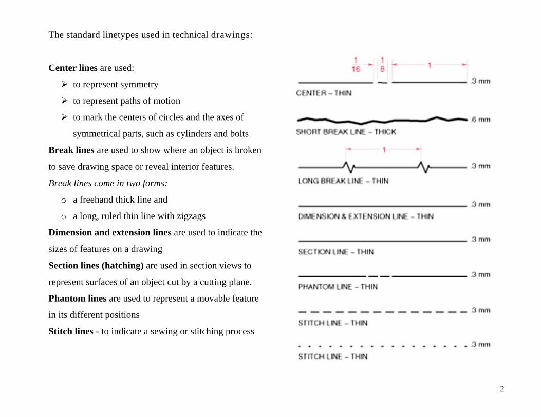
The standard linetypes used in technical drawings:
Center lines are used:
to represent symmetry
to represent paths of motion
to mark the centers of circles and the axes of
symmetrical parts, such as cylinders and bolts
Break lines are used to show where an object is broken
to save drawing space or reveal interior features.
Break lines come in two forms:
o a freehand thick line and
o a long, ruled thin line with zigzags
Dimension and extension lines are used to indicate the
sizes of features on a drawing
Section lines (hatching) are used in section views to
represent surfaces of an object cut by a cutting plane.
Phantom lines are used to represent a movable feature
in its different positions
Stitch lines - to indicate a sewing or stitching process
2
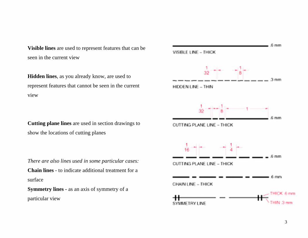
Visible lines are used to represent features that can be
seen in the current view
Hidden lines, as you already know, are used to
represent features that cannot be seen in the current
view
Cutting plane lines are used in section drawings to
show the locations of cutting planes
There are also lines used in some particular cases:
Chain lines - to indicate additional treatment for a
surface
Symmetry lines - as an axis of symmetry of a
particular view
3
Elements of line technique
According to the Canadian Standard CAN3-B78.1-M83 “Technical Drawings – General Principles”, the thickness
of lines should be chosen according to the size and type of the drawing from the following range:
0.25, 0.35, 0.5, 0.7, 1.0, 1.4, and 2.0 mm
However, in many text books (especially, of the US authors) you will come across the thicknesses of lines:
0.3 mm and 0.6 mm. In general cases it is good enough since in practical work it is not so easy to see the
difference in thickness of 0.1 mm.
In cases where other types of lines are used for special drawings (for example, electrical drawings, pipeline
diagrams, or building drawings) the conventions adopted must be clearly indicated by reference to other
standards or by notes on the drawings concerned.
However, even for those drawings a simplified representation can be used, where two thicknesses – 0.3 mm and
0.6 mm – are also acceptable.
For all views of one piece or assembly to the same scale, the thickness of the lines should be the same.
The minimum space between parallel lines should never be less than twice the thickness of the heaviest line. It
is recommended that these spaces be 0.7 mm or greater.
4
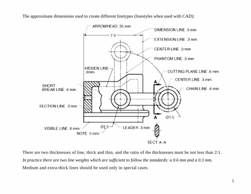
The approximate dimensions used to create different linetypes (linestyles when used with CAD):
There are two thicknesses of line, thick and thin, and the ratio of the thicknesses must be not less than 2:1.
In practice there are two line weights which are sufficient to follow the standards: a 0.6 mm and a 0.3 mm.
Medium and extra-thick lines should be used only in special cases.
5
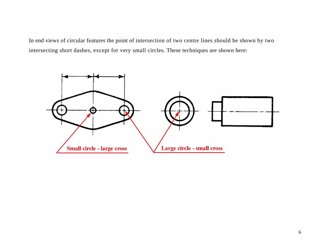
In end views of circular features the point of intersection of two centre lines should be shown by two
intersecting short dashes, except for very small circles. These techniques are shown here:
6
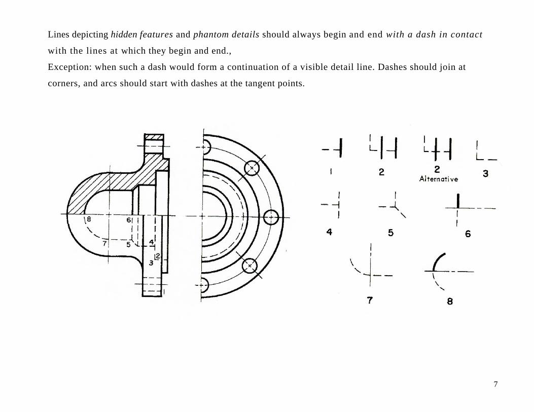
Lines depicting hidden features and phantom details should always begin and end with a dash in contact
with the lines at which they begin and end.,
Exception: when such a dash would form a continuation of a visible detail line. Dashes should join at
corners, and arcs should start with dashes at the tangent points.
7
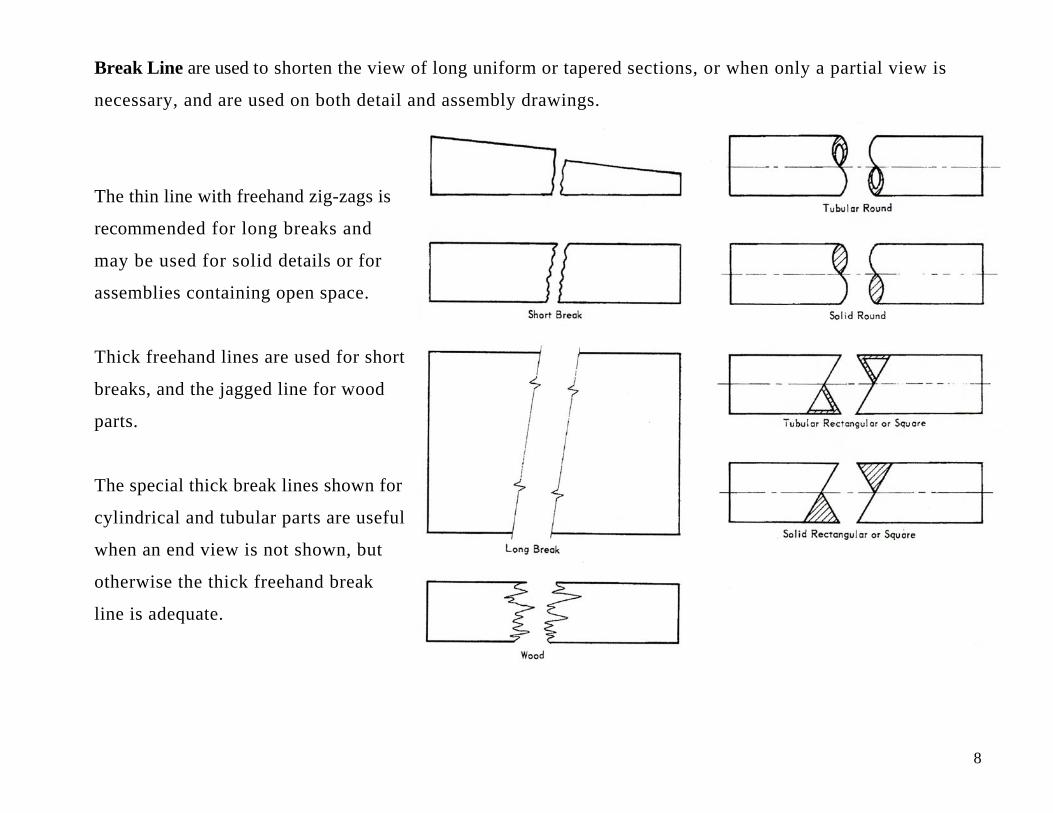
Break Line are used to shorten the view of long uniform or tapered sections, or when only a partial view is
necessary, and are used on both detail and assembly drawings.
The thin line with freehand zig-zags is
recommended for long breaks and
may be used for solid details or for
assemblies containing open space.
Thick freehand lines are used for short
breaks, and the jagged line for wood
parts.
The special thick break lines shown for
cylindrical and tubular parts are useful
when an end view is not shown, but
otherwise the thick freehand break
line is adequate.
8
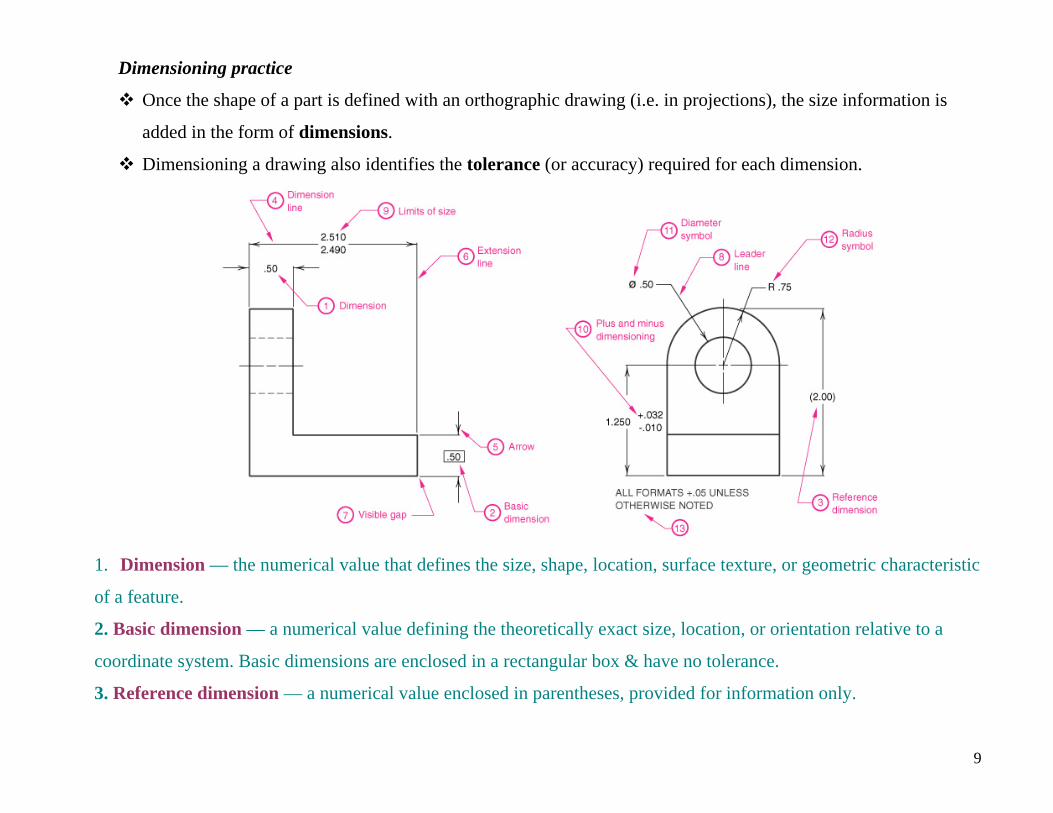
Dimensioning practice
Once the shape of a part is defined with an orthographic drawing (i.e. in projections), the size information is
added in the form of dimensions.
Dimensioning a drawing also identifies the tolerance (or accuracy) required for each dimension.
1. Dimension — the numerical value that defines the size, shape, location, surface texture, or geometric characteristic
of a feature.
2. Basic dimension — a numerical value defining the theoretically exact size, location, or orientation relative to a
coordinate system. Basic dimensions are enclosed in a rectangular box & have no tolerance.
3. Reference dimension — a numerical value enclosed in parentheses, provided for information only.
9
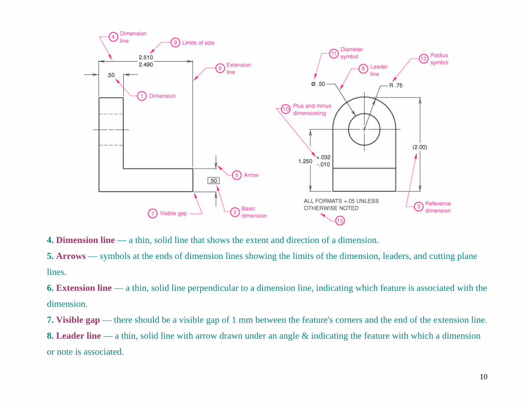
4. Dimension line — a thin, solid line that shows the extent and direction of a dimension.
5. Arrows — symbols at the ends of dimension lines showing the limits of the dimension, leaders, and cutting plane
lines.
6. Extension line — a thin, solid line perpendicular to a dimension line, indicating which feature is associated with the
dimension.
7. Visible gap — there should be a visible gap of 1 mm between the feature's corners and the end of the extension line.
8. Leader line — a thin, solid line with arrow drawn under an angle & indicating the feature with which a dimension
or note is associated.
10
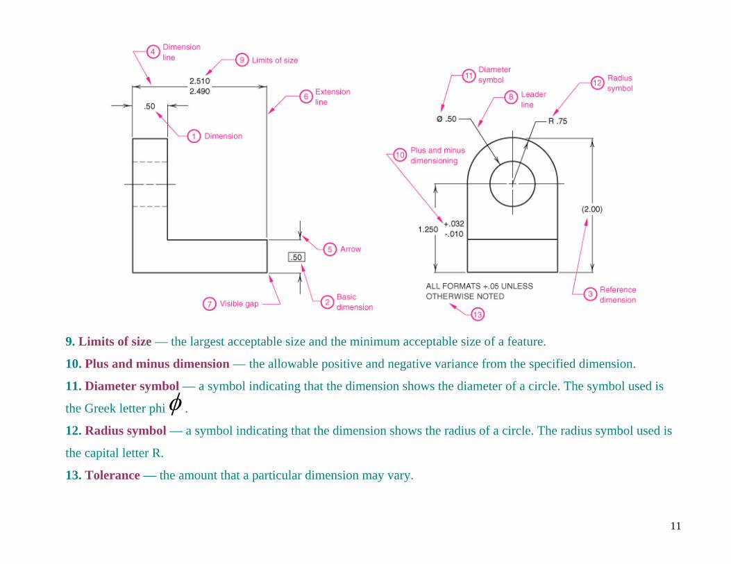
9. Limits of size — the largest acceptable size and the minimum acceptable size of a feature.
10. Plus and minus dimension — the allowable positive and negative variance from the specified dimension.
11. Diameter symbol — a symbol indicating that the dimension shows the diameter of a circle. The symbol used is
the Greek letter phi . φ12. Radius symbol — a symbol indicating that the dimension shows the radius of a circle. The radius symbol used is
the capital letter R.
13. Tolerance — the amount that a particular dimension may vary.
11
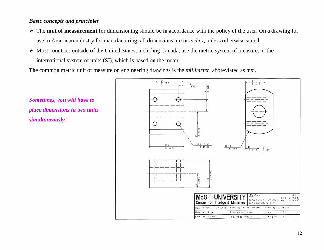
Basic concepts and principles
The unit of measurement for dimensioning should be in accordance with the policy of the user. On a drawing for
use in American industry for manufacturing, all dimensions are in inches, unless otherwise stated.
Most countries outside of the United States, including Canada, use the metric system of measure, or the
international system of units (SI), which is based on the meter.
The common metric unit of measure on engineering drawings is the millimeter, abbreviated as mm.
Sometimes, you will have to
place dimensions in two units
simultaneously!
12
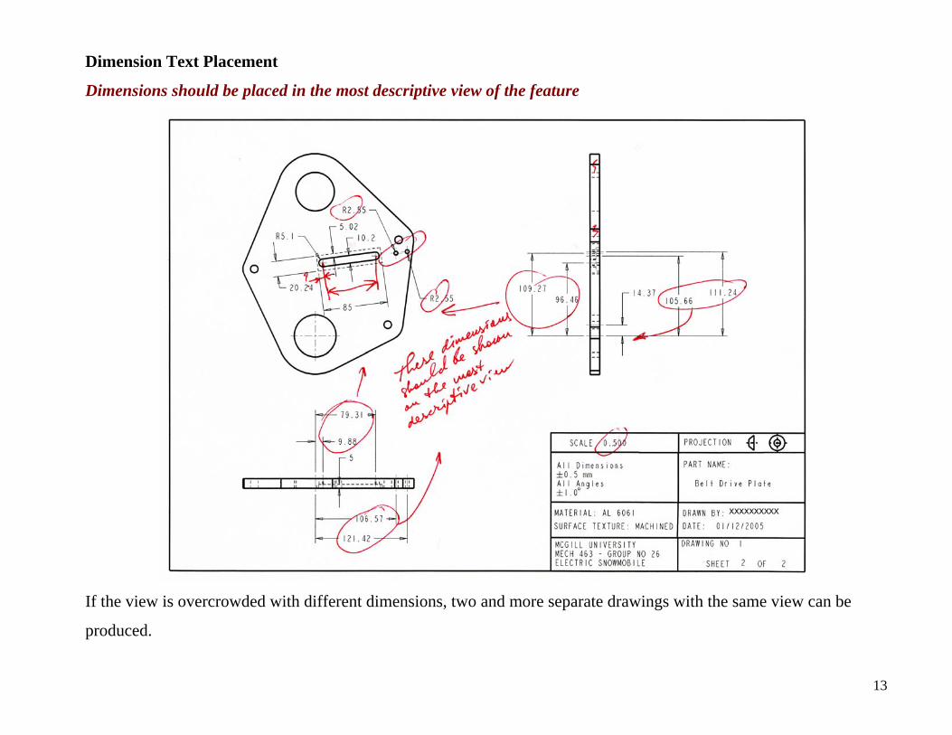
Dimension Text Placement
Dimensions should be placed in the most descriptive view of the feature
If the view is overcrowded with different dimensions, two and more separate drawings with the same view can be
produced.
13

Dimension Text Placement
Text of the dimensions can be placed in different ways:
dimension inside the extension lines, with
arrows inside or outside; and
dimension outside the extension lines, with
arrows again inside or outside.
14
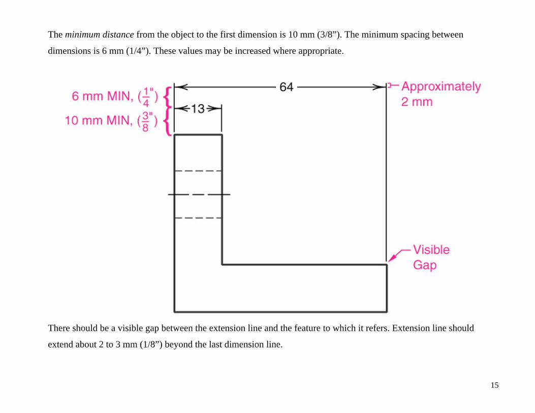
The minimum distance from the object to the first dimension is 10 mm (3/8”). The minimum spacing between
dimensions is 6 mm (1/4”). These values may be increased where appropriate.
There should be a visible gap between the extension line and the feature to which it refers. Extension line should
extend about 2 to 3 mm (1/8”) beyond the last dimension line.
15

Where space is limited extension lines may be drawn at an angle:
16
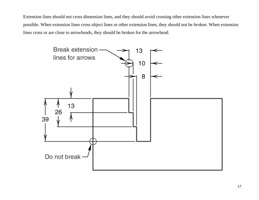
Extension lines should not cross dimension lines, and they should avoid crossing other extension lines whenever
possible. When extension lines cross object lines or other extension lines, they should not be broken. When extension
lines cross or are close to arrowheads, they should be broken for the arrowhead.
17
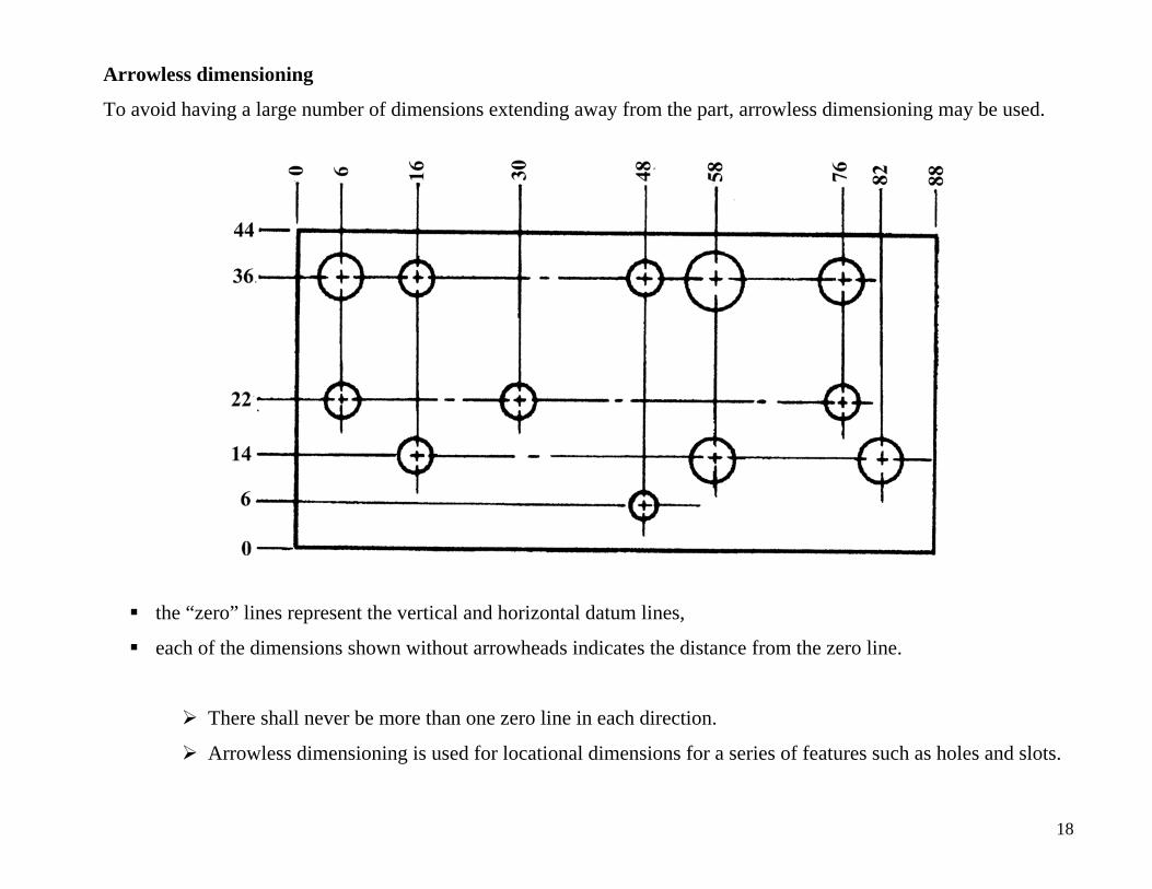
Arrowless dimensioning
To avoid having a large number of dimensions extending away from the part, arrowless dimensioning may be used.
the “zero” lines represent the vertical and horizontal datum lines,
each of the dimensions shown without arrowheads indicates the distance from the zero line.
There shall never be more than one zero line in each direction.
Arrowless dimensioning is used for locational dimensions for a series of features such as holes and slots.
18
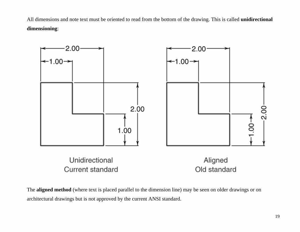
All dimensions and note text must be oriented to read from the bottom of the drawing. This is called unidirectional
dimensioning:
The aligned method (where text is placed parallel to the dimension line) may be seen on older drawings or on
architectural drawings but is not approved by the current ANSI standard.
19
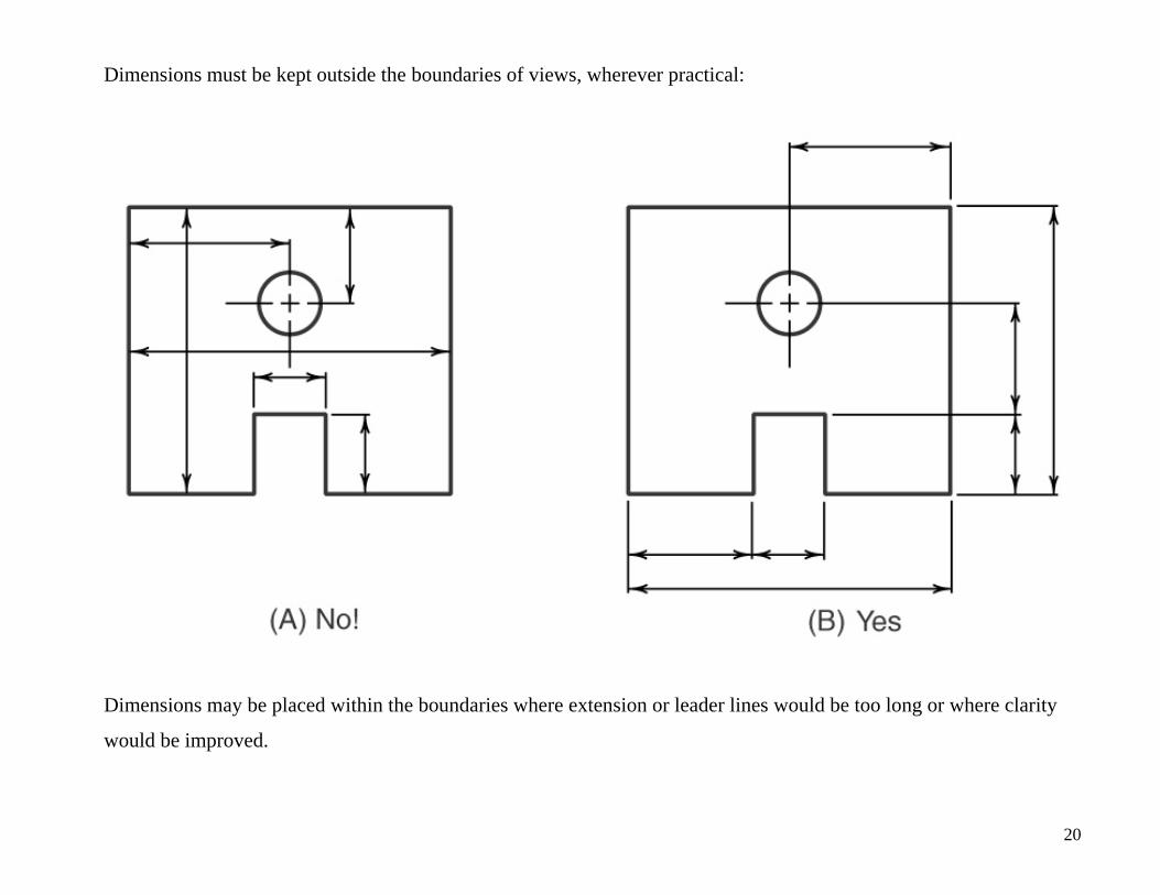
Dimensions must be kept outside the boundaries of views, wherever practical:
Dimensions may be placed within the boundaries where extension or leader lines would be too long or where clarity
would be improved.
20
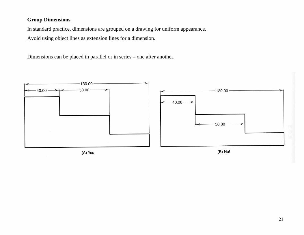
Group Dimensions
In standard practice, dimensions are grouped on a drawing for uniform appearance.
Avoid using object lines as extension lines for a dimension.
Dimensions can be placed in parallel or in series – one after another.
21
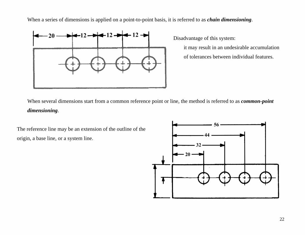
When a series of dimensions is applied on a point-to-point basis, it is referred to as chain dimensioning.
Disadvantage of this system:
it may result in an undesirable accumulation
of tolerances between individual features.
When several dimensions start from a common reference point or line, the method is referred to as common-point
dimensioning.
The reference line may be an extension of the outline of the
origin, a base line, or a system line.
22
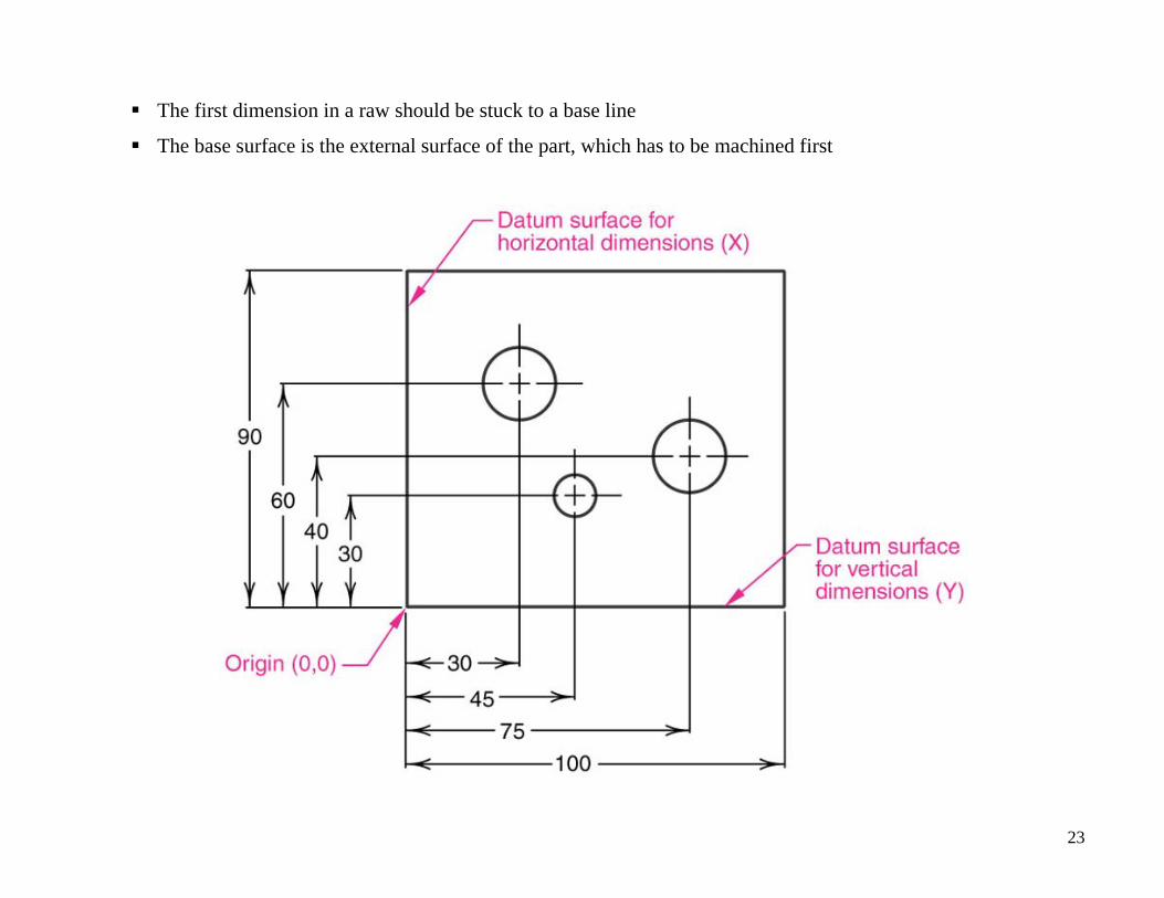
The first dimension in a raw should be stuck to a base line
The base surface is the external surface of the part, which has to be machined first
23
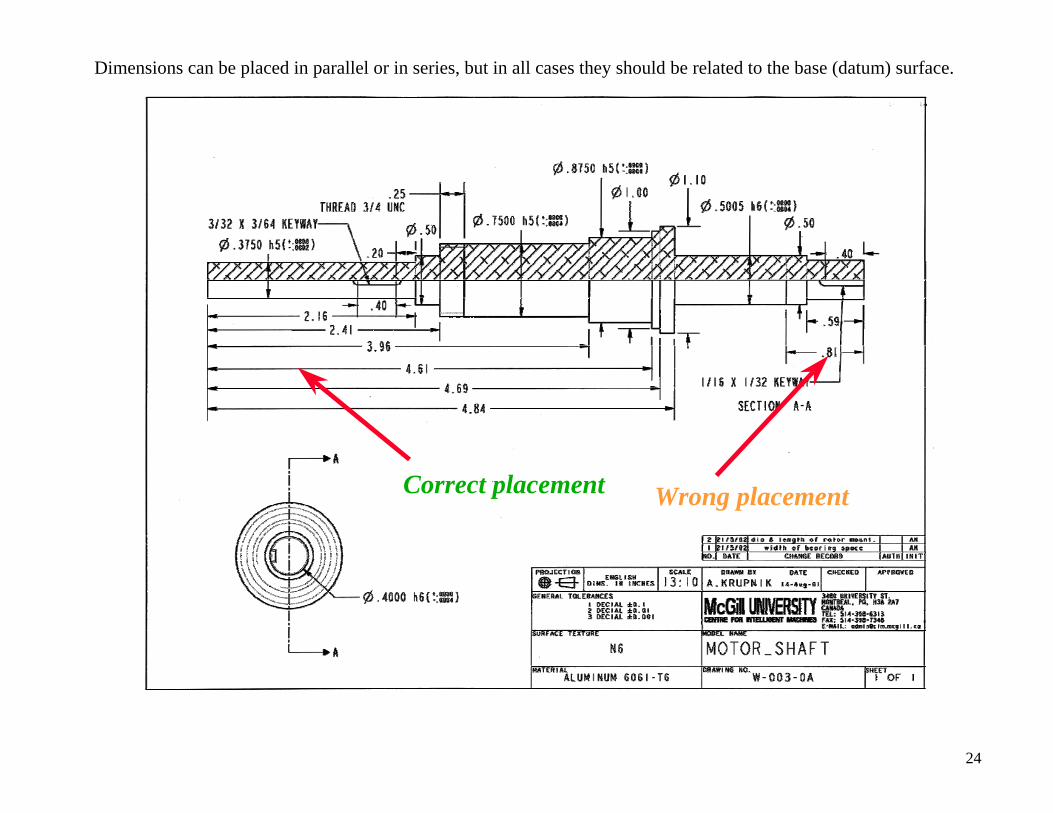
Dimensions can be placed in parallel or in series, but in all cases they should be related to the base (datum) surface.
Correct placement Wrong placement
24
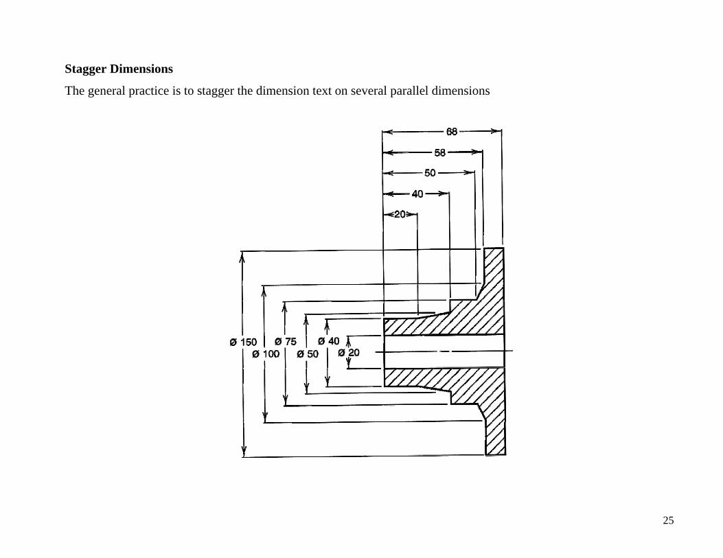
Stagger Dimensions
The general practice is to stagger the dimension text on several parallel dimensions
25

Size Dimension
The dimensions can be classified by types of size:
o Horizontal — the left-to-right distance
relative to the drawing sheet. Here the
width is the only horizontal size dimension.
o Vertical — the up and down distance
relative to the drawing sheet. Here the
height and the depth are both vertical
dimensions, even though they are in two
different directions on the part.
o Diameter—the full distance across a circle,
measured through the center.
o Radius—the distance from the center of an
arc to any point on the arc. Radius is
usually used on arcs less than half circles.
26
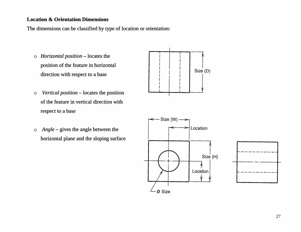
Location & Orientation Dimensions Location & Orientation Dimensions
The dimensions can be classified by type of location or orientation: The dimensions can be classified by type of location or orientation:
o Horizontal position – locates the
position of the feature in horizontal
direction with respect to a base
o Horizontal position – locates the
position of the feature in horizontal
direction with respect to a base
o Vertical position – locates the position
of the feature in vertical direction with
respect to a base
o Vertical position – locates the position
of the feature in vertical direction with
respect to a base
o Angle – gives the angle between the
horizontal plane and the sloping surface
o Angle – gives the angle between the
horizontal plane and the sloping surface
27 26

Angular units
Angular dimensions are shown either in decimal degrees or in degrees, minutes, and seconds
Where only minutes and seconds are specified, the number of minutes or seconds are preceded by the 0°
28
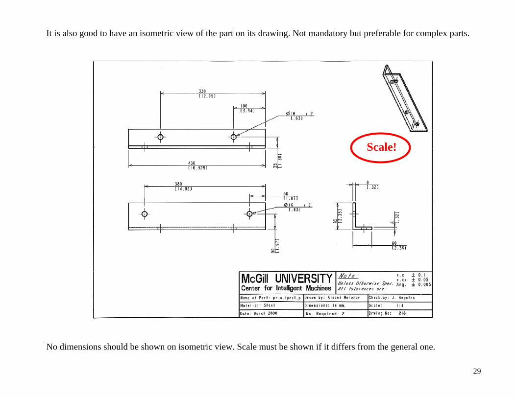
It is also good to have an isometric view of the part on its drawing. Not mandatory but preferable for complex parts.
No dimensions should be shown on isometric view. Scale must be shown if it differs from the general one.
Scale!
29
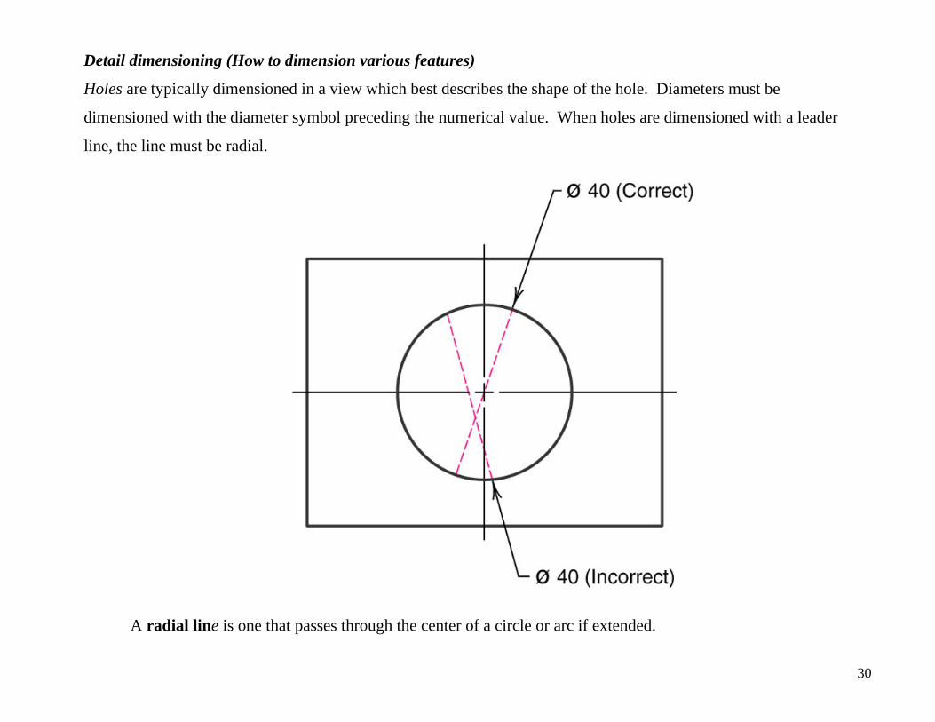
Detail dimensioning (How to dimension various features)
Holes are typically dimensioned in a view which best describes the shape of the hole. Diameters must be
dimensioned with the diameter symbol preceding the numerical value. When holes are dimensioned with a leader
line, the line must be radial.
A radial line is one that passes through the center of a circle or arc if extended.
30
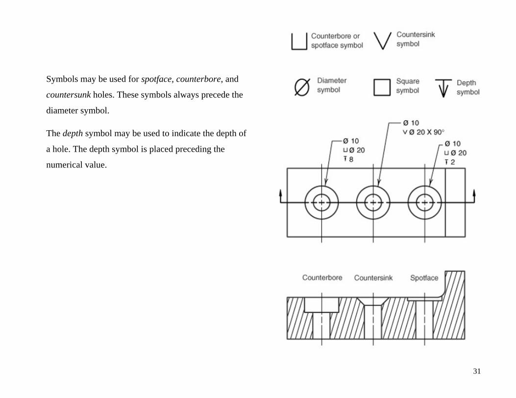
Symbols may be used for spotface, counterbore, and
countersunk holes. These symbols always precede the
diameter symbol.
The depth symbol may be used to indicate the depth of
a hole. The depth symbol is placed preceding the
numerical value.
31
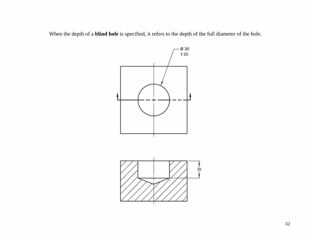
When the depth of a blind hole is specified, it refers to the depth of the full diameter of the hole.
32
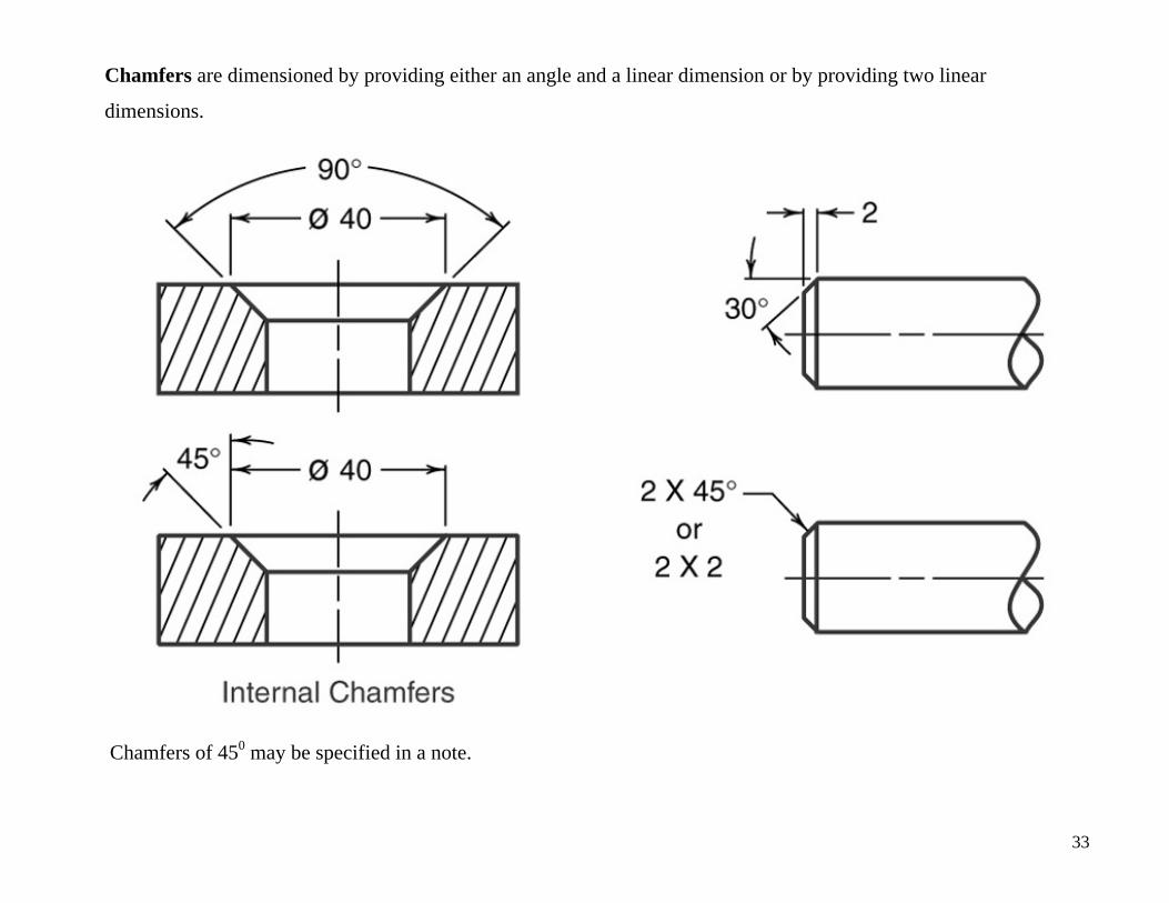
Chamfers are dimensioned by providing either an angle and a linear dimension or by providing two linear
dimensions.
Chamfers of 450 may be specified in a note.
33
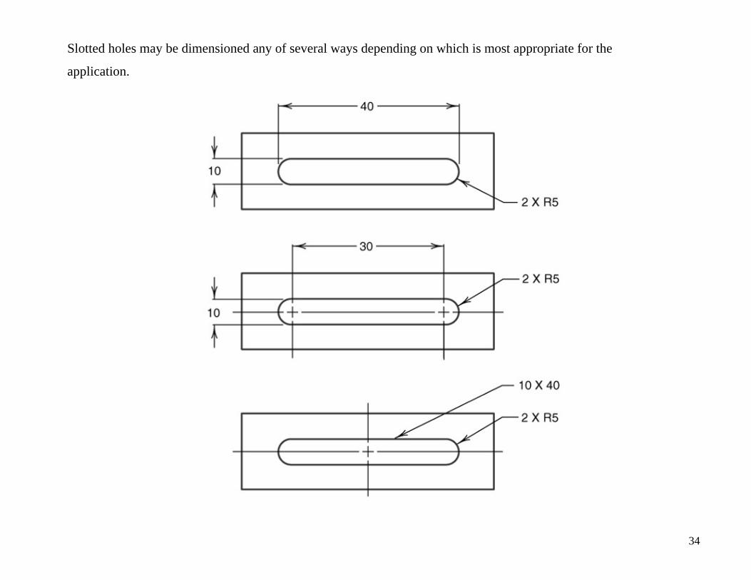
Slotted holes may be dimensioned any of several ways depending on which is most appropriate for the
application.
34
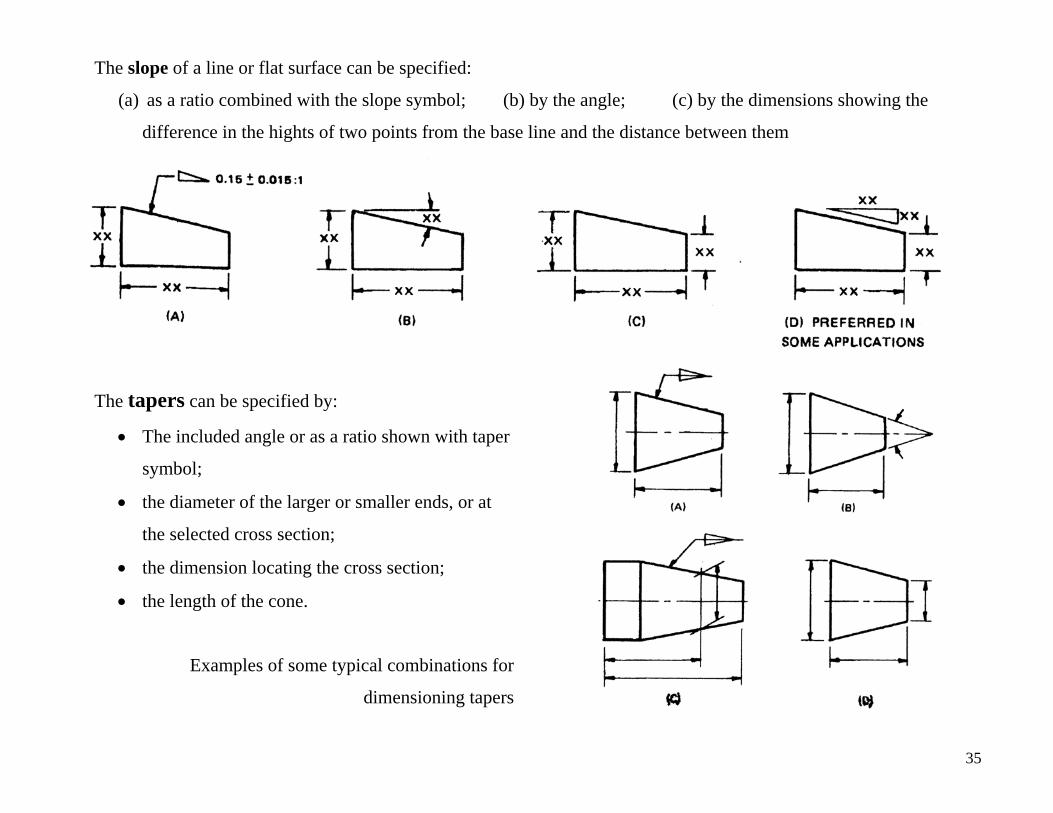
The slope of a line or flat surface can be specified:
(a) as a ratio combined with the slope symbol; (b) by the angle; (c) by the dimensions showing the
difference in the hights of two points from the base line and the distance between them
The tapers can be specified by:
• The included angle or as a ratio shown with taper
symbol;
• the diameter of the larger or smaller ends, or at
the selected cross section;
• the dimension locating the cross section;
• the length of the cone.
Examples of some typical combinations for
dimensioning tapers
35
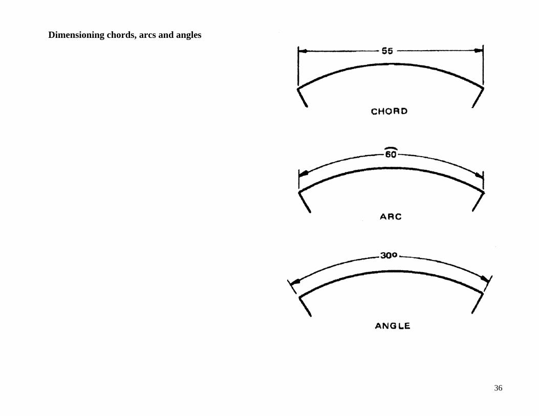
Dimensioning chords, arcs and angles
36
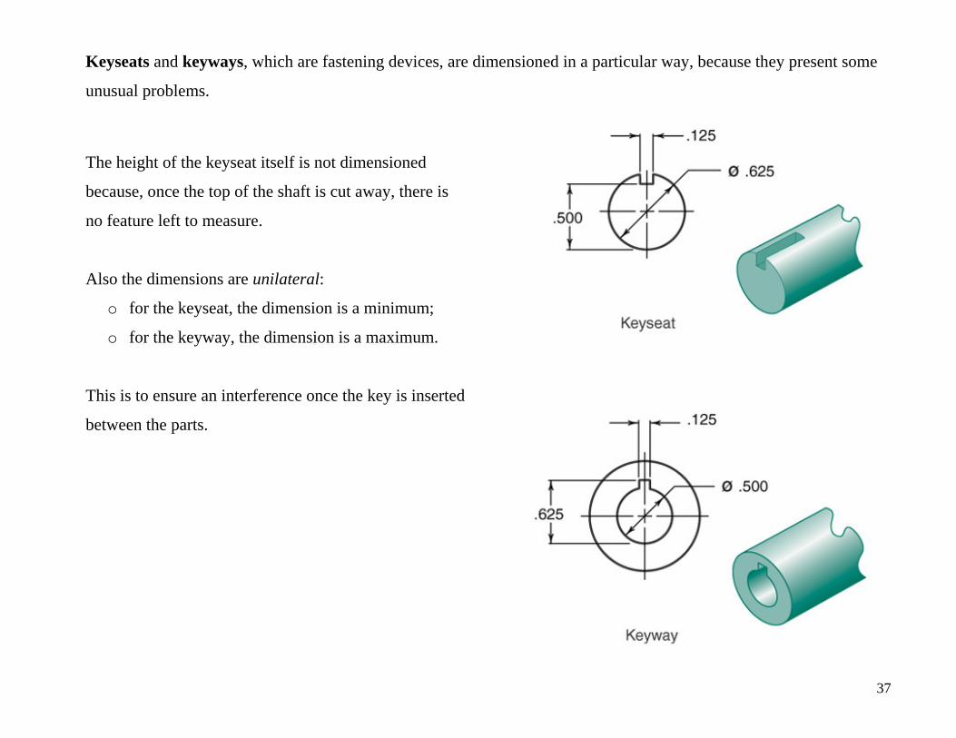
Keyseats and keyways, which are fastening devices, are dimensioned in a particular way, because they present some
unusual problems.
The height of the keyseat itself is not dimensioned
because, once the top of the shaft is cut away, there is
no feature left to measure.
Also the dimensions are unilateral:
o for the keyseat, the dimension is a minimum;
o for the keyway, the dimension is a maximum.
This is to ensure an interference once the key is inserted
between the parts.
37
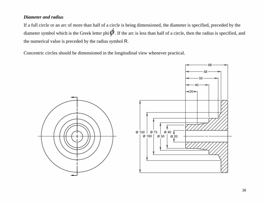
Diameter and radius
If a full circle or an arc of more than half of a circle is being dimensioned, the diameter is specified, preceded by the
diameter symbol which is the Greek letter phi . If the arc is less than half of a circle, then the radius is specified, and
the numerical value is preceded by the radius symbol R.
Concentric circles should be dimensioned in the longitudinal view whenever practical.
φ
38
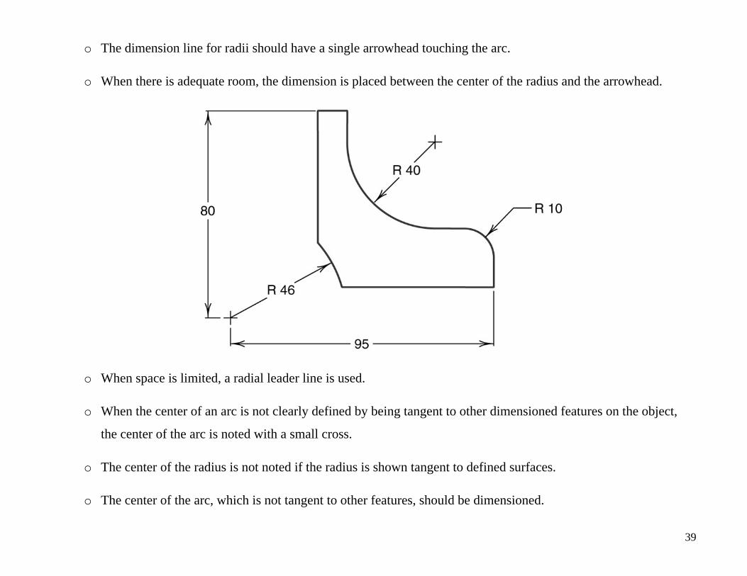
o The dimension line for radii should have a single arrowhead touching the arc.
o When there is adequate room, the dimension is placed between the center of the radius and the arrowhead.
o When space is limited, a radial leader line is used.
o When the center of an arc is not clearly defined by being tangent to other dimensioned features on the object,
the center of the arc is noted with a small cross.
o The center of the radius is not noted if the radius is shown tangent to defined surfaces.
o The center of the arc, which is not tangent to other features, should be dimensioned.
39
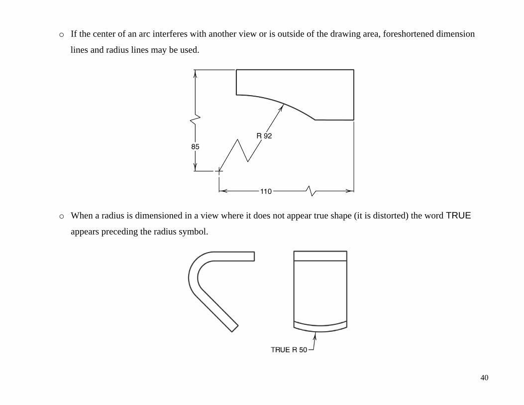
o If the center of an arc interferes with another view or is outside of the drawing area, foreshortened dimension
lines and radius lines may be used.
o When a radius is dimensioned in a view where it does not appear true shape (it is distorted) the word TRUE
appears preceding the radius symbol.
40
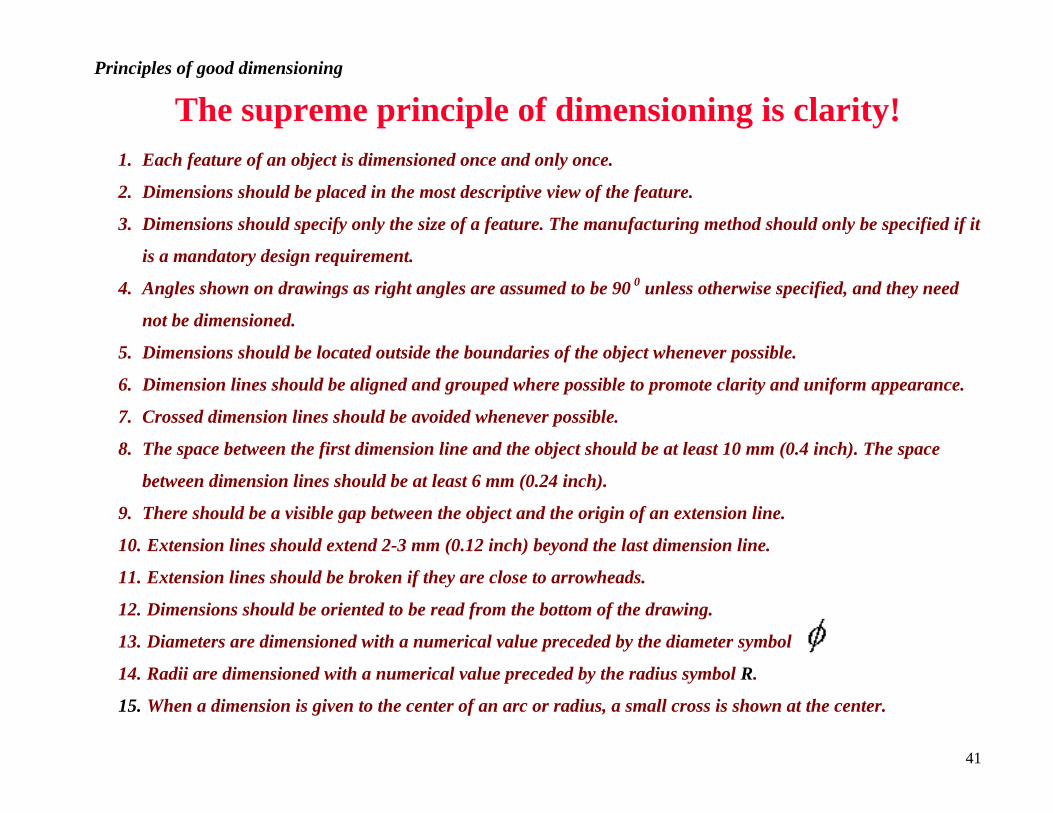
Principles of good dimensioning
The supreme principle of dimensioning is clarity! 1. Each feature of an object is dimensioned once and only once.
2. Dimensions should be placed in the most descriptive view of the feature.
3. Dimensions should specify only the size of a feature. The manufacturing method should only be specified if it
is a mandatory design requirement.
4. Angles shown on drawings as right angles are assumed to be 90 0 unless otherwise specified, and they need
not be dimensioned.
5. Dimensions should be located outside the boundaries of the object whenever possible.
6. Dimension lines should be aligned and grouped where possible to promote clarity and uniform appearance.
7. Crossed dimension lines should be avoided whenever possible.
8. The space between the first dimension line and the object should be at least 10 mm (0.4 inch). The space
between dimension lines should be at least 6 mm (0.24 inch).
9. There should be a visible gap between the object and the origin of an extension line.
10. Extension lines should extend 2-3 mm (0.12 inch) beyond the last dimension line.
11. Extension lines should be broken if they are close to arrowheads.
12. Dimensions should be oriented to be read from the bottom of the drawing.
13. Diameters are dimensioned with a numerical value preceded by the diameter symbol .
14. Radii are dimensioned with a numerical value preceded by the radius symbol R.
15. When a dimension is given to the center of an arc or radius, a small cross is shown at the center.
41