Electrical Machines
67
Electrical Machines Instructor: Tirffneh Yimer (M.Tech) 1
-
Upload
independent -
Category
Documents
-
view
1 -
download
0
Transcript of Electrical Machines
Electrical Machines
Instructor: Tirffneh Yimer (M.Tech)
1
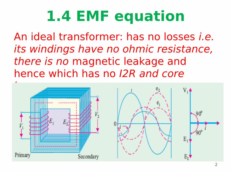
1.4 EMF equationAn ideal transformer: has no losses i.e. its windings have no ohmic resistance, there is no magnetic leakage and hence which has no I2R and core losses.
2
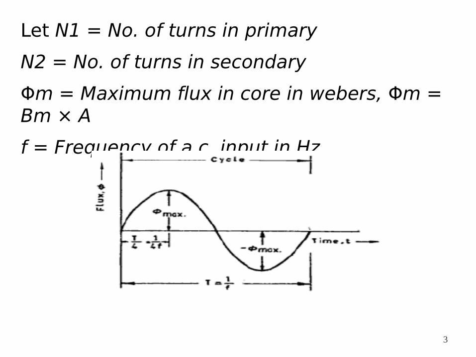
Let N1 = No. of turns in primary
N2 = No. of turns in secondary
Φm = Maximum flux in core in webers, Φm = Bm × A
f = Frequency of a.c. input in Hz
3
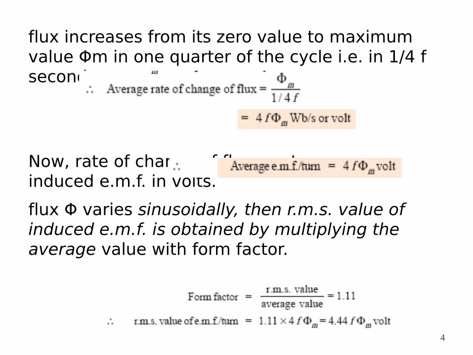
flux increases from its zero value to maximum value Φm in one quarter of the cycle i.e. in 1/4 f second.
Now, rate of change of flux per turn means induced e.m.f. in volts.
flux Φ varies sinusoidally, then r.m.s. value of induced e.m.f. is obtained by multiplying the average value with form factor.
4
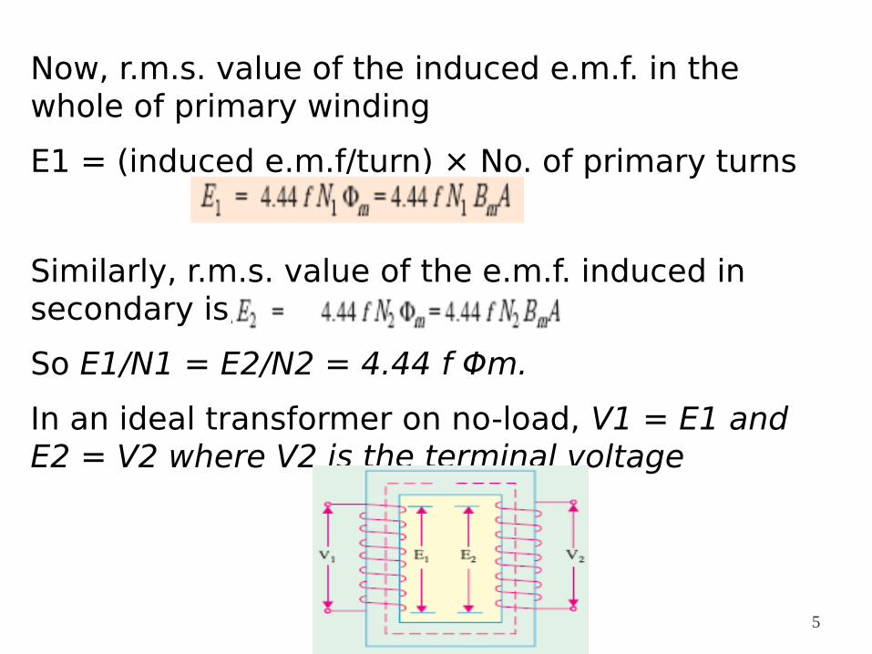
Now, r.m.s. value of the induced e.m.f. in the whole of primary winding
E1 = (induced e.m.f/turn) × No. of primary turns
Similarly, r.m.s. value of the e.m.f. induced in secondary is,
So E1/N1 = E2/N2 = 4.44 f Φm.
In an ideal transformer on no-load, V1 = E1 and E2 = V2 where V2 is the terminal voltage
5
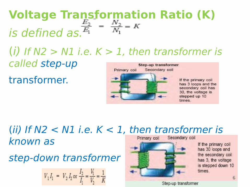
Voltage Transformation Ratio (K)
is defined as:
(i) If N2 > N1 i.e. K > 1, then transformer is called step-up
transformer.
(ii) If N2 < N1 i.e. K < 1, then transformer is known as
step-down transformer
Again, for an ideal transformer, input VA = output VA.
6
1.5 Transformer on No-load and load
Transformer on No-load
Unlike to the ideal transformer in practice the primary input current is not wholly reactive.
Instead it has to supply
(i) iron losses in the core and
(ii) a very small amount of copper loss in primary when it is on No-load condition.
So I0 is not at 90° behind V1 but lags it by an angle φ0 <90°
7
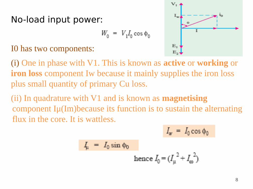
No-load input power:
I0 has two components:
(i) One in phase with V1. This is known as active or working or iron loss component Iw because it mainly supplies the iron loss plus small quantity of primary Cu loss.
(ii) In quadrature with V1 and is known as magnetising component Iμ(Im)because its function is to sustain the alternating flux in the core. It is wattless.
8
The following points should be noted carefully :
1. I0 is very small as compared to the full-load primary current. It is about 1 % of the full-load current.
2. The wave of the exciting or magnetising current is not truly sinusoidal
3. Cu loss is negligibly small which means that no-load primary input is practically equal to the iron loss in the transformer.
4. As it is principally the core-loss which is responsible for shift in the current vector, angle φ0 is known as hysteresis angle of advance. 9
Transformer on Load
When the secondary is loaded, the secondary current I2 is set up
The magnitude and phase of I2 with respect to V2 is determined by the characteristics of the load
Ø I2 is in phase with V2 if load is non-inductive, it lags if load is inductive and it leads if load is capacitive
10
The secondary current sets up its own m.m.f (magnetomotive force) =N2I2 and hence its own flux Φ2 which is in opposition to the main primary flux Φ0 which is due to I0.
Φ2 weakens Φ0 hence primary back e.m.f. E1 tends to be reduced
For a moment V1 gains the upper hand over E1 and hence causes more current to flow in primary
Let the additional primary current be I2′ (known as load component of primary current)
11
I2′ is in antiphase with I2
The additional primary m.m.f. N1 I2′ sets up its own flux Φ2′
Φ2′ is in the same direction as Φ0
Φ2′ is in opposition to Φ2 but is equal to it in magnitude, hence, the two cancel each other
So, we find that the magnetic effects of secondary current I2 are immediately neutralized by the additional primary current I2′
Hence, whatever the load conditions, the net flux passing through the core is approximately the same as at no-load
12
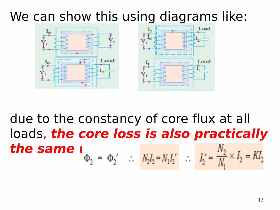
We can show this using diagrams like:
due to the constancy of core flux at all loads, the core loss is also practically the same under all load conditions
13
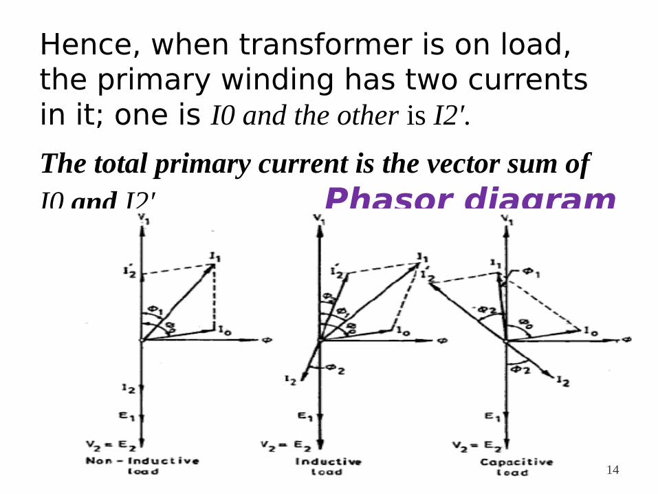
Hence, when transformer is on load, the primary winding has two currents in it; one is I0 and the other is I2′.
The total primary current is the vector sum of I0 and I2′ Phasor diagram
14
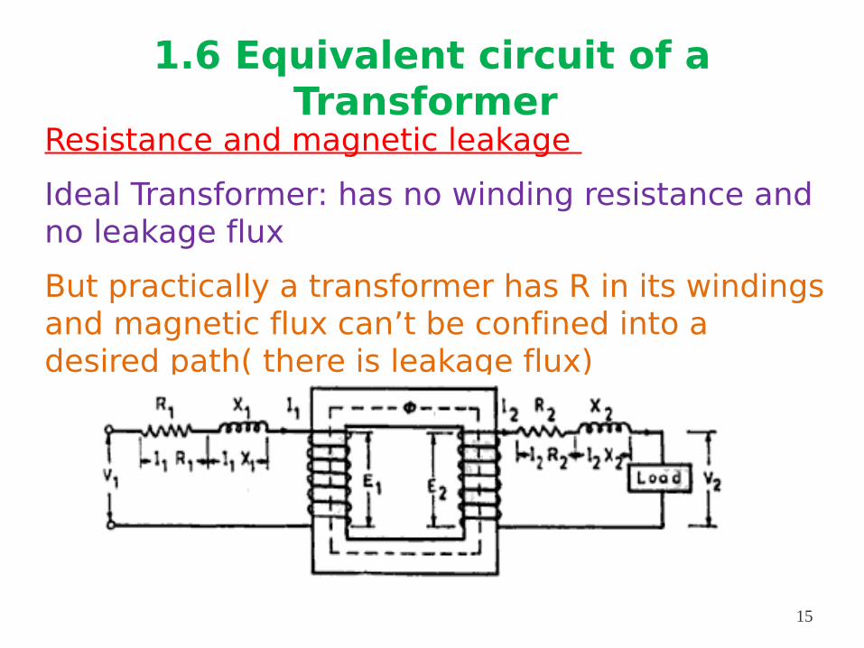
1.6 Equivalent circuit of a Transformer
Resistance and magnetic leakage
Ideal Transformer: has no winding resistance and no leakage flux
But practically a transformer has R in its windings and magnetic flux can’t be confined into a desired path( there is leakage flux)
15
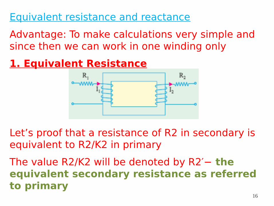
Equivalent resistance and reactance
Advantage: To make calculations very simple and since then we can work in one winding only
1. Equivalent Resistance
Let’s proof that a resistance of R2 in secondary is equivalent to R2/K2 in primary
The value R2/K2 will be denoted by R2′− the equivalent secondary resistance as referred to primary
16
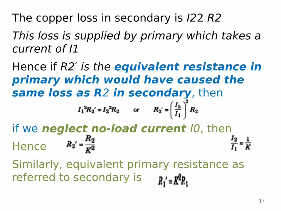
The copper loss in secondary is I22 R2
This loss is supplied by primary which takes a current of I1
Hence if R2′ is the equivalent resistance in primary which would have caused the same loss as R2 in secondary, then
if we neglect no-load current I0, then
Hence
Similarly, equivalent primary resistance as referred to secondary is
17
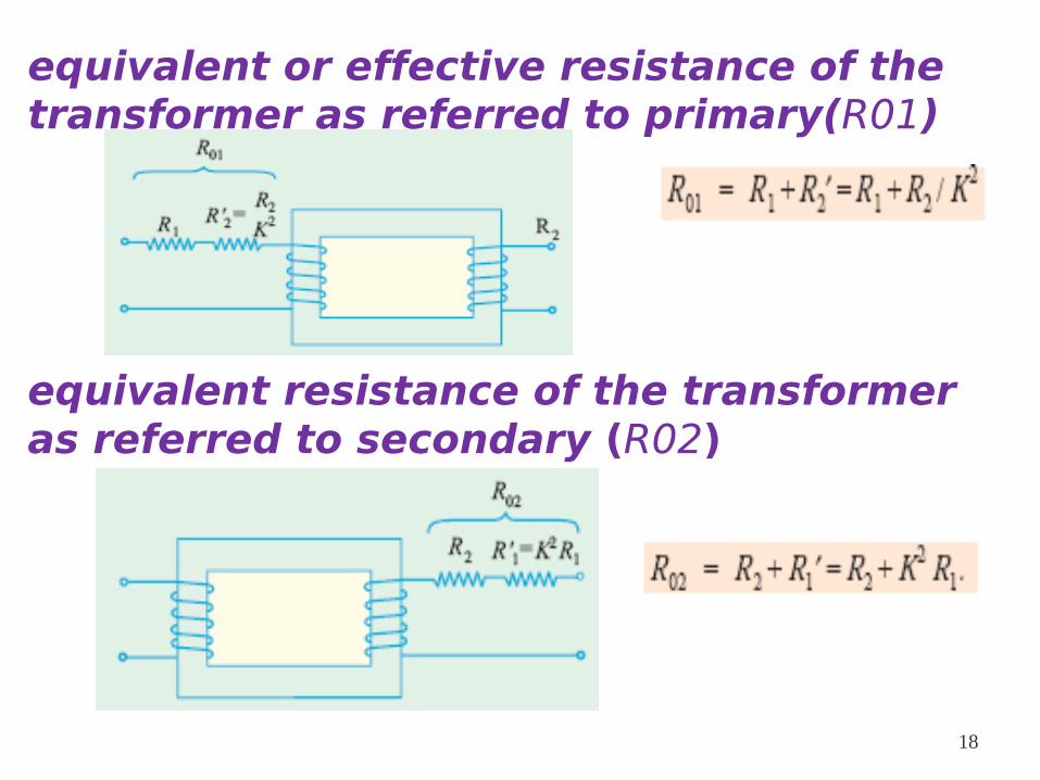
equivalent or effective resistance of the transformer as referred to primary(R01)
equivalent resistance of the transformer as referred to secondary (R02)
18

2. Equivalent leakage reactance
leakage reactances can also be transferred from one winding to the other in the same way as resistance :
19
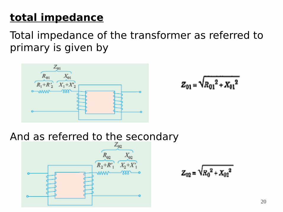
total impedance
Total impedance of the transformer as referred to primary is given by
And as referred to the secondary
20
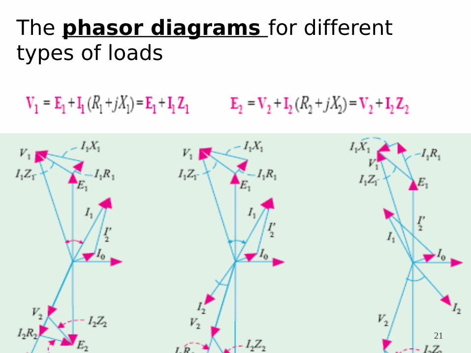
The phasor diagrams for different types of loads
21
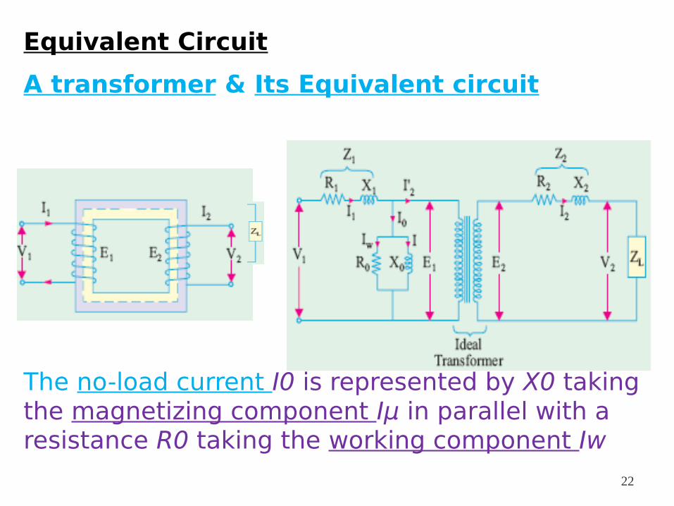
Equivalent Circuit
A transformer & Its Equivalent circuit
The no-load current I0 is represented by X0 taking the magnetizing component Iμ in parallel with a resistance R0 taking the working component Iw
22
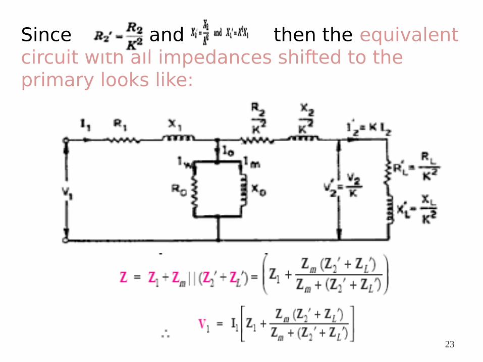
Since and then the equivalent circuit with all impedances shifted to the primary looks like:
23
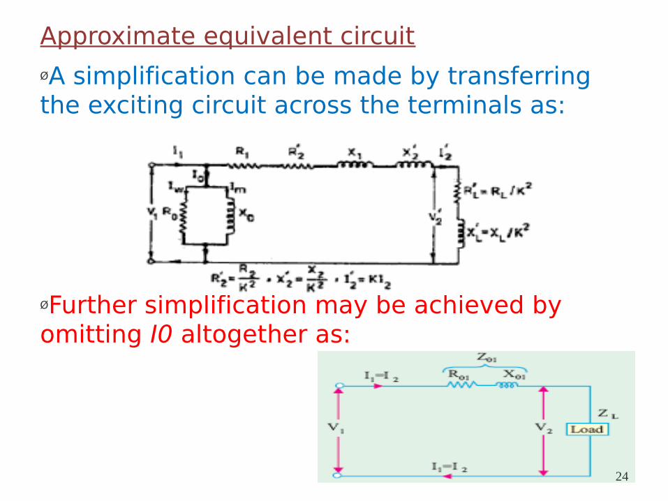
Approximate equivalent circuit
ØA simplification can be made by transferring the exciting circuit across the terminals as:
ØFurther simplification may be achieved by omitting I0 altogether as:
24
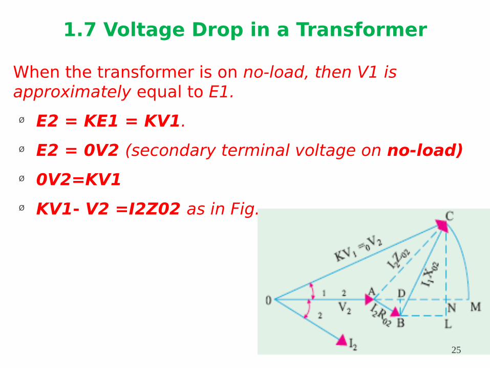
1.7 Voltage Drop in a Transformer
When the transformer is on no-load, then V1 is approximately equal to E1.
Ø E2 = KE1 = KV1.
Ø E2 = 0V2 (secondary terminal voltage on no-load)
Ø 0V2=KV1
Ø KV1- V2 =I2Z02 as in Fig.
25
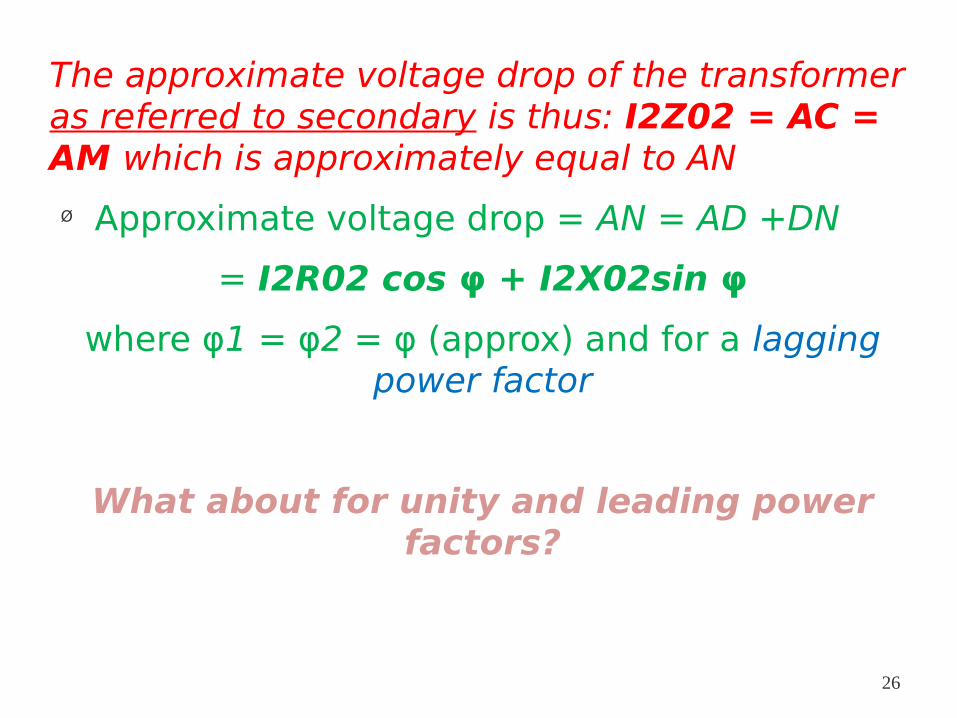
The approximate voltage drop of the transformer as referred to secondary is thus: I2Z02 = AC = AM which is approximately equal to AN
Ø Approximate voltage drop = AN = AD +DN
= I2R02 cos φ + I2X02sin φ
where φ1 = φ2 = φ (approx) and for a lagging power factor
What about for unity and leading power factors?
26
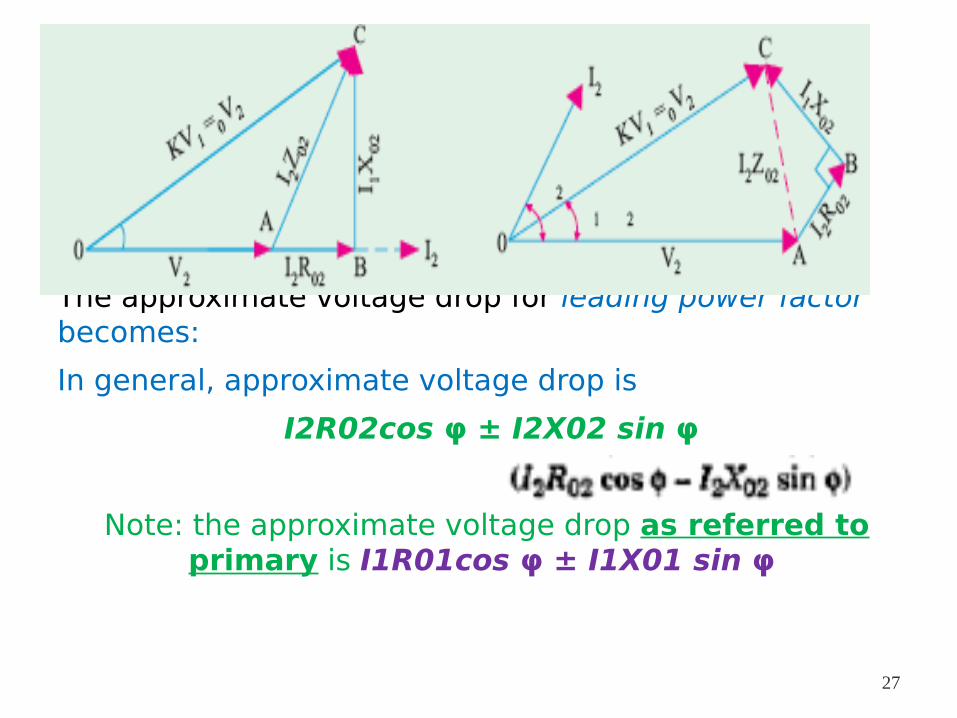
The approximate voltage drop for leading power factor becomes:
In general, approximate voltage drop is
I2R02cos φ ± I2X02 sin φ
Note: the approximate voltage drop as referred to primary is I1R01cos φ ± I1X01 sin φ
27
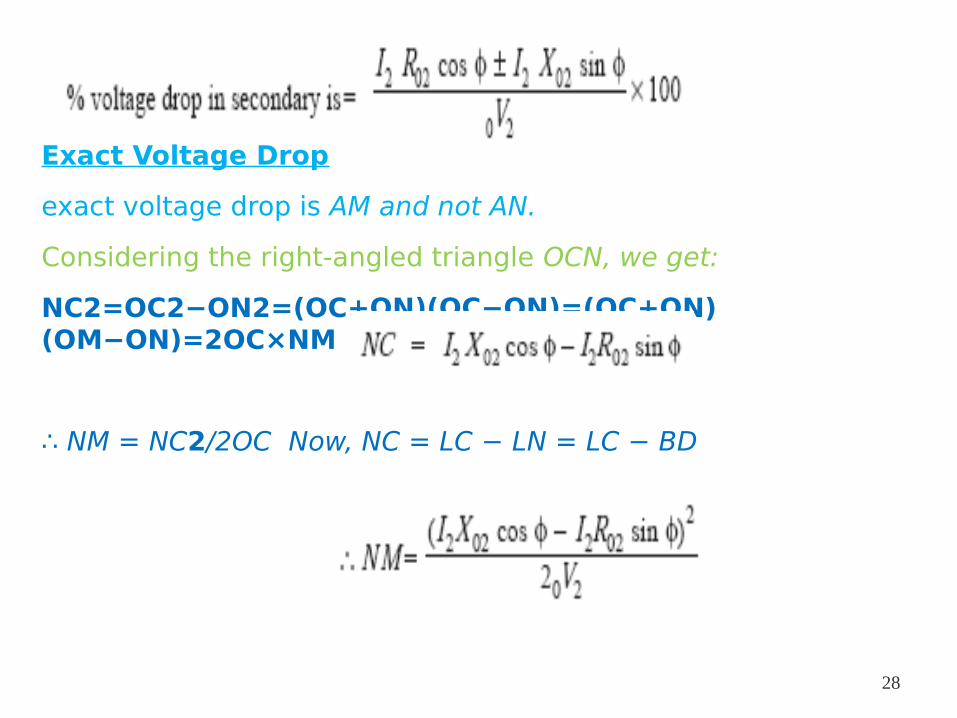
Exact Voltage Drop
exact voltage drop is AM and not AN.
Considering the right-angled triangle OCN, we get:
NC2=OC2−ON2=(OC+ON)(OC−ON)=(OC+ON)(OM−ON)=2OC×NM
∴ NM = NC2/2OC Now, NC = LC − LN = LC − BD
28
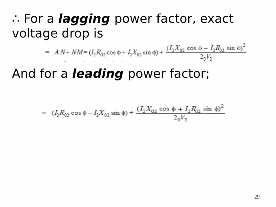
∴ For a lagging power factor, exact voltage drop is
And for a leading power factor;
29
1.8 Transformer Tests
The performance of a transformer can be calculated on the basis of its equivalent circuit which contains:
1. R01 as referred to primary (or secondary R02),
2. X01 as referred to primary (or secondary X02)
3. core-loss conductance G0 (or resistance R0) and
4. The magnetising susceptance B0 (or reactance X0).
These constants or parameters can be easily determined by two tests
(i) open-circuit test
(ii) Short-circuit test
30
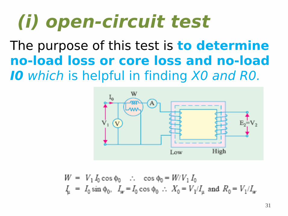
(i) open-circuit testThe purpose of this test is to determine no-load loss or core loss and no-load I0 which is helpful in finding X0 and R0.
31
when a transformer is on no-load (i.e. I0 ≅ Iμ) and as the voltage drop in primary leakage impedance is small,
hence the exciting admittance Y0 of the transformer is given by
The exciting conductance G0 is given by
The exciting susceptance
32
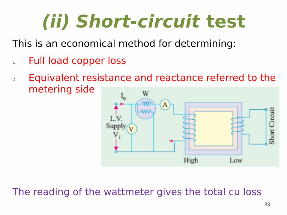
(ii) Short-circuit testThis is an economical method for determining:
1. Full load copper loss
2. Equivalent resistance and reactance referred to the metering side
The reading of the wattmeter gives the total cu loss33
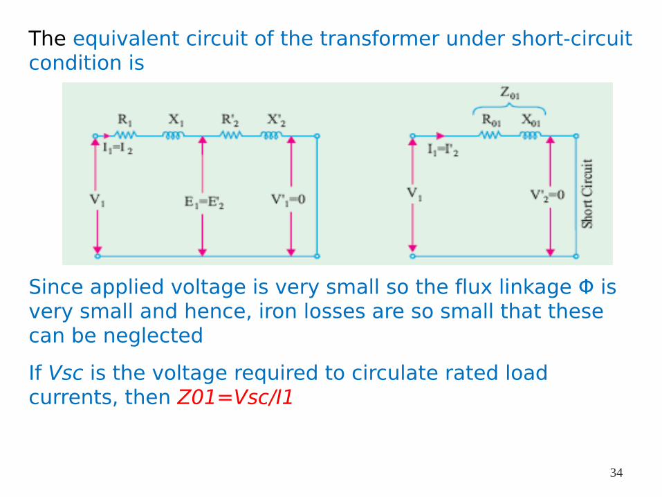
The equivalent circuit of the transformer under short-circuit condition is
Since applied voltage is very small so the flux linkage Φ is very small and hence, iron losses are so small that these can be neglected
If Vsc is the voltage required to circulate rated load currents, then Z01=Vsc/I1
34
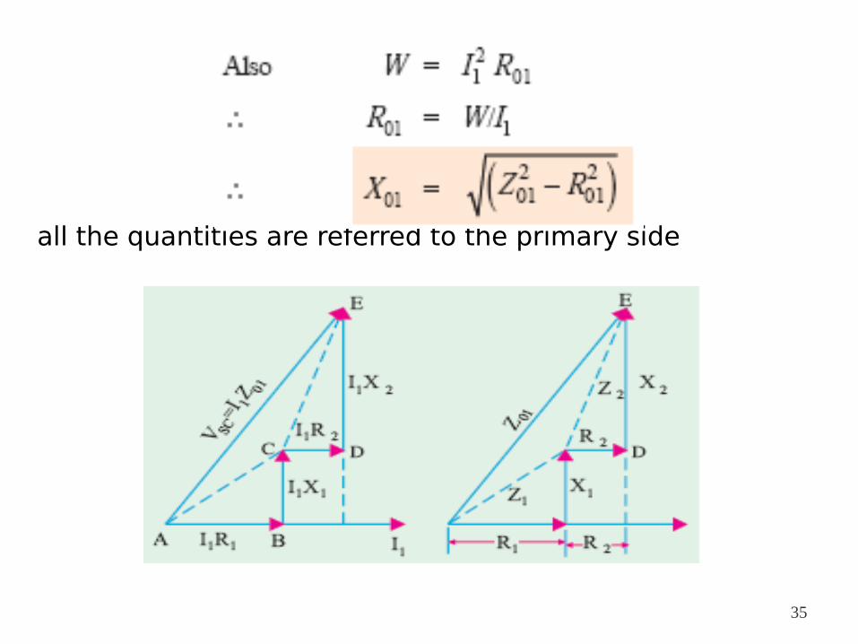
all the quantities are referred to the primary side
35
Why Transformer Rating in kVA ?
Cu loss of a transformer depends on current and iron loss on voltage
So the total transformer loss depends on volt-ampere (VA)
That is why rating of transformers is in kVA and not in kW
36
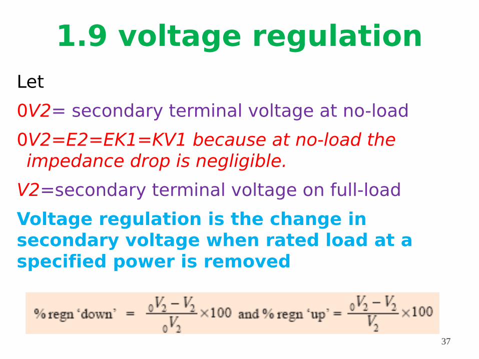
1.9 voltage regulationLet
0V2= secondary terminal voltage at no-load
0V2=E2=EK1=KV1 because at no-load the impedance drop is negligible.
V2=secondary terminal voltage on full-load
Voltage regulation is the change in secondary voltage when rated load at a specified power is removed
37
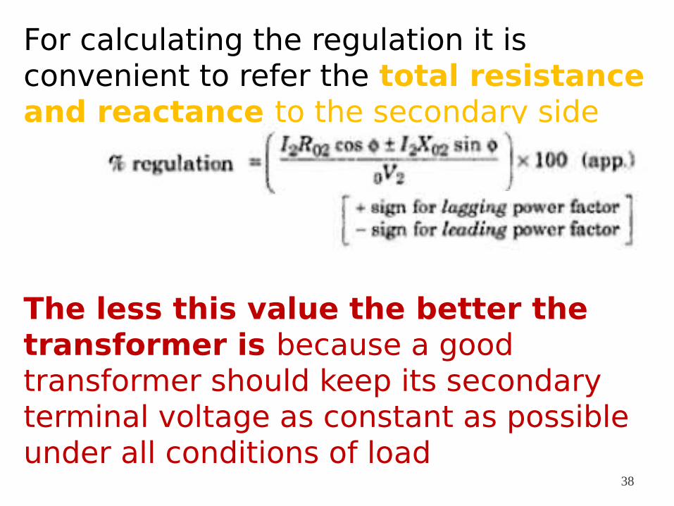
For calculating the regulation it is convenient to refer the total resistance and reactance to the secondary side
The less this value the better the transformer is because a good transformer should keep its secondary terminal voltage as constant as possible under all conditions of load
38
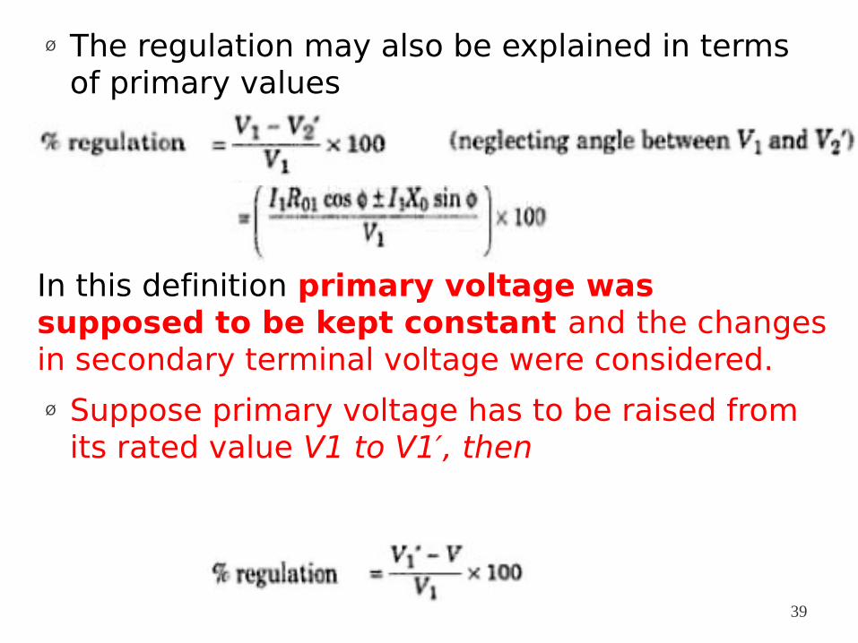
Ø The regulation may also be explained in terms of primary values
In this definition primary voltage was supposed to be kept constant and the changes in secondary terminal voltage were considered.
Ø Suppose primary voltage has to be raised from its rated value V1 to V1′, then
39
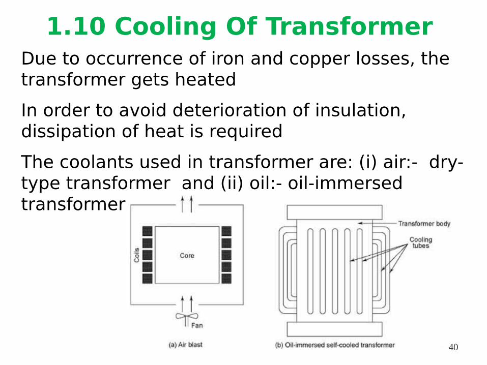
1.10 Cooling Of TransformerDue to occurrence of iron and copper losses, the transformer gets heated
In order to avoid deterioration of insulation, dissipation of heat is required
The coolants used in transformer are: (i) air:- dry-type transformer and (ii) oil:- oil-immersed transformer
40
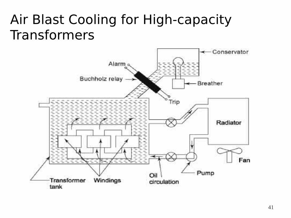
Air Blast Cooling for High-capacity Transformers
41
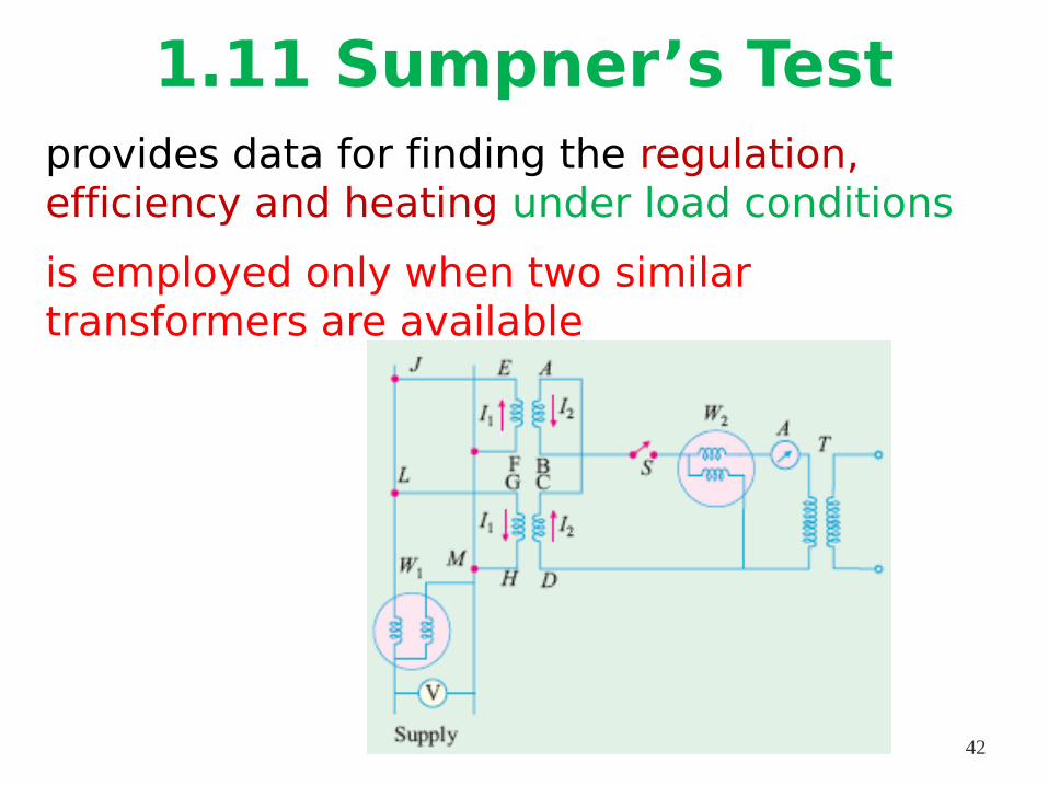
1.11 Sumpner’s Testprovides data for finding the regulation, efficiency and heating under load conditions
is employed only when two similar transformers are available
42
With switch S open, the wattmeter W1 reads the core loss for the two transformers
if VAB = VCD and A is joined to C whilst B is joined to D => no secondary current flowing around the loop formed by the two secondaries
T is an auxiliary low-voltage transformer
adjusting T full-load secondary current I2 flows from D to C and then from A to B
Flow of I1 is confined to the loop FEJLGHMF and it does not pass through W1.
Hence, W1 continues to read the core loss and W2 measures full-load Cu loss
43
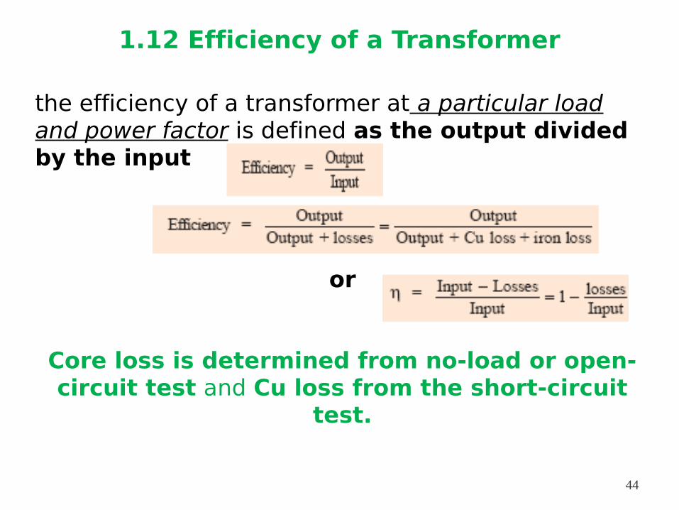
1.12 Efficiency of a Transformer
the efficiency of a transformer at a particular load and power factor is defined as the output divided by the input
or
Core loss is determined from no-load or open-circuit test and Cu loss from the short-circuit
test.
44
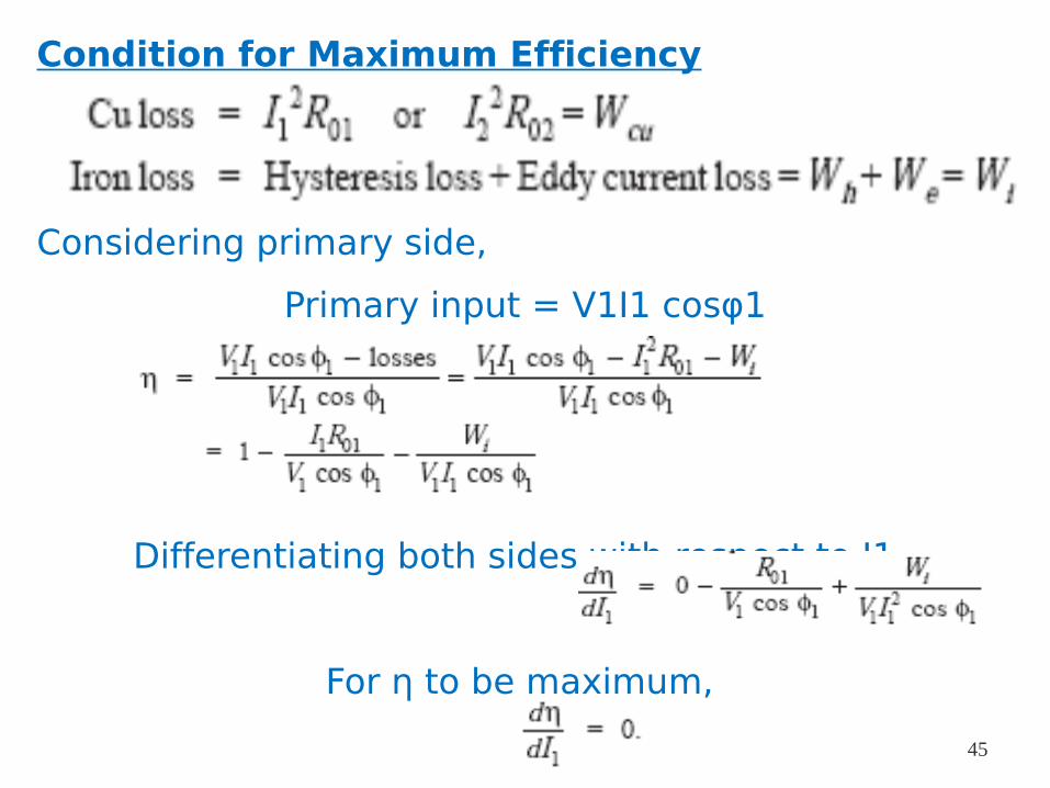
Condition for Maximum Efficiency
Considering primary side,
Primary input = V1I1 cosφ1
Differentiating both sides with respect to I1,
For η to be maximum,
45
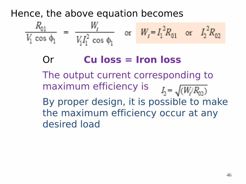
Hence, the above equation becomes
Or Cu loss = Iron loss
The output current corresponding to maximum efficiency is
By proper design, it is possible to make the maximum efficiency occur at any desired load
46
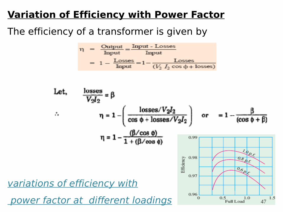
Variation of Efficiency with Power Factor
The efficiency of a transformer is given by
variations of efficiency with
power factor at different loadings 47
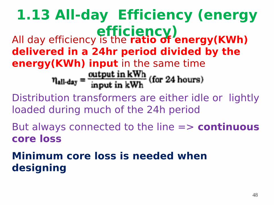
1.13 All-day Efficiency (energy efficiency)
All day efficiency is the ratio of energy(KWh) delivered in a 24hr period divided by the energy(KWh) input in the same time
Distribution transformers are either idle or lightly loaded during much of the 24h period
But always connected to the line => continuous core loss
Minimum core loss is needed when designing
48
The Cu losses are relatively less important, because they depend on the load
So distribution transformers are designed for relatively large full load cu loss and have their maximum efficiencies at light loads
Ø high all-day efficiency
Power transformers however, on the other hand are continuously and are designed for full-load cu losses equal to about twice the no load losses 49
To find this all-day efficiency we have to know the load cycle on the transformer i.e., how much and how long the transformer is loaded during 24 hours
Practical calculations are facilitated by making use of a load factor
50
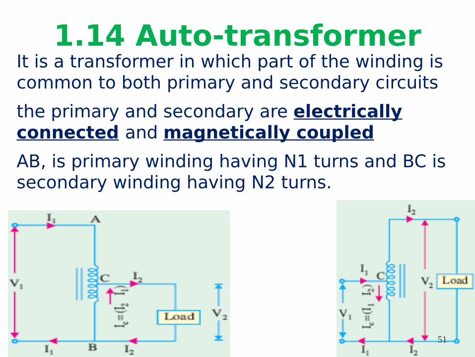
1.14 Auto-transformerIt is a transformer in which part of the winding is common to both primary and secondary circuits
the primary and secondary are electrically connected and magnetically coupled
AB, is primary winding having N1 turns and BC is secondary winding having N2 turns.
51
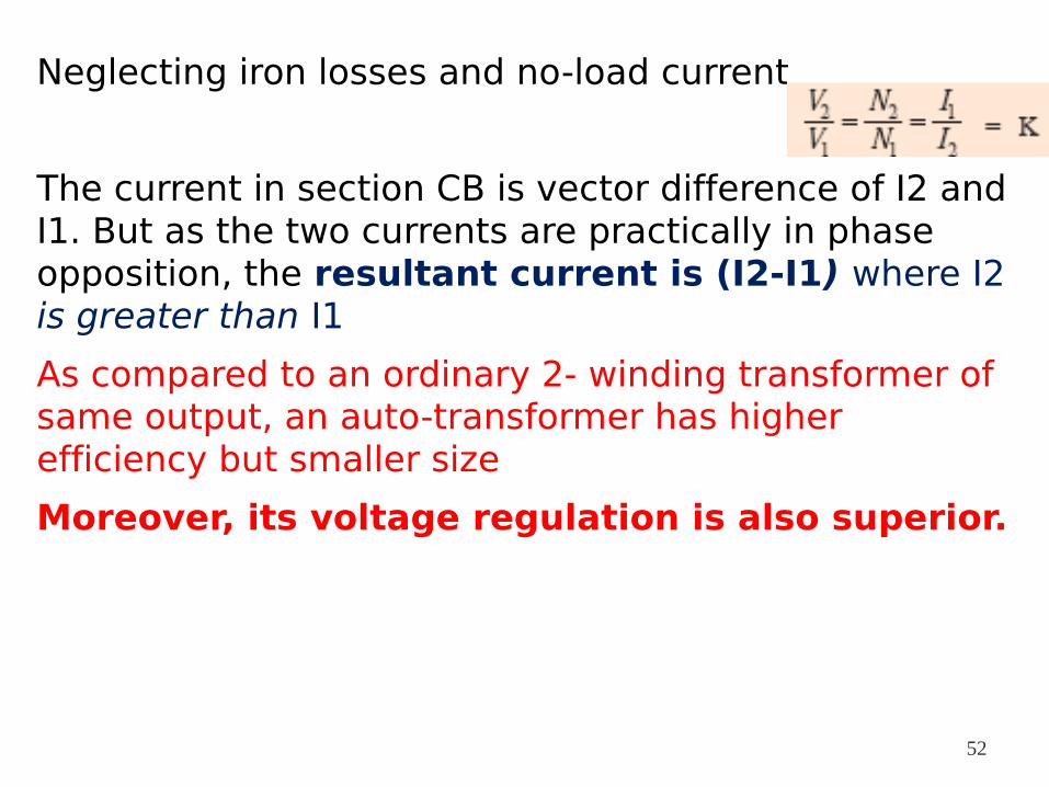
Neglecting iron losses and no-load current
The current in section CB is vector difference of I2 and I1. But as the two currents are practically in phase opposition, the resultant current is (I2-I1) where I2 is greater than I1
As compared to an ordinary 2- winding transformer of same output, an auto-transformer has higher efficiency but smaller size
Moreover, its voltage regulation is also superior.
52
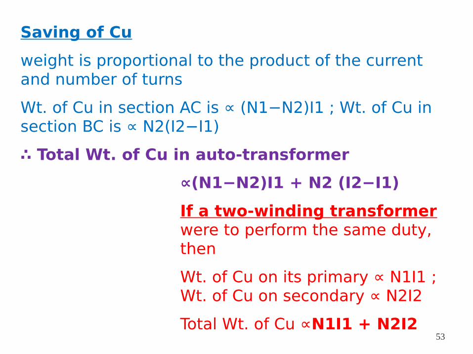
Saving of Cu
weight is proportional to the product of the current and number of turns
Wt. of Cu in section AC is ∝ (N1−N2)I1 ; Wt. of Cu in section BC is ∝ N2(I2−I1)
∴ Total Wt. of Cu in auto-transformer
∝(N1−N2)I1 + N2 (I2−I1)
If a two-winding transformer were to perform the same duty, then
Wt. of Cu on its primary ∝ N1I1 ; Wt. of Cu on secondary ∝ N2I2
Total Wt. of Cu ∝N1I1 + N2I253
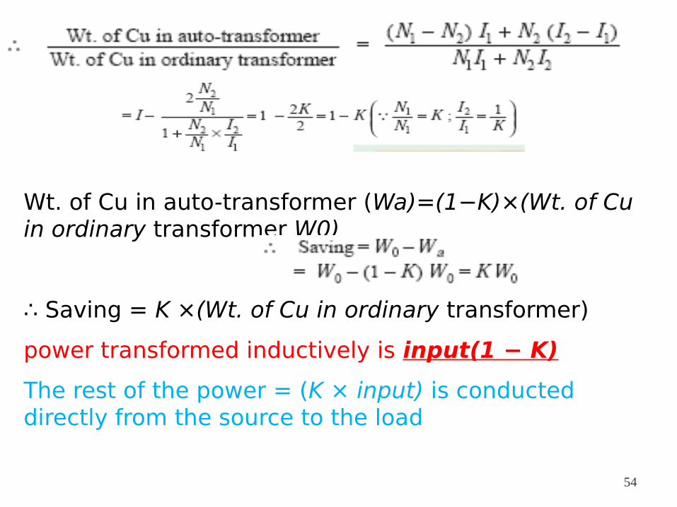
Wt. of Cu in auto-transformer (Wa)=(1−K)×(Wt. of Cu in ordinary transformer W0)
∴ Saving = K ×(Wt. of Cu in ordinary transformer)
power transformed inductively is input(1 − K)
The rest of the power = (K × input) is conducted directly from the source to the load
54
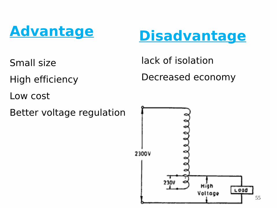
Advantage
Small size
High efficiency
Low cost
Better voltage regulation
Disadvantage
lack of isolation
Decreased economy
55
Application
1. To give small boost to a distribution cable to correct the voltage drop
2. As auto-starter transformers to give up to 50 to 60 % of full voltage to an induction motor during starting.
3. As furnace transformers for getting a convenient supply to suit the furnace winding from a 230-V supply
4. As interconnecting transformers in 132 kV/330 kV system.
5. In control equipment for 1-phase and 3-phase electrical locomotives. 56
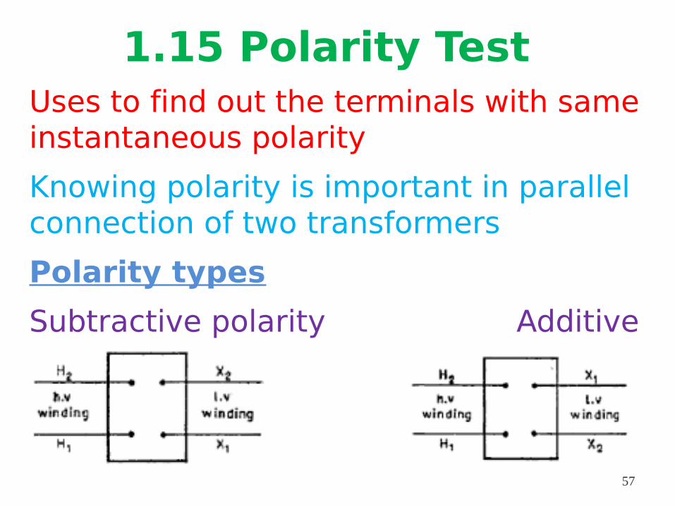
1.15 Polarity TestUses to find out the terminals with same instantaneous polarity
Knowing polarity is important in parallel connection of two transformers
Polarity types
Subtractive polarity Additive polarity
57
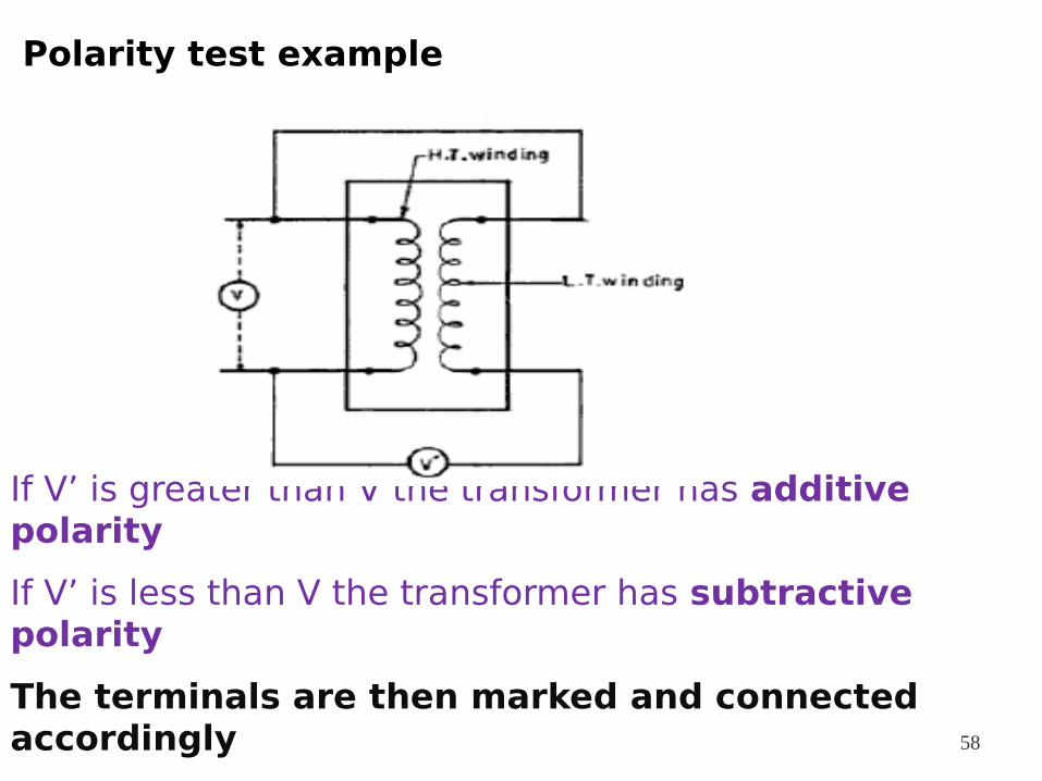
Polarity test example
If V’ is greater than V the transformer has additive polarity
If V’ is less than V the transformer has subtractive polarity
The terminals are then marked and connected accordingly 58
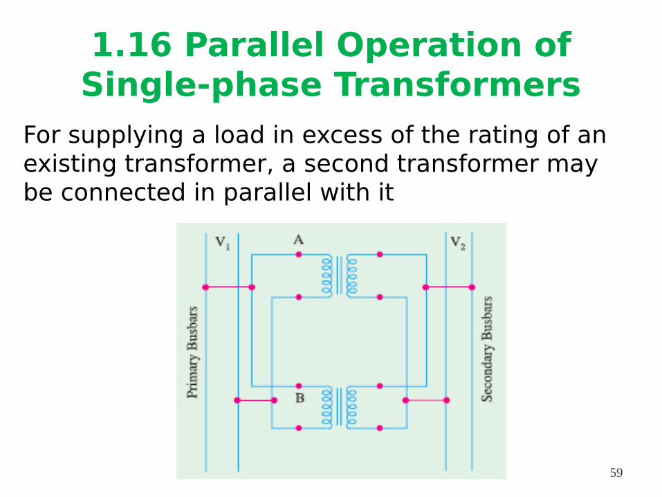
1.16 Parallel Operation of Single-phase Transformers
For supplying a load in excess of the rating of an existing transformer, a second transformer may be connected in parallel with it
59
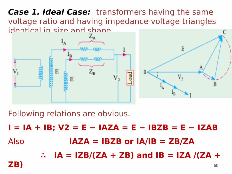
Case 1. Ideal Case: transformers having the same voltage ratio and having impedance voltage triangles identical in size and shape
Following relations are obvious.
I = IA + IB; V2 = E − IAZA = E − IBZB = E − IZAB
Also IAZA = IBZB or IA/IB = ZB/ZA
∴ IA = IZB/(ZA + ZB) and IB = IZA /(ZA + ZB) 60
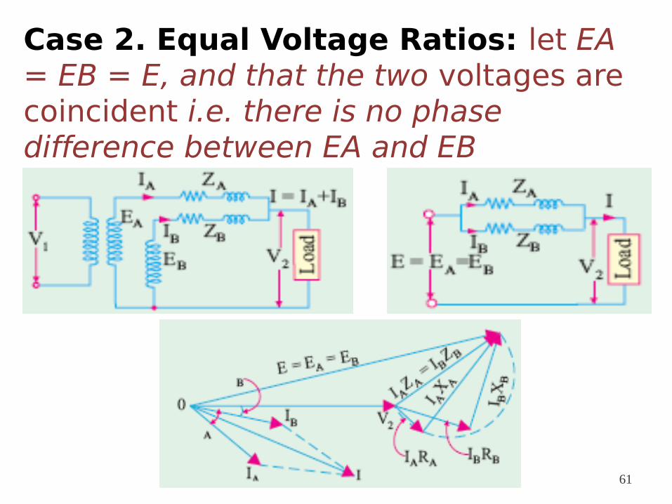
Case 2. Equal Voltage Ratios: let EA = EB = E, and that the two voltages are coincident i.e. there is no phase difference between EA and EB
61
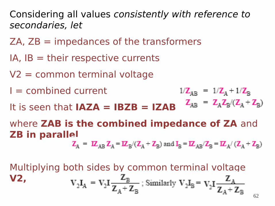
Considering all values consistently with reference to secondaries, let
ZA, ZB = impedances of the transformers
IA, IB = their respective currents
V2 = common terminal voltage
I = combined current
It is seen that IAZA = IBZB = IZAB
where ZAB is the combined impedance of ZA and ZB in parallel
Multiplying both sides by common terminal voltage V2,
62
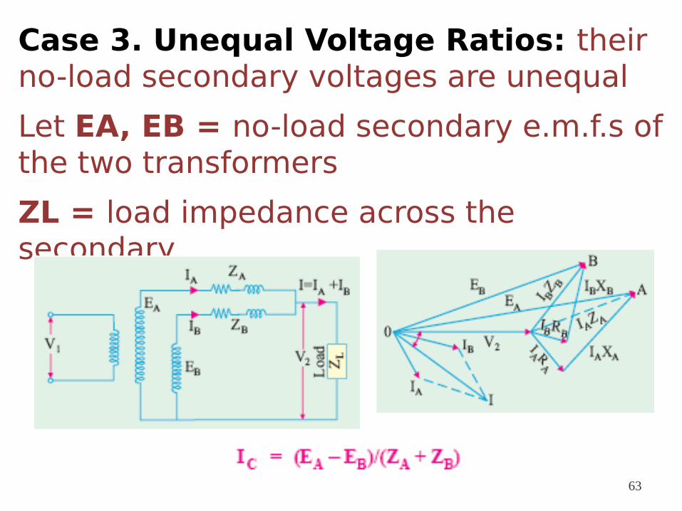
Case 3. Unequal Voltage Ratios: their no-load secondary voltages are unequal
Let EA, EB = no-load secondary e.m.f.s of the two transformers
ZL = load impedance across the secondary
63
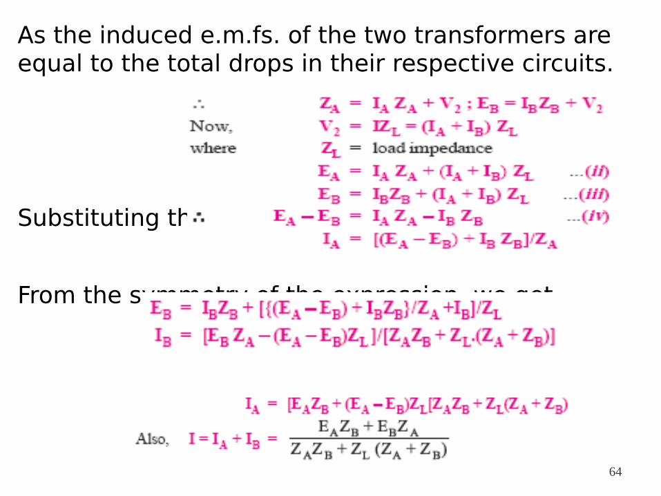
As the induced e.m.fs. of the two transformers are equal to the total drops in their respective circuits.
Substituting this value of IA in eqn (iii),we get
From the symmetry of the expression, we get
64
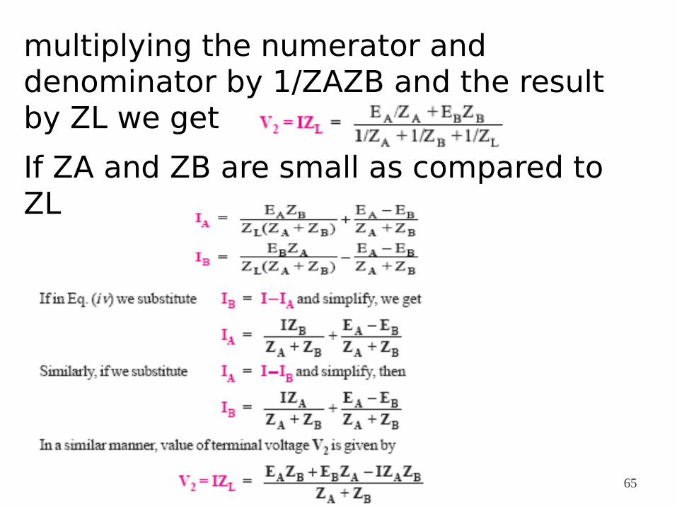
multiplying the numerator and denominator by 1/ZAZB and the result by ZL we get
If ZA and ZB are small as compared to ZL
65

66

67