“Electrical Machines”Liu, C.C., Vu, K.T., Yu, Y., Galler, D., Strange, E.G., Ong, Chee-Mun
42
Liu, C.C., Vu, K.T., Yu, Y., Galler, D., Strange, E.G., Ong, Chee-Mun “Electrical Machines” The Electrical Engineering Handbook Ed. Richard C. Dorf Boca Raton: CRC Press LLC, 2000
Transcript of “Electrical Machines”Liu, C.C., Vu, K.T., Yu, Y., Galler, D., Strange, E.G., Ong, Chee-Mun

Liu, C.C., Vu, K.T., Yu, Y., Galler, D., Strange, E.G., Ong, Chee-Mun “ElectricalMachines”The Electrical Engineering HandbookEd. Richard C. DorfBoca Raton: CRC Press LLC, 2000

66Electrical Machines
66.1 GeneratorsAC Generators • DC Generators
66.2 MotorsMotor Applications • Motor Analysis
66.3 Small Electric MotorsSingle Phase Induction Motors • Universal Motors • Permanent Magnet AC Motors • Stepping Motors
66.4 Simulation of Electric MachineryBasics in Modeling • Modular Approach • Mathematical Transformations • Base Quantities • Simulation of Synchronous Machines • Three-Phase Induction Machines
66.1 Generators
Chen-Ching Liu, Khoi Tien Vu, and Yixin Yu
Electric generators are devices that convert energy from a mechanical form to an electrical form. This process,known as electromechanical energy conversion, involves magnetic fields that act as an intermediate medium.There are two types of generators: alternating current (ac) and direct current (dc). This section explains howthese devices work and how they are modeled in analytical or numerical studies.
The input to the machine can be derived from a number of energy sources. For example, in the generationof large-scale electric power, coal can produce steam that drives the shaft of the machine. Typically, for such athermal process, only about 1/3 of the raw energy (i.e., from coal) is converted into mechanical energy. Thefinal step of the energy conversion is quite efficient, with an efficiency close to 100%.
The generator’s operation is based on Faraday’s law of electromagnetic induction. In brief, if a coil (orwinding) is linked to a varying magnetic field, then an electromotive force, or voltage, emf, is induced acrossthe coil. Thus, generators have two essential parts: one creates a magnetic field, and the other where the emf ’sare induced. The magnetic field is typically generated by electromagnets (thus, the field intensity can be adjustedfor control purposes), whose windings are referred to as field windings or field circuits. The coils where theemf ’s are induced are called armature windings or armature circuits. One of these two components is stationary(stator), and the other is a rotational part (rotor) driven by an external torque. Conceptually, it is immaterialwhich of the two components is to rotate because, in either case, the armature circuits always “see” a varyingmagnetic field. However, practical considerations lead to the common design that for ac generators, the fieldwindings are mounted on the rotor and the armature windings on the stator. In contrast, for dc generators,the field windings are on the stator and armature on the rotor.
AC Generators
Today, most electric power is produced by synchronous generators. Synchronous generators rotate at a constantspeed, called synchronous speed. This speed is dictated by the operating frequency of the system and themachine structure. There are also ac generators that do not necessarily rotate at a fixed speed such as those
Chen-Ching LiuUniversity of Washington
Khoi Tien VuABB Transmission Technical Institute
Yixin YuTianjing University
Donald GallerMassachusetts Institute of Technology
Elias G. StrangasMichigan State University
Chee-Mun OngPurdue University
© 2000 by CRC Press LLC

found in windmills (induction generators); these generators, however, account for only a very small percentageof today’s generated power.
Synchronous Generators
Principle of Operation. For an illustration of the steady-state operation,refer to Fig. 66.1 which shows a cross section of an ac machine. The rotorconsists of a winding wrapped around a steel body. A dc current is madeto flow in the rotor winding (or field winding), and this results in amagnetic field (rotor field). When the rotor is made to rotate at a constantspeed, the three stationary windings aa ′, bb′, and cc ′ experience a period-ically varying magnetic field. Thus, emf ’s are induced across these wind-ings in accordance with Faraday’s law. These emf ’s are ac and periodic;each period corresponds to one revolution of the rotor. Thus, for 60-Hzelectricity, the rotor of Fig. 66.1 has to rotate at 3600 revolutions perminute (rpm); this is the synchronous speed of the given machine. Becausethe windings aa ′, bb′, and cc ′ are displaced equally in space from eachother (by 120 degrees), their emf waveforms are displaced in time by 1/3of a period. In other words, the machine of Fig. 66.1 is capable of gener-ating three-phase electricity. This machine has two poles since its rotorfield resembles that of a bar magnet with a north pole and a south pole.
When the stator windings are connected to an external (electrical) systemto form a closed circuit, the steady-state currents in these windings are also periodic. These currents create magneticfields of their own. Each of these fields is pulsating with time because the associated current is ac; however, thecombination of the three fields is a revolving field. This revolving field arises from the space displacements of thewindings and the phase differences of their currents. This combined magnetic field has two poles and rotates atthe same speed and direction as the rotor. In summary, for a loaded synchronous (ac) generator operating in asteady state, there are two fields rotating at the same speed: one is due to the rotor winding and the other due tothe stator windings. It is important to observe that the armature circuits are in fact exposed to two rotating fields,one of which, the armature field, is caused by and in fact tends to counter the effect of the other, the rotor field.The result is that the induced emf in the armature can be reduced when compared with an unloaded machine(i.e., open-circuited stator windings). This phenomenon is referred to as armature reaction.
It is possible to build a machine with p poles, where p = 4, 6, 8, . . . (even numbers). For example, the cross-sectional view of a four-pole machine is given in Fig. 66.2. For the specified direction of the (dc) current in therotor windings, the rotor field has two pairs of north and south poles arranged as shown. The emf induced in astator winding completes one period for every pair of north and south poles sweeping by; thus, each revolutionof the rotor corresponds to two periods of the stator emf’s. If the machine is to operate at 60 Hz then the rotorneeds to rotate at 1800 rpm. In general, a p-pole machine operating at 60 Hz has a rotor speed of 3600/(p/2) rpm.That is, the lower the number of poles is, the higher the rotor speed has to be. In practice, the number of polesis dictated by the mechanical system (prime mover) that drives the rotor. Steam turbines operate best at a highspeed; thus, two- or four-pole machines are suitable. Machines driven by hydro turbines usually have more poles.
Usually, the stator windings are arranged so that the resulting armature field has the same number of polesas the rotor field. In practice, there are many possible ways to arrange these windings; the essential idea, however,can be understood via the simple arrangement shown in Fig. 66.2. Each phase consists of a pair of windings(thus occupies four slots on the stator structure), e.g., those for phase a are labeled a1a1′ and a2a2′. Geometrysuggests that, at any time instant, equal emf ’s are induced across the windings of the same phase. If the individualwindings are connected in series as shown in Fig. 66.2, their emf ’s add up to form the phase voltage.
Mathematical/Circuit Models. There are various models for synchronous machines, depending on how muchdetail one needs in an analysis. In the simplest model, the machine is equivalent to a constant voltage sourcein series with an impedance. In more complex models, numerous nonlinear differential equations are involved.
Steady-state model. When a machine is in a steady state, the model requires no differential equations. Therepresentation, however, depends on the rotor structure: whether the rotor is cylindrical (round) or salient.
FIGURE 66.1 Cross section of a sim-ple two-pole synchronous machine.The rotor body is salient. Current inrotor winding: � into the page, � outof the page.
© 2000 by CRC Press LLC

The rotors depicted in Figs. 66.1 and 66.2 are salient since the poles are protruding from the shaft. Suchstructures are mechanically weak, since at a high speed (3600 rpm and 1800 rpm, respectively) the centrifugalforce becomes a serious problem. Practically, for high-speed turbines, round-rotor (or cylindrical-rotor) struc-tures are preferred. The cross section of a two-pole, round-rotor machine is depicted in Fig. 66.3. From apractical viewpoint, salient rotors are easier to build because each pole and its winding can be manufacturedseparately and then mounted on the rotor shaft. For round rotors, slots need to be reserved in the rotor wherethe windings can be placed.
The mathematical model for round-rotor machines is much simpler than that for salient-rotor ones. Thisstems from the fact that the rotor body has a permeability much higher than that of the air. In a steady state,the stator field and the rotor body are at a standstill relative to each other. (They rotate at the same speed asdiscussed earlier.) If the rotor is salient, it is easier to establish the magnetic flux lines along the direction ofthe rotor body (when viewed from the cross section). Therefore, for the same set of stator currents, differentpositions of the rotor alter the stator field in different ways; this implies that the induced emf ’s are different.If the rotor is round, then the relative position of the rotor structure does not affect the stator field. Hence, theassociated mathematical model is simplified.
In the following, the steady-state models of the round-rotor and salient-rotor generators are explained.Refer to Fig. 66.3 which shows a two-pole round-rotor machine. Without loss of generality, one can select
phase a (i.e., winding aa¢) for the development of a mathematical model of the machine. As mentionedpreviously, the (armature or stator) winding of phase a is exposed to two magnetic fields: rotor field and statorfield.
1. Rotor field. Its flux as seen by winding aa¢ varies with the rotor position; the flux linkage is largest whenthe N–S axis is perpendicular to the winding surface and minimum (zero) when this axis aligns withthe surface. Thus, one can express the flux due to the rotor field as seen by winding aa¢ as l1 = L(q)IF
where q is to denote the angular position of the N–S axis (of the rotor field) relative to the surface ofaa¢, IF is the rotor current (a dc current), and L is a periodic function of q.
2. Stator field. Its flux as seen by winding aa¢ is a combination of three individual fields which are due tocurrents in the stator windings, ia, ib, and ic. This flux can be expressed as l2 = Ls ia + Lmib + Lmic , whereLs (Lm) is the self (mutual) inductance. Because the rotor is round, Ls and Lm are not dependent on q,the relative position of the rotor and the winding. Typically, the sum of the stator currents ia + ib + ic isnear zero; thus, one can write l2 = (Ls – Lm)ia.
The total flux seen by winding aa¢ is l = l1 – l2 = L(q)IF – (Ls – Lm)ia, where the minus sign in l1 – l2 isdue to the fact that the stator field opposes the rotor field. The induced emf across the winding aa¢ is dl/dt,the time derivative of l:
FIGURE 66.2 Left, cross section of a four-pole synchro-nous machine. Rotor has a salient pole structure. Right,schematic diagram for phase a windings.
FIGURE 66.3 Cross section of atwo-pole round-rotor synchronousmachine.
© 2000 by CRC Press LLC

The time-varying quantities are normally sinusoidal, and for practical purposes, can be represented byphasors. Thus the above expression becomes:
where w0 is the angular speed (rad/s) of the rotor in a steady state. This equation can be modeled as a voltagesource –E F behind a reactance jXs , as shown in Fig. 66.4; this reactance is usually referred to as synchronousreactance. The resistor Ra in the diagram represents the winding resistance, and Vt is the voltage measured acrossthe winding.
As mentioned, the theory for salient-rotor machines is more com-plicated. In the equation l2 = Ls ia + Lmib + Lmic, the terms Ls and Lm
are now dependent on the (relative) position of the rotor. For example(refer to Fig. 66.1), Ls is maximum when the rotor is in a verticalposition and minimum when the rotor is 90° away.
In the derivation of the mathematical/circuit model for salient-rotormachines, the stator field B2 can be resolved into two components;when the rotor is viewed from a cross section, one component alignsalong the rotor and the other is perpendicular to the rotor (Fig. 66.5).The component Bd , which directly opposes the rotor field, is said tobelong to the direct axis; the other component, Bq, is weaker andbelongs to the quadrature axis. The model for a salient-rotor machineconsists of two circuits, direct-axis circuit and quadrature-axis circuit,each similar to Fig. 66.4. Any quantity of interest, such as Ia, the currentin winding aa¢, is made up of two components, one from each circuit.The round-rotor machine can be viewed as a special case of the salient-pole theory where the corresponding parameters of the d-axis andq-axis circuits are equal.
Dynamic models. When a power system is in a steady state (i.e.,operated at an equilibrium), the electrical output of each generator isequal to the power applied to the rotor shaft. (Various losses have beenneglected without affecting the essential ideas provided in this discus-sion.) Disturbances occur frequently in power systems, however.Examples of disturbances are load changes, short circuits, and equip-ment outages. A disturbance results in a mismatch between the powerinput and output of generators, and therefore the rotors depart fromtheir synchronous-speed operation. Intuitively, the impact is moresevere for machines closer to the disturbance. When a system is per-turbed, there are several possibilities for its subsequent behavior. If thedisturbance is small, the machines may soon reach a new steady speed,which is close to or identical to their synchronous speed, in which casethe system is said to be stable. It may also happen that some machines speed up while others slow down. In amore complicated situation, a rotor may oscillate about its synchronous speed. This results in an unstable case.An unstable situation can result in abnormal changes in system frequency and voltage and, unless properlycontrolled, may lead to damage to machines (e.g., broken shafts). To study these phenomena, dynamic modelsare required. Details of a dynamic model depend on a number of factors such as location of disturbance andtime duration of interest. An overview of dynamic generator models is given here. In essence, there are twoaspects that need be modeled: electromechanical and electromagnetic.
ed
dt
dL
dtI L L
di
dte L L
di
dta F s m
aF s m
a= = =l
– ( – ) – ( – )D
E E L L j I E jX Ia F s m a F s a= - =( – ) –w0D
FIGURE 66.4 Per-phase equivalent cir-cuit of round-rotor synchronousmachines. – E F is the internal voltage(phasor form) and Vt is the terminal volt-
FIGURE 66.5 In the salient-pole the-ory, the stator field (represented by asingle vector B2 ) is decomposed into Bd
and Bq . Note that *Bd* > *Bq *.
© 2000 by CRC Press LLC

1. Electromechanical equations. Electromechanical equations are to model the effect of input–output imbal-ance on the rotor speed (and therefore on the operating frequency). The rotor of each machine can be describedby the so-called swing equation,
where q denotes the rotor position relative to a certain rotating frame, M the inertia of rotor, and D damping.The term dq/dt represents the angular velocity and d2q/dt2 is the angular acceleration of the rotor. The precedingdifferential equation is derived from Newton’s law for rotational motions and, in some respects, resembles thedynamical equation of a swinging pendulum (with Pin ~ driving torque, and Pout ~ restoring torque). The termPin, which drives the rotor shaft, can be considered constant in many cases. The term Pout, the power sent outto the system, may behave in a very complicated way. Qualitatively, Pout tends to increase (respectively, decrease)as the rotor position moves forward (respectively, backward) relative to the synchronous rotating frame.However, such a stable operation can take place only when the system is capable of absorbing (respectively,providing) the extra power. In a multimachine system, conflict might arise when various machines competewith each other in sending out more (or sending out less) electrical power; as a result, the stabilizing effectmight be reduced or even lost.
2. Electromagnetic equations. The (nonlinear) electromagnetic equations are derived from Faraday’s law ofelectromagnetic induction—induced emf ’s are proportional to the rate of change of the magnetic fluxes. Ageneral form is as follows:
(66.1)
where
(66.2)
The true terminal voltage, e.g., ea for phase a, can be obtained bycombining the direct-axis and quadrature-axis components ed and eq,respectively, which are given in Eq. (66.1). On each line of Eq. (66.1),the induced emf is the combination of two sources: the first is the rateof change of the flux on the same axis [(d/dt)ld on the first line,(d/dt)lq on the second]; the second comes into effect only when adisturbance makes the rotor and stator fields depart from each other[given by (d/dt)q]. The third term in the voltage equation representsthe ohmic loss associated with the stator winding.
Equation (66.2) expresses the fluxes in terms of relevant currents:flux is equal to inductance times current, with inductances G(s), Xd(s),Xq(s) given in an operational form (s denotes the derivative operator).
Figure 66.6 gives a general view of the input–output state descrip-tion of machine’s dynamic model, the state variables of which appearin Eqs. (66.1) and (66.2).
Md
dtD
d
dtP P
2
2
q q+ = in out–
ed
dt
d
dtri
ed
dt
d
dtri
d d q d
q q d q
= +
= +
ì
íïï
îïï
l l q
l l q
–
–
ll
d F d d
q q q
G s i X s i
X s i
==
ìíï
îï( ) – ( )
– ( )
FIGURE 66.6 A block diagram depictinga qualitative relationship among variouselectrical and mechanical quantities of asynchronous machine. ea , eb , ec are phasevoltages; ia , ib , ic phase currents; iF rotorfield current; q relative position of rotor;w deviation of rotor speed from synchro-nous speed; Pin mechanical power input.The state variables appear in Eqs. (66.1)and (66.2).
© 2000 by CRC Press LLC

3. Miscellaneous. In addition to the basic components of a synchronous generator (rotor, stator, and theirwindings), there are auxiliary devices which help maintain the machine’s operation within acceptable limits.Three such devices are mentioned here: governor, damper windings, and excitation control system.
• Governor. This is to control the mechanical power input Pin. The control is via a feedback loop wherethe speed of the rotor is constantly monitored. For instance, if this speed falls behind the synchronousspeed, the input is insufficient and has to be increased. This is done by opening up the valve to increasethe steam for turbogenerators or the flow of water through the penstock for hydrogenerators. Governorsare mechanical systems and therefore have some significant time lags (many seconds) compared to otherelectromagnetic phenomena associated with the machine. If the time duration of interest is short, theeffect of governor can be ignored in the study; that is, Pin is treated as a constant.
• Damper windings (armortisseur windings). These are special conducting bars buried in notches on therotor surface, and the rotor resembles that of a squirrel-cage-rotor induction machine (see Section 66.2).The damper windings provide an additional stabilizing force for the machine when it is perturbed froman equilibrium. As long as the machine is in a steady state, the stator field rotates at the same speed asthe rotor, and no currents are induced in the damper windings. That is, these windings exhibit no effecton a steady-state machine. However, when the speeds of the stator field and the rotor become different(because of a disturbance), currents are induced in the damper windings in such a way as to keep,according to Lenz’s law, the two speeds from separating.
• Excitation control system. Modern excitation systems are very fast and quite efficient. An excitationcontrol system is a feedback loop that aims at keeping the voltage at machine terminals at a set level. Toexplain the main feature of the excitation system, it is sufficient to consider Fig. 66.4. Assume that adisturbance occurs in the system, and as a result, the machine’s terminal voltage Vt drops. The excitationsystem boosts the internal voltage EF ; this action can increase the voltage Vt and also tends to increasethe reactive power output.
From a system viewpoint, the two controllers of excitation and governor rely on local information (machine’sterminal voltage and rotor speed). In other words, they are decentralized controls. For large-scale systems, suchdesigns do not always guarantee a desired stable behavior since the effect of interconnection is not taken intoaccount in detail.
Synchronous Machine Parameters. When a disturbance, such as a short circuit at the machine terminals,takes place, the dynamics of a synchronous machine will be observed before a new steady state is reached. Sucha process typically takes a few seconds and can be divided into subprocesses. The damper windings (armortis-seur) exhibit their effect only during the first few cycles when the difference in speed between the rotor andthe perturbed stator field is significant. This period is referred to as subtransient. The next and longer period,which is between the subtransient and the new steady state, is called transient.
Various parameters associated with the subprocesses can be visualized from an equivalent circuit. The d-axisand q-axis (dynamic) equivalent circuits of a synchronous generator consist of resistors, inductors, and voltagesources. In the subtransient period, the equivalent of the damper windings needs to be considered. In thetransient period, this equivalent can be ignored. When the new steady state is reached, the current in the rotorwinding becomes a constant (dc); thus, one can further ignore the equivalent inductance of this winding. Thisapproximate method results in three equivalent circuits, listed in order of complexity: subtransient, transient,and steady state. For each circuit, one can define parameters such as (effective) reactance and time constant.For example, the d-axis circuit for the transient period has an effective reactance X ¢d and a time constant T ¢do
(computed from the R-L circuit) when open circuited. The parameters of a synchronous machine can becomputed from experimental data and are used in numerical studies. Typical values for these parameters aregiven in Table 66.1.
References on synchronous generators are numerous because of the historical importance of these machinesin large-scale electric energy production. [Sarma, 1979] includes a derivation of the steady-state and dynamicmodels, dynamic performance, excitation, and trends in development of large generators. [Chapman, 1991]
© 2000 by CRC Press LLC

and [McPherson, 1981] are among the basic sources of reference in electric machinery, where many practicalaspects are given. An introductory discussion of power system stability as related to synchronous generatorscan be found in [Bergen, 1986]. A number of handbooks that include subjects on ac as well as dc generatorsare also available in [Laughton and Say, 1985; Fink and Beaty, 1987; and Chang, 1982].
Superconducting Generators
The demand for electricity has increased steadily over the years. To satisfy the increasing demand, there hasbeen a trend in the development of generators with very high power rating. This has been achieved, to a greatextent, by improvement in materials and cooling techniques. Cooling is necessary because the loss dissipatedas heat poses a serious problem for winding insulation. The progress in machine design based on conventionalmethods appears to reach a point where further increases in power ratings are becoming difficult. An alternativemethod involves the use of superconductivity.
In a superconducting generator, the field winding is kept at a very low temperature so that it stays super-conductive. An obvious advantage to this is that no resistive loss can take place in this winding, and thereforea very large current can flow. A large field current yields a very strong magnetic field, and this means that manyissues considered important in the conventional design may no longer be critical. For example, the conventionaldesign makes use of iron core for armature windings to achieve an appropriate level of magnetic flux for thesewindings; iron cores, however, contribute to heat loss—because of the effects of hysteresis and eddy cur-rents—and therefore require appropriate designs for winding insulation. With the new design, there is no needfor iron cores since the magnetic field can be made very strong; the absence of iron allows a simpler windinginsulation, thereby accommodating additional armature windings.
There is, however, a limit to the field current increase. It is known that superconductivity and diamagnetismare closely related; that is, if a material is in the superconducting state, no magnetic lines of force can enter itsinterior. Increasing the current produces more and more magnetic lines of force, and this can continue untilthe dense magnetic field can penetrate the material. When this happens, the material fails to stay supercon-ductive, and therefore resistive loss can take place. In other words, a material can stay superconductive until acertain critical field strength is reached. The critical field strength is dependent on the material and itstemperature.
TABLE 66.1 Typical Synchronous Generator Parametersa
Parameter Symbol Round RotorSalient-Pole Rotor
with Damper Windings
Synchronous reactanced-axis Xd 1.0–2.5 1.0–2.0q-axis Xq 1.0–2.5 0.6–1.2
Transient reactanced-axis X¢d 0.2–0.35 0.2–0.45q-axis X¢q 0.5–1.0 0.25–0.8
Subtransient reactanced-axis X²d 0.1–0.25 0.15–0.25q-axis X²q 0.1–0.25 0.2–0.8
Time constantsTransient
Stator winding open-circuited T¢do 4.5–13 3.0–8.0Stator winding short-circuited T¢d 1.0–1.5 1.5–2.0
SubtransientStator winding short-circuited T²d 0.03–0.1 0.03–0.1
a Reactances are per unit, i.e., normalized quantities. Time constants are in seconds.Source: M.A. Laughton and M.G. Say, eds., Electrical Engineer’s Reference Book, Stoneham,
Mass.: Butterworth, 1985.
© 2000 by CRC Press LLC

A typical superconducting design of an ac generator, as in the conventional design, has the field windingmounted on the rotor and armature winding on the stator. The main differences between the two designs liein the way cooling is done. The rotor has an inner body which is to support a winding cooled to a very lowtemperature by means of liquid helium. The liquid helium is fed to the winding along the rotor axis. To maintainthe low temperature, thermal insulation is needed, and this can be achieved by means of a vacuum space anda radiation shield. The outer body of the rotor shields the rotor’s winding from being penetrated by the armaturefields so that the superconducting state will not be destroyed. The stator structure is made of nonmagneticmaterial, which must be mechanically strong. The stator windings (armature) are not superconducting and aretypically cooled by water. The immediate surroundings of the machine must be shielded from the strongmagnetic fields; this requirement, though not necessary for the machine’s operation, can be satisfied by the useof a copper or laminated iron screen.
From a circuit viewpoint, superconducting machines have smaller internal impedance relative to the con-ventional ones (refer to equivalent circuit shown in Fig. 66.4). Recall that the reactance jXs stems from the factthat the armature circuits give rise to a magnetic field that tends to counter the effect of the rotor winding. Inthe conventional design, such a magnetic field is enhanced because iron core is used for the rotor and statorstructures; thus jXs is large. In the superconducting design, the core is basically air; thus, jXs is smaller. Thedifference is generally a ratio of 5:1 in magnitude. An implication is that, at the same level of output currentIa and terminal voltage Vt, it requires of the superconducting generator a smaller induced emf EF or, equivalently,a smaller field current.
It is expected that the use of superconductivity adds another 0.4% to the efficiency of generators. Thisimprovement might seem insignificant (compared to an already achieved figure of 98% by the conventionaldesign) but proves considerable in the long run. It is estimated that given a frame size and weight, a supercon-ducting generator’s capacity is three times that of a conventional one. However, the new concept has to dealwith such practical issues as reliability, availability, and costs before it can be put into large-scale operation.
[Bumby, 1983] provides more details on superconducting electric machines with issues such as design,performance, and application of such machines.
Induction Generators
Conceptually, a three-phase induction machine is similar to a synchronous machine, but the former has a muchsimpler rotor circuit. A typical design of the rotor is the squirrel-cage structure, where conducting bars areembedded in the rotor body and shorted out at the ends. When a set of three-phase currents (waveforms ofequal amplitude, displaced in time by one-third of a period) is applied to the stator winding, a rotating magneticfield is produced. (See the discussion of a revolving magnetic field for synchronous generators in the section“Principle of Operation”.) Currents are therefore induced in the bars, and their resulting magnetic field interactswith the stator field to make the rotor rotate in the same direction. In this case, the machine acts as a motorsince, in order for the rotor to rotate, energy is drawn from the electric power source. When the machine actsas a motor, its rotor can never achieve the same speed as the rotating field (this is the synchronous speed) forthat would imply no induced currents in the rotor bars. If an external mechanical torque is applied to the rotorto drive it beyond the synchronous speed, however, then electric energy is pumped to the power grid, and themachine will act as a generator.
An advantage of induction generators is their simplicity (no separate field circuit) and flexibility in speed.These features make induction machines attractive for applications such as windmills.
A disadvantage of induction generators is that they are highly inductive. Because the current and voltagehave very large phase shifts, delivering a moderate amount of power requires an unnecessarily high current onthe power line. This current can be reduced by connecting capacitors at the terminals of the machine. Capacitorshave negative reactance; thus, the machine’s inductive reactance can be compensated. Such a scheme is knownas capacitive compensation. It is ideal to have a compensation in which the capacitor and equivalent inductorcompletely cancel the effect of each other. In windmill applications, for example, this faces a great challengebecause the varying speed of the rotor (as a result of wind speed) implies a varying equivalent inductor.Fortunately, strategies for ideal compensation have been designed and put to commercial use.
© 2000 by CRC Press LLC

In [Chapman, 1991], an analysis of induction generators and the effect of capacitive compensation onmachine’s performance are given.
DC Generators
To obtain dc electricity, one may prefer an available ac source with an electronic rectifier circuit. Anotherpossibility is to generate dc electricity directly. Although the latter method is becoming obsolete, it is stillimportant to understand how a dc generator works. This section provides a brief discussion of the basic issuesassociated with dc generators.
Principle of Operation
As in the case of ac generators, a basic design will be used to explain the essential ideas behind the operationof dc generators. Figure 66.7 is a schematic diagram showing an end of a simple dc machine.
The stator of the simple machine is a permanent magnet with two poles labeled N and S. The rotor is acylindrical body and has two (insulated) conductors embedded in its surface. At one end of the rotor, asillustrated in Fig. 66.7, the two conductors are connected to a pair of copper segments; these semicircularsegments, shown in the diagram, are mounted on the shaft of the rotor. Hence, they rotate together with therotor. At the other end of the rotor, the two conductors are joined to form a coil.
Assume that an external torque is applied to the shaft so that the rotor rotates at a certain speed. The rotorwinding formed by the two conductors experiences a periodically varying magnetic field, and hence an emf isinduced across the winding. Note that this voltage periodically alternates in sign, and thus, the situation isconceptually the same as the one encountered in ac generators. To make the machine act as a dc source, viewedfrom the terminals, some form of rectification needs be introduced. This function is made possible with theuse of copper segments and brushes.
According to Fig. 66.7, each copper segment comes into contactwith one brush half of the time during each rotor revolution. Theplacement of the (stationary) brushes guarantees that one brushalways has positive potential relative to the other. For the chosendirection of rotation, the brush with higher potential is the onedirectly beneath the N-pole. (Should the rotor rotate in the reversedirection, the opposite is true.) Thus, the brushes can serve as theterminals of the dc source. In electric machinery, the rectifying actionof the copper segments and brushes is referred to as commutation,and the machine is called a commutating machine.
A qualitative sketch of Vt , the voltage across terminals of anunloaded simple dc generator, as a function of time is given inFig. 66.8. Note that this voltage is not a constant. A unidirectionalcurrent can flow when a resistor is connected across the terminals ofthe machine.
The pulsating voltage waveform generated by the simple dcmachine usually cannot meet the requirement of practical applica-tions. An improvement can be made with more pairs of conductors.These conductors are placed in slots that are made equidistant on therotor surface. Each pair of conductors can generate a voltage wave-form similar to the one in Fig. 66.8, but there are time shifts amongthese waveforms due to the spatial displacement among the conduc-tor pairs. For instance, when an individual voltage is minimum(zero), other voltages are not. If these voltage waveforms are added,the result is a near constant voltage waveform. This improvement ofthe dc waveform requires many pairs of the copper segments and apair of brushes.
FIGURE 66.7 A basic two-pole dc gen-erator. Vt is the voltage across the machineterminals. ^# and (# indicate the direc-tion of currents (into or out of the page)that would flow if a closed circuit is made.
FIGURE 66.8 Open-circuited terminalvoltage of the simple dc generator.
© 2000 by CRC Press LLC

When the generator is connected to an electrical load, load currents flow through the rotor conductors.Therefore, a magnetic field is set up in addition to that of the permanent magnet. This additional field generallyweakens the magnetic flux seen by the rotor conductors. A direct consequence is that the induced emf ’s areless than those in an unloaded machine. Similar to the case of ac generators, this phenomenon is referred toas armature reaction, or flux-weakening effect.
The use of brushes in the design of dc generators can cause a serious problem in practice. Each time a brushcomes into contact with two adjacent copper segments, the corresponding conductors are short-circuited. Fora loaded generator, such an event occurs when the currents in these conductors are not zero, resulting inflashover at the brushes. This means that the life span of the brushes can be drastically reduced and that frequentmaintenance is needed. A number of design techniques have been developed to mitigate this problem.
Mathematical/Circuit Model
The (no-load) terminal voltage Vt of a dc generator depends on several factors. First, it depends on theconstruction of the machine (e.g., the number of conductors). Second, the voltage magnitude depends on themagnetic field of the stator: the stronger the field is, the higher the voltage becomes. Third, since the inducedemf is proportional to the rate of change of the magnetic flux (Faraday’s law), the terminals have higher voltagewith a higher machine speed. One can write
Vt (no load) = K ln
where K is a constant representing the first factor, l is magnetic flux, and n is rotor speed. The foregoingequation provides some insights into the voltage control of dc generators. Among the three terms, it isimpractical to modify K, which is determined by the machine design. Changing n over a wide range may notbe feasible since this is limited by what drives the rotor. Changing the magnetic flux l can be done if thepermanent magnet is replaced by an electromagnet, and this is how the voltage control is done in practice. Thecontrol of l is made possible by adjusting the current fed to this electromagnet. Figure 66.9 shows the modifieddesign of the simple dc generator. The stator winding is called the field winding, which produces excitation forthe machine. The current in the field winding is adjusted by means of a variable resistor connected in serieswith this winding. It is also possible to use two field windings in order to have more flexibility in control.
The use of field winding(s) on the stator of the dc machine leads to a number of methods to produce themagnetic field. Depending on how the field winding(s) and the rotor winding are connected, one may have
FIGURE 66.9 A simple two-pole dc generator with a stator winding to produce a magnetic field. Top, main componentsof the machine; bottom, coupled-circuit representation; the circuit on the left represents the field winding; the induced emfE is controlled by iF .
© 2000 by CRC Press LLC

shunt excitation, series excitation, etc. Each connection yields a different terminal characteristic. The possibleconnections and the resulting current–voltage characteristics are given in Table 66.2.
[Chapman, 1991] and [Fink and Beaty, 1987] provide more detailed discussions of dc generators. Specifically,[Chapman, 1991] shows how the characteristics are derived for various excitation methods.
TABLE 66.2 Excitation Methods and Voltage Current Characteristics for DC Generators
Excitation Methods Characteristics
Separate
For low currents, the curve is nearly a straight line. As load current increases, the armature reaction becomes more severe and contributes to the nonlinear drop.
Series
At no load, there is no field current, and voltage is due to the residual flux of the stator core. The voltage rises rapidly over the range of low currents, but the resistive drop soon becomes dominant.
Shunt
Voltage buildup depends on the residual flux. The shunt field resistance must be less than a critical value.
Compounded
There are two field windings. Depending on how they are set up, one may have cumulative if the two fields are additive, differential if the two fields are subtractive.
Cumulative: An increase in load current increases the resistive drop, yet creates more flux. At high currents, however, resistive drop becomes dominant.
Differential: An increase in load current not only increases the resistive drop, but also reduces the net flux. Voltage drops drastically.
iF IL
E
Vt
+
+
––
IL
Vt Separate
iƒ
IL
E
Vt
+
+
––
IL
Vt Shunt
ia
IL
iF
EVt
+
+
–
–IL
Vt Shunt
ia
IL
iF
EVt
+
+
–
–
IL
VtCompounded
cumulativedifferential
© 2000 by CRC Press LLC

FRANK JULIAN SPRAGUE (1857–1934)
rank Sprague was a true entrepreneur inthe new field of electrical technology.After a brief stint on Thomas Edison’s
staff, Sprague went out on his own, foundingSprague Electric Railway and Motor Companyin 1884. In 1887, Sprague equipped the firstmodern trolley railway in the United States.Sprague’s successful construction of a streetcarsystem for Richmond, Virginia, in 1888 was thebeginning of the great electric railway boom.Sprague followed this system with 100 other suchsystems, both in America and Europe, during thenext two years. In less than 15 years, more than20,000 miles (32,000 km) of electric street rail-way were built.
In addition to his work in railroads, Sprague’sdiverse talents led to his development of electricelevators, an ac induction smelting furnace, min-iature electric power units for use in small appli-ances, and as a member of the U.S. Naval Consulting Board during World War I, he developed fuses andair and depth bombs. Sprague was awarded the AIEE’s Edison Medal in 1910. (Courtesy of the IEEECenter for the History of Electrical Engineering.)
F
Defining Terms
Armature circuit: A winding where the load current is carried.Armature reaction: The phenomenon in which the magnetic field due to currents in the armature circuit
counters the effect of the field circuit.Commutation: A mechanical technique in which rectification can be achieved in dc machines.Field circuit: A set of windings that produces a magnetic field so that the electromagnetic induction can take
place in electric machines.Revolving fields: A magnetic field created by multiphase currents on spatially displaced windings in rotating
machines; the field revolves in the air gap.Swing equation: A nonlinear differential equation describing the rotor dynamics of an ac synchronous
machine.Synchronous speed: A characteristic speed of synchronous and induction machines with a revolving field; it
is determined by the rotor structure and the line frequency.
Related Topics
2.2 Ideal and Practical Sources • 3.4 Power and Energy • 104.1 Welding and Bonding
© 2000 by CRC Press LLC

References
M. S. Sarma, Synchronous Machines (Their Theory, Stability, and Excitation Systems), New York: Gordon andBreach, 1979.
J. R. Bumby, Superconducting Rotating Electrical Machines, New York: Oxford University Press, 1983.S. J. Chapman, Electric Machinery Fundamentals, New York: McGraw-Hill, 1991.G. McPherson, An Introduction to Electrical Machines and Transformers, New York: Wiley, 1981.A. R. Bergen, Power Systems Analysis, Englewood Cliffs, N.J.: Prentice-Hall, 1986.M. A. Laughton and M. G. Say, Eds., Electrical Engineer’s Reference Book, Stoneham, Mass.: Butterworth, 1985.D. G. Fink and H. W. Beaty, Eds., Standard Handbook for Electrical Engineers, New York: McGraw-Hill, 1987.S. S. L. Chang, ed., Fundamentals Handbook of Electrical and Computer Engineering, New York: Wiley, 1982.
Further Information
Several handbooks, e.g., Electrical Engineer’s Reference Book and Standard Handbook for Electrical Engineers,give more details on the machine design. [Bumby, 1983] covers the subject of superconducting generators.Some textbooks in the area of rotating machines are listed as [Sarma, 1979; Chapman, 1991; McPherson, 1981].
The quarterly journal IEEE Transactions on Energy Conversion covers the field of rotating machinery andpower generation. Another IEEE quarterly journal, IEEE Transactions on Power Systems, is devoted to the generalaspects of power system engineering and power engineering education.
The bimonthly journal Electric Machines and Power Systems, published by Hemisphere Publishing Corpora-tion, covers the broad field of electromechanics, electric machines, and power systems.
66.2 Motors
Donald Galler
Electric motors are the most commonly used prime mover in industry. The classification of the types of ac anddc motors commonly used in industrial applications is shown in Fig. 66.10.
Motor Applications
DC Motors
Permanent magnet (PM) field motors occupy the low end of the horsepower (hp) range and are commerciallyavailable up to about 10 hp. Below 1 hp they are used for servo applications, such as in machine tools, forrobotics, and in high-performance computer peripherals.
Wound field motors are used above about 10 hp and represent the highest horsepower range of dc motorapplication. They are commercially available up to several hundred horsepower and are commonly used intraction, hoisting, and other applications where a wide range of speed control is needed. The shunt wound dcmotor is commonly found in industrial applications such as grinding and machine tools and in elevator andhoist applications. Compound wound motors have both a series and shunt field component to provide specifictorque-speed characteristics. Propulsion motors for transit vehicles are usually compound wound dc motors.
AC Motors
Single-phase ac motors occupy the low end of the horsepower spectrum and are offered commercially up toabout 5 hp. Single-phase synchronous motors are only used below about 1/10 of a horsepower. Typicalapplications are timing and motion control, where low torque is required at fixed speeds. Single-phase inductionmotors are used for operating household appliances and machinery from about 1/3 to 5 hp.
Polyphase ac motors are primarily three-phase and are by far the largest electric prime mover in all ofindustry. They are offered in ranges from 5 up to 50,000 hp and account for a large percentage of the totalmotor industry in the world. In number of units, the three-phase squirrel cage induction motor is the mostcommon. It is commercially available from 1 hp up to several thousand horsepower and can be used on
© 2000 by CRC Press LLC

conventional ac power or in conjunction with adjustable speed ac drives. Fans, pumps, and material handlingare the most common applications.
When the torque-speed characteristics of a conventional ac induction motor need to be modified, the woundrotor induction motor is used. These motors replace the squirrel cage rotor with a wound rotor and slip rings.External resistors are used to adjust the torque-speed characteristics for speed control in such applications asac cranes, hoists, and elevators.
Three-phase synchronous motors can be purchased with PM fields up to about 5 hp and are used forapplications such as processing lines and transporting film and sheet materials at precise speeds.
In the horsepower range above about 10,000 hp, three-phase synchronous motors with wound fields areused rather than large squirrel cage induction motors. Starting current and other characteristics can be con-trolled by the external field exciter. Three-phase synchronous motors with wound fields are available up toabout 50,000 hp.
Motor Analysis
DC Motor Analysis
The separately excited dc motor is the simplest of all dc motorsand is the one most commonly found in industrial applications.The equivalent circuit is shown in Fig. 66.11. An adjustable dcvoltage V is applied to the motor terminals. This voltage isimpressed across the series combination of the armature resis-tance Ra and the back emf Va generated by the armature. Thefield is energized with a separate dc power supply, usually at300 or 500 V dc.
The terminal voltage is given as
V = Ia Ra + Va (66.3)
The torque in steady state is
T = Kt IaF (66.4)
FIGURE 66.10 Classification of ac and dc motors for industrial applications.
FIGURE 66.11 Equivalent circuit of separatelyexcited dc motor.
© 2000 by CRC Press LLC

and the generated armature voltage is
V = Ka w F (66.5)
where F is the magnitude of the flux produced by the field winding and is proportional to the field current If .The torque constant Kt and the armature constant Ka are numerically equal in a consistent set of units. w isthe shaft speed in radians/second.
Solving the three equations gives the steady-state speed as
(66.6)
The input power and output power are
Pin = IaV (66.7)
Pout = wT = IaV – Ia2 Ra (66.8)
The efficiency (neglecting power loss in the field) is
(66.9)
A simplified torque-speed curve is shown in Fig. 66.12. The torque capability is constant up to the basespeed of the motor while the armature and field currents are held constant. The speed is controlled by armaturevoltage in this range. Operation above base speed is accomplished by reducing the field current. This is calledfield weakening. The motor operates at constant power in this range, and the torque reduces with increasingspeed.
FIGURE 66.12 Torque-speed capability for the separately excited dc motor.
w = V T R K
Ka t
a
– ( / )FF
h
w
=
=
P
P
T
I Va
out
in
© 2000 by CRC Press LLC

Synchronous Motor Analysis
Synchronous motor analysis may be conducted using either a round rotor orsalient pole model for the motor. The round rotor model is used in thefollowing discussion. The equivalent circuit is shown in Fig. 66.13. The modelconsists of two ac voltages V1 and V2 connected by an impedance Z = R + jX.Analysis is facilitated by use of the phasor diagram shown in Fig. 66.14. Thepower delivered through the impedance to the load is
P2 = V2 I cos f 2 (66.10)
where f2 is the phase angle of I with respect to V2 . The phasor current
(66.11)
is expressed in polar form as
(66.12)
The equations make use of the fact that the three-phase operation is symmetrical and uses a “per-phase”equivalent circuit. This will also be true for the induction motor, which is analyzed in the following section.
The real part of I is
(66.13)
FIGURE 66.14 Phasor diagram for the ac synchronous motor (round rotor model).
FIGURE 66.13 Per-phase equiva-lent circuit model for the syncho-nous motor (round rotor model).
IV V
Z= 1 2–
IV V
Z
V
Z
V
Zz
= Ð Ð °
Ð
= - Ð Ð
1 2
1 2
0
2
df
d f f
–
– –
IV
Z
V
Zz z cos cos( – cos2f d f f= 1 2) – (– )
© 2000 by CRC Press LLC

Using Eq. (66.13) in Eq. (66.10) gives
(66.14)
Letting a = 90° – fz = arctan R/X gives the output power as
(66.15)
and the input power as
(66.16)
Usually R is neglected and
(66.17)
which shows that the power is maximum when d = 90° and is
(66.18)
The current can be found from Eqs. (66.15) and (66.16) since the only loss occurs in R. Setting
I2R = P2 – P1 (66.19)
and solving for I gives
(66.20)
which is the input line current.The power factor is
(66.21)
and q = d + f2 as shown in Fig. 66.14.All the foregoing values are per-phase values. The total input power is
Pin = 3P1 (66.22)
The mechanical output power is
Pout = Tw (66.23)
= 3 · P2
PV V
Z
V R
Zz2 cos( – = 1 2 2
2
2d f ) –
PV V
Z
V R
Z2 sin( + = 1 2 2
2
2d a) –
PV V
Z
V R
Z1 sin( – = +1 2 1
2
2d a)
P PV V
X1 sin = =2
1 2 d
PV V
XMAX = 1 2
I P P R= -( )/2 1
cos q = P
V I1
1
© 2000 by CRC Press LLC

and the torque is
T = 3 · Pout /w (66.24)
where w is the rotational speed of the motor expressed in radians per second.Synchronous motor operation is determined by the torque angle d and is illustrated in Fig. 66.15 for a typical
motor. Input power, output power, and current are shown on a per-unit basis. Torque is not shown but isrelated to output power only by a constant.
Induction Motor Analysis
The characteristic algebraic equations for the steady-state power, torque, and efficiency of the ac inductionmotor are derived from the per-phase equivalent circuit of Fig. 66.16. All voltages and currents are in sinusoidalsteady state. The derivation of the equations can be simplified by defining the complex motor impedance as
(66.25)
By defining the following constants as
M1 = R1R22
M2 = R2Lm2
M3 = L2 + Lm (66.26)
M4 = L1 + Lm
M5 = R1M32 + M2
the terms of Eq. (66.25) become
FIGURE 66.15 Synchronous motor performance.
Z jm = +az
bz
© 2000 by CRC Press LLC

z = R22 + ws
2M32 (66.27)
a = zR1 + (wm + ws)ws M2 (66.28)
b = (wm + ws) [zL1 + LMR22 + ws
2M3 L2Lm] (66.29)
The angular velocity ws is the slip frequency and is defined as follows:
ws = w f – wm (66.30)
where w f is the frequency applied to the stator and
wm = w /Np (66.31)
is the rotor angular velocity in terms of an equivalent stator frequency. Np is the number of stator pole pairs.The average mechanical output power of the motor is the power in the resistance R2 w m /ws and is given as
(66.32)
where V is the rms line-neutral voltage. Since
(66.33)
the torque becomes
(66.34)
The motor efficiency is defined as
(66.35)
FIGURE 66.16 Equivalent circuit of ac induction motor.
PV Mm s
out
23=+
zw wa b
2
2 2
TP
P N p
m
=
=
out
out
w
w
TV N Mp s=
+
3 22
2
z w
a b2
h = P
Pout
in
© 2000 by CRC Press LLC

where the input power is
(66.36)
Using Eqs. (66.32) and (66.36), the efficiency becomes
(66.37)
Typical performance characteristics of the induction motor are shown in Fig. 66.17.Classical analysis represents all the motor expressions in terms of the slip, s, which is defined as
(66.38)
where w m is the equivalent mechanical frequency of the rotor, w m = w /Np , and w f is the angular velocity ofthe stator field in radians/second.
In this format, the output power is
(66.39)
FIGURE 66.17 Induction motor operating characteristics, fixed voltage, and frequency.
PV
Z
V
Z
f
m
f
m
in
cos
=
=
3
3
2
2
2
q
a
z
* *
* *
h w wa
= m s M2
s f m
f
=w w
w–
P I Rs
s= ×
-( )22
2
1
© 2000 by CRC Press LLC

© 2000 by CRC Press LLC
AUTOMATIC MOTOR
SYNCHRONIZATION CONTROL
William P. LearPatented July 2, 1946#2,403,098
ear described a system for synchronizing instrumentation throughout an aircraft using DC servomotors instead of mechanical linkages that loaded down the master instrument. Its greater appli-cation came in using it to control and maintain altitude and heading by synchronizing the aircraft’s
control surfaces and using the servos to adjust them. This “autopilot” helped reduce pilot fatigue on longflights and was one of the developments that made commercial air practical during the 1950s and beyond.The servo control principles described are still used in automated air and sea navigation today.
Lear is perhaps best known for his development of small corporate jet aircraft known as Learjets inthe 1960s. He patented the first practical car radio in the 1930s that launched today’s giant MotorolaCompany. He also developed the eight-track tape system for autos in the 1960s and before his death in1978, he designed the Lear fan, a high speed propeller aircraft made entirely from composites. (Copyright© 1995, DewRay Products, Inc. Used with permission.)
L

The maximum torque, Tm, occurs at a slip of
(66.40)
where X1 and X2 are the stator and rotor reactances corresponding to L1 and L2. If R1 and X are neglected, thetorque can be expressed as
(66.41)
but this expression loses accuracy if s < 0.1 where most practical operation takes place. Another expression,
may be used and is useful over the whole slip range. The full equation set of the previous discussion shouldbe used where variable frequency and variable voltage operation is used, such as in adjustable speed drives.These equations are accurate for all regions of motor and generator operation.
ACand DC Motor Terms
General Terms
w: Shaft angular velocity in radians/secondPout: Electrical output powerPin: Electrical input powerh: EfficiencyT: Shaft torque
DC Motor Terms
Ia: Armature currentI f : Field currentVa: Back emf generated by armatureV: Motor terminal voltageRa: Armature resistanceKt : Torque constantKa : Armature constantF: Field flux
AC Induction Motor Terms
L1: Stator winding inductanceR1: Stator winding resistanceL2 : Rotor winding inductance
R2: Rotor winding resistanceLM: Magnetizing inductanceNp: Number of pole pairs in stator windingw f : Frequency of voltage applied to statorw m: Rotor equivalent mechanical frequencyw s : Slip frequency, ws = w f – w m
s: Slip s = (w f – wm)/w f
TM : Maximum torquesM : Slip at maximum torque
AC Synchronous Motor Terms
V1: Terminal voltageV2: Back emf generated by rotorR: Rotor circuit resistanceX: Rotor circuit reactanceZ: Rotor circuit impedance Z = R + jXd: Torque angle (between V1 and V2 )f2: Angle between I and V2
fZ: Rotor circuit reactance angle fz = tan–1 X/Ra: 90° – fz
q: Power factor angle q = d + f2
Defining Terms
DC motor: A dc motor consists of a stationary active part, usually called the field structure, and a movingactive part, usually called the armature. Both the field and armature carry dc.
Induction motor: An ac motor in which a primary winding on the stator is connected to the power sourceand polyphase secondary winding on the rotor carries induced current.
SR
R X Xm =
+ +( )2
12
1 2
2
T Tss
s smm
m
= ×+
22 2
T Tss
s s sR Rs R Rm
m
m
m= ×+ +( )
× + +( )æè
öø
æè
öø2
11 1
21 2
2 1 2
2
© 2000 by CRC Press LLC

Permanent magnet dc motor: A dc motor in which the field flux is supplied by permanent magnets insteadof a wound field.
Rotor: The rotating member of a motor including the shaft. It is commonly called the armature on most dcmotors.
Separately excited dc motor: A dc motor in which the field current is derived from a circuit which isindependent of the armature.
Squirrel cage induction motor: An induction motor in which the secondary circuit (on the rotor) consistsof bars, short-circuited by end rings. This forms a squirrel cage conductor structure which is disposedin slots in the rotor core.
Stator: The portion of a motor that includes and supports the stationary active parts. The stator includes thestationary portions of the magnetic circuit and the associated windings and leads.
Synchronous motor: An ac motor in which the average speed of normal operation is exactly proportionalto the frequency to which it is connected. A synchronous motor generally has rotating field poles whichare excited by dc.
Wound rotor induction motor: An induction motor in which the secondary circuit consists of a polyphasewinding or coils connected through a suitable circuit. When provided with slip rings, the term slip-ringinduction motor is used.
Related Topics
2.2 Ideal and Practical Sources • 104.2 Large Drives
References
P. C. Sen, Thyristor DC Drives, New York: John Wiley, 1981.P. C. Sen, Principles of Electric Machines and Power Electronics, 2nd ed., New York: John Wiley, 1997.G. R. Slemon, Electric Machines and Drives, Reading, Mass.: Addison-Wesley, 1992.I. Boldea and S. A. Nasar, Vector Control of AC Drives, Boca Raton, Fla.: CRC Press, 1992.M. G. Say and E. O. Taylor, Direct Current Machines, 2nd ed., London: Pitman Publishing, 1986.R. H. Engelmann and W. H. Middendorf, Handbook of Electric Motors, New York: Marcel Dekker, 1995.D. W. Novotny and T. A. Lipo, Vector Control and Dynamics of AC Drives, Oxford: Clarendon Press, 1996.
Further Information
The theory of ac motor drive operation is covered in the collection of papers edited by Bimal K. Bose, AdjustableSpeed AC Drive Systems (IEEE, 1981). A good general text is Electric Machinery, by Fitzgerald, Kingsley, andUmans. The analysis of synchronous machines is covered in the book Alternating Current Machines, by M.G.Say (Wiley, 1984). Three-Phase Electrical Machines — Computer Simulation by J. R. Smith (Wiley, 1993) coverscomputer modeling and simulation techniques.
66.3 Small Electric Motors
Elias G. Strangas
Introduction
Small electrical machines carry a substantial load in residential environments, but also in industrial environ-ments, where they are mostly used to control processes.
In order to adapt to the limitations of the power available, the cost requirements, and the widely varyingoperating requirements, small motors are available in a great variety of designs. Some of the small motorsrequire electronics in order to start and operate, while others can start and run directly connected to the supplyline.
© 2000 by CRC Press LLC

AC motors that can start directly from the line are mostly of the induction type. Universal motors are alsoused extensively for small AC powered, handheld tools. They can either run directly from the line or have theirspeed adjusted through electronics.
Stepping motors of many varying designs require electronics to operate. They are used primarily to positiona tool or a component and are seldom used to provide steady rotating motion.
Besides these motors, permanent magnet AC motors are replacing rapidly both DC and induction motorsfor accurate speed and position control, but also to decrease size and increase efficiency. They require powerand control electronics to start and run.
Single Phase Induction Motors
To produce rotation, a multi-phase stator winding is often used in an AC motor, supplied from a symmetricand balanced system of currents. The magnetomotive force of these windings interacts with the magnetic fieldof the rotor (induced or applied) to produce a torque. In three-phase induction motors, the rotor field is createdby currents that are induced due to the relative speed of the rotor and the synchronously rotating stator field.
In an induction motor that is supplied by a single-phase stator current, it is not as clear how a rotatingmagnetomotive force can be created and a torque be produced. Two different concepts will be used to generatetorque.
The first, conceptually simpler design concept, involves the generation of a second current which flows in asecond winding of the stator. This auxiliary winding is spatially displaced on the stator. This brings the motordesign close to the multi-phase principle. The current in the auxiliary winding has to be out of phase with thecurrent in the main winding, and this is accomplished through the use of increased resistance in it or a capacitorin series with it. A motor can operate in this fashion over its entire speed range.
Once the motor is rotating, the second design concept allows that one of the phases, the auxiliary one, bedisconnected. The current in the remaining main winding alone produces only a pulsating flux, which can beanalyzed as the sum of two rotating fields of equal amplitude but opposite direction. These fields, as seen fromthe moving rotor, rotate at different speeds, hence inducing in it currents of different frequency and amplitude.If the speed of the rotor is wr , the applied frequency to the stator is f and the number of pole pairs in the motoris p, the frequencies of the currents induced in the rotor are pwr – f and pwr + f. These unequal currents inturn produce unequal torques in the two directions, with a nonzero net torque.
The various designs of single-phase induction motors result from the variety of ways that the two phasesare generated and by whether the auxiliary phase remains energized after starting.
Shaded Pole Motors
These motors are simple, reliable, and inefficient. The stator winding is notdistributed on the rotor surface, but rather it is concentrated on salient poles.The auxiliary winding, which has to produce flux out of phase with the mainwinding, is nothing but a hardwired shorted turn around a portion of themain pole as Fig. 66.18.
Because of the shorted turn, the flux out of the shaded part of the polelags behind the flux out of the main pole. The motor always rotates fromthe main to the shaded pole, and it is not possible to change directions.
Shaded pole motors are inefficient and have high starting and runningcurrent and low starting torque. They are used where reliability and cost areimportant, while their small size makes unimportant the overall effect oftheir disadvantages, e.g., small fans. Their size ranges from 0.002 to 0.1 hp.
Resistance Split-Phase Motors
These motors have an auxiliary winding which simply has higher resistancethan the main winding and is displaced spatially on the stator by about 90°.Both windings are distributed on the stator surface and are connected tothe line voltage, but the different time constants between them makes the
FIGURE 66.18 A shaded polemotor with tapered poles and mag-netic wedges. (Source: C. G. Veinottand J. E. Martin, Fractional andSubfractional Horsepower ElectricMotors, New York: McGraw-Hill,1986. With permission.)
© 2000 by CRC Press LLC

current in the auxiliary winding lead that of the main. This arrangement results in a nonzero, but relativelylow starting torque and high starting current.
The use of the auxiliary winding is limited only to starting—the motor runs more efficiently without it, asa single phase motor described earlier. A switch, activated by speed (centrifugal) or by stator temperature,disconnects the auxiliary winding shortly after starting. Figure 66.19 represents schematically the connectionsof this type of motor.
These motors represent an improvement in efficiency and starting torque over shaded pole motors, at theexpense of increased cost and lower reliability. They are built to larger sizes, but their application is limited bythe high starting current.
Capacitor Motors
Another way to generate a phase angle of current in the auxiliary winding is to include a capacitor in serieswith it. The capacitor can be disconnected after starting in a capacitor start motor. Their operation is similarto that of the resistance split-phase motor, but they have better starting characteristics and are made as largeas 5 hp. Figure 66.20 shows schematically the wiring diagram of the capacitor start motor.
To optimize both starting and running, different values of the capacitor are used. One value of the capacitoris calculated to minimize starting current and maximize starting torque, while the other is designed to maximizeefficiency at the operating point. A centrifugal switch handles the changeover. Such motors are built for up to10 hp, and their cost is relatively high because of the switch and two capacitors. Figure 66.21 shows schematicallythe wiring diagram of the capacitor start and run motor.
FIGURE 66.19 Connections of a resistive, split-phase motor.
FIGURE 66.20 Conenctions of a capacitor start motor.
© 2000 by CRC Press LLC

A permanent split capacitor motor uses the same capacitor throughout the speed range of the motor. Itsvalue requires a compromise between the values of the two-capacitor motors. The result is a motor designoptimized for a particular application, e.g., a compressor or a fan. Figure 66.22 shows schematically the wiringdiagram of the permanent split capacitor motor.
Universal Motors
These motors can be supplied from either DC or AC. Their design is essentially similar to a DC motor withseries windings. When operated as AC motors, supplied say by a 60 Hz source, the current in the armature andthe field windings reverses 120 times per second. As the torque is roughly proportional to both armature andfield currents, connecting these windings in series guarantees that the current reverses in both at the same time,retaining the unidirectional torque. Figure 66.23 shows a schematic diagram of the connections of universalmotors.
They can run at speeds up to 20,000 rpm, thus being very compact for a given horsepower. Their mostpopular applications include portable drills, food mixers, and fans.
Universal motors supplied from AC lend themselves easily to variable speed applications. A potentiometer,placed across the line voltage, controls the firing of a TRIAC thus varying the effective value of the voltage atthe motor.
FIGURE 66.21 Connections of a capacitor-start, capacitor-run motor.
FIGURE 66.22 Connections of a permanent split capacitor motor.
© 2000 by CRC Press LLC
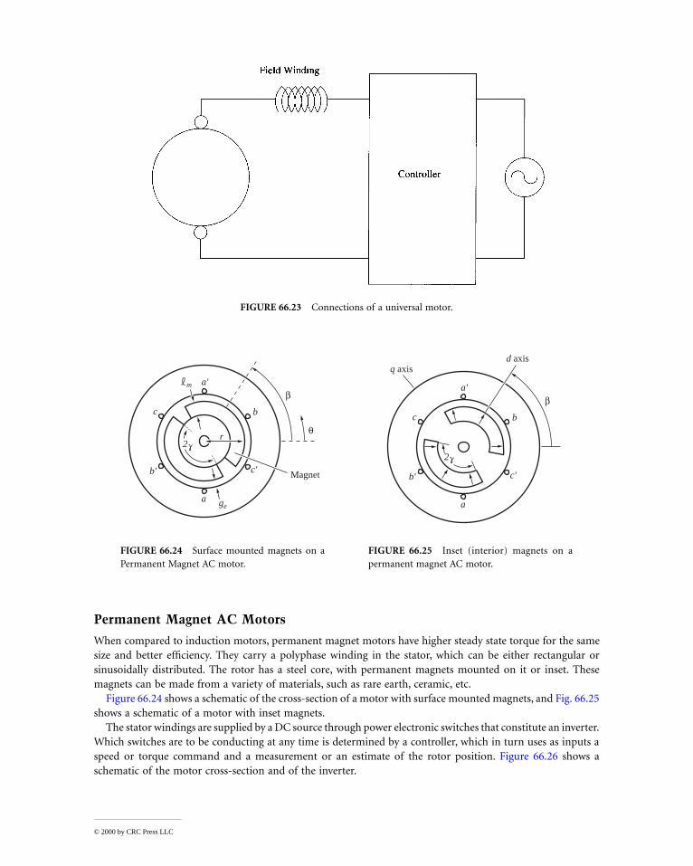
Permanent Magnet AC Motors
When compared to induction motors, permanent magnet motors have higher steady state torque for the samesize and better efficiency. They carry a polyphase winding in the stator, which can be either rectangular orsinusoidally distributed. The rotor has a steel core, with permanent magnets mounted on it or inset. Thesemagnets can be made from a variety of materials, such as rare earth, ceramic, etc.
Figure 66.24 shows a schematic of the cross-section of a motor with surface mounted magnets, and Fig. 66.25shows a schematic of a motor with inset magnets.
The stator windings are supplied by a DC source through power electronic switches that constitute an inverter.Which switches are to be conducting at any time is determined by a controller, which in turn uses as inputs aspeed or torque command and a measurement or an estimate of the rotor position. Figure 66.26 shows aschematic of the motor cross-section and of the inverter.
FIGURE 66.23 Connections of a universal motor.
FIGURE 66.24 Surface mounted magnets on aPermanent Magnet AC motor.
FIGURE 66.25 Inset (interior) magnets on apermanent magnet AC motor.
r
a'
c
c' Magnet
b
b'
a
2
q
b-m
ge
a'
c
c'
b
b'
a
2
b-
q axisd axis
© 2000 by CRC Press LLC

When the stator windings are rectangular and are energized based only on the rotor position, the resultingset of PM motor, inverter, and controller is called a brushless DC motor. The developed torque is proportionalto the airgap flux, Bg, and the stator current, Is.
T = k Bg Is
Due to the rotor speed, w0 a voltage, e, (back emf) is induced to the stator windings.
e = k Bg w0
Stepping Motors
These motors convert a series of power pulses to a corresponding series of equal angular movements. Thesepulses can be delivered at a variable rate, allowing the accurate positioning of the rotor without feedback. Theycan develop torque up to 15 Nm and can handle 1500 to 2500 pulses per second. They have zero steady stateerror in positioning and high torque density. An important characteristic of stepping motors is that when onephase is activated they do not develop a rotating but rather a holding torque, which makes them retain accuratelytheir position, even under load.
Stepping motors are conceptually derived either from a variable reluctance motor or from a permanentmagnet synchronous motor.
FIGURE 66.26 Permanent magnet AC motor and inverter.
RotorPositionSignals
Controlleddirect-current
source
(a)
a
b c
a'
b'c'
1
i
3 5
a
b
c
4 6 2
u
w0
t
© 2000 by CRC Press LLC

One design of stepping motors, based on the doubly salient switched reluctance motor, uses a large numberof teeth in the rotor (typically 45) to create saliency, as shown in Fig. 66.27. In this design, when the rotor teethare aligned in say Phase 1, they are misaligned in Phases 2 and 3. A pulse of current in Phase 2 will cause arotation so that the alignment will occur at Phase 2. If, instead, a pulse to Phase 3 is given, the rotor will movethe same distance in the opposite rotation.
The angle corresponding to a pulse is small, typically 3° to 5°, resulting from alternatively exciting one statorphase at a time.
A permanent magnet stepping motor uses permanent magnets in the rotor. Figure 66.28 shows the steps inthe motion of a four-phase PM stepping motor.
Hybrid stepping motors come in a variety of designs. One, shown in Fig. 66.29, consists of two rotorsmounted on the same shaft, displaced by one half tooth. The permanent magnet is placed axially between therotors, and the magnetic flux flows radially at the air gaps, closing through the stator circuit. Torque is createdby the interaction of two magnetic fields, that due to the magnets and that due to the stator currents. Thisdesign allows a finer step angle control and higher torque, as well as smoother torque during a step.
FIGURE 66.27 Cross-sectional view of a four-phase variable reluctance motor. Number of rotor teeth 50, step number200, step angle 1.8°. (Source: Oxford University Press, 1989. With permission.)
FIGURE 66.28 Steps in the operation of a permanent magnet stepping motor. (Source: T. Kenjo, Stepping Motors and TheirMicroprocessor Controls, Oxford University Press, 1989. With permission.)
© 2000 by CRC Press LLC

Fundamental to the operation of stepping motors is the utilization of power electronic switches, and of acircuit providing the timing and duration of the pulses. A characteristic of a specific stepping motor is themaximum frequency it can operate at starting or running without load.
As the frequency of the pulses to a running motor is increased, eventually the motor loses synchronism. Therelation between the frictional load torque and maximum pulse frequency is called the pull-out characteristic.
References
G. R. Slemon, Electrical Machines and Drives, Addison-Wesley, 1992.T. Kenjo, Stepping Motors and Their Microprocessor Controls, Oxford University Press, 1984.R. H. Engelman and W. H. Middendorf, Eds., Handbook of Electric Motors, New York: Marcel Dekker, 1995.R. Miller and M. R. Miller, Fractional Horsepower Electric Motors, Bobs Merrill Co., 1984.G. G. Veinott and J. E. Martin, Fractional and Subfractional Horsepower Electric Motors, New York: McGraw-
Hill, 1986.T. J. E. Miller, Brushless Permanent-Magnet and Reluctance Motor Drives, Oxford University Press, 1989.S. A. Nasar, I. Boldea, and L. E. Unnewehr, Permanent Magnet, Reluctance and Self-Synchronous Motors, Boca
Raton, Fla.: CRC Press, 1993.
Further Information
There is an abundance of books and literature on small electrical motors. IEEE Transactions on Industry Appli-cations, Power Electronics, Power Delivery and Industrial Electronics all have articles on the subject. In addition,IEE and other publications and conference records can provide the reader with specific and useful information.
Electrical Machines and Drives [Slemon, 1992] is one of the many excellent textbooks on the subject. SteppingMotors and their Microprocessor Controls [Kenjo, 1984] has a thorough discussion of stepping motors, whileFractional and Subfractional Horsepower Electric Motors [Veinott and Martin, 1986] covers small AC and DCmotors. Brushless Permanent-Magnet and Reluctance Motor Drives [Miller, 1989] and Permanent Magnet, Reluctanceand Self-Synchronous Motors [Nasar et al., 1993] reflect the increased interest in reluctance and brushless DCmotors, and provide information on their theory of operation, design and control. Finally, Fractional HorsepowerElectric Motors [Miller and Miller, 1984] gives a lot of practical information about the application of small motors.
66.4 Simulation of Electric Machinery
Chee-Mun Ong
Simulation has been an option when the physical system is too large or expensive to experiment with or simplynot available. Today, with powerful simulation packages, simulation is becoming a popular option for conduct-ing studies and for learning, especially when well-established models are available. Modeling refers to the process
FIGURE 66.29 Construction of a hybrid stepping motor. (Source: Oxford University Press, 1989. With permission.)
© 2000 by CRC Press LLC

of analysis and synthesis to determine a suitable mathematical description that captures the relevant dynamicalcharacteristics and simulation to the techniques of setting up and experimenting with the model.
Models of three-phase synchronous and induction machines for studying electromechanical and low-fre-quency electrical transients are well established because of the importance of generator and load behavior instability and fault studies. Electric machines, however, do interact with other connected components over awide range of frequencies, from fractions of Hertz for electromechanical phenomena to millions of Hertz forelectromagnetic phenomena.
Reduced models suitable for limited frequency ranges are often preferred over complex models because ofthe relative ease in usage — as in determining the values of model parameter and in implementing a simulation.In practice, reduced models that portray essential behavior over a limited frequency range are obtained bymaking judicious approximations. Hence, one has to be aware of the assumptions and limitations when decidingon the level of modeling details of other components in the simulation and when interpreting the simulationresults.
Basics in Modeling
Most machine models for electromechanical transient studies are derived from a lumped-parameter circuitrepresentation of the machine’s windings. Such lumped-parameter circuit representations are adequate for low-frequency electromechanical phenomena. They are suited for dynamical studies, often times to determine themachine’s performance and control behavior or to learn about the nature of interactions from electromechanicaloscillations. Studies of interactions occurring at higher frequencies, such as surge or traveling waves studies,may require a distributed-parameter circuit representation of the machine windings.
A lumped-parameter model for dynamical studies typically will include the voltage equations of the windings,derived using a coupled circuit approach, and an expression for the developed electromagnetic torque. Thelatter is obtained from an expression of the developed electromagnetic power by considering the input powerexpression and allowing for losses and magnetic energy storage terms. The expression for the developedelectromagnetic torque is obtained by dividing that for developed electromagnetic power by the rotor mechan-ical speed. The rotor speed, in turn, is determined by an equation of the rotor’s dynamics that equates therotor’s inertia torque to its acceleration torque.
For example, in a reduced order model of a separately excited dc machinethat ignores the details of commutation action and only portrays the averagevalues of voltage, current, and power, the armature winding can be representedas an equivalent winding whose axis is determined by the position of thecommutator brushes. The induced voltage in the armature, Ea, due to fieldflux can be expressed as kaωφ, ka being a machine constant; ω, the rotor speed;and φ the flux per pole. When armature reaction is ignored, φ will be the fluxproduced by the field winding. (See Fig. 66.30).
Using motoring convention, the voltage equations of the armature and fieldwindings with axes that are at right angles to each other can be expressed as
(66.42)
where Va is the terminal voltage of the armature winding, Ra its effective resistance including brush drops, Laq
its inductance, vf the applied field voltage, Rf and Lf , the field circuit resistance and inductance. For motoring,positive Ia will flow into the positive terminal of Va, as power flows from the external voltage source into thearmature winding. Like the physical device, the model is capable of motoring and generating, and the transitionfrom one mode to the other will take place naturally.
FIGURE 66.30 dc machine.
V E R I LI
dt
v R i Li
t
a a a a aqa
f f f f
f
= + +
= +
dV
d
d
© 2000 by CRC Press LLC

Equating the acceleration torque of the rotor to its inertia torque, one obtains:
(66.43)
where Tem is the electromagnetic torque developed by the machine; Tloss, the equivalent torque representingfriction and windage and stray load losses; and Tmech, the externally applied mechanical torque on the shaft inthe direction of rotation. As shown in Fig. 66.30, Tem is positive for motoring and negative for generating; Tmech
is negative for motoring and positive for generating.Like the derivation of Ea, the developed torque, Tem, can be shown to be equal to kaφIa by considering first
the total power flow into the windings, that is,
(66.44)
Summing the input powers to both windings, dropping the resistive losses and magnetic energy storage terms,and equating the remaining term to developed power, one will obtain the following relationships from whichan expression of the developed torque can be written.
Temωm = Pem = EaIa W (66.45)
Figure 66.31 shows the flowchart for a simple dcmachine simulation. The required inputs are Va, vf,and Tmech. Solving the windings’ voltage equationswith the required inputs, we can obtain the windingcurrents, Ia and if . The magnetizing curve block con-tains open-circuit test data of the machine to translateif to kaφ or the ratio of the open-circuit armaturevoltage to some fixed speed, that is Ea /ωmo. The sim-ulation yields the output of the two winding currents,the field flux, the developed torque, and the rotorspeed.
Modular Approach
Simulation of larger systems consisting of electric machines can be assembled directly from basic equations ofthe individual components and their connections. On a higher level of integration, it will be more convenientand advantageous to utilize templates of subsystems to construct the full system in a modular manner. Subsystemtemplates once verified can be reused with confidence for studies that are within the scope of the modelsimplemented. The tasks of constructing and debugging a simulation using the modular approach can be mucheasier than building the same simulation from elementary representations.
Proper considerations to matching inputs to outputs of the connected templates are required when usingtemplates. Take, for example, a template of the above dc motor simulation. Such a template will require inputsof Va, vf , and Tmech to produce outputs of Ia, if , flux, and rotor speed. On the mechanical side, the motor templatehas to be interfaced to the simulation of the mechanical prime mover or load for its remaining input of Tmech.In the case of a simple load, the load torque, Tmech, could be constant or some simple function of rotor speed,as shown in Fig. 66.32. On the electrical side, the motor template has to be interfaced to the templates of thepower supplies to the armature and field windings for its inputs of Va and vf . These voltages can come from
T T T Jtem loss mech
m– + = −d
dN m
ω
V I E I R IL I
t
v i R iL i
t
a a a a a a
aq a
f f f f
f f
= + +( )
= +( )
2
2
2
2
2
2
d
dW
d
d
FIGURE 66.31 dc machine simulation flowchart.
© 2000 by CRC Press LLC
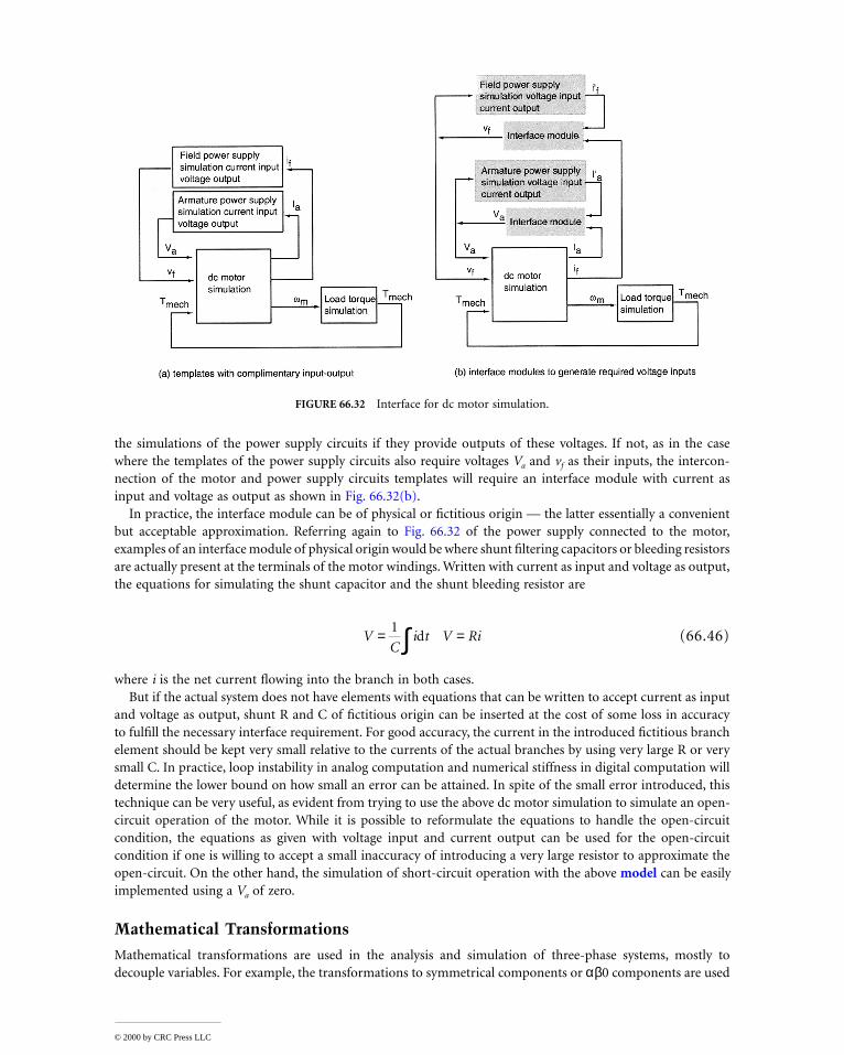
the simulations of the power supply circuits if they provide outputs of these voltages. If not, as in the casewhere the templates of the power supply circuits also require voltages Va and vf as their inputs, the intercon-nection of the motor and power supply circuits templates will require an interface module with current asinput and voltage as output as shown in Fig. 66.32(b).
In practice, the interface module can be of physical or fictitious origin — the latter essentially a convenientbut acceptable approximation. Referring again to Fig. 66.32 of the power supply connected to the motor,examples of an interface module of physical origin would be where shunt filtering capacitors or bleeding resistorsare actually present at the terminals of the motor windings. Written with current as input and voltage as output,the equations for simulating the shunt capacitor and the shunt bleeding resistor are
(66.46)
where i is the net current flowing into the branch in both cases.But if the actual system does not have elements with equations that can be written to accept current as input
and voltage as output, shunt R and C of fictitious origin can be inserted at the cost of some loss in accuracyto fulfill the necessary interface requirement. For good accuracy, the current in the introduced fictitious branchelement should be kept very small relative to the currents of the actual branches by using very large R or verysmall C. In practice, loop instability in analog computation and numerical stiffness in digital computation willdetermine the lower bound on how small an error can be attained. In spite of the small error introduced, thistechnique can be very useful, as evident from trying to use the above dc motor simulation to simulate an open-circuit operation of the motor. While it is possible to reformulate the equations to handle the open-circuitcondition, the equations as given with voltage input and current output can be used for the open-circuitcondition if one is willing to accept a small inaccuracy of introducing a very large resistor to approximate theopen-circuit. On the other hand, the simulation of short-circuit operation with the above model can be easilyimplemented using a Va of zero.
Mathematical Transformations
Mathematical transformations are used in the analysis and simulation of three-phase systems, mostly todecouple variables. For example, the transformations to symmetrical components or αβ0 components are used
FIGURE 66.32 Interface for dc motor simulation.
VC
i t V Ri= =∫1d
© 2000 by CRC Press LLC

in the analysis of unbalanced three-phase network analysis. Transformations to decouple variables, to facilitatethe solution of difficult equations with time-varying coefficients, or to refer variables from one frame of referenceto another are employed in the analysis and simulation of three-phase ac machines.
For example, in the analysis and simulation of a three-phase synchronous machine with a salient pole rotor,transformation of stator quantities onto a frame of reference attached to the asymmetrical rotor results in amuch simpler model. In this rotor reference model, the inductances are not dependent on rotor position and,in steady-state operation, the stator voltages and currents are not time varying.
Park’s transformation decouples and rotates the stator variablesof a synchronous machine onto a dq reference frame that is fixed tothe rotor. The positive d-axis of the dq frame is aligned with themagnetic axis of the field winding, that of the positive q-axis is aheadin the direction of rotation or lead the positive d-axis by π/2. Definedin this manner, the internal excitation voltage given by Ef = ωLaf if isin the direction of the positive q-axis. Park’s original dq0 transfor-mation [1929] was expressed in terms of the angle, θd, between therotor’s d-axis and the axis of the stator’s a-phase winding.
The so-called qd0 transformation in more recent publications isPark’s transformation expressed in terms of the angle, θq, betweenthe rotor’s q-axis and the axis of the stator’s a-phase winding. Therow order of components in the qd0 transformation matrix fromtop of bottom is q-, d-, and then 0. As evident from Fig. 66.33, theangle θq is equal to θd + π/2. The transformation from abc variablesto a qd0 reference frame is accomplished with
[fqd0] = [Tqd0(θq)][fabc] (66.47)
where f can be voltage, current, or flux, and
(66.48)
Transforming back from qd0 to abc is accomplished by premultiplying both sides of Eq. (66.47) with the inverse
(66.49)
The angle θq can be determined from
(66.50)
FIGURE 66.33 qd0 transformation.
Tqd q
q q q
q q q0
2
3
2
3
2
3
2
3
2
3
1
2
1
2
1
2
θ
θ θ π θ π
θ θ π θ π( )[ ] =
+
+
cos cos – cos
sin sin – sin
Tqd q
q q
q q
q q
0
1
1
2
3
2
31
2
3
2
31
θ
θ θ
θ π θ π
θ π θ π
( )[ ] =
+
+
–
cos sin
cos – sin –
cos sin
θ ω θd
t
qt t dt( ) = ( ) + ( )∫0
0 rad
© 2000 by CRC Press LLC

where ω(t) is the rotational speed of the qd reference frame and θq(0), the initial value of θq at t = 0. In thecase of the rotor’s qd reference frame, ω(t) is equal to the rotor’s speed in electrical radians (per second), thatis, ω(t) = ωr(t).
Figure 66.34 shows a circuit representation of an idealized synchronous machine with damper windings, kdand kq, and field winding, f, on the rotor. The equivalent circuit representation and equations of the machinein its own rotor qd0 reference frame and in motor convention are shown in Fig. 66.35 and Table 66.3, respectively.
Base Quantities
Oftentimes, the machine equations are expressed in terms of the flux linkages per second, ψ, and reactances,x, instead of λ and L. These are related simply by the base or rated value of angular frequency, ωb, that is,
ψ = ωbλ and x = ωbL (66.51)
FIGURE 66.34 Circuit representation of idealized synchronous machine.
FIGURE 66.35 Equivalent qd0 circuits of synchronous machine.
© 2000 by CRC Press LLC

where ωb = 2πfrated electrical radian per second, frated being the rated frequency in Hertz of the machine. Whendealing with complex waveforms, it is logical to use peak rather than the rms value as the base value. The basequantities with peak rather rms value of a P-pole, three-phase induction machines with rated line-to-line rmsvoltage, Vrated , and rated volt-ampere, Srated, area as follows:
Simulation of Synchronous Machines
Table 66.4 shows the main steps in a simulation of a three-phase synchronous machine with Tmech, vf , and abcstator voltages as input. The rotor’s speed and angle, ωr(t) and δ, are determined by the rotor’s equation of motion.
(66.52)
The developed torque, Tem, is positive for motoring operation and negative for generating operation.The rotor angle, δ, is defined as the angle of the qr axis of the rotor with respect to the qe axis of the
synchronously rotating reference frame, that is,
(66.53)
Since the synchronous speed, ωe, is a constant,
(66.54)
TABLE 66.3 qd0 Model of Synchronous Machine
Voltage equations
Flux linkage equations
Torque equation
v r id
dt
d
dtv r i
d
dt
v r id
dt
d
dtv r i
d
dt
v r id
dtv r i
d
dt
q s q
q
dr
f f f
f
d s dd
qr
kd kd kdkd
s kq kq kq
kq
= + + ′ = ′ ′ +
= + ′ = ′ ′ +′
= + ′ = ′ ′ +′
λλ
θ λ
λλ
θ λ
λ λ
–
0 00
λ λλ λλ λ
q q q mq kq f md d md kd ff f
d d d md f md kd kd md d md f kdkd kd
ls kq mq q kqkq kq
L i L i L i L i L i
L i L i L i L i L i L i
L i L i L i
= + ′ ′ = + ′ + ′ ′= + ′ + ′ ′ = + ′ + ′ ′= ′ = + ′ ′0 0
TP
i iem d q q d= ( )3
2 2λ λ– N – m
base voltage, base volt-ampere, base current,
base impedance, base torque, base speed,
V V S S I S V
Z V I T S Pb rated b rated b b b
b b b b b bm bm b
= = == = =2 3 2 3
2ω ω ω
T T T Jd t
dtem mech damp
rm+ =( )
–ω
N – m
δ θ θ
ω ω θ θ
t t t
t dt
r e
t
r e r e
( ) = ( ) ( )
= ( )( ) + ( ) ( )∫
–
– –
elect. rad
0
0 0
d t
dt
d t
dt
r e rω ω ω( )( )
=( )–
© 2000 by CRC Press LLC

Using (2/P) ωr(t) in place of ωrm(t) and Eq. (66.54) to replace dωr(t)/dt, Eq. (66.52) can be rewritten in termsof the slip speed:
(66.55)
The angles θr(t) and θe(t) are the respective angles of the qr and qe axes of the rotor and synchronouslyrotating reference frames measured with respect to the stationary axis of the a-phase stator winding. Note thatδ is the angle between the qr axis of the rotor and the qe axis of the reference synchronously rotating frame.For multi-machine systems, the rotor angles of the machines could all be referred to a common synchronouslyrotating reference frame at some bus or to the qr axis of the rotor of a chosen reference machine.
A flowchart showing the main blocks for the above simulation is given in Fig. 66.36. As shown, the inputvoltages and output currents are in abc phase quantities. For some studies, the representation of the supply
TABLE 66.4 Simulation of Synchronous Machine
Transform input stator abc voltages to the qd reference frame attached to the rotor using [vqd0] = [Tqd0(θr)][vabc] where θr(t) = ∫ t
0 ωr(t)dt + θr(0). The currents or flux linkages of the cut set of three inductors in both the q- and d-axis circuits of Fig. 66.35, are not independent. Using the winding flux linkages per second as states, the mutual flux linkages per second are expressed as
where
Solve winding flux linkages using the following integral form of the winding voltage equations:
where Ef = xmd , and
Determine qd0 winding currents from winding flux linkages.
Transform qd0 currents to abc using [iabc] = [T–1qd0(θr)][iqd0].
ψ ωψ ψ
ψ ωψ ψ ψ
mq b mq q kq MQ
q
ls
kq
lkqmd b md d kd f MD
d
ls
kd
lkd
f
lf
L i i xx x
L i i i xx x x
= + ′( ) = +′′
= + ′ + ′( ) = +
′′
+′′
1 1 1 1 1 1 1 1 1
x x x x x x x x xMQ mq lkq ls MD md lkd lf ls
= +′
+ = +′
+′
+
ψ ωωω
ψ ψ ψ ψω
ψ ψ
ψ ωωω
ψ ψ ψ ψω
ψ ψ
ψ ω
q b qr
b
ds
ls
mq q kq
b kq
lkq
mq kq
d b dr
b
qs
ls
md d kdb kd
lkd
md kd
vr
xdt
r
xdt
vr
xdt
r
xdt
= + ′ =′
′′
= + + ′ =′
′′
=
( )
( )
( )
( )∫ ∫∫ ∫
– – –
– –
0 bbs
ls
f
b f
md
fmd
lf
md fv
r
xdt
r
xE
x
xdt
0 0– –ψ ψ
ωψ ψ
( )
∫ ∫′ =′
+′
′
ν ′f
fτ
ψ ψ ψ ψ ψψ ψ ψ ψ ψ ψ
q ls q mq d ls d md ls
f lf f md kd lkd kd md kq lkq kq mq
x i x i x i
x i x i x i
= + = + =′ = ′ ′ + ′ = ′ ′ + ′ = ′ ′ +
0 0
ix
ix
ix
ix
ix
ix
q
q mq
lsd
d md
ls ls
kdkd md
lkdkq
kq mq
lkqf
f md
lf
= = =
′ =′
′′ =
′′
′ =′ −
′
ψ ψ ψ ψ ψ
ψ ψ ψ ψ ψ ψ
– –
– –
00
ω ωr e
t
em mech damptP
JT T T dt( ) = +( )∫– –
2 0
elect. rad/s
© 2000 by CRC Press LLC

network connected to the machine may not be in phase variables. For example, in linearized analysis, and alsoin transient stability of power systems, the network representation is usually in a synchronously rotatingreference frame. In linearized analysis, the small-signal representation of the system is obtained by makingsmall perturbations about an operating point. When the machines are in their respective rotor qd0 referenceframes and the power network is in a synchronously rotating qd0 reference frame, the qd0 variables of thenetwork and machines are in steady-state; thus linearized analysis about an operating point can be performed.
In transient stability, the main interest is the stability of the system after some large disturbances. The modelsemployed are to portray the transient behavior of the power flows in the network and the electromechanicalresponse of the machines. When dealing with large networks, the fast electromagnetic transients of the networkare usually ignored and a static network representation is used. At each new time step of the dynamic simulation,an update of the network condition can be obtained by solving the phasor equations of the static network alongwith power or current injections from the machines. Because the phasor quantities of the network can beexpressed as qd components of a synchronously rotating qd0 reference [Ong, 1998], the exchange of voltagevariables between network and machine at the bus will require a rotational transformation given below
(66.56)
where δ is the rotor angle of the qr of the machines qd0 rotor reference frame measured with respect to the qe
axis of the network’s synchronously rotating reference frame. The above transformation is also applicable tothe exchange of current variables between network and machine.
Other synchronous machine models, besides that given in Table 66.3, are used in power system analysis.Typically, when the network is large and the phenomenon of interest is somewhat localized in nature, machinesfurther away from the action can be represented by simpler models to save computation time. On the otherhand, certain phenomena may require an even more sophisticated model than that given in Table 66.3. Canay[1993] described refinements in both the rotor circuit representation and the method of parameter determi-nation to obtain a closer fit of the rotor variables. For studying shaft torsion, the damper circuit representationshould not be ignored. In transient stability studies, machines beyond the first two neighborhoods of thedisturbance can be represented by progressively simpler models with distance from the disturbance. Ignoringjust the pψq and pψd terms and also setting ω = ωe in the stator equations will yield a so-called subtransientmodel of two orders less than the above given model. Further simplification by setting pψ′kq and pψ′kd to zeroor omitting the damper winding equations will yield a so-called transient model of another two orders less.Finally, setting pψ ′f to zero and holding field flux linkage constant yields the constant field flux linkage model.
Significant savings in computing time can also be made by neglecting the subtransient and transient saliencyof the machine. When rotor saliency is ignored, the effective stator impedances along the rotor’s qr and dr axesare equal. In other words, the stator impedance in the synchronously rotating reference frame of the networkwill not be a function of rotor angle. Because its value need not be updated with the rotor angle at each timestep of the dynamic simulation, the constant stator impedance of this model can be absorbed into the network’sadmittance or impedance representation.
FIGURE 66.36 Block diagram of synchronous machine simulation.
v
v
v
v
v
v
q
d
qe
de
0 0
0
0
0 0 1
=−
cos sin
sin cos
δ δδ δ
© 2000 by CRC Press LLC

Three-Phase Induction Machines
Figure 66.37 shows a circuit representation of a symmetrical three-phase induction machine with uniformairgap. The axes of the qd0 reference frames are assumed to be rotating at an arbitrary angular speed of ω. Theangles θ(t) and θr(t), in electrical radians, can be determined from
(66.57)
where θ(0) and θr(0) are their respective initial values at time t = 0.As before, the voltage equations of the stator and rotor windings can be written using the coupled circuit
approach. Corresponding voltage equations in the arbitrary qd0 reference frame can be obtained by applyingthe transformation Tqd0(θ) to the stator variables and the transformation Tqd0(θ – θr) to the rotor variables.The equations of a symmetrical induction machine in the arbitrary reference frame in terms of the flux linkagesper second and reactances are summarized in Table 66.5.
Seldom is there a need to simulate an induction machine in the arbitrary rotating reference frame. Inductionmachine loads are often simulated on the network’s synchronously rotating reference frame in power systemstudies. However, in transient studies of adjustable speed drives, it is usually more convenient to simulate theinduction machine and its converter on a stationary reference frame. Equations of the machine in the stationaryand synchronously rotating reference frames can be obtained by setting the speed of the arbitrary referenceframe, ω, to zero and ωe, respectively.
Often the stator windings are connected to the supply by a three-wire connection, as shown in Fig. 66.38.With a three-wire connection, the stator zero-sequence current, i0s, or (ias + ibs + ics)/3, is zero by physicalconstraint, irrespective of whether the phase currents are balanced or not. The phase currents could beunbalanced, as in single-phasing operation. The stator neutral is free-floating. Its voltage, vsg, measured withrespect to some ground point g, need not be zero. Where the applied voltages are non-sinusoidal, as in the casewhen the supply is from a bridge inverter, vsg is not zero.
In general, the input stator phase voltages, vag, vbg, and vcg, for the simulation of the induction machine canbe established from the following relationships:
vas = vag – vsg vbs = vbg – vsg vcs = vcg – vsg (66.58)
When point s is solidly connected to point, g, vsg will be zero. Otherwise, if Rsg and Lsg are the resistance andinductance of the connection between points s and g, vsg can be determined from
FIGURE 66.37 Circuit representation of induction machine.
θ ω θ θ ω θt t dt t dtt
r
t
r r( ) = ( ) + ( ) ( ) = + ( )∫ ∫0 0
0 0
© 2000 by CRC Press LLC

(66.59)
Where the stator windings’ neutral is free-floating, vsg can be determined from an open-circuit approximationof the form shown in Eq. (66.46).
TABLE 66.5 Model of induction machine in arbitrary qdo
Voltage equations
Flux linkage equations
Torque equation
FIGURE 66.38 Three-wire power supply connection.
vp
r i vp
r i
vp
r i vp
r i
vp
r
qsb
qsb
ds s qs qrb
qrr
bdr r qr
dsb
dsb
qs s ds drb
drr
bqr r dr
sb
s
= + + ′ = ′ +−
′ + ′ ′
= − + ′ = ′ −−
′ + ′ ′
= +
ωψ ω
ωψ
ωψ
ω ωω
ψ
ωψ ω
ωψ
ωψ
ω ωω
ψ
ωψ0 0 ss s r
br r ri v
pr i0 0 0 0′ = ′ + ′ ′
ωψ
ψψψψψψ
qs
ds
s
qr
dr
r
ls m m
ls m m
ls
m lr m
m lr m
lr
x x x
x x x
x
x x x
x x x
x
0
0
0 0 0 0
0 0 0 0
0 0 0 0 0
0 0 0 0
0 0 0 0
0 0 0 0 0
′′′
=
++
′ +′ +
′
′′′
i
i
i
i
i
i
qs
ds
s
qr
dr
r
0
0
TP
i i i i
Pi i
Pi i
Px i i i i
emr b
ds qs qs dsr
bdr qr qr dr
bqr dr dr qr
bds qs qs ds
bm dr qs qr ds
= −( )+−
′ ′ − ′ ′( )
−
= ′ ′ − ′ ′( ) = −( ) = ′ − ′( )
3
2 2
3
2 2
3
2 2
3
2 2
ωωω
ψ ψω ω
ωψ ψ
ωψ ψ
ωψ ψ
ω
N m
v R i i Ld
dti i i R L
d
dtisg sg as bs cs sg as bs cs sg sg s= + +( )+ + +( ) = +
3 0
© 2000 by CRC Press LLC

Defining Terms
Model of an electric machine: Differential algebraic equations describing the dynamic behavior of the electricmachine.
Dynamic simulation: Setting up of a model capable of portraying certain dynamic behavior of the real deviceand performing experiments on the model.
Rotating reference frame: A rotating qd plane. For example, a synchronously rotating reference frame is aqd plane that is rotating at synchronous speed as defined by the fundamental excitation frequency.
References
Canay, I. M. (1993) Modelling of Alternating-Current Machines Having Multiple Rotor Circuits, IEEE Trans.on Energy Conversion, Vol. 8, No. 2, June 1993, pp. 280–296.
Demerdash, N. A. O. and Alhamadi M. A. (1995) Three-Dimensional Finite Element Analysis of PermanentMagnet Brushless DC Motor Drives – Status of the State of Art, IEEE Trans. on Industrial Electronics,Vol. 43, No. 2, April 1995, pp. 268–275.
Ong, C. M. (1998) Dynamic Simulation of Electric Machinery, Prentice-Hall PTR, New Jersey.Park, R. H. (1929) Two-Reaction Theory of Synchronous Machines Generalized Method of Analysis. Part I,
A.I.E.E. Transactions, Vol. 48, 1929, pp. 716–727.Preston, T. W., Reece, A. B. J., and Sangha, P. C. (1988) Induction Motor Analysis by Time-Stepping Techniques,
IEEE Trans. on Magnetics, Vol. 24, No. 1, Jan. 1998, pp. 471–474.Rahman, M. A. and Little, T. A. (1984) Dynamic Performance Analysis of Permanent Magnet Synchronous
Magnet Motors, IEEE Trans. on Power Apparatus and Systems, Vol. 103, No. 6, June 1984, pp. 1277–1282.Salon, S. J. (1995) Finite Element Analysis of Electrical Machines, Kluwer Academic Publishers, Boston.Shen, J. (1995) Computational Electromagnetics Using Boundary Element: Advances in Modeling Eddy Currents,
Computational Mechanics Publication, Southampton, UK.
Further Information
The above chapter section has briefly described some of the techniques of the coupled-circuit approach andqd0 transformation in modeling, and the treatment of interface and floating neutral conditions in implementinga simulation. For more information on modeling and implementation of machine simulations, see [Ong, 1998].
Some techniques of modeling permanent magnet machines are described in [Rahman and Little, 1984; Ong,1998].
Problems concerning effects of local saturation, anisotropic magnetic properties, and eddy-currents inmachines require detailed modeling of the field region. Two- and three-dimensional models of the field regioncan be solved using finite-element [Salon, 1995] and boundary-element [Shen, 1995] techniques. Although thefield models are not as amenable as the circuit models for use in large system studies, they have been successfullyintegrated with lumped circuit element models in dynamic simulations [Demerdash and Alhamadi, 1995;Preston et al., 1988].
© 2000 by CRC Press LLC