Geometric dimensioning and tolerancing a tool for concurrent ...
108
Copyright Warning & Restrictions The copyright law of the United States (Title 17, United States Code) governs the making of photocopies or other reproductions of copyrighted material. Under certain conditions specified in the law, libraries and archives are authorized to furnish a photocopy or other reproduction. One of these specified conditions is that the photocopy or reproduction is not to be “used for any purpose other than private study, scholarship, or research.” If a, user makes a request for, or later uses, a photocopy or reproduction for purposes in excess of “fair use” that user may be liable for copyright infringement, This institution reserves the right to refuse to accept a copying order if, in its judgment, fulfillment of the order would involve violation of copyright law. Please Note: The author retains the copyright while the New Jersey Institute of Technology reserves the right to distribute this thesis or dissertation Printing note: If you do not wish to print this page, then select “Pages from: first page # to: last page #” on the print dialog screen
-
Upload
khangminh22 -
Category
Documents
-
view
1 -
download
0
Transcript of Geometric dimensioning and tolerancing a tool for concurrent ...
Copyright Warning & Restrictions
The copyright law of the United States (Title 17, United States Code) governs the making of photocopies or other
reproductions of copyrighted material.
Under certain conditions specified in the law, libraries and archives are authorized to furnish a photocopy or other
reproduction. One of these specified conditions is that the photocopy or reproduction is not to be “used for any
purpose other than private study, scholarship, or research.” If a, user makes a request for, or later uses, a photocopy or reproduction for purposes in excess of “fair use” that user
may be liable for copyright infringement,
This institution reserves the right to refuse to accept a copying order if, in its judgment, fulfillment of the order
would involve violation of copyright law.
Please Note: The author retains the copyright while the New Jersey Institute of Technology reserves the right to
distribute this thesis or dissertation
Printing note: If you do not wish to print this page, then select “Pages from: first page # to: last page #” on the print dialog screen

The Van Houten library has removed some of the personal information and all signatures from the approval page and biographical sketches of theses and dissertations in order to protect the identity of NJIT graduates and faculty.
ABSTRACT
Geometric Dimensioning and Tolerancing
A Tool for Concurrent Engineering
by
Tapan Kumar S. K. Jain
The concept of Concurrent Engineering recognizes an immediate need for a new
design environment and technology and so requires extensive interdisciplinary
cooperation and integration of diverse functions of a manufacturing organization
such as marketing, design, manufacturing and finance. One of the key factors to
achieve successful integration among the departments is better communication
and it becomes imperative in cases of varying levels of communication needs,
especially in interdepartmental cases.
Concurrent Engineering is a philosophy which provides certain benefits.
There are various tools and methods available for implementation of Concurrent
Engineering concepts. One of the tools is Geometric Dimensioning & Tolerancing
(GD & T), which can be used for indespensible communication of exact part
design and its proper execution. Unlike other tools, GD & T concepts emphasize
on the integration of various functions in a manufacturing organization.
This thesis discusses the applicability of Geometric Dimensioning and
Tolerancing as an integrating tool for related functional departments in the concur-
rent environment. It also establishes the synchronization between the objectives of
the two concepts. Also, it discusses the effect of using GD & T on vendor lead time
and manufacturing lead time. The effect on the product quality, the cost econom-
ics and the learning curve is also investigated.
Lastly, the thesis concludes that the implementation of GD & T concepts
automatically attains the objectives of concurrent engineering. The use of GD & T
in industries may lead to widespread implementation of the concurrent engineer-
ing concepts globally. Therefore, it can be considered as a medium or tool for Con-
current Engineering.

GEOMETRIC DIMENSIONING AND TOLERANCING
A TOOL FOR CONCURRENT ENGINEERING
by
Tapan Kumar S. K. Jain
A Thesis
Submitted to the Faculty of
New Jersey Institute of Technology
in Partial Fulfillment of the Requirements for the Degree of
Masters of Science in Manufacturing Systems Engineering
Manufacturing Engineering Division
May 1993
APPROVAL PAGE
Geometric Dimensioning and Tolerancing
A Tool for Concurrent Engineering
by
Tapan Kumar S. K. Jain
Dr. Stojan Kotefski, Thesis Adviser Date Assistant Professor and Program Coordinator for Manufacturing Engineering Technology, NJIT
Dr. Raj Sodhi, Committee Member Date Associate Professor of Mechanical Engineering and Director of Manufacturing Engineering Programs, NJIT
Dr. Nouri Levy, Committee Member Date Associate Professor o epartment of Mechanical Engineering, NJIT
BIOGRAPHICAL SKETCH
Author : Tapan Kumar S. K. Jain
Degree Master of Science in Manufacturing Systems Engineering
Date : May 1993
Undergraduate and Graduate Education :
0 Master of Science in Manufacturing Systems Engineering,
New Jersey Institute of Technology, Newark, NJ, 1993
e Bachelor of Science in Mechanical Engineering, Birla Vishwakarma
Mahavidyalaya, Gujarat, India, 1989
Major : Manufacturing Systems Engineering
iv
This Thesis is dedicated to
my Mother
ACKNOWLEDGMENT
The author wishes to thank his thesis adviser, Dr. Stojan Kotefski for
patiently reviewing the progress of the thesis at every stage and helping him to
plan it efficiently. This thesis would not have been successful but for his invalu-
able guidance, continuous motivation and sincere concern.
Furthermore, I would like to express my gratitude to Dr. Nouri Levy and
Dr. Raj Sodhi for serving as committee members and providing necessary guid-
ance for this work.
Thanks also are due to the librarians at NJIT for their help in survey of
research papers relevant to the thesis topic.
Lastly, special thanks to Pankaj, Anjali, Deven and all other friends for their
unique support and cooperation.
vi

TABLE OF CONTENTS
Chapter Page
1 INTRODUCTION 1
1.1 Introduction 1
1.2 Background 2
1.3 Research Emphasis 5
2 GEOMETRIC DIMENSIONING & TOLERANCING 6
2.1 What is G D & T 6
2.2 Advantages 7
2.3 Disadvantages 9
2.4 Functional Dimensioning 9
2.5 G D & T Terminology 10
2.6 Geometric Characteristics 12
2.7 Rules 29
2.8 Virtual Condition 31
2.9 Modifiers 33
2.9.1 Maximum Material Condition (MMC) 34
2.9.2 Regardless of Feature Size (RFS) 39
2.9.3 Least Material Condition (LMC) 41
2.9.4 Projected Tolerances 43
2.10 Bonus Tolerances 43
3 CONCURRENT ENGINEERING 45
3.1 Chapter Synopsis 45
3.2 Philosophy of Concurrent Engineering 45
3.3 Product Life Cycle and C E 49
3.4 Objectives of Concurrent Engineering 51
3.5 Traditional Product Development Trend 52
3.6 Integrated or Concurrent Approach to Product Process Development 53
3.7 Practical Limitation to Concurrent Product Process Design 55
3.8 Tools for Concurrent Engineering 56
3.9 Advantages and Economy of Concurrent Engineering 58
vii

Chapter Page
4 G D & T - A TOOL FOR CONCURRENT ENGINEERING 59
4.1 Chapter Synopsis 59
4.2 Introduction 59
4.3 The Relevance 61
4.4 Problem Defination 62
4.5 Manufacturing Engineering Concerns 67
4.5.1 Design Concerns 67
4.5.2 Tooling Concerns 69
4.5.3 Production Concerns 71
4.5.4 Inspection Concerns 73
4.5.5 Gaging 76
4.5.6 Vendor Concerns 77
4.6 Inferences 78
5 CONCLUSION 83
5.1 Conclusion 83
5.2 Future Research 84
REFERENCES 85
viii
LIST OF TABLES
Table Page
1 Modifiers 33
2 Effect of Different Hole Sizes on Positional Tolerances (Part 1) 37
3 Effect of Different Shaft Sizes on Positional Tolerances (Part 2) 38
4 Positional Tolerances and Bonus Tolerances Applicable at Hole Sizes 74
5 Positional Tolerances with LMC Applicable at Different Hole Sizes 77
lx
LIST OF FIGURES
Figure Page
1 Types of Dimensioning and Tolerancing 6
2 Flatness 1.3
3 Straightness 14
4 Circularity 15
5 Cylindricity facing 16
6 Perpendicularity Applied to a Plane Surface 17
7 Perpendicularity Applied to a Slot - Centerplane Control 18
8 Specifying Angularity for a Plane Surface 18
9 Specifying Angularity for an Axis (Feature RFS) 19
10 Specifying Parallelism for a Plane Surface 20
11 Specifying Parallelism for an Axis (Feature RFS) 20
12 Requirements of Positional Tolerancing Dimensioning 21
13 Floating Fasteners - Positional Tolerances for Mating Parts 22
14 Concentricity Tolerance Application facing 24
15 Profile of a Surface 26
16 Profile of a Line and Size Control 27
17 Circular Runout 28
18 Total Runout 29
19 Individual Size Feature 30
20 Virtual Condition 32
21 Maximum Material Condition 35
22 Effect and Calculation of MMC facing 36
23 Gage Dimensions and Calculation of MMC facing 39
24 Effect of RFS and Calculation facing 40
25 Effect and Calculation of LMC facing 41
26 Projected Tolerance 43
27 Bonus Tolerance 44
28 A Manufacturing Company's Operational Decisions and their Relationship 47
29 Integration of Different Functions of an Organization facing 48
Figure Page
30 Product Life Cycle Phases v/s Life Cycle Costs 50
31 Product Development Life Comparision 51
32 The Conventional Product - Process Design Method 52
33 The Strategic Method of Product and Application Sytem Design 54
34 Precedence of Decisions in Product Process Design facing 55
35 Assemby Problem 63
36 Conventional Drawing of Washer 63
37 Manufacturing Setup with Conventional Drawing 64
38 Acceptable Washers 65
39 GD & T Drawing for Washer 66
40 Interpretation of GD & T Drawing 67
41 Drill Jig for Washer Production facing 70
42 Effect and Calculation of MMC on Hole Positioning 74
43 FIM Setup when Positional Tolerances at Hole is at LMC 77
44 Mating Part Situation Represented by Gage Pin 79
45 Effect on Learning Curve 81
xi
CHAPTER 1
INTRODUCTION
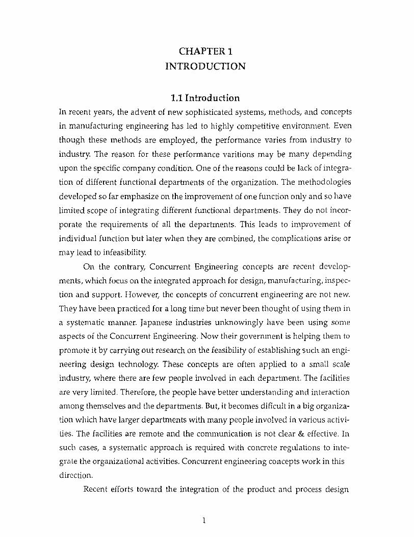
1.1 Introduction In recent years, the advent of new sophisticated systems, methods, and concepts
in manufacturing engineering has led to highly competitive environment. Even
though these methods are employed, the performance varies from industry to
industry. The reason for these performance varitions may be many depending
upon the specific company condition. One of the reasons could be lack of integra-
tion of different functional departments of the organization. The methodologies
developed so far emphasize on the improvement of one function only and so have
limited scope of integrating different functional departments. They do not incor-
porate the requirements of all the departments. This leads to improvement of
individual function but later when they are combined, the complications arise or
may lead to infeasibility.
On the contrary, Concurrent Engineering concepts are recent develop-
ments, which focus on the integrated approach for design, manufacturing, inspec-
tion and support. However, the concepts of concurrent engineering are not new.
They have been practiced for a long time but never been thought of using them in
a systematic manner. Japanese industries unknowingly have been using some
aspects of the Concurrent Engineering. Now their government is helping them to
promote it by carrying out research on the feasibility of establishing such an engi-
neering design technology. These concepts are often applied to a small scale
industry, where there are few people involved in each department. The facilities
are very limited. Therefore, the people have better understanding and interaction
among themselves and the departments. But, it becomes dificult in a big organiza-
tion which have larger departments with many people involved in various activi-
ties. The facilities are remote and the communication is not clear & effective. In
such cases, a systematic approach is required with concrete regulations to inte-
grate the organizational activities. Concurrent engineering concepts work in this
direction.
Recent efforts toward the integration of the product and process design
1
2
such as design for manufacturing', 'design for assembly', 'design for reliability',
'design for automation', attempt to address some of the problems which are gen-
erated by job specialization and separation. The new concepts of integration of
engineering design and system manufacturing yields significant advantages such
as reduction in market lead time, increase in product quality and reliability and
reduction in life cycle cost. Despite the fact that many of these trends are impor-
tant, they lack an overarching rational framework to guide their implementation
and they do not always take full advantage of modem managerial and technolog-
ical capabilities [9]. There requires an approach or media which, while imple-
menting, can take into consideration all the functions.
Offlet, the engineers and scientists are focussing more towards develop-
ment or employment of new methods or systems. But many of the shortcomings
present in the existing systems remain ignored. One of the defects lies in the tradi-
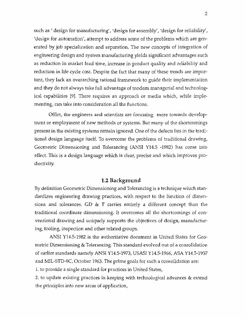
tional design language itself. To overcome the problems of traditional drawing,
Geometric Dimensioning and Tolerancing (ANSI Y14.5 -1982) has come into
effect. This is a design language which is clear, precise and which improves pro-
ductivity.
1.2 Background
By definition Geometric Dimensioning and Tolerancing is a technique which stan-
dardizes engineering drawing practices, with respect to the function of dimen-
sions and tolerances. GD & T carries entirely a different concept than the
traditional coordinate dimensioning. It overcomes all the shortcomings of con-
ventional drawing and uniquely supports the objectives of design, manufactur-
ing, tooling, inspection and other related groups.
ANSI Y14.5-1982 is the authoritative document in United States for Geo-
metric Dimensioning & Tolerancing. This standard evolved out of a consolidation
of earlier standards namely ANSI Y14.5-1973, USASI Y14.5-1966, ASA Y14.5-1957
and MIL-STD-8C, October 1963. The prime goals for such a consolidation are:
1. to provide a single standard for practices in United States,
2. to update existing practices in keeping with technological advances & extend
the principles into new areas of application,
3
3. to establish a single basis and "voice" for the United States in the interest of
international trade, in keeping with United States' desire to be more active, gain
greater influence, and pursue a more extensive exchange of ideas with nations in
the area of international standard development. [ 1 ]
GD & T has gained acceptance in manufacturing environment because it is
the link that acknowledges machining capabilities and desired part configura-
tions through the utilization of graphical symbols for form, fit, and function
requirements. The GD & T system allows one to maximize tolerance conditions of
the parts, while still maintaining interchangeable characteristics. The GD & T
technique uses above noimal practices in addition to the datum reference, basic
dimensions, and various geometric control characteristics, classified in five
groups of Form, Orientation, Location, Profile and Runout. These requirements
are generally not specified in the standard print specifications, but these addi-
tional specifications will further assure product compliance.
The objectives of GD & T are clear and well defined and may lead to effec-
tive coordination among the departments. But much less awareness is found in
actual practice in the industries. Very few organizations and acedemic institutions
provide a formal training or education in the field of GD & T. Majority of them
still stick to the conventional drawing methods or they hesitate to employ GD & T
approach associating certain myths to it, for example, GD & T raises product
costs, GD & T and ANSI Y14.5 are confusing, it is easier to use coordinate dimen-
sioning, Dimensioning and Tolerancing are separate steps, GD & T should be
used on critical parts and so on. The GD & T method is used by Military and
automative industries.
Concurrent engineering concepts emphasize working together by all the
related department representatives around a table. The process may work fine for
a short time but then may cause fight among themselves because of a variety of
conflicting factors. In such cases, there has to be a systematic methodology or tool
which takes care of these factors and should be abide by all the departments.
Although the philosophy of Concurrent Engineering reflects integration of
all the activities related to the design of product such as market , sales, finance,
engineering, manufacturing and support, it is crucial to achieve this integration
4
during the product design process. An Internal Company studies at Westing-
house, GM's Detroit Diesel Allison Division, Ford, and Rolls Royce, and others
indicate that about 70 % of the life cycle cost of a product is determined when it is
designed [12] . Design choices determine materials, fabrication methods, assem-
bly methods, and to a lesser degree material handling options, inspection tech-
niques, and other aspects of production system. Production engineers and shop
floor workers will consume less time and effort if they are presented with a fin-
ished design, and so reduces overall product development cost.
Traditional approaches for product development like Sequential Engineer-
ing involves number of recurring activities because of linear characteristics of the
process. The information flow is unidirectional from customers need to design to
manufacturing to market. The process does have a feed back but its implementa-
tion is delayed till each discipline finishes its part of the process. Turino of Logical
Solution Technology, Inc. in his paper describes that Concurrent Engineering is an
integrated approach that eliminates recurring activities like redesigning and
reverification, thereby saving time to market typically between 10 and 25 % and
results in a better product. [ 18, p. 192]
British aerospace study indicates that approximately 65 % of total cost is
spent during product conception and validation stages as compared to rest spent
in the development, production, operation and support stages of the product
development. Therefore, as much of the product's cost is commited early in the
design, all the product issues must be considered from begining.
One of the greatest difficulties in organizing multidisciplinary teams,
which is an CE concept, is communication among the team members. Markowitz
states in his article " Concurrent Engineering journey starts with the first step",
that for many organizations, communication may mean collocating employees
along project, rather than functional lines [ 10, p.113]. Otherwise, it is neccessary
to provide some communication tool, assuming that project development com-
munications may need a tool beyond that telephone and facimile transmission.
The objectives clearly indicate the intention of using GD & T as to provide
a uniform understanding in print reading as regard to part manufacture. Gehrke
in his article states [3, p.86] that GD & T is the simplest way to avoid ambiguity in
5
print interpretation. The symbology and concepts used in GD & T do not directly
reference to other standards like ISO 9000 series or ABCA (America, Britain, Can-
ada and Australia), but requirements included in these standards effectively man-
date the use of GD & T.
1.3 Research Emphasis
In a concurrent environment, where integration is a key word, communication
should be accurate and interpretable at all the levels in a uniform way. Today's
sophisticated engineering design demands, new and better ways of accurately
communicating requirements is one of the reasons for GD & T and this is true in a
manufacturing, inspection and tooling enviroments. This is one of the area where
importance is given in this thesis.
The thesis compares and analyses the objectives of Concurrent Engineering
concepts with Geometric Dimensioning & Tolerancing method of drawing. The
implementation of GD & T concepts in different areas such as design, manufac-
turing, tooling is discussed in details. Later at each area, it will be shown how GD
& T concepts interlink all these departments and how if establish the concurrent
engineering objectives directly or indirectly. To highlight the importance and
accuracy of conditions like MMC, RFS and LMC, besides all the geometric charac-
teristics, emphasis is also given to usage of functional gages. A condition is dis-
cussed when LMC features are required to be measured. An alternative method is
highlighted for RFS and LMC feature measurements. Moreover, the cost and qual-
ity objectives of Concurrent engineering will be established by the use of GD & T
methodology. It should also be emphasized that GD & T should be the "key
word" for industries and its implementation would automatically lead to realiza-
tion of concurrent engineering concepts.

CHAPTER 2
GEOMETRIC DIMENSIONING & TOLERANCING
2.1 Introduction
GD & T can be described in its simplest terms as a means of specifying the geom-
etry or shape of a piece of hardware on an engineering drawing. GD & T is one of
the three types of dimensions used on engineering drawings. Figure 1 shows how
geometric dimensioning fits into the total subject of dimensioning of engineering
drawings.
Figure 1. Types of Dimensioning and Tolerancing
GD & T is a dual purpose system. First it is set of standard symbols whicn
are used to define part features and their tolerance zones. The symbols and their
interpretations are documented by American Standards Institute Dimensioning
Standard (ANSI Y14.5M-1982). Secondly, GD & T has philosophy of designing
part based on its functions. It is a powerful language which helps a designer in
providing with a clear way of expressing design intents and part requirements,
which in turn enables the manufacturer to choose the proper method of inspect-
ing and gaging the part, thus protecting the design intent. In this way the mar-
keter the designer, the manufacturer, and inspector with the same standards can
6
7
can thus avoid misunderstandings.
The dimensions on a drawing with GD & T also define size and shape of
the part in order to function as the design intended. This dimensioning philoso-
phy is a powerful design tool. Also it helps in better communication. As a design
philosophy it provides the most liberal tolerances, and thus can provide substan-
tial saving in product costs and company's operating expenses.
Geometric dimensioning & tolerancing is rapidly becoming a universal
engineering drawing language & technique that manufacturing industries and
government agencies are finding essential to their operation well being.
The authoritive document governing the use of geometric dimensioning
and tolerancing in the United States is ANSI Y14.5-1982, "Dimensioning and Tol-
erancing." This standard evolved out of a consolidation of earlier standards,
ANSI Y14.5-1973, USASI Y14.5-1966, ASA Y14.5-1957, SAE Automative Aero-
space Drawing Standards and MIL-STD-8C, October 1963. This consolidation has
accomplished over years by committee representing military, industrial, and edu-
cational interests. The work of the committee has had three prime objectives :
1. to provide a single standard for practices in the United States,
2. to update existing practices in keeping with technological advances and extend
the principles into new area of application,
3. to establish a single basis and "voice" for the United States in the interest of
international trade, in keeping with United States' desire to be more active, gain
greater influence, and pursue a more extensive exchange of ideas with nations in
the area of international standard development.
2.2 Advantages
During the past 40 years, the GD & T has matured to become as indespensible
tool; it assists productivity, quality, and economics in building and marketing
products around the world. The military, the automotive and other industries
have been using GD & T for over the years. One of the reason that this subject has
become popular is that it saves money. The other advantages of theuse of GD & T
can be grouped as following :

8
1. Improve communications :
GD & T can provide uniformity in drawing specifications and interpreta-
tions, and so reduces controversy, guesswork and assumptions. Design, produc-
tion, and inspection all work to the same language.
2. Better product designs:
The use of GD & T can improve the product designs. First, by providing
designer with tools to "say what they mean". Second, by establishing a dimen-
sioning philosophy based on part function. This philosophy, called functional
dimensioning, studies product function in the design stage and establishes part
tolerances based upon functional requirements.
3. Production tolerances increased :
There are two ways tolerances are increased through the use of GD & T.
Firstly, under certain conditions, GD & T provides "bonus" or extra tolerance for
manufacturing. This additional tolerance can make a significant savings in pro-
duction costs. Second, by the use of functional dimensioning, the tolerances are
assigned to the part based upon its functional requirements. This often results in a
larger tolerance for manufacturing. It eliminates copying existing tolerances, or
assigning tight tolerances, because of lack of knowledge to decide reasonable tol-
erances.
4. Reduced rework and reverification :
Since the drawing indicates the dimensions clearly and unambiguously
and how the part is to be manufactured and inspected, the parts are produced
exactly as per the design requirements. The rejection quantity is reduced and
hence rework and reverification is reduced or eliminated in many cases.
5. Time and Cost saving :
Reduction or elimination of ambiguity, confusions, conflicts, rework and
reverification ultimately provides for saving in time and so reduced production
costs. And thus the competitiveness of the company.
6. Interchangability :
GD & T is a powerful addition to drafting documentation practice that pro-
vides increased design and manufacturing flexibility, and it can ensure 100 %
interchangability at optimm cost.

9
2.3 Disadvantages :
The biggest limitations of GD & T is lack of awareness and training programs
availlable in this field. There are very few school and organizations where a for-
mal course on GD & T is offered. Most of the organization employ traditional way
of dimensioning which has discrepencies and may leads to either wrong interpre-
tation or incomplete dimensioning specifications. The involvment of people with
this subject is because of their personal interest and they developed it by reading
articles & books teaching themselves. Another shortcoming is the large number of
bad examples of GD & T on drawing today & so lack of uniform interpretation.
This makes it extremely difficult, if not impossible for drawing users like manu-
facturing & inspection departments to correctly interpret drawings where there is
no correct interpretation. This leads to much confusion. Usually GD & T is
blamed, when really the confusion exist because the dimensions are incorrectly
applied.
2.4 Functional Dimensioning Functional dimensioning is a philosophy of dimensioning & tolerancing a part
based on how it functions. When functionally dimensioning a part, the designer
performs a functional analysis. A functional analysis is a process in which a
designer identifies the functions of a part and uses this information to establish
the actual part dimensioning & tolerances. Functional dimensions & analysis are
very powerful design tool. Yet, the use of functional dimensioning requires a lot
of effort & time even for an experienced designer. The rewards with such types of
benefits are :
1. The designer will develop an objective design philosophy.
2. The designer will develop a true understanding of functioning of each part in
design.
3. Potential product problems will be identified at the design stage.
4. An objective method for evaluating change requests will be established.
5. Larger tolerance for manufacturing. Tolerances will be based on the "maximum
allowable tolerance that will not adveresly affect the product function."
6. Promote better communication between design & development departments.
10
7. Fewer change requests. In most cases, part tolerances will already be at their
maximum value.
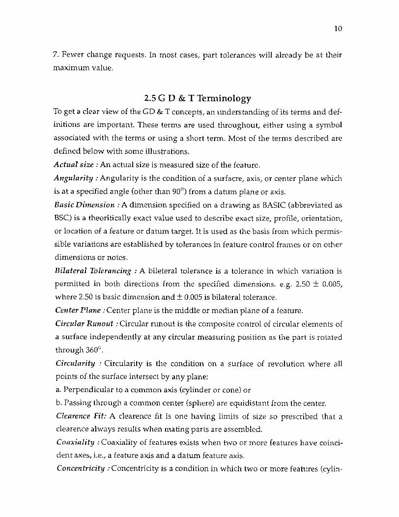
2.5 G D & T Terminology To get a clear view of the GD & T concepts, an understanding of its terms and def-
initions are important. These terms are used throughout, either using a symbol
associated with the terms or using a short term. Most of the terms described are
defined below with some illustrations.
Actual size : An actual size is measured size of the feature.
Angularity : Angularity is the condition of a surfacre, axis, or center plane which
is at a specified angle (other than 90°) from a datum plane or axis.
Basic Dimension : A dimension specified on a drawing as BASIC (abbreviated as
BSC) is a theoritically exact value used to describe exact size, profile, orientation,
or location of a feature or datum target. It is used as the basis from which permis-
sible variations are established by tolerances in feature control frames or on other
dimensions or notes.
Bilateral Tolerancing : A bileteral tolerance is a tolerance in which variation is
permitted in both directions from the specified dimensions. e.g. 2.50 ± 0.005,
where 2.50 is basic dimension and ± 0.005 is bilateral tolerance.
Center Plane : Center plane is the middle or median plane of a feature.
Circular Runout : Circular runout is the composite control of circular elements of
a surface independently at any circular measuring position as the part is rotated
through 360°.
Circularity : Circularity is the condition on a surface of revolution where all
points of the surface intersect by any plane:
a. Perpendicular to a common axis (cylinder or cone) or
b. Passing through a common center (sphere) are equidistant from the center.
Clearence Fit: A clearence fit is one having limits of size so prescribed that a
clearence always results when mating parts are assembled.
Coaxiality : Coaxiality of features exists when two or more features have coinci-
dent axes, i.e., a feature axis and a datum feature axis.
Concentricity : Concentricity is a condition in which two or more features (cylin-

11
ders, cones, spheres, hexagons, etc.) in any combination have a common axis.
Cylindricity : Cylindricity is a condition of a surface of revolution in which all
points of the surface are equidistant from a common axis.
Datum : A theoritically exact point, axis, or plane derived from the true geometric
counterpart of a specified datum feature. A datum is the origin from which the
location or geometric characteristics of features of a part are established.
Datum Axis : The datum axis is the theoritically exact axis of datum feature when
its surface is in contact with the simulated datum; the smallest circumscribed cyl-
inder (for external features) or largest inscribed cylinder (for internal features).
Datum Feature : A datum feature is an actual (physical) feature of a part used to
establish a datum.
Datum Feature Symbol : The datum feature symbol contains the datum reference
letter in a drawn rectangular box. e.g. - A -
Datum Line : A datum line is that which has length but no breadth or depth such
as the intersection line of two planes, center lines or axis of holes or cylinders, ref-
erence line for tooling, gaging, or datum target purposes.
Datum Reference Planes : A datum reference frame is a set of three mutually per-
pendicular datum planes or axes established from the simulated datums in con-
tact with datum surfaces or features and used as a basis fro dimensions for
design, manufacture, and measurement. It provides complete orientation for the
features involved.
Datum Surface : A datum surface or feature (hole, slot etc.) refers to the actual
part, surface, or feature coincidental with, relative to, and/or establish a datum
plane.
Dimension : A dimension is a numerical value expressed in appropriate units of
measure and indicated on a drawing and in other documents along with lines,
symbols and notes to define the size or geometric characteristic (or both) of a part
or part feature.
Feature : A feature is the general term applied to a physical portion of a part and
may include one or more surfaces such as holes, pins, screw threads, profiles,
faces, or slots. A feature may be individual or related.
Feature Control Frame : The feature control frame is a rectangular box containing
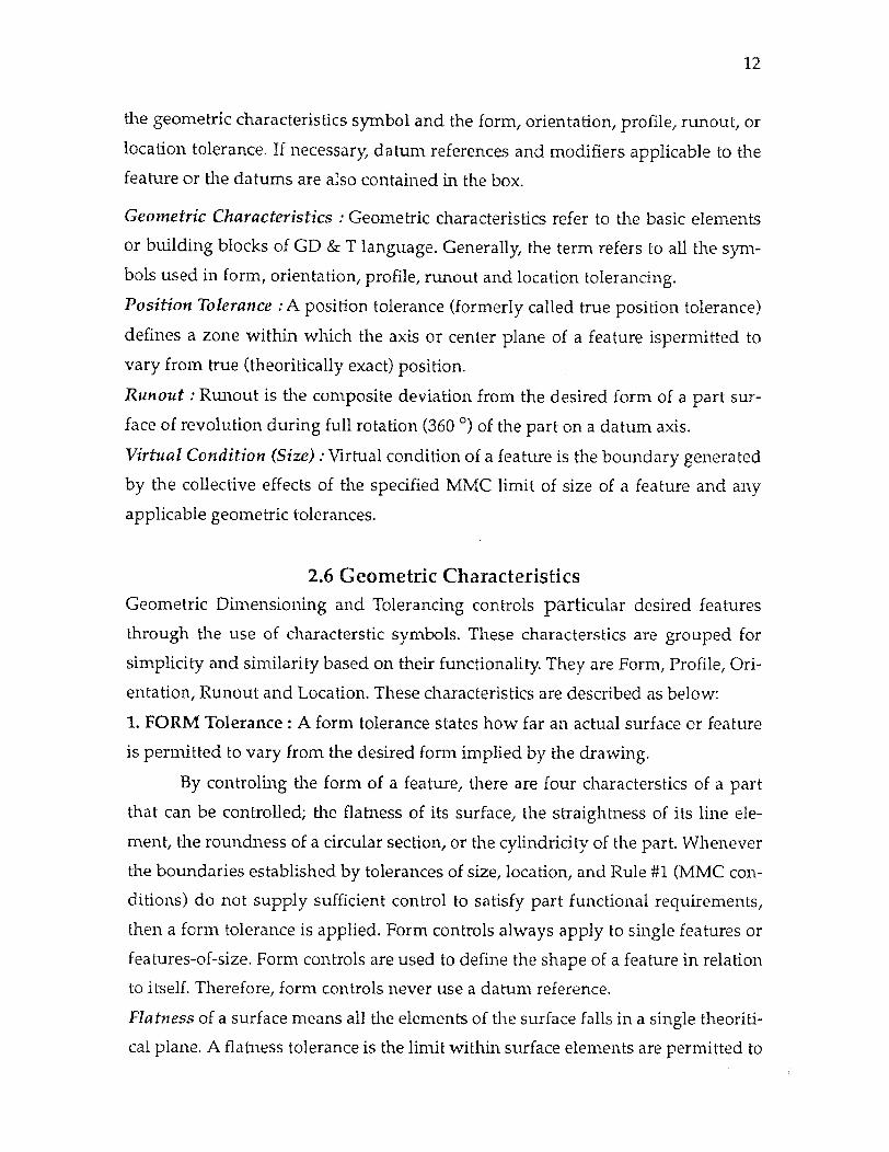
12
the geometric characteristics symbol and the form, orientation, profile, runout, or
location tolerance. If necessary, datum references and modifiers applicable to the
feature or the datums are also contained in the box.
Geometric Characteristics : Geometric characteristics refer to the basic elements
or building blocks of GD & T language. Generally, the term refers to all the sym-
bols used in form, orientation, profile, runout and location tolerancing.
Position Tolerance : A position tolerance (formerly called true position tolerance)
defines a zone within which the axis or center plane of a feature ispermitted to
vary from true (theoritically exact) position.
Runout : Runout is the composite deviation from the desired form of a part sur-
face of revolution during full rotation (360°) of the part on a datum axis.
Virtual Condition (Size) : Virtual condition of a feature is the boundary generated
by the collective effects of the specified MMC limit of size of a feature and any
applicable geometric tolerances.
2.6 Geometric Characteristics Geometric Dimensioning and Tolerancing controls particular desired features
through the use of characterstic symbols. These characterstics are grouped for
simplicity and similarity based on their functionality. They are Form, Profile, Ori-
entation, Runout and Location. These characteristics are described as below:
1. FORM Tolerance : A form tolerance states how far an actual surface or feature
is permitted to vary from the desired form implied by the drawing.
By controling the form of a feature, there are four characterstics of a part
that can be controlled; the flatness of its surface, the straightness of its line ele-
ment, the roundness of a circular section, or the cylindricity of the part. Whenever
the boundaries established by tolerances of size, location, and Rule #1 (MMC con-
ditions) do not supply sufficient control to satisfy part functional requirements,
then a form tolerance is applied. Form controls always apply to single features or
features-of-size. Form controls are used to define the shape of a feature in relation
to itself. Therefore, form controls never use a datum reference.
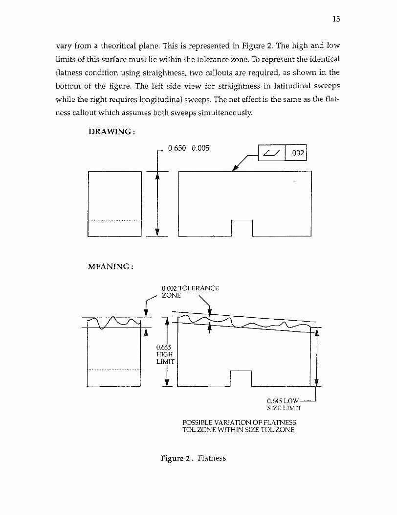
Flatness of a surface means all the elements of the surface falls in a single theoriti-
cal plane. A flatness tolerance is the limit within surface elements are permitted to
13
vary from a theoritical plane. This is represented in Figure 2. The high and low
limits of this surface must lie within the tolerance zone. To represent the identical
flatness condition using straightness, two callouts are required, as shown in the
bottom of the figure. The left side view for straightness in latitudinal sweeps
while the right requires longitudinal sweeps. The net effect is the same as the flat-
ness callout which assumes both sweeps simulteneously.
Figure 2 . Flatness
14
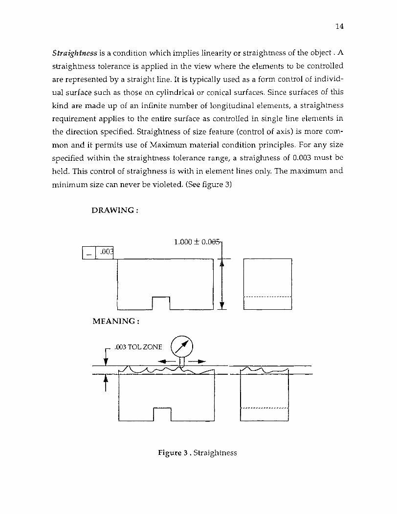
Straightness is a condition which implies linearity or straightness of the object . A
straightness tolerance is applied in the view where the elements to be controlled
are represented by a straight line. It is typically used as a form control of individ-
ual surface such as those on cylindrical or conical surfaces. Since surfaces of this
kind are made up of an infinite number of longitudinal elements, a straightness
requirement applies to the entire surface as controlled in single line elements in
the direction specified. Straightness of size feature (control of axis) is more com-
mon and it permits use of Maximum material condition principles. For any size
specified within the straightness tolerance range, a straighness of 0.003 must be
held. This control of straighness is with in element lines only. The maximum and
minimum size can never be violeted. (See figure 3)
Figure 3 . Straightness
15
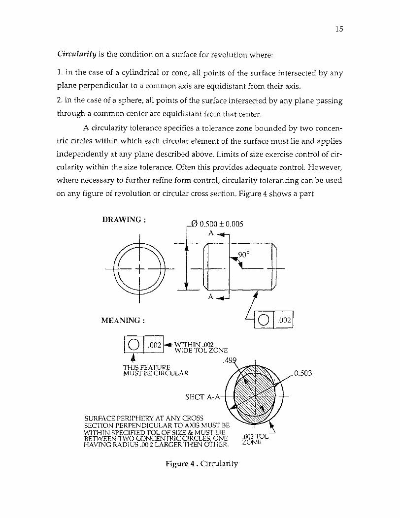
Circularity is the condition on a surface for revolution where:
1. in the case of a cylindrical or cone, all points of the surface intersected by any
plane perpendicular to a common axis are equidistant from their axis.
2. in the case of a sphere, all points of the surface intersected by any plane passing
through a common center are equidistant from that center.
A circularity tolerance specifies a tolerance zone bounded by two concen-
tric circles within which each circular element of the surface must lie and applies
independently at any plane described above. Limits of size exercise control of cir-
cularity within the size tolerance. Often this provides adequate control. However,
where necessary to further refine form control, circularity tolerancing can be used
on any figure of revolution or circular cross section. Figure 4 shows a part
Figure 4 . Circularity

Facing 16
Figure 5 . Cylindricity

16
with circularity tolerance of 0.002 specified on cylindrical part. The interpretation
also indicates how the tolerance zone can be established.
Cylindricity is the condition of a surface of revolution in which all points of the
surface are equidistant from a common axis. A cylindricity tolerance specifies a
tolerance zone bounded by two concentric cylinders within which the surface
must lie.
Limits of size exercise control of cylindricity within the size tolerance. This
control is often adequate. However, where more refined form control is required,
cylindricity tolerancing can be used. In cylindricity, unlike circularity, the toler-
ance applies simultenouslyto both circular and longitudinal elements of entire
surface.
Figure 5 illustrates a part with a cylindricity tolerance of 0.002. A cylindric-
ity tolerance is interpretated as 0.002 wide tolerance zone defined by two concen-
tric cylinders 0.002 apart. A cylindricity tolerance can be considered circularity
tolerancing extended to control the entire surface of a cylinder.
2. ORIENTATION Tolerance : When no orientation controls are specified on a
drawing, the orientation (i.e. squareness, angularity, & parallelism ) of the part
features is controlled by one of the various methods. Lines shown at right angles
often have their tolerance controlled by an angular dimensions with a tolerance,
or a general note for angular tolerances on the drawing. Features which are
shown parallel on a drawing are often controlled by the tolerance limits of the
dimension locating the feature surfaces in conjunction with Rule # 1. Orientation
controls become necessary when the type of controls mentioned above are inade-
quate or insufficiently accurate to satisfy the functional requirements.
Orientation controls define the angularity, squareness, and parallelism of
part features relative to one another. These are sometimes refers to as attitude con-
trols. There are mainly three orientation controls, namely : Perpendicularity, Par-
allelism and Angularity.
Perpendicularity is the condition of a surface, or centerplane, or axis being exactly
90° to a datum. A perpendicularity tolerance is the amount which a surface, or

17
axis, or a centerplane is permitted to vary from being perpendicular.
Most perpendicularity applications fall into one of four types of general
cases:
1. Perpendicularity applied to a surface or a planer feature-of-size
In this case, the perpendicularity control specifies a tolerance zone defined
by two parallel planes perpendicular to a datum plane or axis within which the
surface or median plane of the feature must lie. See figure 6 and 7 when it applied
to a feature and feature-of-size.
Figure 6 . Perpendicularity Applied to a Plane Surface
2. Perpendicularity applied to a diameter (in one direction only)
In this case, the perpendicularity control specifies a tolerance zone defined
by two parallel planes perpendicular to a datum plane or axis within which the
axis of the tolerances feature-of-size must lie.
3. Perpendicularity applied to the axis of diameter
In this case, the perpendicularuty control specifies a cylindrical tolerance
zone perpendicular to datum plane or axis within which the axis of the consid-
ered feature must lie.
4. Perpendicularity applied to a surface line element
In this case, the perpendicularity control defines a tolerance zone of two

18
parallel lines perpendicular to a datum plane or axis.
Figure 7. Perpendicularity Applied to a Slot - Centerplane Control
Angularity is the condition of a surface, centerplane, or axis being exactly at a
specified angle from a datum. An angularity tolerance is the amount which a sur-
face, centerplane, or axis is permitted to vary from its specified exact angle. Angu-
larity establishes a tolerance zone for a surface, centerplane, or axis which is
specified as a basic angle (other than 900) from the datum plane or axis. An angu-
larity tolerance zone has always two parallel planes.
Figure 8. Specifying Angularity for a Plane Surface

19
There are two main types of applications for angularity :
1. Angularity applied to a surface or a planer feature-of-size
In this case, the angularity control specifies a tolerance zone defined by two
parallel planes at the specified basic angle from the datum plane or axis within
which the surface or centerplane of the considered feature must lie. See figure 8.
2. Angularity applied to axis
The angularity control specifies a tolerance zone defined by two parallel
planes at the specified basic angle from a datum plane or axis within which the
axis of the considered feature must lie. See figure 9.
Figure 9. Specifying Angularity for an Axis ( Feature RFS )
Parallelism is the condition where all points of a surface, centerplane, or axis are
at equidistant from the datum plane or axis. A parallelism tolerance is the amount
by which a surface, centerplane, or axis is permitted to vary from the parallel
state. A parallelism control establishes a tolerance zone of two parallel planes or a
cylinder within which all points of a controlled surface, centerplane. or axis must
lie. There are two main applications within which almost all cases can fit. They are
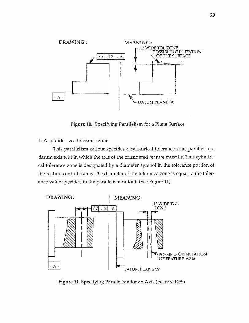
1. Parallel planes as a tolerance zone
As shown in the figure10, this parallelism control specifies a tolerance zone
defined by two planes parallel to a datum or axis. The distance between the
planes is the tolerance value specified in the parallelism callout. All elements, line
elements or axes of the considered feature must lie within these planes.
20
Figure 10. Specifying Parallelism for a Plane Surface
1. A cylinder as a tolerance zone
This parallelism callout specifies a cylindrical tolerance zone parallel to a
datum axis within which the axis of the considered feature must lie. This cylindri-
cal tolerance zone is designated by a diameter symbol in the tolerance portion of
the feature control frame. The diameter of the tolerance zone is equal to the toler-
ance value specified in the parallelism callout. (See Figure 11)
Figure 11. Specifying Parallelism for an Axis (Feature RFS)
POSITIONAL TOL
21
BASIC
1 2
REQUIREMENTS
4 COMMENTS
YES YES YES YES GOOD APPLICATION
YES NO NO NO NEEDS BASIC DIM FROM 'B' NEEDS TERI. DATUM TOL . AT MMC OR RFS ?
YES YES YES NO DOES NOT SPECIFY IF
TOL AT MMC OR RFS
NO YES YES YES POSITIONAL TOL MUST BE APPLIED TO FEATURI1 OF SIZE
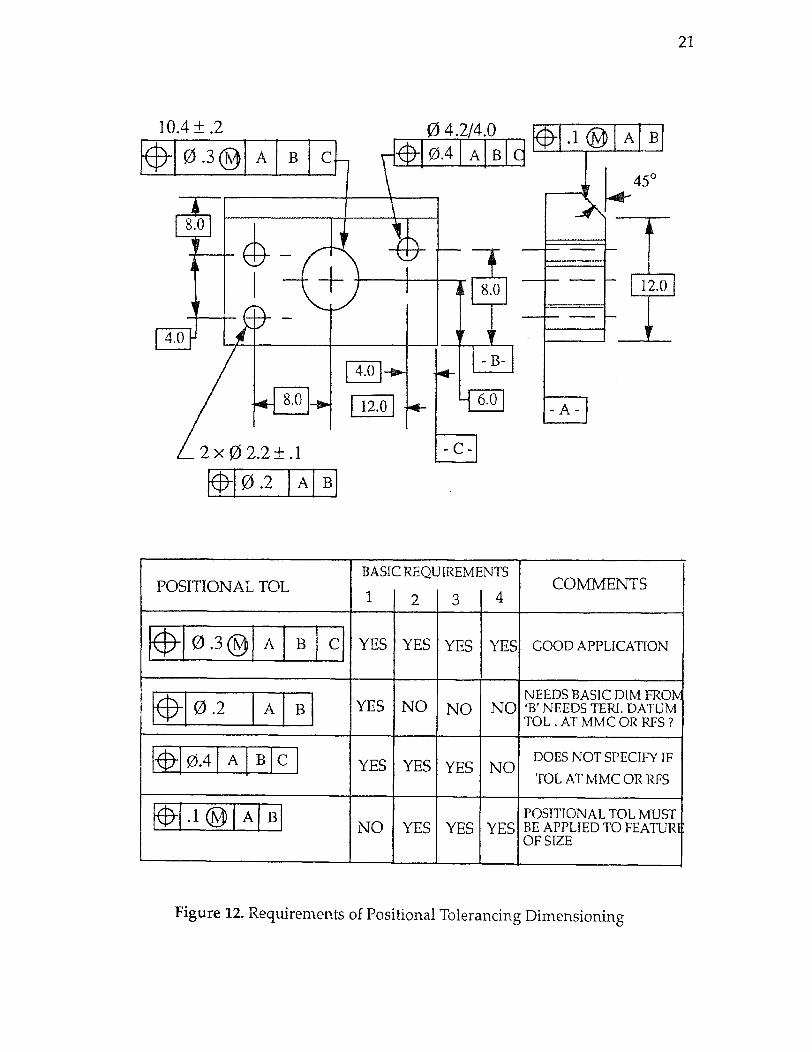
Figure 12. Requirements of Positional Tolerancing Dimensioning
22
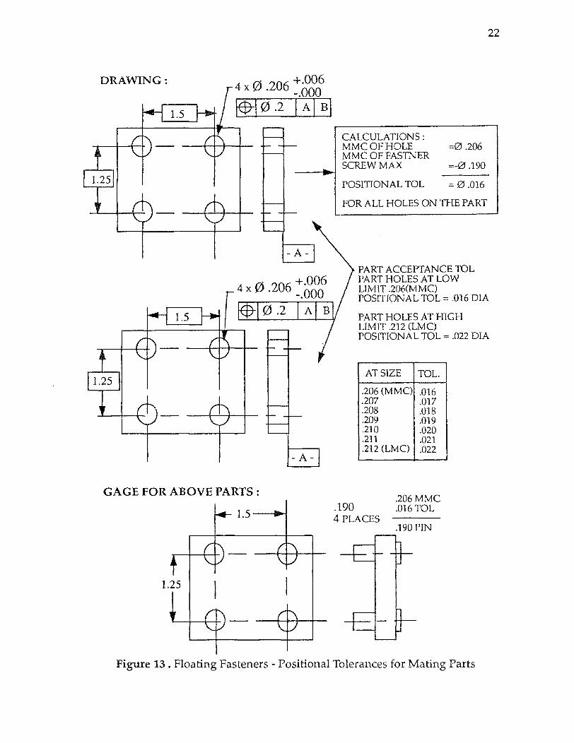
Figure 13 . Floating Fasteners - Positional Tolerances for Mating Parts
23
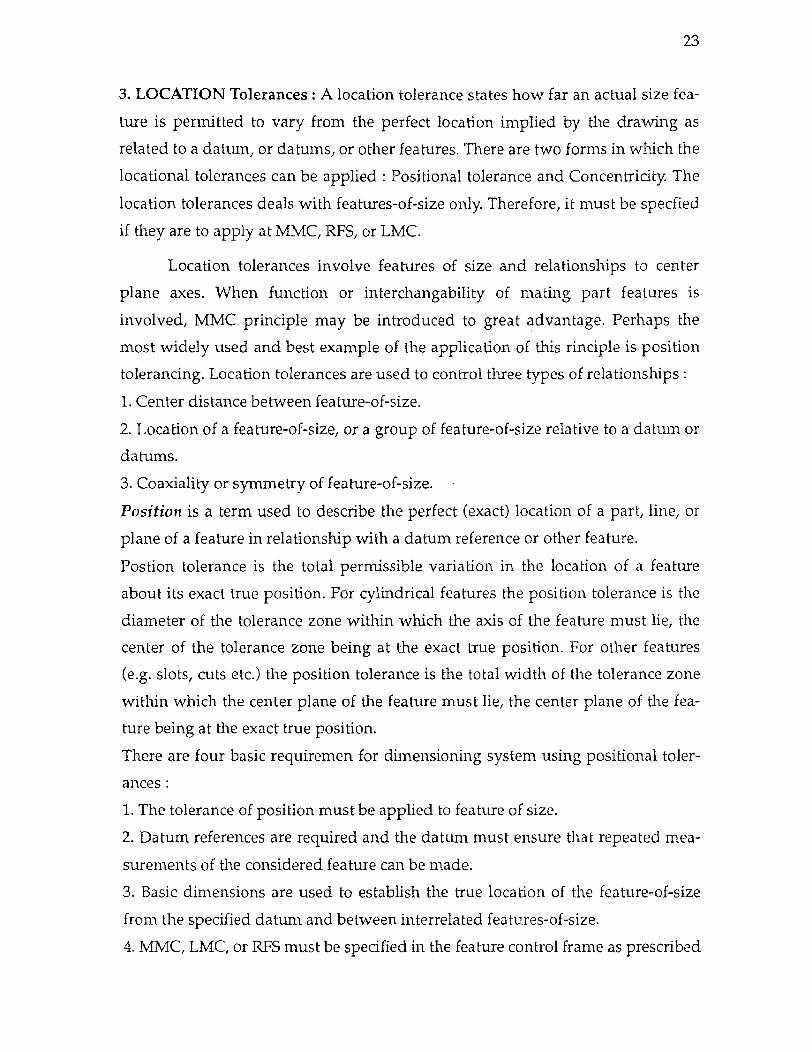
3. LOCATION Tolerances : A location tolerance states how far an actual size fea-
ture is permitted to vary from the perfect location implied by the drawing as
related to a datum, or datums, or other features. There are two forms in which the
locational tolerances can be applied : Positional tolerance and Concentricity. The
location tolerances deals with features-of-size only. Therefore, it must be specfied
if they are to apply at MMC, RFS, or LMC.
Location tolerances involve features of size and relationships to center
plane axes. When function or interchangability of mating part features is
involved, MMC principle may be introduced to great advantage. Perhaps the
most widely used and best example of the application of this rinciple is position
tolerancing. Location tolerances are used to control three types of relationships :
1. Center distance between feature-of-size.
2. Location of a feature-of-size, or a group of feature-of-size relative to a datum or
datums.
3. Coaxiality or symmetry of feature-of-size.
Position is a term used to describe the perfect (exact) location of a part, line, or
plane of a feature in relationship with a datum reference or other feature.
Postion tolerance is the total permissible variation in the location of a feature
about its exact true position. For cylindrical features the position tolerance is the
diameter of the tolerance zone within which the axis of the feature must lie, the
center of the tolerance zone being at the exact true position. For other features
(e.g. slots, cuts etc.) the position tolerance is the total width of the tolerance zone
within which the center plane of the feature must lie, the center plane of the fea-
ture being at the exact true position.
There are four basic requiremen for dimensioning system using positional toler-
ances :
1. The tolerance of position must be applied to feature of size.
2. Datum references are required and the datum must ensure that repeated mea-
surements of the considered feature can be made.
3. Basic dimensions are used to establish the true location of the feature-of-size
from the specified datum and between interrelated features-of-size.
4. MMC, LMC, or RFS must be specified in the feature control frame as prescribed
Facing 24
THE DERIVED AXIS OF THE CONSIDERED FEATURE MUST LIE WITHIN THE CONCENTRICITY TOLERANCE ZONE, THIS AXIS IS ESTABLISHED BY ANALYSIS OF THE SURFACE ELEMENTS OF THE CONSIDERED FEATURE
Figure 14 . Concentricity Tolerance Application

24
by Rule #2.
If any of these requirements are not fulfilled, the positional tolerance is uninter-
pretable. An example of positional tolerances are shown in Figure 12. Tolerance of
position is used widely because of its ability to describe the requirements of inter-
changeable components. One of the primary applications of this is related to bolt
hole pattern location because no other method describes the functional require-
ments of mating hole pattern so accurately. The other advantages of the positional
tolerances are :
a. Round tolerance zone compared to square zone of coordinate system of dimen-
sioning - 57% larger
b. Permits additional tolerances - bonus and shift
c. Permits use of fixed gages
d. Overcomes tolerance accumulation
e. Protects part functions
f. Lowers production cost
Figure 13 illustrates how the positioning tolerances can be applied to a floating
fastner. It also indicates the calculations of tolerances and gage dimensions for
checking the holes. More details are explained in chapter 4.
Concentricity is the condition where the axis of a cylinder, cone, square, hex etc.
are common to the axis of a datum feature. Concentricity tolerance is the total
amount of allowable variation of a feature-of-size to a datum axis. A concentricity
tolerance is a cylindrical tolerance zone, whose axis is coincident with the datum
axis, within which the axis of the considered feature-of-size must lie.
A concentricity tolerance zone and its datum reference can only be applied on an
RFS basis. The size tolerance of a feature-of-size is independent of the concentric-
ity tolerance. The measurement of concentricity tolerance requires that the axis of
the considered feature-of-size to be established by detailed analysis of circular ele-
ments of the surface. This determines a point of the axis for each circular element
checked. All the points of axis must lie within the concentricity tolerance zone.
Since irregularities in the form of feature being inspected make it difficult to
establish the axis of feature, therefore concentricity tolerances should be avoided

25
whenever possible. When specifying tolerances for coaxial features, consider-
ations should be given to positional or runout tolerances.
A simple illustration of a concentricity is as shown in figure 14.
The following terms apply when using a concentricity callout :
a. Rule # 1 is overridden
b. Rule # 3 applies
c. A datum reference is required
d. The tolerance zone must be RFS
e. The datum references must be RFS.
4. PROFILE Tolerance : Profile tolerance specifies a uniform boundary along the
true profile within which the elements of the surface must lie.
A profile tolerance specifies a tolerance zone, always intended and measured nor-
mal to the basic profile at all points of the profile, within which the true part sur-
face profile or line profile must lie.
Profile controls can be used to limit the form, size, or orientation of a part
feature. The outline of an object in a given plane is referred to as the profile. There
are two types of profile tolerances applied to a surface :
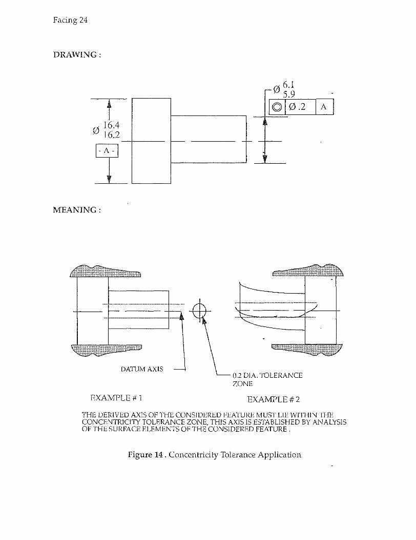
a. Profile of a surface :
The tolerance zone established by the profile of a surface tolerance is a
three -dimensional zone or total control across the entire length and width or cir-
cumference of the feature, it may be applied to parts having a constant cross sec-
tion or to the parts having a surface of revolution. Usually profile of a surface
requires datum references. Figure 15 indicates the application of profile of a sur-
face tolerances.
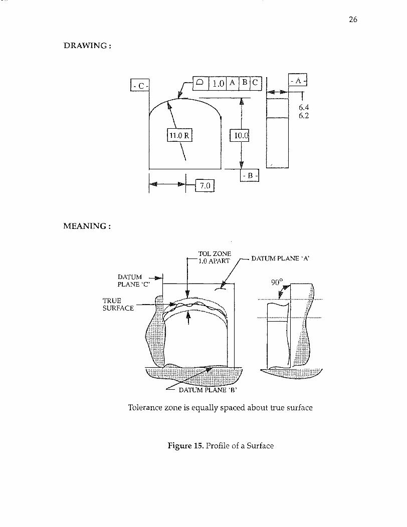
b. Profile of a line :
The tolerance zone established by profile of a line tolerance is a two-dimen-
sional zone extending along the length of the considered feature; it may be
applied to the profiles of parts having varing cross section such as propeller, air-
craft wing, nose cone and other random cross sections where it is not required to
control the entire surface as a single entity. Profile of a line may or may not require
the datum references. Figure 16 illustrates the profile of a line application.
Tolerance zone is equally spaced about true surface
26
Figure 15. Profile of a Surface
27
Figure 16. Profile of a Line and Size Control

28
5. RUNOUT Tolerances : A runout tolerance states how far an actual surface or
feature is permitted to vary from thedesired form implied by the drawing during
full (360°) rotation of the part on a datum axis.
The catagory of runout examines how circular an actual surface is with
respect to its axis, in which the axis is generated from a control surface. In com-
paring the two variables, one can conclude that it is similar to a concentricity mea-
surement with respect to common axis of rotation. the difference is that the
control surface generates the axis of rotation as in concentricity. The reason for
runout is that theoritical axis do not have to be located and then there is a large
cost difference in terms of manpower and achine requirements between runout
and concentricity. Desired features are best controlled by the concentricity callout
because it is an axis to axis measurement. It should be noted that concentricity
should never be used if position and or runout symbols can be utilized for cost
effectiveness.
Figure 17. Circular Runout
There are two types of runout callouts : Circular runout and Total runout.
As shown in Figure 17, circular runout indicates a out of round condition at a sin-
gle position perpendicular to a common axis. Total runout is similar to circular
runout except rather than a single position it includes the entire surface area. Fig-
ure 18 illustrates total runout callout.
29
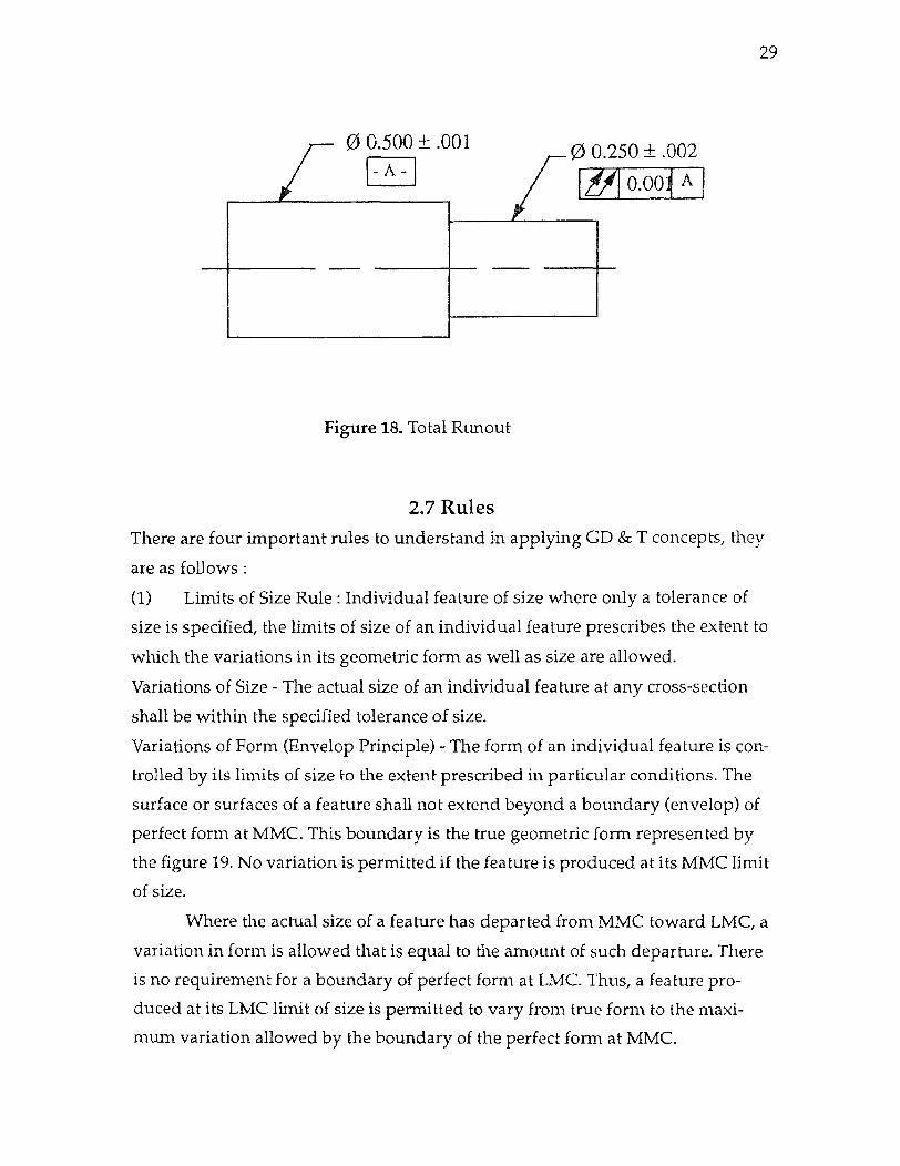
Figure 18. Total Runout
2.7 Rules
There are four important rules to understand in applying GD & T concepts, they
are as follows :
(1) Limits of Size Rule : Individual feature of size where only a tolerance of
size is specified, the limits of size of an individual feature prescribes the extent to
which the variations in its geometric form as well as size are allowed.
Variations of Size - The actual size of an individual feature at any cross-section
shall be within the specified tolerance of size.
Variations of Form {Envelop Principle) - The form of an individual feature is con-
trolled by its limits of size to the extent prescribed in particular conditions. The
surface or surfaces of a feature shall not extend beyond a boundary (envelop) of
perfect form at MMC. This boundary is the true geometric form represented by
the figure 19. No variation is permitted if the feature is produced at its MMC limit
of size.
Where the actual size of a feature has departed from MMC toward LMC, a
variation in form is allowed that is equal to the amount of such departure. There
is no requirement for a boundary of perfect form at LMC. Thus, a feature pro-
duced at its LMC limit of size is permitted to vary from true form to the maxi-
mum variation allowed by the boundary of the perfect form at MMC.

30
The control of geometric form prescribed by limits of size does not apply to
the following :
(a) Stock such as bars, sheets, tubings, structural shapes, and other items pro-
duced to established industry or government standards that prescribe limits for
straighness, flatness, and other geometric characteristics. Unless geometric toler-
ances are specified on the drawing of a part made from these items, standards for
these items govern the surfaces that remain in the "as furnished" condition on the
finished part.
(b) Parts subjected to free variation in the unrestrained condition.
Figure 19. Individual Size Feature
(2) Position tolerance rule : For a tolerance of position, MMC, LMC, or RFS
must be specified on the drawing with respect to the individual tolerance, datum
referenc, or both, as applicable.
Other than position tolerance rules : For all applicable geometric tolerances, other
than position tolerance, RFS applies with respect to the individual tolerance,
datum reference, or both, where no modifying symbol is specified. MMC must be
specified on the drawing where it is required.
(3) Pitch diameter rule : Eaach tolerance of orientation or position and datum ref-
31
erence specified for a screw thread applies to the axis of the thread derived form
the pitch cylinder. Where an exception to this practice is necessary, the specific
feature of the screw thread (such as MAJOR diameter or MINOR diameter). This
information is stated beneath the feature control frame or beneath the datum fea-
ture symbol.
(4.) Datum/ Virtual condition rule : Depending on whether it is used as a pri-
mary, secondary, or teriary datum, a virtual condition exists for a datum feature of
size where its axis or center plane is controlled by a geometric tolerance. In such a
case, the datum feature applies at its virtual condition even though it is referenced
in a feature cintrol frame at MMC.
2.8 Virtual Condition Definition : The virtual condition of a feature is a derived size generated from the
collective effect of all profile variations permitted by the specified tolerances. It
represents the most extreme condition of assembly at MMC.
Depending upon its function, a feature is controlled by tolerances such as
size, form, orientation, and location; MMC or RFS may also be applicable. The vir-
tual condition of a feature is the effective size of the profile that must be consid-
ered in determining the clearence between mating parts or features and in
establishing gage feature size. When a feature-of-size has no geometric tolerances
apllied to it, its virtual condition is equal to its MMC plus the effect of Rule # 1. If
a geometric tolerance overrides Rule# 1, then its effect must be considered in
determining the virtual condition. The virtual condition concept is used by three
groups :
a. Product Designers -
To calculate extreme conditions for analysing mating parts.
b. Inspectors -
To determine extreme conditions for open inspection set-up.
c. Gage designers -
To calculate gage dimensions.
Virtual conditions can be calculated as:
Size + orientation or position control = virtual condition (for shaft)
32
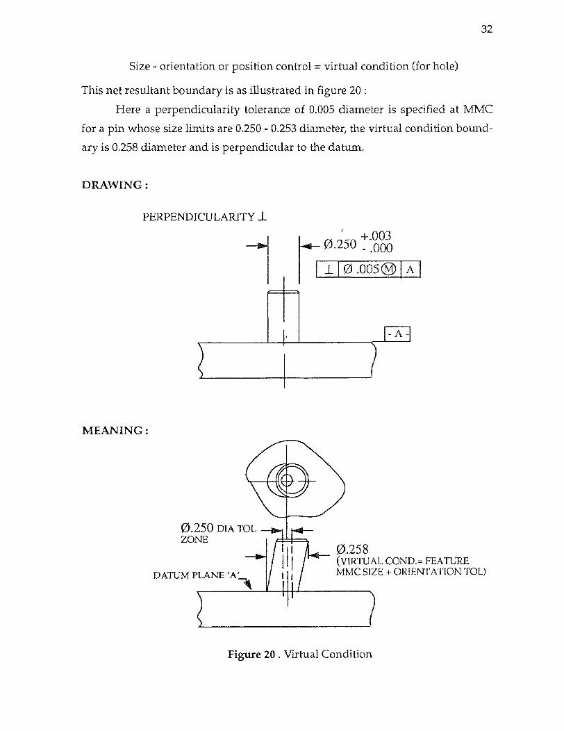
Size - orientation or position control = virtual condition (for hole)
This net resultant boundary is as illustrated in figure 20 :
Here a perpendicularity tolerance of 0.005 diameter is specified at MMC
for a pin whose size limits are 0.250 - 0.253 diameter, the virtual condition bound-
ary is 0.258 diameter and is perpendicular to the datum.
Figure 20 . Virtual Condition

33
2.9 Modifiers
In addition to the geometric characterstics symbols, there are five modify-
ing symbols used in GD & T. The modifiers specify the conditions on which the
other geometric characterstics are applicable. These five modifiers are described
in Table 1.
Table 1: Modifiers
TERM ABBREVIATION SYMBOL
MAXI. MATERIAL CONDITION MMC M
LEAST MATERIAL CONDITION LMC L
REGARDLESS OF FEATURE SIZE RFS S
PROJECTED TOLERANCE ZONE P
DIAMETER DIA Ø
Applicability of MMC, RFS and LMC is limited to features subject to varia-
tions in size. They may be datum features or other features whose axes or center
planes are controlled by geometric tolerances. In such cases following practices
are applied :
a. Tolerance of position (Rule# 2) :
RFS, MMC or LMC must be specified on the drawing with respect to the
individual tolerance, datum references, or both as applicable.
b. All other geometric tolerances (Rule# 3) :
RFS applies with respect to individual tolerances, datum reference, or both,
where no modifying symbol is specified on drawing where it is required.
34
The fourth modifier is called projected tolerance zone which means that
the theoritical tolerance zone is projected above or below the part as indicated by
the callout. The fifth modifier is called Diameter, indicating the dimension as
diameter of feature on which it is applied. Each of these modifierare explained in
details as following.
2.9.1 Maximum Material Condition (MMC): Definition : MMC may be defined as the condition in which a feature of size con-
tains the maximum amount of material within the stated limits of size such as
minimum hole diameter or maximum shaft diameter.
The MMC principle is normally valid only when both of the following
conditions exist :
1. Two or more features are interrelated with respect to location or orientation.
(Example - a hole, & an edge or surface, two holes etc.). Atleast one of the related
feature is to be a feature-of-size.
2. The feature to which the MMC principle is to be applied must be a feature-of-
size (e.g. - a hole, slot, pin etc. ) within axis or center plane.
In the conventional method, the MMC condition is described as "worst
condition" or "critical condition" etc. , used for the relating mating part features.
The MMC refers to the dimension of a part at which it will contain maxi-
mum material i.e. lower limit for a hole and higher limit for a shaft. The Figure 21
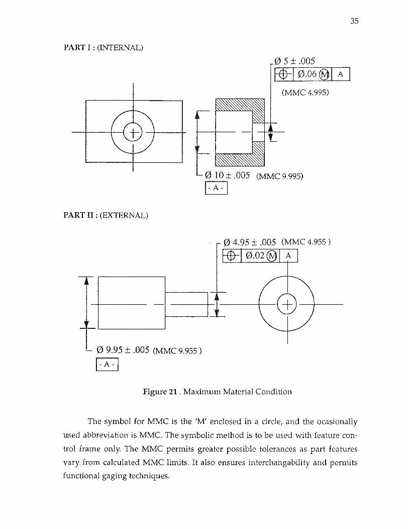
indicates the concept of MMC for a internal and externel dimensions.
The MMC size of 10 ± 0.005 diameter hole is 9.995, or its lower limit size.
Whenever a hole is at its low size, it retains more material than if it were at its
high size on larger size, which will be 10.005 in this example. Similarly, the MMC
of 5 ± 0.005 diameter hole is 4.995.
In the same way, it can be seen that for the outer diameter of 9.95 ± 0.005
the higher limit is 9.955. And for 4.95±0.005 dimension the higher limit is 4.955.
The two parts, part1 and part2 in the Figure 20 are mating parts. Relative mating
part features in this manner ensures their functional relationships. This condition
also establishes the criteria for determining necessary form, orientation & posi-
tional tolerances.
35
Figure 21 . Maximum Material Condition
The symbol for MMC is the 'M' enclosed in a circle, and the ocasionally
used abbreviation is MMC. The symbolic method is to be used with feature con-
trol frame only. The MMC permits greater possible tolerances as part features
vary from calculated MMC limits. It also ensures interchangability and permits
functional gaging techniques.

= - 4.955 = - 4.955 0.040
0.040 0.040
= 9.995 0.080 = 9.955
0.040
POSITION TOLERANCE CALCULATIONS :
MMC SIZE HOLE (PART #1 )
MMC SIZE SHAFT (PART #2)
MMC SIZE DATUM HOLE (PART #1)
MMC SIZE DATUM SHAFT (PART #2)
EXTRA TOL FOR EACH PART
TOTAL TOL TO BE DIVIDED AS -DESIRED TO ESTABLISHED REQUIRED POSITION TOL ON EACH INDIVIDUAL PART
-CAN BE ANY COMBINATION WHICH TOTALS TO .080 (e.g. 0.06 & 0.02)
Facing 36
PERMISSIBLE HOLE POSITION TOL AS HOLE SIZE DEPARTS (GETS LARGER) FROM MMC :
STATED POSITION TOL WITH HOLE AT 4.995 MMC = .060
PLUS TOTAL 4.995 HOLE TOL = .010
POSN TOL WITH DATUM HOLE 9.995 AT MMC .070
PLUS TOTAL 4.995 DATUM HOLE TOL +.010
TOTAL POSN TOL WITH BOTH HOLES AT LEAST MAT'L CONDITION (PART # 1) .080
PERMISSIBLE HOLE POSITION TOL AS HOLE SIZE DEPARTS (GETS LARGER ). FROM MMC :
STATED POSITION TOL WITH SHAFT AT 4.955 MMC 0= .020
PLUS TOTAL 4.955 DIA TOL = .010
POSN TOL WITH DATUM SHAFT 9.955 AT MMC .030
PLUS TOTAL 4.995 DATUM SHAFT TOL +.010
TOTAL POSN TOL WITH BOTH HOLES AT LEAST MAT'L CONDITION: (PART #2) .040
Figure 22 Effect and Calculation of MMC
36
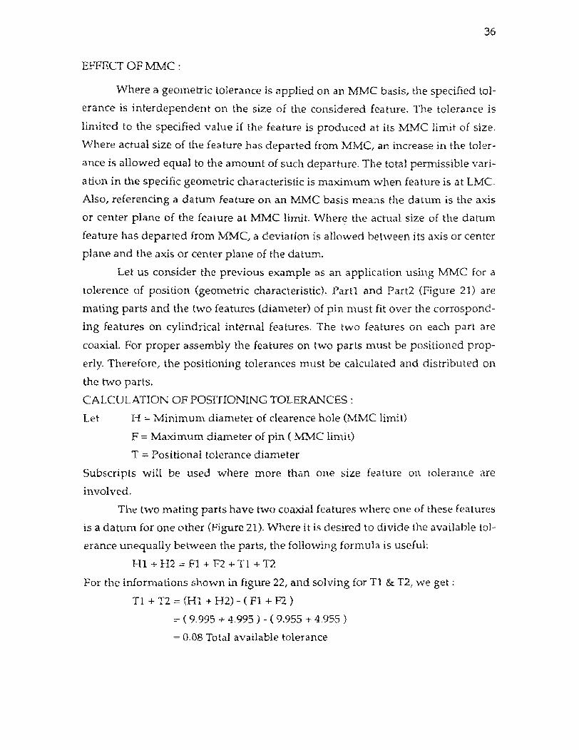
EFFECT OF MMC :
Where a geometric tolerance is applied on an MMC basis, the specified tol-
erance is interdependent on the size of the considered feature. The tolerance is
limited to the specified value if the feature is produced at its MMC limit of size.
Where actual size of the feature has departed from MMC, an increase in the toler-
ance is allowed equal to the amount of such departure. The total permissible vari-
ation in the specific geometric characteristic is maximum when feature is at LMC.
Also, referencing a datum feature on an MMC basis means the datum is the axis
or center plane of the feature at MMC limit. Where the actual size of the datum
feature has departed from MMC, a deviation is allowed between its axis or center
plane and the axis or center plane of the datum.
Let us consider the previous example as an application using MMC for a
tolerence of position (geometric characteristic). Part1 and Part2 (Figure 21) are
mating parts and the two features (diameter) of pin must fit over the corrospond-
ing features on cylindrical internal features. The two features on each part are
coaxial. For proper assembly the features on two parts must be positioned prop-
erly. Therefore, the positioning tolerances must be calculated and distributed on
the two parts.
CALCULATION OF POSITIONING TOLERANCES :
Let H = Minimum diameter of clearence hole (MMC limit)
F = Maximum diameter of pin ( MMC
T = Positional tolerance diameter
Subscripts will be used where more than one size feature on tolerance are
involved.
The two mating parts have two coaxial features where one of these features
is a datum for one other (Figure 21). Where it is desired to divide the available tol-
erance unequally between the parts, the following formula is useful:
H1 + H2 F1 + F2 + T1 + T2
For the informations shown in figure 22, and solving for T1 & T2, we get :
T1 + T2 = (H1 + H2) - ( F1 + F2 )
= ( 9.995 + 4.995 ) - ( 9.955 + 4.955 )
= 0.08 Total available tolerance
37
Normally it is easy to produce the tolerances on external features than
internal dimensions, therefore larger tolerance is provided on the hole and
smaller tolerance on shaft (pin), i.e. T1 = 0.06 and T2 = 0.02. However, these posi-
tional tolerances can be distributed as per the design requirements.
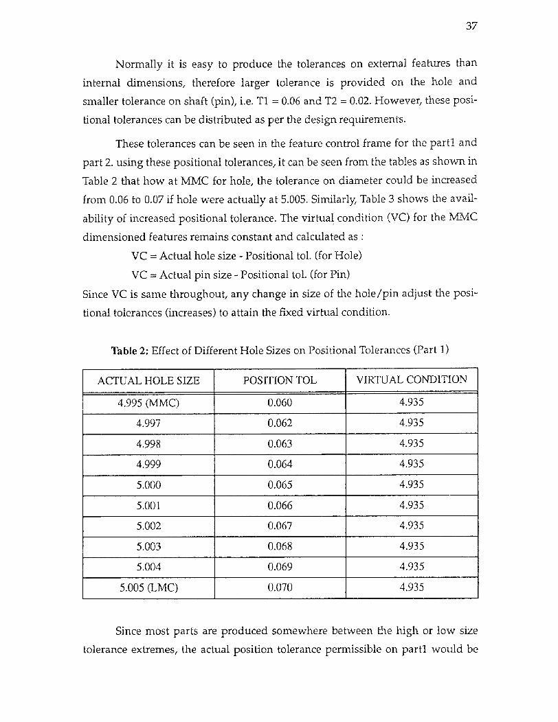
These tolerances can be seen in the feature control frame for the para. and
part 2. using these positional tolerances, it can be seen from the tables as shown in
Table 2 that how at MMC for hole, the tolerance on diameter could be increased
from 0.06 to 0.07 if hole were actually at 5.005. Similarly, Table 3 shows the avail-
ability of increased positional tolerance. The virtual condition (VC) for the MMC
dimensioned features remains constant and calculated as :
VC = Actual hole size - Positional tol. (for Hole)
VC = Actual pin size - Positional tol. (for Pin)
Since VC is same throughout, any change in size of the hole/pin adjust the posi-
tional tolerances (increases) to attain the fixed virtual condition.
Table 2: Effect of Different Hole Sizes on Positional Tolerances (Part 1)
ACTUAL HOLE SIZE POSITION TOL VIRTUAL CONDITION
4.995 (MMC) 0.060 4.935
4.997 0.062 4.935
4.998 0.063 4.935
4.999 0.064 4.935
5.000 0.065 4.935
5.001 0.066 4.935
5.002 0.067 4.935
5.003 0.068 4.935
5.004 0.069 4.935
5.005 (LMC) 0.070 4.935
Since most parts are produced somewhere between the high or low size
tolerance extremes, the actual position tolerance permissible on part1 would be
38
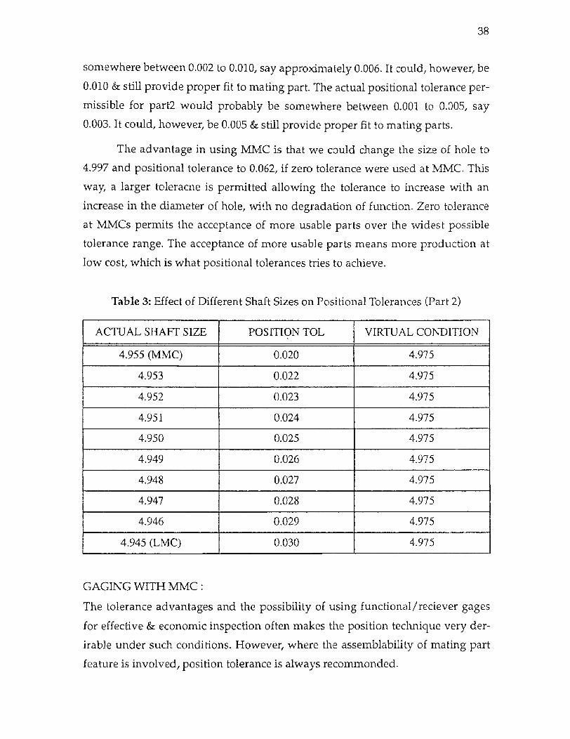
somewhere between 0.002 to 0.010, say approximately 0.006. It could, however, be
0.010 & still provide proper fit to mating part. The actual positional tolerance per-
missible for part2 would probably be somewhere between 0.001 to 0.005, say
0.003. It could, however, be 0.005 & still provide proper fit to mating parts.
The advantage in using MMC is that we could change the size of hole to
4.997 and positional tolerance to 0.062, if zero tolerance were used at MMC. This
way, a larger toleracne is permitted allowing the tolerance to increase with an
increase in the diameter of hole, with no degradation of function. Zero tolerance
at MMCs permits the acceptance of more usable parts over the widest possible
tolerance range. The acceptance of more usable parts means more production at
low cost, which is what positional tolerances tries to achieve.
Table 3: Effect of Different Shaft Sizes on Positional Tolerances (Part 2)
ACTUAL SHAFT SIZE POSITION TOL VIRTUAL CONDITION
4.955 (MMC) 0.020 4.975
4.953 0.022 4,975
4.952 0.023 4.975
4.951 0.024 4.975
4,950 0.025 4,975
4.949 0.026 4.975
4.948 0.027 4.975
4.947 0.028 4.975
4.946 0.029 4.975
4.945 (LMC) 0.030 4.975
GAGING WITH MMC :
The tolerance advantages and the possibility of using functional /reciever gages
for effective & economic inspection often makes the position technique very der-
irable under such conditions. However, where the assemblability of mating part
feature is involved, position tolerance is always recommonded.
Facing 39
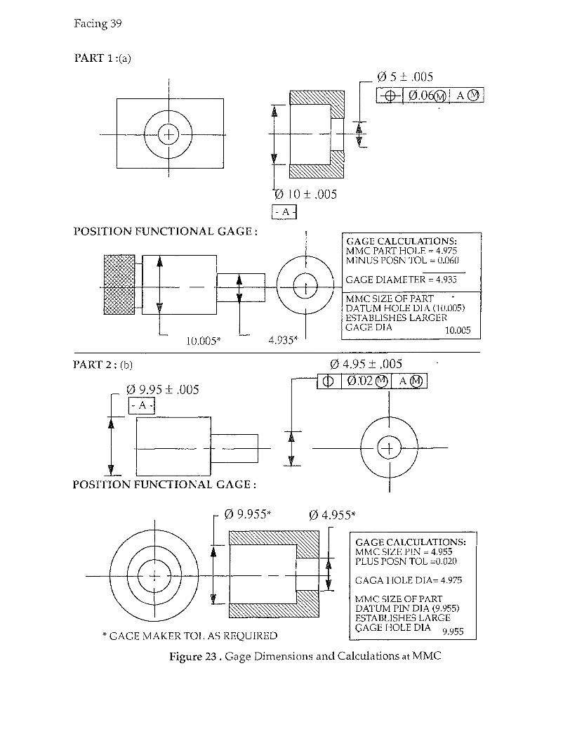
Figure 23 . Gage Dimensions and Calculations at MMC
39
Functional or reciever gages for coaxial features of mating parts simulate
the fit of the actual part features in a manner similar to the hole pattern functional
gages. As in the hole pattern functional gages, part tolerance size departure from
MMC permits greater part acceptance based on the functional interrelationship of
size and positional variations.
To construct a functional gage, tolerance for the gage feature location must
be taken from the piece part feature location tolerance. This is commonly refered
to as the 10% rule, which means that up to 10% of part tolerance limits could be
rejected by a functional gage if the part were at fringe edge of the acceptable toler-
ance range. The gage will not, however, ever accept a bad part.
The Figure 23 illustrates functional gage to check the position requirements
of each part. Figure 23 (a) shows a gage for functionally checking the position tol-
erance of holes. The calculations to determine the gage dimensions are shown at
right in the figure. As discussed before, gage makers tolerance can also be applied
as required. Figure 23 (b) shows part2 and functional gage for checking the posi-
tion of the shaft diameter. The gage dimensions can be calculated as shown in the
figure.
The advantage with MMC is that the virtual condition remains constant.
Therefore, the corresponding mating part (gage) can be constructed with this con-
stant dimension and can be used for all dimensions of part within the tolerance
limits. The gages discussed only checks the positional tolerance of the part. Sizes
of the associated features requires a separate size checks.
2.9.2 Regardless of feature sizes (RFS) : Definition : The term used to indicate that a geometric tolerance or datum refer-
ence applies at any increment of size of the feature within its size tolerance.
The RFS principle do not allow any additional positional, form or orienta-
tion tolerance, no matter to which size the related features are produced. It is actu-
ally the independent form of dimensioning & tolerancing which has always been
used prior to the introduction of MMC principle. The symbol for RFS is 'S'
enclosed in circle. this principle is valid only when applied to feature-of-sizes ( for
example- hole, slot, pin etc. with an axis or center plane ).

Facing 40
ACTUAL HOLE SIZE POSITION TOL VIRTUAL CONDITION
5.005 (LMC) 0.060 4.945
5.003 0.060 4.943
5.001 0.060 4.941
4.999 0.060 4.939
4.997 0.060 4.937
4.995 (MMC) 0.060 4.935
ACTUAL HOLE SIZE POSITION TOL VIRTUAL CONDITION
5.005 (MMC) 0.060 4.945
5.003 0.060 4.943
5.001 0.060 4.941
4.999 0.060 4.939
4.997 0.060 4.937
4.995 (LMC) 0.060 4.935 .
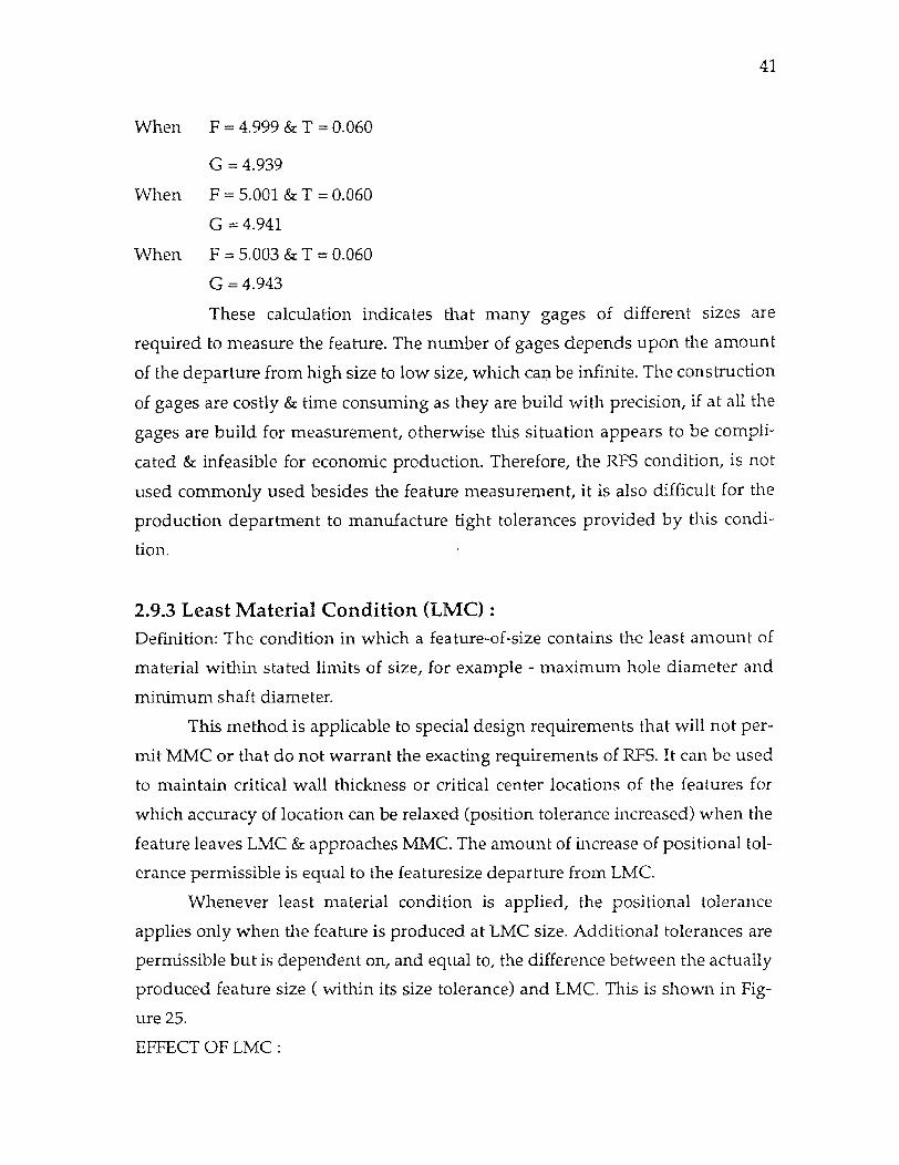
Figure 24 . Effect of RFS and Calculation
40
This feature condition actually demands a very tight tolerance, hence it is
not flexible for the production department to manufacture the part easily. RFS
condition is quite similar to the conventional method of tolerancing i.e. unilat-
eral/bilateral tolerancing, because the positional tolerances could not be
increased or decreased as can be done with MMC or LMC.
EFFECT OF RFS :
Where a geometric tolerance is applied on RFS basic, the specified toler-
ance is independent of the size of the considered feature. The tolerance is limited
to the specified value regardless of the actual size of the feature. Likewise, refer-
encing a datum feature on an RFS basis means that a centering about its asis or
center plane is necessary, regardless of actual size of feature.
Figure 24 illustrates the previous example but now with RFS condition on
the part1 and part2. The tables indicated below each part shows how the posi-
tional tolerances are applicable at different hole (or pin) sizes. It can be seen that
there is no effect of feature size on positional tolerances, therefore the virtual con-
dition for each feature size within the tolerance zone changes.
GAGING WITH RFS :
Now let us consider, how inspection can be performed when RFS condition is
given for positional tolerances. This is illustrated in figure 24 . The virtual condi-
tion has also been calculated in figure. The positional tolerance remains the same
irrespective of change in size of the hole/ shaft. So, for hole if upper tolerance
limit is say 4.995, the positional tolerance will be 0.060, and virtual condition will
be 4.935 (4.995 - 0.060). If the feature is perfect i.e. 5.000, still the positional toler-
ance applicable will be 0.060, thus giving virtual condition as 4.940.
To calculate the size of the functional gage, we need to know the feature
size & tolerance specified.
Let F = Feature size
G = Gage size
T = Tolerance
then, T = F - G
Using this equation, and from figure 24

Facing 41
PART 1:
ACTUAL HOLE SIZE POSITION TOL VIRTUAL CONDITION
5.005 (LMC) 0.060 4.945
5.003 0.062 4.941
5.001 0.064 4.937
4.999 0.066 4.933
4.997 0.068 4.929
4.995 (MMC) 0.070 4.925
ACTUALPIN SIZE POSITION TOL VIRTUAL CONDITION
4.955 (MMC) 0.060 5.015
4.953 0.062 5.015
4.951 0.064 • 5.015
4.949 0. 066 5.015
4.947 0.068 5.015
4.945 (LMC) 0.070 5.015
Figure 25 . Effect and Calculation of LMC
41
When F = 4.999 & T = 0.060
G = 4.939
When F = 5.001 & T = 0.060
G = 4.941
When F = 5.003 & T = 0.060
G = 4.943
These calculation indicates that many gages of different sizes are
required to measure the feature. The number of gages depends upon the amount
of the departure from high size to low size, which can be infinite. The construction
of gages are costly & time consuming as they are build with precision, if at all the
gages are build for measurement, otherwise this situation appears to be compli-
cated & infeasible for economic production. Therefore, the RFS condition, is not
used commonly used besides the feature measurement, it is also difficult for the
production department to manufacture tight tolerances provided by this condi-
tion.
2.9.3 Least Material Condition (LMC) Definition: The condition in which a feature-of-size contains the least amount of
material within stated limits of size, for example - maximum hole diameter and
minimum shaft diameter.
This method is applicable to special design requirements that will not per-
mit MMC or that do not warrant the exacting requirements of RFS. It can be used
to maintain critical wall thickness or critical center locations of the features for
which accuracy of location can be relaxed (position tolerance increased) when the
feature leaves LMC & approaches MMC. The amount of increase of positional tol-
erance permissible is equal to the featuresize departure from LMC.
Whenever least material condition is applied, the positional tolerance
applies only when the feature is produced at LMC size. Additional tolerances are
permissible but is dependent on, and equal to, the difference between the actually
produced feature size ( within its size tolerance) and LMC. This is shown in Fig-
ure 25.
EFFECT OF LMC :
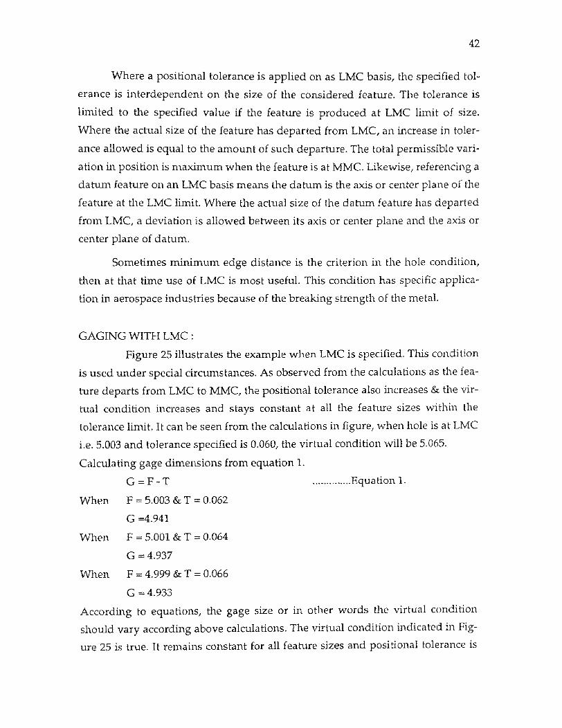
42
Where a positional tolerance is applied on as LMC basis, the specified tol-
erance is interdependent on the size of the considered feature. The tolerance is
limited to the specified value if the feature is produced at LMC limit of size.
Where the actual size of the feature has departed from LMC, an increase in toler-
ance allowed is equal to the amount of such departure. The total permissible vari-
ation in position is maximum when the feature is at MMC. Likewise, referencing a
datum feature on an LMC basis means the datum is the axis or center plane of the
feature at the LMC limit. Where the actual size of the datum feature has departed
from LMC, a deviation is allowed between its axis or center plane and the axis or
center plane of datum.
Sometimes minimum edge distance is the criterion in the hole condition,
then at that time use of LMC is most useful. This condition has specific applica-
tion in aerospace industries because of the breaking strength of the metal.
GAGING WITH LMC :
Figure 25 illustrates the example when LMC is specified. This condition
is used under special circumstances. As observed from the calculations as the fea-
ture departs from LMC to MMC, the positional tolerance also increases & the vir-
tual condition increases and stays constant at all the feature sizes within the
tolerance limit. It can be seen from the calculations in figure, when hole is at LMC
i.e. 5.003 and tolerance specified is 0.060, the virtual condition will be 5.065.
Calculating gage dimensions from equation 1.
G = F - T Equation 1.
When F = 5.003 & T = 0.062
G =4.941
When F = 5.001 & T = 0.064
G = 4.937
When F= 4.999 & T = 0.066
G = 4.933
According to equations, the gage size or in other words the virtual condition
should vary according above calculations. The virtual condition indicated in Fig-
ure 25 is true. It remains constant for all feature sizes and positional tolerance is

43
adjusted as the actual feature dimension vary from its basic sizes.
It can be concluded from the calculations that it is difficult to calculate
an appropriate functional gage that complies with the situation. Functional gag-
ing of the hole does not work because of the variations of the axis position with
respect to change in feature size. Since there are specific applications for LMC pro-
duction e.g. aerospace or critical thichness on the part etc., different methods can
be employed for such measurements. These methods may be paper gaging, opti-
cal comparator, and CMMs. These equipments are sophisticated and costly as
compared to functional gages. Additionally, it requires skilled workers for mathe-
matical measurements, which means the loss of time & increase in cost towards
payment of high salaries.
2.9.4 Projected Tolerances : The application of projected tolerance is in the situation where the variation in
perpendicularity of treaded or press-fit holes could cause fastners such as screws,
studs etc. to interfere with mating parts. An interference can occur where a posi-
tional tolerance is applied to the depth of threaded or press-fit holes, and the hole
axes are inclined within allowable limits. The attitude of the fastner is restrained
by the inclination of the produced hole into which it assembles. Figure 26 illus-
trates how the projected tolerance zone concept realistically treats the condition.
The location & perpendicularity of threaded hole is important only if affects the
extended portion of the engaging fastner. When design consideration require a
closer control in perpendicularity of a threaded hole, than that allowed by the
positional tolerance, a perpendicularity tolerance specified as a projected toler-
Figure 26 . Projected Tolerances
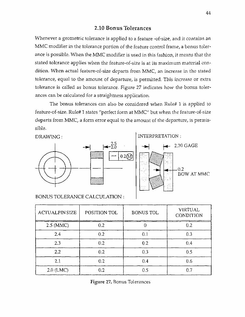
44
2.10 Bonus Tolerances
Whenever a geometric tolerance is applied to a feature -of-size, and it contains an
MMC modifier in the tolerance portion of the feature control frame, a bonus toler-
ance is possible. When the MMC modifier is used in this fashion, it means that the
stated tolerance applies when the feature-of-size is at its maximum material con-
dition. When actual feature-of-size departs from MMC, an increase in the stated
tolerance, equal to the amount of departure, is permitted. This increase or extra
tolerance is called as bonus tolerance. Figure 27 indicates how the bonus toler-
ances can be calculated for a straightness application.
The bonus tolerances can also be considered when Rule# 1 is applied to
feature-of-size. Rule# 1 states "perfect form at MMC" but when the feature-of-size
departs from MMC, a form error equal to the amount of the departure, is permis-
sible.
BONUS TOLERANCE CALCULATION
ACTUALPIN SIZE POSITION TOL BONUS TOL VIRTUAL
CONDITION
2.5 (MMC) 0.2 0 0.2
2.4 0.2 0.1 0.3
2.3 0.2 0.2 0.4
2.2 0.2 0.3 0.5
2.1 0.2 0.4 0.6
2.0 (LMC) 0.2 0.5 0.7
Figure 27. Bonus Tolerances
CHAPTER 3
CONCURRENT ENGINEERING
3.1 Chapter synopsis
Concurrent Engineering has become one of the hottest topics in engineering
today. Perhaps no other concepts in the past decade has so captured the imagina-
tion of design engineers as concurrent engineering (CE). The potential benefits of
CE are by now well known namely faster cycle time, better products and more
responsive organization. Although the principles that underlie concurrent engi-
neering are conceptually simple, they can be deceptively difficult to implement
effectively. They involve a well planned mixture of cutting-edge technology com-
bined with enlightened personnel and resource management policies that cut
across departmental lines.
The product life cycle is an important issue in CE. Designers give very little
consideration to these issues like product assembly, test, repair, and modification.
This is true even though designers are increasingly aware of the need of design
product parts so that they can be fabricated economically and still meet perfor-
mance requirements. While 'Design for Manufacturability' has increased produc-
tivity, it is not an integrated approach and thus miss most of the opportunities for
productivity enhancement.
This chapter describe the concepts of Concurrent Engineering, its objective,
its implementation and complexities during implementation. Also the conceptual
design process is with concurrent design (CD) indicating the corrosponding
advantages of CD.
3.2 Philosophy of Concurrent Engineering As the name suggest, Concurrent Engineering means doing the things together or
simulteneously. Although this statement can be vaguely interpretated as perform-
ing various activities at one time by all areas. Beyond that Concurrent Engineer-
ing is an integrated approach of performing various functions of an organization.
Concurrent Engineering can mean many things. Normally defined, it is the
45

46
merging or overlapping of hardware and software design tasks. A broader per-
spective on CE might more appropriately be called Concurrent product develop-
ment because it merges all product development disciplines. Among these
desciplines are marketing, hardware & software design, purchasing, test, manu-
facturing, and service.
The philosophy of CE is to reorient product development. Rather than per-
forming past design reviews, testing to correct problems, and constantly reengi-
neering the problems, Concurrent engineering strives to prevent problems and
build on existing designs.
Concurent Engineering can be defined in many ways. A formal definition
can be given as " Concurrent engineering is designing of a product and process to
manufacture that at the same time."
The definition of CE given by two faculty members of Georgia Institute of
Technology ( Deniel P. Scharge and J. Edward. Rogan) is as under :
" Concurrent Engineering is defined as a systematic approach to the integrated,
concurrent design of products and their related processes, including manufactur-
ing and support."
Both of these definition place emphasis on integration of all departments
involved in the process of product development such as engineering, manufactur-
ing, and marketing in order that they work together during early stages of prod-
uct development, i.e. conceptual design phase. It is in this phase that the design is
fluid, hardware is still remote, few number of people are involved and constraints
& restrictions have not become tight. It is this stage that the design team has most
latitude to explore alternate possibilities and therefore the greatest opportunities
to identify the inherently best product and process to manufacture, thus saving
time and money.
A typical manufacturing company occupies a place in long chain of suppli-
ers, fabricators, producers, transporters, wholesalers, and retailers. Raw materials
are converted into standard stocks and subsequently to standard components.
Materials and standard parts are made into products that are sold to wholesalers
& retailers. The management of company seeks to operate within this chain by
determining market demands, designing products, scheduling production, pre2
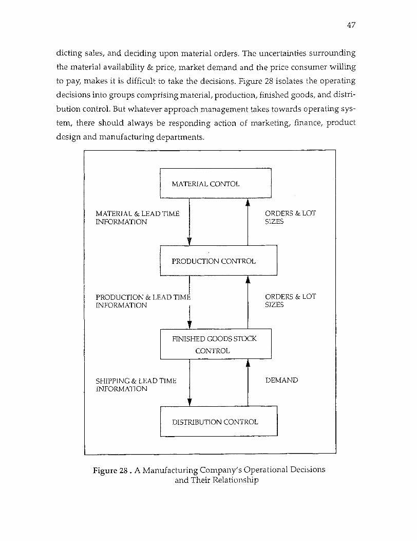
47
dieting sales, and deciding upon material orders. The uncertainties surrounding
the material availability & price, market demand and the price consumer willing
to pay, makes it is difficult to take the decisions. Figure 28 isolates the operating
decisions into groups comprising material, production, finished goods, and distri-
bution control. But whatever approach management takes towards operating sys-
tem, there should always be responding action of marketing, finance, product
design and manufacturing departments.
Figure 28 . A Manufacturing Company's Operational Decisions and Their Relationship

facing 48
Fig
ure
29 .
Inte
grat
ion
of D
iffe
rent
Fun
ctio
ns o
f an
Org
aniz
atio
n

48
The problem faced by manufacturing are many like the challenges of com-
petitiveness, the need for better quality, more flexibility and efficiency, and diffi-
culty attaining thesewith manual labor in complex products. Also these problems
are long standing. Therefore, an effective mix of technological and institutional
advances are required in product development stages so that the above
character-stics can be attained. Figure 29 indicates how different functions of an organiza-
tion can be welded into the coherent team that makes the decisions
simultaneously.
The job of a marketing department is to determine the characteristics and
features of a potential product and how big its market might be at a certain price.
Using a cost model of production cost and possible market share, the marketing
department estimates whether a product might be made in the right quantity for
the right price.
The product design department seeks to design a product that will meet
the market's demand or stimulate a market. Based on the findings of market sur-
veys or stimulated by product research and development, the design department
seeks to design a product with a target price that will meet the market's needs or
create a new market.
The manufacturing department must be able to make the product as
designed and as it is planned to be sold. A manufacturing process must designed
to create the product as designed. This process must comprise a strategy for meet-
ing the anticipated market method, including what models will be made, how
production will grow and so on.
The finance department must determine if the manufacturing depart-
ment's plans make sense economically. The overall estimated investment be com-
pared to the market and prospective revenue from selling the product. Also the
investment must be compared against alternate investments to determine if the
return is adequate.
An integrated approach to manufacturing comprises five interrelated ele-
ments. They are :
a. Careful analysis and understanding of fabrication and assembly processes to
permit their operation with consistency and quality.
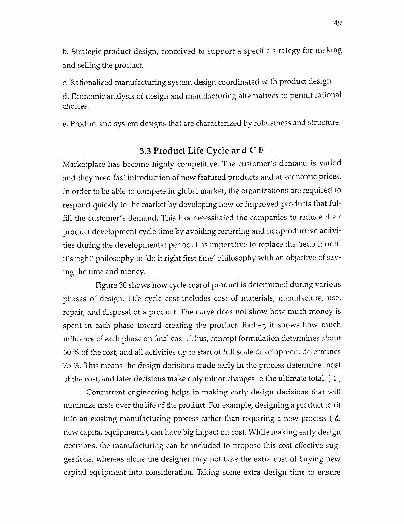
49
b. Strategic product design, conceived to support a specific strategy for making
and selling the product.
c. Rationalized manufacturing system design coordinated with product design.
d. Economic analysis of design and manufacturing alternatives to permit rational choices.
e. Product and system designs that are characterized by robustness and structure.
3.3 Product Life Cycle and C E
Marketplace has become highly competitive. The customer's demand is varied
and they need fast introduction of new featured products and at economic prices.
In order to be able to compete in global market, the organizations are required to
respond quickly to the market by developing new or improved products that ful-
fill the customer's demand. This has necessitated the companies to reduce their
product development cycle time by avoiding recurring and nonproductive activi-
ties during the developmental period. It is imperative to replace the 'redo it until
it's right' philosophy to 'do it right first time' philosophy with an objective of sav-
ing the time and money.
Figure 30 shows how cycle cost of product is determined during various
phases of design. Life cycle cost includes cost of materials, manufacture, use,
repair, and disposal of a product. The curve does not show how much money is
spent in each phase toward creating the product. Rather, it shows how much
influence of each phase on final cost . Thus, concept formulation determines about
60 % of the cost, and all activities up to start of full scale development determines
75 %. This means the design decisions made early in the process determine most
of the cost, and later decisions make only minor changes to the ultimate total. [ 4 ]
Concurrent engineering helps in making early design decisions that will
minimize costs over the life of the product. For example, designing a product to fit
into an existing manufacturing process rather than requiring a new process ( &
new capital equipments), can have big impact on cost. While making early design
decisions, the manufacturing can be included to propose this cost effective sug-
gestions, whereas alone the designer may not take the extra cost of buying new
capital equipment into consideration. Taking some extra design time to ensure

50
error free assembly by using a minimal number of assembly operations can also
significantly lower overall product costs.
Figure 31 shows a comparision of times taken in product development
for commonly used development technique - Sequential engineering and Concur-
rent engineering. It can be derived that around 60 - 85 % of overall product cost is
determined during the design phase. Product parts assembly, test, & service costs
are dictated for more often by the design then by actual manufacturing, testing &
service. Also not only the redesign and reverification costs using CE are elimi-
nated, but a considerable amount of time is saved in design verification, test gen-
eration, and test because of the efficiency early in the design phase. The saving in
time to market typically amount to between 10 and 25 % and results in better
product. [1]
1. Define use patterns 5. Prove feasibility 9. Product 2. Define alternatives 6. Provide preliminary designs 3. Develop alternatives 7. Provide detail designs 4. Freeze subsystems 8. Provide manufacturing plans
Figure 30 . Product Life Cycle Phases v/s Life Cycle Cost
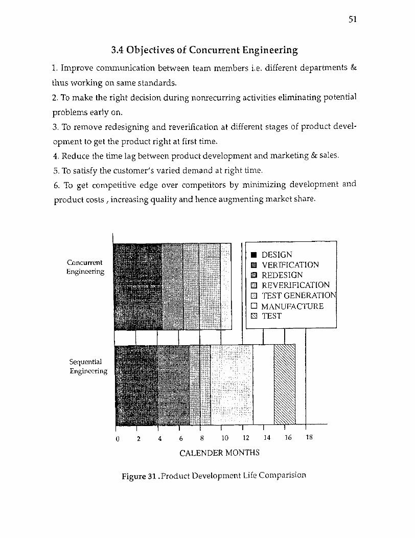
51
3.4 Objectives of Concurrent Engineering
1. Improve communication between team members i.e. different departments &
thus working on same standards.
2. To make the right decision during nonrecurring activities eliminating potential
problems early on.
3. To remove redesigning and reverification at different stages of product devel-
opment to get the product right at first time.
4. Reduce the time lag between product development and marketing & sales.
5. To satisfy the customer's varied demand at right time.
6. To get competitive edge over competitors by minimizing development and
product costs , increasing quality and hence augmenting market share.
CALENDER MONTHS
Figure 31 .Product Development Life Comparision

52
3.5 Traditional Product Development Trend
The Industrial Revolution introduced mass production with standardization and
reliance on machine tools that were operated by a widely available, but relatively
unskilled labor force. Lately, increasingly complex and yet inexpensive products
have resulted from the use of practices instituted at that time. But it is now well
recognized that a number of existing practices inimical to today's manufacturing
environment of high product mix, but low production volume, find their roots in
the very methods that made the Industrial Revolution successful.
Figure 32. The Conventional Product -Process Design Method

53
Figure 32 indicates the conceptual product-process development, the
majority of companies are organized along functional lines typically employ
greater degree of Sequential Engineering. Engineers are given a technically ori-
ented view which emphasizes determining the need, preparing product specifica-
tions, and making trial designs, then prototype for bench tests, then final design,
and then manufacturing process plan. These departments can have feedbacks and
the problems are uncovered and resolved. But in the main, the process is self-con-
tained from need to final design, with little outside interference. This unidirec-
tional approach to product development is limited by the ability of each group to
finish its portion of design. As each functional group finishes its task, it hands the
project to the next group in the sequence. This approach is often called 'over-the-
wall' engineering.
The greatest disadvantage of Sequential Engineering is its too much linear-
ity. The functions are divided into steps and sequences. It is too compartmental-
ized, assuming that the design, manufacturing, purchase manager, marketer etc.
works in their specified domains. The information flow is unidirectional.
Although downstream development departments might contribute useful infor-
mations to the design team, no formal mechanism for that data flow exists. The
most disadvantages can be independent schedule pressures on each of the func-
tional teams act to inhibit any sponteneous bidirectional information flows. There
pressures may lead to change, modify or compromise with project goals such as
unquantified ability to test, manufacture, and service of product.
3.6 Integrated or Concurrent Approach to Product Process Development
How the above problems can be avoided is the question? The alternative to
Sequential engineering can be Concurrent approach of product development
where a multidisciplinary product team can be employed instead of functionally
organized teams. These teams consists of representative from the disciplines of
engineering and corporate : manufacturing, services, product management, sales,
and finance. These teams provides a formal means of bidirectional communica-
tion between upstream and downstream operations. These teams can also include
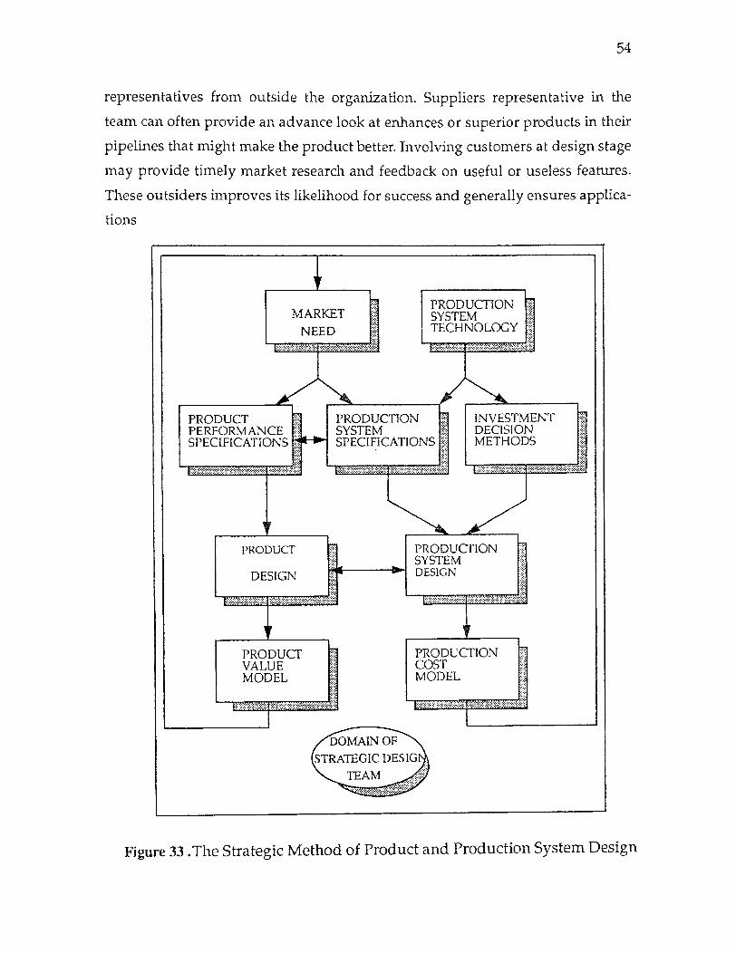
54
representatives from outside the organization. Suppliers representative in the
team can often provide an advance look at enhances or superior products in their
pipelines that might make the product better. Involving customers at design stage
may provide timely market research and feedback on useful or useless features.
These outsiders improves its likelihood for success and generally ensures applica-
tions
Figure 33. The Strategic Method of Product and Production System Design

facing 55
MA
NA
GE
ME
NT
D
ES
IGN
EN
GIN
EE
RIN
G
MA
NU
FA
CT
UR
ING
E
NG
INE
ER
ING
O
UA
LIT
Y
CO
N I
'RO
L
DE
TE
RM
INE
M
AR
KE
T
NE
ED
:
PR
EL
IMIN
AR
Y
DE
SIG
N
DE
TA
IL
DE
SIG
N
MA
NU
FA
CT
UR
ING
P
LA
N
ASS
EM
BL
Y
PL
AN
T
EST
&
INS
PE
CT
ION
P
LA
N
DE
SC
RIP
TIO
N
PE
RF
OR
MA
NC
E
CO
ST
Q
UA
LIT
Y
DE
SIG
N
SC
HE
DU
LE
P
RO
DU
CT
ION
S
CH
ED
UL
E
TE
CH
NIQ
UE
P
HY
SIC
AL
PR
INC
IPL
ES
A
ND
LA
YO
UT
E
NE
RG
Y S
TO
RA
GE
A
ND
TR
AN
SM
ISS
ION
L
OA
D B
EA
RIN
G S
IZE
S,
DIA
ME
TE
RS
, LE
NG
TH
S
SP
EE
DS
C
RIT
ICA
L M
AT
ER
IAL
S M
AJO
R C
OM
PO
NE
NT
S
VO
LT
AG
ES,
PR
ESS
UR
ES,
FL
OW
S
LA
YO
UT
DE
TA
ILS
TO
T F
RA
NC
ES
PIT
CH
ES
D
RA
FT
S
CH
AM
FE
RS
M
AT
ER
IAL
S F
INIS
HE
S
FAST
ENER
S
SEA
LS
CIR
CU
IT
CO
MP
ON
EN
TS
MA
KE
/ B
UY
M
FR
EQ
UIP
ME
NT
V
EN
DO
R C
HO
ICE
S
MFR
. LO
CA
TIO
N
SHIF
TS
S L
AB
OR
, TR
AIN
ING
IN-H
OUSE
O
R O
UT
A
SSY
M
ET
HO
DS
SH
IFT
S L
AB
OR
T
RA
ININ
G
WH
AT
TO
C
HE
CK
HO
W T
O
CH
EC
K
WH
EN
TO
C
HE
CK
GE
NE
RA
L P
RE
CE
DE
NC
E O
F D
ES
IGN
DE
CIS
ION
S
Fig
ure
34 .
Pre
cede
nce
of D
ecis
ions
in
Pro
duct
-P
roce
ss D
esig
n
55
The methods being used by competitive companies vary according to their
traditions and experiences, but they share attributes as per the Figure 33. This dia-
gram emphasizes the degree to which decisions made by different parties affect
each other's activity and alter the product's design. A single engineer cannot have
knowledge needed to carry out such a comprehensive activity . Also there is no
superintelligent computer as such which can design products & manufacturing
process. The teams of specialists can contribute their knowledge to create superior
products & manufacturing systems. The process of designing do have the itera-
tions, but the iterations between design & production or between production and
marketing can be of equal importance. Perhaps this is the cause of traditional time
lag between product design and manufacturing system design. The essence of a
sophisticated design can depend upon careful choice of tolerances, materials, or
new fabrication methods that cannot be seperated from the design of the manu-
facturing process and therefore it is never too early to begin the process before
having engineering prototype in the simulteneous engineering environment.
3.7 Practical Limitation to Concurrent Product Process Design Although the advantages of Concurrent design are many, it can be difficult to
implement because it is difficult to convince people to carry out through. The con-
straints can be listed as below :
1. One of the engineering limitations include the precedence of decisions. Figure
34 shows this process along with certain precedences that must be observed.
Some functions cannot begin until others have been considered. The purpose of
CD is not to ignore or obviate these precedences but rather to organize the flow of
debate & decisions so that the impact of decisions, especially the influential early
ones, is understood by all constituencies.
2. Difficulty in coordinating the activities of the many people involved in the
design of complex products. Even if the people in the various departments have
similar technical background, they are likely to think & work differently. Thus
making the group work more challenging.
3. In organizing multidisciplinary teams, communication can be difficult unless
appropriate infrastructure is provided. A procedure or tools can be developed
56
which will give unique interpretation and understanding at different levels.
4. Ingrained habits and training of engineers and managers and lack of experience
in participating in or managing teams. Many people are hesitant in sharing the
information with the others thus making the process sluggish and inefficient.
3.8 Tools for Concurrent Engineering For the effective implementation of Concurrent Engineering, some procedure or
tools should be defined that will make this new corporate philosophy to work.
Some of these tools can be listed as follows :
1. Design Standardization :
By standardizating the design, a considerable amount of redesigning and
reverification time can be saved. The design engineer can frequently search the
existing designs and reuse them rather than redesigning the same part. This will
also help in interchangability of parts and thus facilitating assembly. The use of
computerized database can be helpful in storing and easy retrieval of the stan-
dard designs.
2. Taguchi Methods :
These methods are based on mathematical analysis and is intended to aid
the designer in creating a product that can be produced within economical toler-
ances on economical equipments and still function as desired. Taguchi identifies
three elements in product design: System design, Parameter design and Tolerance
design.
System design means concept design of a product and engineering analy-
sis to determine that the product will function. It also includes the separation of
the factors into controllable and uncontrolable ones, or "noise" and then taking
suitable actions to eliminate or minimize the noises.
Parameter design is an attempt to deal with unpredictable factors. It uses
the statistical methods to identify the probable noise factors and controllable fac-
tors associated with the product's function.
3. Quality Function Deployment :
Quality function deployment is a tool for translating customers require-
ments into the appropriate technical requirements for each of the stages of prod-
57
uct development. A marketer can add the customer's attributes in House of
Quality to convey the needs to designer to enable him in incorporating these
attributes in the design.
4. Process Control Planning :
This method enables the documentation of all the informations regarding
the process in a single document for analysis and necessary modification of the
processs.
5. Simulation and Analysis :
This relatively new technique permits on-screen "testing" of a system
before significant time, capital, and expenses are incurred. The tool provides a
means of determining whether or not the system will work and or what is
required to make it efficiently.
6. Networks and Data Communication :
Proper communication is vital for successful implementation of Concur-
rent Engineering project. The flow of information to related departments is
important so that further action can be performed efficiently and quickly. The
local area networks can make the same information available almost instante-
neous and clearly to a large number of users. This allows the rapid transmission
of design informations to purchase, sales, inventory control departments etc.
Thus facilitating Concurrent Engineering approach.
7. Group Technology :
It is an approach developed to improve the effectiveness of producing sim-
ilar parts in small batches. A classification and coding scheme is used to identify
the similar parts that are already designed and manufactured using similar
machine tools and procedures in past. This saves the redesigning of parts and pro-
cesses to prodece them. Thus saving product development cycle time and cost
which are the prime factors in Concurrent Engineering.
8. Value Engineering :
It is defined as the systematic application of recognized techniques that
identify the function of the product or service, establish its value and provide the
service at the lowest possible cost without diminishing performance or quality. It
is the process in which the product design and function are examined critically so
58
as to decide for economic choices of materials, design features and manufacturing
processes.
9. Solid Modelling :
A solid model provides a complete geometric representation of a part or an
assembly. It includes more information about the part than either a
two-dimentional drawing or a 3D wireframe model. It can give a better idea to the represen-
tatives from other departments about the concepts included in the design.
10. Design for Manufacturability / Assembly :
This is the tool or process which can optimize the relationship between the
materials, technologies discussed, the manufacturing processes, and the costs
involved in the design stages.
11. Synchronous Manufacturing :
It is a manufacturing management technique which focuses on the system-
atic acceleration of materials flow through a production operation. It is also an
analytical technique that provides a framework for the systematic application of
quality and productivity programs.
12. Project Management :
The project management environment provides the flexibility to assemble
the personnel with require expertise to meet specific project requirements. Spe-
cific functions in the group can be assigned to the experts of specific field, all
working under a leader or evaluation committe in order to have an effective &
smooth incorporation of concurrent engineering concepts.
3.9 Advantages and Economy of Concurrent Engineering If implemented properly, the benefits from CE can be tremendous. Time and
money are two important factors that every organization is scarce of and always
tries to save or use them in an efficient manner. These two factors can be the sum-
marized advantages by using the concurrent engineering concepts.
Even though, the implementation of CE requires a considerable amount of
initial investment to set up the concurrent environment e.g. training, coordinated
efforts, computer systems etc., in the long run these costs can be justified by bun-
dle of benefits that CE would provide to the organization.

59
The following advantages can be obtained by the use of concurrent
engi-fleeing:
1.. Customer satisfaction :
Marketing point of view, customer satisfaction can be the biggest advan-
tage that an organization can achieve. With the interaction of marketing and sales
departments which are in the direct contact of customers, the needs can be
directly translated to the designer. This way the designer can incorporate desired
features in his design and satisfying customers.
2. Fast time to market :
The overall time for product development cycle is rduced by utilizing the
CE concepts, thereby reducing the time it takes to place a new product in the mar-
ket at economic price. This can give a competitive edge over competitors.
3. Reduction scrap and rework :
Simulteneous product and process design will help a product designer to
visualize the facilities available at shop floor and enable him to design a manufac-
turable product. At the same time, the manufacturing engineer can make valuable
suggestions which will be easier and feasible for him to manufacture in existing
facilities. By such an interaction the redesigning and reverification time will be
saved giving the right product at first time.
4. Cost reduction :
By making early decisions in the design stage, CE minimizes the costs over
the life of the products. For instance, a product design has to be done in such a
way that it fits into the actual manufacturing process. In this way, the company
does not have to invest in new technologies for a new designs, thus reduction in
cost. Also the cost for recurring activities, manufacturing and inventory costs can
be saved.
5. High Competitiveness :
The reduction in product development cycle time, early introduction of
new products in market at economic prices, reduction in overall cast, better qual-
ity of products etc. can place company in better position in market over the other
competitors. This also improves cpmpany's reputation and share.
CHAPTER 4
GD & T
- A TOOL FOR CONCURRENT ENGINEERING
4.1 Chapter Synopsis Once the concepts of Concurrent Engineering and GD & T are well defined and
the objectives are understood seperately, a great extent of similarities can be
observed. This chapters explains about how the GD & T can be applied in design
and different fields of manufacturing like tooling, inspection etc. and fulfilling the
concurrent engineering objectives. The chapter does this by taking an example
and then infering a definate relationship between concurrent engineering and GD
& T as a tool.
4.2 Introduction Geometric Dimensioning and Tolerancing is the means of specifying dimensions
& geometry on a drawing with respect to actual 'function' and 'relationship' of
the features. 'Functions' and 'Relation' are th key words. By definition, GD & T is
a technique which standardizes engineering drawing practices with respect to the
function of dimension and tolerances. Thus GD & T can be considered both an
engineering design drawing language and a functional production and inspection
technique. Uniform interpretation and understanding among design, manufac-
turing and inspection groups are the major objectives of the system. This will
ensure effective communication and result in a reduced potential of misunder-
standing.
Concurrent Engineering is one of the recent developing philosophies an
organization must adopt and trust in it which can lead to a considerable savings
in terms and money. CE as defined by Daniel P. Scharge and J. Edward Rogen of
Georgia Institute of Technology, " Concurrent Engineering is a systematic
approach to the integrated, concurrent design of products and their related pro-
cess, including manufacturing, and support."[15, p.34] The concept of CE empha-
sizes on integrated or team effort where different functions of an organization
60
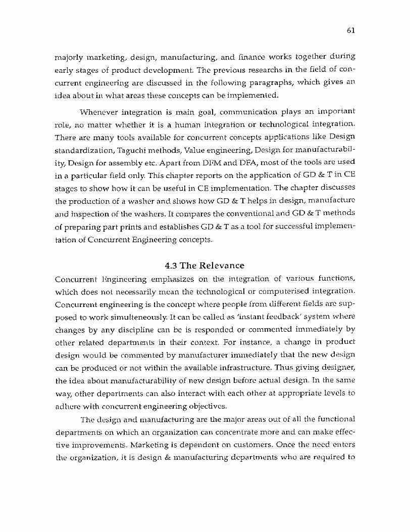
61
majorly marketing, design, manufacturing, and finance works together during
early stages of product development. The previous researchs in the field of con-
current engineering are discussed in the following paragraphs, which gives an
idea about in what areas these concepts can be implemented.
Whenever integration is main goal, communication plays an important
role, no matter whether it is a human integration or technological integration.
There are many tools available for concurrent concepts applications like Design
standardization, Taguchi methods, Value engineering, Design for manufacturabil-
ity, Design for assembly etc. Apart from DFM and DFA, most of the tools are used
in a particular field only. This chapter reports on the application of GD & T in CE
stages to show how it can be useful in CE implementation. The chapter discusses
the production of a washer and shows how GD & T helps in design, manufacture
and inspection of the washers. It compares the conventional and GD & T methods
of preparing part prints and establishes GD & T as a tool for successful implemen-
tation of Concurrent Engineering concepts.
4.3 The Relevance
Concurrent Engineering emphasizes on the integration of various functions,
which does not necessarily mean the technological or computerised integration.
Concurrent engineering is the concept where people from different fields are sup-
posed to work simulteneously. It can be called as 'instant feedback' system where
changes by any discipline can be is responded or commented immediately by
other related departments in their context. For instance, a change in product
design would be commented by manufacturer immediately that the new design
can be produced or not within the available infrastructure. Thus giving designer,
the idea about manufacturability of new design before actual design. In the same
way, other departments can also interact with each other at appropriate levels to
adhere with concurrent engineering objectives.
The design and manufacturing are the major areas out of all the functional
departments on which an organization can concentrate more and can make effec-
tive improvements. Marketing is dependent on customers. Once the need enters
the organization, it is design & manufacturing departments who are required to
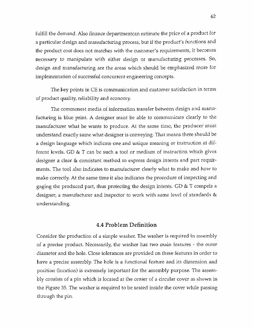
62
fulfill the demand. Also finance departmentcan estimate the price of a product for
a particular design and manufacturing process, but if the product's functions and
the product cost does not matches with the customer's requirements, it becomes
necessary to manipulate with either design or manufacturing processes. So,
design and manufacturing are the areas which should be emphasized more for
implementation of successful concurrent engineering concepts.
The key points in CE is communication and customer satisfaction in terms
of product quality, reliability and economy.
The commonest media of information transfer between design and manu-
facturing is blue print. A designer must be able to communicate clearly to the
manufacturer what he wants to produce. At the same time, the producer must
understand exactly same what designer is conveying. That means there should be
a design language which indicate one and unique meaning or instruction at dif-
ferent levels. GD & T can be such a tool or medium of instruction which gives
designer a clear & consistant method to express design intents and part requir-
ments. The tool also indicates to manufacturer clearly what to make and how to
make correctly. At the same time it also indicates the procedure of inspecting and
gaging the produced part, thus protecting the design intents. GD & T compels a
designer, a manufacturer and inspector to work with same level of standards &
understanding.
4.4 Problem Definition
Consider the production of a simple washer. The washer is required in assembly
of a precise product. Necessarily, the washer has two main features - the outer
diameter and the hole. Close tolerances are provided on these features in order to
have a precise assembly. The hole is a functional feature and its dimension and
position (location) is extremely important for the assembly purpose. The assem-
bly consists of a pin which is located at the center of a circular cover as shown in
the Figure 35. The washer is required to be seated inside the cover while passing
through the pin.
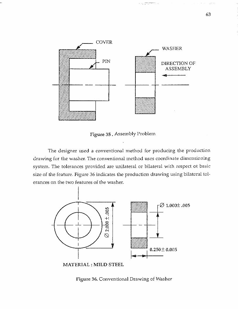
63
Figure 35 . Assembly Problem
The designer used a conventional method for producing the production
drawing for the washer. The conventional method uses coordinate dimensioning
system. The tolerances provided are unilateral or bilateral with respect of basic
size of the feature. Figure 36 indicates the production drawing using bilateral tol-
erances on the two features of the washer.
MATERIAL : MILD STEEL
Figure 36. Conventional Drawing of Washer

64
The production of this washer seems to be simple assuming that the facili-
ties are available to make the washer within the specified tolerances of ±0.005.
There may be various sequence of operations and production methods. The
washer can be either produced by compound shearing dies or by drilling a hole
on the available circular blank. Since precision is required on washer dimensions,
consider the later method of production. Also it would help in explaining the con-
cept. Assuming that the blanks are available from some other process and are well
within the tolerances. The simplest setup for drilling hole on a drilling machine
can be as shown in the Figure 37.
The results of such a manufacturing process may be a hole within perfect
dimensions (within tolerances), since the machine used is precise, but on the other
hand, the washers might be produced as shown in figure 38.
Figure 37. Manufacturing setup with Conventional drawing
Dimensionally, the washers shown in figure 38 a. & b. are with in the spec-
ified tolerances. Any washer of such dimensions will pass through the quality
checks. Also there won't be any process control since the output product is fitting
to required specifications. But such washers can never be assembled to seat on the
cover base. The hole does not comply to functional requirements. Eventhough,
the outer diameter of washer fits in the cover inside diameter, the misposition of
65
hole will prevent from assembly. These washers can be called as non-functional
good washers.
The reasons for such non-functional washers may be many. These washers
might be produced at different machines with different setting. The washers
might have been manufactured during the different shifts where different people
are involved. Different persons can have different interpretations of the existing
drawing. The designer do have intention by showing that the hole should be con-
centric to the outside diameter, but the drawing does not give a solid basis which
indicates that the hole should lie at exact center.
On analysing the conventional drawing it can be seen that the two features
are independently dimensioned. There is no direct or indirect link between the
two dimensions indicated in the drawing, while the assembly procedures does
indicate a relationship between them.
The washer in figure 38 is made with the extreme dimensions , it may not
be a good part for assembly. There is a shift in hole with respect to outer diameter
which makes the washer non-functional.
( a.) Acceptable Washer with OD Adhering to Left Extermity and Hole Dia. with Right
( b.) Acceptable Washer with OD Adhering to Right Extermity and Hole Dia. with Left
Figure 38. Acceptable Washers
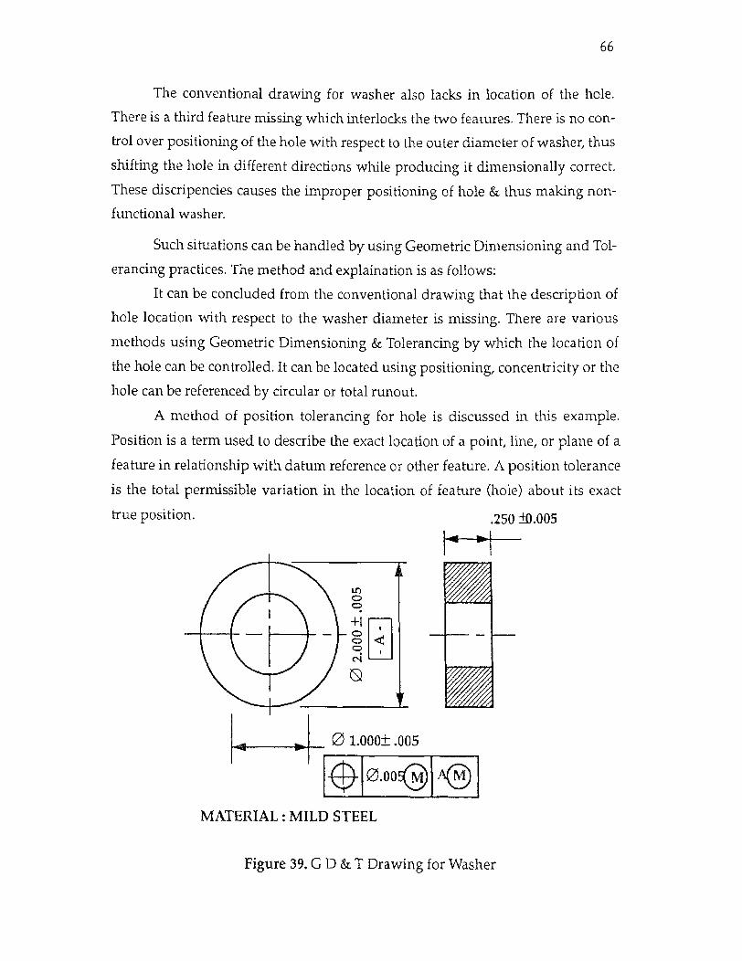
66
The conventional drawing for washer also lacks in location of the hole.
There is a third feature missing which interlocks the two features. There is no con-
trol over positioning of the hole with respect to the outer diameter of washer, thus
shifting the hole in different directions while producing it dimensionally correct.
These discripencies causes the improper positioning of hole & thus making non-
functional washer.
Such situations can be handled by using Geometric Dimensioning and Tol-
erancing practices. The method and explaination is as follows:
It can be concluded from the conventional drawing that the description of
hole location with respect to the washer diameter is missing. There are various
methods using Geometric Dimensioning & Tolerancing by which the location of
the hole can be controlled. It can be located using positioning, concentricity or the
hole can be referenced by circular or total runout.
A method of position tolerancing for hole is discussed in this example.
Position is a term used to describe the exact location of a point, line, or plane of a
feature in relationship with datum reference or other feature. A position tolerance
is the total permissible variation in the location of feature (hole) about its exact
true position.
MATERIAL : MILD STEEL
Figure 39. G D & T Drawing for Washer

67
The production drawing for the washer using Geometric Dimensioning
and tolerancing is as shown in Figure 39.
The true position of hole is the center of outer diameter of washer as shown
in figure 40, which is denoted as basic dimension (without tolerances). The func-
tional requirement of hole is to be concentric to the washer periphery. Therefore,
idealy, the center of hole must coincide with center! of the washer. The following
sections discusses how the GD & T implementation affects on the different func-
tional divisions of a manufacturing organization.
Figure 40. Interpretation of GD & T Drawing
4.5 Manufacturing Engineering Concerns
4.5.1 Design Concerns : It can be seen from the previous researchs and experiences that while integrating
the different departments as an implementation of concerrent engineering, a
major emphasis should be given at the early design stages. This is because a
majority of costs are committed in this stage. For example a design specifies about
material, it gives an idea about the manufacturing or fabrication methods, assem-
bly methods, materials handling options, inspection requireed and other produc-

68
tion aspects. All of these fields involves certain cost. This cost is as high as about
70% of life cycle costs of the product.
Since the design contributes to many cost factors, it is imperative to define
clearly these factors at design stage only so that the later stages of production can
be properly executed and justified. So far as material selection & materials han-
dling are concerned, they affect in a lesser degree because there is no specific
equipment setting or executing methods required once the material & handling
process is decided. These costs contribution is relatively constant.
The actual problem arises when the part is required to be processes ( man-
ufactured) or assembled. A part can be manufactured in different ways with dif-
ferent sequence of operations. Also the part can be manufactured by different
workers at different times who will try to interpret the drawing in their own way
and produce it as per their knowledge and judgement. Also each machine has
inherent error, but assuming this error to be constant for all parts, the parts pro-
duced with other variability would be different in dimensions and characteristics.
This will create problems in assembly process. Thus will result in defective or
non-fuctional parts.
This necessitates need of a tool or media which states all the informations
required to produce the part. GD & T can be used as media which indicates
almost every information required for production, tooling, and gaging. Since a
single drawing drawn with GD & T standards involving various informations
and because of unique methodology of GD & T, the drawing is interpreted in one
and unique way at different areas of manufacturing like production, tooling and
inspection. It creates a link among all these areas so that they can work with same
standards.
Let us consider the problem in question. When the washer is drawn with
GD & T practices, following points a designer would like to convey
1. The outer diameter (Ø 2.000 ± 0.005) is considered as the the datum 'A'. As the
datum is specified on feature of size, it must be simulated by the modifiers i.e.
MMC, LMC or RFS. It can be seen that control frame indicates maximum material
condition (MMC) for outer diameter when using as datum 'A'.
2. The tolerance of position is applied to feature of size Ø 1.000 ± 0.005. This per-
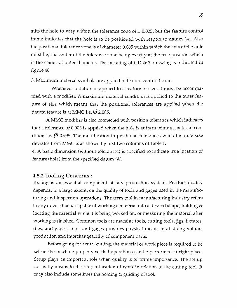
69
mits the hole to vary within the tolerance zone of ± 0.005, but the feature control
frame indicates that the hole is to be positioned with respect to datum 'A'. Also
the positional tolerance zone is of diameter 0.005 within which the axis of the hole
must lie, the center of the tolerance zone being exactly at the true position which
is the center of outer diameter. The meaning of GD & T drawing is indicated in
figure 40.
3. Maximum material symbols are applied in feature control frame.
Whenever a datum is applied to a feature of size, it must be accompa-
nied with a modifier. A maximum material condition is applied to the outer fea-
ture of size which means that the positional tolerances are applied when the
datum feature is at MMC i.e.Ø 2.005.
A MMC modifier is also connected with position tolerance which indicates
that a tolerance of 0.003 is applied when the hole is at its maximum material con-
dition i.e. Ø 0.995. The modification in positional tolerances when the hole size
deviates from MMC is as shown by first two columns of Table 1.
4. A basic dimension (without tolerances) is specified to indicate true location of
feature (hole) from the specified datum 'A'.
4.5.2 Tooling Concerns
Tooling is an essential component of any production system. Product quality
depends, to a large extent, on the quality of tools and gages used in the manufac-
turing and inspection operations. The term tool in manufacturing industry refers
to any device that is capable of working a material into a desired shape, holding &
locating the material while it is being worked on, or measuring the material after
working is finished. Common tools are machine tools, cutting tools, jigs, fixtures,
dies, and gages. Tools and gages provides physical means to attaining volume
production and interchangeability of component parts.
Before going for actual cutting, the material or work piece is required to be
set on the machine properly so that operations can be performed at right place.
Setup plays an important role when quality is of prime importance. The set up
normally means to the proper location of work in relation to the cutting tool. It
may also include sometimes the holding & guiding of tool.
facing 70
Figure 41 . Drill Jig for Washer Production

70
The considered example requires a mass production of the washers with
precision. Hence, the raw material i.e. blank for drilling hole must be located
properly so that the drilled hole has the specified positioning requirements. A
drill jig will be required to design for such a purpose which will locate the blank
from datum A, the outer diameter. The blank is assumed to be available from pre-
vious operation and is within the tolerance limits. The jig should be designed in
such a way that it is suitable to locate the blank size from LMC to MMC i.e. Ø
1.995 to Ø 2.005 only. This location would also serve as purpose of datum 'A'.
A possible drill jig design is as shown in the Figure 41. The jig consists of
one fixed V blocks and a movable V block, which acts as locators for cylindrical
surface i.e. washer outer surface. The movable V block is given freedom in such a
way that when it reaches to its maximum position, the circle made by the imagi-
nary three locators touches both the block surfaces and would be equal to the
MMC of blank. Therefore, a blank of MMC can be mounted on the jig easily. The
blanks more than MMC will not be fit in the jig and hence will be rejected. At the
MMC condition, the bush center line, coincides with that of blank at MMC. This
will ensure that if blank is at MMC, it will be located perfectly and hole will be
drilled exactly at the position. The bush is used to guide the drill bit.
On the other hand, if the blank is at LMC, it would be located by fixed
block and minimum position (extreme left) of the movable block. this will ensure
that if the blank is below LMC, it is a rejection. When the blank is at LMC i.e. Ø
1.995, its center would still lie on the circumference of tolerance zone, hence mak-
ing an acceptable positional hole. This is as shown in the Figure 41 by dotted lines.
This jig perfectly follows the 3-2-1 principle of location. The base of the jig
gives the effect of three points onwhich the part is mounted. These locators
restricts the three degrees of freedom. The fixed V- block provides the two locators
and restricts the motion in two directions. The sixth degree of freedom will be
stopped by the moving V-block, which will act as a single locator. It can be seen
that this jig design locates the washer successfully and at the same time allows the
outer dimension variation of the washer.
The drill bit will be located and guided at the center of blank when it is at
MMC (true position). This will ensure that if blank is at MMC, it will be located
71
perfectly and hole will be drilled exactly at true position. If the blank deviates
from MMC the hole position will still be ensured within the axis tolerance zone of Ø
0.005.
Thus it can be seen that GD & T also tells a tool design department as how
to produce a tool for an interchangeable part production. It has also incorporated
a tool design division and thus pursuing the integrated approach of CE imple-
mentation.
4.5.3 Production Concerns By providing additional informations, GD & T has dramatized product engineer-
ing to a large extent. When using a coordinate system and producing & inspecting
a prototype following problem arises
1. Sometimes the product made according to the design specification with great
difficulty, was rejected by the quality control and the inspection department. The
design department and production tends to blame each other. But the truth is that
the language or the design intent was not clear, hence communication of how the
part has made was a failure, though the specification was in tolerance.
2. Many a times the problem lied in making the product itself under the specified
tight tolerances. The machinist was under great pressure to produce the part
which is difficult to make under design specifications.
These two problems have been solved by GD & T. In the first case GD & T
ensures 57% more tolerance zone compared to the square tolerance. It is always
easy to produce a product in different components, but when they are assembled
they do not fit. This is because either the design is not clearly interpreted or by
giving tight tolerances, this problem will be evident if the traditional drafting pro-
cedures are used. Whenever part features are critical to function or interchange-
ability, the 'plus minus' kind of tolerancing does not work good in ensuring
quality products. This is where GD & T steps in, and hence all these concepts like
DFM needs to rely on for cost savings and productivity.
It can be seen from the GD & T drawing for the washer that it delivers the
exact sequence of operation for the manufacturing department. By doing so it
maintains the uniformity in the manufacturing of all the washers irresective of
where it is made i.e. at different machines or at vendor etc. and who makes it. As
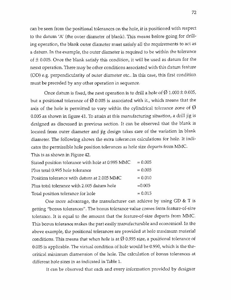
72
can be seen from the positional tolerances on the hole, it is positioned with respect
to the datum 'A' (the outer diameter of blank). This means before going for drill-
ing operation, the blank outer diameter must satisfy all the requirements to act as
a datum. In the example, the outer diameter is required to be within the tolerance
of Ø ± 0.005. Once the blank satisfy this condition, it will be used as datum for the
nesxt operation. There may be other conditions associated with this datum feature
(OD) e.g. perpendicularity of outer diameter etc.. In this case, this first condition
must be preceded by any other operation in sequence.
Once datum is fixed, the next operation is to drill a hole of Ø 1.000 ± 0.005,
but a positional tolerance of Ø 0.005 is associated with it., which means that the
axis of the hole is permitted to vary within the cylindrical tolerance zone of 0
0.005 as shown in figure 41. To attain at this manufacturing situation, a drill jig is
designed as discussed in previous section. It can be observed that the blank is
located from outer diameter and jig design takes care of the variation in blank
diameter. The following shows the extra tolerances calculations for hole. It indi-
cates the permissible hole position tolerances as hole size departs from MMC.
This is as shown in Figure 42.
Stated position tolerance with hole at 0.995 MMC = 0.005
Plus total 0.995 hole tolerance = 0.005
Position tolerance with datum at 2.005 MMC = 0.010
Plus total tolerance with 2.005 datum hole =0.005
Total position tolerance for hole = 0.015
One more advantage, the manufacturer can achieve by using GD & T is
getting "bonus tolerances". The bonus tolerance value comes from feature-of-size
tolerance. It is equal to the amount that the feature-of-size departs from MMC.
This bonus tolerance makes the part easily manufacturable and economical. In the
above example, the positional tolerances are provided at hole maximum material
conditions. This means that when hole is at Ø 0.995 size, a positional tolerance of
0.005 is applicable. The virtual condition of hole would be 0.990, which is the the-
oritical minimum diamension of the hole. The calculation of bonus tolerances at
different hole sizes in as indicated in Table 1.
It can be observed that each and every information provided by designer
73
in GD & T print guides the manufacturer in deciding the steps in production of
the part. In this way both designer and manufacturer has same interpretation and
execution of the drawing without any ambiguity and conflicts.
4.5.4 Inspection : Marketing and sales are the departments, which bring the need of customers to
design stages. These needs incorporate quality as well as economic requirements.
Quality planning operations are initiated by consumer quality requirements.
Quality control operations are directed and implemented from cost-criterion
basis. Economic decisions underlie the development of specification tolerances,
control procedures and inspection plans.
In production situations, specification requirements for modern products
are so restrictive that measurement error becomes most serious problem facing
the quality control and inspection staff. This is particularly true in mechanical
industries. There are two types of inspection processes that can be involved :
1. Inspection/ Checking : This process of inspection involves the measurement of
variables or attributes on the part. Basically, it checks the dimensional accuracy
and other defects present on the part. It is primarily concerned with determining
the degree to which production output conformed to the established technical
specifications for the product. The result of such checks can be used for product
and process controls. It can also be used for preparing quality audits to generate
feedback informations to the quality planning operations and upper level man-
agement sections.
2. Performance check or Testing : This kind of inspection is used when product is
finished after assembly. It actually checks the function of product what the prod-
uct is supposed to do. An assembly consists of more than one part and it may be
possible that the parts do have movements relative to each other. Therefore, it
must be ensured that parts are dimensioned and manufactured properly so that,
when assembled, they achieve the desired relative motion and thus giving desired
functions.

74
MATERIAL : MILD STEEL EXTRA TOL FOR HOLE : PERMISSIBLE HOLE POSITION TOL. AS HOLE SIZE DEPARTS FROM MMC : STA POSITION TOL. WITH HOLE AT 0.995 MMC = 0.005 PLUS TOTAL 0.995 HOLE TOLERANCE = 0.005 POSITION TOL. WITH DATUM HOLE AT 2.005 MMC = 0.010 PLUS TOTAL TOL. WITH 2.005 DATUM HOLE = 0.005 TOTAL POSITIONAL TOLERANCE FOR HOLE = 0.015
Figure 42. Effect and Calculation of MMC on Hole Positioning
Table 4 : Positional Tolerances and Bonus Tolerances Applicable at Hole Sizes
Hole size Positional tol. Bonus tolerance Virtual condition
0.995 ( MMC ) 0.005 0.0 0.990
0.997 0.007 0.002 0.990
0.998 0.008 0.003 0.990
0.999 0.009 0.004 0.990
1.000 0.010 0.005 0.990
1.001 0.011 0.006 0.990
1.002 0.012 0.007 0.990
1.003 0.013 0.008 0.990
1.005 (LMC ) 0.015 0.010 0.990
75
In such cases, functional gages can be used. These gages check the dimen-
sions and tolerances on the parts as well as ensure that part would function when
assembled. GD & T gives all the information about dimensioning and functional-
ity of part and thus help a gage designer to design and produce the specific gage
for specific part feature.
Functional gages are economic to manufacture and use as well. These
gages give only two types of answer i.e. accept or reject. Also a functional gage
has fixed dimensions and is suitable for one or few dimension checks. In other
words, the functional gage can only be applicable to a part with constant virtual
condition. Hence in the cases where virtual condition changes with the part
dimensions other methods, for instance comparators should be used to determine
the variation and accept or reject the part depending upon the permissible dimen-
sional limits.
In the example in question (washer), the positional tolerance is applicable
when the hole becomes 0 0.990. As the hole size departs from MMC, there is
additional positional tolerance available for manufacturing, but still the virtual
condition remains same for all sizes. This indicates that a functional gage can be
constructed for an MMC condition of hole. The gage dimensions and design is
discussed in the next section.
But if the positional tolerances are applied with LMC, the situation would
be different. With the change in hole size from LMC to MMC, the positional toler-
ance would also change. So, when virtual condition is calculated, it changes with
different hole sizes. This is shown in the Table II. This implies that there should be
different gages mede for each different size of hole, which is uneconomical,
because to construct a functional gage requires precision and is also costly affair.
In such cases, the other methods can be employed. For example, A comparator or
Dial Indicator. A full indicator movement method setup is as shown in Figure 43.
Variations at single cross section will be observed on the dial indicator and if it
varies within the limits, the washer would be accepted. The same process should
be used at all the cross section of the washer. This method has an advantage that
the dial indicator can be used for any washer irrespective to the hole size or mate-
rial conditions. But it is a slow and tedious process of measurement.
76
4.5.5 Gaging :
Transfer of a length standard from the National Bureau of Standards to a manu-
facturing plant is accomplished by means of gage blocks. A gage is a reference
piece, either square or round in cross section, with two faces end surfaces or cylin-
drical surfaces. These surfaces are measurement surfaces. That is, the end faces
are flat parallel surfaces where separation has been established to tight wave pre-
cision and accuracy.
When a GD & T drawing is presented to an inspection department, it
gives the exact picture of how the part was produced by manufacturer. It will give
an idea about which features were placed as datum and which features are made
with reference to the datum. Accordingly, the functional gage can be prepared for
gaging a particular feature on the component.
In the above example, the possible functional gage can be as shown in the
Figure 44. The Ø 0.990 size gage pin is determined by the MMC size of the hole,
0.995, minus the stated positional tolerance of 0.005. Functional gages are,
ofcourse, not required with positional applications, but they do, however, provide
an effective method of evaluation where desired. The inner diameter of the gage is
produced at MMC (Ø 2.005 ) which checks the outside diameter of the washer.
Once the outside diameter of washer is ensured, the next step is to check
the dimension and location of hole. The Figure 44 illustrates the mating part situ-
ation represented by a functional or fixed pin. The gage pin size as calculated
above represents the maximum permissible offset of the hole within its stated
positional tolerance when hole is at MMC size of 0.995. The figure shows the hole
at MMC offset to the maximum permissible limits of the 0.005 positional tolerance
zone. The hole is within tolerance and, as can be seen, would satisfactorily pass
the simulated mating part condition as represented by the gage pin. It can be
noted that that a functional pin gage illustrated here explains that it can be used
only to check the positional location of the hole. Hole size tolerances, however,
must be held within the tolerances specified on the drawing and must be checked
separately from the positional check.

77
THE FEATURE MUST BE WITHIN THE SPECIFIED TOL . SIZE AT ANY MEASURING POSITION. EACH CIRCULAR ELEMENT OF THE SURFACE MUST BE WITHIN 0.005 FIM WHEN THE PART IS ROTATED ONE FULL ROTATION ABOUT THE SPECIFIED DATUM AXIS WITH THE INDICATOR FIXED IN POSITION NORMAL TO THE SURFACE.
Figure 43. FIM Setup when Positional Tolerances at Hole is at LMC
Table 5 : Positional Tolerances with LMC Applicable at Different Hole Sizes
Hole size Positional tol. Virtual condition
1.005 (LMC) 0.005 1.000
1.003 0.007 0.996
1.002 0.008 0.994
1.001 0.009 0.992
1.000 0.010 0.990
0.999 0.011 0.988
0.998 0.012 0.986
0.997 0.013 0.984
0.996 0.014 0.982
0.995 (MMC) 0.015 0.980
4.5.6 Vendor Concerns : A key to the success of the Concurrent Engineering project is the inclusion of sup-

78
pliers as members of the team. The manufacturing engages in long-term relation-
ships with selected vendors who demonstrate the ability and desire to be flexible
and work as a integral part of the team. Whereas in the past a supplier would bid
on a specification for a system or a component, now a vendor is developing the
specifications for products that he/ she will be awarded on a sole source basis.
An GD & T drawing can translate the exact needs of the company to the
vendor. And at the same time vendor have clearcut idea about what is to be man-
ufactured, How to make it and how it functions. Also the inspection procedures
are well defined. This will lead to reduction in the inspection points e.g. inspec-
tion at vendor's end may eliminate the inspection at company. At the same time,
the vendor has all the chances to provide the right product at first time. Thus,
while concurrent concepts tells to include the suppliers as a team member, the GD
& T makes the link tighter in the sense it gives supplier a credibility and confi-
dence to keep the contract on long term basis.
4.6 Inferences
The example explains the implementation of GD &T and compares this method of
dimensioning with conventional methods. When analysing closely, it can be
established that procedures and concepts in GD & T directly or indirectly tends to
adhere with the concurrent engineering objectives. The interrelations are as dis-
cussed below :
(a) One of the objectives of concurrent engineering is to achieve a team effort
among the functional groups in an organization and in turn improve the commu-
nication within the departments.
The above example illustrates how using a GD & T drawing , the designer
communicates with the manufacturer, tool designer and inspection. The GD & T
print includes enough information so as to guide them in their operations. For
example, the datum, dimensions and locational tolerances between two features
of washer gives the precedence of operation to actual producer. At the same time,
the drawing tells the inspection how to gage the washer. This way a single GD &
T drawing provides one & unique interpretation to different departments thus
improving communication and ensuring a standardized operation on different
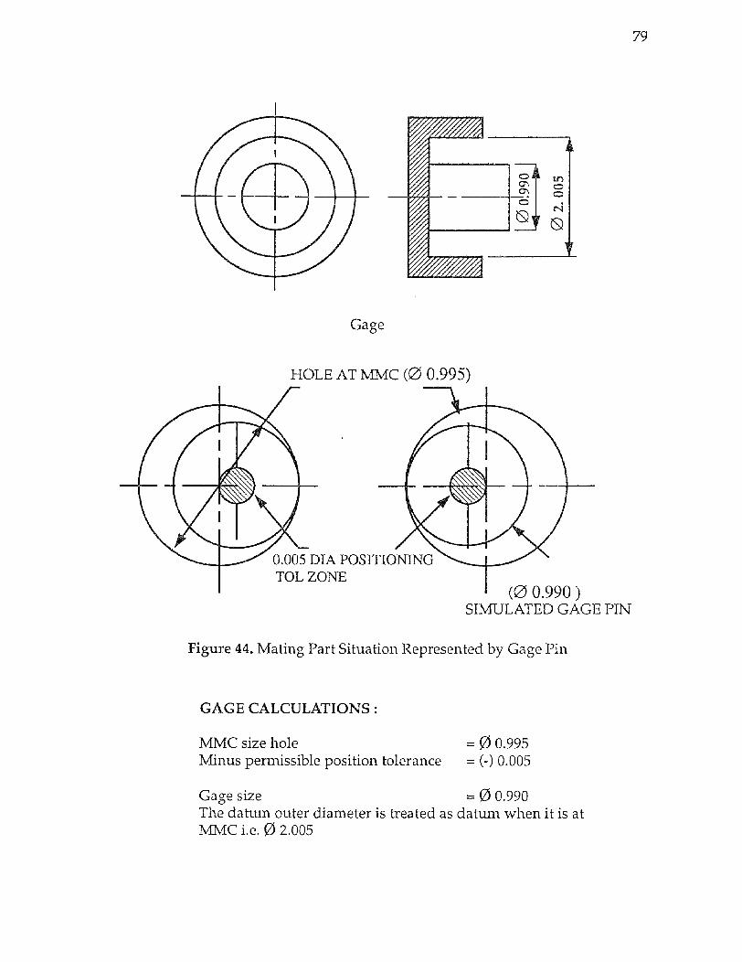
79
Figure 44. Mating Part Situation Represented by Gage Pin
GAGE CALCULATIONS :
MMC size hole = Ø 0.995 Minus permissible position tolerance = (-) 0.005
Gage size = Ø 0.990 The datum outer diameter is treated as datum when it is at MMC i.e. Ø 2.005
80
levels.
(b) As discussed before, the concurrent engineering approach is effective in con-
ceptual design phase. In this phase the design is fluid, hardware is remote and
few people are involved, therefore the interactions and constraints are less. It is
the stage when the designer has maximum latitude to explore the alternatives and
the a chance to identify best product and process concepts for manufacture.
The concept of GD & T compels a designer to include the manufacturing
aspects of the part in his design. Also GD & T tries to consolidate the design, man-
ufacturing and inspection in very early stages of product development. It is often
difficult for a designer to know about manufaturing aspects of product. Hence,
before designing a GD & T drawing, the designer has to consult with the manu-
facturer and inspection department. This improves the team effort and also
ensures that the design will be implementable successfully at later stages of prod-
uct development cycle.
(c) Another concurrent engineering concept is to eliminate or reduce redesign-
ing and reverification time and related costs. The objective is to make the right
decision during the non-recurring activity. Making good decisions in early stages
creates maximum leverage in terms of investing a little time and money during
product design to achieve larger profits over life of product.
With the intense competition, designers often are under pressure to bring
the product in market as quickly as possible. There is always an argument that
there is no time for concurrent engineering practices. But time to market a product
is not only a design time. Time to market is the time it takes to get a product into
the customer's hands at a competitive prices. Also there is a time involved in
manufacturing, testing and other process before product is marketed.
Concurrent Engineering helps speed the products actual time to market,
even if that means spending little more time making sure the design is flawless in
its performance and making sure it is manufacturable, testable and serviceable.
Since GD & T provides unique interpretation to different people and also
considers production and inspection aspects early at design stages, it ensures that
the right product will be made at first time thus eliminating or reducing the possi-
bility of recurring design and verification.

81
(d) Learning curve : The time taken to produce first unit is always more than the
subsequent units. Ultimately, the curve becomes horizontal at particular time
which can be called as standard time to produce the unit. GD & T can help in
steeping down this learning curve. Much of the time is spent in interpretation of
drawings and then setup for manufacturing. If the drawing provides a clearcut
Figure 45 Effect on Learning Curve
idea about what to produce and how to produce, the curve can even start from
lesser time as compared to traditional drawing methods. Also it can reach to stan-
dard time for unit manufactring very early, thus saving time. Figure 45 shows the
learning curve with conventional and GD & T application.
(e) Concurrent engineering concepts also leads to achieve a competative edge
over competitors by minimising developmental and product costs, increasing
quality and hence augmenting market share.
GD & T has indirect contribution to this goal. Certainly uniformity in print
interpretation among different functional groups makes the learning curve
steeper. Much of the time is spent in understanding the drawings & then setup for

82
manufaturing. If the drawing provides a clearcut idea about what to produce and
how to produce, the product developmental time is reduced and also quality
product is produced. This also reduces the time lag between product develop-
ment and marketing & sale. Thus GD & T gives both quality as well as marketing
advantages to an organization.
CHAPTER 5
CONCLUSION
5.1 Conclusion Concurrent engineering is a philosophy or management practice which leads to a
definite benefit of faster cycle time, better products, better communication and
more responsive organization. But successful implementation of these concepts
requires a physical tool, the use of which would lead to common advantages as of
concurrent engineering. Geometric Dimensioning and Tolerancing can be consid-
ered as a tool or medium, the concepts of which comply directly or indirectly with
concurrent engineering objectives.
As discussed in chapter 4, using geometric dimensioning and tolerancing
language provides the manufacturing with more benefits than the traditional
drawing system. It can be observed from the inferences how GD & T can help in
realising the goals of concurrent engineering. The first and major accomplishment
that could be achieved is a uniform communication at different levels. It is also a
media which integrates the related departments by providing full and clear infor-
mations to all. Moreover, a proper use and interpretation of GD & T eliminates the
recurring activities like redesigning, reinspection and performance checks etc.
This leads to saving in product development time and costs. Also it allows an
early introduction of products in the market. This also improves the product man-
ufactured quality. Thus gaining a competitive edge over other competitors.
It can be seen that all of the above achievements tend to represent the con-
current engineering objectives in one way or other. Therefore, it can be considered
as a tool or media for implementing the concurrent engineering philosophy in a
manufacturing industry.
The use of GD & T does not give a solution by itself. The process of product
development is always sequential and it applies in a specific order. But, GD & T
captures the interdependece relationships among the departments and at the
same time maintains the order of operations.
The greatest shortcoming of GD & T system is lack of awareness and train-
ing available. There are very few educational institutions and organizations
83

84
which provide a formal education for this dimensioning system. The myths and
barriers for practicing GD & T concepts must be broken and adequate training
and instructions must be spread among actual users so as to achieve the benefits
of Geometric Dimensioning & Tolerancing.
ISO 9000 and ABCA standards do not refer to GD & T directly, but GD & T
does comply with the recommondations of these standards. Therefore, the use of
GD & T in industies may lead to widespread implementation of Concurrent Engi-
neering concepts globally.
5.2 Future Research A great potential lies in improving and evolving easier techniques for implement-
ing GD & T at the unskilled level. The current system is an effort of three decades
of research by a committee action representing military, industrial and educa-
tional interests. This is a result of three other standards which were used sepa-
rately.
As discussed before an immediate need in this area is to increase the
awareness about geometric dimensioning and tolerancing methodology at all lev-
els of users, from shop floor worker to designer. A definite scope lies in the devel-
opment of a computerized system, which incorporate CAD with all tolerancing
and geometric features. Besides this it should coordinate with Concurrent Engi-
neering requirements. There are some software in market integrating the design
and manufacturing aspects, but lacks in emphasizing the tooling, inspection and
financial goals of concurrent engineering.
85
REFERENCES
(1) Foster, Lowell W. Geo-Metrics II, 1986 Edition, Addison- Wesley Publishing Company, Inc., Massachusetts 01867.
(2) Garrett, Ronald W. "Eight Steps to Simultaneous Engineering." Manufacturing Engineering, November (1990) : 41-47.
(3) Gehrke, T. "Blueprints Never Lie", Machine Design, November 12 (1992) : 83.
(4) Gossard, D. C., Zuffante, R. P., and Sakurai, H. "Representing Dimensions, Tolerances and Features in MCAE Systems." IEEE Computer Graphics and Applications, March (1988) : 51-59.
(5) Krulikowski, A. Geometric Dimensioning and Tolerancing, A self study Workbook, Effective Training Incorporated, Westland, MI-48185.
(6) Krulikowski, A. "Nine Myths of Geometric Dimensioning and Tolerancing." Machine Design, June 6 (1991) : 86.
(7) Krulikowski, A. "The Seven Deadly Sins of Dimensioning and Tolerancing." Machine Design, November 8 (1990) : 60-61.
(8) Kotefski, S. "Geometric Dimensioning and Tolerancing." To be published.
(9) Kuo, Way, and Hsu, J. P. "Update : Simultaneous Engineering Design in Japan." Industrial Engineering, October (1990) : 23 -26.
(10) Markowitz, Michael C. "Concurrent Engineering Starts with First Step." EDN, July 18 1991, 110 -114.
(11) Mcknight, Seldon W., and Jackson, Jerry M. "Simultaneous Engineering Saves Manufacturing Lead Time, Costs and Frustration." Industrial Engineering, August (1989) : 25-27.
(12) Nevins, James L. and Whitney, D. E. Concurrent Design of Products and Processes, 1989 Edition, Mcgraw Hill, Inc., USA.
(13) Neuman, Al. "Geometric Dimensioning and Tolerancing." Carbide and Tool Journal, July/August (1990) : 9-15.
(14) Requicha, A. A. G. " Toward a Theory of Geometric Tolerancing." The International Journal of Robotics Research, No.4 Winter (1983) : 45-60.
86
(15) Scharge, D.P. and Rogan, J. E. "Impact of Concurrent Engineering.", Aerospace America, September (1991) : 34.
(16) Shepherd, Don W. "Applying Geometric Dimensioning Successfully." Machine Design, May 12 (1988) : 112.
(17) Thompson, Daniel C. "Tighter Tolerances at Lower Costs." Mechanical Engineering, September (1988) : 36-42.
(18) Turino, J. "Concurrent Engineering Speeds Development Time, Lower Costs." EDN, May 7 1992, 191-195.
(19) Valaer, P. "The Problems with Geometric Dimensioning and Tolerancing." Machine Design, August 23 (1990) : 129-133.